Dell D Dock Expansion Station Users Manual D/Dock User's Guide
2014-11-13
: Dell Dell-D-Dock-Expansion-Station-Users-Manual-111443 dell-d-dock-expansion-station-users-manual-111443 dell pdf
Open the PDF directly: View PDF  .
.
Page Count: 37
Dell™ D/Dock Expansion-Station User's Guide
Using the Expansion Station
Regulatory Notices
Glossary
Notes, Notices, and Cautions
NOTE: A NOTE indicates important information that helps you make better use of your computer.
NOTICE: A NOTICE indicates either potential damage to hardware or loss of data and tells you how to avoid the
problem.
CAUTION: A CAUTION indicates a potential for property damage, personal injury, or death.
Abbreviations and Acronyms
For a complete list of abbreviations and acronyms, see the Glossary.
Information in this document is subject to change without notice.
© 2003 Dell Computer Corporation. All rights reserved.
Reproduction in any manner whatsoever without the written permission of Dell Computer Corporation is strictly forbidden.
Trademarks used in this text: Dell and the DELL logo are trademarks of Dell Computer Corporation.
Other trademarks and trade names may be used in this document to refer to either the entities claiming the marks and names or their products.
Dell Computer Corporation disclaims any proprietary interest in trademarks and trade names other than its own.
Model PD01X
January 2003 P/N J0836 Rev. A00
Back to Contents Page
Using the Expansion Station
Dell™ D/Dock Expansion-Station User's Guide
Safety Instructions
Other Documents Available
Overview
Docking Your Computer
Connecting External Devices to the Expansion
Station
Undocking Your Computer
Removing and Installing a PCI Expansion
Card
Using the Module Bay
Securing the D/Dock Expansion Station
Dell Diagnostics
Specifications
Safety Instructions
CAUTION: For precautions on safely handling and using your Expansion Station and preventing
electrostatic discharge, see the safety instructions in the D/Dock Expansion-Station Setup Guide.
Other Documents Available
Documentation updates, which are sometimes included with your expansion station to describe changes to the
expansion station or software. Always read the updates before consulting any other documentation, because the
updates often contain the latest information.
Documentation included with any options you purchase separately from your expansion station. The documentation
includes information that you need to configure and install the options in your expansion station.
Overview
NOTE: Alert your network administrator before you connect the expansion station to a network.
The Dell D/Dock Expansion Station is a full docking device that supports Dell D-Family portable computers and modules.
When docked to the expansion station, the computer only runs on electrical power and not battery power. Any battery
installed in the computer is charged while you are using the expansion station.
CAUTION: Do not block, push objects into, or allow dust to accumulate in the air vents. Doing so can
damage the expansion station or cause a fire.
Docking Controls and Lights
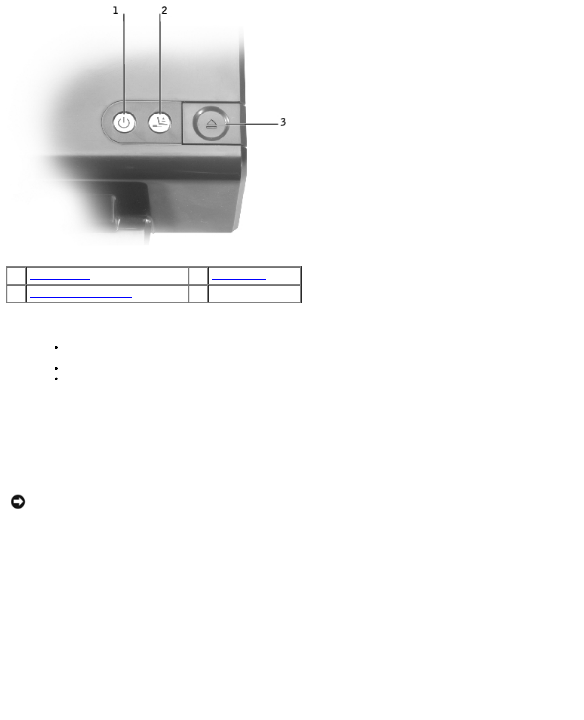
1power button 3eject button
2undock request button
power button — Press to turn a docked computer on or off. The power button light indicates the power status of the
expansion station or a docked computer as follows:
Off — The expansion station is either not connected to an electrical outlet or, if a computer is docked, the
computer is turned off or in hibernate mode.
Amber — The expansion station is connected to an electrical outlet; no computer is docked.
Green — Indicates the status of a docked computer:
Steady green — The computer is turned on.
Slow-pulsing green ("breathing") — The computer is in standby mode.
undock request button — Whenever the undock-request button light is green, you can press it to prepare the computer for
physical undocking. The light blinks during the preparation process and turns off when preparation is complete.
eject button — When the eject button light turns green, the computer is ready to be physically undocked. Ensure that the
slide lock is in the unlocked position, and then press the eject button to eject the computer.
NOTICE: After the computer is docked, do not eject the computer unless the eject button light is green. Ejecting while
the light is off may cause loss of data and damage to the computer or expansion station.
Back View
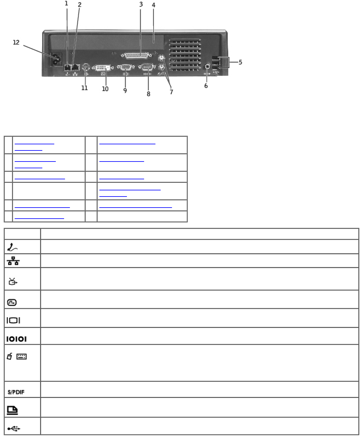
The following table shows the connectors and icons on the back of the expansion station and indicates the purpose of each
connector.
1RJ-11 modem
connector 7PS/2 connectors (2)
2RJ-45 network
connector 8serial connector
3parallel connector 9video connector
4PCI expansion-card
cover 10 digital-video interface
connector
5USB 2.0 connectors (3) 11 S-video TV-out connector
6S/PDIF connector 12 AC power connector
Connector Description
RJ-11 modem connector — Connects a telephone line.
RJ-45 network connector — Connects a network interface cable.
S-video TV-out connector — Connects to any device (such as a television, VCR, or camcorder) that accepts
S-video input.
digital-video interface connector — Connects an external display.
video connector — Connects an external VGA monitor.
serial connector — Connects a serial device, such as a serial mouse.
PS/2 connectors (2) — Connects PS/2-compatible devices, such as a mouse, keyboard, or external numeric
keypad. Shut down the computer before attaching or removing a PS/2-compatible device. If the device does
not work, install the device drivers from the floppy disk or CD that came with the device, and restart the
computer. You can use the integrated keyboard and an external keyboard at the same time. When you attach a
PS/2 keyboard or PS/2 numeric keypad, the integrated keypad is disabled.
S/PDIF connector — Connects a digital audio (S/PDIF) cable.
parallel connector — Connects a parallel device, such as a parallel printer.
USB 2.0 connectors — Connects up to three USB 2.0-compliant devices to the back of the expansion station.
A fourth USB connector can be found on the left side of the expansion station.
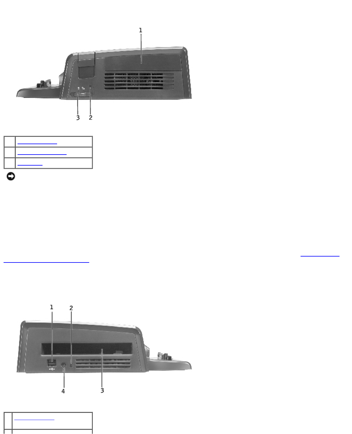
Right View
1PCI card cover
2security cable slot
3slide lock
NOTICE: You can damage the computer and/or the expansion station by attempting to dock the computer with the
slide lock in the locked position.
slide lock — Move the lock toward the front of the expansion station (locked position) to secure the computer in the
expansion station. The lock also secures the PCI card cover and locks a device into the module bay. Move the lock toward the
back of the expansion station (unlocked position) before using the eject button.
The slide lock must be in the locked position to attach a security cable to the expansion station.
security cable slot — Lets you attach a commercially available antitheft device to the expansion station. The slide lock must
be in the locked position to attach a security cable.
PCI card cover — Lets you access a PCI card installed in the expansion station. For more information, see "Removing and
Installing a PCI Expansion Card."
Left View
1USB connector for Dell
D/Bay
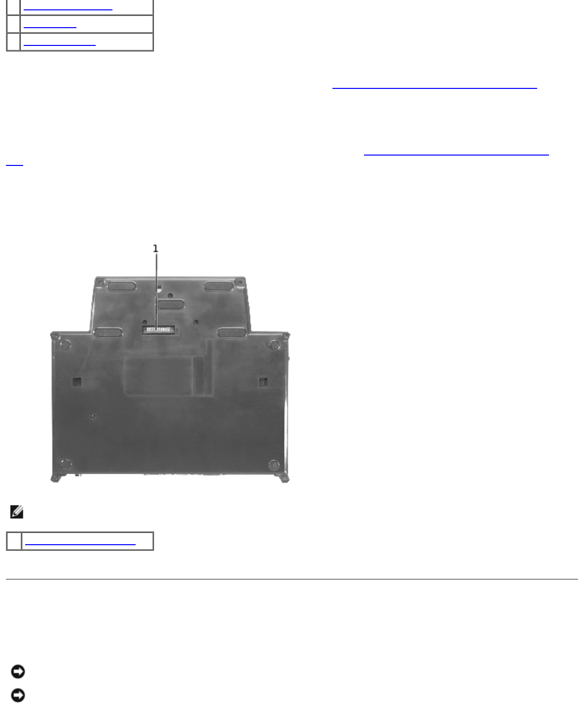
2battery charge light
3module bay
4audio connector
module bay — Lets you install a Dell D-series compatible module, such as a floppy, optical or combination drive. You can
also use the module bay to charge the computer's second battery (see "Charging a Second Battery in the Module Bay").
USB connector — Lets you connect a Dell D/Bay external module bay. The lower portion of the connector also accepts a
standard USB 1.0 or 2.0 cable.
battery charge light — Indicates the charge status of a second battery (see "Charging a Second Battery in the Module
Bay").
audio connector — Lets you attach headphones to the expansion station.
Bottom View
NOTE: For information about the optional monitor stand, see the documentation that came with the stand.
1monitor stand connector
monitor stand connector — Connects the expansion station to the optional monitor stand.
Docking Your Computer
You can dock your computer to the D/Dock expansion station when your computer is running, or turned off, or in a power
management mode.
NOTICE: To avoid losing data, save any open files before you dock the computer.
NOTICE: If a PCI card is installed in the expansion station, shut down the computer before undocking to avoid losing
data.
NOTE: Docking drivers are installed automatically as part of your operating system.
1. Save any open files.
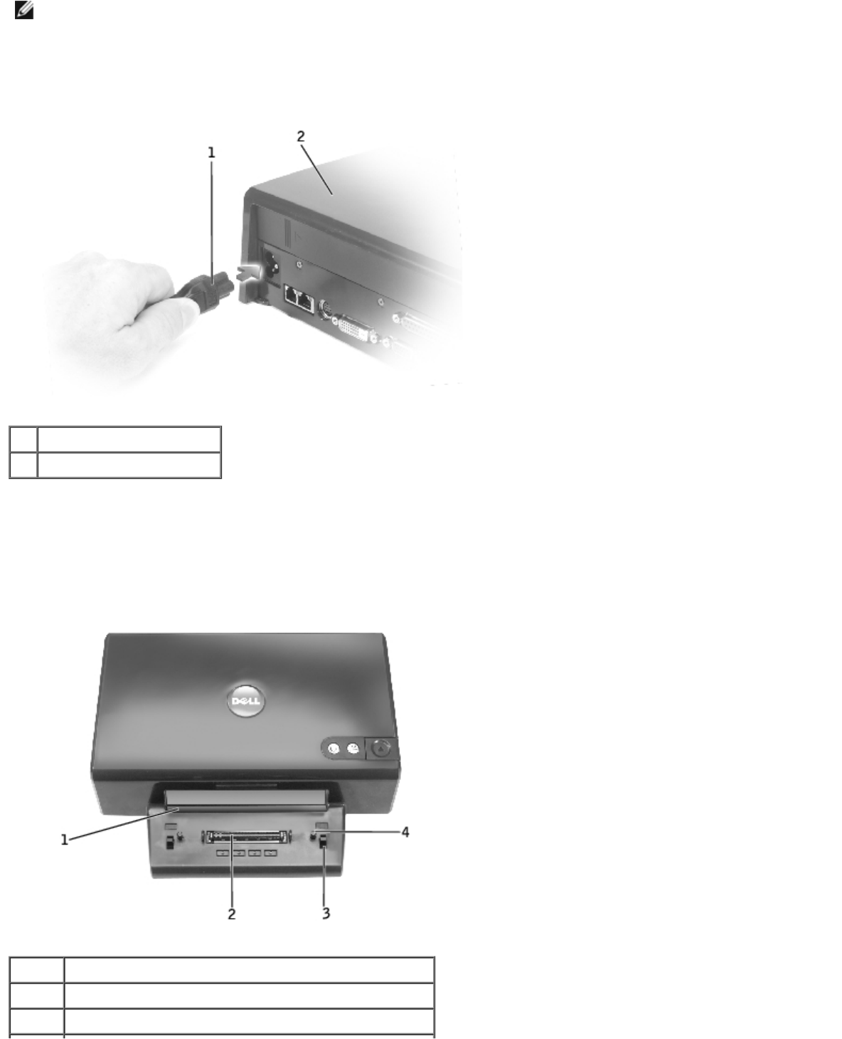
2. Connect the AC power cable to the expansion station, and connect the expansion station to an electrical outlet.
1AC power cable
2expansion station
3. Place the expansion station so that there is enough flat space in front of it to completely support the computer when
the computer is docked.
4. Ensure that the slide lock is in the unlocked position (toward the back of the computer).
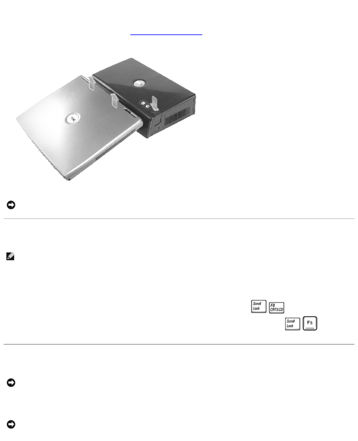
5. Hold the computer by its sides and center it against the backstop at the front of the expansion station.
1 backstop
2docking connector
3alignment posts
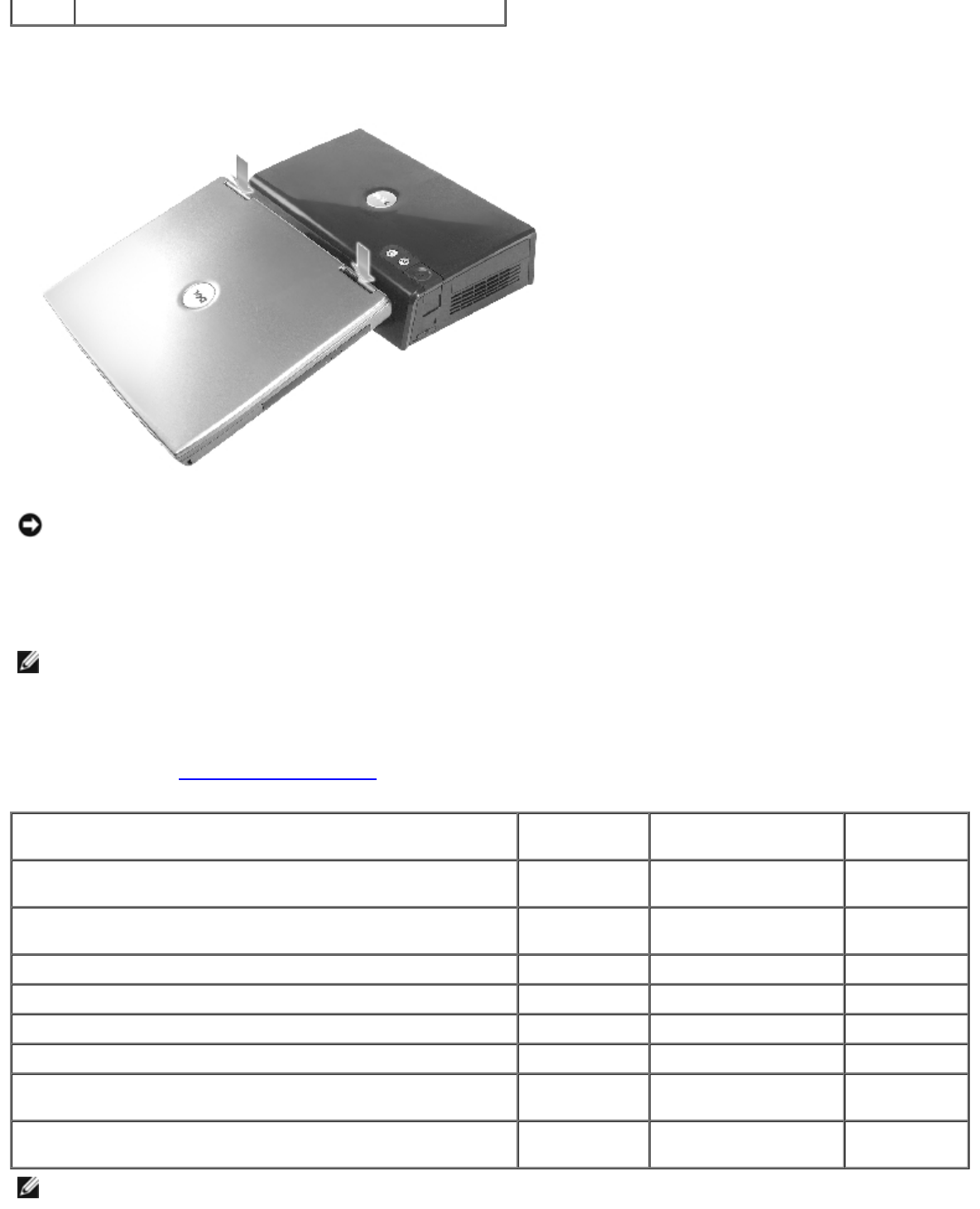
4docking latches
6. Lower the computer and ensure that the DELL badge on the computer aligns with the badge on the expansion station.
Move it slightly from side to side until the computer is seated on the docking connector.
NOTICE: To avoid damaging the computer display, press down only over the hinges.
7. Press down firmly over the hinges until the docking connector clicks into place.
8. Verify that the computer is properly docked:
NOTE: To save battery life, it is recommended that you not run your computer on battery power while it is docked.
If the expansion station is connected to an electrical outlet and the computer is turned on, the power button light on
the top of the expansion station turns from amber to green. See the following table for more information on docking-
control light behavior under different computer and expansion station conditions. If the light behavior on your
expansion station does not match the table, you might not have docked correctly. Follow the steps to undock the
computer (see "Undocking Your Computer") and dock it again.
States Power Button
Light Undock-Request
Button Light Eject Button
Light
Computer undocked and expansion station not connected
to an electrical outlet Off Off Off
Computer undocked but expansion station connected to
an electrical outlet Amber Off Off
Computer docked and turned off Off Off Green
Computer docked and turned on Green Green Off
Computer docked and in hibernate mode Off Off Green
Computer is docked and undock is requested On Blinks Off
Computer is docked and in standby mode Pulses
(breathes) Off Off
Computer is docked, in standby mode, and undock has
been requested Pulses
(breathes) Blinks and turns off Green
NOTE: When docked, the computer will not turn on unless the expansion station is connected to an electrical outlet.
9. If the computer was not already turned on, you can turn it on using the power button on either the computer or the
expansion station.
10. If the computer does not turn on or awaken successfully, ensure that the expansion station is connected to an electrical
outlet. If it is connected, undock (see "Undocking Your Computer") and reseat the computer.
NOTICE: While the computer is docked, do not pick up the computer and expansion station. Doing so can damage the
connectors on the computer and the expansion station.
Connecting External Devices to the Expansion Station
NOTE: If the cable connector of the external device has thumbscrews, tighten them to ensure a proper connection.
1. Connect the device's cable to the appropriate connector on the expansion station.
2. Connect the external devices to electrical outlets.
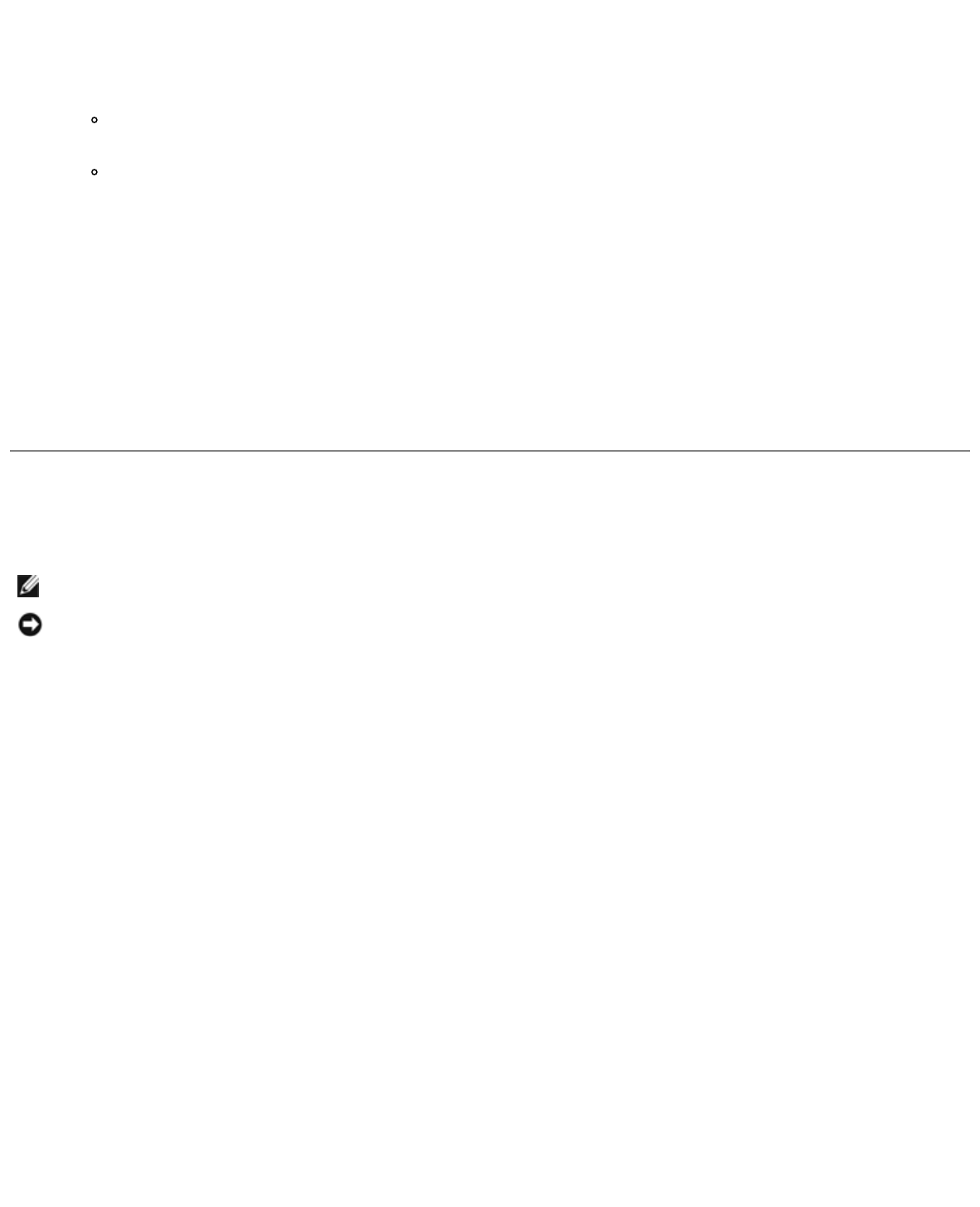
If you attach an external monitor to the expansion station, you may need to press one or more times to
switch the screen image to the desired location. If the computer cover is closed, you can press key on an
attached external keyboard to switch the image.
Undocking Your Computer
NOTICE: If the computer is not receiving power from a battery, the computer turns off when you undock it, and you
will lose all unsaved data.
You can undock the computer from the D/Dock expansion station while the computer is in a power management mode or
turned off. You should not undock while the computer is running in normal mode.
NOTICE: Never undock the computer without first preparing the computer to undock. If you undock before preparing
the computer, you will lose data. If you accidentally undock the computer without first preparing to undock and your
computer stops responding, press the power button until the computer turns off and restart the computer. Any
unsaved data will be lost.
1. Save and close any open files and exit any open programs.
2. To begin the undocking process, determine the docking status of the computer:
If the computer is turned on and the undock-request button light is a steady green, and the eject button light
off, then the computer must be prepared before undocking. Perform steps 2 to 4.
If the computer is turned off or in power management mode, and the undock-request button light is off and the
eject button light is green, then the computer is ready for undocking. Perform only steps 3 and 4.
3. Press the undock request button. The button light turns from solid green to blinking green, indicating that the
computer is preparing for undocking (either shutting down or going into power management mode, depending on the
power option settings on your computer).
When the computer is ready to be undocked, the undock-request button light turns off and the eject button light turns
green.
4. Ensure that the slide lock is in the unlocked position (toward the back of the expansion station).
5. Press the eject button to release the computer from the docking connector and lift the computer away from the
docking device.
Removing and Installing a PCI Expansion Card
To install a Peripheral Component Interconnect (PCI) expansion card in the expansion station, perform the following steps.
NOTE: The expansion station supports one 3.3- or 5.0-volt, half-size or smaller PCI expansion card.
NOTICE: Do not touch or handle anything inside the expansion station except as instructed in the following steps. If
you touch other objects, you may damage the expansion station and may void your warranty.
1. Save and close any open files, exit any open programs, and then shut down the computer.
2. Undock the computer and leave the slide lock in the unlocked position.
3. Detach all cables—including the AC power cable—from the expansion station.
4. If the computer is attached to the optional monitor stand, remove the expansion station from the monitor stand. For
more information, see the documentation that came with the monitor stand.
5. Remove the PCI expansion-card cover on the back of the expansion station:
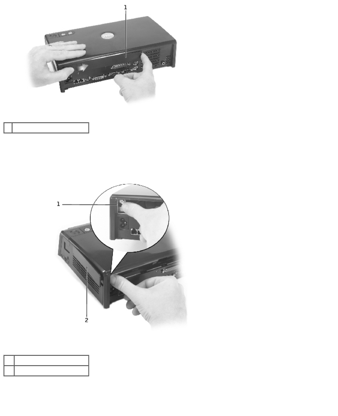
1PCI expansion-card cover
Press on the vertical strips near the left end of the PCI expansion-card cover, and slide the cover to the right. The
cover should pop out at the right side for easy removal.
6. Remove the PCI card cover on the right side of the expansion station:
1plastic securing tab
2PCI card cover
Press the cover's plastic securing tab in and to the left while prying the same end of the cover out from the outside.
7. Remove the screw that secures the metal filler panel or existing PCI card bracket, and set the screw aside temporarily.
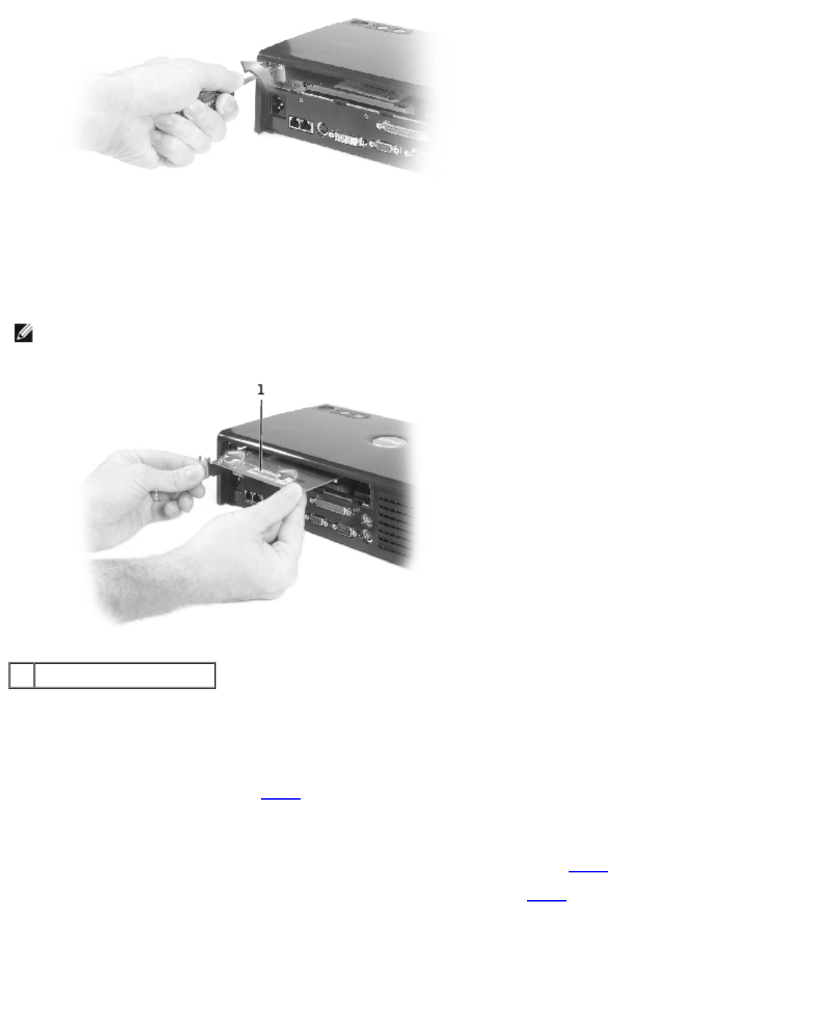
8. Remove the filler panel if one is present.
9. If a PCI card is installed, remove the card by grasping it by its back corners and easing it out of the connector on the
PCI interface board.
10. To install a PCI card:
NOTE: It is recommended that you install PCI expansion cards purchased from Dell. Dell does not guarantee
functionality of non-Dell PCI cards.
1PCI expansion card
a. To avoid damaging the connector pins, ensure the keying on the card edge connector is aligned with the PCI
interface connector, and then insert the card edge connector into the PCI interface connector.
b. Gently rock the card from side to side into the connector until the card is fully seated.
11. Install the screw you removed in step 7 to secure the PCI card bracket.
12. To replace the PCI expansion-card cover on the back of the expansion station, insert the securing tabs into their slot at
the front end of the cover, and then snap the back end of the cover into place.
13. If you removed PCI expansion-card cover on the back of the expansion station in step 5, replace it now.
14. Reconnect the cables—including the AC power cable—that you detached in step 4.
15. Dock your computer.
16. Turn on the computer.
17. Install the drivers for the PCI card. (If you are using a PCI card that was not purchased from Dell, use the drivers and
instructions provided by the manufacturers of the card.)
Using the Module Bay
You can install any module from your computer, such as a floppy drive or CD drive, in the module bay of the D/Dock
expansion station. You can also charge a second D-series battery from your computer.
NOTICE: To avoid damaging the expansion station or the module, do not install any device in the expansion-station
module bay that you do not normally use in your computer.
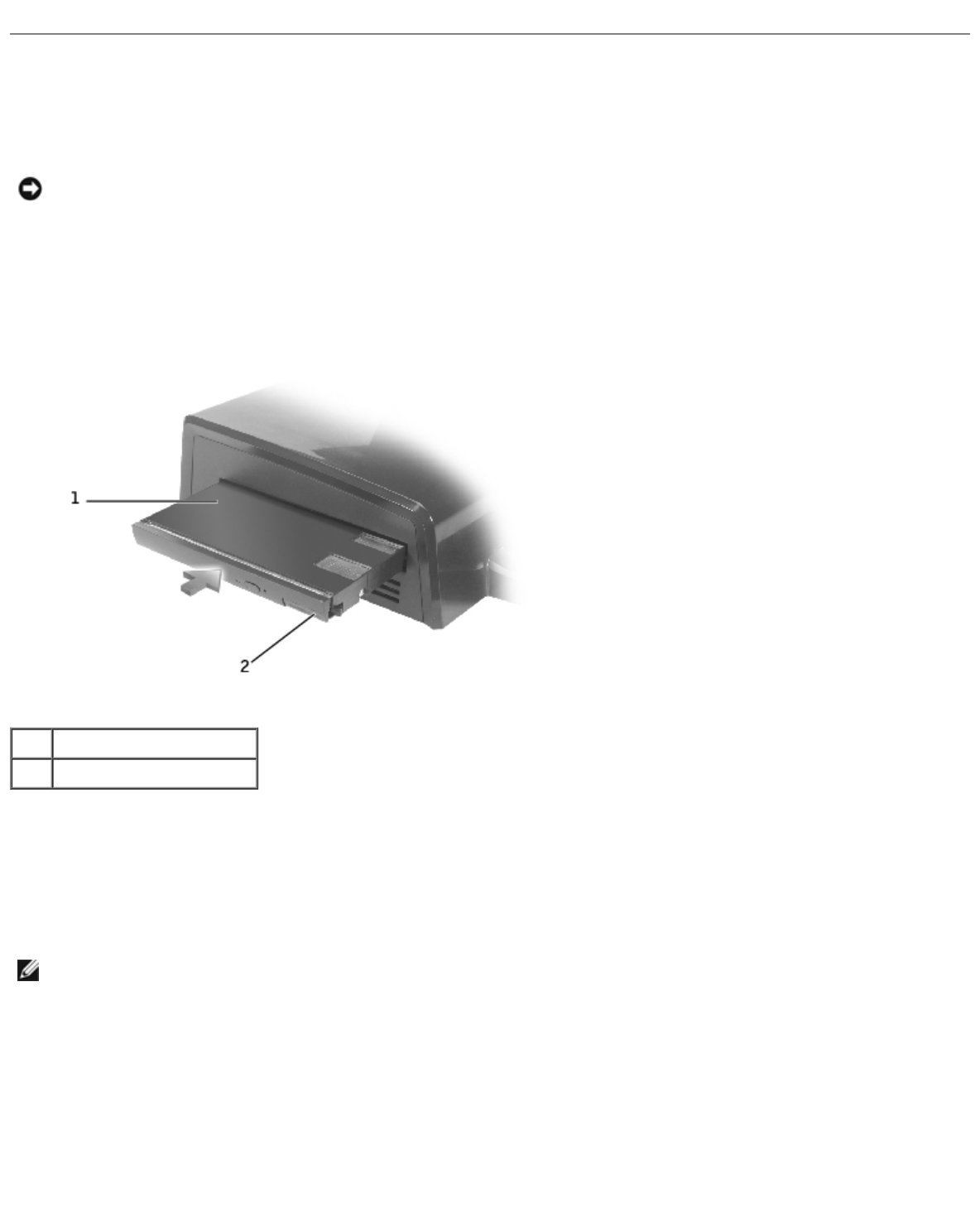
Installing a Device in the Module Bay
1. Save and close any open files, exit any open programs.
1 module
2latch release
2. Push the module firmly into the bay and push in the latch release to seat the module.
3. Verify that the device is properly seated. If it is not, remove the module and reseat it.
Removing a Device From the Module Bay
NOTE: The slide lock on the right side of the expansion station must be in the unlocked position before you remove a
device from the module bay.
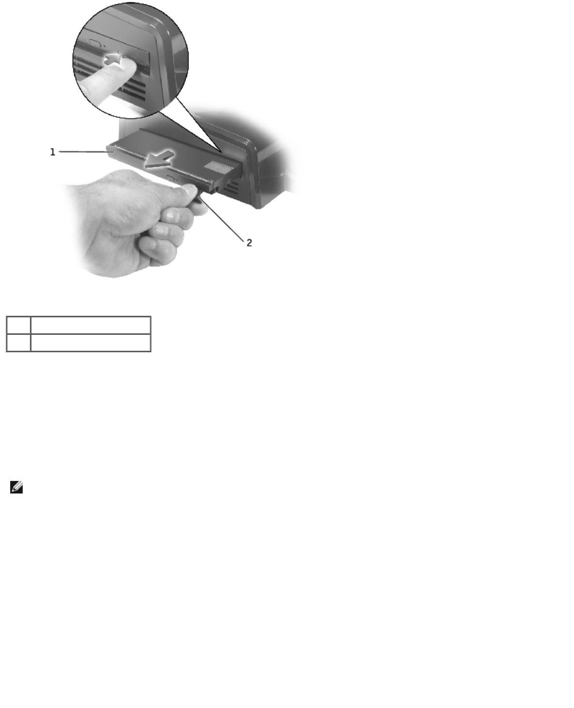
1 module
2latch release
1. Ensure the slide lock on the right side of the expansion station is in the unlocked position.
2. Push the latch release on the module and pull out the module from the bay.
Charging a Second Battery in the Module Bay
You can charge your computer's second battery in the D/Dock module bay. A battery light below the module bay displays the
status of the charging battery.
NOTE: If you charge a second battery while the computer is docked, the expansion station charges the battery in the
computer before charging the second battery in the D/Dock module bay.
1. Connect the expansion station to an electrical outlet.
2. Insert a D-Family second battery firmly into the D/Dock module bay and push in the battery latch release to seat the
battery.
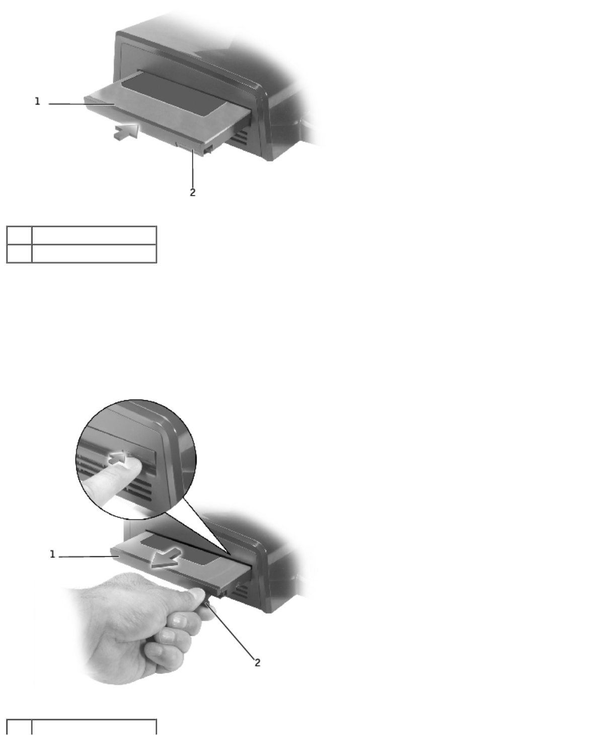
1 battery
2latch release
If no computer is docked, or if the docked computer's batteries are fully charged and the computer is turned off, the
expansion starts charging the battery in the module bay immediately. The battery light below the module bay turns
green while the battery is being charged; it may start to blink when battery charge is near completion. The battery
should charge to about 80 percent of its capacity in approximately 1 hour.
If a computer is docked and turned on, the expansion station charges the computer battery fully before charging the
battery in the module bay. When the battery is fully charged, the battery light turns off.
3. When the battery is fully charged, push the latch release and remove the battery from the bay.
1 battery
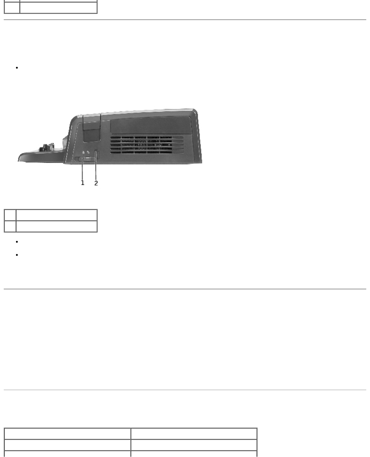
2latch release
Securing the D/Dock Expansion Station
The expansion station offers the following security features:
A slide lock that allows you to secure your computer as well as a PCI expansion card and a module installed in the
expansion station. Slide the lock toward the front of the expansion station to lock, toward the back to unlock.
1slide lock
2security cable slot
A security cable slot that allows use of a security cable when the slide lock is in the locked position.
Attach a commercially available antitheft device to the security lock slot on the expansion station.
Antitheft devices usually include a segment of metal-stranded cable with an attached locking device and associated key. For
instructions on installing the antitheft device, see the documentation that came with the device.
Dell Diagnostics
The Dell Diagnostics that came with your computer includes tests that help you to troubleshoot the controllers in your
expansion station.
The subtests in the Serial/Infrared Ports test group check the expansion station interface with external devices (such as a
serial mouse or a printer). The subtests in this test group are not intended as a diagnostics test for the external device itself.
The subtests in the USB test group check the expansion station interface with external serial USB devices (such as a mouse).
The subtests in this test group are not intended as a diagnostic test for the external device itself.
For complete instructions on using the Dell Diagnostics, see the documentation that came with your computer.
Specifications
Physical
Height 70 mm (2.76 inches)
Depth 160 mm (6.30 inches)
Width 312 mm (12.28 inches)
AC Power Input
Voltage 100–240 VAC, 50–60 Hz
Amperage up to 2.0 A
I/0
Serial (DTE) one 9-pin connector, 16550-compatible,
16-byte buffer
Parallel one 25-hole unidirectional, bidirectional,
or ECP connector
PS/2 two 6-pin mini-DIN connectors
USB four 4-pin, USB 2.0-compliant
connectors: three standard USB and one
powered USB
Audio Audio line-out connector for
headphones/speakers
Digital audio S/PDIF
Video:
VGA one 15-hole connector
S-video TV-out one 7-pin mini-DIN connector
Digital video interface (DVI) one 24-hole connector
Network one RJ-45 port; 10/100/1000 GB
Ethernet
Modem one RJ-11 port
Docking (to connect to computer) one connector
PCI one 32-bit, 33 MHz add-in slot
Back to Contents Page
Back to Contents Page
Regulatory Notices
Dell™ D/Dock Expansion-Station User's Guide
FCC Notices (U.S. Only)
IC Notice (Canada Only)
CE Notice (European Union)
CE Mark Notice
New Zealand Telecom Warnings
Simplified Chinese Class A Warning Notice (China
Only)
EN 55022 Compliance (Czech Republic
Only)
VCCI Notice (Japan Only)
MIC Notice (Republic of Korea Only)
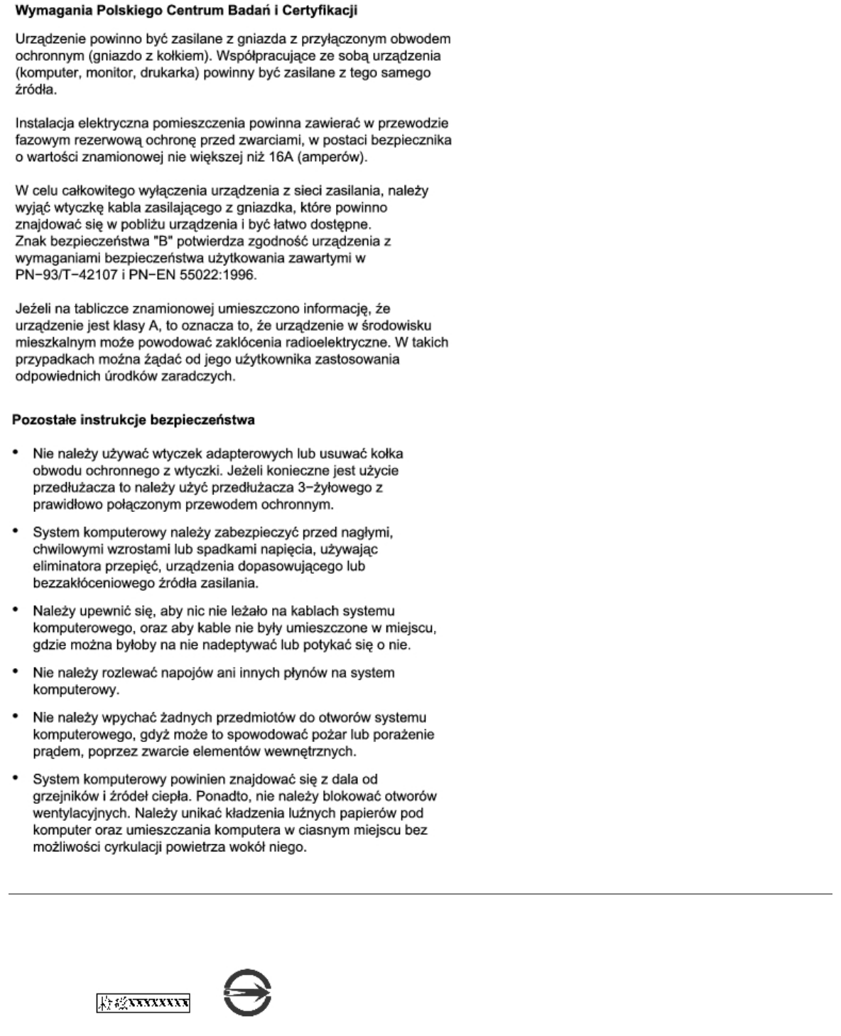
Polish Center for Testing and Certification
Notice
BSMI Notice (Taiwan Only)
Dell™ computers are designed, tested, and classified for their intended electromagnetic environment. These electromagnetic
environment classifications generally refer to the following harmonized definitions:
Class A is typically for business or industrial environments.
Class B is typically for residential environments.
Information Technology Equipment (ITE), including devices, expansion cards, printers, input/output (I/O) devices, monitors,
and so on, that are integrated into or connected to the computer should match the electromagnetic environment classification
of the computer.
A Notice About Shielded Signal Cables: Use only shielded cables for connecting devices to any Dell device to
reduce the possibility of interference with radio communications services. Using shielded cables ensures that you
maintain the appropriate EMC classification for the intended environment. For parallel printers, a cable is
available from Dell. If you prefer, you can order a cable from Dell on the World Wide Web at
accessories.us.dell.com/sna/category.asp?category_id=4117.
Most Dell computers are classified for Class B environments. However, the inclusion of certain options can change the rating
of some configurations to Class A. To determine the electromagnetic classification for your computer or device, refer to the
following sections specific for each regulatory agency. Each section provides country-specific EMC/EMI or product safety
information.
FCC Notices (U.S. Only)
Most Dell computers are classified by the Federal Communications Commission (FCC) as Class B digital devices. To determine
which classification applies to your computer, examine all FCC registration labels located on the bottom, side, or back panel of
your computer, on card-mounting brackets, and on the cards themselves. If any one of the labels carries a Class A rating,
your entire computer is considered to be a Class A digital device. If all labels carry an FCC Class B rating as distinguished by
either an FCC ID number or the FCC logo, ( ), your computer is considered to be a Class B digital device.
Once you have determined your computer's FCC classification, read the appropriate FCC notice. Note that FCC regulations
provide that changes or modifications not expressly approved by Dell could void your authority to operate this equipment.
This device complies with Part 15 of the FCC Rules. Operation is subject to the following two conditions:
This device may not cause harmful interference.
This device must accept any interference received, including interference that may cause undesired operation.
Class B
This equipment has been tested and found to comply with the limits for a Class B digital device pursuant to Part 15 of the
FCC Rules. These limits are designed to provide reasonable protection against harmful interference in a residential installation.

This equipment generates, uses, and can radiate radio frequency energy and, if not installed and used in accordance with the
manufacturer's instruction manual, may cause interference with radio communications. However, there is no guarantee that
interference will not occur in a particular installation. If this equipment does cause harmful interference to radio or television
reception, which can be determined by turning the equipment off and on, you are encouraged to try to correct the
interference by one or more of the following measures:
Reorient or relocate the receiving antenna.
Increase the separation between the equipment and the receiver.
Connect the equipment into an outlet on a circuit different from that to which the receiver is connected.
Consult the dealer or an experienced radio/television technician for help.
The following information is provided on the device or devices covered in this document in compliance with FCC regulations:
Model number: PD01X
Company name:
Dell Computer Corporation
One Dell Way
Round Rock, Texas 78682 USA
512-338-4400
Modem Regulatory Information
This equipment complies with Part 68 of the FCC rules. On the bottom of your computer is a label that contains, among other
information, the FCC registration number and ringer equivalence number (REN) for your equipment. If requested, you must
provide this information to the telephone company.
The REN is used to determine the quantity of devices that may be connected to the telephone line. Excessive RENs on the
telephone line may result in the devices not ringing in response to an incoming call. In most areas, the sum of all the RENs on
your telephone line should be less than five to ensure proper service from the telephone company. To be certain of the
number of devices that you may connect to a line, as determined by the total RENs, contact your local telephone company.
The registration jack Universal Service Order Code (USOC) used by this equipment is RJ-11C. An FCC compliant telephone
cord and modular plug is provided with this equipment. This equipment is designed to be connected to the telephone network
or premises wiring using a compatible modular jack that is Part 68 compliant.
This equipment cannot be used on public coin-phone service provided by the telephone company. Connection to party line
service is subject to state tariffs.
There are no user serviceable parts on the modem contained in your computer.
If your telephone equipment causes harm to the telephone network, the telephone company will notify you in advance that
service may be temporarily discontinued. If advance notice is not practical, the telephone company will notify you as soon as
possible. Also, you will be advised of your right to file a complaint with the FCC if you believe it is necessary.
The telephone company may make changes in its facilities, equipment, operations, or procedures that could affect the
operation of this equipment. If this happens, the telephone company will provide advance notice in order for you to make
necessary modifications to maintain uninterrupted service.
If you experience trouble with this telephone equipment, refer to your computer's troubleshooting documentation or, for some
computers, the section titled "Contacting Dell" in your computer's online guide to find the appropriate telephone number for
obtaining customer assistance. If the equipment is causing harm to the telephone network, the telephone company may
request that you disconnect the equipment until the problem is resolved.
Fax Branding
The Telephone Consumer Protection Act of 1991 makes it unlawful for any person to use a computer or other electronic
device, including fax machines, to send any message unless such message clearly contains in a margin at the top or bottom
of each transmitted page or on the first page of the transmission, the date and time it is sent, identification of the business,
other entity, or individual sending the message, and the telephone number of the sending machine or such business, other
entity, or individual. The telephone number provided may not be a 900 number or any other number for which charges exceed
local or long-distance transmission charges.
IC Notice (Canada Only)
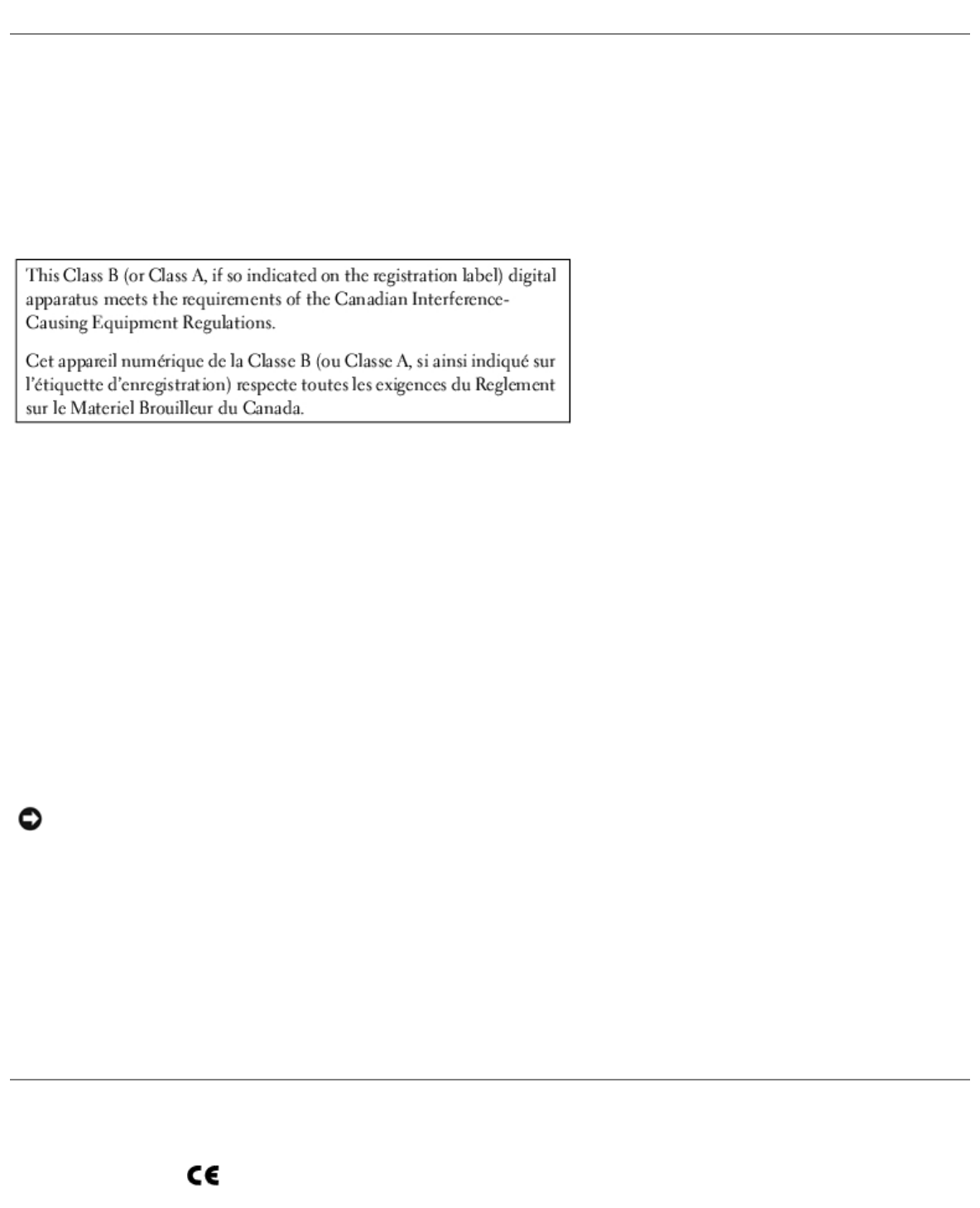
Most Dell computers (and other Dell digital apparatus) are classified by the Industry Canada (IC) Interference-Causing
Equipment Standard #3 (ICES-003) as Class B digital devices. To determine which classification (Class A or B) applies to your
computer (or other Dell digital apparatus), examine all registration labels located on the bottom, side, or the back panel of
your computer (or other digital apparatus). A statement in the form of "IC Class A ICES-003" or "IC Class B ICES-003" will be
located on one of these labels. Note that Industry Canada regulations provide that changes or modifications not expressly
approved by Dell could void your authority to operate this equipment.
Modem Regulatory Information
The IC label identifies certified equipment. This certification means that the equipment meets telecommunications network
protective, operational, and safety requirements as prescribed in the appropriate Terminal Equipment Technical Requirements
document(s). The IC label does not guarantee that the equipment will operate to the user's satisfaction.
Before installing this equipment, users should ensure that it is permissible to be connected to the facilities of the local
telecommunications company. The equipment must also be installed using an acceptable method of connection. The customer
should be aware that compliance with the above conditions may not prevent degradation of service in some situations.
Repairs to certified equipment should be coordinated by a representative designated by the supplier. Any repairs or alteration
made by a user to this equipment, or equipment malfunctions, may give the telephone communications company cause to
request the user to disconnect the equipment.
Users should ensure for their own protection, that the electrical ground connections of the power utility, telephone lines, and
internal metallic water-pipe system, if present, are connected together. This precaution may be particularly important in rural
areas.
NOTICE: Users should not attempt to make such connections themselves. Contact the appropriate electric inspection
authority, or electrician, as appropriate.
NOTE: The REN assigned to each terminal device provides an indication of the maximum number of terminals allowed to be
connected to a telephone interface. The termination on an interface may consist of any combination of devices subject only to
the requirement that the sum of the RENs of all the devices does not exceed the number five.
The REN for the internal modem as stated on the IC regulatory label located on the bottom of the computer is 0.6 B.
The following information is provided in compliance with IC regulations:
Dell Computer Corporation
One Dell Way
Round Rock, TX 78682 USA
512-338-4400
CE Notice (European Union)
Marking by the symbol indicates compliance of this Dell computer to the EMC Directive and the Low Voltage Directive of
the European Union. Such marking is indicative that this Dell system meets the following technical standards:
EN 55022 — "Information Technology Equipment — Radio Disturbance Characteristics — Limits and Methods of
Measurement."
EN 55024 — "Information Technology Equipment - Immunity Characteristics - Limits and Methods of Measurement."
EN 61000-3-2 — "Electromagnetic Compatibility (EMC) - Part 3: Limits - Section 2: Limits for Harmonic Current
Emissions (Equipment Input Current Up to and Including 16 A Per Phase)."
EN 61000-3-3 — "Electromagnetic Compatibility (EMC) - Part 3: Limits - Section 3: Limitation of Voltage Fluctuations
and Flicker in Low-Voltage Supply Systems for Equipment With Rated Current Up to and Including 16 A."
EN 60950 — "Safety of Information Technology Equipment."
NOTE: EN 55022 emissions requirements provide for two classifications:
Class A is for typical commercial areas.
Class B is for typical domestic areas.
This Dell device is classified for use in a typical Class B domestic environment.
A "Declaration of Conformity" in accordance with the preceding directives and standards has been made and is on file at Dell
Computer Corporation Products Europe BV, Limerick, Ireland.
CE Mark Notice
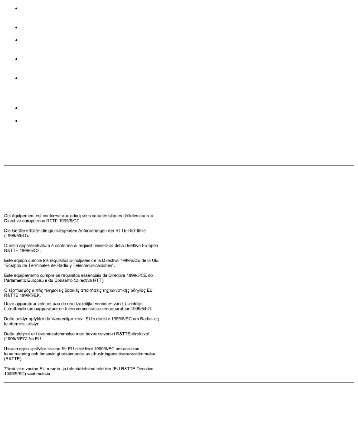
This equipment complies with the essential requirements of the European Union Directive 1999/5/EC.
New Zealand Telecom Warnings
General
"The grant of a Telepermit for any item of terminal equipment indicates only that Telecom has accepted that the item
complies with minimum conditions for connection to its network. It indicates no endorsement of the product by Telecom, nor
does it provide any sort of warranty. Above all, it provides no assurance that any item will work correctly in all respects with
another item of Telepermitted equipment of a different make or model, nor does it imply that any product is compatible with
all of Telecom's network services."
"This equipment does not fully meet Telecom impedance requirements. Performance limitations may occur when used in
conjunction with some parts of the network. Telecom will accept no responsibility should difficulties arise in such
circumstances."
"This equipment shall not be set up to make automatic calls to the Telecom `111' Emergence Service."
"If a charge for local calls is unacceptable, the `Dial' button should NOT be used for local calls. Only the 7-digits of the local
number should be dialed from your telephone. DO NOT dial the area code digit or the `0' prefix."
"This equipment may not provide for the effective hand-over of a call to another device connected to the same line."
Important Notice
"Under power failure conditions, this telephone may not operate. Please ensure that a separate telephone, not dependent on
local power, is available for emergency use."
"Some parameters required for compliance with Telecom's Telepermit requirements are dependent on the equipment (PC)
associated with this device. The associated equipment shall be set to operate within the following limits for compliance with
Telecom's Specification:
1. There shall be no more than 10 call attempts to the same number within any 30-minute period for any single manual
call initiation, and the equipment shall go on-hook for a period of not less than 30 seconds between the end of one
attempt and the beginning of the next attempt.
2. Where automatic calls are made to different numbers, the equipment shall go on-line for a period of not less than 5
seconds between the end of one attempt and the beginning of the next attempt.
3. The equipment shall be set to ensure that calls are answered between 3 and 30 seconds of receipt of ringing."
"All persons using this device for recording telephone conversations shall comply with New Zealand law. This requires that at
least one party to the conversation is to be aware that it is being recorded. In addition, the Principles enumerated in the
Privacy Act of 1993 shall be complied with in respect to the nature of the personal information collected, the purpose for its
collection, how it is used and what is disclosed to any other party."
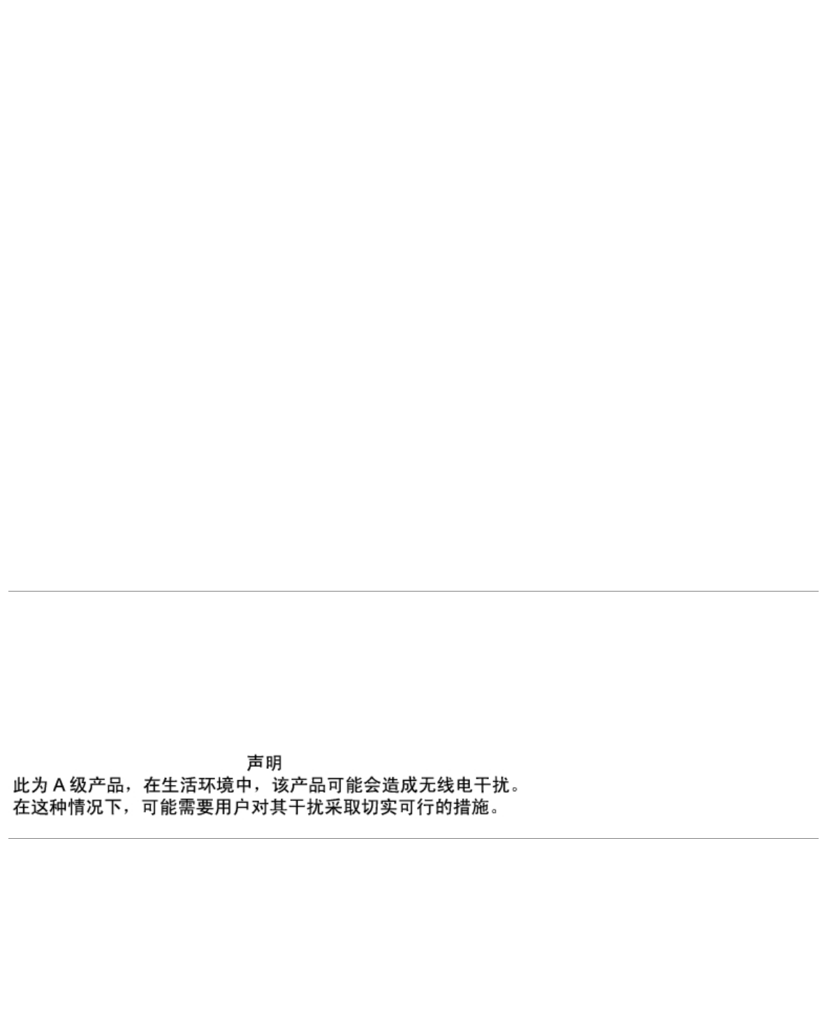
Simplified Chinese Class A Warning Notice (China Only)
On Class A systems, the following warning will appear near the regulatory label:
Warning: This is a Class A product. In a domestic environment this product may cause radio interference, in
which case the user may be required to take adequate measures.
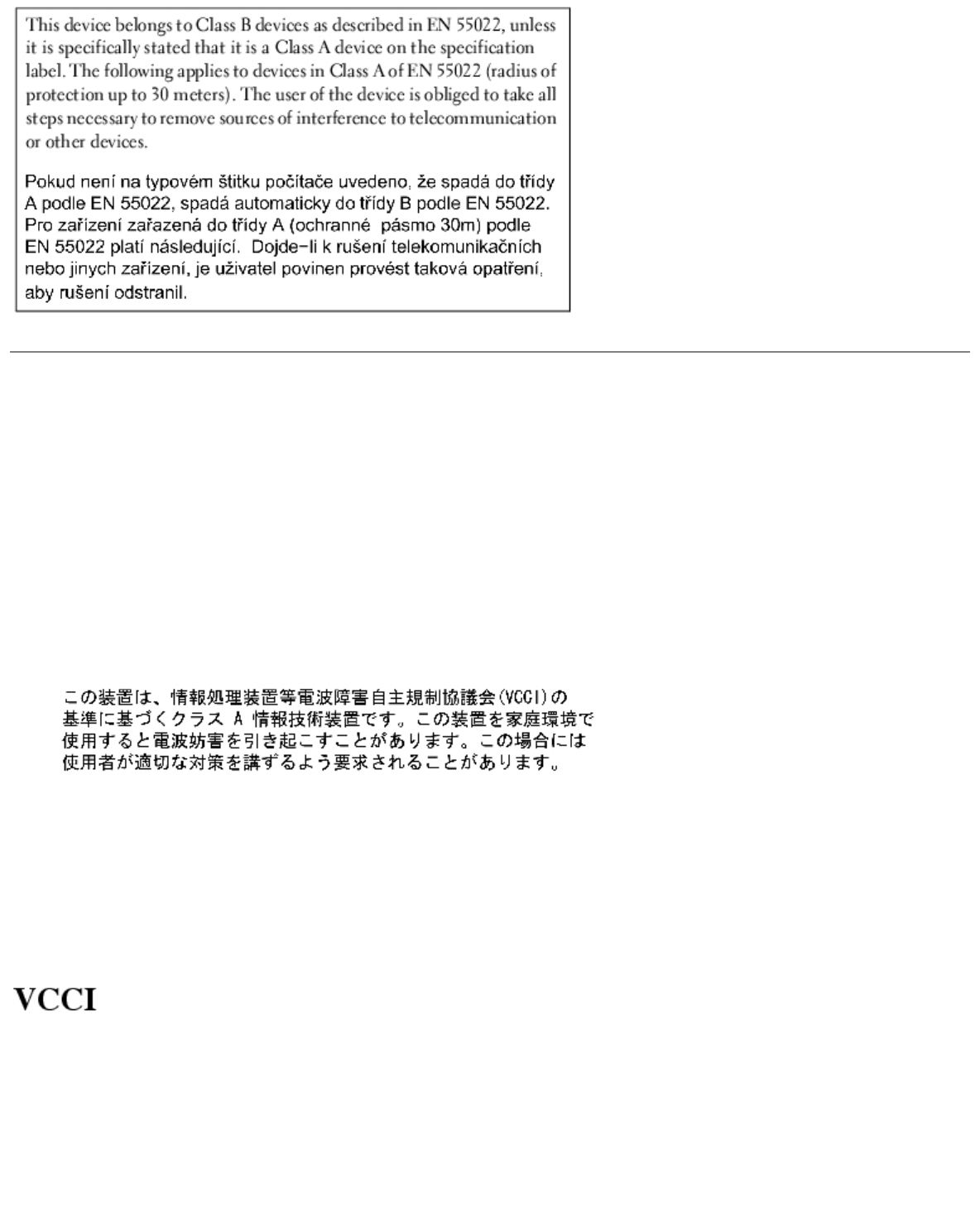
EN 55022 Compliance (Czech Republic Only)
VCCI Notice (Japan Only)
Most Dell computers are classified by the Voluntary Control Council for Interference (VCCI) as Class B information technology
equipment (ITE). However, the inclusion of certain options can change the rating of some configurations to Class A. ITE,
including devices, expansion cards, printers, input/output (I/O) devices, monitors, and so on, integrated into or connected to
the computer should match the electromagnetic environment classification (Class A or B) of the computer.
To determine which classification applies to your computer, examine the regulatory labels/markings (see "VCCI Class A ITE
Regulatory Mark" and "VCCI Class B ITE Regulatory Mark") located on the bottom, side, or back panel of your computer.
Once you have determined your computer's VCCI classification, read the appropriate VCCI notice.
Class A ITE
This is a Class A product based on the standard of the Voluntary Control Council for Interference (VCCI) for information
technology equipment. If this equipment is used in a domestic environment, radio disturbance may arise. When such trouble
occurs, the user may be required to take corrective actions.
VCCI Class A ITE Regulatory Mark
If the regulatory label includes the following marking, your computer is a Class A product:
Class B ITE
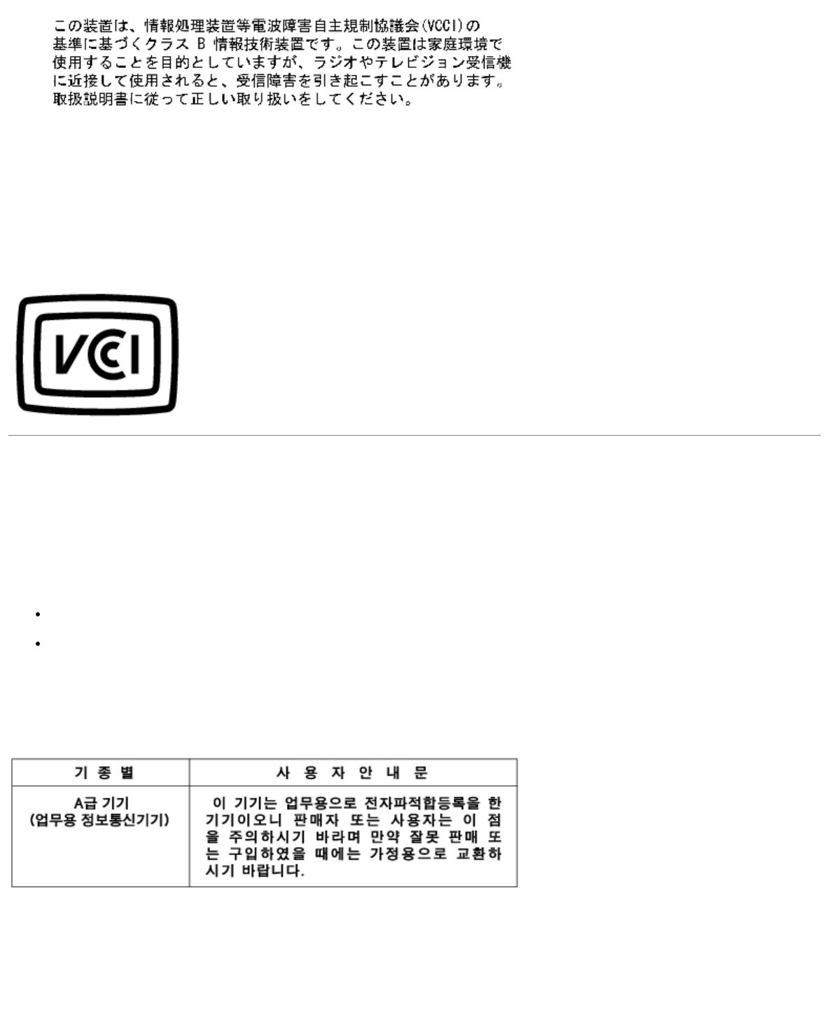
This is a Class B product based on the standard of the Voluntary Control Council for Interference (VCCI) for information
technology equipment. If this equipment is used near a radio or television receiver in a domestic environment, it may cause
radio interference. Install and use the equipment according to the instruction manual.
VCCI Class B ITE Regulatory Mark
If the regulatory label includes the following marking, your computer is a Class B product:
MIC Notice (Republic of Korea Only)
To determine which classification (Class A or B) applies to your computer (or other Dell digital device), examine the Republic
of Korean Ministry of Information and Communications (MIC) registration labels located on your computer (or other Dell
digital device). The MIC label may be located separately from the other regulatory marking applied to your product. Line two
of the label identifies the emissions class for the product—"(A)" for Class A products or "(B)" for Class B products.
NOTE: MIC emissions requirements provide for two classifications:
Class A devices are for business purposes.
Class B devices are for nonbusiness purposes.
Class A Device
Please note that this device has been approved for business purposes with regard to electromagnetic interference. If you find
that this device is not suitable for your use, you may exchange it for a nonbusiness-purpose device.
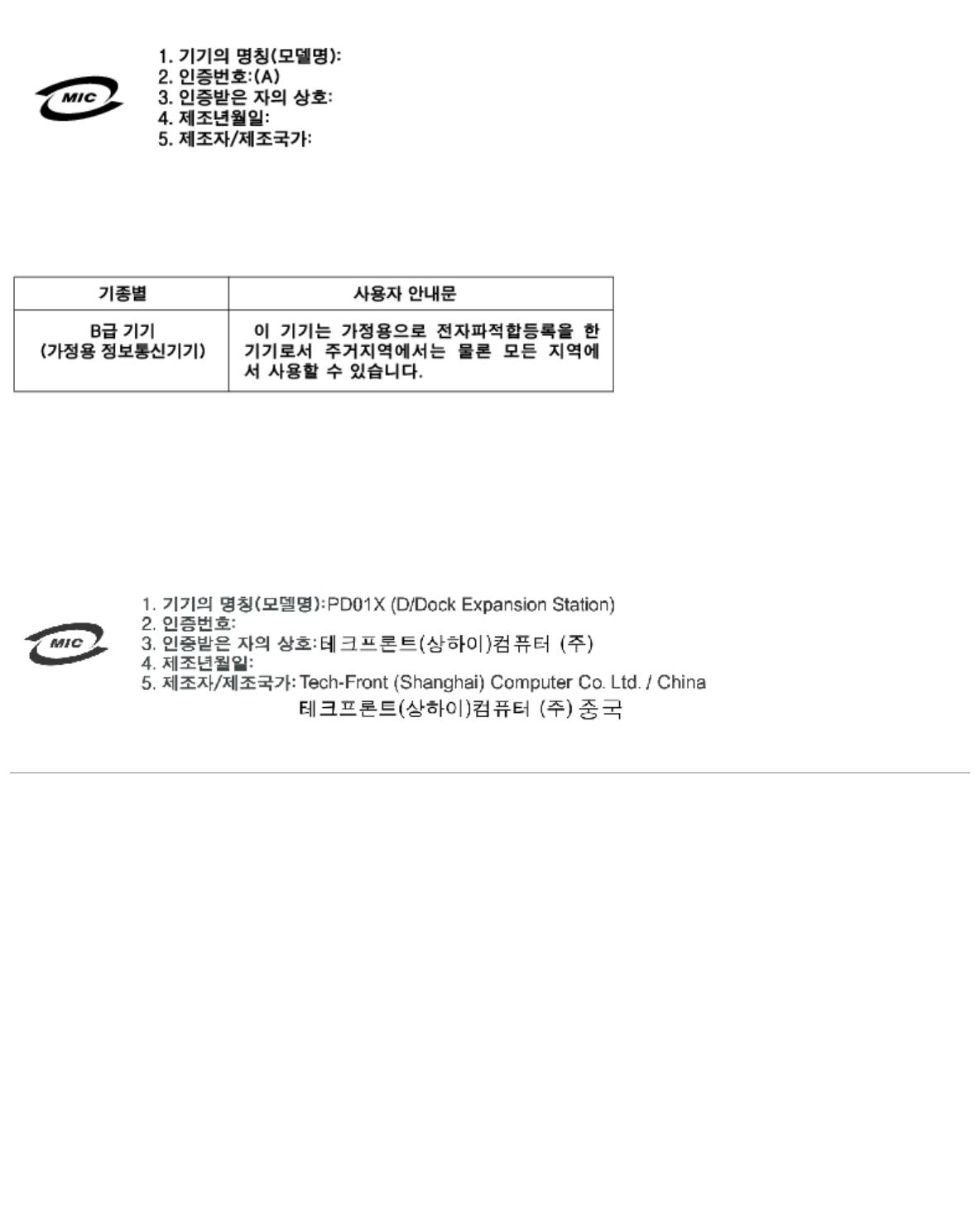
MIC Class A Regulatory Label
If the regulatory label includes the following marking, your computer is a Class A product:
Class B Device
Please note that this device has been approved for nonbusiness purposes and may be used in any environment, including
residential areas.
MIC Class B Regulatory Label
If the regulatory label includes the following marking, your computer is a Class B product.
Polish Center for Testing and Certification Notice
The equipment should draw power from a socket with an attached protection circuit (a 3-prong socket). All equipment that
works together (computer, monitor, printer, and so on) should have the same power supply source.
The phasing conductor of the room's electrical installation should have a reserve short-circuit protection device in the form of
a fuse with a nominal value no larger than 16 amperes (A).
To completely switch off the equipment, the power supply cable must be removed from the power supply socket, which should
be located near the equipment and easily accessible.
A protection mark "B" confirms that the equipment is in compliance with the protection usage requirements of standards PN-
93/T-42107 and PN-EN 55022.
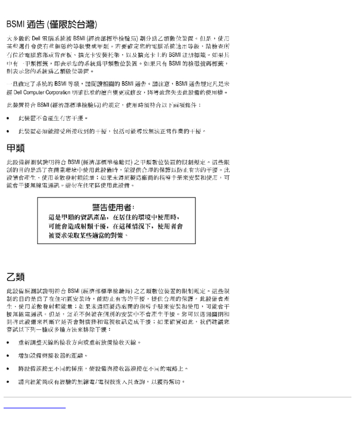
BSMI Notice (Taiwan Only)
If you find a or mark on the regulatory

Back to Contents Page
Glossary
Dell™ D/Dock Expansion-Station User's Guide
A B C D E F G H I K L M N O P R S T U V W X Z
Terms in this Glossary are provided for informational purposes only and may or may not describe features included with your
particular docking device.
A
AC — alternating current — The form of electricity that powers your computer when you plug the AC adapter power cable into
an electrical outlet.
ACPI — advanced configuration and power interface — A power management specification that enables Microsoft®
Windows® operating systems to put a computer in standby or hibernate mode to conserve the amount of electrical power
allocated to each device attached to the computer.
AGP — accelerated graphics port — A dedicated graphics port that allows system memory to be used for video-related tasks.
AGP delivers a smooth, true-color video image because of the faster interface between the video circuitry and the computer
memory.
antivirus software — A program designed to identify, quarantine, and/or delete viruses from your computer.
APR — advanced port replicator — A docking device that allows you to conveniently use a monitor, keyboard, mouse, and
other devices with your portable computer.
ASF — alert standards format — A standard to define a mechanism for reporting hardware and software alerts to a
management console. ASF is designed to be platform- and operating system-independent.
B
backup — A copy of a program or data file on a floppy disk, CD, or hard drive. As a precaution, back up the data files from
your hard drive regularly.
battery — An internal power source used to operate portable computers when not connected to an AC adapter and an
electrical outlet.
battery life span — The length of time (years) during which a portable computer battery is able to be depleted and
recharged.
battery operating time — The length of time (minutes or hours) that a portable computer battery holds a charge while
powering the computer.
BIOS — basic input/output system — A program (or utility) that serves as an interface between the computer hardware and
the operating system. Unless you understand what effect the settings have on the computer, do not change the settings for
this program. Also referred to as the system setup program.
bit — The smallest unit of data interpreted by your computer.
Bluetooth™ — A wireless technology standard for short-range (9 m [29 feet]) networking devices that allows for enabled
devices to automatically recognize each other.
boot sequence — Specifies the order of the devices from which the computer attempts to boot.
bootable CD — A CD that you can use to start your computer. In case your hard drive is damaged or your computer has a
virus, ensure that you always have a bootable CD or floppy disk available. Your Drivers and Utilities or Resource CD is a
bootable CD.
bootable disk — A disk that you can use to start your computer. In case your hard drive is damaged or your computer has a
virus, ensure that you always have a bootable CD or floppy disk available.
bps — bits per second — The standard unit for measuring data transmission speed.

BTU — British thermal unit — A measurement of heat output.
bus — A communication pathway between the components in your computer.
bus speed — The speed, given in MHz, that indicates how fast a bus can transfer information.
byte — The basic data unit used by your computer. A byte is usually equal to 8 bits.
C
C — Celsius — A temperature measurement system where 0° is the freezing point and 100° is the boiling point of water.
cache — A special high-speed storage mechanism which can be either a reserved section of main memory or an independent
high-speed storage device. The cache enhances the efficiency of many microprocessor operations.
L1 cache — Primary cache stored inside the microprocessor.
L2 cache — Secondary cache which can either be external to the microprocessor or incorporated into the
microprocessor architecture.
carnet — An international customs document that facilitates temporary imports into foreign countries. Also known as a
merchandise passport.
CD — compact disc — An optical form of storage media, typically used for audio and software programs.
CD drive — A drive that uses optical technology to read data from CDs.
CD player — The software used to play music CDs. The CD player displays a window with buttons that you use to play a CD.
CD-R — CD recordable — A recordable version of a CD. Data can be recorded only once onto a CD-R. Once recorded, the
data cannot be erased or written over.
CD-RW — CD rewritable — A rewritable version of a CD. Data can be written to a CD-RW disc, and then erased and written
over (rewritten).
CD-RW drive — A drive that can read CDs and write to CD-RW (rewritable CDs) and CD-R (recordable CDs) discs. You can
write to CD-RW discs multiple times, but you can write to CD-R discs only once.
CD-RW/DVD drive — A drive, sometimes referred to as a combo drive, that can read CDs and DVDs and write to CD-RW
(rewritable CDs) and CD-R (recordable CDs) discs. You can write to CD-RW discs multiple times, but you can write to CD-R
discs only once.
clock speed — The speed, given in MHz, that indicates how fast computer components that are connected to the system bus
operate.
COA — Certificate of Authenticity — The Windows alpha-numeric code located on a sticker on your computer. You may need
the COA to complete the operating system setup or reinstallation. Also referred to as the Product Key or Product ID.
Control Panel — A Windows utility that allows you to modify operating system and hardware settings, such as display
settings.
controller — A chip that controls the transfer of data between the microprocessor and memory or between the
microprocessor and devices.
CRIMM — continuity rambus in-line memory module — A special module that has no memory chips and is used to fill unused
RIMM slots.
cursor — The marker on a display or screen that shows where the next keyboard, touch pad, or mouse action will occur. It
often is a blinking solid line, an underline character, or a small arrow.
D
DDR SDRAM — double-data-rate SDRAM — A type of SDRAM that doubles the data burst cycle, improving system
performance.
device — Hardware such as a disk drive, printer, or keyboard that is installed in or connected to your computer.

device driver — See driver.
DIN connector — A round, six-pin connector that conforms to DIN (Deutsche Industrie-Norm) standards; it is typically used
to connect PS/2 keyboard or mouse cable connectors.
disk striping — A technique for spreading data over multiple disk drives. Disk striping can speed up operations that retrieve
data from disk storage. Computers that use disk striping generally allow the user to select the data unit size or stripe width.
DMA — direct memory access — A channel that allows certain types of data transfer between RAM and a device to bypass the
microprocessor.
docking device — See APR.
DMTF — Distributed Management Task Force — A consortium of hardware and software companies who develop management
standards for distributed desktop, network, enterprise, and Internet environments.
domain — A group of computers, programs, and devices on a network that are administered as a unit with common rules and
procedures for use by a specific group of users. A user logs on to the domain to gain access to the resources.
DRAM — dynamic random-access memory — Memory that stores information in integrated circuits containing capacitors.
driver — Software that allows the operating system to control a device such as a printer. Many devices do not work properly
if the correct driver is not installed in the computer.
DSL — Digital Subscriber Line — A technology that provides a constant, high-speed Internet connection through an analog
telephone line.
dual display mode — A display setting that allows you to use a second monitor as an extension of your display. Also
referred to as extended display mode.
DVD — digital versatile disc — A disc usually used to store movies. DVDs are double-sided, whereas CDs are single-sided.
DVD drives read most CD media as well.
DVD drive — A drive that uses optical technology to read data from DVDs and CDs.
DVD player — The software used to watch DVD movies. The DVD player displays a window with buttons that you use to
watch a movie.
DVD+RW — DVD rewritable — A rewritable version of a DVD. Data can be written to a DVD+RW disc, and then erased and
written over (rewritten). (DVD+RW technology is different from DVD-RW technology.)
DVD+RW drive — A drive that can read DVDs and most CD media and write to DVD+RW (rewritable DVDs) discs.
DVI — digital video interface — A standard for digital transmission between a computer and a digital video display; the DVI
adapter works through the computer's integrated graphics.
E
ECC — error checking and correction — A type of memory that includes special circuitry for testing the accuracy of data as it
passes in and out of memory.
ECP — extended capabilities port — A parallel connector design that provides improved bidirectional data transmission.
Similar to EPP, ECP uses direct memory access to transfer data and often improves performance.
EIDE — enhanced integrated device electronics — An improved version of the IDE interface for hard drives and CD drives.
EMI — electromagnetic interference — Electrical interference caused by electromagnetic radiation.
ENERGY STAR® — Environmental Protection Agency requirements that decrease the overall consumption of electricity.
EPP — enhanced parallel port — A parallel connector design that provides bidirectional data transmission.
ESD — electrostatic discharge — A rapid discharge of static electricity. ESD can damage integrated circuits found in computer
and communications equipment.
expansion card — A circuit board that installs in an expansion slot on the system board in some computers, expanding the
capabilities of the computer. Examples include video, modem, and sound cards.
expansion slot — A connector on the system board (in some computers) where you insert an expansion card, connecting it

to the system bus.
Express Service Code — A numeric code located on a sticker on your Dell™ computer. Use the Express Service Code when
contacting Dell for assistance. Express Service Code service may not be available in some countries.
extended display mode — A display setting that allows you to use a second monitor as an extension of your display. Also
referred to as dual display mode.
NOTE: If your computer has two PC Card connectors, always install extended PC Cards in the top connector.
extended PC Card — A PC Card that extends beyond the edge of the PC Card slot when installed.
NOTICE: Always remove an extended PC Card before packing the computer or traveling. If something strikes the
exposed end of the PC Card, the system board may be damaged.
F
Fahrenheit — A temperature measurement system where 32° is the freezing point and 212° is the boiling point of water.
FCC — Federal Communications Commission — A U.S. agency responsible for enforcing communications-related regulations
that state how much radiation computers and other electronic equipment can emit.
floppy drive — A disk drive that can read and write to floppy disks.
folder — A term used to describe space on a disk or drive where files are organized and grouped. Files in a folder can be
viewed and ordered in various ways, such as alphabetically, by date, and by size.
format — The process that prepares a drive or disk for file storage. When a drive or disk is formatted, the existing
information on it is lost.
FSB — front side bus — The data path and physical interface between the microprocessor and RAM.
FTP — file transfer protocol — A standard Internet protocol used to exchange files between computers connected to the
Internet.
G
G — gravity — A measurement of weight and force.
GB — gigabyte — A measurement of data storage that equals 1024 MB (1,073,741,824 bytes). When used to refer to hard
drive storage, the term is often rounded to 1,000,000,000 bytes.
GHz — gigahertz — A measurement of frequency that equals one thousand million Hz, or one thousand MHz. The speeds for
computer microprocessors, buses, and interfaces are often measured in GHz.
graphics mode — A video mode that can be defined as x horizontal pixels by y vertical pixels by z colors. Graphics modes
can display an unlimited variety of shapes and fonts.
GUI — graphical user interface — Software that interacts with the user by means of menus, windows, and icons. Most
programs that operate on the Windows operating systems are GUIs.
H
hard drive — A drive that reads and writes data on a hard disk. The terms hard drive and hard disk are often used
interchangeably.
heat sink — A metal plate on some microprocessors that helps dissipate heat.
help file — A file that contains descriptive or instructional information about a product. Some help files are associated with a
particular program, such as Help in Microsoft Word. Other help files function as stand-alone reference sources. Help files
typically have a filename extension of .hlp or .chm.
hibernate mode — A power management mode that saves everything in memory to a reserved space on the hard drive and

then turns off the computer. When you restart the computer, the memory information that was saved to the hard drive is
automatically restored.
HTML — hypertext markup language — A set of codes inserted into an Internet web page intended for display on an Internet
browser.
HTTP — hypertext transfer protocol — A protocol for exchanging files between computers connected to the Internet.
Hz — hertz — A unit of frequency measurement that equals 1 cycle per second. Computers and electronic devices are often
measured in kilohertz (kHz), megahertz (MHz), gigahertz (GHz), or terahertz (THz).
I
IC — Industry Canada — The Canadian regulatory body responsible for regulating emissions from electronic equipment, much
as the FCC does in the United States.
IC — integrated circuit — A semiconductor wafer, or chip, on which thousands or millions of tiny electronic components are
fabricated for use in computer, audio, and video equipment.
IDE — integrated device electronics — An interface for mass storage devices in which the controller is integrated into the hard
drive or CD drive.
IEEE 1394 — Institute of Electrical and Electronics Engineers, Inc. — A high-performance serial bus used to connect IEEE
1394-compatible devices, such as digital cameras and DVD players, to the computer.
infrared sensor — A port that allows you to transfer data between the computer and infrared-compatible devices without
using a cable connection.
integrated — Usually refers to components that are physically located on the computer's system board. Also referred to as
built-in.
I/O — input/output — An operation or device that enters and extracts data from your computer. Keyboards and printers are
I/O devices.
I/O address — An address in RAM that is associated with a specific device (such as a serial connector, parallel connector, or
expansion slot) and allows the microprocessor to communicate with that device.
IRQ — interrupt request — An electronic pathway assigned to a specific device so that the device can communicate with the
microprocessor. Each device connection must be assigned an IRQ. Although two devices can share the same IRQ assignment,
you cannot operate both devices simultaneously.
ISP — Internet service provider — A company that allows you to access its host server to connect directly to the Internet,
send and receive e-mail, and access websites. The ISP typically provides you with a software package, user name, and access
phone numbers for a fee.
K
Kb — kilobit — A unit of data that equals 1024 bits. A measurement of the capacity of memory integrated circuits.
KB — kilobyte — A unit of data that equals 1024 bytes but is often referred to as 1000 bytes.
keyboard shortcut — A command requiring you to press multiple keys at the same time. Also referred to as a key
combination.
kHz — kilohertz — A measurement of frequency that equals 1000 Hz.
L
LAN — local area network — A computer network covering a small area. A LAN usually is confined to a building or a few
nearby buildings. A LAN can be connected to another LAN over any distance through telephone lines and radio waves to form
a wide area network (WAN).
LCD — liquid crystal display — The technology used by portable computer and flat-panel displays.

LED — light-emitting diode — An electronic component that emits light to indicate the status of the computer.
local bus — A data bus that provides a fast throughput for devices to the microprocessor.
LPT — line print terminal — The designation for a parallel connection to a printer or other parallel device.
M
Mb — megabit — A measurement of memory chip capacity that equals 1024 Kb.
Mbps — megabits per second — One million bits per second. This measurement is typically used for transmission speeds for
networks and modems.
MB — megabyte — A measurement of data storage that equals 1,048,576 bytes. 1 MB equals 1024 KB. When used to refer to
hard drive storage, the term is often rounded to 1,000,000 bytes.
MB/sec — megabytes per second — One million bytes per second. This measurement is typically used for data transfer
ratings.
memory — A temporary data storage area inside your computer. Because the data in memory is not permanent, it is
recommended that you frequently save your files while you are working on them, and always save your files before you shut
down the computer. Your computer can contain several different forms of memory, such as RAM, ROM, and video memory.
Frequently, the word memory is used as a synonym for RAM.
memory address — A specific location where data is temporarily stored in RAM.
memory mapping — The process by which the computer assigns memory addresses to physical locations at start-up.
Devices and software can then identify information that the microprocessor can access.
memory module — A small circuit board containing memory chips, which connects to the system board.
MHz — megahertz — A measure of frequency that equals 1 million cycles per second. The speeds for computer
microprocessors, buses, and interfaces are often measured in MHz.
microprocessor — A computer chip that interprets and executes program instructions. Sometimes the microprocessor is
referred to as the processor or the CPU (central processing unit).
modem — A device that allows your computer to communicate with other computers over analog telephone lines. Three
types of modems include: external, PC Card, and internal. You typically use your modem to connect to the Internet and
exchange e-mail.
module bay — A bay that supports devices such as optical drives, a second battery, or a Dell TravelLite™ module.
monitor — The high-resolution TV-like device that displays computer output.
mouse — A pointing device that controls the movement of the cursor on your screen. Typically you roll the mouse over a
hard, flat surface to move the pointer or cursor on your screen.
ms — millisecond — A measure of time that equals one thousandth of a second. Access times of storage devices are often
measured in ms.
N
network adapter — A chip that provides network capabilities. A computer may include a network adapter on its system
board, or it may contain a PC Card with an adapter on it. A network adapter is also referred to as a NIC (network interface
controller).
NIC — See network adapter.
notification area — The section of the Windows taskbar that contains icons for providing quick access to programs and
computer functions, such as the clock, volume control, and print status. Also referred to as system tray.
ns — nanosecond — A measure of time that equals one billionth of a second.
NVRAM — nonvolatile random access memory — A type of memory that stores data when the computer is turned off or loses
its external power source. NVRAM is used for maintaining computer configuration information such as date, time, and other

system setup options that you can set.
O
Optical Drive — A drive that uses optical technology to read or write data from CDs, DVDs, or DVD+RWs. Example of optical
drives include CD drives, DVD drives, CD-RW drives, and CD-RW/DVD combo drives.
P
parallel connector — An I/O port often used to connect a parallel printer to your computer. Also referred to as an LPT port.
partition — A physical storage area on a hard drive that is assigned to one or more logical storage areas known as logical
drives. Each partition can contain multiple logical drives.
PC Card — A removable I/O card adhering to the PCMCIA standard. Modems and network adapters are common types of PC
Cards.
PCI — peripheral component interconnect — PCI is a local bus that supports 32-and 64-bit data paths, providing a high-
speed data path between the microprocessor and devices such as video, drives, and networks.
PCMCIA — Personal Computer Memory Card International Association — The organization that establishes standards for PC
Cards.
PIN — personal identification number — A sequence of numerals and/or letters used to restrict unauthorized access to
computer networks and other secure systems.
PIO — programmed input/output — A method of transferring data between two devices through the microprocessor as part of
the data path.
pixel — A single point on a display screen. Pixels are arranged in rows and columns to create an image. A video resolution,
such as 800 x 600, is expressed as the number of pixels across by the number of pixels up and down.
Plug-and-Play — The ability of the computer to automatically configure devices. Plug and Play provides automatic
installation, configuration, and compatibility with existing hardware if the BIOS, operating system, and all devices are Plug
and Play compliant.
POST — power-on self-test — Diagnostics programs, loaded automatically by the BIOS, that perform basic tests on the major
computer components, such as memory, hard drives, and video. If no problems are detected during POST, the computer
continues the start-up.
program — Any software that processes data for you, including spreadsheet, word processor, database, and game packages.
Programs require an operating system to run.
PS/2 — personal system/2 — A type of connector for attaching a PS/2-compatible keyboard, mouse, or keypad.
PXE — pre-boot execution environment — A WfM (Wired for Management) standard that allows networked computers that do
not have an operating system to be configured and started remotely.
R
RAID — redundant array of independent disks — A system of two or more drives working together for performance and fault
tolerance. RAID drives are typically used on servers and high-end PCs. The three most common RAID levels are 0, 3, and 5:
Level 0: Provides data striping but no redundancy. Level 0 improves performance but does not provide fault
tolerance.
Level 3: Same as Level 0, but also reserves one dedicated drive for error correction data, providing good
performance and some level of fault tolerance.
Level 5: Provides data striping at the byte level and also stripe error correction information, resulting in excellent
performance and good fault tolerance.
RAM — random-access memory — The primary temporary storage area for program instructions and data. Any information
stored in RAM is lost when you shut down your computer.

readme file — A text file included with a software package or hardware product. Typically, readme files provide installation
information and describe new product enhancements or corrections that have not yet been documented.
read-Only — Data and/or files you can view but cannot edit or delete. A file can have read-only status if:
It resides on a physically write-protected floppy disk, CD, or DVD.
It is located on a network in a directory and the system administrator has assigned rights only to specific
individuals.
refresh rate — The frequency, measured in Hz, at which your screen's horizontal lines are recharged (sometimes also
referred to as its vertical frequency). The higher the refresh rate, the less video flicker can be seen by the human eye.
resolution — The sharpness and clarity of an image produced by a printer or displayed on a monitor. The higher the
resolution, the sharper the image.
RFI — radio frequency interference — Interference that is generated at typical radio frequencies, in the range of 10 kHz to
100,000 MHz. Radio frequencies are at the lower end of the electromagnetic frequency spectrum and are more likely to have
interference than the higher frequency radiations, such as infrared and light.
ROM — read-only memory — Memory that stores data and programs that cannot be deleted or written to by the computer.
ROM, unlike RAM, retains its contents after you shut down your computer. Some programs essential to the operation of your
computer reside in ROM.
RPM — revolutions per minute — The number of rotations that occur per minute. Hard drive speed is often measured in rpm.
RTC — real time clock — Battery-powered clock on the system board that keeps the date and time after you shut down the
computer.
RTCRST — real-time clock reset — A jumper on the system board of some computers that can often be used for
troubleshooting problems.
S
ScanDisk — A Microsoft utility that checks files, folders, and the hard disk's surface for errors. ScanDisk often runs when you
restart the computer after it has stopped responding.
SDRAM — synchronous dynamic random-access memory — A type of DRAM that is synchronized with the optimal clock speed
of the microprocessor.
serial connector — An I/O port often used to connect devices such as a handheld digital device or digital camera to your
computer.
service tag — A bar code label on your computer that identifies your computer when you access Dell Support at
support.dell.com or when you call Dell for customer service or technical support.
setup program — A program that is used to install and configure hardware and software. The setup.exe or install.exe
program comes with most Windows software packages. Setup program differs from system setup program.
shortcut — An icon that provides quick access to frequently used programs, files, folders, and drives. When you place a
shortcut on your Windows desktop and double-click the icon, you can open its corresponding folder or file without having to
find it first. Shortcut icons do not change the location of files. If you delete a shortcut, the original file is not affected. Also,
you can rename a shortcut icon.
shutdown — The process of closing windows and exiting programs, exiting the operating system, and turning off your
computer. You can lose data if you turn off your computer before completing a shutdown.
smart card — A card that is embedded with a microprocessor and a memory chip. Smart cards can be used to authenticate
a user on computers equipped for smart cards.
software — Anything that can be stored electronically, such as computer files or programs.
S/PDIF — Sony/Philips Digital Interface — An audio transfer file format that allows the transfer of audio from one file to
another without converting it to and from an analog format, which could degrade the quality of the file.
standby mode — A power management mode that shuts down all unnecessary computer operations to save energy.
surge protectors — Prevent voltage spikes, such as those that may occur during an electrical storm, from entering the
computer through the electrical outlet. Surge protectors do not protect against lightning strikes or against brownouts, which
occur when the voltage drops more than 20 percent below the normal AC-line voltage level.

Network connections cannot be protected by surge protectors. Always disconnect the network cable from the network
connector during electrical storms.
SVGA — super-video graphics array — A video standard for video cards and controllers. Typical SVGA resolutions are 800 x
600 and 1024 x 768. The number of colors and resolution that a program displays depends on the capabilities of the monitor,
the video controller and its drivers, and the amount of video memory installed in the computer.
S-video TV-out — A connector used to attach a TV or digital audio device to the computer.
SXGA — super-extended graphics array — A video standard for video cards and controllers that supports resolutions up to
1280 x 1024.
SXGA+ — super-extended graphics array plus — A video standard for video cards and controllers that supports resolutions
up to 1400 x 1050.
system board — The main circuit board in your computer. Also known as the motherboard.
system setup program — A utility that serves as an interface between the computer hardware and the operating system.
System setup allows you to configure user-selectable options in the BIOS, such as date and time or system password. Unless
you understand what effect the settings have on the computer, do not change the settings for this program.
system tray — See notification area.
T
TAPI — telephony application programming interface — Enables Windows programs to operate with a wide variety of
telephony devices, including voice, data, fax, and video.
text editor — A program used to create and edit files that contain only text; for example, Windows Notepad uses a text
editor. Text editors do not usually provide word wrap or formatting functionality (the option to underline, change fonts, and so
on).
travel module — A plastic device designed to fit inside the module bay of a portable computer to reduce the weight of the
computer.
U
UPS — uninterruptible power supply — A backup power source used when the electrical power fails or drops to an
unacceptable voltage level. A UPS keeps a computer running for a limited amount of time when there is no electrical power.
UPS systems typically provide surge suppression and may also provide voltage regulation. Small UPS systems provide battery
power for a few minutes to enable you to shut down your computer.
USB — universal serial bus — A hardware interface for a low-speed device such as a USB-compatible keyboard, mouse,
joystick, scanner, set of speakers, printer, broadband devices (DSL and cable modems), imaging devices, or storage devices.
Devices are plugged directly in to a 4-pin socket on your computer or into a multi-port hub that plugs in to your computer.
USB devices can be connected and disconnected while the computer is turned on, and they can also be daisy-chained
together.
UTP — unshielded twisted pair — Describes a type of cable used in most telephone networks and some computer networks.
Pairs of unshielded wires are twisted to protect against electromagnetic interference, rather than relying on a metal sheath
around each pair of wires to protect against interference.
UXGA — ultra extended graphics array — A video standard for video cards and controllers that supports resolutions up to
1600 x 1200.
V
video controller — The circuitry on a video card or on the system board (in computers with an integrated video controller)
that provides the video capabilities—in combination with the monitor—for your computer.
video memory — Memory that consists of memory chips dedicated to video functions. Video memory is usually faster than
system memory. The amount of video memory installed primarily influences the number of colors that a program can display.
video mode — A mode that describes how text and graphics are displayed on a monitor. Graphics-based software, such as
Windows operating systems, displays in video modes that can be defined as x horizontal pixels by y vertical pixels by z colors.
Character-based software, such as text editors, displays in video modes that can be defined as x columns by y rows of
characters.
video resolution — See resolution.
virus — A program that is designed to inconvenience you or to destroy data stored on your computer. A virus program
moves from one computer to another through an infected disk, software downloaded from the Internet, or e-mail
attachments. When an infected program starts, its embedded virus also starts.
A common type of virus is a boot virus, which is stored in the boot sectors of a floppy disk. If the floppy disk is left in the
drive when the computer is shut down and then turned on, the computer is infected when it reads the boot sectors of the
floppy disk expecting to find the operating system. If the computer is infected, the boot virus may replicate itself onto all the
floppy disks that are read or written in that computer until the virus is eradicated.
V — volt — The measurement of electric potential or electromotive force. One V appears across a resistance of 1 ohm when a
current of 1 ampere flows through that resistance.
W
W — watt — The measurement of electrical power. One W is 1 ampere of current flowing at 1 volt.
WHr — watt-hour — A unit of measure commonly used to indicate the approximate capacity of a battery. For example, a 66-
WHr battery can supply 66 W of power for 1 hour or 33 W for 2 hours.
wallpaper — The background pattern or picture on the Windows desktop. Change your wallpaper through the Windows
Control Panel. You can also scan in your favorite picture and make it wallpaper.
write-protected — Files or media that cannot be changed. Use write-protection when you want to protect data from being
changed or destroyed. To write-protect a 3.5-inch floppy disk, slide its write-protect tab to the open position.
X
XGA — extended graphics array — A video standard for video cards and controllers that supports resolutions up to 1024 x
768.
Z
ZIF — zero insertion force — A type of socket or connector that allows a computer chip to be installed or removed with no
stress applied to either the chip or its socket.
Zip — A popular data compression format. Files that have been compressed with the Zip format are called Zip files and
usually have a filename extension of .zip. A special kind of zipped file is a self-extracting file, which has a filename extension
of .exe. You can unzip a self-extracting file by double-clicking it.
Zip drive — A high-capacity floppy drive developed by Iomega Corporation that uses 3.5-inch removable disks called Zip
disks. Zip disks are slightly larger than regular floppy disks, about twice as thick, and hold up to 100 MB of data.
Back to Contents Page
