Dell Networking Z9500 Configuration Manual 9.5(0.1) Guide For The Switch
2015-01-05
: Dell Dell-Dell-Networking-Z9500-Configuration-Manual-136337 dell-dell-networking-z9500-configuration-manual-136337 dell pdf
Open the PDF directly: View PDF ![]() .
.
Page Count: 920 [warning: Documents this large are best viewed by clicking the View PDF Link!]
- Dell Networking Configuration Guide for the Z9500 Switch Version 9.5(0.1)
- About this Guide
- Configuration Fundamentals
- Getting Started
- Switch Management
- Configuring Privilege Levels
- Configuring Logging
- Log Messages in the Internal Buffer
- Disabling System Logging
- Sending System Messages to a Syslog Server
- Display the Logging Buffer and the Logging Configuration
- Changing System Logging Settings
- Configuring a UNIX Logging Facility Level
- Synchronizing Log Messages
- Enabling Timestamp on Syslog Messages
- File Transfer Services
- Terminal Lines
- Setting Time Out of EXEC Privilege Mode
- Using Telnet to Access Another Network Device
- Lock CONFIGURATION Mode
- Recovering from a Forgotten Password on the Z9500
- Ignoring the Startup Configuration and Booting from the Factory-Default Configuration
- Recovering from a Failed Start on the Z9500
- Restoring Factory-Default Settings
- 802.1X
- The Port-Authentication Process
- Configuring 802.1X
- Important Points to Remember
- Enabling 802.1X
- Configuring Request Identity Re-Transmissions
- Forcibly Authorizing or Unauthorizing a Port
- Re-Authenticating a Port
- Configuring Timeouts
- Configuring Dynamic VLAN Assignment with Port Authentication
- Guest and Authentication-Fail VLANs
- Access Control Lists (ACLs)
- Bare Metal Provisioning (BMP)
- Bidirectional Forwarding Detection (BFD)
- Border Gateway Protocol IPv4 (BGPv4)
- Autonomous Systems (AS)
- Sessions and Peers
- Route Reflectors
- BGP Attributes
- Multiprotocol BGP
- Implement BGP
- Configuration Information
- BGP Configuration
- Enabling BGP
- Configuring AS4 Number Representations
- Configuring Peer Groups
- Configuring BGP Fast Fail-Over
- Configuring Passive Peering
- Maintaining Existing AS Numbers During an AS Migration
- Allowing an AS Number to Appear in its Own AS Path
- Enabling Neighbor Graceful Restart
- Filtering on an AS-Path Attribute
- Regular Expressions as Filters
- Redistributing Routes
- Enabling Additional Paths
- Configuring IP Community Lists
- Configuring an IP Extended Community List
- Filtering Routes with Community Lists
- Manipulating the COMMUNITY Attribute
- Changing MED Attributes
- Changing the LOCAL_PREFERENCE Attribute
- Changing the NEXT_HOP Attribute
- Changing the WEIGHT Attribute
- Enabling Multipath
- Filtering BGP Routes
- Filtering BGP Routes Using Route Maps
- Filtering BGP Routes Using AS-PATH Information
- Configuring BGP Route Reflectors
- Aggregating Routes
- Configuring BGP Confederations
- Enabling Route Flap Dampening
- Changing BGP Timers
- Enabling BGP Neighbor Soft-Reconfiguration
- Route Map Continue
- Enabling MBGP Configurations
- BGP Regular Expression Optimization
- Debugging BGP
- Sample Configurations
- Content Addressable Memory (CAM)
- Control Plane Policing (CoPP)
- Debugging and Diagnostics
- Dynamic Host Configuration Protocol (DHCP)
- Equal Cost Multi-Path (ECMP)
- Enabling FIPS Cryptography
- Force10 Resilient Ring Protocol (FRRP)
- GARP VLAN Registration Protocol (GVRP)
- Internet Group Management Protocol (IGMP)
- IGMP Implementation Information
- IGMP Protocol Overview
- Configure IGMP
- Viewing IGMP Enabled Interfaces
- Selecting an IGMP Version
- Viewing IGMP Groups
- Adjusting Timers
- Configuring a Static IGMP Group
- Enabling IGMP Immediate-Leave
- IGMP Snooping
- Fast Convergence after MSTP Topology Changes
- Designating a Multicast Router Interface
- Interfaces
- Basic Interface Configuration
- Advanced Interface Configuration
- Port Numbering Convention
- Interface Types
- View Basic Interface Information
- Enabling a Physical Interface
- Physical Interfaces
- Egress Interface Selection (EIS)
- Management Interfaces
- VLAN Interfaces
- Loopback Interfaces
- Null Interfaces
- Port Channel Interfaces
- Port Channel Definition and Standards
- Port Channel Benefits
- Port Channel Implementation
- 10/40 Gbps Interfaces in Port Channels
- Configuration Tasks for Port Channel Interfaces
- Creating a Port Channel
- Adding a Physical Interface to a Port Channel
- Reassigning an Interface to a New Port Channel
- Configuring the Minimum Oper Up Links in a Port Channel
- Adding or Removing a Port Channel from a VLAN
- Assigning an IP Address to a Port Channel
- Deleting or Disabling a Port Channel
- Load Balancing Through Port Channels
- Load-Balancing Methods
- Changing the Hash Algorithm
- Bulk Configuration
- Defining Interface Range Macros
- Monitoring and Maintaining Interfaces
- Displaying Traffic Statistics on HiGig Ports
- Link Bundle Monitoring
- Monitoring HiGig Link Bundles
- Splitting QSFP Ports to SFP+ Ports
- Link Dampening
- Using Ethernet Pause Frames for Flow Control
- Configure the MTU Size on an Interface
- Auto-Negotiation on Ethernet Interfaces
- View Advanced Interface Information
- Dynamic Counters
- Internet Protocol Security (IPSec)
- IPv4 Routing
- IP Addresses
- Configuration Tasks for IP Addresses
- Assigning IP Addresses to an Interface
- Configuring Static Routes
- Configure Static Routes for the Management Interface
- Enabling Directed Broadcast
- Resolution of Host Names
- Enabling Dynamic Resolution of Host Names
- Specifying the Local System Domain and a List of Domains
- Configuring DNS with Traceroute
- ARP
- Configuration Tasks for ARP
- Configuring Static ARP Entries
- Enabling Proxy ARP
- Clearing ARP Cache
- ARP Learning via Gratuitous ARP
- Enabling ARP Learning via Gratuitous ARP
- ARP Learning via ARP Request
- Configuring ARP Retries
- ICMP
- Configuration Tasks for ICMP
- Enabling ICMP Unreachable Messages
- UDP Helper
- Enabling UDP Helper
- Configuring a Broadcast Address
- Configurations Using UDP Helper
- UDP Helper with Broadcast-All Addresses
- UDP Helper with Subnet Broadcast Addresses
- UDP Helper with Configured Broadcast Addresses
- UDP Helper with No Configured Broadcast Addresses
- Troubleshooting UDP Helper
- IPv6 Routing
- Intermediate System to Intermediate System
- Link Aggregation Control Protocol (LACP)
- Layer 2
- Link Layer Discovery Protocol (LLDP)
- 802.1AB (LLDP) Overview
- Optional TLVs
- TIA-1057 (LLDP-MED) Overview
- Configure LLDP
- CONFIGURATION versus INTERFACE Configurations
- Enabling LLDP
- Enabling LLDP on Management Ports
- Advertising TLVs
- Viewing the LLDP Configuration
- Viewing Information Advertised by Adjacent LLDP Agents
- Configuring LLDPDU Intervals
- Configuring Transmit and Receive Mode
- Configuring a Time to Live
- Debugging LLDP
- Relevant Management Objects
- Microsoft Network Load Balancing
- Multicast Source Discovery Protocol (MSDP)
- Protocol Overview
- Anycast RP
- Implementation Information
- Configure Multicast Source Discovery Protocol
- Enable MSDP
- Manage the Source-Active Cache
- Accept Source-Active Messages that Fail the RFP Check
- Specifying Source-Active Messages
- Limiting the Source-Active Messages from a Peer
- Preventing MSDP from Caching a Local Source
- Preventing MSDP from Caching a Remote Source
- Preventing MSDP from Advertising a Local Source
- Logging Changes in Peership States
- Terminating a Peership
- Clearing Peer Statistics
- Debugging MSDP
- MSDP with Anycast RP
- Configuring Anycast RP
- MSDP Sample Configurations
- Multiple Spanning Tree Protocol (MSTP)
- Protocol Overview
- Spanning Tree Variations
- Configure Multiple Spanning Tree Protocol
- Enable Multiple Spanning Tree Globally
- Adding and Removing Interfaces
- Creating Multiple Spanning Tree Instances
- Influencing MSTP Root Selection
- Interoperate with Non-Dell Bridges
- Changing the Region Name or Revision
- Modifying Global Parameters
- Modifying the Interface Parameters
- Configuring an EdgePort
- Flush MAC Addresses after a Topology Change
- MSTP Sample Configurations
- Debugging and Verifying MSTP Configurations
- Multicast Features
- Open Shortest Path First (OSPFv2 and OSPFv3)
- Protocol Overview
- OSPF Implementation
- Configuration Information
- Sample Configurations for OSPFv2
- Configuration Task List for OSPFv3 (OSPF for IPv6)
- Enabling IPv6 Unicast Routing
- Assigning IPv6 Addresses on an Interface
- Assigning Area ID on an Interface
- Assigning OSPFv3 Process ID and Router ID Globally
- Configuring Stub Areas
- Configuring Passive-Interface
- Redistributing Routes
- Configuring a Default Route
- OSPFv3 Authentication Using IPsec
- Troubleshooting OSPFv3
- Pay As You Grow
- PIM Sparse-Mode (PIM-SM)
- PIM Source-Specific Mode (PIM-SSM)
- Policy-based Routing (PBR)
- Port Monitoring
- Private VLANs (PVLAN)
- Per-VLAN Spanning Tree Plus (PVST+)
- Protocol Overview
- Implementation Information
- Configure Per-VLAN Spanning Tree Plus
- Enabling PVST+
- Disabling PVST+
- Influencing PVST+ Root Selection
- Modifying Global PVST+ Parameters
- Modifying Interface PVST+ Parameters
- Configuring an EdgePort
- PVST+ in Multi-Vendor Networks
- Enabling PVST+ Extend System ID
- PVST+ Sample Configurations
- Quality of Service (QoS)
- Implementation Information
- Port-Based QoS Configurations
- Policy-Based QoS Configurations
- DSCP Color Maps
- Enabling QoS Rate Adjustment
- Enabling Strict-Priority Queueing
- Weighted Random Early Detection
- Explicit Congestion Notification
- Using A Configurable Weight for WRED and ECN
- Pre-Calculating Available QoS CAM Space
- SNMP Support for Buffer Statistics Tracking
- Routing Information Protocol (RIP)
- Remote Monitoring (RMON)
- Rapid Spanning Tree Protocol (RSTP)
- Protocol Overview
- Configuring Rapid Spanning Tree
- Important Points to Remember
- Configuring Interfaces for Layer 2 Mode
- Enabling Rapid Spanning Tree Protocol Globally
- Adding and Removing Interfaces
- Modifying Global Parameters
- Modifying Interface Parameters
- Influencing RSTP Root Selection
- Configuring an EdgePort
- Configuring Fast Hellos for Link State Detection
- Security
- Role-Based Access Control
- AAA Accounting
- AAA Authentication
- AAA Authorization
- RADIUS
- TACACS+
- Protection from TCP Tiny and Overlapping Fragment Attacks
- Enabling SCP and SSH
- Using SCP with SSH to Copy a Software Image
- Removing the RSA Host Keys and Zeroizing Storage
- Configuring When to Re-generate an SSH Key
- Configuring the SSH Server Cipher List
- Configuring the HMAC Algorithm for the SSH Server
- Configuring the SSH Server Cipher List
- Secure Shell Authentication
- Troubleshooting SSH
- Telnet
- VTY Line and Access-Class Configuration
- Service Provider Bridging
- sFlow
- Simple Network Management Protocol (SNMP)
- Protocol Overview
- Implementation Information
- Configuration Task List for SNMP
- Important Points to Remember
- Set up SNMP
- Reading Managed Object Values
- Writing Managed Object Values
- Configuring Contact and Location Information using SNMP
- Subscribing to Managed Object Value Updates using SNMP
- Enabling a Subset of SNMP Traps
- Copy Configuration Files Using SNMP
- Copying a Configuration File
- Copying Configuration Files via SNMP
- Copying the Startup-Config Files to the Running-Config
- Copying the Startup-Config Files to the Server via FTP
- Copying the Startup-Config Files to the Server via TFTP
- Copy a Binary File to the Startup-Configuration
- Additional MIB Objects to View Copy Statistics
- Obtaining a Value for MIB Objects
- Manage VLANs using SNMP
- Managing Overload on Startup
- Enabling and Disabling a Port using SNMP
- Fetch Dynamic MAC Entries using SNMP
- Deriving Interface Indices
- Monitor Port-Channels
- Troubleshooting SNMP Operation
- Storm Control
- Spanning Tree Protocol (STP)
- Protocol Overview
- Configure Spanning Tree
- Important Points to Remember
- Configuring Interfaces for Layer 2 Mode
- Enabling Spanning Tree Protocol Globally
- Adding an Interface to the Spanning Tree Group
- Modifying Global Parameters
- Modifying Interface STP Parameters
- Enabling PortFast
- Preventing Network Disruptions with BPDU Guard
- Selecting STP Root
- STP Root Guard
- Enabling SNMP Traps for Root Elections and Topology Changes
- STP Loop Guard
- Displaying STP Guard Configuration
- System Time and Date
- Tunneling
- Upgrade Procedures
- Uplink Failure Detection (UFD)
- Virtual LANs (VLANs)
- Virtual Link Trunking (VLT)
- Overview
- VLT Terminology
- Configure Virtual Link Trunking
- RSTP Configuration
- eVLT Configuration Example
- PIM-Sparse Mode Configuration Example
- Verifying a VLT Configuration
- Additional VLT Sample Configurations
- Troubleshooting VLT
- Reconfiguring Stacked Switches as VLT
- Specifying VLT Nodes in a PVLAN
- Association of VLTi as a Member of a PVLAN
- MAC Synchronization for VLT Nodes in a PVLAN
- PVLAN Operations When One VLT Peer is Down
- PVLAN Operations When a VLT Peer is Restarted
- Interoperation of VLT Nodes in a PVLAN with ARP Requests
- Scenarios for VLAN Membership and MAC Synchronization With VLT Nodes in PVLAN
- Configuring a VLT VLAN or LAG in a PVLAN
- Proxy ARP Capability on VLT Peer Nodes
- VLT Nodes as Rendezvous Points for Multicast Resiliency
- VLT Proxy Gateway
- Virtual Router Redundancy Protocol (VRRP)
- Standards Compliance

Dell Networking Configuration Guide for the
Z9500 Switch
Version 9.5(0.1)

Notes, Cautions, and Warnings
NOTE: A NOTE indicates important information that helps you make better use of your computer.
CAUTION: A CAUTION indicates either potential damage to hardware or loss of data and tells you
how to avoid the problem.
WARNING: A WARNING indicates a potential for property damage, personal injury, or death.
Copyright © 2014 Dell Inc. All rights reserved. This product is protected by U.S. and international copyright and
intellectual property laws. Dell™ and the Dell logo are trademarks of Dell Inc. in the United States and/or other
jurisdictions. All other marks and names mentioned herein may be trademarks of their respective companies.
2014 - 07
Rev. A01
Contents
1 About this Guide................................................................................................. 30
Audience..............................................................................................................................................30
Conventions........................................................................................................................................30
Related Documents............................................................................................................................ 30
2 Configuration Fundamentals............................................................................31
Accessing the Command Line............................................................................................................ 31
CLI Modes............................................................................................................................................ 31
Navigating CLI Modes................................................................................................................... 34
The do Command............................................................................................................................... 37
Undoing Commands...........................................................................................................................38
Obtaining Help.................................................................................................................................... 39
Entering and Editing Commands....................................................................................................... 39
Command History.............................................................................................................................. 40
Filtering show Command Outputs.....................................................................................................40
Multiple Users in Configuration Mode............................................................................................... 42
3 Getting Started....................................................................................................43
Console Access...................................................................................................................................43
Serial Console................................................................................................................................43
Default Configuration......................................................................................................................... 44
Configuring a Host Name...................................................................................................................44
Accessing the System Remotely.........................................................................................................45
Accessing the Z9500 Remotely....................................................................................................45
Configure the Management Port IP Address............................................................................... 45
Configure a Management Route..................................................................................................46
Configuring a Username and Password.......................................................................................46
Configuring the Enable Password......................................................................................................46
Manage Configuration Files................................................................................................................47
File Storage.................................................................................................................................... 47
Copy Files to and from the System.............................................................................................. 47
Save the Running-Configuration..................................................................................................49
Configure the Overload Bit for a Startup Scenario......................................................................49
Viewing Files..................................................................................................................................49
Changes in Configuration Files.................................................................................................... 50
View Command History...................................................................................................................... 51
Upgrading the Dell Networking OS.................................................................................................... 51
Using Hashes to Validate Software Images........................................................................................ 51
4 Switch Management.......................................................................................... 53
Configuring Privilege Levels................................................................................................................53
Creating a Custom Privilege Level................................................................................................53
Removing a Command from EXEC Mode....................................................................................53
Moving a Command from EXEC Privilege Mode to EXEC Mode................................................ 53
Allowing Access to CONFIGURATION Mode Commands.......................................................... 54
Allowing Access to the Following Modes.................................................................................... 54
Applying a Privilege Level to a Username.................................................................................... 56
Applying a Privilege Level to a Terminal Line...............................................................................56
Configuring Logging...........................................................................................................................56
Audit and Security Logs.................................................................................................................57
Configuring Logging Format ...................................................................................................... 58
Setting Up a Secure Connection to a Syslog Server....................................................................59
Log Messages in the Internal Buffer...................................................................................................60
Configuration Task List for System Log Management................................................................ 60
Disabling System Logging.................................................................................................................. 60
Sending System Messages to a Syslog Server....................................................................................61
Configuring a UNIX System as a Syslog Server............................................................................ 61
Display the Logging Buffer and the Logging Configuration..............................................................61
Changing System Logging Settings....................................................................................................62
Configuring a UNIX Logging Facility Level.........................................................................................63
Synchronizing Log Messages............................................................................................................. 64
Enabling Timestamp on Syslog Messages......................................................................................... 64
File Transfer Services...........................................................................................................................65
Configuration Task List for File Transfer Services........................................................................65
Enabling the FTP Server................................................................................................................ 65
Configuring FTP Server Parameters............................................................................................. 66
Configuring FTP Client Parameters..............................................................................................66
Terminal Lines..................................................................................................................................... 67
Denying and Permitting Access to a Terminal Line..................................................................... 67
Configuring Login Authentication for Terminal Lines................................................................. 67
Setting Time Out of EXEC Privilege Mode......................................................................................... 68
Using Telnet to Access Another Network Device............................................................................. 69
Lock CONFIGURATION Mode............................................................................................................70
Viewing the Configuration Lock Status........................................................................................70
Recovering from a Forgotten Password on the Z9500..................................................................... 71
Ignoring the Startup Configuration and Booting from the Factory-Default Configuration.............71
Recovering from a Failed Start on the Z9500....................................................................................72
Restoring Factory-Default Settings.................................................................................................... 72
Important Points to Remember....................................................................................................72
Restoring Factory-Default Boot Environment Variables..............................................................73
5 802.1X................................................................................................................... 75
The Port-Authentication Process.......................................................................................................76
EAP over RADIUS........................................................................................................................... 77
Configuring 802.1X............................................................................................................................. 78
Related Configuration Tasks.........................................................................................................78
Important Points to Remember..........................................................................................................78
Enabling 802.1X...................................................................................................................................79
Configuring Request Identity Re-Transmissions...............................................................................80
Configuring a Quiet Period after a Failed Authentication............................................................81
Forcibly Authorizing or Unauthorizing a Port....................................................................................82
Re-Authenticating a Port.................................................................................................................... 83
Configuring Timeouts.........................................................................................................................84
Configuring Dynamic VLAN Assignment with Port Authentication..................................................85
Guest and Authentication-Fail VLANs................................................................................................86
Configuring a Guest VLAN............................................................................................................ 87
Configuring an Authentication-Fail VLAN....................................................................................87
6 Access Control Lists (ACLs).............................................................................. 89
IP Access Control Lists (ACLs)............................................................................................................ 89
CAM Usage....................................................................................................................................90
Implementing ACLs ...................................................................................................................... 91
IP Fragment Handling......................................................................................................................... 92
IP Fragments ACL Examples......................................................................................................... 92
Layer 4 ACL Rules Examples.........................................................................................................93
Configure a Standard IP ACL..............................................................................................................94
Configuring a Standard IP ACL Filter............................................................................................ 95
Configure an Extended IP ACL...........................................................................................................96
Configuring Filters with a Sequence Number..............................................................................96
Configuring Filters Without a Sequence Number........................................................................97
Configure Layer 2 and Layer 3 ACLs..................................................................................................98
Using ACL VLAN Groups.....................................................................................................................99
Guidelines for Configuring ACL VLAN Groups............................................................................ 99
Configuring an ACL VLAN Group...............................................................................................100
Allocating ACL VLAN CAM.......................................................................................................... 101
Applying an IP ACL to an Interface................................................................................................... 101
Configure Ingress ACLs...............................................................................................................102
Configure Egress ACLs................................................................................................................103
Applying Egress Layer 3 ACLs (Control-Plane).......................................................................... 103
Counting ACL Hits.......................................................................................................................104
IP Prefix Lists......................................................................................................................................104
Implementation Information...................................................................................................... 105
Configuration Task List for Prefix Lists....................................................................................... 105
ACL Resequencing............................................................................................................................109
Resequencing an ACL or Prefix List............................................................................................109
Route Maps.........................................................................................................................................111
Implementation Information....................................................................................................... 111
Important Points to Remember.........................................................................................................111
Configuration Task List for Route Maps......................................................................................111
Configuring Match Routes.......................................................................................................... 114
Configuring Set Conditions.........................................................................................................115
Configure a Route Map for Route Redistribution.......................................................................116
Configure a Route Map for Route Tagging.................................................................................117
Continue Clause...........................................................................................................................117
7 Bare Metal Provisioning (BMP)....................................................................... 119
Enhanced Behavior of the stop bmp Command............................................................................. 119
Removal of User-Defined String Parameter in the reload-type Command................................... 119
Service Tag Information in the Option 60 String............................................................................. 119
8 Bidirectional Forwarding Detection (BFD).................................................. 120
How BFD Works................................................................................................................................ 120
BFD Packet Format...................................................................................................................... 121
BFD Sessions................................................................................................................................122
BFD Three-Way Handshake........................................................................................................123
Session State Changes................................................................................................................ 124
Important Points to Remember........................................................................................................125
Configure BFD...................................................................................................................................125
Configure BFD for Static Routes.................................................................................................126
Configure BFD for OSPF..............................................................................................................127
Configure BFD for OSPFv3.......................................................................................................... 131
Configure BFD for IS-IS...............................................................................................................132
Configure BFD for BGP............................................................................................................... 135
Configure BFD for VRRP............................................................................................................. 142
Configuring Protocol Liveness....................................................................................................145
9 Border Gateway Protocol IPv4 (BGPv4).......................................................146
Autonomous Systems (AS)................................................................................................................146
Sessions and Peers............................................................................................................................148
Establish a Session.......................................................................................................................149
Route Reflectors................................................................................................................................149
Communities...............................................................................................................................150
BGP Attributes................................................................................................................................... 150
Best Path Selection Criteria......................................................................................................... 151
Weight..........................................................................................................................................153
Local Preference..........................................................................................................................153
Multi-Exit Discriminators (MEDs)................................................................................................ 154
Origin........................................................................................................................................... 155
AS Path.........................................................................................................................................156
Next Hop......................................................................................................................................156
Multiprotocol BGP.............................................................................................................................156
Implement BGP ................................................................................................................................ 157
Additional Path (Add-Path) Support............................................................................................157
Advertise IGP Cost as MED for Redistributed Routes.................................................................157
Ignore Router-ID for Some Best-Path Calculations..................................................................158
Four-Byte AS Numbers............................................................................................................... 158
AS4 Number Representation...................................................................................................... 158
AS Number Migration..................................................................................................................160
BGP4 Management Information Base (MIB).............................................................................. 162
Important Points to Remember..................................................................................................162
Configuration Information................................................................................................................163
BGP Configuration............................................................................................................................ 163
Enabling BGP...............................................................................................................................164
Configuring AS4 Number Representations................................................................................168
Configuring Peer Groups............................................................................................................169
Configuring BGP Fast Fail-Over..................................................................................................172
Configuring Passive Peering....................................................................................................... 174
Maintaining Existing AS Numbers During an AS Migration........................................................ 175
Allowing an AS Number to Appear in its Own AS Path..............................................................176
Enabling Neighbor Graceful Restart........................................................................................... 176
Filtering on an AS-Path Attribute.................................................................................................177
Regular Expressions as Filters..................................................................................................... 179
Redistributing Routes..................................................................................................................180
Enabling Additional Paths............................................................................................................181
Configuring IP Community Lists................................................................................................. 181
Configuring an IP Extended Community List.............................................................................183
Filtering Routes with Community Lists.......................................................................................184
Manipulating the COMMUNITY Attribute...................................................................................184
Changing MED Attributes........................................................................................................... 186
Changing the LOCAL_PREFERENCE Attribute.......................................................................... 186
Changing the NEXT_HOP Attribute............................................................................................187
Changing the WEIGHT Attribute................................................................................................ 188
Enabling Multipath...................................................................................................................... 188
Filtering BGP Routes................................................................................................................... 188
Filtering BGP Routes Using Route Maps.................................................................................... 190
Filtering BGP Routes Using AS-PATH Information.................................................................... 190
Configuring BGP Route Reflectors............................................................................................. 191
Aggregating Routes.....................................................................................................................192
Configuring BGP Confederations...............................................................................................192
Enabling Route Flap Dampening................................................................................................ 193
Changing BGP Timers.................................................................................................................196
Enabling BGP Neighbor Soft-Reconfiguration.......................................................................... 196
Route Map Continue................................................................................................................... 197
Enabling MBGP Configurations........................................................................................................198
BGP Regular Expression Optimization.............................................................................................199
Debugging BGP.................................................................................................................................199
Storing Last and Bad PDUs.........................................................................................................200
Capturing PDUs...........................................................................................................................201
PDU Counters............................................................................................................................. 202
Sample Configurations.....................................................................................................................202
10 Content Addressable Memory (CAM)......................................................... 212
CAM Allocation..................................................................................................................................212
Test CAM Usage................................................................................................................................ 214
View CAM-ACL Settings....................................................................................................................214
View CAM Usage............................................................................................................................... 215
Return to the Default CAM Configuration....................................................................................... 216
CAM Optimization.............................................................................................................................216
Applications for CAM Profiling..........................................................................................................217
LAG HashingLAG Hashing Based on Bidirectional Flow............................................................ 217
11 Control Plane Policing (CoPP)......................................................................218
Z9500 CoPP Implementation...........................................................................................................218
Protocol-based Control Plane Policing..................................................................................... 218
Queue-based Control Plane Policing........................................................................................ 219
CoPP Example.................................................................................................................................. 220
Configure Control Plane Policing.....................................................................................................221
Configuring CoPP for Protocols.................................................................................................221
Examples of Configuring CoPP for Protocols........................................................................... 222
Configuring CoPP for CPU Queues...........................................................................................224
Examples of Configuring CoPP for CPU Queues......................................................................224
Displaying CoPP Configuration..................................................................................................225
Troubleshooting CoPP Operation................................................................................................... 229
Enabling CPU Traffic Statistics................................................................................................... 229
Viewing CPU Traffic Statistics.....................................................................................................229
Troubleshooting CPU Packet Loss.............................................................................................229
Viewing Per-Protocol CoPP Counters.......................................................................................232
Viewing Per-Queue CoPP Counters..........................................................................................234
12 Debugging and Diagnostics......................................................................... 236
Offline Diagnostics........................................................................................................................... 236
Important Points to Remember................................................................................................. 236
Running Offline Diagnostics.......................................................................................................236
Examples of Running Offline Diagnostics..................................................................................237
TRACE Logs.......................................................................................................................................245
Auto Save on Reload, Crash, or Rollover................................................................................... 245
Last Restart Reason.......................................................................................................................... 246
Line Card Restart Causes and Reasons......................................................................................246
show hardware Commands.............................................................................................................246
Environmental Monitoring............................................................................................................... 248
Display Power Supply Status...................................................................................................... 248
Display Fan Status....................................................................................................................... 249
Display Transceiver Type............................................................................................................249
Recognize an Over-Temperature Condition............................................................................. 251
Troubleshoot an Over-Temperature Condition........................................................................252
Troubleshooting Packet Loss...........................................................................................................254
Displaying Drop Counters.......................................................................................................... 254
Displaying Dataplane Statistics...................................................................................................256
Displaying Line-Card Counters.................................................................................................. 257
Accessing Application Core Dumps.................................................................................................258
Mini Core Dumps..............................................................................................................................259
Full Kernel Core Dumps....................................................................................................................259
Enabling TCP Dumps........................................................................................................................260
13 Dynamic Host Configuration Protocol (DHCP)........................................ 261
DHCP Packet Format and Options...................................................................................................261
Assign an IP Address using DHCP....................................................................................................263
Implementation Information............................................................................................................264
Configure the System to be a DHCP Server....................................................................................265
Configuring the Server for Automatic Address Allocation........................................................ 265
Specifying a Default Gateway.....................................................................................................267
Configure a Method of Hostname Resolution...........................................................................267
Using DNS for Address Resolution............................................................................................. 267
Using NetBIOS WINS for Address Resolution............................................................................ 267
Creating Manual Binding Entries................................................................................................268
Debugging the DHCP Server......................................................................................................268
Using DHCP Clear Commands.................................................................................................. 268
Configure the System to be a Relay Agent......................................................................................269
Configure the System to be a DHCP Client..................................................................................... 271
DHCP Client on a Management Interface..................................................................................271
DHCP Client Operation with Other Features.............................................................................272
Configure Secure DHCP...................................................................................................................272
Option 82.....................................................................................................................................273
DHCP Snooping.......................................................................................................................... 273
Drop DHCP Packets on Snooped VLANs Only.......................................................................... 275
Dynamic ARP Inspection............................................................................................................ 276
Configuring Dynamic ARP Inspection........................................................................................277
Source Address Validation................................................................................................................278
Enabling IP Source Address Validation.......................................................................................278
DHCP MAC Source Address Validation......................................................................................279
Enabling IP+MAC Source Address Validation............................................................................ 279
14 Equal Cost Multi-Path (ECMP).....................................................................280
ECMP for Flow-Based Affinity..........................................................................................................280
Enabling Deterministic ECMP Next Hop....................................................................................280
Configuring the Hash Algorithm Seed.......................................................................................280
Link Bundle Monitoring.....................................................................................................................281
Managing ECMP Group Paths.....................................................................................................281
Creating an ECMP Group Bundle...............................................................................................282
Modifying the ECMP Group Threshold......................................................................................282
ECMP Support in L3 Host and LPM Tables......................................................................................283
15 Enabling FIPS Cryptography........................................................................ 285
Configuration Tasks..........................................................................................................................285
Preparing the System........................................................................................................................285
Enabling FIPS Mode..........................................................................................................................286
Generating Host-Keys...................................................................................................................... 286
Monitoring FIPS Mode Status........................................................................................................... 287
Disabling FIPS Mode......................................................................................................................... 287
16 Force10 Resilient Ring Protocol (FRRP).....................................................289
Protocol Overview............................................................................................................................289
Ring Status.................................................................................................................................. 290
Multiple FRRP Rings.....................................................................................................................291
Important FRRP Points................................................................................................................ 291
Important FRRP Concepts.......................................................................................................... 291
Implementing FRRP.......................................................................................................................... 293
FRRP Configuration.......................................................................................................................... 293
Creating the FRRP Group........................................................................................................... 293
Configuring the Control VLAN...................................................................................................294
Configuring and Adding the Member VLANs.............................................................................295
Setting the FRRP Timers............................................................................................................. 296
Clearing the FRRP Counters.......................................................................................................296
Viewing the FRRP Configuration................................................................................................ 297
Viewing the FRRP Information....................................................................................................297
Troubleshooting FRRP......................................................................................................................297
Configuration Checks.................................................................................................................297
Sample Configuration and Topology...............................................................................................297
17 GARP VLAN Registration Protocol (GVRP)................................................ 300
Important Points to Remember.......................................................................................................300
Configure GVRP................................................................................................................................ 301
Related Configuration Tasks.......................................................................................................301
Enabling GVRP Globally....................................................................................................................302
Enabling GVRP on a Layer 2 Interface............................................................................................. 302
Configure GVRP Registration...........................................................................................................302
Configure a GARP Timer.................................................................................................................. 303
18 Internet Group Management Protocol (IGMP).........................................305
IGMP Implementation Information..................................................................................................305
IGMP Protocol Overview..................................................................................................................305
IGMP Version 2............................................................................................................................305
IGMP Version 3............................................................................................................................307
Configure IGMP.................................................................................................................................310
Related Configuration Tasks.......................................................................................................310
Viewing IGMP Enabled Interfaces.....................................................................................................311
Selecting an IGMP Version................................................................................................................ 311
Viewing IGMP Groups....................................................................................................................... 312
Adjusting Timers................................................................................................................................312
Adjusting Query and Response Timers.......................................................................................312
Adjusting the IGMP Querier Timeout Value............................................................................... 313
Configuring a Static IGMP Group..................................................................................................... 313
Enabling IGMP Immediate-Leave.....................................................................................................314
IGMP Snooping................................................................................................................................. 314
IGMP Snooping Implementation Information............................................................................314
Configuring IGMP Snooping.......................................................................................................314
Removing a Group-Port Association..........................................................................................315
Disabling Multicast Flooding.......................................................................................................315
Specifying a Port as Connected to a Multicast Router.............................................................. 316
Configuring the Switch as Querier............................................................................................. 316
Fast Convergence after MSTP Topology Changes.......................................................................... 317
Designating a Multicast Router Interface......................................................................................... 317
19 Interfaces......................................................................................................... 318
Basic Interface Configuration...........................................................................................................318
Advanced Interface Configuration................................................................................................... 318
Port Numbering Convention............................................................................................................ 318
Interface Types..................................................................................................................................319
View Basic Interface Information..................................................................................................... 319
Enabling a Physical Interface............................................................................................................ 321
Physical Interfaces............................................................................................................................ 322
Port Pipes.....................................................................................................................................322
Network Processing Units (NPUs).............................................................................................. 322
Configuration Task List for Physical Interfaces..........................................................................322
Overview of Layer Modes........................................................................................................... 323
Configuring Layer 2 (Data Link) Mode........................................................................................323
Configuring Layer 2 (Interface) Mode........................................................................................ 324
Configuring Layer 3 (Network) Mode.........................................................................................324
Configuring Layer 3 (Interface) Mode........................................................................................ 325
Egress Interface Selection (EIS)........................................................................................................ 325
Important Points to Remember................................................................................................. 326
Configuring EIS........................................................................................................................... 326
Management Interfaces....................................................................................................................326
Configuring a Dedicated Management Interface .....................................................................326
Configuring a Management Interface on an Ethernet Port...................................................... 328
VLAN Interfaces.................................................................................................................................329
Loopback Interfaces......................................................................................................................... 330
Null Interfaces...................................................................................................................................330
Port Channel Interfaces....................................................................................................................330
Port Channel Definition and Standards...................................................................................... 331
Port Channel Benefits..................................................................................................................331
Port Channel Implementation.................................................................................................... 331
10/40 Gbps Interfaces in Port Channels....................................................................................332
Configuration Tasks for Port Channel Interfaces...................................................................... 332
Creating a Port Channel............................................................................................................. 332
Adding a Physical Interface to a Port Channel.......................................................................... 333
Reassigning an Interface to a New Port Channel......................................................................335
Configuring the Minimum Oper Up Links in a Port Channel....................................................336
Adding or Removing a Port Channel from a VLAN................................................................... 336
Assigning an IP Address to a Port Channel................................................................................ 337
Deleting or Disabling a Port Channel.........................................................................................337
Load Balancing Through Port Channels.................................................................................... 337
Load-Balancing Methods............................................................................................................337
Changing the Hash Algorithm....................................................................................................338
Bulk Configuration............................................................................................................................339
Interface Range...........................................................................................................................339
Bulk Configuration Examples..................................................................................................... 339
Defining Interface Range Macros.....................................................................................................341
Define the Interface Range.........................................................................................................342
Choosing an Interface-Range Macro........................................................................................ 342
Monitoring and Maintaining Interfaces............................................................................................342
Displaying Traffic Statistics on HiGig Ports......................................................................................343
Link Bundle Monitoring.................................................................................................................... 344
Monitoring HiGig Link Bundles........................................................................................................ 344
Guidelines for Monitoring HiGig Link-Bundles .........................................................................345
Enabling HiGig Link-Bundle Monitoring....................................................................................346
Splitting QSFP Ports to SFP+ Ports...................................................................................................347
Converting a QSFP or QSFP+ Port to an SFP or SFP+ Port...................................................... 347
Link Dampening................................................................................................................................ 352
Important Points to Remember..................................................................................................353
Enabling Link Dampening...........................................................................................................353
Using Ethernet Pause Frames for Flow Control.............................................................................. 355
Threshold Settings...................................................................................................................... 355
Enabling Pause Frames...............................................................................................................356
Configure the MTU Size on an Interface......................................................................................... 356
Auto-Negotiation on Ethernet Interfaces........................................................................................ 357
Set Auto-Negotiation Options................................................................................................... 358
View Advanced Interface Information............................................................................................. 358
Configuring the Interface Sampling Size................................................................................... 359
Dynamic Counters............................................................................................................................360
Clearing Interface Counters........................................................................................................361
20 Internet Protocol Security (IPSec).............................................................. 362
Configuring IPSec ............................................................................................................................ 363
21 IPv4 Routing....................................................................................................364
IP Addresses......................................................................................................................................364
Implementation Information......................................................................................................364
Configuration Tasks for IP Addresses.............................................................................................. 364
Assigning IP Addresses to an Interface............................................................................................ 365
Configuring Static Routes................................................................................................................ 366
Configure Static Routes for the Management Interface................................................................. 367
Enabling Directed Broadcast............................................................................................................367
Resolution of Host Names............................................................................................................... 368
Enabling Dynamic Resolution of Host Names................................................................................ 368
Specifying the Local System Domain and a List of Domains..........................................................369
Configuring DNS with Traceroute................................................................................................... 369
ARP.................................................................................................................................................... 370
Configuration Tasks for ARP.............................................................................................................370
Configuring Static ARP Entries..........................................................................................................371
Enabling Proxy ARP........................................................................................................................... 371
Clearing ARP Cache.......................................................................................................................... 371
ARP Learning via Gratuitous ARP......................................................................................................372
Enabling ARP Learning via Gratuitous ARP...................................................................................... 372
ARP Learning via ARP Request..........................................................................................................372
Configuring ARP Retries....................................................................................................................373
ICMP.................................................................................................................................................. 374
Configuration Tasks for ICMP.......................................................................................................... 374
Enabling ICMP Unreachable Messages............................................................................................374
UDP Helper........................................................................................................................................375
Configure UDP Helper................................................................................................................ 375
Important Points to Remember..................................................................................................375
Enabling UDP Helper........................................................................................................................ 375
Configuring a Broadcast Address.....................................................................................................376
Configurations Using UDP Helper....................................................................................................376
UDP Helper with Broadcast-All Addresses...................................................................................... 376
UDP Helper with Subnet Broadcast Addresses................................................................................377
UDP Helper with Configured Broadcast Addresses........................................................................ 378
UDP Helper with No Configured Broadcast Addresses.................................................................. 378
Troubleshooting UDP Helper...........................................................................................................379
22 IPv6 Routing................................................................................................... 380
Protocol Overview............................................................................................................................380
Extended Address Space............................................................................................................ 380
Stateless Autoconfiguration....................................................................................................... 380
IPv6 Headers................................................................................................................................381
IPv6 Header Fields.......................................................................................................................382
Extension Header Fields..............................................................................................................383
IPv6 Addressing...........................................................................................................................384
IPv6 Implementation on the Dell Networking OS...........................................................................386
Configuring the LPM Table for IPv6 Extended Prefixes.................................................................. 388
ICMPv6..............................................................................................................................................388
Path MTU Discovery......................................................................................................................... 388
IPv6 Neighbor Discovery..................................................................................................................389
IPv6 Neighbor Discovery of MTU Packets.................................................................................390
Configuring the IPv6 Recursive DNS Server..............................................................................390
Secure Shell (SSH) Over an IPv6 Transport......................................................................................392
Configuration Tasks for IPv6............................................................................................................ 392
Adjusting Your CAM Profile........................................................................................................ 393
Assigning an IPv6 Address to an Interface.................................................................................393
Assigning a Static IPv6 Route..................................................................................................... 394
Configuring Telnet with IPv6......................................................................................................395
SNMP over IPv6...........................................................................................................................395
Displaying IPv6 Information....................................................................................................... 395
Displaying an IPv6 Configuration...............................................................................................396
Displaying IPv6 Routes............................................................................................................... 396
Displaying the Running Configuration for an Interface............................................................ 398
Clearing IPv6 Routes...................................................................................................................398
23 Intermediate System to Intermediate System..........................................399
IS-IS Protocol Overview................................................................................................................... 399
IS-IS Addressing................................................................................................................................399
Multi-Topology IS-IS........................................................................................................................400
Transition Mode..........................................................................................................................400
Interface Support........................................................................................................................ 401
Adjacencies..................................................................................................................................401
Graceful Restart................................................................................................................................ 401
Timers..........................................................................................................................................401
Implementation Information............................................................................................................402
Configuration Information............................................................................................................... 403
Configuration Tasks for IS-IS..................................................................................................... 403
Configuring the Distance of a Route..........................................................................................412
Changing the IS-Type................................................................................................................. 412
Redistributing IPv4 Routes..........................................................................................................415
Redistributing IPv6 Routes..........................................................................................................416
Configuring Authentication Passwords......................................................................................417
Setting the Overload Bit.............................................................................................................. 417
Debugging IS-IS.......................................................................................................................... 418
IS-IS Metric Styles..............................................................................................................................419
Configure Metric Values................................................................................................................... 419
Maximum Values in the Routing Table...................................................................................... 420
Change the IS-IS Metric Style in One Level Only......................................................................420
Leaks from One Level to Another.............................................................................................. 422
Sample Configurations..................................................................................................................... 422
24 Link Aggregation Control Protocol (LACP)...............................................425
Introduction to Dynamic LAGs and LACP....................................................................................... 425
Important Points to Remember................................................................................................. 425
LACP Modes................................................................................................................................426
Configuring LACP Commands...................................................................................................426
LACP Configuration Tasks................................................................................................................ 427
Creating a LAG............................................................................................................................ 427
Configuring the LAG Interfaces as Dynamic..............................................................................427
Setting the LACP Long Timeout.................................................................................................428
Monitoring and Debugging LACP.............................................................................................. 429
Shared LAG State Tracking...............................................................................................................429
Configuring Shared LAG State Tracking.................................................................................... 430
Important Points about Shared LAG State Tracking.................................................................. 431
LACP Basic Configuration Example................................................................................................. 432
Configure a LAG on ALPHA........................................................................................................ 432
25 Layer 2..............................................................................................................440
Manage the MAC Address Table......................................................................................................440
Clearing the MAC Address Table............................................................................................... 440
Setting the Aging Time for Dynamic Entries............................................................................. 440
Configuring a Static MAC Address..............................................................................................441
Displaying the MAC Address Table.............................................................................................441
MAC Learning Limit...........................................................................................................................441
Setting the MAC Learning Limit..................................................................................................442
mac learning-limit Dynamic.......................................................................................................442
mac learning-limit mac-address-sticky.....................................................................................442
mac learning-limit station-move............................................................................................... 443
mac learning-limit no-station-move.........................................................................................443
Learning Limit Violation Actions................................................................................................ 444
Setting Station Move Violation Actions......................................................................................444
Recovering from Learning Limit and Station Move Violations................................................. 444
NIC Teaming.....................................................................................................................................445
Configure Redundant Pairs.............................................................................................................. 446
Important Points about Configuring Redundant Pairs..............................................................448
Far-End Failure Detection................................................................................................................ 449
FEFD State Changes....................................................................................................................450
Configuring FEFD........................................................................................................................ 451
Enabling FEFD on an Interface................................................................................................... 452
Debugging FEFD......................................................................................................................... 453
26 Link Layer Discovery Protocol (LLDP)........................................................455
802.1AB (LLDP) Overview.................................................................................................................455
Protocol Data Units.....................................................................................................................455
Optional TLVs....................................................................................................................................456
Management TLVs...................................................................................................................... 456
TIA-1057 (LLDP-MED) Overview......................................................................................................458
TIA Organizationally Specific TLVs.............................................................................................459
Configure LLDP.................................................................................................................................463
Related Configuration Tasks...................................................................................................... 463
Important Points to Remember................................................................................................. 464
LLDP Compatibility..................................................................................................................... 464
CONFIGURATION versus INTERFACE Configurations................................................................... 464
Enabling LLDP...................................................................................................................................465
Disabling and Undoing LLDP......................................................................................................465
Enabling LLDP on Management Ports............................................................................................. 465
Disabling and Undoing LLDP on Management Ports................................................................465
Advertising TLVs................................................................................................................................466
Viewing the LLDP Configuration......................................................................................................467
Viewing Information Advertised by Adjacent LLDP Agents............................................................ 468
Configuring LLDPDU Intervals......................................................................................................... 469
Configuring Transmit and Receive Mode........................................................................................469
Configuring a Time to Live...............................................................................................................470
Debugging LLDP................................................................................................................................471
Relevant Management Objects........................................................................................................ 472
27 Microsoft Network Load Balancing............................................................478
NLB Unicast and Multicast Modes................................................................................................... 478
NLB Unicast Mode Example....................................................................................................... 478
NLB Multicast Mode Example.....................................................................................................479
NLB Benefits......................................................................................................................................479
NLB Restrictions................................................................................................................................479
NLB VLAN Flooding..........................................................................................................................480
Configuring NLB on a Switch...........................................................................................................480
.....................................................................................................................................................480
28 Multicast Source Discovery Protocol (MSDP)...........................................481
Protocol Overview............................................................................................................................ 481
Anycast RP........................................................................................................................................ 483
Implementation Information............................................................................................................483
Configure Multicast Source Discovery Protocol.............................................................................483
Related Configuration Tasks...................................................................................................... 483
Enable MSDP.....................................................................................................................................487
Manage the Source-Active Cache...................................................................................................488
Viewing the Source-Active Cache............................................................................................. 488
Limiting the Source-Active Cache.............................................................................................489
Clearing the Source-Active Cache............................................................................................ 489
Enabling the Rejected Source-Active Cache............................................................................ 489
Accept Source-Active Messages that Fail the RFP Check.............................................................. 489
Specifying Source-Active Messages................................................................................................ 493
Limiting the Source-Active Messages from a Peer......................................................................... 494
Preventing MSDP from Caching a Local Source.............................................................................494
Preventing MSDP from Caching a Remote Source.........................................................................495
Preventing MSDP from Advertising a Local Source........................................................................ 496
Logging Changes in Peership States................................................................................................497
Terminating a Peership.....................................................................................................................497
Clearing Peer Statistics..................................................................................................................... 497
Debugging MSDP............................................................................................................................. 498
MSDP with Anycast RP..................................................................................................................... 498
Configuring Anycast RP................................................................................................................... 500
Reducing Source-Active Message Flooding..............................................................................500
Specifying the RP Address Used in SA Messages...................................................................... 500
MSDP Sample Configurations.......................................................................................................... 503
29 Multiple Spanning Tree Protocol (MSTP).................................................. 506
Protocol Overview............................................................................................................................506
Spanning Tree Variations..................................................................................................................507
Implementation Information...................................................................................................... 507
Configure Multiple Spanning Tree Protocol....................................................................................507
Related Configuration Tasks.......................................................................................................507
Enable Multiple Spanning Tree Globally..........................................................................................508
Adding and Removing Interfaces.....................................................................................................508
Creating Multiple Spanning Tree Instances.....................................................................................508
Influencing MSTP Root Selection.....................................................................................................510
Interoperate with Non-Dell Bridges.................................................................................................510
Changing the Region Name or Revision.......................................................................................... 511
Modifying Global Parameters............................................................................................................511
Modifying the Interface Parameters................................................................................................. 512
Configuring an EdgePort.................................................................................................................. 513
Flush MAC Addresses after a Topology Change..............................................................................514
MSTP Sample Configurations........................................................................................................... 514
Router 1 Running-ConfigurationRouter 2 Running-ConfigurationRouter 3 Running-
ConfigurationExample Running-Configuration.........................................................................515
Debugging and Verifying MSTP Configurations.............................................................................. 518
30 Multicast Features..........................................................................................521
Enabling IP Multicast......................................................................................................................... 521
Multicast with ECMP......................................................................................................................... 521
Implementation Information............................................................................................................522
First Packet Forwarding for Lossless Multicast................................................................................ 523
Multicast Policies...............................................................................................................................523
IPv4 Multicast Policies.................................................................................................................523
31 Open Shortest Path First (OSPFv2 and OSPFv3)....................................... 531
Protocol Overview.............................................................................................................................531
Autonomous System (AS) Areas..................................................................................................531
Area Types................................................................................................................................... 532
Networks and Neighbors............................................................................................................533
Router Types............................................................................................................................... 533
Designated and Backup Designated Routers.............................................................................535
Link-State Advertisements (LSAs)............................................................................................... 535
Virtual Links..................................................................................................................................537
Router Priority and Cost..............................................................................................................537
OSPF Implementation...................................................................................................................... 538
Fast Convergence (OSPFv2, IPv4 Only)..................................................................................... 538
Multi-Process OSPFv2 (IPv4 only)..............................................................................................538
RFC-2328 Compliant OSPF Flooding........................................................................................ 539
OSPF ACK Packing......................................................................................................................540
Setting OSPF Adjacency with Cisco Routers.............................................................................540
Configuration Information................................................................................................................541
Configuration Task List for OSPFv2 (OSPF for IPv4).................................................................. 541
Sample Configurations for OSPFv2..................................................................................................556
Basic OSPFv2 Router Topology..................................................................................................556
OSPF Area 0 — Te 1/1 and 1/2....................................................................................................556
OSPF Area 0 — Te 3/1 and 3/2....................................................................................................557
OSPF Area 0 — Te 2/1 and 2/2....................................................................................................557
Configuration Task List for OSPFv3 (OSPF for IPv6)........................................................................557
Enabling IPv6 Unicast Routing................................................................................................... 558
Assigning IPv6 Addresses on an Interface................................................................................. 558
Assigning Area ID on an Interface.............................................................................................. 558
Assigning OSPFv3 Process ID and Router ID Globally.............................................................. 559
Configuring Stub Areas...............................................................................................................559
Configuring Passive-Interface....................................................................................................559
Redistributing Routes................................................................................................................. 560
Configuring a Default Route...................................................................................................... 560
OSPFv3 Authentication Using IPsec........................................................................................... 561
Troubleshooting OSPFv3............................................................................................................568
32 Pay As You Grow ........................................................................................... 570
Installing a License............................................................................................................................570
Displaying License Information........................................................................................................ 573
33 PIM Sparse-Mode (PIM-SM)..........................................................................575
Implementation Information............................................................................................................ 575
Protocol Overview............................................................................................................................ 575
Requesting Multicast Traffic........................................................................................................575
Refuse Multicast Traffic...............................................................................................................576
Send Multicast Traffic..................................................................................................................576
Configuring PIM-SM..........................................................................................................................577
Related Configuration Tasks....................................................................................................... 577
Enable PIM-SM.................................................................................................................................. 577
Configuring S,G Expiry Timers..........................................................................................................578
Configuring a Static Rendezvous Point............................................................................................579
Overriding Bootstrap Router Updates....................................................................................... 580
Configuring a Designated Router.................................................................................................... 580
Creating Multicast Boundaries and Domains...................................................................................581
Enabling PIM-SM Graceful Restart................................................................................................... 581
34 PIM Source-Specific Mode (PIM-SSM).......................................................582
Implementation Information............................................................................................................582
Important Points to Remember................................................................................................. 582
Configure PIM-SMM......................................................................................................................... 583
Related Configuration Tasks.......................................................................................................583
Enabling PIM-SSM.............................................................................................................................583
Use PIM-SSM with IGMP Version 2 Hosts........................................................................................583
Configuring PIM-SSM with IGMPv2........................................................................................... 584
35 Policy-based Routing (PBR)......................................................................... 586
Overview........................................................................................................................................... 586
Implementing Policy-based Routing with Dell Networking OS.....................................................588
Configuration Task List for Policy-based Routing.......................................................................... 588
PBR Exceptions (Permit)..............................................................................................................591
Sample Configuration.......................................................................................................................593
Create the Redirect-List GOLDAssign Redirect-List GOLD to Interface 2/11View
Redirect-List GOLD.....................................................................................................................594
36 Port Monitoring..............................................................................................596
Local Port Monitoring.......................................................................................................................596
Important Points to Remember................................................................................................. 596
Examples of Port Monitoring......................................................................................................596
Configuring Port Monitoring......................................................................................................598
Remote Port Mirroring......................................................................................................................599
Remote Port Mirroring Example.................................................................................................599
Configuring Remote Port Mirroring...........................................................................................600
Displaying a Remote-Port Mirroring Configuration..................................................................602
Configuring Remote Port Monitoring........................................................................................602
Encapsulated Remote-Port Monitoring.......................................................................................... 606
37 Private VLANs (PVLAN)..................................................................................608
Private VLAN Concepts.................................................................................................................... 608
Using the Private VLAN Commands................................................................................................ 609
Configuration Task List..................................................................................................................... 610
Creating PVLAN ports................................................................................................................. 610
Creating a Primary VLAN............................................................................................................. 611
Creating a Community VLAN......................................................................................................612
Creating an Isolated VLAN.......................................................................................................... 613
Private VLAN Configuration Example...............................................................................................614
Inspecting the Private VLAN Configuration..................................................................................... 615
38 Per-VLAN Spanning Tree Plus (PVST+)...................................................... 618
Protocol Overview............................................................................................................................ 618
Implementation Information............................................................................................................ 619
Configure Per-VLAN Spanning Tree Plus.........................................................................................619
Related Configuration Tasks.......................................................................................................619
Enabling PVST+.................................................................................................................................619
Disabling PVST+............................................................................................................................... 620
Influencing PVST+ Root Selection...................................................................................................620
Modifying Global PVST+ Parameters...............................................................................................622
Modifying Interface PVST+ Parameters...........................................................................................623
Configuring an EdgePort..................................................................................................................624
PVST+ in Multi-Vendor Networks....................................................................................................625
Enabling PVST+ Extend System ID...................................................................................................625
PVST+ Sample Configurations.........................................................................................................626
39 Quality of Service (QoS)................................................................................628
Implementation Information............................................................................................................628
Port-Based QoS Configurations...................................................................................................... 629
Setting dot1p Priorities for Incoming Traffic..............................................................................629
Honoring dot1p Priorities on Ingress Traffic..............................................................................630
Configuring Port-Based Rate Policing.......................................................................................630
Configuring Port-Based Rate Shaping....................................................................................... 631
Policy-Based QoS Configurations................................................................................................... 632
Classify Traffic............................................................................................................................. 632
Create a QoS Policy....................................................................................................................638
Create Policy Maps......................................................................................................................641
DSCP Color Maps............................................................................................................................. 645
Creating a DSCP Color Map.......................................................................................................645
Displaying DSCP Color Maps..................................................................................................... 646
Displaying a DSCP Color Policy Configuration ........................................................................ 646
Enabling QoS Rate Adjustment........................................................................................................ 647
Enabling Strict-Priority Queueing....................................................................................................648
Weighted Random Early Detection................................................................................................. 648
Creating WRED Profiles..............................................................................................................649
Applying a WRED Profile to Traffic.............................................................................................650
Displaying Default and Configured WRED Profiles................................................................... 650
Displaying WRED Drop Statistics................................................................................................650
Explicit Congestion Notification.......................................................................................................651
ECN Packet Classification........................................................................................................... 651
Example: Color-marking non-ECN Packets in One Traffic Class............................................ 652
Example: Color-marking non-ECN Packets in Different Traffic Classes................................. 652
Using A Configurable Weight for WRED and ECN.......................................................................... 653
Benefits of Using a Configurable Weight for WRED with ECN................................................. 654
Setting Average Queue Size using a Weight..............................................................................654
Global Service-Pools for WRED with ECN.................................................................................655
Configuring a Weight for WRED and ECN Operation............................................................... 656
Pre-Calculating Available QoS CAM Space..................................................................................... 657
SNMP Support for Buffer Statistics Tracking................................................................................... 658
40 Routing Information Protocol (RIP)...........................................................659
Protocol Overview............................................................................................................................659
RIPv1............................................................................................................................................ 659
RIPv2............................................................................................................................................659
Implementation Information............................................................................................................660
Configuration Information...............................................................................................................660
Configuration Task List...............................................................................................................660
RIP Configuration Example.........................................................................................................667
41 Remote Monitoring (RMON)........................................................................ 673
Implementation Information............................................................................................................ 673
Fault Recovery...................................................................................................................................673
Setting the RMON Alarm............................................................................................................ 674
Configuring an RMON Event...................................................................................................... 675
Configuring RMON Collection Statistics....................................................................................675
Configuring the RMON Collection History................................................................................676
42 Rapid Spanning Tree Protocol (RSTP)........................................................677
Protocol Overview............................................................................................................................ 677
Configuring Rapid Spanning Tree.................................................................................................... 677
Related Configuration Tasks.......................................................................................................677
Important Points to Remember........................................................................................................677
RSTP and VLT.............................................................................................................................. 678
Configuring Interfaces for Layer 2 Mode.........................................................................................678
Enabling Rapid Spanning Tree Protocol Globally............................................................................679
Adding and Removing Interfaces..................................................................................................... 681
Modifying Global Parameters...........................................................................................................682
Enabling SNMP Traps for Root Elections and Topology Changes........................................... 683
Modifying Interface Parameters.......................................................................................................683
Influencing RSTP Root Selection..................................................................................................... 684
Configuring an EdgePort..................................................................................................................684
Configuring Fast Hellos for Link State Detection............................................................................685
43 Security............................................................................................................ 687
Role-Based Access Control..............................................................................................................687
Overview of RBAC.......................................................................................................................687
User Roles................................................................................................................................... 690
AAA Authentication and Authorization for Roles.......................................................................693
Role Accounting......................................................................................................................... 696
Display Information About User Roles....................................................................................... 697
AAA Accounting................................................................................................................................699
Configuration Task List for AAA Accounting............................................................................. 699
AAA Authentication........................................................................................................................... 701
Configuration Task List for AAA Authentication.........................................................................701
AAA Authorization.............................................................................................................................704
Privilege Levels Overview........................................................................................................... 704
Configuration Task List for Privilege Levels............................................................................... 705
RADIUS.............................................................................................................................................. 709
RADIUS Authentication and Authorization................................................................................ 709
Configuration Task List for RADIUS............................................................................................710
TACACS+........................................................................................................................................... 713
Configuration Task List for TACACS+.........................................................................................713
TACACS+ Remote Authentication and Authorization............................................................... 715
Command Authorization.............................................................................................................716
Protection from TCP Tiny and Overlapping Fragment Attacks....................................................... 717
Enabling SCP and SSH.......................................................................................................................717
Using SCP with SSH to Copy a Software Image.........................................................................718
Removing the RSA Host Keys and Zeroizing Storage ............................................................... 719
Configuring When to Re-generate an SSH Key ........................................................................ 719
Configuring the SSH Server Cipher List..................................................................................... 720
Configuring the HMAC Algorithm for the SSH Server...............................................................720
Configuring the SSH Server Cipher List...................................................................................... 721
Secure Shell Authentication........................................................................................................ 721
Troubleshooting SSH.................................................................................................................. 724
Telnet.................................................................................................................................................724
VTY Line and Access-Class Configuration.......................................................................................725
VTY Line Local Authentication and Authorization..................................................................... 725
VTY Line Remote Authentication and Authorization.................................................................726
VTY MAC-SA Filter Support.........................................................................................................726
44 Service Provider Bridging.............................................................................728
VLAN Stacking...................................................................................................................................728
Important Points to Remember..................................................................................................729
Configure VLAN Stacking........................................................................................................... 730
Creating Access and Trunk Ports............................................................................................... 730
Enable VLAN-Stacking for a VLAN..............................................................................................731
Configuring the Protocol Type Value for the Outer VLAN Tag................................................. 731
Configuring Options for Trunk Ports..........................................................................................731
Debugging VLAN Stacking..........................................................................................................732
VLAN Stacking in Multi-Vendor Networks................................................................................. 733
VLAN Stacking Packet Drop Precedence.........................................................................................736
Enabling Drop Eligibility.............................................................................................................. 736
Honoring the Incoming DEI Value..............................................................................................737
Marking Egress Packets with a DEI Value...................................................................................738
Dynamic Mode CoS for VLAN Stacking........................................................................................... 738
Mapping C-Tag to S-Tag dot1p Values..................................................................................... 740
Layer 2 Protocol Tunneling..............................................................................................................740
Implementation Information...................................................................................................... 742
Enabling Layer 2 Protocol Tunneling......................................................................................... 742
Specifying a Destination MAC Address for BPDUs.................................................................... 743
Setting Rate-Limit BPDUs........................................................................................................... 743
Debugging Layer 2 Protocol Tunneling.....................................................................................744
Provider Backbone Bridging.............................................................................................................744
45 sFlow.................................................................................................................745
Overview............................................................................................................................................745
Implementation Information............................................................................................................ 745
Important Points to Remember................................................................................................. 746
Enabling and Disabling sFlow...........................................................................................................746
Enabling and Disabling sFlow on an Interface.................................................................................746
sFlow Show Commands................................................................................................................... 747
Displaying Show sFlow Global....................................................................................................747
Displaying Show sFlow on an Interface..................................................................................... 747
Displaying Show sFlow on a Line Card...................................................................................... 748
Configuring Specify Collectors........................................................................................................ 748
Changing the Polling Intervals......................................................................................................... 748
Back-Off Mechanism........................................................................................................................749
sFlow on LAG ports...........................................................................................................................749
Enabling Extended sFlow..................................................................................................................749
Important Points to Remember..................................................................................................750
46 Simple Network Management Protocol (SNMP)......................................752
Protocol Overview............................................................................................................................ 752
Implementation Information............................................................................................................ 752
Configuration Task List for SNMP.....................................................................................................752
Related Configuration Tasks.......................................................................................................753
Important Points to Remember........................................................................................................753
Set up SNMP......................................................................................................................................753
Creating a Community................................................................................................................753
Setting Up User-Based Security (SNMPv3).................................................................................754
Reading Managed Object Values......................................................................................................755
Writing Managed Object Values.......................................................................................................756
Configuring Contact and Location Information using SNMP.........................................................756
Subscribing to Managed Object Value Updates using SNMP..........................................................757
Enabling a Subset of SNMP Traps.................................................................................................... 758
Copy Configuration Files Using SNMP............................................................................................ 760
Copying a Configuration File......................................................................................................762
Copying Configuration Files via SNMP.......................................................................................763
Copying the Startup-Config Files to the Running-Config........................................................ 763
Copying the Startup-Config Files to the Server via FTP............................................................764
Copying the Startup-Config Files to the Server via TFTP..........................................................764
Copy a Binary File to the Startup-Configuration....................................................................... 765
Additional MIB Objects to View Copy Statistics.........................................................................765
Obtaining a Value for MIB Objects.............................................................................................766
Manage VLANs using SNMP..............................................................................................................767
Creating a VLAN.......................................................................................................................... 767
Assigning a VLAN Alias................................................................................................................ 767
Displaying the Ports in a VLAN....................................................................................................767
Add Tagged and Untagged Ports to a VLAN.............................................................................. 767
Managing Overload on Startup........................................................................................................ 768
Enabling and Disabling a Port using SNMP......................................................................................769
Fetch Dynamic MAC Entries using SNMP........................................................................................ 770
Deriving Interface Indices..................................................................................................................771
Monitor Port-Channels.....................................................................................................................772
Troubleshooting SNMP Operation...................................................................................................774
47 Storm Control................................................................................................. 775
Configure Storm Control..................................................................................................................775
Configuring Storm Control from INTERFACE Mode................................................................. 775
Configuring Storm Control from CONFIGURATION Mode...................................................... 775
48 Spanning Tree Protocol (STP)......................................................................776
Protocol Overview............................................................................................................................ 776
Configure Spanning Tree..................................................................................................................776
Related Configuration Tasks.......................................................................................................776
Important Points to Remember........................................................................................................776
Configuring Interfaces for Layer 2 Mode......................................................................................... 777
Enabling Spanning Tree Protocol Globally...................................................................................... 778
Adding an Interface to the Spanning Tree Group........................................................................... 780
Modifying Global Parameters........................................................................................................... 781
Modifying Interface STP Parameters................................................................................................782
Enabling PortFast.............................................................................................................................. 782
Preventing Network Disruptions with BPDU Guard........................................................................ 783
Selecting STP Root............................................................................................................................785
STP Root Guard................................................................................................................................ 786
Root Guard Scenario.................................................................................................................. 786
Configuring Root Guard............................................................................................................. 787
Enabling SNMP Traps for Root Elections and Topology Changes................................................. 788
STP Loop Guard................................................................................................................................788
Configuring Loop Guard.............................................................................................................789
Displaying STP Guard Configuration............................................................................................... 790
49 System Time and Date...................................................................................792
Network Time Protocol.................................................................................................................... 792
Protocol Overview...................................................................................................................... 793
Configure the Network Time Protocol...................................................................................... 793
Enabling NTP...............................................................................................................................794
Setting the Hardware Clock with the Time Derived from NTP.................................................794
Configuring NTP Broadcasts...................................................................................................... 795
Disabling NTP on an Interface....................................................................................................795
Configuring a Source IP Address for NTP Packets.................................................................... 795
Configuring NTP Authentication................................................................................................796
Time and Date...................................................................................................................................799
Configuration Task List .............................................................................................................. 799
Setting the Time and Date for the Switch Hardware Clock......................................................799
Setting the Time and Date for the Switch Software Clock....................................................... 799
Setting the Timezone................................................................................................................. 800
Set Daylight Saving Time............................................................................................................800
Setting Daylight Saving Time Once........................................................................................... 800
Setting Recurring Daylight Saving Time.....................................................................................801
50 Tunneling ....................................................................................................... 803
Configuring a Tunnel........................................................................................................................803
Configuring Tunnel Keepalive Settings........................................................................................... 804
Configuring a Tunnel Interface........................................................................................................805
Configuring Tunnel allow-remote Decapsulation..........................................................................805
Configuring Tunnel source anylocal Decapsulation...................................................................... 806
Multipoint Receive-Only Tunnels....................................................................................................806
Guidelines for Configuring Multipoint Receive-Only Tunnels................................................. 806
51 Upgrade Procedures......................................................................................808
Upgrade OverviewGet Help with Upgrades....................................................................................808
Z9500 Bootup and Upgrades.......................................................................................................... 808
52 Uplink Failure Detection (UFD)....................................................................810
Feature Description...........................................................................................................................810
How Uplink Failure Detection Works................................................................................................811
UFD and NIC Teaming...................................................................................................................... 812
Important Points to Remember........................................................................................................812
Configuring Uplink Failure Detection...............................................................................................813
Clearing a UFD-Disabled Interface...................................................................................................815
Displaying Uplink Failure Detection................................................................................................. 816
Sample Configuration: Uplink Failure Detection.............................................................................818
53 Virtual LANs (VLANs)..................................................................................... 820
Default VLAN.....................................................................................................................................820
Port-Based VLANs.............................................................................................................................821
VLANs and Port Tagging................................................................................................................... 821
Configuration Task List.....................................................................................................................822
Creating a Port-Based VLAN...................................................................................................... 822
Assigning Interfaces to a VLAN...................................................................................................823
Moving Untagged Interfaces...................................................................................................... 824
Assigning an IP Address to a VLAN.............................................................................................826
Configuring Native VLANs................................................................................................................826
Enabling Null VLAN as the Default VLAN......................................................................................... 827
54 Virtual Link Trunking (VLT).......................................................................... 828
Overview........................................................................................................................................... 828
VLT on Core Switches................................................................................................................ 829
Enhanced VLT............................................................................................................................. 829
VLT Terminology.............................................................................................................................. 830
Configure Virtual Link Trunking........................................................................................................831
Important Points to Remember..................................................................................................831
Configuration Notes................................................................................................................... 832
Primary and Secondary VLT Peers............................................................................................. 835
RSTP and VLT..............................................................................................................................836
VLT Bandwidth Monitoring.........................................................................................................836
VLT and Stacking.........................................................................................................................836
VLT and IGMP Snooping.............................................................................................................837
VLT IPv6.......................................................................................................................................837
VLT Port Delayed Restoration.....................................................................................................837
PIM-Sparse Mode Support on VLT.............................................................................................837
VLT Routing ................................................................................................................................839
Non-VLT ARP Sync......................................................................................................................841
RSTP Configuration.......................................................................................................................... 842
Preventing Forwarding Loops in a VLT Domain........................................................................842
Sample RSTP Configuration....................................................................................................... 842
Configuring VLT..........................................................................................................................843
eVLT Configuration Example........................................................................................................... 854
eVLT Configuration Step Examples............................................................................................855
PIM-Sparse Mode Configuration Example...................................................................................... 857
Verifying a VLT Configuration.......................................................................................................... 857
Additional VLT Sample Configurations............................................................................................ 861
Configuring Virtual Link Trunking (VLT Peer 1)Configuring Virtual Link Trunking (VLT Peer
2)Verifying a Port-Channel Connection to a VLT Domain (From an Attached Access
Switch)......................................................................................................................................... 861
Troubleshooting VLT........................................................................................................................863
Reconfiguring Stacked Switches as VLT..........................................................................................865
Specifying VLT Nodes in a PVLAN....................................................................................................865
Association of VLTi as a Member of a PVLAN............................................................................866
MAC Synchronization for VLT Nodes in a PVLAN..................................................................... 867
PVLAN Operations When One VLT Peer is Down..................................................................... 867
PVLAN Operations When a VLT Peer is Restarted.....................................................................867
Interoperation of VLT Nodes in a PVLAN with ARP Requests...................................................868
Scenarios for VLAN Membership and MAC Synchronization With VLT Nodes in PVLAN....... 868
Configuring a VLT VLAN or LAG in a PVLAN................................................................................... 870
Creating a VLT LAG or a VLT VLAN............................................................................................870
Associating the VLT LAG or VLT VLAN in a PVLAN.................................................................... 871
Proxy ARP Capability on VLT Peer Nodes........................................................................................872
Working of Proxy ARP for VLT Peer Nodes................................................................................872
VLT Nodes as Rendezvous Points for Multicast Resiliency.............................................................873
55 VLT Proxy Gateway........................................................................................ 875
Proxy Gateway in VLT Domains....................................................................................................... 875
LLDP organizational TLV for proxy gateway.............................................................................. 877
Sample Configuration Scenario for VLT Proxy Gateway...........................................................878
Configuring an LLDP VLT Proxy Gateway.......................................................................................880
56 Virtual Router Redundancy Protocol (VRRP)............................................881
VRRP Overview..................................................................................................................................881
VRRP Benefits................................................................................................................................... 882
VRRP Implementation...................................................................................................................... 882
VRRP Configuration..........................................................................................................................883
Configuration Task List...............................................................................................................883
Setting VRRP Initialization Delay................................................................................................ 893
Sample Configurations.....................................................................................................................894
VRRP for an IPv4 Configuration.................................................................................................894
VRRP in a VRF Configuration......................................................................................................899
57 Standards Compliance..................................................................................905
IEEE Compliance.............................................................................................................................. 905
RFC and I-D Compliance.................................................................................................................906
General Internet Protocols.........................................................................................................906
Border Gateway Protocol (BGP).................................................................................................907
General IPv4 Protocols...............................................................................................................908
General IPv6 Protocols...............................................................................................................909
Intermediate System to Intermediate System (IS-IS).................................................................910
Network Management................................................................................................................ 912
Multicast...................................................................................................................................... 918
Open Shortest Path First (OSPF).................................................................................................919
Routing Information Protocol (RIP)........................................................................................... 920
MIB Location.....................................................................................................................................920

1
About this Guide
This guide describes the protocols and features that the Dell Networking Operating Software (OS)
supports on the Z9500 system and provides configuration instructions and examples for implementing
them.
Though this guide contains information on protocols, it is not intended to be a complete reference. This
guide is a reference for configuring protocols on Dell Networking systems. For complete information
about protocols, refer to related documentation, including IETF requests for comments (RFCs). The
instructions in this guide cite relevant RFCs. The Standards Compliance chapter contains a complete list
of the supported RFCs and management information base files (MIBs).
Audience
This document is intended for system administrators who are responsible for configuring and maintaining
networks and assumes knowledge in Layer 2 and Layer 3 networking technologies.
Conventions
This guide uses the following conventions to describe command syntax.
Keyword Keywords are in Courier (a monospaced font) and must be entered in the CLI as
listed.
parameter Parameters are in italics and require a number or word to be entered in the CLI.
{X} Keywords and parameters within braces must be entered in the CLI.
[X] Keywords and parameters within brackets are optional.
x|y Keywords and parameters separated by a bar require you to choose one option.
x||y Keywords and parameters separated by a double bar allows you to choose any or
all of the options.
Related Documents
For more information about the Dell Networking Z9500 system, refer to the following documents:
•Dell Networking Z9500 Getting Started Guide
•Dell Networking Z9500 Installation Guide
•Dell Networking Z9500 Command Line Reference Guide
•Dell Networking Z9500 Release Notes
30 About this Guide

2
Configuration Fundamentals
The Dell Networking OS command line interface (CLI) is a text-based interface you can use to configure
interfaces and protocols.
The CLI is structured in modes for security and management purposes. Different sets of commands are
available in each mode, and you can limit user access to modes using privilege levels.
After you enter a command, the command is added to the running configuration file. You can view the
current configuration for the whole system or for a particular CLI mode. To save the current
configuration, copy the running configuration to another location.
NOTE: Due to differences in hardware architecture and continued system development, features
may occasionally differ between the platforms. Differences are noted in each CLI description and
related documentation.
Accessing the Command Line
Access the CLI through a serial console port or a Telnet session.
When the system successfully boots, enter the command line in EXEC mode.
NOTE: You must have a password configured on a virtual terminal line before you can Telnet into
the system. Therefore, you must use a console connection when connecting to the system for the
first time.
telnet 172.31.1.53
Trying 172.31.1.53...
Connected to 172.31.1.53.
Escape character is '^]'.
Login: username
Password:
Dell>
CLI Modes
Different sets of commands are available in each mode.
A command found in one mode cannot be executed from another mode (except for EXEC mode
commands with a preceding do command (refer to the do Command section).
You can set user access rights to commands and command modes using privilege levels; for more
information about privilege levels and security options, refer to the Privilege Levels Overview section in
the Security chapter.
The CLI is divided into three major mode levels:
Configuration Fundamentals 31

• EXEC mode is the default mode and has a privilege level of 1, which is the most restricted level. Only a
limited selection of commands is available, notably the show commands, which allow you to view
system information.
• EXEC Privilege mode has commands to view configurations, clear counters, manage configuration
files, run diagnostics, and enable or disable debug operations. The privilege level is 15, which is
unrestricted. You can configure a password for this mode; refer to the Configure the Enable Password
section in the Getting Started chapter.
• CONFIGURATION mode allows you to configure security features, time settings, set logging and
SNMP functions, configure static ARP and MAC addresses, and set line cards on the system.
Beneath CONFIGURATION mode are submodes that apply to interfaces, protocols, and features. The
following example shows the submode command structure. Two sub-CONFIGURATION modes are
important when configuring the chassis for the first time:
• INTERFACE submode is the mode in which you configure Layer 2 and Layer 3 protocols and IP
services specific to an interface. An interface can be physical (Management interface, 10 Gigabit
Ethernet, or 40 Gigabit Ethernet, or logical (Loopback, Null, port channel, or virtual local area network
[VLAN]).
• LINE submode is the mode in which you to configure the console and virtual terminal lines.
NOTE: At any time, entering a question mark (?) displays the available command options. For
example, when you are in CONFIGURATION mode, entering the question mark first lists all available
commands, including the possible submodes.
The CLI modes are:
EXEC
EXEC Privilege
CONFIGURATION
AS-PATH ACL
CONTROL-PLANE
CLASS-MAP
DCB POLICY
DHCP
DHCP POOL
ECMP-GROUP
EXTENDED COMMUNITY
FRRP
INTERFACE
GIGABIT ETHERNET
10 GIGABIT ETHERNET
40 GIGABIT ETHERNET
INTERFACE RANGE
LOOPBACK
MANAGEMENT ETHERNET
NULL
PORT-CHANNEL
TUNNEL
VLAN
VRRP
IP
IPv6
IP COMMUNITY-LIST
IP ACCESS-LIST
STANDARD ACCESS-LIST
EXTENDED ACCESS-LIST
MAC ACCESS-LIST
LINE
AUXILLIARY
CONSOLE
32 Configuration Fundamentals

VIRTUAL TERMINAL
LLDP
LLDP MANAGEMENT INTERFACE
MONITOR SESSION
MULTIPLE SPANNING TREE
OPENFLOW INSTANCE
PVST
PORT-CHANNEL FAILOVER-GROUP
PREFIX-LIST
PRIORITY-GROUP
PROTOCOL GVRP
QOS POLICY
RSTP
ROUTE-MAP
ROUTER BGP
BGP ADDRESS-FAMILY
ROUTER ISIS
ISIS ADDRESS-FAMILY
ROUTER OSPF
ROUTER OSPFV3
ROUTER RIP
SPANNING TREE
TRACE-LIST
VLT DOMAIN
VRRP
UPLINK STATE GROUP
uBoot
EXEC
EXEC Privilege
CONFIGURATION
AS-PATH ACL
CONTROL-PLANE
CLASS-MAP
DCB POLICY
DHCP
DHCP POOL
ECMP-GROUP
EXTENDED COMMUNITY
FRRP
INTERFACE
GIGABIT ETHERNET
10 GIGABIT ETHERNET
40 GIGABIT ETHERNET
INTERFACE RANGE
LOOPBACK
MANAGEMENT ETHERNET
NULL
PORT-CHANNEL
TUNNEL
VLAN
VRRP
IP
IPv6
IP COMMUNITY-LIST
IP ACCESS-LIST
STANDARD ACCESS-LIST
EXTENDED ACCESS-LIST
MAC ACCESS-LIST
LINE
AUXILLIARY
CONSOLE
VIRTUAL TERMINAL
Configuration Fundamentals 33

LLDP
LLDP MANAGEMENT INTERFACE
MONITOR SESSION
MULTIPLE SPANNING TREE
OPENFLOW INSTANCE
PVST
PORT-CHANNEL FAILOVER-GROUP
PREFIX-LIST
PRIORITY-GROUP
PROTOCOL GVRP
QOS POLICY
RSTP
ROUTE-MAP
ROUTER BGP
BGP ADDRESS-FAMILY
ROUTER ISIS
ISIS ADDRESS-FAMILY
ROUTER OSPF
ROUTER OSPFV3
ROUTER RIP
SPANNING TREE
TRACE-LIST
VLT DOMAIN
VRRP
UPLINK STATE GROUP
GRUB
Navigating CLI Modes
The Dell Networking OS prompt changes to indicate the CLI mode.
The following table lists the CLI mode, its prompt, and information about how to access and exit the CLI
mode. Move linearly through the command modes, except for the end command which takes you
directly to EXEC Privilege mode and the exit command which moves you up one command mode level.
NOTE: Sub-CONFIGURATION modes all have the letters “conf” in the prompt with more modifiers
to identify the mode and slot/port information.
Table 1. Command Modes
CLI Command Mode Prompt Access Command
EXEC Dell> Access the router through the
console or Telnet.
EXEC Privilege Dell# • From EXEC mode, enter the
enable command.
• From any other mode, use
the end command.
CONFIGURATION Dell(conf)# • From EXEC privilege mode,
enter the configure
command.
• From every mode except
EXEC and EXEC Privilege,
enter the exit command.
34 Configuration Fundamentals

CLI Command Mode Prompt Access Command
NOTE: Access all of the
following modes from
CONFIGURATION mode.
AS-PATH ACL Dell(config-as-path)# ip as-path access-list
10 Gigabit Ethernet Interface Dell(conf-if-te-0/0)# interface (INTERFACE modes)
40 Gigabit Ethernet Interface Dell(conf-if-fo-0/0)# interface (INTERFACE modes)
Interface Range Dell(conf-if-range)# interface (INTERFACE modes)
Loopback Interface Dell(conf-if-lo-0)# interface (INTERFACE modes)
Management Ethernet Interface Dell(conf-if-ma-0/0)# interface (INTERFACE modes)
Null Interface Dell(conf-if-nu-0)# interface (INTERFACE modes)
Port-channel Interface Dell(conf-if-po-0)# interface (INTERFACE modes)
Tunnel Interface Dell(conf-if-tu-0)# interface (INTERFACE modes)
VLAN Interface Dell(conf-if-vl-0)# interface (INTERFACE modes)
STANDARD ACCESS-LIST Dell(config-std-nacl)# ip access-list standard (IP
ACCESS-LIST Modes)
EXTENDED ACCESS-LIST Dell(config-ext-nacl)# ip access-list extended (IP
ACCESS-LIST Modes)
IP COMMUNITY-LIST Dell(config-community-
list)#
ip community-list
AUXILIARY Dell(config-line-aux)# line (LINE Modes)
CONSOLE Dell(config-line-
console)#
line (LINE Modes)
VIRTUAL TERMINAL Dell(config-line-vty)# line (LINE Modes)
STANDARD ACCESS-LIST Dell(config-std-macl)# mac access-list standard
(MAC ACCESS-LIST Modes)
EXTENDED ACCESS-LIST Dell(config-ext-macl)# mac access-list extended
(MAC ACCESS-LIST Modes)
MULTIPLE SPANNING TREE Dell(config-mstp)# protocol spanning-tree
mstp
Per-VLAN SPANNING TREE Plus Dell(config-pvst)# protocol spanning-tree
pvst
PREFIX-LIST Dell(conf-nprefixl)# ip prefix-list
RAPID SPANNING TREE Dell(config-rstp)# protocol spanning-tree
rstp
REDIRECT Dell(conf-redirect-list)# ip redirect-list
Configuration Fundamentals 35

CLI Command Mode Prompt Access Command
ROUTE-MAP Dell(config-route-map)# route-map
ROUTER BGP Dell(conf-router_bgp)# router bgp
BGP ADDRESS-FAMILY Dell(conf-router_bgp_af)#
(for IPv4)
Dell(conf-
routerZ_bgpv6_af)# (for IPv6)
address-family {ipv4
multicast | ipv6 unicast}
(ROUTER BGP Mode)
ROUTER ISIS Dell(conf-router_isis)# router isis
ISIS ADDRESS-FAMILY Dell(conf-router_isis-
af_ipv6)#
address-family ipv6
unicast (ROUTER ISIS Mode)
ROUTER OSPF Dell(conf-router_ospf)# router ospf
ROUTER OSPFV3 Dell(conf-
ipv6router_ospf)#
ipv6 router ospf
ROUTER RIP Dell(conf-router_rip)# router rip
SPANNING TREE Dell(config-span)# protocol spanning-tree 0
TRACE-LIST Dell(conf-trace-acl)# ip trace-list
CLASS-MAP Dell(config-class-map)# class-map
CONTROL-PLANE Dell(conf-control-
cpuqos)#
control-plane-cpuqos
DCB POLICY Dell(conf-dcb-in)# (for input
policy)
Dell(conf-dcb-out)# (for
output policy)
dcb-input for input policy
dcb-output for output policy
DHCP Dell(config-dhcp)# ip dhcp server
DHCP POOL Dell(config-dhcp-pool-
name)#
pool (DHCP Mode)
ECMP Dell(conf-ecmp-group-
ecmp-group-id)#
ecmp-group
EIS Dell(conf-mgmt-eis)# management egress-
interface-selection
FRRP Dell(conf-frrp-ring-id)# protocol frrp
LLDP Dell(conf-lldp)# or
Dell(conf-if—interface-
lldp)#
protocol lldp
(CONFIGURATION or INTERFACE
Modes)
LLDP MANAGEMENT INTERFACE Dell(conf-lldp-mgmtIf)# management-interface (LLDP
Mode)
LINE Dell(config-line-console)
or Dell(config-line-vty)
line console orline vty
36 Configuration Fundamentals

CLI Command Mode Prompt Access Command
MONITOR SESSION Dell(conf-mon-sess-
sessionID)#
monitor session
OPENFLOW INSTANCE Dell(conf-of-instance-of-
id)#
openflow of-instance
PORT-CHANNEL FAILOVER-
GROUP
Dell(conf-po-failover-
grp)#
port-channel failover-
group
PRIORITY GROUP Dell(conf-pg)# priority-group
PROTOCOL GVRP Dell(config-gvrp)# protocol gvrp
QOS POLICY Dell(conf-qos-policy-out-
ets)#
qos-policy-output
VLT DOMAIN Dell(conf-vlt-domain)# vlt domain
VRRP Dell(conf-if-interface-
type-slot/port-vrid-vrrp-
group-id)#
vrrp-group
u-Boot Dell(=>)# Press any key when the following
line appears on the console
during a system boot: Hit any
key to stop autoboot:
UPLINK STATE GROUP Dell(conf-uplink-state-
group-groupID)#
uplink-state-group
The following example shows how to change the command mode from CONFIGURATION mode to
PROTOCOL SPANNING TREE.
Example of Changing Command Modes
Dell(conf)#protocol spanning-tree 0
Dell(config-span)#
The do Command
Use the do command to enter an EXEC mode command from any CONFIGURATION mode
(CONFIGURATION, INTERFACE, SPANNING TREE, and so on.) without having to return to EXEC mode.
The following examples show how to use the do command in CONFIGURATION mode.
Rainier(conf)# do show ip interface brief
Interface IP-Address OK Method Status
Protocol
TenGigabitEthernet 0/0 unassigned NO Manual up down
TenGigabitEthernet 0/1 unassigned NO Manual up down
TenGigabitEthernet 0/2 unassigned NO Manual up down
TenGigabitEthernet 0/3 unassigned NO Manual up down
TenGigabitEthernet 0/4 unassigned YES Manual up up
TenGigabitEthernet 0/5 unassigned YES Manual up up
TenGigabitEthernet 0/6 unassigned YES Manual up up
TenGigabitEthernet 0/7 unassigned YES Manual up up
Configuration Fundamentals 37

TenGigabitEthernet 0/8 unassigned YES Manual up up
TenGigabitEthernet 0/9 unassigned YES Manual up up
Rainier(conf)# do show version
Dell Real Time Operating System Software
Dell Operating System Version: 2.0
Dell Application Software Version: 9-5
Copyright (c) 1999-2014 by Dell Inc. All Rights Reserved.
Build Time: Wed Jul 2 11:24:04 2014
Build Path: /sites/eqx/work/swbuild01_1/build16/MERCED-MR-9-5-0/SW/SRC
Dell Networking OS uptime is 2 hour(s), 20 minute(s)
System image file is "rith-rainier"
System Type: Z9500
Control Processor: Intel Centerton with 3 Gbytes (3203928064 bytes) of memory,
cores(s) 2.
16G bytes of boot flash memory.
1 36-port TE/FG (ZC)
2 48-port TE/FG (ZC)
520 Ten GigabitEthernet/IEEE 802.3 interface(s)
2 Forty GigabitEthernet/IEEE 802.3 interface(s)
Rainier(conf)# do show running-config interface tengigabitethernet 0/0
!
interface TenGigabitEthernet 0/0
no ip address
no shutdown
Undoing Commands
When you enter a command, the command line is added to the running configuration file (running-
config).
To disable a command and remove it from the running-config, enter the no command, then the original
command. For example, to delete an IP address configured on an interface, use the no ip address
ip-address command.
NOTE: Use the help or ? command as described in Obtaining Help.
Example of Viewing Disabled Commands
Dell(conf)#interface tengigabitethernet 4/17
Dell(conf-if-te-4/17)#ip address 192.168.10.1/24
Dell(conf-if-te-4/17)#show config
!
interface TenGigabitEthernet 4/17
ip address 192.168.10.1/24
no shutdown
Dell(conf-if-te-4/17)#no ip address
Dell(conf-if-te-4/17)#show config
!
interface TenGigabitEthernet 4/17
no ip address
no shutdown
Layer 2 protocols are disabled by default. To enable Layer 2 protocols, use the no disable command.
For example, in PROTOCOL SPANNING TREE mode, enter no disable to enable Spanning Tree.
38 Configuration Fundamentals

Obtaining Help
Obtain a list of keywords and a brief functional description of those keywords at any CLI mode using
the ? or help command:
• To list the keywords available in the current mode, enter ? at the prompt or after a keyword.
• Enter ? after a command prompt lists all of the available keywords. The output of this command is the
same as the help command.
Dell#?
calendar Manage the hardware calendar
cd Change current directory
change Change subcommands
clear Reset functions
clock Manage the system clock
configure Configuring from terminal
copy Copy from one file to another
debug Debug functions
--More--
• Enter ? after a partial keyword lists all of the keywords that begin with the specified letters.
Dell(conf)#cl?
class-map
clock
Dell(conf)#cl
• Enter [space]? after a keyword lists all of the keywords that can follow the specified keyword.
Dell(conf)#clock ?
summer-time Configure summer (daylight savings) time
timezone Configure time zone
Dell(conf)#clock
Entering and Editing Commands
Notes for entering commands.
• The CLI is not case-sensitive.
• You can enter partial CLI keywords.
– Enter the minimum number of letters to uniquely identify a command. For example, you cannot
enter cl as a partial keyword because both the clock and class-map commands begin with the
letters “cl.” You can enter clo, however, as a partial keyword because only one command begins
with those three letters.
• The TAB key auto-completes keywords in commands. Enter the minimum number of letters to
uniquely identify a command.
• The UP and DOWN arrow keys display previously entered commands (refer to Command History).
• The BACKSPACE and DELETE keys erase the previous letter.
• Key combinations are available to move quickly across the command line. The following table
describes these short-cut key combinations.
Short-Cut Key
Combination
Action
CNTL-A Moves the cursor to the beginning of the command line.
CNTL-B Moves the cursor back one character.
Configuration Fundamentals 39
Short-Cut Key
Combination
Action
CNTL-D Deletes character at cursor.
CNTL-E Moves the cursor to the end of the line.
CNTL-F Moves the cursor forward one character.
CNTL-I Completes a keyword.
CNTL-K Deletes all characters from the cursor to the end of the command line.
CNTL-L Re-enters the previous command.
CNTL-N Return to more recent commands in the history buffer after recalling commands
with CTRL-P or the UP arrow key.
CNTL-P Recalls commands, beginning with the last command.
CNTL-R Re-enters the previous command.
CNTL-U Deletes the line.
CNTL-W Deletes the previous word.
CNTL-X Deletes the line.
CNTL-Z Ends continuous scrolling of command outputs.
Esc B Moves the cursor back one word.
Esc F Moves the cursor forward one word.
Esc D Deletes all characters from the cursor to the end of the word.
Command History
The Dell Networking OS maintains a history of previously-entered commands for each mode. For
example:
• When you are in EXEC mode, the UP and DOWN arrow keys display the previously-entered EXEC
mode commands.
• When you are in CONFIGURATION mode, the UP or DOWN arrows keys recall the previously-entered
CONFIGURATION mode commands.
Filtering show Command Outputs
Filter the output of a show command to display specific information by adding | [except | find |
grep | no-more | save] specified_text after the command.
The variable specified_text is the text for which you are filtering and it IS case sensitive unless you
use the ignore-case sub-option.
The grep command accepts an ignore-case sub-option that forces the search to case-insensitive. For
example, the commands:
•show run | grep Ethernet returns a search result with instances containing a capitalized
“Ethernet,” such as interface TengigabitEthernet 0/0.
40 Configuration Fundamentals

•show run | grep ethernet does not return that search result because it only searches for
instances containing a non-capitalized “ethernet.”
•show run | grep Ethernet ignore-case returns instances containing both “Ethernet” and
“ethernet.”
The grep command displays only the lines containing specified text. The following example shows this
command used in combination with the show processes command.
Dell#show processes cpu cp | grep system
0 72000 7200 10000 17.97% 17.81% 17.96%
0 system
NOTE: Dell Networking OS accepts a space or no space before and after the pipe. To filter a phrase
with spaces, underscores, or ranges, enclose the phrase with double quotation marks.
The except keyword displays text that does not match the specified text. The following example shows
this command used in combination with the show processes command.
Example of the except Keyword
Dell#show processes cpu cp | except system
CPU utilization for five seconds: 28%/1%; one minute: 28%; five minutes: 28%
PID Runtime(ms) Invoked uSecs 5Sec 1Min 5Min TTY Process
538 43770 4377 10000 6.50% 7.59% 8.68% 0 sys
535 51140 5114 10000 3.54% 3.53% 3.83% 0 sysdlp
614 300 30 10000 0.59% 0.06% 0.07% 0 ssMgr
557 190 19 10000 0.20% 0.00% 0.03% 0 ipm
615 130 13 10000 0.00% 0.02% 0.03% 0 ipSecMgr
508 290 29 10000 0.00% 0.02% 0.04% 0 confdMgr
720 330 33 10000 0.00% 0.13% 0.10% 0 clish
19 410 41 10000 0.00% 0.00% 0.00% 0 mount_mfs
30 60 6 10000 0.00% 0.00% 0.00% 0 mount_mfs
25 1720 172 10000 0.00% 0.00% 0.00% 0 mount_mfs
22 0 0 0 0.00% 0.00% 0.00% 0 mount_mfs
533 0 0 0 0.00% 0.00% 0.00% 0 sysmon
12 0 0 0 0.00% 0.00% 0.00% 0 mount_mfs
2 10 1 10000 0.00% 0.00% 0.00% 0 sh
1 0 0 0 0.00% 0.00% 0.00% 0 init
529 0 0 0 0.00% 0.00% 0.00% 0 sysmon
523 10 1 10000 0.00% 0.00% 0.00% 0 mount_mfs
646 0 0 0 0.00% 0.00% 0.00% 0 cron
445 0 0 0 0.00% 0.00% 0.00% 0 flashmntr
579 5670 567 10000 0.00% 0.00% 0.00% 0 confd
329 0 0 0 0.00% 0.00% 0.00% 0 inetd
655 270 27 10000 0.00% 0.00% 0.00% 0 login
244 30 3 10000 0.00% 0.00% 0.00% 0 sh
74 30 3 10000 0.00% 0.00% 0.00% 0 sh
Example of the find Keyword
The find keyword displays the output of the show command beginning from the first occurrence of
specified text. The following example shows this command used in combination with the show
processes command.
Dell#show processes cpu cp | find system
0 72900 7290 10000 17.79% 17.93% 17.96% 0 system
538 42710 4271 10000 6.52% 7.74% 8.68% 0 sysd
535 50600 5060 10000 3.56% 3.61% 3.83% 0 sysdlp
720 290 29 10000 0.20% 0.07% 0.17% 0 clish
614 250 25 10000 0.00% 0.03% 0.07% 0 ssMgr
615 130 13 10000 0.00% 0.02% 0.04% 0 ipSecMgr
Configuration Fundamentals 41

508 290 29 10000 0.00% 0.02% 0.09% 0 confdMgr
655 270 27 10000 0.00% 0.00% 0.09% 0 login
557 180 18 10000 0.00% 0.00% 0.06% 0 ipm
579 5670 567 10000 0.00% 0.00% 1.85% 0 confd
19 410 41 10000 0.00% 0.00% 0.00% 0 mount_mfs
22 0 0 0 0.00% 0.00% 0.00% 0 mount_mfs
533 0 0 0 0.00% 0.00% 0.00% 0 sysmon
12 0 0 0 0.00% 0.00% 0.00% 0 mount_mfs
2 10 1 10000 0.00% 0.00% 0.00% 0 sh
1 0 0 0 0.00% 0.00% 0.00% 0 init
529 0 0 0 0.00% 0.00% 0.00% 0 sysmon
523 10 1 10000 0.00% 0.00% 0.00% 0 mount_mfs
646 0 0 0 0.00% 0.00% 0.00% 0 cron
445 0 0 0 0.00% 0.00% 0.00% 0 flashmntr
329 0 0 0 0.00% 0.00% 0.00% 0 inetd
244 30 3 10000 0.00% 0.00% 0.00% 0 sh
74 30 3 10000 0.00% 0.00% 0.00% 0 sh
30 60 6 10000 0.00% 0.00% 0.00% 0 mount_mfs
25 1720 172 10000 0.00% 0.00% 0.00% 0 mount_mfs
The display command displays additional configuration information.
The no-more command displays the output all at once rather than one screen at a time. This is similar to
the terminal length command except that the no-more option affects the output of the specified
command only.
The save command copies the output to a file for future reference.
NOTE: You can filter a single command output multiple times. The save option must be the last
option entered. For example: Dell# command | grep regular-expression | except
regular-expression | grep other-regular-expression | find regular-expression
| save.
Multiple Users in Configuration Mode
The Z9500 operating system notifies all users when there are multiple users logged in to
CONFIGURATION mode.
A warning message indicates the username, type of connection (console or VTY), and in the case of a VTY
connection, the IP address of the terminal on which the connection was established. For example:
• On the system that telnets into the switch, this message appears:
% Warning: The following users are currently configuring the system:
User "<username>" on line console0
• On the system that is connected over the console, this message appears:
% Warning: User "<username>" on line vty0 "10.11.130.2" is in configuration
mode
If either of these messages appears, Dell Networking recommends coordinating with the users listed in
the message so that you do not unintentionally overwrite each other’s configuration changes.
42 Configuration Fundamentals
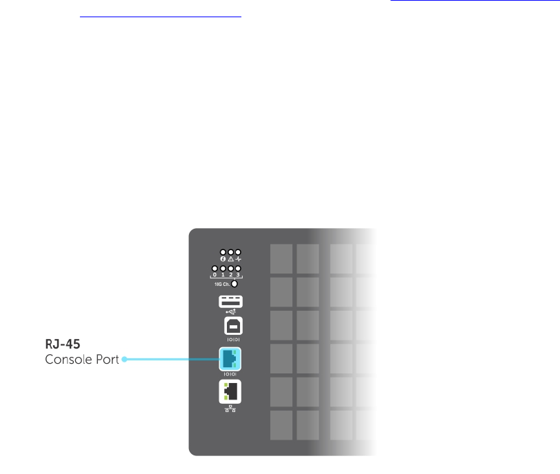
3
Getting Started
This chapter describes how you start configuring your Z9500 operating software.
When you power up the chassis, the system performs a power-on self test (POST) and loads the Dell
Networking operating software. Boot messages scroll up the terminal window during this process. No
user interaction is required if the boot process proceeds without interruption.
When the boot process completes, the system status LED remains online (green) and the console
monitor displays the EXEC mode prompt.
For details about using the command line interface (CLI), refer to the Accessing the Command Line
section in the Configuration Fundamentals chapter.
Console Access
The Z9500 has two management ports:
• A serial RS-232 /RJ-45 console port for a local management connection
• An out-of-band (OOB) Ethernet port to manage the switch using its IP address
Serial Console
The RJ-45/RS-232 console port is labeled on the I/O side (upper right-hand) of the Z9500 chassis.
Figure 1. RJ-45 Console Port
1. RJ-45 Console Port
Getting Started 43

Accessing the Console Port
To access the console port, follow these steps:
For the console port pinout, refer to Accessing the RJ-45 Console Port with a DB-9 Adapter.
1. Install an RJ-45 copper cable into the console port. Use a rollover (crossover) cable to connect the
Z9500 console port to a terminal server.
2. Connect the other end of the cable to the DTE terminal server.
3. Terminal settings on the console port cannot be changed in the software and are set as follows:
• 9600 baud rate
• No parity
• 8 data bits
• 1 stop bit
• No flow control
Pin Assignments
You can connect to the console using a RJ-45 to RJ-45 rollover cable and a RJ-45 to DB-9 female DTE
adapter to a terminal server (for example, a PC).
The pin assignments between the console and a DTE terminal server are as follows:
Table 2. Pin Assignments Between the Console and a DTE Terminal Server
Console Port RJ-45 to RJ-45
Rollover Cable RJ-45 to RJ-45
Rollover Cable RJ-45 to DB-9
Adapter Terminal Server
Device
Signal RJ-45 Pinout RJ-45 Pinout DB-9 Pin Signal
RTS 1 8 8 CTS
NC 2 7 6 DSR
TxD 3 6 2 RxD
GND 4 5 5 GND
GND 5 4 5 GND
RxD 6 3 3 TxD
NC 7 2 4 DTR
CTS 8 1 7 RTS
Default Configuration
Although a version of the Dell Networking OS is pre-loaded on the switch, the system is not configured
when you power up the first time (except for the default hostname, which is Dell). You must configure
the system using the CLI.
Configuring a Host Name
The host name appears in the prompt. The default host name is Dell.
• Host names must start with a letter and end with a letter or digit.
44 Getting Started

• Characters within the string can be letters, digits, and hyphens.
To create a host name, use the following command.
• Create a host name.
CONFIGURATION mode
hostname name
Example of the hostname Command
Dell(conf)#hostname R1
R1(conf)#
Accessing the System Remotely
You can configure the system to access it remotely by Telnet or SSH.
• The Z9500 has a dedicated management port and a management routing table that is separate from
the IP routing table.
• You can manage all Dell Networking products in-band via the front-end data ports through interfaces
assigned an IP address as well.
Accessing the Z9500 Remotely
Configuring the system for Telnet is a three-step process:
1. Configure an IP address for the management port. Configure the Management Port IP Address
2. Configure a management route with a default gateway. Configure a Management Route
3. Configure a username and password. Configure a Username and Password
Configure the Management Port IP Address
To access the system remotely, assign IP addresses to the management ports.
NOTE: Assign an IP address to the management port.
1. Enter INTERFACE mode for the Management port.
CONFIGURATION mode
interface ManagementEthernet 0/0
• The slot number is 0.
• The port number is 0.
2. Assign an IP address to the interface.
INTERFACE mode
ip address ip-address/mask
•ip-address: an address in dotted-decimal format (A.B.C.D).
•mask: a subnet mask in /prefix-length format (/ xx).
3. Enable the interface.
INTERFACE mode
Getting Started 45
no shutdown
Configure a Management Route
Define a path from the Z9500 to the network from which you are accessing the system remotely.
Management routes are separate from IP routes and are only used to manage the Z9500 through the
management port.
• Configure a management route to the network from which you are accessing the system.
CONFIGURATION mode
management route ip-address/mask gateway
–ip-address: the network address in dotted-decimal format (A.B.C.D).
–mask: a subnet mask in /prefix-length format (/ xx).
–gateway: the next hop for network traffic originating from the management port.
Configuring a Username and Password
To access the system remotely, you must configure a system username and password.
• Configure a username and password to access the system remotely.
CONFIGURATION mode
username username password [encryption-type] password
–encryption-type: specifies how you are inputting the password, is 0 by default, and is not
required.
* 0 is for inputting the password in clear text.
* 7 is for inputting a password that is already encrypted using a Type 7 hash. Obtaining the
encrypted password from the configuration of another Dell Networking system.
Configuring the Enable Password
Access EXEC Privilege mode using the enable command. EXEC Privilege mode is unrestricted by default.
Configure a password as a basic security measure.
There are two types of enable passwords:
•enable password stores the password in the running/startup configuration using a DES encryption
method.
•enable secret is stored in the running/startup configuration in using a stronger, MD5 encryption
method.
Dell Networking recommends using the enable secret password.
To configure an enable password, use the following command.
• Create a password to access EXEC Privilege mode.
CONFIGURATION mode
enable [password | secret] [level level] [encryption-type] password
–level: is the privilege level, is 15 by default, and is not required
46 Getting Started

–encryption-type: specifies how you are inputting the password, is 0 by default, and is not
required.
* 0 is for inputting the password in clear text.
* 7 is for inputting a password that is already encrypted using a DES hash. Obtain the encrypted
password from the configuration file of another Dell Networking system.
* 5 is for inputting a password that is already encrypted using an MD5 hash. Obtain the
encrypted password from the configuration file of another Dell Networking system.
Manage Configuration Files
Files can be stored on and accessed from various storage media. Rename, delete, and copy files on the
system from EXEC Privilege mode.
File Storage
The Dell Networking OS can use the internal Flash, external Flash, or remote devices to store files.
The system stores files on the internal Flash by default, but can be configured to store files elsewhere.
To view file system information, use the following command.
• View information about each file system.
EXEC Privilege mode
show file-systems
The output of the show file-systems command in the following example shows the total capacity,
amount of free memory, file structure, media type, read/write privileges for each storage device in use.
Dell#show file-systems
Size(b) Free(b) Feature Type Flags Prefixes
6429872128 6397476864 FAT32 USERFLASH rw flash:
15775404032 15775399936 FAT32 USBFLASH rw usbflash:
- - - network rw ftp:
- - - network rw tftp:
- - - network rw scp:
You can change the default file system so that file management commands apply to a particular device
or memory.
To change the default directory, use the following command.
• Change the default directory.
EXEC Privilege mode
cd directory
Copy Files to and from the System
The command syntax for copying files is similar to UNIX. The copy command uses the format copy
source-file-url destination-file-url.
NOTE: For a detailed description of the copy command, refer to the Dell Networking OS Command
Reference.
Getting Started 47

• To copy a local file to a remote system, combine the file-origin syntax for a local file location with the
file-destination syntax for a remote file location.
• To copy a remote file to Dell Networking system, combine the file-origin syntax for a remote file
location with the file-destination syntax for a local file location.
Table 3. Forming a copy Command
Location source-file-url Syntax destination-file-url Syntax
Internal flash: System copy flash://filename flash://filename
For a remote file location:
FTP server
copy ftp://
username:password@{hostip
| hostname}/filepath/
filename
ftp://
username:password@{hostip
| hostname}/ filepath/
filename
For a remote file location:
HTTP server
copy http://
username:password@{hostip
| hostname}/filepath/
filename
http://
username:password@{hostip
| hostname}/ filepath/
filename
For a remote file location:
SCP server
copy scp://{hostip |
hostname}/filepath/
filename
scp://{hostip |
hostname}/filepath/
filename
For a remote file location:
TFTP server
copy tftp://{hostip |
hostname}/filepath/
filename
tftp://{hostip |
hostname}/filepath/
filename
Important Points to Remember
• You may not copy a file from one remote system to another.
• You may not copy a file from one location to the same location.
• When copying to a server, you can only use a host name if a domain name server (DNS) server is
configured.
• The host IP address (hostip) supports IPv4 and IPv6 addresses in the source-file-url and destination-
file-url variables.
• When copying files to and from the system using FTP, HTTP, TFTP, or Telnet, you can specify a default
IP source interface for the file transfer protocol (ip {ftp | http |tlenet | tftp} source-
interface commands). The IP source interface can be a loopback, port-channel, or physical
interface.
• HTTP copy operations support egress interface selection (EIS) to isolate management-plane and
control-plane domains for HTTP traffic. For more information, see Egress Interface Selection (EIS).
Example of Copying a File to an FTP Server
Dell#copy flash://FTOS-ZC-9.2.1.0B2.bin ftp://
myusername:mypassword@10.10.10.10//FTOS/FTOS-ZC-9.2.1.0B2
!!!!!!!!!!!!!!!!!!!!!!!!!!!!!!!!!!!!!!!!!!!!!!!!!!!!!!!!!!!!!!!!!!!!!!!!!!!!!
94926657 bytes successfully copied
Example of Importing a File to the Local System
core1#$//copy ftp://myusername:mypassword@10.10.10.10//FTOS/
FTOS-ZC-9.2.1.0B2 flash://
Destination file name [FTOS-EF-8.2.1.0.bin.bin]:
48 Getting Started

!!!!!!!!!!!!!!!!!!!!!!!!!!!!!!!!!!!!!!!!!!!!!!!!!!!!!!!!!!!!!!!!
26292881 bytes successfully copied
Save the Running-Configuration
The running-configuration contains the current system configuration. Dell Networking recommends
coping your running-configuration to the startup-configuration.
The system uses the startup-configuration during boot-up to configure the system. The startup-
configuration is stored in the internal flash on the system by default, but it can be saved on a USB flash
device or a remote server.
The commands in this section follow the same format as those commands in the Copy Files to and from
the System section but use the filenames startup-configuration and running-configuration. These
commands assume that current directory is the internal flash, which is the system default.
• Save the running-configuration to the startup-configuration on the system.
EXEC Privilege mode
copy running-config startup-config
• Save the running-configuration to an FTP server.
EXEC Privilege mode
copy running-config ftp:// username:password@{hostip | hostname}/filepath/
filename
• Save the running-configuration to a TFTP server.
EXEC Privilege mode
copy running-config tftp://{hostip | hostname}/ filepath/filename
• Save the running-configuration to an SCP server.
EXEC Privilege mode
copy running-config scp://{hostip | hostname}/ filepath/filename
NOTE: When copying to a server, a host name can only be used if a DNS server is configured.
Configure the Overload Bit for a Startup Scenario
For information about setting the router overload bit for a specific period of time after a switch reload is
implemented, refer to the Intermediate System to Intermediate System (IS-IS) section in the Dell
Networking OS Command Line Reference Guide.
Viewing Files
You can only view file information and content on local file systems.
To view a list of files or the contents of a file, use the following commands.
• View a list of files on the internal flash.
EXEC Privilege mode
dir flash:
• View the contents of a file in the internal flash.
EXEC Privilege mode
show file flash://filename
Getting Started 49

• View a list of files on an external flash.
EXEC Privilege mode
dir usbflash:
• View the running-configuration.
EXEC Privilege mode
show running-config
• View the startup-configuration.
EXEC Privilege mode
show startup-config
Example of the dir Command
The output of the dir command also shows the read/write privileges, size (in bytes), and date of
modification for each file.
Dell#dir
Directory of flash:
1 drw- 32768 Jan 01 1980 00:00:00 .
2 drwx 512 Jul 23 2007 00:38:44 ..
3 drw- 8192 Mar 30 1919 10:31:04 TRACE_LOG_DIR
4 drw- 8192 Mar 30 1919 10:31:04 CRASH_LOG_DIR
5 drw- 8192 Mar 30 1919 10:31:04 NVTRACE_LOG_DIR
6 drw- 8192 Mar 30 1919 10:31:04 CORE_DUMP_DIR
7 d--- 8192 Mar 30 1919 10:31:04 ADMIN_DIR
8 -rw- 33059550 Jul 11 2007 17:49:46 FTOS-EF-7.4.2.0.bin
9 -rw- 27674906 Jul 06 2007 00:20:24 FTOS-EF-4.7.4.302.bin
10 -rw- 27674906 Jul 06 2007 19:54:52 boot-image-FILE
11 drw- 8192 Jan 01 1980 00:18:28 diag
12 -rw- 7276 Jul 20 2007 01:52:40 startup-config.bak
13 -rw- 7341 Jul 20 2007 15:34:46 startup-config
14 -rw- 27674906 Jul 06 2007 19:52:22 boot-image
15 -rw- 27674906 Jul 06 2007 02:23:22 boot-flash
--More--
Changes in Configuration Files
Configuration files have three commented lines at the beginning of the file, as shown in the following
example, to help you track the last time any user made a change to the file, which user made the
changes, and when the file was last saved to the startup-configuration.
In the running-configuration file, if there is a difference between the timestamp on the “Last
configuration change,” and “Startup-config last updated,” you have made changes that have not been
saved and will not be preserved after a system reboot.
Example of the show running-config Command
Dell#show running-config
Current Configuration ...
! Version 9-2(1-552)
! Last configuration change at Tue Jan 21 09:32:57 2014 by admin
!
boot system primary tftp://10.11.8.13/rithvik-rainier
boot system secondary tftp://10.11.8.13/rithvik-rainier
boot system default system: A:
boot system gateway 172.27.1.1
50 Getting Started

!
redundancy auto-synchronize full
redundancy disable-auto-reboot
!
service timestamps log datetime
!
logging coredump
!
hostname pt-z9500-11
!
enable password 7 b125455cf679b208e79b910e85789edf
!
username admin password 7 1d28e9f33f99cf5c
!
linecard 0 provision Z9500LC36
--More—
View Command History
The command-history trace feature captures all commands entered by all users of the system with a time
stamp and writes these messages to a dedicated trace log buffer.
The system generates a trace message for each executed command. No password information is saved
to the file.
To view the command-history trace, use the show command-history command.
Example of the show command-history Command
Dell#show command-history
[12/5 10:57:8]: CMD-(CLI):service password-encryption
[12/5 10:57:12]: CMD-(CLI):hostname Force10
[12/5 10:57:12]: CMD-(CLI):ip telnet server enable
[12/5 10:57:12]: CMD-(CLI):line console 0
[12/5 10:57:12]: CMD-(CLI):line vty 0 9
Upgrading the Dell Networking OS
NOTE: To upgrade the Dell Networking operating software, refer to the Release Notes for the
version you want to load on the switch.
Using Hashes to Validate Software Images
You can use the MD5 message-digest algorithm or SHA256 Secure Hash Algorithm to validate the
software image on the flash drive, after the image has been transferred to the system, but before the
image has been installed. The validation calculates a hash value of the downloaded image file on system’s
flash drive, and, optionally, compares it to a Dell Networking published hash for that file.
The MD5 or SHA256 hash provides a method of validating that you have downloaded the original
software. Calculating the hash on the local image file, and comparing the result to the hash published for
that file on iSupport, provides a high level of confidence that the local copy is exactly the same as the
published software image. This validation procedure, and the verify {md5 | sha256} command to support
it, can prevent the installation of corrupted or modified images.
Getting Started 51

The verify {md5 | sha256} command calculates and displays the hash of any file on the specified local
flash drive. You can compare the displayed hash against the appropriate hash published on i-Support.
Optionally, the published hash can be included in the verify {md5 | sha256} command, which will display
whether it matches the calculated hash of the indicated file.
To validate a software image:
1. Download Dell Networking OS software image file from the iSupport page to the local (FTP or TFTP)
server. The published hash for that file is displayed next to the software image file on the iSupport
page.
2. Go on to the Dell Networking system and copy the software image to the flash drive, using the copy
command.
3. Run the verify {md5 | sha256} [ flash://]img-file [hash-value] command. For example, verify sha256
flash://FTOS-SE-9.5.0.0.bin
4. Compare the generated hash value to the expected hash value published on the iSupport page.
To validate the software image on the flash drive after the image has been transferred to the system, but
before the image has been installed, use the verify {md5 | sha256} [ flash://]img-file [hash-value]
command in EXEC mode.
•md5: MD5 message-digest algorithm
•sha256: SHA256 Secure Hash Algorithm
•flash: (Optional) Specifies the flash drive. The default is to use the flash drive. You can just enter the
image file name.
•hash-value: (Optional). Specify the relevant hash published on i-Support.
•img-file: Enter the name of the Dell Networking software image file to validate
Examples: Without Entering the Hash Value for Verification
MD5
Dell# verify md5 flash://FTOS-SE-9.5.0.0.bin
MD5 hash for FTOS-SE-9.5.0.0.bin: 275ceb73a4f3118e1d6bcf7d75753459
SHA256
Dell# verify sha256 flash://FTOS-SE-9.5.0.0.bin
SHA256 hash for FTOS-SE-9.5.0.0.bin:
e6328c06faf814e6899ceead219afbf9360e986d692988023b749e6b2093e933
Examples: Entering the Hash Value for Verification
MD5
Dell# verify md5 flash://FTOS-SE-9.5.0.0.bin 275ceb73a4f3118e1d6bcf7d75753459
MD5 hash VERIFIED for FTOS-SE-9.5.0.0.bin
SHA256
Dell# verify sha256 flash://FTOS-SE-9.5.0.0.bin
e6328c06faf814e6899ceead219afbf9360e986d692988023b749e6b2093e933
SHA256 hash VERIFIED for FTOS-SE-9.5.0.0.bin
52 Getting Started

4
Switch Management
This chapter describes the switch management tasks supported on the Z9500.
Configuring Privilege Levels
Privilege levels restrict access to commands based on user or terminal line.
There are 16 privilege levels, of which three are pre-defined. The default privilege level is 1.
Level Description
Level 0 Access to the system begins at EXEC mode, and EXEC mode commands are
limited to enable, disable, and exit.
Level 1 Access to the system begins at EXEC mode, and all commands are available.
Level 15 Access to the system begins at EXEC Privilege mode, and all commands are
available.
For information about how access and authorization is controlled based on a user’s role, see Role-Based
Access Control.
Creating a Custom Privilege Level
Custom privilege levels start with the default EXEC mode command set. You can then customize privilege
levels 2-14 by:
• restricting access to an EXEC mode command
• moving commands from EXEC Privilege to EXEC mode
• restricting access
A user can access all commands at his privilege level and below.
Removing a Command from EXEC Mode
To remove a command from the list of available commands in EXEC mode for a specific privilege level,
use the privilege exec command from CONFIGURATION mode.
In the command, specify a level greater than the level given to a user or terminal line, then the first
keyword of each command you wish to restrict.
Moving a Command from EXEC Privilege Mode to EXEC Mode
To move a command from EXEC Privilege to EXEC mode for a privilege level, use the privilege exec
command from CONFIGURATION mode.
In the command, specify the privilege level of the user or terminal line and specify all keywords in the
command to which you want to allow access.
Switch Management 53
Allowing Access to CONFIGURATION Mode Commands
To allow access to CONFIGURATION mode, use the privilege exec level level configure
command from CONFIGURATION mode.
A user that enters CONFIGURATION mode remains at his privilege level and has access to only two
commands, end and exit. You must individually specify each CONFIGURATION mode command you
want to allow access to using the privilege configure level level command. In the command,
specify the privilege level of the user or terminal line and specify all the keywords in the command to
which you want to allow access.
Allowing Access to the Following Modes
This section describes how to allow access to the INTERFACE, LINE, ROUTE-MAP, and ROUTER modes.
Similar to allowing access to CONFIGURATION mode, to allow access to INTERFACE, LINE, ROUTE-MAP,
and ROUTER modes, you must first allow access to the command that enters you into the mode. For
example, to allow a user to enter INTERFACE mode, use the privilege configure level level
interface tengigabitethernet command.
Next, individually identify the INTERFACE, LINE, ROUTE-MAP or ROUTER commands to which you want
to allow access using the privilege {interface | line | route-map | router} level
level command. In the command, specify the privilege level of the user or terminal line and specify all
the keywords in the command to which you want to allow access.
To remove, move or allow access, use the following commands.
The configuration in the following example creates privilege level 3. This level:
• removes the resequence command from EXEC mode by requiring a minimum of privilege level 4
• moves the capture bgp-pdu max-buffer-size command from EXEC Privilege to EXEC mode by
requiring a minimum privilege level 3, which is the configured level for VTY 0
• allows access to CONFIGURATION mode with the banner command
• allows access to INTERFACE and LINE modes are allowed with no commands
• Remove a command from the list of available commands in EXEC mode.
CONFIGURATION mode
privilege exec level level {command ||...|| command}
• Move a command from EXEC Privilege to EXEC mode.
CONFIGURATION mode
privilege exec level level {command ||...|| command}
• Allow access to CONFIGURATION mode.
CONFIGURATION mode
privilege exec level level configure
• Allow access to INTERFACE, LINE, ROUTE-MAP, and/or ROUTER mode. Specify all the keywords in
the command.
CONFIGURATION mode
privilege configure level level {interface | line | route-map | router}
{command-keyword ||...|| command-keyword}
54 Switch Management

• Allow access to a CONFIGURATION, INTERFACE, LINE, ROUTE-MAP, and/or ROUTER mode
command.
CONFIGURATION mode
privilege {configure |interface | line | route-map | router} level level
{command ||...|| command}
Example of EXEC Privilege Commands
Dell(conf)#do show run priv
!
privilege exec level 3 capture
privilege exec level 3 configure
privilege exec level 4 resequence
privilege exec level 3 capture bgp-pdu
privilege exec level 3 capture bgp-pdu max-buffer-size
privilege configure level 3 line
privilege configure level 3 interface
Dell(conf)#do telnet 10.11.80.201
[telnet output omitted]
Dell#show priv
Current privilege level is 3.
Dell#?
capture Capture packet
configure Configuring from terminal
disable Turn off privileged commands
enable Turn on privileged commands
exit Exit from the EXEC
ip Global IP subcommands
monitor Monitoring feature
mtrace Trace reverse multicast path from destination to source
ping Send echo messages
quit Exit from the EXEC
show Show running system information
[output omitted]
Dell#config
[output omitted]
Dell(conf)#do show priv
Current privilege level is 3.
Dell(conf)#?
end Exit from configuration mode
exit Exit from configuration mode
interface Select an interface to configure
line Configure a terminal line
linecard Set line card type
Dell(conf)#interface ?
loopback Loopback interface
managementethernet Management Ethernet interface
null Null interface
port-channel Port-channel interface
range Configure interface range
tengigabitethernet TenGigabit Ethernet interface
vlan VLAN interface
Dell(conf)#interface tengigabitethernet 1/1
Dell(conf-if-te-1/1)#?
end Exit from configuration mode
exit Exit from interface configuration mode
Dell(conf-if-te-1/1)#exit
Dell(conf)#line ?
aux Auxiliary line
console Primary terminal line
vty Virtual terminal
Switch Management 55

Dell(conf)#line vty 0
Dell(config-line-vty)#?
exit Exit from line configuration mode
Dell(config-line-vty)#
Applying a Privilege Level to a Username
To set the user privilege level, use the following command.
• Configure a privilege level for a user.
CONFIGURATION mode
username username privilege level
Applying a Privilege Level to a Terminal Line
To set a privilege level for a terminal line, use the following command.
• Configure a privilege level for a user.
CONFIGURATION mode
username username privilege level
NOTE: When you assign a privilege level between 2 and 15, access to the system begins at EXEC
mode, but the prompt is hostname#, rather than hostname>.
Configuring Logging
The Dell Networking operating system tracks changes in the system using event and error messages.
By default, the operating system logs these messages on:
• the internal buffer
• console and terminal lines
• any configured syslog servers
To disable logging, use the following commands.
• Disable all logging except on the console.
CONFIGURATION mode
no logging on
• Disable logging to the logging buffer.
CONFIGURATION mode
no logging buffer
• Disable logging to terminal lines.
CONFIGURATION mode
no logging monitor
• Disable console logging.
CONFIGURATION mode
no logging console
56 Switch Management

Audit and Security Logs
This section describes how to configure, display, and clear audit and security logs.
The following is the configuration task list for audit and security logs:
•Enabling Audit and Security Logs
•Displaying Audit and Security Logs
•Clearing Audit Logs
Enabling Audit and Security Logs
You enable audit and security logs to monitor configuration changes or determine if these changes affect
the operation of the system in the network. You log audit and security events to a system log server,
using the logging extended command in CONFIGURATION mode. This command is available with or
without RBAC enabled. For information about RBAC, see Role-Based Access Control.
Audit Logs
The audit log contains configuration events and information. The types of information in this log consist
of the following:
• User logins to the switch.
• System events for network issues or system issues.
• Users making configuration changes. The switch logs who made the configuration changes and the
date and time of the change. However, each specific change on the configuration is not logged. Only
that the configuration was modified is logged with the user ID, date, and time of the change.
• Uncontrolled shutdown.
Security Logs
The security log contains security events and information. RBAC restricts access to audit and security logs
based on the CLI sessions’ user roles. The types of information in this log consist of the following:
• Establishment of secure traffic flows, such as SSH.
• Violations on secure flows or certificate issues.
• Adding and deleting of users.
• User access and configuration changes to the security and crypto parameters (not the key
information but the crypto configuration)
Important Points to Remember
When you enabled RBAC and extended logging:
• Only the system administrator user role can execute this command.
• The system administrator and system security administrator user roles can view security events and
system events.
• The system administrator user roles can view audit, security, and system events.
• Only the system administrator and security administrator user roles can view security logs.
Switch Management 57

• The network administrator and network operator user roles can view system events.
NOTE: If extended logging is disabled, you can only view system events, regardless of RBAC user
role.
Example of Enabling Audit and Security Logs
Dell(conf)#logging extended
Displaying Audit and Security Logs
To display audit logs, use the show logging auditlog command in Exec mode. To view these logs,
you must first enable the logging extended command. Only the RBAC system administrator user role can
view the audit logs. Only the RBAC security administrator and system administrator user role can view the
security logs. If extended logging is disabled, you can only view system events, regardless of RBAC user
role. To view security logs, use the show logging command.
Example of the show logging auditlog Command
For information about the logging extended command, see Enabling Audit and Security Logs
Dell#show logging auditlog
May 12 12:20:25: Dell#: %CLI-6-logging extended by admin from vty0 (10.14.1.98)
May 12 12:20:42: Dell#: %CLI-6-configure terminal by admin from vty0
(10.14.1.98)
May 12 12:20:42: Dell#: %CLI-6-service timestamps log datetime by admin from
vty0 (10.14.1.98)
Example of the show logging Command for Security
For information about the logging extended command, see Enabling Audit and Security Logs
Dell#show logging
Jun 10 04:23:40: %STKUNIT0-M:CP %SEC-5-LOGIN_SUCCESS: Login successful for
user admin on line vty0 ( 10.14.1.91 )
Clearing Audit Logs
To clear audit logs, use the clear logging auditlog command in Exec mode. When RBAC is
enabled, only the system administrator user role can issue this command.
Example of the clear logging auditlog Command
Dell# clear logging auditlog
Configuring Logging Format
To display syslog messages in a RFC 3164 or RFC 5424 format, use the logging version [0 | 1}
command in CONFIGURATION mode. By default, the system log version is set to 0.
The following describes the two log messages formats:
•0 – Displays syslog messages format as described in RFC 3164, The BSD syslog Protocol
•1 – Displays syslog message format as described in RFC 5424, The SYSLOG Protocol
Example of Configuring the Logging Message Format
Dell(conf)#logging version ?
<0-1> Select syslog version (default = 0)
Dell(conf)#logging version 1
58 Switch Management
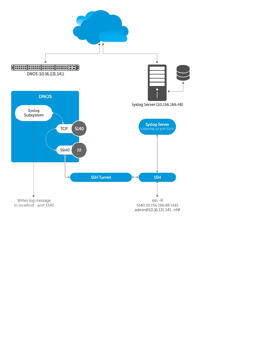
Setting Up a Secure Connection to a Syslog Server
You can use reverse tunneling with the port forwarding to securely connect to a syslog server.
Pre-requisites
To configure a secure connection from the switch to the syslog server:
1. On the switch, enable the SSH server
Dell(conf)#ip ssh server enable
2. On the syslog server, create a reverse SSH tunnel from the syslog server to FTOS switch, using
following syntax:
ssh -R <remote port>:<syslog server>:<syslog server listen port>
user@remote_host -nNf
In the following example the syslog server IP address is 10.156.166.48 and the listening port is
5141. The switch IP address is 10.16.131.141 and the listening port is 5140
ssh -R 5140:10.156.166.48:5141 admin@10.16.131.141 -nNf
Switch Management 59

3. Configure logging to a local host. locahost is “127.0.0.1” or “::1”.
If you do not, the system displays an error when you attempt to enable role-based only AAA
authorization.
Dell(conf)# logging localhost tcp port
Dell(conf)#logging 127.0.0.1 tcp 5140
Log Messages in the Internal Buffer
All error messages, except those beginning with %BOOTUP (Message), are logged in the internal buffer.
Configuration Task List for System Log Management
There are two configuration tasks for system log management:
•Disable System Logging
•Send System Messages to a Syslog Server
•Send System Messages to a Syslog Server
•Change System Logging Settings
•Display the Logging Buffer and the Logging Configuration
•Configure a UNIX Logging Facility Level
•Enable Timestamp on Syslog Messages
•Synchronize Log Messages
•Audit and Security Logs
•
Configuring Logging Format
•Secure Connection to a Syslog Server
Disabling System Logging
By default, logging is enabled and log messages are sent to the logging buffer, all terminal lines, the
console, and the syslog servers.
To disable system logging, use the following commands.
• Disable all logging except on the console.
CONFIGURATION mode
no logging on
• Disable logging to the logging buffer.
CONFIGURATION mode
no logging buffer
• Disable logging to terminal lines.
CONFIGURATION mode
no logging monitor
• Disable console logging.
CONFIGURATION mode
60 Switch Management

no logging console
Sending System Messages to a Syslog Server
To send system messages to a specified syslog server, use the following command. The following syslog
standards are supported: RFC 5424 The SYSLOG Protocol, R.Gerhards and Adiscon GmbH, March 2009,
obsoletes RFC 3164 and RFC 5426 Transmission of Syslog Messages over UDP.
• Specify the server to which you want to send system messages. You can configure up to eight syslog
servers.
CONFIGURATION mode
logging {ip-address | ipv6-address | hostname} {{udp {port}} | {tcp {port}}}
Configuring a UNIX System as a Syslog Server
To configure a UNIX System as a syslog server, use the following command.
• Configure a UNIX system as a syslog server by adding the following lines to /etc/syslog.conf on the
UNIX system and assigning write permissions to the file.
– Add line on a 4.1 BSD UNIX system. local7.debugging /var/log/ftos.log
– Add line on a 5.7 SunOS UNIX system. local7.debugging /var/adm/ftos.log
In the previous lines, local7 is the logging facility level and debugging is the severity level.
Display the Logging Buffer and the Logging
Configuration
To display the current contents of the logging buffer and the logging settings for the system, use the
show logging command in EXEC privilege mode. When RBAC is enabled, the security logs are filtered
based on the user roles. Only the security administrator and system administrator can view the security
logs.
Example of the show logging Command
Dell#show logging
Syslog logging: enabled
Console logging: level debugging
Monitor logging: level debugging
Buffer logging: level debugging, 416 Messages Logged, Size (40960 bytes)
Trap logging: level informational
Logging to 10.1.2.4
Logging to 172.31.1.4
Logging to 133.33.33.4
Logging to 172.16.1.162
Logging to 10.10.10.4
Jan 21 09:52:21: %SYSTEM:CP %SYS-5-CONFIG_I: Configured from vty0
( 10.11.8.68 )by admin
Jan 21 09:32:57: %SYSTEM:CP %SYS-5-CONFIG_I: Configured from vty0
( 10.11.8.68 )by admin
Jan 21 09:32:57: %SYSTEM:CP %SEC-3-AUTHENTICATION_ENABLE_SUCCESS: Enable
password authentication success on vty0 ( 10.11.8.68 )
Jan 21 09:32:57: %SYSTEM:CP %SEC-5-LOGIN_SUCCESS: Login successful for user
admin on line vty0 ( 10.11.8.68 )
Jan 21 04:11:02: %SYSTEM:CP %IFMGR-5-OSTATE_DN: Changed interface state to
down: Te 0/1
Switch Management 61

Jan 21 04:11:02: %SYSTEM:CP %IFMGR-5-OSTATE_DN: Changed interface state to
down: Te 0/0
Jan 21 03:12:54: %SYSTEM:LP %CHMGR-2-PSU_FAN_SPEED_CHANGE: PSU_Fan speed
changed to 60 % of the full speed
Jan 21 03:12:54: %SYSTEM:LP %CHMGR-2-FAN_SPEED_CHANGE: Fan speed changed to 40
% of the full speed
Jan 21 03:02:51: %SYSTEM:LP %CHMGR-2-PSU_FAN_SPEED_CHANGE: PSU_Fan speed
changed to 80 % of the full speed
Jan 21 03:02:51: %SYSTEM:LP %CHMGR-2-FAN_SPEED_CHANGE: Fan speed changed to 50
% of the full speed
Jan 21 02:56:54: %SYSTEM:CP %SNMP-6-SNMP_WARM_START: Agent Initialized - SNMP
WARM_START.
Jan 21 02:56:54: %SYSTEM:CP %IFMGR-5-OSTATE_UP: Changed interface state to up:
Te 2/3
--More--
To view any changes made, use the show running-config logging command in EXEC privilege
mode, as shown in the example for Configure a UNIX Logging Facility Level.
Changing System Logging Settings
You can change the default settings of the system logging by changing the severity level and the storage
location.
The default is to log all messages up to debug level, that is, all system messages. By changing the severity
level in the logging commands, you control the number of system messages logged.
To specify the system logging settings, use the following commands.
• Specify the minimum severity level for logging to the logging buffer.
CONFIGURATION mode
logging buffered level
• Specify the minimum severity level for logging to the console.
CONFIGURATION mode
logging console level
• Specify the minimum severity level for logging to terminal lines.
CONFIGURATION mode
logging monitor level
• Specify the minimum severity level for logging to a syslog server.
CONFIGURATION mode
logging trap level
• Specify the minimum severity level for logging to the syslog history table.
CONFIGURATION mode
logging history level
• Specify the size of the logging buffer.
CONFIGURATION mode
logging buffered size
62 Switch Management

NOTE: When you decrease the buffer size, the operating system deletes all messages stored in
the buffer. Increasing the buffer size does not affect messages in the buffer.
• Specify the number of messages that the operating system saves to its logging history table.
CONFIGURATION mode
logging history size size
To view the logging buffer and configuration, use the show logging command in EXEC privilege mode,
as shown in the example for Display the Logging Buffer and the Logging Configuration.
To view the logging configuration, use the show running-config logging command in privilege
mode, as shown in the example for Configure a UNIX Logging Facility Level.
Configuring a UNIX Logging Facility Level
You can save system log messages with a UNIX system logging facility.
To configure a UNIX logging facility level, use the following command.
• Specify one of the following parameters.
CONFIGURATION mode
logging facility [facility-type]
–auth (for authorization messages)
–cron (for system scheduler messages)
–daemon (for system daemons)
–kern (for kernel messages)
–local0 (for local use)
–local1 (for local use)
–local2 (for local use)
–local3 (for local use)
–local4 (for local use)
–local5 (for local use)
–local6 (for local use)
–local7 (for local use)
–lpr (for line printer system messages)
–mail (for mail system messages)
–news (for USENET news messages)
–sys9 (system use)
–sys10 (system use)
–sys11 (system use)
–sys12 (system use)
–sys13 (system use)
–sys14 (system use)
–syslog (for syslog messages)
–user (for user programs)
Switch Management 63

–uucp (UNIX to UNIX copy protocol)
Example of the show running-config logging Command
To view non-default settings, use the show running-config logging command in EXEC mode.
Dell#show running-config logging
!
logging buffered 524288 debugging
service timestamps log datetime msec
service timestamps debug datetime msec
!
logging trap debugging
logging facility user
logging source-interface Loopback 0
logging 10.10.10.4
Dell#
Synchronizing Log Messages
You can configure the Dell Networking OS to filter and consolidate the system messages for a specific
line by synchronizing the message output.
Only the messages with a severity at or below the set level appear. This feature works on the terminal and
console connections available on the system.
1. Enter LINE mode.
CONFIGURATION mode
line {console 0 | vty number [end-number] | aux 0}
Configure the following parameters for the virtual terminal lines:
•number: the range is from zero (0) to 8.
•end-number: the range is from 1 to 8.
You can configure multiple virtual terminals at one time by entering a number and an end-number.
2. Configure a level and set the maximum number of messages to print.
LINE mode
logging synchronous [level severity-level | all] [limit]
Configure the following optional parameters:
•level severity-level: the range is from 0 to 7. The default is 2. Use the all keyword to
include all messages.
•limit: the range is from 20 to 300. The default is 20.
To view the logging synchronous configuration, use the show config command in LINE mode.
Enabling Timestamp on Syslog Messages
By default, syslog messages do not include a time/date stamp stating when the error or message was
created.
To enable timestamp, use the following command.
64 Switch Management

• Add timestamp to syslog messages.
CONFIGURATION mode
service timestamps [log | debug] [datetime [localtime] [msec] [show-timezone]
| uptime]
Specify the following optional parameters:
– You can add the keyword localtime to include the localtime, msec, and show-timezone. If
you do not add the keyword localtime, the time is UTC.
–uptime: To view time since last boot.
If you do not specify a parameter, the system configures uptime.
To view the configuration, use the show running-config logging command in EXEC privilege mode.
To disable time stamping on syslog messages, use the no service timestamps [log | debug]
command.
File Transfer Services
You can configure the system to transfer files over the network using the file transfer protocol (FTP).
One FTP application is copying the system image files over an interface on to the system; however, FTP is
not supported on virtual local area network (VLAN) interfaces.
For more information about FTP, refer to RFC 959, File Transfer Protocol.
NOTE: To transmit large files, Dell Networking recommends configuring the switch as an FTP
server.
Configuration Task List for File Transfer Services
The configuration tasks for file transfer services are:
•Enable FTP Server (mandatory)
•Configure FTP Server Parameters (optional)
•Configure FTP Client Parameters (optional)
Enabling the FTP Server
To enable the system as an FTP server, use the following command.
To view FTP configuration, use the show running-config ftp command in EXEC privilege mode.
• Enable FTP on the system.
CONFIGURATION mode
ftp-server enable
Example of Viewing FTP Configuration
Dell#show running ftp
!
ftp-server enable
Switch Management 65

ftp-server username nairobi password 0 zanzibar
Dell#
Configuring FTP Server Parameters
After you enable the FTP server on the system, you can configure different parameters.
To specify the system logging settings, use the following commands.
• Specify the directory for users using FTP to reach the system.
CONFIGURATION mode
ftp-server topdir dir
The default is the internal flash directory.
• Specify a user name for all FTP users and configure either a plain text or encrypted password.
CONFIGURATION mode
ftp-server username username password [encryption-type] password
Configure the following optional and required parameters:
–username: enter a text string.
–encryption-type: enter 0 for plain text or 7 for encrypted text.
–password: enter a text string.
NOTE: You cannot use the change directory (cd) command until you have configured ftp-
server topdir.
To view the FTP configuration, use the show running-config ftp command in EXEC privilege mode.
Configuring FTP Client Parameters
To configure FTP client parameters, use the following commands.
• Enter the following keywords and slot/port or number information:
– For a loopback interface, enter the keyword loopback then a number between 0 and 16383.
– For a port channel interface, enter the keywords port-channel then a number from 1 to 255.
– For a 10-Gigabit Ethernet interface, enter the keyword TenGigabitEthernet then the slot/port
information.
– For a 40-Gigabit Ethernet interface, enter the keyword fortyGigE then the slot/port information.
– For a VLAN interface, enter the keyword vlan then a number from 1 to 4094.
CONFIGURATION mode
ip ftp source-interface interface
• Configure a password.
CONFIGURATION mode
ip ftp password password
• Enter a username to use on the FTP client.
CONFIGURATION mode
66 Switch Management

ip ftp username name
To view the FTP configuration, use the show running-config ftp command in EXEC privilege mode,
as shown in the example for Enable FTP Server.
Terminal Lines
You can access the system remotely and restrict access to the system by creating user profiles.
Terminal lines on the system provide different means of accessing the system. The console line (console)
connects you through the console port. The virtual terminal lines (VTYs) connect you through Telnet to
the system.
Denying and Permitting Access to a Terminal Line
Dell Networking recommends applying only standard access control lists (ACLs) to deny and permit
access to VTY lines.
• Layer 3 ACLs deny all traffic that is not explicitly permitted, but in the case of VTY lines, an ACL with
no rules does not deny traffic.
• You cannot use the show ip accounting access-list command to display the contents of an
ACL that is applied only to a VTY line.
To apply an IP ACL to a line, Use the following command.
• Apply an ACL to a VTY line.
LINE mode
ip access-class access-list
Example of an ACL that Permits Terminal Access
To view the configuration, use the show config command in LINE mode.
Dell(config-std-nacl)#show config
!
ip access-list standard myvtyacl
seq 5 permit host 10.11.0.1
Dell(config-std-nacl)#line vty 0
Dell(config-line-vty)#show config
line vty 0
access-class myvtyacl
Configuring Login Authentication for Terminal Lines
You can use any combination of up to six authentication methods to authenticate a user on a terminal
line.
A combination of authentication methods is called a method list. If the user fails the first authentication
method, the system prompts the next method until all methods are exhausted, at which point the
connection is terminated. The available authentication methods are:
enable Prompt for the enable password.
line Prompt for the password you assigned to the terminal line. Configure a password
for the terminal line to which you assign a method list that contains the line
authentication method. Configure a password using the password command from
LINE mode.
Switch Management 67

local Prompt for the system username and password.
none Do not authenticate the user.
radius Prompt for a username and password and use a RADIUS server to authenticate.
tacacs+ Prompt for a username and password and use a TACACS+ server to authenticate.
1. Configure an authentication method list. You may use a mnemonic name or use the keyword
default. The default authentication method for terminal lines is local and the default method list is
empty.
CONFIGURATION mode
aaa authentication login {method-list-name | default} [method-1] [method-2]
[method-3] [method-4] [method-5] [method-6]
2. Apply the method list from Step 1 to a terminal line.
CONFIGURATION mode
login authentication {method-list-name | default}
3. If you used the line authentication method in the method list you applied to the terminal line,
configure a password for the terminal line.
LINE mode
password
Example of Terminal Line Authentication
In the following example, VTY lines 0-2 use a single authentication method, line.
Dell(conf)#aaa authentication login myvtymethodlist line
Dell(conf)#line vty 0 2
Dell(config-line-vty)#login authentication myvtymethodlist
Dell(config-line-vty)#password myvtypassword
Dell(config-line-vty)#show config
line vty 0
password myvtypassword
login authentication myvtymethodlist
line vty 1
password myvtypassword
login authentication myvtymethodlist
line vty 2
password myvtypassword
login authentication myvtymethodlist
Dell(config-line-vty)#
Setting Time Out of EXEC Privilege Mode
EXEC time-out is a basic security feature that returns the system to EXEC mode after a period of inactivity
on the terminal lines.
To set time out, use the following commands.
• Set the number of minutes and seconds. The default is 10 minutes on the console and 30 minutes
on VTY. Disable EXEC time out by setting the time-out period to 0.
LINE mode
exec-timeout minutes [seconds]
68 Switch Management

• Return to the default time-out values.
LINE mode
no exec-timeout
Example of Setting the Time Out Period for EXEC Privilege Mode
The following example shows how to set the time-out period and how to view the configuration using
the show config command from LINE mode.
Dell(conf)#line con 0
Dell(config-line-console)#exec-timeout 0
Dell(config-line-console)#show config
line console 0
exec-timeout 0 0
Dell(config-line-console)#
Using Telnet to Access Another Network Device
To telnet to another device, use the following commands.
NOTE: On the Z9500, the system allows 120 Telnet sessions per minute, allowing the login and
logout of 10 Telnet sessions, 12 times in a minute. If the system reaches this non-practical limit, the
Telnet service is stopped for 10 minutes. You can use console and SSH service to access the system
during downtime.
• Telnet to a device with an IPv4 or IPv6 address.
EXEC Privilege
telnet [ip-address]
If you do not enter an IP address, the system enters a Telnet dialog that prompts you for one.
Enter an IPv4 address in dotted decimal format (A.B.C.D).
Enter an IPv6 address in the format 0000:0000:0000:0000:0000:0000:0000:0000. Elision of zeros
is supported.
Example of the telnet Command for Device Access
Dell# telnet 10.11.80.203
Trying 10.11.80.203...
Connected to 10.11.80.203.
Exit character is '^]'.
Login:
Login: admin
Password:
Dell>exit
Dell#telnet 2200:2200:2200:2200:2200::2201
Trying 2200:2200:2200:2200:2200::2201...
Connected to 2200:2200:2200:2200:2200::2201.
Exit character is '^]'.
FreeBSD/i386 (freebsd2.force10networks.com) (ttyp1)
login: admin
Dell#
Switch Management 69

Lock CONFIGURATION Mode
The system allows multiple users to make configurations at the same time. You can lock
CONFIGURATION mode so that only one user can be in CONFIGURATION mode at any time (Message
2).
You can set two types of locks: auto and manual.
• Set auto-lock using the configuration mode exclusive auto command from
CONFIGURATION mode. When you set auto-lock, every time a user is in CONFIGURATION mode, all
other users are denied access. This means that you can exit to EXEC Privilege mode, and re-enter
CONFIGURATION mode without having to set the lock again.
• Set manual lock using the configure terminal lock command from CONFIGURATION mode.
When you configure a manual lock, which is the default, you must enter this command each time you
want to enter CONFIGURATION mode and deny access to others.
Viewing the Configuration Lock Status
If you attempt to enter CONFIGURATION mode when another user has locked it, you may view which
user has control of CONFIGURATION mode using the show configuration lock command from
EXEC Privilege mode.
You can then send any user a message using the send command from EXEC Privilege mode.
Alternatively, you can clear any line using the clear command from EXEC Privilege mode. If you clear a
console session, the user is returned to EXEC mode.
Example of Locking CONFIGURATION Mode for Single-User Access
Dell(conf)#configuration mode exclusive auto
BATMAN(conf)#exit
3d23h35m: %SYSTEM-P:CP %SYS-5-CONFIG_I: Configured from console by console
Dell#config
! Locks configuration mode exclusively.
Dell(conf)#
If another user attempts to enter CONFIGURATION mode while a lock is in place, the following appears
on their terminal (message 1): % Error: User "" on line console0 is in exclusive
configuration mode.
If any user is already in CONFIGURATION mode when while a lock is in place, the following appears on
their terminal (message 2): % Error: Can't lock configuration mode exclusively since
the following users are currently configuring the system: User "admin" on line
vty1 ( 10.1.1.1 ).
NOTE: The CONFIGURATION mode lock corresponds to a VTY session, not a user. Therefore, if you
configure a lock and then exit CONFIGURATION mode, and another user enters CONFIGURATION
mode, when you attempt to re-enter CONFIGURATION mode, you are denied access even though
you are the one that configured the lock.
NOTE: If your session times out and you return to EXEC mode, the CONFIGURATION mode lock is
unconfigured.
70 Switch Management

Recovering from a Forgotten Password on the Z9500
If you configure authentication for the console and you exit out of EXEC mode or your console session
times out, you are prompted for a password to re-enter.
If you forget your password, follow these steps:
1. Log onto the system using the console.
2. Power-cycle the chassis by disconnecting and.then reconnecting the power cord.
3. During bootup, press Esc when prompted to abort the boot process.
You enter Boot-Line Interface (BLI) mode at the BOOT_USER# prompt.
4. At the BLI prompt, set the system parameter to ignore the enable password and reload the system:
BOOT_USER# ignore enable-password
BOOT_USER# reload
NOTE: You must manually enter each CLI command. The system rejects a command if you
copy and paste it in the command line.
5. Configure a new password.
CONFIGURATION mode
enable {secret | password}
6. Save the change in the running configuration to the startup configuration.
EXEC Privilege mode
copy running-config startup-config
Ignoring the Startup Configuration and Booting from the
Factory-Default Configuration
If you do not want to do not want to boot up with your current startup configuration and do not want to
delete it, you can interrupt the boot process and boot up with the Z9500 factory-default configuration.
To boot up with the factory-default configuration:
1. Log onto the system using the console.
2. Power-cycle the chassis by disconnecting and.then reconnecting the power cord.
3. During bootup, press Esc when prompted to abort the boot process.
You enter Boot-Line Interface (BLI) mode at the BOOT_USER# prompt.
4. At the BLI prompt, set the system parameter to ignore the startup configuration and reload the
system:
BOOT_USER# ignore startup-config
BOOT_USER# reload
NOTE: You must manually enter each CLI command. The system rejects a command if you
copy and paste it in the command line.
Switch Management 71

Recovering from a Failed Start on the Z9500
A switch that does not start correctly might be trying to boot from a corrupted Dell Networking OS image
or from a mis-specified location.
In this case, you can restart the system and interrupt the boot process to point the system to another
boot location.
1. Power-cycle the chassis (pull the power cord and reinsert it).
2. During bootup, press the ESC key when this message appears: Press Esc to stop autoboot...
You enter Boot-Line Interface (BLI) mode at the BOOT_USER# prompt.
3. At the BLI prompt, set the system parameter to ignore the enable password and reload the system:
BOOT_USER mode
BOOT_USER# boot change primary
You are prompted to enter a valid boot device (for example, ftp o r tftp) and a path or filename for
the Dell Networking OS image that you want to use.
4. (Optional) Set the secondary and default boot locations by entering the following commands:
BOOT_USER mode
BOOT_USER# boot change secondary
BOOT_USER# boot change default
5. Reboot the chassis.
BOOT_USER mode
reload
Restoring Factory-Default Settings
When you restore factory-default settings on a switch, the existing NVRAM settings, startup configuration,
and all configured settings are deleted.
To restore the factory-default settings, enter the restore factory-defaults {clear-all |
nvram} command in EXEC Privilege mode.
CAUTION: There is no undo for this command.
Important Points to Remember
• When you restore the factory-default settings on all units in a stack, the units are placed in standalone
mode.
• After the restore is complete, a switch reloads immediately.
The following example shows how the restore factory-defaults command restores a switch to its factory
default settings.
Dell# restore factory-defaults nvram
***********************************************************************
* Warning - Restoring factory defaults will delete the existing *
* persistent settings (stacking, fanout, etc.) *
72 Switch Management

* After restoration the unit(s) will be powercycled immediately. *
* Proceed with caution ! *
***********************************************************************
Proceed with factory settings? Confirm [yes/no]:yes
-- Restore status --
Unit Nvram Config
------------------------
0 Success
Power-cycling the unit(s).
....
Restoring Factory-Default Boot Environment Variables
The Boot line determines the location of the image that is used to boot up the switch after restoring
factory-default settings. Ideally, these locations contain valid images, which the switch uses to boot up.
When you restore factory-default settings, you can either use a flash boot procedure or a network boot
procedure to boot the switch.
When you use a flash boot procedure to boot the switch, the reset boot variables are displayed below
restore bootvar in the command output.
• If the primary boot line is A: and the A: partition contains a valid image, the primary boot line is set to
A:, the secondary boot line is set to B: (if B: also contains a valid image), and default boot line is set to
a Null String.
• If the primary boot line is B: and the B: partition contains a valid image, the primary boot line is set to
B:, the secondary boot line is set to A: (if A: also contains a valid image), and default boot line is set to
a Null string.
• If either partition contains an invalid or corrupted image, the partition is not set in any of the boot
lines. If both partitions contain invalid images, the primary, secondary, and default boot lines are set to
a Null string.
When you use a network boot procedure to boot the switch, the reset boot variables are displayed below
restore bootvar in the command output.
• If the primary partition contains a valid image and the secondary partition does not contain a valid
image, the primary boot line is set to A: and the secondary and default boot lines are set to a Null
string.
• If both partitions have valid images, the primary boot line value is set to the partition configured to
boot the device in case of a network failure. The secondary and default boot lines are set to a Null
string.
Important Points to Remember
• The CLI remains at the boot prompt if no partition contains a valid image.
• To enable a TFTP boot after restoring factory default settings, you must stop the boot process using
the boot-line interface (BLI).
• The tftpboot command does not work after you perform a reset bootvar because the
management IP address, network mask, and gateway IP address are all reset to NULL.
In case the system fails to reload the image from a flash partition, follow these steps:
1. Power-cycle the chassis (pull the power cord and reinsert it).
Switch Management 73
2. When prompted by the system, press the Esc key to abort the boot process.
You are placed in the boot-line interface (BLI) at the BOOT_USER # prompt.
Press any key
3. Assign the new location of the FTOS image to be used when the system reloads.
To boot from flash partition A:
BOOT_USER # boot change primary
boot device : flash
file name : systema
BOOT_USER #
To boot from flash partition B:
BOOT_USER # boot change primary
boot device : flash
file name : systemb
BOOT_USER #
To boot from the network:
BOOT_USER # boot change primary
boot device : tftp
file name : FTOS-SI-9-5-0-169.bin
Server IP address : 10.16.127.35
BOOT_USER #
4. Assign an IP address and network mask to the Management Ethernet interface.
BOOT_USER # interface management ethernet ip address ip_address_with_mask
For example, 10.16.150.106/16.
5. Assign an IP address as the default gateway for the system.
default-gateway gateway_ip_address
For example, 10.16.150.254.
6. The environment variables are auto saved.
7. Reload the system.
BOOT_USER # reload
74 Switch Management
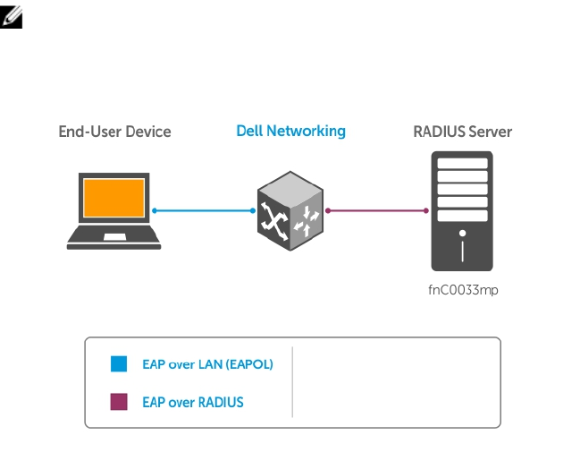
5
802.1X
802.1X is a method of port security. A device connected to a port that is enabled with 802.1X is
disallowed from sending or receiving packets on the network until its identity can be verified (through a
username and password, for example). This feature is named for its IEEE specification.
802.1X employs extensible authentication protocol (EAP) to transfer a device’s credentials to an
authentication server (typically RADIUS) using a mandatory intermediary network access device, in this
case, a Dell Networking switch. The network access device mediates all communication between the
end-user device and the authentication server so that the network remains secure. The network access
device uses EAP-over-Ethernet (EAPOL) to communicate with the end-user device and EAP-over-
RADIUS to communicate with the server.
NOTE: The Dell Networking OS supports 802.1X with EAP-MD5, EAP-OTP, EAP-TLS, EAP-TTLS,
PEAPv0, PEAPv1, and MS-CHAPv2 with PEAP.
The following figures show how the EAP frames are encapsulated in Ethernet and RADIUS frames.
Figure 2. EAP Frames Encapsulated in Ethernet and RADUIS
802.1X 75

Figure 3. EAP Frames Encapsulated in Ethernet and RADUIS
The authentication process involves three devices:
• The device attempting to access the network is the supplicant. The supplicant is not allowed to
communicate on the network until the authenticator authorizes the port. It can only communicate
with the authenticator in response to 802.1X requests.
• The device with which the supplicant communicates is the authenticator. The authenticator is the
gate keeper of the network. It translates and forwards requests and responses between the
authentication server and the supplicant. The authenticator also changes the status of the port based
on the results of the authentication process. The Dell Networking switch is the authenticator.
• The authentication-server selects the authentication method, verifies the information the supplicant
provides, and grants it network access privileges.
Ports can be in one of two states:
• Ports are in an unauthorized state by default. In this state, non-802.1X traffic cannot be forwarded in
or out of the port.
• The authenticator changes the port state to authorized if the server can authenticate the supplicant.
In this state, network traffic can be forwarded normally.
NOTE: The Z9500 places 802.1X-enabled ports in the unauthorized state by default.
The Port-Authentication Process
The authentication process begins when the authenticator senses that a link status has changed from
down to up:
1. When the authenticator senses a link state change, it requests that the supplicant identify itself using
an EAP Identity Request frame.
2. The supplicant responds with its identity in an EAP Response Identity frame.
3. The authenticator decapsulates the EAP response from the EAPOL frame, encapsulates it in a
RADIUS Access-Request frame and forwards the frame to the authentication server.
76 802.1X
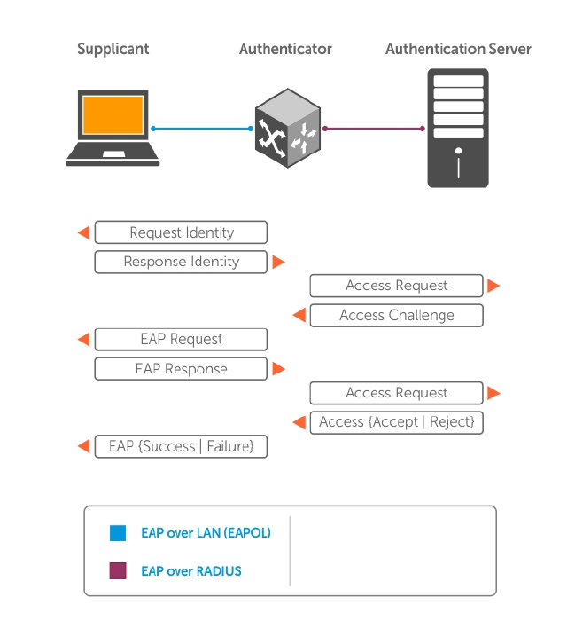
4. The authentication server replies with an Access-Challenge frame. The Access-Challenge frame
requests that the supplicant prove that it is who it claims to be, using a specified method (an EAP-
Method). The challenge is translated and forwarded to the supplicant by the authenticator.
5. The supplicant can negotiate the authentication method, but if it is acceptable, the supplicant
provides the Requested Challenge information in an EAP response, which is translated and
forwarded to the authentication server as another Access-Request frame.
6. If the identity information provided by the supplicant is valid, the authentication server sends an
Access-Accept frame in which network privileges are specified. The authenticator changes the port
state to authorized and forwards an EAP Success frame. If the identity information is invalid, the
server sends an Access-Reject frame. If the port state remains unauthorized, the authenticator
forwards an EAP Failure frame.
Figure 4. EAP Port-Authentication
EAP over RADIUS
802.1X uses RADIUS to shuttle EAP packets between the authenticator and the authentication server, as
defined in RFC 3579.
EAP messages are encapsulated in RADIUS packets as a type of attribute in Type, Length, Value (TLV)
format. The Type value for EAP messages is 79.
802.1X 77
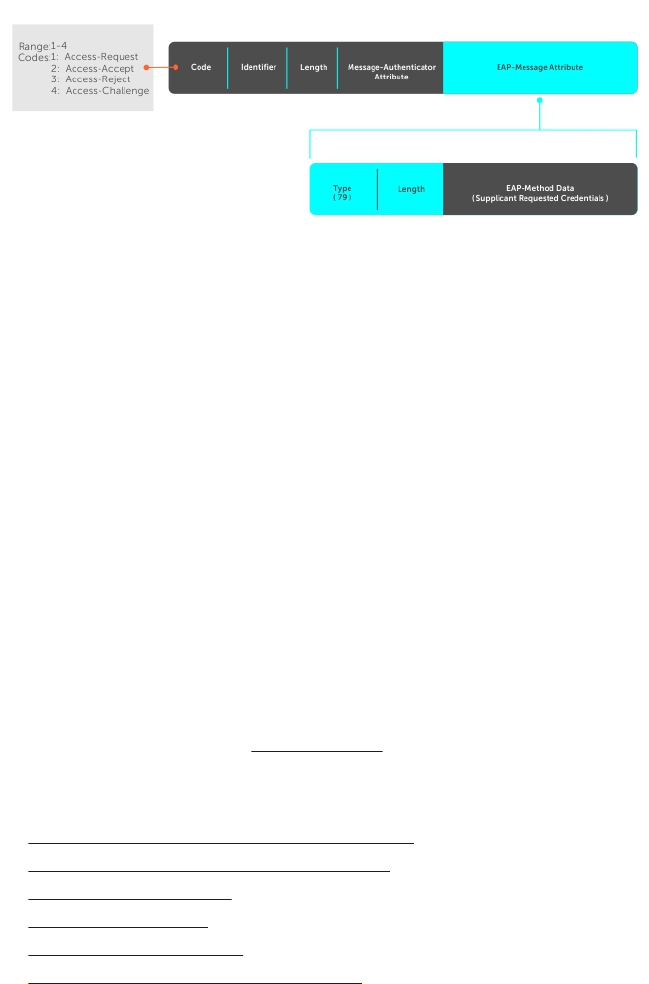
Figure 5. EAP Over RADIUS
RADIUS Attributes for 802.1 Support
Dell Networking systems include the following RADIUS attributes in all 802.1X-triggered Access-Request
messages:
Attribute 31 Calling-station-id: relays the supplicant MAC address to the authentication server.
Attribute 41 NAS-Port-Type: NAS-port physical port type. 15 indicates Ethernet.
Attribute 61 NAS-Port: the physical port number by which the authenticator is connected to
the supplicant.
Attribute 81 Tunnel-Private-Group-ID: associate a tunneled session with a particular group of
users.
Configuring 802.1X
Configuring 802.1X on a port is a one-step process.
For more information, refer to Enabling 802.1X.
Related Configuration Tasks
•Configuring Request Identity Re-Transmissions
•Forcibly Authorizing or Unauthorizing a Port
•Re-Authenticating a Port
•Configuring Timeouts
•Configuring a Guest VLAN
•Configuring an Authentication-Fail VLAN
Important Points to Remember
• The system supports 802.1X with EAP-MD5, EAP-OTP, EAP-TLS, EAP-TTLS, PEAPv0, PEAPv1, and MS-
CHAPv2 with PEAP.
• All platforms support only RADIUS as the authentication server.
• If the primary RADIUS server becomes unresponsive, the authenticator begins using a secondary
RADIUS server, if configured.
78 802.1X
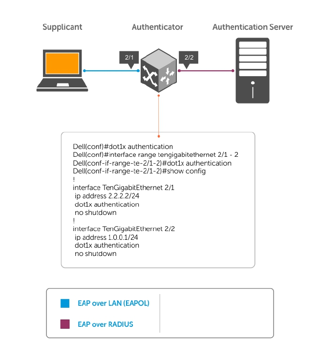
• 802.1X is not supported on port-channels or port-channel members.
Enabling 802.1X
Enable 802.1X globally.
Figure 6. 802.1X Enabled
1. Enable 802.1X globally.
CONFIGURATION mode
dot1x authentication
2. Enter INTERFACE mode on an interface or a range of interfaces.
INTERFACE mode
interface [range]
3. Enable 802.1X on the supplicant interface only.
INTERFACE mode
dot1x authentication
802.1X 79

Examples of Verifying that 802.1X is Enabled Globally or on an Interface
Verify that 802.1X is enabled globally and at the interface level using the show running-config |
find dot1x command from EXEC Privilege mode.
The bold lines show that 802.1X is enabled.
Dell#show running-config | find dot1x
dot1x authentication
!
[output omitted]
!
interface TenGigabitEthernet 2/1
no ip address
dot1x authentication
no shutdown
!
Dell#
View 802.1X configuration information for an interface using the show dot1x interface command.
The bold lines show that 802.1X is enabled on all ports unauthorized by default.
Dell#show dot1x interface TenGigabitEthernet 2/1
802.1x information on Te 2/1:
-----------------------------
Dot1x Status: Enable
Port Control: AUTO
Port Auth Status: UNAUTHORIZED
Re-Authentication: Disable
Untagged VLAN id: None
Guest VLAN: Disable
Guest VLAN id: NONE
Auth-Fail VLAN: Disable
Auth-Fail VLAN id: NONE
Auth-Fail Max-Attempts: NONE
Mac-Auth-Bypass: Disable
Mac-Auth-Bypass Only: Disable
Tx Period: 30 seconds
Quiet Period: 60 seconds
ReAuth Max: 2
Supplicant Timeout: 30 seconds
Server Timeout: 30 seconds
Re-Auth Interval: 3600 seconds
Max-EAP-Req: 2
Host Mode: SINGLE_HOST
Auth PAE State: Initialize
Backend State: Initialize
Configuring Request Identity Re-Transmissions
If the authenticator sends a Request Identity frame, but the supplicant does not respond, the
authenticator waits 30 seconds and then re-transmits the frame.
The amount of time that the authenticator waits before re-transmitting and the maximum number of
times that the authenticator re-transmits are configurable.
NOTE: There are several reasons why the supplicant might fail to respond; for example, the
supplicant might have been booting when the request arrived or there might be a physical layer
problem.
80 802.1X

To configure re-transmissions, use the following commands.
• Configure the amount of time that the authenticator waits before re-transmitting an EAP Request
Identity frame.
INTERFACE mode
dot1x tx-period number
The range is from 1 to 65535 (1 year)
The default is 30.
• Configure a maximum number of times the authenticator re-transmits a Request Identity frame.
INTERFACE mode
dot1x max-eap-req number
The range is from 1 to 10.
The default is 2.
The example in Configuring a Quiet Period after a Failed Authentication shows configuration information
for a port for which the authenticator re-transmits an EAP Request Identity frame after 90 seconds and
re-transmits a maximum of 10 times.
Configuring a Quiet Period after a Failed Authentication
If the supplicant fails the authentication process, the authenticator sends another Request Identity frame
after 30 seconds by default, but you can configure this period.
NOTE: The quiet period (dot1x quiet-period) is a transmit interval for after a failed
authentication; the Request Identity Re-transmit interval (dot1x tx-period) is for an unresponsive
supplicant.
To configure a quiet period, use the following command.
• Configure the amount of time that the authenticator waits to re-transmit a Request Identity frame
after a failed authentication.
INTERFACE mode
dot1x quiet-period seconds
The range is from 1 to 65535.
The default is 60 seconds.
Example of Configuring and Verifying Port Authentication
The following example shows configuration information for a port for which the authenticator re-
transmits an EAP Request Identity frame:
• after 90 seconds and a maximum of 10 times for an unresponsive supplicant
• re-transmits an EAP Request Identity frame
802.1X 81

The bold lines show the new re-transmit interval, new quiet period, and new maximum re-transmissions.
Dell(conf-if-range-Te-0/0)#dot1x tx-period 90
Dell(conf-if-range-Te-0/0)#dot1x max-eap-req 10
Dell(conf-if-range-Te-0/0)#dot1x quiet-period 120
Dell#show dot1x interface TenGigabitEthernet 2/1
802.1x information on Te 2/1:
-----------------------------
Dot1x Status: Enable
Port Control: AUTO
Port Auth Status: UNAUTHORIZED
Re-Authentication: Disable
Untagged VLAN id: None
Tx Period: 90 seconds
Quiet Period: 120 seconds
ReAuth Max: 2
Supplicant Timeout: 30 seconds
Server Timeout: 30 seconds
Re-Auth Interval: 3600 seconds
Max-EAP-Req: 10
Auth Type: SINGLE_HOST
Auth PAE State: Initialize
Backend State: Initialize
Forcibly Authorizing or Unauthorizing a Port
IEEE 802.1X requires that a port can be manually placed into any of three states:
•ForceAuthorized — an authorized state. A device connected to this port in this state is never
subjected to the authentication process, but is allowed to communicate on the network. Placing the
port in this state is same as disabling 802.1X on the port.
•ForceUnauthorized — an unauthorized state. A device connected to a port in this state is never
subjected to the authentication process and is not allowed to communicate on the network. Placing
the port in this state is the same as shutting down the port. Any attempt by the supplicant to initiate
authentication is ignored.
•Auto — an unauthorized state by default. A device connected to this port in this state is subjected to
the authentication process. If the process is successful, the port is authorized and the connected
device can communicate on the network. All ports are placed in the Auto state by default.
To set the port state, use the following command.
• Place a port in the ForceAuthorized, ForceUnauthorized, or Auto state.
INTERFACE mode
dot1x port-control {force-authorized | force-unauthorized | auto}
The default state is auto.
Example of Placing a Port in Force-Authorized State and Viewing the Configuration
The example shows configuration information for a port that has been force-authorized.
The bold line shows the new port-control state.
Dell(conf-if-Te-0/0)#dot1x port-control force-authorized
Dell(conf-if-Te-0/0)#show dot1x interface TenGigabitEthernet 0/0
802.1x information on Te 0/0:
82 802.1X

-----------------------------
Dot1x Status: Enable
Port Control: FORCE_AUTHORIZED
Port Auth Status: UNAUTHORIZED
Re-Authentication: Disable
Untagged VLAN id: None
Tx Period: 90 seconds
Quiet Period: 120 seconds
ReAuth Max: 2
Supplicant Timeout: 30 seconds
Server Timeout: 30 seconds
Re-Auth Interval: 3600 seconds
Max-EAP-Req: 10
Auth Type: SINGLE_HOST
Auth PAE State: Initialize
Backend State: Initialize
Auth PAE State: Initialize
Backend State: Initialize
Re-Authenticating a Port
You can configure the authenticator for periodic re-authentication.
After the supplicant has been authenticated, and the port has been authorized, you can configure the
authenticator to re-authenticate the supplicant periodically. If you enable re-authentication, the
supplicant is required to re-authenticate every 3600 seconds, but you can configure this interval. You can
configure a maximum number of re-authentications as well.
To configure re-authentication time settings, use the following commands.
• Configure the authenticator to periodically re-authenticate the supplicant.
INTERFACE mode
dot1x reauthentication [interval] seconds
The range is from 1 to 65535.
The default is 3600.
• Configure the maximum number of times that the supplicant can be re-authenticated.
INTERFACE mode
dot1x reauth-max number
The range is from 1 to 10.
The default is 2.
Example of Re-Authenticating a Port and Verifying the Configuration
The bold lines show that re-authentication is enabled and the new maximum and re-authentication time
period.
Dell(conf-if-Te-0/0)#dot1x reauthentication interval 7200
Dell(conf-if-Te-0/0)#dot1x reauth-max 10
Dell(conf-if-Te-0/0)#do show dot1x interface TenGigabitEthernet 0/0
802.1x information on Te 0/0:
-----------------------------
Dot1x Status: Enable
802.1X 83

Port Control: FORCE_AUTHORIZED
Port Auth Status: UNAUTHORIZED
Re-Authentication: Enable
Untagged VLAN id: None
Tx Period: 90 seconds
Quiet Period: 120 seconds
ReAuth Max: 10
Supplicant Timeout: 30 seconds
Server Timeout: 30 seconds
Re-Auth Interval: 7200 seconds
Max-EAP-Req: 10
Auth Type: SINGLE_HOST
Auth PAE State: Initialize
Backend State: Initialize
Auth PAE State: Initialize
Backend State: Initialize
Configuring Timeouts
If the supplicant or the authentication server is unresponsive, the authenticator terminates the
authentication process after 30 seconds by default. You can configure the amount of time the
authenticator waits for a response.
To terminate the authentication process, use the following commands.
• Terminate the authentication process due to an unresponsive supplicant.
INTERFACE mode
dot1x supplicant-timeout seconds
The range is from 1 to 300.
The default is 30.
• Terminate the authentication process due to an unresponsive authentication server.
INTERFACE mode
dot1x server-timeout seconds
The range is from 1 to 300.
The default is 30.
Example of Viewing Configured Server Timeouts
The example shows configuration information for a port for which the authenticator terminates the
authentication process for an unresponsive supplicant or server after 15 seconds.
The bold lines show the new supplicant and server timeouts.
Dell(conf-if-Te-0/0)#dot1x port-control force-authorized
Dell(conf-if-Te-0/0)#do show dot1x interface TenGigabitEthernet 0/0
802.1x information on Te 0/0:
-----------------------------
Dot1x Status: Enable
Port Control: FORCE_AUTHORIZED
Port Auth Status: UNAUTHORIZED
Re-Authentication: Disable
Untagged VLAN id: None
84 802.1X

Guest VLAN: Disable
Guest VLAN id: NONE
Auth-Fail VLAN: Disable
Auth-Fail VLAN id: NONE
Auth-Fail Max-Attempts: NONE
Tx Period: 90 seconds
Quiet Period: 120 seconds
ReAuth Max: 10
Supplicant Timeout: 15 seconds
Server Timeout: 15 seconds
Re-Auth Interval: 7200 seconds
Max-EAP-Req: 10
Auth Type: SINGLE_HOST
Auth PAE State: Initialize
Backend State: Initialize
Enter the tasks the user should do after finishing this task (optional).
Configuring Dynamic VLAN Assignment with Port
Authentication
On the Z9500, 802.1X authentication supports dynamic VLAN assignment.
The basis for VLAN assignment is RADIUS attribute 81, Tunnel-Private-Group-ID. Dynamic VLAN
assignment uses the standard dot1x procedure:
1. The host sends a dot1x packet to the Dell Networking system
2. The system forwards a RADIUS REQEST packet containing the host MAC address and ingress port
number
3. The RADIUS server authenticates the request and returns a RADIUS ACCEPT message with the VLAN
assignment using Tunnel-Private-Group-ID
The illustration shows the configuration before connecting the end user device in black and blue text,
and after connecting the device in red text. The blue text corresponds to the preceding numbered steps
on dynamic VLAN assignment with 802.1X.
802.1X 85
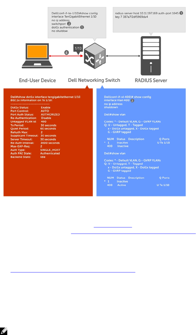
Figure 7. Dynamic VLAN Assignment
1. Configure 8021.x globally (refer to Enabling 802.1X) along with relevant RADIUS server configurations
(refer to the illustration inDynamic VLAN Assignment with Port Authentication).
2. Make the interface a switchport so that it can be assigned to a VLAN.
3. Create the VLAN to which the interface will be assigned.
4. Connect the supplicant to the port configured for 802.1X.
5. Verify that the port has been authorized and placed in the desired VLAN (refer to the illustration in
Dynamic VLAN Assignment with Port Authentication).
Guest and Authentication-Fail VLANs
Typically, the authenticator (the Dell system) denies the supplicant access to the network until the
supplicant is authenticated. If the supplicant is authenticated, the authenticator enables the port and
places it in either the VLAN for which the port is configured or the VLAN that the authentication server
indicates in the authentication data.
NOTE: Ports cannot be dynamically assigned to the default VLAN.
86 802.1X

If the supplicant fails authentication, the authenticator typically does not enable the port. In some cases
this behavior is not appropriate. External users of an enterprise network, for example, might not be able
to be authenticated, but still need access to the network. Also, some dumb-terminals, such as network
printers, do not have 802.1X capability and therefore cannot authenticate themselves. To be able to
connect such devices, they must be allowed access the network without compromising network security.
The Guest VLAN 802.1X extension addresses this limitation with regard to non-802.1X capable devices
and the Authentication-fail VLAN 802.1X extension addresses this limitation with regard to external users.
• If the supplicant fails authentication a specified number of times, the authenticator places the port in
the Authentication-fail VLAN.
• If a port is already forwarding on the Guest VLAN when 802.1X is enabled, the port is moved out of
the Guest VLAN and the authentication process begins.
Configuring a Guest VLAN
If the supplicant does not respond within a determined amount of time ([reauth-max + 1] * tx-period, the
system assumes that the host does not have 802.1X capability and the port is placed in the Guest VLAN.
NOTE: For more information about configuring timeouts, refer to Configuring Timeouts.
Configure a port to be placed in the Guest VLAN after failing to respond within the timeout period using
the dot1x guest-vlan command from INTERFACE mode. View your configuration using the show
config command from INTERFACE mode or using the show dot1x interface command from EXEC
Privilege mode.
Example of Viewing Guest VLAN Configuration
Dell(conf-if-Te-2/1)#dot1x guest-vlan 200
Dell(conf-if-Te 2/1))#show config
!
interface TenGigabitEthernet 21
switchport
dot1x guest-vlan 200
no shutdown
Dell(conf-if-Te 2/1))#
Configuring an Authentication-Fail VLAN
If the supplicant fails authentication, the authenticator re-attempts to authenticate after a specified
amount of time.
NOTE: For more information about authenticator re-attempts, refer to Configuring a Quiet Period
after a Failed Authentication.
You can configure the maximum number of times the authenticator re-attempts authentication after a
failure (3 by default), after which the port is placed in the Authentication-fail VLAN.
Configure a port to be placed in the VLAN after failing the authentication process as specified number of
times using the dot1x auth-fail-vlan command from INTERFACE mode. Configure the maximum
number of authentication attempts by the authenticator using the keyword max-attempts with this
command.
Example of Configuring Maximum Authentication Attempts
Dell(conf-if-Te-2/1)#dot1x guest-vlan 200
Dell(conf-if-Te 2/1)#show config
802.1X 87

!
interface TenGigabitEthernet 2/1
switchport
dot1x authentication
dot1x guest-vlan 200
no shutdown
Dell(conf-if-Te-2/1)#
Dell(conf-if-Te-2/1)#dot1x auth-fail-vlan 100 max-attempts 5
Dell(conf-if-Te-2/1)#show config
!
interface TenGigabitEthernet 2/1
switchport
dot1x authentication
dot1x guest-vlan 200
dot1x auth-fail-vlan 100 max-attempts 5
no shutdown
Dell(conf-if-Te-2/1)#
View your configuration using the show config command from INTERFACE mode, as shown in the
example in Configuring a Guest VLAN or using the show dot1x interface command from EXEC
Privilege mode.
Example of Viewing Configured Authentication
802.1x information on Te 2/1:
-----------------------------
Dot1x Status: Enable
Port Control: FORCE_AUTHORIZED
Port Auth Status: UNAUTHORIZED
Re-Authentication: Disable
Untagged VLAN id: None
Guest VLAN: Disabled
Guest VLAN id: 200
Auth-Fail VLAN: Disabled
Auth-Fail VLAN id: 100
Auth-Fail Max-Attempts: 5
Tx Period: 90 seconds
Quiet Period: 120 seconds
ReAuth Max: 10
Supplicant Timeout: 15 seconds
Server Timeout: 15 seconds
Re-Auth Interval: 7200 seconds
Max-EAP-Req: 10
Auth Type: SINGLE_HOST
Auth PAE State: Initialize
Backend State: Initialize
88 802.1X

6
Access Control Lists (ACLs)
This chapter describes access control lists (ACLs), prefix lists, and route-maps.
• Access control lists (ACLs), Ingress IP and MAC ACLs , and Egress IP and MAC ACLs are supported on
the Z9500.
At their simplest, access control lists (ACLs), prefix lists, and route-maps permit or deny traffic based on
MAC and/or IP addresses. This chapter describes implementing IP ACLs, IP prefix lists and route-maps.
For MAC ACLS, refer to Layer 2.
An ACL is essentially a filter containing some criteria to match (examine IP, transmission control protocol
[TCP], or user datagram protocol [UDP] packets) and an action to take (permit or deny). ACLs are
processed in sequence so that if a packet does not match the criterion in the first filter, the second filter
(if configured) is applied. When a packet matches a filter, the switch drops or forwards the packet based
on the filter’s specified action. If the packet does not match any of the filters in the ACL, the packet is
dropped (implicit deny).
The number of ACLs supported on a system depends on your content addressable memory (CAM) size.
For more information, refer to User Configurable CAM Allocation and CAM Optimization. For complete
CAM profiling information, refer to Content Addressable Memory (CAM).
IP Access Control Lists (ACLs)
You can create two different types of IP ACLs: standard or extended.
A standard ACL filters packets based on the source IP packet. An extended ACL filters traffic based on the
following criteria:
• IP protocol number
• Source IP address
• Destination IP address
• Source TCP port number
• Destination TCP port number
• Source UDP port number
• Destination UDP port number
For more information about ACL options, refer to the Dell Networking OS Command Reference Guide.
For extended ACL, TCP, and UDP filters, you can match criteria on specific or ranges of TCP or UDP
ports. For extended ACL TCP filters, you can also match criteria on established TCP sessions.
When creating an access list, the sequence of the filters is important. You have a choice of assigning
sequence numbers to the filters as you enter them, or the system assigns numbers in the order the filters
are created. The sequence numbers are listed in the display output of the show config and show ip
accounting access-list commands.
Access Control Lists (ACLs) 89

Ingress and egress Hot Lock ACLs allow you to append or delete new rules into an existing ACL (already
written into CAM) without disrupting traffic flow. Existing entries in the CAM are shuffled to
accommodate the new entries. Hot lock ACLs are enabled by default and support both standard and
extended ACLs and on all platforms.
NOTE: Hot lock ACLs are supported for Ingress ACLs only.
CAM Usage
The following section describes CAM allocation and CAM optimization.
•User Configurable CAM Allocation
•CAM Optimization
User-Configurable CAM Allocation
User-configurable content-addressable memory (CAM) allows you to specify the amount of memory
space that you want to allocate for ACLs.
To allocate ACL CAM, use the cam-acl command in CONFIGURATION mode. For information about
how to allocate CAM for ACL VLANs, see Allocating ACL VLAN CAM.
The CAM space is allotted in filter processor (FP) blocks. The total space allocated must equal 13 FP
blocks. (There are 16 FP blocks, but System Flow requires three blocks that cannot be reallocated.)
Enter the allocation as a factor of 2 (2, 4, 6, 8, 10). All other profile allocations can use either even or odd
numbered ranges.
Save the new CAM settings to the startup-config (use write-mem or copy run start) then reload the
system for the new settings to take effect.
Test CAM Usage
The test cam-usage command is supported on the Z9500.
This command applies to both IPv4 and IPv6 CAM profiles, but is best used when verifying QoS
optimization for IPv6 ACLs.
To determine whether sufficient ACL CAM space is available to enable a service-policy, use this
command. To verify the actual CAM space required, create a class map with all the required ACL rules,
then execute the test cam-usage command in Privilege mode. The following example shows the
output when executing this command. The status column indicates whether you can enable the policy.
Example of the test cam-usage Command
Dell#test cam-usage service-policy input TestPolicy linecard all
Linecard|Portpipe|CAM Partition|Available CAM|Estimated CAM per Port|Status
--------------------------------------------------------------------------
2| 1| IPv4Flow| 232| 0|Allowed
2| 1| IPv6Flow| 0| 0|Allowed
4| 0| IPv4Flow| 232| 0|Allowed
4| 0| IPv6Flow| 0| 0|Allowed
Dell#
90 Access Control Lists (ACLs)
Implementing ACLs
You can assign one IP ACL per physical or VLAN interface. If you do not assign an IP ACL to an interface,
it is not used by the software in any other capacity.
The number of entries allowed per ACL is hardware-dependent.
If you enable counters on IP ACL rules that are already configured, those counters are reset when a new
rule is inserted or prepended. If a rule is appended, the existing counters are not affected. This is
applicable to the following features:
• L2 Ingress Access list
• L2 Egress Access list
• L3 Egress Access list
ACLs and VLANs
There are some differences when assigning ACLs to a VLAN rather than a physical port.
For example, when using a single port-pipe, if you apply an ACL to a VLAN, one copy of the ACL entries is
installed in the ACL CAM on the port-pipe. The entry looks for the incoming VLAN in the packet. Whereas
if you apply an ACL on individual ports of a VLAN, separate copies of the ACL entries are installed for each
port belonging to a port-pipe.
When you use the log keyword, the CP has to log the details about the packets that match. Depending
on how many packets match the log entry and at what rate, the CP might become busy as it has to log
these packets’ details. However, the Route Processor (RP) is unaffected. This option is typically useful
when debugging some problem related to control traffic. We have used this option numerous times in
the field and have not encountered problems so far.
ACL Optimization
If an access list contains duplicate entries, the system deletes one entry to conserve CAM space.
Standard and extended ACLs take up the same amount of CAM space. A single ACL rule uses two CAM
entries whether it is identified as a standard or extended ACL.
Determine the Order in which ACLs are Used to Classify Traffic
When you link class-maps to queues using the service-queue command, the system matches the
class-maps according to queue priority (queue numbers closer to 0 have lower priorities).
As shown in the following example, class-map cmap2 is matched against ingress packets before cmap1.
ACLs acl1 and acl2 have overlapping rules because the address range 20.1.1.0/24 is within 20.0.0.0/8.
Therefore (without the keyword order), packets within the range 20.1.1.0/24 match positive against
cmap1 and are buffered in queue 7, though you intended for these packets to match positive against
cmap2 and be buffered in queue 4.
In cases such as these, where class-maps with overlapping ACL rules are applied to different queues, use
the order keyword to specify the order in which you want to apply ACL rules. The order can range from
0 to 254. The system writes to the CAM ACL rules with lower-order numbers (order numbers closer to 0)
before rules with higher-order numbers so that packets are matched as you intended. By default, all ACL
rules have an order of 254.
Access Control Lists (ACLs) 91

Example of the order Keyword to Determine ACL Sequence
Dell(conf)#ip access-list standard acl1
Dell(config-std-nacl)#permit 20.0.0.0/8
Dell(config-std-nacl)#exit
Dell(conf)#ip access-list standard acl2
Dell(config-std-nacl)#permit 20.1.1.0/24 order 0
Dell(config-std-nacl)#exit
Dell(conf)#class-map match-all cmap1
Dell(conf-class-map)#match ip access-group acl1
Dell(conf-class-map)#exit
Dell(conf)#class-map match-all cmap2
Dell(conf-class-map)#match ip access-group acl2
Dell(conf-class-map)#exit
Dell(conf)#policy-map-input pmap
Dell(conf-policy-map-in)#service-queue 7 class-map cmap1
Dell(conf-policy-map-in)#service-queue 4 class-map cmap2
Dell(conf-policy-map-in)#exit
Dell(conf)#interface tengig 1/0
Dell(conf-if-te-1/0)#service-policy input pmap
IP Fragment Handling
The system supports a configurable option to explicitly deny IP fragmented packets, particularly second
and subsequent packets.
It extends the existing ACL command syntax with the fragments keyword for all Layer 3 rules applicable
to all Layer protocols (permit/deny ip/tcp/udp/icmp).
• Both standard and extended ACLs support IP fragments.
• Second and subsequent fragments are allowed because a Layer 4 rule cannot be applied to these
fragments. If the packet is to be denied eventually, the first fragment would be denied and hence the
packet as a whole cannot be reassembled.
• Implementing the required rules uses a significant number of CAM entries per TCP/UDP entry.
• For an IP ACL, the system always applies implicit deny. You do not have to configure it.
• For an IP ACL, the system applies implicit permit for second and subsequent fragment just prior to the
implicit deny.
• If you configure an explicit deny, the second and subsequent fragments do not hit the implicit permit
rule for fragments.
• Loopback interfaces do not support ACLs using the IP fragment option. If you configure an ACL
with the fragments option and apply it to a Loopback interface, the command is accepted but the
ACL entries are not actually installed the offending rule in CAM.
IP Fragments ACL Examples
The following examples show how you can use ACL commands with the fragment keyword to filter
fragmented packets.
Example of Permitting All Packets on an Interface
The following configuration permits all packets (both fragmented and non-fragmented) with destination
IP 10.1.1.1. The second rule does not get hit at all.
Dell(conf)#ip access-list extended ABC
Dell(conf-ext-nacl)#permit ip any 10.1.1.1/32Dell(conf-ext-nacl)#deny ip any
10.1.1.1./32 fragments
Dell(conf-ext-nacl)
92 Access Control Lists (ACLs)

Example of Denying Second and Subsequent Fragments
To deny the second/subsequent fragments, use the same rules in a different order. These ACLs deny all
second and subsequent fragments with destination IP 10.1.1.1 but permit the first fragment and non-
fragmented packets with destination IP 10.1.1.1.
Dell(conf)#ip access-list extended ABC
Dell(conf-ext-nacl)#deny ip any 10.1.1.1/32 fragments
Dell(conf-ext-nacl)#permit ip any 10.1.1.1/32
Dell(conf-ext-nacl)
Layer 4 ACL Rules Examples
The following examples show the ACL commands for Layer 4 packet filtering.
Permit an ACL line with L3 information only, and the fragments keyword is present:
If a packet’s L3 information matches the L3 information in the ACL line, the packet's FO is checked.
• If a packet's FO > 0, the packet is permitted.
• If a packet's FO = 0, the next ACL entry is processed.
Deny ACL line with L3 information only, and the fragments keyword is present:
If a packet's L3 information does match the L3 information in the ACL line, the packet's FO is checked.
• If a packet's FO > 0, the packet is denied.
• If a packet's FO = 0, the next ACL line is processed.
Example of Permitting All Packets from a Specified Host
In this first example, TCP packets from host 10.1.1.1 with TCP destination port equal to 24 are permitted.
All others are denied.
Dell(conf)#ip access-list extended ABC
Dell(conf-ext-nacl)#permit tcp host 10.1.1.1 any eq 24
Dell(conf-ext-nacl)#deny ip any any fragment
Dell(conf-ext-nacl)
Example of Permitting Only First Fragments and Non-Fragmented Packets from a Specified Host
In the following example, the TCP packets that are first fragments or non-fragmented from host 10.1.1.1
with TCP destination port equal to 24 are permitted. Additionally, all TCP non-first fragments from host
10.1.1.1 are permitted. All other IP packets that are non-first fragments are denied.
Dell(conf)#ip access-list extended ABC
Dell(conf-ext-nacl)#permit tcp host 10.1.1.1 any eq 24
Dell(conf-ext-nacl)#permit tcp host 10.1.1.1 any fragment
Dell(conf-ext-nacl)#deny ip any any fragment
Dell(conf-ext-nacl)
Example of Logging Denied Packets
To log all the packets denied and to override the implicit deny rule and the implicit permit rule for TCP/
UDP fragments, use a configuration similar to the following.
Dell(conf)#ip access-list extended ABC
Dell(conf-ext-nacl)#permit tcp any any fragment
Dell(conf-ext-nacl)#permit udp any any fragment
Dell(conf-ext-nacl)#deny ip any any log
Dell(conf-ext-nacl)
When configuring ACLs with the fragments keyword, be aware of the following.
Access Control Lists (ACLs) 93

When an ACL filters packets, it looks at the fragment offset (FO) to determine whether it is a fragment.
• FO = 0 means it is either the first fragment or the packet is a non-fragment.
• FO > 0 means it is dealing with the fragments of the original packet.
Configure a Standard IP ACL
To configure an ACL, use commands in IP ACCESS LIST mode and INTERFACE mode.
For a complete list of all the commands related to IP ACLs, refer to the Dell Networking OS Command
Line Interface Reference Guide. To set up extended ACLs, refer to Configure an Extended IP ACL.
A standard IP ACL uses the source IP address as its match criterion.
1. Enter IP ACCESS LIST mode by naming a standard IP access list.
CONFIGURATION mode
ip access-list standard access-listname
2. Configure a drop or forward filter.
CONFIG-STD-NACL mode
seq sequence-number {deny | permit} {source [mask] | any | host ip-address}
[count [byte]] [order] [fragments]
NOTE: When assigning sequence numbers to filters, keep in mind that you might need to insert a
new filter. To prevent reconfiguring multiple filters, assign sequence numbers in multiples of five.
When you use the log keyword, the CP logs details about the packets that match. Depending on how
many packets match the log entry and at what rate, the CP may become busy as it has to log these
packets’ details.
To view the rules of a particular ACL configured on a particular interface, use the show ip accounting
access-list ACL-name interface interface command in EXEC Privilege mode.
Examples of Using a Standard IP ACL
The following example shows viewing the rules of a specific ACL on an interface.
Dell#show ip accounting access-list ToOspf interface gig 1/6
Standard IP access list ToOspf
seq 5 deny any
seq 10 deny 10.2.0.0 /16
seq 15 deny 10.3.0.0 /16
seq 20 deny 10.4.0.0 /16
seq 25 deny 10.5.0.0 /16
seq 30 deny 10.6.0.0 /16
seq 35 deny 10.7.0.0 /16
seq 40 deny 10.8.0.0 /16
seq 45 deny 10.9.0.0 /16
seq 50 deny 10.10.0.0 /16
Dell#
The following example shows how the seq command orders the filters according to the sequence
number assigned. In the example, filter 25 was configured before filter 15, but the show config
command displays the filters in the correct order.
Dell(config-std-nacl)#seq 25 deny ip host 10.5.0.0 any log
Dell(config-std-nacl)#seq 15 permit tcp 10.3.0.0 /16 any
Dell(config-std-nacl)#show config
94 Access Control Lists (ACLs)

!
ip access-list standard dilling
seq 15 permit tcp 10.3.0.0/16 any
seq 25 deny ip host 10.5.0.0 any log
Dell(config-std-nacl)#
To delete a filter, use the no seq sequence-number command in IP ACCESS LIST mode.
Configuring a Standard IP ACL Filter
If you are creating a standard ACL with only one or two filters, you can let the system assign a sequence
number based on the order in which the filters are configured. The software assigns filters in multiples of
five.
1. Configure a standard IP ACL and assign it a unique name.
CONFIGURATION mode
ip access-list standard access-list-name
2. Configure a drop or forward IP ACL filter.
CONFIG-STD-NACL mode
{deny | permit} {source [mask] | any | host ip-address} [count [byte]]
[order] [fragments]
When you use the log keyword, the CP logs details about the packets that match. Depending on how
many packets match the log entry and at what rate, the CP may become busy as it has to log these
packets’ details.
The following example shows a standard IP ACL in which the system assigns the sequence numbers. The
filters were assigned sequence numbers based on the order in which they were configured (for example,
the first filter was given the lowest sequence number). The show config command in IP ACCESS LIST
mode displays the two filters with the sequence numbers 5 and 10.
Examples of Viewing Filter Sequence Standard ACLs
The following example shows viewing a filter sequence for a specified standard ACL.
Dell(config-route-map)#ip access standard kigali
Dell(config-std-nacl)#permit 10.1.0.0/16
Dell(config-std-nacl)#show config
!
ip access-list standard kigali
seq 5 permit 10.1.0.0/16 seq 10 deny tcp any any eq 111
Dell(config-std-nacl)#
To view all configured IP ACLs, use the show ip accounting access-list command in EXEC
Privilege mode.
Dell#show ip accounting access example interface gig 4/12
Extended IP access list example
seq 10 deny tcp any any eq 111
seq 15 deny udp any any eq 111
seq 20 deny udp any any eq 2049
seq 25 deny udp any any eq 31337
seq 30 deny tcp any any range 12345 12346
seq 35 permit udp host 10.21.126.225 10.4.5.0 /28
seq 40 permit udp host 10.21.126.226 10.4.5.0 /28
seq 45 permit udp 10.8.0.0 /16 10.50.188.118 /31 range 1812 1813
Access Control Lists (ACLs) 95

seq 50 permit tcp 10.8.0.0 /16 10.50.188.118 /31 eq 49
seq 55 permit udp 10.15.1.0 /24 10.50.188.118 /31 range 1812 1813
To delete a filter, enter the show config command in IP ACCESS LIST mode and locate the sequence
number of the filter you want to delete. Then use the no seq sequence-number command in IP
ACCESS LIST mode.
Configure an Extended IP ACL
Extended IP ACLs filter on source and destination IP addresses, IP host addresses, TCP addresses, TCP
host addresses, UDP addresses, and UDP host addresses.
Because traffic passes through the filter in the order of the filter’s sequence, you can configure the
extended IP ACL by first entering IP ACCESS LIST mode and then assigning a sequence number to the
filter.
Configuring Filters with a Sequence Number
To configure filters with a sequence number, use the following commands.
1. Enter IP ACCESS LIST mode by creating an extended IP ACL.
CONFIGURATION mode
ip access-list extended access-list-name
2. Configure a drop or forward filter.
CONFIG-EXT-NACL mode
seq sequence-number {deny | permit} {ip-protocol-number | icmp | ip | tcp |
udp} {source mask | any | host ip-address} {destination mask | any | host
ip-address} [operator port [port]] [count [byte]] [order] [fragments]
When you use the log keyword, the CP logs details about the packets that match. Depending on how
many packets match the log entry and at what rate, the CP may become busy as it has to log these
packets’ details.
Configure Filters, TCP Packets
To create a filter for TCP packets with a specified sequence number, use the following commands.
1. Create an extended IP ACL and assign it a unique name.
CONFIGURATION mode
ip access-list extended access-list-name
2. Configure an extended IP ACL filter for TCP packets.
CONFIG-EXT-NACL mode
seq sequence-number {deny | permit} tcp {source mask | any | host ip-
address}} [count [byte]] [order] [fragments]
Configure Filters, TCP Packets
To create a filter for UDP packets with a specified sequence number, use the following commands.
1. Create an extended IP ACL and assign it a unique name.
96 Access Control Lists (ACLs)

CONFIGURATION mode
ip access-list extended access-list-name
2. Configure an extended IP ACL filter for UDP packets.
CONFIG-EXT-NACL mode
seq sequence-number {deny | permit} tcp {source mask | any | host ip-
address}} [count [byte]] [order] [fragments]
Example of the seq Command
When you create the filters with a specific sequence number, you can create the filters in any order and
the filters are placed in the correct order.
NOTE: When assigning sequence numbers to filters, you may have to insert a new filter. To prevent
reconfiguring multiple filters, assign sequence numbers in multiples of five or another number.
The example below shows how the seq command orders the filters according to the sequence number
assigned. In the example, filter 15 was configured before filter 5, but the show config command
displays the filters in the correct order.
Dell(config-ext-nacl)#seq 15 deny ip host 112.45.0.0 any log
Dell(config-ext-nacl)#seq 5 permit tcp 12.1.3.45 0.0.255.255 any
Dell(config-ext-nacl)#show confi
!
ip access-list extended dilling
seq 5 permit tcp 12.1.0.0 0.0.255.255 any
seq 15 deny ip host 112.45.0.0 any log
Dell(config-ext-nacl)#
Configuring Filters Without a Sequence Number
If you are creating an extended ACL with only one or two filters, you can let the system assign a
sequence number based on the order in which the filters are configured. Filters are assigned in multiples
of five.
To configure a filter for an extended IP ACL without a specified sequence number, use any or all of the
following commands:
• Configure a deny or permit filter to examine IP packets.
CONFIG-EXT-NACL mode
{deny | permit} {source mask | any | host ip-address} [count [byte]] [order]
[fragments]
• Configure a deny or permit filter to examine TCP packets.
CONFIG-EXT-NACL mode
{deny | permit} tcp {source mask] | any | host ip-address}} [count [byte]]
[order] [fragments]
• Configure a deny or permit filter to examine UDP packets.
CONFIG-EXT-NACL mode
{deny | permit} udp {source mask | any | host ip-address}} [count [byte]]
[order] [fragments]
Access Control Lists (ACLs) 97

When you use the log keyword, the CP logs details about the packets that match. Depending on how
many packets match the log entry and at what rate, the CP may become busy as it has to log these
packets’ details.
The following example shows an extended IP ACL in which the sequence numbers were assigned by the
software. The filters were assigned sequence numbers based on the order in which they were configured
(for example, the first filter was given the lowest sequence number). The show config command in IP
ACCESS LIST mode displays the two filters with the sequence numbers 5 and 10.
Example of Viewing Filter Sequence for a Specified Extended ACL
Dell(config-ext-nacl)#deny tcp host 123.55.34.0 any
Dell(config-ext-nacl)#permit udp 154.44.123.34 0.0.255.255 host 34.6.0.0
Dell(config-ext-nacl)#show config
!
ip access-list extended nimule
seq 5 deny tcp host 123.55.34.0 any
seq 10 permit udp 154.44.0.0 0.0.255.255 host 34.6.0.0
Dell(config-ext-nacl)#
To view all configured IP ACLs and the number of packets processed through the ACL, use the show ip
accounting access-list command in EXEC Privilege mode, as shown in the first example in
Configure a Standard IP ACL Filter.
Configure Layer 2 and Layer 3 ACLs
Both Layer 2 and Layer 3 ACLs may be configured on an interface in Layer 2 mode.
If both L2 and L3 ACLs are applied to an interface, the following rules apply:
• When the system routes the packets, only the L3 ACL governs them because they are not filtered
against an L2 ACL.
• When the system switches the packets, first the L3 ACL filters them, then the L2 ACL filters them.
• When the system switches the packets, the egress L3 ACL does not filter the packet.
For the following features, if you enable counters on rules that have already been configured and a new
rule is either inserted or prepended, all the existing counters are reset:
• L2 ingress access list
• L3 egress access list
• L2 egress access list
If a rule is simply appended, existing counters are not affected.
Table 4. L2 and L3 Filtering on Switched Packets
L2 ACL Behavior L3 ACL Behavior Decision on Targeted Traffic
Deny Deny L3 ACL denies.
Deny Permit L3 ACL permits.
Permit Deny L3 ACL denies.
Permit Permit L3 ACL permits.
98 Access Control Lists (ACLs)

NOTE: If you configure an interface as a vlan-stack access port, only the L2 ACL filters the packets.
The L3 ACL applied to such a port does not affect traffic. That is, existing rules for other features
(such as trace-list, policy-based routing [PBR], and QoS) are applied to the permitted traffic.
For information about MAC ACLs, refer to Layer 2.
Using ACL VLAN Groups
Use an ACL VLAN group to optimize ACL CAM usage by minimizing the number of CAM entries when you
apply an egress IP ACL on the member interfaces of specified VLANs.
When you apply an ACL on individual VLANs, the amount of CAM space required increases greatly
because the ACL rules are saved for each VLAN ID. To avoid excessive use of the CAM space, you can
configure ACL VLAN groups to combine all VLANs on which ACL filtering criteria is applied in a single
class ID instead of multiple VLAN IDs.
NOTE: CAM optimization applies only when you use an ACL VLAN group; it does not apply if you
apply an ACL on individual VLANs.
Guidelines for Configuring ACL VLAN Groups
Keep the following points in mind when you configure ACL VLAN groups:
• The VLAN member interfaces, on which the ACL in an ACL VLAN group is applied, function as
restricted interfaces. The ACL VLAN group name identifies the group of VLANs on which hierarchical
filtering is performed.
• You can add only one ACL to an interface at a time.
• When you apply an ACL VLAN group to a member interface, an error message is displayed if an ACL
with different criteria has already been separately applied to the interface.
• The maximum number of members in an ACL VLAN group is determined by the type of switch and its
hardware capabilities. This scaling limit depends on the number of slices that are allocated for ACL
CAM optimization. If one slice is allocated, the maximum number of VLAN members is 256 for all ACL
VLAN groups. If two slices are allocated, the maximum number of VLAN members is 512 for all ACL
VLAN groups.
• The maximum number of VLAN groups that you can configure also depends on the hardware
specifications of the switch. Each VLAN group is mapped to a unique ID in the hardware. The
maximum number of ACL VLAN groups supported is 31. Only a maximum of two components (iSCSI
counters, Open Flow, ACL optimization) can be allocated virtual flow processing slices at a time.
• Port ACL optimization is applicable only for ACLs that are applied without the VLAN range.
• You cannot view the statistical details of ACL rules per VLAN and per interface if you enable the ACL
VLAN group capability. You can view the counters per ACL only by using the show ip accounting
access list command.
• On a port, you can apply Layer 2 ACLs on a VLAN or a set of VLANs. In this case, CAM optimization is
not applied.
• To enable optimization of CAM space for Layer 2 or Layer 3 ACLs that are applied to ports, the port
number is removed as a qualifier for ACL application on ports, and port bits are used. When you apply
the same ACL to a set of ports, the port bitmap is set when the ACL flow processor (FP) entry is added.
When you remove the ACL from a port, the port bitmap is removed.
• If you do not attach an ACL to any of the ports, the FP entries are deleted. Similarly, when the same
ACL is applied on a set of ports, only one set of entries is installed in the FP, thereby effectively saving
Access Control Lists (ACLs) 99

CAM space. The optimization is enabled only if you specify the optimized option with the ip
access-group command. This option is not valid for VLAN and LAG interfaces.
Configuring an ACL VLAN Group
Configure an ACL VLAN group to optimize ACL CAM use.
NOTE: After you configure an ACL VLAN group, you must allocate CAM memory for ACL VLAN
services to enable CAM optimization. See Allocating ACL VLAN CAM for more information.
1. Create an ACL VLAN group
CONFIGURATION mode
acl-vlan-group group-name
You can create up to eight different ACL VLAN groups.
2. Add a description.
ACL-VLAN-GROUP CONFIGURATION (conf-acl-vl-grp) mode
description description
3. Apply an egress IP ACL.
ACL-VLAN-GROUP CONFIGURATION (conf-acl-vl-grp) mode
ip access-group access-list-name out implicit-permit
4. Specify the VLAN members in the ACL VLAN group.
ACL-VLAN-GROUP CONFIGURATION (conf-acl-vl-grp) mode
member vlan vlan-range
5. Verify the currently configured ACL VLAN groups on the switch.
ACL-VLAN-GROUP CONFIGURATION (conf-acl-vl-grp) mode
show acl-vlan-group {group-name | detail}
Dell#show acl-vlan-group detail
Group Name :
TestGroupSeventeenTwenty
Egress IP Acl :
SpecialAccessOnlyExpertsAllowed
Vlan Members :
100,200,300
Group Name :
CustomerNumberIdentificationEleven
Egress IP Acl :
AnyEmployeeCustomerElevenGrantedAccess
Vlan Members :
2-10,99
Group Name :
HostGroup
Egress IP Acl :
Group5
Vlan Members :
1,1000
Dell#
100 Access Control Lists (ACLs)

Allocating ACL VLAN CAM
CAM optimization for ACL VLAN groups is not enabled by default. You must allocate blocks of ACL VLAN
CAM to enable ACL CAM optimization by using the cam-acl-vlan command.
By default, 0 blocks of CAM are allocated for VLAN services in the VLAN Content Aware Processor
(VCAP), an application that modifies VLAN settings before forwarding packets on member interfaces. The
cam-acl-vlan {vlanaclopt | vlaniscsi | vlanopenflow} command allows you to allocate
filter processor (FP) blocks of memory for ACL VLAN services: iSCSI counters, Open Flow, and ACL VLAN
optimization.
You can configure CAM allocation for only two of these VLAN services at a time. You can allocate from 0
to 2 FP blocks for each VLAN service.
To allocate the number of FP blocks for ACL VLAN optimization, enter the cam-acl-vlan vlanaclopt
<0-2> command. After you configure ACL VLAN CAM, reboot the switch to enable CAM allocation for
ACL VLAN optimization.
To display the number of FP blocks currently allocated to different ACL VLAN services, enter the show
cam-acl-vlan command.
To display the amount of CAM space currently used and available for Layer 2 and Layer 3 ACLs on the
switch, enter the show cam-usage command.
Applying an IP ACL to an Interface
To pass traffic through a configured IP ACL, assign that ACL to a physical interface, a port channel
interface, or a VLAN.
The IP ACL is applied to all traffic entering a physical or port channel interface and the traffic is either
forwarded or dropped depending on the criteria and actions specified in the ACL.
The same ACL may be applied to different interfaces and that changes its functionality. For example, you
can take ACL “ABCD” and apply it using the in keyword and it becomes an ingress access list. If you apply
the same ACL using the out keyword, it becomes an egress access list. If you apply the same ACL to the
Loopback interface, it becomes a Loopback access list.
For more information about Layer 3 interfaces, refer to Interfaces.
1. Enter the interface number.
CONFIGURATION mode
interface interface {slot/port | port-channel-number}
2. Configure an IP address for the interface, placing it in Layer 3 mode.
INTERFACE mode
ip address ip-address
3. Apply an IP ACL to traffic entering or exiting an interface.
INTERFACE mode
Access Control Lists (ACLs) 101

ip access-group access-list-name {in} [implicit-permit] [vlan vlan-range]
NOTE: The number of entries allowed per ACL is hardware-dependent. For detailed
specification about entries allowed per ACL, refer to your line card documentation.
4. Apply rules to the new ACL.
INTERFACE mode
ip access-list [standard | extended] name
To view which IP ACL is applied to an interface, use the show config command in INTERFACE mode, or
use the show running-config command in EXEC mode.
Example of Viewing ACLs Applied to an Interface
Dell(conf-if)#show conf
!
interface TengigabitEthernet 0/0
ip address 10.2.1.100 255.255.255.0
ip access-group nimule in
no shutdown
Dell(conf-if)#
To filter traffic on Telnet sessions, use only standard ACLs in the access-class command.
Configure Ingress ACLs
Ingress ACLs are applied to interfaces and to traffic entering the system.
These system-wide ACLs eliminate the need to apply ACLs onto each interface and achieves the same
results. By localizing target traffic, it is a simpler implementation.
To create an ingress ACL, use the ip access-group command in EXEC Privilege mode. The example
shows applying the ACL, rules to the newly created access group, and viewing the access list.
Example of Applying ACL Rules to Ingress Traffic and Viewing ACL Configuration
To specify ingress, use the in keyword. Begin applying rules to the ACL with the ip access-list
extended abcd command. To view the access-list, use the show command.
Dell(conf)#interface gige 0/0
Dell(conf-if-gige0/0)#ip access-group abcd in
Dell(conf-if-gige0/0)#show config
!
gigethernet 0/0
no ip address
ip access-group abcd in
no shutdown
Dell(conf-if-gige0/0)#end
Dell#configure terminal
Dell(conf)#ip access-list extended abcd
Dell(config-ext-nacl)#permit tcp any any
Dell(config-ext-nacl)#deny icmp any any
Dell(config-ext-nacl)#permit 1.1.1.2
Dell(config-ext-nacl)#end
Dell#show ip accounting access-list
!
Extended Ingress IP access list abcd on gigethernet 0/0
seq 5 permit tcp any any
102 Access Control Lists (ACLs)

seq 10 deny icmp any any
seq 15 permit 1.1.1.2
Configure Egress ACLs
Egress ACLs are supported on interfaces and affect the traffic leaving the system.
Configuring egress ACLs onto physical interfaces protects the system infrastructure from attack —
malicious and incidental — by explicitly allowing only authorized traffic. These system-wide ACLs
eliminate the need to apply ACLs onto each interface and achieves the same results. By localizing target
traffic, it is a simpler implementation.
To restrict egress traffic, use an egress ACL. For example, when a direct operating system (DOS) attack
traffic is isolated to a specific interface, you can apply an egress ACL to block the flow from the exiting
the box, thus protecting downstream devices.
To create an egress ACL, use the ip access-group command in EXEC Privilege mode. The example
shows viewing the configuration, applying rules to the newly created access group, and viewing the
access list.
Example of Applying ACL Rules to Egress Traffic and Viewing ACL Configuration
To specify ingress, use the out keyword. Begin applying rules to the ACL with the ip access-list
extended abcd command. To view the access-list, use the show command.
Dell(conf)#interface gige 0/0
Dell(conf-if-gige0/0)#ip access-group abcd out
Dell(conf-if-gige0/0)#show config
!
gigethernet 0/0
no ip address
ip access-group abcd out
no shutdown
Dell(conf-if-gige0/0)#end
Dell#configure terminal
Dell(conf)#ip access-list extended abcd
Dell(config-ext-nacl)#permit tcp any any
Dell(config-ext-nacl)#deny icmp any any
Dell(config-ext-nacl)#permit 1.1.1.2
Dell(config-ext-nacl)#end
Dell#show ip accounting access-list
!
Extended Ingress IP access list abcd on gigethernet 0/0
seq 5 permit tcp any any
seq 10 deny icmp any any
seq 15 permit 1.1.1.2
Applying Egress Layer 3 ACLs (Control-Plane)
By default, packets originated from the system are not filtered by egress ACLs.
For example, if you initiate a ping session from the system and apply an egress ACL to block this type of
traffic on the interface, the ACL does not affect that ping traffic. The Control Plane Egress Layer 3 ACL
feature enhances IP reachability debugging by implementing control-plane ACLs for CPU-generated and
CPU-forwarded traffic. Using permit rules with the count option, you can track on a per-flow basis
whether CPU-generated and CPU-forwarded packets were transmitted successfully.
1. Apply Egress ACLs to IPv4 system traffic.
Access Control Lists (ACLs) 103

CONFIGURATION mode
ip control-plane [egress filter]
2. Apply Egress ACLs to IPv6 system traffic.
CONFIGURATION mode
ipv6 control-plane [egress filter]
3. Create a Layer 3 ACL using permit rules with the count option to describe the desired CPU traffic.
CONFIG-NACL mode
permit ip {source mask | any | host ip-address} {destination mask | any |
host ip-address} count
Dell Networking OS Behavior: Virtual router redundancy protocol (VRRP) hellos and internet group
management protocol (IGMP) packets are not affected when you enable egress ACL filtering for CPU
traffic. Packets sent by the CPU with the source address as the VRRP virtual IP address have the interface
MAC address instead of VRRP virtual MAC address.
Counting ACL Hits
You can view the number of packets matching the ACL by using the count option when creating ACL
entries.
1. Create an ACL that uses rules with the count option. Refer to Configure a Standard IP ACL Filter.
2. Apply the ACL as an inbound or outbound ACL on an interface. Refer to Applying an IP ACL.
3. show ip accounting access-list
EXEC Privilege mode
View the number of packets matching the ACL.
IP Prefix Lists
IP prefix lists are supported to control routing policy.
An IP prefix list is a series of sequential filters that contain a matching criterion (examine IP route prefix)
and an action (permit or deny) to process routes. The filters are processed in sequence so that if a route
prefix does not match the criterion in the first filter, the second filter (if configured) is applied. When the
route prefix matches a filter, the system drops or forwards the packet based on the filter’s designated
action. If the route prefix does not match any of the filters in the prefix list, the route is dropped (that is,
implicit deny).
A route prefix is an IP address pattern that matches on bits within the IP address. The format of a route
prefix is A.B.C.D/X where A.B.C.D is a dotted-decimal address and /X is the number of bits that should be
matched of the dotted decimal address. For example, in 112.24.0.0/16, the first 16 bits of the address
112.24.0.0 match all addresses between 112.24.0.0 to 112.24.255.255.
The following examples show permit or deny filters for specific routes using the le and ge parameters,
where x.x.x.x/x represents a route prefix:
• To deny only /8 prefixes, enter deny x.x.x.x/x ge 8 le 8.
• To permit routes with the mask greater than /8 but less than /12, enter permit x.x.x.x/x ge 8.
104 Access Control Lists (ACLs)

• To deny routes with a mask less than /24, enter deny x.x.x.x/x le 24.
• To permit routes with a mask greater than /20, enter permit x.x.x.x/x ge 20.
The following rules apply to prefix lists:
• A prefix list without any permit or deny filters allows all routes.
• An “implicit deny” is assumed (that is, the route is dropped) for all route prefixes that do not match a
permit or deny filter in a configured prefix list.
• After a route matches a filter, the filter’s action is applied. No additional filters are applied to the route.
Implementation Information
Prefix lists are used in processing routes for routing protocols (for example, router information protocol
[RIP], open shortest path first [OSPF], and border gateway protocol [BGP]).
NOTE: It is important to know which protocol your system supports prior to implementing prefix-
lists.
Configuration Task List for Prefix Lists
To configure a prefix list, use commands in PREFIX LIST, ROUTER RIP, ROUTER OSPF, and ROUTER BGP
modes.
Create the prefix list in PREFIX LIST mode and assign that list to commands in ROUTER RIP, ROUTER
OSPF and ROUTER BGP modes.
The following list includes the configuration tasks for prefix lists, as described in the following sections.
• Configuring a prefix list
• Use a prefix list for route redistribution
For a complete listing of all commands related to prefix lists, refer to the Dell Networking OS Command
Line Reference Guide.
Creating a Prefix List
To create a prefix list, use the following commands.
1. Create a prefix list and assign it a unique name.
You are in PREFIX LIST mode.
CONFIGURATION mode
ip prefix-list prefix-name
2. Create a prefix list with a sequence number and a deny or permit action.
CONFIG-NPREFIXL mode
seq sequence-number {deny | permit} ip-prefix [ge min-prefix-length] [le
max-prefix-length]
The optional parameters are:
•ge min-prefix-length: the minimum prefix length to match (from 0 to 32).
•le max-prefix-length: the maximum prefix length to match (from 0 to 32).
Access Control Lists (ACLs) 105

Example of Assigning Sequence Numbers to Filters
If you want to forward all routes that do not match the prefix list criteria, configure a prefix list filter to
permit all routes (permit 0.0.0.0/0 le 32). The “permit all” filter must be the last filter in your prefix
list. To permit the default route only, enter permit 0.0.0.0/0.
The following example shows how the seq command orders the filters according to the sequence
number assigned. In the example, filter 20 was configured before filter 15 and 12, but the show config
command displays the filters in the correct order.
Dell(conf-nprefixl)#seq 20 permit 0.0.0.0/0 le 32
Dell(conf-nprefixl)#seq 12 deny 134.23.0.0 /16
Dell(conf-nprefixl)#seq 15 deny 120.23.14.0 /8 le 16
Dell(conf-nprefixl)#show config
!
ip prefix-list juba
seq 12 deny 134.23.0.0/16
seq 15 deny 120.0.0.0/8 le 16
seq 20 permit 0.0.0.0/0 le 32
Dell(conf-nprefixl)#
NOTE: The last line in the prefix list Juba contains a “permit all” statement. By including this line in a
prefix list, you specify that all routes not matching any criteria in the prefix list are forwarded.
To delete a filter, use the no seq sequence-number command in PREFIX LIST mode.
If you are creating a standard prefix list with only one or two filters, you can let the system assign a
sequence number based on the order in which the filters are configured. The system assigns filters in
multiples of five.
Creating a Prefix List Without a Sequence Number
To create a filter without a specified sequence number, use the following commands.
1. Create a prefix list and assign it a unique name.
CONFIGURATION mode
ip prefix-list prefix-name
2. Create a prefix list filter with a deny or permit action.
CONFIG-NPREFIXL mode
{deny | permit} ip-prefix [ge min-prefix-length] [le max-prefix-length]
The optional parameters are:
•ge min-prefix-length: is the minimum prefix length to be matched (0 to 32).
•le max-prefix-length: is the maximum prefix length to be matched (0 to 32).
Example of Creating a Filter with System-Assigned Sequence Numbers
The example shows a prefix list in which the sequence numbers were assigned by the software. The filters
were assigned sequence numbers based on the order in which they were configured (for example, the
first filter was given the lowest sequence number). The show config command in PREFIX LIST mode
displays the two filters with the sequence numbers 5 and 10.
Dell(conf-nprefixl)#permit 123.23.0.0 /16
Dell(conf-nprefixl)#deny 133.24.56.0 /8
106 Access Control Lists (ACLs)

Dell(conf-nprefixl)#show conf
!
ip prefix-list awe
seq 5 permit 123.23.0.0/16
seq 10 deny 133.0.0.0/8
Dell(conf-nprefixl)#
To delete a filter, enter the show config command in PREFIX LIST mode and locate the sequence
number of the filter you want to delete, then use the no seq sequence-number command in PREFIX
LIST mode.
Viewing Prefix Lists
To view all configured prefix lists, use the following commands.
• Show detailed information about configured prefix lists.
EXEC Privilege mode
show ip prefix-list detail [prefix-name]
• Show a table of summarized information about configured Prefix lists.
EXEC Privilege mode
show ip prefix-list summary [prefix-name]
Examples of the show ip prefix-list Commands
The following example shows the show ip prefix-list detail command.
Dell>show ip prefix detail
Prefix-list with the last deletion/insertion: filter_ospf
ip prefix-list filter_in:
count: 3, range entries: 3, sequences: 5 - 10
seq 5 deny 1.102.0.0/16 le 32 (hit count: 0)
seq 6 deny 2.1.0.0/16 ge 23 (hit count: 0)
seq 10 permit 0.0.0.0/0 le 32 (hit count: 0)
ip prefix-list filter_ospf:
count: 4, range entries: 1, sequences: 5 - 10
seq 5 deny 100.100.1.0/24 (hit count: 0)
seq 6 deny 200.200.1.0/24 (hit count: 0)
seq 7 deny 200.200.2.0/24 (hit count: 0)
seq 10 permit 0.0.0.0/0 le 32 (hit count: 0)
The following example shows the show ip prefix-list summary command.
Dell>
Dell>show ip prefix summary
Prefix-list with the last deletion/insertion: filter_ospf
ip prefix-list filter_in:
count: 3, range entries: 3, sequences: 5 - 10
ip prefix-list filter_ospf:
count: 4, range entries: 1, sequences: 5 - 10
Dell>
Applying a Prefix List for Route Redistribution
To pass traffic through a configured prefix list, use the prefix list in a route redistribution
command.
Apply the prefix list to all traffic redistributed into the routing process. The traffic is either forwarded or
dropped, depending on the criteria and actions specified in the prefix list.
To apply a filter to routes in RIP, use the following commands.
Access Control Lists (ACLs) 107

• Enter RIP mode.
CONFIGURATION mode
router rip
• Apply a configured prefix list to incoming routes. You can specify an interface.
If you enter the name of a nonexistent prefix list, all routes are forwarded.
CONFIG-ROUTER-RIP mode
distribute-list prefix-list-name in [interface]
• Apply a configured prefix list to outgoing routes. You can specify an interface or type of route.
If you enter the name of a non-existent prefix list, all routes are forwarded.
CONFIG-ROUTER-RIP mode
distribute-list prefix-list-name out [interface | connected | static | ospf]
Example of Viewing Configured Prefix Lists (ROUTER RIP mode)
To view the configuration, use the show config command in ROUTER RIP mode, or the show
running-config rip command in EXEC mode.
Dell(conf-router_rip)#show config
!
router rip
distribute-list prefix juba out
network 10.0.0.0
Dell(conf-router_rip)#router ospf 34
Applying a Filter to a Prefix List (OSPF)
To apply a filter to routes in open shortest path first (OSPF), use the following commands.
• Enter OSPF mode.
CONFIGURATION mode
router ospf
• Apply a configured prefix list to incoming routes. You can specify an interface.
If you enter the name of a non-existent prefix list, all routes are forwarded.
CONFIG-ROUTER-OSPF mode
distribute-list prefix-list-name in [interface]
• Apply a configured prefix list to incoming routes. You can specify which type of routes are affected.
If you enter the name of a non-existent prefix list, all routes are forwarded.
CONFIG-ROUTER-OSPF mode
distribute-list prefix-list-name out [connected | rip | static]
Example of Viewing Configured Prefix Lists (ROUTER OSPF mode)
To view the configuration, use the show config command in ROUTER OSPF mode, or the show
running-config ospf command in EXEC mode.
108 Access Control Lists (ACLs)

Dell(conf-router_ospf)#show config
!
router ospf 34
network 10.2.1.1 255.255.255.255 area 0.0.0.1
distribute-list prefix awe in
Dell(conf-router_ospf)#
ACL Resequencing
ACL resequencing allows you to re-number the rules and remarks in an access or prefix list.
The placement of rules within the list is critical because packets are matched against rules in sequential
order. To order new rules using the current numbering scheme, use resequencing whenever there is no
opportunity.
For example, the following table contains some rules that are numbered in increments of 1. You cannot
place new rules between these packets, so apply resequencing to create numbering space, as shown in
the second table. In the same example, apply resequencing if more than two rules must be placed
between rules 7 and 10.
You can resequence IPv4 and IPv6 ACLs, prefixes, and MAC ACLs. No CAM writes happen as a result of
resequencing, so there is no packet loss; the behavior is similar Hot-lock ACLs.
NOTE: ACL resequencing does not affect the rules, remarks, or order in which they are applied.
Resequencing merely renumbers the rules so that you can place new rules within the list as needed.
Table 5. ACL Resequencing
Rules Resquencing
Rules Before Resequencing: seq 5 permit any host 1.1.1.1
seq 6 permit any host 1.1.1.2
seq 7 permit any host 1.1.1.3
seq 10 permit any host 1.1.1.4
Rules After Resequencing: seq 5 permit any host 1.1.1.1
seq 10 permit any host 1.1.1.2
seq 15 permit any host 1.1.1.3
seq 20 permit any host 1.1.1.4
Resequencing an ACL or Prefix List
Resequencing is available for IPv4 and IPv6 ACLs, prefix lists, and MAC ACLs.
To resequence an ACL or prefix list, use the following commands. You must specify the list name, starting
number, and increment when using these commands.
• IPv4, IPv6, or MAC ACL
EXEC mode
resequence access-list {ipv4 | ipv6 | mac} {access-list-name StartingSeqNum
Step-to-Increment}
• IPv4 or IPv6 prefix-list
Access Control Lists (ACLs) 109

EXEC mode
resequence prefix-list {ipv4 | ipv6} {prefix-list-name StartingSeqNum Step-
to-Increment}
Examples of Resequencing ACLs When Remarks and Rules Have the Same Number or Different
Numbers
The example shows the resequencing of an IPv4 access-list beginning with the number 2 and
incrementing by 2.
Remarks and rules that originally have the same sequence number have the same sequence number after
you apply the resequence command.
The following example shows resequencing ACLs when the remarks and rules have the same number.
Dell(config-ext-nacl)# show config
!
ip access-list extended test
remark 4 XYZ
remark 5 this remark corresponds to permit any host 1.1.1.1
seq 5 permit ip any host 1.1.1.1
remark 9 ABC
remark 10 this remark corresponds to permit ip any host 1.1.1.2
seq 10 permit ip any host 1.1.1.2
seq 15 permit ip any host 1.1.1.3
seq 20 permit ip any host 1.1.1.4
Dell# end
Dell# resequence access-list ipv4 test 2 2
Dell# show running-config acl
!
ip access-list extended test
remark 2 XYZ
remark 4 this remark corresponds to permit any host 1.1.1.1
seq 4 permit ip any host 1.1.1.1
remark 6 this remark has no corresponding rule
remark 8 this remark corresponds to permit ip any host 1.1.1.2
seq 8 permit ip any host 1.1.1.2
seq 10 permit ip any host 1.1.1.3
seq 12 permit ip any host 1.1.1.4
Remarks that do not have a corresponding rule are incremented as a rule. These two mechanisms allow
remarks to retain their original position in the list. The following example shows remark 10 corresponding
to rule 10 and as such, they have the same number before and after the command is entered. Remark 4 is
incremented as a rule, and all rules have retained their original positions.
Dell(config-ext-nacl)# show config
!
ip access-list extended test
remark 4 XYZ
remark 5 this remark corresponds to permit any host 1.1.1.1
seq 5 permit ip any host 1.1.1.1
remark 9 ABC
remark 10 this remark corresponds to permit ip any host 1.1.1.2
seq 10 permit ip any host 1.1.1.2
seq 15 permit ip any host 1.1.1.3
seq 20 permit ip any host 1.1.1.4
Dell# end
Dell# resequence access-list ipv4 test 2 2
Dell# show running-config acl
!
ip access-list extended test
110 Access Control Lists (ACLs)

remark 2 XYZ
remark 4 this remark corresponds to permit any host 1.1.1.1
seq 4 permit ip any host 1.1.1.1
remark 6 this remark has no corresponding rule
remark 8 this remark corresponds to permit ip any host 1.1.1.2
seq 8 permit ip any host 1.1.1.2
seq 10 permit ip any host 1.1.1.3
seq 12 permit ip any host 1.1.1.4
Route Maps
Although route maps are similar to ACLs and prefix lists in that they consist of a series of commands that
contain a matching criterion and an action, route maps can modify parameters in matching packets.
ACLs and prefix lists can only drop or forward the packet or traffic. Route maps process routes for route
redistribution. For example, a route map can be called to filter only specific routes and to add a metric.
Route maps also have an “implicit deny.” Unlike ACLs and prefix lists; however, where the packet or traffic
is dropped, in route maps, if a route does not match any of the route map conditions, the route is not
redistributed.
Implementation Information
The implementation of route maps allows route maps with the no match or no set commands. When
there is no match command, all traffic matches the route map and the set command applies.
Important Points to Remember
• For route-maps with more than one match clause:
– Two or more match clauses within the same route-map sequence have the same match
commands (though the values are different), matching a packet against these clauses is a logical
OR operation.
– Two or more match clauses within the same route-map sequence have different match
commands, matching a packet against these clauses is a logical AND operation.
• If no match is found in a route-map sequence, the process moves to the next route-map sequence
until a match is found, or there are no more sequences.
• When a match is found, the packet is forwarded and no more route-map sequences are processed.
– If a continue clause is included in the route-map sequence, the next or a specified route-map
sequence is processed after a match is found.
Configuration Task List for Route Maps
Configure route maps in ROUTE-MAP mode and apply the maps in various commands in ROUTER RIP
and ROUTER OSPF modes.
The following list includes the configuration tasks for route maps, as described in the following sections.
• Create a route map (mandatory)
• Configure route map filters (optional)
• Configure a route map for route redistribution (optional)
• Configure a route map for route tagging (optional)
Access Control Lists (ACLs) 111

Creating a Route Map
Route maps, ACLs, and prefix lists are similar in composition because all three contain filters, but route
map filters do not contain the permit and deny actions found in ACLs and prefix lists.
Route map filters match certain routes and set or specify values.
To create a route map, use the following command.
• Create a route map and assign it a unique name. The optional permit and deny keywords are the
action of the route map.
CONFIGURATION mode
route-map map-name [permit | deny] [sequence-number]
The default is permit.
The optional seq keyword allows you to assign a sequence number to the route map instance.
Examples of Working with Route Maps
The default action is permit and the default sequence number starts at 10. When you use the keyword
deny in configuring a route map, routes that meet the match filters are not redistributed.
To view the configuration, use the show config command in ROUTE-MAP mode.
The following example shows viewing a configured route-map.
Dell(config-route-map)#show config
!
route-map dilling permit 10
Dell(config-route-map)#
You can create multiple instances of this route map by using the sequence number option to place the
route maps in the correct order. The system processes the route maps with the lowest sequence number
first. When a configured route map is applied to a command, such as redistribute, traffic passes
through all instances of that route map until a match is found. The following is an example with two
instances of a route map.
Dell#show route-map
route-map zakho, permit, sequence 10
Match clauses:
Set clauses:
route-map zakho, permit, sequence 20
Match clauses:
interface TengigabitEthernet 0/1
Set clauses:
tag 35
level stub-area
Dell#
To delete all instances of that route map, use the no route-map map-name command. To delete just
one instance, add the sequence number to the command syntax.
Dell(conf)#no route-map zakho 10
Dell(conf)#end
Dell#show route-map
route-map zakho, permit, sequence 20
Match clauses:
interface TengigabitEthernet 0/1
112 Access Control Lists (ACLs)

Set clauses:
tag 35
level stub-area
Dell#
The following example shows a route map with multiple instances. The show config command displays
only the configuration of the current route map instance. To view all instances of a specific route map,
use the show route-map command.
Dell#show route-map dilling
route-map dilling, permit, sequence 10
Match clauses:
Set clauses:
route-map dilling, permit, sequence 15
Match clauses:
interface Loopback 23
Set clauses:
tag 3444
Dell#
To delete a route map, use the no route-map map-name command in CONFIGURATION mode.
Configure Route Map Filters
Within ROUTE-MAP mode, there are match and set commands.
•match commands search for a certain criterion in the routes.
•set commands change the characteristics of routes, either adding something or specifying a level.
When there are multiple match commands with the same parameter under one instance of route-map,
the system does a match between all of those match commands. If there are multiple match commands
with different parameters, the system does a match ONLY if there is a match among ALL the match
commands.
In the following example, there is a match if a route has any of the tag values specified in the match
commands.
Example of the match Command to Match Any of Several Values
Dell(conf)#route-map force permit 10
Dell(config-route-map)#match tag 1000
Dell(config-route-map)#match tag 2000
Dell(config-route-map)#match tag 3000
In the next example, there is a match only if a route has both of the specified characteristics. In this
example, there a match only if the route has a tag value of 1000 and a metric value of 2000.
Also, if there are different instances of the same route-map, then it’s sufficient if a permit match happens
in any instance of that route-map.
Example of the match Command to Match All Specified Values
Dell(conf)#route-map force permit 10
Dell(config-route-map)#match tag 1000
Dell(config-route-map)#match metric 2000
In the following example, instance 10 permits the route having a tag value of 1000 and instances 20 and
30 deny the route having a tag value of 1000. In this scenario, the system scans all the instances of the
Access Control Lists (ACLs) 113

route-map for any permit statement. If there is a match anywhere, the route is permitted. However, other
instances of the route-map deny it.
Example of the match Command to Permit and Deny Routes
Dell(conf)#route-map force permit 10
Dell(config-route-map)#match tag 1000
Dell(conf)#route-map force deny 20
Dell(config-route-map)#match tag 1000
Dell(conf)#route-map force deny 30
Dell(config-route-map)#match tag 1000
Configuring Match Routes
To configure match criterion for a route map, use the following commands.
• Match routes with the same AS-PATH numbers.
CONFIG-ROUTE-MAP mode
match as-path as-path-name
• Match routes with COMMUNITY list attributes in their path.
CONFIG-ROUTE-MAP mode
match community community-list-name [exact]
• Match routes whose next hop is a specific interface.
CONFIG-ROUTE-MAP mode
match interface interface
The parameters are:
– For a loopback interface, enter the keyword loopback then a number between zero (0) and
16383.
– For a port channel interface, enter the keywords port-channel then a number.
– For a 10-Gigabit Ethernet interface, enter the keyword tengigabitEthernet then the slot/port
information.
– For a 40-Gigabit Ethernet interface, enter the keyword fortyGigE then the slot/port information.
– For a VLAN, enter the keyword vlan then a number from 1 to 4094.
• Match destination routes specified in a prefix list (IPv4).
CONFIG-ROUTE-MAP mode
match ip address prefix-list-name
• Match destination routes specified in a prefix list (IPv6).
CONFIG-ROUTE-MAP mode
match ipv6 address prefix-list-name
• Match next-hop routes specified in a prefix list (IPv4).
CONFIG-ROUTE-MAP mode
match ip next-hop {access-list-name | prefix-list prefix-list-name}
• Match next-hop routes specified in a prefix list (IPv6).
114 Access Control Lists (ACLs)
CONFIG-ROUTE-MAP mode
match ipv6 next-hop {access-list-name | prefix-list prefix-list-name}
• Match source routes specified in a prefix list (IPv4).
CONFIG-ROUTE-MAP mode
match ip route-source {access-list-name | prefix-list prefix-list-name}
• Match source routes specified in a prefix list (IPv6).
CONFIG-ROUTE-MAP mode
match ipv6 route-source {access-list-name | prefix-list prefix-list-name}
• Match routes with a specific value.
CONFIG-ROUTE-MAP mode
match metric metric-value
• Match BGP routes based on the ORIGIN attribute.
CONFIG-ROUTE-MAP mode
match origin {egp | igp | incomplete}
• Match routes specified as internal or external to OSPF, ISIS level-1, ISIS level-2, or locally generated.
CONFIG-ROUTE-MAP mode
match route-type {external [type-1 | type-2] | internal | level-1 | level-2 |
local }
• Match routes with a specific tag.
CONFIG-ROUTE-MAP mode
match tag tag-value
To create route map instances, use these commands. There is no limit to the number of match
commands per route map, but the convention is to keep the number of match filters in a route map low.
Set commands do not require a corresponding match command.
Configuring Set Conditions
To configure a set condition, use the following commands.
• Add an AS-PATH number to the beginning of the AS-PATH.
CONFIG-ROUTE-MAP mode
set as-path prepend as-number [... as-number]
• Generate a tag to be added to redistributed routes.
CONFIG-ROUTE-MAP mode
set automatic-tag
• Specify an OSPF area or ISIS level for redistributed routes.
CONFIG-ROUTE-MAP mode
set level {backbone | level-1 | level-1-2 | level-2 | stub-area}
• Specify a value for the BGP route’s LOCAL_PREF attribute.
CONFIG-ROUTE-MAP mode
Access Control Lists (ACLs) 115
set local-preference value
• Specify a value for redistributed routes.
CONFIG-ROUTE-MAP mode
set metric {+ | - | metric-value}
• Specify an OSPF or ISIS type for redistributed routes.
CONFIG-ROUTE-MAP mode
set metric-type {external | internal | type-1 | type-2}
• Assign an IP address as the route’s next hop.
CONFIG-ROUTE-MAP mode
set next-hop ip-address
• Assign an IPv6 address as the route’s next hop.
CONFIG-ROUTE-MAP mode
set ipv6 next-hop ip-address
• Assign an ORIGIN attribute.
CONFIG-ROUTE-MAP mode
set origin {egp | igp | incomplete}
• Specify a tag for the redistributed routes.
CONFIG-ROUTE-MAP mode
set tag tag-value
• Specify a value as the route’s weight.
CONFIG-ROUTE-MAP mode
set weight value
To create route map instances, use these commands. There is no limit to the number of set commands
per route map, but the convention is to keep the number of set filters in a route map low. Set commands
do not require a corresponding match command.
Configure a Route Map for Route Redistribution
Route maps on their own cannot affect traffic and must be included in different commands to affect
routing traffic.
Route redistribution occurs when the system learns the advertising routes from static or directly
connected routes or another routing protocol. Different protocols assign different values to redistributed
routes to identify either the routes and their origins. The metric value is the most common attribute that
is changed to properly redistribute other routes into a routing protocol. Other attributes that can be
changed include the metric type (for example, external and internal route types in OSPF) and route tag.
Use the redistribute command in OSPF, RIP, ISIS, and BGP to set some of these attributes for routes
that are redistributed into those protocols.
Route maps add to that redistribution capability by allowing you to match specific routes and set or
change more attributes when redistributing those routes.
In the following example, the redistribute command calls the route map static ospf to
redistribute only certain static routes into OSPF. According to the route map static ospf, only routes
116 Access Control Lists (ACLs)

that have a next hop of Tengigabitethernet interface 0/0 and that have a metric of 255 are redistributed
into the OSPF backbone area.
NOTE: When re-distributing routes using route-maps, you must create the route-map defined in
the redistribute command under the routing protocol. If you do not create a route-map, NO
routes are redistributed.
Example of Calling a Route Map to Redistribute Specified Routes
router ospf 34
default-information originate metric-type 1
redistribute static metric 20 metric-type 2 tag 0 route-map staticospf
!
route-map staticospf permit 10
match interface TengigabitEthernet 0/0
match metric 255
set level backbone
Configure a Route Map for Route Tagging
One method for identifying routes from different routing protocols is to assign a tag to routes from that
protocol.
As the route enters a different routing domain, it is tagged. The tag is passed along with the route as it
passes through different routing protocols. You can use this tag when the route leaves a routing domain
to redistribute those routes again.
In the following example, the redistribute ospf command with a route map is used in ROUTER RIP
mode to apply a tag of 34 to all internal OSPF routes that are redistributed into RIP.
Example of the redistribute Command Using a Route Tag
!
router rip
redistribute ospf 34 metric 1 route-map torip
!
route-map torip permit 10
match route-type internal
set tag 34
!
Continue Clause
Normally, when a match is found, set clauses are executed, and the packet is then forwarded; no more
route-map modules are processed.
If you configure the continue command at the end of a module, the next module (or a specified
module) is processed even after a match is found. The following example shows a continue clause at the
end of a route-map module. In this example, if a match is found in the route-map “test” module 10,
module 30 is processed.
NOTE: If you configure the continue clause without specifying a module, the next sequential
module is processed.
Example of Using the continue Clause in a Route Map
!
route-map test permit 10
match commu comm-list1
Access Control Lists (ACLs) 117

set community 1:1 1:2 1:3
set as-path prepend 1 2 3 4 5
continue 30!
118 Access Control Lists (ACLs)
7
Bare Metal Provisioning (BMP)
Starting with Dell Networking OS Release 9.2(1.0), BMP is supported on the Z9500 switch. This chapter
describes the latest Bare Metal Provisioning (BMP) enhancements that apply to the Z9500. For details
about supported BMP commands and configuration procedures, refer to the Dell Networking Open
Automation Guide.
Enhanced Behavior of the stop bmp Command
The stop bmp command behaves as follows:
• When a Dell Networking OS image upgrade is in progress, stop bmp aborts the BMP process after
the Dell Networking OS image is upgraded.
• When configuration settings are being applied from the specified file, stop bmp aborts the BMP
process after all configurations are applied in the system.
• When pre-configuration or post-configuration scripts are running, stop bmp stops execution of the
script and aborts the BMP process immediately.
• When a configuration or script file is being downloaded, stop bmp aborts the BMP process after the
download without applying the configuration or running the script.
During the BMP process, avoid working in CONFIGURATION mode to prevent conflicts between BMP-
based configuration changes and user-based changes.
Removal of User-Defined String Parameter in the reload-
type Command
In the reload-type command, vendor-class-identifier replaces the user-defined-string
parameter.
Service Tag Information in the Option 60 String
The vendor class identifier (option 60) supports up to 128 characters to include the Type, Hardware, Serial
Number, Service Tag, and OS Version fields.
Bare Metal Provisioning (BMP) 119

8
Bidirectional Forwarding Detection (BFD)
BFD is a protocol that is used to rapidly detect communication failures between two adjacent systems. It
is a simple and lightweight replacement for existing routing protocol link state detection mechanisms. It
also provides a failure detection solution for links on which no routing protocol is used.
BFD is a simple hello mechanism. Two neighboring systems running BFD establish a session using a
three-way handshake. After the session has been established, the systems exchange periodic control
packets at sub-second intervals. If a system does not receive a hello packet within a specified amount of
time, routing protocols are notified that the forwarding path is down.
BFD provides forwarding path failure detection times on the order of milliseconds rather than seconds as
with conventional routing protocol hellos. It is independent of routing protocols, and as such, provides a
consistent method of failure detection when used across a network. Networks converge faster because
BFD triggers link state changes in the routing protocol sooner and more consistently because BFD
eliminates the use of multiple protocol-dependent timers and methods.
BFD also carries less overhead than routing protocol hello mechanisms. Control packets can be
encapsulated in any form that is convenient, and, on Dell Networking routers, BFD agents maintain
sessions that reside on the line card, which frees resources on the Route Processor. Only session state
changes are reported to the BFD Manager (on the Route Processor), which in turn notifies the routing
protocols that are registered with it.
BFD is an independent and generic protocol, which all media, topologies, and routing protocols can
support using any encapsulation. Dell Networking has implemented BFD at Layer 3 and with user
datagram protocol (UDP) encapsulation. BFD functionality will be implemented in phases. On the Z9500,
BFD is supported on static routes and dynamic routing protocols, such as VRRP, OSPF, OSPFv3, IS-IS, and
BGP.
How BFD Works
Two neighboring systems running BFD establish a session using a three-way handshake.
After the session has been established, the systems exchange control packets at agreed upon intervals. In
addition, systems send a control packet anytime there is a state change or change in a session parameter.
These control packets are sent without regard to transmit and receive intervals.
NOTE: The Dell Networking OS does not support multi-hop BFD sessions.
If a system does not receive a control packet within an agreed-upon amount of time, the BFD agent
changes the session state to Down. It then notifies the BFD manager of the change and sends a control
packet to the neighbor that indicates the state change (though it might not be received if the link or
receiving interface is faulty). The BFD manager notifies the routing protocols that are registered with it
(clients) that the forwarding path is down and a link state change is triggered in all protocols.
NOTE: A session state change from Up to Down is the only state change that triggers a link state
change in the routing protocol client.
120 Bidirectional Forwarding Detection (BFD)
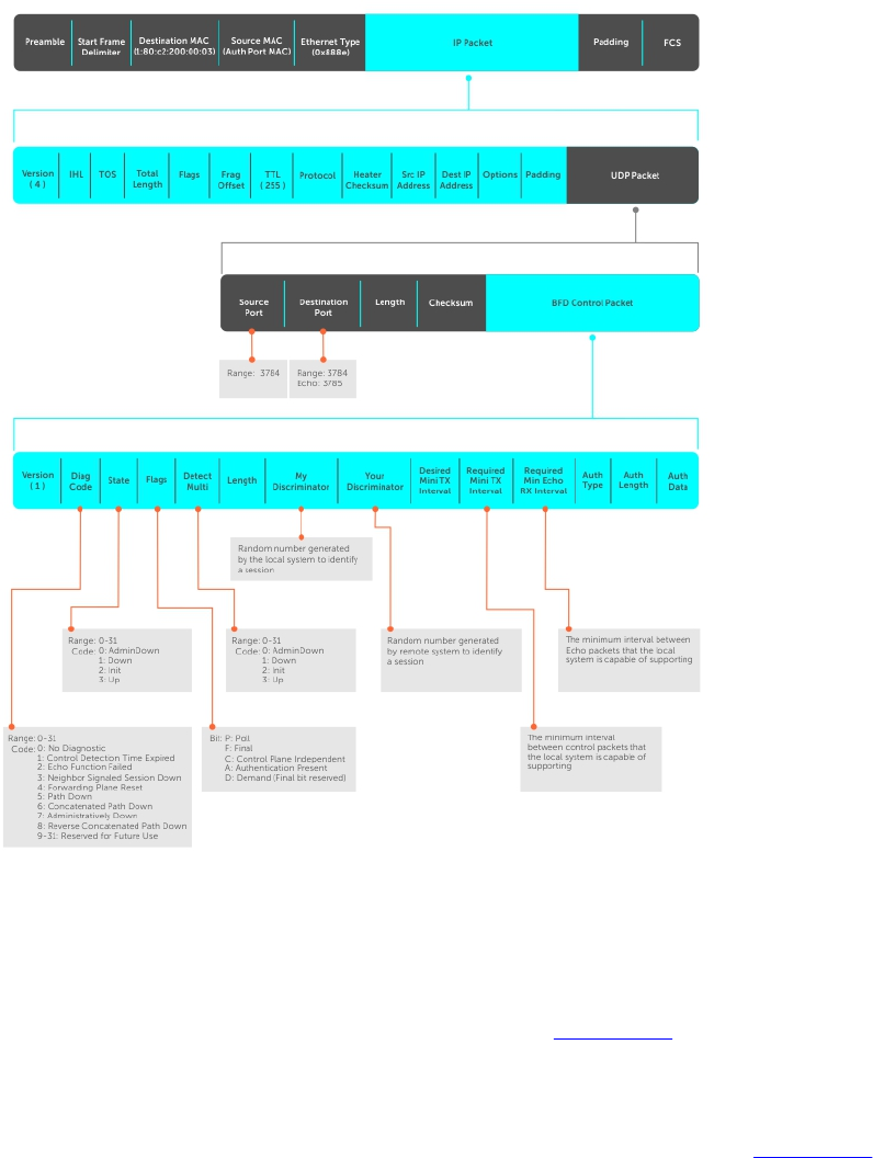
BFD Packet Format
Control packets are encapsulated in user datagram protocol (UDP) packets. The following illustration
shows the complete encapsulation of a BFD control packet inside an IPv4 packet.
Figure 8. BFD in IPv4 Packet Format
Field Description
Diagnostic Code The reason that the last session failed.
State The current local session state. Refer to BFD Sessions.
Flag A bit that indicates packet function. If the poll bit is set, the receiving system must
respond as soon as possible, without regard to its transmit interval. The responding
system clears the poll bit and sets the final bit in its response. The poll and final bits
are used during the handshake and in Demand mode (refer to BFD Sessions).
Bidirectional Forwarding Detection (BFD) 121

Field Description
NOTE: The Dell Networking OS does not currently support multi-point
sessions, Demand mode, authentication, or control plane independence;
these bits are always clear.
Detection
Multiplier
The number of packets that must be missed in order to declare a session down.
Length The entire length of the BFD packet.
My Discriminator A random number generated by the local system to identify the session.
Your Discriminator A random number generated by the remote system to identify the session.
Discriminator values are necessary to identify the session to which a control packet
belongs because there can be many sessions running on a single interface.
Desired Min TX
Interval
The minimum rate at which the local system would like to send control packets to
the remote system.
Required Min RX
Interval
The minimum rate at which the local system would like to receive control packets
from the remote system.
Required Min Echo
RX
The minimum rate at which the local system would like to receive echo packets.
NOTE: The Dell Networking OS does not currently support the echo function.
Authentication
Type,
Authentication
Length,
Authentication
Data
An optional method for authenticating control packets.
NOTE: The Dell Networking OS does not currently support the BFD
authentication function.
Two important parameters are calculated using the values contained in the control packet.
Transmit
interval
Transmit interval is the agreed-upon rate at which a system sends control packets.
Each system has its own transmit interval, which is the greater of the last received
remote Desired TX Interval and the local Required Min RX Interval.
Detection time Detection time is the amount of time that a system does not receive a control
packet, after which the system determines that the session has failed. Each system
has its own detection time.
• In Asynchronous mode: Detection time is the remote Detection Multiplier
multiplied by greater of the remote Desired TX Interval and the local Required
Min RX Interval.
• In Demand mode: Detection time is the local Detection Multiplier multiplied by
the greater of the local Desired Min TX and the remote Required Min RX
Interval.
BFD Sessions
BFD must be enabled on both sides of a link in order to establish a session.
The two participating systems can assume either of two roles:
122 Bidirectional Forwarding Detection (BFD)

Active The active system initiates the BFD session. Both systems can be active for the
same session.
Passive The passive system does not initiate a session. It only responds to a request for
session initialization from the active system.
A BFD session has two modes:
Asynchronous
mode
In Asynchronous mode, both systems send periodic control messages at an agreed
upon interval to indicate that their session status is Up.’
Demand mode If one system requests Demand mode, the other system stops sending periodic
control packets; it only sends a response to status inquiries from the Demand
mode initiator. Either system (but not both) can request Demand mode at any time.
NOTE: The Dell Networking OS supports Asynchronous mode only.
A session can have four states: Administratively Down, Down, Init, and Up.
Administratively
Down
The local system does not participate in a particular session.
Down The remote system is not sending control packets or at least not within the
detection time for a particular session.
Init The local system is communicating.
Up Both systems are exchanging control packets.
The session is declared down if:
• A control packet is not received within the detection time.
• Sufficient echo packets are lost.
• Demand mode is active and a control packet is not received in response to a poll packet.
BFD Three-Way Handshake
A three-way handshake must take place between the systems that participate in the BFD session.
The handshake shown in the following illustration assumes that there is one active and one passive
system, and that this session is the first session established on this link. The default session state on both
ports is Down.
1. The active system sends a steady stream of control packets that indicates that its session state is
Down, until the passive system responds. These packets are sent at the desired transmit interval of
the Active system. The Your Discriminator field is set to zero.
2. When the passive system receives any of these control packets, it changes its session state to Init
and sends a response that indicates its state change. The response includes its session ID in the My
Discriminator field and the session ID of the remote system in the Your Discriminator field.
3. The active system receives the response from the passive system and changes its session state to
Up. It then sends a control packet indicating this state change. This is the third and final part of the
handshake. Now the discriminator values have been exchanged and the transmit intervals have been
negotiated.
4. The passive system receives the control packet and changes its state to Up. Both systems agree that
a session has been established. However, because both members must send a control packet — that
requires a response — anytime there is a state change or change in a session parameter, the passive
Bidirectional Forwarding Detection (BFD) 123
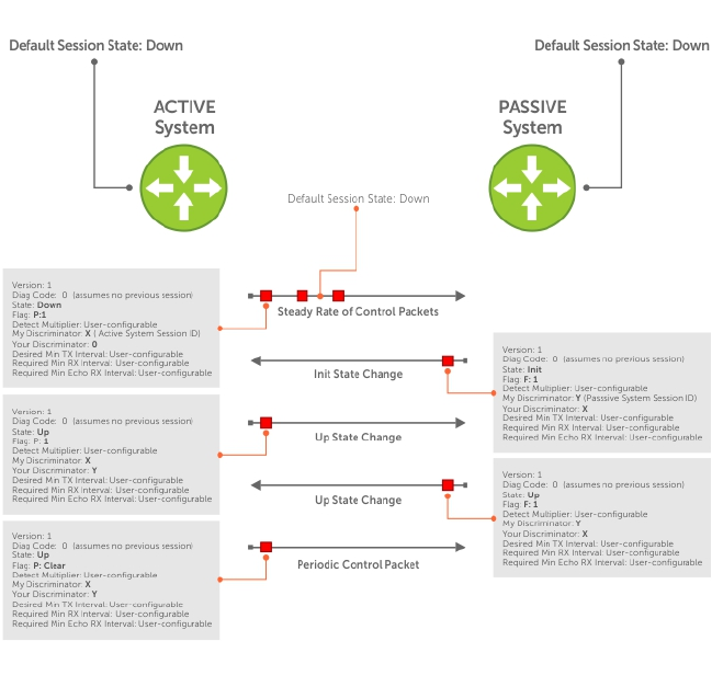
system sends a final response indicating the state change. After this, periodic control packets are
exchanged.
Figure 9. BFD Three-Way Handshake State Changes
Session State Changes
The following illustration shows how the session state on a system changes based on the status
notification it receives from the remote system. For example, if a session on a system is down and it
124 Bidirectional Forwarding Detection (BFD)

receives a Down status notification from the remote system, the session state on the local system
changes to Init.
Figure 10. Session State Changes
Important Points to Remember
• On the Z9500, the system supports 128 sessions at 200 minimum transmit and receive intervals with a
multiplier of 3, and 64 sessions at 100 minimum transmit and receive intervals with a multiplier of 4.
• Enable BFD on both ends of a link.
• Demand mode, authentication, and the Echo function are not supported.
• BFD is not supported on multi-hop and virtual links.
• Protocol Liveness is supported for routing protocols only.
• The Z9500 supports only OSPF, IS-IS, and VRRP protocols as BFD clients; BGP is not supported.
Configure BFD
This section contains the following procedures.
•Configure BFD for Static Routes
•Configure BFD for OSPF
•Configure BFD for OSPFv3
Bidirectional Forwarding Detection (BFD) 125
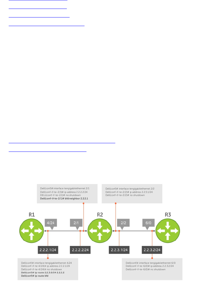
•Configure BFD for IS-IS
•Configure BFD for BGP
•Configure BFD for VRRP
•Configuring Protocol Liveness
Configure BFD for Static Routes
Configuring BFD for static routes is supported on the Z9500 switch..
BFD offers systems a link state detection mechanism for static routes. With BFD, systems are notified to
remove static routes from the routing table as soon as the link state change occurs, rather than waiting
until packets fail to reach their next hop.
Configuring BFD for static routes is a three-step process:
1. Enable BFD globally.
2. Configure static routes on both routers on the system (either local or remote).
3. Configure an IP route to connect BFD on the static routes using the ip route bfd command.
Related Configuration Tasks
•Changing Static Route Session Parameters
•Disabling BFD for Static Routes
Establishing Sessions for Static Routes
Sessions are established for all neighbors that are the next hop of a static route.
Figure 11. Establishing Sessions for Static Routes
To establish a BFD session, use the following command.
• Establish BFD sessions for all neighbors that are the next hop of a static route.
CONFIGURATION mode
ip route bfd
Example of the show bfd neighbors Command to Verify Static Routes
To verify that sessions have been created for static routes, use the show bfd neighbors command.
126 Bidirectional Forwarding Detection (BFD)

R1(conf)#ip route 2.2.3.0/24 2.2.2.2
R1(conf)#ip route bfd
R1(conf)#do show bfd neighbors
* - Active session role
Ad Dn - Admin Down
C - CLI
I - ISIS
O - OSPF
R - Static Route (RTM)
LocalAddr RemoteAddr Interface State Rx-int Tx-int Mult Clients
2.2.2.1 2.2.2.2 Te 4/24 Up 100 100 4 R
To view detailed session information, use the show bfd neighbors detail command, as shown in
the examples in Displaying BFD for BGP Information.
Changing Static Route Session Parameters
BFD sessions are configured with default intervals and a default role.
The parameters you can configure are: Desired TX Interval, Required Min RX Interval, Detection Multiplier,
and system role. These parameters are configured for all static routes. If you change a parameter, the
change affects all sessions for static routes.
To change parameters for static route sessions, use the following command .
• Change parameters for all static route sessions.
CONFIGURATION mode
ip route bfd interval milliseconds min_rx milliseconds multiplier value role
[active | passive]
To view session parameters, use the show bfd neighbors detail command, as shown in the
examples in Displaying BFD for BGP Information.
Disabling BFD for Static Routes
If you disable BFD, all static route BFD sessions are torn down.
A final Admin Down packet is sent to all neighbors on the remote systems, and those neighbors change
to the Down state.
To disable BFD for static routes, use the following command.
• Disable BFD for static routes.
CONFIGURATION mode
no ip route bfd
Configure BFD for OSPF
When using BFD with OSPF, the OSPF protocol registers with the BFD manager. BFD sessions are
established with all neighboring interfaces participating in OSPF. If a neighboring interface fails, the BFD
Bidirectional Forwarding Detection (BFD) 127

agent on the line card notifies the BFD manager, which in turn notifies the OSPF protocol that a link state
change occurred.
NOTE:
If you enable BFD after OSPF with a large number (more than 100) of OSPF neighbors on a VLAN
port-channel and if the VLAN has more than one port-channel, BFD does not come up
immediately. (This behavior occurs only if you enable BFD after connections with all OSPF
neighbors are fully established.)
BFD does not come up for 5 to 6 minutes in a scenario when all the following conditions are met:
• A large number of BFD neighbors are present.
• The neighbors are reachable over a VLAN through a port-channel and the VLAN has multiple
port-channels as members.
• BFD is enabled after all the OSPF neighbors are in an established state.
This delay should not be seen after a reload because OSPF will throttle neighbor establishment.
Configuring BFD for OSPF is a two-step process:
1. Enable BFD globally.
2. Establish sessions with OSPF neighbors.
Related Configuration Tasks
•Changing OSPF Session Parameters
•Disabling BFD for OSPF
128 Bidirectional Forwarding Detection (BFD)
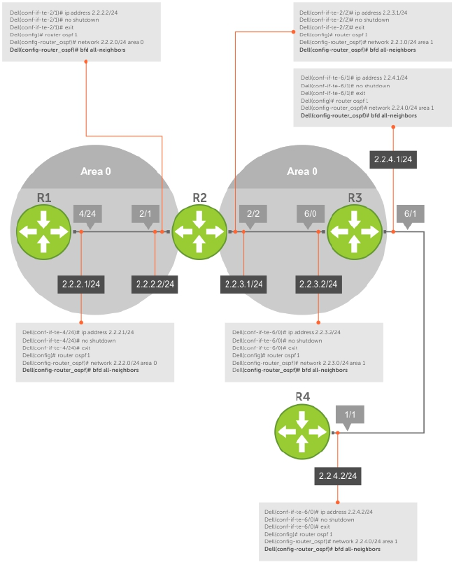
Establishing Sessions with OSPF Neighbors
BFD sessions can be established with all OSPF neighbors at once or sessions can be established with all
neighbors out of a specific interface. Sessions are only established when the OSPF adjacency is in the Full
state.
Figure 12. Establishing Sessions with OSPF Neighbors
To establish BFD with all OSPF neighbors or with OSPF neighbors on a single interface, use the following
commands.
• Establish sessions with all OSPF neighbors.
ROUTER-OSPF mode
bfd all-neighbors
• Establish sessions with OSPF neighbors on a single interface.
Bidirectional Forwarding Detection (BFD) 129

INTERFACE mode
ip ospf bfd all-neighbors
Example of Verifying Sessions with OSPF Neighbors
To view the established sessions, use the show bfd neighbors command.
The bold line shows the OSPF BFD sessions.
R2(conf-router_ospf)#bfd all-neighbors
R2(conf-router_ospf)#do show bfd neighbors
* - Active session role
Ad Dn - Admin Down
C - CLI
I - ISIS
O - OSPF
R - Static Route (RTM)
LocalAddr RemoteAddr Interface State Rx-int Tx-int Mult Clients
* 2.2.2.2 2.2.2.1 Te 2/1 Up 100 100 3 O
* 2.2.3.1 2.2.3.2 Te 2/2 Up 100 100 3 O
Changing OSPFv3 Session Parameters
Configure BFD sessions with default intervals and a default role.
The parameters that you can configure are: desired tx interval, required min rx interval,
detection multiplier, and system role. Configure these parameters for all OSPFv3 sessions or all
OSPFv3 sessions on a particular interface. If you change a parameter globally, the change affects all
OSPFv3 neighbors sessions. If you change a parameter at the interface level, the change affects all
OSPFv3 sessions on that interface.
To change parameters for all OSPFv3 sessions or for OSPFv3 sessions on a single interface, use the
following commands.
To view session parameters, use the show bfd neighbors detail command, as shown in the
example in Displaying BFD for BGP Information.
• Change parameters for all OSPFv3 sessions.
ROUTER-OSPFv3 mode
bfd all-neighbors interval milliseconds min_rx milliseconds multiplier value
role [active | passive]
• Change parameters for OSPFv3 sessions on a single interface.
INTERFACE mode
ipv6 ospf bfd all-neighbors interval milliseconds min_rx milliseconds
multiplier value role [active | passive]
Disabling BFD for OSPFv3
If you disable BFD globally, all sessions are torn down and sessions on the remote system are placed in a
Down state.
If you disable BFD on an interface, sessions on the interface are torn down and sessions on the remote
system are placed in a Down state. Disabling BFD does not trigger a change in BFD clients; a final Admin
Down packet is sent before the session is terminated.
130 Bidirectional Forwarding Detection (BFD)

To disable BFD sessions, use the following commands.
• Disable BFD sessions with all OSPFv3 neighbors.
ROUTER-OSPFv3 mode
no bfd all-neighbors
• Disable BFD sessions with OSPFv3 neighbors on a single interface.
INTERFACE mode
ipv6 ospf bfd all-neighbors disable
Configure BFD for OSPFv3
BFD for OSPFv3 provides support for IPV6.
Configuring BFD for OSPFv3 is a two-step process:
1. Enable BFD globally.
2. Establish sessions with OSPFv3 neighbors.
Related Configuration Tasks
•Changing OSPFv3 Session Parameters
•Disabling BFD for OSPFv3
Changing OSPFv3 Session Parameters
Configure BFD sessions with default intervals and a default role.
The parameters that you can configure are: desired tx interval, required min rx interval,
detection multiplier, and system role. Configure these parameters for all OSPFv3 sessions or all
OSPFv3 sessions on a particular interface. If you change a parameter globally, the change affects all
OSPFv3 neighbors sessions. If you change a parameter at the interface level, the change affects all
OSPFv3 sessions on that interface.
To change parameters for all OSPFv3 sessions or for OSPFv3 sessions on a single interface, use the
following commands.
To view session parameters, use the show bfd neighbors detail command, as shown in the
example in Displaying BFD for BGP Information.
• Change parameters for all OSPFv3 sessions.
ROUTER-OSPFv3 mode
bfd all-neighbors interval milliseconds min_rx milliseconds multiplier value
role [active | passive]
• Change parameters for OSPFv3 sessions on a single interface.
INTERFACE mode
ipv6 ospf bfd all-neighbors interval milliseconds min_rx milliseconds
multiplier value role [active | passive]
Bidirectional Forwarding Detection (BFD) 131

Disabling BFD for OSPFv3
If you disable BFD globally, all sessions are torn down and sessions on the remote system are placed in a
Down state.
If you disable BFD on an interface, sessions on the interface are torn down and sessions on the remote
system are placed in a Down state. Disabling BFD does not trigger a change in BFD clients; a final Admin
Down packet is sent before the session is terminated.
To disable BFD sessions, use the following commands.
• Disable BFD sessions with all OSPFv3 neighbors.
ROUTER-OSPFv3 mode
no bfd all-neighbors
• Disable BFD sessions with OSPFv3 neighbors on a single interface.
INTERFACE mode
ipv6 ospf bfd all-neighbors disable
Establishing Sessions with OSPFv3 Neighbors
You can establish BFD sessions with all OSPFv3 neighbors at once or with all neighbors out of a specific
interface. Sessions are only established when the OSPFv3 adjacency is in the Full state.
To establish BFD with all OSPFv3 neighbors or with OSPFv3 neighbors on a single interface, use the
following commands.
• Establish sessions with all OSPFv3 neighbors.
ROUTER-OSPFv3 mode
bfd all-neighbors
• Establish sessions with OSPFv3 neighbors on a single interface.
INTERFACE mode
ipv6 ospf bfd all-neighbors
To view the established sessions, use the show bfd neighbors command.
Configure BFD for IS-IS
When using BFD with IS-IS, the IS-IS protocol registers with the BFD manager. BFD sessions are then
established with all neighboring interfaces participating in IS-IS. If a neighboring interface fails, the BFD
agent on the line card notifies the BFD manager, which in turn notifies the IS-IS protocol that a link state
change occurred.
Configuring BFD for IS-IS is a two-step process:
1. Enable BFD globally.
2. Establish sessions for all or particular IS-IS neighbors.
Related Configuration Tasks
•Changing IS-IS Session Parameters
•Disabling BFD for IS-IS
132 Bidirectional Forwarding Detection (BFD)
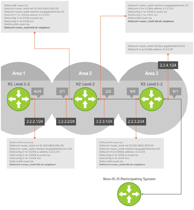
Establishing Sessions with IS-IS Neighbors
BFD sessions can be established for all IS-IS neighbors at once or sessions can be established for all
neighbors out of a specific interface.
Figure 13. Establishing Sessions with IS-IS Neighbors
To establish BFD with all IS-IS neighbors or with IS-IS neighbors on a single interface, use the following
commands.
• Establish sessions with all IS-IS neighbors.
ROUTER-ISIS mode
bfd all-neighbors
• Establish sessions with IS-IS neighbors on a single interface.
INTERFACE mode
isis bfd all-neighbors
Example of Verifying Sessions with IS-IS Neighbors
To view the established sessions, use the show bfd neighbors command.
Bidirectional Forwarding Detection (BFD) 133

The bold line shows that IS-IS BFD sessions are enabled.
R2(conf-router_isis)#bfd all-neighbors
R2(conf-router_isis)#do show bfd neighbors
* - Active session role
Ad Dn - Admin Down
C - CLI
I - ISIS
O - OSPF
R - Static Route (RTM)
LocalAddr RemoteAddr Interface State Rx-int Tx-int Mult Clients
* 2.2.2.2 2.2.2.1 Te 2/1 Up 100 100 3 I
Changing IS-IS Session Parameters
BFD sessions are configured with default intervals and a default role.
The parameters that you can configure are: Desired TX Interval, Required Min RX Interval, Detection
Multiplier, and system role. These parameters are configured for all IS-IS sessions or all IS-IS sessions out
of an interface. If you change a parameter globally, the change affects all IS-IS neighbors sessions. If you
change a parameter at the interface level, the change affects all IS-IS sessions on that interface.
To change parameters for all IS-IS sessions or for IS-IS sessions on a single interface, use the following
commands.
To view session parameters, use the show bfd neighbors detail command, as shown in Verifying
BFD Sessions with BGP Neighbors Using the show bfd neighbors Command in Displaying BFD for
BGP Information.
• Change parameters for all IS-IS sessions.
ROUTER-ISIS mode
bfd all-neighbors interval milliseconds min_rx milliseconds multiplier value
role [active | passive]
• Change parameters for IS-IS sessions on a single interface.
INTERFACE mode
isis bfd all-neighbors interval milliseconds min_rx milliseconds multiplier
value role [active | passive]
Disabling BFD for IS-IS
If you disable BFD globally, all sessions are torn down and sessions on the remote system are placed in a
Down state.
If you disable BFD on an interface, sessions on the interface are torn down and sessions on the remote
system are placed in a Down state. Disabling BFD does not trigger a change in BFD clients; a final Admin
Down packet is sent before the session is terminated.
To disable BFD sessions, use the following commands.
• Disable BFD sessions with all IS-IS neighbors.
ROUTER-ISIS mode
no bfd all-neighbors
• Disable BFD sessions with IS-IS neighbors on a single interface.
134 Bidirectional Forwarding Detection (BFD)

INTERFACE mose
isis bfd all-neighbors disable
Configure BFD for BGP
In a BGP core network, BFD provides rapid detection of communication failures in BGP fast-forwarding
paths between internal BGP (iBGP) and external BGP (eBGP) peers for faster network reconvergence. BFD
for BGP is supported on 1GE, 10GE, 40GE, port-channel, and VLAN interfaces. BFD for BGP does not
support IPv6 and the BGP multihop feature.
Prerequisites
Before configuring BFD for BGP, you must first configure the following settings:
1. Configure BGP on the routers that you want to interconnect, as described in Border Gateway
Protocol IPv4 (BGPv4).
2. Enable fast fall-over for BGP neighbors to reduce convergence time (the neighbor fall-over
command), as described in BGP Fast Fall-Over.
Establishing Sessions with BGP Neighbors
Before configuring BFD for BGP, you must first configure BGP on the routers that you want to
interconnect.
For more information, refer to Border Gateway Protocol IPv4 (BGPv4).
For example, the following illustration shows a sample BFD configuration on Router 1 and Router 2 that
use eBGP in a transit network to interconnect AS1 and AS2. The eBGP routers exchange information with
each other as well as with iBGP routers to maintain connectivity and accessibility within each
autonomous system.
Bidirectional Forwarding Detection (BFD) 135
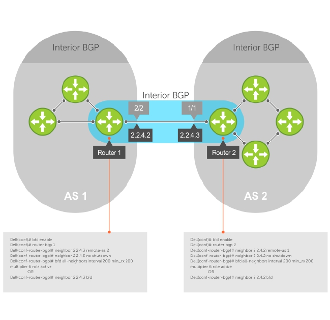
Figure 14. Establishing Sessions with BGP Neighbors
The sample configuration shows alternative ways to establish a BFD session with a BGP neighbor:
• By establishing BFD sessions with all neighbors discovered by BGP (the bfd all-neighbors
command).
• By establishing a BFD session with a specified BGP neighbor (the neighbor {ip-address | peer-
group-name} bfd command)
BFD packets originating from a router are assigned to the highest priority egress queue to minimize
transmission delays. Incoming BFD control packets received from the BGP neighbor are assigned to the
highest priority queue within the control plane policing (COPP) framework to avoid BFD packets drops
due to queue congestion.
BFD notifies BGP of any failure conditions that it detects on the link. Recovery actions are initiated by
BGP.
BFD for BGP is supported only on directly-connected BGP neighbors and only in BGP IPv4 networks. Up
to 128 simultaneous BFD sessions are supported
As long as each BFD for BGP neighbor receives a BFD control packet within the configured BFD interval
for failure detection, the BFD session remains up and BGP maintains its adjacencies. If a BFD for BGP
neighbor does not receive a control packet within the detection interval, the router informs any clients of
the BFD session (other routing protocols) about the failure. It then depends on the individual routing
protocols that uses the BGP link to determine the appropriate response to the failure condition. The
136 Bidirectional Forwarding Detection (BFD)
typical response is to terminate the peering session for the routing protocol and reconverge by bypassing
the failed neighboring router. A log message is generated whenever BFD detects a failure condition.
1. Enable BFD globally.
CONFIGURATION mode
bfd enable
2. Specify the AS number and enter ROUTER BGP configuration mode.
CONFIGURATION mode
router bgp as-number
3. Add a BGP neighbor or peer group in a remote AS.
CONFIG-ROUTERBGP mode
neighbor {ip-address | peer-group name} remote-as as-number
4. Enable the BGP neighbor.
CONFIG-ROUTERBGP mode
neighbor {ip-address | peer-group-name} no shutdown
5. Configure parameters for a BFD session established with all neighbors discovered by BGP. OR
Establish a BFD session with a specified BGP neighbor or peer group using the default BFD session
parameters.
CONFIG-ROUTERBGP mode
bfd all-neighbors [interval millisecs min_rx millisecs multiplier value role
{active | passive}]
OR
neighbor {ip-address | peer-group-name} bfd
NOTES:
• When you establish a BFD session with a specified BGP neighbor or peer group using the
neighbor bfd command, the default BFD session parameters are used (interval: 100
milliseconds, min_rx: 100 milliseconds, multiplier: 3 packets, and role: active).
• When you explicitly enable or disable a BGP neighbor for a BFD session with the neighbor bfd
or neighbor bfd disable commands, the neighbor does not inherit the BFD enable/disable
values configured with the bfd all-neighbors command or configured for the peer group to
which the neighbor belongs. Also, the neighbor only inherits the global timer values configured
with the bfd all-neighbors command (interval, min_rx, and multiplier).
6. Repeat Steps 1 to 5 on each BGP peer participating in a BFD session.
Disabling BFD for BGP
You can disable BFD for BGP.
To disable a BFD for BGP session with a specified neighbor, use the first command. To remove the
disabled state of a BFD for BGP session with a specified neighbor, use the second command.
The BGP link with the neighbor returns to normal operation and uses the BFD session parameters globally
configured with the bfd all-neighbors command or configured for the peer group to which the
neighbor belongs.
• Disable a BFD for BGP session with a specified neighbor.
Bidirectional Forwarding Detection (BFD) 137

ROUTER BGP mode
neighbor {ip-address | peer-group-name} bfd disable
• Remove the disabled state of a BFD for BGP session with a specified neighbor.
ROUTER BGP mode
no neighbor {ip-address | peer-group-name} bfd disable
Use BFD in a BGP Peer Group
You can establish a BFD session for the members of a peer group (the neighbor peer-group-name
bfd command in ROUTER BGP configuration mode).
Members of the peer group may have BFD:
• Explicitly enabled (the neighbor ip-address bfd command)
• Explicitly disabled (the neighbor ip-address bfd disable command)
• Inherited (neither explicitly enabled or disabled) according to the current BFD configuration of the
peer group. For information about BGP peer groups, refer to Configure Peer Groups.
If you explicitly enable (or disable) a BGP neighbor for BFD that belongs to a peer group:
• The neighbor does not inherit the BFD enable/disable values configured with the bfd all-
neighbors command or configured for the peer group to which the neighbor belongs.
• The neighbor inherits only the global timer values that are configured with the bfd all-neighbors
command (interval, min_rx, and multiplier).
If you explicitly enable (or disable) a peer group for BFD that has no BFD parameters configured (for
example, advertisement interval) using the neighbor peer-group-name bfd command, the peer
group inherits any BFD settings configured with the bfd all-neighbors command.
Displaying BFD for BGP Information
You can display related information for BFD for BGP.
To display information about BFD for BGP sessions on a router, use the following commands and refer to
the following examples.
• Verify a BFD for BGP configuration.
EXEC Privilege mode
show running-config bgp
• Verify that a BFD for BGP session has been successfully established with a BGP neighbor. A line-by-
line listing of established BFD adjacencies is displayed.
EXEC Privilege mode
show bfd neighbors [interface] [detail]
• Check to see if BFD is enabled for BGP connections.
EXEC Privilege mode
show ip bgp summary
• Displays routing information exchanged with BGP neighbors, including BFD for BGP sessions.
EXEC Privilege mode
show ip bgp neighbors [ip-address]
138 Bidirectional Forwarding Detection (BFD)

Examples of Verifying BGP Information
The following example shows viewing a BGP configuration.
R2# show running-config bgp
!
router bgp 2
neighbor 1.1.1.2 remote-as 1
neighbor 1.1.1.2 no shutdown
neighbor 2.2.2.2 remote-as 1
neighbor 2.2.2.2 no shutdown
neighbor 3.3.3.2 remote-as 1
neighbor 3.3.3.2 no shutdown
bfd all-neighbors
The following example shows viewing all BGP neighbors.
R2# show bfd neighbors
* - Active session role
Ad Dn - Admin Down
B - BGP
C - CLI
I - ISIS
O - OSPF
R - Static Route (RTM)
M - MPLS
V - VRRP
LocalAddr RemoteAddr Interface State Rx-int Tx-int Mult Clients
* 1.1.1.3 1.1.1.2 Te 6/0 Up 100 100 3 B
* 2.2.2.3 2.2.2.2 Te 6/1 Up 100 100 3 B
* 3.3.3.3 3.3.3.2 Te 6/2 Up 100 100 3 B
The following example shows viewing BFD neighbor detail. The bold lines show the BFD session
parameters: TX (packet transmission), RX (packet reception), and multiplier (maximum number of missed
packets).
R2# show bfd neighbors detail
Session Discriminator: 9
Neighbor Discriminator: 10
Local Addr: 1.1.1.3
Local MAC Addr: 00:01:e8:66:da:33
Remote Addr: 1.1.1.2
Remote MAC Addr: 00:01:e8:8a:da:7b
Int: TenGigabitEthernet 6/0
State: Up
Configured parameters:
TX: 100ms, RX: 100ms, Multiplier: 3
Neighbor parameters:
TX: 100ms, RX: 100ms, Multiplier: 3
Actual parameters:
TX: 100ms, RX: 100ms, Multiplier: 3
Role: Active
Delete session on Down: True
Client Registered: BGP
Uptime: 00:07:55
Statistics:
Number of packets received from neighbor: 4762
Number of packets sent to neighbor: 4490
Number of state changes: 2
Number of messages from IFA about port state change: 0
Bidirectional Forwarding Detection (BFD) 139

Number of messages communicated b/w Manager and Agent: 5
Session Discriminator: 10
Neighbor Discriminator: 11
Local Addr: 2.2.2.3
Local MAC Addr: 00:01:e8:66:da:34
Remote Addr: 2.2.2.2
Remote MAC Addr: 00:01:e8:8a:da:7b
Int: TenGigabitEthernet 6/1
State: Up
Configured parameters:
TX: 100ms, RX: 100ms, Multiplier: 3
Neighbor parameters:
TX: 100ms, RX: 100ms, Multiplier: 3
Actual parameters:
TX: 100ms, RX: 100ms, Multiplier: 3
Role: Active
Delete session on Down: True
Client Registered: BGP
Uptime: 00:02:22
Statistics:
Number of packets received from neighbor: 1428
Number of packets sent to neighbor: 1428
Number of state changes: 1
Number of messages from IFA about port state change: 0
Number of messages communicated b/w Manager and Agent: 4
The following example shows viewing the configured BFD counters.
R2# show bfd counters bgp
Interface TenGigabitEthernet 6/0
Protocol BGP
Messages:
Registration : 5
De-registration : 4
Init : 0
Up : 6
Down : 0
Admin Down : 2
Interface TenGigabitEthernet 6/1
Protocol BGP
Messages:
Registration : 5
De-registration : 4
Init : 0
Up : 6
Down : 0
Admin Down : 2
Interface TenGigabitEthernet 6/2
Protocol BGP
Messages:
Registration : 1
De-registration : 0
Init : 0
Up : 1
Down : 0
Admin Down : 2
140 Bidirectional Forwarding Detection (BFD)

The following example shows viewing BFD summary information. The bold line shows the message that
displays when you enable BFD for BGP connections.
R2# show ip bgp summary
BGP router identifier 10.0.0.1, local AS number 2
BGP table version is 0, main routing table version 0
BFD is enabled, Interval 100 Min_rx 100 Multiplier 3 Role Active
3 neighbor(s) using 24168 bytes of memory
Neighbor AS MsgRcvd MsgSent TblVer InQ OutQ Up/Down State/Pfx
1.1.1.2 1 282 281 0 0 0 00:38:12 0
2.2.2.2 1 273 273 0 0 (0) 04:32:26 0
3.3.3.2 1 282 281 0 0 0 00:38:12 0
The following example shows viewing BFD information for a specified neighbor. The bold lines show the
message that displays when you enable a BFD session with different configurations:
• Message displayed when you enable a BFD session with a BGP neighbor that inherits the global BFD
session settings configured with the global bfd all-neighbors command.
• Message displayed when you enable a BFD session with a BGP neighbor using the neighbor ip-
address bfd command.
• Message displayed when you enable a BGP neighbor in a peer group for which you enabled a BFD
session using the neighbor peer-group-name bfd command
R2# show ip bgp neighbors 2.2.2.2
BGP neighbor is 2.2.2.2, remote AS 1, external link
BGP version 4, remote router ID 12.0.0.4
BGP state ESTABLISHED, in this state for 00:05:33
Last read 00:00:30, last write 00:00:30
Hold time is 180, keepalive interval is 60 seconds
Received 8 messages, 0 in queue
1 opens, 0 notifications, 0 updates
7 keepalives, 0 route refresh requests
Sent 9 messages, 0 in queue
2 opens, 0 notifications, 0 updates
7 keepalives, 0 route refresh requests
Minimum time between advertisement runs is 30 seconds
Minimum time before advertisements start is 0 seconds
Capabilities received from neighbor for IPv4 Unicast :
MULTIPROTO_EXT(1)
ROUTE_REFRESH(2)
CISCO_ROUTE_REFRESH(128)
Capabilities advertised to neighbor for IPv4 Unicast :
MULTIPROTO_EXT(1)
ROUTE_REFRESH(2)
CISCO_ROUTE_REFRESH(128)
Neighbor is using BGP global mode BFD configuration
For address family: IPv4 Unicast
BGP table version 0, neighbor version 0
Prefixes accepted 0 (consume 0 bytes), withdrawn 0 by peer, martian prefixes
ignored 0
Prefixes advertised 0, denied 0, withdrawn 0 from peer
Connections established 1; dropped 0
Last reset never
Local host: 2.2.2.3, Local port: 63805
Bidirectional Forwarding Detection (BFD) 141

Foreign host: 2.2.2.2, Foreign port: 179
R2#
R2# show ip bgp neighbors 2.2.2.3
BGP neighbor is 2.2.2.3, remote AS 1, external link
Member of peer-group pg1 for session parameters
BGP version 4, remote router ID 12.0.0.4
BGP state ESTABLISHED, in this state for 00:05:33
...
Neighbor is using BGP neighbor mode BFD configuration
Peer active in peer-group outbound optimization
...
R2# show ip bgp neighbors 2.2.2.4
BGP neighbor is 2.2.2.4, remote AS 1, external link
Member of peer-group pg1 for session parameters
BGP version 4, remote router ID 12.0.0.4
BGP state ESTABLISHED, in this state for 00:05:33
...
Neighbor is using BGP peer-group mode BFD configuration
Peer active in peer-group outbound optimization
...
Configure BFD for VRRP
When using BFD with VRRP, the VRRP protocol registers with the BFD manager. BFD sessions are
established with all neighboring interfaces participating in VRRP. If a neighboring interface fails, the BFD
agent on the line card notifies the BFD manager, which in turn notifies the VRRP protocol that a link state
change occurred.
Configuring BFD for VRRP is a three-step process:
1. Enable BFD globally.
2. Establish VRRP BFD sessions with all VRRP-participating neighbors.
3. On the master router, establish a VRRP BFD sessions with the backup routers. Refer to Establishing
Sessions with All VRRP Neighbors.
Related Configuration Tasks
•Changing VRRP Session Parameters.
•Establishing Sessions with OSPF Neighbors.
142 Bidirectional Forwarding Detection (BFD)
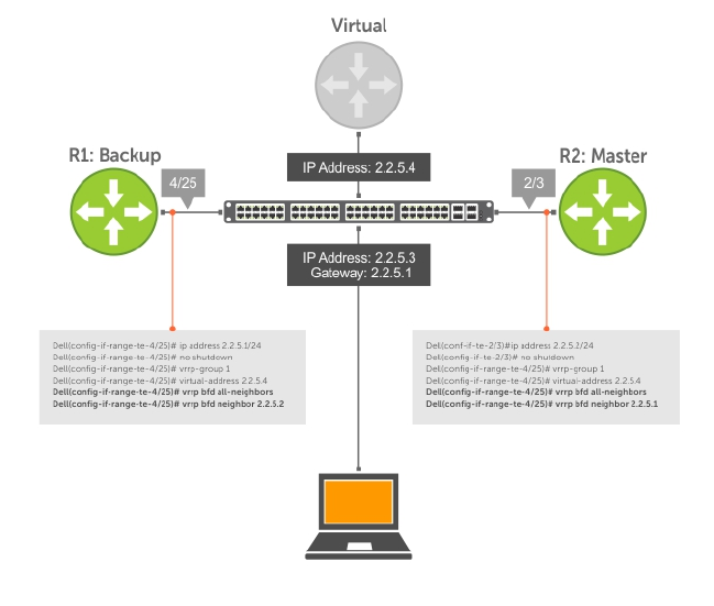
Establishing Sessions with All VRRP Neighbors
BFD sessions can be established for all VRRP neighbors at once, or a session can be established with a
particular neighbor.
Figure 15. Establishing Sessions with All VRRP Neighbors
To establish sessions with all VRRP neighbors, use the following command.
• Establish sessions with all VRRP neighbors.
INTERFACE mode
vrrp bfd all-neighbors
Establishing VRRP Sessions on VRRP Neighbors
The master router does not care about the state of the backup router, so it does not participate in any
VRRP BFD sessions.
VRRP BFD sessions on the backup router cannot change to the UP state. Configure the master router to
establish an individual VRRP session the backup router.
To establish a session with a particular VRRP neighbor, use the following command.
• Establish a session with a particular VRRP neighbor.
INTERFACE mode
vrrp bfd neighbor ip-address
Examples of Viewing VRRP Sessions
To view the established sessions, use the show bfd neighbors command.
Bidirectional Forwarding Detection (BFD) 143

The following example shows viewing sessions with VRRP neighbors. The bold line shows that VRRP BFD
sessions are enabled.
R1(conf-if-te-4/25)#vrrp bfd all-neighbors
R1(conf-if-te-4/25)#do show bfd neighbor
* - Active session role
Ad Dn - Admin Down
C - CLI
I - ISIS
O - OSPF
R - Static Route (RTM)
V - VRRP
LocalAddr RemoteAddr Interface State Rx-int Tx-int Mult Clients
* 2.2.5.1 2.2.5.2 Te 4/25 Down 1000 1000 3 V
To view session state information, use the show vrrp command.
The following example shows viewing VRRP session state information. The bold line shows the VRRP BFD
session.
R1(conf-if-te-4/25)#do show vrrp
------------------
TenGigabitEthernet 4/1, VRID: 1, Net: 2.2.5.1
State: Backup, Priority: 1, Master: 2.2.5.2
Hold Down: 0 sec, Preempt: TRUE, AdvInt: 1 sec
Adv rcvd: 95, Bad pkts rcvd: 0, Adv sent: 933, Gratuitous ARP sent: 3
Virtual MAC address:
00:00:5e:00:01:01
Virtual IP address:
2.2.5.4
Authentication: (none)
BFD Neighbors:
RemoteAddr State
2.2.5.2 Up
Changing VRRP Session Parameters
BFD sessions are configured with default intervals and a default role.
The parameters that you can configure are: Desired TX Interval, Required Min RX Interval, Detection
Multiplier, and system role. You can change parameters for all VRRP sessions or for a particular neighbor.
To change parameters for all VRRP sessions or for a particular VRRP session, use the following
commands.
• Change parameters for all VRRP sessions.
INTERFACE mode
vrrp bfd all-neighbors interval milliseconds min_rx milliseconds multiplier
value role [active | passive]
• Change parameters for a particular VRRP session.
INTERFACE mode
vrrp bfd neighbor ip-address interval milliseconds min_rx milliseconds
multiplier value role [active | passive]
To view session parameters, use the show bfd neighbors detail command, as shown in the
example in Verifying BFD Sessions with BGP Neighbors Using the show bfd neighbors command
example in Displaying BFD for BGP Information.
144 Bidirectional Forwarding Detection (BFD)
Disabling BFD for VRRP
If you disable any or all VRRP sessions, the sessions are torn down.
A final Admin Down control packet is sent to all neighbors and sessions on the remote system change to
the Down state.
To disable all VRRP sessions on an interface, sessions for a particular VRRP group, or for a particular VRRP
session on an interface, use the following commands.
• Disable all VRRP sessions on an interface.
INTERFACE mode
no vrrp bfd all-neighbors
• Disable all VRRP sessions in a VRRP group.
VRRP mode
bfd disable
• Disable a particular VRRP session on an interface.
INTERFACE mode
no vrrp bfd neighbor ip-address
Configuring Protocol Liveness
Protocol liveness is a feature that notifies the BFD manager when a client protocol is disabled.
When you disable a client, all BFD sessions for that protocol are torn down. Neighbors on the remote
system receive an Admin Down control packet and are placed in the Down state.
To enable protocol liveness, use the following command.
• Enable Protocol Liveness.
CONFIGURATION mode
bfd protocol-liveness
Bidirectional Forwarding Detection (BFD) 145

9
Border Gateway Protocol IPv4 (BGPv4)
This chapter provides a general description of BGPv4 as it is supported in the Dell Networking OS.
BGP protocol standards are listed in the Standards Compliance chapter.
BGP is an external gateway protocol that transmits interdomain routing information within and between
autonomous systems (AS). The primary function of the BGP is to exchange network reachability
information with other BGP systems. BGP generally operates with an internal gateway protocol (IGP) such
as open shortest path first (OSPF) or router information protocol (RIP), allowing you to communicate to
external ASs smoothly. BGP adds reliability to network connections by having multiple paths from one
router to another.
Autonomous Systems (AS)
BGP autonomous systems (ASs) are a collection of nodes under common administration with common
network routing policies.
Each AS has a number, which an internet authority already assigns. You do not assign the BGP number.
AS numbers (ASNs) are important because the ASN uniquely identifies each network on the internet. The
Internet Assigned Numbers Authority (IANA) has reserved AS numbers 64512 through 65534 to be used
for private purposes. IANA reserves ASNs 0 and 65535 and must not be used in a live environment.
You can group autonomous systems into three categories (multihomed, stub, and transit), defined by
their connections and operation.
•multihomed AS — is one that maintains connections to more than one other AS. This group allows
the AS to remain connected to the Internet in the event of a complete failure of one of their
connections. However, this type of AS does not allow traffic from one AS to pass through on its way
to another AS. A simple example of this group is seen in the following illustration.
•stub AS — is one that is connected to only one other AS.
•transit AS — is one that provides connections through itself to separate networks. For example, in the
following illustration, Router 1 can use Router 2 (the transit AS) to connect to Router 4. Internet
service providers (ISPs) are always transit ASs, because they provide connections from one network to
another. The ISP is considered to be “selling transit service” to the customer network, so thus the term
Transit AS.
When BGP operates inside an AS (AS1 or AS2, as seen in the following illustration), it is referred to as
Internal BGP (IBGP Interior Border Gateway Protocol). When BGP operates between ASs (AS1 and AS2), it
is called External BGP (EBGP Exterior Border Gateway Protocol). IBGP provides routers inside the AS with
the knowledge to reach routers external to the AS. EBGP routers exchange information with other EBGP
routers as well as IBGP routers to maintain connectivity and accessibility.
146 Border Gateway Protocol IPv4 (BGPv4)
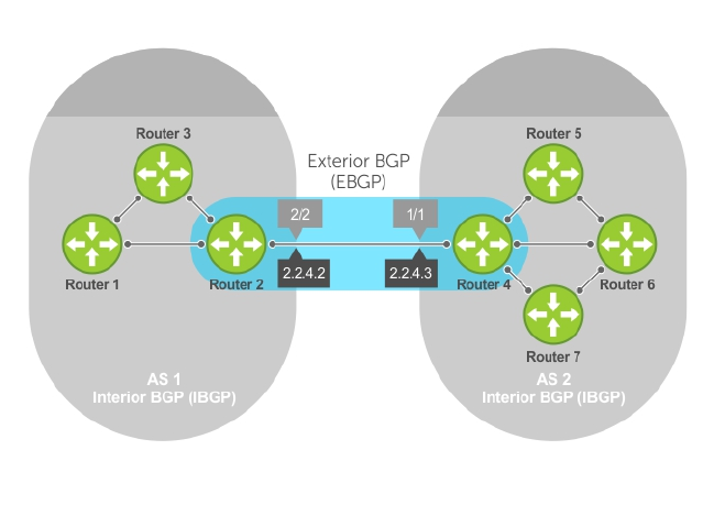
Figure 16. Interior BGP
BGP version 4 (BGPv4) supports classless interdomain routing and aggregate routes and AS paths. BGP is
a path vector protocol — a computer network in which BGP maintains the path that updated information
takes as it diffuses through the network. Updates traveling through the network and returning to the
same node are easily detected and discarded.
BGP does not use a traditional interior gateway protocol (IGP) matrix, but makes routing decisions based
on path, network policies, and/or rulesets. Unlike most protocols, BGP uses TCP as its transport protocol.
Since each BGP router talking to another router is a session, a BGP network needs to be in “full mesh.”
This is a topology that has every router directly connected to every other router. Each BGP router within
an AS must have iBGP sessions with all other BGP routers in the AS. For example, a BGP network within
an AS needs to be in “full mesh.” As seen in the illustration below, four routers connected in a full mesh
have three peers each, six routers have five peers each, and eight routers in full mesh have seven peers
each.
Border Gateway Protocol IPv4 (BGPv4) 147
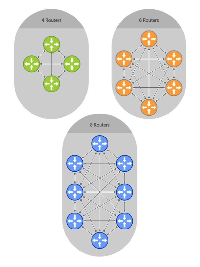
Figure 17. BGP Routers in Full Mesh
The number of BGP speakers each BGP peer must maintain increases exponentially. Network
management quickly becomes impossible.
Sessions and Peers
When two routers communicate using the BGP protocol, a BGP session is started. The two end-points of
that session are Peers. A Peer is also called a Neighbor.
148 Border Gateway Protocol IPv4 (BGPv4)

Establish a Session
Information exchange between peers is driven by events and timers. The focus in BGP is on the traffic
routing policies.
In order to make decisions in its operations with other BGP peers, a BGP process uses a simple finite state
machine that consists of six states: Idle, Connect, Active, OpenSent, OpenConfirm, and Established. For
each peer-to-peer session, a BGP implementation tracks which of these six states the session is in. The
BGP protocol defines the messages that each peer should exchange in order to change the session from
one state to another.
State Description
Idle BGP initializes all resources, refuses all inbound BGP connection attempts, and
initiates a TCP connection to the peer.
Connect In this state the router waits for the TCP connection to complete, transitioning to
the OpenSent state if successful.
If that transition is not successful, BGP resets the ConnectRetry timer and
transitions to the Active state when the timer expires.
Active The router resets the ConnectRetry timer to zero and returns to the Connect state.
OpenSent After successful OpenSent transition, the router sends an Open message and waits
for one in return.
OpenConfirm After the Open message parameters are agreed between peers, the neighbor
relation is established and is in the OpenConfirm state. This is when the router
receives and checks for agreement on the parameters of open messages to
establish a session.
Established Keepalive messages are exchanged next, and after successful receipt, the router is
placed in the Established state. Keepalive messages continue to be sent at regular
periods (established by the Keepalive timer) to verify connections.
After the connection is established, the router can now send/receive Keepalive, Update, and Notification
messages to/from its peer.
Peer Groups
Peer groups are neighbors grouped according to common routing policies. They enable easier system
configuration and management by allowing groups of routers to share and inherit policies.
Peer groups also aid in convergence speed. When a BGP process needs to send the same information to
a large number of peers, the BGP process needs to set up a long output queue to get that information to
all the proper peers. If the peers are members of a peer group however, the information can be sent to
one place and then passed onto the peers within the group.
Route Reflectors
Route reflectors reorganize the iBGP core into a hierarchy and allow some route advertisement rules.
NOTE: Do not use route reflectors (RRs) in the forwarding path. In iBGP, hierarchal RRs maintaining
forwarding plane RRs could create routing loops.
Border Gateway Protocol IPv4 (BGPv4) 149

Route reflection divides iBGP peers into two groups: client peers and nonclient peers. A route reflector
and its client peers form a route reflection cluster. Because BGP speakers announce only the best route
for a given prefix, route reflector rules are applied after the router makes its best path decision.
• If a route was received from a nonclient peer, reflect the route to all client peers.
• If the route was received from a client peer, reflect the route to all nonclient and all client peers.
To illustrate how these rules affect routing, refer to the following illustration and the following steps.
Routers B, C, D, E, and G are members of the same AS (AS100). These routers are also in the same Route
Reflection Cluster, where Router D is the Route Reflector. Router E and H are client peers of Router D;
Routers B and C and nonclient peers of Router D.
Figure 18. BGP Router Rules
1. Router B receives an advertisement from Router A through eBGP. Because the route is learned
through eBGP, Router B advertises it to all its iBGP peers: Routers C and D.
2. Router C receives the advertisement but does not advertise it to any peer because its only other peer
is Router D, an iBGP peer, and Router D has already learned it through iBGP from Router B.
3. Router D does not advertise the route to Router C because Router C is a nonclient peer and the
route advertisement came from Router B who is also a nonclient peer.
4. Router D does reflect the advertisement to Routers E and G because they are client peers of Router
D.
5. Routers E and G then advertise this iBGP learned route to their eBGP peers Routers F and H.
Communities
BGP communities are sets of routes with one or more common attributes. Communities are a way to
assign common attributes to multiple routes at the same time.
BGP Attributes
Routes learned using BGP have associated properties that are used to determine the best route to a
destination when multiple paths exist to a particular destination.
These properties are referred to as BGP attributes, and an understanding of how BGP attributes influence
route selection is required for the design of robust networks. This section describes the attributes that
BGP uses in the route selection process:
•Weight
150 Border Gateway Protocol IPv4 (BGPv4)

•Local Preference
•Multi-Exit Discriminators (MEDs)
•Origin
•AS Path
•Next Hop
Best Path Selection Criteria
Paths for active routes are grouped in ascending order according to their neighboring external AS
number (BGP best path selection is deterministic by default, which means the bgp non-
deterministic-med command is NOT applied).
The best path in each group is selected based on specific criteria. Only one “best path” is selected at a
time. If any of the criteria results in more than one path, BGP moves on to the next option in the list. For
example, two paths may have the same weights, but different local preferences. BGP sees that the Weight
criteria results in two potential “best paths” and moves to local preference to reduce the options. If a
number of best paths is determined, this selection criteria is applied to group’s best to determine the
ultimate best path.
In non-deterministic mode (the bgp non-deterministic-med command is applied), paths are
compared in the order in which they arrive. This method can lead to the system choosing different best
paths from a set of paths, depending on the order in which they were received from the neighbors
because MED may or may not get compared between the adjacent paths. In deterministic mode, the
system compares MED between the adjacent paths within an AS group because all paths in the AS group
are from the same AS.
The following illustration shows that the decisions BGP goes through to select the best path. The list
following the illustration details the path selection criteria.
Border Gateway Protocol IPv4 (BGPv4) 151
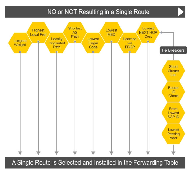
Figure 19. BGP Best Path Selection
Best Path Selection Details
1. Prefer the path with the largest WEIGHT attribute.
2. Prefer the path with the largest LOCAL_PREF attribute.
3. Prefer the path that was locally Originated via a network command, redistribute
command or aggregate-address command.
a. Routes originated with the Originated via a network or redistribute commands are
preferred over routes originated with the aggregate-address command.
4. Prefer the path with the shortest AS_PATH (unless the bgp bestpath as-path ignore command
is configured, then AS_PATH is not considered). The following criteria apply:
a. An AS_SET has a path length of 1, no matter how many ASs are in the set.
b. A path with no AS_PATH configured has a path length of 0.
c. AS_CONFED_SET is not included in the AS_PATH length.
d. AS_CONFED_SEQUENCE has a path length of 1, no matter how many ASs are in the
AS_CONFED_SEQUENCE.
5. Prefer the path with the lowest ORIGIN type (IGP is lower than EGP, and EGP is lower than
INCOMPLETE).
6. Prefer the path with the lowest multi-exit discriminator (MED) attribute. The following criteria apply:
a. This comparison is only done if the first (neighboring) AS is the same in the two paths; the MEDs
are compared only if the first AS in the AS_SEQUENCE is the same for both paths.
b. If you entered the bgp always-compare-med command, MEDs are compared for all paths.
152 Border Gateway Protocol IPv4 (BGPv4)

c. Paths with no MED are treated as “worst” and assigned a MED of 4294967295.
7. Prefer external (EBGP) to internal (IBGP) paths or confederation EBGP paths.
8. Prefer the path with the lowest IGP metric to the BGP if next-hop is selected when
synchronization is disabled and only an internal path remains.
9. The system deems the paths as equal and does not perform steps 9 through 11, if the following
criteria is met:
a. the IBGP multipath or EBGP multipath are configured (the maximum-path command).
b. the paths being compared were received from the same AS with the same number of ASs in the
AS Path but with different NextHops.
c. the paths were received from IBGP or EBGP neighbor respectively.
10. If the bgp bestpath router-id ignore command is enabled and:
a. if the Router-ID is the same for multiple paths (because the routes were received from the same
route) skip this step.
b. if the Router-ID is NOT the same for multiple paths, prefer the path that was first received as
the Best Path. The path selection algorithm returns without performing any of the checks
detailed here.
11. Prefer the external path originated from the BGP router with the lowest router ID. If both paths are
external, prefer the oldest path (first received path). For paths containing a route reflector (RR)
attribute, the originator ID is substituted for the router ID.
12. If two paths have the same router ID, prefer the path with the lowest cluster ID length. Paths without
a cluster ID length are set to a 0 cluster ID length.
13. Prefer the path originated from the neighbor with the lowest address. (The neighbor address is used
in the BGP neighbor configuration and corresponds to the remote peer used in the TCP connection
with the local router.)
After a number of best paths is determined, this selection criteria is applied to group’s best to determine
the ultimate best path.
In non-deterministic mode (the bgp non-deterministic-med command is applied), paths are
compared in the order in which they arrive. This method can lead to the system choosing different best
paths from a set of paths, depending on the order in which they were received from the neighbors
because MED may or may not get compared between the adjacent paths. In deterministic mode, the
system compares MED between the adjacent paths within an AS group because all paths in the AS group
are from the same AS.
Weight
The weight attribute is local to the router and is not advertised to neighboring routers.
If the router learns about more than one route to the same destination, the route with the highest weight
is preferred. The route with the highest weight is installed in the IP routing table.
Local Preference
Local preference (LOCAL_PREF) represents the degree of preference within the entire AS. The higher the
number, the greater the preference for the route.
Local preference (LOCAL_PREF) is one of the criteria used to determine the best path, so keep in mind
that other criteria may impact selection, as shown in the illustration in Best Path Selection Criteria. For
this example, assume that thelocal preference (LOCAL_PREF) is the only attribute applied. In the
following illustration, AS100 has two possible paths to AS 200. Although the path through Router A is
shorter (one hop instead of two), the LOCAL_PREF settings have the preferred path go through Router B
Border Gateway Protocol IPv4 (BGPv4) 153
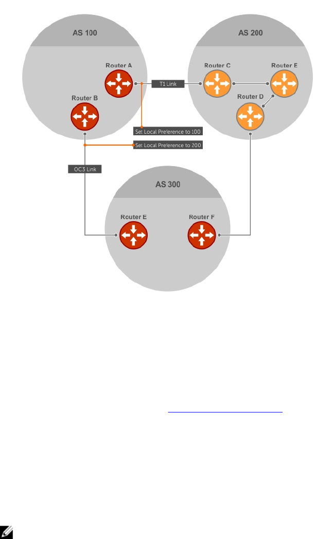
and AS300. This is advertised to all routers within AS100, causing all BGP speakers to prefer the path
through Router B.
Figure 20. BGP Local Preference
Multi-Exit Discriminators (MEDs)
If two ASs connect in more than one place, a multi-exit discriminator (MED) can be used to assign a
preference to a preferred path.
MED is one of the criteria used to determine the best path, so keep in mind that other criteria may impact
selection, as shown in the illustration in Best Path Selection Criteria.
One AS assigns the MED a value and the other AS uses that value to decide the preferred path. For this
example, assume the MED is the only attribute applied. In the following illustration, AS100 and AS200
connect in two places. Each connection is a BGP session. AS200 sets the MED for its T1 exit point to 100
and the MED for its OC3 exit point to 50. This sets up a path preference through the OC3 link. The MEDs
are advertised to AS100 routers so they know which is the preferred path.
MEDs are non-transitive attributes. If AS100 sends an MED to AS200, AS200 does not pass it on to AS300
or AS400. The MED is a locally relevant attribute to the two participating ASs (AS100 and AS200).
NOTE: The MEDs are advertised across both links, so if a link goes down, AS 1 still has connectivity
to AS300 and AS400.
154 Border Gateway Protocol IPv4 (BGPv4)
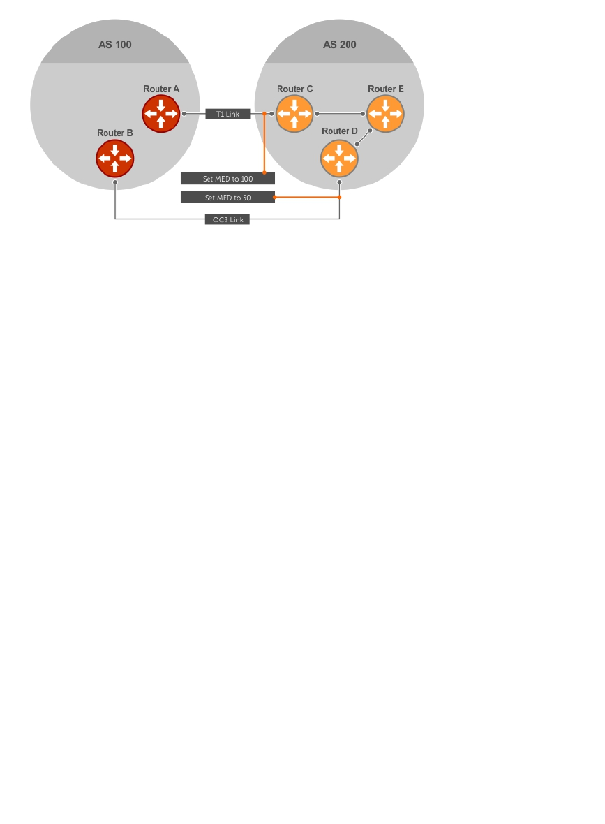
Figure 21. Multi-Exit Discriminators
Origin
The origin indicates the origin of the prefix, or how the prefix came into BGP. There are three origin
codes: IGP, EGP, INCOMPLETE.
Origin Type Description
IGP Indicates the prefix originated from information learned through an interior
gateway protocol.
EGP Indicates the prefix originated from information learned from an EGP protocol,
which NGP replaced.
INCOMPLETE Indicates that the prefix originated from an unknown source.
Generally, an IGP indicator means that the route was derived inside the originating AS. EGP generally
means that a route was learned from an external gateway protocol. An INCOMPLETE origin code
generally results from aggregation, redistribution, or other indirect ways of installing routes into BGP.
In the Dell Networking OS, these origin codes appear as shown in the following example. The question
mark (?) indicates an origin code of INCOMPLETE (shown in bold). The lower case letter (i) indicates an
origin code of IGP (shown in bold).
Example of Viewing Origin Codes
Dell#show ip bgp
BGP table version is 0, local router ID is 10.101.15.13
Status codes: s suppressed, d damped, h history, * valid, > best
Path source: I - internal, a - aggregate, c - confed-external, r -
redistributed, n - network
Origin codes: i - IGP, e - EGP, ? - incomplete
Network Next Hop Metric LocPrf Weight Path
*> 7.0.0.0/29 10.114.8.33 0 0 18508 ?
*> 7.0.0.0/30 10.114.8.33 0 0 18508 ?
*> 9.2.0.0/16 10.114.8.33 10 0 18508 701 i
Border Gateway Protocol IPv4 (BGPv4) 155

AS Path
The AS path is the list of all ASs that all the prefixes listed in the update have passed through.
The local AS number is added by the BGP speaker when advertising to a eBGP neighbor.
The AS path is shown in the following example. The origin attribute is shown following the AS path
information (shown in bold).
Example of Viewing AS Paths
Dell#show ip bgp paths
Total 30655 Paths
Address Hash Refcount Metric Path
0x4014154 0 3 18508 701 3549 19421 i
0x4013914 0 3 18508 701 7018 14990 i
0x5166d6c 0 3 18508 209 4637 1221 9249 9249 i
0x5e62df4 0 2 18508 701 17302 i
0x3a1814c 0 26 18508 209 22291 i
0x567ea9c 0 75 18508 209 3356 2529 i
0x6cc1294 0 2 18508 209 1239 19265 i
0x6cc18d4 0 1 18508 701 2914 4713 17935 i
0x5982e44 0 162 18508 209 i
0x67d4a14 0 2 18508 701 19878 ?
0x559972c 0 31 18508 209 18756 i
0x59cd3b4 0 2 18508 209 7018 15227 i
0x7128114 0 10 18508 209 3356 13845 i
0x536a914 0 3 18508 209 701 6347 7781 i
0x2ffe884 0 1 18508 701 3561 9116 21350 i
Next Hop
The next hop is the IP address used to reach the advertising router.
For EBGP neighbors, the next-hop address is the IP address of the connection between the neighbors.
For IBGP, the EBGP next-hop address is carried into the local AS. A next hop attribute is set when a BGP
speaker advertises itself to another BGP speaker outside its local AS and when advertising routes within
an AS. The next hop attribute also serves as a way to direct traffic to another BGP speaker, rather than
waiting for a speaker to advertise.
The system allows you to set the next hop attribute in the CLI. Setting the next hop attribute lets you
determine a router as the next hop for a BGP neighbor.
Multiprotocol BGP
Multiprotocol extensions for BGP (MBGP) is defined in IETF RFC 2858. MBGP allows different types of
address families to be distributed in parallel.
MBGP allows information about the topology of the IP multicast-capable routers to be exchanged
separately from the topology of normal IPv4 and IPv6 unicast routers. It allows a multicast routing
topology different from the unicast routing topology.
NOTE: It is possible to configure BGP peers that exchange both unicast and multicast network layer
reachability information (NLRI), but you cannot connect multiprotocol BGP with BGP. Therefore,
you cannot redistribute multiprotocol BGP routes into BGP.
156 Border Gateway Protocol IPv4 (BGPv4)

Implement BGP
The following sections describe how BGP is implemented on the Z9500 switch.
Additional Path (Add-Path) Support
The add-path feature reduces convergence times by advertising multiple paths to its peers for the same
address prefix without replacing existing paths with new ones. By default, a BGP speaker advertises only
the best path to its peers for a given address prefix. If the best path becomes unavailable, the BGP speaker
withdraws its path from its local RIB and recalculates a new best path. This situation requires both IGP
and BGP convergence and can be a lengthy process. BGP add-path also helps switchover to the next
new best path when the current best path is unavailable.
Advertise IGP Cost as MED for Redistributed Routes
When using multipath connectivity to an external AS, you can advertise the MED value selectively to each
peer for redistributed routes. For some peers you can set the internal/IGP cost as the MED while setting
others to a constant pre-defined metric as MED value.
Use the set metric-type internal command in a route-map to advertise the IGP cost as the MED
to outbound EBGP peers when redistributing routes. The configured set metric value overwrites the
default IGP cost.
By using the redistribute command with the route-map command, you can specify whether a peer
advertises the standard MED or uses the IGP cost as the MED.
When configuring this functionality:
• If the redistribute command does not have metric configured and the BGP peer outbound
route-map does have metric-type internal configured, BGP advertises the IGP cost as MED.
• If the redistribute command has metric configured (route-map set metric or
redistribute route-type metric) and the BGP peer outbound route-map has metric-type
internal configured, BGP advertises the metric configured in the redistribute command as
MED.
• If BGP peer outbound route-map has metric configured, all other metrics are overwritten by this
configuration.
NOTE: When redistributing static, connected, or OSPF routes, there is no metric option. Simply
assign the appropriate route-map to the redistributed route.
The following table lists some examples of these rules.
Table 6. Redistributed Route Rules
Command Settings BGP Local Routing
Information Base MED Advertised to Peer
WITH route-map
metric-type internal
MED Advertised to Peer
WITHOUT route-map
metric-type internal
redistribute isis (IGP cost
= 20)
MED: IGP cost 20 MED = 20 MED = 0
redistribute isis route-
map set metric 50
MED: IGP cost 50 MED: 50 MED: 50 MED: 50 MED: 50
redistribute isis metric
100
MED: IGP cost 100 MED: 100 MED: 100
Border Gateway Protocol IPv4 (BGPv4) 157

Ignore Router-ID for Some Best-Path Calculations
You can avoid unnecessary BGP best-path transitions between external paths under certain conditions.
The bgp bestpath router-id ignore command reduces network disruption caused by routing and
forwarding plane changes and allows for faster convergence.
Four-Byte AS Numbers
The 4-Byte (32-bit) format is supported to configure autonomous system numbers (ASNs).
The 4-Byte support is advertised as a new BGP capability (4-BYTE-AS) in the OPEN message. If a 4-Byte
BGP speaker has sent and received this capability from another speaker, all the messages will be 4-octet.
The behavior of a 4-Byte BGP speaker is different with the peer depending on whether the peer is a 4-
Byte or 2-Byte BGP speaker.
Where the 2-Byte format is 1-65535, the 4-Byte format is 1-4294967295. Enter AS numbers using the
traditional format. If the ASN is greater than 65535, the dot format is shown when using the show ip
bgp commands. For example, an ASN entered as 3183856184 appears in the show commands as
48581.51768; an ASN of 65123 is shown as 65123. To calculate the comparable dot format for an ASN
from a traditional format, use ASN/65536. ASN%65536.
Traditional Format DOT Format
65001 0.65501
65536 1.0
100000 1.34464
4294967295 65535.65535
When creating Confederations, all the routers in a Confederation must be either 4-Byte or 2-Byte
identified routers. You cannot mix them.
Configure 4-byte AS numbers with the four-octet-support command.
AS4 Number Representation
Multiple representations of 4-byte AS numbers (asplain, asdot+, and asdot) are supported.
NOTE: The ASDOT and ASDOT+ representations are supported only with the 4-Byte AS numbers
feature. If 4-Byte AS numbers are not implemented, only ASPLAIN representation is supported.
ASPLAIN is the default method the system uses. With the ASPLAIN notation, a 32-bit binary AS number is
translated into a decimal value.
• All AS numbers between 0 and 65535 are represented as a decimal number when entered in the CLI
and when displayed in the show commands output.
• AS numbers larger than 65535 are represented using ASPLAIN notation. When entered in the CLI and
when displayed in the show commands output, 65546 is represented as 65546.
ASDOT+ representation splits the full binary 4-byte AS number into two words of 16 bits separated by a
decimal point (.): <high-order 16 bit value>.<low-order 16 bit value>. Some examples are shown in the
following table.
158 Border Gateway Protocol IPv4 (BGPv4)

• All AS numbers between 0 and 65535 are represented as a decimal number, when entered in the CLI
and when displayed in the show commands outputs.
• AS Numbers larger than 65535 is represented using ASDOT notation as <higher 2 bytes in
decimal>.<lower 2 bytes in decimal>. For example: AS 65546 is represented as 1.10.
ASDOT representation combines the ASPLAIN and ASDOT+ representations. AS numbers less than 65536
appear in integer format (asplain); AS numbers equal to or greater than 65536 appear in the decimal
format (asdot+). For example, the AS number 65526 appears as 65526 and the AS number 65546 appears
as 1.10.
Dynamic AS Number Notation Application
A change in the ASN notation type is dynamically applied to the running-config statements.
When you apply or change an ASN notation, the type selected is reflected immediately in the running-
configuration and the show commands (refer to the following two examples).
Example of Dynamic Changes in the Running Configuration When Using the bgp asnotation
Command
ASDOT
Dell(conf-router_bgp)#bgp asnotation asdot
Dell(conf-router_bgp)#show conf
!
router bgp 100
bgp asnotation asdot
bgp four-octet-as-support
neighbor 172.30.1.250 local-as 65057
<output truncated>
Dell(conf-router_bgp)#do show ip bgp
BGP table version is 24901, local router ID is 172.30.1.57
<output truncated>
ASDOT+
Dell(conf-router_bgp)#bgp asnotation asdot+
Dell(conf-router_bgp)#show conf
!
router bgp 100
bgp asnotation asdot+
bgp four-octet-as-support
neighbor 172.30.1.250 local-as 65057
<output truncated>
Dell(conf-router_bgp)#do show ip bgp
BGP table version is 31571, local router ID is 172.30.1.57
<output truncated>
AS-PLAIN
Dell(conf-router_bgp)#bgp asnotation asplain
Dell(conf-router_bgp)#sho conf
!
router bgp 100
bgp four-octet-as-support
neighbor 172.30.1.250 local-as 65057
<output truncated>
Dell(conf-router_bgp)#do sho ip bgp
BGP table version is 34558, local router ID is 172.30.1.57
<output truncated>
Border Gateway Protocol IPv4 (BGPv4) 159

Example of the Running Configuration When AS Notation is Disabled
AS NOTATION DISABLED
Dell(conf-router_bgp)#no bgp asnotation
Dell(conf-router_bgp)#sho conf
!
router bgp 100
bgp four-octet-as-support
neighbor 172.30.1.250 local-as 65057
<output truncated>
Dell(conf-router_bgp)#do sho ip bgp
BGP table version is 28093, local router ID is 172.30.1.57
AS4 SUPPORT DISABLED
Dell(conf-router_bgp)#no bgp four-octet-as-support
Dell(conf-router_bgp)#sho conf
!
router bgp 100
neighbor 172.30.1.250 local-as 65057
Dell(conf-router_bgp)#do show ip bgp
BGP table version is 28093, local router ID is 172.30.1.57
AS Number Migration
With this feature you can transparently change the AS number of an entire BGP network and ensure that
the routes are propagated throughout the network while the migration is in progress.
When migrating one AS to another, perhaps combining ASs, an eBGP network may lose its routing to an
iBGP if the ASN changes. Migration can be difficult as all the iBGP and eBGP peers of the migrating
network must be updated to maintain network reachability. Essentially, Local-AS provides a capability to
the BGP speaker to operate as if it belongs to "virtual" AS network besides its physical AS network.
The following illustration shows a scenario where Router A, Router B, and Router C belong to AS 100,
200, and 300, respectively. Router A acquired Router B; Router B has Router C as its customer. When
Router B is migrating to Router A, it must maintain the connection with Router C without immediately
updating Router C’s configuration. Local-AS allows this behavior to happen by allowing Router B to
appear as if it still belongs to Router B’s old network (AS 200) as far as communicating with Router C is
concerned.
160 Border Gateway Protocol IPv4 (BGPv4)
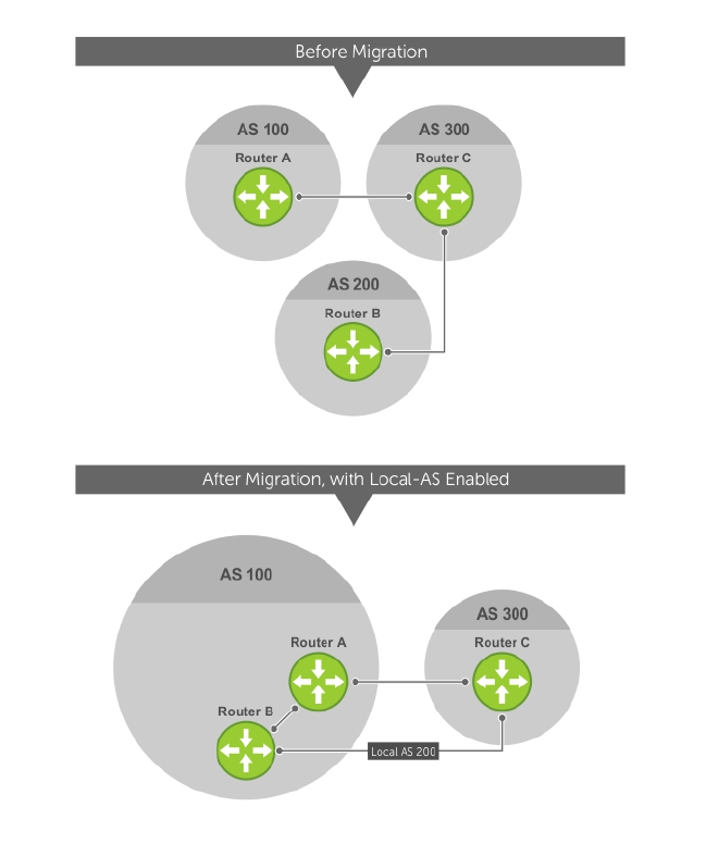
Figure 22. Before and After AS Number Migration with Local-AS Enabled
When you complete your migration, and you have reconfigured your network with the new information,
disable this feature.
If you use the “no prepend” option, the Local-AS does not prepend to the updates received from the
eBGP peer. If you do not select “no prepend” (the default), the Local-AS is added to the first AS segment
in the AS-PATH. If an inbound route-map is used to prepend the as-path to the update from the peer, the
Local-AS is added first. For example, consider the topology described in the previous illustration. If Router
B has an inbound route-map applied on Router C to prepend "65001 65002" to the as-path, the
following events take place on Router B:
1. Receive and validate the update.
2. Prepend local-as 200 to as-path.
3. Prepend "65001 65002" to as-path.
Local-AS is prepended before the route-map to give an impression that update passed through a router
in AS 200 before it reached Router B.
Border Gateway Protocol IPv4 (BGPv4) 161

BGP4 Management Information Base (MIB)
The FORCE10-BGP4-V2-MIB enhances support for the BGP management information base (MIB) with
many new simple network management protocol (SNMP) objects and notifications (traps) defined in
draft-ietf-idr-bgp4-mibv2-05. To see these enhancements, download the MIB from the Dell website.
NOTE: For the Force10-BGP4-V2-MIB and other MIB documentation, refer to the Dell iSupport web
page.
Important Points to Remember
• Because eBGP packets are not controlled by the ACL, packets from BGP neighbors cannot be blocked
using the deny ip command.
• The f10BgpM2AsPathTableEntry table, f10BgpM2AsPathSegmentIndex, and
f10BgpM2AsPathElementIndex are used to retrieve a particular ASN from the AS path. These indices
are assigned to the AS segments and individual ASN in each segment starting from 0. For example, an
AS path list of {200 300 400} 500 consists of two segments: {200 300 400} with segment index 0 and
500 with segment index 1. ASN 200, 300, and 400 are assigned 0, 1, and 2 element indices in that
order.
• Unknown optional transitive attributes within a given path attribute (PA) are assigned indices in order.
These indices correspond to the f10BgpM2PathAttrUnknownIndex field in the
f10BgpM2PathAttrUnknownEntry table.
• Negotiation of multiple instances of the same capability is not supported.
F10BgpM2PeerCapAnnouncedIndex and f10BgpM2PeerCapReceivedIndex are ignored in the peer
capability lookup.
• Configure inbound BGP soft-reconfiguration on a peer for f10BgpM2PrefixInPrefixesRejected to
display the number of prefixes filtered due to a policy. If you do enable BGP soft-reconfig, the
denied prefixes are not accounted for.
•F10BgpM2AdjRibsOutRoute stores the pointer to the NLRI in the peer's Adj-Rib-Out.
• PA Index (f10BgpM2PathAttrIndex field in various tables) is used to retrieve specific attributes from the
PA table. The Next-Hop, RR Cluster-list, and Originator ID attributes are not stored in the PA Table
and cannot be retrieved using the index passed in command. These fields are not populated in
f10BgpM2PathAttrEntry, f10BgpM2PathAttrClusterEntry, and f10BgpM2PathAttrOriginatorIdEntry.
•F10BgpM2PathAttrUnknownEntry contains the optional-transitive attribute details.
• Query for f10BgpM2LinkLocalNextHopEntry returns the default value for Link-local Next-hop.
• RFC 2545 and the f10BgpM2Rfc2545Group are not supported.
• An SNMP query displays up to 89 AS paths. A query for a larger AS path count displays as "…" at the
end of the output.
• SNMP set for BGP is not supported. For all peer configuration tables
(f10BgpM2PeerConfigurationGroup, f10BgpM2PeerRouteReflectorCfgGroup, and
f10BgpM2PeerAsConfederationCfgGroup), an SNMP set operation returns an error. Only SNMP
queries are supported. In addition, the f10BgpM2CfgPeerError, f10BgpM2CfgPeerBgpPeerEntry, and
f10BgpM2CfgPeerRowEntryStatus fields are to hold the SNMP set status and are ignored in SNMP
query.
• The AFI/SAFI is not used as an index to the f10BgpM2PeerCountersEntry table. The BGP peer’s AFI/
SAFI (IPv4 Unicast or IPv6 Multicast) is used for various outbound counters. Counters corresponding
to IPv4 Multicast cannot be queried.
• The f10BgpM2[Cfg]PeerReflectorClient field is populated based on the assumption that route-
reflector clients are not in a full mesh if you enable BGP client-2-client reflection and that
the BGP speaker acting as reflector advertises routes learned from one client to another client. If
disabled, it is assumed that clients are in a full mesh and there is no need to advertise prefixes to the
other clients.
162 Border Gateway Protocol IPv4 (BGPv4)

• High CPU utilization may be observed during an SNMP walk of a large BGP Loc-RIB.
• To avoid SNMP timeouts with a large-scale configuration (large number of BGP neighbors and a large
BGP Loc-RIB), Dell Networking recommends setting the timeout and retry count values to a relatively
higher number. For example, t = 60 or r = 5.
• To return all values on an snmpwalk for the f10BgpM2Peer sub-OID, use the -C c option, such as
snmpwalk -v 2c -C c -c public<IP_address><OID>.
• An SNMP walk may terminate pre-maturely if the index does not increment lexicographically. Dell
Networking recommends using options to ignore such errors.
• Multiple BPG process instances are not supported. Thus, the f10BgpM2PeerInstance field in various
tables is not used to locate a peer.
• Multiple instances of the same NLRI in the BGP RIB are not supported and are set to zero in the SNMP
query response.
• The f10BgpM2NlriIndex and f10BgpM2AdjRibsOutIndex fields are not used.
• Carrying MPLS labels in BGP is not supported. The f10BgpM2NlriOpaqueType and
f10BgpM2NlriOpaquePointer fields are set to zero.
• 4-byte ASN is supported. The f10BgpM2AsPath4byteEntry table contains 4-byte ASN-related
parameters based on the configuration.
Traps (notifications) specified in the BGP4 MIB draft <draft-ietf-idr-bgp4–mibv2–05.txt> are not
supported. Such traps (bgpM2Established and bgpM2BackwardTransition) are supported as part of RFC
1657.
Configuration Information
The software supports BGPv4 as well as the following:
• deterministic multi-exit discriminator (MED) (default)
• a path with a missing MED is treated as worst path and assigned an MED value of (0xffffffff)
• the community format follows RFC 1998
• delayed configuration (the software at system boot reads the entire configuration file prior to sending
messages to start BGP peer sessions)
The following are not yet supported:
• auto-summarization (the default is no auto-summary)
• synchronization (the default is no synchronization)
BGP Configuration
To enable the BGP process and begin exchanging information, assign an AS number and use commands
in ROUTER BGP mode to configure a BGP neighbor.
By default, BGP is disabled.
By default, the system compares the MED attribute on different paths from within the same AS (the bgp
always-compare-med command is not enabled).
NOTE: All newly configured neighbors and peer groups are disabled. To enable a neighbor or peer
group, enter the neighbor {ip-address | peer-group-name} no shutdown command.
The following table displays the default values for BGP in the Dell Networking OS.
Border Gateway Protocol IPv4 (BGPv4) 163

Table 7. BGP Default Values
Item Default
BGP Neighbor Adjacency changes All BGP neighbor changes are logged.
Fast External Fallover feature Disabled
Graceful Restart feature Disabled
Local preference 100
MED 0
Route Flap Damping Parameters half-life = 15 minutes
reuse = 750
suppress = 2000
max-suppress-time = 60 minutes
Distance external distance = 20
internal distance = 200
local distance = 200
Timers keepalive = 60 seconds
holdtime = 180 seconds
Add-path Disabled
Enabling BGP
By default, BGP is not enabled on the system. The Dell Networking OS supports one autonomous system
(AS) and assigns the AS number (ASN).
To establish BGP sessions and route traffic, configure at least one BGP neighbor or peer.
In BGP, routers with an established TCP connection are called neighbors or peers. After a connection is
established, the neighbors exchange full BGP routing tables with incremental updates afterward. In
addition, neighbors exchange KEEPALIVE messages to maintain the connection.
In BGP, neighbor routers or peers can be classified as internal or external. External BGP peers must be
connected physically to one another (unless you enable the EBGP multihop feature), while internal BGP
peers do not need to be directly connected. The IP address of an EBGP neighbor is usually the IP address
of the interface directly connected to the router. First, the BGP process determines if all internal BGP
peers are reachable, then it determines which peers outside the AS are reachable.
NOTE: Sample Configurations for enabling BGP routers are found at the end of this chapter.
1. Assign an AS number and enter ROUTER BGP mode.
CONFIGURATION mode
router bgp as-number
164 Border Gateway Protocol IPv4 (BGPv4)

•as-number: from 0 to 65535 (2 Byte) or from 1 to 4294967295 (4 Byte) or 0.1 to 65535.65535
(Dotted format).
Only one AS is supported per system.
NOTE: If you enter a 4-Byte AS number, 4-Byte AS support is enabled automatically.
a. Enable 4-Byte support for the BGP process.
NOTE: This command is OPTIONAL. Enable if you want to use 4-Byte AS numbers or if you
support AS4 number representation.
CONFIG-ROUTER-BGP mode
bgp four-octet-as-support
NOTE: Use it only if you support 4-Byte AS numbers or if you support AS4 number
representation. If you are supporting 4-Byte ASNs, enable this command.
Disable 4-Byte support and return to the default 2-Byte format by using the no bgp four-
octet-as-support command. You cannot disable 4-Byte support if you currently have a 4-
Byte ASN configured.
Disabling 4-Byte AS numbers also disables ASDOT and ASDOT+ number representation. All AS
numbers are displayed in ASPLAIN format.
b. Enable IPv4 multicast or IPv6 mode.
CONFIG-ROUTER-BGP mode
address-family [ipv4 | ipv6}
Use this command to enter BGP for IPv6 mode (CONF-ROUTER_BGPv6_AF).
2. Add a neighbor as a remote AS.
CONFIG-ROUTER-BGP mode
neighbor {ip-address | peer-group name} remote-as as-number
•peer-group name: 16 characters
•as-number: from 0 to 65535 (2 Byte) or from 1 to 4294967295 (4 Byte) or 0.1 to 65535.65535
(Dotted format)
Formats: IP Address A.B.C.D
You must Configure Peer Groups before assigning it a remote AS.
3. Enable the BGP neighbor.
CONFIG-ROUTER-BGP mode
neighbor {ip-address | peer-group-name} no shutdown
Examples of the show ip bgp summary Command (2-Byte and 4–Byte AS number)
NOTE: When you change the configuration of a BGP neighbor, always reset it by entering the
clear ip bgp command in EXEC Privilege mode.
Border Gateway Protocol IPv4 (BGPv4) 165

To view the BGP configuration, enter show config in CONFIGURATION ROUTER BGP mode. To view
the BGP status, use the show ip bgp summary command in EXEC Privilege mode. The first example
shows the summary with a 2-byte AS number displayed (in bold); the second example shows that the
summary with a 4-byte AS number using the show ip bgp summary command (displays a 4–byte AS
number in bold).
R2#show ip bgp summary
BGP router identifier 192.168.10.2, local AS number 65123
BGP table version is 1, main routing table version 1
1 network entrie(s) using 132 bytes of memory
1 paths using 72 bytes of memory
BGP-RIB over all using 73 bytes of memory
1 BGP path attribute entrie(s) using 72 bytes of memory
1 BGP AS-PATH entrie(s) using 47 bytes of memory
5 neighbor(s) using 23520 bytes of memory
Neighbor AS MsgRcvd MsgSent TblVer InQ OutQ Up/Down State/Pfx
10.10.21.1 65123 0 0 0 0 0 never Active
10.10.32.3 65123 0 0 0 0 0 never Active
100.10.92.9 65192 0 0 0 0 0 never Active
192.168.10.1 65123 0 0 0 0 0 never Active
192.168.12.2 65123 0 0 0 0 0 never Active
R2#
R2#show ip bgp summary
BGP router identifier 192.168.10.2, local AS number 48735.59224
BGP table version is 1, main routing table version 1
1 network entrie(s) using 132 bytes of memory
1 paths using 72 bytes of memory
BGP-RIB over all using 73 bytes of memory
1 BGP path attribute entrie(s) using 72 bytes of memory
1 BGP AS-PATH entrie(s) using 47 bytes of memory
5 neighbor(s) using 23520 bytes of memory
Neighbor AS MsgRcvd MsgSent TblVer InQ OutQ Up/Down State/Pfx
10.10.21.1 65123 0 0 0 0 0 never Active
10.10.32.3 65123 0 0 0 0 0 never Active
100.10.92.9 65192 0 0 0 0 0 never Active
192.168.10.1 65123 0 0 0 0 0 never Active
192.168.12.2 65123 0 0 0 0 0 never Active
R2#
For the router’s identifier, the system uses the highest IP address of the Loopback interfaces configured.
Because Loopback interfaces are virtual, they cannot go down, thus preventing changes in the router ID.
If you do not configure Loopback interfaces, the highest IP address of any interface is used as the router
ID.
To view the status of BGP neighbors, use the show ip bgp neighbors command in EXEC Privilege
mode as shown in the first example. For BGP neighbor configuration information, use the show
running-config bgp command in EXEC Privilege mode as shown in the second example.
NOTE: The showconfig command in CONFIGURATION ROUTER BGP mode gives the same
information as the show running-config bgp command.
166 Border Gateway Protocol IPv4 (BGPv4)

The following example displays two neighbors: one is an external internal BGP neighbor and the second
one is an internal BGP neighbor. The first line of the output for each neighbor displays the AS number and
states whether the link is an external or internal (shown in bold).
The third line of the show ip bgp neighbors output contains the BGP State. If anything other than
ESTABLISHED is listed, the neighbor is not exchanging information and routes. For more information
about using the show ip bgp neighbors command, refer to the Dell Nettworking OS Command Line
Interface Reference Guide.
Dell#show ip bgp neighbors
BGP neighbor is 10.114.8.60, remote AS 18508, external link
BGP version 4, remote router ID 10.20.20.20
BGP state ESTABLISHED, in this state for 00:01:58
Last read 00:00:14, hold time is 90, keepalive interval is 30 seconds
Received 18552 messages, 0 notifications, 0 in queue
Sent 11568 messages, 0 notifications, 0 in queue
Received 18549 updates, Sent 11562 updates
Minimum time between advertisement runs is 30 seconds
For address family: IPv4 Unicast
BGP table version 216613, neighbor version 201190
130195 accepted prefixes consume 520780 bytes
Prefix advertised 49304, rejected 0, withdrawn 36143
Connections established 1; dropped 0
Last reset never
Local host: 10.114.8.39, Local port: 1037
Foreign host: 10.114.8.60, Foreign port: 179
BGP neighbor is 10.1.1.1, remote AS 65535, internal link
Administratively shut down
BGP version 4, remote router ID 10.0.0.0
BGP state IDLE, in this state for 17:12:40
Last read 17:12:40, hold time is 180, keepalive interval is 60 seconds
Received 0 messages, 0 notifications, 0 in queue
Sent 0 messages, 0 notifications, 0 in queue
Received 0 updates, Sent 0 updates
Minimum time between advertisement runs is 5 seconds
For address family: IPv4 Unicast
BGP table version 0, neighbor version 0
0 accepted prefixes consume 0 bytes
Prefix advertised 0, rejected 0, withdrawn 0
Connections established 0; dropped 0
Last reset never
No active TCP connection
Dell#
The following example shows verifying the BGP configuration.
R2#show running-config bgp
!
router bgp 65123
bgp router-id 192.168.10.2
network 10.10.21.0/24
network 10.10.32.0/24
network 100.10.92.0/24
network 192.168.10.0/24
bgp four-octet-as-support
Border Gateway Protocol IPv4 (BGPv4) 167

neighbor 10.10.21.1 remote-as 65123
neighbor 10.10.21.1 filter-list ISP1in
neighbor 10.10.21.1 no shutdown
neighbor 10.10.32.3 remote-as 65123
neighbor 10.10.32.3 no shutdown
neighbor 100.10.92.9 remote-as 65192
neighbor 100.10.92.9 no shutdown
neighbor 192.168.10.1 remote-as 65123
neighbor 192.168.10.1 update-source Loopback 0
neighbor 192.168.10.1 no shutdown
neighbor 192.168.12.2 remote-as 65123
neighbor 192.168.12.2 update-source Loopback 0
neighbor 192.168.12.2 no shutdown
R2#
Configuring AS4 Number Representations
Enable one type of AS number representation: ASPLAIN, ASDOT+, or ASDOT.
Term Description
ASPLAIN Default method for AS number representation. With the ASPLAIN notation, a 32–bit
binary AS number is translated into a decimal value.
ASDOT+ A representation that splits the full binary 4-byte AS number into two words of 16
bits separated by a decimal point (.): <high-order 16 bit value>.<low-order 16 bit
value>.
ASDOT A representation that combines the ASPLAIN and ASDOT+ representations. AS
numbers less than 65536 appear in integer format (asplain); AS numbers equal to or
greater than 65536 appear using the decimal method (asdot+). For example, the AS
number 65526 appears as 65526 and the AS number 65546 appears as 1.10.
NOTE: The ASDOT and ASDOT+ representations are supported only with the 4-Byte AS numbers
feature. If you do not implement 4-Byte AS numbers, only ASPLAIN representation is supported.
Only one form of AS number representation is supported at a time. You cannot combine the types of
representations within an AS.
To configure AS4 number representations, use the following commands.
• Enable ASPLAIN AS Number representation.
CONFIG-ROUTER-BGP mode
bgp asnotation asplain
NOTE: ASPLAIN is the default method used to represent AS numbers and does not appear in the
configuration display.
• Enable ASDOT AS Number representation.
CONFIG-ROUTER-BGP mode
bgp asnotation asdot
• Enable ASDOT+ AS Number representation.
CONFIG-ROUTER-BGP mode
bgp asnotation asdot+
168 Border Gateway Protocol IPv4 (BGPv4)

Examples of the bgp asnotation Commands
The following example shows the bgp asnotation asplain command.
Dell(conf-router_bgp)#bgp asnotation asplain
Dell(conf-router_bgp)#sho conf
!
router bgp 100
bgp four-octet-as-support
neighbor 172.30.1.250 remote-as 18508
neighbor 172.30.1.250 local-as 65057
neighbor 172.30.1.250 route-map rmap1 in
neighbor 172.30.1.250 password 7
5ab3eb9a15ed02ff4f0dfd4500d6017873cfd9a267c04957
neighbor 172.30.1.250 no shutdown
5332332 9911991 65057 18508 12182 7018 46164 i
The following example shows the bgp asnotation asdot command.
Dell(conf-router_bgp)#bgp asnotation asdot
Dell(conf-router_bgp)#sho conf
!
router bgp 100
bgp asnotation asdot
bgp four-octet-as-support
neighbor 172.30.1.250 remote-as 18508
neighbor 172.30.1.250 local-as 65057
neighbor 172.30.1.250 route-map rmap1 in
neighbor 172.30.1.250 password 7
5ab3eb9a15ed02ff4f0dfd4500d6017873cfd9a267c04957
neighbor 172.30.1.250 no shutdown
5332332 9911991 65057 18508 12182 7018 46164 i
The following example shows the bgp asnotation asdot+ command.
Dell(conf-router_bgp)#bgp asnotation asdot+
Dell(conf-router_bgp)#sho conf
!
router bgp 100
bgp asnotation asdot+
bgp four-octet-as-support
neighbor 172.30.1.250 remote-as 18508
neighbor 172.30.1.250 local-as 65057
neighbor 172.30.1.250 route-map rmap1 in
neighbor 172.30.1.250 password 7
5ab3eb9a15ed02ff4f0dfd4500d6017873cfd9a267c04957
neighbor 172.30.1.250 no shutdown
5332332 9911991 65057 18508 12182 7018 46164 i
Configuring Peer Groups
To configure multiple BGP neighbors at one time, create and populate a BGP peer group.
An advantage of peer groups is that members of a peer group inherit the configuration properties of the
group and share same update policy.
A maximum of 256 peer groups are allowed on the system.
Create a peer group by assigning it a name, then adding members to the peer group. After you create a
peer group, you can configure route policies for it. For information about configuring route policies for a
peer group, refer to Filtering BGP Routes.
Border Gateway Protocol IPv4 (BGPv4) 169

NOTE: Sample Configurations for enabling peer groups are found at the end of this chapter.
1. Create a peer group by assigning a name to it.
CONFIG-ROUTERBGP mode
neighbor peer-group-name peer-group
2. Enable the peer group.
CONFIG-ROUTERBGP mode
neighbor peer-group-name no shutdown
By default, all peer groups are disabled.
3. Create a BGP neighbor.
CONFIG-ROUTERBGP mode
neighbor ip-address remote-as as-number
4. Enable the neighbor.
CONFIG-ROUTERBGP mode
neighbor ip-address no shutdown
5. Add an enabled neighbor to the peer group.
CONFIG-ROUTERBGP mode
neighbor ip-address peer-group peer-group-name
6. Add a neighbor as a remote AS.
CONFIG-ROUTERBGP mode
neighbor {ip-address | peer-group name} remote-as as-number
Formats: IP Address A.B.C.D
•Peer-Group Name: 16 characters.
•as-number: the range is from 0 to 65535 (2-Byte) or 1 to 4294967295 | 0.1 to 65535.65535 (4-
Byte) or 0.1 to 65535.65535 (Dotted format)
To add an external BGP (EBGP) neighbor, configure the as-number parameter with a number
different from the BGP as-number configured in the router bgp as-number command.
To add an internal BGP (IBGP) neighbor, configure the as-number parameter with the same BGP as-
number configured in the router bgp as-number command.
Examples of Working with Peer Groups
After you create a peer group, you can use any of the commands beginning with the keyword neighbor
to configure that peer group.
When you add a peer to a peer group, it inherits all the peer group’s configured parameters.
A neighbor cannot become part of a peer group if it has any of the following commands configured:
•neighbor advertisement-interval
170 Border Gateway Protocol IPv4 (BGPv4)

•neighbor distribute-list out
•neighbor filter-list out
•neighbor next-hop-self
•neighbor route-map out
•neighbor route-reflector-client
•neighbor send-community
A neighbor may keep its configuration after it was added to a peer group if the neighbor’s configuration is
more specific than the peer group’s and if the neighbor’s configuration does not affect outgoing updates.
NOTE: When you configure a new set of BGP policies for a peer group, always reset the peer group
by entering the clear ip bgp peer-group peer-group-name command in EXEC Privilege
mode.
To view the configuration, use the show config command in CONFIGURATION ROUTER BGP mode.
When you create a peer group, it is disabled (shutdown). The following example shows the creation of a
peer group (zanzibar) (in bold).
Dell(conf-router_bgp)#neighbor zanzibar peer-group
Dell(conf-router_bgp)#show conf
!
router bgp 45
bgp fast-external-fallover
bgp log-neighbor-changes
neighbor zanzibar peer-group
neighbor zanzibar shutdown
neighbor 10.1.1.1 remote-as 65535
neighbor 10.1.1.1 shutdown
neighbor 10.14.8.60 remote-as 18505
neighbor 10.14.8.60 no shutdown
Dell(conf-router_bgp)#
To enable a peer group, use the neighbor peer-group-name no shutdown command in
CONFIGURATION ROUTER BGP mode (shown in bold).
Dell(conf-router_bgp)#neighbor zanzibar no shutdown
Dell(conf-router_bgp)#show config
!
router bgp 45
bgp fast-external-fallover
bgp log-neighbor-changes
neighbor zanzibar peer-group
neighbor zanzibar no shutdown
neighbor 10.1.1.1 remote-as 65535
neighbor 10.1.1.1 shutdown
neighbor 10.14.8.60 remote-as 18505
neighbor 10.14.8.60 no shutdown
Dell(conf-router_bgp)#
To disable a peer group, use the neighbor peer-group-name shutdown command in
CONFIGURATION ROUTER BGP mode. The configuration of the peer group is maintained, but it is not
applied to the peer group members. When you disable a peer group, all the peers within the peer group
that are in the ESTABLISHED state move to the IDLE state.
To view the status of peer groups, use the show ip bgp peer-group command in EXEC Privilege
mode, as shown in the following example.
Dell>show ip bgp peer-group
Border Gateway Protocol IPv4 (BGPv4) 171

Peer-group zanzibar, remote AS 65535
BGP version 4
Minimum time between advertisement runs is 5 seconds
For address family: IPv4 Unicast
BGP neighbor is zanzibar, peer-group internal,
Number of peers in this group 26
Peer-group members (* - outbound optimized):
10.68.160.1
10.68.161.1
10.68.162.1
10.68.163.1
10.68.164.1
10.68.165.1
10.68.166.1
10.68.167.1
10.68.168.1
10.68.169.1
10.68.170.1
10.68.171.1
10.68.172.1
10.68.173.1
10.68.174.1
10.68.175.1
10.68.176.1
10.68.177.1
10.68.178.1
10.68.179.1
10.68.180.1
10.68.181.1
10.68.182.1
10.68.183.1
10.68.184.1
10.68.185.1
Dell>
Configuring BGP Fast Fail-Over
By default, a BGP session is governed by the hold time.
BGP routers typically carry large routing tables, so frequent session resets are not desirable. The BGP fast
fail-over feature reduces the convergence time while maintaining stability. The connection to a BGP peer
is immediately reset if a link to a directly connected external peer fails.
When you enable fail-over, BGP tracks IP reachability to the peer remote address and the peer local
address. Whenever either address becomes unreachable (for example, no active route exists in the
routing table for peer IPv6 destinations/local address), BGP brings down the session with the peer.
The BGP fast fail-over feature is configured on a per-neighbor or peer-group basis and is disabled by
default.
To enable the BGP fast fail-over feature, use the following command.
To disable fast fail-over, use the [no] neighbor [neighbor | peer-group] fail-over command
in CONFIGURATION ROUTER BGP mode.
• Enable BGP Fast Fail-Over.
CONFIG-ROUTER-BGP mode
neighbor {ip-address | peer-group-name} fail-over
172 Border Gateway Protocol IPv4 (BGPv4)

Examples of Verifying that Fast Fail-Over is Enabled
To verify fast fail-over is enabled on a particular BGP neighbor, use the show ip bgp neighbors
command. Because fast fail-over is disabled by default, it appears only if it has been enabled (shown in
bold).
Dell#sh ip bgp neighbors
BGP neighbor is 100.100.100.100, remote AS 65517, internal link
Member of peer-group test for session parameters
BGP version 4, remote router ID 30.30.30.5
BGP state ESTABLISHED, in this state for 00:19:15
Last read 00:00:15, last write 00:00:06
Hold time is 180, keepalive interval is 60 seconds
Received 52 messages, 0 notifications, 0 in queue
Sent 45 messages, 5 notifications, 0 in queue
Received 6 updates, Sent 0 updates
Route refresh request: received 0, sent 0
Minimum time between advertisement runs is 5 seconds
Minimum time before advertisements start is 0 seconds
Capabilities received from neighbor for IPv4 Unicast :
MULTIPROTO_EXT(1)
ROUTE_REFRESH(2)
CISCO_ROUTE_REFRESH(128)
Capabilities advertised to neighbor for IPv4 Unicast :
MULTIPROTO_EXT(1)
ROUTE_REFRESH(2)
CISCO_ROUTE_REFRESH(128)
fail-over enabled
Update source set to Loopback 0
Peer active in peer-group outbound optimization
For address family: IPv4 Unicast
BGP table version 52, neighbor version 52
4 accepted prefixes consume 16 bytes
Prefix advertised 0, denied 0, withdrawn 0
Connections established 6; dropped 5
Last reset 00:19:37, due to Reset by peer
Notification History
'Connection Reset' Sent : 5 Recv: 0
Local host: 200.200.200.200, Local port: 65519
Foreign host: 100.100.100.100, Foreign port: 179
Dell#
To verify that fast fail-over is enabled on a peer-group, use the show ip bgp peer-group command
(shown in bold).
Dell#sh ip bgp peer-group
Peer-group test
fail-over enabled
BGP version 4
Minimum time between advertisement runs is 5 seconds
Border Gateway Protocol IPv4 (BGPv4) 173

For address family: IPv4 Unicast
BGP neighbor is test
Number of peers in this group 1
Peer-group members (* - outbound optimized):
100.100.100.100*
Dell#
router bgp 65517
neighbor test peer-group
neighbor test fail-over
neighbor test no shutdown
neighbor 100.100.100.100 remote-as 65517
neighbor 100.100.100.100 fail-over
neighbor 100.100.100.100 update-source Loopback 0
neighbor 100.100.100.100 no shutdown
Dell#
Configuring Passive Peering
When you enable a peer-group, the software sends an OPEN message to initiate a TCP connection.
If you enable passive peering for the peer group, the software does not send an OPEN message, but it
responds to an OPEN message.
When a BGP neighbor connection with authentication configured is rejected by a passive peer-group, the
system does not allow another passive peer-group on the same subnet to connect with the BGP
neighbor. To work around this, change the BGP configuration or change the order of the peer group
configuration.
You can constrain the number of passive sessions accepted by the neighbor. The limit keyword allows
you to set the total number of sessions the neighbor will accept, between 2 and 265. The default is 256
sessions.
1. Configure a peer group that does not initiate TCP connections with other peers.
CONFIG-ROUTER-BGP mode
neighbor peer-group-name peer-group passive limit
Enter the limit keyword to restrict the number of sessions accepted.
2. Assign a subnet to the peer group.
CONFIG-ROUTER-BGP mode
neighbor peer-group-name subnet subnet-number mask
The peer group responds to OPEN messages sent on this subnet.
3. Enable the peer group.
CONFIG-ROUTER-BGP mode
neighbor peer-group-name no shutdown
4. Create and specify a remote peer for BGP neighbor.
CONFIG-ROUTER-BGP mode
neighbor peer-group-name remote-as as-number
174 Border Gateway Protocol IPv4 (BGPv4)

Only after the peer group responds to an OPEN message sent on the subnet does its BGP state change to
ESTABLISHED. After the peer group is ESTABLISHED, the peer group is the same as any other peer group.
For more information about peer groups, refer to Configure Peer Groups.
Maintaining Existing AS Numbers During an AS Migration
The local-as feature smooths out the BGP network migration operation and allows you to maintain
existing ASNs during a BGP network migration.
When you complete your migration, be sure to reconfigure your routers with the new information and
disable this feature.
• Allow external routes from this neighbor.
CONFIG-ROUTERBGP mode
neighbor {IP address | peer-group-name local-as as number [no prepend]
–Peer Group Name: 16 characters.
–AS-number: 0 to 65535 (2-Byte) or 1 to 4294967295 (4-Byte) or 0.1 to 65535.65535 (Dotted
format).
–No Prepend: specifies that local AS values are not prepended to announcements from the
neighbor.
Format: IP Address: A.B.C.D.
You must Configure Peer Groups before assigning it to an AS. This feature is not supported on passive
peer groups.
Example of the Verifying that Local AS Numbering is Disabled
The first line in bold shows the actual AS number. The second two lines in bold show the local AS number
(6500) maintained during migration.
To disable this feature, use the no neighbor local-as command in CONFIGURATION ROUTER BGP
mode.
R2(conf-router_bgp)#show conf
!
router bgp 65123
bgp router-id 192.168.10.2
network 10.10.21.0/24
network 10.10.32.0/24
network 100.10.92.0/24
network 192.168.10.0/24
bgp four-octet-as-support
neighbor 10.10.21.1 remote-as 65123
neighbor 10.10.21.1 filter-list Laura in
neighbor 10.10.21.1 no shutdown
neighbor 10.10.32.3 remote-as 65123
neighbor 10.10.32.3 no shutdown
neighbor 100.10.92.9 remote-as 65192
neighbor 100.10.92.9 local-as 6500
neighbor 100.10.92.9 no shutdown
neighbor 192.168.10.1 remote-as 65123
neighbor 192.168.10.1 update-source Loopback 0
neighbor 192.168.10.1 no shutdown
neighbor 192.168.12.2 remote-as 65123
neighbor 192.168.12.2 update-source Loopback 0
Border Gateway Protocol IPv4 (BGPv4) 175

neighbor 192.168.12.2 no shutdown
R2(conf-router_bgp)#
Allowing an AS Number to Appear in its Own AS Path
This command allows you to set the number of times a particular AS number can occur in the AS path.
The allow-as feature permits a BGP speaker to allow the ASN to be present for a specified number of
times in the update received from the peer, even if that ASN matches its own. The AS-PATH loop is
detected if the local ASN is present more than the specified number of times in the command.
• Allow this neighbor ID to use the AS path the specified number of times.
CONFIG-ROUTER-BGP mode
neighbor {IP address | peer-group-name} allowas-in number
–Peer Group Name: 16 characters.
–Number: 1 through 10.
Format: IP Address: A.B.C.D.
You must Configure Peer Groups before assigning it to an AS.
Example of Viewing AS Numbers in AS Paths
The lines shown in bold are the number of times ASN 65123 can appear in the AS path (allows–in 9).
To disable this feature, use the no neighbor allow-as in number command in CONFIGURATION
ROUTER BGP mode.
R2(conf-router_bgp)#show conf
!
router bgp 65123
bgp router-id 192.168.10.2
network 10.10.21.0/24
network 10.10.32.0/24
network 100.10.92.0/24
network 192.168.10.0/24
bgp four-octet-as-support
neighbor 10.10.21.1 remote-as 65123
neighbor 10.10.21.1 filter-list Laura in
neighbor 10.10.21.1 no shutdown
neighbor 10.10.32.3 remote-as 65123
neighbor 10.10.32.3 no shutdown
neighbor 100.10.92.9 remote-as 65192
neighbor 100.10.92.9 local-as 6500
neighbor 100.10.92.9 no shutdown
neighbor 192.168.10.1 remote-as 65123
neighbor 192.168.10.1 update-source Loopback 0
neighbor 192.168.10.1 no shutdown
neighbor 192.168.12.2 remote-as 65123
neighbor 192.168.12.2 allowas-in 9
neighbor 192.168.12.2 update-source Loopback 0
neighbor 192.168.12.2 no shutdown
R2(conf-router_bgp)#R2(conf-router_bgp)#
Enabling Neighbor Graceful Restart
BGP graceful restart is active only when the neighbor becomes established. Otherwise, it is disabled.
Graceful-restart applies to all neighbors with established adjacency.
176 Border Gateway Protocol IPv4 (BGPv4)
With the graceful restart feature, the system enables the receiving/restarting mode by default. In
Receiver-Only mode, graceful restart saves the advertised routes of peers that support this capability
when they restart. This option provides support for remote peers for their graceful restart without
supporting the feature itself.
You can implement BGP graceful restart either by neighbor or by BGP peer-group. For more information,
refer to the Dell Networking OS Command Line Interface Reference Guide.
• Add graceful restart to a BGP neighbor or peer-group.
CONFIG-ROUTER-BGP mode
neighbor {ip-address | peer-group-name} graceful-restart
• Set the maximum restart time for the neighbor or peer-group.
CONFIG-ROUTER-BGP mode
neighbor {ip-address | peer-group-name} graceful-restart [restart-time time-
in-seconds]
The default is 120 seconds.
• Local router supports graceful restart for this neighbor or peer-group as a receiver only.
CONFIG-ROUTER-BGP mode
neighbor {ip-address | peer-group-name} graceful-restart [role receiver-only]
• Set the maximum time to retain the restarting neighbor’s or peer-group’s stale paths.
CONFIG-ROUTER-BGP mode
neighbor {ip-address | peer-group-name} graceful-restart [stale-path-time
time-in-seconds]
The default is 360 seconds.
Filtering on an AS-Path Attribute
You can use the BGP attribute, AS_PATH, to manipulate routing policies.
The AS_PATH attribute contains a sequence of AS numbers representing the route’s path. As the route
traverses an AS, the ASN is prepended to the route. You can manipulate routes based on their AS_PATH
to affect interdomain routing. By identifying certain ASN in the AS_PATH, you can permit or deny routes
based on the number in its AS_PATH.
AS-PATH ACLs use regular expressions to search AS_PATH values. AS-PATH ACLs have an “implicit deny.”
This means that routes that do not meet a deny or match filter are dropped.
To configure an AS-PATH ACL to filter a specific AS_PATH value, use these commands in the following
sequence.
1. Assign a name to a AS-PATH ACL and enter AS-PATH ACL mode.
CONFIGURATION mode
ip as-path access-list as-path-name
2. Enter the parameter to match BGP AS-PATH for filtering.
CONFIG-AS-PATH mode
Border Gateway Protocol IPv4 (BGPv4) 177

{deny | permit} filter parameter
This is the filter that is used to match the AS-path. The entries can be any format, letters, numbers, or
regular expressions.
You can enter this command multiple times if multiple filters are desired.
For accepted expressions, refer to Regular Expressions as Filters.
3. Return to CONFIGURATION mode.
AS-PATH ACL mode
exit
4. Enter ROUTER BGP mode.
CONFIGURATION mode
router bgp as-number
5. Use a configured AS-PATH ACL for route filtering and manipulation.
CONFIG-ROUTER-BGP mode
neighbor {ip-address | peer-group-name} filter-list as-path-name {in | out}
If you assign an non-existent or empty AS-PATH ACL, the software allows all routes.
Example of the show ip bgp paths Command
To view all BGP path attributes in the BGP database, use the show ip bgp paths command in EXEC
Privilege mode.
Dell#show ip bgp paths
Total 30655 Paths
Address Hash Refcount Metric Path
0x4014154 0 3 18508 701 3549 19421 i
0x4013914 0 3 18508 701 7018 14990 i
0x5166d6c 0 3 18508 209 4637 1221 9249 9249 i
0x5e62df4 0 2 18508 701 17302 i
0x3a1814c 0 26 18508 209 22291 i
0x567ea9c 0 75 18508 209 3356 2529 i
0x6cc1294 0 2 18508 209 1239 19265 i
0x6cc18d4 0 1 18508 701 2914 4713 17935 i
0x5982e44 0 162 18508 209 i
0x67d4a14 0 2 18508 701 19878 ?
0x559972c 0 31 18508 209 18756 i
0x59cd3b4 0 2 18508 209 7018 15227 i
0x7128114 0 10 18508 209 3356 13845 i
0x536a914 0 3 18508 209 701 6347 7781 i
0x2ffe884 0 1 18508 701 3561 9116 21350 i
0x2ff7284 0 99 18508 701 1239 577 855 ?
0x2ff7ec4 0 4 18508 209 3561 4755 17426 i
0x2ff8544 0 3 18508 701 5743 2648 i
0x736c144 0 1 18508 701 209 568 721 1494 i
0x3b8d224 0 10 18508 209 701 2019 i
0x5eb1e44 0 1 18508 701 8584 16158 i
0x5cd891c 0 9 18508 209 6453 4759 i
--More--
178 Border Gateway Protocol IPv4 (BGPv4)

Regular Expressions as Filters
Regular expressions are used to filter AS paths or community lists. A regular expression is a special
character used to define a pattern that is then compared with an input string.
For an AS-path access list, as shown in the previous commands, if the AS path matches the regular
expression in the access list, the route matches the access list.
The following lists the regular expressions accepted in the Dell Networking OS.
Regular Expression Definition
^ (caret) Matches the beginning of the input string. Alternatively, when used as the first
character within brackets [^ ], this matches any number except the ones specified
within the brackets.
$ (dollar) Matches the end of the input string.
. (period) Matches any single character, including white space.
* (asterisk) Matches 0 or more sequences of the immediately previous character or pattern.
+ (plus) Matches 1 or more sequences of the immediately previous character or pattern.
? (question) Matches 0 or 1 sequence of the immediately previous character or pattern.
( ) (parenthesis) Specifies patterns for multiple use when one of the multiplier metacharacters
follows: asterisk *, plus sign +, or question mark ?
[ ] (brackets) Matches any enclosed character and specifies a range of single characters.
- (hyphen) Used within brackets to specify a range of AS or community numbers.
_ (underscore) Matches a ^, a $, a comma, a space, or a {, or a }. Placed on either side of a string to
specify a literal and disallow substring matching. You can precede or follow
numerals enclosed by underscores by any of the characters listed.
| (pipe) Matches characters on either side of the metacharacter; logical OR.
As seen in the following example, the expressions are displayed when using the show commands. To
view the AS-PATH ACL configuration, use the show config command in CONFIGURATION AS-PATH
ACL mode and the show ip as-path-access-list command in EXEC Privilege mode.
For more information about this command and route filtering, refer to Filtering BGP Routes.
The following example applies access list Eagle to routes inbound from BGP peer 10.5.5.2. Access list
Eagle uses a regular expression to deny routes originating in AS 32. The first lines shown in bold create
the access list and filter. The second lines shown in bold are the regular expression shown as part of the
access list filter.
Example of Using Regular Expression to Filter AS Paths
Dell(config)#router bgp 99
Dell(conf-router_bgp)#neigh AAA peer-group
Dell(conf-router_bgp)#neigh AAA no shut
Dell(conf-router_bgp)#show conf
!
router bgp 99
neighbor AAA peer-group
Border Gateway Protocol IPv4 (BGPv4) 179

neighbor AAA no shutdown
neighbor 10.155.15.2 remote-as 32
neighbor 10.155.15.2 shutdown
Dell(conf-router_bgp)#neigh 10.155.15.2 filter-list 1 in
Dell(conf-router_bgp)#ex
Dell(conf)#ip as-path access-list Eagle
Dell(config-as-path)#deny 32$
Dell(config-as-path)#ex
Dell(conf)#router bgp 99
Dell(conf-router_bgp)#neighbor AAA filter-list Eagle in
Dell(conf-router_bgp)#show conf
!
router bgp 99
neighbor AAA peer-group
neighbor AAA filter-list Eaglein
neighbor AAA no shutdown
neighbor 10.155.15.2 remote-as 32
neighbor 10.155.15.2 filter-list 1 in
neighbor 10.155.15.2 shutdown
Dell(conf-router_bgp)#ex
Dell(conf)#ex
Dell#show ip as-path-access-lists
ip as-path access-list Eagle
deny 32$
Dell#
Redistributing Routes
In addition to filtering routes, you can add routes from other routing instances or protocols to the BGP
process. With the redistribute command, you can include ISIS, OSPF, static, or directly connected
routes in the BGP process.
To add routes from other routing instances or protocols, use any of the following commands in ROUTER
BGP mode.
• Include, directly connected or user-configured (static) routes in BGP.
ROUTER BGP or CONF-ROUTER_BGPv6_ AF mode
redistribute {connected | static} [route-map map-name]
Configure the map-name parameter to specify the name of a configured route map.
• Include specific ISIS routes in BGP.
ROUTER BGP or CONF-ROUTER_BGPv6_ AF mode
redistribute isis [level-1 | level-1-2 | level-2] [metric value] [route-map
map-name]
Configure the following parameters:
–level-1, level-1-2, or level-2: Assign all redistributed routes to a level. The default is level-2.
–metric value: The value is from 0 to 16777215. The default is 0.
–map-name: name of a configured route map.
• Include specific OSPF routes in IS-IS.
ROUTER BGP or CONF-ROUTER_BGPv6_ AF mode
180 Border Gateway Protocol IPv4 (BGPv4)

redistribute ospf process-id [match external {1 | 2} | match internal]
[metric-type {external | internal}] [route-map map-name]
Configure the following parameters:
–process-id: the range is from 1 to 65535.
–match external: the range is from 1 or 2.
–match internal
–metric-type: external or internal.
–map-name: name of a configured route map.
Enabling Additional Paths
The add-path feature is disabled by default.
NOTE: Dell Networking recommends not using multipath and add path simultaneously in a route
reflector.
To allow multiple paths sent to peers, use the following commands.
1. Allow the advertisement of multiple paths for the same address prefix without the new paths
replacing any previous ones.
CONFIG-ROUTER-BGP mode
bgp add-path {send | both} path-count count bgp add-path receive
The range is from 2 to 64.
2. Allow the specified neighbor/peer group to send/ receive multiple path advertisements.
CONFIG-ROUTER-BGP mode
neighbor {ipaddress| peergroup name} add-path [send | receive| both] path-
count count
NOTE: The path-count parameter controls the number of paths that are advertised, not the
number of paths that are received.
Configuring IP Community Lists
Mmultiple methods of manipulating routing attributes are supported in the Dell Networking OS.
One attribute you can manipulate is the COMMUNITY attribute. This attribute is an optional attribute that
is defined for a group of destinations. You can assign a COMMUNITY attribute to BGP routers by using an
IP community list. After you create an IP community list, you can apply routing decisions to all routers
meeting the criteria in the IP community list.
IETF RFC 1997 defines the COMMUNITY attribute and the predefined communities of INTERNET,
NO_EXPORT_SUBCONFED, NO_ADVERTISE, and NO_EXPORT. All BGP routes belong to the INTERNET
community. In the RFC, the other communities are defined as follows:
• All routes with the NO_EXPORT_SUBCONFED (0xFFFFFF03) community attribute are not sent to
CONFED-EBGP or EBGP peers, but are sent to IBGP peers within CONFED-SUB-AS.
• All routes with the NO_ADVERTISE (0xFFFFFF02) community attribute must not be advertised.
• All routes with the NO_EXPORT (0xFFFFFF01) community attribute must not be advertised outside a
BGP confederation boundary, but are sent to CONFED-EBGP and IBGP peers.
Border Gateway Protocol IPv4 (BGPv4) 181

The system also supports BGP Extended Communities as described in RFC 4360 — BGP Extended
Communities Attribute.
To configure an IP community list, use these commands.
1. Create a community list and enter COMMUNITY-LIST mode.
CONFIGURATION mode
ip community-list community-list-name
2. Configure a community list by denying or permitting specific community numbers or types of
community.
CONFIG-COMMUNITYLIST mode
{deny | permit} {community-number | local-AS | no-advertise | no-export |
quote-regexp regular-expression-list | regexp regular-expression}
•community-number: use AA:NN format where AA is the AS number (2 Bytes or 4 Bytes) and NN
is a value specific to that autonomous system.
•local-AS: routes with the COMMUNITY attribute of NO_EXPORT_SUBCONFED.
•no-advertise: routes with the COMMUNITY attribute of NO_ADVERTISE.
•no-export: routes with the COMMUNITY attribute of NO_EXPORT.
•quote-regexp: then any number of regular expressions. The software applies all regular
expressions in the list.
•regexp: then a regular expression.
Example of the show ip community-lists Command
To view the configuration, use the show config command in CONFIGURATION COMMUNITY-LIST or
CONFIGURATION EXTCOMMUNITY LIST mode or the show ip {community-lists |
extcommunity-list} command in EXEC Privilege mode.
Dell#show ip community-lists
ip community-list standard 1
deny 701:20
deny 702:20
deny 703:20
deny 704:20
deny 705:20
deny 14551:20
deny 701:112
deny 702:112
deny 703:112
deny 704:112
deny 705:112
deny 14551:112
deny 701:667
deny 702:667
deny 703:667
deny 704:666
deny 705:666
deny 14551:666
Dell#
182 Border Gateway Protocol IPv4 (BGPv4)

Configuring an IP Extended Community List
To configure an IP extended community list, use these commands.
1. Create a extended community list and enter the EXTCOMMUNITY-LIST mode.
CONFIGURATION mode
ip extcommunity-list extcommunity-list-name
2. Two types of extended communities are supported.
CONFIG-COMMUNITY-LIST mode
{permit | deny} {{rt | soo} {ASN:NN | IPADDR:N} | regex REGEX-LINE}
Filter routes based on the type of extended communities they carry using one of the following
keywords:
•rt: route target.
•soo: route origin or site-of-origin. Support for matching extended communities against regular
expression is also supported. Match against a regular expression using the following keyword.
•regexp: regular expression.
Example of the show ip extcommunity-lists Command
To set or modify an extended community attribute, use the set extcommunity {rt | soo}
{ASN:NN | IPADDR:NN} command.
To view the configuration, use the show config command in CONFIGURATION COMMUNITY-LIST or
CONFIGURATION EXTCOMMUNITY LIST mode or the show ip {community-lists |
extcommunity-list} command in EXEC Privilege mode.
Dell#show ip community-lists
ip community-list standard 1
deny 701:20
deny 702:20
deny 703:20
deny 704:20
deny 705:20
deny 14551:20
deny 701:112
deny 702:112
deny 703:112
deny 704:112
deny 705:112
deny 14551:112
deny 701:667
deny 702:667
deny 703:667
deny 704:666
deny 705:666
deny 14551:666
Dell#
Border Gateway Protocol IPv4 (BGPv4) 183
Filtering Routes with Community Lists
To use an IP community list or IP extended community list to filter routes, you must apply a match
community filter to a route map and then apply that route map to a BGP neighbor or peer group.
1. Enter the ROUTE-MAP mode and assign a name to a route map.
CONFIGURATION mode
route-map map-name [permit | deny] [sequence-number]
2. Configure a match filter for all routes meeting the criteria in the IP community or IP extended
community list.
CONFIG-ROUTE-MAP mode
match {community community-list-name [exact] | extcommunity extcommunity-
list-name [exact]}
3. Return to CONFIGURATION mode.
CONFIG-ROUTE-MAP mode
exit
4. Enter ROUTER BGP mode.
CONFIGURATION mode
router bgp as-number
AS-number: 0 to 65535 (2-Byte) or 1 to 4294967295 (4-Byte) or 0.1 to 65535.65535 (Dotted format)
5. Apply the route map to the neighbor or peer group’s incoming or outgoing routes.
CONFIG-ROUTER-BGP mode
neighbor {ip-address | peer-group-name} route-map map-name {in | out}
To view the BGP configuration, use the show config command in CONFIGURATION ROUTER BGP
mode. To view a route map configuration, use the show route-map command in EXEC Privilege mode.
To view which BGP routes meet an IP community or IP extended community list’s criteria, use the show
ip bgp {community-list | extcommunity-list} command in EXEC Privilege mode.
Manipulating the COMMUNITY Attribute
In addition to permitting or denying routes based on the values of the COMMUNITY attributes, you can
manipulate the COMMUNITY attribute value and send the COMMUNITY attribute with the route
information.
By default, the system does not send the COMMUNITY attribute.
To send the COMMUNITY attribute to BGP neighbors, use the following command.
• Enable the software to send the router’s COMMUNITY attribute to the BGP neighbor or peer group
specified.
CONFIG-ROUTER-BGP mode
neighbor {ip-address | peer-group-name} send-community
184 Border Gateway Protocol IPv4 (BGPv4)
To view the BGP configuration, use the show config command in CONFIGURATION ROUTER BGP
mode.
If you want to remove or add a specific COMMUNITY number from a BGP path, you must create a route
map with one or both of the following statements in the route map. Then apply that route map to a BGP
neighbor or peer group.
1. Enter ROUTE-MAP mode and assign a name to a route map.
CONFIGURATION mode
route-map map-name [permit | deny] [sequence-number]
2. Configure a set filter to delete all COMMUNITY numbers in the IP community list.
CONFIG-ROUTE-MAP mode
set comm-list community-list-name delete
OR
set community {community-number | local-as | no-advertise | no-export |
none}
Configure a community list by denying or permitting specific community numbers or types of
community.
•community-number: use AA:NN format where AA is the AS number (2 or 4 Bytes) and NN is a
value specific to that autonomous system.
•local-AS: routes with the COMMUNITY attribute of NO_EXPORT_SUBCONFED and are not sent
to EBGP peers.
•no-advertise: routes with the COMMUNITY attribute of NO_ADVERTISE and are not
advertised.
•no-export: routes with the COMMUNITY attribute of NO_EXPORT.
•none: remove the COMMUNITY attribute.
•additive: add the communities to already existing communities.
3. Return to CONFIGURATION mode.
CONFIG-ROUTE-MAP mode
exit
4. Enter the ROUTER BGP mode.
CONFIGURATION mode
router bgp as-number
5. Apply the route map to the neighbor or peer group’s incoming or outgoing routes.
CONFIG-ROUTER-BGP mode
neighbor {ip-address | peer-group-name} route-map map-name {in | out}
Example of the show ip bgp community Command
To view the BGP configuration, use the show config command in CONFIGURATION ROUTER BGP
mode. To view a route map configuration, use the show route-map command in EXEC Privilege mode.
To view BGP routes matching a certain community number or a pre-defined BGP community, use the
show ip bgp community command in EXEC Privilege mode.
Border Gateway Protocol IPv4 (BGPv4) 185

Dell>show ip bgp community
BGP table version is 3762622, local router ID is 10.114.8.48
Status codes: s suppressed, d damped, h history, * valid, > best, i - internal
Origin codes: i - IGP, e - EGP, ? - incomplete
Network Next Hop Metric LocPrf Weight Path
* i 3.0.0.0/8 195.171.0.16 100 0 209 701 80 i
*>i 4.2.49.12/30 195.171.0.16 100 0 209 i
* i 4.21.132.0/23 195.171.0.16 100 0 209 6461 16422 i
*>i 4.24.118.16/30 195.171.0.16 100 0 209 i
*>i 4.24.145.0/30 195.171.0.16 100 0 209 i
*>i 4.24.187.12/30 195.171.0.16 100 0 209 i
*>i 4.24.202.0/30 195.171.0.16 100 0 209 i
*>i 4.25.88.0/30 195.171.0.16 100 0 209 3561 3908 i
*>i 6.1.0.0/16 195.171.0.16 100 0 209 7170 1455 i
*>i 6.2.0.0/22 195.171.0.16 100 0 209 7170 1455 i
*>i 6.3.0.0/18 195.171.0.16 100 0 209 7170 1455 i
*>i 6.4.0.0/16 195.171.0.16 100 0 209 7170 1455 i
*>i 6.5.0.0/19 195.171.0.16 100 0 209 7170 1455 i
*>i 6.8.0.0/20 195.171.0.16 100 0 209 7170 1455 i
*>i 6.9.0.0/20 195.171.0.16 100 0 209 7170 1455 i
*>i 6.10.0.0/15 195.171.0.16 100 0 209 7170 1455 i
*>i 6.14.0.0/15 205.171.0.16 100 0 209 7170 1455 i
*>i 6.133.0.0/21 205.171.0.16 100 0 209 7170 1455 i
*>i 6.151.0.0/16 205.171.0.16 100 0 209 7170 1455 i
--More--
Changing MED Attributes
By default, the system uses the MULTI_EXIT_DISC or MED attribute when comparing EBGP paths from
the same AS.
To change how the MED attribute is used, enter any or all of the following commands.
• Enable MED comparison in the paths from neighbors with different ASs.
CONFIG-ROUTER-BGP mode
bgp always-compare-med
By default, this comparison is not performed.
• Change the bestpath MED selection.
CONFIG-ROUTER-BGP mode
bgp bestpath med {confed | missing-as-best}
–confed: Chooses the bestpath MED comparison of paths learned from BGP confederations.
–missing-as-best: Treat a path missing an MED as the most preferred one.
To view the nondefault values, use the show config command in CONFIGURATION ROUTER BGP
mode.
Changing the LOCAL_PREFERENCE Attribute
In the Dell Networking OS, you can change the value of the LOCAL_PREFERENCE attribute.
To change the default values of this attribute for all routes received by the router, use the following
command.
• Change the LOCAL_PREF value.
186 Border Gateway Protocol IPv4 (BGPv4)
CONFIG-ROUTER-BGP mode
bgp default local-preference value
–value: the range is from 0 to 4294967295.
The default is 100.
To view the BGP configuration, use the show config command in CONFIGURATION ROUTER BGP
mode or the show running-config bgp command in EXEC Privilege mode.
A more flexible method for manipulating the LOCAL_PREF attribute value is to use a route map.
1. Enter the ROUTE-MAP mode and assign a name to a route map.
CONFIGURATION mode
route-map map-name [permit | deny] [sequence-number]
2. Change LOCAL_PREF value for routes meeting the criteria of this route map.
CONFIG-ROUTE-MAP mode
set local-preference value
3. Return to CONFIGURATION mode.
CONFIG-ROUTE-MAP mode
exit
4. Enter ROUTER BGP mode.
CONFIGURATION mode
router bgp as-number
5. Apply the route map to the neighbor or peer group’s incoming or outgoing routes.
CONFIG-ROUTER-BGP mode
neighbor {ip-address | peer-group-name} route-map map-name {in | out}
To view the BGP configuration, use the show config command in CONFIGURATION ROUTER BGP
mode. To view a route map configuration, use the show route-map command in EXEC Privilege mode.
Changing the NEXT_HOP Attribute
You can change how the NEXT_HOP attribute is used.
To change how the NEXT_HOP attribute is used, enter the first command. To view the BGP
configuration, use the show config command in CONFIGURATION ROUTER BGP mode or the show
running-config bgp command in EXEC Privilege mode.
You can also use route maps to change this and other BGP attributes. For example, you can include the
second command in a route map to specify the next hop address.
• Disable next hop processing and configure the router as the next hop for a BGP neighbor.
CONFIG-ROUTER-BGP mode
neighbor {ip-address | peer-group-name} next-hop-self
• Sets the next hop address.
CONFIG-ROUTE-MAP mode
Border Gateway Protocol IPv4 (BGPv4) 187

set next-hop ip-address
Changing the WEIGHT Attribute
To change how the WEIGHT attribute is used, enter the first command. You can also use route maps to
change this and other BGP attributes. For example, you can include the second command in a route map
to specify the next hop address.
• Assign a weight to the neighbor connection.
CONFIG-ROUTER-BGP mode
neighbor {ip-address | peer-group-name} weight weight
–weight: the range is from 0 to 65535.
The default is 0.
• Sets weight for the route.
CONFIG-ROUTE-MAP mode
set weight weight
–weight: the range is from 0 to 65535.
To view BGP configuration, use the show config command in CONFIGURATION ROUTER BGP mode
or the show running-config bgp command in EXEC Privilege mode.
Enabling Multipath
By default, the system supports one path to a destination. You can enable multipath to allow up to 16
parallel paths to a destination.
NOTE: Dell Networking recommends not using multipath and add path simultaneously in a route
reflector.
To allow more than one path, use the following command.
The show ip bgp network command includes multipath information for that network.
• Enable multiple parallel paths.
CONFIG-ROUTER-BGP mode
maximum-paths {ebgp | ibgp} number
Filtering BGP Routes
Filtering routes allows you to implement BGP policies.
You can use either IP prefix lists, route maps, AS-PATH ACLs or IP community lists (using a route map) to
control which routes the BGP neighbor or peer group accepts and advertises. Prefix lists filter routes
based on route and prefix length, while AS-Path ACLs filter routes based on the ASN. Route maps can
filter and set conditions, change attributes, and assign update policies.
NOTE: The system supports up to 255 characters in a set community statement inside a route map.
NOTE: You can create inbound and outbound policies. Each of the commands used for filtering has
in and out parameters that you must apply. The order of preference varies depending on whether
the attributes are applied for inbound updates or outbound updates.
For inbound and outbound updates the order of preference is:
188 Border Gateway Protocol IPv4 (BGPv4)

• prefix lists (using the neighbor distribute-list command)
• AS-PATH ACLs (using the neighbor filter-list command)
• route maps (using the neighbor route-map command)
Prior to filtering BGP routes, create the prefix list, AS-PATH ACL, or route map.
For configuration information about prefix lists, AS-PATH ACLs, and route maps, refer to Access Control
Lists (ACLs).
NOTE: When you configure a new set of BGP policies, to ensure the changes are made, always
reset the neighbor or peer group by using the clear ip bgp command in EXEC Privilege mode.
To filter routes using prefix lists, use the following commands.
1. Create a prefix list and assign it a name.
CONFIGURATION mode
ip prefix-list prefix-name
2. Create multiple prefix list filters with a deny or permit action.
CONFIG-PREFIX LIST mode
seq sequence-number {deny | permit} {any | ip-prefix [ge | le] }
•ge: minimum prefix length to be matched.
•le: maximum prefix length to me matched.
For information about configuring prefix lists, refer to Access Control Lists (ACLs).
3. Return to CONFIGURATION mode.
CONFIG-PREFIX LIST mode
exit
4. Enter ROUTER BGP mode.
CONFIGURATION mode
router bgp as-number
5. Filter routes based on the criteria in the configured prefix list.
CONFIG-ROUTER-BGP mode
neighbor {ip-address | peer-group-name} distribute-list prefix-list-name {in
| out}
Configure the following parameters:
•ip-address or peer-group-name: enter the neighbor’s IP address or the peer group’s name.
•prefix-list-name: enter the name of a configured prefix list.
•in: apply the prefix list to inbound routes.
•out: apply the prefix list to outbound routes.
As a reminder, the following are rules concerning prefix lists:
• If the prefix list contains no filters, all routes are permitted.
• If none of the routes match any of the filters in the prefix list, the route is denied. This action is called
an implicit deny. (If you want to forward all routes that do not match the prefix list criteria, you must
Border Gateway Protocol IPv4 (BGPv4) 189

configure a prefix list filter to permit all routes. For example, you could have the following filter as the
last filter in your prefix list permit 0.0.0.0/0 le 32).
• After a route matches a filter, the filter’s action is applied. No additional filters are applied to the route.
To view the BGP configuration, use the show config command in ROUTER BGP mode. To view a prefix
list configuration, use the show ip prefix-list detail or show ip prefix-list summary
commands in EXEC Privilege mode.
Filtering BGP Routes Using Route Maps
To filter routes using a route map, use these commands.
1. Create a route map and assign it a name.
CONFIGURATION mode
route-map map-name [permit | deny] [sequence-number]
2. Create multiple route map filters with a match or set action.
CONFIG-ROUTE-MAP mode
{match | set}
For information about configuring route maps, refer to Access Control Lists (ACLs).
3. Return to CONFIGURATION mode.
CONFIG-ROUTE-MAP mode
exit
4. Enter ROUTER BGP mode.
CONFIGURATION mode
router bgp as-number
5. Filter routes based on the criteria in the configured route map.
CONFIG-ROUTER-BGP mode
neighbor {ip-address | peer-group-name} route-map map-name {in | out}
Configure the following parameters:
•ip-address or peer-group-name: enter the neighbor’s IP address or the peer group’s name.
•map-name: enter the name of a configured route map.
•in: apply the route map to inbound routes.
•out: apply the route map to outbound routes.
To view the BGP configuration, use the show config command in CONFIGURATION ROUTER BGP
mode. To view a route map configuration, use the show route-map command in EXEC Privilege mode.
Filtering BGP Routes Using AS-PATH Information
To filter routes based on AS-PATH information, use these commands.
1. Create a AS-PATH ACL and assign it a name.
CONFIGURATION mode
190 Border Gateway Protocol IPv4 (BGPv4)

ip as-path access-list as-path-name
2. Create a AS-PATH ACL filter with a deny or permit action.
AS-PATH ACL mode
{deny | permit} as-regular-expression
3. Return to CONFIGURATION mode.
AS-PATH ACL
exit
4. Enter ROUTER BGP mode.
CONFIGURATION mode
router bgp as-number
5. Filter routes based on the criteria in the configured route map.
CONFIG-ROUTER-BGP mode
neighbor {ip-address | peer-group-name} filter-list as-path-name {in | out}
Configure the following parameters:
•ip-address or peer-group-name: enter the neighbor’s IP address or the peer group’s name.
•as-path-name: enter the name of a configured AS-PATH ACL.
•in: apply the AS-PATH ACL map to inbound routes.
•out: apply the AS-PATH ACL to outbound routes.
To view which commands are configured, use the show config command in CONFIGURATION
ROUTER BGP mode and the show ip as-path-access-list command in EXEC Privilege mode.
To forward all routes not meeting the AS-PATH ACL criteria, include the permit .* filter in your AS-PATH
ACL.
Configuring BGP Route Reflectors
BGP route reflectors are intended for ASs with a large mesh; they reduce the amount of BGP control
traffic.
NOTE: Dell Networking recommends not using multipath and add path simultaneously in a route
reflector.
With route reflection configured properly, IBGP routers are not fully meshed within a cluster but all
receive routing information.
Configure clusters of routers where one router is a concentration router and the others are clients who
receive their updates from the concentration router.
To configure a route reflector, use the following commands.
• Assign an ID to a router reflector cluster.
CONFIG-ROUTER-BGP mode
bgp cluster-id cluster-id
You can have multiple clusters in an AS.
Border Gateway Protocol IPv4 (BGPv4) 191

• Configure the local router as a route reflector and the neighbor or peer group identified is the route
reflector client.
CONFIG-ROUTER-BGP mode
neighbor {ip-address | peer-group-name} route-reflector-client
When you enable a route reflector, the system automatically enables route reflection to all clients. To
disable route reflection between all clients in this reflector, use the no bgp client-to-client
reflection command in CONFIGURATION ROUTER BGP mode. All clients must be fully meshed
before you disable route reflection.
To view a route reflector configuration, use the show config command in CONFIGURATION ROUTER
BGP mode or the show running-config bgp in EXEC Privilege mode.
Aggregating Routes
The system provides multiple ways to aggregate routes in the BGP routing table. At least one specific
route of the aggregate must be in the routing table for the configured aggregate to become active.
To aggregate routes, use the following command.
AS_SET includes AS_PATH and community information from the routes included in the aggregated route.
• Assign the IP address and mask of the prefix to be aggregated.
CONFIG-ROUTER-BGP mode
aggregate-address ip-address mask [advertise-map map-name] [as-set]
[attribute-map map-name] [summary-only] [suppress-map map-name]
Example of Viewing Aggregated Routes
In the show ip bgp command, aggregates contain an ‘a’ in the first column (shown in bold) and routes
suppressed by the aggregate contain an ‘s’ in the first column.
Dell#show ip bgp
BGP table version is 0, local router ID is 10.101.15.13
Status codes: s suppressed, d damped, h history, * valid, > best
Path source: I - internal, a - aggregate, c - confed-external, r - redistributed,
n - network
Origin codes: i - IGP, e - EGP, ? - incomplete
Network Next Hop Metric LocPrf Weight Path
*> 7.0.0.0/29 10.114.8.33 0 0 18508 ?
*> 7.0.0.0/30 10.114.8.33 0 0 18508 ?
*>a 9.0.0.0/8 192.0.0.0 32768 18508 701 {7018 2686 3786} ?
*> 9.2.0.0/16 10.114.8.33 0 18508 701 i
*> 9.141.128.0/24 10.114.8.33 0 18508 701 7018 2686 ?
Dell#
Configuring BGP Confederations
Another way to organize routers within an AS and reduce the mesh for IBGP peers is to configure BGP
confederations.
As with route reflectors, BGP confederations are recommended only for IBGP peering involving many
IBGP peering sessions per router. Basically, when you configure BGP confederations, you break the AS
into smaller sub-AS, and to those outside your network, the confederations appear as one AS. Within the
confederation sub-AS, the IBGP neighbors are fully meshed and the MED, NEXT_HOP, and LOCAL_PREF
attributes are maintained between confederations.
To configure BGP confederations, use the following commands.
192 Border Gateway Protocol IPv4 (BGPv4)
• Specifies the confederation ID.
CONFIG-ROUTER-BGP mode
bgp confederation identifier as-number
–as-number: from 0 to 65535 (2 Byte) or from 1 to 4294967295 (4 Byte).
• Specifies which confederation sub-AS are peers.
CONFIG-ROUTER-BGP mode
bgp confederation peers as-number [... as-number]
–as-number: from 0 to 65535 (2 Byte) or from 1 to 4294967295 (4 Byte).
All Confederation routers must be either 4 Byte or 2 Byte. You cannot have a mix of router ASN
support.
To view the configuration, use the show config command in CONFIGURATION ROUTER BGP mode.
Enabling Route Flap Dampening
When EBGP routes become unavailable, they “flap” and the router issues both WITHDRAWN and UPDATE
notices.
A flap is when a route:
• is withdrawn
• is readvertised after being withdrawn
• has an attribute change
The constant router reaction to the WITHDRAWN and UPDATE notices causes instability in the BGP
process. To minimize this instability, you may configure penalties (a numeric value) for routes that flap.
When the penalty value reaches a configured limit, the route is not advertised, even if the route is up. The
system uses a penalty value is 1024. As time passes and the route does not flap, the penalty value
decrements or is decayed. However, if the route flaps again, it is assigned another penalty.
The penalty value is cumulative and penalty is added under following cases:
• Withdraw
• Readvertise
• Attribute change
When dampening is applied to a route, its path is described by one of the following terms:
• history entry — an entry that stores information on a downed route
• dampened path — a path that is no longer advertised
• penalized path — a path that is assigned a penalty
To configure route flap dampening parameters, set dampening parameters using a route map, clear
information on route dampening and return suppressed routes to active state, view statistics on route
flapping, or change the path selection from the default mode (deterministic) to non-deterministic, use
the following commands.
• Enable route dampening.
CONFIG-ROUTER-BGP mode
Border Gateway Protocol IPv4 (BGPv4) 193
bgp dampening [half-life | reuse | suppress max-suppress-time] [route-map
map-name]
Enter the following optional parameters to configure route dampening parameters:
–half-life: the range is from 1 to 45. Number of minutes after which the Penalty is decreased.
After the router assigns a Penalty of 1024 to a route, the Penalty is decreased by half after the half-
life period expires. The default is 15 minutes.
–reuse: the range is from 1 to 20000. This number is compared to the flapping route’s Penalty
value. If the Penalty value is less than the reuse value, the flapping route is once again advertised
(or no longer suppressed). Withdrawn routes are removed from history state. The default is 750.
–suppress: the range is from 1 to 20000. This number is compared to the flapping route’s Penalty
value. If the Penalty value is greater than the suppress value, the flapping route is no longer
advertised (that is, it is suppressed). The default is 2000.)
–max-suppress-time: the range is from 1 to 255. The maximum number of minutes a route can
be suppressed. The default is four times the half-life value. The default is 60 minutes.
–route-map map-name: name of a configured route map. Only match commands in the
configured route map are supported. Use this parameter to apply route dampening to selective
routes.
• Enter the following optional parameters to configure route dampening.
CONFIG-ROUTE-MAP mode
set dampening half-life reuse suppress max-suppress-time
–half-life: the range is from 1 to 45. Number of minutes after which the Penalty is decreased.
After the router assigns a Penalty of 1024 to a route, the Penalty is decreased by half after the half-
life period expires. The default is 15 minutes.
–reuse: the range is from 1 to 20000. This number is compared to the flapping route’s Penalty
value. If the Penalty value is less than the reuse value, the flapping route is once again advertised
(or no longer suppressed). The default is 750.
–suppress: the range is from 1 to 20000. This number is compared to the flapping route’s Penalty
value. If the Penalty value is greater than the suppress value, the flapping route is no longer
advertised (that is, it is suppressed). The default is 2000.
–max-suppress-time: the range is from 1 to 255. The maximum number of minutes a route can
be suppressed. The default is four times the half-life value. The default is 60 minutes.
• Clear all information or only information on a specific route.
EXEC Privilege
clear ip bgp dampening [ip-address mask]
• View all flap statistics or for specific routes meeting the following criteria.
EXEC or EXEC Privilege mode
show ip bgp flap-statistics [ip-address [mask]] [filter-list as-path-name]
[regexp regular-expression]
–ip-address [mask]: enter the IP address and mask.
–filter-list as-path-name: enter the name of an AS-PATH ACL.
–regexp regular-expression: enter a regular express to match on.
By default, the path selection is deterministic, that is, paths are compared irrespective of the order of
their arrival. You can change the path selection method to non-deterministic, that is, paths are
compared in the order in which they arrived (starting with the most recent). Furthermore, in non-
deterministic mode, the software may not compare MED attributes though the paths are from the
same AS.
194 Border Gateway Protocol IPv4 (BGPv4)

• Change the best path selection method to non-deterministic.
Change the best path selection method to non-deterministic.
CONFIG-ROUTER-BGP mode
bgp non-deterministic-med
NOTE: When you change the best path selection method, path selection for existing paths
remains unchanged until you reset it by entering the clear ip bgp command in EXEC
Privilege mode.
Examples of Working with Route Dampening
To view the BGP configuration, use the show config command in CONFIGURATION ROUTER BGP
mode or the show running-config bgp command in EXEC Privilege mode.
The following example shows how to configure values to reuse or restart a route. In the following
example, default = 15 is the set time before the value decrements, bgp dampening 2 ? is the set
re-advertise value, bgp dampening 2 2000 ? is the suppress value, and bgp dampening 2 2000
3000 ? is the time to suppress a route. Default values are also shown.
Dell(conf-router_bgp)#bgp dampening ?
<1-45> Half-life time for the penalty (default = 15)
route-map Route-map to specify criteria for dampening
<cr>
Dell(conf-router_bgp)#bgp dampening 2 ?
<1-20000> Value to start reusing a route (default = 750)
Dell(conf-router_bgp)#bgp dampening 2 2000 ?
<1-20000> Value to start suppressing a route (default = 2000)
Dell(conf-router_bgp)#bgp dampening 2 2000 3000 ?
<1-255> Maximum duration to suppress a stable route (default = 60)
Dell(conf-router_bgp)#bgp dampening 2 2000 3000 10 ?
route-map Route-map to specify criteria for dampening
<cr>
To view a count of dampened routes, history routes, and penalized routes when you enable route
dampening, look at the seventh line of the show ip bgp summary command output, as shown in the
following example (bold).
Dell>show ip bgp summary
BGP router identifier 10.114.8.131, local AS number 65515
BGP table version is 855562, main routing table version 780266
122836 network entrie(s) and 221664 paths using 29697640 bytes of memory
34298 BGP path attribute entrie(s) using 1920688 bytes of memory
29577 BGP AS-PATH entrie(s) using 1384403 bytes of memory
184 BGP community entrie(s) using 7616 bytes of memory
Dampening enabled. 0 history paths, 0 dampened paths, 0 penalized paths
Neighbor AS MsgRcvd MsgSent TblVer InQ OutQ Up/Down State/PfxRcd
10.114.8.34 18508 82883 79977 780266 0 2 00:38:51 118904
10.114.8.33 18508 117265 25069 780266 0 20 00:38:50 102759
Dell>
To view which routes are dampened (non-active), use the show ip bgp dampened-routes command
in EXEC Privilege mode.
Border Gateway Protocol IPv4 (BGPv4) 195
Changing BGP Timers
To configure BGP timers, use either or both of the following commands.
Timer values configured with the neighbor timers command override the timer values configured
with the timers bgp command.
When two neighbors, configured with different keepalive and holdtime values, negotiate for new
values, the resulting values are as follows:
• the lower of the holdtime values is the new holdtime value, and
• whichever is the lower value; one-third of the new holdtime value, or the configured keepalive
value is the new keepalive value.
• Configure timer values for a BGP neighbor or peer group.
CONFIG-ROUTER-BGP mode
neighbors {ip-address | peer-group-name} timers keepalive holdtime
–keepalive: the range is from 1 to 65535. Time interval, in seconds, between keepalive messages
sent to the neighbor routers. The default is 60 seconds.
–holdtime: the range is from 3 to 65536. Time interval, in seconds, between the last keepalive
message and declaring the router dead. The default is 180 seconds.
• Configure timer values for all neighbors.
CONFIG-ROUTER-BGP mode
timers bgp keepalive holdtime
–keepalive: the range is from 1 to 65535. Time interval, in seconds, between keepalive messages
sent to the neighbor routers. The default is 60 seconds.
–holdtime: the range is from 3 to 65536. Time interval, in seconds, between the last keepalive
message and declaring the router dead. The default is 180 seconds.
To view non-default values, use the show config command in CONFIGURATION ROUTER BGP mode
or the show running-config bgp command in EXEC Privilege mode.
Enabling BGP Neighbor Soft-Reconfiguration
BGP soft-reconfiguration allows for faster and easier route changing.
Changing routing policies typically requires a reset of BGP sessions (the TCP connection) for the policies
to take effect. Such resets cause undue interruption to traffic due to hard reset of the BGP cache and the
time it takes to re-establish the session. BGP soft reconfig allows for policies to be applied to a session
without clearing the BGP Session. Soft-reconfig can be done on a per-neighbor basis and can either be
inbound or outbound.
BGP soft-reconfiguration clears the policies without resetting the TCP connection.
To reset a BGP connection using BGP soft reconfiguration, use the clear ip bgp command in EXEC
Privilege mode at the system prompt.
When you enable soft-reconfiguration for a neighbor and you execute the clear ip bgp soft in
command, the update database stored in the router is replayed and updates are reevaluated. With this
command, the replay and update process is triggered only if a route-refresh request is not negotiated
with the peer. If the request is indeed negotiated (after execution of clear ip bgp soft in), BGP
sends a route-refresh request to the neighbor and receives all of the peer’s updates.
196 Border Gateway Protocol IPv4 (BGPv4)

To use soft reconfiguration (or soft reset) without preconfiguration, both BGP peers must support the soft
route refresh capability, which is advertised in the open message sent when the peers establish a TCP
session.
To determine whether a BGP router supports this capability, use the show ip bgp neighbors
command. If a router supports the route refresh capability, the following message displays: Received
route refresh capability from peer.
If you specify a BGP peer group by using the peer-group-name argument, all members of the peer
group inherit the characteristic configured with this command.
• Clear all information or only specific details.
EXEC Privilege mode
clear ip bgp {* | neighbor-address | AS Numbers | ipv4 | peer-group-name}
[soft [in | out]]
–*: Clears all peers.
–neighbor-address: Clears the neighbor with this IP address.
–AS Numbers: Peers’ AS numbers to be cleared.
–ipv4: Clears information for the IPv4 address family.
–peer-group-name: Clears all members of the specified peer group.
• Enable soft-reconfiguration for the BGP neighbor specified.
CONFIG-ROUTER-BGP mode
neighbor {ip-address | peer-group-name} soft-reconfiguration inbound
BGP stores all the updates received by the neighbor but does not reset the peer-session.
Entering this command starts the storage of updates, which is required to do inbound soft
reconfiguration. Outbound BGP soft reconfiguration does not require inbound soft reconfiguration to
be enabled.
Example of Soft-Reconfigration of a BGP Neighbor
The example enables inbound soft reconfiguration for the neighbor 10.108.1.1. All updates received from
this neighbor are stored unmodified, regardless of the inbound policy. When inbound soft reconfiguration
is done later, the stored information is used to generate a new set of inbound updates.
Dell>router bgp 100
neighbor 10.108.1.1 remote-as 200
neighbor 10.108.1.1 soft-reconfiguration inbound
Route Map Continue
The BGP route map continue feature, continue [sequence-number], (in ROUTE-MAP mode) allows
movement from one route-map entry to a specific route-map entry (the sequence number).
If you do not specify a sequence number, the continue feature moves to the next sequence number (also
known as an “implied continue”). If a match clause exists, the continue feature executes only after a
successful match occurs. If there are no successful matches, continue is ignored.
Border Gateway Protocol IPv4 (BGPv4) 197
Match a Clause with a Continue Clause
The continue feature can exist without a match clause.
Without a match clause, the continue clause executes and jumps to the specified route-map entry. With
a match clause and a continue clause, the match clause executes first and the continue clause next in a
specified route map entry. The continue clause launches only after a successful match. The behavior is:
• A successful match with a continue clause—the route map executes the set clauses and then goes to
the specified route map entry after execution of the continue clause.
• If the next route map entry contains a continue clause, the route map executes the continue clause if
a successful match occurs.
• If the next route map entry does not contain a continue clause, the route map evaluates normally. If a
match does not occur, the route map does not continue and falls-through to the next sequence
number, if one exists
Set a Clause with a Continue Clause
If the route-map entry contains sets with the continue clause, the set actions operation is performed first
followed by the continue clause jump to the specified route map entry.
• If a set actions operation occurs in the first route map entry and then the same set action occurs with
a different value in a subsequent route map entry, the last set of actions overrides the previous set of
actions with the same set command.
• If the set community additive and set as-path prepend commands are configured, the
communities and AS numbers are prepended.
Enabling MBGP Configurations
Multiprotocol BGP (MBGP) is an enhanced BGP that carries IP multicast routes. BGP carries two sets of
routes: one set for unicast routing and one set for multicast routing. The routes associated with multicast
routing are used by the protocol independent multicast (PIM) to build data distribution trees.
MBGP for IPv4 multicast is supported on the Z9500 switch.
In the Dell Networking OS, MBGP is implemented per RFC 1858. You can enable the MBGP feature per
router and/or per peer/peer-group.
The default is IPv4 Unicast routes.
When you configure a peer to support IPv4 multicast, the system takes the following actions:
• Send a capacity advertisement to the peer in the BGP Open message specifying IPv4 multicast as a
supported AFI/SAFI (Subsequent Address Family Identifier).
• If the corresponding capability is received in the peer’s Open message, BGP marks the peer as
supporting the AFI/SAFI.
• When exchanging updates with the peer, BGP sends and receives IPv4 multicast routes if the peer is
marked as supporting that AFI/SAFI.
• Exchange of IPv4 multicast route information occurs through the use of two new attributes called
MP_REACH_NLRI and MP_UNREACH_NLRI, for feasible and withdrawn routes, respectively.
• If the peer has not been activated in any AFI/SAFI, the peer remains in Idle state.
Most BGP IPv4 unicast commands are extended to support the IPv4 multicast RIB using extra options to
the command. For a detailed description of the MBGP commands, refer to the Dell Networking OS
Command Line Interface Reference Guide.
198 Border Gateway Protocol IPv4 (BGPv4)
• Enables support for the IPv4 multicast family on the BGP node.
CONFIG-ROUTER-BGP mode
address family ipv4 multicast
• Enable IPv4 multicast support on a BGP neighbor/peer group.
CONFIG-ROUTER-BGP-AF (Address Family) mode
neighbor [ip-address | peer-group-name] activate
BGP Regular Expression Optimization
The system optimizes processing time when using regular expressions by caching and re-using regular
expression evaluated results, at the expense of some memory in RP1 processor.
BGP policies that contain regular expressions to match against as-paths and communities might take a
lot of CPU processing time, thus affect BGP routing convergence. Also, show bgp commands that get
filtered through regular expressions can to take a lot of CPU cycles, especially when the database is large.
This feature is turned on by default. If necessary, use the bgp regex-eval-optz-disable command in
CONFIGURATION ROUTER BGP mode to disable it.
Debugging BGP
To enable BGP debugging, use any of the following commands.
• View all information about BGP, including BGP events, keepalives, notifications, and updates.
EXEC Privilege mode
debug ip bgp [ip-address | peer-group peer-group-name] [in | out]
• View information about BGP route being dampened.
EXEC Privilege mode
debug ip bgp dampening [in | out]
• View information about local BGP state changes and other BGP events.
EXEC Privilege mode
debug ip bgp [ip-address | peer-group peer-group-name] events [in | out]
• View information about BGP KEEPALIVE messages.
EXEC Privilege mode
debug ip bgp [ip-address | peer-group peer-group-name] keepalive [in | out]
• View information about BGP notifications received from or sent to neighbors.
EXEC Privilege mode
debug ip bgp [ip-address | peer-group peer-group-name] notifications [in |
out]
• View information about BGP updates and filter by prefix name.
EXEC Privilege mode
debug ip bgp [ip-address | peer-group peer-group-name] updates [in | out]
[prefix-list name]
Border Gateway Protocol IPv4 (BGPv4) 199

• Enable soft-reconfiguration debug.
EXEC Privilege mode
debug ip bgp {ip-address | peer-group-name} soft-reconfiguration
To enhance debugging of soft reconfig, use the bgp soft-reconfig-backup command only when
route-refresh is not negotiated to avoid the peer from resending messages.
In-BGP is shown using the show ip protocols command.
The system displays debug messages on the console. To view which debugging commands are enabled,
use the show debugging command in EXEC Privilege mode.
To disable a specific debug command, use the keyword no then the debug command. For example, to
disable debugging of BGP updates, use no debug ip bgp updates command.
To disable all BGP debugging, use the no debug ip bgp command.
To disable all debugging, use the undebug all command.
Storing Last and Bad PDUs
The system stores the last notification sent/received and the last bad protocol data unit (PDU) received
on a per peer basis. The last bad PDU is the one that causes a notification to be issued.
In the following example, the last seven lines shown in bold are the last PDUs.
Example of the show ip bgp neighbor Command to View Last and Bad PDUs
Dell(conf-router_bgp)#do show ip bgp neighbors 1.1.1.2
BGP neighbor is 1.1.1.2, remote AS 2, external link
BGP version 4, remote router ID 2.4.0.1
BGP state ESTABLISHED, in this state for 00:00:01
Last read 00:00:00, last write 00:00:01
Hold time is 90, keepalive interval is 30 seconds
Received 1404 messages, 0 in queue
3 opens, 1 notifications, 1394 updates
6 keepalives, 0 route refresh requests
Sent 48 messages, 0 in queue
3 opens, 2 notifications, 0 updates
43 keepalives, 0 route refresh requests
Minimum time between advertisement runs is 30 seconds
Minimum time before advertisements start is 0 seconds
Capabilities received from neighbor for IPv4 Unicast :
MULTIPROTO_EXT(1)
ROUTE_REFRESH(2)
CISCO_ROUTE_REFRESH(128)
Capabilities advertised to neighbor for IPv4 Unicast :
MULTIPROTO_EXT(1)
ROUTE_REFRESH(2)
CISCO_ROUTE_REFRESH(128)
For address family: IPv4 Unicast
BGP table version 1395, neighbor version 1394
Prefixes accepted 1 (consume 4 bytes), 0 withdrawn by peer
Prefixes advertised 0, rejected 0, 0 withdrawn from peer
Connections established 3; dropped 2
200 Border Gateway Protocol IPv4 (BGPv4)

Last reset 00:00:12, due to Missing well known attribute
Notification History
'UPDATE error/Missing well-known attr' Sent : 1 Recv: 0
'Connection Reset' Sent : 1 Recv: 0
Last notification (len 21) sent 00:26:02 ago
ffffffff ffffffff ffffffff ffffffff 00160303 03010000
Last notification (len 21) received 00:26:20 ago
ffffffff ffffffff ffffffff ffffffff 00150306 00000000
Last PDU (len 41) received 00:26:02 ago that caused notification to be issued
ffffffff ffffffff ffffffff ffffffff 00290200 00000e01 02040201 00024003 04141414 0218c0a8
01000000
Local host: 1.1.1.1, Local port: 179
Foreign host: 1.1.1.2, Foreign port: 41758
Capturing PDUs
To capture incoming and outgoing PDUs on a per-peer basis, use the capture bgp-pdu neighbor
direction command. To disable capturing, use the no capture bgp-pdu neighbor direction
command.
The buffer size supports a maximum value between 40 MB (the default) and 100 MB. The capture buffers
are cyclic and reaching the limit prompts the system to overwrite the oldest PDUs when new ones are
received for a given neighbor or direction. Setting the buffer size to a value lower than the current
maximum, might cause captured PDUs to be freed to set the new limit.
NOTE: Memory on RP1 is not pre-allocated and is allocated only when a PDU needs to be captured.
The buffers storing the PDU free memory when:
• BGP is disabled.
• A neighbor is unconfigured.
• The clear ip bgp command is issued.
• New PDU are captured and there is no more space to store them.
• The max buffer size is reduced. (This may cause PDUs to be cleared depending on the buffer space
consumed and the new limit.)
Examples of Capturing PDUs
To change the maximum buffer size, use the capture bgp-pdu max-buffer-size command.
To view the captured PDUs, use the show capture bgp-pdu neighbor command.
Dell#show capture bgp-pdu neighbor 20.20.20.2
Incoming packet capture enabled for BGP neighbor 20.20.20.2
Available buffer size 40958758, 26 packet(s) captured using 680 bytes
PDU[1] : len 101, captured 00:34:51 ago
ffffffff ffffffff ffffffff ffffffff 00650100 00000013 00000000 00000000
419ef06c 00000000
00000000 00000000 00000000 00000000 0181a1e4 0181a25c 41af92c0 00000000
00000000 00000000
00000000 00000001 0181a1e4 0181a25c 41af9400 00000000
PDU[2] : len 19, captured 00:34:51 ago
ffffffff ffffffff ffffffff ffffffff 00130400
PDU[3] : len 19, captured 00:34:51 ago
ffffffff ffffffff ffffffff ffffffff 00130400
PDU[4] : len 19, captured 00:34:22 ago
ffffffff ffffffff ffffffff ffffffff 00130400
[. . .]
Border Gateway Protocol IPv4 (BGPv4) 201

Outgoing packet capture enabled for BGP neighbor 20.20.20.2
Available buffer size 40958758, 27 packet(s) captured using 562 bytes
PDU[1] : len 41, captured 00:34:52 ago
ffffffff ffffffff ffffffff ffffffff 00290104 000100b4 14141401 0c020a01
04000100 01020080
00000000
PDU[2] : len 19, captured 00:34:51 ago
ffffffff ffffffff ffffffff ffffffff 00130400
PDU[3] : len 19, captured 00:34:50 ago
ffffffff ffffffff ffffffff ffffffff 00130400
PDU[4] : len 19, captured 00:34:20 ago
ffffffff ffffffff ffffffff ffffffff 00130400
[. . .]
With full internet feed (205K) captured, approximately 11.8MB is required to store all of the PDUs.
The following example shows viewing space requirements for storing all PDUs.
Dell(conf-router_bgp)#do show capture bgp-pdu neighbor 172.30.1.250
Incoming packet capture enabled for BGP neighbor 172.30.1.250
Available buffer size 29165743, 192991 packet(s) captured using 11794257 bytes
[. . .]
Dell(conf-router_bgp)#do sho ip bg s
BGP router identifier 172.30.1.56, local AS number 65056
BGP table version is 313511, main routing table version 313511
207896 network entrie(s) and 207896 paths using 42364576 bytes of memory
59913 BGP path attribute entrie(s) using 2875872 bytes of memory
59910 BGP AS-PATH entrie(s) using 2679698 bytes of memory
3 BGP community entrie(s) using 81 bytes of memory
Neighbor AS MsgRcvd MsgSent TblVer InQ OutQ Up/Down State/Pfx
1.1.1.2 2 17 18966 0 0 0 00:08:19 Active
172.30.1.250 18508 243295 25 313511 0 0 00:12:46 207896
PDU Counters
Additional counters for various types of PDUs that are sent and received from neighbors are also
supported.
These are seen in the output of the show ip bgp neighbor command.
Sample Configurations
The following example configurations show how to enable BGP and set up some peer groups. These
examples are not comprehensive directions. They are intended to give you some guidance with typical
configurations.
To support your own IP addresses, interfaces, names, and so on, you can copy and paste from these
examples to your CLI. Be sure that you make the necessary changes.
The following illustration shows the configurations described on the following examples. These
configurations show how to create BGP areas using physical and virtual links. They include setting up the
interfaces and peers groups with each other.
202 Border Gateway Protocol IPv4 (BGPv4)
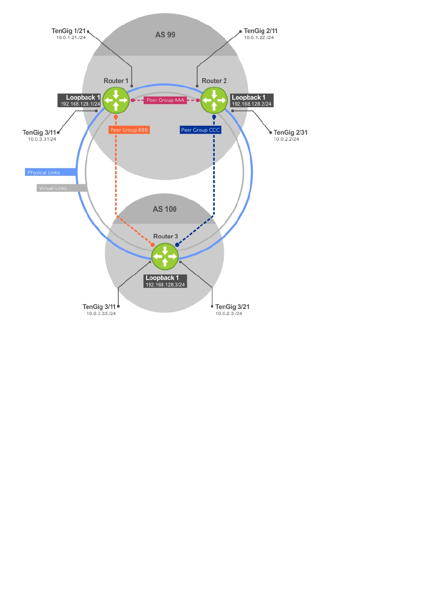
Figure 23. Sample Configurations
Example of Enabling BGP (Router 1)
R1# conf
R1(conf)#int loop 0
R1(conf-if-lo-0)#ip address 192.168.128.1/24
R1(conf-if-lo-0)#no shutdown
R1(conf-if-lo-0)#show config
!
interface Loopback 0
ip address 192.168.128.1/24
no shutdown
R1(conf-if-lo-0)#int tengig 1/21
R1(conf-if-te-1/21)#ip address 10.0.1.21/24
R1(conf-if-te-1/21)#no shutdown
R1(conf-if-te-1/21)#show config
!
interface TenGigabitEthernet 1/21
ip address 10.0.1.21/24
no shutdown
R1(conf-if-te-1/21)#int tengig 1/31
R1(conf-if-te-1/31)#ip address 10.0.3.31/24
R1(conf-if-te-1/31)#no shutdown
R1(conf-if-te-1/31)#show config
!
interface TenGigabitEthernet 1/31
ip address 10.0.3.31/24
Border Gateway Protocol IPv4 (BGPv4) 203

no shutdown
R1(conf-if-te-1/31)#router bgp 99
R1(conf-router_bgp)#network 192.168.128.0/24
R1(conf-router_bgp)#neighbor 192.168.128.2 remote 99
R1(conf-router_bgp)#neighbor 192.168.128.2 no shut
R1(conf-router_bgp)#neighbor 192.168.128.2 update-source loop 0
R1(conf-router_bgp)#neighbor 192.168.128.3 remote 100
R1(conf-router_bgp)#neighbor 192.168.128.3 no shut
R1(conf-router_bgp)#neighbor 192.168.128.3 update-source loop 0
R1(conf-router_bgp)#show config
!
router bgp 99
network 192.168.128.0/24
neighbor 192.168.128.2 remote-as 99
neighbor 192.168.128.2 update-source Loopback 0
neighbor 192.168.128.2 no shutdown
neighbor 192.168.128.3 remote-as 100
neighbor 192.168.128.3 update-source Loopback 0
neighbor 192.168.128.3 no shutdown
R1(conf-router_bgp)#end
R1#
R1#show ip bgp summary
BGP router identifier 192.168.128.1, local AS number 99
BGP table version is 4, main routing table version 4
4 network entrie(s) using 648 bytes of memory
6 paths using 408 bytes of memory
BGP-RIB over all using 414 bytes of memory
3 BGP path attribute entrie(s) using 144 bytes of memory
2 BGP AS-PATH entrie(s) using 74 bytes of memory
2 neighbor(s) using 8672 bytes of memory
Neighbor AS MsgRcvd MsgSent TblVer InQ OutQ Up/Down State/Pfx
192.168.128.2 99 4 5 4 0 0 00:00:32 1
192.168.128.3 100 5 4 1 0 0 00:00:09 4
R1#
Example of Enabling BGP (Router 2)
R2# conf
R2(conf)#int loop 0
R2(conf-if-lo-0)#ip address 192.168.128.2/24
R2(conf-if-lo-0)#no shutdown
R2(conf-if-lo-0)#show config
!
interface Loopback 0
ip address 192.168.128.2/24
no shutdown
R2(conf-if-lo-0)#int tengig 2/11
R2(conf-if-te-2/11)#ip address 10.0.1.22/24
R2(conf-if-te-2/11)#no shutdown
R2(conf-if-te-2/11)#show config
!
interface TenGigabitEthernet 2/11
ip address 10.0.1.22/24
no shutdown
R2(conf-if-te-2/11)#int tengig 2/31
R2(conf-if-te-2/31)#ip address 10.0.2.2/24
R2(conf-if-te-2/31)#no shutdown
R2(conf-if-te-2/31)#show config
!
interface TenGigabitEthernet 2/31
ip address 10.0.2.2/24
no shutdown
R2(conf-if-te-2/31)#
204 Border Gateway Protocol IPv4 (BGPv4)

R2(conf-if-te-2/31)#router bgp 99
R2(conf-router_bgp)#network 192.168.128.0/24
R2(conf-router_bgp)#neighbor 192.168.128.1 remote 99
R2(conf-router_bgp)#neighbor 192.168.128.1 no shut
R2(conf-router_bgp)#neighbor 192.168.128.1 update-source loop 0
R2(conf-router_bgp)#neighbor 192.168.128.3 remote 100
R2(conf-router_bgp)#neighbor 192.168.128.3 no shut
R2(conf-router_bgp)#neighbor 192.168.128.3 update loop 0
R2(conf-router_bgp)#show config
!
router bgp 99
bgp router-id 192.168.128.2
network 192.168.128.0/24
bgp graceful-restart
neighbor 192.168.128.1 remote-as 99
neighbor 192.168.128.1 update-source Loopback 0
neighbor 192.168.128.1 no shutdown
neighbor 192.168.128.3 remote-as 100
neighbor 192.168.128.3 update-source Loopback 0
neighbor 192.168.128.3 no shutdown
R2(conf-router_bgp)#end
R2#show ip bgp summary
BGP router identifier 192.168.128.2, local AS number 99
BGP table version is 1, main routing table version 1
1 network entrie(s) using 132 bytes of memory
3 paths using 204 bytes of memory
BGP-RIB over all using 207 bytes of memory
2 BGP path attribute entrie(s) using 128 bytes of memory
2 BGP AS-PATH entrie(s) using 90 bytes of memory
2 neighbor(s) using 9216 bytes of memory
Neighbor AS MsgRcvd MsgSent TblVer InQ OutQ Up/Down State/Pfx
192.168.128.1 99 40 35 1 0 0 00:01:05 1
192.168.128.3 100 4 4 1 0 0 00:00:16 1
R2#
Example of Enabling BGP (Router 3)
R3# conf
R3(conf)#
R3(conf)#int loop 0
R3(conf-if-lo-0)#ip address 192.168.128.3/24
R3(conf-if-lo-0)#no shutdown
R3(conf-if-lo-0)#show config
!
interface Loopback 0
ip address 192.168.128.3/24
no shutdown
R3(conf-if-lo-0)#int tengig 3/11
R3(conf-if-te-3/11)#ip address 10.0.3.33/24
R3(conf-if-te-3/11)#no shutdown
R3(conf-if-te-3/11)#show config
!
interface TenGigabitEthernet 3/11
ip address 10.0.3.33/24
no shutdown
R3(conf-if-lo-0)#int tengig 3/21
R3(conf-if-te-3/21)#ip address 10.0.2.3/24
R3(conf-if-te-3/21)#no shutdown
R3(conf-if-te-3/21)#show config
!
interface TenGigabitEthernet 3/21
ip address 10.0.2.3/24
Border Gateway Protocol IPv4 (BGPv4) 205

no shutdown
R3(conf-if-te-3/21)#
R3(conf-if-te-3/21)#router bgp 100
R3(conf-router_bgp)#show config
!
router bgp 100
R3(conf-router_bgp)#network 192.168.128.0/24
R3(conf-router_bgp)#neighbor 192.168.128.1 remote 99
R3(conf-router_bgp)#neighbor 192.168.128.1 no shut
R3(conf-router_bgp)#neighbor 192.168.128.1 update-source loop 0
R3(conf-router_bgp)#neighbor 192.168.128.2 remote 99
R3(conf-router_bgp)#neighbor 192.168.128.2 no shut
R3(conf-router_bgp)#neighbor 192.168.128.2 update loop 0
R3(conf-router_bgp)#show config
!
router bgp 100
network 192.168.128.0/24
neighbor 192.168.128.1 remote-as 99
neighbor 192.168.128.1 update-source Loopback 0
neighbor 192.168.128.1 no shutdown
neighbor 192.168.128.2 remote-as 99
neighbor 192.168.128.2 update-source Loopback 0
neighbor 192.168.128.2 no shutdown
R3(conf)#end
R3#show ip bgp summary
BGP router identifier 192.168.128.3, local AS number 100
BGP table version is 1, main routing table version 1
1 network entrie(s) using 132 bytes of memory
3 paths using 204 bytes of memory
BGP-RIB over all using 207 bytes of memory
2 BGP path attribute entrie(s) using 128 bytes of memory
2 BGP AS-PATH entrie(s) using 90 bytes of memory
2 neighbor(s) using 9216 bytes of memory
Neighbor AS MsgRcvd MsgSent TblVer InQ OutQ Up/Down State/Pfx
192.168.128.1 99 24 25 1 0 0 00:14:20 1
192.168.128.2 99 14 14 1 0 0 00:10:22 1
R3#
Example of Enabling Peer Groups (Router 1)
R1#conf
R1(conf)#router bgp 99
R1(conf-router_bgp)# network 192.168.128.0/24
R1(conf-router_bgp)# neighbor AAA peer-group
R1(conf-router_bgp)# neighbor AAA no shutdown
R1(conf-router_bgp)# neighbor BBB peer-group
R1(conf-router_bgp)# neighbor BBB no shutdown
R1(conf-router_bgp)# neighbor 192.168.128.2 peer-group AAA
R1(conf-router_bgp)# neighbor 192.168.128.3 peer-group BBB
R1(conf-router_bgp)#
R1(conf-router_bgp)#show config
!
router bgp 99
network 192.168.128.0/24
neighbor AAA peer-group
neighbor AAA no shutdown
neighbor BBB peer-group
neighbor BBB no shutdown
neighbor 192.168.128.2 remote-as 99
neighbor 192.168.128.2 peer-group AAA
neighbor 192.168.128.2 update-source Loopback 0
neighbor 192.168.128.2 no shutdown
neighbor 192.168.128.3 remote-as 100
neighbor 192.168.128.3 peer-group BBB
206 Border Gateway Protocol IPv4 (BGPv4)

neighbor 192.168.128.3 update-source Loopback 0
neighbor 192.168.128.3 no shutdown
R1#
R1#show ip bgp summary
BGP router identifier 192.168.128.1, local AS number 99
BGP table version is 1, main routing table version 1
1 network entrie(s) using 132 bytes of memory
3 paths using 204 bytes of memory
BGP-RIB over all using 207 bytes of memory
2 BGP path attribute entrie(s) using 96 bytes of memory
2 BGP AS-PATH entrie(s) using 74 bytes of memory
2 neighbor(s) using 8672 bytes of memory
Neighbor AS MsgRcvd MsgSent TblVer InQ OutQ Up/Down State/Pfx
192.168.128.2 99 23 24 1 0 (0) 00:00:17 1
192.168.128.3 100 30 29 1 0 (0) 00:00:14 1
!
R1#show ip bgp neighbors
BGP neighbor is 192.168.128.2, remote AS 99, internal link
Member of peer-group AAA for session parameters
BGP version 4, remote router ID 192.168.128.2
BGP state ESTABLISHED, in this state for 00:00:37
Last read 00:00:36, last write 00:00:36
Hold time is 180, keepalive interval is 60 seconds
Received 23 messages, 0 in queue
2 opens, 0 notifications, 2 updates
19 keepalives, 0 route refresh requests
Sent 24 messages, 0 in queue
2 opens, 1 notifications, 2 updates
19 keepalives, 0 route refresh requests
Minimum time between advertisement runs is 5 seconds
Minimum time before advertisements start is 0 seconds
Capabilities received from neighbor for IPv4 Unicast :
MULTIPROTO_EXT(1)
ROUTE_REFRESH(2)
CISCO_ROUTE_REFRESH(128)
Capabilities advertised to neighbor for IPv4 Unicast :
MULTIPROTO_EXT(1)
ROUTE_REFRESH(2)
CISCO_ROUTE_REFRESH(128)
Update source set to Loopback 0
Peer active in peer-group outbound optimization
For address family: IPv4 Unicast
BGP table version 1, neighbor version 1
Prefixes accepted 1 (consume 4 bytes), withdrawn 0 by peer
Prefixes advertised 1, denied 0, withdrawn 0 from peer
Connections established 2; dropped 1
Last reset 00:00:57, due to user reset
Notification History
'Connection Reset' Sent : 1 Recv: 0
Last notification (len 21) sent 00:00:57 ago
ffffffff ffffffff ffffffff ffffffff 00150306 00000000
Local host: 192.168.128.1, Local port: 179
Foreign host: 192.168.128.2, Foreign port: 65464
BGP neighbor is 192.168.128.3, remote AS 100, external link
Member of peer-group BBB for session parameters
BGP version 4, remote router ID 192.168.128.3
BGP state ESTABLISHED, in this state for 00:00:37
Last read 00:00:36, last write 00:00:36
Hold time is 180, keepalive interval is 60 seconds
Border Gateway Protocol IPv4 (BGPv4) 207

Received 30 messages, 0 in queue
4 opens, 2 notifications, 4 updates
20 keepalives, 0 route refresh requests
Sent 29 messages, 0 in queue
4 opens, 1 notifications, 4 updates
20 keepalives, 0 route refresh requests
Minimum time between advertisement runs is 30 seconds
Minimum time before advertisements start is 0 seconds
Capabilities received from neighbor for IPv4 Unicast :
MULTIPROTO_EXT(1)
Capabilities received from neighbor for IPv4 Unicast :
MULTIPROTO_EXT(1)
ROUTE_REFRESH(2)
CISCO_ROUTE_REFRESH(128)
Update source set to Loopback 0
Peer active in peer-group outbound optimization
For address family: IPv4 Unicast
BGP table version 1, neighbor version 1
Prefixes accepted 1 (consume 4 bytes), withdrawn 0 by peer
Prefixes advertised 1, denied 0, withdrawn 0 from peer
Connections established 4; dropped 3
Last reset 00:00:54, due to user reset
R1#
Example of Enabling Peer Groups (Router 2)
R2#conf
R2(conf)#router bgp 99
R2(conf-router_bgp)# neighbor CCC peer-group
R2(conf-router_bgp)# neighbor CC no shutdown
R2(conf-router_bgp)# neighbor BBB peer-group
R2(conf-router_bgp)# neighbor BBB no shutdown
R2(conf-router_bgp)# neighbor 192.168.128.1 peer AAA
R2(conf-router_bgp)# neighbor 192.168.128.1 no shut
R2(conf-router_bgp)# neighbor 192.168.128.3 peer BBB
R2(conf-router_bgp)# neighbor 192.168.128.3 no shut
R2(conf-router_bgp)#show conf
!
router bgp 99
network 192.168.128.0/24
neighbor AAA peer-group
neighbor AAA no shutdown
neighbor BBB peer-group
neighbor BBB no shutdown
neighbor 192.168.128.1 remote-as 99
neighbor 192.168.128.1 peer-group CCC
neighbor 192.168.128.1 update-source Loopback 0
neighbor 192.168.128.1 no shutdown
neighbor 192.168.128.3 remote-as 100
neighbor 192.168.128.3 peer-group BBB
neighbor 192.168.128.3 update-source Loopback 0
neighbor 192.168.128.3 no shutdown
R2(conf-router_bgp)#end
R2#
R2#show ip bgp summary
BGP router identifier 192.168.128.2, local AS number 99
BGP table version is 2, main routing table version 2
1 network entrie(s) using 132 bytes of memory
3 paths using 204 bytes of memory
BGP-RIB over all using 207 bytes of memory
2 BGP path attribute entrie(s) using 128 bytes of memory
2 BGP AS-PATH entrie(s) using 90 bytes of memory
2 neighbor(s) using 9216 bytes of memory
208 Border Gateway Protocol IPv4 (BGPv4)

Neighbor AS MsgRcvd MsgSent TblVer InQ OutQ Up/Down State/Pfx
192.168.128.1 99 140 136 2 0 (0) 00:11:24 1
192.168.128.3 100 138 140 2 0 (0) 00:18:31 1
R2#show ip bgp neighbor
BGP neighbor is 192.168.128.1, remote AS 99, internal link
Member of peer-group AAA for session parameters
BGP version 4, remote router ID 192.168.128.1
BGP state ESTABLISHED, in this state for 00:11:42
Last read 00:00:38, last write 00:00:38
Hold time is 180, keepalive interval is 60 seconds
Received 140 messages, 0 in queue
6 opens, 2 notifications, 19 updates
113 keepalives, 0 route refresh requests
Sent 136 messages, 0 in queue
12 opens, 3 notifications, 6 updates
115 keepalives, 0 route refresh requests
Minimum time between advertisement runs is 5 seconds
Minimum time before advertisements start is 0 seconds
Example of Enabling Peer Groups (Router 3)
R3#conf
R3(conf)#router bgp 100
R3(conf-router_bgp)# neighbor AAA peer-group
R3(conf-router_bgp)# neighbor AAA no shutdown
R3(conf-router_bgp)# neighbor CCC peer-group
R3(conf-router_bgp)# neighbor CCC no shutdown
R3(conf-router_bgp)# neighbor 192.168.128.2 peer-group BBB
R3(conf-router_bgp)# neighbor 192.168.128.2 no shutdown
R3(conf-router_bgp)# neighbor 192.168.128.1 peer-group BBB
R3(conf-router_bgp)# neighbor 192.168.128.1 no shutdown
R3(conf-router_bgp)#
R3(conf-router_bgp)#end
R3#show ip bgp summary
BGP router identifier 192.168.128.3, local AS number 100
BGP table version is 1, main routing table version 1
1 network entrie(s) using 132 bytes of memory
3 paths using 204 bytes of memory
BGP-RIB over all using 207 bytes of memory
2 BGP path attribute entrie(s) using 128 bytes of memory
2 BGP AS-PATH entrie(s) using 90 bytes of memory
2 neighbor(s) using 9216 bytes of memory
Neighbor AS MsgRcvd MsgSent TblVer InQ OutQ Up/Down State/Pfx
192.168.128.1 99 93 99 1 0 (0) 00:00:15 1
192.168.128.2 99 122 120 1 0 (0) 00:00:11 1
R3#show ip bgp neighbor
BGP neighbor is 192.168.128.1, remote AS 99, external link
Member of peer-group BBB for session parameters
BGP version 4, remote router ID 192.168.128.1
BGP state ESTABLISHED, in this state for 00:00:21
Last read 00:00:09, last write 00:00:08
Hold time is 180, keepalive interval is 60 seconds
Received 93 messages, 0 in queue
5 opens, 0 notifications, 5 updates
83 keepalives, 0 route refresh requests
Sent 99 messages, 0 in queue
5 opens, 4 notifications, 5 updates
Border Gateway Protocol IPv4 (BGPv4) 209

85 keepalives, 0 route refresh requests
Minimum time between advertisement runs is 30 seconds
Minimum time before advertisements start is 0 seconds
Capabilities received from neighbor for IPv4 Unicast :
MULTIPROTO_EXT(1)
ROUTE_REFRESH(2)
CISCO_ROUTE_REFRESH(128)
Capabilities advertised to neighbor for IPv4 Unicast :
MULTIPROTO_EXT(1)
ROUTE_REFRESH(2)
CISCO_ROUTE_REFRESH(128)
Update source set to Loopback 0
Peer active in peer-group outbound optimization
For address family: IPv4 Unicast
BGP table version 1, neighbor version 1
Prefixes accepted 1 (consume 4 bytes), withdrawn 0 by peer
Prefixes advertised 1, denied 0, withdrawn 0 from peer
Capabilities received from neighbor for IPv4 Unicast :
MULTIPROTO_EXT(1)
ROUTE_REFRESH(2)
CISCO_ROUTE_REFRESH(128)
Capabilities advertised to neighbor for IPv4 Unicast :
MULTIPROTO_EXT(1)
ROUTE_REFRESH(2)
CISCO_ROUTE_REFRESH(128)
Update source set to Loopback 0
Peer active in peer-group outbound optimization
For address family: IPv4 Unicast
BGP table version 2, neighbor version 2
Prefixes accepted 1 (consume 4 bytes), withdrawn 0 by peer
Prefixes advertised 1, denied 0, withdrawn 0 from peer
Connections established 6; dropped 5
Last reset 00:12:01, due to Closed by neighbor
Notification History
'HOLD error/Timer expired' Sent : 1 Recv: 0
'Connection Reset' Sent : 2 Recv: 2
Last notification (len 21) received 00:12:01 ago
ffffffff ffffffff ffffffff ffffffff 00150306 00000000
Local host: 192.168.128.2, Local port: 65464
Foreign host: 192.168.128.1, Foreign port: 179
BGP neighbor is 192.168.128.3, remote AS 100, external link
Member of peer-group BBB for session parameters
BGP version 4, remote router ID 192.168.128.3
BGP state ESTABLISHED, in this state for 00:18:51
Last read 00:00:45, last write 00:00:44
Hold time is 180, keepalive interval is 60 seconds
Received 138 messages, 0 in queue
7 opens, 2 notifications, 7 updates
122 keepalives, 0 route refresh requests
Sent 140 messages, 0 in queue
7 opens, 4 notifications, 7 updates
122 keepalives, 0 route refresh requests
Minimum time between advertisement runs is 30 seconds
210 Border Gateway Protocol IPv4 (BGPv4)

Minimum time before advertisements start is 0 seconds
Capabilities advertised to neighbor for IPv4 Unicast :
MULTIPROTO_EXT(1)
Capabilities received from neighbor for IPv4 Unicast :
MULTIPROTO_EXT(1)
ROUTE_REFRESH(2)
CISCO_ROUTE_REFRESH(128)
ROUTE_REFRESH(2)
CISCO_ROUTE_REFRESH(128)
Update source set to Loopback 0
Peer active in peer-group outbound optimization
For address family: IPv4 Unicast
BGP table version 2, neighbor version 2
Prefixes accepted 1 (consume 4 bytes), withdrawn 0 by peer
Prefixes advertised 1, denied 0, withdrawn 0 from peer
Border Gateway Protocol IPv4 (BGPv4) 211

10
Content Addressable Memory (CAM)
CAM is a type of memory that stores information in the form of a lookup table.
On the Z9500, CAM stores Layer 2 and Layer 3 forwarding information, access-lists (ACLs), flows, and
routing policies. On a line card, there are one or two CAM (Dual-CAM) modules per port-pipe.
CAM Allocation
CAM space is allotted in filter processor (FP) blocks. The total space allocated must equal 13 FP blocks.
NOTE: There are 16 FP blocks, but the system flow requires three blocks that cannot be reallocated.
The following table displays the default CAM allocation settings. To display the default CAM allocation,
enter the show cam-acl command.
Dell#show cam-acl
-- Chassis Cam ACL --
Current Settings(in block sizes)
1 block = 256 entries
L2Acl : 6
Ipv4Acl : 4
Ipv6Acl : 0
Ipv4Qos : 2
L2Qos : 1
L2PT : 0
IpMacAcl : 0
VmanQos : 0
EcfmAcl : 0
Openflow : 0
-- linecard 0 --
Current Settings(in block sizes)
1 block = 256 entries
L2Acl : 6
Ipv4Acl : 4
Ipv6Acl : 0
Ipv4Qos : 2
L2Qos : 1
L2PT : 0
IpMacAcl : 0
VmanQos : 0
EcfmAcl : 0
Openflow : 0
-- linecard 1 --
Current Settings(in block sizes)
1 block = 256 entries
L2Acl : 6
Ipv4Acl : 4
Ipv6Acl : 0
212 Content Addressable Memory (CAM)

Ipv4Qos : 2
L2Qos : 1
L2PT : 0
IpMacAcl : 0
VmanQos : 0
EcfmAcl : 0
Openflow : 0
-- linecard 2 --
Current Settings(in block sizes)
1 block = 256 entries
L2Acl : 6
Ipv4Acl : 4
Ipv6Acl : 0
Ipv4Qos : 2
L2Qos : 1
L2PT : 0
IpMacAcl : 0
VmanQos : 0
EcfmAcl : 0
Openflow : 0
The ipv6acl and vman-dual-qos allocations must be entered as a factor of 2 (2, 4, 6, 8, 10). All other
profile allocations can use either even or odd numbered ranges.
You must save the new CAM settings to the startup-config (write-mem or copy run start) then
reload the system for the new settings to take effect.
1. Select a cam-acl action.
CONFIGURATION mode
cam-acl [default | l2acl]
NOTE: Selecting default resets the CAM entries to the default settings. Select l2acl to allocate
space for the ACLs and QoS regions.
2. Enter the number of FP blocks for each region.
EXEC Privilege mode
l2acl number ipv4acl number ipv6acl number, ipv4qos number l2qos number,
l2pt number ipmacacl number ecfmacl number [vman-qos | vman-dual-qos number
NOTE: If the allocation values are not entered for the CAM regions, the value is 0.
3. Verify that the new settings will be written to the CAM on the next boot.
EXEC Privilege mode
show cam-acl
4. Reload the system.
EXEC Privilege mode
reload
Content Addressable Memory (CAM) 213

Test CAM Usage
The test cam-usage command applies to both IPv4 and IPv6 CAM profiles, but is best used when
verifying QoS optimization for IPv6 ACLs.
Use this command to determine whether sufficient ACL CAM space is available to enable a service-policy.
Create a Class Map with all required ACL rules, then execute the test cam-usage command in Privilege
mode to verify the actual CAM space required. The Status column in the command output indicates
whether or not the policy can be enabled.
Example of the test cam-usage Command
Dell# test cam-usage service-policy input pcam linecard all
linecard | Portpipe | CAM Partition | Available CAM | Estimated CAM per Port
| Status
--------------------------------------------------------------------------------
----------
0 | 0 | IPv4Flow | 408 | 1
| Allowed (408)
0 | 1 | IPv4Flow | 408 | 1
| Allowed (408)
0 | 2 | IPv4Flow | 408 | 1
| Allowed (408)
1 | 0 | IPv4Flow | 408 | 1
| Allowed (408)
1 | 1 | IPv4Flow | 408 | 1
| Allowed (408)
1 | 2 | IPv4Flow | 408 | 1
| Allowed (408)
1 | 3 | IPv4Flow | 408 | 1
| Allowed (408)
2 | 0 | IPv4Flow | 408 | 1
| Allowed (408)
2 | 1 | IPv4Flow | 408 | 1
| Allowed (408)
2 | 2 | IPv4Flow | 408 | 1
| Allowed (408)
2 | 3 | IPv4Flow | 408 | 1
| Allowed (408)
View CAM-ACL Settings
View the current cam-acl settings using the show cam-acl command.
Example of Viewing CAM-ACL Settings
Dell# show cam-acl
-- Chassis Cam ACL --
Current Settings(in block sizes)
1 block = 256 entries
L2Acl : 6
Ipv4Acl : 4
Ipv6Acl : 0
Ipv4Qos : 2
L2Qos : 1
L2PT : 0
IpMacAcl : 0
VmanQos : 0
EcfmAcl : 0
214 Content Addressable Memory (CAM)

Openflow : 0
-- linecard 0 --
Current Settings(in block sizes)
1 block = 256 entries
L2Acl : 6
Ipv4Acl : 4
Ipv6Acl : 0
Ipv4Qos : 2
L2Qos : 1
L2PT : 0
IpMacAcl : 0
VmanQos : 0
EcfmAcl : 0
Openflow : 0
-- linecard 1 --
Current Settings(in block sizes)
1 block = 256 entries
L2Acl : 6
Ipv4Acl : 4
Ipv6Acl : 0
Ipv4Qos : 2
L2Qos : 1
L2PT : 0
IpMacAcl : 0
VmanQos : 0
EcfmAcl : 0
Openflow : 0
-- linecard 2 --
Current Settings(in block sizes)
1 block = 256 entries
L2Acl : 6
Ipv4Acl : 4
Ipv6Acl : 0
Ipv4Qos : 2
L2Qos : 1
L2PT : 0
IpMacAcl : 0
VmanQos : 0
EcfmAcl : 0
Openflow : 0
View CAM Usage
View the amount of CAM space available, used, and remaining in each partition (including IPv4Flow and
Layer 2 ACL sub-partitions) using the show cam-usage command from EXEC Privilege mode.
Example of the show cam-usage Command
R1#show cam-usage
Linecard|Portpipe| CAM Partition | Total CAM | Used CAM | Available CAM
========|========|=============== |=============|=============|==============
1 | 0 | IN-L2 ACL | 1008 | 320 | 688
| | IN-L2 FIB | 32768 | 1132 | 31636
| | IN-L3 ACL | 12288 | 2 | 12286
| | IN-L3 FIB | 262141 | 14 | 262127
| | IN-L3-SysFlow | 2878 | 45 | 2833
| | IN-L3-TrcList | 1024 | 0 | 1024
| | IN-L3-McastFib | 9215 | 0 | 9215
| | IN-L3-Qos | 8192 | 0 | 8192
Content Addressable Memory (CAM) 215

| | IN-L3-PBR | 1024 | 0 | 1024
| | IN-V6 ACL | 0 | 0 | 0
| | IN-V6 FIB | 0 | 0 | 0
| | IN-V6-SysFlow | 0 | 0 | 0
| | IN-V6-McastFib | 0 | 0 | 0
| | OUT-L2 ACL | 1024 | 0 | 1024
| | OUT-L3 ACL | 1024 | 0 | 1024
| | OUT-V6 ACL | 0 | 0 | 0
1 | 1 | IN-L2 ACL | 320 | 0 | 320
| | IN-L2 FIB | 32768 | 1136 | 31632
| | IN-L3 ACL | 12288 | 2 | 12286
| | IN-L3 FIB | 262141 | 14 | 262127
| | IN-L3-SysFlow | 2878 | 44 | 2834
--More--
Return to the Default CAM Configuration
Return to the default CAM Profile, microcode, IPv4Flow, or Layer 2 ACL configuration using the keyword
default from EXEC Privilege mode or CONFIGURATION mode, as shown in the following example.
Example of the cam-profile default Command
Dell(conf)#cam-profile ?
default Enable default CAM profile
eg-default Enable eg-default CAM profile
ipv4-320k Enable 320K CAM profile
ipv4-egacl-16k Enable CAM profile with 16K IPv4 egress ACL
ipv6-extacl Enable CAM profile with extended ACL
l2-ipv4-inacl Enable CAM profile with 32K L2 and 28K IPv4 ingress ACL
unified-default Enable default unified CAM profile
Dell(conf)#cam-profile default microcode ?
default Enable default microcode
lag-hash-align Enable microcode with LAG hash align
lag-hash-mpls Enable microcode with LAG hash MPLS
Dell(conf)#cam-profile default microcode default
Dell(conf)#cam-ipv4flow ?
default Reset IPv4flow CAM entries to default setting
multicast-fib Set multicast FIB entries
Dell(conf)#cam-l2acl ?
default Reset L2-ACL CAM entries to default setting
system-flow Set system flow entries
CAM Optimization
The cam-optimization command allows you to optimize CAM utilization for QoS entries by
minimizing the amount of required policy-map CAM space.
When you enable this command, if a Policy Map containing classification rules (ACL and/or dscp/ ip-
precedence rules) is applied to more than one physical interface on the same port-pipe, only a single
copy of the policy is written (only 1 FP entry is used). When you disable this command, the system
behaves as described in this chapter.
216 Content Addressable Memory (CAM)
Applications for CAM Profiling
The following describes link aggregation group (LAG) hashing.
LAG Hashing
The Dell Networking OS includes a CAM profile and microcode that treats MPLS packets as non-IP
packets. Normally, switching and LAG hashing is based on source and destination MAC addresses.
Alternatively, you can base LAG hashing for MPLS packets on source and destination IP addresses. This
type of hashing is allowed for MPLS packets with five labels or less.
MPLS packets are treated as follows:
• When MPLS IP packets are received, the system looks up to five labels deep for the IP header.
• When an IP header is present, hashing is based on IP three tuples (source IP address, destination IP
address, and IP protocol).
• If an IP header is not found after the fifth label, hashing is based on the MPLS labels.
• If the packet has more than five MPLS labels, hashing is based on the source and destination MAC
address.
To enable this type of hashing, use the default CAM profile with the microcode lag-hash-mpls.
LAG Hashing Based on Bidirectional Flow
To hash LAG packets such that both directions of a bidirectional flow (for example, VoIP or P2P file
sharing) are mapped to the same output link in the LAG bundle, use the default CAM profile with the
microcode lag-hash-align.
Content Addressable Memory (CAM) 217

11
Control Plane Policing (CoPP)
Control plane policing (CoPP) protects the Z9500 routing, control, and line-card processors from
undesired or malicious traffic and Denial of Service (DoS) attacks by filtering control-plane flows.
CoPP uses a dedicated control-plane service policy that consists of ACLs and QoS policies, which
provide filtering and rate-limiting capabilities for control-plane packets. CoPP is only applied to control-
plane packets destined to CPUs on the switch, and not to transit protocol-control packets and data traffic
that is passing through the switch. CoPP prevents undesired or malicious traffic from reaching the
control-plane CPUs and rate limits legitimate control-plane traffic to acceptable limits.
Z9500 CoPP Implementation
The Z9500 control plane consists of multi-core CPUs with internal queues for handling packets destined
to the Route Processor, Control Processor, and line-card CPUs.
On the Z9500, CoPP is implemented as a distributed architecture. In this architecture, CoPP operates
simultaneously in both distributed and aggregated modes. Distributed CoPP is achieved by applying
protocol rate-limiting on each port pipe on a line card. Aggregated CoPP is achieved by applying
protocol rate-limiting followed by queue rate-limiting on the centralized control plane on the switch.
Only aggregated CoPP rate limits are user-configurable. Distributed CoPP rate limits applied at the port-
pipe level are internally derived from the aggregated CoPP configuration.
NOTE:
The CoPP configurations described in this chapter only apply to aggregated CoPP operation on the
Z9500.
To configure a CoPP service policy, you create extended ACL rules and specify rate limits in QoS policies.
QoS rate limits are applied to a protocol-based ACL filter or to a CPU queue.
User-configured ACLs that filter protocol traffic flows to the control plane are automatically applied or
disabled as the corresponding protocol is enabled or disabled in the system. In this way, control packets
from disabled protocols never reach the control plane.
Protocol-based Control Plane Policing
To configure a protocol-based CoPP policy, you create an extended ACL rule for the protocol and
specify the rate limit in a QoS policy. It is not necessary to specify the CPU queue because the protocol-
queue mapping is handled internally by the system. To display the protocol-queue mapping for protocols
that you can configure for protocol-based CoPP, enter the show {mac | ip | ipv6} protocol-queue-
mapping command.
218 Control Plane Policing (CoPP)

Queue-based Control Plane Policing
When configuring a queue-based CoPP policy, take into account that there are twenty-four CP queues
divided into groups of eight queues for the Route Processor, Control Processor, and line-card CPUs:
• Queues 0 to 7 process packets destined to the Control Processor CPU .
• Queues 8 to 15 process packets destined to the Route Processor CPU.
• Queues 16 to 23 process packets destined to the line-card CPU.
The protocols mapped to each CPU queue and the default rate limit applied to the eight CPU queues for
the Route Processor, Control Processor, and line cards are as follows:
CPU Queue Protocols Mapped to Control Processor Queues Rate Limit (in kbps)
0 TTL0, IP options, L3 Broadcast MAC destination address 1000
1 L3 MTU Fail 200
2 ARP request, NS, RS 1800
3 ARP reply, NA, RA 1800
4 FTP, Telnet, SSH, Local terminated, NTP, VLT IPM PDU, VLT
ARPM
2800
5 ICMPv6 300
6 ICMP 300
7 DHCP, LLDP, FEFD, 8021x 3200
CPU Queue Protocols Mapped to Route Processor Queues Rate Limit (in kbps)
8 Unknown L3, L3 with Broadcast MAC destination address 400
9 PIM DR, Multicast Catch All, iSCSI, IPv6 Multicast Catch All,
IPv6 Multicast tunnels
400
10 ARP request, NS, RS 1800
11 ARP reply, NA, RA 1800
12 VLT 2000
13 BFD 5200
14 PVST, GVRP, FCoE, OpenFlow, IGMP, PIM, MLD, MSDP 1850
15 STP, L2PT, LACP, ECFM, BGP, RIP, OSPF, IS-IS, VRRP 12450
CPU Queue Protocols Mapped to Line-Card CPU Queues Rate Limit (in kbps)
16 — 1
17 — 1
18 — 1
Control Plane Policing (CoPP) 219

19 — 1
20 Source miss, Station move, Trace flow 600
21 BFD 7000
22 HyperPull, FRRP 800
23 sFlow 5000
NOTE:
In the line-card CPU, some queues have no protocol traffic mapped to them. These rows appear
blank in the preceding table.
CoPP Example
The illustrations in this section show the benefit of using CoPP compared to not using CoPP on a switch.
The following illustration shows how CoPP rate limits protocol traffic destined to the control-plane CPU.
Figure 24. Control Plane Policing
NOTE:
On the Z9500, CoPP does not convert the input rate of control-plane traffic from kilobits per
second (kbps) to packets per second (pps) as on other Dell Networking switches. On other switch,
CoPP converts the input kilobit-per-second rate to a packet-per-second rate, assuming 64 bytes as
the average packet size. CoPP then applies the packet-per-second rate to the appropriate queue.
On these switches, 1 kbps is approximately equal to 2 pps.
The following illustration shows the difference between using CoPP and not using CoPP on a switch.
220 Control Plane Policing (CoPP)

Figure 25. CoPP Versus Non-CoPP Operation
Configure Control Plane Policing
You can create a CoPP service policy on a per-protocol and/or a per-queue basis that serves as the
system-wide configuration for filtering and rate limiting control-plane traffic.
Configuring CoPP for Protocols
This section describes how to create a protocol-based CoPP service policy and apply it to control plane
traffic.
To create a protocol-based CoPP service policy, you must first create a Layer 2, Layer 3, and/or an IPv6
ACL rule for specified protocol traffic. Then, create a QoS input policy to rate-limit the protocol traffic
permitted by the ACL. Associate the ACL and QoS policy for each protocol in a QoS input policy-map
and apply the complete protocol-based rate-limiting configuration to control-plane traffic.
Control Plane Policing (CoPP) 221

For complete information about creating ACL rules and QoS policies, refer to Access Control Lists (ACLs)
and Quality of Service (QoS).
1. Create a Layer 2 extended ACL for specified protocol traffic.
CONFIGURATION mode
mac access-list extended name permit {arp | frrp | gvrp | isis | lacp | lldp
| stp} cpu-qos
2. Create a Layer 3 extended ACL for specified protocol traffic.
CONFIGURATION mode
ip access-list extended name permit {bgp | dhcp | dhcp-relay | ftp | icmp |
igmp | msdp | ntp | ospf | pim | rip | ssh | telnet | vrrp} cpu-qos
3. Create an IPv6 ACL for specified protocol traffic.
CONFIGURATION mode
ipv6 access-list name permit {bgp | icmp | icmp-nd-na | icmp-nd-ns | icmp-
rd-ra | icmp-rd-rs | ospf | vrrp} cpu-qos
4. Create a QoS input policy to rate limit input traffic.
CONFIGURATION mode
qos-policy-input name rate-police [rate-kbps] [burst-kbytes] peak [rate-
kbps] [burst-kbytes] cpu-qos
5. Create a QoS class map to filter protocol traffic.
CONFIGURATION mode
class-map match-any name match {ip | mac | ipv6} access-group name cpu-qos
6. Create a QoS input-policy map to associate filtered protocol traffic with the rate limiting
configuration.
CONFIGURATION mode
policy-map-input name class-map name qos-policy name cpu-qos
7. Enter Control Plane configuration mode.
CONFIGURATION mode
control-plane-cpuqos
8. Apply the QoS input policy-map that configures rate limiting on specified protocol traffic on the
control plane.
CONTROL-PLANE mode
service-policy rate-limit-protocols input-policy-map cpu-qos
Examples of Configuring CoPP for Protocols
Example of Creating an IP/IPv6/MAC Extended ACL to Select Protocol Traffic
Dell(conf)#ip access-list extended ospf cpu-qos
Dell(conf-ip-acl-cpuqos)#permit ospf
Dell(conf-ip-acl-cpuqos)#exit
Dell(conf)#ip access-list extended bgp cpu-qos
Dell(conf-ip-acl-cpuqos)#permit bgp
222 Control Plane Policing (CoPP)

Dell(conf-ip-acl-cpuqos)#exit
Dell(conf)#mac access-list extended lacp cpu-qos
Dell(conf-mac-acl-cpuqos)#permit lacp
Dell(conf-mac-acl-cpuqos)#exit
Dell(conf)#ipv6 access-list ipv6-icmp cpu-qos
Dell(conf-ipv6-acl-cpuqos)#permit icmp
Dell(conf-ipv6-acl-cpuqos)#exit
Dell(conf)#ipv6 access-list ipv6-vrrp cpu-qos
Dell(conf-ipv6-acl-cpuqos)#permit vrrp
Dell(conf-ipv6-acl-cpuqos)#exit
Example of Creating a QoS Rate-Limiting Input Policy
Dell(conf)#qos-policy-in rate_limit_200k cpu-qos
Dell(conf-in-qos-policy-cpuqos)#rate-police 200 40 peak 500 40
Dell(conf-in-qos-policy-cpuqos)#exit
Dell(conf)#qos-policy-in rate_limit_400k cpu-qos
Dell(conf-in-qos-policy-cpuqos)#rate-police 400 50 peak 600 50
Dell(conf-in-qos-policy-cpuqos)#exit
Dell(conf)#qos-policy-in rate_limit_500k cpu-qos
Dell(conf-in-qos-policy-cpuqos)#rate-police 500 50 peak 1000 50
Dell(conf-in-qos-policy-cpuqos)#exit
Example of Creating a QoS Class Map to Match Protocol Traffic
Dell(conf)#class-map match-any class_ospf cpu-qos
Dell(conf-class-map-cpuqos)#match ip access-group ospf
Dell(conf-class-map-cpuqos)#exit
Dell(conf)#class-map match-any class_bgp cpu-qos
Dell(conf-class-map-cpuqos)#match ip access-group bgp
Dell(conf-class-map-cpuqos)#exit
Dell(conf)#class-map match-any class_lacp cpu-qos
Dell(conf-class-map-cpuqos)#match mac access-group lacp
Dell(conf-class-map-cpuqos)#exit
Dell(conf)#class-map match-any class-ipv6-icmp cpu-qos
Dell(conf-class-map-cpuqos)#match ipv6 access-group ipv6-icmp
Dell(conf-class-map-cpuqos)#exit
Example of Associating a QoS Class Map with a QoS Rate-Limit Policy
Dell(conf)#policy-map-input egressFP_rate_policy cpu-qos
Dell(conf-policy-map-in-cpuqos)#class-map class_ospf qos-policy rate_limit_500k
Dell(conf-policy-map-in-cpuqos)#class-map class_bgp qos-policy rate_limit_400k
Dell(conf-policy-map-in-cpuqos)#class-map class_lacp qos-policy rate_limit_200k
Dell(conf-policy-map-in-cpuqos)#class-map class-ipv6 qos-policy rate_limit_200k
Dell(conf-policy-map-in-cpuqos)#exit
Example of Applying a Protocol-Based Rate Limit to Control Plane Traffic
Dell(conf)#control-plane-cpuqos
Dell(conf-control-cpuqos)#service-policy rate-limit-protocols
egressFP_rate_policy
Dell(conf-control-cpuqos)#exit
Control Plane Policing (CoPP) 223

Configuring CoPP for CPU Queues
This section describes how to create a queue-based CoPP service policy and apply it to control plane
traffic.
Controlling traffic on the CPU queues of the control plane does not require ACL rules; only QoS rate-
limiting policies are used.
To create a queue-based CoPP service policy, you must create a QoS input policy with rate-limiting,
associate it with a control-plane queue in a QoS policy map, and apply the complete queue-based rate
limiting configuration to control-plane traffic.
1. Create a QoS input policy and configure a rate limit.
CONFIGURATION mode
qos-policy-input name cpu-qos
rate-police [rate-kbps] [burst-kbytes] peak [rate-kbps] [burst-kbytes]
2. Create an input policy-map to assign the QoS rate-limit policy to a control-plane queue.
CONFIGURATION mode
policy-map-input name cpu-qos
service-queue queue-number qos-policy name
On the Z9500, the range of queue-number values is from 0 to 23. The twenty-four control–plane
queues are divided into groups of eight queues for the Route Processor, Control Processor, and line-
card CPUs as follows:
• Queues 0 to 7 process packets destined to the Control Processor CPU .
• Queues 8 to 15 process packets destined to the Route Processor CPU.
• Queues 16 to 23 process packets destined to the line-card CPU.
For information about the default rate limits applied to the eight CPU queues for the Route
Processor, Control Processor, and line cards, refer to Z9500 CoPP Implementation.
3. Enter Control Plane configuration mode.
CONFIGURATION mode
control-plane-cpuqos
4. Apply the QoS input policy-map with queue-based rate limiting on control plane traffic.
CONTROL-PLANE mode
service-policy rate-limit-cpu-queues input-policy-map
Examples of Configuring CoPP for CPU Queues
Example of Creating a QoS Policy to Configure the Rate Limit
Dell#conf
Dell(conf)#qos-policy-input cpuq_1 cpu-qos
Dell(conf-qos-policy-in)#rate-police 3000 40 peak 500 40
Dell(conf-qos-policy-in)#exit
Dell(conf)#qos-policy-input cpuq_2 cpu-qos
Dell(conf-qos-policy-in)#rate-police 5000 80 peak 600 50
Dell(conf-qos-policy-in)#exit
224 Control Plane Policing (CoPP)

Example of Assigning a QoS Policy to a CPU Queue
Dell(conf)#policy-map-input cpuq_rate_policy cpu-qos
Dell(conf-qos-policy-in)#service-queue 5 qos-policy cpuq_1
Dell(conf-qos-policy-in)#service-queue 6 qos-policy cpuq_2
Dell(conf-qos-policy-in)#service-queue 7 qos-policy cpuq_1
Example of Applying a Queue-Based Rate Limit to Control Plane Traffic
Dell#conf
Dell(conf)#control-plane
Dell(conf-control-plane)#service-policy rate-limit-cpu-queues cpuq_rate_policy
Displaying CoPP Configuration
The CLI provides show commands to display the protocol traffic assigned to each control-plane queue
and the current rate-limit applied to each queue. Other show commands display statistical information
for trouble shooting CoPP operation.
Viewing Queue Rates
To view the rates that are currently applied on each control-plane queue, use the show cpu-queue
rate [all | queue-id id | range from-queue to-queue] command.
Dell# show cpu-queue rate all
Service-Queue Rate (kbps) Burst (kb)
-------------- ----------- ----------
Q0 1000 1000
Q1 400 1000
Q2 1800 1000
Q3 1800 1000
Q4 2800 5000
Q5 300 2000
Q6 300 2000
Q7 3200 3000
Q8 400 1000
Q9 400 1000
Q10 1800 1000
Q11 1800 1000
Q12 2000 6000
Q13 5200 3000
Q14 1850 3000
Q15 12450 4000
Q16 1 100
Q17 1 100
Q18 1 100
Q19 1 100
Q20 600 1000
Q21 7000 7000
Q22 800 1000
Q23 5000 5000
Viewing MAC Protocol-Queue Mapping
To view the queues to which MAC protocol traffic is assigned, use the show mac protocol-queue-
mapping command.
Dell#show mac protocol-queue-mapping
Protocol Destination Mac EtherType Queue EgPort Rate
(kbps)
Control Plane Policing (CoPP) 225

-------- --------------- --------- ----- ------
-----------
ARP any 0x0806 Q2/Q10/Q3/Q11 CP/RP 600
FRRP 01:01:e8:00:00:10/11 any Q22 LP 300
LACP 01:80:c2:00:00:02 0x8809 Q15 RP 500
LLDP any 0x88cc Q7 CP 500
GVRP 01:80:c2:00:00:21 any Q14 RP 200
STP 01:80:c2:00:00:00 any Q15 RP 150
ISIS 01:80:c2:00:00:14/15 any Q15 RP 500
09:00:2b:00:00:04/05 any Q15 RP 500
Viewing IPv4 Protocol-Queue Mapping
To view the queues to which IPv4 protocol traffic is assigned, use the show ip protocol-queue-
mapping command.
Dell#show ip protocol-queue-mapping
Protocol Src-Port Dst-Port TcpFlag Queue EgPort Rate (kbps)
-------- -------- -------- ------- ----- ------ -----------
TCP (BGP) any/179 179/any _ Q15 RP 2500
UDP (DHCP) 67/68 68/67 _ Q7 CP 1200
UDP (DHCP-R) 67 67 _ Q7 CP 1200
TCP (FTP) any 21 _ Q4 CP 400
ICMP any any _ Q6 CP 300
IGMP any any _ Q14 RP 300
TCP (MSDP) any/639 639/any _ Q14 RP 100
UDP (NTP) any 123 _ Q4 CP 200
OSPF any any _ Q15 RP 2500
PIM any any _ Q14 RP 300
UDP (RIP) any 520 _ Q15 RP 200
TCP (SSH) any 22 _ Q4 CP 400
TCP (TELNET) any 23 _ Q4 CP 400
VRRP any any _ Q15 RP 400
Viewing IPv6 Protocol-Queue Mapping
To view the queues to which IPv6 protocol traffic is assigned, use the show ipv6 protocol-queue-
mapping command.
Dell#show ipv6 protocol-queue-mapping
Protocol Src-Port Dst-Port TcpFlag Queue EgPort Rate (kbps)
-------- -------- -------- ------- ----- ------ -----------
TCP (BGP) any/179 179/any _ Q15 RP 2500
ICMPV6 NA any any _ Q3/Q11 CP/RP 600
ICMPV6 RA any any _ Q3/Q11 CP/RP 600
ICMPV6 NS any any _ Q2/Q10 CP/RP 600
ICMPV6 RS any any _ Q2/Q10 CP/RP 600
ICMPV6 any any _ Q5 CP 300
VRRPV6 any any _ Q15 RP 400
OSPFV3 any any _ Q15 RP 2500
Viewing Per-Queue Protocol-Queue Mapping
To view the protocol traffic assigned to a specified queue, use the show protocol-queue-mapping
queue-id command.
Dell#show protocol-queue-mapping queue-id 2
Protocol Queue EgPort CommitRate(kbps) Peak Rate(kbps)
226 Control Plane Policing (CoPP)

-------- ----- ------ --------------- -----------
ARP Q2/Q10/Q3/Q11 CP/RP 600 600
v6 ICMP NS Q2/Q10 CP/RP 600 600
v6 ICMP RS Q2/Q10 CP/RP 600 600
Viewing Complete Protocol-Queue Mapping
To view the queues to which all protocol traffic is assigned, use the show protocol-queue-mapping
command.
Dell# show protocol-queue-mapping
CommitRate Peak Rate CommitBurst
PeakBurst
Protocol Queue EgPort (kbps) (kbps) (kb)
(kb)
-------- ----- ------ ---------- --------- -----------
---------
STP Q15 RP 150 150 1000
1000
LLDP Q7 CP 500 500 1000
1000
PVST Q14 RP 200 200 1000
1000
LACP Q15 RP 500 500 1000
1000
ARP Q2/Q10/Q3/Q11 CP/RP 600 600 1000
1000
GVRP Q14 RP 200 200 1000
1000
FRRP Q22 LP 300 300 1000
1000
ECFM Q15 RP 150 150 1000
1000
ISIS Q15 RP 500 500 3000
3000
L2PT Q15 RP 150 150 1000
1000
v6 BGP Q15 RP 2500 2500 2000
2000
v6 OSPF Q15 RP 2500 2500 2000
2000
v6 VRRP Q15 RP 400 400 2000
2000
MLD Q14 RP 150 150 500 500
v6 MULTICAST Q9 RP 100 100 500 500
CATCH ALL
v6 ICMP NA Q3/Q11 CP/RP 600 600 1000
1000
v6 ICMP RA Q3/Q11 CP/RP 600 600 1000
1000
v6 ICMP NS Q2/Q10 CP/RP 600 600 1000
1000
v6 ICMP RS Q2/Q10 CP/RP 600 600 1000
1000
v6 ICMP Q5 CP 300 300 2000
2000
BGP Q15 RP 2500 2500 2000
2000
OSPF Q15 RP 2500 2500 2000
2000
RIP Q15 RP 200 200 1000
1000
VRRP Q15 RP 400 400 2000
Control Plane Policing (CoPP) 227

2000
ICMP Q6 CP 300 300 2000
2000
IGMP Q14 RP 300 300 2000
2000
PIM Q14 RP 300 300 2000
2000
MSDP Q14 RP 100 100 2000
2000
BFD Q13/Q21 RP/LP 7000 7000 3000
3000
802.1x Q7 CP 150 150 1000
1000
iSCSI Q9 RP 100 100 500 500
DHCP RELAY Q7 CP 1200 1200 2000
2000
DHCP Q7 CP 1200 1200 2000
2000
NTP Q4 CP 200 200 2000
2000
FTP Q4 CP 400 400 3000
3000
TELNET Q4 CP 400 400 2000
2000
SSH Q4 CP 400 400 2000
2000
VLT CTRL Q12 RP 2000 2000 3000
3000
VLT IPM PDU Q4/Q12 CP/RP 500 500 3000
3000
VLT TTL1 Q0 CP 100 100 500 500
HYPERPULL Q22 LP 500 500 1000
1000
OPENFLOW Q14 RP 300 300 1000
1000
FEFD Q7 CP 150 150 1000
1000
TRACEFLOW Q20 LP 200 200 500 500
FCoE Q14 RP 300 300 2000
2000
SFLOW Q23 LP 5000 5000 3000
3000
L3 LOCAL TERMINATED Q4 CP 400 400 5000
5000
L3 UNKNOWN/ Q8 RP 200 200 3000
3000
UNRESOLVED ARP
L2 DST HIT/ Q0/Q8 CP/RP 200 200 500 500
BROADCAST
MULTICAST CATCH ALL Q9 RP 200 200 500 500
ACL LOGGING Q20 LP 200 200 1000
1000
L3 HEADER ERROR/TTL0 Q0 CP 200 200 500 500
IP OPTION/TTL1 Q0 CP 100 100 500 500
VLAN L3 MTU FAIL Q1 CP 200 200 500 500
Physical L3 MTU FAIL Q1 CP 200 200 500 500
ICMP REDIRECT Q1 CP 200 200 500 500
SOURCE MISS Q20 LP 200 200 500 500
STATION MOVE Q20 LP 200 200 500 500
228 Control Plane Policing (CoPP)

Troubleshooting CoPP Operation
To troubleshoot CoPP operation, use the debug commands described in this section.
Enabling CPU Traffic Statistics
During high-traffic network conditions, you may want to manually enable the collection of CPU traffic
statistics by entering the debug cpu-traffic-stats command. Statistic collection begins as soon as
you enter the command, not when the system boots up.
The following message is displayed when the collection of CPU traffic statistics is enabled. Use the show
cpu-traffic-stats command to view the statistics.
Excessive traffic is received by CPU and traffic will be rate controlled.
NOTE: You must manually enable the collection of CPU traffic statistics with the debug cpu-
traffic-stats command before the statistics display in show cpu-traffic-stats output. It is
recommended that when you finish CoPP troubleshooting, you disable the collection of CPU traffic
statistics by entering the no debug cpu-traffic-stats command.
Viewing CPU Traffic Statistics
To view the statistics collected on CPU traffic, use the show cpu-traffic-stats [cp | rp |
linecard {0–2} |all] command.
Traffic statistics are sorted on a per-interface basis; the interface receiving the most traffic is displayed
first. All CPU and port information is displayed unless you specify a port or CPU queue. Traffic information
is displayed for router ports only, not for management interfaces. CPU traffic statistics are collected only
after you enter the debug cpu-traffic-stats command, not from when the system boots up.
Dell#show cpu-traffic-stats
Processor : CP
--------------
Received 100% traffic on fortyGigE 2/12 Total packets:8
LLC:0, SNAP:0, IP:5, ARP:0, other:3
Unicast:5, Multicast:3, Broadcast:0
Processor : RP
---------------
Received 100% traffic on fortyGigE 2/12 Total packets:168
LLC:0, SNAP:0, IP:165, ARP:0, other:3
Unicast:42, Multicast:126, Broadcast:0
NOTE: When you finish troubleshooting CoPP operation, disable the collection of CPU traffic
statistics by entering the no debug cpu-traffic-stats command.
Troubleshooting CPU Packet Loss
To troubleshoot the reason for CPU packet loss, you can display statistics about system flows on the
central switch (aggregated CoPP) or on a specified set of Z9500 ports by entering the show hardware
Control Plane Policing (CoPP) 229

system-flow layer2 [cp-switch | linecard slot-id portset port-pipe] command. The
number of hits for each system flow is also displayed.
Dell#show hardware system-flow layer2 linecard 2 port-set 0
############## FP Entry for redirecting STP BPDU to CPU Port ################
EID 0x00000300: gid=0xa,
slice=9, slice_idx=0x1, part =0 prio=0x300, flags=0x10202, Installed,
Enabled
tcam: color_indep=0,
Stage
InPorts
DATA=0x0000000000000000000000000000000000000000000000000000222222222222
MASK=0x0000000000000000000000000000000000000000000000000000222222222223
DstMac
Offset: 88 Width: 48
DATA=0x00000180 c2000000
MASK=0x0000ffff ffffffff
action={act=DropPrecedence, param0=1(0x1), param1=0(0), param2=0(0),
param3=0(0)}
action={act=Drop, param0=0(0), param1=0(0), param2=0(0), param3=0(0)}
action={act=CosQCpuNew, param0=0(0), param1=0(0), param2=0(0),
param3=0(0)}
action={act=CopyToCpu, param0=1(0x1), param1=1(0x1), param2=0(0),
param3=0(0)}
policer=
statistics={stat id 1 slice = 9 idx=0 entries=1}{Packets}
################ FP Entry for redirecting LLDP BPDU to RSM ################
EID 0x000002ff: gid=0xa,
slice=9, slice_idx=0x2, part =0 prio=0x2ff, flags=0x10202, Installed,
Enabled
tcam: color_indep=0,
Stage
InPorts
DATA=0x0000000000000000000000000000000000000000000000000000222222222222
MASK=0x0000000000000000000000000000000000000000000000000000222222222223
DstMac
Offset: 88 Width: 48
DATA=0x00000180 c200000e
MASK=0x0000ffff ffffffff
action={act=DropPrecedence, param0=1(0x1), param1=0(0), param2=0(0),
param3=0(0)}
action={act=Drop, param0=0(0), param1=0(0), param2=0(0), param3=0(0)}
action={act=CosQCpuNew, param0=1(0x1), param1=0(0), param2=0(0),
param3=0(0)}
action={act=CopyToCpu, param0=1(0x1), param1=2(0x2), param2=0(0),
param3=0(0)}
policer=
statistics={stat id 2 slice = 9 idx=0 entries=1}{Packets}
--More--
############## FP Entry for redirecting LACP traffic to CPU Port ############
EID 0x000002fd: gid=0xa,
slice=9, slice_idx=0x3, part =0 prio=0x2fd, flags=0x10202, Installed,
Enabled
tcam: color_indep=0,
Stage
InPorts
DATA=0x0000000000000000000000000000000000000000000000000000222222222222
MASK=0x0000000000000000000000000000000000000000000000000000222222222223
DstMac
Offset: 88 Width: 48
DATA=0x00000180 c2000002
230 Control Plane Policing (CoPP)

MASK=0x0000ffff ffffffff
action={act=DropPrecedence, param0=1(0x1), param1=0(0), param2=0(0),
param3=0(0)}
action={act=Drop, param0=0(0), param1=0(0), param2=0(0), param3=0(0)}
action={act=CosQCpuNew, param0=3(0x3), param1=0(0), param2=0(0),
param3=0(0)}
action={act=CopyToCpu, param0=1(0x1), param1=4(0x4), param2=0(0),
param3=0(0)}
policer=
statistics={stat id 3 slice = 9 idx=1 entries=1}{Packets}
--More--
################# FP Entry for redirecting GVRP traffic to RSM ###########
EID 0x000002fc: gid=0xa,
slice=9, slice_idx=0x4, part =0 prio=0x2fc, flags=0x10202, Installed,
Enabled
tcam: color_indep=0,
Stage
InPorts
DATA=0x0000000000000000000000000000000000000000000000000000222222222222
MASK=0x0000000000000000000000000000000000000000000000000000222222222223
DstMac
Offset: 88 Width: 48
DATA=0x00000180 c2000021
MASK=0x0000ffff ffffffff
action={act=DropPrecedence, param0=1(0x1), param1=0(0), param2=0(0),
param3=0(0)}
action={act=Drop, param0=0(0), param1=0(0), param2=0(0), param3=0(0)}
action={act=CosQCpuNew, param0=4(0x4), param1=0(0), param2=0(0),
param3=0(0)}
action={act=CopyToCpu, param0=1(0x1), param1=5(0x5), param2=0(0),
param3=0(0)}
policer=
statistics={stat id 8 slice = 9 idx=2 entries=1}{Packets}
--More--
################# FP Entry for redirecting ARP Replies to RSM #############
--More--
################# FP Entry for redirecting 802.1x frames to CPU Port #########
--More--
########## FP Entry for redirecting VRRP frames [Extn. entry] to CPU Port ####
--More--
######################## FP Entry for GRAT ARP to CPU Port ####################
--More--
######################## FP Entry for IPv6 Mcast traffic
##########################
--More--
######################## FP Entry for Tuinnel IPv6 Mcast traffic
######################
--More--
######################## FP Entry for FEFD Mcast traffic
##########################
--More--
######################## FP Entry for VRRP MAC ARP Replies to RSM
####################
--More--
######################## FP Entry for VLT ARP Replies for Peer
##########################
--More--
######################## FP Entry for VLT ICL Hellos ##########################
--More--
######################## FP Entry for VLT MAC SYNC Frames
##########################
--More--
######################## FP Entry for VLT STP BPDUs Tunneled
##########################
Control Plane Policing (CoPP) 231

--More--
######################## FP Entry for VLT IGMP Sync frames
##########################
--More--
######################## FP Entry for VLT ARP Replies Tunneled
##########################
--More--
######################## FP Entry for VLT L2PM Sync frames
##########################
--More--
######################## FP Entry for VLT ARP Sync frames
##########################
--More--
######################## FP Entry for VLT IPM Sync frames
##########################
--More--
######################## FP Entry for VLT NDPM Sync frames
##########################
--More--
######################## FP Entry for VLT TTL1 Packets Tunneled
##########################
--More--
######################## FP Entry for VLT Dyn Client pkts
##########################
--More--
######################## FP Entry for VLT PIM Sync frames
##########################
--More--
######################## FP Entry for DROP Cases ##########################
--More--
#################### FP Entry for BGP_SPORT PACKETS #####################
--More--
#################### FP Entry for BGP_DPORT PACKETS #####################
--More--
#################### FP Entry for MSDP_SPORT PACKETS #####################
--More--
Viewing Per-Protocol CoPP Counters
To view per-protocol counters of rate-limited control-plane traffic, use the show control-traffic
protocol [cp—switch | linecard slot-id portset port-pipe] counters command,
where:
•cp-switch displays counters for rate-limited traffic on the central switch (aggregated CoPP).
•linecard portset displays counters for rate-limited traffic on a specified Z9500 line card and port
set (distributed CoPP).
There are three line cards (0-2) with fixed ports on the Z9500. Line card 0 uses three sets of ports (port
pipes): 0 to 2; line cards 1 and 2 use four sets of ports: 0 to 3.
In the show output, Rx Counters displays the number of bytes of control-plane traffic received, on which
protocol-based rate limiting is applied. Tx Counters displays the number of bytes transmitted to a
control-plane CPU after protocol-based rate limiting is applied. Drop Counters displays the number of
bytes of control-plane traffic that have been dropped as a result of protocol-based rate limiting.
Dell#show control-traffic protocol linecard 2 portset 0 counters
Protocol RxBytes TxBytes Drops
------- ------- ------- -----
STP 14956278172 403036 14955875136
LLDP 15029657016 559096 15029097920
PVST 0 0 0
LACP 15122824104 556648 15122267456
232 Control Plane Policing (CoPP)

GVRP 14988129080 551480 14987577600
ARP RESP/ARP REQ 29604578172 3559868 29601018304
802.1x 0 0 0
FEFD 0 0 0
FRRP 0 0 0
ECFM 0 0 0
L2PT 0 0 0
ISIS 0 0 0
BFD 0 0 0
BGP 0 0 0
v6 BGP 0 0 0
OSPF 0 0 0
v6 OSPF 0 0 0
RIP 0 0 0
VRRP 0 0 0
v6 VRRP 0 0 0
IGMP 0 0 0
PIM 0 0 0
NTP 0 0 0
MULTICAST CATCH ALL 0 0 0
v6 MULTICAST CATCH ALL 0 0 0
DHCP RELAY/DHCP 0 0 0
v6 ICMP NA/v6 ICMP RA 0 0 0
v6 ICMP NS/v6 ICMP RS 0 0 0
v6 ICMP/ICMP 0 0 0
MLD 0 0 0
MSDP 0 0 0
FTP/TELNET/SSH/L3 LOCAL TERMINATED 0 0 0
L3 UNKNOWN/UNRESOLVED ARP 0 0 0
iSCSI 0 0 0
FCoE 0 0 0
SFLOW 0 0 0
VLT CTRL/VLT IPM PDU 0 0 0
HYPERPULL 0 0 0
OPENFLOW 0 0 0
L2 DST HIT/BROADCAST 0 0 0
VLT TTL1/TRACEFLOW/TTL0/ 0 0 0
STATION MOVE/TTL1/IP OPTION/L3 MTU FAIL/SOURCE MISS
Dell#show control-traffic protocol cp-switch counters
Protocol RxBytes TxBytes Drops
-------- ------- ------- -----
STP 0 0 0
LLDP 0 0 0
PVST 0 0 0
LACP 1130124 960220 169904
ARP REQ 4220376 1101588 3118788
ARP RESP 4365844 1257552 3108292
GVRP 1330040 1160300 169740
FRRP 0 0 0
ECFM 0 0 0
ISIS 0 0 0
L2PT 0 0 0
v6 BGP 0 0 0
v6 OSPF 0 0 0
v6 VRRP 0 0 0
MLD 0 0 0
v6 ICMP NA 0 0 0
v6 ICMP RA 0 0 0
v6 ICMP NS 0 0 0
v6 ICMP RS 0 0 0
v6 ICMP 0 0 0
BGP 0 0 0
Control Plane Policing (CoPP) 233

OSPF 0 0 0
RIP 0 0 0
VRRP 0 0 0
ICMP 0 0 0
IGMP 0 0 0
PIM 0 0 0
MSDP 0 0 0
BFD ON PHYSICAL PORTS 0 0 0
BFD ON LOGICAL PORTS 0 0 0
802.1x 0 0 0
iSCSI 0 0 0
DHCP RELAY 0 0 0
DHCP 0 0 0
NTP 0 0 0
FTP 0 0 0
TELNET 0 0 0
SSH 0 0 0
VLT CTRL 0 0 0
VLT IPM PDU 0 0 0
VLT TTL1 0 0 0
HYPERPULL 0 0 0
OPENFLOW 0 0 0
FEFD 0 0 0
TRACEFLOW 0 0 0
FCoE 0 0 0
SFLOW 0 0 0
L3 LOCAL TERMINATED 0 0 0
L3 UNKNOWN/UNRESOLVED ARP 0 0 0
L2 DST HIT/BROADCAST 0 0 0
MULTICAST CATCH ALL 0 0 0
v6 MULTICAST CATCH ALL 12600 12600 0
L3 HEADER ERROR/TTL0 0 0 0
IP OPTION/TTL1 0 0 0
L3 MTU FAIL 0 0 0
SOURCE MISS 0 0 0
STATION MOVE 0 0 0
TX ENTRY 887040 887040 0
DROP ENTRY 0 0 0
To clear the per-protocol counters of rate-limited control-plane traffic at the aggregated (switch) or line
card and port set level, use the clear control-traffic protocol [cp—switch | linecard {0–
2} portset {0–3}] counters command; for example:
Dell#clear control-traffic protocol linecard 1 portset 2 counters
Dell#
Dell#clear control-traffic protocol cp-switch counters
Dell#
Viewing Per-Queue CoPP Counters
To view per-queue counters of CoPP rate-limited traffic, use the show control-traffic queue
{all | queue-id queue-number} counters command.
The range of queue-number values is from 0 to 23. The twenty-four control–plane queues are divided
into groups of eight queues for the Route Processor, Control Processor, and line-card CPUs as follows:
• Queues 0 to 7 process packets destined to the Control Processor CPU .
• Queues 8 to 15 process packets destined to the Route Processor CPU.
• Queues 16 to 23 process packets destined to the line card CPU.
234 Control Plane Policing (CoPP)

In the show output, Rx Counters displays the number of bytes of control-plane traffic received, on which
queue-based rate limiting is applied. Tx Counters displays the number of bytes transmitted to a control-
plane CPU after queue-based rate limiting is applied. Drop Counters displays the number of bytes of
control-plane traffic that have been dropped as a result of queue-based rate limiting.
Dell#show control-traffic queue queue-id 0 counters
Queue-ID RxBytes TxBytes Drops
-------- -------- ------- -----
Q0 3439080 3439080 0
Dell#show control-traffic queue all counters
Queue-ID RxBytes TxBytes Drops
-------- -------- ------- -----
Q0 727996 727996 0
Q1 0 0 0
Q2 1101588 1101588 0
Q3 1257552 1257552 0
Q4 0 0 0
Q5 0 0 0
Q6 0 0 0
Q7 1178668 1178668 0
Q8 727996 727996 0
Q9 12600 12600 0
Q10 1101588 1101588 0
Q11 1257552 1257552 0
Q12 0 0 0
Q13 0 0 0
Q14 1160300 1160300 0
Q15 8515864 8515864 0
Q16 0 0 0
Q17 0 0 0
Q18 0 0 0
Q19 0 0 0
Q20 0 0 0
Q21 0 0 0
Q22 1157004 1157004 0
Q23 0 0 0
To clear the per-queue counters of rate-limited traffic at the aggregated (switch) or individual queue
level, use the clear control-traffic queue {all | queue-id queue-number} counters
command; for example:
Dell#clear control-traffic queue queue-id 2 counters
Dell#
Control Plane Policing (CoPP) 235

12
Debugging and Diagnostics
This chapter describes the debugging and diagnostics tasks you can perform on the switch.
Offline Diagnostics
The offline diagnostics test suite is useful for isolating faults and debugging hardware.
The diagnostic tests are grouped into three levels:
•Level 0 — Level 0 diagnostics check for the presence of various components and perform essential
path verifications. In addition, they verify the identification registers of the components on the board.
•Level 1 — A smaller set of diagnostic tests. Level 1 diagnostics perform status/self-test for all the
components on the board and test their registers for appropriate values. In addition, they perform
extensive tests on memory devices (for example, SDRAM, flash, NVRAM, or EEPROM) wherever
possible.
•Level 2 — The full set of diagnostic tests. Level 2 diagnostics are used primarily for on-board
Loopback tests and more extensive component diagnostics. Various components on the board are
put into Loopback mode and test packets are transmitted through those components. These
diagnostics also perform snake tests using VLAN configurations.
Important Points to Remember
• Diagnostics only test connectivity, not the entire data path.
• Diagnostic results are stored on the flash of the switch on which you performed the diagnostics.
Running Offline Diagnostics
To run offline diagnostics:
1. Place the switch in offline mode.
EXEC Privilege mode
offline system
NOTE: When the diagnostic tests complete on all Z9500 CPUs, you are prompted to reload the
system. The system requires a full reboot to resume normal operation.
A warning message displays after you enter the offline system command. Type yes to proceed:
Warning - offline of system will bring down all the protocols and
the system will be operationally down, except for running Diagnostics.
The "reload" command is required for normal operation after the offline
command is issued.
Proceed with Offline [confirm yes/no]:
2. Verify offline status of the switch.
EXEC Privilege mode
show system brief
236 Debugging and Diagnostics

3. Start diagnostics on the switch.
diag system unit
When the tests complete, the system displays a syslog message:
00:13:17 : Diagnostic test results are stored on file: flash:/TestReport-
LP-0.txt
00:13:19 : Diagnostic test results are stored on file: flash:/TestReport-
LP-1.txt
00:13:20 : Diagnostic test results are stored on file: flash:/TestReport-
LP-2.txt
00:13:22: %Z9500LC12:0 %DIAGAGT-6-DA_DIAG_DONE: Diags finished on linecard 0
00:13:22 : Recommended to reboot the system after diagnostics!!!
00:13:24: %Z9500LC12:1 %DIAGAGT-6-DA_DIAG_DONE: Diags finished on linecard 1
00:13:25 : Recommended to reboot the system after diagnostics!!!
00:13:25: %Z9500LC12:2 %DIAGAGT-6-DA_DIAG_DONE: Diags finished on linecard 2
00:13:25 : Recommended to reboot the system after diagnostics!!!
00:15:41 : Diagnostic test results are stored on file: flash:/TestReport-CP-
unit.txt
00:15:46: %SYSTEM:LP %DIAGAGT-6-DA_DIAG_DONE: Diags finished on CP unit
00:15:47 : Recommended to reboot the system after diagnostics!!!
Diagnostic results are printed to a file in the flash using the filename format TestReport-{CP | LP}-
unit-id.txt.
4. View the results of the diagnostic tests.
EXEC Privilege mode
show file flash://TestReport-{LP}-unit-id.txt
Where unit-id specifies the Z9500 CPU:
• Line-card CPU 0 is LP-0.
• Line-card CPU 1 is LP-1.
• Line-card CPU 2 is LP-2.
• The Control Processor is CP.
5. View offline diagnostics.
EXEC Privilege mode
show diag information
Dell#show diag information
Diag information:
Diag software image version:
9.2(1.0B2)
-------------------------------------------------------------------
Linecard slot 0: Card diags are done (Card Offline).
Linecard slot 1: Card diags are done (Card Offline).
Linecard slot 2: Card diags are done (Card Offline).
Linecard slot 3: Card diags are done (Card Offline).
-------------------------------------------------------------------
Examples of Running Offline Diagnostics
Example of Taking a Switch Offline
Dell# offline system
Warning - offline of system will bring down all the protocols and
the system will be operationally down, except for running Diagnostics.
The "reload" command is required for normal operation after the offline command
Debugging and Diagnostics 237

is issued.
Proceed with Offline [confirm yes/no]:yes
00:10:29: %SYSTEM:CP %CHMGR-2-UNIT_DOWN: linecard 0 down - linecard offline
FTOS-BMP#00:10:30: %SYSTEM:CP %IFMGR-5-OSTATE_DN: Changed interface state to
down: Fo 0/4
00:10:30: %SYSTEM:CP %IFMGR-1-DEL_PORT: Removed port: Fo 0/0-44,
00:10:30: %SYSTEM:CP %CHMGR-2-UNIT_DOWN: linecard 1 down - linecard offline
00:10:30: %SYSTEM:CP %IFMGR-5-OSTATE_DN: Changed interface state to down: Fo 1/0
00:10:30: %SYSTEM:CP %IFMGR-1-DEL_PORT: Removed port: Fo 1/0-44,
00:10:30: %SYSTEM:CP %CHMGR-2-UNIT_DOWN: linecard 2 down - linecard offline
00:10:30: %SYSTEM:CP %IFMGR-5-OSTATE_DN: Changed interface state to down: Fo 2/0
00:10:30: %SYSTEM:CP %IFMGR-1-DEL_PORT: Removed port: Fo 2/0-44,
00:10:31: %SYSTEM:CP %CHMGR-2-UNIT_DOWN: CP unit down - CP unit offline
Example of Verifying the Offline/Online Status of a Switch
Dell# show system brief
System MAC : 74:86:7a:ff:70:74
Reload-Type : normal-reload [Next boot : normal-reload]
-- Linecard Info --
LinecardId Type Status ReqTyp CurTyp Version Ports
---------------------------------------------------------------------------
0 Linecard offline Z9500LC36 Z9500LC36 9.2(1.0B2) 144
1 Linecard offline Z9500LC48 Z9500LC48 9.2(1.0B2) 192
2 Linecard offline Z9500LC48 Z9500LC48 9.2(1.0B2) 192
-- Power Supplies --
Unit Bay Status Type FanStatus FanSpeed(rpm) Power Usage (W)
-----------------------------------------------------------------------------
0 0 up AC up 19264 290.0
0 1 up AC up 19104 288.5
0 2 up AC up 19072 288.5
0 3 up AC up 19328 324.0
Total power: 1191.0 W
-- Fan Status --
Unit Bay TrayStatus Fan0 Speed Fan1 Speed
------------------------------------------------------
0 0 up up 6581 up 6614
0 1 up up 6542 up 6603
0 2 up up 6548 up 6704
0 3 up up 6642 up 6619
0 4 up up 6581 up 6642
Speed in RPM
Example of Running Offline Diagnostics on a Standalone Switch
Dell# diag system unit
Warning - diagnostic execution will cause multiple link flaps on the peer side
- advisable to shut directly connected ports
Proceed with Diags [confirm yes/no]: yes
FTOS-BMP#00:11:05: %Z9500LC12:1 %DIAGAGT-6-DA_DIAG_STARTED: Starting diags on
linecard 1
00:11:05 : Approximate time to complete the Diags (all levels)... 10 Mins
00:11:05: %Z9500LC12:0 %DIAGAGT-6-DA_DIAG_STARTED: Starting diags on linecard 0
00:11:05 : Approximate time to complete the Diags (all levels)... 10 Mins
00:11:06: %Z9500LC12:2 %DIAGAGT-6-DA_DIAG_STARTED: Starting diags on linecard 2
00:11:06 : Approximate time to complete the Diags (all levels)... 10 Mins
00:11:06: %SYSTEM:LP %DIAGAGT-6-DA_DIAG_STARTED: Starting diags on CP unit
00:11:06 : Approximate time to complete the Diags (all levels)... 10
Mins
238 Debugging and Diagnostics

00:13:17 : Diagnostic test results are stored on file: flash:/TestReport-
LP-0.txt
00:13:19 : Diagnostic test results are stored on file: flash:/TestReport-
LP-1.txt
00:13:20 : Diagnostic test results are stored on file: flash:/TestReport-
LP-2.txt
00:13:22: %Z9500LC12:0 %DIAGAGT-6-DA_DIAG_DONE: Diags finished on linecard 0
00:13:22 : Recommended to reboot the system after diagnostics!!!
00:13:24: %Z9500LC12:1 %DIAGAGT-6-DA_DIAG_DONE: Diags finished on linecard 1
00:13:25 : Recommended to reboot the system after diagnostics!!!
00:13:25: %Z9500LC12:2 %DIAGAGT-6-DA_DIAG_DONE: Diags finished on linecard 2
00:13:25 : Recommended to reboot the system after diagnostics!!!
00:15:41 : Diagnostic test results are stored on file: flash:/TestReport-CP-
unit.txt
00:15:46: %SYSTEM:LP %DIAGAGT-6-DA_DIAG_DONE: Diags finished on CP unit
00:15:47 : Recommended to reboot the system after diagnostics!!!
Dell# dir
Directory of flash:
1 drwx 4096 Jan 01 1980 00:00:00 +00:00 .
2 drwx 2048 Mar 06 2014 10:31:40 +00:00 ..
3 drwx 4096 Apr 13 2008 14:26:18 +00:00 TRACE_LOG_DIR
4 drwx 4096 Apr 13 2008 14:26:18 +00:00 CRASH_LOG_DIR
5 drwx 4096 Apr 13 2008 14:26:18 +00:00 CORE_DUMP_DIR
6 d--- 4096 Apr 13 2008 14:26:18 +00:00 ADMIN_DIR
7 -rwx 3 Mar 06 2014 10:42:42 +00:00 ssMDiskUsageInfo
8 -rwx 91459902 Apr 13 2008 14:38:32 +00:00 rain-9.2.1.0B1
9 -rwx 6127 Mar 06 2014 10:12:06 +00:00 startup-config
10 drwx 4096 Apr 13 2008 14:43:14 +00:00 NVTRACE_LOG_DIR
11 drwx 4096 Apr 13 2008 14:43:14 +00:00 RUNTIME_PATCH_DIR
12 -rwx 32 Mar 06 2014 10:18:32 +00:00 ssCronCopy.txt
13 drwx 4096 Apr 13 2008 14:45:54 +00:00 CONFD_LOG_DIR
14 -rwx 96573311 Apr 13 2008 14:54:24 +00:00 rain500
15 -rwx 40 Apr 30 2008 15:04:30 +00:00 dhcpBindConflict
16 -rwx 5398 Apr 20 2008 09:14:58 +00:00 without-copp
17 -rwx 9716 Apr 22 2008 14:11:34 +00:00 PR
18 -rwx 4568 Mar 06 2014 02:10:34 +00:00 BMP-runningCfgCpy
19 -rwx 2690 Mar 06 2014 02:10:34 +00:00 BMP-intCfg
20 -rwx 6283 Mar 06 2014 10:29:16 +00:00 TestReport-LP-0.txt <<<<<
21 -rwx 6479 Mar 06 2014 10:29:18 +00:00 TestReport-LP-1.txt <<<<<
22 -rwx 6479 Mar 06 2014 10:29:18 +00:00 TestReport-LP-2.txt <<<<<
23 drwx 4096 Mar 06 2014 10:31:36 +00:00 diag
24 -rwx 21762 Mar 06 2014 10:31:40 +00:00 TestReport-CP-unit.txt <<<<<
Example of the Results of Offline/Online Diagnostics on a Standalone Switch
Dell# show file flash://TestReport-{LP-unit-id}.txt
Where unit-id specifies the Z9500 CPU:
• Line-card CPU 0 is LP-0.
• Line-card CPU 1 is LP-1.
• Line-card CPU 2 is LP-2.
• The Control Processor is CP.
Example of a Test Log Report (All Levels) for Control Processor: TestReport-CP.txt
Dell# show file flash://TestReport-CP.txt
DELL DIAGNOSTICS-Z9500-CP00 [0]
PPID -- US0WGHX2779513AG00T
Debugging and Diagnostics 239

PPID Rev -- X00
Service Tag -- 6NHW6Z1
Part Number -- 7520072402
Part Number Revision -- H
SW Version -- 9.2(1.0B2)
Available free memory: 2,231,607,296 bytes
LEVEL 0 DIAGNOSTIC
eepromTest .................................................. PASS
Starting test: fabricAccessTest ......
+ Access Test for BCM unit 0 : PASSED
+ Access Test for BCM unit 1 : PASSED
+ Access Test for BCM unit 2 : PASSED
+ Access Test for BCM unit 3 : PASSED
+ Access Test for BCM unit 4 : PASSED
+ Access Test for BCM unit 5 : PASSED
fabricAccessTest ............................................ PASS
Starting test: fabricBoardRevisionTest ......
Fabric Board 0 Version = 0x1
Fabric Board 1 Version = 0x1
fabricBoardRevisionTest ..................................... PASS
fabricIdTest ................................................ PASS
fabricPllStatusTest ......................................... PASS
Starting test: fanTest ......
+Fan tray[0] Sanity test PASS
+Fan tray[1] Sanity test PASS
+Fan tray[2] Sanity test PASS
+Fan tray[3] Sanity test PASS
+Fan tray[4] Sanity test PASS
fanTest ..................................................... PASS
Starting test: fpgaTest ......
WARNING: FPGA Version must be at least 0x1a to access the status, boot status
and device id registers
fpgaTest .................................................... PASS
i2cTest ..................................................... PASS
macPhyRegTest ............................................... PASS
Starting test: pcieScanTest ......
39 PCI devices installed out of 39
pcieScanTest ................................................ PASS
Starting test: psuTest ......
PSU[0] sensor[0] temperature 37.0 C
PSU[0] sensor[1] temperature 30.0 C
PSU[0] sensor[2] temperature 25.0 C
+PSU[0] test PASS
PSU[1] sensor[0] temperature 32.0 C
PSU[1] sensor[1] temperature 29.0 C
PSU[1] sensor[2] temperature 23.0 C
+PSU[1] test PASS
PSU[2] sensor[0] temperature 32.0 C
PSU[2] sensor[1] temperature 30.0 C
PSU[2] sensor[2] temperature 23.0 C
+PSU[2] test PASS
PSU[3] sensor[0] temperature 37.0 C
PSU[3] sensor[1] temperature 30.0 C
PSU[3] sensor[2] temperature 21.0 C
+PSU[3] test PASS
psuTest ..................................................... PASS
rtcTest ..................................................... PASS
sataSsdTest ................................................. PASS
Starting test: temperatureTest ......
240 Debugging and Diagnostics

Sensor "BrdTmpPwr0" temperature 31.5 C
Sensor "BrdTmpPwr1" temperature 34.0 C
Sensor "BrdTmpPwr2" temperature 31.0 C
Sensor "BrdTmpPwr3" temperature 33.5 C
Thermal Shutdown Diodes:
Diode[0] temperature 31.5 C
Thermal Monitor Diodes:
Diode[0] temperature 32.4 C
Diode[1] temperature 34.6 C
Diode[2] temperature 34.5 C
Diode[4] temperature 34.4 C
Spine[0]:
Average temperature 40.8 C, maximum 42.7 C
Spine[1]:
Average temperature 46.1 C, maximum 48.2 C
Spine[2]:
Average temperature 44.2 C, maximum 46.0 C
Spine[3]:
Average temperature 42.1 C, maximum 44.4 C
Spine[4]:
Average temperature 45.3 C, maximum 47.6 C
Spine[5]:
Average temperature 45.7 C, maximum 47.6 C
PSU Temperatures
PSU[0] sensor[0] temperature 37.0 C
PSU[0] sensor[1] temperature 30.0 C
PSU[0] sensor[2] temperature 25.0 C
PSU[1] sensor[0] temperature 32.0 C
PSU[1] sensor[1] temperature 29.0 C
PSU[1] sensor[2] temperature 23.0 C
PSU[2] sensor[0] temperature 33.0 C
PSU[2] sensor[1] temperature 30.0 C
PSU[2] sensor[2] temperature 23.0 C
PSU[3] sensor[0] temperature 38.0 C
PSU[3] sensor[1] temperature 30.0 C
PSU[3] sensor[2] temperature 21.0 C
Ethernet MAC temperature 48.0 C
temperatureTest ............................................. PASS
Starting test: triumphAccessTest ......
+ Access Test for unit 6 : PASSED
triumphAccessTest ........................................... PASS
triumphPllStatusTest ........................................ PASS
Starting test: usbTest ......
-USB "/dev/rsd0d" is not plugged/mounted/formatted; test SKIPPED
usbTest ..................................................... FAIL
LEVEL 1 DIAGNOSTIC
eepromTest .................................................. PASS
Starting test: fabricLinkStatusTest ......
+ HG Link Status Test for Fabric 0: PASSED
+ HG Link Status Test for Fabric 1: PASSED
+ HG Link Status Test for Fabric 2: PASSED
+ HG Link Status Test for Fabric 3: PASSED
+ HG Link Status Test for Fabric 4: PASSED
+ HG Link Status Test for Fabric 5: PASSED
fabricLinkStatusTest ........................................ PASS
Starting test: fanTest ......
ERROR: Tray[0] fan[1] speed 49% is out of expected range [80-100%]
ERROR: Fan speed variation failed for tray[0]
ERROR: Tray[1] fan[0] speed 49% is out of expected range [80-100%]
ERROR: Fan speed variation failed for tray[1]
+Fan tray[2] Speed test PASS
Debugging and Diagnostics 241

+Fan tray[3] Speed test PASS
ERROR: Tray[4] fan[0] speed 49% is out of expected range [80-100%]
ERROR: Fan speed variation failed for tray[4]
fanTest ..................................................... FAIL
i2cTest ..................................................... PASS
macPhyRegTest ............................................... PASS
Starting test: partyLinkStatusTest ......
WM0 Link Status UP
partyLinkStatusTest ......................................... PASS
Starting test: pcieRwTest ......
PCIe Read/Write Test for Vendor ID = 0x10ee device ID = 0x7011
PCIe Read/Write Test for Vendor ID = 0x14e4 device ID = 0xb636
pcieRwTest .................................................. PASS
rtcTest ..................................................... PASS
sataSsdTest ................................................. PASS
triumphLinkStatusTest ....................................... PASS
Starting test: usbTest ......
-USB "/dev/rsd0d" is not plugged/mounted/formatted; test SKIPPED
usbTest ..................................................... FAIL
--------- Group Test Statistics ---------
Total : 28
Passed : 25
Failed : 3
Elapsed time : 00H:03M:38S
Stop reason : after completion
------ Failed tests (level, times) ------
usbTest (0, 1)
fanTest (1, 1)
usbTest (1, 1)
LEVEL 2 DIAGNOSTIC
Starting test: triumphFabricTrafficTest ......
Triumph port 7 to Fabric traffic test PASSED
Triumph port 8 to Fabric traffic test PASSED
Triumph port 9 to Fabric traffic test PASSED
Triumph port 10 to Fabric traffic test PASSED
Triumph port 11 to Fabric traffic test PASSED
Triumph port 12 to Fabric traffic test PASSED
triumphFabricTrafficTest .................................... PASS
--------- Group Test Statistics ---------
Total : 26
Passed : 25
Failed : 1
Elapsed time : 00H:05M:21S
Stop reason : after completion
------ Failed tests (level, times) ------ psuTest (0, 1)
Sample Test Log for Line-Card CPU: TestReport-LP-0.txt
Example of a Test Log for Line-Card CPU 0: TestReport-LP-0.txt
Dell#show file flash://TestReport-LP-0.txt
DELL DIAGNOSTICS-Z9500-CP00 [0]
PPID -- NA
PPID Rev -- NA
Service Tag -- NA
Part Number -- NA
Part Number Revision -- NA
SW Version -- 9.2(1.0B2)
242 Debugging and Diagnostics

Available free memory: 2,646,888,448 bytes
LEVEL 0 DIAGNOSTIC
eepromTest .................................................. PASS
i2cTest ..................................................... PASS
macPhyRegTest ............................................... PASS
Starting test: pcieScanTest ......
22 PCI devices installed out of 22
pcieScanTest ................................................ PASS
portcardBcmIdTest ........................................... PASS
Starting test: portcardBoardRevisionTest ......
+ Access Test for BCM unit 0 : PASSED
+ Access Test for BCM unit 1 : PASSED
+ Access Test for BCM unit 2 : PASSED
portcardBoardRevisionTest ................................... PASS
qsfpOpticsTest .............................................. PASS
qsfpPhyTest ................................................. PASS
rtcTest ..................................................... PASS
sataSsdTest ................................................. PASS
Starting test: temperatureTest ......
Thermal Monitor Diodes:
Diode[0] temperature 33.9 C
Diode[1] temperature 35.0 C
Diode[2] temperature 35.0 C
Diode[4] temperature 34.5 C
Port card[0]:
Average temperature 38.3 C, maximum 41.1 C
Port card[1]:
Average temperature 40.5 C, maximum 43.3 C
Port card[2]:
Average temperature 42.8 C, maximum 44.9 C
Ethernet MAC temperature 45.0 C
temperatureTest ............................................. PASS
LEVEL 1 DIAGNOSTIC
eepromTest .................................................. PASS
i2cTest ..................................................... PASS
macPhyRegTest ............................................... PASS
Starting test: partyLinkStatusTest ......
WM0 Link Status UP
partyLinkStatusTest ......................................... PASS
Starting test: portcardHiGigLinkStatusTest ......
+ HG Link Status Test for Unit 0 (Portcard 0): PASSED
+ HG Link Status Test for Unit 1 (Portcard 1): PASSED
+ HG Link Status Test for Unit 2 (Portcard 2): PASSED
portcardHiGigLinkStatusTest ................................. PASS
Starting test: portcardXELinkStatusTest ......
+ XE Link Status Test for unit 0 (Portcard 0): PASSED
+ XE Link Status Test for unit 1 (Portcard 1): PASSED
ERROR: Unit 2 (Portcard 2): XE 11 is DOWN
+ XE Link Status Test for unit 2 (Portcard 2): FAILED
portcardXELinkStatusTest .................................... FAIL
qsfpOpticsTest .............................................. PASS
qsfpPhyTest ................................................. PASS
qsfpPresenceTest ............................................ PASS
rtcTest ..................................................... PASS
sataSsdTest ................................................. PASS
Debugging and Diagnostics 243

--------- Group Test Statistics ---------
Total : 22
Passed : 21
Failed : 1
Elapsed time : 00H:00M:56S
Stop reason : after completion
------ Failed tests (level, times) ------
portcardXELinkStatusTest (1, 1)
Example of the show diag Command
Dell# show diag linecard 0 detail
Diag status of linecard member 0:
--------------------------------------------------------------------------
linecard is currently offline.
linecard alllevels diag issued at Mon Jan 20, 2014 02:33:48 AM.
Current diag status : Card diags are done.
Duration of execution (Total) : 1 min 9 sec.
Diagnostic test results located: flash:/TestReport-LP-0.txt
Last notification received at Mon Jan 20, 2014 02:34:57 AM
Last notification message : Alllevels diag done.
--------------------------------------------------------------------------
DELL DIAGNOSTICS-Z9500-CP00 [0]
PPID -- NA
PPID Rev -- NA
Service Tag -- NA
Part Number -- NA
Part Number Revision -- NA
SW Version -- 9.2(1.0B2)
Available free memory: 2,646,888,448 bytes
LEVEL 0 DIAGNOSTIC
eepromTest .................................................. PASS
i2cTest ..................................................... PASS
macPhyRegTest ............................................... PASS
Starting test: pcieScanTest ......
22 PCI devices installed out of 22
pcieScanTest ................................................ PASS
portcardBcmIdTest ........................................... PASS
Starting test: portcardBoardRevisionTest ......
+ Access Test for BCM unit 0 : PASSED
+ Access Test for BCM unit 1 : PASSED
+ Access Test for BCM unit 2 : PASSED
portcardBoardRevisionTest ................................... PASS
qsfpOpticsTest .............................................. PASS
qsfpPhyTest ................................................. PASS
rtcTest ..................................................... PASS
sataSsdTest ................................................. PASS
Starting test: temperatureTest ......
Thermal Monitor Diodes:
Diode[0] temperature 33.9 C
Diode[1] temperature 35.0 C
Diode[2] temperature 35.0 C
Diode[4] temperature 34.5 C
Port card[0]:
Average temperature 38.3 C, maximum 41.1 C
Port card[1]:
Average temperature 40.5 C, maximum 43.3 C
244 Debugging and Diagnostics

Port card[2]:
Average temperature 42.8 C, maximum 44.9 C
Ethernet MAC temperature 45.0 C
temperatureTest ............................................. PASS
LEVEL 1 DIAGNOSTIC
eepromTest .................................................. PASS
i2cTest ..................................................... PASS
macPhyRegTest ............................................... PASS
Starting test: partyLinkStatusTest ......
WM0 Link Status UP
partyLinkStatusTest ......................................... PASS
Starting test: portcardHiGigLinkStatusTest ......
+ HG Link Status Test for Unit 0 (Portcard 0): PASSED
+ HG Link Status Test for Unit 1 (Portcard 1): PASSED
+ HG Link Status Test for Unit 2 (Portcard 2): PASSED
portcardHiGigLinkStatusTest ................................. PASS
Starting test: portcardXELinkStatusTest ......
+ XE Link Status Test for unit 0 (Portcard 0): PASSED
+ XE Link Status Test for unit 1 (Portcard 1): PASSED
ERROR: Unit 2 (Portcard 2): XE 11 is DOWN
+ XE Link Status Test for unit 2 (Portcard 2): FAILED
portcardXELinkStatusTest .................................... FAIL
qsfpOpticsTest .............................................. PASS
qsfpPhyTest ................................................. PASS
qsfpPresenceTest ............................................ PASS
rtcTest ..................................................... PASS
sataSsdTest ................................................. PASS
--------- Group Test Statistics ---------
Total : 22
Passed : 21
Failed : 1
Elapsed time : 00H:00M:56S
Stop reason : after completion
------ Failed tests (level, times) ------
portcardXELinkStatusTest (1, 1)
-------------------------------------------------------------------
TRACE Logs
In addition to the syslog buffer, to report hardware and software events and status information, the
system buffers trace messages which are continuously written by various software tasks.
Each TRACE message provides the date, time, and name of the system process. All messages are stored
in a ring buffer that you can save to a file either manually or automatically after failover.
Auto Save on Reload, Crash, or Rollover
Exception information for the switch is stored in the flash:/TRACE_LOG_DIR directory. This directory
contains files that save trace information when there has been a task crash or timeout and trace
information from the Route Processor and Control Processor CPUs.
You can access the TRACE_LOG_DIR files by FTP or by using the show file command from the flash://
TRACE_LOG_DIR directory.
Debugging and Diagnostics 245

Last Restart Reason
If a switch restarted for some reason (automatically or manually), the show system command output
includes the reason for the restart.
The following table shows the reasons displayed in the output and their corresponding causes.
Line Card Restart Causes and Reasons
Causes Displayed Reasons
Remote power cycle of the chassis push-button reset
reload soft reset
reboot after a crash soft reset
show hardware Commands
Use the show hardware commands to troubleshoot error conditions by displaying information about a
hardware subcomponent and details from hardware-based feature tables.
NOTE: Use the show hardware commands only under the guidance of the Dell Networking
Technical Assistance Center (TAC).
• Display internal interface status of the line-card CPU port which connects to the external
management interface.
show hardware linecard {0-2} cpu management statistics
• Display driver-level statistics for the data-plane port on the CPU for the specified line card.
show hardware linecard {0-2} cpu data-plane statistics
The command output provides details about the packet types entering the CPU to see whether CPU-
bound traffic is internal (IPC traffic) or network control traffic, which the CPU must process.
• Display internal status and driver-level CPU port statistics of the Control Processor and Route
Processor.
show hardware cp cpu {data-plane | i2c| management | sata-interface}
statistics
show hardware rp cpu {data-plane | i2c| management | sata-interface}
statistics
The command output provides details about the packet types entering the CPU to see whether CPU-
bound traffic is internal (IPC traffic) or network control traffic, which the CPU must process.
• Display detailed information on the modular packet buffers per line card and the mode of allocation.
show hardware linecard {0-2} buffer total-buffer
• Display the modular packet buffers details per unit and the mode of allocation.
show hardware linecard {0-2} buffer unit {0-3} total-buffer
• Display the forwarding plane statistics containing the packet buffer usage per port per line card.
show hardware linecard {0-2} buffer unit {0-3} port {1-104 | all} buffer-info
• Display the forwarding plane statistics containing the packet buffer statistics per CoS per port.
246 Debugging and Diagnostics
show hardware linecard {0-2} buffer unit {0-3} port {1-104} queue {0-20 |
all} buffer-info
• Display input and output statistics on the party bus, which carries inter-process communication traffic
between CPUs.
show hardware party-bus {port {0-7} | all} statistics
• Display the ingress and egress internal packet-drop counters, MAC drop counters, and FP packet
drops for the line card on a per port basis.
show hardware linecard {0-2} drops unit {0-3} port {1-104}
Use the command output to troubleshoot a line card and port-pipe unit that may experience internal
drops.
• Display the input and output statistics for a stack-port interface.
show hardware linecard {0-2} unit {0-3}
• Display the counters in the field processors of a port-pipe unit on a line card.
show hardware linecard {0-2} unit {0-3} counters
• Display the details of the FP devices, and HiGig ports on a port-pipe unit on a line card.
show hardware linecard {0-2} unit {0-3} details
• Execute a specified bShell command from the CLI without going into the bShell.
show hardware linecard {0-2} unit {0-3} execute-shell-cmd {command}
• Display the Multicast IPMC replication table from the bShell.
show hardware unit {0-3} ipmc-replication
• Display the internal statistics for each port-pipe (unit) on per port basis.
show hardware linecard {0-2} unit {0-3} port-stats [detail]
• Display the line-card internal registers for each port-pipe.
show hardware linecard {0-2} unit {0-3} register
• Display the tables from the bShell through the CLI without going into the bShell.
show hardware linecard {0-2} unit {0-3} table-dump {table-name}
• Display the registers, counters, drops, buffers, and other details about the Triumph and Switch fabric.
show hardware cp-switch {counters | details | drops | port-stats | register |
table-dump}
show hardware sfm sfm-unit-num {buffer {total-buffer | unit unit-num {port |
total-buffer}} | counters | details | drops | port-stats | register | table-
dump}
• Display the operational status or the internal ports that are dynamically mapped to a backplane link or
control-plane trunk group that is down.
show hardware {cp | linecard {0–2}} bp-link-map
show hardware {cp | linecard {0–2}} bp-link-state
show hg-link-bundle—distribution {cp | linecard {0–2}} npuUnit {0–6} hg-port-
channel {0–10}
Troubleshoot a flap or fault condition on a HiGig backplane link by displaying the internal ports that
are mapped to backplane links for control or data traffic and the status of backplane links. In the show
hardware bp-link-state command output, 1 indicates that a backplane link is up; 0 indicates the
a link is down. You can also display the traffic utilization of member interfaces in a HiGig port channel
that transmits control or data traffic from the Control Processor or a line card over the Z9500
Debugging and Diagnostics 247

backplane. unit defines the Network Processing unit (NPU) of a HiGig port channel. hg-port-
channel defines the HiGig port-channel number.
NOTE:
In the Z9500 CLI, NPUs are sometimes referred to as units.
Besides the front-end I/O ports on line cards, the Z9500 uses six internal SFM units to transmit the
data between line-card ports.
Environmental Monitoring
Switch components use environmental monitoring hardware to detect transmit power readings, receive
power readings, and temperature updates.
Use the commands described in this section to:
• Monitor the status of hardware components: power supplies, fan trays, and transceivers.
• Recognize and troubleshoot over-temperature conditions.
Display Power Supply Status
To monitor the operational status of a power supply, use the show environment pem command.
Use the command output to verify the operation of installed power supplies. The current operational
status (up or down), power supply type, fan status and speed, and power usage are displayed. A Z9500
power supply is sometimes referred to as a power entry module (PEM).
Dell#show environment pem
-- Power Supplies --
Unit Bay Status Type FanStatus FanSpeed(rpm) Power Usage (W)
-----------------------------------------------------------------------------
0 0 down AC up 1376 0.0
0 1 up AC up 18848 666.0
0 2 down AC up 1312 0.0
0 3 up AC up 18880 643.0
When an under-voltage condition occurs on a power supply (for example, a power cable is removed):
• A Syslog message is displayed to inform you that the power supply is down. The power supply
number (for example, power supply 0) indicates the chassis bay in which it is installed; chassis bays
are numbered 0 to 4, starting from the leftmost bay 0. unit 0 refers to the switch itself.
Dell#00:20:34: %SYSTEM:CP %CHMGR-0-PS_DOWN: Major alarm: Power supply 0 in
unit 0 is down
Dell#00:20:53: %SYSTEM:CP %CHMGR-0-PS_DOWN: Major alarm: Power supply 2 in
unit 0 is down
• Use the show alarms command to display power-supply alarm messages.
Dell#show alarms
...
-- Major Alarms --
Alarm Type Duration
---------------------------------------------------------------------------
PEM 0 in unit 0 down 25 sec
PEM 2 in unit 0 down 6 sec
• Use the show environment pem command to display complete information on power supply
operation.
Dell#show environment pem
-- Power Supplies --
248 Debugging and Diagnostics

Unit Bay Status Type FanStatus FanSpeed(rpm) Power Usage (W)
-----------------------------------------------------------------------------
0 0 down AC up 1376 0.0
0 1 up AC up 18848 666.0
0 2 down AC up 1312 0.0
0 3 up AC up 18880 643.0
Total power: 1309.0 W
Display Fan Status
To monitor the status of fan operation, use the show environment fan command.
The command output displays the operational status of each fan, including tray status, and speed of each
fan.
Dell#show environment fan
-- Fan Status --
Unit Bay TrayStatus Fan0 Speed Fan1 Speed
--------------------------------------------------------------------------------
----
0 0 up up 5263 up 5292
0 1 up up 5274 up 5317
0 2 up up 5256 up 5292
0 3 up up 5278 up 5328
0 4 up up 5270 up 5320
Speed in RPM
Display Transceiver Type
To monitor the types of transceivers installed in switch ports, use the show inventory media
command.
Use the command output to verify the type of QSFP transceiver installed in a port when Syslog messages
are displayed following the removal or insertion of a QSFP transceiver:
Apr 2 22:28:43: %Z9500LC48:1 %IFAGT-5-INSERT_OPTICS_QSFP: Optics QSFP
When you configure a 40GbE QSFP+ port to operate in quad (4x10GbE) mode as four 10GbE SFP+ ports,
a Syslog message is displayed for each 10GbE port.
Apr 2 22:28:38: %Z9500LC48:1 %IFAGT-5-REMOVED_OPTICS_QSFP: Optics
QSFP removed in slot 1 port 140
Apr 2 22:28:38: %Z9500LC48:1 %IFAGT-5-REMOVED_OPTICS_QSFP: Optics QSFP removed
in slot 1 port 141
Apr 2 22:28:38: %Z9500LC48:1 %IFAGT-5-REMOVED_OPTICS_QSFP: Optics QSFP removed
in slot 1 port 142
Apr 2 22:28:38: %Z9500LC48:1 %IFAGT-5-REMOVED_OPTICS_QSFP: Optics QSFP removed
in slot 1 port 143
To verify the transceiver plugged into a Z9500 port, use the show inventory media command.
Dell#show inventory media
Slot Port Type Media Serial Number
F10Qualified
--------------------------------------------------------------------------------
-----------
2 0 QSFP 40GBASE-CR4-1M APF12380010GM4
Yes
2 4 Media not present or accessible
Debugging and Diagnostics 249

2 8 Media not present or accessible
2 12 Media not present or accessible
2 16 QSFP 40GBASE-SR4 7503825D0169
Yes
2 20 Media not present or accessible
2 24 QSFP 40GBASE-CR4-1M APF12380010GM4
Yes
2 28 Media not present or accessible
2 32 Media not present or accessible
2 36 Media not present or accessible
2 40 QSFP 40GBASE-SR4 7503825H006J
Yes
2 44 Media not present or accessible
To display more detailed information about the transceiver type, wavelength, and power reception on a
Z9500 port, use the show interfaces command.
Dell#show interfaces fortyGigE 2/16
fortyGigE 2/16 is down, line protocol is down
Hardware is DellForce10Eth, address is 00:02:e5:c1:00:c2
Current address is 00:02:e5:c1:00:c2
Pluggable media present, QSFP type is 40GBASE-SR4
Wavelength is 850nm
QSFP receive power reading is 0.3145dBm
Interface index is 155337218
Internet address is not set
MTU 1554 bytes, IP MTU 1500 bytes
LineSpeed 40000 Mbit
Flowcontrol rx off tx off
To display more diagnostic data when troubleshooting a transceiver, use the show interfaces
tranceiver command. Additional information about QSFP temperature, voltage, and current alarm
thresholds are displayed.
Dell#show interfaces fortyGigE 2/168 transceiver
QSFP 168 Serial ID Base Fields
QSFP 168 Id = 0x0d
QSFP 168 Ext Id = 0xc0
QSFP 168 Connector = 0x07
QSFP 168 Transceiver Code = 0x02 0x00 0x00 0x00 0x00 0x00 0x00 0x00
QSFP 168 Encoding = 0x05
QSFP 168 Length(SFM) Km = 0x0a
QSFP 168 Length(OM3) 2m = 0x00
QSFP 168 Length(OM2) 1m = 0x00
QSFP 168 Length(OM1) 1m = 0x00
QSFP 168 Length(Copper) 1m = 0x00
QSFP 168 Vendor Rev = X
QSFP 168 Laser Wavelength = 1301.00 nm
QSFP 168 CheckCodeBase = 0x19
QSFP 168 Serial ID Extended Fields
QSFP 168 BR max = 0
QSFP 168 BR min = 0
QSFP 168 Vendor SN = Z12I00005
QSFP 168 Datecode = 130117
QSFP 168 CheckCodeExt = 0xe8
QSFP 168 Diagnostic Information
===================================
QSFP 168 Rx Power measurement type = Average
250 Debugging and Diagnostics

===================================
QSFP 168 Temp High Alarm threshold = 80.000C
QSFP 168 Voltage High Alarm threshold = 3.630V
QSFP 168 Bias High Alarm threshold = 120.000mA
QSFP 168 RX Power High Alarm threshold = 2.138mW
QSFP 168 Temp Low Alarm threshold = -10.000C
QSFP 168 Voltage Low Alarm threshold = 2.970V
QSFP 168 Bias Low Alarm threshold = 5.000mA
QSFP 168 RX Power Low Alarm threshold = 0.017mW
===================================
QSFP 168 Temp High Warning threshold = 75.000C
QSFP 168 Voltage High Warning threshold = 3.465V
QSFP 168 Bias High Warning threshold = 100.000mA
QSFP 168 RX Power High Warning threshold = 1.698mW
QSFP 168 Temp Low Warning threshold = -5.000C
QSFP 168 Voltage Low Warning threshold = 3.135V
QSFP 168 Bias Low Warning threshold = 10.000mA
QSFP 168 RX Power Low Warning threshold = 0.043mW
===================================
QSFP 168 Temperature = 21.891C
QSFP 168 Voltage = 3.314V
QSFP 168 TX1 Bias Current = 0.000mA
QSFP 168 TX2 Bias Current = 0.000mA
QSFP 168 TX3 Bias Current = 0.000mA
QSFP 168 TX4 Bias Current = 0.000mA
QSFP 168 RX1 Power = 0.000mW
QSFP 168 RX2 Power = 0.000mW
QSFP 168 RX3 Power = 0.000mW
QSFP 168 RX4 Power = 0.000mW
Recognize an Over-Temperature Condition
An alarm message is generated and displayed when an over-temperature condition on a system
component occurs. Either a minor or a major alarm is triggered.
A minor temperature alarm is displayed when any system temperature threshold is exceeded. In this case,
the system fan speed is gradually increased to 60% duty cycle (PWM). If the sensor’s temperature does
not decrease, the system fan speed is increased to a 70% duty cycle (PWM) and a major over-temperature
alarm is generated.
Over-temperature alarms are logged. Use the show alarms command to display the currently logged
alarms.
To display the pre-configured sensor thresholds, use the show alarms threshold command.
Dell#show alarms threshold
-- System Core --
-- Temperature Limits (deg C) --
---------------------------------------------------------------------------
Minor Minor Off Major Major Off Shutdown
S0 50 45 50 45 N/A
S1 N/A N/A N/A N/A N/A
S2 50 45 50 45 N/A
S3 50 45 50 45 N/A
S4 40 35 40 35 N/A
S5 50 45 50 45 N/A
S6 67 62 67 62 N/A
S7 68 63 68 63 N/A
Debugging and Diagnostics 251

S8 66 61 66 61 N/A
S9 66 61 66 61 N/A
-- Switching Core --
-- Temperature Limits (deg C) --
---------------------------------------------------------------------------
Minor Minor Off Major Major Off Shutdown
S0 93 86 100 95 105
S1 93 86 100 95 105
S2 93 86 100 95 105
S3 93 86 100 95 105
S4 93 86 100 95 105
S5 93 86 100 95 105
-- Port Modules --
-- Temperature Limits (deg C) --
---------------------------------------------------------------------------
Minor Minor Off Major Major Off Shutdown
S0 93 86 100 95 105
S1 93 86 100 95 105
S2 93 86 100 95 105
S3 93 86 100 95 105
S4 93 86 100 95 105
S5 93 86 100 95 105
S6 93 86 100 95 105
S7 93 86 100 95 105
S8 93 86 100 95 105
S9 93 86 100 95 105
S10 93 86 100 95 105
NOTE: The system software automatically shuts down the system if a critical component reaches a
critical shutdown threshold. The software attempts to correct the situation by running the system
and power-supply fans at their maximum prescribed levels (70% PWM for system fans, and 99% for
PSU fans). If sensor’s temperature does not decrease to a non-critical level within one minute (60
seconds), the system automatically shuts down.
Troubleshoot an Over-Temperature Condition
To troubleshoot an over-temperature condition, determine the sensor(s) that triggered the over-
temperature alarm by displaying the current temperature levels and the historical logs of the temperature
threshold-crossing events.
To display current temperature levels, use the show environment thermal-sensors command. If a
temperature threshold has been crossed, the command output appends a flag to the temperature value
of the sensor: m for minor over-temperature, M for major over-temperature, or S for shutdown. Minor
threshold crossings do not cause alarms, but are used to trigger increases in the speed of the system fans
as needed to keep the component temperature within the desired range.
Dell#show environment thermal-sensors
-- Thermal Sensor Readings (deg C) --
Module S0 S1 S2 S3 S4 S5 S6 S7 S8 S9
S10
--------------------------------------------------------------------------------
--
System Core 33 33 34 33 28 39 25 36 39 39 -
Switching Core 100[M] 46 47 45 44 45 - - - - -
252 Debugging and Diagnostics

Port Modules 49 101[M] 60 49 62 52 78 55 53 50
46
Threshold crossed [m]: minor [M]: major, [S]: shutdown
When a temperature threshold is crossed (either below or above the pre-configured value), the system
logs an event that contains information about the time when the event occurred, the type of event
(minor, major, or shutdown), the current temperature of the sensor, and the identity of the sensor. The
system also logs events when the fan speeds change (increase or decrease) as a result of changes in
sensor temperature. To display the event log, use the show logging command.
The following examples display over-temperature event messages. Note that although the minimum
speed for system fans is 40% of full speed, the corresponding power-supply fan speed is 60% of full
speed.
00:21:47: %SYSTEM:LP %CHMGR-2-FAN_SPEED_CHANGE: Fan speed changed to 40 % of
the full speed
00:21:47: %SYSTEM:LP %CHMGR-2-PSU_FAN_SPEED_CHANGE: PSU_Fan speed changed to 60
% of the full speed
Temperature sensors are also logged on the console and event messages are displayed when an
individual temperature sensor crosses a threshold.
Because sensors are reported individually, not all temperature events cause a fan speed change. For
example, if sensor S1 crosses from minor to major threshold and is the first sensor to cross a major
threshold, the fan speed will increase. Afterwards, if sensor S2 crosses from minor to major threshold, the
system does not modify the fan speeds because sensor S1 already triggered the group state change;
however, an event is logged:
00:27:35: %SYSTEM:LP %POLLMGR-2-SENSOR_TEMP_CHANGE: Switching Core Sensor S2,
temperature 52C, changed to Major state
When the system experiences a high temperature on any temperature sensor that exceeds the Critical
threshold, a shutdown log event is generated; for example:
00:15:07: %Z9500LC12:2 %POLLMGR-2-SENSOR_TEMP_CHANGE: System Core S8,
temperature 106C, changed to Shutdown state
00:15:35: %SYSTEM:LP %CHMGR-2-TEMP_SHUTDOWN_WARN: WARNING! Unit 0 temperature
is 105C; approaching shutdown threshold of 105C)
The identity of the sensor which caused the shutdown can be determined by displaying the system log
for temperature-crossing events (show environment thermal-sensors command).
If the system is not able to cool down within one minute from the time the shutdown alarm is generated,
a second alarm is triggered and the system shuts down immediately to avoid damaging any component
due to overheating:
00:16:08: %SYSTEM:LP %CHMGR-0-TEMP_SHUTDOWN_WARN: Unit 0 a temperature sensor
has exceeded its critical shutdown temperature; Unit will shutdown now. Power
cycle the unit to power it on.
After the system shuts down, it is not possible to operate the console until you reload (power cycle) the
system.
Debugging and Diagnostics 253

NOTE: The Z9500 fan trays and power supplies always blow air from the front (I/O side) to the back
(Utility/power supply and fan side) of the switch. Ensure the air ducts are clean and that all fans
(system fans and power-supply fans) are working correctly. Ensure that there are fan alarms,
including fan-tray and power-supply fan alarms. Use the show alarms command to display alarm
information and the show environment command to display the current operational status of
power supplies and fan-tray components.
Troubleshooting Packet Loss
Use show hardware linecard commands to troubleshoot packet loss.
•show hardware linecard cpu data-plane statistics
•show hardware party-bus port {{0-7} | all} statistics
•show hardware linecard {0-2} drops unit {0-3} port {1-104}
•show hardware linecard {0-2} unit {0-3} {counters | details | port-stats
[detail] | register | execute-shell-cmd | ipmc-replication | table-dump}
•show hardware {layer2| layer3} {e.g. acl |in acl} linecard {0-2} port—set
{0-3}
•show hardware layer3 qos linecard {0-2} port—set {0-3}
•show hardware ipv6 {e.g.-acl |in-acl} linecard {0-2} port—set {0-3}
•show hardware system-flow layer2 linecard {0-2} port—set {0-3} [counters]
•clear hardware linecard {0-2} counters
•clear hardware linecard {0-2} unit {0-3} counters
•clear hardware linecard {0-2} cpu data-plane statistics
•clear hardware party-bus port {{0-7} | all} statistics
•clear hardware cp cpu {data-plane | i2c | sata-interface} statistics
•clear hardware rp cpu {data-plane | i2c | sata-interface} statistics
•clear hardware sfm sfm-unit-num counters
•clear hardware cp-switch counters
Displaying Drop Counters
To display drop counters, use the show hardware linecard drops commands.
• Identify the line card, port pipe, and port that is experiencing internal drops.
show hardware linecard {0–2} drops [unit {0–3} [port {1–104}]]
• Display drop counters.
show hardware linecard {0–2} drops unit {0–3}
Dell#show hardware linecard 2 drops
UNIT No: 0
Total Ingress Drops : 41694
Total IngMac Drops : 0
Total Mmu Drops : 0
Total EgMac Drops : 0
Total Egress Drops : 0
Dell#show hardware linecard 2 drops unit 0
254 Debugging and Diagnostics

UserPort PortNumber Ingress Drops IngMac Drops Total Mmu Drops
EgMac Drops Egress Drops
0 1 0 0
0 0 0
4 5 0 0
0 0 0
8 9 0 0
0 0 0
12 13 41745 0
0 0 0
16 17 0 0
0 0 0
17 18 0 0
0 0 0
18 19 0 0
0 0 0
19 20 0 0
0 0 0
20 21 0 0
0 0 0
21 22 0 0
0 0 0
22 23 0 0
0 0 0
23 24 0 0
0 0 0
24 25 0 0
0 0 0
28 29 0 0
0 0 0
32 33 0 0
0 0 0
36 37 0 0
0 0 0
40 41 0 0
0 0 0
44 45 0 0
0 0 0
Internal 50 0 0
0 0 0
Internal 51 0 0
0 0 0
Internal 52 0 0
0 0 0
Internal 53 0 0
0 0 0
Internal 54 0 0
0 0 0
Internal 55 0 0
0 0 0
Internal 56 0 0
0 0 0
Internal 57 0 0
0 0 0
Internal 58 0 0
0 0 0
Internal 59 0 0
0 0 0
Internal 60 0 0
0 0 0
Internal 61 0 0
0 0 0
Debugging and Diagnostics 255

Displaying Dataplane Statistics
The show hardware linecard {0–2} cpu data-plane statistics command provides
information about the packet types entering a line-card CPU.
As shown in the following example, the show hardware linecard cpu data-plane statistics
command output provides detailed RX/TX packet statistics on a per-queue basis. The output allows you
to verify if CPU-bound traffic is internal (so-called party bus or IPC traffic) or network control traffic,
which the CPU must process.
To display input and output statistics on the party bus, which carries inter-process communication traffic
between CPUs use the show hardware party-bus port {{0-7}|all} statistics command.
Dell#show hardware linecard 2 cpu data-plane statistics
HANSKVILLE Mib Counters:
TR 64 byte frames = 3
TR 127 byte frames = 358
TR 255 byte frames = 1363
TR 511 byte frames = 1934
TR 1023 byte frames = 18
TR MAX Byte frames = 6202
TR MGV Frames = 0
Bytes Transmitted = 0
Frames Transmitted = 125183
Mcast Frames Transmitted = 0
Bcast Frames Transmitted = 4
Pause Frames Transmitted = 0
Deferred Transmits = 0
Excessive Deferred Transmits = 0
TX single collisions = 0
TX multiple collisions = 0
TX late collisions = 0
TX Excessive collisions = 0
TX total collisions = 0
TX Drops = 0
TX Jabber = 0
TX FCS errors = 0
TX Control frames = 0
TX oversize frames = 0
TX undersize frames = 0
TX fragments = 0
Bytes received = 0
Frames received = 2868
Bcast frames recvd = 24
Mcast frames recvd = 0
Control frames received = 0
Pause frames received = 0
FCS Errors = 0
Alignment errors = 0
Undersize frames recvd = 0
Oversize frames recvd = 0
Fragments = 0
Jabber = 0
Dropped Frames = 0
Under/oversized frames = 0
FLR frames = 0
256 Debugging and Diagnostics

RCDE frames = 0
RCSE frames = 0
Dell#show hardware party-bus port 0 statistics
Party Bus Transmit Counters for port 0:
Tx Octets = 350320163
Tx Drop Packets = 0
tx_q0_pkts = 597876
tx_q1_pkts = 0
tx_q2_pkts = 0
tx_q3_pkts = 0
tx_q4_pkts = 0
tx_q5_pkts = 0
tx_broad_pkts = 114500
tx_multi_pkts = 7422
tx_uni_pkts = 475954
tx_pause_pkts = 0
tx_cols = 0
tx_single_cols = 0
tx_multi_cols = 0
tx_late_cols = 0
tx_excess_cols = 0
tx_deferred = 0
tx_discarded = 0
Party Bus Receive Counters for port 0:
Rx Octets = 251640594
Rx Undersize Packets = 0
Rx Oversize Packets = 0
Rx Pause Packets = 0
Rx 64 Octet Packets = 122688
Rx 65to127octets Packets = 246245
Rx 128to255octets Packets = 441
Rx 256to511octets Packets = 3816
Rx 512to1023octets Packets = 3247
Rx 1024toMaxoctets Packets = 150599
Rx Jabbers = 0
Rx align errors = 0
Rx fcs errors = 0
Rx good octets = 251640594
Rx Drop pkts = 0
Rx Unicast Packets = 333370
Rx Multicast Packets = 193621
Rx Broadcast Packets = 45
Rx Source Address Changes = 3
Rx Fragments = 0
Rx Jumbo Packets = 0
Rx Symbol Errros = 0
Rx In Range Errors = 0
Rx OutofRange Errors = 0
Displaying Line-Card Counters
The show hardware linecard {0–2} unit unit-num {counters | details | ipmc-
replication | port-stats | register | table-dump} command displays internal receive and
transmit statistics for a port-pipe unit on a specified line card, according to the command option you
enter.
Dell#show hardware linecard 0 unit 1 counters
RUC.cpu0 : 528,687 +528,687
ING_NIV_RX_FRAMES.cpu0 : 528,687 +528,687
Debugging and Diagnostics 257

TDBGC6.cpu0 : 528,687 +528,687
PERQ_PKT(0).cpu0 : 1,172 +1,172
PERQ_PKT(41).cpu0 : 527,515 +527,515
PERQ_BYTE(0).cpu0 : 79,696 +79,696
PERQ_BYTE(41).cpu0 : 35,871,020 +35,871,020
PERQ_DROP_PKT(0).cpu0 : 217,930 +217,930
PERQ_DROP_PKT(41).cpu0 : 2,186,107,010 +2,186,107,010
PERQ_DROP_BYTE(0).cpu0 : 14,819,240 +14,819,240
PERQ_DROP_BYTE(41).cpu0 : 148,655,276,680 +148,655,276,680
QUEUE_PEAK(0).cpu0 : 224
QUEUE_PEAK(41).cpu0 : 236
RUC.xe0 : 2,756,973,184 +2,756,973,184
RDBGC0.xe0 : 2,186,634,525 +2,186,634,525
RDBGC5.xe0 : 2,186,634,525 +2,186,634,525
ING_NIV_RX_FRAMES.xe0 : 2,756,973,184 +2,756,973,184
TDBGC3.xe0 : 2,881,121 +2,881,121
TDBGC6.xe0 : 190,692,963,094 +190,692,963,094
12,017,817/s
TDBGC10.xe0 : 2,881,121 +2,881,121
R127.xe0 : 2,756,973,184 +2,756,973,184
RPKT.xe0 : 2,756,973,184 +2,756,973,184
Accessing Application Core Dumps
Core dumps for an application crash are enabled by default. On the Z9500, core dumps are generated
and stored in the local flash of the Z9500 Control Processor CPU. To access an application core-dump
file, you must perform an FTP to the Control Processor CPU flash directory where the application core
dump is stored in the format: /flash/CORE_DUMP_DIR/f10cpu_application_timestamp.acore.gz:
Where cpu specifies a Z9500 CPU and is one of the following values: cp (Control Processor), rp (Route
Processor), lp0 (line-card processor 0), lp1 (line-card processor 1), or lp2 (line-card processor 2);
application specifies the name of the executable that has crashed;
timestamp is a text string in the format: yymmddhhmmss (YearMonthDayHourMinuteSecond).
You can also configure the system to automatically move (upload) an application core dump to an
external FTP server. Use the logging coredump server server-ip-address username ftp-
username password ftp-password command in global configuration mode to configure an FTP
server.
When you enter the logging coredump server command, you are required to enter a password. Use
the password of the FTP server where the core files are to be copied. The password can be up to 15
characters; special characters are allowed. After you enter the password, an FTP URL is created with the
credentials in the operating system. The CLI monitors application core dumps in the unit.
NOTE: On the Z9500, when you enable core dumps of application crashes to be uploaded to an
FTP server, only core dumps from the Control Processor are uploaded to the server. Application
core-dump files from the Route Processor and line-card CPUs are moved to flash memory on the
Control Processor CPU and can be accessed by performing an FTP to the Control Processor (CP)
core-dump directory:
• The application core-dump file for the Route Processor is stored at: flash:/CORE_DUMP_DIR/
f10rp_application_timestamp.acore.gz
• The application core-dump file for a line-card processor is stored at:flash:/CORE_DUMP_DIR/
f10lpslot-number_application_timestamp.acore.gz
258 Debugging and Diagnostics

To disable the automatic uploading of application core dumps, enter the no logging coredump
server command.
Mini Core Dumps
The system supports mini core dumps for kernel crashes. The mini core dump applies to all Z9500 CPUs.
Kernel mini core dumps are always enabled. Mini core dumps contain the stack space and some other
very minimal information that can be used to debug a crash. A mini core dump is a small file that is
written into flash until space is exhausted. When the flash is full, the write process is stopped.
A mini core dump contains critical information in the event of a crash. Mini core dump files are located in
the flash://CORE_DUMP_DIR directory. The kernel mini core filename format is
f10_cpu_timestamp.kcore.mini.tx, where:
Where cpu specifies a Z9500 CPU and is one of the following values: cp (Control Processor), cp (Route
Processor), lp0 (line-card processor 0), lp1 (line-card processor 1), or lp2 (line-card processor 2);
timestamp is a text string in the format: yyyyddmmhhmmss (YearDayMonthHourMinuteSecond).
The panic string contains key information regarding the crash. Several panic string types exist, and are
displayed in normal English text to enable easier understanding of the crash cause.
Example of a Mini Core Text File
VALID MAGIC
------------------------PANIC STRING -----------------
panic string is : <null>
----------------------STACK TRACE START---------------
0035d60c <f10_save_mmu+0x120>:
00274f8c <panic+0x144>:
0024e2b0 <db_fncall+0x134>:
0024dee8 <db_command+0x258>:
0024d9c4 <db_command_loop+0xc4>:
002522b0 <db_trap+0x158>:
0026a8d0 <mi_switch+0x1b0>:
0026a00c <bpendtsleep>:
------------------------STACK TRACE END----------------
---------------------------FREE MEMORY---------------
uvmexp.free = 0x2312
Full Kernel Core Dumps
The system supports full core dumps for kernel crashes. The kernel core dump applies to all Z9500 CPUs
and is not enabled by default. To enable full kernel core dumps, enter the logging coredump
command in global configuration mode. The kernel core dump is copied to flash://CORE_DUMP_DIR/
f10_cpu_timestamp.kcore.gz
Where cpu specifies a Z9500 CPU and is one of the following values: cp (Control Processor), cp (Route
Processor), lp0 (line-card processor 0), lp1 (line-card processor 1), or lp2 (line-card processor 2);
timestamp is a text string in the format: yyyyddmmhhmmss (YearDayMonthHourMinuteSecond).
To disable the full kernel and other core dumps, enter the no logging coredump command.
Debugging and Diagnostics 259
Enabling TCP Dumps
A TCP dump captures CPU-bound control-plane traffic to improve troubleshooting and system
manageability. You can perform a TCP dump on the Control Processor (CP) and Route Processor (RP)
CPUs.
When you enable TCP dumps, a dump captures all the packets on the local CPU, as specified in the CLI.
You can save the traffic capture files to flash, to FTP, SCP, or TFTP. The files saved on the flash are located
in the flash://TCP_DUMP_DIR/tcpdump_<time_stamp_dir>/ directory and are labeled tcpdump_*.pcap.
There can be up to 20 tcpdump_<time_stamp_dir> directories. The file after 20 overwrites the oldest
saved file. The maximum file size for a TCP dump capture is 1MB. When a file reaches 1MB, a new file is
created, up to the specified total number of files.
Maximize the number of packets recorded in a file by specifying the snap-length to capture the file
headers only.
The tcpdump command has a finite run process. When you enable the command, it runs until the
capture-duration timer and/or the packet-count counter threshold is met. If you do not set a threshold,
the system uses a default of 5 minute capture-duration and/or a single 1k file as the stopping point for
the dump.
You can use the capture-duration timer and the packet-count counter at the same time. The TCP dump
stops when the first of the thresholds are met. That means that even if the duration timer is 9000
seconds, if the maximum file count parameter is met first, the dumps stop.
• Enable a TCP dump for CPU bound traffic.
CONFIGURATION mode
tcpdump {cp | rp} [capture-duration time | filter expression | max-file-count
value | packet-count value | snap-length value | write-to path]
260 Debugging and Diagnostics
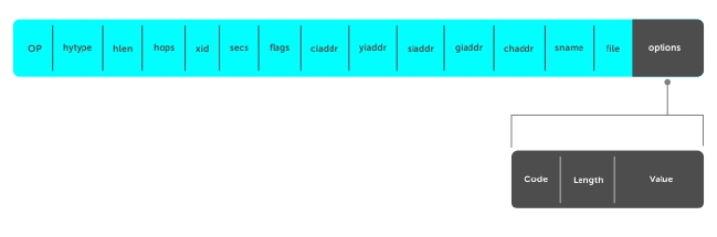
13
Dynamic Host Configuration Protocol
(DHCP)
DHCP is an application layer protocol that dynamically assigns IP addresses and other configuration
parameters to network end-stations (hosts) based on configuration policies determined by network
administrators.
DHCP relieves network administrators of manually configuring hosts, which can be a tedious and error-
prone process when hosts often join, leave, and change locations on the network and it reclaims IP
addresses that are no longer in use to prevent address exhaustion.
DHCP is based on a client-server model. A host discovers the DHCP server and requests an IP address,
and the server either leases or permanently assigns one. There are three types of devices that are involved
in DHCP negotiation:
DHCP Server This is a network device offering configuration parameters to the client.
DHCP Client This is a network device requesting configuration parameters from the server.
Relay Agent This is an intermediary network device that passes DHCP messages between the
client and server when the server is not on the same subnet as the host.
DHCP Packet Format and Options
DHCP uses the user datagram protocol (UDP) as its transport protocol.
The server listens on port 67 and transmits to port 68; the client listens on port 68 and transmits to port
67. The configuration parameters are carried as options in the DHCP packet in Type, Length, Value (TLV)
format; many options are specified in RFC 2132. To limit the number of parameters that servers must
provide, hosts specify the parameters that they require, and the server sends only those parameters.
Some common options are shown in the following illustration.
Figure 26. DHCP packet Format
The following table lists common DHCP options.
Dynamic Host Configuration Protocol (DHCP) 261
Option Number and Description
Subnet Mask Option 1
Specifies the client’s subnet mask.
Router Option 3
Specifies the router IP addresses that may serve as the client’s default gateway.
Domain Name
Server
Option 6
Specifies the domain name servers (DNSs) that are available to the client.
Domain Name Option 15
Specifies the domain name that clients should use when resolving hostnames via
DNS.
IP Address Lease
Time
Option 51
Specifies the amount of time that the client is allowed to use an assigned IP
address.
DHCP Message
Type
Option 53
• 1: DHCPDISCOVER
• 2: DHCPOFFER
• 3: DHCPREQUEST
• 4: DHCPDECLINE
• 5: DHCPACK
• 6: DHCPNACK
• 7: DHCPRELEASE
• 8: DHCPINFORM
Parameter Request
List
Option 55
Clients use this option to tell the server which parameters it requires. It is a series of
octets where each octet is DHCP option code.
Renewal Time Option 58
Specifies the amount of time after the IP address is granted that the client attempts
to renew its lease with the original server.
Rebinding Time Option 59
Specifies the amount of time after the IP address is granted that the client attempts
to renew its lease with any server, if the original server does not respond.
Vendor Class
Identifer
Option 60
262 Dynamic Host Configuration Protocol (DHCP)
Option Number and Description
Identifiers a user-defined string used by the Relay Agent to forward DHCP client
packets to a specific server.
L2 DHCP
Snooping
Option 82
Specifies IP addresses for DHCP messages received from the client that are to be
monitored to build a DHCP snooping database.
End Option 255
Signals the last option in the DHCP packet.
Assign an IP Address using DHCP
The following section describes DHCP and the client in a network.
When a client joins a network:
1. The client initially broadcasts a DHCPDISCOVER message on the subnet to discover available DHCP
servers. This message includes the parameters that the client requires and might include suggested
values for those parameters.
2. Servers unicast or broadcast a DHCPOFFER message in response to the DHCPDISCOVER that offers
to the client values for the requested parameters. Multiple servers might respond to a single
DHCPDISCOVER; the client might wait a period of time and then act on the most preferred offer.
3. The client broadcasts a DHCPREQUEST message in response to the offer, requesting the offered
values.
4. After receiving a DHCPREQUEST, the server binds the clients’ unique identifier (the hardware address
plus IP address) to the accepted configuration parameters and stores the data in a database called a
binding table. The server then broadcasts a DHCPACK message, which signals to the client that it
may begin using the assigned parameters.
5. When the client leaves the network, or the lease time expires, returns its IP address to the server in a
DHCPRELEASE message.
There are additional messages that are used in case the DHCP negotiation deviates from the process
previously described and shown in the illustration below.
DHCPDECLINE A client sends this message to the server in response to a DHCPACK if the
configuration parameters are unacceptable; for example, if the offered address is
already in use. In this case, the client starts the configuration process over by
sending a DHCPDISCOVER.
DHCPINFORM A client uses this message to request configuration parameters when it assigned an
IP address manually rather than with DHCP. The server responds by unicast.
DHCPNAK A server sends this message to the client if it is not able to fulfill a DHCPREQUEST;
for example, if the requested address is already in use. In this case, the client starts
the configuration process over by sending a DHCPDISCOVER.
Dynamic Host Configuration Protocol (DHCP) 263
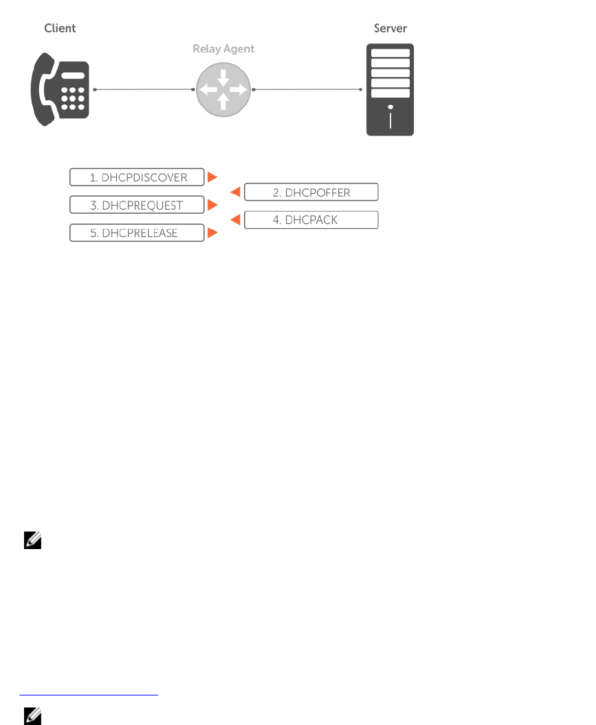
Figure 27. Client and Server Messaging
Implementation Information
The following describes DHCP implementation.
• Dell Networking implements DHCP based on RFC 2131 and RFC 3046.
• IP source address validation is a sub-feature of DHCP Snooping; the Dell Networking OS uses access
control lists (ACLs) internally to implement this feature and as such, you cannot apply ACLs to an
interface which has IP source address validation. If you configure IP source address validation on a
member port of a virtual local area network (VLAN) and then apply an access list to the VLAN, the
system displays the first line in the following message. If you first apply an ACL to a VLAN and then
enable IP source address validation on one of its member ports, the system displays the second line in
the following message.
% Error: Vlan member has access-list configured.
% Error: Vlan has an access-list configured.
NOTE: If you enable DHCP Snooping globally and you have any configured L2 ports, any IP ACL,
MAC ACL, or DHCP source address validation ACL does not block DHCP packets.
• The system provides 40K entries that can be divided between leased addresses and excluded
addresses. By extension, the maximum number of pools you can configure depends on the subnet
mask that you give to each pool. For example, if all pools were configured for a /24 mask, the total
would be 40000/253 (approximately 158). If the subnet is increased, more pools can be configured.
The maximum subnet that can be configured for a single pool is /17. The system displays an error
message for configurations that exceed the allocated memory.
• The Z9500 switch supports 4K DHCP Snooping entries.
• All platforms support Dynamic ARP Inspection on 16 VLANs per system. For more information, refer to
Dynamic ARP Inspection.
NOTE: If the DHCP server is on the top of rack (ToR) and the VLTi (ICL) is down due to a failed
link, when a VLT node is rebooted in JumpStart mode, it is not able to reach the DHCP server,
resulting in bare metal provisioning (BMP) failure.
264 Dynamic Host Configuration Protocol (DHCP)

Configure the System to be a DHCP Server
A DHCP server is a network device that has been programmed to provide network configuration
parameters to clients upon request. Servers typically serve many clients, making host management much
more organized and efficient.
The following table lists the key responsibilities of DHCP servers.
Table 8. DHCP Server Responsibilities
DHCP Server Responsibility Description
Address Storage and Management DHCP servers are the owners of the addresses
used by DHCP clients.The server stores the
addresses and manages their use, keeping track of
which addresses have been allocated and which
are still available.
Configuration Parameter Storage and Management DHCP servers also store and maintain other
parameters that are sent to clients when
requested. These parameters specify in detail how
a client is to operate.
Lease Management DHCP servers use leases to allocate addresses to
clients for a limited time. The DHCP server
maintains information about each of the leases,
including lease length.
Responding To Client Requests DHCP servers respond to different types of
requests from clients, primarily, granting, renewing,
and terminating leases.
Providing Administration Services DHCP servers include functionality that allows an
administrator to implement policies that govern
how DHCP performs its other tasks.
Configuring the Server for Automatic Address Allocation
Automatic address allocation is an address assignment method by which the DHCP server leases an IP
address to a client from a pool of available addresses.
An address pool is a range of IP addresses that the DHCP server may assign. The subnet number indexes
the address pools.
To create an address pool, follow these steps.
1. Access the DHCP server CLI context.
CONFIGURATION mode
ip dhcp server
2. Create an address pool and give it a name.
DHCP mode
pool name
3. Specify the range of IP addresses from which the DHCP server may assign addresses.
Dynamic Host Configuration Protocol (DHCP) 265

DHCP <POOL> mode
network network/prefix-length
•network: the subnet address.
•prefix-length: specifies the number of bits used for the network portion of the address you
specify.
The prefix-length range is from 17 to 31.
4. Display the current pool configuration.
DHCP <POOL> mode
show config
After an IP address is leased to a client, only that client may release the address. The system performs a IP
+ MAC source address validation to ensure that no client can release another clients address. This
validation is a default behavior and is separate from IP+MAC source address validation.
Configuration Tasks
To configure DHCP, an administrator must first set up a DHCP server and provide it with configuration
parameters and policy information including IP address ranges, lease length specifications, and
configuration data that DHCP hosts need.
Configuring the Dell system to be a DHCP server is a three-step process:
1. Configuring the Server for Automatic Address Allocation
2. Specifying a Default Gateway
3. Enable the system to be a DHCP server (no disable command).
Related Configuration Tasks
•Configure a Method of Hostname Resolution
•Creating Manual Binding Entries
•Debugging the DHCP Server
•Using DHCP Clear Commands
Excluding Addresses from the Address Pool
The DHCP server assumes that all IP addresses in a DHCP address pool are available for assigning to
DHCP clients.
You must specify the IP address that the DHCP server should not assign to clients.
To exclude an address, follow this step.
• Exclude an address range from DHCP assignment. The exclusion applies to all configured pools.
DHCP mode
excluded-address
Specifying an Address Lease Time
To specify an address lease time, use the following command.
• Specify an address lease time for the addresses in a pool.
DHCP <POOL>
266 Dynamic Host Configuration Protocol (DHCP)
lease {days [hours] [minutes] | infinite}
The default is 24 hours.
Specifying a Default Gateway
The IP address of the default router should be on the same subnet as the client.
To specify a default gateway, follow this step.
• Specify default gateway(s) for the clients on the subnet, in order of preference.
DHCP <POOL>
default-router address
Configure a Method of Hostname Resolution
Dell Networking systems are capable of providing DHCP clients with parameters for two methods of
hostname resolution—using DNS or NetBIOS WINS.
Using DNS for Address Resolution
A domain is a group of networks. DHCP clients query DNS IP servers when they need to correlate host
names to IP addresses.
1. Create a domain.
DHCP <POOL>
domain-name name
2. Specify in order of preference the DNS servers that are available to a DHCP client.
DHCP <POOL>
dns-server address
Using NetBIOS WINS for Address Resolution
Windows internet naming service (WINS) is a name resolution service that Microsoft DHCP clients use to
correlate host names to IP addresses within a group of networks. Microsoft DHCP clients can be one of
four types of NetBIOS nodes: broadcast, peer-to-peer, mixed, or hybrid.
1. Specify the NetBIOS WINS name servers, in order of preference, that are available to Microsoft
Dynamic Host Configuration Protocol (DHCP) clients.
DHCP <POOL> mode
netbios-name-server address
2. Specify the NetBIOS node type for a Microsoft DHCP client. Dell Networking recommends specifying
clients as hybrid.
DHCP <POOL> mode
netbios-node-type type
Dynamic Host Configuration Protocol (DHCP) 267

Creating Manual Binding Entries
An address binding is a mapping between the IP address and the media access control (MAC) address of a
client.
The DHCP server assigns the client an available IP address automatically, and then creates an entry in the
binding table. However, the administrator can manually create an entry for a client; manual bindings are
useful when you want to guarantee that a particular network device receives a particular IP address.
Manual bindings can be considered single-host address pools. There is no limit on the number of manual
bindings, but you can only configure one manual binding per host.
NOTE: The system does not prevent you from using a network IP as a host IP; be sure to not use a
network IP as a host IP.
1. Create an address pool.
DHCP mode
pool name
2. Specify the client IP address.
DHCP <POOL>
host address
3. Specify the client hardware address.
DHCP <POOL>
hardware-address hardware-address type
•hardware-address: the client MAC address.
•type: the protocol of the hardware platform.
The default protocol is Ethernet.
Debugging the DHCP Server
To debug the DHCP server, use the following command.
• Display debug information for DHCP server.
EXEC Privilege mode
debug ip dhcp server [events | packets]
Using DHCP Clear Commands
To clear DHCP binding entries, address conflicts, and server counters, use the following commands.
• Clear DHCP binding entries for the entire binding table.
EXEC Privilege mode.
clear ip dhcp binding
• Clear a DHCP binding entry for an individual IP address.
EXEC Privilege mode.
clear ip dhcp binding ip address
268 Dynamic Host Configuration Protocol (DHCP)

Configure the System to be a Relay Agent
DHCP clients and servers request and offer configuration information via broadcast DHCP messages.
Routers do not forward broadcasts, so if there are no DHCP servers on the subnet, the client does not
receive a response to its request and therefore cannot access the network.
You can configure an interface on the Dell Networking system to relay the DHCP messages to a specific
DHCP server using the ip helper-address dhcp-address command from INTERFACE mode, as
shown in the following illustration. Specify multiple DHCP servers by using the ip helper-address
dhcp-address command multiple times.
When you configure the ip helper-address command, the system listens for DHCP broadcast
messages on port 67. The system rewrites packets received from the client and forwards them via unicast
to the DHCP servers; the system rewrites the destination IP address and writes its own address as the
relay device. Responses from the server are unicast back to the relay agent on port 67 and the relay agent
rewrites the destination address and forwards the packet to the client subnet via broadcast or unicast,
depending whether the client has set or cleared the BROADCAST flag in the DHCP Client PDUs.
NOTE: DHCP Relay is not available on Layer 2 interfaces and VLANs.
Dynamic Host Configuration Protocol (DHCP) 269
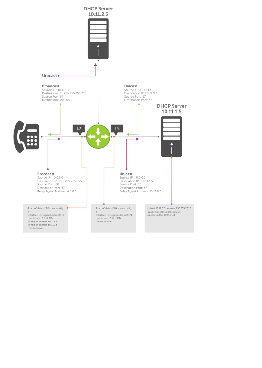
Figure 28. Configuring a Relay Agent
To view the ip helper-address configuration for an interface, use the show ip interface
command from EXEC privilege mode.
Example of the show ip interface Command
R1_E600#show ip int gig 1/3
GigabitEthernet 1/3 is up, line protocol is down
Internet address is 10.11.0.1/24
Broadcast address is 10.11.0.255
Address determined by user input
IP MTU is 1500 bytes
Helper address is 192.168.0.1
192.168.0.2
Directed broadcast forwarding is disabled
Proxy ARP is enabled
Split Horizon is enabled
Poison Reverse is disabled
270 Dynamic Host Configuration Protocol (DHCP)

ICMP redirects are not sent
ICMP unreachables are not sent
Configure the System to be a DHCP Client
A DHCP client is a network device that requests an IP address and configuration parameters from a DHCP
server.
Implement the DHCP client functionality as follows:
• The switch can obtain a dynamically assigned IP address from a DHCP server. A start-up configuration
is not received. Use bare metal provisioning (BMP) to receive configuration parameters (OS version
and a configuration file). BMP is enabled as a factory-default setting on a switch.
A switch cannot operate with BMP and as a DHCP client simultaneously. To disable BMP in EXEC
mode, use the stop bmp command. After BMP stops, the switch acts as a DHCP client.
• Acquire a dynamic IP address from a DHCP client is for a limited period or until the client releases the
address.
• A DHCP server manages and assigns IP addresses to clients from an address pool stored on the
server. For more information, refer to Configuring the Server for Automatic Address Allocation.
• Dynamically assigned IP addresses are supported on Z9500 10-Gigabit and 40-Gigabit interfaces. The
DHCP client is supported on VLAN and port-channel interfaces.
• The public out-of-band management interface and default VLAN 1 are configured by default as a
DHCP client to acquire a dynamic IP address from a DHCP server.
DHCP Client on a Management Interface
These conditions apply when you enable a management interface to operate as a DHCP client.
• The management default route is added with the gateway as the router IP address received in the
DHCP ACK packet. It is required to send and receive traffic to and from other subnets on the external
network. The route is added irrespective when the DHCP client and server are in the same or different
subnets. The management default route is deleted if the management IP address is released like other
DHCP client management routes.
•ip route for 0.0.0.0 takes precedence if it is present or added later.
• Management routes added by a DHCP client display with Route Source as DHCP in the show ip
management route and show ip management-route dynamic command output.
• Management routes added by DHCP are automatically reinstalled if you configure a static IP route
with the ip route command that replaces a management route added by the DHCP client. If you
remove the statically configured IP route using the no ip route command, the management route
is reinstalled. Manually delete management routes added by the DHCP client.
• To reinstall management routes added by the DHCP client that is removed or replaced by the same
statically configured management routes, release the DHCP IP address and renew it on the
management interface.
• Management routes added by the DHCP client have higher precedence over the same statically
configured management route. Static routes are not removed from the running configuration if a
dynamically acquired management route added by the DHCP client overwrites a static management
route.
• Management routes added by the DHCP client are not added to the running configuration.
NOTE: Management routes added by the DHCP client include the specific routes to reach a DHCP
server in a different subnet and the management route.
Dynamic Host Configuration Protocol (DHCP) 271

DHCP Client Operation with Other Features
A DHCP client also operates with the following software features.
Virtual Link Trunking (VLT)
A DHCP client is not supported on VLT interfaces.
VLAN and Port Channels
DHCP client configuration and behavior are the same on Virtual LAN (VLAN) and port-channel (LAG)
interfaces as on a physical interface.
DHCP Snooping
A DHCP client can run on a switch simultaneously with the DHCP snooping feature as follows:
• If you enable DHCP snooping globally on a switch and you enable a DHCP client on an interface, the
trust port, source MAC address, and snooping table validations are not performed on the interface by
DHCP snooping for packets destined to the DHCP client daemon.
The following criteria determine packets destined for the DHCP client:
– DHCP is enabled on the interface.
– The user data protocol (UDP) destination port in the packet is 68.
– The chaddr (change address) in the DHCP header of the packet is the same as the interface’s
MAC address.
• An entry in the DHCP snooping table is not added for a DHCP client interface.
DHCP Server
A switch can operate as a DHCP client and a DHCP server. DHCP client interfaces cannot acquire a
dynamic IP address from the DHCP server running on the switch. Acquire a dynamic IP address from
another DHCP server.
Virtual Router Redundancy Protocol (VRRP)
Do not enable the DHCP client on an interface and set the priority to 255 or assign the same DHCP
interface IP address to a VRRP virtual group. Doing so guarantees that this router becomes the VRRP
group owner.
To use the router as the VRRP owner, if you enable a DHCP client on an interface that is added to a VRRP
group, assign a priority less than 255 but higher than any other priority assigned in the group.
Configure Secure DHCP
The following feature is available on the Z-SeriesS4810 S4820T platform, except where noted.
DHCP as defined by RFC 2131 provides no authentication or security mechanisms. Secure DHCP is a suite
of features that protects networks that use dynamic address allocation from spoofing and attacks.
•Option 82
•DHCP Snooping
•Dynamic ARP Inspection
272 Dynamic Host Configuration Protocol (DHCP)

•Source Address Validation
Option 82
RFC 3046 (the relay agent information option, or Option 82) is used for class-based IP address
assignment.
The code for the relay agent information option is 82, and is comprised of two sub-options, circuit ID and
remote ID.
Circuit ID This is the interface on which the client-originated message is received.
Remote ID This identifies the host from which the message is received. The value of this sub-
option is the MAC address of the relay agent that adds Option 82.
The DHCP relay agent inserts Option 82 before forwarding DHCP packets to the server. The server can
use this information to:
• track the number of address requests per relay agent. Restricting the number of addresses available
per relay agent can harden a server against address exhaustion attacks.
• associate client MAC addresses with a relay agent to prevent offering an IP address to a client
spoofing the same MAC address on a different relay agent.
• assign IP addresses according to the relay agent. This prevents generating DHCP offers in response to
requests from an unauthorized relay agent.
The server echoes the option back to the relay agent in its response, and the relay agent can use the
information in the option to forward a reply out the interface on which the request was received rather
than flooding it on the entire VLAN.
The relay agent strips Option 82 from DHCP responses before forwarding them to the client.
To insert Option 82 into DHCP packets, follow this step.
• Insert Option 82 into DHCP packets.
CONFIGURATION mode
ip dhcp relay information-option [trust-downstream]
For routers between the relay agent and the DHCP server, enter the trust-downstream option.
• Manually reset the remote ID for Option 82.
CONFIGURATION mode
ip dhcp relay information-option remote-id
DHCP Snooping
DHCP snooping protects networks from spoofing. In the context of DHCP snooping, ports are either
trusted or not trusted.
By default, all ports are not trusted. Trusted ports are ports through which attackers cannot connect.
Manually configure ports connected to legitimate servers and relay agents as trusted.
When you enable DHCP snooping, the relay agent builds a binding table — using DHCPACK messages —
containing the client MAC address, IP addresses, IP address lease time, port, VLAN ID, and binding type.
Every time the relay agent receives a DHCPACK on a trusted port, it adds an entry to the table.
The relay agent checks all subsequent DHCP client-originated IP traffic (DHCPRELEASE, DHCPNACK, and
DHCPDECLINE) against the binding table to ensure that the MAC-IP address pair is legitimate and that the
Dynamic Host Configuration Protocol (DHCP) 273

packet arrived on the correct port. Packets that do not pass this check are forwarded to the server for
validation. This checkpoint prevents an attacker from spoofing a client and declining or releasing the real
client’s address. Server-originated packets (DHCPOFFER, DHCPACK, and DHCPNACK) that arrive on a not
trusted port are also dropped. This checkpoint prevents an attacker from acting as an imposter as a
DHCP server to facilitate a man-in-the-middle attack.
Binding table entries are deleted when a lease expires, or the relay agent encounters a DHCPRELEASE,
DHCPNACK, or DHCPDECLINE.
DHCP snooping is supported on Layer 2 and Layer 3 traffic. DHCP snooping on Layer 3 interfaces
depends on the configured DHCP relay agent (ip helper-address). DHCP snooping on Layer 2
interfaces does not require a relay agent.
Binding table entries are deleted when a lease expires or when the relay agent encounters a
DHCPRELEASE. Line cards maintain a list of snooped VLANs. When the binding table is exhausted, DHCP
packets are dropped on snooped VLANs, while these packets are forwarded across non-snooped VLANs.
Because DHCP packets are dropped, no new IP address assignments are made. However, DHCPRELEASE
and DHCPDECLINE packets are allowed so that the DHCP snooping table can decrease in size. After the
table usage falls below the maximum limit of 4000 entries, new IP address assignments are allowed.
NOTE: DHCP server packets are dropped on all not trusted interfaces of a system configured for
DHCP snooping. To prevent these packets from being dropped, configure ip dhcp snooping
trust on the server-connected port.
Enabling DHCP Snooping
To enable DHCP snooping, use the following commands.
1. Enable DHCP snooping globally.
CONFIGURATION mode
ip dhcp snooping
2. Specify ports connected to DHCP servers as trusted.
INTERFACE mode
ip dhcp snooping trust
3. Enable DHCP snooping on a VLAN.
CONFIGURATION mode
ip dhcp snooping vlan name
Adding a Static Entry in the Binding Table
To add a static entry in the binding table, use the following command.
• Add a static entry in the binding table.
EXEC Privilege mode
ip dhcp snooping binding mac
Clearing the Binding Table
To clear the binding table, use the following command.
274 Dynamic Host Configuration Protocol (DHCP)

• Delete all of the entries in the binding table.
EXEC Privilege mode
clear ip dhcp snooping binding
Displaying the Contents of the Binding Table
To display the contents of the binding table, use the following command.
• Display the contents of the binding table.
EXEC Privilege mode
show ip dhcp snooping
Example of the show ip dhcp snooping Command
View the DHCP snooping statistics with the show ip dhcp snooping command.
Dell#show ip dhcp snooping
IP DHCP Snooping : Enabled.
IP DHCP Snooping Mac Verification : Disabled.
IP DHCP Relay Information-option : Disabled.
IP DHCP Relay Trust Downstream : Disabled.
Database write-delay (In minutes) : 0
DHCP packets information
Relay Information-option packets : 0
Relay Trust downstream packets : 0
Snooping packets : 0
Packets received on snooping disabled L3 Ports : 0
Snooping packets processed on L2 vlans : 142
DHCP Binding File Details
Invalid File : 0
Invalid Binding Entry : 0
Binding Entry lease expired : 0
List of Trust Ports :Te 0/49
List of DHCP Snooping Enabled Vlans :Vl 10
List of DAI Trust ports :Te 0/49
Drop DHCP Packets on Snooped VLANs Only
Binding table entries are deleted when a lease expires or the relay agent encounters a DHCPRELEASE.
Line cards maintain a list of snooped VLANs. When the binding table fills, DHCP packets are dropped only
on snooped VLANs, while such packets are forwarded across non-snooped VLANs. Because DHCP
packets are dropped, no new IP address assignments are made. However, DHCP release and decline
packets are allowed so that the DHCP snooping table can decrease in size. After the table usage falls
below the maximum limit of 4000 entries, new IP address assignments are allowed.
To view the number of entries in the table, use the show ip dhcp snooping binding command. This
output displays the snooping binding table created using the ACK packets from the trusted port.
Dell#show ip dhcp snooping binding
Codes : S - Static D - Dynamic
Dynamic Host Configuration Protocol (DHCP) 275

IP Address MAC Address Expires(Sec) Type VLAN Interface
================================================================
10.1.1.251 00:00:4d:57:f2:50 172800 D Vl 10 Te 0/2
10.1.1.252 00:00:4d:57:e6:f6 172800 D Vl 10 Te 0/1
10.1.1.253 00:00:4d:57:f8:e8 172740 D Vl 10 Te 0/3
10.1.1.254 00:00:4d:69:e8:f2 172740 D Vl 10 Te 0/50
Total number of Entries in the table : 4
Dynamic ARP Inspection
Dynamic address resolution protocol (ARP) inspection prevents ARP spoofing by forwarding only ARP
frames that have been validated against the DHCP binding table.
ARP is a stateless protocol that provides no authentication mechanism. Network devices accept ARP
requests and replies from any device. ARP replies are accepted even when no request was sent. If a client
receives an ARP message for which a relevant entry already exists in its ARP cache, it overwrites the
existing entry with the new information.
The lack of authentication in ARP makes it vulnerable to spoofing. ARP spoofing is a technique attackers
use to inject false IP-to-MAC mappings into the ARP cache of a network device. It is used to launch man-
in-the-middle (MITM), and denial-of-service (DoS) attacks, among others.
A spoofed ARP message is one in which the MAC address in the sender hardware address field and the IP
address in the sender protocol field are strategically chosen by the attacker. For example, in an MITM
attack, the attacker sends a client an ARP message containing the attacker’s MAC address and the
gateway’s IP address. The client then thinks that the attacker is the gateway, and sends all internet-bound
packets to it. Likewise, the attacker sends the gateway an ARP message containing the attacker’s MAC
address and the client’s IP address. The gateway then thinks that the attacker is the client and forwards all
packets addressed to the client to it. As a result, the attacker is able to sniff all packets to and from the
client.
Other attacks using ARP spoofing include:
Broadcast An attacker can broadcast an ARP reply that specifies FF:FF:FF:FF:FF:FF as the
gateway’s MAC address, resulting in all clients broadcasting all internet-bound
packets.
MAC flooding An attacker can send fraudulent ARP messages to the gateway until the ARP cache
is exhausted, after which, traffic from the gateway is broadcast.
Denial of
service
An attacker can send a fraudulent ARP messages to a client to associate a false
MAC address with the gateway address, which would blackhole all internet-bound
packets from the client.
276 Dynamic Host Configuration Protocol (DHCP)

NOTE: Dynamic ARP inspection (DAI) uses entries in the L2SysFlow CAM region, a sub-region of
SystemFlow. One CAM entry is required for every DAI-enabled VLAN. You can enable DAI on up to
16 VLANs on a system. However, the default CAM profile allocates only nine entries to the
L2SysFlow region for DAI. You can configure 10 to 16 DAI-enabled VLANs by allocating more CAM
space to the L2SysFlow region before enabling DAI.
SystemFlow has 102 entries by default. This region is comprised of two sub-regions: L2Protocol and
L2SystemFlow. L2Protocol has 87 entries; L2SystemFlow has 15 entries. Six L2SystemFlow entries
are used by Layer 2 protocols, leaving nine for DAI. L2Protocol can have a maximum of 100 entries;
you must expand this region to capacity before you can increase the size of L2SystemFlow. This is
relevant when you are enabling DAI on VLANs. If, for example, you want to enable DAI on 16 VLANs,
you need seven more entries; in this case, reconfigure the SystemFlow region for 122 entries using
the layer-2 eg-acl value fib value frrp value ing-acl value learn value l2pt
value qos value system-flow 122 command.
The logic is as follows:
L2Protocol has 87 entries by default and must be expanded to its maximum capacity, 100 entries,
before L2SystemFlow can be increased; therefore, 13 more L2Protocol entries are required.
L2SystemFlow has 15 entries by default, but only nine are for DAI; to enable DAI on 16 VLANs, seven
more entries are required. 87 L2Protocol + 13 additional L2Protocol + 15 L2SystemFlow + 7
additional L2SystemFlow equals 122.
Configuring Dynamic ARP Inspection
To enable dynamic ARP inspection, use the following commands.
1. Enable DHCP snooping.
2. Validate ARP frames against the DHCP snooping binding table.
INTERFACE VLAN mode
arp inspection
Examples of Viewing the ARP Information
To view entries in the ARP database, use the show arp inspection database command.
Dell#show arp inspection database
Protocol Address Age(min) Hardware Address Interface VLAN CPU
---------------------------------------------------------------------
Internet 10.1.1.251 - 00:00:4d:57:f2:50 Te 0/2 Vl 10 CP
Internet 10.1.1.252 - 00:00:4d:57:e6:f6 Te 0/1 Vl 10 CP
Internet 10.1.1.253 - 00:00:4d:57:f8:e8 Te 0/3 Vl 10 CP
Internet 10.1.1.254 - 00:00:4d:69:e8:f2 Te 0/50 Vl 10 CP
Dell#
To see how many valid and invalid ARP packets have been processed, use the show arp inspection
statistics command.
Dell#show arp inspection statistics
Dynamic ARP Inspection (DAI) Statistics
---------------------------------------
Valid ARP Requests : 0
Valid ARP Replies : 1000
Invalid ARP Requests : 1000
Dynamic Host Configuration Protocol (DHCP) 277

Invalid ARP Replies : 0
Dell#
Bypassing the ARP Inspection
You can configure a port to skip ARP inspection by defining the interface as trusted, which is useful in
multi-switch environments.
ARPs received on trusted ports bypass validation against the binding table. All ports are untrusted by
default.
To bypass the ARP inspection, use the following command.
• Specify an interface as trusted so that ARPs are not validated against the binding table.
INTERFACE mode
arp inspection-trust
DAI is supported on Layer 2 and Layer 3.
Source Address Validation
Using the DHCP binding table, the system can perform three types of source address validation (SAV).
Table 9. Three Types of Source Address Validation
Source Address Validation Description
IP Source Address Validation Prevents IP spoofing by forwarding only IP packets
that have been validated against the DHCP binding
table.
DHCP MAC Source Address Validation Verifies a DHCP packet’s source hardware address
matches the client hardware address field
(CHADDR) in the payload.
IP+MAC Source Address Validation Verifies that the IP source address and MAC source
address are a legitimate pair.
Enabling IP Source Address Validation
IP source address validation (SAV) prevents IP spoofing by forwarding only IP packets that have been
validated against the DHCP binding table.
A spoofed IP packet is one in which the IP source address is strategically chosen to disguise the attacker.
For example, using ARP spoofing, an attacker can assume a legitimate client’s identity and receive traffic
addressed to it. Then the attacker can spoof the client’s IP address to interact with other clients.
The DHCP binding table associates addresses the DHCP servers assign, with the port on which the
requesting client is attached. When you enable IP source address validation on a port, the system verifies
that the source IP address is one that is associated with the incoming port. If an attacker is impostering as
a legitimate client, the source address appears on the wrong ingress port and the system drops the
packet. Likewise, if the IP address is fake, the address is not on the list of permissible addresses for the
port and the packet is dropped.
To enable IP source address validation, use the following command.
278 Dynamic Host Configuration Protocol (DHCP)

NOTE: If you enable IP source guard using the ip dhcp source-address-validation
command and there are 187 entries or more in the current DHCP snooping binding table, SAV may
not be applied to all entries. To ensure that SAV is applied correctly to all entries, enable the ip
dhcp source-address-validation command before adding entries to the binding table.
• Enable IP source address validation.
INTERFACE mode
ip dhcp source-address-validation
DHCP MAC Source Address Validation
DHCP MAC source address validation (SAV) validates a DHCP packet’s source hardware address against
the client hardware address field (CHADDR) in the payload.
The system ensures that the packet’s source MAC address is checked against the CHADDR field in the
DHCP header only for packets from snooped VLANs.
• Enable DHCP MAC SAV.
CONFIGURATION mode
ip dhcp snooping verify mac-address
Enabling IP+MAC Source Address Validation
IP source address validation (SAV) validates the IP source address of an incoming packet against the
DHCP snooping binding table. IP+MAC SAV ensures that the IP source address and MAC source address
are a legitimate pair, rather than validating each attribute individually. You cannot configure IP+MAC SAV
with IP SAV.
1. Allocate at least one FP block to the ipmacacl CAM region.
CONFIGURATION mode
cam-acl l2acl
2. Save the running-config to the startup-config.
EXEC Privilege mode
copy running-config startup-config
3. Reload the system.
EXEC Privilege
reload
4. Enable IP+MAC SAV.
INTERFACE mode
ip dhcp source-address-validation ipmac
The system creates an ACL entry for each IP+MAC address pair in the binding table and applies it to the
interface.
To display the IP+MAC ACL for an interface for the entire system, use the show ip dhcp snooping
source-address-validation [interface] command in EXEC Privilege mode.
Dynamic Host Configuration Protocol (DHCP) 279

14
Equal Cost Multi-Path (ECMP)
Equal cost multi-path (ECMP) supports multiple paths in next-hop packet forwarding to a destination
device.
ECMP for Flow-Based Affinity
ECMP for flow-based affinity includes link bundle monitoring.
Enabling Deterministic ECMP Next Hop
Deterministic ECMP next hop arranges all ECMPs in order before writing them into the content
addressable memory (CAM).
For example, suppose the RTM learns eight ECMPs in the order that the protocols and interfaces came
up. In this case, the forwarding information base (FIB) and CAM sort them so that the ECMPs are always
arranged. This implementation ensures that every chassis having the same prefixes orders the ECMPs the
same.
With eight or less ECMPs, the ordering is lexicographic and deterministic. With more than eight ECMPs,
ordering is deterministic, but it is not in lexicographic order.
To enable deterministic ECMP next hop, use the appropriate command.
NOTE: Packet loss might occur when you enable ip/ipv6 ecmp-deterministic for the first-
time only.
• Enable IPv4 Deterministic ECMP Next Hop.
CONFIGURATION mode.
ip ecmp-deterministic
• Enable IPv6 Deterministic ECMP Next Hop.
CONFIGURATION mode.
ipv6 ecmp-deterministic
Configuring the Hash Algorithm Seed
Deterministic ECMP sorts ECMPs in order even though RTM provides them in a random order. However,
the hash algorithm uses as a seed the lower 12 bits of the chassis MAC, which yields a different hash
result for every chassis.
This behavior means that for a given flow, even though the prefixes are sorted, two unrelated chassis can
select different hops.
The system provides a command line interface (CLI)-based solution for modifying the hash seed to
ensure that on each configured system, the ECMP selection is same. When configured, the same seed is
set for ECMP, LAG, and NH, and is used for incoming traffic only.
280 Equal Cost Multi-Path (ECMP)

NOTE: While the seed is stored separately on each port-pipe, the same seed is used across all
CAMs.
NOTE: You cannot separate LAG and ECMP, but you can use different algorithms across the chassis
with the same seed. If LAG member ports span multiple port-pipes and line cards, set the seed to
the same value on each port-pipe to achieve deterministic behavior.
NOTE: If you remove the hash algorithm configuration, the hash seed does not return to the
original factory default setting.
To configure the hash algorithm seed, use the following command.
• Specify the hash algorithm seed.
CONFIGURATION mode.
hash-algorithm seed value [linecard slot-id] [port-set number]
The range is from 0 to 4095.
Link Bundle Monitoring
Link bundle monitoring allows the system to monitor the use of multiple links for an uneven distribution.
A global default threshold of 60% is the usage percentage for the bundle; when the system reaches this
threshold, it begins monitoring the configured ECMP groups for uneven distribution. Links are monitored
in 15-second intervals for three consecutive instances. Any deviation exceeding 10% among any of the
bundle links sends a syslog and an alarm event is generated; for example, 01:16:25: %STKUNIT0-M:CP
%IFMGR-5-BUNDLE_UNEVEN_DISTRIBUTION: Found uneven distribution in ECMP-GROUP
bundle 1.
When the deviation clears, another syslog is sent and a clear alarm event is generated; for example,
01:35:14: %STKUNIT0-M:CP %IFMGR-5-BUNDLE_UNEVEN_DISTRIBUTION_ALARM_CLEAR: Uneven
distribution in ECMP-GROUP bundle 1 got cleared.
The link bundle utilization is calculated as the total bandwidth of all links divided by the total bytes-per-
second of all links, as shown in the following example.
Example of Viewing Link Bundle Monitoring
Dell# show link-bundle-distribution ecmp-group 1
Link-bundle trigger threshold - 60
ECMP bundle - 1 Utilization[In Percent] - 44 Alarm State - Active
Interface Line Protocol Utilization[In Percent]
Te 0/0 Up 36
Te 0/1 Up 52
Managing ECMP Group Paths
To manage ECMP group paths, you can configure the maximum number of paths for an ECMP route that
the L3 CAM can hold to avoid path degeneration. When you do not configure the maximum number of
routes, the CAM can hold a maximum ECMP per route.
To configure the maximum number of paths, use the following command.
Equal Cost Multi-Path (ECMP) 281

NOTE: Save the new ECMP settings to the startup-config (write-mem) then reload the system for
the new settings to take effect.
• Configure the maximum number of paths per ECMP group.
CONFIGURATION mode.
ip ecmp-group maximum-paths {2-64}
• Enable ECMP group path management.
CONFIGURATION mode.
ip ecmp-group path-fallback
Example of the ip ecmp-group maximum-paths Command
Dell(conf)#ip ecmp-group maximum-paths 3
User configuration has been changed. Save the configuration and reload to take
effect
Dell(conf)#
Creating an ECMP Group Bundle
Within each ECMP group, you can specify an interface.
If you enable monitoring for the ECMP group, the utilization calculation is performed when the average
utilization of the link-bundle (as opposed to a single link within the bundle) exceeds 60%.
1. Create a user-defined ECMP group bundle.
CONFIGURATION mode
ecmp-group ecmp-group-id
The range is from 1 to 64.
2. Add interfaces to the ECMP group bundle.
CONFIGURATION ECMP-GROUP mode
interface interface interface tengigabitethernet 0/0 interface port-channel
100
3. Enable the monitoring for the bundle.
CONFIGURATION ECMP-GROUP mode
link-bundle-monitor enable
Modifying the ECMP Group Threshold
You can customize the threshold percentage for monitoring ECMP group bundles.
To customize the ECMP group bundle threshold and to view the changes, use the following commands.
• Modify the threshold for monitoring ECMP group bundles.
CONFIGURATION mode
link-bundle-distribution trigger-threshold {percent}
The range is from 1 to 90%.
282 Equal Cost Multi-Path (ECMP)

The default is 60%.
• Display details for an ECMP group bundle.
EXEC mode
show link-bundle-distribution ecmp-group ecmp-group-id
The range is from 1 to 64.
Viewing an ECMP Group
NOTE: An ecmp-group index is generated automatically for each unique ecmp-group when you
configure multipath routes to the same network. The system can generate a maximum of 512
unique ecmp-groups. The ecmp-group indices are generated in even numbers (0, 2, 4, 6... 1022)
and are for information only.
You can configure ecmp-group with id 2 for link bundle monitoring. This ecmp-group is different
from the ecmp-group index 2 that is created by configuring routes and is automatically generated.
These two ecmp-groups are not related in any way.
Dell(conf-ecmp-group-5)#show config
!
ecmp-group 5
interface tengigabitethernet 0/2
interface tengigabitethernet 0/3
link-bundle-monitor enable
Dell(conf-ecmp-group-5)#
ECMP Support in L3 Host and LPM Tables
The L3 host and Longest Prefix Match (LPM) tables provide ECMP next-hop forwarding for destination
addresses. You can program IPv6 /128 and IPv4 /32 route prefixes to be stored in the L3 host table and
move IPv6 /128 and IPv4 /32 route prefixes between the host table and the LPM route table.
By default, IPv4 route prefixes are installed only in the LPM table and IPv6/128 route prefixes are installed
only in the L3 host table. In previous releases, the IPv6 /128 entries in the host table were not supported
by ECMP.
NOTE: When moving destination prefixes from the LPM to the host table, there may be a hash
collision because the host table is a hash table. In this case, a workaround does not exist for
programming route entries in the host table.
NOTE: Before moving IPv6/128 route prefixes from the host table to the LPM table, you must enable
LPM CAM partitioning for extended IPv6 prefixes. See Configuring the LPM Table for IPv6 Extended
Prefixes for more information.
Use the ipv4 unicast-host-route or ipv6 unicast-host-route commands to program IPv4 /32
or IPv6 /128 route prefixes to be stored in the L3 host table. A warning message states that the change
takes effect only when IPv4 or IPv6 route prefixes are cleared from the routing table (RTM) using the
clear ip route * command. The IPv6 /128 and IPv4 /32 route-prefix entries that you move to the
host table receive ECMP handling.
To verify ECMP support for IPv6 /128 route prefixes stored in the host table, use the show ipv6 cam
command. The command output includes the ECMP field with IPv6 neighbor addresses. 1 indicates
ECMP handling of destination routes.
Dell# show ipv6 cam linecard 0 port-set 0
Neighbor Mac-Addr Port Vid EC
Equal Cost Multi-Path (ECMP) 283

--------------------------------------------------
[ 132] 20::1 00:00:20:d5:ec:a0 Fo 0/16 0 1
[ 132] 20::1 00:00:20:d5:ec:a1 Fo 0/24 0 1
To re-enable programming of IPv6 /128 route prefixes in the LPM table, use the no ipv6 unicast-
host-route command. A warning message states that the change takes effect only when IPv4 or IPv6
route prefixes are cleared from the routing table (RTM) using the clear ip route * command.
284 Equal Cost Multi-Path (ECMP)

15
Enabling FIPS Cryptography
Federal information processing standard (FIPS) cryptography provides cryptographic algorithms
conforming to various FIPS standards published by the National Institute of Standards and Technology
(NIST), a non-regulatory agency of the US Department of Commerce. FIPS mode is also validated for
numerous platforms to meet the FIPS-140-2 standard for a software-based cryptographic module.
This chapter describes how to enable FIPS cryptography requirements on Dell Networking platforms.
NOTE: The Dell Networking OS uses an embedded FIPS 140-2-validated cryptography module
(Certificate #1747) running on NetBSD 5.1 per FIPS 140-2 Implementation Guidance section G.5
guidelines.
NOTE: Only the following features use the embedded FIPS 140-2-validated cryptography module:
• SSH Client
• SSH Server
• RSA Host Key Generation
• SCP File Transfers
Currently, other features using cryptography do not use the embedded FIPS 140-2-validated
cryptography module.
Configuration Tasks
To configure and use FIPS cryptography on the switch, perform these tasks:
•Preparing the System
•Enabling FIPS Mode
•Generating Host-Keys
•Monitoring FIPS Mode Status
•Disabling FIPS Mode
Preparing the System
Before you enable FIPS mode, Dell Networking recommends making the following changes to your
system.
1. Disable the Telnet server (only use secure shell [SSH] to access the system).
2. Disable the FTP server (only use secure copy [SCP] to transfer files to and from the system).
3. Attach a secure, standalone host to the console port for the FIPS configuration to use.
Enabling FIPS Cryptography 285

Enabling FIPS Mode
To enable or disable FIPS mode, use the console port.
Secure the host attached to the console port against unauthorized access. Any attempts to enable or
disable FIPS mode from a virtual terminal session are denied.
When you enable FIPS mode, the following actions are taken:
• If enabled, the SSH server is disabled.
• All open SSH and Telnet sessions, as well as all SCP and FTP file transfers, are closed.
• Any existing host keys (both RSA and RSA1) are deleted from system memory and NVRAM storage.
• FIPS mode is enabled.
– If you enable the SSH server when you enter the fips mode enable command, it is re-enabled
for version 2 only.
– If you re-enable the SSH server, a new RSA host key-pair is generated automatically. You can also
manually create this key-pair using the crypto key generate command.
NOTE: Under certain unusual circumstances, it is possible for the fips enable command to
indicate a failure.
• This failure occurs if any of the self-tests fail when you enable FIPS mode.
• This failure occurs if there were existing SSH/Telnet sessions that could not be closed
successfully in a reasonable amount of time. In general, this failure can occur if a user at a
remote host is in the process of establishing an SSH session to the local system, and has been
prompted to accept a new host key or to enter a password, but is not responding to the request.
Assuming this failure is a transient condition, attempting to enable FIPS mode again should be
successful.
To enable FIPS mode, use the following command.
• Enable FIPS mode from a console port.
CONFIGURATION
fips mode enable
Generating Host-Keys
The following describes hot-key generation.
When you enable or disable FIPS mode, the system deletes the current public/private host-key pair,
terminatesany SSH sessions that are in progress (deleting all the per-session encryption key information),
actually enables/tests FIPS mode, generates new host-keys, and re-enables the SSH server (assuming it
was enabled before enabling FIPS).
For more information, refer to the SSH Server and SCP Commands section in the Security chapter of the
Dell Networking OS Command Line Reference Guide.
286 Enabling FIPS Cryptography

Monitoring FIPS Mode Status
To view the status of the current FIPS mode (enabled/disabled), use the following commands.
• Use either command to view the status of the current FIPS mode.
show fips status
show system
Example of the show fips status Command
Example of the show system Command
Dell#show fips status
FIPS Mode : Enabled
for the system using the show system command.
Dell#show system
System MAC : 00:01:e8:8a:ff:0c
Reload Type : normal-reload [Next boot : normal-reload]
-- Unit 0 --
Unit Type : Management Unit
Status : online
Next Boot : online
Required Type : S4810 - 52-port GE/TE/FG (SE)
Current Type : S4810 - 52-port GE/TE/FG (SE)
Master priority : 0
Hardware Rev : 3.0
Num Ports : 64
Up Time : 7 hr, 3 min
FTOS Version : 4810-8-3-7-1061
Jumbo Capable : yes
POE Capable : no
FIPS Mode : enabled
Burned In MAC : 00:01:e8:8a:ff:0c
No Of MACs : 3
...
Disabling FIPS Mode
The following describes disabling FIPS mode.
When you disable FIPS mode, the following changes occur:
• The SSH server disables.
• All open SSH and Telnet sessions, as well as all SCP and FTP file transfers, close.
• Any existing host keys (both RSA and RSA1) are deleted from system memory and NVRAM storage.
• FIPS mode disables.
• The SSH server re-enables.
• The Telnet server re-enables (if it is present in the configuration).
• New 1024–bit RSA and RSA1 host key-pairs are created.
To disable FIPS mode, use the following command.
Enabling FIPS Cryptography 287

• To disable FIPS mode from a console port.
CONFIGURATION mode
no fips mode enable
The following Warning message displays:
WARNING: Disabling FIPS mode will close all SSH/Telnet connections, restart
those servers, and destroy
all configured host keys.
Proceed (y/n) ?
288 Enabling FIPS Cryptography
16
Force10 Resilient Ring Protocol (FRRP)
Force10 resilient ring protocol (FRRP) provides fast network convergence to Layer 2 switches
interconnected in a ring topology, such as a metropolitan area network (MAN) or large campuses.
FRRP is similar to what can be achieved with the spanning tree protocol (STP), though even with
optimizations, STP can take up to 50 seconds to converge (depending on the size of network and node
of failure) may require 4 to 5 seconds to reconverge. FRRP can converge within 150ms to 1500ms when a
link in the ring breaks (depending on network configuration).
To operate a deterministic network, a network administrator must run a protocol that converges
independently of the network size or node of failure. FRRP is a proprietary protocol that provides this
flexibility, while preventing Layer 2 loops. FRRP provides sub-second ring-failure detection and
convergence/re-convergence in a Layer 2 network while eliminating the need for running spanning-tree
protocol. With its two-way path to destination configuration, FRRP provides protection against any single
link/switch failure and thus provides for greater network uptime.
Protocol Overview
FRRP is built on a ring topology.
You can configure up to 255 rings on a system. FRRP uses one Master node and multiple Transit nodes in
each ring. There is no limit to the number of nodes on a ring. The Master node is responsible for the
intelligence of the Ring and monitors the status of the Ring. The Master node checks the status of the
Ring by sending ring health frames (RHF) around the Ring from its Primary port and returning on its
Secondary port. If the Master node misses three consecutive RHFs, the Master node determines the ring
to be in a failed state. The Master then sends a Topology Change RHF to the Transit Nodes informing
them that the ring has changed. This causes the Transit Nodes to flush their forwarding tables, and re-
converge to the new network structure.
One port of the Master node is designated the Primary port (P) to the ring; another port is designated as
the Secondary port (S) to the ring. In normal operation, the Master node blocks the Secondary port for all
non-control traffic belonging to this FRRP group, thereby avoiding a loop in the ring, like STP. Layer 2
switching and learning mechanisms operate per existing standards on this ring.
Each Transit node is also configured with a Primary port and a Secondary port on the ring, but the port
distinction is ignored as long as the node is configured as a Transit node. If the ring is complete, the
Master node logically blocks all data traffic in the transmit and receive directions on the Secondary port
to prevent a loop. If the Master node detects a break in the ring, it unblocks its Secondary port and allows
data traffic to be transmitted and received through it. Refer to the following illustration for a simple
example of this FRRP topology. Note that ring direction is determined by the Master node’s Primary and
Secondary ports.
A virtual LAN (VLAN) is configured on all node ports in the ring. All ring ports must be members of the
Member VLAN and the Control VLAN.
Force10 Resilient Ring Protocol (FRRP) 289
The Member VLAN is the VLAN used to transmit data as described earlier.
The Control VLAN is used to perform the health checks on the ring. The Control VLAN can always pass
through all ports in the ring, including the secondary port of the Master node.
Ring Status
The ring failure notification and the ring status checks provide two ways to ensure the ring remains up
and active in the event of a switch or port failure.
Ring Checking
At specified intervals, the Master node sends a ring health frame (RHF) through the ring. If the ring is
complete, the frame is received on its secondary port and the Master node resets its fail-period timer and
continues normal operation.
If the Master node does not receive the RHF before the fail-period timer expires (a configurable timer),
the Master node moves from the Normal state to the Ring-Fault state and unblocks its Secondary port.
The Master node also clears its forwarding table and sends a control frame to all other nodes, instructing
them to also clear their forwarding tables. Immediately after clearing its forwarding table, each node
starts learning the new topology.
Ring Failure
If a Transit node detects a link down on any of its ports on the FRRP ring, it immediately sends a link-
down control frame on the Control VLAN to the Master node.
When the Master node receives this control frame, the Master node moves from the Normal state to the
Ring-Fault state and unblocks its Secondary port. The Master node clears its routing table and sends a
control frame to all other ring nodes, instructing them to clear their routing tables as well. Immediately
after clearing its routing table, each node begins learning the new topology.
Ring Restoration
The Master node continues sending ring health frames out its primary port even when operating in the
Ring-Fault state.
After the ring is restored, the next status check frame is received on the Master node's Secondary port.
This causes the Master node to transition back to the Normal state. The Master node then logically blocks
non-control frames on the Secondary port, clears its own forwarding table, and sends a control frame to
the Transit nodes, instructing them to clear their forwarding tables and re-learn the topology.
During the time between the Transit node detecting that its link is restored and the Master node
detecting that the ring is restored, the Master node’s Secondary port is still forwarding traffic. This can
create a temporary loop in the topology. To prevent this, the Transit node places all the ring ports
transiting the newly restored port into a temporary blocked state. The Transit node remembers which
port has been temporarily blocked and places it into a pre- forwarding state. When the Transit node in
the pre-forwarding state receives the control frame instructing it to clear its routing table, it does so and
unblocks the previously blocked ring ports on the newly restored port. Then the Transit node returns to
the Normal state.
290 Force10 Resilient Ring Protocol (FRRP)

Multiple FRRP Rings
Up to 255 rings are allowed per system and multiple rings can be run on one system.
More than the recommended number of rings may cause interface instability. You can configure multiple
rings with a single switch connection; a single ring can have multiple FRRP groups; multiple rings can be
connected with a common link.
Member VLAN Spanning Two Rings Connected by One Switch
A member VLAN can span two rings interconnected by a common switch, in a figure-eight style
topology.
A switch can act as a Master node for one FRRP group and a Transit for another FRRP group, or it can be
a Transit node for both rings.
In the following example, FRRP 101 is a ring with its own Control VLAN, and FRRP 202 has its own Control
VLAN running on another ring. A Member VLAN that spans both rings is added as a Member VLAN to both
FRRP groups. Switch R3 has two instances of FRRP running on it: one for each ring. The example
topology that follows shows R3 assuming the role of a Transit node for both FRRP 101 and FRRP 202.
Important FRRP Points
FRRP provides a convergence time that can generally range between 150ms and 1500ms for Layer 2
networks.
The Master node originates a high-speed frame that circulates around the ring. This frame, appropriately,
sets up or breaks down the ring.
• The Master node transmits ring status check frames at specified intervals.
• You can run multiple physical rings on the same switch.
• One Master node per ring — all other nodes are Transit.
• Each node has two member interfaces — primary and secondary.
• There is no limit to the number of nodes on a ring.
• Master node ring port states — blocking, pre-forwarding, forwarding, and disabled.
• Transit node ring port states — blocking, pre-forwarding, forwarding, and disabled.
• STP disabled on ring interfaces.
• Master node secondary port is in blocking state during Normal operation.
• Ring health frames (RHF)
– Hello RHF: sent at 500ms (hello interval); Only the Master node transmits and processes these.
– Topology Change RHF: triggered updates; processed at all nodes.
Important FRRP Concepts
The following table lists some important FRRP concepts.
Concept Explanation
Ring ID Each ring has a unique 8-bit ring ID through which the ring is identified (for
example, FRRP 101 and FRRP 202, as shown in the illustration in Member VLAN
Spanning Two Rings Connected by One Switch.
Force10 Resilient Ring Protocol (FRRP) 291
Concept Explanation
Control VLAN Each ring has a unique Control VLAN through which tagged ring health frames
(RHF) are sent. Control VLANs are used only for sending RHF, and cannot be used
for any other purpose.
Member VLAN Each ring maintains a list of member VLANs. Member VLANs must be consistent
across the entire ring.
Port Role Each node has two ports for each ring: Primary and Secondary. The Master node
Primary port generates RHFs. The Master node Secondary port receives the RHFs.
On Transit nodes, there is no distinction between a Primary and Secondary
interface when operating in the Normal state.
Ring Interface
State
Each interface (port) that is part of the ring maintains one of four states”
•Blocking State — Accepts ring protocol packets but blocks data packets. LLDP,
FEFD, or other Layer 2 control packets are accepted. Only the Master node
Secondary port can enter this state.
•Pre-Forwarding State — A transition state before moving to the Forward state.
Control traffic is forwarded but data traffic is blocked. The Master node
Secondary port transitions through this state during ring bring-up. All ports
transition through this state when a port comes up.
•Pre-Forwarding State — A transition state before moving to the Forward state.
Control traffic is forwarded but data traffic is blocked. The Master node
Secondary port transitions through this state during ring bring-up. All ports
transition through this state when a port comes up.
•Disabled State — When the port is disabled or down, or is not on the VLAN.
Ring Protocol
Timers •Hello Interval — The interval when ring frames are generated from the Master
node’s Primary interface (default 500 ms). The Hello interval is configurable in
50 ms increments from 50 ms to 2000 ms.
•Dead Interval — The interval when data traffic is blocked on a port. The default
is three times the Hello interval rate. The dead interval is configurable in 50 ms
increments from 50 ms to 6000 ms.
Ring Status The state of the FRRP ring. During initialization/configuration, the default ring
status is Ring-down (disabled). The Primary and Secondary interfaces, control
VLAN, and Master and Transit node information must be configured for the ring to
be up.
•Ring-Up — Ring is up and operational.
•Ring-Down — Ring is broken or not set up.
Ring Health-Check
Frame (RHF)
The Master node generates two types of RHFs. RHFs never loop the ring because
they terminate at the Master node’s secondary port.
•Hello RHF (HRHF) — These frames are processed only on the Master node’s
Secondary port. The Transit nodes pass the HRHF through without processing
it. An HRHF is sent at every Hello interval.
•Topology Change RHF (TCRHF) — These frames contains ring status, keepalive,
and the control and member VLAN hash. The TCRHF is processed at each node
of the ring. TCRHFs are sent out the Master Node’s Primary and Secondary
interface when the ring is declared in a Failed state with the same sequence
number, on any topology change to ensure that all Transit nodes receive it.
292 Force10 Resilient Ring Protocol (FRRP)

Concept Explanation
There is no periodic transmission of TCRHFs. The TCRHFs are sent on triggered
events of ring failure or ring restoration only.
Implementing FRRP
• FRRP is media and speed independent.
• FRRP is a Dell proprietary protocol that does not interoperate with any other vendor.
• You must disable the spanning tree protocol (STP) on both the Primary and Secondary interfaces
before you can enable FRRP.
• All ring ports must be Layer 2 ports. This is required for both Master and Transit nodes.
• A VLAN configured as a control VLAN for a ring cannot be configured as a control or member VLAN
for any other ring.
• The control VLAN is not used to carry any data traffic; it carries only RHFs.
• The control VLAN cannot have members that are not ring ports.
• If multiple rings share one or more member VLANs, they cannot share any links between them.
• Member VLANs across multiple rings are not supported in Master nodes.
• Each ring has only one Master node; all others are transit nodes.
FRRP Configuration
These are the tasks to configure FRRP.
•Creating the FRRP Group
•Configuring the Control VLAN
– Configure Primary and Secondary ports
•Configuring and Adding the Member VLANs
– Configure Primary and Secondary ports
Other FRRP related commands are:
•Clearing the FRRP Counters
•Viewing the FRRP Configuration
•Viewing the FRRP Information
Creating the FRRP Group
Create the FRRP group on each switch in the ring.
To create the FRRP group, use the command.
• Create the FRRP group with this Ring ID.
CONFIGURATION mode
protocol frrp ring-id
Ring ID: the range is from 1 to 255.
Force10 Resilient Ring Protocol (FRRP) 293

Configuring the Control VLAN
Control and member VLANS are configured normally for Layer 2. Their status as control or member is
determined at the FRRP group commands.
For more information about configuring VLANS in Layer 2 mode, refer to Layer 2.
Be sure to follow these guidelines:
• All VLANS must be in Layer 2 mode.
• You can only add ring nodes to the VLAN.
• A control VLAN can belong to one FRRP group only.
• Tag control VLAN ports.
• All ports on the ring must use the same VLAN ID for the control VLAN.
• You cannot configure a VLAN as both a control VLAN and member VLAN on the same ring.
• Only two interfaces can be members of a control VLAN (the Master Primary and Secondary ports).
• Member VLANs across multiple rings are not supported in Master nodes.
To create the control VLAN for this FRRP group, use the following commands on the switch that is to act
as the Master node.
1. Create a VLAN with this ID number.
CONFIGURATION mode.
interface vlan vlan-id
VLAN ID: from 1 to 4094.
2. Tag the specified interface or range of interfaces to this VLAN.
CONFIG-INT-VLAN mode.
tagged interface slot/ port {range}
Interface:
• For a 10-Gigabit Ethernet interface, enter the keyword TenGigabitEthernet then the slot/port
information.
• For a 40-Gigabit Ethernet interface, enter the keyword fortyGigE then the slot/port
information.
Slot/Port, Range: Slot and Port ID for the interface. Range is entered Slot/Port-Port.
3. Assign the Primary and Secondary ports and the control VLAN for the ports on the ring.
CONFIG-FRRP mode.
interface primary int slot/port secondary int slot/port control-vlan vlan id
Interface:
• For a 10-Gigabit Ethernet interface, enter the keyword TenGigabitEthernet then the slot/port
information.
• For a 40-Gigabit Ethernet interface, enter the keyword fortyGigE then the slot/port
information.
Slot/Port, Range: Slot and Port ID for the interface. Range is entered Slot/Port-Port.
VLAN ID: The VLAN identification of the control VLAN.
294 Force10 Resilient Ring Protocol (FRRP)

4. Configure the Master node.
CONFIG-FRRP mode.
mode master
5. Identify the Member VLANs for this FRRP group.
CONFIG-FRRP mode.
member-vlan vlan-id {range}
VLAN-ID, Range: VLAN IDs for the ring’s member VLANS.
6. Enable FRRP.
CONFIG-FRRP mode.
no disable
Configuring and Adding the Member VLANs
Control and member VLANS are configured normally for Layer 2. Their status as Control or Member is
determined at the FRRP group commands.
For more information about configuring VLANS in Layer 2 mode, refer to the Layer 2 chapter.
Be sure to follow these guidelines:
• All VLANS must be in Layer 2 mode.
• Tag control VLAN ports. Member VLAN ports, except the Primary/Secondary interface, can be tagged
or untagged.
• The control VLAN must be the same for all nodes on the ring.
To create the Members VLANs for this FRRP group, use the following commands on all of the Transit
switches in the ring.
1. Create a VLAN with this ID number.
CONFIGURATION mode.
interface vlan vlan-id
VLAN ID: the range is from 1 to 4094.
2. Tag the specified interface or range of interfaces to this VLAN.
CONFIG-INT-VLAN mode.
tagged interface slot/port {range}
Interface:
•Slot/Port, range: Slot and Port ID for the interface. The range is entered Slot/Port-Port.
• For a 10-Gigabit Ethernet interface, enter the keyword TenGigabitEthernet then the slot/port
information.
• For a 40-Gigabit Ethernet interface, enter the keyword fortyGigE then the slot/port
information.
3. Assign the Primary and Secondary ports and the Control VLAN for the ports on the ring.
CONFIG-FRRP mode.
interface primary int slot/port secondary int slot/port control-vlan vlan id
Force10 Resilient Ring Protocol (FRRP) 295

Interface:
• For a 10-Gigabit Ethernet interface, enter the keyword TenGigabitEthernet then the slot/port
information.
• For a 40-Gigabit Ethernet interface, enter the keyword fortyGigE then the slot/port
information.
Slot/Port, Range: Slot and Port ID for the interface. Range is entered Slot/Port-Port.
VLAN ID: Identification number of the Control VLAN.
4. Configure a Transit node.
CONFIG-FRRP mode.
mode transit
5. Identify the Member VLANs for this FRRP group.
CONFIG-FRRP mode.
member-vlan vlan-id {range}
VLAN-ID, Range: VLAN IDs for the ring’s Member VLANs.
6. Enable this FRRP group on this switch.
CONFIG-FRRP mode.
no disable
Setting the FRRP Timers
To set the FRRP timers, use the following command.
NOTE: Set the Dead-Interval time 3 times the Hello-Interval.
• Enter the desired intervals for Hello-Interval or Dead-Interval times.
CONFIG-FRRP mode.
timer {hello-interval|dead-interval} milliseconds
–Hello-Interval: the range is from 50 to 2000, in increments of 50 (default is 500).
–Dead-Interval: the range is from 50 to 6000, in increments of 50 (default is 1500).
Clearing the FRRP Counters
To clear the FRRP counters, use one of the following commands.
• Clear the counters associated with this Ring ID.
EXEC PRIVELEGED mode.
clear frrp ring-id
Ring ID: the range is from 1 to 255.
• Clear the counters associated with all FRRP groups.
EXEC PRIVELEGED mode.
clear frrp
296 Force10 Resilient Ring Protocol (FRRP)

Viewing the FRRP Configuration
To view the configuration for the FRRP group, use the following command.
• Show the configuration for this FRRP group.
CONFIG-FRRP mode.
show configuration
Viewing the FRRP Information
To view general FRRP information, use one of the following commands.
• Show the information for the identified FRRP group.
EXEC or EXEC PRIVELEGED mode.
show frrp ring-id
Ring ID: the range is from 1 to 255.
• Show the state of all FRRP groups.
EXEC or EXEC PRIVELEGED mode.
show frrp summary
Ring ID: the range is from 1 to 255.
Troubleshooting FRRP
To troubleshoot FRRP, use the following information.
Configuration Checks
• Each Control Ring must use a unique VLAN ID.
• Only two interfaces on a switch can be Members of the same control VLAN.
• There can be only one Master node for any FRRP group.
• You can configure FRRP on Layer 2 interfaces only.
• Spanning Tree (if you enable it globally) must be disabled on both Primary and Secondary interfaces
when you enable FRRP.
– When the interface ceases to be a part of any FRRP process, if you enable Spanning Tree globally,
also enable it explicitly for the interface.
• The maximum number of rings allowed on a chassis is 255.
Sample Configuration and Topology
The following example shows a basic FRRP topology.
Example of R1 MASTER
interface TengigabitEthernet 1/24
no ip address
switchport
Force10 Resilient Ring Protocol (FRRP) 297

no shutdown
!
interface TengigabitEthernet 1/34
no ip address
switchport
no shutdown
!
interface Vlan 101
no ip address
tagged TengigabitEthernet 1/24,34
no shutdown
!
interface Vlan 201
no ip address
tagged TengigabitEthernet 1/24,34
no shutdown
!
protocol frrp 101
interface primary TengigabitEthernet 1/24
secondary TengigabitEthernet 1/34 control-vlan 101
member-vlan 201
mode master
no disable
Example of R2 TRANSIT
interface TengigabitEthernet 2/14
no ip address
switchport
no shutdown
!
interface TengigabitEthernet 2/31
no ip address
switchport
no shutdown
!
interface Vlan 101
no ip address
tagged TengigabitEthernet 2/14,31
no shutdown
!
interface Vlan 201
no ip address
tagged TengigabitEthernet 2/14,31
no shutdown
!
protocol frrp 101
interface primary TengigabitEthernet 2/14 secondary TengigabitEthernet 2/31
control-vlan 101
member-vlan 201
mode transit
no disable
Example of R3 TRANSIT
interface TengigabitEthernet 3/14
no ip address
switchport
no shutdown
!
interface TengigabitEthernet 3/21
no ip address
switchport
no shutdown
298 Force10 Resilient Ring Protocol (FRRP)

!
interface Vlan 101
no ip address
tagged TengigabitEthernet 3/14,21
no shutdown
!
interface Vlan 201
no ip address
tagged TengigabitEthernet 3/14,21
no shutdown
!
protocol frrp 101
interface primary TengigabitEthernet 3/21
secondary TengigabitEthernet 3/14 control-vlan 101
member-vlan 201
mode transit
no disable
Force10 Resilient Ring Protocol (FRRP) 299

17
GARP VLAN Registration Protocol (GVRP)
GARP VLAN registration protocol (GVRP), defined by the IEEE 802.1q specification, is a Layer 2 network
protocol that provides for automatic VLAN configuration of switches. GVRP-compliant switches use
GARP to register and de-register attribute values, such as VLAN IDs, with each other.
Typical virtual local area network (VLAN) implementation involves manually configuring each Layer 2
switch that participates in a given VLAN. GVRP exchanges network VLAN information to allow switches to
dynamically forward frames for one or more VLANs. Therefore, GVRP spreads this information and
configures the needed VLANs on any additional switches in the network. Data propagates via the
exchange of GVRP protocol data units (PDUs).
The purpose of GVRP is to simplify (but not eliminate) static configuration. The idea is to configure
switches at the edge and have the information dynamically propagate into the core. As such, the edge
ports must still be statically configured with VLAN membership information, and they do not run GVRP. It
is this information that is propagated to create dynamic VLAN membership in the core of the network.
Important Points to Remember
• GVRP propagates VLAN membership throughout a network. GVRP allows end stations and switches to
issue and revoke declarations relating to VLAN membership.
• VLAN registration is made in the context of the port that receives the GARP PDU and is propagated to
the other active ports.
• GVRP is disabled by default; enable GVRP for the switch and then for individual ports.
• Dynamic VLANs are aged out after the LeaveAll timer expires three times without receipt of a Join
message. To display status, use the show gvrp statistics {interface interface |
summary} command.
Dell(conf)#protocol spanning-tree pvst
Dell(conf-pvst)#no disable
% Error: GVRP running. Cannot enable PVST.
.........
Dell(conf)#protocol spanning-tree mstp
Dell(conf-mstp)#no disable
% Error: GVRP running. Cannot enable MSTP.
.........
Dell(conf)#protocol gvrp
Dell(conf-gvrp)#no disable
% Error: PVST running. Cannot enable GVRP.
% Error: MSTP running. Cannot enable GVRP.
300 GARP VLAN Registration Protocol (GVRP)
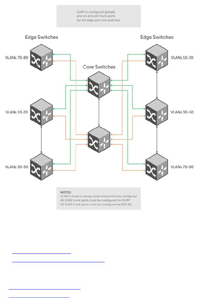
Configure GVRP
To begin, enable GVRP.
To facilitate GVRP communications, enable GVRP globally on each switch. GVRP configuration is per
interface on a switch-by-switch basis. Enable GVRP on each port that connects to a switch where you
want GVRP information exchanged. In the following example, GVRP is configured on VLAN trunk ports.
Figure 29. Global GVRP Configuration Example
Basic GVRP configuration is a two-step process:
1. Enabling GVRP Globally
2. Enabling GVRP on a Layer 2 Interface
Related Configuration Tasks
•Configure GVRP Registration
•Configure a GARP Timer
GARP VLAN Registration Protocol (GVRP) 301

Enabling GVRP Globally
To configure GVRP globally, use the following command.
• Enable GVRP for the entire switch.
CONFIGURATION mode
gvrp enable
Example of Configuring GVRP
Dell(conf)#protocol gvrp
Dell(config-gvrp)#no disable
Dell(config-gvrp)#show config
!
protocol gvrp
no disable
Dell(config-gvrp)#
To inspect the global configuration, use the show gvrp brief command.
Enabling GVRP on a Layer 2 Interface
To enable GVRP on a Layer 2 interface, use the following command.
• Enable GVRP on a Layer 2 interface.
INTERFACE mode
gvrp enable
Example of Enabling GVRP on an Interface
Dell(conf-if-te-1/21)#switchport
Dell(conf-if-te-1/21)#gvrp enable
Dell(conf-if-te-1/21)#no shutdown
Dell(conf-if-te-1/21)#show config
!
interface TenGigabitEthernet 1/21
no ip address
switchport
gvrp enable
no shutdown
To inspect the interface configuration, use the show config command from INTERFACE mode or use
the show gvrp interface command in EXEC or EXEC Privilege mode.
Configure GVRP Registration
Configure GVRP registration.
There are two GVRP registration modes:
•Fixed Registration Mode — figuring a port in fixed registration mode allows for manual creation and
registration of VLANs, prevents VLAN deregistration, and registers all VLANs known on other ports on
the port. For example, if an interface is statically configured via the CLI to belong to a VLAN, it should
302 GARP VLAN Registration Protocol (GVRP)

not be unconfigured when it receives a Leave PDU. Therefore, the registration mode on that interface
is FIXED.
•Forbidden Mode — Disables the port to dynamically register VLANs and to propagate VLAN
information except information about VLAN 1. A port with forbidden registration type thus allows only
VLAN 1 to pass through even though the PDU carries information for more VLANs. Therefore, if you
do not want the interface to advertise or learn about particular VLANS, set the interface to the
registration mode of FORBIDDEN.
Based on the configuration in the following example, the interface 1/21 is not removed from VLAN 34 or
VLAN 35 despite receiving a GVRP Leave message. Additionally, the interface is not dynamically added to
VLAN 45 or VLAN 46, even if a GVRP Join message is received.
Example of the gvrp registration Command
Dell(conf-if-te-1/21)#gvrp registration fixed 34,35
Dell(conf-if-te-1/21)#gvrp registration forbidden 45,46
Dell(conf-if-te-1/21)#show conf
!
interface TenGigabitEthernet 1/21
no ip address
switchport
gvrp enable
gvrp registration fixed 34-35
gvrp registration forbidden 45-46
no shutdown
Dell(conf-if-te-1/21)#
Configure a GARP Timer
Set GARP timers to the same values on all devices that are exchanging information using GVRP.
There are three GARP timer settings.
•Join — A GARP device reliably transmits Join messages to other devices by sending each Join
message two times. To define the interval between the two sending operations of each Join message,
use this parameter. The default is 200ms.
•Leave — When a GARP device expects to de-register a piece of attribute information, it sends out a
Leave message and starts this timer. If a Join message does not arrive before the timer expires, the
information is de-registered. The Leave timer must be greater than or equal to 3x the Join timer. The
default is 600ms.
•LeaveAll — After startup, a GARP device globally starts a LeaveAll timer. After expiration of this interval,
it sends out a LeaveAll message so that other GARP devices can re-register all relevant attribute
information. The device then restarts the LeaveAll timer to begin a new cycle. The LeaveAll timer must
be greater than or equal to 5x of the Leave timer. The default is 10000ms.
Example of the garp timer Command
Dell(conf)#garp timer leav 1000
Dell(conf)#garp timers leave-all 5000
Dell(conf)#garp timer join 300
Verification:
Dell(conf)#do show garp timer
GARP Timers Value (milliseconds)
----------------------------------------
Join Timer 300
Leave Timer 1000
GARP VLAN Registration Protocol (GVRP) 303

LeaveAll Timer 5000
Dell(conf)#
The system displays this message if an attempt is made to configure an invalid GARP timer:
Dell(conf)#garp timers join 300 % Error: Leave timer should be >= 3*Join timer.
304 GARP VLAN Registration Protocol (GVRP)
18
Internet Group Management Protocol
(IGMP)
Internet group management protocol (IGMP) is a Layer 3 multicast protocol that hosts use to join or leave
a multicast group.
Multicast is premised on identifying many hosts by a single destination IP address; hosts represented by
the same IP address are a multicast group. Multicast routing protocols (such as protocol-independent
multicast [PIM]) use the information in IGMP messages to discover which groups are active and to
populate the multicast routing table.
IGMP Implementation Information
• The Dell Networking OS supports IGMP versions 1, 2, and 3 based on RFCs 1112, 2236, and 3376,
respectively.
• The system does not support IGMP version 3 and versions 1 or 2 on the same subnet.
• Dell Networking switches cannot serve as an IGMP host or an IGMP version 1 IGMP Querier.
• The system automatically enables IGMP on interfaces on which you enable a multicast routing
protocol.
IGMP Protocol Overview
IGMP has three versions. Version 3 obsoletes and is backwards-compatible with version 2; version 2
obsoletes version 1.
IGMP Version 2
IGMP version 2 improves on version 1 by specifying IGMP Leave messages, which allows hosts to notify
routers that they no longer care about traffic for a particular group.
Leave messages reduce the amount of time that the router takes to stop forwarding traffic for a group to
a subnet (leave latency) after the last host leaves the group. In version 1 hosts quietly leave groups, and
the router waits for a query response timer several times the value of the query interval to expire before it
stops forwarding traffic.
To receive multicast traffic from a particular source, a host must join the multicast group to which the
source is sending traffic. A host that is a member of a group is called a receiver. A host may join many
groups, and may join or leave any group at any time. A host joins and leaves a multicast group by sending
an IGMP message to its IGMP Querier. The querier is the router that surveys a subnet for multicast
receivers and processes survey responses to populate the multicast routing table.
IGMP messages are encapsulated in IP packets, as shown in the following illustration.
Internet Group Management Protocol (IGMP) 305
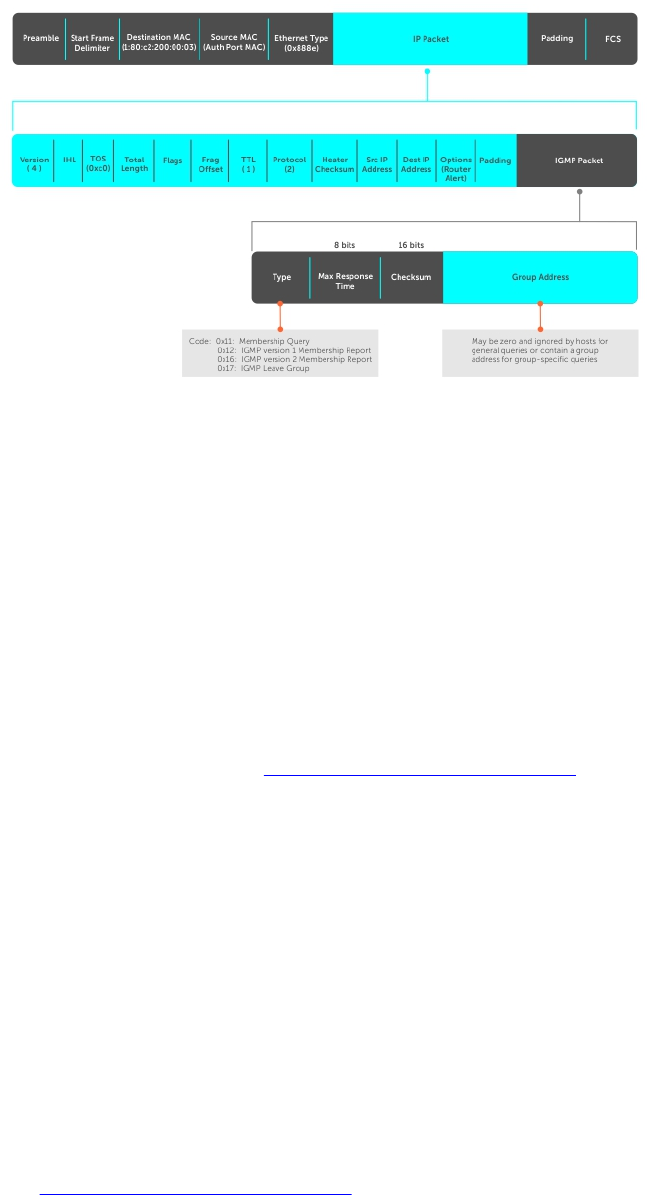
Figure 30. IGMP Messages in IP Packets
Join a Multicast Group
There are two ways that a host may join a multicast group: it may respond to a general query from its
querier or it may send an unsolicited report to its querier.
Responding to an IGMP Query
The following describes how a host can join a multicast group.
1. One router on a subnet is elected as the querier. The querier periodically multicasts (to all-multicast-
systems address 224.0.0.1) a general query to all hosts on the subnet.
2. A host that wants to join a multicast group responds with an IGMP Membership Report that contains
the multicast address of the group it wants to join (the packet is addressed to the same group). If
multiple hosts want to join the same multicast group, only the report from the first host to respond
reaches the querier and the remaining hosts suppress their responses (For how the delay timer
mechanism works, refer to Adjusting Query and Response Timers).
3. The querier receives the report for a group and adds the group to the list of multicast groups
associated with its outgoing port to the subnet. Multicast traffic for the group is then forwarded to
that subnet.
Sending an Unsolicited IGMP Report
A host does not have to wait for a general query to join a group. It may send an unsolicited IGMP
Membership Report, also called an IGMP Join message, to the querier.
Leaving a Multicast Group
The following describes how a host can leave a multicast group.
1. A host sends a membership report of type 0x17 (IGMP Leave message) to the all routers multicast
address 224.0.0.2 when it no longer cares about multicast traffic for a particular group.
2. The querier sends a Group-Specific Query to determine whether there are any remaining hosts in
the group. There must be at least one receiver in a group on a subnet for a router to forward
multicast traffic for that group to the subnet.
3. Any remaining hosts respond to the query according to the delay timer mechanism (refer to
Adjusting Query and Response Timers). If no hosts respond (because there are none remaining in
the group), the querier waits a specified period and sends another query. If it still receives no
306 Internet Group Management Protocol (IGMP)
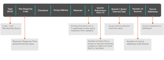
response, the querier removes the group from the list associated with forwarding port and stops
forwarding traffic for that group to the subnet.
IGMP Version 3
Conceptually, IGMP version 3 behaves the same as version 2. However, there are differences.
• Version 3 adds the ability to filter by multicast source, which helps multicast routing protocols avoid
forwarding traffic to subnets where there are no interested receivers.
• To enable filtering, routers must keep track of more state information, that is, the list of sources that
must be filtered. An additional query type, the Group-and-Source-Specific Query, keeps track of state
changes, while the Group-Specific and General queries still refresh the existing state.
• Reporting is more efficient and robust: hosts do not suppress query responses (non-suppression
helps track state and enables the immediate-leave and IGMP snooping features), state-change reports
are retransmitted to insure delivery, and a single membership report bundles multiple statements from
a single host, rather than sending an individual packet for each statement.
The version 3 packet structure is different from version 2 to accommodate these protocol
enhancements. Queries are still sent to the all-systems address 224.0.0.1, as shown in the following
illustration, but reports are sent to the all IGMP version 3-capable multicast routers address 244.0.0.22, as
shown in the second illustration.
Figure 31. IGMP Version 3 Packet Structure
Internet Group Management Protocol (IGMP) 307
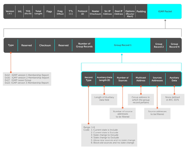
Figure 32. IGMP Version 3–Capable Multicast Routers Address Structure
Joining and Filtering Groups and Sources
The following illustration shows how multicast routers maintain the group and source information from
unsolicited reports.
1. The first unsolicited report from the host indicates that it wants to receive traffic for group 224.1.1.1.
2. The host’s second report indicates that it is only interested in traffic from group 224.1.1.1, source
10.11.1.1. Include messages prevents traffic from all other sources in the group from reaching the
subnet. Before recording this request, the querier sends a group-and-source query to verify that
there are no hosts interested in any other sources. The multicast router must satisfy all hosts if they
have conflicting requests. For example, if another host on the subnet is interested in traffic from
10.11.1.3, the router cannot record the include request. There are no other interested hosts, so the
request is recorded. At this point, the multicast routing protocol prunes the tree to all but the
specified sources.
3. The host’s third message indicates that it is only interested in traffic from sources 10.11.1.1 and
10.11.1.2. Because this request again prevents all other sources from reaching the subnet, the router
sends another group-and-source query so that it can satisfy all other hosts. There are no other
interested hosts so the request is recorded.
308 Internet Group Management Protocol (IGMP)
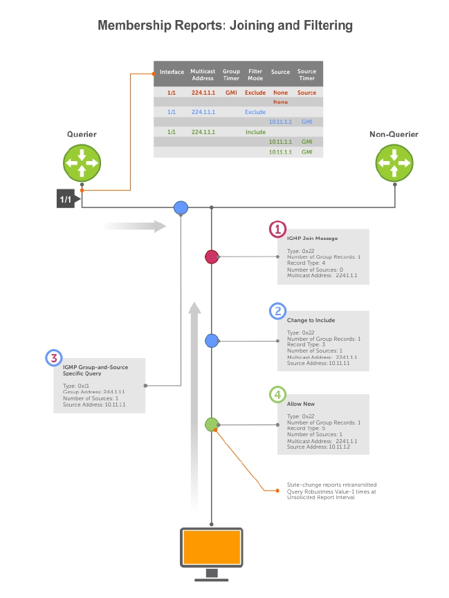
Figure 33. Membership Reports: Joining and Filtering
Leaving and Staying in Groups
The following illustration shows how multicast routers track and refresh state changes in response to
group-and-specific and general queries.
1. Host 1 sends a message indicating it is leaving group 224.1.1.1 and that the included filter for 10.11.1.1
and 10.11.1.2 are no longer necessary.
2. The querier, before making any state changes, sends a group-and-source query to see if any other
host is interested in these two sources; queries for state-changes are retransmitted multiple times. If
any are, they respond with their current state information and the querier refreshes the relevant state
information.
3. Separately in the following illustration, the querier sends a general query to 224.0.0.1.
4. Host 2 responds to the periodic general query so the querier refreshes the state information for that
group.
Internet Group Management Protocol (IGMP) 309
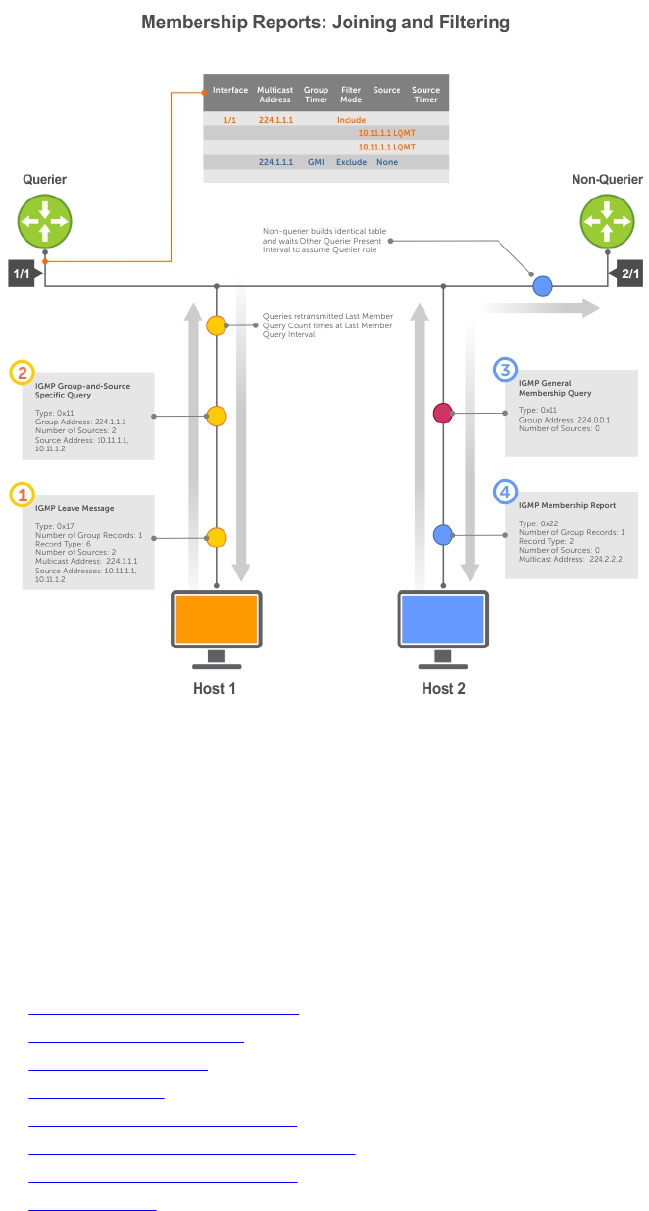
Figure 34. Membership Queries: Leaving and Staying
Configure IGMP
Configuring IGMP is a two-step process.
1. Enable multicast routing using the ip multicast-routing command.
2. Enable a multicast routing protocol.
Related Configuration Tasks
•Viewing IGMP Enabled Interfaces
•Selecting an IGMP Version
•Viewing IGMP Groups
•Adjusting Timers
•Configuring a Static IGMP Group
•Preventing a Host from Joining a Group
•Enabling IGMP Immediate-Leave
•IGMP Snooping
310 Internet Group Management Protocol (IGMP)

•Fast Convergence after MSTP Topology Changes
•Designating a Multicast Router Interface
Viewing IGMP Enabled Interfaces
Interfaces that are enabled with PIM-SM are automatically enabled with IGMP.
To view IGMP-enabled interfaces, use the following command.
• View IGMP-enabled interfaces.
EXEC Privilege mode
show ip igmp interface
Example of the show ip igmp interface Command
Dell#show ip igmp interface tengig 1/16
TenGigabitEthernet 1/16 is up, line protocol is up
Internet address is 10.87.3.2/24
IGMP is enabled on interface
IGMP query interval is 60 seconds
IGMP querier timeout is 300 seconds
IGMP max query response time is 10 seconds
Last member query response interval is 199 ms
IGMP activity: 0 joins, 0 leaves
IGMP querying router is 10.87.3.2 (this system)
IGMP version is 2
Dell#
Selecting an IGMP Version
The Dell Networking OS enables IGMP version 2 by default, which supports version 1 and 2 hosts, but is
not compatible with version 3 on the same subnet.
If hosts require IGMP version 3, you can switch to IGMP version 3.
To switch to version 3, use the following command.
• Switch to a different IGMP version.
INTERFACE mode
ip igmp version
Example of the ip igmp version Command
Dell(conf-if-te-1/13)#ip igmp version 3
Dell(conf-if-te-1/13)#do show ip igmp interface
TenGigabitEthernet 1/13 is up, line protocol is down
Inbound IGMP access group is not set
Interface IGMP group join rate limit is not set
Internet address is 1.1.1.1/24
IGMP is enabled on interface
IGMP query interval is 60 seconds
IGMP querier timeout is 125 seconds
IGMP max query response time is 10 seconds
IGMP last member query response interval is 1000 ms
IGMP immediate-leave is disabled
IGMP activity: 0 joins, 0 leaves, 0 channel joins, 0 channel leaves
IGMP querying router is 1.1.1.1 (this system)
Internet Group Management Protocol (IGMP) 311

IGMP version is 3
Dell(conf-if-te-1/13)#
Viewing IGMP Groups
To view both learned and statically configured IGMP groups, use the following command.
• View both learned and statically configured IGMP groups.
EXEC Privilege mode
show ip igmp groups
Example of the show ip igmp groups Command
Dell(conf-if-te-1/0)#do show ip igmp groups
Total Number of Groups: 2
IGMP Connected Group Membership
Group Address Interface Uptime Expires Last Reporter
224.1.1.1 GigabitEthernet 1/0 00:00:03 Never CLI
224.1.2.1 GigabitEthernet 1/0 00:56:55 00:01:22 1.1.1.2
Adjusting Timers
The following sections describe viewing and adjusting timers.
To view the current value of all IGMP timers, use the following command.
• View the current value of all IGMP timers.
EXEC Privilege mode
show ip igmp interface
For more information, refer to the example shown in Viewing IGMP Enabled Interfaces.
Adjusting Query and Response Timers
The querier periodically sends a general query to discover which multicast groups are active. A group
must have at least one host to be active.
When a host receives a query, it does not respond immediately, but rather starts a delay timer. The delay
time is set to a random value between 0 and the maximum response time. The host sends a response
when the timer expires; in version 2, if another host responds before the timer expires, the timer is
nullified, and no response is sent.
The maximum response time is the amount of time that the querier waits for a response to a query
before taking further action. The querier advertises this value in the query (refer to the illustration in IGMP
Version 2). Lowering this value decreases leave latency but increases response burstiness because all host
membership reports must be sent before the maximum response time expires. Inversely, increasing this
value decreases burstiness at the expense of leave latency.
When the querier receives a leave message from a host, it sends a group-specific query to the subnet. If
no response is received, it sends another. The amount of time that the querier waits to receive a response
to the initial query before sending a second one is the last member query interval (LMQI). The switch
waits one LMQI after the second query before removing the group from the state table.
• Adjust the period between queries.
312 Internet Group Management Protocol (IGMP)

INTERFACE mode
ip igmp query-interval
• Adjust the maximum response time.
INTERFACE mode
ip igmp query-max-resp-time
• Adjust the last member query interval.
INTERFACE mode
ip igmp last-member-query-interval
Adjusting the IGMP Querier Timeout Value
If there is more than one multicast router on a subnet, only one is elected to be the querier, which is the
router that sends queries to the subnet.
1. Routers send queries to the all multicast systems address, 224.0.0.1. Initially, all routers send queries.
2. When a router receives a query, it compares the IP address of the interface on which it was received
with the source IP address given in the query. If the receiving router IP address is greater than the
source address given in the query, the router stops sending queries. By this method, the router with
the lowest IP address on the subnet is elected querier and continues to send queries.
3. If a specified amount of time elapses during which other routers on the subnet do not receive a
query, those routers assume that the querier is down and a new querier is elected.
The amount of time that elapses before routers on a subnet assume that the querier is down is the other
querier present interval.
• Adjust the other querier present interval.
INTERFACE mode
ip igmp querier-timeout
Configuring a Static IGMP Group
To configure and view a static IGMP group, use the following commands.
Multicast traffic for static groups is always forwarded to the subnet even if there are no members in the
group.
Static groups have an expiration value of Never and a Last Reporter value of CLI, as shown in the example
in Viewing IGMP Groups.
• Configure a static IGMP group.
INTERFACE mode
ip igmp static-group
• View the static groups.
EXEC Privilege mode.
show ip igmp groups
Internet Group Management Protocol (IGMP) 313

Enabling IGMP Immediate-Leave
If the querier does not receive a response to a group-specific or group-and-source query, it sends
another (querier robustness value). Then, after no response, it removes the group from the outgoing
interface for the subnet.
IGMP immediate leave reduces leave latency by enabling a router to immediately delete the group
membership on an interface after receiving a Leave message (it does not send any group-specific or
group-and-source queries before deleting the entry).
• Configure the system for IGMP immediate leave.
ip igmp immediate-leave
• View the enable status of the IGMP immediate leave feature.
EXEC Privilege mode
show ip igmp interface
View the enable status of this feature using the command from EXEC Privilege mode, as shown in the
example in Selecting an IGMP Version.
IGMP Snooping
IGMP snooping enables switches to use information in IGMP packets to generate a forwarding table that
associates ports with multicast groups so that when they receive multicast frames, they can forward them
only to interested receivers.
Multicast packets are addressed with multicast MAC addresses, which represent a group of devices, rather
than one unique device. Switches forward multicast frames out of all ports in a virtual local area network
(VLAN) by default, even though there may be only some interested hosts, which is a waste of bandwidth.
If you enable IGMP snooping on a VLT unit, IGMP snooping dynamically learned groups and multicast
router ports are made to learn on the peer by explicitly tunneling the received IGMP control packets.
IGMP Snooping Implementation Information
• IGMP snooping uses IP multicast addresses not MAC addresses.
• IGMP snooping reacts to spanning tree protocol (STP) and multiple spanning tree protocol (MSTP)
topology changes by sending a general query on the interface that transitions to the forwarding state.
• If IGMP snooping is enabled on a PIM-enabled VLAN interface, data packets using the router as an
Layer 2 hop may be dropped. To avoid this scenario, Dell Networking recommends that users enable
IGMP snooping on server-facing end-point VLANs only.
Configuring IGMP Snooping
Configuring IGMP snooping is a one-step process. To enable, view, or disable IGMP snooping, use the
following commands.
There is no specific configuration needed for IGMP snooping with virtual link trunking (VLT). For
information about VLT configurations, refer to Virtual Link Trunking (VLT).
• Enable IGMP snooping on a switch.
CONFIGURATION mode
ip igmp snooping enable
314 Internet Group Management Protocol (IGMP)

• View the configuration.
CONFIGURATION mode
show running-config
• Disable snooping on a VLAN.
INTERFACE VLAN mode
no ip igmp snooping
Related Configuration Tasks
•Removing a Group-Port Association
•Disabling Multicast Flooding
•Specifying a Port as Connected to a Multicast Router
•Configuring the Switch as Querier
Example of ip igmp snooping enable Command
Dell(conf)#ip igmp snooping enable
Dell(conf)#do show running-config igmp
ip igmp snooping enable
Dell(conf)#
Removing a Group-Port Association
To configure or view the remove a group-port association feature, use the following commands.
• Configure the switch to remove a group-port association after receiving an IGMP Leave message.
INTERFACE VLAN mode
ip igmp fast-leave
• View the configuration.
INTERFACE VLAN mode
show config
Example of Configuration Output After Removing a Group-Port Association
Dell(conf-if-vl-100)#show config
!
interface Vlan 100
no ip address
ip igmp snooping fast-leave
shutdown
Dell(conf-if-vl-100)#
Disabling Multicast Flooding
If the switch receives a multicast packet that has an IP address of a group it has not learned (unregistered
frame), the switch floods that packet out of all ports on the VLAN.
When you configure the no ip igmp snooping flood command, the system drops the packets
immediately. The system does not forward the frames on mrouter ports, even if they are present. Disable
Layer 3 multicast (no ip multicast-routing) in order to disable multicast flooding.
Internet Group Management Protocol (IGMP) 315
• Configure the switch to only forward unregistered packets to ports on a VLAN that are connected to
mrouter ports.
CONFIGURATION mode
no ip igmp snooping flood
Specifying a Port as Connected to a Multicast Router
To statically specify or view a port in a VLAN, use the following commands.
• Statically specify a port in a VLAN as connected to a multicast router.
INTERFACE VLAN mode
ip igmp snooping mrouter
• View the ports that are connected to multicast routers.
EXEC Privilege mode.
show ip igmp snooping mrouter
Configuring the Switch as Querier
To configure the switch as a querier, use the following command.
Hosts that do not support unsolicited reporting wait for a general query before sending a membership
report. When the multicast source and receivers are in the same VLAN, multicast traffic is not routed and
so there is no querier. Configure the switch to be the querier for a VLAN so that hosts send membership
reports and the switch can generate a forwarding table by snooping.
• Configure the switch to be the querier for a VLAN by first assigning an IP address to the VLAN
interface.
INTERFACE VLAN mode
ip igmp snooping querier
IGMP snooping querier does not start if there is a statically configured multicast router interface in the
VLAN.
The switch may lose the querier election if it does not have the lowest IP address of all potential
queriers on the subnet.
When enabled, IGMP snooping querier starts after one query interval in case no IGMP general query
(with IP SA lower than its VLAN IP address) is received on any of its VLAN members.
Adjusting the Last Member Query Interval
To adjust the last member query interval, use the following command.
When the querier receives a Leave message from a receiver, it sends a group-specific query out of the
ports specified in the forwarding table. If no response is received, it sends another. The amount of time
that the querier waits to receive a response to the initial query before sending a second one is the last
member query interval (LMQI). The switch waits one LMQI after the second query before removing the
group-port entry from the forwarding table.
• Adjust the last member query interval.
INTERFACE VLAN mode
316 Internet Group Management Protocol (IGMP)
ip igmp snooping last-member-query-interval
Fast Convergence after MSTP Topology Changes
When a port transitions to the Forwarding state as a result of an STP or MSTP topology change, the
system sends a general query out of all ports except the multicast router ports. The host sends a
response to the general query and the forwarding database is updated without having to wait for the
query interval to expire.
When an IGMP snooping switch is not acting as a querier, it sends out the general query in response to
the MSTP triggered link-layer topology change, with the source IP address of 0.0.0.0 to avoid triggering
querier election.
Designating a Multicast Router Interface
To designate an interface as a multicast router interface, use the following command.
The system also has the capability of listening in on the incoming IGMP general queries and designate
those interfaces as the multicast router interface when the frames have a non-zero IP source address. All
IGMP control packets and IP multicast data traffic originating from receivers is forwarded to multicast
router interfaces.
• Designate an interface as a multicast router interface.
ip igmp snooping mrouter interface
Internet Group Management Protocol (IGMP) 317

19
Interfaces
This chapter describes interface types, both physical and logical, and how to configure them on the
Z9500 switch.
• 10-Gigabit Ethernet and 40-Gigabit Ethernet interfaces are supported on the Z9500.
Basic Interface Configuration
•Interface Types
•View Basic Interface Information
•Enabling a Physical Interface
•Physical Interfaces
•Management Interfaces
•VLAN Interfaces
•Loopback Interfaces
•Null Interfaces
•Port Channel Interfaces
Advanced Interface Configuration
•Bulk Configuration
•Defining Interface Range Macros
•Monitoring and Maintaining Interfaces
•Splitting QSFP Ports to SFP+ Ports
•Link Dampening
•Link Bundle Monitoring
•Ethernet Pause Frames
•Configure the MTU Size on an Interface
•Port-pipes
•Auto-Negotiation on Ethernet Interfaces
•View Advanced Interface Information
Port Numbering Convention
On the switch, all ports operate by default in 40GbE mode. If you use a breakout cable, each port can
operate in 4x10GbE mode.
Ports are located on three line cards as shown below. The line cards are factory-installed and are not
hot-swappable or field-replaceable. On each line card, the fixed 40GbE ports are numbered from bottom
to top in multiples of four, starting with zero; for example, 0, 4, 8, 12, and so on. When a breakout cable is
318 Interfaces

installed, the resulting four 10GbE ports are numbered with the remaining numbers. For example, 40GbE
port 0 contains 10GbE ports 0, 1, 2, and 3; 40GbE port 4 contains 10GbE ports 4, 5, 6, and 7.
Line card 0 consists of ports 0 to 143; line card 1 consists of ports 0 to 191; line card 2 consists of ports 0
to 191.
Figure 35. Port Numbering
Interface Types
The following table describes different interface types.
Interface Type Modes Possible Default Mode Requires Creation Default State
Physical L2, L3 Unset No Shutdown
(disabled)
Management N/A N/A No No Shutdown
(enabled)
Loopback L3 L3 Yes No Shutdown
(enabled)
Null N/A N/A No Enabled
Port Channel L2, L3 L3 Yes Shutdown
(disabled)
VLAN L2, L3 L2 Yes (except default) L2 - Shutdown
(disabled)
L3 - No Shutdown
(enabled)
View Basic Interface Information
To view basic interface information, use the following command.
You have several options for viewing interface status and configuration parameters.
• Lists all configurable interfaces on the chassis.
Interfaces 319

EXEC mode
show interfaces
This command has options to display the interface status, IP and MAC addresses, and multiple
counters for the amount and type of traffic passing through the interface.
If you configured a port channel interface, this command lists the interfaces configured in the port
channel.
NOTE: To end output from the system, such as the output from the show interfaces
command, enter CTRL+C. The system returns you to the command prompt.
NOTE: The CLI output may be incorrectly displayed as 0 (zero) for the Rx/Tx power values. To
obtain the correct power information, perform a simple network management protocol (SNMP)
query.
Examples of Using the Show Commands
The following example shows the configuration and status information for one interface.
Dell#show interfaces tengigabitethernet 1/0
TenGigabitEthernet 1/0 is up, line protocol is up
Hardware is Dell Force10Eth, address is 00:01:e8:05:f3:6a
Current address is 00:01:e8:05:f3:6a
Pluggable media present, XFP type is 10GBASE-LR.
Medium is MultiRate, Wavelength is 1310nm
XFP receive power reading is -3.7685
Interface index is 67436603
Internet address is 65.113.24.238/28
MTU 1554 bytes, IP MTU 1500 bytes
LineSpeed 10000 Mbit, Mode full duplex, Master
ARP type: ARPA, ARP Timeout 04:00:00
Last clearing of "show interface" counters 00:09:54
Queueing strategy: fifo
Input Statistics:
0 packets, 0 bytes
0 Vlans
0 64-byte pkts, 0 over 64-byte pkts, 0 over 127-byte pkts
0 over 255-byte pkts, 0 over 511-byte pkts, 0 over 1023-byte pkts
0 Multicasts, 0 Broadcasts
0 runts, 0 giants, 0 throttles
0 CRC, 0 overrun, 0 discarded
Output Statistics:
3 packets, 192 bytes, 0 underruns
3 64-byte pkts, 0 over 64-byte pkts, 0 over 127-byte pkts
0 over 255-byte pkts, 0 over 511-byte pkts, 0 over 1023-byte pkts
0 Multicasts, 3 Broadcasts, 0 Unicasts
0 Vlans, 0 throttles, 0 discarded, 0 collisions
Rate info (interval 299 seconds):
Input 00.00 Mbits/sec, 0 packets/sec, 0.00% of line-rate
Output 00.00 Mbits/sec, 0 packets/sec, 0.00% of line-rate
Time since last interface status change: 00:00:31
Dell#
To view which interfaces are enabled for Layer 3 data transmission, use the show ip interfaces
brief command in EXEC Privilege mode. In the following example, TengigabitEthernet interface 1/5 is in
Layer 3 mode because an IP address has been assigned to it and the interface’s status is operationally up.
Dell#show ip interface brief
Interface IP-Address OK? Method Status Protocol
320 Interfaces

TengigabitEthernet 1/0 unassigned NO Manual administratively down down
TengigabitEthernet 1/1 unassigned NO Manual administratively down down
TengigabitEthernet 1/2 unassigned YES Manual up up
TengigabitEthernet 1/3 unassigned YES Manual up up
TengigabitEthernet 1/4 unassigned YES Manual up up
TengigabitEthernet 1/5 10.10.10.1 YES Manual up up
TengigabitEthernet 1/6 unassigned NO Manual administratively down down
TengigabitEthernet 1/7 unassigned NO Manual administratively down down
TengigabitEthernet 1/8 unassigned NO Manual administratively down down
To view only configured interfaces, use the show interfaces configured command in the EXEC
Privilege mode. In the previous example, TengigabitEthernet interface 1/5 is in Layer 3 mode because an
IP address has been assigned to it and the interface’s status is operationally up.
To determine which physical interfaces are available, use the show running-config command in EXEC
mode. This command displays all physical interfaces available on the line cards.
Dell#show running
Current Configuration ...
!
interface TengigabitEthernet 9/6
no ip address
shutdown
!
interface TengigabitEthernet 9/7
no ip address
shutdown
!
interface TengigabitEthernet 9/8
no ip address
shutdown
!
interface TengigabitEthernet 9/9
no ip address
shutdown
Enabling a Physical Interface
After determining the type of physical interfaces available, to enable and configure the interfaces, enter
INTERFACE mode by using the interface interface slot/port command.
1. Enter the keyword interface then the type of interface and slot/port information.
CONFIGURATION mode
interface interface
• For the Management interface, enter the keyword ManagementEthernet then the slot/port
information.
• For a 10-Gigabit Ethernet interface, enter the keyword TenGigabitEthernet then the slot/port
information.
• For a 40-Gigabit Ethernet interface, enter the keyword fortyGigE then the slot/port
information.
2. Enable the interface.
INTERFACE mode
no shutdown
Interfaces 321

To confirm that the interface is enabled, use the show config command in INTERFACE mode. To leave
INTERFACE mode, use the exit command or end command. You cannot delete a physical interface.
Physical Interfaces
The Management Ethernet interface is a single RJ-45 Fast Ethernet port on a switch.
The interface provides dedicated management access to the system.
Line card interfaces support Layer 2 and Layer 3 traffic over 10-Gigabit Ethernet and 40-Gigabit Ethernet
interfaces. These interfaces can also become part of virtual interfaces such as virtual local area networks
(VLANs) or port channels.
For more information about VLANs, refer to Bulk Configuration. For more information on port channels,
refer to Port Channel Interfaces.
Dell Networking OS Behavior: The Z9500 system uses a single MAC address for all physical interfaces.
Port Pipes
A port pipe is a Dell Networking-specific term for the hardware packet-processing elements that handle
network traffic to and from a set of front-end I/O ports. The physical, front-end I/O ports are referred to
as a port set.
In the command-line interface, a Z9500 port pipe is entered as portset port-pipe-number.
A line card is a Dell Networking-specific term that describes the subsystem for a logical grouping of one
or more port pipes. The Z9500 has three line-card subsystems (0-2) with fixed, front-end ports. Each
Z9500 line card consists of several port pipes. Line card 0 consists of three port pipes: 0 to 2; line cards 1
and 2 consist of four port pipes: 0 to 3.
The ports and port pipes on each Z9500 line card are as follows:
• On line card 0, ports 0 to 47 belong to port pipe 0; ports 48 to 95 belong to port pipe 1; ports 96 to
143 belong to port pipe 2.
• On line card 1, ports 0 to 47 belong to port pipe 0; ports 48 to 95 belong to port pipe 1; ports 96 to
143 belong to port pipe 2; ports 144 to 191 belong to port pipe 3.
• On line card 2, ports 0 to 47 belong to port pipe 0; ports 48 to 95 belong to port pipe 1; ports 96 to
143 belong to port pipe 2; ports 144 to 191 belong to port pipe 3.
Refer to Port Numbering Conventionfor the exact port location on Z9500 line cards.
Network Processing Units (NPUs)
The Z9500 uses network processing units (NPUs) to process traffic from front-end I/O ports and
interconnect packet-processing elements in the chassis to form one fully connected logical switch. The
interconnect links run across 40-Gigabit Ethernet internal ports. A 40-Gigabit Ethernet internal port is
also referred to as a HiGig port.
On the Z9500, each NPU that constitutes a port pipe processes traffic from a set of front-end I/O ports.
In the command-line interface, a Z9500 NPU is entered as unit unit-number.
Configuration Task List for Physical Interfaces
By default, all interfaces are operationally disabled and traffic does not pass through them.
The following section includes information about optional configurations for physical interfaces:
322 Interfaces

•Overview of Layer Modes
•Configuring Layer 2 (Data Link) Mode
•Configuring Layer 2 (Interface) Mode
•Management Interfaces
•Auto-Negotiation on Ethernet Interfaces
•Clearing Interface Counters
Overview of Layer Modes
On the Dell Networking OS, you can place physical interfaces, port channels, and VLANs in Layer 2 mode
or Layer 3 mode.
By default, VLANs are in Layer 2 mode.
Type of Interface Possible Modes Requires Creation Default State
10–Gigabit Ethernet and
40–Gigabit Ethernet
Layer 2
Layer 3
No Shutdown (disabled)
Management N/A No Shutdown (disabled)
Loopback Layer 3 Yes No shutdown (enabled)
Null interface N/A No Enabled
Port Channel Layer 2
Layer 3
Yes Shutdown (disabled)
VLAN Layer 2
Layer 3
Yes, except for the
default VLAN.
No shutdown (active for
Layer 2)
Shutdown (disabled for
Layer 3)
Configuring Layer 2 (Data Link) Mode
Do not configure switching or Layer 2 protocols such as spanning tree protocol (STP) on an interface
unless the interface has been set to Layer 2 mode.
To set Layer 2 data transmissions through an individual interface, use the following command.
• Enable Layer 2 data transmissions through an individual interface.
INTERFACE mode
switchport
Example of a Basic Layer 2 Interface Configuration
Dell(conf-if)#show config
!
interface Port-channel 1
no ip address
switchport
no shutdown
Dell(conf-if)#
Interfaces 323

Configuring Layer 2 (Interface) Mode
To configure an interface in Layer 2 mode, use the following commands.
• Enable the interface.
INTERFACE mode
no shutdown
• Place the interface in Layer 2 (switching) mode.
INTERFACE mode
switchport
For information about enabling and configuring the Spanning Tree Protocol, refer to Spanning Tree
Protocol (STP).
To view the interfaces in Layer 2 mode, use the show interfaces switchport command in EXEC
mode.
Configuring Layer 3 (Network) Mode
When you assign an IP address to a physical interface, you place it in Layer 3 mode.
To enable Layer 3 mode on an individual interface, use the following commands. In all interface types
except VLANs, the shutdown command prevents all traffic from passing through the interface. In VLANs,
the shutdown command prevents Layer 3 traffic from passing through the interface. Layer 2 traffic is
unaffected by the shutdown command. One of the interfaces in the system must be in Layer 3 mode
before you configure or enter a Layer 3 protocol mode (for example, OSPF).
• Enable Layer 3 on an individual interface
INTERFACE mode
ip address
• Enable the interface.
INTERFACE mode
no shutdown
Example of Error Due to Issuing a Layer 3 Command on a Layer 2 Interface
If an interface is in the incorrect layer mode for a given command, an error message is displayed (shown
in bold). In the following example, the ip address command triggered an error message because the
interface is in Layer 2 mode and the ip address command is a Layer 3 command only.
Dell(conf-if)#show config
!
interface TengigabitEthernet 1/2
no ip address
switchport
no shutdown
Dell(conf-if)#ip address 10.10.1.1 /24
% Error: Port is in Layer 2 mode Te 1/2.
Dell(conf-if)#
To determine the configuration of an interface, use the show config command in INTERFACE mode or
the various show interface commands in EXEC mode.
324 Interfaces

Configuring Layer 3 (Interface) Mode
To assign an IP address, use the following commands.
• Enable the interface.
INTERFACE mode
no shutdown
• Configure a primary IP address and mask on the interface.
INTERFACE mode
ip address ip-address mask [secondary]
The ip-address must be in dotted-decimal format (A.B.C.D) and the mask must be in slash format (/
xx).
Add the keyword secondary if the IP address is the interface’s backup IP address.
Example of the show ip interface Command
You can only configure one primary IP address per interface. You can configure up to 255 secondary IP
addresses on a single interface.
To view all interfaces to see with an IP address assigned, use the show ip interfaces brief
command in EXEC mode as shown in View Basic Interface Information.
To view IP information on an interface in Layer 3 mode, use the show ip interface command in
EXEC Privilege mode.
Dell>show ip int vlan 58
Vlan 58 is up, line protocol is up
Internet address is 1.1.49.1/24
Broadcast address is 1.1.49.255
Address determined by config file
MTU is 1554 bytes
Inbound access list is not set
Proxy ARP is enabled
Split Horizon is enabled
Poison Reverse is disabled
ICMP redirects are not sent
ICMP unreachables are not sent
Egress Interface Selection (EIS)
EIS allows you to isolate the management and front-end port domains by preventing switch-initiated
traffic routing between the two domains. This feature provides additional security by preventing flooding
attacks on front-end ports.
The following protocols support EIS: DNS, FTP, HTTP, IGMP, NTP, RADIUS, SNMP, SSH, Syslog, TACACS,
Telnet, and TFTP.
When you enable this feature, all management routes (connected, static, and default) are copied to the
management EIS routing table. Use the management route command to add new management routes
to the default and EIS routing tables. Use the show ip management-eis-route command to view the
EIS routes.
Interfaces 325

Important Points to Remember
• Deleting a management route removes the route from both the EIS routing table and the default
routing table.
• If the management port is down or route lookup fails in the management EIS routing table, the
outgoing interface is selected based on route lookup from the default routing table.
• If a route in the EIS table conflicts with a front-end port route, the front-end port route has
precedence.
• Due to protocol, ARP packets received through the management port create two ARP entries (one for
the lookup in the EIS table and one for the default routing table).
Configuring EIS
EIS is compatible with the following protocols: DNS, FTP, NTP, RADIUS, sFlow, SNMP, SSH, Syslog,
TACACS, Telnet, and TFTP.
To enable and configure EIS, use the following commands:
1. Enter EIS mode.
CONFIGURATION mode
management egress-interface-selection
2. Configure which applications uses EIS.
EIS mode
application {all | application-type}
NOTE: If you configure SNMP as the management application for EIS and you add a default
management route, when you perform an SNMP walk and check the debugging logs for the
source and destination IPs, the SNMP agent uses the destination address of incoming SNMP
packets as the source address for outgoing SNMP responses for security.
Management Interfaces
The Z9500 supports the Management Ethernet interface as well as the standard interface on any port.
You can use either method to connect to the system.
Configuring a Dedicated Management Interface
The dedicated Management interface provides management access to the system.
You can configure this interface using the CLI, but the configuration options on this interface are limited.
You cannot configure Gateway addresses and IP addresses if it appears in the main routing table of Dell
Networking OS. In addition, proxy ARP is not supported on this interface.
To configure a management interface, use the following commands.
• Enter the slot and the port (0) to configure a Management interface.
CONFIGURATION mode
interface managementethernet interface
The slot range is 0.
• Configure an IP address and mask on a Management interface.
326 Interfaces

INTERFACE mode
ip address ip-address mask
–ip-address mask: enter an address in dotted-decimal format (A.B.C.D). The mask must be in /
prefix format (/x).
Viewing Two Global IPv6 Addresses
Important Points to Remember — virtual-ip
You can configure two global IPv6 addresses on the Z9500 in EXEC Privilege mode. To view the
addresses, use the show interface managementethernet command, as shown in the following
example. If you try to configure a third IPv6 address, an error message displays. If you enable auto-
configuration, all IPv6 addresses on that management interface are auto-configured. The first IPv6
address that you configure on the management interface is the primary address. If deleted, you must re-
add it; the secondary address is not promoted.
The following rules apply to having two IPv6 addresses on a management interface:
• IPv6 addresses on a single management interface cannot be in the same subnet.
• IPv6 secondary addresses on management interfaces:
– across a platform must be in the same subnet.
– must not match the virtual IP address and must not be in the same subnet as the virtual IP.
Dell#show interfaces managementethernet 0/0
ManagementEthernet 0/0 is up, line protocol is up
Hardware is DellForce10Eth, address is 00:01:e8:a0:bf:f3
Current address is 00:01:e8:a0:bf:f3
Pluggable media not present
Interface index is 302006472
Internet address is 10.16.130.5/16
Link local IPv6 address: fe80::201:e8ff:fea0:bff3/64
Global IPv6 address: 1::1/
Global IPv6 address: 2::1/64
Virtual-IP is not set
Virtual-IP IPv6 address is not set
MTU 1554 bytes, IP MTU 1500 bytes
LineSpeed 1000 Mbit, Mode full duplex
ARP type: ARPA, ARP Timeout 04:00:00
Last clearing of "show interface" counters 00:06:14
Queueing strategy: fifo
Input 791 packets, 62913 bytes, 775 multicast
Received 0 errors, 0 discarded
Output 21 packets, 3300 bytes, 20 multicast
Output 0 errors, 0 invalid protocol
Time since last interface status change: 00:06:03
Unless you configure the management route command, you can only access the Management
interface from the local LAN. To access the Management interface from another LAN, configure the
management route command to point to the Management interface.
A virtual IP is an IP address assigned to the system (not to any management interfaces) and is a
CONFIGURATION mode command. When a virtual IP address is assigned to the system, the management
interface is recognized by the virtual IP address — not by the actual interface IP address assigned to it.
•virtual-ip is a CONFIGURATION mode command.
Interfaces 327

• Executing the show interfaces and show ip interface brief commands on themanagement
interface displays the virtual IP address and not the actual IP address assigned on that interface.
• The management interface uses only the virtual IP address if it is configured. The system cannot be
accessed through the native IP address of the management interface.
• After the virtual IP address is removed, the system is accessible through the native IP address of the
management interface.
• Primary and secondary management interface IP and virtual IP must be in the same subnet.
To view the Management port, use the show interface Managementethernet command in EXEC
Privilege mode.
Configuring a Management Interface on an Ethernet Port
You can manage the Z9500 from any port.
To configure an IP address for the port, use the following commands. There is no separate management
routing table, so configure all routes in the IP routing table (the ip route command).
• Configure an IP address.
INTERFACE mode
ip address
• Enable the interface.
INTERFACE mode
no shutdown
• The interface is the management interface.
INTEFACE mode
description
Example of the show interface and show ip route Commands
To display the configuration for a given port, use the show interface command in EXEC Privilege
mode, as shown in the following example. To display the routing table, use the show ip route
command in EXEC Privilege mode.
Dell#show int fortyGigE 2/12
fortyGigE 2/12 is up, line protocol is up
Hardware is DellForce10Eth, address is 74:86:7a:ff:6f:48
Current address is 74:86:7a:ff:6f:48
Pluggable media present, QSFP type is 40GBASE-CR4-1M
Interface index is 154288642
Internet address is 6.1.1.1/24
Mode of IPv4 Address Assignment : MANUAL
[output omitted]
Dell#show ip route
Codes: C - connected, S - static, R - RIP,
B - BGP, IN - internal BGP, EX - external BGP,LO - Locally Originated,
O - OSPF, IA - OSPF inter area, N1 - OSPF NSSA external type 1,
N2 - OSPF NSSA external type 2, E1 - OSPF external type 1,
E2 - OSPF external type 2, i - IS-IS, L1 - IS-IS level-1,
L2 - IS-IS level-2, IA - IS-IS inter area, * - candidate default,
> - non-active route, + - summary route
Gateway of last resort is not set
328 Interfaces

Destination Gateway Dist/Metric Last Change
----------- ------- ----------- -----------
C 6.1.1.0/24 Direct, Fo 2/12 0/0 00:01:12
C 10.1.1.0/24 Direct, Vl 10 0/0 01:09:08
*S 0.0.0.0/0 via 6.1.1.1, Fo 2/12 0/0
00:01:12
Dell#
VLAN Interfaces
VLANs are logical interfaces and are, by default, in Layer 2 mode. Physical interfaces and port channels
can be members of VLANs.
For more information about VLANs and Layer 2, refer to Layer 2 and Virtual LANs (VLANs).
NOTE: To monitor VLAN interfaces, use Management Information Base for Network Management of
TCP/IP-based internets: MIB-II (RFC 1213).
NOTE: You cannot simultaneously use egress rate shaping and ingress rate policing on the same
VLAN.
The system supports Inter-VLAN routing (Layer 3 routing in VLANs). You can add IP addresses to VLANs
and use them in routing protocols in the same manner that physical interfaces are used. For more
information about configuring different routing protocols, refer to the chapters on the specific protocol.
A consideration for including VLANs in routing protocols is that you must configure the no shutdown
command. (For routing traffic to flow, you must enable the VLAN.)
NOTE: You cannot assign an IP address to the default VLAN, which is VLAN 1 (by default). To assign
another VLAN ID to the default VLAN, use the default vlan-id vlan-id command.
To assign an IP address to an interface, use the following command.
• Configure an IP address and mask on the interface.
INTERFACE mode
ip address ip-address mask [secondary]
–ip-address mask: enter an address in dotted-decimal format (A.B.C.D). The mask must be in
slash format (/24).
–secondary: the IP address is the interface’s backup IP address. You can configure up to eight
secondary IP addresses.
Example of a Configuration for a VLAN Participating in an OSPF Process
interface Vlan 10
ip address 1.1.1.2/24
tagged TenGigabitEthernet 2/2-13
tagged TenGigabitEthernet 5/0
ip ospf authentication-key force10
ip ospf cost 1
ip ospf dead-interval 60
ip ospf hello-interval 15
no shutdown
!
Interfaces 329

Loopback Interfaces
A Loopback interface is a virtual interface in which the software emulates an interface. Packets routed to
it are processed locally.
Because this interface is not a physical interface, you can configure routing protocols on this interface to
provide protocol stability. You can place Loopback interfaces in default Layer 3 mode.
To configure, view, or delete a Loopback interface, use the following commands.
• Enter a number as the Loopback interface.
CONFIGURATION mode
interface loopback number
The range is from 0 to 16383.
• View Loopback interface configurations.
EXEC mode
show interface loopback number
• Delete a Loopback interface.
CONFIGURATION mode
no interface loopback number
Many of the commands supported on physical interfaces are also supported on a Loopback interface.
Null Interfaces
The Null interface is another virtual interface. There is only one Null interface. It is always up, but no
traffic is transmitted through this interface.
To enter INTERFACE mode of the Null interface, use the following command.
• Enter INTERFACE mode of the Null interface.
CONFIGURATION mode
interface null 0
The only configurable command in INTERFACE mode of the Null interface is the ip unreachable
command.
Port Channel Interfaces
Port channel interfaces support link aggregation, as described in IEEE Standard 802.3ad.
This section covers the following topics:
•Port Channel Definition and Standards
•Port Channel Benefits
•Port Channel Implementation
•Configuration Tasks for Port Channel Interfaces
330 Interfaces

Port Channel Definition and Standards
Link aggregation is defined by IEEE 802.3ad as a method of grouping multiple physical interfaces into a
single logical interface—a link aggregation group (LAG) or port channel.
A LAG is “a group of links that appear to a MAC client as if they were a single link” according to IEEE
802.3ad. In the Dell Networking OS, a LAG is referred to as a port channel interface.
A port channel provides redundancy by aggregating physical interfaces into one logical interface. If one
physical interface goes down in the port channel, another physical interface carries the traffic.
Port Channel Benefits
A port channel interface provides many benefits, including easy management, link redundancy, and
sharing.
Port channels are transparent to network configurations and can be modified and managed as one
interface. For example, you configure one IP address for the group and that IP address is used for all
routed traffic on the port channel.
With this feature, you can create larger-capacity interfaces by utilizing a group of lower-speed links. For
example, you can build a 30-Gigabit interface by aggregating three 10-Gigabit Ethernet interfaces
together. If one of the five interfaces fails, traffic is redistributed across the four remaining interfaces.
Port Channel Implementation
The system supports static and dynamic port channels.
•Static — Port channels that are statically configured.
•Dynamic — Port channels that are dynamically configured using the link aggregation control protocol
(LACP). For details, refer to Link Aggregation Control Protocol (LACP).
Up to 128 port- channels with sixteen 10GbE or 40GbE port members per channel are supported.
As soon as you configure a port channel, the system treats it like a physical interface. For example, IEEE
802.1Q tagging is maintained while the physical interface is in the port channel.
Member ports of a LAG are added and programmed into the hardware in a predictable order based on
the port ID, instead of in the order in which the ports come up. With this implementation, load balancing
yields predictable results across line card resets and chassis reloads.
A physical interface can belong to only one port channel at a time.
Each port channel must contain interfaces of the same interface type/speed.
Port channels can contain a mix of 10 or 40 Gigabit Ethernet interfaces. The interface speed (10, 40
Gbps) the port channel uses is determined by the first port channel member that is physically up. The
system disables the interfaces that do match the interface speed that the first channel member sets. That
first interface may be the first interface that is physically brought up or was physically operating when
interfaces were added to the port channel. For example, if the first operational interface in the port
channel is a 10–Gigabit Ethernet interface, all interfaces at 40Gbps are kept up, and all 10/40 GbE
interfaces that are not set to 1000 speed or auto negotiate are disabled.
Interfaces 331

The system brings up 10/40 GbE interfaces that are set to auto negotiate so that their speed is identical to
the speed of the first channel member in the port channel.
10/40 Gbps Interfaces in Port Channels
When both 10/40 interfaces GigE interfaces are added to a port channel, the interfaces must share a
common speed. When interfaces have a configured speed different from the port channel speed, the
software disables those interfaces.
The common speed is determined when the port channel is first enabled. At that time, the software
checks the first interface listed in the port channel configuration. If you enabled that interface, its speed
configuration becomes the common speed of the port channel. If the other interfaces configured in that
port channel are configured with a different speed, the system disables them.
For example, if four interfaces (TenGig 0/1, 0/2, 0/3 and 0/4) in which TenGig 0/1 and TenGig 0/2 are set
to speed 10 Gb/s and the others(te 0/3 and 0/4) are set to 40 Gb/s, with all interfaces enabled, and you
add them to a port channel by entering channel-member tengigabitethernet 0/1-4 while in port
channel interface mode, and the system determines if the first interface specified (TenGig 0/1) is up. After
it is up, the common speed of the port channel is 10 Gb/s. The system disables those interfaces
configured with speed 40 Gb/s or whose speed is 40 Gb/s as a result of auto-negotiation.
In this example, you can change the common speed of the port channel by changing its configuration so
the first enabled interface referenced in the configuration is a 10 Gb/s speed interface. You can also
change the common speed of the port channel here by setting the speed of the Te 0/0 interface to 10
Gb/s.
Configuration Tasks for Port Channel Interfaces
To configure a port channel (LAG), use the commands similar to those found in physical interfaces. By
default, no port channels are configured in the startup configuration.
These are the mandatory and optional configuration tasks:
•Creating a Port Channel (mandatory)
•Adding a Physical Interface to a Port Channel (mandatory)
•Reassigning an Interface to a New Port Channel (optional)
•Configuring the Minimum Oper Up Links in a Port Channel (optional)
•Adding or Removing a Port Channel from a VLAN (optional)
•Assigning an IP Address to a Port Channel (optional)
•Deleting or Disabling a Port Channel (optional)
•Load Balancing Through Port Channels (optional)
Creating a Port Channel
You can create up to 128 port channels with eight port members per group on the Z9500.
To configure a port channel, use the following commands.
1. Create a port channel.
CONFIGURATION mode
332 Interfaces

interface port-channel id-number
2. Ensure that the port channel is active.
INTERFACE PORT-CHANNEL mode
no shutdown
After you enable the port channel, you can place it in Layer 2 or Layer 3 mode. To place the port channel
in Layer 2 mode or configure an IP address to place the port channel in Layer 3 mode, use the
switchport command.
You can configure a port channel as you would a physical interface by enabling or configuring protocols
or assigning access control lists.
Adding a Physical Interface to a Port Channel
The physical interfaces in a port channel can be on any line card in the chassis, but must be the same
physical type.
You can add any physical interface to a port channel if the interface configuration is minimal. You can
configure only the following commands on an interface if it is a member of a port channel:
•description
•shutdown/no shutdown
•mtu
•ip mtu (if the interface is on a Jumbo-enabled by default)
NOTE: A logical port channel interface cannot have flow control. Flow control can only be present
on the physical interfaces if they are part of a port channel.
NOTE: The Z9500 supports jumbo frames by default (the default maximum transmission unit (MTU)
is 9216 bytes). To configure the MTU, use the mtu command from INTERFACE mode.
To view the interface’s configuration, enter INTERFACE mode for that interface and use the show
config command or from EXEC Privilege mode, use the show running-config interface
interface command.
When an interface is added to a port channel, the system recalculates the hash algorithm.
To add a physical interface to a port, use the following commands.
1. Add the interface to a port channel.
INTERFACE PORT-CHANNEL mode
channel-member interface
The interface variable is the physical interface type and slot/port information.
2. Double check that the interface was added to the port channel.
INTERFACE PORT-CHANNEL mode
show config
Interfaces 333

Examples of the show interfaces port-channel Commands
To view the port channel’s status and channel members in a tabular format, use the show interfaces
port-channel brief command in EXEC Privilege mode, as shown in the following example.
Dell#show int port brief
LAG Mode Status Uptime Ports
1 L2L3 up 00:06:03 Te 13/6 (Up) *
Te 13/12 (Up)
2 L2L3 up 00:06:03 Te 13/7 (Up) *
Te 13/8 (Up)
Te 13/13 (Up)
Te 13/14 (Up)
Dell#
The following example shows the port channel’s mode (L2 for Layer 2 and L3 for Layer 3 and L2L3 for a
Layer 2-port channel assigned to a routed VLAN), the status, and the number of interfaces belonging to
the port channel.
Dell>show interface port-channel 20
Port-channel 20 is up, line protocol is up
Hardware address is 00:01:e8:01:46:fa
Internet address is 1.1.120.1/24
MTU 1554 bytes, IP MTU 1500 bytes
LineSpeed 2000 Mbit
Members in this channel: Te 9/10 Te 9/17
ARP type: ARPA, ARP timeout 04:00:00
Last clearing of "show interface" counters 00:00:00
Queueing strategy: fifo
1212627 packets input, 1539872850 bytes
Input 1212448 IP Packets, 0 Vlans 0 MPLS
4857 64-byte pkts, 17570 over 64-byte pkts, 35209 over 127-byte pkts
69164 over 255-byte pkts, 143346 over 511-byte pkts, 942523 over 1023-byte
pkts
Received 0 input symbol errors, 0 runts, 0 giants, 0 throttles
42 CRC, 0 IP Checksum, 0 overrun, 0 discarded
2456590833 packets output, 203958235255 bytes, 0 underruns
Output 1640 Multicasts, 56612 Broadcasts, 2456532581 Unicasts
2456590654 IP Packets, 0 Vlans, 0 MPLS
0 throttles, 0 discarded
Rate info (interval 5 minutes):
Input 00.01Mbits/sec, 2 packets/sec
Output 81.60Mbits/sec, 133658 packets/sec
Time since last interface status change: 04:31:57
Dell>
When more than one interface is added to a Layer 2-port channel, the system selects one of the active
interfaces in the port channel to be the primary port. The primary port replies to flooding and sends
protocol data units (PDUs). An asterisk in the show interfaces port-channel brief command
indicates the primary port.
As soon as a physical interface is added to a port channel, the properties of the port channel determine
the properties of the physical interface. The configuration and status of the port channel are also applied
to the physical interfaces within the port channel. For example, if the port channel is in Layer 2 mode, you
cannot add an IP address or a static MAC address to an interface that is part of that port channel. In the
334 Interfaces

following example, interface TengigabitEthernet 1/6 is part of port channel 5, which is in Layer 2 mode,
and an error message appeared when an IP address was configured.
Dell(conf-if-portch)#show config
!
interface Port-channel 5
no ip address
switchport
channel-member TengigabitEthernet 1/6
Dell(conf-if-portch)#int te 1/6
Dell(conf-if)#ip address 10.56.4.4 /24
% Error: Port is part of a LAG Te 1/6.
Dell(conf-if)#
Reassigning an Interface to a New Port Channel
An interface can be a member of only one port channel. If the interface is a member of a port channel,
remove it from the first port channel and then add it to the second port channel.
Each time you add or remove a channel member from a port channel, the system recalculates the hash
algorithm for the port channel.
To reassign an interface to a new port channel, use the following commands.
1. Remove the interface from the first port channel.
INTERFACE PORT-CHANNEL mode
no channel-member interface
2. Change to the second port channel INTERFACE mode.
INTERFACE PORT-CHANNEL mode
interface port-channel id number
3. Add the interface to the second port channel.
INTERFACE PORT-CHANNEL mode
channel-member interface
Example of Moving an Interface to a New Port Channel
The following example shows moving the TengigabitEthernet 1/8 interface from port channel 4 to port
channel 3.
Dell(conf-if-portch)#show config
!
interface Port-channel 4
no ip address
channel-member TengigabitEthernet 1/8
no shutdown
Dell(conf-if-portch)#no chann te 1/8
Dell(conf-if-portch)#int port 5
Dell(conf-if-portch)#channel te 1/8
Dell(conf-if-portch)#show conf
!
interface Port-channel 5
no ip address
channel-member TengigabitEthernet 1/8
shutdown
Dell(conf-if-portch)#
Interfaces 335

Configuring the Minimum Oper Up Links in a Port Channel
You can configure the minimum links in a port channel (LAG) that must be in “oper up” status to consider
the port channel to be in “oper up” status.
To set the “oper up” status of your links, use the following command.
• Enter the number of links in a LAG that must be in “oper up” status.
INTERFACE mode
minimum-links number
The default is 1.
Example of Configuring the Minimum Oper Up Links in a Port Channel
Dell#config t
Dell(conf)#int po 1
Dell(conf-if-po-1)#minimum-links 5
Dell(conf-if-po-1)#
Adding or Removing a Port Channel from a VLAN
As with other interfaces, you can add Layer 2 port channel interfaces to VLANs. To add a port channel to
a VLAN, place the port channel in Layer 2 mode (by using the switchport command).
To add or remove a VLAN port channel and to view VLAN port channel members, use the following
commands.
• Add the port channel to the VLAN as a tagged interface.
INTERFACE VLAN mode
tagged port-channel id number
An interface with tagging enabled can belong to multiple VLANs.
• Add the port channel to the VLAN as an untagged interface.
INTERFACE VLAN mode
untagged port-channel id number
An interface without tagging enabled can belong to only one VLAN.
• Remove the port channel with tagging enabled from the VLAN.
INTERFACE VLAN mode
no tagged port-channel id number
or
no untagged port-channel id number
• Identify which port channels are members of VLANs.
EXEC Privilege mode
show vlan
336 Interfaces
Assigning an IP Address to a Port Channel
You can assign an IP address to a port channel and use port channels in Layer 3 routing protocols.
To assign an IP address, use the following command.
• Configure an IP address and mask on the interface.
INTERFACE mode
ip address ip-address mask [secondary]
–ip-address mask: enter an address in dotted-decimal format (A.B.C.D). The mask must be in
slash format (/24).
–secondary: the IP address is the interface’s backup IP address. You can configure up to eight
secondary IP addresses.
Deleting or Disabling a Port Channel
To delete or disable a port channel, use the following commands.
• Delete a port channel.
CONFIGURATION mode
no interface portchannel channel-number
• Disable a port channel.
shutdown
When you disable a port channel, all interfaces within the port channel are operationally down also.
Load Balancing Through Port Channels
The system uses hash algorithms for distributing traffic evenly over channel members in a port channel
(LAG).
The hash algorithm distributes traffic among electronic commerce messaging protocol (ECMP) paths and
LAG members. The distribution is based on a flow, except for packet-based hashing. A flow is identified
by the hash and is assigned to one link. In packet-based hashing, a single flow can be distributed on the
LAG and uses one link.
Packet based hashing is used to load balance traffic across a port-channel based on the IP Identifier field
within the packet. Load balancing uses source and destination packet information to get the greatest
advantage of resources by distributing traffic over multiple paths when transferring data to a destination.
The system allows you to modify the hashing algorithms used for flows and for fragments. The load-
balance and hash-algorithm commands are available for modifying the distribution algorithms.
Load-Balancing Methods
By default, LAG hashing uses the source IP, destination IP, source transmission control protocol (TCP)/
user datagram protocol (UDP) port, and destination TCP/UDP port for hash computation. For packets
without a Layer 3 header, the system automatically uses load-balance mac source-dest-mac.
Do not configure IP hashing or MAC hashing at the same time. If you configure an IP and MAC hashing
scheme at the same time, the MAC hashing scheme takes precedence over the IP hashing scheme.
To change the IP traffic load-balancing default, use the following command.
Interfaces 337

• Replace the default IP 4-tuple method of balancing traffic over a port channel.
CONFIGURATION mode
[no] load-balance {ip-selection [dest-ip | source-ip]} | {mac [dest-mac |
source-dest-mac | source-mac]} | {tcp-udp enable} | {ing-port}
You can select one, two, or all three of the following basic hash methods:
–ip-selection [dest-ip | source-ip] — Distribute IP traffic based on the IP destination or
source address.
–mac [dest-mac | source-dest-mac | source-mac] — Distribute IPV4 traffic based on the
destination or source MAC address, or both, along with the VLAN, Ethertype, source module ID
and source port ID.
–tcp-udp enable — Distribute traffic based on the TCP/UDP source and destination ports.
–ing-port — Distribute traffic based on the port ID of the IP source address.
Changing the Hash Algorithm
The load-balance command selects the hash criteria applied to port channels.
If you do not obtain even distribution with the load-balance command, you can use the hash-
algorithm command to select the hash scheme for LAG, ECMP and NH-ECMP. You can rotate or shift
the 12–bit Lag Hash until the desired hash is achieved.
To change to another algorithm, use the second command.
• Change the default (0) to another algorithm and apply it to ECMP, LAG hashing, or a particular line
card.
CONFIGURATION mode
hash-algorithm {ecmp {crc16 | crc16cc | crc32MSB | crc32LSB | crc–upper |
dest-ip | lsb | xor1 | xor2 | xor4 | xor8 | xor16} hg {crc16 | crc16cc |
crc32MSB | crc32LSB | xor1 | xor2 | xor4 | xor8 | xor16} {hg-seed seed-value}
lag {crc16 | crc16cc | crc32MSB | crc32LSB | xor1 | xor2 | xor4 | xor8 |
xor16} | seed seed-value} linecard slot-id | port-set port-pipe
For more information about algorithm choices, refer to the command details in the IP Routing
chapter of the Dell Networking OS Command Reference Guide.
• Change to another algorithm.
CONFIGURATION mode
hash-algorithm ecmp {crc-upper} | {dest-ip} | {lsb}
Example of the hash-algorithm Command
Dell(conf)#hash-algorithm ecmp xor1 lag crc16
Dell(conf)#
The hash-algorithm command is specific to ECMP group. The default ECMP hash configuration is crc-
lower. This command takes the lower 32 bits of the hash key to compute the egress port. Other options
for ECMP hash-algorithms are:
•crc-upper — uses the upper 32 bits of the hash key to compute the egress port.
338 Interfaces

•dest-ip — uses destination IP address as part of the hash key.
•lsb — always uses the least significant bit of the hash key to compute the egress port.
Bulk Configuration
Bulk configuration allows you to determine if interfaces are present for physical interfaces or configured
for logical interfaces.
Interface Range
An interface range is a set of interfaces to which other commands may be applied and may be created if
there is at least one valid interface within the range.
Bulk configuration excludes from configuration any non-existing interfaces from an interface range. A
default VLAN may be configured only if the interface range being configured consists of only VLAN ports.
The interface range command allows you to create an interface range allowing other commands to
be applied to that range of interfaces.
The interface range prompt offers the interface (with slot and port information) for valid interfaces. The
maximum size of an interface range prompt is 32. If the prompt size exceeds this maximum, it displays (...)
at the end of the output.
NOTE: Non-existing interfaces are excluded from the interface range prompt. In the following
example, 10 Gigabit 3/0 and VLAN 1000 do not exist.
NOTE: When creating an interface range, interfaces appear in the order they were entered and are
not sorted.
The show range command is available under Interface Range mode. This command allows you to
display all interfaces that have been validated under the interface range context.
The show configuration command is also available under Interface Range mode. This command
allows you to display the running configuration only for interfaces that are part of interface range.
Bulk Configuration Examples
Use the interface range command for bulk configuration.
•Create a Single-Range
•Create a Multiple-Range
•Exclude Duplicate Entries
•Exclude a Smaller Port Range
•Overlap Port Ranges
•Commas
•Add Ranges
Interfaces 339

Create a Single-Range
The following is an example of a single range.
Example of the interface range Command (Single Range)
Dell(config)# interface range tengigabitethernet 0/1 - 23
Dell(config-if-range-te-0/1-23)# no shutdown
Dell(config-if-range-te-0/1-23)#
Create a Multiple-Range
The following is an example of multiple range.
Example of the interface range Command (Multiple Ranges)
Dell(conf)#interface range tengigabitethernet 0/5 - 10 , tengigabitethernet
0/1 , vlan 1
Dell(conf-if-range-te-0/5-10,te-0/1,vl-1)#
Exclude Duplicate Entries
The following is an example showing how duplicate entries are omitted from the interface-range prompt.
Example of the Interface-Range Prompt for Duplicate Interfaces
Dell(conf)#interface range vlan 1 , vlan 1 , vlan 3 , vlan 3
Dell(conf-if-range-vl-1,vl-3)#
Dell(conf)#interface range tengigabitethernet 2/0 - 23 , tengigabitethernet 2/0
- 23 , tengigabitethernet 2/0 - 23
Dell(conf-if-range-te-2/0-23)#
Exclude a Smaller Port Range
The following is an example show how the smaller of two port ranges is omitted in the interface-range
prompt.
Example of the Interface-Range Prompt for Multiple Port Ranges
Dell(conf)#interface range tengigabitethernet 2/0 - 23 , tengigabitethernet 2/1
- 10
Dell(conf-if-range-te-2/0-23)#
Overlap Port Ranges
The following is an example showing how the interface-range prompt extends a port range from the
smallest start port number to the largest end port number when port ranges overlap. handles overlapping
port ranges.
Example of the Interface-Range Prompt for Overlapping Port Ranges
Dell(conf)#inte ra te 2/1 - 11 , te 2/1 - 23
Dell(conf-if-range-te-2/1-23)#
340 Interfaces

Commas
The following is an example of how to use commas to add different interface types to the range, enabling
all Ten Gigabit Ethernet interfaces in the range 5/1 to 5/23 and both Ten Gigabit Ethernet interfaces 1/1
and 1/2.
Example of Adding Interface Ranges
Dell(config-if)# interface range tengigabitethernet 5/1 - 23,
tengigabitethernet 1/1 - 2
Dell(config-if-range-te-5/1-23)# no shutdown
Dell(config-if-range-te-5/1-23)#
Add Ranges
The following example shows how to use commas to add VLAN and port-channel interfaces to the
range.
Example of Adding VLAN and Port-Channel Interface Ranges
Dell(config-ifrange-te-5/1-23-te-1/1-2)# interface range Vlan 2 – 100 , Port 1
– 25
Dell(config-if-range-te-5/1-23-te-1/1-2-so-5/1-vl-2-100-po-1-25)# no shutdown
Dell(config-if-range)#
Interface Range Enhancements
Inserting a space between comma-separated interfaces and interface ranges in interface range
command syntax is no longer required.
For example, you can enter the following valid interface range: interface range fo 2/0-16,te
1/0,te 0/0–3,fo 0/4.
Also, you can associate a static multicast MAC address with one or more VLANs and port interfaces by
using the mac-address-table static multicast-mac-address vlan vlan-id output-range
interface command.
Defining Interface Range Macros
You can define an interface-range macro to automatically select a range of interfaces for configuration.
Before you can use the macro keyword in the interface-range macro command string, define the
macro.
To define an interface-range macro, use the following command.
• Defines the interface-range macro and saves it in the running configuration file.
CONFIGURATION mode
define interface-range macro_name {vlan vlan_ID - vlan_ID} |
{{tengigabitethernet | fortyGigE} slot/interface - interface} [ , {vlan
vlan_ID - vlan_ID} {{tengigabitethernet | fortyGigE} slot/interface -
interface}]
Interfaces 341

Define the Interface Range
The following example shows how to define an interface-range macro named “test” to select 10–
GigabitEthernet interfaces 5/1 through 5/4.
Example of the define interface-range Command for Macros
Dell(config)# define interface-range test tengigabitethernet 5/1 - 4
Choosing an Interface-Range Macro
To use an interface-range macro, use the following command.
• Selects the interfaces range to be configured using the values saved in a named interface-range
macro.
CONFIGURATION mode
interface range macro name
Example of Using a Macro to Change the Interface Range Configuration Mode
The following example shows how to change to the interface-range configuration mode using the
interface-range macro named “test.”
Dell(config)# interface range macro test
Dell(config-if)#
Monitoring and Maintaining Interfaces
Monitor interface statistics with the monitor interface command. This command displays an ongoing
list of the interface status (up/down), number of packets, traffic statistics, and so on.
To view the interface’s statistics, use the following command.
• View the interface’s statistics.
EXEC Privilege mode
Enter the type of interface and slot/port information:
– For the Management interface, enter the keyword ManagementEthernet then the slot/port
information.
– For a 10-Gigabit Ethernet interface, enter the keyword TenGigabitEthernet then the slot/port
information.
– For a 40-Gigabit Ethernet interface, enter the keyword fortyGigE then the slot/port information.
Example of the monitor interface Command
The information displays in a continuous run, refreshing every 2 seconds by default. To manage the
output, use the following keys.
•m — Change mode
•l — Page up
•T — Increase refresh interval (by 1 second)
•t — Decrease refresh interval (by 1 second)
•c — Clear screen
342 Interfaces

•a — Page down
•q — Quit
Dell#monitor interface te 3/1
FTOS uptime is 1 day(s), 4 hour(s), 31 minute(s)
Monitor time: 00:00:00 Refresh Intvl.: 2s
Interface: Te 3/1, Disabled, Link is Down, Linespeed is 1000 Mbit
Traffic statistics: Current Rate Delta
Input bytes: 0 0 Bps 0
Output bytes: 0 0 Bps 0
Input packets: 0 0 pps 0
Output packets: 0 0 pps 0
64B packets: 0 0 pps 0
Over 64B packets: 0 0 pps 0
Over 127B packets: 0 0 pps 0
Over 255B packets: 0 0 pps 0
Over 511B packets: 0 0 pps 0
Over 1023B packets: 0 0 pps 0
Error statistics:
Input underruns: 0 0 pps 0
Input giants: 0 0 pps 0
Input throttles: 0 0 pps 0
Input CRC: 0 0 pps 0
Input IP checksum: 0 0 pps 0
Input overrun: 0 0 pps 0
Output underruns: 0 0 pps 0
Output throttles: 0 0 pps 0
m - Change mode c - Clear screen
l - Page up a - Page down
T - Increase refresh interval t - Decrease refresh interval
q - Quit
q
Dell#
Displaying Traffic Statistics on HiGig Ports
You can verify the buffer usage and queue counters for high-Gigabit Ethernet (HiGig) ports and link
bundles (port channels). The buffer counters supported for front-end ports are extended to HiGig
backplane ports.
You can display the queue statistics and buffer counters for backplane line-card (leaf) and switch fabric
module (SFM - spine) NPU port queues on a Z9500 switch using the show commands described in this
section. Transmit, receive, and drop counters are displayed. Buffer counters include the total number of
cells currently used by all queues on all ports in a port pipe.
The f10-bp-stats.mib is used for gathering statistics about backplane HiGig ports. Line-card NPUs range
from 0 to 3; SFM NPUs range from 0 to 5.
In an NPU unit, port numbering of HiGig ports starts from the last front-end I/O port number used.
Use the show hardware sfm hg-stats and show hardware linecard hg-stats commands to
display traffic statistics about the HiGig links on a line-card or SFM NPU.
Interfaces 343
Use the clear hardware sfm hg-stats and clear hardware linecard hg-stats commands to
reset HiGig port statistics.
Link Bundle Monitoring
Monitoring linked LAG bundles allows traffic distribution amounts in a link to be monitored for unfair
distribution at any given time. A threshold of 60% is defined as an acceptable amount of traffic on a
member link.
Links are monitored in 15-second intervals for three consecutive instances. Any deviation within that time
sends Syslog and an alarm event generates. When the deviation clears, another Syslog sends and a clear
alarm event generates.
The link bundle utilization is calculated as the total bandwidth of all links divided by the total bytes-per-
second of all links. If you enable monitoring, the utilization calculation is performed when the utilization
of the link-bundle (not a link within a bundle) exceeds 60%.
To enable and view link bundle monitoring, use the following commands.
• Enable link bundle monitoring.
ecmp-group
• View all LAG link bundles being monitored.
show running-config ecmp-group
Monitoring HiGig Link Bundles
You can monitor the HiGig link bundles that transmit data between internal backplane ports on line-card
(leaf) and switch fabric module (SFM - spine) network processing units (NPUs) and generate a system log
message or SNMP trap when traffic distribution in a link bundle is uneven. Each NPU is a Trident chip.
On the Z9500, backplane port channels operate as HiGig link bundles to transmit data traffic between
line-card and SFM NPUs. There are 11 line-card and 6 SFM NPUs. The 6 SFM (spine) NPUs comprise the
switch fabric module; the 11 line-card (leaf) NPUs are used across three Z9500 line cards.
Line-card NPUs are numbered as follows:
• Line-card slot 0 uses three NPUs numbered 0 to 2.
• Line-card slot 1 uses four NPUs numbered 0 to 3.
• Line-card slot 2 uses four NPUs numbered 0 to 3.
SFM NPUs are numbered 0 to 5.
Line-card and SFM NPUs use HiGig link bundles to transmit data.
• An SFM (spine) NPU uses 11 HiGig link bundles, one link bundle to transmit data to each line-card
(leaf) NPU. Each HiGig link bundle in an SFM NPU consists of two HiGig links.
• A line-card (leaf) NPU supports 12 front-end I/O ports and 12 backplane HiGig ports. The 12
backplane links are members of a single HiGig link bundle that connects the line-card NPU to each
SFM (spine) NPU. Two HiGig links in the bundle are used to connect to each SFM NPU.
344 Interfaces
You can enable the capability to detect uneven traffic distribution in the member links of a HiGig link
bundle on a line-card or SFM NPU. You can also enable a notification to be sent using alarms and SNMP
traps. The algorithm used to determine uneven distribution of traffic is predefined.
Monitoring HiGig link bundles allows you to view and analyze unequal traffic flow in backplane port
channels and take corrective action. Alarms are generated if the link-bundle traffic threshold is greater
than the configured threshold and the unevenness is greater than 10 percent between links for three
successive rate-intervals. Alarms are removed when the link-bundle threshold is lower than the
configured threshold and the unevenness is less than 10 percent between links for three successive rate
intervals.
An alarm includes the following information:
• Line-card or SFM NPU unit and HiGig port-channel ID in the format: hg-port-channel slot
slot/npu-id/hg-port—channel-id
• Alarm: triggered or cleared
Examples of the system log messages triggered when the threshold for a HiGig link bundle/port channel
is exceeded are:
•%STKUNIT0-M:CP %SWMGR-5-HG-BUNDLE_UNEVEN_DISTRIBUTION: Found uneven distribution
in hg-port-channel 0/5/0
•%STKUNIT0-M:CP %SWMGR-5-HG-BUNDLE_UNEVEN_DISTRIBUTION_ALARM_CLEAR: Uneven
distribution in hg-port-channel 0/5/0 got cleared
Guidelines for Monitoring HiGig Link-Bundles
Take the following considerations into account when you configure HiGig link-bundle monitoring on the
backplane:
• By default, the capability to monitor the traffic distribution in a HiGig link bundle on a line-card or SFM
NPU is disabled.
• Each line-card NPU uses a single HiGig link bundle for its backplane links to connect each SFM (spine)
NPU. The convention used to identify a HiGig link-bundle interface is: hg-port-channel slot/npu-id/0,
where slot specifies the line-card slot number (0–2), npu-id specifies the NPU ID number (0–3), and 0
specifies the HiGig port-channel ID which is always 0 on a line-card NPU.
• Each SFM NPU uses a separate HiGig link bundle to connect to each line-card (leaf) NPU. The
convention used to identify a HiGig link-bundle interface is: hg-port-channel 0/npu-id/higig-port-
channel-id, where 0 specifies the SFM slot number which is always 0, npu-id specifies the NPU ID
number (0–5), and higig-port-channel-id specifies the HiGig port-channel ID on an SFM NPU (0–10).
• HiGig link-bundle monitoring starts only when:
– You enable monitoring for a specified HiGig link bundle using the hg-link-bundle monitor
command.
– Bundle usage for egress traffic exceeds the threshold configured with the hg-link-bundle
monitor trigger-threshold command.
Alarms are generated only when link-bundle traffic levels are high. At low traffic levels, only one or
two significant flows may cause unevenness. However, uneven traffic distribution across links during
low-traffic periods is not critical and does not trigger an alarm.
Interfaces 345
• You can enable SNMP traps and syslog messages to be generated when an uneven traffic distribution
is detected in a HiGig link bundle.
• Traffic distribution in a HiGig link bundle is calculated as the bandwidth-weighted mean use of all links
in the bundle. This calculation is performed only on links that are up in their operational status.
• The rate interval used to poll traffic distribution in member links in a HiGig link bundle is user-
configurable. The default polling interval is 15 seconds.
• The trigger threshold specifies the percentage of total bundle bandwidth used to issue an alarm for
uneven traffic distribution. The default is 60 percent. When the mean link utilization is below this
value, uneven link-bundle traffic is not reported.
The difference in utilization percentage between the high-used link and low-used link determines the
alarm condition. Alarm reporting for link-bundle monitoring is based on the same algorithm used for
LAG/ECMP. An alarm condition occurs when the unevenness in link-bundle utilization exceeds 10% of
the configured threshold and remains active until traffic on member links falls below the trigger
threshold. If unevenness is recorded for three consecutive measurements, an alarm event is
generated. The time interval between measurements is defined by the rate interval.
Enabling HiGig Link-Bundle Monitoring
To enable the monitoring of HiGig link bundles, follow these steps.
1. Enable the monitoring of traffic distribution on the member links in a HiGig link bundle (port-
channel).
CONFIGURATION mode
Dell(conf)#hg-link-bundle-monitor {sfm npu-id hg-port—channel hg-port—
channel-id | slot slot npuUnit npu-id hg-port—channel 0} enable
2. Specify the trigger threshold for HiGig link-bundle monitoring.
CONFIGURATION mode
Dell(conf)#hg-link-bundle-monitor trigger-threshold percentage
3. Specify the interval (in seconds) when HiGig link-bundle monitoring is performed.
CONFIGURATION mode
Dell(conf)#hg-link-bundle-monitor rate-interval seconds
4. Enable SNMP trap generation for HiGig link-bundle monitoring.
CONFIGURATION mode
Dell(conf)#snmp-server enable traps hg-lbm
5. Display the traffic utilization of member links in a HiGig link bundle (port channel).
EXEC, EXEC Privilege modes
Dell#show hg-link-bundle-distribution {sfm npu-id hg-port—channel hg-port—
channel-id | slot slot npuUnit npu-id hg-port—channel 0}
346 Interfaces

Splitting QSFP Ports to SFP+ Ports
The Z9500 supports splitting a single 40G QSFP port into four 10G SFP+ ports using a supported
breakout cable. (For the link to a list of supported cables, refer to the Z9500 Installation Guide or the
Z9500 Release Notes).
To split a single 40G port into four 10G ports, use the following command.
• Split a single 40G port into 4-10G ports.
CONFIGURATION mode
linecard {0–2} port {0–188} portmode quad
– The range of Z9500 line-card numbers is 0 to 2.
– The range of port numbers on a 40G port to be split is 0 to 188.
To verify port splitting, use the show system linecard {0–2} fanout {count | configure}
command.
• The quad port must be in a default configuration before you can split it into 4x10G ports. The 40G
port is lost in the configuration when the port is split; be sure that the port is also removed from other
L2/L3 feature configurations.
• The system must be reloaded after issuing the CLI for the change to take effect.
Converting a QSFP or QSFP+ Port to an SFP or SFP+ Port
You can convert a QSFP or QSFP+ port to an SFP or SFP+ port using the Quad to Small Form Factor
Pluggable Adapter (QSA).
QSA provides smooth connectivity between devices that use Quad Lane Ports (such as the 40 Gigabit
Ethernet adapters) and 10 Gigabit hardware that uses SFP+ based cabling. Using this adapter, you can
effectively use a QSFP or QSFP+ module to connect to a lower-end switch or server that uses an SFP or
SFP+ based module.
When connected to a QSFP or QSFP+ port on a 40 Gigabit adapter, QSA acts as an interface for the SFP
or SFP+ cables. This interface enables you to directly plug in an SFP or SFP+ cable originating at a 10
Gigabit Ethernet port on a switch or server.
You can use QSFP optical cables (without a QSA) to split a 40 Gigabit port on a switch or a server into
four 10 Gigabit ports. You must enable the fan-out mode in order for this mechanism to work. For more
details, see Splitting QSFP Ports to SFP+ Ports.
Similarly, you can enable the fan-out mode to configure the QSFP port on a device to act as an SFP or
SFP+ port. As the QSA enables a QSFP or QSFP+ port to be used as an SFP or SFP+ port, Dell Networking
OS does not immediately detect the QSA after you insert it into a QSFP port cage.
After you insert an SFP or SFP+ cable into a QSA connected to a 40 Gigabit port, Dell Networking OS
assumes that all the four fanned-out 10 Gigabit ports have plugged-in SFP or SFP+ optical cables.
However, the link UP event happens only for the first 10 Gigabit port and you can use only that port for
data transfer. As a result, only the first fanned-out port is identified as the active 10 Gigabit port with a
speed of 10G or 1G depending on whether you insert an SFP+ or SFP cable respectively.
Interfaces 347

NOTE: Although it is possible to configure the remaining three 10 Gigabit ports, the Link UP event
does not occur for these ports leaving the lanes unusable. Dell Networking OS perceives these ports
to be in a Link Down state. You must not try to use these remaining three 10 Gigabit ports for actual
data transfer or for any other related configurations.
NOTE: Trident2 chip sets do not work at 1G speeds with auto-negotiation enabled. As a result,
when you peer any device using SFP, the link does not come up if auto-negotiation is enabled.
Therefore, you must disable auto-negotiation on platforms that currently use Trident2 chip sets
(S6000 and Z9000). This limitation applies only when you convert QSFP to SFP using the QSA. This
constraint does not apply for QSFP to SFP+ conversions using the QSA.
Important Points to Remember
• Before using the QSA to convert a 40 Gigabit Ethernet port to a 10 Gigabit SFP or SFP+ port, you must
enable 40 G to 4*10 fan-out mode on the device.
• When you insert a QSA into a 40 Gigabit port, you can use only the first 10 Gigabit port in the fan-out
mode to plug-in SFP or SFP+ cables. The remaining three 10 Gigabit ports are perceived to be in Link
Down state and are unusable.
• You cannot use QSFP optical cables in a QSA setup.
• When you remove the QSA module alone from a 40 Gigabit port, without connecting any SFP or SFP
+ cables; Dell Networking OS does not generate any event. However, when you remove a QSA
module that has SFP or SFP+ optical cables plugged in, Dell Networking OS generates a SFP or SFP+
Removed event.
• In the S6000 platform, you can use the QSA on any of the ports. However, the existing maximum fan-
out restrictions apply to the ports.
• The QSA module does not have a designated EEPROM. To recognize a QSA, Dell Networking OS
reads the EEPROM corresponding to a SFP+ or SFP module that is plugged into QSA. The access
location of this EEPROM is different from the EEPROM location of the QSFP+ module.
• The diagnostics application is capable of detecting insertion or removal of both the QSA as well as the
SFP+ or SFP optical cables plugged into the QSA. In addition, the diagnostic application is also
capable of reading the DDS and Vendor information from the EEPROM corresponding to SFP+ or SFP
optical cables. As a result, no separate detection of QSA is required.
Support for LM4 Optics
The newly supported LM4 optics are similar in behavior to the LR4 optics that are already supported.
However, in the output of show inventory media command, an LM4 optical module is denoted as
40G-LM4. Barring this exception, the functionality and behavior of LM4 optics is similar to LR4 optics.
Example Scenarios
Consider the following scenarios:
• QSFP port 0 is connected to a QSA with SFP+ optical cables plugged in.
• QSFP port 4 is connected to a QSA with SFP optical cables plugged in.
• QSFP port 8 in fanned-out mode is plugged in with QSFP optical cables.
• QSFP port 12 in 40 G mode is plugged in with QSFP optical cables.
348 Interfaces

For these configurations, the following examples show the command output that the show interfaces
tengigbitethernet transceiver, show interfaces tengigbitethernet, and show
inventory media commands displays:
Dell#show interfaces tengigabitethernet 0/0 transceiver
SFP+ 0 Serial ID Base Fields
SFP+ 0 Id = 0x0d
SFP+ 0 Ext Id = 0x00
SFP+ 0 Connector = 0x23
SFP+ 0 Transceiver Code = 0x08 0x00 0x00 0x00 0x00 0x00 0x00 0x00
SFP+ 0 Encoding = 0x00
………………
………………
SFP+ 0 Diagnostic Information
===================================
SFP+ 0 Rx Power measurement type = OMA
===================================
SFP+ 0 Temp High Alarm threshold = 0.000C
SFP+ 0 Voltage High Alarm threshold = 0.000V
SFP+ 0 Bias High Alarm threshold = 0.000mA
NOTE: In the following show interfaces tengigbitethernet commands, the ports 1,2, and 3
are inactive and no physical SFP or SFP+ connection actually exists on these ports. However, Dell
Networking OS still perceives these ports as valid and the output shows that pluggable media
(optical cables) is inserted into these ports. This is a software limitation for this release.
Dell#show interfaces tengigabitethernet 0/1 transceiver
SFP+ 0 Serial ID Base Fields
SFP+ 0 Id = 0x0d
SFP+ 0 Ext Id = 0x00
SFP+ 0 Connector = 0x23
……………………….
Dell#show interfaces tengigabitethernet 0/2 transceiver
SFP+ 0 Serial ID Base Fields
SFP+ 0 Id = 0x0d
SFP+ 0 Ext Id = 0x00
SFP+ 0 Connector = 0x23
……………………….
Dell#show interfaces tengigabitethernet 0/3 transceiver
SFP+ 0 Serial ID Base Fields
SFP+ 0 Id = 0x0d
SFP+ 0 Ext Id = 0x00
SFP+ 0 Connector = 0x23
……………………….
Dell#show interfaces tengigabitethernet 0/4 transceiver
SFP 0 Serial ID Base Fields
SFP 0 Id = 0x0d
SFP 0 Ext Id = 0x00
SFP 0 Connector = 0x23
SFP 0 Transceiver Code = 0x08 0x00 0x00 0x00 0x00 0x00 0x00 0x00
SFP 0 Encoding = 0x00
………………
………………
SFP 0 Diagnostic Information
===================================
SFP 0 Rx Power measurement type = OMA
===================================
Interfaces 349

SFP 0 Temp High Alarm threshold = 0.000C
SFP 0 Voltage High Alarm threshold = 0.000V
SFP 0 Bias High Alarm threshold = 0.000mA
NOTE: In the following show interfaces tengigbitethernet transceiver commands, the
ports 5,6, and 7 are inactive and no physical SFP or SFP+ connection actually exists on these ports.
However, Dell Networking OS still perceives these ports as valid and the output shows that
pluggable media (optical cables) is inserted into these ports. This is a software limitation for this
release.
Dell#show interfaces tengigabitethernet 0/5 transceiver
SFP 0 Serial ID Base Fields
SFP 0 Id = 0x0d
SFP 0 Ext Id = 0x00
SFP 0 Connector = 0x23
SFP 0 Transceiver Code = 0x08 0x00 0x00 0x00 0x00 0x00 0x00 0x00
SFP 0 Encoding = 0x00
………………
Dell#show interfaces tengigabitethernet 0/6 transceiver
SFP 0 Serial ID Base Fields
SFP 0 Id = 0x0d
SFP 0 Ext Id = 0x00
SFP 0 Connector = 0x23
SFP 0 Transceiver Code = 0x08 0x00 0x00 0x00 0x00 0x00 0x00 0x00
SFP 0 Encoding = 0x00
………………
Dell#show interfaces tengigabitethernet 0/7 transceiver
SFP 0 Serial ID Base Fields
SFP 0 Id = 0x0d
SFP 0 Ext Id = 0x00
SFP 0 Connector = 0x23
SFP 0 Transceiver Code = 0x08 0x00 0x00 0x00 0x00 0x00 0x00 0x00
SFP 0 Encoding = 0x00
………………
Dell#show interfaces tengigabitethernet 0/8 transceiver
QSFP 0 Serial ID Base Fields
QSFP 0 Id = 0x0d
QSFP 0 Ext Id = 0x00
QSFP 0 Connector = 0x23
QSFP 0 Transceiver Code = 0x08 0x00 0x00 0x00 0x00 0x00 0x00 0x00
QSFP 0 Encoding = 0x00
………………
………………
QSFP 0 Diagnostic Information
===================================
QSFP 0 Rx Power measurement type = OMA
===================================
QSFP 0 Temp High Alarm threshold = 0.000C
QSFP 0 Voltage High Alarm threshold = 0.000V
QSFP 0 Bias High Alarm threshold = 0.000mA
Dell#show interfaces fortyGigE 0/12 transceiver
QSFP 0 Serial ID Base Fields
QSFP 0 Id = 0x0d
QSFP 0 Ext Id = 0x00
QSFP 0 Connector = 0x23
QSFP 0 Transceiver Code = 0x08 0x00 0x00 0x00 0x00 0x00 0x00 0x00
350 Interfaces

QSFP 0 Encoding = 0x00
………………
………………
QSFP 0 Diagnostic Information
===================================
QSFP 0 Rx Power measurement type = OMA
===================================
QSFP 0 Temp High Alarm threshold = 0.000C
QSFP 0 Voltage High Alarm threshold = 0.000V
QSFP 0 Bias High Alarm threshold = 0.000mA
$$$$$$$$$$$$$$$$$$$$$$$$$$$$$$$$$$$$$$$$$$$$$$$$$$$$$$$$$$$$$$$
Dell#show interfaces tengigabitethernet 0/0
tengigabitethernet 0/0 is up, line protocol is up
Hardware is DellEth, address is 90:b1:1c:f4:9a:fa
Current address is 90:b1:1c:f4:9a:fa
Pluggable media present, SFP+ type is 10GBASE-SX
Interface index is 35012865
Internet address is not set
Mode of IPv4 Address Assignment : NONE
DHCP Client-ID :90b11cf49afa
MTU 1554 bytes, IP MTU 1500 bytes
LineSpeed 10000 Mbit
Dell#show interfaces tengigabitethernet 0/1
tengigabitethernet 0/1 is up, line protocol is down
Hardware is DellEth, address is 90:b1:1c:f4:9a:fa
Current address is 90:b1:1c:f4:9a:fa
Pluggable media present, SFP+ type is 10GBASE-SX
……….
LineSpeed 10000 Mbit
Dell#show interfaces tengigabitethernet 0/2
tengigabitethernet 0/1 is up, line protocol is down
Hardware is DellEth, address is 90:b1:1c:f4:9a:fa
Current address is 90:b1:1c:f4:9a:fa
Pluggable media present, SFP+ type is 10GBASE-SX
……….
LineSpeed 10000 Mbit
Dell#show interfaces tengigabitethernet 0/3
tengigabitethernet 0/1 is up, line protocol is down
Hardware is DellEth, address is 90:b1:1c:f4:9a:fa
Current address is 90:b1:1c:f4:9a:fa
Pluggable media present, SFP+ type is 10GBASE-SX
……….
LineSpeed 10000 Mbit
Dell#show interfaces tengigabitethernet 0/4
gigabitethernet 0/0 is up, line protocol is up
Hardware is DellEth, address is 90:b1:1c:f4:9a:fa
Current address is 90:b1:1c:f4:9a:fa
Pluggable media present, SFP type is 1GBASE
……………………
LineSpeed 1000 Mbit
Dell#show interfaces tengigabitethernet 0/5
gigabitethernet 0/0 is up, line protocol is down
Hardware is DellEth, address is 90:b1:1c:f4:9a:fa
Current address is 90:b1:1c:f4:9a:fa
Pluggable media present, SFP type is 1GBASE
……………………
LineSpeed 1000 Mbit
Interfaces 351

Dell#show interfaces tengigabitethernet 0/6
gigabitethernet 0/0 is up, line protocol is down
Hardware is DellEth, address is 90:b1:1c:f4:9a:fa
Current address is 90:b1:1c:f4:9a:fa
Pluggable media present, SFP type is 1GBASE
……………………
LineSpeed 1000 Mbit
Dell#show interfaces tengigabitethernet 0/7
gigabitethernet 0/0 is up, line protocol is down
Hardware is DellEth, address is 90:b1:1c:f4:9a:fa
Current address is 90:b1:1c:f4:9a:fa
Pluggable media present, SFP type is 1GBASE
……………………
LineSpeed 1000 Mbit
Dell#show interfaces tengigabitethernet 0/8
TenGigabitEthernet 0/0 is up, line protocol is up
Hardware is DellEth, address is 90:b1:1c:f4:9a:fa
Current address is 90:b1:1c:f4:9a:fa
Pluggable media present, QSFP type is 4x10GBASE-CR1-3M
……..
LineSpeed 10000 Mbit
The show inventory command shows the following output:
NOTE: In the following show inventory media command output, the port numbers 1, 2, 3, 5, 6,
and 7 ports are actually inactive. However, Dell Networking OS still shows that optical cables are
inserted into these ports. This is a software limitation for this release.
Dell# show inventory media
Slot Port Type Media Serial Number
-------------------------------------------------------------------
0 0 SFP+ 10GBASE-SX APF12420031B3P
0 1 SFP+ 10GBASE-SX APF12420031B3P
0 2 SFP+ 10GBASE-SX APF12420031B3P
0 3 SFP+ 10GBASE-SX APF12420031B3P
0 4 SFP 10GBASE-SX APF12420031B3P
0 5 SFP 10GBASE-SX APF12420031B3P
0 6 SFP 10GBASE-SX APF12420031B3P
0 7 SFP 10GBASE-SX APF12420031B3P
0 8 QSFP 4x10GBASE-CR1-3M APF12420031B3P
0 9 QSFP 4x10GBASE-CR1-3M APF12420031B3P
0 10 QSFP 4x10GBASE-CR1-3M APF12420031B3P
0 11 QSFP 4x10GBASE-CR1-3M APF12420031B3P
0 12 QSFP 40GBASE-SR4
Link Dampening
Interface state changes occur when interfaces are administratively brought up or down or if an interface
state changes.
Every time an interface changes a state or flaps, routing protocols are notified of the status of the routes
that are affected by the change in state. These protocols go through the momentous task of re-
converging. Flapping; therefore, puts the status of entire network at risk of transient loops and black
holes.
Link dampening minimizes the risk created by flapping by imposing a penalty for each interface flap and
decaying the penalty exponentially. After the penalty exceeds a certain threshold, the interface is put in an
352 Interfaces

Error-Disabled state and for all practical purposes of routing, the interface is deemed to be “down.” After
the interface becomes stable and the penalty decays below a certain threshold, the interface comes up
again and the routing protocols re-converge.
Link dampening:
• reduces processing on the CPUs by reducing excessive interface flapping.
• improves network stability by penalizing misbehaving interfaces and redirecting traffic.
• improves convergence times and stability throughout the network by isolating failures so that
disturbances are not propagated.
Important Points to Remember
• Link dampening is not supported on VLAN interfaces.
• Link dampening is disabled when the interface is configured for port monitoring.
• You can apply link dampening to Layer 2 and Layer 3 interfaces.
• You can configure link dampening on individual interfaces in a LAG.
Enabling Link Dampening
To enable link dampening, use the following command.
• Enable link dampening.
INTERFACE mode
dampening
Examples of the show interfaces dampening Commands
R1(conf-if-te-1/1)#show config
!
interface TengigabitEthernet 1/1
ip address 10.10.19.1/24
dampening 1 2 3 4
no shutdown
R1(conf-if-te-1/1)#exit
To view the link dampening configuration on an interface, use the show config command.
To view dampening information on all or specific dampened interfaces, use the show interfaces
dampening command from EXEC Privilege mode.
Dell# show interfaces dampening
InterfaceStateFlapsPenaltyHalf-LifeReuseSuppressMax-Sup
Te 0/0Up005750250020
Te 0/1Up21200205001500300
Te 0/2Down4850306002000120
To view a dampening summary for the entire system, use the show interfaces dampening summary
command from EXEC Privilege mode.
Dell# show interfaces dampening summary
20 interfaces are configured with dampening. 3 interfaces are currently
suppressed.
Following interfaces are currently suppressed:
Te 0/2
Te 3/1
Interfaces 353

Te 4/2
Dell#
Clearing Dampening Counters
To clear dampening counters and accumulated penalties, use the following command.
• Clear dampening counters.
clear dampening
Example of the clear dampening Command
Dell# clear dampening interface Te 0/1
Dell# show interfaces dampening TengigabitEthernet0/0
InterfaceStateFlapsPenaltyHalf-LifeReuseSuppressMax-Sup
Te 0/1Up00205001500300
Link Dampening Support for XML
View the output of the following show commands in XML by adding | display xml to the end of the
command.
•show interfaces dampening
•show interfaces dampening summary
•show interfaces interface x/y
Configure MTU Size on an Interface
Maximum Transmission Unit (MTU) is defined as the entire Ethernet packet (Ethernet header + FCS +
payload).
The link MTU is the frame size of a packet, and the IP MTU size is used for IP fragmentation. If the system
determines that the IP packet must be fragmented as it leaves the interface, the system divides the packet
into fragments no bigger than the size set in the ip mtu command.
NOTE: Because different networking vendors define MTU differently, check their documentation
when planning MTU sizes across a network.
The following table lists the range for each transmission media.
Transmission
Media
MTU Range (in bytes)
Ethernet 594-9216 = link MTU
The IP MTU automatically configures.
354 Interfaces
Using Ethernet Pause Frames for Flow Control
Ethernet Pause Frames allow for a temporary stop in data transmission. A situation may arise where a
sending device may transmit data faster than a destination device can accept it. The destination sends a
PAUSE frame back to the source, stopping the sender’s transmission for a period of time.
An Ethernet interface starts to send pause frames to a sending device when the transmission rate of
ingress traffic exceeds the egress port speed. The interface stops sending pause frames when the ingress
rate falls to less than or equal to egress port speed.
The globally assigned 48-bit Multicast address 01-80-C2-00-00-01 is used to send and receive pause
frames. To allow full-duplex flow control, stations implementing the pause operation instruct the MAC to
enable reception of frames with destination address equal to this multicast address.
The PAUSE frame is defined by IEEE 802.3x and uses MAC Control frames to carry the PAUSE commands.
Ethernet pause frames are supported on full duplex only.
If a port is over-subscribed, Ethernet Pause Frame flow control does not ensure no-loss behavior.
Restriction: Ethernet Pause Frame flow control is not supported if PFC is enabled on an interface.
Control how the system responds to and generates 802.3x pause frames on Ethernet interfaces. The
default is rx off tx off. INTERFACE mode. flowcontrol rx [off | on] tx [off | on]
Where:
rx on: Processes the received flow control frames on this port.
rx off: Ignores the received flow control frames on this port.
tx on: Sends control frames from this port to the connected device when a higher rate of traffic is
received.
tx off: Flow control frames are not sent from this port to the connected device when a higher rate of
traffic is received.
Changes in the flow-control values may not be reflected automatically in show interface output. To
display the change, apply the new flow-control setting, perform a shutdown followed by a no shutdown
on the interface, and then check re-display the show interface output for the port.
Threshold Settings
When the transmission pause is set (tx on), you can set three thresholds to define the controls more
closely. Ethernet pause frames flow control can be triggered when either the flow control buffer
threshold or flow control packet pointer threshold is reached.
The following thresholds are provided:
• Number of flow-control packet pointers: from 1 to 2047 (default = 75)
• Flow-control buffer threshold in KB: from 1 to 2013 (default = 49KB)
• Flow-control discard threshold in KB: from 1-2013 (default= 75KB)
Interfaces 355

The pause is started when either the packet pointer or the buffer threshold is met (whichever is met first).
When the discard threshold is met, packets are dropped.
The pause ends when both the packet pointer and the buffer threshold fall below 50% of the threshold
settings.
The discard threshold defines when the interface starts dropping the packet on the interface. This may be
necessary when a connected device doesn’t honor the flow control frame sent by the switch.
The discard threshold should be larger than the buffer threshold so that the buffer holds at least hold at
least three packets.
Enabling Pause Frames
Enable Ethernet pause frames flow control on all ports on a chassis or a line card. If not, the system may
exhibit unpredictable behavior.
NOTE: Changes in the flow-control values may not be reflected automatically in the show
interface output. As a workaround, apply the new settings, execute shut then no shut on the
interface, and then check the running-config of the port.
NOTE: If you disable rx flow control, Dell Networking recommends rebooting the system.
The flow control sender and receiver must be on the same port-pipe. Flow control is not supported
across different port-pipes.
To enable pause frames, use the following command.
• Control how the system responds to and generates 802.3x pause frames on 10 Gigabit line cards.
INTERFACE mode
flowcontrol rx [off | on] tx [off | on] [threshold {<1-2047> <1-2013>
<1-2013>}]
–rx on: enter the keywords rx on to process the received flow control frames on this port.
–rx off: enter the keywords rx off to ignore the received flow control frames on this port.
–tx on: enter the keywords tx on to send control frames from this port to the connected device
when a higher rate of traffic is received.
–tx off: enter the keywords tx off so that flow control frames are not sent from this port to the
connected device when a higher rate of traffic is received.
–threshold: when you configure tx on, you can set the threshold values for:
* Number of flow-control packet pointers: the range is from 1 to 2047 (default = 75).
* Flow-control buffer threshold in KB: the range is from 1 to 2013 (default = 49KB).
* Flow-control discard threshold in KB: the range is from 1 to 2013 (default= 75KB)
Pause control is triggered when either the flow control buffer threshold or flow control packet pointer
threshold is reached.
Configure the MTU Size on an Interface
If a packet includes a Layer 2 header, the difference in bytes between the link MTU and IP MTU must be
enough to include the Layer 2 header.
For example, for VLAN packets, if the IP MTU is 1400, the Link MTU must be no less than 1422:
356 Interfaces

1400-byte IP MTU + 22-byte VLAN Tag = 1422-byte link MTU
The MTU range is from 592 to 9216, with a default of 9216. IP MTU automatically configures.
The following table lists the various Layer 2 overheads in the Dell Networking OS and the number of
bytes.
Table 10. Layer 2 Overhead
Layer 2 Overhead Difference Between Link MTU and IP MTU
Ethernet (untagged) 18 bytes
VLAN Tag 22 bytes
Untagged Packet with VLAN-Stack Header 22 bytes
Tagged Packet with VLAN-Stack Header 26 bytes
Link MTU and IP MTU considerations for port channels and VLANs are as follows.
Port Channels:
• All members must have the same link MTU value and the same IP MTU value.
• The port channel link MTU and IP MTU must be less than or equal to the link MTU and IP MTU values
configured on the channel members.
For example, if the members have a link MTU of 2100 and an IP MTU 2000, the port channel’s MTU
values cannot be higher than 2100 for link MTU or 2000 bytes for IP MTU.
VLANs:
• All members of a VLAN must have the same IP MTU value.
• Members can have different Link MTU values. Tagged members must have a link MTU 4–bytes higher
than untagged members to account for the packet tag.
• The VLAN link MTU and IP MTU must be less than or equal to the link MTU and IP MTU values
configured on the VLAN members.
For example, the VLAN contains tagged members with Link MTU of 1522 and IP MTU of 1500 and
untagged members with Link MTU of 1518 and IP MTU of 1500. The VLAN’s Link MTU cannot be higher
than 1518 bytes and its IP MTU cannot be higher than 1500 bytes.
Auto-Negotiation on Ethernet Interfaces
By default, auto-negotiation of speed and duplex mode is enabled on 10/100/1000 Base-T Ethernet
interfaces. Only 10GE interfaces do not support auto-negotiation.
When using 10GE interfaces, verify that the settings on the connecting devices are set to no auto-
negotiation.
The local interface and the directly connected remote interface must have the same setting, and auto-
negotiation is the easiest way to accomplish that, as long as the remote interface is capable of auto-
negotiation.
Interfaces 357

NOTE: As a best practice, Dell Networking recommends keeping auto-negotiation enabled. Only
disable auto-negotiation on switch ports that attach to devices not capable of supporting
negotiation or where connectivity issues arise from interoperability issues.
For 10/100/1000 Ethernet interfaces, the negotiation auto command is tied to the speed command.
Auto-negotiation is always enabled when the speed command is set to 1000 or auto.
Set Auto-Negotiation Options
The negotiation auto command provides a mode option for configuring an individual port to forced
master/ forced slave once auto-negotiation is enabled.
CAUTION: Ensure that only one end of the node is configured as forced-master and the other is
configured as forced-slave. If both are configured the same (that is, both as forced-master or
both as forced-slave), the show interface command flaps between an auto-neg-error and
forced-master/slave states.
Example of the negotiation auto Command
Dell(conf)# int tengig 0/0
Dell(conf-if-te-0/1)#neg auto
Dell(conf-if-te-0/1)# ?
end Exit from configuration mode
exit Exit from autoneg configuration mode
mode Specify autoneg mode
no Negate a command or set its defaults
show Show autoneg configuration information
Dell(conf-if-te-0/1)#mode ?
forced-master Force port to master mode
forced-slave Force port to slave mode
Dell(conf-if-te-0/1)#
For details about the speed, duplex, and negotiation auto commands, refer to the Interfaces
chapter of the Dell Networking OS Command Reference Guide.
View Advanced Interface Information
The following options have been implemented for the show [ip | running-config] interfaces
commands for (only) linecard interfaces.
When you use the configured keyword, only interfaces that have non-default configurations are
displayed. Dummy linecard interfaces (created with the linecard command) are treated like any other
physical interface.
Examples of the show Commands
The following example lists the possible show commands that have the configured keyword available:
Dell#show interfaces configured
Dell#show interfaces linecard 0 configured
Dell#show interfaces tengigabitethernet 0 configured
Dell#show ip interface configured
Dell#show ip interface linecard 1 configured
Dell#show ip interface tengigabitethernet 1 configured
Dell#show ip interface br configured
Dell#show ip interface br linecard 1 configured
Dell#show ip interface br tengigabitethernet 1 configured
Dell#show running-config interfaces configured
Dell#show running-config interface tengigabitethernet 1 configured
358 Interfaces

In EXEC mode, the show interfaces switchport command displays only interfaces in Layer 2 mode
and their relevant configuration information. The show interfaces switchport command displays
the interface, whether it supports IEEE 802.1Q tagging or not, and the VLANs to which the interface
belongs.
Dell#show interfaces switchport
Name: TengigabitEthernet 13/0
802.1QTagged: True
Vlan membership:
Vlan 2
Name: TengigabitEthernet 13/1
802.1QTagged: True
Vlan membership:
Vlan 2
Name: TengigabitEthernet 13/2
802.1QTagged: True
Vlan membership:
Vlan 2
Name: TengigabitEthernet 13/3
802.1QTagged: True
Vlan membership:
Vlan 2
--More--
Configuring the Interface Sampling Size
Although you can enter any value between 30 and 299 seconds (the default), software polling is done
once every 15 seconds. So, for example, if you enter “19”, you actually get a sample of the past 15
seconds.
All LAG members inherit the rate interval configuration from the LAG.
The following example shows how to configure rate interval when changing the default value.
To configure the number of seconds of traffic statistics to display in the show interfaces output, use the
following command.
• Configure the number of seconds of traffic statistics to display in the show interfaces output.
INTERFACE mode
rate-interval
Example of the rate-interval Command
The bold lines shows the default value of 299 seconds, the change-rate interval of 100, and the new rate
interval set to 100.
Dell#show interfaces
TenGigabitEthernet 10/0 is down, line protocol is down
Hardware is Force10Eth, address is 00:01:e8:01:9e:d9
Internet address is not set
MTU 1554 bytes, IP MTU 1500 bytes
LineSpeed 10000 Mbit
ARP type: ARPA, ARP Timeout 04:00:00
Last clearing of "show interface" counters 1d23h44m
Queueing strategy: fifo
0 packets input, 0 bytes
Interfaces 359

Input 0 IP Packets, 0 Vlans 0 MPLS
0 64-byte pkts, 0 over 64-byte pkts, 0 over 127-byte pkts
0 over 255-byte pkts, 0 over 511-byte pkts, 0 over 1023-byte pkts
Received 0 input symbol errors, 0 runts, 0 giants, 0 throttles
0 CRC, 0 IP Checksum, 0 overrun, 0 discarded
0 packets output, 0 bytes, 0 underruns
Output 0 Multicasts, 0 Broadcasts, 0 Unicasts
0 IP Packets, 0 Vlans, 0 MPLS
0 throttles, 0 discarded
Rate info (interval 299 seconds):
Input 00.00 Mbits/sec, 0 packets/sec, 0.00% of line-rate
Output 00.00 Mbits/sec, 0 packets/sec, 0.00% of line-rate
Time since last interface status change: 1d23h40m
Dell(conf)#interface tengigabitethernet 10/0
Dell(conf-if-te-10/0)#rate-interval 100
Dell#show interfaces
TenGigabitEthernet 10/0 is down, line protocol is down
Hardware is Force10Eth, address is 00:01:e8:01:9e:d9
Internet address is not set
MTU 1554 bytes, IP MTU 1500 bytes
LineSpeed 10000 Mbit
ARP type: ARPA, ARP Timeout 04:00:00
Last clearing of "show interface" counters 1d23h45m
Queueing strategy: fifo
0 packets input, 0 bytes
Input 0 IP Packets, 0 Vlans 0 MPLS
0 64-byte pkts, 0 over 64-byte pkts, 0 over 127-byte pkts
0 over 255-byte pkts, 0 over 511-byte pkts, 0 over 1023-byte pkts
Received 0 input symbol errors, 0 runts, 0 giants, 0 throttles
0 CRC, 0 IP Checksum, 0 overrun, 0 discarded
0 packets output, 0 bytes, 0 underruns
Output 0 Multicasts, 0 Broadcasts, 0 Unicasts
0 IP Packets, 0 Vlans, 0 MPLS
0 throttles, 0 discarded
Rate info (interval 100 seconds):
Input 00.00 Mbits/sec, 0 packets/sec, 0.00% of line-rate
Output 00.00 Mbits/sec, 0 packets/sec, 0.00% of line-rate
Time since last interface status change: 1d23h42m
Dynamic Counters
By default, counting is enabled for IPFLOW, IPACL, L2ACL, L2FIB.
For the remaining applications, the system automatically turns on counting when you enable the
application, and is turned off when you disable the application.
NOTE: If you enable more than four counter-dependent applications on a port pipe, there is an
impact on line rate performance.
The following counter-dependent applications are supported:
• Egress VLAN
• Ingress VLAN
• Next Hop 2
• Next Hop 1
• Egress ACLs
• ILM
360 Interfaces

• IP FLOW
• IP ACL
• IP FIB
• L2 ACL
• L2 FIB
Clearing Interface Counters
The counters in the show interfaces command are reset by the clear counters command. This
command does not clear the counters any SNMP program captures.
To clear the counters, use the following the command.
• Clear the counters used in the show interface commands for all VRRP groups, VLANs, and physical
interfaces or selected ones. Without an interface specified, the command clears all interface counters.
EXEC Privilege mode
clear counters [interface] [vrrp [vrid] | learning-limit]
(OPTIONAL) Enter the following interface keywords and slot/port or number information:
– For a loopback interface, enter the keyword loopback then a number from 0 to 16383.
– For a Port Channel interface, enter the keywords port-channel then a number.
– For the management interface, enter the keyword ManagementEthernet 0/0. The slot number
is 0; the port number is 0.
– For a 10-Gigabit Ethernet interface, enter the keyword TenGigabitEthernet then the slot/port
information.
– For a 40-Gigabit Ethernet interface, enter the keyword fortyGigE then the slot/port information.
– For a VLAN, enter the keyword vlan then a number.
– (OPTIONAL) To clear statistics for all VRRP groups configured, enter the keyword vrrp. Enter a
number from 1 to 255 as the vrid.
– (OPTIONAL) To clear unknown source address (SA) drop counters when you configure the MAC
learning limit on the interface, enter the keywords learning-limit.
Example of the clear counters Command
When you enter this command, confirm that you want to clear the interface counters for the specified
interface.
Dell#clear counters te 0/0
Clear counters on TengigabitEthernet 0/0 [confirm]
Dell#
Interfaces 361

20
Internet Protocol Security (IPSec)
Internet protocol security (IPSec) is an end-to-end security scheme for protecting IP communications by
authenticating and encrypting all packets in a communication session.
Use IPSec between hosts, between gateways, or between hosts and gateways.
IPSec is compatible with Telnet and FTP protocols. It supports two operational modes: Transport and
Tunnel.
• Transport mode — (default) Use to encrypt only the payload of the packet. Routing information is
unchanged.
• Tunnel mode — Use to encrypt the entire packet including the routing information of the IP header.
Typically used when creating virtual private networks (VPNs).
NOTE: Due to performance limitations on the control processor, You cannot enable IPSec on all
packets in a communication session.
IPSec uses the following protocols:
•Authentication Headers (AH) — Disconnected integrity and origin authentication for IP packets
•Encapsulating Security (ESP) — Confidentiality, authentication, and data integrity for IP packets
•Security Associations (SA) — Necessary algorithmic parameters for AH and ESP functionality
IPSec supports the following authentication and encryption algorithms:
• Authentication only:
– MD5
– SHA1
• Encryption only:
– 3DES
– CBC
– DES
• ESP Authentication and Encryption:
– MD5 & 3DES
– MD5 & CBC
– MD5 & DES
– SHA1 & 3DES
– SHA1 & CBC
– SHA1 & DES
362 Internet Protocol Security (IPSec)
Configuring IPSec
The following sample configuration shows how to configure FTP and telnet for IPSec.
1. Define the transform set.
CONFIGURATION mode
crypto ipsec transform-set myXform-seta esp-authentication md5 esp-
encryption des
2. Define the crypto policy.
CONFIGURATION mode
crypto ipsec policy myCryptoPolicy 10 ipsec-manual
transform-set myXform-set
session-key inbound esp 256 auth <key>
encrypt <key>
session-key outbound esp 257 auth <key> encrypt <key>
match 0 tcp a::1 /128 0 a::2 /128 23
match 1 tcp a::1 /128 23 a::2 /128 0
match 2 tcp a::1 /128 0 a::2 /128 21
match 3 tcp a::1 /128 21 a::2 /128 0
match 4 tcp 1.1.1.1 /32 0 1.1.1.2 /32 23
match 5 tcp 1.1.1.1 /32 23 1.1.1.2 /32 0
match 6 tcp 1.1.1.1 /32 0 1.1.1.2 /32 21
match 7 tcp 1.1.1.1 /32 21 1.1.1.2 /32 0
3. Apply the crypto policy to management traffic.
CONFIGURATION mode
management crypto-policy myCryptoPolicy
Internet Protocol Security (IPSec) 363

21
IPv4 Routing
IPv4 routing and various IP addressing features are supported. This chapter describes the basics of
domain name service (DNS), address resolution protocol (ARP), and routing principles and their
implementation in the Dell Networking OS.
IP Feature Default
DNS Disabled
Directed Broadcast Disabled
Proxy ARP Enabled
ICMP Unreachable Disabled
ICMP Redirect Disabled
IP Addresses
The Dell Networking OS supports IP version 4 (as described in RFC 791), classful routing, and variable
length subnet masks (VLSM).
With VLSM, you can configure one network with different masks. Supernetting, which increases the
number of subnets, is also supported. To subnet, you add a mask to the IP address to separate the
network and host portions of the IP address.
At its most basic level, an IP address is 32-bits composed of network and host portions and represented
in dotted decimal format. For example, 00001010110101100101011110000011 is represented as
10.214.87.131.
For more information about IP addressing, refer to RFC 791, Internet Protocol.
Implementation Information
You can configure any IP address as a static route except IP addresses already assigned to interfaces.
NOTE: 31-bit subnet masks (/31, or 255.255.255.254), as defined by RFC 3021, are supported. This
feature allows you to save two more IP addresses on point-to-point links than 30-bit masks. The
system also supports RFC 3021 with ARP.
Configuration Tasks for IP Addresses
The following describes the tasks associated with IP address configuration.
Configuration tasks for IP addresses includes:
•Assigning IP Addresses to an Interface (mandatory)
•Configuring Static Routes (optional)
364 IPv4 Routing

•Configure Static Routes for the Management Interface (optional)
For a complete listing of all commands related to IP addressing, refer to the Dell Networking OS
Command Line Reference Guide.
Assigning IP Addresses to an Interface
Assign primary and secondary IP addresses to physical or logical (for example, [virtual local area network
[VLAN] or port channel) interfaces to enable IP communication between the system and hosts connected
to that interface.
You can assign one primary address and up to 255 secondary IP addresses to each interface.
1. Enter the keyword interface then the type of interface and slot/port information.
CONFIGURATION mode
interface interface
• For a loopback interface, enter the keyword loopback then a number from 0 to 16383.
• For the Management interface, enter the keyword ManagementEthernet 0/0 . The slot number
is 0; the port number is 0.
• For a port channel interface, enter the keywords port-channel then a number.
• For a 10-Gigabit Ethernet interface, enter the keyword TenGigabitEthernet then the slot/port
information.
• For a 40-Gigabit Ethernet interface, enter the keyword fortyGigE then the slot/port
information.
• For a VLAN interface, enter the keyword vlan then a number from 1 to 4094.
2. Enable the interface.
INTERFACE mode
no shutdown
3. Configure a primary IP address and mask on the interface.
INTERFACE mode
ip address ip-address mask [secondary]
•ip-address mask: the IP address must be in dotted decimal format (A.B.C.D). The mask must
be in slash prefix-length format (/24).
•secondary: add the keyword secondary if the IP address is the interface’s backup IP address.
You can configure up to eight secondary IP addresses.
Example the show config Command
To view the configuration, use the show config command in INTERFACE mode or use the show ip
interface command in EXEC privilege mode, as shown in the second example.
Dell(conf-if)#show conf
!
interface TengigabitEthernet 0/0
ip address 10.11.1.1/24
no shutdown
!
Dell(conf-if)#
Dell(conf-if)#show conf
!
IPv4 Routing 365

interface TengigabitEthernet 0/0
ip address 10.11.1.1/24
no shutdown
!
Dell(conf-if)#
Configuring Static Routes
A static route is an IP address that you manually configure and that the routing protocol does not learn,
such as open shortest path first (OSPF). Often, static routes are used as backup routes in case other
dynamically learned routes are unreachable.
You can enter as many static IP addresses as necessary.
To configure a static route, use the following command.
• Configure a static IP address.
CONFIGURATION mode
ip route ip-address mask {ip-address | interface [ip-address]} [distance]
[permanent] [tag tag-value]
Use the following required and optional parameters:
–ip-address: enter an address in dotted decimal format (A.B.C.D).
–mask: enter a mask in slash prefix-length format (/X).
–interface: enter an interface type then the slot/port information.
–distance: the range is from 1 to 255. (optional)
–permanent: keep the static route in the routing table (if you use the interface option) even if
you disable the interface with the route. (optional)
–tag tag-value: the range is from 1 to 4294967295. (optional)
Example of the show ip route static Command
To view the configured routes, use the show ip route static command.
Dell#show ip route static
Destination Gateway Dist/Metric Last Change
----------- ------- ----------- -----------
S 2.1.2.0/24 Direct, Nu 0 0/0 00:02:30
S 6.1.2.0/24 via 6.1.20.2, Te 5/0 1/0 00:02:30
S 6.1.2.2/32 via 6.1.20.2, Te 5/0 1/0 00:02:30
S 6.1.2.3/32 via 6.1.20.2, Te 5/0 1/0 00:02:30
S 6.1.2.4/32 via 6.1.20.2, Te 5/0 1/0 00:02:30
S 6.1.2.5/32 via 6.1.20.2, Te 5/0 1/0 00:02:30
S 6.1.2.6/32 via 6.1.20.2, Te 5/0 1/0 00:02:30
S 6.1.2.7/32 via 6.1.20.2, Te 5/0 1/0 00:02:30
S 6.1.2.8/32 via 6.1.20.2, Te 5/0 1/0 00:02:30
S 6.1.2.9/32 via 6.1.20.2, Te 5/0 1/0 00:02:30
S 6.1.2.10/32 via 6.1.20.2, Te 5/0 1/0 00:02:30
S 6.1.2.11/32 via 6.1.20.2, Te 5/0 1/0 00:02:30
S 6.1.2.12/32 via 6.1.20.2, Te 5/0 1/0 00:02:30
S 6.1.2.13/32 via 6.1.20.2, Te 5/0 1/0 00:02:30
S 6.1.2.14/32 via 6.1.20.2, Te 5/0 1/0 00:02:30
S 6.1.2.15/32 via 6.1.20.2, Te 5/0 1/0 00:02:30
S 6.1.2.16/32 via 6.1.20.2, Te 5/0 1/0 00:02:30
S 6.1.2.17/32 via 6.1.20.2, Te 5/0 1/0 00:02:30
S 11.1.1.0/24 Direct, Nu 0 0/0 00:02:30
366 IPv4 Routing

Direct, Lo 0
--More--
The system installs a next hop that is on the directly connected subnet of current IP address on the
interface (for example, if interface gig 0/0 is on 172.31.5.0 subnet, the system installs the static
route).
The system also installs a next hop that is not on the directly connected subnet but which recursively
resolves to a next hop on the interface's configured subnet. For example, if gig 0/0 has ip address on
subnet 2.2.2.0 and if 172.31.5.43 recursively resolves to 2.2.2.0, the system installs the static route.
• When the interface goes down, the system withdraws the route.
• When the interface comes up, the system re-installs the route.
• When the recursive resolution is “broken,” the system withdraws the route.
• When the recursive resolution is satisfied, the system re-installs the route.
Configure Static Routes for the Management Interface
When an IP address that a protocol uses and a static management route exists for the same prefix, the
protocol route takes precedence over the static management route.
To configure a static route for the management port, use the following command.
• Assign a static route to point to the management interface or forwarding router.
CONFIGURATION mode
management route ip-address mask {forwarding-router-address |
ManagementEthernet slot/port}
Example of the show ip management-route Command
To view the configured static routes for the management port, use the show ip management-route
command in EXEC privilege mode.
Dell#show ip management-route
Destination Gateway State Route Source
----------- ------- ----- ------------
10.11.0.0/16 ManagementEthernet 0/0 Connected Connected
172.16.1.0/24 10.11.198.4 Active Static
Enabling Directed Broadcast
By default, the system drops directed broadcast packets destined for an interface. This default setting
provides some protection against denial of service (DoS) attacks.
To enable the switch to receive directed broadcasts, use the following command.
• Enable directed broadcast.
INTERFACE mode
ip directed-broadcast
To view the configuration, use the show config command in INTERFACE mode.
IPv4 Routing 367

Resolution of Host Names
Domain name service (DNS) maps host names to IP addresses. This feature simplifies such commands as
Telnet and FTP by allowing you to enter a name instead of an IP address.
Dynamic resolution of host names is disabled by default. Unless you enable the feature, the system
resolves only host names entered into the host table with the ip host command.
The following sections describe DNS and the resolution of host names.
•Enabling Dynamic Resolution of Host Names
•Specifying the Local System Domain and a List of Domains
•Configuring DNS with Traceroute
Enabling Dynamic Resolution of Host Names
By default, dynamic resolution of host names (DNS) is disabled.
To enable DNS, use the following commands.
• Enable dynamic resolution of host names.
CONFIGURATION mode
ip domain-lookup
• Specify up to six name servers.
CONFIGURATION mode
ip name-server ip-address [ip-address2 ... ip-address6]
The order you entered the servers determines the order of their use.
Example of the show hosts Command
To view current bindings, use the show hosts command.
Dell>show host
Default domain is force10networks.com
Name/address lookup uses domain service
Name servers are not set
Host Flags TTL Type Address
-------- ----- ---- ---- -------
ks (perm, OK) - IP 2.2.2.2
patch1 (perm, OK) - IP 192.68.69.2
tomm-3 (perm, OK) - IP 192.68.99.2
gxr (perm, OK) - IP 192.71.18.2
f00-3 (perm, OK) - IP 192.71.23.1
Dell>
To view the current configuration, use the show running-config resolve command.
368 IPv4 Routing
Specifying the Local System Domain and a List of
Domains
If you enter a partial domain, the system can search different domains to finish or fully qualify that partial
domain.
A fully qualified domain name (FQDN) is any name that is terminated with a period/dot. The system
searches the host table first to resolve the partial domain. The host table contains both statically
configured and dynamically learnt host and IP addresses. If the system cannot resolve the domain, it tries
the domain name assigned to the local system. If that does not resolve the partial domain, the system
searches the list of domains configured.
To configure a domain name or a list of domain names, use the following commands.
• Enter up to 63 characters to configure one domain name.
CONFIGURATION mode
ip domain-name name
• Enter up to 63 characters to configure names to complete unqualified host names.
CONFIGURATION mode
ip domain-list name
Configure this command up to six times to specify a list of possible domain names. The system
searches the domain names in the order they were configured until a match is found or the list is
exhausted.
Configuring DNS with Traceroute
To configure your switch to perform DNS with traceroute, use the following commands.
• Enable dynamic resolution of host names.
CONFIGURATION mode
ip domain-lookup
• Specify up to six name servers.
CONFIGURATION mode
ip name-server ip-address [ip-address2 ... ip-address6]
The order you entered the servers determines the order of their use.
• When you enter the traceroute command without specifying an IP address (Extended
Traceroute), you are prompted for a target and source IP address, timeout in seconds (default is 5),
a probe count (default is 3), minimum TTL (default is 1), maximum TTL (default is 30), and port number
(default is 33434).
CONFIGURATION mode
traceroute [host | ip-address]
To keep the default setting for these parameters, press the ENTER key.
Example of the traceroute Command
The following text is example output of DNS using the traceroute command.
IPv4 Routing 369

Dell#traceroute www.force10networks.com
Translating "www.force10networks.com"...domain server (10.11.0.1) [OK]
Type Ctrl-C to abort.
----------------------------------------------------------------------
Tracing the route to www.force10networks.com (10.11.84.18), 30 hops max, 40
byte packets
----------------------------------------------------------------------
TTL Hostname Probe1 Probe2 Probe3
1 10.11.199.190 001.000 ms 001.000 ms 002.000 ms
2 gwegress-sjc-02.force10networks.com (10.11.30.126) 005.000 ms 001.000 ms
001.000 ms
3 fw-sjc-01.force10networks.com (10.11.127.254) 000.000 ms 000.000 ms 000.000
ms
4 www.dell.com (10.11.84.18) 000.000 ms 000.000 ms 000.000 ms
Dell#
ARP
The system uses two forms of address resolution: address resolution protocol (ARP) and Proxy ARP.
ARP runs over Ethernet and enables endstations to learn the MAC addresses of neighbors on an IP
network. Over time, the system creates a forwarding table mapping the MAC addresses to their
corresponding IP address. This table is called the ARP Cache and dynamically learned addresses are
removed after a defined period of time.
For more information about ARP, refer to RFC 826, An Ethernet Address Resolution Protocol.
Proxy ARP enables hosts with knowledge of the network to accept and forward packets from hosts that
contain no knowledge of the network. Proxy ARP makes it possible for hosts to be ignorant of the
network, including subnetting.
For more information about Proxy ARP, refer to RFC 925, Multi-LAN Address Resolution, and RFC 1027,
Using ARP to Implement Transparent Subnet Gateways.
Configuration Tasks for ARP
For a complete listing of all ARP-related commands, refer to the Dell Networking OS Command Line
Reference Guide.
Configuration tasks for ARP include:
•Configuring Static ARP Entries (optional)
•Enabling Proxy ARP (optional)
•Clearing ARP Cache (optional)
•ARP Learning via Gratuitous ARP
•ARP Learning via ARP Request
•Configuring ARP Retries
370 IPv4 Routing

Configuring Static ARP Entries
ARP dynamically maps the MAC and IP addresses, and while most network host support dynamic
mapping, you can configure an ARP entry (called a static ARP) for the ARP cache.
To configure a static ARP entry, use the following command.
• Configure an IP address and MAC address mapping for an interface.
CONFIGURATION mode
arp ip-address mac-address interface
–ip-address: IP address in dotted decimal format (A.B.C.D).
–mac-address: MAC address in nnnn.nnnn.nnnn format.
–interface: enter the interface type slot/port information.
Example of the show arp Command
These entries do not age and can only be removed manually. To remove a static ARP entry, use the no
arp ip-address command.
To view the static entries in the ARP cache, use the show arp static command in EXEC privilege
mode.
Dell#show arp
Protocol Address Age(min) Hardware Address Interface VLAN CPU
--------------------------------------------------------------------------------
Internet 10.1.2.4 17 08:00:20:b7:bd:32 Ma 1/0 - CP
Dell#
Enabling Proxy ARP
By default, Proxy ARP is enabled. To disable Proxy ARP, use the no ip proxy-arp command in the
interface mode.
To re-enable Proxy ARP, use the following command.
• Re-enable Proxy ARP.
INTERFACE mode
ip proxy-arp
To view if Proxy ARP is enabled on the interface, use the show config command in INTERFACE mode. If
it is not listed in the show config command output, it is enabled. Only non-default information is
displayed in the show config command output.
Clearing ARP Cache
To clear the ARP cache of dynamically learnt ARP information, use the following command.
• Clear the ARP caches for all interfaces or for a specific interface by entering the following information.
EXEC privilege
clear arp-cache [interface | ip ip-address] [no-refresh]
IPv4 Routing 371

–ip ip-address (OPTIONAL): enter the keyword ip then the IP address of the ARP entry you
wish to clear.
–no-refresh (OPTIONAL): enter the keywords no-refresh to delete the ARP entry from CAM. Or
to specify which dynamic ARP entries you want to delete, use this option with interface or ip
ip-address.
– For a port channel interface, enter the keywords port-channel then a number.
– For a 10-Gigabit Ethernet interface, enter the keyword TenGigabitEthernet then the slot/port
information.
– For a 40-Gigabit Ethernet interface, enter the keyword fortyGigE then the slot/port information.
– For a VLAN interface, enter the keyword vlan then a number between 1 and 4094.
NOTE: Transit traffic may not be forwarded during the period when deleted ARP entries are resolved
again and re-installed in CAM. Use this option with extreme caution.
ARP Learning via Gratuitous ARP
Gratuitous ARP can mean an ARP request or reply.
During ARP learning via gratuitous ARP, the gratuitous ARP is a request. A gratuitous ARP request is an
ARP request that is not needed according to the ARP specification, but one that hosts may send to:
• detect IP address conflicts
• inform switches of their presence on a port so that packets can be forwarded
• update the ARP table of other nodes on the network in case of an address change
In the request, the host uses its own IP address in the Sender Protocol Address and Target Protocol
Address fields.
When a gratuitous ARP is received, the system installs an ARP entry on all three CPUs.
Enabling ARP Learning via Gratuitous ARP
To enable ARP learning via gratuitous ARP, use the following command.
• Enable ARP learning via gratuitous ARP.
CONFIGURATION mode
arp learn-enable
ARP Learning via ARP Request
The system learns via ARP requests only if the target IP specified in the packet matches the IP address of
the receiving router interface. This is the case when a host is attempting to resolve the gateway address.
If the target IP does not match the incoming interface, the packet is dropped. If there is an existing entry
for the requesting host, it is updated.
372 IPv4 Routing
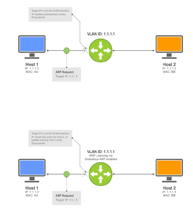
Figure 36. ARP Learning via ARP Request
When you enable ARP learning via gratuitous ARP, the system installs a new ARP entry, or updates an
existing entry for all received ARP requests.
Figure 37. ARP Learning via ARP Request with ARP Learning via Gratuitous ARP Enabled
Whether you enable or disable ARP learning via gratuitous ARP, the system does not look up the target IP.
It only updates the ARP entry for the Layer 3 interface with the source IP of the request.
Configuring ARP Retries
The number of ARP retries is user-configurable.
The default backoff interval remains at 20 seconds.
To set and display ARP retries, use the following commands.
• Set the number of ARP retries.
CONFIGURATION mode
arp retries number
The default is 5.
The range is from 1 to 20.
• Set the exponential timer for resending unresolved ARPs.
IPv4 Routing 373

CONFIGURATION mode
arp backoff-time
The default is 30.
The range is from 1 to 3600.
• Display all ARP entries learned via gratuitous ARP.
EXEC Privilege mode
show arp retries
ICMP
For diagnostics, the internet control message protocol (ICMP) provides routing information to end
stations by choosing the best route (ICMP redirect messages) or determining if a router is reachable
(ICMP Echo or Echo Reply).
ICMP error messages inform the router of problems in a particular packet. These messages are sent only
on unicast traffic.
Configuration Tasks for ICMP
The following lists the configuration tasks for ICMP.
•Enabling ICMP Unreachable Messages
For a complete listing of all commands related to ICMP, refer to the Dell Networking OS Command Line
Reference Guide.
Enabling ICMP Unreachable Messages
By default, ICMP unreachable messages are disabled.
When enabled, ICMP unreachable messages are created and sent out all interfaces.
To disable and re-enable ICMP unreachable messages, use the following commands.
• To disable ICMP unreachable messages.
INTERFACE mode
no ip unreachable
• Set the system to create and send ICMP unreachable messages on the interface.
INTERFACE mode
ip unreachable
To view if ICMP unreachable messages are sent on the interface, use the show config command in
INTERFACE mode. If it is not listed in the show config command output, it is enabled. Only non-default
information is displayed in the show config command output.
374 IPv4 Routing

UDP Helper
User datagram protocol (UDP) helper allows you to direct the forwarding IP/UDP broadcast traffic by
creating special broadcast addresses and rewriting the destination IP address of packets to match those
addresses.
Configure UDP Helper
Configuring the system to direct UDP broadcast is a two-step process:
1. Enable UDP helper and specify the UDP ports for which traffic is forwarded. Refer to Enabling UDP
Helper.
2. Configure a broadcast address on interfaces that will receive UDP broadcast traffic. Refer to
Configuring a Broadcast Address.
Important Points to Remember
• The existing ip directed broadcast command is rendered meaningless if you enable UDP helper
on the same interface.
• The broadcast traffic rate should not exceed 200 packets per second when you enable UDP helper.
• You may specify a maximum of 16 UDP ports.
• UDP helper is compatible with IP helper (ip helper-address):
– UDP broadcast traffic with port number 67 or 68 are unicast to the dynamic host configuration
protocol (DHCP) server per the ip helper-address configuration whether or not the UDP port
list contains those ports.
– If the UDP port list contains ports 67 or 68, UDP broadcast traffic is forwarded on those ports.
Enabling UDP Helper
To enable UDP helper, use the following command.
• Enable UPD helper.
ip udp-helper udp-ports
Examples of Enabling and Viewing UDP Helper
The following example shows how to enable UDP helper.
Dell(conf-if-te-1/1)#ip udp-helper udp-port 1000
Dell(conf-if-te-1/1)#show config
!
interface TengigabitEthernet 1/1
ip address 2.1.1.1/24
ip udp-helper udp-port 1000
no shutdown
To view the interfaces and ports on which you enabled UDP helper, use the show ip udp-helper
command from EXEC Privilege mode.
Dell#show ip udp-helper
--------------------------------------------------
Port UDP port list
IPv4 Routing 375

--------------------------------------------------
Te 1/1 1000
Configuring a Broadcast Address
To configure a broadcast address, use the following command.
• Configure a broadcast address on an interface.
ip udp-broadcast-address
Examples of Configuring and Viewing a Broadcast Address
The following example shows configuring a broadcast address.
Dell(conf-if-vl-100)#ip udp-broadcast-address 1.1.255.255
Dell(conf-if-vl-100)#show config
!
interface Vlan 100
ip address 1.1.0.1/24
ip udp-broadcast-address 1.1.255.255
untagged TengigabitEthernet 1/2
no shutdown
To view the configured broadcast address for an interface, use show interfaces command.
Dell(conf)#do show interfaces vlan 100
Vlan 100 is up, line protocol is down
Address is 00:01:e8:0d:b9:7a, Current address is 00:01:e8:0d:b9:7a
Interface index is 1107787876
Internet address is 1.1.0.1/24
IP UDP-Broadcast address is 1.1.255.255
MTU 1554 bytes, IP MTU 1500 bytes
LineSpeed auto
ARP type: ARPA, ARP Timeout 04:00:00
Last clearing of "show interface" counters 00:07:44
Queueing strategy: fifo
Input Statistics:
0 packets, 0 bytes
Time since last interface status change: 00:07:44
Configurations Using UDP Helper
When you enable UDP helper and the destination IP address of an incoming packet is a broadcast
address, the system suppresses the destination address of the packet.
The following sections describe various configurations that employ UDP helper to direct broadcasts.
•UDP Helper with Broadcast-All Addresses
•UDP Helper with Subnet Broadcast Addresses
•UDP Helper with Configured Broadcast Addresses
•UDP Helper with No Configured Broadcast Addresses
UDP Helper with Broadcast-All Addresses
When the destination IP address of an incoming packet is the IP broadcast address, the system rewrites
the address to match the configured broadcast address.
In the following illustration:
376 IPv4 Routing
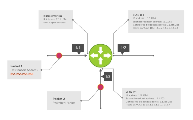
1. Packet 1 is dropped at ingress if you did not configure UDP helper address.
2. If you enable UDP helper (using the ip udp-helper udp-port command), and the UDP
destination port of the packet matches the UDP port configured, the system changes the destination
address to the configured broadcast 1.1.255.255 and routes the packet to VLANs 100 and 101. If you
do not configure an IP broadcast address (using the ip udp-broadcast-address command) on
VLANs 100 or 101, the packet is forwarded using the original destination IP address 255.255.255.255.
Packet 2, sent from a host on VLAN 101 has a broadcast MAC address and IP address. In this case:
1. It is flooded on VLAN 101 without changing the destination address because the forwarding process
is Layer 2.
2. If you enabled UDP helper, the system changes the destination IP address to the configured
broadcast address 1.1.255.255 and forwards the packet to VLAN 100.
3. Packet 2 is also forwarded to the ingress interface with an unchanged destination address because it
does not have broadcast address configured.
Figure 38. UDP Helper with Broadcast-All Addresses
UDP Helper with Subnet Broadcast Addresses
When the destination IP address of an incoming packet matches the subnet broadcast address of any
interface, the system changes the address to the configured broadcast address and sends it to matching
interface.
In the following illustration, Packet 1 has the destination IP address 1.1.1.255, which matches the subnet
broadcast address of VLAN 101. If you configured UDP helper and the packet matches the specified UDP
port, the system changes the address to the configured IP broadcast address and floods the packet on
VLAN 101.
Packet 2 is sent from the host on VLAN 101. It has a broadcast MAC address and a destination IP address
of 1.1.1.255. In this case, it is flooded on VLAN 101 in its original condition as the forwarding process is
Layer 2.
IPv4 Routing 377
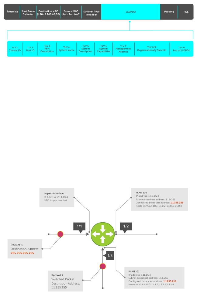
Figure 39. UDP Helper with Subnet Broadcast Addresses
UDP Helper with Configured Broadcast Addresses
Incoming packets with a destination IP address matching the configured broadcast address of any
interface are forwarded to the matching interfaces.
In the following illustration, Packet 1 has a destination IP address that matches the configured broadcast
address of VLAN 100 and 101. If you enabled UDP helper and the UDP port number matches, the packet
is flooded on both VLANs with an unchanged destination address.
Packet 2 is sent from a host on VLAN 101. It has broadcast MAC address and a destination IP address that
matches the configured broadcast address on VLAN 101. In this case, Packet 2 is flooded on VLAN 101
with the destination address unchanged because the forwarding process is Layer 2. If you enabled UDP
helper, the packet is flooded on VLAN 100 as well.
Figure 40. UDP Helper with Configured Broadcast Addresses
UDP Helper with No Configured Broadcast Addresses
The following describes UDP helper with no broadcast addresses configured.
• If the incoming packet has a broadcast destination IP address, the unaltered packet is routed to all
Layer 3 interfaces.
378 IPv4 Routing

• If the Incoming packet has a destination IP address that matches the subnet broadcast address of any
interface, the unaltered packet is routed to the matching interfaces.
Troubleshooting UDP Helper
To display debugging information for troubleshooting, use the debug ip udp-helper command.
Example of the debug ip udp-helper Command
Dell(conf)# debug ip udp-helper
01:20:22: Pkt rcvd on Te 5/0 with IP DA (0xffffffff) will be sent on Te 5/1 Te
5/2 Vlan 3
01:44:54: Pkt rcvd on Te 7/0 is handed over for DHCP processing.
When using the IP helper and UDP helper on the same interface, use the debug ip dhcp command.
Example Output from the debug ip dhcp Command
Packet 0.0.0.0:68 -> 255.255.255.255:67 TTL 128
2005-11-05 11:59:35 %RELAY-I-PACKET, BOOTP REQUEST (Unicast) received at
interface
172.21.50.193 BOOTP Request, XID = 0x9265f901, secs = 0 hwaddr = 00:02:2D:8D:
46:DC,
giaddr = 0.0.0.0, hops = 2
2005-11-05 11:59:35 %RELAY-I-BOOTREQUEST, Forwarded BOOTREQUEST for 00:02:2D:8D:
46:DC
to 137.138.17.6
2005-11-05 11:59:36 %RELAY-I-PACKET, BOOTP REPLY (Unicast) received at interface
194.12.129.98 BOOTP Reply, XID = 0x9265f901, secs = 0 hwaddr = 00:02:2D:8D:
46:DC,
giaddr = 172.21.50.193, hops = 2
2005-07-05 11:59:36 %RELAY-I-BOOTREPLY, Forwarded BOOTREPLY for 00:02:2D:8D:
46:DC to
128.141.128.90 Packet 0.0.0.0:68 -> 255.255.255.255:67 TTL 128
IPv4 Routing 379

22
IPv6 Routing
Internet protocol version 6 (IPv6) routing is the successor to IPv4. Due to the rapid growth in internet
users and IP addresses, IPv4 is reaching its maximum usage. IPv6 will eventually replace IPv4 usage to
allow for the constant expansion.
This chapter provides a brief description of the differences between IPv4 and IPv6, and the Dell
Networking support of IPv6. This chapter is not intended to be a comprehensive description of IPv6.
NOTE: The IPv6 basic commands are supported on all platforms. However, not all features are
supported on all platforms, nor for all releases. To determine the Dell Networking OS version
supporting specific features and platforms, refer to Implementing IPv6 with Dell Networking OS.
Protocol Overview
IPv6 is an evolution of IPv4. IPv6 is generally installed as an upgrade in devices and operating systems.
Most new devices and operating systems support both IPv4 and IPv6.
Some key changes in IPv6 are:
• Extended address space
• Stateless autoconfiguration
• Header format simplification
• Improved support for options and extensions
Extended Address Space
The address format is extended from 32 bits to 128 bits. This not only provides room for all anticipated
needs, it allows for the use of a hierarchical address space structure to optimize global addressing.
Stateless Autoconfiguration
When a booting device comes up in IPv6 and asks for its network prefix, the device can get the prefix (or
prefixes) from an IPv6 router on its link. It can then autoconfigure one or more global IPv6 addresses by
using either the MAC address or a private random number to build its unique IPv6 address.
Stateless autoconfiguration uses three mechanisms for IPv6 address configuration:
•Prefix Advertisement — Routers use “Router Advertisement” messages to announce the network
prefix. Hosts then use their interface-identifier MAC address to generate their own valid IPv6 address.
•Duplicate Address Detection (DAD) — Before configuring its IPv6 address, an IPv6 host node device
checks whether that address is used anywhere on the network using this mechanism.
•Prefix Renumbering — Useful in transparent renumbering of hosts in the network when an
organization changes its service provider.
NOTE: As an alternative to stateless autoconfiguration, network hosts can obtain their IPv6
addresses using the dynamic host control protocol (DHCP) servers via stateful auto-configuration.
380 IPv6 Routing

NOTE: The system provides the flexibility to add prefixes on Router Advertisements (RA) to advertise
responses to Router Solicitations (RS). By default, RA response messages are sent when an RS
message is received.
The manipulation of IPv6 stateless autoconfiguration supports the router side only. Neighbor discovery
(ND) messages are advertised so the neighbor can use this information to auto-configure its address.
However, received ND messages are not used to create an IPv6 address.
NOTE: Inconsistencies in router advertisement values between routers are logged per RFC 4861.
The values checked for consistency include:
• Cur Hop limit
• M and O flags
• Reachable time
• Retrans timer
• MTU options
• Preferred and valid lifetime values for the same prefix
Only management ports support stateless auto-configuration as a host.
The router redirect functionality in the neighbor discovery protocol (NDP) is similar to IPv4 router redirect
messages. NDP uses ICMPv6 redirect messages (Type 137) to inform nodes that a better router exists on
the link.
IPv6 Headers
The IPv6 header has a fixed length of 40 bytes. This fixed length provides 16 bytes each for source and
destination information and 8 bytes for general header information.
The IPv6 header includes the following fields:
•Version (4 bits)
•Traffic Class (8 bits)
•Flow Label (20 bits)
•Payload Length (16 bits)
•Next Header (8 bits)
•Hop Limit (8 bits)
•Source Address (128 bits)
•Destination Address (128 bits)
IPv6 provides for extension headers. Extension headers are used only if necessary. There can be no
extension headers, one extension header or more than one extension header in an IPv6 packet. Extension
headers are defined in the Next Header field of the preceding IPv6 header.
IPv6 Routing 381
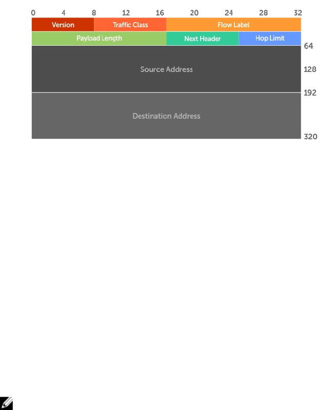
IPv6 Header Fields
The 40 bytes of the IPv6 header are ordered, as shown in the following illustration.
Figure 41. IPv6 Header Fields
Version (4 bits)
The Version field always contains the number 6, referring to the packet’s IP version.
Traffic Class (8 bits)
The Traffic Class field deals with any data that needs special handling. These bits define the packet
priority and are defined by the packet Source. Sending and forwarding routers use this field to identify
different IPv6 classes and priorities. Routers understand the priority settings and handle them
appropriately during conditions of congestion.
Flow Label (20 bits)
The Flow Label field identifies packets requiring special treatment in order to manage real-time data
traffic.
The sending router can label sequences of IPv6 packets so that forwarding routers can process packets
within the same flow without needing to reprocess each packet’s header separately.
NOTE: All packets in the flow must have the same source and destination addresses.
Payload Length (16 bits)
The Payload Length field specifies the packet payload. This is the length of the data following the IPv6
header. IPv6 Payload Length only includes the data following the header, not the header itself.
The Payload Length limit of 2 bytes requires that the maximum packet payload be 64 KB. However, the
Jumbogram option type Extension header supports larger packet sizes when required.
Next Header (8 bits)
The Next Header field identifies the next header’s type. If an Extension header is used, this field contains
the type of Extension header (as shown in the following table). If the next header is a transmission control
protocol (TCP) or user datagram protocol (UDP) header, the value in this field is the same as for IPv4. The
Extension header is located between the IP header and the TCP or UDP header.
382 IPv6 Routing

The following lists the Next Header field values.
Value Description
0Hop-by-Hop option header
4IPv4
6TCP
8Exterior Gateway Protocol (EGP)
41 IPv6
43 Routing header
44 Fragmentation header
50 Encrypted Security
51 Authentication header
59 No Next Header
60 Destinations option header
NOTE: This table is not a comprehensive list of Next Header field values. For a complete and current
listing, refer to the Internet Assigned Numbers Authority (IANA) web page.
Hop Limit (8 bits)
The Hop Limit field shows the number of hops remaining for packet processing. In IPv4, this is known as
the Time to Live (TTL) field and uses seconds rather than hops.
Each time the packet moves through a forwarding router, this field decrements by 1. If a router receives a
packet with a Hop Limit of 1, it decrements it to 0 (zero). The router discards the packet and sends an
ICMPv6 message back to the sending router indicating that the Hop Limit was exceeded in transit.
Source Address (128 bits)
The Source Address field contains the IPv6 address for the packet originator.
Destination Address (128 bits)
The Destination Address field contains the intended recipient’s IPv6 address. This can be either the
ultimate destination or the address of the next hop router.
Extension Header Fields
Extension headers are used only when necessary. Due to the streamlined nature of the IPv6 header,
adding extension headers do not severely impact performance. Each Extension headers’s lengths vary,
but they are always a multiple of 8 bytes.
Each extension header is identified by the Next Header field in the IPv6 header that precedes it. Extension
headers are viewed only by the destination router identified in the Destination Address field. If the
Destination Address is a multicast address, the Extension headers are examined by all the routers in that
multicast group.
IPv6 Routing 383
However, if the Destination Address is a Hop-by-Hop options header, the Extension header is examined
by every forwarding router along the packet’s route. The Hop-by-Hop options header must immediately
follow the IPv6 header, and is noted by the value 0 (zero) in the Next Header field.
Extension headers are processed in the order in which they appear in the packet header.
Hop-by-Hop Options Header
The Hop-by-Hop options header contains information that is examined by every router along the
packet’s path. It follows the IPv6 header and is designated by the Next Header value 0 (zero).
When a Hop-by-Hop Options header is not included, the router knows that it does not have to process
any router specific information and immediately processes the packet to its final destination.
When a Hop-by-Hop Options header is present, the router only needs this extension header and does
not need to take the time to view further into the packet.
The Hop-by-Hop Options header contains:
• Next Header (1 byte)
This field identifies the type of header following the Hop-by-Hop Options header and uses the same
values.
• Header Extension Length (1 byte)
This field identifies the length of the Hop-by-Hop Options header in 8-byte units, but does not include
the first 8 bytes. Consequently, if the header is less than 8 bytes, the value is 0 (zero).
• Options (size varies)
This field can contain one or more options. The first byte if the field identifies the Option type, and directs
the router how to handle the option.
00 Skip and continue processing.
01 Discard the packet.
10 Discard the packet and send an ICMP Parameter Problem Code 2 message to the
packet’s Source IP Address identifying the unknown option type.
11 Discard the packet and send an ICMP Parameter Problem, Code 2 message to the
packet’s Source IP Address only if the Destination IP Address is not a multicast
address.
The second byte contains the Option Data Length.
The third byte specifies whether the information can change en route to the destination. The value is 1 if
it can change; the value is 0 if it cannot change.
IPv6 Addressing
IPv6 addresses are normally written as eight groups of four hexadecimal digits, where each group is
separated by a colon (:).
For example, 2001:0db8:0000:0000:0000:0000:1428:57ab is a valid IPv6 address. If one or more four-
digit group(s) is 0000, the zeros may be omitted and replaced with two colons(::). For example,
2001:0db8:0000:0000:0000:0000:1428:57ab can be shortened to 2001:0db8::1428:57ab. Only one set
384 IPv6 Routing
of double colons is supported in a single address. Any number of consecutive 0000 groups may be
reduced to two colons, as long as there is only one double colon used in an address. Leading and/or
trailing zeros in a group can also be omitted (as in ::1 for localhost, 1:: for network addresses and :: for
unspecified addresses).
All the addresses in the following list are all valid and equivalent.
• 2001:0db8:0000:0000:0000:0000:1428:57ab
• 2001:0db8:0000:0000:0000::1428:57ab
• 2001:0db8:0:0:0:0:1428:57ab
• 2001:0db8:0:0::1428:57ab
• 2001:0db8::1428:57ab
• 2001:db8::1428:57ab
IPv6 networks are written using classless inter-domain routing (CIDR) notation. An IPv6 network (or
subnet) is a contiguous group of IPv6 addresses the size of which must be a power of two; the initial bits
of addresses, which are identical for all hosts in the network, are called the network's prefix.
A network is denoted by the first address in the network and the size in bits of the prefix (in decimal),
separated with a slash. Because a single host is seen as a network with a 128-bit prefix, host addresses
may be written with a following /128.
For example, 2001:0db8:1234::/48 stands for the network with addresses
2001:0db8:1234:0000:0000:0000:0000:0000 through 2001:0db8:1234:ffff:ffff:ffff:ffff:ffff.
Link-local Addresses
Link-local addresses, starting with fe80:, are assigned only in the local link area.
The addresses are generated usually automatically by the operating system's IP layer for each network
interface. This provides instant automatic network connectivity for any IPv6 host and means that if several
hosts connect to a common hub or switch, they have an instant communication path via their link-local
IPv6 address.
Link-local addresses cannot be routed to the public Internet.
Static and Dynamic Addressing
Static IPv6 addresses are manually assigned to a computer by an administrator.
Dynamic IPv6 addresses are assigned either randomly or by a server using dynamic host configuration
protocol (DHCP). Even though IPv6 addresses assigned using DHCP may stay the same for long periods
of time, they can change. In some cases, a network administrator may implement dynamically assigned
static IPv6 addresses. In this case, a DHCP server is used, but it is specifically configured to always assign
the same IPv6 address to a particular computer, and never to assign that IP address to another computer.
This allows static IPv6 addresses to be configured in one place, without having to specifically configure
each computer on the network in a different way.
In IPv6, every interface, whether using static or dynamic address assignments, also receives a local-link
address automatically in the fe80::/64 subnet.
IPv6 Routing 385

IPv6 Implementation on the Dell Networking OS
The Dell Networking OS supports both IPv4 and IPv6 and both may be used simultaneously in your
system.
The following table lists the Dell Networking OS version in which an IPv6 feature became available for
each platform. The sections following the table give greater detail about the feature.
Feature and Functionality Dell Networking OS Release
Introduction Documentation and Chapter
Location
Z9000
Basic IPv6 Commands 8.3.11 IPv6 Basic Commands in the Dell
Networking OS Command Line
Reference Guide.
IPv6 Basic Addressing
IPv6 address types: Unicast 8.3.11 Extended Address Space
IPv6 neighbor discovery 8.3.11 IPv6 Neighbor Discovery
IPv6 stateless autoconfiguration 8.3.11 Stateless Autoconfiguration
IPv6 MTU path discovery 8.3.11 Path MTU Discovery
IPv6 ICMPv6 8.3.11 ICMPv6
IPv6 ping 8.3.11 ICMPv6
IPv6 traceroute 8.3.11 ICMPv6
IPv6 SNMP 8.3.11
IPv6 Routing
Static routing 8.3.11 Assigning a Static IPv6 Route
Route redistribution 8.3.11 OSPF, IS-IS, and IPv6 BGP
chapters in the Dell Networking
OS Command Line Reference
Guide.
Multiprotocol BGP extensions for
IPv6
8.3.11 IPv6 BGP in the Dell Networking
OS Command Line Reference
Guide.
IPv6 BGP MD5 Authentication 8.3.11 IPv6 BGP in the Dell Networking
OS Command Line Reference
Guide.
IS-IS for IPv6 8.3.11 Intermediate System to
Intermediate System
IPv6 IS-IS in the Dell Networking
OS Command Line Reference
Guide.
386 IPv6 Routing

Feature and Functionality Dell Networking OS Release
Introduction Documentation and Chapter
Location
Z9000
IS-IS for IPv6 support for
redistribution
8.3.11 Intermediate System to
Intermediate System
IPv6 IS-IS in the Dell Networking
OS Command Line Reference
Guide.
ISIS for IPv6 support for
distribute lists and administrative
distance
8.3.11 Intermediate System to
Intermediate System
IPv6 IS-IS in the Dell Networking
OS Command Line Reference
Guide.
OSPF for IPv6 (OSPFv3) 8.3.11 OSPFv3 in the Dell Networking OS
Command Line Reference Guide.
Equal Cost Multipath for IPv6 8.3.11
IPv6 Services and Management
Telnet client over IPv6
(outbound Telnet)
8.3.11 Configuring Telnet with IPv6
Control and Monitoring in the Dell
Networking OS Command Line
Reference Guide.
Telnet server over IPv6 (inbound
Telnet)
8.3.11 Configuring Telnet with IPv6
Control and Monitoring in the Dell
Networking OS Command Line
Reference Guide.
Secure Shell (SSH) client support
over IPv6 (outbound SSH) Layer
3 only
8.3.11 Secure Shell (SSH) Over an IPv6
Transport
Secure Shell (SSH) server support
over IPv6 (inbound SSH) Layer 3
only
8.3.11 Secure Shell (SSH) Over an IPv6
Transport
IPv6 Access Control Lists 8.3.11 IPv6 Access Control Lists in the
Dell Networking OS Command
Line Reference Guide.
IPv6 Multicast
MLDv1/v2 N/A IPv6 PIM in the Dell Networking
OS Command Line Reference
Guide.
IPv6 Routing 387
Configuring the LPM Table for IPv6 Extended Prefixes
The LPM CAM table consists of two partitions: Partition I for IPv6 /65-/128 route-prefix entries and
Partition II for IPv6 0/0-/64 and IPv4 0/0-0/32 route-prefix entries. You must reconfigure LPM CAM to
allow IPv6 /65-/128 route prefixes to be stored in Partition I.
• Use the cam-ipv6 extended-prefix command to enable IPv6 /65-/128 route prefixes to be stored
in LPM CAM Partition 1. You must specify the maximum number of IPv6 prefixes with /65-/128 mask
length that are supported in the partition. The valid values are 1024, 2048 or 3072 prefixes. You must
save the configuration and reload the switch for the change to take effect.
• The number of entries in Partition II is reduced as the number of entries in Partition I increases.
• To disable LPM CAM partitioning and return the number of the IPv6 /65-/128 route prefixes stored in
Partition 1 to 0, enter the no cam-ipv6 extended-prefix command.
• Use the show cam-ipv6 extended-prefix command to display the currently configured number
of IPv6 /65-/128 prefixes that can be stored in LPM CAM Partition 1 and the number that are
supported after the next switch reboot.
ICMPv6
ICMP for IPv6 (ICMPv6) combines the roles of ICMP, IGMP and ARP in IPv4. Like IPv4, it provides
functions for reporting delivery and forwarding errors, and provides a simple echo service for
troubleshooting. The implementation of ICMPv6 is based on RFC 4443.
ICMPv6 uses two message types:
• Error reporting messages indicate when the forwarding or delivery of the packet failed at the
destination or intermediate node. These messages include Destination Unreachable, Packet Too Big,
Time Exceeded and Parameter Problem messages.
• Informational messages provide diagnostic functions and additional host functions, such as Neighbor
Discovery and Multicast Listener Discovery. These messages also include Echo Request and Echo
Reply messages.
The ping and traceroute commands extend to support IPv6 addresses. These commands use ICMPv6
Type-2 messages.
Path MTU Discovery
IPv6 path maximum transmission unit (MTU), in accordance with RFC 1981, defines the largest packet size
that can traverse a transmission path without suffering fragmentation. Path MTU for IPv6 uses ICMPv6
Type-2 messages to discover the largest MTU along the path from source to destination and avoid the
need to fragment the packet.
The recommended MTU for IPv6 is 1280. Greater MTU settings increase processing efficiency because
each packet carries more data while protocol overheads (for example, headers) or underlying per-packet
delays remain fixed.
388 IPv6 Routing
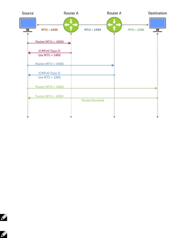
Figure 42. Path MTU Discovery Process
IPv6 Neighbor Discovery
The IPv6 neighbor discovery protocol (NDP) is a top-level protocol for neighbor discovery on an IPv6
network.
In place of address resolution protocol (ARP), NDP uses “Neighbor Solicitation” and “Neighbor
Advertisement” ICMPv6 messages for determining relationships between neighboring nodes. Using these
messages, an IPv6 device learns the link-layer addresses for neighbors known to reside on attached links,
quickly purging cached values that become invalid.
NOTE: If a neighboring node does not have an IPv6 address assigned, it must be manually pinged to
allow the IPv6 device to determine the relationship of the neighboring node.
NOTE: To avoid problems with network discovery, Dell Networking recommends configuring the
static route last or assigning an IPv6 address to the interface and assigning an address to the peer
(the forwarding router’s address) less than 10 seconds apart.
With ARP, each node broadcasts ARP requests on the entire link. This approach causes unnecessary
processing by uninterested nodes. With NDP, each node sends a request only to the intended destination
via a multicast address with the unicast address used as the last 24 bits. Other hosts on the link do not
participate in the process, greatly increasing network bandwidth efficiency.
IPv6 Routing 389

Figure 43. NDP Router Redirect
IPv6 Neighbor Discovery of MTU Packets
You can set the MTU advertised through the RA packets to incoming routers, without altering the actual
MTU setting on the interface.
The ipv6 nd mtu command sets the value advertised to routers. It does not set the actual MTU rate. For
example, if you set ipv6 nd mtu to 1280, the interface still passes 1500-byte packets, if that is what is
set with the mtu command.
Configuring the IPv6 Recursive DNS Server
You can configure up to four Recursive DNS Server (RDNSS) addresses to be distributed via IPv6 router
advertisements to an IPv6 device, using the ipv6 nd dns-server ipv6-RDNSS-address {lifetime
| infinite} command in INTERFACE CONFIG mode.
The lifetime parameter configures the amount of time the IPv6 host can use the IPv6 RDNSS address for
name resolution. The lifetime range is 0 to 4294967295 seconds. When the maximum lifetime value,
4294967295, or the infinite keyword is specified, the lifetime to use the RDNSS address does not
expire. A value of 0 indicates to the host that the RDNSS address should not be used. You must specify a
lifetime using the lifetime or infinite parameter.
The DNS server address does not allow the following:
• link local addresses
• loopback addresses
• prefix addresses
• multicast addresses
• invalid host addresses
If you specify this information in the IPv6 RDNSS configuration, a DNS error is displayed.
390 IPv6 Routing

Example for Configuring an IPv6 Recursive DNS Server
The following example configures a RDNNS server with an IPv6 address of 1000::1 and a lifetime of 1
second.
Dell(conf-if-te-0/1)#ipv6 nd dns-server ?
X:X:X:X::X Recursive DNS Server's (RDNSS) IPv6 address
Dell(conf-if-te-0/1)#ipv6 nd dns-server 1000::1 ?
<0-4294967295> Max lifetime (sec) which RDNSS address may be used for
name resolution
infinite Infinite lifetime (sec) which RDNSS address may be used
for name resolution
Dell(conf-if-te-0/1)#ipv6 nd dns-server 1000::1 1
Debugging IPv6 RDNSS Information Sent to the Host
To verify that the IPv6 RDNSS information sent to the host is configured correctly, use the debug ipv6
nd command in EXEC Privilege mode.
Example of Debugging IPv6 RDNSS Information Sent to the Host
The following example debugs IPv6 RDNSS information sent to the host.
Dell(conf-if-te-0/1)#do debug ipv6 nd tengigabitethernet 0/1
ICMPv6 Neighbor Discovery packet debugging is on for tengigabitethernet 0/1
Dell(conf-if-te-0/1)#00:13:02 : : cp-ICMPV6-ND: Sending RA on Te 0/1
current hop limit=64, flags: M-, O-,
router lifetime=1800 sec, reachable time=0 ms, retransmit time=0 ms
SLLA=00:01:e8:8b:75:70
prefix=1212::/64 on-link autoconfig
valid lifetime=2592000 sec, preferred lifetime=604800 sec
dns-server=1000::0001, lifetime=1 sec
dns-server=3000::0001, lifetime=1 sec
dns-server=2000::0001, lifetime=0 sec
The last 3 lines indicate that the IPv6 RDNSS information was configured correctly.
dns-server=1000::0001, lifetime=1 sec
dns-server=3000::0001, lifetime=1 sec
dns-server=2000::0001, lifetime=0 sec
If the DNS server information is not displayed, verify that the IPv6 recursive DNS server configuration was
configured on the correct interface.
Displaying IPv6 RDNSS Information
To display IPv6 interface information, including IPv6 RDNSS information, use the show ipv6
interface command in EXEC or EXEC Privilege mode.
Examples of Displaying IPv6 RDNSS Information
The following example displays IPv6 RDNSS information. The output in the last 3 lines indicates that the
IPv6 RDNSS was correctly configured on interface te 0/1.
Dell#show ipv6 interface te 0/1
TenGigabitEthernet 0/1 is up, line protocol is up
IPV6 is enabled
Link Local address: fe80::201:e8ff:fe8b:7570
Global Unicast address(es):
1212::12, subnet is 1212::/64 (MANUAL)
Remaining lifetime: infinite
Global Anycast address(es):
Joined Group address(es):
IPv6 Routing 391

ff02::1
ff02::2
ff02::1:ff00:12
ff02::1:ff8b:7570
ND MTU is 0
ICMP redirects are not sent
DAD is enabled, number of DAD attempts: 3
ND reachable time is 20120 milliseconds
ND base reachable time is 30000 milliseconds
ND advertised reachable time is 0 milliseconds
ND advertised retransmit interval is 0 milliseconds
ND router advertisements are sent every 198 to 600 seconds
ND router advertisements live for 1800 seconds
ND advertised hop limit is 64
IPv6 hop limit for originated packets is 64
ND dns-server address is 1000::1 with lifetime of 1 seconds
ND dns-server address is 3000::1 with lifetime of 1 seconds
ND dns-server address is 2000::1 with lifetime of 0 seconds
To display IPv6 RDNSS information, use the show configuration command in INTERFACE CONFIG
mode.
Dell(conf-if-te-0/1)#show configuration
The following example uses the show configuration command to display IPv6 RDNSS information.
!
interface TenGigabitEthernet 0/1
no ip address
ipv6 address 1212::12/64
ipv6 nd dns-server 1000::1 1
ipv6 nd dns-server 3000::1 1
ipv6 nd dns-server 2000::1 0
no shutdown
Secure Shell (SSH) Over an IPv6 Transport
Both inbound and outbound secure shell (SSH) sessions using IPv6 addressing are supported.
Inbound SSH supports accessing the system through the management interface as well as through a
physical Layer 3 interface.
For SSH configuration details, refer to the Security chapter in the Dell Networking OS Command Line
Interface Reference Guide.
Configuration Tasks for IPv6
The following are configuration tasks for the IPv6 protocol.
•Adjusting Your CAM-Profile
•Assigning an IPv6 Address to an Interface
•Assigning a Static IPv6 Route
•Configuring Telnet with IPv6
•SNMP over IPv6
•Showing IPv6 Information
•Clearing IPv6 Routes
392 IPv6 Routing
Adjusting Your CAM Profile
Although adjusting your CAM profile is not a mandatory step, if you plan to implement IPv6 ACLs, Dell
Networking recommends that you adjust your CAM settings.
The CAM space is allotted in FP blocks. The total space allocated must equal 13 FP blocks. There are 16
FP blocks, but the System Flow requires three blocks that cannot be reallocated.
You must enter the ipv6acl allocation as a factor of 2 (2, 4, 6, 8, 10). All other profile allocations can use
either even or odd-numbered ranges.
The default option sets the CAM Profile as follows:
• L3 ACL (ipv4acl): 6
• L2 ACL(l2acl): 5
• IPv6 L3 ACL (ipv6acl): 0
• L3 QoS (ipv4qos): 1
• L2 QoS (l2qos): 1
To have the changes take effect, save the new CAM settings to the startup-config (write-mem or copy
run start) then reload the system for the new settings.
• Allocate space for IPV6 ACLs. Enter the CAM profile name then the allocated amount.
CONFIGURATION mode
cam-acl { ipv6acl }
When not selecting the default option, enter all of the profiles listed and a range for each.
The total space allocated must equal 13.
The ipv6acl range must be a factor of 2.
• Show the current CAM settings.
EXEC mode or EXEC Privilege mode
show cam-acl
• Provides information on FP groups allocated for the egress acl.
CONFIGURATION mode
show cam-acl-egress
Allocate at least one group for L2ACL and IPv4 ACL.
The total number of groups is 4.
Assigning an IPv6 Address to an Interface
Essentially, IPv6 is enabled on a switch simply by assigning IPv6 addresses to individual router interfaces.
You can use IPv6 and IPv4 together on a system, but be sure to differentiate that usage carefully. To
assign an IPv6 address to an interface, use the ipv6 address command.
IPv6 Routing 393

You can configure up to two IPv6 addresses on management interfaces, allowing required default router
support on the management port that is acting as host, per RFC 4861. Data ports support more than two
IPv6 addresses.
When you configure IPv6 addresses on multiple interfaces (the ipv6 address command) and verify the
configuration (the show ipv6 interfaces command), the same link local (fe80) address is displayed
for each IPv6 interface.
• Enter the IPv6 Address for the device.
CONFIG-INTERFACE mode
ipv6 address ipv6 address/mask
–ipv6 address: x:x:x:x::x
–mask: The prefix length is from 0 to 128
NOTE: IPv6 addresses are normally written as eight groups of four hexadecimal digits. Separate
each group by a colon (:). Omitting zeros is accepted as described in Addressing.
Assigning a Static IPv6 Route
To configure IPv6 static routes, use the ipv6 route command.
NOTE: After you configure a static IPv6 route (the ipv6 route command) and configure the
forwarding router’s address (specified in the ipv6 route command) on a neighbor’s interface, the
IPv6 neighbor does not display in the show ipv6 route command output.
• Set up IPv6 static routes.
CONFIGURATION mode
ipv6 route prefix type {slot/port} forwarding router tag
–prefix: IPv6 route prefix
–type {slot/port}: interface type and slot/port
–forwarding router: forwarding router’s address
–tag: route tag
Enter the keyword interface then the type of interface and slot/port information:
– For a 10-Gigabit Ethernet interface, enter the keyword TenGigabitEthernet then the slot/port
information.
– For a 40-Gigabit Ethernet interface, enter the keyword fortyGigE then the slot/port information.
– For a loopback interface, enter the keyword loopback then the loopback number.
– For a port-channel interface, enter the keywords port-channel then the port-channel number.
– For a VLAN interface, enter the keyword vlan then the VLAN ID.
– For a Null interface, enter the keyword null then the Null interface number.
394 IPv6 Routing

Configuring Telnet with IPv6
The Telnet client and server on a switch supports IPv6 connections. You can establish a Telnet session
directly to the router using an IPv6 Telnet client, or you can initiate an IPv6 Telnet connection from the
router.
• Enter the IPv6 Address for the device.
EXEC mode or EXEC Privileged mode
telnet ipv6 address
–ipv6 address: x:x:x:x::x
–mask: prefix length is from 0 to 128.
NOTE: IPv6 addresses are normally written as eight groups of four hexadecimal digits, where
each group is separated by a colon (:). Omitting zeros is accepted as described in Addressing.
SNMP over IPv6
You can configure SNMP over IPv6 transport so that an IPv6 host can perform SNMP queries and receive
SNMP notifications from a device running a Dell Networking OS that supports IPv6.
The SNMP-server commands for IPv6 have been extended to support IPv6. For more information
regarding SNMP commands, refer to the SNMP and SYSLOG chapters in the Dell Networking OS
Command Line Reference Guide.
•snmp-server host
•snmp-server user ipv6
•snmp-server community ipv6
•snmp-server community access-list-name ipv6
•snmp-server group ipv6
•snmp-server group access-list-name ipv6
Displaying IPv6 Information
To view a specified IPv6 configuration, use the show ipv6command.
• List the IPv6 show options.
EXEC mode or EXEC Privileged mode
show ipv6 ?
Example of show ipv6 Command Options
Dell#show ipv6 ?
accounting IPv6 accounting information
cam IPv6 CAM Entries
fib IPv6 FIB Entries
interface IPv6 interface information
mbgproutes MBGP routing table
mld MLD information
mroute IPv6 multicast-routing table
neighbors IPv6 neighbor information
ospf OSPF information
pim PIM V6 information
IPv6 Routing 395

prefix-list List IPv6 prefix lists
route IPv6 routing information
rpf RPF table
Dell#
Displaying an IPv6 Configuration
To view the IPv6 configuration for a specific interface, use the following command.
• Display the currently running configuration for a specified interface.
EXEC mode
show ipv6 interface type {slot/port}
Enter the keyword interface then the type of interface and slot/port information:
– For all brief summary of IPv6 status and configuration, enter the keyword brief.
– For all IPv6 configured interfaces, enter the keyword configured.
– For a 10-Gigabit Ethernet interface, enter the keyword TenGigabitEthernet then the slot/port
information.
– For a 40-Gigabit Ethernet interface, enter the keyword fortyGigE then the slot/port information.
– For a loopback interface, enter the keyword loopback then the loopback number.
– For a port-channel interface, enter the keywords port-channel then the port-channel number.
– For a VLAN interface, enter the keyword vlan then the VLAN ID.
Example of the show ipv6 interface Command
Dell#show ipv6 int man 1/0
ManagementEthernet 1/0 is up, line protocol is up
IPV6 is enabled
Stateless address autoconfiguration is enabled
Link Local address: fe80::201:e8ff:fe8b:386e
Global Unicast address(es):
Actual address is 400::201:e8ff:fe8b:386e, subnet is 400::/64
Actual address is 412::201:e8ff:fe8b:386e, subnet is 412::/64
Virtual-IP IPv6 address is not set
Received Prefix(es):
400::/64 onlink autoconfig
Valid lifetime: 2592000, Preferred lifetime: 604800
Advertised by: fe80::201:e8ff:fe8b:3166
412::/64 onlink autoconfig
Valid lifetime: 2592000, Preferred lifetime: 604800
Advertised by: fe80::201:e8ff:fe8b:3166
Global Anycast address(es):
Joined Group address(es):
ff02::1
ff02::1:ff8b:386e
ND MTU is 0
ICMP redirects are not sent
DAD is enabled, number of DAD attempts: 3
ND reachable time is 32000 milliseconds
ND base reachable time is 30000 milliseconds
ND retransmit interval is 1000 milliseconds
ND hop limit is 64
Displaying IPv6 Routes
To view the global IPv6 routing information, use the following command.
396 IPv6 Routing

• Display IPv6 routing information for the specified route type.
EXEC mode
show ipv6 route type
The following keywords are available:
– To display information about a network, enter ipv6 address (X:X:X:X::X).
– To display information about a host, enter hostname.
– To display information about all IPv6 routes (including non-active routes), enter all.
– To display information about all connected IPv6 routes, enter connected.
– To display information about brief summary of all IPv6 routes, enter summary.
– To display information about Border Gateway Protocol (BGP) routes, enter bgp.
– To display information about ISO IS-IS routes, enter isis.
– To display information about Open Shortest Path First (OSPF) routes, enter ospf.
– To display information about Routing Information Protocol (RIP), enter rip.
– To display information about static IPv6 routes, enter static.
– To display information about an IPv6 Prefix lists, enter list and the prefix-list name.
Examples of the show ipv6 route command output are shown here.
Dell#show ipv6 route summary
Route Source Active Routes Non-active Routes
connected 5 0
static 0 0
Total 5 0
Dell#show ipv6 route
Codes: C - connected, L - local, S - static, R - RIP,
B - BGP, IN - internal BGP, EX - external BGP,LO - Locally Originated,
O - OSPF, IA - OSPF inter area, N1 - OSPF NSSA external type 1,
N2 - OSPF NSSA external type 2, E1 - OSPF external type 1,
E2 - OSPF external type 2, i - IS-IS, L1 - IS-IS level-1,
L2 - IS-IS level-2, IA - IS-IS inter area, * - candidate default,
Gateway of last resort is not set
Destination Dist/Metric, Gateway, Last Change
-----------------------------------------------------
C 600::/64 [0/0]
Direct, Te 0/24, 00:34:42
C 601::/64 [0/0]
Direct, Te 0/24, 00:34:18
C 912::/64 [0/0]
Direct, Lo 2, 00:02:33
O IA 999::1/128 [110/2]
via fe80::201:e8ff:fe8b:3166, Te 0/24, 00:01:30
L fe80::/10 [0/0]
Direct, Nu 0, 00:34:42
Dell#show ipv6 route static
Destination Dist/Metric, Gateway, Last Change
-----------------------------------------------------
IPv6 Routing 397

S 8888:9999:5555:6666:1111:2222::/96 [1/0]
via 2222:2222:3333:3333::1, Te 9/1, 00:03:16
S 9999:9999:9999:9999::/64 [1/0]
via 8888:9999:5555:6666:1111:2222:3333:4444, 00:03:16
Displaying the Running Configuration for an Interface
To view the configuration for any interface, use the following command.
• Display the currently running configuration for the specified interface.
EXEC mode
show running-config interface type {slot/port}
Enter the keyword interface then the type of interface and slot/port information:
– For the management interface, enter the keyword ManagementEthernet 0/0.
– For a 10-Gigabit Ethernet interface, enter the keyword TenGigabitEthernet then the slot/port
information.
– For a 40-Gigabit Ethernet interface, enter the keyword fortyGigE then the slot/port information.
Example of the show running-config interface Command
Dell#show run int te 2/2
!
interface TenGigabitEthernet 2/2
no ip address
ipv6 address 3:4:5:6::8/24
shutdown
Dell#
Clearing IPv6 Routes
To clear routes from the IPv6 routing table, use the following command.
• Clear (refresh) all or a specific route from the IPv6 routing table.
EXEC mode
clear ipv6 route {* | ipv6 address prefix-length}
–*: all routes.
–ipv6 address: the format is x:x:x:x::x.
–mask: the prefix length is from 0 to 128.
NOTE: IPv6 addresses are normally written as eight groups of four hexadecimal digits, where
each group is separated by a colon (:). Omitting zeros is accepted as described in Addressing.
398 IPv6 Routing

23
Intermediate System to Intermediate
System
The intermediate system to intermediate system (IS-IS) protocol that uses a shortest-path-first algorithm.
Dell Networking supports both IPv4 and IPv6 versions of IS-IS.
The IS-IS protocol standards are listed in the Standards Compliance chapter.
IS-IS Protocol Overview
The IS-IS protocol, developed by the International Organization for Standardization (ISO), is an interior
gateway protocol (IGP) that uses a shortest-path-first algorithm.
NOTE: This protocol supports routers passing both IP and OSI traffic, though the Dell Networking
implementation supports only IP traffic.
IS-IS is organized hierarchically into routing domains and each router or system resides in at least one
area. In IS-IS, routers are designated as Level 1, Level 2 or Level 1-2 systems. Level 1 routers only route
traffic within an area, while Level 2 routers route traffic between areas. At its most basic, Level 1 systems
route traffic within the area and any traffic destined for outside the area is sent to a Level 1-2 system.
Level 2 systems manage destination paths for external routers. Only Level 2 routers can exchange data
packets or routing information directly with external routers located outside of the routing domains. Level
1-2 systems manage both inter-area and intra-area traffic by maintaining two separate link databases;
one for Level 1 routes and one for Level 2 routes. A Level 1-2 router does not advertise Level 2 routes to a
Level 1 router.
To establish adjacencies, each IS-IS router sends different protocol data units (PDU). For IP traffic, the IP
addressing information is included in the IS-IS hello PDUs and the link state PDUs (LSPs).
This brief overview is not intended to provide a complete understanding of IS-IS; for that, consult the
documents listed in Multi-Topology IS-IS.
IS-IS Addressing
IS-IS PDUs require ISO-style addressing called network entity title (NET).
For those familiar with name-to-network service mapping point (NSAP) addresses, the composition of
the NET is identical to an NSAP address, except the last byte is always 0. The NET is composed of the IS-
IS area address, system ID, and N-selector. The last byte is the N-selector. All routers within an area have
the same area portion. Level 1 routers route based on the system address portion of the address, while
the Level 2 routers route based on the area address.
The NET length is variable, with a maximum of 20 bytes and a minimum of 8 bytes. It is composed of the
following:
•area address — within your routing domain or area, each area must have a unique area value. The first
byte is called the authority and format indicator (AFI).
Intermediate System to Intermediate System 399
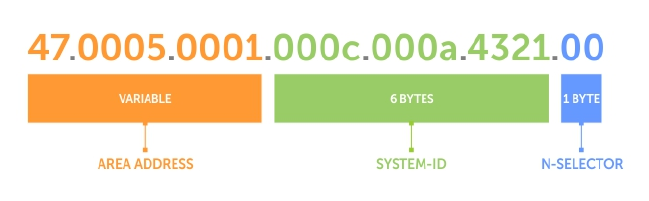
•system address — the router’s MAC address.
•N-selector — this is always 0.
The following illustration is an example of the ISO-style address to show the address format IS-IS uses. In
this example, the first five bytes (47.0005.0001) are the area address. The system portion is 000c.000a.
4321 and the last byte is always 0.
Figure 44. ISO Address Format
Multi-Topology IS-IS
Multi-topology IS-IS (MT IS-IS) allows you to create multiple IS-IS topologies on a single router with
separate databases. Use this feature to place a virtual physical topology into logical routing domains,
which can each support different routing and security policies.
All routers on a LAN or point-to-point must have at least one common supported topology when
operating in Multi-Topology IS-IS mode. If IPv4 is the common supported topology between those two
routers, adjacency can be formed. All topologies must share the same set of L1-L2 boundaries.
You must implement a wide metric-style globally on the autonomous system (AS) to run multi-topology
IS-IS for IPv6 because the Type, Length, Value (TLVs) used to advertise IPv6 information in link-state
packets (LSPs) are defined to use only extended metrics.
The multi-topology ID is shown in the first octet of the IS-IS packet. Certain MT topologies are assigned
to serve predetermined purposes:
• MT ID #0: Equivalent to the “standard” topology.
• MT ID #1: Reserved for IPv4 in-band management purposes.
• MT ID #2: Reserved for IPv6 routing topology.
• MT ID #3: Reserved for IPv4 multicast routing topology.
• MT ID #4: Reserved for IPv6 multicast routing topology.
• MT ID #5: Reserved for IPv6 in-band management purposes.
Transition Mode
All routers in the area or domain must use the same type of IPv6 support, either single-topology or multi-
topology. A router operating in multi-topology mode does not recognize the ability of the single-
topology mode router to support IPv6 traffic, which leads to holes in the IPv6 topology.
While in Transition mode, both types of TLVs (single-topology and multi-topology) are sent in LSPs for all
configured IPv6 addresses, but the router continues to operate in single-topology mode (that is, the
topological restrictions of the single-topology mode remain in effect). Transition mode stops after all
routers in the area or domain have been upgraded to support multi-topology IPv6. After all routers in the
area or domain are operating in multi-topology IPv6 mode, the topological restrictions of single-
topology mode are no longer in effect.
400 Intermediate System to Intermediate System
Interface Support
MT IS-IS is supported on physical Ethernet interfaces, physical synchronous optical network technologies
(SONET) interfaces, port-channel interfaces (static and dynamic using LACP), and virtual local area
network (VLAN) interfaces.
Adjacencies
Adjacencies on point-to-point interfaces are formed as usual, where IS-IS routers do not implement MT
extensions.
If a local router does not participate in certain MTs, it does not advertise those MT IDs in its IS-IS hellos
(IIHs) and so does not include that neighbor within its LSPs. If an MT ID is not detected in the remote
side’s IIHs, the local router does not include that neighbor within its LSPs. The local router does not form
an adjacency if both routers do not have at least one common MT over the interface.
Graceful Restart
Graceful restart is a protocol-based mechanism that preserves the forwarding table of the restarting
router and its neighbors for a specified period to minimize the loss of packets. A graceful-restart router
does not immediately assume that a neighbor is permanently down and so does not trigger a topology
change.
Normally, when an IS-IS router is restarted, temporary disruption of routing occurs due to events in both
the restarting router and the neighbors of the restarting router. When a router goes down without a
graceful restart, there is a potential to lose access to parts of the network due to the necessity of network
topology changes.
IS-IS graceful restart recognizes the fact that in a modern router, the control plane and data plane are
functionally separate. Restarting the control plane functionality (such as the failover of the active route
processor module (RPM) to the backup in a redundant configuration) should not necessarily interrupt
data packet forwarding. This behavior is supported because the forwarding tables previously computed
by an active RPM have been downloaded into the forwarding information base (FIB) on the line cards (the
data plane) and are still resident. For packets that have existing FIB/content addressable memory (CAM)
entries, forwarding between ingress and egress ports can continue uninterrupted while the control plane
IS-IS process comes back to full functionality and rebuilds its routing tables.
A new TLV (the Restart TLV) is introduced in the IIH PDUs, indicating that the router supports graceful
restart.
Timers
Three timers are used to support IS-IS graceful restart functionality. After you enable graceful restart,
these timers manage the graceful restart process.
There are three times, T1, T2, and T3.
• The T1 timer specifies the wait time before unacknowledged restart requests are generated. This is the
interval before the system sends a Restart Request (an IIH with the RR bit set in Restart TLV) until the
complete sequence number PDU (CSNP) is received from the helping router. You can set the duration
to a specific amount of time (seconds) or a number of attempts.
• The T2 timer is the maximum time that the system waits for LSP database synchronization. This timer
applies to the database type (level-1, level-2, or both).
Intermediate System to Intermediate System 401

• The T3 timer sets the overall wait time after which the router determines that it has failed to achieve
database synchronization (by setting the overload bit in its own LSP). You can base this timer on
adjacency settings with the value derived from adjacent routers that are engaged in graceful restart
recovery (the minimum of all the Remaining Time values advertised by the neighbors) or by setting a
specific amount of time manually.
Implementation Information
IS-IS implementation supports one instance of IS-IS and six areas.
You can configure the system as a Level 1 router, a Level 2 router, or a Level 1-2 router. For IPv6, the IPv4
implementation has been expanded to include two new type, length, values (TLVs) in the PDU that carry
information required for IPv6 routing. The new TLVs are IPv6 Reachability and IPv6 Interface Address.
Also, a new IPv6 protocol identifier has also been included in the supported TLVs. The new TLVs use the
extended metrics and up/down bit semantics.
Multi-topology IS-IS adds TLVs:
•MT TLV — contains one or more Multi-Topology IDs in which the router participates. This TLV is
included in IIH and the first fragment of an LSP.
•MT Intermediate Systems TLV — appears for every topology a node supports. An MT ID is added to
the extended IS reachability TLV type 22.
•MT Reachable IPv4 Prefixes TLV — appears for each IPv4 an IS announces for a given MT ID. Its
structure is aligned with the extended IS Reachability TLV Type 236 and it adds an MT ID.
•MT Reachable IPv6 Prefixes TLV — appears for each IPv6 an IS announces for a given MT ID. Its
structure is aligned with the extended IS Reachability TLV Type 236 and add an MT ID.
By default, the system supports dynamic host name exchange to assist with troubleshooting and
configuration. By assigning a name to an IS-IS NET address, you can track IS-IS information on that
address easier. The system does not support ISO CLNS routing; however, the ISO NET format is
supported for addressing.
To support IPv6, the Dell Networking implementation of IS-IS performs the following tasks:
• Advertises IPv6 information in the PDUs.
• Processes IPv6 information received in the PDUs.
• Computes routes to IPv6 destinations.
• Downloads IPv6 routes to the RTM for installing in the FIB.
• Accepts external IPv6 information and advertises this information in the PDUs.
The following table lists the default IS-IS values.
Table 11. IS-IS Default Values
IS-IS Parameter Default Value
Complete sequence number PDU (CSNP) interval 10 seconds
IS-to-IS hello PDU interval 10 seconds
IS-IS interface metric 10
Metric style Narrow
Designated Router priority 64
402 Intermediate System to Intermediate System

IS-IS Parameter Default Value
Circuit Type Level 1 and Level 2
IS Type Level 1 and Level 2
Equal Cost Multi Paths 16
Configuration Information
To use IS-IS, you must configure and enable IS-IS in two or three modes: CONFIGURATION ROUTER
ISIS, CONFIGURATION INTERFACE, and ( when configuring for IPv6) ADDRESS-FAMILY mode.
Commands in ROUTER ISIS mode configure IS-IS globally, while commands executed in INTERFACE
mode enable and configure IS-IS features on that interface only. Commands in the ADDRESS-FAMILY
mode are specific to IPv6.
NOTE: When using the IS-IS routing protocol to exchange IPv6 routing information and to
determine destination reachability, you can route IPv6 along with IPv4 while using a single intra-
domain routing protocol. The configuration commands allow you to enable and disable IPv6
routing and to configure or remove IPv6 prefixes on links.
Except where identified, the commands described in this chapter apply to both IPv4 and IPv6 versions of
IS-IS.
Configuration Tasks for IS-IS
The following describes the configuration tasks for IS-IS.
•Enabling IS-IS
•Configure Multi-Topology IS-IS (MT IS-IS)
•Configuring IS-IS Graceful Restart
•Changing LSP Attributes
•Configuring the IS-IS Metric Style
•Configuring IS-IS Cost
•Changing the IS-Type
•Controlling Routing Updates
•Configuring Authentication Passwords
•Setting the Overload Bit
•Debuging IS-IS
Enabling IS-IS
By default, IS-IS is not enabled.
The system supports one instance of IS-IS. To enable IS-IS globally, create an IS-IS routing process and
assign a NET address. To exchange protocol information with neighbors, enable IS-IS on an interface,
instead of on a network as with other routing protocols.
In IS-IS, neighbors form adjacencies only when they are same IS type. For example, a Level 1 router never
forms an adjacency with a Level 2 router. A Level 1-2 router forms Level 1 adjacencies with a neighboring
Level 1 router and forms Level 2 adjacencies with a neighboring Level 2 router.
NOTE: Even though you enable IS-IS globally, enable the IS-IS process on an interface for the IS-IS
process to exchange protocol information and form adjacencies.
Intermediate System to Intermediate System 403

To configure IS-IS globally, use the following commands.
1. Create an IS-IS routing process.
CONFIGURATION mode
router isis [tag]
tag: (optional) identifies the name of the IS-IS process.
2. Configure an IS-IS network entity title (NET) for a routing process.
ROUTER ISIS mode
net network-entity-title
Specify the area address and system ID for an IS-IS routing process. The last byte must be 00.
For more information about configuring a NET, refer to IS-IS Addressing.
3. Enter the interface configuration mode.
CONFIGURATION mode
interface interface
Enter the keyword interface then the type of interface and slot/port information:
• For a 1-Gigabit Ethernet interface, enter the keyword GigabitEthernet then the slot/port
information.
• For the Loopback interface on the RPM, enter the keyword loopback then a number from 0 to
16383.
• For a port channel, enter the keywords port-channel then a number.
• For a SONET interface, enter the keyword sonet then the slot/port information.
• For a 10-Gigabit Ethernet interface, enter the keyword TenGigabitEthernet then the slot/port
information.
• For a VLAN, enter the keyword vlan then a number from 1 to 4094.
4. Enter an IPv4 Address.
INTERFACE mode
ip address ip-address mask
Assign an IP address and mask to the interface.
The IP address must be on the same subnet as other IS-IS neighbors, but the IP address does not
need to relate to the NET address.
5. Enter an IPv6 Address.
INTERFACE mode
ipv6 address ipv6-address mask
•ipv6 address: x:x:x:x::x
•mask: The prefix length is from 0 to 128.
The IPv6 address must be on the same subnet as other IS-IS neighbors, but the IP address does not
need to relate to the NET address.
404 Intermediate System to Intermediate System

6. Enable IS-IS on the IPv4 interface.
ROUTER ISIS mode
ip router isis [tag]
If you configure a tag variable, it must be the same as the tag variable assigned in step 1.
7. Enable IS-IS on the IPv6 interface.
ROUTER ISIS mode
ipv6 router isis [tag]
If you configure a tag variable, it must be the same as the tag variable assigned in step 1.
Example of Viewing IS-IS Configuration ( EXEC Privilege Mode)
Example of the show isis traffic Command
The default IS type is level-1-2. To change the IS type to Level 1 only or Level 2 only, use the is-type
command in ROUTER ISIS mode.
To view the IS-IS configuration, enter the show isis protocol command in EXEC Privilege mode or
the show config command in ROUTER ISIS mode.
Dell#show isis protocol
IS-IS Router: <Null Tag>
System Id: EEEE.EEEE.EEEE IS-Type: level-1-2
Manual area address(es):
47.0004.004d.0001
Routing for area address(es):
21.2223.2425.2627.2829.3031.3233
47.0004.004d.0001
Interfaces supported by IS-IS:
Vlan 2
GigabitEthernet 4/22
Loopback 0
Redistributing:
Distance: 115
Generate narrow metrics: level-1-2
Accept narrow metrics: level-1-2
Generate wide metrics: none
Accept wide metrics: none
Dell#
To view IS-IS protocol statistics, use the show isis traffic command in EXEC Privilege mode.
Dell#show isis traffic
IS-IS: Level-1 Hellos (sent/rcvd) : 4272/1538
IS-IS: Level-2 Hellos (sent/rcvd) : 4272/1538
IS-IS: PTP Hellos (sent/rcvd) : 0/0
IS-IS: Level-1 LSPs sourced (new/refresh) : 0/0
IS-IS: Level-2 LSPs sourced (new/refresh) : 0/0
IS-IS: Level-1 LSPs flooded (sent/rcvd) : 32/19
IS-IS: Level-2 LSPs flooded (sent/rcvd) : 32/17
IS-IS: Level-1 LSPs CSNPs (sent/rcvd) : 1538/0
IS-IS: Level-2 LSPs CSNPs (sent/rcvd) : 1534/0
IS-IS: Level-1 LSPs PSNPs (sent/rcvd) : 0/0
IS-IS: Level-2 LSPs PSNPs (sent/rcvd) : 0/0
IS-IS: Level-1 DR Elections : 2
IS-IS: Level-2 DR Elections : 2
Intermediate System to Intermediate System 405

IS-IS: Level-1 SPF Calculations : 29
IS-IS: Level-2 SPF Calculations : 29
IS-IS: LSP checksum errors received : 0
IS-IS: LSP authentication failures : 0
Dell#
You can assign more NET addresses, but the System ID portion of the NET address must remain the
same. The system supports up to six area addresses.
Some address considerations are:
• In order to be neighbors, configure Level 1 routers with at least one common area address.
• A Level 2 router becomes a neighbor with another Level 2 router regardless of the area address
configured. However, if the area addresses are different, the link between the Level 2 routers is only at
Level 2.
Configuring Multi-Topology IS-IS (MT IS-IS)
To configure multi-topology IS-IS (MT IS-IS), use the following commands.
1. Enable multi-topology IS-IS for IPv6.
ROUTER ISIS AF IPV6 mode
multi-topology [transition]
Enter the keyword transition to allow an IS-IS IPv6 user to continue to use single-topology mode
while upgrading to multi-topology mode. After every router has been configured with the
transition keyword, and all the routers are in MT IS-IS IPv6 mode, you can remove the
transition keyword on each router.
NOTE: When you do not enable transition mode, you do not have IPv6 connectivity between
routers operating in single-topology mode and routers operating in multi-topology mode.
2. Exclude this router from other router’s SPF calculations.
ROUTER ISIS AF IPV6 mode
set-overload-bit
3. Set the minimum interval between SPF calculations.
ROUTER ISIS AF IPV6 mode
spf-interval [level-l | level-2 | interval] [initial_wait_interval
[second_wait_interval]]
Use this command for IPv6 route computation only when you enable multi-topology. If using single-
topology mode, to apply to both IPv4 and IPv6 route computations, use the spf-interval
command in CONFIG ROUTER ISIS mode.
4. Implement a wide metric-style globally.
ROUTER ISIS AF IPV6 mode
isis ipv6 metric metric-value [level-1 | level-2 | level-1-2]
To configure wide or wide transition metric style, the cost can be between 0 and 16,777,215.
406 Intermediate System to Intermediate System
Configuring IS-IS Graceful Restart
To enable IS-IS graceful restart globally, use the following commands. Additionally, you can implement
optional commands to enable the graceful restart settings.
• Enable graceful restart on ISIS processes.
ROUTER-ISIS mode
graceful-restart ietf
• Configure the time during which the graceful restart attempt is prevented.
ROUTER-ISIS mode
graceful-restart interval minutes
The range is from 1 to 120 minutes.
The default is 5 minutes.
• Enable the graceful restart maximum wait time before a restarting peer comes up.
ROUTER-ISIS mode
graceful-restart restart-wait seconds
When implementing this command, be sure to set the t3 timer to adjacency on the restarting router.
The range is from 1 to 120 minutes.
The default is 30 seconds.
• Configure the time that the graceful restart timer T1 defines for a restarting router to use for each
interface, as an interval before regenerating Restart Request (an IIH with RR bit set in Restart TLV) after
waiting for an acknowledgement.
ROUTER-ISIS mode
graceful-restart t1 {interval seconds | retry-times value}
–interval: wait time (the range is from 5 to 120. The default is 5.)
–retry-times: number of times an unacknowledged restart request is sent before the restarting
router gives up the graceful restart engagement with the neighbor. (The range is from 1 to 10
attempts. The default is 1.)
• Configure the time for the graceful restart timer T2 that a restarting router uses as the wait time for
each database to synchronize.
ROUTER-ISIS mode
graceful-restart t2 {level-1 | level-2} seconds
–level-1, level-2: identifies the database instance type to which the wait interval applies.
The range is from 5 to 120 seconds.
The default is 30 seconds.
• Configure graceful restart timer T3 to set the time used by the restarting router as an overall
maximum time to wait for database synchronization to complete.
ROUTER-ISIS mode
graceful-restart t3 {adjacency | manual seconds}
Intermediate System to Intermediate System 407

–adjacency: the restarting router receives the remaining time value from its peer and adjusts its T3
value so if user has configured this option.
–manual: allows you to specify a fixed value that the restarting router should use.
The range is from 50 to 120 seconds.
The default is 30 seconds.
Example of the show isis graceful-restart detail Command
Example of the show isis interface Command
NOTE: If this timer expires before the synchronization has completed, the restarting router sends
the overload bit in the LSP. The 'overload' bit is an indication to the receiving router that database
synchronization did not complete at the restarting router.
To view all graceful restart-related configurations, use the show isis graceful-restart detail
command in EXEC Privilege mode.
Dell#show isis graceful-restart detail
Configured Timer Value
======================
Graceful Restart : Enabled
Interval/Blackout time : 1 min
T3 Timer : Manual
T3 Timeout Value : 30
T2 Timeout Value : 30 (level-1), 30 (level-2)
T1 Timeout Value : 5, retry count: 1
Adjacency wait time : 30
Operational Timer Value
======================
Current Mode/State : Normal/RUNNING
T3 Time left : 0
T2 Time left : 0 (level-1), 0 (level-2)
Restart ACK rcv count : 0 (level-1), 0 (level-2)
Restart Req rcv count : 0 (level-1), 0 (level-2)
Suppress Adj rcv count : 0 (level-1), 0 (level-2)
Restart CSNP rcv count : 0 (level-1), 0 (level-2)
Database Sync count : 0 (level-1), 0 (level-2)
Circuit GigabitEthernet 2/10:
Mode: Normal L1-State:NORMAL, L2-State: NORMAL
L1: Send/Receive: RR:0/0, RA: 0/0, SA:0/0
T1 time left: 0, retry count left:0
L2: Send/Receive: RR:0/0, RA: 0/0, SA:0/0
T1 time left: 0, retry count left:0
Dell#
To view all interfaces configured with IS-IS routing along with the defaults, use the show isis
interface command in EXEC Privilege mode.
Dell#show isis interface G1/34
GigabitEthernet 2/10 is up, line protocol is up
MTU 1497, Encapsulation SAP
Routing Protocol: IS-IS
Circuit Type: Level-1-2
Interface Index 0x62cc03a, Local circuit ID 1
408 Intermediate System to Intermediate System

Level-1 Metric: 10, Priority: 64, Circuit ID: 0000.0000.000B.01
Hello Interval: 10, Hello Multiplier: 3, CSNP Interval: 10
Number of active level-1 adjacencies: 1
Level-2 Metric: 10, Priority: 64, Circuit ID: 0000.0000.000B.01
Hello Interval: 10, Hello Multiplier: 3, CSNP Interval: 10
Number of active level-2 adjacencies: 1
Next IS-IS LAN Level-1 Hello in 4 seconds
Next IS-IS LAN Level-2 Hello in 6 seconds
LSP Interval: 33 Next IS-IS LAN Level-1 Hello in 4 seconds
Next IS-IS LAN Level-2 Hello in 6 seconds
LSP Interval: 33
Restart Capable Neighbors: 2, In Start: 0, In Restart: 0
Dell#
Changing LSP Attributes
IS-IS routers flood link state PDUs (LSPs) to exchange routing information. LSP attributes include the
generation interval, maximum transmission unit (MTU) or size, and the refresh interval.
You can modify the LSP attribute defaults, but it is not necessary.
To change the defaults, use any or all of the following commands.
• Set interval between LSP generation.
ROUTER ISIS mode
lsp-gen-interval [level-1 | level-2] seconds
–seconds: the range is from 0 to 120.
The default is 5 seconds.
The default level is Level 1.
• Set the LSP size.
ROUTER ISIS mode
lsp-mtu size
–size: the range is from 128 to 9195.
The default is 1497.
• Set the LSP refresh interval.
ROUTER ISIS mode
lsp-refresh-interval seconds
–seconds: the range is from 1 to 65535.
The default is 900 seconds.
• Set the maximum time LSPs lifetime.
ROUTER ISIS mode
max-lsp-lifetime seconds
–seconds: the range is from 1 to 65535.
The default is 1200 seconds.
Example of Viewing IS-IS Configuration (ROUTER ISIS Mode)
To view the configuration, use the show config command in ROUTER ISIS mode or the show
running-config isis command in EXEC Privilege mode.
Intermediate System to Intermediate System 409

Dell#show running-config isis
!
router isis
lsp-refresh-interval 902
net 47.0005.0001.000C.000A.4321.00
net 51.0005.0001.000C.000A.4321.00
Dell#
Configuring the IS-IS Metric Style
All IS-IS links or interfaces are associated with a cost that is used in the shortest path first (SPF)
calculations. The possible cost varies depending on the metric style supported.
If you configure narrow, transition, or narrow transition metric style, the cost can be a number between 0
and 63. If you configure wide or wide transition metric style, the cost can be a number between 0 and
16,777,215. The system supports five different metric styles: narrow, wide, transition, narrow transition,
and wide transition.
By default, the system generates and receives narrow metric values. Matrixes or costs higher than 63 are
not supported. To accept or generate routes with a higher metric, you must change the metric style of
the IS-IS process. For example, if you configure the metric as narrow, and a link state PDU (LSP) with wide
metrics is received, the route is not installed.
The system supports the following IS-IS metric styles.
Table 12. Metric Styles
Metric Style Characteristics Cost Range Supported on IS-IS
Interfaces
narrow Sends and accepts narrow or old
TLVs (Type, Length, Value).
0 to 63
wide Sends and accepts wide or new
TLVs.
0 to 16777215
transition Sends both wide (new) and
narrow (old) TLVs.
0 to 63
narrow transition Sends narrow (old) TLVs and
accepts both narrow (old) and
wide (new) TLVs.
0 to 63
wide transition Sends wide (new) TLVs and
accepts both narrow (old) and
wide (new) TLVs.
0 to 16777215
To change the IS-IS metric style of the IS-IS process, use the following command.
• Set the metric style for the IS-IS process.
ROUTER ISIS mode
metric-style {narrow [transition] | transition | wide [transition]} [level-1
| level-2]
The default is narrow.
410 Intermediate System to Intermediate System

The default is Level 1 and Level 2 (level-1–2)
To view which metric types are generated and received, use the show isis protocol command in
EXEC Privilege mode. The IS-IS matrixes settings are in bold.
Example of Viewing IS-IS Metric Types
Dell#show isis protocol
IS-IS Router: <Null Tag>
System Id: EEEE.EEEE.EEEE IS-Type: level-1-2
Manual area address(es):
47.0004.004d.0001
Routing for area address(es):
21.2223.2425.2627.2829.3031.3233
47.0004.004d.0001
Interfaces supported by IS-IS:
Vlan 2
GigabitEthernet 4/22
Loopback 0
Redistributing:
Distance: 115
Generate narrow metrics: level-1-2
Accept narrow metrics: level-1-2
Generate wide metrics: none
Accept wide metrics: none
Dell#
Configuring the IS-IS Cost
When you change from one IS-IS metric style to another, the IS-IS metric value could be affected. For
each interface with IS-IS enabled, you can assign a cost or metric that is used in the link state calculation.
To change the metric or cost of the interface, use the following commands.
• Assign an IS-IS metric.
INTERFACE mode
isis metric default-metric [level-1 | level-2]
–default-metric: the range is from 0 to 63 if the metric-style is narrow, narrow-transition, or
transition.
The range is from 0 to 16777215 if the metric style is wide or wide transition.
• Assign a metric for an IPv6 link or interface.
INTERFACE mode
isis ipv6 metric default-metric [level-1 | level-2]
–default-metric: the range is from 0 to 63 for narrow and transition metric styles. The range is
from 0 to 16777215 for wide metric styles.
The default is 10.
The default level is level-1.
For more information about this command, refer to Configuring the IS-IS Metric Style.
The following table describes the correct value range for the isis metric command.
Intermediate System to Intermediate System 411

Metric Sytle Correct Value Range
wide 0 to 16777215
narrow 0 to 63
wide transition 0 to 16777215
narrow transition 0 to 63
transition 0 to 63
To view the interface’s current metric, use the show config command in INTERFACE mode or the show
isis interface command in EXEC Privilege mode.
Configuring the Distance of a Route
To configure the distance for a route, use the following command.
• Configure the distance for a route.
ROUTER ISIS mode
distance
Changing the IS-Type
To change the IS-type, use the following commands.
You can configure the system to act as a Level 1 router, a Level 1-2 router, or a Level 2 router.
To change the IS-type for the router, use the following commands.
• Configure IS-IS operating level for a router.
ROUTER ISIS mode
is-type {level-1 | level-1-2 | level-2-only}
Default is level-1-2.
• Change the IS-type for the IS-IS process.
ROUTER ISIS mode
is-type {level-1 | level-1-2 | level-2}
Example of the show isis database Command to View Level 1-2 Link State Databases
To view which IS-type is configured, use the show isis protocol command in EXEC Privilege mode.
The show config command in ROUTER ISIS mode displays only non-default information, so if you do
not change the IS-type, the default value (level-1-2) is not displayed.
The default is Level 1-2 router. When the IS-type is Level 1-2, the software maintains two Link State
databases, one for each level. To view the Link State databases, use the show isis database
command.
Dell#show isis database
IS-IS Level-1 Link State Database
LSPID LSP Seq Num LSP Checksum LSP Holdtime ATT/P/OL
B233.00-00 0x00000003 0x07BF 1088 0/0/0
eljefe.00-00 * 0x00000009 0xF76A 1126 0/0/0
eljefe.01-00 * 0x00000001 0x68DF 1122 0/0/0
412 Intermediate System to Intermediate System

eljefe.02-00 * 0x00000001 0x2E7F 1113 0/0/0
Force10.00-00 0x00000002 0xD1A7 1102 0/0/0
IS-IS Level-2 Link State Database
LSPID LSP Seq Num LSP Checksum LSP Holdtime ATT/P/OL
B233.00-00 0x00000006 0xC38A 1124 0/0/0
eljefe.00-00 * 0x0000000D 0x51C6 1129 0/0/0
eljefe.01-00 * 0x00000001 0x68DF 1122 0/0/0
eljefe.02-00 * 0x00000001 0x2E7F 1113 0/0/0
Force10.00-00 0x00000004 0xCDA9 1107 0/0/0
Dell#
Controlling Routing Updates
To control the source of IS-IS route information, use the following command.
• Disable a specific interface from sending or receiving IS-IS routing information.
ROUTER ISIS mode
passive-interface interface
– For a 1-Gigabit Ethernet interface, enter the keyword GigabitEthernet then the slot/port
information.
– For the Loopback interface on the RPM, enter the keyword loopback then a number from 0 to
16383.
– For a port channel, enter the keywords port-channel then a number.
– For a SONET interface, enter the keyword sonet then the slot/port information.
– For a 10-Gigabit Ethernet interface, enter the keyword TenGigabitEthernet then the slot/ port
information.
– For a VLAN, enter the keyword vlan then a number from 1 to 4094.
Distribute Routes
Another method of controlling routing information is to filter the information through a prefix list.
Prefix lists are applied to incoming or outgoing routes and routes must meet the conditions of the prefix
lists or the system does not install the route in the routing table. The prefix lists are globally applied on all
interfaces running IS-IS.
Configure the prefix list in PREFIX LIST mode prior to assigning it to the IS-IS process. For configuration
information on prefix lists, refer to Access Control Lists (ACLs).
Applying IPv4 Routes
To apply prefix lists to incoming or outgoing IPv4 routes, use the following commands.
NOTE: These commands apply to IPv4 IS-IS only. To apply prefix lists to IPv6 routes, use ADDRESS-
FAMILY IPV6 mode, shown later.
• Apply a configured prefix list to all incoming IPv4 IS-IS routes.
ROUTER ISIS mode
distribute-list prefix-list-name in [interface]
– Enter the type of interface and slot/port information:
– For a 1-Gigabit Ethernet interface, enter the keyword GigabitEthernet then the slot/port
information.
Intermediate System to Intermediate System 413

– For the Loopback interface on the RPM, enter the keyword loopback then a number from 0 to
16383.
– For a port channel, enter the keywords port-channel then a number.
– For a SONET interface, enter the keyword sonet then the slot/port information.
– For a 10-Gigabit Ethernet interface, enter the keyword TenGigabitEthernet then the slot/port
information.
– For a VLAN, enter the keyword vlan then a number from 1 to 4094.
• Apply a configured prefix list to all outgoing IPv4 IS-IS routes.
ROUTER ISIS mode
distribute-list prefix-list-name out [bgp as-number | connected | ospf
process-id | rip | static]
You can configure one of the optional parameters:
–connected: for directly connected routes.
–ospf process-id: for OSPF routes only.
–rip: for RIP routes only.
–static: for user-configured routes.
–bgp: for BGP routes only.
• Deny RTM download for pre-existing redistributed IPv4 routes.
ROUTER ISIS mode
distribute-list redistributed-override in
Applying IPv6 Routes
To apply prefix lists to incoming or outgoing IPv6 routes, use the following commands.
NOTE: These commands apply to IPv6 IS-IS only. To apply prefix lists to IPv4 routes, use ROUTER
ISIS mode, previously shown.
• Apply a configured prefix list to all incoming IPv6 IS-IS routes.
ROUTER ISIS-AF IPV6 mode
distribute-list prefix-list-name in [interface]
Enter the type of interface and slot/port information:
– For a 1-Gigabit Ethernet interface, enter the keyword GigabitEthernet then the slot/port
information.
– For the Loopback interface on the RPM, enter the keyword loopback then a number from 0 to
16383.
– For a port channel, enter the keywords port-channel then a number.
– For a SONET interface, enter the keyword sonet then the slot/port information.
– For a 10-Gigabit Ethernet interface, enter the keyword TenGigabitEthernet then the slot/port
information.
– For a VLAN, enter the keyword vlan then a number from 1 to 4094.
• Apply a configured prefix list to all outgoing IPv6 IS-IS routes.
ROUTER ISIS-AF IPV6 mode
414 Intermediate System to Intermediate System

distribute-list prefix-list-name out [bgp as-number | connected | ospf
process-id | rip | static]
You can configure one of the optional parameters:
–connected: for directly connected routes.
–ospf process-id: for OSPF routes only.
–rip: for RIP routes only.
–static: for user-configured routes.
–bgp: for BGP routes only.
• Deny RTM download for pre-existing redistributed IPv6 routes.
ROUTER ISIS-AF IPV6 mode
distribute-list redistributed-override in
Redistributing IPv4 Routes
In addition to filtering routes, you can add routes from other routing instances or protocols to the IS-IS
process. With the redistribute command syntax, you can include BGP, OSPF, RIP, static, or directly
connected routes in the IS-IS process.
NOTE: Do not route iBGP routes to IS-IS unless there are route-maps associated with the IS-IS
redistribution.
To add routes from other routing instances or protocols, use the following commands.
NOTE: These commands apply to IPv4 IS-IS only. To apply prefix lists to IPv6 routes, use ADDRESS-
FAMILY IPV6 mode, shown later.
• Include BGP, directly connected, RIP, or user-configured (static) routes in IS-IS.
ROUTER ISIS mode
redistribute {bgp as-number | connected | rip | static} [level-1 level-1-2 |
level-2] [metric metric-value] [metric-type {external | internal}] [route-map
map-name]
Configure the following parameters:
–level-1, level-1-2, or level-2: assign all redistributed routes to a level. The default is level-2.
–metric-value the range is from 0 to 16777215. The default is 0.
–metric-type: choose either external or internal. The default is internal.
–map-name: enter the name of a configured route map.
• Include specific OSPF routes in IS-IS.
ROUTER ISIS mode
redistribute ospf process-id [level-1| level-1-2 | level-2] [metric value]
[match external {1 | 2} | match internal] [metric-type {external | internal}]
[route-map map-name]
Configure the following parameters:
–process-id the range is from 1 to 65535.
–level-1, level-1-2, or level-2: assign all redistributed routes to a level. The default is level-2.
Intermediate System to Intermediate System 415

–metric value the range is from 0 to 16777215. The default is 0.
–match external the range is from 1 or 2.
–match internal
–metric-type: external or internal.
–map-name: enter the name of a configured route map.
Redistributing IPv6 Routes
To add routes from other routing instances or protocols, use the following commands.
NOTE: These commands apply to IPv6 IS-IS only. To apply prefix lists to IPv4 routes, use the
ROUTER ISIS mode previously shown.
• Include BGP, directly connected, RIP, or user-configured (static) routes in IS-IS.
ROUTER ISIS mode
redistribute {bgp as-number | connected | rip | static} [level-1 level-1-2 |
level-2] [metric metric-value] [metric-type {external | internal}] [route-map
map-name]
Configure the following parameters:
–level-1, level-1-2, or level-2: assign all redistributed routes to a level. The default is level-2.
–metric-value: the range is from 0 to 16777215. The default is 0.
–metric-type: choose either external or internal. The default is internal.
–map-name: enter the name of a configured route map.
• Include specific OSPF routes in IS-IS.ROUTER ISIS mode
redistribute ospf process-id [level-1| level-1-2 | level-2] [metric value]
[match external {1 | 2} | match internal] [metric-type {external | internal}]
[route-map map-name]
Configure the following parameters:
–process-id: the range is from 1 to 65535.
–level-1, level-1-2, or level-2: assign all redistributed routes to a level. The default is level-2.
–metric value: the range is from 0 to 16777215. The default is 0.
–metric value: the range is from 0 to 16777215. The default is 0.
–match external: the range is 1 or 2.
–match internal
–metric-type: external or internal.
–map-name: name of a configured route map.
To view the IS-IS configuration globally (including both IPv4 and IPv6 settings), use the show running-
config isis command in EXEC Privilege mode. To view the current IPv4 IS-IS configuration, use the
show config command in ROUTER ISIS mode. To view the current IPv6 IS-IS configuration, use the
show config command in ROUTER ISIS-ADDRESS FAMILY IPV6 mode.
416 Intermediate System to Intermediate System
Configuring Authentication Passwords
You can assign an authentication password for routers in Level 1 and for routers in Level 2.
Because Level 1 and Level 2 routers do not communicate with each other, you can assign different
passwords for Level 1 routers and for Level 2 routers. However, if you want the routers in the level to
communicate with each other, configure them with the same password.
To configure a simple text password, use the following commands.
• Configure authentication password for an area.
ROUTER ISIS mode
area-password [hmac-md5] password
FTOS supports HMAC-MD5 authentication.
This password is inserted in Level 1 LSPs, Complete SNPs, and Partial SNPs.
• Set the authentication password for a routing domain.
ROUTER ISIS mode
domain-password [encryption-type | hmac-md5] password
FTOS supports both DES and HMAC-MD5 authentication methods.
This password is inserted in Level 2 LSPs, Complete SNPs, and Partial SNPs.
To view the passwords, use the show config command in ROUTER ISIS mode or the show running-
config isis command in EXEC Privilege mode.
To remove a password, use either the no area-password or no domain-password commands in
ROUTER ISIS mode.
Setting the Overload Bit
Another use for the overload bit is to prevent other routers from using this router as an intermediate hop
in their shortest path first (SPF) calculations. For example, if the IS-IS routing database is out of memory
and cannot accept new LSPs, the system sets the overload bit and IS-IS traffic continues to transit the
system.
To set or remove the overload bit manually, use the following commands.
• Set the overload bit in LSPs.
ROUTER ISIS mode
set-overload-bit
This setting prevents other routers from using it as an intermediate hop in their shortest path first (SPF)
calculations.
• Remove the overload bit.
ROUTER ISIS mode
no set-overload-bit
Intermediate System to Intermediate System 417

Example of Viewing the Overload Bit Setting
When the bit is set, a 1 is placed in the OL column in the show isis database command output. The
overload bit is set in both the Level-1 and Level-2 database because the IS type for the router is
Level-1-2.
Dell#show isis database
IS-IS Level-1 Link State Database
LSPID LSP Seq Num LSP Checksum LSP Holdtime ATT/P/OL
B233.00-00 0x00000003 0x07BF 1074 0/0/0
eljefe.00-00 * 0x0000000A 0xF963 1196 0/0/1
eljefe.01-00 * 0x00000001 0x68DF 1108 0/0/0
eljefe.02-00 * 0x00000001 0x2E7F 1099 0/0/0
Force10.00-00 0x00000002 0xD1A7 1088 0/0/0
IS-IS Level-2 Link State Database
LSPID LSP Seq Num LSP Checksum LSP Holdtime ATT/P/OL
B233.00-00 0x00000006 0xC38A 1110 0/0/0
eljefe.00-00 * 0x0000000E 0x53BF 1196 0/0/1
eljefe.01-00 * 0x00000001 0x68DF 1108 0/0/0
eljefe.02-00 * 0x00000001 0x2E7F 1099 0/0/0
Force10.00-00 0x00000004 0xCDA9 1093 0/0/0
Dell#
Debugging IS-IS
To debug IS-IS processes, use the following commands.
• View all IS-IS information.
EXEC Privilege mode
debug isis
• View information on all adjacency-related activity (for example, hello packets that are sent and
received).
EXEC Privilege mode
debug isis adj-packets [interface]
To view specific information, enter the following optional parameter:
–interface: Enter the type of interface and slot/port information to view IS-IS information on that
interface only.
• View information about IS-IS local update packets.
EXEC Privilege mode
debug isis local-updates [interface]
To view specific information, enter the following optional parameter:
–interface: Enter the type of interface and slot/port information to view IS-IS information on that
interface only.
• View IS-IS SNP packets, include CSNPs and PSNPs.
EXEC Privilege mode
debug isis snp-packets [interface]
To view specific information, enter the following optional parameter:
418 Intermediate System to Intermediate System

–interface: Enter the type of interface and slot/port information to view IS-IS information on that
interface only.
• View the events that triggered IS-IS shortest path first (SPF) events for debugging purposes.
EXEC Privilege mode
debug isis spf-triggers
• View sent and received LSPs.
EXEC Privilege mode
debug isis update-packets [interface]
To view specific information, enter the following optional parameter:
–interface: Enter the type of interface and slot/port information to view IS-IS information on that
interface only.
The system displays debug messages on the console. To view which debugging commands are enabled,
use the show debugging command in EXEC Privilege mode.
To disable a specific debug command, enter the keyword no then the debug command. For example, to
disable debugging of IS-IS updates, use the no debug isis updates-packets command.
To disable all IS-IS debugging, use the no debug isis command.
To disable all debugging, use the undebug all command.
IS-IS Metric Styles
The following sections provide additional information about the IS-IS metric styles.
•Configuring the IS-IS Metric Style
•Configure Metric Values
FTOS supports the following IS-IS metric styles:
• narrow (supports only type, length, and value [TLV] up to 63)
• wide (supports TLV up to 16777215)
• transition (supports both narrow and wide and uses a TLV up to 63)
• narrow transition (accepts both narrow and wide and sends only narrow or old-style TLV)
• wide transition (accepts both narrow and wide and sends only wide or new-style TLV)
Configure Metric Values
For any level (Level-1, Level-2, or Level-1-2), the value range possible in the isis metric command in
INTERFACE mode changes depending on the metric style.
The following describes the correct value range for the isis metric command.
Metric Style Correct Value Range for the isis metric Command
wide 0 to 16777215
narrow 0 to 63
Intermediate System to Intermediate System 419

Metric Style Correct Value Range for the isis metric Command
wide transition 0 to 16777215
narrow transition 0 to 63
transition 0 to 63
Maximum Values in the Routing Table
IS-IS metric styles support different cost ranges for the route. The cost range for the narrow metric style
is 0 to 1023, while all other metric styles support a range of 0 to 0xFE000000.
Change the IS-IS Metric Style in One Level Only
By default, the IS-IS metric style is narrow. When you change from one IS-IS metric style to another, the
IS-IS metric value (configured with the isis metric command) could be affected.
In the following scenarios, the IS-type is either Level-1 or Level-2 or Level-1-2 and the metric style
changes.
Table 13. Metric Value When the Metric Style Changes
Beginning Metric Style Final Metric Style Resulting IS-IS Metric Value
wide narrow default value (10) if the original
value is greater than 63. A
message is sent to the console.
wide transition truncated value (the truncated
value appears in the LSP only).
The original isis metric value
is displayed in the show config
and show running-config
commands and is used if you
change back to transition metric
style.
NOTE: A truncated value is a
value that is higher than 63,
but set back to 63 because
the higher value is not
supported.
wide narrow transition default value (10) if the original
value is greater than 63. A
message is sent to the console.
wide wide transition original value
narrow wide original value
narrow transition original value
narrow narrow transition original value
narrow wide transition original value
transition wide original value
420 Intermediate System to Intermediate System

Beginning Metric Style Final Metric Style Resulting IS-IS Metric Value
transition narrow original value
transition narrow original value
transition wide transition original value
narrow transition wide original value
narrow transition narrow original value
narrow transition wide transition original value
narrow transition transition original value
wide transition wide original value
wide transition narrow default value (10) if the original
value is greater than 63. A
message is sent to the console.
wide transition narrow transition default value (10) if the original
value is greater than 63. A
message is sent to the console.
wide transition transition truncated value (the truncated
value appears in the LSP only).
The original isis metric value
is displayed in the show config
and show running-config
commands and is used if you
change back to transition metric
style.
Moving to transition and then to another metric style produces different results.
Table 14. Metric Value when the Metric Style Changes Multiple Times
Beginning Metric
Style Next Metric Style Resulting Metric
Value Next Metric Style Final Metric Value
wide transition truncated value wide original value is
recovered
wide transition transition truncated value wide transition original value is
recovered
wide transition truncated value narrow default value (10). A
message is sent to
the logging buffer
wide transition transition truncated value narrow transition default value (10). A
message is sent to
the logging buffer
Intermediate System to Intermediate System 421

Leaks from One Level to Another
In the following scenarios, each IS-IS level is configured with a different metric style.
Table 15. Metric Value with Different Levels Configured with Different Metric Styles
Level-1 Metric Style Level-2 Metric Style Resulting Metric Value
narrow wide original value
narrow wide transition original value
narrow narrow transition original value
narrow transition original value
wide narrow truncated value
wide narrow transition truncated value
wide wide transition original value
wide transition truncated value
narrow transition wide original value
narrow transition narrow original value
narrow transition wide transition original value
narrow transition transition original value
transition wide original value
transition narrow original value
transition wide transition original value
transition narrow transition original value
wide transition wide original value
wide transition narrow truncated value
wide transition narrow transition truncated value
wide transition transition truncated value
Sample Configurations
The following configurations are examples for enabling IPv6 IS-IS. These examples are not
comprehensive directions. They are intended to give you some guidance with typical configurations.
NOTE: Only one IS-IS process can run on the router, even if both IPv4 and IPv6 routing is being
used.
You can copy and paste from these examples to your CLI. To support your own IP addresses, interfaces,
names, and so on, be sure that you make the necessary changes.
422 Intermediate System to Intermediate System
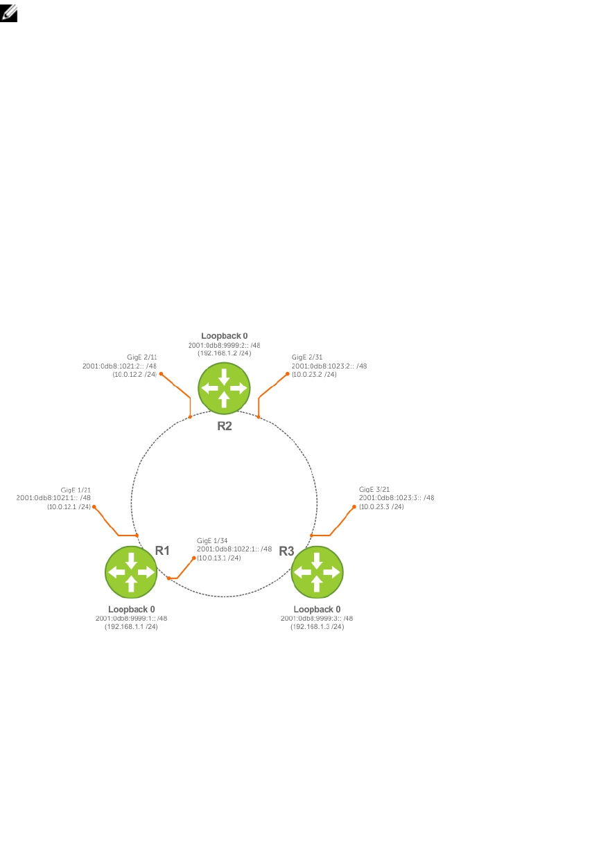
NOTE: Whenever you make IS-IS configuration changes, clear the IS-IS process (re-started) using
the clear isis command. The clear isis command must include the tag for the ISIS process.
The following example shows the response from the router:
Dell#clear isis *
% ISIS not enabled.
Dell#clear isis 9999 *
You can configure IPv6 IS-IS routes in one of the following three different methods:
•Congruent Topology — You must configure both IPv4 and IPv6 addresses on the interface. Enable
the ip router isis and ipv6 router isis commands on the interface. Enable the wide-
metrics parameter in router isis configuration mode.
•Multi-topology — You must configure the IPv6 address. Configuring the IPv4 address is optional. You
must enable the ipv6 router isis command on the interface. If you configure IPv4, also enable
the router isis command. In router isis configuration mode, enable multi-topology under
address-family ipv6 unicast.
•Multi-topology Transition — You must configure the IPv6 address. Configuring the IPv4 address is
optional. You must enable the ipv6 router isis command on the interface. If you configure IPv4,
also enable the ip router isis command. In router isis configuration mode, enable multi-
topology transition under address-family ipv6 unicast.
Figure 45. IPv6 IS-IS Sample Topography
IS-IS Sample Configuration — Congruent Topology
IS-IS Sample Configuration — Multi-topology
IS-IS Sample Configuration — Multi-topology Transition
The following is a sample configuration for enabling IPv6 IS-IS.
Dell(conf-if-te-3/17)#show config
!
interface TenGigabitEthernet 3/17
ip address 24.3.1.1/24
Intermediate System to Intermediate System 423

ipv6 address 24:3::1/76
ip router isis
ipv6 router isis
no shutdown
Dell (conf-if-te-3/17)#
Dell(conf-router_isis)#show config
!
router isis
metric-style wide level-1
metric-style wide level-2
net 34.0000.0000.AAAA.00
Dell (conf-router_isis)#
Dell(conf-if-te-3/17)#show config
!
interface TenGigabitEthernet 3/17
ipv6 address 24:3::1/76
ipv6 router isis
no shutdown
Dell(conf-if-te-3/17)#
Dell(conf-router_isis)#show config
!
router isis
net 34.0000.0000.AAAA.00
!
address-family ipv6 unicast
multi-topology
exit-address-family
Dell (conf-router_isis)#
Dell(conf-if-te-3/17)#show config
!
interface TenGigabitEthernet 3/17
ipv6 address 24:3::1/76
ipv6 router isis
no shutdown
Dell(conf-if-te-3/17)#
Dell(conf-router_isis)#show config
!
router isis
net 34.0000.0000.AAAA.00
!
address-family ipv6 unicast
multi-topology transition
exit-address-family
Dell(conf-router_isis)#
424 Intermediate System to Intermediate System

24
Link Aggregation Control Protocol (LACP)
A link aggregation group (LAG), referred to as a port channel by the Dell Networking OS, can provide both
load-sharing and port redundancy across line cards. You can enable LAGs as static or dynamic.
Introduction to Dynamic LAGs and LACP
The Dell Networking OS uses LACP to create dynamic LAGs. LACP provides a standardized means of
exchanging information between two systems (also called Partner Systems) and automatically establishes
the LAG between the systems.
The benefits and constraints of a LAG are basically the same as a port channel, as described in Port
Channel Interfaces in the Interfaces chapter. The unique benefit of a dynamic LAG is that its ports can
toggle between participating in the LAG or acting as dedicated ports, whereas ports in a static LAG must
be removed from the LAG in order to act alone.
LACP permits the exchange of messages on a link to allow their LACP instances to:
• Reach an agreement on the identity of the LAG to which the link belongs.
• Move the link to that LAG.
• Enable the transmission and reception functions in an orderly manner.
The Dell Networking implementation of LACP is based on the standards specified in the IEEE 802.3:
“Carrier sense multiple access with collision detection (CSMA/CD) access method and physical layer
specifications.”
LACP functions by constantly exchanging custom MAC protocol data units (PDUs) across local area
network (LAN) Ethernet links. The protocol packets are only exchanged between ports that are
configured as LACP capable.
Important Points to Remember
• LACP allows you to add members to a port channel (LAG) as long as it has no static members.
Conversely, if the LAG already contains a statically defined member (the channel-member
command), the port-channel mode command is not permitted.
• A static LAG cannot be created if a dynamic LAG using the selected number exists.
• No dual membership in static and dynamic LAGs:
– If a physical interface is a part of a static LAG, the port-channel-protocol lacp command is
rejected on that interface.
– If a physical interface is a part of a dynamic LAG, it cannot be added as a member of a static LAG.
The channel-member tengigabitethernet x/y command is rejected in the static LAG
interface for that physical interface.
• A dynamic LAG can be created with any type of configuration.
• There is a difference between the shutdown and no interface port-channel commands:
Link Aggregation Control Protocol (LACP) 425

– The shutdown command on LAG “xyz” disables the LAG and retains the user commands.
However, the system does not allow the channel number “xyz” to be statically created.
– The no interface port-channel channel-number command deletes the specified LAG,
including a dynamically created LAG. This command removes all LACP-specific commands on the
member interfaces. The interfaces are restored to a state that is ready to be configured.
NOTE: There is no configuration on the interface because that condition is required for an
interface to be part of a LAG.
• You can configure link dampening on individual members of a LAG.
LACP Modes
Three LACP configuration modes are supported — Off, Active, and Passive.
•Off — In this state, an interface is not capable of being part of a dynamic LAG. LACP does not run on
any port that is configured to be in this state.
•Active — In this state, the interface is said to be in the “active negotiating state.” LACP runs on any link
that is configured to be in this state. A port in Active state also automatically initiates negotiations with
other ports by initiating LACP packets.
•Passive — In this state, the interface is not in an active negotiating state, but LACP runs on the link. A
port in Passive state also responds to negotiation requests (from ports in Active state). Ports in Passive
state respond to LACP packets.
LAGs are supported in the following cases:
• A port in Active state can set up a port channel (LAG) with another port in Active state.
• A port in Active state can set up a LAG with another port in Passive state.
A port in Passive state cannot set up a LAG with another port in Passive state.
Configuring LACP Commands
If you configure aggregated ports with compatible LACP modes (Off, Active, Passive), LACP can
automatically link them, as defined in IEEE 802.3, Section 43.
To configure LACP, use the following commands.
• Configure the system priority.
CONFIGURATION mode
[no] lacp system-priority priority-value
The range is from 1 to 65535 (the higher the number, the lower the priority).
The default is 32768.
• Enable or disable LACP on any LAN port.
INTERFACE mode
[no] port-channel-protocol lacp
The default is LACP disabled.
This command creates context.
• Configure LACP mode.
LACP mode
[no] port-channel number mode [active | passive | off]
426 Link Aggregation Control Protocol (LACP)

–number: cannot statically contain any links.
The default is LACP active.
• Configure port priority.
LACP mode
[no] lacp port-priority priority-value
The range is from 1 to 65535 (the higher the number, the lower the priority).
The default is 32768.
LACP Configuration Tasks
The following configuration tasks apply to LACP.
•Creating a LAG
•Configuring the LAG Interfaces as Dynamic
•Setting the LACP Long Timeout
•Monitoring and Debugging LACP
•Configuring Shared LAG State Tracking
Creating a LAG
To create a dynamic port channel (LAG), use the following command. First you define the LAG and then
the LAG interfaces.
• Create a dynamic port channel (LAG).
CONFIGURATION mode
interface port-channel
• Create a dynamic port channel (LAG).
CONFIGURATION mode
switchport
Examples of Configuring a LAG Interface
The following example shows configuring a LAG interface.
Dell(conf)#interface port-channel 32
Dell(conf-if-po-32)#no shutdown
Dell(conf-if-po-32)#switchport
The LAG is in the default VLAN. To place the LAG into a non-default VLAN, use the tagged command on
the LAG.
Dell(conf)#interface vlan 10
Dell(conf-if-vl-10)#tagged port-channel 32
Configuring the LAG Interfaces as Dynamic
After creating a LAG, configure the dynamic LAG interfaces.
To configure the dynamic LAG interfaces, use the following command.
Link Aggregation Control Protocol (LACP) 427

• Configure the dynamic LAG interfaces.
CONFIGURATION mode
port-channel-protocol lacp
Example of the port-channel-protocol lacp Command
Dell(conf)#interface Tengigabitethernet 3/15
Dell(conf-if-te-3/15)#no shutdown
Dell(conf-if-te-3/15)#port-channel-protocol lacp
Dell(conf-if-te-3/15-lacp)#port-channel 32 mode active
...
Dell(conf)#interface Tengigabitethernet 3/16
Dell(conf-if-te-3/16)#no shutdown
Dell(conf-if-te-3/16)#port-channel-protocol lacp
Dell(conf-if-te-3/16-lacp)#port-channel 32 mode active
...
Dell(conf)#interface Tengigabitethernet 4/15
Dell(conf-if-te-4/15)#no shutdown
Dell(conf-if-te-4/15)#port-channel-protocol lacp
Dell(conf-if-te-4/15-lacp)#port-channel 32 mode active
...
Dell(conf)#interface Tengigabitethernet 4/16
Dell(conf-if-te-4/16)#no shutdown
Dell(conf-if-te-4/16)#port-channel-protocol lacp
Dell(conf-if-te-4/16-lacp)#port-channel 32 mode active
The port-channel 32 mode active command shown here may be successfully issued as long as there is
no existing static channel-member configuration in LAG 32.
Setting the LACP Long Timeout
PDUs are exchanged between port channel (LAG) interfaces to maintain LACP sessions.
PDUs are transmitted at either a slow or fast transmission rate, depending upon the LACP timeout value.
The timeout value is the amount of time that a LAG interface waits for a PDU from the remote system
before bringing the LACP session down. The default timeout value is 1 second. You can configure the
default timeout value to be 30 seconds. Invoking the longer timeout might prevent the LAG from flapping
if the remote system is up but temporarily unable to transmit PDUs due to a system interruption.
NOTE: The 30-second timeout is available for dynamic LAG interfaces only. You can enter the lacp
long-timeout command for static LAGs, but it has no effect.
To configure LACP long timeout, use the following command.
• Set the LACP timeout value to 30 seconds.
CONFIG-INT-PO mode
lacp long-timeout
Example of the lacp long-timeout and show lacp Commands
Dell(conf)# interface port-channel 32
Dell(conf-if-po-32)#no shutdown
Dell(conf-if-po-32)#switchport
Dell(conf-if-po-32)#lacp long-timeout
Dell(conf-if-po-32)#end
Dell# show lacp 32
Port-channel 32 admin up, oper up, mode lacp
Actor System ID: Priority 32768, Address 0001.e800.a12b
428 Link Aggregation Control Protocol (LACP)
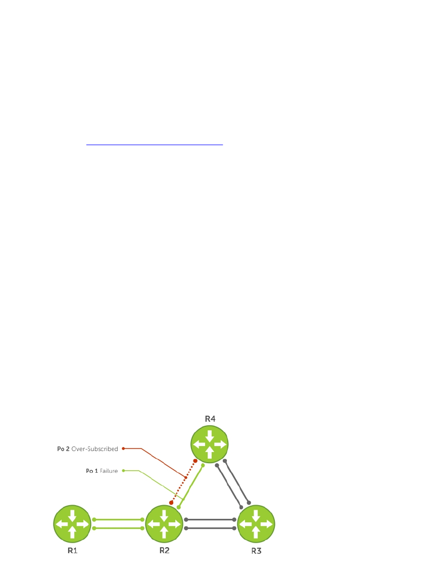
Partner System ID: Priority 32768, Address 0001.e801.45a5
Actor Admin Key 1, Oper Key 1, Partner Oper Key 1
LACP LAG 1 is an aggregatable link
A - Active LACP, B - Passive LACP, C - Short Timeout, D - Long Timeout
E - Aggregatable Link, F - Individual Link, G - IN_SYNC, H - OUT_OF_SYNC
I - Collection enabled, J - Collection disabled, K - Distribution enabled L -
Distribution disabled,
M - Partner Defaulted, N - Partner Non-defaulted, O - Receiver is in expired
state,
P - Receiver is not in expired state
Port Te 10/6 is enabled, LACP is enabled and mode is lacp
Actor Admin: State ADEHJLMP Key 1 Priority 128
To view the PDU exchanges and the timeout value, use the debug lacp command. For more
information, refer to Monitoring and Debugging LACP.
Monitoring and Debugging LACP
The system log (syslog) records faulty LACP actions.
To debug LACP, use the following command.
• Debug LACP, including configuration and events.
EXEC mode
[no] debug lacp [config | events | pdu [in | out | [interface [in | out]]]]
Shared LAG State Tracking
Shared LAG state tracking provides the flexibility to bring down a port channel (LAG) based on the
operational state of another LAG.
At any time, only two LAGs can be a part of a group such that the fate (status) of one LAG depends on the
other LAG.
As shown in the following illustration, the line-rate traffic from R1 destined for R4 follows the lowest-cost
route via R2. Traffic is equally distributed between LAGs 1 and 2. If LAG 1 fails, all traffic from R1 to R4
flows across LAG 2 only. This condition over-subscribes the link and packets are dropped.
Figure 46. Shared LAG State Tracking
Link Aggregation Control Protocol (LACP) 429

To avoid packet loss, redirect traffic through the next lowest-cost link (R3 to R4). the system has the
ability to bring LAG 2 down if LAG 1 fails, so that traffic can be redirected. This redirection is what is meant
by shared LAG state tracking. To achieve this functionality, you must group LAG 1 and LAG 2 into a single
entity, called a failover group.
Configuring Shared LAG State Tracking
To configure shared LAG state tracking, you configure a failover group.
NOTE: If a LAG interface is part of a redundant pair, you cannot use it as a member of a failover
group created for shared LAG state tracking.
1. Enter port-channel failover group mode.
CONFIGURATION mode
port-channel failover-group
2. Create a failover group and specify the two port-channels that will be members of the group.
CONFIG-PO-FAILOVER-GRP mode
group number port-channel number port-channel number
Examples of Configuring and Viewing LAGs
In the following example, LAGs 1 and 2 have been placed into to the same failover group.
R2#config
R2(conf)#port-channel failover-group
R2(conf-po-failover-grp)#group 1 port-channel 1 port-channel 2
To view the failover group configuration, use the show running-configuration po-failover-
group command.
R2#show running-config po-failover-group
!
port-channel failover-group
group 1 port-channel 1 port-channel 2
As shown in the following illustration, LAGs 1 and 2 are members of a failover group. LAG 1 fails and LAG
2 is brought down after the failure. This effect is logged by Message 1, in which a console message
declares both LAGs down at the same time.
430 Link Aggregation Control Protocol (LACP)
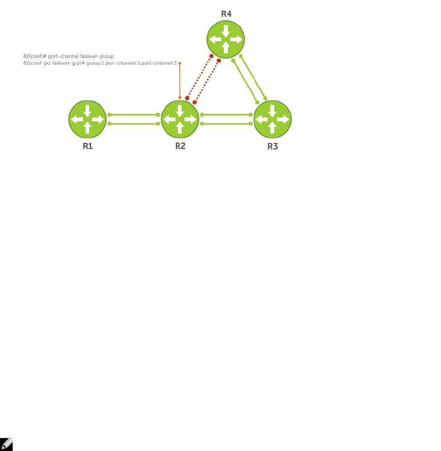
Figure 47. Configuring Shared LAG State Tracking
The following are shared LAG state tracking console messages:
•2d1h45m: %SYSTEM-P:CP %IFMGR-5-OSTATE_DN: Changed interface state to down: Po
1
•2d1h45m: %SYSTEM-P:CP %IFMGR-5-OSTATE_DN: Changed interface state to down: Po
2
To view the status of a failover group member, use the show interface port-channel command.
R2#show interface port-channel 2
Port-channel 2 is up, line protocol is down (Failover-group 1 is down)
Hardware address is 00:01:e8:05:e8:4c, Current address is 00:01:e8:05:e8:4c
Interface index is 1107755010
Minimum number of links to bring Port-channel up is 1
Port-channel is part of failover-group 1
Internet address is not set
MTU 1554 bytes, IP MTU 1500 bytes
LineSpeed 1000 Mbit
Members in this channel: Te 1/17(U)
ARP type: ARPA, ARP Timeout 04:00:00
Last clearing of "show interface" counters 00:01:28
Queueing strategy: fifo
NOTE: The set of console messages shown above appear only if you configure shared LAG state
tracking on that router (you can configure the feature on one or both sides of a link). For example,
as previously shown, if you configured shared LAG state tracking on R2 only, no messages appear
on R4 regarding the state of LAGs in a failover group.
Important Points about Shared LAG State Tracking
The following is more information about shared LAG state tracking.
• This feature is available for static and dynamic LAGs.
• Only a LAG can be a member of a failover group.
• You can configure shared LAG state tracking on one side of a link or on both sides.
• If a LAG that is part of a failover group is deleted, the failover group is deleted.
• If a LAG moves to the Down state due to this feature, its members may still be in the Up state.
Link Aggregation Control Protocol (LACP) 431
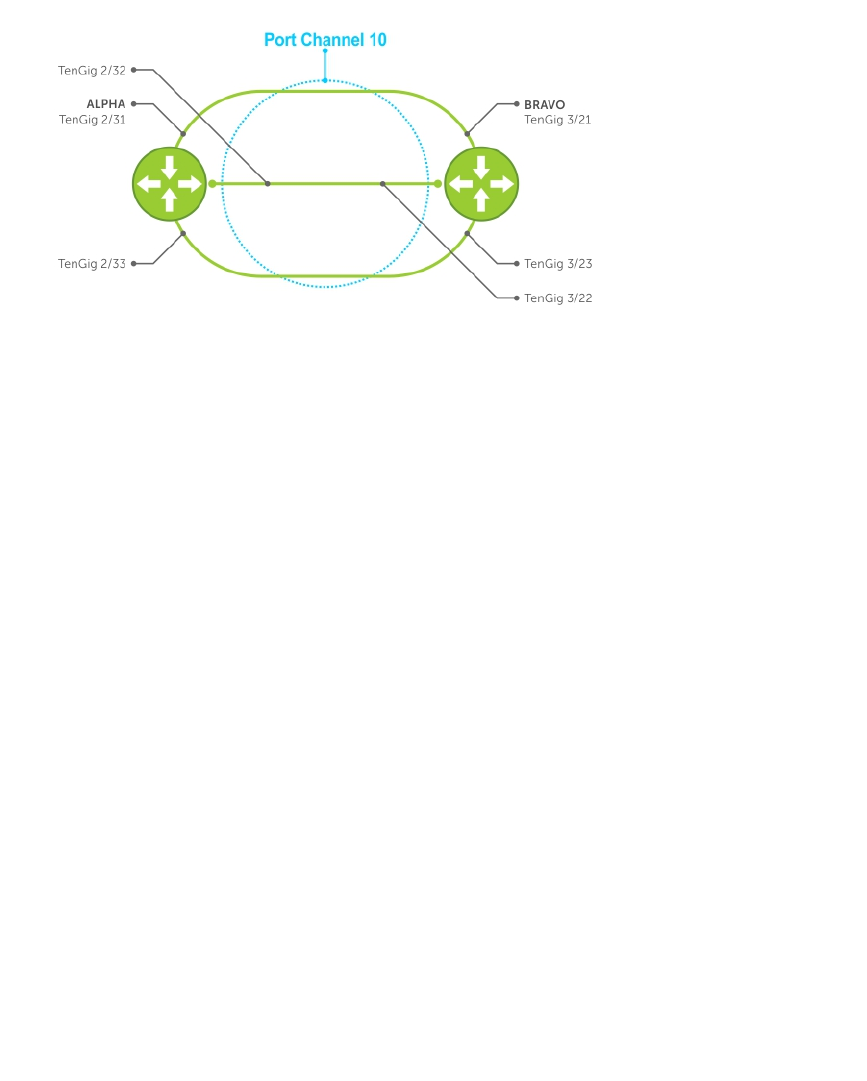
LACP Basic Configuration Example
The screenshots in this section are based on the following example topology. Two routers are named
ALPHA and BRAVO, and their hostname prompts reflect those names.
Figure 48. LACP Basic Configuration Example
Configure a LAG on ALPHA
The following example creates a LAG on ALPHA.
Example of Configuring a LAG
Alpha(conf)#interface port-channel 10
Alpha(conf-if-po-10)#no ip address
Alpha(conf-if-po-10)#switchport
Alpha(conf-if-po-10)#no shutdown
Alpha(conf-if-po-10)#show config
!
interface Port-channel 10
no ip address
switchport
no shutdown
!
Alpha(conf-if-po-10)#
Example of Viewing a LAG Port Configuration
The following example inspects a LAG port configuration on ALPHA.
Alpha#show int tengig 2/31
TengigabitEthernet 2/31 is up, line protocol is up
Port is part of Port-channel 10
Hardware is Dell Force10Eth, address is 00:01:e8:06:95:c0
Current address is 00:01:e8:06:95:c0
Interface Index is 109101113
Port will not be disabled on partial SFM failure
Internet address is not set
MTU 1554 bytes, IP MTU 1500 bytes
LineSpeed 1000 Mbit, Mode full duplex, Slave
Flowcontrol rx on tx on
ARP type: ARPA, ARP Timeout 04:00:00
Last clearing of "show interface" counters 00:02:11
Queueing strategy: fifo
432 Link Aggregation Control Protocol (LACP)
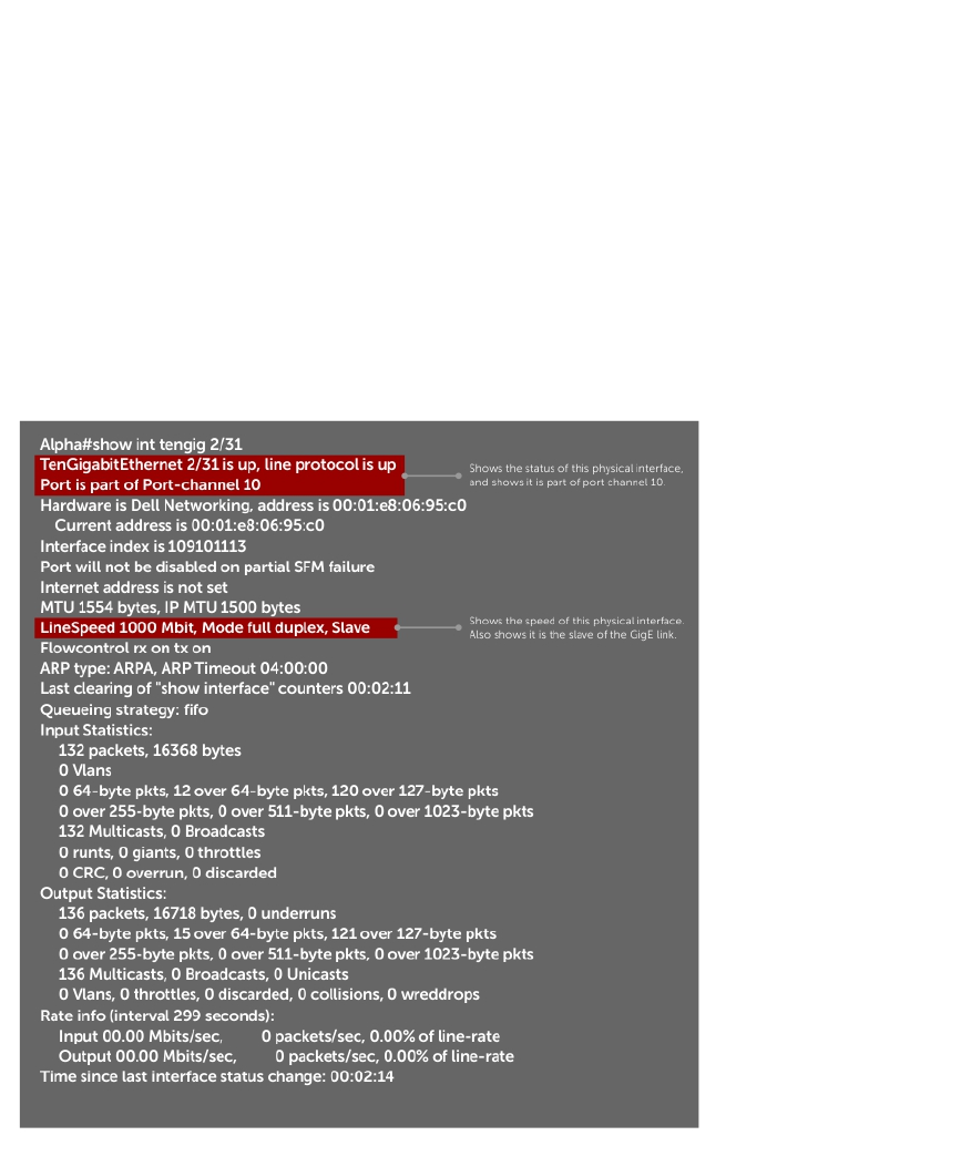
Input statistics:
132 packets, 163668 bytes
0 Vlans
0 64-byte pkts, 12 over 64-byte pkts, 120 over 127-byte pkts
0 over 255-byte pkts, 0 over 511-byte pkts, 0 over 1023-byte pkts
132 Multicasts, 0 Broadcasts
0 runts, 0 giants, 0 throttles
0 CRC, 0 overrun, 0 discarded
Output Statistics
136 packets, 16718 bytes, 0 underruns
0 64-byte pkts, 15 over 64-byte pkts, 121 over 127-byte pkts
0 over 255-byte pkts, 0 over 511-byte pkts, 0 over 1023-byte pkts
136 Multicasts, 0 Broadcasts, 0 Unicasts
0 Vlans, 0 throttles, 0 discarded, 0 collisions, 0 wreddrops
Rate info (interval 299 seconds):
Input 00.00 Mbits/sec,0 packets/sec, 0.00% of line-rate
Output 00.00 Mbits/sec,0 packets/sec, 0.00% of line-rate
Time since last interface status change: 00:02:14
Figure 49. Inspecting the LAG Configuration
Link Aggregation Control Protocol (LACP) 433
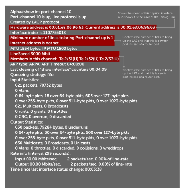
Figure 50. Inspecting Configuration of LAG 10 on ALPHA
434 Link Aggregation Control Protocol (LACP)
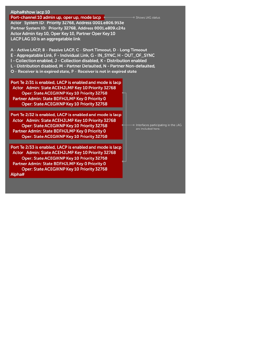
Figure 51. Verifying LAG 10 Status on ALPHA Using the show lacp Command
Summary of the LAG Configuration on Alpha
Alpha(conf-if-po-10)#int tengig 2/31
Alpha(conf-if-te-2/31)#no ip address
Alpha(conf-if-te-2/31)#no switchport
Alpha(conf-if-te-2/31)#shutdown
Alpha(conf-if-te-2/31)#port-channel-protocol lacp
Alpha(conf-if-te-2/31-lacp)#port-channel 10 mode active
Alpha(conf-if-te-2/31-lacp)#no shut
Alpha(conf-if-te-2/31)#show config
!
interface TengigabitEthernet 2/31
no ip address
!
port-channel-protocol LACP
port-channel 10 mode active
no shutdown
!
Alpha(conf-if-te-2/31)#
interface Port-channel 10
no ip address
switchport
no shutdown
Link Aggregation Control Protocol (LACP) 435

interface TengigabitEthernet 2/31
no ip address
Summary of the LAG Configuration on Bravo
Bravo(conf-if-te-3/21)#int port-channel 10
Bravo(conf-if-po-10)#no ip add
Bravo(conf-if-po-10)#switch
Bravo(conf-if-po-10)#no shut
Bravo(conf-if-po-10)#show config
!
interface Port-channel 10
no ip address
switchport
no shutdown
!
Bravo(conf-if-po-10)#exit
Bravo(conf)#int tengig 3/21
Bravo(conf)#no ip address
Bravo(conf)#no switchport
Bravo(conf)#shutdown
Bravo(conf-if-te-3/21)#port-channel-protocol lacp
Bravo(conf-if-te-3/21-lacp)#port-channel 10 mode active
Bravo(conf-if-te-3/21-lacp)#no shut
Bravo(conf-if-te-3/21)#end
!
interface TengigabitEthernet 3/21
no ip address
!
port-channel-protocol LACP
port-channel 10 mode active
no shutdown
Bravo(conf-if-te-3/21)#end
int port-channel 10
no ip address
switchport
no shutdown
show config
int tengig 3/21
no ip address
436 Link Aggregation Control Protocol (LACP)
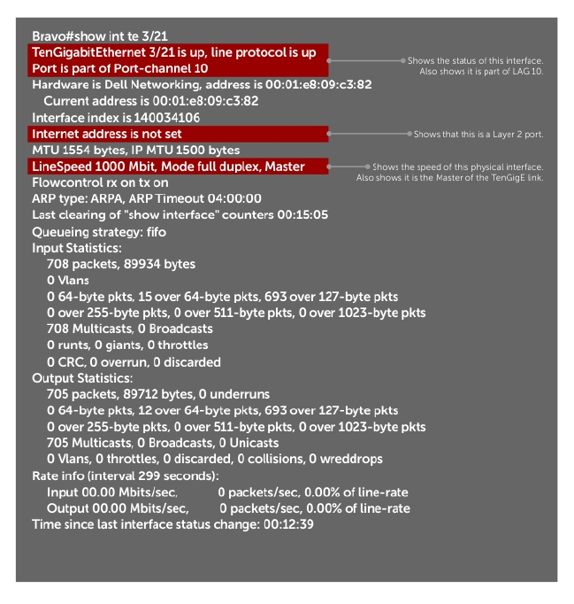
Figure 52. Inspecting a LAG Port on BRAVO Using the show interface Command
Link Aggregation Control Protocol (LACP) 437
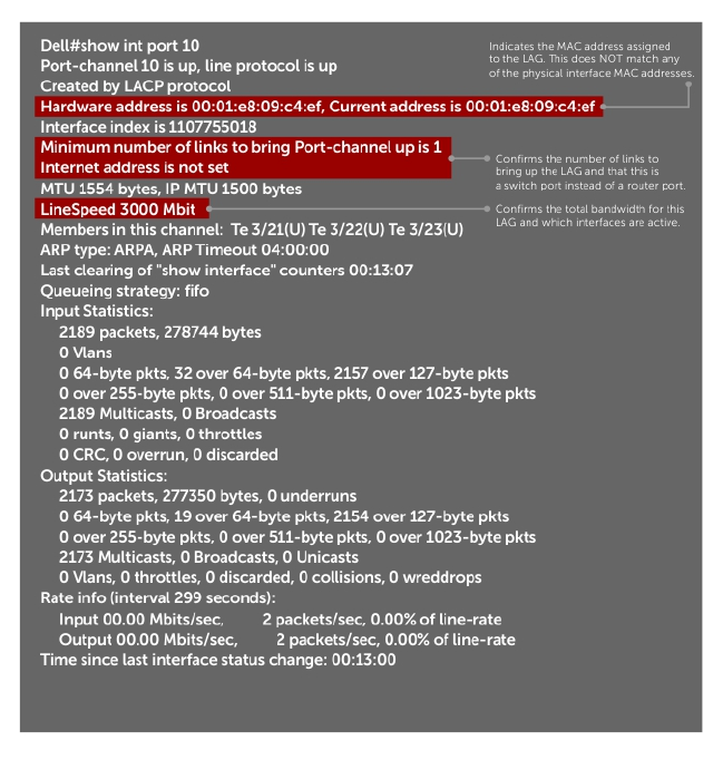
Figure 53. Inspecting LAG 10 Using the show interfaces port-channel Command
438 Link Aggregation Control Protocol (LACP)
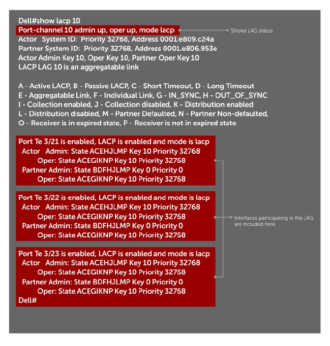
Figure 54. Inspecting the LAG Status Using the show lacp command
The point-to-point protocol (PPP) is a connection-oriented protocol that enables layer two links over
various different physical layer connections. It is supported on both synchronous and asynchronous lines,
and can operate in Half-Duplex or Full-Duplex mode. It was designed to carry IP traffic but is general
enough to allow any type of network layer datagram to be sent over a PPP connection. As its name
implies, it is for point-to-point connections between exactly two devices, and assumes that frames are
sent and received in the same order.
Link Aggregation Control Protocol (LACP) 439

25
Layer 2
This chapter describes the Layer 2 features supported on the Z9500.
Manage the MAC Address Table
You can perform the following management tasks inr the MAC address table.
•Clearing the MAC Address Table
•Setting the Aging Time for Dynamic Entries
•Configuring a Static MAC Address
•Displaying the MAC Address Table
Clearing the MAC Address Table
You may clear the MAC address table of dynamic entries.
To clear a MAC address table, use the following command.
• Clear a MAC address table of dynamic entries.
EXEC Privilege mode
clear mac-address-table {dynamic | sticky} {address | all | interface | vlan}
–address: deletes the specified entry.
–all: deletes all dynamic entries.
–interface: deletes all entries for the specified interface.
–vlan: deletes all entries for the specified VLAN.
Setting the Aging Time for Dynamic Entries
Learned MAC addresses are entered in the table as dynamic entries, which means that they are subject to
aging.
For any dynamic entry, if no packet arrives on the switch with the MAC address as the source or
destination address within the timer period, the address is removed from the table. The default aging time
is 1800 seconds.
To disable a MAC address and specify an aging time, use the following commands.
• Disable MAC address aging for all dynamic entries.
CONFIGURATION mode
mac-address-table aging-time 0
• Specify an aging time.
CONFIGURATION mode
mac-address-table aging-time seconds
440 Layer 2

The range is from 10 to 1000000.
Configuring a Static MAC Address
A static entry is one that is not subject to aging. Enter static entries manually.
To create a static MAC address entry, use the following command.
• Create a static MAC address entry in the MAC address table.
CONFIGURATION mode
mac-address-table static
Displaying the MAC Address Table
To display the MAC address table, use the following command.
• Display the contents of the MAC address table.
EXEC Privilege mode
show mac-address-table [address | aging-time [vlan vlan-id]| count | dynamic
| interface | static | vlan]
–address: displays the specified entry.
–aging-time: displays the configured aging-time.
–count: displays the number of dynamic and static entries for all VLANs, and the total number of
entries.
–dynamic: displays only dynamic entries.
–interface: displays only entries for the specified interface.
–static: displays only static entries.
–vlan: displays only entries for the specified VLAN.
MAC Learning Limit
MAC address learning limit is a method of port security on Layer 2 port-channel and physical interfaces,
and VLANs. It allows you to set an upper limit on the number of MAC addresses that learned on an
interface/VLAN. After the limit is reached, the system drops all traffic from a device with an unlearned
MAC address.
This section describes the following:
•Setting the MAC Learning Limit
•mac learning-limit Dynamic
•mac learning-limit mac-address-sticky
•mac learning-limit station-move
•Learning Limit Violation Actions
•Setting Station Move Violation Actions
•Recovering from Learning Limit and Station Move Violations
Dell Networking OS Behavior: When configuring the MAC learning limit on a port or VLAN, the
configuration is accepted (becomes part of running-config and show mac learning-limit
Layer 2 441

interface) before the system verifies that sufficient CAM space exists. If the CAM check fails, a message
is displayed:
%E90MH:5 %ACL_AGENT-2-ACL_AGENT_LIST_ERROR: Unable to apply access-list Mac-
Limit on TengigabitEthernet 5/84
In this case, the configuration is still present in the running-config and show output. Remove the
configuration before re-applying a MAC learning limit with a lower value. Also, ensure that you can view
the Syslog messages on your session.
Setting the MAC Learning Limit
To set a MAC learning limit on an interface, use the following command.
• Specify the number of MAC addresses that the system can learn off a Layer 2 interface.
INTERFACE mode
mac learning-limit address_limit
Three options are available with the mac learning-limit command:
–dynamic
–no-station-move
–station-move
NOTE: An SNMP trap is available for mac learning-limit station-move. No other SNMP
traps are available for MAC Learning Limit, including limit violations.
mac learning-limit Dynamic
The MAC address table is stored on the Layer 2 forwarding information base (FIB) region of the CAM.
The Layer 2 FIB region allocates space for static MAC address entries and dynamic MAC address entries.
When you enable MAC learning limit, entries created on this port are static by default. When you
configure the dynamic option, learned MAC addresses are stored in the dynamic region and are subject
to aging. Entries created before this option is set are not affected.
Dell Networking OS Behavior: If you do not configure the dynamic option, the system does not detect
station moves in which a MAC address learned off of a MAC-limited port is learned on another port on
same line card. Therefore, any configured violation response to detected station moves is not performed.
When a MAC address is relearned on any other line card (any line card except the one to which the
original MAC-limited port belongs), the station-move is detected and the system takes the configured the
violation action.
mac learning-limit mac-address-sticky
Using sticky MAC addresses allows you to associate a specific port with MAC addresses from trusted
devices. If you enable sticky MAC, the specified port retains any dynamically-learned addresses and
prevents them from being transferred or learned on other ports. Up to 1000 sticky entries are supported
on a port.
If you configure mac-learning-limit and you enabled sticky MAC, all dynamically-learned addresses
are converted to sticky MAC addresses for the selected port. Any new MAC addresses learned on the port
are converted to sticky MAC addresses.
442 Layer 2

To save all sticky MAC addresses into a configuration file that can be used as a startup configuration file,
use the write config command. If the number of existing MAC addresses is fewer than the configured
MAC learning limit, additional MAC addresses are converted to sticky MACs addresse on the port. To
remove all sticky MAC addresses from the running configuration file, disable sticky MAC and enter the
write config command.
When you enable sticky MAC on an interface, dynamically-learned MAC addresses do not age, even if
you enabled mac-learning-limit dynamic. If you configured mac-learning-limit and mac-
learning-limit dynamic and you disabled sticky MAC, any dynamically-learned MAC address ages.
mac learning-limit station-move
The mac learning-limit station-move command allows a MAC address already in the table to be
learned from another interface.
For example, if you disconnect a network device from one interface and reconnect it to another
interface, the MAC address is learned on the new interface. When the system detects this “station move,”
the system clears the entry learned on the original interface and installs a new entry on the new interface.
mac learning-limit no-station-move
The no-station-move option, also known as “sticky MAC,” provides additional port security by
preventing a station move.
When you configure this option, the first entry in the table is maintained instead of creating an entry on
the new interface. no-station-move is the default behavior. Entries created before you set this option
are not affected.
To display a list of all interfaces with a MAC learning limit, use the following command.
Display a list of all interfaces with a MAC learning limit.
EXEC Privilege mode
show mac learning-limit
Dell Networking OS Behavior: The systems do not generate a station-move violation log entry for
physical interfaces or port-channels when you configure mac learning-limit or when you configure
mac learning-limit station-move-violation log. The system detects a station-move violation
only when you configure mac learning-limit dynamic and logs the violation only when you
configure the mac learning-limit station-move-violation log, as shown in the following
example.
Dell(conf-if-te-1/1)#show config
!
interface TengigabitEthernet 1/1
no ip address
switchport
mac learning-limit 1 dynamic no-station-move
mac learning-limit station-move-violation log
no shutdown
Layer 2 443
Learning Limit Violation Actions
Learning limit violation actions are user-configurable.
To configure the system to take an action when the MAC learning limit is reached on an interface and a
new address is received using one the following options with the mac learning-limit command, use
the following commands.
• Generate a system log message when the MAC learning limit is exceeded.
INTERFACE mode
learn-limit-violation log
• Shut down the interface and generate a system log message when the MAC learning limit is
exceeded.
INTERFACE mode
learn-limit-violation shutdown
Setting Station Move Violation Actions
Station move violation actions are user-configurable.
no-station-move is the default behavior. You can configure the system to take an action if a station
move occurs using one the following options with the mac learning-limit command.
To display a list of interfaces configured with MAC learning limit or station move violation actions, use the
following commands.
• Generate a system log message indicating a station move.
INTERFACE mode
station-move-violation log
• Shut down the first port to learn the MAC address.
INTERFACE mode
station-move-violation shutdown-original
• Shut down the second port to learn the MAC address.
INTERFACE mode
station-move-violation shutdown-offending
• Shut down both the first and second port to learn the MAC address.
INTERFACE mode
station-move-violation shutdown-both
• Display a list of all of the interfaces configured with MAC learning limit or station move violation.
CONFIGURATION mode
show mac learning-limit violate-action
Recovering from Learning Limit and Station Move Violations
After a learning-limit or station-move violation shuts down an interface, you must manually reset it.
To reset the learning limit, use the following commands.
444 Layer 2
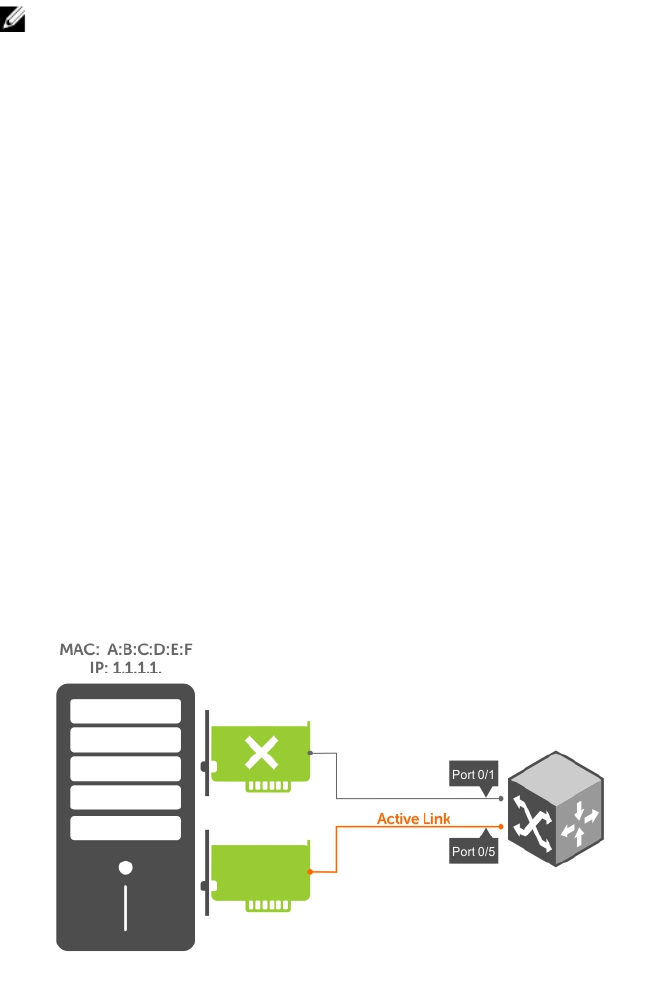
NOTE: Alternatively, you can reset the interface by shutting it down using the shutdown command
and then re-enabling it using the no shutdown command.
• Reset interfaces in the ERR_Disabled state caused by a learning limit violation or station move
violation.
EXEC Privilege mode
mac learning-limit reset
• Reset interfaces in the ERR_Disabled state caused by a learning limit violation.
EXEC Privilege mode
mac learning-limit reset learn-limit-violation [interface | all]
• Reset interfaces in the ERR_Disabled state caused by a station move violation.
EXEC Privilege mode
mac learning-limit reset station-move-violation [interface | all]
NIC Teaming
Network interface controller (NIC) teaming is a feature that allows multiple network interface cards in a
server to be represented by one MAC address and one IP address in order to provide transparent
redundancy, balancing, and to fully utilize network adapter resources.
The following illustration shows a topology where two NICs have been teamed together. In this case, if
the primary NIC fails, traffic switches to the secondary NIC because they are represented by the same set
of addresses.
Figure 55. Redundant NICs with NIC Teaming
When you use NIC teaming, consider that the server MAC address is originally learned on Port 0/1 of the
switch (shown in the following) and Port 0/5 is the failover port. When the NIC fails, the system
automatically sends an ARP request for the gateway or host NIC to resolve the ARP and refresh the egress
interface. When the ARP is resolved, the same MAC address is learned on the same port where the ARP is
resolved (in the previous example, this location is Port 0/5 of the switch). To ensure that the MAC address
is disassociated with one port and re-associated with another port in the ARP table, configure the mac-
Layer 2 445

address-table station-move refresh-arp command on the switch at the time that NIC teaming
is being configured on the server.
NOTE: If you do not configure the mac-address-table station-move refresh-arp
command, traffic continues to be forwarded to the failed NIC until the ARP entry on the switch
times out.
Figure 56. Configuring the mac-address-table station-move refresh-arp Command
Configure Redundant Pairs
Networks that employ switches that do not support the spanning tree protocol (STP) — for example,
networks with digital subscriber line access multiplexers (DSLAM) — cannot have redundant links
between switches because they create switching loops (as shown in the following illustration).
The redundant pairs feature allows you to create redundant links in networks that do not use STP by
configuring backup interfaces for the interfaces on either side of the primary link.
NOTE: For more information about STP, refer to Spanning Tree Protocol (STP).
Assign a backup interface to an interface using the switchport backup command. The backup
interface remains in a Down state until the primary fails, at which point it transitions to Up state. If the
primary interface fails, and later comes up, it becomes the backup interface for the redundant pair. The
system supports 10 Gigabit and 40-Gigabit interfaces as backup interfaces.
Apply all other configurations to each interface in the redundant pair such that their configurations are
identical, so that transition to the backup interface in the event of a failure is transparent to rest of the
network.
446 Layer 2
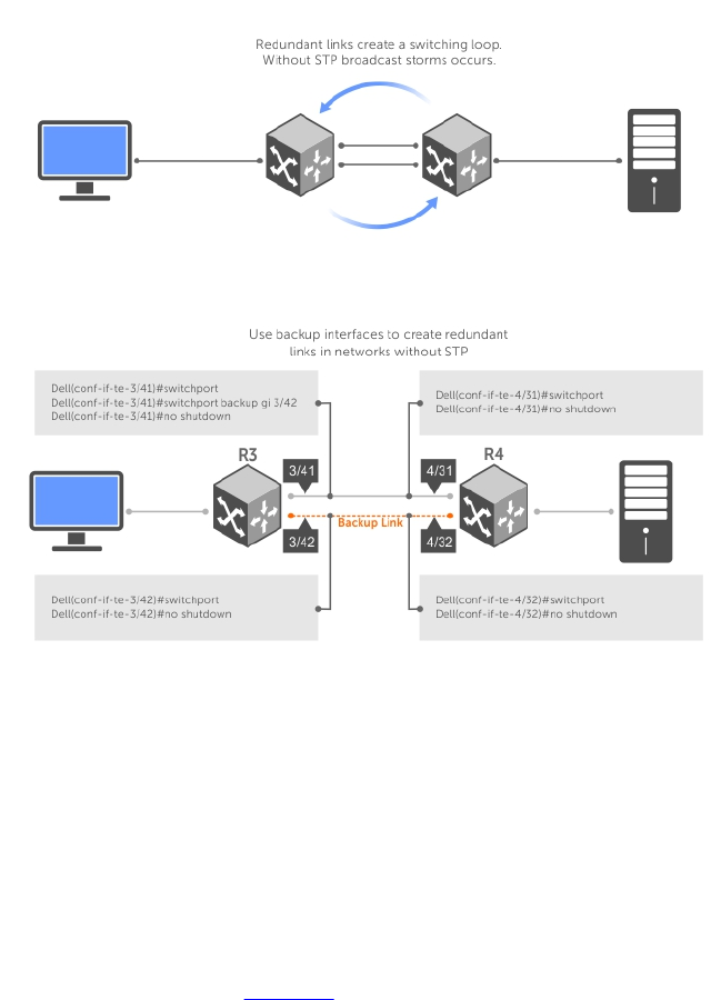
Figure 57. Configuring Redundant Layer 2 Pairs without Spanning Tree
You configure a redundant pair by assigning a backup interface to a primary interface with the
switchport backup interface command. Initially, the primary interface is active and transmits traffic
and the backup interface remains down. If the primary fails for any reason, the backup transitions to an
active Up state. If the primary interface fails and later comes back up, it remains as the backup interface
for the redundant pair.
The system supports only 10 Gigabit and 40-Gigabit ports and port channels as primary/backup
interfaces in redundant pairs. (A port channel is also referred to as a link aggregation group (LAG). For
more information, refer to Interfaces) If the interface is a member link of a LAG, the following primary/
backup interfaces are also supported:
• primary interface is a physical interface, the backup interface can be a physical interface
• primary interface is a physical interface, the backup interface can be a static or dynamic LAG
• primary interface is a static or dynamic LAG, the backup interface can be a physical interface
• primary interface is a static or dynamic LAG, the backup interface can be a static or dynamic LAG
In a redundant pair, any combination of physical and port-channel interfaces is supported as the two
interfaces in a redundant pair. For example, you can configure a static (without LACP) or dynamic (with
LACP) port-channel interface as either the primary or backup link in a redundant pair with a physical
interface.
Layer 2 447

To ensure that existing network applications see no difference when a primary interface in a redundant
pair transitions to the backup interface, be sure to apply identical configurations of other traffic
parameters to each interface.
If you remove an interface in a redundant link (remove the line card of a physical interface or delete a
port channel with the no interface port-channel command), the redundant pair configuration is
also removed.
Important Points about Configuring Redundant Pairs
• You may not configure any interface to be a backup for more than one interface, no interface can
have more than one backup, and a backup interface may not have a backup interface.
• The active or backup interface may not be a member of a LAG.
• The active and standby do not have to be of the same type (1G, 10G, and so on).
• You may not enable any Layer 2 protocol on any interface of a redundant pair or to ports connected
to them.
As shown in the previous illustration, interface 3/41 is a backup interface for 3/42, and 3/42 is in the
Down state. If 3/41 fails, 3/42 transitions to the Up state, which makes the backup link active. A message
similar to the following message appears whenever you configure a backup port.
02:28:04: %SYSTEM-P:CP %IFMGR-5-L2BKUP_WARN: Do not run any Layer2 protocols on
Te 3/41
and Te 3/42
02:28:04: %SYSTEM-P:CP %IFMGR-5-OSTATE_DN: Changed interface state to down: Te 3/42
02:28:04: %SYSTEM-P:CP %IFMGR-5-STATE_ACT_STBY: Changed interface state to
standby: Te
3/42
Example of Configuring Redundant Layer 2 Pairs
Dell(conf-if-range-te-3/41-42)#switchport backup interface TengigabitEthernet
3/42
Dell(conf-if-range-te-3/41-42)#show config
!
interface TengigabitEthernet 3/41
no ip address
switchport
switchport backup interface TengigabitEthernet 3/42
no shutdown
!
interface TengigabitEthernet 3/42
no ip address
switchport
no shutdown
Dell(conf-if-range-te-3/41-42)#
Dell(conf-if-range-te-3/41-42)#do show ip int brief | find 3/41
TengigabitEthernet 3/41 unassigned YES Manual up up
TengigabitEthernet 3/42 unassigned NO Manual up down
[output omitted]
Dell(conf-if-range-te-3/41-42)#interface tengig 3/41
Dell(conf-if-te-3/41)#shutdown
00:24:53: %SYSTEM-P:CP %IFMGR-5-ASTATE_DN: Changed interface Admin state to
down: Te 3/41
Dell(conf-if-te-3/41)#00:24:55: %SYSTEM-P:CP %IFMGR-5-OSTATE_DN: Changed
interface state to
down: Te 3/41
00:24:55: %SYSTEM-P:CP %IFMGR-5-INACTIVE: Changed Vlan interface state to
inactive: Vl 1
00:24:55: %SYSTEM-P:CP %IFMGR-5-OSTATE_UP: Changed interface state to up: Te
3/42
448 Layer 2

00:24:55: %SYSTEM-P:CP %IFMGR-5-ACTIVE: Changed Vlan interface state to active:
Vl 1
00:24:55: %SYSTEM-P:CP %IFMGR-5-STATE_STBY_ACT: Changed interface state from standby to
active:
Te 3/42
Dell(conf-if-te-3/41)#do show ip int brief | find 3/41
TengigabitEthernet 3/41 unassigned NO Manual administratively down down
TengigabitEthernet 3/42 unassigned YES Manual up up
[output omitted]
Example of Configuring Redundant Pairs on a Port-Channel
Dell#show interfaces port-channel brief
Codes: L - LACP Port-channel
LAG Mode Status Uptime Ports
1 L2 up 00:08:33 Te 0/0 (Up)
2 L2 up 00:00:02 Te 0/1 (Up)
Dell#configure
Dell(conf)#interface port-channel 1
Dell(conf-if-po-1)#switchport backup interface port-channel 2
Apr 9 00:15:13: %STKUNIT0-M:CP %IFMGR-5-L2BKUP_WARN: Do not run any Layer2
protocols on Po 1 and Po 2
Apr 9 00:15:13: %STKUNIT0-M:CP %IFMGR-5-OSTATE_DN: Changed interface state to
down: Po 2
Apr 9 00:15:13: %STKUNIT0-M:CP %IFMGR-5-STATE_ACT_STBY: Changed interface state
to standby: Po 2
Dell(conf-if-po-1)#
Dell#
Dell#show interfaces switchport backup
Interface Status Paired Interface Status
Port-channel 1 Active Port-chato mannel 2 Standby
Port-channel 2 Standby Port-channel 1 Active
Dell#
Dell(conf-if-po-1)#switchport backup interface tengigabitethernet 0/2
Apr 9 00:16:29: %STKUNIT0-M:CP %IFMGR-5-L2BKUP_WARN: Do not run any Layer2
protocols on Po 1 and Te 0/2
Dell(conf-if-po-1)#
Far-End Failure Detection
Far-end failure detection (FEFD) is a protocol that senses remote data link errors in a network. FEFD
responds by sending a unidirectional report that triggers an echoed response after a specified time
interval.
You can enable FEFD globally or locally on an interface basis. Disabling the global FEFD configuration
does not disable the interface configuration.
Layer 2 449
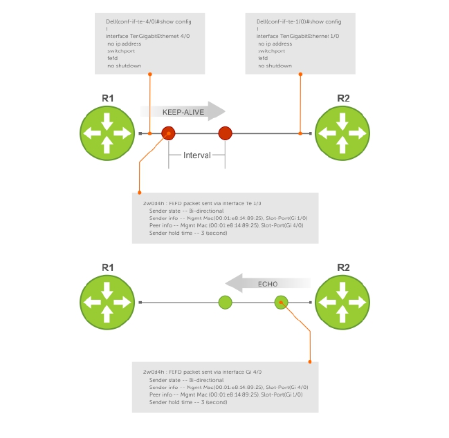
Figure 58. Configuring Far-End Failure Detection
The report consists of several packets in SNAP format that are sent to the nearest known MAC address.
In the event of a far-end failure, the device stops receiving frames and, after the specified time interval,
assumes that the far-end is not available. The connecting line protocol is brought down so that upper
layer protocols can detect the neighbor unavailability faster.
FEFD State Changes
FEFD has two operational modes, Normal and Aggressive.
When you enable Normal mode on an interface and a far-end failure is detected, no intervention is
required to reset the interface to bring it back to an FEFD operational state. When you enable Aggressive
mode on an interface in the same state, manual intervention is required to reset the interface.
FEFD enabled systems (comprised of one or more interfaces) automatically switchs between four
different states: Idle, Unknown, Bi-directional, and Err-disabled.
1. An interface on which FEFD is not configured is in Normal mode by default.
2. After you enable FEFD on an interface, it transitions to the Unknown state and sends an FEFD packet
to the remote end of the link.
3. When the local interface receives the echoed packet from the remote end, the local interface
transitions to the Bi-directional state.
450 Layer 2

4. If the FEFD enabled system is configured to use FEFD in Normal mode and neighboring echoes are
not received after three intervals, (you can set each interval can be set between 3 and 300 seconds)
the state changes to unknown.
5. If the FEFD system has been set to Aggressive mode and neighboring echoes are not received after
three intervals, the state changes to Err-disabled. You must manually reset all interfaces in the Err-
disabled state using the fefd reset [interface] command in EXEC privilege mode (it can be
done globally or one interface at a time) before the FEFD enabled system can become operational
again.
Table 16. State Change When Configuring FEFD
Local
Event Mode Local State Remote
State Local
Admin
Status
Local
Protocol
Status
Remote
Admin
Status
Remote
Protocol
Status
Shutdown Normal Admin
Shutdown
Unknown Down Down Up Down
Shutdown Aggressive Admin
Shutdown
Err-
disabled
Up Down Up Down
FEFD
enable
Normal Bi-
directional
Bi-
directional
Up Up Up Up
FEFD
enable
Aggressive Bi-
directional
Bi-
directional
Up Up Up Up
FEFD +
FEFD
disable
Normal Locally
disabled
Unknown Up Down Up Down
FEFD +
FEFD
disable
Aggressive Locally
disabled
Err-
disabled
Up Down Up Down
Link Failure Normal Unknown Unknown Up Down Up Down
Link Failure Aggressive Err-
disabled
Err-
disabled
Up Down Up Down
Important Points to Remember
• You can enable FEFD globally or on a per-interface basis. Interface FEFD configurations override
global FEFD configurations.
• The system supports FEFD on physical Ethernet interfaces only, excluding the management interface.
Configuring FEFD
You can configure FEFD for all interfaces from CONFIGURATION mode, or on individual interfaces from
INTERFACE mode.
To enable FEFD globally on all interfaces, use the following command.
• Enable FEFD globally on all interfaces.
CONFIGURATION mode
fefd-global
Layer 2 451

To report interval frequency and mode adjustments, use the following commands.
1. Setup two or more connected interfaces for Layer 2 or Layer 3.
INTERFACE mode
ip address ip address, switchport
2. Activate the necessary ports administratively.
INTEFACE mode
no shutdown
3. Enable fefd globally.
CONFIGURATION mode
fefd {interval | mode}
Example of the show fefd Command
To display information about the state of each interface, use the show fefd command in EXEC privilege
mode.
Dell#show fefd
FEFD is globally 'ON', interval is 3 seconds, mode is 'Normal'.
INTERFACE MODE INTERVAL STATE
(second)
Te 1/0 Normal 3 Bi-directional
Te 1/1 Normal 3 Admin Shutdown
Te 1/2 Normal 3 Admin Shutdown
Te 1/3 Normal 3 Admin Shutdown
Dell#show run fefd
!
fefd-global mode normal
fefd-global interval 3
Enabling FEFD on an Interface
To enable, change, or disable FEFD on an interface, use the following commands.
• Enable FEFD on a per interface basis.
INTERFACE mode
fefd
• Change the FEFD mode.
INTERFACE mode
fefd [mode {aggressive | normal}]
• Disable FEFD protocol on one interface.
INTERFACE mode
fefd disable
Disabling an interface shuts down all protocols working on that interface’s connected line. It does not
delete your previous FEFD configuration which you can enable again at any time.
452 Layer 2

To set up and activate two or more connected interfaces, use the following commands.
1. Setup two or more connected interfaces for Layer 2 or Layer 3.
INTERFACE mode
ip address ip address, switchport
2. Activate the necessary ports administratively.
INTERFACE mode
no shutdown
3. INTERFACE mode
fefd {disable | interval | mode}
Example of Viewing FEFD Configuration
Dell(conf-if-te-1/0)#show config
!
interface TengigabitEthernet 1/0
no ip address
switchport
fefd mode normal
no shutdown
Dell(conf-if-te-1/0)#do show fefd | grep 1/0
Te 1/0 Normal 3 Unknown
Debugging FEFD
To debug FEFD, use the first command. To provide output for each packet transmission over the FEFD
enabled connection, use the second command.
• Display output whenever events occur that initiate or disrupt an FEFD enabled connection.
EXEC Privilege mode
debug fefd events
• Provide output for each packet transmission over the FEFD enabled connection.
EXEC Privilege mode
debug fefd packets
Examples of the debug fefd Commands
The following example shows the debug fefd events command.
Dell#debug fefd events
Dell#config
Dell(conf)#int te 1/0
Dell(conf-if-te-1/0)#shutdown
2w1d22h: %SYSTEM-P:CP %IFMGR-5-ASTATE_DN: Changed interface Admin state to
down: Te 1/0
Dell(conf-if-te-1/0)#2w1d22h : FEFD state on Te 1/0 changed from ANY to Unknown
2w1d22h: %SYSTEM-P:CP %IFMGR-5-OSTATE_DN: Changed interface state to down: Te
1/0
2w1d22h: %SYSTEM-P:CP %IFMGR-5-OSTATE_DN: Changed interface state to down: Te
4/0
2w1d22h: %SYSTEM-P:CP %IFMGR-5-INACTIVE: Changed Vlan interface state to
Layer 2 453

inactive: Vl 1
2w1d22h : FEFD state on Te 4/0 changed from Bi-directional to Unknown
The following example shows the debug fefd packets command.
Dell#debug fefd packets
Dell#2w1d22h : FEFD packet sent via interface Te 1/0
Sender state -- Bi-directional
Sender info -- Mgmt Mac(00:01:e8:14:89:25), Slot-Port(Te 1/0)
Peer info -- Mgmt Mac (00:01:e8:14:89:25), Slot-Port(Te 4/0)
Sender hold time -- 3 (second)
2w1d22h : FEFD packet received on interface Te 4/0
Sender state -- Bi-directional
Sender info -- Mgmt Mac(00:01:e8:14:89:25), Slot-Port(Te 1/0)
Peer info -- Mgmt Mac (00:01:e8:14:89:25), Slot-Port(Te 4/0)
Sender hold time -- 3 (second)
454 Layer 2

26
Link Layer Discovery Protocol (LLDP)
This chapter describes how to configure and use the link layer discovery protocol (LLDP) on the Z9500
switch.
802.1AB (LLDP) Overview
LLDP — defined by IEEE 802.1AB — is a protocol that enables a local area network (LAN) device to
advertise its configuration and receive configuration information from adjacent LLDP-enabled LAN
infrastructure devices.
The collected information is stored in a management information base (MIB) on each device, and is
accessible via simple network management protocol (SNMP).
Protocol Data Units
Configuration information is exchanged in the form of Type, Length, Value (TLV) segments.
• Type — The kind of information included in the TLV.
• Length — The value, in octets, of the TLV after the Length field.
• Value — The configuration information that the agent is advertising.
The chassis ID TLV is shown in the following illustration.
Figure 59. Type, Length, Value (TLV) Segment
TLVs are encapsulated in a frame called an LLDP data unit (LLDPDU) (shown in the following table), which
is transmitted from one LLDP-enabled device to its LLDP-enabled neighbors. LLDP is a one-way
protocol. LLDP-enabled devices (LLDP agents) can transmit and/or receive advertisements, but they
cannot solicit and do not respond to advertisements.
There are five types of TLVs. All types are mandatory in the construction of an LLDPDU except Optional
TLVs. You can configure the inclusion of individual Optional TLVs.
Link Layer Discovery Protocol (LLDP) 455

Table 17. Type, Length, Value (TLV) Types
Type TLV Description
0 End of LLDPDU Marks the end of an LLDPDU.
1 Chassis ID An administratively assigned
name that identifies the LLDP
agent.
2 Port ID An administratively assigned
name that identifies a port
through which TLVs are sent and
received.
3 Time to Live An administratively assigned
name that identifies a port
through which TLVs are sent and
received.
— Optional Includes sub-types of TLVs that
advertise specific configuration
information. These sub-types are
Management TLVs, IEEE 802.1,
IEEE 802.3, and TIA-1057
Organizationally Specific TLVs.
Figure 60. LLDPDU Frame
Optional TLVs
The Dell Networking OS) upports these optional TLVs: management TLVs, IEEE 802.1 and 802.3
organizationally specific TLVs, and TIA-1057 organizationally specific TLVs.
Management TLVs
A management TLV is an optional TLVs sub-type. This kind of TLV contains essential management
information about the sender.
Organizationally Specific TLVs
A professional organization or a vendor can define organizationally specific TLVs. They have two
mandatory fields (as shown in the following illustration) in addition to the basic TLV fields.
456 Link Layer Discovery Protocol (LLDP)
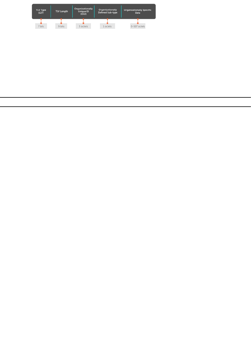
Figure 61. Organizationally Specific TLV
IEEE Organizationally Specific TLVs
Eight TLV types have been defined by the IEEE 802.1 and 802.3 working groups as a basic part of LLDP;
the IEEE OUI is 00-80-C2. You can configure the Dell Networking system to advertise any or all of these
TLVs.
Table 18. Optional TLV Types
Type TLV Description
Optional TLVs
4 Port description A user-defined alphanumeric
string that describes the port. The
Dell Networking OS does not
currently support this TLV.
5 System name A user-defined alphanumeric
string that identifies the system.
6 System description A user-defined alphanumeric
string that identifies the system.
7 System capabilities Identifies the chassis as one or
more of the following: repeater,
bridge, WLAN Access Point,
Router, Telephone, DOCSIS cable
device, end station only, or other.
8 Management address Indicates the network address of
the management interface. The
Dell Networking OS does not
currently support this TLV.
IEEE 802.1 Organizationally
Specific TLVs
127 Port-VLAN ID On Dell Networking systems,
indicates the untagged VLAN to
which a port belongs.
127 Port and Protocol VLAN ID On Dell Networking systems,
indicates the tagged VLAN to
which a port belongs (and the
untagged VLAN to which a port
belongs if the port is in Hybrid
mode).
Link Layer Discovery Protocol (LLDP) 457

Type TLV Description
127 Protocol Identity Indicates the protocols that the
port can process. The Dell
Networking OS does not
currently support this TLV.
IEEE 802.3 Organizationally
Specific TLVs
127 MAC/PHY Configuration/Status Indicates the capability and
current setting of the duplex
status and bit rate, and whether
the current settings are the result
of auto-negotiation. This TLV is
not available in the Dell
Networking OS implementation
of LLDP, but is available and
mandatory (non-configurable) in
the LLDP-MED implementation.
127 Power via MDI Dell Networking supports the
LLDP-MED protocol, which
recommends that Power via MDI
TLV be not implemented, and
therefore Dell Networking
implements Extended Power via
MDI TLV only.
127 Link Aggregation Indicates whether the link is
capable of being aggregated,
whether it is currently in a LAG,
and the port identification of the
LAG. The Dell Networking OS
does not currently support this
TLV.
127 Maximum Frame Size Indicates the maximum frame
size capability of the MAC and
PHY.
TIA-1057 (LLDP-MED) Overview
Link layer discovery protocol — media endpoint discovery (LLDP-MED) as defined by ANSI/ TIA-1057—
provides additional organizationally specific TLVs so that endpoint devices and network connectivity
devices can advertise their characteristics and configuration information; the OUI for the
Telecommunications Industry Association (TIA) is 00-12-BB.
•LLDP-MED Endpoint Device — any device that is on an IEEE 802 LAN network edge can
communicate using IP and uses the LLDP-MED framework.
•LLDP-MED Network Connectivity Device — any device that provides access to an IEEE 802 LAN to an
LLDP-MED endpoint device and supports IEEE 802.1AB (LLDP) and TIA-1057 (LLDP-MED). The Dell
Networking system is an LLDP-MED network connectivity device.
458 Link Layer Discovery Protocol (LLDP)

Regarding connected endpoint devices, LLDP-MED provides network connectivity devices with the ability
to:
• manage inventory
• manage Power over Ethernet (PoE)
• identify physical location
• identify network policy
LLDP-MED is designed for, but not limited to, VoIP endpoints.
TIA Organizationally Specific TLVs
The Dell Networking system is an LLDP-MED Network Connectivity Device (Device Type 4).
Network connectivity devices are responsible for:
• transmitting an LLDP-MED capability TLV to endpoint devices
• storing the information that endpoint devices advertise
The following table describes the five types of TIA-1057 Organizationally Specific TLVs.
Table 19. TIA-1057 (LLDP-MED) Organizationally Specific TLVs
Type SubType TLV Description
127 1 LLDP-MED Capabilities Indicates:
• whether the
transmitting device
supports LLDP-MED
• what LLDP-MED
TLVs it supports
• LLDP device class
127 2 Network Policy Indicates the application
type, VLAN ID, Layer 2
Priority, and DSCP value.
127 3 Location Identification Indicates that the
physical location of the
device expressed in one
of three possible
formats:
• Coordinate Based
LCI
• Civic Address LCI
• Emergency Call
Services ELIN
127 4 Location Identification Indicates power
requirements, priority,
and power status.
Inventory Management
TLVs
Implementation of this
set of TLVs is optional in
LLDP-MED devices.
Link Layer Discovery Protocol (LLDP) 459

Type SubType TLV Description
None or all TLVs must
be supported. The Dell
Networking OS does not
currently support these
TLVs.
127 5 Inventory — Hardware
Revision
Indicates the hardware
revision of the LLDP-
MED device.
127 6 Inventory — Firmware
Revision
Indicates the firmware
revision of the LLDP-
MED device.
127 7 Inventory — Software
Revision
Indicates the software
revision of the LLDP-
MED device.
127 8 Inventory — Serial
Number
Indicates the device
serial number of the
LLDP-MED device.
127 9 Inventory —
Manufacturer Name
Indicates the
manufacturer of the
LLDP-MED device.
127 10 Inventory — Model
Name
Indicates the model of
the LLDP-MED device.
127 11 Inventory — Asset ID Indicates a user
specified device number
to manage inventory.
127 12–255 Reserved —
LLDP-MED Capabilities TLV
The LLDP-MED capabilities TLV communicates the types of TLVs that the endpoint device and the
network connectivity device support. LLDP-MED network connectivity devices must transmit the
Network Policies TLV.
• The value of the LLDP-MED capabilities field in the TLV is a 2–octet bitmap, each bit represents an
LLDP-MED capability (as shown in the following table).
• The possible values of the LLDP-MED device type are shown in the following. The Dell Networking
system is a network connectivity device, which is Type 4.
When you enable LLDP-MED (using the advertise med command), the system begins transmitting this
TLV.
460 Link Layer Discovery Protocol (LLDP)
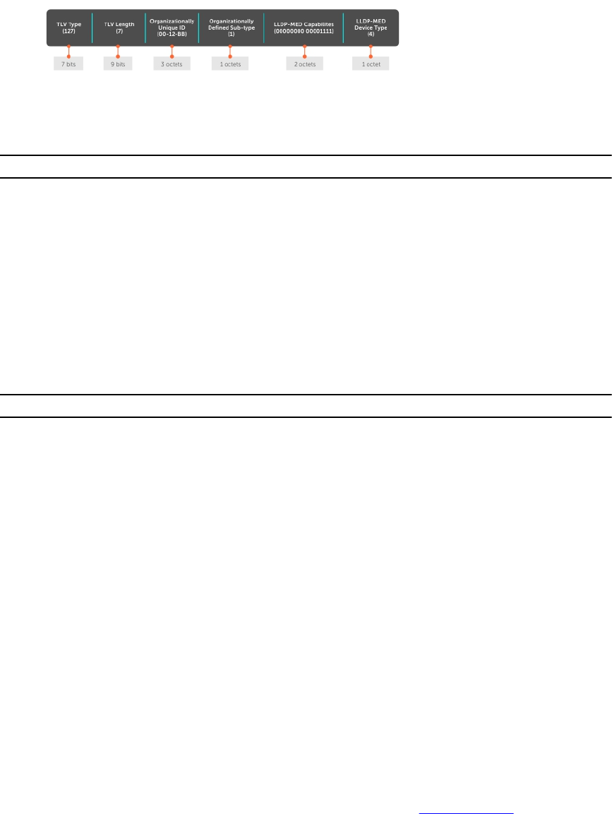
Figure 62. LLDP-MED Capabilities TLV
Table 20. LLDP-MED Capabilities
Bit Position TLV Supported?
0 LLDP-MED Capabilities Yes
1 Network Policy Yes
2 Location Identification Yes
3 Extended Power via MDI-PSE Yes
4 Extended Power via MDI-PD No
5 Inventory No
6–15 reserved No
Table 21. LLDP-MED Device Types
Value Device Type
0 Type Not Defined
1 Endpoint Class 1
2 Endpoint Class 2
3 Endpoint Class 3
4 Network Connectivity
5–255 Reserved
LLDP-MED Network Policies TLV
A network policy in the context of LLDP-MED is a device’s VLAN configuration and associated Layer 2 and
Layer 3 configurations.
LLDP-MED network policies TLV include:
• VLAN ID
• VLAN tagged or untagged status
• Layer 2 priority
• DSCP value
An integer represents the application type (the Type integer shown in the following table), which indicates
a device function for which a unique network policy is defined. An individual LLDP-MED network policy
TLV is generated for each application type that you specify with the CLI (Advertising TLVs).
Link Layer Discovery Protocol (LLDP) 461

NOTE: As shown in the following table, signaling is a series of control packets that are exchanged
between an endpoint device and a network connectivity device to establish and maintain a
connection. These signal packets might require a different network policy than the media packets
for which a connection is made. In this case, configure the signaling application.
Table 22. Network Policy Applications
Type Application Description
0 Reserved —
1 Voice Specify this application type for dedicated IP
telephony handsets and other appliances
supporting interactive voice services.
2 Voice Signaling Specify this application type only if voice control
packets use a separate network policy than voice
data.
3 Guest Voice Specify this application type for a separate
limited voice service for guest users with their
own IP telephony handsets and other appliances
supporting interactive voice services.
4 Guest Voice Signaling Specify this application type only if guest voice
control packets use a separate network policy
than voice data.
5 Softphone Voice Specify this application type only if guest voice
control packets use a separate network policy
than voice data.
6 Video Conferencing Specify this application type for dedicated video
conferencing and other similar appliances
supporting real-time interactive video.
7 Streaming Video Specify this application type for dedicated video
conferencing and other similar appliances
supporting real-time interactive video.
8 Video Signaling Specify this application type only if video control
packets use a separate network policy than video
data.
9–255 Reserved —
Figure 63. LLDP-MED Policies TLV
462 Link Layer Discovery Protocol (LLDP)
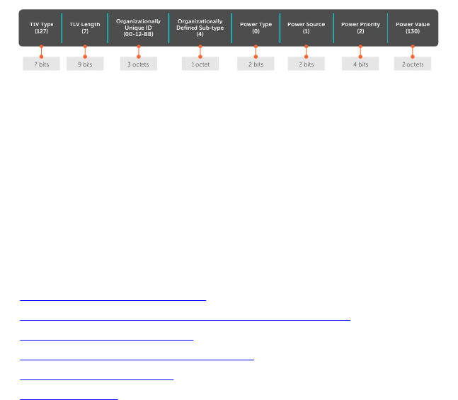
Extended Power via MDI TLV
The extended power via MDI TLV enables advanced PoE management between LLDP-MED endpoints
and network connectivity devices.
Advertise the extended power via MDI on all ports that are connected to an 802.3af powered, LLDP-MED
endpoint device.
•Power Type — there are two possible power types: power source entity (PSE) or power device (PD).
The Dell Networking system is a PSE, which corresponds to a value of 0, based on the TIA-1057
specification.
•Power Source — there are two possible power sources: primary and backup. The Dell Networking
system is a primary power source, which corresponds to a value of 1, based on the TIA-1057
specification.
•Power Priority — there are three possible priorities: Low, High, and Critical. On Dell Networking
systems, the default power priority is High, which corresponds to a value of 2 based on the TIA-1057
specification. You can configure a different power priority through the CLI. Dell Networking also
honors the power priority value the powered device sends; however, the CLI configuration takes
precedence.
•Power Value — Dell Networking advertises the maximum amount of power that can be supplied on
the port. By default the power is 15.4W, which corresponds to a power value of 130, based on the
TIA-1057 specification. You can advertise a different power value using the max-milliwatts option
with the power inline auto | static command. Dell Networking also honors the power value
(power requirement) the powered device sends when the port is configured for power inline
auto.
Figure 64. Extended Power via MDI TLV
Configure LLDP
Configuring LLDP is a two-step process.
1. Enable LLDP globally.
2. Advertise TLVs out of an interface.
Related Configuration Tasks
•Viewing the LLDP Configuration
•Viewing Information Advertised by Adjacent LLDP Agents
•Configuring LLDPDU Intervals
•Configuring Transmit and Receive Mode
•Configuring a Time to Live
•Debugging LLDP
Link Layer Discovery Protocol (LLDP) 463

Important Points to Remember
• LLDP is enabled by default.
• Dell Networking systems support up to eight neighbors per interface.
• Dell Networking systems support a maximum of 8000 total neighbors per system. If the number of
interfaces multiplied by eight exceeds the maximum, the system does not configure more than 8000.
• INTERFACE level configurations override all CONFIGURATION level configurations.
• LLDP is not hitless.
LLDP Compatibility
• Spanning tree and force10 ring protocol “blocked” ports allow LLDPDUs.
• 802.1X controlled ports do not allow LLDPDUs until the connected device is authenticated.
CONFIGURATION versus INTERFACE Configurations
All LLDP configuration commands are available in PROTOCOL LLDP mode, which is a sub-mode of the
CONFIGURATION mode and INTERFACE mode.
• Configurations made at the CONFIGURATION level are global; that is, they affect all interfaces on the
system.
• Configurations made at the INTERFACE level affect only the specific interface; they override
CONFIGURATION level configurations.
Example of the protocol lldp Command (CONFIGURATION Level)
R1(conf)#protocol lldp
R1(conf-lldp)#?
advertise Advertise TLVs
disable Disable LLDP protocol globally
end Exit from configuration mode
exit Exit from LLDP configuration mode
hello LLDP hello configuration
mode LLDP mode configuration (default = rx and tx)
multiplier LLDP multiplier configuration
no Negate a command or set its defaults
show Show LLDP configuration
R1(conf-lldp)#exit
R1(conf)#interface tengigabitethernet 1/31
R1(conf-if-te-1/31)#protocol lldp
R1(conf-if-te-1/31-lldp)#?
advertise Advertise TLVs
disable Disable LLDP protocol on this interface
end Exit from configuration mode
exit Exit from LLDP configuration mode
hello LLDP hello configuration
mode LLDP mode configuration (default = rx and tx)
multiplier LLDP multiplier configuration
no Negate a command or set its defaults
show Show LLDP configuration
R1(conf-if-te-1/31-lldp)#
464 Link Layer Discovery Protocol (LLDP)
Enabling LLDP
LLDP is disabled by default. Enable and disable LLDP globally or per interface. If you enable LLDP globally,
all UP interfaces send periodic LLDPDUs.
To enable LLDP, use the following command.
1. Enter Protocol LLDP mode.
CONFIGURATION or INTERFACE mode
protocol lldp
2. Enable LLDP.
PROTOCOL LLDP mode
no disable
Disabling and Undoing LLDP
To disable or undo LLDP, use the following command.
• Disable LLDP globally or for an interface.
disable
To undo an LLDP configuration, precede the relevant command with the keyword no.
Enabling LLDP on Management Ports
LLDP on management ports is enabled by default.
To enable LLDP on management ports, use the following command.
1. Enter Protocol LLDP mode.
CONFIGURATION mode
protocol lldp
2. Enable LLDP.
PROTOCOL LLDP mode
no disable
Disabling and Undoing LLDP on Management Ports
To disable or undo LLDP on management ports, use the following command.
1. Enter Protocol LLDP mode.
CONFIGURATION mode.
protocol lldp
2. Enter LLDP management-interface mode.
LLDP-MANAGEMENT-INTERFACE mode.
management-interface
Link Layer Discovery Protocol (LLDP) 465
3. Enter the disable command.
LLDP-MANAGEMENT-INTERFACE mode.
To undo an LLDP management port configuration, precede the relevant command with the keyword no.
Advertising TLVs
You can configure the system to advertise TLVs out of all interfaces or out of specific interfaces.
• If you configure the system globally, all interfaces send LLDPDUs with the specified TLVs.
• If you configure an interface, only the interface sends LLDPDUs with the specified TLVs.
• If you configure LLDP both globally and at interface level, the interface level configuration overrides
the global configuration.
To advertise TLVs, use the following commands.
1. Enter LLDP mode.
CONFIGURATION or INTERFACE mode
protocol lldp
2. Advertise one or more TLVs.
PROTOCOL LLDP mode
advertise {management-tlv | dot1-tlv | dot3-tlv | med}
Include the keyword for each TLV you want to advertise.
• For management TLVs: system-capabilities, system-description.
• For 802.1 TLVs: port-protocol-vlan-id, port-vlan-id.
• For 802.3 TLVs: max-frame-size.
• For TIA-1057 TLVs:
–guest-voice
–guest-voice-signaling
–location-identification
–power-via-mdi
–softphone-voice
–streaming-video
–video-conferencing
–video-signaling
–voice
–voice-signaling
In the following example, LLDP is enabled globally. R1 and R2 are transmitting periodic LLDPDUs that
contain management, 802.1, and 802.3 TLVs.
466 Link Layer Discovery Protocol (LLDP)
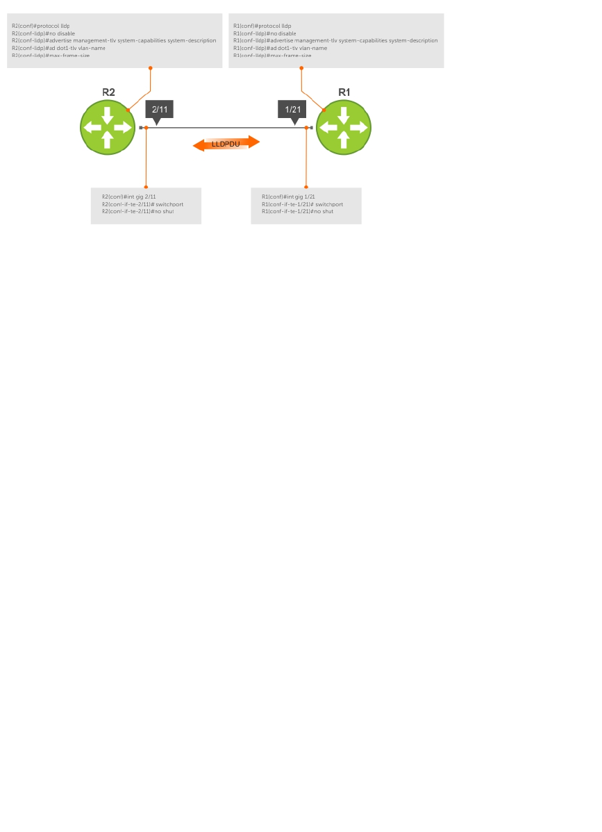
Figure 65. Configuring LLDP
Viewing the LLDP Configuration
To view the LLDP configuration, use the following command.
• Display the LLDP configuration.
CONFIGURATION or INTERFACE mode
show config
Examples of Viewing LLDP Configurations
The following example shows viewing an LLDP global configuration.
R1(conf)#protocol lldp
R1(conf-lldp)#show config
!
protocol lldp
advertise dot1-tlv port-protocol-vlan-id port-vlan-id
advertise dot3-tlv max-frame-size
advertise management-tlv system-capabilities system-description
hello 10
no disable
R1(conf-lldp)#
The following example shows viewing an LLDP interface configuration.
R1(conf-lldp)#exit
R1(conf)#interface tengigabitethernet 1/31
R1(conf-if-te-1/31)#show config
!
interface TengigabitEthernet 1/31
no ip address
switchport
no shutdown
R1(conf-if-te-1/31)#protocol lldp
R1(conf-if-te-1/31-lldp)#show config
!
protocol lldp
R1(conf-if-te-1/31-lldp)#
Link Layer Discovery Protocol (LLDP) 467

Viewing Information Advertised by Adjacent LLDP Agents
To view brief information about adjacent devices or to view all the information that neighbors are
advertising, use the following commands.
• Display brief information about adjacent devices.
show lldp neighbors
• Display all of the information that neighbors are advertising.
show lldp neighbors detail
Examples of Viewing Brief or Detailed Information Advertised by Neighbors
The following example shows viewing brief information advertised by neighbors.
R1(conf-if-te-1/31-lldp)#end
R1(conf-if-te-1/31)#do show lldp neighbors
Loc PortID Rem Host Name Rem Port Id Rem Chassis Id
-------------------------------------------------------------------------
Te 1/21 - TengigabitEthernet 2/11 00:01:e8:06:95:3e
Te 1/31 - TengigabitEthernet 3/11 00:01:e8:09:c2:4a
The following example shows viewing detailed information advertised by neighbors.
R1#show lldp neighbors detail
========================================================================
Local Interface Te 1/21 has 1 neighbor
Total Frames Out: 6547
Total Frames In: 4136
Total Neighbor information Age outs: 0
Total Frames Discarded: 0
Total In Error Frames: 0
Total Unrecognized TLVs: 0
Total TLVs Discarded: 0
Next packet will be sent after 7 seconds
The neighbors are given below:
-----------------------------------------------------------------------
Remote Chassis ID Subtype: Mac address (4)
Remote Chassis ID: 00:01:e8:06:95:3e
Remote Port Subtype: Interface name (5)
Remote Port ID: TengigabitEthernet 2/11
Local Port ID: TengigabitEthernet 1/21
Locally assigned remote Neighbor Index: 4
Remote TTL: 120
Information valid for next 120 seconds
Time since last information change of this neighbor: 01:50:16
Remote MTU: 1554
Remote System Desc: Dell Force10 Networks Real Time Operating System Software
. Dell Force10 Operating System Version: 1.0. Dell Force10 App
lication Software Version: 7.5.1.0. Copyright (c) 19
99-Build Time: Thu Aug 9 01:05:51 PDT 2007
Existing System Capabilities: Repeater Bridge Router
Enabled System Capabilities: Repeater Bridge Router
Remote Port Vlan ID: 1
Port and Protocol Vlan ID: 1, Capability: Supported, Status: Enabled
---------------------------------------------------------------------------
========================================================================
468 Link Layer Discovery Protocol (LLDP)

Configuring LLDPDU Intervals
LLDPDUs are transmitted periodically; the default interval is 30 seconds.
To configure LLDPDU intervals, use the following command.
• Configure a non-default transmit interval.
CONFIGURATION mode or INTERFACE mode
hello
Example of Viewing LLDPDU Intervals
R1(conf)#protocol lldp
R1(conf-lldp)#show config
!
protocol lldp
advertise dot1-tlv port-protocol-vlan-id port-vlan-id
advertise dot3-tlv max-frame-size
advertise management-tlv system-capabilities system-description
no disable
R1(conf-lldp)#mode ?
rx Rx only
tx Tx only
R1(conf-lldp)#mode tx
R1(conf-lldp)#show config
!
protocol lldp
advertise dot1-tlv port-protocol-vlan-id port-vlan-id
advertise dot3-tlv max-frame-size
advertise management-tlv system-capabilities system-description
mode tx
no disable
R1(conf-lldp)#no mode
R1(conf-lldp)#show config
!
protocol lldp
advertise dot1-tlv port-protocol-vlan-id port-vlan-id
advertise dot3-tlv max-frame-size
advertise management-tlv system-capabilities system-description
no disable
R1(conf-lldp)#
Configuring Transmit and Receive Mode
After you enable LLDP, the switch transmits and receives LLDPDUs by default.
To configure the system to transmit or receive only and return to the default, use the following
commands.
• Transmit only.
CONFIGURATION mode or INTERFACE mode
mode tx
• Receive only.
CONFIGURATION mode or INTERFACE mode
mode rx
Link Layer Discovery Protocol (LLDP) 469

• Return to the default setting.
CONFIGURATION mode or INTERFACE mode
no mode
Example of Configuring a Single Mode
R1(conf)#protocol lldp
R1(conf-lldp)#show config
!
protocol lldp
advertise dot1-tlv port-protocol-vlan-id port-vlan-id
advertise dot3-tlv max-frame-size
advertise management-tlv system-capabilities system-description
no disable
R1(conf-lldp)#mode ?
rx Rx only
tx Tx only
R1(conf-lldp)#mode tx
R1(conf-lldp)#show config
!
protocol lldp
advertise dot1-tlv port-protocol-vlan-id port-vlan-id
advertise dot3-tlv max-frame-size
advertise management-tlv system-capabilities system-description
mode tx
no disable
R1(conf-lldp)#no mode
R1(conf-lldp)#show config
!
protocol lldp
advertise dot1-tlv port-protocol-vlan-id port-vlan-id
advertise dot3-tlv max-frame-size
advertise management-tlv system-capabilities system-description
no disable
R1(conf-lldp)#
Configuring a Time to Live
The information received from a neighbor expires after a specific amount of time (measured in seconds)
called a time to live (TTL).
The TTL is the product of the LLDPDU transmit interval (hello) and an integer called a multiplier. The
default multiplier is 4, which results in a default TTL of 120 seconds.
• Adjust the TTL value.
CONFIGURATION mode or INTERFACE mode.
multiplier
• Return to the default multiplier value.
CONFIGURATION mode or INTERFACE mode.
no multiplier
Example of the multiplier Command to Configure Time to Live
R1(conf-lldp)#show config
!
protocol lldp
470 Link Layer Discovery Protocol (LLDP)

advertise dot1-tlv port-protocol-vlan-id port-vlan-id
advertise dot3-tlv max-frame-size
advertise management-tlv system-capabilities system-description
no disable
R1(conf-lldp)#multiplier ?
<2-10> Multiplier (default=4)
R1(conf-lldp)#multiplier 5
R1(conf-lldp)#show config
!
protocol lldp
advertise dot1-tlv port-protocol-vlan-id port-vlan-id
advertise dot3-tlv max-frame-size
advertise management-tlv system-capabilities system-description
multiplier 5
no disable
R1(conf-lldp)#no multiplier
R1(conf-lldp)#show config
!
protocol lldp
advertise dot1-tlv port-protocol-vlan-id port-vlan-id
advertise dot3-tlv max-frame-size
advertise management-tlv system-capabilities system-description
no disable
R1(conf-lldp)#
Debugging LLDP
You can view the TLVs that your system is sending and receiving.
To view the TLVs, use the following commands.
• View a readable version of the TLVs.
debug lldp brief
• View a readable version of the TLVs plus a hexadecimal version of the entire LLDPDU.
debug lldp detail
Link Layer Discovery Protocol (LLDP) 471
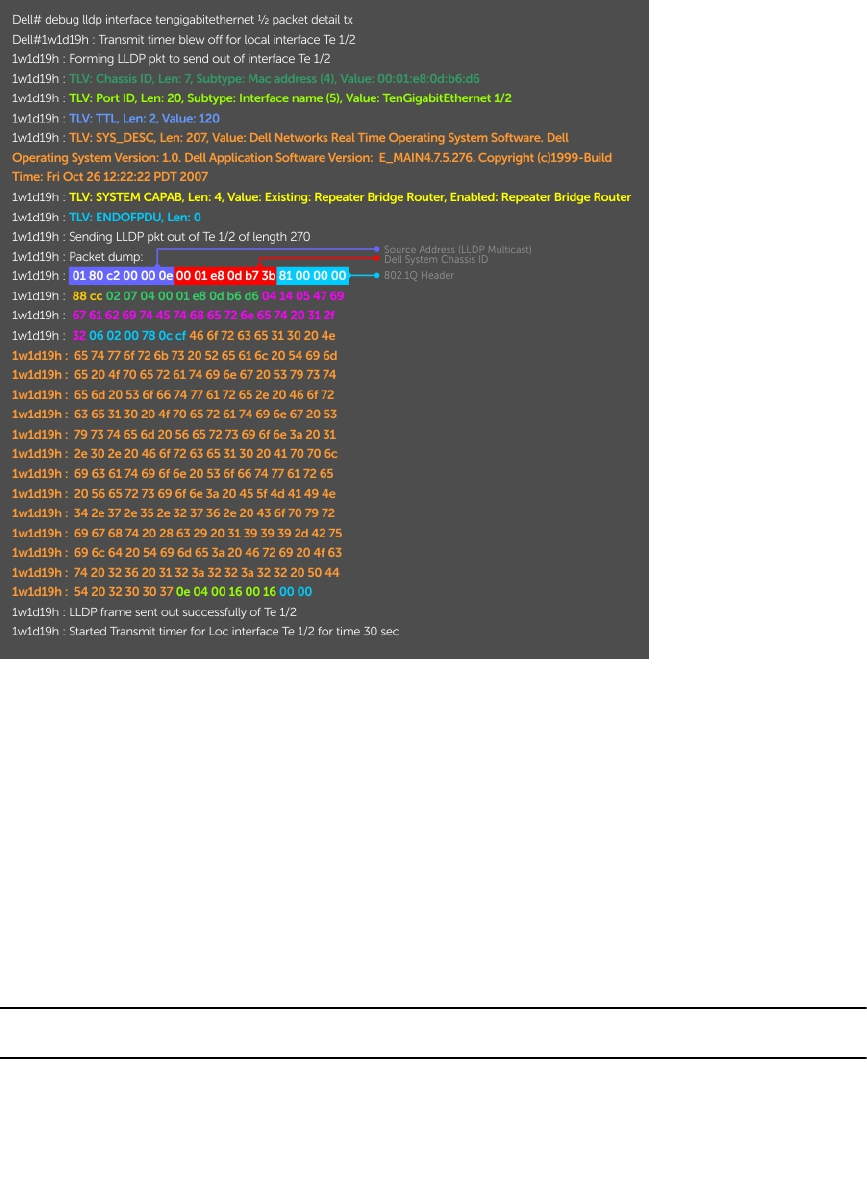
Figure 66. The debug lldp detail Command — LLDPDU Packet Dissection
Relevant Management Objects
The system supports all IEEE 802.1AB MIB objects.
The following tables list the objects associated with:
• received and transmitted TLVs
• the LLDP configuration on the local agent
• IEEE 802.1AB Organizationally Specific TLVs
• received and transmitted LLDP-MED TLVs
Table 23. LLDP Configuration MIB Objects
MIB Object
Category LLDP Variable LLDP MIB Object Description
LLDP
Configuration
adminStatus lldpPortConfigAdminStatus Whether you enable the
local LLDP agent for
transmit, receive, or both.
msgTxHold lldpMessageTxHoldMultiplie
r
Multiplier value.
472 Link Layer Discovery Protocol (LLDP)

MIB Object
Category LLDP Variable LLDP MIB Object Description
msgTxInterval lldpMessageTxInterval Transmit Interval value.
rxInfoTTL lldpRxInfoTTL Time to live for received
TLVs.
txInfoTTL lldpTxInfoTTL Time to live for transmitted
TLVs.
Basic TLV
Selection
mibBasicTLVsTxEnable lldpPortConfigTLVsTxEnabl
e
Indicates which
management TLVs are
enabled for system ports.
mibMgmtAddrInstanceTxEn
able
lldpManAddrPortsTxEnable The management addresses
defined for the system and
the ports through which
they are enabled for
transmission.
LLDP
Statistics
statsAgeoutsTotal lldpStatsRxPortAgeoutsTotal Total number of times that
a neighbor’s information is
deleted on the local system
due to an rxInfoTTL timer
expiration.
statsFramesDiscardedTotal lldpStatsRxPortFramesDisca
rdedTotal
Total number of LLDP
frames received then
discarded.
statsFramesInErrorsTotal lldpStatsRxPortFramesErrors Total number of LLDP
frames received on a port
with errors.
statsFramesInTotal lldpStatsRxPortFramesTotal Total number of LLDP
frames received through the
port.
statsFramesOutTotal lldpStatsTxPortFramesTotal Total number of LLDP
frames transmitted through
the port.
statsTLVsDiscardedTotal lldpStatsRxPortTLVsDiscard
edTotal
Total number of TLVs
received then discarded.
statsTLVsUnrecognizedTota
l
lldpStatsRxPortTLVsUnreco
gnizedTotal
Total number of all TLVs the
local agent does not
recognize.
Link Layer Discovery Protocol (LLDP) 473

Table 24. LLDP System MIB Objects
TLV Type TLV Name TLV Variable System LLDP MIB Object
1 Chassis ID chassis ID subtype Local lldpLocChassisIdSub
type
Remote lldpRemChassisIdSu
btype
chassid ID Local lldpLocChassisId
Remote lldpRemChassisId
2 Port ID port subtype Local lldpLocPortIdSubtyp
e
Remote lldpRemPortIdSubty
pe
port ID Local lldpLocPortId
Remote lldpRemPortId
4 Port Description port description Local lldpLocPortDesc
Remote lldpRemPortDesc
5 System Name system name Local lldpLocSysName
Remote lldpRemSysName
6 System Description system description Local lldpLocSysDesc
Remote lldpRemSysDesc
7 System Capabilities system capabilities Local lldpLocSysCapSupp
orted
Remote lldpRemSysCapSupp
orted
8 Management
Address
enabled capabilities Local lldpLocSysCapEnabl
ed
Remote lldpRemSysCapEnab
led
management
address length
Local lldpLocManAddrLen
Remote lldpRemManAddrLen
management
address subtype
Local lldpLocManAddrSubt
ype
Remote lldpRemManAddrSu
btype
management
address
Local lldpLocManAddr
Remote lldpRemManAddr
474 Link Layer Discovery Protocol (LLDP)

TLV Type TLV Name TLV Variable System LLDP MIB Object
interface numbering
subtype
Local lldpLocManAddrIfSu
btype
Remote lldpRemManAddrIfS
ubtype
interface number Local lldpLocManAddrIfId
Remote lldpRemManAddrIfId
OID Local lldpLocManAddrOID
Remote lldpRemManAddrOI
D
Table 25. LLDP 802.1 Organizationally specific TLV MIB Objects
TLV Type TLV Name TLV Variable System LLDP MIB Object
127 Port-VLAN ID PVID Local lldpXdot1LocPortVla
nId
Remote lldpXdot1RemPortVl
anId
127 Port and Protocol
VLAN ID
port and protocol
VLAN supported
Local lldpXdot1LocProtoVl
anSupported
Remote lldpXdot1RemProtoV
lanSupported
port and protocol
VLAN enabled
Local lldpXdot1LocProtoVl
anEnabled
Remote lldpXdot1RemProtoV
lanEnabled
PPVID Local lldpXdot1LocProtoVl
anId
Remote lldpXdot1RemProtoV
lanId
127 VLAN Name VID Local lldpXdot1LocVlanId
Remote lldpXdot1RemVlanId
VLAN name length Local lldpXdot1LocVlanNa
me
Remote lldpXdot1RemVlanN
ame
VLAN name Local lldpXdot1LocVlanNa
me
Remote lldpXdot1RemVlanN
ame
Link Layer Discovery Protocol (LLDP) 475

Table 26. LLDP-MED System MIB Objects
TLV Sub-Type TLV Name TLV Variable System LLDP-MED MIB
Object
1 LLDP-MED
Capabilities
LLDP-MED
Capabilities
Local lldpXMedPortCapSu
pported
lldpXMedPortConfig
TLVsTx Enable
Remote lldpXMedRemCapSu
pported
lldpXMedRemConfig
TLVsTxEnable
LLDP-MED Class
Type
Local lldpXMedLocDevice
Class
Remote lldpXMedRemDevice
Class
2 Network Policy Application Type Local lldpXMedLocMediaP
olicyAppType
Remote lldpXMedRemMedia
PolicyAppType
Unknown Policy
Flag
Local lldpXMedLocMediaP
olicyUnknown
Remote lldpXMedLocMediaP
olicyUnknown
Tagged Flag Local lldpXMedLocMediaP
olicyTagged
Remote lldpXMedLocMediaP
olicyTagged
VLAN ID Local lldpXMedLocMediaP
olicyVlanID
Remote lldpXMedRemMedia
PolicyVlanID
L2 Priority Local lldpXMedLocMediaP
olicyPriority
Remote lldpXMedRemMedia
PolicyPriority
DSCP Value Local lldpXMedLocMediaP
olicyDscp
Remote lldpXMedRemMedia
PolicyDscp
476 Link Layer Discovery Protocol (LLDP)

TLV Sub-Type TLV Name TLV Variable System LLDP-MED MIB
Object
3 Location Identifier Location Data
Format
Local lldpXMedLocLocatio
nSubtype
Remote lldpXMedRemLocati
onSubtype
Location ID Data Local lldpXMedLocLocatio
nInfo
Remote lldpXMedRemLocati
onInfo
4 Extended Power via
MDI
Power Device Type Local lldpXMedLocXPoED
eviceType
Remote lldpXMedRemXPoED
eviceType
Power Source Local lldpXMedLocXPoEPS
EPowerSource
lldpXMedLocXPoEP
DPowerSource
Remote lldpXMedRemXPoEP
SEPowerSource
lldpXMedRemXPoEP
DPowerSource
Power Priority Local lldpXMedLocXPoEP
DPowerPriority
lldpXMedLocXPoEPS
EPortPDPriority
Remote lldpXMedRemXPoEP
SEPowerPriority
lldpXMedRemXPoEP
DPowerPriority
Power Value Local lldpXMedLocXPoEPS
EPortPowerAv
lldpXMedLocXPoEP
DPowerReq
Remote lldpXMedRemXPoEP
SEPowerAv
lldpXMedRemXPoEP
DPowerReq
Link Layer Discovery Protocol (LLDP) 477
27
Microsoft Network Load Balancing
Network Load Balancing (NLB) is a clustering functionality that is implemented by Microsoft on Windows
2000 Server and Windows Server 2003 operating systems. Microsoft NLB clustering allows multiple
servers running Microsoft Windows to be represented by one MAC and one IP address to provide
transparent failover and load-balancing. The Dell Networking OS does not recognize server clusters by
default; you must configure NLB functionality on a switch to support server clusters.
NLB Unicast and Multicast Modes
On a switch, you can configure NLB functionality to operate in two modes: unicast and multicast mode.
The server-cluster IP address and the associated cluster MAC address are configured in the NLB
application running on the Windows Server.
• In unicast mode, when the server IP address is resolved to the MAC address using the ARP application,
the switch determines whether the ARP reply obtained from the server is of an NLB type. The switch
then maps the IP address (cluster IP) with the MAC address (cluster MAC address).
• In multicast mode, the cluster IP address is mapped to a cluster multicast MAC address that is
configured using the static ARP CLI configuration command. After the static NLB entry is configured,
the traffic is forwarded to the subset of ports configured for the VLAN that corresponds to the cluster
virtual IP address.
NLB Unicast Mode Example
Consider a sample topology in which four servers, namely S1 through S4, are configured as a cluster or a
farm. This set of servers is connected to a Layer 3 switch, which in turn is connected to the end-clients.
The servers contain a single IP address (IP-cluster address of 172.16.2.20) and a single unicast MAC
address (MAC-Cluster address of 00-bf-ac-10-00-01) for load-balancing. Because multiple ports of a
switch cannot learn a single MAC address, the servers are assigned with MAC addresses of MAC-s1 to
MAC-s4) respectively on S1 through S4 in addition to the MAC cluster address. All the servers of the
cluster belong to the VLAN named VLAN1.
In unicast NLB mode, the following sequence of events occurs:
• The switch sends an ARP request to resolve the IP address to the cluster MAC address.
• The NLB server responds with an ARP reply containing the MAC cluster address in the ARP header and
a MAC address of MAC-s1/s2/s3/s4 (for servers S1 through S4) in the Ethernet header.
• The switch associates the IP address with the MAC cluster address with the last ARP response it
obtains. Assume that in this case, the last ARP reply is obtained from MAC-s4.(assuming that the ARP
response with MAC-s4 is received as the last one). The interface associated with server, S4, is added
to the ARP table.
• After the NLB ARP entry is learned on a switch when NLB enabled, all subsequent traffic is flooded on
all ports in VLAN1.
478 Microsoft Network Load Balancing
With NLB, the data frame is forwarded to all servers in the cluster for the servers to perform load-
balancing.
NLB Multicast Mode Example
Consider a sample topology in which four servers, namely S1 through S4, are configured as a cluster or a
farm. This set of servers is connected to a Layer 3 switch, which in turn is connected to the end-clients.
They contain a single multicast MAC address (MAC-Cluster: 03-00-5E-11-11-11).
In the multicast NLB mode, a static ARP configuration command is configured to associate the cluster IP
address with a multicast cluster MAC address.
In multicast NLB mode, data is forwarded to all servers in the cluster based on the port specified using the
Layer 2 multicast command: mac-address-table static <multicast_mac> multicast vlan
<vlan_id> output-range <port1>, <port2>, ... in CONFIGURATION mode.
NLB Benefits
You must configure a switch to recognize Microsoft NLB clustering so that multiple servers using
Microsoft Windows can be represented by one MAC address and IP address to support transparent server
failover and load-balancing.
When NLB functionality is not enabled and a switch sends an ARP request to a server cluster, either the
active server or all the servers send a reply, depending on the cluster configuration. If the active server
sends a reply, the switch learns the active server’s MAC address. If all servers reply, the switch registers
only the last received ARP reply, and the switch learns one server’s actual MAC address; the virtual MAC
address is never learned. Because the virtual MAC address is never learned, traffic is forwarded to only
one server rather than the entire cluster; server failover and balancing are not supported.
To preserve server failover and balancing, the switch forwards traffic destined to the server cluster on all
member ports in the VLAN connected to the cluster. To configure this switch capability, enter the ip
vlan-flooding command when you configure the Microsoft server cluster.
The server MAC address is given in the Ethernet frame header of the ARP reply, while the virtual MAC
address of the cluster is given in the payload. As a result, all traffic destined for the server cluster is
flooded from the switch on all VLAN member ports. Since all servers in the cluster receive traffic, failover
and load-balancing are preserved.
NLB Restrictions
The following limitations apply to switches which support Microsoft network load balancing.
• NLB unicast mode uses switch flooding to transmit packets to all servers that are part of the VLAN
connected to the cluster. When a large volume of traffic is processed, the clustering performance
might be impacted in a small way. This limitation is applicable to switches that perform unicast
flooding in the software.
• The ip vlan-flooding command applies globally across all VLANs on the switch. In cases where
NLB VLAN flooding is enabled and ARP replies contain a discrepancy in the Ethernet SA and ARP
header SA frames, packet flooding over the relevant VLAN is performed.
• The maximum number of server clusters supported at a time is eight.
Microsoft Network Load Balancing 479
NLB VLAN Flooding
To preserve Microsoft server failover and load-balancing, configure a switch to forward the traffic
destined for a server cluster on all member ports of the VLAN connected to the cluster (ip vlan-
floodingcommand). Configure the switch for NLB VLAN flooding when you configure the server
cluster.
After you configure a switch to perform NLB VLAN flooding:
• Older ARP entries are overwritten when newer NLB entries are learned. All learned ARP entries are
deleted when you disable NLB VLAN flooding (no ip vlan-flooding command).
• When you add a port to the NLB VLAN, the port automatically receives traffic if the feature is enabled.
Old ARP entries are not deleted or updated. Port channels in the NLB VLAN also receive traffic. When
you delete a VLAN member port, its ARP entries are also deleted from CAM.
• There is no impact on the running configuration if you save the switch configuration with NLB VLAN
flooding enabled.
• To verify if NLB VLAN flooding is enabled, enter the show running-config command. The
command output displays the ip vlan-flooding CLI configuration, if enabled.
Configuring NLB on a Switch
You can enable NLB functionality to operate in unicast or multicast mode on a switch.
To enable NLB unicast mode:
Enter the ip vlan-flooding command to enable Layer 3 unicast data traffic routed through a
VLAN port to be flooded on all member ports of the VLAN connected to a server cluster.
CONFIGURATION mode
ip vlan-flooding
Unicast data traffic flooding is performed only on packets that use ARP entries that are resolved through
ARP packets in which the Ethernet MAC source address (SA) is different from the MAC information inside
the ARP packet.
To enable multicast NLB mode:
1. Configure a L2 multicast configuration to associate the cluster MAC address and a subset of ports
within a VLAN.
CONFIGURATION mode
mac-address-table static multicast-mac-address vlan vlan-id output-range
interface
2. Configure a static ARP entry to associate the cluster IP address with the corresponding multicast NLB
MAC address. Specify any of the interfaces entered in the L2 multicast configuration in Step 1.
CONFIGURATION mode
arp ip-address multicast-mac-address interface
480 Microsoft Network Load Balancing
28
Multicast Source Discovery Protocol
(MSDP)
This chapter describes how to configure and use the multicast source discovery protocol (MSDP) on the
Z9500 switch.
Protocol Overview
MSDP is a Layer 3 protocol that connects IPv4 protocol-independent multicast-sparse mode (PIM-SM)
domains. A domain in the context of MSDP is a contiguous set of routers operating PIM within a common
boundary defined by an exterior gateway protocol, such as border gateway protocol (BGP).
Each rendezvous point (RP) peers with every other RP via the transmission control protocol (TCP).
Through this connection, peers advertise the sources in their domain.
1. When an RP in a PIM-SM domain receives a PIM register message from a source, it sends a source-
active (SA) message to MSDP peers, as shown in the following illustration.
2. Each MSDP peer receives and forwards the message to its peers away from the originating RP.
3. When an MSDP peer receives an SA message, it determines if there are any group members within
the domain interested in any of the advertised sources. If there are, the receiving RP sends a join
message to the originating RP, creating a shortest path tree (SPT) to the source.
Multicast Source Discovery Protocol (MSDP) 481
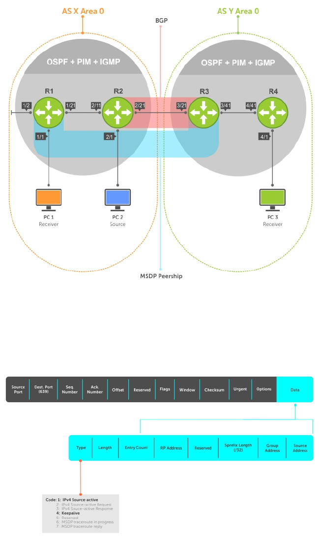
Figure 67. Multicast Source Discovery Protocol (MSDP)
RPs advertise each (S,G) in its domain in type, length, value (TLV) format. The total number of TLVs
contained in the SA is indicated in the “Entry Count” field. SA messages are transmitted every 60 seconds,
and immediately when a new source is detected.
Figure 68. MSDP SA Message Format
482 Multicast Source Discovery Protocol (MSDP)

Anycast RP
Using MSDP, anycast RP provides load sharing and redundancy in PIM-SM networks. Anycast RP allows
two or more rendezvous points (RPs) to share the load for source registration and the ability to act as hot
backup routers for each other.
Anycast RP allows you to configure two or more RPs with the same IP address on Loopback interfaces.
The Anycast RP Loopback address are configured with a 32-bit mask, making it a host address. All
downstream routers are configured to know that the Anycast RP Loopback address is the IP address of
their local RP. IP routing automatically selects the closest RP for each source and receiver. Assuming that
the sources are evenly spaced around the network, an equal number of sources register with each RP.
Consequently, all the RPs in the network share the process of registering the sources equally. Because a
source may register with one RP and receivers may join to a different RP, a method is needed for the RPs
to exchange information about active sources. This information exchange is done with MSDP.
With Anycast RP, all the RPs are configured to be MSDP peers of each other. When a source registers with
one RP, an SA message is sent to the other RPs informing them that there is an active source for a
particular multicast group. The result is that each RP is aware of the active sources in the area of the
other RPs. If any of the RPs fail, IP routing converges and one of the RPs becomes the active RP in more
than one area. New sources register with the backup RP. Receivers join toward the new RP and
connectivity is maintained.
Implementation Information
The Dell Networking OS implementation of MSDP is in accordance with RFC 3618 and Anycast RP is in
accordance with RFC 3446.
Configure Multicast Source Discovery Protocol
Configuring MSDP is a four-step process.
1. Enable an exterior gateway protocol (EGP) with at least two routing domains.
Refer to the following figures.
The MSDP Sample Configurations show the OSPF-BGP configuration used in this chapter for MSDP.
Also, refer to Open Shortest Path First (OSPFv2) and Border Gateway Protocol IPv4 (BGPv4).
2. Configure PIM-SM within each EGP routing domain.
Refer to the following figures.
The MSDP Sample Configurations show the PIM-SM configuration in this chapter for MSDP. Also,
refer to PIM Sparse-Mode (PIM-SM).
3. Enable MSDP.
4. Peer the RPs in each routing domain with each other. Refer to Enable MSDP.
Related Configuration Tasks
The following lists related MSDP configuration tasks.
•Enable MSDP
•Manage the Source-Active Cache
Multicast Source Discovery Protocol (MSDP) 483
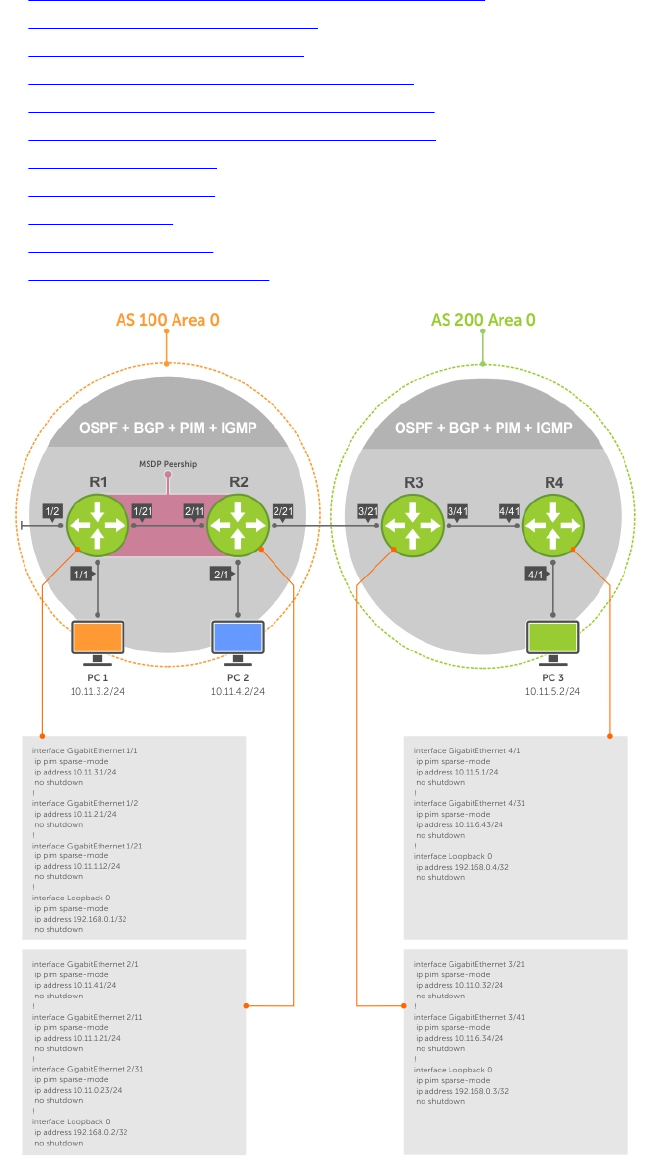
•Accept Source-Active Messages that Fail the RFP Check
•Specifying Source-Active Messages
•Limiting the Source-Active Cache
•Preventing MSDP from Caching a Local Source
•Preventing MSDP from Caching a Remote Source
•Preventing MSDP from Advertising a Local Source
•Terminating a Peership
•Clearing Peer Statistics
•Debugging MSDP
•MSDP with Anycast RP
•MSDP Sample Configurations
Figure 69. Configuring Interfaces for MSDP
484 Multicast Source Discovery Protocol (MSDP)
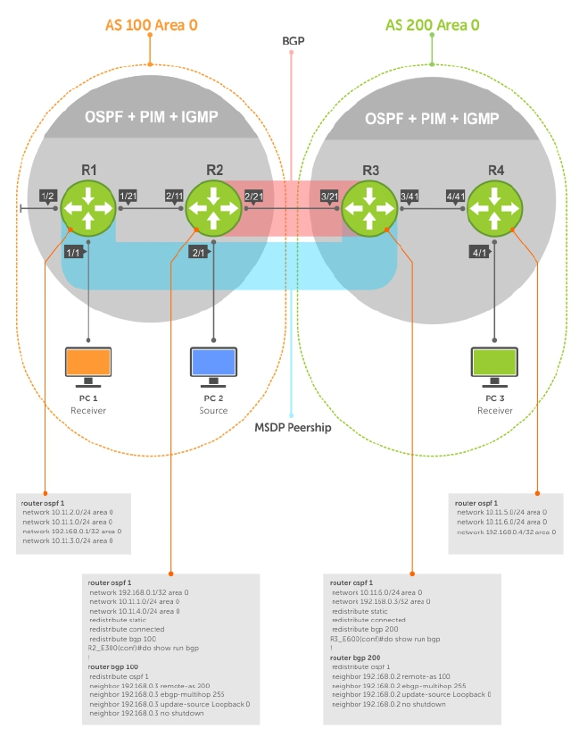
Figure 70. Configuring OSPF and BGP for MSDP
Multicast Source Discovery Protocol (MSDP) 485
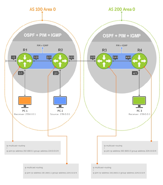
Figure 71. Configuring PIM in Multiple Routing Domains
486 Multicast Source Discovery Protocol (MSDP)
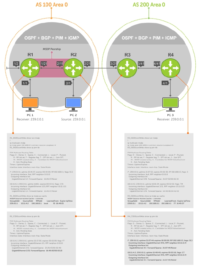
Figure 72. Configuring MSDP
Enable MSDP
Enable MSDP by peering RPs in different administrative domains.
1. Enable MSDP.
CONFIGURATION mode
ip multicast-msdp
2. Peer PIM systems in different administrative domains.
CONFIGURATION mode
ip msdp peer connect-source
Multicast Source Discovery Protocol (MSDP) 487

Example of Configuring MSDP
Example of Viewing Peer Information
R3(conf)#ip multicast-msdp
R3(conf)#ip msdp peer 192.168.0.1 connect-source Loopback 0
R3(conf)#do show ip msdp summary
Peer Addr Local Addr State Source SA Up/Down
Description
To view details about a peer, use the show ip msdp peer command in EXEC privilege mode.
Multicast sources in remote domains are stored on the RP in the source-active cache (SA cache). The
system does not create entries in the multicast routing table until there is a local receiver for the
corresponding multicast group.
R3#show ip msdp peer
Peer Addr: 192.168.0.1
Local Addr: 192.168.0.3(639) Connect Source: Lo 0
State: Established Up/Down Time: 00:15:20
Timers: KeepAlive 30 sec, Hold time 75 sec
SourceActive packet count (in/out): 8/0
SAs learned from this peer: 1
SA Filtering:
Input (S,G) filter: none
Output (S,G) filter: none
Manage the Source-Active Cache
Each SA-originating RP caches the sources inside its domain (domain-local), and the sources which it has
learned from its peers (domain-remote).
By caching sources:
• domain-local receivers experience a lower join latency
• RPs can transmit SA messages periodically to prevent SA storms
• only sources that are in the cache are advertised in the SA to prevent transmitting multiple copies of
the same source information
Viewing the Source-Active Cache
To view the source-active cache, use the following command.
• View the SA cache.
EXEC Privilege mode
show ip msdp sa-cache
Example of the show ip msdp sa-cache Command
R3#show ip msdp sa-cache
MSDP Source-Active Cache - 1 entries
GroupAddr SourceAddr RPAddr LearnedFrom Expire UpTime
239.0.0.1 10.11.4.2 192.168.0.1 192.168.0.1 76 00:10:44
488 Multicast Source Discovery Protocol (MSDP)
Limiting the Source-Active Cache
Set the upper limit of the number of active sources that the system caches.
The default active source limit is 500K messages. When the total number of active sources reaches the
specified limit, subsequent active sources are dropped even if they pass the reverse path forwarding (RPF)
and policy check.
To limit the number of sources that SA cache stores, use the following command.
• Limit the number of sources that can be stored in the SA cache.
EXEC Privilege mode
show ip msdp sa-limit
If the total number of active sources is already larger than the limit when limiting is applied, the sources
that are already in FTOS are not discarded. To enforce the limit in such a situation, use the clear ip
msdp sa-cache command to clear all existing entries.
Clearing the Source-Active Cache
To clear the source-active cache, use the following command.
• Clear the SA cache of all, local, or rejected entries, or entries for a specific group.
CONFIGURATION mode
clear ip msdp sa-cache [group-address | local | rejected-sa]
Enabling the Rejected Source-Active Cache
To cache rejected sources, use the following command.
Active sources can be rejected because the RPF check failed, the SA limit is reached, the peer RP is
unreachable, or the SA message has a format error.
• Cache rejected sources.
CONFIGURATION mode
ip msdp cache-rejected-sa
Accept Source-Active Messages that Fail the RFP Check
A default peer is a peer from which active sources are accepted even though they fail the RFP check.
Referring to the following illustrations:
• In Scenario 1, all MSPD peers are up.
• In Scenario 2, the peership between RP1 and RP2 is down, but the link (and routing protocols)
between them is still up. In this case, RP1 learns all active sources from RP3, but the sources from RP2
and RP4 are rejected because the reverse path to these routers is through Interface A.
• In Scenario 3, RP3 is configured as a default MSDP peer for RP1 and so the RPF check is disregarded
for RP3.
• In Scenario 4, RP1 has a default peer plus an access list. The list permits RP4 so the RPF check is
disregarded for active sources from it, but RP5 (and all others because of the implicit deny all) are
subject to the RPF check and fail, so those active sources are rejected.
Multicast Source Discovery Protocol (MSDP) 489
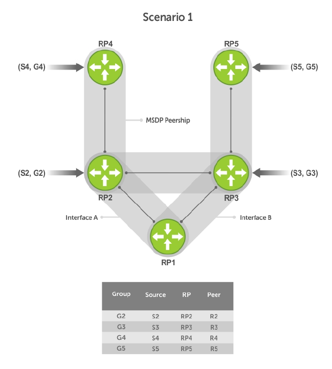
Figure 73. MSDP Default Peer, Scenario 1
490 Multicast Source Discovery Protocol (MSDP)
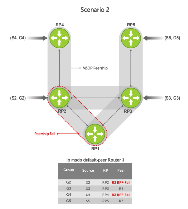
Figure 74. MSDP Default Peer, Scenario 2
Multicast Source Discovery Protocol (MSDP) 491
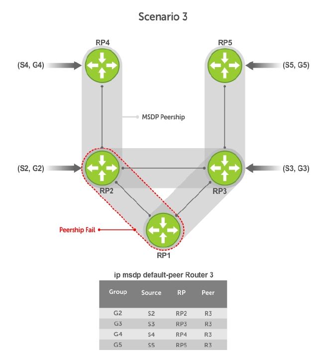
Figure 75. MSDP Default Peer, Scenario 3
492 Multicast Source Discovery Protocol (MSDP)
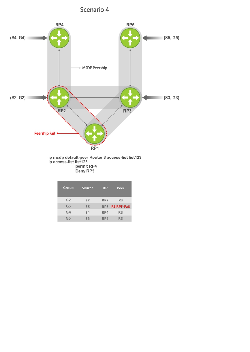
Figure 76. MSDP Default Peer, Scenario 4
Specifying Source-Active Messages
To specify messages, use the following command.
• Specify the forwarding-peer and originating-RP from which all active sources are accepted without
regard for the RPF check.
CONFIGURATION mode
ip msdp default-peer ip-address list
If you do not specify an access list, the peer accepts all sources that peer advertises. All sources from
RPs that the ACL denies are subject to the normal RPF check.
Example of the ip msdp default-peer Command and Viewing Denied Sources
Dell(conf)#ip msdp peer 10.0.50.2 connect-source Vlan 50
Dell(conf)#ip msdp default-peer 10.0.50.2 list fifty
Multicast Source Discovery Protocol (MSDP) 493

Dell(conf)#ip access-list standard fifty
Dell(conf)#seq 5 permit host 200.0.0.50
Dell#ip msdp sa-cache
MSDP Source-Active Cache - 3 entries
GroupAddr SourceAddr RPAddr LearnedFrom Expire UpTime
229.0.50.2 24.0.50.2 200.0.0.50 10.0.50.2 73 00:13:49
229.0.50.3 24.0.50.3 200.0.0.50 10.0.50.2 73 00:13:49
229.0.50.4 24.0.50.4 200.0.0.50 10.0.50.2 73 00:13:49
Dell#ip msdp sa-cache rejected-sa
MSDP Rejected SA Cache
3 rejected SAs received, cache-size 32766
UpTime GroupAddr SourceAddr RPAddr LearnedFrom Reason
00:33:18 229.0.50.64 24.0.50.64 200.0.1.50 10.0.50.2 Rpf-Fail
00:33:18 229.0.50.65 24.0.50.65 200.0.1.50 10.0.50.2 Rpf-Fail
00:33:18 229.0.50.66 24.0.50.66 200.0.1.50 10.0.50.2 Rpf-Fail
Limiting the Source-Active Messages from a Peer
To limit the source-active messages from a peer, use the following commands.
1. OPTIONAL: Store sources that are received after the limit is reached in the rejected SA cache.
CONFIGURATION mode
ip msdp cache-rejected-sa
2. Set the upper limit for the number of sources allowed from an MSDP peer.
CONFIGURATION mode
ip msdp peer peer-address sa-limit
The default limit is 100K.
If the total number of sources received from the peer is already larger than the limit when this
configuration is applied, those sources are not discarded. To enforce the limit in such a situation, first
clear the SA cache.
Preventing MSDP from Caching a Local Source
You can prevent MSDP from caching an active source based on source and/or group. Because the
source is not cached, it is not advertised to remote RPs.
1. OPTIONAL: Cache sources that are denied by the redistribute list in the rejected SA cache.
CONFIGURATION mode
ip msdp cache-rejected-sa
2. Prevent the system from caching local SA entries based on source and group using an extended ACL.
CONFIGURATION mode
ip msdp redistribute list
494 Multicast Source Discovery Protocol (MSDP)

Example of Verifying the System is not Caching Local Sources
When you apply this filter, the SA cache is not affected immediately. When sources that are denied by the
ACL time out, they are not refreshed. Until they time out, they continue to reside in the cache. To apply
the redistribute filter to entries already present in the SA cache, first clear the SA cache. You may
optionally store denied sources in the rejected SA cache.
R1(conf)#do show run msdp
!
ip multicast-msdp
ip msdp peer 192.168.0.3 connect-source Loopback 0
ip msdp redistribute list mylocalfilter
ip msdp cache-rejected-sa 1000
R1_E600(conf)#do show run acl
!
ip access-list extended mylocalfilter
seq 5 deny ip host 239.0.0.1 host 10.11.4.2
seq 10 deny ip any any
R1_E600(conf)#do show ip msdp sa-cache
R1_E600(conf)#do show ip msdp sa-cache rejected-sa
MSDP Rejected SA Cache
1 rejected SAs received, cache-size 1000
UpTime GroupAddr SourceAddr RPAddr LearnedFrom Reason
00:02:20 239.0.0.1 10.11.4.2 192.168.0.1 local Redistribute
Preventing MSDP from Caching a Remote Source
To prevent MSDP from caching a remote source, use the following commands.
1. OPTIONAL: Cache sources that the SA filter denies in the rejected SA cache.
CONFIGURATION mode
ip msdp cache-rejected-sa
2. Prevent the system from caching remote sources learned from a specific peer based on source and
group.
CONFIGURATION mode
ip msdp sa-filter list out peer list ext-acl
Example of Verifying the System is not Caching Remote Sources
As shown in the following example, R1 is advertising source 10.11.4.2. It is already in the SA cache of R3
when an ingress SA filter is applied to R3. The entry remains in the SA cache until it expires and is not
stored in the rejected SA cache.
[Router 3]
R3(conf)#do show run msdp
!
ip multicast-msdp
ip msdp peer 192.168.0.1 connect-source Loopback 0
ip msdp sa-filter in 192.168.0.1 list myremotefilter
R3(conf)#do show run acl
!
ip access-list extended myremotefilter
seq 5 deny ip host 239.0.0.1 host 10.11.4.2
R3(conf)#do show ip msdp sa-cache
MSDP Source-Active Cache - 1 entries
GroupAddr SourceAddr RPAddr LearnedFrom Expire UpTime
239.0.0.1 10.11.4.2 192.168.0.1 192.168.0.1 1 00:03:59
Multicast Source Discovery Protocol (MSDP) 495

R3(conf)#do show ip msdp sa-cache
R3(conf)#
R3(conf)#do show ip msdp peer
Peer Addr: 192.168.0.1
Local Addr: 0.0.0.0(639) Connect Source: Lo 0
State: Listening Up/Down Time: 00:01:19
Timers: KeepAlive 30 sec, Hold time 75 sec
SourceActive packet count (in/out): 0/0
SAs learned from this peer: 0
SA Filtering:
Input (S,G) filter: myremotefilter
Output (S,G) filter: none
Preventing MSDP from Advertising a Local Source
To prevent MSDP from advertising a local source, use the following command.
• Prevent an RP from advertising a source in the SA cache.
CONFIGURATION mode
ip msdp sa-filter list in peer list ext-acl
Example of Verifying the System is not Advertising Local Sources
In the following example, R1 stops advertising source 10.11.4.2. Because it is already in the SA cache of
R3, the entry remains there until it expires.
[Router 1]
R1(conf)#do show run msdp
!
ip multicast-msdp
ip msdp peer 192.168.0.3 connect-source Loopback 0
ip msdp sa-filter out 192.168.0.3 list mylocalfilter
R1(conf)#do show run acl
!
ip access-list extended mylocalfilter
seq 5 deny ip host 239.0.0.1 host 10.11.4.2
seq 10 deny ip any any
R1(conf)#do show ip msdp sa-cache
MSDP Source-Active Cache - 1 entries
GroupAddr SourceAddr RPAddr LearnedFrom Expire UpTime
239.0.0.1 10.11.4.2 192.168.0.1 local 70 00:27:20
R1(conf)#do show ip msdp sa-cache
MSDP Source-Active Cache - 1 entries
GroupAddr SourceAddr RPAddr LearnedFrom Expire UpTime
239.0.0.1 10.11.4.2 192.168.0.1 192.168.0.1 1 00:10:29
[Router 3]
R3(conf)#do show ip msdp sa-cache
R3(conf)#
To display the configured SA filters for a peer, use the show ip msdp peer command from EXEC
Privilege mode.
496 Multicast Source Discovery Protocol (MSDP)

Logging Changes in Peership States
To log changes in peership states, use the following command.
• Log peership state changes.
CONFIGURATION mode
ip msdp log-adjacency-changes
Terminating a Peership
MSDP uses TCP as its transport protocol. In a peering relationship, the peer with the lower IP address
initiates the TCP session, while the peer with the higher IP address listens on port 639.
• Terminate the TCP connection with a peer.
CONFIGURATION mode
ip msdp shutdown
Example of the Verifying that Peering State is Disabled
After the relationship is terminated, the peering state of the terminator is SHUTDOWN, while the peering
state of the peer is INACTIVE.
[Router 3]
R3(conf)#ip msdp shutdown 192.168.0.1
R3(conf)#do show ip msdp peer
Peer Addr: 192.168.0.1
Local Addr: 0.0.0.0(0) Connect Source: Lo 0
State: Shutdown Up/Down Time: 00:00:18
Timers: KeepAlive 30 sec, Hold time 75 sec
SourceActive packet count (in/out): 0/0
SAs learned from this peer: 0
SA Filtering:
Input (S,G) filter: myremotefilter
Output (S,G) filter: none
[Router 1]
R1(conf)#do show ip msdp peer
Peer Addr: 192.168.0.3
Local Addr: 0.0.0.0(0) Connect Source: Lo 0
State: Inactive Up/Down Time: 00:00:03
Timers: KeepAlive 30 sec, Hold time 75 sec
SourceActive packet count (in/out): 0/0
SAs learned from this peer: 0
SA Filtering:
Clearing Peer Statistics
To clear the peer statistics, use the following command.
• Reset the TCP connection to the peer and clear all peer statistics.
CONFIGURATION mode
clear ip msdp peer peer-address
Multicast Source Discovery Protocol (MSDP) 497

Example of the clear ip msdp peer Command and Verifying Statistics are Cleared
R3(conf)#do show ip msdp peer
Peer Addr: 192.168.0.1
Local Addr: 192.168.0.3(639) Connect Source: Lo 0
State: Established Up/Down Time: 00:04:26
Timers: KeepAlive 30 sec, Hold time 75 sec
SourceActive packet count (in/out): 5/0
SAs learned from this peer: 0
SA Filtering:
Input (S,G) filter: myremotefilter
Output (S,G) filter: none
R3(conf)#do clear ip msdp peer 192.168.0.1
R3(conf)#do show ip msdp peer
Peer Addr: 192.168.0.1
Local Addr: 0.0.0.0(0) Connect Source: Lo 0
State: Inactive Up/Down Time: 00:00:04
Timers: KeepAlive 30 sec, Hold time 75 sec
SourceActive packet count (in/out): 0/0
SAs learned from this peer: 0
SA Filtering:
Input (S,G) filter: myremotefilter
Output (S,G) filter: none
Debugging MSDP
To debug MSDP, use the following command.
• Display the information exchanged between peers.
CONFIGURATION mode
debug ip msdp
Example of the debug ip msdp Command
R1(conf)#do debug ip msdp
All MSDP debugging has been turned on
R1(conf)#03:16:08 : MSDP-0: Peer 192.168.0.3, sent Keepalive msg
03:16:09 : MSDP-0: Peer 192.168.0.3, rcvd Keepalive msg
03:16:27 : MSDP-0: Peer 192.168.0.3, sent Source Active msg
03:16:38 : MSDP-0: Peer 192.168.0.3, sent Keepalive msg
03:16:39 : MSDP-0: Peer 192.168.0.3, rcvd Keepalive msg
03:17:09 : MSDP-0: Peer 192.168.0.3, sent Keepalive msg
03:17:10 : MSDP-0: Peer 192.168.0.3, rcvd Keepalive msg
03:17:27 : MSDP-0: Peer 192.168.0.3, sent Source Active msg
Input (S,G) filter: none
Output (S,G) filter: none
MSDP with Anycast RP
Anycast RP uses MSDP with PIM-SM to allow more than one active group to use RP mapping.
PIM-SM allows only active groups to use RP mapping, which has several implications:
•traffic concentration: PIM-SM allows only one active group to RP mapping which means that all
traffic for the group must, at least initially, travel over the same part of the network. You can load
balance source registration between multiple RPs by strategically mapping groups to RPs, but this
498 Multicast Source Discovery Protocol (MSDP)

technique is less effective as traffic increases because preemptive load balancing requires prior
knowledge of traffic distributions.
•lack of scalable register decasulation: With only a single RP per group, all joins are sent to that RP
regardless of the topological distance between the RP, sources, and receivers, and data is transmitted
to the RP until the SPT switch threshold is reached.
•slow convergence when an active RP fails: When you configure multiple RPs, there can be
considerable convergence delay involved in switching to the backup RP.
Anycast RP relieves these limitations by allowing multiple RPs per group, which can be distributed in a
topologically significant manner according to the locations of the sources and receivers.
1. All the RPs serving a given group are configured with an identical anycast address.
2. Sources then register with the topologically closest RP.
3. RPs use MSDP to peer with each other using a unique address.
Figure 77. MSDP with Anycast RP
Multicast Source Discovery Protocol (MSDP) 499
Configuring Anycast RP
To configure anycast RP:
1. In each routing domain that has multiple RPs serving a group, create a Loopback interface on each
RP serving the group with the same IP address.
CONFIGURATION mode
interface loopback
2. Make this address the RP for the group.
CONFIGURATION mode
ip pim rp-address
3. In each routing domain that has multiple RPs serving a group, create another Loopback interface on
each RP serving the group with a unique IP address.
CONFIGURATION mode
interface loopback
4. Peer each RP with every other RP using MSDP, specifying the unique Loopback address as the
connect-source.
CONFIGURATION mode
ip msdp peer
5. Advertise the network of each of the unique Loopback addresses throughout the network.
ROUTER OSPF mode
network
Reducing Source-Active Message Flooding
RPs flood source-active messages to all of their peers away from the RP.
When multiple RPs exist within a domain, the RPs forward received active source information back to the
originating RP, which violates the RFP rule. You can prevent this unnecessary flooding by creating a
mesh-group. A mesh in this context is a topology in which each RP in a set of RPs has a peership with all
other RPs in the set. When an RP is a member of the mesh group, it forwards active source information
only to its peers outside of the group.
To create a mesh group, use the following command.
• Create a mesh group.
CONFIGURATION mode
ip msdp mesh-group
Specifying the RP Address Used in SA Messages
The default originator-id is the address of the RP that created the message. In the case of Anycast RP,
there are multiple RPs all with the same address.
To use the (unique) address of another interface as the originator-id, use the following command.
• Use the address of another interface as the originator-id instead of the RP address.
500 Multicast Source Discovery Protocol (MSDP)

CONFIGURATION mode
ip msdp originator-id
Example of R1 Configuration for MSDP with Anycast RP
Example of R2 Configuration for MSDP with Anycast RP
Example of R3 Configuration for MSDP with Anycast RP
ip multicast-routing
!
interface TenGigabitEthernet 1/1
ip pim sparse-mode
ip address 10.11.3.1/24
no shutdown
!
interface TenGigabitEthernet 1/2
ip address 10.11.2.1/24
no shutdown
!
interface TenGigabitEthernet 1/21
ip pim sparse-mode
ip address 10.11.1.12/24
no shutdown
!
interface Loopback 0
ip pim sparse-mode
ip address 192.168.0.1/32
no shutdown
!
interface Loopback 1
ip address 192.168.0.11/32
no shutdown
!
router ospf 1
network 10.11.2.0/24 area 0
network 10.11.1.0/24 area 0
network 10.11.3.0/24 area 0
network 192.168.0.11/32 area 0
!
ip multicast-msdp
ip msdp peer 192.168.0.3 connect-source Loopback 1
ip msdp peer 192.168.0.22 connect-source Loopback 1
ip msdp mesh-group AS100 192.168.0.22
ip msdp originator-id Loopback 1!
ip pim rp-address 192.168.0.1 group-address 224.0.0.0/4
ip multicast-routing
!
interface TenGigabitEthernet 2/1
ip pim sparse-mode
ip address 10.11.4.1/24
no shutdown
!
interface TenGigabitEthernet 2/11
ip pim sparse-mode
ip address 10.11.1.21/24
no shutdown
!
interface TenGigabitEthernet 2/31
ip pim sparse-mode
Multicast Source Discovery Protocol (MSDP) 501

ip address 10.11.0.23/24
no shutdown
!
interface Loopback 0
ip pim sparse-mode
ip address 192.168.0.1/32
no shutdown
!
interface Loopback 1
ip address 192.168.0.22/32
no shutdown
!
router ospf 1
network 10.11.1.0/24 area 0
network 10.11.4.0/24 area 0
network 192.168.0.22/32 area 0
redistribute static
redistribute connected
redistribute bgp 100
!
router bgp 100
redistribute ospf 1
neighbor 192.168.0.3 remote-as 200
neighbor 192.168.0.3 ebgp-multihop 255
neighbor 192.168.0.3 no shutdown
!
ip multicast-msdp
ip msdp peer 192.168.0.3 connect-source Loopback 1
ip msdp peer 192.168.0.11 connect-source Loopback 1
ip msdp mesh-group AS100 192.168.0.11
ip msdp originator-id Loopback 1
!
ip route 192.168.0.3/32 10.11.0.32
!
ip pim rp-address 192.168.0.1 group-address 224.0.0.0/4
ip multicast-routing
!
interface TenGigabitEthernet 0/21
ip pim sparse-mode
ip address 10.11.0.32/24
no shutdown
interface TenGigabitEthernet 0/41
ip pim sparse-mode
ip address 10.11.6.34/24
no shutdown
!
interface Loopback 0
ip pim sparse-mode
ip address 192.168.0.3/32
no shutdown
!
router ospf 1
network 10.11.6.0/24 area 0
network 192.168.0.3/32 area 0
redistribute static
redistribute connected
redistribute bgp 200
!
router bgp 200
redistribute ospf 1
neighbor 192.168.0.22 remote-as 100
502 Multicast Source Discovery Protocol (MSDP)

neighbor 192.168.0.22 ebgp-multihop 255
neighbor 192.168.0.22 update-source Loopback 0
neighbor 192.168.0.22 no shutdown
!
ip multicast-msdp
ip msdp peer 192.168.0.11 connect-source Loopback 0
ip msdp peer 192.168.0.22 connect-source Loopback 0
ip msdp sa-filter out 192.168.0.22
!
ip route 192.168.0.1/32 10.11.0.23
ip route 192.168.0.22/32 10.11.0.23
!
ip pim rp-address 192.168.0.3 group-address 224.0.0.0/4
MSDP Sample Configurations
The following examples show the running-configurations described in this chapter.
For more information, refer to the illustrations in the Related Configuration Tasks section.
MSDP Sample Configuration: R1 Running-Config
MSDP Sample Configuration: R2 Running-Config
MSDP Sample Configuration: R3 Running-Config
MSDP Sample Configuration: R4 Running-Config
ip multicast-routing
!
interface TenGigabitEthernet 1/1
ip pim sparse-mode
ip address 10.11.3.1/24
no shutdown
!
interface TenGigabitEthernet 1/2
ip address 10.11.2.1/24
no shutdown
!
interface TenGigabitEthernet 1/21
ip pim sparse-mode
ip address 10.11.1.12/24
no shutdown
!
interface Loopback 0
ip pim sparse-mode
ip address 192.168.0.1/32
no shutdown
!
router ospf 1
network 10.11.2.0/24 area 0
network 10.11.1.0/24 area 0
network 192.168.0.1/32 area 0
network 10.11.3.0/24 area 0
!
ip multicast-msdp
ip msdp peer 192.168.0.3 connect-source Loopback 0
!
ip pim rp-address 192.168.0.1 group-address 224.0.0.0/4
ip multicast-routing
!
Multicast Source Discovery Protocol (MSDP) 503

interface TenGigabitEthernet 2/1
ip pim sparse-mode
ip address 10.11.4.1/24
no shutdown
!
interface TenGigabitEthernet 2/11
ip pim sparse-mode
ip address 10.11.1.21/24
no shutdown
!
interface TenGigabitEthernet 2/31
ip pim sparse-mode
ip address 10.11.0.23/24
no shutdown
!
interface Loopback 0
ip address 192.168.0.2/32
no shutdown
!
router ospf 1
network 10.11.1.0/24 area 0
network 10.11.4.0/24 area 0
network 192.168.0.2/32 area 0
redistribute static
redistribute connected
redistribute bgp 100
!
router bgp 100
redistribute ospf 1
neighbor 192.168.0.3 remote-as 200
neighbor 192.168.0.3 ebgp-multihop 255
neighbor 192.168.0.3 update-source Loopback 0
neighbor 192.168.0.3 no shutdown
!
ip route 192.168.0.3/32 10.11.0.32
!
ip pim rp-address 192.168.0.1 group-address 224.0.0.0/4
ip multicast-routing
!
interface TenGigabitEthernet 0/21
ip pim sparse-mode
ip address 10.11.0.32/24
no shutdown
!
interface TenGigabitEthernet 0/41
ip pim sparse-mode
ip address 10.11.6.34/24
no shutdown
!
interface ManagementEthernet 0/0
ip address 10.11.80.3/24
no shutdown
!
interface Loopback 0
ip pim sparse-mode
ip address 192.168.0.3/32
no shutdown
!
router ospf 1
network 10.11.6.0/24 area 0
network 192.168.0.3/32 area 0
redistribute static
504 Multicast Source Discovery Protocol (MSDP)

redistribute connected
redistribute bgp 200
!
router bgp 200
redistribute ospf 1
neighbor 192.168.0.2 remote-as 100
neighbor 192.168.0.2 ebgp-multihop 255
neighbor 192.168.0.2 update-source Loopback 0
neighbor 192.168.0.2 no shutdown
!
ip multicast-msdp
ip msdp peer 192.168.0.1 connect-source Loopback 0
!
ip route 192.168.0.2/32 10.11.0.23
ip multicast-routing
!
interface TenGigabitEthernet 0/21
ip pim sparse-mode
ip address 10.11.5.1/24
no shutdown
!
interface TenGigabitEthernet 0/22
ip address 10.10.42.1/24
no shutdown
!
interface TenGigabitEthernet 0/31
ip pim sparse-mode
ip address 10.11.6.43/24
no shutdown
!
interface Loopback 0
ip address 192.168.0.4/32
no shutdown
!
router ospf 1
network 10.11.5.0/24 area 0
network 10.11.6.0/24 area 0
network 192.168.0.4/32 area 0
!
ip pim rp-address 192.168.0.3 group-address 224.0.0.0/4
Multicast Source Discovery Protocol (MSDP) 505
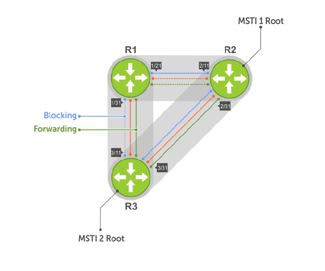
29
Multiple Spanning Tree Protocol (MSTP)
Multiple spanning tree protocol (MSTP) — specified in IEEE 802.1Q-2003 — is a rapid spanning tree
protocol (RSTP)-based spanning tree variation that improves on per-VLAN spanning tree plus (PVST+).
MSTP allows multiple spanning tree instances and allows you to map many VLANs to one spanning tree
instance to reduce the total number of required instances.
Protocol Overview
In contrast, PVST+ allows a spanning tree instance for each VLAN. This 1:1 approach is not suitable if you
have many VLANs, because each spanning tree instance costs bandwidth and processing resources.
In the following illustration, three VLANs are mapped to two multiple spanning tree instances (MSTI).
VLAN 100 traffic takes a different path than VLAN 200 and 300 traffic. The behavior demonstrates how
you can use MSTP to achieve load balancing.
Figure 78. MSTP with Three VLANs Mapped to TWO Spanning Tree Instances
506 Multiple Spanning Tree Protocol (MSTP)

Spanning Tree Variations
The Dell Networking OS supports four variations of spanning tree, as shown in the following table.
Table 27. Spanning Tree Variations
Dell Networking Term IEEE Specification
Spanning Tree Protocol (STP) 802 .1d
Rapid Spanning Tree Protocol (RSTP) 802 .1w
Multiple Spanning Tree Protocol (MSTP) 802 .1s
Per-VLAN Spanning Tree Plus (PVST+) Third Party
Implementation Information
MSTP is implemented as follows on the Dell Networking OS:
• The MSTP implementation is based on IEEE 802.1Q-2003 and interoperates only with bridges that
also use this standard implementation.
• MSTP is compatible with STP and RSTP.
• The system supports only one MSTP region.
• When you enable MSTP, all ports in Layer 2 mode participate in MSTP.
Configure Multiple Spanning Tree Protocol
Configuring multiple spanning tree is a four-step process.
1. Configure interfaces for Layer 2.
2. Place the interfaces in VLANs.
3. Enable the multiple spanning tree protocol.
4. Create multiple spanning tree instances and map VLANs to them.
Related Configuration Tasks
The following are the related configuration tasks for MSTP.
•Creating Multiple Spanning Tree Instances
•Adding and Removing Interfaces
•Influencing MSTP Root Selection
•Interoperate with Non-Dell Networking OS Bridges
•Changing the Region Name or Revision
•Modifying Global Parameters
•Modifying the Interface Parameters
•Configuring an EdgePort
•Flush MAC Addresses after a Topology Change
•Debugging and Verifying MSTP Configurations
•Prevent Network Disruptions with BPDU Guard
Multiple Spanning Tree Protocol (MSTP) 507

•Enabling SNMP Traps for Root Elections and Topology Changes
Enable Multiple Spanning Tree Globally
MSTP is not enabled by default. To enable MSTP globally, use the following commands.
When you enable MSTP, all physical, VLAN, and port-channel interfaces that are enabled and in Layer 2
mode are automatically part of the MSTI 0.
• Within an MSTI, only one path from any bridge to any other bridge is enabled.
• Bridges block a redundant path by disabling one of the link ports.
1. Enter PROTOCOL MSTP mode.
CONFIGURATION mode
protocol spanning-tree mstp
2. Enable MSTP.
PROTOCOL MSTP mode
no disable
Example of Verifying MSTP is Enabled
To verify that MSTP is enabled, use the show config command in PROTOCOL MSTP mode.
Dell(conf)#protocol spanning-tree mstp
Dell(config-mstp)#show config
!
protocol spanning-tree mstp
no disable
Dell#
Adding and Removing Interfaces
To add and remove interfaces, use the following commands.
To add an interface to the MSTP topology, configure it for Layer 2 and add it to a VLAN.
If you previously disabled MSTP on the interface using the no spanning-tree 0 command, to enable
MSTP, use the following command.
•spanning-tree 0
To remove an interface from the MSTP topology, use the no spanning-tree 0 command.
Creating Multiple Spanning Tree Instances
To create multiple spanning tree instances, use the following command.
A single MSTI provides no more benefit than RSTP. To take full advantage of MSTP, create multiple MSTIs
and map VLANs to them.
• Create an MSTI.
PROTOCOL MSTP mode
msti
Specify the keyword vlan then the VLANs that you want to participate in the MSTI.
508 Multiple Spanning Tree Protocol (MSTP)

Examples of Creating and Viewing MSTP Instances
The following example shows using the msti command.
Dell(conf)#protocol spanning-tree mstp
Dell(conf-mstp)#msti 1 vlan 100
Dell(conf-mstp)#msti 2 vlan 200-300
Dell(conf-mstp)#show config
!
protocol spanning-tree mstp
no disable
MSTI 1 VLAN 100
MSTI 2 VLAN 200-300
All bridges in the MSTP region must have the same VLAN-to-instance mapping.
To view which instance a VLAN is mapped to, use the show spanning-tree mst vlan command
from EXEC Privilege mode.
Dell(conf-mstp)#name my-mstp-region
Dell(conf-mstp)#exit
Dell(conf)#do show spanning-tree mst config
MST region name: my-mstp-region
Revision: 0
MSTI VID
1 100
2 200-300
To view the forwarding/discarding state of the ports participating in an MSTI, use the show spanning-
tree msti command from EXEC Privilege mode.
Dell#show spanning-tree msti 1
MSTI 1 VLANs mapped 100
Root Identifier has priority 32768, Address 0001.e806.953e
Root Bridge hello time 2, max age 20, forward delay 15, max hops 19
Bridge Identifier has priority 32768, Address 0001.e80d.b6d6
Configured hello time 2, max age 20, forward delay 15, max hops 20
Current root has priority 32768, Address 0001.e806.953e
Number of topology changes 2, last change occured 1d2h ago on Te 1/21
Port 374 (TengigabitEthernet 1/21) is root Forwarding
Port path cost 20000, Port priority 128, Port Identifier 128.374
Designated root has priority 32768, address 0001.e806.953e
Designated bridge has priority 32768, address 0001.e806.953e
Designated port id is 128.374, designated path cost 20000
Number of transitions to forwarding state 1
BPDU (MRecords): sent 93671, received 46843
The port is not in the Edge port mode
Port 384 (TengigabitEthernet 1/31) is alternate Discarding
Port path cost 20000, Port priority 128, Port Identifier 128.384
Designated root has priority 32768, address 0001.e806.953e
Designated bridge has priority 32768, address 0001.e809.c24a
Designated port id is 128.384, designated path cost 20000
Number of transitions to forwarding state 1
BPDU (MRecords): sent 39291, received 7547
The port is not in the Edge port mode
Multiple Spanning Tree Protocol (MSTP) 509

Influencing MSTP Root Selection
MSTP determines the root bridge, but you can assign one bridge a lower priority to increase the
probability that it becomes the root bridge.
To change the bridge priority, use the following command.
• Assign a number as the bridge priority.
PROTOCOL MSTP mode
msti instance bridge-priority priority
A lower number increases the probability that the bridge becomes the root bridge.
The range is from 0 to 61440, in increments of 4096.
The default is 32768.
Example of Assigning and Verifying the Root Bridge Priority
By default, the simple configuration shown previously yields the same forwarding path for both MSTIs.
The following example shows how R3 is assigned bridge priority 0 for MSTI 2, which elects a different
root bridge than MSTI 2.
To view the bridge priority, use the show config command from PROTOCOL MSTP mode.
R3(conf-mstp)#msti 2 bridge-priority 0
1d2h51m: %SYSTEM-P:RP2 %SPANMGR-5-STP_ROOT_CHANGE: MSTP root changed for
instance 2. My
Bridge ID: 0:0001.e809.c24a Old Root: 32768:0001.e806.953e New Root:
0:0001.e809.c24a
R3(conf-mstp)#show config
!
protocol spanning-tree mstp
no disable
MSTI 1 VLAN 100
MSTI 2 VLAN 200,300
MSTI 2 bridge-priority 0
Interoperate with Non-Dell Bridges
The Dell Networking OS supports only one MSTP region.
A region is a combination of three unique qualities:
•Name is a mnemonic string you assign to the region. The default region name is null.
•Revision is a 2-byte number. The default revision number is 0.
• VLAN-to-instance mapping is the placement of a VLAN in an MSTI.
For a bridge to be in the same MSTP region as another, all three of these qualities must match exactly.
The default values for the name and revision number must match on all Dell Networking OS devices. If
there are non-Dell devices that participate in MSTP, ensure that these values match on all devices.
510 Multiple Spanning Tree Protocol (MSTP)

NOTE: Some non-Dell equipment may implement a non-null default region name, such as the
Bridge ID or a MAC address.
Changing the Region Name or Revision
To change the region name or revision, use the following commands.
• Change the region name.
PROTOCOL MSTP mode
name name
• Change the region revision number.
PROTOCOL MSTP mode
revision number
Example of the name Command
To view the current region name and revision, use the show spanning-tree mst configuration
command from EXEC Privilege mode.
Dell(conf-mstp)#name my-mstp-region
Dell(conf-mstp)#exit
Dell(conf)#do show spanning-tree mst config
MST region name: my-mstp-region
Revision: 0
MSTI VID
1 100
2 200-300
Modifying Global Parameters
The root bridge sets the values for forward-delay, hello-time, max-age, and max-hops and overwrites the
values set on other MSTP bridges.
•Forward-delay — the amount of time an interface waits in the Listening state and the Learning state
before it transitions to the Forwarding state.
•Hello-time — the time interval in which the bridge sends MSTP bridge protocol data units (BPDUs).
•Max-age — the length of time the bridge maintains configuration information before it refreshes that
information by recomputing the MST topology.
•Max-hops — the maximum number of hops a BPDU can travel before a receiving switch discards it.
NOTE: Dell Networking recommends that only experienced network administrators change MSTP
parameters. Poorly planned modification of MSTP parameters can negatively affect network
performance.
To change the MSTP parameters, use the following commands on the root bridge.
1. Change the forward-delay parameter.
PROTOCOL MSTP mode
forward-delay seconds
The range is from 4 to 30.
Multiple Spanning Tree Protocol (MSTP) 511

The default is 15 seconds.
2. Change the hello-time parameter.
PROTOCOL MSTP mode
hello-time seconds
NOTE: With large configurations (especially those configurations with more ports) Dell
Networking recommends increasing the hello-time.
The range is from 1 to 10.
The default is 2 seconds.
3. Change the max-age parameter.
PROTOCOL MSTP mode
max-age seconds
The range is from 6 to 40.
The default is 20 seconds.
4. Change the max-hops parameter.
PROTOCOL MSTP mode
max-hops number
The range is from 1 to 40.
The default is 20.
Example of the forward-delay Parameter
To view the current values for MSTP parameters, use the show running-config spanning-tree
mstp command from EXEC privilege mode.
Dell(conf-mstp)#forward-delay 16
Dell(conf-mstp)#exit
Dell(conf)#do show running-config spanning-tree mstp
!
protocol spanning-tree mstp
no disable
name my-mstp-region
MSTI 1 VLAN 100
MSTI 2 VLAN 200-300
forward-delay 16
MSTI 2 bridge-priority 4096
Dell(conf)#
Modifying the Interface Parameters
You can adjust two interface parameters to increase or decrease the probability that a port becomes a
forwarding port.
•Port cost is a value that is based on the interface type. The greater the port cost, the less likely the
port is selected to be a forwarding port.
512 Multiple Spanning Tree Protocol (MSTP)

•Port priority influences the likelihood that a port is selected to be a forwarding port in case that
several ports have the same port cost.
The following lists the default values for port cost by interface.
Table 28. Default Values for Port Costs by Interface
Port Cost Default Value
100-Mb/s Ethernet interfaces 200000
1-Gigabit Ethernet interfaces 20000
10-Gigabit Ethernet interfaces 2000
Port Channel with 100 Mb/s Ethernet interfaces 180000
Port Channel with 1-Gigabit Ethernet interfaces 18000
Port Channel with 10-Gigabit Ethernet interfaces 1800
To change the port cost or priority of an interface, use the following commands.
1. Change the port cost of an interface.
INTERFACE mode
spanning-tree msti number cost cost
The range is from 0 to 200000.
For the default, refer to the default values shown in the table..
2. Change the port priority of an interface.
INTERFACE mode
spanning-tree msti number priority priority
The range is from 0 to 240, in increments of 16.
The default is 128.
To view the current values for these interface parameters, use the show config command from
INTERFACE mode.
Configuring an EdgePort
The EdgePort feature enables interfaces to begin forwarding traffic approximately 30 seconds sooner.
In this mode, an interface forwards frames by default until it receives a BPDU that indicates that it should
behave otherwise; it does not go through the Learning and Listening states. The bpduguard shutdown-
on-violation option causes the interface hardware to be shut down when it receives a BPDU. When
you implement only bpduguard, although the interface is placed in an Error Disabled state when
receiving the BPDU, the physical interface remains up and spanning-tree drops packets in the hardware
after a BPDU violation. BPDUs are dropped in the software after receiving the BPDU violation. This feature
is the same as PortFast mode in spanning tree.
CAUTION: Configure EdgePort only on links connecting to an end station. EdgePort can cause
loops if you enable it on an interface connected to a network.
To enable EdgePort on an interface, use the following command.
Multiple Spanning Tree Protocol (MSTP) 513

• Enable EdgePort on an interface.
INTERFACE mode
spanning-tree mstp edge-port [bpduguard | shutdown-on-violation]
Dell Networking OS Behavior: Regarding bpduguard shutdown-on-violation behavior:
– If the interface to be shut down is a port channel, all the member ports are disabled in the
hardware.
– When you add a physical port to a port channel already in the Error Disable state, the new member
port is also disabled in the hardware.
– When you remove a physical port from a port channel in the Error Disable state, the error disabled
state is cleared on this physical port (the physical port is enabled in the hardware).
– The reset linecard command does not clear the Error Disabled state of the port or the
Hardware Disabled state. The interface continues to be disabled in the hardware.
– You can clear the Error Disabled state with any of the following methods:
* Use the shutdown command on the interface.
* Disable the shutdown-on-violation command on the interface (using the no spanning-
tree stp-id portfast [bpduguard | [shutdown-on-violation]] command).
* Disable spanning tree on the interface (using the no spanning-tree command in
INTERFACE mode).
* Disabling global spanning tree (using the no spanning-tree command in CONFIGURATION
mode).
Example of Enabling an EdgePort on an Interface
To verify that EdgePort is enabled, use the show config command from INTERFACE mode.
Dell(conf-if-te-3/41)#spanning-tree mstp edge-port
Dell(conf-if-te-3/41)#show config
!
interface TengigabitEthernet 3/41
no ip address
switchport
spanning-tree mstp edge-port
spanning-tree MSTI 1 priority 144
no shutdown
Dell(conf-if-te-3/41)#
Flush MAC Addresses after a Topology Change
The system has an optimized MAC address flush mechanism for RSTP, MSTP, and PVST+ that flushes
addresses only when necessary, which allows for faster convergence during topology changes.
However, you may activate the flushing mechanism defined by 802.1Q-2003 using the tc-flush-
standard command, which flushes MAC addresses after every topology change notification.
To view the enable status of this feature, use the show running-config spanning-tree mstp
command from EXEC Privilege mode.
MSTP Sample Configurations
The running-configurations support the topology shown in the following illustration.
The configurations are from Dell Networking OS systems.
514 Multiple Spanning Tree Protocol (MSTP)
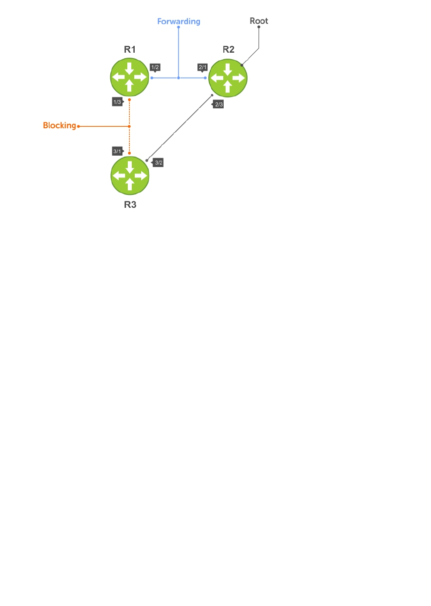
Figure 79. MSTP with Three VLANs Mapped to Two Spanning Tree Instances
Router 1 Running-Configuration
This example uses the following steps:
1. Enable MSTP globally and set the region name and revision map MSTP instances to the VLANs.
2. Assign Layer-2 interfaces to the MSTP topology.
3. Create VLANs mapped to MSTP instances tag interfaces to the VLANs.
(Step 1)
protocol spanning-tree mstp
no disable
name Tahiti
revision 123
MSTI 1 VLAN 100
MSTI 2 VLAN 200,300
!
(Step 2)
interface TenGigabitEthernet 1/21
no ip address
switchport
no shutdown
!
interface TenGigabitEthernet 1/31
no ip address
switchport
no shutdown
!
(Step 3)
interface Vlan 100
no ip address
tagged TenGigabitEthernet 1/21,31
no shutdown
!
interface Vlan 200
no ip address
tagged TenGigabitEthernet 1/21,31
Multiple Spanning Tree Protocol (MSTP) 515

no shutdown
!
interface Vlan 300
no ip address
tagged TenGigabitEthernet 1/21,31
no shutdown
Router 2 Running-Configuration
This example uses the following steps:
1. Enable MSTP globally and set the region name and revision map MSTP instances to the VLANs.
2. Assign Layer-2 interfaces to the MSTP topology.
3. Create VLANs mapped to MSTP instances tag interfaces to the VLANs.
(Step 1)
protocol spanning-tree mstp
no disable
name Tahiti
revision 123
MSTI 1 VLAN 100
MSTI 2 VLAN 200,300
!
(Step 2)
interface TenGigabitEthernet 2/11
no ip address
switchport
no shutdown
!
interface TenGigabitEthernet 2/31
no ip address
switchport
no shutdown
!
(Step 3)
interface Vlan 100
no ip address
tagged TenGigabitEthernet 2/11,31
no shutdown
!
interface Vlan 200
no ip address
tagged TenGigabitEthernet 2/11,31
no shutdown
!
interface Vlan 300
no ip address
tagged TenGigabitEthernet 2/11,31
no shutdown
Router 3 Running-Configuration
This example uses the following steps:
1. Enable MSTP globally and set the region name and revision map MSTP instances to the VLANs.
2. Assign Layer-2 interfaces to the MSTP topology.
3. Create VLANs mapped to MSTP instances tag interfaces to the VLANs.
(Step 1)
protocol spanning-tree mstp
no disable
516 Multiple Spanning Tree Protocol (MSTP)

name Tahiti
revision 123
MSTI 1 VLAN 100
MSTI 2 VLAN 200,300
!
(Step 2)
interface TenGigabitEthernet 3/11
no ip address
switchport
no shutdown
!
interface TenGigabitEthernet 3/21
no ip address
switchport
no shutdown
!
(Step 3)
interface Vlan 100
no ip address
tagged TenGigabitEthernet 3/11,21
no shutdown
!
interface Vlan 200
no ip address
tagged TenGigabitEthernet 3/11,21
no shutdown
!
interface Vlan 300
no ip address
tagged TenGigabitEthernet 3/11,21
no shutdown
Example Running-Configuration
This example uses the following steps:
1. Enable MSTP globally and set the region name and revision map MSTP instances to the VLANs.
2. Assign Layer-2 interfaces to the MSTP topology.
3. Create VLANs mapped to MSTP instances tag interfaces to the VLANs.
(Step 1)
spanning-tree
spanning-tree configuration name Tahiti
spanning-tree configuration revision 123
spanning-tree MSTi instance 1
spanning-tree MSTi vlan 1 100
spanning-tree MSTi instance 2
spanning-tree MSTi vlan 2 200
spanning-tree MSTi vlan 2 300
(Step 2)
interface 1/0/31
no shutdown
spanning-tree port mode enable
switchport protected 0
exit
interface 1/0/32
no shutdown
spanning-tree port mode enable
switchport protected 0
exit
Multiple Spanning Tree Protocol (MSTP) 517

(Step 3)
interface vlan 100
tagged 1/0/31
tagged 1/0/32
exit
interface vlan 200
tagged 1/0/31
tagged 1/0/32
exit
interface vlan 300
tagged 1/0/31
tagged 1/0/32
exit
Debugging and Verifying MSTP Configurations
To debut and verify MSTP configuration, use the following commands.
• Display BPDUs.
EXEC Privilege mode
debug spanning-tree mstp bpdu
• Display MSTP-triggered topology change messages.
debug spanning-tree mstp events
Examples of Viewing MSTP Information
To ensure all the necessary parameters match (region name, region version, and VLAN to instance
mapping), examine your individual routers.
To show various portions of the MSTP configuration, use the show spanning-tree mst commands.
To view the overall MSTP configuration on the router, use the show running-configuration
spanning-tree mstp in EXEC Privilege mode.
To monitor and verify that the MSTP configuration is connected and communicating as desired, use the
debug spanning-tree mstp bpdu command.
Key items to look for in the debug report include:
• MSTP flags indicate communication received from the same region.
– As shown in the following, the MSTP routers are located in the same region.
– Does the debug log indicate that packets are coming from a “Different Region”? If so, one of the
key parameters is not matching.
• MSTP Region Name and Revision.
– The configured name and revisions must be identical among all the routers.
– Is the Region name blank? That may mean that a name was configured on one router and but was
not configured or was configured differently on another router (spelling and capitalization counts).
• MSTP Instances.
– To verify the VLAN to MSTP instance mapping, use the show commands.
518 Multiple Spanning Tree Protocol (MSTP)

– Are there “extra” MSTP instances in the Sending or Received logs? This may mean that an
additional MSTP instance was configured on one router but not the others.
The following example shows viewing an MSTP configuration.
Dell#show run spanning-tree mstp
!
protocol spanning-tree mstp
name Tahiti
revision 123
MSTI 1 VLAN 100
MSTI 2 VLAN 200,300
The following example shows viewing the debug log (a successful MSTP configuration).
Dell#debug spanning-tree mstp bpdu
MSTP debug bpdu is ON
Dell#
4w0d4h : MSTP: Sending BPDU on Te 2/21 :
ProtId: 0, Ver: 3, Bpdu Type: MSTP, Flags 0x6e
CIST Root Bridge Id: 32768:0001.e806.953e, Ext Path Cost: 0
Regional Bridge Id: 32768:0001.e806.953e, CIST Port Id: 128:470
Msg Age: 0, Max Age: 20, Hello: 2, Fwd Delay: 15, Ver1 Len: 0, Ver3 Len: 96
Name: Tahiti, Rev: 123, Int Root Path Cost: 0
Rem Hops: 20, Bridge Id: 32768:0001.e806.953e
4w0d4h : INST 1: Flags: 0x6e, Reg Root: 32768:0001.e806.953e, Int Root Cost: 0
Brg/Port Prio: 32768/128, Rem Hops: 20
INST 2: Flags: 0x6e, Reg Root: 32768:0001.e806.953e, Int Root Cost: 0
Brg/Port Prio: 32768/128, Rem Hops: 20
4w0d4h : MSTP: Received BPDU on Te 2/21 :
ProtId: 0, Ver: 3, Bpdu Type: MSTP, Flags 0x78 (Indicates MSTP routers are in the [single]
region.)
CIST Root Bridge Id: 32768:0001.e806.953e, Ext Path Cost: 0
Regional Bridge Id: 32768:0001.e806.953e, CIST Port Id: 128:470
Msg Age: 0, Max Age: 20, Hello: 2, Fwd Delay: 15, Ver1 Len: 0, Ver3 Len: 96
Name: Tahiti, Rev: 123 (MSTP region name and revision), Int Root Path Cost: 0
Rem Hops: 19, Bridge Id: 32768:0001.e8d5.cbbd
4w0d4h : INST 1 (MSTP Instance): Flags: 0x78, Reg Root: 32768:0001.e806.953e, Int
Root Cost: 0
Brg/Port Prio: 32768/128, Rem Hops: 19
INST 2 (MSTP Instance): Flags: 0x78, Reg Root: 32768:0001.e806.953e, Int Root Cost:
0
Brg/Port Prio: 32768/128, Rem Hops: 19
Indicates MSTP
routers are in the
(single) region
MSTP Instance
MSTP Region name
The following example shows viewing the debug log (an unsuccessful MSTP configuration).
4w0d4h : MSTP: Received BPDU on Te 2/21 :
ProtId: 0, Ver: 3, Bpdu Type: MSTP, Flags 0x78Different Region (Indicates MSTP routers
are in different regions and are not communicating with each other.)
CIST Root Bridge Id: 32768:0001.e806.953e, Ext Path Cost: 0
Regional Bridge Id: 32768:0001.e806.953e, CIST Port Id: 128:470
Msg Age: 0, Max Age: 20, Hello: 2, Fwd Delay: 15, Ver1 Len: 0, Ver
Name: Tahiti, Rev: 123, Int Root Path Cost: 0
Rem Hops: 20, Bridge Id: 32768:0001.e8d5.cbbd
4w0d4h : INST 1: Flags: 0x70, Reg Root: 32768:0001.e8d5.cbbd, Int
Brg/Port Prio: 32768/128, Rem Hops: 20
Multiple Spanning Tree Protocol (MSTP) 519

INST 2: Flags: 0x70, Reg Root: 32768:0001.e8d5.cbbd, Int Root Cost
Brg/Port Prio: 32768/128, Rem Hops: 20
520 Multiple Spanning Tree Protocol (MSTP)

30
Multicast Features
The Dell Networking OS supports the following multicast protocols:
•PIM Sparse-Mode (PIM-SM)
•Internet Group Management Protocol (IGMP)
•Multicast Source Discovery Protocol (MSDP)
Enabling IP Multicast
Before enabling any multicast protocols, you must enable IP multicast routing.
• Enable multicast routing.
CONFIGURATION mode
ip multicast-routing
Multicast with ECMP
Dell Networking multicast uses equal-cost multi-path (ECMP) routing to load-balance multiple streams
across equal cost links.
When creating the shared-tree protocol independent multicast (PIM) uses routes from all configured
routing protocols to select the best route to the rendezvous point (RP). If there are multiple, equal-cost
paths, the PIM selects the route with the least number of currently running multicast streams. If multiple
routes have the same number of streams, PIM selects the first equal-cost route the route table manager
(RTM) returns.
In the following illustration, the receiver joins three groups. The last-hop DR initially has two equal-cost
routes to the RP with no streams, so it non-deterministically selects Route 1 for the Group 1 IGMP Join
message. Route 1 then has one stream associated with it, so the last-hop DR sends the Group 2 Join by
Route 2. It then non-deterministically selects Route 2 for the Group 3 Join because both routes already
have one multicast stream.
Multicast Features 521

Figure 80. Multicast with ECMP
Implementation Information
Because protocol control traffic is redirected using the MAC address, and multicast control traffic and
multicast data traffic might map to the same MAC address, the system might forward data traffic with
certain MAC addresses to the CPU in addition to control traffic.
As the upper5 bits of an IP Multicast address are dropped in the translation, 32 different multicast group
IDs all map to the same Ethernet address. For example, 224.0.0.5 is a known IP address for open shortest
path first (OSPF) that maps to the multicast MAC address 01:00:5e:00:00:05. However, 225.0.0.5,
226.0.0.5, and so on, map to the same multicast MAC address. The Layer 2 forwarding information base
(FIB) alone cannot differentiate multicast control traffic multicast data traffic with the same address, so if
you use IP address 225.0.0.5 for data traffic, both the multicast data and OSPF control traffic match the
same entry and are forwarded to the CPU. Therefore, do not use well-known protocol multicast
addresses for data transmission, such as the following.
Protocol Ethernet Address
OSPF 01:00:5e:00:00:05
01:00:5e:00:00:06
RIP 01:00:5e:00:00:09
NTP 01:00:5e:00:01:01
VRRP 01:00:5e:00:00:12
522 Multicast Features

Protocol Ethernet Address
PIM-SM 01:00:5e:00:00:0d
• The Dell Networking OS implementation of MTRACE is in accordance with IETF draft draft-fenner-
traceroute-ipm.
• Multicast is not supported on secondary IP addresses.
• Egress L3 ACL is not applied to multicast data traffic if you enable multicast routing.
First Packet Forwarding for Lossless Multicast
All initial multicast packets are forwarded to receivers to achieve lossless multicast.
When the Dell Networking system is the RP, and has receivers for a group G, it forwards all initial
multicast packets for the group based on the (*,G) entry rather than discarding them until the (S,G) entry
is created, making Dell Networking systems suitable for applications sensitive to multicast packet loss.
NOTE: When a source begins sending traffic, the Source DR forwards the initial packets to the RP as
encapsulated registered packets. These packets are forwarded via the soft path at a maximum rate
of 70 packets/second. Incoming packets beyond this rate are dropped.
Multicast Policies
The Dell Networking OS supports multicast features for IPv4. IPv6 multicast is not supported.
•IPv4 Multicast Policies
IPv4 Multicast Policies
The following sections describe IPv4 multicast policies.
•Limiting the Number of Multicast Routes
•Preventing a Host from Joining a Group
•Rate Limiting IGMP Join Requests
•Preventing a PIM Router from Forming an Adjacency
•Preventing a Source from Registering with the RP
•Preventing a PIM Router from Processing a Join
Limiting the Number of Multicast Routes
When the total number of multicast routes on a system limit is reached, the system does not process any
IGMP or multicast listener discovery protocol (MLD) joins to PIM — though it still processes leave
messages — until the number of entries decreases below 95% of the limit.
When the limit falls below 95% after hitting the maximum, the system begins relearning route entries
through IGMP, MLD, and MSDP.
• If the limit is increased after it is reached, join subsequent join requests are accepted. In this case,
increase the limit by at least 10% for IGMP and MLD to resume.
• If the limit is decreased after it is reached, the system does not clear the existing sessions. Entries are
cleared after a timeout (you may also clear entries using clear ip mroute).
NOTE: The system waits at least 30 seconds between stopping and starting IGMP join processing.
You may experience this delay when manipulating the limit after it is reached.
Multicast Features 523

When the multicast route limit is reached, the following message is displayed:
3w1d13h: %RPM0-P:RP2 %PIM-3-PIM_TIB_LIMIT: PIM TIB limit reached. No new
routes will
be learnt until TIB level falls below low watermark.
3w1d13h: %RPM0-P:RP2 %PIM-3-PIM_TIB_LIMIT: PIM TIB below low watermark.
Route learning
will begin.
To limit the number of multicast routes, use the following command.
• Limit the total number of multicast routes on the system.
CONFIGURATION mode
ip multicast-limit
The range if from 1 to 50000.
The default is 15000.
NOTE: The IN-L3-McastFib CAM partition is used to store multicast routes and is a separate
hardware limit that exists per port-pipe. Any software-configured limit may supersede by this
hardware space limitation. The opposite is also true, the CAM partition might not be exhausted at
the time the system-wide route limit the ip multicast-limit command sets is reached.
Preventing a Host from Joining a Group
You can prevent a host from joining a particular group by blocking specific IGMP reports. Create an
extended access list containing the permissible source-group pairs.
NOTE: For rules in IGMP access lists, source is the multicast source, not the source of the IGMP
packet. For IGMPv2, use the keyword any for source (as shown in the following example), because
IGMPv2 hosts do not know in advance who the source is for the group in which they are interested.
To apply the access list, use the following command.
• Apply the access list.
INTERFACE mode
ip igmp access-group access-list-name
Dell Networking OS Behavior: Do not enter the ip igmp access-group command before creating the
access-list. If you do, after entering your first deny rule, the system clears multicast routing table and re-
learns all groups, even those not covered by the rules in the access-list, because there is an implicit deny
all rule at the end of all access-lists. Therefore, configuring an IGMP join request filter in this order might
result in data loss. If you must enter the ip igmp access-group command before creating the access-
list, prevent the system from clearing the routing table by entering a permit any rule with high sequence
number before you enter any other rules.
In the following example, virtual local area network (VLAN) 400 is configured with an access list to permit
only IGMP reports for group 239.0.0.1. Though Receiver 2 sends a membership report for groups
239.0.0.1 and 239.0.0.2, a multicast routing table entry is created only for group 239.0.0.1. VLAN 300 has
no access list limiting Receiver 1, so both IGMP reports are accepted, and two corresponding entries are
created in the routing table.
524 Multicast Features
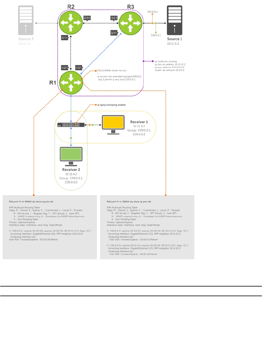
Figure 81. Preventing a Host from Joining a Group
Table 29. Preventing a Host from Joining a Group — Description
Location Description
1/21 • Interface GigabitEthernet 1/21
• ip pim sparse-mode
• ip address 10.11.12.1/24
• no shutdown
1/31 • Interface GigabitEthernet 1/31
• ip pim sparse-mode
• ip address 10.11.13.1/24
Multicast Features 525

Location Description
• no shutdown
2/1 • Interface GigabitEthernet 2/1
• ip pim sparse-mode
• ip address 10.11.1.1/24
• no shutdown
2/11 • Interface GigabitEthernet 2/11
• ip pim sparse-mode
• ip address 10.11.12.2/24
• no shutdown
2/31 • Interface GigabitEthernet 2/31
• ip pim sparse-mode
• ip address 10.11.23.1/24
• no shutdown
3/1 • Interface GigabitEthernet 3/1
• ip pim sparse-mode
• ip address 10.11.5.1/24
• no shutdown
3/11 • Interface GigabitEthernet 3/11
• ip pim sparse-mode
• ip address 10.11.13.2/24
• no shutdown
3/21 • Interface GigabitEthernet 3/21
• ip pim sparse-mode
• ip address 10.11.23.2/24
• no shutdown
Receiver 1 • Interface VLAN 300
• ip pim sparse-mode
• ip address 10.11.3.1/24
• untagged GigabitEthernet 1/1
• no shutdown
Receiver 2 • Interface VLAN 400
• ip pim sparse-mode
• ip address 10.11.4.1/24
• untagged GigabitEthernet 1/2
•ip igmp access-group igmpjoinfilR2G2
• no shutdown
526 Multicast Features
Rate Limiting IGMP Join Requests
If you expect a burst of IGMP Joins, protect the IGMP process from overload by limiting that rate at which
new groups can be joined.
Hosts whose IGMP requests are denied will use the retry mechanism built-in to IGMP so that they’re
membership is delayed rather than permanently denied.
• Limit the rate at which new groups can be joined.
INTERFACE mode
ip igmp group-join-limit
To view the enable status of this feature, use the show ip igmp interface command from EXEC
Privilege mode.
Preventing a PIM Router from Forming an Adjacency
To prevent a router from participating in PIM (for example, to configure stub multicast routing), use the
following command.
• Prevent a router from participating in protocol independent multicast (PIM).
INTERFACE mode
ip pim neighbor-filter
Preventing a Source from Registering with the RP
To prevent the PIM source DR from sending register packets to RP for the specified multicast source and
group, use the following command. If the source DR never sends register packets to the RP, no hosts can
ever discover the source and create a shortest path tree (SPT) to it.
• Prevent a source from transmitting to a particular group.
CONFIGURATION mode
ip pim register-filter
In the following example, Source 1 and Source 2 are both transmitting packets for groups 239.0.0.1 and
239.0.0.2. R3 has a PIM register filter that only permits packets destined for group 239.0.0.2. An entry is
created for group 239.0.0.1 in the routing table, but no outgoing interfaces are listed. R2 has no filter, so
it is allowed to forward both groups. As a result, Receiver 1 receives only one transmission, while Receiver
2 receives duplicate transmissions.
Multicast Features 527
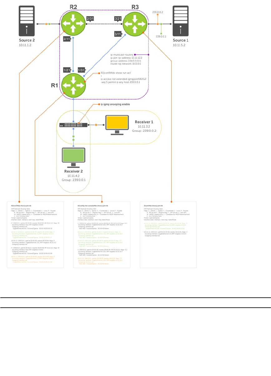
Figure 82. Preventing a Source from Transmitting to a Group
Table 30. Preventing a Source from Transmitting to a Group — Description
Location Description
1/21 • Interface GigabitEthernet 1/21
• ip pim sparse-mode
• ip address 10.11.12.1/24
• no shutdown
1/31 • Interface GigabitEthernet 1/31
• ip pim sparse-mode
• ip address 10.11.13.1/24
528 Multicast Features

Location Description
• no shutdown
2/1 • Interface GigabitEthernet 2/1
• ip pim sparse-mode
• ip address 10.11.1.1/24
• no shutdown
2/11 • Interface GigabitEthernet 2/11
• ip pim sparse-mode
• ip address 10.11.12.2/24
• no shutdown
2/31 • Interface GigabitEthernet 2/31
• ip pim sparse-mode
• ip address 10.11.23.1/24
• no shutdown
3/1 • Interface GigabitEthernet 3/1
• ip pim sparse-mode
• ip address 10.11.5.1/24
• no shutdown
3/11 • Interface GigabitEthernet 3/11
• ip pim sparse-mode
• ip address 10.11.13.2/24
• no shutdown
3/21 • Interface GigabitEthernet 3/21
• ip pim sparse-mode
• ip address 10.11.23.2/24
• no shutdown
Receiver 1 • Interface VLAN 300
• ip pim sparse-mode
• ip address 10.11.3.1/24
• untagged GigabitEthernet 1/1
• no shutdown
Receiver 2 • Interface VLAN 400
• ip pim sparse-mode
• ip address 10.11.4.1/24
• untagged GigabitEthernet 1/2
• no shutdown
Multicast Features 529

Preventing a PIM Router from Processing a Join
To permit or deny PIM Join/Prune messages on an interface using an extended IP access list, use the
following command.
NOTE: Dell Networking recommends not using the ip pim join-filter command on an
interface between a source and the RP router. Using this command in this scenario could cause
problems with the PIM-SM source registration process resulting in excessive traffic being sent to the
CPU of both the RP and PIM DR of the source.
Excessive traffic is generated when the join process from the RP back to the source is blocked due
to a new source group being permitted in the join-filter. This results in the new source becoming
stuck in registering on the DR and the continuous generation of UDP-encapsulated registration
messages between the DR and RP routers which are being sent to the CPU.
• Prevent the PIM SM router from creating state based on multicast source and/ or group.
ip pim join-filter
530 Multicast Features

31
Open Shortest Path First (OSPFv2 and
OSPFv3)
This chapter describes how to configure and use Open Shortest Path First (OSPFv2 for IPv4) and OSPF
version 3 (OSPF for IPv6) on the Z9500.
NOTE: The fundamental mechanisms of OSPF (flooding, DR election, area support, SPF calculations,
and so on) are the same between OSPFv2 and OSPFv3. This chapter identifies and clarifies the
differences between the two versions of OSPF. Except where identified, the information in this
chapter applies to both protocol versions.
OSPF protocol standards are listed in the Standards Compliance chapter.
Protocol Overview
OSPF routing is a link-state routing protocol that calls for the sending of link-state advertisements (LSAs)
to all other routers within the same autonomous system (AS) areas.
Information on attached interfaces, metrics used, and other variables is included in OSPF LSAs. As OSPF
routers accumulate link-state information, they use the shortest path first (SPF) algorithm to calculate the
shortest path to each node.
OSPF routers initially exchange HELLO messages to set up adjacencies with neighbor routers. The HELLO
process is used to establish adjacencies between routers of the AS. It is not required that every router
within the AS areas establish adjacencies. If two routers on the same subnet agree to become neighbors
through the HELLO process, they begin to exchange network topology information in the form of LSAs.
In OSPFv2 neighbors on broadcast and NBMA links are identified by their interface addresses, while
neighbors on other types of links are identified by RID.
Autonomous System (AS) Areas
OSPF operates in a type of hierarchy.
The largest entity within the hierarchy is the autonomous system (AS), which is a collection of networks
under a common administration that share a common routing strategy. OSPF is an intra-AS (interior
gateway) routing protocol, although it is capable of receiving routes from and sending routes to other
ASs.
You can divide an AS into a number of areas, which are groups of contiguous networks and attached
hosts. Routers with multiple interfaces can participate in multiple areas. These routers, called area border
routers (ABRs), maintain separate databases for each area. Areas are a logical grouping of OSPF routers
identified by an integer or dotted-decimal number.
Areas allow you to further organize your routers within in the AS. One or more areas are required within
the AS. Areas are valuable in that they allow sub-networks to "hide" within the AS, thus minimizing the
Open Shortest Path First (OSPFv2 and OSPFv3) 531
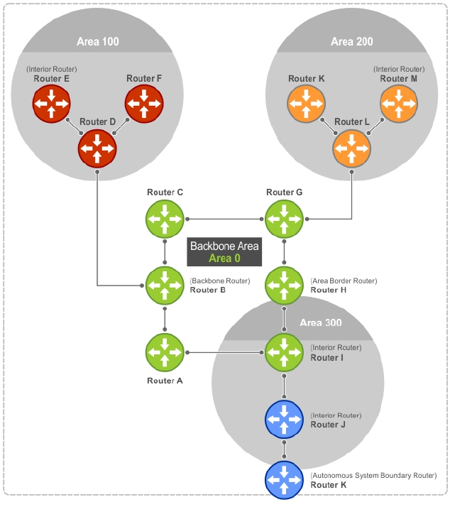
size of the routing tables on all routers. An area within the AS may not see the details of another area’s
topology. AS areas are known by their area number or the router’s IP address.
Figure 83. Autonomous System Areas
Area Types
The backbone of the network is Area 0. It is also called Area 0.0.0.0 and is the core of any AS.
All other areas must connect to Area 0. Areas can be defined in such a way that the backbone is not
contiguous. In this case, backbone connectivity must be restored through virtual links. Virtual links are
configured between any backbone routers that share a link to a non-backbone area and function as if
they were direct links.
An OSPF backbone is responsible for distributing routing information between areas. It consists of all area
border routers, networks not wholly contained in any area, and their attached routers.
The backbone is the only area with a default area number. All other areas can have their Area ID assigned
in the configuration.
532 Open Shortest Path First (OSPFv2 and OSPFv3)

In the previous example, Routers A, B, C, G, H, and I are the Backbone.
• A stub area (SA) does not receive external route information, except for the default route. These areas
do receive information from inter-area (IA) routes.
NOTE: Configure all routers within an assigned stub area as stubby, and not generate LSAs that
do not apply. For example, a Type 5 LSA is intended for external areas and the Stubby area
routers may not generate external LSAs. A virtual link cannot traverse stubby areas.
• A not-so-stubby area (NSSA) can import AS external route information and send it to the backbone. It
cannot receive external AS information from the backbone or other areas. However, a virtual link can
traverse it.
• Totally stubby areas are referred to as no summary areas in the Dell Networking OS.
Networks and Neighbors
As a link-state protocol, OSPF sends routing information to other OSPF routers concerning the state of
the links between them. The state (up or down) of those links is important.
Routers that share a link become neighbors on that segment. OSPF uses the Hello protocol as a neighbor
discovery and keep alive mechanism. After two routers are neighbors, they may proceed to exchange and
synchronize their databases, which creates an adjacency.
Router Types
Router types are attributes of the OSPF process.
A given physical router may be a part of one or more OSPF processes. For example, a router connected
to more than one area, receiving routing from a border gateway protocol (BGP) process connected to
another AS acts as both an area border router and an autonomous system router.
Each router has a unique ID, written in decimal format (A.B.C.D). You do not have to associate the router
ID with a valid IP address. However, to make troubleshooting easier, Dell Networking recommends that
the router ID and the router’s IP address reflect each other.
The following example shows different router designations.
Open Shortest Path First (OSPFv2 and OSPFv3) 533
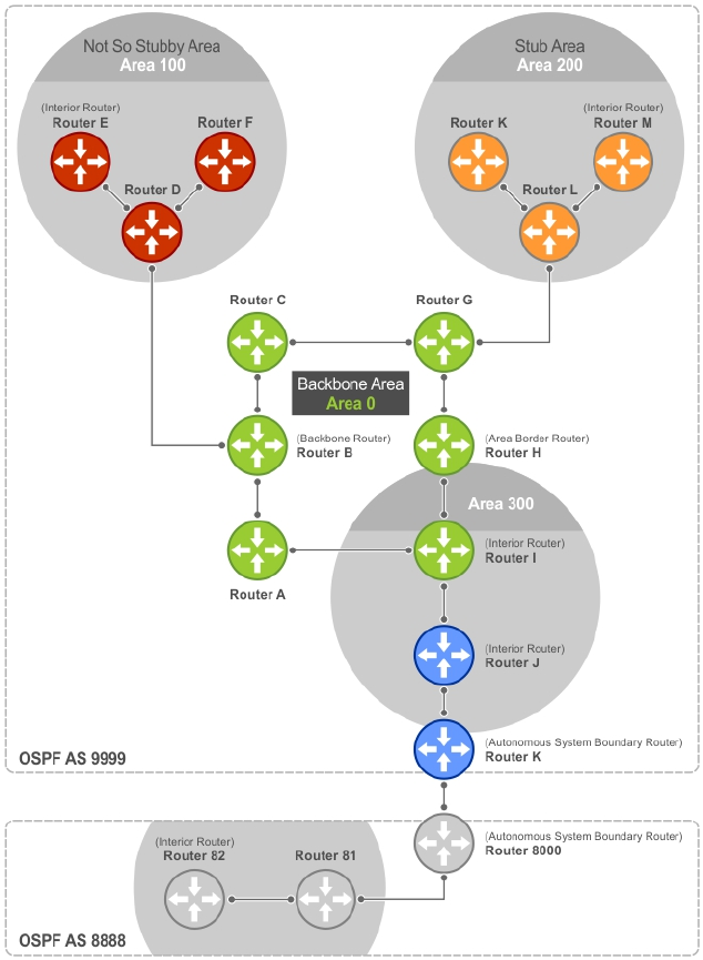
Figure 84. OSPF Routing Examples
Backbone Router (BR)
A backbone router (BR) is part of the OSPF Backbone, Area 0.
This includes all ABRs. It can also include any routers that connect only to the backbone and another
ABR, but are only part of Area 0, such as Router I in the previous example.
Area Border Router (ABR)
Within an AS, an area border router (ABR) connects one or more areas to the backbone.
The ABR keeps a copy of the link-state database for every area it connects to, so it may keep multiple
copies of the link state database. An ABR takes information it has learned on one of its attached areas and
can summarize it before sending it out on other areas it is connected to.
534 Open Shortest Path First (OSPFv2 and OSPFv3)
An ABR can connect to many areas in an AS, and is considered a member of each area it connects to.
Autonomous System Border Router (ASBR)
The autonomous system border area router (ASBR) connects to more than one AS and exchanges
information with the routers in other ASs.
Generally, the ASBR connects to a non-interior gate protocol (IGP) such as BGP or uses static routes.
Internal Router (IR)
The internal router (IR) has adjacencies with ONLY routers in the same area, as Router E, M, and I shown
in the previous example.
Designated and Backup Designated Routers
OSPF elects a designated router (DR) and a backup designated router (BDR). Among other things, the DR
is responsible for generating LSAs for the entire multiaccess network.
Designated routers allow a reduction in network traffic and in the size of the topological database.
• The DR maintains a complete topology table of the network and sends the updates to the other
routers via multicast. All routers in an area form a slave/master relationship with the DR. Every time a
router sends an update, the router sends it to the DR and BDR. The DR sends the update out to all
other routers in the area.
• The BDR is the router that takes over if the DR fails.
Each router exchanges information with the DR and BDR. The DR and BDR relay the information to the
other routers. On broadcast network segments, the number of OSPF packets is further reduced by the DR
and BDR sending such OSPF updates to a multicast IP address that all OSPF routers on the network
segment are listening on.
These router designations are not the same ad the router IDs described earlier. The DRs and BDRs are
configurable in the Dell Networking OS. If you do not define DR or BDR, the system assigns them. OSPF
looks at the priority of the routers on the segment to determine which routers are the DR and BDR. The
router with the highest priority is elected the DR. If there is a tie, the router with the higher router ID takes
precedence. After the DR is elected, the BDR is elected the same way. A router with a router priority set to
zero cannot become the DR or BDR.
Link-State Advertisements (LSAs)
A link-state advertisement (LSA) communicates the router’s local routing topology to all other local
routers in the same area.
The LSA types supported by Dell Networking are defined as follows:
•Type 1: Router LSA — The router lists links to other routers or networks in the same area. Type 1 LSAs
are flooded across their own area only. The link-state ID of the Type 1 LSA is the originating router ID.
•Type 2: Network LSA — The DR in an area lists which routers are joined within the area. Type 2 LSAs
are flooded across their own area only. The link-state ID of the Type 2 LSA is the IP interface address
of the DR.
•Type 3: Summary LSA (OSPFv2), Inter-Area-Prefix LSA (OSPFv3) — An ABR takes information it has
learned on one of its attached areas and can summarize it before sending it out on other areas it is
connected to. The link-state ID of the Type 3 LSA is the destination network number.
•Type 4: AS Border Router Summary LSA (OSPFv2), Inter-Area-Router LSA (OSPFv3) — In some cases,
Type 5 External LSAs are flooded to areas where the detailed next-hop information may not be
Open Shortest Path First (OSPFv2 and OSPFv3) 535

available. An ABR floods the information for the router (for example, the ASBR where the Type 5
advertisement originated. The link-state ID for Type 4 LSAs is the router ID of the described ASBR).
•Type 5: LSA — These LSAs contain information imported into OSPF from other routing processes.
They are flooded to all areas, except stub areas. The link-state ID of the Type 5 LSA is the external
network number.
•Type 7: External LSA — Routers in an NSSA do not receive external LSAs from ABRs, but are allowed
to send external routing information for redistribution. They use Type 7 LSAs to tell the ABRs about
these external routes, which the ABR then translates to Type 5 external LSAs and floods as normal to
the rest of the OSPF network.
•Type 8: Link LSA (OSPFv3) — This LSA carries the IPv6 address information of the local links.
•Type 9: Link Local LSA (OSPFv2), Intra-Area-Prefix LSA (OSPFv3) — For OSPFv2, this is a link-local
"opaque" LSA as defined by RFC2370. For OSPFv3, this LSA carries the IPv6 prefixes of the router and
network links.
•Type 11 - Grace LSA (OSPFv3) — For OSPFv3 only, this LSA is a link-local “opaque” LSA sent by a
restarting OSPFv3 router during a graceful restart.
For all LSA types, there are 20-byte LSA headers. One of the fields of the LSA header is the link-state ID.
Each router link is defined as one of four types: type 1, 2, 3, or 4. The LSA includes a link ID field that
identifies, by the network number and mask, the object this link connects to.
Depending on the type, the link ID has different meanings.
• 1: point-to-point connection to another router/neighboring router.
• 2: connection to a transit network IP address of the DR.
• 3: connection to a stub network IP network/subnet number.
• 4: virtual link neighboring router ID.
LSA Throttling
LSA throttling provides configurable interval timers to improve OSPF convergence times.
The default OSPF static timers (5 seconds for transmission, 1 second for acceptance) ensures sufficient
time for sending and resending LSAs and for system acceptance of arriving LSAs. However, some
networks may require reduced intervals for LSA transmission and acceptance. Throttling timers allow for
this improved convergence times.
The LSA throttling timers are configured in milliseconds, with the interval time increasing exponentially
until a maximum time has been reached. If the maximum time is reached, the system, the system
continues to transmit at the max-interval until twice the max-interval time has passed. At that point, the
system reverts to the start-interval timer and the cycle begins again.
When you configure the LSA throttle timers, syslog messages appear, indicating the interval times, as
shown below for the transmit timer (45000ms) and arrival timer (1000ms).
Mar 15 09:46:00: %STKUNIT0-M:CP %OSPF-4-LSA_BACKOFF: OSPF Process 10,Router lsa
id
2.2.2.2 router-id 2.2.2.2 is backed off to transmit after 45000ms
Mar 15 09:46:06: %STKUNIT0-M:CP %OSPF-4-LSA_BACKOFF: OSPF Process 10,Router lsa
id
3.3.3.3 rtrid 3.3.3.3 received before 1000ms time
536 Open Shortest Path First (OSPFv2 and OSPFv3)
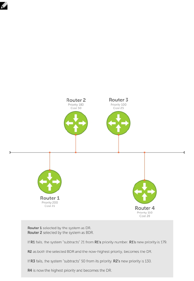
Virtual Links
In the case in which an area cannot be directly connected to Area 0, you must configure a virtual link
between that area and Area 0.
The two endpoints of a virtual link are ABRs, and you must configure the virtual link in both routers. The
common non-backbone area to which the two routers belong is called a transit area. A virtual link
specifies the transit area and the router ID of the other virtual endpoint (the other ABR).
NOTE: You cannot configure a virtual link through a stub area or NSSA.
Router Priority and Cost
Router priority and cost is the method the system uses to “rate” the routers.
For example, if not assigned, the system selects the router with the highest priority as the DR. The second
highest priority is the BDR.
• Priority is a numbered rating 0 to 255. The higher the number, the higher the priority.
• Cost is a numbered rating 1 to 65535. The higher the number, the greater the cost. The cost assigned
reflects the cost should the router fail. When a router fails and the cost is assessed, a new priority
number results.
Figure 85. Priority and Cost Examples
Open Shortest Path First (OSPFv2 and OSPFv3) 537

OSPF Implementation
The Dell Networking OS supports up to 10,000 OSPF routes for OSPFv2. Within the 10,000 routes, you
can designate up to 8,000 routes as external and up to 2,000 as inter/intra area routes.
Multiple OSPF processes (OSPF MP) are supported on OSPFv2 only; up to 32 simultaneous processes are
supported.
On OSPFv3, the system supports only one process at a time for all platforms.
OSPFv2 and OSPFv3 can coexist on a switch, but you must configure them individually.
The system supports stub areas, totally stub (no summary) and not so stubby areas (NSSAs) and supports
the following LSAs:
• Router (type 1)
• Network (type 2)
• Network Summary (type 3)
• AS Boundary (type 4)
• LSA(type 5)
• External LSA (type 7)
• Link LSA, OSPFv3 only (type 8)
• Opaque Link-Local (type 9)
• Grace LSA, OSPFv3 only (type 11)
Fast Convergence (OSPFv2, IPv4 Only)
Fast convergence allows you to define the speeds at which LSAs are originated and accepted, and reduce
OSPFv2 end-to-end convergence time.
The system allows you to accept and originate LSAs as soon as they are available to speed up route
information propagation.
NOTE: The faster the convergence, the more frequent the route calculations and updates. This
impacts CPU utilization and may impact adjacency stability in larger topologies.
Multi-Process OSPFv2 (IPv4 only)
Multi-process OSPF is supported only on OSPFv2 with IPv4 on the Z9500. Up to 32 OSPFv2 processes
are supported.
Multi-process OSPF allows multiple OSPFv2 processes on a single router. Multiple OSPFv2 processes
allow for isolating routing domains, supporting multiple route policies and priorities in different domains,
and creating smaller domains for easier management.
Each OSPFv2 process has a unique process ID and must have an associated router ID. There must be an
equal number of interfaces and must be in Layer-3 mode for the number of processes created. For
example, if you create five OSPFv2 processes on a system, there must be at least five interfaces assigned
in Layer 3 mode.
Each OSPFv2 process is independent. If one process loses adjacency, the other processes continue to
function.
538 Open Shortest Path First (OSPFv2 and OSPFv3)

Processing SNMP and Sending SNMP Traps
Though there are may be several OSPFv2 processes, only one process can process simple network
management protocol (SNMP) requests and send SNMP traps.
The mib-binding command identifies one of the OSPVFv2 processes as the process responsible for
SNMP management. If you do not specify the mib-binding command, the first OSPFv2 process created
manages the SNMP processes and traps.
RFC-2328 Compliant OSPF Flooding
In OSPF, flooding is the most resource-consuming task. The flooding algorithm described in RFC 2328
requires that OSPF flood LSAs on all interfaces, as governed by LSA’s flooding scope (refer to Section 13
of the RFC.)
When multiple direct links connect two routers, the RFC 2328 flooding algorithm generates significant
redundant information across all links.
By default, the system implements an enhanced flooding procedure which dynamically and intelligently
detects when to optimize flooding. Wherever possible, the OSPF task attempts to reduce flooding
overhead by selectively flooding on a subset of the interfaces between two routers.
Enabling RFC-2328 Compliant OSPF Flooding
To enable OSPF flooding, use the following command.
When you enable this command, it configures the system to flood LSAs on all interfaces.
• Enable RFC 2328 flooding.
ROUTER OSPF mode
flood-2328
Examples of OSPF Flooding Behavior
To confirm RFC 2328 flooding behavior, use the debug ip ospf packet command.
The following example shows no change in the updated packets (shown in bold). ACKs 2 (shown in bold)
is printed only for ACK packets.
00:10:41 : OSPF(1000:00):
Rcv. v:2 t:5(LSAck) l:64 Acks 2 rid:2.2.2.2
aid:1500 chk:0xdbee aut:0 auk: keyid:0 from:Vl 1000
LSType:Type-5 AS External id:160.1.1.0 adv:6.1.0.0 seq:0x8000000c
LSType:Type-5 AS External id:160.1.2.0 adv:6.1.0.0 seq:0x8000000c
00:10:41 : OSPF(1000:00):
Rcv. v:2 t:5(LSAck) l:64 Acks 2 rid:2.2.2.2
aid:1500 chk:0xdbee aut:0 auk: keyid:0 from:Vl 100
LSType:Type-5 AS External id:160.1.1.0 adv:6.1.0.0 seq:0x8000000c
LSType:Type-5 AS External id:160.1.2.0 adv:6.1.0.0 seq:0x8000000c
00:10:41 : OSPF(1000:00):
Rcv. v:2 t:4(LSUpd) l:100 rid:6.1.0.0
aid:0 chk:0xccbd aut:0 auk: keyid:0 from:Te 10/21
Number of LSA:2
LSType:Type-5 AS External(5) Age:1 Seq:0x8000000c id:170.1.1.0 Adv:6.1.0.0
Netmask:255.255.255.0 fwd:0.0.0.0 E2, tos:0 metric:0
LSType:Type-5 AS External(5) Age:1 Seq:0x8000000c id:170.1.2.0 Adv:6.1.0.0
Netmask:255.255.255.0 fwd:0.0.0.0 E2, tos:0 metric:0
Open Shortest Path First (OSPFv2 and OSPFv3) 539

To confirm that you enabled RFC-2328–compliant OSPF flooding, use the show ip ospf command.
Dell#show ip ospf
Routing Process ospf 1 with ID 2.2.2.2
Supports only single TOS (TOS0) routes
It is an Autonomous System Boundary Router
It is Flooding according to RFC 2328
SPF schedule delay 5 secs, Hold time between two SPFs 10 secs
Number of area in this router is 1, normal 0 stub 0 nssa 1
--More--
OSPF ACK Packing
The OSPF ACK packing feature bundles multiple LS acknowledgements in a single packet, significantly
reducing the number of ACK packets transmitted when the number of LSAs increases.
This feature also enhances network utilization and reduces the number of small ACK packets sent to a
neighboring router. OSPF ACK packing is enabled by default and non-configurable.
Setting OSPF Adjacency with Cisco Routers
To establish an OSPF adjacency between Dell Networking and Cisco routers, the hello interval and dead
interval must be the same on both routers.
The OSPF dead interval value is, by default, set to 40 secondsand is independent of the OSPF hello
interval. Configuring a hello interval does not change the dead interval in the system. In contrast, the
OSPF dead interval on a Cisco router is, by default, four times as long as the hello interval. Changing the
hello interval on the Cisco router automatically changes the dead interval.
To ensure equal intervals between the routers, use the following command.
• Manually set the dead interval of the Dell Networking router to match the Cisco configuration.
INTERFACE mode
ip ospf dead-interval <x>
Examples of Setting and Viewing a Dead Interval
In the following example, the dead interval is set at 4x the hello interval (shown in bold).
Dell(conf)#int te 2/2
Dell(conf-if-te-2/2)#ip ospf hello-interval 20
Dell(conf-if-te-2/2)#ip ospf dead-interval 80
Dell(conf-if-te-2/2)#
In the following example, the dead interval is set at 4x the hello interval (shown in bold).
Dell (conf-if-te-2/2)#ip ospf dead-interval 20
Dell (conf-if-te-2/2)#do show ip os int te 1/3
TengigabitEthernet 2/2 is up, line protocol is up
Internet Address 20.0.0.1/24, Area 0
Process ID 10, Router ID 1.1.1.2, Network Type BROADCAST, Cost: 1
Transmit Delay is 1 sec, State DR, Priority 1
Designated Router (ID) 1.1.1.2, Interface address 30.0.0.1
Backup Designated Router (ID) 1.1.1.1, Interface address 30.0.0.2
Timer intervals configured, Hello 20, Dead 80, Wait 20, Retransmit 5
Hello due in 00:00:04
Neighbor Count is 1, Adjacent neighbor count is 1
Adjacent with neighbor 1.1.1.1 (Backup Designated Router)
Dell(conf-if-te-2/2)#
540 Open Shortest Path First (OSPFv2 and OSPFv3)

Configuration Information
The interfaces must be in Layer 3 mode (assigned an IP address) and enabled so that they can send and
receive traffic. The OSPF process must know about these interfaces.
To make the OSPF process aware of these interfaces, they must be assigned to OSPF areas.
You must configure OSPF GLOBALLY on the system in CONFIGURATION mode.
OSPF features and functions are assigned to each router using the CONFIG-INTERFACE commands for
each interface.
NOTE: By default, OSPF is disabled.
Configuration Task List for OSPFv2 (OSPF for IPv4)
You can perform the following tasks to configure Open Shortest Path First version 2 (OSPF for IPv4) on
the switch. Two of the tasks are mandatory; others are optional.
•Enabling OSPFv2 (mandatory)
•Assigning a Router ID
•Enabling Multi-Process OSPF
•Assigning an OSPFv2 Area (mandatory)
•Enable OSPFv2 on Interfaces
•Configuring Stub Areas
•Configuring LSA Throttling Timers
•Enabling Passive Interfaces
•Enabling Fast-Convergence
•Changing OSPFv2 Parameters on Interfaces
•Enabling OSPFv2 Authentication
•Configuring Virtual Links
•Creating Filter Routes
•Applying Prefix Lists
•Redistributing Routes
•Troubleshooting OSPFv2
1. Configure a physical interface. Assign an IP address, physical or Loopback, to the interface to enable
Layer 3 routing.
2. Enable OSPF globally. Assign network area and neighbors.
3. Add interfaces or configure other attributes.
For a complete list of the OSPF commands, refer to the OSPF section in the Dell Networking OS
Command Line Reference Guide document.
Enabling OSPFv2
To enable Layer 3 routing, assign an IP address to an interface (physical or Loopback). By default, OSPF,
similar to all routing protocols, is disabled.
You must configure at least one interface for Layer 3 before enabling OSPFv2 globally.
Open Shortest Path First (OSPFv2 and OSPFv3) 541

If implementing multi-process OSPF, create an equal number of Layer 3 enabled interfaces and OSPF
process IDs. For example, if you create four OSPFv2 process IDs, you must have four interfaces with Layer
3 enabled.
1. Assign an IP address to an interface.
CONFIG-INTERFACE mode
ip address ip-address mask
The format is A.B.C.D/M.
If you are using a Loopback interface, refer to Loopback Interfaces.
2. Enable the interface.
CONFIG-INTERFACE mode
no shutdown
3. Return to CONFIGURATION mode to enable the OSPFv2 process globally.
CONFIGURATION mode
router ospf process-id [vrf {vrf name}]
•vrf name: enter the keyword VRF and the instance name to tie the OSPF instance to the VRF. All
network commands under this OSPF instance are later tied to the VRF instance.
The range is from 0 to 65535.
The OSPF process ID is the identifying number assigned to the OSPF process. The router ID is the IP
address associated with the OSPF process.
After the OSPF process and the VRF are tied together, the OSPF process ID cannot be used again in
the system.
If you try to enter an OSPF process ID, or if you try to enable more OSPF processes than available
Layer 3 interfaces, prior to assigning an IP address to an interface and setting the no shutdown
command, the following message displays:
Dell(conf)#router ospf 1
% Error: No router ID available.
Assigning a Router ID
In CONFIGURATION ROUTER OSPF mode, assign the router ID.
The router ID is not required to be the router’s IP address. However, Dell Networking recommends using
the IP address as the router ID for easier management and troubleshooting. Optional process-id
commands are also described.
• Assign the router ID for the OSPFv2 process.
CONFIG-ROUTER-OSPF-id mode
router-id ip address
• Disable OSPF.
CONFIGURATION mode
no router ospf process-id
542 Open Shortest Path First (OSPFv2 and OSPFv3)

• Reset the OSPFv2 process.
EXEC Privilege mode
clear ip ospf process-id
• View the current OSPFv2 status.
EXEC mode
show ip ospf process-id
Example of Viewing the Current OSPFv2 Status
Dell#show ip ospf 55555
Routing Process ospf 55555 with ID 10.10.10.10
Supports only single TOS (TOS0) routes
SPF schedule delay 5 secs, Hold time between two SPFs 10 secs
Number of area in this router is 0, normal 0 stub 0 nssa 0
Dell#
Enabling Multi-Process OSPF (OSPFv2, IPv4 Only)
Multi-process OSPF allows multiple OSPFv2 processes on a single router.
For more information, refer to Multi-Process OSPF (OSPFv2, IPv4 Only)
When configuring a single OSPF process, follow the same steps previously described. Repeat them as
often as necessary for the desired number of processes. After the process is created, all other
configurations apply as usual.
1. Assign an IP address to an interface.
CONFIG-INTERFACE mode
ip address ip-address mask
Format: A.B.C.D/M.
If you are using a Loopback interface, refer to Loopback Interfaces.
2. Enable the interface.
CONFIG-INTERFACE mode
no shutdown
3. Return to CONFIGURATION mode to enable the OSPFv2 process globally.
CONFIGURATION mode
router ospf process-id [vrf]
The range is from 0 to 65535.
After the OSPF process and the VRF are tied together, the OSPF process ID cannot be used again in
the system.
Open Shortest Path First (OSPFv2 and OSPFv3) 543

If you try to enable more OSPF processes than available Layer 3 interfaces, the following message
displays:
Dell(conf)#router ospf 1
% Error: No router ID available.
Assigning an OSPFv2 Area
After you enable OSPFv2, assign the interface to an OSPF area. Set up OSPF areas and enable OSPFv2 on
an interface with the network command.
You must have at least one AS area: Area 0. This is the backbone area. If your OSPF network contains
more than one area, configure a backbone area (Area ID 0.0.0.0). Any area besides Area 0 can have any
number ID assigned to it.
The OSPFv2 process evaluates the network commands in the order they are configured. Assign the
network address that is most explicit first to include all subnets of that address. For example, if you assign
the network address 10.0.0.0 /8, you cannot assign the network address 10.1.0.0 /16 because it is already
included in the first network address.
When configuring the network command, configure a network address and mask that is a superset of
the IP subnet configured on the Layer-3 interface for OSPFv2 to use.
You can assign the area in the following step by a number or with an IP interface address.
• Enable OSPFv2 on an interface and assign a network address range to a specific OSPF area.
CONFIG-ROUTER-OSPF-id mode
network ip-address mask area area-id
The IP Address Format is A.B.C.D/M.
The area ID range is from 0 to 65535 or A.B.C.D/M.
Enable OSPFv2 on Interfaces
Enable and configure OSPFv2 on each interface (configure for Layer 3 protocol), and not shutdown.
You can also assign OSPFv2 to a Loopback interface as a virtual interface.
OSPF functions and features, such as MD5 Authentication, Grace Period, Authentication Wait Time, are
assigned on a per interface basis.
NOTE: If using features like MD5 Authentication, ensure all the neighboring routers are also
configured for MD5.
In the example below, an IP address is assigned to an interface and an OSPFv2 area is defined that
includes the IP address of a Layer 3 interface.
The first bold lines assign an IP address to a Layer 3 interface, and theno shutdown command ensures
that the interface is UP.
The second bold line assigns the IP address of an interface to an area.
Example of Enabling OSPFv2 and Assigning an Area to an Interface
Dell#(conf)#int te 4/44
Dell(conf-if-te-4/44)#ip address 10.10.10.10/24
Dell(conf-if-te-4/44)#no shutdown
Dell(conf-if-te-4/44)#ex
544 Open Shortest Path First (OSPFv2 and OSPFv3)

Dell(conf)#router ospf 1
Dell(conf-router_ospf-1)#network 1.2.3.4/24 area 0
Dell(conf-router_ospf-1)#network 10.10.10.10/24 area 1
Dell(conf-router_ospf-1)#network 20.20.20.20/24 area 2
Dell(conf-router_ospf-1)#
Dell#
Dell Networking recommends using the interface IP addresses for the OSPFv2 router ID for easier
management and troubleshooting.
To view the configuration, use the show config command in CONFIGURATION ROUTER OSPF mode.
OSPF, by default, sends hello packets out to all physical interfaces assigned an IP address that is a subset
of a network on which OSPF is enabled.
To view currently active interfaces and the areas assigned to them, use the show ip ospf interface
command.
Example of Viewing Active Interfaces and Assigned Areas
Dell>show ip ospf 1 interface
TengigabitEthernet 12/17 is up, line protocol is up
Internet Address 10.2.2.1/24, Area 0.0.0.0
Process ID 1, Router ID 11.1.2.1, Network Type BROADCAST, Cost: 1
Transmit Delay is 1 sec, State DR, Priority 1
Designated Router (ID) 11.1.2.1, Interface address 10.2.2.1
Backup Designated Router (ID) 0.0.0.0, Interface address 0.0.0.0
Timer intervals configured, Hello 10, Dead 40, Wait 40, Retransmit 5
Hello due in 00:00:04
Neighbor Count is 0, Adjacent neighbor count is 0
TengigabitEthernet 12/21 is up, line protocol is up
Internet Address 10.2.3.1/24, Area 0.0.0.0
Process ID 1, Router ID 11.1.2.1, Network Type BROADCAST, Cost: 1
Transmit Delay is 1 sec, State BDR, Priority 1
Designated Router (ID) 13.1.1.1, Interface address 10.2.3.2
Backup Designated Router (ID) 11.1.2.1, Interface address 10.2.3.1
Timer intervals configured, Hello 10, Dead 40, Wait 40, Retransmit 5
Hello due in 00:00:05
Neighbor Count is 1, Adjacent neighbor count is 1
Adjacent with neighbor 13.1.1.1 (Designated Router)
Dell>
Loopback interfaces also help the OSPF process. OSPF picks the highest interface address as the router-
id and a Loopback interface address has a higher precedence than other interface addresses.
Example of Viewing OSPF Status on a Loopback Interface
Dell#show ip ospf 1 int
TengigabitEthernet 13/23 is up, line protocol is up
Internet Address 10.168.0.1/24, Area 0.0.0.1
Process ID 1, Router ID 10.168.253.2, Network Type BROADCAST, Cost: 1
Transmit Delay is 1 sec, State DROTHER, Priority 1
Designated Router (ID) 10.168.253.5, Interface address 10.168.0.4
Backup Designated Router (ID) 192.168.253.3, Interface address 10.168.0.2
Timer intervals configured, Hello 10, Dead 40, Wait 40, Retransmit 5
Hello due in 00:00:08
Neighbor Count is 3, Adjacent neighbor count is 2
Adjacent with neighbor 10.168.253.5 (Designated Router)
Adjacent with neighbor 10.168.253.3 (Backup Designated Router)
Open Shortest Path First (OSPFv2 and OSPFv3) 545

Loopback 0 is up, line protocol is up
Internet Address 10.168.253.2/32, Area 0.0.0.1
Process ID 1, Router ID 10.168.253.2, Network Type LOOPBACK, Cost: 1
Loopback interface is treated as a stub Host.
Dell#
Configuring Stub Areas
OSPF supports different types of LSAs to help reduce the amount of router processing within the areas.
Type 5 LSAs are not flooded into stub areas; the ABR advertises a default route into the stub area to which
it is attached. Stub area routers use the default route to reach external destinations.
To ensure connectivity in your OSPFv2 network, never configure the backbone area as a stub area.
To configure a stub area, use the following commands.
1. Review all areas after they were configured to determine which areas are NOT receiving type 5 LSAs.
EXEC Privilege mode
show ip ospf process-id [vrf] database database-summary
2. Enter CONFIGURATION mode.
EXEC Privilege mode
configure
3. Enter ROUTER OSPF mode.
CONFIGURATION mode
router ospf process-id [vrf]
Process ID is the ID assigned when configuring OSPFv2 globally.
4. Configure the area as a stub area.
CONFIG-ROUTER-OSPF-id mode
area area-id stub [no-summary]
Use the keywords no-summary to prevent transmission into the area of summary ASBR LSAs.
Area ID is the number or IP address assigned when creating the area.
Example of the show ip ospf database database-summary Command
To view which LSAs are transmitted, use the show ip ospf database process-id database-
summary command in EXEC Privilege mode.
Dell#show ip ospf 34 database database-summary
OSPF Router with ID (10.1.2.100) (Process ID 34)
Area ID Router Network S-Net S-ASBR Type-7 Subtotal
2.2.2.2 1 0 0 0 0 1
3.3.3.3 1 0 0 0 0 1
Dell#
To view information on areas, use the show ip ospf process-id command in EXEC Privilege mode.
546 Open Shortest Path First (OSPFv2 and OSPFv3)
Configuring LSA Throttling Timers
Configured link-state advertisement (LSA) timers replace the standard transmit and acceptance times for
LSAs.
The LSA throttling timers are configured in milliseconds. The interval time increases exponentially until a
maximum time is reached. If the maximum time is reached, the system continues to transmit at the
maximum interval. If the system is stable for twice the maximum interval time, it reverts to the start-
interval timer. The cycle repeats.
To configure the LSA throttling timers, use the following commands.
1. Specify the interval times for all LSA transmissions. CONFIG-ROUTER-OSPF-id mode. timers
throttle lsa all {start-interval | hold-interval | max-interval} To set the minimum
interval between initial sending and resending the same LSA, use the keywords start-interval.
To set the next interval to send the same LSA, use the keywords hold-interval. The hold-interval
is the time between sending the same LSA after the start-interval is attempted. To set the maximum
amount of time the system waits before sending the LSA, use the keywords max-interval. The
interval range is 0 to 600,000 milliseconds.
2. Specify the interval for LSA acceptance. CONFIG-ROUTER-OSPF-id mode. timers throttle
lsa all arrival-time
Enabling Passive Interfaces
A passive interface is one that does not send or receive routing information.
Enabling passive interface suppresses routing updates on an interface. Although the passive interface
does not send or receive routing updates, the network on that interface is still included in OSPF updates
sent via other interfaces.
To suppress the interface’s participation on an OSPF interface, use the following command. This
command stops the router from sending updates on that interface.
• Specify whether all or some of the interfaces are passive.
CONFIG-ROUTEROSPF- id mode
passive-interface {default | interface}
The default is enabled passive interfaces on ALL interfaces in the OSPF process.
Entering the physical interface type, slot, and number enables passive interface on only the identified
interface.
– For a 10–Gigabit Ethernet interface, enter the keyword TenGigabitEthernet then the slot/port
information (for example, passive-interface te 2/1).
– For a port channel, enter the keywords port-channel then a number from 1 to 255 for TeraScale
and ExaScale.
– For a 40-Gigabit Ethernet interface, enter the keyword FortyGigabitEthernet then the slot/
port information (for example, passive-interface fo 2/3).
– For a VLAN, enter the keyword vlan then a number from 1 to 4094 (for example, passive-
interface vlan 2222).
The keyword default sets all interfaces on this OSPF process as passive.
To remove the passive interface from select interfaces, use the no passive-interface
interface command while passive interface default is configured.
Open Shortest Path First (OSPFv2 and OSPFv3) 547

To enable both receiving and sending routing updates, use the no passive-interface
interface command.
Example of Viewing Passive Interfaces
When you configure a passive interface, the show ip ospf process-id interface command adds
the words passive interface to indicate that the hello packets are not transmitted on that interface
(shown in bold).
Dell#show ip ospf 34 int
TengigabitEthernet 0/0 is up, line protocol is down
Internet Address 10.1.2.100/24, Area 1.1.1.1
Process ID 34, Router ID 10.1.2.100, Network Type BROADCAST, Cost: 10
Transmit Delay is 1 sec, State DOWN, Priority 1
Designated Router (ID) 10.1.2.100, Interface address 0.0.0.0
Backup Designated Router (ID) 0.0.0.0, Interface address 0.0.0.0
Timer intervals configured, Hello 10, Dead 40, Wait 40, Retransmit 5
Hello due in 13:39:46
Neighbor Count is 0, Adjacent neighbor count is 0
TengigabitEthernet 0/1 is up, line protocol is down
Internet Address 10.1.3.100/24, Area 2.2.2.2
Process ID 34, Router ID 10.1.2.100, Network Type BROADCAST, Cost: 10
Transmit Delay is 1 sec, State DR, Priority 1
Designated Router (ID) 10.1.2.100, Interface address 10.1.3.100
Backup Designated Router (ID) 0.0.0.0, Interface address 0.0.0.0
Timer intervals configured, Hello 10, Dead 40, Wait 40, Retransmit 5
No Hellos (Passive interface)
Neighbor Count is 0, Adjacent neighbor count is 0
Loopback 45 is up, line protocol is up
Internet Address 10.1.1.23/24, Area 2.2.2.2
Process ID 34, Router ID 10.1.2.100, Network Type LOOPBACK, Cost: 1
Enabling Fast-Convergence
The fast-convergence CLI sets the minimum origination and arrival LSA parameters to zero (0), allowing
rapid route calculation.
When you disable fast-convergence, origination and arrival LSA parameters are set to 5 seconds and 1
second, respectively.
Setting the convergence parameter (from 1 to 4) indicates the actual convergence level. Each
convergence setting adjusts the LSA parameters to zero, but the fast-convergence parameter setting
allows for even finer tuning of the convergence speed. The higher the number, the faster the
convergence.
To enable or disable fast-convergence, use the following command.
• Enable OSPF fast-convergence and specify the convergence level.
CONFIG-ROUTEROSPF- id mode
fast-convergence {number}
The parameter range is from 1 to 4.
The higher the number, the faster the convergence.
When disabled, the parameter is set at 0.
548 Open Shortest Path First (OSPFv2 and OSPFv3)

NOTE: A higher convergence level can result in occasional loss of OSPF adjacency. Generally,
convergence level 1 meets most convergence requirements. Only select higher convergence
levels following consultation with Dell Technical Support.
Examples of Enabling Fast-Convergence
In the following examples, Convergence Level shows the fast-converge parameter setting and Min
LSA origination shows the LSA parameters (shown in bold).
The following example shows the fast-converge command.
Dell(conf-router_ospf-1)#fast-converge 2
Dell(conf-router_ospf-1)#ex
Dell(conf)#ex
Dell#show ip ospf 1
Routing Process ospf 1 with ID 192.168.67.2
Supports only single TOS (TOS0) routes
SPF schedule delay 5 secs, Hold time between two SPFs 10 secs
Convergence Level 2
Min LSA origination 0 secs, Min LSA arrival 0 secs
Number of area in this router is 0, normal 0 stub 0 nssa 0
Dell#
To disable fast-convergence, use the no fast-converge command.
Dell#(conf-router_ospf-1)#no fast-converge
Dell#(conf-router_ospf-1)#ex
Dell#(conf)#ex
Dell##show ip ospf 1
Routing Process ospf 1 with ID 192.168.67.2
Supports only single TOS (TOS0) routes
SPF schedule delay 5 secs, Hold time between two SPFs 10 secs
Convergence Level 0
Min LSA origination 5 secs, Min LSA arrival 1 secs
Number of area in this router is 0, normal 0 stub 0 nssa 0
Dell#
Changing OSPFv2 Parameters on Interfaces
You can modify the OSPF configuration on switch interfaces.
Some interface parameter values must be consistent across all interfaces to avoid routing errors. For
example, set the same time interval for the hello packets on all routers in the OSPF network to prevent
misconfiguration of OSPF neighbors.
To change OSPFv2 parameters on the interfaces, use any or all of the following commands.
• Change the cost associated with OSPF traffic on the interface.
CONFIG-INTERFACE mode
ip ospf cost
–cost: The range is from 1 to 65535 (the default depends on the interface speed).
• Change the time interval the router waits before declaring a neighbor dead.
CONFIG-INTERFACE mode
ip ospf dead-interval seconds
–seconds: the range is from 1 to 65535 (the default is 40 seconds).
The dead interval must be four times the hello interval.
Open Shortest Path First (OSPFv2 and OSPFv3) 549

The dead interval must be the same on all routers in the OSPF network.
• Change the time interval between hello-packet transmission.
CONFIG-INTERFACE mode
ip ospf hello-interval seconds
–seconds: the range is from 1 to 65535 (the default is 10 seconds).
The hello interval must be the same on all routers in the OSPF network.
• Use the MD5 algorithm to produce a message digest or key, which is sent instead of the key.
CONFIG-INTERFACE mode
ip ospf message-digest-key keyid md5 key
–keyid: the range is from 1 to 255.
–Key: a character string.
NOTE: Be sure to write down or otherwise record the key. You cannot learn the key after it is
configured. You must be careful when changing this key.
NOTE: You can configure a maximum of six digest keys on an interface. Of the available six
digest keys, the switches select the MD5 key that is common. The remaining MD5 keys are
unused.
• Change the priority of the interface, which is used to determine the Designated Router for the OSPF
broadcast network.
CONFIG-INTERFACE mode
ip ospf priority number
–number: the range is from 0 to 255 (the default is 1).
• Change the retransmission interval between LSAs.
CONFIG-INTERFACE mode
ip ospf retransmit-interval seconds
–seconds: the range is from 1 to 65535 (the default is 5 seconds).
The retransmit interval must be the same on all routers in the OSPF network.
• Change the wait period between link state update packets sent out the interface.
CONFIG-INTERFACE mode
ip ospf transmit-delay seconds
–seconds: the range is from 1 to 65535 (the default is 1 second).
The transmit delay must be the same on all routers in the OSPF network.
Example of Changing and Verifying the cost Parameter and Viewing Interface Status
To view interface configurations, use the show config command in CONFIGURATION INTERFACE
mode.
To view interface status in the OSPF process, use the show ip ospf interface command in EXEC
mode.
550 Open Shortest Path First (OSPFv2 and OSPFv3)

The bold lines in the example show the change on the interface. The change is reflected in the OSPF
configuration.
Dell(conf-if)#ip ospf cost 45
Dell(conf-if)#show config
!
interface TengigabitEthernet 0/0
ip address 10.1.2.100 255.255.255.0
no shutdown
ip ospf cost 45
Dell(conf-if)#end
Dell#show ip ospf 34 interface
TengigabitEthernet 0/0 is up, line protocol is up
Internet Address 10.1.2.100/24, Area 2.2.2.2
Process ID 34, Router ID 10.1.2.100, Network Type BROADCAST, Cost: 45
Transmit Delay is 1 sec, State DR, Priority 1
Designated Router (ID) 10.1.2.100, Interface address 10.1.2.100
Backup Designated Router (ID) 10.1.2.100, Interface address 0.0.0.0
Timer intervals configured, Hello 10, Dead 40, Wait 40, Retransmit 5
Hello due in 00:00:06
Neighbor Count is 0, Adjacent neighbor count is 0
Dell#
Enabling OSPFv2 Authentication
To enable or change various OSPF authentication parameters, use the following commands.
• Set a clear text authentication scheme on the interface.
CONFIG-INTERFACE mode
ip ospf authentication-key key
Configure a key that is a text string no longer than eight characters.
All neighboring routers must share password to exchange OSPF information.
• Set the authentication change wait time in seconds between 0 and 300 for the interface.
CONFIG-INTERFACE mode
ip ospf auth-change-wait-time seconds
This setting is the amount of time OSPF has available to change its interface authentication type.
During the auth-change-wait-time, OSPF sends out packets with both the new and old
authentication schemes.
This transmission stops when the period ends.
The default is 0 seconds.
Configuring Virtual Links
Areas within OSPF must be connected to the backbone area (Area ID 0.0.0.0).
If an OSPF area does not have a direct connection to the backbone, at least one virtual link is required.
Configure virtual links on an ABR connected to the backbone.
•hello-interval — help packet
Open Shortest Path First (OSPFv2 and OSPFv3) 551

•retransmit-interval — LSA retransmit interval
•transmit-delay — LSA transmission delay
•dead-interval — dead router detection time
•authentication-key — authentication key
•message-digest-key — MD5 authentication key
To configure virtual links, use the following command.
• Configure the optional parameters of a virtual link.
CONFIG-ROUTEROSPF- id mode
area area-id virtual-link router-id [hello-interval seconds | retransmit-
interval seconds | transmit-delay seconds | dead-interval seconds |
authentication-key key | message-digest-key keyid md5 key]
–area ID: assigned earlier (the range is from 0 to 65535 or A.B.C.D).
–router ID: IP address associated with the virtual link neighbor.
–hello interval seconds: the range is from 1 to 8192 (the default is 10).
–retransmit interval seconds: the range is from 1 to 3600 (the default is 5).
–transmit delay seconds: the range is from 1 to 3600 (the default is 1).
–dead interval seconds: the range is from 1 to 8192 (the default is 40).
–authentication key: eight characters.
–message digest key keyid: the range is from 1 to 255.
–md5 key: 16 characters.
If you do not enter other parameters, the defaults are used.
Only the area ID and router ID require configuration to create a virtual link.
Use EITHER the Authentication Key or the Message Digest (MD5) key.
Example of Viewing Virtual Links
Use the show ip ospf process-id virtual-links command to view the virtual link.
Dell#show ip ospf 1 virtual-links
Virtual Link to router 192.168.253.5 is up
Run as demand circuit
Transit area 0.0.0.1, via interface TengigabitEthernet 13/16, Cost of using 2
Transmit Delay is 1 sec, State POINT_TO_POINT,
Timer intervals configured, Hello 10, Dead 40, Wait 40, Retransmit 5
Hello due in 00:00:02
Dell#
Creating Filter Routes
To filter routes, use prefix lists. OSPF applies prefix lists to incoming or outgoing routes.
Incoming routes must meet the conditions of the prefix lists. If they do not, OSPF does not add the route
to the routing table. Configure the prefix list in CONFIGURATION PREFIX LIST mode prior to assigning it
to the OSPF process.
• Create a prefix list and assign it a unique name.
CONFIGURATION mode
552 Open Shortest Path First (OSPFv2 and OSPFv3)

ip prefix-list prefix-name
You are in PREFIX LIST mode.
• Create a prefix list with a sequence number and a deny or permit action.
CONFIG- PREFIX LIST mode
seq sequence-number {deny |permit} ip-prefix [ge min-prefix-length] [le max-
prefix-length]
The optional parameters are:
–ge min-prefix-length: is the minimum prefix length to match (from 0 to 32).
–le max-prefix-length: is the maximum prefix length to match (from 0 to 32).
For configuration information about prefix lists, refer to Access Control Lists (ACLs).
Applying Prefix Lists
To apply prefix lists to incoming or outgoing OSPF routes, use the following commands.
• Apply a configured prefix list to incoming OSPF routes.
CONFIG-ROUTEROSPF-id mode
distribute-list prefix-list-name in [interface]
• Assign a configured prefix list to outgoing OSPF routes.
CONFIG-ROUTEROSPF-id
distribute-list prefix-list-name out [connected | isis | rip | static]
Redistributing Routes
You can add routes from other routing instances or protocols to the OSPF process.
With the redistribute command, you can include RIP, static, or directly connected routes in the OSPF
process.
NOTE: Do not route iBGP routes to OSPF unless there are route-maps associated with the OSPF
redistribution.
To redistribute routes, use the following command.
• Specify which routes are redistributed into OSPF process.
CONFIG-ROUTEROSPF-id mode
redistribute {bgp | connected | isis | rip | static} [metric metric-value |
metric-type type-value] [route-map map-name] [tag tag-value]
Configure the following required and optional parameters:
–bgp, connected, isis, rip, static: enter one of the keywords to redistribute those
routes.
–metric metric-value: the range is from 0 to 4294967295.
–metric-type metric-type: 1 for OSPF external route type 1. 2 for OSPF external route type 2.
–route-map map-name: enter a name of a configured route map.
–tag tag-value: the range is from 0 to 4294967295.
Open Shortest Path First (OSPFv2 and OSPFv3) 553

Example of Viewing OSPF Configuration after Redistributing Routes
To view the current OSPF configuration, use the show running-config ospf command in EXEC
mode or the show config command in ROUTER OSPF mode.
Dell(conf-router_ospf)#show config
!
router ospf 34
network 10.1.2.32 0.0.0.255 area 2.2.2.2
network 10.1.3.24 0.0.0.255 area 3.3.3.3
distribute-list dilling in
Dell(conf-router_ospf)#
Troubleshooting OSPFv2
Use the information in this section to troubleshoot OSPFv2 operation on the switch.
Be sure to check the following, as these questions represent typical issues that interrupt an OSPFv2
process.
NOTE: The following tasks are not a comprehensive list; they provide some examples of typical
troubleshooting checks.
• Have you enabled OSPF globally?
• Is the OSPF process active on the interface?
• Are adjacencies established correctly?
• Are the interfaces configured for Layer 3 correctly?
• Is the router in the correct area type?
• Have the routes been included in the OSPF database?
• Have the OSPF routes been included in the routing table (not just the OSPF database)?
Some useful troubleshooting commands are:
•show interfaces
•show protocols
•debug IP OSPF events and/or packets
•show neighbors
•show virtual links
•show routes
To help troubleshoot OSPFv2, use the following commands.
• View the summary of all OSPF process IDs enables on the router.
EXEC Privilege mode
show running-config ospf
• View the summary information of the IP routes.
EXEC Privilege mode
show ip route summary
• View the summary information for the OSPF database.
EXEC Privilege mode
show ip ospf database
554 Open Shortest Path First (OSPFv2 and OSPFv3)

• View the configuration of OSPF neighbors connected to the local router.
EXEC Privilege mode
show ip ospf neighbor
• View the LSAs currently in the queue.
EXEC Privilege mode
show ip ospf timers rate-limit
• View debug messages.
EXEC Privilege mode
debug ip ospf process-id [event | packet | spf | database-timers rate-limit]
To view debug messages for a specific OSPF process ID, use the debug ip ospf process-id
command.
If you do not enter a process ID, the command applies to the first OSPF process.
To view debug messages for a specific operation, enter one of the optional keywords:
–event: view OSPF event messages.
–packet: view OSPF packet information.
–spf: view SPF information.
–database-timers rate-limit: view the LSAs currently in the queue.
Example of Viewing OSPF Configuration
Dell#show run ospf
!
router ospf 3
!
router ospf 4
router-id 4.4.4.4
network 4.4.4.0/28 area 1
!
router ospf 5
!
router ospf 6
!
router ospf 7
mib-binding
!
router ospf 8
!
router ospf 90
area 2 virtual-link 4.4.4.4
area 2 virtual-link 90.90.90.90 retransmit-interval 300
!
ipv6 router ospf 999
default-information originate always
router-id 10.10.10.10
Dell#
Open Shortest Path First (OSPFv2 and OSPFv3) 555
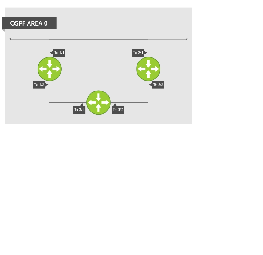
Sample Configurations for OSPFv2
The following configurations are examples for enabling OSPFv2.
These examples are not comprehensive directions. They are intended to give you some guidance with
typical configurations.
You can copy and paste from these examples to your CLI. To support your own IP addresses, interfaces,
names, and so on, be sure that you make the necessary changes.
Basic OSPFv2 Router Topology
The following illustration is a sample basic OSPFv2 topology.
Figure 86. Basic Topology and CLI Commands for OSPFv2
OSPF Area 0 — Te 1/1 and 1/2
router ospf 11111
network 10.0.11.0/24 area 0
network 10.0.12.0/24 area 0
network 192.168.100.0/24 area 0
!
interface TengigabitEthernet 1/1
ip address 10.1.11.1/24
no shutdown
!
interface TengigabitEthernet 1/2
ip address 10.2.12.2/24
no shutdown
!
interface Loopback 10
ip address 192.168.100.100/24
no shutdown
556 Open Shortest Path First (OSPFv2 and OSPFv3)

OSPF Area 0 — Te 3/1 and 3/2
router ospf 33333
network 192.168.100.0/24 area 0
network 10.0.13.0/24 area 0
network 10.0.23.0/24 area 0
!
interface Loopback 30
ip address 192.168.100.100/24
no shutdown
!
interface TengigabitEthernet 3/1
ip address 10.1.13.3/24
no shutdown
!
interface TengigabitEthernet 3/2
ip address 10.2.13.3/24
no shutdown
OSPF Area 0 — Te 2/1 and 2/2
router ospf 22222
network 192.168.100.0/24 area 0
network 10.2.21.0/24 area 0
network 10.2.22.0/24 area 0
!
interface Loopback 20
ip address 192.168.100.20/24
no shutdown
!
interface TengigabitEthernet 2/1
ip address 10.2.21.2/24
no shutdown
!
interface TengigabitEthernet 2/2
ip address 10.2.22.2/24
no shutdown
Configuration Task List for OSPFv3 (OSPF for IPv6)
This section describes the configuration tasks for Open Shortest Path First version 3 (OSPF for IPv6) on
the switch.
The configuration options of OSPFv3 are the same as those options for OSPFv2, but you may configure
OSPFv3 with differently labeled commands. Specify process IDs and areas and include interfaces and
addresses in the process. Define areas as stub or totally stubby.
The interfaces must be in IPv6 Layer-3 mode (assigned an IPv6 IP address) and enabled so that they can
send and receive traffic. The OSPF process must know about these interfaces. To make the OSPF process
aware of these interfaces, assign them to OSPF areas.
The OSPFv3 ipv6 ospf area command enables OSPFv3 on the interface and places the interface in an
area. With OSPFv2, two commands are required to accomplish the same tasks — the router ospf
command to create the OSPF process, then the network area command to enable OSPF on an
interface.
Open Shortest Path First (OSPFv2 and OSPFv3) 557

NOTE: The OSPFv2 network area command enables OSPF on multiple interfaces with the single
command. Use the OSPFv3 ipv6 ospf area command on each interface that runs OSPFv3.
All IPv6 addresses on an interface are included in the OSPFv3 process that is created on the interface.
Enable OSPFv3 for IPv6 by specifying an OSPF process ID and an area in INTERFACE mode. If you have
not created an OSPFv3 process, it is created automatically. All IPv6 addresses configured on the interface
are included in the specified OSPF process.
NOTE: IPv6 and OSPFv3 do not support Multi-Process OSPF. You can only enable a single OSPFv3
process.
Enabling IPv6 Unicast Routing
To enable IPv6 unicast routing, use the following command.
• Enable IPv6 unicast routing globally.
CONFIGURATION mode
ipv6 unicast routing
Assigning IPv6 Addresses on an Interface
To assign IPv6 addresses to an interface, use the following commands.
1. Assign an IPv6 address to the interface.
CONF-INT-type slot/port mode
ipv6 address ipv6 address
IPv6 addresses are normally written as eight groups of four hexadecimal digits; separate each group
by a colon (:).
The format is A:B:C::F/128.
2. Bring up the interface.
CONF-INT-type slot/port mode
no shutdown
Assigning Area ID on an Interface
To assign the OSPFv3 process to an interface, use the following command.
The ipv6 ospf area command enables OSPFv3 on an interface and places the interface in the
specified area. Additionally, the command creates the OSPFv3 process with ID on the router. OSPFv2
requires two commands to accomplish the same tasks — the router ospf command to create the
OSPF process, then the network area command to enable OSPFv2 on an interface.
NOTE: The OSPFv2 network area command enables OSPFv2 on multiple interfaces with the single
command. Use the OSPFv3 ipv6 ospf area command on each interface that runs OSPFv3.
• Assign the OSPFv3 process and an OSPFv3 area to this interface.
CONF-INT-type slot/port mode
558 Open Shortest Path First (OSPFv2 and OSPFv3)

ipv6 ospf process-id area area-id
–process-id: the process ID number assigned.
–area-id: the area ID for this interface.
Assigning OSPFv3 Process ID and Router ID Globally
To assign, disable, or reset OSPFv3 globally, use the following commands.
• Enable the OSPFv3 process globally and enter OSPFv3 mode.
CONFIGURATION mode
ipv6 router ospf {process ID}
The range is from 0 to 65535.
• Assign the router ID for this OSPFv3 process.
CONF-IPV6-ROUTER-OSPF mode
router-id {number}
–number: the IPv4 address.
The format is A.B.C.D.
NOTE: Enter the router-id for an OSPFv3 router as an IPv4 IP address.
• Disable OSPF.
CONFIGURATION mode
no ipv6 router ospf process-id
• Reset the OSPFv3 process.
EXEC Privilege mode
clear ipv6 ospf process
Enter an example that illustrates the current task (optional).
Enter the tasks the user should do after finishing this task (optional).
Configuring Stub Areas
To configure IPv6 stub areas, use the following command.
• Configure the area as a stub area.
CONF-IPV6-ROUTER-OSPF mode
area area-id stub [no-summary]
–no-summary: use these keywords to prevent transmission in to the area of summary ASBR LSAs.
–Area ID: a number or IP address assigned when creating the area. You can represent the area ID
as a number from 0 to 65536 if you assign a dotted decimal format rather than an IP address.
Configuring Passive-Interface
To suppress the interface’s participation on an OSPFv3 interface, use the following command.
This command stops the router from sending updates on that interface.
Open Shortest Path First (OSPFv2 and OSPFv3) 559
• Specify whether some or all some of the interfaces are passive.
CONF-IPV6-ROUTER-OSPF mode
passive-interface {type slot/port}
Interface: identifies the specific interface that is passive.
– For a port channel, enter the keywords port-channel then a number from 1 to 255 (for example,
passive-interface po 100)
– For a 10-Gigabit Ethernet interface, enter the keyword TenGigabitEthernet then the slot/port
information (for example, passive-interface ten 2/3).
– For a 40-Gigabit Ethernet interface, enter the keyword fortyGigE then the slot/port information
(for example, passive-interface ten 2/4).
– For a VLAN, enter the keyword vlan then a number from 1 to 4094 (for example, passive-
interface vlan 2222).
To enable both receiving and sending routing updates, use the no passive-interface interface
command.
To indicate that hello packets are not transmitted on that interface, when you configure a passive
interface, the show ipv6 ospf interface command adds the words passive interface.
Redistributing Routes
You can add routes from other routing instances or protocols to the OSPFv3 process.
With the redistribute command, you can include RIP, static, or directly connected routes in the OSPF
process. Route redistribution is also supported between OSPF Routing process IDs.
To add redistributing routes, use the following command.
• Specify which routes are redistributed into the OSPF process.
CONF-IPV6-ROUTER-OSPF mode
redistribute {bgp | connected | static} [metric metric-value | metric-type
type-value] [route-map map-name] [tag tag-value]
Configure the following required and optional parameters:
–bgp | connected | static: enter one of the keywords to redistribute those routes.
–metric metric-value: The range is from 0 to 4294967295.
–metric-type metric-type: enter 1 for OSPFv3 external route type 1 OR 2 for OSPFv3 external
route type 2.
–route-map map-name: enter a name of a configured route map.
–tag tag-value: The range is from 0 to 4294967295.
Configuring a Default Route
To generate a default external route into the OSPFv3 routing domain, configure the following parameters.
To specify the information for the default route, use the following command.
• Specify the information for the default route.
CONF-IPV6-ROUTER-OSPF mode
560 Open Shortest Path First (OSPFv2 and OSPFv3)

default-information originate [always [metric metric-value] [metric-type
type-value]] [route-map map-name]
Configure the following required and optional parameters:
–always: indicate that default route information is always advertised.
–metric metric-value: The range is from 0 to 4294967295.
–metric-type metric-type: enter 1 for OSPFv3 external route type 1 OR 2 for OSPFv3 external
route type 2.
–route-map map-name: enter a name of a configured route map.
OSPFv3 Authentication Using IPsec
OSPFv3 uses OSPFv3 authentication using IP security (IPsec) to provide authentication for OSPFv3
packets. IPsec authentication ensures security in the transmission of OSPFv3 packets between IPsec-
enabled routers.
IPsec is a set of protocols developed by the internet engineering task force (IETF) to support secure
exchange of packets at the IP layer. IPsec supports two encryption modes: transport and tunnel.
•Transport mode — encrypts only the data portion (payload) of each packet, but leaves the header
untouched.
•Tunnel mode — is more secure and encrypts both the header and payload. On the receiving side, an
IPsec-compliant device decrypts each packet.
NOTE: The system supports only Transport Encryption mode in OSPFv3 authentication with IPsec.
With IPsec-based authentication, Crypto images are used to include the IPsec secure socket application
programming interface (API) required for use with OSPFv3.
To ensure integrity, data origin authentication, detection and rejection of replays, and confidentiality of
the packet, RFC 4302 and RFC 4303 propose using two security protocols — authentication header (AH)
and encapsulating security payload (ESP). For OSPFv3, these two IPsec protocols provide interoperable,
high-quality cryptographically-based security.
•HA — IPsec authentication header is used in packet authentication to verify that data is not altered
during transmission and ensures that users are communicating with the intended individual or
organization. Insert the authentication header after the IP header with a value of 51. AH provides
integrity and validation of data origin by authenticating every OSPFv3 packet. For detailed information
about the IP AH protocol, refer to RFC 4302.
•ESP — encapsulating security payload encapsulates data, enabling the protection of data that follows
in the datagram. ESP provides authentication and confidentiality of every packet. The ESP extension
header is designed to provide a combination of security services for both IPv4 and IPv6. Insert the ESP
header after the IP header and before the next layer protocol header in Transport mode. It is possible
to insert the ESP header between the next layer protocol header and encapsulated IP header in
Tunnel mode. However, Tunnel mode is not supported in the Dell Networking OS. For detailed
information about the IP ESP protocol, refer to RFC 4303.
In OSPFv3 communication, IPsec provides security services between a pair of communicating hosts or
security gateways using either AH or ESP. In an authentication policy on an interface or in an OSPF area,
AH and ESP are used alone; in an encryption policy, AH and ESP may be used together. The difference
between the two mechanisms is the extent of the coverage. ESP only protects IP header fields if they are
encapsulated by ESP.
Open Shortest Path First (OSPFv2 and OSPFv3) 561

You decide the set of IPsec protocols that are employed for authentication and encryption and the ways
in which they are employed. When you correctly implement and deploy IPsec, it does not adversely affect
users or hosts. AH and ESP are designed to be cryptographic algorithm-independent.
OSPFv3 Authentication Using IPsec: Configuration Notes
OSPFv3 authentication using IPsec is implemented according to the specifications in RFC 4552.
• To use IPsec, configure an authentication (using AH) or encryption (using ESP) security policy on an
interface or in an OSPFv3 area. Each security policy consists of a security policy index (SPI) and the
key used to validate OSPFv3 packets. After IPsec is configured for OSPFv3, IPsec operation is invisible
to the user.
– You can only enable one security protocol (AH or ESP) at a time on an interface or for an area.
Enable IPsec AH with the ipv6 ospf authentication command; enable IPsec ESP with the
ipv6 ospf encryption command.
– The security policy configured for an area is inherited by default on all interfaces in the area.
– The security policy configured on an interface overrides any area-level configured security for the
area to which the interface is assigned.
– The configured authentication or encryption policy is applied to all OSPFv3 packets transmitted on
the interface or in the area. The IPsec security associations (SAs) are the same on inbound and
outbound traffic on an OSPFv3 interface.
– There is no maximum AH or ESP header length because the headers have fields with variable
lengths.
• Manual key configuration is supported in an authentication or encryption policy (dynamic key
configuration using the internet key exchange [IKE] protocol is not supported).
• In an OSPFv3 authentication policy:
– AH is used to authenticate OSPFv3 headers and certain fields in IPv6 headers and extension
headers.
– MD5 and SHA1 authentication types are supported; encrypted and unencrypted keys are
supported.
• In an OSPFv3 encryption policy:
– Both encryption and authentication are used.
– IPsec security associations (SAs) are supported only in Transport mode (Tunnel mode is not
supported).
– ESP with null encryption is supported for authenticating only OSPFv3 protocol headers.
– ESP with non-null encryption is supported for full confidentiality.
– 3DES, DES, AES-CBC, and NULL encryption algorithms are supported; encrypted and unencrypted
keys are supported.
NOTE: To encrypt all keys on a router, use the service password-encryption command in
Global Configuration mode. However, this command does not provide a high level of network
security. To enable key encryption in an IPsec security policy at an interface or area level, specify 7
for [key-encryption-type] when you enter the ipv6 ospf authentication ipsec or ipv6
ospf encryption ipsec command.
• To configure an IPsec security policy for authenticating or encrypting OSPFv3 packets on a physical,
port-channel, or VLAN interface or OSPFv3 area, perform any of the following tasks:
–Configuring IPsec Authentication on an Interface
–Configuring IPsec Encryption on an Interface
–Configuring IPsec Authentication for an OSPFv3 Area
562 Open Shortest Path First (OSPFv2 and OSPFv3)

–Configuring IPsec Encryption for an OSPFv3 Area
–Displaying OSPFv3 IPsec Security Policies
Configuring IPsec Authentication on an Interface
To configure, remove, or display IPsec authentication on an interface, use the following commands.
Prerequisite: Before you enable IPsec authentication on an OSPFv3 interface, first enable IPv6 unicast
routing globally, configure an IPv6 address and enable OSPFv3 on the interface, and assign it to an area
(refer to Configuration Task List for OSPFv3 (OSPF for IPv6)).
The SPI value must be unique to one IPsec security policy (authentication or encryption) on the router.
Configure the same authentication policy (the same SPI and key) on each OSPFv3 interface in a link.
• Enable IPsec authentication for OSPFv3 packets on an IPv6-based interface.
INTERFACE mode
ipv6 ospf authentication {null | ipsec spi number {MD5 | SHA1} [key-
encryption-type] key}
–null: causes an authentication policy configured for the area to not be inherited on the interface.
–ipsec spi number: the security policy index (SPI) value. The range is from 256 to 4294967295.
–MD5 | SHA1: specifies the authentication type: Message Digest 5 (MD5) or Secure Hash Algorithm
1 (SHA-1).
–key-encryption-type: (optional) specifies if the key is encrypted. The valid values are 0 (key is
not encrypted) or 7 (key is encrypted).
–key: specifies the text string used in authentication. All neighboring OSPFv3 routers must share
key to exchange information. For MD5 authentication, the key must be 32 hex digits (non-
encrypted) or 64 hex digits (encrypted). For SHA-1 authentication, the key must be 40 hex digits
(non-encrypted) or 80 hex digits (encrypted).
• Remove an IPsec authentication policy from an interface.
no ipv6 ospf authentication ipsec spi number
• Remove null authentication on an interface to allow the interface to inherit the authentication policy
configured for the OSPFv3 area.
no ipv6 ospf authentication null
• Display the configuration of IPsec authentication policies on the router.
show crypto ipsec policy
• Display the security associations set up for OSPFv3 interfaces in authentication policies.
show crypto ipsec sa ipv6
Configuring IPsec Encryption on an Interface
To configure, remove, or display IPsec encryption on an interface, use the following commands.
Prerequisite: Before you enable IPsec encryption on an OSPFv3 interface, first enable IPv6 unicast
routing globally, configure an IPv6 address and enable OSPFv3 on the interface, and assign it to an area
(refer to Configuration Task List for OSPFv3 (OSPF for IPv6)).
NOTE: When you configure encryption using the ipv6 ospf encryption ipsec command, you
enable both IPsec encryption and authentication. However, when you enable authentication on an
interface using the ipv6 ospf authentication ipsec command, you do not enable
encryption at the same time.
The SPI value must be unique to one IPsec security policy (authentication or encryption) on the router.
Configure the same authentication policy (the same SPI and key) on each OSPFv3 interface in a link.
Open Shortest Path First (OSPFv2 and OSPFv3) 563

• Enable IPsec encryption for OSPFv3 packets on an IPv6-based interface.
INTERFACE mode
ipv6 ospf encryption {null | ipsec spi number esp encryption-algorithm [key-
encryption-type] key authentication-algorithm [key-authentication-type] key}
–null: causes an encryption policy configured for the area to not be inherited on the interface.
–ipsec spi number: is the security policy index (SPI) value. The range is from 256 to
4294967295.
–esp encryption-algorithm: specifies the encryption algorithm used with ESP. The valid values
are 3DES, DES, AES-CBC, and NULL. For AES-CBC, only the AES-128 and AES-192 ciphers are
supported.
–key: specifies the text string used in the encryption. All neighboring OSPFv3 routers must share
the same key to decrypt information. Required lengths of a non-encrypted or encrypted key are:
3DES - 48 or 96 hex digits; DES - 16 or 32 hex digits; AES-CBC - 32 or 64 hex digits for AES-128
and 48 or 96 hex digits for AES-192.
–key-encryption-type: (optional) specifies if the key is encrypted. The valid values are 0 (key is
not encrypted) or 7 (key is encrypted).
–authentication-algorithm: specifies the encryption authentication algorithm to use. The
valid values are MD5 or SHA1.
–key: specifies the text string used in authentication. All neighboring OSPFv3 routers must share
key to exchange information. For MD5 authentication, the key must be 32 hex digits (non-
encrypted) or 64 hex digits (encrypted). For SHA-1 authentication, the key must be 40 hex digits
(non-encrypted) or 80 hex digits (encrypted).
–key-authentication-type: (optional) specifies if the authentication key is encrypted. The valid
values are 0 or 7.
• Remove an IPsec encryption policy from an interface.
no ipv6 ospf encryption ipsec spi number
• Remove null encryption on an interface to allow the interface to inherit the encryption policy
configured for the OSPFv3 area.
no ipv6 ospf encryption null
• Display the configuration of IPsec encryption policies on the router.
show crypto ipsec policy
• Display the security associations set up for OSPFv3 interfaces in encryption policies.
show crypto ipsec sa ipv6
Configuring IPSec Authentication for an OSPFv3 Area
To configure, remove, or display IPSec authentication for an OSPFv3 area, use the following commands.
Prerequisite: Before you enable IPsec authentication on an OSPFv3 area, first enable OSPFv3 globally on
the router (refer to Configuration Task List for OSPFv3 (OSPF for IPv6)).
The security policy index (SPI) value must be unique to one IPSec security policy (authentication or
encryption) on the router. Configure the same authentication policy (the same SPI and key) on each
interface in an OPSFv3 link.
If you have enabled IPSec encryption in an OSPFv3 area using the area encryption command, you
cannot use the area authentication command in the area at the same time.
The configuration of IPSec authentication on an interface-level takes precedence over an area-level
configuration. If you remove an interface configuration, an area authentication policy that has been
configured is applied to the interface.
564 Open Shortest Path First (OSPFv2 and OSPFv3)

• Enable IPSec authentication for OSPFv3 packets in an area.
CONF-IPV6-ROUTER-OSPF mode
area-id authentication ipsec spi number {MD5 | SHA1} [key-encryption-type]
key
–area area-id: specifies the area for which OSPFv3 traffic is to be authenticated. For area-id,
enter a number or an IPv6 prefix.
–spi number: is the SPI value. The range is from 256 to 4294967295.
–MD5 | SHA1: specifies the authentication type: message digest 5 (MD5) or Secure Hash Algorithm
1 (SHA-1).
–key-encryption-type: (optional) specifies if the key is encrypted. The valid values are 0 (key is
not encrypted) or 7 (key is encrypted).
–key: specifies the text string used in authentication. All neighboring OSPFv3 routers must share
key to exchange information. For MD5 authentication, the key must be 32 hex digits (non-
encrypted) or 64 hex digits (encrypted). For SHA-1 authentication, the key must be 40 hex digits
(non-encrypted) or 80 hex digits (encrypted).
• Remove an IPSec authentication policy from an OSPFv3 area.
no area area-id authentication ipsec spi number
• Display the configuration of IPSec authentication policies on the router.
show crypto ipsec policy
Configuring IPsec Encryption for an OSPFv3 Area
To configure, remove, or display IPsec encryption in an OSPFv3 area, use the following commands.
Prerequisite: Before you enable IPsec encryption in an OSPFv3 area, first enable OSPFv3 globally on the
router (refer to Configuration Task List for OSPFv3 (OSPF for IPv6)).
The SPI value must be unique to one IPsec security policy (authentication or encryption) on the router.
Configure the same encryption policy (the same SPI and keys) on each interface in an OPSFv3 link.
NOTE: When you configure encryption using the area encryption command, you enable both
IPsec encryption and authentication. However, when you enable authentication on an area using
the area authentication command, you do not enable encryption at the same time.
If you have enabled IPsec authentication in an OSPFv3 area using the area authentication
command, you cannot use the area encryption command in the area at the same time.
The configuration of IPsec encryption on an interface-level takes precedence over an area-level
configuration. If you remove an interface configuration, an area encryption policy that has been
configured is applied to the interface.
• Enable IPsec encryption for OSPFv3 packets in an area.
CONF-IPV6-ROUTER-OSPF mode
area area-id encryption ipsec spi number esp encryption-algorithm [key-
encryption-type] key authentication-algorithm [key-authentication-type] key
–area area-id: specifies the area for which OSPFv3 traffic is to be encrypted. For area-id, enter
a number or an IPv6 prefix.
–spi number: is the security policy index (SPI) value. The range is from 256 to 4294967295.
–esp encryption-algorithm: specifies the encryption algorithm used with ESP. The valid values
are 3DES, DES, AES-CBC, and NULL. For AES-CBC, only the AES-128 and AES-192 ciphers are
supported.
Open Shortest Path First (OSPFv2 and OSPFv3) 565

–key: specifies the text string used in the encryption. All neighboring OSPFv3 routers must share
the same key to decrypt information. The required lengths of a non-encrypted or encrypted key
are: 3DES - 48 or 96 hex digits; DES - 16 or 32 hex digits; AES-CBC - 32 or 64 hex digits for
AES-128 and 48 or 96 hex digits for AES-192.
–key-encryption-type: (optional) specifies if the key is encrypted. Valid values: 0 (key is not
encrypted) or 7 (key is encrypted).
–authentication-algorithm: specifies the authentication algorithm to use for encryption. The
valid values are MD5 or SHA1.
–key: specifies the text string used in authentication. All neighboring OSPFv3 routers must share
key to exchange information. For MD5 authentication, the key must be 32 hex digits (non-
encrypted) or 64 hex digits (encrypted). For SHA-1 authentication, the key must be 40 hex digits
(non-encrypted) or 80 hex digits (encrypted).
–key-authentication-type: (optional) specifies if the authentication key is encrypted. The valid
values are 0 or 7.
• Remove an IPsec encryption policy from an OSPFv3 area.
no area area-id encryption ipsec spi number
• Display the configuration of IPsec encryption policies on the router.
show crypto ipsec policy
Displaying OSPFv3 IPsec Security Policies
To display the configuration of IPsec authentication and encryption policies, use the following
commands.
• Display the AH and ESP parameters configured in IPsec security policies, including the SPI number,
key, and algorithms used.
EXEC Privilege mode
show crypto ipsec policy [name name]
–name: displays configuration details about a specified policy.
• Display security associations set up for OSPFv3 links in IPsec authentication and encryption policies
on the router.
EXEC Privilege
show crypto ipsec sa ipv6 [interface interface]
To display information on the SAs used on a specific interface, enter interface interface, where
interface is one of the following values:
– For a 10-Gigabit Ethernet interface, enter TenGigabitEthernet slot/port.
– For a Port Channel interface, enter port-channel number.
– For a 40-Gigabit Ethernet interface, enter FortyGigabitEthernet slot/port.
– For a VLAN interface, enter vlan vlan-id. The valid VLAN IDs are from 1 to 4094.
Examples of the show crypto ipsec Commands
In the first example, the keys are not encrypted (shown in bold). In the second and third examples, the
keys are encrypted (shown in bold).
Dell#show crypto ipsec policy
Crypto IPSec client security policy data
566 Open Shortest Path First (OSPFv2 and OSPFv3)

Policy name : OSPFv3-1-502
Policy refcount : 1
Inbound ESP SPI : 502 (0x1F6)
Outbound ESP SPI : 502 (0x1F6)
Inbound ESP Auth Key : 123456789a123456789b123456789c12
Outbound ESP Auth Key : 123456789a123456789b123456789c12
Inbound ESP Cipher Key : 123456789a123456789b123456789c123456789d12345678
Outbound ESP Cipher Key : 123456789a123456789b123456789c123456789d12345678
Transform set : esp-3des esp-md5-hmac
Crypto IPSec client security policy data
Policy name : OSPFv3-1-500
Policy refcount : 2
Inbound AH SPI : 500 (0x1F4)
Outbound AH SPI : 500 (0x1F4)
Inbound AH Key :
bbdd96e6eb4828e2e27bc3f9ff541e43faa759c9ef5706ba8ed8bb5efe91e97e
Outbound AH Key :
bbdd96e6eb4828e2e27bc3f9ff541e43faa759c9ef5706ba8ed8bb5efe91e97e
Transform set : ah-md5-hmac
Crypto IPSec client security policy data
Policy name : OSPFv3-0-501
Policy refcount : 1
Inbound ESP SPI : 501 (0x1F5)
Outbound ESP SPI : 501 (0x1F5)
Inbound ESP Auth Key :
bbdd96e6eb4828e2e27bc3f9ff541e43faa759c9ef5706ba8ed8bb5efe91e97eb7c0c30808825fb5
Outbound ESP Auth Key :
bbdd96e6eb4828e2e27bc3f9ff541e43faa759c9ef5706ba8ed8bb5efe91e97eb7c0c30808825fb5
Inbound ESP Cipher Key :
bbdd96e6eb4828e2e27bc3f9ff541e43faa759c9ef5706ba10345a1039ba8f8a
Outbound ESP Cipher Key :
bbdd96e6eb4828e2e27bc3f9ff541e43faa759c9ef5706ba10345a1039ba8f8a
Transform set : esp-128-aes esp-sha1-hmac
The following example shows the show crypto ipsec sa ipv6 command.
Dell#show crypto ipsec sa ipv6
Interface: TenGigabitEthernet 0/0
Link Local address: fe80::201:e8ff:fe40:4d10
IPSecv6 policy name: OSPFv3-1-500
inbound ah sas
spi : 500 (0x1f4)
transform : ah-md5-hmac
in use settings : {Transport, }
replay detection support : N
STATUS : ACTIVE
outbound ah sas
spi : 500 (0x1f4)
transform : ah-md5-hmac
in use settings : {Transport, }
replay detection support : N
STATUS : ACTIVE
inbound esp sas
outbound esp sas
Open Shortest Path First (OSPFv2 and OSPFv3) 567

Interface: TenGigabitEthernet 0/1
Link Local address: fe80::201:e8ff:fe40:4d11
IPSecv6 policy name: OSPFv3-1-600
inbound ah sas
outbound ah sas
inbound esp sas
spi : 600 (0x258)
transform : esp-des esp-sha1-hmac
in use settings : {Transport, }
replay detection support : N
STATUS : ACTIVE
outbound esp sas
spi : 600 (0x258)
transform : esp-des esp-sha1-hmac
in use settings : {Transport, }
replay detection support : N
STATUS : ACTIVE
Troubleshooting OSPFv3
The system provides several tools to troubleshoot OSPFv3 operation on the switch. This section
describes typical, OSPFv3 troubleshooting scenarios.
NOTE: The following troubleshooting section is not meant to be a comprehensive list, but only to
provide examples of typical troubleshooting checks.
• Have you enabled OSPF globally?
• Is the OSPF process active on the interface?
• Are the adjacencies established correctly?
• Did you configure the interfaces for Layer 3 correctly?
• Is the router in the correct area type?
• Did you include the routes in the OSPF database?
• Did you include the OSPF routes in the routing table (not just the OSPF database)?
Some useful troubleshooting commands are:
•show ipv6 interfaces
•show ipv6 protocols
•debug ipv6 ospf events and/or packets
•show ipv6 neighbors
•show virtual links
•show ipv6 routes
Viewing Summary Information
To get general route, configuration, links status, and debug information, use the following commands.
• View the summary information of the IPv6 routes.
EXEC Privilege mode
show ipv6 route summary
568 Open Shortest Path First (OSPFv2 and OSPFv3)
• View the summary information for the OSPFv3 database.
EXEC Privilege mode
show ipv6 ospf database
• View the configuration of OSPFv3 neighbors.
EXEC Privilege mode
show ipv6 ospf neighbor
• View debug messages for all OSPFv3 interfaces.
EXEC Privilege mode
debug ipv6 ospf [event | packet] {type slot/port}
–event: View OSPF event messages.
–packet: View OSPF packets.
– For a 10–Gigabit Ethernet interface, enter the keyword TenGigabitEthernet then the slot/port
information (for example, passive-interface te 2/1).
– For a port channel, enter the keywords port-channel then a number from 1 to 255.
– For a 40-Gigabit Ethernet interface, enter the keyword FortyGigabitEthernet then the slot/
port information (for example, passive-interface fo 2/3).
– For a VLAN, enter the keyword vlan then a number from 1 to 4094 (for example, passive-
interface vlan 2222). The system supports up to 4094 VLANs.
Open Shortest Path First (OSPFv2 and OSPFv3) 569

32
Pay As You Grow
The Pay As You Grow (PAYG) software feature allows you to purchase a Z9500 switch with 36 40G ports
(144 10G ports) and upgrade to a larger number of ports as your networking needs grow.
A Z9500 switch with a 36 40G-port license has only the ports on line card 0 enabled. See the Port
Numbering figure in this section for exact port location. You can purchase a license for additional Z9500
port configurations:
• 84 40G ports on line cards 0 and 1 (336 10G ports)
• 132 40G ports on line cards 0, 1, and 2 (528 10G ports)
You can upgrade from a 36 40G-port to either an 84 40G-port or a 132 40G-port configuration. Each
license change requires you to reload the switch to enable the additional ports.
Figure 87. Z9500 Port Numbering
On each line card, the fixed 40G ports are numbered from bottom to top in multiples of four, starting
with zero; for example, 0, 4, 8, 12, and so on. When a breakout cable is installed, the resulting four 10G
ports are numbered with the remaining numbers. For example, the 40G port 0 contains 10G ports 0, 1, 2,
and 3; the 40G port 4 contains 10G ports 4, 5, 6, and 7.
NOTE: Although unlicensed ports are powered down, they are user-configurable.
Installing a License
The Z9500 supports only perpetual licensing — licenses that are valid for the life of the product and never
need to be renewed. A perpetual license does not expire. It must be bound to only one service tag at a
time. For more information about Z9500 licensing, contact your local Dell Networking support team or
the Dell Networking Technical Assistance Center.
570 Pay As You Grow

To install a license on a Z9500 switch:
1. Check the currently installed port license.
show license
EXEC Privilege mode
In the command output, System Service Tag displays the service tag of the switch on which you
enter the command. License Service Tag displays the service tag read from the license file.
Current State displays the current number of licensed (usable) ports on the switch; Next Boot
displays the number of licensed ports on the switch after the next reload.
Dell# show license
LICENSE INFORMATION
Vendor : Dell
Product :
System Service Tag : RtHvKsJ
License Service Tag :
Current State : HW-Port-License 36 Ports (Fo 0/0 - Fo 0/140)
Next Boot : HW-Port-License 36 Ports (Fo 0/0 - Fo 0/140)
2. Locate the license file you want to use and verify that the port license is valid for the switch.
show license [flash://filepath | ftp://userid:password@host-ip/filepath |
scp://userid:password@hostip/filepath | tftp://host-ip/filepath |
usbflash://filepath]
EXEC Privilege mode
In the command output, the information displayed in the License Type and Status fields indicates the
number of licensed ports and whether the license is valid for the switch. As shown in the following
example, Valid License File means that the licensed port configuration is supported on the
switch.
Dell# show license tftp://10.11.8.12/132.lic
!
3594 bytes successfully copied
LICENSE INFORMATION
Vendor : Dell
Product : Dell Force10 Z9500
System Service Tag : RTHVKSJ
License Service Tag : RTHVKSJ
License Type : HW-Port-License 132 Ports (Fo 0/0 - Fo 2/188)
Status : Valid license file
NOTE: If the system service and license service tags do not match, the license cannot be
installed. To generate the correct license service tag for the desired port license, contact your
local Dell Networking support team or the Dell Networking Technical Assistance Center.
3. Install the Z9500 port license that you validated in Step 2.
install license {flash://filepath | ftp://userid:password@host-ip/filepath |
scp://userid:password@hostip/filepath | tftp://host-ip/filepath |
usbflash://filepath}
EXEC Privilege mode
Pay As You Grow 571

Enter Yes at the prompt to continue the installation; for example:
Dell# install license tftp://10.11.8.12/132.lic
!
3594 bytes successfully copied
Retrieving license ....... (OK)
LICENSE INFORMATION
Vendor : Dell
Product : Dell Force10 Z9500
System Service Tag : RtHvKsJ
License Service Tag : RTHVKSJ
Feature : HW-Port-License 132 Ports
Retrieving license data ....... (OK)
Validating license ....... (OK)
Validating Service Tag in license ....... (OK)
Note: You must reload the chassis to activate the license.
System will continue to run with current active 84 ports until the
next reload !
Continue to install license [yes/no]: yes
Installing license ....... (ok)
License installation successful. Restart chassis to activate license
Dell#Jul 1 11:00:58: %SYSTEM:CP %LICMGR-5-LICMGR_LIC_INSTALL_SUCCESS:
License file install is successful
To verify the installation of a new license before you reload the switch, enter the show license
command. The following example shows the currently installed 36-port license and the newly
installed 132-port license before reloading the switch.
Dell# show license
LICENSE INFORMATION
Vendor : Dell
Product : Dell Force10 Z9500
System Service Tag: RtHvKsJ
License Service Tag: RTHVKSJ
Current State : HW-Port-License 36 Ports (Fo 0/0 - Fo 0/140)
Next Boot : HW-Port-License 132 Ports (Fo 0/0 - Fo 2/188)
4. Reboot the switch to enable the licensed ports.
reload
EXEC Privilege mode
Enter Yes at the prompts to save the port configuration and complete the reload; for example:
Dell# reload
System configuration has been modified. Save? [yes/no]: yes
!
00:14:28: %SYSTEM:CP %FILEMGR-5-FILESAVED: Copied running-config to startup-
config in flash by default
Proceed with reload [confirm yes/no]: yes
Starting to save trace messages...done.
00:14:39: %SYSTEM:CP %CHMGR-5-RELOAD: User request to reload the chassis
syncing disks... done
unmounting file systems...
unmounting /f10/flash (/dev/wd0e)...
unmounting /f10/ConfD/db (mfs:509)...
572 Pay As You Grow

unmounting /usr/pkg (/dev/wd0i)...
unmounting /boot (/dev/wd0b)...
unmounting /usr (mfs:30)...
unmounting /force10 (mfs:25)...
unmounting /lib (mfs:22)...
unmounting /f10 (mfs:19)...
unmounting /tmp (mfs:12)...
unmounting /kern (kernfs)...
unmounting / (/dev/md0a)... done
rebooting...
Displaying License Information
To check the status of an installed Z9500 license and display the number of usable ports, enter the show
license command.
• Display the current Z9500 port license.
show license
EXEC Privilege mode
Display of an 84 40G-Port License
Dell# show license
LICENSE INFORMATION
Vendor : Dell
Product : Dell Force10 Z9500
System Service Tag : RtHvKsJ
License Service Tag : RTHVKSJ
Current State : HW-Port-License 84 Ports (Fo 0/0 - Fo 1/188)
Next Boot : HW-Port-License 84 Ports (Fo 0/0 - Fo 1/188)
Display of a 132 40G-Port License
Dell# show license
LICENSE INFORMATION
Vendor : Dell
Product : Dell Force10 Z9500
System Service Tag : RtHvKsJ
License Service Tag : RTHVKSJ
Current State : HW-Port-License 132 Ports (Fo 0/0 - Fo 2/188)
Next Boot : HW-Port-License 132 Ports (Fo 0/0 - Fo 2/188)
Example of show system brief Output
You can also display information on the currently installed Z9500 license by entering the show system
brief command. In the Linecard Info section, the Status column displays the licensed (online) and
unlicensed (unlicensed) line cards. The Ports column displays the number of licensed (usable) 40G-
ports on each line card.
Dell# show system brief
System MAC : 74:86:7a:ff:70:d4
Reload-Type : normal-reload [Next boot : normal-reload]
-- Linecard Info --
LinecardId Type Status ReqTyp CurTyp Version Ports
---------------------------------------------------------------------
0 Linecard online Z9500LC36 Z9500LC36 9-5 144
1 Linecard unlicensed Z9500LC48 Z9500LC48 9-5 -
2 Linecard unlicensed Z9500LC48 Z9500LC48 9-5 -
Pay As You Grow 573

-- Power Supplies --
Unit Bay Status Type FanStatus FanSpeed(rpm) Power Usage (W)
-----------------------------------------------------------------------------
0 0 up AC up 23008 217.8
0 1 up AC up 22912 189.5
0 2 up AC up 23008 184.8
0 3 up AC up 22912 192.0
574 Pay As You Grow
33
PIM Sparse-Mode (PIM-SM)
Protocol-independent multicast sparse-mode (PIM-SM) is a multicast protocol that forwards multicast
traffic to a subnet only after a request using a PIM Join message; this behavior is the opposite of PIM-
Dense mode, which forwards multicast traffic to all subnets until a request to stop.
Implementation Information
The Dell Networking implementation of PIM-SM is based on IETF Internet Draft draft-ietf-pim-sm-v2-
new-05.
• There is no limit on the number of PIM neighbors can have.
• The SPT-Threshold is zero, which means that the last-hop designated router (DR) joins the shortest
path tree (SPT) to the source after receiving the first multicast packet.
• The Dell Networking OS reduces the number of control messages sent between multicast routers by
bundling Join and Prune requests in the same message.
• The system supports PIM-SM on physical, virtual local area network (VLAN), and port-channel
interfaces.
• The system supports 2000 IPv6 multicast forwarding entries, with up to 128 PIM-source-specific
multicast (SSM) neighbors/interfaces.
• IPv6 Multicast is not supported on synchronous optical network technologies (SONET) interfaces.
Protocol Overview
PIM-SM initially uses unidirectional shared trees to forward multicast traffic; that is, all multicast traffic
must flow only from the rendezvous point (RP) to the receivers.
After a receiver receives traffic from the RP, PM-SM switches to SPT to forward multicast traffic. Every
multicast group has an RP and a unidirectional shared tree (group-specific shared tree).
Requesting Multicast Traffic
A host requesting multicast traffic for a particular group sends an Internet group management protocol
(IGMP) Join message to its gateway router.
The gateway router is then responsible for joining the shared tree to the RP (RPT) so that the host can
receive the requested traffic.
1. After receiving an IGMP Join message, the receiver gateway router (last-hop DR) creates a (*,G) entry
in its multicast routing table for the requested group. The interface on which the join message was
received becomes the outgoing interface associated with the (*,G) entry.
2. The last-hop DR sends a PIM Join message to the RP. All routers along the way, including the RP,
create an (*,G) entry in their multicast routing table, and the interface on which the message was
received becomes the outgoing interface associated with the (*,G) entry. This process constructs an
RPT branch to the RP.
3. If a host on the same subnet as another multicast receiver sends an IGMP report for the same
multicast group, the gateway takes no action. If a router between the host and the RP receives a PIM
Join message for which it already has a (*,G) entry, the interface on which the message was received
PIM Sparse-Mode (PIM-SM) 575
is added to the outgoing interface list associated with the (*,G) entry, and the message is not (and
does not need to be) forwarded towards the RP.
Refuse Multicast Traffic
A host requesting to leave a multicast group sends an IGMP Leave message to the last-hop DR. If the host
is the only remaining receiver for that group on the subnet, the last-hop DR is responsible for sending a
PIM Prune message up the RPT to prune its branch to the RP.
1. After receiving an IGMP Leave message, the gateway removes the interface on which it is received
from the outgoing interface list of the (*,G) entry. If the (*,G) entry has no remaining outgoing
interfaces, multicast traffic for that group is no longer forwarded to that subnet.
2. If the (*,G) entry has no remaining outgoing interfaces, the last-hop DR sends a PIM Prune message
to towards the RP. All routers along the way remove the interface on which the message was
received from the outgoing interface list of the (*,G) entry. If on any router there is at least one
outgoing interface listed for that (*,G) entry, the Prune message is not forwarded.
Send Multicast Traffic
With PIM-SM, all multicast traffic must initially originate from the RP. A source must unicast traffic to the
RP so that the RP can learn about the source and create an SPT to it. Then the last-hop DR may create an
SPT directly to the source.
1. The source gateway router (first-hop DR) receives the multicast packets and creates an (S,G) entry in
its multicast routing table. The first-hop DR encapsulates the initial multicast packets in PIM Register
packets and unicasts them to the RP.
2. The RP decapsulates the PIM Register packets and forwards them if there are any receivers for that
group. The RP sends a PIM Join message towards the source. All routers between the RP and the
source, including the RP, create an (S,G) entry and list the interface on which the message was
received as an outgoing interface, thus recreating a SPT to the source.
3. After the RP starts receiving multicast traffic via the (S,G), it unicasts a Register-Stop message to the
first-hop DR so that multicast packets are no longer encapsulated in PIM Register packets and
unicast. After receiving the first multicast packet from a particular source, the last-hop DR sends a
PIM Join message to the source to create an SPT to it.
4. There are two paths, then, between the receiver and the source, a direct SPT and an RPT. One router
receives a multicast packet on two interfaces from the same source in this case; this router prunes
the shared tree by sending a PIM Prune message to the RP that tells all routers between the source
and the RP to remove the outgoing interface from the (*,G) entry, and tells the RP to prune its SPT to
the source with a Prune message.
Dell Networking OS Behavior: When the router creates an SPT to the source, there are then two paths
between the receiver and the source, the SPT and the RPT. Until the router can prune itself from the RPT,
the receiver receives duplicate multicast packets which may cause disruption. Therefore, the router must
prune itself from the RPT as soon as possible. Dell Networking OS optimizes the shared to shortest-path
tree switchover latency by copying and forwarding the first (S,G) packet received on the SPT to the PIM
task immediately upon arrival. The arrival of the (S,G) packet confirms for PIM that the SPT is created, and
that it can prune itself from the shared tree.
Important Point to Remember
If you use a Loopback interface with a /32 mask as the RP, you must enable PIM Sparse-mode on the
interface.
576 PIM Sparse-Mode (PIM-SM)

Configuring PIM-SM
Configuring PIM-SM is a three-step process.
1. Enable multicast routing (refer to the following step).
2. Select a rendezvous point.
3. Enable PIM-SM on an interface.
Enable multicast routing.
CONFIGURATION mode
ip multicast-routing
Related Configuration Tasks
The following are related PIM-SM configuration tasks.
•Configuring S,G Expiry Timers
•Configuring a Static Rendezvous Point
•Configuring a Designated Router
•Creating Multicast Boundaries and Domains
Enable PIM-SM
You must enable PIM-SM on each participating interface.
1. Enable multicast routing on the system.
CONFIGURATION mode
ip multicast-routing
2. Enable PIM-Sparse mode.
INTERFACE mode
ip pim sparse-mode
Examples of Viewing PIM-SM Information
To display which interfaces are enabled with PIM-SM, use the show ip pim interface command
from EXEC Privilege mode.
Dell#show ip pim interface
Address Interface VIFindex Ver/ Nbr Query DR DR
Mode Count Intvl Prio
189.87.5.6 Te 0/11 0x2 v2/S 1 30 1 127.87.5.6
189.87.3.2 Te 0/12 0x3 v2/S 1 30 1 127.87.3.5
189.87.31.6 Te 1/11 0x0 v2/S 0 30 1 127.87.31.6
189.87.50.6 Te 1/13 0x4 v2/S 1 30 1 127.87.50.6
Dell#
NOTE: You can influence the selection of the Rendezvous Point by enabling PIM-Sparse mode on a
Loopback interface and assigning a low IP address.
PIM Sparse-Mode (PIM-SM) 577

To display PIM neighbors for each interface, use the show ip pim neighbor command EXEC Privilege
mode.
Dell#show ip pim neighbor
Neighbor Interface Uptime/Expires Ver DR
Address Prio/Mode
127.87.5.5 Te 0/11 01:44:59/00:01:16 v2 1 / S
127.87.3.5 Te 0/12 01:45:00/00:01:16 v2 1 / DR
127.87.50.5 Te 1/13 00:03:08/00:01:37 v2 1 / S
Dell#
To display the PIM routing table, use the show ip pim tib command from EXEC privilege mode.
Dell#show ip pim tib
PIM Multicast Routing Table
Flags: D - Dense, S - Sparse, C - Connected, L - Local, P - Pruned,
R - RP-bit set, F - Register flag, T - SPT-bit set, J - Join SPT,
Timers: Uptime/Expires
Interface state: Interface, next-Hop, State/Mode
(*, 192.1.2.1), uptime 00:29:36, expires 00:03:26, RP 10.87.2.6, flags: SCJ
Incoming interface: TenGigabitEthernet 0/12, RPF neighbor 10.87.3.5
Outgoing interface list:
TenGigabitEthernet 0/11
TenGigabitEthernet 1/13
(10.87.31.5, 192.1.2.1), uptime 00:01:24, expires 00:02:26, flags: FT
Incoming interface: TenGigabitEthernet 1/11, RPF neighbor 0.0.0.0
Outgoing interface list:
TenGigabitEthernet 0/11
TenGigabitEthernet 0/12
TenGigabitEthernet 1/13
--More--
Configuring S,G Expiry Timers
By default, S, G entries expire in 210 seconds. You can configure a global expiry time (for all [S,G] entries)
or configure an expiry time for a particular entry.
If you configure both, the ACL supersedes the global configuration for the specified entries.
When you create, delete, or update an expiry time, the changes are applied when the keep alive timer
refreshes.
To configure a global expiry time or to configure the expiry time for a particular (S,G) entry, use the
following commands.
1. Enable global expiry timer for S, G entries.
CONFIGURATION mode
ip pim sparse-mode sg-expiry-timer seconds
The range is from 211 to 86,400 seconds.
The default is 210.
2. Create an extended ACL.
CONFIGURATION mode
578 PIM Sparse-Mode (PIM-SM)

ip access-list extended access-list-name
3. Specify the source and group to which the timer is applied using extended ACLs with permit rules
only.
CONFIG-EXT-NACL mode
[seq sequence-number] permit ip source-address/mask | any | host source-
address} {destination-address/mask | any | host destination-address}
4. Set the expiry time for a specific (S,G) entry (as shown in the following example).
CONFIGURATION mode
ip pim sparse-mode sg-expiry-timer seconds sg-list access-list-name
The range is from 211 to 86,400 seconds.
The default is 210.
Example Configuring an (S,G) Expiry Time
NOTE: The expiry time configuration is nullified and the default global expiry time is used if:
• an ACL is specified in the ip pim sparse-mode sg-expiry-timer command, but the ACL
has not been created or is a standard ACL.
• if the expiry time is specified for an (S,G) entry in a deny rule.
Dell(conf)#ip access-list extended SGtimer
Dell(config-ext-nacl)#permit ip 10.1.2.3/24 225.1.1.0/24
Dell(config-ext-nacl)#permit ip any 232.1.1.0/24
Dell(config-ext-nacl)#permit ip 100.1.1.0/16 any
Dell(config-ext-nacl)#show conf
!
ip access-list extended SGtimer
seq 5 permit ip 10.1.2.0/24 225.1.1.0/24
seq 10 permit ip any 232.1.1.0/24
seq 15 permit ip 100.1.0.0/16 any
Dell(config-ext-nacl)#exit
Dell(conf)#ip pim sparse-mode sg-expiry-timer 1800 sg-list SGtimer
To display the expiry time configuration, use the show running-configuration [acl | pim]
command from EXEC Privilege mode.
Configuring a Static Rendezvous Point
The rendezvous point (RP) is a PIM-enabled interface on a router that acts as the root a group-specific
tree; every group must have an RP.
• Identify an RP by the IP address of a PIM-enabled or Loopback interface.
ip pim rp-address
Example of Viewing an RP on a Loopback Interface
Dell#sh run int loop0
!
interface Loopback 0
ip address 1.1.1.1/32
ip pim sparse-mode
no shutdown
PIM Sparse-Mode (PIM-SM) 579

Dell#sh run pim
!
ip pim rp-address 1.1.1.1 group-address 224.0.0.0/4
Overriding Bootstrap Router Updates
PIM-SM routers must know the address of the RP for each group for which they have (*,G) entry.
This address is obtained automatically through the bootstrap router (BSR) mechanism or a static RP
configuration.
Use the following command if you have configured a static RP for a group. If you do not use the
override option with the following command, the RPs advertised in the BSR updates take precedence
over any statically configured RPs.
• Use the override option to override bootstrap router updates with your static RP configuration.
ip pim rp-address
Examples of Viewing the Rendezvous Point (Multicast Group) Information
To display the assigned RP for a group, use the show ip pim rp command from EXEC privilege mode.
Dell#show ip pim rp
Group RP
225.0.1.40 165.87.50.5
226.1.1.1 165.87.50.5
To display the assigned RP for a group range (group-to-RP mapping), use the show ip pim rp
mapping command in EXEC privilege mode.
Dell#show ip pim rp mapping
PIM Group-to-RP Mappings
Group(s): 224.0.0.0/4, Static
RP: 165.87.50.5, v2
Configuring a Designated Router
Multiple PIM-SM routers might be connected to a single local area network (LAN) segment. One of these
routers is elected to act on behalf of directly connected hosts. This router is the designated router (DR).
The DR is elected using hello messages. Each PIM router learns about its neighbors by periodically
sending a hello message out of each PIM-enabled interface. Hello messages contain the IP address of the
interface out of which it is sent and a DR priority value. The router with the greatest priority value is the
DR. If the priority value is the same for two routers, then the router with the greatest IP address is the DR.
By default, the DR priority value is 192, so the IP address determines the DR.
• Assign a DR priority value.
INTERFACE mode
ip pim dr-priority priority-value
• Change the interval at which a router sends hello messages.
INTERFACE mode
ip pim query-interval seconds
• Display the current value of these parameter.
EXEC Privilege mode
show ip pim interface
580 PIM Sparse-Mode (PIM-SM)

Creating Multicast Boundaries and Domains
A PIM domain is a contiguous set of routers that all implement PIM and are configured to operate within
a common boundary defined by PIM multicast border routers (PMBRs).
PMBRs connect each PIM domain to the rest of the Internet.
Create multicast boundaries and domains by filtering inbound and outbound bootstrap router (BSR)
messages per interface. The following command is applied to the subsequent inbound and outbound
updates. Timeout removes existing BSR advertisements.
• Create multicast boundaries and domains by filtering inbound and outbound BSR messages per
interface.
ip pim bsr-border
• Remove candidate RP advertisements.
clear ip pim rp-mapping
Enabling PIM-SM Graceful Restart
To enable PIM-SM graceful restart, use the following commands.
• Enable PIM-SM graceful restart (non-stop forwarding capability).
CONFIGURATION mode
ip pim graceful-restart nsf
– (option) restart-time: the time the Dell Networking system requires to restart. The default value
is 180 seconds.
– (option) stale-entry-time: the maximum amount of time that the Dell Networking system
preserves entries from a restarting neighbor. The default value is 60 seconds.
– (option) helper-only: this mode takes precedence over any graceful restart configuration.
NOTE: In helper-only mode, the system preserves the PIM states of a neighboring router while
the neighbor gracefully restarts, but the Dell Networking system allows itself to be taken off the
forwarding path if it restarts.
Enter an example that illustrates the current task (optional).
Enter the tasks the user should do after finishing this task (optional).
PIM Sparse-Mode (PIM-SM) 581
34
PIM Source-Specific Mode (PIM-SSM)
PIM source-specific mode (PIM-SSM) is a multicast protocol that forwards multicast traffic from a single
source to a subnet. In the other versions of protocol independent multicast (PIM), a receiver subscribes to
a group only. The receiver receives traffic not just from the source in which it is interested but from all
sources sending to that group. PIM-SSM requires that receivers specify the sources in which they are
interested using IGMPv3 include messages to avoid receiving unwanted traffic.
PIM-SSM is more efficient than PIM-SM because it immediately creates shortest path trees (SPT) to the
source rather than first using shared trees. PIM-SM requires a shared tree rooted at the RP because
IGMPv2 receivers do not know about the source sending multicast data. Multicast traffic passes from the
source to the receiver through the RP, until the receiver learns the source address, at which point it
switches to the SPT. PIM-SSM uses IGMPv3. Because receivers subscribe to a source and group, the RP
and shared tree is unnecessary; only SPTs are used. On Dell Networking systems, it is possible to use
PIM-SM with IGMPv3 to achieve the same result, but PIM-SSM eliminates the unnecessary protocol
overhead.
PIM-SSM also solves the multicast address allocation problem. Applications must use unique multicast
addresses because if multiple applications use the same address, receivers receive unwanted traffic.
However, global multicast address space is limited. Currently GLOP/EGLOP is used to statically assign
Internet-routable multicast addresses, but each autonomous system number yields only 255 multicast
addresses. For short-term applications, an address could be leased, but no global dynamic multicast
address allocation scheme has been accepted yet. PIM-SSM eliminates the need for unique multicast
addresses because routing decisions for (S1, G1) are independent from (S2, G1). As a result, subnets do
not receive unwanted traffic when multiple applications use the same address.
Implementation Information
• The Dell Networking implementation of PIM-SSM is based on RFC 3569.
• The Dell Networking OS reduces the number of control messages sent between multicast routers by
bundling Join and Prune requests in the same message.
Important Points to Remember
• The default SSM range is 232/8 always. Applying an SSM range does not overwrite the default range.
Both the default range and SSM range are effective even when the default range is not added to the
SSM ACL.
• Extended ACLs cannot be used for configuring SSM range. Be sure to create the ACL first and then
apply it to the SSM range.
• The default range is always supported, so range can never be smaller than the default.
582 PIM Source-Specific Mode (PIM-SSM)

Configure PIM-SMM
Configuring PIM-SSM is a two-step process.
1. Configure PIM-SMM.
2. Enable PIM-SSM for a range of addresses.
Related Configuration Tasks
•Use PIM-SSM with IGMP Version 2 Hosts
Enabling PIM-SSM
To enable PIM-SSM, follow these steps.
1. Create an ACL that uses permit rules to specify what range of addresses should use SSM.
CONFIGURATION mode
ip access-list standard name
2. Enter the ip pim ssm-range command and specify the ACL you created.
CONFIGURATION mode
ip pim ssm-range acl-name
Enabling PIM-SSM
To display address ranges in the PIM-SSM range, use the show ip pim ssm-range command from
EXEC Privilege mode.
R1(conf)#do show run pim
!
ip pim rp-address 10.11.12.2 group-address 224.0.0.0/4
ip pim ssm-range ssm
R1(conf)#do show run acl
!
ip access-list standard ssm
seq 5 permit host 239.0.0.2
R1(conf)#do show ip pim ssm-range
Group Address / MaskLen
239.0.0.2 / 32
Use PIM-SSM with IGMP Version 2 Hosts
PIM-SSM requires receivers that support IGMP version 3. You can employ PIM-SSM even when receivers
support only IGMP version 1 or version 2 by translating (*,G) entries to (S,G) entries.
Translate (*,G) entries to (S,G) entries using the ip igmp ssm-map acl command source from
CONFIGURATION mode. In a standard access list, specify the groups or the group ranges that you want
to map to a source. Then, specify the multicast source.
• When an SSM map is in place and the system cannot find any matching access lists for a group, it
continues to create (*,G) entries because there is an implicit deny for unspecified groups in the ACL.
• When you remove the mapping configuration, the system removes the corresponding (S,G) states that
it created and re-establishes the original (*,G) states.
PIM Source-Specific Mode (PIM-SSM) 583

• You may enter multiple ssm-map commands for different access lists. You may also enter multiple
ssm-map commands for the same access list, as long as they use different source addresses.
• When an extended ACL is associated with this command, an error message is displayed. If you apply
an extended ACL before you create it, the system accepts the configuration, but when the ACL is later
defined, the system ignores the ACL and the stated mapping has no effect.
To display the source to which a group is mapped, use the show ip igmp ssm-map [group]
command. If you use the group option, the command displays the group-to-source mapping even if the
group is not currently in the IGMP group table. If you do not specify the group option, the display is a list
of groups currently in the IGMP group table that has a group-to-source mapping.
To display the list of sources mapped to a group currently in the IGMP group table, use the show ip
igmp groups group detail command.
Configuring PIM-SSM with IGMPv2
R1(conf)#do show run pim
!
ip pim rp-address 10.11.12.2 group-address 224.0.0.0/4
ip pim ssm-range ssm
R1(conf)#do show run acl
!
ip access-list standard map
seq 5 permit host 239.0.0.2
!
ip access-list standard ssm
seq 5 permit host 239.0.0.2
R1(conf)#ip igmp ssm-map map 10.11.5.2
R1(conf)#do show ip igmp groups
Total Number of Groups: 2
IGMP Connected Group Membership
Group Address Interface Mode Uptime Expires Last Reporter
239.0.0.2 Vlan 300 IGMPv2-Compat 00:00:07 Never 10.11.3.2
Member Ports: Te 1/1
239.0.0.1 Vlan 400 INCLUDE 00:00:10 Never 10.11.4.2
R1(conf)#do show ip igmp ssm-map
IGMP Connected Group Membership
Group Address Interface Mode Uptime Expires Last Reporter
239.0.0.2 Vlan 300 IGMPv2-Compat 00:00:36 Never 10.11.3.2
Member Ports: Te 1/1
R1(conf)#do show ip igmp ssm-map 239.0.0.2
SSM Map Information
Group : 239.0.0.2
Source(s) : 10.11.5.2
R1(conf)#do show ip igmp groups detail
Interface Vlan 300
Group 239.0.0.2
Uptime 00:00:01
Expires Never
Router mode IGMPv2-Compat
Last reporter 10.11.3.2
Last reporter mode IGMPv2
Last report received Join
Group source list
Source address Uptime Expires
10.11.5.2 00:00:01 Never
Interface Vlan 400
Group 239.0.0.1
584 PIM Source-Specific Mode (PIM-SSM)

Uptime 00:00:05
Expires Never
Router mode INCLUDE
Last reporter 10.11.4.2
Last reporter mode INCLUDE
Last report received ALLOW
Group source list
Source address Uptime Expires
10.11.5.2 00:00:05 00:02:04
Member Ports: Te 1/2
PIM Source-Specific Mode (PIM-SSM) 585
35
Policy-based Routing (PBR)
Policy-based Routing (PBR) allows a switch to make routing decisions based on policies applied to an
interface.
This chapter covers the following topics:
• Overview
• Implementing Policy-based Routing with Dell Networking OS
• Configuration Task List for Policy-based Routing
• Sample Configuration
Overview
When a router receives a packet it normally decides where to forward it based on the destination address
in the packet, which is used to look up an entry in a routing table. However, in some cases, there may be
a need to forward the packet based on other criteria: size, source, protocol type, destination, etc. For
example, a network administrator might want to forward a packet that uses TCP across a different next-
hop than packets using ICMP. In these situations, you can configure a switch route packets according to
a policy applied to interfaces.
Rules for PBR can also be a combination of things:
When the packet comes from this source and wants to go to that destination then route it to this next-
hop or onto that specific interface. This permits routing over different links or towards different networks
even while the destination is the same but depending on where the packet originates.
586 Policy-based Routing (PBR)
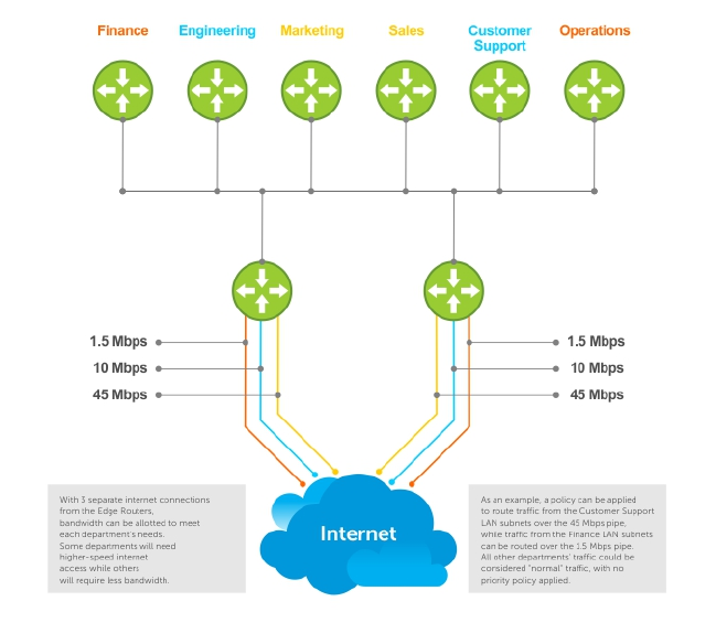
To enable a PBR, you create a redirect list. Redirect lists are defined by rules, or routing policies. The
following parameters can be defined in the routing policies or rules:
• IP address of the forwarding router (next-hop IP address)
• Protocol as defined in the header
• Source IP address and mask
• Destination IP address and mask
• Source port
• Destination port
• TCP Flags
Once a redirect-list is applied to an interface, all traffic passing through it is subjected to the rules defined
in the redirect-list.
The traffic is forwarded based on the following:
• Next-hop addresses are verified. If the specified next hop is reachable, then the traffic is forwarded to
the specified next-hop.
• If the specified next-hops are not reachable, then the normal routing table is used to forward the
traffic.
• Dell Networking OS supports multiple next-hop entries in the redirect lists.
• Redirect-Lists are applied at Ingress.
Policy-based Routing (PBR) 587

Implementing Policy-based Routing with Dell
Networking OS
• Non-contiguous bitmasks for PBR
• Hot-Lock PBR
Non-contiguous bitmasks for PBR
Non-contiguous bitmasks for PBR allows more granular and flexible control over routing policies.
Network addresses that are in the middle of a subnet can be included or excluded. Specific bitmasks can
be entered using the dotted decimal format.
Non-contiguous bitmask example
Dell#show ip redirect-list
IP redirect-list rcl0:
Defined as:
seq 5 permit ip 200.200.200.200 200.200.200.200 199.199.199.199 199.199.199.199
seq 10 redirect 1.1.1.2 tcp 234.224.234.234 255.234.234.234 222.222.222.222/24
seq 40 ack, Next-hop reachable(via Te 8/1), ARP resolved
Applied interfaces:
Te 8/0
Hot-Lock PBR
Ingress and egress Hot Lock PBR allow you to add or delete new rules into an existing policy (already
written into CAM) without disruption to traffic flow. Existing entries in CAM are adjusted to accommodate
the new entries. Hot Lock PBR is enabled by default.
Configuration Task List for Policy-based Routing
To enable the PBR:
• Create a Redirect List
• Create a Rule for a Redirect-list
• Apply a Redirect-list to an Interface using a Redirect-group
Create a Redirect List
Use the following command in CONFIGURATION mode:
Command Syntax Command Mode Purpose
ip redirect-list redirect-list-
name
CONFIGURATION Create a redirect list by entering the list name.
Format: 16 characters
Delete the redirect list with the no ip redirect-list command.
588 Policy-based Routing (PBR)

The following example creates a redirect list by the name of “xyz.”
Dell(conf)#ip redirect-list ?
WORD Redirect-list name (max 16 chars)
Dell(conf)#ip redirect-list xyz
Create a Rule for a Redirect-list
Use the following command in CONFIGURATION REDIRECT-LIST mode to set the rules for the redirect
list. You can enter the command multiple times and create a sequence of redirect rules. Use the seq nn
redirect version of the command to organize your rules.
Command Syntax Command Mode Purpose
seq {number} redirect {ip-
address}{ip-protocol-
number | protocol-type
[bit]} {source mask | any |
host ip-address}
{destination mask | any |
host ip-address}
CONF-REDIRECT-LIST Configure a rule for the redirect list.
number is the number in sequence to initiate this
rule
ip-address is the Forwarding router’s address
FORMAT: A.B.C.D
FORMAT: slot/port
ip-protocol-number or protocol-type is the type
of protocol to be redirected
FORMAT: 0-255 for IP protocol number, or enter
protocol type
source ip-address or any or host ip-address is
the Source’s IP address
FORMAT: A.B.C.D/NN, or ANY or HOST IP
address
destination ip-address or any or host ip-address
is the Destination’s IP address
FORMAT: A.B.C.D/NN, or ANY or HOST IP
address
Delete a rule with the no redirect command.
The redirect rule supports Non-contiguous bitmasks for PBR in the
Destination router IP address
The below step shows a step-by-step example of how to create a rule for a redirect list by configuring:
• IP address of the next-hop router in the forwarding route
• IP protocol number
• Source address with mask information
• Destination address with mask information
Creating a Rule Example:
Dell(conf-redirect-list)#redirect ?
A.B.C.D Forwarding router's address
Policy-based Routing (PBR) 589

Dell(conf-redirect-list)#redirect 3.3.3.3 ?
<0-255> An IP protocol number
icmp Internet Control Message Protocol
ip Any Internet Protocol
tcp Transmission Control Protocol
udp User Datagram Protocol
Dell(conf-redirect-list)#redirect 3.3.3.3 ip ?
A.B.C.D Source address
any Any source host
host A single source host
Dell(conf-redirect-list)#redirect 3.3.3.3 ip 222.1.1.1 ?
Mask A.B.C.D or /nn Mask in dotted decimal or in slash
format
Dell(conf-redirect-list)#redirect 3.3.3.3 ip 222.1.1.1 /32 ?
A.B.C.D Destination address
any Any destination host
host A single destination host
Dell(conf-redirect-list)#redirect 3.3.3.3 ip 222.1.1.1 /32 77.1.1.1 ?
Mask A.B.C.D or /nn Mask in dotted decimal or in slash
format
Dell(conf-redirect-list)#redirect 3.3.3.3 ip 222.1.1.1 /32 77.1.1.1 /32 ?
Dell(conf-redirect-list)#redirect 3.3.3.3 ip 222.1.1.1 /32 77.1.1.1 /32
Dell(conf-redirect-list)#do show ip redirect-list
IP redirect-list xyz:
Defined as:
seq 5 redirect 3.3.3.3 ip host 222.1.1.1 host 77.1.1.1
Applied interfaces:
None
Multiple rules can be applied to a single redirect-list. The rules are applied in ascending order, starting
with the rule that has the lowest sequence number in a redirect-list displays the correct method for
applying multiple rules to one list.
Creating multiple rules for a redirect-list:
Dell(conf)#ip redirect-list test
Dell(conf-redirect-list)#seq 10 redirect 10.1.1.2 ip 20.1.1.0/24 any
Dell(conf-redirect-list)#seq 15 redirect 10.1.1.3 ip 20.1.1.0/25 any
Dell(conf-redirect-list)#seq 20 redirect 10.1.1.3 ip 20.1.1.128/24 any
Dell(conf-redirect-list)#show config
!
ip redirect-list test
seq 10 redirect 10.1.1.2 ip 20.1.1.0/24 any
seq 15 redirect 10.1.1.3 ip 20.1.1.0/25 any
seq 20 redirect 10.1.1.3 ip 20.1.1.0/24 any
Dell(conf-redirect-list)#
NOTE: Starting in release 9.4(0.0), Dell Networking OS supports the use of multiple recursive routes
with the same source-address and destination-address combination in a redirect policy on an
router.
A recursive route is a route for which the immediate next-hop address is learned dynamically through a
routing protocol and acquired through a route lookup in the routing table. The user can configure
multiple recursive routes in a redirect list by entering multiple seq redirect statements with the same
source and destination address and specify a different next-hop IP address. In this way, the recursive
routes are used as different forwarding routes for dynamic failover. If the primary path goes down and the
recursive route is removed from the routing table, the seq redirect statement is ignored and the next
statement in the list with a different route is used.
590 Policy-based Routing (PBR)

PBR Exceptions (Permit)
Use the command permit to create an exception to a redirect list. Exceptions are used when a
forwarding decision should be based on the routing table rather than a routing policy.
Dell Networking OS assigns the first available sequence number to a rule configured without a sequence
number and inserts the rule into the PBR CAM region next to the existing entries. Since the order of rules
is important, ensure that you configure any necessary sequence numbers.
The permit statement is never applied because the redirect list covers all source and destination IP
addresses.
Ineffective PBR Exception due to Low Sequence Number
ip redirect-list rcl0
seq 5 redirect 2.2.2.2 ip any any
seq 10 permit ip host 3.3.3.3 any
To ensure that the permit statement or PBR exception is effective, use a lower sequence number, as
shown below:
ip redirect-list rcl0
seq 10 permit ip host 3.3.3.3 any
seq 15 redirect 2.2.2.2 ip any any
Apply a Redirect-list to an Interface using a Redirect-group
IP redirect lists are supported on physical interfaces as well as VLAN and port-channel interfaces.
NOTE: When you apply a redirect-list on a port-channel, when traffic is redirected to the next hop
and the destination port-channel is shut down, the traffic is dropped. However, on the S-Series, the
traffic redirected to the destination port-channel is sometimes switched.
Use the following command inINTERFACE mode to apply a redirect list to an interface. Multiple redirect-
lists can be applied to a redirect-group. It is also possible to create two or more redirect-groups on one
interface for backup purposes.
Command Syntax Command Mode Purpose
ip redirect-group redirect-list-name INTERFACE Apply a redirect list (policy-based routing) to
an interface.
redirect-list-name is the name of a redirect
list to apply to this interface.
FORMAT: up to 16 characters
Delete the redirect list from this interface with the [no] ip
redirect-group command.
In this example, the list “xyz” is applied to the tenGigabitEthernet 4/0 interface.
Policy-based Routing (PBR) 591

Applying a Redirect-list to an Interface Example:
Dell(conf-if-te-2/0)#ip redirect-group xyz
Dell(conf-if-te-2/0)#
Applying a Redirect-list to an Interface Example:
Dell(conf-if-te-1/0)#ip redirect-group test
Dell(conf-if-te-1/0)#ip redirect-group xyz
Dell(conf-if-te-1/0)#show config
!
interface TenGigabitEthernet 1/0
no ip address
ip redirect-group test
ip redirect-group xyz
shutdown
Dell(conf-if-te-1/0)#
In addition to supporting multiple redirect-lists in a redirect-group, multiple redirect-groups are
supported on a single interface. Dell Networking OS has the capability to support multiple groups on an
interface for backup purposes.
Show Redirect List Configuration
To view the configuration redirect list configuration, use the following command in EXEC mode:
Command Syntax Command Mode Purpose
show ip redirect-list redirect-list-name EXEC View the redirect list configuration and
the associated interfaces.
show cam pbr
show cam-usage
EXEC View the redirect list entries
programmed in the CAM.
List the redirect list configuration using the show ip redirect-list redirect-list-name command. The non-
contiguous mask is displayed in dotted format (x.x.x.x). The contiguous mask is displayed in /x format.
Some sample outputs are shown below:
Dell#show ip redirect-list xyz
IP redirect-list xyz:
Defined as:
seq 5 redirect 3.3.3.3 ip host 222.1.1.1 host 77.1.1.1
Use the show ip redirect-list (without the list name) to display all the redirect-lists configured on the
device.
Dell#show ip redirect-list
IP redirect-list rcl0:
Defined as:
seq 5 permit ip 200.200.200.200 200.200.200.200 199.199.199.199 199.199.199.199
seq 10 redirect 1.1.1.2 tcp 234.224.234.234 255.234.234.234
222.222.222.222/24 eq 40 ack, Next-hop reachable
(via Te 2/1), ARP resolved
Applied interfaces:
Te 2/0
592 Policy-based Routing (PBR)

NOTE: If, the redirect-list is applied to an interface, the output of show ip redirect-list redirect-list-
name command displays reachability and ARP status for the specified next-hop.
Showing CAM PBR Configuration Example :
Dell(conf-if-te-2/1)#do show cam pbr linecard 0 port-set 0
TCP Flag: Bit 5 - URG, Bit 4 - ACK, Bit 3 - PSH, Bit 2 - RST, Bit 1 - SYN, Bit
0 - FIN
Cam Port VlanID Proto Tcp Src Dst SrcIp DstIp Next-hop Egress
Index Flag Port Port MAC Port
------------------------------------------------------------------------------
06080 0 N/A IP 0x0 0 0 200.200.200.200 200.200.200.200 199.199.199.199
199.199.199.199 N/A NA
06081 0 N/A TCP 0x10 0 40 234.234.234.234 255.234.234.234
222.222.222.222/24 00:00:00:00:00:09 8/1
Sample Configuration
The following configuration is an example for setting up a PBR. These are not comprehensive directions.
They are intended to give you a some guidance with typical configurations. You can copy and paste from
these examples to your CLI. Be sure you make the necessary changes to support your own IP Addresses,
Interfaces, Names, etc.
Graphic illustration of the configuration shown below:
The Redirect-List GOLD defined in this example, creates the following rules:
• description Route Gold traffic to the DS3.
• seq 5 redirect 10.99.99.254 ip 192.168.1.0/24 any “ Redirect to next-hop router IP 10.99.99.254 any
traffic originating in 192.168.1.0/24”
• seq 10 redirect 10.99.99.254 ip 192.168.2.0/24 any “ Redirect to next-hop router IP 10.99.99.254 any
traffic originating in 192.168.2.0/24”
• seq 15 permit ip any
PBR Sample Configuration examples are shown below:
Policy-based Routing (PBR) 593

Create the Redirect-List GOLD
EDGE_ROUTER(conf-if-Te-2/23)#ip redirect-list GOLD
EDGE_ROUTER(conf-redirect-list)#description Route GOLD traffic to ISP_GOLD.
EDGE_ROUTER(conf-redirect-list)#direct 10.99.99.254 ip 192.168.1.0/24 any
EDGE_ROUTER(conf-redirect-list)#redirect 10.99.99.254 ip 192.168.2.0/24 any
EDGE_ROUTER(conf-redirect-list)# seq 15 permit ip any any
EDGE_ROUTER(conf-redirect-list)#show config
!
ip redirect-list GOLD
description Route GOLD traffic to ISP_GOLD.
seq 5 redirect 10.99.99.254 ip 192.168.1.0/24 any
seq 10 redirect 10.99.99.254 ip 192.168.2.0/24 any
seq 15 permit ip any any
Assign Redirect-List GOLD to Interface 2/11
EDGE_ROUTER(conf)#int Te 2/11
EDGE_ROUTER(conf-if-Te-2/11)#ip add 192.168.3.2/24
EDGE_ROUTER(conf-if-Te-2/11)#no shut
EDGE_ROUTER(conf-if-Te-2/11)#
EDGE_ROUTER(conf-if-Te-2/11)#ip redirect-group GOLD
EDGE_ROUTER(conf-if-Te-2/11)#no shut
EDGE_ROUTER(conf-if-Te-2/11)#end
EDGE_ROUTER(conf-redirect-list)#end
EDGE_ROUTER#
594 Policy-based Routing (PBR)

View Redirect-List GOLD
EDGE_ROUTER#show ip redirect-list
IP redirect-list GOLD:
Defined as:
seq 5 redirect 10.99.99.254 ip 192.168.1.0/24 any, Next-hop reachable (via Te
3/23), ARP resolved
seq 10 redirect 10.99.99.254 ip 192.168.2.0/24 any, Next-hop reachable (via
Te 3/23), ARP resolved
seq 15 permit ip any any
Applied interfaces:
Te 2/11
EDGE_ROUTER#
Policy-based Routing (PBR) 595

36
Port Monitoring
Port monitoring (also referred to as mirroring) allows you to monitor ingress and/or egress traffic on
specified ports. The mirrored traffic can be sent to a port to which a network analyzer is connected to
inspect or troubleshoot the traffic.
The Dell Networking OS supports the following mirroring techniques:
• Port monitoring — Monitors network traffic by forwarding a copy of incoming and outgoing packets
from a source port to a destination port on the same network router.
• Remote port monitoring (RPM) — Monitors traffic on a remote device in the network. Mirrored traffic
is sent over the L2 network to a destination port, where a probe device can analyze it. RPM is an
extension of the port monitoring feature.
• Encapsulated remote-port monitoring (ERPM) — Encapsulates mirrored packet using GRE tunneling
over an IP routed network.
Local Port Monitoring
Port monitoring is supported on both physical and logical interfaces, such as VLAN and port-channel
interfaces. The source port (MD) with monitored traffic and the destination ports (MG) to which an
analyzer can be attached must be on the same switch. You can configure up to 128 source ports in a
monitoring session. Only one destination port is supported in a monitoring session.
Important Points to Remember
• A source port should have only no ip address and no shutdown as its configured settings. A
source port cannot be a member of a VLAN.
• The range command is supported in the source command to specify multiple source ports.
• You can enter multiple source statements in a monitoring session. A source port can be monitored
by more than one destination port.
• A destination port can be a physical or port-channel interface, and can be used in multiple sessions.
• A maximum number of four destination ports is supported per port pipe. For information about port
pipes on the switch, see Port-pipes.
• Flow-based monitoring is supported on all types of source interfaces.
Examples of Port Monitoring
In the following examples of port monitoring, the four source ports 0/13, 0/14, 0/15, and 0/16 belong to
the same port pipe and mirror traffic to four different destinations (0/1, 0/2, 0/3, and 0/37).
You cannot add another destination on the same port pipe in a monitoring session because a maximum
number of four destination ports are supported on the same port pipe. If you configure another
destination port on the same port pipe, a Syslog message is generated: Unable to create MTP entry
for MD interface MG interface in stack-unit stack-num port-pipe port-num.
Example of Changing the Destination Port in a Monitoring Session
Dell(conf-mon-sess-5)#do show moni session
SessID Source Destination Dir Mode Source IP Dest IP
596 Port Monitoring

------ ------ ----------- --- ---- --------- --------
1 Te 0/0 Te 0/1 both Port N/A N/A
2 Te 0/0 Te 0/2 both Port N/A N/A
3 Te 0/0 Te 0/3 both Port N/A N/A
4 Te 0/0 Te 0/4 both Port N/A N/A
5 Te 0/0 Te 0/5 both Port N/A N/A
Dell(conf-mon-sess-5)#
Dell(conf)#mon ses 300
Dell(conf-mon-sess-300)#source tengig 0/17 destination tengig 0/4 direction tx
%Unable to create MTP entry for MD tenG 0/17 MG tenG 0/4 in stack-unit 0 port-
pipe 0.
Dell(conf-mon-sess-300)#
Dell(conf-mon-sess-300)#source tengig 0/17 destination tengig 0/1 direction tx
Dell(conf-mon-sess-300)#do show mon session
SessionID Source Destination Direction Mode Type
--------- ------ ----------- --------- ---- ----
0 Te 0/13 Te 0/1 rx interface Port-based
10 Te 0/14 Te 0/2 rx interface Port-based
20 Te 0/15 Te 0/3 rx interface Port-based
30 Te 0/16 Te 0/37 rx interface Port-based
300 Te 0/17 Te 0/1 tx interface Port-based
Dell(conf-mon-sess-300)#
Example of Configuring Another Monitoring Session with a Previously Used Destination Port
Dell(conf)#mon ses 300
Dell(conf-mon-sess-300)#source tengig 0/17 destination tengig 0/4 direction tx
%Unable to create MTP entry for MD tenG 0/17 MG tenG 0/4 in stack-unit 0 port-
pipe 0.
Dell(conf-mon-sess-300)#
Dell(conf-mon-sess-300)#source tengig 0/17 destination tengig 0/1 direction tx
Dell(conf-mon-sess-300)#do show mon session
SessionID Source Destination Direction Mode Type
--------- ------ ----------- --------- ---- ----
0 Te 0/13 Te 0/1 rx interface Port-based
10 Te 0/14 Te 0/2 rx interface Port-based
20 Te 0/15 Te 0/3 rx interface Port-based
30 Te 0/16 Te 0/37 rx interface Port-based
300 Te 0/17 Te 0/1 tx interface Port-based
Example of Viewing a Monitoring Session
In the example below, 0/25 and 0/26 belong to port-pipe 1. This port-pipe has the same restriction of
only four destination ports, new or used.
Dell(conf-mon-sess-300)#do show mon session
SessionID Source Destination Direction Mode Type
--------- ------ ----------- --------- ---- ----
0 Te 0/13 Te 0/1 rx interface Port-based
10 Te 0/14 Te 0/2 rx interface Port-based
20 Te 0/15 Te 0/3 rx interface Port-based
30 Te 0/16 Te 0/37 rx interface Port-based
100 Te 0/25 Te 0/38 tx interface Port-based
110 Te 0/26 Te 0/39 tx interface Port-based
300 Te 0/17 Te 0/1 tx interface Port-based
Dell(conf-mon-sess-300)#
Dell Networking OS Behavior: All monitored frames are tagged if the configured monitoring direction is
egress (TX), regardless of whether the monitored port (MD) is a Layer 2 or Layer 3 port. If the MD port is a
Layer 2 port, the frames are tagged with the VLAN ID of the VLAN to which the MD belongs. If the MD
port is a Layer 3 port, the frames are tagged with VLAN ID 4095. If the MD port is in a Layer 3 VLAN, the
frames are tagged with the respective Layer 3 VLAN ID. For example, in the configuration source TenGig
Port Monitoring 597

6/0 destination TenGig 6/1 direction tx, if the MD port TenGig 6/0 is an untagged member of any VLAN,
all monitored frames that the MG port TenGig 6/1 receives are tagged with the VLAN ID of the MD port.
Similarly, if BPDUs are transmitted, the MG port receives them tagged with the VLAN ID 4095. This
behavior might result in a difference between the number of egress packets on the MD port and
monitored packets on the MG port.
Dell Networking OS Behavior: The switch continues to mirror outgoing traffic even after an MD
participating in spanning tree protocol (STP) transitions from the forwarding to blocking.
Configuring Port Monitoring
To configure port monitoring, use the following commands.
1. Verify that the intended monitoring port has no configuration other than no shutdown, as shown in
the following example.
EXEC Privilege mode
show interface
2. Create a monitoring session, as shown in the following example.
CONFIGURATION mode
monitor session
3. Specify the source and destination port and direction of traffic, as shown in the following example.
MONITOR SESSION mode
source
Example of Viewing Port Monitoring Configuration
To display monitor sessions, use the show monitor session command in EXEC Privilege mode.
Dell(conf-if-te-1/2)#show config
!
interface TengigabitEthernet 1/2
no ip address
no shutdown
Dell(conf-if-te-1/2)#exit
Dell(conf)#monitor session 0
Dell(conf-mon-sess-0)#source tengig 1/1 dest tengig 1/2 direction rx
Dell(conf-mon-sess-0)#exit
Dell(conf)#do show monitor session 0
SessionID Source Destination Direction Mode Type
--------- ------ ----------- --------- ---- ----
0 Te 1/1 Te 1/2 rx interface Port-based
Dell(conf)#
In the example below, the host and server are exchanging traffic which passes through interface
tengigabitethernet 1/ 1. Interface tengigabitethernet 1/1 is the monitored port and tengigabitethernet 1/2
is the monitoring port, which is configured to only monitor traffic received on tengigabitethernet 1/1
(host-originated traffic).
598 Port Monitoring

Figure 88. Port Monitoring Example
Remote Port Mirroring
While local port monitoring allows you to monitor traffic from one or more source ports by directing it to
a destination port on the same switch/router, remote port mirroring allows you to monitor Layer 2 and
Layer 3 ingress and/or egress traffic on multiple source ports on different switches and forward the
mirrored traffic to multiple destination ports on different switches.
Remote port mirroring helps network administrators monitor and analyze traffic to troubleshoot network
problems in a time-saving and efficient way.
In a remote-port mirroring session, monitored traffic is tagged with a VLAN ID and switched on a user-
defined, non-routable L2 VLAN. The VLAN is reserved in the network to carry only mirrored traffic, which
is forwarded on all egress ports of the VLAN. Each intermediate switch that participates in the transport of
mirrored traffic must be configured with the reserved L2 VLAN. Remote port monitoring supports
mirroring sessions in which multiple source and destination ports are distributed across multiple switches
Remote Port Mirroring Example
Remote port mirroring uses the analyzers shown in the aggregation network in Site A.
The VLAN traffic on monitored links from the access network is tagged and assigned to a dedicated L2
VLAN. Monitored links are configured in two source sessions shown with orange and green circles. Each
source session uses a separate reserved VLAN to transmit mirrored packets (mirrored source-session
traffic is shown with an orange or green circle with a blue border).
Port Monitoring 599
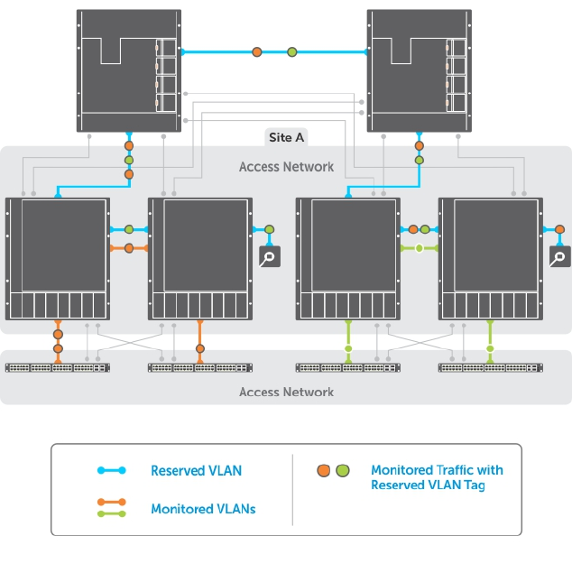
The reserved VLANs transport the mirrored traffic in sessions (blue pipes) to the destination analyzers in
the local network. Two destination sessions are shown: one for the reserved VLAN that transports
orange-circle traffic; one for the reserved VLAN that transports green-circle traffic.
Configuring Remote Port Mirroring
Remote port mirroring requires a source session (monitored ports on different source switches), a
reserved tagged VLAN for transporting mirrored traffic (configured on source, intermediate, and
destination switches), and a destination session (destination ports connected to analyzers on destination
switches).
Configuration Notes
When you configure remote port mirroring, the following conditions apply:
• You can configure any switch in the network with source ports and destination ports, and allow it to
function in an intermediate transport session for a reserved VLAN at the same time for multiple
remote-port mirroring sessions. You can enable and disable individual mirroring sessions.
• BPDU monitoring is not required to use remote port mirroring.
• A remote port mirroring session mirrors monitored traffic by prefixing the reserved VLAN tag to
monitored packets so that they are copied to the reserve VLAN.
• Mirrored traffic is transported across the network using 802.1Q-in-802.1Q tunneling. The source
address, destination address and original VLAN ID of the mirrored packet are preserved with the
tagged VLAN header. Untagged source packets are tagged with the reserve VLAN ID.
600 Port Monitoring
• You cannot configure a private VLAN or a GVRP VLAN as the reserved RPM VLAN.
• The L3 interface configuration should be blocked for the reserved VLAN.
• The member port of the reserved VLAN should have MTU and IPMTU value as MAX+4 (to hold the
VLAN tag parameter).
• To associate with a source session, the reserved VLAN can have a maximum of 4 member ports.
• To associate with a destination session, the reserved VLAN can have multiple member ports.
• The reserved VLAN cannot have untagged ports.
In the reserved L2 VLAN used for remote port mirroring:
• MAC address learning in the reserved VLAN is automatically disabled.
• The reserved VLAN for remote port mirroring can be automatically configured in intermediate
switches by using GVRP.
• There is no restriction on the VLAN IDs used for the reserved remote-mirroring VLAN. Valid VLAN IDs
are from 2 to 4094. The default VLAN ID is not supported.
• In mirrored traffic, packets that have the same destination MAC address as an intermediate or
destination switch in the path used by the reserved VLAN to transport the mirrored traffic are dropped
by the switch that receives the traffic if the switch has a L3 VLAN configured.
In a source session used for remote port mirroring:
• You can configure any port as a source port in a remote-port monitoring session with a maximum of
three source ports per port pipe.
• Maximum number of source sessions supported on a switch: 4
• Maximum number of source ports supported in a source session: 128
• You can configure physical ports and port-channels as sources in remote port mirroring and use
them in the same source session. You can use both Layer 2 (configured with the switchport
command) and Layer 3 ports as source ports. You can optionally configure one or more source
VLANs to specify the VLAN traffic to be mirrored on source ports.
• You can use the default VLAN and native VLANs as a source VLAN.
• You cannot configure the dedicated VLAN used to transport mirrored traffic as a source VLAN.
• Egressing remote-vlan packets are rate limited to a default value of 100 Mbps.
In a destination session used for remote port mirroring:
• Maximum number of destination sessions supported on a switch: 64
• Maximum number ports supported in a destination session: 64.
• You can configure any port as a destination port.
• You can configure additional destination ports in an active session.
• You can tunnel the mirrored traffic from multiple remote-port source sessions to the same
destination port.
• By default, destination port sends the mirror traffic to the probe port by stripping off the rpm header.
We can also configure the destination port to send the mirror traffic with the rpm header intact in the
original mirror traffic..
• By default, ingress traffic on a destination port is dropped.
Restrictions
When you configure remote port mirroring, the following restrictions apply:
Port Monitoring 601

• You can configure the same source port to be used in multiple source sessions.
• You cannot configure a source port channel or source VLAN in a source session if the port channel or
VLAN has a member port that is configured as a destination port in a remote-port mirroring session.
• A destination port for remote port mirroring cannot be used as a source port, including the session in
which the port functions as the destination port.
• A destination port cannot be used in any spanning tree instance.
• The reserved VLAN used to transport mirrored traffic must be a L2 VLAN. L3 VLANs are not supported.
Displaying a Remote-Port Mirroring Configuration
To display the current configuration of remote port mirroring for a specified session, enter the show
config command in MONITOR SESSION configuration mode.
Dell(conf-mon-sess-2)#show config
!
monitor session 2 type rpm
source fortyGigE 0/60 destination remote-vlan 300 direction rx
source Port-channel 10 destination remote-vlan 300 direction rx
no disable
To display the currently configured source and destination sessions for remote port mirroring on a
switch, enter the show monitor session command in EXEC Privilege mode.
Dell(conf)#do show monitor session
SessID Source Destination Dir Mode Source IP Dest IP
------ ------ ----------- --- ---- --------- --------
1 remote-vlan 100 Fo 0/48 N/A N/A N/A N/A
1 remote-vlan 100 Po 100 N/A N/A N/A N/A
2 Fo 0/60 remote-vlan 300 rx Port N/A N/A
2 Po 10 remote-vlan 300 rx Port N/A N/A
To display the current configuration of the reserved VLAN, enter the show vlan command.
Dell#show vlan
Codes: * - Default VLAN, G - GVRP VLANs, R - Remote Port Mirroring VLANs, P -
Primary, C - Community, I - Isolated
O - Openflow
Q: U - Untagged, T - Tagged
x - Dot1x untagged, X - Dot1x tagged
o - OpenFlow untagged, O - OpenFlow tagged
G - GVRP tagged, M - Vlan-stack
i - Internal untagged, I - Internal tagged, v - VLT untagged, V - VLT tagged
NUM Status Description Q Ports
* 1 Inactive
R 100 Active T Fo 0/44
R 300 Active T Fo 0/52
Configuring Remote Port Monitoring
Remote port monitoring requires a source session (monitored ports on different source switches), a
reserved tagged VLAN for transporting mirrored traffic (configured on source, intermediate, and
destination switches), and a destination session (destination ports connected to analyzers on destination
switches).
To configure a remote-port monitoring session:
602 Port Monitoring

Step Command Description
1configure terminal Enter global configuration mode.
2monitor session id type rpm Specify a unique session ID number and RPM as the
session type, and enter Monitoring-Session
configuration mode.
3source {interface | range}
destination interface direction {rx |
tx | both}
Enter a source port or a range of source port
interfaces to be monitored. Enter the destination port
interface. Specify ingress (rx), egress (tx), or both
ingress and egress traffic to be monitored.
7no disable Enter the no disable command to activate the RPM
session.
Examples of Remote-Port Monitoring Configuration
Dell(conf)#interface vlan 10
Dell(conf-if-vl-10)#mode remote-port-mirroring
Dell(conf-if-vl-10)#tagged te 0/4
Dell(conf-if-vl-10)#exit
Dell(conf)#monitor session 1 type rpm
Dell(conf-mon-sess-1)#source te 0/5 destination remote-vlan 10 dir rx
Dell(conf-mon-sess-1)#no disable
Dell(conf-mon-sess-1)#exit
Dell(conf)#inte vlan 100
Dell(conf-if-vl-100)#tagged te 0/7
Dell(conf-if-vl-100)#exit
Dell(conf)#interface vlan 20
Dell(conf-if-vl-20)#mode remote-port-mirroring
Dell(conf-if-vl-20)#tagged te 0/6
Dell(conf-if-vl-20)#exit
Dell(conf)#monitor session 2 type rpm
Dell(conf-mon-sess-2)#source vlan 100 destination remote-vlan 20 dir rx
Dell(conf-mon-sess-2)#no disable
Dell(conf-mon-sess-2)#exit
Dell(conf)#mac access-list standard mac_acl
Dell(config-std-macl)#permit 00:00:00:00:11:22 count monitor
Dell(config-std-macl)#exit
Dell(conf)#interface vlan 100
Dell(conf-if-vl-100)#mac access-group mac_acl1 in
Dell(conf-if-vl-100)#exit
Dell(conf)#inte te 0/30
Dell(conf-if-te-0/30)#no shutdown
Dell(conf-if-te-0/30)#switchport
Dell(conf-if-te-0/30)#exit
Dell(conf)#interface vlan 30
Dell(conf-if-vl-30)#mode remote-port-mirroring
Dell(conf-if-vl-30)#tagged te 0/30
Dell(conf-if-vl-30)#exit
Dell(conf)#interface port-channel 10
Dell(conf-if-po-10)#channel-member te 0/28-29
Port Monitoring 603

Dell(conf-if-po-10)#no shutdown
Dell(conf-if-po-10)#exit
Dell(conf)#monitor session 3 type rpm
Dell(conf-mon-sess-3)#source port-channel 10 dest remote-vlan 30 dir both
Dell(conf-mon-sess-3)#no disable
Dell(conf-mon-sess-3)#exit
Dell(conf)#end
Dell#
Dell#show monitor session
SessID Source Destination Dir Mode Source IP Dest IP
------ ------ ----------- --- ---- --------- --------
1 Te 0/5 remote-vlan 10 rx Port N/A N/A
2 Vl 100 remote-vlan 20 rx Port N/A N/A
3 Po 10 remote-vlan 30 both Port N/A N/A
Dell#
Dell(conf)#interface te 0/0
Dell(conf-if-te-0/0)#switchport
Dell(conf-if-te-0/0)#no shutdown
Dell(conf-if-te-0/0)#exit
Dell(conf)#interface te 0/1
Dell(conf-if-te-0/1)#switchport
Dell(conf-if-te-0/1)#no shutdown
Dell(conf-if-te-0/1)#exit
Dell(conf)#interface te 0/2
Dell(conf-if-te-0/2)#switchport
Dell(conf-if-te-0/2)#no shutdown
Dell(conf-if-te-0/2)#exit
Dell(conf)#interface vlan 10
Dell(conf-if-vl-10)#mode remote-port-mirroring
Dell(conf-if-vl-10)#tagged te 0/0
Dell(conf-if-vl-10)#exit
Dell(conf)#inte vlan 20
Dell(conf-if-vl-20)#mode remote-port-mirroring
Dell(conf-if-vl-20)#tagged te 0/1
Dell(conf-if-vl-20)#exit
Dell(conf)#interface vlan 30
Dell(conf-if-vl-30)#mode remote-port-mirroring
Dell(conf-if-vl-30)#tagged te 0/2
Dell(conf-if-vl-30)#exit
Dell(conf)#monitor session 1 type rpm
Dell(conf-mon-sess-1)#source remote-vlan 10 dest te 0/3
Dell(conf-mon-sess-1)#exit
Dell(conf)#monitor session 2 type rpm
Dell(conf-mon-sess-2)#source remote-vlan 20 destination te 0/4
Dell(conf-mon-sess-2)#tagged destination te 0/4
Dell(conf-mon-sess-2)#exit
Dell(conf)#monitor session 3 type rpm
Dell(conf-mon-sess-3)#source remote-vlan 30 destination te 0/5
Dell(conf-mon-sess-3)#tagged destination te 0/5
Dell(conf-mon-sess-3)#end
Dell#
Dell#show monitor session
SessID Source Destination Dir Mode Source IP Dest IP
604 Port Monitoring

------ ------ ----------- --- ---- --------- --------
1 remote-vlan 10 Te 0/3 N/A N/A N/A N/A
2 remote-vlan 20 Te 0/4 N/A N/A N/A N/A
3 remote-vlan 30 Te 0/5 N/A N/A N/A N/A
Dell#
Configuring RPM Source Sessions to Avoid BPD Issues
When you configure an RPM source session, you can avoid BPDU issues by using the configuration:
1. Enable the MAC control-plane egress ACL.
mac control-plane egress-acl
2. Create an extended MAC access list and add a deny rule for (0x0180c2xxxxxx) packets using the
following commands:
mac access-list extended mac2
seq 5 deny any 01:80:c2:00:00:00 00:00:00:ff:ff:ff count
3. Apply the extended MAC ACL on the RPM VLAN (VLAN 10 in the following example).
Dell#show running-config interface vlan 10
!
interface Vlan 10
no ip address
mode remote-port-mirroring
tagged Port-channel 2
mac access-group mac2 out
no shutdown
4. Create an RPM session (In the following example, port-channels 1 and 2 are LACP).
Dell(conf)#monitor session 1 type rpm
Dell(conf-mon-sess-1)#source port-channel 1 destination remote-vlan 10
dir rx
Dell(conf-mon-sess-1)#no disable
5. Verify the port-channel configuration.
Dell#show interfaces port-channel brief
Codes: L - LACP Port-channel
O - OpenFlow Controller Port-channel
LAG Mode Status Uptime Ports
L1 L3 up 00:01:17 Te 0/44 (Up)
L2 L2 up 00:00:58 Te 0/45 (Up)
Dell#
Port Monitoring 605

Encapsulated Remote-Port Monitoring
Encapsulated Remote Port Monitoring (ERPM) copies traffic from source ports/port-channels or source
VLANs and forwards the traffic using routable GRE-encapsulated packets to the destination IP address
specified in the session.
Important:
When configuring ERPM, follow these guidelines:
• The Dell Networking OS supports ERPM source sessions only. Encapsulated packets terminate at
the destination IP address or at the analyzer.
• You can configure up to four ERPM source sessions on the switch.
• You can configure any port as a source port in an ERPM session.
• The maximum number of source ports that can be defined in a session is 128.
• Make sure that the destination IP address is reachable via the configured IP route (static or
dynamic)
• The system MTU should be configured properly to accommodate the increased size of the
ERPM mirrored packet.
• The system encapsulates the complete ingress or egress data under GRE header, IP header and
outer MAC header and sends it out at the next hop interface as pointed by the routing table.
• The source IP address can be any port's ip address defined in the box but it should be unique
and should not be assigned to any other system in the network.
• You must specify the keyword monitor in the ACL rules used on a source interface (as shown in
one of the examples following the configuration procedure).
• ERPM sessions do not copy locally sourced remote-VLAN traffic from source trunk ports that
carry RPM VLANs. ERPM sessions do not copy locally sourced ERPM GRE-encapsulated traffic
from source ports.
• A flow-based source VLAN can be monitored only for ingress traffic (not egress traffic).
To configure an ERPM session:
Step Command Description
1configure terminal Enter global configuration mode.
2monitor session id type erpm Specify a session ID and ERPM as the type
of monitoring session, and enter
Monitoring-Session configuration mode.
The session number needs to be unique
and not already defined.
3source {interface | range }
direction {rx | tx | both}
Specify the source port or range of ports.
Specify the ingress (rx), egress (tx), or both
ingress and egress traffic to be
monitored. You can enter mulitple source
statements in an ERPM monitoring
session.
5erpm source-ip-address dest-ip-
address
Specify the source IP address and the
destination IP address to which
encapsulated mirrored traffic is sent.
606 Port Monitoring

6flow-based enable Specify ERPM to be performed on a flow-
by-flow basis or if you configure a VLAN
source interface. Enter no flow-based
disable to disable flow-based ERPM.
7no disable Enter the no disable command to
activate the ERPM session.
The following example shows a sample ERPM configuration.
Dell(conf)#monitor session 0 type erpm
Dell(conf-mon-sess-0)#source tengigabitethernet 0/9 direction rx
Dell(conf-mon-sess-0)#source port-channel 1 direction tx
Dell(conf-mon-sess-0)#erpm source-ip 1.1.1.1 dest-ip 7.1.1.2
Dell(conf-mon-sess-0)#no disable
Dell(conf)#monitor session 1 type erpm
Dell(conf-mon-sess-1)#source vlan 11 direction rx
Dell(conf-mon-sess-1)#erpm source-ip 5.1.1.1 dest-ip 3.1.1.2
Dell(conf-mon-sess-1)#flow-based enable
Dell(conf-mon-sess-1)#no disable
Dell# show monitor session
SessID Source Destination Dir Mode Source IP Dest IP
------ ------ ----------- --- ---- --------- --------
0 Te 0/9 remote-ip rx Port 1.1.1.1 7.1.1.2
0 Po 1 remote-ip tx Port 1.1.1.1 7.1.1.2
1 Vl 11 remote-ip rx Flow 5.1.1.1 3.1.1.2
The next example shows the configuration of an ERPM session in which VLAN 11 is monitored as the
source interface and a MAC ACL filters the monitored ingress traffic.
Dell(conf)#mac access-list standard flow
Dell(config-std-macl)#seq 5 permit 00:00:0a:00:00:0b count monitor
Dell#show running-config interface vlan 11
!
interface Vlan 11
no ip address
tagged TenGigabitEthernet 0/1-3
mac access-group flow in
shutdown
Dell#
Port Monitoring 607
37
Private VLANs (PVLAN)
Private VLANs (PVLANs) extend Dell Networking OS security suite by providing Layer 2 isolation between
ports within the same virtual local area network (VLAN).
A PVLAN partitions a traditional VLAN into subdomains identified by a primary and secondary VLAN pair.
Private VLANs block all traffic to isolated ports except traffic from promiscuous ports. Traffic received
from an isolated port is forwarded only to promiscuous ports or trunk ports.
Example uses of PVLANs:
• A hotel can use an isolated VLAN in a PVLAN to provide Internet access for its guests, while stopping
direct access between the guest ports.
• A service provider can provide Layer 2 security for customers and use the IP addresses more
efficiently, by using a separate community VLAN per customer and at the same time using the same IP
subnet address space for all community and isolated VLANs mapped to the same primary VLAN.
– In more detail, community VLANs are especially useful in the service provider environment
because multiple customers are likely to maintain servers that must be strictly separated in
customer-specific groups. A set of servers owned by a customer could comprise a community
VLAN, so that those servers could communicate with each other, and would be isolated from
other customers. Another customer might have another set of servers in another community
VLAN. Another customer might want an isolated VLAN, which has one or more ports that are also
isolated from each other.
For complete syntax information about the commands described in this chapter, refer to the Private
VLANs chapter in the Dell Networking OS Command Line Reference Guide.
Private VLAN Concepts
Review the following PVLAN concepts before you create PVLANs on your system.
The VLAN types in a PVLAN include:
•Community VLAN — a type of secondary VLAN in a primary VLAN:
– Ports in a community VLAN can communicate with each other.
– Ports in a community VLAN can communicate with all promiscuous ports in the primary VLAN.
– A community VLAN can only contain ports configured as host.
•Isolated VLAN — a type of secondary VLAN in a primary VLAN:
– Ports in an isolated VLAN cannot talk directly to each other.
– Ports in an isolated VLAN can only communicate with promiscuous ports in the primary VLAN.
– An isolated VLAN can only contain ports configured as host.
•Primary VLAN — the base VLAN of a PVLAN:
– A switch can have one or more primary VLANs, and it can have none.
– A primary VLAN has one or more secondary VLANs.
608 Private VLANs (PVLAN)

– A primary VLAN and each of its secondary VLANs decrement the available number of VLAN IDs in
the switch.
– A primary VLAN has one or more promiscuous ports.
– A primary VLAN might have one or more trunk ports, or none.
•Secondary VLAN — a subdomain of the primary VLAN.
– There are two types of secondary VLAN — community VLAN and isolated VLAN.
PVLAN port types include:
•Community port — a port that belongs to a community VLAN and is allowed to communicate with
other ports in the same community VLAN and with promiscuous ports.
•Host port — in the context of a private VLAN, is a port in a secondary VLAN:
– The port must first be assigned that role in INTERFACE mode.
– A port assigned the host role cannot be added to a regular VLAN.
•Isolated port — a port that, in Layer 2, can only communicate with promiscuous ports that are in the
same PVLAN.
•Promiscuous port — a port that is allowed to communicate with any other port type in the PVLAN:
– A promiscuous port can be part of more than one primary VLAN.
– A promiscuous port cannot be added to a regular VLAN.
•Trunk port — carries traffic between switches:
– A trunk port in a PVLAN is always tagged.
– In tagged mode, the trunk port carries the primary or secondary VLAN traffic. The tag on the
packet helps identify the VLAN to which the packet belongs.
– A trunk port can also belong to a regular VLAN (non-private VLAN).
Each of the port types can be any type of physical Ethernet port, including port channels (LAGs). For
more information about port channels, refer to Port Channel Interfaces in the Interfaces chapter.
For an introduction to VLANs, refer to Layer 2.
Using the Private VLAN Commands
To use the PVLAN feature, use the following commands.
• Enable/disable Layer 3 communication between secondary VLANs.
INTERFACE VLAN mode
[no] ip local-proxy-arp
NOTE: Even after you disable ip-local-proxy-arp (no ip-local-proxy-arp) in a
secondary VLAN, Layer 3 communication may happen between some secondary VLAN hosts,
until the address resolution protocol (ARP) timeout happens on those secondary VLAN hosts.
• Set the mode of the selected VLAN to community, isolated, or primary.
INTERFACE VLAN mode
[no] private-vlan mode {community | isolated | primary}
• Map secondary VLANs to the selected primary VLAN.
INTERFACE VLAN mode
Private VLANs (PVLAN) 609

[no] private-vlan mapping secondary-vlan vlan-list
• Display type and status of PVLAN interfaces.
EXEC mode or EXEC Privilege mode
show interfaces private-vlan [interface interface]
• Display PVLANs and/or interfaces that are part of a PVLAN.
EXEC mode or EXEC Privilege mode
show vlan private-vlan [community | interface | isolated | primary |
primary_vlan | interface interface]
• Display primary-secondary VLAN mapping.
EXEC mode or EXEC Privilege mode
show vlan private-vlan mapping
• Set the PVLAN mode of the selected port.
INTERFACE
switchport mode private-vlan {host | promiscuous | trunk}
NOTE: Secondary VLANs are Layer 2 VLANs, so even if they are operationally down while primary
VLANs are operationally up, Layer 3 traffic is still transmitted across secondary VLANs.
NOTE: For more information about PVLAN commands, refer to the Dell Networking OS Command
Line Reference Guide.
Configuration Task List
The following sections contain the procedures that configure a private VLAN.
•Creating PVLAN Ports
•Creating a Primary VLAN
•Creating a Community VLAN
•Creating an Isolated VLAN
Creating PVLAN ports
PVLAN ports are those that will be assigned to the PVLAN.
1. Access INTERFACE mode for the port that you want to assign to a PVLAN.
CONFIGURATION mode
interface interface
2. Enable the port.
INTERFACE mode
no shutdown
3. Set the port in Layer 2 mode.
INTERFACE mode
switchport
610 Private VLANs (PVLAN)

4. Select the PVLAN mode.
INTERFACE mode
switchport mode private-vlan {host | promiscuous | trunk}
•host (isolated or community VLAN port)
•promiscuous (intra-VLAN communication port)
•trunk (inter-switch PVLAN hub port)
Example of the switchport mode private-vlan Command
For interface details, refer to Enabling a Physical Interface in the Interfaces chapter.
NOTE: You cannot add interfaces that are configured as PVLAN ports to regular VLANs. Conversely,
you cannot add “regular” ports (ports not configured as PVLAN ports) to PVLANs.
The example below shows the switchport mode private-vlan command on a port and on a port
channel.
Dell#conf
Dell(conf)#interface TengigabitEthernet 2/1
Dell(conf-if-te-2/1)#switchport mode private-vlan promiscuous
Dell(conf)#interface TengigabitEthernet 2/2
Dell(conf-if-te-2/2)#switchport mode private-vlan host
Dell(conf)#interface TengigabitEthernet 2/3
Dell(conf-if-te-2/3)#switchport mode private-vlan trunk
Dell(conf)#interface TengigabitEthernet 2/2
Dell(conf-if-te-2/2)#switchport mode private-vlan host
Dell(conf)#interface port-channel 10
Dell(conf-if-po-10)#switchport mode private-vlan promiscuous
Creating a Primary VLAN
A primary VLAN is a port-based VLAN that is specifically enabled as a primary VLAN to contain the
promiscuous ports and PVLAN trunk ports for the private VLAN.
A primary VLAN also contains a mapping to secondary VLANs, which are comprised of community VLANs
and isolated VLANs.
1. Access INTERFACE VLAN mode for the VLAN to which you want to assign the PVLAN interfaces.
CONFIGURATION mode
interface vlan vlan-id
2. Enable the VLAN.
INTERFACE VLAN mode
no shutdown
3. Set the PVLAN mode of the selected VLAN to primary.
INTERFACE VLAN mode
private-vlan mode primary
4. Map secondary VLANs to the selected primary VLAN.
Private VLANs (PVLAN) 611

INTERFACE VLAN mode
private-vlan mapping secondary-vlan vlan-list
The list of secondary VLANs can be:
• Specified in comma-delimited (VLAN-ID,VLAN-ID) or hyphenated-range format (VLAN-ID-
VLAN-ID).
• Specified with this command even before they have been created.
• Amended by specifying the new secondary VLAN to be added to the list.
5. Add promiscuous ports as tagged or untagged interfaces.
INTERFACE VLAN mode
tagged interface or untagged interface
Add PVLAN trunk ports to the VLAN only as tagged interfaces.
You can enter interfaces singly or in range format, either comma-delimited (slot/
port,port,port) or hyphenated (slot/port-port).
You can only add promiscuous ports or PVLAN trunk ports to the PVLAN (no host or regular ports).
6. (OPTIONAL) Assign an IP address to the VLAN.
INTERFACE VLAN mode
ip address ip address
7. (OPTIONAL) Enable/disable Layer 3 communication between secondary VLANs.
INTERFACE VLAN mode
ip local-proxy-arp
NOTE: If a promiscuous or host port is untagged in a VLAN and it receives a tagged packet in the
same VLAN, the packet is NOT dropped.
Creating a Community VLAN
A community VLAN is a secondary VLAN of the primary VLAN in a private VLAN.
The ports in a community VLAN can talk to each other and with the promiscuous ports in the primary
VLAN.
1. Access INTERFACE VLAN mode for the VLAN that you want to make a community VLAN.
CONFIGURATION mode
interface vlan vlan-id
2. Enable the VLAN.
INTERFACE VLAN mode
no shutdown
3. Set the PVLAN mode of the selected VLAN to community.
INTERFACE VLAN mode
private-vlan mode community
4. Add one or more host ports to the VLAN.
612 Private VLANs (PVLAN)

INTERFACE VLAN mode
tagged interface or untagged interface
You can enter the interfaces singly or in range format, either comma-delimited (slot/
port,port,port) or hyphenated (slot/ port-port).
You can only add host (isolated) ports to the VLAN.
Creating an Isolated VLAN
An isolated VLAN is a secondary VLAN of a primary VLAN.
An isolated VLAN port can only talk with the promiscuous ports in that primary VLAN.
1. Access INTERFACE VLAN mode for the VLAN that you want to make an isolated VLAN.
CONFIGURATION mode
interface vlan vlan-id
2. Enable the VLAN.
INTERFACE VLAN mode
no shutdown
3. Set the PVLAN mode of the selected VLAN to isolated.
INTERFACE VLAN mode
private-vlan mode isolated
4. Add one or more host ports to the VLAN.
INTERFACE VLAN mode
tagged interface or untagged interface
You can enter the interfaces singly or in range format, either comma-delimited (slot/
port,port,port) or hyphenated (slot/ port-port).
You can only add ports defined as host to the VLAN.
Example of Configuring Private VLAN Members
The following example shows the use of the PVLAN commands that are used in VLAN INTERFACE mode
to configure the PVLAN member VLANs (primary, community, and isolated VLANs).
Dell#conf
Dell(conf)# interface vlan 10
Dell(conf-vlan-10)# private-vlan mode primary
Dell(conf-vlan-10)# private-vlan mapping secondary-vlan 100-101
Dell(conf-vlan-10)# untagged Te 2/1
Dell(conf-vlan-10)# tagged Te 2/3
Dell(conf)# interface vlan 101
Dell(conf-vlan-101)# private-vlan mode community
Dell(conf-vlan-101)# untagged Te 2/10
Dell(conf)# interface vlan 100
Dell(conf-vlan-100)# private-vlan mode isolated
Dell(conf-vlan-100)# untagged Te 2/2
Private VLANs (PVLAN) 613
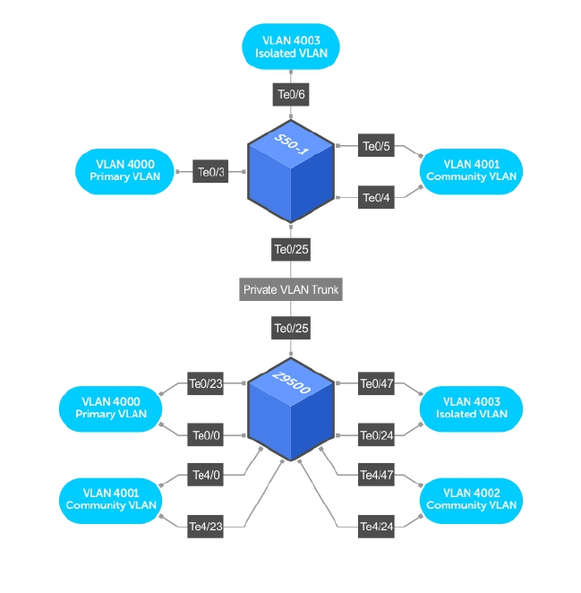
Private VLAN Configuration Example
The following example shows a private VLAN topology.
Figure 89. Sample Private VLAN Topology
The following configuration is based on the example diagram for the C300–1:
• Te 0/0 and Te 23 are configured as promiscuous ports, assigned to the primary VLAN, VLAN 4000.
• Te 0/25 is configured as a PVLAN trunk port, also assigned to the primary VLAN 4000.
• Te 0/24 and Te 0/47 are configured as host ports and assigned to the isolated VLAN, VLAN 4003.
• Te 4/0 and Te 23 are configured as host ports and assigned to the community VLAN, VLAN 4001.
• Te 4/24 and Te 4/47 are configured as host ports and assigned to community VLAN 4002.
The result is that:
• The ports in community VLAN 4001 can communicate directly with each other and with promiscuous
ports.
• The ports in community VLAN 4002 can communicate directly with each other and with promiscuous
ports.
• The ports in isolated VLAN 4003 can only communicate with the promiscuous ports in the primary
VLAN 4000.
614 Private VLANs (PVLAN)

• All the ports in the secondary VLANs (both community and isolated VLANs) can only communicate
with ports in the other secondary VLANs of that PVLAN over Layer 3, and only when the ip local-
proxy-arp command is invoked in the primary VLAN.
NOTE: Even after you disable ip-local-proxy-arp (no ip-local-proxy-arp) in a secondary
VLAN, Layer 3 communication may happen between some secondary VLAN hosts, until the ARP
timeout happens on those secondary VLAN hosts.
In parallel, on S50-1:
• Te 0/3 is a promiscuous port and Te 0/25 is a PVLAN trunk port, assigned to the primary VLAN 4000.
• Te 0/4-6 are host ports. Te 0/4 and Te 0/5 are assigned to the community VLAN 4001, while Te 0/6 is
assigned to the isolated VLAN 4003.
The result is that:
• The S50V ports would have the same intra-switch communication characteristics as described for the
C300.
• For transmission between switches, tagged packets originating from host PVLAN ports in one
secondary VLAN and destined for host PVLAN ports in the other switch travel through the
promiscuous ports in the local VLAN 4000 and then through the trunk ports (0/25 in each switch).
Inspecting the Private VLAN Configuration
The standard methods of inspecting configurations also apply in PVLANs.
To inspect your PVLAN configurations, use the following commands.
• Display the specific interface configuration.
INTERFACE mode and INTERFACE VLAN mode
show config
• Inspect the running-config, and, with the grep pipe option, display a specific part of the running-
config.
show running-config | grep string
The following example shows the PVLAN parts of the running-config from the S50V switch in the
topology diagram previously shown.
• Display the type and status of the configured PVLAN interfaces.
show interfaces private-vlan [interface interface]
This command is specific to the PVLAN feature.
For more information, refer to the Security chapter in the Dell Networking OS Command Line
Reference Guide.
• Display the configured PVLANs or interfaces that are part of a PVLAN.
show vlan private-vlan [community | interface | isolated | primary |
primary_vlan | interface interface]
This command is specific to the PVLAN feature.
The following examples show the results of using this command without the command options in the
topology diagram previously shown.
• Display the primary-secondary VLAN mapping. The following example shows the output from the
S50V.
Private VLANs (PVLAN) 615

show vlan private-vlan mapping
This command is specific to the PVLAN feature.
Examples of Viewing a Private VLANs
The show arp and show vlan commands are revised to display PVLAN data.
The following example shows viewing a private VLAN for a C300 system.
Dell#show vlan private-vlan
Primary Secondary Type Active Ports
------- --------- --------- ------ --------------
4000 Primary Yes Te 0/0,23,25
4001 Community Yes Te 4/0,23
4002 Community Yes Te 4/24,47
4003 Isolated Yes Te 0/24,47
The following example shows viewing a private VLAN for a S50V system.
Dell#show vlan private-vlan
Primary Secondary Type Active Ports
------- --------- --------- ------ -----------
4000 Primary Yes Te 0/3,25
4001 Community Yes Te 0/4-5
4003 Isolated Yes Te 0/6
The following example shows the show vlan private-vlan mapping command.
Dell#show vlan private-vlan mapping
Private Vlan:
Primary : 4000
Isolated : 4003
Community : 4001
NOTE: In the following example, notice the addition of the PVLAN codes – P, I, and C – in the left
column.
The following example shows the VLAN status.
Dell#show vlan
Codes: * - Default VLAN, G - GVRP VLANs, P - Primary, C - Community, I - Isolated
Q: U - Untagged, T - Tagged
x - Dot1x untagged, X - Dot1x tagged
G - GVRP tagged, M - Vlan-stack
NUM Status Description Q Ports
* 1 Inactive
100 Inactive
P 200 Inactive primary VLAN in PVLAN T Te 0/19-20
I 201 Inactive isolated VLAN in VLAN 200 T Te 0/21
The following example shows viewing a private VLAN configuration.
!
interface TengigabitEthernet 0/3
no ip address
switchport
switchport mode private-vlan promiscuous
no shutdown
!
interface TengigabitEthernet 0/4
no ip address
616 Private VLANs (PVLAN)

switchport
switchport mode private-vlan host
no shutdown
!
interface TengigabitEthernet 0/5
no ip address
switchport
switchport mode private-vlan host
no shutdown
!
interface TengigabitEthernet 0/6
no ip address
switchport
switchport mode private-vlan host
no shutdown
!
interface TengigabitEthernet 0/25
no ip address
switchport
switchport mode private-vlan trunk
no shutdown
!
interface Vlan 4000
private-vlan mode primary
private-vlan mapping secondary-vlan 4001-4003
no ip address
tagged TengigabitEthernet 0/3,25
no shutdown
!
interface Vlan 4001
private-vlan mode community
Private VLANs (PVLAN) 617
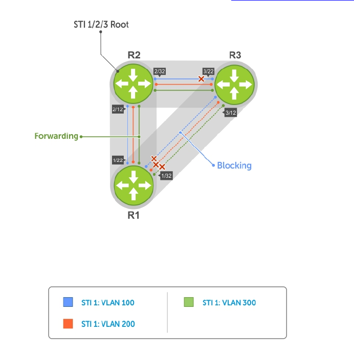
38
Per-VLAN Spanning Tree Plus (PVST+)
Per-VLAN spanning tree plus (PVST+) is a variation of spanning tree — developed by a third party — that
allows you to configure a separate spanning tree instance for each virtual local area network (VLAN).
Protocol Overview
A sample PVST+ topology is shown below.
For more information about spanning tree, refer to the Spanning Tree Protocol (STP) chapter.
Figure 90. Per-VLAN Spanning Tree
The Dell Networking OS supports three other versions of spanning tree, as shown in the following table.
618 Per-VLAN Spanning Tree Plus (PVST+)

Table 31. Spanning Tree Versions Supported
Dell Networking Term IEEE Specification
Spanning Tree Protocol (STP) 802 .1d
Rapid Spanning Tree Protocol (RSTP) 802 .1w
Multiple Spanning Tree Protocol (MSTP) 802 .1s
Per-VLAN Spanning Tree Plus (PVST+) Third Party
Implementation Information
• The Dell Networking OS implementation of PVST+ is based on IEEE Standard 802.1w.
• The Dell Networking OS implementation of PVST+ uses IEEE 802.1s costs as the default costs (as
shown in the following table). Other implementations use IEEE 802.1w costs as the default costs. If
you are using Dell Networking systems in a multivendor network, verify that the costs are values you
intended.
• You can enable PVST+ on 254 VLANs. To set up VLANs, refer to Virtual LANs (VLANs).
Configure Per-VLAN Spanning Tree Plus
Configuring PVST+ is a four-step process.
1. Configure interfaces for Layer 2.
2. Place the interfaces in VLANs.
3. Enable PVST+.
4. Optionally, for load balancing, select a nondefault bridge-priority for a VLAN.
Related Configuration Tasks
•Modifying Global PVST+ Parameters
•Modifying Interface PVST+ Parameters
•Configuring an EdgePort
•Flush MAC Addresses after a Topology Change
•Prevent Network Disruptions with BPDU Guard
•Enabling SNMP Traps for Root Elections and Topology Changes
•PVST+ in Multi-Vendor Networks
•Enabling PVST+ Extended System ID
•PVST+ Sample Configurations
Enabling PVST+
When you enable PVST+, the system instantiates STP on each active VLAN.
1. Enter PVST context.
PROTOCOL PVST mode
protocol spanning-tree pvst
2. Enable PVST+.
Per-VLAN Spanning Tree Plus (PVST+) 619

PROTOCOL PVST mode
no disable
Disabling PVST+
To disable PVST+ globally or on an interface, use the following commands.
• Disable PVST+ globally.
PROTOCOL PVST mode
disable
• Disable PVST+ on an interface, or remove a PVST+ parameter configuration.
INTERFACE mode
no spanning-tree pvst
Example of Viewing PVST+ Configuration
To display your PVST+ configuration, use the show config command from PROTOCOL PVST mode.
Dell_E600(conf-pvst)#show config verbose
!
protocol spanning-tree pvst
no disable
vlan 100 bridge-priority 4096
Influencing PVST+ Root Selection
As shown in the previous PVST+ illustration, all VLANs use the same forwarding topology because R2 is
elected the root, and all TengigabitEthernet ports have the same cost.
The following per-VLAN spanning tree illustration changes the bridge priority of each bridge so that a
different forwarding topology is generated for each VLAN. This behavior demonstrates how you can use
PVST+ to achieve load balancing.
620 Per-VLAN Spanning Tree Plus (PVST+)

Figure 91. Load Balancing with PVST+
The bridge with the bridge value for bridge priority is elected root. Because all bridges use the default
priority (until configured otherwise), the lowest MAC address is used as a tie-breaker. To increase the
likelihood that a bridge is selected as the STP root, assign bridges a low non-default value for bridge
priority.
To assign a bridge priority, use the following command.
• Assign a bridge priority.
PROTOCOL PVST mode
vlan bridge-priority
The range is from 0 to 61440.
The default is 32768.
Example of the show spanning-tree pvst vlan Command
To display the PVST+ forwarding topology, use the show spanning-tree pvst [vlan vlan-id]
command from EXEC Privilege mode.
Dell(conf)#do show spanning-tree pvst vlan 100
VLAN 100
Per-VLAN Spanning Tree Plus (PVST+) 621

Root Identifier has priority 4096, Address 0001.e80d.b6d6
Root Bridge hello time 2, max age 20, forward delay 15
Bridge Identifier has priority 4096, Address 0001.e80d.b6d6
Configured hello time 2, max age 20, forward delay 15
We are the root of VLAN 100
Current root has priority 4096, Address 0001.e80d.b6d6
Number of topology changes 5, last change occurred 00:34:37 ago on Te 1/32
Port 375 (TengigabitEthernet 1/22) is designated Forwarding
Port path cost 20000, Port priority 128, Port Identifier 128.375
Designated root has priority 4096, address 0001.e80d.b6:d6
Designated bridge has priority 4096, address 0001.e80d.b6:d6
Designated port id is 128.375 , designated path cost 0
Number of transitions to forwarding state 2
BPDU sent 1159, received 632
The port is not in the Edge port mode
Port 385 (TengigabitEthernet 1/32) is designated Forwarding
Port path cost 20000, Port priority 128, Port Identifier 128.385
Designated root has priority 4096, address 0001.e80d.b6:d6
Designated bridge has priority 4096, address 0001.e80d.b6:d6
Designated port id is 128.385 , designated path cost 0
Modifying Global PVST+ Parameters
The root bridge sets the values for forward-delay and hello-time, and overwrites the values set on other
PVST+ bridges.
•Forward-delay — the amount of time an interface waits in the Listening state and the Learning state
before it transitions to the Forwarding state.
•Hello-time — the time interval in which the bridge sends bridge protocol data units (BPDUs).
•Max-age — the length of time the bridge maintains configuration information before it refreshes that
information by recomputing the PVST+ topology.
To change PVST+ parameters on the root bridge, use the following commands.
• Change the forward-delay parameter.
PROTOCOL PVST mode
vlan forward-delay
The range is from 4 to 30.
The default is 15 seconds.
• Change the hello-time parameter.
PROTOCOL PVST mode
vlan hello-time
NOTE: With large configurations (especially those configurations with more ports), Dell
Networking recommends increasing the hello-time.
The range is from 1 to 10.
The default is 2 seconds.
• Change the max-age parameter.
622 Per-VLAN Spanning Tree Plus (PVST+)

PROTOCOL PVST mode
vlan max-age
The range is from 6 to 40.
The default is 20 seconds.
The values for global PVST+ parameters are given in the output of the show spanning-tree pvst
command.
Modifying Interface PVST+ Parameters
You can adjust two interface parameters (port cost and port priority) to increase or decrease the
probability that a port becomes a forwarding port.
•Port cost — a value that is based on the interface type. The greater the port cost, the less likely the
port is selected to be a forwarding port.
•Port priority — influences the likelihood that a port is selected to be a forwarding port in case that
several ports have the same port cost.
The following tables lists the default values for port cost by interface.
Table 32. Default Values for Port Cost
Port Cost Default Value
100-Mb/s Ethernet interfaces 200000
1-Gigabit Ethernet interfaces 20000
10-Gigabit Ethernet interfaces 2000
Port Channel with 100 Mb/s Ethernet interfaces 180000
Port Channel with 1-Gigabit Ethernet interfaces 18000
Port Channel with 10-Gigabit Ethernet interfaces 1800
NOTE: The Dell Networking OS implementation of PVST+ uses IEEE 802.1s costs as the default
costs. Other implementations use IEEE 802.1w costs as the default costs. If you are using Dell
Networking systems in a multi-vendor network, verify that the costs are values you intended.
To change the port cost or port priority of an interface, use the following commands.
• Change the port cost of an interface.
INTERFACE mode
spanning-tree pvst vlan cost.
The range is from 0 to 200000.
Refer to the table for the default values.
• Change the port priority of an interface.
INTERFACE mode
spanning-tree pvst vlan priority.
Per-VLAN Spanning Tree Plus (PVST+) 623

The range is from 0 to 240, in increments of 16.
The default is 128.
The values for interface PVST+ parameters are given in the output of the show spanning-tree pvst
command, as previously shown.
Configuring an EdgePort
The EdgePort feature enables interfaces to begin forwarding traffic approximately 30 seconds sooner.
In this mode an interface forwards frames by default until it receives a BPDU that indicates that it should
behave otherwise; it does not go through the Learning and Listening states. The bpduguard shutdown-
on-violation option causes the interface hardware to be shut down when it receives a BPDU. When
you only implement bpduguard, although the interface is placed in an Error Disabled state when
receiving the BPDU, the physical interface remains up and spanning-tree drops packets in the hardware
after a BPDU violation. BPDUs are dropped in the software after receiving the BPDU violation.
This feature is the same as PortFast mode in spanning tree.
CAUTION: Configure EdgePort only on links connecting to an end station. EdgePort can cause
loops if you enable it on an interface connected to a network.
To enable EdgePort on an interface, use the following command.
• Enable EdgePort on an interface.
INTERFACE mode
spanning-tree pvst edge-port [bpduguard | shutdown-on-violation]
The EdgePort status of each interface is given in the output of the show spanning-tree pvst
command, as previously shown.
Dell Networking OS Behavior: Regarding the bpduguard shutdown-on-violation command
behavior:
• If the interface to be shut down is a port channel, all the member ports are disabled in the hardware.
• When you add a physical port to a port channel already in an Error Disable state, the new member
port is also disabled in the hardware.
• When you remove a physical port from a port channel in an Error Disable state, the Error Disabled
state is cleared on this physical port (the physical port is enabled in the hardware).
• The reset linecard command does not clear the Error Disabled state of the port or the hardware
Disabled state. The interface continues to be disables in the hardware.
• You can clear the Error Disabled state with any of the following methods:
– Perform a shutdown command on the interface.
– Disable the shutdown-on-violation command on the interface (the no spanning-tree
stp-id portfast [bpduguard | [shutdown-on-violation]] command).
– Disable spanning tree on the interface (the no spanning-tree command in INTERFACE mode).
– Disabling global spanning tree (the no spanning-tree command in CONFIGURATION mode).
624 Per-VLAN Spanning Tree Plus (PVST+)
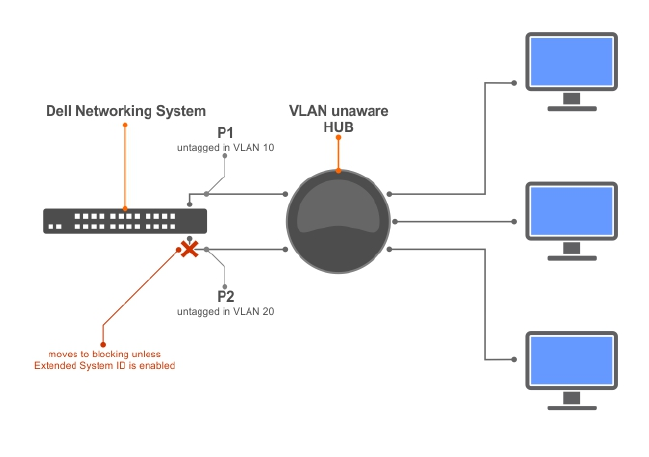
PVST+ in Multi-Vendor Networks
Some non-Dell Networking systems which have hybrid ports participating in PVST+ transmit two kinds of
BPDUs: an 802.1D BPDU and an untagged PVST+ BPDU.
Dell Networking systems do not expect PVST+ BPDU (tagged or untagged) on an untagged port. If this
situation occurs, the system places the port in an Error-Disable state. This behavior might result in the
network not converging. To prevent the system from executing this action, use the no spanning-tree
pvst err-disable cause invalid-pvst-bpdu command. After you configure this command, if the
port receives a PVST+ BPDU, the BPDU is dropped and the port remains operational.
Enabling PVST+ Extend System ID
In the following example, ports P1 and P2 are untagged members of different VLANs. These ports are
untagged because the hub is VLAN unaware. There is no data loop in this scenario; however, you can
employ PVST+ to avoid potential misconfigurations.
If you enable PVST+ on the Dell Networking switch in this network, P1 and P2 receive BPDUs from each
other. Ordinarily, the Bridge ID in the frame matches the Root ID, a loop is detected, and the rules of
convergence require that P2 move to blocking state because it has the lowest port ID.
To keep both ports in a Forwarding state, use extend system ID. Extend system ID augments the bridge ID
with a VLAN ID to differentiate BPDUs on each VLAN so that PVST+ does not detect a loop and both
ports can remain in a Forwarding state.
Figure 92. PVST+ with Extend System ID
• Augment the bridge ID with the VLAN ID.
PROTOCOL PVST mode
extend system-id
Per-VLAN Spanning Tree Plus (PVST+) 625

Example of Viewing the Extend System ID in a PVST+ Configuration
Dell(conf-pvst)#do show spanning-tree pvst vlan 5 brief
VLAN 5
Executing IEEE compatible Spanning Tree Protocol
Root ID Priority 32773, Address 0001.e832.73f7
Root Bridge hello time 2, max age 20, forward delay 15
Bridge ID Priority 32773 (priority 32768 sys-id-ext 5), Address 0001.e832.73f7
We are the root of Vlan 5
Configured hello time 2, max age 20, forward delay 15
PVST+ Sample Configurations
The following examples provide the running configurations for the topology shown in the previous
illustration.
Example of PVST+ Configuration (R1)
interface TengigabitEthernet 1/22
no ip address
switchport
no shutdown
!
interface TengigabitEthernet 1/32
no ip address
switchport
no shutdown
!
protocol spanning-tree pvst
no disable
vlan 100 bridge-priority 4096
interface Vlan 100
no ip address
tagged TengigabitEthernet 1/22,32
no shutdown
!
interface Vlan 200
no ip address
tagged TengigabitEthernet 1/22,32
no shutdown
!
interface Vlan 300
no ip address
tagged TengigabitEthernet 1/22,32
no shutdown
!
protocol spanning-tree pvst
no disable
vlan 100 bridge-priority 4096
Example of PVST+ Configuration (R2)
interface TengigabitEthernet 2/12
no ip address
switchport
no shutdown
!
interface TengigabitEthernet 2/32
no ip address
switchport
no shutdown
!
626 Per-VLAN Spanning Tree Plus (PVST+)

interface Vlan 100
no ip address
tagged TengigabitEthernet 2/12,32
no shutdown
!
interface Vlan 200
no ip address
tagged TengigabitEthernet 2/12,32
no shutdown
!
interface Vlan 300
no ip address
tagged TengigabitEthernet 2/12,32
no shutdown
!
protocol spanning-tree pvst
no disable
vlan 200 bridge-priority 4096
Example of PVST+ Configuration (R3)
interface TengigabitEthernet 3/12
no ip address
switchport
no shutdown
!
interface TengigabitEthernet 3/22
no ip address
switchport
no shutdown
!
interface Vlan 100
no ip address
tagged TengigabitEthernet 3/12,22
no shutdown
!
interface Vlan 200
no ip address
tagged TengigabitEthernet 3/12,22
no shutdown
!
interface Vlan 300
no ip address
tagged TengigabitEthernet 3/12,22
no shutdown
!
protocol spanning-tree pvst
no disable
vlan 300 bridge-priority 4096
Per-VLAN Spanning Tree Plus (PVST+) 627
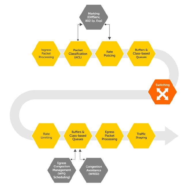
39
Quality of Service (QoS)
This chapter describes how to use and configure Quality of Service (QoS) features on the switch.
Differentiated service is accomplished by classifying and queuing traffic, and assigning priorities to those
queues.
Figure 93. Dell Networking QoS Architecture
Implementation Information
The Dell Networking QoS implementation complies with IEEE 802.1p User Priority Bits for QoS Indication.
It also implements these Internet Engineering Task Force (IETF) documents:
• RFC 2474, Definition of the Differentiated Services Field (DS Field) in the IPv4 Headers
• RFC 2475, An Architecture for Differentiated Services
628 Quality of Service (QoS)

• RFC 2597, Assured Forwarding PHB Group
• RFC 2598, An Expedited Forwarding PHB
You cannot configure port-based and policy-based QoS on the same interface.
Port-Based QoS Configurations
You can configure the following QoS features on an interface.
NOTE: You cannot simultaneously use egress rate shaping and ingress rate policing on the same
virtual local area network (VLAN).
•Setting dot1p Priorities for Incoming Traffic
•Honoring dot1p Priorities on Ingress Traffic
•Configuring Port-Based Rate Policing
•Configuring Port-Based Rate Shaping
Setting dot1p Priorities for Incoming Traffic
The system assigns traffic marked with a priority in a queue based on the following table.
If you set a dot1p priority for a port-channel, all port-channel members are configured with the same
value. You cannot assign a dot1p value to an individual interface in a port-channel.
Table 33. dot1p-priority Values and Queue Numbers
dot1p Queue Number
0 2
1 0
2 1
3 3
4 4
5 5
6 6
7 7
• Change the priority of incoming traffic on the interface.
dot1p-priority
Example of Configuring a dot1p Priority on an Interface
Dell#config
Dell(conf)#interface tengigabitethernet 1/2
Dell(conf-if)#switchport
Dell(conf-if)#dot1p-priority 1
Dell(conf-if)#end
Dell#
Quality of Service (QoS) 629

Honoring dot1p Priorities on Ingress Traffic
By default, the system does not honor dot1p priorities on ingress traffic.
You can configure this feature on physical interfaces and port-channels, but you cannot configure it on
individual interfaces in a port channel.
You can configure service-class dynamic dot1p from CONFIGURATION mode, which applies the
configuration to all interfaces. A CONFIGURATION mode service-class dynamic dot1p entry supersedes
any INTERFACE entries. For more information, refer to Mapping dot1p Values to Service Queues.
NOTE: You cannot configure service-policy input and service-class dynamic dot1p on
the same interface.
• Honor dot1p priorities on ingress traffic.
INTERFACE mode
service-class dynamic dot1p
Example of Configuring an Interface to Honor dot1p Priorities on Ingress Traffic
Dell#config t
Dell(conf)#interface tengigabitethernet 1/2
Dell(conf-if)#service-class dynamic dot1p
Dell(conf-if)#end
Dell#
Priority-Tagged Frames on the Default VLAN
VLAN Priority-tagged frames are 802.1Q tagged frames with (default) VLAN ID 0. For VLAN classification,
these packets are treated as untagged. However, the dot1p value is still honored when you configure
service-class dynamic dot1p or trust dot1p.
When priority-tagged frames ingress an untagged port or hybrid port, the frames are classified to the
default VLAN of the port and to a queue according to their dot1p priority if you configure service-
class dynamic dotp or trust dot1p. When priority-tagged frames ingress a tagged port, the frames
are dropped because, for a tagged port, the default VLAN is 0.
Dell Networking OS Behavior: Hybrid ports can receive untagged, tagged, and priority tagged frames.
The rate metering calculation might be inaccurate for untagged ports because an internal assumption is
made that all frames are treated as tagged. Internally, the ASIC adds a 4-bytes tag to received untagged
frames. Though these 4-bytes are not part of the untagged frame received on the wire, they are included
in the rate metering calculation resulting in metering inaccuracy.
Configuring Port-Based Rate Policing
If the interface is a member of a VLAN, you may specify the VLAN for which ingress packets are policed.
• Rate policing ingress traffic on an interface.
INTERFACE mode
rate police
630 Quality of Service (QoS)

Example of Configuring and Viewing Rate Policing
The following example shows configuring rate policing.
Dell#config t
Dell(conf)#interface tengigabitethernet 1/2
Dell(conf-if)#rate police 100 40 peak 150 50
Dell(conf-if)#end
Dell#
The following example shows viewing the rate policing status.
Dell#show interfaces tengigabitEthernet 1/2 rate police
Rate police 300 (50) peak 800 (50)
Traffic Monitor 0: normal 300 (50) peak 800 (50)
Out of profile yellow 23386960 red 320605113
Traffic Monitor 1: normal NA peak NA
Out of profile yellow 0 red 0
Traffic Monitor 2: normal NA peak NA
Out of profile yellow 0 red 0
Traffic Monitor 3: normal NA peak NA
Out of profile yellow 0 red 0
Traffic Monitor 4: normal NA peak NA
Out of profile yellow 0 red 0
Configuring Port-Based Rate Shaping
Rate shaping buffers, rather than drops, traffic exceeding the specified rate until the buffer is exhausted. If
any stream exceeds the configured bandwidth on a continuous basis, it can consume all of the buffer
space that is allocated to the port.
• Apply rate shaping to outgoing traffic on a port.
INTERFACE mode
rate shape
• Apply rate shaping to a queue.
QoS Policy mode
rate shape
Example of rate shape Command
Dell#config
Dell(conf)#interface tengigabitethernet 1/2
Dell(conf-if)#rate shape 500 50
Dell(conf-if)#end
Dell#
Quality of Service (QoS) 631
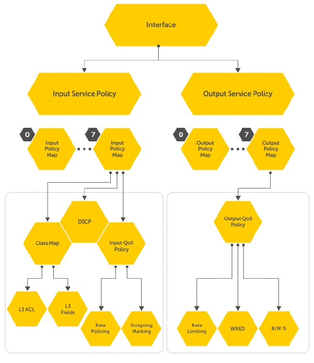
Policy-Based QoS Configurations
Policy-based QoS configurations consist of the components shown in the following example.
Figure 94. Constructing Policy-Based QoS Configurations
Classify Traffic
Class maps differentiate traffic so that you can apply separate quality of service policies to different types
of traffic.
For both class maps, Layer 2 and Layer 3, the system matches packets against match criteria in the order
that you configure them.
632 Quality of Service (QoS)

Creating a Layer 3 Class Map
A Layer 3 class map differentiates ingress packets based on the DSCP value, IP precedence, VLANs, or
characteristics defined in an IP ACL. You can also use VLAN IDs and VRF IDs to classify the traffic using
layer 3 class-maps.
You can specify more than one DSCP and IP precedence value, but only one value must match to trigger
a positive match for the class map.
NOTE: IPv6 and IP-any class maps cannot match on ACLs or VLANs.
Use step 1 or step 2 to start creating a Layer 3 class map.
1. Create a match-any class map.
CONFIGURATION mode
class-map match-any class-map-name
2. Create a match-all class map.
CONFIGURATION mode
class-map match-all class-map-name
3. Specify your match criteria.
CLASS MAP mode
match {ip | ipv6 | ip-any}
After you create a class-map, you are placed in CLASS MAP mode.
Match-any class maps allow up to five ACLs. Match-all class-maps allow only one ACL.
4. Link the class-map to a queue.
POLICY MAP mode
service-queue
Example of Creating a Layer 3 Class Map
Dell(conf)#ip access-list standard acl1
Dell(config-std-nacl)#permit 20.0.0.0/8
Dell(config-std-nacl)#exit
Dell(conf)#ip access-list standard acl2
Dell(config-std-nacl)#permit 20.1.1.0/24 order 0
Dell(config-std-nacl)#exit
Dell(conf)#class-map match-all cmap1
Dell(conf-class-map)#match ip access-group acl1
Dell(conf-class-map)#exitDell(conf)#class-map match-all cmap2
Dell(conf-class-map)#match ip access-group acl2
Dell(conf-class-map)#exit
Dell(conf)#policy-map-input pmap
Dell(conf-policy-map-in)#service-queue 3 class-map cmap1
Dell(conf-policy-map-in)#service-queue 1 class-map cmap2
Dell(conf-policy-map-in)#exit
Dell(conf)#interface tegig 1/0
Dell(conf-if-te-1/0)#service-policy input pmap
Examples of Creating a Layer 3 IPv6 Class Map
Quality of Service (QoS) 633

The following example matches IPv6 traffic with a DSCP value of 40.
Dell(conf)# class-map match-all test
Dell(conf-class-map)# match ipv6 dscp 40
The following example matches IPv4 and IPv6 traffic with a precedence value of 3.
Dell(conf)# class-map match-any test1
Dell(conf-class-map)#match ip-any precedence 3
Creating a Layer 2 Class Map
All class maps are Layer 3 by default; however, you can create a Layer 2 class map by specifying the
layer2 option with the class-map command.
A Layer 2 class map differentiates traffic according to 802.1p value and/or characteristics defined in a
MAC ACL.
Use Step 1 or Step 2 to start creating a Layer 2 class map.
1. Create a match-any class map.
CONFIGURATION mode
class-map match-any
2. Create a match-all class map.
CONFIGURATION mode
class-map match-all
3. Specify your match criteria.
CLASS MAP mode
match mac
After you create a class-map, you are placed in CLASS MAP mode.
Match-any class maps allow up to five access-lists. Match-all class-maps allow only one. You can
match against only one VLAN ID.
4. Link the class-map to a queue.
POLICY MAP mode
service-queue
Applying Layer 2 Match Criteria on a Layer 3 Interface
To process Layer 3 packets that contain a dot1p (IEEE 802.1p) VLAN Layer 2 header, configure VLAN tags
on a Layer 3 port interface which is configured with an IP address but has no VLAN associated with it. You
can also configure a VLAN sub-interface on the port interface and apply a policy map that classifies
packets using the dot1p VLAN ID.
To apply an input policy map with Layer 2 match criteria to a Layer 3 port interface, use the service-
policy input policy-name layer 2 command in Interface configuration mode.
To apply a Layer 2 policy on a Layer 3 interface:
1. Configure an interface with an IP address or a VLAN sub-interface
CONFIGURATION mode
634 Quality of Service (QoS)
Dell(conf)# interface fo 0/0
INTERFACE mode
Dell(conf-if-fo-0/0)# ip address 90.1.1.1/16
2. Configure a Layer 2 QoS policy with Layer 2 (Dot1p or source MAC-based) match criteria.
CONFIGURATION mode
Dell(conf)# policy-map-input l2p layer2
3. Apply the Layer 2 policy on a Layer 3 interface.
INTERFACE mode
Dell(conf-if-fo-0/0)# service-policy input l2p layer2
Applying DSCP and VLAN Match Criteria on a Service Queue
You can configure Layer 3 class maps which contain both a Layer 3 Differentiated Services Code Point
(DSCP) and IP VLAN IDs as match criteria to filter incoming packets on a service queue on the switch.
To configure a Layer 3 class map to classify traffic according to both an IP VLAN ID and DSCP value, use
the match ip vlan vlan-id command in class-map input configuration mode. You can include the
class map in a policy map, and apply the class and policy map to a service queue using the service-
queue command. In this way, the system applies the match criteria in a class map according to queue
priority (queue numbers closer to 0 have a lower priority).
To configure IP VLAN and DSCP match criteria in a Layer 3 class map, and apply the class and policy
maps to a service queue:
1. Create a match-any or a match-all Layer 3 class map, depending on whether you want the packets
to meet all or any of the match criteria. By default, a Layer 3 class map is created if you do not enter
the layer2 option with the class-map command. When you create a class map, you enter the class-
map configuration mode.
CONFIGURATION mode
Dell(conf)#class-map match-all pp_classmap
2. Configure a DSCP value as a match criterion.
CLASS-MAP mode
Dell(conf-class-map)#match ipdscp 5
3. Configure an IP VLAN ID as a match criterion.
CLASS-MAP mode
Dell(conf-class-map)#match ip vlan 5
4. Create a QoS input policy.
CONFIGURATION mode
Dell(conf)#qos-policy-input pp_qospolicy
5. Configure the DSCP value to be set on matched packets.
QOS-POLICY-IN mode
Dell(conf-qos-policy-in)#set ip-dscp 5
Quality of Service (QoS) 635

6. Create an input policy map.
CONFIGURATION mode
Dell(conf)#policy-map-input pp_policmap
7. Create a service queue to associate the class map and QoS policy map.
POLICY-MAP mode
Dell(conf-policy-map-in)#service-queue 0 class-map pp_classmap qos-policy
pp_qospolicy
Ordering ACL Rules
When you link class-maps to queues using the service-queue command, the system matches the
class-maps according to queue priority (queue numbers closer to 0 have lower priorities).
For example, as described in the previous example, class-map cmap2 is matched against ingress packets
before cmap1.
ACLs acl1 and acl2 have overlapping rules because the address range 20.1.1.0/24 is within 20.0.0.0/8.
Therefore (without the keyword order), packets within the range 20.1.1.0/24 match positive against
cmap1 and are buffered in queue 7, although you intended for these packets to match positive against
cmap2 and be buffered in queue 4.
When class-maps with overlapping ACL rules are applied to different queues, use the keyword order to
process ACL rules in the desired order. ACL rules with lower order numbers (order numbers closer to 0)
are applied before rules with higher order numbers so that packets are matched as you intended.
• Specify the order in which you want to apply ACL rules using the keyword order.
order
The order can range from 0 to 254.
By default, all ACL rules have an order of 254.
Displaying Configured Class Maps and Match Criteria
To display all class-maps or a specific class map, use the following command.
Dell Networking OS Behavior: An explicit “deny any" rule in a Layer 3 ACL used in a (match any or match
all) class-map creates a "default to Queue 0" entry in the CAM, which causes unintended traffic
classification. In the following example, traffic is classified in two Queues, 1 and 2. Class-map ClassAF1 is
“match any,” and ClassAF2 is “match all”.
• Display all class-maps or a specific class map.
EXEC Privilege mode
show qos class-map
Examples of Traffic Classifications
The following example shows incorrect traffic classifications.
Dell#show running-config policy-map-input
!
policy-map-input PolicyMapIn
service-queue 1 class-map ClassAF1 qos-policy QosPolicyIn-1
service-queue 2 class-map ClassAF2 qos-policy QosPolicyIn-2
Dell#show running-config class-map
!
636 Quality of Service (QoS)

class-map match-any ClassAF1
match ip access-group AF1-FB1 set-ip-dscp 10
match ip access-group AF1-FB2 set-ip-dscp 12
match ip dscp 10 set-ip-dscp 14
match ipv6 dscp 20 set-ip-dscp 14
!
class-map match-all ClassAF2
match ip access-group AF2
match ip dscp 18
Dell#show running-config ACL
!
ip access-list extended AF1-FB1
seq 5 permit ip host 23.64.0.2 any
seq 10 deny ip any any
!
ip access-list extended AF1-FB2
seq 5 permit ip host 23.64.0.3 any
seq 10 deny ip any any
!
ip access-list extended AF2
seq 5 permit ip host 23.64.0.5 any
seq 10 deny ip any any
Dell# show cam layer3-qos interface tengigabitethernet 2/49
Cam Port Dscp Proto Tcp Src Dst SrcIp DstIp DSCP Queue
Index Flag Port Port Marking
-----------------------------------------------------------------------
20416 1 18 IP 0x0 0 0 23.64.0.5/32 0.0.0.0/0 20 2
20417 1 18 IP 0x0 0 0 0.0.0.0/0 0.0.0.0/0 - 0
20418 1 0 IP 0x0 0 0 23.64.0.2/32 0.0.0.0/0 10 1
20419 1 0 IP 0x0 0 0 0.0.0.0/0 0.0.0.0/0 - 0
20420 1 0 IP 0x0 0 0 23.64.0.3/32 0.0.0.0/0 12 1
20421 1 0 IP 0x0 0 0 0.0.0.0/0 0.0.0.0/0 - 0
20422 1 10 0 0x0 0 0 0.0.0.0/0 0.0.0.0/0 14 1
24511 1 0 0 0x0 0 0 0.0.0.0/0 0.0.0.0/0 - 0
In the previous example, the ClassAF1 does not classify traffic as intended. Traffic matching the first
match criteria is classified to Queue 1, but all other traffic is classified to Queue 0 as a result of CAM entry
20419.
When you remove the explicit “deny any” rule from all three ACLs, the CAM reflects exactly the desired
classification.
The following example shows correct traffic classifications.
Dell#show cam layer3-qos interface tengigabitethernet 2/49
Cam Port Dscp Proto Tcp Src Dst SrcIp DstIp DSCP Queue
Index Flag Port Port Marking
-------------------------------------------------------------------------
20416 1 18 IP 0x0 0 0 23.64.0.5/32 0.0.0.0/0 20 2
20417 1 0 IP 0x0 0 0 23.64.0.2/32 0.0.0.0/0 10 1
20418 1 0 IP 0x0 0 0 23.64.0.3/32 0.0.0.0/0 12 1
20419 1 10 0 0x0 0 0 0.0.0.0/0 0.0.0.0/0 14 1
24511 1 0 0 0x0 0 0 0.0.0.0/0 0.0.0.0/0 - 0
Quality of Service (QoS) 637

Create a QoS Policy
There are two types of QoS policies — input and output.
Input QoS policies regulate Layer 3 and Layer 2 ingress traffic. The regulation mechanisms for input QoS
policies are rate policing and setting priority values.
•Layer 3 — QoS input policies allow you to rate police and set a DSCP or dot1p value. In addition, you
can configure a drop precedence for incoming packets based on their DSCP value by using a DSCP
color map. For more information, see DSCP Color Maps.
•Layer 2 — QoS input policies allow you to rate police and set a dot1p value.
Output QoS policies regulate egress traffic. The regulation mechanisms for output QoS policies are
bandwidth percentage, scheduler strict, rate shaping and WRED.
NOTE: When changing a "service-queue" configuration in a QoS policy map, all QoS rules are
deleted and re-added automatically to ensure that the order of the rules is maintained. As a result,
the Matched Packets value shown in the show qos statistics command is reset.
NOTE: To avoid issues misconfiguration causes, Dell Networking recommends configuring either
DCBX or Egress QoS features, but not both simultaneously. If you enable both DCBX and Egress
QoS at the same time, the DCBX configuration is applied and unexpected behavior occurs on the
Egress QoS.
Creating an Input QoS Policy
To create an input QoS policy, use the following steps.
1. Create a Layer 3 input QoS policy.
CONFIGURATION mode
qos-policy-input
Create a Layer 2 input QoS policy by specifying the keyword layer2 after the qos-policy-input
command.
2. After you create an input QoS policy, do one or more of the following:
Configuring Policy-Based Rate Policing
Setting a DSCP Value for Egress Packets
Setting a dot1p Value for Egress Packets
Configuring Policy-Based Rate Policing
To configure policy-based rate policing, use the following command.
• Configure rate police ingress traffic.
QOS-POLICY-IN mode
rate-police
Setting a DSCP Value for Egress Packets
In an input QoS policy, you can set a DSCP value for egress packets based on ingress QoS classification.
The 6–bits that are used for DSCP are also used to identify the queue in which traffic is buffered. When
you set a DSCP value, Dell Networking OS displays an informational message advising you of the queue
638 Quality of Service (QoS)

to which you should apply the QoS policy (using the service-queue from POLICY-MAP-IN mode). If
you apply the QoS policy to a queue other than the one specified in the informational message, Dell
Networking OS replaces the first 3–bits in the DSCP field with the queue ID you specified.
Example of Setting a DSCP Value for Egress Packets
Dell#config
Dell(conf)#qos-policy-input my-input-qos-policy
Dell(conf-qos-policy-in)#set ip-dscp 34
% Info: To set the specified DSCP value 34 (100-010 b) the QoS policy must be
mapped to queue
4 (100 b).
Dell(conf-qos-policy-in)#show config
!
qos-policy-input my-input-qos-policy
set ip-dscp 34
Dell(conf-qos-policy-in)#end
Dell#
Setting a dot1p Value for Egress Packets
To set a dot1p value for egress packets, use the following command.
• Set a dot1p value for egress packets.
QOS-POLICY-IN mode
set mac-dot1p
Creating an Output QoS Policy
To create an output QoS policy, use the following commands.
1. Create an output QoS policy.
CONFIGURATION mode
qos-policy-output
2. After you configure an output QoS policy, do one or more of the following:
Strict-Priority Queuing
Configuring Policy-Based Rate Shaping
Allocating Bandwidth to Queue
Specifying WRED Drop Precedence
Strict-Priority Queuing
You can configure strict-priority queueing in an output QoS policy. Strict-priority means that the system
de-queues all packets from the assigned queue before servicing any other queues.
Strict-priority queueing is performed using the Scheduler Strict feature. When scheduler strict is applied
to multiple queues, the higher queue number takes precedence. For more information, see Enabling
Strict-Priority Queueing.
Quality of Service (QoS) 639

Configuring Policy-Based Rate Shaping
To configure policy-based rate-shaping, use the rate-shape command.
• Configure rate-shaping on egress traffic.
QOS-POLICY-OUT mode
rate-shape {kbps | pps} peak-rate {burst-kbps | burst-packets} [committed
{kbps | pps} committed-rate {burst-kbps | burst-packets}]
In a QoS output policy, you can configure rate-shaping on egress traffic:
• In either kilobits per second (kbps) or packets per second (pps)
• By specifying peak rate and the peak burst, and (optionally) committed rate and committed burst size
You must configure the peak rate and peak burst size using the same value: kilobits or packets per
second. Similarly, you must configure the committed rate and committed burst size with the same
measurement.
Peak rate refers to the maximum rate for traffic arriving or exiting an interface under normal traffic
conditions. Peak burst size indicates the maximum size of unused peak bandwidth that is aggregated.
This aggregated bandwidth enables brief durations of burst traffic that exceeds the peak rate and
committed burst.
Committed rate refers to the guaranteed bandwidth for traffic entering or leaving the interface under
normal network conditions. When traffic propagates at an average rate that is less than or equal to the
committed rate, it is considered to be green-colored or coded. When the transmitted traffic falls below
the committed rate, the bandwidth, which is not used by any traffic that is traversing the network, is
aggregated to form the committed burst size. Traffic is considered to be green-colored up to the point at
which the unused bandwidth does not exceed the committed burst size.
Allocating Bandwidth to Queue
The switch schedules packets for egress based on Deficit Round Robin (DRR). This strategy offers a
guaranteed data rate.
Allocate bandwidth to queues only in terms of percentage in 4-queue and 8-queue systems. The
following table shows the default bandwidth percentage for each queue.
Table 34. Default Bandwidth Weights
Queue Default Bandwidth Percentage for
4–Queue System Default Bandwidth Percentage for
8–Queue System
0 6.67% 1%
1 13.33% 2%
2 26.67% 3%
3 53.33% 4%
4 — 5%
5 — 10%
6 — 25%
640 Quality of Service (QoS)

Queue Default Bandwidth Percentage for
4–Queue System Default Bandwidth Percentage for
8–Queue System
7 — 50%
When you assign a percentage to one queue, note that this change also affects the amount of bandwidth
that is allocated to other queues. Therefore, whenever you are allocating bandwidth to one queue, Dell
Networking recommends evaluating your bandwidth requirements for all other queues as well.
• Allocate bandwidth to queues.
bandwidth-percentage
Assign each queue a bandwidth percentage ranging from 1 to 100%, in increments of 1%.
Specifying WRED Drop Precedence
You can configure the WRED drop precedence in an output QoS policy.
• Specify a WRED profile to yellow and/or green traffic.
QOS-POLICY-OUT mode
wred
For more information, refer to Applying a WRED Profile to Traffic.
Create Policy Maps
There are two types of policy maps: input and output.
Creating Input Policy Maps
There are two types of input policy-maps: Layer 3 and Layer 2.
1. Create a Layer 3 input policy map.
CONFIGURATION mode
policy-map-input
Create a Layer 2 input policy map by entering the policy-map-input layer2 command.
2. After you create an input policy map, do one or more of the following:
Applying a Class-Map or Input QoS Policy to a Queue
Applying an Input QoS Policy to an Input Policy Map
Honoring DSCP Values on Ingress Packets
Guaranteeing Bandwidth to dot1p-Based Service Queues
Honoring dot1p Values on Ingress Packets
3. Apply the input policy map to an interface.
Quality of Service (QoS) 641

Applying a Class-Map or Input QoS Policy to a Queue
To apply a class-map or input QoS policy to a queue, use the following command.
• Assign an input QoS policy to a queue.
POLICY-MAP-IN mode
service-queue
Applying an Input QoS Policy to an Input Policy Map
To apply an input QoS policy to an input policy map, use the following command.
• Apply an input QoS policy to an input policy map.
POLICY-MAP-IN mode
policy-aggregate
Honoring DSCP Values on Ingress Packets
You can configure the ability to honor DSCP values on ingress packets by using the Trust DSCP feature.
The following table lists the standard DSCP definitions and indicates how DSCP values are mapped to
queues. When you configure trust DSCP, the matched packets and matched bytes counters are not
incremented in the show qos statistics.
Table 35. Default DSCP to Queue Mapping
DSCP/CP bit range
(in hexadecimal) DSCP Definition Traditional IP
Precedence Internal Queue ID DSCP/CP decimal
range
111xxx Network Control 7 56–63
110xxx Internetwork
Control
6 48–55
101xxx EF (Expedited
Forwarding)
CRITIC/ECP 5 40–47
100xxx AF4 (Assured
Forwarding)
Flash Override 4 32–39
011xxx AF3 Flash 3 24–31
010xxx AF2 Immediate 2 16–23
001xxx AF1 Priority 1 8–15
000xxx BE (Best Effort) Best Effort 0 0–7
• Enable the trust DSCP feature.
POLICY-MAP-IN mode
trust diffserv
Honoring dot1p Values on Ingress Packets
In an input QoS policy, you can configure the system to honor dot1p values on ingress packets using the
Trust dot1p feature.
The following table specifies the queue to which the classified traffic is sent based on the dot1p value.
642 Quality of Service (QoS)

Table 36. Default dot1p to Queue Mapping
dot1p Queue ID
0 2
1 0
2 1
3 3
4 4
5 5
6 6
7 7
The dot1p value is also honored for frames on the default VLAN. For more information, refer to Priority-
Tagged Frames on the Default VLAN.
• Enable the trust dot1p feature.
POLICY-MAP-IN mode
trust dot1p
Mapping dot1p Values to Service Queues
All traffic is by default mapped to the same queue, Queue 0.
If you honor dot1p on ingress, you can create service classes based the queueing strategy in Honoring
dot1p Values on Ingress Packets. You may apply this queuing strategy globally by entering the following
command from CONFIGURATION mode.
• All dot1p traffic is mapped to Queue 0 unless you enable service-class dynamic dot1p on an
interface or globally.
• Layer 2 or Layer 3 service policies supersede dot1p service classes.
• Create service classes.
INTERFACE mode
service-class dynamic dot1p
Guaranteeing Bandwidth to dot1p-Based Service Queues
To guarantee bandwidth to dot1p-based service queues, use the following command.
Apply this command in the same way as the bandwidth-percentage command in an output QoS
policy (refer to Allocating Bandwidth to Queue). The bandwidth-percentage command in QOS-
POLICY-OUT mode supersedes the service-class bandwidth-percentage command.
• Guarantee a minimum bandwidth to queues globally.
CONFIGURATION mode
service-class bandwidth-percentage
Applying an Input Policy Map to an Interface
To apply an input policy map to an interface, use the following command.
You can apply the same policy map to multiple interfaces, and you can modify a policy map after you
apply it.
Quality of Service (QoS) 643

• You cannot apply a class-map and QoS policies to the same interface.
• You cannot apply an input Layer 2 QoS policy on an interface you also configure with vlan-stack
access.
• If you apply a service policy that contains an ACL to more than one interface, the system uses ACL
optimization to conserve CAM space. The ACL optimization behavior detects when an ACL exists in
the CAM rather than writing it to the CAM multiple times.
• Apply an input policy map to an interface.
INTERFACE mode
service-policy input
Specify the keyword layer2 if the policy map you are applying a Layer 2 policy map; in this case,
INTERFACE mode must be in Switchport mode.
Creating Output Policy Maps
Creating output policy maps is supported only on the E-Series and S4810 platforms.
1. Create an output policy map.
CONFIGURATION mode
policy-map-output
2. After you create an output policy map, do one or more of the following:
Applying an Output QoS Policy to a Queue
Specifying an Aggregate QoS Policy
Applying an Output Policy Map to an Interface
3. Apply the policy map to an interface.
Applying an Output QoS Policy to a Queue
To apply an output QoS policy to a queue, use the following command.
• Apply an output QoS policy to queues.
INTERFACE mode
service-queue
Specifying an Aggregate QoS Policy
To specify an aggregate QoS policy, use the following command.
• Specify an aggregate QoS policy.
POLICY-MAP-OUT mode
policy-aggregate
Applying an Output Policy Map to an Interface
To apply an output policy map to an interface, use the following command.
• Apply an input policy map to an interface.
INTERFACE mode
service-policy output
644 Quality of Service (QoS)
You can apply the same policy map to multiple interfaces, and you can modify a policy map after you
apply it.
DSCP Color Maps
This section describes how to configure color maps and how to display the color map and color map
configuration.
This sections consists of the following topics:
• Creating a DSCP Color Map
• Displaying Color Maps
• Display Color Map Configuration
Creating a DSCP Color Map
You can create a DSCP color map to outline the differentiated services codepoint (DSCP) mappings to
the appropriate color mapping (green, yellow, red) for the input traffic. The system uses this information
to classify input traffic on an interface based on the DSCP value of each packet and assigns it an initial
drop precedence of green, yellow, or red
The default setting for each DSCP value (0-63) is green (low drop precedence). The DSCP color map
allows you to set the number of specific DSCP values to yellow or red. Traffic marked as yellow delivers
traffic to the egress interface, which will either transmit or drop the packet based on configured queuing
behavior. Traffic marked as red (high drop precedence) is dropped.
Important Points to Remember
• All DSCP values that are not specified as yellow or red are colored green (low drop precedence).
• A DSCP value cannot be in both the yellow and red lists. Setting the red or yellow list with any DSCP
value that is already in the other list results in an error and no update to that DSCP list is made.
• Each color map can only have one list of DSCP values for each color; any DSCP values previously
listed for that color that are not in the new DSCP list are colored green.
• If you configured a DSCP color map on an interface that does not exist or you delete a DSCP color
map that is configured on an interface, that interface uses an all green color policy.
To create a DSCP color map:
1. Create the color-aware map QoS DSCP color map.
CONFIGURATION mode
qos dscp-color-map color-map-name
2. Create the color aware map profile.
DSCP-COLOR-MAP
dscp {yellow | red} {list-dscp-values}
3. Apply the map profile to the interface.
CONFIG-INTERFACE mode
Quality of Service (QoS) 645

qos dscp-color-policy color-map-name
Example: Create a DSCP Color Map
The following example creates a DSCP color map profile, color-awareness policy, and applies it to
interface te 0/11.
Create the DSCP color map profile, bat-enclave-map, with a yellow drop precedence , and set the
DSCP values to 9,10,11,13,15,16
Dell(conf)# qos dscp-color-map bat-enclave-map
Dell(conf-dscp-color-map)# dscp yellow 9,10,11,13,15,16
Dell (conf-dscp-color-map)# exit
Assign the color map, bat-enclave-map to interface te 0/11.
Dell(conf)# int te 0/11
Dell(conf-if-te-0/11)# qos dscp-color-policy bat-enclave-map
Displaying DSCP Color Maps
To display DSCP color maps, use the show qos dscp-color-map command in EXEC mode.
Examples for Creating a DSCP Color Map
Display all DSCP color maps.
Dell# show qos dscp-color-map
Dscp-color-map mapONE
yellow 4,7
red 20,30
Dscp-color-map mapTWO
yellow 16,55
Display a specific DSCP color map.
Dell# show qos dscp-color-map mapTWO
Dscp-color-map mapTWO
yellow 16,55
Displaying a DSCP Color Policy Configuration
To display the DSCP color policy configuration for one or all interfaces, use the show qos dscp-
color-policy {summary [interface] | detail {interface}} command in EXEC mode.
summary: Displays summary information about a color policy on one or more interfaces.
detail: Displays detailed color policy information on an interface
interface: Enter the name of the interface that has the color policy configured.
Examples for Displaying a DSCP Color Policy
Display summary information about a color policy for one or more interfaces.
Dell# show qos dscp-color-policy summary
Interface dscp-color-map
646 Quality of Service (QoS)

TE 0/10 mapONE
TE0/11 mapTWO
Display summary information about a color policy for a specific interface.
Dell# show qos dscp-color-policy summary te 0/10
Interface dscp-color-map
TE 0/10 mapONE
Display detailed information about a color policy for a specific interface
Dell# show qos dscp-color-policy detail te 0/10
Interface TenGigabitEthernet 0/10
Dscp-color-map mapONE
yellow 4,7
red 20,30
Enabling QoS Rate Adjustment
By default, while rate limiting, policing, and shaping, the system does not include the Preamble, SFD, or
the IFG fields. These fields are overhead; only the fields from MAC destination address to the CRC are
used for forwarding and are included in these rate metering calculations.
The Ethernet packet format consists of:
• Preamble: 7 bytes Preamble
• Start frame delimiter (SFD): 1 byte
• Destination MAC address: 6 bytes
• Source MAC address: 6 bytes
• Ethernet Type/Length: 2 bytes
• Payload: (variable)
• Cyclic redundancy check (CRC): 4 bytes
• Inter-frame gap (IFG): (variable)
You can optionally include overhead fields in rate metering calculations by enabling QoS rate adjustment.
QoS rate adjustment is disabled by default, and no qos-rate-adjust is listed in the running-
configuration
• Include a specified number of bytes of packet overhead to include in rate limiting, policing, and
shaping calculations.
CONFIGURATION mode
qos-rate-adjust overhead-bytes
For example, to include the Preamble and SFD, enter qos-rate-adjust 8. For variable length
overhead fields, know the number of bytes you want to include.
The default is disabled.
The range is from 1 to 31.
Quality of Service (QoS) 647

Enabling Strict-Priority Queueing
In strict-priority queuing, the system de-queues all packets from the assigned queue before servicing any
other queues. You can assign strict-priority to one unicast queue, using the strict-priority
command
• Policy-based per-queue rate shaping is not supported on the queue configured for strict-priority
queuing. To use queue-based rate-shaping as well as strict-priority queuing at the same time on a
queue, use the Scheduler Strict feature as described in Scheduler Strict.
• The strict-priority supersedes bandwidth-percentage and bandwidth-weight
percentage configurations.
• A queue with strict priority can starve other queues in the same port-pipe.
• Assign strict priority to one unicast queue.
CONFIGURATION mode
strict-priority
The queue range is from 1 to 7.
Weighted Random Early Detection
Weighted random early detection (WRED) is a congestion avoidance mechanism that drops packets to
prevent buffering resources from being consumed.
NOTE: On the Z9500, WRED and Explicit Congestion Notification (ECN) marking are supported on
front-end I/O and backplane HiGig ports. When you enable WRED, packets are dropped during
times of network congestion based on the configured minimum and maximum WRED thresholds.
ECN marks packets for later transmission (instead of dropping them) when the network recovers
from a heavy traffic condition. For information about how to configure weights for WRED and ECN
operation, see Configuring Weights and ECN for WRED.
Traffic is a mixture of various kinds of packets. The rate at which some types of packets arrive might be
greater than others. In this case, the space on the buffer and traffic manager (BTM) (ingress or egress) can
be consumed by only one or a few types of traffic, leaving no space for other types. You can apply a
WRED profile to a policy-map so that specified traffic can be prevented from consuming too much of the
BTM resources.
WRED uses a profile to specify minimum and maximum threshold values. The minimum threshold is the
allotted buffer space for specified traffic, for example, 1000KB on egress. If the 1000KB is consumed,
packets are dropped randomly at an exponential rate until the maximum threshold is reached (as shown
in the following illustration); this procedure is the “early detection” part of WRED. If the maximum
threshold, for example, 2000KB, is reached, all incoming packets are dropped until the buffer space
consumes less than 2000KB of the specified traffic.
648 Quality of Service (QoS)
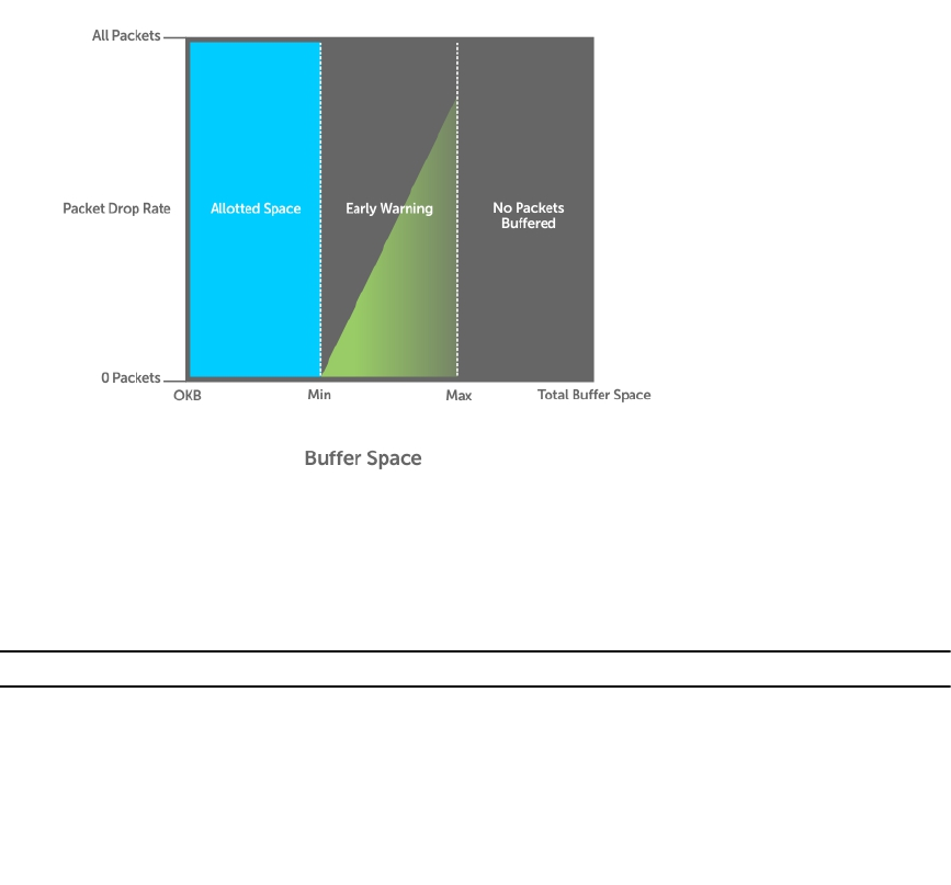
Figure 95. Packet Drop Rate for WRED
You can create a custom WRED profile or use one of the five pre-defined profiles.
Table 37. Pre-Defined WRED Profiles
Default Profile Name Minimum Threshold Maximum Threshold Maximum Drop Rate
wred_drop 0 0 100
wred_teng_y 594 5941 100
wred_teng_g 594 5941 50
wred_fortyg_y 594 5941 50
wred_fortyg_g 594 5941 25
Creating WRED Profiles
To create WRED profiles, use the following commands.
1. Create a WRED profile.
CONFIGURATION mode
wred
2. Specify the minimum and maximum threshold values.
WRED mode
threshold
Quality of Service (QoS) 649

Applying a WRED Profile to Traffic
After you create a WRED profile, you must specify on which traffic the system applies the profile.
The system assigns a color-coded drop precedence — red, yellow, or green — to each packet based on
the fourth bit of the 6-bit DSCP field in the packet header before queuing it.
• If the fourth DSCP bit is 0, packet is marked as green.
• If the fourth DSCP bit is 1, the packet is marked as yellow (except for DSCP 63, which is marked as
red).
• If you do not configure honor DSCP values on ingress packets (trust diffservcommand), all
traffic defaults to green drop precedence. See Honoring DSCP Values on Ingress Packets for more
information.
• Assign a WRED profile to either yellow or green traffic.
QOS-POLICY-OUT mode
wred
Displaying Default and Configured WRED Profiles
To display the default and configured WRED profiles, use the following command.
• Display default and configured WRED profiles and their threshold values.
EXEC mode
show qos wred-profile
Example of the show qos wred-profile Command
Dell# show qos wred-profile
Wred-profile-name min-threshold max-threshold max-drop-rate
wred_drop 0 0 100
wred_teng_y 467 4671 100
wred_teng_g 467 4671 50
wred_fortyg_y 467 4671 50
wred_fortyg_g 467 4671 25
Displaying WRED Drop Statistics
To display WRED drop statistics, use the following command.
• Display the number of packets that the WRED profile drops.
EXEC Privilege mode
show qos statistics
Example of the show qos statistics Command
Dell# show qos statitstics wred-profile
WInterface Te 0/49
Drop-statistic Dropped Pkts
Green 51624
Yellow 51300
Out of Profile 0
650 Quality of Service (QoS)
Explicit Congestion Notification
Explicit Congestion Notification (ECN) enhances and extends WRED functionality by marking packets for
later transmission instead of dropping them when a threshold value is exceeded. Use ECN for WRED to
reduce the packet transmission rate in a congested, heavily-loaded network.
While WRED drops packets to indicate congestion, ECN marks packets instead of dropping them when
the average queue length exceeds the threshold value. ECN provides an improved method for
congestion avoidance by allowing the switch to mark packets for later transmission rather than dropping
them from a queue.
ECN uses a two-bit ECN-specific field in the IP header to indicate if a packet is ECN-capable, if the
endpoints in the transport protocol are ECN-capable, and if there is network congestion.
When ECN for WRED is enabled, if the queue length is between the minimum threshold and the
maximum threshold, one of the following actions is taken:
• If the WRED drop precedence determines that the packet should be dropped but the ECN field in the
packet header indicates that the endpoints are ECN-capable, the packet is marked with a congestion-
experienced (CE) bit and transmitted.
• If the ECN field indicates that both endpoints are not ECN-capable, the packet can be dropped
according to the configured WRED drop precedence.
• If the ECN field indicates a network congestion condition, the packet is marked with a congestion-
experienced (CE) bit and then transmitted.
If the queue length falls below the minimum threshold or exceeds the maximum threshold, the same
WRED treatment is applied as when ECN is not enabled:
• If queued packets fall below the minimum threshold, they are transmitted.
• If queued packets exceed the maximum threshold, they are dropped.
ECN Packet Classification
When ECN for WRED is enabled on an interface, non-ECN-capable packets are marked as green-profiled
traffic and are subject to early WRED drops. For example, TCP-acks, OAM, and ICMP ping packets are
non-ECN-capable. However, it is not desirable for these packets to be WRED-dropped. You can use ECN
match criteria in an ingress class map or an ACL to classify ECN-capable and non-ECN-capable packets
and apply the appropriate color-based WRED action.
Standard and extended IPv4 ACLs support the use of the 2-bit ECN field in packet headers as L3 deny/
permit criteria for IP, TCP, UDP, and ICMP packets. Enter the keyword ecn in a deny/permit statement to
mark ingress traffic according to its ECN-capability or non-capability. You can specify DSCP and ECN
classifiers in the same ACL entry in an IP standard or extended ACL.
In a match-any class map, you can mark selected ECN/non-ECN traffic for yellow handling by entering
set-color yellow in any of the following L3 match commands:
•match ip access-group
•match ip dscp
•match ip precedence
Quality of Service (QoS) 651

•match ip vlan
By default, all packets are marked for green handling if the rate-police and trust-diffserv commands are
not used in an ingress policy map. All packets marked for red handling or “violate” are dropped.
In the class map, in addition to color-marking matching packets for yellow handling, you can also
configure a DSCP value for matching packets.
When you use ECN to classify and color-mark packets in an ingress class map, take into account:
• When all matching packets are marked for yellow treatment, policer-based coloring is not supported
at the same time.
• If a single-rate two-color policer is configured at the same time as ECN-matched packets are set for
yellow handling, by default all packets less than PIR are marked for “green” handling. All green packets
selected by ECN match criteria and color-marked yellow are over-written and marked for yellow
handling.
• If a two-rate three-color policer is configured at the same time as ECN-matched packets are set for
yellow handling:
– x < CIR is marked as green.
– CIR < x< PIR is marked as yellow.
– PIR < x is marked as red.
Green packets matching the ECN criteria for which yellow color-marking is configured are
overwritten and marked as yellow.
Example: Color-marking non-ECN Packets in One Traffic Class
The following example shows how to mark non-ECN packets for “yellow” handling when all packets
egress on the default queue 0. Non-ECN-capable packets have the ECN field in their packet headers set
to 0.
ip access-list standard ecn_0
seq 5 permit any ecn 0
class-map match-any ecn_0_cmap
match ip access-group ecn_0 set-color yellow
policy-map-input ecn_0_pmap
service-queue 0 class-map ecn_0_cmap
Applying the policy map “ecn_0_pmap” marks all incoming packets with the ECN field set to 0 for
“yellow” handling on queue 0 (default queue).
Example: Color-marking non-ECN Packets in Different Traffic Classes
The following examples both show how to mark non-ECN packets for “yellow” handling when packets
with DCSP 40 egress on queue 2 and packets with DSCP 50 egress on queue 3. Non-ECN-capable
packets have the ECN field in their packet headers set to 0.
The first example shows how to achieve the desired configuration without specifying ECN match criteria
to classify ECN-capable packets:
ip access-list standard dscp_50
seq 5 permit any dscp 50
652 Quality of Service (QoS)

ip access-list standard dscp_40
seq 5 permit any dscp 40
ip access-list standard dscp_50_non_ecn
seq 5 permit any dscp 50 ecn 0
ip access-list standard dscp_40_non_ecn
seq 5 permit any dscp 40 ecn 0
class-map match-any class_dscp_40
match ip access-group dscp_40_non_ecn set-color yellow
match ip access-group dscp_40
class-map match-any class_dscp_50
match ip access-group dscp_50_non_ecn set-color yellow
match ip access-group dscp_50
policy-map-input pmap_dscp_40_50
service-queue 2 class-map class_dscp_40
service-queue 3 class-map class_dscp_50
The second example shows how to achieve the desired configuration by specifying ECN match criteria to
classify ECN-capable packets:
ip access-list standard dscp_50_ecn
seq 5 permit any dscp 50 ecn 1
seq 10 permit any dscp 50 ecn 2
seq 15 permit any dscp 50 ecn 3
ip access-list standard dscp_40_ecn
seq 5 permit any dscp 40 ecn 1
seq 10 permit any dscp 40 ecn 2
seq 15 permit any dscp 40 ecn 3
ip access-list standard dscp_50_non_ecn
seq 5 permit any dscp 50 ecn 0
ip access-list standard dscp_40_non_ecn
seq 5 permit any dscp 40 ecn 0
class-map match-any class_dscp_40
match ip access-group dscp_40_non_ecn set-color yellow
match ip access-group dscp_40_ecn
class-map match-any class_dscp_50
match ip access-group dscp_50_non_ecn set-color yellow
match ip access-group dscp_50_ecn
policy-map-input pmap_dscp_40_50
service-queue 2 class-map class_dscp_40
service-queue 3 class-map class_dscp_50
Using A Configurable Weight for WRED and ECN
The Z9500 switch supports a user-configurable weight that determines the average queue size used in
WRED and Explicit Congestion Notification (ECN) operation on front-end I/O and backplane interfaces.
By default, the switch uses a weight factor of 0 (instantaneous ECN marking), which results in packet
dropping during times of network congestion based on the configured minimum and maximum WRED
Quality of Service (QoS) 653
thresholds. You can configure different weights for WRED and ECN operation to finely tune how different
types of traffic are handled when a WRED threshold is exceeded.
Benefits of Using a Configurable Weight for WRED with ECN
On the Z9500, using a configurable weight for WRED and ECN allows you to specify how the average
queue size is calculated. In WRED, the average queue size determines when a threshold is exceeded and
packets are dropped; in WRED with ECN, the average queue size determines when packets are marked
for later transmission and when the transmission rate is reduced on an interface during times of network
congestion.
For example, in a best-effort network topology that uses WRED with instantaneous ECN, data packets
may be transmitted at a rate in which latency or throughput are not maintained at an effective, optimal
level. Packets are dropped when the network experiences a large traffic load according to the configured
WRED thresholds. This best-effort network deployment is not suitable for applications that are time-
sensitive, such as video on demand (VoD) or voice over IP (VoIP) applications.
To resolve the problem of packet loss at times of network congestion, you may need to apply WRED with
ECN and more finely tune packet transmission for certain traffic types. To do so, you can configure the
weight used to calculate the average queue size; the average queue size is used to determine when to
drop packets with WRED and when to mark packets with ECN when WRED thresholds are exceeded.
The user-configurable weight in WRED and ECN provides better control in how the switch responds to
congestion before a queue overflows and packets are dropped or delayed. Using a configurable weight
for WRED and ECN allows you to customize network performance and throughput.
Setting Average Queue Size using a Weight
On the Z9500, you can configure the weight factor that determines the average queue size for WRED
and ECN packet handling by using the wred weight command.
The average queue size is computed using the last calculated average-queue size and the current queue
size. The following is the formula to calculate the average queue size: average-queue-size (t+1) =
average-queue-size (t) + (current-queue-length - average-queue-size (t))/2^N
where t is the time or the current instant at which average queue size is measured, t+1 is the next
calculation of the average queue size, and N is the weight factor.
In a topology in which network congestion varies over time, you can specify a weight to enable a
smooth, seamless averaging of packets to handle the bursty nature of packets based on the previous time
sampling performed. You can specify a weight value for front-end and backplane ports separately. The
range of weight values is from 0 to 15.
You can enable WRED with ECN capabilities per queue to fine-tune packet transmission. You can disable
WRED with ECN per queue while configuring the minimum and maximum buffer thresholds for each
WRED color-coded profile. You can configure the maximum drop-rate percentage for yellow and green
profiles. You can configure these parameters for both front-end and backplane ports.
654 Quality of Service (QoS)

Global Service-Pools for WRED with ECN
You can enable WRED with ECN to work with global service-pools. Global service pools that function as
shared buffers are accessed by multiple queues when the minimum guaranteed buffers for a queue are
consumed. The Z9500 switch supports four global service-pools in the egress direction.
Two types of service-pools are used: one for lossy queues and the other for lossless (priority-based flow
control (PFC)) queues.
NOTE: Service pool 1 for lossless queues is not supported in software releases that do not support
PFC.
You can define WRED profiles and a weight on global service-pools for both lossy and lossless (PFC)
service-pools. The following events occur when you configure WRED with ECN on a global service-pool:
• If WRED/ECN is enabled on the global service-pool with threshold values and if it is not enabled on
the queues, WRED/ECN are not effective based on global service-pool WRED thresholds. The queue
on which traffic is scheduled must have WRED/ECN settings enabled for WRED to be valid for its
traffic.
• When WRED is configured on a global service-pool (regardless of whether ECN is configured on the
global service-pool), and one or more queues have WRED enabled and ECN disabled, WRED is
effective for the minimum threshold between the queue threshold and the service-pool threshold.
• When WRED is configured on the global service-pool (regardless of whether ECN is configured on the
global service-pool), and one or more queues are enabled with both WRED and ECN, ECN marking
takes effect. The packets are ECN marked to the shared-buffer limits as determined by the shared-
ratio for the global service-pool.
WRED/ECN configurations for backplane port queues are applied to all backplane ports and cannot be
specified separately on each backplane port. Also, WRED/ECN is not supported for multicast packets.
The following table describes the WRED and ECN operations performed on a queue and service pool for
various WRED with ECN scenarios. (N/A indicates that a configuration is not applicable. )
Table 38. Scenarios for WRED and ECN Configuration
Queue
Configuration Service-Pool
Configuration WRED Threshold
Relationship
Q threshold = Q-T
Service-pool threshold =
SP-T
Expected Functionality
WRED ECN WRED ECN
Disabled Disabled N/A N/A N/A WRED/ECN not applicable
Enabled Disabled Disabled N/A N/A Queue-based WRED;
No ECN marking
Enabled N/A Q-T < SP-T
SP-T < Q-T Service-pool-based WRED;
No ECN marking
Quality of Service (QoS) 655

Queue
Configuration Service-Pool
Configuration WRED Threshold
Relationship
Q threshold = Q-T
Service-pool threshold =
SP-T
Expected Functionality
Enabled Enabled Disabled N/A N/A Queue-based ECN marking above
queue threshold.
ECN marking up to shared buffer
limits of the service-pool and then
packets are tail dropped.
Enabled N/A Q-T < SP-T
SP-T < Q-T Same as above but ECN marking
starts above SP-T.
Configuring a Weight for WRED and ECN Operation
You can configure a WRED weight to customize WRED and ECN operation on a front-end or backplane
interface. In the configuration procedure, you must also configure the global service-pools of shared
buffer memory that can be accessed by multiple queues when the minimum guaranteed buffers for a
queue are consumed.
1. Configure the weight factor for computation of average-queue size. This weight value applies to
front-end and backplane ports.
QOS-POLICY-OUT mode
Dell(conf-qos-policy-out)#wred weight number
2. Configure one or more WRED profiles, and specify the threshold and maximum drop rate
WRED mode
Dell(conf-wred)#wred thresh-1
Dell(conf-wred)#threshold min 100 max 200 max-drop-rate 40
Dell(conf-wred)#wred thresh-2
Dell(conf-wred)#threshold min 300 max 400 max-drop-rate 80
3. Associate a service class for each WRED profile, and assign the WRED profile to specific queues on
backplane ports.
CONFIGURATION mode
Dell(conf)#service-class wred green queue5 thresh-1 queue7 thresh-2
backplane
Dell(conf)#service-class wred yellow queue1 thresh-2 queue3 thresh-1
backplane
Dell(conf)#service-class wred weight queue0 11 queue6 4 queue7 9 backplane
4. Create a global buffer pool that serves as a shared buffer accessed by multiple queues when the
minimum guaranteed buffers for a queue are consumed. The Z9500 supports four global service-
pools in the egress direction.
656 Quality of Service (QoS)

mode
Dell(conf)#service-pool wred green pool0 thresh-1 pool1 thresh-2
Dell(conf)#service-pool wred yellow pool0 thresh-3 pool1 thresh-4
Dell(conf)#service-pool wred weight pool0 11 pool1 4
5. Enable ECN marking on specific queues on backplane ports with a service class.
CONFIGURATION mode
Dell(conf)#service-class wred ecn 0, 3-5, 7 backplane
Pre-Calculating Available QoS CAM Space
Pre-calculating available QoS CAM space allows you to measure the number of CAM entries a policy-
map consumes.
This feature allows you to avoid applying a policy-map on an interface that requires more CAM entries
than are available and receive a CAM full error message (shown in the following example). The partial
policy-map configuration might cause unintentional system behavior.
%EX2YD:12 %DIFFSERV-2-DSA_QOS_CAM_INSTALL_FAILED: Not enough space in L3
Cam(PolicyQos) for class 2 (Te 12/20) entries on portpipe 1 for linecard 12
%EX2YD:12 %DIFFSERV-2-
DSA_QOS_CAM_INSTALL_FAILED: Not enough space in L3 Cam(PolicyQos) for
class 5 (Te 12/
22) entries on portpipe 1 for linecard 12
Use the test cam-usage command to verify that there are enough available CAM entries before
applying a policy-map to an interface so that you avoid exceeding the QoS CAM space and partial
configurations. This command measures the size of the specified policy-map and compares it to the
available CAM space in a partition for a specified port-pipe.
Test the policy-map size against the CAM space for a specific port-pipe or all port-pipes using these
commands:
•test cam-usage service-policy input policy-map linecard {0–2} number port-set
number
•test cam-usage service-policy input policy-map linecard {0–2} all
The output of this command, shown in the following example, displays:
• The estimated number of CAM entries the policy-map will consume.
• Whether or not the policy-map can be applied.
• The number of interfaces in a port-pipe to which the policy-map can be applied.
Specifically:
•Available CAM — the available number of CAM entries in the specified CAM partition for the specified
line-card port pipe.
•Estimated CAM — the estimated number of CAM entries that the policy will consume when it is
applied to an interface.
•Status — indicates whether the specified policy-map can be completely applied to an interface in the
port-pipe.
Quality of Service (QoS) 657

–Allowed — indicates that the policy-map can be applied because the estimated number of CAM
entries is less or equal to the available number of CAM entries. The number of interfaces in the
port-pipe to which the policy-map can be applied is given in parentheses.
–Exception — indicates that the number of CAM entries required to write the policy-map to the
CAM is greater than the number of available CAM entries, and therefore the policy-map cannot be
applied to an interface in the specified port-pipe.
NOTE: The show cam-usage command provides much of the same information as the test cam-
usage command, but whether a policy-map can be successfully applied to an interface cannot be
determined without first measuring how many CAM entries the policy-map would consume; the
test cam-usage command is useful because it provides this measurement.
• Verify that there are enough available CAM entries.
test cam-usage
Example of the test cam-usage Command
Dell# test cam-usage service-policy input pmap_l2 linecard 0 port-set 0
Linecard | Port-pipe | CAM Partition | Available CAM | Estimated CAM | Status
===============================================================================
0 0 L2ACL 500 200
Allowed(2)
SNMP Support for Buffer Statistics Tracking
SNMP support for buffer statistics tracking (BST) counters is implemented in the F10-FPSTATS MIB. BST
counters allow you to better monitor system resources and allocate buffer memory.
BST counters include the Max Use Count statistic, which provides the maximum counter value over a
period of time.
In the F10-FPSTATS MIB, the following tables display BST counters:
• fpEgrQBuffSnapshotTable: Retrieves BST statistics from the egress port used in a buffer. This table
displays a snapshot of the buffer cells used by unicast and multicast data and control queues.
• fpIngPgBuffSnapshotTable: Retrieves BST statistics from the ingress port for the shared and headroom
cells used in a priority group. The snapshot of the ingress shared cells and the ingress headroom cells
used for each priority group are displayed in this table when PFC is enabled. This table is indexed by
stack-unit index, port number and priority-group number.
• fpStatsPerPgTable: Retrieves information on the allocated Min cells, shared cells, and headroom cells
for each priority group, the mode in which the buffer cells are allocated (static or dynamic), and the
used Min cells, shared cells, and headroom cells for each priority group. The table returns a value of 0
if the allocation mode is static and a value of 1 if the allocation mode is dynamic. This table is indexed
by stack-unit number, port number and priority-group number.
658 Quality of Service (QoS)

40
Routing Information Protocol (RIP)
The Routing Information Protocol (RIP) tracks distances or hop counts to nearby routers when
establishing network connections and is based on a distance-vector algorithm.
RIP protocol standards are listed in the Standards Compliance chapter.
Protocol Overview
RIP is the oldest interior gateway protocol.
There are two versions of RIP: RIP version 1 (RIPv1) and RIP version 2 (RIPv2). These versions are
documented in RFCs 1058 and 2453.
RIPv1
RIPv1 learns where nodes in a network are located by automatically constructing a routing data table.
The routing table is established after RIP sends out one or more broadcast signals to all adjacent nodes in
a network. Hop counts of these signals are tracked and entered into the routing table, which defines
where nodes in the network are located.
The information that is used to update the routing table is sent as either a request or response message.
In RIPv1, automatic updates to the routing table are performed as either one-time requests or periodic
responses (every 30 seconds). RIP transports its responses or requests by means of user datagram
protocol (UDP) over port 520.
RIP must receive regular routing updates to maintain a correct routing table. Response messages
containing a router’s full routing table are transmitted every 30 seconds. If a router does not send an
update within a certain amount of time, the hop count to that route is changed to unreachable (a route
hop metric of 16 hops). Another timer sets the amount of time before the unreachable routes are
removed from the routing table.
This first RIP version does not support variable length subnet mask (VLSM) or classless inter-domain
routing (CIDR) and is not widely used.
RIPv2
RIPv2 adds support for subnet fields in the RIP routing updates, thus qualifying it as a classless routing
protocol.
The RIPv2 message format includes entries for route tags, subnet masks, and next hop addresses.
Another enhancement included in RIPv2 is multicasting for route updates on IP multicast address
224.0.0.9.
Routing Information Protocol (RIP) 659

Implementation Information
The Dell Networking OS supports both versions of RIP and allows you to configure one version globally
and the other version on interfaces or both versions on the interfaces.
The following table lists the default values for RIP parameters on the switch.
Table 39. RIP Defaults
Feature Default
Interfaces running RIP • Listen to RIPv1 and RIPv2
• Transmit RIPv1
RIP timers • update timer = 30 seconds
• invalid timer = 180 seconds
• holddown timer = 180 seconds
• flush timer = 240 seconds
Auto summarization Enabled
ECMP paths supported 16
Configuration Information
By default, RIP is disabled on the switch.
To configure RIP, you must use commands in two modes: ROUTER RIP and INTERFACE. Commands
executed in the ROUTER RIP mode configure RIP globally, while commands executed in the INTERFACE
mode configure RIP features on that interface only.
RIP is best suited for small, homogeneous networks. You must configure all devices within the RIP
network to support RIP if they are to participate in the RIP.
Configuration Task List
The following is the configuration task list for RIP.
•Enabling RIP Globally (mandatory)
•Configure RIP on Interfaces (optional)
•Controlling RIP Routing Updates (optional)
•Setting Send and Receive Version (optional)
•Generating a Default Route (optional)
•Controlling Route Metrics (optional)
•Summarize Routes (optional)
•Controlling Route Metrics
•Debugging RIP
For a complete listing of all commands related to RIP, refer to the Dell Networking OS Command
Reference Interface Guide.
660 Routing Information Protocol (RIP)

Enabling RIP Globally
By default, RIP is disabled on the switch.
To enable RIP globally, use the following commands.
1. Enter ROUTER RIP mode and enable the RIP process.
CONFIGURATION mode
router rip
2. Assign an IP network address as a RIP network to exchange routing information.
ROUTER RIP mode
network ip-address
Examples of Viewing RIP Information
After designating networks with which the system is to exchange RIP information, ensure that all devices
on that network are configured to exchange RIP information.
The system default is to send RIPv1 and to receive RIPv1 and RIPv2. To change the RIP version globally,
use the version command in ROUTER RIP mode.
To view the global RIP configuration, use the show running-config command in EXEC mode or the
show config command in ROUTER RIP mode.
Dell(conf-router_rip)#show config
!
router rip
network 10.0.0.0
Dell(conf-router_rip)#
When the RIP process has learned the RIP routes, use the show ip rip database command in EXEC
mode to view those routes.
Dell#show ip rip database
Total number of routes in RIP database: 978
160.160.0.0/16
[120/1] via 29.10.10.12, 00:00:26, Fa 0/0
160.160.0.0/16 auto-summary
2.0.0.0/8
[120/1] via 29.10.10.12, 00:01:22, Fa 0/0
2.0.0.0/8 auto-summary
4.0.0.0/8
[120/1] via 29.10.10.12, 00:01:22, Fa 0/0
4.0.0.0/8 auto-summary
8.0.0.0/8
[120/1] via 29.10.10.12, 00:00:26, Fa 0/0
8.0.0.0/8 auto-summary
12.0.0.0/8
[120/1] via 29.10.10.12, 00:00:26, Fa 0/0
12.0.0.0/8 auto-summary
20.0.0.0/8
[120/1] via 29.10.10.12, 00:00:26, Fa 0/0
20.0.0.0/8 auto-summary
29.10.10.0/24 directly connected,Fa 0/0
29.0.0.0/8 auto-summary
31.0.0.0/8
[120/1] via 29.10.10.12, 00:00:26, Fa 0/0
31.0.0.0/8 auto-summary
Routing Information Protocol (RIP) 661

192.162.2.0/24
[120/1] via 29.10.10.12, 00:01:21, Fa 0/0
192.162.2.0/24 auto-summary
192.161.1.0/24
[120/1] via 29.10.10.12, 00:00:27, Fa 0/0
192.161.1.0/24 auto-summary
192.162.3.0/24
[120/1] via 29.10.10.12, 00:01:22, Fa 0/0
192.162.3.0/24 auto-summary
To disable RIP globally, use the no router rip command in CONFIGURATION mode.
Configure RIP on Interfaces
When you enable RIP globally on the system, interfaces meeting certain conditions start receiving RIP
routes.
By default, interfaces that you enable and configure with an IP address in the same subnet as the RIP
network address receive RIPv1 and RIPv2 routes and send RIPv1 routes.
Assign IP addresses to interfaces that are part of the same subnet as the RIP network identified in the
network command syntax.
Controlling RIP Routing Updates
By default, RIP broadcasts routing information out all enabled interfaces, but you can configure RIP to
send or to block RIP routing information, either from a specific IP address or a specific interface.
To control which devices or interfaces receive routing updates, configure a direct update to one router
and configure interfaces to block RIP updates from other sources.
To control the source of RIP route information, use the following commands.
• Define a specific router to exchange RIP information between it and the Dell Networking system.
ROUTER RIP mode
neighbor ip-address
You can use this command multiple times to exchange RIP information with as many RIP networks as
you want.
• Disable a specific interface from sending or receiving RIP routing information.
ROUTER RIP mode
passive-interface interface
Assigning a Prefix List to RIP Routes
Another method of controlling RIP (or any routing protocol) routing information is to filter the
information through a prefix list. A prefix list is applied to incoming or outgoing routes.
Those routes must meet the conditions of the prefix list; if not, the system drops the route. Prefix lists are
globally applied on all interfaces running RIP. Configure the prefix list in PREFIX LIST mode prior to
assigning it to the RIP process.
For configuration information about prefix lists, refer to Access Control Lists (ACLs).
To apply prefix lists to incoming or outgoing RIP routes, use the following commands.
• Assign a configured prefix list to all incoming RIP routes.
ROUTER RIP mode
662 Routing Information Protocol (RIP)
distribute-list prefix-list-name in
• Assign a configured prefix list to all outgoing RIP routes.
ROUTER RIP mode
distribute-list prefix-list-name out
To view the current RIP configuration, use the show running-config command in EXEC mode or the
show config command in ROUTER RIP mode.
Adding RIP Routes from Other Instances
In addition to filtering routes, you can add routes from other routing instances or protocols to the RIP
process.
With the redistribute command, you can include open shortest path first (OSPF), static, or directly
connected routes in the RIP process.
To add routes from other routing instances or protocols, use the following commands.
• Include directly connected or user-configured (static) routes in RIP.
ROUTER RIP mode
redistribute {connected | static} [metric metric-value] [route-map map-name]
–metric-value: the range is from 0 to 16.
–map-name: the name of a configured route map.
• Include specific OSPF routes in RIP.
ROUTER RIP mode
redistribute ospf process-id [match external {1 | 2} | match internal]
[metric value] [route-map map-name]
Configure the following parameters:
–process-id: the range is from 1 to 65535.
–metric: the range is from 0 to 16.
–map-name: the name of a configured route map.
To view the current RIP configuration, use the show running-config command in EXEC mode or the
show config command in ROUTER RIP mode.
Setting the Send and Receive Version
To change the RIP version globally or on an interface, use the following command.
To specify the RIP version, use the version command in ROUTER RIP mode. To set an interface to
receive only one or the other version, use the ip rip send version or the ip rip receive
version commands in INTERFACE mode.
You can set one RIP version globally on the system using system. This command sets the RIP version for
RIP traffic on the interfaces participating in RIP unless the interface was specifically configured for a
specific RIP version.
• Set the RIP version sent and received on the system.
ROUTER RIP mode
version {1 | 2}
Routing Information Protocol (RIP) 663

• Set the RIP versions received on that interface.
INTERFACE mode
ip rip receive version [1] [2]
• Set the RIP versions sent out on that interface.
INTERFACE mode
ip rip send version [1] [2]
Examples of Setting the RIP Process
To see whether the version command is configured, use the show config command in ROUTER RIP
mode. To view the routing protocols configuration, use the show ip protocols command in EXEC
mode.
The following example shows the RIP configuration after the ROUTER RIP mode version command is
set to RIPv2. When you set the ROUTER RIP mode version command, the interface
(TengigabitEthernet 0/0) participating in the RIP process is also set to send and receive RIPv2 (shown in
bold).
Dell#show ip protocols
Routing Protocols is RIP
Sending updates every 30 seconds, next due in 23
Invalid after 180 seconds, hold down 180, flushed after 240
Output delay 8 milliseconds between packets
Automatic network summarization is in effect
Outgoing filter for all interfaces is
Incoming filter for all interfaces is
Default redistribution metric is 1
Default version control: receive version 2, send version 2
Interface Recv Send
TengigabitEthernet 0/0 2 2
Routing for Networks:
10.0.0.0
Routing Information Sources:
Gateway Distance Last Update
Distance: (default is 120)
Dell#
To configure an interface to receive or send both versions of RIP, include 1 and 2 in the command syntax.
The command syntax for sending both RIPv1 and RIPv2 and receiving only RIPv2 is shown in the
following example.
Dell(conf-if)#ip rip send version 1 2
Dell(conf-if)#ip rip receive version 2
The following example of the show ip protocols command confirms that both versions are sent out
on the interface. This interface no longer sends and receives the same RIP versions as the system does
globally (shown in bold).
Dell#show ip protocols
Routing Protocols is RIP
Sending updates every 30 seconds, next due in 11
Invalid after 180 seconds, hold down 180, flushed after 240
Output delay 8 milliseconds between packets
Automatic network summarization is in effect
664 Routing Information Protocol (RIP)

Outgoing filter for all interfaces is
Incoming filter for all interfaces is
Default redistribution metric is 1
Default version control: receive version 2, send version 2
Interface Recv Send
FastEthernet 0/0 2 1 2
Routing for Networks:
10.0.0.0
Routing Information Sources:
Gateway Distance Last Update
Distance: (default is 120)
Dell#
Generating a Default Route
Traffic is forwarded to the default route when the traffic’s network is not explicitly listed in the routing
table.
Default routes are not enabled in RIP unless specified. Use the default-information originate
command in ROUTER RIP mode to generate a default route into RIP. Default routes received in RIP
updates from other routes are advertised if you configure the default-information originate
command.
• Specify the generation of a default route in RIP.
ROUTER RIP mode
default-information originate [always] [metric value] [route-map route-map-
name]
–always: Enter the keyword always to always generate a default route.
–value The range is from 1 to 16.
–route-map-name: The name of a configured route map.
To confirm that the default route configuration is completed, use the show config command in
ROUTER RIP mode.
Summarize Routes
Routes in the RIPv2 routing table are summarized by default, thus reducing the size of the routing table
and improving routing efficiency in large networks.
By default, the autosummary command in ROUTER RIP mode is enabled and summarizes RIP routes up
to the classful network boundary.
If you must perform routing between discontiguous subnets, disable automatic summarization. With
automatic route summarization disabled, subnets are advertised.
The autosummary command requires no other configuration commands. To disable automatic route
summarization, enter no autosummary in ROUTER RIP mode.
NOTE: If you enable the ip split-horizon command on an interface, the system does not
advertise the summarized address.
Routing Information Protocol (RIP) 665
Controlling Route Metrics
As a distance-vector protocol, RIP uses hop counts to determine the best route, but sometimes the
shortest hop count is a route over the lowest-speed link.
To manipulate RIP routes so that the routing protocol prefers a different route, manipulate the route by
using the offset command.
Exercise caution when applying an offset command to routers on a broadcast network, as the router
using the offset command is modifying RIP advertisements before sending out those advertisements.
The distance command also allows you to manipulate route metrics. To assign different weights to
routes so that the ones with the lower weight or administrative distance assigned are preferred, use the
distance command.
To set route matrixes, use the following commands.
• Apply a weight to all routes or a specific route and ACL.
ROUTER RIP mode
distance weight [ip-address mask [access-list-name]]
Configure the following parameters:
–weight: the range is from 1 to 255. The default is 120.
–ip-address mask: the IP address in dotted decimal format (A.B.C.D), and the mask in slash
format (/x).
–access-list-name: the name of a configured IP ACL.
• Apply an additional number to the incoming or outgoing route metrics.
ROUTER RIP mode
offset-list access-list-name {in | out} offset [interface]
Configure the following parameters:
–prefix-list-name: the name of an established Prefix list to determine which incoming routes
are modified
–offset: the range is from 0 to 16.
–interface: the type, slot, and number of an interface.
To view the configuration changes, use the show config command in ROUTER RIP mode.
Debugging RIP
The debug ip rip command enables RIP debugging.
When you enable debugging, you can view information on RIP protocol changes or RIP routes.
To enable RIP debugging, use the following command.
•debug ip rip [interface | database | events | trigger]
EXEC privilege mode
Enable debugging of RIP.
Example of the debug ip rip Command
The following example shows the confirmation when you enable the debug function.
666 Routing Information Protocol (RIP)

Dell#debug ip rip
RIP protocol debug is ON
Dell#
To disable RIP, use the no debug ip rip command.
RIP Configuration Example
The examples in this section show the command sequence to configure RIPv2 on the two routers shown
in the following illustration — Core 2 and Core 3.
The host prompts used in the following example reflect those names. The examples are divided into the
following groups of command sequences:
•Configuring RIPv2 on Core 2
•Core 2 RIP Output
•RIP Configuration on Core 3
•Core 3 RIP Output
•RIP Configuration Summary
Figure 96. RIP Topology Example
RIP Configuration on Core2
The following example shows how to configure RIPv2 on a host named Core2.
Example of Configuring RIPv2 on Core 2
Core2(conf-if-te-2/31)#
Core2(conf-if-te-2/31)#router rip
Core2(conf-router_rip)#ver 2
Core2(conf-router_rip)#network 10.200.10.0
Core2(conf-router_rip)#network 10.300.10.0
Core2(conf-router_rip)#network 10.11.10.0
Core2(conf-router_rip)#network 10.11.20.0
Core2(conf-router_rip)#show config
!
router rip
network 10.0.0.0
version 2
Core2(conf-router_rip)#
Routing Information Protocol (RIP) 667

Core 2 RIP Output
The examples in the section show the core 2 RIP output.
Examples of the show ip Command with Core 2 Output
• To display Core 2 RIP database, use the show ip rip database command.
• To display Core 2 RIP setup, use the show ip route command.
• To display Core 2 RIP activity, use the show ip protocols command.
To view the learned RIP routes on Core 2, use the show ip rip database command.
Core2(conf-router_rip)#end
00:12:24: %SYSTEM-P:CP %SYS-5-CONFIG_I: Configured from console by console
Core2#show ip rip database
Total number of routes in RIP database: 7
10.11.30.0/24
[120/1] via 10.11.20.1, 00:00:03, TenGigabitEthernet 2/31
10.300.10.0/24 directly connected,TenGigabitEthernet 2/42
10.200.10.0/24 directly connected,TenGigabitEthernet 2/41
10.11.20.0/24 directly connected,TenGigabitEthernet 2/31
10.11.10.0/24 directly connected,TenGigabitEthernet 2/11
10.0.0.0/8 auto-summary
192.168.1.0/24
[120/1] via 10.11.20.1, 00:00:03, TenGigabitEthernet 2/31
192.168.1.0/24 auto-summary
192.168.2.0/24
[120/1] via 10.11.20.1, 00:00:03, TenGigabitEthernet 2/31
192.168.2.0/24 auto-summary
Core2#
To view the RIP setup on Core 2, use the show ip route command.
Core2#show ip route
Codes: C - connected, S - static, R - RIP,
B - BGP, IN - internal BGP, EX - external BGP,LO - Locally Originated,
O - OSPF, IA - OSPF inter area, N1 - OSPF NSSA external type 1,
N2 - OSPF NSSA external type 2, E1 - OSPF external type 1,
E2 - OSPF external type 2, i - IS-IS, L1 - IS-IS level-1,
L2 - IS-IS level-2, IA - IS-IS inter area, * - candidate default,
> - non-active route, + - summary route
Gateway of last resort is not set
Destination Gateway Dist/Metric Last Change
----------- ------- ----------- -----------
C 10.11.10.0/24 Direct, Te 2/11 0/0 00:02:26
C 10.11.20.0/24 Direct, Te 2/31 0/0 00:02:02
R 10.11.30.0/24 via 10.11.20.1, Te 2/31 120/1 00:01:20
C 10.200.10.0/24 Direct, Te 2/41 0/0 00:03:03
C 10.300.10.0/24 Direct, Te 2/42 0/0 00:02:42
R 192.168.1.0/24 via 10.11.20.1, Te 2/31 120/1 00:01:20
R 192.168.2.0/24 via 10.11.20.1, Te 2/31 120/1 00:01:20
Core2#
R 192.168.1.0/24 via 10.11.20.1, Te 2/31 120/1 00:05:22
R 192.168.2.0/24 via 10.11.20.1, Te 2/31 120/1 00:05:22
Core2#
668 Routing Information Protocol (RIP)

To view the RIP configuration activity on Core 2, use the show ip protocols command.
Core2#show ip protocols
Routing Protocol is "RIP"
Sending updates every 30 seconds, next due in 17
Invalid after 180 seconds, hold down 180, flushed after 240
Output delay 8 milliseconds between packets
Automatic network summarization is in effect
Outgoing filter for all interfaces is
Incoming filter for all interfaces is
Default redistribution metric is 1
Default version control: receive version 2, send version 2
Interface Recv Send
TenGigabitEthernet 2/42 2 2
TenGigabitEthernet 2/41 2 2
TenGigabitEthernet 2/31 2 2
TenGigabitEthernet 2/11 2 2
Routing for Networks:
10.300.10.0
10.200.10.0
10.11.20.0
10.11.10.0
Routing Information Sources:
Gateway Distance Last Update
10.11.20.1 120 00:00:12
Distance: (default is 120)
Core2#
RIP Configuration on Core3
The following example shows how to configure RIPv2 on a host named Core3.
Example of Configuring RIPv2 on Core3
Core3(conf-if-te-3/21)#router rip
Core3(conf-router_rip)#version 2
Core3(conf-router_rip)#network 192.168.1.0
Core3(conf-router_rip)#network 192.168.2.0
Core3(conf-router_rip)#network 10.11.30.0
Core3(conf-router_rip)#network 10.11.20.0
Core3(conf-router_rip)#show config
!
router rip
network 10.0.0.0
network 192.168.1.0
network 192.168.2.0
version 2
Core3(conf-router_rip)#
Core 3 RIP Output
The examples in this section show the core 2 RIP output.
• To display Core 3 RIP database, use the show ip rip database command.
• To display Core 3 RIP setup, use the show ip route command.
• To display Core 3 RIP activity, use the show ip protocols command.
Routing Information Protocol (RIP) 669

Examples of the show ip Command with Core 3 Output
To view learned RIP routes on Core 3, use the show ip rip database command.
Core3#show ip rip database
Total number of routes in RIP database: 7
10.11.10.0/24
[120/1] via 10.11.20.2, 00:00:13, TenGigabitEthernet 3/21
10.200.10.0/24
[120/1] via 10.11.20.2, 00:00:13, TenGigabitEthernet 3/21
10.300.10.0/24
[120/1] via 10.11.20.2, 00:00:13, TenGigabitEthernet 3/21
10.11.20.0/24 directly connected,TenGigabitEthernet 3/21
10.11.30.0/24 directly connected,TenGigabitEthernet 3/11
10.0.0.0/8 auto-summary
192.168.1.0/24 directly connected,TenGigabitEthernet 3/43
192.168.1.0/24 auto-summary
192.168.2.0/24 directly connected,TenGigabitEthernet 3/44
192.168.2.0/24 auto-summary
Core3#
To view the RIP setup on Core 3, use the show ip routes command.
Core3#show ip routes
Codes: C - connected, S - static, R - RIP,
B - BGP, IN - internal BGP, EX - external BGP,LO - Locally Originated,
O - OSPF, IA - OSPF inter area, N1 - OSPF NSSA external type 1,
N2 - OSPF NSSA external type 2, E1 - OSPF external type 1,
E2 - OSPF external type 2, i - IS-IS, L1 - IS-IS level-1,
L2 - IS-IS level-2, IA - IS-IS inter area, * - candidate default,
> - non-active route, + - summary route
Gateway of last resort is not set
Destination Gateway Dist/Metric Last Change
----------- ------- ----------- -----------
R 10.11.10.0/24 via 10.11.20.2, Te 3/21 120/1 00:01:14
C 10.11.20.0/24 Direct, Te 3/21 0/0 00:01:53
C 10.11.30.0/24 Direct, Te 3/11 0/0 00:06:00
R 10.200.10.0/24 via 10.11.20.2, Te 3/21 120/1 00:01:14
R 10.300.10.0/24 via 10.11.20.2, Te 3/21 120/1 00:01:14
C 192.168.1.0/24 Direct, Te 3/43 0/0 00:06:53
C 192.168.2.0/24 Direct, Te 3/44 0/0 00:06:26
Core3#
To view the RIP configuration activity on Core 3, use the show ip protocols command.
Core3#show ip protocols
Routing Protocol is "RIP"
Sending updates every 30 seconds, next due in 6
Invalid after 180 seconds, hold down 180, flushed after 240
Output delay 8 milliseconds between packets
Automatic network summarization is in effect
Outgoing filter for all interfaces is
Incoming filter for all interfaces is
Default redistribution metric is 1
Default version control: receive version 2, send version 2
Interface Recv Send
TenGigabitEthernet 3/21 2 2
TenGigabitEthernet 3/11 2 2
TenGigabitEthernet 3/44 2 2
TenGigabitEthernet 3/43 2 2
Routing for Networks:
670 Routing Information Protocol (RIP)

10.11.20.0
10.11.30.0
192.168.2.0
192.168.1.0
Routing Information Sources:
Gateway Distance Last Update
10.11.20.2 120 00:00:22
Distance: (default is 120)
Core3#
RIP Configuration Summary
Examples of Viewing the RIP Configuration on Core 2 and Core 3
The following example shows viewing the RIP configuration on Core 2.
!
interface TengigabitEthernet 2/11
ip address 10.11.10.1/24
no shutdown
!
interface TengigabitEthernet 2/31
ip address 10.11.20.2/24
no shutdown
!
interface TengigabitEthernet 2/41
ip address 10.200.10.1/24
no shutdown
!
interface TengigabitEthernet 2/42
ip address 10.250.10.1/24
no shutdown
router rip
version 2
10.200.10.0
10.300.10.0
10.11.10.0
10.11.20.0
The following example shows viewing the RIP configuration on Core 3.
!
interface TengigabitEthernet 3/11
ip address 10.11.30.1/24
no shutdown
!
interface TengigabitEthernet 3/21
ip address 10.11.20.1/24
no shutdown
!
interface TengigabitEthernet 3/43
ip address 192.168.1.1/24
no shutdown
!
interface TengigabitEthernet 3/44
ip address 192.168.2.1/24
no shutdown
Routing Information Protocol (RIP) 671

!
router rip
version 2
network 10.11.20.0
network 10.11.30.0
network 192.168.1.0
network 192.168.2.0
672 Routing Information Protocol (RIP)

41
Remote Monitoring (RMON)
Remote monitoring (RMON) is an industry-standard implementation that monitors network traffic by
sharing network monitoring information. RMON provides both 32-bit and 64-bit monitoring facility and
long-term statistics collection on Dell Networking Ethernet interfaces.
RMON operates with the simple network management protocol (SNMP) and monitors all nodes on a
local area network (LAN) segment. RMON monitors traffic passing through the router and segment traffic
not destined for the router. The monitored interfaces may be chosen by using alarms and events with
standard management information bases (MIBs).
Implementation Information
Configure SNMP prior to setting up RMON.
For a complete SNMP implementation description, refer to Simple Network Management Protocol
(SNMP).
Configuring RMON requires using the RMON CLI and includes the following tasks:
•Setting the rmon Alarm
•Configuring an RMON Event
•Configuring RMON Collection Statistics
•Configuring the RMON Collection History
RMON implements the following standard request for comments (RFCs) (for more information, refer to
the Standards Compliance chapter).
• RFC-2819
• RFC-3273
• RFC-3434
Fault Recovery
RMON provides the following fault recovery functions.
•Interface Down — When an RMON-enabled interface goes down, monitoring continues. However, all
data values are registered as 0xFFFFFFFF (32 bits) or ixFFFFFFFFFFFFFFFF (64 bits). When the interface
comes back up, RMON monitoring processes resumes.
NOTE: A network management system (NMS) should be ready to interpret a down interface and
plot the interface performance graph accordingly.
•Line Card Down — The same as Interface Down (see previous).
•Chassis Down — When a chassis goes down, all sampled data is lost. But the RMON configurations
are saved in the configuration file. The sampling process continues after the chassis returns to
operation.
•Platform Adaptation — RMON supports all Dell Networking chassis and all Dell Networking Ethernet
interfaces.
Remote Monitoring (RMON) 673
Setting the RMON Alarm
To set an alarm on any MIB object, use the rmon alarm or rmon hc-alarm command in GLOBAL
CONFIGURATION mode.
• Set an alarm on any MIB object.
CONFIGURATION mode
[no] rmon alarm number variable interval {delta | absolute} rising-threshold
[value event-number] falling-threshold value event-number [owner string]
OR
[no] rmon hc-alarm number variable interval {delta | absolute} rising-
threshold value event-number falling-threshold value event-number [owner
string]
Configure the alarm using the following optional parameters:
–number: alarm number, an integer from 1 to 65,535, the value must be unique in the RMON Alarm
Table.
–variable: the MIB object to monitor — the variable must be in SNMP OID format; for example,
1.3.6.1.2.1.1.3. The object type must be a 32-bit integer for the rmon alarm command and 64 bits
for the rmon hc-alarm command.
–interval: time in seconds the alarm monitors the MIB variable, the value must be between 1 to
3,600.
–delta: tests the change between MIB variables, this option is the alarmSampleType in the RMON
Alarm table.
–absolute: tests each MIB variable directly, this option is the alarmSampleType in the RMON Alarm
table.
–rising-threshold value: value at which the rising-threshold alarm is triggered or reset. For
the rmon alarm command, this setting is a 32-bits value, for the rmon hc-alarm command, this
setting is a 64-bits value.
–event-number: event number to trigger when the rising threshold exceeds its limit. This value is
identical to the alarmRisingEventIndex in the alarmTable of the RMON MIB. If there is no
corresponding rising-threshold event, the value should be zero.
–falling-threshold value: value at which the falling-threshold alarm is triggered or reset. For
the rmon alarm command, this setting is a 32-bits value, for the rmon hc-alarm command this
setting is a 64 bits value.
–event-number: event number to trigger when the falling threshold exceeds its limit. This value is
identical to the alarmFallingEventIndex in the alarmTable of the RMON MIB. If there is no
corresponding falling-threshold event, the value should be zero.
–owner string: (Optional) specifies an owner for the alarm, this setting is the alarmOwner object
in the alarmTable of the RMON MIB. Default is a null-terminated string.
Example of the rmon alarm Command
To disable the alarm, use the no form of the command.
The following example configures RMON alarm number 10. The alarm monitors the MIB variable
1.3.6.1.2.1.2.2.1.20.1 (ifEntry.ifOutErrors) once every 20 seconds until the alarm is disabled, and checks the
rise or fall of the variable. The alarm is triggered when the 1.3.6.1.2.1.2.2.1.20.1 value shows a MIB counter
increase of 15 or more (such as from 100000 to 100015). The alarm then triggers event number 1, which
674 Remote Monitoring (RMON)

is configured with the RMON event command. Possible events include a log entry or an SNMP trap. If the
1.3.6.1.2.1.2.2.1.20.1 value changes to 0 (falling-threshold 0), the alarm is reset and can be triggered again.
Dell(conf)#rmon alarm 10 1.3.6.1.2.1.2.2.1.20.1 20 delta rising-threshold 15 1
falling-threshold 0
owner nms1
Configuring an RMON Event
To add an event in the RMON event table, use the rmon event command in GLOBAL CONFIGURATION
mode.
• Add an event in the RMON event table.
CONFIGURATION mode
[no] rmon event number [log] [trap community] [description string] [owner
string]
–number: assigned event number, which is identical to the eventIndex in the eventTable in the
RMON MIB. The value must be an integer from 1 to 65,535 and be unique in the RMON Event
Table.
–log: (Optional) generates an RMON log entry when the event is triggered and sets the eventType
in the RMON MIB to log or log-and-trap. Default is no log.
–trap community: (Optional) SNMP community string used for this trap. Configures the setting of
the eventType in the RMON MIB for this row as either snmp-trap or log-and-trap. This value is
identical to the eventCommunityValue in the eventTable in the RMON MIB. Default is public.
–description string: (Optional) specifies a description of the event, which is identical to the
event description in the eventTable of the RMON MIB. The default is a null-terminated string.
–owner string: (Optional) owner of this event, which is identical to the eventOwner in the
eventTable of the RMON MIB. Default is a null-terminated string.
Example of the rmon event Command
To disable RMON on the interface, use the no form of this command.
In the following example, the configuration creates RMON event number 1, with the description “High
ifOutErrors”, and generates a log entry when an alarm triggers the event. The user nms1 owns the row
that is created in the event table by this command. This configuration also generates an SNMP trap when
the event is triggered using the SNMP community string “eventtrap”.
Dell(conf)#rmon event 1 log trap eventtrap description “High ifOutErrors” owner
nms1
Configuring RMON Collection Statistics
To enable RMON MIB statistics collection on an interface, use the RMON collection statistics
command in INTERFACE CONFIGURATION mode.
• Enable RMON MIB statistics collection.
CONFIGURATION INTERFACE (config-if) mode
[no] rmon collection statistics {controlEntry integer} [owner ownername]
–controlEntry: specifies the RMON group of statistics using a value.
Remote Monitoring (RMON) 675

–integer: a value from 1 to 65,535 that identifies the RMON Statistics Table. The value must be
unique in the RMON Statistic Table.
–owner: (Optional) specifies the name of the owner of the RMON group of statistics.
–ownername: (Optional) records the name of the owner of the RMON group of statistics. The
default is a null-terminated string.
Example of the rmon collection statistics Command
To remove a specified RMON statistics collection, use the no form of this command.
The following command example enables the RMON statistics collection on the interface, with an ID
value of 20 and an owner of john.
Dell(conf-if-mgmt)#rmon collection statistics controlEntry 20 owner john
Configuring the RMON Collection History
To enable the RMON MIB history group of statistics collection on an interface, use the rmon
collection history command in INTERFACE CONFIGURATION mode.
• Configure the RMON MIB history group of statistics collection.
CONFIGURATION INTERFACE (config-if) mode
[no] rmon collection history {controlEntry integer} [owner ownername]
[buckets bucket-number] [interval seconds]
–controlEntry: specifies the RMON group of statistics using a value.
–integer: a value from 1 to 65,535 that identifies the RMON group of statistics. The value must be
a unique index in the RMON History Table.
–owner: (Optional) specifies the name of the owner of the RMON group of statistics. The default is
a null-terminated string.
–ownername: (Optional) records the name of the owner of the RMON group of statistics.
–buckets: (Optional) specifies the maximum number of buckets desired for the RMON collection
history group of statistics.
–bucket-number: (Optional) a value associated with the number of buckets specified for the
RMON collection history group of statistics. The value is limited to from 1 to 1000. The default is
50 (as defined in RFC-2819).
–interval: (Optional) specifies the number of seconds in each polling cycle.
–seconds: (Optional) the number of seconds in each polling cycle. The value is ranged from 5 to
3,600 (Seconds). The default is 1,800 (as defined in RFC-2819).
Example of the rmon collection history Command
To remove a specified RMON history group of statistics collection, use the no form of this command.
The following command example enables an RMON MIB collection history group of statistics with an ID
number of 20 and an owner of john, both the sampling interval and the number of buckets use their
respective defaults.
Dell(conf-if-mgmt)#rmon collection history controlEntry 20 owner john
676 Remote Monitoring (RMON)

42
Rapid Spanning Tree Protocol (RSTP)
The Rapid Spanning Tree Protocol (RSTP) is a Layer 2 protocol — specified by IEEE 802.1w — that is
essentially the same as spanning-tree protocol (STP) but provides faster convergence and interoperability
with switches configured with STP and multiple spanning tree protocol (MSTP)..
Protocol Overview
The Dell Networking OS supports three other versions of spanning tree, as shown in the following table.
Table 40. Spanning Tree Versions Supported
Dell Networking Term IEEE Specification
Spanning Tree Protocol (STP) 802.1d
Rapid Spanning Tree Protocol (RSTP) 802.1w
Multiple Spanning Tree Protocol (MSTP) 802.1s
Per-VLAN Spanning Tree Plus (PVST+) Third Party
Configuring Rapid Spanning Tree
Configuring RSTP is a two-step process.
1. Configure interfaces for Layer 2.
2. Enable the rapid spanning tree protocol.
Related Configuration Tasks
•Adding and Removing Interfaces
•Modifying Global Parameters
•Modifying Interface Parameters
•Configuring an EdgePort
•Prevent Network Disruptions with BPDU Guard
•Influencing RSTP Root Selection
•Enabling SNMP Traps for Root Elections and Topology Changes
•Configuring Fast Hellos for Link State Detection
•Flush MAC Addresses after a Topology Change
Important Points to Remember
• RSTP is disabled by default on the switch.
• The system supports only one Rapid Spanning Tree (RST) instance.
Rapid Spanning Tree Protocol (RSTP) 677
• All interfaces in virtual local area networks (VLANs) and all enabled interfaces in Layer 2 mode are
automatically added to the RST topology.
• Adding a group of ports to a range of VLANs sends multiple messages to the RSTP task, avoid using
the range command. When using the range command, Dell Networking recommends limiting the
range to five ports and 40 VLANs.
RSTP and VLT
Virtual link trunking (VLT) provides loop-free redundant topologies and does not require RSTP.
RSTP can cause temporary port state blocking and may cause topology changes after link or node
failures. Spanning tree topology changes are distributed to the entire Layer 2 network, which can cause a
network-wide flush of learned media access control (MAC) and address resolution protocol (ARP)
addresses, requiring these addresses to be re-learned. However, enabling RSTP can detect potential
loops caused by non-system issues such as cabling errors or incorrect configurations. RSTP is useful for
potential loop detection but to minimize possible topology changes after link or node failure, configure it
using the following specifications.
The following recommendations help you avoid these issues and the associated traffic loss caused by
using RSTP when you enable VLT on both VLT peers:
• Configure any ports at the edge of the spanning tree’s operating domain as edge ports, which are
directly connected to end stations or server racks. Ports connected directly to Layer 3-only routers
not running STP should have RSTP disabled or be configured as edge ports.
• Ensure that the primary VLT node is the root bridge and the secondary VLT peer node has the
second-best bridge ID in the network. If the primary VLT peer node fails, the secondary VLT peer
node becomes the root bridge, avoiding problems with spanning tree port state changes that occur
when a VLT node fails or recovers.
• Even with this configuration, if the node has non-VLT ports using RSTP that are not configured as
edge ports and are connected to other layer 2 switches, spanning tree topology changes can still be
detected after VLT node recovery. To avoid this scenario, ensure that you configure any non-VLT
ports as edge ports or have RSTP disabled.
Configuring Interfaces for Layer 2 Mode
To configure and enable interfaces in Layer 2 mode, use the following commands.
All interfaces on all bridges that participate in Rapid Spanning Tree must be in Layer 2 and enabled.
1. If the interface has been assigned an IP address, remove it.
INTERFACE mode
no ip address
2. Place the interface in Layer 2 mode.
INTERFACE mode
switchport
3. Enable the interface.
INTERFACE mode
no shutdown
Example of Verifying an Interface is in Layer 2 Mode and Enabled
To verify that an interface is in Layer 2 mode and enabled, use the show config command from
INTERFACE mode. The bold lines indicate that the interface is in Layer 2 mode.
678 Rapid Spanning Tree Protocol (RSTP)

Dell(conf-if-te-1/1)#show config
!
interface TenGigabitEthernet 1/1
no ip address
switchport
no shutdown
Enabling Rapid Spanning Tree Protocol Globally
Enable RSTP globally on all participating bridges; it is not enabled by default.
When you enable RSTP, all physical and port-channel interfaces that are enabled and in Layer 2 mode are
automatically part of the RST topology.
• Only one path from any bridge to any other bridge is enabled.
• Bridges block a redundant path by disabling one of the link ports.
To enable RSTP globally for all Layer 2 interfaces, use the following commands.
1. Enter PROTOCOL SPANNING TREE RSTP mode.
CONFIGURATION mode
protocol spanning-tree rstp
2. Enable RSTP.
PROTOCOL SPANNING TREE RSTP mode
no disable
Examples of Viewing RSTP Information
To disable RSTP globally for all Layer 2 interfaces, enter the disable command from PROTOCOL
SPANNING TREE RSTP mode.
To verify that RSTP is enabled, use the show config command from PROTOCOL SPANNING TREE RSTP
mode. The bold line indicates that RSTP is enabled.
Dell(conf-rstp)#show config
!
protocol spanning-tree rstp
no disable
Dell(conf-rstp)#
Rapid Spanning Tree Protocol (RSTP) 679

Figure 97. Rapid Spanning Tree Enabled Globally
To view the interfaces participating in RSTP, use the show spanning-tree rstp command from EXEC
privilege mode. If a physical interface is part of a port channel, only the port channel is listed in the
command output.
Dell#show spanning-tree rstp
Root Identifier has priority 32768, Address 0001.e801.cbb4
Root Bridge hello time 2, max age 20, forward delay 15, max hops 0
Bridge Identifier has priority 32768, Address 0001.e801.cbb4
Configured hello time 2, max age 20, forward delay 15, max hops 0
We are the root
Current root has priority 32768, Address 0001.e801.cbb4
Number of topology changes 4, last change occurred 00:02:17 ago on Te 1/26
Port 377 (TengigabitEthernet 2/1) is designated Forwarding
Port path cost 20000, Port priority 128, Port Identifier 128.377
Designated root has priority 32768, address 0001.e801.cbb4
Designated bridge has priority 32768, address 0001.e801.cbb4
Designated port id is 128.377, designated path cost 0
Number of transitions to forwarding state 1
BPDU : sent 121, received 9
The port is not in the Edge port mode
Port 378 (TengigabitEthernet 2/2) is designated Forwarding
Port path cost 20000, Port priority 128, Port Identifier 128.378
Designated root has priority 32768, address 0001.e801.cbb4
Designated bridge has priority 32768, address 0001.e801.cbb4
Designated port id is 128.378, designated path cost 0
Number of transitions to forwarding state 1
680 Rapid Spanning Tree Protocol (RSTP)

BPDU : sent 121, received 2
The port is not in the Edge port mode
Port 379 (TengigabitEthernet 2/3) is designated Forwarding
Port path cost 20000, Port priority 128, Port Identifier 128.379
Designated root has priority 32768, address 0001.e801.cbb4
Designated bridge has priority 32768, address 0001.e801.cbb4
Designated port id is 128.379, designated path cost 0
Number of transitions to forwarding state 1
BPDU : sent 121, received 5
The port is not in the Edge port mode
Port 380 (TengigabitEthernet 2/4) is designated Forwarding
Port path cost 20000, Port priority 128, Port Identifier 128.380
Designated root has priority 32768, address 0001.e801.cbb4
Designated bridge has priority 32768, address 0001.e801.cbb4
Designated port id is 128.380, designated path cost 0
Number of transitions to forwarding state 1
BPDU : sent 147, received 3
The port is not in the Edge port mode
To confirm that a port is participating in RSTP, use the show spanning-tree rstp brief command
from EXEC privilege mode.
R3#show spanning-tree rstp brief
Executing IEEE compatible Spanning Tree Protocol
Root ID Priority 32768, Address 0001.e801.cbb4
Root Bridge hello time 2, max age 20, forward delay 15
Bridge ID Priority 32768, Address 0001.e80f.1dad
Configured hello time 2, max age 20, forward delay 15
Interface Designated
Name PortID Prio Cost Sts Cost Bridge ID PortID
---------- -------- ---- ------- --- ------- ------------- --------
Te 3/1 128.681 128 20000 BLK 20000 32768 0001.e80b.88bd 128.469
Te 3/2 128.682 128 20000 BLK 20000 32768 0001.e80b.88bd 128.470
Te 3/3 128.683 128 20000 FWD 20000 32768 0001.e801.cbb4 128.379
Te 3/4 128.684 128 20000 BLK 20000 32768 0001.e801.cbb4 128.380
Interface
Name Role PortID Prio Cost Sts Cost Link-type Edge
------- --- ------ -------- ---- ------- --- -----------
Te 3/1 Altr 128.681 128 20000 BLK 20000 P2P No
Te 3/2 Altr 128.682 128 20000 BLK 20000 P2P No
Te 3/3 Root 128.683 128 20000 FWD 20000 P2P No
Te 3/4 Altr 128.684 128 20000 BLK 20000 P2P No
R3#
Adding and Removing Interfaces
To add and remove interfaces, use the following commands.
To add an interface to the Rapid Spanning Tree topology, configure it for Layer 2 and it is automatically
added. If you previously disabled RSTP on the interface using the command no spanning-tree 0
command, re-enable it using the spanning-tree 0 command.
• Remove an interface from the Rapid Spanning Tree topology.
no spanning-tree 0
Rapid Spanning Tree Protocol (RSTP) 681

Modifying Global Parameters
You can modify RSTP parameters.
The root bridge sets the values for forward-delay, hello-time, and max-age and overwrites the values set
on other bridges participating in the Rapid Spanning Tree group.
•Forward-delay — the amount of time an interface waits in the Listening state and the Learning state
before it transitions to the Forwarding state.
•Hello-time — the time interval in which the bridge sends RSTP BPDUs.
•Max-age — the length of time the bridge maintains configuration information before it refreshes that
information by recomputing the RST topology.
NOTE: Dell Networking recommends that only experienced network administrators change the
Rapid Spanning Tree group parameters. Poorly planned modification of the RSTP parameters can
negatively affect network performance.
The following table displays the default values for RSTP.
Table 41. RSTP Default Values
RSTP Parameter Default Value
Forward Delay 15 seconds
Hello Time 2 seconds
Max Age 20 seconds
Port Cost:
• 10-Gigabit Ethernet interfaces
• Port Channel with 10-Gigabit Ethernet
interfaces
Port Cost:
•2000
•1800
Port Priority 128
To change these parameters, use the following commands.
• Change the forward-delay parameter.
PROTOCOL SPANNING TREE RSTP mode
forward-delay seconds
The range is from 4 to 30.
The default is 15 seconds.
• Change the hello-time parameter.
PROTOCOL SPANNING TREE RSTP mode
hello-time seconds
NOTE: With large configurations (especially those configurations with more ports) Dell
Networking recommends increasing the hello-time.
The range is from 1 to 10.
The default is 2 seconds.
682 Rapid Spanning Tree Protocol (RSTP)
• Change the max-age parameter.
PROTOCOL SPANNING TREE RSTP mode
max-age seconds
The range is from 6 to 40.
The default is 20 seconds.
To view the current values for global parameters, use the show spanning-tree rstp command from
EXEC privilege mode.
Enabling SNMP Traps for Root Elections and Topology Changes
To enable SNMP traps, use the following command.
• Enable SNMP traps for RSTP, MSTP, and PVST+ collectively.
snmp-server enable traps xstp
Modifying Interface Parameters
On interfaces in Layer 2 mode, you can set the port cost and port priority values.
•Port cost — a value that is based on the interface type. The previous table lists the default values. The
greater the port cost, the less likely the port is selected to be a forwarding port.
•Port priority — influences the likelihood that a port is selected to be a forwarding port in case that
several ports have the same port cost.
To change the port cost or priority of an interface, use the following commands.
• Change the port cost of an interface.
INTERFACE mode
spanning-tree rstp cost cost
The range is from 0 to 65535.
The default is listed in the previous table.
• Change the port priority of an interface.
INTERFACE mode
spanning-tree rstp priority priority-value
The range is from 0 to 15.
The default is 128.
To view the current values for interface parameters, use the show spanning-tree rstp command
from EXEC privilege mode.
Rapid Spanning Tree Protocol (RSTP) 683

Influencing RSTP Root Selection
RSTP determines the root bridge, but you can assign one bridge a lower priority to increase the likelihood
that it is selected as the root bridge.
To change the bridge priority, use the following command.
• Assign a number as the bridge priority or designate it as the primary or secondary root.
PROTOCOL SPANNING TREE RSTP mode
bridge-priority priority-value
–priority-value The range is from 0 to 65535. The lower the number assigned, the more likely
this bridge becomes the root bridge.
The default is 32768. Entries must be multiples of 4096.
Example of the bridge-priority Command
A console message appears when a new root bridge has been assigned. The following example example
shows the console message after the bridge-priority command is used to make R2 the root bridge
(shown in bold).
Dell(conf-rstp)#bridge-priority 4096
04:27:59: %SYSTEM-P:RP2 %SPANMGR-5-STP_ROOT_CHANGE: RSTP root changed. My
Bridge ID:
4096:0001.e80b.88bd Old Root: 32768:0001.e801.cbb4 New Root: 4096:0001.e80b.88bd
Configuring an EdgePort
The EdgePort feature enables interfaces to begin forwarding traffic approximately 30 seconds sooner.
In this mode an interface forwards frames by default until it receives a BPDU that indicates that it should
behave otherwise; it does not go through the Learning and Listening states. The bpduguard shutdown-
on-violation option causes the interface hardware to be shut down when it receives a BPDU. When
only bpduguard is implemented, although the interface is placed in an Error Disabled state when
receiving the BPDU, the physical interface remains up and spanning-tree drops packets in the hardware
after a BPDU violation. BPDUs are dropped in the software after receiving the BPDU violation. This feature
is the same as PortFast mode in Spanning Tree.
CAUTION: Configure EdgePort only on links connecting to an end station. If you enable EdgePort
on an interface connected to a network, it can cause loops.
Dell Networking OS Behavior: Regarding bpduguard shutdown-on-violation behavior:
• If the interface to be shut down is a port channel, all the member ports are disabled in the hardware.
• When you add a physical port to a port channel already in the Error Disable state, the new member
port is also disabled in the hardware.
• When you remove a physical port from a port channel in the Error Disable state, the error disabled
state is cleared on this physical port (the physical port is enabled in the hardware).
• The reset linecard command does not clear the Error Disabled state of the port or the hardware
disabled state. The interface continues to be disables in the hardware.
• You can clear the Error Disabled state with any of the following methods:
– Perform an shutdown command on the interface.
684 Rapid Spanning Tree Protocol (RSTP)

– Disable the shutdown-on-violation command on the interface (the no spanning-tree
stp-id portfast [bpduguard | [shutdown-on-violation]] command).
– Disable spanning tree on the interface (the no spanning-tree command in INTERFACE mode).
– Disable global spanning tree (the no spanning-tree command in CONFIGURATION mode).
To enable EdgePort on an interface, use the following command.
• Enable EdgePort on an interface.
INTERFACE mode
spanning-tree rstp edge-port [bpduguard | shutdown-on-violation]
Example of Verifying an EdgePort is Enabled on an Interface
To verify that EdgePort is enabled on a port, use the show spanning-tree rstp command from EXEC
privilege mode or the show config command from INTERFACE mode.
NOTE: Dell Networking recommends using the show config command from INTERFACE mode.
In the following example, the bold line indicates that the interface is in EdgePort mode.
Dell(conf-if-te-2/0)#show config
!
interface TenGigabitEthernet 2/0
no ip address
switchport
spanning-tree rstp edge-port
shutdown
Configuring Fast Hellos for Link State Detection
Use RSTP fast hellos to achieve sub-second link-down detection so that convergence is triggered faster.
The standard RSTP link-state detection mechanism does not offer the same low link-state detection
speed.
RSTP fast hellos decrease the hello interval to the order of milliseconds and all timers derived from the
hello timer are adjusted accordingly. This feature does not inter-operate with other vendors, and is
available only for RSTP.
• Configure a hello time on the order of milliseconds.
PROTOCOL RSTP mode
hello-time milli-second interval
The range is from 50 to 950 milliseconds.
Example of Verifying Hello-Time Interval
Dell(conf-rstp)#do show spanning-tree rstp brief
Executing IEEE compatible Spanning Tree Protocol
Root ID Priority 0, Address 0001.e811.2233
Root Bridge hello time 50 ms, max age 20, forward delay 15
Bridge ID Priority 0, Address 0001.e811.2233
We are the root
Configured hello time 50 ms, max age 20, forward delay 15
Rapid Spanning Tree Protocol (RSTP) 685

NOTE: The hello time is encoded in BPDUs in increments of 1/256ths of a second. The standard
minimum hello time in seconds is 1 second, which is encoded as 256. Millisecond. hello times are
encoded using values less than 256; the millisecond hello time equals (x/1000)*256. When you
configure millisecond hellos, the default hello interval of 2 seconds is still used for edge ports; the
millisecond hello interval is not used.
686 Rapid Spanning Tree Protocol (RSTP)

43
Security
This chapter describes several ways to provide access security to the Dell Networking system.
For details about all the commands described in this chapter, refer to the Security chapter in the Dell
Networking OS Command Reference Guide.
Role-Based Access Control
With Role-Based Access Control (RBAC), access and authorization is controlled based on a user’s role.
Users are granted permissions based on their user roles, not on their individual user ID. User roles are
created for job functions and through those roles they acquire the permissions to perform their
associated job function.
This section contains the following sections:
•Overview of RBAC
•Privilege-or-role Mode versus Role-only Mode
•Configuring Role-based Only AAA Authorization
•System-Defined RBAC User Roles
•User Roles
•Role Accounting
•AAA Authentication and Authorization for Roles
•Display Information About User Roles
Overview of RBAC
With Role-Based Access Control (RBAC), access and authorization is controlled based on a user’s role.
Users are granted permissions based on their user roles, not on their individual user ID. User roles are
created for job functions and through those roles they acquire the permissions to perform their
associated job function. Each user can be assigned only a single role. Many users can have the same role.
The Dell Networking OS supports the constrained RBAC model. With a constrained RBAC model, you can
inherit permissions when you create a new user role, restrict or add commands a user can enter and the
actions the user can perform. This allows for greater flexibility in assigning permissions for each
command to each role and as a result, it is easier and much more efficient to administer user rights. If a
user’s role matches one of the allowed user roles for that command, then command authorization is
granted.
A constrained RBAC model provides for separation of duty and as a result, provides greater security than
the hierarchical RBAC model. Essentially, a constrained model puts some limitations around each role’s
permissions to allow you to partition of tasks. However, some inheritance is possible.
Default command permissions are based on CLI mode (such as configure, interface, router), any specific
command settings, and the permissions allowed by the privilege and role commands. The role command
Security 687

allows you to change permissions based on the role. You can modify the permissions specific to that
command and/or command option. For more information, see Modifying Command Permissions for
Roles .
NOTE: When you enter a user role, you have already been authenticated and authorized. You do
not need to enter an enable password because you will be automatically placed in EXEC Priv mode.
For greater security, the ability to view event, audit, and security system log is associated with user roles.
For information about these topics, see Audit and Security Logs.
Privilege-or-Role Mode versus Role-only Mode
By default, the system provides access to commands determined by the user’s role or by the user’s
privilege level. The user’s role takes precedence over a user’s privilege level. If the system is in “privilege or
role” mode, then all existing user IDs can continue to access the switch even if they do not have a user
role defined. To change to more secure mode, use role-based AAA authorization. When role-based only
AAA authorization is configured, access to commands is determined only by the user’s role. For more
information, see Configuring Role-based Only AAA Authorization.
Configuring Role-based Only AAA Authorization
You can configure authorization so that access to commands is determined only by the user’s role. If the
user has no user role, access to the system is denied as the user will not be able to login successfully.
When you enable role-based only AAA authorization using the aaa authorization role-only command in
Configuration mode, the Dell Networking OS checks to ensure that you do not lock yourself out and that
the user authentication is available for all terminal lines.
Pre-requisites
Before you enable role-based only AAA authorization:
1. Locally define a system administrator user role. This will give you access to login with full
permissions even if network connectivity to remote authentication servers is not available.
2. Configure login authentication on the console. This ensures that all users are properly identified
through authentication no matter the access point.
If you do not configure login the authentication on the console, the system displays an error when
you attempt to enable role-based only AAA authorization.
3. Specify an authentication method list (RADIUS, TACACS+, or Local).
You must specify at least local authentication. For consistency, the best practice is to define the
same authentication method list across all lines, in the same order of comparison; for example VTY
and console port.
You could also use the default authentication method to apply to all the LINES (console port, VTY).
NOTE: The authentication method list should be in the same order as the authorization
method list. For example, if you configure the authentication method list in the following order
(TACACS+, local), Dell Networking recommends that authorization method list is configured in
the same order (TACACS+, local).
4. Specify authorization method list (RADIUS, TACACS+, or Local). You must at least specify local
authorization.
688 Security

For consistency, the best practice is to define the same authorization method list across all lines, in
the same order of comparison; for example VTY and console port.
You could also use the default authorization method list to apply to all the LINES (console port, VTY).
If you do not, the following error is displayed when you attempt to enable role-based only AAA
authorization.
% Error: Exec authorization must be applied to more than one line to be
useful, e.g. console and vty lines. Could use default authorization method
list as alternative.
5. Verify the configuration has been applied to the console or VTY line.
Dell (conf)#do show running-config line
!
line console 0
login authentication test
authorization exec test
exec-timeout 0 0
line vty 0
login authentication test
authorization exec test
line vty 1
login authentication test
authorization exec test
To enable role-based only AAA authorization:
Dell(conf)#aaa authorization role-only
System-Defined RBAC User Roles
By default, the Dell Networking OS provides 4 system defined user roles. You can create up to 8
additional user roles.
NOTE: You cannot delete any system defined roles.
The system defined user roles are as follows:
• Network Operator (netoperator) - This user role has no privilege to modify any configuration on the
switch. You can access Exec mode (monitoring) to view the current configuration and status
information.
• Network Administrator (netadmin): This user role can configure, display, and debug the network
operations on the switch. You can access all of the commands that are available from the network
operator user role. This role does not have access to the commands that are available to the system
security administrator for cryptography operations, AAA, or the commands reserved solely for the
system administrator.
• Security Administrator (secadmin): This user role can control the security policy across the systems
that are within a domain or network topology. The security administrator commands include FIPS
mode enablement, password policies, inactivity timeouts, banner establishment, and cryptographic
key operations for secure access paths.
• System Administrator (sysadmin). This role has full access to all the commands in the system,
exclusive access to commands that manipulate the file system formatting, and access to the system
shell. This role can also create user IDs and user roles.
The following summarizes the modes that the predefined user roles can access.
Security 689

Role Modes
netoperator
netadmin Exec Config Interface Router IP Route-map Protocol MAC
secadmin Exec Config Line
sysadmin Exec Config Interface Line Router IP Route-map Protocol MAC
User Roles
This section describes how to create a new user role and configure command permissions and contains
the following topics.
•Creating a New User Role
•Modifying Command Permissions for Roles
•Adding and Deleting Users from a Role
Creating a New User Role
Instead of using the system defined user roles, you can create a new user role that best matches your
organization. When you create a new user role, you can first inherit permissions from one of the system
defined roles. Otherwise you would have to create a user role’s command permissions from scratch. You
then restrict commands or add commands to that role. For more information about this topic, see
Modifying Command Permissions for Roles.
NOTE: You can change user role permissions on system pre-defined user roles or user-defined user
roles.
Important Points to Remember
Consider the following when creating a user role:
• Only the system administrator and user-defined roles inherited from the system administrator can
create roles and user names. Only the system administrator, security administrator, and roles inherited
from these can use the "role" command to modify command permissions. The security administrator
and roles inherited by security administrator can only modify permissions for commands they already
have access to.
• Make sure you select the correct role you want to inherit.
• If you inherit a user role, you cannot modify or delete the inheritance. If you want to change or
remove the inheritance, delete the user role and create it again. If the user role is in use, you cannot
delete the user role.
1. Create a new user role
CONFIGURATION mode
userrole name [inherit existing-role-name]
2. Verify that the new user role has inherited the security administrator permissions.
Dell(conf)#do show userroles
EXEC Privilege mode
3. After you create a user role, configure permissions for the new user role. See Modifying Command
Permissions for Roles.
690 Security

Example of Creating a User Role
The configuration in the following example creates a new user role, myrole, which inherits the security
administrator (secadmin) permissions.
Create a new user role, myrole and inherit security administrator permissions.
Dell(conf)#userrole myrole inherit secadmin
Verify that the user role, myrole, has inherited the security administrator permissions. The output
highlighted in bold indicates that the user role has successfully inherited the security administrator
permissions.
Dell(conf)#do show userroles
************* Mon Apr 28 14:46:25 PDT 2014 **************
Authorization Mode: role or privilege
Role Inheritance Modes
netoperator
netadmin Exec Config Interface Router IP Route-map Protocol MAC
secadmin Exec Config Line
sysadmin Exec Config Interface Line Router IP Route-map
Protocol MAC.
myrole secadmin Exec Config Line
Modifying Command Permissions for Roles
You can modify (add or delete) command permissions for newly created user roles and system defined
roles using the role mode { { { addrole | deleterole } role-name } | reset } command
command in Configuration mode.
NOTE: You cannot modify system administrator command permissions.
If you add or delete command permissions using the role command, those changes only apply to the
specific user role. They do not apply to other roles that have inheritance from that role. Authorization and
accounting only apply to the roles specified in that configuration.
When you modify a command for a role, you specify the role, the mode, and whether you want to restrict
access using the deleterole keyword or grant access using the addrole keyword followed by the
command you are controlling access. For information about how to create new roles, see also Creating a
New User Role.
The following output displays the modes available for the role command.
Dell (conf)#role ?
configure Global configuration mode
exec Exec Mode
interface Interface configuration mode
line Line Configuration mode
route-map Route map configuration mode
router Router configuration mode
Examples: Deny Network Administrator from Using the show users Command.
Security 691

The following example denies the netadmin role from using the show users command and then
verifies that netadmin cannot access the show users command in exec mode. Note that the
netadmin role is not listed in the Role access: secadmin,sysadmin, which means the netadmin
cannot access the show users command.
Dell(conf)#role exec deleterole netadmin show users
Dell#show role mode exec show users
Role access: secadmin,sysadmin
Example: Allow Security Administrator to Configure Spanning Tree
The following example allows the security administrator (secadmin) to configure the spanning tree
protocol. Note command is protocol spanning-tree.
Dell(conf)#role configure addrole secadmin protocol spanning-tree
Example: Allow Security Administrator to Access Interface Mode
The following example allows the security administrator (secadmin) to access Interface mode.
Dell(conf)#role configure addrole secadmin ?
LINE Initial keywords of the command to modify
Dell(conf)#role configure addrole secadmin interface
Example: Allow Security Administrator to Access Only 10-Gigabit Ethernet Interfaces
The following example allows the security administrator (secadmin) to only access 10-Gigabit Ethernett
interfaces and then shows that the secadmin, highlighted in bold, can now access Interface mode.
However, the secadmin can only access 10-Gigabit Ethernet interfaces.
Dell(conf)#role configure addrole secadmin ?
LINE Initial keywords of the command to modify
Dell(conf)#role configure addrole secadmin interface tengigabitethernet
Dell(conf)#show role mode configure interface
Role access: netadmin, secadmin, sysadmin
Example: Verify that the Security Administrator Can Access Interface Mode
The following example shows that the secadmin role can now access Interface mode (highlighted in
bold).
Role Inheritance Modes
netoperator
netadmin Exec Config Interface Router IP RouteMap Protocol MAC
secadmin Exec Config Interface Line
sysadmin Exec Config Interface Line Router IP RouteMap Protocol
MAC
Example: Remove Security Administrator Access to Line Mode.
The following example removes the secadmin access to LINE mode and then verifies that the security
administrator can no longer access LINE mode, using the show role mode configure line
command in EXEC Privilege mode.
Dell(conf)#role configure deleterole secadmin ?
LINE Initial keywords of the command to modify
692 Security

Dell(conf)#role configure deleterole secadmin line
Dell(conf)#do show role mode ?
configure Global configuration mode
exec Exec Mode
interface Interface configuration mode
line Line Configuration mode
route-map Route map configuration mode
router Router configuration mode
Dell(conf)#do show role mode configure line
Role access:sysadmin
Example: Grant and Remove Security Administrator Access to Configure Protocols
By default, the system defined role, secadmin, is not allowed to configure protocols. The following
example first grants the secadmin role to configure protocols and then removes access to configure
protocols.
Dell(conf)#role configure addrole secadmin protocol
Dell(conf)#role configure deleterole secadmin protocol
Example: Resets Only the Security Administrator role to its original setting.
The following example resets only the secadmin role to its original setting.
Dell(conf)#no role configure addrole secadmin protocol
Example: Reset System-Defined Roles and Roles that Inherit Permissions
In the following example the command protocol permissions are reset to their original setting or one or
more of the system-defined roles and any roles that inherited permissions from them.
Dell(conf)#role configure reset protocol
Adding and Deleting Users from a Role
To create a user name that is authenticated based on a user role, use the username name password
encryption-type password role role-name command in CONFIGURATION mode.
Example
The following example creates a user name that is authenticated based on a user role.
Dell (conf) #username john password 0 password role secadmin
The following example deletes a user role.
NOTE: If you already have a user ID that exists with a privilege level, you can add the user role to
username that has a privilege
Dell (conf) #no username john
The following example adds a user, to the secadmin user role.
Dell (conf)#username john role secadmin password 0 password
AAA Authentication and Authorization for Roles
This section describes how to configure AAA Authentication and Authorization for Roles.
Configuration Task List for AAA Authentication and Authorization for Roles
Security 693

This section contains the following AAA Authentication and Authorization for Roles configuration tasks:
•Configuring AAA Authentication for Roles
•Configuring AAA Authorization for Roles
•Configuring TACACS+ and RADIUS VSA Attributes for RBAC
Configure AAA Authentication for Roles
Authentication services verify the user ID and password combination. Users with defined roles and users
with privileges are authenticated with the same mechanism. There are six methods available for
authentication: radius, tacacs+, local, enable, line, and none.
When role-based only AAA authorization is enabled, the enable, line, and none methods are not
available. Each of these three methods allows users to be verified with either a password that is not
specific to their user ID or with no password at all. Because of the lack of security these methods are not
available for role only mode. When the system is in role-only mode, users that have only privilege levels
are denied access to the system because they do not have a role. For information about role only mode,
see Configuring Role-based Only AAA Authorization.
NOTE: Authentication services only validate the user ID and password combination. To determine
which commands are permitted for users, configure authorization. For information about how to
configure authorization for roles, see Configure AAA Authorization for Roles.
To configure AAA authentication, use the aaa authentication command in CONFIGURATION mode.
aaa authentication login {method-list-name | default} method [… method4]
Configure AAA Authorization for Roles
Authorization services determine if the user has permission to use a command in the CLI. Users with only
privilege levels can use commands in privilege-or-role mode (the default) provided their privilege level is
the same or greater than the privilege level of those commands. Users with defined roles can use
commands provided their role is permitted to use those commands. Role inheritance is also used to
determine authorization.
Users with roles and privileges are authorized with the same mechanism. There are six methods available
for authorization: radius, tacacs+, local, enable, line, and none.
When role-based only AAA authorization is enabled, the enable, line, and none methods are not
available. Each of these three methods allows users to be authorized with either a password that is not
specific to their userid or with no password at all. Because of the lack of security, these methods are not
available for role-based only mode.
To configure AAA authorization, use the aaa authorization exec command in CONFIGURATION
mode. The aaa authorization exec command determines which CLI mode the user will start in for
their session; for example, Exec mode or Exec Privilege mode. For information about how to configure
authentication for roles, see Configure AAA Authentication for Roles.
aaa authorization exec {method-list-name | default} method [… method4]
You can further restrict users’ permissions, using the aaa authorization command command in
CONFIGURATION mode.
aaa authorization command {method-list-name | default} method [… method4]
694 Security

Examples of Applying a Method List
The following configuration example applies a method list: TACACS+, RADIUS and local:
!
radius-server host 10.16.150.203 key <clear-text>
!
tacacs-server host 10.16.150.203 key <clear-text>
!
aaa authentication login ucraaa tacacs+ radius local
aaa authorization exec ucraaa tacacs+ radius local
aaa accounting commands role netadmin ucraaa start-stop tacacs+
!
The following configuration example applies a method list other than default to each VTY line.
NOTE: Note that the methods were not applied to the console so the default methods (if
configured) are applied there.
!
line console 0
exec-timeout 0 0
line vty 0
login authentication ucraaa
authorization exec ucraaa
accounting commands role netadmin ucraaa
line vty 1
login authentication ucraaa
authorization exec ucraaa
accounting commands role netadmin ucraaa
line vty 2
login authentication ucraaa
authorization exec ucraaa
accounting commands role netadmin ucraaa
line vty 3
login authentication ucraaa
authorization exec ucraaa
accounting commands role netadmin ucraaa
line vty 4
login authentication ucraaa
authorization exec ucraaa
accounting commands role netadmin ucraaa
line vty 5
login authentication ucraaa
authorization exec ucraaa
accounting commands role netadmin ucraaa
line vty 6
login authentication ucraaa
authorization exec ucraaa
accounting commands role netadmin ucraaa
line vty 7
login authentication ucraaa
authorization exec ucraaa
accounting commands role netadmin ucraaa
line vty 8
login authentication ucraaa
authorization exec ucraaa
accounting commands role netadmin ucraaa
line vty 9
login authentication ucraaa
authorization exec ucraaa
Security 695

accounting commands role netadmin ucraaa
!
Configuring TACACS+ and RADIUS VSA Attributes for RBAC
For RBAC and privilege levels, the Dell Networking OS RADIUS and TACACS+ implementation supports
two vendor-specific options: privilege level and roles. The Dell Networking vendor-ID is 6027 and the
supported option has attribute of type string, which is titled “Force10-avpair”. The value is a string in the
following format:
protocol : attribute sep value
“attribute” and “value” are an attribute-value (AV) pair defined in the Dell Network OS TACACS+
specification, and “sep” is “=”. These attributes allow the full set of features available for TACACS+
authorization and are authorized with the same attributes for RADIUS.
Example for Configuring a VSA Attribute for a Privilege Level 15
The following example configures an AV pair which allows a user to login from a network access server
with a privilege level of 15, to have access to EXEC commands.
The format to create a Dell Network OS AV pair for privilege level is shell:priv-lvl=<number> where
number is a value between 0 and 15.
Force10-avpair= ”shell:priv-lvl=15“
Example for Creating a AVP Pair for System Defined or User-Defined Role
The following section shows you how to create an AV pair to allow a user to login from a network access
server to have access to commands based on the user’s role. The format to create an AV pair for a user
role is Force10-avpair= ”shell:role=<user-role>“ where user-role is a user defined or system-
defined role.
In the following example, you create an AV pair for a system-defined role, sysadmin.
Force10-avpair= "shell:role=sysadmin"
In the following example, you create an AV pair for a user-defined role. You must also define a role, using
the userrole myrole inherit command on the switch to associate it with this AV pair.
Force10-avpair= ”shell:role=myrole“
The string, “myrole”, is associated with a TACACS+ user group. The user IDs are associated with the user
group.
Role Accounting
This section describes how to configure role accounting and how to display active sessions for roles.
This sections consists of the following topics:
•Configuring AAA Accounting for Roles
•Applying an Accounting Method to a Role
•Displaying Active Accounting Sessions for Roles
696 Security

Configuring AAA Accounting for Roles
To configure AAA accounting for roles, use the aaa accounting command in CONFIGURATION mode.
aaa accounting {system | exec | commands {level | role role-name}} {name |
default} {start-stop | wait-start | stop-only} {tacacs+}
Example of Configuring AAA Accounting for Roles
The following example shows you how to configure AAA accounting to monitor commands executed by
the users who have a secadmin user role.
Dell(conf)#aaa accounting command role secadmin default start-stop tacacs+
Applying an Accounting Method to a Role
To apply an accounting method list to a role executed by a user with that user role, use the accounting
command in LINE mode.
accounting {exec | commands {level | role role-name}} method-list
Example of Applying an Accounting Method to a Role
The following example applies the accounting default method to the user role secadmin (security
administrator).
Dell(conf-vty-0)# accounting commands role secadmin default
Displaying Active Accounting Sessions for Roles
To display active accounting sessions for each user role, use the show accounting command in EXEC
mode.
Example of Displaying Active Accounting Sessions for Roles
Dell#show accounting
Active accounted actions on tty2, User john Priv 1 Role netoperator
Task ID 1, EXEC Accounting record, 00:00:30 Elapsed,
service=shell
Active accounted actions on tty3, User admin Priv 15 Role sysadmin
Task ID 2, EXEC Accounting record, 00:00:26 Elapsed,
service=shell
Display Information About User Roles
This section describes how to display information about user roles.
This sections consists of the following topics:
• Displaying User Roles
• Displaying Information About Roles Logged into the Switch
Security 697

• Displaying Active Accounting Sessions for Roles
Displaying User Roles
To display user roles using the show userrole command in EXEC Privilege mode, use the show
userroles and show users commands in EXEC privilege mode.
Examples of Displaying User Roles
Dell#show userroles
Role Inheritance Modes
netoperator Exec
netadmin Exec Config Interface Line Router IP Routemap
Protocol MAC
secadmin Exec Config
sysadmin Exec Config Interface Line Router IP Routemap
Protocol MAC
testadmin netadmin Exec Config Interface Line Router IP Routemap
Protocol MAC
Displaying Role Permissions Assigned to a Command
To display permissions assigned to a command, use the show role command in EXEC Privilege mode.
The output displays the user role and or permission level.
Examples of Role Permissions Assigned to a Command
Dell#show role mode ?
configure Global configuration mode
exec Exec Mode
interface Interface configuration mode
line Line Configuration mode
route-map Route map configuration mode
router Router configuration mode
Dell#show role mode configure username
Role access: sysadmin
Dell##show role mode configure password-attributes
Role access: secadmin,sysadmin
Dell#show role mode configure interface
Role access: netadmin, sysadmin
Dell#show role mode configure line
Role access: netadmin,sysadmin
Displaying Information About Users Logged into the Switch
To display information on all users logged into the switch, using the show users command in EXEC
Privilege mode. The output displays privilege level and/or user role. The mode is displayed at the start of
the output and both the privilege and roles for all users is also displayed. If the role is not defined, the
system displays "unassigned" .
Example of Displaying Information About Users Logged into the Switch
Dell#show users
Authorization Mode: role or privilege
Line User Role Privilege Host(s) Location
0 console 0 admin sysadmin 15 idle
*3 vty 1 sec1 secadmin 14 idle 172.31.1.4
4 vty 2 ml1 netadmin 12 idle 172.31.1.5
698 Security

AAA Accounting
Accounting, authentication, and authorization (AAA) accounting is part of the AAA security model.
For details about commands related to AAA security, refer to the Security chapter in the Dell Networking
OS Command Reference Guide.
AAA accounting enables tracking of services that users are accessing and the amount of network
resources being consumed by those services. When you enable AAA accounting, the network server
reports user activity to the security server in the form of accounting records. Each accounting record is
comprised of accounting atribute/value (AV) pairs and is stored on the access control server.
As with authentication and authorization, you must configure AAA accounting by defining a named list of
accounting methods and then applying that list to various virtual terminal line (VTY) lines.
Configuration Task List for AAA Accounting
The following sections present the AAA accounting configuration tasks.
•Enabling AAA Accounting (mandatory)
•Suppressing AAA Accounting for Null Username Sessions (optional)
•Configuring Accounting of EXEC and Privilege-Level Command Usage (optional)
•Configuring AAA Accounting for Terminal Lines (optional)
•Monitoring AAA Accounting (optional)
Enabling AAA Accounting
The aaa accounting command allows you to create a record for any or all of the accounting functions
monitored.
To enable AAA accounting, use the following command.
• Enable AAA accounting and create a record for monitoring the accounting function.
CONFIGURATION mode
aaa accounting {system | exec | command level} {default | name} {start-stop |
wait-start | stop-only} {tacacs+}
The variables are:
–system: sends accounting information of any other AAA configuration.
–exec: sends accounting information when a user has logged in to EXEC mode.
–command level: sends accounting of commands executed at the specified privilege level.
–default | name: enter the name of a list of accounting methods.
–start-stop: use for more accounting information, to send a start-accounting notice at the
beginning of the requested event and a stop-accounting notice at the end.
–wait-start: ensures that the TACACS+ security server acknowledges the start notice before
granting the user's process request.
–stop-only: use for minimal accounting; instructs the TACACS+ server to send a stop record
accounting notice at the end of the requested user process.
–tacacs+: designate the security service. The system supports only TACACS+.
Security 699

Suppressing AAA Accounting for Null Username Sessions
When you activate AAA accounting, the system issues accounting records for all users on the system,
including users whose username string, because of protocol translation, is NULL.
An example of this is a user who comes in on a line where the AAA authentication login method-list
none command is applied. To prevent accounting records from being generated for sessions that do not
have usernames associated with them, use the following command.
• Prevent accounting records from being generated for users whose username string is NULL.
CONFIGURATION mode
aaa accounting suppress null-username
Configuring Accounting of EXEC and Privilege-Level Command Usage
The network access server monitors the accounting functions defined in the TACACS+ attribute/value
(AV) pairs.
• Configure AAA accounting to monitor accounting functions defined in TACACS+.
CONFIGURATION mode
aaa accounting system default start-stop tacacs+
aaa accounting command 15 default start-stop tacacs+
System accounting can use only the default method list.
Example of Configuring AAA Accounting to Track EXEC and EXEC Privilege Level Command Use
In the following sample configuration, AAA accounting is set to track all usage of EXEC commands and
commands on privilege level 15.
Dell(conf)#aaa accounting exec default start-stop tacacs+
Dell(conf)#aaa accounting command 15 default start-stop tacacs+
Configuring AAA Accounting for Terminal Lines
To enable AAA accounting with a named method list for a specific terminal line (where com15 and
execAcct are the method list names), use the following commands.
• Configure AAA accounting for terminal lines.
CONFIG-LINE-VTY mode
accounting commands 15 com15
accounting exec execAcct
Example of Enabling AAA Accounting with a Named Method List
Dell(config-line-vty)# accounting commands 15 com15
Dell(config-line-vty)# accounting exec execAcct
700 Security

Monitoring AAA Accounting
The system does not support periodic interim accounting because the periodic command can cause
heavy congestion when many users are logged in to the network.
No specific show command exists for TACACS+ accounting.
To obtain accounting records displaying information about users currently logged in, use the following
command.
• Step through all active sessions and print all the accounting records for the actively accounted
functions.
CONFIGURATION mode or EXEC Privilege mode
show accounting
Example of the show accounting Command for AAA Accounting
Dell#show accounting
Active accounted actions on tty2, User admin Priv 1
Task ID 1, EXEC Accounting record, 00:00:39 Elapsed, service=shell
Active accounted actions on tty3, User admin Priv 1
Task ID 2, EXEC Accounting record, 00:00:26 Elapsed, service=shell
Dell#
AAA Authentication
The system supports a distributed client/server system implemented through authentication,
authorization, and accounting (AAA) to help secure networks against unauthorized access.
In the Dell Networking implementation, the switch acts as a RADIUS or TACACS+ client and sends
authentication requests to a central remote authentication dial-in service (RADIUS) or Terminal access
controller access control system plus (TACACS+) server that contains all user authentication and network
service access information.
Dell Networking uses local usernames/passwords (stored on the Dell Networking system) or AAA for login
authentication. With AAA, you can specify the security protocol or mechanism for different login methods
and different users. In the Dell Networking OS, AAA uses a list of authentication methods, called method
lists, to define the types of authentication and the sequence in which they are applied. You can define a
method list or use the default method list. User-defined method lists take precedence over the default
method list.
NOTE: If a console user logs in with RADIUS authentication, the privilege level is applied from the
RADIUS server if the privilege level is configured for that user in RADIUS, whether you configure
RADIUS authorization.
Configuration Task List for AAA Authentication
The following sections provide the configuration tasks.
•Configure Login Authentication for Terminal Lines
•Configuring AAA Authentication Login Methods
•Enabling AAA Authentication
•Enabling AAA Authentication—RADIUS
Security 701

For a complete list of all commands related to login authentication, refer to the Security chapter in the
Dell Networking OS Command Reference Guide.
Configure Login Authentication for Terminal Lines
You can assign up to five authentication methods to a method list. The system evaluates the methods in
the order in which you enter them in each list.
If the first method list does not respond or returns an error, the system applies the next method list until
the user either passes or fails the authentication. If the user fails a method list, the system does not apply
the next method list.
Configuring AAA Authentication Login Methods
To configure an authentication method and method list, use the following commands.
Dell Networking OS Behavior: If you use a method list on the console port in which RADIUS or TACACS
is the last authentication method and the server is not reachable, the system allows access even though
the username and password credentials cannot be verified. Only the console port behaves this way, and
does so to ensure that users are not locked out of the system if network-wide issue prevents access to
these servers.
1. Define an authentication method-list (method-list-name) or specify the default.
CONFIGURATION mode
aaa authentication login {method-list-name | default} method1 [... method4]
The default method-list is applied to all terminal lines.
Possible methods are:
•enable: use the password you defined using the enable secret or enable password
command in CONFIGURATION mode.
•line: use the password you defined using the password command in LINE mode.
•local: use the username/password database defined in the local configuration.
•none: no authentication.
•radius: use the RADIUS servers configured with the radius-server host command.
•tacacs+: use the TACACS+ servers configured with the tacacs-server host command.
2. Enter LINE mode.
CONFIGURATION mode
line {aux 0 | console 0 | vty number [... end-number]}
3. Assign a method-list-name or the default list to the terminal line.
LINE mode
login authentication {method-list-name | default}
To view the configuration, use the show config command in LINE mode or the show running-
config in EXEC Privilege mode.
NOTE: Dell Networking recommends using the none method only as a backup. This method does
not authenticate users. The none and enable methods do not work with secure shell (SSH).
You can create multiple method lists and assign them to different terminal lines.
702 Security

Enabling AAA Authentication
To enable AAA authentication, use the following command.
• Enable AAA authentication.
CONFIGURATION mode
aaa authentication enable {method-list-name | default} method1 [... method4]
–default: uses the listed authentication methods that follow this argument as the default list of
methods when a user logs in.
–method-list-name: character string used to name the list of enable authentication methods
activated when a user logs in.
–method1 [... method4]: any of the following: RADIUS, TACACS, enable, line, none.
If you do not set the default list, only the local enable is checked. This setting has the same effect as
issuing an aaa authentication enable default enable command.
Enabling AAA Authentication — RADIUS
To enable authentication from the RADIUS server, and use TACACS as a backup, use the following
commands.
1. Enable RADIUS and set up TACACS as backup.
CONFIGURATION mode
aaa authentication enable default radius tacacs
2. Establish a host address and password.
CONFIGURATION mode
radius-server host x.x.x.x key some-password
3. Establish a host address and password.
CONFIGURATION mode
tacacs-server host x.x.x.x key some-password
Examples of Enabling Authentication
To get enable authentication from the RADIUS server and use TACACS as a backup, issue the
following commands.
Dell(config)# aaa authentication enable default radius tacacs
Radius and TACACS server has to be properly setup for this.
Dell(config)# radius-server host x.x.x.x key <some-password>
Dell(config)# tacacs-server host x.x.x.x key <some-password>
To use local authentication for enable secret on the console, while using remote authentication on
VTY lines, issue the following commands.
Dell(config)# aaa authentication enable mymethodlist radius tacacs
Dell(config)# line vty 0 9
Dell(config-line-vty)# enable authentication mymethodlist
Security 703

Server-Side Configuration
Using AAA authentication, the switch acts as a RADIUS or TACACS+ client to send authentication
requests to a TACACS+ or RADIUS server.
•TACACS+ — When using TACACS+, the switch sends an initial packet with service type SVC_ENABLE,
and then sends a second packet with just the password. The TACACS server must have an entry for
username $enable$.
•RADIUS — When using RADIUS authentication, the switch sends an authentication packet with the
following:
Username: $enab15$
Password: <password-entered-by-user>
Therefore, the RADIUS server must have an entry for this username.
AAA Authorization
The system enables AAA new-model by default.
You can set authorization to be either local or remote. Different combinations of authentication and
authorization yield different results. By default, the system sets both to local.
Privilege Levels Overview
Limiting access to the system is one method of protecting the system and your network. However, at
times, you might need to allow others access to the router and you can limit that access to a subset of
commands. You can configure a privilege level for users who need limited access to the system.
Every command in the Dell Networking OS is assigned a privilege level of 0, 1, or 15. You can configure
up to 16 privilege levels. The system is pre-configured with three privilege levels and you can configure
13 more. The three pre-configured levels are:
•Privilege level 1 — is the default level for EXEC mode. At this level, you can interact with the router,
for example, view some show commands and Telnet and ping to test connectivity, but you cannot
configure the router. This level is often called the “user” level. One of the commands available in
Privilege level 1 is the enable command, which you can use to enter a specific privilege level.
•Privilege level 0 — contains only the end, enable, and disable commands.
•Privilege level 15 — the default level for the enable command, is the highest level. In this level you
can access any command in the system.
Privilege levels 2 through 14 are not configured and you can customize them for different users and
access.
After you configure other privilege levels, enter those levels by adding the level parameter after the
enable command or by configuring a user name or password that corresponds to the privilege level. For
more information about configuring user names, refer to Configuring a Username and Password.
By default, commands in the Dell Networking OS are assigned to different privilege levels. You can access
those commands only if you have access to that privilege level. For example, to reach the protocol
spanning-tree command, log in to the router, enter the enable command for privilege level 15 (this
privilege level is the default level for the command) and then enter CONFIGURATION mode.
You can configure passwords to control access to the box and assign different privilege levels to users.
The system supports the use of passwords when you log in to the system and when you enter the
704 Security

enable command. If you move between privilege levels, you are prompted for a password if you move
to a higher privilege level.
Configuration Task List for Privilege Levels
The following list has the configuration tasks for privilege levels and passwords.
•Configuring a Username and Password (mandatory)
•Configuring the Enable Password Command (mandatory)
•Configuring Custom Privilege Levels (mandatory)
•Specifying LINE Mode Password and Privilege (optional)
•Enabling and Disabling Privilege Levels (optional)
For a complete listing of all commands related to privilege levels and passwords, refer to the Security
chapter in the Dell Networking OS Command Reference Guide.
Configuring a Username and Password
In the Dell Networking OS, you can assign a specific username to limit user access to the system.
To configure a username and password, use the following command.
• Assign a user name and password.
CONFIGURATION mode
username name [access-class access-list-name] [nopassword | password
[encryption-type] password] [privilege level]
Configure the optional and required parameters:
–name: Enter a text string up to 63 characters long.
–access-class access-list-name: Enter the name of a configured IP ACL.
–nopassword: Do not require the user to enter a password.
–encryption-type: Enter 0 for plain text or 7 for encrypted text.
–password: Enter a string.
–privilege level The range is from 0 to 15.
To view usernames, use the show users command in EXEC Privilege mode.
Configuring the Enable Password Command
To configure the Dell Networking OS, use the enable command to enter EXEC Privilege level 15. After
entering the command, the system requests that you enter a password.
Privilege levels are not assigned to passwords, rather passwords are assigned to a privilege level. You can
always change a password for any privilege level. To change to a different privilege level, enter the
enable command, then the privilege level. If you do not enter a privilege level, the default level 15 is
assumed.
To configure a password for a specific privilege level, use the following command.
• Configure a password for a privilege level.
CONFIGURATION mode
enable password [level level] [encryption-mode] password
Configure the optional and required parameters:
Security 705
–level level: Specify a level from 0 to 15. Level 15 includes all levels.
–encryption-type: Enter 0 for plain text or 7 for encrypted text.
–password: Enter a string.
To change only the password for the enable command, configure only the password parameter.
To view the configuration for the enable secret command, use the show running-config
command in EXEC Privilege mode.
In custom-configured privilege levels, the enable command is always available. No matter what privilege
level you use on the system, you can enter the enable 15 command to access and configure all CLIs.
Configuring Custom Privilege Levels
In addition to assigning privilege levels to the user, you can configure the privilege levels of commands so
that they are visible in different privilege levels.
Within the Dell Networking OS, commands have certain privilege levels. With the privilege command,
you can change the default level or you can reset their privilege level back to the default.
• Assign the launch keyword (for example, configure) for the keyword’s command mode.
• If you assign only the first keyword to the privilege level, all commands beginning with that keyword
are also assigned to the privilege level. If you enter the entire command, the software assigns the
privilege level to that command only.
To assign commands and passwords to a custom privilege level, use the following commands. You must
be in privilege level 15.
1. Assign a user name and password.
CONFIGURATION mode
username name [access-class access-list-name] [privilege level] [nopassword
| password [encryption-type] password]
Configure the optional and required parameters:
•name: enter a text string (up to 63 characters).
•access-class access-list-name: enter the name of a configured IP ACL.
•privilege level: the range is from 0 to 15.
•nopassword: do not require the user to enter a password.
•encryption-type: enter 0 for plain text or 7 for encrypted text.
•password: enter a string.
2. Configure a password for privilege level.
CONFIGURATION mode
enable password [level level] [encryption-mode] password
Configure the optional and required parameters:
•level level: specify a level from 0 to 15. Level 15 includes all levels.
•encryption-type: enter 0 for plain text or 7 for encrypted text.
•password: enter a string up to 25 characters long.
To change only the password for the enable command, configure only the password parameter.
3. Configure level and commands for a mode or reset a command’s level.
706 Security

CONFIGURATION mode
privilege mode {level level command | reset command}
Configure the following required and optional parameters:
•mode: enter a keyword for the modes (exec, configure, interface, line, route-map, or
router)
•level level: the range is from 0 to 15. Levels 0, 1, and 15 are pre-configured. Levels 2 to 14 are
available for custom configuration.
•command: a CLI keyword (up to five keywords allowed).
•reset: return the command to its default privilege mode.
Examples of Custom Privilege Level Commands
To view the configuration, use the show running-config command in EXEC Privilege mode.
The following example shows a configuration to allow a user john to view only EXEC mode commands
and all snmp-server commands. Because the snmp-server commands are enable level commands
and, by default, found in CONFIGURATION mode, also assign the launch command for CONFIGURATION
mode, configure, to the same privilege level as the snmp-server commands.
Line 1: The user john is assigned privilege level 8 and assigned a password.
Line 2: All other users are assigned a password to access privilege level 8.
Line 3: The configure command is assigned to privilege level 8 because it needs to reach
CONFIGURATION mode where the snmp-server commands are located.
Line 4: The snmp-server commands, in CONFIGURATION mode, are assigned to privilege level 8.
Dell(conf)#username john privilege 8 password john
Dell(conf)#enable password level 8 notjohn
Dell(conf)#privilege exec level 8 configure
Dell(conf)#privilege config level 8 snmp-server
Dell(conf)#end
Dell#show running-config
Current Configuration ...
!
hostname Force10
!
enable password level 8 notjohn
enable password Force10
!
username admin password 0 admin
username john password 0 john privilege 8
!
The following example shows the Telnet session for user john. The show privilege command output
confirms that john is in privilege level 8. In EXEC Privilege mode, john can access only the commands
listed. In CONFIGURATION mode, john can access only the snmp-server commands.
apollo% telnet 172.31.1.53
Trying 172.31.1.53...
Connected to 172.31.1.53.
Escape character is '^]'.
Login: john
Password:
Dell#show priv
Current privilege level is 8
Security 707

Dell#?
configure Configuring from terminal
disable Turn off privileged commands
enable Turn on privileged commands
exit Exit from the EXEC
no Negate a command
show Show running system information
terminal Set terminal line parameters
traceroute Trace route to destination
Dell#confi
Dell(conf)#?
end Exit from Configuration mode
exit Exit from Configuration mode
no Reset a command
snmp-server Modify SNMP parameters
Dell(conf)#
Specifying LINE Mode Password and Privilege
You can specify a password authentication of all users on different terminal lines.
The user’s privilege level is the same as the privilege level assigned to the terminal line, unless a more
specific privilege level is assigned to the user.
To specify a password for the terminal line, use the following commands.
• Configure a custom privilege level for the terminal lines.
LINE mode
privilege level level
–level level: The range is from 0 to 15. Levels 0, 1, and 15 are pre-configured. Levels 2 to 14 are
available for custom configuration.
• Specify either a plain text or encrypted password.
LINE mode
password [encryption-type] password
Configure the following optional and required parameters:
–encryption-type: Enter 0 for plain text or 7 for encrypted text.
–password: Enter a text string up to 25 characters long.
To view the password configured for a terminal, use the show config command in LINE mode.
Enabling and Disabling Privilege Levels
To enable and disable privilege levels, use the following commands.
• Set a user’s security level.
EXEC Privilege mode
enable or enable privilege-level
If you do not enter a privilege level, the system uses 15 by default.
• Move to a lower privilege level.
EXEC Privilege mode
disable level-number
708 Security

–level-number: The level-number you wish to set.
If you enter disable without a level-number, your security level is 1.
Resetting a Password
To reset a password on the Z9500 switch, follow the procedure in Recovering from a Forgotten
Password on the Z9500.
RADIUS
Remote authentication dial-in user service (RADIUS) is a distributed client/server protocol.
This protocol transmits authentication, authorization, and configuration information between a central
RADIUS server and a RADIUS client (the Dell Networking system). The system sends user information to
the RADIUS server and requests authentication of the user and password. The RADIUS server returns one
of the following responses:
•Access-Accept — the RADIUS server authenticates the user.
•Access-Reject — the RADIUS server does not authenticate the user.
If an error occurs in the transmission or reception of RADIUS packets, you can view the error by enabling
the debug radius command.
Transactions between the RADIUS server and the client are encrypted (the users’ passwords are not sent
in plain text). RADIUS uses UDP as the transport protocol between the RADIUS server host and the client.
For more information about RADIUS, refer to RFC 2865, Remote Authentication Dial-in User Service.
RADIUS Authentication and Authorization
The system supports RADIUS for user authentication (text password) at login and can be specified as one
of the login authentication methods in the aaa authentication login command.
When configuring AAA authorization, you can configure to limit the attributes of services available to a
user. When you enable authorization, the network access server uses configuration information from the
user profile to issue the user's session. The user’s access is limited based on the configuration attributes.
RADIUS exec-authorization stores a user-shell profile and that is applied during user login. You may name
the relevant named-lists with either a unique name or the default name. When you enable authorization
by the RADIUS server, the server returns the following information to the client:
•Idle Time
•ACL Configuration Information
•Auto-Command
•Privilege Levels
After gaining authorization for the first time, you may configure these attributes.
NOTE: RADIUS authentication/authorization is done for every login. There is no difference between
first-time login and subsequent logins.
Security 709

Idle Time
Every session line has its own idle-time. If the idle-time value is not changed, the default value of 30
minutes is used.
RADIUS specifies idle-time allow for a user during a session before timeout. When a user logs in, the
lower of the two idle-time values (configured or default) is used. The idle-time value is updated if both of
the following happens:
• The administrator changes the idle-time of the line on which the user has logged in.
• The idle-time is lower than the RADIUS-returned idle-time.
ACL Configuration Information
The RADIUS server can specify an ACL. If an ACL is configured on the RADIUS server, and if that ACL is
present, the user may be allowed access based on that ACL.
If the ACL is absent, authorization fails, and a message is logged indicating this.
RADIUS can specify an ACL for the user if both of the following are true:
• If an ACL is absent.
• If there is a very long delay for an entry, or a denied entry because of an ACL, and a message is
logged.
NOTE: The ACL name must be a string. Only standard ACLs in authorization (both RADIUS and
TACACS) are supported. Authorization is denied in cases using Extended ACLs.
Auto-Command
You can configure the system through the RADIUS server to automatically execute a command when
you connect to a specific line.
The auto-command command is executed when the user is authenticated and before the prompt
appears to the user.
• Automatically execute a command.
auto-command
Privilege Levels
Through the RADIUS server, you can configure a privilege level for the user to enter into when they
connect to a session.
This value is configured on the client system.
• Set a privilege level.
privilege level
Configuration Task List for RADIUS
To authenticate users using RADIUS, you must specify at least one RADIUS server so that the system can
communicate with and configure RADIUS as one of your authentication methods.
The following list includes the configuration tasks for RADIUS.
•Defining a AAA Method List to be Used for RADIUS (mandatory)
•Applying the Method List to Terminal Lines (mandatory except when using default lists)
710 Security

•Specifying a RADIUS Server Host (mandatory)
•Setting Global Communication Parameters for all RADIUS Server Hosts (optional)
•Monitoring RADIUS (optional)
For a complete listing of supported RADIUS commands, refer to the Security chapter in the Dell
Networking OS Command Reference Guide.
NOTE: RADIUS authentication and authorization are done in a single step. Hence, authorization
cannot be used independent of authentication. However, if you have configured RADIUS
authorization and have not configured authentication, a message is logged stating this. During
authorization, the next method in the list (if present) is used, or if another method is not present, an
error is reported.
To view the configuration, use the show config in LINE mode or the show running-config
command in EXEC Privilege mode.
Defining a AAA Method List to be Used for RADIUS
To configure RADIUS to authenticate or authorize users on the system, create a AAA method list.
Default method lists do not need to be explicitly applied to the line, so they are not mandatory.
To create a method list, use the following commands.
• Enter a text string (up to 16 characters long) as the name of the method list you wish to use with the
RADIUS authentication method.
CONFIGURATION mode
aaa authentication login method-list-name radius
• Create a method list with RADIUS and TACACS+ as authorization methods.
CONFIGURATION mode
aaa authorization exec {method-list-name | default} radius tacacs+
Typical order of methods: RADIUS, TACACS+, Local, None.
If RADIUS denies authorization, the session ends (RADIUS must not be the last method specified).
Applying the Method List to Terminal Lines
To enable RADIUS AAA login authentication for a method list, apply it to a terminal line.
To configure a terminal line for RADIUS authentication and authorization, use the following commands.
• Enter LINE mode.
CONFIGURATION mode
line {aux 0 | console 0 | vty number [end-number]}
• Enable AAA login authentication for the specified RADIUS method list.
LINE mode
login authentication {method-list-name | default}
This procedure is mandatory if you are not using default lists.
• To use the method list.
CONFIGURATION mode
Security 711

authorization exec methodlist
Specifying a RADIUS Server Host
When configuring a RADIUS server host, you can set different communication parameters, such as the
UDP port, the key password, the number of retries, and the timeout.
To specify a RADIUS server host and configure its communication parameters, use the following
command.
• Enter the host name or IP address of the RADIUS server host.
CONFIGURATION mode
radius-server host {hostname | ip-address} [auth-port port-number]
[retransmit retries] [timeout seconds] [key [encryption-type] key]
Configure the optional communication parameters for the specific host:
–auth-port port-number: the range is from 0 to 65335. Enter a UDP port number. The default is
1812.
–retransmit retries: the range is from 0 to 100. Default is 3.
–timeout seconds: the range is from 0 to 1000. Default is 5 seconds.
–key [encryption-type] key: enter 0 for plain text or 7 for encrypted text, and a string for the
key. The key can be up to 42 characters long. This key must match the key configured on the
RADIUS server host.
If you do not configure these optional parameters, the global default values for all RADIUS host are
applied.
To specify multiple RADIUS server hosts, configure the radius-server host command multiple times.
If you configure multiple RADIUS server hosts, the system attempts to connect with them in the order in
which they were configured. When the switch authenticates a user, the software connects with the
RADIUS server hosts one at a time, until a RADIUS server host responds with an accept or reject response.
If you want to change an optional parameter setting for a specific host, use the radius-server host
command. To change the global communication settings to all RADIUS server hosts, refer to Setting
Global Communication Parameters for all RADIUS Server Hosts.
To view the RADIUS configuration, use the show running-config radius command in EXEC Privilege
mode.
To delete a RADIUS server host, use the no radius-server host {hostname | ip-address}
command.
Setting Global Communication Parameters for all RADIUS Server Hosts
You can configure global communication parameters (auth-port, key, retransmit, and timeout
parameters) and specific host communication parameters on the same system.
However, if you configure both global and specific host parameters, the specific host parameters override
the global parameters for that RADIUS server host.
To set global communication parameters for all RADIUS server hosts, use the following commands.
• Set a time interval after which a RADIUS host server is declared dead.
CONFIGURATION mode
radius-server deadtime seconds
712 Security

–seconds: the range is from 0 to 2147483647. The default is 0 seconds.
• Configure a key for all RADIUS communications between the system and RADIUS server hosts.
CONFIGURATION mode
radius-server key [encryption-type] key
–encryption-type: enter 7 to encrypt the password. Enter 0 to keep the password as plain text.
–key: enter a string. The key can be up to 42 characters long. You cannot use spaces in the key.
• Configure the number of times the system retransmits RADIUS requests.
CONFIGURATION mode
radius-server retransmit retries
–retries: the range is from 0 to 100. Default is 3 retries.
• Configure the time interval the system waits for a RADIUS server host response.
CONFIGURATION mode
radius-server timeout seconds
–seconds: the range is from 0 to 1000. Default is 5 seconds.
To view the configuration of RADIUS communication parameters, use the show running-config
command in EXEC Privilege mode.
Monitoring RADIUS
To view information on RADIUS transactions, use the following command.
• View RADIUS transactions to troubleshoot problems.
EXEC Privilege mode
debug radius
TACACS+
The system supports terminal access controller access control system (TACACS+ client, including
support for login authentication.
Configuration Task List for TACACS+
The following list includes the configuration task for TACACS+ functions.
•Choosing TACACS+ as the Authentication Method
•Monitoring TACACS+
•TACACS+ Remote Authentication and Authorization
•Specifying a TACACS+ Server Host
For a complete listing of all commands related to TACACS+, refer to the Security chapter in the Dell
Networking OS Command Reference Guide.
Security 713

Choosing TACACS+ as the Authentication Method
One of the login authentication methods available is TACACS+ and the user’s name and password are
sent for authentication to the TACACS hosts specified.
To use TACACS+ to authenticate users, specify at least one TACACS+ server for the system to
communicate with and configure TACACS+ as one of your authentication methods.
To select TACACS+ as the login authentication method, use the following commands.
1. Configure a TACACS+ server host.
CONFIGURATION mode
tacacs-server host {ip-address | host}
Enter the IP address or host name of the TACACS+ server.
Use this command multiple times to configure multiple TACACS+ server hosts.
2. Enter a text string (up to 16 characters long) as the name of the method list you wish to use with the
TACAS+ authentication method.
CONFIGURATION mode
aaa authentication login {method-list-name | default} tacacs+ [...method3]
The TACACS+ method must not be the last method specified.
3. Enter LINE mode.
CONFIGURATION mode
line {aux 0 | console 0 | vty number [end-number]}
4. Assign the method-list to the terminal line.
LINE mode
login authentication {method-list-name | default}
Example of a Failed Authentication
To view the configuration, use the show config in LINE mode or the show running-config tacacs
+ command in EXEC Privilege mode.
If authentication fails using the primary method, the system employs the second method (or third
method, if necessary) automatically. For example, if the TACACS+ server is reachable, but the server key is
invalid, the system proceeds to the next authentication method. In the following example, the TACACS+
is incorrect, but the user is still authenticated by the secondary method.
First bold line: Server key purposely changed to incorrect value.
Second bold line: User authenticated using the secondary method.
Dell(conf)#
Dell(conf)#do show run aaa
!
aaa authentication enable default tacacs+ enable
aaa authentication enable LOCAL enable tacacs+
aaa authentication login default tacacs+ local
aaa authentication login LOCAL local tacacs+
aaa authorization exec default tacacs+ none
aaa authorization commands 1 default tacacs+ none
714 Security

aaa authorization commands 15 default tacacs+ none
aaa accounting exec default start-stop tacacs+
aaa accounting commands 1 default start-stop tacacs+
aaa accounting commands 15 default start-stop tacacs+
Dell(conf)#
Dell(conf)#do show run tacacs+
!
tacacs-server key 7 d05206c308f4d35b
tacacs-server host 10.10.10.10 timeout 1
Dell(conf)#tacacs-server key angeline
Dell(conf)#%SYSTEM-P:CP %SEC-5-LOGIN_SUCCESS: Login successful for user admin on
vty0 (10.11.9.209)
%SYSTEM-P:CP %SEC-3-AUTHENTICATION_ENABLE_SUCCESS: Enable password
authentication success on vty0 ( 10.11.9.209 )
%SYSTEM-P:CP %SEC-5-LOGOUT: Exec session is terminated for user admin on line
vty0 (10.11.9.209)
Dell(conf)#username angeline password angeline
Dell(conf)#%SYSTEM-P:CP %SEC-5-LOGIN_SUCCESS: Login successful for user angeline
on vty0 (10.11.9.209)
%SYSTEM-P:CP %SEC-3-AUTHENTICATION_ENABLE_SUCCESS: Enable password
authentication success on vty0 ( 10.11.9.209 )
Monitoring TACACS+
To view information on TACACS+ transactions, use the following command.
• View TACACS+ transactions to troubleshoot problems.
EXEC Privilege mode
debug tacacs+
TACACS+ Remote Authentication and Authorization
The system takes the access class from the TACACS+ server. Access class is the class of service that
restricts Telnet access and packet sizes.
If you have configured remote authorization, the system ignores the access class you have configured for
the VTY line and gets this access class information from the TACACS+ server. The system must know the
username and password of the incoming user before it can fetch the access class from the server. A user,
therefore, at least sees the login prompt. If the access class denies the connection, the system closes the
Telnet session immediately.
The following example demonstrates how to configure the access-class from a TACACS+ server. This
configuration ignores the configured access-class on the VTY line. If you have configured a deny10 ACL
on the TACACS+ server, the system downloads it and applies it. If the user is found to be coming from
the 10.0.0.0 subnet, the system also immediately closes the Telnet connection. Note, that no matter
where the user is coming from, they see the login prompt.
When configuring a TACACS+ server host, you can set different communication parameters, such as the
key password.
Example of Specifying a TACACS+ Server Host
Dell#
Dell(conf)#
Dell(conf)#ip access-list standard deny10
Dell(conf-std-nacl)#permit 10.0.0.0/8
Dell(conf-std-nacl)#deny any
Dell(conf)#
Dell(conf)#aaa authentication login tacacsmethod tacacs+
Security 715

Dell(conf)#aaa authentication exec tacacsauthorization tacacs+
Dell(conf)#tacacs-server host 25.1.1.2 key Force10
Dell(conf)#
Dell(conf)#line vty 0 9
Dell(config-line-vty)#login authentication tacacsmethod
Dell(config-line-vty)#authorization exec tacauthor
Dell(config-line-vty)#
Dell(config-line-vty)#access-class deny10
Dell(config-line-vty)#end
Specifying a TACACS+ Server Host
To specify a TACACS+ server host and configure its communication parameters, use the following
command.
• Enter the host name or IP address of the TACACS+ server host.
CONFIGURATION mode
tacacs-server host {hostname | ip-address} [port port-number] [timeout
seconds] [key key]
Configure the optional communication parameters for the specific host:
–port port-number: the range is from 0 to 65335. Enter a TCP port number. The default is 49.
–timeout seconds: the range is from 0 to 1000. Default is 10 seconds.
–key key: enter a string for the key. The key can be up to 42 characters long. This key must match
a key configured on the TACACS+ server host. This parameter must be the last parameter you
configure.
If you do not configure these optional parameters, the default global values are applied.
Example of Connecting with a TACACS+ Server Host
To specify multiple TACACS+ server hosts, configure the tacacs-server host command multiple
times. If you configure multiple TACACS+ server hosts, the system attempts to connect with them in the
order in which they were configured.
To view the TACACS+ configuration, use the show running-config tacacs+ command in EXEC
Privilege mode.
To delete a TACACS+ server host, use the no tacacs-server host {hostname | ip-address}
command.
freebsd2# telnet 2200:2200:2200:2200:2200::2202
Trying 2200:2200:2200:2200:2200::2202...
Connected to 2200:2200:2200:2200:2200::2202.
Escape character is '^]'.
Login: admin
Password:
Dell#
Command Authorization
The AAA command authorization feature configures the system to send each configuration command to
a TACACS server for authorization before it is added to the running configuration.
By default, the AAA authorization commands configure the system to check both EXEC mode and
CONFIGURATION mode commands. Use the no aaa authorization config-commands command
to enable only EXEC mode command checking.
716 Security

If rejected by the AAA server, the command is not added to the running config, and a message displays:
04:07:48: %SYSTEM-P:CP %SEC-3-SEC_AUTHORIZATION_FAIL: Authorization failure
Command
authorization failed for user (denyall) on vty0 ( 10.11.9.209 )
Protection from TCP Tiny and Overlapping Fragment
Attacks
Tiny and overlapping fragment attack is a class of attack where configured ACL entries — denying TCP
port-specific traffic — is bypassed and traffic is sent to its destination although denied by the ACL.
RFC 1858 and 3128 proposes a countermeasure to the problem. This countermeasure is configured into
the line cards and enabled by default.
Enabling SCP and SSH
Secure shell (SSH) is a protocol for secure remote login and other secure network services over an
insecure network. The Dell Neetworking OS is compatible with SSH versions 1.5 and 2, both the client
and server modes. SSH sessions are encrypted and use authentication.
For details about the command syntax, refer to the Security chapter in the Dell Networking OS Command
Line Interface Reference Guide.
SCP is a remote file copy program that works with SSH and is supported on the switch.
NOTE: The Windows-based WinSCP client software is not supported for secure copying between a
PC and a Dell Networking OS-based system. Unix-based SCP client software is supported.
To use the SSH client, use the following command.
• Open an SSH connection and specifying the host name, username, port number, and version of the
SSH client.
EXEC Privilege mode
ssh {hostname} [-l username | -p port-number | -v {1 | 2}
hostname is the IP address or host name of the remote device. Enter an IPv4 or IPv6 address in
dotted decimal format (A.B.C.D).
• Configure the Dell Networking system as an SCP/SSH server.
CONFIGURATION mode
ip ssh server {enable | port port-number}
• Configure the Dell Networking system as an SSH server that uses only version 1 or 2.
CONFIGURATION mode
ip ssh server version {1|2}
• Display SSH connection information.
EXEC Privilege mode
show ip ssh
Specifying an SSH Version
The following example shows using the ip ssh server version 2 command to enable SSH version 2
and the show ip ssh command to confirm the setting.
Security 717

Dell(conf)#ip ssh server version 2
Dell(conf)#do show ip ssh
SSH server : disabled.
SSH server version : v2.
Password Authentication : enabled.
Hostbased Authentication : disabled.
RSA Authentication : disabled.
To disable SSH server functions, use the no ip ssh server enable command.
Using SCP with SSH to Copy a Software Image
To use secure copy (SCP) to copy a software image through an SSH connection from one switch to
another, use the following commands.
1. On Switch 1, set the SSH port number (port 22 by default).
CONFIGURATION mode
ip ssh server port number
2. On Switch 1, enable SSH.
CONFIGURATION mode
ip ssh server enable
3. On Switch 2, invoke SCP.
CONFIGURATION mode
copy scp: flash:
4. On Switch 2, in response to prompts, enter the path to the desired file and enter the port number
specified in Step 1.
EXEC Privilege mode
Example of Using SCP to Copy from an SSH Server on Another Switch
Other SSH-related commands include:
•crypto key generate: generate keys for the SSH server.
•debug ip ssh: enables collecting SSH debug information.
•ip scp topdir: identify a location for files used in secure copy transfer.
•ip ssh authentication-retries: configure the maximum number of attempts that should be
used to authenticate a user.
•ip ssh connection-rate-limit: configure the maximum number of incoming SSH connections
per minute.
•ip ssh hostbased-authentication enable: enable host-based authentication for the SSHv2
server.
•ip ssh key-size: configure the size of the server-generated RSA SSHv1 key.
•ip ssh password-authentication enable: enable password authentication for the SSH server.
•ip ssh pub-key-file: specify the file the host-based authentication uses.
•ip ssh rhostsfile: specify the rhost file the host-based authorization uses.
•ip ssh rsa-authentication enable: enable RSA authentication for the SSHv2 server.
•ip ssh rsa-authentication: add keys for the RSA authentication.
718 Security

•show crypto: display the public part of the SSH host-keys.
•show ip ssh client-pub-keys: display the client public keys used in host-based authentication.
•show ip ssh rsa-authentication: display the authorized-keys for the RSA authentication.
The following example shows the use of SCP and SSH to copy a software image from one switch running
SSH server on UDP port 99 to the local switch.
Dell#copy scp: flash:
Address or name of remote host []: 10.10.10.1
Port number of the server [22]: 99
Source file name []: test.cfg
User name to login remote host: admin
Password to login remote host:
Removing the RSA Host Keys and Zeroizing Storage
Use the crypto key zeroize rsa command to delete the host key pairs, both the public and private
key information for RSA 1 and or RSA 2 types. Note that when FIPS mode is enabled there is no RSA 1 key
pair. Any memory currently holding these keys is zeroized (written over with zeroes) and the NVRAM
location where the keys are stored for persistence across reboots is also zeroized.
To remove the generated RSA host keys and zeroize the key storage location, use the crypto key
zeroize rsa command in CONFIGURATION mode.
Dell(conf)#crypto key zeroize rsa
Configuring When to Re-generate an SSH Key
You can configure the time-based or volume-based rekey threshold for an SSH session. If both threshold
types are configured, the session rekeys when either one of the thresholds is reached.
To configure the time or volume rekey threshold at which to re-generate the SSH key during an SSH
session, use the ip ssh rekey [time rekey-interval] [volume rekey-limit] command.
CONFIGURATION mode.
Configure the following parameters:
•rekey-interval: time-based rekey threshold for an SSH session. The range is from 10 to 1440 minutes.
The default is 60 minutes.
•rekey-limit: volume-based rekey threshold for an SSH session. The range is from 1 to 4096 to
megabytes. The default is 1024 megabytes.
Examples
The following example configures the time-based rekey threshold for an SSH session to 30 minutes.
Dell(conf)#ip ssh rekey time 30
The following example configures the volume-based rekey threshold for an SSH session to 4096
megabytes.
Dell(conf)#ip ssh rekey volume 4096
Security 719

Configuring the SSH Server Cipher List
To configure the cipher list supported by the SSH server, use the ip ssh server ciphers cipher-list
command in CONFIGURATION mode.
cipher-list-: Enter a space-delimited list of ciphers the SSH server will support.
The following ciphers are available.
•3des-cbc
•aes128-cbc
•aes192-cbc
•aes256-cbc
•aes128-ctr
•aes192-ctr
•aes256-ctr
The default cipher list is 3des-cbc,aes128-cbc,aes192-cbc,aes256-cbc,aes128-ctr,aes192-ctr,aes256-ctr
Example of Configuring a Cipher List
The following example shows you how to configure a cipher list.
Dell(conf)#ip ssh server cipher 3des-cbc aes128-cbc aes128-ctr
Configuring the HMAC Algorithm for the SSH Server
To configure the HMAC algorithm for the SSH server, use the ip ssh server mac hmac-algorithm
command in CONFIGURATION mode.
hmac-algorithm: Enter a space-delimited list of keyed-hash message authentication code (HMAC)
algorithms supported by the SSH server.
The following HMAC algorithms are available:
• hmac-sha1
• hmac-sha1-96
• hmac-sha2-256
• hmac-sha2-256-96
The default HMAC algorithms are the following:
• hmac-md5
• hmac-md5-96
• hmac-sha1
• hmac-sha1-96
• hmac-sha2-256
720 Security

• hmac-sha2-256-96
When FIPS is enabled, the default HMAC algorithm is hmac-sha1-96.
Example of Configuring a HMAC Algorithm
The following example shows you how to configure a HMAC algorithm list.
Dell(conf)# ip ssh server mac hmac-sha1-96
Configuring the SSH Server Cipher List
To configure the cipher list supported by the SSH server, use the ip ssh server ciphers cipher-list
command in CONFIGURATION mode.
cipher-list-: Enter a space-delimited list of ciphers the SSH server will support.
The following ciphers are available.
•3des-cbc
•aes128-cbc
•aes192-cbc
•aes256-cbc
•aes128-ctr
•aes192-ctr
•aes256-ctr
The default cipher list is 3des-cbc,aes128-cbc,aes192-cbc,aes256-cbc,aes128-ctr,aes192-ctr,aes256-ctr
Example of Configuring a Cipher List
The following example shows you how to configure a cipher list.
Dell(conf)#ip ssh server cipher 3des-cbc aes128-cbc aes128-ctr
Secure Shell Authentication
Secure Shell (SSH) is disabled by default.
Enable SSH using the ip ssh server enable command.
SSH supports three methods of authentication:
•Enabling SSH Authentication by Password
•Using RSA Authentication of SSH
•Configuring Host-Based SSH Authentication
Important Points to Remember
• If you enable more than one method, the order in which the methods are preferred is based on the
ssh_config file on the Unix machine.
• When you enable all the three authentication methods, password authentication is the backup
method when the RSA method fails.
Security 721

• The files known_hosts and known_hosts2 are generated when a user tries to SSH using version 1 or
version 2, respectively.
Enabling SSH Authentication by Password
Authenticate an SSH client by prompting for a password when attempting to connect to the Dell
Networking system. This setup is the simplest method of authentication and uses SSH version 1.
To enable SSH password authentication, use the following command.
• Enable SSH password authentication.
CONFIGURATION mode
ip ssh password-authentication enable
Example of Enabling SSH Password Authentication
To view your SSH configuration, use the show ip ssh command from EXEC Privilege mode.
Dell(conf)#ip ssh server enable
% Please wait while SSH Daemon initializes ... done.
Dell(conf)#ip ssh password-authentication enable
Dell#sh ip ssh
SSH server : enabled.
Password Authentication : enabled.
Hostbased Authentication : disabled.
RSA Authentication : disabled.
Using RSA Authentication of SSH
The following procedure authenticates an SSH client based on an RSA key using RSA authentication. This
method uses SSH version 2.
1. On the SSH client (Unix machine), generate an RSA key, as shown in the following example.
2. Copy the public key id_rsa.pub to the Dell Networking system.
3. Disable password authentication if enabled.
CONFIGURATION mode
no ip ssh password-authentication enable
4. Bind the public keys to RSA authentication.
EXEC Privilege mode
ip ssh rsa-authentication enable
5. Bind the public keys to RSA authentication.
EXEC Privilege mode
ip ssh rsa-authentication my-authorized-keys flash://public_key
Example of Generating RSA Keys
admin@Unix_client#ssh-keygen -t rsa
Generating public/private rsa key pair.
Enter file in which to save the key (/home/admin/.ssh/id_rsa):
/home/admin/.ssh/id_rsa already exists.
Overwrite (y/n)? y
Enter passphrase (empty for no passphrase):
Enter same passphrase again:
722 Security

Your identification has been saved in /home/admin/.ssh/id_rsa.
Your public key has been saved in /home/admin/.ssh/id_rsa.pub.
Configuring Host-Based SSH Authentication
Authenticate a particular host. This method uses SSH version 2.
To configure host-based authentication, use the following commands.
1. Configure RSA Authentication. Refer to Using RSA Authentication of SSH.
2. Create shosts by copying the public RSA key to the file shosts in the directory .ssh, and write the IP
address of the host to the file.
cp /etc/ssh/ssh_host_rsa_key.pub /.ssh/shosts
Refer to the first example.
3. Create a list of IP addresses and usernames that are permitted to SSH in a file called rhosts.
Refer to the second example.
4. Copy the file shosts and rhosts to the Dell Networking system.
5. Disable password authentication and RSA authentication, if configured
CONFIGURATION mode or EXEC Privilege mode
no ip ssh password-authentication or no ip ssh rsa-authentication
6. Enable host-based authentication.
CONFIGURATION mode
ip ssh hostbased-authentication enable
7. Bind shosts and rhosts to host-based authentication.
CONFIGURATION mode
ip ssh pub-key-file flash://filename or ip ssh rhostsfile flash://filename
Examples of Creating shosts and rhosts
The following example shows creating shosts.
admin@Unix_client# cd /etc/ssh
admin@Unix_client# ls
moduli sshd_config ssh_host_dsa_key.pub ssh_host_key.pub
ssh_host_rsa_key.pub ssh_config ssh_host_dsa_key ssh_host_key
ssh_host_rsa_key
admin@Unix_client# cat ssh_host_rsa_key.pub
ssh-rsa AAAAB3NzaC1yc2EAAAABIwAAAIEA8K7jLZRVfjgHJzUOmXxuIbZx/
AyWhVgJDQh39k8v3e8eQvLnHBIsqIL8jVy1QHhUeb7GaDlJVEDAMz30myqQbJgXBBRTWgBpLWwL/
doyUXFufjiL9YmoVTkbKcFmxJEMkE3JyHanEi7hg34LChjk9hL1by8cYZP2kYS2lnSyQWk=
admin@Unix_client# ls
id_rsa id_rsa.pub shosts
admin@Unix_client# cat shosts
10.16.127.201, ssh-rsa AAAAB3NzaC1yc2EAAAABIwAAAIEA8K7jLZRVfjgHJzUOmXxuIbZx/AyW
hVgJDQh39k8v3e8eQvLnHBIsqIL8jVy1QHhUeb7GaDlJVEDAMz30myqQbJgXBBRTWgBpLWwL/
doyUXFufjiL9YmoVTkbKcFmxJEMkE3JyHanEi7hg34LChjk9hL1by8cYZP2kYS2lnSyQWk=
Security 723

The following example shows creating rhosts.
admin@Unix_client# ls
id_rsa id_rsa.pub rhosts shosts
admin@Unix_client# cat rhosts
10.16.127.201 admin
Using Client-Based SSH Authentication
To SSH from the chassis to the SSH client, use the following command.
This method uses SSH version 1 or version 2. If the SSH port is a non-default value, use the ip ssh
server port number command to change the default port number. You may only change the port
number when SSH is disabled. Then use the -p option with the ssh command.
• SSH from the chassis to the SSH client.
ssh ip_address
Example of Client-Based SSH Authentication
Dell#ssh 10.16.127.201 ?
-l User name option
-p SSH server port option (default 22)
-v SSH protocol version
Troubleshooting SSH
To troubleshoot SSH, use the following information.
You may not bind id_rsa.pub to RSA authentication while logged in via the console. In this case, this
message displays:%Error: No username set for this term.
Enable host-based authentication on the server (Dell Networking system) and the client (Unix machine).
The following message appears if you attempt to log in via SSH and host-based is disabled on the client.
In this case, verify that host-based authentication is set to “Yes” in the file ssh_config (root permission is
required to edit this file): permission denied (host based).
If the IP address in the RSA key does not match the IP address from which you attempt to log in, the
following message appears. In this case, verify that the name and IP address of the client is contained in
the file /etc/hosts: RSA Authentication Error.
Telnet
To use Telnet with SSH, first enable SSH, as previously described.
By default, the Telnet daemon is enabled. If you want to disable the Telnet daemon, use the following
command, or disable Telnet in the startup config. To enable or disable the Telnet daemon, use the [no]
ip telnet server enable command.
Example of Using Telnet for Remote Login
Dell(conf)#ip telnet server enable
Dell(conf)#no ip telnet server enable
724 Security

VTY Line and Access-Class Configuration
Various methods are available to restrict VTY access in the Dell Networking OS. These depend on which
authentication scheme you use — line, local, or remote.
Table 42. VTY Access
Authentication Method VTY access-class
support? Username access-class
support? Remote authorization
support?
Line YES NO NO
Local NO YES NO
TACACS+ YES NO YES
RADIUS YES NO YES
The system provides several ways to configure access classes for VTY lines, including:
•VTY Line Local Authentication and Authorization
•VTY Line Remote Authentication and Authorization
VTY Line Local Authentication and Authorization
The system retrieves the access class from the local database.
To use this feature:
1. Create a username.
2. Enter a password.
3. Assign an access class.
4. Enter a privilege level.
You can assign line authentication on a per-VTY basis; it is a simple password authentication, using an
access-class as authorization.
Configure local authentication globally and configure access classes on a per-user basis.
The system can assign different access classes to different users by username. Until users attempt to log
in, the system does not know if they will be assigned a VTY line. This means that incoming users always
see a login prompt even if you have excluded them from the VTY line with a deny-all access class. After
users identify themselves, the system retrieves the access class from the local database and applies it.
(The system can then close the connection if a user is denied access.)
NOTE: If a VTY user logs in with RADIUS authentication, the privilege level is applied from the
RADIUS server only if you configure RADIUS authentication.
The following example shows how to allow or deny a Telnet connection to a user. Users see a login
prompt even if they cannot log in. No access class is configured for the VTY line. It defaults from the local
database.
NOTE: For more information, refer to Access Control Lists (ACLs).
Security 725

Example of Configuring VTY Authorization Based on Access Class Retrieved from a Local Database (Per
User)
Dell(conf)#user gooduser password abc privilege 10 access-class permitall
Dell(conf)#user baduser password abc privilege 10 access-class denyall
Dell(conf)#
Dell(conf)#aaa authentication login localmethod local
Dell(conf)#
Dell(conf)#line vty 0 9
Dell(config-line-vty)#login authentication localmethod
Dell(config-line-vty)#end
VTY Line Remote Authentication and Authorization
The system retrieves the access class from the VTY line.
The Dell Networking OS takes the access class from the VTY line and applies it to ALL users. The system
does not need to know the identity of the incoming user and can immediately apply the access class. If
the authentication method is RADIUS, TACACS+, or line, and you have configured an access class for the
VTY line, the system immediately applies it. If the access-class is set to deny all or deny for the incoming
subnet, the system closes the connection without displaying the login prompt. The following example
shows how to deny incoming connections from subnet 10.0.0.0 without displaying a login prompt. The
example uses TACACS+ as the authentication mechanism.
Example of Configuring VTY Authorization Based on Access Class Retrieved from the Line (Per
Network Address)
Dell(conf)#ip access-list standard deny10
Dell(conf-ext-nacl)#permit 10.0.0.0/8
Dell(conf-ext-nacl)#deny any
Dell(conf)#
Dell(conf)#aaa authentication login tacacsmethod tacacs+
Dell(conf)#tacacs-server host 256.1.1.2 key Force10
Dell(conf)#
Dell(conf)#line vty 0 9
Dell(config-line-vty)#login authentication tacacsmethod
Dell(config-line-vty)#
Dell(config-line-vty)#access-class deny10
Dell(config-line-vty)#end
(same applies for radius and line authentication)
VTY MAC-SA Filter Support
The system supports MAC access lists which permit or deny users based on their source MAC address.
With this approach, you can implement a security policy based on the source MAC address.
To apply a MAC ACL on a VTY line, use the same access-class command as IP ACLs.
The following example shows how to deny incoming connections from subnet 10.0.0.0 without
displaying a login prompt.
Example of Configuring VTY Authorization Based on MAC ACL for the Line (Per MAC Address)
Dell(conf)#mac access-list standard sourcemac
Dell(config-std-mac)#permit 00:00:5e:00:01:01
Dell(config-std-mac)#deny any
Dell(conf)#
Dell(conf)#line vty 0 9
726 Security

Dell(config-line-vty)#access-class sourcemac
Dell(config-line-vty)#end
Security 727
44
Service Provider Bridging
Service provider bridging provides the ability to add a second VLAN ID tag in an Ethernet frame and is
referred to as VLAN stacking in the Dell Networking OS.
VLAN Stacking
Virtual local area network (VLAN) stacking is supported on the Z9000 S4810 S4820T platform.
VLAN stacking, also called Q-in-Q, is defined in IEEE 802.1ad — Provider Bridges, which is an amendment
to IEEE 802.1Q — Virtual Bridged Local Area Networks. It enables service providers to use 802.1Q
architecture to offer separate VLANs to customers with no coordination between customers, and
minimal coordination between customers and the provider.
Using only 802.1Q VLAN tagging all customers would have to use unique VLAN IDs to ensure that traffic
is segregated, and customers and the service provider would have to coordinate to ensure that traffic
mapped correctly across the provider network. Even under ideal conditions, customers and the provider
would still share the 4094 available VLANs.
Instead, 802.1ad allows service providers to add their own VLAN tag to frames traversing the provider
network. The provider can then differentiate customers even if they use the same VLAN ID, and providers
can map multiple customers to a single VLAN to overcome the 4094 VLAN limitation. Forwarding
decisions in the provider network are based on the provider VLAN tag only, so the provider can map
traffic through the core independently; the customer and provider only coordinate at the provider edge.
At the access point of a VLAN-stacking network, service providers add a VLAN tag, the S-Tag, to each
frame before the 802.1Q tag. From this point, the frame is double-tagged. The service provider uses the
S-Tag, to forward the frame traffic across its network. At the egress edge, the provider removes the S-
Tag, so that the customer receives the frame in its original condition, as shown in the following
illustration.
728 Service Provider Bridging
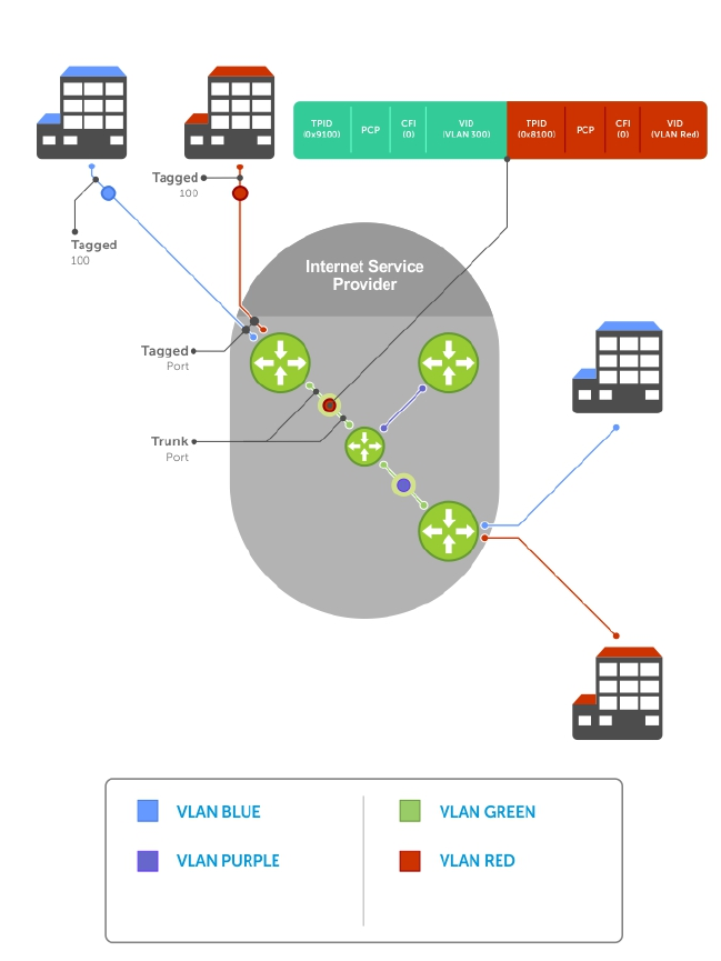
Figure 98. VLAN Stacking in a Service Provider Network
Important Points to Remember
• Interfaces that are members of the Default VLAN and are configured as VLAN-Stack access or trunk
ports do not switch untagged traffic. To switch traffic, add these interfaces to a non-default VLAN-
stack-enabled VLAN.
• Dell Networking cautions against using the same MAC address on different customer VLANs, on the
same VLAN-stack VLAN.
• This limitation becomes relevant if you enable the port as a multi-purpose port (carrying single-
tagged and double-tagged traffic).
Service Provider Bridging 729

Configure VLAN Stacking
Configuring VLAN-Stacking is a three-step process.
1. Creating Access and Trunk Ports
2. Assign access and trunk ports to a VLAN (Creating Access and Trunk Ports).
3. Enabling VLAN-Stacking for a VLAN.
Related Configuration Tasks
•Configuring the Protocol Type Value for the Outer VLAN Tag
•Configuring Options for Trunk Ports
•Debugging VLAN Stacking
•VLAN Stacking in Multi-Vendor Networks
Creating Access and Trunk Ports
To create access and trunk ports, use the following commands.
•Access port — a port on the service provider edge that directly connects to the customer. An access
port may belong to only one service provider VLAN.
•Trunk port — a port on a service provider bridge that connects to another service provider bridge and
is a member of multiple service provider VLANs.
Physical ports and port-channels can be access or trunk ports.
1. Assign the role of access port to a Layer 2 port on a provider bridge that is connected to a customer.
INTERFACE mode
vlan-stack access
2. Assign the role of trunk port to a Layer 2 port on a provider bridge that is connected to another
provider bridge.
INTERFACE mode
vlan-stack trunk
3. Assign all access ports and trunk ports to service provider VLANs.
INTERFACE VLAN mode
member
Example of Displaying the VLAN-Stack Configuration for a Switchport
To display the VLAN-Stacking configuration for a switchport, use the show config command from
INTERFACE mode.
Dell#show run interface te 2/0
!
interface TenGigabitEthernet 2/0
no ip address
switchport
vlan-stack access
no shutdown
Dell#show run interface te 2/12
730 Service Provider Bridging

!
interface TenGigabitEthernet 2/12
no ip address
switchport
vlan-stack trunk
no shutdown
Enable VLAN-Stacking for a VLAN
To enable VLAN-Stacking for a VLAN, use the following command.
• Enable VLAN-Stacking for the VLAN.
INTERFACE VLAN mode
vlan-stack compatible
Example of Viewing VLAN Stack Member Status
To display the status and members of a VLAN, use the show vlan command from EXEC Privilege mode.
Members of a VLAN-Stacking-enabled VLAN are marked with an M in column Q.
Dell#show vlan
Codes: * - Default VLAN, G - GVRP VLANs
NUM Status Q Ports
* 1 Active U Te 1/0-5,18
2 Inactive
3 Inactive
4 Inactive
5 Inactive
6 Active M Po1(Te 1/14-15)
M Te 1/13
Dell#
Configuring the Protocol Type Value for the Outer VLAN Tag
The tag protocol identifier (TPID) field of the S-Tag is user-configurable.
To set the S-Tag TPID, use the following command.
• Select a value for the S-Tag TPID.
CONFIGURATION mode
vlan-stack protocol-type
The default is 9100.
To display the S-Tag TPID for a VLAN, use the show running-config command from EXEC privilege
mode. The system displays the S-Tag TPID only if it is a non-default value.
Configuring Options for Trunk Ports
802.1ad trunk ports may also be tagged members of a VLAN so that it can carry single and double-tagged
traffic.
You can enable trunk ports to carry untagged, single-tagged, and double-tagged VLAN traffic by making
the trunk port a hybrid port.
Service Provider Bridging 731

To configure trunk ports, use the following commands.
1. Configure a trunk port to carry untagged, single-tagged, and double-tagged traffic by making it a
hybrid port.
INTERFACE mode
portmode hybrid
NOTE: You can add a trunk port to an 802.1Q VLAN as well as a Stacking VLAN only when the
TPID 0x8100.
2. Add the port to a 802.1Q VLAN as tagged or untagged.
INTERFACE VLAN mode
[tagged | untagged]
Example of Configuring a Trunk Port as a Hybrid Port and Adding it to Stacked VLANs
In the following example, the TenGigabitEthernet 0/1 interface is a trunk port that is configured as a
hybrid port and then added to VLAN 100 as untagged VLAN 101 as tagged, and VLAN 103, which is a
stacking VLAN.
Dell(conf)#int te 0/1
Dell(conf-if-te-0/1)#portmode hybrid
Dell(conf-if-te-0/1)#switchport
Dell(conf-if-te-0/1)#vlan-stack trunk
Dell(conf-if-te-0/1)#show config
!
interface TenGigabitEthernet 0/1
no ip address
portmode hybrid
switchport
vlan-stack trunk
shutdown
Dell(conf-if-te-0/1)#interface vlan 100
Dell(conf-if-vl-100)#untagged tengigabitethernet 0/1
Dell(conf-if-vl-100)#interface vlan 101
Dell(conf-if-vl-101)#tagged tengigabitethernet 0/1
Dell(conf-if-vl-101)#interface vlan 103
Dell(conf-if-vl-103)#vlan-stack compatible
Dell(conf-if-vl-103-stack)#member tengigabitethernet 0/1
Dell(conf-if-vl-103-stack)#do show vlan
Codes: * - Default VLAN, G - GVRP VLANs
Q: U - Untagged, T - Tagged
x - Dot1x untagged, X - Dot1x tagged
G - GVRP tagged, M - Vlan-stack
NUM Status Description Q Ports
* 1 Inactive
100 Inactive U Te 0/1
101 Inactive T Te 0/1
103 Inactive M Te 0/1
Debugging VLAN Stacking
To debug VLAN stacking, use the following command.
• Debug the internal state and membership of a VLAN and its ports.
debug member
732 Service Provider Bridging

Example of Debugging a VLAN and its Ports
The port notations are as follows:
•MT — stacked trunk
•MU — stacked access port
•T — 802.1Q trunk port
•U — 802.1Q access port
•NU — Native VLAN (untagged)
Dell# debug member vlan 603
vlan id : 603
ports : Te 1/47 (MT), Te 2/1(MU), Te 2/25(MT), Te 2/26(MT), Te 2/27(MU)
Dell#debug member port tengigabitethernet 1/47
vlan id : 603 (MT), 100(T), 101(NU)
VLAN Stacking in Multi-Vendor Networks
The first field in the VLAN tag is the tag protocol identifier (TPID), which is 2 bytes. In a VLAN-stacking
network, after the frame is double tagged, the outer tag TPID must match the TPID of the next-hop
system.
While 802.1Q requires that the inner tag TPID is 0x8100, it does not require a specific value for the outer
tag TPID. Systems may use any 2-byte value. The switch uses 0x9100 (shown in the following) while non-
Dell Networking devices might use a different value.
If the next-hop system’s TPID does not match the outer-tag TPID of the incoming frame, the system
drops the frame. For example, as shown in the following, the frame originating from Building A is tagged
VLAN RED, and then double-tagged VLAN PURPLE on egress at R4. The TPID on the outer tag is 0x9100.
R2’s TPID must also be 0x9100, and it is, so R2 forwards the frame.
Given the matching-TPID requirement, there are limitations when you employ Dell Networking systems
at network edges, at which, frames are either double tagged on ingress (R4) or the outer tag is removed
on egress (R3).
VLAN Stacking
The default TPID for the outer VLAN tag is 0x9100. The system allows you to configure both bytes of the
2 byte TPID.
Previous versions allowed you to configure the first byte only, and thus, the systems did not differentiate
between TPIDs with a common first byte. For example, 0x8100 and any other TPID beginning with 0x81
were treated as the same TPID, as shown in the following illustration. The system differentiates between
0x9100 and 0x91XY, as shown in the following illustration.
You can configure the first 8 bits of the TPID using the vlan-stack protocol-type command.
The TPID is global. Ingress frames that do not match the system TPID are treated as untagged. This rule
applies for both the outer tag TPID of a double-tagged frame and the TPID of a single-tagged frame.
For example, if you configure TPID 0x9100, the system treats 0x8100 and untagged traffic the same and
maps both types to the default VLAN, as shown by the frame originating from Building C. For the same
traffic types, if you configure TPID 0x8100, the system is able to differentiate between 0x8100 and
untagged traffic and maps each to the appropriate VLAN, as shown by the packet originating from
Building A.
Service Provider Bridging 733

Therefore, a mismatched TPID results in the port not differentiating between tagged and untagged traffic.
Figure 99. Single and Double-Tag TPID Match
734 Service Provider Bridging
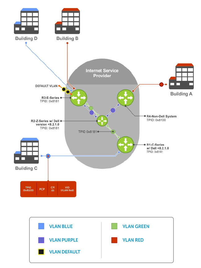
Figure 100. Single and Double-Tag First-byte TPID Match
Service Provider Bridging 735

Figure 101. Single and Double-Tag TPID Mismatch
VLAN Stacking Packet Drop Precedence
VLAN stacking packet-drop precedence is supported on the switch.
The drop eligible indicator (DEI) bit in the S-Tag indicates to a service provider bridge which packets it
should prefer to drop when congested.
Enabling Drop Eligibility
Enable drop eligibility globally before you can honor or mark the DEI value.
When you enable drop eligibility, DEI mapping or marking takes place according to the defaults. In this
case, the CFI is affected according to the following table.
736 Service Provider Bridging

Table 43. Drop Eligibility Behavior
Ingress Egress DEI Disabled DEI Enabled
Normal Port Normal Port Retain CFI Set CFI to 0.
Trunk Port Trunk Port Retain inner tag CFI Retain inner tag CFI.
Retain outer tag CFI Set outer tag CFI to 0.
Access Port Trunk Port Retain inner tag CFI Retain inner tag CFI
Set outer tag CFI to 0 Set outer tag CFI to 0
To enable drop eligibility globally, use the following command.
• Make packets eligible for dropping based on their DEI value.
CONFIGURATION mode
dei enable
By default, packets are colored green, and DEI is marked 0 on egress.
Honoring the Incoming DEI Value
To honor the incoming DEI value, you must explicitly map the DEI bit to a drop precedence value.
Precedence can have one of three colors.
Precedence Description
Green High-priority packets that are the least preferred to be dropped.
Yellow Lower-priority packets that are treated as best-effort.
Red Lowest-priority packets that are always dropped (regardless of congestion status).
• Honor the incoming DEI value by mapping it to a drop precedence value.
INTERFACE mode
dei honor {0 | 1} {green | red | yellow}
You may enter the command once for 0 and once for 1.
Packets with an unmapped DEI value are colored green.
Example of Viewing DEI-Honoring Configuration
To display the DEI-honoring configuration, use the show interface dei-honor [interface slot/
port | linecard number port-set number] in EXEC Privilege mode.
Dell#show interface dei-honor
Default Drop precedence: Green
Interface CFI/DEI Drop precedence
---------------------------------------
Te 0/1 0 Green
Te 0/1 1 Yellow
Te 1/9 1 Red
Te 1/40 0 Yellow
Service Provider Bridging 737
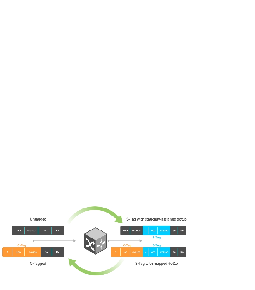
Marking Egress Packets with a DEI Value
On egress, you can set the DEI value according to a different mapping than ingress.
For ingress information, refer to Honoring the Incoming DEI Value.
To mark egress packets, use the following command.
• Set the DEI value on egress according to the color currently assigned to the packet.
INTERFACE mode
dei mark {green | yellow} {0 | 1}
Example of Viewing DEI-Marking Configuration
To display the DEI-marking configuration, use the show interface dei-mark [interface slot/
port | linecard number port-set number] in EXEC Privilege mode.
Dell#show interface dei-mark
Default CFI/DEI Marking: 0
Interface Drop precedence CFI/DEI
--------------------------------
Te 0/1 Green 0
Te 0/1 Yellow 1
Te 1/9 Yellow 0
Te 1/40 Yellow 0
Dynamic Mode CoS for VLAN Stacking
One of the ways to ensure quality of service for customer VLAN-tagged frames is to use the 802.1p
priority bits in the tag to indicate the level of QoS desired.
When an S-Tag is added to incoming customer frames, the 802.1p bits on the S-Tag may be configured
statically for each customer or derived from the C-Tag using Dynamic Mode CoS. Dynamic Mode CoS
maps the C-Tag 802.1p value to a S-Tag 802.1p value.
Figure 102. Statically and Dynamically Assigned dot1p for VLAN Stacking
When configuring Dynamic Mode CoS, you have two options:
738 Service Provider Bridging

• Option 1: Mark the S-Tag dot1p and queue the frame according to the original C-Tag dot1p. In this
case, you must have other dot1p QoS configurations; this option is classic dot1p marking.
• Option 2: Mark the S-Tag dot1p and queue the frame according to the S-Tag dot1p. For example, if
frames with C-Tag dot1p values 0, 6, and 7 are mapped to an S-Tag dot1p value 0, all such frames are
sent to the queue associated with the S-Tag 802.1p value 0. This option requires two different CAM
entries, each in a different Layer 2 ACL FP block.
NOTE: The ability to map incoming C-Tag dot1p to any S-Tag dot1p requires installing up to eight
entries in the Layer 2 QoS and Layer 2 ACL table for each configured customer VLAN. The scalability
of this feature is limited by the impact of the 1:8 expansion in these content addressable memory
(CAM) tables.
Dell Networking OS Behavior: For Option 1 shown in the previous illustration, when there is a conflict
between the queue selected by Dynamic Mode CoS (vlan-stack dot1p-mapping) and a QoS
configuration, the queue selected by Dynamic Mode CoS takes precedence. However, rate policing for
the queue is determined by QoS configuration. For example, the following access-port configuration
maps all traffic to Queue 0:
vlan-stack dot1p-mapping c-tag-dot1p 0-7 sp-tag-dot1p 1
However, if the following QoS configuration also exists on the interface, traffic is queued to Queue 0 but
is policed at 40Mbps (qos-policy-input for queue 3) because class-map "a" of Queue 3 also matches
the traffic. This is an expected behavior.
Examples of QoS Interface Configuration and Rate Policing
policy-map-input in layer2
service-queue 3 class-map a qos-policy 3
!
class-map match-any a layer2
match mac access-group a
!
mac access-list standard a
seq 5 permit any
!
qos-policy-input 3 layer2
rate-police 40
Likewise, in the following configuration, packets with dot1p priority 0–3 are marked as dot1p 7 in the
outer tag and queued to Queue 3. Rate policing is according to qos-policy-input 3. All other packets
will have outer dot1p 0 and hence are queued to Queue 1. They are therefore policed according to qos-
policy-input 1.
policy-map-input in layer2
service-queue 1 qos-policy 1
service-queue 3 qos-policy 3
!
qos-policy-input 1 layer2
rate-police 10
!
qos-policy-input 3 layer2
rate-police 30
!
interface TengigabitEthernet 0/21
no ip address
switchport
vlan-stack access
vlan-stack dot1p-mapping c-tag-dot1p 0-3 sp-tag-dot1p 7
Service Provider Bridging 739

service-policy input in layer2
no shutdown
Mapping C-Tag to S-Tag dot1p Values
To map C-Tag dot1p values to S-Tag dot1p values and mark the frames accordingly, use the following
commands.
1. Allocate CAM space to enable queuing frames according to the C-Tag or the S-Tag.
CONFIGURATION mode
cam-acl l2acl number ipv4acl number ipv6acl number ipv4qos number l2qos
number l2pt number ipmacacl number ecfmacl number {vman-qos | vman-qos-dual-
fp} number
•vman-qos: mark the S-Tag dot1p and queue the frame according to the original C-Tag dot1p.
This method requires half as many CAM entries as vman-qos-dual-fp.
•vman-qos-dual-fp: mark the S-Tag dot1p and queue the frame according to the S-Tag dot1p.
This method requires twice as many CAM entries as vman-qos and FP blocks in multiples of 2.
The default is: 0 FP blocks for vman-qos and vman-qos-dual-fp.
2. The new CAM configuration is stored in NVRAM and takes effect only after a save and reload.
EXEC Privilege mode
copy running-config startup-config reload
3. Map C-Tag dot1p values to a S-Tag dot1p value.
INTERFACE mode
vlan-stack dot1p-mapping c-tag-dot1p values sp-tag-dot1p value
Separate C-Tag values by commas. Dashed ranges are permitted.
Dynamic Mode CoS overrides any Layer 2 QoS configuration in case of conflicts.
NOTE: Because dot1p-mapping marks and queues packets, the only remaining applicable QoS
configuration is rate metering. You may use Rate Shaping or Rate Policing.
Layer 2 Protocol Tunneling
Spanning tree bridge protocol data units (BPDUs) use a reserved destination MAC address called the
bridge group address, which is 01-80-C2-00-00-00.
Only spanning-tree bridges on the local area network (LAN) recognize this address and process the
BPDU. When you use VLAN stacking to connect physically separate regions of a network, BPDUs
attempting to traverse the intermediate network might be consumed and later dropped because the
intermediate network itself might be using spanning tree (shown in the following illustration).
740 Service Provider Bridging
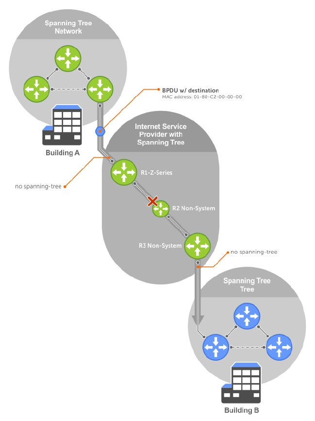
Figure 103. VLAN Stacking without L2PT
You might need to transport control traffic transparently through the intermediate network to the other
region. Layer 2 protocol tunneling enables BPDUs to traverse the intermediate network by identifying
frames with the Bridge Group Address, rewriting the destination MAC to a user-configured non-reserved
address, and forwarding the frames. Because the frames now use a unique MAC address, BPDUs are
treated as normal data frames by the switches in the intermediate network core. On egress edge of the
intermediate network, the MAC address rewritten to the original MAC address and forwarded to the
opposing network region (shown in the following illustration).
Dell Networking OS Behavior: The L2PT MAC address is user-configurable, so you can specify an
address that non-Dell Networking systems can recognize and rewrite the address at egress edge.
Service Provider Bridging 741
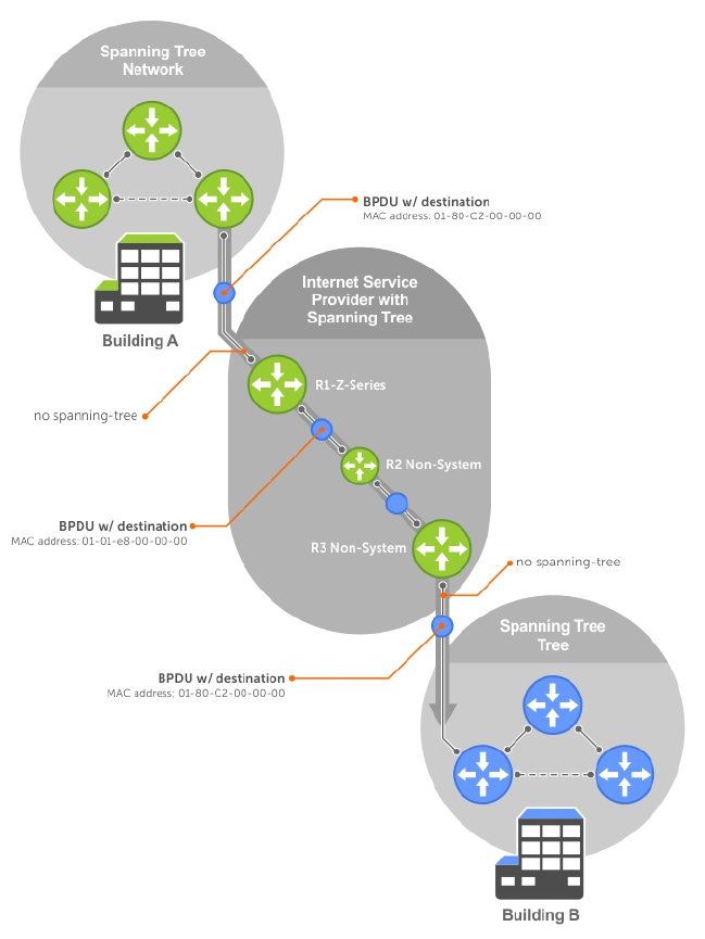
Figure 104. VLAN Stacking with L2PT
Implementation Information
• L2PT is available for STP, RSTP, MSTP, and PVST+ BPDUs.
• No protocol packets are tunneled when you enable VLAN stacking.
• L2PT requires the default CAM profile.
Enabling Layer 2 Protocol Tunneling
To enable Layer 2 protocol tunneling, use the following command.
1. Verify that the system is running the default CAM profile. Use this CAM profile for L2PT.
EXEC Privilege mode
742 Service Provider Bridging

show cam-profile
2. Enable protocol tunneling globally on the system.
CONFIGURATION mode
protocol-tunnel enable
3. Tunnel BPDUs the VLAN.
INTERFACE VLAN mode
protocol-tunnel stp
Specifying a Destination MAC Address for BPDUs
By default, the system uses a Dell Networking-unique MAC address for tunneling BPDUs. You can
configure another value.
To specify a destination MAC address for BPDUs, use the following command.
• Overwrite the BPDU with a user-specified destination MAC address when BPDUs are tunneled across
the provider network.
CONFIGURATION mode
protocol-tunnel destination-mac
The default is 01:01:e8:00:00:00
Setting Rate-Limit BPDUs
CAM space is allocated in sections called field processor (FP) blocks.
There are a total of 13 user-configurable FP blocks. The default number of blocks for L2PT is 0; you must
allocate at least one to enable BPDU rate-limiting.
To set the rate-lime BPDUs, use the following commands.
1. Create at least one FP group for L2PT.
CONFIGURATION mode
cam-acl l2acl
For details about this command, refer to CAM Allocation.
2. Save the running-config to the startup-config.
EXEC Privilege mode
copy running-config startup-config
3. Reload the system.
EXEC Privilege mode
reload
4. Set a maximum rate at which the BPDUs are processed for L2PT.
VLAN STACKING mode
protocol-tunnel rate-limit
The default is: no rate limiting.
Service Provider Bridging 743
The range is from 64 to 320 kbps.
Debugging Layer 2 Protocol Tunneling
To debug Layer 2 protocol tunneling, use the following command.
• Display debugging information for L2PT.
EXEC Privilege mode
debug protocol-tunnel
Provider Backbone Bridging
IEEE 802.1ad—Provider Bridges amends 802.1Q—Virtual Bridged Local Area Networks so that service
providers can use 802.1Q architecture to offer separate VLANs to customers with no coordination
between customers, and minimal coordination between customers and the provider.
802.1ad specifies that provider bridges operating spanning tree use a reserved destination MAC address
called the Provider Bridge Group Address, 01-80-C2-00-00-08, to exchange BPDUs instead of the
Bridge Group Address, 01-80-C2-00-00-00, originally specified in 802.1Q. Only bridges in the service
provider network use this destination MAC address so these bridges treat BPDUs originating from the
customer network as normal data frames, rather than consuming them.
The same is true for GARP VLAN registration protocol (GVRP). 802.1ad specifies that provider bridges
participating in GVRP use a reserved destination MAC address called the Provider Bridge GVRP Address,
01-80-C2-00-00-0D, to exchange GARP PDUs instead of the GVRP Address, 01-80-C2-00-00-21,
specified in 802.1Q. Only bridges in the service provider network use this destination MAC address so
these bridges treat GARP PDUs originating from the customer network as normal data frames, rather than
consuming them.
Provider backbone bridging through IEEE 802.1ad eliminates the need for tunneling BPDUs with L2PT
and increases the reliability of provider bridge networks as the network core need only learn the MAC
addresses of core switches, as opposed to all MAC addresses received from attached customer devices.
• Use the Provider Bridge Group address as the destination MAC address in BPDUs. The xstp keyword
applies this functionality to STP, RSTP, and MSTP; this functionality is not available for PVST+.
CONFIGURATION
bpdu-destination-mac-address [xstp | gvrp] provider-bridge-group
744 Service Provider Bridging
45
sFlow
sFlow is a standard-based sampling technology embedded within switches and routers which is used to
monitor network traffic. It is designed to provide traffic monitoring for high-speed networks with many
switches and routers.
Overview
The Dell Networking OS supports sFlow version 5.
sFlow uses two types of sampling:
• Statistical packet-based sampling of switched or routed packet flows.
• Time-based sampling of interface counters.
The sFlow monitoring system consists of an sFlow agent (embedded in the switch/router) and an sFlow
collector. The sFlow agent resides anywhere within the path of the packet and combines the flow
samples and interface counters into sFlow datagrams and forwards them to the sFlow collector at regular
intervals. The datagrams consist of information on, but not limited to, packet header, ingress and egress
interfaces, sampling parameters, and interface counters.
Application-specific integrated circuits (ASICs) typically complete packet sampling. sFlow collector
analyses the sFlow datagrams received from different devices and produces a network-wide view of
traffic flows.
Implementation Information
Dell Networking sFlow is designed so that the hardware sampling rate is per line card port-pipe and is
decided based on all the ports in that port-pipe.
If you do not enable sFlow on any port specifically, the global sampling rate is downloaded to that port
and is to calculate the port-pipe’s lowest sampling rate. This design supports the possibility that sFlow
might be configured on that port in the future. Back-off is triggered based on the port-pipe’s hardware
sampling rate.
For example, if port 1 in the port-pipe has sFlow configured with a 16384 sampling rate while port 2 in the
port-pipe has sFlow configured but no sampling rate set, the system applies a global sampling rate of 512
to port 2. The hardware sampling rate on the port-pipe is then set at 512 because that is the lowest
configured rate on the port-pipe. When a high traffic situation occurs, a back-off is triggered and the
hardware sampling rate is backed-off from 512 to 1024. Note that port 1 maintains its sampling rate of
16384; port 1 is unaffected because it maintains its configured sampling rate of 16484.
To avoid the back-off, either increase the global sampling rate or configure all the line card ports with the
desired sampling rate even if some ports have no sFlow configured.
sFlow 745
Important Points to Remember
• The Dell Networking OS implementation of the sFlow MIB supports sFlow configuration via snmpset.
• Dell Networking recommends the sFlow Collector be connected to the Dell Networking chassis
through a line card port rather than the management Ethernet port.
• Only egress sampling is supported.
• The system exports all sFlow packets to the collector. A small sampling rate can equate to many
exported packets. A backoff mechanism is automatically applied to reduce this amount. Some
sampled packets may be dropped when the exported packet rate is high and the backoff mechanism
is about to or is starting to take effect. The dropEvent counter, in the sFlow packet, is always zero.
• Community list and local preference fields are not filled in extended gateway element in the sFlow
datagram.
• 802.1P source priority field is not filled in extended switch element in sFlow datagram.
• Only Destination and Destination Peer AS number are packed in the dst-as-path field in extended
gateway element.
• If the packet being sampled is redirected using policy-based routing (PBR), the sFlow datagram may
contain incorrect extended gateway/router information.
• The source virtual local area network (VLAN) field in the extended switch element is not packed in
case of routed packet.
• The destination VLAN field in the extended switch element is not packed in a Multicast packet.
• Up to 700 packets can be sampled and processed per second.
Enabling and Disabling sFlow
By default, sFlow is disabled globally on the system.
Use the following command to enable sFlow globally.
• Enable sFlow globally.
CONFIGURATION mode
[no] sflow enable
Enabling and Disabling sFlow on an Interface
By default, sFlow is disabled on all interfaces.
This CLI is supported on physical ports and link aggregation group (LAG) ports.
To enable sFlow on a specific interface, use the following command.
• Enable sFlow on an interface.
INTERFACE mode
[no] sflow enable
To disable sFlow on an interface, use the no version of this command.
746 sFlow

sFlow Show Commands
You can display sFlow statistics at the switch, interface, and line card level.
•Displaying Show sFlow Globally
•Displaying Show sFlow on an Interface
•Displaying Show sFlow on a Line Card
Displaying Show sFlow Global
To view sFlow statistics, use the following command.
• Display sFlow configuration information and statistics.
EXEC mode
show sflow
Example of Viewing sFlow Configuration (Global)
The first bold line indicates sFlow is globally enabled. The second bold lines indicate sFlow is enabled on
linecards Te 1/16 and Te 1/17.
Dell#show sflow
sFlow services are enabled
Global default sampling rate: 32768
Global default counter polling interval: 20
1 collectors configured
Collector IP addr: 133.33.33.53, Agent IP addr: 133.33.33.116, UDP port: 6343
77 UDP packets exported
0 UDP packets dropped
165 sFlow samples collected
69 sFlow samples dropped due to sub-sampling
Linecard 1 Port set 0 H/W sampling rate 8192
Te 1/16: configured rate 8192, actual rate 8192, sub-sampling rate 1
Te 1/17: configured rate 16384, actual rate 16384, sub-sampling rate 2
Displaying Show sFlow on an Interface
To view sFlow information on a specific interface, use the following command.
• Display sFlow configuration information and statistics on a specific interface.
EXEC mode
show sflow interface interface-name
Examples of Viewing a sFlow Configuration
The following example shows the show sflow interface command.
Dell#show sflow interface tengigabitethernet 1/16
Te 1/16
Configured sampling rate :8192
Actual sampling rate :8192
Sub-sampling rate :2
Counter polling interval :15
sFlow 747

Samples rcvd from h/w :33
Samples dropped for sub-sampling :6
The following example shows the show running-config interface command.
Dell#show running-config interface tengigabitethernet 1/16
!
interface TenGigabitEthernet 1/16
no ip address
mtu 9252
ip mtu 9234
switchport
sflow enable
sflow sample-rate 8192
no shutdown
Displaying Show sFlow on a Line Card
To view sFlow statistics on a specified line card, use the following command.
• Display sFlow configuration information and statistics on the specified interface.
EXEC mode
show sflow linecard slot-number
Example of Viewing sFlow Configuration (Line Card)
Dell#show sflow linecard 1
Linecard 1
Samples rcvd from h/w :165
Samples dropped for sub-sampling :69
Total UDP packets exported :77
UDP packets exported via RP :77
UDP packets dropped :
Configuring Specify Collectors
The sflow collector command allows identification of sFlow collectors to which sFlow datagrams are
forwarded.
You can specify up to two sFlow collectors. If you specify two collectors, the samples are sent to both.
• Identify sFlow collectors to which sFlow datagrams are forwarded.
CONFIGURATION mode
sflow collector ip-address agent-addr ip-address [number [max-datagram-size
number] ] | [max-datagram-size number ]
The default UDP port is 6343.
The default max-datagram-size is 1400.
Changing the Polling Intervals
The sflow polling-interval command configures the polling interval for an interface in the
maximum number of seconds between successive samples of counters sent to the collector.
This command changes the global default counter polling (20 seconds) interval. You can configure an
interface to use a different polling interval.
748 sFlow

To configure the polling intervals globally (in CONFIGURATION mode) or by interface (in INTERFACE
mode), use the following command.
• Change the global default counter polling interval.
CONFIGURATION mode or INTERFACE mode
sflow polling-interval interval value
–interval value: in seconds.
The range is from 15 to 86400 seconds.
The default is 20 seconds.
Back-Off Mechanism
If the sampling rate for an interface is set to a very low value, the CPU can get overloaded with flow
samples under high-traffic conditions.
In such a scenario, a binary back-off mechanism gets triggered, which doubles the sampling-rate (halves
the number of samples per second) for all interfaces. The backoff mechanism continues to double the
sampling-rate until the CPU condition is cleared. This is as per sFlow version 5 draft. After the back-off
changes the sample-rate, you must manually change the sampling rate to the desired value.
As a result of back-off, the actual sampling-rate of an interface may differ from its configured sampling
rate. You can view the actual sampling-rate of the interface and the configured sample-rate by using the
show sflow command.
sFlow on LAG ports
When a physical port becomes a member of a LAG, it inherits the sFlow configuration from the LAG port.
Enabling Extended sFlow
Extended sFlow packs additional information in the sFlow datagram depending on the type of sampled
packet.
You can enable the following options:
•extended-switch — 802.1Q VLAN ID and 802.1p priority information.
•extended-router — Next-hop and source and destination mask length.
•extended-gateway — Source and destination AS number and the BGP next-hop.
NOTE: The entire AS path is not included. BGP community-list and local preference information are
not included. These fields are assigned default values and are not interpreted by the collector.
• Enable extended sFlow.
sflow [extended-switch] [extended-router] [extended-gateway] enable
By default packing of any of the extended information in the datagram is disabled.
• Confirm that extended information packing is enabled.
show sflow
sFlow 749

Examples of Verifying Extended sFlow
The bold line shows that extended sFlow settings are enabled on all three types.
Dell#show sflow
sFlow services are enabled
Global default sampling rate: 4096
Global default counter polling interval: 15
Global extended information enabled: gateway, router, switch
1 collectors configured
Collector IP addr: 10.10.10.3, Agent IP addr: 10.10.0.0, UDP port: 6343
77 UDP packets exported
0 UDP packets dropped
165 sFlow samples collected
69 sFlow samples dropped due to sub-sampling
Linecard 1 Port set 0 H/W sampling rate 8192
Gi 1/16: configured rate 8192, actual rate 8192, sub-sampling rate 1
Gi 1/17: configured rate 16384, actual rate 16384, sub-sampling rate 2
Linecard 3 Port set 1 H/W sampling rate 16384
Gi 3/40: configured rate 16384, actual rate 16384, sub-sampling rate 1
If you did not enable any extended information, the show output displays the following (shown in bold).
Dell#show sflow
sFlow services are disabled
Global default sampling rate: 32768
Global default counter polling interval: 20
Global extended information enabled: none
0 collectors configured
0 UDP packets exported
0 UDP packets dropped
0 sFlow samples collected
0 sFlow samples dropped due to sub-sampling
Important Points to Remember
• If the IP source address is learned via IGP, srcAS and srcPeerAS are zero.
• The srcAS and srcPeerAS might be zero even though the IP source address is learned via BGP. The c
system packs the srcAS and srcPeerAS information only if the route is learned via BGP and it is
reachable via the ingress interface of the packet.
The previous points are summarized in following table.
Table 44. Extended Gateway Summary
IP SA IP DA srcAS and
srcPeerAS dstAS and
dstPeerAS Description
static/
connected/IGP
static/
connected/IGP
— — Extended gateway
data is not
exported because
there is no AS
information.
static/
connected/IGP
BGP 0 Exported src_as and
src_peer_as are
zero because there
is no AS
750 sFlow

IP SA IP DA srcAS and
srcPeerAS dstAS and
dstPeerAS Description
information for
IGP.
BGP static/
connected/IGP
—
Exported
—
Exported
The system allows
extended gateway
information in
cases where the
source and
destination IP
addresses are
learned by different
routing protocols,
and for cases
where is source is
reachable over
ECMP.
BGP BGP Exported Exported Extended gateway
data is packed.
sFlow 751

46
Simple Network Management Protocol
(SNMP)
The Simple Network Management Protocol (SNMP) is designed to manage devices on IP networks by
monitoring device operation, which might require administrator intervention.
NOTE: On Dell Networking routers, standard and private SNMP management information bases
(MIBs) are supported, including all Get and a limited number of Set operations (such as set vlan
and copy cmd).
Protocol Overview
Network management stations use SNMP to retrieve or alter management data from network elements.
A datum of management information is called a managed object; the value of a managed object can be
static or variable. Network elements store managed objects in a database called a management
information base (MIB).
MIBs are hierarchically structured and use object identifiers to address managed objects, but managed
objects also have a textual name called an object descriptor.
Implementation Information
The following describes SNMP implementation information.
• The Dell Networking OS supports SNMP version 1 as defined by RFC 1155, 1157, and 1212, SNMP
version 2c as defined by RFC 1901, and SNMP version 3 as defined by RFC 2571.
• The system supports up to 16 trap receivers.
• The Dell Networking OS implementation of the sFlow MIB supports sFlow configuration via SNMP
sets.
• SNMP traps for the spanning tree protocol (STP) and multiple spanning tree protocol (MSTP) state
changes are based on BRIDGE MIB (RFC 1483) for STP and IEEE 802.1 draft ruzin-mstp-mib-02 for
MSTP.
Configuration Task List for SNMP
Configuring SNMP version 1 or version 2 requires a single step.
NOTE: The configurations in this chapter use a UNIX environment with net-snmp version 5.4. This
environment is only one of many RFC-compliant SNMP utilities you can use to manage your Dell
Networking system using SNMP. Also, these configurations use SNMP version 2c.
•Creating a Community
Configuring SNMP version 3 requires configuring SNMP users in one of three methods. Refer to Setting
Up User-Based Security (SNMPv3).
752 Simple Network Management Protocol (SNMP)

Related Configuration Tasks
•Managing Overload on Startup
•Reading Managed Object Values
•Writing Managed Object Values
•Subscribing to Managed Object Value Updates using SNMP
•Copying Configuration Files via SNMP
•Manage VLANs Using SNMP
•Enabling and Disabling a Port using SNMP
•Fetch Dynamic MAC Entries using SNMP
•Deriving Interface Indices
•Monitor Port-channels
Important Points to Remember
• Typically, 5-second timeout and 3-second retry values on an SNMP server are sufficient for both LAN
and WAN applications. If you experience a timeout with these values, increase the timeout value to
greater than 3 seconds, and increase the retry value to greater than 2 seconds on your SNMP server.
• User ACLs override group ACLs.
Set up SNMP
The Dell Networking OS supports SNMP version 1 and version 2 that are community-based security
models.
The primary difference between the two versions is that version 2 supports two additional protocol
operations (informs operation and snmpgetbulk query) and one additional object (counter64 object).
SNMP version 3 (SNMPv3) is a user-based security model that provides password authentication for user
security and encryption for data security and privacy. Three sets of configurations are available for SNMP
read/write operations: no password or privacy, password privileges, password and privacy privileges.
You can configure a maximum of 32 users even if they are in different groups.
Creating a Community
For SNMPv1 and SNMPv2, create a community to enable the community-based security on the switch.
The management station generates requests to either retrieve or alter the value of a management object
and is called the SNMP manager. A network element that processes SNMP requests is called an SNMP
agent. An SNMP community is a group of SNMP agents and managers that are allowed to interact.
Communities are necessary to secure communication between SNMP managers and agents; SNMP
agents do not respond to requests from management stations that are not part of the community.
The system enables SNMP automatically when you create an SNMP community and displays the
following message. You must specify whether members of the community may only retrieve values
(read), or retrieve and alter values (read-write).
22:31:23: %SYSTEM-P:CP %SNMP-6-SNMP_WARM_START: Agent Initialized - SNMP
WARM_START.
To choose a name for the community you create, use the following command.
Simple Network Management Protocol (SNMP) 753

• Choose a name for the community.
CONFIGURATION mode
snmp-server community name {ro | rw}
Example of Creating an SNMP Community
To view your SNMP configuration, use the show running-config snmp command from EXEC Privilege
mode.
Dell(conf)#snmp-server community my-snmp-community ro
22:31:23: %SYSTEM-P:CP %SNMP-6-SNMP_WARM_START: Agent Initialized - SNMP
WARM_START.
Dell#show running-config snmp
!
snmp-server community mycommunity ro
Setting Up User-Based Security (SNMPv3)
When setting up SNMPv3, you can set users up with one of the following three types of configuration for
SNMP read/write operations.
Users are typically associated to an SNMP group with permissions provided, such as OID view.
•noauth — no password or privacy. Select this option to set up a user with no password or privacy
privileges. This setting is the basic configuration. Users must have a group and profile that do not
require password privileges.
•auth — password privileges. Select this option to set up a user with password authentication.
•priv — password and privacy privileges. Select this option to set up a user with password and privacy
privileges.
To set up user-based security (SNMPv3), use the following commands.
• Configure the user with view privileges only (no password or privacy privileges).
CONFIGURATION mode
snmp-server user name group-name 3 noauth
• Configure an SNMP group with view privileges only (no password or privacy privileges).
CONFIGURATION mode
snmp-server group group-name 3 noauth auth read name write name
• Configure an SNMPv3 view.
CONFIGURATION mode
snmp-server view view-name oid-tree {included | excluded}
NOTE: To give a user read and write view privileges, repeat this step for each privilege type.
• Configure the user with an authorization password (password privileges only).
CONFIGURATION mode
snmp-server user name group-name 3 noauth auth md5 auth-password
• Configure an SNMP group (password privileges only).
CONFIGURATION mode
snmp-server group groupname {oid-tree} auth read name write name
754 Simple Network Management Protocol (SNMP)

• Configure an SNMPv3 view.
CONFIGURATION mode
snmp-server view view-name 3 noauth {included | excluded}
NOTE: To give a user read and write privileges, repeat this step for each privilege type.
• Configure an SNMP group (with password or privacy privileges).
CONFIGURATION mode
snmp-server group group-name {oid-tree} priv read name write name
• Configure the user with a secure authorization password and privacy password.
CONFIGURATION mode
snmp-server user name group-name {oid-tree} auth md5 auth-password priv des56
priv password
• Configure an SNMPv3 view.
CONFIGURATION mode
snmp-server view view-name oid-tree {included | excluded}
Select a User-based Security Type
Dell(conf)#snmp-server host 1.1.1.1 traps {oid tree} version 3 ?
auth Use the SNMPv3 authNoPriv Security Level
noauth Use the SNMPv3 noAuthNoPriv Security Level
priv Use the SNMPv3 authPriv Security Level
Dell(conf)#snmp-server host 1.1.1.1 traps {oid tree} version 3 noauth ?
WORD SNMPv3 user name
Reading Managed Object Values
You may only retrieve (read) managed object values if your management station is a member of the same
community as the SNMP agent.
Dell Networking supports RFC 4001, Textual Conventions for Internet Work Addresses that defines values
representing a type of internet address. These values display for ipAddressTable objects using the
snmpwalk command.
There are several UNIX SNMP commands that read data.
• Read the value of a single managed object.
snmpget -v version -c community agent-ip {identifier.instance |
descriptor.instance}
• Read the value of the managed object directly below the specified object.
snmpgetnext -v version -c community agent-ip {identifier.instance |
descriptor.instance}
• Read the value of many objects at once.
snmpwalk -v version -c community agent-ip {identifier.instance |
descriptor.instance}
Simple Network Management Protocol (SNMP) 755

Examples of Reading Managed Object Values
In the following example, the value “4” displays in the OID before the IP address for IPv4. For an IPv6 IP
address, a value of “16” displays.
> snmpget -v 2c -c mycommunity 10.11.131.161 sysUpTime.0
DISMAN-EVENT-MIB::sysUpTimeInstance = Timeticks: (32852616) 3 days, 19:15:26.16
> snmpget -v 2c -c mycommunity 10.11.131.161 .1.3.6.1.2.1.1.3.0
The following example shows reading the value of the next managed object.
> snmpgetnext -v 2c -c mycommunity 10.11.131.161 .1.3.6.1.2.1.1.3.0
SNMPv2-MIB::sysContact.0 = STRING:
> snmpgetnext -v 2c -c mycommunity 10.11.131.161 sysContact.0
The following example shows reading the value of many managed objects at one time.
> snmpwalk -v 2c -c public 10.11.198.100 .1.3.6.1.2.1.1
SNMPv2-MIB::sysDescr.0 = STRING: Dell Force10 OS
Operating System Version: 2.0
Application Software Version: 9.2(1.0B2)
Series: Z9500
Copyright (c) 1999-2013 by Dell Inc. All Rights Reserved.
Build Time: Sun Jan 12 22:24:47 2014
SNMPv2-MIB::sysObjectID.0 = OID: SNMPv2-SMI::enterprises.6027.1.5.1
DISMAN-EVENT-MIB::sysUpTimeInstance = Timeticks: (133410) 0:22:14.10
SNMPv2-MIB::sysContact.0 = STRING:
SNMPv2-MIB::sysName.0 = STRING: FTOS
SNMPv2-MIB::sysLocation.0 = STRING:
SNMPv2-MIB::sysServices.0 = INTEGER: 6
Writing Managed Object Values
You may only alter (write) a managed object value if your management station is a member of the same
community as the SNMP agent, and the object is writable.
Use the following command to write or write-over the value of a managed object.
• To write or write-over the value of a managed object.
snmpset -v version -c community agent-ip {identifier.instance |
descriptor.instance}syntax value
Example of Writing the Value of a Managed Object
> snmpset -v 2c -c mycommunity 10.11.131.161 sysName.0 s "R5"
SNMPv2-MIB::sysName.0 = STRING: R5
Configuring Contact and Location Information using
SNMP
You may configure system contact and location information from the Dell Networking system or from
the management station using SNMP.
To configure system contact and location information from the Dell Networking system and from the
management station using SNMP, use the following commands.
• (From a Dell Networking system) Identify the system manager along with this person’s contact
information (for example, an email address or phone number).
CONFIGURATION mode
756 Simple Network Management Protocol (SNMP)
snmp-server contact text
You may use up to 55 characters.
The default is None.
• (From a Dell Networking system) Identify the physical location of the system (for example, San Jose,
350 Holger Way, 1st floor lab, rack A1-1).
CONFIGURATION mode
snmp-server location text
You may use up to 55 characters.
The default is None.
• (From a management station) Identify the system manager along with this person’s contact
information (for example, an email address or phone number).
CONFIGURATION mode
snmpset -v version -c community agent-ip sysContact.0 s “contact-info”
You may use up to 55 characters.
The default is None.
• (From a management station) Identify the physical location of the system (for example, San Jose, 350
Holger Way, 1st floor lab, rack A1-1).
CONFIGURATION mode
snmpset -v version -c community agent-ip sysLocation.0 s “location-info”
You may use up to 55 characters.
The default is None.
Subscribing to Managed Object Value Updates using
SNMP
By default, the system displays some unsolicited SNMP messages (traps) upon certain events and
conditions.
You can also configure the system to send the traps to a management station. Traps cannot be saved on
the system.
The following sets of traps are supported:
•RFC 1157-defined traps — coldStart, warmStart, linkDown, linkUp, authenticationFailure, and
egpNeighbborLoss.
•Dell Networking enterpriseSpecific environment traps — fan, supply, and temperature.
•Dell Networking enterpriseSpecific protocol traps — bgp, ecfm, stp, and xstp.
To configure the system to send SNMP notifications, use the following commands.
1. Configure the Dell Networking system to send notifications to an SNMP server.
CONFIGURATION mode
Simple Network Management Protocol (SNMP) 757

snmp-server host ip-address [traps | informs] [version 1 | 2c |3]
[community-string]
To send trap messages, enter the keyword traps.
To send informational messages, enter the keyword informs.
To send the SNMP version to use for notification messages, enter the keyword version.
To identify the SNMPv1 community string, enter the name of the community-string.
2. Specify which traps the Dell Networking system sends to the trap receiver.
CONFIGURATION mode
snmp-server enable traps
Enable all Dell Networking enterprise-specific and RFC-defined traps using the snmp-server
enable traps command from CONFIGURATION mode.
Enable all of the RFC-defined traps using the snmp-server enable traps snmp command from
CONFIGURATION mode.
3. Specify the interfaces which send SNMP traps.
CONFIGURATION mode
snmp-server trap-source
Example of RFC-Defined SNMP Traps and Related Enable Commands
The following example lists the RFC-defined SNMP traps and the command used to enable each. The
coldStart and warmStart traps are enabled using a single command.
snmp authentication SNMP_AUTH_FAIL:SNMP Authentication failed.Request with
invalid community string.
snmp coldstart SNMP_COLD_START: Agent Initialized - SNMP COLD_START.
SNMP_WARM_START:Agent Initialized - SNMP WARM_START.
snmp linkdown PORT_LINKDN:changed interface state to down:%d
snmp linkup PORT_LINKUP:changed interface state to up:%d
Enabling a Subset of SNMP Traps
You can enable a subset of Dell Networking enterprise-specific SNMP traps using one of the following
listed command options.
To enable a subset of Dell Networking enterprise-specific SNMP traps, use the following command.
• Enable a subset of SNMP traps.
snmp-server enable traps
NOTE: The envmon option enables all environment traps including those traps that are enabled
with the envmon supply, envmon temperature, and envmon fan options.
Example of Dell Networking Enterprise-specific SNMP Traps
envmon
LINECARDUP: %sLine card %d is up
CARD_MISMATCH: Mismatch: line card %d is type %s - type %s required.
758 Simple Network Management Protocol (SNMP)

TASK SUSPENDED: SUSPENDED - svce:%d - inst:%d - task:%s
SYSTEM-P:CP %CHMGR-2-CARD_PARITY_ERR
ABNORMAL_TASK_TERMINATION: CRASH - task:%s %s
CPU_THRESHOLD: Cpu %s usage above threshold. Cpu5SecUsage (%d)
CPU_THRESHOLD_CLR: Cpu %s usage drops below threshold. Cpu5SecUsage (%d)
MEM_THRESHOLD: Memory %s usage above threshold. MemUsage (%d)
MEM_THRESHOLD_CLR: Memory %s usage drops below threshold. MemUsage (%d)
DETECT_STN_MOVE: Station Move threshold exceeded for Mac %s in vlan %d
CAM-UTILIZATION: Enable SNMP envmon CAM utilization traps.
envmon supply
PEM_PRBLM: Major alarm: problem with power entry module %s
PEM_OK: Major alarm cleared: power entry module %s is good
MAJOR_PS: Major alarm: insufficient power %s
MAJOR_PS_CLR: major alarm cleared: sufficient power
MINOR_PS: Minor alarm: power supply non-redundant
MINOR_PS_CLR: Minor alarm cleared: power supply redundant
envmon temperature
MINOR_TEMP: Minor alarm: chassis temperature
MINOR_TEMP_CLR: Minor alarm cleared: chassis temperature normal (%s %d
temperature is within threshold of %dC)
MAJOR_TEMP: Major alarm: chassis temperature high (%s temperature reaches or
exceeds threshold of %dC)
MAJOR_TEMP_CLR: Major alarm cleared: chassis temperature lower (%s %d
temperature is within threshold of %dC)
envmon fan
FAN_TRAY_BAD: Major alarm: fantray %d is missing or down
FAN_TRAY_OK: Major alarm cleared: fan tray %d present
FAN_BAD: Minor alarm: some fans in fan tray %d are down
FAN_OK: Minor alarm cleared: all fans in fan tray %d are good
vlt
Enable VLT traps.
vrrp
Enable VRRP state change traps
xstp
%SPANMGR-5-STP_NEW_ROOT: New Spanning Tree Root, Bridge ID Priority 32768,
Address 0001.e801.fc35.
%SPANMGR-5-STP_TOPOLOGY_CHANGE: Bridge port TenGigabitEthernet 11/38
transitioned
from Forwarding to Blocking state.
%SPANMGR-5-MSTP_NEW_ROOT_BRIDGE: Elected root bridge for instance 0.
%SPANMGR-5-MSTP_NEW_ROOT_PORT: MSTP root changed to port Te 11/38 for instance
0. My Bridge ID: 40960:0001.e801.fc35 Old Root: 40960:0001.e801.fc35 New Root:
32768:00d0.038a.2c01.
%SPANMGR-5-MSTP_TOPOLOGY_CHANGE: Topology change BridgeAddr: 0001.e801.fc35
Mstp
Instance Id 0 port Te 11/38 transitioned from forwarding to discarding state.
ecfm
%ECFM-5-ECFM_XCON_ALARM: Cross connect fault detected by MEP 1 in Domain
customer1 at Level 7 VLAN 1000
%ECFM-5-ECFM_ERROR_ALARM: Error CCM Defect detected by MEP 1 in Domain
customer1
at Level 7 VLAN 1000
%ECFM-5-ECFM_MAC_STATUS_ALARM: MAC Status Defect detected by MEP 1 in Domain
provider at Level 4 VLAN 3000
%ECFM-5-ECFM_REMOTE_ALARM: Remote CCM Defect detected by MEP 3 in Domain
customer1 at Level 7 VLAN 1000
Simple Network Management Protocol (SNMP) 759

%ECFM-5-ECFM_RDI_ALARM: RDI Defect detected by MEP 3 in Domain customer1 at
Level 7 VLAN 1000
entity
Enable entity change traps
Trap SNMPv2-MIB::sysUpTime.0 = Timeticks: (1487406) 4:07:54.06,
SNMPv2-MIB::snmpTrapOID.0 = OID: SNMPv2-SMI::mib-2.47.2.0.1,
SNMPv2-SMI::enterprises.6027.3.6.1.1.2.0 = INTEGER: 4
Trap SNMPv2-MIB::sysUpTime.0 = Timeticks: (1488564) 4:08:05.64,
SNMPv2-MIB::snmpTrapOID.0 = OID: SNMPv2-SMI::mib-2.47.2.0.1,
SNMPv2-SMI::enterprises.6027.3.6.1.1.2.0 = INTEGER: 5
Trap SNMPv2-MIB::sysUpTime.0 = Timeticks: (1489064) 4:08:10.64,
SNMPv2-MIB::snmpTrapOID.0 = OID: SNMPv2-SMI::mib-2.47.2.0.1,
SNMPv2-SMI::enterprises.6027.3.6.1.1.2.0 = INTEGER: 6
Trap SNMPv2-MIB::sysUpTime.0 = Timeticks: (1489568)
4:08:15.68,SNMPv2-MIB::snmpTrapOID.0 = OID: SNMPv2-SMI::mib-2.47.2.0.1,
SNMPv2-SMI::enterprises.6027.3.6.1.1.2.0 = INTEGER: 7
<cr>
SNMP Copy Config Command Completed
%SYSTEM-P:CP %SNMP-4-RMON_RISING_THRESHOLD: RMON rising threshold alarm from
SNMP OID <oid>
%SYSTEM-P:CP %SNMP-4-RMON_FALLING_THRESHOLD: RMON falling threshold alarm from
SNMP OID <oid>
%SYSTEM-P:CP %SNMP-4-RMON_HC_RISING_THRESHOLD: RMON high-capacity rising
threshold
alarm from SNMP OID <oid>
Copy Configuration Files Using SNMP
To do the following, use SNMP from a remote client.
• copy the running-config file to the startup-config file
• copy configuration files from the Dell Networking system to a server
• copy configuration files from a server to the Dell Networking system
You can perform all of these tasks using IPv4 or IPv6 addresses. The examples in this section use IPv4
addresses; however, you can substitute IPv6 addresses for the IPv4 addresses in all of the examples.
The following table lists the relevant MIBs for these functions are.
Table 45. MIB Objects for Copying Configuration Files via SNMP
MIB Object OID Object Values Description
copySrcFileType .
1.3.6.1.4.1.6027.3.5.1.1.1.
1.2
1 = Dell Networking OS
file
2 = running-config
3 = startup-config
Specifies the type of file
to copy from. The range
is:
• If copySrcFileType is
running-config or
startup-config, the
default
copySrcFileLocation
is flash.
• If copySrcFileType is
a binary file, you
must also specify
copySrcFileLocation
760 Simple Network Management Protocol (SNMP)

MIB Object OID Object Values Description
and
copySrcFileName.
copySrcFileLocation .
1.3.6.1.4.1.6027.3.5.1.1.1.
1.3
1 = flash
2 = slot0
3 = tftp
4 = ftp
5 = scp
6 = usbflash
Specifies the location of
source file.
• If
copySrcFileLocation
is FTP or SCP, you
must specify
copyServerAddress,
copyUserName, and
copyUserPassword.
copySrcFileName .
1.3.6.1.4.1.6027.3.5.1.1.1.
1.4
Path (if the file is not in
the current directory)
and filename.
Specifies name of the
file.
• If
copySourceFileType
is set to running-
config or startup-
config,
copySrcFileName is
not required.
copyDestFileType .
1.3.6.1.4.1.6027.3.5.1.1.1.
1.5
1 = Dell Networking OS
file
2 = running-config
3 = startup-config
Specifies the type of file
to copy to.
• If
copySourceFileType
is running-config or
startup-config, the
default
copyDestFileLocatio
n is flash.
• If copyDestFileType
is a binary, you must
specify
copyDestFileLocatio
n and
copyDestFileName.
copyDestFileLocation .
1.3.6.1.4.1.6027.3.5.1.1.1.
1.6
1 = flash
2 = slot0
3 = tftp
4 = ftp
5 = scp
Specifies the location of
destination file.
• If
copyDestFileLocatio
n is FTP or SCP, you
must specify
copyServerAddress,
copyUserName, and
copyUserPassword.
copyDestFileName .
1.3.6.1.4.1.6027.3.5.1.1.1.
1.7
Path (if the file is not in
the default directory)
and filename.
Specifies the name of
destination file.
Simple Network Management Protocol (SNMP) 761

MIB Object OID Object Values Description
copyServerAddress .
1.3.6.1.4.1.6027.3.5.1.1.1.
1.8
IP Address of the server. The IP address of the
server.
• If you specify
copyServerAddress,
you must also
specify
copyUserName and
copyUserPassword.
copyUserName .
1.3.6.1.4.1.6027.3.5.1.1.1.
1.9
Username for the server. Username for the FTP,
TFTP, or SCP server.
• If you specify
copyUserName, you
must also specify
copyUserPassword.
copyUserPassword .
1.3.6.1.4.1.6027.3.5.1.1.1.
1.10
Password for the server. Password for the FTP,
TFTP, or SCP server.
Copying a Configuration File
To copy a configuration file, use the following commands.
NOTE: In UNIX, enter the snmpset command for help using the following commands. Place the
f10-copy-config.mib file in the directory from which you are executing the snmpset command or
in the snmpset tool path.
1. Create an SNMP community string with read/write privileges.
CONFIGURATION mode
snmp-server community community-name rw
2. Copy the f10-copy-config.mib MIB from the Dell iSupport web page to the server to which you are
copying the configuration file.
3. On the server, use the snmpset command as shown in the following example.
snmpset -v snmp-version -c community-name -m mib_path/f10-copy-config.mib
force10system-ip-address mib-object.index {i | a | s} object-value...
• Every specified object must have an object value and must precede with the keyword i. Refer to
the previous table.
•index must be unique to all previously executed snmpset commands. If an index value has been
used previously, a message like the following appears. In this case, increment the index value and
enter the command again.
Error in packet.
Reason: notWritable (that object does not support modification)
Failed object: FTOS-COPY-CONFIG-MIB::copySrcFileType.101
• To complete the command, use as many MIB objects in the command as required by the MIB
object descriptions shown in the previous table.
NOTE: You can use the entire OID rather than the object name. Use the form: OID.index i
object-value.
To view more information, use the following options in the snmpset command.
762 Simple Network Management Protocol (SNMP)

•-c: View the community, either public or private.
•-m: View the MIB files for the SNMP command.
•-r: Number of retries using the option
•-t: View the timeout.
•-v: View the SNMP version (either 1, 2, 2d, or 3).
The following examples show the snmpset command to copy a configuration. These examples assume
that:
• the server OS is UNIX
• you are using SNMP version 2c
• the community name is public
• the file f10-copy-config.mib is in the current directory or in the snmpset tool path
Copying Configuration Files via SNMP
To copy the running-config to the startup-config from the UNIX machine, use the following command.
• Copy the running-config to the startup-config from the UNIX machine.
snmpset -v 2c -c public force10system-ip-address copySrcFileType.index i 2
copyDestFileType.index i 3
Examples of Copying Configuration Files
The following examples show the command syntax using MIB object names and the same command
using the object OIDs. In both cases, a unique index number follows the object.
The following example shows copying configuration files using MIB object names.
> snmpset -v 2c -r 0 -t 60 -c private -m ./f10-copy-config.mib 10.10.10.10
copySrcFileType.101
i 2 copyDestFileType.101 i 3
FTOS-COPY-CONFIG-MIB::copySrcFileType.101 = INTEGER: runningConfig(2)
FTOS-COPY-CONFIG-MIB::copyDestFileType.101 = INTEGER: startupConfig(3)
The following example shows copying configuration files using OIDs.
> snmpset -v 2c -c public -m ./f10-copy-config.mib 10.10.10.10
.1.3.6.1.4.1.6027.3.5.1.1.1.1.2.100 i 2 .1.3.6.1.4.1.6027.3.5.1.1.1.1.5.100 i 3
FTOS-COPY-CONFIG-MIB::copySrcFileType.100 = INTEGER: runningConfig(2)
FTOS-COPY-CONFIG-MIB::copyDestFileType.100 = INTEGER: startupConfig(3)
Copying the Startup-Config Files to the Running-Config
To copy the startup-config to the running-config from a UNIX machine, use the following command.
• Copy the startup-config to the running-config from a UNIX machine.
snmpset -c private -v 2c force10system-ip-address copySrcFileType.index i 3
copyDestFileType.index i 2
Examples of Copying Configuration Files from a UNIX Machine
The following example shows copying configuration files from a UNIX machine using the object name.
> snmpset -c public -v 2c -m ./f10-copy-config.mib 10.11.131.162
copySrcFileType.7 i 3
copyDestFileType.7 i 2
Simple Network Management Protocol (SNMP) 763

FTOS-COPY-CONFIG-MIB::copySrcFileType.7 = INTEGER: runningConfig(3)
FTOS-COPY-CONFIG-MIB::copyDestFileType.7 = INTEGER: startupConfig(2)
The following example shows copying configuration files from a UNIX machine using the OID.
>snmpset -c public -v 2c 10.11.131.162 .1.3.6.1.4.1.6027.3.5.1.1.1.1.2.8 i 3
.1.3.6.1.4.1.6027.3.5.1.1.1.1.5.8 i 2
SNMPv2-SMI::enterprises.6027.3.5.1.1.1.1.2.8 = INTEGER: 3
SNMPv2-SMI::enterprises.6027.3.5.1.1.1.1.5.8 = INTEGER: 2
Copying the Startup-Config Files to the Server via FTP
To copy the startup-config to the server via FTP from the UNIX machine, use the following command.
Copy the startup-config to the server via FTP from the UNIX machine.
snmpset -v 2c -c public -m ./f10-copy-config.mib force10system-ip-address
copySrcFileType.index i 2 copyDestFileName.index s filepath/filename
copyDestFileLocation.index i 4 copyServerAddress.index a server-ip-address
copyUserName.index s server-login-id copyUserPassword.index s server-login-
password
• precede server-ip-address by the keyword a.
• precede the values for copyUsername and copyUserPassword by the keyword s.
Example of Copying Configuration Files via FTP From a UNIX Machine
> snmpset -v 2c -c private -m ./f10-copy-config.mib 10.10.10.10 copySrcFileType.
110 i 2
copyDestFileName.110 s /home/startup-config copyDestFileLocation.110 i 4
copyServerAddress.110
a 11.11.11.11 copyUserName.110 s mylogin copyUserPassword.110 s mypass
FTOS-COPY-CONFIG-MIB::copySrcFileType.110 = INTEGER: runningConfig(2)
FTOS-COPY-CONFIG-MIB::copyDestFileName.110 = STRING: /home/startup-config
FTOS-COPY-CONFIG-MIB::copyDestFileLocation.110 = INTEGER: ftp(4)
FTOS-COPY-CONFIG-MIB::copyServerAddress.110 = IpAddress: 11.11.11.11
FTOS-COPY-CONFIG-MIB::copyUserName.110 = STRING: mylogin
FTOS-COPY-CONFIG-MIB::copyUserPassword.110 = STRING: mypass
Copying the Startup-Config Files to the Server via TFTP
To copy the startup-config to the server via TFTP from the UNIX machine, use the following command.
NOTE: Verify that the file exists and its permissions are set to 777. Specify the relative path to the
TFTP root directory.
• Copy the startup-config to the server via TFTP from the UNIX machine.
snmpset -v 2c -c public -m ./f10-copy-config.mib force10system-ip-address
copySrcFileType.index i 3 copyDestFileType.index i 1 copyDestFileName.index s
filepath/filename copyDestFileLocation.index i 3 copyServerAddress.index a
server-ip-address
Example of Copying Configuration Files via TFTP From a UNIX Machine
.snmpset -v 2c -c private -m ./f10-copy-config.mib 10.10.10.10
copySrcFileType.4 i 3
copyDestFileType.4 i 1
copyDestFileLocation.4 i 3
copyDestFileName.4 s /home/myfilename
copyServerAddress.4 a 11.11.11.11
764 Simple Network Management Protocol (SNMP)

Copy a Binary File to the Startup-Configuration
To copy a binary file from the server to the startup-configuration on the Dell Networking system via FTP,
use the following command.
• Copy a binary file from the server to the startup-configuration on the Dell Networking system via FTP.
snmpset -v 2c -c public -m ./f10-copy-config.mib force10system-ip-address
copySrcFileType.index i 1 copySrcFileLocation.index i 4 copySrcFileName.index
s filepath/filename copyDestFileType.index i 3 copyServerAddress.index a
server-ip-address copyUserName.index s server-login-id copyUserPassword.index
s server-login-password
Example of Copying a Binary File From the Server to the Startup-Configuration via FTP
> snmpset -v 2c -c private -m ./f10-copy-config.mib 10.10.10.10 copySrcFileType.
10 i 1
copySrcFileLocation.10 i 4 copyDestFileType.10 i 3 copySrcFileName.10 s /home/
myfilename
copyServerAddress.10 a 172.16.1.56 copyUserName.10 s mylogin copyUserPassword.
10 s mypass
Additional MIB Objects to View Copy Statistics
Dell Networking provides more MIB objects to view copy statistics, as shown in the following table.
Table 46. Additional MIB Objects for Copying Configuration Files via SNMP
MIB Object OID Values Description
copyState .
1.3.6.1.4.1.6027.3.5.1.1.1.
1.11
1= running
2 = successful
3 = failed
Specifies the state of the
copy operation.
copyTimeStarted .
1.3.6.1.4.1.6027.3.5.1.1.1.
1.12
Time value Specifies the point in the
up-time clock that the
copy operation started.
copyTimeCompleted .
1.3.6.1.4.1.6027.3.5.1.1.1.
1.13
Time value Specifies the point in the
up-time clock that the
copy operation
completed.
copyFailCause .
1.3.6.1.4.1.6027.3.5.1.1.1.
1.14
1 = bad filename
2 = copy in progress
3 = disk full
4 = file exists
5 = file not found
6 = timeout
Specifies the reason the
copy request failed.
Simple Network Management Protocol (SNMP) 765

MIB Object OID Values Description
7 = unknown
copyEntryRowStatus .
1.3.6.1.4.1.6027.3.5.1.1.1.
1.15
Row status Specifies the state of the
copy operation. Uses
CreateAndGo when you
are performing the copy.
The state is set to active
when the copy is
completed.
Obtaining a Value for MIB Objects
To obtain a value for any of the MIB objects, use the following command.
• Get a copy-config MIB object value.
snmpset -v 2c -c public -m ./f10-copy-config.mib force10system-ip-address
[OID.index | mib-object.index]
index: the index value used in the snmpset command used to complete the copy operation.
NOTE: You can use the entire OID rather than the object name. Use the form: OID.index.
Examples of Getting a MIB Object Value
The following examples show the snmpget command to obtain a MIB object value. These examples
assume that:
• the server OS is UNIX
• you are using SNMP version 2c
• the community name is public
• the file f10-copy-config.mib is in the current directory
NOTE: In UNIX, enter the snmpset command for help using this command.
The following examples show the command syntax using MIB object names and the same command
using the object OIDs. In both cases, the same index number used in the snmpset command follows the
object.
The following example shows getting a MIB object value using the object name.
> snmpget -v 2c -c private -m ./f10-copy-config.mib 10.11.131.140
copyTimeCompleted.110
FTOS-COPY-CONFIG-MIB::copyTimeCompleted.110 = Timeticks: (1179831) 3:16:38.31
The following example shows getting a MIB object value using the OID.
> snmpget -v 2c -c private 10.11.131.140 .1.3.6.1.4.1.6027.3.5.1.1.1.1.13.110
SNMPv2-SMI::enterprises.6027.3.5.1.1.1.1.13.110 = Timeticks: (1179831)
3:16:38.31
766 Simple Network Management Protocol (SNMP)

Manage VLANs using SNMP
The qBridgeMIB managed objects in Q-BRIDGE-MIB, defined in RFC 2674, allows you to use SNMP to
manage VLANs.
Creating a VLAN
To create a VLAN, use the dot1qVlanStaticRowStatus object.
The snmpset operation shown in the following example creates VLAN 10 by specifying a value of 4 for
instance 10 of the dot1qVlanStaticRowStatus object.
Example of Creating a VLAN using SNMP
> snmpset -v2c -c mycommunity 123.45.6.78 .1.3.6.1.2.1.17.7.1.4.3.1.5.10 i 4
SNMPv2-SMI::mib-2.17.7.1.4.3.1.5.10 = INTEGER: 4
Assigning a VLAN Alias
Write a character string to the dot1qVlanStaticName object to assign a name to a VLAN.
Example of Assigning a VLAN Alias using SNMP
[Unix system output]
> snmpset -v2c -c mycommunity 10.11.131.185 .
1.3.6.1.2.1.17.7.1.4.3.1.1.1107787786 s "My
VLAN"
SNMPv2-SMI::mib-2.17.7.1.4.3.1.1.1107787786 = STRING: "My VLAN"
[System output]
Dell#show int vlan 10
Vlan 10 is down, line protocol is down
Vlan alias name is: My VLAN
Address is 00:01:e8:cc:cc:ce, Current address is 00:01:e8:cc:cc:ce
Interface index is 1107787786
Internet address is not set
MTU 1554 bytes, IP MTU 1500 bytes
LineSpeed auto
Displaying the Ports in a VLAN
The system identifies VLAN interfaces using an interface index number that is displayed in the output of
the show interface vlan command.
Add Tagged and Untagged Ports to a VLAN
The value dot1qVlanStaticEgressPorts object is an array of all VLAN members.
The dot1qVlanStaticUntaggedPorts object is an array of only untagged VLAN members. All VLAN
members that are not in dot1qVlanStaticUntaggedPorts are tagged.
• To add a tagged port to a VLAN, write the port to the dot1qVlanStaticEgressPorts object.
• To add an untagged port to a VLAN, write the port to the dot1qVlanStaticEgressPorts and
dot1qVlanStaticUntaggedPorts objects.
NOTE: Whether adding a tagged or untagged port, specify values for both
dot1qVlanStaticEgressPorts and dot1qVlanStaticUntaggedPorts.
Simple Network Management Protocol (SNMP) 767

In the following example, Port 0/2 is added as an untagged member of VLAN 10.
Example of Adding an Untagged Port to a VLAN using SNMP
>snmpset -v2c -c mycommunity 10.11.131.185 .
1.3.6.1.2.1.17.7.1.4.3.1.2.1107787786 x "40 00
00 00 00 00 00 00 00 00 00 00 00 00 00 00 00 00 00 00 00 00 00 00 00 00 00 00
00 00 00 00 00
00 00 00 00 00 00 00 00 00 00 00 00 00 00 00 00 00 00 00 00 00 00 00 00"
.1.3.6.1.2.1.17.7.1.4.3.1.4.1107787786 x "40 00 00 00 00 00 00 00 00 00 00 00
00 00 00 00 00
00 00 00 00 00 00 00 00 00 00 00 00 00 00 00 00 00 00 00 00 00 00 00 00 00 00
00 00 00 00 00
00 00 00 00 00 00 00 00 00"
SNMPv2-SMI::mib-2.17.7.1.4.3.1.2.1107787786 = Hex-STRING: 40 00 00 00 00 00 00
00 00 00 00
00 00 00 00 00
00 00 00 00 00 00 00 00 00 00 00 00 00 00 00 00
00 00 00 00 00 00 00 00 00 00 00 00 00 00 00 00
00 00 00 00 00 00 00 00 00
SNMPv2-SMI::mib-2.17.7.1.4.3.1.4.1107787786 = Hex-STRING: 40 00 00 00 00 00 00
00 00 00 00
00 00 00 00 00
00 00 00 00 00 00 00 00 00 00 00 00 00 00 00 00
00 00 00 00 00 00 00 00 00 00 00 00 00 00 00 00
00 00 00 00 00 00 00 00 00
Example of Adding a Tagged Port to a VLAN using SNMP
In the following example, Port 0/2 is added as a tagged member of VLAN 10.
>snmpset -v2c -c mycommunity 10.11.131.185 .
1.3.6.1.2.1.17.7.1.4.3.1.2.1107787786 x "40 00
00 00 00 00 00 00 00 00 00 00 00 00 00 00 00 00 00 00 00 00 00 00 00 00 00 00
00 00 00 00 00
00 00 00 00 00 00 00 00 00 00 00 00 00 00 00 00 00 00 00 00 00 00 00 00"
.1.3.6.1.2.1.17.7.1.4.3.1.4.1107787786 x "00 00 00 00 00 00 00 00 00 00 00 00
00 00 00 00 00
00 00 00 00 00 00 00 00 00 00 00 00 00 00 00 00 00 00 00 00 00 00 00 00 00 00
00 00 00 00 00
00 00 00 00 00 00 00 00 00"
SNMPv2-SMI::mib-2.17.7.1.4.3.1.2.1107787786 = Hex-STRING: 40 00 00 00 00 00 00
00 00 00 00
00 00 00 00 00
00 00 00 00 00 00 00 00 00 00 00 00 00 00 00 00
00 00 00 00 00 00 00 00 00 00 00 00 00 00 00 00
00 00 00 00 00 00 00 00 00
SNMPv2-SMI::mib-2.17.7.1.4.3.1.4.1107787786 = Hex-STRING: 00 00 00 00 00 00 00
00 00 00 00
00 00 00 00 00
00 00 00 00 00 00 00 00 00 00 00 00 00 00 00 00
00 00 00 00 00 00 00 00 00 00 00 00 00 00 00 00
Managing Overload on Startup
If you are running IS-IS, you can set a specific amount of time to prevent ingress traffic from being
received after a reload and allow the routing protocol upgrade process to complete.
To prevent ingress traffic on a router while the IS reload is implemented, use the following command.
• Set the amount of time after an IS-IS reload is performed before ingress traffic is allowed at startup.
set-overload-bit on-startup isis
768 Simple Network Management Protocol (SNMP)

The following OIDs are configurable through the snmpset command.
The node OID is 1.3.6.1.4.1.6027.3.18
F10-ISIS-MIB::f10IsisSysOloadSetOverload
F10-ISIS-MIB::f10IsisSysOloadSetOloadOnStartupUntil
F10-ISIS-MIB::f10IsisSysOloadWaitForBgp
F10-ISIS-MIB::f10IsisSysOloadV6SetOverload
F10-ISIS-MIB::f10IsisSysOloadV6SetOloadOnStartupUntil
F10-ISIS-MIB::f10IsisSysOloadV6WaitForBgp
To enable overload bit for IPv4 set 1.3.6.1.4.1.6027.3.18.1.1 and IPv6 set
1.3.6.1.4.1.6027.3.18.1.4
To set time to wait set 1.3.6.1.4.1.6027.3.18.1.2 and
1.3.6.1.4.1.6027.3.18.1.5
respectively
To set time to wait till bgp session are up set 1.3.6.1.4.1.6027.3.18.1.3
and
1.3.6.1.4.1.6027.3.18.1.6
Enabling and Disabling a Port using SNMP
To enable and disable a port using SNMP, use the following commands.
1. Create an SNMP community on the Dell system.
CONFIGURATION mode
snmp-server community
2. From the Dell Networking system, identify the interface index of the port for which you want to
change the admin status.
EXEC Privilege mode
show interface
Or, from the management system, use the snmpwwalk command to identify the interface index.
3. Enter the snmpset command to change the admin status using either the object descriptor or the
OID.
snmpset with descriptor: snmpset -v version -c community agent-ip
ifAdminStatus.ifindex i {1 | 2}
snmpset with OID: snmpset -v version -c community agent-ip .
1.3.6.1.2.1.2.2.1.7.ifindex i {1 | 2}
Choose integer 1 to change the admin status to Up, or 2 to change the admin status to Down.
Simple Network Management Protocol (SNMP) 769

Fetch Dynamic MAC Entries using SNMP
Dell Networking supports the RFC 1493 dot1d table for the default VLAN and the dot1q table for all other
VLANs.
NOTE: The 802.1q Q-BRIDGE MIB defines VLANs regarding 802.1d, as 802.1d itself does not define
them. As a switchport must belong a VLAN (the default VLAN or a configured VLAN), all MAC
address learned on a switchport are associated with a VLAN. For this reason, the Q-Bridge MIB is
used for MAC address query. Moreover, specific to MAC address query, the MAC address indexes
dot1dTpFdbTable only for a single forwarding database, while dot1qTpFdbTable has two indices —
VLAN ID and MAC address — to allow for multiple forwarding databases and considering that the
same MAC address is learned on multiple VLANs. The VLAN ID is added as the first index so that
MAC addresses are read by the VLAN, sorted lexicographically. The MAC address is part of the OID
instance, so in this case, lexicographic order is according to the most significant octet.
Table 47. MIB Objects for Fetching Dynamic MAC Entries in the Forwarding Database
MIB Object OID MIB Description
dot1dTpFdbTable .1.3.6.1.2.1.17.4.3 Q-BRIDGE MIB List the learned unicast
MAC addresses on the
default VLAN.
dot1qTpFdbTable .1.3.6.1.2.1.17.7.1.2. 2 Q-BRIDGE MIB List the learned unicast
MAC addresses on non-
default VLANs.
dot3aCurAggFdb Table .1.3.6.1.4.1.6027.3.2. 1.1.5 F10-LINK-
AGGREGATION -MIB
List the learned MAC
addresses of aggregated
links (LAG).
In the following example, R1 has one dynamic MAC address, learned off of port TenGigabitEthernet 1/21,
which a member of the default VLAN, VLAN 1. The SNMP walk returns the values for dot1dTpFdbAddress,
dot1dTpFdbPort, and dot1dTpFdbStatus.
Each object is comprised of an OID concatenated with an instance number. In the case of these objects,
the instance number is the decimal equivalent of the MAC address; derive the instance number by
converting each hex pair to its decimal equivalent. For example, the decimal equivalent of E8 is 232, and
so the instance number for MAC address 00:01:e8:06:95:ac is.0.1.232.6.149.172.
The value of dot1dTpFdbPort is the port number of the port off which the system learns the MAC address.
In this case, of TenGigabitEthernet 1/21, the manager returns the integer 118.
Example of Fetching MAC Addresses Learned on the Default VLAN Using SNMP
----------------MAC Addresses on Force10 System------------------
R1_E600#show mac-address-table
VlanId Mac Address Type Interface State
1 00:01:e8:06:95:ac Dynamic Te 1/21 Active
----------------Query from Management Station----------------------
>snmpwalk -v 2c -c techpubs 10.11.131.162 .1.3.6.1.2.1.17.4.3.1
SNMPv2-SMI::mib-2.17.4.3.1.1.0.1.232.6.149.172 = Hex-STRING: 00 01 E8 06 95 AC
770 Simple Network Management Protocol (SNMP)

Example of Fetching MAC Addresses Learned on a Non-default VLAN Using SNMP
In the following example, TenGigabitEthernet 1/21 is moved to VLAN 1000, a non-default VLAN. To fetch
the MAC addresses learned on non-default VLANs, use the object dot1qTpFdbTable. The instance
number is the VLAN number concatenated with the decimal conversion of the MAC address.
---------------MAC Addresses on Force10 System------------
R1_E600#show mac-address-table
VlanId Mac Address Type Interface State
1000 00:01:e8:06:95:ac Dynamic Te 1/21 Active
---------------Query from Management Station----------------
>snmpwalk -v 2c -c techpubs 10.11.131.162 .1.3.6.1.2.1.17.7.1.2.2.1
Example of Fetching MAC Addresses Learned on a Port-Channel Using SNMP
Use dot3aCurAggFdbTable to fetch the learned MAC address of a port-channel. The instance number is
the decimal conversion of the MAC address concatenated with the port-channel number.
--------------MAC Addresses on Force10 System-------------------
R1_E600(conf)#do show mac-address-table
VlanId Mac Address Type Interface State
1000 00:01:e8:06:95:ac Dynamic Po 1 Active
-------------Query from Management Station----------------------
>snmpwalk -v 2c -c techpubs 10.11.131.162 .1.3.6.1.4.1.6027.3.2.1.1.5
SNMPv2-SMI::enterprises.6027.3.2.1.1.5.1.1.1000.0.1.232.6.149.172.1 = INTEGER:
1000
SNMPv2-SMI::enterprises.6027.3.2.1.1.5.1.2.1000.0.1.232.6.149.172.1 = Hex-
STRING: 00 01 E8
06 95 AC
SNMPv2-SMI::enterprises.6027.3.2.1.1.5.1.3.1000.0.1.232.6.149.172.1 = INTEGER: 1
SNMPv2-SMI::enterprises.6027.3.2.1.1.5.1.4.1000.0.1.232.6.149.172.1 = INTEGER: 1
Deriving Interface Indices
The Dell Networking OS assigns an interface index to each (configured and unconfigured) physical or
logical interface, and displays it in the output of the show interface command.
Dell#show interface fortyGigE 0/4
fortyGigE 0/4 is down, line protocol is down
Description: if_0/4 | if_forty
Hardware is DellForce10Eth, address is 74:86:7a:ff:6f:08
Current address is 74:86:7a:ff:6f:08
Pluggable media not present
Interface index is 51528196
[output omitted]
The interface index is a binary number with bits that indicate the slot number, port number, interface
type, and card type of the interface. The system converts this binary index number to decimal, and
displays it in the show command output.
Simple Network Management Protocol (SNMP) 771
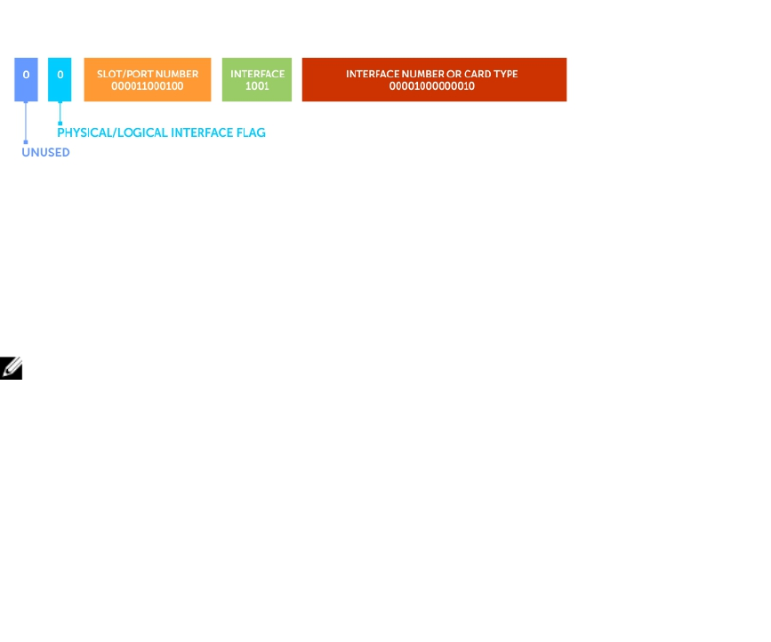
Starting from the least significant bit (LSB) in the preceding figure:
• The first 14 bits represent the card type of a physical interface or the interface number of a logical
interface.
• The next 4 bits represent the interface type.
• The next 12 bits represent the slot and port numbers.
• The next bit is 0 for a physical interface and 1 for a logical interface.
• The last next is unused.
The Slot-Port Number value is derived from the slotId and portId parameters as follows: slotPortNum =
((slotId +1) * IFM_IFINDEX_MAX_PORTS_PER_SLOT + portId).
On the Z9500, the IFM_IFINDEX_MAX_PORTS_PER_SLOT value is 192 (10G). For backward compatibility,
the IFM_IFINDEX_MAX_PORTS_PER_SLOT value is 128 on other Dell Networking switches.
The slotId value is derived as follows: slotId = (slotPortNum / IFM_IFINDEX_MAX_PORTS_PER_SLOT) -1.
The portId value is derived as follows: portId = slotPortNum % IFM_IFINDEX_MAX_PORTS_PER_SLOT.
For example, the interface index 51528196 for the FortyGigE 0/4 port is 0000 0011 0001 0010 0100 0010
0000 0100 in binary format as shown in the following figure.
In this example, if you start from the least significant bit on the right:
• The first 14 bits (00001000000010) identify a Z9500 line card.
• The next 4 bits (1001) identify a 40-Gigabit Ethernet interface.
• The next 12 bits (000011000100) identify slot 0 and port 4.
• The next bit (0) identifies a physical interface.
• The last bit is always 0, which means that it is unused.
NOTE: On the Z9500, the interface index does not change if the interface reloads or fails over.
Monitor Port-Channels
To check the status of a Layer 2 port-channel, use f10LinkAggMib (.1.3.6.1.4.1.6027.3.2). In the following
example, Po 1 is a switchport and Po 2 is in Layer 3 mode.
Example of SNMP Trap for Monitored Port-Channels
[senthilnathan@lithium ~]$ snmpwalk -v 2c -c public 10.11.1.1 .
1.3.6.1.4.1.6027.3.2.1.1
SNMPv2-SMI::enterprises.6027.3.2.1.1.1.1.1.1 = INTEGER: 1
SNMPv2-SMI::enterprises.6027.3.2.1.1.1.1.1.2 = INTEGER: 2
SNMPv2-SMI::enterprises.6027.3.2.1.1.1.1.2.1 = Hex-STRING: 00 01 E8 13 A5 C7
SNMPv2-SMI::enterprises.6027.3.2.1.1.1.1.2.2 = Hex-STRING: 00 01 E8 13 A5 C8
SNMPv2-SMI::enterprises.6027.3.2.1.1.1.1.3.1 = INTEGER: 1107755009
772 Simple Network Management Protocol (SNMP)

SNMPv2-SMI::enterprises.6027.3.2.1.1.1.1.3.2 = INTEGER: 1107755010
SNMPv2-SMI::enterprises.6027.3.2.1.1.1.1.4.1 = INTEGER: 1
SNMPv2-SMI::enterprises.6027.3.2.1.1.1.1.4.2 = INTEGER: 1
SNMPv2-SMI::enterprises.6027.3.2.1.1.1.1.5.1 = Hex-STRING: 00 00
SNMPv2-SMI::enterprises.6027.3.2.1.1.1.1.5.2 = Hex-STRING: 00 00
SNMPv2-SMI::enterprises.6027.3.2.1.1.1.1.6.1 = STRING: "Te 5/84 " << Channel
member for Po1
SNMPv2-SMI::enterprises.6027.3.2.1.1.1.1.6.2 = STRING: "Te 5/85 " << Channel
member for Po2
dot3aCommonAggFdbIndex
SNMPv2-SMI::enterprises.6027.3.2.1.1.6.1.1.1107755009.1 = INTEGER: 1107755009
dot3aCommonAggFdbVlanId
SNMPv2-SMI::enterprises.6027.3.2.1.1.6.1.2.1107755009.1 = INTEGER: 1
dot3aCommonAggFdbTagConfig
SNMPv2-SMI::enterprises.6027.3.2.1.1.6.1.3.1107755009.1 = INTEGER: 2 (Tagged 1 or
Untagged 2)
dot3aCommonAggFdbStatus
SNMPv2-SMI::enterprises.6027.3.2.1.1.6.1.4.1107755009.1 = INTEGER: 1 << Status
active, 2 – status inactive
Example of Viewing Status of Learned MAC Addresses
If we learn MAC addresses for the LAG, status is shown for those as well.
dot3aCurAggVlanId
SNMPv2-SMI::enterprises.6027.3.2.1.1.4.1.1.1.0.0.0.0.0.1.1 = INTEGER: 1
dot3aCurAggMacAddr
SNMPv2-SMI::enterprises.6027.3.2.1.1.4.1.2.1.0.0.0.0.0.1.1 = Hex-STRING: 00 00
00 00 00 01
dot3aCurAggIndex
SNMPv2-SMI::enterprises.6027.3.2.1.1.4.1.3.1.0.0.0.0.0.1.1 = INTEGER: 1
dot3aCurAggStatus
SNMPv2-SMI::enterprises.6027.3.2.1.1.4.1.4.1.0.0.0.0.0.1.1 = INTEGER: 1 << Status
active, 2 – status
inactive
Example of Viewing Changed Interface State for Monitored Ports
Layer 3 LAG does not include this support. SNMP trap works for the Layer 2 / Layer 3 / default mode LAG.
SNMPv2-MIB::sysUpTime.0 = Timeticks: (8500842) 23:36:48.42
SNMPv2-MIB::snmpTrapOID.0 = OID: IF-MIB::linkDown
IF-MIB::ifIndex.33865785 = INTEGER: 33865785
SNMPv2-SMI::enterprises.6027.3.1.1.4.1.2 = STRING: "OSTATE_DN: Changed
interface state to down: Te 0/0"
2010-02-10 14:22:39 10.16.130.4 [10.16.130.4]:
SNMPv2-MIB::sysUpTime.0 = Timeticks: (8500842) 23:36:48.42
SNMPv2-MIB::snmpTrapOID.0 = OID: IF-MIB::linkDown
IF-MIB::ifIndex.1107755009 = INTEGER: 1107755009
SNMPv2-SMI::enterprises.6027.3.1.1.4.1.2 = STRING: "OSTATE_DN: Changed interface
state to down: Po 1"
2010-02-10 14:22:40 10.16.130.4 [10.16.130.4]:
SNMPv2-MIB::sysUpTime.0 = Timeticks: (8500932) 23:36:49.32 SNMPv2-
MIB::snmpTrapOID.0 = OID:
IF-MIB::linkUp IF-MIB::ifIndex.33865785 = INTEGER: 33865785 SNMPv2-
SMI::enterprises.6027.3.1.1.4.1.2 =
STRING: "OSTATE_UP: Changed interface state to up: Te 0/0"
2010-02-10 14:22:40 10.16.130.4 [10.16.130.4]:
SNMPv2-MIB::sysUpTime.0 = Timeticks: (8500934) 23:36:49.34 SNMPv2-
MIB::snmpTrapOID.0 = OID:
IF-MIB::linkUp IF-MIB::ifIndex.1107755009 = INTEGER: 1107755009
SNMPv2-SMI::enterprises.6027.3.1.1.4.1.2 = STRING: "OSTATE_UP: Changed interface
state to up: Po 1"
Simple Network Management Protocol (SNMP) 773
Troubleshooting SNMP Operation
When you use SNMP to retrieve management data from an SNMP agent on a Dell Networking router,
take into account the following behavior.
• When you query an IPv4 icmpMsgStatsInPkts object in the ICMP table by using the snmpwalk
command, the output for echo replies may be incorrectly displayed. To correctly display this
information under ICMP statistics, use the show ip traffic command.
• When you query an icmpStatsInErrors object in the icmpStats table by using the snmpget or
snmpwalk command, the output for IPv4 addresses may be incorrectly displayed. To correctly display
this information under IP and ICMP statistics, use the show ip traffic command.
• When you query an IPv4 icmpMsgStatsInPkts object in the ICMP table by using the snmpwalk
command, the echo response output may not be displayed. To correctly display ICMP statistics, such
as echo response, use the show ip traffic command.
774 Simple Network Management Protocol (SNMP)
47
Storm Control
Storm control allows you to control unknown-unicast and broadcast traffic on Layer 2 and Layer 3
physical interfaces.
Dell Networking OS Behavior: The switch supports broadcast control (the storm-control broadcast
command) for Layer 2 and Layer 3 traffic.
Configure Storm Control
Storm control is supported in INTERFACE mode and CONFIGURATION mode.
Configuring Storm Control from INTERFACE Mode
To configure storm control, use the following command.
From INTERFACE mode:
• You can only on configure storm control for ingress traffic.
• If you configure storm control from both INTERFACE and CONFIGURATION mode, the INTERFACE
mode configurations override the CONFIGURATION mode configurations.
• The percentage of storm control is calculated based on the advertised rate of the line card, not by the
speed setting.
• Configure storm control.
INTERFACE mode
storm control
Configuring Storm Control from CONFIGURATION Mode
To configure storm control from CONFIGURATION mode, use the following command.
From CONFIGURATION mode you can configure storm control for ingress and egress traffic.
Do not apply per-viritual local area network (VLAN) quality of service (QoS) on an interface that has
storm-control enabled (either on an interface or globally).
• Configure storm control.
CONFIGURATION mode
storm control
Storm Control 775
48
Spanning Tree Protocol (STP)
The spanning tree protocol (STP) is a Layer 2 protocol — specified by IEEE 802.1d — that eliminates loops
in a bridged topology by enabling only a single path through the network.
Protocol Overview
By eliminating loops, STP improves scalability in a large network and allows you to implement redundant
paths, which can be activated after the failure of active paths. Layer 2 loops, which can occur in a
network due to poor network design and without enabling protocols like xSTP, can cause unnecessarily
high switch CPU utilization and memory consumption.
The system supports three other versions of spanning tree, as shown in the following table.
Table 48. Dell Networking OS Supported Spanning Tree Protocols
Dell Networking Term IEEE Specification
Spanning Tree Protocol (STP) 802.1d
Rapid Spanning Tree Protocol (RSTP) 802.1w
Multiple Spanning Tree Protocol (MSTP) 802.1s
Per-VLAN Spanning Tree Plus (PVST+) Third Party
Configure Spanning Tree
Configuring spanning tree is a two-step process.
•Configuring Interfaces for Layer 2 Mode
•Enabling Spanning Tree Protocol Globally
Related Configuration Tasks
•Adding an Interface to the Spanning Tree Group
•Modifying Global Parameters
•Modifying Interface STP Parameters
•Enabling PortFast
•Prevent Network Disruptions with BPDU Guard
•STP Root Guard
•Enabling SNMP Traps for Root Elections and Topology Changes
Important Points to Remember
• STP is disabled by default.
776 Spanning Tree Protocol (STP)
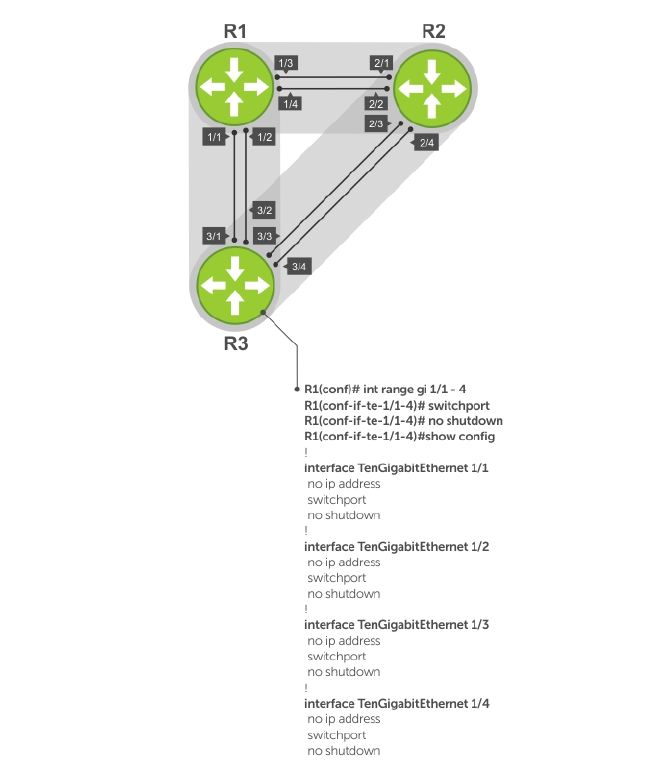
• The Dell Networking OS supports only one spanning tree instance (0). For multiple instances, enable
the multiple spanning tree protocol (MSTP) or per-VLAN spanning tree plus (PVST+). You may only
enable one flavor of spanning tree at any one time.
• All ports in virtual local area networks (VLANs) and all enabled interfaces in Layer 2 mode are
automatically added to the spanning tree topology at the time you enable the protocol.
• To add interfaces to the spanning tree topology after you enable STP, enable the port and configure it
for Layer 2 using the switchport command.
• The IEEE Standard 802.1D allows 8 bits for port ID and 8 bits for priority. The 8 bits for port ID provide
port IDs for 256 ports.
Configuring Interfaces for Layer 2 Mode
All interfaces on all switches that participate in spanning tree must be in Layer 2 mode and enabled.
Figure 105. Example of Configuring Interfaces for Layer 2 Mode
To configure and enable the interfaces for Layer 2, use the following command.
1. If the interface has been assigned an IP address, remove it.
Spanning Tree Protocol (STP) 777

INTERFACE mode
no ip address
2. Place the interface in Layer 2 mode.
INTERFACE
switchport
3. Enable the interface.
INTERFACE mode
no shutdown
Example of the show config Command
To verify that an interface is in Layer 2 mode and enabled, use the show config command from
INTERFACE mode.
Dell(conf-if-te-1/1)#show config
!
interface TenGigabitEthernet 1/1
no ip address
switchport
no shutdown
Dell(conf-if-te-1/1)#
Enabling Spanning Tree Protocol Globally
Enable the spanning tree protocol globally; it is not enabled by default.
When you enable STP, all physical, VLAN, and port-channel interfaces that are enabled and in Layer 2
mode are automatically part of the Spanning Tree topology.
• Only one path from any bridge to any other bridge participating in STP is enabled.
• Bridges block a redundant path by disabling one of the link ports.
778 Spanning Tree Protocol (STP)
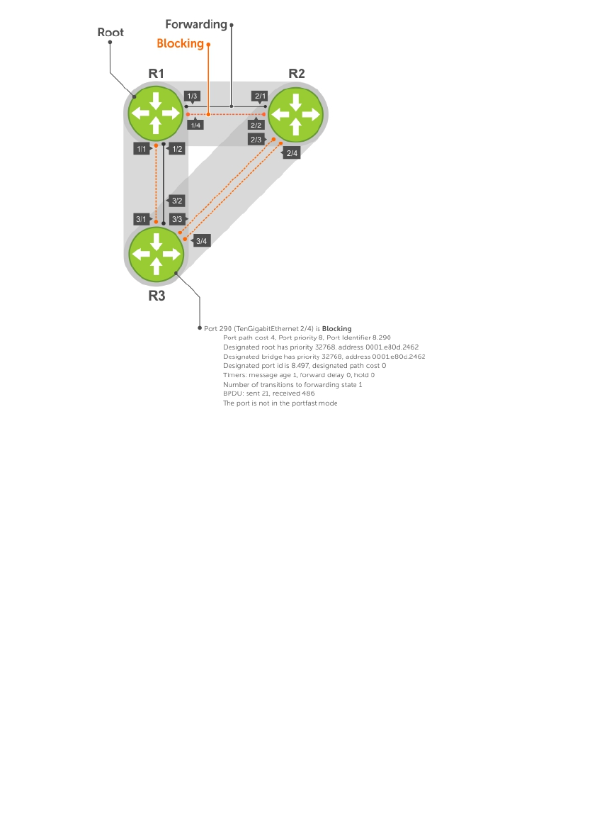
Figure 106. Spanning Tree Enabled Globally
To enable STP globally, use the following commands.
1. Enter PROTOCOL SPANNING TREE mode.
CONFIGURATION mode
protocol spanning-tree 0
2. Enable STP.
PROTOCOL SPANNING TREE mode
no disable
Examples of Verifying and Viewing Spanning Tree
To disable STP globally for all Layer 2 interfaces, use the disable command from PROTOCOL
SPANNING TREE mode.
To verify that STP is enabled, use the show config command from PROTOCOL SPANNING TREE mode.
Dell(conf)#protocol spanning-tree 0
Dell(config-span)#show config
!
protocol spanning-tree 0
no disable
Dell#
Spanning Tree Protocol (STP) 779

To view the spanning tree configuration and the interfaces that are participating in STP, use the show
spanning-tree 0 command from EXEC privilege mode. If a physical interface is part of a port channel,
only the port channel is listed in the command output.
R2#show spanning-tree 0
Executing IEEE compatible Spanning Tree Protocol
Bridge Identifier has priority 32768, address 0001.e826.ddb7
Configured hello time 2, max age 20, forward delay 15
Current root has priority 32768, address 0001.e80d.2462
Root Port is 289 (TenGigabitEthernet 2/1), cost of root path is 4
Topology change flag not set, detected flag not set
Number of topology changes 3 last change occurred 0:16:11 ago
from TenGigabitEthernet 2/3
Timers: hold 1, topology change 35
hello 2, max age 20, forward delay 15
Times: hello 0, topology change 0, notification 0, aging Normal
Port 289 (TenGigabitEthernet 2/1) is Forwarding
Port path cost 4, Port priority 8, Port Identifier 8.289
Designated root has priority 32768, address 0001.e80d.2462
Designated bridge has priority 32768, address 0001.e80d.2462
Designated port id is 8.496, designated path cost 0
Timers: message age 1, forward delay 0, hold 0
Number of transitions to forwarding state 1
BPDU: sent 21, received 486
The port is not in the portfast mode
Port 290 (TenGigabitEthernet 2/2) is Blocking
Port path cost 4, Port priority 8, Port Identifier 8.290
--More--
Timers: message age 1, forward delay 0, hold 0
Number of transitions to forwarding state 1
BPDU: sent 21, received 486
The port is not in the portfast mode
To confirm that a port is participating in Spanning Tree, use the show spanning-tree 0 brief
command from EXEC privilege mode.
Dell#show spanning-tree 0 brief
Executing IEEE compatible Spanning Tree Protocol
Root ID Priority 32768, Address 0001.e80d.2462
We are the root of the spanning tree
Root Bridge hello time 2, max age 20, forward delay 15
Bridge ID Priority 32768, Address 0001.e80d.2462
Configured hello time 2, max age 20, forward delay 15
Interface Designated
Name PortID Prio Cost Sts Cost Bridge ID PortID
-------------- ------ ---- ---- --- ----- --------------------
Te 1/1 8.496 8 4 DIS 0 32768 0001.e80d.2462 8.496
Te 1/2 8.497 8 4 DIS 0 32768 0001.e80d.2462 8.497
Te 1/3 8.513 8 4 FWD 0 32768 0001.e80d.2462 8.513
Te 1/4 8.514 8 4 FWD 0 32768 0001.e80d.2462 8.514
Dell#
Adding an Interface to the Spanning Tree Group
To add a Layer 2 interface to the spanning tree topology, use the following command.
• Enable spanning tree on a Layer 2 interface.
INTERFACE mode
780 Spanning Tree Protocol (STP)

spanning-tree 0
To remove a Layer 2 interface from the spanning tree topology, enter the no spanning-tree 0
command.
Modifying Global Parameters
You can modify the spanning tree parameters. The root bridge sets the values for forward-delay, hello-
time, and max-age and overwrites the values set on other bridges participating in STP.
NOTE: Dell Networking recommends that only experienced network administrators change the
spanning tree parameters. Poorly planned modification of the spanning tree parameters can
negatively affect network performance.
The following table displays the default values for STP.
Table 49. STP Default Values
STP Parameters Default Value
Forward Delay 15 seconds
Hello Time 2 seconds
Max Age 20 seconds
Port Cost
• 100-Mb/s Ethernet interfaces
• 1-Gigabit Ethernet interfaces
• 10-Gigabit Ethernet interfaces
• Port Channel with 100 Mb/s Ethernet interfaces
• Port Channel with 1-Gigabit Ethernet interfaces
• Port Channel with 10-Gigabit Ethernet
interfaces
• 19
• 4
• 2
• 18
• 3
• 1
Port Priority 8
• Change the forward-delay parameter (the wait time before the interface enters the Forwarding
state).
PROTOCOL SPANNING TREE mode
forward-delay seconds
The range is from 4 to 30.
The default is 15 seconds.
• Change the hello-time parameter (the BPDU transmission interval).
PROTOCOL SPANNING TREE mode
hello-time seconds
NOTE: With large configurations (especially those with more ports) Dell Networking
recommends increasing the hello-time.
The range is from 1 to 10.
Spanning Tree Protocol (STP) 781

the default is 2 seconds.
• Change the max-age parameter (the refresh interval for configuration information that is generated
by recomputing the spanning tree topology).
PROTOCOL SPANNING TREE mode
max-age seconds
The range is from 6 to 40.
The default is 20 seconds.
To view the current values for global parameters, use the show spanning-tree 0 command from
EXEC privilege mode. Refer to the second example in Enabling Spanning Tree Protocol Globally.
Modifying Interface STP Parameters
You can set the port cost and port priority values of interfaces in Layer 2 mode.
•Port cost — a value that is based on the interface type. The greater the port cost, the less likely the
port is selected to be a forwarding port.
•Port priority — influences the likelihood that a port is selected to be a forwarding port in case that
several ports have the same port cost.
The default values are listed in Modifying Global Parameters.
To change the port cost or priority of an interface, use the following commands.
• Change the port cost of an interface.
INTERFACE mode
spanning-tree 0 cost cost
The range is from 0 to 65535.
The default values are listed in Modifying Global Parameters.
• Change the port priority of an interface.
INTERFACE mode
spanning-tree 0 priority priority-value
The range is from 0 to 15.
The default is 8.
To view the current values for interface parameters, use the show spanning-tree 0 command from
EXEC privilege mode. Refer to the second example in Enabling Spanning Tree Protocol Globally.
Enabling PortFast
The PortFast feature enables interfaces to begin forwarding traffic approximately 30 seconds sooner.
Interfaces forward frames by default until they receive a BPDU that indicates that they should behave
otherwise; they do not go through the Learning and Listening states. The bpduguard shutdown-on-
violation option causes the interface hardware to be shut down when it receives a BPDU. When you
782 Spanning Tree Protocol (STP)

only implement bpduguard, although the interface is placed in an Error Disabled state when receiving
the BPDU, the physical interface remains up and spanning-tree drops packets in the hardware after a
BPDU violation. BPDUs are dropped in the software after receiving the BPDU violation.
CAUTION: Enable PortFast only on links connecting to an end station. PortFast can cause loops if
it is enabled on an interface connected to a network.
To enable PortFast on an interface, use the following command.
• Enable PortFast on an interface.
INTERFACE mode
spanning-tree stp-id portfast [bpduguard | [shutdown-on-violation]]
Example of Verifying PortFast is Enabled on an Interface
To verify that PortFast is enabled on a port, use the show spanning-tree command from EXEC
Privilege mode or the show config command from INTERFACE mode. Dell Networking recommends
using the show config command.
Dell#(conf-if-te-1/1)#show conf
!
interface TenGigabitEthernet 1/1
no ip address
switchport
spanning-tree 0 portfast
no shutdown
Dell#(conf-if-te-1/1)#
Preventing Network Disruptions with BPDU Guard
Configure the Portfast (and Edgeport, in the case of RSTP, PVST+, and MSTP) feature on ports that
connect to end stations. End stations do not generate BPDUs, so ports configured with Portfast/ Edgport
(edgeports) do not expect to receive BDPUs.
If an edgeport does receive a BPDU, it likely means that it is connected to another part of the network,
which can negatively affect the STP topology. The BPDU Guard feature blocks an edgeport after
receiving a BPDU to prevent network disruptions, and the system displays the following message.
3w3d0h: %SYSTEM-P:RP2 %SPANMGR-5-BPDU_GUARD_RX_ERROR: Received Spanning Tree
BPDU on
BPDU guard port. Disable TenGigabitEthernet 3/41.
Enable BPDU Guard using the bpduguard option when enabling PortFast or EdgePort. The bpduguard
shutdown-on-violation option causes the interface hardware to be shut down when it receives a
BPDU. Otherwise, although the interface is placed in an Error Disabled state when receiving the BPDU,
the physical interface remains up and spanning-tree will only drop packets after a BPDU violation.
The following example shows a scenario in which an edgeport might unintentionally receive a BPDU. The
port on the Dell Networking system is configured with Portfast. If the switch is connected to the hub, the
BPDUs that the switch generates might trigger an undesirable topology change. If you enable BPDU
Guard, when the edge port receives the BPDU, the BPDU is dropped, the port is blocked, and a console
message is generated.
NOTE: Unless you enable the shutdown-on-violation option, spanning-tree only drops packets
after a BPDU violation; the physical interface remains up.
Dell Networking OS Behavior: Regarding bpduguard shutdown-on-violation behavior:
Spanning Tree Protocol (STP) 783
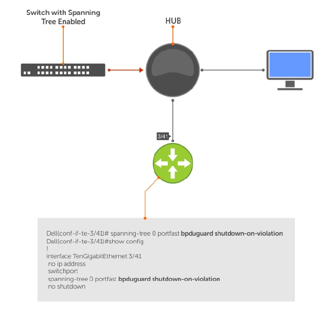
• If the interface to be shut down is a port channel, all the member ports are disabled in the hardware.
• When you add a physical port to a port channel already in the Error Disable state, the new member
port is also disabled in the hardware.
• When you remove a physical port from a port channel in the Error Disable state, the Error Disabled
state is cleared on this physical port (the physical port is enabled in the hardware).
• The reset linecard command does not clear the Error Disabled state of the port or the Hardware
Disabled state. The interface continues to be disables in the hardware.
• You can clear the Error Disabled state with any of the following methods:
– Perform a shutdown command on the interface.
– Disable the shutdown-on-violation command on the interface (the no spanning-tree
stp-id portfast [bpduguard | [shutdown-on-violation]] command).
– Disable spanning tree on the interface (the no spanning-tree command in INTERFACE mode).
– Disabling global spanning tree (the no spanning-tree in CONFIGURATION mode).
Figure 107. Enabling BPDU Guard
Dell Networking OS Behavior: BPDU guard and BPDU filtering both block BPDUs, but are two separate
features.
BPDU guard:
• is used on edgeports and blocks all traffic on edgeport if it receives a BPDU.
• drops the BPDU after it reaches the Route Processor and generates a console message.
BPDU filtering:
784 Spanning Tree Protocol (STP)

• disables spanning tree on an interface
• drops all BPDUs at the line card without generating a console message
Example of Blocked BPDUs
Dell(conf-if-te-0/7)#do show spanning-tree rstp brief
Executing IEEE compatible Spanning Tree Protocol
Root ID Priority 32768, Address 0001.e805.fb07
Root Bridge hello time 2, max age 20, forward delay 15
Bridge ID Priority 32768, Address 0001.e85d.0e90
Configured hello time 2, max age 20, forward delay 15
Interface Designated
Name PortID Prio Cost Sts Cost Bridge ID PortID
---------- -------- ---- ------- --- ------- --------------------
Te 0/6 128.263 128 20000 FWD 20000 32768 0001.e805.fb07 128.653
Te 0/7 128.264 128 20000 EDS 20000 32768 0001.e85d.0e90 128.264
Interface
Name Role PortID Prio Cost Sts Cost Link-type Edge
---------- ------ -------- ---- ------- --- ----------------
Te 0/6 Root 128.263 128 20000 FWD 20000 P2P No
Te 0/7 ErrDis 128.264 128 20000 EDS 20000 P2P No
Dell(conf-if-te-0/7)#do show ip int br te 0/7
Interface IP-Address OK Method Status Protocol
TenGigabitEthernet 0/7 unassigned YES Manual up up
Selecting STP Root
The STP determines the root bridge, but you can assign one bridge a lower priority to increase the
likelihood that it becomes the root bridge. You can also specify that a bridge is the root or the secondary
root.
To change the bridge priority or specify that a bridge is the root or secondary root, use the following
command.
• Assign a number as the bridge priority or designate it as the root or secondary root.
PROTOCOL SPANNING TREE mode
bridge-priority {priority-value | primary | secondary}
–priority-value: the range is from 0 to 65535. The lower the number assigned, the more likely
this bridge becomes the root bridge.
The primary option specifies a bridge priority of 8192.
The secondary option specifies a bridge priority of 16384.
The default is 32768.
Example of Viewing STP Root Information
To view only the root information, use the show spanning-tree root command from EXEC privilege
mode.
Dell#show spanning-tree 0 root
Root ID Priority 32768, Address 0001.e80d.2462
We are the root of the spanning tree
Spanning Tree Protocol (STP) 785

Root Bridge hello time 2, max age 20, forward delay 15
Dell#
STP Root Guard
Use the STP root guard feature in a Layer 2 network to avoid bridging loops.
In STP, the switch in the network with the lowest priority (as determined by STP or set with the bridge-
priority command) is selected as the root bridge. If two switches have the same priority, the switch
with the lower MAC address is selected as the root. All other switches in the network use the root bridge
as the reference used to calculate the shortest forwarding path.
Because any switch in an STP network with a lower priority can become the root bridge, the forwarding
topology may not be stable. The location of the root bridge can change, resulting in unpredictable
network behavior. The STP root guard feature ensures that the position of the root bridge does not
change.
Root Guard Scenario
For example, as shown in the following illustration (STP topology 1, upper left) Switch A is the root bridge
in the network core. Switch C functions as an access switch connected to an external device. The link
between Switch C and Switch B is in a Blocking state. The flow of STP BPDUs is shown in the illustration.
In STP topology 2 (shown in the upper right), STP is enabled on device D on which a software bridge
application is started to connect to the network. Because the priority of the bridge in device D is lower
than the root bridge in Switch A, device D is elected as root, causing the link between Switches A and B to
enter a Blocking state. Network traffic then begins to flow in the directions indicated by the BPDU arrows
in the topology. If the links between Switches C and A or Switches C and B cannot handle the increased
traffic flow, frames may be dropped.
In STP topology 3 (shown in the lower middle), if you have enabled the root guard feature on the STP
port on Switch C that connects to device D, and device D sends a superior BPDU that would trigger the
election of device D as the new root bridge, the BPDU is ignored and the port on Switch C transitions
from a forwarding to a root-inconsistent state (shown by the green X icon). As a result, Switch A becomes
the root bridge.
786 Spanning Tree Protocol (STP)
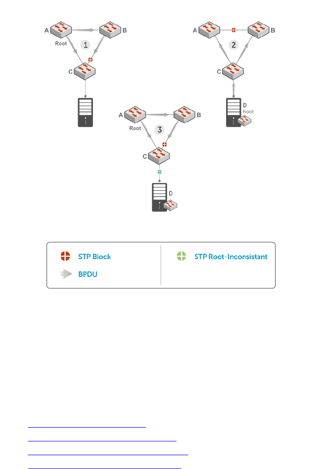
Figure 108. STP Root Guard Prevents Bridging Loops
Configuring Root Guard
Enable STP root guard on a per-port or per-port-channel basis.
Dell Networking OS Behavior: The following conditions apply to a port enabled with STP root guard:
• Root guard is supported on any STP-enabled port or port-channel interface.
• Root guard is supported on a port in any Spanning Tree mode:
–Spanning Tree Protocol (STP)
–Rapid Spanning Tree Protocol (RSTP)
–Multiple Spanning Tree Protocol (MSTP)
–Per-VLAN Spanning Tree Plus (PVST+)
• When enabled on a port, root guard applies to all VLANs configured on the port.
• You cannot enable root guard and loop guard at the same time on an STP port. For example, if you
configure root guard on a port on which loop guard is already configured, the following error
message displays: • % Error: LoopGuard is configured. Cannot configure RootGuard.
• When used in an MSTP network, if root guard blocks a boundary port in the CIST, the port is also
blocked in all other MST instances.
To enable the root guard on an STP-enabled port or port-channel interface in instance 0, use the
following command.
• Enable root guard on a port or port-channel interface.
Spanning Tree Protocol (STP) 787
INTERFACE mode or INTERFACE PORT-CHANNEL mode
spanning-tree {0 | mstp | rstp | pvst} rootguard
–0: enables root guard on an STP-enabled port assigned to instance 0.
–mstp: enables root guard on an MSTP-enabled port.
–rstp: enables root guard on an RSTP-enabled port.
–pvst: enables root guard on a PVST-enabled port.
To disable STP root guard on a port or port-channel interface, use the no spanning-tree 0
rootguard command in an interface configuration mode.
To verify the STP root guard configuration on a port or port-channel interface, use the show spanning-
tree 0 guard [interface interface] command in a global configuration mode.
Enabling SNMP Traps for Root Elections and Topology
Changes
To enable SNMP traps individually or collectively, use the following commands.
• Enable SNMP traps for spanning tree state changes.
snmp-server enable traps stp
• Enable SNMP traps for RSTP, MSTP, and PVST+ collectively.
snmp-server enable traps xstp
STP Loop Guard
The STP loop guard feature provides protection against Layer 2 forwarding loops (STP loops) caused by a
hardware failure, such as a cable failure or an interface fault.
When a cable or interface fails, a participating STP link may become unidirectional (STP requires links to
be bidirectional) and an STP port does not receive BPDUs. When an STP blocking port does not receive
BPDUs, it transitions to a Forwarding state. This condition can create a loop in the network.
For example, in the following example (STP topology 1, upper left), Switch A is the root switch and Switch
B normally transmits BPDUs to Switch C. The link between Switch C and Switch B is in a Blocking state.
However, if there is a unidirectional link failure (STP topology 1, lower left), Switch C does not receive
BPDUs from Switch B. When the max-age timer expires, the STP port on Switch C becomes unblocked
and transitions to Forwarding state. A loop is created as both Switch A and Switch C transmit traffic to
Switch B.
As shown in the following illustration (STP topology 2, upper right), a loop can also be created if the
forwarding port on Switch B becomes busy and does not forward BPDUs within the configured
forward-delay time. As a result, the blocking port on Switch C transitions to a forwarding state, and
both Switch A and Switch C transmit traffic to Switch B (STP topology 2, lower right).
As shown in STP topology 3 (bottom middle), after you enable loop guard on an STP port or port-channel
on Switch C, if no BPDUs are received and the max-age timer expires, the port transitions from a blocked
state to a Loop-Inconsistent state (instead of to a Forwarding state). Loop guard blocks the STP port so
that no traffic is transmitted and no loop is created.
788 Spanning Tree Protocol (STP)
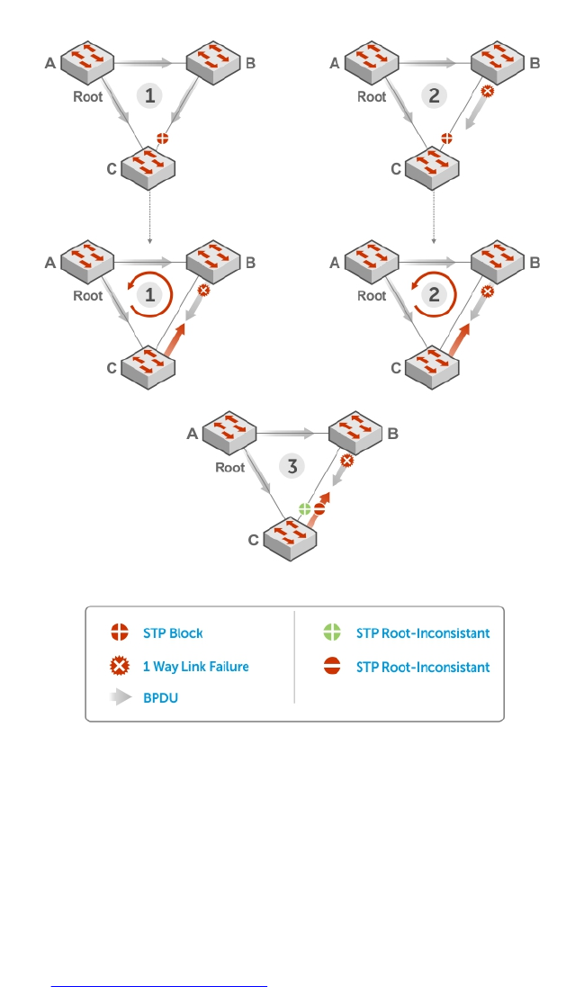
As soon as a BPDU is received on an STP port in a Loop-Inconsistent state, the port returns to a blocking
state. If you disable STP loop guard on a port in a Loop-Inconsistent state, the port transitions to an STP
blocking state and restarts the max-age timer.
Figure 109. STP Loop Guard Prevents Forwarding Loops
Configuring Loop Guard
Enable STP loop guard on a per-port or per-port channel basis.
The following conditions apply to a port enabled with loop guard:
• Loop guard is supported on any STP-enabled port or port-channel interface.
• Loop guard is supported on a port or port-channel in any spanning tree mode:
–Spanning Tree Protocol (STP)
Spanning Tree Protocol (STP) 789

–Rapid Spanning Tree Protocol (RSTP)
–Multiple Spanning Tree Protocol (MSTP)
–Per-VLAN Spanning Tree Plus (PVST+)
• You cannot enable root guard and loop guard at the same time on an STP port. For example, if you
configure loop guard on a port on which root guard is already configured, the following error
message is displayed: % Error: RootGuard is configured. Cannot configure LoopGuard.
• Enabling Portfast BPDU guard and loop guard at the same time on a port results in a port that remains
in a blocking state and prevents traffic from flowing through it. For example, when Portfast BPDU
guard and loop guard are both configured:
– If a BPDU is received from a remote device, BPDU guard places the port in an Err-Disabled
Blocking state and no traffic is forwarded on the port.
– If no BPDU is received from a remote device, loop guard places the port in a Loop-Inconsistent
Blocking state and no traffic is forwarded on the port.
• When used in a PVST+ network, STP loop guard is performed per-port or per-port channel at a VLAN
level. If no BPDUs are received on a VLAN interface, the port or port-channel transitions to a Loop-
Inconsistent (Blocking) state only for this VLAN.
To enable a loop guard on an STP-enabled port or port-channel interface, use the following command.
• Enable loop guard on a port or port-channel interface.
INTERFACE mode or INTERFACE PORT-CHANNEL mode
spanning-tree {0 | mstp | rstp | pvst} loopguard
–0: enables loop guard on an STP-enabled port assigned to instance 0.
–mstp: enables loop guard on an MSTP-enabled port.
–rstp: enables loop guard on an RSTP-enabled port.
–pvst: enables loop guard on a PVST-enabled port.
To disable STP loop guard on a port or port-channel interface, use the no spanning-tree 0
loopguard command in an INTERFACE configuration mode.
To verify the STP loop guard configuration on a port or port-channel interface, use the show spanning-
tree 0 guard [interface interface] command in a global configuration mode.
Displaying STP Guard Configuration
To display the STP guard configuration, use the following command.
The following example shows an STP network (instance 0) in which:
• Root guard is enabled on a port that is in a root-inconsistent state.
• Loop guard is enabled on a port that is in a listening state.
• BPDU guard is enabled on a port that is shut down (Error Disabled state) after receiving a BPDU.
• Verify the STP guard configured on port or port-channel interfaces.
show spanning-tree 0 guard [interface interface]
Example of Viewing STP Guard Configuration
Dell#show spanning-tree 0 guard
Interface
Name Instance Sts Guard type
--------- -------- --------- ----------
Te 0/1 0 INCON(Root) Rootguard
790 Spanning Tree Protocol (STP)

Te 0/2 0 LIS Loopguard
Te 0/3 0 EDS (Shut) Bpduguard
Spanning Tree Protocol (STP) 791
49
System Time and Date
System time and date settings are user-configurable and maintained through the network time protocol
(NTP).
System times and dates are also set in hardware settings using the Dell Networking OS CLI.
Network Time Protocol
The network time protocol (NTP) synchronizes timekeeping among a set of distributed time servers and
clients.
The protocol also coordinates time distribution in a large, diverse network with various interfaces. In NTP,
servers maintain the time and NTP clients synchronize with a time-serving host. NTP clients choose from
among several NTP servers to determine which offers the best available source of time and the most
reliable transmission of information.
NTP is a fault-tolerant protocol that automatically selects the best of several available time sources to
synchronize to. You can combine multiple candidates to minimize the accumulated error. Temporarily or
permanently insane time sources are detected and avoided.
Dell Networking recommends configuring NTP for the most accurate time. Using the CLI, you can
configure other time sources (the hardware clock and the software clock).
NTP is designed to produce three products: clock offset, roundtrip delay, and dispersion, all of which are
relative to a selected reference clock.
•Clock offset — represents the amount to adjust the local clock to bring it into correspondence with
the reference clock.
•Roundtrip delay — provides the capability to launch a message to arrive at the reference clock at a
specified time.
•Dispersion — represents the maximum error of the local clock relative to the reference clock.
Because most host time servers synchronize via another peer time server, there are two components in
each of these three products, those determined by the peer relative to the primary reference source of
standard time and those measured by the host relative to the peer.
In order to facilitate error control and management of the subnet itself, each of these components is
maintained separately in the protocol. They provide not only precision measurements of offset and delay,
but also definitive maximum error bounds, so that the user interface can determine not only the time, but
the quality of the time as well.
In what may be the most common client/server model, a client sends an NTP message to one or more
servers and processes the replies as received. The server interchanges addresses and ports, overwrites
certain fields in the message, recalculates the checksum and returns the message immediately.
Information included in the NTP message allows the client to determine the server time regarding local
time and adjust the local clock accordingly. In addition, the message includes information to calculate
the expected timekeeping accuracy and reliability, as well as select the best from possibly several servers.
792 System Time and Date
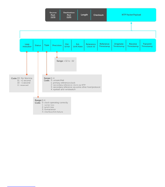
Following conventions established by the telephone industry [BEL86], the accuracy of each server is
defined by a number called the stratum, with the topmost level (primary servers) assigned as one and
each level downwards (secondary servers) in the hierarchy assigned as one greater than the preceding
level.
The system synchronizes with a time-serving host to get the correct time. You can set the system to poll
specific NTP time-serving hosts for the current time. From those time-serving hosts, the system chooses
one NTP host with which to synchronize and serve as a client to the NTP host. As soon as a host-client
relationship is established, the networking device propagates the time information throughout its local
network.
Protocol Overview
The NTP messages to one or more servers and processes the replies as received. The server interchanges
addresses and ports, fills in or overwrites certain fields in the message, recalculates the checksum, and
returns it immediately.
Information included in the NTP message allows each client/server peer to determine the timekeeping
characteristics of its other peers, including the expected accuracies of their clocks. Using this
information, each peer is able to select the best time from possibly several other clocks, update the local
clock, and estimate its accuracy.
Figure 110. NTP Fields
Implementation Information
Dell Networking systems can only be an NTP client.
Configure the Network Time Protocol
Configuring NTP is a one-step process.
•Enabling NTP
System Time and Date 793

Related Configuration Tasks
•Configuring NTP Broadcasts
•Setting the Hardware Clock with the Time Derived from NTP
•Disabling NTP on an Interface
•Configuring a Source IP Address for NTP Packets (optional)
Enabling NTP
NTP is disabled by default.
To enable NTP, specify an NTP server to which the Dell Networking system synchronizes. To specify
multiple servers, enter the command multiple times. You may specify an unlimited number of servers at
the expense of CPU resources.
• Specify the NTP server to which the Dell Networking system synchronizes.
CONFIGURATION mode
ntp server ip-address
Example of Viewing the System Clock State
To display the system clock state with respect to NTP, use the show ntp status command from EXEC
Privilege mode.
R6(conf)#do show ntp status
Clock is synchronized, stratum 2, reference is 192.168.1.1
frequency is -369.623 ppm, stability is 53.319 ppm, precision is 4294967279
reference time is CD63BCC2.0CBBD000 (16:54:26.049 UTC Thu Mar 12 2009)
clock offset is 997.529984 msec, root delay is 0.00098 sec
root dispersion is 10.04271 sec, peer dispersion is 10032.715 msec
peer mode is client
To display the calculated NTP synchronization variables received from the server that the system uses to
synchronize its clock, use the show ntp associations command from EXEC Privilege mode.
R6(conf)#do show ntp associations
remote ref clock st when poll reach delay offset disp
==========================================================
#192.168.1.1 .LOCL. 1 16 16 76 0.98 -2.470 879.23
* master (synced), # master (unsynced), + selected, - candidate
Setting the Hardware Clock with the Time Derived from NTP
To set the hardware clock, use the following command.
• Periodically update the system hardware clock with the time value derived from NTP.
CONFIGURATION mode
ntp update-calendar
Example of Updating the System Clock Relative to NTP
R5/R8(conf)#do show calendar
06:31:02 UTC Mon Mar 13 1989
R5/R8(conf)#ntp update-calendar 1
R5/R8(conf)#do show calendar
06:31:26 UTC Mon Mar 13 1989
794 System Time and Date

R5/R8(conf)#do show calendar
12:24:11 UTC Thu Mar 12 2009
Configuring NTP Broadcasts
The switch can receive broadcasts of time information.
You can set interfaces within the system to receive NTP information through broadcast.
To configure an interface to receive NTP broadcasts, use the following commands.
• Set the interface to receive NTP packets.
INTERFACE mode
ntp broadcast client
Example of Configuring NTP Broadcasts
2w1d11h : NTP: Maximum Slew:-0.000470, Remainder = -0.496884
Disabling NTP on an Interface
By default, NTP is enabled on all active interfaces. If you disable NTP on an interface, the system drops
any NTP packets sent to that interface.
To disable NTP on an interface, use the following command.
• Disable NTP on the interface.
INTERFACE mode
ntp disable
To view whether NTP is configured on the interface, use the show config command in INTERFACE
mode. If ntp disable is not listed in the show config command output, NTP is enabled. (The show
config command displays only non-default configuration information.)
Configuring a Source IP Address for NTP Packets
By default, the source address of NTP packets is the IP address of the interface used to reach the
network.
You can configure one interface’s IP address include in all NTP packets.
To configure an IP address as the source address of NTP packets, use the following command.
• Configure a source IP address for NTP packets.
CONFIGURATION mode
ntp source interface
Enter the following keywords and slot/port or number information:
– For a loopback interface, enter the keyword loopback then a number between 0 and 16383.
– For a port channel interface, enter the keyword lag then a number from 1 to 255.
– For a 10-Gigabit Ethernet interface, enter the keyword TenGigabitEthernet then the slot/port
information.
– For a 40-Gigabit Ethernet interface, enter the keyword fortyGigE then the slot/port information.
– For a VLAN interface, enter the keyword vlan then a number from 1 to 4094.
System Time and Date 795

To view the configuration, use the show running-config ntp command in EXEC privilege mode
(refer to the example in Configuring NTP Authentication).
Configuring NTP Authentication
NTP authentication and the corresponding trusted key provide a reliable means of exchanging NTP
packets with trusted time sources.
NTP authentication begins when the first NTP packet is created following the configuration of keys. In the
Dell Networking OS, NTP authentication uses the message digest 5 (MD5) algorithm and the key is
embedded in the synchronization packet that is sent to an NTP time source.
Dell Networking OS Behavior: The system uses a data encryption standard (DES) encryption to store the
key in the startup-config when you enter the ntp authentication-key command.
To configure NTP authentication, use the following commands.
1. Enable NTP authentication.
CONFIGURATION mode
ntp authenticate
2. Set an authentication key.
CONFIGURATION mode
ntp authentication-key number md5 key
Configure the following parameters:
•number: the range is from 1 to 4294967295. This number must be the same as the number in the
ntp trusted-key command.
•key: enter a text string. This text string is encrypted.
3. Define a trusted key.
CONFIGURATION mode
ntp trusted-key number
Configure a number from 1 to 4294967295.
The number must be the same as the number used in the ntp authentication-key command.
4. Configure an NTP server.
CONFIGURATION mode
ntp server ip-address [key keyid] [prefer] [version number]
Configure the IP address of a server and the following optional parameters:
•key keyid: configure a text string as the key exchanged between the NTP server and the client.
•prefer: enter the keyword prefer to set this NTP server as the preferred server.
•version number: enter a number as the NTP version. The range is from 1 to 3.
Example of Configuring and Viewing an NTP Configuration
The following example shows configuring an NTP server.
R6_E300(conf)#1w6d23h : NTP: xmit packet to 192.168.1.1:
leap 0, mode 3, version 3, stratum 2, ppoll 1024
rtdel 0219 (8.193970), rtdsp AF928 (10973.266602), refid C0A80101
796 System Time and Date

(192.168.1.1)
ref CD7F4F63.6BE8F000 (14:51:15.421 UTC Thu Apr 2 2009)
org CD7F4F63.68000000 (14:51:15.406 UTC Thu Apr 2 2009)
rec CD7F4F63.6BE8F000 (14:51:15.421 UTC Thu Apr 2 2009)
xmt CD7F5368.D0535000 (15:8:24.813 UTC Thu Apr 2 2009)
1w6d23h : NTP: rcv packet from 192.168.1.1
leap 0, mode 4, version 3, stratum 1, ppoll 1024
rtdel 0000 (0.000000), rtdsp AF587 (10959.090820), refid 4C4F434C
(76.79.67.76)
ref CD7E14FD.43F7CED9 (16:29:49.265 UTC Wed Apr 1 2009)
org CD7F5368.D0535000 (15:8:24.813 UTC Thu Apr 2 2009)
rec CD7F5368.D0000000 (15:8:24.812 UTC Thu Apr 2 2009)
xmt CD7F5368.D0000000 (15:8:24.812 UTC Thu Apr 2 2009)
inp CD7F5368.D1974000 (15:8:24.818 UTC Thu Apr 2 2009)
rtdel-root delay
rtdsp - round trip dispersion
refid - reference id
org -
rec - (last?) receive timestamp
xmt - transmit timestamp
mode - 3 client, 4 server
stratum - 1 primary reference clock, 2 secondary reference clock (via NTP)
version - NTP version 3
leap -
System Time and Date 797

NOTE:
•Leap Indicator (sys.leap, peer.leap, pkt.leap) — This is a two-bit code warning of an
impending leap second to be inserted in the NTP time scale. The bits are set before 23:59 on the
day of insertion and reset after 00:00 on the following day. This causes the number of seconds
(rollover interval) in the day of insertion to be increased or decreased by one. In the case of
primary servers, the bits are set by operator intervention, while in the case of secondary servers,
the bits are set by the protocol. The two bits, bit 0, and bit 1, respectively, are coded as follows:
•Poll Interval — integer indicating the minimum interval between transmitted messages, in
seconds as a power of two. For instance, a value of six indicates a minimum interval of 64
seconds.
•Precision — integer indicating the precision of the various clocks, in seconds to the nearest
power of two. The value must be rounded to the next larger power of two; for instance, a 50 Hz
(20 ms) or 60 Hz (16.67ms) power-frequency clock is assigned the value -5 (31.25 ms), while a
1000 Hz (1 ms) crystal-controlled clock is assigned the value -9 (1.95 ms).
•Root Delay (sys.rootdelay, peer.rootdelay, pkt.rootdelay) — a signed fixed-point
number indicating the total round-trip delay to the primary reference source at the root of the
synchronization subnet, in seconds. This variable can take on both positive and negative values,
depending on clock precision and skew.
•Root Dispersion (sys.rootdispersion, peer.rootdispersion, pkt.rootdispersion) —
a signed fixed-point number indicating the maximum error relative to the primary reference
source at the root of the synchronization subnet, in seconds. Only positive values greater than
zero are possible.
•Reference Clock Identifier (sys.refid, peer.refid, pkt.refid) — This is a 32-bit code
identifying the particular reference clock. In the case of stratum 0 (unspecified) or stratum 1
(primary reference source), this is a four-octet, left-justified, zero-padded ASCII string, for
example: in the case of stratum 2 and greater (secondary reference) this is the four-octet
internet address of the peer selected for synchronization.
•Reference Timestamp (sys.reftime, peer.reftime, pkt.reftime) — This is the local time,
in timestamp format, when the local clock was last updated. If the local clock has never been
synchronized, the value is zero.
•Originate Timestamp: The departure time on the server of its last NTP message. If the server
becomes unreachable, the value is set to zero.
•Receive Timestamp — the arrival time on the client of the last NTP message from the server. If
the server becomes unreachable, the value is set to zero.
•Transmit Timestamp — the departure time on the server of the current NTP message from the
sender.
•Filter dispersion — the error in calculating the minimum delay from a set of sample data from a
peer.
To view the NTP configuration, use the show running-config ntp command in EXEC privilege mode.
The following example shows an encrypted authentication key (in bold). All keys are encrypted.
Dell#show running ntp
!
ntp authenticate
ntp authentication-key 345 md5 5A60910F3D211F02
ntp server 11.1.1.1 version 3
ntp trusted-key 345
Dell#
798 System Time and Date

Time and Date
You can set the time and date in the Dell Networking OS using the CLI.
Configuration Task List
The following is a configuration task list for configuring the time and date settings.
•Setting the Time and Date for the Switch Hardware Clock
•Setting the Time and Date for the Switch Software Clock
•Setting the Timezone
•Setting Daylight Saving Time Once
•Setting Recurring Daylight Saving Time
Setting the Time and Date for the Switch Hardware Clock
To set the time and date for the switch hardware clock, use the following command.
• Set the hardware clock to the current time and date.
EXEC Privilege mode
calendar set time month day year
–time: enter the time in hours:minutes:seconds. For the hour variable, use the 24-hour format; for
example, 17:15:00 is 5:15 pm.
–month: enter the name of one of the 12 months in English. You can enter the name of a day to
change the order of the display to time day month year.
–day: enter the number of the day. The range is from 1 to 31. You can enter the name of a month
to change the order of the display to time day month year.
–year: enter a four-digit number as the year. The range is from 1993 to 2035.
Example of the calendar set Command
Dell#calendar set 08:55:00 september 18 2009
Dell#
Setting the Time and Date for the Switch Software Clock
You can change the order of the month and day parameters to enter the time and date as time day
month year. You cannot delete the software clock.
The software clock runs only when the software is up. The clock restarts, based on the hardware clock,
when the switch reboots.
To set the software clock, use the following command.
• Set the system software clock to the current time and date.
EXEC Privilege mode
clock set time month day year
–time: enter the time in hours:minutes:seconds. For the hour variable, use the 24-hour format; for
example, 17:15:00 is 5:15 pm.
System Time and Date 799

–month: enter the name of one of the 12 months in English. You can enter the name of a day to
change the order of the display to time day month year.
–day: enter the number of the day. The range is from 1 to 31. You can enter the name of a month
to change the order of the display to time day month year.
–year: enter a four-digit number as the year. The range is from 1993 to 2035.
Example of the clock set Command
Dell#clock set 16:20:00 19 september 2009
Dell#
Setting the Timezone
Universal time coordinated (UTC) is the time standard based on the International Atomic Time standard,
commonly known as Greenwich Mean time.
When determining system time, include the differentiator between UTC and your local timezone. For
example, San Jose, CA is the Pacific Timezone with a UTC offset of -8.
To set the clock timezone, use the following command.
• Set the clock to the appropriate timezone.
CONFIGURATION mode
clock timezone timezone-name offset
–timezone-name: enter the name of the timezone. Do not use spaces.
–offset: enter one of the following:
* a number from 1 to 23 as the number of hours in addition to UTC for the timezone.
* a minus sign (-) then a number from 1 to 23 as the number of hours.
Example of the clock timezone Command
Dell#conf
Dell(conf)#clock timezone Pacific -8
Dell(conf)#01:40:19: %SYSTEM-P:CP %CLOCK-6-TIME CHANGE: Timezone
configuration changed from "UTC 0 hrs 0 mins" to "Pacific -8 hrs 0
mins"
Dell#
Set Daylight Saving Time
The system supports setting the system to daylight saving time once or on a recurring basis every year.
Setting Daylight Saving Time Once
Set a date (and time zone) on which to convert the switch to daylight saving time on a one-time basis.
To set the clock for daylight savings time once, use the following command.
• Set the clock to the appropriate timezone and daylight saving time.
CONFIGURATION mode
clock summer-time time-zone date start-month start-day start-year start-time
end-month end-day end-year end-time [offset]
–time-zone: enter the three-letter name for the time zone. This name displays in the show clock
output.
800 System Time and Date

–start-month: enter the name of one of the 12 months in English. You can enter the name of a
day to change the order of the display to time day month year.
–start-day: enter the number of the day. The range is from 1 to 31. You can enter the name of a
month to change the order of the display to time day month year.
–start-year: enter a four-digit number as the year. The range is from 1993 to 2035.
–start-time: enter the time in hours:minutes. For the hour variable, use the 24-hour format;
example, 17:15 is 5:15 pm.
–end-month: enter the name of one of the 12 months in English. You can enter the name of a day
to change the order of the display to time day month year.
–end-day: enter the number of the day. The range is from 1 to 31. You can enter the name of a
month to change the order of the display to time day month year.
–end-year: enter a four-digit number as the year. The range is from 1993 to 2035.
–end-time: enter the time in hours:minutes. For the hour variable, use the 24-hour format;
example, 17:15 is 5:15 pm.
–offset: (OPTIONAL) enter the number of minutes to add during the summer-time period. The
range is from 1 to1440. The default is 60 minutes.
Example of the clock summer-time Command
Dell(conf)#clock summer-time pacific date Mar 14 2009 00:00 Nov 7 2009 00:00
Dell(conf)#02:02:13: %SYSTEM-P:CP %CLOCK-6-TIME CHANGE: Summertime
configuration changed from
"none" to "Summer time starts 00:00:00 Pacific Sat Mar 14 2009;Summer time ends
00:00:00 pacific
Sat Nov 7 2009"
Setting Recurring Daylight Saving Time
Set a date (and time zone) on which to convert the switch to daylight saving time on a specific day every
year.
If you have already set daylight saving for a one-time setting, you can set that date and time as the
recurring setting with the clock summer-time time-zone recurring command.
To set a recurring daylight saving time, use the following command.
• Set the clock to the appropriate timezone and adjust to daylight saving time every year.
CONFIGURATION mode
clock summer-time time-zone recurring start-week start-day start-month start-
time end-week end-day end-month end-time [offset]
–time-zone: Enter the three-letter name for the time zone. This name displays in the show clock
output.
–start-week: (OPTIONAL) Enter one of the following as the week that daylight saving begins and
then enter values for start-day through end-time:
*week-number: Enter a number from 1 to 4 as the number of the week in the month to start
daylight saving time.
*first: Enter the keyword first to start daylight saving time in the first week of the month.
*last: Enter the keyword last to start daylight saving time in the last week of the month.
–start-month: Enter the name of one of the 12 months in English. You can enter the name of a
day to change the order of the display to time day month year.
–start-day: Enter the number of the day. The range is from 1 to 31. You can enter the name of a
month to change the order of the display to time day month year.
System Time and Date 801

–start-year: Enter a four-digit number as the year. The range is from 1993 to 2035.
–start-time: Enter the time in hours:minutes. For the hour variable, use the 24-hour format;
example, 17:15 is 5:15 pm.
–end-week: If you entered a start-week, enter the one of the following as the week that daylight
saving ends:
*week-number: Enter a number from 1 to 4 as the number of the week in the month to start
daylight saving time.
*first: Enter the keyword first to start daylight saving time in the first week of the month.
*last: Enter the keyword last to start daylight saving time in the last week of the month.
–end-month: Enter the name of one of the 12 months in English. You can enter the name of a day
to change the order of the display to time day month year.
–end-day: Enter the number of the day. The range is from 1 to 31. You can enter the name of a
month to change the order of the display to time day month year.
–end-year: Enter a four-digit number as the year. The range is from 1993 to 2035.
–end-time: Enter the time in hours:minutes. For the hour variable, use the 24-hour format;
example, 17:15 is 5:15 pm.
–offset: (OPTIONAL) Enter the number of minutes to add during the summer-time period. The
range is from 1 to1440. The default is 60 minutes.
Examples of Configuring and Viewing the Clock Summer-Time Recurring Option
The following example shows using the clock summer-time recurring command.
Dell(conf)#clock summer-time pacific recurring Mar 14 2009 00:00 Nov 7 2009
00:00 ?
Dell(conf)#02:02:13: %SYSTEM-P:CP %CLOCK-6-TIME CHANGE: Summertime
configuration changed from
"none" to "Summer time starts 00:00:00 Pacific Sat Mar 14 2009;Summer time ends
00:00:00 pacific
Sat Nov 7 2009"
NOTE: If you enter <CR> after entering the recurring command parameter, and you have already
set a one-time daylight saving time/date, the system uses that time and date as the recurring
setting.
To view the clock summer-time recurring parameters, use the clock summer-time <time>
recurring ? command.
Dell(conf)#clock summer-time pacific recurring ?
<1-4> Week number to start
first Week number to start
last Week number to start
<cr>
Dell(conf)#clock summer-time pacific recurring
Dell(conf)#02:10:57: %SYSTEM-P:CP %CLOCK-6-TIME CHANGE: Summertime
configuration changed from
"Summer time starts 00:00:00 Pacific Sat Mar 14 2009 ; Summer time ends
00:00:00 pacific Sat Nov
7 2009" to "Summer time starts 02:00:00 Pacific Sun Mar 8 2009;Summer time ends
02:00:00 pacific
Sun Nov 1 2009"
802 System Time and Date

50
Tunneling
Tunnel interfaces create a logical tunnel for IPv4 or IPv6 traffic. Tunneling supports RFC 2003, RFC 2473,
and 4213.
DSCP, hop-limits, flow label values, OSPFv2, and OSPFv3 are also supported. ICMP error relay, PATH MTU
transmission, and fragmented packets are not supported.
Configuring a Tunnel
You can configure a tunnel in IPv6 mode, IPv6IP mode, and IPIP mode.
You can configure a tunnel in IPv6 mode, IPv6IP mode, and IPIP mode.
• If the tunnel mode is IPIP or IPv6IP, the tunnel source address and the tunnel destination address
must be an IPv4 address.
• If the tunnel mode is IPv6, the tunnel source address and the tunnel destination address must be an
IPv6 address.
• If the tunnel mode is IPv6 or IPIP, you can use either an IPv6 address or an IPv4 address for the logical
address of the tunnel, but in IPv6IP mode, the logical address must be an IPv6 address.
The following sample configuration shows a tunnel configured in IPv6 mode (carries IPv6 and IPv4
traffic).
Dell(conf)#interface tunnel 1
Dell(conf-if-tu-1)#tunnel source 30.1.1.1
Dell(conf-if-tu-1)#tunnel destination 50.1.1.1
Dell(conf-if-tu-1)#tunnel mode ipip
Dell(conf-if-tu-1)#ip address 1.1.1.1/24
Dell(conf-if-tu-1)#ipv6 address 1::1/64
Dell(conf-if-tu-1)#no shutdown
Dell(conf-if-tu-1)#show config
!
interface Tunnel 1
ip address 1.1.1.1/24
ipv6 address 1::1/64
tunnel destination 50.1.1.1
tunnel source 30.1.1.1
tunnel mode ipip
no shutdown
The following sample configuration shows a tunnel configured in IPV6IP mode (IPv4 tunnel carries IPv6
traffic only):
Dell(conf)#interface tunnel 2
Dell(conf-if-tu-2)#tunnel source 60.1.1.1
Dell(conf-if-tu-2)#tunnel destination 90.1.1.1
Dell(conf-if-tu-2)#tunnel mode ipv6ip
Dell(conf-if-tu-2)#ipv6 address 2::1/64
Dell(conf-if-tu-2)#no shutdown
Dell(conf-if-tu-2)#show config
!
interface Tunnel 2
no ip address
Tunneling 803

ipv6 address 2::1/64
tunnel destination 90.1.1.1
tunnel source 60.1.1.1
tunnel mode ipv6ip
no shutdown
The following sample configuration shows a tunnel configured in IPIP mode (IPv4 tunnel carries IPv4 and
IPv6 traffic):
Dell(conf)#interface tunnel 3
Dell(conf-if-tu-3)#tunnel source 5::5
Dell(conf-if-tu-3)#tunnel destination 8::9
Dell(conf-if-tu-3)#tunnel mode ipv6
Dell(conf-if-tu-3)#ip address 3.1.1.1/24
Dell(conf-if-tu-3)#ipv6 address 3::1/64
Dell(conf-if-tu-3)#no shutdown
Dell(conf-if-tu-3)#show config
!
interface Tunnel 3
ip address 3.1.1.1/24
ipv6 address 3::1/64
tunnel destination 8::9
tunnel source 5::5
tunnel mode ipv6
no shutdown
Configuring Tunnel Keepalive Settings
You can configure a tunnel keepalive target, keepalive interval, and attempts.
NOTE: By default the tunnel keepalive is disabled.
The following sample configuration shows how to use tunnel keepalive command.
Dell(conf-if-te-0/12)#show config
!
interface TenGigabitEthernet 0/12
ip address 40.1.1.1/24
ipv6 address 500:10::1/64
no shutdown
Dell(conf-if-te-0/12)#
Dell(conf)#interface tunnel 1
Dell(conf-if-tu-1)#ipv6 address 1abd::1/64
Dell(conf-if-tu-1)#ip address 1.1.1.1/24
Dell(conf-if-tu-1)#tunnel source 40.1.1.1
Dell(conf-if-tu-1)#tunnel destination 40.1.1.2
Dell(conf-if-tu-1)#tunnel mode ipip
Dell(conf-if-tu-1)#no shutdown
Dell(conf-if-tu-1)#tunnel keepalive 1.1.1.2 attempts 4 interval 6
Dell(conf-if-tu-1)#show config
!
interface Tunnel 1
ip address 1.1.1.1/24
ipv6 address 1abd::1/64
tunnel destination 40.1.1.2
tunnel source 40.1.1.1
tunnel keepalive 1.1.1.2 attempts 4 interval 6
tunnel mode ipip
no shutdown
804 Tunneling

Configuring a Tunnel Interface
You can configure the tunnel interface using the ip unnumbered and ipv6 unnumbered commands.
To configure the tunnel interface to operate without a unique explicit ip or ipv6 address, select the
interface from which the tunnel will borrow its address.
The following sample configuration shows how to use the tunnel interface configuration commands.
Dell(conf-if-te-0/0)#show config
!
interface TenGigabitEthernet 0/0
ip address 20.1.1.1/24
ipv6 address 20:1::1/64
no shutdown
Dell(conf)#interface tunnel 1
Dell(conf-if-tu-1)#ip unnumbered tengigabitethernet 0/0
Dell(conf-if-tu-1)#ipv6 unnumbered tengigabitethernet 0/0
Dell(conf-if-tu-1)#tunnel source 40.1.1.1
Dell(conf-if-tu-1)#tunnel mode ipip decapsulate-any
Dell(conf-if-tu-1)#no shutdown
Dell(conf-if-tu-1)#show config
!
interface Tunnel 1
ip unnumbered TenGigabitEthernet 0/0
ipv6 unnumbered TenGigabitEthernet 0/0
tunnel source 40.1.1.1
tunnel mode ipip decapsulate-any
no shutdown
Dell(conf-if-tu-1)#
Configuring Tunnel allow-remote Decapsulation
You can configure an IPv4 or IPV6 address or prefix whose tunneled packet will be accepted for
decapsulation.
• If no allow-remote entries are configured, then tunneled packets from any remote peer address will
be accepted.
• Upto eight allow-remote entries can be configured on any particular multipoint receive-only tunnel.
The following sample configuration shows how to configure a tunnel allow-remote address.
Dell(conf)#interface tunnel 1
Dell(conf-if-tu-1)#ipv6 address 1abd::1/64
Dell(conf-if-tu-1)#ip address 1.1.1.1/24
Dell(conf-if-tu-1)#tunnel source 40.1.1.1
Dell(conf-if-tu-1)#tunnel mode ipip decapsulate-any
Dell(conf-if-tu-1)#tunnel allow-remote 40.1.1.2
Dell(conf-if-tu-1)#no shutdown
Dell(conf-if-tu-1)#show config
!
interface Tunnel 1
ip address 1.1.1.1/24
ipv6 address 1abd::1/64
tunnel source 40.1.1.1
tunnel allow-remote 40.1.1.2
tunnel mode ipip decapsulate-any
no shutdown
Tunneling 805

Configuring Tunnel source anylocal Decapsulation
The tunnel source anylocal command allows a multipoint receive-only tunnel to decapsulate
tunnel packets addressed to any IPv4 or IPv6 (depending on the tunnel mode) address configured on the
switch that is operationally UP.
The source anylocal parameters can be used for packet decapsulation instead of the ip address or
interface (tunnel allow-remote command), but only on multipoint receive-only mode tunnels.
The following sample configuration shows how to use the tunnel source anylocal command.
Dell(conf)#interface tunnel 1
Dell(conf-if-tu-1)#ipv6 address 1abd::1/64
Dell(conf-if-tu-1)#ip address 1.1.1.1/24
Dell(conf-if-tu-1)#tunnel source anylocal
Dell(conf-if-tu-1)#tunnel mode ipip decapsulate-any
Dell(conf-if-tu-1)#tunnel allow-remote 40.1.1.2
Dell(conf-if-tu-1)#no shutdown
Dell(conf-if-tu-1)#show config
!
interface Tunnel 1
ip address 1.1.1.1/24
ipv6 address 1abd::1/64
tunnel source anylocal
tunnel allow-remote 40.1.1.2
tunnel mode ipip decapsulate-any
no shutdown
Multipoint Receive-Only Tunnels
A multipoint receive-only IP tunnel decapsulates packets from remote end-points and never forwards
packets on the tunnel. You can configure an additional level of security on a receive-only IP tunnel by
specifying a valid prefix or range of remote peers.
The operational status of a multipoint receive-only tunnel interface always remains up. Packets from the
remote addresses configured for a multipoint receive-only tunnel are decapsulated and are not marked
for neighbor resolution as for a standard tunnel’s destination address. Connected routes for the tunnel
interface’s IP subnet do not point towards the tunnel but towards the switch CPU for the receive-only
tunnel. The tunnel interface can function as an unnumbered interface with no IPv4/IPv6 address
assigned.
Guidelines for Configuring Multipoint Receive-Only Tunnels
• You can configure up to eight remote end-points for a multipoint receive-only tunnel. The maximum
number of remote end-points supported for all multipoint receive-only tunnels on the switch
depends on the hardware table size to setup termination.
• The IP MTU configured on the physical interface determines how multiple nested encapsulated
packets are handled in a multipoint receive-only tunnel.
• Control-plane packets received on a multipoint receive-only tunnel are destined to the local IP
address and routed to the CPU after decapsulation. A response to these packets from the switch is
only possible if the route to the sender does not pass through a receive-only tunnel.
• Multipathing over more than one VLAN interface is not supported on packets routed through the
tunnel interface.
806 Tunneling
• IP tunnel interfaces are supported over ECMP paths to the next hop. ECMP paths over IP tunnel
interfaces are supported. ARP and neighbor resolution for the IP tunnel next-hop are supported.
Tunneling 807

51
Upgrade Procedures
For detailed upgrade procedures, refer to the Dell Networking OS Release Notes for your switch. The
release notes describe the requirements and steps to follow to upgrade to a desired OS version.
Upgrade Overview
To upgrade system software on the switch, follow these general steps:
1. Identify the boot and system images currently stored on the Z9500 (Control Processor, Route
Processor, and line-card CPUs) using the show boot system all command.
2. Upgrade the operating system image using the following commands:
•upgrade system
•boot system
•write memory
•reload
3. Upgrade the bootflash and bootselector images (if necessary) using the upgrade boot
bootflash-image and upgrade boot bootselector-image commands. Then reload the
switch.
For detailed upgrade procedures, refer to the Z9500 Release Notes.
Get Help with Upgrades
Direct any questions or concerns about the OS upgrade procedures to the Dell Technical Support
Center. You can reach Technical Support:
• On the web: http://support.dell.com/
• By email: Dell-Force10_Technical_Support@Dell.com
• By phone: US and Canada: 866.965.5800, International: 408.965.5800.
Z9500 Bootup and Upgrades
The Z9500 switch has multiple CPUs that boot up at the same time but separately from one another. The
switch supports bootups from a network-server download as well as from the local flash. Each CPU has a
local flash with multiple partitions, including partitions A and B where system images are stored. All CPUs
must be configured to boot up in the same way:
• Using a software image stored on a network server (network boot) and downloaded on the switch or
stored in the local flash (flash boot)
• When booting from the local flash, boot up with an image stored in the same partition: A or B.
A firmware upgrade includes upgrades for the system image, BIOS, and bootcode. Use the upgrade
command to upgrade the switch firmware by downloading an image from a network server or from the
808 Upgrade Procedures
local flash. This image contains independent images for the CPUs: Control Processor (CP), Route
Processor (RP), and line-card processor (LP). Each separate image runs on a different CPU and are
unpacked and downloaded on the appropriate CPU via the party bus. You can use TFTP or FTP to copy
images to the local storage of each CPU.
Upgrade Procedures 809
52
Uplink Failure Detection (UFD)
Uplink failure detection (UFD) provides detection of the loss of upstream connectivity and, if used with
network interface controller (NIC) teaming, automatic recovery from a failed link.
Feature Description
A switch provides upstream connectivity for devices, such as servers. If a switch loses its upstream
connectivity, downstream devices also lose their connectivity. However, the devices do not receive a
direct indication that upstream connectivity is lost because connectivity to the switch is still operational
UFD allows a switch to associate downstream interfaces with upstream interfaces. When upstream
connectivity fails, the switch disables the downstream links. Failures on the downstream links allow
downstream devices to recognize the loss of upstream connectivity.
For example, as shown in the following illustration, Switches S1 and S2 both have upstream connectivity
to Router R1 and downstream connectivity to the server. UFD operation is shown in Steps A through C:
• In Step A, the server configuration uses the connection to S1 as the primary path. Network traffic
flows from the server to S1 and then upstream to R1.
• In Step B, the upstream link between S1 and R1 fails. The server continues to use the link to S1 for its
network traffic, but the traffic is not successfully switched through S1 because the upstream link is
down.
• In Step C, UFD on S1 disables the link to the server. The server then stops using the link to S1 and
switches to using its link to S2 to send traffic upstream to R1.
810 Uplink Failure Detection (UFD)
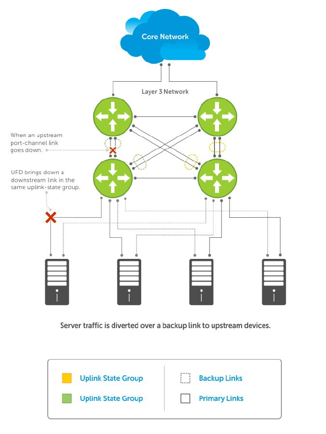
Figure 111. Uplink Failure Detection
How Uplink Failure Detection Works
UFD creates an association between upstream and downstream interfaces. The association of uplink and
downlink interfaces is called an uplink-state group.
An interface in an uplink-state group can be a physical interface or a port-channel (LAG) aggregation of
physical interfaces.
An enabled uplink-state group tracks the state of all assigned upstream interfaces. Failure on an upstream
interface results in the automatic disabling of downstream interfaces in the uplink-state group. As a
result, downstream devices can execute the protection or recovery procedures they have in place to
establish alternate connectivity paths, as shown in the following illustration.
Uplink Failure Detection (UFD) 811
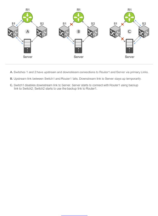
Figure 112. Uplink Failure Detection Example
If only one of the upstream interfaces in an uplink-state group goes down, a specified number of
downstream ports associated with the upstream interface are put into a Link-Down state. You can
configure this number and is calculated by the ratio of the upstream port bandwidth to the downstream
port bandwidth in the same uplink-state group. This calculation ensures that there is no traffic drops due
to insufficient bandwidth on the upstream links to the routers/switches.
By default, if all upstream interfaces in an uplink-state group go down, all downstream interfaces in the
same uplink-state group are put into a Link-Down state.
Using UFD, you can configure the automatic recovery of downstream ports in an uplink-state group
when the link status of an upstream port changes. The tracking of upstream link status does not have a
major impact on central processing unit (CPU) usage.
UFD and NIC Teaming
To implement a rapid failover solution, you can use uplink failure detection on a switch with network
adapter teaming on a server.
For more information, refer to NIC Teaming.
For example, as shown previously, the switch/ router with UFD detects the uplink failure and
automatically disables the associated downstream link port to the server. To continue to transmit traffic
upstream, the server with NIC teaming detects the disabled link and automatically switches over to the
backup link in order.
Important Points to Remember
When you configure UFD, the following conditions apply.
• You can configure up to 16 uplink-state groups. By default, no uplink-state groups are created.
– An uplink-state group is considered to be operationally up if it has at least one upstream interface
in the Link-Up state.
812 Uplink Failure Detection (UFD)

– An uplink-state group is considered to be operationally down if it has no upstream interfaces in
the Link-Up state. No uplink-state tracking is performed when a group is disabled or in an
Operationally Down state.
• You can assign physical port or port-channel interfaces to an uplink-state group.
– You can assign an interface to only one uplink-state group. Configure each interface assigned to
an uplink-state group as either an upstream or downstream interface, but not both.
– You can assign individual member ports of a port channel to the group. An uplink-state group can
contain either the member ports of a port channel or the port channel itself, but not both.
– If you assign a port channel as an upstream interface, the port channel interface enters a Link-
Down state when the number of port-channel member interfaces in a Link-Up state drops below
the configured minimum number of members parameter.
• If one of the upstream interfaces in an uplink-state group goes down, either a user-configurable set
of downstream ports or all the downstream ports in the group are put in an Operationally Down state
with an UFD Disabled error. The order in which downstream ports are disabled is from the lowest
numbered port to the highest.
– If one of the upstream interfaces in an uplink-state group that was down comes up, the set of
UFD-disabled downstream ports (which were previously disabled due to this upstream port going
down) is brought up and the UFD Disabled error is cleared.
• If you disable an uplink-state group, the downstream interfaces are not disabled regardless of the
state of the upstream interfaces.
– If an uplink-state group has no upstream interfaces assigned, you cannot disable downstream
interfaces when an upstream link goes down.
• To enable the debug messages for events related to a specified uplink-state group or all groups, use
the debug uplink-state-group [group-id] command, where the group-id is from 1 to 16.
– To turn off debugging event messages, use the no debug uplink-state-group [group-id]
command.
– For an example of debug log message, refer to Clearing a UFD-Disabled Interface.
Configuring Uplink Failure Detection
To configure UFD, use the following commands.
1. Create an uplink-state group and enable the tracking of upstream links on the switch/router.
CONFIGURATION mode
uplink-state-group group-id
•group-id: values are from 1 to 16.
To delete an uplink-state group, use the no uplink-state-group group-id command.
2. Assign a port or port-channel to the uplink-state group as an upstream or downstream interface.
UPLINK-STATE-GROUP mode
{upstream | downstream} interface
For interface, enter one of the following interface types:
• 10-Gigabit Ethernet: enter tengigabitethernet {slot/port |slot/port-range}
• 40-Gigabit Ethernet: enter fortyGigE {slot/port |slot/port-range}
Uplink Failure Detection (UFD) 813

• Port channel: enter port-channel {1-512 | port-channel-range}
Where port-range and port-channel-range specify a range of ports separated by a dash (-)
and/or individual ports/port channels in any order; for example:
upstream tengigabitethernet 1/1-2,5,9,11-12
downstream port-channel 1-3,5
• A comma is required to separate each port and port-range entry.
To delete an interface from the group, use the no {upstream | downstream} interface
command.
3. Configure the number of downstream links in the uplink-state group that will be disabled (Oper
Down state) if one upstream link in the group goes down.
UPLINK-STATE-GROUP mode
downstream disable links {number | all}
•number: specifies the number of downstream links to be brought down. The range is from 1 to
1024.
•all: brings down all downstream links in the group.
The default is no downstream links are disabled when an upstream link goes down.
NOTE: Downstream interfaces in an uplink-state group are put into a Link-Down state with an
UFD-Disabled error message only when all upstream interfaces in the group go down.
To revert to the default setting, use the no downstream disable links command.
4. (Optional) Enable auto-recovery so that UFD-disabled downstream ports in the uplink-state group
come up when a disabled upstream port in the group comes back up.
UPLINK-STATE-GROUP mode
downstream auto-recover
The default is auto-recovery of UFD-disabled downstream ports is enabled.
To disable auto-recovery, use the no downstream auto-recover command.
5. (Optional) Enters a text description of the uplink-state group.
UPLINK-STATE-GROUP mode
description text
The maximum length is 80 alphanumeric characters.
6. (Optional) Disables upstream-link tracking without deleting the uplink-state group.
UPLINK-STATE-GROUP mode
no enable
The default is upstream-link tracking is automatically enabled in an uplink-state group.
To re-enable upstream-link tracking, use the enable command.
814 Uplink Failure Detection (UFD)

Clearing a UFD-Disabled Interface
You can manually bring up a downstream interface in an uplink-state group that UFD disabled and is in a
UFD-Disabled Error state.
To re-enable one or more disabled downstream interfaces and clear the UFD-Disabled Error state, use
the following command.
• Re-enable a downstream interface on the switch/router that is in a UFD-Disabled Error State so that it
can send and receive traffic.
EXEC mode
clear ufd-disable {interface interface | uplink-state-group group-id}
For interface, enter one of the following interface types:
– 10-Gigabit Ethernet: enter tengigabitethernet {slot/port | slot/port-range}
– 40-Gigabit Ethernet: enter fortyGigE {slot/port |slot/port-range}
– Port channel: enter port-channel {1-512 | port-channel-range}
* Where port-range and port-channel-range specify a range of ports separated by a dash
(-) and/or individual ports/port channels in any order; for example:
tengigabitethernet 1/1-2,5,9,11-12
port-channel 1-3,5
* A comma is required to separate each port and port-range entry.
clear ufd-disable {interface interface | uplink-state-group group-id}: re-
enables all UFD-disabled downstream interfaces in the group. The range is from 1 to 16.
Example of Syslog Messages Before and After Entering the clear ufd-disable uplink-state-
group Command
The following example message shows the Syslog messages that display when you clear the UFD-
Disabled state from all disabled downstream interfaces in an uplink-state group by using the clear
ufd-disable uplink-state-group group-id command. All downstream interfaces return to an
operationally up state.
02:36:43: %SYSTEM-P:CP %IFMGR-5-ASTATE_DN: Changed interface Admin state to
down: Te 0/46
02:36:43: %SYSTEM-P:CP %IFMGR-5-OSTATE_DN: Changed interface state to down:
Te 0/46
02:36:43: %SYSTEM-P:CP %IFMGR-5-OSTATE_DN: Downstream interface set to UFD error-
disabled: Fo 1/0
02:36:43: %SYSTEM-P:CP %IFMGR-5-OSTATE_DN: Downstream interface set to UFD error-
disabled: Fo 1/4
02:36:43: %SYSTEM-P:CP %IFMGR-5-OSTATE_DN: Downstream interface set to UFD error-
disabled: Fo 1/8
02:36:43: %SYSTEM-P:CP %IFMGR-5-OSTATE_DN: Downstream interface set to UFD error-
disabled: Fo 1/12
02:36:43: %SYSTEM-P:CP %IFMGR-5-OSTATE_DN: Changed interface state to down:
Fo 1/0
02:36:43: %SYSTEM-P:CP %IFMGR-5-OSTATE_DN: Changed interface state to down:
Fo 1/4
02:36:43: %SYSTEM-P:CP %IFMGR-5-OSTATE_DN: Changed interface state to down:
Fo 1/8
02:36:43: %SYSTEM-P:CP %IFMGR-5-OSTATE_DN: Changed interface state to down:
Fo 1/12
Uplink Failure Detection (UFD) 815

02:37:29: %SYSTEM-P:CP %IFMGR-5-ASTATE_DN: Changed interface Admin state to
down: Te 0/47
02:37:29: %SYSTEM-P:CP %IFMGR-5-OSTATE_DN: Changed interface state to down:
Te 0/47
02:37:29 : UFD: Group:3, UplinkState: DOWN
02:37:29: %SYSTEM-P:CP %IFMGR-5-OSTATE_DN: Changed uplink state group state to down:
Group 3
02:37:29: %SYSTEM-P:CP %IFMGR-5-OSTATE_DN: Downstream interface set to UFD error-
disabled: Fo 1/0
02:37:29: %SYSTEM-P:CP %IFMGR-5-OSTATE_DN: Changed interface state to down:
Fo 1/0
02:38:31 : UFD: Group:3, UplinkState: UP
02:38:31: %SYSTEM-P:CP %IFMGR-5-OSTATE_UP: Changed uplink state group state to up:
Group 3
02:38:53: %SYSTEM-P:CP %IFMGR-5-OSTATE_UP: Downstream interface cleared from UFD
error-disabled: Fo 1/0
02:38:53: %SYSTEM-P:CP %IFMGR-5-OSTATE_UP: Downstream interface cleared from UFD
error-disabled: Fo 1/4
02:38:53: %SYSTEM-P:CP %IFMGR-5-OSTATE_UP: Downstream interface cleared from UFD
error-disabled: Fo 1/8
02:38:53: %SYSTEM-P:CP %IFMGR-5-OSTATE_UP: Downstream interface cleared from UFD
error-disabled: Fo 1/12
02:38:53: %SYSTEM-P:CP %IFMGR-5-OSTATE_UP: Downstream interface cleared from UFD
error-disabled: Fo 1/16
02:38:53: %SYSTEM-P:CP %IFMGR-5-OSTATE_UP: Changed interface state to up: Fo
1/0
02:38:53: %SYSTEM-P:CP %IFMGR-5-OSTATE_UP: Changed interface state to up: Fo
1/4
02:38:53: %SYSTEM-P:CP %IFMGR-5-OSTATE_UP: Changed interface state to up: Fo
1/8
02:38:53: %SYSTEM-P:CP %IFMGR-5-OSTATE_UP: Changed interface state to up: Fo
1/12
02:38:53: %SYSTEM-P:CP %IFMGR-5-OSTATE_UP: Changed interface state to up: Fo
1/16
Displaying Uplink Failure Detection
To display information on the UFD feature, use any of the following commands.
• Display status information on a specified uplink-state group or all groups.
EXEC mode
show uplink-state-group [group-id] [detail]
–group-id: The values are 1 to 16.
–detail: displays additional status information on the upstream and downstream interfaces in
each group.
• Display the current status of a port or port-channel interface assigned to an uplink-state group.
EXEC mode
show interfaces interface
interface specifies one of the following interface types:
– 10-Gigabit Ethernet: enter tengigabitethernet slot/port.
– 10-Gigabit Ethernet: enter tengigabitethernet slot/port.
– Port channel: enter port-channel {1-512}.
816 Uplink Failure Detection (UFD)

If a downstream interface in an uplink-state group is disabled (Oper Down state) by uplink-state
tracking because an upstream port is down, the message error-disabled[UFD] displays in the output.
• Display the current configuration of all uplink-state groups or a specified group.
EXEC mode or UPLINK-STATE-GROUP mode
(For EXEC mode) show running-config uplink-state-group [group-id]
(For UPLINK-STATE-GROUP mode) show configuration
–group-id: The values are from 1 to 16.
Examples of Viewing Uplink State Group Status
The following example shows viewing the uplink state group status for an S50 system.
Dell# show uplink-state-group
Uplink State Group: 1 Status: Enabled, Up
Uplink State Group: 3 Status: Enabled, Up
Uplink State Group: 5 Status: Enabled, Down
Uplink State Group: 6 Status: Enabled, Up
Uplink State Group: 7 Status: Enabled, Up
Uplink State Group: 16 Status: Disabled, Up
Dell# show uplink-state-group 16
Uplink State Group: 16 Status: Disabled, Up
Dell#show uplink-state-group detail
(Up): Interface up (Dwn): Interface down (Dis): Interface disabled
Uplink State Group : 1 Status: Enabled, Up
Upstream Interfaces :
Downstream Interfaces :
Uplink State Group : 3 Status: Enabled, Up
Upstream Interfaces : Te 0/46(Up) Te 0/47(Up)
Downstream Interfaces : Te 1/0(Up) Te 1/1(Up) Te 1/3(Up) Te 1/5(Up) Te 1/6(Up)
Uplink State Group : 5 Status: Enabled, Down
Upstream Interfaces : Te 0/0(Dwn) Te 0/3(Dwn) Te 0/5(Dwn)
Downstream Interfaces : Te 1/2(Dis) Te 1/4(Dis) Te 1/11(Dis) Te 1/12(Dis) Te
1/13(Dis)
Te 1/14(Dis) Te 1/15(Dis)
Uplink State Group : 6 Status: Enabled, Up
Upstream Interfaces :
Downstream Interfaces :
Uplink State Group : 7 Status: Enabled, Up
Upstream Interfaces :
Downstream Interfaces :
Uplink State Group : 16 Status: Disabled, Up
Upstream Interfaces : Te 0/41(Dwn) Po 8(Dwn)
Downstream Interfaces : Te 0/40(Dwn)
The following example shows viewing the uplink state group interface status for an S50 system.
Dell#show interfaces tengigabitethernet 0/45
TenGigabitEthernet 0/45 is up, line protocol is down (error-disabled[UFD])
Hardware is Dell Force10Eth, address is 00:01:e8:32:7a:47
Current address is 00:01:e8:32:7a:47
Uplink Failure Detection (UFD) 817

Interface index is 280544512
Internet address is not set
MTU 1554 bytes, IP MTU 1500 bytes
LineSpeed 1000 Mbit, Mode auto
Flowcontrol rx off tx off
ARP type: ARPA, ARP Timeout 04:00:00
Last clearing of "show interface" counters 00:25:46
Queueing strategy: fifo
Input Statistics:
0 packets, 0 bytes
0 64-byte pkts, 0 over 64-byte pkts, 0 over 127-byte pkts
0 over 255-byte pkts, 0 over 511-byte pkts, 0 over 1023-byte pkts
0 Multicasts, 0 Broadcasts
0 runts, 0 giants, 0 throttles
0 CRC, 0 overrun, 0 discarded
Output Statistics:
0 packets, 0 bytes, 0 underruns
0 64-byte pkts, 0 over 64-byte pkts, 0 over 127-byte pkts
0 over 255-byte pkts, 0 over 511-byte pkts, 0 over 1023-byte pkts
0 Multicasts, 0 Broadcasts, 0 Unicasts
0 throttles, 0 discarded, 0 collisions
Rate info (interval 299 seconds):
Input 00.00 Mbits/sec, 0 packets/sec, 0.00% of line-rate
Output 00.00 Mbits/sec, 0 packets/sec, 0.00% of line-rate
Time since last interface status change: 00:01:23
The following example shows viewing the uplink state group configuration for an S50 system.
Dell#show running-config uplink-state-group
!
no enable
uplink state track 1
downstream TengigabitEthernet 0/2, 4, 6, 11-19
upstream TengigabitEthernet 0/48, 52
upstream PortChannel 1
!
uplink state track 2
downstream TengigabitEthernet 0/1, 3, 5, 7-10
upstream TengigabitEthernet 0/56, 60
Dell(conf-uplink-state-group-16)# show configuration
!
uplink-state-group 16
no enable
description test
downstream disable links all
downstream TengigabitEthernet 0/40
upstream TengigabitEthernet 0/41
upstream Port-channel 8
Sample Configuration: Uplink Failure Detection
The following example shows a sample configuration of UFD on a switch/router in which you configure
as follows.
• Configure uplink-state group 3.
• Add downstream links Tengigabitethernet 0/1, 0/2, 0/5, 0/9, 0/11, and 0/12.
• Configure two downstream links to be disabled if an upstream link fails.
• Add upstream links Tengigabitethernet 0/3 and 0/4.
818 Uplink Failure Detection (UFD)

• Add a text description for the group.
• Verify the configuration with various show commands.
Example of Configuring UFD (S50)
Dell(conf)# uplink-state-group 3
00:08:11: %STKUNIT0-M:CP %IFMGR-5-ASTATE_UP: Changed uplink state group Admin
state to up:
Group 3
Dell(conf-uplink-state-group-3)# downstream tengigabitethernet 0/1-2,5,9,11-12
Dell(conf-uplink-state-group-3)# downstream disable links 2
Dell(conf-uplink-state-group-3)# upstream tengigabitethernet 0/3-4
00:10:00: %STKUNIT0-M:CP %IFMGR-5-OSTATE_DN: Downstream interface set to UFD
error-disabled:
Te 0/1
Dell#
00:10:00: %STKUNIT0-M:CP %IFMGR-5-OSTATE_DN: Changed interface state to down:
Te 0/1
Dell(conf-uplink-state-group-3)# description Testing UFD feature
Dell(conf-uplink-state-group-3)# show config
!
uplink-state-group 3
description Testing UFD feature
downstream disable links 2
downstream TengigabitEthernet 0/1-2,5,9,11-12
upstream TengigabitEthernet 0/3-4
Dell(conf-uplink-state-group-3)#
Dell(conf-uplink-state-group-3)#exit
Dell(conf)#exit
Dell#
00:13:06: %STKUNIT0-M:CP %SYS-5-CONFIG_I: Configured from console by console
Dell# show running-config uplink-state-group
!
uplink-state-group 3
description Testing UFD feature
downstream disable links 2
downstream TengigabitEthernet 0/1-2,5,9,11-12
upstream TengigabitEthernet 0/3-4
Dell# show uplink-state-group 3
Uplink State Group: 3 Status: Enabled, Up
Dell# show uplink-state-group detail
(Up): Interface up (Dwn): Interface down (Dis): Interface disabled
Uplink State Group : 3 Status: Enabled, Up
Upstream Interfaces : Te 0/3(Up) Te 0/4(Dwn)
Downstream Interfaces : Te 0/1(Dis) Te 0/2(Dwn) Te 0/5(Dwn) Te 0/9(Dwn) Te
0/11(Dwn)
Te 0/12(Dwn)
Uplink Failure Detection (UFD) 819

53
Virtual LANs (VLANs)
Virtual LANs (VLANs) are a logical broadcast domain or logical grouping of interfaces in a local area
network (LAN) in which all data received is kept locally and broadcast to all members of the group.
When in Layer 2 mode, VLANs move traffic at wire speed and can span multiple devices. The system
supports up to 4093 port-based VLANs and one default VLAN, as specified in IEEE 802.1Q.
VLANs benefits include:
• Improved security because you can isolate groups of users into different VLANs
• Ability to create one VLAN across multiple devices
For more information about VLANs, refer to the IEEE Standard 802.1Q Virtual Bridged Local Area
Networks. In this guide, also refer to:
•Bulk Configuration in the Interfaces chapter.
•VLAN Stacking in the Service Provider Bridging chapter.
For a complete listing of all VLAN configuration commands, refer to these Dell Networking OS Command
Reference Guide chapters:
•Interfaces
•802.1X
•GARP VLAN Registration Protocol (GVRP)
•Service Provider Bridging
•Per-VLAN Spanning Tree Plus (PVST+)
The following table lists the defaults for VLANs in the system.
Feature Default
Spanning Tree
group ID
All VLANs are part of Spanning Tree group 0.
Mode Layer 2 (no IP address is assigned).
Default VLAN ID VLAN 1
Default VLAN
When you configure interfaces for Layer 2 mode, they are automatically placed in the Default VLAN as
untagged interfaces. Only untagged interfaces can belong to the Default VLAN.
The following example displays the outcome of placing an interface in Layer 2 mode. To configure an
interface for Layer 2 mode, use the switchport command. As shown in bold, the switchport
command places the interface in Layer 2 mode and the show vlan command in EXEC privilege mode
indicates that the interface is now part of the Default VLAN (VLAN 1).
820 Virtual LANs (VLANs)

By default, VLAN 1 is the Default VLAN. To change that designation, use the default vlan-id
command in CONFIGURATION mode. You cannot delete the Default VLAN.
NOTE: You cannot assign an IP address to the Default VLAN. To assign an IP address to a VLAN that
is currently the Default VLAN, create another VLAN and assign it to be the Default VLAN. For more
information about assigning IP addresses, refer to Assigning an IP Address to a VLAN.
• Untagged interfaces must be part of a VLAN. To remove an untagged interface from the Default
VLAN, create another VLAN and place the interface into that VLAN. Alternatively, use the no
switchport command, and the system removes the interface from the Default VLAN.
• A tagged interface requires an additional step to remove it from Layer 2 mode. Because tagged
interfaces can belong to multiple VLANs, remove the tagged interface from all VLANs using the no
tagged interface command. Only after the interface is untagged and a member of the Default
VLAN can you use the no switchport command to remove the interface from Layer 2 mode. For
more information, refer to VLANs and Port Tagging.
Example of Configuring an Interface for Layer 2 Belonging to the Default VLAN
Dell(conf)#int te 2/2
Dell(conf-if)#no shut
Dell(conf-if)#switchport
Dell(conf-if)#show config
!
interface TenGigabitEthernet 2/2
no ip address
switchport
no shutdown
Dell(conf-if)#end
Dell#show vlan
Codes: * - Default VLAN, G - GVRP VLANs
NUM Status Q Ports
* 1 Active U Te 2/2
2 Active T Po1(Te 0/0-1)
T Te 2/0
Dell#
Port-Based VLANs
Port-based VLANs are a broadcast domain defined by different ports or interfaces. A port-based VLAN
can contain interfaces from different line cards within the chassis. The system supports 4094 port-based
VLANs.
Port-based VLANs offer increased security for traffic, conserve bandwidth, and allow switch
segmentation. Interfaces in different VLANs do not communicate with each other, adding some security
to the traffic on those interfaces. Different VLANs can communicate between each other by means of IP
routing. Because traffic is only broadcast or flooded to the interfaces within a VLAN, the VLAN conserves
bandwidth. Finally, you can have multiple VLANs configured on one switch, thus segmenting the device.
Interfaces within a port-based VLAN must be in Layer 2 mode and can be tagged or untagged in the
VLAN ID.
VLANs and Port Tagging
To add an interface to a VLAN, the interface must be in Layer 2 mode. After you place an interface in
Layer 2 mode, the interface is automatically placed in the Default VLAN.
The system supports IEEE 802.1Q tagging at the interface level to filter traffic. When you enable tagging,
a tag header is added to the frame after the destination and source MAC addresses. That information is
Virtual LANs (VLANs) 821
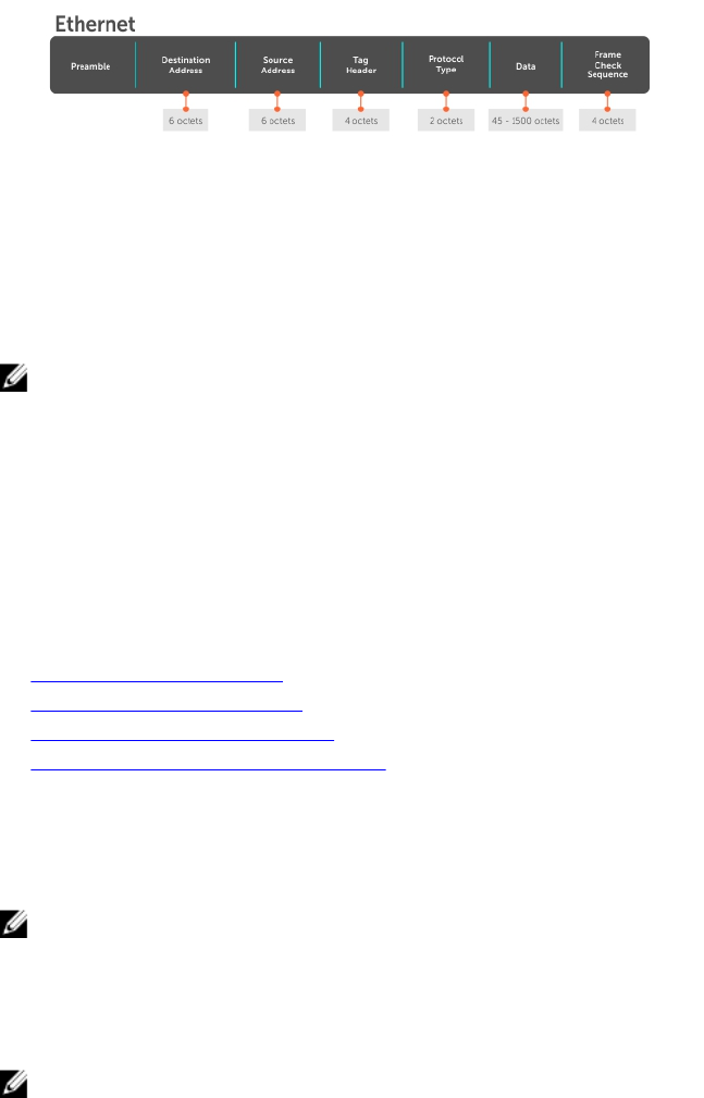
preserved as the frame moves through the network. The following example shows the structure of a
frame with a tag header. The VLAN ID is inserted in the tag header.
Figure 113. Tagged Frame Format
The tag header contains some key information that the system uses:
• The VLAN protocol identifier identifies the frame as tagged according to the IEEE 802.1Q
specifications (2 bytes).
• Tag control information (TCI) includes the VLAN ID (2 bytes total). The VLAN ID can have 4,096 values,
but two are reserved.
NOTE: The insertion of the tag header into the Ethernet frame increases the size of the frame to
more than the 1,518 bytes as specified in the IEEE 802.3 standard. Some devices that are not
compliant with IEEE 802.3 may not support the larger frame size.
Information contained in the tag header allows the system to prioritize traffic and to forward information
to ports associated with a specific VLAN ID. Tagged interfaces can belong to multiple VLANs, while
untagged interfaces can belong only to one VLAN.
Configuration Task List
This section contains the following VLAN configuration tasks.
•Creating a Port-Based VLAN (mandatory)
•Assigning Interfaces to a VLAN (optional)
•Assigning an IP Address to a VLAN (optional)
•Enabling Null VLAN as the Default VLAN
Creating a Port-Based VLAN
To configure a port-based VLAN, create the VLAN and then add physical interfaces or port channel (LAG)
interfaces to the VLAN.
NOTE: The Default VLAN (VLAN 1) is part of the system startup configuration and does not require
configuration.
A VLAN is active only if the VLAN contains interfaces and those interfaces are operationally up. As shown
in the following example, VLAN 1 is inactive because it does not contain any interfaces. The other VLANs
contain enabled interfaces and are active.
NOTE: In a VLAN, the shutdown command stops Layer 3 (routed) traffic only. Layer 2 traffic
continues to pass through the VLAN. If the VLAN is not a routed VLAN (that is, configured with an IP
address), the shutdown command has no affect on VLAN traffic.
When you delete a VLAN (using the no interface vlan vlan-id command), any interfaces assigned
to that VLAN are assigned to the Default VLAN as untagged interfaces.
To create a port-based VLAN, use the following command.
822 Virtual LANs (VLANs)

• Configure a port-based VLAN (if the VLAN-ID is different from the Default VLAN ID) and enter
INTERFACE VLAN mode.
CONFIGURATION mode
interface vlan vlan-id
To activate the VLAN, after you create a VLAN, assign interfaces in Layer 2 mode to the VLAN.
Example of Verifying a Port-Based VLAN
To view the configured VLANs, use the show vlan command in EXEC Privilege mode.
Dell#show vlan
Codes: * - Default VLAN, G - GVRP VLANs
NUM Status Q Ports
* 1 Inactive U Te 1/4-11
2 Active U Te 0/1,18
3 Active U Te 0/2,19
4 Active T Te 0/3,20
5 Active U Po 1
6 Active U Te 0/12
U Te 2/0
Dell#
Assigning Interfaces to a VLAN
You can only assign interfaces in Layer 2 mode to a VLAN using the tagged and untagged commands. To
place an interface in Layer 2 mode, use the switchport command.
You can further designate these Layer 2 interfaces as tagged or untagged. For more information, refer to
the Interfaces chapter and Configuring Layer 2 (Data Link) Mode. When you place an interface in Layer 2
mode by the switchport command, the interface is automatically designated untagged and placed in
the Default VLAN.
To view which interfaces are tagged or untagged and to which VLAN they belong, use the show vlan
command. The following example shows that six VLANs are configured, and two interfaces are assigned
to VLAN 2. The Q column in the show vlan command example notes whether the interface is tagged (T)
or untagged (U). For more information about this command, refer to the Layer 2 chapter of the Dell
Networking OS Command Reference Guide.
To tag frames leaving an interface in Layer 2 mode, assign that interface to a port-based VLAN to tag it
with that VLAN ID. To tag interfaces, use the following commands.
1. Access INTERFACE VLAN mode of the VLAN to which you want to assign the interface.
CONFIGURATION mode
interface vlan vlan-id
2. Enable an interface to include the IEEE 802.1Q tag header.
INTERFACE mode
tagged interface
Add an Interface to Another VLAN
To view just the interfaces that are in Layer 2 mode, use the show interfaces switchport command
in EXEC Privilege mode or EXEC mode.
Virtual LANs (VLANs) 823

The following example shows the steps to add a tagged interface (in this case, port channel 1) to VLAN 4.
To view the interface’s status. Interface (po 1) is tagged and in VLAN 2 and 3, use the show vlan
command. In a port-based VLAN, use the tagged command to add the interface to another VLAN. The
show vlan command output displays the interface’s (po 1) changed status.
Except for hybrid ports, only a tagged interface can be a member of multiple VLANs. You can assign
hybrid ports to two VLANs if the port is untagged in one VLAN and tagged in all others.
Dell#show vlan
Codes: * - Default VLAN, G - GVRP VLANs
NUM Status Q Ports
* 1 Inactive
2 Active T Po1(Te 0/0-1)
T Te 2/0
3 Active T Po1(Te 0/0-1)
T Te 2/1
Dell#config
Dell(conf)#int vlan 4
Dell(conf-if-vlan)#tagged po 1
Dell(conf-if-vlan)#show conf
!
interface Vlan 4
no ip address
tagged Port-channel 1
Dell(conf-if-vlan)#end
Dell#show vlan
Codes: * - Default VLAN, G - GVRP VLANs
NUM Status Q Ports
* 1 Inactive
2 Active T Po1(Te 0/0-1)
T Te 3/0
3 Active T Po1(Te 0/0-1)
T Te 3/1
4 Active T Po1(Te 0/0-1)
Dell#
When you remove a tagged interface from a VLAN (using the no tagged interface command), it
remains tagged only if it is a tagged interface in another VLAN. If the tagged interface is removed from
the only VLAN to which it belongs, the interface is placed in the Default VLAN as an untagged interface.
Moving Untagged Interfaces
To move untagged interfaces from the Default VLAN to another VLAN, use the following commands.
1. Access INTERFACE VLAN mode of the VLAN to which you want to assign the interface.
CONFIGURATION mode
interface vlan vlan-id
2. Configure an interface as untagged.
824 Virtual LANs (VLANs)

INTERFACE mode
untagged interface
This command is available only in VLAN interfaces.
Move an Untagged Interface to Another VLAN
The no untagged interface command removes the untagged interface from a port-based VLAN and
places the interface in the Default VLAN. You cannot use the no untagged interface command in
the Default VLAN. The following example shows the steps and commands to move an untagged interface
from the Default VLAN to another VLAN.
To determine interface status, use the show vlan command. Interface (te 2/2) is untagged and in the
Default VLAN (vlan 1). In a port-based VLAN (vlan 4), use the untagged command to add the interface to
that VLAN. The show vlan command output displays the interface’s changed status (te 2/2). Because the
Default VLAN no longer contains any interfaces, it is listed as inactive.
Dell#show vlan
Codes: * - Default VLAN, G - GVRP VLANs
NUM Status Q Ports
* 1 Active U Te 2/2
2 Active T Po1(Te 0/0-1)
T Te 2/0
3 Active T Po1(Te 0/0-1)
T Te 2/1
4 Inactive
Dell#conf
Dell(conf)#int vlan 4
Dell(conf-if-vlan)#untagged te 2/2
Dell(conf-if-vlan)#show config
!
interface Vlan 4
no ip address
untagged TenGigabitEthernet 2/2
Dell(conf-if-vlan)#end
Dell#show vlan
Codes: * - Default VLAN, G - GVRP VLANs
NUM Status Q Ports
* 1 Inactive
2 Active T Po1(Te 0/0-1)
T Te 2/0
3 Active T Po1(Te 0/0-1)
T Te 2/1
4 Active U Te 2/2
Dell#
The only way to remove an interface from the Default VLAN is to place the interface in Default mode by
using the no switchport command in INTERFACE mode.
Virtual LANs (VLANs) 825

Assigning an IP Address to a VLAN
VLANs are a Layer 2 feature. For two physical interfaces on different VLANs to communicate, you must
assign an IP address to the VLANs to route traffic between the two interfaces.
The shutdown command in INTERFACE mode does not affect Layer 2 traffic on the interface; the
shutdown command only prevents Layer 3 traffic from traversing over the interface.
NOTE: You cannot assign an IP address to the Default VLAN (VLAN 1). To assign another VLAN ID to
the Default VLAN, use the default vlan-id vlan-id command.
You can place VLANs and other logical interfaces in Layer 3 mode to receive and send routed traffic. For
more information, refer to Bulk Configuration.
To assign an IP address, use the following command.
• Configure an IP address and mask on the interface.
INTERFACE mode
ip address ip-address mask [secondary]
–ip-address mask — Enter an address in dotted-decimal format (A.B.C.D) and the mask must be
in slash format (/24).
–secondary — This is the interface’s backup IP address. You can configure up to eight secondary
IP addresses.
Configuring Native VLANs
Traditionally, ports can be either untagged for membership to one VLAN or tagged for membership to
multiple VLANs.
You must connect an untagged port to a VLAN-unaware station (one that does not understand VLAN
tags), and you must connect a tagged port to a VLAN-aware station (one that generates and understands
VLAN tags).
Native VLAN support breaks this barrier so that you can connect a port to both VLAN-aware and VLAN-
unaware stations. Such ports are referred to as hybrid ports. Physical and port-channel interfaces may be
hybrid ports.
Native VLAN is useful in deployments where a Layer 2 port can receive both tagged and untagged traffic
on the same physical port. The classic example is connecting a voice-over-IP (VOIP) phone and a PC to
the same port of the switch. The VOIP phone is configured to generate tagged packets (with VLAN =
VOICE VLAN) and the attached PC generates untagged packets.
NOTE: When a hybrid port is untagged in a VLAN but it receives tagged traffic, all traffic is accepted.
NOTE: You cannot configure an existing switchport or port channel interface for Native VLAN.
Interfaces must have no other Layer 2 or Layer 3 configurations when using the portmode hybrid
command or a message similar to this displays: % Error: Port is in Layer-2 mode Te
5/6.
To configure a port so that it can be a member of an untagged and tagged VLANs, use the following
commands.
1. Remove any Layer 2 or Layer 3 configurations from the interface.
826 Virtual LANs (VLANs)
INTERFACE mode
2. Configure the interface for Hybrid mode.
INTERFACE mode
portmode hybrid
3. Configure the interface for Switchport mode.
INTERFACE mode
switchport
4. Add the interface to a tagged or untagged VLAN.
VLAN INTERFACE mode
[tagged | untagged]
Enabling Null VLAN as the Default VLAN
In a Carrier Ethernet for Metro Service environment, service providers who perform frequent
reconfigurations for customers with changing requirements occasionally enable multiple interfaces, each
connected to a different customer, before the interfaces are fully configured.
This presents a vulnerability because both interfaces are initially placed in the native VLAN, VLAN 1, and
for that period customers are able to access each other's networks. The system has a Null VLAN to
eliminate this vulnerability. When you enable the Null VLAN, all ports are placed into it by default, so even
if you activate the physical ports of multiple customers, no traffic is allowed to traverse the links until
each port is place in another VLAN.
To enable Null VLAN, use the following command.
• Disable the default VLAN, so that all ports belong to the Null VLAN until configured as a member of
another VLAN.
CONFIGURATION mode
default-vlan disable
Default: the default VLAN is enabled (no default-vlan disable).
Virtual LANs (VLANs) 827

54
Virtual Link Trunking (VLT)
Virtual link trunking (VLT) allows physical links between two chassis to appear as a single virtual link to the
network core or other switches such as Edge, Access, or top-of-rack (ToR).
Overview
VLT reduces the role of spanning tree protocols (STPs) by allowing link aggregation group (LAG)
terminations on two separate distribution or core switches and supporting a loop-free topology.
To prevent the initial loop that may occur prior to VLT being established, use a spanning tree protocol.
After VLT is established, you may use rapid spanning tree protocol (RSTP) to prevent loops from forming
with new links that are incorrectly connected and outside the VLT domain.
VLT provides Layer 2 multipathing, creating redundancy through increased bandwidth, enabling multiple
parallel paths between nodes and load-balancing traffic where alternative paths exist.
Virtual link trunking offers the following benefits:
• Allows a single device to use a LAG across two upstream devices.
• Eliminates STP-blocked ports.
• Provides a loop-free topology.
• Uses all available uplink bandwidth.
• Provides fast convergence if either the link or a device fails.
• Optimized forwarding with virtual router redundancy protocol (VRRP).
• Provides link-level resiliency.
• Assures high availability.
CAUTION: Dell Networking does not recommend enabling Stacking and VLT simultaneously. If
you enable both features at the same time, unexpected behavior occurs.
As shown in the following example, VLT presents a single logical Layer 2 domain from the perspective of
attached devices that have a virtual link trunk terminating on separate chassis in the VLT domain.
However, the two VLT chassis are independent Layer2/Layer3 (L2/L3) switches for devices in the
upstream network. L2/L3 control plane protocols and system management features function normally in
VLT mode. Features such as VRRP and Internet Group Management Protocol (IGMP) snooping require
state information coordinating between the two VLT chassis. IGMP and VLT configurations must be
identical on both sides of the trunk to ensure the same behavior on both sides.
The following example shows how VLT is deployed. The switches appear as a single virtual switch from
the point of view of the switch or server supporting link aggregation control protocol (LACP).
828 Virtual Link Trunking (VLT)
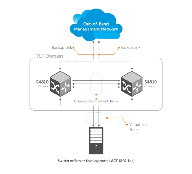
Figure 114. Example of VLT Deployment
VLT on Core Switches
You can also deploy VLT on core switches.
Uplinks from servers to the access layer and from access layer to the aggregation layer are bundled in
LAG groups with end-to-end Layer 2 multipathing. This set up requires “horizontal” stacking at the access
layer and VLT at the aggregation layer such that all the uplinks from servers to access and access to
aggregation are in Active-Active Load Sharing mode. This example provides the highest form of
resiliency, scaling, and load balancing in data center switching networks.
The following example shows stacking at the access, VLT in aggregation, and Layer 3 at the core.
The aggregation layer is mostly in the L2/L3 switching/routing layer. For better resiliency in the
aggregation, Dell Networking recommends running the internal gateway protocol (IGP) on the VLTi VLAN
to synchronize the L3 routing table across the two nodes on a VLT system.
Enhanced VLT
An enhanced VLT (eVLT) configuration creates a port channel between two VLT domains by allowing two
different VLT domains, using different VLT domain ID numbers, connected by a standard link aggregation
control protocol (LACP) LAG to form a loop-free Layer 2 topology in the aggregation layer.
This configuration supports a maximum of four units, increasing the number of available ports and
allowing for dual redundancy of the VLT. The following example shows how the core/aggregation port
density in the Layer 2 topology is increased using eVLT. For inter-VLAN routing and other Layer 3 routing,
you need a separate Layer 3 router.
Virtual Link Trunking (VLT) 829

Figure 115. Enhanced VLT
VLT Terminology
The following are key VLT terms.
•Virtual link trunk (VLT) — The combined port channel between an attached device and the VLT peer
switches.
•VLT backup link — The backup link monitors the vitality of VLT peer switches. The backup link sends
configurable, periodic keep alive messages between the VLT peer switches.
•VLT interconnect (VLTi) — The link used to synchronize states between the VLT peer switches. Both
ends must be on 10G or 40G interfaces.
•VLT domain — This domain includes both the VLT peer devices, VLT interconnect, and all of the port
channels in the VLT connected to the attached devices. It is also associated to the configuration
mode that you must use to assign VLT global parameters.
•VLT peer device — One of a pair of devices that are connected with the special port channel known
as the VLT interconnect (VLTi).
VLT peer switches have independent management planes. A VLT interconnect between the VLT chassis
maintains synchronization of L2/L3 control planes across the two VLT peer switches. The VLT
interconnect uses either 10G or 40G user ports on the chassis.
A separate backup link maintains heartbeat messages across an out-of-band (OOB) management
network. The backup link ensures that node failure conditions are correctly detected and are not
confused with failures of the VLT interconnect. VLT ensures that local traffic on a chassis does not
traverse the VLTi and takes the shortest path to the destination via directly attached links.
830 Virtual Link Trunking (VLT)

Configure Virtual Link Trunking
VLT requires that you enable the feature and then configure the same VLT domain, backup link, and VLT
interconnect on both peer switches.
Important Points to Remember
• VLT port channel interfaces must be switch ports.
• If you include RSTP on the system, configure it before VLT. Refer to Configure Rapid Spanning Tree.
• Dell Networking strongly recommends that the VLTi (VLT interconnect) be a static LAG and that you
disable LACP on the VLTi.
• Ensure that the spanning tree root bridge is at the Aggregation layer. If you enable RSTP on the VLT
device, refer to RSTP and VLT for guidelines to avoid traffic loss.
• If you reboot both VLT peers in BMP mode and the VLT LAGs are static, the DHCP server reply to the
DHCP discover offer may not be forwarded by the ToR to the correct node. To avoid this scenario,
configure the VLT LAGs to the ToR and the ToR port channel to the VLT peers with LACP. If supported
by the ToR, enable the lacp-ungroup feature on the ToR using the lacp ungroup member-
independent port-channel command.
• If the lacp-ungroup feature is not supported on the ToR, reboot the VLT peers one at a time. After
rebooting, verify that VLTi (ICL) is active before attempting DHCP connectivity.
• When you enable IGMP snooping on the VLT peers, ensure the value of the delay-restore
command is not less than the query interval.
• When you enable Layer 3 routing protocols on VLT peers, make sure the delay-restore timer is set to a
value that allows sufficient time for all routes to establish adjacency and exchange all the L3 routes
between the VLT peers before you enable the VLT ports.
• Only use the lacp ungroup member-independent command if the system connects to nodes
using bare metal provisioning (BMP) to upgrade or boot from the network.
• Ensure that you configure all port channels where LACP ungroup is applicable as hybrid ports and as
untagged members of a VLAN. BMP uses untagged dynamic host configuration protocol (DHCP)
packets to communicate with the DHCP server.
• If the DHCP server is located on the ToR and the VLTi (ICL) is down due to a failed link when a VLT
node is rebooted in BMP mode, it is not able to reach the DHCP server, resulting in BMP failure.
• If the source is connected to an orphan (non-spanned, non-VLT) port in a VLT peer, the receiver is
connected to a VLT (spanned) port-channel, and the VLT port-channel link between the VLT peer
connected to the source and TOR is down, traffic is duplicated due to route inconsistency between
peers. To avoid this scenario, Dell Networking recommends configuring both the source and the
receiver on a spanned VLT VLAN.
• After you enter the clear arp command on a Z9500 configured as the primary VLT peer switch, an
ARP request destined for the secondary VLT peer that arrives from a host and is tunneled through the
primary peer updates the ARP entry in the Route Processor (RP) on the primary peer. However, the
same ARP request packet is dropped on the Control Processor (CP) because it is not destined to the
primary peer and the CP has no corresponding ARP entry that can be refreshed with this packet. As a
result, there is an ARP entry mismatch in the RP and CP tables. There is no impact on switch behavior.
• Bulk synchronization happens only for global IPv6 Neighbors; link-local neighbor entries are not
synced.
• If all of the following conditions are true, MAC addresses may not be synced correctly:
– VLT peers use VLT interconnect (VLTi)
– Sticky MAC is enabled on an orphan port in the primary or secondary peer
– MACs are currently inactive
Virtual Link Trunking (VLT) 831
If this scenario occurs, use the clear mac-address-table sticky all command on the primary
or secondary peer to correctly sync the MAC addresses.
• If static ARP is enabled on only one VLT peer, entries may be overwritten during bulk sync.
Configuration Notes
When you configure VLT, the following conditions apply.
• VLT domain
– A VLT domain supports two chassis members, which appear as a single logical device to network
access devices connected to VLT ports through a port channel.
– A VLT domain consists of the two core chassis, the interconnect trunk, backup link, and the LAG
members connected to attached devices.
– Each VLT domain has a unique MAC address that you can configure using the system-mac
command. If you do not specify a MAC address, VLT uses the primary peer’s MAC address by
default.
– ARP tables are synchronized between the VLT peer nodes.
– VLT peer switches operate as separate chassis with independent control and data planes for
devices attached on non-VLT ports.
– One chassis in the VLT domain is assigned a primary role; the other chassis takes the secondary
role. The primary and secondary roles are required for scenarios when connectivity between the
chassis is lost. VLT assigns the primary chassis role according to the lowest MAC address. You can
configure the primary role.
– In a VLT domain, the peer switches must run the same Dell Networking OS version.
– Separately configure each VLT peer switch with the same VLT domain ID and the VLT version. If
the system detects mismatches between VLT peer switches in the VLT domain ID or VLT version,
the VLT Interconnect (VLTi) does not activate. To find the reason for the VLTi being down, use the
show vlt statistics command to verify that there are mismatch errors, then use the show
vlt brief command on each VLT peer to view the VLT version on the peer switch. If the VLT
version is more than one release different from the current version in use, the VLTi does not
activate.
– The chassis members in a VLT domain support connection to orphan hosts and switches that are
not connected to both switches in the VLT core.
• VLT interconnect (VLTi)
– The VLT interconnect must consist of either 10G or 40G ports. A maximum of eight 10G or four
40G ports is supported. A combination of 10G and 40G ports is not supported.
– A VLT interconnect over 1G ports is not supported.
– The port channel must be in Default mode (not Switchport mode) to have VLTi recognize it.
– The system automatically includes the required VLANs in VLTi. You do not need to manually select
VLANs.
– VLT peer switches operate as separate chassis with independent control and data planes for
devices attached to non-VLT ports.
– Port-channel link aggregation (LAG) across the ports in the VLT interconnect is required; individual
ports are not supported. Dell Networking strongly recommends configuring a static LAG for VLTi.
– The VLT interconnect synchronizes L2 and L3 control-plane information across the two chassis.
– The VLT interconnect is used for data traffic only when there is a link failure that requires using
VLTi in order for data packets to reach their final destination.
– Unknown, multicast, and broadcast traffic can be flooded across the VLT interconnect.
– MAC addresses for VLANs configured across VLT peer chassis are synchronized over the VLT
interconnect on an egress port such as a VLT LAG. MAC addresses are the same on both VLT peer
nodes.
832 Virtual Link Trunking (VLT)

– ARP entries configured across the VLTi are the same on both VLT peer nodes.
– If you shut down the port channel used in the VLT interconnect on a peer switch in a VLT domain
in which you did not configure a backup link, the switch’s role displays in the show vlt brief
command output as Primary instead of Standalone.
– When you change the default VLAN ID on a VLT peer switch, the VLT interconnect may flap.
– In a VLT domain, the following software features are supported on VLTi: link layer discovery
protocol (LLDP), flow control, port monitoring, jumbo frames, and data center bridging (DCB).
– When you enable the VLTi link, the link between the VLT peer switches is established if the
following configured information is true on both peer switches:
* the VLT-system MAC address (if configured) matches.
* the VLT unit-id (if configured) is not identical.
NOTE: If the VLT-system MAC address or VLT unit-id is not configured on both VLT peer
switches, VLT automatically sets the default VLT-system MAC address and unit-id on each
peer.
– If the link between the VLT peer switches is established, changing the VLT-system MAC address or
the VLT unit-id causes the link between the VLT peer switches to become disabled. However,
removing the VLT-system MAC address or the VLT unit-id may disable the VLT ports if you happen
to configure the unit ID or system MAC address on only one VLT peer at any time.
– If the link between VLT peer switches is established, any change to the VLT-system MAC address
or unit-id fails if the changes made create a mismatch by causing the VLT unit-ID to be the same
on both peers and/or the VLT-system MAC address does not match on both peers.
– If you replace a VLT peer node, pre-configure the switch with the VLT-system MAC address, unit-
id, and other VLT parameters (if applicable) before connecting it to the existing VLT peer switch
using the VLTi connection.
• VLT backup link
– In the backup link between peer switches, heartbeat messages are exchanged between the two
chassis for health checks. The default time interval between heartbeat messages over the backup
link is 1 second. You can configure this interval. The range is from 1 to 5 seconds. DSCP marking
on heartbeat messages is CS6.
– In order that the chassis backup link does not share the same physical path as the interconnect
trunk, Dell Networking recommends using the management ports on the chassis and traverse an
out-of-band management network. The backup link can use user ports, but not the same ports
the interconnect trunk uses.
– The chassis backup link does not carry control plane information or data traffic. Its use is restricted
to health checks only.
• Virtual link trunks (VLTs) between access devices and VLT peer switches
– To connect servers and access switches with VLT peer switches, you use a VLT port channel, as
shown in Overview. Up to 48 port-channels are supported; up to eight member links are
supported in each port channel between the VLT domain and an access device.
– The discovery protocol running between VLT peers automatically generates the ID number of the
port channel that connects an access device and a VLT switch. The discovery protocol uses LACP
properties to identify connectivity to a common client device and automatically generates a VLT
number for port channels on VLT peers that connects to the device. The discovery protocol
requires that an attached device always runs LACP over the port-channel interface.
– VLT provides a loop-free topology for port channels with endpoints on different chassis in the VLT
domain.
– VLT uses shortest path routing so that traffic destined to hosts via directly attached links on a
chassis does not traverse the chassis-interconnect link.
– VLT allows multiple active parallel paths from access switches to VLT chassis.
Virtual Link Trunking (VLT) 833

– VLT supports port-channel links with LACP between access switches and VLT peer switches. Dell
Networking recommends using static port channels on VLTi.
– If VLTi connectivity with a peer is lost but the VLT backup connectivity indicates that the peer is
still alive, the VLT ports on the Secondary peer are orphaned and are shut down.
* In one possible topology, a switch uses the BMP feature to receive its IP address, configuration
files, and boot image from a DHCP server that connects to the switch through the VLT domain.
In the port-channel used by the switch to connect to the VLT domain, configure the port
interfaces on each VLT peer as hybrid ports before adding them to the port channel (refer to
Connecting a VLT Domain to an Attached Access Device (Switch or Server)). To configure a
port in Hybrid mode so that it can carry untagged, single-tagged, and double-tagged traffic,
use the portmode hybrid command in Interface Configuration mode as described in
Configuring Native VLANs.
* For example, if the DHCP server is on the ToR and VLTi (ICL) is down (due to either an
unavailable peer or a link failure), whether you configured the VLT LAG as static or LACP, when
a single VLT peer is rebooted in BMP mode, it cannot reach the DHCP server, resulting in BMP
failure.
• Software features supported on VLT port-channels
– In a VLT domain, the following software features are supported on VLT port-channels: 802.1p,
ingress and egress ACLs, BGP, DHCP relay, IS-IS, OSPF, active-active PIM-SM, PIM-SSM, VRRP,
Layer 3 VLANs, LLDP, flow control, port monitoring, jumbo frames, IGMP snooping, sFlow, ingress
and egress ACLs, and Layer 2 control protocols RSTP only).
NOTE: PVST+ passthrough is supported in a VLT domain. PVST+ BPDUs does not result in an
interface shutdown. PVST+ BPDUs for a nondefault VLAN is flooded out as any other L2
multicast packet. On a default VLAN, RTSP is part of the PVST+ topology in that specific
VLAN (default VLAN).
– For detailed information about how to use VRRP in a VLT domain, refer to the following VLT and
VRRP interoperability section.
– For information about configuring IGMP Snooping in a VLT domain, refer to VLT and IGMP
Snooping.
– All system management protocols are supported on VLT ports, including SNMP, RMON, AAA, ACL,
DNS, FTP, SSH, Syslog, NTP, RADIUS, SCP, TACACS+, Telnet, and LLDP.
– Enable Layer 3 VLAN connectivity VLT peers by configuring a VLAN network interface for the same
VLAN on both switches.
– Dell Networking does not recommend enabling peer-routing if the CAM is full. To enable peer-
routing, a minimum of two local DA spaces for wild card functionality are required.
• Software features supported on VLT physical ports
– In a VLT domain, the following software features are supported on VLT physical ports: 802.1p,
LLDP, IPv6 dynamic routing, flow control, port monitoring, and jumbo frames.
– In a VLT domain, ingress and egress QoS policies are supported on physical VLT ports, which can
be members of VLT port channels in the domain.
* Ingress and egress QoS policies applied on VLT ports must be the same on both VLT peers.
* You should apply the same ingress and egress QoS policies on VLTi (ICL) member ports to
handle failed links.
• Software features not supported with VLT
– In a VLT domain, the following software features are supported on non-VLT ports: 802.1x, , DHCP
snooping, and FRRP.
• VLT and VRRP interoperability
– In a VLT domain, VRRP interoperates with virtual link trunks that carry traffic to and from access
devices (refer to Overview). The VLT peers belong to the same VRRP group and are assigned
834 Virtual Link Trunking (VLT)

master and backup roles. Each peer actively forwards L3 traffic, reducing the traffic flow over the
VLT interconnect.
– VRRP elects the router with the highest priority as the master in the VRRP group. To ensure VRRP
operation in a VLT domain, configure VRRP group priority on each VLT peer so that a peer is either
the master or backup for all VRRP groups configured on its interfaces. For more information, refer
to Setting VRRP Group (Virtual Router) Priority.
– To verify that a VLT peer is consistently configured for either the master or backup role in all VRRP
groups, use the show vrrp command on each peer.
– Configure the same L3 routing (static and dynamic) on each peer so that the L3 reachability and
routing tables are identical on both VLT peers. Both the VRRP master and backup peers must be
able to locally forward L3 traffic in the same way.
– In a VLT domain, although both VLT peers actively participate in L3 forwarding as the VRRP master
or backup router, the show vrrp command output displays one peer as master and the other
peer as backup.
– In a VRRP group, packets may be carried to the secondary VLT peer due to the LACP hash
algorithm regardless of CAM table settings. Some packets may be routed through the VLTi trunk if
one of the VLT LAG ports or an uplink link fails.
• Failure scenarios
– On a link failover, when a VLT port channel fails, the traffic destined for that VLT port channel is
redirected to the VLTi to avoid flooding.
– When a VLT switch determines that a VLT port channel has failed (and that no other local port
channels are available), the peer with the failed port channel notifies the remote peer that it no
longer has an active port channel for a link. The remote peer then enables data forwarding across
the interconnect trunk for packets that would otherwise have been forwarded over the failed port
channel. This mechanism ensures reachability and provides loop management. If the VLT
interconnect fails, the VLT software on the primary switch checks the status of the remote peer
using the backup link. If the remote peer is up, the secondary switch disables all VLT ports on its
device to prevent loops.
– If all ports in the VLT interconnect fail, or if the messaging infrastructure fails to communicate
across the interconnect trunk, the VLT management system uses the backup link interface to
determine whether the failure is a link-level failure or whether the remote peer has failed entirely.
If the remote peer is still alive (heartbeat messages are still being received), the VLT secondary
switch disables its VLT port channels. If keepalive messages from the peer are not being received,
the peer continues to forward traffic, assuming that it is the last device available in the network. In
either case, after recovery of the peer link or reestablishment of message forwarding across the
interconnect trunk, the two VLT peers resynchronize any MAC addresses learned while
communication was interrupted and the VLT system continues normal data forwarding.
– If the primary chassis fails, the secondary chassis takes on the operational role of the primary.
• The SNMP MIB reports VLT statistics.
Primary and Secondary VLT Peers
Primary and secondary VLT peers are supported to prevent issues when connectivity between peers is
lost on the switch.
You can elect or configure the Primary Peer. By default, the peer with the lowest MAC address is selected
as the Primary Peer. You can configure another peer as the Primary Peer using the VLT domain domain-
id role priority priority-value command.
If the VLTi link fails, the status of the remote VLT Primary Peer is checked using the backup link. If the
remote VLT Primary Peer is available, the Secondary Peer disables all VLT ports to prevent loops.
If all ports in the VLTi link fail or if the communication between VLTi links fails, VLT checks the backup link
to determine the cause of the failure. If the failed peer can still transmit heartbeat messages, the
Secondary Peer disables all VLT member ports and any Layer 3 interfaces attached to the VLAN
Virtual Link Trunking (VLT) 835

associated with the VLT domain. If heartbeat messages are not received, the Secondary Peer forwards
traffic assumes the role of the Primary Peer. If the original Primary Peer is restored, the VLT peer
reassigned as the Primary Peer retains this role and the other peer must be reassigned as a Secondary
Peer. Peer role changes are reported as SNMP traps.
RSTP and VLT
VLT provides loop-free redundant topologies and does not require RSTP.
RSTP can cause temporary port state blocking and may cause topology changes after link or node
failures. Spanning tree topology changes are distributed to the entire layer 2 network, which can cause a
network-wide flush of learned MAC and ARP addresses, requiring these addresses to be re-learned.
However, enabling RSTP can detect potential loops caused by non-system issues such as cabling errors
or incorrect configurations. To minimize possible topology changes after link or node failure, RSTP is
useful for potential loop detection. Configure RSTP using the following specifications.
The following recommendations help you avoid these issues and the associated traffic loss caused by
using RSTP when you enable VLT on both VLT peers:
• Configure any ports at the edge of the spanning tree’s operating domain as edge ports, which are
directly connected to end stations or server racks. Disable RSTP on ports connected directly to Layer
3-only routers not running STP or configure them as edge ports.
• Ensure that the primary VLT node is the root bridge and the secondary VLT peer node has the
second-best bridge ID in the network. If the primary VLT peer node fails, the secondary VLT peer
node becomes the root bridge, avoiding problems with spanning tree port state changes that occur
when a VLT node fails or recovers.
• Even with this configuration, if the node has non-VLT ports using RSTP that you did not configure as
edge ports and are connected to other Layer 2 switches, spanning tree topology changes are still
detected after VLT node recovery. To avoid this scenario, ensure that you configure any non-VLT
ports as edge ports or disable RSTP.
VLT Bandwidth Monitoring
When bandwidth usage of the VLTi (ICL) exceeds 80%, a syslog error message (shown in the following
message) and an SNMP trap are generated.
%STKUNIT0-M:CP %VLTMGR-6-VLT-LAG-ICL: Overall Bandwidth utilization of VLT-ICL-
LAG (port-channel 25)
crosses threshold. Bandwidth usage (80 )
When the bandwidth usage drops below the 80% threshold, the system generates another syslog
message (shown in the following message) and an SNMP trap.
%STKUNIT0-M:CP %VLTMGR-6-VLT-LAG-ICL: Overall Bandwidth utilization of VLT-ICL-
LAG (port-channel 25)
reaches below threshold. Bandwidth usage (74 )VLT show remote port channel
status
VLT and Stacking
You cannot enable stacking on switches configured for VLT operation.
If you enable stacking on a Dell Networking switch on which you want to enable VLT, you must first
remove the unit from the existing stack. After you remove the unit, you can configure VLT on the switch.
836 Virtual Link Trunking (VLT)
VLT and IGMP Snooping
When configuring IGMP Snooping with VLT, ensure the configurations on both sides of the VLT trunk are
identical to get the same behavior on both sides of the trunk.
When you configure IGMP snooping on a VLT node, the dynamically learned groups and multicast router
ports are automatically learned on the VLT peer node.
VLT IPv6
The following features have been enhanced to support VLT on IPv6.
:
•VLT Sync — Entries learned on the VLT interface are synced on both VLT peers.
•Non-VLT Sync — Entries learned on non-VLT interfaces are synced on both VLT peers.
•Tunneling — Control information is associated with tunnel traffic so that the appropriate VLT peer can
mirror the ingress port as the VLT interface rather than pointing to the VLT peer’s VLTi link.
•Statistics and Counters — Statistical and counter information displays IPv6 information when
applicable.
•Heartbeat — You can configure an IPv4 or IPv6 address as a backup link destination. You cannot use
an IPv4 and an IPv6 address simultaneously.
VLT Port Delayed Restoration
When a VLT node boots up, if the VLT ports have been previously saved in the start-up configuration,
they are not immediately enabled.
To ensure MAC and ARP entries from the VLT per node are downloaded to the newly enabled VLT node,
the system allows time for the VLT ports on the new node to be enabled and begin receiving traffic.
The delay-restore feature waits for all saved configurations to be applied, then starts a configurable
timer. After the timer expires, the VLT ports are enabled one-by-one in a controlled manner. The delay
between bringing up each VLT port-channel is proportional to the number of physical members in the
port-channel. The default is 90 seconds.
To change the duration of the configurable timer, use the delay-restore command.
If you enable IGMP snooping, IGMP queries are also sent out on the VLT ports at this time allowing any
receivers to respond to the queries and update the multicast table on the new node.
This delay in bringing up the VLT ports also applies when the VLTi link recovers from a failure that caused
the VLT ports on the secondary VLT peer node to be disabled.
PIM-Sparse Mode Support on VLT
The designated router functionality of the PIM Sparse-Mode multicast protocol is supported on VLT peer
switches for multicast sources and receivers that are connected to VLT ports.
VLT peer switches can act as a last-hop router for IGMP receivers and as a first-hop router for multicast
sources.
Virtual Link Trunking (VLT) 837

Figure 116. PIM-Sparse Mode Support on VLT
On each VLAN where the VLT peer nodes act as the first hop or last hop routers, one of the VLT peer
nodes is elected as the PIM designated router. If you configured IGMP snooping along with PIM on the
VLT VLANs, you must configure VLTi as the static multicast router port on both VLT peer switches. This
ensures that for first hop routers, the packets from the source are redirected to the designated router
(DR) if they are incorrectly hashed. In addition to being first-hop or last -hop routers, the peer node can
also act as an intermediate router.
On a VLT-enabled PIM router, if any PIM neighbor is reachable through a Spanned Layer 3 (L3) VLAN
interface, this must be the only PIM-enabled interface to reach that neighbor. A Spanned L3 VLAN is any
L3 VLAN configured on both peers in a VLT domain. This does not apply to server-side L2 VLT ports
because they do not connect to any PIM routers. These VLT ports can be members of multiple PIM-
enabled L3 VLANs for compatibility with IGMP.
838 Virtual Link Trunking (VLT)
To route traffic to and from the multicast source and receiver, enable PIM on the L3 side connected to
the PIM router using the ip pim sparse-mode command.
Each VLT peer runs its own PIM protocol independently of other VLT peers. To ensure the PIM protocol
states or multicast routing information base (MRIB) on the VLT peers are synced, if the incoming interface
(IIF) and outgoing interface (OIF) are Spanned, the multicast route table is synced between the VLT peers.
To verify the PIM neighbors on the VLT VLAN and on the multicast port, use the show ip pim
neighbor, show ip igmp snooping mrouter, and show running config commands.
You cannot configure VLT peer nodes as rendezvous points, but you can connect PIM routers to VLT
ports.
If the VLT node elected as the designated router fails and you enable VLT Multicast Routing, multicast
routes are synced to the other peer for traffic forwarding to ensure minimal traffic loss. If you did not
enable VLT Multicast Routing, traffic loss occurs until the other VLT peer is selected as the DR.
VLT Routing
VLT unicast and multicast routing is supported on the switch.
Layer 2 protocols from the ToR to the server are intra-rack and inter-rack. No spanning tree is required,
but interoperability with spanning trees at the aggregation layer is supported. Communication is active-
active, with no blocked links. MAC tables are synchronized between VLT nodes for bridging and you can
enable IGMP snooping.
Because VLT ports are Layer 2 ports and not IP interfaces, VLT Unicast and VLT Multicast routing
protocols do not operate directly on VLT ports. You must add the VLT ports as a member of one or more
VLANs and assign IP addresses to these VLANs. VLT Unicast and VLT Multicast routing protocols require
VLAN IP interfaces for operation. Protocols such as BGP, ISIS, OSPF, and PIM are compatible with VLT
Unicast Routing and VLT Multicast Routing.
Spanned VLANs
Any VLAN configured on both VLT peer nodes is referred to as a Spanned VLAN. The VLT Interconnect
(VLTi) port is automatically added as a member of the Spanned VLAN. As a result, any adjacent router
connected to at least one VLT node on a Spanned VLAN subnet is directly reachable from both VLT peer
nodes at the routing level.
VLT Unicast Routing
VLT unicast routing locally routes packets destined for the L3 endpoint of the VLT peer. This method
avoids suboptimal routing.
In VLT unicast routing, peer-routing syncs the MAC addresses of both VLT peers and requires two local
DA entries in TCAM. In case a VLT node is down, a timer that allows you to configure the amount of time
needed for peer recovery provides resiliency. You can enable VLT unicast across multiple configurations
using VLT links. You can enable ECMP on VLT nodes using VLT unicast.
VLT unicast routing is supported on both IPv4 and IPv6. To enable VLT unicast routing, both VLT peers
must be in L3 mode. Static route and routing protocols such as RIP, OSPF, ISIS, and BGP are supported.
However, point-to-point configuration is not supported. To enable VLT unicast, VLAN configuration must
be symmetrical on both peers. You cannot configure the same VLAN as Layer 2 on one node and as
Virtual Link Trunking (VLT) 839

Layer 3 on the other node. Configuration mismatches are logged in the syslog and display in the show
vlt mismatch command output.
If you enable VLT unicast routing, the following actions occur:
• L3 routing is enabled on any new IP or IPv6 address configured for a VLAN interface that is up.
• L3 routing is enabled on any VLAN with an admin state of up.
NOTE: If the CAM is full, do not enable peer-routing.
NOTE: The peer-routing and peer-routing-timeout commands are supported on both IPv4
and IPv6 to enable L3 VLT peer routing and configure the delay after which peer routing is disabled.
Configuring VLT Unicast
To enable and configure VLT unicast, follow these steps.
1. Enable VLT on a switch, then configure a VLT domain and enter VLT-domain configuration mode.
CONFIGURATION mode
vlt domain domain-id
2. Enable peer-routing.
VLT DOMAIN mode
peer-routing
3. Configure the peer-routing timeout.
VLT DOMAIN mode
peer-routing—timeout value
value: Specify a value (in seconds) from 1 to 65535.
VLT Multicast Routing
VLT Multicast Routing provides resiliency to multicast routed traffic during the multicast routing protocol
convergence period after a VLT link or VLT peer fails using the least intrusive method (PIM) and does not
alter current protocol behavior.
Unlike VLT Unicast Routing, a normal multicast routing protocol does not exchange multicast routes
between VLT peers. When you enable VLT Multicast Routing, the multicast routing table is synced
between the VLT peers. Only multicast routes configured with a Spanned VLAN IP as their IIF are synced
between VLT peers. For multicast routes with a Spanned VLAN IIF, only OIFs configured with a Spanned
VLAN IP interface are synced between VLT peers.
The advantages of syncing the multicast routes between VLT peers are:
•VLT resiliency — After a VLT link or peer failure, if the traffic hashes to the VLT peer, the traffic
continues to be routed using multicast until the PIM protocol detects the failure and adjusts the
multicast distribution tree.
•Optimal routing — The VLT peer that receives the incoming traffic can directly route traffic to all
downstream routers connected on VLT ports.
•Optimal VLTi forwarding — Only one copy of the incoming multicast traffic is sent on the VLTi for
routing or forwarding to any orphan ports, rather than forwarding all the routed copies.
840 Virtual Link Trunking (VLT)

Important Points to Remember
• You cannot configure a VLT node as a rendezvous point (RP), but any PIM-SM compatible VLT node
can serve as a designated router (DR).
• You can only use one spanned VLAN from a PIM-enabled VLT node to an external neighboring PIM
router.
• If you connect multiple spanned VLANs to a PIM neighbor, or if both spanned and non-spanned
VLANs can access the PIM neighbor, ECMP can cause the PIM protocol running on each VLT peer
node to choose a different VLAN or IP route to reach the PIM neighbor. This can result in issues with
multicast route syncing between peers.
• Both VLT peers require symmetric Layer 2 and Layer 3 configurations on both VLT peers for any
spanned VLAN.
• For optimal performance, configure the VLT VLAN routing metrics to prefer VLT VLAN interfaces over
non-VLT VLAN interfaces.
• When using factory default settings on a new switch deployed as a VLT node, packet loss may occur
due to the requirement that all ports must be open.
• ECMP is not compatible on VLT nodes using VLT multicast. You must use a single VLAN.
Configuring VLT Multicast
To enable and configure VLT multicast, follow these steps.
1. Enable VLT on a switch, then configure a VLT domain and enter VLT-domain configuration mode.
CONFIGURATION mode
vlt domain domain-id
2. Enable peer-routing.
VLT DOMAIN mode
peer-routing
3. Configure the multicast peer-routing timeout.
VLT DOMAIN mode
multicast peer-routing—timeout value
value: Specify a value (in seconds) from 1 to 1200.
4. Configure a PIM-SM compatible VLT node as a designated router (DR). For more information, refer to
Configuring a Designated Router.
5. Configure a PIM-enabled external neighboring router as a rendezvous point (RP). For more
information, refer to Configuring a Static Rendezvous Point.
6. Configure the VLT VLAN routing metrics to prefer VLT VLAN interfaces over non-VLT VLAN
interfaces. For more information, refer to Classify Traffic.
7. Configure symmetrical Layer 2 and Layer 3 configurations on both VLT peers for any spanned VLAN.
Non-VLT ARP Sync
Synchronization for non-ARP routing table entries is supported on the switch.
ARP entries (including ND entries) learned on other ports are synced with the VLT peer to support station
move scenarios.
NOTE: ARP entries learned on non-VLT, non-spanned VLANs are not synced with VLT peers.
Virtual Link Trunking (VLT) 841

RSTP Configuration
RSTP is supported in a VLT domain.
Before you configure VLT on peer switches, configure RSTP in the network. RSTP is required for initial
loop prevention during the VLT startup phase. You may also use RSTP for loop prevention in the network
outside of the VLT port channel. For information about how to configure RSTP, Rapid Spanning Tree
Protocol (RSTP).
Run RSTP on both VLT peer switches. The primary VLT peer controls the RSTP states, such as forwarding
and blocking, on both the primary and secondary peers. Dell Networking recommends configuring the
primary VLT peer as the RSTP primary root device and configuring the secondary VLT peer as the RSTP
secondary root device.
BPDUs use the MAC address of the primary VLT peer as the RSTP bridge ID in the designated bridge ID
field. The primary VLT peer sends these BPDUs on VLT interfaces connected to access devices. The MAC
address for a VLT domain is automatically selected on the peer switches when you create the domain
(refer to Enabling VLT and Creating a VLT Domain).
Configure both ends of the VLT interconnect trunk with identical RSTP configurations. When you enable
VLT, the show spanning-tree rstp brief command output displays VLT information (refer to
Verifying a VLT Configuration).
Preventing Forwarding Loops in a VLT Domain
During the bootup of VLT peer switches, a forwarding loop may occur until the VLT configurations are
applied on each switch and the primary/secondary roles are determined.
To prevent the interfaces in the VLT interconnect trunk and RSTP-enabled VLT ports from entering a
Forwarding state and creating a traffic loop in a VLT domain, take the following steps.
1. Configure RSTP in the core network and on each peer switch as described in Rapid Spanning Tree
Protocol (RSTP).
Disabling RSTP on one VLT peer may result in a VLT domain failure.
2. Enable RSTP on each peer switch.
PROTOCOL SPANNING TREE RSTP mode
no disable
3. Configure each peer switch with a unique bridge priority.
PROTOCOL SPANNING TREE RSTP mode
bridge-priority
Sample RSTP Configuration
The following is a sample of an RSTP configuration.
Using the example shown in the Overview section as a sample VLT topology, the primary VLT switch
sends BPDUs to an access device (switch or server) with its own RSTP bridge ID. BPDUs generated by an
RSTP-enabled access device are only processed by the primary VLT switch. The secondary VLT switch
tunnels the BPDUs that it receives to the primary VLT switch over the VLT interconnect. Only the primary
VLT switch determines the RSTP roles and states on VLT ports and ensures that the VLT interconnect link
is never blocked.
842 Virtual Link Trunking (VLT)

In the case of a primary VLT switch failure, the secondary switch starts sending BPDUs with its own bridge
ID and inherits all the port states from the last synchronization with the primary switch. An access device
never detects the change in primary/secondary roles and does not see it as a topology change.
The following examples show the RSTP configuration that you must perform on each peer switch to
prevent forwarding loops.
Configure RSTP on VLT Peers to Prevent Forwarding Loops (VLT Peer 1)
Dell_VLTpeer1(conf)#protocol spanning-tree rstp
Dell_VLTpeer1(conf-rstp)#no disable
Dell_VLTpeer1(conf-rstp)#bridge-priority 4096
Configure RSTP on VLT Peers to Prevent Forwarding Loops (VLT Peer 2)
Dell_VLTpeer2(conf)#protocol spanning-tree rstp
Dell_VLTpeer2(conf-rstp)#no disable
Dell_VLTpeer2(conf-rstp)#bridge-priority 0
Configuring VLT
To configure VLT, use the following procedure.
Prerequisites: Before you begin, make sure that both VLT peer switches are running the same Dell
Networking OS version and are configured for RSTP as described in RSTP Configuration. For VRRP
operation, ensure that you configure VRRP groups and L3 routing on each VLT peer as described in VLT
and VRRP interoperability in the Configuration Notes section.
1. Configure the VLT interconnect for the VLT domain. The primary and secondary switch roles in the
VLT domain are automatically assigned after you configure both sides of the VLTi.
NOTE: If you use a third-party ToR unit, to avoid potential problems if you reboot the VLT
peers, Dell recommends using static LAGs on the VLTi between VLT peers.
2. Enable VLT and create a VLT domain ID. VLT automatically selects a system MAC address.
3. Configure a backup link for the VLT domain.
4. (Optional) Manually reconfigure the default VLT settings, such as the MAC address and VLT primary/
secondary roles.
5. Connect the peer switches in a VLT domain to an attached access device (switch or server).
Configuring a VLT Interconnect
To configure a VLT interconnect, follow these steps.
1. Configure the port channel for the VLT interconnect on a VLT switch and enter interface
configuration mode.
CONFIGURATION mode
interface port-channel id-number
Enter the same port-channel number configured with the peer-link port-channel command as
described in Enabling VLT and Creating a VLT Domain.
NOTE: To be included in the VLTi, the port channel must be in Default mode (no switchport
or VLAN assigned).
2. Remove an IP address from the interface.
INTERFACE PORT-CHANNEL mode
Virtual Link Trunking (VLT) 843

no ip address
3. Add one or more port interfaces to the port channel.
INTERFACE PORT-CHANNEL mode
channel-member interface
interface: specify one of the following interface types:
• 1-Gigabit Ethernet: Enter gigabitethernet slot/port.
• 10-Gigabit Ethernet: Enter tengigabitethernet slot/port.
• 40-Gigabit Ethernet: Enter fortyGigE slot/port.
4. Ensure that the port channel is active.
INTERFACE PORT-CHANNEL mode
no shutdown
5. Repeat Steps 1 to 4 on the VLT peer switch to configure the VLT interconnect.
Enabling VLT and Creating a VLT Domain
To enable VLT and create a VLT domain, use the following steps.
1. Enable VLT on a switch, then configure a VLT domain and enter VLT-domain configuration mode.
CONFIGURATION mode
vlt domain domain-id
The domain ID range is from 1 to 1000.
Configure the same domain ID on the peer switch to allow for common peering. VLT uses the
domain ID to automatically create a VLT MAC address for the domain. If you do not configure the
system explicitly, the system mac-address of the primary will be the VLT MAC address for the
domain.
To disable VLT, use the no vlt domain command.
NOTE: Do not use MAC addresses such as “reserved” or “multicast.”
2. Configure the IP address of the management interface on the remote VLT peer to be used as the
endpoint of the VLT backup link for sending out-of-band hello messages.
VLT DOMAIN CONFIGURATION mode
back-up destination {ipv4–address] | ipv6 ipv6–address [interval seconds]}
You can optionally specify the time interval used to send hello messages. The range is from 1 to 5
seconds.
3. Configure the port channel to be used as the VLT interconnect between VLT peers in the domain.
VLT DOMAIN CONFIGURATION mode
peer-link port-channel id-number
4. (Optional) Prevent a possible loop during the bootup of a VLT peer switch or a device that accesses
the VLT domain.
CONFIGURATION mode
844 Virtual Link Trunking (VLT)

lacp ungroup member-independent {vlt | port-channel port-channel-id}
LACP on VLT ports (on a VLT switch or access device), which are members of the virtual link trunk, is
not brought up until the VLT domain is recognized on the access device.
5. Repeat Steps 1 to 4 on the VLT peer switch to configure the IP address of this switch as the endpoint
of the VLT backup link and to configure the same port channel for the VLT interconnect.
Configuring a VLT Backup Link
To configure a VLT backup link, use the following command.
1. Specify the management interface to be used for the backup link through an out-of-band
management network.
CONFIGURATION mode
interface managementethernet slot/ port
Enter the slot (0-1) and the port (0).
2. Configure an IPv4 address (A.B.C.D) or IPv6 address (X:X:X:X::X) and mask (/x) on the interface.
MANAGEMENT INTERFACE mode
{ip address ipv4-address/ mask | ipv6 address ipv6-address/ mask}
This is the IP address to be configured on the VLT peer with the back-up destination command.
3. Ensure that the interface is active.
MANAGEMENT INTERFACE mode
no shutdown
4. Repeat Steps 1 to 3 on the VLT peer switch.
To set an amount of time, in seconds, to delay the system from restoring the VLT port, use the delay-
restore command at any time. For more information, refer to VLT Port Delayed Restoration.
Configuring a VLT Port Delay Period
To configure a VLT port delay period, use the following commands.
1. Enter VLT-domain configuration mode for a specified VLT domain.
CONFIGURATION mode
vlt domain domain-id
The range of domain IDs from 1 to 1000.
2. Enter an amount of time, in seconds, to delay the restoration of the VLT ports after the system is
rebooted.
CONFIGURATION mode
delay-restore delay-restore-time
The range is from 1 to 1200.
The default is 90 seconds.
Virtual Link Trunking (VLT) 845
Reconfiguring the Default VLT Settings (Optional)
To reconfigure the default VLT settings, use the following commands.
1. Enter VLT-domain configuration mode for a specified VLT domain.
CONFIGURATION mode
vlt domain domain-id
The range of domain IDs is from 1 to 1000.
2. (Optional) After you configure the VLT domain on each peer switch on both sides of the interconnect
trunk, by default, the system elects a primary and secondary VLT peer device.
VLT DOMAIN CONFIGURATION mode
primary-priority value
To reconfigure the primary role of VLT peer switches, use the primary-priority command. To
configure the primary role on a VLT peer, enter a lower value than the priority value of the remote
peer.
The priority values are from 1 to 65535. The default is 32768.
3. (Optional) When you create a VLT domain on a switch, the system automatically creates a VLT-
system MAC address used for internal system operations.
VLT DOMAIN CONFIGURATION mode
system-mac mac-address mac-address
To explicitly configure the default MAC address for the domain by entering a new MAC address, use
the system-mac command. The format is aaaa.bbbb.cccc.
Also, reconfigure the same MAC address on the VLT peer switch.
Use this command to minimize the time required for the VLT system to synchronize the default MAC
address of the VLT domain on both peer switches when one peer switch reboots.
4. (Optional) When you create a VLT domain on a switch, the system automatically assigns a unique
unit ID (0 or 1) to each peer switch.
VLT DOMAIN CONFIGURATION mode
unit-id {0 | 1}
To explicitly configure the default values on each peer switch, use the unit-id command.
Configure a different unit ID (0 or 1) on each peer switch.
Unit IDs are used for internal system operations.
Use this command to minimize the time required for the VLT system to determine the unit ID
assigned to each peer switch when one peer switch reboots.
846 Virtual Link Trunking (VLT)

Connecting a VLT Domain to an Attached Access Device (Switch or Server)
To connect a VLT domain to an attached access device, use the following commands.
On a VLT peer switch: To connect to an attached device, configure the same port channel ID number on
each peer switch in the VLT domain.
1. Configure the same port channel to be used to connect to an attached device and enter interface
configuration mode.
CONFIGURATION mode
interface port-channel id-number
2. Remove an IP address from the interface.
INTERFACE PORT-CHANNEL mode
no ip address
3. Place the interface in Layer 2 mode.
INTERFACE PORT-CHANNEL mode
switchport
4. Add one or more port interfaces to the port channel.
INTERFACE PORT-CHANNEL mode
channel-member interface
interface: specify one of the following interface types:
• 1-Gigabit Ethernet: enter gigabitethernet slot/port.
• 10-Gigabit Ethernet: enter tengigabitethernet slot/port.
• 40-Gigabit Ethernet: Enter fortyGigE slot/port.
5. Ensure that the port channel is active.
INTERFACE PORT-CHANNEL mode
no shutdown
6. Associate the port channel to the corresponding port channel in the VLT peer for the VLT connection
to an attached device.
INTERFACE PORT-CHANNEL mode
vlt-peer-lag port-channel id-number
The valid port-channel ID numbers are from 1 to 128.
7. Repeat Steps 1 to 6 on the VLT peer switch to configure the same port channel as part of the VLT
domain.
8. On an attached switch or server: To connect to the VLT domain and add port channels to it,
configure a port channel. For an example of how to verify the port-channel configuration, refer to
VLT Sample Configuration.
To configure the VLAN where a VLT peer forwards received packets over the VLTi from an adjacent VLT
peer that is down, use the peer-down-vlan parameter. When a VLT peer with BMP reboots, untagged
DHCP discover packets are sent to the peer over the VLTi. Using this configuration ensures the DHCP
discover packets are forwarded to the VLAN that has the DHCP server.
Virtual Link Trunking (VLT) 847

Configuring a VLT VLAN Peer-Down (Optional)
To configure a VLT VLAN peer-down, use the following commands.
1. Enter VLT-domain configuration mode for a specified VLT domain.
CONFIGURATION mode
vlt domain domain-id
The range of domain IDs is from 1 to 1000.
2. Enter the port-channel number that acts as the interconnect trunk.
VLT DOMAIN CONFIGURATION mode
peer-link port-channel id-number
The range is from 1 to 128.
3. Enter the VLAN ID number of the VLAN where the VLT forwards packets received on the VLTi from
an adjacent peer that is down.
VLT DOMAIN CONFIGURATION mode
peer-down-vlan vlan interface number
The range is from 1 to 4094.
Configuring Enhanced VLT (eVLT) (Optional)
To configure enhanced VLT (eVLT) between two VLT domains on your network, use the following
procedure.
For a sample configuration, refer to eVLT Configuration Example. To set up the VLT domain, use the
following commands.
1. Configure the port channel to be used for the VLT interconnect on a VLT switch and enter interface
configuration mode.
CONFIGURATION mode
interface port-channel id-number
Enter the same port-channel number configured with the peer-link port-channel command in
the Enabling VLT and Creating a VLT Domain.
2. Add one or more port interfaces to the port channel.
INTERFACE PORT-CHANNEL mode
channel-member interface
interface: specify one of the following interface types:
• 1 Gigabit Ethernet: enter gigabitethernet slot/port.
• 10 Gigabit Ethernet: enter tengigabitethernet slot/port.
• 40-Gigabit Ethernet: Enter fortyGigE slot/port.
3. Enter VLT-domain configuration mode for a specified VLT domain.
CONFIGURATION mode
848 Virtual Link Trunking (VLT)

vlt domain domain-id
The range of domain IDs is from 1 to 1000.
4. Enter the port-channel number that acts as the interconnect trunk.
VLT DOMAIN CONFIGURATION mode
peer-link port-channel id-number
The range is from 1 to 128.
5. Configure the IP address of the management interface on the remote VLT peer to be used as the
endpoint of the VLT backup link for sending out-of-band hello messages.
VLT DOMAIN CONFIGURATION mode
back-up destination {ipv4–address] | ipv6 ipv6–address [interval seconds]}
You can optionally specify the time interval used to send hello messages. The range is from 1 to 5
seconds.
6. When you create a VLT domain on a switch, the system automatically creates a VLT-system MAC
address used for internal system operations.
VLT DOMAIN CONFIGURATION mode
system-mac mac-address mac-address
To explicitly configure the default MAC address for the domain by entering a new MAC address, use
the system-mac command. The format is aaaa.bbbb.cccc.
Also reconfigure the same MAC address on the VLT peer switch.
Use this command to minimize the time required for the VLT system to synchronize the default MAC
address of the VLT domain on both peer switches when one peer switch reboots.
7. When you create a VLT domain on a switch, the system automatically assigns a unique unit ID (0 or 1)
to each peer switch.
VLT DOMAIN CONFIGURATION mode
unit-id {0 | 1}
The unit IDs are used for internal system operations.
To explicitly configure the default values on each peer switch, use the unit-id command.
Configure a different unit ID (0 or 1) on each peer switch.
Use this command to minimize the time required for the VLT system to determine the unit ID
assigned to each peer switch when one peer switch reboots.
8. Configure enhanced VLT. Configure the port channel to be used for the VLT interconnect on a VLT
switch and enter interface configuration mode.
CONFIGURATION mode
interface port-channel id-number
Enter the same port-channel number configured with the peer-link port-channel command in
the Enabling VLT and Creating a VLT Domain.
Virtual Link Trunking (VLT) 849

9. Place the interface in Layer 2 mode.
INTERFACE PORT-CHANNEL mode
switchport
10. Associate the port channel to the corresponding port channel in the VLT peer for the VLT connection
to an attached device.
INTERFACE PORT-CHANNEL mode
vlt-peer-lag port-channel id-number
Valid port-channel ID numbers are from 1 to 128.
11. Ensure that the port channel is active.
INTERFACE PORT-CHANNEL mode
no shutdown
12. Add links to the eVLT port. Configure a range of interfaces to bulk configure.
CONFIGURATION mode
interface range {port-channel id}
13. Enable LACP on the LAN port.
INTERFACE mode
port-channel-protocol lacp
14. Configure the LACP port channel mode.
INTERFACE mode
port-channel number mode [active]
15. Ensure that the interface is active.
MANAGEMENT INTERFACE mode
no shutdown
16. Repeat steps 1 through 15 for the VLT peer node in Domain 1.
17. Repeat steps 1 through 15 for the first VLT node in Domain 2.
18. Repeat steps 1 through 15 for the VLT peer node in Domain 2.
To verify the configuration of a VLT domain, use any of the show commands described in Verifying a VLT
Configuration.
VLT Sample Configuration
To review a sample VLT configuration setup, study these steps.
1. Configure the VLT domain with the same ID in VLT peer 1 and VLT peer 2.
VLT DOMAIN mode
vlt domain domain id
2. Configure the VLTi between VLT peer 1 and VLT peer 2.
3. You can configure LACP/static LAG between the peer units (not shown).
CONFIGURATION mode
850 Virtual Link Trunking (VLT)

interface port-channel port-channel id
NOTE: To benefit from the protocol negotiations, Dell Networking recommends configuring
VLTs used as facing hosts/switches with LACP. Ensure both peers use the same port channel ID.
4. Configure the peer-link port-channel in the VLT domains of each peer unit.
INTERFACE PORTCHANNEL mode
channel-member
5. Configure the backup link between the VLT peer units (shown in the following example).
6. Configure the peer 2 management ip/ interface ip for which connectivity is present in VLT peer 1.
EXEC Privilege mode
show running-config vlt
7. Configure the peer 1 management ip/ interface ip for which connectivity is present in VLT peer 1.
EXEC mode or EXEC Privilege mode
show interfaces interface
8. Configure the VLT links between VLT peer 1 and VLT peer 2 to the top of rack unit (shown in the
following example).
9. Configure the static LAG/LACP between ports connected from VLT peer 1 and VLT peer 2 to the top
of rack unit.
EXEC Privilege mode
show running-config entity
10. Configure the VLT peer link port channel id in VLT peer 1 and VLT peer 2.
EXEC mode or EXEC Privilege mode
show interfaces interface
11. In the top of rack unit, configure LACP in the physical ports.
EXEC Privilege mode
show running-config entity
12. Verify that VLT is running.
EXEC mode
show vlt brief or show vlt detail
13. Verify that the VLT LAG is running in both VLT peer units.
EXEC mode or EXEC Privilege mode
show interfaces interface
Example of Configuring VLT
In the following sample VLT configuration steps, VLT peer 1 is Dell-2, VLT peer 2 is Dell-4, and the ToR is
S60-1.
NOTE: If you use a third-party ToR unit, Dell Networking recommends using static LAGs with VLT
peers to avoid potential problems if you reboot the VLT peers.
Virtual Link Trunking (VLT) 851

Configure the VLT domain with the same ID in VLT peer 1 and VLT peer 2.
Dell-2(conf)#vlt domain 5
Dell-2(conf-vlt-domain)#
Dell-4(conf)#vlt domain 5
Dell-4(conf-vlt-domain)#
Configure the VLTi between VLT peer 1 and VLT peer 2.
1. You can configure the LACP/static LAG between the peer units (not shown).
2. Configure the peer-link port-channel in the VLT domains of each peer unit.
Dell-2(conf)#interface port-channel 1
Dell-2(conf-if-po-1)#channel-member TenGigabitEthernet 0/4-7
Dell-4(conf)#interface port-channel 1
Dell-4(conf-if-po-1)#channel-member TenGigabitEthernet 0/4-7
Configure the backup link between the VLT peer units.
1. Configure the peer 2 management ip/ interface ip for which connectivity is present in VLT peer 1.
2. Configure the peer 1 management ip/ interface ip for which connectivity is present in VLT peer 2.
Dell-2#show running-config vlt
!
vlt domain 5
peer-link port-channel 1
back-up destination 10.11.206.58
Dell-2# show interfaces managementethernet 0/0
Internet address is 10.11.206.43/16
Dell-4#show running-config vlt
!
vlt domain 5
peer-link port-channel 1
back-up destination 10.11.206.43
Dell-4#show running-config interface managementethernet 0/0
ip address 10.11.206.58/16
no shutdown
Configure the VLT links between VLT peer 1 and VLT peer 2 to the Top of Rack unit. In the following
example, port Te 0/40 in VLT peer 1 is connected to Te 0/48 of TOR and port Te 0/18 in VLT peer 2 is
connected to Te 0/50 of TOR.
1. Configure the static LAG/LACP between the ports connected from VLT peer 1 and VLT peer 2 to the
Top of Rack unit.
2. Configure the VLT peer link port channel id in VLT peer 1 and VLT peer 2.
3. In the Top of Rack unit, configure LACP in the physical ports (shown for VLT peer 1 only. Repeat
steps for VLT peer 2. The bold vlt-peer-lag port-channel 2 indicates that port-channel 2 is
the port-channel id configured in VLT peer 2).
Dell-2#show running-config interface tengigabitethernet 0/40
!
interface TenGigabitEthernet 0/40
no ip address
852 Virtual Link Trunking (VLT)

!
port-channel-protocol LACP
port-channel 2 mode active
no shutdown
Dell-2#show running-config interface port-channel 2
!
interface Port-channel 2
no ip address
switchport
vlt-peer-lag port-channel 2
no shutdown
Dell-2#show interfaces port-channel 2 brief
Codes: L - LACP Port-channel
LAG Mode Status Uptime Ports
L 2 L2L3 up 03:33:14 Te 0/40 (Up)
In the ToR unit, configure LACP on the physical ports.
Dell-1#show running-config interface tengigabitethernet 0/48
!
interface TenGigabitEthernet 0/48
no ip address
!
port-channel-protocol LACP
port-channel 100 mode active
no shutdown
Dell-1#show running-config interface tengigabitethernet 0/50
!
interface TenGigabitEthernet 0/50
no ip address
!
port-channel-protocol LACP
port-channel 100 mode active
no shutdown
Dell-1#show running-config interface port-channel 100
!
interface Port-channel 100
no ip address
switchport
no shutdown
Dell-1#show interfaces port-channel 100 brief
Codes: L - LACP Port-channel
LAG Mode Status Uptime Ports
L 100 L2 up 03:33:48 Te 0/48 (Up)
Te 0/50 (Up)
Verify VLT is up. Verify that the VLTi (ICL) link, backup link connectivity (heartbeat status), and VLT peer
link (peer chassis) are all up.
Dell-2#show vlt brief
VLT Domain Brief
------------------
Domain ID: 5
Role: Primary
Virtual Link Trunking (VLT) 853
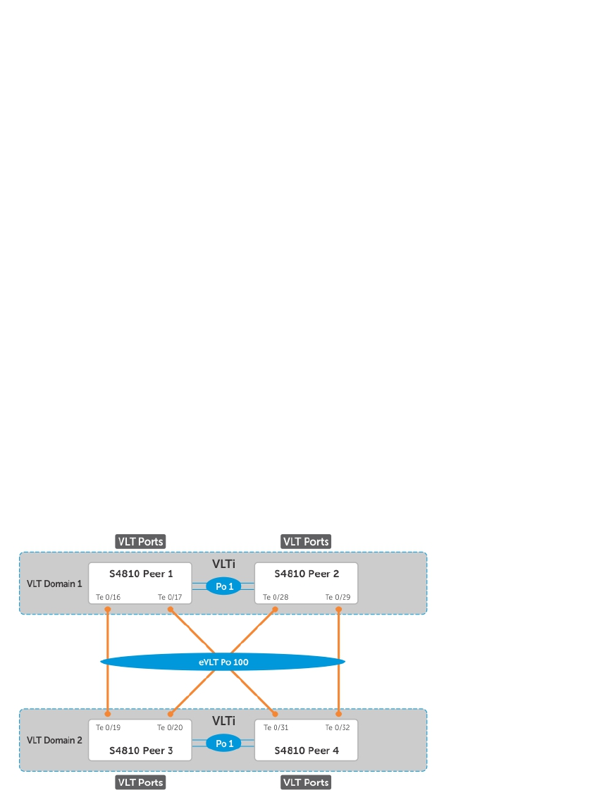
Role Priority: 32768
ICL Link Status: Up
HeartBeat Status: Up
VLT Peer Status: Up
Local System MAC address: 00:01:e8:8c:4d:08
Remote System MAC address: 00:01:e8:8c:4d:1c
Dell-2#show vlt detail
Local LAG Id Peer LAG Id Local Status Active VLANs
------------ ----------- ------------ ------------
2 2 Up 1000-1199
Verify that the VLT LAG is up in both VLT peer units.
Dell-2#show interfaces port-channel 2 brief
Codes: L - LACP Port-channel
LAG Mode Status Uptime Ports
L 2 L2L3 up 03:43:24 Te 0/40 (Up)
Dell-4#show interfaces port-channel 2 brief
Codes: L - LACP Port-channel
LAG Mode Status Uptime Ports
L 2 L2L3 up 03:33:31 Te 0/18 (Up)
eVLT Configuration Example
The following example demonstrates the steps to configure enhanced VLT (eVLT) in a network.
In this example, you are configuring two domains. Domain 1 consists of Peer 1 and Peer 2; Domain 2
consists of Peer 3 and Peer 4, as shown in the following example.
In Domain 1, configure Peer 1 fist, then configure Peer 2. When that is complete, perform the same steps
for the peer nodes in Domain 2. The interface used in this example is TenGigabitEthernet.
Figure 117. eVLT Configuration Example
854 Virtual Link Trunking (VLT)

eVLT Configuration Step Examples
In Domain 1, configure the VLT domain and VLTi on Peer 1.
Domain_1_Peer1#configure
Domain_1_Peer1(conf)#interface port-channel 1
Domain_1_Peer1(conf-if-po-1)# channel-member TenGigabitEthernet 0/8-9
Domain_1_Peer1(conf)#vlt domain 1000
Domain_1_Peer1(conf-vlt-domain)# peer-link port-channel 1
Domain_1_Peer1(conf-vlt-domain)# back-up destination 10.16.130.11
Domain_1_Peer1(conf-vlt-domain)# system-mac mac-address 00:0a:00:0a:00:0a
Domain_1_Peer1(conf-vlt-domain)# unit-id 0
Configure eVLT on Peer 1.
Domain_1_Peer1(conf)#interface port-channel 100
Domain_1_Peer1(conf-if-po-100)# switchport
Domain_1_Peer1(conf-if-po-100)# vlt-peer-lag port-channel 100
Domain_1_Peer1(conf-if-po-100)# no shutdown
Add links to the eVLT port-channel on Peer 1.
Domain_1_Peer1(conf)#interface range tengigabitethernet 0/16 - 17
Domain_1_Peer1(conf-if-range-te-0/16-17)# port-channel-protocol LACP
Domain_1_Peer1(conf-if-range-te-0/16-17)# port-channel 100 mode active
Domain_1_Peer1(conf-if-range-te-0/16-17)# no shutdown
Next, configure the VLT domain and VLTi on Peer 2.
Domain_1_Peer2#configure
Domain_1_Peer2(conf)#interface port-channel 1
Domain_1_Peer2(conf-if-po-1)# channel-member TenGigabitEthernet 0/8-9
Domain_1_Peer2(conf) #vlt domain 200
Domain_1_Peer2(conf-vlt-domain)# peer-link port-channel 1
Domain_1_Peer2(conf-vlt-domain)# back-up destination 10.16.130.12
Domain_1_Peer2(conf-vlt-domain)# system-mac mac-address 00:0a:00:0a:00:0a
Domain_1_Peer2(conf-vlt-domain)# unit-id 1
Configure eVLT on Peer 2.
Domain_1_Peer2(conf)#interface port-channel 100
Domain_1_Peer2(conf-if-po-100)# switchport
Domain_1_Peer2(conf-if-po-100)# vlt-peer-lag port-channel 100
Domain_1_Peer2(conf-if-po-100)# no shutdown
Add links to the eVLT port-channel on Peer 2.
Domain_1_Peer2(conf)#interface range tengigabitethernet 0/28 - 29
Domain_1_Peer2(conf-if-range-te-0/16-17)# port-channel-protocol LACP
Domain_1_Peer2(conf-if-range-te-0/16-17)# port-channel 100 mode active
Domain_1_Peer2(conf-if-range-te-0/16-17)# no shutdown
Virtual Link Trunking (VLT) 855

In Domain 2, configure the VLT domain and VLTi on Peer 3.
Domain_2_Peer3#configure
Domain_2_Peer3(conf)#interface port-channel 1
Domain_2_Peer3(conf-if-po-1)# channel-member TenGigabitEthernet 0/8-9
Domain_1_Peer3#no shutdown
Domain_2_Peer3(conf)#vlt domain 200
Domain_2_Peer3(conf-vlt-domain)# peer-link port-channel 1
Domain_2_Peer3(conf-vlt-domain)# back-up destination 10.18.130.11
Domain_2_Peer3(conf-vlt-domain)# system-mac mac-address 00:0b:00:0b:00:0b
Domain_2_Peer3(conf-vlt-domain)# unit-id 0
Configure eVLT on Peer 3.
Domain_2_Peer3(conf)#interface port-channel 100
Domain_2_Peer3(conf-if-po-100)# switchport
Domain_2_Peer3(conf-if-po-100)# vlt-peer-lag port-channel 100
Domain_2_Peer3(conf-if-po-100)# no shutdown
Add links to the eVLT port-channel on Peer 3.
Domain_2_Peer3(conf)#interface range tengigabitethernet 0/19 - 20
Domain_2_Peer3(conf-if-range-te-0/16-17)# port-channel-protocol LACP
Domain_2_Peer3(conf-if-range-te-0/16-17)# port-channel 100 mode active
Domain_2_Peer3(conf-if-range-te-0/16-17)# no shutdown
Next, configure the VLT domain and VLTi on Peer 4.
Domain_2_Peer4#configure
Domain_2_Peer4(conf)#interface port-channel 1
Domain_2_Peer4(conf-if-po-1)# channel-member TenGigabitEthernet 0/8-9
Domain_1_Peer4#no shutdown
Domain_2_Peer4(conf)#vlt domain 200
Domain_2_Peer4(conf-vlt-domain)# peer-link port-channel 1
Domain_2_Peer4(conf-vlt-domain)# back-up destination 10.18.130.12
Domain_2_Peer4(conf-vlt-domain)# system-mac mac-address 00:0b:00:0b:00:0b
Domain_2_Peer4(conf-vlt-domain)# unit-id 1
Configure eVLT on Peer 4.
Domain_2_Peer4(conf)#interface port-channel 100
Domain_2_Peer4(conf-if-po-100)# switchport
Domain_2_Peer4(conf-if-po-100)# vlt-peer-lag port-channel 100
Domain_2_Peer4(conf-if-po-100)# no shutdown
Add links to the eVLT port-channel on Peer 4.
Domain_2_Peer4(conf)#interface range tengigabitethernet 0/31 - 32
Domain_2_Peer4(conf-if-range-te-0/16-17)# port-channel-protocol LACP
Domain_2_Peer4(conf-if-range-te-0/16-17)# port-channel 100 mode active
Domain_2_Peer4(conf-if-range-te-0/16-17)# no shutdown
856 Virtual Link Trunking (VLT)

PIM-Sparse Mode Configuration Example
The following sample configuration shows how to configure the PIM Sparse mode designated router
functionality on the VLT domain with two VLT port-channels that are members of VLAN 4001.
For more information, refer to PIM-Sparse Mode Support on VLT.
Example of Configuring PIM-Sparse Mode
Enable PIM Multicast Routing on the VLT node globally.
VLT_Peer1(conf)#ip multicast-routing
Enable PIM on the VLT port VLANs.
VLT_Peer1(conf)#interface vlan 4001
VLT_Peer1(conf-if-vl-4001)#ip address 140.0.0.1/24
VLT_Peer1(conf-if-vl-4001)#ip pim sparse-mode
VLT_Peer1(conf-if-vl-4001)#tagged port-channel 101
VLT_Peer1(conf-if-vl-4001)#tagged port-channel 102
VLT_Peer1(conf-if-vl-4001)#no shutdown
VLT_Peer1(conf-if-vl-4001)#exit
Configure the VLTi port as a static multicast router port for the VLAN.
VLT_Peer1(conf)#interface vlan 4001
VLT_Peer1(conf-if-vl-4001)#ip igmp snooping mrouter interface port-channel 128
VLT_Peer1(conf-if-vl-4001)#exit
VLT_Peer1(conf)#end
Repeat these steps on VLT Peer Node 2.
VLT_Peer2(conf)#ip multicast-routing
VLT_Peer2(conf)#interface vlan 4001
VLT_Peer2(conf-if-vl-4001)#ip address 140.0.0.2/24
VLT_Peer2(conf-if-vl-4001)#ip pim sparse-mode
VLT_Peer2(conf-if-vl-4001)#tagged port-channel 101
VLT_Peer2(conf-if-vl-4001)#tagged port-channel 102
VLT_Peer2(conf-if-vl-4001)#no shutdown
VLT_Peer2(conf-if-vl-4001)#ip igmp snooping mrouter interface port-channel 128
VLT_Peer2(conf-if-vl-4001)#exit
VLT_Peer2(conf)#end
Verifying a VLT Configuration
To monitor the operation or verify the configuration of a VLT domain, use any of the following show
commands on the primary and secondary VLT switches.
• Display information on backup link operation.
EXEC mode
show vlt backup-link
• Display general status information about VLT domains currently configured on the switch.
Virtual Link Trunking (VLT) 857

EXEC mode
show vlt brief
• Display detailed information about the VLT-domain configuration, including local and peer port-
channel IDs, local VLT switch status, and number of active VLANs on each port channel.
EXEC mode
show vlt detail
• Display the VLT peer status, role of the local VLT switch, VLT system MAC address and system priority,
and the MAC address and priority of the locally-attached VLT device.
EXEC mode
show vlt role
• Display the current configuration of all VLT domains or a specified group on the switch.
EXEC mode
show running-config vlt
• Display statistics on VLT operation.
EXEC mode
show vlt statistics
• Display the RSTP configuration on a VLT peer switch, including the status of port channels used in the
VLT interconnect trunk and to connect to access devices.
EXEC mode
show spanning-tree rstp
• Display the current status of a port or port-channel interface used in the VLT domain.
EXEC mode
show interfaces interface
–interface: specify one of the following interface types:
* Fast Ethernet: enter fastethernet slot/port.
* 1-Gigabit Ethernet: enter gigabitethernet slot/port.
* 10-Gigabit Ethernet: enter tengigabitethernet slot/port.
* Port channel: enter port-channel {1-128}.
Examples of the show vlt and show spanning-tree rstp Commands
The following example shows the show vlt backup-link command.
Dell_VLTpeer1# show vlt backup-link
VLT Backup Link
-----------------
Destination: 10.11.200.18
Peer HeartBeat status: Up
HeartBeat Timer Interval: 1
HeartBeat Timeout: 3
UDP Port: 34998
HeartBeat Messages Sent: 1026
HeartBeat Messages Received: 1025
Dell_VLTpeer2# show vlt backup-link
858 Virtual Link Trunking (VLT)

VLT Backup Link
-----------------
Destination: 10.11.200.20
Peer HeartBeat status: Up
HeartBeat Timer Interval: 1
HeartBeat Timeout: 3
UDP Port: 34998
HeartBeat Messages Sent: 1030
HeartBeat Messages Received: 1014
The following example shows the show vlt brief command.
Dell_VLTpeer1# show vlt brief
VLT Domain Brief
------------------
Domain ID: 1000
Role: Secondary
Role Priority: 32768
ICL Link Status: Up
HeartBeat Status: Up
VLT Peer Status: Up
Local Unit Id: 0
Version: 5(1)
Local System MAC address: 00:01:e8:8a:e9:70
Remote System MAC address: 00:01:e8:8a:e7:e7
Configured System MAC address: 00:0a:0a:01:01:0a
Remote system version: 5(1)
Delay-Restore timer: 90 seconds
Dell_VLTpeer2# show vlt brief
VLT Domain Brief
------------------
Domain ID: 1000
Role: Primary
Role Priority: 32768
ICL Link Status: Up
HeartBeat Status: Up
VLT Peer Status: Up
Local Unit Id: 1
Version: 5(1)
Local System MAC address: 00:01:e8:8a:e7:e7
Remote System MAC address: 00:01:e8:8a:e9:70
Configured System MAC address: 00:0a:0a:01:01:0a
Remote system version: 5(1)
Delay-Restore timer: 90 seconds
The following example shows the show vlt detail command.
Dell_VLTpeer1# show vlt detail
Local LAG Id Peer LAG Id Local Status Peer Status Active VLANs
------------ ----------- ------------ ----------- -------------
100 100 UP UP 10, 20, 30
127 2 UP UP 20, 30
Dell_VLTpeer2# show vlt detail
Local LAG Id Peer LAG Id Local Status Peer Status Active VLANs
------------ ----------- ------------ ----------- -------------
2 127 UP UP 20, 30
100 100 UP UP 10, 20, 30
Virtual Link Trunking (VLT) 859

The following example shows the show vlt role command.
Dell_VLTpeer1# show vlt role
VLT Role
----------
VLT Role: Primary
System MAC address: 00:01:e8:8a:df:bc
System Role Priority: 32768
Local System MAC address: 00:01:e8:8a:df:bc
Local System Role Priority: 32768
Dell_VLTpeer2# show vlt role
VLT Role
----------
VLT Role: Secondary
System MAC address: 00:01:e8:8a:df:bc
System Role Priority: 32768
Local System MAC address: 00:01:e8:8a:df:e6
Local System Role Priority: 32768
The following example shows the show running-config vlt command.
Dell_VLTpeer1# show running-config vlt
!
vlt domain 30
peer-link port-channel 60
back-up destination 10.11.200.18
Dell_VLTpeer2# show running-config vlt
!
vlt domain 30
peer-link port-channel 60
back-up destination 10.11.200.20
The following example shows the show vlt statistics command.
Dell_VLTpeer1# show vlt statistics
VLT Statistics
----------------
HeartBeat Messages Sent: 987
HeartBeat Messages Received: 986
ICL Hello's Sent: 148
ICL Hello's Received: 98
Dell_VLTpeer2# show vlt statistics
VLT Statistics
----------------
HeartBeat Messages Sent: 994
HeartBeat Messages Received: 978
ICL Hello's Sent: 89
ICL Hello's Received: 89
The following example shows the show spanning-tree rstp command.
860 Virtual Link Trunking (VLT)

The bold section displays the RSTP state of port channels in the VLT domain. Port channel 100 is used in
the VLT interconnect trunk (VLTi) to connect to VLT peer2. Port channels 110, 111, and 120 are used to
connect to access switches or servers (vlt).
Dell_VLTpeer1# show spanning-tree rstp brief
Executing IEEE compatible Spanning Tree Protocol
Root ID Priority 0, Address 0001.e88a.dff8
Root Bridge hello time 2, max age 20, forward delay 15
Bridge ID Priority 4096, Address 0001.e88a.d656
Configured hello time 2, max age 20, forward delay 15
Interface Designated
Name PortID Prio Cost Sts Cost Bridge ID PortID
---------- -------- ---- ------- --------- ------- ------------------
Po 1 128.2 128 200000 DIS 800 4096 0001.e88a.d656 128.2
Po 3 128.4 128 200000 DIS 800 4096 0001.e88a.d656 128.4
Po 4 128.5 128 200000 DIS 800 4096 0001.e88a.d656 128.5
Po 100 128.101 128 800 FWD(VLTi) 800 0 0001.e88a.dff8 128.101
Po 110 128.111 128 00 FWD(vlt) 800 4096 0001.e88a.d656 128.111
Po 111 128.112 128 200000 DIS(vlt) 800 4096 0001.e88a.d656 128.112
Po 120 128.121 128 2000 FWD(vlt) 800 4096 0001.e88a.d656 128.121
Dell_VLTpeer2# show spanning-tree rstp brief
Executing IEEE compatible Spanning Tree Protocol
Root ID Priority 0, Address 0001.e88a.dff8
Root Bridge hello time 2, max age 20, forward delay 15
Bridge ID Priority 0, Address 0001.e88a.dff8
We are the root
Configured hello time 2, max age 20, forward delay 15
Interface Designated
Name PortID Prio Cost Sts Cost Bridge ID PortID
---------- -------- ---- ------- -------- - ------- -------------
Po 1 128.2 128 200000 DIS 0 0 0001.e88a.dff8 128.2
Po 3 128.4 128 200000 DIS 0 0 0001.e88a.dff8 128.4
Po 4 128.5 128 200000 DIS 0 0 0001.e88a.dff8 128.5
Po 100 128.101 128 800 FWD(VLTi)0 0 0001.e88a.dff8 128.101
Po 110 128.111 128 00 FWD(vlt) 0 0 0001.e88a.dff8 128.111
Po 111 128.112 128 200000 DIS(vlt) 0 0 0001.e88a.dff8 128.112
Po 120 128.121 128 2000 FWD(vlt) 0 0 0001.e88a.dff8 128.121
Additional VLT Sample Configurations
To configure VLT, configure a backup link and interconnect trunk, create a VLT domain, configure a
backup link and interconnect trunk, and connect the peer switches in a VLT domain to an attached
access device (switch or server).
Review the following examples of VLT configurations.
Configuring Virtual Link Trunking (VLT Peer 1)
Enable VLT and create a VLT domain with a backup-link and interconnect trunk (VLTi).
Dell_VLTpeer1(conf)#vlt domain 999
Dell_VLTpeer1(conf-vlt-domain)#peer-link port-channel 100
Dell_VLTpeer1(conf-vlt-domain)#back-up destination 10.11.206.35
Dell_VLTpeer1(conf-vlt-domain)#exit
Virtual Link Trunking (VLT) 861

Configure the backup link.
Dell_VLTpeer1(conf)#interface ManagementEthernet 0/0
Dell_VLTpeer1(conf-if-ma-0/0)#ip address 10.11.206.23/
Dell_VLTpeer1(conf-if-ma-0/0)#no shutdown
Dell_VLTpeer1(conf-if-ma-0/0)#exit
Configure the VLT interconnect (VLTi).
Dell_VLTpeer1(conf)#interface port-channel 100
Dell_VLTpeer1(conf-if-po-100)#no ip address
Dell_VLTpeer1(conf-if-po-100)#channel-member fortyGigE 0/56,60
Dell_VLTpeer1(conf-if-po-100)#no shutdown
Dell_VLTpeer1(conf-if-po-100)#exit
Configure the port channel to an attached device.
Dell_VLTpeer1(conf)#interface port-channel 110
Dell_VLTpeer1(conf-if-po-110)#no ip address
Dell_VLTpeer1(conf-if-po-110)#switchport
Dell_VLTpeer1(conf-if-po-110)#channel-member fortyGigE 0/52
Dell_VLTpeer1(conf-if-po-110)#no shutdown
Dell_VLTpeer1(conf-if-po-110)#vlt-peer-lag port-channel 110
Dell_VLTpeer1(conf-if-po-110)#end
Verify that the port channels used in the VLT domain are assigned to the same VLAN.
Dell_VLTpeer1# show vlan id 10
Codes: * - Default VLAN, G - GVRP VLANs, P - Primary, C - Community, I -
Isolated
Q: U - Untagged, T - Tagged
x - Dot1x untagged, X - Dot1x tagged
G - GVRP tagged, M - Vlan-stack, H - Hyperpull tagged
NUM Status Description Q Ports
10 Active U Po110(Fo 0/52)
T Po100(Fo 0/56,60)
Configuring Virtual Link Trunking (VLT Peer 2)
Enable VLT and create a VLT domain with a backup-link VLT interconnect (VLTi).
Dell_VLTpeer2(conf)#vlt domain 999
Dell_VLTpeer2(conf-vlt-domain)#peer-link port-channel 100
Dell_VLTpeer2(conf-vlt-domain)#back-up destination 10.11.206.23
Dell_VLTpeer2(conf-vlt-domain)#exit
Configure the backup link.
Dell_VLTpeer2(conf)#interface ManagementEthernet 0/0
Dell_VLTpeer2(conf-if-ma-0/0)#ip address 10.11.206.35/
Dell_VLTpeer2(conf-if-ma-0/0)#no shutdown
Dell_VLTpeer2(conf-if-ma-0/0)#exit
862 Virtual Link Trunking (VLT)

Configure the VLT interconnect (VLTi).
Dell_VLTpeer2(conf)#interface port-channel 100
Dell_VLTpeer2(conf-if-po-100)#no ip address
Dell_VLTpeer2(conf-if-po-100)#channel-member fortyGigE 0/46,50
Dell_VLTpeer2(conf-if-po-100)#no shutdown
Dell_VLTpeer2(conf-if-po-100)#exit
Configure the port channel to an attached device.
Dell_VLTpeer2(conf)#interface port-channel 110
Dell_VLTpeer2(conf-if-po-110)#no ip address
Dell_VLTpeer2(conf-if-po-110)#switchport
Dell_VLTpeer2(conf-if-po-110)#channel-member fortyGigE 0/48
Dell_VLTpeer2(conf-if-po-110)#no shutdown
Dell_VLTpeer2(conf-if-po-110)#vlt-peer-lag port-channel 110
Dell_VLTpeer2(conf-if-po-110)#end
Verify that the port channels used in the VLT domain are assigned to the same VLAN.
Dell_VLTpeer2# show vlan id 10
Codes: * - Default VLAN, G - GVRP VLANs, P - Primary, C - Community, I -
Isolated
Q: U - Untagged, T - Tagged
x - Dot1x untagged, X - Dot1x tagged
G - GVRP tagged, M - Vlan-stack, H - Hyperpull tagged
NUM Status Description Q Ports
10 Active U Po110(Fo 0/48)
T Po100(Fo 0/46,50)
Verifying a Port-Channel Connection to a VLT Domain (From an Attached
Access Switch)
On an access device, verify the port-channel connection to a VLT domain.
Dell_TORswitch(conf)# show running-config interface port-channel 11
!
interface Port-channel 11
no ip address
switchport
channel-member fortyGigE 1/18,22
no shutdown
Troubleshooting VLT
To help troubleshoot different VLT issues that may occur, use the following information.
NOTE: For information on VLT Failure mode timing and its impact, contact your Dell Networking
representative.
Virtual Link Trunking (VLT) 863

Table 50. Troubleshooting VLT
Description Behavior at Peer Up Behavior During Run
Time Action to Take
Bandwidth monitoring A syslog error message
and an SNMP trap is
generated when the
VLTi bandwidth usage
goes above the 80%
threshold and when it
drops below 80%.
A syslog error message
and an SNMP trap is
generated when the
VLTi bandwidth usage
goes above its threshold.
Depending on the traffic
that is received, the
traffic can be offloaded
inVLTi.
Domain ID mismatch The VLT peer does not
boot up. The VLTi is
forced to a down state.
A syslog error message
and an SNMP trap are
generated.
The VLT peer does not
boot up. The VLTi is
forced to a down state.
A syslog error message
and an SNMP trap are
generated.
Verify the domain ID
matches on both VLT
peers.
Dell Networking OS
Version mismatch
A syslog error message
is generated.
A syslog error message
is generated.
Follow the correct
upgrade procedure for
the unit with the
mismatched Dell
Networking OS version.
Remote VLT port
channel status
N/A N/A Use the show vlt
detail and show vlt
brief commands to
view the VLT port
channel status
information.
Spanning tree mismatch
at global level
All VLT port channels go
down on both VLT
peers. A syslog error
message is generated.
No traffic is passed on
the port channels.
A one-time
informational syslog
message is generated.
During run time, a loop
may occur as long as
the mismatch lasts.
To resolve, enable RSTP
on both VLT peers.
Spanning tree mismatch
at port level
A syslog error message
is generated.
A one-time
informational syslog
message is generated.
Correct the spanning
tree configuration on
the ports.
System MAC mismatch A syslog error message
and an SNMP trap are
generated.
A syslog error message
and an SNMP trap are
generated.
Verify that the unit ID of
VLT peers is not the
same on both units and
that the MAC address is
the same on both units.
Unit ID mismatch The VLT peer does not
boot up. The VLTi is
forced to a down state.
The VLT peer does not
boot up. The VLTi is
forced to a down state.
Verify the unit ID is
correct on both VLT
peers. Unit ID numbers
must be sequential on
peer units; for example,
864 Virtual Link Trunking (VLT)

Description Behavior at Peer Up Behavior During Run
Time Action to Take
A syslog error message
is generated.
A syslog error message
is generated. if Peer 1 is unit ID “0”,
Peer 2 unit ID must be
“1’.
Version ID mismatch A syslog error message
and an SNMP trap are
generated.
A syslog error message
and an SNMP trap are
generated.
Verify the Dell
Networking OS versions
on the VLT peers is
compatible. For more
information, refer to the
Release Notes for this
release.
VLT LAG ID is not
configured on one VLT
peer
A syslog error message
is generated. The peer
with the VLT configured
remains active.
A syslog error message
is generated. The peer
with the VLT configured
remains active.
Verify the VLT LAG ID is
configured correctly on
both VLT peers.
VLT LAG ID mismatch The VLT port channel is
brought down.
A syslog error message
is generated.
The VLT port channel is
brought down.
A syslog error message
is generated.
Perform a mismatch
check after the VLT peer
is established.
Reconfiguring Stacked Switches as VLT
To convert switches that have been stacked to VLT peers, use the following procedure.
1. Remove the current configuration from the switches. You will need to split the configuration up for
each switch.
2. Copy the files to the flash memory of the appropriate switch.
3. Copy the files on the flash drive to the startup-config.
4. Reset the stacking ports to user ports for both switches.
5. Reload the stack and confirm the new configurations have been applied.
6. On the Secondary switch (stack-unit1), enter the command stack-unit1 renumber 0.
7. Confirm the reload query.
8. After reloading, confirm that VLT is enabled.
9. Confirm that the management ports are interconnected or connected to a switch that can transfer
Heartbeat information.
Specifying VLT Nodes in a PVLAN
You can configure VLT peer nodes in a private VLAN (PVLAN). VLT enables redundancy without the
implementation of Spanning Tree Protocol (STP), and provides a loop-free network with optimal
bandwidth utilization.
Because the VLT LAG interfaces are terminated on two different nodes, PVLAN configuration of VLT
VLANs and VLT LAGs are symmetrical and identical on both the VLT peers. PVLANs provide Layer 2
isolation between ports within the same VLAN. A PVLAN partitions a traditional VLAN into sub-domains
Virtual Link Trunking (VLT) 865
identified by a primary and secondary VLAN pair. With VLT being a Layer 2 redundancy mechanism,
support for configuration of VLT nodes in a PVLAN enables Layer 2 security functionalities. To achieve
maximum VLT resiliency, you should configure the PVLAN IDs and mappings to be identical on both the
VLT peer nodes.
The association of PVLAN with the VLT LAG must also be identical. After the VLT LAG is configured to be
a member of either the primary or secondary PVLAN (which is associated with the primary), ICL becomes
an automatic member of that PVLAN on both switches. This association helps the PVLAN data flow
received on one VLT peer for a VLT LAG to be transmitted on that VLT LAG from the peer.
You can associate either a VLT VLAN or a VLT LAG to a PVLAN. First configure the VLT interconnect (VLTi)
or a VLT LAG by using the peer-link port-channel id-number command or the VLT VLAN by using
the peer-link port-channel id-number peer-down-vlan vlan interface number command
and the switchport command. After you specify the VLTi link and VLT LAGs, you can associate the
same port channel or LAG bundle that is a part of a VLT to a PVLAN by using the interface interface
and switchport mode private-vlan commands.
When a VLTi port in trunk mode is a member of symmetric VLT PVLANs, the PVLAN packets are
forwarded only if the PVLAN settings of both the VLT nodes are identical. You can configure the VLTi in
trunk mode to be a member of non-VLT PVLANs if the VLTi is configured on both the peers. MAC address
synchronization is performed for VLT PVLANs across peers in a VLT domain.
Keep the following points in mind when you configure VLT nodes in a PVLAN:
• Configure the VLTi link to be in trunk mode. Do not configure the VLTi link to be in access or
promiscuous mode.
• You can configure a VLT LAG or port channel to be in trunk, access, or promiscuous port modes
when you include the VLT LAG in a PVLAN. The VLT LAG settings must be the same on both the peers.
If you configure a VLT LAG as a trunk port, you can associate that LAG to be a member of a normal
VLAN or a PVLAN. If you configure a VLT LAG to be a promiscuous port, you can configure that LAG
to be a member of PVLAN only. If you configure a VLT LAG to be in access port mode, you can add
that LAG to be a member of the secondary VLAN only.
• ARP entries are synchronized even when a mismatch occurs in the PVLAN mode of a VLT LAG.
Any VLAN that contains at least one VLT port as a member is treated as a VLT VLAN. You can configure a
VLT VLAN to be a primary, secondary, or a normal VLAN. However, the VLT VLAN configuration must be
symmetrical across peers. If the VLT LAG is tagged to any one of the primary or secondary VLANs of a
PVLAN, then both the primary and secondary VLANs are considered as VLT VLANs.
If you add an ICL or VLTi link as a member of a primary VLAN, the ICL becomes a part of the primary
VLAN and its associated secondary VLANs, similar to the behavior for normal trunk ports. VLAN parity is
not validated if you associate an ICL to a PVLAN. Similarly, if you dissociate an ICL from a PVLAN,
although the PVLAN parity exists, ICL is removed from that PVLAN.
Association of VLTi as a Member of a PVLAN
If a VLAN is configured as a non-VLT VLAN on both the peers, the VLTi link is made a member of that
VLAN if the VLTi link is configured as a PVLAN or normal VLAN on both the peers. If a PVLAN is
configured as a VLT VLAN on one peer and a non-VLT VLAN on another peer, the VLTi is added as a
member of that VLAN by verifying the PVLAN parity on both the peers. In such a case, if a PVLAN is
present as a VLT PVLAN on at least one of the peers, then symmetric configuration of the PVLAN is
866 Virtual Link Trunking (VLT)
validated to cause the VLTi to be a member of that VLAN. Whenever a change in the VLAN mode on one
of the peers occurs, the information is synchronized with the other peer and VLTi is either added or
removed from the VLAN based on the validation of the VLAN parity.
For VLT VLANs, the association between primary VLAN and secondary VLANs is examined on both the
peers. Only if the association is identical on both the peers, VLTi is configured as a member of those
VLANs. This behavior is because of security functionalities in a PVLAN. For example, if a VLAN is a primary
VLT VLAN on one peer and not a primary VLT VLAN on the other peer, VLTi is not made a part of that
VLAN.
MAC Synchronization for VLT Nodes in a PVLAN
For the MAC addresses that are learned on non-VLT ports, MAC address synchronization is performed
with the other peer if the VLTi (ICL) link is part of the same VLAN as the non-VLT port. For MAC addresses
that are learned on VLT ports, the VLT LAG mode of operation and the primary to secondary association
of the VLT nodes is determined on both the VLT peers. MAC synchronization is performed for the VLT
LAGs only if the VLT LAG and primary-secondary VLT peer mapping are symmetrical.
The PVLAN mode of VLT LAGs on one peer is validated against the PVLAN mode of VLT LAGs on the
other peer. MAC addresses that are learned on that VLT LAG are synchronized between the peers only if
the PVLAN mode on both the peers is identical. For example, if the MAC address is learned on a VLT LAG
and the VLAN is a primary VLT VLAN on one peer and not a primary VLT VLAN on the other peer, MAC
synchronization does not occur.
Whenever a change occurs in the VLAN mode of one of the peers, this modification is synchronized with
the other peers. Depending on the validation mechanism that is initiated for MAC synchronization of VLT
peers, MAC addresses learned on a particular VLAN are either synchronized with the other peers, or MAC
addresses synchronized from the other peers on the same VLAN are deleted. This method of processing
occurs when the PVLAN mode of VLT LAGs is modified.
Because the VLTi link is only a member of symmetric VLT PVLANs, MAC synchronization takes place
directly based on the membership of the VLTi link in a VLAN and the VLT LAG mode.
PVLAN Operations When One VLT Peer is Down
When a VLT port moves to the Admin or Operationally Down state on only one of the VLT nodes, the VLT
Lag is still considered to be up. All the PVLAN MAC entries that correspond to the operationally down VLT
LAG are maintained as synchronized entries in the device. These MAC entries are removed when the peer
VLT LAG also becomes inactive or a change in PVLAN configuration occurs.
PVLAN Operations When a VLT Peer is Restarted
When the VLT peer node is rebooted, the VLAN membership of the VLTi link is preserved and when the
peer node comes back online, a verification is performed with the newly received PVLAN configuration
from the peer. If any differences are identified, the VLTi link is either added or removed from the VLAN.
When the peer node restarts and returns online, all the PVLAN configurations are exchanged across the
peers. Based on the information received from the peer, a bulk synchronization of MAC addresses that
belong to spanned PVLANs is performed.
During the booting phase or when the ICL link attempts to come up, a system logging message is
recorded if VLT PVLAN mismatches, PVLAN mode mismatches, PVLAN association mismatches, or PVLAN
Virtual Link Trunking (VLT) 867

port mode mismatches occur. Also, you can view these discrepancies if any occur by using the show
vlt mismatch command.
Interoperation of VLT Nodes in a PVLAN with ARP Requests
When an ARP request is received, and the following conditions are applicable, the IP stack performs
certain operations.
• The VLAN on which the ARP request is received is a secondary VLAN (community or isolated VLAN).
• Layer 3 communication between secondary VLANs in a private VLAN is enabled by using the ip
local-proxy-arp command in INTERFACE VLAN configuration mode.
• The ARP request is not received on the ICL
Under such conditions, the IP stack performs the following operations:
• The ARP reply is sent with the MAC address of the primary VLAN.
• The ARP request packet originates on the primary VLAN for the intended destination IP address.
The ARP request received on ICLs are not proxied, even if they are received with a secondary VLAN tag.
This behavior change occurs because the node from which the ARP request was forwarded would have
replied with its MAC address, and the current node discards the ARP request.
Scenarios for VLAN Membership and MAC Synchronization With VLT Nodes
in PVLAN
The following table illustrates the association of the VLTi link and PVLANs, and the MAC synchronization
of VLT nodes in a PVLAN (for various modes of operations of the VLT peers):
Table 51. VLAN Membership and MAC Synchronization With VLT Nodes in PVLAN
VLT LAG Mode PVLAN Mode of VLT VLAN ICL VLAN
Membership Mac
Synchronization
Peer1 Peer2 Peer1 Peer2
Trunk Trunk Primary Primary Yes Yes
Trunk Trunk Primary Normal No No
Trunk Trunk Normal Normal Yes Yes
Promiscuo
us
Trunk Primary Primary Yes No
Trunk Access Primary Secondary No No
Promiscuo
us
Promiscuo
us
Primary Primary Yes Yes
Promiscuo
us
Access Primary Secondary No No
Promiscuo
us
Promiscuo
us
Primary Primary Yes Yes
868 Virtual Link Trunking (VLT)

VLT LAG Mode PVLAN Mode of VLT VLAN ICL VLAN
Membership Mac
Synchronization
Peer1 Peer2 Peer1 Peer2
- Secondary
(Community)
- Secondary
(Isolated)
No No
Access Access Secondary
(Community)
Secondary
(Isolated)
No No
• Primary X • Primary X Yes Yes
Promiscuo
us
Promiscuo
us
Primary Primary Yes Yes
- Secondary
(Community)
- Secondary
(Community)
Yes Yes
- Secondary
(Isolated)
- Secondary
(Isolated)
Yes Yes
Promiscuo
us
Trunk Primary Normal No No
Promiscuo
us
Trunk Primary Primary Yes No
Access Access Secondary
(Community)
Secondary
(Community)
Yes Yes
- Primary VLAN X - Primary VLAN X Yes Yes
Access Access Secondary
(Isolated)
Secondary
(Isolated)
Yes Yes
- Primary VLAN X - Primary VLAN X Yes Yes
Access Access Secondary
(Isolated)
Secondary
(Isolated)
No No
- Primary VLAN X - Primary VLAN Y No No
Access Access Secondary
(Community)
Secondary
(Community)
No No
- Primary VLAN Y - Primary VLAN X No No
Promiscuo
us
Access Primary Secondary No No
Trunk Access Primary/Normal Secondary No No
Virtual Link Trunking (VLT) 869

Configuring a VLT VLAN or LAG in a PVLAN
You can configure the VLT peers or nodes in a private VLAN (PVLAN). Because the VLT LAG interfaces are
terminated on two different nodes, PVLAN configuration of VLT VLANs and VLT LAGs are symmetrical
and identical on both the VLT peers. PVLANs provide Layer 2 isolation between ports within the same
VLAN. A PVLAN partitions a traditional VLAN into subdomains identified by a primary and secondary VLAN
pair. With VLT being a Layer 2 redundancy feature, support for configuration of VLT nodes in a PVLAN
enables Layer 2 security functionalities to be achieved. This section contains the following topics that
describe how to configure a VLT VLAN or a VLT LAG (VLTi link) and assign that VLT interface to a PVLAN.
Creating a VLT LAG or a VLT VLAN
1. Configure the port channel for the VLT interconnect on a VLT switch and enter interface
configuration mode
CONFIGURATION mode
interface port-channel id-number.
Enter the same port-channel number configured with the peer-link port-channel command as
described in Enabling VLT and Creating a VLT Domain.
NOTE: To be included in the VLTi, the port channel must be in Default mode (no switchport
or VLAN assigned).
2. Remove an IP address from the interface.
INTERFACE PORT-CHANNEL mode
no ip address
3. Add one or more port interfaces to the port channel.
INTERFACE PORT-CHANNEL mode
channel-member interface
interface: specify one of the following interface types:
• 1-Gigabit Ethernet: Enter gigabitethernet slot/port.
• 10-Gigabit Ethernet: Enter tengigabitethernet slot/port.
• 40-Gigabit Ethernet: Enter fortyGigE slot/port.
4. Ensure that the port channel is active.
INTERFACE PORT-CHANNEL mode
no shutdown
5. To configure the VLT interconnect, repeat Steps 1–4 on the VLT peer switch.
6. Enter VLT-domain configuration mode for a specified VLT domain.
CONFIGURATION mode
vlt domain domain-id
The range of domain IDs is from 1 to 1000.
7. Enter the port-channel number that acts as the interconnect trunk.
870 Virtual Link Trunking (VLT)
VLT DOMAIN CONFIGURATION mode
peer-link port-channel id-number
The range is from 1 to 128.
8. (Optional) To configure a VLT LAG, enter the VLAN ID number of the VLAN where the VLT forwards
packets received on the VLTi from an adjacent peer that is down.
VLT DOMAIN CONFIGURATION mode
peer-link port-channel id-number peer-down-vlan vlan interface number
The range is from 1 to 4094.
Associating the VLT LAG or VLT VLAN in a PVLAN
1. Access INTERFACE mode for the port that you want to assign to a PVLAN.
CONFIGURATION mode
interface interface
2. Enable the port.
INTERFACE mode
no shutdown
3. Set the port in Layer 2 mode.
INTERFACE mode
switchport
4. Select the PVLAN mode.
INTERFACE mode
switchport mode private-vlan {host | promiscuous | trunk}
•host (isolated or community VLAN port)
•promiscuous (intra-VLAN communication port)
•trunk (inter-switch PVLAN hub port)
5. Access INTERFACE VLAN mode for the VLAN to which you want to assign the PVLAN interfaces.
CONFIGURATION mode
interface vlan vlan-id
6. Enable the VLAN.
INTERFACE VLAN mode
no shutdown
7. To obtain maximum VLT resiliency, configure the PVLAN IDs and mappings to be identical on both
the VLT peer nodes. Set the PVLAN mode of the selected VLAN to primary.
INTERFACE VLAN mode
private-vlan mode primary
8. Map secondary VLANs to the selected primary VLAN.
Virtual Link Trunking (VLT) 871
INTERFACE VLAN mode
private-vlan mapping secondary-vlan vlan-list
The list of secondary VLANs can be:
• Specified in comma-delimited (VLAN-ID,VLAN-ID) or hyphenated-range format (VLAN-ID-
VLAN-ID).
• Specified with this command even before they have been created.
• Amended by specifying the new secondary VLAN to be added to the list.
Proxy ARP Capability on VLT Peer Nodes
The proxy ARP functionality is supported on VLT peer nodes.
A proxy ARP-enabled device answers the ARP requests that are destined for another host or router. The
local host forwards the traffic to the proxy ARP-enabled device, which in turn transmits the packets to the
destination.
By default, proxy ARP is enabled. To disable proxy ARP, use the no proxy-arp command in the interface
mode. To re-enable proxy ARP, use the ip proxy-arp command in INTERFACE mode. To view if proxy
ARP is enabled on the interface, use the show config command in INTERFACE mode. If it is not listed in
the show config command output, it is enabled. Only nondefault information is displayed in the show
config command output.
ARP proxy operation is performed on the VLT peer node IP address when the peer VLT node is down. The
ARP proxy stops working either when the peer routing timer expires or when the peer VLT node goes up.
Layer 3 VLT provides a higher resiliency at the Layer 3 forwarding level. VLT peer routing enables you to
replace VRRP with routed VLT to route the traffic from Layer 2 access nodes. With proxy ARP, hosts can
resolve the MAC address of the VLT node even when VLT node is down.
If the ICL link is down when a VLT node receives an ARP request for the IP address of the VLT peer, owing
to LAG-level hashing algorithm in the top-of-rack (TOR) switch, the incorrect VLT node responds to the
ARP request with the peer MAC address. Proxy ARP is not performed when the ICL link is up and the ARP
request the wrong VLT peer. In this case, ARP requests are tunneled to the VLT peer.
Proxy ARP supported on both VLT interfaces and non-VLT interfaces. Proxy ARP supported on symmetric
VLANs only. Proxy ARP is enabled by default. Routing table must be symmetrically configured to support
proxy ARP. For example, consider a sample topology in which VLAN 100 is configured on two VLT nodes,
node 1 and node 2. ICL link is not configured between the two VLT nodes. Assume that the VLAN 100 IP
address in node 1 is 10.1.1.1/24 and VLAN 100 IP address in node 2 is 20.1.1.2/24. In this case, if the ARP
request for 20.1.1.1 reaches node 1, node 1 will not perform the ARP request for 20.1.1.2. Proxy ARP is
supported only for the IP address belongs to the received interface IP network. Proxy ARP is not
supported if the ARP requested IP address is different from the received interface IP subnet. For example,
if VLAN 100 and 200 are configured on the VLT peers, and if the VLAN 100 IP address is configured as
10.1.1.0/24 and the VLAN 200 IP address is configured as 20.1.1.0/24, the proxy ARP is not performed if
the VLT node receives an ARP request for 20.1.1.0/24 on VLAN 100.
Working of Proxy ARP for VLT Peer Nodes
Proxy ARP is enabled only when peer routing is enabled on both the VLT peers. If peer routing is disabled
on one of the VLT peers, proxy ARP is not performed when the ICL link goes down. Proxy ARP is
872 Virtual Link Trunking (VLT)
performed only when the VLT peer's MAC address is installed in the database. Proxy ARP is stopped when
the VLT peer's MAC address is removed from the ARP database because of the peer routing timer expiry.
The source hardware address in the ARP response contains the VLT peer MAC address. Proxy ARP is
supported for both unicast and broadcast ARP requests. Control packets, other than ARP requests
destined for the VLT peers that reach the undesired and incorrect VLT node, are dropped if the ICL link is
down. Further processing is not done on these control packets. The VLT node does not perform any
action if it receives gratuitous ARP requests for the VLT peer IP address. Proxy ARP is also supported on
secondary VLANs. When the ICL link or peer is down, and the ARP request for a private VLAN IP address
reaches the wrong peer, then the wrong peer responds to the ARP request with the peer MAC address.
The IP address of the VLT node VLAN interface is synchronized with the VLT peer over ICL when the VLT
peers are up. Whenever an IP address is added or deleted, this updated information is synchronized with
the VLT peer. IP address synchronization occurs regardless of the VLAN administrative state. IP address
addition and deletion serve as the trigger events for synchronization. When a VLAN state is down, the VLT
peer might perform a proxy ARP operation for the IP addresses of that VLAN interface.
VLT nodes start performing Proxy ARP when the ICL link goes down. When the VLT peer comes up, proxy
ARP will be stopped for the peer VLT IP addresses. When the peer node is rebooted, the IP address
synchronized with the peer is not flushed. Peer down events cause the proxy ARP to commence.
When a VLT node detects peer up, it will not perform proxy ARP for the peer IP addresses. IP address
synchronization occurs again between the VLT peers.
Proxy ARP is enabled only if peer routing is enabled on both the VLT peers. If you disable peer routing by
using the no peer-routingcommand in VLT DOMAIN node, a notification is sent to the VLT peer to
disable the proxy ARP. If peer routing is disabled when ICL link is down, a notification is not sent to the
VLT peer and in such a case, the VLT peer does not disable the proxy ARP operation.
When the VLT domain is removed on one of the VLT nodes, the peer routing configuration removal will
be notified to the peer. In this case VLT peer node disables the proxy ARP. When the ICL link is removed
on one of the VLT nodes by using the no peer-link command, the ICL down event is triggered on the
other VLT node, which in turn starts the proxy ARP application. The VLT node, where the ICL link is
deleted, flushes the peer IP addresses and does not perform proxy ARP for the additional LAG hashed
ARP requests.
VLT Nodes as Rendezvous Points for Multicast Resiliency
You can configure virtual link trunking (VLT) peer nodes as rendezvous points (RPs) in a Protocol
Independent Multicast (PIM) domain.
PIM uses a VLT node as the RP to distribute multicast traffic to a multicast group. Messages to join the
multicast group (Join messages) and data are sent towards the RP, so that receivers can discover who the
senders are and begin receiving traffic destined for the multicast group.
To enable an explicit multicast routing table synchronization method for VLT nodes, you can configure
VLT nodes as RPs. Multicast routing needs to identify the incoming interface for each route. The PIM
running on both VLT peers enables both the peers to obtain traffic from the same incoming interface.
You can configure a VLT node to be an RP through the ip pim rp-address command in Global
Configuration mode. When you configure a VLT node as an RP, the (*, G) routes that are synchronized
from the VLT peers are ignored and not downloaded to the device. For the (S, G) routes that are
Virtual Link Trunking (VLT) 873
synchronized from the VLT peer, after the RP starts receiving multicast traffic via these routes, these (S, G)
routes are considered valid and are downloaded to the device. Only (S, G) routes are used to forward the
multicast traffic from the source to the receiver.
You can configure VLT nodes, which function as RP, as Multicast Source Discovery Protocol (MSDP)
peers in different domains. However, you cannot configure the VLT peers as MSDP peers in the same VLT
domain. In such instances, the VLT peer does not support the RP functionality.
If the same source or RP can be accessed over both a VLT and a non-VLT VLAN, configure better metrics
for the VLT VLANs. Otherwise, it is possible that one VLT node chooses a non-VLT VLAN (if the path
through the VLT VLAN was not available when the route was learned) and another VLT node selects a VLT
VLAN. Such a scenario can cause duplication of packets. ECMP is not supported when you configure VLT
nodes as RPs.
Backup RP is not supported if the VLT peer that functions as the RP is statically configured. With static RP
configuration, if the RP reboots, it can handle new clients only after it comes back online. Until the RP
returns to the active state, the VLT peer forwards the packets for the already logged-in clients. To enable
the VLT peer node to retain the synchronized multicast routes or synchronized multicast outgoing
interface (OIF) maps after a peer node failure, use the timeout value that you configured through the
multicast peer-routing timeout value command. You can configure an optimal time for a VLT
node to retain synced multicast routes or synced multicast outgoing interface (OIF), after a VLT peer
node failure, through the multicast peer-routing-timeout command in VLT DOMAIN mode. Using
the bootstrap router (BSR) mechanism, both the VLT nodes in a VLT domain can be configured as the
candidate RP for the same group range. When an RP fails, the VLT peer automatically takes over the role
of the RP. This phenomenon enables resiliency to be achieved by the PIM BSR protocol.
874 Virtual Link Trunking (VLT)
55
VLT Proxy Gateway
You can configure a proxy gateway in VLT domains. A proxy gateway enables you to locally route the
packets that are destined to a L3 endpoint in another VLT domain.
Proxy Gateway in VLT Domains
Using a proxy gateway, the VLT peers in a domain can route the L3 packets destined for VLT peers in
another domain as long as they have L3 reachability of these IP destinations.
A proxy gateway in a VLT domain provides the following benefits:
• Avoid sub-optimal routing of packets by a VLT domain when packets are destined to the endpoint in
another VLT domain.
• Provide resiliency if a VLT peer goes down by performing proxy routing for the peer’s DA MAC in
another VLT domain.
A typical scenario is virtual movement of servers across data centers. Virtual movement enables live
migration of running virtual machines from one host to another without a downtime. Consider a square
VLT connecting two data centers. If a VM, say VM1 on Server Rack 1 has C as its default gateway and VM1
performs a virtual movement to Server Rack 2 with no change in default gateway, then L3 packets
destined for C can be routed either C1 or D1 locally. This behavior is achieved by installing the local_DA
entries for C/D in C1/D1 so that the packets for C/D could have a hit at C1/D1 and routed locally.
In the following figure, server racks, named Rack 1 and Rack 2 are part of data centers, named DC1 and
DC2 respectively. Rack 1 is connected to devices A and B in Layer 2. Similarly, Rack 2 is connected to
devices A and B in Layer 2. A VLT LAG is present between A and B. A and B are connected to core routers,
C and D. VLT routing is present between C and D. C1 and D1 are Layer 3 routers in DC2 and they are
connected with core routers, C and D. The core or Layer 3 routers are then part of a Layer 3 cloud.
VLT Proxy Gateway 875
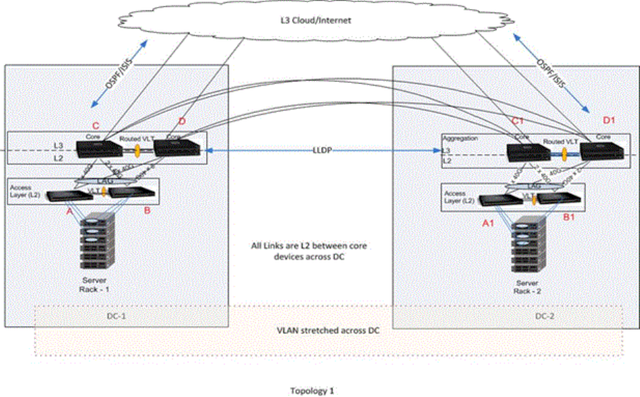
When the routing table across DCs is not symmetrical, there is a possibility of a routing miss by a DC that
do not have the route for the L3 traffic. Since routing protocols will enabled and both the DC’s comes in
same subnet there will not be route asymmetry dynamically. But if static route is configured on one DC
and not on the other, it will result is asymmetry. Proxy routing can still be achieved locally by configuring
a static route or default gateway.
Guidelines for Configuring a VLT Proxy Gateway
Keep the following points in mind when you configure this functionality:
1. Proxy gateway is supported only for VLT i.e. across VLT domain.
2. The current design will not handle the asymmetric VLAN configuration scenarios such as same VLAN
configured with L2 mode on one VLT domain and L3 mode on the other VLT domain. It is always
required to configure same mode for the VLAN’s across the VLT domain.
3. VLAN symmetry within a VLT domain is also to be maintained.
4. The connection between DC’s can only be a VLT.
5. Trace route across DC’s may possibly show extra hops.
6. Route symmetry has to be maintained across the VLT domains to ensure no traffic drops.
7. If the port-channel specified in the proxy-gateway command is not a VLT LAG then the configuration is
rejected by CLI. The VLT LAG cannot be changed to a legacy LAG when it is part of proxy-gateway.
876 VLT Proxy Gateway
8. LLDP port channel interface can’t be changed to legacy lag when proxy gateway is enabled.
9.“vlt-peer-mac transmit” is recommended only for square VLT without any diagonal links.
10. VRRP and IPv6 routing is not supported now.
11. With the existing hardware capabilities, only 512 my_station_tcam entries can be supported.
12. PVLAN not supported
13. After VM Motion, it’s expected that VM Host will send GARP in term, host previous VLT Domain will
have mac movement points to newer VLT Domain
14. After station move, it is expected that if host send TTL1 packet destined to its gateway i.e previous Vlt
Node, the packet may get dropped.
15. After station move, it’s expected that if host first PING its gateway (i.e previous VLT node) it would
results in 40 to 60% success rate considering it take long path
Configuring a VLT Proxy Gateway
The VLT proxy gateway feature can be configured in a VLT domain context using the cli command
proxy-gateway LLDP. You enter the proxy-gateway Configuration mode when you enter this
command. The port-channel interface of the square VLT link on which LLDP packets are to be sent is
specified by peer-domain-link port-channel command.
On a proxy gateway interface configuration corresponding to LLDP, LLDP sets TLV flags on the interfaces
for receiving and transmitting private TLV packets. After defining these organizational TLV settings, LLDP
encodes the proxy gateway TLVs based on the organizational TLVs for transmitting to the peer. If you
specify the no proxy gateway LLDP interface command, LLDP stops transmitting and receiving
proxy gateway TLV packets on the specified interfaces. However, other TLVs are not affected. Because of
the timing defined in the LLDP configuration and the operational state, LLDP periodically sends or
receives packets. However, the local DA updates may not be able to reach the destination on time. From
the interfaces on which proxy gateway LLDP is enabled, LLDP decodes TLV packets from the remote
LLDP by using the new organizational TLV.
The following requirements must be satisfied for LLDP proxy gateway to function correctly:
• As LLDP is direct link protocol, Data Centers must be directly connected.
• LLDP has a limited TLV size. As a result, information that is carried by this new TLV is limited to only
one or two MACs.
• Proper configuration and physical setup must be ensured on all related systems.
LLDP organizational TLV for proxy gateway
A new organizational TLV is defined for this purpose:
• LLDP will define an organizationally specific TLV (type 127) with organizationally unique identifier
(0x0001E8) and organizationally defined subtype (0x01) for sending or receiving this information.
• LLDP will use existing infrastructure but just adding this new TLV, and send and receive only on
configured ports
VLT Proxy Gateway 877
• There are only a couple of MACs for each unit to be transmitted so that all current active MACs can
definitely be carried on the newly defined TLV.
• This TLV is recognizable only by FTOS devices with this feature support. Other device will ignore this
field and should still be able to process other standard TLVs.
The LLDP organizational TLV passes local DA information to peer VLT domain devices so they can act as
proxy gateway. Two configurations are sent to LLDP to enable this feature:
• Global proxy gateway LLDP configuration to enable this feature
• Interface proxy gateway LLDP configuration to enable/disable proxy-gateway LLDP TLV on particular
interfaces
• The interface is typically a port channel which connects to a remote VLT domain.
• The new proxy gateway TLV will be carried on the physical links under the port channel only
• There should be at least one link connects to each unit of the VLT domain
The configuration is complete if these two configurations are applied, with the following prerequisities:
• LLDP must be globally enabled;
• There should not be any interface level LLDP disable CLI on the interfaces configured for proxy
gateway, and both transmission and reception must be enabled;
• Both units of the remote VLT domain must be connected by the port channel member.
• If more than one port is connected to a unit of the remote VLT domain, it has to be completed by the
time proxy gateway LLDP is enabled
• no other conflict configuration (i.e., no static proxy gateway configuration)
This feature might not operate properly if one of the following conditions is true:
• Any proxy gateway configuration or LLDP configuration is not working
• LLDP packets fail to reach to remote VLT domain devices (due to system down, rebooting, port down,
physical link connection)
Sample Configuration Scenario for VLT Proxy Gateway
1. Assume the following topology with C1/D1 part of VLT domain 1 and C2/D2 part of VLT domain 2.
This will undergo sub-optimal routing. The following figure illustrates a sample VLT Proxy gateway
scenario.
878 VLT Proxy Gateway
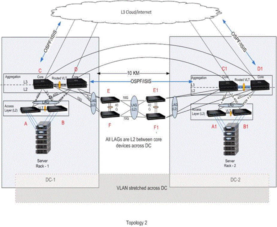
2. Trace route across VLT domains may show extra hops.
3. IP route symmetry must be maintained across the VLT domains. Assume if the route to a destination
is not available at C2, though the packet hits the MY_STATION_TCAM and routing is enabled for that
VLAN, if there is no entry for that prefix in the routing table it will dropped to CPU. By default, all
route miss packets are given to CPU. To avoid this static entry must be configured.
4. There could be L3 frames received out-of-order at the L3 cloud, when a MAC is removed and added
back. This could happen when proxy-routing and sub-optimal routing intersperse each other.
5. This feature is not supported for IPv6.
6. ICL shut – Assume ICL between C1 and D1 is shut and if D1 is secondary VLT then one half of the
inter DC link goes down. After vm motion, If a packet reaches D2 with the destination MAC address
of D1, it may be dropped. This behaviour is applicable only in the LLDP configuration; In static
configuration, the packet will be forwarded.
7. Any L3 packet that was originally should have been switched across domains, when gets a hit at
my_station_tcam (because of this feature) and routed, will have a TTL decrement as expected.
VLT Proxy Gateway 879
8. Packet duplication – Assume exclude-vlan (say VLAN 10) is configured on C2/D2 for C1’s MAC. If
packets for VLAN 10 with C1’s MAC get a hit at C2, they will be switched to both D2 (via ICL) and C1
via inter DC link. This could lead to packet duplication. So, if C1’s MAC is learnt at C2 then the packet
would not have flooded (to D2) and only switched to C1 and thus avoided packet duplication.
Configuring an LLDP VLT Proxy Gateway
You can configure a proxy gateway in a VLT domain to locally route packets destined to a L3 endpoint in
another VLT domain.
To configure an LLDP proxy gateway:
1. Enable VLT on a switch, then configure a VLT domain and enter VLT-domain configuration mode.
CONFIGURATION mode
Dell(conf)#vlt domain domain-id
2. Configure the LLDP proxy gateway
VLT DOMAIN mode
Dell(conf-vlt-domain)#proxy-gateway lldp
3. You can configure the port channel interface for an LLDP proxy gateway and exclude a VLAN or a
range of VLANs from proxy routing. This parameter is for an LLDP proxy gateway configuration.
VLT DOMAIN PROXY GW LLDP mode
Dell(conf-vlt-domain-proxy-gw-lldp)#peer-domain-link port-channel interface
exclude-vlan vlan-range
4. Display the VLT proxy gateway configuration.
EXEC mode
Dell#show vlt-proxy-gateway
880 VLT Proxy Gateway
56
Virtual Router Redundancy Protocol
(VRRP)
Virtual router redundancy protocol (VRRP) is designed to eliminate a single point of failure in a statically
routed network.
VRRP Overview
VRRP specifies a MASTER router that owns the next hop IP and MAC address for end stations on a local
area network (LAN). The MASTER router is chosen from the virtual routers by an election process and
forwards packets sent to the next hop IP address. If the MASTER router fails, VRRP begins the election
process to choose a new MASTER router and that new MASTER continues routing traffic.
VRRP uses the virtual router identifier (VRID) to identify each virtual router configured. The IP address of
the MASTER router is used as the next hop address for all end stations on the LAN. The other routers the
IP addresses represent are BACKUP routers.
VRRP packets are transmitted with the virtual router MAC address as the source MAC address. The MAC
address is in the following format: 00-00-5E-00-01-{VRID}. The first three octets are unchangeable. The
next two octets (00-01) indicate the address block assigned to the VRRP protocol, and are unchangeable.
The final octet changes depending on the VRRP virtual router identifier and allows for up to 255 VRRP
routers on a network.
The following example shows a typical network configuration using VRRP. Instead of configuring the
hosts on the network 10.10.10.0 with the IP address of either Router A or Router B as their default router;
their default router is the IP address configured on the virtual router. When any host on the LAN segment
wants to access the Internet, it sends packets to the IP address of the virtual router.
In the following example, Router A is configured as the MASTER router. It is configured with the IP
address of the virtual router and sends any packets addressed to the virtual router through interface
TenGigabitEthernet 1/1 to the Internet. As the BACKUP router, Router B is also configured with the IP
address of the virtual router. If, for any reason, Router A becomes unavailable, VRRP elects a new MASTER
Router. Router B assumes the duties of Router A and becomes the MASTER router. At that time, Router B
responds to the packets sent to the virtual IP address.
All workstations continue to use the IP address of the virtual router to address packets destined to the
Internet. Router B receives and forwards them on interface TenGigabitEthernet 10/1. Until Router A
resumes operation, VRRP allows Router B to provide uninterrupted service to the users on the LAN
segment accessing the Internet.
For more detailed information about VRRP, refer to RFC 2338, Virtual Router Redundancy Protocol.
Virtual Router Redundancy Protocol (VRRP) 881
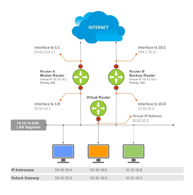
Figure 118. Basic VRRP Configuration
VRRP Benefits
With VRRP configured on a network, end-station connectivity to the network is not subject to a single
point-of-failure. End-station connections to the network are redundant and are not dependent on
internal gateway protocol (IGP) protocols to converge or update routing tables.
VRRP Implementation
Within a single VRRP group, up to 12 virtual IP addresses are supported.
Virtual IP addresses can belong to the primary or secondary IP address’ subnet configured on the
interface. You can ping all the virtual IP addresses configured on the Master VRRP router from anywhere
in the local subnet.
Up to 255 VRRP groups are supported on the switch. The total number of VRRP groups per system
should be less than 512.
The following recommendations shown may vary depending on various factors like address resolution
protocol (ARP) broadcasts, IP broadcasts, or spanning tree protocol (STP) before changing the
advertisement interval. When the number of packets processed by RP2/CP/FP processor increases or
882 Virtual Router Redundancy Protocol (VRRP)

decreases based on the dynamics of the network, the advertisement intervals may increase or decrease
accordingly.
CAUTION: Increasing the advertisement interval increases the VRRP Master dead interval,
resulting in an increased failover time for Master/Backup election. Take caution when increasing
the advertisement interval, as the increased dead interval may cause packets to be dropped
during that switch-over time.
Table 52. Recommended VRRP Advertise Intervals on the Z9500
Recommended Advertise
Interval Groups/Interface
Total VRRP Groups
Less than 250 1 second 12
Between 250 and 450 2–3 seconds 24
Between 450 and 600 3–4 seconds 36
Between 600 and 800 4 seconds 48
Between 800 and 1000 5 seconds 84
Between 1000 and 1200 7 seconds 100
Between 1200 and 1500 8 seconds 120
VRRP Configuration
By default, VRRP is not configured.
Configuration Task List
The following list specifies the configuration tasks for VRRP.
•Creating a Virtual Router (mandatory)
•Configuring the VRRP Version for an IPv4 Group (optional)
•Assign Virtual IP Addresses mandatory)
•Setting VRRP Group (Virtual Router) Priority (optional)
•Configuring VRRP Authentication (optional)
•Disabling Preempt (optional)
•Changing the Advertisement Interval (optional)
•Track an Interface or Object
•Setting VRRP Initialization Delay
For a complete listing of all commands related to VRRP, refer to Dell Networking OS Command Line
Reference Guide.
Creating a Virtual Router
To enable VRRP, create a virtual router. In the Dell Networking Operating System, the virtual router
identifier (VRID) identifies a VRRP group.
To enable or delete a virtual router, use the following commands.
Virtual Router Redundancy Protocol (VRRP) 883

• Create a virtual router for that interface with a VRID.
INTERFACE mode
vrrp-group vrid
The VRID range is from 1 to 255.
NOTE: The interface must already have a primary IP address defined and be enabled, as shown
in the second example.
• Delete a VRRP group.
INTERFACE mode
no vrrp-group vrid
Examples of Configuring Verifying a VRRP Configuration
The following example shows configuring a VRRP configuration.
Dell(conf)#int te 1/1
Dell(conf-if-te-1/1)#vrrp-group 111
Dell(conf-if-te-1/1-vrid-111)#
The following example shows verifying a VRRP configuration.
Dell(conf-if-te-1/1)#show conf
!
interface TenGigabitEthernet 1/1
ip address 10.10.10.1/24
!
vrrp-group 111
no shutdown
Dell(conf-if-te-1/1)#
Configuring the VRRP Version for an IPv4 Group
For IPv4, you can configure a VRRP group to use one of the following VRRP versions:
• VRRPv2 as defined in RFC 3768, Virtual Router Redundancy Protocol (VRRP)
• VRRPv3 as defined in RFC 5798, Virtual Router Redundancy Protocol (VRRP) Version 3 for IPv4 and
IPv6
You can also migrate a IPv4 group from VRRPv2 to VRRP3.
To configure the VRRP version for IPv4, use the version command in INTERFACE mode.
Example: Configuring VRRP to Use Version 3
The following example configures the IPv4 VRRP 100 group to use VRRP protocol version 3.
Dell(conf-if-te-0/0)# vrrp-group 100
Dell (conf-if-te-0/0-vrid-100)#version ?
2 VRRPv2
3 VRRPv3
both Interoperable, send VRRPv3 receive both
Dell(conf-if-te-0/0-vrid-100)#version 3
884 Virtual Router Redundancy Protocol (VRRP)

You can use the version both command in INTERFACE mode to migrate from VRRPv2 to VRRPv3. When
you set the VRRP version to both, the switch sends only VRRPv3 advertisements but can receive VRRPv2
or VRRPv3 packets.
To migrate an IPv4 VRRP group from VRRPv2 to VRRPv3:
1. Set the switches with the lowest priority to “both”.
2. Set the switch with the highest priority to version to 3.
3. Set all the switches from both to version 3.
NOTE: Do not run VRRP version 2 and version 3 in the same group for an extended period of time
Example: Migrating an IPv4 VRRP Group from VRRPv2 to VRRPv3
NOTE: Carefully following this procedure, otherwise you might introduce dual master switches
issues.
To migrate an IPv4 VRRP Group from VRRPv2 to VRRPv3:
1. Set the backup switches to VRRP version to both.
Dell_backup_switch1(conf-if-te-0/1-vrid-100)#version both
Dell_backup_switch2(conf-if-te-0/2-vrid-100)#version both
2. Set the master switch to VRRP protocol version 3.
Dell_master_switch(conf-if-te-0/1-vrid-100)#version 3
3. Set the backup switches to version 3.
Dell_backup_switch1(conf-if-te-0/1-vrid-100)#version 3
Dell_backup_switch2(conf-if-te-0/2-vrid-100)#version 3
Assign Virtual IP addresses
Virtual routers contain virtual IP addresses configured for that VRRP group (VRID). A VRRP group does not
transmit VRRP packets until you assign the Virtual IP address to the VRRP group.
For more information, refer to VRRP Implementation.
To activate a VRRP group on an interface (so that VRRP group starts transmitting VRRP packets),
configure at least one virtual IP address in a VRRP group. The virtual IP address is the IP address of the
virtual router and does not require the IP address mask.
You can configure up to 12 virtual IP addresses on a single VRRP group (VRID).
The following rules apply to virtual IP addresses:
• The virtual IP addresses must be in the same subnet as the primary or secondary IP addresses
configured on the interface. Though a single VRRP group can contain virtual IP addresses belonging
to multiple IP subnets configured on the interface, Dell Networking recommends configuring virtual
IP addresses belonging to the same IP subnet for any one VRRP group.
– For example, an interface (on which you enable VRRP) contains a primary IP address of 50.1.1.1/24
and a secondary IP address of 60.1.1.1/24. The VRRP group (VRID 1) must contain virtual addresses
belonging to either subnet 50.1.1.0/24 or subnet 60.1.1.0/24, but not from both subnets (though
the system allows the same).
• If the virtual IP address and the interface’s primary/secondary IP address are the same, the priority on
that VRRP group MUST be set to 255. The interface then becomes the OWNER router of the VRRP
Virtual Router Redundancy Protocol (VRRP) 885

group and the interface’s physical MAC address is changed to that of the owner VRRP group’s MAC
address.
• If you configure multiple VRRP groups on an interface, only one of the VRRP Groups can contain the
interface primary or secondary IP address.
Configuring a Virtual IP Address
To configure a virtual IP address, use the following commands.
1. Configure a VRRP group.
INTERFACE mode
vrrp-group vrrp-id
The VRID range is from 1 to 255.
2. Configure virtual IP addresses for this VRID.
INTERFACE -VRID mode
virtual-address ip-address1 [...ip-address12]
The range is up to 12 addresses.
Examples of Configuring and Verifying a Virtual IP Address
The following example shows how to configure a virtual IP adddress.
Dell(conf-if-te-1/1-vrid-111)#virtual-address 10.10.10.1
Dell(conf-if-te-1/1-vrid-111)#virtual-address 10.10.10.2
Dell(conf-if-te-1/1-vrid-111)#virtual-address 10.10.10.3
Dell(conf-if-te-1/1-vrid-111)#
The following example shows how to verify a virtual IP adddress configuration.
NOTE: In the following example, the primary IP address and the virtual IP addresses are on the same
subnet.
Dell(conf-if-te-1/1)#show conf
!
interface TenGigabitEthernet 1/1
ip address 10.10.10.1/24
!
vrrp-group 111
priority 255
virtual-address 10.10.10.1
virtual-address 10.10.10.2
virtual-address 10.10.10.3
!
vrrp-group 222
no shutdown
Dell(conf-if-te-1/1)#
The following example shows the same VRRP group (VRID 111) configured on multiple interfaces on
different subnets.
Dellshow vrrp
------------------
TenGigabitEthernet 1/1, VRID: 111, Net: 10.10.10.1
State: Master, Priority: 255, Master: 10.10.10.1 (local)
Hold Down: 0 sec, Preempt: TRUE, AdvInt: 1 sec
Adv rcvd: 0, Bad pkts rcvd: 0, Adv sent: 1768, Gratuitous ARP sent: 5
886 Virtual Router Redundancy Protocol (VRRP)

Virtual MAC address:
00:00:5e:00:01:6f
Virtual IP address:
10.10.10.1 10.10.10.2 10.10.10.3 10.10.10.10
Authentication: (none)
------------------
TenGigabitEthernet 1/2, VRID: 111, Net: 10.10.2.1
State: Master, Priority: 100, Master: 10.10.2.1 (local)
Hold Down: 0 sec, Preempt: TRUE, AdvInt: 1 sec
Adv rcvd: 0, Bad pkts rcvd: 0, Adv sent: 27, Gratuitous ARP sent: 2
Virtual MAC address:
00:00:5e:00:01:6f
Virtual IP address:
10.10.2.2 10.10.2.3
Authentication:
When the VRRP process completes its initialization, the State field contains either Master or Backup.
Setting VRRP Group (Virtual Router) Priority
Setting a virtual router priority to 255 ensures that router is the “owner” virtual router for the VRRP group.
VRRP elects the MASTER router by choosing the router with the highest priority.
The default priority for a virtual router is 100. The higher the number, the higher the priority. If the
MASTER router fails, VRRP begins the election process to choose a new MASTER router based on the
next-highest priority.
If two routers in a VRRP group come up at the same time and have the same priority value, the interface’s
physical IP addresses are used as tie-breakers to decide which is MASTER. The router with the higher IP
address becomes MASTER.
To configure the VRRP group’s priority, use the following command.
• Configure the priority for the VRRP group.
INTERFACE -VRID mode
priority priority
The range is from 1 to 255.
The default is 100.
Examples of Configuring and Verifying the VRRP Group Priority
The following example shows configuring a group priority.
Dell(conf-if-te-1/2)#vrrp-group 111
Dell(conf-if-te-1/2-vrid-111)#priority 125
The following example shows verifying a group priority.
Dellshow vrrp
------------------
TenGigabitEthernet 1/1, VRID: 111, Net: 10.10.10.1
State: Master, Priority: 255, Master: 10.10.10.1 (local)
Hold Down: 0 sec, Preempt: TRUE, AdvInt: 1 sec
Adv rcvd: 0, Bad pkts rcvd: 0, Adv sent: 2343, Gratuitous ARP sent: 5
Virtual MAC address:
00:00:5e:00:01:6f
Virtual IP address:
10.10.10.1 10.10.10.2 10.10.10.3 10.10.10.10
Authentication: (none)
------------------
Virtual Router Redundancy Protocol (VRRP) 887

TenGigabitEthernet 1/2, VRID: 111, Net: 10.10.2.1
State: Master, Priority: 125, Master: 10.10.2.1 (local)
Hold Down: 0 sec, Preempt: TRUE, AdvInt: 1 sec
Adv rcvd: 0, Bad pkts rcvd: 0, Adv sent: 601, Gratuitous ARP sent: 2
Virtual MAC address:
00:00:5e:00:01:6f
Virtual IP address:
10.10.2.2 10.10.2.3
Authentication: (none)
Dell(conf)#
Configuring VRRP Authentication
Simple authentication of VRRP packets ensures that only trusted routers participate in VRRP processes.
When you enable authentication, the system includes the password in its VRRP transmission. The
receiving router uses that password to verify the transmission.\
NOTE: You must configure all virtual routers in the VRRP group the same: you must enable
authentication with the same password or authentication is disabled.
To configure simple authentication, use the following command.
• Configure a simple text password.
INTERFACE-VRID mode
authentication-type simple [encryption-type] password
Parameters:
–encryption-type: 0 indicates unencrypted; 7 indicates encrypted.
–password: plain text.
Examples of Configuring and Verifying VRRP Authentication
The following example shows how to configure VRRP authentication. The bold section shows the
encryption type (encrypted) and the password.
Dell(conf-if-te-1/1-vrid-111)#authentication-type ?
Dell(conf-if-te-1/1-vrid-111)#authentication-type simple 7 dell
The following example shows how to verify VRRP authentication. The bold section shows the encrypted
password.
Dell(conf-if-te-1/1-vrid-111)#show conf
!
vrrp-group 111
authentication-type simple 7 387a7f2df5969da4
priority 255
virtual-address 10.10.10.1
virtual-address 10.10.10.2
virtual-address 10.10.10.3
virtual-address 10.10.10.10
Dell(conf-if-te-1/1-vrid-111)#
Disabling Preempt
The preempt command is enabled by default. The command forces the system to change the MASTER
router if another router with a higher priority comes online.
Prevent the BACKUP router with the higher priority from becoming the MASTER router by disabling
preempt.
888 Virtual Router Redundancy Protocol (VRRP)

NOTE: You must configure all virtual routers in the VRRP group the same: you must configure all
with preempt enabled or configure all with preempt disabled.
Because preempt is enabled by default, disable the preempt function with the following command.
• Prevent any BACKUP router with a higher priority from becoming the MASTER router.
INTERFACE-VRID mode
no preempt
Examples of Disabling and Verifying Preempt
Re-enable preempt by entering the preempt command. When you enable preempt, it does not display in
the show commands, because it is a default setting.
To disable preempt, use the no preempt command.
Dell(conf-if-te-1/1)#vrrp-group 111
Dell(conf-if-te-1/1-vrid-111)#no preempt
Dell(conf-if-te-1/1-vrid-111)#
To verify the preempt status, use the show config command.
Dell(conf-if-te-1/1-vrid-111)#show conf
!
vrrp-group 111
authentication-type simple 7 387a7f2df5969da4
no preempt
priority 255
virtual-address 10.10.10.1
virtual-address 10.10.10.2
virtual-address 10.10.10.3
virtual-address 10.10.10.10
Dell(conf-if-te-1/1-vrid-111)#
Changing the Advertisement Interval
By default, the MASTER router transmits a VRRP advertisement to all members of the VRRP group every
one second, indicating it is operational and is the MASTER router.
If the VRRP group misses three consecutive advertisements, the election process begins and the BACKUP
virtual router with the highest priority transitions to MASTER.
NOTE: To avoid throttling VRRP advertisement packets, Dell Networking recommends increasing
the VRRP advertisement interval to a value higher than the default value of one second. If you do
change the time interval between VRRP advertisements on one router, change it on all participating
routers.
If are using VRRP version 2, you must configure the timer values in multiple of whole seconds. For
example a timer value of 3 seconds or 300 centisecs are valid and equivalent. However, a time value of
50 centisecs is invalid because it not a multiple of 1 second. If you are using VRRP version 3, you must
configure the timer values in multiples of 25 centisecs.
If you are configured for VRRP version 2, the timer values must be in multiples of whole seconds. For
example, timer value of 3 seconds or 300 centisecs are valid and equivalent. However, a timer value of
50 centisecs is invalid because it not is not multiple of 1 second.
If are using VRRP version 3, you must configure the timer values in multiples of 25 centisecs.
Virtual Router Redundancy Protocol (VRRP) 889

To change the advertisement interval in seconds or centisecs, use the following command. A centisecs is
1/100 of a second.
• Change the advertisement seconds interval setting.
INTERFACE-VRID mode
advertise-interval seconds
The range is from 1 to 255 seconds.
The default is 1 second.
• For VRRPv3, change the advertisement centisecs interval setting.
INTERFACE-VRID mode
advertise-interval centisecs centisecs
The range is from 25 to 4075 centisecs in units of 25 centisecs.
The default is 100 centisecs.
Examples of Configuring and Verifying the Advertisement Interval
The following example shows the advertise-interval command configured in seconds.
Dell(conf-if-te-1/1)#vrrp-group 111
Dell(conf-if-te-1/1-vrid-111)#advertise-interval 10
Dell(conf-if-te-1/1-vrid-111)#
The following example shows the advertise-interval command configured in 1000 centisecs.
Dell(conf-if-te-1/1)#vrrp-group 111
Dell(conf-if-te-1/1-vrid-111)#version 3
Dell(conf-if-te-1/1-vrid-111)#advertise-interval centisecs 1000
Dell(conf-if-te-1/1-vrid-111)#
NOTE:
To verify the advertise-interval setting, use the show conf command.
Dell(conf-if-te-1/1-vrid-111)#show conf
!
vrrp-group 111
advertise-interval 10
authentication-type simple 7 387a7f2df5969da4
no preempt
priority 255
virtual-address 10.10.10.1
virtual-address 10.10.10.2
virtual-address 10.10.10.3
virtual-address 10.10.10.10
Dell(conf-if-te-1/1-vrid-111)#
Track an Interface or Object
You can set the system to monitor the state of any interface according to the virtual group.
Each VRRP group can track up to 12 interfaces and up to 20 additional objects, which may affect the
priority of the VRRP group. If the tracked interface goes down, the VRRP group’s priority decreases by a
890 Virtual Router Redundancy Protocol (VRRP)

default value of 10 (also known as cost). If the tracked interface’s state goes up, the VRRP group’s priority
increases by 10.
The lowered priority of the VRRP group may trigger an election. As the Master/Backup VRRP routers are
selected based on the VRRP group’s priority, tracking features ensure that the best VRRP router is the
Master for that group. The sum of all the costs of all the tracked interfaces must be less than the
configured priority on the VRRP group. If the VRRP group is configured as Owner router (priority 255),
tracking for that group is disabled, irrespective of the state of the tracked interfaces. The priority of the
owner group always remains at 255.
For a virtual group, you can track the line-protocol state or the routing status of any of the following
interfaces:
• 10-Gigabit Ethernet: enter tengigabitethernet slot/port.
• 40-Gigabit Ethernet: enter fortyGigE slot/port.
• Port channel: enter port-channel number.
• VLAN: enter vlan vlan-id. Valid VLAN IDs are from 1 to 4094.
For a virtual group, you can also track the status of a configured object by entering its object number.
NOTE: You can configure a tracked object for a VRRP group (using the track object-id
command in INTERFACE-VRID mode) before you actually create the tracked object (using a track
object-id command in CONFIGURATION mode). However, no changes in the VRRP group’s
priority occur until the tracked object is defined and determined to be down.
In addition, if you configure a VRRP group on an interface that belongs to a VRF instance and later
configure object tracking on an interface for the VRRP group, the tracked interface must belong to the
VRF instance.
Tracking an Interface
To track an interface, use the following commands.
NOTE: The sum of all the costs for all tracked interfaces must be less than the configured priority of
the VRRP group.
• Monitor an interface and, optionally, set a value to be subtracted from the interface’s VRRP group
priority.
INTERFACE-VRID mode
track interface [priority-cost cost]
The cost range is from 1 to 254.
The default is 10.
• (Optional) Display the configuration and the UP or DOWN state of tracked objects, including the client
(VRRP group) that is tracking an object’s state.
EXEC mode or EXEC Privilege mode
show track
• (Optional) Display the configuration and the UP or DOWN state of tracked interfaces and objects in
VRRP groups, including the time since the last change in an object’s state.
EXEC mode or EXEC Privilege mode
show vrrp
Virtual Router Redundancy Protocol (VRRP) 891

• (Optional) Display the configuration of tracked objects in VRRP groups on a specified interface.
EXEC mode or EXEC Privilege mode
show running-config interface interface
Example of Configuring and Verifying the Tracking Configuration
The following example shows configuring VRRP tracking.
Dell(conf-if-te-1/1)#vrrp-group 111
Dell(conf-if-te-1/1-vrid-111)#track tengigabitethernet 1/2
Dell(conf-if-te-1/1-vrid-111)#
The following example shows verifying the tracking configuration.
Dell(conf-if-te-1/1-vrid-111)#show conf
!
vrrp-group 111
advertise-interval 10
authentication-type simple 7 387a7f2df5969da4
no preempt
priority 255
track TenGigabitEthernet 1/2
virtual-address 10.10.10.1
virtual-address 10.10.10.2
virtual-address 10.10.10.3
virtual-address 10.10.10.10
Dell(conf-if-te-1/1-vrid-111)#
To view the tracking status, use the show track command.
Dell#show track
Track 2
IPv6 route 2040::/64 metric threshold
Metric threshold is Up (STATIC/0/0)
5 changes, last change 00:02:16
Metric threshold down 255 up 254
First-hop interface is TenGigabitEthernet 1/2
Tracked by:
VRRP TenGigabitEthernet 2/30 IPv6 VRID 1
Track 3
IPv6 route 2050::/64 reachability
Reachability is Up (STATIC)
5 changes, last change 00:02:16
First-hop interface is TenGigabitEthernet 1/2
Tracked by:
VRRP TenGigabitEthernet 2/30 IPv6 VRID 1
The following example shows verifying the VRRP status.
Dell#show vrrp
------------------
TenGigabitEthernet 2/30, IPv6 VRID: 1, Version: 3, Net: fe80::201:e8ff:fe01:95cc
VRF: 0 default-vrf
State: Master, Priority: 100, Master: fe80::201:e8ff:fe01:95cc (local)
Hold Down: 0 centisec, Preempt: TRUE, AdvInt: 100 centisec
Accept Mode: FALSE, Master AdvInt: 100 centisec
Adv rcvd: 0, Bad pkts rcvd: 0, Adv sent: 310
Virtual MAC address:
00:00:5e:00:02:01
892 Virtual Router Redundancy Protocol (VRRP)

Virtual IP address:
2007::1 fe80::1
Tracking states for 2 resource Ids:
2 - Up IPv6 route, 2040::/64, priority-cost 20, 00:02:11
3 - Up IPv6 route, 2050::/64, priority-cost 30, 00:02:11
The following example shows viewing the VRRP configuration on an interface.
Dell#show running-config interface tengigabitethernet 2/30
interface TenGigabitEthernet 2/30
no ip address
ipv6 address 2007::30/64
vrrp-ipv6-group 1
track 2 priority-cost 20
track 3 priority-cost 30
virtual-address 2007::1
virtual-address fe80::1
no shutdown
Setting VRRP Initialization Delay
When configured, VRRP is enabled immediately upon system reload or boot. You can delay VRRP
initialization to allow the IGP and EGP protocols to be enabled prior to selecting the VRRP Master.
AVRRP initialization delay ensures that VRRP initializes with no errors or conflicts. You can configure the
delay for up to 15 minutes, after which VRRP enables normally.
Set the delay timer on individual interfaces. The delay timer is supported on all physical interfaces, VLANs,
and LAGs.
When you configure both CLIs, the later timer rules VRRP enabling. For example, if you set vrrp delay
reload 600 and vrrp delay minimum 300, the following behavior occurs:
• When the system reloads, VRRP waits 600 seconds (10 minutes) to bring up VRRP on all interfaces
that are up and configured for VRRP.
• When an interface comes up and becomes operational, the system waits 300 seconds (5 minutes) to
bring up VRRP on that interface.
To set the delay time for VRRP initialization, use the following commands.
• Set the delay time for VRRP initialization on an individual interface.
INTERFACE mode
vrrp delay minimum seconds
This time is the gap between an interface coming up and being operational, and VRRP enabling.
The seconds range is from 0 to 900.
The default is 0.
• Set the delay time for VRRP initialization on all the interfaces in the system configured for VRRP.
INTERFACE mode
vrrp delay reload seconds
This time is the gap between system boot up completion and VRRP enabling.
Virtual Router Redundancy Protocol (VRRP) 893
The seconds range is from 0 to 900.
The default is 0.
Sample Configurations
Before you set up VRRP, review the following sample configurations.
VRRP for an IPv4 Configuration
The following configuration shows how to enable IPv4 VRRP. This example does not contain
comprehensive directions and is intended to provide guidance for only a typical VRRP configuration. You
can copy and paste from the example to your CLI. To support your own IP addresses, interfaces, names,
and so on, be sure that you make the necessary changes. The VRRP topology was created using the CLI
configuration shown in the following example.
894 Virtual Router Redundancy Protocol (VRRP)
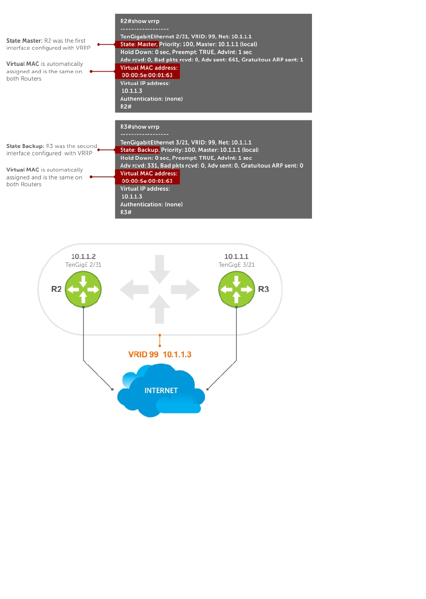
Figure 119. VRRP for IPv4 Topology
Example of Configuring VRRP for IPv4 Router 2
R2(conf)#int te 2/31
R2(conf-if-te-2/31)#ip address 10.1.1.1/24
R2(conf-if-te-2/31)#vrrp-group 99
R2(conf-if-te-2/31-vrid-99)#priority 200
R2(conf-if-te-2/31-vrid-99)#virtual 10.1.1.3
R2(conf-if-te-2/31-vrid-99)#no shut
R2(conf-if-te-2/31)#show conf
!
interface TenGigabitEthernet 2/31
ip address 10.1.1.1/24
!
vrrp-group 99
priority 200
virtual-address 10.1.1.3
Virtual Router Redundancy Protocol (VRRP) 895

no shutdown
R2(conf-if-te-2/31)#end
R2#show vrrp
------------------
TenGigabitEthernet 2/31, VRID: 99, Net: 10.1.1.1
State: Master, Priority: 200, Master: 10.1.1.1 (local)
Hold Down: 0 sec, Preempt: TRUE, AdvInt: 1 sec
Adv rcvd: 0, Bad pkts rcvd: 0, Adv sent: 817, Gratuitous ARP sent: 1
Virtual MAC address:
00:00:5e:00:01:63
Virtual IP address:
10.1.1.3
Authentication: (none)
R2#
Router 3
R3(conf)#int te 3/21
R3(conf-if-te-3/21)#ip address 10.1.1.2/24
R3(conf-if-te-3/21)#vrrp-group 99
R3(conf-if-te-3/21-vrid-99)#virtual 10.1.1.3
R3(conf-if-te-3/21-vrid-99)#no shut
R3(conf-if-te-3/21)#show conf
!
interface TenGigabitEthernet 3/21
ip address 10.1.1.1/24
!
vrrp-group 99
virtual-address 10.1.1.3
no shutdown
R3(conf-if-te-3/21)#end
R3#show vrrp
------------------
TenGigabitEthernet 3/21, VRID: 99, Net: 10.1.1.2
State: Backup, Priority: 100, Master: 10.1.1.1
Hold Down: 0 sec, Preempt: TRUE, AdvInt: 1 sec
Adv rcvd: 698, Bad pkts rcvd: 0, Adv sent: 0, Gratuitous ARP sent: 0
Virtual MAC address:
00:00:5e:00:01:63
Virtual IP address:
10.1.1.3
Authentication: (none)
896 Virtual Router Redundancy Protocol (VRRP)
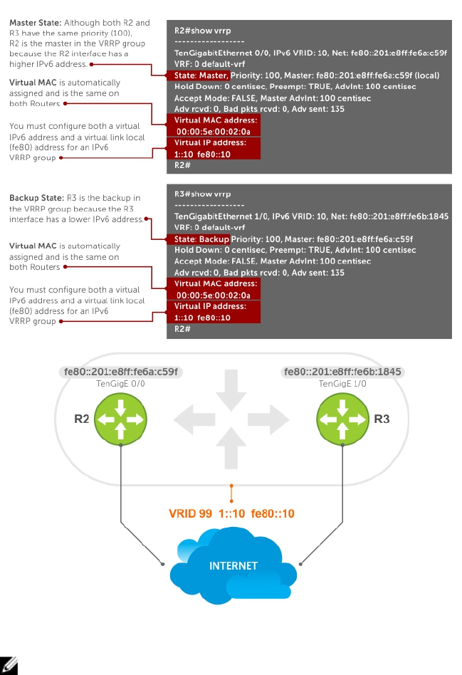
Figure 120. VRRP for an IPv6 Configuration
NOTE: In a VRRP or VRRPv3 group, if two routers come up with the same priority and another
router already has MASTER status, the router with master status continues to be MASTER even if one
of two routers has a higher IP or IPv6 address.
Example of Configuring VRRP for IPv6 Router 2 and Router 3
Configure a virtual link local (fe80) address for each VRRPv3 group created for an interface. The VRRPv3
group becomes active as soon as you configure the link local address. Afterward, you can configure the
group’s virtual IPv6 address.
The virtual IPv6 address you configure must be the same as the IPv6 subnet to which the interface
belongs.
Virtual Router Redundancy Protocol (VRRP) 897

Although R2 and R3 have the same default, priority (100), R2 is elected master in the VRRPv3 group
because the TenGigE 0/0 interface has a higher IPv6 address than the TenGigE 1/0 interface on R3.
Router 2
R2(conf)#interface tengigabitethernet 0/0
R2(conf-if-te-0/0)#no ip address
R2(conf-if-te-0/0)#ipv6 address 1::1/64
R2(conf-if-te-0/0)#vrrp-group 10
R2(conf-if-te-0/0-vrid-10)#virtual-address fe80::10
R2(conf-if-te-0/0-vrid-10)#virtual-address 1::10
R2(conf-if-te-0/0-vrid-10)#no shutdown
R2(conf-if-te-0/0)#show config
interface TenGigabitEthernet 0/0
ipv6 address 1::1/64
vrrp-group 10
priority 100
virtual-address fe80::10
virtual-address 1::10
no shutdown
R2(conf-if-te-0/0)#end
R2#show vrrp
------------------
TenGigabitEthernet 0/0, IPv6 VRID: 10, Version: 3, Net:fe80::201:e8ff:fe6a:c59f
VRF: 0 default-vrf
State: Master, Priority: 100, Master: fe80::201:e8ff:fe6a:c59f (local)
Hold Down: 0 centisec, Preempt: TRUE, AdvInt: 100 centisec
Accept Mode: FALSE, Master AdvInt: 100 centisec
Adv rcvd: 0, Bad pkts rcvd: 0, Adv sent: 135
Virtual MAC address:
00:00:5e:00:02:0a
Virtual IP address:
1::10 fe80::10
Router 3
R3(conf)#interface tengigabitethernet 1/0
R3(conf-if-te-1/0)#no ipv6 address
R3(conf-if-te-1/0)#ipv6 address 1::2/64
R3(conf-if-te-1/0)#vrrp-group 10
R2(conf-if-te-1/0-vrid-10)#virtual-address fe80::10
R2(conf-if-te-1/0-vrid-10)#virtual-address 1::10
R3(conf-if-te-1/0-vrid-10)#no shutdown
R3(conf-if-te-1/0)#show config
interface TenGigabitEthernet 1/0
ipv6 address 1::2/64
vrrp-group 10
priority 100
virtual-address fe80::10
virtual-address 1::10
no shutdown
R3(conf-if-te-1/0)#end
R3#show vrrp
------------------
TenGigabitEthernet 1/0, IPv6 VRID: 10, Version: 3, Net:
fe80::201:e8ff:fe6b:1845
VRF: 0 default-vrf
State: Backup, Priority: 100, Master: fe80::201:e8ff:fe6a:c59f
Hold Down: 0 centisec, Preempt: TRUE, AdvInt: 100 centisec
Accept Mode: FALSE, Master AdvInt: 100 centisec
Adv rcvd: 11, Bad pkts rcvd: 0, Adv sent: 0
Virtual MAC address:
00:00:5e:00:02:0a
898 Virtual Router Redundancy Protocol (VRRP)

VRRP in a VRF Configuration
The following example shows how to enable VRRP operation in a VRF virtualized network for the
following scenarios.
• Multiple VRFs on physical interfaces running VRRP.
• Multiple VRFs on VLAN interfaces running VRRP.
To view a VRRP in a VRF configuration, use the show commands described in Displaying VRRP in a VRF
Configuration.
VRRP in a VRF: Non-VLAN Scenario
The following example shows how to enable VRRP in a non-VLAN.
The following example shows a typical use case in which you create three virtualized overlay networks by
configuring three VRFs in two switches. The default gateway to reach the Internet in each VRF is a static
route with the next hop being the virtual IP address configured in VRRP. In this scenario, a single VLAN is
associated with each VRF.
Both Switch-1 and Switch-2 have three VRF instances defined: VRF-1, VRF-2, and VRF-3. Each VRF has a
separate physical interface to a LAN switch and an upstream VPN interface to connect to the Internet.
Both Switch-1 and Switch-2 use VRRP groups on each VRF instance in order that there is one MASTER
and one backup router for each VRF. In VRF-1 and VRF-2, Switch-2 serves as owner-master of the VRRP
group and Switch-1 serves as the backup. On VRF-3, Switch-1 is the owner-master and Switch-2 is the
backup.
In VRF-1 and VRF-2 on Switch-2, the virtual IP and node IP address, subnet, and VRRP group are the
same. On Switch-1, the virtual IP address, subnet, and VRRP group are the same in VRF-1 and VRF-2, but
the IP address of the node interface is unique. There is no requirement for the virtual IP and node IP
addresses to be the same in VRF-1 and VRF-2; similarly, there is no requirement for the IP addresses to be
different. In VRF-3, the node IP addresses and subnet are unique.
Virtual Router Redundancy Protocol (VRRP) 899
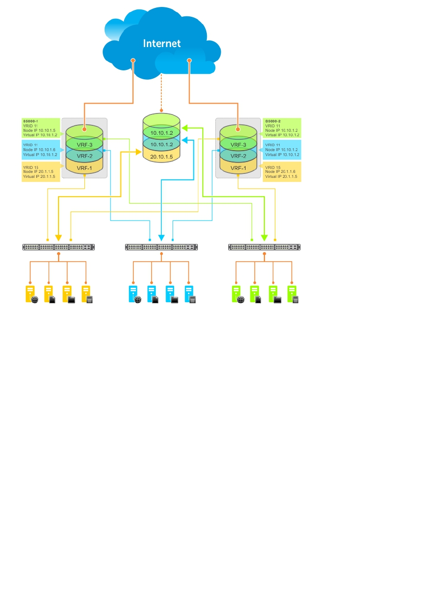
Figure 121. VRRP in a VRF: Non-VLAN Example
Example of Configuring VRRP in a VRF on Switch-1 (Non-VLAN)
Switch-1
S1(conf)#ip vrf default-vrf 0
!
S1(conf)#ip vrf VRF-1 1
!
S1(conf)#ip vrf VRF-2 2
!
S1(conf)#ip vrf VRF-3 3
!
S1(conf)#interface TenGigabitEthernet 2/1
S1(conf-if-te-2/1)#ip vrf forwarding VRF-1
S1(conf-if-te-2/1)#ip address 10.10.1.5/24
S1(conf-if-te-12/1)#vrrp-group 11
% Info: The VRID used by the VRRP group 11 in VRF 1 will be 177.
S1(conf-if-te-2/1-vrid-101)#priority 100
S1(conf-if-te-2/1-vrid-101)#virtual-address 10.10.1.2
S1(conf-if-te-2/1)#no shutdown
!
S1(conf)#interface TenGigabitEthernet 2/2
S1(conf-if-te-2/2)#ip vrf forwarding VRF-2
S1(conf-if-te-2/2)#ip address 10.10.1.6/24
S1(conf-if-te-2/2)#vrrp-group 11
% Info: The VRID used by the VRRP group 11 in VRF 2 will be 178.
S1(conf-if-te-12/2-vrid-101)#priority 100
S1(conf-if-te-12/2-vrid-101)#virtual-address 10.10.1.2
S1(conf-if-te-12/2)#no shutdown
900 Virtual Router Redundancy Protocol (VRRP)

!
S1(conf)#interface TenGigabitEthernet 2/3
S1(conf-if-te-2/3)#ip vrf forwarding VRF-3
S1(conf-if-te-2/3)#ip address 20.1.1.5/24
S1(conf-if-te-2/3)#vrrp-group 15
% Info: The VRID used by the VRRP group 15 in VRF 3 will be 243.
S1(conf-if-te-2/3-vrid-105)#priority 255
S1(conf-if-te-2/3-vrid-105)#virtual-address 20.1.1.5
S1(conf-if-te-2/3)#no shutdown
Example of Configuring VRRP in a VRF on Switch-2 (Non-VLAN Configuration)
Switch-2
S2(conf)#ip vrf default-vrf 0
!
S2(conf)#ip vrf VRF-1 1
!
S2(conf)#ip vrf VRF-2 2
!
S2(conf)#ip vrf VRF-3 3
!
S2(conf)#interface TenGigabitEthernet 2/1
S2(conf-if-te-2/1)#ip vrf forwarding VRF-1
S2(conf-if-te-2/1)#ip address 10.10.1.2/24
S2(conf-if-te-2/1)#vrrp-group 11
% Info: The VRID used by the VRRP group 11 in VRF 1 will be 177.
S2(conf-if-te-2/1-vrid-101)#priority 255
S2(conf-if-te-2/1-vrid-101)#virtual-address 10.10.1.2
S2(conf-if-te-2/1)#no shutdown
!
S2(conf)#interface TenGigabitEthernet 2/2
S2(conf-if-te-2/2)#ip vrf forwarding VRF-2
S2(conf-if-te-2/2)#ip address 10.10.1.2/24
S2(conf-if-te-2/2)#vrrp-group 11
% Info: The VRID used by the VRRP group 11 in VRF 2 will be 178.
S2(conf-if-te-2/2-vrid-101)#priority 255
S2(conf-if-te-2/2-vrid-101)#virtual-address 10.10.1.2
S2(conf-if-te-2/2)#no shutdown
!
S2(conf)#interface TenigabitEthernet 2/3
S2(conf-if-te-2/3)#ip vrf forwarding VRF-3
S2(conf-if-te-2/3)#ip address 20.1.1.6/24
S2(conf-if-te-2/3)#vrrp-group 15
% Info: The VRID used by the VRRP group 15 in VRF 3 will be 243.
S2(conf-if-te-2/3-vrid-105)#priority 100
S2(conf-if-te-2/3-vrid-105)#virtual-address 20.1.1.5
S2(conf-if-te-2/3)#no shutdown
VLAN Scenario
In another scenario, to connect to the LAN, VRF-1, VRF-2, and VRF-3 use a single physical interface with
multiple tagged VLANs (instead of separate physical interfaces).
In this case, you configure three VLANs: VLAN-100, VLAN-200, and VLAN-300. Each VLAN is a member
of one VRF. A physical interface (tengigabitethernet 0/1) attaches to the LAN and is configured as a
tagged interface in VLAN-100, VLAN-200, and VLAN-300. The rest of this example is similar to the non-
VLAN scenario.
This VLAN scenario often occurs in a service-provider network in which you configure VLAN tags for
traffic from multiple customers on customer-premises equipment (CPE), and separate VRF instances
associated with each VLAN are configured on the provider edge (PE) router in the point-of-presence
(POP).
Virtual Router Redundancy Protocol (VRRP) 901

VRRP in VRF: Switch-1 VLAN Configuration
VRRP in VRF: Switch-2 VLAN Configuration
Switch-1
S1(conf)#ip vrf VRF-1 1
!
S1(conf)#ip vrf VRF-2 2
!
S1(conf)#ip vrf VRF-3 3
!
S1(conf)#interface TenGigabitEthernet 2/4
S1(conf-if-te-2/4)#no ip address
S1(conf-if-te-2/4)#switchport
S1(conf-if-te-2/4)#no shutdown
!
S1(conf-if-te-2/4)#interface vlan 100
S1(conf-if-vl-100)#ip vrf forwarding VRF-1
S1(conf-if-vl-100)#ip address 10.10.1.5/24
S1(conf-if-vl-100)#tagged tengigabitethernet 12/4
S1(conf-if-vl-100)#vrrp-group 11
% Info: The VRID used by the VRRP group 11 in VRF 1 will be 177.
S1(conf-if-vl-100-vrid-101)#priority 100
S1(conf-if-vl-100-vrid-101)#virtual-address 10.10.1.2
S1(conf-if-vl-100)#no shutdown
!
S1(conf-if-te-2/4)#interface vlan 200
S1(conf-if-vl-200)#ip vrf forwarding VRF-2
S1(conf-if-vl-200)#ip address 10.10.1.6/24
S1(conf-if-vl-200)#tagged tengigabitethernet 12/4
S1(conf-if-vl-200)#vrrp-group 11
% Info: The VRID used by the VRRP group 11 in VRF 2 will be 178.
S1(conf-if-vl-200-vrid-101)#priority 100
S1(conf-if-vl-200-vrid-101)#virtual-address 10.10.1.2
S1(conf-if-vl-200)#no shutdown
!
S1(conf-if-te-2/4)#interface vlan 300
S1(conf-if-vl-300)#ip vrf forwarding VRF-3
S1(conf-if-vl-300)#ip address 20.1.1.5/24
S1(conf-if-vl-300)#tagged tengigabitethernet 12/4
S1(conf-if-vl-300)#vrrp-group 15
% Info: The VRID used by the VRRP group 15 in VRF 3 will be 243.
S1(conf-if-vl-300-vrid-101)#priority 255
S1(conf-if-vl-300-vrid-101)#virtual-address 20.1.1.5
S1(conf-if-vl-300)#no shutdown
Switch-2
S2(conf)#ip vrf VRF-1 1
!
S2(conf)#ip vrf VRF-2 2
!
S2(conf)#ip vrf VRF-3 3
!
S2(conf)#interface TenGigabitEthernet 2/4
S2(conf-if-te-2/4)#no ip address
S2(conf-if-te-2/4)#switchport
S2(conf-if-te-2/4)#no shutdown
!
S2(conf-if-te-2/4)#interface vlan 100
S2(conf-if-vl-100)#ip vrf forwarding VRF-1
S2(conf-if-vl-100)#ip address 10.10.1.2/24
S2(conf-if-vl-100)#tagged tengigabitethernet 12/4
S2(conf-if-vl-100)#vrrp-group 11
% Info: The VRID used by the VRRP group 11 in VRF 1 will be 177.
902 Virtual Router Redundancy Protocol (VRRP)

S2(conf-if-vl-100-vrid-101)#priority 255
S2(conf-if-vl-100-vrid-101)#virtual-address 10.10.1.2
S2(conf-if-vl-100)#no shutdown
!
S2(conf-if-te-2/4)#interface vlan 200
S2(conf-if-vl-200)#ip vrf forwarding VRF-2
S2(conf-if-vl-200)#ip address 10.10.1.2/24
S2(conf-if-vl-200)#tagged tengigabitethernet 12/4
S2(conf-if-vl-200)#vrrp-group 11
% Info: The VRID used by the VRRP group 11 in VRF 2 will be 178.
S2(conf-if-vl-200-vrid-101)#priority 255
S2(conf-if-vl-200-vrid-101)#virtual-address 10.10.1.2
S2(conf-if-vl-200)#no shutdown
!
S2(conf-if-te-2/4)#interface vlan 300
S2(conf-if-vl-300)#ip vrf forwarding VRF-3
S2(conf-if-vl-300)#ip address 20.1.1.6/24
S2(conf-if-vl-300)#tagged tengigabitethernet 12/4
S2(conf-if-vl-300)#vrrp-group 15
% Info: The VRID used by the VRRP group 15 in VRF 3 will be 243.
S2(conf-if-vl-300-vrid-101)#priority 100
S2(conf-if-vl-300-vrid-101)#virtual-address 20.1.1.5
S2(conf-if-vl-300)#no shutdown
Displaying VRRP in a VRF Configuration
To display information on a VRRP group that is configured on an interface that belongs to a VRF instance,
use the following commands.
• Display information on a VRRP group that is configured on an interface that belongs to a VRF
instance.
show running-config track [interface interface]
• Display information on VRRP groups configured on interfaces that belong to a VRF instance.
show vrrp vrf [vrf instance]
Example of Verifying and Viewing Configuration on VRRP in a VRF
The following example shows verifying a configuration on VRRP in a VRF interface.
Dell#show running-config track interface tengigabitethernet 1/4
interface TenGigabitEthernet 1/4
ip vrf forwarding red
ip address 192.168.0.1/24
vrrp-group 4
virtual-address 192.168.0.254
no shutdown
The following example shows viewing the status of VRRP in a global VRF configuration.
Dell#show vrrp vrf red
------------------
TenGigabitEthernet 1/4, IPv4 Vrrp-group: 4, VRID: 65, Version: 2, Net: 192.168.0.1
VRF: 1 red
State: Master, Priority: 100, Master: 192.168.0.1 (local)
Hold Down: 0 sec, Preempt: TRUE, AdvInt: 1 sec
Adv rcvd: 0, Bad pkts rcvd: 0, Adv sent: 9, Gratuitous ARP sent: 1
Virtual MAC address:
00:00:5e:00:01:41
Virtual IP address:
Virtual Router Redundancy Protocol (VRRP) 903

192.168.0.254
Authentication: (none)
904 Virtual Router Redundancy Protocol (VRRP)

57
Standards Compliance
This chapter describes standards compliance for Dell Networking products.
NOTE: Unless noted, when a standard cited here is listed as supported by the Dell Networking OS,
the system also supports predecessor standards. One way to search for predecessor standards is to
use the http://tools.ietf.org/ website. Click “Browse and search IETF documents,” enter an RFC
number, and inspect the top of the resulting document for obsolescence citations to related RFCs.
IEEE Compliance
The following is a list of IEEE compliance.
802.1AB LLDP
802.1D Bridging, STP
802.1p L2 Prioritization
802.1Q VLAN Tagging, Double VLAN Tagging, GVRP
802.1s MSTP
802.1w RSTP
802.1X Network Access Control (Port Authentication)
802.3ab Gigabit Ethernet (1000BASE-T)
802.3ac Frame Extensions for VLAN Tagging
802.3ad Link Aggregation with LACP
802.3ae 10 Gigabit Ethernet (10GBASE-W, 10GBASE-X)
802.3af Power over Ethernet
802.3ak 10 Gigabit Ethernet (10GBASE-CX4)
802.3i Ethernet (10BASE-T)
802.3u Fast Ethernet (100BASE-FX, 100BASE-TX)
802.3x Flow Control
802.3z Gigabit Ethernet (1000BASE-X)
ANSI/TIA-1057 LLDP-MED
Force10 FRRP (Force10 Redundant Ring Protocol)
Force10 PVST+
SFF-8431 SFP+ Direct Attach Cable (10GSFP+Cu)
Standards Compliance 905

MTU 9,252 bytes
RFC and I-D Compliance
The system supports the following standards. The standards are grouped by related protocol. The
columns showing support by platform indicate which version of the Dell Networking OS first supports the
standard.
General Internet Protocols
The following table lists the Dell Networking OS support per platform for general internet protocols.
Table 53. General Internet Protocols
RFC# Full Name S-Series/Z-
Series C-Series E-Series
TeraScale E-Series
ExaScale
768 User Datagram
Protocol
7.6.1 7.5.1 √8.1.1
793 Transmission
Control Protocol
7.6.1 7.5.1 √8.1.1
854 Telnet Protocol
Specification
7.6.1 7.5.1 √8.1.1
959 File Transfer
Protocol (FTP)
7.6.1 7.5.1 √8.1.1
1321 The MD5 Message-
Digest Algorithm
7.6.1 7.5.1 √8.1.1
1350 The TFTP Protocol
(Revision 2)
7.6.1 7.5.1 √8.1.1
1661 The Point-to-Point
Protocol (PPP)
√
1989 PPP Link Quality
Monitoring
√
1990 The PPP Multilink
Protocol (MP)
√
1994 PPP Challenge
Handshake
Authentication
Protocol (CHAP)
√
2460 Internationalization
of the File Transfer
Protocol
8.3.12.0 √
2474 Definition of the
Differentiated
Services Field (DS
7.7.1 7.5.1 √8.1.1
906 Standards Compliance

RFC# Full Name S-Series/Z-
Series C-Series E-Series
TeraScale E-Series
ExaScale
Field) in the IPv4
and IPv6 Headers
2615 PPP over
SONET/SDH
√
2698 A Two Rate Three
Color Marker
√8.1.1
3164 The BSD syslog
Protocol
7.6.1 7.5.1 √8.1.1
draft-ietf-bfd -
base-03
Bidirectional
Forwarding
Detection
7.6.1 √8.1.1
Border Gateway Protocol (BGP)
The following table lists the Dell Networking OS support per platform for BGP protocols.
Table 54. Border Gateway Protocol (BGP)
RFC# Full Name S-Series/Z-Series
1997 BGP ComAmtturnibituitees 7.8.1
2385 Protection of BGP Sessions via the
TCP MD5 Signature Option
7.8.1
2439 BGP Route Flap Damping 7.8.1
2545 Use of BGP-4 Multiprotocol
Extensions for IPv6 Inter-Domain
Routing
2796 BGP Route Reflection: An Alternative
to Full Mesh Internal BGP (IBGP)
7.8.1
2842 Capabilities Advertisement with BGP-4 7.8.1
2858 Multiprotocol Extensions for BGP-4 7.8.1
2918 Route Refresh Capability for BGP-4 7.8.1
3065 Autonomous System Confederations
for BGP
7.8.1
4360 BGP Extended Communities Attribute 7.8.1
4893 BGP Support for Four-octet AS
Number Space
7.8.1
5396 Textual Representation of
Autonomous System (AS) Numbers
8.1.2
draft-ietf-idrbgp4- 20 A Border Gateway Protocol 4 (BGP-4) 7.8.1
draft-ietf-idrrestart- 06 Graceful Restart Mechanism for BGP 7.8.1
Standards Compliance 907

General IPv4 Protocols
The following table lists the Dell Networking OS support per platform for general IPv4 protocols.
Table 55. General IPv4 Protocols
RFC# Full Name S-Series/Z-
Series C-Series E-Series
TeraScale E-Series
ExaScale
791 Internet Protocol 7.6.1 7.5.1 √8.1.1
792 Internet Control
Message Protocol
7.6.1 7.5.1 √8.1.1
826 An Ethernet
Address Resolution
Protocol
7.6.1 7.5.1 √8.1.1
1027 Using ARP to
Implement
Transparent Subnet
Gateways
7.6.1 7.5.1 √8.1.1
1035 DOMAIN NAMES -
IMPLEMENTATION
AND
SPECIFICATION
(client)
7.6.1 7.5.1 √8.1.1
1042 A Standard for the
Transmission of IP
Datagrams over
IEEE 802 Networks
7.6.1 7.5.1 √8.1.1
1191 Path MTU
Discovery
7.6.1 7.5.1 √8.1.1
1305 Network Time
Protocol (Version 3)
Specification,
Implementation
and Analysis
7.6.1 7.5.1 √8.1.1
1519 Classless Inter-
Domain Routing
(CIDR): an Address
Assignment and
Aggregation
Strategy
7.6.1 7.5.1 √8.1.1
1542 Clarifications and
Extensions for the
Bootstrap Protocol
7.6.1 7.5.1 √8.1.1
1812 Requirements for IP
Version 4 Routers
7.6.1 7.5.1 √8.1.1
908 Standards Compliance

RFC# Full Name S-Series/Z-
Series C-Series E-Series
TeraScale E-Series
ExaScale
2131 Dynamic Host
Configuration
Protocol
7.6.1 7.5.1 √8.1.1
2338 Virtual Router
Redundancy
Protocol (VRRP)
7.6.1 7.5.1 √8.1.1
3021 Using 31-Bit
Prefixes on IPv4
Point-to-Point
Links
7.7.1 7.5.1 7.7.1 8.1.1
3046 DHCP Relay Agent
Information Option
7.8.1 7.8.1
3069 VLAN Aggregation
for Efficient IP
Address Allocation
7.8.1 7.8.1
3128 Protection Against
a Variant of the Tiny
Fragment Attack
7.6.1 7.5.1 √8.1.1
General IPv6 Protocols
The following table lists the Dell Networking OS support per platform for general IPv6 protocols.
Table 56. General IPv6 Protocols
RFC# Full Name S-Series/Z-
Series C-Series E-Series
TeraScale E-Series
ExaScale
1886 DNS Extensions to
support IP version 6
7.8.1 7.8.1 √8.2.1
1981 (Partial) Path MTU
Discovery for IP
version 6
7.8.1 7.8.1 √8.2.1
2460 Internet Protocol,
Version 6 (IPv6)
Specification
7.8.1 7.8.1 √8.2.1
2462 (Partial) IPv6 Stateless
Address
Autoconfiguration
7.8.1 7.8.1 √8.2.1
2464 Transmission of
IPv6 Packets over
Ethernet Networks
7.8.1 7.8.1 √8.2.1
2675 IPv6 Jumbograms 7.8.1 7.8.1 √8.2.1
Standards Compliance 909

RFC# Full Name S-Series/Z-
Series C-Series E-Series
TeraScale E-Series
ExaScale
2711 IPv6 Router Alert
Option
8.3.12.0
3587 IPv6 Global Unicast
Address Format
7.8.1 7.8.1 √8.2.1
4007 IPv6 Scoped
Address
Architecture
8.3.12.0
4291 Internet Protocol
Version 6 (IPv6)
Addressing
Architecture
7.8.1 7.8.1 √8.2.1
4443 Internet Control
Message Protocol
(ICMPv6) for the
IPv6 Specification
7.8.1 7.8.1 √8.2.1
4861 Neighbor Discovery
for IPv6
8.3.12.0 7.8.1 √8.2.1
4862 IPv6 Stateless
Address
Autoconfiguration
8.3.12.0
5175 IPv6 Router
Advertisement
Flags Option
8.3.12.0
Intermediate System to Intermediate System (IS-IS)
The following table lists the Dell Networking OS support per platform for IS-IS protocol.
Table 57. Intermediate System to Intermediate System (IS-IS)
RFC# Full Name S-Series C-Series E-Series
TeraScale E-Series
ExaScale
1142 OSI IS-IS Intra-
Domain Routing
Protocol (ISO DP
10589)
√8.1.1
1195 Use of OSI IS-IS for
Routing in TCP/IP
and Dual
Environments
√8.1.1
2763 Dynamic
Hostname
Exchange
√8.1.1
910 Standards Compliance

RFC# Full Name S-Series C-Series E-Series
TeraScale E-Series
ExaScale
Mechanism for IS-
IS
2966 Domain-wide
Prefix Distribution
with Two-Level IS-
IS
√8.1.1
3373 Three-Way
Handshake for
Intermediate
System to
Intermediate
System (IS-IS)
Point-to-Point
Adjacencies
√8.2.1
3567 IS-IS
ACruythpetongtirca
apthioicn
√8.1.1
3784 Intermediate
System to
Intermediate
System (IS-IS)
Extensions in
Support of
Generalized Multi-
Protocol Label
Switching (GMPLS)
√8.1.1
5120 MT-ISIS: Multi
Topology (MT)
Routing in
Intermediate
System to
Intermediate
Systems (IS-ISs)
7.8.1 8.2.1
5306 Restart Signaling
for IS-IS
8.3.1 8.3.1
5308 Routing IPv6 with
IS-IS
8.3.10.0 7.5.1 8.2.1
draft-ietf-isis-
igpp2p- over-
lan-06
Point-to-point
operation over LAN
in link-state routing
protocols
√8.1.1
draft-kaplan-
isis-e xt-eth-02
Extended Ethernet
Frame Size Support
√8.1.1
Standards Compliance 911

Network Management
The following table lists the Dell Networking OS support per platform for network management protocol.
Table 58. Network Management
RFC# Full Name S4810 S4820T Z-Series
1155 Structure and
Identification of
Management Information
for TCP/IP-based
Internets
7.6.1
1156 Management Information
Base for Network
Management of TCP/IP-
based internets
7.6.1
1157 A Simple Network
Management Protocol
(SNMP)
7.6.1
1212 Concise MIB Definitions 7.6.1
1215 A Convention for Defining
Traps for use with the
SNMP
7.6.1
1493 Definitions of Managed
Objects for Bridges
[except for the
dot1dTpLearnedEntryDisc
ards object]
7.6.1
1724 RIP Version 2 MIB
Extension
1850 OSPF Version 2
Management Information
Base
7.6.1
1901 Introduction to
Community-based
SNMPv2
7.6.1
2011 SNMPv2 Management
Information Base for the
Internet Protocol using
SMIv2
7.6.1
2012 SNMPv2 Management
Information Base for the
Transmission Control
Protocol using SMIv2
7.6.1
912 Standards Compliance

RFC# Full Name S4810 S4820T Z-Series
2013 SNMPv2 Management
Information Base for the
User Datagram Protocol
using SMIv2
7.6.1
2024 Definitions of Managed
Objects for Data Link
Switching using SMIv2
7.6.1
2096 IP Forwarding Table MIB 7.6.1
2558 Definitions of Managed
Objects for the
Synchronous Optical
Network/Synchronous
Digital Hierarchy (SONET/
SDH) Interface Type
2570 Introduction and
Applicability Statements
for Internet Standard
Management Framework
7.6.1
2571 An Architecture for
Describing Simple
Network Management
Protocol (SNMP)
Management Frameworks
7.6.1
2572 Message Processing and
Dispatching for the
Simple Network
Management Protocol
(SNMP)
7.6.1
2574 User-based Security
Model (USM) for version 3
of the Simple Network
Management Protocol
(SNMPv3)
7.6.1
2575 View-based Access
Control Model (VACM) for
the Simple Network
Management Protocol
(SNMP)
7.6.1
2576 Coexistence Between
Version 1, Version 2, and
Version 3 of the Internet-
standard Network
Management Framework
7.6.1
Standards Compliance 913

RFC# Full Name S4810 S4820T Z-Series
2578 Structure of Management
Information Version 2
(SMIv2)
7.6.1
2579 Textual Conventions for
SMIv2
7.6.1
2580 Conformance Statements
for SMIv2
7.6.1
2618 RADIUS Authentication
Client MIB, except the
following four counters:
radiusAuthClientInvalidSer
verAddresses
radiusAuthClientMalforme
dAccessResponses
radiusAuthClientUnknown
Types
radiusAuthClientPacketsD
ropped
7.6.1
2698 A Two Rate Three Color
Marker
9.5.(0.0) 9.5.(0.0) 9.5.(0.0)
3635 Definitions of Managed
Objects for the Ethernet-
like Interface Types
7.6.1
2674 Definitions of Managed
Objects for Bridges with
Traffic Classes, Multicast
Filtering and Virtual LAN
Extensions
7.6.1
2787 Definitions of Managed
Objects for the Virtual
Router Redundancy
Protocol
7.6.1
2819 Remote Network
Monitoring Management
Information Base:
Ethernet Statistics Table,
Ethernet History Control
Table, Ethernet History
Table, Alarm Table, Event
Table, Log Table
7.6.1
2863 The Interfaces Group MIB 7.6.1
914 Standards Compliance

RFC# Full Name S4810 S4820T Z-Series
2865 Remote Authentication
Dial In User Service
(RADIUS)
7.6.1
3273 Remote Network
Monitoring Management
Information Base for High
Capacity Networks (64
bits): Ethernet Statistics
High-Capacity Table,
Ethernet History High-
Capacity Table
7.6.1
3416 Version 2 of the Protocol
Operations for the Simple
Network Management
Protocol (SNMP)
7.6.1
3418 Management Information
Base (MIB) for the Simple
Network Management
Protocol (SNMP)
7.6.1
3434 Remote Monitoring MIB
Extensions for High
Capacity Alarms, High-
Capacity Alarm Table (64
bits)
7.6.1
3580 IEEE 802.1X Remote
Authentication Dial In
User Service (RADIUS)
Usage Guidelines
7.6.1
3815 Definitions of Managed
Objects for the
Multiprotocol Label
Switching (MPLS), Label
Distribution Protocol
(LDP)
4001 Textual Conventions for
Internet Network
Addresses
8.3.12
4292 IP Forwarding Table MIB 9.5.(0.0) 9.5.(0.0) 9.5.(0.0)
4750 OSPF Version 2
Management Information
Base
9.5.(0.0) 9.5.(0.0) 9.5.(0.0)
5060 Protocol Independent
Multicast MIB
7.8.1
Standards Compliance 915

RFC# Full Name S4810 S4820T Z-Series
ANSI/TIA-1057 The LLDP Management
Information Base
extension module for
TIA-TR41.4 Media
Endpoint Discovery
information
7.7.1
draft-grant-tacacs
-02
The TACACS+ Protocol 7.6.1
draft-ietf-idr-bgp4
-mib-06
Definitions of Managed
Objects for the Fourth
Version of the Border
Gateway Protocol
(BGP-4) using SMIv2
7.8.1
draft-ietf-isis-
wgmib- 16
Management Information
Base for Intermediate
System to Intermediate
System (IS-IS):
isisSysObject (top level
scalar objects)
isisISAdjTable
isisISAdjAreaAddrTable
isisISAdjIPAddrTable
isisISAdjProtSuppTable
draft-ietf-netmod-
interfaces-cfg-03
Defines a YANG data
model for the
configuration of network
interfaces. Used in the
Programmatic Interface
RESTAPI feature.
9.2(0.0) 9.2(0.0) 9.2(0.0)
IEEE 802.1AB Management Information
Base module for LLDP
configuration, statistics,
local system data and
remote systems data
components.
7.7.1
IEEE 802.1AB The LLDP Management
Information Base
extension module for
IEEE 802.1
organizationally defined
discovery information.
7.7.1
916 Standards Compliance

RFC# Full Name S4810 S4820T Z-Series
(LLDP DOT1 MIB and
LLDP DOT3 MIB)
IEEE 802.1AB The LLDP Management
Information Base
extension module for
IEEE 802.3
organizationally defined
discovery information.
(LLDP DOT1 MIB and
LLDP DOT3 MIB)
7.7.1
ruzin-mstp-mib-0
2 (Traps)
Definitions of Managed
Objects for Bridges with
Multiple Spanning Tree
Protocol
7.6.1
sFlow.org sFlow Version 5 7.7.1
sFlow.org sFlow Version 5 MIB 7.7.1
FORCE10-BGP4-
V2-MIB
Force10 BGP MIB (draft-
ietf-idr-bgp4-mibv2-05)
7.8.1
f10–bmp-mib Force10 Bare Metal
Provisioning MIB
9.2(0.0) 9.2.(0.0) 9.2.(0.0)
FORCE10-FIB-MIB Force10 CIDR Multipath
Routes MIB (The IP
Forwarding Table
provides information that
you can use to determine
the egress port of an IP
packet and troubleshoot
an IP reachability issue. It
reports the autonomous
system of the next hop,
multiple next hop
support, and policy
routing support)
FORCE10-CS-
CHASSIS-MIB
Force10 C-Series
Enterprise Chassis MIB
FORCE10-IF-
EXTENSION-MIB
Force10 Enterprise IF
Extension MIB (extends
the Interfaces portion of
the MIB-2 (RFC 1213) by
providing proprietary
SNMP OIDs for other
counters displayed in the
"show interfaces" output)
7.6.1
Standards Compliance 917

RFC# Full Name S4810 S4820T Z-Series
FORCE10-
LINKAGG-MIB
Force10 Enterprise Link
Aggregation MIB
7.6.1
FORCE10-
CHASSIS-MIB
Force10 E-Series
Enterprise Chassis MIB
FORCE10-COPY-
CONFIG-MIB
Force10 File Copy MIB
(supporting SNMP SET
operation)
7.7.1
FORCE10-MONMIB Force10 Monitoring MIB 7.6.1
FORCE10-
PRODUCTS-MIB
Force10 Product Object
Identifier MIB
7.6.1
FORCE10-SS-
CHASSIS-MIB
Force10 S-Series
Enterprise Chassis MIB
7.6.1
FORCE10-SMI Force10 Structure of
Management Information
7.6.1
FORCE10-SYSTEM-
COMPONENT-MIB
Force10 System
Component MIB (enables
the user to view CAM
usage information)
7.6.1
FORCE10-TC-MIB Force10 Textual
Convention
7.6.1
FORCE10-TRAP-
ALARM-MIB
Force10 Trap Alarm MIB 7.6.1
Multicast
The following table lists the Dell Networking OS support per platform for Multicast protocol.
Table 59. Multicast
RFC# Full Name S-Series C-Series E-Series
TeraScale E-Series
ExaScale
1112 Host Extensions for
IP Multicasting
7.8.1 7.7.1 √8.1.1
2236 Internet Group
Management
Protocol, Version 2
7.8.1 7.7.1 √8.1.1
2710 Multicast Listener
Discovery (MLD)
for IPv6
√8.2.1
3376 Internet Group
Management
Protocol, Version 3
7.8.1 7.7.1 √8.1.1
918 Standards Compliance

RFC# Full Name S-Series C-Series E-Series
TeraScale E-Series
ExaScale
3569 An Overview of
Source-Specific
Multicast (SSM)
7.8.1 SSM for
IPv4
7.7.1 SSM for
IPv4
7.5.1 SSM for
IPv4/IPv6
8.2.1 SSM for
IPv4
3618 Multicast Source
Discovery Protocol
(MSDP)
√8.1.1
3810 Multicast Listener
Discovery Version
2 (MLDv2) for IPv6
√8.2.1
3973 Protocol
Independent
Multicast - Dense
Mode (PIM-DM):
Protocol
Specification
(Revised)
√
4541 Considerations for
Internet Group
Management
Protocol (IGMP)
and Multicast
Listener Discovery
(MLD) Snooping
Switches
7.6.1
(IGMPv1/v2)
7.6.1
(IGMPv1/v2)
√
IGMPv1/v2/v3,
MLDv1
Snooping
8.2.1
IGMPv1/v2/ v3,
MLDv1
Snooping
draft-ietf-pim -
sm-v2-new- 05
Protocol
Independent
Multicast - Sparse
Mode (PIM-SM):
Protocol
Specification
(Revised)
7.8.1 PIM-SM
for IPv4
7.7.1 √ IPv4/ IPv6 8.2.1 PIM-SM
for IPv4/IPv6
Open Shortest Path First (OSPF)
The following table lists the Dell Networking OS support per platform for OSPF protocol.
Table 60. Open Shortest Path First (OSPF)
RFC# Full Name S-Series/Z-Series
1587 The OSPF Not-So-Stubby Area (NSSA)
Option
7.6.1
2154 OSPF with Digital Signatures 7.6.1
2328 OSPF Version 2 7.6.1
2370 The OSPF Opaque LSA Option 7.6.1
Standards Compliance 919

RFC# Full Name S-Series/Z-Series
2740 OSPF for IPv6 9.1(0.0)
3623 Graceful OSPF Restart 7.8.1
4222 Prioritized Treatment of Specific OSPF
Version 2 Packets and Congestion
Avoidance
7.6.1
Routing Information Protocol (RIP)
The following table lists the Dell Networking OS support per platform for RIP protocol.
Table 61. Routing Information Protocol (RIP)
RFC# Full Name S-Series C-Series E-Series
TeraScale E-Series
ExaScale
1058 Routing
Information
Protocol
7.8.1 7.6.1 √8.1.1
2453 RIP Version 7.8.1 7.6.1 √8.1.1
4191 Default Router
Preferences and
More-Specific
Routes
8.3.12.0
MIB Location
You can find Dell Networking MIBs under the Force10 MIBs subhead on the Documentation page of
iSupport:
https://www.force10networks.com/csportal20/KnowledgeBase/Documentation.aspx
You also can obtain a list of selected MIBs and their OIDs at the following URL:
https://www.force10networks.com/csportal20/MIBs/MIB_OIDs.aspx
Some pages of iSupport require a login. To request an iSupport account, go to:
https://www.force10networks.com/CSPortal20/Support/AccountRequest.aspx
If you have forgotten or lost your account information, contact Dell Technical Support for assistance.
920 Standards Compliance
