Dell Openmanage Server Administrator Version 6 2 Users Manual 6.2 Storage Management User's Guide
2015-01-05
: Dell Dell-Dell-Openmanage-Server-Administrator-Version-6-2-Users-Manual-137769 dell-dell-openmanage-server-administrator-version-6-2-users-manual-137769 dell pdf
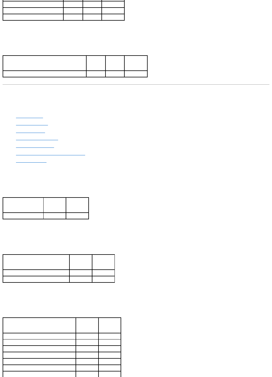
Open the PDF directly: View PDF ![]() .
.
Page Count: 155 [warning: Documents this large are best viewed by clicking the View PDF Link!]

Dell™OpenManage™ServerAdministratorStorageManagementUser's
Guide
Notes and Cautions
Information in this document is subject to change without notice.
©2009 Dell Inc. All rights reserved.
Reproduction in any manner whatsoever without the written permission of Dell Inc. is strictly forbidden.
Trademarks used in this text: Dell, the DELL logo, PowerVault, and Dell OpenManage are trademarks of Dell Inc.; Microsoft, Windows are registered trademarks and Windows Server is
a trademark of Microsoft Corporation in the United States and other countries; VMware is a registered trademark of VMware Inc.
Server Administrator includes software developed by the Apache Software Foundation (www.apache.org). Server Administrator utilizes the OverLIB JavaScript library. This library can
be obtained from www.bosrup.com.
Other trademarks and trade names may be used in this document to refer to either the entities claiming the marks and names or their products. Dell Inc. disclaims any
proprietary interest in trademarks and trade names other than its own.
August 2009
Overview
Virtual Disks
Getting Started
Physical Disks
Understanding RAID Concepts
Protecting Your Virtual Disk with a Hot Spare
Quick Access to Storage Status and Tasks
Moving Physical and Virtual Disks from One System to Another
Storage Information and Global Tasks
BIOS Terminology
Setting Hot Spare Protection Policy
Troubleshooting
Controllers
Frequently Asked Questions
RAID Controller Batteries
Supported Features
Connectors
Determining the Health Status for Storage Components
Enclosures and Backplanes
NOTE: A NOTE indicates important information that helps you make better use of your computer.
CAUTION: A CAUTION indicates potential damage to hardware or loss of data if instructions are not followed.
Back to Contents Page
Supported Features
Dell™OpenManage™ServerAdministratorStorageManagementUser'sGuide
Different controllers support different features. The tasks displayed by the Storage Management menus and other features vary depending on whether the
controller supports the feature. This appendix identifies the features that each controller supports. For more information, see your hardware documentation.
Supported Features on the PERC 3/SC, 3/DC, 3/QC, 4/SC, 4/DC, 4/Di, 4e/Si, 4e/Di,
4e/DC, CERC ATA100/4ch, and 4/IM Controllers
This section identifies the controller-supported features and whether or not an enclosure can be attached to the controller.
l"Controller Tasks"
l"Battery Tasks"
l"Connector Tasks"
l"Physical Disk Tasks"
l"Virtual Disk Tasks"
l"Virtual Disk Specifications"
l"Supported RAID Levels"
l"Read, Write, and Disk Cache Policy"
l"Enclosure Support"
For enclosure-supported tasks, see "Enclosure and Backplane Features."
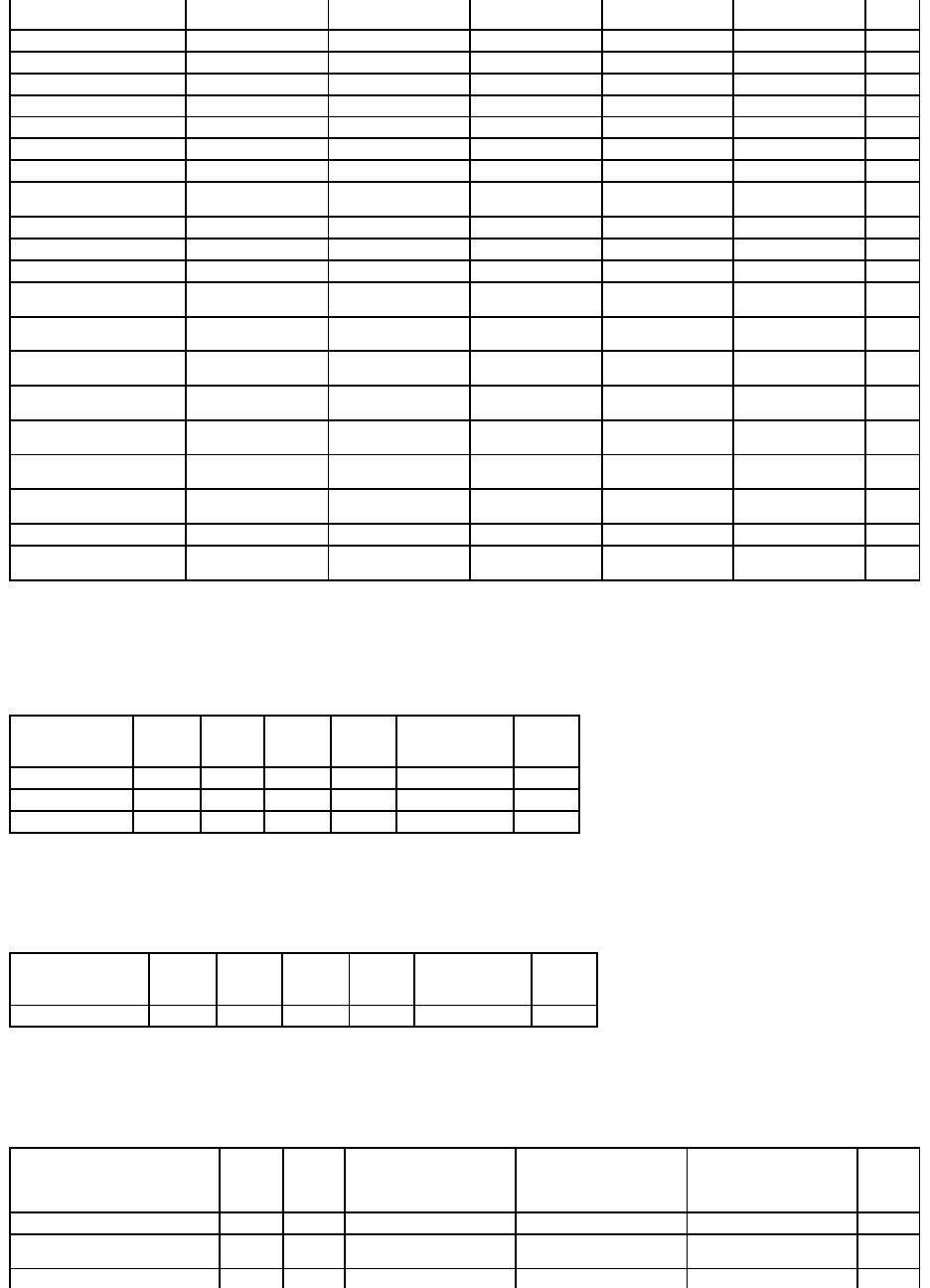
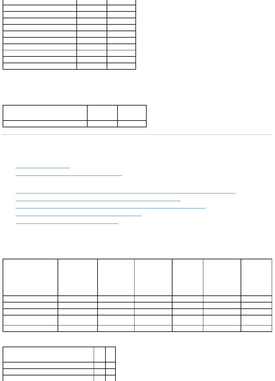
Controller Tasks
Table A-1. Controller Tasks Supported by the PERC 3/SC, 3/DC, 3/QC, 4/SC, 4/DC, 4/Di, 4e/Si, 4e/Di, 4e/DC, CERC ATA100/4ch, and
4/IMControllers
Supported Features on the PERC 3/SC, 3/DC, 3/QC, 4/SC, 4/DC, 4/Di, 4e/Si, 4e/Di, 4e/DC, CERC ATA100/4ch, and 4/IM
Controllers
Supported Features on
the PERC S100 and S300
Controllers
Supported Features on the PERC 3/Si, 3/Di, CERC SATA1.5/2s, and CERC SATA1.5/6ch Controllers
Supported Features on
the Non-RAID Controllers
Supported Features on the PERC 5/E, PERC 5/i, PERC 6/E, PERC 6/I, PERC 6/I Modular, and CERC 6/I Controllers
Enclosure and Backplane
Features
Supported Features on the PERC H800, PERC H700 Adapter, PERC H700 Integrated, and PERC H700 Modular Controllers
Maximum Supported
Configuration
Supported Features on the SAS 5/iR, SAS 6/iR, and PERC H200 Controllers
Controller Task Name
PERC
3/SC
PERC
3/DC
PERC
3/QC
PERC
4/SC
PERC
4/DC
PERC
4/DI
PERC
4e/SI
PERC
4e/DI
PERC
4e/DC
CERC ATA
100/4ch
PERC
4/IM
Enable Alarm
Yes
Yes
Yes
Yes
Yes
No
No
No
Yes
Yes
No
Disable Alarm
Yes
Yes
Yes
Yes
Yes
No
No
No
Yes
Yes
No
Quiet Alarm
Yes
Yes
Yes
Yes
Yes
No
No
No
Yes
Yes
No
Test Alarm
No
No
No
No
No
No
No
No
No
No
No
Reset configuration
Yes
Yes
Yes
Yes
Yes
Yes
Yes
Yes
Yes
Yes
No
Set Rebuild Rate
Yes
Yes
Yes
Yes
Yes
Yes
Yes
Yes
Yes
Yes
No
Set Background Initialization Rate
No
No
No
No
No
No
No
No
No
No
No
Set Check Consistency Rate
No
No
No
No
No
No
No
No
No
No
No
Set Reconstruct Rate
No
No
No
No
No
No
No
No
No
No
No
Rescan Controller
Yes
Yes
Yes
Yes
Yes
Yes
Yes
Yes
Yes
Yes
Yes
Create Virtual Disk
Yes
Yes
Yes
Yes
Yes
Yes
Yes
Yes
Yes
Yes
No
Export Log File
Yes
Yes
Yes
Yes
Yes
Yes
Yes
Yes
Yes
Yes
No
Clear Foreign Configuration
No
No
No
No
No
No
No
No
No
No
No
Import Foreign Configuration
No
No
No
No
No
No
No
No
No
No
No
Import/Recover Foreign
Configuration
No
No
No
No
No
No
No
No
No
No
No
Set Patrol Read Mode
No
No
No
Yes
Yes
Yes
Yes
Yes
Yes
No
No
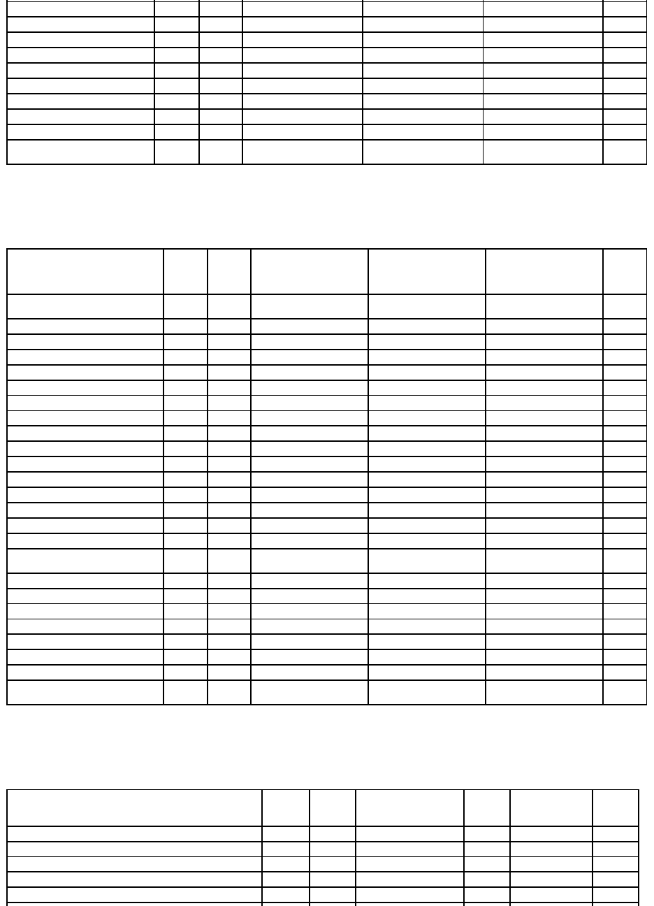
Battery Tasks
Table A-2. Battery Tasks Supported by the PERC 3/SC, 3/DC, 3/QC, 4/SC, 4/DC, 4/Di, 4e/Si, 4e/Di, 4e/DC, CERC ATA100/4ch, and 4/IM
Controllers
Connector Tasks
Table A-3. Connector Tasks Supported by the PERC 3/SC, 3/DC, 3/QC, 4/SC, 4/DC, 4/Di, 4e/Si, 4e/Di, 4e/DC, CERC ATA100/4ch, and
4/IMControllers
Physical Disk Tasks
Table A-4. Physical Disk Tasks Supported by the PERC 3/SC, 3/DC, 3/QC, 4/SC, 4/DC, 4/Di, 4e/Si, 4e/Di, 4e/DC, CERC ATA100/4ch, and
4/IMControllers
Virtual Disk Tasks
Table A-5. Virtual Disk Tasks Supported by the PERC 3/SC, 3/DC, 3/QC, 4/SC, 4/DC, 4/Di, 4e/Si, 4e/Di, 4e/DC, CERC ATA100/4ch, and
NOTE: ForPERC4controllers,
(Manual mode is not available).
Start Patrol Read
No
No
No
No
No
No
No
No
No
No
No
Stop Patrol Read
No
No
No
No
No
No
No
No
No
No
No
Battery Task
Name
PERC
3/SC
PERC
3/DC
PERC
3/QC
PERC
4/SC
PERC
4/DC
PERC
4/DI
PERC
4e/SI
PERC
4e/DI
PERC
4e/DC
CERC ATA
100/4ch
PERC
4/IM
Recondition
Battery
No
No
No
No
No
No
No
No
No
No
No
Start Learn Cycle
No
No
No
No
No
No
No
No
No
No
No
Delay Learn
Cycle
No
No
No
No
No
No
No
No
No
No
No
Connector Task
Name
PERC
3/SC
PERC
3/DC
PERC
3/QC
PERC
4/SC
PERC
4/DC
PERC
4/DI
PERC
4e/SI
PERC
4e/DI
PERC
4e/DC
CERC ATA
100/4ch
PERC
4/IM
Connector Rescan
Yes
Yes
Yes
Yes
Yes
Yes
Yes
Yes
Yes
Yes
Yes
Physical Disk Task
Name
PERC
3/SC
PERC
3/DC
PERC
3/QC
PERC
4/SC
PERC
4/DC
PERC
4/DI
PERC
4e/SI
PERC
4e/DI
PERC
4e/DC
CERC ATA
100/4ch
PERC 4/IM
Blink/Unblink
Yes
Yes
Yes
Yes
Yes
Yes
Yes
Yes
Yes
No
Yes
Task only available when an
enclosure or backplane and LEDs
on the physical disks are present.
Assign and
Unassign Global Hot
Spare
Yes
Yes
Yes
Yes
Yes
Yes
Yes
Yes
Yes
Yes
No
Prepare to Remove
Yes
Yes
Yes
Yes
Yes
Yes
Yes
Yes
Yes
No
No
Offline
Yes
Yes
Yes
Yes
Yes
Yes
Yes
Yes
Yes
Yes
No
Online
Yes
Yes
Yes
Yes
Yes
Yes
Yes
Yes
Yes
Yes
No
Initialize
No
No
No
No
No
No
No
No
No
No
No
Rebuild
Yes
Yes
Yes
Yes
Yes
Yes
Yes
Yes
Yes
No
No
Cancel Rebuild
Yes
Yes
Yes
Yes
Yes
Yes
Yes
Yes
Yes
No
No
Remove Dead Disk
Segments
No
No
No
No
No
No
No
No
No
No
No
Format Disk
No
No
No
No
No
No
No
No
No
No
No
Clear
No
No
No
No
No
No
No
No
No
No
No
Cancel Clear
No
No
No
No
No
No
No
No
No
No
No
4/IMControllers
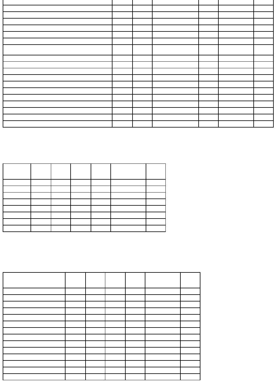
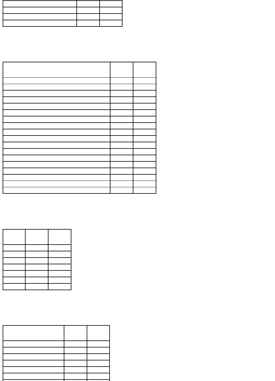
Virtual Disk Specifications
Table A-6. Virtual Disk Specifications for the PERC 3/SC, 3/DC, 3/QC, 4/SC, 4/DC, 4/Di, 4e/Si, 4e/Di, 4e/DC, CERC ATA100/4ch, and 4/IM
Controllers
Virtual Disk Task Name
PERC
3/SC
PERC
3/DC
PERC
3/QC
PERC
4/SC
PERC
4/DC
PERC
4/DI
PERC
4e/SI
PERC
4e/DI
PERC
4e/DC
CERC ATA
100/4ch
PERC
4/IM
Assign and Unassign
Dedicated Hot Spare
Yes
Yes
Yes
Yes
Yes
Yes
Yes
Yes
Yes
Yes
No
Create Virtual Disk
Yes
Yes
Yes
Yes
Yes
Yes
Yes
Yes
Yes
Yes
No
Create Virtual Disk Advanced
Wizard
Yes
Yes
Yes
Yes
Yes
Yes
Yes
Yes
Yes
Yes
No
Create Virtual Disk Express
Wizard
Yes
Yes
Yes
Yes
Yes
Yes
Yes
Yes
Yes
Yes
No
Rename
Yes
Yes
Yes
Yes
Yes
Yes
Yes
Yes
Yes
Yes
Yes
Blink/Unblink
Yes
Yes
Yes
Yes
Yes
Yes
Yes
Yes
Yes
No
Yes
Reconfigure
Yes
Yes
Yes
Yes
Yes
Yes
Yes
Yes
Yes
Yes
No
Change Policy
Yes
Yes
Yes
Yes
Yes
Yes
Yes
Yes
Yes
Yes
No
Split Mirror
No
No
No
No
No
No
No
No
No
No
No
Unmirror
No
No
No
No
No
No
No
No
No
No
No
Delete Last Virtual Disk
Yes
Yes
Yes
Yes
Yes
Yes
Yes
Yes
Yes
Yes
No
Delete (any) Virtual Disk
Yes
Yes
Yes
Yes
Yes
Yes
Yes
Yes
Yes
Yes
No
Check Consistency
Yes
Yes
Yes
Yes
Yes
Yes
Yes
Yes
Yes
Yes
No
Cancel Check Consistency
Yes
Yes
Yes
Yes
Yes
Yes
Yes
Yes
Yes
Yes
No
Pause Check Consistency
No
No
No
No
No
No
No
No
No
No
No
Resume Check Consistency
No
No
No
No
No
No
No
No
No
No
No
Cancel Background
Initialization (BGI)
Yes
Yes
Yes
Yes
Yes
Yes
Yes
Yes
Yes
No
No
Format Virtual Disk
No
No
No
No
No
No
No
No
No
No
No
Cancel Format Virtual Disk
No
No
No
No
No
No
No
No
No
No
No
Restore Dead Disk Segments
No
No
No
No
No
No
No
No
No
No
No
Initialize Virtual Disk
Yes
Yes
Yes
Yes
Yes
Yes
Yes
Yes
Yes
Yes
No
Fast Initialize Virtual Disk
No
No
No
No
No
No
No
No
No
No
No
Slow Initialize Virtual Disk
No
No
No
No
No
No
No
No
No
No
No
Cancel Initialize Virtual Disk
Yes
Yes
Yes
Yes
Yes
Yes
Yes
Yes
Yes
Yes
No
Virtual Disk Specification
PERC
3/SC
PERC
3/DC
PERC
3/QC
PERC
4/SC
PERC
4/DC
PERC
4/DI
PERC
4e/SI
PERC
4e/DI
PERC
4e/DC
CERC ATA
100/4ch
PERC
4/IM
Maximum Number of Virtual Disks
per Controller
40
40
40
40
40
40
40
40
40
40
1
Minimum Virtual Disk Size
100
MB
100
MB
100
MB
100
MB
100
MB
100
MB
100
MB
100
MB
100
MB
100
MB
Max
Maximum Virtual Disk Size
2TB
2TB
2TB
2TB
2TB
2TB
2TB
2TB
2TB
2TB
2TB
Maximum Number of Spans per
Virtual Disk
8
8
8
8
8
8
8
8
8
8
1
Maximum Number of Physical Disks
per Span
32
32
32
32
32
32
32
32
32
32
2
Minimum Stripe Size
2k
2k
2k
2k
2k
2k
2k
2k
2k
2k
NA
Maximum Stripe Size
128k
128k
128k
128k
128k
128k
128k
128k
128k
128k
NA
Maximum Number of Virtual Disks
per Disk Group
16
16
16
16
16
16
16
16
16
16
1
Maximum Number of Physical Disks
that Can Be Concatenated
8
8
8
8
8
8
8
8
8
8
NA
Maximum Number of Physical Disks
in a RAID 0
32
32
32
32
32
32
32
32
32
32
NA
Maximum Physical Disks in a RAID 1
2
2
2
2
2
2
2
2
2
2
2
Maximum Number of Physical Disks
in a RAID 5
32
32
32
32
32
32
32
32
32
32
NA
Maximum Number of Physical Disks
in a RAID 10
16
16
16
16
16
16
16
16
16
16
NA
Maximum Number of Physical Disks
256
256
256
256
256
256
256
256
256
NA
NA
Supported RAID Levels
Table A-7. RAID Levels Supported by the PERC 3/SC, 3/DC, 3/QC, 4/SC, 4/DC, 4/Di, 4e/Si, 4e/Di, 4e/DC, CERC ATA100/4ch, and 4/IM
Controllers
Read, Write, and Disk Cache Policy
Table A-8. Read, Write and Disk Cache Policy Supported by the PERC 3/SC, 3/DC, 3/QC, 4/SC, 4/DC, 4/Di, 4e/Si, 4e/Di, 4e/DC, CERC
ATA100/4ch,and4/IMControllers
in a RAID 50
Minimum Number of Physical Disks
that Can Be Concatenated
2
2
2
2
2
2
2
2
2
2
NA
Minimum Number of Physical Disks in
a RAID 0
1
1
1
1
1
1
1
1
1
1
NA
Minimum Number of Physical Disks in
a RAID 1
2
2
2
2
2
2
2
2
2
2
2
Minimum Number of Physical Disks in
a RAID 5
3
3
3
3
3
3
3
3
3
3
NA
Minimum Number of Physical Disks in
a RAID 10
4
4
4
4
4
4
4
4
4
4
NA
Minimum Number of Physical Disks in
a RAID 50
6
6
6
6
6
6
6
6
6
NA
NA
Maximum number of physical disks in
a RAID 6
NA
NA
NA
NA
NA
NA
NA
NA
NA
NA
NA
Maximum number of physical disks in
a RAID 60
NA
NA
NA
NA
NA
NA
NA
NA
NA
NA
NA
Minimum number of physical disks in
a RAID 6
NA
NA
NA
NA
NA
NA
NA
NA
NA
NA
NA
Minimum number of physical disks in
a RAID 60
NA
NA
NA
NA
NA
NA
NA
NA
NA
NA
NA
RAID Level
PERC
3/SC
PERC
3/DC
PERC
3/QC
PERC
4/SC
PERC
4/DC
PERC
4/DI
PERC
4e/SI
PERC
4e/DI
PERC
4e/DC
CERC ATA
100/4ch
PERC
4/IM
Concatenation
Yes
Yes
Yes
Yes
Yes
Yes
Yes
Yes
Yes
Yes
No
RAID 0
Yes
Yes
Yes
Yes
Yes
Yes
Yes
Yes
Yes
Yes
No
RAID 1
Yes
Yes
Yes
Yes
Yes
Yes
Yes
Yes
Yes
Yes
Yes
RAID 5
Yes
Yes
Yes
Yes
Yes
Yes
Yes
Yes
Yes
Yes
No
RAID 10
Yes
Yes
Yes
Yes
Yes
Yes
Yes
Yes
Yes
Yes
No
RAID 50
Yes
Yes
Yes
Yes
Yes
Yes
Yes
Yes
Yes
No
No
RAID 6
No
No
No
No
No
No
No
No
No
No
No
RAID 60
No
No
No
No
No
No
No
No
No
No
No
Read, Write, and Disk
Cache Policy
PERC
3/SC
PERC
3/DC
PERC
3/QC
PERC
4/SC
PERC
4/DC
PERC
4/DI
PERC
4e/SI
PERC
4e/DI
PERC
4e/DC
CERC ATA
100/4ch
PERC
4/IM
Cache settings
Yes
Yes
Yes
Yes
Yes
Yes
Yes
Yes
Yes
Yes
No
Read Policy
Yes
Yes
Yes
Yes
Yes
Yes
Yes
Yes
Yes
Yes
No
Read Ahead (Enabled)
Yes
Yes
Yes
Yes
Yes
Yes
Yes
Yes
Yes
Yes
No
Adaptive Read Ahead
Yes
Yes
Yes
Yes
Yes
Yes
Yes
Yes
Yes
Yes
No
No Read Ahead (Disabled)
Yes
Yes
Yes
Yes
Yes
Yes
Yes
Yes
Yes
Yes
No
Write Policy
Yes
Yes
Yes
Yes
Yes
Yes
Yes
Yes
Yes
Yes
No
Write Back (Enabled)
Yes
Yes
Yes
Yes
Yes
Yes
Yes
Yes
Yes
Yes
No
Write Through (Disabled)
Yes
Yes
Yes
Yes
Yes
Yes
Yes
Yes
Yes
Yes
No
Force Write Back (Enabled
Always)
No
No
No
No
No
No
No
No
No
No
No
Write Cache Enabled
Protected
No
No
No
No
No
No
No
No
No
No
No
Disk Cache Policy
Yes
Yes
Yes
Yes
Yes
Yes
Yes
Yes
Yes
Yes
No
Cache I/O
Yes
Yes
Yes
Yes
Yes
Yes
Yes
Yes
Yes
Yes
No
Direct I/O
Yes
Yes
Yes
Yes
Yes
Yes
Yes
Yes
Yes
Yes
No
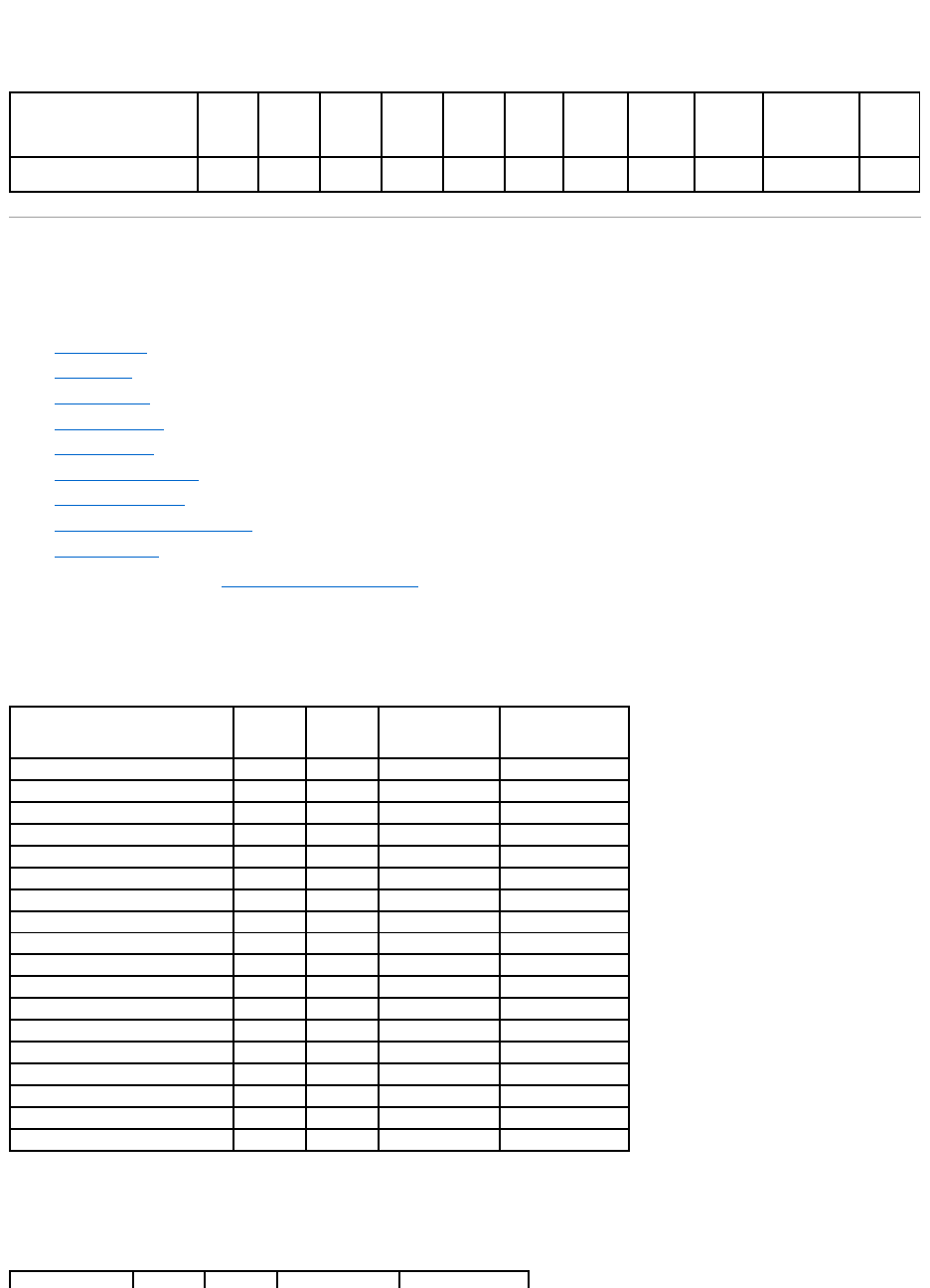
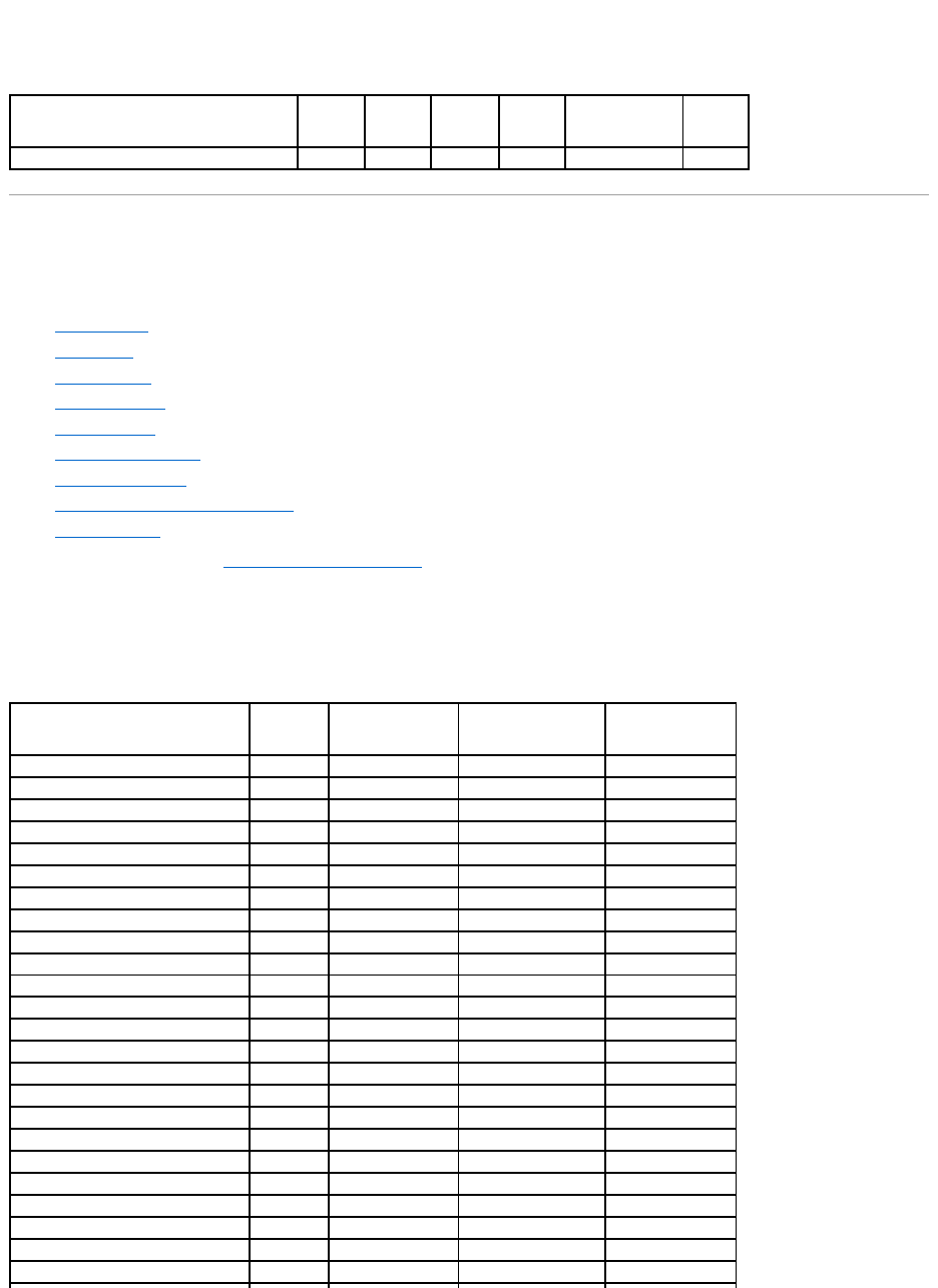
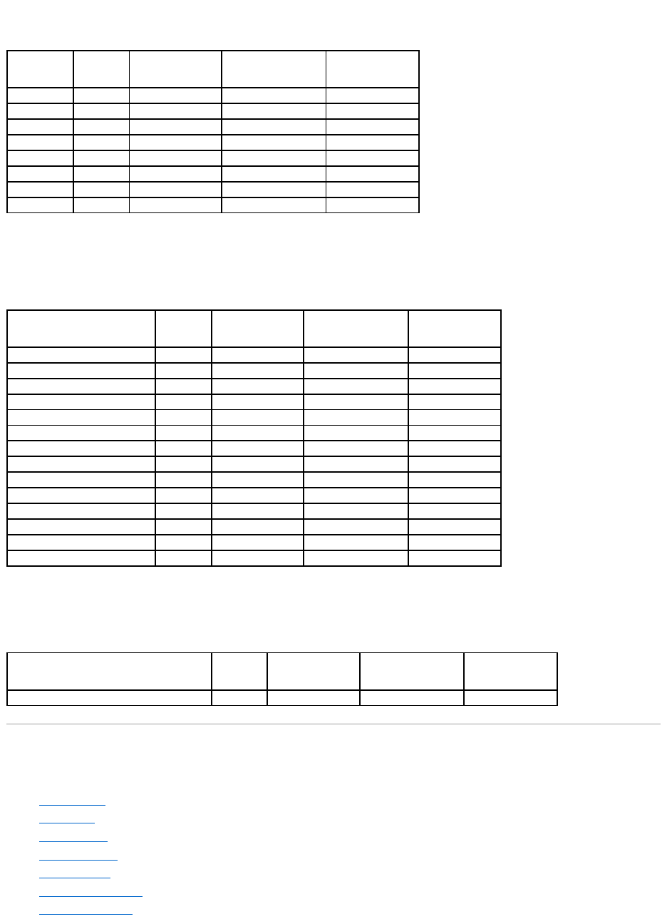
Enclosure Support
Table A-9. Enclosure Support on the PERC 3/SC, 3/DC, 3/QC, 4/SC, 4/DC, 4/Di, 4e/Si, 4e/Di, 4e/DC, CERC ATA100/4ch, and 4/IM
Controllers
Supported Features on the PERC 3/Si, 3/Di, CERC SATA1.5/2s, and CERC
SATA1.5/6ch Controllers
This section identifies the controller-supported features and whether or not an enclosure can be attached to the controller.
l"Controller Tasks"
l"Battery Tasks"
l"Connector Tasks"
l"Physical Disk Tasks"
l"Virtual Disk Tasks"
l"Virtual Disk Specifications"
l"Supported RAID Levels"
l"Read, Write, and Disk Cache Policy"
l"Enclosure Support"
For enclosure-supported tasks, see "Enclosure and Backplane Features."
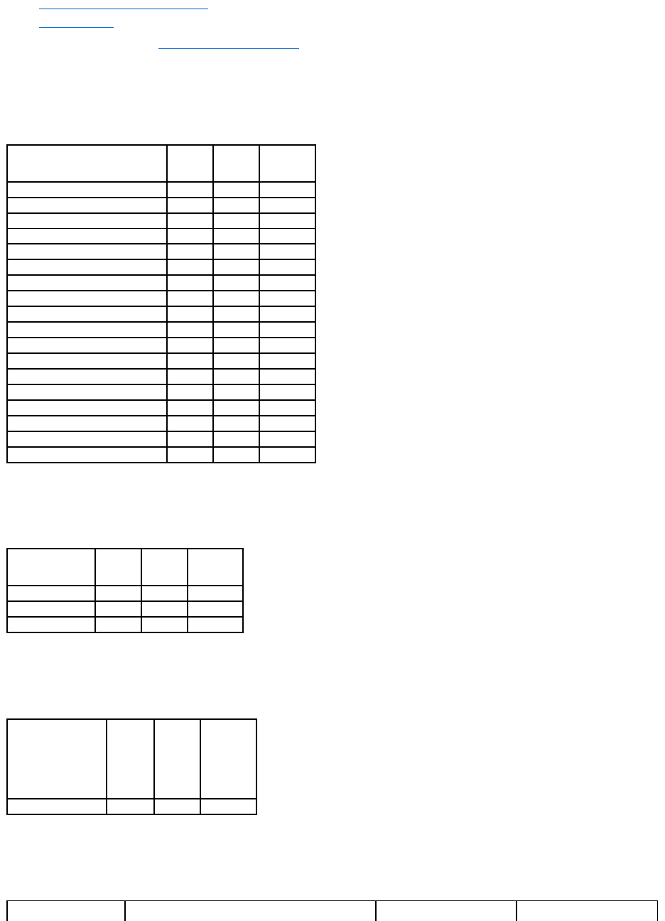
Controller Tasks
Table A-10.ControllerTasksSupportedbythePERC3/Si,3/Di,CERCSATA1.5/2s,andCERCSATA1.5/6chControllers
Battery Tasks
Table A-11.BatteryTasksSupportedbythePERC3/Si,3/Di,CERCSATA1.5/2s,andCERCSATA1.5/6chControllers
Enclosure Support
PERC
3/SC
PERC
3/DC
PERC
3/QC
PERC
4/SC
PERC
4/DC
PERC
4/DI
PERC
4e/SI
PERC
4e/DI
PERC
4e/DC
CERC ATA
100/4ch
PERC
4/IM
Can an enclosure be attached
to this controller?
Yes
Yes
Yes
Yes
Yes
Yes
Yes
Yes
Yes
No
No
Controller Task Name
PERC 3/Si
PERC 3/Di
CERC SATA 1.5/2s
CERC SATA 1.5/6ch
Enable Alarm
No
No
No
Yes
Disable Alarm
No
No
No
Yes
Quiet Alarm
No
No
No
Yes
Test Alarm
No
No
No
Yes
Reset configuration
Yes
Yes
Yes
Yes
Set Rebuild Rate
No
No
No
No
Set Background Initialization Rate
No
No
No
No
Set Check Consistency Rate
No
No
No
No
Set Reconstruct Rate
No
No
No
No
Rescan Controller
Yes
Yes
Yes
Yes
Create Virtual Disk
Yes
Yes
Yes
Yes
Export Log File
Yes
Yes
No
Yes
Clear Foreign Configuration
No
No
No
No
Import Foreign Configuration
No
No
No
No
Import/Recover Foreign Configuration
No
No
No
No
Set Patrol Read Mode
No
No
No
No
Start Patrol Read
No
No
No
No
Stop Patrol Read
No
No
No
No
Connector Tasks
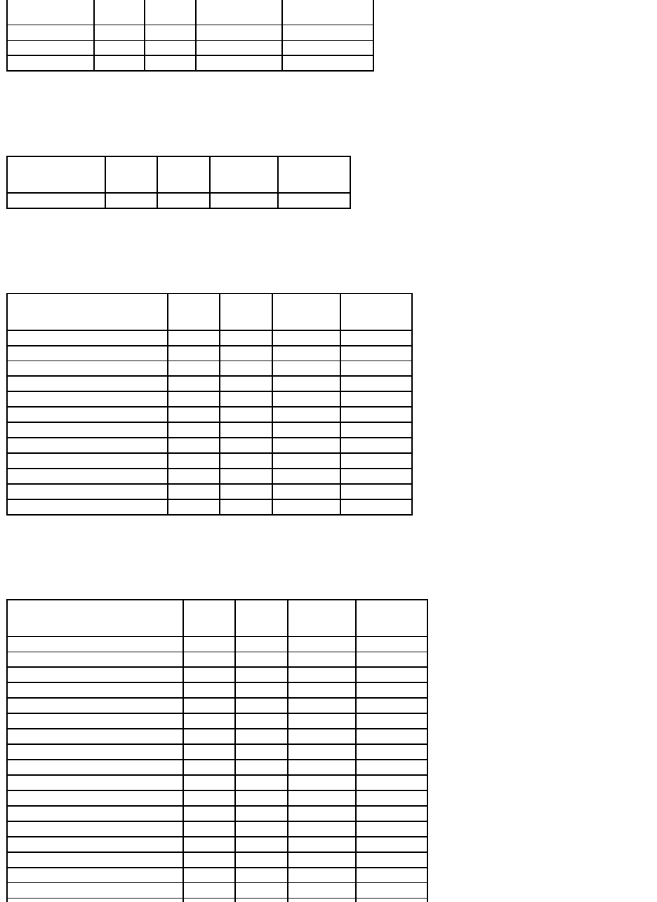
Table A-12.ConnectorTasksSupportedbythePERC3/Si,3/Di,CERCSATA1.5/2s,andCERCSATA1.5/6chControllers
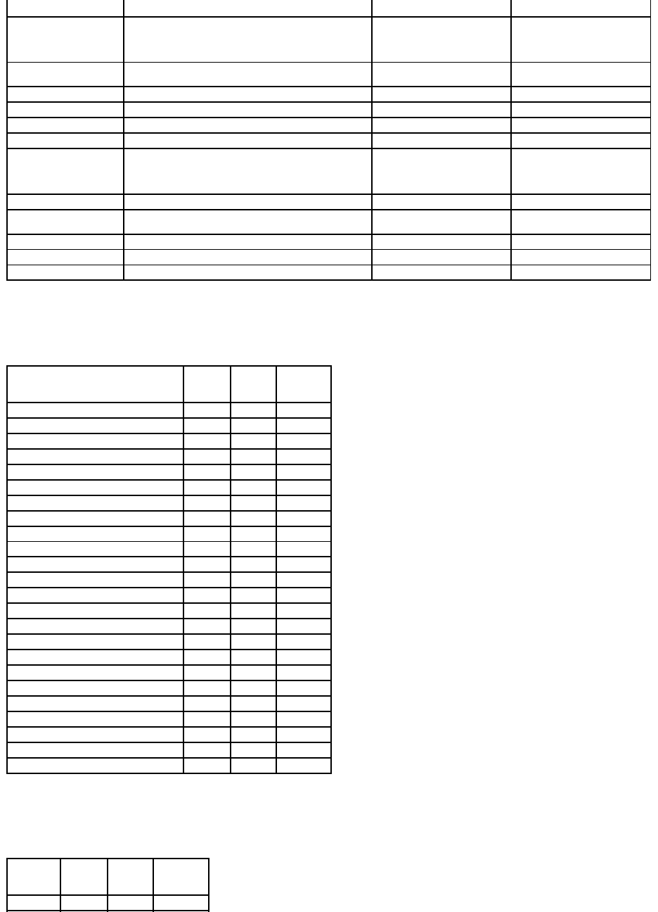
Physical Disk Tasks
Table A-13.PhysicalDiskTasksSupportedbythePERC3/Si,3/Di,CERCSATA1.5/2s,andCERCSATA1.5/6chControllers
Virtual Disk Tasks
Table A-14.VirtualDiskTasksSupportedbythePERC3/Si,3/Di,CERCSATA1.5/2s,andCERCSATA1.5/6chControllers
Battery Task Name
PERC 3/Si
PERC 3/Di
CERC SATA 1.5/2s
CERC SATA 1.5/6ch
Recondition Battery
Yes
Yes
No
No
Start Learn Cycle
No
No
No
No
Delay Learn Cycle
No
No
No
No
Connector Task Name
PERC 3/SI
PERC 3/DI
CERC SATA 2S
CERC SATA 6ch
Connector Rescan
Yes
Yes
Yes
Yes
Physical Disk Task Name
PERC 3/SI
PERC 3/DI
CERC SATA 2S
CERC SATA 6ch
Blink/Unblink
Yes
Yes
No
No
Assign and Unassign Global Hot Spare
Yes
Yes
No
Yes
Prepare to Remove
Yes
Yes
No
No
Offline
No
No
No
No
Online
No
No
No
No
Initialize
Yes
Yes
Yes
Yes
Rebuild
No
No
Yes
No
Cancel Rebuild
No
No
No
No
Remove Dead Disk Segments
Yes
Yes
No
Yes
Format Disk
No
No
No
No
Clear
No
No
No
No
Cancel Clear
No
No
No
No
Virtual Disk Task Name
PERC 3/SI
PERC 3/DI
CERC SATA 2S
CERC SATA 6ch
Assign and Unassign Dedicated Hot Spare
Yes
Yes
No
Yes
Create Virtual Disk
Yes
Yes
Yes
Yes
Create Virtual Disk Advanced Wizard
Yes
Yes
Yes
Yes
Create Virtual Disk Express Wizard
Yes
Yes
Yes
Yes
Rename
Yes
Yes
Yes
Yes
Blink/Unblink
Yes
Yes
No
No
Reconfigure
Yes
Yes
No
Yes
Change Policy
Yes
Yes
No
Yes
Split Mirror
Yes
Yes
No
Yes
Unmirror
Yes
Yes
No
Yes
Delete Last Virtual Disk
Yes
Yes
Yes
Yes
Delete (any) Virtual Disk
Yes
Yes
No
Yes
Check Consistency
Yes
Yes
Yes
Yes
Cancel Check Consistency
Yes
Yes
Yes
Yes
Pause Check Consistency
Yes
Yes
No
Yes
Resume Check Consistency
Yes
Yes
No
Yes
Cancel Background Initialization (BGI)
No
No
No
No
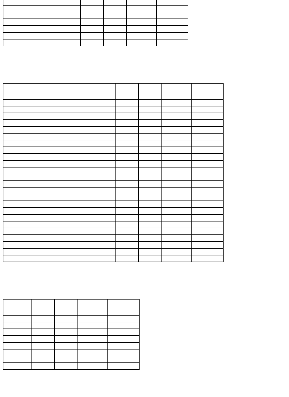
Virtual Disk Specifications
Table A-15.VirtualDiskSpecificationsforthePERC3/Si,3/Di,CERCSATA1.5/2s,andCERCSATA1.5/6chControllers
Supported RAID Levels
Table A-16.RAIDLevelsSupportedbythePERC3/Si,3/Di,CERCSATA1.5/2s,andCERCSATA1.5/6chControllers
Read, Write, and Disk Cache Policy
Format Virtual Disk
Yes
Yes
No
Yes
Cancel Format Virtual Disk
No
No
No
No
Restore Dead Disk Segments
Yes
Yes
No
Yes
Initialize Virtual Disk
No
No
No
No
Fast Initialize Virtual Disk
No
No
No
No
Slow Initialize Virtual Disk
No
No
No
No
Cancel Initialize Virtual Disk
No
No
No
No
Virtual Disk Specification
PERC 3/SI
PERC 3/DI
CERC SATA 2S
CERC SATA 6ch
Maximum Number of Virtual Disks per Controller
24
24
1
10
Minimum Virtual Disk Size
100MB
100MB
100MB
100MB
Maximum Virtual Disk Size
2TB
2TB
2TB
2TB
Maximum Number of Spans per Virtual Disk
16
16
1
16
Maximum Number of Physical Disks per Span
2
2
2
2
Minimum Stripe Size
8k
8k
16k
8k
Maximum Stripe Size
64k
64k
64k
64k
Maximum Number of Virtual Disks per Disk Group
10
10
1
9
Maximum Number of Physical Disks that Can Be Concatenated
1
1
1
1
Maximum Number of Physical Disks in a RAID 0
48
48
2
48
Maximum Physical Disks in a RAID 1
2
2
2
2
Maximum Number of Physical Disks in a RAID 5
16
16
NA
16
Maximum Number of Physical Disks in a RAID 10
32
32
NA
32
Maximum Number of Physical Disks in a RAID 50
NA
NA
NA
NA
Minimum Number of Physical Disks that Can Be Concatenated
1
1
1
1
Minimum Number of Physical Disks in a RAID 0
1
1
1
1
Minimum Number of Physical Disks in a RAID 1
2
2
2
2
Minimum Number of Physical Disks in a RAID 5
3
3
NA
3
Minimum Number of Physical Disks in a RAID 10
4
4
NA
4
Minimum Number of Physical Disks in a RAID 50
NA
NA
NA
NA
Maximum number of physical disks in a RAID 6
NA
NA
NA
NA
Maximum number of physical disks in a RAID 60
NA
NA
NA
NA
Minimum number of physical disks in a RAID 6
NA
NA
NA
NA
Minimum number of physical disks in a RAID 60
NA
NA
NA
NA
RAID Level
PERC 3/SI
PERC 3/DI
CERC SATA 2S
CERC SATA 6ch
Concatenation
Yes
Yes
Yes
Yes
RAID 0
Yes
Yes
Yes
Yes
RAID 1
Yes
Yes
Yes
Yes
RAID 5
Yes
Yes
No
Yes
RAID 10
Yes
Yes
No
Yes
RAID 50
No
No
No
No
RAID 6
No
No
No
No
RAID 60
No
No
No
No
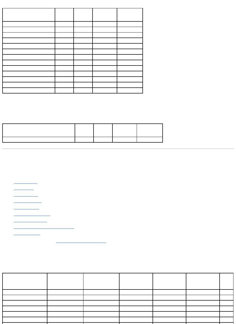
Table A-17.Read,Write,andCachePolicySupportedbythePERC3/Si,3/Di,CERCSATA1.5/2s,andCERCSATA1.5/6chControllers
Enclosure Support
Table A-18.EnclosureSupportonthePERC3/Si,3/Di,CERCSATA1.5/2s,andCERCSATA1.5/6chControllers
Supported Features on the PERC 5/E, PERC 5/i, PERC 6/E, PERC 6/I, PERC 6/I
Modular, and CERC 6/I Controllers
This section identifies the controller-supported features and whether or not an enclosure can be attached to the controller.
l"Controller Tasks"
l"Battery Tasks"
l"Connector Tasks"
l"Physical Disk Tasks"
l"Virtual Disk Tasks"
l"Virtual Disk Specifications"
l"Supported RAID Levels"
l"Read, Write, Cache and Disk Cache Policy"
l"Enclosure Support"
For enclosure-supported tasks, see "Enclosure and Backplane Features."
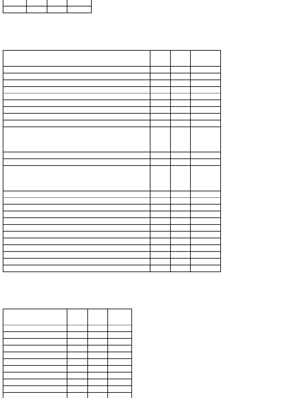
Controller Tasks
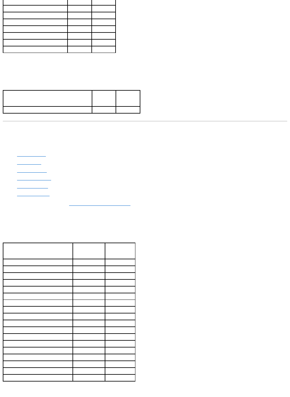
Table A-19.ControllerTasksSupportedonthePERC5/E,PERC5/i,PERC6/E,PERC6/I,PERC6/IModular,andCERC6/IControllers
Read, Write, and Cache Policy
PERC 3/SI
PERC 3/DI
CERC SATA 2S
CERC SATA 6ch
Cache settings
Yes
Yes
No
Yes
Read Policy
Yes
Yes
No
Yes
Read Ahead (Enabled)
Yes
Yes
No
Yes
Adaptive Read Ahead
No
No
No
No
No Read Ahead (Disabled)
Yes
Yes
Yes
Yes
Write Policy
Yes
Yes
No
Yes
Write Back (Enabled)
No
No
No
No
Write Through (Disabled)
Yes
Yes
Yes
Yes
Force Write Back (Enabled Always)
No
No
No
No
Write Cache Enabled Protected
Yes
Yes
No
Yes
Cache Policy
No
No
No
No
Cache I/O
No
No
No
No
Direct I/O
No
No
No
No
Enclosure Support
PERC 3/SI
PERC 3/DI
CERC SATA 2S
CERC SATA 6ch
Can an enclosure be attached to this controller?
No
Yes
No
No
Controller Task Name
PERC 5/E
PERC 5/i
PERC 6/E
PERC 6/I
PERC 6/I Modular
CERC
6/I
Enable Alarm
Yes
No
Yes
NA
NA
NA
Disable Alarm
Yes
No
Yes
NA
NA
NA
Quiet Alarm
Yes
No
Yes
NA
NA
NA
Test Alarm
Yes
No
Yes
NA
NA
NA
Reset configuration
Yes
Yes
Yes
Yes
Yes
Yes
Set Rebuild Rate
Yes
Yes
Yes
Yes
Yes
Yes
Battery Tasks
Table A-20. Battery Tasks Supported on the PERC 5/E, PERC 5/i, PERC 6/E, PERC 6/I, PERC 6/I, PERC 6/I Modular, and CERC 6/I
Controllers
Connector Tasks
Table A-21. Connector Tasks Supported by the PERC 5/E, PERC 5/i, PERC 6/E, PERC 6/I, PERC 6/I, Modular, and CERC 6/I Controllers
Physical Disk Tasks
Table A-22. Physical Disk Tasks Supported by the PERC 5/E, PERC 5/i, PERC 6/E, PERC 6/I, PERC 6/I Modular, and CERC 6/I Controllers
Set Background Initialization
Rate
Yes
Yes
Yes
Yes
Yes
Yes
Set Check Consistency Rate
Yes
Yes
Yes
Yes
Yes
Yes
Set Reconstruct Rate
Yes
Yes
Yes
Yes
Yes
Yes
Rescan Controller
No
No
No
No
No
No
Create Virtual Disk
Yes
Yes
Yes
Yes
Yes
Yes
Export Log File
Yes
Yes
Yes
Yes
Yes
Yes
Clear Foreign Configuration
Yes
Yes
Yes
Yes
Yes
Yes
Import Foreign Configuration
Yes
Yes
Yes
Yes
Yes
Yes
Import/Recover Foreign
Configuration
Yes with firmware
5.1.x or greater.
Yes with firmware
5.1.x or greater.
Yes
Yes
Yes
Yes
Set Patrol Read Mode
Yes
Yes
Yes
Yes
Yes
Yes
Start Patrol Read
Yes
Yes
Yes
Yes
Yes
Yes
Stop Patrol Read
Yes
Yes
Yes
Yes
Yes
Yes
Replace Member
No
No
Yes with firmware
6.1 and later
Yes with firmware
6.1 and later
Yes with firmware
6.1 and later
No
Foreign Configuration
No
No
Yes with firmware
6.1 and later
Yes with firmware
6.1 and later
Yes with firmware
6.1 and later
No
Import Preview of Foreign
Configuration
No
No
Yes with firmware
6.1 and later
Yes with firmware
6.1 and later
Yes with firmware
6.1 and later
No
Hot-plug of Enclosures
No
No
Yes with firmware
6.1 and later
No
No
No
Change Controller
Properties
No
No
Yes with firmware
6.1 and later
Yes with firmware
6.1 and later
Yes with firmware
6.1 and later
No
Intelligent Mirroring
No
No
Yes with firmware
6.1 and later
Yes with firmware
6.1 and later
Yes with firmware
6.1 and later
No
Redundant Path
Configuration
No
No
Yes with firmware
6.1 and later
No
No
No
Disk Cache Policy
Yes
Yes
Yes
Yes
Yes
No
Managing Preserved Cache
No
No
Yes with firmware
6.1 and later
Yes with firmware
6.1 and later
Yes with firmware
6.1 and later
No
Battery Task Name
PERC 5/E
PERC 5/i
PERC 6/E
PERC 6/I
PERC 6/I Modular
CERC 6/I
Recondition Battery
No
No
No
No
No
No
Start Learn Cycle
Yes
Yes
Yes
Yes
Yes
No
Delay Learn Cycle
Yes
Yes
Yes
Yes
Yes
No
Connector Task Name
PERC 5/E
PERC 5/I
PERC 6/E
PERC 6/I
PERC 6/I Modular
CERC 6/I
Connector Rescan
No
No
No
No
No
No
Physical Disk Task Name
PERC
5/E
PERC
5/I
PERC 6/E
PERC 6/I
PERC 6/I Modular
CERC
6/I
Blink/Unblink
Yes
Yes
Yes
Yes
Yes
Yes
Assign and Unassign Global Hot
Spare
Yes
Yes
Yes
Yes
Yes
Yes
Prepare to Remove
No
No
No
No
No
No
Virtual Disk Tasks
Table A-23. Virtual Disk Tasks Supported by the PERC 5/E, PERC 5/i, PERC 6/E, PERC 6/I, PERC 6/I Modular, and CERC 6/I Controllers
Virtual Disk Specifications
Table A-24.VirtualDiskSpecificationsforthePERC5/E,PERC5/i,PERC6/E,PERC6/I,PERC6/IModular,andCERC6/IControllers
Offline
Yes
Yes
Yes
Yes
Yes
Yes
Online
Yes
Yes
Yes
Yes
Yes
Yes
Initialize
No
No
No
No
No
No
Rebuild
Yes
Yes
Yes
Yes
Yes
Yes
Cancel Rebuild
Yes
Yes
Yes
Yes
Yes
Yes
Remove Dead Disk Segments
No
No
No
No
No
No
Format Disk
No
No
No
No
No
No
Clear
Yes
Yes
Yes
Yes
Yes
Yes
Cancel Clear
Yes
Yes
Yes
Yes
Yes
Yes
Cancel Replace Member
No
No
Yes with firmware 6.1 and
later
Yes with firmware 6.1 and
later
Yes with firmware 6.1 and
later
No
Virtual Disk Task Name
PERC
5/E
PERC
5/I
PERC 6/E
PERC 6/I
PERC 6/I Modular
CERC
6/I
Assign and Unassign Dedicated Hot
Spare
Yes
Yes
Yes
Yes
Yes
Yes
Create Virtual Disk
Yes
Yes
Yes
Yes
Yes
Yes
Create Virtual Disk Advanced Wizard
Yes
Yes
Yes
Yes
Yes
Yes
Create Virtual Disk Express Wizard
Yes
Yes
Yes
Yes
Yes
Yes
Rename
Yes
Yes
Yes
Yes
Yes
Yes
Blink/Unblink
Yes
Yes
Yes
Yes
Yes
Yes
Reconfigure
Yes
Yes
Yes
Yes
Yes
Yes
Change Policy
Yes
Yes
Yes
Yes
Yes
Yes
Split Mirror
No
No
No
No
No
No
Unmirror
No
No
No
No
No
No
Delete Last Virtual Disk
Yes
Yes
Yes
Yes
Yes
Yes
Delete (any) Virtual Disk
Yes
Yes
Yes
Yes
Yes
Yes
Check Consistency
Yes
Yes
Yes
Yes
Yes
Yes
Cancel Check Consistency
Yes
Yes
Yes
Yes
Yes
Yes
Pause Check Consistency
No
No
No
No
No
No
Resume Check Consistency
No
No
No
No
No
No
Cancel Background Initialization
(BGI)
Yes
Yes
Yes
Yes
Yes
Yes
Format Virtual Disk
No
No
No
No
No
No
Cancel Format Virtual Disk
No
No
No
No
No
No
Restore Dead Disk Segments
No
No
No
No
No
No
Initialize Virtual Disk
No
No
No
No
No
No
Fast Initialize Virtual Disk
Yes
Yes
Yes
Yes
Yes
Yes
Slow Initialize Virtual Disk
Yes
Yes
Yes
Yes
Yes
Yes
Cancel Initialize Virtual Disk
Yes
Yes
Yes
Yes
Yes
Yes
Replace Member
No
No
Yes with firmware 6.1 and
later
Yes with firmware 6.1 and
later
Yes with firmware 6.1 and
later
No
Virtual Disk Specification
PERC 5/E
PERC 5/I
PERC 6/E
PERC 6/I
PERC 6/I Modular
CERC 6/I
Maximum Number of Virtual Disks per Controller
64
64
64
64
64
64
Minimum Virtual Disk Size
100MB
100MB
100MB
100MB
100MB
100MB
Maximum Virtual Disk Size
None
None
None
None
None
None
Maximum Number of Spans per Virtual Disk
8
8
8
8
8
8
Maximum Number of Physical Disks per Span
32
32
32
32
32
32
Supported RAID Levels
Table A-25. RAID Levels Supported by the PERC 5/E, PERC 5/i, PERC 6/E, PERC 6/I, PERC 6/I Modular, and CERC 6/I Controllers
Read, Write, Cache and Disk Cache Policy
Table A-26. Read, Write, and Cache Policy Supported by the PERC 5/E, PERC 5/i, PERC 6/E, PERC 6/I, PERC 6/I Modular, and CERC 6/I
Controllers
Minimum Stripe Size
8k
8k
8k
8k
8k
8k
Maximum Stripe Size
128k
128k
1MB
1MB
1MB
1MB
Maximum Number of Virtual Disks per Disk Group
16
16
16
16
16
16
Maximum Number of Physical Disks that Can Be Concatenated
NA
NA
NA
NA
NA
NA
Maximum Number of Physical Disks in a RAID 0
32
32
32
32
32
32
Maximum Physical Disks in a RAID 1
2
2
2
2
2
2
Maximum Number of Physical Disks in a RAID 5
32
32
32
32
32
32
Maximum Number of Physical Disks in a RAID 10
16
16
256
with firmware version 6.1
16
16
16
Maximum Number of Physical Disks in a RAID 50
256
256
256
256
256
256
Minimum Number of Physical Disks that Can Be Concatenated
NA
NA
NA
NA
NA
NA
Minimum Number of Physical Disks in a RAID 0
1
1
1
1
1
1
Minimum Number of Physical Disks in a RAID 1
2
2
2
2
2
2
Minimum Number of Physical Disks in a RAID 5
3
3
3
3
3
3
Minimum Number of Physical Disks in a RAID 10
4
4
4
4
4
4
Minimum Number of Physical Disks in a RAID 50
6
6
6
6
6
6
Maximum number of physical disks in a RAID 6
NA
NA
32
32
32
32
Maximum number of physical disks in a RAID 60
NA
NA
256
256
256
256
Minimum number of physical disks in a RAID 6
NA
NA
4
4
4
4
Minimum number of physical disks in a RAID 60
NA
NA
8
8
8
8
RAID Level
PERC 5/E
PERC 5/I
PERC 6/E
PERC 6/I
PERC 6/I Modular
CERC 6/I
Concatenation
No
No
No
No
No
No
RAID 0
Yes
Yes
Yes
Yes
Yes
Yes
RAID 1
Yes
Yes
Yes
Yes
Yes
Yes
RAID 5
Yes
Yes
Yes
Yes
Yes
Yes
RAID 10
Yes
Yes
Yes
Yes
Yes
Yes
RAID 50
Yes
Yes
Yes
Yes
Yes
Yes
RAID 6
No
No
Yes
Yes
Yes
Yes
RAID 60
No
No
Yes
Yes
Yes
Yes
Read, Write, and Cache Policy
PERC 5/E
PERC 5/I
PERC 6/E
PERC 6/I
PERC 6/I Modular
CERC 6/I
Cache settings
Yes
Yes
Yes
Yes
Yes
Yes
Read Policy
Yes
Yes
Yes
Yes
Yes
Yes
Read Ahead (Enabled)
Yes
Yes
Yes
Yes
Yes
Yes
Adaptive Read Ahead
Yes
Yes
Yes
Yes
Yes
Yes
No Read Ahead (Disabled)
Yes
Yes
Yes
Yes
Yes
Yes
Write Policy
Yes
Yes
Yes
Yes
Yes
Yes
Write Back (Enabled)
Yes
Yes
Yes
Yes
Yes
Yes
Write Through (Disabled)
Yes
Yes
Yes
Yes
Yes
Yes
Force Write Back (Enabled Always)
Yes
Yes
Yes
Yes
Yes
Yes
Write Cache Enabled Protected
No
No
No
No
No
No
Cache Policy
No
No
No
No
No
No
Disk Cache Policy
Yes
Yes
Yes
Yes
Yes
No
Cache I/O
No
No
No
No
No
No
Direct I/O
No
No
No
No
No
No
Enclosure Support
Table A-27. Enclosure Support on the PERC 5/E, PERC 5/i, PERC 6/E, PERC 6/I, PERC 6/I, Modular, and CERC 6/I Controllers
Supported Features on the PERC H800, PERC H700 Adapter, PERC H700 Integrated,
and PERC H700 Modular Controllers
This section identifies the controller-supported features and whether or not an enclosure can be attached to the controller.
l"Controller Tasks"
l"Battery Tasks"
l"Connector Tasks"
l"Physical Disk Tasks"
l"Virtual Disk Tasks"
l"Virtual Disk Specifications"
l"Supported RAID Levels"
l"Read, Write, Cache and Disk Cache Policy"
l"Enclosure Support"
For enclosure-supported tasks, see "Enclosure and Backplane Features."
Controller Tasks
Table A-28. Controller Tasks Supported on the PERC H800, PERC H700 Adapter, PERC H700 Integrated, and PERC H700 Modular
Controllers
Enclosure Support
PERC 5/E
PERC 5/I
PERC 6/E
PERC 6/I
PERC 6/I Modular
CERC 6/I
Can an enclosure be attached to this controller?
Yes
No
Yes
No
No
No
Controller Task Name
PERC H800
PERC H700 Adapter
PERC H700 Integrated
PERC H700 Modular
Enable Alarm
No
NA
NA
NA
Disable Alarm
No
NA
NA
NA
Quiet Alarm
No
NA
NA
NA
Test Alarm
No
NA
NA
NA
Reset configuration
Yes
Yes
Yes
Yes
Set Rebuild Rate
Yes
Yes
Yes
Yes
Set Background Initialization Rate
Yes
Yes
Yes
Yes
Set Check Consistency Rate
Yes
Yes
Yes
Yes
Set Reconstruct Rate
Yes
Yes
Yes
Yes
Rescan Controller
No
No
No
No
Create Virtual Disk
Yes
Yes
Yes
Yes
Export Log File
Yes
Yes
Yes
Yes
Clear Foreign Configuration
Yes
Yes
Yes
Yes
Import Foreign Configuration
Yes
Yes
Yes
Yes
Import/Recover Foreign Configuration
Yes
Yes
Yes
Yes
Set Patrol Read Mode
Yes
Yes
Yes
Yes
Start Patrol Read
Yes
Yes
Yes
Yes
Stop Patrol Read
Yes
Yes
Yes
Yes
Replace Member
Yes
Yes
Yes
Yes
Foreign Configuration
Yes
Yes
Yes
Yes
Import Preview of Foreign Configuration
Yes
Yes
Yes
Yes
Hot-plug of Enclosures
Yes
No
No
No
Change Controller Properties
Yes
Yes
Yes
Yes
Intelligent Mirroring
Yes
Yes
Yes
Yes

Battery Tasks
Table A-29.BatteryTasksSupportedonthePERCH800,PERCH700Adapter,PERCH700Integrated,andPERCH700ModularControllers
Connector Tasks
Table A-30. Connector Tasks Supported by the PERC H800, PERC H700 Adapter, PERC H700 Integrated, and PERC H700 Modular
Controllers
Physical Disk Tasks
Table A-31. Physical Disk Tasks Supported by the PERC H800, PERC H700 Adapter, PERC H700 Integrated, and PERC H700 Modular
Controllers
Virtual Disk Tasks
Table A-32. Virtual Disk Tasks Supported by the PERC H800, PERC H700 Adapter, PERC H700 Integrated, and PERC H700 Modular
Controllers
Redundant Path Configuration
Yes
No
No
No
Disk Cache Policy
Yes
Yes
Yes
Yes
Managing Preserved Cache
Yes
Yes
Yes
Yes
Manage Security Key
Yes
Yes
Yes
Yes
Battery Task Name
PERC H800
PERC H700 Adapter
PERC H700 Integrated
PERC H700 Modular
Recondition Battery
No
No
No
No
Start Learn Cycle
Yes
Yes
Yes
Yes
Delay Learn Cycle
Yes
Yes
Yes
Yes
Connector Task Name
PERC H800
PERC H700 Adapter
PERC H700 Integrated
PERC H700 Modular
Connector Rescan
No
No
No
No
Physical Disk Task Name
PERC H800
PERC H700 Adapter
PERC H700 Integrated
PERC H700 Modular
Blink/Unblink
Yes
Yes
Yes
Yes
Assign and Unassign Global Hot Spare
Yes
Yes
Yes
Yes
Prepare to Remove
No
No
No
No
Offline
Yes
Yes
Yes
Yes
Online
Yes
Yes
Yes
Yes
Initialize
No
No
No
No
Rebuild
Yes
Yes
Yes
Yes
Cancel Rebuild
Yes
Yes
Yes
Yes
Remove Dead Disk Segments
No
No
No
No
Format Disk
No
No
No
No
Clear
Yes
Yes
Yes
Yes
Cancel Clear
Yes
Yes
Yes
Yes
Instant Secure Erase
Yes
Yes
Yes
Yes
Cancel Replace Member
Yes
Yes
Yes
Yes
Virtual Disk Task Name
PERC H800
PERC H700 Adapter
PERC H700 Integrated
PERC H700 Modular
Assign and Unassign Dedicated Hot Spare
Yes
Yes
Yes
Yes
Create Virtual Disk
Yes
Yes
Yes
Yes
Create Virtual Disk Advanced Wizard
Yes
Yes
Yes
Yes

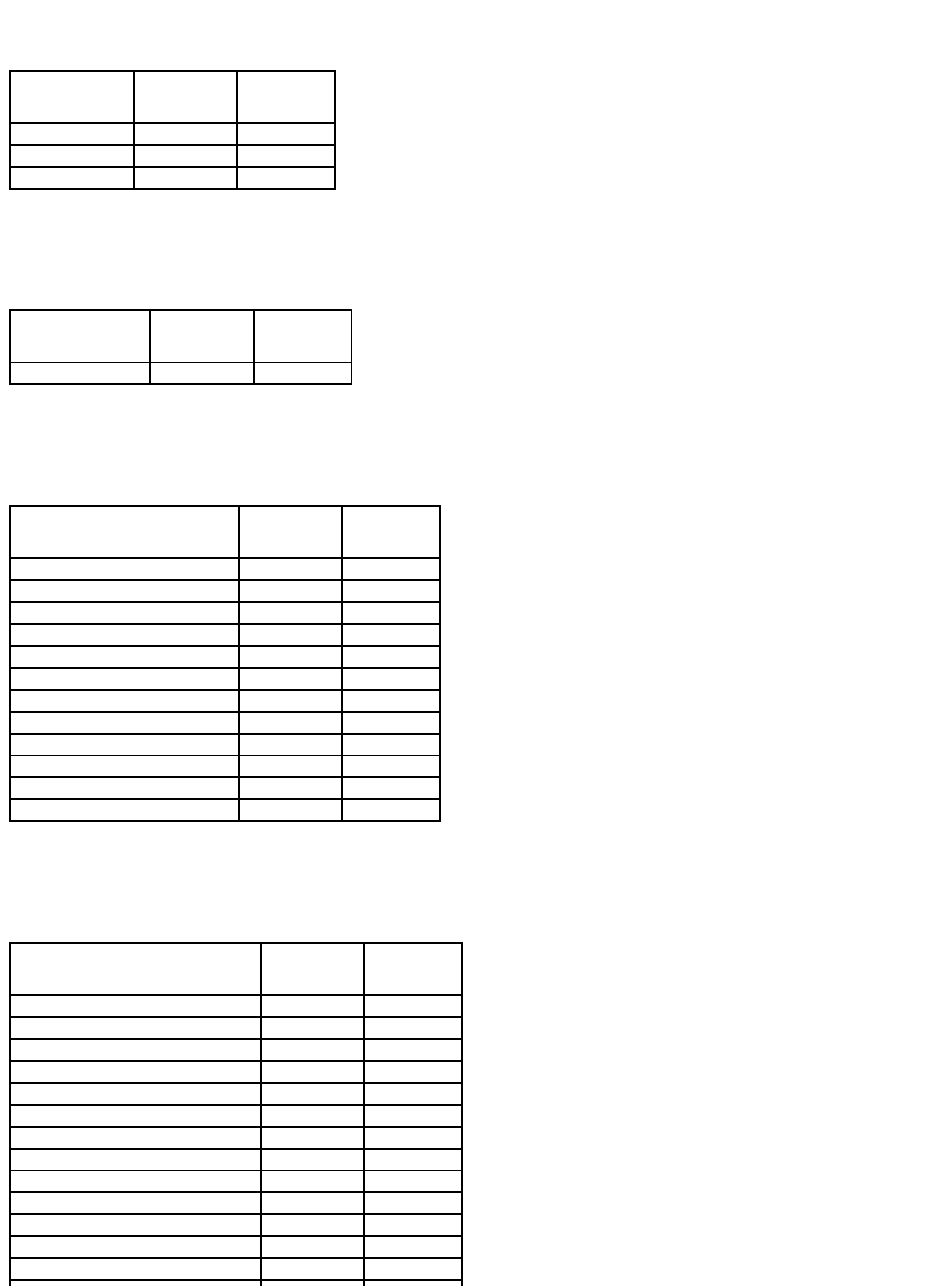
Virtual Disk Specifications
Table A-33. Virtual Disk Specifications for the PERC H800, PERC H700 Adapter, PERC H700 Integrated, and PERC H700 Modular Controllers
Create Virtual Disk Express Wizard
Yes
Yes
Yes
Yes
Rename
Yes
Yes
Yes
Yes
Blink/Unblink
Yes
Yes
Yes
Yes
Reconfigure
Yes
Yes
Yes
Yes
Change Policy
Yes
Yes
Yes
Yes
Split Mirror
No
No
No
No
Unmirror
No
No
No
No
Delete Last Virtual Disk
Yes
Yes
Yes
Yes
Delete (any) Virtual Disk
Yes
Yes
Yes
Yes
Check Consistency
Yes
Yes
Yes
Yes
Cancel Check Consistency
Yes
Yes
Yes
Yes
Pause Check Consistency
No
No
No
No
Resume Check Consistency
No
No
No
No
Cancel Background Initialization (BGI)
Yes
Yes
Yes
Yes
Format Virtual Disk
No
No
No
No
Cancel Format Virtual Disk
No
No
No
No
Restore Dead Disk Segments
No
No
No
No
Initialize Virtual Disk
No
No
No
No
Fast Initialize Virtual Disk
Yes
Yes
Yes
Yes
Slow Initialize Virtual Disk
Yes
Yes
Yes
Yes
Cancel Initialize Virtual Disk
Yes
Yes
Yes
Yes
Replace Member
Yes
Yes
Yes
Yes
Secure Virtual Disk
Yes
Yes
Yes
Yes
Clear Virtual Disk Bad Blocks
Yes
Yes
Yes
Yes
Virtual Disk Specification
PERC H800
PERC H700 Adapter
PERC H700 Integrated
PERC H700 Modular
Maximum Number of Virtual Disks per Controller
64
64
64
64
Minimum Virtual Disk Size
100MB
100MB
100MB
100MB
Maximum Virtual Disk Size
None
None
None
None
Maximum Number of Spans per Virtual Disk
8
8
8
8
Maximum Number of Physical Disks per Span
32
32
32
32
Minimum Stripe Size
8k
8k
8k
8k
Maximum Stripe Size
1MB
1MB
1MB
1MB
Maximum Number of Virtual Disks per Disk Group
16
16
16
16
Maximum Number of Physical Disks that Can Be Concatenated
NA
NA
NA
NA
Maximum Number of Physical Disks in a RAID 0
32
32
32
32
Maximum Physical Disks in a RAID 1
2
2
2
2
Maximum Number of Physical Disks in a RAID 5
32
32
32
32
Maximum Number of Physical Disks in a RAID 10
256
16
16
16
Maximum Number of Physical Disks in a RAID 50
256
256
256
256
Minimum Number of Physical Disks that Can Be Concatenated
NA
NA
NA
NA
Minimum Number of Physical Disks in a RAID 0
1
1
1
1
Minimum Number of Physical Disks in a RAID 1
2
2
2
2
Minimum Number of Physical Disks in a RAID 5
3
3
3
3
Minimum Number of Physical Disks in a RAID 10
4
4
4
4
Minimum Number of Physical Disks in a RAID 50
6
6
6
6
Maximum number of physical disks in a RAID 6
32
32
32
32
Maximum number of physical disks in a RAID 60
256
256
256
256
Minimum number of physical disks in a RAID 6
4
4
4
4
Minimum number of physical disks in a RAID 60
8
8
8
8
Supported RAID Levels
Table A-34. RAID Levels Supported by the PERC H800, PERC H700 Adapter, PERC H700 Integrated, and PERC H700 Modular Controllers
Read, Write, Cache and Disk Cache Policy
Table A-35. Read, Write, and Cache Policy Supported by the PERC H800, PERC H700 Adapter, PERC H700 Integrated, and PERC H700
ModularControllers
Enclosure Support
Table A-36. Enclosure Support on the PERC H800, PERC H700 Adapter, PERC H700 Integrated, and PERC H700 Modular Controllers
Supported Features on the SAS 5/iR, SAS 6/iR, and PERC H200 Controllers
This section identifies the controller-supported features and whether or not an enclosure can be attached to the controller.
l"Controller Tasks"
l"Battery Tasks"
l"Connector Tasks"
l"Physical Disk Tasks"
l"Virtual Disk Tasks"
l"Virtual Disk Specifications"
l"Supported RAID Levels"
RAID Level
PERC H800
PERC H700 Adapter
PERC H700 Integrated
PERC H700 Modular
Concatenation
No
No
No
No
RAID 0
Yes
Yes
Yes
Yes
RAID 1
Yes
Yes
Yes
Yes
RAID 5
Yes
Yes
Yes
Yes
RAID 10
Yes
Yes
Yes
Yes
RAID 50
Yes
Yes
Yes
Yes
RAID 6
Yes
Yes
Yes
Yes
RAID 60
Yes
Yes
Yes
Yes
Read, Write, and Cache Policy
PERC H800
PERC H700 Adapter
PERC H700 Integrated
PERC H700 Modular
Cache settings
Yes
Yes
Yes
Yes
Read Policy
Yes
Yes
Yes
Yes
Read Ahead (Enabled)
Yes
Yes
Yes
Yes
Adaptive Read Ahead
Yes
Yes
Yes
Yes
No Read Ahead (Disabled)
Yes
Yes
Yes
Yes
Write Policy
Yes
Yes
Yes
Yes
Write Back (Enabled)
Yes
Yes
Yes
Yes
Write Through (Disabled)
Yes
Yes
Yes
Yes
Force Write Back (Enabled Always)
Yes
Yes
Yes
Yes
Write Cache Enabled Protected
No
No
No
No
Cache Policy
No
No
No
No
Disk Cache Policy
Yes
Yes
Yes
Yes
Cache I/O
No
No
No
No
Direct I/O
No
No
No
No
Enclosure Support
PERC H800
PERC H700 Adapter
PERC H700 Integrated
PERC H700 Modular
Can an enclosure be attached to this controller?
Yes
No
No
No
l"Read, Write, Cache and Disk Cache Policy"
l"Enclosure Support"
For enclosure-supported tasks, see "Enclosure and Backplane Features."
Controller Tasks
Table A-37. Controller Tasks Supported on the SAS 5/iR, SAS 6/iR, and
H200Controllers
Battery Tasks
Table A-38.BatteryTasksSupportedontheSAS5/iR,SAS6/iR,andH200Controllers
Connector Tasks
Table A-39.ConnectorTasksSupportedontheSAS5/iR,SAS6/iR,andH200Controllers
Physical Disk Tasks
Table A-40.PhysicalDiskTasksSupportedontheSAS5/iR,SAS6/iR,andH200Controllers
Controller Task Name
SAS 5/iR
SAS 6/iR
PERC H200
Enable Alarm
No
No
No
Disable Alarm
No
No
No
Quiet Alarm
No
No
No
Test Alarm
No
No
No
Reset configuration
No
Yes
Yes
Set Rebuild Rate
No
No
No
Set Background Initialization Rate
No
No
No
Set Check Consistency Rate
No
No
No
Set Reconstruct Rate
No
No
No
Rescan Controller
No
No
No
Create Virtual Disk
No
Yes
Yes
Export Log File
No
No
No
Clear Foreign Configuration
Yes
Yes
Yes
Import Foreign Configuration
No
Yes
Yes
Import/Recover Foreign Configuration
No
Yes
Yes
Set Patrol Read Mode
No
No
No
Start Patrol Read
No
No
No
Stop Patrol Read
No
No
No
Battery Task Name
SAS 5/iR
SAS 6/iR
PERC H200
Recondition Battery
No
No
No
Start Learn Cycle
No
No
No
Delay Learn Cycle
No
No
No
Connector Task Name
SAS 5/IR
SAS 6/iR
PERC H200
Connector Rescan
No
No
No
Virtual Disk Tasks
Table A-41.VirtualDiskTasksSupportedbytheSAS5/iR,SAS6/iR,andH200Controllers
Supported RAID Levels
Table A-42. RAID Levels Supported by the SAS 5/iR, SAS 6/iR, and H200 Controllers
Physical Disk Task Name
SAS 5/IR
SAS 6/iR
PERC H200
Blink/Unblink
Yes
Task only available when an enclosure or backplane and
LEDs on the physical disks are present.
Yes
Yes
Assign and Unassign
Global Hot Spare
No
Supports up to two global hot
spares
Supports up to two global hot
spares
Prepare to Remove
No
No
No
Offline
No
No
No
Online
No
No
No
Initialize
No
No
No
Rebuild
No
NA.
Rebuild automatically initiated by
the controller.
NA.
Rebuild automatically initiated by
the controller.
Cancel Rebuild
No
No
No
Remove Dead Disk
Segments
No
No
No
Format Disk
No
No
No
Clear
No
No
No
Cancel Clear
No
No
No
Virtual Disk Task Name
SAS 5/IR
SAS 6/iR
PERC H200
Assign and Unassign Dedicated Hot Spare
No
No
No
Create Virtual Disk
No
Yes
Yes
Create Virtual Disk Advanced Wizard
No
Yes
Yes
Create Virtual Disk Express Wizard
No
No
No
Rename
No
No
No
Blink/Unblink
Yes
Yes
Yes
Reconfigure
No
No
No
Change Policy
No
No
No
Split Mirror
No
No
No
Unmirror
No
No
No
Delete Last Virtual Disk
No
Yes
Yes
Delete (any) Virtual Disk
No
Yes
Yes
Check Consistency
No
No
No
Cancel Check Consistency
No
No
No
Pause Check Consistency
No
No
No
Resume Check Consistency
No
No
No
Cancel Background Initialization (BGI)
No
No
No
Format Virtual Disk
No
No
No
Cancel Format Virtual Disk
No
No
No
Restore Dead Disk Segments
No
No
No
Initialize Virtual Disk
No
No
No
Fast Initialize Virtual Disk
No
No
No
Slow Initialize Virtual Disk
No
No
No
Cancel Initialize Virtual Disk
No
No
No
RAID Level
SAS 5/IR
SAS 6/iR
PERC H200
RAID 0
Yes
Yes
Yes
Virtual Disk Specifications
Table A-43.VirtualDiskSpecificationsfortheSAS5/iR,SAS6/iR,andPERCH200Controllers
Read, Write, Cache and Disk Cache Policy
Table A-44. Read, Write, and Cache Policy Supported by the SAS 5/iR, SAS 6/iR, and H200 Controllers
RAID 1
Yes
Yes
Yes
RAID 10
No
No
Yes
Virtual Disk Specification
SAS 5/IR
SAS 6/iR
PERC H200
Maximum Number of Virtual Disks per Controller
2
2
2
Minimum Virtual Disk Size
Max
Max
Max
Maximum Virtual Disk Size
2TB
None
None
Maximum Number of Spans per Virtual Disk
1
1
1
Maximum Number of Physical Disks per Span
4
10
10
Minimum Stripe Size
64k
64k
64k
Maximum Stripe Size
64k
64k
64k
Maximum Number of Virtual Disks per Disk Group
1
1
1
Maximum Number of Physical Disks that Can Be Concatenated
NA
NA
NA
Maximum Number of Physical Disks in a RAID 0
4
8
10 - Adapter
10 - Integrated
4 - Modular
Maximum Physical Disks in a RAID 1
2
2
2
Maximum Number of Physical Disks in a RAID 5
NA
NA
NA
Maximum Number of Physical Disks in a RAID 10
NA
NA
10 - Adapter
10 - Integrated
4 - Modular
Maximum Number of Physical Disks in a RAID 50
NA
NA
NA
Minimum Number of Physical Disks that Can Be Concatenated
NA
NA
NA
Minimum Number of Physical Disks in a RAID 0
2
2
2
Minimum Number of Physical Disks in a RAID 1
2
2
2
Minimum Number of Physical Disks in a RAID 5
NA
NA
NA
Minimum Number of Physical Disks in a RAID 10
NA
NA
4
Minimum Number of Physical Disks in a RAID 50
NA
NA
NA
Maximum number of physical disks in a RAID 6
NA
NA
NA
Maximum number of physical disks in a RAID 60
NA
NA
NA
Minimum number of physical disks in a RAID 6
NA
NA
NA
Minimum number of physical disks in a RAID 60
NA
NA
NA
Maximum number of disks in configured state (part of a virtual disk or hot spares)
8
8
14
Read, Write, and Cache Policy
SAS 5/IR
SAS 6/iR
PERC H200
Cache settings
No
No
No
Read Policy
No
No
No
Read Ahead (Enabled)
No
No
No
Adaptive Read Ahead
No
No
No
No Read Ahead (Disabled)
No
No
No
Write Policy
No
No
No
Write Back
No
No
No
Write Through
No
No
No
Force Write Back (Enabled Always)
No
No
No
Write Cache Enabled Protected
No
No
No
Cache Policy
No
No
No
Enclosure Support
Table A-45. Enclosure Support on the SAS 5/iR, SAS 6/iR, and H200 Controllers
Supported Features on the PERC S100 and S300 Controllers
This section identifies the controller-supported features and whether or not an enclosure can be attached to the controller.
l"Controller Tasks"
l"Physical Disk Tasks"
l"Virtual Disk Tasks"
l"Virtual Disk Specifications"
l"Supported RAID Levels"
l"Read, Write, Cache and Disk Cache Policy"
l"Enclosure Support"
Controller Tasks
Table A-46. Controller Tasks Supported on the PERC S100 and S300 Controllers
Physical Disk Tasks
Table A-47. Physical Disk Tasks Supported by the PERC S100 and S300 Controllers
Virtual Disk Tasks
Table A-48. Virtual Disk Tasks Supported by the PERC S100 and S300 Controllers
Disk Cache Policy
Yes
Yes
Yes
Cache I/O
No
No
No
Direct I/O
No
No
No
Enclosure Support
SAS 5/IR
SAS 6/iR
PERC H200
Can an enclosure be attached to this controller?
No
No
No
Controller Task Name
PERC S100
PERC S300
Create Virtual Disk
Yes
Yes
Physical Disk Task Name
PERC S100
PERC S300
Blink/Unblink
No
Yes
Assign and Unassign Global Hot Spare
Yes
Yes
Virtual Disk Task Name
PERC S100
PERC S300
Assign and Unassign Dedicated Hot Spare
Yes
Yes
Create Virtual Disk
Yes
Yes
Create Virtual Disk Advanced Wizard
Yes
Yes
Create Virtual Disk Express Wizard
Yes
Yes
Rename
Yes
Yes
Blink/Unblink
No
Yes
Reconfigure
Yes
Yes
Virtual Disk Specifications
Table A-49. Virtual Disk Specifications for the PERC S100 and S300 Controllers
Supported RAID Levels
Table A-50. RAID Levels Supported by the PERC S100 and S300 Controllers
Read, Write, Cache and Disk Cache Policy
Table A-51. Read, Write, and Cache Policy Supported by the PERC S100 and S300 Controllers
Change Policy
Yes
Yes
Delete Last Virtual Disk
Yes
Yes
Delete (any) Virtual Disk
Yes
Yes
Check Consistency
Yes
Yes
Virtual Disk Specification
PERC S100
PERC S300
Maximum Number of Virtual Disks per Controller
8
8
Minimum Virtual Disk Size
100MB
100MB
Maximum Virtual Disk Size
None
None
Maximum Number of Spans per Virtual Disk
NA
NA
Maximum Number of Physical Disks per Span
NA
NA
Minimum Stripe Size
64k
64k
Maximum Stripe Size
64k
64k
Maximum Number of Virtual Disks per Physical Disk
8
8
Maximum Number of Physical Disks that Can Be Concatenated
NA
NA
Maximum Number of Physical Disks in a RAID 0
8
8
Maximum Physical Disks in a RAID 1
2
2
Maximum Number of Physical Disks in a RAID 5
8
8
Maximum Number of Physical Disks in a RAID 10
4
4
Minimum Number of Physical Disks that Can Be Concatenated
NA
NA
Minimum Number of Physical Disks in a RAID 0
2
2
Minimum Number of Physical Disks in a RAID 1
2
2
Minimum Number of Physical Disks in a RAID 5
3
3
Minimum Number of Physical Disks in a RAID 10
4
4
RAID Level
PERC S100
PERC S300
RAID 0
Yes
Yes
RAID 1
Yes
Yes
RAID 5
Yes
Yes
RAID 10
Yes
Yes
RAID 50
No
No
RAID 6
No
No
RAID 60
No
No
Read, Write, and Cache Policy
PERC S100
PERC S300
Cache settings
Yes
Yes
Read Policy
Yes
Yes
Read Ahead (Enabled)
Yes
Yes
Adaptive Read Ahead
No
No
No Read Ahead (Disabled)
Yes
Yes
Write Policy
Yes
Yes
Enclosure Support
Table A-52. Enclosure Support on the PERC S100 and S300 Controllers
Supported Features on the Non-RAID Controllers
This section identifies the controller-supported features and whether or not an enclosure can be attached to the controller.
l"Controller Tasks"
l"Battery Tasks"
l"Connector Tasks"
l"Physical Disk Tasks"
l"Virtual Disk Tasks"
l"Enclosure Support"
For enclosure-supported tasks, see "Enclosure and Backplane Features."
Controller Tasks
Table A-53. Controller Tasks Supported on the Non-RAIDControllers
Write Back (Enabled)
Yes
Yes
Write Through (Disabled)
Yes
Yes
Force Write Back (Enabled Always)
No
No
Write Cache Enabled Protected
No
No
Cache Policy
No
No
Disk Cache Policy
No
No
Cache I/O
No
No
Direct I/O
No
No
Enclosure Support
PERC S100
PERC S300
Can an enclosure be attached to this controller?
No
No
Controller Task Name
Non-RAID SCSI
Non-RAID SAS
Enable Alarm
No
No
Disable Alarm
No
No
Quiet Alarm
No
No
Test Alarm
No
No
Reset configuration
No
No
Set Rebuild Rate
No
No
Set Background Initialization Rate
No
No
Set Check Consistency Rate
No
No
Set Reconstruct Rate
No
No
Rescan Controller
No
No
Create Virtual Disk
No
No
Export Log File
No
No
Clear Foreign Configuration
No
No
Import Foreign Configuration
No
No
Import/Recover Foreign Configuration
No
No
Set Patrol Read Mode
No
No
Start Patrol Read
No
No
Stop Patrol Read
No
No
Battery Tasks
Table A-54. Battery Tasks Supported on the Non-RAIDControllers
Connector Tasks
Table A-55. Connector Tasks Supported on the Non-RAIDControllers
Physical Disk Tasks
Table A-56. Physical Disk Tasks Supported on the Non-RAIDControllers
Virtual Disk Tasks
Table A-57. Virtual Disk Tasks Supported by the Non-RAIDControllers
Battery Task Name
Non-RAID SCSI
Non-RAID SAS
Recondition Battery
No
No
Start Learn Cycle
No
No
Delay Learn Cycle
No
No
Connector Task Name
Non-RAID SCSI
Non-RAID SAS
Connector Rescan
No
No
Physical Disk Task Name
Non-RAID SCSI
Non-RAID SAS
Blink/Unblink
Yes
Yes
Assign and Unassign Global Hot Spare
No
No
Prepare to Remove
No
No
Offline
No
No
Online
No
No
Initialize
No
No
Rebuild
No
No
Cancel Rebuild
No
No
Remove Dead Disk Segments
No
No
Format Disk
No
No
Clear
No
No
Cancel Clear
No
No
Virtual Disk Task Name
Non-RAID SCSI
Non-RAID SAS
Assign and Unassign Dedicated Hot Spare
No
No
Create Virtual Disk
No
No
Create Virtual Disk Advanced Wizard
No
No
Create Virtual Disk Express Wizard
No
No
Rename
No
No
Blink/Unblink
No
No
Reconfigure
No
No
Change Policy
No
No
Split Mirror
No
No
Unmirror
No
No
Delete Last Virtual Disk
No
No
Delete (any) Virtual Disk
No
No
Check Consistency
No
No
Enclosure Support
Table A-58. Enclosure Support on the Non-RAIDControllers
Enclosure and Backplane Features
This section identifies the features supported by the enclosure or backplane.
l"Enclosure and Backplane Tasks"
l"Enclosure and Backplane Support for Smart Thermal Shutdown"
For information on controller-supported features, see:
l"Supported Features on the PERC 3/SC, 3/DC, 3/QC, 4/SC, 4/DC, 4/Di, 4e/Si, 4e/Di, 4e/DC, CERC ATA100/4ch, and 4/IM Controllers"
l"Supported Features on the PERC 3/Si, 3/Di, CERC SATA1.5/2s, and CERC SATA1.5/6ch Controllers"
l"Supported Features on the PERC 5/E, PERC 5/i, PERC 6/E, PERC 6/I, PERC 6/I Modular, and CERC 6/I Controllers"
l"Supported Features on the SAS 5/iR, SAS 6/iR, and PERC H200 Controllers"
l"Supported Features on the PERC S100 and S300 Controllers"
Enclosure and Backplane Tasks
Table A-59.EnclosureTasks
Table A-60.BackplaneTasks
Cancel Check Consistency
No
No
Pause Check Consistency
No
No
Resume Check Consistency
No
No
Cancel Background Initialization (BGI)
No
No
Format Virtual Disk
No
No
Cancel Format Virtual Disk
No
No
Restore Dead Disk Segments
No
No
Initialize Virtual Disk
No
No
Fast Initialize Virtual Disk
No
No
Slow Initialize Virtual Disk
No
No
Cancel Initialize Virtual Disk
No
No
Enclosure Support
Non-RAID SCSI
Non-RAID SAS
Can an enclosure be attached to this controller?
Yes
No
Enclosure and Backplane
Tasks
PowerVault™20xS
and 21xS
PowerVault 220S
and 221S
PowerVault
MD1000 Storage
PowerVault
MD1120
PowerVault
MD1200 Storage
PowerVault
MD1220
Enable Alarm
No
Yes
Yes
Yes
Yes
Yes
Disable Alarm
No
Yes
Yes
Yes
Yes
Yes
Set Temperature Probe Values
Yes
Yes
Yes
Yes
Yes
Yes
Set Asset Data (includes asset
tag and asset name)
Yes
Yes
Yes
Yes
Yes
Yes
Blink Enclosure
No
No
Yes
Yes
Yes
Yes
Enclosure and Backplane Tasks
SCSI
SAS
Enable Alarm
No
No
Disable Alarm
No
No
Set Temperature Probe Values
No
No

Enclosure and Backplane Support for Smart Thermal Shutdown
Table A-61.EnclosureSupportforSmartThermalShutdown
Set Asset Data (includes asset tag and asset name)
No
No
Blink Enclosure
No
No
Table A-62.BackplaneSupportforSmartThermalShutdown
Maximum Supported Configuration
Table A-63. Maximum Supported Configuration for SAS and SCSI Controllers
Back to Contents Page
Smart Thermal
Shutdown
PowerVault 20xS
and 21xS
PowerVault 220S
and 221S
PowerVault MD1000
Storage
PowerVault
MD1120
PowerVault MD1200
Storage
PowerVault
MD1220
Smart Thermal
Shutdown
No
Yes
No
No
No
No
Smart Thermal Shutdown
SCSI
SAS
Smart Thermal Shutdown
No
No
Maximum Supported Configuration
SCSI
SAS (MD 1000, MD 1120)
SAS (MD 1200, MD 1220)
External controllers on each Server (a)
2
2
2
External connectors on each controller (b)
2
2
2
Enclosures per connector (c)
1
3
4
Total numbers of enclosures on a server
(a x b x c)
4
12
16
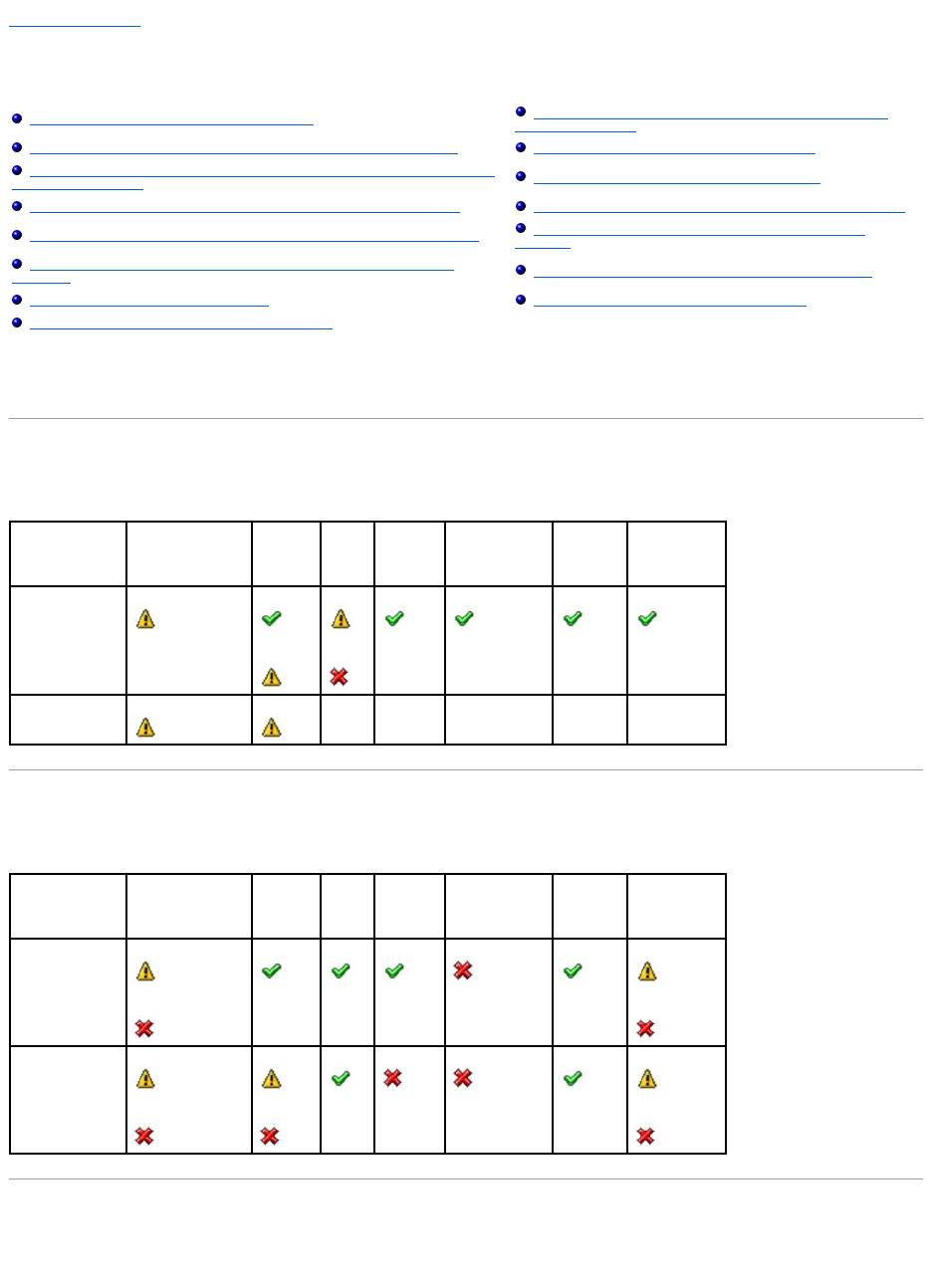
Back to Contents Page
Determining the Health Status for Storage Components
Dell™OpenManage™ServerAdministratorStorageManagementUser'sGuide
The tables in this appendix indicate how the status of lower-level storage components is "rolled up" into the combined status displayed for the controller or
other higher-level component. The examples provided by these tables do not cover all scenarios, but they do indicate how status is rolled up when a particular
component is in a healthy, degraded, or failed state.
Health Status Rollup: Battery is Charging or Dead
Table B-1. Health Status Rollup: Battery is Charging or Dead (Enclosures Not Included)
Health Status Rollup: Physical Disks in a Virtual Disk are Failed or Removed
Table B-2. Health Status Rollup: Physical Disks in a Virtual Disk are Failed or Removed (Enclosures Not Included)
Health Status Rollup: Physical Disks in a Virtual Disk are Unsupported, Partially or
Permanently Degraded
Table B-3. Health Status Rollup: Physical Disks in a Virtual Disk are Unsupported, Partially or Permanently Degraded (Enclosures Not
Health Status Rollup: Battery is Charging or Dead
Health Status Rollup: Enclosure Power Supply Failed or Power
Connection Removed
Health Status Rollup: Physical Disks in a Virtual Disk are Failed or Removed
Health Status Rollup: One Enclosure Fan is Failed
Health Status Rollup: Physical Disks in a Virtual Disk are Unsupported, Partially or
Permanently Degraded
Health Status Rollup: One Enclosure EMM is Failed
Health Status Rollup: All Physical Disks in a Virtual Disk are in Foreign State
Health Status Rollup: One Enclosure Temperature Probe is Failed
Health Status Rollup: Some Physical Disks in a Virtual Disk are in Foreign State
Health Status Rollup: Lost Both Power Connections to the
Enclosure
Health Status Rollup: Virtual Disk is Degraded; Physical Disks are Failed or
Rebuilding
Health Status Rollup: One or More Physical Disks are Failed
Health Status Rollup: Virtual Disk is Failed
Health Status Rollup: Physical Disk is Rebuilding
Health Status Rollup: Unsupported Firmware Version
Storage Subsystem
Controller
Battery
Connector
Physical Disk(s)
Firmware/
Driver
Virtual Disk(s)
Component Status
Health Rollup
NA
NA
NA
NA
NA
Storage Subsystem
Controller
Battery
Connector
Physical Disk(s)
Firmware/
Driver
Virtual Disk(s)
Component Status
Health Rollup
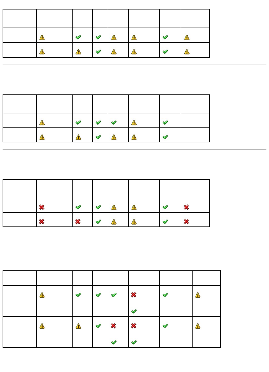
Included)
Health Status Rollup: All Physical Disks in a Virtual Disk are in Foreign State
Table B-4. Health Status Rollup: All Physical Disks in a Virtual Disk are in Foreign State (Enclosures Not Included)
Health Status Rollup: Some Physical Disks in a Virtual Disk are in Foreign State
Table B-5. Health Status Rollup: Some Physical Disks in a Virtual Disk are in Foreign State (Enclosures Not Included)
Health Status Rollup: Virtual Disk is Degraded; Physical Disks are Failed or
Rebuilding
Table B-6. Health Status Rollup: Virtual Disk is Degraded; Physical Disks are Failed or Rebuilding (Enclosures Not Included)
Health Status Rollup: Virtual Disk is Failed
Storage Subsystem
Controller
Battery
Connector
Physical Disk(s)
Firmware/
Driver
Virtual Disk(s)
Component Status
Health
Rollup
Storage Subsystem
Controller
Battery
Connector
Physical Disk(s)
Firmware/
Driver
Virtual Disk(s)
Component Status
NA
Health Rollup
NA
Storage Subsystem
Controller
Battery
Connector
Physical Disk(s)
Firmware/
Driver
Virtual Disk(s)
Component Status
Health Rollup
Storage Subsystem
Controller
Battery
Connector
Physical Disk(s)
Firmware/Driver
Virtual Disk(s)
Component Status
Health Rollup

Table B-7. Health Status Rollup: Virtual Disk is Failed (Enclosures Not Included)
Health Status Rollup: Unsupported Firmware Version
Table B-8. Health Status Rollup: Unsupported Firmware Version (Enclosures Not Included)
Health Status Rollup: Enclosure Power Supply Failed or Power Connection Removed
Table B-9. Health Status Rollup: Enclosure Power Supply Failed or Power Connection Removed
Health Status Rollup: One Enclosure Fan is Failed
Table B-10. Health Status Rollup: One Enclosure Fan is Failed
Health Status Rollup: One Enclosure EMM is Failed
Table B-11. Health Status Rollup: One Enclosure EMM is Failed
Storage Subsystem
Controller
Battery
Connector
Physical Disk(s)
Firmware/Driver
Virtual Disk(s)
Component Status
Health Rollup
Storage Subsystem
Controller
Battery
Connector
Physical Disk(s)
Firmware/Driver
Virtual Disk(s)
Component Status
Health Rollup
Storage Subsystem
Controller
Connector
Enclosure
Enclosure Power Supply
Virtual Disks
Physical Disks
Component Status
Health Rollup
NA
NA
NA
Storage Subsystem
Controller
Connector
Enclosure
Enclosure Fan
Virtual Disks
Physical Disks
Component Status
Health Rollup
NA
NA
NA
Storage Subsystem
Controller
Connector
Enclosure
Enclosure EMM
Virtual Disks
Physical Disks
Component Status
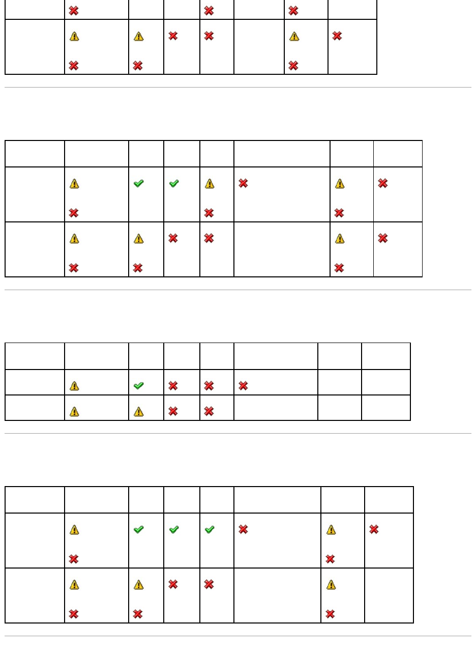
Health Status Rollup: One Enclosure Temperature Probe is Failed
Table B-12. Health Status Rollup: One Enclosure Temperature Probe is Failed
Health Status Rollup: Lost Both Power Connections to the Enclosure
Table B-13. Health Status Rollup: Lost Both Power Connections to the Enclosure
Health Status Rollup: One or More Physical Disks are Failed
Table B-14. Health Status Rollup: One or More Physical Disks are Failed
Health Rollup
NA
Storage Subsystem
Controller
Connector
Enclosure
Enclosure Temperature Probe
Virtual Disks
Physical Disks
Component Status
Health Rollup
NA
Storage Subsystem
Controller
Connector
Enclosure
All Enclosure Components
Virtual Disks
Physical Disks
Component Status
NA
NA
Health Rollup
NA
NA
NA
Storage Subsystem
Controller
Connector
Enclosure
Enclosure Physical Disk(s)
Virtual Disks
Physical Disks
Component Status
Health Rollup
NA
NA
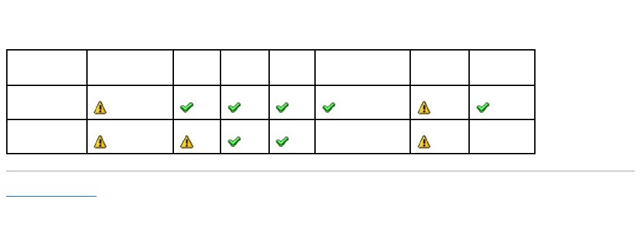

Back to Contents Page
Physical Disks
Dell™OpenManage™ServerAdministratorStorageManagementUser'sGuide
Physical disks reside within an enclosure or are attached to the controller. On a RAID controller, physical disks are used to create virtual disks.
Add a New Disk to Your System
1. Install or attach the new physical disk (or disks). Refer to the documentation that came with the disk for more information.
2. Do one of the following depending on the controller technology. See "RAID Controller Technology: SCSI, SATA, ATA, and SAS" for more information.
For SCSI, SATA, and ATA Controllers
a. Select the controller to which the disk is attached and click the Information/Configuration tab.
b. Execute the Rescan task.
The new disk should be displayed in the tree view after the rescan. If the new disk is not displayed, restart the computer.
For SAS Controllers
a. Check the Alert Log for an alert verifying that the system has identified the new disk. You may receive alert 2052 or 2294. For information on Alert
Messages, see the Dell OpenManage Server Administrator Messages Reference Guide on the Dell Support website at support.dell.com/manuals.
b. Refresh the display by clicking Refresh or by changing screens.
The new physical disk should be displayed in the tree view after refreshing the display. If the new disk is not displayed, restart the computer.
Related Information
lSee "Replacing a Failed Disk" if you are replacing a disk that is part of a virtual disk.
lSee "Virtual Disk Considerations for PERC 3/SC, 3/DC, 3/QC, 4/SC, 4/DC, 4e/DC, 4/Di, 4e/Si, 4e/Di, CERC ATA100/4ch, PERC 5/E, PERC 5/i, PERC 6/E, and
PERC 6/I Controllers" or "Virtual Disk Considerations for PERC 3/Si, 3/Di, CERC SATA1.5/6ch, and CERC SATA1.5/2s controllers" if you are intending to
include the new disk in a virtual disk.
How to Avoid Removing the Wrong Disk
You can avoid removing the wrong disk by blinking the LED display on the disk that you intend to remove. See the following sections for information on blinking
the LED display:
lSee "Blink and Unblink (Physical Disk)" to blink the LED display on a physical disk.
lSee "Blink and Unblink (Virtual Disk)" to blink the LED display on all physical disks included in a particular virtual disk.
If you have already removed the wrong disk, see "Recovering from Removing the Wrong Physical Disk."
Replacing a Physical Disk Receiving SMART Alerts
Add a New Disk to Your System
Initialize
How to Avoid Removing the Wrong Disk
Rebuild
Replacing a Physical Disk Receiving SMART Alerts
Cancel Rebuild
Other Disk Procedures
Assign and Unassign Global Hot Spare
Physical Disk Properties and Tasks
Online and Offline
Blink and Unblink (Physical Disk)
Clear Physical Disk and Cancel Clear
Remove Dead Segments
Revertible Hot Spare
Prepare to Remove
Instant Secure Erase
NOTE: Clicking the Refresh button in the right pane refreshes only the right pane. To view the new physical disk in the left pane tree view, click the
system name displayed at the top of the left pane, or select View --> Refresh from the browser's menu bar.

SMART alerts are messages predicting that a disk may fail in the near future. If a physical disk is receiving SMART alerts, you should replace the disk. Use the
following procedures to replace a disk receiving SMART alerts.
If the disk is part of a redundant virtual disk:
1. Select the redundant virtual disk that includes the physical disk that is receiving SMART alerts and perform the Check Consistency task. See "Check
Consistency" for more information.
2. Select the disk that is receiving SMART alerts and execute the Offline task.
3. Manually remove the disk.
4. Insert a new disk. Make sure that the new disk is the same size or larger as the disk you are replacing. (On some controllers, you may not be able to
use the additional disk space if you insert a larger disk. See "Virtual Disk Considerations for PERC 3/SC, 3/DC, 3/QC, 4/SC, 4/DC, 4e/DC, 4/Di, 4e/Si,
4e/Di, CERC ATA100/4ch, PERC 5/E, PERC 5/i, PERC 6/E, and PERC 6/I Controllers" for more information.) After you complete this procedure, a rebuild is
automatically initiated because the virtual disk is redundant.
If the disk is not part of a redundant virtual disk:
1. Back up data from the virtual disk.
2. Delete the virtual disk.
3. Replace the disk that is receiving SMART alerts.
4. Create a new virtual disk. Make sure that the new virtual disk is the same size or larger than the original virtual disk. For controller-specific information
on creating virtual disks, see "Virtual Disk Considerations for PERC 3/SC, 3/DC, 3/QC, 4/SC, 4/DC, 4e/DC, 4/Di, 4e/Si, 4e/Di, CERC ATA100/4ch, PERC 5/E,
PERC 5/i, PERC 6/E, and PERC 6/I Controllers" and "Virtual Disk Considerations for PERC 3/Si, 3/Di, CERC SATA1.5/6ch, and CERC SATA1.5/2s controllers."
5. Restore the backed up data from the original virtual disk onto the newly created virtual disk.
Related Information:
l"Monitoring Disk Reliability on RAID Controllers"
Other Disk Procedures
See the following sections:
l"Replacing a Failed Disk"
l"Recovering from Removing the Wrong Physical Disk"
l"Moving Physical and Virtual Disks from One System to Another"
l"Troubleshooting"
Physical Disk Properties and Tasks
Use this window to view information about physical disks and execute physical disk tasks.
Physical Disk Properties
The following table describes properties that may be displayed for physical disks depending on the controller.
CAUTION: To avoid potential data loss, you should perform a check consistency before removing a physical disk that is receiving SMART alerts.
The check consistency verifies that all data is accessible within the redundant virtual disk and uses the redundancy to repair any bad blocks that
may be present. In some circumstances, failure to perform a check consistency can result in data loss. This may occur, for example, if the
physical disk receiving SMART alerts has bad disk blocks and you do not perform a check consistency before removing the disk.
Property
Definition
Status
These icons represent the severity or health of the storage component.
Normal/OK
Warning/Non-critical
Critical/Fatal
See "Storage Component Severity" for more information.
Name
This property displays the name of the physical disk. The name is comprised of the connector number followed by the disk number.
State
This property displays the current state of the physical disk.
Ready — The physical disk is functioning normally. If the disk is attached to a RAID controller, Ready state indicates that the disk is available
to be used by a virtual disk. When the physical disk is used in a virtual disk, the state changes to Online.
Online — The physical disk is part of a virtual disk and is functioning normally. See "Online and Offline" for more information.
Degraded — The physical disk has encountered a failure and is operating in a degraded state.
Failed — The physical disk has encountered a failure and is no longer functioning. This state is also displayed when a physical disk that is
part of a redundant virtual disk has been taken offline or deactivated. See "Online and Offline" for more information.
Offline — The physical disk has failed or contains dead segments. Check to see whether the "Remove Dead Segments" task appears on the
physical disk drop-down menu. If it does, perform a "Rescan Controller" and then do a "Remove Dead Segments" for the physical disk. If the
"Remove Dead Segments" task is not displayed, then the physical disk cannot be recovered. See "Considerations for PERC 3/Si, 3/Di, CERC
SATA1.5/6ch, and CERC SATA1.5/2s Controllers When Physical Disks are Shared by Redundant and Nonredundant Virtual Disks" for related
information.
On the PERC 5/E controller, the Offline state indicates that the disk is included in a virtual disk, but it is not receiving I/O. This may occur
when a user has set the disk to Offline. See "Online and Offline" for more information.
Rebuilding — Data from a redundant virtual disk is currently being rebuilt onto the physical disk.
Incompatible — The physical disk is not suitable for a rebuild. The physical disk may be too small or it may be using an incompatible
technology. For example, you cannot rebuild a SAS disk with a SATA disk or a SATA disk with a SAS disk.
Removed — The physical disk has been removed. This state only applies to physical disks that are part of a virtual disk.
Clear — The Clear task is being performed on the physical disk. A physical disk may also display the Clear state if the physical disk is a
member of a virtual disk that is being slow initialized. For more information, see "Clear Physical Disk and Cancel Clear" and "Format and
Initialize; Slow and Fast Initialize."
SMART Alert Detected — A SMART alert (predictive failure) has been detected on the physical disk. The physical disk may fail and should be
replaced. This state applies to physical disks attached to non-RAID controllers.
Unknown — The physical disk has failed or is in an unusable state. In some cases the physical disk can be returned to a usable state by
performing an "Initialize" task. If the "Initialize" task does not appear on the physical disk drop-down menu, then this disk cannot be
recovered.
Foreign — The physical disk has been moved from another controller and contains all or some portion of a virtual disk (foreign configuration).
A physical disk that has lost communication with the controller due to a power loss, faulty cable or other failure event may also display the
Foreign state. See "Foreign Configuration Operations" for more information.
Unsupported — The physical disk is using an unsupported technology or it may not be certified by Dell. The physical disk cannot be managed
by Storage Management.
Replacing — A Replace Member Disk task is being performed on the physical disk. For more information, see "Replace Member Disk" and
"Revertible Hot Spare."
NOTE: You can cancel the copying of data at any time during the execution of this task.
Capacity
This property displays the full capacity of the disk.
Certified
This property displays whether or not the physical disk is certified by Dell.
Failure
Predicted
This property displays whether or not the physical disk has received a SMART alert and is therefore predicted to fail. For more information on
SMART predictive failure analysis, see "Monitoring Disk Reliability on RAID Controllers." For information on replacing the physical disk, see
"Replacing a Physical Disk Receiving SMART Alerts."
You may also want to review the Alert Log to see whether the physical disk has generated alerts pertaining to a SMART predictive failure.
These alerts can assist you in identifying the cause of the SMART alert. The following alerts may be generated in response to a SMART alert:
2094
2106
2107
2108
2109

Physical Disk Tasks
Do the following to execute a physical disk task:
1. Expand the Storage tree object to display the controller objects.
2. Expand a controller object.
3. Expand a Connector object.
4. Expand the enclosure or Backplane object.
5. Select the Physical Disks object.
6. Select the Information/Configuration subtab.
2110
2111
For information on Alert Messages, see the Dell OpenManage Server Administrator Messages Reference Guide on the Dell Support website at
support.dell.com/manuals.
Progress
This property displays how close to completion an operation is that is being performed on the physical disk. For example, if the physical disk
is being rebuilt, then a value of 52% indicates that the rebuild is 52% complete.
This property is only displayed when an operation is being performed on the physical disk.
Encryption
Capable
This property displays whether the physical disk is a Self Encryption Disk (SED.) The possible values are Yes and No.
Secured
This property displays whether the physical disk is secured to the controller. The possible values are Yes and No. For a non-SED the value is
N/A.
Bus Protocol
This property displays the technology that the physical disk is using. Possible values are:
SCSI — Small Computer System Interface
SAS — Serial Attached SCSI
SATA — Serial Advanced Technology Attachment (SATA)
Media
This property displays the media type of the physical disk. The possible values are:
HDD—Hard Disk Drive. A HDD is a non-volatile storage device which stores digitally-encoded data on rapidly rotating platters with magnetic
surfaces.
SSD—Solid State Drive. An SSD is a data storage device that uses solid-state memory to store persistent data.
Unknown—Storage Management is unable to determine the media type of the physical disk.
Used RAID
Disk Space
This property displays how much of the physical disk space is being used by the virtual disks on the controller. This property is Not
Applicable for physical disks attached to non-RAID controllers.
In certain circumstances, the Used RAID Disk Space displays a value of zero (0) even though a portion of the physical disk is being used.
This occurs when the used space is 0.005 GB or less. The algorithm for calculating the used disk space rounds a figure of 0.005 GB or less to
0. Used disk space that is between 0.006 GB and 0.009 GB is rounded up to 0.01 GB.
Available RAID
Disk Space
This property displays the amount of available space on the disk. This property is Not Applicable for physical disks attached to non-RAID
controllers.
Hot Spare
This property indicates whether the disk has been assigned as a hot spare. This property is Not Applicable for physical disks attached to
non-RAID controllers.
Vendor ID
This property displays the disk's hardware vendor.
Product ID
This property displays the disk's product ID.
Revision
This property displays the disk's revision number.
Serial No.
This property displays the disk's serial number.
Part Number
This property displays the Piece Part Identification (PPID) of the physical drive.
Negotiated
Speed
This property displays the speed of data transfer that the disk negotiated while spinning up and upon initial communication with the
controller. This speed is dependent on the speed of the disk, the capable speed of the controller, the current speed of the controller on that
connector, and the speed of the EMM (Enclosure Management Module) on the enclosure.
Capable
Speed
This property displays the highest possible speed that the device can transfer data.
Manufacture
Day
This property displays the day of the month during which the physical disk was manufactured.
Manufacture
Week
This property displays the week of the year during which the physical disk was manufactured.
Manufacture
Year
This property displays the year that the physical disk was manufactured.
SAS Address
This property displays the SAS address of the physical disk. The SAS address is unique to each SAS disk.
7. Select a task from the Available Tasks drop-down menu.
8. Click Execute.
Physical Disk Drop-down Menu Tasks:
l"Blink and Unblink (Physical Disk)"
l"Remove Dead Segments"
l"Assign and Unassign Global Hot Spare"
l"Prepare to Remove"
l"Online and Offline"
l"Initialize"
l"Rebuild"
l"Cancel Rebuild"
l"Clear Physical Disk and Cancel Clear"
l"Revertible Hot Spare"
l"Instant Secure Erase"
Blink and Unblink (Physical Disk)
Does my controller support this feature? See "Supported Features."
The Blink task allows you to find a disk within an enclosure by blinking one of the light-emitting diodes (LEDs) on the disk. You may want to use this task to
locate a failed disk.
On most controllers, the Blink task automatically cancels after a short duration such as 30 or 60 seconds. If you need to cancel the Blink task or if the physical
disk continues to blink indefinitely, use the Unblink task.
Remove Dead Segments
Does my controller support this feature? See "Supported Features."
The Remove Dead Segments task recovers disk space that is currently unusable. A dead or orphaned disk segment refers to an area of a physical disk that is
unusable for any of the following reasons:
lThe dead segment is an area of the physical disk that is damaged.
lThe dead segment is included in a virtual disk, but the virtual disk is no longer using this area of the physical disk.
lThe physical disk contains more than one virtual disk. In this case, disk space that is not included in one of the virtual disks may be unusable.
lThe dead segment resides on a physical disk that has been disconnected from and then reconnected to the controller.
Prepare to Remove
Does my controller support this feature? See "Supported Features."
Use the Prepare to Remove task to spin down a physical disk so that it can safely be removed from an enclosure or backplane. It is recommended that you
perform this task before removing a disk to prevent data loss.
This task causes the lights on the disk to blink. You can safely remove the disk under the following conditions:
lWait for about 30 seconds to allow the disk to spin down.
NOTE: Different controllers support different features. For this reason, the tasks displayed on the Tasks drop-down menu can vary depending on which
controller is selected in the tree view. If no tasks can be performed because of controller or system configuration limitations, then the Tasks drop-down
menu displays No Task Available.
NOTE: The Blink and Unblink tasks are only supported for hotswap physical disks (disks that reside in a carrier). When using an Ultra SCSI, Ultra2 SCSI,
Ultra160 SCSI, LSI 1020, LSI 1030, or LSI PCI-e U320 controller, the Blink and Unblink tasks apply to physical disks contained in carriers that can be
inserted into a server or an enclosure. If the physical disk is not contained in a carrier but is instead designed to be connected with a SCSI cable
(typically a ribbon cable), then the Blink and Unblink tasks are disabled.
lWait until you notice the initial blink pattern has changed into a different pattern or the lights have stopped blinking.
A physical disk is no longer in Ready state after doing a Prepare to Remove. Removing the physical disk from the enclosure or backplane and replacing it
causes the physical disk to spin up and return to Ready state.
In some cases, a rescan is required for the controller to recognize configuration changes such as the removal of a disk. See "Rescan to Update Storage
Configuration Changes" for more information.
Initialize
Does my controller support this feature? See "Supported Features."
The Initialize task prepares a physical disk for use as a member of a virtual disk.
Physical disks attached to PERC 3/Si, 3/Di, and CERC SATA1.5/6ch controllers must be initialized before they can be used. On these controllers, the Initialize
task can only be performed once on a physical disk. In some cases a physical disk that is in an Unknown state can be returned to a usable state by performing
the Initialize task. The Initialize task is not displayed for physical disks that have already been initialized using Storage Management or the BIOS.
Rebuild
Does my controller support this feature? See "Supported Features."
Use the Rebuild task to reconstruct data when a physical disk in a redundant virtual disk fails. See "Replacing a Failed Disk that is Part of a Redundant Virtual
Disk" for more information.
Rebuilding a disk may take several hours.
Cancel Rebuild
Does my controller support this feature? See "Supported Features."
Use the Cancel Rebuild task to cancel a rebuild that is in progress. If you cancel a rebuild, the virtual disk remains in a degraded state. The failure of an
additional physical disk can cause the virtual disk to fail and may result in data loss. It is highly recommended that you rebuild the failed physical disk as soon
as possible.
Assign and Unassign Global Hot Spare
Does my controller support this feature? See "Supported Features."
A global hot spare is an unused backup disk that is part of the disk group. Hot spares remain in standby mode. When a physical disk that is used in a virtual
disk fails, the assigned hot spare is activated to replace the failed physical disk without interrupting the system or requiring your intervention. When a hot
spare is activated, it rebuilds the data for all redundant virtual disks that were using the failed physical disk.
You can change the hot spare assignment by unassigning a disk and choosing another disk as needed. You can also assign more than one physical disk as a
global hot spare.
Global hot spares must be assigned and unassigned manually. They are not assigned to specific virtual disks. If you want to assign a hot spare to a virtual
disk (it will replace any physical disk that fails in the virtual disk) then use the "Assign and Unassign Dedicated Hot Spare."
NOTE: This procedure is not available for physical disks that have been assigned as a hot spare or physical disks that are part of a virtual disk. In
addition, this procedure is only supported for hotswap physical disks (disks that reside in a carrier).
NOTE: This procedure is not supported on the CERC ATA100/4ch, CERC SATA1.5/6ch, and CERC SATA1.5/2s controllers. For the PERC 4/IM controller, this
procedureisonlysupportedonaPowerEdge™1855system.
CAUTION: This is a data-destructive task. Any virtual disks residing on this physical disk will be removed.
NOTE: If you cancel the rebuild of a physical disk that is assigned as a hot spare, you will need to reinitiate the rebuild on the same physical disk in
order to restore the data. Canceling the rebuild of a physical disk and then assigning another physical disk as a hot spare will not cause the newly
assigned hot spare to rebuild the data. You will need to reinitiate the rebuild on the physical disk that was the original hot spare.
NOTE: On SAS 6/iR controllers, you cannot assign physical disks that have boot partitions, as hot spares.
NOTE: On PERC S100 and S300 controllers, if there is free space available on the global hot spare, it continues to function as a spare even after
replacing a failed physical disk. See "Considerations for Hot Spares on PERC 3/Si, 3/Di, CERC SATA1.5/6ch, S100, and S300 Controllers".
You should be familiar with the size requirements and other considerations associated with hot spares. See the following sections for more information:
l"Protecting Your Virtual Disk with a Hot Spare"
l"Considerations for Hot Spares on PERC 3/SC, 3/DC, 3/QC, 4/SC, 4/DC, 4e/DC, 4/Di, 4e/Si, 4e/Di, CERC ATA100/4ch, PERC 5/E, PERC 5/i, PERC 6/E, PERC
6/I, and CERC 6/I Controllers"
l"Considerations for Hot Spares on PERC 3/Si, 3/Di, CERC SATA1.5/6ch, S100, and S300 Controllers"
l"Global Hot Spare Considerations on a SAS 6/iR"
Online and Offline
Does my controller support this feature? See "Supported Features."
The Online and Offline tasks only apply to physical disks that are included in a redundant virtual disk and attached to a PERC 3/SC, 3/DC, 3/QC,4/SC, 4/DC,
4e/Si, 4e/Di, 4e/DC, 4/Di, or CERC ATA100/4ch controller.
Use the Offline task to deactivate a disk before removing it. Use the Online task to reactivate an offline disk. In some cases, you may want to use the Online
task on a failed disk in an attempt to recover data from the disk. See "Using the Physical Disk Online Command on Select Controllers" for more information.
To online or offline the physical disk:
1. Review the physical disk that will be made online or offline. When making a physical disk offline, be aware that there can be data loss. Back up your
data, if necessary. If you want to blink the physical disk, click the Blink button.
2. Click Online or Offline when ready or click Go Back to Previous Page.
To locate this task in Storage Management:
1. Expand the Storage tree object to display the controller objects.
2. Expand a controller object.
3. Expand a Connector object.
4. Expand the enclosure or Backplane object.
5. Select the Physical Disks object.
6. Select Online or Offline from the Available Tasks drop-down menu of the physical disk you want to make online or offline.
7. Click Execute.
Clear Physical Disk and Cancel Clear
Does my controller support this feature? See "Supported Features."
Use the clear physical disk task to erase data residing on a physical disk. The Clear task applies to physical disks that are in Ready state and that contain data
or that are in Clear state.
NOTE: When deleting virtual disks, all assigned global hot spares may be automatically unassigned when the last virtual disk associated with the
controller is deleted.
CAUTION: The SAS 6/iR controller enables you to assign two physical disks as global hot spare. Assigning a physical disk as a global hot spare on
a SAS 6/iR controller is likely to cause data loss from the physical disk. If the system or boot partition resides on the physical disks, it may be
destroyed. You should only assign physical disks that do not contain critical data. For more information about global hot spares and the SAS 6/iR,
see "Global Hot Spare Considerations on a SAS 6/iR."
NOTE: The Online and Offline tasks are not supported on the PERC 4/IM controller or the PERC 3/Si, 3/Di, CERC SATA1.5/6ch, and CERC SATA1.5/2s
controllers.
NOTE: A physical disk may display the Clear state if it is a member of a virtual disk that is being slow initialized. Performing a Cancel Clear task on the
physical disk causes the Slow Initialize task to be cancelled for the entire virtual disk. See "Format and Initialize; Slow and Fast Initialize" and
"Considerations for Slow Initialize" for more information.
To clear the physical disk:
1. Review the physical disk that will be erased by the clear task. Be sure that it does not contain necessary data and make a backup if necessary. If you
want to blink the physical disk, click the Blink button.
2. Click Clear when you are ready to erase all information on the physical disk. To exit without clearing the physical disk, click Go Back to Previous Page.
To locate this task in Storage Management:
1. Expand the Storage tree object to display the controller objects.
2. Expand a controller object.
3. Expand a Connector object.
4. Expand the enclosure or Backplane object.
5. Select the Physical Disks object.
6. Select Clear from the Available Tasks drop-down menu of the physical disk you want to clear.
7. Click Execute.
Revertible Hot Spare
Does my controller support this feature? See "Supported Features."
Use the Revertible Hot Spare task to copy data back from a hot spare to a physical disk.
If the physical disk in a virtual disk fails, the data on the failed disk is copied to the assigned hot spare. If you replace the failed disk with a new physical disk
and if you have enabled the revertible hot spare task, the data is copied from the erstwhile hot spare to the new disk.
You can also use the Revertible Hot Spare task to copy data from a physical disk to the hot spare on a predictive failure event.
If Revertible Hot Spare is enabled and the physical disk is SMART-enabled, the controller firmware automatically starts copying data from the SMART-enabled
disk in the virtual disk to the hot spare.
To enable Revertible Hot Spare:
1. On the Change Controller Properties page, enable Revertible Hot Spare and Auto replace on predictive failure.
2. Click Apply Changes.
To locate this task in Storage Management:
1. Expand the Storage tree object to display the controller objects.
2. Select a controller object on which you want to enable the revertible hot spare task and select the Information/Configuration tab.
3. From the Controller Task drop down menu, select Change Controller Properties and click Execute.
Instant Secure Erase
Does my controller support this feature? See "Supported Features."
Use the Instant Secure Erase task to erase a secured physical disk. This task is available for:
NOTE: To use the Revertible Hot Spare task, you should have assigned a hot spare to the virtual disk.
NOTE: If the disk is not SMART-enabled or if the Auto Replace on Predictive Failure option is disabled, the failed disk will not be replaced automatically.
NOTE: The Rebuild rate for Revertible Hot Spare will be the same as defined for the controller.

lUnconfigured SED drive
lForeign configured secured drives
lUnconfigured and foreign SED drive even when Security Key is not present in the controller
To locate this task in Storage Management:
1. Expand the Storage tree object to display the controller objects.
2. Expand a controller object.
3. Expand a Connector object.
4. Expand the enclosure or Backplane object.
5. Select the Physical Disks object.
6. Select Instant Secure Erase from the Available Tasks drop-down menu of the physical disk you want to clear.
7. Click Execute.
Back to Contents Page
CAUTION: Instant Secure Erase permanently erases all data present on the disk.
Back to Contents Page
RAID Controller Batteries
Dell™OpenManage™ServerAdministratorStorageManagementUser'sGuide
Battery Properties and Tasks
Some RAID controllers have batteries. If the controller has a battery, Storage Management displays the battery under the controller object in the tree view.
In the event of a power outage, the controller battery preserves data that is in the nonvolatile cache memory (NVRAM) but not yet written to disk. The battery
is designed to provide a minimum of 72 hours protection for DIMMs up to 64 MB and 48 hours protection for 128-MB DIMMs. The actual period of protection (or
holdover time) depends on the battery's charge level.
When a RAID controller is first installed in a server, the battery is fully discharged. When the server is powered, the battery begins a full charge cycle. On most
controllers, it takes three hours to fully charge the battery. The controller can be used during this time; however, the battery is unable to meet the specified
holdover time until it is fully charged. The battery is still able to handle brief power losses during the initial charge cycle.
There are two types of controller batteries:
lNiMHi batteries
lLi-Ion batteries
The NiMHi batteries need to be reconditioned approximately every six months to maintain reliability. (See "Recondition Battery" for more information.) A battery
recondition fully discharges and then recharges the battery. When the battery needs reconditioning, the controller reports its state as Degraded. In addition,
the controller may generate event 2145 to indicate that the battery needs reconditioning.
For information on Alert Messages, see the Dell OpenManage Server Administrator Messages Reference Guide on the Dell Support website at
support.dell.com/manuals.
The Li-Ion or lithium ion batteries are automatically reconditioned by the controller. These batteries do not require that you run the battery recondition task. To
see which type of battery the RAID controller has, refer to the documentation that came with the controller.
All RAID controller batteries should be replaced every three years. You should also monitor the Recharge Count and Max Recharge Count properties for the
battery. (See "Battery Properties" for more information.) These properties indicate when the battery is approaching the maximum number of times that it can
be recharged. When the battery approaches this limit, it should be replaced.
Related Information:
l"Battery Properties and Tasks"
l"Recondition Battery"
l"Start Learn Cycle"
l"Battery Delay Learn Cycle"
Battery Properties and Tasks
Use this window to view information about the battery and execute battery tasks.
Battery Properties
The battery tree-view object has the following properties.
NOTE: Some controllers do not have batteries. Other controllers have lithium ion batteries which are automatically reconditioned and therefore do not
have a Recondition task in Storage Management.
Property
Definition
Status
These icons represent the severity or health of the storage component.
Normal/OK
Warning/Non-critical
Critical/Fatal
See "Storage Component Severity" for more information.
Name
This property displays the name of the battery.

Battery Tasks
Do the following to execute a drop-down menu battery task:
1. Expand the Storage tree object to display the controller objects.
2. Expand a controller object.
3. Select the Battery object.
4. Select a task from the Available Tasks drop-down menu.
5. Click Execute.
State
This property displays the current status of the battery. Possible values are:
Ready — The battery is functioning normally.
Degraded — The battery needs to be reconditioned.
Reconditioning — The battery is being reconditioned. See "Recondition Battery" for more information.
Charging — The battery is undergoing the recharge phase of the battery Learn cycle. See "Start Learn Cycle" for more information.
Learning — The battery is undergoing the discharge phase of the battery Learn cycle. See "Start Learn Cycle" for more information.
Missing — The controller is missing a battery.
Power Low — The battery charge is low and the battery needs to be reconditioned.
Failed — The battery has failed and needs to be replaced.
Unknown — The battery state is not available.
Predicted
Capacity
Status
This property displays the charge capacity of the battery. Possible values are:
Ready — The battery can be charged to full capacity.
Failed — The battery cannot be charged and needs to be replaced.
Unknown — The battery is completing a Learn cycle. The charge capacity of the battery cannot be determined until the Learn cycle is
complete.
Learn State
This property displays the current status of the battery Learn cycle. Possible values are:
Active — The Learn cycle is currently in progress.
Failed — The Learn cycle initiated but then terminated without completing successfully.
Timed out — The Learn cycle is timed out.
Requested — The Learn State displays Requested when either the controller firmware or a user attempts to initiate a Learn cycle while the
battery is charging. The battery must be fully charged before the Learn cycle begins. The Learn State displays Requested until the battery is
fully charged. When the battery is fully charged, the Learn cycle will begin.
Idle — The Learn cycle is currently not active.
Due — The Learn cycle is due.
Learn Mode
Auto — Storage Management will perform an automatic learn cycle based on the time you set.
Warn — The Learn cycle is past the default 90 days.
NOTE: Warn is available only on SAS controllers with firmware version 6.1 and later.
When the battery is in Warn mode, the status of the controller is displayed as degraded.
Next Learn
Time
This property displays the number of days and hours left before the controller firmware initiates the next Learn cycle.
Maximum
Learn Delay
This property displays the maximum number of days and hours that you can delay the battery Learn cycle. The controller firmware
automatically initiates the battery Learn cycle. You cannot stop or pause the Learn cycle, but you can delay it. See "Battery Delay Learn
Cycle" and "Start Learn Cycle" for more information.
Recharge
Count
This property displays the number of times the controller's battery has been recharged.
Max Recharge
Count
This property displays the maximum number of times the controller's battery can be recharged.

Drop-down Menu Battery Tasks:
l"Recondition Battery"
l"Start Learn Cycle"
l"Battery Delay Learn Cycle"
Recondition Battery
Does my controller support this feature? See "Supported Features."
Some controllers have NiMHi batteries which need to be reconditioned approximately every six months to maintain reliability. This reconditioning cycle requires
a full discharge and recharge of the battery. It ensures that the battery's capacity is being measured correctly and that the battery's full holdover time is
maintained. See "RAID Controller Batteries" for more information.
The controller battery should be reconditioned when either of the following occurs:
lThe controller reports the battery state as Degraded. See "Battery Properties" for more information on the battery state.
lThe controller generates event 2145 indicating that the battery needs reconditioning.
For information on Alert Messages, see the Dell OpenManage Server Administrator Messages Reference Guide on the Dell Support website at
support.dell.com/manuals.
The battery recondition takes approximately 8 to 10 hours. During this time, the battery is fully discharged and recharged. The battery holdover time is
reduced to zero (during discharge) and then restored as the battery is fully charged. The write cache is disabled during the battery recondition resulting in
performance degradation.
Do the following to recondition the controller battery:
1. Expand the Storage tree object to display the controller objects.
2. Expand the controller object.
3. Select the Battery object.
4. Select Recondition Battery from the Available Tasks drop-down menu.
5. Click Execute.
Related information:
l"Battery Properties"
Start Learn Cycle
Does my controller support this feature? See "Supported Features."
Use the Start Learn Cycle task to initiate the battery Learn cycle.
The battery Learn cycle discharges and then fully charges the controller battery.
The Learn cycle recalibrates the battery integrated circuit so that the controller can determine whether the battery can maintain the controller cache for the
prescribed period of time in the event of a power loss. For example, some controller batteries are required to maintain the controller cache for 72 hours.
While the Learn cycle is in progress, the battery may not be able to maintain the cache during a power loss. If the controller is using write-back cache policy,
then the controller changes to write-through cache policy until the Learn cycle completes. The write-through cache policy writes the data directly to the disk
and reduces the risk that data can be lost in the cache if there is a power loss.
The controller firmware automatically initiates the Learn cycle every 90 days. You can, however, delay the start time of the Learn cycle for a further seven
days, after which the firmware automatically initiates the Learn cycle. For more information, see "Battery Delay Learn Cycle."
NOTE: The Recondition Battery task is only available on controllers with NiMHi batteries that are in Degraded state or that have generated alert 2145.
For information on Alert Messages, see the Dell OpenManage Server Administrator Messages Reference Guide on the Dell Support website at
support.dell.com/manuals. Some controllers do not have batteries. Other controllers have lithium ion batteries which are automatically reconditioned
and therefore do not have a recondition task in Storage Management.
NOTE: If you have set the controller to write-back force cache policy, then the cache policy is not changed during the Learn cycle. When using write-back
force cache policy, it is possible for data loss to occur if there is a power loss while the Learn cycle is in progress.
NOTE: The Learn cycle cannot be performed while the battery is charging. If either a user or the controller firmware initiate the Learn cycle while the
battery is charging, then the battery Learn State displays Requested. When the battery is fully charged, the Learn cycle will begin.

Battery Delay Learn Cycle
Does my controller support this feature? See "Supported Features."
The controller firmware automatically initiates the battery Learn cycle every 90 days. Although you cannot stop the firmware from running the Learn cycle, you
can delay the start time of the Learn cycle for up to seven days. See "Start Learn Cycle" for more information on the battery Learn cycle.
To delay the battery Learn cycle:
1. Type a numerical value in the Days text box. The value must be within the 0 – 7 range. The value you enter indicates the number of days for which you
want to delay the battery Learn cycle. The Learn cycle can be delayed for a maximum of seven days.
2. Type a numerical value in the Hours text box. The value must be within the 0 – 23 range. The value you enter indicates the number of hours for which
you want to delay the battery Learn cycle.
3. Click Apply Changes. If you want to exit and cancel your changes, click Go Back To Battery Information Page.
To locate this task in Storage Management:
1. Expand the Storage tree object to display the controller objects.
2. Expand the controller object.
3. Select the Battery object.
4. Select Delay Learn Cycle from the Available Tasks drop-down menu.
5. Click Execute.
Related Information:
l"Battery Properties and Tasks"
l"Start Learn Cycle"
Back to Contents Page
Back to Contents Page
BIOS Terminology
Dell™OpenManage™ServerAdministratorStorageManagementUser'sGuide
BIOS Terms and the PERC 3/SC, 3/DC, 3/QC, 4/SC, 4/DC, 4e/DC, 4/Di, and CERC ATA100/4ch Controllers
BIOS Terms and the PERC 3/Si, 3/Di, CERC SATA1.5/6ch, and CERC SATA1.5/2s Controllers
The terminology used by Storage Management can be different from the terminology used in the controller BIOS. The following sections show some of these
differences.
BIOS Terms and the PERC 3/SC, 3/DC, 3/QC, 4/SC, 4/DC, 4e/DC, 4/Di, and CERC
ATA100/4ch Controllers
Table 15-1. Naming convention differences between Storage Management and PERC BIOS Configuration Utility
BIOS Terms and the PERC 3/Si, 3/Di, CERC SATA1.5/6ch, and CERC SATA1.5/2s
Controllers
Table 15-2.NamingconventiondifferencesbetweenStorageManagementandPERCBIOSContainerConfigurationUtility(CCU)
Back to Contents Page
Storage Management
PERC BIOS Configuration Utility for the 3/SC, 3/DC, 3/QC, 4/SC, 4/DC, 4e/DC, 4/Di, and CERC ATA100/4ch Controllers
Controller
Adapter
Virtual Disk
Logical Drive
Physical disk
Physical Drive
Reconfigure Virtual Disk
Reconstruct
Storage Management
PERC BIOS CCU for the 3/Si, 3/Di, CERC SATA1.5/6ch, and CERC SATA1.5/2s Controllers
Virtual Disk
Container
Physical disk
Drive
Check Consistency
Scrub
Stripe Size
Chunk Size
Concatenation
Volume
Concatenation of RAID 1
Volume
RAID 0
RAID-0 (Stripe)
RAID 1
RAID-1 (Mirror)
Diagnostics
Verify

Back to Contents Page
Connectors
Dell™OpenManage™ServerAdministratorStorageManagementUser'sGuide
Channel Redundancy and Thermal Shutdown
Channel Redundancy on PERC 3/DC, 3/QC, 4/DC, 4e/DC, 4/Di, and 4e/Di Controllers
Creating a Channel-redundant Virtual Disk
Connector Health
Connector Properties and Tasks
Logical Connector Properties and Tasks
A controller contains one or more connectors (channels or ports) to which you can attach disks. A connector is externally accessible for attaching an enclosure
(with external disks) to the system. A connector may also be attached to the system's backplane (for internal disks). The controller's connectors are displayed
by expanding the controller object in the tree view.
Channel Redundancy and Thermal Shutdown
It is possible to create a virtual disk that uses physical disks that are attached to different controller channels. The physical disks may reside in an external
enclosure or the backplane (internal enclosure). If the virtual disk is maintaining redundant data on different channels, then the virtual disk is channel
redundant. Channel redundancy means that if one of the channels fails, data will not be lost because redundant data resides on another channel.
Channel redundancy might also be used for disks that reside in enclosures subject to thermal shutdown. Should the enclosure attached to one of the channels
shut down, redundant data is maintained on the other channel.
Channel redundancy is implemented by selecting physical disks on different channels when using the Create Virtual Disk Advanced Wizard.
Related Information:
l"SMART Thermal Shutdown"
l"Channel Redundancy on PERC 3/DC, 3/QC, 4/DC, 4e/DC, 4/Di, and 4e/Di Controllers"
l"Creating a Channel-redundant Virtual Disk"
Channel Redundancy on PERC 3/DC, 3/QC, 4/DC, 4e/DC, 4/Di, and 4e/Di Controllers
The following considerations apply when creating a channel-redundant virtual disk on these controllers:
lIt is recommended that you use a RAID 10 or RAID 50 when implementing channel redundancy on the PERC 3/DC, 3/QC, 4/DC, 4e/DC, 4/Di, and 4e/Di
controllers.
lIf one of the channels (or enclosure) fails, you will no longer be able to maintain I/O operations on any of the channels included in the channel
redundant configuration even though data has not been lost. To restore I/O, do one of the following:
¡Fix the failed channel and reboot the system.
¡Reboot the system. This will restore I/O on the channels that have not encountered a failure. The virtual disks on these channels will be in a
degraded state.
Creating a Channel-redundant Virtual Disk
The following instructions describe creating a virtual disk that uses channel redundancy.
1. Launch the Create Virtual Disk Advanced Wizard by doing the following:
a. Locate the controller on which you are creating a channel-redundant virtual disk Expand the controller object until the Virtual Disks object is
displayed.
b. Select the Virtual Disks object and click Go To Create Virtual Disk Wizard.
c. Click Virtual Disk Advanced Wizard.
2. Complete "Create Virtual Disk Advanced Wizard (Step 1 of 4)." This portion of the Create Virtual Disk Advanced Wizard asks you to select a RAID level.
When creating a channel-redundant virtual disk, it is recommended that you select the following RAID levels.
Recommended RAID Levels:
NOTE: Channel redundancy only applies to controllers that have more than one channel and that attach to an external disk enclosure.
NOTE: Channel redundancy only applies to controllers that have more than one channel and that attach to an external disk enclosure.

¡PERC 3/DC, 3/QC, 4/DC, 4e/DC, 4/Di, and 4e/Di Controllers: It is recommended that you only use RAID 10 or RAID 50.
¡PERC 3/Di Controller: It is recommended that you only use RAID 10.
3. Complete "Create Virtual Disk Advanced Wizard (Step 2 of 4)." In this step, you select the channels and the disks to be used by the virtual disk. The
selections you make determine whether or not the virtual disk is channel-redundant.
There are specific RAID level and configuration requirements for implementing channel redundancy. You must select the same number of physical disks
on each channel that you use. See "Number of Physical Disks per Virtual Disk" for information on the number of physical disks that can be used for
different RAID levels. See "Controller-supported RAID Levels" for information on controller-specific implementations of the RAID levels.
Depending on the controller type, use one of the following procedures when completing "Create Virtual Disk Advanced Wizard (Step 2 of 4):"
¡"Physical disk Selection for Channel-redundant Virtual Disks on PERC 3/DC, 3/QC, 4/DC, 4e/DC, 4/Di, and 4e/Di Controllers"
¡"Physical disk Selection for Channel-redundant Virtual Disks on a PERC 3/Di Controller:"
Physical disk Selection for Channel-redundant Virtual Disks on PERC 3/DC, 3/QC, 4/DC, 4e/DC, 4/Di, and 4e/Di Controllers
The following sections describe creating a channel-redundant virtual disk using RAID 10 or RAID 50 on a PERC 3/DC, 3/QC, 4/DC, 4e/DC, 4/Di, or 4e/Di,
controller.
RAID 10
a. Select one physical disk on each of two channels. (In other words, each of the two channels will have a single disk selected.)
b. Select an additional disk on each of the two channels. You have now selected the minimum number of disks for a RAID 10.
c. Repeat "step b" until you have the desired number of disks.
d. Click Continue.
RAID 50
a. Select one physical disk on each of three channels. (In other words, each of the three channels will have a single disk selected.)
b. Select an additional disk on each of the three channels. You have now selected the minimum number of disks for a RAID 50. Continue selecting a
disk on each channel until you have selected the desired number of disks.
c. Repeat "step b" until you have the desired number of disks.
d. Click Continue.
Physical disk Selection for Channel-redundant Virtual Disks on a PERC 3/Di Controller:
The following section describes creating a channel-redundant virtual disk using RAID 10 on a PERC 3/Di controller.
RAID 10
a. Select one physical disk on each of two channels. (In other words, each of the two channels will have a single disk selected.)
b. Select an additional disk on each of the two channels. You have now selected the minimum number of disks for a RAID 10.
c. Repeat "step b" until you have selected the desired number of disks. You must select the same number of physical disks on each channel that
you use.
d. Click Continue.
Connector Health
This screen displays the status of the connector and the components attached to the connector.
Connector Status
Component status is indicated by the severity. A component with a Warning or Critical/Failure status requires immediate attention to avoid data loss if
possible. A component's status may indicate the combined status of the component and its lower-level objects. See "Determining the Health Status for
Storage Components" for more information.
It may be useful to review the Alert Log for events indicating why a component has a Warning or Critical status. For additional troubleshooting information,
see "Troubleshooting."
Severity
Component Status
Normal/OK. The component is working as expected.
Warning/Non-critical. A probe or other monitoring device has detected a reading for the component that is above or below the acceptable level.
Connector Information
For information on the connector, see the following topics:
l"Connectors"
l"Connector Properties and Tasks"
Connector Components
For information on attached components, see the following topic:
l"Enclosures and Backplanes"
Connector Properties and Tasks
Use this window to view information about the connector and execute connector tasks.
Connector Properties
The connector properties can vary depending on the model of the controller. Connector properties may include:
Connector Tasks: Rescan Connector
The component may still be functioning, but it could fail. The component may also be functioning in an impaired state. Data loss is possible.
Critical/Failure/Error. The component has either failed or failure is imminent. The component requires immediate attention and may need to be
replaced. Data loss may have occurred.
Property
Definition
These icons represent the severity or health of the storage component. See "Storage Component Severity" for more information. A Warning
or Critical severity may indicate that the connector is unable to communicate with attached devices such as an enclosure. Check the status of
attached devices. See "Cables Attached Correctly" and "Isolate Hardware Problems" for more information.
Name
This property displays the connector number.
State
This property displays the current status of the connector. Possible values are:
Ready — The connector is functioning normally.
Degraded — The connector has encountered a failure and is operating in a degraded state.
Failed — The connector has encountered a failure and is no longer functioning.
Connector
Type
This property displays whether the connector is operating in RAID or SCSI mode. Depending on the controller type, the connector can be
either a SCSI connector or a SAS port.
Termination
This property indicates the termination type of the connector.
Narrow — Indicates an 8 bit data bus.
Wide — Indicates a 16 bit data bus.
Unknown — Indicates that the termination type is unknown.
Not Terminated — On a SCSI controller, this property indicates that the data bus is not terminated. This property is also displayed when the
termination type is unknown.
SCSI Rate
This property displays the SCSI speed for a SCSI device.
Does my controller support this feature? See "Supported Features."
On a SCSI controller, this task rescans the controller connectors to verify the currently connected devices or to recognize new devices that have been added
to the connectors. Performing a rescan on a connector is similar to performing a rescan on the controller. For information on when you may want to do a
rescan, see "Rescan to Update Storage Configuration Changes."
Do the following to rescan a controller connector:
1. Expand the Storage tree object to display the controller objects.
2. Expand a controller object.
3. Select a Connector object.
4. Select the Information/Configuration subtab.
5. Select Rescan from the Available Tasks drop-down menu.
6. Click Execute.
Connector Components
For information on attached components, see the following topic:
l"Enclosure and Backplane Properties and Tasks"
Logical Connector Properties and Tasks
Use this window to view information about the logical connector (connector in redundant path mode) and to execute connector tasks.
Logical Connector Properties
The connector properties can vary depending on the model of the controller. Connector properties may include:
Path Health
The path health of the connectors is represented as normal, warning, or critical. The possible values are displayed as Available, Degraded, or Failed.
If the enclosure health is displayed as degraded and further investigation shows all enclosure components (EMMs, Fans, Physical Disks, Power Supplies, and
Temperature) to be in normal condition, select the Information/Configuration subtab of the enclosure to view details of the Path Failure.
NOTE: Rescan is not supported on non-RAID SCSI controllers. You must reboot the system before Storage Management can see configuration changes
on non-RAID SCSI controllers. Otherwise, configuration changes are not reflected in the Storage Management graphical user interface (GUI).
Property
Definition
These icons represent the severity or health of the storage component. See "Storage Component Severity" for more information.
A Warning or Critical severity may indicate that the connector is unable to communicate with attached devices such as an enclosure. Check
the status of attached devices. See "Cables Attached Correctly" and "Isolate Hardware Problems" for more information.
Name
This property displays the connector number, usually 0.
State
This property displays the current status of the connector. Possible values are:
Ready — The connector is functioning normally.
Degraded — The connector has encountered a failure and is operating in a degraded state.
Failed — The connector has encountered a failure and is no longer functioning.
Connector
Type
This property displays whether the connector is operating in RAID mode. The connector will always be a SAS connector.

Clearing the Redundant Path View
If you do not want the redundant path view, physically disconnect the connector port from the enclosure and reboot the system. After the system reboots, the
user interface will still display the Logical Connector, but in a critical state. If you are certain you do not want the redundant path mode, select Clear
Redundant Path view from the Connector Tasks.
Selecting this option clears the redundant path view and the connectors are represented on the user interface as Connector 0 and Connector 1.
Related Tasks
l"Redundant Path Configuration"
Logical Connector Components
For information on attached components, see the following topic:
l"Enclosure and Backplane Properties and Tasks"
Back to Contents Page
Back to Contents Page
Controllers
Dell™OpenManage™ServerAdministratorStorageManagementUser'sGuide
This section describes the controllers supported by Storage Management as well as the different controller features.
What is a Controller?
Most operating systems do not read and write data directly from the disks, but instead send read and write instructions to a controller. The controller is the
hardware in your system that interacts directly with the disks to write and retrieve data. A controller has connectors (channels or ports) which are attached to
one or more physical disks or an enclosure containing physical disks. RAID controllers can span the boundaries of the disks so as to create an extended
amount of storage space – or a virtual disk – using the capacity of more than one disk.
Controllers also perform other tasks, such as initiating rebuilds, initializing disks, and so on. To complete their tasks, controllers require special software known
as firmware and drivers. In order to function properly, the controller must have the minimum required version of the firmware and drivers installed.
Storage Management supports different types of controllers. If your system has a supported controller, the controller is displayed by expanding the Storage
object in the tree view. You can select the controller to display tabs for executing controller tasks and viewing controller properties.
Different controllers have different characteristics in the way they read and write data and execute tasks. It is helpful to understand these features to most
efficiently manage your storage. The following sections describe the supported controllers and their features.
RAID Controller Technology: SCSI, SATA, ATA, and SAS
Storage Management supports RAID controllers using SCSI, SATA, ATA, and SAS technology. This section indicates which technology the supported RAID
controllers use. For more information on these controllers, see "Supported Features" and the controller hardware documentation.
SCSI RAID Controllers
The following RAID controllers use Small Computer System Interface (SCSI) technology.
lPERC 3/SC, 3/DC, 3/QC, 4/SC, 4/DC, 4e/DC, 4/Di, 4/IM, 4e/Si, 4e/Di
lPERC 3/Si, 3/Di
CERC SATA RAID Controllers
The following Cost Effective RAID Controller (CERC) controllers use Serial Advanced Technology Attachment (SATA) technology.
lCERC SATA1.5/6ch
lCERC SATA1.5/2s
CERC ATA RAID Controllers
What is a Controller?
Export Log
RAID Controller Technology: SCSI, SATA, ATA, and SAS
Foreign Configuration Operations
RAID Controller Features
Importing Foreign Configurations
Controller-supported RAID Levels
Importing/Recovering Foreign
Configurations
Controller-supported Stripe Sizes
Clear Foreign Configuration
RAID Controller Read, Write, Cache, and Disk Cache Policy
Physical Disks in Foreign Virtual Disks
Cluster-enabled RAID Controllers
Set Background Initialization Rate
Creating and Deleting Virtual Disks on Cluster-enabled Controllers
Set Check Consistency Rate
Integrated Mirroring and the PERC 4/IM Controller
Set Reconstruct Rate
Background Initialization on PERC 3/SC, 3/DC, 3/QC, 4/SC, 4/DC, 4e/DC, 4/Di, 4e/Si, and 4e/Di Controllers
Redundant Path Configuration
Non-RAID Controller Description
Set Patrol Read Mode
Firmware/Driver Versions
Start and Stop Patrol Read
Controller Health
Change Controller Properties
Controller Properties and Tasks
Manage Preserved Cache
Set Rebuild Rate
Manage Security Key
Reset Configuration

The following Cost Effective RAID Controller (CERC) controllers use Advanced Technology Attachment (ATA) technology.
lCERC ATA100/4ch
lCERC 6/I controller family
SAS RAID Controllers
The following RAID controllers use Serial Attached SCSI (SAS) technology.
lPERC 5/E
lPERC 5/i Integrated
lPERC 5/i Adapter
lSAS 5/iR Integrated
lSAS 5/iR Adapter
lPERC 6/E
lPERC 6/I controller family
lSAS 6/iR controller family
lPERC S100 and S300 controllers
lPERC H200, H700, and H800 controllers
RAID Controller Features
Different controllers have different features. If you have more than one controller attached to your system, you may notice that the tasks displayed on the
controller's Information/Configuration subtab are different for each controller.
Controllers may also have differences in their read, write, and cache policies as well as how they handle hot spares. You should be aware of these differences
when creating virtual disks and assigning hot spares.
The following describes some of the RAID controller features and provides links to a more detailed explanation. For information on which controllers support
which features, see "Supported Features."
lHot spares. On RAID controllers, a hot spare is a backup for a disk that fails. See the "Protecting Your Virtual Disk with a Hot Spare."
lRebuilding data. You can rebuild data from a failed physical disk if the disk is a member of a redundant virtual disk. See "Rebuilding Redundant
Information."
lVirtual disk expansion. Virtual disk expansion enables you to expand the capacity of a virtual disk while it remains online by adding additional disks to
the virtual disk. This feature is also known as online capacity expansion (OLCE). See "Virtual Disk Tasks."
lRAID migration. After creating a virtual disk, you can change the RAID level. See "Reconfiguring/Migrating Virtual Disks."
lMoving physical and virtual disks to another controller. The PERC 3/SC, 3/DC, 3/QC, 4/SC, 4/DC, 4e/DC, 4/Di, 4e/Si, 4e/Di, and CERC ATA100/4ch
controllers enable you to move physical and virtual disks from one controller to another. See "Moving Physical and Virtual Disks from One System to
Another."
lRead, write, and cache policies. The manner in which a controller reads and writes data can vary. The read, write, and cache policies have implications
for data security and system performance. See "RAID Controller Read, Write, Cache, and Disk Cache Policy."
lCheck consistency. A check consistency determines the integrity of a virtual disk's redundant data. When necessary, this feature rebuilds the redundant
information. See "Maintain Integrity of Redundant Virtual Disks."
lCluster Support. Storage Management supports PERC 3/DC, 4/DC, and 4e/DC controllers that have Microsoft®Cluster Server (MSCS) enabled. See
"Cluster-enabled RAID Controllers."
lPatrol Read. Patrol Read identifies disk errors in order to avoid disk failures and data loss or corruption. See "Set Patrol Read Mode" for more
information.
lDisk migration or foreign configurations. Some controllers enable you to move physical disks that contain one or more virtual disks to another controller.
The receiving controller is able to recognize and import the foreign configuration (virtual disks). See "Foreign Configuration Operations" for more
information.
Controller-supported RAID Levels
RAID controllers may support different RAID levels. For information on which RAID levels a controller supports, see the supported RAID levels section for the
controller in "Supported Features."
Controller-supported Stripe Sizes
When creating a virtual disk, you may need to specify the stripe size for the virtual disk. Different controllers have different limitations on the stripe sizes they
can support. For information on the stripe sizes a controller supports, see the virtual disk specifications section for the controller in "Supported Features."

RAID Controller Read, Write, Cache, and Disk Cache Policy
When creating a virtual disk, you specify the read, write, and cache policies for the virtual disk. The following sub-section describes these policies.
Read Policy
Does my controller support this feature? See "Supported Features"
The read policies indicate whether or not the controller should read sequential sectors of the virtual disk when seeking data.
lRead-Ahead. When using read-ahead policy, the controller reads sequential sectors of the virtual disk when seeking data. Read-ahead policy may
improve system performance if the data is actually written to sequential sectors of the virtual disk.
lNo-Read-Ahead. Selecting no-read-ahead policy indicates that the controller should not use read-ahead policy.
lAdaptive Read-Ahead. When using adaptive read-ahead policy, the controller initiates read-ahead only if the two most recent read requests accessed
sequential sectors of the disk. If subsequent read requests access random sectors of the disk, the controller reverts to no-read-ahead policy. The
controller continues to evaluate whether read requests are accessing sequential sectors of the disk, and can initiate read-ahead if necessary.
lRead Cache Enabled. When the read cache is enabled, the controller reads the cache information to see if the requested data is available in the cache
before retrieving the data from the disk. Reading the cache information first can provide faster read performance because the data (if available in the
cache) can more quickly be retrieved from the cache than from the disk.
lRead Cache Disabled. When the read cache is disabled, the controller retrieves data directly from the disk and not from the cache.
Write Policy
Does my controller support this feature? See "Supported Features"
The write policies specify whether the controller sends a write-request completion signal as soon as the data is in the cache or after it has been written to
disk.
lWrite-Back. When using write-back caching, the controller sends a write-request completion signal as soon as the data is in the controller cache but
has not yet been written to disk. Write-back caching may provide improved performance since subsequent read requests can more quickly retrieve data
from the controller cache than they could from the disk. Write-back caching also entails a data security risk, however, since a system failure could
prevent the data from being written to disk even though the controller has sent a write-request completion signal. In this case, data may be lost. Other
applications may also experience problems when taking actions that assume the data is available on the disk.
lForce Write Back. When using force write-back caching, the write cache is enabled regardless of whether the controller has a battery. If the controller
does not have a battery and force write-back caching is used, data loss may occur in the event of a power failure.
lWrite Back Enabled. When using write-back enabled caching, the controller firmware disables the write cache if it does not detect the presence of a
charged battery over a specified period of time. For example, on some controllers, the write cache is disabled if the firmware cannot detect a charged
battery within 72 hours.
lWrite-Through. When using write-through caching, the controller sends a write-request completion signal only after the data is written to the disk.
Write-through caching provides better data security than write-back caching, since the system assumes the data is available only after it has been
safely written to the disk.
lWrite Cache Enabled Protected. When the write cache is enabled, the controller writes data to the write cache before writing data to the physical disk.
Because it takes less time to write data to the write cache than it does to a disk, enabling the write cache can improve system performance. After data
is written to the write cache, the system is free to continue with other operations. The controller, in the meantime, completes the write operation by
writing the data from the write cache to the physical disk. The Write Cache Enabled Protected option is only available if the controller has a functional
battery. The presence of a functional battery ensures that data can be written from the write cache to the physical disk even in the case of a power
outage.
lWrite Cache Disabled. This is the only available option if the controller does not have a functional battery.
Cache Policy
NOTE: Read, write, and cache policies are not supported on the CERC SATA1.5/2s controller.
NOTE: Storage Management does not allow you to select the Write-Back policy for controllers that do not have a battery. The only exception are
PERC S100 and S300. This restriction protects a controller without a battery from the loss of data that may occur in the event of a power failure.
On some controllers, the Write-Back policy may be available in the controller BIOS even though it is not available in Storage Management.
NOTE: Write-through is the default write policy setting when cluster mode is enabled. In cluster mode, the PERC 3/DC, 4/DC, and 4e/DC
controllers only allow write-through caching.
NOTE: Storage Management does not allow you to select the Write Cache Enabled Protected policy for controllers that do not have a battery.
This restriction protects a controller without a battery from the data loss that may occur in the event of a power failure. When using the Create
Virtual Disk Advanced Wizard on a controller without a battery, the wizard will either display Write Cache Disabled as the only available option
or the wizard will display no option at all for write policy.
Does my controller support this feature? See "Supported Features."
The Direct I/O and Cache I/O cache policies apply to reads on a specific virtual disk. These settings do not affect the read-ahead policy. The cache policies are
as follows:
lCache I/O. Specifies that all reads are buffered in cache memory.
lDirect I/O. Specifies that reads are not buffered in cache memory. When using direct I/O, data is transferred to the controller cache and the host system
simultaneously during a read request. If a subsequent read request requires data from the same data block, it can be read directly from the controller
cache. The direct I/O setting does not override the cache policy settings. Direct I/O is also the default setting.
Disk Cache Policy
Does my controller support this feature? See "Supported Features."
Set the physical disk caching policy of all members of a Virtual Disk by enabling the Disk Cache Policy. When this feature is enabled, the physical disk writes
data to the physical disk cache before writing it to the physical disk. Because it is faster to write data to the cache than to a disk, enabling this feature can
improve system performance.
The cache policies are:
lEnabled — Specifies that the disk cache policy is enabled.
lDisabled — Specifies that the disk cache policy is disabled.
Cluster-enabled RAID Controllers
This section applies to 3/DC, 4/DC, and 4e/DC controllers
Storage Management supports PERC 3/DC, 4/DC, and 4e/DC controllers that have Microsoft Cluster Server (MSCS) enabled.
A cluster refers to two or more servers that are connected so that their resources can be shared and accessed as if the clustered servers were a single
machine. Clusters provide increased availability because when one server in the cluster experiences downtime, another server can take over the processing
and workload requests of the failed server.
Updating the Display of Clustered Resources
This section applies to 3/DC, 4/DC, and 4e/DC controllers
After a failover of cluster resources, it is necessary to perform a rescan operation in order for Storage Management to display the most up-to-date information
about shared resources.
Downloading Firmware and Cluster Controllers
This section applies to 3/DC, 4/DC, and 4e/DC controllers
When downloading firmware to a clustered controller, it is recommended that you shut down the other systems in the cluster first. When restarted, the other
systems in the cluster should be able to see the firmware updates that you have applied.
If, however, you have downloaded firmware to a controller without first shutting down the other systems in the cluster, you may find that the other systems
cannot see the firmware update until you restart the disk management service on those systems. For example, if you download firmware onto system A, and
system B cannot see the firmware update, then restart the disk management service on system B.
Creating and Deleting Virtual Disks on Cluster-enabled Controllers
NOTE: Cache policy is not supported on any controller that does not have a battery.
NOTE: On PERC 5 and PERC 6 controllers, for virtual disks based on SATA drives, the default Disk Cache Policy is Enabled; for virtual disks based on
SAS drives, it is Disabled.
NOTE: For SAS 6i/R and PERC H200 family of controllers, disk cache policy setting is available only after creating the virtual disk.
NOTE: Storage Management does not set resource ownership in a Microsoft Windows® cluster configuration.

This section applies to 3/DC, 4/DC, and 4e/DC controllers
If you are using a PERC 3/DC, 4/DC, or 4e/DC controller in a cluster configuration, you must shut down and power off the other systems in the cluster before
creating or deleting the virtual disk. The following procedure describes the sequence of actions required to create or delete a virtual disk from a cluster-
enabled controller. For the purposes of this procedure, the system on which you are creating or deleting the virtual disk is identified as system A and the other
system in the cluster is identified as system B.
1. Stop the clustering services on system B.
2. Shut down and power off system B.
3. Create or delete the virtual disk on system A. For more information on creating and deleting virtual disks, see:
¡"Considerations Before Creating Virtual Disks"
¡"Creating Virtual Disks"
¡"Virtual Disk Task: Delete"
4. Reboot system A.
5. Restart system B.
Integrated Mirroring and the PERC 4/IM Controller
The PERC 4/IM controller enables you to mirror a physical disk that resides internally in the server. This feature can be used to mirror the system's boot drive
from one physical disk to another, ensuring that the system remains running in the event that one of the physical disks fails. The PERC 4/IM controller firmware
maintains the mirrored data on both physical disks so that the system's CPU is not burdened with the extra processing required to maintain the mirrored data.
When implementing mirroring on a PERC 4/IM controller, you use the controller BIOS to create a virtual disk from the physical disks. Unlike creating a virtual
disk on other controllers, the PERC 4/IM controller is able to implement a mirror for a physical disk that already contains data. The data is then copied to the
mirror. Any data previously residing on the mirror is overwritten.
After you have created the integrated mirror using the controller BIOS, the operating system sees the mirror as a virtual disk and a virtual disk object for the
mirror is displayed in the Storage Management tree view. Expanding the Virtual Disks object displays the disks included in the mirror. These physical disks are
no longer individually visible to the operating system.
Background Initialization on PERC 3/SC, 3/DC, 3/QC, 4/SC, 4/DC, 4e/DC, 4/Di,
4e/Si, and 4e/Di Controllers
On PERC 3/SC, 3/DC, 3/QC, 4/SC, 4/DC, 4e/DC, 4/Di, 4e/Si, and 4e/Di controllers, background initialization of a redundant virtual disk begins automatically
within 0 to 5 minutes after the virtual disk is created. The background initialization of a redundant virtual disk prepares the virtual disk to maintain redundant
data and improves write performance. For example, after the background initialization of a RAID 5 virtual disk completes, the parity information has been
initialized. After the background initialization of a RAID 1 virtual disk completes, the physical disks are mirrored.
The background initialization process helps the controller identify and correct problems that may occur with the redundant data at a later time. In this regard,
the background initialization process is similar to a check consistency.
The background initialization should be allowed to run to completion. If cancelled, the background initialization will automatically restart within 0 to 5 minutes.
Some processes such as read and write operations are possible while the background initialization is running. Other processes, such as creating a virtual disk,
cannot be run concurrently with a background initialization. These processes cause the background initialization to cancel.
Non-RAID Controller Description
The non-RAID SCSI and SAS controllers are non-RAID controllers that support SCSI and SAS devices. Because these controllers are non-RAID, they do not
support virtual disks. You can manage these non-RAID controllers and their attached SCSI and SAS devices with Storage Management.
Non-RAID SCSI Controllers
The following non-RAID controllers use Small Computer System Interface (SCSI) technology.
lUltra SCSI, Ultra2 SCSI, and Ultra160 SCSI
lLSI 1020, LSI 1030, and LSI PCI-e U320
NOTE: When creating a virtual disk on a controller that is in a cluster configuration, you must specify the maximum virtual disk size.
NOTE: On replacing a SMART error drive with a good drive on PERC4/IM controllers, it is necessary to perform a rescan operation on the controller, for
Storage Management to display the correct status of the newly inserted drive.
NOTE: Supported features may vary from controller to controller.

Non-RAID SAS Controllers
The following non-RAID controllers use Serial Attached SCSI (SAS) technology.
lSAS 5/i Integrated
lSAS 5/E
lSAS 6Gbps Adapter
Firmware/Driver Versions
Use this window to view information about the controller firmware and drivers. For more information on firmware and drivers, see "Installation Considerations
for Storage Management."
Firmware/Driver Properties
The firmware and driver properties can vary depending on the model of the controller. On some controllers, Storage Management may not be able to obtain
the driver or firmware version. In this case, Storage Management displays Not Applicable. Firmware and driver properties may include:
Controller Health
This screen displays the status of the controller and the components attached to the controller.
Controller Severity
Component status is indicated by the severity. A component with a Warning or Critical/Failure status requires immediate attention to avoid data loss if
possible. A component's status may indicate the combined status of the component and its lower-level objects. See "Determining the Health Status for
Storage Components" for more information.
It may be useful to review the Alert Log for events indicating why a component has a Warning or Critical status. For additional troubleshooting information,
see "Troubleshooting."
Property
Definition
Firmware Version
This property displays the version of the firmware that is currently installed on the controller.
NOTE: On some controllers, Storage Management may not be able to obtain the firmware version. In this case, Storage Management
displays Not Applicable.
Minimum Required
Firmware Version
This property displays the minimum firmware version that is required by Storage Management. This property is only displayed if the
controller firmware does not meet the minimum requirement.
The firmware and drivers listed in the Readme file refer to the minimum supported version for these controllers. Later versions of the
firmwareanddriversarealsosupported.SeetheDell™Supportwebsiteatsupport.dell.com for the most recent driver and firmware
requirements.
Driver Version
This property displays the version of the driver that is currently installed on the controller.
The 2.8.0.6085 driver install package for the PERC 3/Si, and 3/Di controllers contains the 6076 driver. For this driver, Storage
Management displays 2.8.0.6076 whereas Microsoft® Windows® Device Manager displays 2.8.0.6085.
NOTE: On some controllers, Storage Management may not be able to obtain the driver version. In this case, Storage Management
displays Not Applicable.
Minimum Required
Driver Version
This property displays the minimum driver version that is required by Storage Management. This property is only displayed if the
controller driver does not meet the minimum requirement.
The firmware and drivers listed in the Readme file refer to the minimum supported version for these controllers. Later versions of the
firmware and drivers are also supported. See the Dell Support website at support.dell.com for the most recent driver and firmware
requirements.
Storport Driver
Version
This property displays the version of the storport driver that is installed on the system.
Minimum Required
Storport Driver
Version
This property displays the minimum storport driver version required by Storage Management. This property is displayed if the
operating system storport driver does not meet the minimum requirement. This is applicable for Windows operating system only.
NOTE: To download the latest storport driver, see the Microsoft Knowledge Base article at support.microsoft.com/kb/943545.
Controller Information
For information on the controller, see the following topics:
l"Controllers"
l"Controller Properties and Tasks"
Controller Components
For information on attached components, see the following topics:
l"RAID Controller Batteries"
l"Firmware/Driver Versions"
l"Connectors"
l"Virtual Disks"
Controller Properties and Tasks
Use this window to view information about the controller and execute controller tasks.
Controller Properties
The controller properties can vary depending on the model of the controller. Controller properties may include:
Severity
Component Status
Normal/OK. The component is working as expected.
Warning/Non-critical. A probe or other monitoring device has detected a reading for the component that is above or below the acceptable level.
The component may still be functioning, but it could fail. The component may also be functioning in an impaired state. Data loss is possible.
Critical/Failure/Error. The component has either failed or failure is imminent. The component requires immediate attention and may need to be
replaced. Data loss may have occurred.
NOTE: If you have connected the enclosure in Redundant path mode, the connectors are represented as Logical Connector.
Property
Definition
Status
These icons represent the severity or health of the storage component.
Normal/OK
Warning/Non-critical
Critical/Fatal
See "Storage Component Severity" for more information.
ID
This property displays the controller ID assigned to the controller by Storage Management. Storage Management numbers the
controllers attached to the system starting with zero. This number is the same as the controller ID number reported by the omreport
Command. For information on Command Line Interface, see the Dell OpenManage Server Administrator Command Line Interface User's
Guide on the Dell Support website at support.dell.com/manuals.
Name
This property displays the name of the controller.
State
This property displays the current status of the controller. Possible values are:
Ready — The controller is functioning normally.
Degraded — The controller has encountered a failure and is operating in a degraded state.
Failed — The controller has encountered a failure and is no longer functioning.
Firmware Version
This property displays the version of the firmware that is currently installed on the controller.
NOTE: On some controllers, Storage Management may not be able to obtain the firmware version. In this case, Storage Management
displays Not Applicable.
Minimum Required
Firmware Version
This property displays the minimum firmware version that is required by Storage Management. This property is only displayed if the
controller firmware does not meet the minimum requirement.
The firmware and drivers listed in the Readme file refer to the minimum supported version for these controllers. Later versions of the
firmwareanddriversarealsosupported.SeetheDell™Supportwebsiteatsupport.dell.comforthemostrecentdriverandfirmware
requirements.
Driver Version
This property displays the version of the driver that is currently installed on the controller.
The 2.8.0.6085 driver install package for the PERC 3/Si, and 3/Di controllers contains the 6076 driver. For this driver, Storage
Management displays 2.8.0.6076 whereas Microsoft® Windows® Device Manager displays 2.8.0.6085.
NOTE: On some controllers, Storage Management may not be able to obtain the driver version. In this case, Storage Management
displays Not Applicable.
Minimum Required
Driver Version
This property displays the minimum driver version that is required by Storage Management. This property is only displayed if the
controller driver does not meet the minimum requirement.
The firmware and drivers listed in the Readme file refer to the minimum supported version for these controllers. Later versions of the
firmware and drivers are also supported. See the Dell Support website at support.dell.com for the most recent driver and firmware
requirements.
Number of
Connectors
This property displays the number of connectors the controller has. Each connector can be attached to physical disks or an enclosure.
Depending on the controller type, the connector can be either a SCSI channel or a SAS port.
Rebuild Rate
The rebuild rate is the percentage of the system's resources dedicated to rebuilding a failed disk when a rebuild is necessary. See "Set
Rebuild Rate" for more information.
NOTE: Revertible Hot Spare operation will have the same rebuild rate that you set here.
BGI Rate
The background initialization (BGI) rate is the percentage of the system's resources dedicated to performing the background initialization
of a virtual disk after it is created. See "Set Background Initialization Rate" for more information.
Check
Consistency Rate
The check consistency rate is the percentage of the system's resources dedicated to performing a check consistency on a redundant
virtual disk. See "Check Consistency" for more information.
Reconstruct Rate
The reconstruct rate is the percentage of the system's resources dedicated to reconstructing a disk group after adding a physical disk or
changing the RAID level of a virtual disk residing on the disk group. See "Set Reconstruct Rate" for more information.
Alarm State
This property displays whether the controller's alarm is enabled or disabled.
NOTE: This property is displayed only for SCSI storage controllers.
Abort check
consistency on
error
This property enables you to stop the Check Consistency operation on error rather than continuing. This property is available only on
controllers that have controller firmware version 6.1 and later.
Revertible Hot
Spare
This property enables the automatic copying of data from a physical disk to a hot spare (in case of predictive failure) or from a hot spare
to a physical disk (in case of replacement of a degraded disk). For more information, see "Revertible Hot Spare."
Loadbalance
This property provides the ability to automatically use both controller ports or connectors connected to the same enclosure to route I/O
requests. This property is available only on SAS controllers that have controller firmware version 6.1 and later. For more information, see
"Redundant path view."
Auto replace on
predictive failure
In case of predictive failure, this property enables the automatic copying of data from a physical disk to a hot spare. Use this property in
conjunction with the "Revertible Hot Spare" property.
Redundant path
view
Indicates whether Storage Management has detected a redundant path configuration. Storage Management detects a redundant path
configuration when both controller ports are connected to the same enclosure that is in a unified mode. For more information, see
"Redundant Path Configuration."
Security Capable
Indicates whether the controller has the capability to support security. Possible values are Yes and No.
Security Key
Present
Indicates whether the controller has a Security Key established. Possible values are Yes and No.
Cache Memory
Size
This property displays the size of the controller's cache memory.
Patrol Read Mode
This property displays the Patrol Read mode setting for the controller. Possible values are:
Auto — When set to Auto, a Patrol Read runs continuously on the system. When one iteration of the Patrol Read is complete, the next
Patrol Read is scheduled to start within a period of time specified by the controller. You do not have the option of manually starting or
stopping the Patrol Read in Auto mode.
Manual — When set to Manual, you can start or stop the Patrol Read process.
Disabled — This property indicates that the Patrol Read process is disabled.
For more information about Patrol Read, see:
"Set Patrol Read Mode"
"Start and Stop Patrol Read"

Controller Tasks
Do the following to execute a controller task:
1. Expand the Storage tree object to display the controller objects.
2. Select a controller object.
3. Select the Information/Configuration subtab.
4. Select a task from the Available Tasks drop-down menu.
5. Click Execute.
Controller Tasks:
l"Rescan Controller"
l"Create Virtual Disk"
l"Enable Alarm (Controller)"
l"Disable Alarm (Controller)"
l"Quiet Alarm (Controller)"
l"Test Alarm (Controller)"
l"Set Rebuild Rate"
l"Reset Configuration"
l"Export Log"
l"Foreign Configuration Operations"
l"Importing Foreign Configurations"
l"Importing/Recovering Foreign Configurations"
l"Clear Foreign Configuration"
l"Set Background Initialization Rate"
l"Set Check Consistency Rate"
l"Set Reconstruct Rate"
l"Set Patrol Read Mode"
l"Start and Stop Patrol Read"
l"Manage Preserved Cache"
l"Change Controller Properties"
Rescan Controller
Patrol Read State
This property displays the current state of the Patrol Read process. Possible values are:
Ready — The Patrol Read process is enabled and will run when next scheduled or when manually initiated.
Active — The Patrol Read process is currently running.
Stopped — The Patrol Read has been stopped.
For more information about Patrol Read, see "Set Patrol Read Mode."
Patrol Read
Iterations
This property displays the number of Patrol Read iterations.
For more information about Patrol Read, see "Set Patrol Read Mode."
Cluster Mode
This property indicates whether the controller is part of a cluster configuration.
SCSI Initiator ID
This property displays the SCSI ID of a SCSI controller. The default value is usually 7. You can change the default value in the BIOS. In
cluster mode, the value is 6 or 7.
The SCSI ID is not displayed on the PERC 4/IM, PERC 3/Si, and 3/Di controllers. Use the BIOS on these controllers to identify the SCSI ID.
Controller Tasks
Enables you to configure and manage the controller. For more information, see "Controller Tasks:."
NOTE: Different controllers support different features. For this reason, the tasks displayed on the Tasks drop-down menu can vary depending on which
controller is selected in the tree view. If no tasks can be performed because of controller or system configuration limitations, then the Tasks drop-down
menu displays No Task Available.

Does my controller support this feature? See "Supported Features."
On SCSI controllers, a rescan updates configuration changes (such as new or removed devices) for all components attached to the controller. For information
on when you may want to do a rescan, see "Rescan to Update Storage Configuration Changes."
To rescan a controller:
1. Expand the tree view to display the controller object.
2. Select the Controller object.
3. Click the Configuration/Information subtab.
4. Select Rescan from the Controller Tasks drop-down menu.
5. Click Execute.
You can also locate this task from the Change Controller Properties drop down menu. For more information, see "Change Controller Properties."
Create Virtual Disk
Does my controller support this feature? See "Supported Features."
Use the Create Virtual Disk task to launch the Create Virtual Disk Express Wizard. See "Create Virtual Disk Express Wizard (Step 1 of 2)" for more information.
Enable Alarm (Controller)
Does my controller support this feature? See "Supported Features."
Use the Enable Alarm task to enable the controller's alarm. When enabled, the alarm sounds in the event of a device failure.
Disable Alarm (Controller)
Does my controller support this feature? See "Supported Features."
Use the Disable Alarm task to disable the controller's alarm. When disabled, the alarm does not sound in the event of a device failure.
Quiet Alarm (Controller)
Does my controller support this feature? See "Supported Features."
Use the Quiet Alarm task to quiet the controller's alarm when it is sounding. After it is quieted, the alarm is still enabled in the event of a future device failure.
Test Alarm (Controller)
Does my controller support this feature? See "Supported Features."
Use the Test Alarm task to test whether the controller alarm is functional. The alarm will sound for about two seconds.
NOTE: Rescan Controller is not supported on non-RAID SCSI controllers. You must reboot the system before Storage Management can see configuration
changes on non-RAID SCSI controllers. Otherwise, configuration changes are not reflected in the Storage Management graphical user interface (GUI).
NOTE: The Test Alarm task is only available on the CERC SATA1.5/6ch controller.

Set Rebuild Rate
Does my controller support this feature? See "Supported Features."
Use the Set Rebuild Rate task to change the rebuild rate. See "Set Rebuild Rate" for more information.
Export Log File
Does my controller support this feature? See "Supported Features."
Use this task to export the controller log to a text file. See "Export Log" for more information.
Controller Components
For information on attached components, see the following topics:
l"Battery Properties and Tasks"
l"Connector Properties and Tasks"
l"Enclosure and Backplane Properties and Tasks"
l"Firmware/Driver Properties"
l"Virtual Disk Properties and Tasks"
Foreign Configuration Operations
Does my controller support this feature? See "Supported Features."
The Foreign Configuration Operations task provides a preview of the foreign configurations that you can import. This task is available on PERC 6 controllers
with firmware version 6.1 and later. See "Foreign Configuration Operations" for more information.
Set Rebuild Rate
Does my controller support this feature? See "Supported Features."
The Set Rebuild Rate task changes the controller's rebuild rate.
During a rebuild, the complete contents of a physical disk are reconstructed. The rebuild rate, configurable between 0% and 100%, represents the percentage
of the system resources dedicated to rebuilding failed physical disks. At 0%, the rebuild will have the lowest priority for the controller, will take the most time
to complete, and will be the setting with the least impact to system performance. A rebuild rate of 0% does not mean that the rebuild is stopped or paused.
At 100%, the rebuild will be the highest priority for the controller, will minimize the rebuild time, and will be the setting with the most impact to system
performance.
On the PERC 3/SC, 3/DC, 3/QC, 4/SC, 4/DC, 4e/DC, 4/Di, 4e/Si, 4e/Di, and CERC ATA100/4ch controllers, the controller firmware also uses the rebuild rate
setting to control the system resource allocation for the following tasks. For these controllers, the rebuild rate setting applies to these tasks in the same
manner that it applies to the Rebuild task.
l"Check Consistency"
lBackground Initialization (see "Cancel Background Initialization")
lFull Initialization (A BIOS setting determines whether a full or fast initialization occurs. See "Format and Initialize; Slow and Fast Initialize.")
lReconfigure (see "Virtual Disk Task: Reconfigure (Step 1 of 3)")
To change the controller's rebuild rate:
1. Type a numerical value in the New Rebuild Rate text box. The value must be within the 0 – 100 range.
2. Click Apply Changes. If you want to exit and cancel your changes, click Go Back to Previous Page.

To locate this task in Storage Management:
1. Expand the Storage tree object to display the controller objects.
2. Select a controller object.
3. Select the Information/Configuration subtab.
4. Select Set Rebuild Rate from the Available Tasks drop-down menu.
5. Click Execute.
You can also locate this task from the Change Controller Properties drop down menu. For more information, see "Change Controller Properties."
Reset Configuration
Does my controller support this feature? See "Supported Features."
Use the Reset Configuration task to erase all information on the controller so that you can perform a fresh configuration. This operation destroys all data and
virtual disks on the controller and unassigns any hot spares.
You will need to completely reconfigure your storage after performing this operation.
To reset the controller configuration:
1. Review the virtual disks that will be destroyed by resetting the controller configuration. Make backups as necessary. Click Blink at the bottom of the
screen to blink the physical disks included in the virtual disks.
2. Click Reset Configuration when you are ready to erase all information on the controller. To exit without resetting the controller configuration, click Go
Back to Previous Page.
To locate this task in Storage Management:
1. Expand the Storage tree object to display the controller objects.
2. Select a controller object.
3. Select the Information/Configuration subtab.
4. Select Reset Configuration from the Available Tasks drop-down menu.
5. Click Execute.
You can also locate this task from the Change Controller Properties drop down menu. For more information, see "Change Controller Properties."
Export Log
Does my controller support this feature? See "Supported Features."
The Export Log task exports the controller log to a text file. The log gives detailed information on the controller activities and can be useful for troubleshooting.
On a Microsoft®Windows®system, the log file is exported to the windows or winnt directory. On a Linux system, the log file is exported to the /var/log
directory.
CAUTION: Resetting a configuration permanently destroys all data on all virtual disks attached to the controller. If the system or boot partition
resides on these virtual disks, it will be destroyed.
NOTE: Resetting the controller configuration does not remove a foreign configuration. To remove a foreign configuration, use the "Clear Foreign
Configuration" task.
Depending on the controller, the log file name will be either afa_<mmdd>.log or lsi_<mmdd>.log where <mmdd> is the month and date. For example, a log
file exported on September 21 will be named either afa_0921.log or lsi_0921.log.
To export the controller log file:
Click Export Log File when ready. To exit without exporting the controller log file, click Go Back to Previous Page.
To locate this task in Storage Management:
1. Expand the Storage tree object to display the controller objects.
2. Select a controller object.
3. Select the Information/Configuration subtab.
4. Select Export Log from the Available Tasks drop-down menu.
5. Click Execute.
You can also locate this task from the Change Controller Properties drop down menu. For more information, see "Change Controller Properties."
Foreign Configuration Operations
A foreign configuration is data residing on physical disks that have been moved from one controller to another. Virtual disks residing on physical disks that
have been moved are considered to be a foreign configuration.
The Foreign Configuration Operations option is displayed only when a controller detects a foreign configuration. Select this option and click Execute to
display the Foreign Configuration Preview page.
The Foreign Configuration Operations task displays foreign configuration preview of the foreign disks and enables you to perform operations such as,
importing, recovering, or clearing the foreign disks.
This task also enables you to import or clear a locked foreign configuration. If any locked foreign configurations are detected, the associated Security Key
Identifier is displayed prompting you to enter the corresponding Passphrase to unlock. The locked foreign configurations are available for you to
preview/import/clear only after authentication with associated Passphrase.
If you do not want to import/clear the foreign configurations, or in case of loss of the associated Passphrase of the corresponding Security Key Identifier,
execute the Instant Secure Erase task for the physical disks.
Some conditions, such as an unsupported RAID level or an incomplete disk group, can prevent the import or recovery of foreign virtual disks.
Foreign Configuration Properties
The following table describes the properties that are displayed for the Foreign Disks and Global Hot Spares.
NOTE: In the VMware® ESXi environment, only one log file is created (lsiexport.log). If the file already exists, exporting the log file overwrites the
existing log file.
NOTE: The Export Log File command is not supported on the PERC 4/IM, CERC ATA100/4ch, CERC SATA1.5/2s. In addition, some of the non-RAID SCSI
controllers do not support the Export Log File command.
NOTE: Foreign Configuration Operations is available only on SAS controllers with firmware versions 6.1 and later.
CAUTION: Executing the Instant Secure Erase task will erase all data on the physical disk.
Property
Definition
Status
These icons represent the severity or health of the storage component.
Normal/OK
Warning/Non-critical
Critical/Fatal
Based on this information, you can decide whether you want to import, recover, or clear the foreign configuration.
To preview the import of foreign configuration
Click Foreign Configuration Operations from the Controller Tasks drop down menu. Click Execute to display the Foreign Configuration Preview screen.
To locate this task in Storage Management
For SAS controllers with firmware version 6.1:
1. Expand the Storage tree object to display the controller objects.
2. Select a controller object.
3. Select the Information/Configuration subtab.
4. Select Foreign Configuration Operations from the Controller Available Tasks drop-down menu.
5. Click Execute.
Importing Foreign Configurations
Some controllers enable you to import a foreign configuration so that virtual disks are not lost after moving the physical disks.
To be imported, the foreign configuration must contain a virtual disk that is in either Ready or Degraded state. In other words, all of the virtual disk data must
be present, but if the virtual disk is using a redundant RAID level, the additional redundant data does not need to be present.
For example, if the foreign configuration contains only one side of a mirror in a RAID 1 virtual disk, then the virtual disk is in Degraded state and can be
imported. On the other hand, if the foreign configuration contains only one physical disk that was originally configured as a RAID 5 using three physical disks,
then the RAID 5 virtual disk is failed and cannot be imported.
In addition to virtual disks, a foreign configuration may consist of a physical disk that was assigned as a hot spare on one controller and then moved to
another controller. The Import Foreign Configuration task imports the new physical disk as a hot spare. If the physical disk was a dedicated hot spare on the
previous controller, but the virtual disk to which the hot spare was assigned is no longer present in the foreign configuration, then the physical disk is
imported as a global hot spare.
See "Storage Component Severity" for more information.
Name
This property displays the name of the foreign configuration and is available as a link. The link enables you to access the physical disks
that constitute the foreign disk.
State
This property displays the current state of the foreign configuration.
Ready — The foreign disk can be imported and will function normally after import.
Degraded — The foreign disk is in degraded state and will rebuild after import.
Failed — The foreign disk has encountered a failure and is no longer functioning. You cannot import the foreign configuration.
The foreign configuration may be in degraded or failed state due to any of the following reasons:
lMissing physical disk — One of the physical disks in the potential virtual disk is missing or not available.
lMissing Span — One or more span of a hybrid virtual disk is missing
lStale physical disks — One or more physical disk in the configuration may contain out-of-date data with respect to other disks of
that virtual disk. Hence, the data integrity of the imported virtual disk is not intact.
lUnsupported configuration of the virtual disk — The virtual disk has an unsupported RAID level.
lThe virtual disks available for import exceed the number of virtual disk available for export.
lIncompatible physical disks — Configuration on the physical disks is not recognized by the RAID firmware.
lOrphan drive — A physical disk in the foreign configuration has configuration information that matches another physical disk that is
already a part of an array (either a foreign or a native array).
NOTE: For other applicable physical disk tasks and properties, see "Physical Disk Properties and Tasks."
Layout
This property displays the RAID level of the foreign configuration.
Remarks
This property gives more information about the foreign virtual disk. If the virtual disk cannot be imported, the reason for failure is
displayed.
lExceeded Maximum — The number of virtual disks selected for import has exceeded the maximum number of supported disks.
lMissing physical disk or missing span — One or more physical disks or spans in the virtual disk to be imported is missing.
lUnsupported — The selected RAID level is not supported on this controller.
lOrphan Drive — The physical disk was once part of a RAID volume but was replaced. The configuration should be cleared.
lStale Physical Disk — The physical disk in the virtual disk to be imported has outdated data.
lPartially Foreign — The virtual disk is part of an already existing configuration. Some physical disks in this virtual disk are foreign.
Dedicated Hot
Spare
This property displays whether the foreign disk is a dedicated hot spare.

The Import Foreign Configuration task is only displayed when the controller has detected a foreign configuration. You can also identify whether or not a
physical disk contains a foreign configuration (virtual disk or hot spare) by checking the physical disk state. If the physical disk state is Foreign, then the
physical disk contains all or some portion of a virtual disk or has a hot spare assignment.
If you have an incomplete foreign configuration which cannot be imported, you can use the "Clear Foreign Configuration" task to erase the foreign data on the
physical disks.
Importing/Recovering Foreign Configurations
The recover operation attempts to restore degraded, failed, or missing virtual disks to a healthy state. A virtual disk may be in a degraded, failed, or missing
state after losing communication with the controller due to a power loss, faulty cable connection, or other failure. A rebuild or background initialization may
automatically initiate after the recover operation completes.
The virtual disk data may be inconsistent after recovery. You should always verify the virtual disk data after the Import/Recover Foreign Configuration task
completes.
In some cases, the virtual disk data is incomplete and it is not possible to successfully recover the virtual disk.
To import or recover a foreign configuration:
Click Import/Recover when you are ready to import or recover all virtual disks residing on physical disks attached to the controller. To exit without importing or
recovering the foreign configuration, click Cancel.
To locate this task in Storage Management:
For SAS controllers with firmware versions 6.1 and later:
1. Expand the Storage tree object to display the controller objects.
2. Select a controller object.
3. Select the Information/Configuration subtab.
4. Select Foreign Configuration Operations from the Controller Available Tasks drop-down menu.
5. Click Execute.
6. On the Foreign Configuration Preview page, click Import/Recover.
For controllers with firmware version 6.0 and earlier:
1. Expand the Storage tree object to display the controller objects.
2. Select a controller object.
3. Select the Information/Configuration subtab.
4. Select Import/Recover Foreign Configuration from the Controller tasks.
Related Information:
l"Foreign Configuration Operations"
l"Importing Foreign Configurations"
l"Clear Foreign Configuration"
Clear Foreign Configuration
Does my controller support this feature? See "Supported Features."
After moving a physical disk from one controller to another, you may find that the physical disk contains all or some portion of a virtual disk (foreign
NOTE: The task of importing foreign configuration imports all virtual disks residing on physical disks that have been added to the controller. If more than
one foreign virtual disk is present, you cannot choose which one to import. All foreign configurations will be imported.
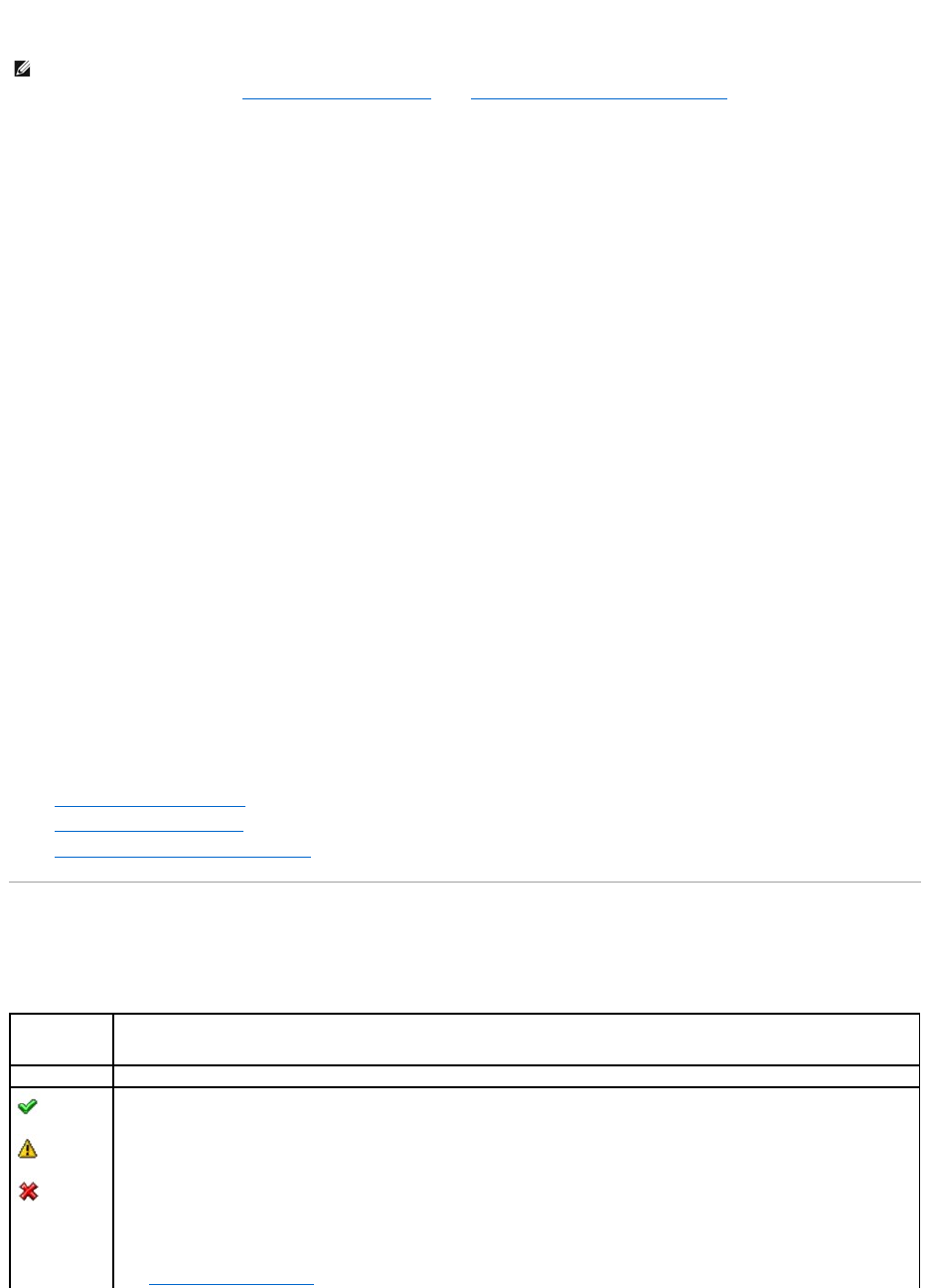
configuration). You can identify whether or not a previously used physical disk contains a foreign configuration (virtual disk) by checking the physical disk state.
If the physical disk state is Foreign, then the physical disk contains all or some portion of a virtual disk. Use the clear foreign configuration task to clear or
erase the virtual disk information from the newly attached physical disks.
To clear a foreign configuration:
Click Clear Foreign Configuration when you are ready to clear or erase all virtual disks residing on physical disks that have been added to the controller. To
exit without clearing the foreign configuration, click Cancel.
To locate this task in Storage Management:
For SAS controllers with firmware versions 6.1 and later:
1. Expand the Storage tree object to display the controller objects.
2. Select a controller object.
3. Select the Information/Configuration subtab.
4. Select Foreign Configuration Operations from the Controller Available Tasks drop-down menu.
5. Click Execute.
6. On the Foreign Configuration Preview page, click Clear.
For controllers with firmware version 6.0 and earlier:
1. Expand the Storage tree object to display the controller objects.
2. Select a controller object.
3. Select the Information/Configuration subtab.
4. Select Clear Foreign Configuration from the Controller tasks.
Related Information:
l"Foreign Configuration Operations"
l"Importing Foreign Configurations"
l"Importing/Recovering Foreign Configurations"
Physical Disks in Foreign Virtual Disks
The Physical Disks in Foreign Virtual Disks page displays the physical disks and the dedicated hot spare, if any, included in the foreign configuration.
The following table describes properties for physical disks in the foreign configuration.
NOTE: The clear foreign configuration task permanently destroys all data residing on the physical disks that have been added to the controller. If more
than one foreign virtual disk is present, you cannot choose which one to clear. All will be cleared or erased. You may prefer to import the virtual disk
rather than destroy the data. See "Importing Foreign Configurations" and "Importing/Recovering Foreign Configurations" for more information.
Property
Definition
Status
These icons represent the severity or health of the storage component.
Normal/OK
Warning/Non-critical
Critical/Fatal
See "Storage Component Severity" for more information.

Name
This property displays the name of the physical disk. The name is comprised of the connector number followed by the disk number.
Current State
This property displays the current state of the physical disk.
After Import
State
This property displays the after-import state of the physical disk. The physical disk can be imported in any of the following states.
Online — The physical disk will be part of the imported virtual disk and will function normally.
Offline — The physical disk will be offline after import to the virtual disk.
Foreign — The virtual disk containing the physical disk cannot be imported and the physical disk will remain in foreign state.
Rebuild — After import of virtual disk, the physical disk will rebuild.
Replacing — A Replace Member Disk task will be performed on the physical disk. For more information, see "Replace Member Disk" and
"Revertible Hot Spare."
Capacity
This property displays the full capacity of the disk.
Failure
Predicted
This property displays whether or not the physical disk has received a Self-Monitoring Analysis and Reporting Technology (SMART) alert and
is therefore predicted to fail. For more information on SMART predictive failure analysis, see "Monitoring Disk Reliability on RAID
Controllers." For information on replacing the physical disk, see "Replacing a Physical Disk Receiving SMART Alerts."
You may also want to review the Alert Log to see whether the physical disk has generated alerts pertaining to a SMART predictive failure.
These alerts can assist you in identifying the cause of the SMART alert. The following alerts may be generated in response to a SMART
alert:
2094
2106
2107
2108
2109
2110
2111
For information on Alert Messages, see the Dell OpenManage Server Administrator Messages Reference Guide on the Dell Support website at
support.dell.com/manuals.
NOTE: On replacing a SMART error drive with a good drive on PERC4/IM controllers, it is necessary to perform a rescan operation on the
controller, for Storage Management to display the correct status of the newly inserted drive.
Progress
This property displays the progress of an operation being performed on the physical disk. For example, if the physical disk is being rebuilt,
then a value of 52% indicates that the rebuild is 52% complete.
This property is only displayed when an operation is being performed on the physical disk.
Bus Protocol
This property displays the technology that the physical disk is using. Possible values are:
SCSI — Small Computer System Interface
SAS — Serial Attached SCSI
SATA — Serial Advanced Technology Attachment (SATA)
Media
This property displays the media type of the physical disk. The possible values are:
HDD—Hard Disk Drive. A HDD is a non-volatile storage device which stores digitally-encoded data on rapidly rotating platters with magnetic
surfaces.
SSD—Solid State Drive. An SSD is a data storage device that uses solid-state memory to store persistent data.
Unknown—Storage Management is unable to determine the media type of the physical disk.
Used RAID Disk
Space
This property displays how much of the physical disk space is being used by the virtual disks on the controller. This property is not
applicable for physical disks attached to non-RAID controllers.
In certain circumstances, the Used RAID Disk Space displays a value of zero (0) even though a portion of the physical disk is actually
being used. This occurs when the used space is 0.005 GB or less. The algorithm for calculating the used disk space rounds off a figure of
0.005 GB or less to 0. Used disk space that is between 0.006 GB and 0.009 GB is rounded off to 0.01 GB.
Available RAID
Disk Space
This property displays the amount of available space on the disk. This property is not applicable for physical disks attached to non-RAID
controllers.
Hot Spare
This property indicates whether the disk has been assigned as a hot spare. This property is not applicable for physical disks attached to
non-RAID controllers.
Vendor ID
This property displays the disk's hardware vendor.
Product ID
This property displays the disk's product ID.
Revision
This property displays the disk's revision number.
Serial No.
This property displays the disk's serial number.
Negotiated
Speed
This property displays the speed of data transfer that the disk negotiated while spinning up and upon initial communication with the
controller. This speed is dependent on the speed of the disk, the capable speed of the controller, the current speed of the controller on
that connector, and the speed of the Enclosure Management Module (EMM) on the enclosure.

Related Information:
l"Foreign Configuration Operations"
Set Background Initialization Rate
Does my controller support this feature? See "Supported Features."
The Set Background Initialization Rate task changes the amount of system resources dedicated to the background initialization task. See "Background
Initialization on PERC 3/SC, 3/DC, 3/QC, 4/SC, 4/DC, 4e/DC, 4/Di, 4e/Si, and 4e/Di Controllers" for more information on the background initialization task.
The background initialization rate, configurable between 0% and 100%, represents the percentage of the system resources dedicated to running the
background initialization task. At 0%, the background initialization will have the lowest priority for the controller, will take the most time to complete, and will
be the setting with the least impact to system performance. A background initialization rate of 0% does not mean that the background initialization is stopped
or paused.
At 100%, the background initialization will be the highest priority for the controller, will minimize the background initialization time, and will be the setting with
the most impact to system performance.
To change the controller's background initialization rate:
1. Type a numerical value in the New Background Initialization Rate text box. The value must be within the 0 – 100 range.
2. Click Apply Changes. If you want to exit and cancel your changes, click Go Back to Previous Page.
To locate this task in Storage Management:
1. Expand the Storage tree object to display the controller objects.
2. Select a controller object.
3. Select the Information/Configuration subtab.
4. Select Set Background Initialization Rate from the Available Tasks drop-down menu.
5. Click Execute.
You can also locate this task from the Change Controller Properties drop down menu. For more information, see "Change Controller Properties."
Set Check Consistency Rate
Does my controller support this feature? See "Supported Features."
The Set Check Consistency Rate task changes the amount of system resources dedicated to the check consistency task. See "Check Consistency" for more
Capable Speed
This property displays the highest possible speed with which the device can transfer data.
Manufacture
Day
This property displays the day of the month on which the physical disk was manufactured.
Manufacture
Week
This property displays the week of the year during which the physical disk was manufactured.
Manufacture
Year
This property displays the year in which the physical disk was manufactured.
SAS Address
This property displays the SAS address of the physical disk. The SAS address is unique to each SAS disk.
After Import
Status
This property displays what the status of the physical disk would be after the foreign configuration has been imported. Possible values
are:
lForeign
lOnline
lOffline
lReplaced
lRebuild

information about the check consistency task.
The check consistency rate, configurable between 0% and 100%, represents the percentage of the system resources dedicated to running the check
consistency task. At 0%, the check consistency will have the lowest priority for the controller, will take the most time to complete, and will be the setting with
the least impact to system performance. A check consistency rate of 0% does not mean that the check consistency is stopped or paused.
At 100%, the check consistency will be the highest priority for the controller, will minimize the check consistency time, and will be the setting with the most
impact to system performance.
To change the controller's check consistency rate:
1. Type a numerical value in the New Check Consistency Rate text box. The value must be within the 0 – 100 range.
2. Click Apply Changes. If you want to exit and cancel your changes, click Go Back to Previous Page.
To locate this task in Storage Management:
1. Expand the Storage tree object to display the controller objects.
2. Select a controller object.
3. Select the Information/Configuration subtab.
4. Select Set Check Consistency Rate from the Available Tasks drop-down menu.
5. Click Execute.
You can also locate this task from the Change Controller Properties drop down menu. For more information, see "Change Controller Properties."
Related Information:
l"Check Consistency"
l"Cancel Check Consistency"
Set Reconstruct Rate
Does my controller support this feature? See "Supported Features."
The Set Reconstruct Rate task changes the amount of system resources dedicated to the reconstruct task.
The reconstruct task remakes the virtual disk after you have changed the RAID level or otherwise reconfigured the virtual disk. The reconstruct rate,
configurable between 0% and 100%, represents the percentage of the system resources dedicated to running the reconstruct task. At 0%, the reconstruct
will have the lowest priority for the controller, will take the most time to complete, and will be the setting with the least impact to system performance. A
reconstruct rate of 0% does not mean that the reconstruct is stopped or paused.
At 100%, the reconstruct will be the highest priority for the controller, will minimize the reconstruct time, and will be the setting with the most impact to system
performance.
To change the controller's reconstruct rate:
1. Type a numerical value in the New Reconstruct Rate text box. The value must be within the 0 – 100 range.
2. Click Apply Changes. If you want to exit and cancel your changes, click Go Back to Previous Page.
To locate this task in Storage Management:
1. Expand the Storage tree object to display the controller objects.
2. Select a controller object.
3. Select the Information/Configuration subtab.
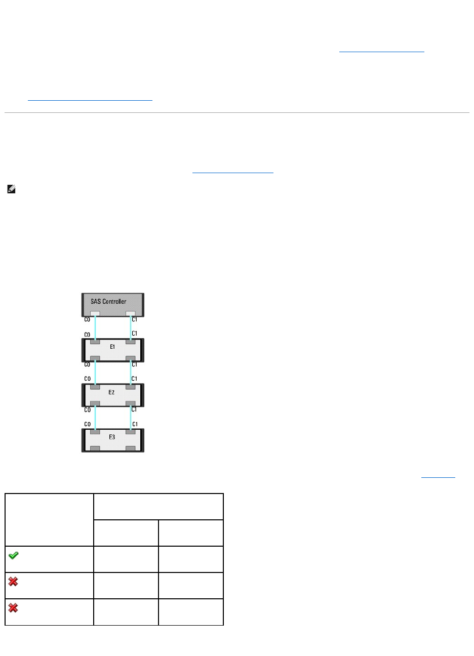
4. Select Set Reconstruct Rate from the Available Tasks drop-down menu.
5. Click Execute.
You can also locate this task from the Change Controller Properties drop down menu. For more information, see "Change Controller Properties."
Related Information:
l"Virtual Disk Task: Reconfigure (Step 1 of 3)"
Redundant Path Configuration
Does my controller support this feature? See "Supported Features."
This feature is supported only on SAS controllers with firmware version 6.1 or later., which can be connected to enclosures (and not backplanes). The
supportedenclosuresareDell™PowerVault™MD1000andPowerVaultMD1120.ThisfeatureenablesloadbalancingbyfasterprocessingofI/Orequests.
In a redundant path configuration, connect both the connectors of a SAS enclosure—which must be in a unified mode—to both connectors of a controller.
Storage Management detects this configuration and displays it on the user interface as a redundant path configuration. The two connectors (Connector 0 and
Connector 1) that were previously available are now replaced with one Logical Connector.
In a daisy-chain scenario, more than one enclosure can be connected to a controller in a redundant path mode. You can connect up to three PowerVault
MD1000 and MD1120 to a PERC 6/E controller in a daisy-chained enclosure. And, you can connect up to four PowerVault MD1200 and MD1220 to a PERC H800
controller in a daisy-chained enclosure. See the figure below for an example of a daisy chain configuration (for PERC 6/E controller.)
If the communication channel between the connector and the first enclosure is lost, the redundant path configuration itself is lost. In this case, the health of
the logical connector is displayed as critical. Navigate to the Information/Configuration subtab of the logical connector to view details of the "Path Health."
See the table below for a brief outline of this scenario.
However, if the communication channel between any two enclosures is lost, the redundant path configuration is degraded and the health of the logical
connector is displayed as degraded. See the table below for a brief outline of this scenario.
NOTE: This feature requires that the physical devices connected to the controller have the latest firmware. For the latest supported firmware, see the
Dell Support website at support.dell.com.
Health of Logical Connector
Path between Controller and Enclosure 1
Connector 0 (C0)
Connector 1 (C1)
Available
Available
Available
Disconnected
Disconnected
Available

In this case, the enclosure status is displayed in warning mode. The Enclosures page displays all enclosure components (EMMs, Fans, Physical Disks, Power
Supplies, and Temperature) to be in normal condition. Select the Information/Configuration subtab of the enclosure. This page displays the Path Failure
message to indicate that the enclosure has lost a communication path to the controller, thereby indicating that the enclosure is no longer in redundant path
mode. For more information, see "Path Health."
Clearing the Redundant Path View
Consider a case where you reboot your system and Storage Management, displays the Logical Connector with a path failure message. It is possible that you
may have intentionally unplugged the second connector. In this case, the path failure message is not relevant. Else, there could be a fault in the connected
cable or the cable may not be connected properly to the controller. In both cases, Storage Management displays that the system was in redundant path
configuration before reboot and is no longer in this configuration. If you are sure you do not want the redundant path mode, clear the existing redundant path
view using Clear Redundant Path View provided in the "Change Controller Properties" controller task. Selecting this option clears the redundant path view
and the connectors are represented on the user interface as Connector 0 and Connector 1.
Related Topics
l"Logical Connector Properties and Tasks"
l"Enclosure and Backplane Properties and Tasks"
Set Patrol Read Mode
Does my controller support this feature? See "Supported Features."
Patrol Read is a feature for identifying disk errors in order to avoid disk failures and data loss or corruption. The Patrol Read only runs on disks that are being
used in a virtual disk or that are hot spares.
When possible, the Patrol Read corrects disk errors and restores the integrity of the data. The Patrol Read task runs in the background. When the Patrol Read
mode is set to Auto, the Patrol Read is initiated when the controller has been idle for a period of time and when no other background tasks are active. In this
circumstance, the Patrol Read feature also enhances system performance as disk errors can be identified and corrected while the disk is not the subject of I/O
activity.
The controller adjusts the amount of system resources dedicated to the Patrol Read based on the amount of controller activity that is competing with the
Patrol Read task. During heavy controller activity, fewer system resources are dedicated to the Patrol Read task.
The Patrol Read will not run on a physical disk in the following circumstances:
lThe physical disk is not included in a virtual disk or assigned as a hot spare.
lThe physical disk is included in a virtual disk that is currently undergoing one of the following:
¡A rebuild
¡A reconfiguration or reconstruction
¡A background initialization
¡A check consistency
In addition, the Patrol Read suspends during heavy I/O activity and resumes when the I/O is finished.
To set the Patrol Read mode:
Click the radio button for the Patrol Read mode setting that you want to select: The possible settings are:
lAuto — Setting the mode to Auto initiates the Patrol Read task. When the task is complete, it automatically runs again within a specified period of time.
For example, on some controllers the Patrol Read runs every four hours and on other controllers, the Patrol Read runs every seven days. The Patrol
Read task runs continuously on the system starting again within the specified period of time after each iteration of the task completes. If the system
Health of Logical Connector
Path between Enclosure n and Enclosure n+1
Connector 0 (C0)
Connector 1 (C1)
Available
Available
Available
Disconnected
Disconnected
Available

reboots while the Patrol Read task is running in Auto mode, the Patrol Read restarts at zero percent (0%). When the Patrol Read task is set to Auto
mode, you cannot start or stop the task. Auto mode is the default setting.
lManual — Setting the mode to Manual enables you to start and stop the Patrol Read when you want using the "Start and Stop Patrol Read" tasks.
Setting the mode to Manual does not initiate the Patrol Read task. If you have started the Patrol Read and the system reboots while the Patrol Read is
running in Manual mode, the Patrol Read does not restart.
lDisabled — Setting the mode to Disabled prevents the Patrol Read task from running on the system.
To locate this task in Storage Management:
1. Expand the Storage tree object to display the controller objects.
2. Select a controller object.
3. Select the Information/Configuration subtab.
4. Select Set Patrol Read Mode from the Available Tasks drop-down menu.
5. Click Execute.
You can also locate this task from the Change Controller Properties drop down menu. For more information, see "Change Controller Properties."
Related Information:
l"Start and Stop Patrol Read"
Start and Stop Patrol Read
Does my controller support this feature? See "Supported Features."
When the Patrol Read mode is set to manual, you can start the Patrol Read task or stop the task when it is running.
There are certain conditions under which the Patrol Read task cannot be run. See "Set Patrol Read Mode" for more information.
To start or stop the Patrol Read task:
Click Start Patrol Read or Stop Patrol Read when ready. To exit without starting or stopping the Patrol Read, click Go Back to Previous Page.
To locate this task in Storage Management:
1. Expand the Storage tree object to display the controller objects.
2. Select a controller object.
3. Select the Information/Configuration subtab.
4. Select Start Patrol Read or Stop Patrol Read from the Available Tasks drop-down menu.
5. Click Execute.
You can also locate this task from the Change Controller Properties drop down menu. For more information, see "Change Controller Properties."
Related Information:
l"Set Patrol Read Mode"
NOTE: Refer to your controller documentation for more information on how often the Patrol Read task runs when in Auto mode.

Change Controller Properties
Does my controller support this feature? See "Supported Features."
The Change Controller Properties task provides you the option to change multiple controller properties simultaneously. This task is available only on SAS
controllers with firmware version 6.1 and later.
You can change any or all of the following properties using the Change Controller Properties task:
lRebuild Rate
lBGI Rate
lCheck Consistency Rate
lReconstruct Rate
lAbort check consistency on error
lRevertible Hot Spare
lLoadbalance
lAuto replace member on predictive failure
lRedundant path view
To locate this task in Storage Management, do one of the following:
1. Select Storage in the Storage tree.
2. On the Storage Dashboard page, select Change Controller Properties... from the Available Tasks drop down menu.
3. Click Execute.
Or:
1. Expand the Storage tree object to display the controller objects.
2. Select a controller object.
3. Select the Information/Configuration subtab.
4. Select Change Controller Properties... from the Controller Tasks drop down menu.
5. Click Execute.
Related Information:
l"Set Rebuild Rate"
l"Set Background Initialization Rate"
l"Set Check Consistency Rate"
l"Set Reconstruct Rate"
l"Abort check consistency on error"
l"Revertible Hot Spare"
l"Loadbalance"
l"Redundant Path Configuration"
Manage Preserved Cache
The Managed Preserved Cache feature provides you the option to ignore or restore the controller cache data.
In the write-back policy, data is written to the cache before being written to the physical disk. If the virtual disk goes offline or is deleted for any reason, the
data in the cache is lost.
NOTE: You can set these properties through the command line interface also. See the Dell OpenManage Server Administrator Command Line
Interface User's Guide on the Dell Support website at support.dell.com/manuals, for more information.

Data in the cache may also be lost in case of unintended cable or power failure. In the event of such a failure, Storage Management preserves the data
written on the preserved or dirty cache until you recover the virtual disk or clear the cache.
This feature is available only on SAS controllers with firmware version 6.1 and later.
The status of the controller is affected by the preserved cache. The controller status is displayed as degraded if the controller has preserved cache.
CAUTION: You may not be able to use Storage Management to manage the preserved cache in some cases. As an example, consider you have a
RAID 1 level with two disks
—
D1 and D2. If you now remove D2, the virtual disk is degraded and the data in the controller cache is written to D1.
Manage Preserved Cache
You can discard the preserved cache only if all of the following conditions are met:
lThe controller does not have any foreign configuration. Select Click for Preview to view details of the foreign configuration. See "Foreign Configuration
Operations."
lThe controller does not have any offline or missing virtual disks. If there are offline or missing virtual disks, ensure you have a backup of these virtual
disks.
lCables to any virtual disk are not disconnected.
Manage Security Key
Does my controller support this feature? See "Supported Features."
The Manage Security Key task enables you to create a new Security Key or change/delete an existing Security Key on a security-capable controller.
To locate this task in Storage Management, do one of the following:
1. Select Storage in the Storage tree.
2. On the Storage Dashboard page, select Manage Security Key... from the Available Tasks drop down menu.
3. Click Execute.
Or:
1. Expand the Storage tree object to display the controller objects.
2. Select a security-capable controller object.
3. Select the Information/Configuration subtab.
4. Select Manage Security Key... from the Controller Tasks drop down menu.
5. Click Execute.
If the controller is security capable and a Security Key is not present, then the Create Security Key page is displayed. Else, the Change or Delete Security
page is displayed.
Create Security Key
To create a security key on the selected controller do the following:
1. Enter a Security Key Identifier.
A Security Key Identifier can contain numerals, lowercase alphabets, uppercase alphabets, non-alphanumeric characters, or a combination of any of
these.
2. Enter a Passphrase.
A Passphrase must contain at least one numeral, one lowercase alphabet, one uppercase alphabet, and one non-alphanumeric character (except
RAID 1 level with two disks—D1 and D2. If you now remove D2, the virtual disk is degraded and the data in the controller cache is written to D1.
At this point, D1 has the latest data. Now, if you re-insert D2 and pull out D1, the virtual disk will still be degraded and will not have the latest
data.
NOTE: This task is available only on PERC H800 and PERC H700 controllers.

space.)
3. Read the Passphrase guidelines and acknowledge the note by selecting the accompanying check box.
Ensure that you save the Passphrase.
4. Click Apply Changes.
The controller information is displayed. The Security Capable property value displays Yes, indicating that the Create Security Key task is successful.
Change or Delete Security Key
You can change a Security Key of a controller if the controller already has a configured Security Key. You can delete a Security Key for secured controllers only if
there are no secured virtual disks.
To change the Security Key, enter the new Security Key Identifier and Passphrase. You are prompted to authenticate with the current Passphrase. Ensure you
read the note on the importance of Passphrase and consequences of not saving the same, before applying the changes.
When you change the Security Key, the existing configuration on this controller is updated to use the new Security Key. If you have removed any of the
secured drives previously, you must authenticate with the old Passphrase to import the secured drives.
If you delete the Security Key, you cannot create secured virtual disks and all secured unconfigured self-encrypting drives are erased. However, deleting a
Security Key does not affect security or data in foreign disks.
Back to Contents Page
CAUTION: It is important to understand that if you lose the Passphrase, you cannot recover it. If you move the physical disks associated with the
lost Passphrase to another controller, you will not be able to access data from that disk.
Back to Contents Page
Enclosures and Backplanes
Dell™OpenManage™ServerAdministratorStorageManagementUser'sGuide
Physical disks can be contained in an enclosure or attached to the system's backplane. An enclosure is attached to the system externally while the backplane
and its physical disks are internal.
Backplanes
You can view the Backplane object by expanding the controller and Connector object in the Storage Management tree view. Storage Management displays the
status of the backplane and attached physical disks. Although a backplane is similar to an enclosure in that it is attached to a controller connector and has
physical disks, it does not have the management features (temperature probes, alarms, and so on) associated with external enclosures.
Enclosures
Storage Management enables management of various enclosures and their components. In addition to managing the physical disks contained in the
enclosure, you can monitor the status of the enclosure's fans, power supply, and temperature probes. You can view these components by expanding the
controller, Connector, and enclosure objects in the Storage Management tree view.
Storage management allows hot plugging of enclosures. Hot plugging is defined as the adding of a component to a system while the operating system is still
running.
After you hot plug or hot reconfigure an enclosure, refresh the left tree to display changes in status and configuration; a system reboot is not required.
Storage Management displays the properties of the enclosure's fans, power supply, and temperature probes. Storage Management also notifies you of
enclosure status changes through alerts that are displayed in the Alert Log.
The following sections provide more information on the enclosure components and management features provided by Storage Management:
l"SMART Thermal Shutdown"
l"Enclosure Physical Disks"
l"Enclosure Fans"
l"Enclosure Power Supplies"
l"Enclosure Temperature Probes"
l"Enclosure Management Modules (EMMs)"
l"Enclosure and Backplane Health"
l"Enclosure and Backplane Properties and Tasks"
Enclosure Physical Disks
The enclosure's physical disks are displayed under the enclosure object in the tree view. Selecting a disk in the tree view displays the disk's status
information.
Enclosure Fans
The fans are a component of the enclosure's cooling module. The fans are displayed by expanding the enclosure object in the tree view. You can select the
Fans object to display their status information.
Backplanes
Set Asset Data
Enclosures
Set Temperature Probe Values
SMART Thermal Shutdown
EMM Properties
Changing the Mode on PowerVault 220S and PowerVault 221S Enclosures
Fan Properties
Enclosure Management
Power Supply Properties
Enclosure and Backplane Health
Temperature Probe Properties and Tasks
Enclosure and Backplane Properties and Tasks
NOTE: This feature requires that the physical devices connected to the controller have the latest firmware. For the latest supported firmware, see the
Dell Support website at support.dell.com.
NOTE: Storage Management does not allow hot removal of enclosures. You must reboot the system to effect this change in Storage Management.

Enclosure Power Supplies
The enclosure's power supplies are displayed under the Power Supplies object in the tree view. You can select the Power Supplies object to display their
status information.
Enclosure Temperature Probes
The enclosure's temperature probes are displayed under the Temperatures object. You can select the Temperatures object to display their status information.
The status information includes the current temperature in Celsius and the Warning and Failure thresholds for the temperature probe. The Failure threshold
has a default value that cannot be changed. You can set the Warning threshold, however. See "Set Temperature Probe Values" for information on setting the
warning threshold.
For information related to the enclosure's temperature, see the following:
l"Checking the Enclosure's Temperature"
l"Set Temperature Probe Values"
l"Temperature Probe Properties and Tasks"
l"SMART Thermal Shutdown"
Enclosure Management Modules (EMMs)
The Enclosure Management Modules (EMMs) that are installed in the enclosure are displayed under the EMMs object in the tree view. You can select the EMMs
object to display the individual EMM modules and their status information.
The enclosure may contain one or more EMMs. The EMM modules monitor components of the enclosure. These components include:
lFans
lPower supplies
lTemperature probes
lThe insertion or removal of a physical disk
lThe LEDs on the enclosure
When the enclosure's alarm is enabled, the EMM activates the alarm when certain conditions occur. For more information on enabling the alarm and the
conditions that activate the alarm, see "Enable Alarm (Enclosure)." For more information on EMMs, see the enclosure hardware documentation.
All EMM modules in the enclosure should have the same version of firmware. You can view the properties of each individual EMM module to verify the firmware
version.
SMART Thermal Shutdown
Does my enclosure support this feature? See "Supported Features."
Enclosure management provides a feature which automatically shuts down the operating system, the server, and the enclosure when the enclosure's
temperature reaches dangerous extremes. The temperature, when shutdown occurs, is determined by the enclosure temperature probe's Minimum Failure
Threshold and the Maximum Failure Threshold. These thresholds are default settings that cannot be changed.
ThermalShutdownforthePowerVault™20xSandPowerVault21xSEnclosures
For the PowerVault 20xS and PowerVault 21xS enclosures, the operating system shuts down and the server powers off when the enclosure reaches 0
degrees Celsius or 50 degrees Celsius. After the server powers off, the enclosure also powers off.
Thermal Shutdown for the PowerVault 220S and PowerVault 221S Enclosures
For the PowerVault 220S and PowerVault 221S, the operating system and server shut down at 0 degrees Celsius or 50 degrees Celsius if you have not
implemented "Channel Redundancy and Thermal Shutdown." If you have implemented channel redundancy enabled smart thermal shutdown using the
command line interface (CLI), then only the enclosure shuts down at 0 degrees Celsius or 50 degrees Celsius. This will not result in data loss because
redundant data resides on the enclosure attached to the other channel.
The PowerVault 220S and PowerVault 221S enclosures automatically shut down when their temperature reaches 55 degrees Celsius. This shutdown occurs
whether or not you have implemented channel redundancy or have Storage Management installed.
You can enable smart thermal shutdown using the command line interface. For more information, see the Dell OpenManage Server Administrator Command Line
Interface User's Guide on the Dell Support website at support.dell.com/manuals.
NOTE: Thermal shutdown does not apply to the Ultra SCSI, Ultra2 SCSI, Ultra160 SCSI, LSI 1020, LSI 1030, and LSI PCI-e U320 controllers.

Changing the Mode on PowerVault 220S and PowerVault 221S Enclosures
When toggling the bus configuration switch on a PowerVault 220S or PowerVault 221S enclosure, the enclosure should be powered off. The bus configuration
switch is used to change the enclosure to split bus, joined bus, or clustered mode. If you change the PowerVault 220S or PowerVault 221S enclosure mode
with the enclosure powered on, the enclosure may no longer be displayed by Storage Management and you may notice other erratic behaviors. In addition,
the bus configuration switch on these enclosures is not rated for frequent toggling.
Enclosure Management
In addition to the drop-down menu "Enclosure Tasks," the following activities may be required for enclosure management.
lIdentifying the enclosure's service tag — To identify the enclosure's service tag, select the enclosure in the tree view and click the
Information/Configuration tab. The Information/Configuration tab displays the service tag and other enclosure properties.
lPreparing a physical disk for removal — The task that enables you to prepare a physical disk for removal is a physical disk command. See "Prepare to
Remove."
lTroubleshooting — For general information on troubleshooting procedures, see "Troubleshooting."
lRemoving the wrong physical disk — You can avoid removing the wrong physical disk by blinking the LED display of the disk you intend to remove. See
"Blink and Unblink (Physical Disk)."
lIf you have already removed the wrong physical disk, see "Recovering from Removing the Wrong Physical Disk."
l"Identifying an Open Connector for the Enclosure"
l"Checking the Enclosure's Temperature"
l"Verifying the Enclosure's EMM Firmware Version"
Enclosure and Backplane Health
This screen displays the status of the enclosure or backplane and the components attached to the enclosure or backplane.
Enclosure and Backplane Status
Component status is indicated by the severity. A component with a Warning or Critical/Failure status requires immediate attention to avoid data loss if
possible. A component's status may indicate the combined status of the component and its lower-level objects. See "Determining the Health Status for
Storage Components" for more information.
It may be useful to review the Alert Log for events indicating why a component has a Warning or Critical status. For additional troubleshooting information,
see "Troubleshooting."
Enclosure and Backplane Information
For information on enclosures and backplanes, see the following topics:
l"Enclosures and Backplanes"
l"Enclosure and Backplane Properties and Tasks"
Enclosure and Backplane Components
For information on attached components, see the following topics:
Severity
Component Status
Normal/OK. The component is working as expected.
Warning/Non-critical. A probe or other monitoring device has detected a reading for the component that is above or below the acceptable level.
The component may still be functioning, but it could fail. The component may also be functioning in an impaired state. Data loss is possible.
Critical/Failure/Error. The component has either failed or failure is imminent. The component requires immediate attention and may need to be
replaced. Data loss may have occurred.
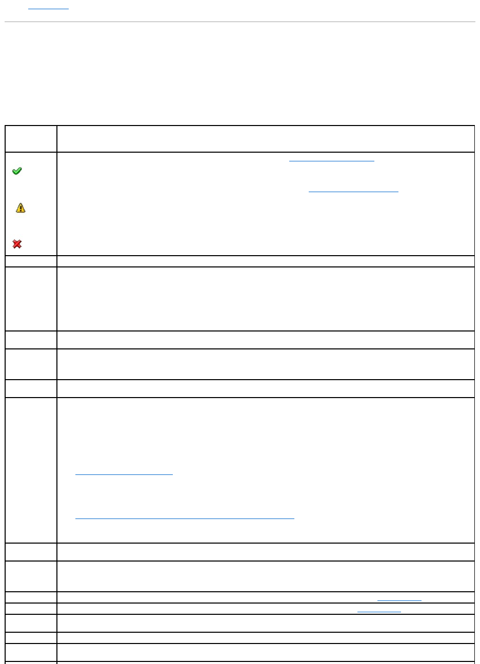
l"Physical Disks"
Enclosure and Backplane Properties and Tasks
Use this window to view information about the enclosure or backplane and execute enclosure tasks.
Enclosure and Backplane Properties
The enclosure or backplane properties can vary depending on the model of the controller. Enclosure or backplane properties may include:
Property
Definition
These icons represent the severity or health of the storage component. See "Storage Component Severity" for more information.
NOTE: If the enclosure is connected to the controller in redundant path mode (see "Redundant Path Configuration" for more information),
the loss of connection to any one EMM may cause the enclosure status to be displayed as degraded.
Name
This property displays the name of the enclosure or backplane.
State
This property displays the current status of the enclosure or backplane. Possible values are:
Ready — The enclosure or backplane is functioning normally.
Degraded — The enclosure has encountered a failure and is operating in a degraded state. The Degraded state does not apply to
backplanes.
Failed — The enclosure or backplane has encountered a failure and is no longer functioning.
Connector
This property displays the number of the connector to which the enclosure or backplane is attached. This number matches the connector
number on the controller hardware. Depending on the controller type, the connector can be either a SCSI channel or a SAS port.
Enclosure ID
This property displays the enclosure ID assigned to the enclosure by Storage Management. Storage Management numbers the enclosures
attached to the controller starting with zero. This number is the same as the enclosure ID number reported by the omreport Command. For
information on Command Line Interface, see the Dell OpenManage Server Administrator Command Line Interface User's Guide on the Dell
Support website at support.dell.com/manuals.
Target ID
This property displays the SCSI ID of the backplane (internal to the server) or the enclosure to which the controller connector is attached.
The value is usually 6.
Configuration
This property displays the mode in which the enclosure is operating. Possible values are:
Joined — Indicates that the enclosure is operating in joined-bus mode.
Split — Indicates that the enclosure is operating in split-bus mode.
Unified — Indicates that enclosure is operating in unified mode.
Clustered — Indicates that the enclosure is operating in cluster mode. Clustered mode is only available on cluster-enabled RAID controllers.
See "Cluster-enabled RAID Controllers" for more information.
For more information on joined, split, and cluster modes, see the enclosure hardware documentation. For information on how to cable the
enclosure to accommodate these different modes, see the enclosure hardware documentation.
WhentogglingthebusconfigurationswitchonaPowerVault™220SorPowerVault221Senclosure,theenclosureshouldbepoweredoff.
See "Changing the Mode on PowerVault 220S and PowerVault 221S Enclosures" for more information.
Older PowerVault 200S enclosures with a version 1.8 kernel that only have one EMM may display Split Bus mode and not Joined Bus mode.
Joined Bus or Clustered when applicable are the only possible modes in these circumstances.
Firmware
Version
This property displays the version of the enclosure firmware.
Service Tag
Thispropertydisplaystheenclosure'sservicetagnumber.ThisnumberisrequiredwhentalkingtoDell™support.Youcanusethisnumber
to identify a specific enclosure in your environment by matching this number with the number on the service tag affixed to the enclosure.
For example, if you have multiple enclosures and one of them experiences a failure, you can use the service tag number to identify which
enclosure has failed.
Asset Tag
This property displays the asset tag information for the enclosure. You can change this property using the "Set Asset Data" task.
Asset Name
This property displays the name assigned to the enclosure. You can change this property using the "Set Asset Data" task.
Backplane Part
Number
This property displays the part number of the enclosure's backplane.
SAS Address
This property displays the SAS address of the SAS backplane.
Split Bus Part
Number
This property displays the part number of the enclosure's split bus module. A split bus is indicated by a single triangle symbol on the back
of the enclosure.

Enclosure Tasks
Do the following to execute a drop-down menu enclosure task:
1. Expand the Storage tree object to display the controller objects.
2. Expand a controller object.
3. Expand a Connector object.
4. Select the enclosure object.
5. Select the Information/Configuration subtab.
6. Select a task from the Available Tasks drop-down menu.
7. Click Execute.
Drop-down Menu Enclosure Tasks:
l"Enable Alarm (Enclosure)"
l"Disable Alarm (Enclosure)"
l"Set Asset Data"
l"Blink"
l"Set Temperature Probe Values"
Enable Alarm (Enclosure)
Does my enclosure support this feature? See "Supported Features."
Use the Enable Alarm task to enable the enclosure alarm. When enabled, the audible alarm sounds whenever the fault LED lights. This may occur to signal
events such as:
lThe enclosure temperature has exceeded the warning threshold.
lA power supply, fan, or enclosure management module (EMM) has failed.
lThe split bus is not installed. (A split bus is indicated by a single triangle symbol on the back of the enclosure.)
Disable Alarm (Enclosure)
Does my enclosure support this feature? See "Supported Features."
Use the Disable Alarm task to disable the enclosure alarm. When disabled, the alarm does not sound when the enclosure exceeds a warning threshold for
temperature or experiences other error conditions such as a failed fan, power supply, or controller. If the alarm is already sounding, you can turn it off with
this task.
Set Asset Data
Does my enclosure support this feature? See "Supported Features."
Use the Set Asset Data task to specify the enclosure's asset tag and asset name. See "Set Asset Data" for more information.
Blink
Enclosure Part
Number
This property displays the part number of the enclosure.
Enclosure Alarm
This property displays whether the enclosure's alarm is enabled or disabled.

Does my enclosure support this feature? See "Supported Features."
Use the Blink task to blink the light-emitting diodes (LEDs) on the enclosure. You may want to use this task to locate an enclosure. The LEDs on the enclosure
may display different colors and blinking patterns. Refer to the enclosure hardware documentation for more information on what the blink colors and patterns
indicate.
Set Temperature Probe Value
Does my enclosure support this feature? See "Supported Features."
Use the Set Temperature Probe Values task to specify the Warning and Failure thresholds for the enclosure's temperature probes. See "Set Temperature
Probe Values" for more information.
Identifying an Open Connector for the Enclosure
Does my controller support this feature? See "Supported Features."
If you have not yet attached the enclosure to an open connector, you may need to identify a connector on the controller that can be used for this purpose. To
identify an open connector:
1. Expand the Storage Management tree view until the controller object is expanded. When the controller object is expanded, the tree view displays the
controller's connectors. These connectors are numbered starting from zero.
2. Identify a connector that is not attached to storage. If the connector is already attached to storage, then the Connector object can be expanded to
display an enclosure or backplane and the attached physical disks. A Connector object that cannot be expanded in the tree view is an open connector
not currently attached to storage. Storage Management displays a number for each connector. These numbers correspond to the connector numbers on
the controller hardware. You can use these numbers to identify which open connector displayed in the tree view is the open connector on the controller
hardware.
Checking the Enclosure's Temperature
Does my controller support this feature? See "Supported Features."
To check the enclosure's temperature:
1. Expand the tree view until the Temperatures object is displayed.
2. Select the Temperatures object. The temperature reported by the temperature probe is displayed in Celsius in the Reading column in the right pane.
For information related to the enclosure's temperature, see the following:
l"Enclosure Temperature Probes"
l"Set Temperature Probe Values"
l"Temperature Probe Properties and Tasks"
l"SMART Thermal Shutdown" (does not apply to the Ultra SCSI, Ultra2 SCSI, Ultra160 SCSI, LSI 1020, LSI 1030, and LSI PCI-e U320 controllers)
Verifying the Enclosure's EMM Firmware Version
Does my controller support this feature? See "Supported Features."
The firmware for the Enclosure Management Modules (EMMs) must be at the same level. The status of the EMMs is displayed as degraded if there is a
mismatch between the EMM firmware.
To verify the EMM firmware version:
1. Expand the tree view until the EMMs object is displayed.
2. Select the EMMs object. The firmware version for each EMM is displayed in the Firmware Version column in the right pane.

For information related to the enclosure's EMMs, see "Enclosure Management Modules (EMMs)."
Enclosure Components
For information on attached components, see the following topics:
l"Physical Disk Properties and Tasks"
l"EMM Properties"
l"Fan Properties"
l"Power Supply Properties"
l"Temperature Probe Properties and Tasks"
Set Asset Data
Does my enclosure support this feature? See "Supported Features."
You can change the enclosure's asset tag and asset name. The new asset tag and asset name that you specify are displayed on the enclosure's
Information/Configuration subtab.
To change the enclosure's asset tag and asset name:
1. Type the new asset tag name in the New asset tag text box. You can specify an inventory number or other useful information for your environment. The
asset tag typically refers to the enclosure hardware.
2. Type the new asset name in the New asset name text box. You can specify a name useful to you for organizing your storage environment. For example,
the asset name could refer to the type of data stored on the enclosure or to the enclosure's location.
3. Click Apply Changes. If you want to exit and cancel your changes, click Go Back To Enclosure Information Page.
To locate this task in Storage Management:
1. Expand the Storage tree object to display the controller objects.
2. Expand a controller object.
3. Expand a Connector object.
4. Select the enclosure object.
5. Select the Information/Configuration subtab.
6. Select Set Asset Data from the Available Tasks drop-down menu.
7. Click Execute.
Set Temperature Probe Values
Does my enclosure support this feature? See "Supported Features."
The temperature probes monitor the enclosure's temperature. Each temperature probe has a Warning and a Failure threshold. The Warning threshold
indicates that the enclosure is approaching an unacceptably warm or cool temperature. You can modify the Warning threshold.
The Failure threshold indicates that the enclosure has reached a dangerous temperature that may cause damage and data loss. You cannot change the
default values for the Failure threshold.
To change the temperature probe's Warning threshold:
1. The enclosure's temperature probes are listed in the Temperature Probes section of the screen. Select the probes that you want to change.
2. Select Set new values in the Set New Temperature Probe Values section of the screen.
3. Type the lowest acceptable temperature in Celsius for the enclosure in the Minimum Warning Threshold text box. The text box label indicates the range
that you can specify.
4. Type the highest acceptable temperature in Celsius for the enclosure in the Maximum Warning Threshold text box. The text box label indicates the range
that you can specify.
5. Click Apply Changes.
If you want to return the temperature probe's Warning threshold to the default values, select the Reset to default values button and click Apply Changes. The
default values are displayed in the Minimum Warning Threshold and Maximum Warning Threshold text boxes.
To locate this task in Storage Management:
1. Expand the Storage tree object to display the controller objects.
2. Expand a controller object.
3. Expand a Connector object.
4. Select the enclosure object.
5. Select the Information/Configuration subtab.
6. Select Set Temperature Probe Values from the Available Tasks drop- down menu.
7. Click Execute.
EMM Properties
Use this window to view information about the Enclosure Management Modules (EMMs).
NOTE: On some enclosures, Storage Management may experience a short delay before displaying the current enclosure temperature and temperature
probe status. For more information, see "Storage Management May Delay Before Updating Temperature Probe Status."
Property
Definition
Status
These icons represent the severity or health of the storage component.
Normal/OK
Warning/Non-critical
Critical/Fatal
See "Storage Component Severity" for more information.
Name
This property displays the name of the EMM.
State
This property displays the current state of the EMMs.
Ready — The EMM is functioning normally.
Degraded — The EMM has encountered a failure and is operating in a degraded state.
Failed — The EMM has encountered a failure and is no longer functioning. Storage Management may also be unable to communicate with the
enclosure using SES commands. The Failed state is displayed when the enclosure does not respond to a status query from Storage
Management for any reason. For example, disconnecting the cable would cause this state to be displayed.
Missing — The EMM is not present in the enclosure.
Not Installed — The EMM is not present in the enclosure.
Part
Number
This property displays the part number of the EMM module.
Fan Properties
Use this window to view information about the enclosure's fans.
The fans are a component of the enclosure's cooling module. The following table describes the fan properties.
Power Supply Properties
Use this window to view information about the enclosure's power supplies.
Type
This property indicates whether the EMM is a SCSI SES Module or a SCSI Terminator.
SCSI SES Module — A SCSI SES Module provides SES and SAFTE reporting to the host server, control of all system LED indicators, and
monitoring of all environmental elements, such as temperature sensors, cooling modules, and power supplies.
SCSI Terminator — The SCSI Terminator card is only used if the PowerVault™220SorPowerVault221Senclosureis not configured with a
redundant SCSI SES Module type of EMM. In systems equipped with two SCSI SES Modules, the SCSI termination is done through the EMMs.
Firmware
Version
This property indicates the version of the firmware loaded on the EMM. All EMM modules in the enclosure should have the same level of
firmware.
SCSI Rate
This property displays the maximum SCSI speed that the EMM in a SCSI enclosure supports.
Property
Definition
Status
These icons represent the severity or health of the storage component.
Normal/OK
Warning/Non-critical
Critical/Fatal
See "Storage Component Severity" for more information.
Name
This property displays the name of the fan.
State
This property displays the current status of the fan.
Ready — The fan is functioning normally.
Degraded — The fan has encountered a failure and is operating in a degraded state.
Offline — The fan or power supply has been removed from the enclosure.
Failed — The fan has encountered a failure and is no longer functioning. Storage Management may also be unable to communicate with the
enclosure using SES commands. The Failed state is displayed when the enclosure does not respond to a status query from Storage Management
for any reason. For example, disconnecting the cable would cause this state to be displayed.
Missing — The fan is not present in the enclosure.
Part
Number
This property displays the part number of the fan.
ThispropertyisnotdisplayedforthePowerVault™22xSenclosuresthathaveE.17firmwareorlater.
Speed
This property indicates the fan speed. Possible values are Fast, Medium, Slow, and Stopped. If the fan is in Offline state, the value for the Speed
property is Unknown.
For information on events that cause the fan speed to change, refer to the hardware documentation.
Property
Definition
Status
These icons represent the severity or health of the storage component.
Normal/OK
Warning/Non-critical
Temperature Probe Properties and Tasks
Does my enclosure support this feature? See "Supported Features."
Use this window to view information about the enclosure's temperature probes.
Temperature Probe Properties and Tasks
Critical/Fatal
See "Storage Component Severity" for more information.
Name
This property displays the name of the power supply.
State
This property displays the current status of the power supply.
Ready — The power supply is functioning normally.
Degraded — The power supply has encountered a failure and is operating in a degraded state.
Failed — The power supply has encountered a failure and is no longer functioning. Storage Management may also be unable to communicate
with the enclosure using SES commands. The Failed state is displayed when the enclosure does not respond to a status query from Storage
Management for any reason. For example, disconnecting the cable would cause this state to be displayed.
Missing — The power supply is not present in the enclosure.
Part
Number
This property displays the part number of the power supply.
ThispropertyisnotdisplayedforthePowerVault™22xSenclosuresthathaveE.17firmwareorlater.
Property
Definition
Status
These icons represent the severity or health of the storage component. See "Storage Component Severity" for more information.
NOTE: On some enclosures, Storage Management may experience a short delay before displaying the current enclosure temperature and
temperature probe status. For more information, see "Storage Management May Delay Before Updating Temperature Probe Status."
Name
This property displays the name of the temperature probe.
State
This property displays the current status of the temperature probe.
Ready — The temperature probe is functioning normally.
Degraded — The temperature probe has encountered a failure and is operating in a degraded state.
Failed — The temperature probe has encountered a failure and is no longer functioning. Storage Management may also be unable to
communicate with the enclosure using SES commands. The Failed state is displayed when the enclosure does not respond to a status query
from Storage Management for any reason. For example, disconnecting the cable would cause this state to be displayed.
Minimum Warning Threshold Exceeded — The enclosure's temperature has dropped below the minimum warning threshold. See "Set
Temperature Probe Values" for more information.
Maximum Warning Threshold Exceeded — The enclosure's temperature has risen above the maximum warning threshold. See "Set
Temperature Probe Values" for more information.
Missing — The temperature probe is not present in the enclosure.
Inactive — The temperature probe is present in the enclosure, but the EMM that it monitors is not installed.
Reading
This property displays the current temperature of the enclosure as reported by the temperature probe.
Warning
Threshold
The Minimum and Maximum properties indicate the temperatures currently set for the Warning threshold. See "Set Temperature Probe Values"
for more information.
Failure
Threshold
The Minimum and Maximum properties indicate the temperatures currently set for the Failure threshold. See "Set Temperature Probe Values"
for more information.

Set Temperature Probe Properties and Tasks
Click the Set Temperature Probe button to launch the wizard for changing the temperature probe's Warning threshold. You can change the Warning threshold
for each of the temperature probes included in the enclosure. See "Set Temperature Probe Values" for more information.
Do the following to launch the Set Temperature Probe wizard:
1. Expand the Storage tree object to display the controller objects.
2. Expand a controller object.
3. Expand a Connector object.
4. Expand the enclosure object.
5. Select the Temperatures object.
6. Click Set Temperature Probe.
Back to Contents Page
Back to Contents Page
Frequently Asked Questions
Dell™OpenManage™ServerAdministratorStorageManagementUser'sGuide
Why is a rebuild not working?
How can I safely remove or replace a physical disk?
How do I recover from removing the wrong physical disk?
How do I know what firmware is installed?
What controllers do I have?
How do I turn off an alarm?
What RAID level is best for me?
This section provides frequently asked questions that address situations commonly experienced in a storage environment.
Why is a rebuild not working?
See "A Rebuild Does Not Work" for more information.
How can I safely remove or replace a physical disk?
The following sections provide information related to safely removing a healthy physical disk:
lFor disks that reside in an enclosure, use the "Prepare to Remove" task to locate the disk within the enclosure and deactivate it prior to removal.
lFor physical disks included in a virtual disk, use the Offline task to deactivate the disk prior to removal. See "Online and Offline" for more information. If
you need help locating the disk within the enclosure, you can blink the disk's light-emitting diode (LED) displays. See "Blink and Unblink (Physical Disk)
"for more information.
The following sections describe how to replace a disk that has failed or is receiving SMART alerts:
l"Replacing a Failed Disk"
l"Replacing a Physical Disk Receiving SMART Alerts"
The following sections have related information:
l"Moving Physical and Virtual Disks from One System to Another"
l"Recovering from Removing the Wrong Physical Disk"
l"Protecting Your Virtual Disk with a Hot Spare"
How do I recover from removing the wrong physical disk?
See "Recovering from Removing the Wrong Physical Disk" for more information.
How do I know what firmware is installed?
The controller's properties information displays the firmware version that is installed on the controller. From the Storage tree view object, you can display the
firmware version for all controllers attached to the system. (A controller's Information/Configuration subtab also displays the firmware installed on that
controller.)
To display the firmware version of all controllers:
1. Select the Storage object in the tree view.
2. Click the Information/Configuration subtab. The Firmware Version column on the Information/Configuration subtab displays the firmware version for all
controllers attached to the system.
Related Information:
l"Downloading Firmware and Cluster Controllers"
l"Controller Properties and Tasks"

What controllers do I have?
Each controller attached to the system is displayed under the Storage object in the tree view.
In addition, the Storage object's Health and Information/Configuration subtabs display information for each controller.
To identify which controllers are attached to the system:
1. Select the Storage tree view object. The Health subtab displays the name and status for each controller attached to the system.
2. Click the Information/Configuration subtab to display additional information for each controller.
3. To display more information about a particular controller including its tasks, click the controller's name in the Name column on the
Information/Configuration subtab. This action displays the controller's Information/Configuration subtab. The Information/Configuration subtab displays
information about the controller's components and enables you to execute the controller tasks.
Related information:
l"Controllers"
l"Controller Health"
l"Controller Properties and Tasks"
How do I turn off an alarm?
Some storage components have alarms to indicate error conditions. The following describes how to turn off an alarm after it is sounding:
l"Quiet Alarm (Controller)"
l"Disable Alarm (Controller)"
l"Disable Alarm (Enclosure)"
What RAID level is best for me?
See "Choosing RAID Levels and Concatenation" and "Comparing RAID Level and Concatenation Performance" for more information.
Back to Contents Page
Back to Contents Page
Getting Started
Dell™OpenManage™ServerAdministratorStorageManagementUser'sGuide
Launching Storage Management
User Privileges
Using the Graphical User Interface
Using the Storage Management Command Line Interface
Displaying the Online Help
Common Storage Tasks
Dell™OpenManage™ServerAdministratorStorageManagementisdesignedforsystemadministratorswhoimplementhardwareRAIDsolutionsand
understand corporate and small business storage environments.
Storage Management enables you to configure the storage components attached to your system. These components include RAID and non-RAID controllers
and the channels, ports, enclosures, and disks attached to them. Using Storage Management, you can configure and manage controller functions without
accessing the BIOS. These functions include configuring virtual disks and applying RAID levels and hot spares for data protection. You can initiate many other
controller functions such as rebuilds, troubleshooting, setting thresholds, and so on. Most functions can be configured and managed while the system remains
online and continues to process requests.
Storage Management reports the status of storage components. When the status for a component changes, Storage Management updates the display for
that component and sends an alert to the Alert Log.
In addition to status changes, Storage Management generates alerts for user actions such as creating or deleting a virtual disk and for many other events.
Most alerts also generate SNMP traps.
Other than monitoring and reporting status, Storage Management does not automatically initiate actions independent of user input. (Automatic shutdown of
enclosures that have exceeded a critical temperature is the only exception. See "SMART Thermal Shutdown.") Storage Management actions are user-initiated
using wizards and drop-down menus. Storage Management does, however, report the actions taken by the controllers, which include generating alerts,
initiating tasks, such as a rebuild, and making state changes.
Launching Storage Management
Storage Management is installed as a Dell OpenManage Server Administrator service. All Storage Management features are accessible by selecting the Storage
object in the Server Administrator tree view. For more information on starting Server Administrator, see the Dell OpenManage Server Administrator User's Guide.
Microsoft® Windows®
To start a Server Administrator session on a local Microsoft®Windows®system, click the Dell OpenManage icon on your desktop and log in using an account
with Administrator privileges.
Linux and any Remote System
To start a Server Administrator session on a Linux or any remote system, click the Dell OpenManage icon on your desktop and log in using an account with
Administrator privileges.
Or, open a Web browser and type one of the following in the address field and press <Enter>:
https://<localhost>:1311
where <localhost> is the assigned name for the managed system and 1311 is the default port
or
https://<IP address>:1311
where <IP address> is the IP address for the managed system and 1311 is the default port.
User Privileges
Server Administrator provides security through the User, Power User, and Administrator user groups. Each user group is assigned a different level of access to
the Server Administrator features.
Administrator privileges are required to access all Storage Management features. Administrator privilege allows you to execute the drop-down menu tasks,
launch wizards, and use the omconfig storage command line interface commands. Without Administrator privileges, you cannot manage and configure the
storage component.
NOTE: Storage Management reports the change in state of disks and other storage components as viewed by the controller.
NOTE: Administrative privileges are required for configuration purposes.
NOTE: You must type https:// (not http://) in the address field to receive a valid response in your browser.

User and Power User privileges allow you to view storage status, but not manage or configure storage. With User and Power User privileges, you can use the
omreport storage command but not the omconfig storage command.
For more information on user groups and other Server Administrator security features, see the Dell OpenManage Server Administrator User's Guide.
Using the Graphical User Interface
The following sections describe how to access the Storage Management features using the Server Administrator graphical user interface (GUI).
Storage Object
The Server Administrator tree view displays a Storage object. The Storage Management features are accessible by selecting the Storage object or expanding
the Storage object and selecting a lower-level object.
Health Subtab
The Health subtab displays status information for the storage components. See "Storage Health" for more information.
Information/Configuration Subtab
The Information/Configuration subtab displays the property information for a storage object. The Information/Configuration subtabs also have drop down
menus and buttons for executing storage tasks or launching wizards.
Drop-down Menus and Wizards for Running Tasks
Many of the storage objects displayed in the tree view have tasks. Examples of these tasks include creating virtual disks, assigning hot spares, reconditioning
a battery, and so on. To access a storage object's task, select the component in the tree view and then select the Information/Configuration subtab. The
Information/Configuration subtabs have task drop-down menus or buttons for launching a task.
Using the Storage Management Command Line Interface
Storage Management has a fully-featured command line interface (CLI). See the Dell OpenManage Server Administrator Command Line Interface User's Guide on
the Dell Support website at support.dell.com/manuals, for more information.
Displaying the Online Help
Storage Management provides extensive online help. This help is available from the Server Administrator graphical user interface when the Storage or lower-
level tree view object is selected. See "Storage Object" for more information.
The online help is available as:
lContext-sensitive Help. Each Storage Management screen has a Help button. Clicking the Help button displays context-sensitive online help that
describes the contents of the displayed screen.
lTable of Contents. The help screens for the context-sensitive (Help button) help contain links to the online help's Table of Contents. To access the
Table of Contents, first click a Storage Management Help button to display a help screen. Next, click the Go to Table of Contents for Storage
Management Online Help link to display the Table of Contents. This link is displayed at the top and bottom of each help screen. Use the Table of
Contents to access all topics covered in the online help.
Common Storage Tasks
This section provides links to information describing commonly performed storage tasks.
lCreate and configure virtual disks (RAID configuration). For more information see:
¡"Create Virtual Disk Express Wizard (Step 1 of 2)." This sub-section describes using the Express Wizard to create a virtual disk. Using the Express
Wizard is the quickest method for creating a virtual disk. The Express Wizard is appropriate for novice users.
¡"Create Virtual Disk Advanced Wizard (Step 1 of 4)." This sub-section describes using the Advanced Wizard to create a virtual disk. The Advanced
Wizard requires a good knowledge of RAID levels and hardware and is appropriate for advanced users.
¡"Virtual Disks." This sub-section provides detailed information regarding virtual disk management. This information includes controller-specific
considerations that affect virtual disk creation and management.
¡"Understanding RAID Concepts." This sub-section describes basic storage concepts including "What Is RAID?", "Organizing Data Storage for
Availability and Performance," and "Choosing RAID Levels and Concatenation."

lAssign a hot spare to the virtual disk. When a virtual disk uses a redundant RAID level, then you can assign a hot spare (backup physical disk) to
rebuild data if a physical disk in the virtual disk fails. For more information, see:
¡"Protecting Your Virtual Disk with a Hot Spare." This section describes hot spares and includes controller-specific information.
lPerform a Check Consistency. The "Maintain Integrity of Redundant Virtual Disks" task verifies the accuracy of a virtual disk's redundant data.
lReconfigure a Virtual Disk. You can add physical disks to a virtual disk to expand the virtual disk's capacity. You can also change RAID levels. For more
information see "Virtual Disk Task: Reconfigure (Step 1 of 3)."
Back to Contents Page
Back to Contents Page
Protecting Your Virtual Disk with a Hot Spare
Dell™OpenManage™ServerAdministratorStorageManagementUser'sGuide
Understanding Hot Spares
Considerations for Hot Spares on PERC 3/SC, 3/DC, 3/QC, 4/SC, 4/DC, 4e/DC, 4/Di, 4e/Si, 4e/Di, CERC ATA100/4ch, PERC 5/E, PERC 5/i, PERC 6/E, PERC 6/I,
and CERC 6/I Controllers
Considerations for Hot Spares on PERC 3/Si, 3/Di, CERC SATA1.5/6ch, S100, and S300 Controllers
Global Hot Spare Considerations on a SAS 6/iR
When you create a redundant virtual disk using a RAID controller, you have the opportunity to maintain system operations even when a disk fails. To do so,
you would assign a hot spare to the virtual disk. When a disk fails, the redundant data is rebuilt onto the hot spare without interrupting system operations.
Understanding Hot Spares
A hot spare is an unused backup physical disk that can be used to rebuild data from a redundant virtual disk. Hot spares remain in standby mode. When a
physical disk that is used in a redundant virtual disk fails, the assigned hot spare is activated to replace the failed physical disk without interrupting the system
or requiring your intervention. If a virtual disk using the failed physical disk is not redundant, then the data is permanently lost without any method (unless
you have a backup) to restore the data.
Hot spare implementation is different for different controllers. See the following sections for more information.
l"Considerations for Hot Spares on PERC 3/SC, 3/DC, 3/QC, 4/SC, 4/DC, 4e/DC, 4/Di, 4e/Si, 4e/Di, CERC ATA100/4ch, PERC 5/E, PERC 5/i, PERC 6/E, PERC
6/I, and CERC 6/I Controllers"
l"Considerations for Hot Spares on PERC 3/Si, 3/Di, CERC SATA1.5/6ch, S100, and S300 Controllers"
l"Global Hot Spare Considerations on a SAS 6/iR"
The following sections describe procedures for assigning a hot spare:
l"Assign and Unassign Global Hot Spare"
l"Assign and Unassign Dedicated Hot Spare"
Considerations for Hot Spares on PERC 3/SC, 3/DC, 3/QC, 4/SC, 4/DC, 4e/DC, 4/Di,
4e/Si, 4e/Di, CERC ATA100/4ch, PERC 5/E, PERC 5/i, PERC 6/E, PERC 6/I, and CERC
6/I Controllers
On the PERC 3/SC, 3/DC, 3/QC, 4/SC, 4/DC, 4e/DC, 4/Di, 4e/Si, 4e/Di, CERC ATA100/4ch, PERC 5/E, PERC 5/i, PERC 6/E, PERC 6/I, and CERC 6/I controllers,
assigning a hot spare is equivalent to assigning a physical disk to replace another physical disk if it fails. If more than one redundant virtual disk resides on the
physical disk, then all redundant portions of the physical disk are rebuilt.
When creating a virtual disk, the physical disks included in the virtual disk can be different sizes. When assigning a hot spare to a RAID 1 or 5 virtual disk, the
hot spare only needs to be the same size (or larger) as the smallest physical disk included in the virtual disk.
This is because when using a PERC 3/SC, 3/DC, 3/QC, 4/SC, 4/DC, 4e/DC, 4/Di, 4e/Si, 4e/Di, CERC ATA100/4ch, PERC 5/E, PERC 5/i, PERC 6/E, PERC 6/I, and
CERC 6/I controller, you can assign physical disks of different sizes to a virtual disk. When you have fully consumed a smaller physical disk with a virtual disk,
however, any portion of larger physical disks that are not consumed by the virtual disk become unusable. Therefore, there is no data on the unused portion of
a larger disk that needs to be rebuilt. A redundant virtual disk will also be either striped or mirrored in equal portions across its member physical disks. The
amount of data requiring a rebuild will therefore not be larger than the smallest physical disk.
A RAID 10 or 50 virtual disk may include spans that have physical disks of different sizes. In this case, you should identify the span that has the largest "small"
physical disk. The hot spare should be large enough to rebuild this physical disk. For example, if one span has three physical disks that are 60 MB, 60 MB and
40 MB and another span has physical disks that are 60 MB, 60 MB, and 50 MB, then the hot spare must be 50 MB or larger.
A dedicated hot spare can only be assigned to the set of virtual disks that share the same physical disks. A global hot spare is assigned to all redundant
virtual disks on the controller. A global hot spare must be the same size (or larger) as the smallest physical disk included in any virtual disk on the controller.
After you have assigned a global hot spare, any new virtual disks created on the controller will not be protected by the hot spare in either of the following
circumstances:
lThe controller is a SCSI controller and the partition size of the disk is larger than the global hot spare.
lThe controller is a SAS controller and the disk size is larger than the global hot spare.
In this case, you can unassign the global hot spare after creating a new virtual disk and then assign a new and larger hot spare to cover all redundant virtual
disks on the controller. See "RAID Controller Technology: SCSI, SATA, ATA, and SAS" to determine whether the controller is using SCSI or SAS technology.
On the PERC 3/SC, 3/DC, 3/QC, 4/SC, 4/DC, 4e/DC, 4/Di, 4e/Si, 4e/Di, and CERC ATA100/4ch controllers, the virtual disk state is not updated until the controller
performs an I/O operation. This means that when a redundant virtual disk is degraded on one of these controllers, the hot spare will not be activated until the
controller performs an I/O operation. See "I/O and Reboot Requirements for Detecting Physical Disk Status Changes" for more information.
NOTE: When rebuilding a physical disk, you need to delete any nonredundant virtual disks (such as RAID 0) that reside on the physical disk before
rebuilding the physical disk.

Dedicated Hot Spare Considerations
The following considerations apply to dedicated hot spares:
lConsiderations for RAID 10 and RAID 50. If you have created a RAID 10 or RAID 50 virtual disk that does not fully consume its member physical disks,
then you will not be able to assign a dedicated hot spare to the RAID 10 or RAID 50 virtual disk. Storage Management does not allow you to create RAID
10 and RAID 50 virtual disks from partial physical disks. You will therefore not encounter this situation if you are using Storage Management to create
your virtual disks. If, however, the RAID 10 or 50 virtual disk was created using another application and if it does contain partial physical disks, then you
will not be able to assign a dedicated hot spare to the virtual disk.
lConsiderations for Multiple Dedicated Hot Spares. From Storage Management version 3.1 onwards, Storage Management enables you to assign more
than one dedicated hot spare to a virtual disk.
Physical Disk State, Alert Messages and Hot Spares on PERC 3/SC, 3/DC, 3/QC, 4/SC,
4/DC, 4e/DC, 4/Di, 4e/Si, 4e/Di, and CERC ATA100/4ch Controllers
If you have a hot spare assigned to a virtual disk and a physical disk in the virtual disk fails, the failed physical disk may change from Online state to Ready
state without displaying a Failed state. This occurs when the hot spare is activated before the physical disk is able to report the Failed state. Because the
Failed state is not reported, the "Device failed: physical disk" event 2048 is not generated.
When the hot spare is activated, the hot spare displays the "Rebuilding" state. If you review the event log and identify a "rebuilding" event such as 2064 or
2065, you can assume that a physical disk has failed.
For information on Alert Messages, see the Dell OpenManage Server Administrator Messages Reference Guide on the Dell Support website at
support.dell.com/manuals.
Considerations for Hot Spares on PERC 3/Si, 3/Di, CERC SATA1.5/6ch, S100, and
S300 Controllers
For the PERC 3/Si, 3/Di, CERC SATA1.5/6ch, S100, and S300 controllers, a hot spare is assigned to a virtual disk. When a physical disk fails, only the portion of
the physical disk containing the virtual disk is rebuilt onto the hot spare. Data or space on the physical disk not included in the virtual disk will not be rebuilt.
On the PERC 3/Si, 3/Di, CERC SATA1.5/6ch, S100, and S300 controllers, individual physical disks may be included in more than one virtual disk. (Assigning a
portion of a physical disk to a virtual disk does not preclude the remaining portion of the physical disk from being used by other virtual disks.) Only the virtual
disks to which the hot spare is assigned will be rebuilt. When using Storage Management, a disk that is assigned as a hot spare on a PERC 3/Si, 3/Di, CERC
SATA1.5/6ch, S100, and S300 controller cannot be used as a member of a virtual disk.
Size Requirements for Global Hot Spares on PERC 3/Si, 3/Di, CERC SATA1.5/6ch, S100, and
S300 Controllers
When assigning a physical disk as a global hot spare on a PERC 3/Si, 3/Di, CERC SATA1.5/6ch, S100, and S300 controllers, the physical disk should be as large
or larger than the largest physical disk on the controller.
Dedicated Hot Spare Considerations on PERC 3/Si, 3/Di, and CERC SATA1.5/6ch Controllers
You can assign the same dedicated hot spare to more than one virtual disk. In this case, the hot spare attempts to rebuild all portions of redundant virtual
disks that reside on a failed physical disk. To increase the likelihood that the hot spare is able to rebuild all virtual disks, you should do the following:
1. Create virtual disks that share the same set of physical disks.
2. Only assign dedicated hot spares to those virtual disks that share the same set of physical disks.
3. Assign a hot spare that is big enough to rebuild the largest physical disk in the virtual disk. For example, if the virtual disk is using physical disks that are
20 MB, 30 MB, and 50 MB, then the hot spare needs to be 50 MB or larger.
After the hot spare is activated to rebuild a particular virtual disk, it is no longer available for rebuilding other virtual disks should an additional physical disk
fail. For this reason, when a hot spare is activated it is automatically unassigned from the remaining virtual disks. To maintain data protection, you will need to
add a new hot spare and assign it to the other virtual disks.
Global Hot Spare Considerations on a SAS 6/iR
The SAS 6/iR controller enables you to assign two global hot spares. The controller firmware remembers the hot spare assignment even after the physical
disks that you assigned as hot spares have been removed. In other words, in the case of a disk removal, the firmware may assume that a hot spare is
present when it is not. In this case, the firmware may prevent you from assigning a new global hot spare as the firmware assumes that a global hot spare is
NOTE: This feature is applicable only on PERC 5 and PERC 6 family of controllers.
NOTE: When using the BIOS on a PERC 3/Si, 3/Di, or CERC SATA1.5/6ch controller, it may be possible to create a hot spare from a physical disk that is
also used in a virtual disk. To avoid confusion and maximize data protection, Storage Management does not allow a physical disk to be both a hot spare
and a member of a virtual disk. When assigning a hot spare, Storage Management displays the physical disks that are not being used by a virtual disk.
NOTE: The "Assign and Unassign Dedicated Hot Spare" command is not available on the CERC SATA1.5/2s controller.

already assigned.
When a physical disk fails in a redundant virtual disk, the failed disk is rebuilt onto the hot spare. In this case, the controller firmware reassigns the slot
containing the failed disk as the hot spare. In this circumstance, a disk not previously assigned as a global hot spare becomes a hot spare through failure or
removal.
To ensure that the controller firmware always has a healthy physical disk as a global hot spare, do the following:
lWhen removing a physical disk that is assigned as a global hot spare, unassign the hot spare before removal and reassign another physical disk as the
global hot spare.
lImmediately replace any physical disk that has failed or been removed. This ensures that a healthy disk resides in a slot that the controller firmware
assumes is a hot spare.
Back to Contents Page

Back to Contents Page
Setting Hot Spare Protection Policy
Dell™OpenManage™ServerAdministratorStorageManagementUser'sGuide
Dedicated Hot Spare Protection Policy
Global Hot Spare Protection Policy
Considerations for Hot Spare Protection Policy
Considerations for Enclosure Affinity
The Hot Spare Protection Policy is supported only on Serial Attached SCSI (SAS) controllers.
The Hot Spare Protection Policy provides you with a higher protection level for the virtual disks by enabling you to specify the number of dedicated/global hot
sparestobeassignedtothevirtualdisks/controller.Youcanalsospecifytheseveritylevelsfortheprotectionpolicy.Dell™OpenManage™Storage
Management sends alerts when the hot spare protection policy is violated.
You can determine the hot spare protection policy best suited for your environment; however, Storage Management does not provide a default policy.
Dedicated Hot Spare Protection Policy
Resetting the Hot Spare Protection Policy
Deselect the RAID Layout to reset the dedicated hot spare protection policy.
Global Hot Spare Protection Policy
Considerations for Hot Spare Protection Policy
lThe dedicated hot spare protection policy is not applicable to SCSI, SAS/iR, PERC H200, and CERC SATA 6ch/2s controllers.
lRAID 0 does not support assigning hot spares. Also, the protection policy is not applicable for RAID 0.
lFor SAS/iR and PERC H200 family of controllers, you can assign only two global hot spares.
lIf the status of the virtual disk is displayed as Degraded or Failed because of the hot spare protection policy violation, you must assign the required
number of hot spares (as defined in the protection policies) for the status to be displayed as normal.
lHot Spare Protection Policy is not applicable to PERC S100 and S300 controllers.
Considerations for Enclosure Affinity
lEnclosure affinity settings for dedicated hot spare are applicable only on PERC 5 and PERC 6 family of controllers.
Property
Definition
RAID Layout
The RAID level(s) for which you want to configure the hot spare protection policy.
Minimum Number of Disks
The minimum number of physical disks to be assigned as dedicated hot spares for the selected RAID level(s).
Severity Level
The severity level you want to assign to the generated alert, if this policy is violated.
NOTE: The status of the virtual disk is determined by the severity level you specify for this policy.
Property
Definition
Enable Global Hot Spare
Select this check box to enable the Global Hot Spare Protection Policy
Minimum Number of Disks
The minimum number of physical disks to be assigned as global hot spares for the controller.
Severity Level
The severity level you want to assign to the generated alert, if this policy is violated.
Consider Global Hot Spare Policy when determining
Virtual Disk status
Select this check box if you want Storage Management to consider this policy to determine the
status of the virtual disk.
The status of the virtual disk is determined by the severity level you specify for this policy.
NOTE: When assigning a global hot spare, consider a physical disk that has higher capacity, which can replace any failed disk in the controller.


Back to Contents Page
Moving Physical and Virtual Disks from One System to Another
Dell™OpenManage™ServerAdministratorStorageManagementUser'sGuide
Required Conditions
Migrating SCSI Virtual Disks to Another System
Migrating SAS Virtual Disks to Another System
This section describes how to move physical and virtual disks from one system to another.
Required Conditions
This section applies to PERC 3/SC, 3/DC, 3/QC, 4/SC, 4/DC, 4e/DC, 4/Di, CERC ATA100/4ch, PERC 5/E and
PERC 5/i, and SAS 5/iR controllers
After some planning and preparation, it is possible to migrate physical and virtual disks from one controller, enclosure or server to another. You can perform
physical and virtual disk migration on PERC 3/SC, 3/DC, 3/QC, 4/SC, 4/DC, 4e/DC, 4/Di, CERC ATA100/4ch, PERC 5/E and PERC 5/i, and SAS 5/iR controllers as
long as the following conditions are met.
General Conditions for SCSI and SAS Controllers
lVirtual disks can only be migrated to a controller that is using the same technology. For example, virtual disks on a SCSI controller must be migrated to
a SCSI controller and virtual disks on a SAS controller must be migrated to a SAS controller. See "RAID Controller Technology: SCSI, SATA, ATA, and SAS"
for more information.
lWhen moving an enclosure, both SCSI and SAS controllers require that you power down the enclosure and the server before moving the enclosure.
SCSI Controller Conditions
lPERC 3/SC, 3/DC, 3/QC, 4/SC, 4/DC, 4e/DC, 4/Di, 4e/Si, and 4e/Di virtual disks cannot be migrated to a PERC 2/SC or PERC 2/DC controller. PERC 2/SC
and PERC 2/DC virtual disks can be migrated to a PERC 3/DC, 3/QC, 4/SC, 4/DC, 4e/DC, 4/Di, 4e/Si, or 4e/Di controller.
lA virtual disk cannot be migrated between the PERC 3/Si, PERC 3/Di, CERC SATA1.5/6ch, and CERC SATA1.5/2s controller family and the PERC 3/SC,
3/DC, 3/QC, 4/SC, 4/DC, 4e/DC, 4/Di, 4e/Si, 4e/Di, and CERC ATA100/4ch controller family.
lOn SCSI controllers, a virtual disk cannot be migrated from one controller to another unless the receiving controller's configuration has been cleared.
lWhen moving the physical disks on a SCSI controller from one enclosure to another, the SCSI ID for each disk must remain the same. See "RAID
Controller Technology: SCSI, SATA, ATA, and SAS" for more information.
lWhen moving the physical disks from one enclosure to another or when moving an external enclosure from one server to another, the enclosure must
be connected to the same connector number on the controller as in the original condition.
lIn the case where a virtual disk consists of physical disks on multiple connectors, each physical disk must be migrated to an enclosure that is connected
to the same connector number that the physical disk or enclosure was originally connected to.
SAS Controller Conditions
lOn SAS controllers, you can migrate a virtual disk by moving the physical disks from one controller to another and then importing the foreign
configuration on the receiving controller. See "Foreign Configuration Operations" for more information.
lWhen moving an enclosure on a SAS controller, you can move the enclosure to any connector number and then import the foreign configuration on the
receiving controller. See "Foreign Configuration Operations" for more information.
Migrating SCSI Virtual Disks to Another System
This section applies to the PERC 3/SC, 3/DC, 3/QC, 4/SC, 4/DC, 4e/DC, 4/Di, 4e/Si, 4e/Di, and CERC
ATA100/4ch controllers
The following describes how to migrate virtual disks and volumes from one system to another. Completing the migration requires the following activities:
l"Moving the Disks"
l"Saving the New Controller Configuration"
NOTE: The current version of Storage Management does not support the PERC 2, 2/Si, 2/SC, or 2/DC controllers.

Moving the Disks
1. Shut down the system that the physical disks are being moved from.
2. If the receiving controller has a preexisting virtual disk configuration on attached physical disks, use the following procedure for clearing the
configuration:
¡Shut down the receiving server.
¡Remove all the physical disks from the controller.
¡Start up the receiving server and clear the configuration from the controller BIOS. After making the changes, power down the server when it
indicates to reboot the system.
3. If the receiving controller does not have a preexisting virtual disk configuration, then shut down its server.
4. Place the physical disks into the new enclosure.
5. Start up the system connected to the receiving controller. When the system connected to the new enclosure comes up, use the BIOS access (Ctrl-M) to
update the controller configuration with the information saved on the physical disks. Exiting the BIOS access will require one more reboot of the system.
6. The migration is complete. The virtual disk is now manageable through Storage Management.
7. Continue with "Saving the New Controller Configuration."
Saving the New Controller Configuration
Use the following procedure to enter the controller BIOS configuration screens to save the new configuration.
1. Reboot the PowerEdge™server.
2. Enter the PowerEdge RAID Controller BIOS by pressing Ctrl+M when prompted during the power on self test (POST) of the controller during the bootup
sequence.
3. Select the Configure menu option and press Enter.
4. Select View/Add Configuration and press Enter.
5. This will read the data on the physical disks to restore the RAID controller's proprietary configuration information. Press Esc and save the new
configuration when prompted.
6. Press the Esc key and save the new configuration when prompted.
7. Reboot the system.
Migrating SAS Virtual Disks to Another System
The following describes how to migrate virtual disks and volumes from one system to another.
1. Shut down the system that the physical disks are being moved from.
2. If the receiving controller does not have a preexisting virtual disk configuration, then shut down its server.
3. Place the physical disks into the new enclosure.
4. Start up the system connected to the receiving controller.
5. Use the "Foreign Configuration Operations" task to import the migrated virtual disks on the receiving controller.
The migration is complete. The virtual disk is now manageable through Storage Management.
Back to Contents Page
NOTE: The Foreign Configuration Operations are not supported on PERC S100 and S300 controllers.


Back to Contents Page
Dell™OpenManage™ServerAdministratorStorageManagementUser'sGuide
A
Alert Messages 1
Assign and Unassign Dedicated Hot Spare 1
Assign and Unassign Global Hot Spare 1
B
Backplanes 1
Battery Delay Learn Cycle 1
Battery Properties and Tasks 1
Blink 1
Blink and Unblink (Physical Disk) 1
Blink and Unblink (Virtual Disk) 1
C
Cancel Background Initialization 1
Cancel Check Consistency 1
Cancel Rebuild 1, 2
Change Controller Properties 1
Change Policy 1
Check Consistency 1
Clear Foreign Configuration 1
Clear Physical Disk and Cancel Clear 1
Command Line Interface 1
Compatibility With Linux Utilities 1
Concatenation 1
Connector Health 1
Connector Properties and Tasks 1
Creating Virtual Disks 1
D
Disable Alarm (Controller) 1
Disable Alarm (Enclosure) 1
Drivers and firmware 1
E
EMM Properties 1
Enable Alarm (Enclosure) 1
Enclosure and Backplane Health 1
Enclosure and Backplane Properties and Tasks 1
Enclosure Management 1
Enclosure Management Modules (EMMs) 1

Enclosure Temperature 1
Enclosure's EMM Firmware Version 1
Enclosures 1
Event Log
viewing entries 1
Export Log 1
F
Fan Properties 1
FAQs 1
Foreign Configuration Operations 1
Format, Initialize, Slow and Fast Initialize 1
H
hot spare protection policy
dedicated hot spare 1
global hot spare 1
resetting 1
I
Importing Foreign Configurations 1
Initialize 1
Installation
Windows 2000 1
Installation Considerations for Storage Management 1
Integrated
mirror 1
L
Logical Connector Components 1
Logical Connector Properties 1
M
Manage Preserved Cache 1
Migrating Virtual Disks 1
Mirroring 1
integrated 1
Mirroring, defined 1
Moving Physical Disks 1
Moving Virtual Disks 1
O
omconfig Battery Commands 1
omconfig Connector Commands 1
omconfig Controller Commands 1
omconfig Enclosure Commands 1

omconfig Global Commands 1
omconfig Physical Disk Commands 1
omconfig Virtual Disk Commands 1
Online and Offline 1
P
Parity 1
PERC 2/SC, 2/DC, 3/SC, 3/DC, 3/QC, 4/Di, CERC ATA100/4ch controllers
RAID configuration 1
PERC 2/SC, 2/DC, 3/SC, 3/DC, 3/QC, 4/SC, 4/DC, 4/Di controllers
limitations 1
PERC 4/IM 1
PERC S100 and S300 Controllers
Considerations for Hot Spares 1
Supported Features 1
Virtual Disk Considerations 1
Physical Disk Properties 1
Power Supply Properties 1
Prepare to Remove 1
Q
Quiet Alarm (Controller) 1
R
RAID level 0 (striped) 1
RAID level 1 (mirrored) 1
RAID level 10 (mirrored striped) 1
RAID level 1-concatenated (concatenated mirror) 1
RAID level 50 (concatenated distributed parity) 1
RAID level 6 (striping with additional distributed parity) 1
RAID level 60 (striping over RAID 6 sets) 1
RAID levels 3 and 5 (striped with parity) 1
Rebuild 1
Recondition Battery 1
Reconfigure 1
Reconfiguring a virtual disk
1
Reconfiguring Virtual Disks 1
Recovering Foreign Configurations 1
Redundant Path Configuration 1
Remove Dead Segments 1
Replace Member Disk 1
Replacing a Physical Disk 1
Rescan computer's storage objects 1

Rescan Connector 1
Rescan Controller 1
Resolving Windows 2000 Upgrade Problems 1
Revertible Hot Spare 1
S
S.M.A.R.T alerts 1
Set Asset Data 1
Set Background Initialization Rate 1
Set Check Consistency Rate 1
Set Patrol Read Mode 1
Set Rebuild Rate 1
Set Reconstruct Rate 1
Set Temperature Probe Value 1
SMART alerts 1
SNMP support, configuring 1
SNMP traps 1
Span 1
Span Edit 1
Split Mirror 1
SSD 1, 2, 3
Start and Stop Patrol Read 1
Start Learn Cycle 1
Storage Component Severity 1
Stripe element 1
Stripe element size 1
Stripe size 1
Striping 1
Supported Controllers 1
Supported Enclosures 1
Supported Features 1
Syntax for Command Elements 1
T
Temperature Probe Properties and Tasks 1
Temperature Probes (PERC 2/SC, 2/DC, 3/SC, 3/DC, 3/QC, 4/SC, 4/DC, 4/Di) 1
Test Alarm (Controller) 1
Troubleshooting 1
common problems 1
procedures 1
U
Understanding Hot spares
PERC 3/QC, 3/DC, 4/Di 1

Unmirror 1
Updating disk information 1
Upgrading from Windows NT 1
User Privileges 1
Using the Command Line Interface 1
Using the Graphical User Interface 1
V
Viewing
SNMP traps 1
Virtual Disk Advanced Wizard 1
Virtual Disk Bad Block
definition 1
Recommendations 1
Virtual Disk Express Wizard 1
Virtual Disk Properties 1
Virtual Disk Task
Change Policy 1
Delete 1
Reconfigure 1
Rename 1
Replace Member Disk 1
Virtual Disk Tasks 1
W
What Is RAID? 1
What's New 1
Back to Contents Page

Back to Contents Page
Dell™OpenManage™ServerAdministratorStorageManagementUser'sGuide
Information in this document is subject to change without notice.
©2009 Dell Inc. All rights reserved.
Reproduction in any manner whatsoever without the written permission of Dell Inc. is strictly forbidden.
Trademarks used in this text: Dell, the DELL logo, PowerVault, and Dell OpenManage are trademarks of Dell Inc.; Microsoft, Windows are registered trademarks and Windows Server is
a trademark of Microsoft Corporation in the United States and other countries; VMware is a registered trademark of VMware Inc.
Server Administrator includes software developed by the Apache Software Foundation (www.apache.org). Server Administrator utilizes the OverLIB JavaScript library. This library can
be obtained from www.bosrup.com.
Other trademarks and trade names may be used in this document to refer to either the entities claiming the marks and names or their products. Dell Inc. disclaims any
proprietary interest in trademarks and trade names other than its own.
August 2009
Back to Contents Page
NOTE: A NOTE indicates important information that helps you make better use of your computer.
CAUTION: A CAUTION indicates potential damage to hardware or loss of data if instructions are not followed.

Back to Contents Page
Overview
Dell™OpenManage™ServerAdministratorStorageManagementUser'sGuide
What's New in this Release?
Installation Considerations for Storage Management
Supported Controllers
Supported Enclosures
Support for Disk and Volume Management
Support for Security Key Management
Dell™OpenManage™ServerAdministratorStorageManagementprovidesenhancedfeaturesforconfiguringasystem'slocally-attached RAID and non-RAID
disk storage. Storage Management enables you to perform controller and enclosure functions for all supported RAID and non-RAID controllers and enclosures
from a single graphical or command-line interface without requiring use of the controller BIOS utilities. The graphical interface is wizard-driven with features for
novice and advanced users. The command-line interface is fully-featured and scriptable. Using Storage Management, you can protect your data by configuring
data-redundancy, assigning hot spares, or rebuilding failed physical disks. You can also perform data-destructive tasks. All users of Storage Management
should be familiar with their storage environment and storage management.
Storage Management supports SCSI, SATA, ATA, and SAS but not fibre channel.
For more information, see the following:
l"Getting Started"
l"Understanding RAID Concepts"
l"Quick Access to Storage Status and Tasks"
For information on Storage Management alerts, see the Dell OpenManage Server Administrator Messages Reference Guide on the Dell Support website at
support.dell.com/manuals.
What's New in this Release?
This release of Storage Management provides the following new features:
lAddedsupportforDellPowerVault™MD1200andMD1220enclosures.Theseenclosuressupport6Gbpsdrivesandbackplane
lAdded support for PERC H200 Adapter, PERC H200 Integrated, and PERC H200 Modular controllers
lAdded support for series 7 controllers — PERC H800 Adapter, PERC H700 Adapter, PERC H700 Integrated, and PERC H700 Modular
lAdded support for virtual disk bad block management for PERC H700 and PERC H800 controllers
lAdded support for RAID 10 on PERC H200 controllers
lAdded a feature that notifies you of the non-Dell certified drives
lAdded support for 6 Gbps physical drives
lAdded support for collection and verification of minimum storport driver version
lAdded support for Security Key Management on a security-capable controller.
This version of Storage Management User's Guide no longer carries information on Alert Messages and Command Line Interface.
For information on Alert Messages, see the Dell OpenManage Server Administrator Messages Reference Guide and for information on Command Line Interface, see
Dell OpenManage Server Administrator Command Line Interface User's Guide, on the Dell Support website at support.dell.com/manuals.
Installation Considerations for Storage Management
The following sections describe considerations for installing Storage Management.
PERC Console and FAST Compatibility Issues When Installing Storage Management
To maintain the integrity of storage device configuration, installing Storage Management on a system that has File and Storage Technologies (FAST) or the
PowerEdge™RAIDController(PERC)Consoleinstalledisanunsupportedconfiguration.ItishighlyrecommendedthatyouuninstallFASTandthePERC
Console before installing Storage Management. In particular, you may find that Storage Management or the FAST features are disabled at run time when using
Storage Management on a system that also has FAST installed.
Storage Management replaces all storage management features provided by FAST and the PERC Console. In addition, Storage Management has features not
provided by FAST and the PERC Console.
NOTE: It is highly recommended that you uninstall FAST before installing Storage Management. Uninstalling FAST on a system that has both FAST and
Storage Management installed will also uninstall the Adaptec filter driver. In this situation, you will need to reinstall Storage Management to restore the
Adaptec filter driver. To prevent this, verify that FAST is uninstalled before installing Storage Management.

Compatibility With Linux Utilities
Installing Storage Management on a Linux system that has RAID storage management utilities provided by Dell or other vendors is an unsupported
configuration. It is recommended that you uninstall these utilities before installing Storage Management. Storage Management replaces the storage
management features provided by these utilities. Examples of the Dell or vendor-supplied Linux utilities include:
lLinFlash
lDellMgr
lDellMON
lLINLib
lMegaMgr
lMegaMON
Prerequisite Drivers and Firmware on Linux Operating Systems
On Linux operating systems, Storage Management installation is unable to detect whether the drivers and firmware on the system are at the required level for
installing and using Storage Management. When installing on Linux systems, you will be able to complete the installation regardless of whether the driver and
firmware version meets the required level. If the driver and firmware version do not meet the required level, however, you may not have access to all functions
provided by Storage Management. At Storage Management runtime, check your application log files for notifications on outdated firmware versions. See the
Storage Management readme.txt for a complete listing of supported controller firmware and driver versions.
Version Requirements for Controller Firmware and Drivers
In order for Storage Management to function properly, the controllers must have the minimum required version of the firmware and drivers installed. The
firmware and drivers listed in the readme.txt file refer to the minimum supported version for these controllers. Later versions of the firmware and drivers are
also supported. See the Dell Support website at support.dell.com for the most recent driver and firmware requirements.
If you install Storage Management without the minimum required firmware and drivers, Storage Management may not be able to display any of the controllers
or perform other functions. Storage Management generates alerts 2131 and 2132 when it detects unsupported firmware or drivers on a controller.
For information on Alert Messages, see the Dell OpenManage Server Administrator Messages Reference Guide on the Dell Support website at
support.dell.com/manuals.
Supported Controllers
This release of Storage Management supports the following controllers.
The firmware and drivers listed in the Readme file refer to the minimum supported version for these controllers. Later versions of the firmware and drivers are
also supported. See the Dell Support website at support.dell.com for the most recent driver and firmware requirements.
Supported RAID Controllers
Storage Management supports the following RAID controllers. See "RAID Controller Technology: SCSI, SATA, ATA, and SAS" for information on which technology
the supported RAID controllers use.
lPERC 3/SC, 3/DC, 3/QC, 4/SC, 4/DC, 4e/DC, 4/Di, 4/IM, 4e/Si, 4e/Di, and CERC ATA100/4ch
lPERC 3/Si, 3/Di, CERC SATA1.5/6ch, and CERC SATA1.5/2s
lPERC 5/E
lPERC 5/i Integrated and PERC 5/i Adapter
lSAS 5/iR Integrated and SAS 5/iR Adapter
lPERC 6/E
lPERC 6/I Integrated and PERC 6/I Adapter
lPERC 6/I Modular
lCERC 6/I controller
lSAS 6/iR controller
lPERC S100 and S300
lPERC H200 Adapter, PERC H200 Integrated, and PERC H200 Modular
lPERC H800 Adapter, PERC H700 Adapter, PERC H700 Integrated, and PERC H700 Modular
NOTE: To download the latest storport driver, see the Microsoft Knowledge Base article at support.microsoft.com/kb/943545.
NOTE: Integrated mirroring on the PERC 4/IM controller enables you to mirror a physical disk that resides internally in the server. You can implement the
integrated mirror using the PERC 4/IM BIOS. When implemented, Storage Management recognizes the integrated mirror as a virtual disk. You cannot,

Supported Non-RAID Controllers
Storage Management supports the following non-RAID controllers.
lUltra SCSI, Ultra2 SCSI, Ultra160 SCSI, LSI 1020, LSI 1030, and LSI PCI-e U320
lSAS 5/i Integrated
lSAS 5/E
lSAS 6Gbps Adapter
Supported Enclosures
This release of Storage Management supports the following enclosures:
lDellPowerVault™20xSand21xSstoragesystems
lDell PowerVault 220S and 221S storage systems
lDell PowerVault MD1000 and MD1120 storage system
lDell PowerVault MD1200 and MD1220 storage system
Support for Disk and Volume Management
Storage Management does not provide disk and volume management. To implement disk and volume management, you need to use the native disk and
volume management utilities provided by your operating system.
Support for Security Key Management
Storage Management enables creating, changing, and deleting the Security Key on a security-capable controller. PERC H700 and H800 family of controllers are
security-capable. You can enable security on these security-capable controllers through the Storage Management graphical user interface (GUI) or the
Command Line Interface (CLI). Setting a Security Key allows you to create secured virtual disks using Self Encryption Disks (SED). The data stored in the
secured virtual disk is encrypted.
For information on Command Line Interface, see Dell OpenManage Server Administrator Command Line Interface User's Guide on the Dell Support website at
support.dell.com/manuals.
Security Key
The controller uses the Security Key to lock or unlock access to Self Encryption Disks (SEDs). You can create only one Security Key for each security-enabled
controller.
Create a Security Key on a security-capable controller by providing a Security Key Identifier and a Passphrase.
Security Key Identifier
A Security Key Identifier is a user-supplied text label for the Passphrase. The identifier helps you determine which Passphrase to enter during authentication
for import of foreign secured SED drives.
Passphrase
A Passphrase is a user supplied string that the controller uses to create the Security Key.
For more information on creating a Security Key, see "Manage Security Key."
Back to Contents Page
however, use Storage Management to create a virtual disk on the PERC 4/IM controller. Storage Management supports other functions provided by the
PERC 4/IM controller. See "Integrated Mirroring and the PERC 4/IM Controller" for more information.

Back to Contents Page
Quick Access to Storage Status and Tasks
Dell™OpenManage™ServerAdministratorStorageManagementUser'sGuide
This section describes various methods to determine the status or health of your system's storage components and how to quickly launch available controller
tasks.
Storage Dashboard and Storage Health
For each controller, the Storage Health tab or Storage Dashboard displays a summary of the controller severity (health or status) and a task menu for
launching the controller tasks. A link is provided to access virtual disk status and tasks.
Storage Health
The Storage Dashboard displays the combined status for each controller and lower-level storage components. For example, if the health of the storage system
has been compromised due to a degraded enclosure, both the enclosure Health subtab and the controller severity on the Storage Dashboard display a yellow
exclamation mark to indicate a Warning severity. If a controller on the Storage Dashboard displays a Warning or Critical status, take the following actions to
investigate the cause of the Warning or Critical status:
lClick Check Alert Log displayed to the right of the controller. This link displays the Alert Log. Examine the Alert Log for alerts relating to the status of the
controller and its lower-level components. The Check Alert Log link is only displayed when the controller displays a Warning or Critical status.
lSelect the controller and investigate the status of the lower-level components. See "Storage Component Severity" for more information.
lClick the virtual disk that is in degraded state to display the Physical Disk Properties page.
For more information on how the status of lower-level components is "rolled up" into the status displayed for the controller, see "Determining the Health
Status for Storage Components."
Hot Spare Protection Policy
The Set Hot Spare Protection Policy task allows you to set or modify the number of hot spares to be assigned to the virtual disks.
Once you set the number of assigned hot spares, any deviation from the protection policy threshold triggers an alert based on the severity level you set.
For more information, see "Setting Hot Spare Protection Policy."
Storage Component Severity
Component status is indicated by the severity. A component with a Warning or Critical/Failure status requires immediate attention to avoid data loss, if
possible. A component's status may indicate the combined status of the component and its lower-level objects. See "Determining the Health Status for
Storage Components" for more information.
It may be useful to review the Alert Log for events indicating why a component has a Warning or Critical status. For additional troubleshooting information,
see "Troubleshooting."
Storage Dashboard and Storage Health
Monitoring Disk Reliability on RAID Controllers
Storage Health
Using Alarms to Detect Failures
Hot Spare Protection Policy
Using Enclosure Temperature Probes
Storage Component Severity
Rescan to Update Storage Configuration Changes
Storage Properties and Current Activity
Time Delay in Displaying Configuration Changes
Alerts or Events
I/O and Reboot Requirements for Detecting Physical Disk Status Changes
NOTE: The virtual disk link will display only if the physical disks that are part of the virtual disk, are in a Warning or Critical state.
Severity
Component Status
Normal/OK. The component is working as expected.
Warning/Non-critical. A probe or other monitoring device has detected a reading for the component that is above or below the acceptable level.
The component may still be functioning, but it could fail. The component may also be functioning in an impaired state. Data loss is possible.
Critical/Failure/Error. The component has either failed or failure is imminent. The component requires immediate attention and may need to be
Storage Properties and Current Activity
The Configuration/Information subtab displays information regarding a storage component. These properties include details such as the number of connectors
(channels or ports) on a controller or the Enclosure Management Modules (EMM) firmware version.
The State and Progress properties indicate a component's current activity. For example, an offline physical disk displays the Offline status while the Progress
property displays how close to completion an operation (such as a rebuild) is.
The following sections describe the properties for each component:
l"Storage Information and Global Tasks"
l"Controller Properties and Tasks"
l"Battery Properties and Tasks"
l"Connector Properties and Tasks"
l"Enclosure and Backplane Properties and Tasks"
l"Physical Disk Properties and Tasks"
l"EMM Properties"
l"Fan Properties"
l"Power Supply Properties"
l"Temperature Probe Properties and Tasks"
l"Virtual Disk Properties and Tasks"
Alerts or Events
Storage activity generates alerts or events that are displayed in the Alert Log. Some alerts indicate normal activity and are displayed for informational
purposes only. Other alerts indicate abnormal activity which should be addressed immediately. For more information about alerts and their corrective actions,
see the Dell OpenManage Server Administrator Messages Reference Guide on the Dell Support website at support.dell.com/manuals.
Monitoring Disk Reliability on RAID Controllers
Storage Management supports Self Monitoring Analysis and Reporting Technology (SMART) on physical disks that are SMART-enabled.
SMART performs predictive failure analysis on each disk and sends alerts if a disk failure is predicted. The RAID controllers check physical disks for failure
predictions and, if found, pass this information to Storage Management. Storage Management immediately displays an alert icon on the disk. Storage
Management also sends an alert to the Alert Log and the Microsoft®Windows®application log.
Related Information:
l"Replacing a Physical Disk Receiving SMART Alerts"
Using Alarms to Detect Failures
Some storage components have alarms. When enabled, these alarms alert you when a component fails. See the following sections for more information:
l"Enable Alarm (Controller)"
l"Enable Alarm (Enclosure)"
Using Enclosure Temperature Probes
Physical disk enclosures have temperature probes that warn you when the enclosure has exceeded an acceptable temperature range. For more information
on using temperature probes, see the following:
replaced. Data loss may have occurred.
NOTE: When a controller's I/O is paused, you will not receive SMART alerts.
NOTE: The PERC 3/SC, 3/DC, 3/QC, 4/SC, 4/DC, 4e/DC, 4/Di, 4e/Si, 4e/Di, and CERC ATA100/4ch controllers will not report SMART alerts for unassigned
or hot spare disks.
l"SMART Thermal Shutdown"
l"Set Temperature Probe Values"
Rescan to Update Storage Configuration Changes
The Rescan task scans the storage attached to the controller's connectors (channels or ports) to verify the currently connected devices or to recognize devices
that have been added to or removed from the connectors. When you do a rescan on a controller object, all storage attached to the controller is rescanned.
Performing a rescan causes the controller to recognize changes in the storage configuration, such as adding or removing physical disks from a virtual disk or
changing a RAID level.
You may want to rescan in the following situations:
lTo see new disks attached to the controller.
lTo make the operating system recognize a virtual disk.
lTo make Storage Management display a new virtual disk.
lAfter expanding a virtual disk, you may need to rescan the controller so that the virtual disk can use the additional disk space.
lTo update the status of an offline disk.
lTo display updated information in a clustered configuration after a failover of cluster resources.
Related Information:
l"I/O and Reboot Requirements for Detecting Physical Disk Status Changes"
l"Time Delay in Displaying Configuration Changes"
Time Delay in Displaying Configuration Changes
When you change the storage configuration, Storage Management quickly generates SNMP traps in response to the configuration changes. The Storage
Management MIB (Management Information Base) is also updated to reflect storage configuration changes. However, it may take up to five minutes to update
the MIB with the most recent storage configuration. For this reason, there is a time delay of up to five minutes between the receipt of an SNMP trap and the
ability to identify the configuration changes by querying the Storage Management MIB. This time delay is particularly notable when creating a new virtual disk
or performing an unmirror or split mirror on a RAID 1-concatenated virtual disk. You can minimize this time delay by performing a controller rescan. See "Rescan
Controller" for more information.
I/O and Reboot Requirements for Detecting Physical Disk Status Changes
This section applies to PERC 3/SC, 3/DC, 3/QC, 4/SC, 4/DC, 4e/DC, 4/Di, 4e/Si, 4e/Di, and CERC ATA100/4ch
controllers
Because of hardware restrictions, the PERC 3/SC, 3/DC, 3/QC, 4/SC, 4/DC, 4e/DC, 4/Di, 4e/Si, 4e/Di, and CERC ATA100/4ch controllers will not detect a physical
disk status change until I/O is attempted or the system is rebooted.
If the controller has an open communication path to the disk, then performing an I/O operation on the controller updates the disk status. For example, when
an unconfigured disk is removed, the controller may not detect the change until a manual rescan is done or other I/O operations are attempted. Likewise,
displaying a status change of a virtual disk or one of its member physical disks may require that you do an I/O operation on the controller on which the virtual
disk resides.
If, however, the controller has lost the communication path, then rebooting the system is required to update the disk status. Communication loss is evident if
the operating system generates I/O errors when you attempt to access data, even though Storage Management displays the disk status as healthy. Once the
communication path is restored, reboot the system to update the disk status. If the communication path is not restored, then Storage Management does not
display the storage objects after the reboot.
Related Information:
l"Rescan to Update Storage Configuration Changes"
Back to Contents Page
NOTE: For SCSI controller-based systems, if you want to rescan all controllers, perform a "Global Rescan." If you want to rescan only the components
attached to a particular controller, perform a "Rescan Controller."
NOTE: Clicking the Refresh button in the right pane refreshes only the right pane. To view the new physical disk in the left pane tree view, click the
system name displayed at the top of the left pane, or select View --> Refresh from the browser's menu bar.
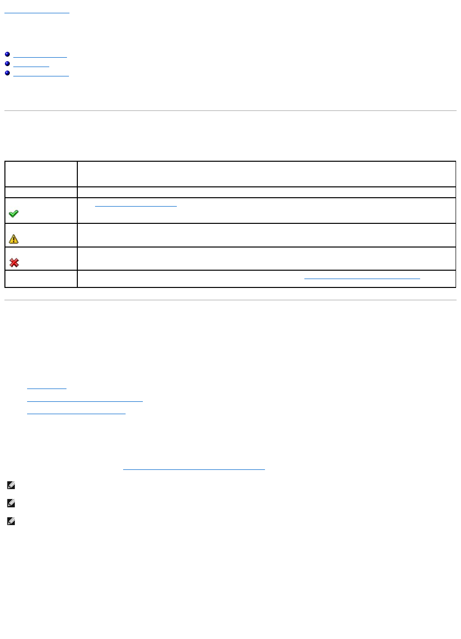
Back to Contents Page
Storage Information and Global Tasks
Dell™OpenManage™ServerAdministratorStorageManagementUser'sGuide
Storage Properties
Global Tasks
Storage Controllers
Use this window to view high-level information about your system's storage. This window also enables you to launch global tasks that affect all controllers
attached to the system.
Storage Properties
The Storage tree-view object has the following properties.
Global Tasks
To execute a global task, select the task from the Global Tasks drop-down menu and click Execute.
Global Tasks:
l"Global Rescan"
l"Enable/Disable Smart Thermal Shutdown"
l"Setting Hot Spare Protection Policy"
Global Rescan
A global rescan updates configuration changes (such as new or removed devices) for all SCSI controllers and their attached components. For information on
when you may want to do a rescan, see "Rescan to Update Storage Configuration Changes."
To do a global rescan:
1. Select the Storage tree view object.
2. Click the Information/Configuration subtab.
3. Select Global Rescan from the Global Tasks drop-down menu.
4. Click Execute.
Property
Definition
Status
These icons represent the severity or health of the storage component.
See "Storage Component Severity" for more information.
Normal/OK
Warning/Non-critical
Critical/Fatal
Smart Thermal
Shutdown
This property displays whether thermal shutdown is enabled or disabled. See "Enable/Disable Smart Thermal Shutdown" for more
information.
NOTE: Global Rescan is not supported on non-RAID controllers. You must reboot the system before Storage Management can see configuration changes
on non-RAID SCSI controllers. Otherwise, configuration changes are not reflected in the Storage Management graphical user interface (GUI).
NOTE: The Global Rescan task updates the Information/Configuration subtab with any configuration changes. To update the tree view, click the server
name which is displayed above the tree view.
NOTE: On the PERC 3/Si, 3/Di, and CERC SATA1.5/6ch controllers, if you pause a check consistency that is being performed on a virtual disk, then the
virtual disk state changes to Resynching Paused. Performing a Global Rescan while a virtual disk is in Resynching Paused state may cause the check
consistency to resume. In this case, the virtual disk state changes to Resynching.

Enable/Disable Smart Thermal Shutdown
By default, the operating system and server shut down when the PowerVault™ 220S and PowerVault 221S enclosures reach a critical temperature of 0 or 50
degrees Celsius. Using the Enable Smart Thermal Shutdown task, however, you can specify that only the enclosure, and not the operating system and
server be shut down when the enclosure reaches a critical temperature.
If the enclosure has virtual disks that are channel-redundant, then the enclosure can shut down while redundant data continues to be available on another
channel. See "Channel Redundancy and Thermal Shutdown" for more information.
To enable or disable thermal shut down:
1. Select the Storage tree view object.
2. Click the Information/Configuration subtab.
3. Select Enable Smart Thermal Shutdown or Disable Smart Thermal Shutdown from the Global Tasks drop-down menu. The Available Tasks drop-down
menu displays only one of these tasks at a time, depending on which option is currently selected.
4. Click Execute.
Storage Controllers
The information displayed for each controller can vary depending on the controller characteristics.
Property
Definition
Status
This property displays the controller status.
ID
This property displays the controller ID as reported by the omreport CLI command.
Name
This property displays the name of the controller. For more detailed information on a controller, click its name.
Slot ID
This property displays the slot to which the controller is attached. On some controllers, Storage Management is unable to display the
slot ID. In this case, this property displays Slot Not Available. For embedded controllers, this property displays Embedded.
NOTE: If Slot Not Available is displayed, you may be able to identify the slot ID by selecting the System ® Main System
Chassis® Slots object in the tree view and displaying the Information tab. The Slot ID property on this tab may display the correct
information.
State
This property displays the current status of the controller. Possible values are:
Ready — The controller is functioning normally.
Degraded — The controller has suffered a failure of a component and is operating in a degraded state.
Failed — The controller has suffered a failure of one or more components and is no longer functioning.
Firmware Version
This property displays the version of the controller's firmware.
The firmware and drivers listed in the Readme file refer to the minimum supported version for these controllers. Later versions of the
firmwareanddriversarealsosupported.SeetheDell™Supportwebsiteatsupport.dell.com for the most recent driver and firmware
requirements.
Minimum Required
Firmware Version
This property displays the minimum firmware version that is required by Storage Management. This property is only displayed if the
controller firmware does not meet the minimum requirement.
The firmware and drivers listed in the Readme file refer to the minimum supported version for these controllers. Later versions of the
firmware and drivers are also supported. See the Dell Support website at support.dell.com for the most recent driver and firmware
requirements.
Driver Version
This property displays the version of the controller's driver.
The firmware and drivers listed in the Readme file refer to the minimum supported version for these controllers. Later versions of the
firmware and drivers are also supported. See the Dell Support website at support.dell.com for the most recent driver and firmware
requirements.
Minimum Required
Driver Version
This property displays the minimum driver version that is required by Storage Management. This property is only displayed if the
controller driver does not meet the minimum requirement.
The firmware and drivers listed in the Readme file refer to the minimum supported version for these controllers. Later versions of the
firmware and drivers are also supported. See the Dell Support website at support.dell.com for the most recent driver and firmware
requirements.
Number of Connector
This property displays the number of connectors the controller has. Each connector can be attached to physical disks or an enclosure.
Depending on the controller type, the connector can be either a SCSI channel or a SAS port.
Rebuild Rate
The rebuild rate is the percentage of the system's resources dedicated to rebuilding a failed disk when a rebuild is necessary. See
"Set Rebuild Rate" for more information.
Alarm State
This property displays whether the controller's alarm is enabled or disabled.
Cluster Mode
This property indicates whether the controller is part of a cluster configuration.

Storage Components
For information on attached controllers, see the following topics:
l"Controller Properties and Tasks"
l"Controllers"
Back to Contents Page
SCSI Initiator ID
This property displays the SCSI ID of a SCSI controller. The default value is usually 7. You can change the default value in the BIOS.
Controllers in a cluster configuration should not have duplicate SCSI Initiator IDs. Refer to SCSI documentation for a list of acceptable
SCSI Initiator ID values.
On some controllers, this property is not available. In this case, this property displays as Not Applicable.
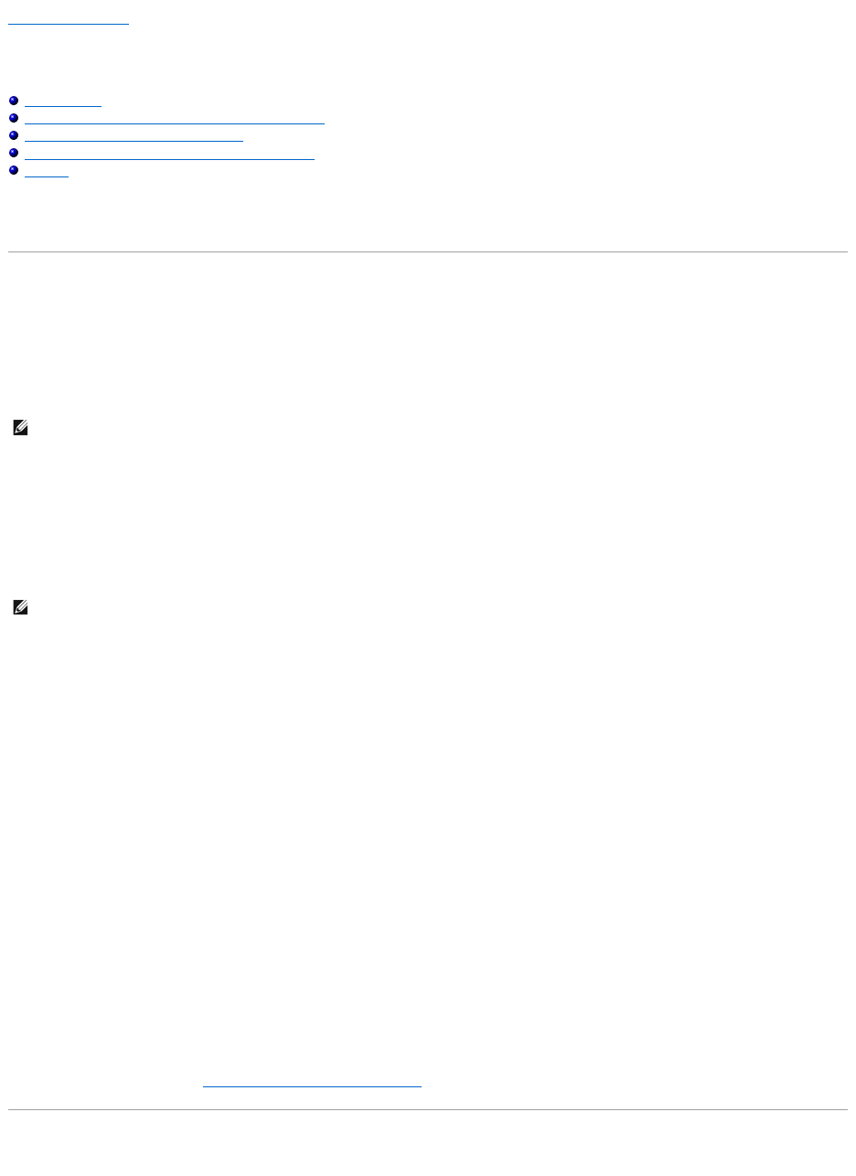
Back to Contents Page
Understanding RAID Concepts
Dell™OpenManage™ServerAdministratorStorageManagementUser'sGuide
What Is RAID?
Organizing Data Storage for Availability and Performance
Choosing RAID Levels and Concatenation
Comparing RAID Level and Concatenation Performance
No-RAID
Storage Management uses Redundant Array of Independent Disks (RAID) technology to provide storage management capability. Understanding storage
management requires an understanding of RAID concepts, as well as some familiarity with how your system's RAID controllers and operating system view disk
space.
What Is RAID?
RAID (Redundant Array of Independent Disks) is a technology for managing how data is stored on the physical disks that reside in your system or are attached
to it. A key aspect of RAID is the ability to span physical disks so that the combined storage capacity of multiple physical disks can be treated as single,
extended disk space. Another key aspect of RAID is the ability to maintain redundant data which can be used to restore data in the event of a disk failure.
RAID uses different techniques, such as striping, mirroring, and parity, to store and reconstruct data. There are different RAID levels that use different methods
for storing and reconstructing data. The RAID levels have different characteristics in terms of read/write performance, data protection, and storage capacity.
Not all RAID levels maintain redundant data, which means for some RAID levels lost data cannot be restored. The RAID level you choose depends on whether
your priority is performance, protection, or storage capacity.
Hardware and Software RAID
RAID can be implemented with either hardware or software. A system using hardware RAID has a RAID controller that implements the RAID levels and
processes data reads and writes to the physical disks. When using software RAID provided by the operating system, the operating system implements the
RAID levels. For this reason, using software RAID by itself can slow system performance. You can, however, use software RAID on top of hardware RAID
volumes to provide better performance and variety in the configuration of RAID volumes. For example, you can mirror a pair of hardware RAID 5 volumes across
two RAID controllers to provide RAID controller redundancy.
RAID Concepts
RAID uses particular techniques for writing data to disks. These techniques enable RAID to provide data redundancy or better performance. These techniques
include:
lMirroring — Duplicating data from one physical disk to another physical disk. Mirroring provides data redundancy by maintaining two copies of the same
data on different physical disks. If one of the disks in the mirror fails, the system can continue to operate using the unaffected disk. Both sides of the
mirror contain the same data at all times. Either side of the mirror can act as the operational side. A mirrored RAID disk group is comparable in
performance to a RAID 5 disk group in read operations but faster in write operations.
lStriping — Disk striping writes data across all physical disks in a virtual disk. Each stripe consists of consecutive virtual disk data addresses that are
mapped in fixed-size units to each physical disk in the virtual disk using a sequential pattern. For example, if the virtual disk includes five physical disks,
the stripe writes data to physical disks one through five without repeating any of the physical disks. The amount of space consumed by a stripe is the
same on each physical disk. The portion of a stripe that resides on a physical disk is a stripe element. Striping by itself does not provide data
redundancy. Striping in combination with parity does provide data redundancy.
lStripe size — The total disk space consumed by a stripe not including a parity disk. For example, consider a stripe that contains 64KB of disk space and
has 16KB of data residing on each disk in the stripe. In this case, the stripe size is 64KB and the stripe element size is 16KB.
lStripe element — A stripe element is the portion of a stripe that resides on a single physical disk.
lStripe element size — The amount of disk space consumed by a stripe element. For example, consider a stripe that contains 64KB of disk space and has
16KB of data residing on each disk in the stripe. In this case, the stripe element size is 16KB and the stripe size is 64KB.
lParity — Parity refers to redundant data that is maintained using an algorithm in combination with striping. When one of the striped disks fails, the data
can be reconstructed from the parity information using the algorithm.
lSpan — A span is a RAID technique used to combine storage space from groups of physical disks into a RAID 10, 50, or 60 virtual disk.
RAID Levels
Each RAID level uses some combination of mirroring, striping, and parity to provide data redundancy or improved read and write performance. For specific
information on each RAID level, see "Choosing RAID Levels and Concatenation."
Organizing Data Storage for Availability and Performance
NOTE: The RAID Advisory Board (RAB) defines the specifications used to implement RAID. Although the RAB defines the RAID levels, commercial
implementation of RAID levels by different vendors may vary from the actual RAID specifications. An implementation used by a particular vendor may
affect the read and write performance and the degree of data redundancy.
NOTE: Storage Management supports only hardware RAID.

RAID provides different methods or RAID levels for organizing the disk storage. Some RAID levels maintain redundant data so that you can restore data after a
disk failure. Different RAID levels may also entail an increase or decrease in the system's I/O (read and write) performance.
Maintaining redundant data requires the use of additional physical disks. As more disks become involved, the likelihood of a disk failure increases. Because of
the differences in I/O performance and redundancy, one RAID level may be more appropriate than another based on the applications in the operating
environment and the nature of the data being stored.
When choosing concatenation or a RAID level, the following performance and cost considerations apply:
lAvailability or fault-tolerance. Availability or fault-tolerance refers to a system's ability to maintain operations and provide access to data even when one
of its components has failed. In RAID volumes, availability or fault-tolerance is achieved by maintaining redundant data. Redundant data includes mirrors
(duplicate data) and parity information (reconstructing data using an algorithm).
lPerformance. Read and write performance can be increased or decreased depending on the RAID level you choose. Some RAID levels may be more
appropriate for particular applications.
lCost efficiency. Maintaining the redundant data or parity information associated with RAID volumes requires additional disk space. In situations where
the data is temporary, easily reproduced, or non-essential, the increased cost of data redundancy may not be justified.
lMean Time Between Failure (MTBF). Using additional disks to maintain data redundancy also increases the chance of disk failure at any given moment.
Although this cannot be avoided in situations where redundant data is a requirement, it does have implications for the workload of your organization's
system support staff.
lVolume. Volume refers to a single disk non-RAID virtual disk. You can create volumes using external utilities like the O-ROM (Ctrl-R). Storage
Management does not support the creation of volumes. However, you can view volumes and use drives from these volumes for creation of new virtual
disks or Online Capacity Expansion (OCE) of existing virtual disks, provided free space is available. Storage Management allows Rename and Delete
operations on such volumes.
For more information, see "Choosing RAID Levels and Concatenation."
Choosing RAID Levels and Concatenation
You can use RAID or concatenation to control data storage on multiple disks. Each RAID level or concatenation has different performance and data protection
characteristics.
The following sub-sections provide specific information on how each RAID level or concatenation store data as well as their performance and protection
characteristics:
l"Concatenation"
l"RAID Level 0 (Striping)"
l"RAID Level 1 (Mirroring)"
l"RAID Level 5 (Striping with distributed parity)"
l"RAID Level 6 (Striping with additional distributed parity)"
l"RAID Level 50 (Striping over RAID 5 sets)"
l"RAID Level 60 (Striping over RAID 6 sets)"
l"RAID Level 10 (Striping over mirror sets)"
l"RAID Level 1-Concatenated (Concatenated mirror)"
l"Comparing RAID Level and Concatenation Performance"
l"No-RAID"
Concatenation
In Storage Management, concatenation refers to storing data on either one physical disk or on disk space that spans multiple physical disks. When spanning
more than one disk, concatenation enables the operating system to view multiple physical disks as a single disk.
Data stored on a single disk can be considered a simple volume. This disk could also be defined as a virtual disk that comprises only a single physical disk.
Data that spans more than one physical disk can be considered a spanned volume. Multiple concatenated disks can also be defined as a virtual disk that
comprises more than one physical disk.
A dynamic volume that spans to separate areas of the same disk is also considered concatenated.
When a physical disk in a concatenated or spanned volume fails, the entire volume becomes unavailable. Because the data is not redundant, it cannot be
restored by rebuilding from a mirrored disk or parity information. Restoring from a backup is the only option.
Because concatenated volumes do not use disk space to maintain redundant data, they are more cost-efficient than volumes that use mirrors or parity
information. A concatenated volume may be a good choice for data that is temporary, easily reproduced, or that does not justify the cost of data redundancy.
In addition, a concatenated volume can easily be expanded by adding an additional physical disk.
Figure 3-1. Concatenating Disks
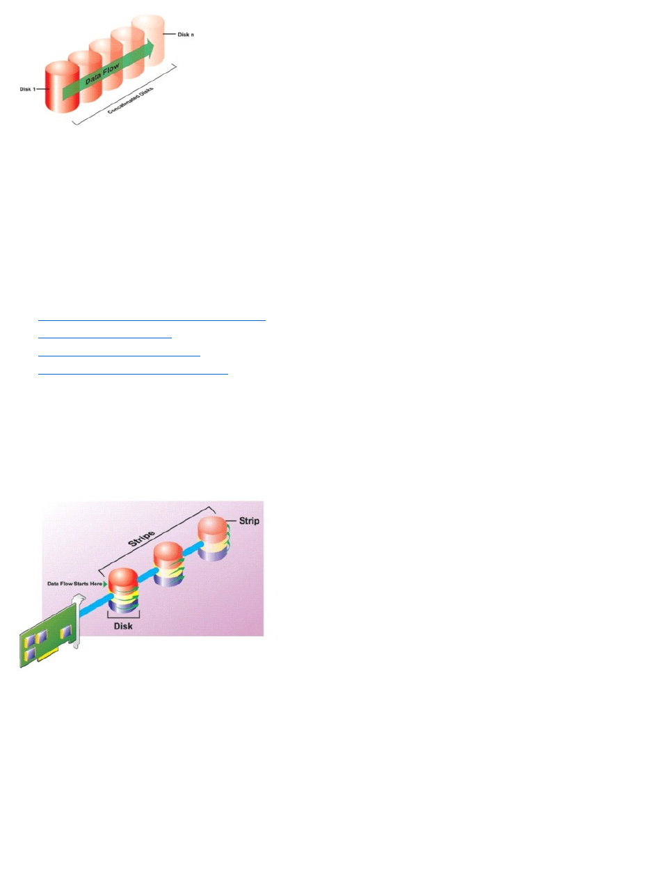
lConcatenates n disks as one large virtual disk with a capacity of n disks.
lData fills up the first disk before it is written to the second disk.
lNo redundancy data is kept. When a disk fails, the large virtual disk fails.
lNo performance gain.
lNo redundancy.
Related Information:
See the following:
l"Organizing Data Storage for Availability and Performance"
l"Controller-supported RAID Levels"
l"Number of Physical Disks per Virtual Disk"
l"Maximum Number of Virtual Disks per Controller"
RAID Level 0 (Striping)
RAID 0 uses data striping, which is writing data in equal-sized segments across the physical disks. RAID 0 does not provide data redundancy.
Figure 3-2. Striping Disks
RAID 0 Characteristics:
lGroups n disks as one large virtual disk with a capacity of (smallest disk size)*n disks.
lData is stored to the disks alternately.
lNo redundancy data is kept. When a disk fails, the large virtual disk fails with no means of rebuilding the data.
lBetter read and write performance.
Related Information:
See the following:
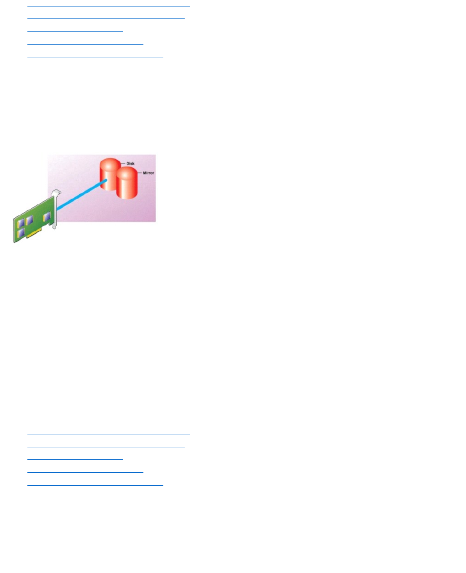
l"Organizing Data Storage for Availability and Performance"
l"Comparing RAID Level and Concatenation Performance"
l"Controller-supported RAID Levels"
l"Number of Physical Disks per Virtual Disk"
l"Maximum Number of Virtual Disks per Controller"
RAID Level 1 (Mirroring)
RAID 1 is the simplest form of maintaining redundant data. In RAID 1, data is mirrored or duplicated on one or more physical disks. If a physical disk on one
side of the mirror fails, then the data can be rebuilt using the physical disk on the other side of the mirror.
Figure 3-3. Mirroring Disks
RAID 1 Characteristics:
lGroups n + n disks as one virtual disk with the capacity of n disks. The controllers currently supported by Storage Management allow the selection of
two disks when creating a RAID 1. Because these disks are mirrored, the total storage capacity is equal to one disk.
lData is replicated on the two disks.
lWhen a disk fails, the virtual disk still works. The data will be read from the failed disk's mirror.
lBetter read performance, but slightly slower write performance.
lRedundancy for protection of data.
lRAID 1 is more expensive in terms of disk space since twice the number of disks are used than required to store the data without redundancy.
Related Information:
See the following:
l"Organizing Data Storage for Availability and Performance"
l"Comparing RAID Level and Concatenation Performance"
l"Controller-supported RAID Levels"
l"Number of Physical Disks per Virtual Disk"
l"Maximum Number of Virtual Disks per Controller"
RAID Level 5 (Striping with distributed parity)
RAID 5 provides data redundancy by using data striping in combination with parity information. Rather than dedicating a physical disk to parity, however, the
parity information is striped across all physical disks in the disk group.
Figure 3-4. Striping Disks with Distributed Parity
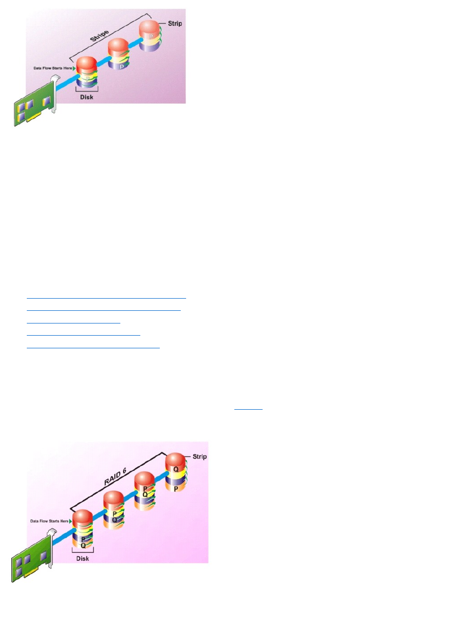
RAID 5 Characteristics:
lGroups n disks as one large virtual disk with a capacity of (n-1) disks.
lRedundant information (parity) is alternately stored on all disks.
lWhen a disk fails, the virtual disk still works, but it is operating in a degraded state. The data is reconstructed from the surviving disks.
lBetter read performance, but slower write performance.
lRedundancy for protection of data.
Related Information:
See the following:
l"Organizing Data Storage for Availability and Performance"
l"Comparing RAID Level and Concatenation Performance"
l"Controller-supported RAID Levels"
l"Number of Physical Disks per Virtual Disk"
l"Maximum Number of Virtual Disks per Controller"
RAID Level 6 (Striping with additional distributed parity)
RAID 6 provides data redundancy by using data striping in combination with parity information. Similar to RAID 5, the parity is distributed within each stripe.
RAID 6, however, uses an additional physical disk to maintain parity, such that each stripe in the disk group maintains two disk blocks with parity information.
The additional parity provides data protection in the event of two disk failures. In Figure3-5, the two sets of parity information are identified as "P" and "Q".
Figure 3-5. RAID 6
RAID 6 Characteristics:
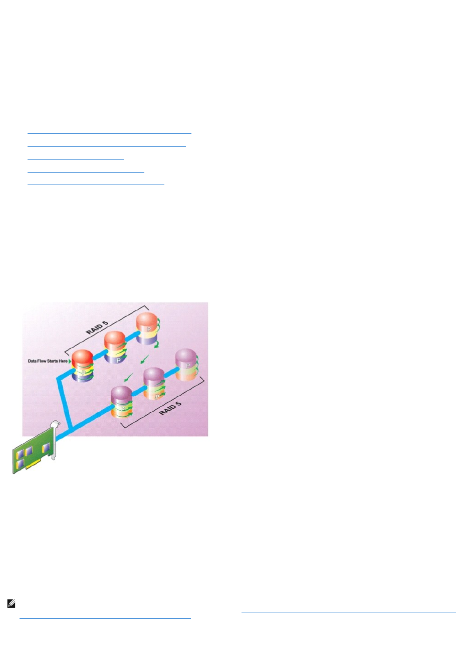
lGroups n disks as one large virtual disk with a capacity of (n-2) disks.
lRedundant information (parity) is alternately stored on all disks.
lThe virtual disk remains functional with up to two disk failures. The data is reconstructed from the surviving disks.
lBetter read performance, but slower write performance.
lIncreased redundancy for protection of data.
lTwo disks per span are required for parity. RAID 6 is more expensive in terms of disk space.
Related Information:
See the following:
l"Organizing Data Storage for Availability and Performance"
l"Comparing RAID Level and Concatenation Performance"
l"Controller-supported RAID Levels"
l"Number of Physical Disks per Virtual Disk"
l"Maximum Number of Virtual Disks per Controller"
RAID Level 50 (Striping over RAID 5 sets)
RAID 50 is striping over more than one span of physical disks. For example, a RAID 5 disk group that is implemented with three physical disks and then
continues on with a disk group of three more physical disks would be a RAID 50.
It is possible to implement RAID 50 even when the hardware does not directly support it. In this case, you can implement more than one RAID 5 virtual disks
and then convert the RAID 5 disks to dynamic disks. You can then create a dynamic volume that is spanned across all RAID 5 virtual disks.
Figure 3-6. RAID 50
RAID 50 Characteristics:
lGroups n*s disks as one large virtual disk with a capacity of s*(n-1) disks, where s is the number of spans and n is the number of disks within each
span.
lRedundant information (parity) is alternately stored on all disks of each RAID 5 span.
lBetter read performance, but slower write performance.
lRequires as much parity information as standard RAID 5.
lData is striped across all spans. RAID 50 is more expensive in terms of disk space.
Related Information:
NOTE: On the PERC 3/SC, 3/DC, 3/QC, 4/SC, 4/DC, 4e/DC, 4/Di, 4e/Si, 4e/Di, and CERC ATA100/4ch controllers, there are special considerations when
implementing RAID 50 on a disk group that has disks of different sizes. See "Considerations for RAID 10 and 50 on PERC 3/SC, 3/DC, 3/QC, 4/SC, 4/DC,
4e/DC, 4/Di, 4e/Si, 4e/Di, and CERC ATA100/4ch Controllers" for more information.
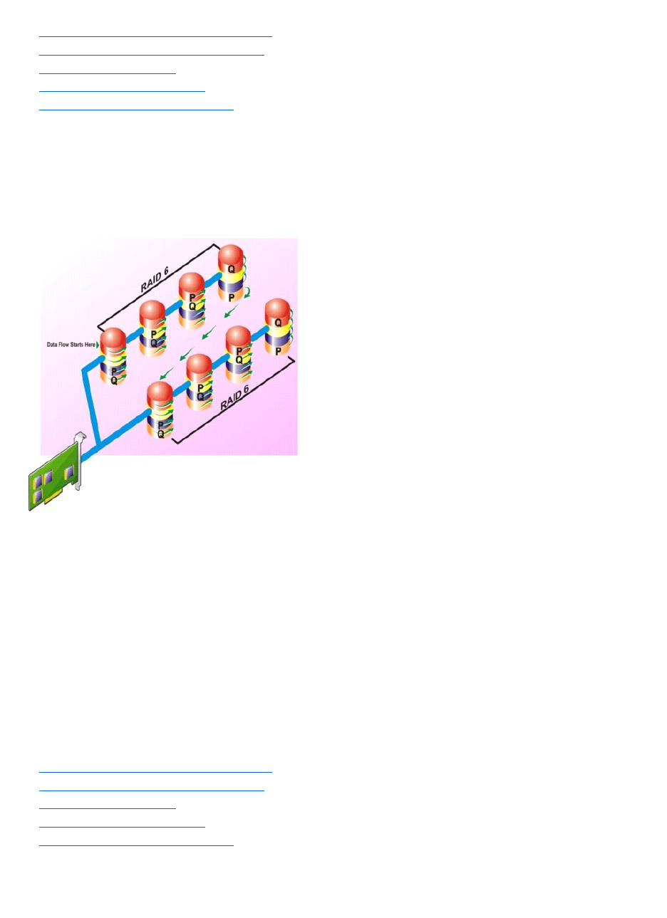
See the following:
l"Organizing Data Storage for Availability and Performance"
l"Comparing RAID Level and Concatenation Performance"
l"Controller-supported RAID Levels"
l"Number of Physical Disks per Virtual Disk"
l"Maximum Number of Virtual Disks per Controller"
RAID Level 60 (Striping over RAID 6 sets)
RAID 60 is striping over more than one span of physical disks that are configured as a RAID 6. For example, a RAID 6 disk group that is implemented with four
physical disks and then continues on with a disk group of four more physical disks would be a RAID 60.
Figure 3-7. RAID 60
RAID 60 Characteristics:
lGroups n*s disks as one large virtual disk with a capacity of s*(n-2) disks, where s is the number of spans and n is the number of disks within each
span.
lRedundant information (parity) is alternately stored on all disks of each RAID 6 span.
lBetter read performance, but slower write performance.
lIncreased redundancy provides greater data protection than a RAID 50.
lRequires proportionally as much parity information as RAID 6.
lTwo disks per span are required for parity. RAID 60 is more expensive in terms of disk space.
Related Information:
See the following:
l"Organizing Data Storage for Availability and Performance"
l"Comparing RAID Level and Concatenation Performance"
l"Controller-supported RAID Levels"
l"Number of Physical Disks per Virtual Disk"
l"Maximum Number of Virtual Disks per Controller"
RAID Level 10 (Striping over mirror sets)
The RAB considers RAID Level 10 to be an implementation of RAID level 1. RAID 10 combines mirrored physical disks (RAID 1) with data striping (RAID 0). With
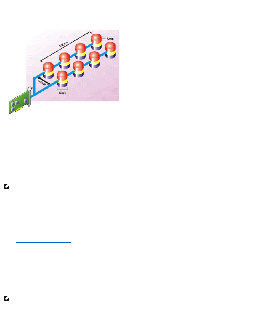
RAID 10, data is striped across multiple physical disks. The striped disk group is then mirrored onto another set of physical disks. RAID 10 can be considered a
mirror of stripes.
Figure 3-8. Striping Over Mirrored Disk Groups
RAID 10 Characteristics:
lGroups n disks as one large virtual disk with a capacity of (n/2) disks, where n is an even integer.
lMirror images of the data are striped across sets of physical disks. This level provides redundancy through mirroring.
lWhen a disk fails, the virtual disk is still functional. The data will be read from the surviving mirrored disk.
lImproved read performance and write performance.
lRedundancy for protection of data.
Related Information:
See the following:
l"Organizing Data Storage for Availability and Performance"
l"Comparing RAID Level and Concatenation Performance"
l"Controller-supported RAID Levels"
l"Number of Physical Disks per Virtual Disk"
l"Maximum Number of Virtual Disks per Controller"
RAID Level 1-Concatenated (Concatenated mirror)
RAID 1-concatenated is a RAID 1 disk group that spans across more than a single pair of physical disks. This combines the advantages of concatenation with
the redundancy of RAID 1. No striping is involved in this RAID type.
Figure 3-9. RAID 1-Concatenated
NOTE: On the PERC 3/SC, 3/DC, 3/QC, 4/SC, 4/DC, 4e/DC, 4/Di, 4e/Si, 4e/Di, and CERC ATA100/4ch controllers, there are special considerations when
implementing RAID 10 on a disk group that has disks of different sizes. See "Considerations for RAID 10 and 50 on PERC 3/SC, 3/DC, 3/QC, 4/SC, 4/DC,
4e/DC, 4/Di, 4e/Si, 4e/Di, and CERC ATA100/4ch Controllers" for more information.
NOTE: You cannot create a RAID 1-concatenated virtual disk or reconfigure to RAID 1-concatenated with Storage Management. You can only monitor a
RAID 1-concatenated virtual disk with Storage Management.
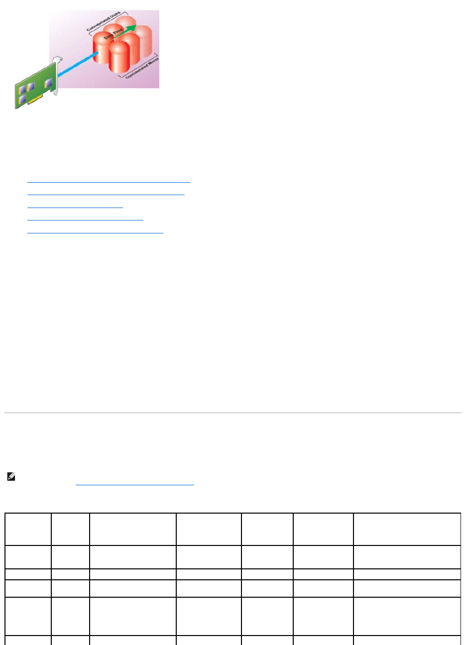
Related Information:
See the following:
l"Organizing Data Storage for Availability and Performance"
l"Comparing RAID Level and Concatenation Performance"
l"Controller-supported RAID Levels"
l"Number of Physical Disks per Virtual Disk"
l"Maximum Number of Virtual Disks per Controller"
Considerations for RAID 10 and 50 on PERC 3/SC, 3/DC, 3/QC, 4/SC, 4/DC, 4e/DC, 4/Di,
4e/Si, 4e/Di, and CERC ATA100/4ch Controllers
On the PERC 3/SC, 3/DC, 3/QC, 4/SC, 4/DC, 4e/DC, 4/Di, 4e/Si, 4e/Di, and CERC ATA100/4ch controllers, there are special considerations when implementing
RAID 10 or RAID 50 on a disk group that has disks of different sizes. When implementing RAID 10 or RAID 50, disk space is spanned to create the stripes and
mirrors. The span size can vary to accommodate the different disk sizes. There is, however, the possibility that a portion of the largest disk in the disk group
will be unusable, resulting in wasted disk space. For example, consider a disk group that has the following disks:
Disk A = 40 GB
Disk B = 40 GB
Disk C = 60 GB
Disk D = 80 GB
In this example, data will be spanned across all four disks until Disk A and Disk B and 40 GB on each of Disk C and D are completely full. Data will then be
spanned across Disks C and D until Disk C is full. This leaves 20 GB of disk space remaining on Disk D. Data cannot be written to this disk space, as there is no
corresponding disk space available in the disk group to create redundant data.
Comparing RAID Level and Concatenation Performance
The following table compares the performance characteristics associated with the more common RAID levels. This table provides general guidelines for
choosing a RAID level. Evaluate your specific environment requirements before choosing a RAID level.
Table 3-1.RAIDLevelandConcatenationPerformanceComparison
NOTE: The following table does not show all RAID levels supported by Storage Management. For information on all RAID levels supported by Storage
Management, see "Choosing RAID Levels and Concatenation."
RAID
Level
Data
Availability
Read Performance
Write Performance
Rebuild
Performance
Minimum Disks
Required
Suggested Uses
Concatenation
No gain
No gain
No gain
N/A
1 or 2 depending
on the controller.
More cost efficient than redundant
RAID levels. Use for noncritical
data.
RAID 0
None
Very Good
Very Good
N/A
N
Noncritical data
RAID 1
Excellent
Very Good
Good
Good
2N
(N = 1)
Small databases, database logs,
critical information
RAID 5
Good
Sequential reads: good.
Transactional reads: Very
good
Fair, unless using
write-back cache
Fair
N + 1
(N = at least two
disks)
Databases and other read-
intensive transactional uses
RAID 10
Excellent
Very Good
Fair
Good
2N x X
Data-intensive environments (large

No-RAID
In Storage Management, a virtual disk of unknown metadata is considered a No- RAID volume. Storage Management does not support this type of virtual
disks. These must either be deleted or the physical disk must be removed. Storage Management allows Delete and Rename operation on No-RAID volumes.
Back to Contents Page
records)
RAID 50
Good
Very Good
Fair
Fair
N + 2
(N = at least 4)
Medium-sized transactional or
data-intensive uses
RAID 6
Excellent
Sequential reads: good.
Transactional reads: Very
good
Fair, unless using
write-back cache
Poor
N + 2
(N = at least two
disks)
Critical information. Databases and
other read-intensive transactional
uses.
RAID 60
Excellent
Very Good
Fair
Poor
X x (N + 2)
(N = at least 2)
Critical information. Medium-sized
transactional or data-intensive
uses.
N = Number of physical disks
X = Number of RAID sets

Back to Contents Page
Troubleshooting
Dell™OpenManage™ServerAdministratorStorageManagementUser'sGuide
Common Troubleshooting Procedures
Virtual Disk Troubleshooting
Specific Problem Situations and Solutions
This section contains troubleshooting procedures for common situations as well as for specific problems.
Common Troubleshooting Procedures
This section describes commands and procedures that can be used in troubleshooting. Topics covered include:
l"Cables Attached Correctly"
l"System Requirements"
l"Drivers and Firmware"
l"Isolate Hardware Problems"
l"Rescan to Update Information on SCSI Controllers"
l"Replacing a Failed Disk"
l"Recovering from Removing the Wrong Physical Disk"
l"Resolving Microsoft®Windows®Upgrade Problems"
Cables Attached Correctly
Verify that the power-supply cord and adapter cables are attached correctly. If the system is having trouble with read and write operations to a particular
virtual disk or non-RAID physical disk (if the system hangs, for example), then make sure that the cables attached to the corresponding enclosure or backplane
are secure. If the connection is secure but the problem persists, you may need to replace a cable. See also "Isolate Hardware Problems."
On SAS controllers, you should verify that the cable configuration is valid. Refer to the SAS hardware documentation for valid cable configurations. If the cable
configuration is invalid, you may receive alerts 2182 or 2356.
For information on Alert Messages, see the Dell OpenManage Server Administrator Messages Reference Guide on the Dell Support website at
support.dell.com/manuals.
System Requirements
Make sure that the system meets all system requirements. In particular, verify that the correct levels of firmware and drivers are installed on the system. For
more information on drivers and firmware, see "Drivers and Firmware."
Drivers and Firmware
Storage Management is tested with the supported controller firmware and drivers. In order to function properly, the controller must have the minimum
required version of the firmware and drivers installed. The most current versions can be obtained from the Dell™ Support website at support.dell.com.
ItisalsorecommendedtoobtainandapplythelatestDellPowerEdge™ServerSystemBIOSonaperiodicbasistobenefitfromthemostrecentimprovements.
Please refer to the Dell PowerEdge system documentation for more information.
Isolate Hardware Problems
If you receive a "timeout" alert related to a hardware device or if you otherwise suspect that a device attached to the system is experiencing a failure, then do
the following to confirm the problem:
lVerify that the cables are correctly attached.
lIf the cables are correctly attached and you are still experiencing the problem, then disconnect the device cables and reboot the system. If the system
reboots successfully, then one of the devices may be defective. Refer to the hardware device documentation for more information.
Rescan to Update Information on SCSI Controllers
NOTE: You can verify which firmware and drivers are installed by selecting the Storage object in the tree view and clicking the Information/Configuration
tab. You can also check the Alert Log for alerts relating to unsupported firmware and driver versions.

On SCSI controllers, use the Rescan controller task to update information for the controller and attached devices. This operation may take a few minutes if
there are a number of devices attached to the controller.
If the Rescan does not properly update the disk information, you may need to reboot your system.
Replacing a Failed Disk
You may need to replace a failed disk in the following situations:
l"Replacing a Failed Disk that is Part of a Redundant Virtual Disk"
l"Replacing a Failed Physical Disk that is Part of a Nonredundant Virtual Disk"
l"Replacing a Failed Physical Disk in a RAID 1 on a CERC SATA1.5/2s"
Replacing a Failed Disk that is Part of a Redundant Virtual Disk
If the failed disk is part of a redundant virtual disk, then the disk failure should not result in data loss. You should replace the failed disk immediately, however,
as additional disk failures can cause data loss.
If the redundant virtual disk has a hot spare assigned to it, then the data from the failed disk is rebuilt onto the hot spare. After the rebuild, the former hot
spare functions as a regular physical disk and the virtual disk is left without a hot spare. In this case, you should replace the failed disk and make the
replacement disk a hot spare.
Replacing the Disk:
1. Remove the failed disk.
2. Insert a new disk. Make sure that the new disk is the same size or larger as the disk you are replacing. (On some controllers, you may not be able to
use the additional disk space if you insert a larger disk. See "Virtual Disk Considerations for PERC 3/SC, 3/DC, 3/QC, 4/SC, 4/DC, 4e/DC, 4/Di, 4e/Si,
4e/Di, CERC ATA100/4ch, PERC 5/E, PERC 5/i, PERC 6/E, and PERC 6/I Controllers" for more information.)
A rebuild is automatically initiated because the virtual disk is redundant.
Assigning a Hot Spare:
If a hot spare was already assigned to the virtual disk, then data from the failed disk may already be rebuilt onto the hot spare. In this case, you need to
assign a new hot spare. See "Assign and Unassign Dedicated Hot Spare" and "Assign and Unassign Global Hot Spare" for more information.
Replacing a Failed Physical Disk that is Part of a Nonredundant Virtual Disk
If the failed physical disk is part of a nonredundant virtual disk (such as RAID 0), then the failure of a single physical disk will cause the entire virtual disk to fail.
To proceed, you need to verify when your last backup was, and if there is any new data that has been written to the virtual disk since that time.
If you have backed up recently and there is no new data on the disks that would be missed, you can restore from backup.
Do the following:
1. Delete the virtual disk which is currently in a failed state.
2. Remove the failed physical disk.
3. Insert a new physical disk.
4. Create a new virtual disk.
5. Restore from backup.
Using the Physical Disk Online Command on Select Controllers
NOTE: If the redundant virtual disk does not have a hot spare assigned to it, then replace the failed disk using the procedure described in Replacing a
Physical Disk Receiving SMART Alerts
NOTE: If the failed disk is attached to a PERC 3/SC, 3/DC, 3/QC, 4/SC, 4/DC, 4e/DC, 4/Di, or CERC ATA100/4ch controller, you can attempt to recover
data from the disk by using the procedure described in "Using the Physical Disk Online Command on Select Controllers" before continuing with the
following procedure.

Does my controller support this feature? See "Supported Features"
If you do not have a suitable backup available, and if the failed disk is part of a virtual disk on a controller that supports the Online physical disk task, then you
can attempt to retrieve data by selecting Online from the failed disk's drop-down task menu.
The Online command attempts to force the failed disk back into a Online state. If you are able to force the disk into a Online state, you may be able to recover
individual files. How much data you can recover depends on the extent of disk damage. File recovery is only possible if a limited portion of the disk is damaged.
There is no guarantee you will be able to recover any data using this method. A forced Online does not fix a failed disk. You should not attempt to write new
data to the virtual disk.
After retrieving any viable data from the disk, replace the failed disk as described previously in "Replacing a Failed Disk that is Part of a Redundant Virtual Disk"
or "Replacing a Failed Physical Disk that is Part of a Nonredundant Virtual Disk."
Replacing a Failed Physical Disk in a RAID 1 on a CERC SATA1.5/2s
On a CERC SATA1.5/2s controller, a rebuild may not start automatically when you replace a failed physical disk that is part of a RAID 1 virtual disk. In this
circumstance, use the following procedure to replace the failed physical disk and rebuild the redundant data.
1. Shut down the system.
2. Disconnect the SATA cable on the failed physical disk in the RAID 1 virtual disk.
3. Replace the failed physical disk with a formatted physical disk. You can format the physical disk using the Disk Utilities in the controller BIOS. (You may
not need to format the entire physical disk. Formatting 1% of the disk may be sufficient.)
4. Reboot the system. When rebooted, the RAID 1 virtual disk should display a Failed Redundancy state.
5. Expand the controller object in the tree view and select the Physical Disks object.
6. Execute the Rebuild task for the physical disk you added.
Recovering from Removing the Wrong Physical Disk
If the physical disk that you mistakenly removed is part of a redundant virtual disk that also has a hot spare, then the virtual disk rebuilds automatically either
immediately or when a write request is made. After the rebuild has completed, the virtual disk will no longer have a hot spare since data has been rebuilt onto
the disk previously assigned as a hot spare. In this case, you should assign a new hot spare.
If the physical disk that you removed is part of a redundant virtual disk that does not have a hot spare, then replace the physical disk and do a rebuild.
See the following sections for information on rebuilding physical disks and assigning hot spares:
l"Understanding Hot Spares" for RAID controllers
l"Rebuild" for PERC 3/SC, 3/DC, 3/QC, 4/SC, 4/DC, 4e/DC, 4/Di, CERC ATA100/4ch, PERC 5/E and PERC 5/i controllers
You can avoid removing the wrong physical disk by blinking the LED display on the physical disk that you intend to remove. See "Blink and Unblink (Physical
Disk)" for information on blinking the LED display.
Resolving Microsoft®Windows®Upgrade Problems
If you upgrade the Microsoft Windows operating system on a server, you may find that Storage Management no longer functions after the upgrade. The
installation process installs files and makes registry entries on the server that are specific to the operating system. For this reason, changing the operating
system can disable Storage Management.
To avoid this problem, you should uninstall Storage Management before upgrading. If you have already upgraded without uninstalling Storage Management,
however, you should uninstall Storage Management after the upgrade.
After you have uninstalled Storage Management and completed the upgrade, reinstall Storage Management using the Storage Management install media. You
can download Storage Management from the Dell Support website at support.dell.com.
Virtual Disk Troubleshooting
The following sections describe troubleshooting procedures for virtual disks.
l"Replacing a Failed Disk that is Part of a Redundant Virtual Disk"
l"Replacing a Failed Physical Disk in a RAID 1 on a CERC SATA1.5/2s"
l"A Rebuild Does Not Work"
l"A Rebuild Completes with Errors"

l"Cannot Create a Virtual Disk"
l"Virtual Disk Errors on Linux"
l"Problems Associated With Using the Same Physical Disks for Both Redundant and Nonredundant Virtual Disks"
A Rebuild Does Not Work
A rebuild will not work in the following situations:
lThe virtual disk is nonredundant. For example, a RAID 0 virtual disk cannot be rebuilt because RAID 0 does not provide data redundancy.
lThere is no hot spare assigned to the virtual disk. As long as the virtual disk is redundant, you can do the following to rebuild it:
¡Pull out the failed physical disk and replace it. A rebuild will automatically start on the new disk.
¡Assign a hot spare to the virtual disk and then perform a rebuild.
lYou are attempting to rebuild onto a hot spare that is too small. Different controllers have different size requirements for hot spares. See
"Considerations for Hot Spares on PERC 3/SC, 3/DC, 3/QC, 4/SC, 4/DC, 4e/DC, 4/Di, 4e/Si, 4e/Di, CERC ATA100/4ch, PERC 5/E, PERC 5/i, PERC 6/E, PERC
6/I, and CERC 6/I Controllers" and "Considerations for Hot Spares on PERC 3/Si, 3/Di, CERC SATA1.5/6ch, S100, and S300 Controllers" for more
information on disk size requirements.
lThe hot spare has been unassigned from the virtual disk. This could happen on some controllers if the hot spare was assigned to more than one virtual
disk and has already been used to rebuild a failed physical disk for another virtual disk. See "Considerations for Hot Spares on PERC 3/Si, 3/Di, CERC
SATA1.5/6ch, S100, and S300 Controllers" for a description of this situation.
lOn SCSI controllers, both redundant and nonredundant virtual disks reside on the same set of physical disks. On the PERC 3/SC, 3/DC, 3/QC, 4/SC,
4/DC, 4e/DC, 4/Di, and CERC ATA100/4ch controllers, a rebuild is not performed for a physical disk that is used by both redundant and nonredundant
virtual disks. In order to rebuild the redundant virtual disk, you need to delete the nonredundant virtual disk. Before deleting this disk, however, you can
attempt to recover data from the failed physical disk by forcing it back online. See "Using the Physical Disk Online Command on Select Controllers" for
more information.
lA physical disk has been removed, and the system has not yet attempted to write data to the removed disk. In this case, the system will not recognize
the removal of a physical disk until it attempts a write operation to the disk. If the physical disk is part of a redundant virtual disk, then the system will
rebuild the disk after attempting a write operation. This situation applies to PERC 3/SC, 3/DC, 3/QC, 4/SC, 4/DC, 4e/DC, 4/Di, and CERC ATA100/4ch
controllers.
lThe virtual disk includes failed or corrupt physical disks. This situation may generate alert 2083. For information on Alert Messages, see the Dell
OpenManage Server Administrator Messages Reference Guide on the Dell Support website at support.dell.com/manuals.
lThe rebuild rate setting is too low. If the rebuild rate setting is quite low and the system is processing a number of operations, then the rebuild may
take an unusual amount of time to complete. See "Set Rebuild Rate" for more information.
lThe rebuild was cancelled. Another user can cancel a rebuild that you have initiated.
A Rebuild Completes with Errors
This section applies to PERC 3/SC, 3/DC, 3/QC, 4/SC, 4/DC, 4e/DC, 4/Di, 4e/Si, 4e/Di, and CERC ATA100/4ch
controllers
In some situations, a rebuild may complete successfully while also reporting errors. This may occur when a portion of the disk containing redundant (parity)
information is damaged. The rebuild process can restore data from the healthy portions of the disk but not from the damaged portion.
When a rebuild is able to restore all data except data from damaged portions of the disk, it will indicate successful completion while also generating alert
2163.
For information on Alert Messages, see the Dell OpenManage Server Administrator Messages Reference Guide on the Dell Support website at
support.dell.com/manuals.
The rebuild may also report sense key errors. In this situation, take the following actions to restore the maximum data possible:
1. Back up the degraded virtual disk onto a fresh (unused) tape.
If the backup is successful. If the backup completes successfully then the user data on the virtual disk has not been damaged. In this case, you can continue
with "step 2."
If the backup encounters errors. If the backup encounters errors then the user data has been damaged and cannot be recovered from the virtual disk. In this
case, the only possibility for recovery is to restore from a previous backup of the virtual disk.
2. Perform a "Check Consistency" on the virtual disk that you have backed up onto tape.
3. Restore the virtual disk from the tape onto healthy physical disks.
Cannot Create a Virtual Disk
You might be attempting a RAID configuration that is not supported by the controller. Check the following:
lHow many virtual disks already exist on the controller? Each controller supports a maximum number of virtual disks. See "Maximum Number of Virtual
Disks per Controller" for more information.

lIs there adequate available space on the disk? The physical disks that you have selected for creating the virtual disk must have an adequate amount of
free space available.
lThe controller may be performing other tasks, such rebuilding a physical disk, that must run to completion before the controller can create the new
virtual disk.
A Virtual Disk of Minimum Size is Not Visible to Windows Disk Management
If you create a virtual disk using the minimum allowable size in Storage Management, the virtual disk may not be visible to Windows Disk Management even
after initialization. This occurs because Windows Disk Management is only able to recognize extremely small virtual disks if they are dynamic. It is generally
advisable to create virtual disks of larger size when using Storage Management.
Virtual Disk Errors on Linux
On some versions of the Linux operating system, the virtual disk size is limited to 1TB. If you create a virtual disk that exceeds the 1TB limitation, your system
may experience the following behavior:
lI/O errors to the virtual disk or logical drive
lInaccessible virtual disk or logical drive
lVirtual disk or logical drive size is smaller than expected
If you have created a virtual disk that exceeds the 1TB limitation, you should do the following:
1. Back up your data.
2. Delete the virtual disk.
3. Create one or more virtual disks that are smaller than 1TB.
4. Restore your data from backup.
Whether or not your Linux operating system limits virtual disk size to 1TB depends on the version of the operating system and any updates or modifications
that you have implemented. See your operating system documentation for more information.
Problems Associated With Using the Same Physical Disks for Both Redundant and
Nonredundant Virtual Disks
When creating virtual disks, you should avoid using the same physical disks for both redundant and nonredundant virtual disks. This recommendation applies
to all controllers. Using the same physical disks for both redundant and nonredundant virtual disks can result in unexpected behavior including data loss.
Considerations for PERC 3/Si, 3/Di, CERC SATA1.5/6ch, and CERC SATA1.5/2s Controllers When Physical Disks
are Shared by Redundant and Nonredundant Virtual Disks
This section describes behavior that may occur on the PERC 3/Si, 3/Di, CERC SATA1.5/6ch, and CERC SATA1.5/2s controllers if you use the same physical disks
for both redundant and nonredundant virtual disks. In this type of configuration, the failure or removal of a physical disk can cause the following behavior:
lThe nonredundant virtual disk displays a Failed state.
Resolution: This behavior is expected because the virtual disk is nonredundant. In this case, the failure or removal of a single physical disk causes the
entire virtual disk to fail with no possibility of recovering the data unless a backup is available.
lThe redundant virtual disks display a Degraded state.
Resolution: This behavior is also expected. Data can be recovered if a hot spare is available to rebuild the failed or removed disk.
lVarious disks display an Offline state. The Offline state may apply to all physical disks used by the redundant and nonredundant virtual disks.
Resolution: Perform a "Rescan Controller." When the rescan is complete, select each physical disk that is Offline and perform a "Remove Dead
Segments" task. You must remove the dead segments before the physical disk can be brought back online. The dead segments are caused by the failure
or removal of the shared physical disk.
Specific Problem Situations and Solutions
This section contains additional trouble-shooting problem areas. Topics include:
NOTE: SAS controllers do not allow you to create redundant and nonredundant virtual disks on the same set of physical disks.
NOTE: It is recommended that you avoid using the same physical disks for both redundant and nonredundant virtual disks.

l"Physical Disk is Offline or Displays an Error Status"
l"A Disk is Marked as Failed When Rebuilding in a Cluster Configuration"
l"A Disk on a PERC 4/Di Controller Does not Return Online after a Prepare to Remove"
l"Receive a "Bad Block" Alert with "Replacement," "Sense," or "Medium" Error"
l"Read and Write Operations Experience Problems"
l"I/O Stops When a Redundant Channel Fails"
l"A Task Menu Option is Not Displayed"
l"A Corrupt Disk or Drive Message Suggests Running autocheck During a Reboot"
l"Erroneous Status and Error Messages after a Windows Hibernation"
l"Storage Management May Delay Before Updating Temperature Probe Status"
l"Storage Management May Delay Displaying Storage Devices After Reboot"
l"You are Unable to Log into a Remote System"
l"CannotConnecttoRemoteWindowsServer™2003System"
l"Reconfiguring a Virtual Disk Displays Error in Mozilla Browser"
l"Physical Disks Display Under Connector Not Enclosure Tree Object"
Physical Disk is Offline or Displays an Error Status
A physical disk may display an error status if it has been damaged, taken offline, or was a member of a virtual disk that has been deleted or initialized. The
following actions may resolve the error condition:
lIf a user has taken the disk offline, then return the disk to Online status by executing the Online disk task.
lRescan the controller. This action updates the status of storage objects attached to the controller. If the error status was caused by deleting or
initializing a virtual disk, rescanning the controller should resolve this problem.
lInvestigate whether there are any cable, enclosure, or controller problems preventing the disk from communicating with the controller. If you find a
problem and resolve it, you may need to rescan the controller to return the disk to Online or Ready status. If the disk does not return to Online or Ready
status, reboot the system.
lIf the disk is damaged, replace it. See "Replacing a Failed Disk" for more information.
A Disk is Marked as Failed When Rebuilding in a Cluster Configuration
When a system in a cluster attempts to rebuild a failed disk but the rebuild fails, then another system takes over the rebuild. In this situation, you may notice
that the rebuilt disk continues to be marked as failed on both systems even after the second system has rebuilt successfully. To resolve this problem, perform
a rescan on both systems after the rebuild completes successfully.
A Disk on a PERC 4/Di Controller Does not Return Online after a Prepare to Remove
When you do a Prepare to Remove command on a physical disk attached to a PERC 4/Di controller, you may find that the disk does not display in the Storage
Management tree view even after doing a rescan or a reboot.
In this case, do the following to redisplay the disk in the Storage Management tree view:
1. Manually remove and then replace the physical disk.
2. Rescan the controller or reboot the system.
Receive a "Bad Block" Alert with "Replacement," "Sense," or "Medium" Error
The following alerts or events are generated when a portion of a physical disk is damaged:
l2146
l2147
l2148
l2149
l2150
This damage is discovered when the controller performs an operation that requires scanning the disk. Examples of operations that may result in these alerts
are as follows:
lConsistency check

lRebuild
lVirtual disk format
lI/O
If you receive an alerts 2146 through 2150 as the result of doing a rebuild or while the virtual disk is in a degraded state, then data cannot be recovered from
the damaged disk without restoring from backup. If you receive alerts 2146 through 2150 under circumstances other than a rebuild, then data recovery may
be possible. The following describes each of these situations.
Alerts 2146 through 2150 Received during a Rebuild or while a Virtual Disk is Degraded
Do the following if you receive alerts 2146 through 2150 during a rebuild or while the virtual disk is in a degraded state:
1. Replace the damaged physical disk.
2. Create a new virtual disk and allow the virtual disk to completely resynchronize. While the resynchronization is in progress, the status of the virtual disk
will be Resynching.
3. Restore data to the virtual disk from backup.
Alerts 2146 through 2150 Received while Performing I/O, Consistency Check, Format, or Other Operation
If you receive alerts 2146 through 2150 while performing an operation other than a rebuild, you should replace the damaged disk immediately to avoid data
loss.
Do the following:
1. Back up the degraded virtual disk to a fresh (unused) tape.
2. Replace the damaged disk.
3. Do a rebuild.
Read and Write Operations Experience Problems
If the system is hanging, timing out, or experiencing other problems with read and write operations, then there may be a problem with the controller cables or
a device. For more information, see "Cables Attached Correctly" and "Isolate Hardware Problems."
I/O Stops When a Redundant Channel Fails
If you have implemented channel redundancy on a PERC 3/SC, 3/DC, 3/QC, 4/SC, 4/DC, 4e/DC, or 4/Di controller, a failure of one channel causes I/O to stop on
the other channels included in the channel-redundant configuration. For the resolution to this problem, see "Channel Redundancy on PERC 3/DC, 3/QC, 4/DC,
4e/DC, 4/Di, and 4e/Di Controllers."
A Task Menu Option is Not Displayed
You may notice that the task menus do not always display the same task options. This is because Storage Management only displays those tasks that are
valid at the time the menu is displayed. Some tasks are only valid for certain types of objects or at certain times. For example, a Check Consistency task can
only be performed on a redundant virtual disk. Similarly, if a disk is already offline, the Offline task option is not displayed.
There may be other reasons why a task cannot be run at a certain time. For example, there may already be a task running on the object that must complete
before additional tasks can be run.
A Corrupt Disk or Drive Message Suggests Running autocheck During a Reboot
Let autocheck run, but do not worry about the message. The reboot will complete after autocheck is finished. Depending on the size of your system, this may
take about ten minutes.
Erroneous Status and Error Messages after a Windows Hibernation
Activating the Windows hibernation feature may cause Storage Management to display erroneous status information and error messages. This problem
resolves itself when the Windows operating system recovers from hibernation.

Storage Management May Delay Before Updating Temperature Probe Status
In order to display the enclosure temperature and temperature probe status, Storage Management polls the enclosure firmware at regular intervals to obtain
temperature and status information. On some enclosures, there is a short delay before the enclosure firmware reports the current temperature and
temperature probe status. Because of this delay, Storage Management may require one or two minutes before displaying the correct temperature and
temperature probe status.
Storage Management May Delay Displaying Storage Devices After Reboot
Storage Management requires time after a reboot to find and inventory all attached storage devices. You may experience a delay in storage controllers being
displayed until this operation has completed.
You are Unable to Log into a Remote System
Access can be denied here if you do not enter a user name and password that match an administrator account on the remote computer or if you mistype the
login information. The remote system may also not be powered on or there may be network problems.
CannotConnecttoRemoteWindowsServer™2003System
When connecting to a remote Windows Server 2003 system, you must log into the remote system using an account that has administrator privileges. By
default, Windows Server 2003 does not allow anonymous (null) connections to access the SAM user accounts. Therefore, if you are attempting to connect
using an account that has a blank or null password, the connection may fail.
Reconfiguring a Virtual Disk Displays Error in Mozilla Browser
When reconfiguring a virtual disk using the Mozilla browser, the following error message may display:
Although this page is encrypted, the information you have entered is to be sent over an unencrypted connection and could easily be read by a
third party.
You can disable this error message by changing a Mozilla browser setting. To disable this error message:
1. Select Edit and then Preferences.
2. Click Privacy and Security.
3. Click SSL.
4. Uncheck the "Sending form data from an unencrypted page to an unencrypted page" option.
Physical Disks Display Under Connector Not Enclosure Tree Object
Storage Management polls the status of physical disks at frequent intervals. When the physical disk is located in an enclosure, Storage Management uses the
data reported by the SCSI Enclosure Processor (SEP) to ascertain the status of the physical disk. In the event that the SEP is not functioning, Storage
Management is still able to poll the status of the physical disk, but Storage Management is not able to identify the physical disk as being located in the
enclosure. In this case, Storage Management displays the physical disk directly below the Connector object in the tree view and not under the enclosure
object.
You can resolve this problem by restarting the Server Administrator service or by rebooting the system. For more information on restarting the Server
Administrator service, see the DellOpenManage™ServerAdministratorUser'sGuide.
Back to Contents Page
Back to Contents Page
Virtual Disks
Dell™OpenManage™ServerAdministratorStorageManagementUser'sGuide
In order to implement RAID functions, RAID controllers must create a virtual disk. A virtual disk refers to storage created by a RAID controller from one or more
physical disks. Although a virtual disk may be created from several physical disks, it is seen by the operating system as a single disk. Depending on the RAID
level used, the virtual disk may retain redundant data in case of a disk failure or have particular performance attributes. See "Understanding RAID Concepts"
for more information.
Considerations Before Creating Virtual Disks
Different controllers have particular characteristics in the way they implement virtual disks. These characteristics may include use of disk space, limitations on
the number of virtual disks per controller, and so on. It can be helpful to understand these characteristics before creating virtual disks on the controller.
The following sections describe controller information that applies to virtual disks:
l"Virtual Disk Considerations for PERC 3/SC, 3/DC, 3/QC, 4/SC, 4/DC, 4e/DC, 4/Di, 4e/Si, 4e/Di, CERC ATA100/4ch, PERC 5/E, PERC 5/i, PERC 6/E, and
PERC 6/I Controllers"
l"Virtual Disk Considerations for PERC 3/Si, 3/Di, CERC SATA1.5/6ch, and CERC SATA1.5/2s controllers"
l"Problems Associated With Using the Same Physical Disks for Both Redundant and Nonredundant Virtual Disks"
l"Virtual Disk Considerations on Linux"
l"Number of Physical Disks per Virtual Disk"
l"Maximum Number of Virtual Disks per Controller"
l"Calculation for Maximum Virtual Disk Size and the Create Virtual Disk Express Wizard"
You may also want to review the following sections:
l"RAID Controller Read, Write, Cache, and Disk Cache Policy"
l"Understanding Hot Spares"
l"Controller-supported Stripe Sizes"
l"Rescan to Update Storage Configuration Changes"
l"Time Delay in Displaying Configuration Changes"
Virtual Disk Considerations for PERC 3/SC, 3/DC, 3/QC, 4/SC, 4/DC, 4e/DC, 4/Di, 4e/Si,
4e/Di, CERC ATA100/4ch, PERC 5/E, PERC 5/i, PERC 6/E, and PERC 6/I Controllers
In addition to the considerations described in this section, you should also be aware of the controller limitations described in "Number of Physical Disks per
Virtual Disk."
Be aware that the following considerations apply when creating virtual disks:
lCreating virtual disks on PERC 3/SC, 3/DC, 3/QC, 4/SC, 4/DC, 4e/DC, 4/Di, 4e/Si, 4e/Di, CERC ATA100/4ch, PERC 5/E, PERC 5/i, PERC 6/E, and PERC 6/I
controllers. When you create a virtual disk, you specify which physical disks are to be included in the virtual disk. The virtual disk you create spans the
Considerations Before Creating Virtual Disks
Span Edit
Creating Virtual Disks
Virtual Disk Task: Reconfigure (Step 1 of 3)
Reconfiguring/Migrating Virtual Disks
Virtual Disk Task: Reconfigure (Step 2 of 3)
Starting and Target RAID Levels for Virtual Disk Reconfiguration and Capacity Expansion
Virtual Disk Task: Reconfigure (Step 3 of 3)
Maintain Integrity of Redundant Virtual Disks
Format and Initialize; Slow and Fast Initialize
Rebuilding Redundant Information
Virtual Disk Task: Delete
Virtual Disk Bad Block Management
Virtual Disk Task: Rename
Virtual Disk Properties and Tasks
Virtual Disk Task: Change Policy
Create Virtual Disk Express Wizard (Step 1 of 2)
Split Mirror
Create Virtual Disk Express Wizard (Step 2 of 2)
Unmirror
Create Virtual Disk Advanced Wizard (Step 1 of 4)
Assign and Unassign Dedicated Hot Spare
Create Virtual Disk Advanced Wizard (Step 2 of 4)
Virtual Disk Task: Replace Member Disk (Step 1 of 2)
Create Virtual Disk Advanced Wizard (Step 3 of 4)
Virtual Disk Task: Replace Member Disk (Step 2 of 2)
Create Virtual Disk Advanced Wizard (Step 4 of 4)
NOTE: Virtual disks can only be created on a RAID controller.
NOTE: In addition to this document, review the hardware documentation that is provided with the controllers. Reviewing the hardware documentation
along with this document may provide a better understanding of the controller limitations.

specified physical disks. Depending on the size of the virtual disk, the virtual disk may not consume all of the space on the physical disks. Any leftover
space on the physical disks cannot be used for a second virtual disk unless the physical disks are of equal size. In addition, when the physical disks are
of equal size and you can use the leftover space for a second virtual disk, this new virtual disk cannot expand to include any physical disks not included
in the original virtual disk.
lSpace allocation when deleting and creating virtual disks on PERC 3/SC, 3/DC, 3/QC, 4/SC, 4/DC, 4e/DC, 4/Di, 4e/Si, 4e/Di, and CERC ATA100/4ch
controllers. When you delete a virtual disk, you free up or make available space on the physical disks that were being used by the deleted virtual disk. If
you have created several virtual disks on a disk group, then deleting virtual disks can result in pockets of free space residing in various locations on the
physical disks. When you create a new virtual disk, the controller must decide which free space on the physical disks to allocate to the new virtual disk.
The PERC 3/SC, 3/DC, 3/QC, 4/SC, 4/DC, 4e/DC, 4/Di, 4e/Si, 4e/Di, and CERC ATA100/4ch controllers look for the largest area of free space and allocate
this space to the new virtual disk.
lSCSI limitation of 2TB. Virtual disks created on a PERC 3/SC, 3/DC, 3/QC, 4/SC, 4/DC, 4e/DC, 4/Di, 4e/Si, 4e/Di, CERC ATA100/4ch, and SAS 5/iR
controller cannot be created from physical disks with an aggregate size greater than 2TB. This is a limitation of the controller implementation. For
example, you cannot select more than 30 physical disks that are 73GB in size, regardless of the size of the resulting virtual disk. When attempting to
select more than 30 disks of this size, a pop-up message is displayed that indicates that the 2TB limit has been reached, and that you should select a
smaller number of physical disks. The 2TB limit is an industry-wide SCSI limitation.
lExpanding virtual disks. You can only use the Reconfigure task to expand a virtual disk that uses the full capacity of its member physical disks. For more
information, see "Virtual Disk Task: Reconfigure (Step 1 of 3)."
lReconfiguring virtual disks. The Reconfigure task is not available when you have more than one virtual disk using the same set of physical disks. You
can, however, reconfigure a virtual disk that is the only virtual disk residing on a set of physical disks. See "Virtual Disk Task: Reconfigure (Step 1 of 3)"
for more information.
lVirtual disk names not stored on controller. The names of the virtual disks that you create are not stored on the controller. This means that if you
reboot using a different operating system, the new operating system may rename the virtual disk using its own naming conventions.
lCreating and deleting virtual disks on cluster-enabled controllers. There are particular considerations for creating or deleting a virtual disk from a
cluster-enabled controller. Review "Creating and Deleting Virtual Disks on Cluster-enabled Controllers" before attempting to create the virtual disk.
lImplementing channel redundancy. A virtual disk is channel-redundant when it maintains redundant data on more than one channel. If one of the
channels fails, data will not be lost because redundant data resides on another channel. For more information, see "Channel Redundancy and Thermal
Shutdown."
lRebuilding data. An failed physical disk that is used by both redundant and nonredundant virtual disks cannot be rebuilt. Rebuilding a failed physical
disk in this situation requires deleting the nonredundant virtual disk.
Virtual Disk Considerations for PERC 3/Si, 3/Di, CERC SATA1.5/6ch, and CERC SATA1.5/2s
controllers
When creating a virtual disk on a PERC 3/Si, 3/Di, CERC SATA1.5/6ch, or CERC SATA1.5/2s controller, the physical disk selection has implications for how
effectively a hot spare can rebuild the virtual disk. See "Understanding Hot Spares" and "Considerations for Hot Spares on PERC 3/Si, 3/Di, CERC SATA1.5/6ch,
S100, and S300 Controllers" for more information.
For related information, see "Considerations for PERC 3/Si, 3/Di, CERC SATA1.5/6ch, and CERC SATA1.5/2s Controllers When Physical Disks are Shared by
Redundant and Nonredundant Virtual Disks."
Virtual Disk Considerations for PERC S100 and S300 Controllers
The following considerations apply when creating virtual disks:
lSpace allocation — When you create a new virtual disk, the PERC S100 and S300 controllers allocate the largest area of free space on the physical
disks to the new virtual disk.
lRebuilding data — If a failed physical disk is used by both redundant and non-redundant virtual disks, only the redundant virtual disks are rebuilt.
For information on controller limitations, see "Number of Physical Disks per Virtual Disk."
Exceptions to One Physical Disk Limitation for Concatenated Virtual Disks on PERC 3/Si, 3/Di, CERC SATA1.5/6ch,
and CERC SATA1.5/2s Controllers
When using the Storage Management Create Virtual Disk wizard, you can only use one physical disk to create a concatenated virtual disk. The Create Virtual
Disk wizard imposes this limitation in order to protect the concatenated virtual disk against potential data loss in the event that you reconfigure the virtual disk
to a RAID 1 mirror. (See "Starting and Target RAID Levels for Virtual Disk Reconfiguration and Capacity Expansion" for possible reconfiguration scenarios.)
There are other situations, however, where you can create a concatenated virtual disk using more than one physical disk. For example, if you perform a "Split
Mirror" or an "Unmirror" on a RAID 1-concatenated virtual disk that has four or more physical disks, then the resulting concatenated virtual disks will have two
or more physical disks. See "Split Mirror" and "Unmirror" for an explanation of what happens to a RAID 1-concatenated virtual disk when it is split or
unmirrored.
When using the controller BIOS, you can create a concatenated virtual disk using more than one physical disk.
Virtual Disk Considerations on Linux
On some versions of the Linux operating system, the virtual disk size is limited to 1TB. Before creating a virtual disk that is larger than 1TB, you should make
sure that your operating system supports this virtual disk size. The support provided by your operating system depends on the version of the operating
system and any updates or modifications that you have implemented. In addition, you should investigate the capacity of your peripheral devices to support a
virtual disk that is larger than 1TB. See your operating system and device documentation for more information.

Number of Physical Disks per Virtual Disk
There are limitations on the number of physical disks that can be included in the virtual disk. These limitations depend on the controller. When creating a
virtual disk, controllers support a certain number of stripes and spans (methods for combining the storage on physical disks). Because the number of total
stripes and spans is limited, the number of physical disks that can be used is also limited. The limitations on stripes and spans affect the possibilities for
concatenation and RAID levels as follows:
lMaximum number of spans affects concatenation, RAID 10, RAID 50, and RAID 60.
lMaximum number of stripes affects RAID 0, RAID 5, RAID 50, RAID 6, and RAID 60.
lNumber of physical disks in a mirror is always 2. This affects RAID 1 and RAID 10.
In the case of RAID 50 and RAID 60, you can use a greater number of physical disks than is possible for the other RAID levels. RAID 10 on a SAS controller with
firmware version 6.1 can use a maximum of 256 physical disks. However, the number of connectors on the controller imposes limitations on how many physical
disks can be included in a virtual disk when using RAID 10, RAID 50, or RAID 60. This is because only a limited number of physical disks can be physically
attached to the controller.
For information on how many physical disks a controller supports per virtual disk, see the virtual disk specifications for the controller in "Supported Features."
Maximum Number of Virtual Disks per Controller
Controllers have limitations on how many virtual disks can be created on the controller. For information on how many virtual disks the controller supports, see
the virtual disk specifications for the controller in "Supported Features."
Calculation for Maximum Virtual Disk Size and the Create Virtual Disk Express Wizard
The Create Virtual Disk Express Wizard displays the minimum and maximum values for the virtual disk size. This section describes how the maximum possible
size for the virtual disk is calculated based on the controller type. To identify the controller type, see "RAID Controller Technology: SCSI, SATA, ATA, and SAS."
SCSI, CERC SATA, and CERC ATA RAID Controllers
When using a SCSI, CERC SATA, or CERC ATA RAID controller, the controller calculates a maximum virtual disk size based on your RAID level selection and the
available physical disk space provided by all suitable physical disks attached to the controller. For example, if the controller contains 12 physical disks with
available space and you have specified a RAID 5, then the controller calculates the maximum virtual disk size based on the disk space provided by all 12
physical disks, because all 12 physical disks can be included in a RAID 5.
SAS RAID Controllers
When using a SAS controller, the controller calculates the maximum virtual disk size based on the available disk space provided by the minimum number of
physical disks required to create the RAID level you selected. For example, if you specified a RAID 5, then the controller calculates the maximum virtual disk size
based on three physical disks, because only three physical disks are required to create a RAID 5.
Channel Redundant Virtual Disks
When creating a virtual disk, it is possible to use disks attached to different channels to implement channel redundancy. This configuration might be used for
disks that reside in enclosures subject to thermal shutdown. See the following for more information:
l"SMART Thermal Shutdown"
l"Channel Redundancy and Thermal Shutdown"
Creating Virtual Disks
Does my controller support this feature? See "Supported Features."
In order to implement RAID functions, you need to create a virtual disk. A virtual disk refers to storage created by a RAID controller from one or more physical
disks. Although a virtual disk may be created from several physical disks, it is seen by the operating system as a single disk. See "What Is RAID?" for more
information.
Before creating a virtual disk, you should be familiar with the information in "Considerations Before Creating Virtual Disks."
Storage Management provides wizards to help you create a virtual disk:
lThe Create Virtual Disk Express Wizard calculates an appropriate virtual disk layout based on the available space and controller considerations. Using
the Express Wizard, you can quickly create a virtual disk using recommended selections. See "Create Virtual Disk Express Wizard (Step 1 of 2)" for more
information.
lThe Create Virtual Disk Advanced Wizard allows you to specify the read, write, and cache policy for the virtual disk. You can also select the physical
NOTE: Channel redundancy only applies to controllers that have more than one channel and that attach to an external disk enclosure.
disks and the controller connector to be used. You need a good knowledge of RAID levels and hardware to use the Advanced Wizard. See "Create
Virtual Disk Advanced Wizard (Step 1 of 4)" for more information.
You may also want to refer to the following related sections:
l"What Is RAID?"
l"Channel Redundancy and Thermal Shutdown" for information on creating a channel-redundant virtual disk
l"Virtual Disk Task: Delete"
l"Reconfiguring/Migrating Virtual Disks"
l"Physical Disk Properties and Tasks"
Reconfiguring/Migrating Virtual Disks
Does my controller support this feature? See "Supported Features."
You can reconfigure or migrate a virtual disk in order to increase the disks capacity or change its RAID level.
To reconfigure a virtual disk:
1. Review the information in "Starting and Target RAID Levels for Virtual Disk Reconfiguration and Capacity Expansion."
2. Locate the controller on which the virtual disk resides in the tree view. Expand the controller object until the Virtual Disks object is displayed.
3. Select the Reconfigure task from the virtual disk's drop-down menu and click Execute.
4. Complete the Reconfigure task using the Reconfigure wizard. See "Virtual Disk Task: Reconfigure (Step 2 of 3)" for more information.
Starting and Target RAID Levels for Virtual Disk Reconfiguration and Capacity
Expansion
After you have created a virtual disk, the possibilities for reconfiguring the virtual disk depend on the controller, RAID level, and available physical disks. The
following table describes the possible scenarios for reconfiguring a virtual disk. For more information on the RAID levels, see "Choosing RAID Levels and
Concatenation."
Table 11-1.VirtualDiskReconfigurationandCapacityExpansion
Controller
Starting RAID Level
Target RAID Level
Comments
PERC 3/SC, 3/DC, 3/QC, 4/SC, PERC 4/DC,
PERC 4e/DC, 4/Di, 4e/Si, PERC 4e/Di, CERC
ATA100/4ch, PERC 5/E and PERC 5/i
RAID 0
RAID 0
Add at least one additional disk
PERC 3/SC, 3/DC, 3/QC, 4/SC, PERC 4/DC,
PERC 4e/DC, 4/Di, 4e/Si, PERC 4e/Di, CERC
ATA100/4ch, PERC 5/E and PERC 5/i
RAID 0 (on a single disk)
RAID 1
Add a single disk
PERC 3/SC, 3/DC, 3/QC, 4/SC, 4/DC,
4e/DC, 4/Di, 4e/Si, PERC 4e/Di, CERC
ATA100/4ch, PERC 5/E and PERC 5/i
RAID 0
RAID 5
Add at least one additional disk
PERC 3/SC, 3/DC, 3/QC, 4/SC, PERC 4/DC,
PERC 4e/DC, 4/Di, 4e/Si, PERC 4e/Di, CERC
ATA100/4ch, PERC 5/E and PERC 5/i
RAID 1
RAID 0
With or without adding additional disks
RAID 1
RAID 5
Add additional disks
RAID 5
RAID 0
With or without adding additional disks
RAID 5
RAID 5
Add additional disks
PERC 4/IM
N/A
N/A
N/A
PERC 3/Si, and 3/Di
Concatenation
RAID 1
Minimum number of physical disks required for the
target RAID level must be available
RAID 0
RAID 0, RAID 5, RAID 10
RAID 1
RAID 0, RAID 1, RAID 5, RAID
10
RAID 5
RAID 0, RAID 5, RAID 10
RAID 10
RAID 0, RAID 5, RAID 10
CERC SATA1.5/6ch
Concatenation
RAID 1
Minimum number of physical disks required for the
target RAID level must be available
See "Exceptions for Reconfiguring a Concatenated Virtual
Disk on PERC 3/Si, 3/Di, CERC SATA1.5/6ch, and CERC
SATA1.5/2s Controllers" for more information.
RAID 0
RAID 0, RAID 5, RAID 10
RAID 1
RAID 0, RAID 1, RAID 5, RAID
Exceptions for Reconfiguring a Concatenated Virtual Disk on PERC 3/Si, 3/Di, CERC SATA1.5/6ch, and CERC
SATA1.5/2s Controllers
You can create a concatenated virtual disk by performing a "Split Mirror" or an "Unmirror" on a RAID 1-concatenated virtual disk. After you have done so,
however, the resulting concatenated virtual disks cannot be subjected to any further modification. You cannot reconfigure or add disks to the resulting
concatenated virtual disks.
Maintain Integrity of Redundant Virtual Disks
Does my controller support this feature? See "Supported Features."
The virtual disk Check Consistency task verifies the accuracy of the redundant (parity) information. This task only applies to redundant virtual disks. When
necessary, the Check Consistency task rebuilds the redundant data.
To verify a virtual disk's redundant information:
1. Locate the controller on which the virtual disk resides in the tree view. Expand the controller object until the Virtual Disks object is displayed.
2. Select the Check Consistency task from the virtual disk's drop-down menu and click Execute.
Rebuilding Redundant Information
Does my controller support this feature? See "Supported Features."
If you have a redundant virtual disk, you can reconstruct the contents of a failed physical disk onto a new disk or a hot spare. A rebuild can take place during
normal operation, but it will degrade performance. The following sections provide additional information on rebuilding disks.
l"Replacing a Failed Disk" describes how to replace a failed physical disk and initiate a rebuild.
l"Set Rebuild Rate" describes how to set the rebuild rate on selected controllers.
l"A Rebuild Does Not Work" describes situations in which a rebuild will not work.
Virtual Disk Bad Block Management
10
RAID 5
RAID 0, RAID 5, RAID 10
RAID 10
RAID 0, RAID 5, RAID 10
CERC SATA1.5/2s
N/A
N/A
N/A
PERC 6/E, PERC 6/I, CERC 6/I, PERC H800
Adapter, PERC H700 Adapter, PERC H700
Integrated, and PERC H700 Modular
RAID 0
RAID 1
Add a single disk
RAID 0
RAID 0, RAID 5
Add at least one additional disk.
RAID 0
RAID 6
RAID 6 requires a minimum of 4 disks.
Reconfiguration from RAID 0 to RAID 6 requires at
least 2 additional disks even when this exceeds
the 4-disk minimum required by RAID 6.
RAID 1
RAID 0
With or without adding additional disks
RAID 1
RAID 5, RAID 6
Add at least one additional disk.
RAID 6 requires a minimum of 4 disks.
RAID 5
RAID 0
With or without adding additional disks
RAID 5
RAID 5, RAID 6
Add at least one additional disk.
RAID 6 requires a minimum of 4 disks.
RAID 6
RAID 0, RAID 5
With or without adding additional disks
RAID 6
RAID 6
Add at least one additional disk
SAS 6/iR
N/A
N/A
N/A
PERC S100, S300
RAID 0
RAID 0
With or without additional disks
RAID 1
RAID 1
Without additional disks
RAID 5
RAID 5
With or without additional disks
RAID 10
RAID 10
Without additional disks
What is a Virtual Disk Bad Block?
Virtual disk bad blocks are due to bad blocks on one or more member physical disks. Read operation on the virtual disks having bad blocks may fail.
Storage Management generates a critical alert (2387) to notify you of the bad blocks on the virtual disk.
Virtual disk bad blocks are discovered when the controller performs any operation that requires scanning the disk. Examples of operations that may result in
this alert are:
lConsistency check
lRebuild
lVirtual disk format
lI/O
lPatrol Read
Recovering a physical disk bad block depends on the RAID level and state of the virtual disk. If a virtual disk is redundant, the controller can recover a bad
block on a physical disk. If a virtual disk is not redundant, then the physical disk bad block results in a virtual disk bad block.
The following table describes some of the possible scenarios that may/may not result in virtual disk bad blocks:
Table 11-2. Sample Scenarios For Virtual Disk Bad Blocks
Recommendations
Storage Management provides the ability to clear the bad block warnings. Dell recommends the following to clear bad blocks:
1. Perform a backup of the virtual disk with the Verify option selected.
One of the two following scenarios can occur:
¡Backup operation fails on one or more files. In this case, restore the file from a previous backup. After restoring the file, proceed to step 2.
¡Backup operation completes without error. This indicates that there are no bad blocks on the written portion of your virtual disk.
If you still receive bad block warnings, the bad blocks are in a non-data area. Proceed to Step 2.
2. Run Patrol Read and check the system event log to ensure that no new bad blocks are found.
If bad blocks still exist, proceed to step 3. If not, the condition is cleared without the need for step 3.
3. To clear these bad blocks, execute the Clear Virtual Disk Bad Blocks task.
This Clear Virtual Disk Bad Block feature is applicable only to PERC H700 and PERC H800 family of controllers.
Virtual Disk Properties and Tasks
RAID Level
Virtual Disk
State
Scenario
Result
RAID 0
Degraded
One bad block on a
physical disk.
The controller cannot regenerate data from peer disks as there is no redundancy.
This results in a virtual disk bad block.
RAID 5
Ready
One bad block on a
physical disk.
The controller regenerates data from peer disks and sends a Write to the bad
block. The disk then re-maps the Logical Block Addressing (LBA) to another
physical location. The problem is resolved.
RAID 5
Degraded
One bad block on a
physical disk.
The controller cannot regenerate data from peer disks because one drive is
missing. This results in a virtual disk bad block.
RAID 5
Ready
One bad block on two
physical disks at the same
location.
The controller cannot regenerate data from peer disks. This results in a virtual disk
bad block.
RAID 6
Partially degraded (one
failed/missing physical disk)
One bad block on a
physical disk.
The controller regenerates data from peer disks and sends a Write to the bad
block. The disk then re-maps the LBA to another physical location. The problem is
resolved.
RAID 6
Degraded (two
failed/missing physical disk)
One bad block on a
physical disk.
The controller cannot regenerate data from peer disks. This results in a virtual disk
bad block
RAID 6
Ready
One bad block on a
physical disk.
The controller regenerates data from peer disks and sends a Write to the bad
block. The disk then re-maps the Logical Block Addressing (LBA) to another
physical location. The problem is resolved.
Use this window to view information about the virtual disks and execute virtual disk tasks.
Virtual Disk Properties
The virtual disk properties can vary depending on the model of the controller. Virtual disk properties may include:
Property
Definition
Status
These icons represent the severity or health of the storage component.
Normal/OK
Warning/Non-critical
Critical/Fatal
See "Storage Component Severity" for more information.
Name
This property displays the virtual disk name.
State
This property displays the current status of the virtual disk. Possible values are:
Ready — The virtual disk is functioning normally.
Degraded — A physical disk in a redundant virtual disk is not online.
Resynching — A consistency check is being performed on the virtual disk.
On the PERC 3/Si, 3/Di, and CERC SATA1.5/6ch controllers, reconfiguring a concatenated virtual disk to a RAID 1 may cause the virtual disk to
be in Resynching state. Performing a "Cancel Check Consistency" on a virtual disk while it is in Resynching state will cause the virtual disk to be
in a Failed Redundancy state. See "Considerations for Concatenated to RAID 1 Reconfiguration on PERC 3/Si, 3/Di, and CERC SATA1.5/6ch
Controllers" for more information.
Resynching Paused — A consistency check has been paused on the virtual disk.
Regenerating — A physical disk in the virtual disk is rebuilding.
Reconstructing — The virtual disk configuration has changed. The physical disks included in the virtual disk are being modified to support the
new configuration.
Failed — The virtual disk has encountered a failure of one or more components and is no longer functioning.
Failed Redundancy — This state is displayed when the initial consistency check for the virtual disk is cancelled or is not successful. This state
may also be displayed when a RAID 1, RAID 10 or RAID 1-concatenated virtual disk suffers a physical disk failure. In addition, there are other
conditions related to disk failures and the firmware that can cause a virtual disk to display a Failed Redundancy state. When a virtual disk is in
Failed Redundancy state, performing a "Check Consistency" may return the virtual disk to a Ready state. This state only applies to virtual disks
on a PERC 3/Si, 3/Di, CERC SATA1.5/6ch, and CERC SATA1.5/2s controller.
Background Initialization — A background initialization is being performed on the virtual disk.
Formatting — The virtual disk is being formatted. Formatting applies to the PERC 3/Si, 3/Di, and CERC SATA1.5/6ch controllers. See "Format and
Initialize; Slow and Fast Initialize" for more information.
Initializing — The virtual disk is being initialized. Initialization applies to the PERC 3/SC, 3/DC, 3/QC, 4/SC, 4/DC, 4e/DC, 4/Di, 4e/Si, 4e/Di, and
CERC ATA100/4ch controllers. See "Format and Initialize; Slow and Fast Initialize" for more information.
On some controllers, the virtual disk state is not updated until the controller performs an I/O operation. See "I/O and Reboot Requirements for
Detecting Physical Disk Status Changes" for more information.
Degraded Redundancy — This state is applicable to RAID 6 only in which a physical disk in a redundant virtual disk is not online, but the virtual
disk is still accessible and functioning.
Virtual Disk
Bad Block
This property displays whether the virtual disk has bad blocks.
Secured
This property displays whether the virtual disk is secured. The possible values are Yes and No.
Hot Spare
Policy
Violated
This property displays whether the Hot Spare Protection Policy has been violated.
NOTE: This property is displayed only if you set any Hot Spare Protection Policy. For more information, see "Setting Hot Spare Protection
Policy."
Layout
This property displays the RAID level.
Size
This property displays the total capacity of the virtual disk.
The algorithm for calculating the virtual disk size rounds a value of 0.005 or less down to 0.00 and a value between 0.006 and 0.009 up to
0.01. For example, a virtual disk size of 819.725 will be rounded down to 819.72. A virtual disk size of 819.726 will be rounded up to 819.73.
Device
Name
This property displays the operating system device name for this object.
Virtual Disk Tasks
Do the following to execute a virtual disk drop-down menu task:
1. Expand the Storage tree object to display the controller objects.
2. Expand a controller object.
3. Select the Virtual Disks object.
4. Select a task from the Available Tasks drop-down menu.
5. Click Execute.
Virtual Disk Drop-down Menu Tasks:
l"Reconfigure"
l"Format, Initialize, Slow and Fast Initialize"
l"Cancel Format or Initialize"
l"Cancel Background Initialization"
l"Restore Dead Segments"
l"Delete"
l"Assign and Unassign Dedicated Hot Spare"
l"Check Consistency"
l"Cancel Check Consistency"
l"Pause Check Consistency"
l"Resume Check Consistency"
l"Blink and Unblink (Virtual Disk)"
l"Rename"
l"Split Mirror"
l"Unmirror"
l"Cancel Rebuild"
Bus Protocol
This property displays the technology that the physical disks included in the virtual disk are using. Possible values are:
SCSI — Small Computer System Interface
SAS — Serial Attached SCSI
SATA — Serial Advanced Technology Attachment (SATA)
Media
This property displays the media type of the physical disks present in the virtual disk. The possible values are:
HDD—Hard Disk Drive. A HDD is a non-volatile storage device which stores digitally-encoded data on rapidly rotating platters with magnetic
surfaces.
SSD—Solid State Drive. An SSD is a data storage device that uses solid-state memory to store persistent data.
Unknown—Storage Management is unable to determine the media type of the physical disk.
NOTE: You cannot have a mix of HDD and SSD media on a virtual disk. Also, you cannot have a mix of SAS and SATA drives on the virtual disk.
Read Policy
This property displays the read policy that the controller is using for this virtual disk. See "RAID Controller Read, Write, Cache, and Disk Cache
Policy."
Write Policy
This property displays the write policy that the controller is using for this virtual disk. See "RAID Controller Read, Write, Cache, and Disk Cache
Policy."
Cache Policy
This property displays the cache policy that the controller is using for this virtual disk. See "RAID Controller Read, Write, Cache, and Disk Cache
Policy."
Stripe Size
This property displays the stripe size of the virtual disk.
Disk Cache
Policy
This property displays whether the disk cache policy of the physical disks that are part of the virtual disk is enabled or disabled. See "RAID
Controller Read, Write, Cache, and Disk Cache Policy."
NOTE: Different controllers support different features. For this reason, the tasks displayed on the Tasks drop-down menu can vary depending on which
controller is selected in the tree view. If no tasks can be performed because of controller or system configuration limitations, then the Tasks drop-down
menu displays No Task Available.
l"Change Policy"
l"Replace Member Disk"
l"Clear Virtual Disk Bad Blocks"
l"Secure Virtual Disk"
Reconfigure
Does my controller support this feature? See "Supported Features."
Use the Reconfigure task to change the virtual disks properties. For example, you can use this task to add physical disks or change the RAID level. See "Virtual
Disk Task: Reconfigure (Step 1 of 3)" for more information.
Format, Initialize, Slow and Fast Initialize
Does my controller support this feature? See "Supported Features."
Use the Format, Initialize, Slow Initialize, or Fast Initialize task to erase the files and remove the file systems on a virtual disk. Some controllers require that
you initialize a virtual disk before it can be used. See "Format and Initialize; Slow and Fast Initialize" for more information.
Cancel Format or Initialize
Does my controller support this feature? See "Supported Features."
Use the Cancel Format or Cancel Initialize task to cancel the virtual disk format or initialize while it is in progress. For more information on virtual disk format or
initialize, see "Format and Initialize; Slow and Fast Initialize."
Cancel Background Initialization
Does my controller support this feature? See "Supported Features."
On PERC 3/SC, 3/DC, 3/QC, 4/SC, 4/DC, 4e/DC, 4/Di, 4e/Si, and 4e/Di controllers, background initialization of redundant virtual disks begins automatically after
the virtual disk is created. Because the initialization is run in the background, other processes can continue while the initialization completes.
The background initialization of a redundant virtual disk prepares the virtual disk for parity information and improves write performance. It is important that the
background initialization be allowed to run to completion. You can, however, cancel the background initialization. When you do so, the controller will restart
the background initialization at a later time. See "Background Initialization on PERC 3/SC, 3/DC, 3/QC, 4/SC, 4/DC, 4e/DC, 4/Di, 4e/Si, and 4e/Di Controllers" for
more information.
Use the Cancel Background Initialization task to cancel a background initialization on a virtual disk.
Restore Dead Segments
Does my controller support this feature? See "Supported Features."
Use the Restore Dead Segments task to recover data from a RAID-5 virtual disk that has been corrupted. The Restore Dead Segments task attempts to
reconstruct data from a corrupt portion of a physical disk included in a RAID-5 virtual disk. The Restore Dead Segments task uses the parity or redundant
information to reconstruct the lost data. This task is not always able to recover lost data.
Delete
Does my controller support this feature? See "Supported Features."
NOTE: The Cancel Initialize task only applies to the PERC 3/SC, 3/DC, 3/QC, 4/SC, 4/DC, 4e/DC, 4/Di, 4e/Si, 4e/Di, and CERC ATA100/4ch controllers.
NOTE: On the PERC 3/SC, 3/DC, 3/QC, 4/SC, 4/DC, 4e/DC, 4/Di, 4e/Si, and 4e/Di controllers, the controller firmware uses the rebuild rate setting to
control the system resource allocation for the Background Initialization task. See "Set Rebuild Rate" for more information.
Use the Delete task to destroy all data on the virtual disk. See "Virtual Disk Task: Delete" for more information.
Assign and Unassign Dedicated Hot Spare
Does my controller support this feature? See "Supported Features."
Use the Assign Dedicated Hot Spare task to assign a disk as a backup for a single virtual disk. See "Assign and Unassign Dedicated Hot Spare" for more
information.
Check Consistency
Does my controller support this feature? See "Supported Features."
Use the Check Consistency task to verify the accuracy of the redundant (parity) information. This task only applies to redundant virtual disks. When necessary,
the Check Consistency task rebuilds the redundant data. If the virtual disk is in a Failed Redundancy state, running a check consistency may be able to return
the virtual disk to a Ready state.
Cancel Check Consistency
Does my controller support this feature? See "Supported Features."
Use the Cancel Check Consistency task to stop a check consistency operation that is in progress.
Pause Check Consistency
Does my controller support this feature? See "Supported Features."
Use the Pause Check Consistency task to pause a check consistency while it is in progress.
Resume Check Consistency
Does my controller support this feature? See "Supported Features."
Use the Resume Check Consistency task to resume a check consistency after it has been paused.
Blink and Unblink (Virtual Disk)
Does my controller support this feature? See "Supported Features."
The Blink and Unblink tasks blink or unblink the lights on the physical disks included in the virtual disk. See "Blink and Unblink (Virtual Disk)" for more
information.
NOTE: On the PERC 3/SC, 3/DC, 3/QC, 4/SC, 4/DC, 4e/DC, 4/Di, 4e/Si, 4e/Di, and CERC ATA100/4ch controllers, the controller firmware uses the rebuild
rate setting to control the system resource allocation for the Check Consistency task. See "Set Rebuild Rate" for more information.
NOTE: On the PERC 3/Si, 3/Di, and CERC SATA1.5/6ch controllers, reconfiguring a concatenated virtual disk to a RAID 1 may cause the virtual disk to be
in Resynching state. Performing a "Pause Check Consistency" or a "Cancel Check Consistency" on a virtual disk while it is in Resynching state will cause
the virtual disk to be in a Failed Redundancy state. See "Considerations for Concatenated to RAID 1 Reconfiguration on PERC 3/Si, 3/Di, and CERC
SATA1.5/6ch Controllers" for more information.
NOTE: The Pause Check Consistency task updates the virtual disk State property to Resynching Paused immediately. The Progress property may
continue to increment for up to three seconds. This time delay occurs because the polling task may take up to three seconds to query the task
information and update the display.
NOTE: On the PERC 3/Si, 3/Di, and CERC SATA1.5/6ch controllers, reconfiguring a concatenated virtual disk to a RAID 1 may cause the virtual disk to be
in Resynching state. Performing a "Pause Check Consistency" or a "Cancel Check Consistency" on a virtual disk while it is in Resynching state will cause
the virtual disk to be in a Failed Redundancy state. See "Considerations for Concatenated to RAID 1 Reconfiguration on PERC 3/Si, 3/Di, and CERC
SATA1.5/6ch Controllers" for more information.

Rename
Does my controller support this feature? See "Supported Features."
Use the Rename task to change the virtual disk's name. See "Virtual Disk Task: Rename" for more information.
Cancel Rebuild
Does my controller support this feature? See "Supported Features."
Use the Cancel Rebuild task to cancel a rebuild while it is in progress.
Change Policy
Does my controller support this feature? See "Supported Features."
Use the Change Policy task to change a virtual disk's read, write, or cache policy. Changes to the read, write, and cache policy only apply to the virtual disk
that you have selected. This task does not change the policy for all virtual disks on the controller. See "RAID Controller Read, Write, Cache, and Disk Cache
Policy" for more information.
You can also modify the physical disk cache policy using this command.
Replace Member Disk
Does my controller support this feature? See "Supported Features."
Use the Replace Member Disk task to copy data from a physical disk, which is a member of a virtual disk, to another physical disk by providing the Replace
Member Configuration option. You can initiate multiple copies of data from different array groups. See "Virtual Disk Task: Replace Member Disk (Step 1 of 2)" for
more information.
Clear Virtual Disk Bad Blocks
Does my controller support this feature? See "Supported Features."
Use the Clear Virtual Disk Bad Blocks task to clear bad blocks on your virtual disk. This feature is only applicable to PERC H700 and PERC H800 family of
controllers.
Secure Virtual Disk
Does my controller support this feature? See "Supported Features."
Use the Secure Virtual Disk task to secure an unsecured virtual disk. This feature is only applicable to controllers that:
lare security capable (PERC H700 and PERC H800 family of controllers)
lhave a Security Key
lhave Self Encryption Drives (SEDs) virtual disks
Create Virtual Disk Express Wizard (Step 1 of 2)
Does my controller support this feature? See "Supported Features."
The Create Virtual Disk Express Wizard calculates an appropriate virtual disk configuration based on the available space and controller considerations. When
using the Express Wizard, you select the RAID level and size for the virtual disk. The wizard selects a recommended disk configuration for you that matches
NOTE: On the CERC SATA1.5/2s controller, you cannot change the default name of a concatenated virtual disk.
NOTE: Renaming a virtual disk generates alert 2159. On the PERC 3/Si, 3/Di, CERC SATA1.5/6ch, and CERC SATA1.5/2s controllers, alert 2159 displays
the new virtual disk name. On the PERC 3/SC, 3/DC, 3/QC, 4/SC, 4/DC, 4e/DC, 4/Di, 4/IM, 4e/Si, 4e/Di, and CERC ATA100/4ch controllers, alert 2159
displays the original virtual disk name.

your RAID and size selection.
Before creating a virtual disk, you should be familiar with the information in "Considerations Before Creating Virtual Disks". You may also want to review
"Choosing RAID Levels and Concatenation."
If you want to make your own selections for the virtual disk configuration, click Go To Advanced Wizard.
To Create a Virtual Disk Express Wizard: Step 1 of 2
1. Click the radio button to select the correct RAID level.
¡Depending on the controller, Concatenated enables you to combine the storage capacity of several disks or to create a virtual disk using only a
single physical disk. See "Number of Physical Disks per Virtual Disk" for information on whether the controller supports a single physical disk or
two or more when using Concatenated. Using Concatenated does not provide data redundancy nor does it affect the read and write
performance.
¡Select RAID 0 for striping. This selection groups n disks together as one large virtual disk with a total capacity of n disks. Data is stored to the
disks alternately so that they are evenly distributed. Data redundancy is not available in this mode. Read and write performance is enhanced.
¡Select RAID 1 for mirroring disks. This selection groups two disks together as one virtual disk with a capacity of one single disk. The data is
replicated on both disks. When a disk fails, the virtual disk continues to function. This feature provides data redundancy and good read
performance, but slightly slower write performance. Your system must have at least two disks to use RAID 1.
¡Select RAID 5 for striping with distributed parity. This selection groups n disks together as one large virtual disk with a total capacity of (n-1)
disks. When a disk fails, the virtual disk continues to function. This feature provides better data redundancy and read performance, but slower
write performance. Your system must have at least three disks to use RAID 5.
¡Select RAID 6 for striping with additional distributed parity. This selection groups n disks as one large virtual disk with a capacity of (n-2) disks.
The virtual disk remains functional with up to two disk failures. RAID 6 provides better read performance, but slower write performance. Your
system must have at least four disks to use RAID 6.
¡Select RAID 10 for striping over mirror sets. This selection groups n disks together as one large virtual disk with a total capacity of (n/2) disks.
Data is striped across the replicated mirrored pair disks. When a disk fails, the virtual disk continues to function. The data is read from the
surviving mirrored pair disk. This feature provides the best failure protection, read and write performance. Your system must have at least four
disks to use RAID 10.
¡Select RAID 50 to implement striping across more than one span of physical disks. RAID 50 groups n*s disks as one large virtual disk with a
capacity of s*(n-1) disks, where s is the number of spans and n is the number of disks within each span.
¡Select RAID 60 to implement striping across more than one RAID 6 span. RAID 60 Groups n*s disks as one large virtual disk with a capacity of s*
(n-2) disks, where s is the number of spans and n is the number of disks within each span. RAID 60 provides increased data protection and better
read performance, but slower write performance.
2. Type a name for the virtual disk in the Name text box.
The virtual disk name can contain only alphanumeric characters as well as spaces, dashes and underscores. The maximum name length depends on the
controller. In most cases, the maximum length is 15 characters. The name cannot start with a space or end with a space.
It is recommended that you specify a unique name for each virtual disk. If you have virtual disks with the same name, it will be hard to differentiate the
alerts generated for these virtual disks.
3. Type the size for the virtual disk in the Size text box. The virtual disk size must be within the minimum and maximum values displayed near the Size text
box. For information on how the maximum virtual disk size is calculated, see "Calculation for Maximum Virtual Disk Size and the Create Virtual Disk
Express Wizard."
In some cases, the virtual will be slightly larger than the size you specify. The Create Virtual Disk wizard may round up the size of the virtual disk to
avoid rendering a portion of the physical disk space unusable.
4. Click Continue to go to the next screen or Exit Wizard if you want to cancel.
To locate this task in Storage Management:
1. Expand the Storage tree object to display the controller objects.
2. Expand a controller object.
3. Select the Virtual Disks object.
4. Click Go To Create Virtual Disk Wizard.
Create Virtual Disk Express Wizard (Step 2 of 2)
NOTE: The CERC SATA1.5/2s controller does not allow you to specify a name for concatenated virtual disks. The concatenated virtual disk will be created
with a default name.
NOTE: When creating a virtual disk on the CERC SATA1.5/2s controller or on a controller that is in a cluster configuration, you must specify the maximum
virtual disk size.
Does my controller support this feature? See "Supported Features."
This screen displays the virtual disk attributes and enables you to assign a dedicated hot spare to the virtual disk.
Do the following:
1. Review the virtual disk attributes displayed in the Summary of Virtual Disk Attributes and the Selected Physical Disks sections of the screen. These
sections display the selections you made using "Create Virtual Disk Express Wizard (Step 1 of 2)" and the physical disks that the Express Wizard
selected.
If you need to change a selection, click Go Back To Previous Page to return to "Create Virtual Disk Express Wizard (Step 1 of 2)."
2. Review the Assign Dedicated Hot Spare section. A hot spare is an unused backup physical disk that can be used to rebuild data from a redundant virtual
disk. See "Protecting Your Virtual Disk with a Hot Spare" for more information.
Select the Physical Disk check box if you want to assign a dedicated hot spare.
The Physical Disk check box is not available if the controller does not have a physical disk that is a suitable hot spare for the virtual disk you are creating.
For example, the available physical disks may be too small to protect the virtual disk. If the Physical Disk check box is not available, you may need to
specify a smaller virtual disk, use a different RAID level, or change the disk selection using the Create Virtual Disk Advanced wizard.
3. Do one of the following:
lClick Finish to create the virtual disk with the attributes shown on this screen.
lClick Go Back To Previous Page to return to "Create Virtual Disk Express Wizard (Step 1 of 2)" if you want to change your selections.
lClick Exit Wizard to cancel the virtual disk.
Create Virtual Disk Advanced Wizard (Step 1 of 4)
Does my controller support this feature? See "Supported Features."
The Create Virtual Disk Advanced Wizard allows you to specify the read, write, and cache policy for the virtual disk. You can also select the physical disks and
the controller connector to be used. You need a good knowledge of RAID levels and hardware to use the Advanced Wizard.
Before creating a virtual disk, you should be familiar with the information in "Considerations Before Creating Virtual Disks." You may also want to review
"Choosing RAID Levels and Concatenation."
If you want to have the wizard choose a recommended virtual disk configuration for you, click Go To Express Wizard.
To Create a Virtual Disk Advanced Wizard: Step 1 of 4
1. Click the radio button to select the correct RAID level.
¡Depending on the controller, Concatenated enables you to combine the storage capacity of several disks or to create a virtual disk using only a
single physical disk. See "Number of Physical Disks per Virtual Disk" for information on whether the controller supports a single physical disk or
two or more when using Concatenated. Using Concatenated does not provide data redundancy nor does it affect the read and write
performance.
¡Select RAID 0 for striping. This selection groups n disks together as one large virtual disk with a total capacity of n disks. Data is stored to the
disks alternately so that they are evenly distributed. Data redundancy is not available in this mode. Read and write performance is enhanced.
¡Select RAID 1 for mirroring disks. This selection groups two disks together as one virtual disk with a capacity of one single disk. The data is
replicated on both disks. When a disk fails, the virtual disk continues to function. This feature provides data redundancy and good read
performance, but slightly slower write performance. Your system must have at least two disks to use RAID 1.
¡Select RAID 5 for striping with distributed parity. This selection groups n disks together as one large virtual disk with a total capacity of (n-1)
disks. When a disk fails, the virtual disk continues to function. This feature provides better data redundancy and read performance, but slower
write performance. Your system must have at least three disks to use RAID 5.
¡Select RAID 6 for striping with additional distributed parity. This selection groups n disks as one large virtual disk with a capacity of (n-2) disks.
The virtual disk remains functional with up to two disk failures. RAID 6 provides better read performance, but slower write performance. Your
system must have at least four disks to use RAID 6.
¡Select RAID 10 for striping over mirror sets. This selection groups n disks together as one large virtual disk with a total capacity of (n/2) disks.
Data is striped across the replicated mirrored pair disks. When a disk fails, the virtual disk continues to function. The data is read from the
surviving mirrored pair disk. This feature provides the best failure protection, read and write performance. Your system must have at least four
disks to use RAID 10.
NOTE: If a physical disk is receiving a SMART alert, it cannot be used in a virtual disk. For more information on SMART alerts, see "Monitoring Disk
Reliability on RAID Controllers."
NOTE: By default a secure virtual disk is created if the controller is security enabled and has sufficient number of secure physical disks to create a virtual
disk of the selected RAID level. In this case, the Summary of Virtual Disk Attributes displays a Secure Virtual Disk attribute with a value Yes, and only
secured physical disks are listed as candidates for hot spare.
¡Intelligent Mirroring — Automatically calculates the span composition based on the physical disks you select.
Spans are not displayed on this screen. Select Continue to view the span grouping on the Summary screen ("Create Virtual Disk Advanced
Wizard (Step 4 of 4).")
Storage Management calculates the optimum span composition in the following manner:
¡Determining span calculation:
- Calculating the number of disks that can be utilized from the selected disks.
- Maximizing the number of spans in order to increase the I/O performance
¡Determining the mirror for the physical disks:
The mirror is determined in a way that ensures maximum possible redundancy. The algorithm will also try to match a physical disk for its mirror to
a disk that is closest to it in size. However, Intelligent Mirroring gives priority to size over redundancy.
The algorithm determines the candidate mirror in the following order:
¡Across connectors at the same level of enclosure and of same size
¡Across connectors in the enclosure that are not at the same level but of same size
¡Across enclosures connected to same connector and to a disk of same size
¡Within the enclosure with a physical disk of acceptable size difference
¡Across connectors at the same level of enclosure and of acceptable size difference
¡Across connectors in the enclosure that are not at the same level of the enclosure but with a physical disk of acceptable size difference
If the size difference is not acceptable, the disk will not be mirrored and hence dropped from the span, and number of span and disk in the span
will be recalculated.
¡Select RAID 50 to implement striping across more than one span of physical disks. RAID 50 groups n*s disks as one large virtual disk with a
capacity of s*(n-1) disks, where s is the number of spans and n is the number of disks within each span.
¡Select RAID 60 to implement striping across more than one RAID 6 span. RAID 60 Groups n*s disks as one large virtual disk with a capacity of s*
(n-2) disks, where s is the number of spans and n is the number of disks within each span. RAID 60 provides increased data protection and better
read performance, but slower write performance.
lSelect the Create Secure Virtual Disk check box to ensure only secured physical disks are used to create the virtual disk.
lClick Continue to go to the next screen or Exit Wizard if you want to cancel.
To locate this task in Storage Management:
1. Expand the Storage tree object to display the controller objects.
2. Expand a controller object.
3. Select the Virtual Disks object.
4. Click Go To Create Virtual Disk Wizard.
5. Click Go To Advanced Wizard.
Create Virtual Disk Advanced Wizard (Step 2 of 4)
Does my controller support this feature? See "Supported Features."
This screen enables you to select which disks will be used to create the virtual disk. The items displayed on this screen depend on the selections you made in
"Create Virtual Disk Advanced Wizard (Step 1 of 4)."
NOTE: It is recommended that you use Intelligent Mirroring to create RAID 10 across enclosures for simple and optimum configuration.
NOTE: To view the redundancy across enclosures achieved through Intelligent Mirroring, click the virtual disk and view the physical disk IDs in
each span, which are from alternate enclosures.
NOTE: If a physical disk is receiving a SMART alert, it cannot be used in a virtual disk. For more information on SMART alerts, see "Monitoring Disk
Reliability on RAID Controllers."
NOTE: For a controller that has more than one channel, it may be possible to configure a virtual disk that is channel-redundant. See "Channel
Redundancy and Thermal Shutdown" for more information.

Depending on the RAID level you selected and the virtual disk size, this screen displays the disks and connectors (channels or ports) available for configuring
the virtual disk.
The following is an example of what might be displayed:
Connector 0
The Connector section of the screen displays the controller's connectors and the disks attached to each connector. Select the disks to be included in the virtual
disk. In this example, the controller has a single connector with five disks.
lPhysical disk 0:0
lPhysical disk 0:1
lPhysical disk 0:2
lPhysical disk 0:3
lPhysical disk 0:4
Physical Disks Selected
The Physical Disks Selected section of the screen displays the disks you have chosen. In this example, two disks are selected.
lPhysical disk 0:0
lPhysical disk 0:1
Each RAID level has specific requirements for the number of disks that must be selected. RAID 10, RAID 50, and RAID 60 also have requirements for how many
disks must be included in each stripe or span.
If the controller is a SAS controller with firmware versions 6.1 and later and you selected RAID 10, the user interface displays the following:
lSelect All Disks check box — Enables you to select all the physical disks in all the enclosures.
lEnclosure check box — Enables you to select all physical disks in the enclosure.
lSelect Number of Disks per Span — Enables you to select the number of disks in each span (default =2). This option is available only on SAS
controllers with firmware version 6.1 and later.
Let us consider that the controller has three enclosures with six physical disks each (total number of available disks = 3 x 6 =18 disks). If you select four
disks per span, the controller will create four spans (18 disks/4 disks per span = 4 spans). The last two disks of the last enclosure will not be part of
RAID 10.
Click Continue when you have completed the disk selection. If you want to cancel the virtual disk, click Exit Wizard. If you want to return to the previous screen
and change your selections, click Go Back To Previous Page.
Create Virtual Disk Advanced Wizard (Step 3 of 4)
Does my controller support this feature? See "Supported Features."
This screen enables you to select attributes for the virtual disk. These attributes include the name, size and read, write, and cache policy. Depending on the
controller and your previous virtual disk selections, the items displayed on this screen can vary.
Do the following:
1. Type the name of the virtual disk in the Name text box.
The virtual disk name can contain only alphanumeric characters as well as spaces, dashes and underscores. The maximum name length depends on the
controller. In most cases, the maximum length is 15 characters. The name cannot start with a space or end with a space.
It is recommended that you specify a unique name for each virtual disk. If you have virtual disks with the same name, it will be hard to differentiate the
alerts generated for these virtual disks.
NOTE: If you have selected the Create Secure Virtual Disk check box in "Create Virtual Disk Advanced Wizard (Step 1 of 4)", then only secured physical
disks are displayed. Else, both secured as well as unsecured physical disks are displayed.
NOTE: The Select All and Enclosure check boxes enable you to edit spans after selecting the physical disks that comprise them. You can remove
a span and re-specify a span with different physical disks before proceeding.
NOTE: This option is available only if you did not select Intelligent Mirroring on the Create Virtual Disk (Step 1 of 4) page.
NOTE: On a SAS controller with firmware version 6.1 and later, RAID 10 supports only even number of disks per span and a maximum of 8 spans
with 32 disks in each span.
2. The Size text box displays the default size of the virtual disk, depending upon the RAID configuration you selected. You can specify a different size. The
virtual disk size must be within the minimum and maximum values displayed near the Size text box. In some cases, the virtual will be slightly larger than
the size you specify. The Create Virtual Disk wizard may round up the size of the virtual disk to avoid rendering a portion of the physical disk space
unusable.
3. Select a stripe size from the Stripe Size drop-down menu. The stripe size refers to the amount of space that each stripe consumes on a single disk. See
"What Is RAID?" for more information.
4. Select the read, write, and disk cache policy. These selections can vary depending on the controller. See "RAID Controller Read, Write, Cache, and Disk
Cache Policy" for more information.
5. Click Continue to go to the next screen If you want to cancel the virtual disk, click Exit Wizard. If you want to return to the previous screen and change
your selections, click Go Back To Previous Page.
Create Virtual Disk Advanced Wizard (Step 4 of 4)
Does my controller support this feature? See "Supported Features."
This screen displays the virtual disk attributes and enables you to assign a dedicated hot spare to the virtual disk.
Do the following:
1. Review the virtual disk attributes displayed in the Summary of Virtual Disk Attributes and the Selected Physical Disks sections of the screen. These
sections display the selections you made using "Create Virtual Disk Express Wizard (Step 1 of 2)" and the physical disks that the Express Wizard
selected.
If you need to change a selection, click Go Back To Previous Page to return to "Create Virtual Disk Advanced Wizard (Step 3 of 4)."
2. Review the Assign Dedicated Hot Spare section. A hot spare is an unused backup physical disk that can be used to rebuild data from a redundant virtual
disk. See "Protecting Your Virtual Disk with a Hot Spare" for more information.
The Create Virtual Disk Advanced wizard displays a check box next to each physical disk that is suitable as a dedicated hot spare. Select a Physical Disk
check box if you want to assign a dedicated hot spare.
The Physical Disk check box is not available if the controller does not have a physical disk that is a suitable hot spare for the virtual disk you are creating.
For example, the available physical disks may be too small to protect the virtual disk. If the Physical Disk check box is not available, you may need to
specify a smaller virtual disk, use a different RAID level, or change the disk selection.
3. Do one of the following:
lClick Span Edit to edit the spans created in "Create Virtual Disk Advanced Wizard (Step 2 of 4)."
This option is available only if the controller is a SAS controller with firmware 6.1 and later and you selected RAID 10.
lClick Finish to create the virtual disk with the attributes shown on this screen.
lClick Go Back To Previous Page to return to "Create Virtual Disk Advanced Wizard (Step 3 of 4)" if you want to change your selections.
lClick Exit Wizard to cancel the virtual disk.
Span Edit
In the edit mode, you cannot alter the number of physical disks per span. If there are enough available physical disks, you can reduce or increase the number
of spans. You can also alter the contents of a span by removing that span and selecting a new physical disk to comprise that span.
To successfully create a virtual disk, a minimum of two spans must exist at all times.
NOTE: The CERC SATA1.5/2s controller does not allow you to specify a name for concatenated virtual disks. The concatenated virtual disk will be created
with a default name.
NOTE: When creating a virtual disk on the CERC SATA1.5/2s controller or on a controller that is in a cluster configuration, you must specify the maximum
virtual disk size.
NOTE: Read, write, and cache policies are not supported on the CERC SATA1.5/2s controller. There is limited support for write policy on controllers that
do not have a battery. See "Write Policy" for more information. The cache policy is not supported on any controller that does not have a battery. See
"RAID Controller Read, Write, Cache, and Disk Cache Policy" for more information.
NOTE: If you have selected the Create Secure Virtual Disk check box in "Create Virtual Disk Advanced Wizard (Step 1 of 4)", then in the Summary of
Virtual Disk Attributes, a Secure Virtual Disk attribute is displayed with a value Yes.
NOTE: If you have selected the Create Secure Virtual Disk check box in "Create Virtual Disk Advanced Wizard (Step 1 of 4)", then only secured physical
disks are listed as candidates for hot spare.
Click Continue to return to "Create Virtual Disk Advanced Wizard (Step 4 of 4)."
Virtual Disk Task: Reconfigure (Step 1 of 3)
Does my controller support this feature? See "Supported Features."
The Reconfigure task enables you to change the virtual disk configuration. Using this task, you can change the RAID level and increase the virtual disk size by
adding physical disks. On some controllers, you can also remove physical disks.
Before continuing with the virtual disk reconfiguration, you should be familiar with the information in "Starting and Target RAID Levels for Virtual Disk
Reconfiguration and Capacity Expansion" and "Choosing RAID Levels and Concatenation."
To Reconfigure a Virtual Disk: Step 1 of 3
1. Select the physical disks that you want to include in the virtual disk. You can expand the virtual disk's capacity by adding additional physical disks. On
some controllers, you can also remove physical disks.
The changes you make to the physical disk selection are displayed in the Selected Physical Disks table.
2. Click Continue to go to the next screen or Exit Wizard if you want to cancel.
To locate this task in Storage Management:
1. Expand the Storage tree object to display the controller objects.
2. Expand a controller object.
3. Select the Virtual Disks object.
4. Select Reconfigure from the Available Tasks drop-down menu.
5. Click Execute.
Virtual Disk Task: Reconfigure (Step 2 of 3)
Does my controller support this feature? See "Supported Features."
This screen enables you to select the RAID level and size for the reconfigured virtual disk.
To Reconfigure a Virtual Disk: Step 2 of 3
1. Select the new RAID level for the virtual disk. The available RAID levels depend on the number or physical disks selected and the controller. The following
describes possible RAID levels:
¡Depending on the controller, Concatenated enables you to combine the storage capacity of several disks or to create a virtual disk using only a
single physical disk. See "Number of Physical Disks per Virtual Disk" for information on whether the controller supports a single physical disk or
two or more when using Concatenated. Using Concatenated does not provide data redundancy nor does it affect the read and write
performance.
NOTE: You cannot reconfigure a virtual disk on a controller that is operating in cluster mode.
NOTE: On the PERC 5/E and PERC 6/E controllers, you can create no more than 64 virtual disks. After you have reached this limit, you will no longer be
able to reconfigure any of the virtual disks on the controller.
NOTE: On Linux, if you do a reconfigure on the same controller on which the operating system resides, you may experience extremely slow system
performance until the reconfigure is complete.
NOTE: You may want to review "Virtual Disk Considerations for PERC 3/SC, 3/DC, 3/QC, 4/SC, 4/DC, 4e/DC, 4/Di, 4e/Si, 4e/Di, CERC ATA100/4ch, PERC
5/E, PERC 5/i, PERC 6/E, and PERC 6/I Controllers." This section contains considerations that also apply to reconfiguring a virtual disk on these
controllers.
NOTE: For a controller that has more than one channel, it may be possible to configure a virtual disk that is channel-redundant. See "Channel
Redundancy and Thermal Shutdown" for more information.
¡Select RAID 0 for striping. This selection groups n disks together as one large virtual disk with a total capacity of n disks. Data is stored to the
disks alternately so that they are evenly distributed. Data redundancy is not available in this mode. Read and write performance is enhanced.
¡Select RAID 1 for mirroring disks. This selection groups two disks together as one virtual disk with a capacity of one single disk. The data is
replicated on both disks. When a disk fails, the virtual disk continues to function. This feature provides data redundancy and good read
performance, but slightly slower write performance. Your system must have at least two disks to use RAID 1.
¡Select RAID 5 for striping with distributed parity. This selection groups n disks together as one large virtual disk with a total capacity of (n-1)
disks. When a disk fails, the virtual disk continues to function. This feature provides better data redundancy and read performance, but slower
write performance. Your system must have at least three disks to use RAID 5.
¡Select RAID 6 for striping with additional parity information. This selection groups n disks as one large virtual disk with a capacity of (n-2) disks.
Two sets of parity information is alternately stored on all disks. The virtual disk remains functional with up to two disk failures.
¡Select RAID 10 for striping over mirror sets. This selection groups n disks together as one large virtual disk with a total capacity of (n/2) disks.
Data is striped across the replicated mirrored pair disks. When a disk fails, the virtual disk continues to function. The data is read from the
surviving mirrored pair disk. This feature provides the best failure protection, read and write performance. Your system must have at least four
disks to use RAID 10.
2. Type the size for the reconfigured virtual disk in the Size text box. The minimum and maximum allowable size is displayed under the Size text box. These
values reflect the new capacity of the virtual disk after any addition or deletion of physical disks which you may have chosen in "Virtual Disk Task:
Reconfigure (Step 1 of 3)."
3. Click Continue to go to the next screen or Exit Wizard if you want to cancel.
Virtual Disk Task: Reconfigure (Step 3 of 3)
Does my controller support this feature? See "Supported Features."
This screen enables you to review your changes before completing the virtual disk reconfiguration.
To Reconfigure a Virtual Disk: Step 3 of 3
1. Review your changes. The New Virtual Disk Configuration table displays the changes you have made to the virtual disk. The Previous Virtual Disk
Configuration displays the original virtual disk prior to reconfiguration.
2. Click Finish to complete the virtual disk reconfiguration. If you want to exit without changing the original virtual disk, click Exit Wizard.
Considerations for Concatenated to RAID 1 Reconfiguration on PERC 3/Si, 3/Di, and CERC SATA1.5/6ch
Controllers
When reconfiguring a concatenated virtual disk to a RAID 1 on a PERC 3/Si, 3/Di, or CERC SATA1.5/6ch controller, the reconfigured virtual disk may display the
Resynching state. When reconfiguring from a concatenated virtual disk to a RAID 1, data is copied from the single concatenated disk to the RAID 1 mirror. The
controller perceives this operation as similar to resynching a mirror, and therefore may display the Resynching state.
Performing a controller rescan during the virtual disk reconfiguration may also cause the virtual disk to display a Resynching state.
While the virtual disk displays a Resynching state, the "Pause Check Consistency" and "Cancel Check Consistency" tasks will be available. Executing either of
these tasks on the virtual disk while it is in Resynching state will cause the virtual disk to be in a Failed Redundancy state.
Format and Initialize; Slow and Fast Initialize
Does my controller support this feature? See "Supported Features."
The Format or Initialize task erases the files and removes the file systems on virtual disks while keeping the virtual disk configuration intact. Formatting or
initializing a virtual disk destroys all data on the virtual disk. If the boot partition resides on the virtual disk, it will be destroyed by the format operation.
Some controllers have BIOS settings for a fast initialize or a slow initialize. In this case, the Initialize task performs the type of initialization (fast or slow) that
is specified in the BIOS.
NOTE: On the CERC SATA1.5/2s controller, you must specify the maximum virtual disk size.
NOTE: The PERC 3/SC, 3/DC, 3/QC, 4/SC, 4/DC, 4e/DC, 4/Di, 4e/Si, 4e/Di, and CERC ATA100/4ch controllers do not allow you to change or reconfigure
the virtual disk size.
NOTE: The PERC S100 and S300 controllers do not allow you to change the RAID level.
NOTE: On some controllers, performing a Rescan while a reconfiguration is in progress will cause the virtual disk configuration and the physical disk
state to display incorrectly. For example, changes to the virtual disk's RAID level may not be displayed and the state of physical disks that were added to
the virtual disk may display as Ready instead of Online.

Other controllers have a Fast Initialize and Slow Initialize task available on the controller task drop-down menu. See "Considerations for Fast Initialize" and
"Considerations for Slow Initialize" for more information.
Considerations for Format
The format task applies to the PERC 3/Si, 3/Di, and CERC SATA1.5/6ch controllers. After the format is initiated, it cannot be cancelled.
Considerations for Initialize
The initialize task applies to the PERC 3/SC, 3/DC, 3/QC, 4/SC, 4/DC, 4e/DC, 4/Di, 4e/Si, 4e/Di, and CERC ATA100/4ch controllers.
These controllers also have a Cancel Initialize and Background Initialization feature. For more information, see "Format and Initialize; Slow and Fast Initialize"
and "Background Initialization on PERC 3/SC, 3/DC, 3/QC, 4/SC, 4/DC, 4e/DC, 4/Di, 4e/Si, and 4e/Di Controllers."
Considerations for Fast Initialize
Use the Fast Initialize task to initialize all physical disks included in the virtual disk. The Fast Initialize task updates the metadata on the physical disks so that
all disk space is available for future write operations. The initialize can be completed quickly because existing information on the physical disks is not erased,
although future write operations will overwrite any information that remains on the physical disks.
In comparison with the Slow Initialize task, the Fast Initialize task has the following advantages:
lThe Fast Initialize task takes less time to complete.
lThe Fast Initialize task does not write zeroes to the disk blocks on the physical disks. Because the Fast Initialize task does not perform a write
operation, it causes less degradation to the disk than does the Slow Initialize task.
If you have had trouble with a physical disk or suspect that it has bad disk blocks, you may want to perform a Slow Initialize task, as this task remaps bad
blocks and writes zeroes to all disk blocks.
Considerations for Slow Initialize
Use the Slow Initialize task to initialize all physical disks included in the virtual disk. The Slow Initialize task updates the metadata on the physical disks and
erases all existing data and file systems.
In comparison with the Fast Initialize task, you may want to use the Slow Initialize task if you have had trouble with a physical disk or suspect that it has bad
disk blocks. The Slow Initialize task remaps bad blocks and writes zeroes to all disk blocks.
The Slow Initialize task initializes one physical disk at a time. Each physical disk displays the Clear state while being initialized. During the time that the
physical disk is in the Clear state, the Cancel Clear physical disk task is available. Performing a Cancel Clear task on the physical disk causes the Slow Initialize
task to be cancelled for the entire virtual disk and all member physical disks. See "Clear Physical Disk and Cancel Clear" for more information.
Formatting or Initializing a Disk
To format or initialize a disk:
1. Review the virtual disk that will be destroyed by the Format or Initialize and make sure that vital data will not be lost. Click Blink at the bottom of the
screen to blink the physical disks included in the virtual disk.
2. Depending on the task you are initiating, click the following button when ready:
¡Format
¡Initialize
¡Slow Initialize
¡Fast Initialize
To exit without formatting or initializing the virtual disk, click Go Back To Virtual Disk Page.
To locate this task in Storage Management:
1. Expand the Storage tree object to display the controller objects.
NOTE: On a Linux system, you cannot format a virtual disk that contains a mounted volume.
NOTE: A fast initialization on the PERC 3/SC, 3/DC, 3/QC, 4/SC, 4/DC, 4e/DC, 4/Di, 4e/Si, 4e/Di, and CERC ATA100/4ch controllers may occur so quickly
that the virtual disk's State does not display Initializing. Use the controller BIOS to change the initialization settings.
NOTE: Doing a Fast Initialize causes existing data to be inaccessible. This task should be considered data destructive.

2. Expand a controller object.
3. Select the Virtual Disks object.
4. Depending on the task you want to initiate, select one of the following from the Available Tasks drop-down menu.
¡Format
¡Initialize
¡Slow Initialize
¡Fast Initialize
5. Click Execute.
Virtual Disk Task: Delete
Does my controller support this feature? See "Supported Features."
Deleting a virtual disk destroys all information including file systems and volumes residing on the virtual disk.
To delete a virtual disk:
To identify which physical disks are included in the virtual disk, click Blink. The LED lights on the physical disks will blink for 30 to 60 seconds.
When deleting a virtual disk, the following considerations apply:
lThere are particular considerations for deleting a virtual disk from a cluster-enabled controller. Review the "Creating and Deleting Virtual Disks on
Cluster-enabled Controllers" before attempting to delete the virtual disk.
lIt is recommended that you reboot the system after deleting the virtual disk. Rebooting the system ensures that the operating system recognizes the
disk configuration correctly.
lIf you delete a virtual disk and immediately create a new virtual disk with all the same characteristics as the one that was deleted, the controller will
recognize the data as if the first virtual disk were never deleted. In this situation, if you don't want the old data after recreating a new virtual disk,
reinitialize the virtual disk.
To locate this task in Storage Management:
1. Expand the Storage tree object to display the controller objects.
2. Expand a controller object.
3. Select the Virtual Disks object.
4. Select Delete from the Available Tasks drop-down menu.
5. Click Execute.
Virtual Disk Task: Rename
Does my controller support this feature? See "Supported Features."
Renaming a virtual disk enables you to change the virtual disk's name. The numbering format for the virtual disk remains unchanged.
Depending on the controller you have, there are different considerations regarding the controller BIOS:
lOn PERC 3/SC, 3/DC, 3/QC, 4/SC, 4/DC, 4e/DC, 4/Di, 4/IM, 4e/Si, 4e/Di, and CERC ATA100/4ch controllers, changing the virtual disk name with Storage
Management does not change the name in the BIOS.
lOn PERC 3/Si, 3/Di, CERC SATA1.5/6ch, and CERC SATA1.5/2s controllers, changing the virtual disk name with Storage Management also changes the
name in the BIOS. If you do not specify a name for a virtual disk (either when you create the virtual disk or by using the Rename task) then the name for
the virtual disk in the BIOS will be "Virtual Disk".
NOTE: When deleting virtual disks, all assigned global hot spares may be automatically unassigned when the last virtual disk associated with the
controller is deleted.

lThe virtual disk name can contain only alphanumeric characters as well as spaces, dashes and underscores. The maximum name length depends on the
controller. In most cases, the maximum length is 15 characters. The name cannot start with a space, end with a space, or be left blank.
To rename a virtual disk:
1. Type the new name in the text box.
2. Click Rename. If you want to exit without renaming the virtual disk, click Go Back To Virtual Disk Page.
To locate this task in Storage Management:
1. Expand the Storage tree object to display the controller objects.
2. Expand a controller object.
3. Select the Virtual Disks object.
4. Select Rename from the Available Tasks drop-down menu.
5. Click Execute.
Virtual Disk Task: Change Policy
Does my controller support this feature? See "Supported Features."
Use the Change Policy task to change a virtual disk's read, write, or cache policy. See "RAID Controller Read, Write, Cache, and Disk Cache Policy" for more
information.
To change a virtual disk's read, write, or disk cache policy:
1. Select the new policy from the Read Policy, Write Policy, and Disk Cache Policy drop-down menus.
2. Click Apply Changes. If you want to exit without changing the virtual disk policy, click Go Back To Virtual Disk Page.
To locate this task in Storage Management:
1. Expand the Storage tree object to display the controller objects.
2. Expand a controller object.
3. Select the Virtual Disks object.
4. Select Change Policy from the Available Tasks drop-down menu.
5. Click Execute.
Split Mirror
Does my controller support this feature? See "Supported Features."
Use the Split Mirror task to separate mirrored data originally configured as a RAID 1, RAID 1-concatenated, or RAID 10 virtual disk. Splitting a RAID 1 or RAID 1-
concatenated mirror creates two concatenated nonredundant virtual disks. Splitting a RAID 10 mirror creates two RAID 0 (striped) nonredundant virtual disks.
Data is not lost during this operation.
NOTE: The Rename task is not available for concatenated virtual disks on a CERC SATA1.5/2s controller.
NOTE: In cluster mode, the PERC 3/DC controller only allows write-through caching.
To Split a Mirror:
Click Split Mirror. If you want to exit without splitting the mirror, click Go Back To Virtual Disk Page.
To locate this task in Storage Management:
1. Expand the Storage tree object to display the controller objects.
2. Expand a controller object.
3. Select the Virtual Disks object.
4. Select Split Mirror from the Available Tasks drop-down menu.
5. Click Execute.
Related Information:
l"Rescan to Update Storage Configuration Changes"
l"Time Delay in Displaying Configuration Changes"
Unmirror
Does my controller support this feature? See "Supported Features."
Use the Unmirror task to separate mirrored data and restore one half of the mirror to free space. Unmirroring a RAID 1 or RAID 1-concatenated virtual disk
results in a single, nonredundant concatenated virtual disk. Unmirroring a RAID 10 virtual disk results in a single, nonredundant RAID 0 (striped) virtual disk.
Data is not lost during this operation.
To Unmirror:
Click Unmirror. If you want to exit without unmirroring, click Go Back To Virtual Disk Page.
To locate this task in Storage Management:
1. Expand the Storage tree object to display the controller objects.
NOTE: The Split Mirror task is not supported on the CERC SATA1.5/2s controller.
NOTE: On the PERC 3/Si, PERC 3/Di, and CERC SATA1.5/6ch controllers, doing a Split Mirror on a RAID 1-concatenated virtual disk results in concatenated
virtual disks that cannot be subjected to any further modification. You cannot reconfigure or add disks to the resulting concatenated virtual disks. If you
do a Split Mirror on a RAID 1 virtual disk, the resulting concatenated virtual disks can be reconfigured back to a RAID 1 virtual disk. After you have
reconfigured to a RAID 1 virtual disk, further reconfiguration may be possible. See "Number of Physical Disks per Virtual Disk" and "Exceptions to One
Physical Disk Limitation for Concatenated Virtual Disks on PERC 3/Si, 3/Di, CERC SATA1.5/6ch, and CERC SATA1.5/2s Controllers" for information on
restrictions associated with concatenated virtual disks on these controllers.
NOTE: On the PERC 3/Si, PERC 3/Di, or CERC SATA1.5/6ch controllers, this operation is not supported when using a dynamic virtual disk or for a RAID 1
virtual disk that is in a Failed Redundancy state.
NOTE: On Linux, a Split Mirror cannot be performed on a mounted virtual disk. For this reason, a Split Mirror cannot be performed on the boot drive.
CAUTION: Your virtual disk will no longer be redundant after performing a Split Mirror operation.
NOTE: The Unmirror task is not supported on the CERC SATA1.5/2s controller.
NOTE: On the PERC 3/Si, PERC 3/Di, and CERC SATA1.5/6ch controllers, doing an Unmirror on a RAID 1-concatenated virtual disk results in a
concatenated virtual disk that cannot be subjected to any further modification. You cannot reconfigure or add disks to the resulting concatenated virtual
disk. If you do an Unmirror on a RAID 1 virtual disk, the resulting concatenated virtual disk can be reconfigured back to a RAID 1 virtual disk. After you
have reconfigured to a RAID 1 virtual disk, further reconfiguration may be possible.
NOTE: This operation is not supported when using a dynamic virtual disk with a PERC 3/Si, PERC 3/Di, or CERC SATA1.5/6ch controller.
NOTE: On Linux, an Unmirror cannot be performed on a mounted virtual disk.
CAUTION: Your virtual disk will no longer be redundant.

2. Expand a controller object.
3. Select the Virtual Disks object.
4. Select Unmirror from the Available Tasks drop-down menu.
5. Click Execute.
Related Information:
l"Rescan to Update Storage Configuration Changes"
l"Time Delay in Displaying Configuration Changes"
Assign and Unassign Dedicated Hot Spare
Does my controller support this feature? See "Supported Features."
A dedicated hot spare is an unused backup disk that is assigned to a single virtual disk. When a physical disk in the virtual disk fails, the hot spare is activated
to replace the failed physical disk without interrupting the system or requiring your intervention.
For more information on hot spares including size requirements, see "Protecting Your Virtual Disk with a Hot Spare." For considerations regarding RAID 10 and
RAID 50 virtual disks created using the controller BIOS, see "Dedicated Hot Spare Considerations."
To assign a dedicated hot spare:
1. Select the disk in the Connector (channel or port) table that you want to use as the dedicated hot spare. On some controllers, more than one disk can
be selected. The disks you have selected as dedicated hot spares are displayed in the Disks currently configured as dedicated hot spare table.
2. Click Apply Changes when ready.
To unassign a dedicated hot spare:
1. Click the disk in the Disks currently configured as dedicated hot spare table to unassign it. On some controllers, more than one disk can be selected.
Clicking the disk removes the disk from the Disks currently configured as dedicated hot spare table and returns it to the Connector (channel or port)
table.
2. Click Apply Changes when ready.
To locate this task in Storage Management:
1. Expand the Storage tree object to display the controller objects.
2. Expand a controller object.
3. Select the Virtual Disks object.
4. Select Assign Dedicated Hot Spare or Unassign Dedicated Hot Spare from the Available Tasks drop-down menu.
5. Click Execute.
Virtual Disk Task: Replace Member Disk (Step 1 of 2)
Does my controller support this feature? See "Supported Features."
NOTE: The CERC SATA1.5/2s controller does not support dedicated hot spares.
NOTE: This feature is supported only on SAS and SATA controllers with firmware versions 6.1 and later.

You can copy data from a physical disk, which is a member of a virtual disk, to another physical disk by providing a Replace Member Configuration option. You
can initiate multiple copies of data from different array groups.
The source physical disk should be part of a virtual disk and in the Online state. Also, the virtual disk should not be fully degraded.
The destination physical disk should be in the Ready state, available to be written to, and of appropriate size and type.
NOTE: You must also enable the Revertible Hot Spare option to use Replace Member Disk task.
NOTE: The destination physical disk can also be an available hot spare.
To Replace a Member Disk: (Step 1 of 2)
1. Select the physical disk in the Connector table that you want to replace.
2. Select the destination disk in the Disks available for replace member operation table.
3. Click Apply Changes. If you want to exit without replacing the member disk, click Go Back To Virtual Disk Page.
You can view the progress of the Replace Member Disk task on the Physical Disk Details page. For more information, see "Physical Disk Properties and
Tasks."
To locate this task in Storage Management:
1. Expand the Storage tree object to display the controller objects.
2. Expand a controller object.
3. Select the Virtual Disks object.
4. Select Replace Member Disk from the Available Tasks drop-down menu.
5. Click Execute.
Virtual Disk Task: Replace Member Disk (Step 2 of 2)
This screen displays the summary of the attributes of the virtual disk in which you replaced the member disk. Use this screen to review your changes before
completing the virtual disk replace member task.
To Replace a Member Disk: Step 2 of 2
1. Review your changes. The source Physical Disk table displays details of the source physical disk. The destination Physical Disk table displays details of
the destination physical disk.
2. Click Finish to complete the replace member task. If you want to change the replace member, click Go Back to Previous Page. If you want to exit without
making changes, click Cancel.
Back to Contents Page
CAUTION: If you choose a hot spare as the destination physical disk, your virtual disk will be without a hot spare, unless you assign one.
NOTE: You can select only one source/destination physical disk at a time.
