Dell Drac 5 Version 1 60 Owners Manual Remote Access Controller Firmware 1.60 User’s Guide
2014-11-13
: Dell Dell-Drac-5-Version-1-60-Owners-Manual-118285 dell-drac-5-version-1-60-owners-manual-118285 dell pdf
Open the PDF directly: View PDF ![]() .
.
Page Count: 418 [warning: Documents this large are best viewed by clicking the View PDF Link!]
- Dell Remote Access Controller 5
- Firmware Version 1.60
- User’s Guide
- Contents
- DRAC 5 Overview
- Getting Started With the DRAC 5
- Basic Installation of the DRAC 5
- Advanced Configuration of the DRAC 5
- Before You Begin
- Configuring DRAC 5 Properties
- Configuring the DRAC 5 Using the Web User Interface
- Enabling and Configuring the Managed System to Use a Serial or Telnet Console
- Using the connect com2 Serial Command
- Configuring the BIOS Setup Program for a Serial Connection on the Managed System
- Using the Remote Access Serial Interface
- Configuring Linux for Serial Console Redirection During Boot
- Enabling Login to the Console After Boot
- Enabling the DRAC 5 Serial/Telnet/SSH Console
- Using the RACADM Command to Configure the Settings for the Serial and Telnet Console
- Using a Serial or Telnet Console
- Configuring Serial and Terminal Modes
- Connecting to the Managed System Through the Local Serial Port or Telnet Management Station (Client System)
- Connecting the DB-9 or Null Modem Cable for the Serial Console
- Configuring the Management Station Terminal Emulation Software
- Using a Serial or Telnet Console
- Using the Secure Shell (SSH)
- Configuring the DRAC 5 Network Settings
- Accessing the DRAC 5 Through a Network
- Configuring the DRAC 5 NIC
- Using RACADM Remotely
- RACADM Synopsis
- Enabling and Disabling the racadm Remote Capability
- Configuring Multiple DRAC 5 Cards
- Frequently Asked Questions
- Adding and Configuring DRAC 5 Users
- Using the DRAC 5 With Microsoft Active Directory
- Prerequisites for Enabling Active Directory Authentication for the DRAC 5
- Supported Active Directory Authentication Mechanisms
- Standard Schema Active Directory Overview
- Extended Schema Active Directory Overview
- Active Directory Schema Extensions
- Overview of the RAC Schema Extensions
- Active Directory Object Overview
- Configuring Extended Schema Active Directory to Access Your DRAC 5
- Extending the Active Directory Schema
- Installing the Dell Extension to the Active Directory Users and Computers Snap-In
- Adding DRAC 5 Users and Privileges to Active Directory
- Configuring the DRAC 5 With Extended Schema Active Directory and Web-Based Interface
- Configuring the DRAC 5 With Extended Schema Active Directory and RACADM
- Accumulating Privileges Using Extended Schema
- Specify Server for Active Directory Configuration
- Configuring and Managing Active Directory Certificates
- Enabling SSL on a Domain Controller
- Supported Active Directory Configuration
- Using Active Directory to Log Into the DRAC 5
- Using Active Directory Single Sign-On
- Frequently Asked Questions
- Enabling Kerberos Authentication
- Enabling Single Sign-On
- Configuring Smart Card Authentication
- Configuring Smart Card Login in DRAC 5
- Configuring Local DRAC 5 Users for Smart Card Logon
- Configuring Active Directory Users for Smart Card Logon
- Configuring Smart Card
- Logging Into the DRAC 5 Using the Smart Card
- Logging Into the DRAC 5 Using Active Directory Smart Card Authentication
- Troubleshooting the Smart Card Logon in DRAC 5
- Using GUI Console Redirection
- Using and Configuring Virtual Media
- Overview
- Installing Virtual Media Browser Plug-In
- Running Virtual Media
- Using Virtual Flash
- Using the Virtual Media Command Line Interface Utility
- Deploying Your Operating System Using VM-CLI
- Before You Begin
- Creating a Bootable Image File
- Preparing for Deployment
- Deploying the Operating System
- Frequently Asked Questions
- Configuring Security Features
- Using the DRAC 5 SM-CLP Command Line Interface
- DRAC 5 SM-CLP Support
- SM-CLP Features
- Using SM-CLP
- SM-CLP Management Operations and Targets
- Options
- DRAC 5 SM-CLP Examples
- Property Names for Fan, Temperature, Numeric Voltage, Power Consumption, and Amperage Sensors
- Supported Property Names for Fans, Temperature, Numeric Voltage, Power Consumption, and Amperage Sensors
- Property Names for Power Supply Sensors
- Property Names for Intrusion, Battery, Voltage, and Hardware Performance Sensors
- Property Names for Fan and Power Supply Redundancy Set Sensors
- Property Names for Chassis Sensors
- Property Names for Power Management Service
- Property Names for Power Capability
- Monitoring and Alert Management
- Configuring Intelligent Platform Management Interface (IPMI)
- Recovering and Troubleshooting the Managed System
- Recovering and Troubleshooting the DRAC 5
- Sensors
- RACADM Subcommand Overview
- help
- arp
- clearasrscreen
- config
- getconfig
- coredump
- coredumpdelete
- fwupdate
- getssninfo
- getsysinfo
- getractime
- ifconfig
- netstat
- ping
- setniccfg
- getniccfg
- getsvctag
- racdump
- racreset
- racresetcfg
- serveraction
- getraclog
- clrraclog
- getsel
- clrsel
- gettracelog
- sslcsrgen
- sslcertupload
- sslcertdownload
- sslcertview
- sslkeyupload
- sslresetcfg
- krbkeytabupload
- testemail
- testtrap
- vmdisconnect
- vmkey
- usercertupload
- usercertview
- localConRedirDisable
- DRAC 5 Property Database Group and Object Definitions
- Displayable Characters
- idRacInfo
- cfgLanNetworking
- cfgDNSDomainNameFromDHCP (Read/Write)
- cfgDNSDomainName (Read/Write)
- cfgDNSRacName (Read/Write)
- cfgDNSRegisterRac (Read/Write)
- cfgDNSServersFromDHCP (Read/Write)
- cfgDNSServer1 (Read/Write)
- cfgDNSServer2 (Read/Write)
- cfgNicEnable (Read/Write)
- cfgNicIpAddress (Read/Write)
- cfgNicNetmask (Read/Write)
- cfgNicGateway (Read/Write)
- cfgNicUseDhcp (Read/Write)
- cfgNicSelection (Read/Write)
- cfgNicMacAddress (Read Only)
- cfgNicVLanEnable (Read/Write)
- cfgNicVLanId (Read/Write)
- cfgNicVLanPriority (Read/Write)
- cfgRemoteHosts
- cfgUserAdmin
- cfgEmailAlert
- cfgSessionManagement
- cfgSerial
- cfgSerialBaudRate (Read/Write)
- cfgSerialConsoleEnable (Read/Write)
- cfgSerialConsoleQuitKey (Read/Write)
- cfgSerialConsoleIdleTimeout (Read/Write)
- cfgSerialConsoleNoAuth (Read/Write)
- cfgSerialConsoleCommand (Read/Write)
- cfgSerialHistorySize (Read/Write)
- cfgSerialSshEnable (Read/Write)
- cfgSerialTelnetEnable (Read/Write)
- cfgSerialCom2RedirEnable (Read/Write)
- cfgNetTuning
- cfgOobSnmp
- cfgRacTuning
- cfgRacTunePluginType
- cfgRacTuneHttpPort (Read/Write)
- cfgRacTuneHttpsPort (Read/Write)
- cfgRacTuneIpRangeEnable
- cfgRacTuneIpRangeAddr
- cfgRacTuneIpRangeMask
- cfgRacTuneIpBlkEnable
- cfgRacTuneIpBlkFailcount
- cfgRacTuneIpBlkFailWindow
- cfgRacTuneIpBlkPenaltyTime
- cfgRacTuneSshPort (Read/Write)
- cfgRacTuneTelnetPort (Read/Write)
- cfgRacTuneRemoteRacadmEnable (Read/Write)
- cfgRacTuneConRedirEncryptEnable (Read/Write)
- cfgRacTuneConRedirPort (Read/Write)
- cfgRacTuneConRedirVideoPort (Read/Write)
- cfgRacTuneAsrEnable (Read/Write)
- cfgRacTuneDaylightOffset (Read/Write)
- cfgRacTuneTimezoneOffset (Read/Write)
- cfgRacTuneWebserverEnable (Read/Write)
- cfgRacTuneLocalServerVideo (Read/Write)
- cfgRacTuneLocalConfigDisable
- cfgRacTuneCtrlEConfigDisable
- cfgRacTuneVirtualConsoleAuthorizeMultipleSessions (Read/Write)
- ifcRacManagedNodeOs
- cfgRacSecurity
- cfgRacVirtual
- cfgActiveDirectory
- cfgStandardSchema
- cfgIpmiSerial
- cfgIpmiSerialConnectionMode (Read/Write)
- cfgIpmiSerialBaudRate (Read/Write)
- cfgIpmiSerialChanPrivLimit (Read/Write)
- cfgIpmiSerialFlowControl (Read/Write)
- cfgIpmiSerialHandshakeControl (Read/Write)
- cfgIpmiSerialLineEdit (Read/Write)
- cfgIpmiSerialEchoControl (Read/Write)
- cfgIpmiSerialDeleteControl (Read/Write)
- cfgIpmiSerialNewLineSequence (Read/Write)
- cfgIpmiSerialInputNewLineSequence (Read/Write)
- cfgIpmiSol
- cfgIpmiLan
- cfgIpmiPef
- cfgIpmiPet
- cfgLogging
- Supported RACADM Interfaces
- Index

Dell Remote Access
Controller 5
Firmware Version 1.60
User’s Guide

Notes and Cautions
NOTE: A NOTE indicates important information that helps you make better use of
your computer.
CAUTION: A CAUTION indicates potential damage to hardware or loss of data if
instructions are not followed.
____________________
Information in this publication is subject to change without notice.
© 2011 Dell Inc. All rights reserved.
Reproduction of these materials in any manner whatsoever without the written permission of Dell Inc.
is strictly forbidden.
Trademarks used in this text: Dell™, the DELL logo, PowerEdge™, and OpenManage™are
trademarks of Dell Inc. Intel
®
is a registered trademarks of Intel Corporation in the U.S. and other
countries. Microsoft®, Active Directory®, Internet Explorer®, Windows®, Windows NT®, Windows
Server®, and Windows Vista® are either trademarks or registered trademarks of Microsoft Corporation
in the United States and/or other countries. Red Hat Enterprise Linux® and Enterprise Linux® are
registered trademarks of Red Hat, Inc. in the United States and/or other countries. Novell® is a
registered trademark and SUSE ™ is a trademark of Novell Inc. in the United States and other countries.
UNIX® is a registered trademark of The Open Group in the United States and other countries.
Copyright 1998-2008 The OpenLDAP Foundation. All rights reserved. Redistribution and use in
source and binary forms, with or without modification, are permitted only as authorized by the
OpenLDAP Public License. A copy of this license is available in the file LICENSE in the top-level
directory of the distribution or, alternatively, at http://www.OpenLDAP.org/license.html.
OpenLDAP is a registered trademark of the OpenLDAP Foundation. Individual files and/or
contributed packages may be copyrighted by other parties and subject to additional restrictions. This
work is derived from the University of Michigan LDAP v3.3 distribution. This work also contains
materials derived from public sources. Information about OpenLDAP can be obtained at
http://www.openldap.org/. Portions Copyright 1998-2004 Kurt D. Zeilenga. Portions Copyright
1998-2004 Net Boolean Incorporated. Portions Copyright 2001-2004 IBM Corporation. All rights
reserved. Redistribution and use in source and binary forms, with or without modification, are
permitted only as authorized by the OpenLDAP Public License. Portions Copyright 1999-2003
Howard Y.H. Chu. Portions Copyright 1999-2003 Symas Corporation. Portions Copyright 1998-2003
Hallvard B. Furuseth. All rights reserved. Redistribution and use in source and binary forms, with or
without modification, are permitted provided that this notice is preserved. The names of the copyright
holders may not be used to endorse or promote products derived from this software without their
specific prior written permission. This software is provided "as is'' without express or implied warranty.
Portions Copyright (c) 1992-1996 Regents of the University of Michigan. All rights reserved.
Redistribution and use in source and binary forms are permitted provided that this notice is preserved and
that due credit is given to the University of Michigan at Ann Arbor. The name of the University may not
be used to endorse or promote products derived from this software without specific prior written
permission. This software is provided "as is'' without express or implied warranty. Other trademarks and
trade names may be used in this publication to refer to either the entities claiming the marks and names
or their products. Dell Inc. disclaims any proprietary interest in trademarks and trade names other than
its own.
2011 - 02

Contents 3
Contents
1 DRAC 5 Overview. . . . . . . . . . . . . . . . . . . 25
DRAC 5 Specifications and Features . . . . . . . . . . 26
DRAC 5 Specifications . . . . . . . . . . . . . . . 26
DRAC 5 Standard Features . . . . . . . . . . . . . 29
Other Documents You May Need . . . . . . . . . . . . 30
2 Getting Started With the DRAC 5 . . . . . . 33
3 Basic Installation of the DRAC 5 . . . . . . . 35
Before You Begin . . . . . . . . . . . . . . . . . . . . 35
Installing the DRAC 5 Hardware. . . . . . . . . . . . . 35
Configuring Your System to Use a DRAC 5 . . . . . . . 36
Software Installation and Configuration
Overview . . . . . . . . . . . . . . . . . . . . . . . . . 37
Installing Your DRAC 5 Software . . . . . . . . . . 37
Configuring Your DRAC 5 . . . . . . . . . . . . . . 38
Installing the Software on the Managed
System . . . . . . . . . . . . . . . . . . . . . . . . . . 38
Installing the Software on the
Management Station. . . . . . . . . . . . . . . . . . . 39
Configuring Your Red Hat Enterprise
Linux (Version 4) Management Station. . . . . . . 39

4Contents
Installing and Removing RACADM on a
Linux Management Station . . . . . . . . . . . . . 40
Installing RACADM . . . . . . . . . . . . . . . . . 40
Updating the DRAC 5 Firmware . . . . . . . . . . . . . 40
Before You Begin . . . . . . . . . . . . . . . . . . 41
Downloading the DRAC 5 Firmware . . . . . . . . 41
Updating the DRAC 5 Firmware Using the
Web-Based Interface . . . . . . . . . . . . . . . . 41
Updating the DRAC 5 Firmware
Using racadm . . . . . . . . . . . . . . . . . . . . 42
Updating the DRAC 5 Firmware Using
Dell Update Packages for Supported
Windows and Linux Operating Systems . . . . . . 43
Clearing the Browser Cache . . . . . . . . . . . . 43
Configuring a Supported Web Browser . . . . . . . . . 43
Configuring Your Web Browser to
Connect to the Web-Based Interface . . . . . . . 43
List of Trusted Domains . . . . . . . . . . . . . . . 44
32-bit and 64-bit Web Browsers . . . . . . . . . . 44
Viewing Localized Versions of the
Web-Based Interface . . . . . . . . . . . . . . . . 44
4 Advanced Configuration
of the DRAC 5 . . . . . . . . . . . . . . . . . . . . . 47
Before You Begin. . . . . . . . . . . . . . . . . . . . . 47
Configuring DRAC 5 Properties . . . . . . . . . . . . . 47
Configuring the DRAC 5 Using the
Web User Interface . . . . . . . . . . . . . . . . . . . 48
Accessing the Web-Based Interface. . . . . . . . 48
Enabling and Configuring the Managed
System to Use a Serial or Telnet Console . . . . . . . . 50

Contents 5
Using the connect com2 Serial Command . . . . . 50
Configuring the BIOS Setup Program
for a Serial Connection on the
Managed System . . . . . . . . . . . . . . . . . . 51
Using the Remote Access Serial Interface. . . . . 51
Configuring Linux for Serial Console
Redirection During Boot . . . . . . . . . . . . . . 52
Enabling Login to the Console After Boot . . . . . 54
Enabling the DRAC 5 Serial/Telnet/SSH
Console . . . . . . . . . . . . . . . . . . . . . . . 57
Using the RACADM Command to
Configure the Settings for the Serial
and Telnet Console . . . . . . . . . . . . . . . . . 58
Using a Serial or Telnet Console . . . . . . . . . . . . 60
Logging in to the DRAC 5 . . . . . . . . . . . . . . 60
Starting a Text Console . . . . . . . . . . . . . . . 60
Configuring Serial and Terminal Modes . . . . . . . . 61
Configuring IPMI and RAC Serial. . . . . . . . . . 61
Configuring Terminal Mode. . . . . . . . . . . . . 63
Connecting to the Managed System Through
the Local Serial Port or Telnet Management
Station (Client System). . . . . . . . . . . . . . . . . . 64
Connecting the DB-9 or Null Modem Cable
for the Serial Console . . . . . . . . . . . . . . . . . . 65
Configuring the Management Station
Terminal Emulation Software . . . . . . . . . . . . . . 65
Configuring Linux Minicom for Serial
Console Emulation . . . . . . . . . . . . . . . . . 66
Configuring HyperTerminal for Serial
Console Redirection . . . . . . . . . . . . . . . . 67
Configuring Linux XTerm for Telnet
Console Redirection . . . . . . . . . . . . . . . . 68

6Contents
Enabling Microsoft Telnet for Telnet
Console Redirection . . . . . . . . . . . . . . . . 69
Using a Serial or Telnet Console . . . . . . . . . . . . 70
Using the Secure Shell (SSH) . . . . . . . . . . . . . . 71
Configuring the DRAC 5 Network Settings . . . . . . . 72
Accessing the DRAC 5 Through a Network . . . . . . . 73
Configuring the DRAC 5 NIC . . . . . . . . . . . . . . . 75
Configuring the Network and
IPMI LAN Settings . . . . . . . . . . . . . . . . . 75
Using RACADM Remotely . . . . . . . . . . . . . . . . 78
RACADM Synopsis . . . . . . . . . . . . . . . . . . . . 79
RACADM Options . . . . . . . . . . . . . . . . . . 80
Enabling and Disabling the racadm
Remote Capability . . . . . . . . . . . . . . . . . . . . 80
RACADM Subcommands . . . . . . . . . . . . . . 81
Frequently Asked Questions About
RACADM Error Messages . . . . . . . . . . . . . 83
Configuring Multiple DRAC 5 Cards . . . . . . . . . . . 83
Creating a DRAC 5 Configuration File. . . . . . . . 85
Parsing Rules . . . . . . . . . . . . . . . . . . . . 87
Modifying the DRAC 5 IP Address . . . . . . . . . 89
Configuring DRAC 5 Network Properties . . . . . . 90
Frequently Asked Questions . . . . . . . . . . . . . . . 92

Contents 7
5 Adding and Configuring
DRAC 5 Users . . . . . . . . . . . . . . . . . . . . . 95
Using the RACADM Utility to
Configure DRAC 5 Users . . . . . . . . . . . . . . . . . 100
Before You Begin . . . . . . . . . . . . . . . . . . 100
Adding a DRAC 5 User . . . . . . . . . . . . . . . 101
Removing a DRAC 5 User . . . . . . . . . . . . . . 102
Testing e-mail Alerting . . . . . . . . . . . . . . . 103
Testing the RAC SNMP Trap Alert Feature . . . . . 103
Enabling a DRAC 5 User With Permissions. . . . . 103
6 Using the DRAC 5 With Microsoft
Active Directory . . . . . . . . . . . . . . . . . . 105
Prerequisites for Enabling Active Directory
Authentication for the DRAC 5. . . . . . . . . . . . . . 105
Supported Active Directory Authentication
Mechanisms . . . . . . . . . . . . . . . . . . . . . . . 106
Standard Schema Active Directory Overview . . . . . 106
Configuring Standard Schema Active
Directory to Access Your DRAC 5 . . . . . . . . . 108
Configuring the DRAC 5 With Standard
Schema Active Directory and
Web-Based Interface. . . . . . . . . . . . . . . . 109
Configuring the DRAC 5 With Standard
Schema Active Directory and
RACADM . . . . . . . . . . . . . . . . . . . . . . 111
Extended Schema Active Directory Overview . . . . . 112
Active Directory Schema Extensions . . . . . . . 112
Overview of the RAC Schema Extensions . . . . . 113
Active Directory Object Overview . . . . . . . . . 113

8Contents
Configuring Extended Schema Active
Directory to Access Your DRAC 5. . . . . . . . . 117
Extending the Active Directory Schema . . . . . 117
Installing the Dell Extension to the Active
Directory Users and Computers Snap-In . . . . . 123
Adding DRAC 5 Users and Privileges to
Active Directory. . . . . . . . . . . . . . . . . . 124
Configuring the DRAC 5 With Extended
Schema Active Directory and
Web-Based Interface . . . . . . . . . . . . . . . 126
Configuring the DRAC 5 With Extended
Schema Active Directory and
RACADM . . . . . . . . . . . . . . . . . . . . . 128
Accumulating Privileges Using
Extended Schema. . . . . . . . . . . . . . . . . 129
Specify Server for Active Directory
Configuration. . . . . . . . . . . . . . . . . . . . . . 131
Configuring and Managing Active
Directory Certificates . . . . . . . . . . . . . . . . . 133
Configuring Active Directory (Standard
Schema and Extended Schema) . . . . . . . . . 133
Uploading an Active Directory
CA Certificate . . . . . . . . . . . . . . . . . . . 137
Downloading a DRAC Server
Certificate . . . . . . . . . . . . . . . . . . . . . 137
Viewing an Active Directory
CA Certificate . . . . . . . . . . . . . . . . . . . 137
Enabling SSL on a Domain Controller . . . . . . . . . 138
Exporting the Domain Controller
Root CA Certificate to the DRAC 5 . . . . . . . . 138
Importing the DRAC 5 Firmware
SSL Certificate . . . . . . . . . . . . . . . . . . 140
Setting the SSL Time on the DRAC 5 . . . . . . . 141
Supported Active Directory Configuration . . . . . . 141

Contents 9
Using Active Directory to Log Into the DRAC 5 . . . . . 142
Using Active Directory Single Sign-On . . . . . . . . . 143
Configuring the DRAC 5 to Use
Single Sign-On . . . . . . . . . . . . . . . . . . . 143
Logging Into the DRAC 5 Using
Single Sign-On . . . . . . . . . . . . . . . . . . . 143
Frequently Asked Questions. . . . . . . . . . . . . . . 144
7 Enabling Kerberos Authentication . . . . 147
Prerequisites for Setting up Kerberos
Authentication . . . . . . . . . . . . . . . . . . . . . . 147
Configuring DRAC 5 for Kerberos
Authentication . . . . . . . . . . . . . . . . . . . . . . 150
8 Enabling Single Sign-On . . . . . . . . . . . . 151
Prerequisites for Setting up Single Sign-On . . . . . . 151
Configuring DRAC 5 to Use Single Sign-On . . . . . . . 151
Logging Into DRAC 5 Using Single Sign-On . . . . . . . 152
9 Configuring Smart Card
Authentication . . . . . . . . . . . . . . . . . . . 153
Configuring Smart Card Login in DRAC 5 . . . . . . . . 153
Configuring Local DRAC 5 Users for
Smart Card Logon . . . . . . . . . . . . . . . . . . . . 154
Exporting the Smart Card Certificate . . . . . . . . 154

10 Contents
Configuring Active Directory Users for
Smart Card Logon . . . . . . . . . . . . . . . . . . . 155
Configuring Smart Card . . . . . . . . . . . . . . . . 155
Logging Into the DRAC 5 Using
the Smart Card . . . . . . . . . . . . . . . . . . . . . 157
Logging Into the DRAC 5 Using Active
Directory Smart Card Authentication . . . . . . . . . 158
Troubleshooting the Smart Card
Logon in DRAC 5 . . . . . . . . . . . . . . . . . . . . 158
10 Using GUI Console Redirection . . . . . . . 161
Overview . . . . . . . . . . . . . . . . . . . . . . . . 161
Using Console Redirection . . . . . . . . . . . . . . 161
Supported Screen Resolutions
Refresh Rates on the Managed System . . . . . 162
Configuring Your Management Station . . . . . . 162
Configuring Console Redirection . . . . . . . . . 163
Opening a Console Redirection Session . . . . . 164
Disabling or Enabling Local Video . . . . . . . . 167
Using the Video Viewer . . . . . . . . . . . . . . . . 167
Accessing the Viewer Menu Bar . . . . . . . . . 168
Adjusting the Video Quality . . . . . . . . . . . . 171
Synchronizing the Mouse Pointers . . . . . . . . 172
Using Power Control Option . . . . . . . . . . . . . . 173
Frequently Asked Questions . . . . . . . . . . . . . . 173

Contents 11
11 Using and Configuring
Virtual Media . . . . . . . . . . . . . . . . . . . . 183
Overview . . . . . . . . . . . . . . . . . . . . . . . . . 183
Installing Virtual Media Browser Plug-In. . . . . . . . 185
Windows-Based Management Station . . . . . . 185
Linux-Based Management Station . . . . . . . . . 185
Running Virtual Media. . . . . . . . . . . . . . . . . . 186
Supported Virtual Media Configurations . . . . . . 186
Running Virtual Media Using the
Web User Interface. . . . . . . . . . . . . . . . . 186
Attaching and Detaching the
Virtual Media Feature . . . . . . . . . . . . . . . 190
Booting From Virtual Media . . . . . . . . . . . . 192
Installing Operating Systems Using
Virtual Media . . . . . . . . . . . . . . . . . . . . 193
Using Virtual Media When the
Server’s Operating System Is Running . . . . . . . 193
Using Virtual Flash. . . . . . . . . . . . . . . . . . . . 194
Enabling Virtual Flash. . . . . . . . . . . . . . . . 194
Disabling Virtual Flash . . . . . . . . . . . . . . . 194
Storing Images in a Virtual Flash . . . . . . . . . . 195
Configuring a Bootable Virtual Flash . . . . . . . . 195
Using the Virtual Media Command
Line Interface Utility . . . . . . . . . . . . . . . . . . . 196
Utility Installation . . . . . . . . . . . . . . . . . . 197
Command Line Options . . . . . . . . . . . . . . . 197
VM-CLI Parameters. . . . . . . . . . . . . . . . . 198
VM-CLI Operating System Shell Options . . . . . . 201
Deploying Your Operating System
Using VM-CLI . . . . . . . . . . . . . . . . . . . . . . 202

12 Contents
Before You Begin. . . . . . . . . . . . . . . . . . . . 202
Remote System Requirements . . . . . . . . . . 202
Network Requirements . . . . . . . . . . . . . . 202
Creating a Bootable Image File . . . . . . . . . . . . 203
Creating an Image File for Linux Systems . . . . 203
Creating an Image File for
Windows Systems . . . . . . . . . . . . . . . . 203
Preparing for Deployment . . . . . . . . . . . . . . . 203
Configuring the Remote Systems . . . . . . . . . 203
Deploying the Operating System. . . . . . . . . . . . 204
Frequently Asked Questions . . . . . . . . . . . . . . 205
12 Configuring Security Features. . . . . . . . 211
Security Options for the DRAC Administrator . . . . . 212
Disabling the DRAC 5 Local Configuration . . . . 212
Disabling DRAC 5 Remote Virtual KVM . . . . . . 214
Securing DRAC 5 Communications Using
SSL and Digital Certificates . . . . . . . . . . . . . . 215
Secure Sockets Layer (SSL) . . . . . . . . . . . 215
Certificate Signing Request (CSR) . . . . . . . . 216
Accessing the SSL Main Menu. . . . . . . . . . 216
Generating a New Certificate
Signing Request. . . . . . . . . . . . . . . . . . 218
Uploading a Server Certificate . . . . . . . . . . 219
Viewing a Server Certificate . . . . . . . . . . . 220
Using the Secure Shell (SSH) . . . . . . . . . . . . . 220
Configuring Services. . . . . . . . . . . . . . . . . . 221
Enabling Additional DRAC 5 Security Options . . . . 225

Contents 13
Configuring the Network Security
Settings Using the DRAC 5 GUI . . . . . . . . . . . 230
13 Using the DRAC 5 SM-CLP
Command Line Interface . . . . . . . . . . . . 233
DRAC 5 SM-CLP Support. . . . . . . . . . . . . . . . . 233
SM-CLP Features . . . . . . . . . . . . . . . . . . . . 233
Using SM-CLP . . . . . . . . . . . . . . . . . . . 234
SM-CLP Management Operations
and Targets . . . . . . . . . . . . . . . . . . . . . 235
Options . . . . . . . . . . . . . . . . . . . . . . . 235
DRAC 5 SM-CLP Examples . . . . . . . . . . . . . 237
Property Names for Fan, Temperature,
Numeric Voltage, Power Consumption,
and Amperage Sensors. . . . . . . . . . . . . . . 248
Supported Property Names for Fans,
Temperature, Numeric Voltage,
Power Consumption, and
Amperage Sensors . . . . . . . . . . . . . . . . . 248
Property Names for Power Supply Sensors . . . . 251
Property Names for Intrusion, Battery,
Voltage, and Hardware
Performance Sensors . . . . . . . . . . . . . . . 252
Property Names for Fan and Power
Supply Redundancy Set Sensors. . . . . . . . . . 254
Property Names for Chassis Sensors . . . . . . . 254
Property Names for Power
Management Service. . . . . . . . . . . . . . . . 255
Property Names for Power Capability . . . . . . . 256

14 Contents
14 Monitoring and Alert
Management . . . . . . . . . . . . . . . . . . . . . 257
Configuring the Managed System to
Capture the Last Crash Screen . . . . . . . . . . 257
Disabling the Windows Automatic
Reboot Option . . . . . . . . . . . . . . . . . . . 258
Configuring Platform Events . . . . . . . . . . . . . . 258
Configuring Platform Event Filters (PEF) . . . . . 259
Configuring PET . . . . . . . . . . . . . . . . . . 261
Configuring E-Mail Alerts . . . . . . . . . . . . . 263
Testing e-mail Alerting . . . . . . . . . . . . . . 265
Testing the RAC SNMP Trap Alert Feature . . . . 265
Frequently Asked Questions . . . . . . . . . . . . . . 265
15 Configuring Intelligent Platform
Management Interface (IPMI) . . . . . . . 267
Configuring IPMI . . . . . . . . . . . . . . . . . . . . 267
Configuring IPMI Using the
Web-Based Interface . . . . . . . . . . . . . . . 267
Configuring IPMI Using the
RACADM CLI . . . . . . . . . . . . . . . . . . . 270
Using the IPMI Remote Access
Serial Interface . . . . . . . . . . . . . . . . . . 274
Configuring Serial Over LAN. . . . . . . . . . . . . . 275
16 Recovering and Troubleshooting
the Managed System . . . . . . . . . . . . . . . 277
First Steps to Troubleshoot a Remote System . . . . . 277
Managing Power on a Remote System . . . . . . . . 277

Contents 15
Selecting Power Control Actions
from the DRAC 5 GUI . . . . . . . . . . . . . . . . 278
Viewing System Information. . . . . . . . . . . . . . . 279
Main System Chassis . . . . . . . . . . . . . . . . 279
Remote Access Controller . . . . . . . . . . . . . 280
Using the System Event Log (SEL) . . . . . . . . . . . . 281
Using the Command Line to
View System Log . . . . . . . . . . . . . . . . . . 282
Using the POST and Operating System
Boot Capture Logs . . . . . . . . . . . . . . . . . . . . 283
Viewing the Last System Crash Screen . . . . . . . . . 283
17 Recovering and Troubleshooting
the DRAC 5 . . . . . . . . . . . . . . . . . . . . . . 285
Using the RAC Log . . . . . . . . . . . . . . . . . . . . 285
Using the Command Line . . . . . . . . . . . . . . 287
Using the Diagnostic Console . . . . . . . . . . . . . . 287
Using the Trace Log . . . . . . . . . . . . . . . . . . . 288
Using the racdump. . . . . . . . . . . . . . . . . . . . 289
Using the coredump . . . . . . . . . . . . . . . . . . . 289
18 Sensors . . . . . . . . . . . . . . . . . . . . . . . . . 291
Battery Probes . . . . . . . . . . . . . . . . . . . . . . 291
Fan Probes . . . . . . . . . . . . . . . . . . . . . . . . 291
Chassis Intrusion Probes . . . . . . . . . . . . . . . . 291

16 Contents
Power Supplies Probes . . . . . . . . . . . . . . . . 292
Hardware Performance Probes . . . . . . . . . . . . 292
Power Monitoring Probes . . . . . . . . . . . . . . . 292
Graph Information. . . . . . . . . . . . . . . . . 293
Power Consumption Information . . . . . . . . . 293
Power Statistics. . . . . . . . . . . . . . . . . . 294
Temperature Probes . . . . . . . . . . . . . . . . . . 294
Voltage Probes . . . . . . . . . . . . . . . . . . . . . 294
A RACADM Subcommand Overview . . . . . 295
help . . . . . . . . . . . . . . . . . . . . . . . . . . . 295
arp . . . . . . . . . . . . . . . . . . . . . . . . . . . 296
clearasrscreen . . . . . . . . . . . . . . . . . . . . . 296
config . . . . . . . . . . . . . . . . . . . . . . . . . . 297
getconfig . . . . . . . . . . . . . . . . . . . . . . . . 299
coredump. . . . . . . . . . . . . . . . . . . . . . . . 302
coredumpdelete . . . . . . . . . . . . . . . . . . . . 303
fwupdate . . . . . . . . . . . . . . . . . . . . . . . . 303
getssninfo . . . . . . . . . . . . . . . . . . . . . . . 306
getsysinfo. . . . . . . . . . . . . . . . . . . . . . . . 308
getractime . . . . . . . . . . . . . . . . . . . . . . . 311
ifconfig . . . . . . . . . . . . . . . . . . . . . . . . . 312
netstat . . . . . . . . . . . . . . . . . . . . . . . . . 312

Contents 17
ping. . . . . . . . . . . . . . . . . . . . . . . . . . . . 313
setniccfg . . . . . . . . . . . . . . . . . . . . . . . . . 314
getniccfg . . . . . . . . . . . . . . . . . . . . . . . . . 315
getsvctag. . . . . . . . . . . . . . . . . . . . . . . . . 316
racdump . . . . . . . . . . . . . . . . . . . . . . . . . 317
racreset . . . . . . . . . . . . . . . . . . . . . . . . . 318
racresetcfg. . . . . . . . . . . . . . . . . . . . . . . . 319
serveraction . . . . . . . . . . . . . . . . . . . . . . . 320
getraclog . . . . . . . . . . . . . . . . . . . . . . . . . 321
clrraclog . . . . . . . . . . . . . . . . . . . . . . . . . 323
getsel. . . . . . . . . . . . . . . . . . . . . . . . . . . 323
clrsel . . . . . . . . . . . . . . . . . . . . . . . . . . . 324
gettracelog. . . . . . . . . . . . . . . . . . . . . . . . 325
sslcsrgen. . . . . . . . . . . . . . . . . . . . . . . . . 326
sslcertupload . . . . . . . . . . . . . . . . . . . . . . 328
sslcertdownload . . . . . . . . . . . . . . . . . . . . . 329
sslcertview. . . . . . . . . . . . . . . . . . . . . . . . 331
sslkeyupload . . . . . . . . . . . . . . . . . . . . . . . 333
sslresetcfg . . . . . . . . . . . . . . . . . . . . . . . . 334
krbkeytabupload . . . . . . . . . . . . . . . . . . . . . 334
testemail . . . . . . . . . . . . . . . . . . . . . . . . . 336

18 Contents
testtrap . . . . . . . . . . . . . . . . . . . . . . . . . 337
vmdisconnect . . . . . . . . . . . . . . . . . . . . . 339
vmkey. . . . . . . . . . . . . . . . . . . . . . . . . . 340
usercertupload . . . . . . . . . . . . . . . . . . . . . 340
usercertview . . . . . . . . . . . . . . . . . . . . . . 342
localConRedirDisable . . . . . . . . . . . . . . . . . 343
B DRAC 5 Property Database
Group and Object Definitions . . . . . . . . . . . 345
Displayable Characters . . . . . . . . . . . . . . . . 345
idRacInfo . . . . . . . . . . . . . . . . . . . . . . . . 345
idRacProductInfo (Read Only) . . . . . . . . . . 345
idRacDescriptionInfo (Read Only) . . . . . . . . 346
idRacVersionInfo (Read Only). . . . . . . . . . . 346
idRacBuildInfo (Read Only) . . . . . . . . . . . . 346
idRacName (Read Only) . . . . . . . . . . . . . 347
idRacType (Read Only) . . . . . . . . . . . . . . 347
cfgLanNetworking . . . . . . . . . . . . . . . . . . . 347
cfgDNSDomainNameFromDHCP
(Read/Write) . . . . . . . . . . . . . . . . . . . 348
cfgDNSDomainName (Read/Write). . . . . . . . 348
cfgDNSRacName (Read/Write). . . . . . . . . . 348
cfgDNSRegisterRac (Read/Write) . . . . . . . . 349
cfgDNSServersFromDHCP (Read/Write) . . . . . 349
cfgDNSServer1 (Read/Write) . . . . . . . . . . . 350
cfgDNSServer2 (Read/Write) . . . . . . . . . . . 350
cfgNicEnable (Read/Write) . . . . . . . . . . . . 350
cfgNicIpAddress (Read/Write) . . . . . . . . . . 351

Contents 19
cfgNicNetmask (Read/Write). . . . . . . . . . . . 351
cfgNicGateway (Read/Write). . . . . . . . . . . . 352
cfgNicUseDhcp (Read/Write) . . . . . . . . . . . 352
cfgNicSelection (Read/Write) . . . . . . . . . . . 353
cfgNicMacAddress (Read Only) . . . . . . . . . . 353
cfgNicVLanEnable (Read/Write) . . . . . . . . . . 354
cfgNicVLanId (Read/Write). . . . . . . . . . . . . 354
cfgNicVLanPriority (Read/Write) . . . . . . . . . . 354
cfgRemoteHosts . . . . . . . . . . . . . . . . . . . . . 355
cfgRhostsSmtpServerIpAddr (Read/Write) . . . . 355
cfgRhostsFwUpdateTftpEnable (Read/Write) . . . 355
cfgRhostsFwUpdateIpAddr (Read/Write) . . . . . 356
cfgRhostsFwUpdatePath (Read/Write). . . . . . . 356
cfgUserAdmin . . . . . . . . . . . . . . . . . . . . . . 357
cfgUserAdminIpmiLanPrivilege (Read/Write) . . . 357
cfgUserAdminIpmiSerialPrivilege
(Read/Write) . . . . . . . . . . . . . . . . . . . . 357
cfgUserAdminPrivilege (Read/Write) . . . . . . . 358
cfgUserAdminUserName (Read/Write) . . . . . . 359
cfgUserAdminPassword (Write Only) . . . . . . . 360
cfgUserAdminEnable . . . . . . . . . . . . . . . . 360
cfgUserAdminSolEnable . . . . . . . . . . . . . . 360
cfgEmailAlert . . . . . . . . . . . . . . . . . . . . . . 361
cfgEmailAlertIndex (Read Only) . . . . . . . . . . 361
cfgEmailAlertEnable (Read/Write) . . . . . . . . . 361
cfgEmailAlertAddress (Read Only) . . . . . . . . . 362
cfgEmailAlertCustomMsg (Read Only) . . . . . . . 362
cfgSessionManagement. . . . . . . . . . . . . . . . . 362
cfgSsnMgtConsRedirMaxSessions
(Read/Write) . . . . . . . . . . . . . . . . . . . . 362
cfgSsnMgtRacadmTimeout (Read/Write) . . . . . 363

20 Contents
cfgSsnMgtWebserverTimeout
(Read/Write) . . . . . . . . . . . . . . . . . . . 363
cfgSsnMgtSshIdleTimeout (Read/Write) . . . . . 364
cfgSsnMgtTelnetTimeout (Read/Write). . . . . . 365
cfgSerial . . . . . . . . . . . . . . . . . . . . . . . . 365
cfgSerialBaudRate (Read/Write) . . . . . . . . . 366
cfgSerialConsoleEnable (Read/Write) . . . . . . 366
cfgSerialConsoleQuitKey (Read/Write). . . . . . 366
cfgSerialConsoleIdleTimeout (Read/Write). . . . 367
cfgSerialConsoleNoAuth (Read/Write) . . . . . . 368
cfgSerialConsoleCommand (Read/Write) . . . . 368
cfgSerialHistorySize (Read/Write) . . . . . . . . 368
cfgSerialSshEnable (Read/Write). . . . . . . . . 369
cfgSerialTelnetEnable (Read/Write) . . . . . . . 369
cfgSerialCom2RedirEnable (Read/Write) . . . . . 369
cfgNetTuning . . . . . . . . . . . . . . . . . . . . . . 370
cfgNetTuningNicAutoneg (Read/Write) . . . . . 370
cfgNetTuningNic100MB (Read/Write) . . . . . . 371
cfgNetTuningNicFullDuplex (Read/Write) . . . . 371
cfgNetTuningNicMtu (Read/Write) . . . . . . . . 371
cfgNetTuningTcpSrttDflt (Read/Write) . . . . . . 372
cfgOobSnmp . . . . . . . . . . . . . . . . . . . . . . 372
cfgOobSnmpAgentCommunity
(Read/Write) . . . . . . . . . . . . . . . . . . . 372
cfgOobSnmpAgentEnable (Read/Write) . . . . . 373
cfgRacTuning. . . . . . . . . . . . . . . . . . . . . . 373
cfgRacTunePluginType . . . . . . . . . . . . . . 373
cfgRacTuneHttpPort (Read/Write) . . . . . . . . 374
cfgRacTuneHttpsPort (Read/Write). . . . . . . . 374
cfgRacTuneIpRangeEnable . . . . . . . . . . . . 374
cfgRacTuneIpRangeAddr . . . . . . . . . . . . . 375

Contents 21
cfgRacTuneIpRangeMask . . . . . . . . . . . . . 375
cfgRacTuneIpBlkEnable . . . . . . . . . . . . . . 375
cfgRacTuneIpBlkFailcount . . . . . . . . . . . . . 376
cfgRacTuneIpBlkFailWindow. . . . . . . . . . . . 376
cfgRacTuneIpBlkPenaltyTime . . . . . . . . . . . 377
cfgRacTuneSshPort (Read/Write) . . . . . . . . . 377
cfgRacTuneTelnetPort (Read/Write) . . . . . . . . 377
cfgRacTuneRemoteRacadmEnable
(Read/Write) . . . . . . . . . . . . . . . . . . . . 378
cfgRacTuneConRedirEncryptEnable
(Read/Write) . . . . . . . . . . . . . . . . . . . . 378
cfgRacTuneConRedirPort (Read/Write) . . . . . . 378
cfgRacTuneConRedirVideoPort
(Read/Write) . . . . . . . . . . . . . . . . . . . . 379
cfgRacTuneAsrEnable (Read/Write) . . . . . . . . 379
cfgRacTuneDaylightOffset (Read/Write) . . . . . . 380
cfgRacTuneTimezoneOffset (Read/Write) . . . . . 380
cfgRacTuneWebserverEnable (Read/Write) . . . . 380
cfgRacTuneLocalServerVideo
(Read/Write) . . . . . . . . . . . . . . . . . . . . 381
cfgRacTuneLocalConfigDisable . . . . . . . . . . 381
cfgRacTuneCtrlEConfigDisable . . . . . . . . . . . 382
cfgRacTuneVirtualConsoleAuthorizeMultipleSessions
(Read/Write) . . . . . . . . . . . . . . . . . . . . 382
ifcRacManagedNodeOs . . . . . . . . . . . . . . . . . 383
ifcRacMnOsHostname (Read/Write) . . . . . . . . 383
ifcRacMnOsOsName (Read/Write). . . . . . . . . 383
cfgRacSecurity. . . . . . . . . . . . . . . . . . . . . . 384
cfgRacSecCsrCommonName (Read/Write) . . . . 384
cfgRacSecCsrOrganizationName
(Read/Write) . . . . . . . . . . . . . . . . . . . . 384
cfgRacSecCsrOrganizationUnit
(Read/Write) . . . . . . . . . . . . . . . . . . . . 385

22 Contents
cfgRacSecCsrLocalityName (Read/Write) . . . . 385
cfgRacSecCsrStateName (Read/Write) . . . . . 385
cfgRacSecCsrCountryCode (Read/Write) . . . . 386
cfgRacSecCsrEmailAddr (Read/Write) . . . . . . 386
cfgRacSecCsrKeySize (Read/Write) . . . . . . . 386
cfgRacVirtual. . . . . . . . . . . . . . . . . . . . . . 387
cfgVirMediaAttached (Read/Write) . . . . . . . 387
cfgVirAtapiSvrPort (Read/Write) . . . . . . . . . 387
cfgVirAtapiSvrPortSsl (Read/Write) . . . . . . . 388
cfgVirMediaKeyEnable (Read/Write) . . . . . . . 389
cfgVirMediaPluginTypr (Read/Write) . . . . . . . 389
cfgVirtualBootOnce (Read/Write) . . . . . . . . 389
cfgFloppyEmulation (Read/Write). . . . . . . . . 390
cfgActiveDirectory . . . . . . . . . . . . . . . . . . . 391
cfgADRacDomain (Read/Write). . . . . . . . . . 391
cfgADRacName (Read/Write) . . . . . . . . . . 391
cfgADEnable (Read/Write) . . . . . . . . . . . . 392
cfgADAuthTimeout (Read/Write) . . . . . . . . . 395
cfgADRootDomain (Read/Write) . . . . . . . . . 395
cfgADType (Read/Write) . . . . . . . . . . . . . 395
cfgADSSOEnable (Read/Write) . . . . . . . . . . 396
cfgStandardSchema . . . . . . . . . . . . . . . . . . 396
cfgSSADRoleGroupIndex (Read Only) . . . . . . 396
cfgSSADRoleGroupName (Read/Write) . . . . . 396
cfgSSADRoleGroupDomain (Read/Write) . . . . 397
cfgSSADRoleGroupPrivilege (Read/Write) . . . . 397
cfgIpmiSerial. . . . . . . . . . . . . . . . . . . . . . 398
cfgIpmiSerialConnectionMode
(Read/Write) . . . . . . . . . . . . . . . . . . . 398
cfgIpmiSerialBaudRate (Read/Write). . . . . . . 399
cfgIpmiSerialChanPrivLimit (Read/Write) . . . . 399

Contents 23
cfgIpmiSerialFlowControl (Read/Write) . . . . . . 399
cfgIpmiSerialHandshakeControl
(Read/Write) . . . . . . . . . . . . . . . . . . . . 400
cfgIpmiSerialLineEdit (Read/Write) . . . . . . . . 400
cfgIpmiSerialEchoControl (Read/Write) . . . . . . 401
cfgIpmiSerialDeleteControl (Read/Write) . . . . . 401
cfgIpmiSerialNewLineSequence
(Read/Write) . . . . . . . . . . . . . . . . . . . . 401
cfgIpmiSerialInputNewLineSequence
(Read/Write) . . . . . . . . . . . . . . . . . . . . 402
cfgIpmiSol . . . . . . . . . . . . . . . . . . . . . . . . 402
cfgIpmiSolEnable (Read/Write). . . . . . . . . . . 402
cfgIpmiSolBaudRate (Read/Write) . . . . . . . . . 403
cfgIpmiSolMinPrivilege (Read/Write) . . . . . . . 403
cfgIpmiSolAccumulateInterval
(Read/Write) . . . . . . . . . . . . . . . . . . . . 404
cfgIpmiSolSendThreshold (Read/Write) . . . . . . 404
cfgIpmiLan . . . . . . . . . . . . . . . . . . . . . . . . 404
cfgIpmiLanEnable (Read/Write) . . . . . . . . . . 404
cfgIpmiLanPrivLimit (Read/Write) . . . . . . . . . 405
cfgIpmiLanAlertEnable (Read/Write). . . . . . . . 405
cfgIpmiEncryptionKey (Read/Write) . . . . . . . . 406
cfgIpmiPetCommunityName (Read/Write) . . . . . 406
cfgIpmiPef . . . . . . . . . . . . . . . . . . . . . . . . 406
cfgIpmiPefName (Read Only). . . . . . . . . . . . 407
cfgIpmiPefIndex (Read Only) . . . . . . . . . . . . 407
cfgIpmiPefAction (Read/Write). . . . . . . . . . . 407
cfgIpmiPefEnable (Read/Write) . . . . . . . . . . 408
cfgIpmiPet . . . . . . . . . . . . . . . . . . . . . . . . 408
cfgIpmiPetIndex (Read/Write) . . . . . . . . . . . 408
cfgIpmiPetAlertDestIpAddr (Read/Write) . . . . . 408
cfgIpmiPetAlertEnable (Read/Write) . . . . . . . . 409


DRAC 5 Overview 25
1
DRAC 5 Overview
The Dell Remote Access Controller 5 (DRAC 5) is a systems management
hardware and software solution designed to provide remote management
capabilities, crashed system recovery, and power control functions for
Dell systems.
By communicating with the system’s baseboard management controller
(BMC), the DRAC 5 (when installed) can be configured to send you e-mail
alerts for warnings or errors related to voltages, temperatures, intrusion, and
fan speeds. The DRAC 5 also logs event data and the most recent crash
screen (for systems running the Microsoft Windows operating system only)
to help you diagnose the probable cause of a system crash.
The DRAC 5 has its own microprocessor and memory, and is powered by the
system in which it is installed. The DRAC 5 may be preinstalled on your
system, or available separately in a kit.
To get started with the DRAC 5, see "Getting Started With the DRAC 5" on
page 33.
26 DRAC 5 Overview
DRAC 5 Specifications and Features
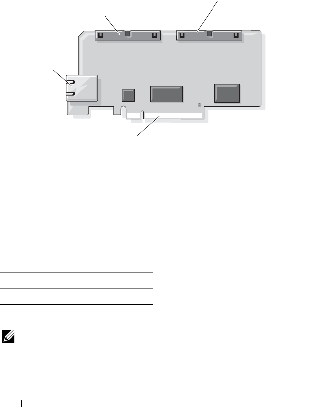
Figure 1-1 shows the DRAC 5 hardware.
Figure 1-1. DRAC 5 Hardware Features
DRAC 5 Specifications
Power Specifications
Table 1-1 lists the power requirements for the DRAC 5.
Connectors
NOTE: The DRAC 5 hardware installation instructions can be found in the Installing
a Remote Access Card document or the Installation and Troubleshooting Guide
included with your system.
Table 1-1. DRAC 5 Power Specifications
System Power
1.2 A on +3.3 V AUX (maximum)
550 mA on +3.3 V main (maximum)
0 mA on +5V main (maximum)
RJ-45
Connector
50-pin management
cable connector
44-pin MII cable
connector
PCIe Connector

DRAC 5 Overview 27
The DRAC 5 includes one onboard 10/100 Mbps RJ-45 NIC, a 50-pin
management cable, and a 44-pin MII cable. See Figure 1-1 for the DRAC 5
cable connectors.
The 50-pin management cable is the main interface to the DRAC that
provides connectivity to USB, serial, video, and an inter-integrated circuit
(I2C) bus. The 44-pin MII cable connects the DRAC NIC to the system’s
motherboard. The RJ-45 connector connects the DRAC NIC to an out-of-band
connection when the DRAC 5 is configured in Dedicated NIC mode.
Depending on your requirements, you can use the management and MII
cables to configure your DRAC in three separate modes. See "DRAC Modes"
on page 91 for more information.
DRAC 5 Ports
Table 1-2 identifies the ports used by the DRAC 5 that listen for a server
connection. Table 1-3 identifies the ports that the DRAC 5 uses as a client.
This information is required when opening firewalls for remote access to
aDRAC 5.
Table 1-2. DRAC 5 Server Listening Ports
Port Number Function
22*
Secure Shell (SSH)
23*
Telnet
80*
HTTP
161
SNMP Agent
443*
HTTPS
623
RMCP/RMCP+
3668*
Virtual Media server
3669*
Virtual Media Secure Service
5900*
Console Redirection keyboard/mouse
5901*
Console Redirection video
* Configurable port

28 DRAC 5 Overview
Supported Remote Access Connections
Table 1-4 lists the connection features.
Table 1-3. DRAC 5 Client Ports
Port Number Function
25
SMTP
53
DNS
68
DHCP-assigned IP address
69
TFTP
162
SNMP trap
636
LDAPS
3269
LDAPS for global catalog (GC)
Table 1-4. Supported Remote Access Connections
Connection Features
DRAC 5 NIC
• 10/100 Mbps Ethernet
•DHCP support
• SNMP traps and e-mail event notification
• Dedicated network interface for the DRAC 5 Web-based
interface
• Support for telnet/ssh console and RACADM CLI commands
including system boot, reset, power-on, and shutdown
commands
Serial port
• Support for Serial console and RACADM CLI commands
including system boot, reset, power-on, and shutdown
commands
• Support for text-only console redirection to a VT-100 terminal
or terminal emulator

DRAC 5 Overview 29
DRAC 5 Standard Features
The DRAC 5 provides the following features:
• Two-factor authentication, which is provided by the Smart Card logon.
The two-factor authentication is based on what the users have (the Smart
Card) and what they know (the PIN).
• User authentication through Microsoft Active Directory (optional) or
hardware-stored user IDs and passwords.
• Role-based authority, which enables an administrator to configure specific
privileges for each user.
• User ID and password configuration through the Web-based interface or
RACADM CLI.
• Dynamic Domain Name System (DNS) registration.
• Remote system management and monitoring using a Web-based
interface, serial connection, remote RACADM, or telnet connection.
• Support for Active Directory authentication — Centralizes all DRAC 5
user ID and passwords in Active Directory using Standard Schema and
Extended Schema.
• Console Redirection — Provides remote system keyboard, video, and
mouse functions.
• Virtual Media — Enables a managed system to access a media drive on the
management station.
• Access to system event logs — Provides access to the system event log
(SEL), DRAC 5 log, and last crash screen of the crashed or unresponsive
system that is independent of the operating system state.
• Dell OpenManage software integration — Enables you to launch the
DRAC5 Web-based interface from Dell OpenManage Server
Administrator or IT Assistant.
• RAC alert — Alerts you to potential managed node issues through e-mail
messages or an SNMP trap using the
Dedicated
,
Shared with Failover
, or
Shared
NIC settings.
• Local and remote configuration — Provides local and remote
configuration using the RACADM command-line utility.
• Remote power management — Provides remote power management
functions from a management console, such as shutdown and reset.

30 DRAC 5 Overview
•IPMI support.
• Standards-based management with IPMI over LAN and SM-CLP.
• Sensors for monitoring power consumption. The DRAC 5 uses this data to
depict system power consumption through charts and statistics.
• Secure Sockets Layer (SSL) encryption — Provides secure remote system
management through the Web-based interface.
• Password-level security management — Prevents unauthorized access to a
remote system.
• Role-based authority — Provides assignable permissions for different
systems management tasks.
Other Documents You May Need
In addition to this User’s Guide, the following documents provide additional
information about the setup and operation of the DRAC 5 in your system:
• DRAC 5 online help provides information about using the Web-based
interface.
•The
Dell OpenManage IT Assistant User’s Guide
provide information
about IT Assistant.
•The
Dell OpenManage Server Administrator’s User’s Guide
provides
information about installing and using Server Administrator.
•The
Dell OpenManage Server Administrator SNMP Reference Guide
documents the Server Administrator SNMP management information
base (MIB). The MIB defines variables that extend the standard MIB to
cover the capabilities of systems management agents.
•The
Dell OpenManage Baseboard Management Controller Utilities User’s
Guide
provides information about configuring the Baseboard Management
Controller (BMC), configuring your managed system using the BMC
Management Utility, and additional BMC information.
•The
Dell Update Packages User's Guide
provides information about obtaining
and using Dell Update Packages as part of your system update strategy.

DRAC 5 Overview 31
•The
Dell Systems Software Support Matrix
provides information about the
various Dell systems, the operating systems supported by these systems,
and the Dell OpenManage components that can be installed on these
systems.
•The
Glossary
on the Dell support website provides information on terms
used in this document.
The following system documents are also available to provide more
information about the system in which your DRAC 5 is installed:
• The safety instructions that came with your system provide important
safety and regulatory information. For additional regulatory information,
see the Regulatory Compliance home page at
www.dell.com/regulatory_compliance. Warranty information may be
included within this document or as a separate document.
•The
Rack Installation Guide
or
Rack Installation Instructions
included
with your rack solution describes how to install your system into a rack.
•The
Getting Started Guide
provides an overview of system features, setting
up your system, and technical specifications.
•The
Hardware Owner’s Manual
provides information about system
features and describes how to troubleshoot the system and install or
replace system components.
• Systems management software documentation describes the features,
requirements, installation, and basic operation of the software.
• Operating system documentation describes how to install (if necessary),
configure, and use the operating system software.
• Documentation for any components you purchased separately provides
information to configure and install these options.
• Updates are sometimes included with the system to describe changes to
the system, software, and/or documentation.
NOTE: Always read the updates first because they often supersede
information in other documents.
• Release notes or readme files may be included to provide last-minute
updates to the system or documentation or advanced technical reference
material intended for experienced users or technicians.

32 DRAC 5 Overview

Getting Started With the DRAC 5 33
2
Getting Started With the DRAC 5
The DRAC 5 enables you to remotely monitor, troubleshoot, and repair a
Dell system even when the system is down. The DRAC 5 offers a rich set of
features like console redirection, virtual media, virtual KVM, Smart Card
authentication, and so on.
Management station is the system from where an administrator remotely
manages a Dell system that is installed with a DRAC card. The systems that
are thus monitored are called managed systems.
To be able to use that DRAC card, follow these steps:
1
Install the DRAC 5 card in your Dell system — The DRAC 5 may be
preinstalled on your system, or available separately in a kit.
NOTE: This procedure may differ for various systems. See your specific
system’s Hardware Owner’s Manual on the Dell Support website at
support.dell.com/manuals for precise instructions on how to perform this
procedure.
You must install the DRAC 5 software on the management station as well
as the managed system. Without the managed system software, you
cannot use the RACADM locally, and the DRAC cannot capture the last
crash screen.
2
Configure the DRAC 5 properties, network settings, and users —
Yo u c a n
configure the DRAC 5 by using either the Remote Access Configuration
Utility, the Web-based interface, or the RACADM.
3
Configure the Microsoft Active Directory to
provide access to the
DRAC 5, allowing you to add and control DRAC 5 user privileges to
your existing users in your Active Directory software.
4
Configure Smart Card authentication — Smart Card provides an added
level of security to your enterprise.
5
Configure remote access points, such as console redirection and
virtual media.
6
Configure the security settings.

34 Getting Started With the DRAC 5
7
Use the standards-based management
Server Management-Command
Line Protocol (
SM-CLP) to manage the systems on your network.
8
Configure alerts for efficient systems management capability.
9
Configure the DRAC 5 Intelligent Platform Management Interface
(IPMI) settings to use the standards-based IPMI tools to manage the
systems on your network.

Basic Installation of the DRAC 5 35
3
Basic Installation of the DRAC 5
This section provides information about how to install and set up your
DRAC 5 hardware and software.
Before You Begin
Gather the following items that were included with your system, prior to
installing and configuring the DRAC 5 software:
• DRAC 5 hardware (currently installed or in the optional kit)
• DRAC 5 installation procedures (located in this chapter)
•
Dell Systems Management Tools and Documentation
DVD
Installing the DRAC 5 Hardware
NOTE: The DRAC 5 connection emulates a USB keyboard connection. As a result,
when you restart the system, the system will not notify you if your keyboard is not
attached.
The DRAC 5 may be preinstalled on your system, or available separately in
a kit. To get started with the DRAC 5 that is installed on your system,
see "Software Installation and Configuration Overview" on page 37.
If a DRAC 5 is not installed on your system, see the Installing a Remote
Access Card document that is included with your DRAC 5 kit, or see your
platform Installation and Troubleshooting Guide for hardware installation
instructions.
NOTE: See the Installation and Troubleshooting Guide included with your system
for information about removing the DRAC 5. Also, review all Microsoft Active
Directory RAC properties associated with the removed DRAC 5 to ensure proper
security if you are using extended schema.

36 Basic Installation of the DRAC 5
Configuring Your System to Use a DRAC 5
To configure your system to use a DRAC 5, use the Dell Remote Access
Configuration Utility (formerly known as the BMC Setup Module).
To run the Dell Remote Access Configuration Utility:
1
Turn on or restart your system.
2
Press <Ctrl><E> when prompted during POST.
If your operating system begins to load before you press <Ctrl><E>,
allow the system to finish booting, and then restart your system and try again.
3
Configure the NIC.
a
Using the down-arrow key, highlight
NIC Selection
.
b
Using the left-arrow and right-arrow keys, select one of the following
NIC selections:
•
Dedicated
— Select this option to enable the remote access
device to utilize the dedicated network interface available on the
Remote Access Controller (RAC). This interface is not shared
with the host operating system and routes the management traffic
to a separate physical network, enabling it to be separated from
the application traffic. This option is available only if a DRAC
card is installed in the system.
•
Shared
— Select this option to share the network interface with the
host operating system. The remote access device network interface
is fully functional when the host operating system is configured for
NIC teaming. The remote access device receives data through NIC
1 and NIC 2, but transmits data only through NIC 1. If NIC 1 fails,
the remote access device will not be accessible.
•
Failover
— Select this option to share the network interface with
the host operating system. The remote access device network
interface is fully functional when the host operating system is
configured for NIC teaming. The remote access device receives
data through NIC 1 and NIC 2, but transmits data only through
NIC 1. If NIC 1 fails, the remote access device fails over to NIC 2
for all data transmission. The remote access device continues to
use NIC 2 for data transmission. If NIC 2 fails, the remote access
device fails over all data transmission back to NIC 1.

Basic Installation of the DRAC 5 37
4
Configure the network controller LAN parameters to use DHCP or
a Static IP address source.
a
Using the down-arrow key, select
LAN Parameters
, and press <Enter>.
b
Using the up-arrow and down-arrow keys, select
IP Address Source
.
c
Using the right-arrow and left-arrow keys, select
DHCP
or
Static
.
d
If you selected
Static
, configure the
Ethernet IP Address
,
Subnet
Mask
, and
Default Gateway
settings.
e
Press <Esc>.
5
Press <Esc>.
6
Select
Save Changes and Exit
.
The system automatically reboots.
NOTE: When viewing the Web user interface on a Dell PowerEdge 1900 system
that is configured with one NIC, the NIC Configuration page displays two NICs
(NIC1 and NIC2). This behavior is normal. The PowerEdge 1900 system (and other
Dell systems that are configured with a single LAN On Motherboard) can be
configured with NIC teaming. Shared and Teamed modes work independently on
these systems.
See the Dell OpenManage Baseboard Management Controller Utilities User’s
Guide for more information about the Dell Remote Access Configuration Utility.
Software Installation and Configuration Overview
This section provides a high-level overview of the DRAC 5 software
installation and configuration process. Configure your DRAC 5 using the
Web-based interface, RACADM CLI, or Serial/Telnet/SSH console.
For more information about the DRAC 5 software components,
see "Installing the Software on the Managed System" on page 38.
Installing Your DRAC 5 Software
To install your DRAC 5 software:
1
Install the software on the managed system. See "Installing the Software
on the Managed System" on page 38.
2
Install the software on the management station. See "Installing the
Software on the Management Station" on page 39.

38 Basic Installation of the DRAC 5
Configuring Your DRAC 5
To configure your DRAC 5:
1
Select one of the following configuration tools:
• Web-based interface
•RACADM CLI
• Serial/Telnet/SSH console
CAUTION: Using more than one DRAC 5 configuration tool at the same time may
generate unexpected results.
2
Configure the DRAC 5 network settings. See "Configuring DRAC 5
Properties" on page 47.
3
Add and configure DRAC 5 users. See "Adding and Configuring DRAC 5
Users" on page 95.
4
Configure the Web browser to access the Web-based interface.
See "Configuring a Supported Web Browser" on page 43.
5
Disable the Windows Automatic Reboot Option. See "Disabling the
Windows Automatic Reboot Option" on page 258.
6
Update the DRAC 5 Firmware. See "Connecting to the Managed System
Through the Local Serial Port or Telnet Management Station (Client
System)" on page 64.
7
Access the DRAC 5 through a network. See "Connecting to the Managed
System Through the Local Serial Port or Telnet Management Station
(Client System)" on page 64.
Installing the Software on the Managed System
Installing software on the managed system is optional. Without the managed
system software, you cannot use the RACADM locally, and the DRAC cannot
capture the last crash screen.
To install the managed system software, install the software on the managed
system using the Dell Systems Management Tools and Documentation DVD.
For instructions about how to install this software, see your Quick
Installation Guide.

Basic Installation of the DRAC 5 39
Managed system software installs your choices from the appropriate version
of Dell OpenManage Server Administrator on the managed system.
NOTE: Do not install the DRAC 5 management station software and the DRAC 5
managed system software on the same system.
CAUTION: The latest DRAC firmware supports only the latest RACADM version.
You may encounter errors if you use an older version of RACADM to query a DRAC
with the latest firmware. Install the RACADM version shipped with your latest
Dell OpenManage DVD media.
If Server Administrator is not installed on the managed system, you cannot
view the system’s last crash screen or use the Auto Recovery feature.
For more information about the last crash screen, see "Viewing the Last
System Crash Screen" on page 283.
Installing the Software on the Management
Station
Your system includes the Dell OpenManage Systems Management Software
Kit. This kit includes, but is not limited to, the Dell Systems Management
Tools and Documentation DVD. For information about installing Server
Administrator software, see your Server Administrator User's Guide.
Configuring Your Red Hat Enterprise Linux (Version 4)
Management Station
The Dell Digital KVM Viewer requires additional configuration to run on a
Red Hat Enterprise Linux (version 4) management station. When you install
the Red Hat Enterprise Linux (version 4) operating system on your
management station, perform the following procedures:
• When prompted to add or remove packages, install the optional
Legacy
Software Development
software. This software package includes the
necessary software components to run the Dell Digital KVM viewer on
your management station.
• To ensure that the Dell Digital KVM Viewer functions properly, open the
following ports on your firewall:
– Keyboard and mouse port (default is port 5900)
– Video port (default is port 5901)

40 Basic Installation of the DRAC 5
Installing and Removing RACADM on a Linux Management Station
To use the remote RACADM functions, install RACADM on a management
station running Linux.
NOTE: When you run Setup on the Dell Systems Management Tools and
Documentation DVD, the RACADM utility for all supported operating systems are
installed on your management station.
Installing RACADM
1
Log on as root to the system where you want to install the management
station components.
2
If necessary, mount the
Dell Systems Management Tools and
Documentation
DVD using the following command or a similar command:
mount /media/cdrom
3
Navigate to the
/linux/rac
directory and execute the following command:
rpm -ivh *.rpm
For help with the RACADM command, type racadm help after issuing the
previous commands.
Uninstalling RACADM
To uninstall RACADM, open a command prompt and type:
rpm -e <racadm_package_name>
where <racadm_package_name> is the rpm package that was used to
install the RAC software.
For example, if the rpm package name is srvadmin-racadm5, then type:
rpm -e srvadmin-racadm5
Updating the DRAC 5 Firmware
Use one of the following methods to update your DRAC 5 firmware.
• Web-based Interface
•RACADM CLI
• Dell Update Packages

Basic Installation of the DRAC 5 41
Before You Begin
Before you update your DRAC 5 firmware using local RACADM or the Dell
Update Packages, perform the following procedures. Otherwise, the firmware
update operation may fail.
1
Install and enable the appropriate IPMI and managed node drivers.
2
If your system is running a Windows operating system, enable and start
the
Windows Management Instrumentation
(WMI) service.
3
If your system is running SUSE Linux Enterprise Server (version 10) for
Intel EM64T, start the
Raw
service.
4
Ensure that the RAC virtual flash is unmounted or not in use by the
operating system or another application or user.
5
Disconnect and unmount Virtual Media.
6
Ensure that the USB is enabled.
Downloading the DRAC 5 Firmware
To update your DRAC 5 firmware, download the latest firmware from the
Dell Support website located at support.dell.com and save the file to your
local system.
The following software components are included with your DRAC 5 firmware
package:
• Compiled DRAC 5 firmware code and data
• Expansion ROM image
• Web-based interface, JPEG, and other user interface data files
• Default configuration files
Use the Firmware Update page to update the DRAC 5 firmware to the latest
revision. When you run the firmware update, the update retains the current
DRAC 5 settings.
Updating the DRAC 5 Firmware Using the Web-Based Interface
1
Open the Web-based interface and login to the remote system.
See "Accessing the Web-Based Interface" on page 48.
2
In the
System
tree, click
Remote Access
and click the
Update
tab.

42 Basic Installation of the DRAC 5
3
In the
Firmware Update
page in the
Firmware Image
field, type the path
to the firmware image that you downloaded from
support.dell.com
or click
Browse
to navigate to the image.
NOTE: If you are running Firefox, the text cursor does not appear in the
Firmware Image field.
For example:
C:\Updates\V1.0\<
image_name
>
.
The default firmware image name is
firmimg.d5
.
4
Click
Update
.
The update may take several minutes to complete. When completed,
a dialog box appears.
5
Click
OK
to close the session and automatically log out.
6
After the DRAC 5 resets, click
Log In
to log in to the DRAC 5.
Updating the DRAC 5 Firmware Using racadm
You can update the DRAC 5 firmware using the CLI-based racadm tool.
If you have installed Server Administrator on the managed system, use local
racadm to update the firmware.
1
Download the DRAC 5 firmware image from the Dell Support website at
support.dell.com
to the managed system.
For example:
C:\downloads\firmimg.d5
2
Run the following racadm command:
racadm -pud c:\downloads\
You can also update the firmware using remote racadm.
For example:
racadm -r <DRAC5 IP address> U <username> -p
<password> fwupdate -p -u -d <path>
where
path
is the location where you saved
firmimg.d5
on the managed
system.

Basic Installation of the DRAC 5 43
Updating the DRAC 5 Firmware Using Dell Update Packages for
Supported Windows and Linux Operating Systems
Download and run the Dell Update Packages for supported Windows and
Linux operating systems from Dell Support website at support.dell.com.
See the Dell Update Package User’s Guide for more information.
Clearing the Browser Cache
After the firmware upgrade, clear the Web browser cache.
See your Web browser’s online help for more information.
Configuring a Supported Web Browser
The following sections provide instructions for configuring the supported
Web browsers. For a list of supported Web browsers, see the Dell Systems
Software Support Matrix on the Dell Support website at
support.dell.com/manuals.
Configuring Your Web Browser to Connect to the Web-Based Interface
If you are connecting to the DRAC 5 Web-based interface from a
management station that connects to the Internet through a proxy server,
you must configure the Web browser to access the Internet from this server.
To configure your Internet Explorer Web browser to access a proxy server:
1
Open a Web browser window.
2
Click
Tools
, and click
Internet Options
.
3
From the
Internet Options
window, click the
Connections
tab.
4
Under
Local Area Network (LAN) settings
, click
LAN Settings
.
5
If the
Use a proxy server
box is selected, select the
Bypass proxy server
for local addresses
box.
6
Click
OK
twice.

44 Basic Installation of the DRAC 5
List of Trusted Domains
When you access the DRAC 5 Web-based interface through the Web
browser, you are prompted to add the DRAC 5 IP address to the list of trusted
domains if the IP address is missing from the list. When completed, click
Refresh or relaunch the Web browser to reestablish a connection to the
DRAC 5 Web-based interface.
32-bit and 64-bit Web Browsers
The DRAC 5 Web-based interface is not supported on 64-bit Web browsers.
If you open a 64-bit Browser, access the Console Redirection page, and
attempt to install the plug-in, the installation procedure fails. If this error was
not acknowledged and you repeat this procedure, the Console Redirect Page
loads even though the plug-in installation fails during your first attempt.
This issue occurs because the Web browser stores the plug-in information in
the profile directory even though the plug-in installation procedure failed.
To fix this issue, install and run a supported 32-bit Web browser and log in to
the DRAC 5.
Viewing Localized Versions of the Web-Based Interface
Windows
The DRAC 5 Web-based interface is supported on the following Windows
operating system languages:
•English
•French
•German
•Spanish
•Japanese
• Simplified Chinese
To view a localized version of the DRAC 5 Web-based interface in
Internet Explorer:
1
Click the
Tools
menu and select
Internet Options
.
2
In the
Internet Options
window, click
Languages
.
3
In the
Language Preference
window, click
Add
.

Basic Installation of the DRAC 5 45
4
In the
Add Language
window, select a supported language.
To select more than one language, press <Ctrl>.
5
Select your preferred language and click
Move Up
to move the language to
the top of the list.
6
Click
OK
.
7
In the
Language Preference
window, click
OK
.
Linux
If you are running Console Redirection on a Red Hat Enterprise Linux
(version 4) client with a Simplified Chinese GUI, the viewer menu and title
may appear in random characters. This issue is caused by an incorrect
encoding in the Red Hat Enterprise Linux (version 4) Simplified Chinese
operating system. To fix this issue, access and modify the current encoding
settings by performing the following steps:
1
Open a command terminal.
2
Type “locale” and press <Enter>. The following output appears.
LANG=zh_CN.UTF-8
LC_CTYPE="zh_CN.UTF-8"
LC_NUMERIC="zh_CN.UTF-8"
LC_TIME="zh_CN.UTF-8"
LC_COLLATE="zh_CN.UTF-8"
LC_MONETARY="zh_CN.UTF-8"
LC_MESSAGES="zh_CN.UTF-8"
LC_PAPER="zh_CN.UTF-8"
LC_NAME="zh_CN.UTF-8"
LC_ADDRESS="zh_CN.UTF-8"
LC_TELEPHONE="zh_CN.UTF-8"
LC_MEASUREMENT="zh_CN.UTF-8"
LC_IDENTIFICATION="zh_CN.UTF-8"
LC_ALL=
3
If the values include “zh_CN.UTF-8”, no changes are required. If the
values do not include “zh_CN.UTF-8”, go to step 4.
4
Navigate to the /etc/sysconfig/i18n file.

46 Basic Installation of the DRAC 5
5
In the file, apply the following changes:
Current entry:
LANG="zh_CN.GB18030"
SUPPORTED="zh_CN.GB18030:zh_CH.GB2312:zh_CN:zh"
Updated entry:
LANG="zh_CN.UTF-8"
SUPPORTED="zh_CN.UTF-
8:zh_CN.GB18030:zh_CH.GB2312:zh_CN:zh"
6
Log out and then login to the operating system.
7
Relaunch the DRAC 5.
When you switch from any other language to the Simplified Chinese
language, ensure that this fix is still valid. If not, repeat this procedure.
For advanced configurations of the DRAC 5, see "Advanced Configuration of
the DRAC 5" on page 47.

Advanced Configuration of the DRAC 5 47
4
Advanced Configuration of the
DRAC 5
This section provides information about advanced DRAC 5 configuration
and is recommended for users with advanced knowledge of systems
management and who want to customize the DRAC environment to suit
their specific needs.
Before You Begin
You should have completed the basic installation and setup of your DRAC 5
hardware and software. See "Basic Installation of the DRAC 5" on page 35 for
more information.
Configuring DRAC 5 Properties
You can configure the DRAC 5 properties (network, users, and so on) by
using either the Web-based interface or the RACADM.
The DRAC 5 provides a Web-based interface and RACADM (a command-line
interface) that enables you to configure the DRAC 5 properties and users,
perform remote management tasks, and troubleshoot a remote (managed)
system for problems. For everyday systems management, use the DRAC 5
Web-based interface. This chapter provides information about how to
perform common systems management tasks with the DRAC 5 Web-based
interface and provides links to related information.
All Web-based interface configuration tasks can also be performed with
RACADM.

48 Advanced Configuration of the DRAC 5
Configuring the DRAC 5 Using the Web
User Interface
See your DRAC 5 online help for context sensitive information about each
Web-based interface page.
Accessing the Web-Based Interface
To access the DRAC 5 Web-based interface:
1
Open a supported Web browser window.
For a list of supported Web browsers, see the Dell Systems Software
Support Matrix on the Dell Support website at
support.dell.com/manuals.
2
In the
Address
field, type the following and press <Enter>:
https://<
IP address>
If the default HTTPS port number (port 443) has been changed, type:
https://<
IP address>
:<
port number
>
where
IP address
is the IP address for the DRAC 5 and
port number
is the HTTPS port number.
The DRAC 5
Log in
window appears.
NOTE: When you use Internet Explorer version 6 SP2 or version 7 to log into the
DRAC 5 Web GUI and the client is on a private network, but without access to the
Internet, you may experience a delay of up to 30 seconds. To resolve this issue:
1. Disable the phishing filter.
https://phishingfilter.microsoft.com/faq.aspx.
2. Disable CRL fetching:
a. Click
Too ls
Options
Advanced
tab
Security
.
b. Deselect
Check for publisher's certificate revocation
.

Advanced Configuration of the DRAC 5 49
Logging In
You can log in either as a DRAC 5 user or as a Microsoft Active Directory user.
The default user name and password are root and calvin, respectively.
Before you log in to the DRAC 5, verify that you have Log In to DRAC 5
permission. Speak to your organization’s DRAC or network administrator to
confirm your access privileges.
To log in:
1
In the
User Name
field, type one of the following:
• Your DRAC 5 user name.
For example, <
username
>
The DRAC 5 user name for local users is case sensitive
• Your Active Directory user name.
For example, <
domain
>\<
username
>, <
domain
>/<
username
>, or
<
user
>@<
domain
>.
Examples of an Active Directory user name are:
dell.com\john_doe
or
john_doe@dell.com
.
The Active Directory user name is not case sensitive.
2
In the
Password
field, type your DRAC 5 user password or Active Directory
user password.
This field is case sensitive.
3
Click
OK
or press <Enter>.

50 Advanced Configuration of the DRAC 5
Logging Out
1
In the upper-right corner of the DRAC 5 Web-based interface window,
click
Log Out
to close the session.
2
Close the browser window.
NOTE: The Log Out button does not appear until you log in.
NOTE: Closing the browser without gracefully logging out causes the session to
remain open until it times out. It is strongly recommended that you click the logout
button to end the session; otherwise, the session remains active until the session
timeout is reached.
NOTE: Closing the DRAC 5 Web-based interface within Microsoft Internet Explorer
using the close button ("x") at the top right corner of the window may generate an
application error. To fix this issue, download the latest Cumulative Security Update for
Internet Explorer from the Microsoft Support website, at support.microsoft.com.
Enabling and Configuring the Managed System to
Use a Serial or Telnet Console
The following subsections provide information about how to enable and
configure a serial/telnet/ssh console on the managed system.
Using the connect com2 Serial Command
When using the connect com2 serial command, ensure that the following are
configured properly:
•The
Serial Communication
Serial Port
setting in the
BIOS Setup
program.
• The DRAC configuration settings.
When a telnet session is established to the DRAC 5 and these settings are
incorrect, connect com2 may display a blank screen.

Advanced Configuration of the DRAC 5 51
Configuring the BIOS Setup Program for a Serial Connection on the
Managed System
Perform the following steps to configure your BIOS Setup program to
redirect output to a serial port.
NOTE: You must configure the System Setup program in conjunction with the
connect com2 command.
1
Turn on or restart your system.
2
Press <F2> immediately after you see the following message:
<F2> = System Setup
3
Scroll down and select
Serial Communication
by pressing <Enter>.
4
Set the
Serial Communication
screen as follows:
External Serial Connector
—
Remote Access Device
Redirection After Boot
—
Disabled
5
Press <Esc> to exit the
System Setup
program to complete the
System
Setup
program configuration.
Using the Remote Access Serial Interface
When establishing a serial connection to the RAC device, the following
interfaces are available:
• IPMI serial interface. See "Using the IPMI Remote Access Serial Interface"
on page 274.
• RAC serial interface
RAC Serial Interface
RAC also supports a serial console interface (or RAC Serial Console) that
provides a RAC CLI, which is not defined by IPMI. If your system includes
aRAC card with Serial Console enabled, the RAC card will override the
IPMI serial settings and display the RAC CLI serial interface.

52 Advanced Configuration of the DRAC 5
To enable the RAC serial terminal interface, set the cfgSerialConsoleEnable
property to 1 (TRUE).
For example:
racadm config -g cfgSerial -o cfgSerialConsoleEnable 1
See "cfgSerialConsoleEnable (Read/Write)" on page 366 for more
information.
Table 4-1 provides the serial interface settings.
Configuring Linux for Serial Console Redirection During Boot
The following steps are specific to the Linux GRand Unified Bootloader (GRUB).
Similar changes would be necessary if you use a different boot loader.
NOTE: When you configure the client VT100 emulation window, set the window or
application that is displaying the redirected console to 25 rows x 80 columns to
ensure proper text display; otherwise, some text screens may be garbled.
Edit the /etc/grub.conf file as follows:
1
Locate the General Setting sections in the file and add the following two
new lines:
serial --unit=1 --speed=57600
terminal --timeout=10 serial
2
Append two options to the kernel line:
kernel ............. console=ttyS1,57600
3
If the
/etc/grub.conf
contains a
splashimage
directive, comment it out.
Table 4-2 provides a sample /etc/grub.conf file that shows the changes
described in this procedure.
Table 4-1. Serial Interface Settings
IPMI Mode RAC Serial Console Interface
Basic Disabled Basic Mode
Basic Enabled RAC CLI
Terminal Disabled IPMI Terminal Mode
Terminal Enabled RAC CLI

Advanced Configuration of the DRAC 5 53
Table 4-2. Sample File: /etc/grub.conf
# grub.conf generated by anaconda
#
# Note that you do not have to rerun grub after
making changes
# to this file
# NOTICE: You do not have a /boot partition. This
means that
# all kernel and initrd paths are relative
to /, e.g.
# root (hd0,0)
# kernel /boot/vmlinuz-version ro root=
/dev/sdal
# initrd /boot/initrd-version.img
#
#boot=/dev/sda
default=0
timeout=10
#splashimage=(hd0,2)/grub/splash.xpm.gz
serial --unit=1 --speed=57600
terminal --timeout=10 serial
title Red Hat Linux Advanced Server (2.4.9-e.3smp)
root (hd0,0)
kernel /boot/vmlinuz-2.4.9-e.3smp ro root=
/dev/sda1 hda=ide-scsi console=ttyS0 console=
ttyS1,57600
initrd /boot/initrd-2.4.9-e.3smp.img
title Red Hat Linux Advanced Server-up (2.4.9-e.3)
root (hd0,00)
kernel /boot/vmlinuz-2.4.9-e.3 ro root=/dev/sda1 s
initrd /boot/initrd-2.4.9-e.3.im

54 Advanced Configuration of the DRAC 5
When you edit the /etc/grub.conf file, use the following guidelines:
1
Disable GRUB's graphical interface and use the text-based interface;
otherwise, the GRUB screen will not be displayed in RAC console
redirection. To disable the graphical interface, comment out the line
starting with
splashimage
.
2
To enable multiple GRUB options to start console sessions through the
RAC serial connection, add the following line to all options:
console=ttyS1,57600
Table 4 -2
shows
console=ttyS1,57600
added to only the first option.
Enabling Login to the Console After Boot
Edit the file /etc/inittab as follows:
Add a new line to configure
agetty
on the COM2 serial port:
co:2345:respawn:/sbin/agetty -h -L 57600 ttyS1 ansi
Table 4-3 shows a sample file with the new line.

Advanced Configuration of the DRAC 5 55
Table 4-3. Sample File: /etc/innitab
#
# inittab This file describes how the INIT process
should set up
# the system in a certain run-level.
#
# Author: Miquel van Smoorenburg
# Modified for RHS Linux by Marc Ewing and
Donnie Barnes
#
# Default runlevel. The runlevels used by RHS are:
# 0 - halt (Do NOT set initdefault to this)
# 1 - Single user mode
# 2 - Multiuser, without NFS (The same as 3, if you
do not have
# networking)
# 3 - Full multiuser mode
# 4 - unused
# 5 - X11
# 6 - reboot (Do NOT set initdefault to this)
#
id:3:initdefault:
# System initialization.
si::sysinit:/etc/rc.d/rc.sysinit
l0:0:wait:/etc/rc.d/rc 0
l1:1:wait:/etc/rc.d/rc 1
l2:2:wait:/etc/rc.d/rc 2
l3:3:wait:/etc/rc.d/rc 3
l4:4:wait:/etc/rc.d/rc 4
l5:5:wait:/etc/rc.d/rc 5
l6:6:wait:/etc/rc.d/rc 6

56 Advanced Configuration of the DRAC 5
Edit the file /etc/securetty as follows:
Add a new line with the name of the serial tty for COM2:
ttyS1
# Things to run in every runlevel.
ud::once:/sbin/update
# Trap CTRL-ALT-DELETE
ca::ctrlaltdel:/sbin/shutdown -t3 -r now
# When our UPS tells us power has failed, assume we
have a few
# minutes of power left. Schedule a shutdown for 2
minutes from now.
# This does, of course, assume you have power
installed and your
# UPS is connected and working correctly.
pf::powerfail:/sbin/shutdown -f -h +2 "Power Failure;
System Shutting Down"
# If power was restored before the shutdown kicked
in, cancel it.
pr:12345:powerokwait:/sbin/shutdown -c "Power
Restored; Shutdown Cancelled"
# Run gettys in standard runlevels
co:2345:respawn:/sbin/agetty -h -L 57600 ttyS1 ansi
1:2345:respawn:/sbin/mingetty tty1
2:2345:respawn:/sbin/mingetty tty2
3:2345:respawn:/sbin/mingetty tty3
4:2345:respawn:/sbin/mingetty tty4
5:2345:respawn:/sbin/mingetty tty5
6:2345:respawn:/sbin/mingetty tty6
# Run xdm in runlevel 5
# xdm is now a separate service
x:5:respawn:/etc/X11/prefdm -nodaemon
Table 4-3. Sample File: /etc/innitab
(continued)

Advanced Configuration of the DRAC 5 57
Table 4-4 shows a sample file with the new line.
Enabling the DRAC 5 Serial/Telnet/SSH Console
The serial/telnet/ssh console can be enabled locally or remotely.
Enabling the Serial/Telnet/SSH Console Locally
NOTE: You (the current user) must have Configure DRAC 5 permission in order to
perform the steps in this section.
To enable the serial/telnet/ssh console from the managed system, type the
following local RACADM commands from a command prompt:
racadm config -g cfgSerial -o cfgSerialConsoleEnable 1
racadm config -g cfgSerial -o cfgSerialTelnetEnable 1
racadm config -g cfgSerial -o cfgSerialSshEnable 1
Table 4-4. Sample File: /etc/securetty
vc/1
vc/2
vc/3
vc/4
vc/5
vc/6
vc/7
vc/8
vc/9
vc/10
vc/11
tty1
tty2
tty3
tty4
tty5
tty6
tty7
tty8
tty9
tty10
tty11
ttyS1

58 Advanced Configuration of the DRAC 5
Enabling the Serial/Telnet/SSH Console Remotely
To enable the serial/telnet/ssh console remotely, type the following remote
RACADM commands from a command prompt:
racadm -u <username> -p <password> -r <DRAC 5 IP
address> config -g cfgSerial -o cfgSerialConsoleEnable 1
racadm -u <username> -p <password> -r <DRAC 5 IP
address> config -g cfgSerial -o cfgSerialTelnetEnable 1
racadm -u <username> -p <password> -r <DRAC 5 IP
address> config -g cfgSerial -o cfgSerialSshEnable 1
NOTE: When you use Internet Explorer version 6 SP2 or version 7 to log into a
managed system on a private network, but without access to the Internet, you may
experience a delay of up to 30 seconds while using remote RACADM commands.
Using the RACADM Command to Configure the Settings for the Serial
and Telnet Console
This subsection provides steps to configure the default configuration settings
for serial/telnet/ssh console redirection.
To configure the settings, type the RACADM config command with the
appropriate group, property, and property value(s) for the setting that you
want to configure.
You can type RACADM commands locally or remotely. When using
RACADM commands remotely, you must include the user name, password,
and managed system DRAC 5 IP address.
Using RACADM Locally
To type RACADM commands locally, type the following command from
a command prompt on the managed system:
racadm config -g <group> -o <property> <value>
To view a list of properties, type the following command from a command
prompt on the managed system:
racadm getconfig -g <group>

Advanced Configuration of the DRAC 5 59
Using RACADM Remotely
To use RACADM commands remotely, type the following command from
a command prompt on a management station:
racadm -u <username> -p <password> -r <DRAC 5
IP address> config -g <group> -o <property> <value>
Ensure that your web server is configured with a DRAC 5 card before you use
RACADM remotely. Otherwise, RACADM times out and the following
message appears:
Unable to connect to RAC at specified IP address.
To enable your web server using Secure Shell (SSH), telnet or local RACADM,
type the following command from a command prompt on a management station:
racadm config -g cfgRacTuning -o
cfgRacTuneWebServerEnable 1
Displaying Configuration Settings
Table 4-5 provides the actions and related commands to display your
configuration settings. To run the commands, open a command prompt on
the managed system, type the command, and press <Enter>.
Table 4-5. Displaying Configuration Settings
Action Command
List the
available groups.
racadm getconfig -h
Display the
current settings
for a particular
group.
racadm getconfig -g <group>
For example, to display a list of all cfgSerial group settings, type the
following command:
racadm getconfig -g cfgSerial
Display the
current settings
for a particular
group remotely.
racadm -u <user> -p <password> -r <DRAC 5
IP address> getconfig -g cfgSerial
For example, to display a list of all of the settings for the cfgSerial
group remotely, type:
racadm -u root -p calvin -r 192.168.0.1
getconfig -g cfgSerial

60 Advanced Configuration of the DRAC 5
Configuring the Telnet Port Number
Type the following command to change the telnet port number on the DRAC 5.
racadm config -g cfgRacTuning -o cfgRacTuneTelnetPort
<new port number>
Using a Serial or Telnet Console
You can run the serial commands in Table 4-19 remotely using RACADM or
from the serial/telnet/ssh console command prompt.
Logging in to the DRAC 5
After you have configured your management station terminal emulator software
and managed node BIOS, perform the following steps to log into the DRAC 5:
1
Connect to the DRAC 5 using your management station terminal
emulation software.
2
Type your DRAC 5 user name and press <Enter>.
You are logged into the DRAC 5.
Starting a Text Console
After you have logged into the DRAC 5 through your management station
terminal software with telnet or SSH, you can redirect the managed system
text console by using connect com2, which is a telnet/SSH command.
Only one connect com2 client is supported at a time.
To connect to the managed system text console, open a DRAC 5 command
prompt (displayed through a telnet or SSH session) and type:
connect com2
From a serial session, you can connect to the managed system’s serial console
by pressing <Esc><Shift><Q>, which connects the managed system’s
serial port directly to the servers’ COM2 port and bypasses the DRAC 5.
To reconnect the DRAC 5 to the serial port, press <Esc><Shift><9>.
The managed node COM2 port and the DRAC 5 serial port baud rates must
be identical.

Advanced Configuration of the DRAC 5 61
The connect -h com2 command displays the contents of the serial
history buffer before waiting for input from the keyboard or new characters
from the serial port.
NOTE: When using the -h option, the client and server terminal emulation type
(ANSI or VT100) must be identical; otherwise, the output may be garbled.
Additionally, set the client terminal row to 25.
The default (and maximum) size of the history buffer is 8192 characters.
You can set this number to a smaller value using the command:
racadm config -g cfgSerial -o cfgSerialHistorySize
<number>
Configuring Serial and Terminal Modes
Configuring IPMI and RAC Serial
1
Expand the
System
tree and click
Remote Access
.
2
Click the
Configuration
tab and then click
Serial
.
3
Configure the IPMI serial settings.
See Table 4-6 for description of the IPMI serial settings.
4
Configure the RAC serial settings.
See Table 4-7 for description of the RAC serial settings.
5
Click
Apply Changes
.
6
Click the appropriate
Serial Configuration
page button to continue.
See Table 4-8 for description of the serial configuration page settings.
Table 4-6. IPMI Serial Settings
Setting Description
Connection Mode
Setting
• Direct Connect Basic Mode - IPMI Serial Basic Mode
• Direct Connect Terminal Mode - IPMI Serial Terminal
Mode
Baud Rate Sets the data speed rate. Select 9600 bps, 19.2 kbps,
57.6 kbps, or 115.2 kbps.

62 Advanced Configuration of the DRAC 5
Flow Control
• None — Hardware Flow Control Off
• RTS/CTS — Hardware Flow Control On
Channel Privilege
Level Limit
• Administrator
•Operator
•User
Table 4-7. RAC Serial Settings
Setting Description
Enabled Enables or disables the RAC serial console. Checked=
Enabled; Unchecked=Disabled
Maximum Sessions The maximum number of simultaneous sessions allowed
for this system.
Timeout The maximum number of seconds of line idle time before
the line is disconnected. The range is 60 to 1920 seconds.
Default is 300 seconds. Use 0 seconds to disable the
Timeout feature.
Redirect Enabled Enables or disables Console Redirection. Checked=
Enabled; Unchecked=Disabled
Baud Rate The data speed on the external serial port. Values are 9600
bps, 28.8 kbps, 57.6 kbps, and 115.2 kbps. Default is
57.6 kbps.
Escape Key Specifies the <Esc> key. The default are the ^\
characters.
History Buffer Size The size of the serial history buffer, which holds the last
characters written to the console. The maximum and
default = 8192 characters.
Login Command The DRAC command line to be executed upon valid
login.
Table 4-6. IPMI Serial Settings
(continued)
Setting Description

Advanced Configuration of the DRAC 5 63
Configuring Terminal Mode
1
Expand the
System
tree and click
Remote Access
.
2
Click the
Configuration
tab and then click
Serial
.
3
In the
Serial Configuration
page, click
Terminal Mode Settings
.
4
Configure the terminal mode settings.
See Table 4-9 for description of the terminal mode settings.
5
Click
Apply Changes
.
6
Click the appropriate
Terminal Mode Settings
page button to continue.
See Table 4-10 for description of the terminal mode settings page buttons.
Table 4-8. Serial Configuration Page Settings
Button Description
Print Print the Serial Configuration page.
Refresh Refresh the Serial Configuration page.
Apply Changes Apply the IPMI and RAC serial changes.
Terminal Mode Settings Opens the Terminal Mode Settings page.
Table 4-9. Terminal Mode Settings
Setting Description
Line Editing Enables or disables line editing.
Delete Control Select one of the following:
•
BMC outputs a <bksp><sp><bksp> character when
<bksp> or <del> is received
—
•
BMC outputs a <del> character when <bksp> or
<del> is received
—
Echo Control Enables or disables echo.
Handshaking Control Enables or disables handshaking.
New Line Sequence Select None, <CR-LF>, <NULL>, <CR>, <LF-CR>,
or <LF>.
Input New Line
Sequence
Select <CR> or <NULL>.

64 Advanced Configuration of the DRAC 5
Connecting to the Managed System Through the
Local Serial Port or Telnet Management Station
(Client System)
The managed system provides access between the DRAC 5 and the serial port
on your system to enable you to power on, power off, or reset the managed
system, and access logs.
The serial console is available on the DRAC 5 through the managed system
external serial connector. Only one serial client system (management station)
may be active at any given time. The telnet and SSH consoles are available on
the DRAC 5 through the DRAC modes (see "DRAC Modes" on page 91). Up
to four telnet client systems and four SSH clients may connect at any given
time. The management station connection to the managed system serial or
telnet console requires management station terminal emulation software. See
"Configuring the Management Station Terminal Emulation Software" on
page 65 for more information.
The following subsections explain how to connect your management station
to the managed system using the following methods:
• A managed system external serial port using terminal software and a DB-9
or a null modem cable
• A telnet connection using terminal software through the managed system
DRAC 5 NIC or the shared, teamed NIC
Table 4-10. Terminal Mode Settings Page Buttons
Button Description
Print Print the Terminal Mode Settings page.
Refresh Refresh the Terminal Mode Settings page.
Go Back to Serial Port
Configuration
Return to the Serial Port Configuration page.
Apply Changes Apply the terminal mode settings changes.

Advanced Configuration of the DRAC 5 65
Connecting the DB-9 or Null Modem Cable for the
Serial Console
To access the managed system using a serial text console, connect a DB-9 null
modem cable to the COM port on the managed system. Not all DB-9 cables
carry the pinout/signals necessary for this connection. The DB-9 cable for this
connection must conform to the specification shown in Table 4-11.
NOTE: The DB-9 cable can also be used for BIOS text console redirection.
Configuring the Management Station Terminal
Emulation Software
Your DRAC 5 supports a serial or telnet text console from a management
station running one of the following types of terminal emulation software:
• Linux Minicom in an Xterm
• Hilgraeve’s HyperTerminal Private Edition (version 6.3)
• Linux Telnet in an Xterm
•Microsoft Telnet
Perform the steps in the following subsections to configure your type of terminal
software. If you are using Microsoft Telnet, configuration is not required.
Table 4-11. Required Pinout for DB-9 Null Modem Cable
Signal Name DB-9 Pin
(server pin)
DB-9 Pin
(workstation pin)
FG (Frame Ground) – –
TD (Transmit data) 3 2
RD (Receive Data) 2 3
RTS (Request To Send) 7 8
CTS (Clear To Send) 8 7
SG (Signal Ground) 5 5
DSR (Data Set Ready) 6 4
CD (Carrier Detect) 1 4
DTR (Data Terminal Ready) 4 1 and 6

66 Advanced Configuration of the DRAC 5
Configuring Linux Minicom for Serial Console Emulation
Minicom is the serial port access utility for Linux. The following steps are
valid for configuring Minicom version 2.0. Other Minicom versions may differ
slightly but require the same basic settings. Use the information in "Required
Minicom Settings for Serial Console Emulation" on page 67 to configure
other versions of Minicom.
Configuring Minicom Version 2.0 for Serial Console Emulation
NOTE: To ensure that the text displays properly, Dell recommends that you use an
Xterm window to display the telnet console instead of the default console provided
by the Linux installation.
1
To start a new Xterm session, type
xterm &
at the command prompt.
2
In the Xterm window, move your mouse arrow to the lower right-hand
corner of the window and resize the window to 80 x 25.
3
If you do not have a Minicom configuration file, go to the next step.
If you have a Minicom configuration file, type
minicom
<
Minicom
config file name
>
and skip to step 17.
4
At the Xterm command prompt, type
minicom -s
.
5
Select
Serial Port Setup
and press <Enter>.
6
Press <a> and select the appropriate serial device (for example,
/dev/ttyS0
).
7
Press <e> and set the
Bps/Par/Bits
option to
57600 8N1
.
8
Press <f> and set
Hardware Flow Control
to
Yes
and set
Software Flow
Control
to
No
.
9
To exit the
Serial Port Setup
menu, press <Enter>.
10
Select
Modem and Dialing
and press <Enter>.
11
In the
Modem Dialing and Parameter Setup
menu, press <Backspace>
to clear the
init
,
reset
,
connect
, and
hangup
settings so that they are blank.
12
Press <Enter> to save each blank value.
13
When all specified fields are clear, press <Enter> to exit the
Modem
Dialing and Parameter Setup
menu.
14
Select
Save setup as config_name
and press <Enter>.
15
Select
Exit From Minicom
and press <Enter>.

Advanced Configuration of the DRAC 5 67
16
At the command shell prompt, type
minicom <
Minicom
config
file name
>
.
17
To expand the Minicom window to 80 x 25, drag the corner of the window.
18
Press <Ctrl+a>, <z>, <x> to exit Minicom.
NOTE: If you are using Minicom for serial text console redirection to configure the
managed system BIOS, it is recommended to turn on color in Minicom. To turn on
color, type the following command: minicom -c on
Ensure that the Minicom window displays a command prompt such as
[DRAC 5\root]#. When the command prompt appears, your connection
is successful and you are ready to connect to the managed system console
using the connect serial command.
Required Minicom Settings for Serial Console Emulation
Use Table 4-12 to configure any version of Minicom.
Configuring HyperTerminal for Serial Console Redirection
HyperTerminal is the Microsoft Windows serial port access utility. To set the
size of your console screen appropriately, use Hilgraeve’s HyperTerminal
Private Edition version 6.3.
To configure HyperTerminal for serial console redirection:
1
Start the HyperTerminal program.
2
Type a name for the new connection and click
OK
.
Table 4-12. Minicom Settings for Serial Console Emulation
Setting Description Required Setting
Bps/Par/Bits 57600 8N1
Hardware flow control Yes
Software flow control No
Terminal emulation ANSI
Modem dialing and
parameter settings
Clear the init, reset, connect, and hangup settings so
that they are blank
Window size 80 x 25 (to resize, drag the corner of the window)

68 Advanced Configuration of the DRAC 5
3
Next to
Connect using:
, select the COM port on the management station
(for example, COM2) to which you have connected the DB-9 null modem
cable and click
OK
.
4
Configure the COM port settings as shown in Table 4-13.
5
Click
OK
.
6
Click
File
Properties
, and then click the
Settings
tab.
7
Set the
Telnet terminal ID:
to
ANSI
.
8
Click
Terminal Setup
and set
Screen Rows
to
26
.
9
Set
Columns
to
80
and click
OK
.
The HyperTerminal window displays a command prompt such as [DRAC
5\root]#. When the command prompt appears, your connection is
successful and you are ready to connect to the managed system console using
the connect com2 serial command.
Configuring Linux XTerm for Telnet Console Redirection
Use the following guidelines when performing the steps in this section:
• When you are using the
connect com2
command through a telnet console
to display the System Setup screens, set the terminal type to
ANSI
in
System Setup and for the telnet session.
• To ensure that the text is properly displayed, Dell recommends that you
use an Xterm window to display the telnet console instead of the default
console provided by the Linux installation.
Table 4-13. Management Station COM Port Settings
Setting Description Required Setting
Bits per second 57600
Data bits 8
Parity None
Stop bits 1
Flow control Hardware

Advanced Configuration of the DRAC 5 69
To run telnet with Linux:
1
Start a new Xterm session.
At the command prompt, type
xterm &
2
Click on the lower right-hand corner of the XTerm window and resize the
window to 80 x 25.
3
Connect to the DRAC 5 in the managed system.
At the Xterm prompt, type
telnet <
DRAC 5 IP address
>
Enabling Microsoft Telnet for Telnet Console Redirection
NOTE: Some telnet clients on Microsoft operating systems may not display the
BIOS setup screen correctly when BIOS console redirection is set for VT100
emulation. If this issue occurs, update the display by changing BIOS console
redirection to ANSI mode. To perform this procedure in the BIOS setup menu,
select Console Redirection
Remote Terminal Type
ANSI.
1
Enable
Telnet
in
Windows Component Services
.
2
Connect to the DRAC 5 in the management station.
Open a command prompt, type the following, and press <Enter>:
telnet <
IP address
>:<
port number
>
where
IP address
is the IP address for the DRAC 5 and
port number
is the telnet port number (if you are using a new port).
Configuring the Backspace Key For Your Telnet Session
Depending on the telnet client, using the <Backspace> key may produce
unexpected results. For example, the session may echo ^h. However, most
Microsoft and Linux telnet clients can be configured to use the
<Backspace> key.
To configure Microsoft telnet clients to use the <Backspace> key:
1
Open a command prompt window (if required).
2
If you are not running a telnet session, type:
telnet
If you are running a telnet session, press <Ctrl><]>.

70 Advanced Configuration of the DRAC 5
3
At the prompt, type:
set bsasdel
The following message appears:
Backspace will be sent as delete.
To configure a Linux telnet session to use the <Backspace> key:
1
Open a command prompt and type:
stty erase ^h
2
At the prompt, type:
telnet
Using a Serial or Telnet Console
Serial and telnet commands, and RACADM CLI can be typed in a serial or
telnet console and executed on the server locally or remotely. The local
RACADM CLI is installed for use by a root user only.
Running Telnet Using Windows XP or Windows 2003
If your management station is running Windows XP or Windows 2003,
you may experience an issue with the characters in a DRAC 5 telnet
session.This issue may occur as a frozen login where the return key does not
respond and the password prompt does not appear.
To fix this issue, download hotfix 824810 from the Microsoft Support website
at support.microsoft.com. See Microsoft Knowledge Base article 824810 for
more information.
Running Telnet Using Windows 2000
If your management station is running Windows 2000, you cannot access
BIOS setup by pressing the <F2> key. To fix this issue, use the telnet client
supplied with the Windows Services for UNIX 3.5—a recommended free
download from Microsoft. Go to www.microsoft.com/downloads/ and search
for Windows Services for UNIX 3.5.

Advanced Configuration of the DRAC 5 71
Using the Secure Shell (SSH)
It is critical that your system’s devices and device management are secure.
Embedded connected devices are the core of many business processes. If
these devices are compromised, your business may be at risk, which requires
new security demands for command line interface (CLI) device management
software.
Secure Shell (SSH) is a command line session that includes the same
capabilities as a telnet session, but with improved security. The DRAC 5
supports SSH version 2 with password authentication. SSH is enabled on the
DRAC 5 when you install or update your DRAC 5 firmware.
You can use either PuTTY or OpenSSH on the management station to
connect to the managed system’s DRAC 5. When an error occurs during the
login procedure, the secure shell client issues an error message. The message
text is dependent on the client and is not controlled by the DRAC 5.
NOTE: OpenSSH should be run from a VT100 or ANSI terminal emulator on
Windows. Running OpenSSH at the Windows command prompt does not result in
full functionality (that is, some keys do not respond and no graphics are displayed).
Only four SSH sessions are supported at any given time. The session time-out
is controlled by the cfgSsnMgtSshIdleTimeout property as described in
the "DRAC 5 Property Database Group and Object Definitions" on page 345.
To enable the SSH on the DRAC 5, type:
racadm config -g cfgSerial -o cfgSerialSshEnable 1
To change the SSH port, type:
racadm config -g cfgRacTuning -o cfgRacTuneSshPort
<port number>
For more information on cfgSerialSshEnable and
cfgRacTuneSshPort properties, see "DRAC 5 Property Database Group
and Object Definitions" on page 345.
The DRAC 5 SSH implementation supports multiple cryptography schemes,
as shown in Table 4-14.
72 Advanced Configuration of the DRAC 5
NOTE: SSHv1 is not supported.
Configuring the DRAC 5 Network Settings
CAUTION: Changing your DRAC 5 Network settings may disconnect your current
network connection.
Configure the DRAC 5 network settings using one of the following tools:
• Web-based Interface — See "Configuring the DRAC 5 NIC" on page 75
• RACADM CLI — See "cfgLanNetworking" on page 347
•
Dell Remote Access Configuration Utility — See
"Configuring Your
System to Use a DRAC 5" on page 36
NOTE: If you are deploying the DRAC 5 in a Linux environment, see "Installing
RACADM" on page 40.
Table 4-14. Cryptography Schemes
Scheme Type Scheme
Asymmetric Cryptography Diffie-Hellman DSA/DSS 512-1024 (random) bits
per NIST specification
Symmetric Cryptography
• AES256-CBC
• RIJNDAEL256-CBC
• AES192-CBC
• RIJNDAEL192-CBC
• AES128-CBC
• RIJNDAEL128-CBC
• BLOWFISH-128-CBC
• 3DES-192-CBC
• ARCFOUR-128
Message Integrity
• HMAC-SHA1-160
•HMAC-SHA1-96
• HMAC-MD5-128
• HMAC-MD5-96
Authentication
• Password

Advanced Configuration of the DRAC 5 73
Accessing the DRAC 5 Through a Network
After you configure the DRAC 5, you can remotely access the managed
system using one of the following interfaces:
• Web-based interface
•RACADM
•Telnet Console
•SSH
•IPMI
Table 4-15 describes each DRAC 5 interface.
Table 4-15. DRAC 5 Interfaces
Interface Description
Web-based
interface
Provides remote access to the DRAC 5 using a graphical user
interface. The Web-based interface is built into the DRAC 5
firmware and is accessed through the NIC interface from a
supported Web browser on the management station.
For a list of supported Web browsers, see the Dell Systems
Software Support Matrix on the Dell Support website at
support.dell.com/manuals.
RACADM Provides remote access to the DRAC 5 using a command line
interface. RACADM uses the managed system’s IP address to
execute RACADM commands (racadm remote capability option
[-r]).
NOTE: The racadm remote capability is supported only on
management stations.
NOTE: When using the racadm remote capability, you must have
write permission on the folders where you are using the racadm
subcommands involving file operations, for example:
racadm getconfig -f <file name>
or:
racadm sslcertupload -t 1 -f
c:\cert\cert.txt subcommands

74 Advanced Configuration of the DRAC 5
NOTE: The DRAC 5 default user name is root and the default password is
calvin.
You can access the DRAC 5 Web-based interface through the DRAC 5 NIC
by using a supported Web browser, or through Server Administrator or IT
Assistant.
For a list of supported Web browsers, see the Dell Systems Software Support
Matrix on the Dell Support website at support.dell.com/manuals.
To access the DRAC 5 remote access interface using Server Administrator,
launch Server Administrator. From the system tree on the left pane of the
Server Administrator home page, click System Main System Chassis
Remote Access Controller. For more information, see your Server
Administrator User’s Guide.
Telnet Console Provides access through the DRAC 5 to the server RAC port and
hardware management interfaces through the DRAC 5 NIC and
provides support for serial and RACADM commands including
powerdown, powerup, powercycle, and hardreset commands.
NOTE: Telnet is an unsecure protocol that transmits all data—
including passwords—in plain text. When transmitting sensitive
information, use the SSH interface.
SSH Interface Provides the same capabilities as the telnet console using an
encrypted transport layer for higher security.
IPMI Interface Provides access through the DRAC 5 to the remote system’s
basic management features. The interface includes IPMI over
LAN, IPMI over Serial, and Serial over LAN. See the Dell
OpenManage Baseboard Management Controller User’s Guide for
more information.
Table 4-15. DRAC 5 Interfaces
(continued)
Interface Description

Advanced Configuration of the DRAC 5 75
Configuring the DRAC 5 NIC
Configuring the Network and IPMI LAN Settings
NOTE: You must have Configure DRAC 5 permission to perform the following steps.
NOTE: Most DHCP servers require a server to store a client identifier token in its
reservations table. The client (DRAC 5, for example) must provide this token during
DHCP negotiation. For RACs, the DRAC 5 supplies the client identifier option using a
one-byte interface number (0) followed by a six-byte MAC address.
NOTE: If your managed system DRAC is configured in Shared or Shared with Failover
mode and the DRAC is connected to a switch with Spanning Tree Protocol (STP)
enabled, network clients will experience a 20-30 second delay in connectivity when
the management station’s LOM link state changes during the STP convergence.
1
In the
System
tree, click
Remote Access
.
2
Click the
Configuration
tab and then click
Network
.
3
In the
Network Configuration
page, configure the DRAC 5 NIC settings.
Table 4-16 and Table 4-17 describes the
Network Settings
and
IPMI
Settings
on the
Network Configuration
page.
4
When completed, click
Apply Changes
.
5
Click the appropriate
Network Configuration
page button to continue.
See Table 4-18.
Table 4-16. Network Settings
Setting Description
NIC Selection Displays the selected NIC mode (Dedicated, Shared with Failover,
or Shared).
The default setting is Dedicated.
MAC Address Displays the DRAC 5 MAC address.
Enable NIC Enables the DRAC 5 NIC and activates the remaining controls in
this group.
The default setting is Enabled.

76 Advanced Configuration of the DRAC 5
Use DHCP (For
NIC IP
Address)
Enables Dell OpenManage Server Administrator to obtain the
DRAC 5 NIC IP address from the Dynamic Host Configuration
Protocol (DHCP) server. Selecting the check box deactivates the
Static IP Address, Static Gateway, and Static Subnet Mask
controls.
The default setting is Disabled.
Static IP
Address
Specifies or edits the static IP address for the DRAC 5 NIC.
To change this setting, deselect the Use DHCP (For NIC
IP Address) check box.
Static Gateway Specifies or edits the static gateway for the DRAC 5 NIC.
To change this setting, deselect the Use DHCP (For NIC
IP Address) check box.
Static Subnet
Mask
Specifies or edits the static subnet mask for the DRAC 5 NIC. To
change this setting, deselect the Use DHCP (For NIC IP Address)
check box.
Use DHCP to
obtain DNS
server addresses
Obtains the primary and secondary DNS server addresses from the
DHCP server instead of the static settings.
The default setting is Disabled.
Static Preferred
DNS Server
Uses the primary DNS server IP address only when Use DHCP to
obtain DNS server addresses is not selected.
Static Alternate
DNS Server
Uses the secondary DNS server IP address when Use DHCP to
obtain DNS server addresses is not selected. You may enter an IP
address of 0.0.0.0 if you do not have an alternate DNS server.
Register DRAC
on DNS
Registers the DRAC 5 name on the DNS server.
The default setting is Disabled.
DNS DRAC
Name
Displays the DRAC 5 name only when Register DRAC 5 on DNS
is selected. The default DRAC 5 name is RAC-service tag, where
service tag is the service tag number of the Dell server (for example,
RAC-EK00002).
Use DHCP for
DNS Domain
Name
Uses the default DNS domain name. When the box is not selected
and the Register DRAC 5 on DNS option is selected, you can
modify the DNS domain name in the DNS Domain Name field.
The default setting is Disabled.
Table 4-16. Network Settings
(continued)
Setting Description

Advanced Configuration of the DRAC 5 77
DNS Domain
Name
The default DNS domain name is MYDOMAIN. When the Use
DHCP for DNS Domain Name check box is selected, this option
is grayed out and you cannot modify this field.
Auto
Negotiation
Determines whether the DRAC 5 automatically sets the Duplex
Mode and Network Speed by communicating with the nearest
router or hub (On) or allows you to set the Duplex Mode and
Network Speed manually (Off).
Network Speed Sets the network speed to 100 Mb or 10 Mb to match your network
environment. This option is not available if Auto Negotiation is set
to On.
Duplex Mode Sets the duplex mode to full or half to match your network
environment. This option is not available if Auto Negotiation is set
to On.
Table 4-17. IPMI LAN Settings
Setting Description
Enable IPMI Over
LAN
Enables the IPMI LAN channel.
Channel Privilege
Level Limit
Configures the user’s maximum privilege level that can be
accepted on the LAN channel. Select one of the following
options: Administrator, Operator, or User.
Encryption Key Configures the encryption key character format: 0 to 20
hexadecimal characters (no blanks allowed).
The default setting is 00000000000000000000.
Enable VLAN ID Enables the VLAN ID. If enabled, only matched VLAN ID
traffic is accepted.
VLAN ID The VLAN ID field of 802.1g fields.
Priority The Priority field of 802.1g fields.
Table 4-16. Network Settings
(continued)
Setting Description

78 Advanced Configuration of the DRAC 5
See "Configuring the Network Security Settings Using the DRAC 5 GUI" on
page 230 for more information.
Using RACADM Remotely
NOTE: Configure the IP address on your DRAC 5 before using the racadm remote
capability. For more information about setting up your DRAC 5 and a list of related
documents, see "Basic Installation of the DRAC 5" on page 35.
RACADM provides a remote capability option (-r) that allows you to connect
to the managed system and execute racadm subcommands from a remote
console or management station. To use the remote capability, you need a
valid user name (-u option) and password (-p option), and the DRAC 5
IP address.
NOTE: If the system from where you are accessing the remote system does not
have a DRAC certificate in its default certificate store, a message is displayed when
you type a racadm command.
Security Alert: Certificate is invalid - Name on
Certificate is invalid or does not match site name
Continuing execution. Use -S option for racadm to
stop the execution on certificate-related errors.
Table 4-18. Network Configuration Page Buttons
Button Description
Print Prints the Network Configuration page
Refresh Reloads the Network Configuration page
Advanced Settings Displays the Network Security page.
Apply Changes Saves the changes made to the network configuration.
NOTE: Changes to the NIC IP address settings will close all user
sessions and require users to reconnect to the DRAC 5 Web-
based interface using the updated IP address settings. All other
changes will require the NIC to be reset, which may cause a brief
loss in connectivity.

Advanced Configuration of the DRAC 5 79
racadm continues to execute the command. However, if you use the
–S
option, racadm stops executing the command and displays the following
message:
Security Alert: Certificate is invalid - Name on
Certificate is invalid or does not match site name
Racadm not continuing execution of the command.
EORROR: Unable to connect to RAC at specified
IP address
NOTE: The racadm remote capability is supported only on management stations.
For more information, see the Dell Systems Software Support Matrix on the Dell
Support website at support.dell.com/manuals for more information.
NOTE: When using the racadm remote capability, you must have write permissions
on the folders where you are using the racadm subcommands involving file
operations, for example:
racadm getconfig -f <file name>
or
racadm sslcertupload -t 1 -f c:\cert\cert.txt
subcommands
RACADM Synopsis
racadm -r <RAC IP Address> -u <username> -p <password>
<subcommand> <subcommand options>
racadm -i -r <RAC IP Address> <subcommand> <subcommand
options>
For example:
racadm -r 192.168.0.120 -u root -p calvin getsysinfo
racadm -i -r 192.168.0.120 getsysinfo
If the HTTPS port number of the RAC has been changed to a custom port
other than the default port (443), the following syntax must be used:
racadm -r <RAC IP Address>:<port> -u <username> -p
<password> <subcommand> <subcommand options>
racadm -i -r <RAC IP Address>:<port> <subcommand>
<subcommand options>

80 Advanced Configuration of the DRAC 5
RACADM Options
Table 4-19 lists the options for the racadm command.
Enabling and Disabling the racadm Remote
Capability
NOTE: It is recommended that you run these commands on your local system.
The racadm remote capability is enabled by default. If disabled, type the
following racadm command to enable:
racadm config -g cfgRacTuning -o
cfgRacTuneRemoteRacadmEnable 1
To disable the remote capability, type:
racadm config -g cfgRacTuning -o
cfgRacTuneRemoteRacadmEnable 0
Table 4-19. racadm Command Options
Option Description
-r <racIpAddr>
-r <racIpAddr>:<port
number>
Specifies the controller’s remote IP address.
Use :<port number> if the DRAC 5 port number is
not the default port (443)
-iInstructs racadm to interactively query the user for
user name and password.
-u <usrName>Specifies the user name that is used to authenticate
the command transaction. If the -u option is used, the
-p option must be used, and the -i option (interactive)
is not allowed.
-p <password>Specifies the password used to authenticate the
command transaction. If the -p option is used, the -i
option is not allowed.
-S Specifies that racadm should check for invalid
certificate errors. racadm stops the execution of the
command with an error message if it detects an invalid
certificate.

Advanced Configuration of the DRAC 5 81
RACADM Subcommands
Table 4-20 provides a description of each racadm subcommand that you can
run in RACADM. For a detailed listing of racadm subcommands including
syntax and valid entries, see "RACADM Subcommand Overview" on
page 295.
When entering a RACADM subcommand, prefix the command with
racadm. For example:
racadm help
Table 4-20. RACADM Subcommands
Command Description
help Lists DRAC 5 subcommands.
help
<subcommand>
Lists usage statement for the specified subcommand.
arp Displays the contents of the ARP table. ARP table entries may
not be added or deleted.
clearasrscreen Clears the last ASR (crash) screen (last blue screen).
clrraclog Clears the DRAC 5 log. A single entry is made to indicate the
user and time that the log was cleared.
config Configures the RAC.
getconfig Displays the current RAC configuration properties.
coredump Displays the last DRAC 5 coredump.
coredumpdelete Deletes the coredump stored in the DRAC 5.
fwupdate Executes or displays status on DRAC 5 firmware updates.
getssninfo Displays information about active sessions.
getsysinfo Displays general DRAC 5 and system information.
getractime Displays the DRAC 5 time.
ifconfig Displays the current RAC IP configuration.
netstat Displays the routing table and the current connections.
ping Verifies that the destination IP address is reachable from the
DRAC 5 with the current routing-table contents.
setniccfg Sets the IP configuration for the controller.
getniccfg Displays the current IP configuration for the controller.

82 Advanced Configuration of the DRAC 5
getsvctag Displays service tags.
racdump Dumps DRAC 5 status and state information for debug.
racreset Resets the DRAC 5.
racresetcfg Resets the DRAC 5 to the default configuration.
serveraction Performs power management operations on the managed system.
getraclog Displays the RAC log.
clrsel Clears the System Event Log entries.
gettracelog Displays the DRAC 5 trace log. If used with -i, the command
displays the number of entries in the DRAC 5 trace log.
sslcsrgen Generates and downloads the SSL CSR.
sslcertupload Uploads a CA certificate or server certificate to the DRAC 5.
sslcertdownload Downloads a CA certificate.
sslcertview Views a CA certificate or server certificate in the DRAC 5.
sslresetcfg Restores the web-server certificate to factory default and
restarts the web-server.
testemail Forces the DRAC 5 to send a test e-mail over the DRAC 5 NIC
to check the e-mail configuration.
testtrap Forces the DRAC 5 to send a test SNMP trap over the DRAC 5
NIC to check the trap configuration.
vmdisconnect Forces a virtual media connection to close.
vmkey Resets the virtual flash size to its default size (16 MB).
Table 4-20. RACADM Subcommands
(continued)
Command Description

Advanced Configuration of the DRAC 5 83
Frequently Asked Questions About RACADM Error Messages
After performing a DRAC 5 reset (using the racadm racreset command),
I issue a command and the following message is displayed:
racadm <command name> Transport: ERROR: (RC=-1)
What does this message mean?
You must wait until the DRAC 5 completes the reset before issuing another
command.
When I use the racadm commands and subcommands, I get errors that
I don’t understand.
You may encounter one or more of the following errors when using the
racadm commands and subcommands:
• Local racadm error messages — Problems such as syntax, typographical
errors, and incorrect names.
• Remote racadm error messages—Problems such as incorrect IP Address,
incorrect username, or incorrect password.
When I ping the DRAC IP address from my system and then switch my
DRAC 5 card between Dedicated and Shared modes during the ping
response, I do not receive a response.
Clear the ARP table on your system.
Configuring Multiple DRAC 5 Cards
Using RACADM, you can configure one or more DRAC 5 cards with
identical properties. When you query a specific DRAC 5 card using its group
ID and object ID, RACADM creates the racadm.cfg configuration file from
the retrieved information. By exporting the file to one or more DRAC 5 cards,
you can configure your controllers with identical properties in a minimal
amount of time.
NOTE: Some configuration files contain unique DRAC 5 information (such as
the static IP address) that must be modified before you export the file to other
DRAC 5 cards.

84 Advanced Configuration of the DRAC 5
To configure multiple DRAC 5 cards, perform the following procedures:
1
Use RACADM to query the target DRAC 5 that contains the appropriate
configuration.
NOTE: The generated .cfg file does not contain user passwords.
Open a command prompt and type:
racadm getconfig -f myfile.cfg
NOTE: Redirecting the RAC configuration to a file using getconfig -f is only
supported with the local and remote RACADM interfaces.
2
Modify the configuration file using a simple text editor (optional).
3
Use the new configuration file to modify a target RAC.
In the command prompt, type:
racadm config -f myfile.cfg
4
Reset the target RAC that was configured.
In the command prompt, type:
racadm reset
The getconfig -f racadm.cfg subcommand requests the DRAC 5
configuration and generates the racadm.cfg file. If required, you can
configure the file with another name.
You can use the getconfig command to enable you to perform the following
actions:
• Display all configuration properties in a group (specified by group name
and index)
• Display all configuration properties for a user by user name
The config subcommand loads the information into other DRAC 5s. Use config
to synchronize the user and password database with Server Administrator

Advanced Configuration of the DRAC 5 85
The initial configuration file, racadm.cfg, is named by the user. In the
following example, the configuration file is named myfile.cfg. To create this
file, type the following at the command prompt:
racadm getconfig -f myfile.cfg
CAUTION: It is recommended that you edit this file with a simple text editor. The
racadm utility uses an ASCII text parser, which does not recognize any kind of
formatting and can corrupt the RACADM database.
Creating a DRAC 5 Configuration File
The DRAC 5 configuration file <filename>.cfg is used with the racadm
config -f <filename>.cfg command. You can use the configuration
file to build a configuration file (similar to an .ini file) and configure the
DRAC 5 from this file. You may use any file name, and the file does not
require a .cfg extension (although it is referred to by that extension name in
this subsection).
The .cfg file can be:
•Created
• Obtained from a
racadm getconfig -f <filename>.cfg
command
• Obtained from a r
acadm getconfig -f <filename>.cfg
command, and then edited
NOTE: See "getconfig" on page 299 for information about the getconfig command.
The .cfg file is first parsed to verify that valid group and object names are
present and that some simple syntax rules are being followed. Errors are
flagged with the line number that detected the error, and a simple message
explains the problem. The entire file is parsed for correctness, and all errors
are displayed. Write commands are not transmitted to the DRAC 5 if an error
is found in the .cfg file. The user must correct all errors before any
configuration can take place. The -c option may be used in the config
subcommand, which verifies syntax only and does not perform a write
operation to the DRAC 5.

86 Advanced Configuration of the DRAC 5
Use the following guidelines when you create a .cfg file:
• If the parser encounters an indexed group, it is the value of the anchored
object that differentiates the various indexes.
The parser reads in all of the indexes from the DRAC 5 for that group.
Any objects within that group are simple modifications when the DRAC 5
is configured. If a modified object represents a new index, the index is
created on the DRAC 5 during configuration.
• You cannot specify an index of your choice in a
.cfg
file.
Indexes may be created and deleted, so over time the group may become
fragmented with used and unused indexes. If an index is present, it is
modified. If an index is not present, the first available index is used. This
method allows flexibility when adding indexed entries where you do not
need to make exact index matches between all the RACs being managed.
New users are added to the first available index. A
.cfg
file that parses and
runs correctly on one DRAC 5 may not run correctly on another if all
indexes are full and you must add a new user.
•Use the
racresetcfg
subcommand to configure all DRAC 5 cards with
identical properties.
Use the
racresetcfg
subcommand to reset the DRAC 5 to original defaults,
and then run the
racadm config -f <filename>.cfg
command. Ensure that the
.cfg
file includes all required objects, users,
indexes, and other parameters.
CAUTION: Use the racresetcfg subcommand to reset the database and the
DRAC 5 NIC settings to the original default settings and remove all users and user
configurations. While the root user is available, other users’ settings are also reset
to the default settings.

Advanced Configuration of the DRAC 5 87
Parsing Rules
• All lines that start with '#' are treated as comments.
A comment line
must
start in column one. A '#' character in any other
column is treated as a '#' character.
Some modem parameters may include # characters in its string. An escape
character is not required. You may want to generate a
.cfg
from a
racadm
getconfig -f <filename>.cfg
command, and then perform a
racadm config -f <filename>.cfg
command to a different
DRAC 5, without adding escape characters.
Example
:
#
# This is a comment
[cfgUserAdmin]
cfgUserAdminPageModemInitString=<Modem init # not
a comment>
• All group entries must be surrounded by "
["
and "
]"
characters.
The starting "
["
character denoting a group name
must
start in column one.
This group name
must
be specified before any of the objects in that group.
Objects that do not include an associated group name generate an error. The
configuration data is organized into groups as defined in "DRAC 5 Property
Database Group and Object Definitions" on page 345.
The following example displays a group name, object, and the object’s
property value.
Example
:
[cfgLanNetworking] -{group name}
cfgNicIpAddress=143.154.133.121 {object name}

88 Advanced Configuration of the DRAC 5
• All parameters are specified as "object=value" pairs with no white space
between the object, =, or value.
White spaces that are included after the value are ignored. A white space
inside a value string remains unmodified. Any character to the right of the
'=' is taken as is (for example, a second '=', or a '#', '[', ']', and so forth).
These characters are valid modem chat script characters.
See the example in the previous bullet.
•The
.cfg
parser ignores an index object entry.
Yo u
cannot
specify which index is used. If the index already exists, it is
either used or the new entry is created in the first available index for that
group.
The
racadm getconfig -f <filename>.cfg
command places a
comment in front of index objects, allowing the user to see the included
comments.
NOTE: You may create an indexed group manually using the following command:
racadm config -g <groupName> -o <anchored object>
-i <index 1-16> <unique anchor name>
• The line for an indexed group
cannot
be deleted from a
.cfg
file.
You must remove an indexed object manually using the following
command:
racadm config -g <groupName> -o <objectName> -i
<index 1-16> ""
NOTE: A NULL string (identified by two
""
characters) directs the DRAC 5 to delete
the index for the specified group.
To view the contents of an indexed group, use the following command:
racadm getconfig -g <groupName> -i <index 1-16>
• For indexed groups the object anchor
must
be the first object after the "[ ]"
pair. The following are examples of the current indexed groups:
[cfgUserAdmin]
cfgUserAdminUserName=<USER_NAME>

Advanced Configuration of the DRAC 5 89
If you type
racadm getconfig -f <myexample>.cfg
, the
command builds a
.cfg
file for the current DRAC 5 configuration. This
configuration file can be used as an example and as a starting point for
your unique
.cfg
file.
Modifying the DRAC 5 IP Address
When you modify the DRAC 5 IP address in the configuration file, remove
all unnecessary <variable>=value entries. Only the actual variable group’s
label with "[" and "]" remains, including the two <variable>=value entries
pertaining to the IP address change.
For example:
#
# Object Group "cfgLanNetworking"
#
[cfgLanNetworking]
cfgNicIpAddress=10.35.10.110
cfgNicGateway=10.35.10.1
This file will be updated as follows:
#
# Object Group "cfgLanNetworking"
#
[cfgLanNetworking]
cfgNicIpAddress=10.35.9.143
# comment, the rest of this line is ignored
cfgNicGateway=10.35.9.1
The command racadm config -f myfile.cfg parses the file and identifies any
errors by line number. A correct file will update the proper entries.
Additionally, you can use the same getconfig command from the previous
example to confirm the update.

90 Advanced Configuration of the DRAC 5
Use this file to download company-wide changes or to configure new systems
over the network.
NOTE: "Anchor" is an internal term and should not be used in the file.
Configuring DRAC 5 Network Properties
To generate a list of available network properties, type the following:
racadm getconfig -g cfgLanNetworking
To use DHCP to obtain an IP address, use the following command to write
the object cfgNicUseDhcp and enable this feature:
racadm config -g cfgLanNetworking -o cfgNicUseDHCP 1
The commands provide the same configuration functionality as the option
ROM at boot-up when you are prompted to type <Ctrl><e>. For more
information about configuring network properties with the option ROM,
see "Configuring DRAC 5 Network Properties" on page 90.
The following is an example of how the command may be used to configure
desired LAN network properties.
racadm config -g cfgLanNetworking -o cfgNicEnable 1
racadm config -g cfgLanNetworking -o cfgNicIpAddress
192.168.0.120
racadm config -g cfgLanNetworking -o cfgNicNetmask
255.255.255.0
racadm config -g cfgLanNetworking -o cfgNicGateway
192.168.0.120
racadm config -g cfgLanNetworking -o cfgNicUseDHCP 0
racadm config -g cfgLanNetworking -o
cfgDNSServersFromDHCP 0
racadm config -g cfgLanNetworking -o cfgDNSServer1
192.168.0.5
racadm config -g cfgLanNetworking -o cfgDNSServer2
192.168.0.6
racadm config -g cfgLanNetworking -o
cfgDNSRegisterRac 1

Advanced Configuration of the DRAC 5 91
racadm config -g cfgLanNetworking -o cfgDNSRacName
RAC-EK00002
racadm config -g cfgLanNetworking -o
cfgDNSDomainNameFromDHCP 0
racadm config -g cfgLanNetworking -o cfgDNSDomainName
MYDOMAIN
NOTE: If cfgNicEnable is set to 0, the DRAC 5 LAN is disabled even if DHCP is
enabled.
DRAC Modes
The DRAC 5 can be configured in one of three modes:
•Dedicated
•Shared
• Shared with failover
Table 4-21 provides a description of each mode.
Table 4-21. DRAC 5 NIC Configurations
Mode Description
Dedicated The DRAC uses its own NIC (RJ-45 connector) and the BMC
MAC address for network traffic.
Shared The DRAC uses Broadcom LOM1 on the planar.
Shared with
failover
The DRAC uses Broadcom LOM1 and LOM2 as a team for
failover. The team uses the BMC MAC address.

92 Advanced Configuration of the DRAC 5
Frequently Asked Questions
When accessing the DRAC 5 Web-based interface, I get a security warning
stating the hostname of the SSL certificate does not match the hostname of
the DRAC 5.
The DRAC 5 includes a default DRAC 5 server certificate to ensure network
security for the Web-based interface and remote racadm features. When this
certificate is used, the Web browser displays a security warning because the
default certificate is issued to DRAC 5 default certificate which does not
match the host name of the DRAC 5 (for example, the IP address).
To address this security concern, upload a DRAC 5 server certificate issued to
the IP address of the DRAC 5. When generating the certificate signing
request (CSR) to be used for issuing the certificate, ensure that the common
name (CN) of the CSR matches the IP address of the DRAC 5 (for example,
192.168.0.120) or the registered DNS DRAC name.
To ensure that the CSR matches the registered DNS DRAC name:
1
In the
System
tree, click
Remote Access
.
2
Click the
Configuration
tab and then click
Network
.
3
In the
Network Settings
page:
a
Select the
Register DRAC on DNS
check box.
b
In the
DNS DRAC Name
field, enter the DRAC name.
4
Click
Apply Changes
.
See "Securing DRAC 5 Communications Using SSL and Digital Certificates"
on page 215 for more information about generating CSRs and issuing
certificates.
Why are the remote racadm and Web-based services unavailable after a
property change?
It may take a while for the remote RACADM services and the Web-based
interface to become available after the DRAC 5 Web server resets.
The DRAC 5 Web server is reset after the following occurrences:
• When the network configuration or network security properties are
changed using the DRAC 5 Web user interface
•When the
cfgRacTuneHttpsPort
property is changed (including when a
config
-
f <
config file
> changes it)

Advanced Configuration of the DRAC 5 93
•When
racresetcfg
is used
• When the DRAC 5 is reset
• When a new SSL server certificate is uploaded
Why doesn’t my DNS server register my DRAC 5?
Some DNS servers only register names of 31 characters or fewer.
When accessing the DRAC 5 Web-based interface, I get a security warning
stating the SSL certificate was issued by a certificate authority (CA) that is
not trusted.
DRAC 5 includes a default DRAC 5 server certificate to ensure network
security for the Web-based interface and remote racadm features. This
certificate was not issued by a trusted CA. To address this security concern,
upload a DRAC 5 server certificate issued by a trusted CA (for example,
Thawte or Verisign). See "Securing DRAC 5 Communications Using SSL and
Digital Certificates" on page 215 for more information about issuing
certificates.

94 Advanced Configuration of the DRAC 5

Adding and Configuring DRAC 5 Users 95
5
Adding and Configuring DRAC 5
Users
To manage your system with the DRAC 5 and maintain system security, create
unique users with specific administrative permissions (or role-based authority).
For additional security, you can also configure alerts that are e-mailed to
specific users when a specific system event occurs.
To add and configure DRAC 5 users:
NOTE: You must have Configure DRAC 5 permission to perform the following steps.
1
Expand the
System
tree and click
Remote Access
.
2
Click the
Configuration
tab and then click
Users
.
The
Users
page appears, which includes each user’s
State
,
User Name, RAC
Privilege
,
IPMI LAN Privilege
,
IPMI Serial Privilege
and
Serial Over LAN
.
3
In the
User ID
column, click a user ID number.
4
On the
User Main Menu
page, you can configure users, upload a user
certificate, view an existing user certificate, upload a trusted certification
authority (CA) certificate, or view a trusted CA certificate.
If you select
Configure User
and click
Next
, the User Configuration page
is displayed. See step 5 for more information.
See Table 5-1 if you select the options under the
Smart Card
Configuration
section.
5
In the
User Configuration
page, configure the user’s properties and privileges.
Table 5-2 describes the General
settings for configuring a new or existing
DRAC user name and password.
Tabl e 5-3
describes
the
IPMI User Privileges
for configuring the user’s
LAN privileges.

96 Adding and Configuring DRAC 5 Users
Table 5- 4
describes
the
User Group Permissions
for the
IPMI User
Privileges
and the
DRAC User Privileges
settings.
Table 5- 5
describes
the
DRAC Group
permissions. If you add a DRAC
User Privilege to the Administrator, Power User, or Guest User, the
DRAC
Group
will change to the
Custom
group.
6
When completed, click
Apply Changes
.
7
Click the appropriate
User Configuration
page button to continue. See
Table 5-6.
Table 5-1. Options in the Smart Card Configuration section
Option Description
Upload User Certificate Enables you to upload the user certificate to DRAC and
import it to the user profile.
View User Certificate Displays the user certificate page that has been
uploaded to the DRAC.
Upload Trusted CA
Certificate
Enables you to upload the trusted CA certificate to
DRAC and import it to the user profile.
View Trusted CA
Certificate
Displays the trusted CA certificate that has been
uploaded to the DRAC. The trusted CA certificate is
issued by the CA who is authorized to issue certificates
to users.
Table 5-2. General Properties
Property Description
User ID Specifies one of 16 preset User ID numbers.
If you are editing information for user root, this field is
static. You cannot edit the username for root.
Enable User Enables the user to access the DRAC 5. When
unchecked, the User Name cannot be changed.

Adding and Configuring DRAC 5 Users 97
User Name Specifies a DRAC 5 user name with up to 16 characters.
Each user must have a unique user name.
NOTE: User names on the local DRAC 5 cannot include
the @ (at the rate) , \ (back slash) , " (double quotes), /
(forward slash), or . (period) characters.
NOTE: If the user name is changed, the new name will
not appear in the user interface until the next user login.
Change Password Enables the New Password and Confirm New Password
fields. When unchecked, the user’s Password cannot be
changed.
New Password Specifies or edits the DRAC 5 user's password.
Confirm New Password Requires you to retype the DRAC 5 user's password to
confirm.
Table 5-3. IPMI User Privileges
Property Description
Maximum LAN User
Privilege Granted
Specifies the user’s maximum privilege on the IPMI
LAN channel to one of the following user groups:
Administrator, Operator, User, or None.
Maximum Serial Port
User Privilege Granted
Specifies the user’s maximum privilege on the IPMI
Serial channel to one of the following: Administrator,
Operator, User, or None.
Enable Serial Over LAN Allows user to use IPMI Serial Over LAN. When
checked, this privilege is enabled.
Table 5-2. General Properties
(continued)
Property Description

98 Adding and Configuring DRAC 5 Users
Table 5-4. DRAC User Privileges
Property Description
DRAC Group Specifies the user’s maximum DRAC user privilege to
one of the following: Administrator, Power User, Guest
User, None, or Custom.
See Table 5-5 for DRAC Group permissions.
Login to DRAC Enables the user to log in to the DRAC.
Configure DRAC Enables the user to configure the DRAC.
Configure Users Enables the user to allow specific users to access the
system.
Clear Logs Enables the user to clear the DRAC logs.
Execute Server Control
Commands
Enables the user to execute racadm commands.
Access Console
Redirection
Enables the user to run Console Redirection.
Access Virtual Media Enables the user to run and use Virtual Media.
Test Alerts Enables the user to send test alerts (e-mail and PET) to
a specific user.
Execute Diagnostic
Commands
Enables the user to run diagnostic commands.
Table 5-5. DRAC Group Permissions
User Group Permissions Granted
Administrator Login to DRAC, Configure DRAC, Configure Users, Clear
Logs, Execute Server Control Commands, Access Console
Redirection, Access Virtual Media, Test Alerts, Execute
Diagnostic Commands.
Power User Login to DRAC, Clear Logs, Execute Server Control
Commands, Access Console Redirection, Access Virtual
Media, Test Alerts.
Guest User Login to DRAC.

Adding and Configuring DRAC 5 Users 99
Custom Selects any combination of the following permissions: Login
to DRAC, Configure DRAC, Configure Users, Clear Logs,
Execute Server Action Commands, Access Console
Redirection, Access Virtual Media, Test Alerts, Execute
Diagnostic Commands.
None No assigned permissions.
Table 5-6. User Configuration Page Buttons
Button Action
Print Prints the User Configuration page
Refresh Reloads the User Configuration page
Go Back To Users
Page
Returns to the Users Page.
Apply Changes Saves the changes made to the network configuration.
Table 5-5. DRAC Group Permissions
User Group Permissions Granted

100 Adding and Configuring DRAC 5 Users
Using the RACADM Utility to Configure
DRAC 5 Users
NOTE: You must be logged in as user root to execute RACADM commands on a
remote Linux system.
The DRAC 5 Web-based interface is the quickest way to configure a DRAC 5.
If you prefer command-line or script configuration or need to configure
multiple DRAC 5s, use RACADM, which is installed with the DRAC 5
agents on the managed system.
To configure multiple DRAC 5s with identical configuration settings,
perform one of the following procedures:
• Use the RACADM examples in this section as a guide to create a batch file
of
racadm
commands and then execute the batch file on each
managed system.
• Create the DRAC 5 configuration file as described in "RACADM
Subcommand Overview" on page 295 and execute the
racadm config
subcommand on each managed system using the same configuration file.
Before You Begin
You can configure up to 16 users in the DRAC 5 property database. Before
you manually enable a DRAC 5 user, verify if any current users exist. If you
are configuring a new DRAC 5 or you ran the racadm racresetcfg command,
the only current user is root with the password calvin. The racresetcfg
subcommand resets the DRAC 5 to the original default values.
CAUTION: Use caution when using the racresetcfg command, as
all
configuration parameters are reset to their default values. Any previous changes
are lost.
NOTE: Users can be enabled and disabled over time. As a result, a user may have a
different index number on each DRAC 5.

Adding and Configuring DRAC 5 Users 101
To verify if a user exists, type the following command at the command prompt:
racadm getconfig -u <username>
OR
type the following command once for each index of 1–16:
racadm getconfig -g cfgUserAdmin -i <index>
NOTE: You can also type racadm getconfig -f <myfile.cfg> and view
or edit the myfile.cfg file, which includes all DRAC 5 configuration parameters.
Several parameters and object IDs are displayed with their current values.
Two objects of interest are:
# cfgUserAdminIndex=XX
cfgUserAdminUserName=
If the cfgUserAdminUserName object has no value, that index number,
which is indicated by the cfgUserAdminIndex object, is available for use.
If a name appears after the "=", that index is taken by that user name.
NOTE: When you manually enable or disable a user with the racadm config
subcommand, you must specify the index with the -i option. Observe that the
cfgUserAdminIndex object displayed in the previous example contains a '#'
character. Also, if you use the racadm config -f racadm.cfg command to specify any
number of groups/objects to write, the index cannot be specified. A new user is
added to the first
available index. This behavior allows more flexibility in configuring
multiple DRAC 5s with the same settings.
Adding a DRAC 5 User
To add a new user to the RAC configuration, a few basic commands can be
used. In general, perform the following procedures:
1
Set the user name.
2
Set the password.
3
Set the user privileges.
4
Enable the user.

102 Adding and Configuring DRAC 5 Users
Example
The following example describes how to add a new user named "John" with a
"123456" password and LOGIN privileges to the RAC.
racadm config -g cfgUserAdmin -o cfgUserAdminUserName
-i 2 john
racadm config -g cfgUserAdmin -o cfgUserAdminPassword
-i 2 123456
racadm config -g cfgUserAdmin -i 2 -o cfgUserPrivilege
0x00000001
racadm config -g cfgUserAdmin -i 2 -o
cfgUserAdminEnable 1
To verify, use one of the following commands:
racadm getconfig -u john
racadm getconfig –g cfgUserAdmin –i 2
Removing a DRAC 5 User
When using RACADM, users must be disabled manually and on an
individual basis. Users cannot be deleted by using a configuration file.
The following example illustrates the command syntax that can be used to
delete a RAC user:
racadm config -g cfgUserAdmin -o cfgUserAdminUserName
-i <index> ""
A null string of double quote characters ("") instructs the DRAC 5 to remove
the user configuration at the specified index and reset the user configuration
to the original factory defaults.

Adding and Configuring DRAC 5 Users 103
Testing e-mail Alerting
The RAC e-mail alerting feature allows users to receive e-mail alerts when
a critical event occurs on the managed system. The following example shows
how to test the e-mail alerting feature to ensure that the RAC can properly
send out e-mail alerts across the network.
racadm testemail -i 2
NOTE: Ensure that the SMTP and Email Alert settings are configured before testing
the e-mail alerting feature. See "Configuring E-Mail Alerts" on page 263 for more
information.
Testing the RAC SNMP Trap Alert Feature
The RAC SNMP trap alerting feature allows SNMP trap listener configurations
to receive traps for system events that occur on the managed system.
The following example shows how a user can test the SNMP trap alert feature
of the RAC.
racadm testtrap -i 2
Before you test the RAC SNMP trap alerting feature, ensure that the SNMP
and trap settings are configured correctly. See "testtrap" on page 337 and
"testemail" on page 336 subcommand descriptions to configure these
settings.
Enabling a DRAC 5 User With Permissions
To enable a user with specific administrative permissions (role-based
authority), first locate an available user index by performing the steps in
"Before You Begin" on page 100. Next, type the following command lines with
the new user name and password.
NOTE: See Table B-2 for a list of valid bit mask values for specific user privileges.
The default privilege value is 0, which indicates the user has no privileges enabled.
racadm config -g cfgUserAdmin -o
cfgUserAdminPrivilege -i <index> <user privilege
bitmask value>

104 Adding and Configuring DRAC 5 Users

Using the DRAC 5 With Microsoft Active Directory 105
6
Using the DRAC 5 With Microsoft
Active Directory
A directory service maintains a common database of all information needed
for controlling users, computers, printers, etc. on a network. If your company
already uses the Microsoft Active Directory service software, you can
configure the software to provide access to the DRAC 5, allowing you to add
and control DRAC 5 user privileges to your existing users in your Active
Directory software.
NOTE: Using Active Directory to recognize DRAC 5 users is supported on the
Microsoft Windows 2000, Windows Server 2003, and Windows Server 2008
operating systems.
Prerequisites for Enabling Active Directory
Authentication for the DRAC 5
To use the Active Directory authentication feature of the DRAC 5, you must
have already deployed an Active Directory infrastructure. The DRAC 5 Active
Directory authentication supports authentication across multiple trees in a
single forest. See "Supported Active Directory Configuration" on page 141 for
information on supported Active Directory configuration with respect to the
Domain Function level, Groups, Objects, and so on.
See the Microsoft website for information on how to set up an Active
Directory infrastructure, if you don't already have one.
DRAC 5 uses the standard Public Key Infrastructure (PKI) mechanism to
authenticate securely into the Active Directory hence, you would also require
an integrated PKI into the Active Directory infrastructure.
See the Microsoft website for more information on the PKI setup.
To correctly authenticate to all the domain controllers you will also need to
enable the Secure Socket Layer (SSL) on all domain controllers.
See "Enabling SSL on a Domain Controller" on page 138 for more specific
information.

106 Using the DRAC 5 With Microsoft Active Directory
Supported Active Directory Authentication
Mechanisms
You can use Active Directory to define user access on the DRAC 5 through
two methods: you can use a standard schema solution, which uses Active
Directory group objects only or you can use the extended schema solution,
which Dell has customized to add Dell-defined Active Directory objects.
For more information about these solutions, see the sections below.
When using Active Directory to configure access to the DRAC 5, you must
choose either the extended schema or the standard schema solution.
The advantages of using the standard schema solution are:
• No schema extension is required because standard schema uses Active
Directory objects only.
• Configuration on Active Directory side is simple.
The advantages of using the extended schema solution are:
• All of the access control objects are maintained in Active Directory.
• Maximum flexibility in configuring user access on different DRAC 5 cards
with different privilege levels.
Standard Schema Active Directory Overview
As shown in Figure 6-1, using standard schema for Active Directory
integration requires configuration on both Active Directory and the DRAC 5.
On the Active Directory side, a standard group object is used as a role group.
A user who has DRAC 5 access will be a member of the role group. In order to
give this user access to a specific DRAC 5 card, the role group name and its
domain name need to be configured on the specific DRAC 5 card. Unlike the
extended schema solution, the role and the privilege level is defined on each
DRAC 5 card, not in the Active Directory. Up to five role groups can be
configured and defined in each DRAC 5. Table 6-12 shows the privileges level
of the role groups and Table 6-1shows the default role group settings.

Using the DRAC 5 With Microsoft Active Directory 107
Figure 6-1. Configuration of DRAC 5 with Microsoft Active Directory and
Standard Schema
Table 6-1. Default Role Group Privileges
Role
Groups
Default
Privilege Level
Permissions Granted Bit Mask
Role
Group 1
Administrator Login to DRAC, Configure
DRAC, Configure Users,
Clear Logs, Execute Server
Control Commands, Access
Console Redirection, Access
Virtual Media, Test Alerts,
Execute Diagnostic
Commands
0x000001ff
Role
Group 2
Power User Login to DRAC, Clear Logs,
Execute Server Control
Commands, Access Console
Redirection, Access Virtual
Media, Test Alerts
0x000000f9
Role
Group
Role
Group Name
and Domain
Name
Role
Definition
User
Configuration on Active
Directory Side
Configuration on
DRAC 5 Side

108 Using the DRAC 5 With Microsoft Active Directory
NOTE: The Bit Mask values are used only when setting Standard Schema with the
RACADM.
There are two ways to enable Standard Schema Active Directory:
• With the DRAC 5 web-based user interface. See "Configuring the DRAC
5 With Standard Schema Active Directory and Web-Based Interface" on
page 109.
• With the RACADM CLI tool. See "Configuring the DRAC 5 With
Standard Schema Active Directory and RACADM" on page 111.
Configuring Standard Schema Active Directory to Access Your DRAC 5
You need to perform the following steps to configure the Active Directory
before an Active Directory user can access the DRAC 5:
1
On an Active Directory server (domain controller), open the Active
Directory Users and Computers Snap-in.
2
Create a group or select an existing group. The name of the group and the
name of this domain will need to be configured on the DRAC 5 either with
the web-based interface or RACADM (see "Configuring the DRAC 5
With Standard Schema Active Directory and Web-Based Interface" on
page 109 or "Configuring the DRAC 5 With Standard Schema Active
Directory and RACADM" on page 111).
3
Add the Active Directory user as a member of the Active Directory group
to access the DRAC 5.
Role
Group 3
Guest User Login to DRAC 0x00000001
Role
Group 4
None No assigned permissions 0x00000000
Role
Group 5
None No assigned permissions 0x00000000
Table 6-1. Default Role Group Privileges
(continued)
Role
Groups
Default
Privilege Level
Permissions Granted Bit Mask

Using the DRAC 5 With Microsoft Active Directory 109
Configuring the DRAC 5 With Standard Schema Active Directory and
Web-Based Interface
1
Open a supported Web browser window.
2
Log in to the DRAC 5 Web-based interface.
3
Expand the
System
tree and click
Remote Access
.
4
Click the
Configuration
tab and select
Active Directory
.
5
On the
Active Directory Main Menu
page, select
Configure Active
Directory
and click
Next
.
6
In the Common Settings section:
a
Select the
Enable Active Directory
check box.
b
Typ e t he
Root Domain Name
. The
Root Domain Name
is the fully
qualified root domain name for the forest.
c
Typ e t he
Timeout
time in seconds.
7
Click
Use Standard Schema
in the Active Directory Schema Selection
section.
8
Click
Apply
to save the Active Directory settings.
9
In the
Role Groups
column of the Standard Schema settings section,
click a
Role Group
.
The
Configure Role Group
page appears, which includes a role group’s
Group Name
,
Group Domain
, and
Role Group Privileges
.
10
Typ e t he
Group Name
. The group name identifies the role group in the
Active Directory associated with the DRAC 5 card.
11
Typ e t he
Group Domain
. The
Group Domain
is the fully qualified root
domain name for the forest.
12
In the
Role Group Privileges
page, set the group privileges.
Table 6-12 describes the
Role Group Privileges
.
Table 6-13 describes the
Role Group Permissions
. If you modify any of the
permissions, the existing
Role Group Privilege
(Administrator, Power
User, or Guest User) will change to either the Custom group or the
appropriate Role Group Privilege based on the permissions modified.
13
Click
Apply
to save the Role Group settings.

110 Using the DRAC 5 With Microsoft Active Directory
14
Click
Go Back To Active Directory Configuration and Management
.
15
Click
Go Back To Active Directory Main Menu
.
16
Upload your domain forest Root CA certificate into the DRAC 5.
a
Select the
Upload Active Directory CA Certificat
e check-box and
then click
Next
.
b
In the
Certificate Upload
page, type the file path of the certificate or
browse to the certificate file.
NOTE: The File Path value displays the relative file path of the certificate you
are uploading. You must type the absolute file path, which includes the full
path and the complete file name and file extension.
The domain controllers' SSL certificates should have been signed by
the root CA. Ensure that the root CA certificate is available on your
management station that is accessing the DRAC 5 (see "Exporting the
Domain Controller Root CA Certificate to the DRAC 5" on
page 138).
c
Click
Apply
.
The DRAC 5 Web server automatically restarts after you click
Apply
.
17
Log out and then log in to the DRAC 5 to complete the DRAC 5 Active
Directory feature configuration.
18
In the
System
tree, click
Remote Access
.
19
Click the
Configuration
tab and then click
Network
.
The
Network Configuration
page appears.
20
If
Use DHCP (for NIC IP Address)
is selected under
Network Settings
,
select
Use DHCP to obtain DNS server address
.
To manually input a DNS server IP address, deselect
Use DHCP to obtain
DNS server addresses
and type your primary and alternate DNS server IP
addresses.
21
Click
Apply Changes
.
The DRAC 5 Standard Schema Active Directory feature configuration is
complete.

Using the DRAC 5 With Microsoft Active Directory 111
Configuring the DRAC 5 With Standard Schema Active Directory and
RACADM
Using the following commands to configure the DRAC 5 Active Directory
Feature with Standard Schema using the RACADM CLI instead of the
Web-based interface.
1
Open a command prompt and type the following racadm commands:
racadm config -g cfgActiveDirectory -o cfgADEnable 1
racadm config -g cfgActiveDirectory -o cfgADType 2
racadm config -g cfgActiveDirectory -o
cfgADRootDomain <
fully qualified root domain name
>
racadm config -g cfgStandardSchema -i <index> -o
cfgSSADRoleGroupName <
common name of the role group
>
racadm config -g cfgStandardSchema -i <index> -o
cfgSSADRoleGroupDomain <
fully qualified domain name
>
racadm config -g cfgStandardSchema -i <index> -o
cfgSSADRoleGroupPrivilege <Bit Mask Number for
specific user permissions>
racadm sslcertupload -t 0x2 -f <
ADS root CA
certificate
>
racadm sslcertdownload -t 0x1 -f <
RAC SSL
certificate
>
NOTE: For Bit Mask number values, see Table B-4.
2
If DHCP is enabled on the DRAC 5 and you want to use the DNS
provided by the DHCP server, type the following racadm commands:
racadm config -g cfgLanNetworking -o
cfgDNSServersFromDHCP 1
3
If DHCP is disabled on the DRAC 5 or you want manually to input your
DNS IP address, type the following racadm commands:
racadm config -g cfgLanNetworking -o
cfgDNSServersFromDHCP 0
racadm config -g cfgLanNetworking -o cfgDNSServer1
<
primary DNS IP address
>
racadm config -g cfgLanNetworking -o cfgDNSServer2
<
secondary DNS IP address>

112 Using the DRAC 5 With Microsoft Active Directory
Instead of DRAC 5 searching for Active Directory servers, you can specify the
servers DRAC 5 needs to connect to, to authenticate the user. See "Specify
Server for Active Directory Configuration" on page 131 for information on
RACADM commands to specify servers.
Extended Schema Active Directory Overview
There are two ways to enable Extended Schema Active Directory:
• With the DRAC 5 web-based user interface. See "Configuring the DRAC
5 With Extended Schema Active Directory and Web-Based Interface" on
page 126.
• With the RACADM CLI tool. See "Configuring the DRAC 5 With
Extended Schema Active Directory and RACADM" on page 128.
Active Directory Schema Extensions
The Active Directory data is a distributed database of Attributes and Classes.
The Active Directory schema includes the rules that determine the type of
data that can be added or included in the database. The user class is one
example of a Class that is stored in the database. Some example user class
attributes can include the user’s first name, last name, phone number, and so
on. Companies can extend the Active Directory database by adding their own
unique Attributes and Classes to solve environment-specific needs. Dell has
extended the schema to include the necessary changes to support remote
management Authentication and Authorization.
Each Attribute or Class that is added to an existing Active Directory Schema
must be defined with a unique ID. To maintain unique IDs across the
industry, Microsoft maintains a database of Active Directory Object
Identifiers (OIDs) so that when companies add extensions to the schema,
they can be guaranteed to be unique and not to conflict with each other. To
extend the schema in Microsoft's Active Directory, Dell received unique
OIDs, unique name extensions, and uniquely linked attribute IDs for our
attributes and classes that are added into the directory service.
Dell extension is: dell
Dell base OID is: 1.2.840.113556.1.8000.1280
RAC LinkID range is:12070 to 12079

Using the DRAC 5 With Microsoft Active Directory 113
The Active Directory OID database maintained by Microsoft can be viewed
at http://msdn.microsoft.com/certification/ADAcctInfo.asp by entering our
extension Dell.
Overview of the RAC Schema Extensions
To provide the greatest flexibility in the multitude of customer
environments, Dell provides a group of properties that can be configured by
the user depending on the desired results. Dell has extended the schema to
include an Association, Device, and Privilege property. The Association
property is used to link together the users or groups with a specific set of
privileges to one or more RAC devices. This model provides an Administrator
maximum flexibility over the different combinations of users, RAC privileges,
and RAC devices on the network without adding too much complexity.
Active Directory Object Overview
For each of the physical RACs on the network that you want to integrate with
Active Directory for Authentication and Authorization, create at least one
Association Object and one RAC Device Object. You can create multiple
Association Objects, and each Association Object can be linked to as many
users, groups of users, or RAC Device Objects as required. The users and
RAC Device Objects can be members of any domain in the enterprise.
However, each Association Object can be linked (or, may link users, groups of
users, or RAC Device Objects) to only one Privilege Object. This example
allows an Administrator to control each user’s privileges on specific RACs.
The RAC Device object is the link to the RAC firmware for querying Active
Directory for authentication and authorization. When a RAC is added to the
network, the Administrator must configure the RAC and its device object
with its Active Directory name so users can perform authentication and
authorization with Active Directory. Additionally, the Administrator must
add the RAC to at least one Association Object in order for users to
authenticate.
Figure 6-2 illustrates that the Association Object provides the connection
that is needed for all of the Authentication and Authorization.

114 Using the DRAC 5 With Microsoft Active Directory
Figure 6-2. Typical Setup for Active Directory Objects
NOTE: The RAC privilege object applies to both DRAC 4 and DRAC 5.
You can create as many or as few association objects as required. However,
you must create at least one Association Object, and you must have one RAC
Device Object for each RAC (DRAC 5) on the network that you want to
integrate with Active Directory for Authentication and Authorization with
the RAC (DRAC 5).
The Association Object allows for as many or as few users and/or groups as
well as RAC Device Objects. However, the Association Object only includes
one Privilege Object per Association Object. The Association Object
connects the "Users" who have "Privileges" on the RACs (DRAC 5s).
Additionally, you can configure Active Directory objects in a single domain or
in multiple domains. For example, you have two DRAC 5 cards (RAC1 and
RAC2) and three existing Active Directory users (user1, user2, and user3).
You want to give user1 and user2 an administrator privilege to both DRAC 5
cards and give user3 a login privilege to the RAC2 card. Figure 6-3 shows how
you set up the Active Directory objects in this scenario.
Association
Object
User(s)
Group(s)
Privilege
Object RAC Device
Object(s)
RAC4 Privilege
Object

Using the DRAC 5 With Microsoft Active Directory 115
When adding Universal Groups from separate domains, create an Association
Object with Universal Scope. The Default Association objects created by the
Dell Schema Extender Utility are Domain Local Groups and will not work
with Universal Groups from other domains.
Figure 6-3. Setting Up Active Directory Objects in a Single Domain
To configure the objects for the single domain scenario, perform the
following tasks:
1
Create two Association Objects.
2
Create two RAC Device Objects, RAC1 and RAC2, to represent the two
DRAC 5 cards.
3
Create two Privilege Objects, Priv1 and Priv2, in which Priv1 has all
privileges (administrator) and Priv2 has login privileges.
4
Group user1 and user2 into Group1.
5
Add Group1 as Members in Association Object 1 (AO1), Priv1 as Privilege
Objects in AO1, and RAC1, RAC2 as RAC Devices in AO1.
6
Add User3 as Members in Association Object 2 (AO2), Priv2 as Privilege
Objects in AO2, and RAC2 as RAC Devices in AO2.
AO1 AO2
Priv2Priv1
Group1
RAC2RAC1User3User2User1
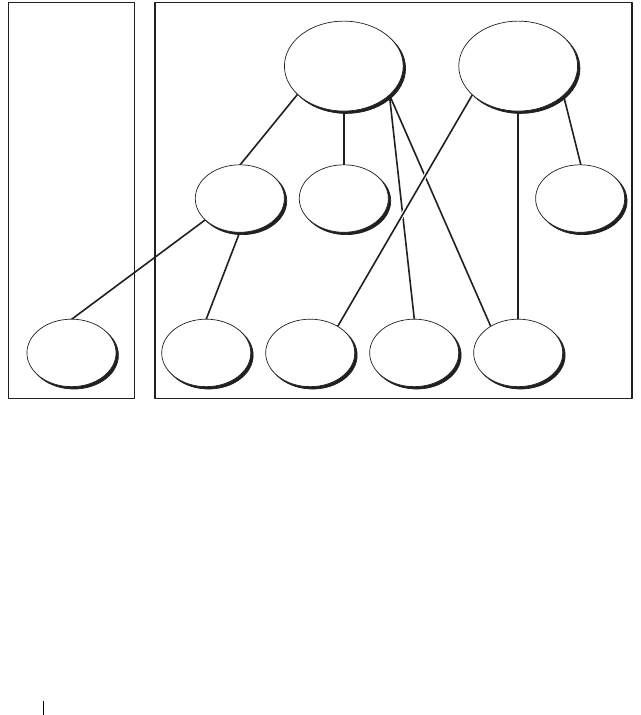
116 Using the DRAC 5 With Microsoft Active Directory
See "Adding DRAC 5 Users and Privileges to Active Directory" on page 124
for detailed instructions.
Figure 6-4 provides an example of Active Directory objects in multiple
domains. In this scenario, you have two DRAC 5 cards (RAC1 and RAC2)
and three existing Active Directory users (user1, user2, and user3). User1 is in
Domain1, and user2 and user 3 are in Domain2. In this scenario, configure
user1 and user 2 with administrator privileges to both DRAC 5 cards and
configure user3 with login privileges to the RAC2 card.
Figure 6-4. Setting Up Active Directory Objects in Multiple Domains
To configure the objects for the multiple domain scenario, perform the
following tasks:
1
Ensure that the domain forest function is in Native or Windows 2003
mode.
2
Create two Association Objects, AO1 (of Universal scope) and AO2,
in any domain.
Figure 6-4 shows the objects in Domain2.
3
Create two RAC Device Objects, RAC1 and RAC2, to represent the two
DRAC 5 cards.
AO1 AO2
Priv2Priv1Group1
RAC2RAC1User3User2User1
Domain2Domain1

Using the DRAC 5 With Microsoft Active Directory 117
4
Create two Privilege Objects, Priv1 and Priv2, in which Priv1 has all
privileges (administrator) and Priv2 has login privileges.
5
Group user1 and user2 into Group1. The group scope of Group1 must
be Universal.
6
Add Group1 as Members in Association Object 1 (AO1), Priv1 as Privilege
Objects in AO1, and RAC1, RAC2 as RAC Devices in AO1.
7
Add User3 as Members in Association Object 2 (AO2), Priv2 as Privilege
Objects in AO2, and RAC2 as RAC Devices in AO2.
Configuring Extended Schema Active Directory to Access Your DRAC 5
Before using Active Directory to access your DRAC 5, configure the Active
Directory software and the DRAC 5 by performing the following steps in
order:
1
Extend the Active Directory schema (see "Extending the Active Directory
Schema" on page 117).
2
Extend the Active Directory Users and Computers Snap-in (see "Installing
the Dell Extension to the Active Directory Users and Computers Snap-In"
on page 123).
3
Add DRAC 5 users and their privileges to Active Directory (see "Adding
DRAC 5 Users and Privileges to Active Directory" on page 124).
4
Enable SSL on each of your domain controllers (see "Enabling SSL on a
Domain Controller" on page 138).
5
Configure the DRAC 5 Active Directory properties using either the DRAC
5 Web-based interface or the RACADM (see "Configuring the DRAC 5
With Extended Schema Active Directory and Web-Based Interface" on
page 126 or "Configuring the DRAC 5 With Extended Schema Active
Directory and RACADM" on page 128).
Extending the Active Directory Schema
Extending your Active Directory schema adds a Dell organizational unit,
schema classes and attributes, and example privileges and association objects
to the Active Directory schema. Before you extend the schema, ensure that
you have Schema Admin privileges on the Schema Master Flexible Single
Master Operation (FSMO) Role Owner of the domain forest.

118 Using the DRAC 5 With Microsoft Active Directory
You can extend your schema using one of the following methods:
• Dell Schema Extender utility
• LDIF script file
If you use the LDIF script file, the Dell organizational unit will not be added
to the schema.
The LDIF files and Dell Schema Extender are located on your Dell Systems
Management Tools and Documentation DVD in the following respective
directories:
•
DVD drive
:\support\OMActiveDirectory Tools\RAC4-5\LDIF_Files
•
DVD drive
:\support\OMActiveDirectory Tools\RAC4-
5\Schema_Extender
To use the LDIF files, see the instructions in the readme included in the
LDIF_Files directory. To use the Dell Schema Extender to extend the Active
Directory Schema, see "Using the Dell Schema Extender" on page 118.
You can copy and run the Schema Extender or LDIF files from any location.
Using the Dell Schema Extender
CAUTION: The Dell Schema Extender uses the SchemaExtenderOem.ini file.
To ensure that the Dell Schema Extender utility functions properly, do not modify
the name of this file.
1
In the
Welcome
screen, click
Next.
2
Read and understand the warning and click
Next
.
3
Select
Use Current Log In Credentials
or enter a user name and password
with schema administrator rights.
4
Click
Next
to run the Dell Schema Extender.
5
Click
Finish
.
The schema is extended. To verify the schema extension, use the
Microsoft Management Console (MMC) and the Active Directory
Schema snap-in to verify that the following exist:
• Classes (see Table 6-2 through Table 6-7)
• Attributes (Table 6-8)
See your Microsoft documentation for more information on how to enable
and use the Active Directory Schema snap-in the MMC.

Using the DRAC 5 With Microsoft Active Directory 119
Table 6-2. Class Definitions for Classes Added to the Active Directory Schema
Class Name Assigned Object Identification Number (OID)
dellRacDevice 1.2.840.113556.1.8000.1280.1.1.1.1
dellAssociationObject 1.2.840.113556.1.8000.1280.1.1.1.2
dellRACPrivileges 1.2.840.113556.1.8000.1280.1.1.1.3
dellPrivileges 1.2.840.113556.1.8000.1280.1.1.1.4
dellProduct 1.2.840.113556.1.8000.1280.1.1.1.5
Table 6-3. dellRacDevice Class
OID 1.2.840.113556.1.8000.1280.1.1.1.1
Description Represents the Dell RAC device. The RAC device must be
configured as dellRacDevice in Active Directory.
This configuration enables the DRAC 5 to send
Lightweight Directory Access Protocol (LDAP) queries to
Active Directory.
Class Type Structural Class
SuperClasses dellProduct
Attributes dellSchemaVersion
dellRacType
Table 6-4. dellAssociationObject Class
OID 1.2.840.113556.1.8000.1280.1.1.1.2
Description Represents the Dell Association Object. The Association
Object provides the connection between the users and the
devices.
Class Type Structural Class
SuperClasses Group
Attributes dellProductMembers
dellPrivilegeMember

120 Using the DRAC 5 With Microsoft Active Directory
Table 6-5. dellRAC4Privileges Class
OID 1.2.840.113556.1.8000.1280.1.1.1.3
Description Used to define the privileges (Authorization Rights) for the
DRAC 5 device.
Class Type Auxiliary Class
SuperClasses None
Attributes dellIsLoginUser
dellIsCardConfigAdmin
dellIsUserConfigAdmin
dellIsLogClearAdmin
dellIsServerResetUser
dellIsConsoleRedirectUser
dellIsVirtualMediaUser
dellIsTestAlertUser
dellIsDebugCommandAdmin
Table 6-6. dellPrivileges Class
OID 1.2.840.113556.1.8000.1280.1.1.1.4
Description Used as a container Class for the Dell Privileges (Authorization Rights).
Class Type Structural Class
SuperClasses User
Attributes dellRAC4Privileges
Table 6-7. dellProduct Class
OID 1.2.840.113556.1.8000.1280.1.1.1.5
Description The main class from which all Dell products are derived.
Class Type Structural Class
SuperClasses Computer
Attributes dellAssociationMembers

Using the DRAC 5 With Microsoft Active Directory 121
Table 6-8. List of Attributes Added to the Active Directory Schema
Attribute Name/Description Assigned OID/Syntax Object Identifier Single
Valued
dellPrivilegeMember
List of dellPrivilege Objects
that belong to this Attribute.
1.2.840.113556.1.8000.1280.1.1.2.1
Distinguished Name (LDAPTYPE_DN
1.3.6.1.4.1.1466.115.121.1.12)
FALSE
dellProductMembers
List of dellRacDevices Objects
that belong to this role. This
attribute is the forward link to
the dellAssociationMembers
backward link.
Link ID: 12070
1.2.840.113556.1.8000.1280.1.1.2.2
Distinguished Name (LDAPTYPE_DN
1.3.6.1.4.1.1466.115.121.1.12)
FALSE
dellIsLoginUser
TRUE if the user has Login
rights on the device.
1.2.840.113556.1.8000.1280.1.1.2.3
Boolean (LDAPTYPE_BOOLEAN
1.3.6.1.4.1.1466.115.121.1.7)
TRUE
dellIsCardConfigAdmin
TRUE if the user has Card
Configuration rights on the
device.
1.2.840.113556.1.8000.1280.1.1.2.4
Boolean (LDAPTYPE_BOOLEAN
1.3.6.1.4.1.1466.115.121.1.7)
TRUE
dellIsUserConfigAdmin
TRUE if the user has User
Configuration rights on the
device.
1.2.840.113556.1.8000.1280.1.1.2.5
Boolean (LDAPTYPE_BOOLEAN
1.3.6.1.4.1.1466.115.121.1.7)
TRUE
delIsLogClearAdmin
TRUE if the user has Log
Clearing rights on the device.
1.2.840.113556.1.8000.1280.1.1.2.6
Boolean (LDAPTYPE_BOOLEAN
1.3.6.1.4.1.1466.115.121.1.7)
TRUE
dellIsServerResetUser
TRUE if the user has Server
Reset rights on the device.
1.2.840.113556.1.8000.1280.1.1.2.7
Boolean (LDAPTYPE_BOOLEAN
1.3.6.1.4.1.1466.115.121.1.7)
TRUE
dellIsConsoleRedirectUser
TRUE if the user has Console
Redirection rights on the
device.
1.2.840.113556.1.8000.1280.1.1.2.8
Boolean (LDAPTYPE_BOOLEAN
1.3.6.1.4.1.1466.115.121.1.7)
TRUE

122 Using the DRAC 5 With Microsoft Active Directory
dellIsVirtualMediaUser
TRUE if the user has Virtual
Media rights on the device.
1.2.840.113556.1.8000.1280.1.1.2.9
Boolean (LDAPTYPE_BOOLEAN
1.3.6.1.4.1.1466.115.121.1.7)
TRUE
dellIsTestAlertUser
TRUE if the user has Test
Alert User rights on the
device.
1.2.840.113556.1.8000.1280.1.1.2.10
Boolean (LDAPTYPE_BOOLEAN
1.3.6.1.4.1.1466.115.121.1.7)
TRUE
dellIsDebugCommandAdmin
TRUE if the user has Debug
Command Admin rights on
the device.
1.2.840.113556.1.8000.1280.1.1.2.11
Boolean (LDAPTYPE_BOOLEAN
1.3.6.1.4.1.1466.115.121.1.7)
TRUE
dellSchemaVersion
The Current Schema Version
is used to update the schema.
1.2.840.113556.1.8000.1280.1.1.2.12
Case Ignore String
(LDAPTYPE_CASEIGNORESTRING
1.2.840.113556.1.4.905)
TRUE
dellRacType
This attribute is the Current
Rac Type for the
dellRacDevice object and the
backward link to the
dellAssociationObjectMembe
rs forward link.
1.2.840.113556.1.8000.1280.1.1.2.13
Case Ignore String
(LDAPTYPE_CASEIGNORESTRING
1.2.840.113556.1.4.905)
TRUE
dellAssociationMembers
List of
dellAssociationObjectMembe
rs that belong to this Product.
This attribute is the backward
link to the
dellProductMembers Linked
attribute.
Link ID: 12071
1.2.840.113556.1.8000.1280.1.1.2.14
Distinguished Name (LDAPTYPE_DN
1.3.6.1.4.1.1466.115.121.1.12)
FALSE
Table 6-8. List of Attributes Added to the Active Directory Schema
(continued)
Attribute Name/Description Assigned OID/Syntax Object Identifier Single
Valued

Using the DRAC 5 With Microsoft Active Directory 123
Installing the Dell Extension to the Active Directory Users and
Computers Snap-In
When you extend the schema in Active Directory, you must also extend the
Active Directory Users and Computers snap-in so the administrator can
manage RAC (DRAC 5) devices, Users and User Groups, RAC Associations,
and RAC Privileges.
When you install your systems management software using the Dell Systems
Management Tools and Documentation DVD, you can extend the snap-in by
selecting the Dell Extension to the Active Directory User’s and Computers
Snap-In option during the installation procedure. See the Dell OpenManage
Software Quick Installation Guide for additional instructions about installing
systems management software.
For more information about the Active Directory User’s and Computers
snap-in, see your Microsoft documentation.
Installing the Administrator Pack
You must install the Administrator Pack on each system that is managing the
Active Directory DRAC 5 Objects. If you do not install the Administrator
Pack, you cannot view the Dell RAC Object in the container.
See "Opening the Active Directory Users and Computers Snap-In" on
page 123 for more information.
Opening the Active Directory Users and Computers Snap-In
To open the Active Directory Users and Computers snap-in:
1
If you are logged into the domain controller, click
Start
Admin Tools
Active Directory Users and Computers
.
If you are not logged into the domain controller, you must have the
appropriate Microsoft Administrator Pack installed on your local system.
To install this Administrator Pack, click
Start
Run
, type
MMC
, and
press
Enter
.
The Microsoft Management Console (MMC) appears.
2
In the
Console 1
window, click
File
(or
Console
on systems running
Windows 2000).
3
Click
Add/Remove Snap-in
.

124 Using the DRAC 5 With Microsoft Active Directory
4
Select the
Active Directory Users and Computers
snap-in and click
Add
.
5
Click
Close
and click
OK
.
Adding DRAC 5 Users and Privileges to Active Directory
Using the Dell-extended Active Directory Users and Computers snap-in, you
can add DRAC 5 users and privileges by creating RAC, Association, and
Privilege objects. To add each object type, perform the following procedures:
•Create a RAC device Object
• Create a Privilege Object
• Create an Association Object
• Add objects to an Association Object
Creating a RAC Device Object
1
In the MMC
Console Root
window, right-click a container.
2
Select
New
Dell RAC Object
.
The
New Object
window appears.
3
Type a name for the new object. The name must be identical to the
DRAC 5 Name that you will type in step a of "Configuring the DRAC 5
With Extended Schema Active Directory and Web-Based Interface" on
page 126.
4
Select
RAC Device Object
.
5
Click
OK
.
Creating a Privilege Object
NOTE: A Privilege Object must be created in the same domain as the related
Association Object.
1
In the
Console Root
(MMC) window, right-click a container.
2
Select
New
Dell RAC Object
.
The
New Object
window appears.
3
Type a name for the new object.
4
Select
Privilege Object
.
5
Click
OK
.

Using the DRAC 5 With Microsoft Active Directory 125
6
Right-click the privilege object that you created, and select
Properties
.
7
Click the
RAC Privileges
tab and select the privileges that you want the
user to have (for more information, see Table 5-4).
Creating an Association Object
The Association Object is derived from a Group and must contain a Group
Type. The Association Scope specifies the Security Group Type for the
Association Object. When you create an Association Object, choose the
Association Scope that applies to the type of objects you intend to add.
For example, if you select Universal, the association objects are only available
when the Active Directory Domain is functioning in Native Mode or above.
1
In the
Console Root
(MMC) window, right-click a container.
2
Select
New
Dell RAC Object
.
This opens the
New Object
window.
3
Type a name for the new object.
4
Select
Association Object
.
5
Select the scope for the
Association Object
.
6
Click
OK
.
Adding Objects to an Association Object
Using the Association Object Properties window, you can associate users or
user groups, privilege objects, and RAC devices or RAC device groups. If your
system is running Windows 2000 mode or higher, use Universal Groups to
span domains with your user or RAC objects.
You can add groups of Users and RAC devices. The procedure for creating
Dell-related groups and non-Dell-related groups is identical.
Adding Users or User Groups
1
Right-click the
Association Object
and select
Properties
.
2
Select the
Users
tab and click
Add
.
3
Type the user or User Group name and click
OK
.

126 Using the DRAC 5 With Microsoft Active Directory
Click the Privilege Object tab to add the privilege object to the association
that defines the user’s or user group’s privileges when authenticating to a
RAC device. Only one privilege object can be added to an Association Object.
Adding Privileges
1
Select the
Privileges Object
tab and click
Add
.
2
Type the Privilege Object name and click
OK
.
Click the Products tab to add one or more RAC devices to the association.
The associated devices specify the RAC devices connected to the network
that are available for the defined users or user groups. Multiple RAC devices
can be added to an Association Object.
Adding RAC Devices or RAC Device Groups
To add RAC devices or RAC device groups:
1
Select the
Products
tab and click
Add.
2
Type the RAC device or RAC device group name and click
OK
.
3
In the
Properties
window, click
Apply
and click
OK
.
Configuring the DRAC 5 With Extended Schema Active Directory and
Web-Based Interface
1
Open a supported Web browser window.
2
Log in to the DRAC 5 Web-based interface.
3
Expand the
System
tree and click
Remote Access
.
4
Click the
Configuration
tab and select
Active Directory
.
5
On the
Active Directory Main Menu
page, select
Configure Active
Directory
and click
Next
.
6
In the Common Settings section:
a
Select the
Enable Active Directory
check box.
b
Typ e t he
Root Domain Name
. The
Root Domain Name
is the
fully qualified root domain name for the forest.
c
Typ e t he
Timeout
time in seconds.
7
Click
Use Extended Schema
in the Active Directory Schema Selection
section.

Using the DRAC 5 With Microsoft Active Directory 127
8
In the Extended Schema Settings section:
a
Typ e t he
DRAC Name
. This name must be the same as the common
name of the new RAC object you created in your Domain Controller
(see step 3 of "Creating a RAC Device Object" on page 124).
b
Typ e t he
DRAC Domain Name
(for example,
drac5.com
). Do not
use the NetBIOS name. The
DRAC Domain Name
is the fully
qualified domain name of the sub-domain where the RAC Device
Object is located.
9
Click
Apply
to save the Active Directory settings.
10
Click
Go Back To Active Directory Main Menu
.
11
Upload your domain forest Root CA certificate into the DRAC 5.
a
Select the
Upload Active Directory CA Certificat
e check-box and
then click
Next
.
b
In the
Certificate Upload
page, type the file path of the certificate or
browse to the certificate file.
NOTE: The File Path value displays the relative file path of the certificate you
are uploading. You must type the absolute file path, which includes the full
path and the complete file name and file extension.
The domain controllers' SSL certificates should have been signed by
the root CA. Have the root CA certificate available on your
management station accessing the DRAC 5 (see "Exporting the
Domain Controller Root CA Certificate to the DRAC 5" on
page 138).
c
Click
Apply
.
The DRAC 5 Web server automatically restarts after you click
Apply
.
12
Log out and then log in to the DRAC 5 to complete the DRAC 5 Active
Directory feature configuration.
13
In the
System
tree, click
Remote Access
.
14
Click the
Configuration
tab and then click
Network
.
The
Network Configuration
page appears.

128 Using the DRAC 5 With Microsoft Active Directory
15
If
Use DHCP (for NIC IP Address)
is selected under
Network Settings
,
then select
Use DHCP to obtain DNS server address
.
To manually input a DNS server IP address, deselect
Use DHCP to obtain
DNS server addresses
and type your primary and alternate DNS server IP
addresses.
16
Click
Apply Changes
.
The DRAC 5 Extended Schema Active Directory feature configuration is
complete.
Configuring the DRAC 5 With Extended Schema Active Directory and
RACADM
Using the following commands to configure the DRAC 5 Active Directory
Feature with Extended Schema using the RACADM CLI tool instead of the
Web-based interface.
1
Open a command prompt and type the following racadm commands:
racadm config -g cfgActiveDirectory -o cfgADEnable
1
racadm config -g cfgActiveDirectory -o cfgADType 1
racadm config -g cfgActiveDirectory -o
cfgADRacDomain <fully qualified rac domain name>
racadm config -g cfgActiveDirectory -o
cfgADRootDomain <fully qualified root domain name>
racadm config -g cfgActiveDirectory -o
cfgADRacName <RAC common name>
racadm sslcertupload -t 0x2 -f <ADS root CA
certificate>
racadm sslcertdownload -t 0x1 -f <RAC SSL
certificate>
2
If DHCP is enabled on the DRAC 5 and you want to use the DNS
provided by the DHCP server, type the following racadm command:
racadm config -g cfgLanNetworking -o
cfgDNSServersFromDHCP 1

Using the DRAC 5 With Microsoft Active Directory 129
3
If DHCP is disabled on the DRAC 5 or you want to input your DNS IP
address, type following racadm commands:
racadm config -g cfgLanNetworking -o
cfgDNSServersFromDHCP 0
racadm config -g cfgLanNetworking -o cfgDNSServer1
<primary DNS IP address>
racadm config -g cfgLanNetworking -o cfgDNSServer2
<secondary DNS IP address>
Press Enter to complete the DRAC 5 Active Directory feature configuration.
Instead of DRAC 5 searching for Active Directory servers, you can specify the
servers DRAC 5 needs to connect to, to authenticate the user. See "Specify
Server for Active Directory Configuration" on page 131 for information on
RACADM commands to specify servers.
Accumulating Privileges Using Extended Schema
The Extended Schema Authentication mechanism supports Privilege
Accumulation from different privilege objects associated with the same user
through different Association Objects. In other words, Extended Schema
Authentication accumulates privileges to allow the user the super set of all
assigned privileges corresponding to the different privilege objects associated
with the same user.
Figure 6-5 provides an example of accumulating privileges using Extended
Schema.
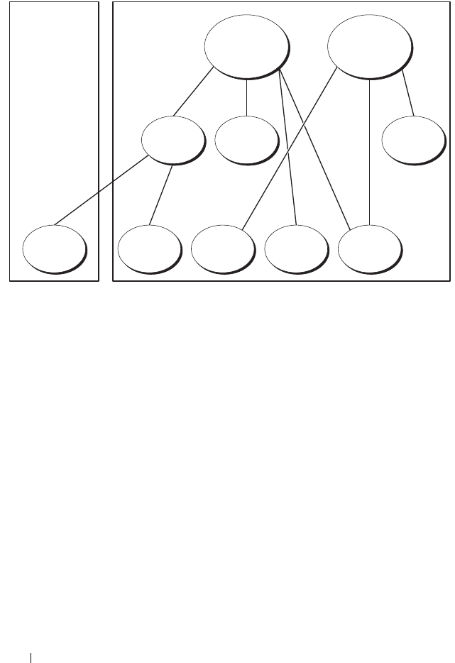
130 Using the DRAC 5 With Microsoft Active Directory
Figure 6-5. Privilege Accumulation for a User
The figure shows two Association Objects—A01 and A02. These Association
Objects may be part of the same or different domains. User1 is associated to
RAC1 and RAC2 through both association objects. Therefore, User1 has
accumulated privileges that results when combining the Privileges set for
objects Priv1 and Priv2.
For example, Priv1 had the privileges: Login, Virtual Media, and Clear Logs
and Privr2 had the privileges: Login, Configure DRAC, and Test Alerts.
User1 will now have the privilege set: Login, Virtual Media, Clear Logs,
Configure DRAC, and Test Alerts, which is the combined privilege set of
Priv1 and Priv2
Extended Schema Authentication, thus, accumulates privileges to allow the
user the maximum set of privileges possible considering the assigned
privileges of the different privilege objects associated to the same user.
A01 A02
Group1 Priv1 Priv2
User1 User2 User1 RAC1 RAC2

Using the DRAC 5 With Microsoft Active Directory 131
Specify Server for Active Directory Configuration
If you want to specify an LDAP, Global Catalog server, or Association Object
(applicable only for Extended Schema) domain instead of using the servers
returned by the DNS server to search for a user name, type the following
command to enable the Specify Server option:
racadm config -g cfgActive Directory -o
cfgADSpecifyServer Enable 1
NOTE: If you use this option, the hostname in the CA certificate is not matched
against the name of the specified server. This is particularly useful if you are a
DRAC administrator because it enables you to enter a hostname as well as an
IP address.
After the Specify Server option is enabled, you can specify an LDAP server or
a Global Catalog server with an IP address or a fully qualified domain name of
the server (FQDN). The FQDN consists of the hostname and the domain
name of the server.
NOTE: If you are using Active Directory authentication based on Kerberos, specify
only the FQDN of the server; specifying the IP address is not supported. For more
information, see "Enabling Kerberos Authentication" on page 147.
To specify an LDAP server using the command line interface (CLI), type:
racadm config -g cfgActive Directory -o
cfgADDomainController <fully qualified domain name or
IP address>
To specify a Global Catalog server using the command line interface (CLI),
type:
racadm config -g cfgActive Directory -o
cfgGlobalCatalog <fully qualified domain name or
IP address>
To specify an Association Object (applicable only for Extended Schema)
domain using the CLI, type:
racadm config -g cfgActive Directory -o cfgAODomain
<domain>:<fully qualified domain name or IP address>
where <domain> is the domain where the Association Object resides and
IP/FQDN is the IP address or the FQDN of the specific host (Domain
Controller of domain) to which the DRAC 5 connects.

132 Using the DRAC 5 With Microsoft Active Directory
To specify the Association Object, ensure that you also provide the IP or
FQDN of the Global Catalog.
NOTE: If you specify the IP address as 0.0.0.0, DRAC 5 will not search for any
server.
You can specify a list of LDAP, Global Catalog servers, or Association Objects
separated by commas. DRAC 5 allows you to specify up to four IP addresses
or hostnames.
If LDAPS is not correctly configured for all domains and applications,
enabling it may produce unexpected results during the functioning of the
existing applications/domains.
For Extended Schema, you can specify either Domain Controller or Global
Catalog with Association Object. Specifying only the Global Catalog or only
the Association Object is not applicable for Extended Schema. If you specify
only the Domain Controller, all objects including User, Group, RAC,
Privilege and Association should be on the same domain. If any of these
objects are on different domains, use the Global Catalog with the Association
Object option. You can specify up to four Domain Controllers and all these
entries should point to the same domain. You can specify up to four Global
Catalog servers. You can specify up to four Association Object servers. All
these entries should point to the same domain. In case you are using the
Association Object option, you should also configure the Global Catalog
option to be able to log in. Specify the Domain Controller name where you
created the user. Both IP or FQDN can be specified here.
For Standard Schema, specify only the Domain Controller and the Global
Catalog. Specify Association Object is not applicable with Standard Schema.
You can specify the Domain Controller where the user role groups are
created. Specify either the IP or the FQDN. You can specify up to four
Domain Controllers. All entries should point to the same domain. If you
specify only the Domain Controller, the User and Group should be on the
same domain. If the Role Groups are on different domains, you have to also
specify the Global Catalog server. You can specify up to four Global Catalog
servers. Both the IP or the FQDN can be specified here. You can also only
specify the Global Catalog servers.

Using the DRAC 5 With Microsoft Active Directory 133
Configuring and Managing Active Directory
Certificates
To access the Active Directory Main Menu:
1
Expand the
System
tree and click
Remote Access
.
2
Click the
Configuration
tab and click
Active Directory
.
Tabl e 6-9 l ist s the Active Directory Main Menu page options.
Configuring Active Directory (Standard Schema and Extended Schema)
1
In the
Active Directory Main Menu
page, select
Configure Active
Directory
and click
Next
.
2
In the
Active Directory Configuration and Management
page, enter the
Active Directory settings.
Table 6-10 describes the
Active Directory Configuration and
Management
page settings.
3
Click
Apply
to save the settings.
Table 6-9. Active Directory Main Menu Page Options
Field Description
Configure Active
Directory
Configures the Active Directory's DRAC Name, ROOT
Domain Name, DRAC Domain Name, Active Directory
Authentication Timeout, Active Directory Schema
Selection, and Role Group settings.
Upload Active
Directory CA
Certificate
Uploads an Active Directory certificate to the DRAC.
Download DRAC
Server Certificate
The Windows Download Manager enables you to
download a DRAC server certificate to your system.
View Active Directory
CA Certificate
Displays the Active Directory Certificate that has been
uploaded to the DRAC.

134 Using the DRAC 5 With Microsoft Active Directory
4
Click the appropriate
Active Directory Configuration
page button to
continue. See Table 6-11.
5
To configure the Role Groups for Active Directory Standard Schema, click
on the individual Role Group (1-5). See Table 6-12 and Table 6-13.
NOTE: To save the settings on the Active Directory Configuration and
Management page, you have to click Apply before proceeding to the Custom
Role Group page.
Table 6-10. Active Directory Configuration and Management Page Settings
Setting Description
Enable Active
Directory
Enables Active Directory. Checked=Enabled;
Unchecked=Disabled.
ROOT Domain Name The Active Directory ROOT domain name. This value is
NULL by default.
The name must be a valid domain name consisting of x.y,
where x is a 1-254 character ASCII string with no blank
spaces between characters, and y is a valid domain type
such as com, edu, gov, int, mil, net, org.
Timeout The time in seconds to wait for Active Directory queries
to complete. Minimum value is equal to or greater than 15
seconds. The default value is 120 seconds.
Use Standard Schema Uses Standard Schema with Active Directory
Use Extended Schema Uses Extended Schema with Active Directory
DRAC Name The name that uniquely identifies the DRAC 5 card in
Active Directory. This value is NULL by default.
The name must be a 1-254 character ASCII string with no
blank spaces between characters.
DRAC Domain Name The DNS name (string) of the domain, where the Active
Directory DRAC 5 object resides. This value is NULL by
default.
The name must be a valid domain name consisting of x.y,
where x is a 1-254 character ASCII string with no blank
spaces between characters, and y is a valid domain type
such as com, edu, gov, int, mil, net, org.

Using the DRAC 5 With Microsoft Active Directory 135
Role Groups The list of role groups associated with the DRAC 5 card.
To change the settings for a role group, click their role
group number, in the role groups list. The Configure Role
Group window displays.
NOTE: If you click on the role group link prior to applying the
settings for the Active Directory Configuration and
Management page, you will lose these settings.
Group Name The name that identifies the role group in the Active
Directory associated with the DRAC 5 card.
Group Domain The domain that the group is in.
Group Privilege The privilege level for the group.
Table 6-11. Active Directory Configuration and Management Page Buttons
Button Description
Print Prints the Active Directory Configuration and
Management page.
Apply Saves the changes made to the Active Directory
Configuration and Management page.
Go Back to Active
Directory Main Menu
Returns to the Active Directory Main Menu page.
Table 6-12. Role Group Privileges
Setting Description
Role Group Privilege Level Specifies the user’s maximum DRAC user
privilege to one of the following: Administrator,
Power User, Guest user, None, or Custom.
See Table 6-13 for Role Group permissions
Login to DRAC Enables the user to log in to the DRAC.
Configure DRAC Enables the user to configure the DRAC.
Table 6-10. Active Directory Configuration and Management Page Settings
(continued)
Setting Description

136 Using the DRAC 5 With Microsoft Active Directory
Configure Users Enables the user to allow specific users to access
the system.
Clear Logs Enables the user to clear the DRAC logs.
Execute Server Control
Commands
Enables the user to execute racadm commands.
Access Console Redirection Enables the user to run Console Redirection.
Access Virtual Media Enables the user to run and use Virtual Media.
Test Alerts Enables the user to send test alerts (e-mail and
PET) to a specific user.
Execute Diagnostic Commands Enables the user to run diagnostic commands.
Table 6-13. Role Group Permissions
Property Description
Administrator Login to DRAC, Configure DRAC, Configure Users, Clear
Logs, Execute Server Control Commands, Access Console
Redirection, Access Virtual Media, Test Alerts, Execute
Diagnostic Commands
Power User Login to DRAC, Clear Logs, Execute Server Control
Commands, Access Console Redirection, Access Virtual
Media, Test Alerts
Guest User Login to DRAC
Custom Selects any combination of the following permissions: Login to
DRAC, Configure DRAC, Configure Users, Clear Logs,
Execute Server Action Commands, Access Console
Redirection, Access Virtual Media, Test Alerts, Execute
Diagnostic Commands
None No assigned permissions
Table 6-12. Role Group Privileges
(continued)
Setting Description

Using the DRAC 5 With Microsoft Active Directory 137
Uploading an Active Directory CA Certificate
1
In the
Active Directory Main Menu
page, select
Upload Active Directory
CA Certificate
and click
Next
.
2
In the
Certificate Upload page,
in the
File Path
field, type the file path of
the certificate or click
Browse
to navigate to the certificate file.
NOTE: The File Path value displays the relative file path of the certificate you
are uploading. You must type the absolute file path, which includes the full
path and the complete file name and file extension.
3
Click
Apply
.
4
Click the appropriate
Certificate Upload
page button to continue. See
Table 6-11.
Downloading a DRAC Server Certificate
1
In the
Active Directory Main Menu
page, select
Download DRAC Server
Certificate
and click
Next
.
2
In the
File Download
window, click
Save
and save the file to a directory on
your system.
3
In the
Download Complete
window, click
Close
.
Viewing an Active Directory CA Certificate
Use the Active Directory Main Menu page to view a CA server certificate for
your DRAC 5.
1
In the
Active Directory Main Menu
page, select
View Active Directory
CA Certificate
and click
Next
.
Table 6-14 describes the fields and associated descriptions listed in the
Certificate
window.
2
Click the appropriate
View Active Directory CA Certificate
page button
to continue. See Table 6-11.
Table 6-14. Active Directory CA Certificate Information
Field Description
Serial Number Certificate serial number.
Subject Information Certificate attributes entered by the subject.
Issuer Information Certificate attributes returned by the issuer.

138 Using the DRAC 5 With Microsoft Active Directory
Enabling SSL on a Domain Controller
When the DRAC 5 authenticates users against an Active Directory domain
controller, it starts an SSL session with the domain controller. At this time,
the domain controller should publish a certificate signed by the Certificate
Authority (CA)—the root certificate of which is also uploaded into the
DRAC 5. In other words, for DRAC 5 to be able to authenticate to any
domain controller—whether it is the root or the child domain controller—
that domain controller should have an SSL-enabled certificate signed by the
domain’s CA.
If you are using Microsoft Enterprise Root CA to automatically assign all your
domain controllers to an SSL certificate, perform the following steps to
enable SSL on each domain controller:
1
Enable SSL on each of your domain controllers by installing the SSL
certificate for each controller.
a
Click
Start
Administrative Tools
Domain Security Policy
.
b
Expand the
Public Key Policies
folder, right-click
Automatic
Certificate Request Settings
and click
Automatic Certificate
Request
.
c
In the
Automatic Certificate Request Setup Wizard
, click
Next
and
select
Domain Controller
.
d
Click
Next
and click
Finish
.
Exporting the Domain Controller Root CA Certificate to the DRAC 5
NOTE: If your system is running Windows 2000, the following steps may vary.
1
Locate the domain controller that is running the Microsoft Enterprise
CA service.
2
Click
Start
Run
.
3
In the
Run
field, type
mmc
and click
OK
.
Valid Fr o m Certificate issue date.
Valid To Certificate expiration date.
Table 6-14. Active Directory CA Certificate Information
(continued)
Field Description

Using the DRAC 5 With Microsoft Active Directory 139
4
In the
Console 1
(MMC) window, click
File (
or
Console
on Windows 2000
machines
)
and select
Add/Remove Snap-in
.
5
In the
Add/Remove Snap-In
window, click
Add
.
6
In the
Standalone Snap-In
window, select
Certificates
and click
Add
.
7
Select
Computer
account and click
Next
.
8
Select
Local Computer
and click
Finish
.
9
Click
OK
.
10
In the
Console 1
window, expand the
Certificates
folder, expand the
Personal
folder, and click the
Certificates
folder.
11
Locate and right-click the root CA certificate, select
All Tasks
,
and click
Export...
.
12
In the
Certificate Export Wizard
, click
Next
, and select
No do not export
the private key
.
13
Click
Next
and select
Base-64 encoded X.509 (.cer)
as the format.
14
Click
Next
and save the certificate to a directory on your system.
15
Upload the certificate you saved in step 14 to the DRAC 5.
To upload the certificate using RACADM, see "Configuring the DRAC 5
With Extended Schema Active Directory and Web-Based Interface" on
page 126.
To upload the certificate using the Web-based interface, perform the
following procedure:
a
Open a supported Web browser window.
b
Log in to the DRAC 5 Web-based interface.
c
Expand the
System
tree and click
Remote Access
.
d
Click the
Configuration
tab, and then click
Security
.
e
In the
Security Certificate Main Menu
page, select
Upload Server
Certificate
and click
Apply
.

140 Using the DRAC 5 With Microsoft Active Directory
f
In the
Certificate Upload
screen, perform one of the following
procedures:
•Click
Browse
and select the certificate
•In the
Val ue
field, type the path to the certificate.
g
Click
Apply
.
Importing the DRAC 5 Firmware SSL Certificate
NOTE: If the Active Directory Server is set to authenticate the client during an SSL
session initialization phase, you need to upload the DRAC 5 Server certificate to the
Active Directory Domain controller as well. This additional step is not required if the
Active Directory does not perform a client authentication during an SSL session’s
initialization phase.
Use the following procedure to import the DRAC 5 firmware SSL certificate
to all domain controller trusted certificate lists.
NOTE: If your system is running Windows 2000, the following steps may vary.
NOTE: If the DRAC 5 firmware SSL certificate is signed by a well-known CA, you
are not required to perform the steps in this section.
The DRAC 5 SSL certificate is the identical certificate used for the DRAC 5
Web server. All DRAC 5 controllers are shipped with a default self-signed
certificate.
To access the certificate using the DRAC 5 Web-based interface, select
Configuration Active DirectoryDownload DRAC 5 Server Certificate.
1
On the domain controller, open an
MMC Console
window and select
Certificates
Trusted Root Certification Authorities
.
2
Right-click
Certificates
, select
All Tasks
and click
Import
.
3
Click
Next
and browse to the SSL certificate file.
4
Install the RAC SSL Certificate in each domain controller’s
Trusted Root
Certification Authority
.
If you have installed your own certificate, ensure that the CA signing your
certificate is in the
Trusted Root Certification Authority
list. If the
Authority is not in the list, you must install it on all your Domain Controllers.

Using the DRAC 5 With Microsoft Active Directory 141
5
Click
Next
and select whether you would like Windows to automatically
select the certificate store based on the type of certificate, or browse to a
store of your choice.
6
Click
Finish
and click
OK
.
Setting the SSL Time on the DRAC 5
When the DRAC 5 authenticates an Active Directory user, the DRAC 5 also
verifies the certificate published by the Active Directory server to ensure that
the DRAC is communicating with an authorized Active Directory server.
This check also ensures that the validity of the certificate is within the time
range specified by the DRAC 5. However, there could be a mismatch between
the time zones specified on the certificate and the DRAC 5. This could
happen when the DRAC 5 time reflects the local system time and the
certificate reflects time in GMT.
To ensure that the DRAC 5 uses the GMT time to compare with the
certificate times, you must set the time zone offset object.
racadm config -g cfgRacTuning -o
cfgRacTuneTimeZoneOffset <offset value>
See "cfgRacTuneTimezoneOffset (Read/Write)" on page 380 for more
details.
Supported Active Directory Configuration
The Active Directory querying algorithm of the DRAC 5 supports multiple
trees in a single forest.
DRAC 5 Active Directory Authentication supports mixed mode (that is, the
domain controllers in the forest run different operating systems, such as
Microsoft Windows NT 4.0, Windows 2000, or Windows Server 2003).
However, all objects used by the DRAC 5 querying process (among user,
RAC Device Object, and Association Object) should be in the same domain.
The Dell-extended Active Directory Users and Computers snap-in checks
the mode and limits users in order to create objects across domains if in
mixed mode.

142 Using the DRAC 5 With Microsoft Active Directory
DRAC 5 Active Directory supports multiple domain environments provided
the domain forest function level is Native mode or Windows 2003 mode. In
addition, the groups among Association Object, RAC user objects, and RAC
Device Objects (including Association Object) must be universal groups.
NOTE: The Association Object and the Privilege Object must be in the same
domain. The Dell-extended Active Directory Users and Computers snap-in forces
you to create these two objects in the same domain. Other objects can be in
different domains.
Using Active Directory to Log Into the DRAC 5
You can use Active Directory to log in to the DRAC 5 using one of the
following methods:
• Web-based interface
• Remote RACADM
• Serial or telnet console.
The login syntax is the same for all three methods:
<username@domain>
or
<domain>\<username> or <domain>/<username>
where username is an ASCII string of 1–256 bytes.
White space and special characters (such as \, /, or @) cannot be used in the
user name or the domain name.
NOTE: You cannot specify NetBIOS domain names, such as Americas, because
these names cannot be resolved.
You can also log into the DRAC 5 using the Smart Card. For more
information, see "Logging Into the DRAC 5 Using the Smart Card" on
page 157.

Using the DRAC 5 With Microsoft Active Directory 143
Using Active Directory Single Sign-On
You can enable the DRAC 5 to use Kerberos—a network authentication
protocol—to enable single sign-on and log into the DRAC 5. For more
information on setting up the DRAC 5 to use the Active Directory Single
Sign-On feature, see "Enabling Kerberos Authentication" on page 147.
Configuring the DRAC 5 to Use Single Sign-On
1
Navigate to
Remote Access
Configuration
tab
Active Directory
subtab
select
Configure Active Directory
.
2
On the
Active Directory Configuration and Management
page, select
Single Sign-On
.
This option enables you to log into the DRAC 5 directly after logging into
your workstation.
Logging Into the DRAC 5 Using Single Sign-On
1
Log into your work station using your network account.
2
Access DRAC Web page using https.
https://<
IP address>
If the default HTTPS port number (port 443) has been changed, type:
https://<
IP address>
:<
port number
>
where
IP address
is the IP address for the DRAC 5 and
port number
is the HTTPS port number.
The DRAC 5 Single Sign-On page appears.
3
Click
Login
.
The DRAC 5 logs you in, using your credentials that were cached in the
operating system when you logged in using your valid Active Directory
account
.

144 Using the DRAC 5 With Microsoft Active Directory
Frequently Asked Questions
Are there any restrictions on Domain Controller SSL configuration?
Yes. All Active Directory servers’ SSL certificates in the forest must be signed
by the same root CA since DRAC 5 only allows uploading one trusted CA
SSL certificate.
I created and uploaded a new RAC certificate and now the Web-based
interface does not launch.
If you use Microsoft Certificate Services to generate the RAC certificate, one
possible cause of this is you inadvertently chose User Certificate instead of
Web Certificate when creating the certificate.
To recover, generate a CSR and then create a new web certificate from
Microsoft Certificate Services and load it using the RACADM CLI from the
managed system by using the following racadm commands:
racadm sslcsrgen [-g] [-u] [-f {filename}]
racadm sslcertupload -t 1 -f {web_sslcert}
What can I do if I cannot log into the DRAC 5 using Active Directory
authentication? How do I troubleshoot the issue?
1
Ensure that you use the correct user domain name during a login and not
the NetBIOS name.
2
If you have a local DRAC user account, log into the DRAC 5 using your
local credentials.
After you are logged in:
a
Ensure that you have checked the
Enable Active Directory
box on the
DRAC 5 Active Directory configuration page.
b
Ensure that the DNS setting is correct on the DRAC 5 Networking
configuration page.
c
Ensure that you have uploaded the Active Directory certificate from
your Active Directory root CA to the DRAC 5.
d
Check the Domain Controller SSL certificates to ensure that they
have not expired.

Using the DRAC 5 With Microsoft Active Directory 145
e
Ensure that your
DRAC Name
,
Root Domain Name
, and
DRAC
Domain Name
match your Active Directory environment
configuration.
f
Ensure that the DRAC 5 password has a maximum of 127 characters.
While the DRAC 5 can support passwords of up to 256 characters,
Active Directory only supports passwords that have a maximum
length of 127 characters.
SSO login fails with Active Directory users on Windows 7 operating systems.
What should I do to resolve this?
You must enable the encryption types for Windows 7. To enable the
encryption types (for standard and extended schema):
1
Log in as administrator or as a user with adminstrative privilege.
2
Go to
Start
and run
gpedit.msc
.
The
Local Group Policy Editor
window is displayed.
3
Navigate to
Local Computer Settings
Windows Settings
Security
Settings
Local Policies
Security Options
.
4
Right-click
Network Security: Configure encryption types allowed for
kerberos
and select
Properties
.
5
Enable all the options and click
OK
.
You can now log in to iDRAC using SSO.
6
In the
Local Group Policy Editor
window, navigate to
Local Computer
Settings
Windows Settings
Security Settings
Local Policies
Security Options
.
7
Right-click
Network Security: Restrict NTLM: Outgoing NTLM traffic
to remote server
and select
Properties
.
8
Select
Allow all
, click
OK
, and then close the
Local Group Policy Editor
window.
9
Go to
Start
and run
cmd
.
The
command prompt
window is displayed.
10
Run the command
gpupdate /force
.
The group policies are updated.
11
Close the
command prompt
window.

146 Using the DRAC 5 With Microsoft Active Directory
Perform the following additional settings for extended schema:
1
Go to
Start
and run
regedit
.
The
Registry Editor
window is displayed.
2
Navigate to
HKEY_LOCAL_MACHINE
System
CurrentControlSet
Control
LSA
.
3
In the right-pane, right-click and select
New
DWORD (32-bit) Value
.
4
Name the new key as
SuppressExtendedProtection
.
5
Right-click
SuppressExtendedProtection
and click
Modify
.
6
In the
Val ue d a ta
field, type
1
and click
OK
.
7
Close the
Registry Editor
window.
You can now log in to iDRAC using SSO.

Enabling Kerberos Authentication 147
7
Enabling Kerberos Authentication
Kerberos is a network authentication protocol that allows systems to
communicate securely over a non-secure network. It achieves this by allowing
the systems to prove their authenticity.
Microsoft Windows 2000, Windows XP, Windows Server 2003,
Windows Vista, and Windows Server 2008 use Kerberos as their default
authentication method.
Starting with DRAC 5 version 1.40, the DRAC 5 uses Kerberos to support
two types of authentication mechanisms—single sign-on and Active
Directory Smart Card login. For the single-sign on, the DRAC 5 uses the user
credentials cached in the operating system after the user has logged in using
a valid Active Directory account.
Starting with DRAC 5 version 1.40, Active Directory authentication will use
the Smart Card-based two factor authentication (TFA) in addition to the
username-password combination, as valid credentials.
Prerequisites for Setting up Kerberos
Authentication
• Configure the DRAC 5 for Active Directory login. For more information,
see "Using Active Directory to Log Into the DRAC 5" on page 142.
• For the Active Directory users for whom you want to provide Kerberos
authentication, set the following properties:
• Use DES encryption types for this account
• Do not require Kerberos pre-authentication
• Register the DRAC 5 as a computer in the Active Directory root domain.
a
Navigate to
Remote Access
Configuration
tab
Network
subtab
Network Settings
.
b
Provide a valid
Preferred/Static DNS Server
IP address. This value is
the IP address of the DNS that is part of the root domain, which
authenticates the Active Directory accounts of the users.

148 Enabling Kerberos Authentication
c
Select
Register DRAC on DNS
.
d
Provide a valid
DNS Domain Name
.
NOTE: Ensure that the DNS name is resolved by the DNS server.
See the
DRAC 5 Online Help
for more information.
• Synchronize the DRAC 5 time settings with that of the Active Directory
Domain Controller. Kerberos authentication on DRAC 5 fails if the
DRAC time differs from the Domain Controller time. A maximum offset
of 5 minutes is allowed. To enable successful authentication, synchronize
the server time with the Domain Controller time and then
reset
the
DRAC time.
You can also use the following RACADM time zone offset command to
synchronize the time:
racadm config -g cfgRacTuning -o
cfgRacTuneTimeZoneOffset offset-value
Offset value is the offset time in minutes.
• Install Microsoft Visual C++ 2005 Redistributable Package on the client
system.
• Run the
ktpass
utility on Active Directory Server.
DRAC 5 is a device with a non-Windows operating system, so you need to
run the
ktpass
utility— part of Microsoft Windows
— on the Domain
Controller (Active Directory server) where you want to map the DRAC 5
to a user account in Active Directory. To do this,
a
Start the Active Directory Management tool.
b
Right-click the
Users
folder, select
New
, and then click
User
.
c
Type the name of the DRAC5 host for which you want to add
Kerberos support.
d
Save the user.

Enabling Kerberos Authentication 149
e
Start a command prompt, and then type the following command:
C:\>ktpass -princ HOST/dracname.domain-
name.com@DOMAIN-NAME.COM -mapuser account -
crypto DES-CBC-MD5 -ptype KRB5_NT_PRINCIPAL -
pass password -out c:\krbkeytab
where:
•
dracname
is the DRAC 5’s DNS name.
•
domain-name
is the Active Directory domain name with which
you want to authenticate. It should be replaced by the actual
domain name in capital letters.
•
account
is the user name, a valid user account that you created
in Active Directory in step b and step c. It should be provided in
the
domain-name.com/user-name
format.
•
password
is the password for the user account.
•
DES-CBC-MD5
is the encryption type that DRAC 5 uses for
Kerberos authentication.
•
KRB5_NT_PRINCIPAL
is the principal type.
f
Upload the resulting keytab file to the DRAC 5 host.
NOTE: It is recommended that you use the latest ktpass utility to create the
keytab file.
This procedure will produce a keytab file that you should upload to the
DRAC 5.
NOTE: The keytab contains an encryption key and should be kept secure.
For more information on the
ktpass
utility, see the Microsoft website at:
http://technet2.microsoft.com/windowsserver/en/library/64042138-9a5a-
4981-84e9-d576a8db0d051033.mspx?mfr=true

150 Enabling Kerberos Authentication
Configuring DRAC 5 for Kerberos Authentication
Upload the keytab obtained from the Active Directory root domain, to the
DRAC 5:
1
Navigate to
Remote Access
Configuration
tab
Active Directory
subtab.
2
Select
Upload Kerberos Keytab
and click
Next
.
3
On the
Kerberos Keytab Upload
page, select the keytab file to upload and
click
Apply
.

Enabling Single Sign-On 151
8
Enabling Single Sign-On
Single Sign-On allows you to log into the DRAC without providing your
credentials, after you have logged into the operating system using a valid
Active Directory account. In this case, DRAC uses the credentials cached in
the operating system. DRAC uses Kerberos, a network authentication
protocol, for single sign-on.
Prerequisites for Setting up Single Sign-On
• Configure DRAC 5 for Active Directory login. For more information, see
"Using Active Directory to Log Into the DRAC 5" on page 142.
• Set up
Kerberos authentication for DRAC 5. For more information, see
"Enabling Kerberos Authentication
" on page 147
.
Configuring DRAC 5 to Use Single Sign-On
1
Navigate to
Remote Access
Configuration
tab
Active Directory
subtab and select
Configure Active Directory
.
2
On the
Active Directory Configuration and Management
page, select
Single Sign-On
.
This option enables you to log into DRAC 5 directly after logging into your
workstation.

152 Enabling Single Sign-On
Logging Into DRAC 5 Using Single Sign-On
NOTE: To log into the DRAC 5, ensure that you have the latest runtime
components of Microsoft Visual C++ 2005 Libraries. For more information,
see the Microsoft website.
1
Log into your system using a valid Active Directory account.
2
Type the web address of the DRAC 5 in the address bar of your browser.
NOTE: Depending on your browser settings, you may be prompted to
download and install the Single Sign-On ActiveX plug-in when using this
feature for the first time.
You are logged into the DRAC 5.

Configuring Smart Card Authentication 153
9
Configuring Smart Card
Authentication
The Dell Remote Access Controller 5 (DRAC 5) version 1.30 and later
support the two-factor-authentication for logging into the DRAC 5 Web
interface. This support is provided by the Smart Card Logon feature on the
DRAC 5.
The traditional authentication schemes use user name and password to
authenticate users. This provides minimal security.
Two-factor-authentication, on the other hand, provides a higher-level of
security by requiring users to have a password or PIN and a private key for
a digital certificate.
The two-factor authentication requires users to verify their identities by
providing both factors.
Configuring Smart Card Login in DRAC 5
Enable the DRAC 5 Smart Card logon feature from Remote Access
Configuration Smart Card.
If you:
•
Disable
Smart Card configuration, you are prompted for a Microsoft
Active Directory or local logon username and password.
•
Enable
or
Enable with Remote Racadm
, you are prompted for a Smart
Card logon during any subsequent logon attempts using the GUI.
When you select
Enable
, all command line interface (CLI) out-of-band
interfaces, such as telnet, ssh, serial, remote racadm, and IPMI over LAN,
are disabled. This is because these services support only single-factor
authentication.

154 Configuring Smart Card Authentication
When you select
Enable with Remote Racadm
, all CLI out-of-band
interfaces, except remote racadm, are disabled.
NOTE: Dell recommends that the DRAC 5 administrator use the Enable with
Remote Racadm setting only to access the DRAC 5 user interface to run
scripts using the remote racadm commands. If the administrator does not
need to use the remote racadm, Dell recommends the Enabled setting for
Smart Card logon. Also, ensure that the DRAC 5 local user configuration
and/or Active Directory configuration is complete before enabling Smart
Card Logon.
•
Enable CRL check for Smart Card Logon
, the user's DRAC certificate,
which is downloaded from the Certificate Revocation List (CRL)
distribution server is checked for revocation in the CRL.
NOTE: The CRL distribution servers are listed in the Smart Card certificates of
the users.
Configuring Local DRAC 5 Users for
Smart Card Logon
You can configure the local DRAC 5 users to log into the DRAC 5 using the
Smart Card. Navigate to Remote Access Configuration Users.
However, before the user can log into the DRAC 5 using the Smart Card,
you must upload the user's Smart Card certificate and the trusted Certificate
Authority (CA) certificate to the DRAC 5.
Exporting the Smart Card Certificate
You can obtain the user's certificate by exporting the Smart Card certificate
using the card management software (CMS) from the Smart Card to a file in
the Base64 encoded form. You can usually obtain the CMS from the vendor
of the Smart Card. This encoded file should be uploaded as the user's
certificate to the DRAC 5. The trusted Certificate Authority that issues the
Smart Card user certificates should also export the CA certificate to a file in
the Base64 encoded form. You should upload this file as the trusted CA
certificate for the user. Configure the user with the username that forms the
user’s User Principle Name (UPN) in the Smart Card certificate.
NOTE: To log into the DRAC 5, the user name that you configure in the DRAC 5
should have the same case as the User Principle Name (UPN) in the Smart Card
certificate.

Configuring Smart Card Authentication 155
For example, in case the Smart Card certificate has been issued to the user,
"sampleuser@domain.com," the username should be configured as
"sampleuser."
Configuring Active Directory Users for
Smart Card Logon
To configure the Active Directory users to log into the DRAC 5 using the
Smart Card, the DRAC 5 administrator should configure the DNS server,
upload the Active Directory CA certificate to the DRAC 5, and enable the
Active Directory logon. See "Using the DRAC 5 With Microsoft Active
Directory" on page 105 for more information on how to set up Active
Directory users.
You must configure Active Directory and Kerberos for Smart Card Active
Directory login. See "Using the DRAC 5 With Microsoft Active Directory" on
page 105 and "Enabling Kerberos Authentication" on page 147 for
information on how to configure them.
You are logged into the DRAC with appropriate privileges if you are a local
DRAC user.
You are logged into the DRAC with appropriate Microsoft Active Directory
privileges if:
• you are a Microsoft Active Directory user
• you are configured in the DRAC for Active Directory login
• the DRAC is enabled for Kerberos Active Directory authentication
Configuring Smart Card
NOTE: To modify these settings, you must have Configure DRAC 5 permission.
1
Expand the
System
tree and click
Remote Access
.
2
Click the
Configuration
tab and then click
Smart Card
.
3
Configure the Smart Card logon settings.
Table 9-1 provides information about the
Smart Card
page settings.
4
Click
Apply Changes
.

156 Configuring Smart Card Authentication
Table 9-1. Smart Card Settings
Setting Description
Configure Smart Card
Logon
• Disabled — Disables Smart Card logon. Subsequent logins
from the graphical user interface (GUI) display the regular
login page. All command line out-of-band interfaces
including secure shell (SSH), Telnet, Serial, and remote
RACADM are set to their default state.
• Enabled — Enables Smart Card logon. After applying the
changes, logout, insert your Smart Card, enter your Smart
Card PIN, and then click
Login
to log on to the DRAC.
Enabling Smart Card logon disables all CLI out-of-band
interfaces including SSH, Telnet, Serial, remote RACADM,
and IPMI over LAN.
• Enabled with Remote Racadm — Enables Smart Card logon
along with remote RACADM. All other CLI out-of-band
interfaces are disabled.
NOTE: The Smart Card logon requires you to configure the local
DRAC 5 users with the appropriate certificates. If the Smart
Card logon is used to log in a Microsoft Active Directory user,
then you must ensure that you configure the Active Directory
user certificate for that user. You can configure the user
certificate in the Users User Main Menu page.
Enable CRL check for
Smart Card Logon
This check is available only for Smart Card local users. Select
this option if you want the DRAC to check the Certificate
Revocation List (CRL) for revocation of the user's Smart
Card certificate. For the CRL feature to work, the DRAC
must have a valid DNS IP address configured as part of its
network configuration. You can configure the DNS IP address
in DRAC under Remote Access Configuration Network.
The user will not be able to login if:
• The user certificate is listed as revoked in the CRL file.
• DRAC is not able to communicate with the CRL
distribution server.
• DRAC is not able to download the CRL.
NOTE: You must correctly configure the IP address of the DNS
server in the Configuration Network page for this check
to succeed.

Configuring Smart Card Authentication 157
Logging Into the DRAC 5 Using the Smart Card
The DRAC 5 Web interface displays the Smart Card login page if you have
enabled the Smart Card Logon feature.
NOTE: Ensure that the DRAC 5 local user and/or Active Directory configuration is
complete before enabling the Smart Card Logon for the user.
NOTE: Depending on your browser settings, you may be prompted to download and
install the Smart Card reader ActiveX plug-in when using this feature for the first time.
1
Access the DRAC 5 Web page using https.
https://<
IP address>
If the default HTTPS port number (port 443) has been changed, type:
https://<
IP address>
:<
port number
>
where
IP address
is the IP address for the DRAC 5 and
port number
is the HTTPS port number.
The DRAC 5
Login
page appears prompting you to insert the Smart Card.
2
Insert the Smart Card into the reader and enter your Smart Card PIN.
3
Click
Login
.
. NOTE: If you are an Active Directory user for whom the Enable CRL check for
Smart Card Logon is selected, DRAC 5 attempts to download the CRL and checks
the CRL for the user's certificate. The login through Active Directory fails if the
certificate is listed as revoked in the CRL or if the CRL cannot be downloaded for
any reason. Smart Card logon is supported only in Microsoft Internet Explorer.

158 Configuring Smart Card Authentication
Logging Into the DRAC 5 Using Active Directory
Smart Card Authentication
1
Log into the DRAC 5 using https.
https://<
IP address>
If the default HTTPS port number (port 443) has been changed, type:
https://<
IP address>
:<
port number
>
where
IP address
is the IP address for the DRAC 5 and
port number
is the HTTPS port number.
The DRAC 5 Login page is displayed prompting you to insert the Smart
Card.
2
Insert the Smart Card into the reader and enter your Smart Card PIN.
3
Click
Login
.
You are logged into the DRAC 5 with your credentials as set in Active
Directory. For more information, see "Enabling Kerberos Authentication"
on page 147.
Troubleshooting the Smart Card Logon in DRAC 5
Use the following tips to help you debug an inaccessible Smart Card:
ActiveX plug-in unable to detect the Smart Card reader
Ensure that the Smart Card is supported on the Microsoft Windows
operating system. Windows supports a limited number of Smart Card
cryptographic service providers (CSPs).
Tip: As a general check to see if the Smart Card CSPs are present on a
particular client, insert the Smart Card in the reader at the Windows logon
(Ctrl-Alt-Del) screen and check to see if Windows detects the Smart Card
and displays the PIN dialog-box.
Incorrect Smart Card PIN
Check to see if the Smart Card has been locked out due to too many attempts
with an incorrect PIN. In such cases, the issuer of the Smart Card in the
organization will be able to help you get a new Smart Card.

Configuring Smart Card Authentication 159
Unable to Log into Local DRAC 5
If a local DRAC 5 user cannot log in, check if the username and the user
certificates uploaded to the DRAC 5 have expired. The DRAC 5 trace logs
may provide important log messages regarding the errors; although the error
messages are sometimes intentionally ambiguous due to security concerns.
Unable to Log into DRAC 5 as an Active Directory User
If you cannot log into the DRAC 5 as an Active Directory user, try to log into
the DRAC 5 without enabling the Smart Card logon. If you have enabled the
CRL check, try the Active Directory logon without enabling the CRL check.
The DRAC 5 trace log should provide important messages in case of CRL
failure.
You also have the option of disabling the Smart Card Logon through the local
racadm using the following command:
racadm config -g cfgActiveDirectory -o
cfgADSmartCardLogonEnable 0

160 Configuring Smart Card Authentication

Using GUI Console Redirection 161
10
Using GUI Console Redirection
This section provides information about using the DRAC 5 console
redirection feature.
Overview
The DRAC 5 console redirection feature enables you to access the local
console remotely in either graphic or text mode. Using console redirection,
you can control one or more DRAC 5-enabled systems from one location.
Today with the power of networking and the Internet, you do not have to sit
in front of each server to perform all the routine maintenance. You can
manage the servers from another city or even from the other side of the world
from your desktop or laptop computer. You can also share the information
with others— remotely and instantly.
Using Console Redirection
NOTE: When you open a console redirection session, the managed system does
not indicate that the console has been redirected.
The Console Redirection page enables you to manage the remote system by
using the keyboard, video, and mouse on your local management station to
control the corresponding devices on a remote managed system. This feature
can be used in conjunction with the Virtual Media feature to perform remote
software installations.
The following rules apply to a console redirection session:
• Only four simultaneous console redirection sessions are supported.
• Console redirection sessions can only be connected to one remote target
system.
• You cannot configure a console redirection session on the local system.
• A minimum available network bandwidth of 1 MB/sec is required.

162 Using GUI Console Redirection
Supported Screen Resolutions Refresh Rates on the Managed System
Table 10-1 lists the supported screen resolutions and corresponding refresh
rates for a console redirection session that is running on the managed system.
Configuring Your Management Station
To use Console Redirection on your management station, perform the
following procedures:
1
Install and configure a supported Web browser. For a list of supported
Web browsers, see the
Dell Systems Software Support Matrix
on the Dell
Support website at
support.dell.com/manuals
.
CAUTION: Console Redirection and Virtual Media only support 32-bit Web
browsers. Using 64-bit Web browsers may generate unexpected results or failure
of operations.
– "Configuring a Supported Web Browser" on page 43
2
Configure your monitor display resolution to at least 1280 x 1024 pixels at
60 Hz with 128 colors. Otherwise, you may not view the console in
Full
Screen Mode
.
3
If you are using the Java plug-in to connect, ensure that your system has
Java Virtual Machine (JVM) version 1.6 update 21 or later installed.
Table 10-1. Supported Screen Resolutions and Refresh Rates
Screen Resolution Refresh Rate (Hz)
720x400 70
640x480 60, 72, 75, 85
800x600 60, 70, 72, 75, 85
1024x768 60, 70, 72, 75, 85
1280x1024 60

Using GUI Console Redirection 163
Configuring Console Redirection
1
On your management station, open a supported Web browser and log into
the DRAC 5. See "Accessing the Web-Based Interface" on page 48 for
more information.
2
In the
System
tree, click
System
.
3
Click the
Console
tab and then click
Configuration
.
4
In the
Console Redirect Configuration
page, use the information in
Table 10-2 to configure your console redirection session.
5
In DRAC 5 versions 1.40 and later, you can select the
Native
or
Java
plug-in type you want to install.
6
Click
Apply Changes
to save the settings.
NOTE: Any change in the Virtual Console configuration settings impacts or
disconnects any existing user Virtual Console sessions.
Table 10-2. Console Redirection Configuration Page Information
Information Description
Enabled Checked = Enabled; Unchecked=Disabled
Max Sessions Displays the number of console redirection sessions
that are available.
Active Sessions Displays the number of active console redirection
sessions.
Keyboard and Mouse Port
Number
Default = 5900
Video Port Number Default = 5901
Video Encryption
Enabled
Checked = Enabled; Unchecked=Disabled
Local Server Video
Enabled
Checked = Enabled; Unchecked=Disabled
Plug-in Type Enables you to select the Native (ActiveX for
Windows and XPI plug-in for Linux) or Java plug-in.
NOTE: If you select the Java plug-in, ensure that you
already have the Java Virtual Machine (JVM) version
1.6 Update 21 or later installed on your system.

164 Using GUI Console Redirection
The buttons in Table 10-3 are available on the Console Redirect
Configuration page.
NOTE: With DRAC 5 version 1.30 and later, you can disable console redirection for
a remote user. For more information, see "Disabling DRAC 5 Remote Virtual KVM" on
page 214.
Opening a Console Redirection Session
When you open a console redirection session, the Dell Virtual KVM Viewer
Application starts and the remote system's desktop appears in the viewer.
Using the Virtual KVM Viewer Application, you can control the system's
mouse and keyboard functions from a local or remote management station.
Default Access for
Console Sharing
Select the default type of console sharing access to be
provided to the console sharing request from the
second user for console access when the first user is
connected to the console. The access permissions are:
•
No Access
— Does not allow any access to the
second user.
•
Read-only Access
— Allows read-only access to the
second user.
•
Full Access
— Allows complete access to the second
user.
Table 10-3. Console Redirection Configuration Page Buttons
Property Description
Print Prints the Console Redirect Configuration page.
Refresh Reloads the Console Redirect Configuration page.
Apply Changes Saves your configuration settings.
Table 10-2. Console Redirection Configuration Page Information
(continued)
Information Description

Using GUI Console Redirection 165
To open a console redirection session:
1
On your management station, open a supported Web browser and log into
the DRAC 5. See "Accessing the Web-Based Interface" on page 48 for
more information.
2
In the
System
tree, click
System
and then in the
Console
tab, click
Console Redirect
.
NOTE: If you receive a security warning prompting you to install and run the
Console Redirection plug-in, verify the plug-in’s authenticity and then click Yes to
install and run the plug-in. If you are running Firefox, restart the browser and then
go to step 1.
3
In the
Console Redirection
page, use the information in Table 10-4 to
ensure that a console redirection session is available.
Table 10-4. Console Redirection Page Information
Property Description
Console Redirection
Enabled
Yes/No
Video Encryption
Enabled
Yes/No
Local Server Video
Enabled
Yes/No
Status Connected or Disconnected
Max Sessions The maximum number of supported console redirection
sessions.
Active Sessions The current number of active console redirection sessions.
Plug-in Type The plug-in type you selected in the Console Redirect
Configuration page.
Default Access for
Console Sharing
The default type of console sharing access to be provided to
the request from the second user when the first user is
connected to the console. The access permissions are:
•
No Access
— Indicates access is denied to the second user.
•
Read-only Access
— Indicates read-only access to the
second user.
•
Full Access
— Indicates complete access to the second user.

166 Using GUI Console Redirection
The buttons in Table 10-5 are available on the Console Redirection page.
4
To open a new console, click
Connect
.
NOTE: DRAC 5 supports four simultaneous console redirections. If you have
opened a session and another user tries to open a different session in the
same managed system, you receive a request for granting permission to the
user. You can permit or deny access. If you do not provide permission within
30 seconds, the request is deactivated.
If you are using a Firefox browser, it will prompt you to Open or Save a
JNLP file. You can open it with the
Java Web Start Launcher
. If you choose
to save the JNLP file, manually open it before you disconnect the session.
Once you disconnect the session, the JNLP file saved cannot be validated.
If you are using Internet Explorer, it caches the JNLP file in the
Te m p o r a r y
Internet Files
folder and runs automatically using the
Java Web Start
Launcher
.
NOTE: If one or more Security Alert windows appear in the following steps,
read the information in the window and click Yes to continue.
When you have finished using the Console and have logged out (using the
remote system's logout procedure), click
Disconnect
on the Console
Redirection page or close the Viewer.
The management station connects to the DRAC 5 and the remote
system’s desktop appears in the Dell Digital KVM Viewer Application.
5
If two mouse pointers appear on the remote system's desktop, synchronize
the mouse pointers on the management station and the remote system.
See "Synchronizing the Mouse Pointers" on page 172.
Table 10-5. Console Redirection Page Buttons
Button Definition
Refresh Reloads the Console Redirection Configuration page
Connect Opens a console redirection session on the targeted
remote system.
Print Prints the Console Redirection Configuration page.

Using GUI Console Redirection 167
Disabling or Enabling Local Video
To disable or enable local video, perform the following procedure:
1
On your management station, open a supported Web browser and log into
the DRAC 5. See "Accessing the Web-Based Interface" on page 48 for
more information.
2
In the
System
tree, click
System
.
3
Click the
Console
tab and then click
Configuration
.
4
If you want to enable (turn ON) local video on the server, in the
Console
Redirect Configuration
page, select the
Local Server Video Enabled
check-box and then click
Apply Changes
. The default value is ON.
5
If you want to disable (turn OFF) local video on the server, in the
Console
Redirect Configuration
page, deselect the
Local Server Video Enabled
check box and then click
Apply Changes
.
The Console Redirection page displays the status of the Local Server Video.
NOTE: The local server video enabled feature is supported on all x9xx PowerEdge
systems except PowerEdge SC1435 and 6950.
NOTE: By disabling (turning OFF) the local video on the server, only the monitor
connected to the local server will be disabled.
NOTE: With DRAC 5 version 1.30 and later, you can disable console redirection for
a remote user. For more information, see "Disabling DRAC 5 Remote Virtual KVM" on
page 214.
Using the Video Viewer
The Video Viewer provides a user interface between the management station
and the remote system, allowing you to see the remote system's desktop and
control its mouse and keyboard functions from your management station.
When you connect to the remote system, the Video Viewer starts in a
separate window.
The Video Viewer provides various control adjustments such as video
calibration, mouse acceleration, and snapshots. Click Help for more
information on these functions.

168 Using GUI Console Redirection
When you start a console redirection session and the Video Viewer appears,
you may be required to adjust the following controls in order to view and
control the remote system properly. These adjustments include:
• Accessing the Viewer Menu Bar
• Adjusting the video quality
• Synchronizing the mouse pointers
Accessing the Viewer Menu Bar
The viewer menu bar is a hidden menu bar. To access the menu bar, move
your cursor near the top-center edge of the Viewer’s desktop window.
Also, the menu bar can be activated by pressing the default function key
<F9>. To reassign this function key to a new function:
1
Press <F9> or move your mouse cursor to the top of the Video Viewer.
2
Press the "push pin" to lock the viewer menu bar.
3
In the viewer menu bar, click
Tools
and select
Session
Options.
4
In the
Session Options
window, click the
General
tab.
5
In the
General
tab window in the
Menu Activation Keystroke
box, click
the drop-down menu and select another function key.
6
Click
Apply
, and then click
OK
.
Table 10-6 provides the main features that are available for use in the viewer
menu bar.
Table 10-6. Viewer Menu Bar Selections
Menu Item Item Description
File Capture to File Captures the current remote system
screen to a .bmp (Windows) or .png
(Linux) file on the local system. A dialog
box is displayed that allows you to save
the file to a specified location.
Exit Exits the Console Redirection page.

Using GUI Console Redirection 169
View Refresh Updates the entire remote system-screen
viewport.
Full Screen Expands the session screen from a
window to full screen.
Macros Various keyboard
shortcuts
Executes a keystroke combination on the
remote system.
To connect your management station’s
keyboard to the remote system and run
amacro:
1
Click
Too ls
.
2
In the
Session Options
window, click
the
General
tab.
3
Select
Pass all keystrokes to target
.
4
Click
OK
.
5
Click
Macros
.
6
In the
Macros
menu, click a keystroke
combination to execute on the target
system.
Table 10-6. Viewer Menu Bar Selections
(continued)
Menu Item Item Description

170 Using GUI Console Redirection
Tools Automatic Video
Adjust
Recalibrates the session viewer video
output.
Manual Video Adjust Provides individual controls to manually
adjust the session viewer video output.
NOTE: Adjusting the horizontal position off-
center desynchronizes the mouse pointers.
Session Options Provides additional session viewer control
adjustments.
The Mouse tab enables you to optimize
mouse performance depending upon your
operating system.
Select a terminating keystroke from the
drop down menu to exit single cursor
mode. The Terminating Keystroke option
is available if the plug-in type is Java.
The General tab provides the following
options:
•
Keyboard pass through mode —
Select
Pass all keystrokes to target
to pass your
management station’s keystrokes to the
remote system.
•
Menu Activation Keystroke
— Selects
the function key that activates the
viewer menu bar.
The Toolbar Hide Delay list box lets you
adjust the interval between the removal of
the mouse cursor and the disappearance
of the menu bar when the thumbtack
button on the menu bar is not clicked.
This option is available if the plug-in type
is Native.
Help N/A Activates the Help menu.
Table 10-6. Viewer Menu Bar Selections
(continued)
Menu Item Item Description

Using GUI Console Redirection 171
Adjusting the Video Quality
The Video Viewer provides video adjustments that allow you to optimize
the video for the best possible view. Click Help for more information.
To automatically adjust the video quality:
1
Access the Viewer Menu Bar. See "Accessing the Viewer Menu Bar" on
page 168.
2
Click
Tools
and select
Automatic Video Adjust
(for
Native
plug-in) or
Video Settings
(for
Java
plug-in) to automatically adjust the video quality
of the Viewer window.
To manually adjust the video quality:
1
Access the Viewer Menu Bar. See "Accessing the Viewer Menu Bar" on
page 168.
2
Click
Tools
and select
Manual Video Adjust
(for
Native
plug-in) or
Video
Settings
(for
Java
plug-in).
3
In the
Manual Video Adjust
window, click each video adjustment button
and adjust the controls as needed.
4
When finished, click
Close
to exit the
Manual Video Adjust
dialog box.
When you manually adjust the video quality, observe the following
guidelines:
• To prevent the mouse pointers from desynchronizing, adjust the horizontal
setting so the remote system’s desktop is centered in the session window.
• Reducing the Pixel Noise Ratio setting to zero causes multiple video
refresh commands that generates excessive network traffic and flickering
video in the
Video Viewer window
. Dell recommends that you adjust the
Pixel Noise Ratio setting at a level that provides optimal system
performance and pixel enhancement while minimizing network traffic.

172 Using GUI Console Redirection
Synchronizing the Mouse Pointers
When you connect to a remote Dell system using Console Redirection, the
mouse acceleration speed on the remote system may not synchronize with
the mouse pointer on your management station, causing two mouse pointers
to appear in the Video Viewer window.
To synchronize the mouse pointers:
1
Access the Viewer Menu Bar. See "Accessing the Viewer Menu Bar" on
page 168.
2
Click
Tools
and select
Session Options
.
3
Click the
Mouse
tab, select your management station’s operating system,
and click
OK
.
4
Click
Tools
and select
Manual Video Adjust
.
5
Adjust the horizontal controls so the remote system’s desktop appears in
the center of the session window.
6
Click
OK
.
When using Linux (Red Hat or Novell), the operating system’s default mouse
settings are used to control the mouse arrow in the DRAC 5 Console
Redirection screen.
NOTE: On Linux (Red Hat or Novell) systems, there are known mouse arrow
synchronization issues. To minimize mouse synchronization problems, ensure that
all users use the default mouse settings.
For information on disabling the console redirection, see "Disabling DRAC 5
Remote Virtual KVM" on page 214.

Using GUI Console Redirection 173
Using Power Control Option
The Power Control option allows you to do the following on the managed
system:
• Power on the system
• Power off the system
• Reset the system
• Power cycle the system
To control power on the managed system:
1
Access the Viewer Menu Bar. See "Accessing the Viewer Menu Bar" on
page 168.
2
Click
Tools
and then click
Power Control
.
3
Click any of the options provided:
• Power on the system.
• Power off the system.
• Reset the system. Restart the system without powering it off.
• Power cycle the system. Restart the system after powering it off.
A pop-up window is displayed.
4
Click
Yes
and click
OK
.
Frequently Asked Questions
Can a new remote console video session be started when the local video on
the server is turned OFF?
Yes.
Why does it take 15 seconds to turn OFF the local video on the server after
requesting to turn OFF the local video?
It gives a local user an opportunity to take any action before the video is
switched OFF.
Is there a time delay when turning ON the local video?
No, once a local video turn ON request is received by DRAC 5 the video is
turned ON instantly.

174 Using GUI Console Redirection
Can the local user also turn OFF the video?
Yes, a local user can use racadm CLI (local) to turn OFF the video.
Can the local user also turn ON the video?
Yes, the user should have racadm CLI installed on the server and only if the
user is able to access the server over an RDP connection, such as terminal
services, telnet, or SSH. The user can then log on to the server and can run
racadm (local) to turn ON the video.
My local video is turned OFF and for some reason my DRAC 5 is not
accessible remotely and the server is not accessible with RDP, telnet, or
SSH. How do I recover the local video?
The only way to recover the local video in this case is by removing the
AC power cord from the server, draining the server flee power and
reconnecting the AC power cord; this will bring back the local video on
the server monitor. Also, the DRAC 5 configuration is changed to local
video ON (default). The DRAC 5 needs to be reconfigured if the local
video needs to be turned OFF again.
Does switching OFF the local video also switch OFF the local keyboard and
mouse?
No, switching OFF the local video only switches OFF the video going from
the server’s monitor output connector; it will not switch off the keyboard and
mouse connected locally to the server.
Does turning off the local server video turn off the video on the remote
vKVM session?
No, turning the local video ON or OFF is independent of the remote console
session.
What privileges are needed for a DRAC 5 user to turn ON or OFF the local
server video?
Any user with DRAC 5 configuration privileges can turn the local server video
ON or OFF.
How can I get the current status of the local server video?

Using GUI Console Redirection 175
The status is displayed on the Console Redirection Configuration page of
the DRAC 5 web-based interface. The racadm CLI command racadm
getconfig –g cfgRacTuning displays the status in the object
cfgRacTuneLocalServerVideo. The status is also seen by the local user on the
server LCD screen as “Video OFF” or as “Video OFF in 15”.
Why is it that sometimes I do not see the “Video OFF” or “Video OFF in
15” status on the server LCD screen?
The local video status is a low-priority message and will get masked if a high
priority server event has occurred. The LCD messages are based on priority;
you must resolve any high-priority LCD messages and once that event is
cleared or resolved, the next low priority message is displayed. The server
video message on the LCD screen is informational in nature.
Where can I get more information on the Local Server Video feature?
See the Dell Support website at support.dell.com/manuals for a white paper
discussing this feature.
I see video corruption on my screen. How do I fix this issue?
In the Console Redirection window, click Refresh to refresh the screen.
NOTE: You may need to click Refresh several times to correct the video corruption.
During Console Redirection, the keyboard and mouse are locked after
hibernation on a Windows 2000 system. What caused this to happen?
To resolve this issue, reset the DRAC 5 by running the racadm racreset
command.
I cannot see the bottom of the system screen from the Console Redirection
window.
Ensure that the management station’s monitor resolution is set to
1280x1024.
During Console Redirection, the mouse is locked after hibernation on a
Windows Server 2003 system. Why did this happen?
To resolve this issue, select an operating system other than Windows for
mouse acceleration from the virtual KVM (vKVM) window pull-down menu,
wait 5 to 10 seconds, and then select Windows again. If the problem is not
resolved, you must reset the DRAC 5 by running the racadm racreset
command.

176 Using GUI Console Redirection
If the problem is still not resolved, you must reset the DRAC 5 by running the
racadm racreset hard command.
Why aren’t the vKVM keyboard and mouse working?
You must set the USB controller to On with BIOS support in the BIOS
settings of the managed system. Restart the managed system and press <F2>
to enter setup. Select Integrated Devices, and then select USB Controller.
Save your changes and restart the system.
Why does the managed system console screen go blank when Windows has a
blue screen?
The managed system does not have the correct ATI video driver. You must
update the video driver with the Dell Systems Management Tools and
Documentation DVD.
Why do I get a blank screen on the remote console after completing a
Windows 2000 installation?
The managed system does not have the correct ATI video driver. The
DRAC 5 Console Redirection will not run correctly on the SVGA video driver
on the Windows 2000 distribution CD. You must install Windows 2000
using the Dell Systems Management Tools and Documentation DVD to ensure
that you have the latest, supported drivers for the managed system.
Why do I get a blank screen on the managed system when loading the
Windows 2000 operating system?
The managed system does not have the correct ATI video driver. You must
update the video driver by using the Dell Systems Management Tools and
Documentation DVD.
Why do I get a blank screen on the managed system in the Windows full
screen DOS window?
The managed system does not have the correct ATI video driver. You must
update the video driver by using the Dell Systems Management Tools and
Documentation DVD.
Why can’t I enter BIOS setup by pressing the <F2> key?
This behavior is typical in a Windows environment. Use your mouse to click
on an area of the Console Redirection window to adjust the focus. To move
the focus to the bottom menu bar of Console Redirection window, use the
mouse and click one of the objects on the bottom menu bar.

Using GUI Console Redirection 177
Why doesn’t the vKVM mouse sync when I use the Dell Systems
Management Tools and Documentation DVD to remotely install the
operating system?
Configure Console Redirection for the operating system that is running on
the target system.
1
In the vKVM toolbar menu, click
Tools
and select
Session Options
.
2
In the
Session Options
window, click the
Mouse
tab.
3
In the
Mouse Acceleration
box, select the operating system that is running
on the target system and click
OK
.
Why doesn’t the vKVM mouse sync after coming back from hibernation on
a Windows system?
Select a different operating system for mouse acceleration on the vKVM
window pull-down menu. Next, return to the original operating system to
initialize the USB mouse device.
1
In the vKVM toolbar, click
Tools
and select
Session Options
.
2
In the
Session Options
window, click the
Mouse
tab.
3
In the
Mouse Acceleration
box, select another operating system and
click
OK
.
4
Initialize the USB mouse device.
Why doesn’t the mouse sync in DOS when performing Console
Redirection?
The Dell BIOS is emulating the mouse driver as a PS/2 mouse. By design, the
PS/2 mouse uses relative position for the mouse pointer, which causes the
sync lag. DRAC 5 has a USB mouse driver, which allows absolute position and
closer tracking of the mouse pointer. Even if DRAC 5 passes the USB
absolute mouse position to the Dell BIOS, the BIOS emulation would
convert it back to relative position and retain the behavior.
Why doesn’t the mouse sync under the Linux text console?
Virtual KVM requires the USB mouse driver, but the USB mouse driver is
available only under the X-Window operating system.

178 Using GUI Console Redirection
I am still having issues with mouse synchronization.
Ensure that the target system’s desktop is centered in the console redirection
window.
1
In the vKVM toolbar, click
Tools
and select
Manual Video Adjustment
.
2
Adjust the horizontal and vertical controls as needed to align the desktop
in the console redirection window.
3
Click
Close
.
4
Move the target system’s mouse cursor to the top left corner of the console
redirection window, and then move the cursor back to the center of the
window.
5
Repeat step 2 through step 4 until both cursors are synchronized.
Why doesn’t the vKVM mouse and keyboard work when changing mouse
acceleration for different operating systems?
The USB vKVM keyboard and mouse are inactive from 5 to 10 seconds after
changing the mouse acceleration. The network load can sometimes cause this
operation to take longer than normal (more than 10 seconds).
Why can't I see the bottom of the server screen from the vKVM window?
Ensure that the server screen resolution is 1280 x 1024 pixels at 60 Hz with
128 colors.
Why can't I use a keyboard or mouse while installing a Microsoft operating
system remotely by using DRAC5 Console Redirection?
When you remotely install a supported Microsoft operating system on a
system with Console Redirection enabled in the BIOS, you receive an EMS
Connection Message that requires you to select OK before you can continue.
You cannot use the mouse to select OK remotely. You must either select OK
on the local system or restart the remotely managed system, reinstall, and
then turn Console Redirection Off in the BIOS.
This message is generated by Microsoft to alert the user that Console
Redirection is enabled. To ensure that this message does not appear, always
turn off Console Redirection in the BIOS before installing an operating
system remotely.

Using GUI Console Redirection 179
Why does console redirection fail to show the operating system boot menu
in the Chinese, Japanese, and Korean versions of Microsoft Windows 2000?
On systems running Windows 2000 that can boot to multiple operating
systems, change the default boot operating system by performing the
following steps:
1
Right-click the
My Computer
icon and select
Properties
.
2
Click the
Advanced
tab.
3
Click
Startup and Recovery
.
4
Select the new default operating system from the
Startup
list.
5
In the
Show
list for box, type the number of seconds that the list of choices
should be displayed before the default operating system automatically
boots.
Why doesn’t the Num Lock indicator on my management station reflect the
status of the Num Lock on the remote server?
When accessed through the DRAC 5, the Num Lock indicator on the
management station does not necessarily coincide with the state of the Num
Lock on the remote server. The state of the Num Lock is dependent on the
setting on the remote server when the remote session is connected, regardless
of the state of the Num Lock on the management station.
Why do multiple Session Viewer windows appear when I establish a console
redirection session?
You are configuring a console redirection session to the local system.
Reconfigure the session to a remote system.
If I am running a console redirection session and a local user accesses the
remote system, do I receive a warning message?
No. If a local user accesses the system, he/she can override your actions
without sending a warning.
How much bandwidth do I need to run a console redirection session?
Dell recommends a 5 MB/sec connection for good performance. A 1 MB/sec
connection is required for minimal performance.

180 Using GUI Console Redirection
What are the minimum system requirements for my management station to
run console redirection?
The management station requires an Intel Pentium III 500 MHz processor
with at least 256 MB of RAM.
What are the maximum number of console redirection sessions that I can
run on a remote system?
The DRAC 5 supports up to two simultaneous console redirection sessions.
Why do I have mouse synchronization problems?
On Linux (Red Hat or Novell) systems, there are known mouse arrow
synchronization issues. To minimize mouse synchronization problems,
ensure that all users use the default mouse settings.
How can I install a Web browser on my management station that has a read-
only file system?
If you are running Linux and your management station has a read-only file
system, a browser can be installed on a client system without requiring a
connection to a DRAC 5. By using the native plug-in installation package, the
browser can be manually installed during the client setup phase.
CAUTION: In a read-only client environment, if the DRAC 5 firmware is updated to
a newer version of the plug-in, the installed virtual media plug-in becomes
inoperative. This is because earlier plug-in features are not allowed to function
when the firmware contains a newer plug-in version. In this case, you are
prompted for plug-in installation. Since the file system is read-only, the
installation fails and the plug-in features are not available.
To obtain the plug-in installation package:
1
Log into an existing DRAC 5.
2
Change the URL in the browser's address bar, from:
https://<RAC_IP>/cgi-bin/webcgi/main
to:
https://<RAC_IP>/plugins/ # Be sure to include the
trailing slash.

Using GUI Console Redirection 181
3
Notice the two subdirectories
vm
and
vkvm.
Navigate to the appropriate
subdirectory, right click the
rac5XXX.xpi
file, and select
Save Link
Target As....
4
Choose a location to save the plug-in installation package file.
To install the plug-in installation package:
1
Copy the installation package to the client's native file system share that is
accessible by the client.
2
Open an instance of the browser on the client system.
3
Enter the file-path to the plug-in installation package in the browser's
address bar. For example:
file:///tmp/rac5vm.xpi
4
The browser guides the user through plug-in installation.
Once installed, the browser will not prompt for that plug-in installation again,
as long as the target DRAC5 firmware does not contain a newer version of the
plug-in.
Why does the console redirection session end when I reboot my terminal?
When the DRAC 5 NIC settings are in "shared" or "shared with failover"
mode, a system reset causes the LAN On Motherboard (LOM) to reset. On
networks that have switches with the Spanning Tree Protocol (STP) enabled,
this causes the connection between the management station and the client to
be re-established after approximately ten to fifteen seconds. As a result,
connectivity with the remote system is lost and a connection lost error
message is displayed on the console redirection and virtual media clients.
If you access the DRAC GUI at this time, you will receive "Page Not Found"
error message.
To work around this issue:
• Use the DRAC 5 dedicated NIC for connection over the network.
• Disable STP on the network switches.

182 Using GUI Console Redirection
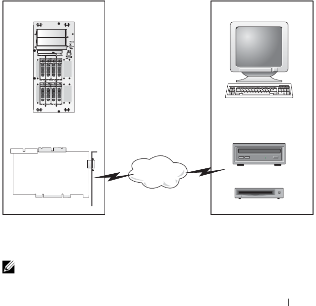
Using and Configuring Virtual Media 183
11
Using and Configuring
Virtual Media
Overview
The Virtual Media feature provides the managed system with a virtual
CD drive, which can use standard media from anywhere on the network.
Figure 11-1 shows the overall architecture of virtual media.
Figure 11-1. Overall Architecture of Virtual Media
Using Virtual Media, administrators can remotely boot their managed
systems, install applications, update drivers, or even install new operating
systems remotely from the virtual CD/DVD and diskette drives.
NOTE: Virtual media requires a minimum available network bandwidth of 128 Kbps.
Managed System Management Station
DRAC 5 Remote CD
Virtual Floppy
Virtual CD
Remote Floppy
Network

184 Using and Configuring Virtual Media
The managed system is configured with a DRAC 5 card. The virtual CD and
floppy drives are two electronic devices embedded in the DRAC 5 that are
controlled by the DRAC 5 firmware. These two devices are present on the
managed system’s operating system and BIOS at all times, whether virtual
media is connected or disconnected.
The management station provides the physical media or image file across the
network. When you launch the RAC browser for the first time and you access
the virtual media page, the virtual media plug-in is downloaded from the
DRAC 5 Web server and is automatically installed on the management
station. The virtual media plug-in must be installed on the management
station for the virtual media feature to function properly.
When virtual media is connected, all virtual CD/floppy drive access requests
from the managed system are directed to the management station across the
network. Connecting virtual media is identical to inserting media into virtual
devices. When virtual media is not connected, virtual devices on the
managed system appear as two drives without media installed in the drives.
NOTE: You can connect to a virtual media using browser plug-in or Java plug-in.
Table 11-1 lists the supported drive connections for virtual floppy and virtual
optical drives.
NOTE: Changing virtual media while connected could stop the system
boot sequence.
Table 11-1. Supported Drive Connections
Supported Virtual Floppy Drive
Connections
Supported Virtual Optical Drive
Connections
Legacy 1.44 floppy drive with a 1.44
floppy diskette
CD-ROM, DVD, CDRW, combination
drive with CD-ROM media
USB floppy drive with a 1.44 floppy
diskette
CD-ROM image file in the ISO9660
format
1.44 floppy image USB CD-ROM drive with CD-ROM
media.

Using and Configuring Virtual Media 185
Installing Virtual Media Browser Plug-In
The virtual media browser plug-in must be installed on your management
station to use the virtual media feature. After you open the DRAC 5 user
interface and launch the Virtual Media page, the browser automatically
downloads the plug-in, if required. If the plug-in is successfully installed,
the Virtual Media page displays a list of floppy diskettes and optical disks that
connect to the virtual drive.
Windows-Based Management Station
To run the virtual media feature on a management station running the
Microsoft Windows operating system, install a supported version of Internet
Explorer with the ActiveX Control plug-in. Set the browser security to
Medium or a lower setting to enable Internet Explorer to download and
install signed ActiveX controls.
Additionally, you must have administrator rights to install and use the virtual
media feature. Before installing the ActiveX control, Internet Explorer may
display a security warning. To complete the ActiveX control installation
procedure, accept the ActiveX control when Internet Explorer prompts you
with a security warning.
Linux-Based Management Station
To run the virtual media feature on a management station running the Linux
operating system, install a supported version of Mozilla or Firefox. If the
virtual media plug-in is not installed or if a newer version is available, a dialog
box appears during the installation procedure to confirm the plug-in
installation on the management station. Ensure that the user ID running the
browser has write permissions in the browser's directory tree. If the user ID
does not have write permissions, you cannot install the virtual media plug-in.
See the Dell Systems Software Support Matrix on the Dell Support website at
support.dell.com/manuals for more information.

186 Using and Configuring Virtual Media
Running Virtual Media
CAUTION: Do not issue a racreset command when running a Virtual Media
session. Otherwise, undesired results may occur, including loss of data.
Using Virtual Media, you can "virtualize" a diskette image or drive, enabling
a floppy image, floppy drive, or optical drive on your management console to
become an available drive on the remote system. You can connect to a virtual
media using the browser plug-in or Java plug-in. If you are using Java plug-in,
ensure that Java Runtime Environment (JRE) 1.6 or later is installed on the
management system.
Supported Virtual Media Configurations
You can enable Virtual Media for one floppy drive and one optical drive.
Only one drive for each media type can be virtualized at a time.
Supported floppy drives include a floppy image or one available floppy drive.
Supported optical drives include a maximum of one available optical drive or
one ISO image file.
Running Virtual Media Using the Web User Interface
Connecting Virtual Media Using the Native Plug-in
1
Open a supported Web browser on your management station.
For a list of
supported Web browsers, see the Dell Systems Software Support Matrix
on the Dell Support website at support.dell.com/manuals.
CAUTION: Console Redirection and Virtual Media only support 32-bit Web
browsers. Using 64-bit Web browsers may generate unexpected results or
failure of operations.
2
Connect and log into the DRAC 5. See "Accessing the Web-Based
Interface" on page 48 for more information.
3
Click the
Media
tab and then click
Virtual Media
.

Using and Configuring Virtual Media 187
The
Virtual Media
page appears with the client drives that can be
virtualized.
NOTE: The Floppy Image File under Floppy Drive (if applicable) may appear,
as this device can be virtualized as a virtual floppy. You can select one optical
drive and one floppy at the same time, or a single drive.
NOTE: The virtual device drive letters on the managed system do not coincide
with the physical drive letters on the management station.
4
If prompted, follow the on-screen instructions to install the virtual media
plug-in.
5
In the
Attribute
box, perform the following steps:
a
In the
Val ue
column, ensure that the
Attach/Detach
status value is
Attached
.
If the value is
Detached
, perform the following steps:
•In the
Media
tab, click
Configuration
.
•In the
Val ue
column, ensure that the
Attach Virtual Media
check
box is selected.
•Click
Apply Changes
.
•In the
Virtual Media
tab, click
Virtual Media
.
•In the
Val ue
column, ensure that the
Attach/Detach
status value
is
Attached
.
NOTE: After the Virtual Media is attached, you can change the Boot Order
only through RACADM, the Configuration page does not allow you to change
any configuration of the Boot Order device.
b
Ensure that the
Current Status
value is
Not connected
. If the
Val ue
field displays connected, you must disconnect from the image or drive
before reconnecting. This status denotes the current status of the
Virtual Media connection on the current Web-based interface only.
c
Ensure that the
Active Session
value is
Available
. If the
Val ue
field
display
In Use
, you must wait for the existing Virtual Media session to
be released or terminate it by going to the Session Management tab
under Remote Access and terminating the active Virtual Media
session.

188 Using and Configuring Virtual Media
Only one active Virtual Media session is allowed at one time. This
session could have been created by any Web-based interface or
VM-
CLI utility
.
d
Select the
Encryption Enabled
check box to establish an encrypted
connection between the remote system and your management station
(if desired).
6
If you are virtualizing a floppy image or ISO image, select
Floppy Image
File
or
ISO Image File
and enter or browse to the image file you want to
virtualize.
If you are virtualizing a floppy drive or an optical drive, select the button
next to the drives that you want to virtualize.
7
Click
Connect
.
If the connection is authenticated, the connection status becomes
Connected
and a list of all connected drives is displayed. All available
diskette images and drives you selected become available on the managed
system’s console as though they are real drives.
NOTE: The assigned virtual drive letter (for Microsoft Windows systems) or
device special file (for Linux systems) may not be identical to the drive letter
on your management console.
NOTE: Virtual Media may not function properly on Windows operating system
clients that are configured with Internet Explorer Enhanced Security. To
resolve this issue, see your Microsoft operating system documentation or
contact your administrator.
Disconnecting Virtual Media
Click Disconnect to disconnect all virtualized images and drives from the
management station. All virtualized images or drives disconnect and are no
longer available on the managed system.
Connecting Virtual Media Using Java Plug-in
1
Open a supported Web browser on your management station.
For a list of
supported Web browsers, see the Dell Systems Software Support Matrix
on the Dell Support website at support.dell.com/manuals.
2
Connect and log into the DRAC 5. For more information, see "Accessing
the Web-Based Interface" on page 48.

Using and Configuring Virtual Media 189
3
Click the
Media
tab and then click
Virtual Media
.
The
Virtual Media
page is displayed with the client drives that can be
virtualized.
NOTE: The plug-in with which you can connect to a virtual media depends on
the pug-in type you selected in the Configuration tab.
4
In the
Attribute
box, perform the following steps:
a
In the
Val ue
column, ensure that the
Attach/Detach
status value is
Attached
.
If the value is
Detached
, perform the following steps:
•In the
Media
tab, click
Configuration
.
•In the
Val ue
column, ensure that the
Attach Virtual Media
is
selected as Attach.
•In the
Va lu e
column, select the
Plug-in Type
as
Java Plug-in
.
•Click
Apply Changes
.
•In the
Virtual Media
tab, click
Virtual Media
.
NOTE: Ensure that JRE 1.6 or later is installed in the management system.
b
Ensure that the
Active Session
value is
0
. If the
Val ue
field displays
1
,
wait for the existing Virtual Media session to be released or terminate
it by accessing the
Session Management
tab under
Remote Access
.
Only one active Virtual Media session is allowed at one time. This
session may have been created by any Web-based interface or
VM-
CLI utility
.
5
Click
Launch VM
.
The
Virtual Media
Session pop-up window is displayed. The pop-up
window displays the drivers you can virtualize.
6
If a device is already virtualized, disconnect it by deselecting the
Mapped
check-box associated with the driver.

190 Using and Configuring Virtual Media
7
To virtualize a floppy image or ISO image, click
Add Image
and select an
image.
8
Click the
Mapped
check-box associated with the driver or image that you
want to connect.
The device in the managed system to which the driver or image attached is
displayed in the
Details
table.
Disconnecting Virtual Media
Deselect the Mapped check box associated with a driver or image.
Attaching and Detaching the Virtual Media Feature
The DRAC 5 Virtual Media feature is based on USB technology and can take
advantage of the USB plug and play features. DRAC 5 adds the option to
attach and detach the virtual devices from the USB bus. When the devices
are detached, the operating system or BIOS cannot see any attached drives.
When the virtual devices are attached, the drives are visible. Unlike DRAC 4,
where the drives could only be enabled or disabled at the next system boot,
DRAC 5 virtual devices can be attached or detached at any time.
The virtual devices can be attached or detached using a Web browser, local
racadm, remote racadm, telnet, and serial port. To configure virtual media
using a Web browser, you can navigate to the Media page and then to the
Configuration page where you can change settings and apply them.You may
also specify the Virtual Media Port Number and the Virtual Media SSL Port
Number. In addition, you can enable or disable the Virtual Flash and the
Boot Once feature. See "cfgVirtualBootOnce (Read/Write)" on page 389 for
information on the Boot Once feature. If this property is set to a supported
device and when the host server is rebooted, the feature will attempt to boot
from the selected device—if the appropriate media is installed in the device.
Auto-Attaching Virtual Media
DRAC 5 firmware version 1.30 and later support the auto-attach virtual
media feature. When you enable this feature, DRAC 5 will automatically
attach a virtual device to the system only when a device is virtualized
(connected) on a supported client.
The DRAC 5 will detach the virtual media devices when the virtual media
session is disconnected.

Using and Configuring Virtual Media 191
Attaching, Auto-Attaching, and Detaching Virtual Media using the Web browser
You can set the status of a virtual media to Attach, Auto-Attach, or Detach.
Based on this status, the devices in the remote system are displayed in the
DRAC 5 GUI.
•
Attach
—If the status is Attach, DRAC 5 automatically attaches all devices
of the remote system to the server. When you connect to the server, the
devices available in the remote system are displayed in the DRAC 5 GUI.
•
Auto Attach
—If the status is Auto Attach, DRAC 5 attaches a device to
the server only if the device is virtualized. For example, when you connect
to the server from a remote machine that has a CD drive, the CD drive is
displayed only if it is virtualized using a CD. Otherwise, the CD drive is
not displayed in the DRAC 5 GUI.
•
Detach
—If the status is Detach, virtual device is not displayed in the
server.
To Attach the virtual media feature, do the following:
1
Click
System
Media
Configuration.
2
Change the value for
Attach Virtual Media
to
Attach
.
3
Click
Apply Changes.
To Detach the virtual media feature, do the following:
1
Click
System
Media
Configuration.
2
Change the value for
Attach Virtual Media
to
Detach.
3
Click
Apply Changes.
Attaching, Auto-Attaching, and Detaching Virtual Media using RACADM
To Attach the virtual media feature, open a command prompt, type the
following command, and press <Enter>:
racadm config -g cfgRacVirtual -o cfgVirMediaAttached 1
To Detach the virtual media, open a command prompt, type the following
command, and press <Enter>:
racadm config -g cfgRacVirtual -o cfgVirMediaAttached 0
To Auto-Attach the virtual media, open a command prompt, type the
following command, and press <Enter>:
racadm config -g cfgRacVirtual -o cfgVirMediaAttached 2

192 Using and Configuring Virtual Media
Booting From Virtual Media
On supported systems, the system BIOS enables you to boot from virtual optical
drives or virtual floppy drives. During POST, enter the BIOS setup window
and verify that the virtual drives are enabled and listed in the correct order.
To change the BIOS setting:
1
Boot the managed system.
2
Press <F2> to enter the BIOS setup window.
3
Scroll to the boot sequence and press <Enter>.
In the pop-up window, the virtual optical drives and virtual floppy drives
are listed with the standard boot devices.
4
Ensure that the virtual drive is enabled and listed as the first device with
bootable media. If required, follow the on-screen instructions to modify
the boot order.
5
Save the changes and exit.
The managed system reboots.
The managed system attempts to boot from a bootable device based on
the boot order. If a virtual device is connected and a bootable media is
present, the system boots to the virtual device. Otherwise, the system
overlooks the device—similar to a physical device—without bootable
media.

Using and Configuring Virtual Media 193
Installing Operating Systems Using Virtual Media
This section describes a manual, interactive method to install the operating
system on your management station that may take several hours to complete.
A scripted operating system installation procedure using Virtual Media may
take less than 15 minutes to complete. See "Deploying Your Operating
System Using VM-CLI" on page 202 for more information.
1
Verify the following:
• The operating system installation CD is inserted in the management
station’s CD drive.
• The local CD drive is selected.
• You are connected to the virtual drives.
2
Follow the steps for booting from the virtual media in the "Booting From
Virtual Media" on page 192 section to ensure that the BIOS is set to boot
from the CD drive that you are installing from.
3
Follow the on-screen instructions to complete the installation.
Using Virtual Media When the Server’s Operating System Is Running
Windows-Based Systems
On Windows systems, the virtual media drives are automounted and
configured with a drive letter.
Using the virtual drives from within Windows is similar to using your physical
drives. When you connect to the media at a management station, the media
is available at the system by clicking the drive and browsing its content.
Linux-Based Systems
On Linux systems, the virtual media drives are not configured with a drive
letter. Depending on the software installed on your system, the virtual media
drives may not be automounted. If your drives are not automounted,
manually mount the drives.

194 Using and Configuring Virtual Media
Using Virtual Flash
The DRAC 5 provides persistent Virtual Flash—16 MB of flash memory that
resides in the DRAC 5 file system that can be used for persistent storage and
accessed by the system. When enabled, Virtual Flash is configured as a third
virtual drive and appears in the BIOS boot order, allowing a user to boot from
the Virtual Flash.
NOTE: To boot from the Virtual Flash, the Virtual Flash image must be a
bootable image.
Unlike a CD or floppy drive that requires an external client connection or
functional device in the host system, implementing Virtual Flash only requires
the DRAC 5 persistent Virtual Flash feature. The 16 MB of flash memory
appears as an unformatted, removable USB drive in the host environment.
Use the following guidelines when implementing Virtual Flash:
• Attaching or detaching the Virtual Flash performs a USB renumeration,
which attaches and detaches all Virtual Media devices, respectively
(for example, CD drive and floppy drive).
• When you enable or disable Virtual Flash, the Virtual Media CD/floppy
drive connection status does not change.
CAUTION: The Detach and Attach procedures disrupt active Virtual Media read
and write operations.
Enabling Virtual Flash
To enable Virtual Flash, open a command prompt, type the following
command, and press <Enter>:
racadm config -g cfgRacVirtual -o
cfgVirMediaKeyEnable 1
Disabling Virtual Flash
To disable Virtual Flash, open a command prompt, type the following
command, and press <Enter>:
racadm config -gcfgRacVirtual -o cfgVirMediaKeyEnable 0

Using and Configuring Virtual Media 195
Storing Images in a Virtual Flash
The Virtual Flash can be formatted from the managed host. If you are
running the Windows operating system, right-click the drive icon and select
Format. If you are running Linux, system tools such as format and fdisk allow
you to partition and format the USB.
Before you upload an image from the RAC Web browser to the Virtual Flash,
ensure that the image file is between 1.44 MB and 16 MB in size (inclusive)
and Virtual Flash is disabled. After you download the image and re-enable the
Virtual Flash drive, the system and BIOS recognize the Virtual Flash.
Configuring a Bootable Virtual Flash
1
Insert a bootable diskette into the diskette drive or insert a bootable CD
into the optical drive.
2
Restart your system and boot to the selected media drive.
3
Add a partition to Virtual Flash and enable the partition.
Use
fdisk
if Virtual Flash is emulating the hard drive. If Virtual Flash is
configured as Drive B:, the Virtual Flash is floppy emulated and does not
require a partition to configure Virtual Flash as a bootable drive.
4
Using the
format
command, format the drive with the
/s
switch to transfer
the system files to the Virtual Flash.
For example:
format /s x
where
x
is the drive letter assigned to Virtual Flash.
5
Shut down the system and remove the bootable floppy or CD from the
appropriate drive.
6
Turn on the system and verify that the system boots from Virtual Flash to
the
C:\
or
A:\
prompt.

196 Using and Configuring Virtual Media
Using the Virtual Media Command Line
Interface Utility
The Virtual Media Command Line Interface (VM-CLI) utility is a scriptable
command-line interface that provides virtual media features from the
management station to the DRAC 5 in the remote system.
The VM-CLI utility provides the following features:
• Supports multiple, simultaneously-active sessions.
NOTE: When virtualizing read-only image files, multiple sessions may share
the same image media. When virtualizing physical drives, only one session
can access a given physical drive at a time.
• Removable media devices or image files that are consistent with the
Virtual Media plug-ins
• Automatic termination when the DRAC firmware boot once option is
enabled.
• Secure communications to the DRAC 5 using Secure Sockets Layer (SSL)
Before you run the utility, ensure that you have Virtual Media user privilege
to the DRAC 5 in the remote system.
If your operating system supports administrator privileges or an operating
system-specific privilege or group membership, administrator privileges are
also required to run the VM-CLI command.
The client system's administrator controls user groups and privileges, thereby
controlling the users who can run the utility.
For Windows systems, you must have Power User privileges to run the
VM-CLI utility.
For Linux systems, you can access the VM-CLI utility without administrator
privileges by using the sudo command. This command provides a centralized
means of providing non-administrator access and logs all user commands. To
add or edit users in the VM-CLI group, the administrator uses the visudo
command. Users without administrator privileges can add the sudo command
as a prefix to the VM-CLI command line (or to the VM-CLI script) to obtain
access to the DRAC 5 in the remote system and run the utility.

Using and Configuring Virtual Media 197
Utility Installation
The VM-CLI utility is located on the Dell Systems Management Tools and
Documentation DVD, which is included with your Dell OpenManage System
Management Software Kit. To install the utility, insert the Dell Systems
Management Tools and Documentation DVD into your system’s DVD drive
and follow the on-screen instructions.
The Dell Systems Management Tools and Documentation DVD contains the
latest systems management software products, including diagnostics, storage
management, remote access service, and the RACADM utility. This DVD
also contains readme files, which provide the latest systems management
software product information.
Additionally, the Dell Systems Management Tools and Documentation DVD
includes vmdeploy—a sample script that illustrates how to use the VM-CLI
and RACADM utilities to deploy software to multiple remote systems. For
more information, see "Deploying Your Operating System Using VM-CLI" on
page 202.
Command Line Options
The VM-CLI interface is identical on both Windows and Linux systems.
The utility uses options that are consistent with the RACADM utility
options. For example, an option to specify the DRAC 5 IP address requires
the same syntax for both RACADM and VM-CLI utilities.
The VM-CLI command format is as follows:
racvmcli [parameter] [operating_system_shell_options]
NOTE: You need Administrator privileges to run the racvmcli command.
All command-line syntax are case sensitive. See "VM-CLI Parameters" on
page 198 for more information.
If the remote system accepts the commands and the DRAC 5 authorizes the
connection, the command continues to run until either of the following occurs:
• The VM-CLI connection terminates for any reason.
• The process is manually terminated using an operating system control. For
example, in Windows, you can use the Task Manager to terminate the
process.

198 Using and Configuring Virtual Media
VM-CLI Parameters
DRAC 5 IP Address
-r <RAC-IP-address>[:<RAC-SSL-port>]
where <RAC-IP-address> is a valid, unique IP address or the DRAC 5
Dynamic Domain Naming System (DDNS) name (if supported).
This parameter provides the DRAC 5 IP address and SSL port. The VM-CLI
utility needs this information to establish a Virtual Media connection with
the target DRAC 5. If you enter an invalid IP address or DDNS name,
an error message appears and the command is terminated.
If <RAC-SSL-port> is omitted, port 443 (the default port) is used.
The optional SSL port is not required unless you change the DRAC 5 default
SSL port.
DRAC 5 User Name
-u <DRAC-user-name>
This parameter provides the DRAC 5 user name that will run Virtual Media.
The <DRAC-user-name> must have the following attributes:
• Valid user name
• DRAC Virtual Media User permission
If DRAC 5 authentication fails, an error message appears and the command
is terminated.
DRAC User Password
-p <DRAC-user-password>
This parameter provides the password for the specified DRAC 5 user.
If DRAC 5 authentication fails, an error message displays and the command
terminates.

Using and Configuring Virtual Media 199
Floppy/Disk Device or Image File
-f {<device-name> | <image-file>}
where <device-name> is a valid drive letter (for Windows systems) or a
valid device file name, including the mountable file system partition number,
if applicable (for Linux systems); and <image-file> is the filename and
path of a valid image file.
This parameter specifies the device or file to supply the virtual floppy/disk media.
For example, an image file is specified as:
-f c:\temp\myfloppy.img (Windows system)
-f /tmp/myfloppy.img (Linux system)
If the file is not write-protected, Virtual Media may write to the image file.
Configure the operating system to write-protect a floppy image file that
should not be overwritten.
For example, a device is specified as:
-f a:\ (Windows system)
-f /dev/sdb4 # 4th partition on device /dev/sdb
(Linux system)
If the device provides a write-protection capability, use this capability to
ensure that Virtual Media will not write to the media.
Additionally, omit this parameter from the command line if you are not
virtualizing floppy media. If an invalid value is detected, an error message
displays and the command terminates.
CD/DVD Device or Image File
-c {<device-name> | <image-file>}
where <device-name> is a valid CD/DVD drive letter (Windows systems)
or a valid CD/DVD device file name (Linux systems) and <image-file> is
the file name and path of a valid ISO-9660 image file.
This parameter specifies the device or file that will supply the virtual
CD/DVD-ROM media:
For example, an image file is specified as:
-c c:\temp\mydvd.img (Windows systems)
-c /tmp/mydvd.img (Linux systems)

200 Using and Configuring Virtual Media
For example, a device is specified as:
-c d:\ (Windows systems)
-c /dev/cdrom (Linux systems)
Additionally, omit this parameter from the command line if you are not
virtualizing CD/DVD media. If an invalid value is detected, an error message
is listed and the command terminates.
Specify at least one media type (floppy or CD/DVD drive) with the
command, unless only switch options are provided. Otherwise, an error
message displays and the command terminates and generates an error.
Version Display
-v
This parameter is used to display the VM-CLI utility version. If no other
non-switch options are provided, the command terminates without an error
message.
Help Display
-h
This parameter displays a summary of the VM-CLI utility parameters.
If no other non-switch options are provided, the command terminates
without error.
Encrypted Data
-e
When this parameter is included in the command line, the VM-CLI utility
will use an SSL-encrypted channel to transfer data between the management
station and the DRAC 5 in the remote system. If this parameter is not
included in the command line, the data transfer is not encrypted.

Using and Configuring Virtual Media 201
VM-CLI Operating System Shell Options
The following operating system features can be used in the VM-CLI
command line:
• stderr/stdout redirection — Redirects any printed utility output to a file.
For example, using the greater-than character (>) followed by a filename
overwrites the specified file with the printed output of the VM-CLI utility.
NOTE: The VM-CLI utility does not read from standard input (stdin). As a result,
stdin redirection is not required.
• Background execution — By default, the VM-CLI utility runs in the
foreground. Use the operating system's command shell features to cause
the utility to run in the background. For example, under a Linux operating
system, the ampersand character (&) following the command causes the
program to be spawned as a new background process.
The latter technique is useful in script programs, as it allows the script to
proceed after a new process is started for the VM-CLI command (otherwise,
the script would block until the VM-CLI program is terminated). When
multiple VM-CLI instances are started in this way, and one or more of the
command instances must be manually terminated, use the operating system-
specific facilities for listing and terminating processes.
VM-CLI Return Codes
0 = No error
1 = Unable to connect
2 = VM-CLI command line error
3 = RAC firmware connection dropped
English-only text messages are also issued to standard error output whenever
errors are encountered.

202 Using and Configuring Virtual Media
Deploying Your Operating System Using VM-CLI
The Virtual Media Command Line Interface (VM-CLI) utility is a
command-line interface that provides Virtual Media features from the
management station to the DRAC 5 in the remote system. Using VM-CLI
and scripted methods, you can deploy your operating system on multiple
remote systems in your network.
This section provides information on integrating the VM-CLI utility into
your corporate network.
Before You Begin
Before using the VM-CLI utility, ensure that your targeted remote systems
and corporate network meet the requirements listed in the following sections.
Remote System Requirements
• DRAC 5 card is installed in each remote system
• The virtual device in each remote system is the first device in the BIOS
boot order.
Dell Custom Factory Integration
When you order your Dell system using the Dell Custom Factory Integration
(CFI) options, Dell can preconfigure your system with a DRAC 5 card that
includes a DDNS name and a preconfigured system BIOS that is enabled for
Virtual Media. Using this configuration, your system is ready to boot from its
Virtual Media devices when installed into your corporate network.
For more information, see the Dell website at www.dell.com.
Network Requirements
You must have a network share containing:
• Operating system files
• Required drivers
• Operating system boot image file(s)
The image file must be a floppy image or CD/DVD ISO image with an
industry-standard, bootable format.

Using and Configuring Virtual Media 203
Creating a Bootable Image File
Before you deploy your image file to the remote systems, ensure that a
supported system can boot from the file. To test the image file, transfer the
image file to a test system using the DRAC 5 Web user interface and then
reboot the system.
The following sections provide specific information for creating image files
for Linux and Windows systems.
Creating an Image File for Linux Systems
Use the Data Duplicator utility to create a bootable image file for your Linux
system.
To run the utility, open a command prompt and type the following:
dd if=<input-device> of=<output-file>
For example:
dd if=/dev/fd0 of=myfloppy.img
Creating an Image File for Windows Systems
When choosing a data replicator utility for Windows image files, select a
utility that copies the image file and the CD/DVD boot sectors.
Preparing for Deployment
Configuring the Remote Systems
1
Create a network share that can be accessed by the management station.
2
Copy the operating system files to the network share.
3
If you have a bootable, preconfigured deployment image file to deploy the
operating system to the remote systems, skip this step.
If you do not have a bootable, preconfigured deployment image file, create
the file. Include any programs and/or scripts used for the operating system
deployment procedures
For example, to deploy Microsoft Windows operating system, the image
file may include programs that are similar to deployment methods used by
Microsoft Systems Management Server (SMS).

204 Using and Configuring Virtual Media
When you create the image file, ensure that you:
• Follow standard network-based installation procedures
• Mark the deployment image as "read only" to ensure that each target
system boots and executes the same deployment procedure
4
Perform one of the following procedures:
• Integrate RACADM and the Virtual Media command line interface
(VM-CLI) into your existing operating system deployment
application. Use the sample deployment script as a guide when
integrating the DRAC 5 utilities into your existing operating system
deployment application.
• Use the existing
vmdeploy
script to deploy your operating system.
Deploying the Operating System
Use the VM-CLI utility and the vmdeploy script included with the utility to
deploy the operating system to your remote systems.
Before you begin, review the sample vmdeploy script included with the
VM-CLI utility. The script offers detailed requirements to deploy the
operating system to remote systems in your network.
The following procedure is a high-level overview for deploying the operating
system on targeted remote systems.
1
Identify the remote systems that will be deployed.
2
Record the DRAC 5 names and IP addresses of the targeted remote systems.
3
Perform the following procedure for each targeted remote system:
a
Configure a VM-CLI process that includes the following parameters
for the targeted system:
• DRAC 5 IP address or DDNS name
• Bootable deployment image file name
•DRAC 5 user name
•DRAC 5 user password
b
Using RACADM, set the target DRAC 5
boot once
option.
c
Using RACADM, reboot the DRAC 5 system.

Using and Configuring Virtual Media 205
Frequently Asked Questions
Sometimes, I notice my Virtual Media client connection drops. Why?
When a network time-out occurs, the DRAC 5 firmware drops the
connection, disconnecting the link between the server and the Virtual Drive.
To reconnect to the Virtual Drive, use the Virtual Media feature.
Which operating systems support the DRAC 5?
See the Dell Systems Software Support Matrix on the Dell Support website at
support.dell.com/manuals for a list of supported operating systems.
Which Web browsers support the DRAC 5?
See the Dell Systems Software Support Matrix on the Dell Support website at
support.dell.com/manuals for a list of supported Web browsers.
Why do I sometimes lose my client connection?
• You can sometimes lose your client connection if the network is slow or if
you change the CD in the client system CD drive. For example, if you
change the CD in the client system’s CD drive, the new CD might have an
autostart feature. If this is the case, the firmware can time out and the
connection can be lost if the client system takes too long before it is ready
to read the CD. If a connection is lost, reconnect from the GUI and
continue the previous operation.
• When a network time-out occurs, the DRAC 5 firmware drops the
connection, disconnecting the link between the server and the Virtual
Drive. To reconnect to the Virtual Drive, use the Virtual Media feature.
What should I do if Windows 2000 with Service Pack 4 fails to install
properly?
If you use Virtual Media and the Windows 2000 operating system CD to
install Windows 2000 with Service Pack 4, your system may momentarily lose
its connection to the CD drive during the installation procedure, and the
operating system may fail to install properly. To fix this issue, download the
file usbstor.sys from the Microsoft Support website at support.microsoft.com
and run the program only on systems that experience this issue. For more
information, see Microsoft Knowledge Base article 823086.

206 Using and Configuring Virtual Media
Why can’t I install Windows 2000 locally or remotely?
This issue usually happens if Virtual Flash is enabled and does not contain a
valid image, for example, the virtual flash contains a corrupted or random
image, you may not be able to install Windows 2000 locally or remotely. To
fix this issue, install a valid image on Virtual Flash or disable Virtual Flash if it
will not be used during the installation procedure.
Why does the Virtual Media connection drop when configured in the
Shared-NIC mode?
Installing network and chipset drivers on the server causes the Virtual Media
connection to drop when configured in the Shared-NIC mode. Installing the
network or chipset drivers causes the LOM to reset, which in turn causes
network packets to timeout and the Virtual Media connection to timeout and
drop. To work around this issue, copy the drivers from your virtual drive to
the server’s local hard drive. To prevent a dropped Virtual Media connection
from interfering with your driver installation procedure, start the driver
installation directly from the server.
An installation of the Windows operating system seems to take too
long. Why?
If you are installing the Windows operating system using the Dell Systems
Management Tools and Documentation DVD and experience a slow network
connection, the installation procedure may require an extended amount of
time to access the DRAC 5 Web-based interface due to network latency.
While the installation window does not indicate the installation progress, the
installation procedure is in progress.
I am viewing the contents of a floppy drive or USB memory key. If I try to
establish a Virtual Media connection using the same drive, I receive a
connection failure message and am asked to retry. Why?
Simultaneous access to Virtual Floppy drives is not allowed. Close the
application used to view the drive contents before you attempt to virtualize
the drive.
How do I configure my virtual device as a bootable device?
On the managed system, access the BIOS Setup and navigate to the boot
menu. Locate the virtual CD, Virtual Floppy, or Virtual Flash and change the
device boot order as needed. For example, to boot from a CD drive, configure
the CD drive as the first drive in the boot order.

Using and Configuring Virtual Media 207
What types of media can I boot from?
The DRAC 5 allows you to boot from the following bootable media:
• CDROM/DVD Data media
• ISO 9660 image
• 1.44 Floppy disk or floppy image
• DRAC 5 embedded virtual flash
• A USB key that is recognized by the operating system as a removable disk
•A USB key image
How can I make my USB key bootable?
Only USB keys with Windows 98 DOS can boot from the Virtual Floppy. To
configure your own bootable USB key, boot to a Windows 98 startup disk and
copy system files from the startup disk to your USB key. For example, from
the DOS prompt, type the following command:
sys a: x: /s
where "x:" is the USB key you want to make bootable.
You can also use the Dell boot utility to create a bootable USB key. This
utility is only compatible with Dell-branded USB keys. To download the
utility, open a supported Web browser, navigate to the Dell Support website
located at support.dell.com, and search for "R122672.exe."
Do I need Administrator privileges to install the ActiveX plug-in?
You must have Administrator or Power User privileges on Windows systems
to install the Virtual Media plug-in.
What privileges do I need to install and use the Virtual Media plug-in on a
Red Hat Linux Management station?
Yo u m u s t h a v e Write privileges on the browser’s directory tree to
successfully install the Virtual Media plug-in.

208 Using and Configuring Virtual Media
I cannot locate my Virtual Floppy device on a system running Red Hat
Enterprise Linux or the SUSE Linux operating System. My Virtual Media is
attached and I am connected to my remote floppy. What should I do?
Some Linux versions do not automount the Virtual Floppy Drive and the
Virtual CD drive in a similar manner. In order to mount the Virtual Floppy
Drive, locate the device node that Linux assigns to the Virtual Floppy Drive.
Perform the following steps to correctly find and mount the Virtual
Floppy Drive:
1
Open a Linux command prompt and run the following command:
grep "Virtual Floppy" /var/log/messages
2
Locate the last entry to that message and note the time.
3
At the Linux prompt, run the following command:
grep "hh:mm:ss" /var/log/messages
where:
hh:mm:ss
is the time stamp of the message returned by grep in step 1.
4
In step 3, read the result of the grep command and locate the device name
that is given to the "Dell Virtual Floppy"
5
Ensure that you are attached and connected to the Virtual Floppy Drive.
6
At the Linux prompt, run the following command:
mount /dev/sdx /mnt/floppy
where:
/dev/sdx
is the device name found in step 4
/mnt/floppy
is the mount point.
What file system types are supported on my Virtual Floppy Drive or Virtual
Flash?
Your Virtual Floppy Drive or Virtual Flash supports FAT16 or FAT32 file
systems.

Using and Configuring Virtual Media 209
When I performed a firmware update remotely using the DRAC 5 Web-
based interface, my virtual drives at the server were removed. Why?
Firmware updates cause the DRAC 5 to reset, drop the remote connection,
and unmount the virtual drives. The drives will reappear when the DRAC
reset is complete.
When enabling or disabling the Virtual Flash, I noticed that all my virtual
drives disappeared and then reappeared. Why?
Disabling or enabling the Virtual Flash causes a USB reset and causes all
virtual drives to detach from and then reattach to the USB bus.
How can I install a Web browser on my management station that has a read-
only file system?
If you are running Linux and your management station has a read-only file
system, a browser can be installed on a client system without requiring a
connection to a DRAC 5. By using the native plug-in installation package, the
browser can be manually installed during the client setup phase.
CAUTION: In a read-only client environment, if the DRAC 5 firmware is updated to
a newer version of the plug-in, the installed virtual media plug-in becomes
inoperative. This is because earlier plug-in features are not allowed to function
when the firmware contains a newer plug-in version. In this case, you are
prompted for plug-in installation. Since the file system is read-only, the
installation fails and the plug-in features are not available.
To obtain the plug-in installation package:
1
Login to an existing DRAC 5.
2
Change the URL in the browser's address bar, from:
https://<RAC_IP>/cgi-bin/webcgi/main
to:
https://<RAC_IP>/plugins/ # Be sure to include the
trailing slash.
3
Locate the two subdirectories
vm
and
vkvm
. Navigate to the appropriate
subdirectory, right click the
rac5XXX.xpi
file, and select
Save Link
Target As....
4
Choose a location to save the plug-in installation package file.

210 Using and Configuring Virtual Media
To install the plug-in installation package:
1
Copy the installation package to the client's native file system share that is
accessible by the client.
2
Open an instance of the browser on the client system.
3
Enter the file-path to the plug-in installation package in the browser's
address bar. For example:
file:///tmp/rac5vm.xpi
4
The browser guides the user through plug-in installation.
Once installed, the browser will not prompt for that plug-in installation again,
as long as the target DRAC 5 firmware does not contain a newer version of
the plug-in.

Configuring Security Features 211
12
Configuring Security Features
The DRAC 5 provides the following security features:
• Advanced Security options for the DRAC administrator:
• The Console Redirection disable option allows the
local
system user
to disable console redirection using the DRAC 5 Console
Redirection feature.
• The local configuration disable features allows the
remote
DRAC
administrator to selectively disable the ability to configure the
DRAC 5 from:
– BIOS POST option-ROM
– operating system using the local racadm and Dell OpenManage
Server Administrator utilities
• RACADM CLI and Web-based interface operation, which supports
128-bit SSL encryption and 40-bit SSL encryption (for countries where
128-bit is not acceptable)
NOTE: Telnet does not support SSL encryption.
• Session time-out configuration (in seconds) through the Web-based
interface or RACADM CLI
• Configurable IP ports (where applicable)
• Secure Shell (SSH), which uses an encrypted transport layer for higher
security.
• Login failure limits per IP address, with login blocking from the IP address
when the limit is exceeded.
• Limited IP address range for clients connecting to the DRAC 5

212 Configuring Security Features
Security Options for the DRAC Administrator
Disabling the DRAC 5 Local Configuration
Administrators can disable local configuration through the DRAC 5 graphical
user interface (GUI) by selecting Remote Access Configuration
Services. When the Disable the DRAC local Configuration using option
ROM check box is selected, the Remote Access Configuration Utility—
accessed by pressing Ctrl+E during system boot—operates in read-only
mode, preventing local users from configuring the device. When the
administrator selects the Disable the DRAC local Configuration using
RACADM check box, local users cannot configure the DRAC 5 through the
racadm utility, or the Dell OpenManage Server Administrator, although they
can still read the configuration settings.
Administrators can enable one or both of these options at the same time.
In addition to enabling them through the GUI, administrators can do so
using local racadm commands.
Disabling Local Configuration During System Reboot
This feature disables the ability of the managed system’s user to configure the
DRAC 5 during system reboot.
racadm config -g cfgRacTune -o
cfgRacTuneCtrlEConfigDisable 1
NOTE: This option is supported only on the Remote Access Configuration Utility
version 1.13 and later. To upgrade to this version, upgrade your BIOS using the
BIOS update package from the Dell Server Updates DVD or the Dell Support
website at support.dell.com.

Configuring Security Features 213
Disabling Local Configuration From Local racadm
This feature disables the ability of the managed system’s user to configure the
DRAC 5 using the local racadm or the Dell OpenManage Server
Administrator utilities.
racadm config -g cfgRacTune -o
cfgRacTuneLocalConfigDisable 1
CAUTION: These features severely limit the ability of the local user to configure
the DRAC 5 from the local system, including performing a reset to default of the
configuration. Dell recommends that you use these features with discretion and
should disable only one interface at a time to help avoid losing login privileges
altogether.
NOTE: See the white paper on Disabling Local Configuration and Remote Virtual
KVM in the DRAC on the Dell Support site at support.dell.com/manuals for more
information.
Although administrators can set the local configuration options using local
racadm commands, for security reasons they can reset them only from an
out-of-band DRAC 5 GUI or command-line interface. The
cfgRacTuneLocalConfigDisable option applies once the system
power-on self-test is complete and the system has booted into an operating
system environment. The operating system could be one such as Microsoft
Windows Server or Enterprise Linux operating systems that can run local
racadm commands, or a limited-use operating system such as Microsoft
Windows Preinstallation Environment or vmlinux used to run Dell
OpenManage Deployment Toolkit local racadm commands.
Several situations might call for administrators to disable local configuration.
For example, in a data center with multiple administrators for servers and
remote access devices, those responsible for maintaining server software
stacks may not require administrative access to remote access devices.
Similarly, technicians may have physical access to servers during routine
systems maintenance—during which they can reboot the systems and access
password-protected BIOS—but should not be able to configure remote access
devices. In such situations, remote access device administrators may want to
disable local configuration.
Administrators should keep in mind that because disabling local
configuration severely limits local configuration privileges—including the
ability to reset the DRAC 5 to its default configuration—they should only use
these options when necessary, and typically should disable only one interface

214 Configuring Security Features
at a time to help avoid losing login privileges altogether. For example,
if administrators have disabled all local DRAC 5 users and allow only
Microsoft Active Directory directory service users to log in to the DRAC 5,
and the Active Directory authentication infrastructure subsequently fails,
the administrators may be unable to log in. Similarly, if administrators have
disabled all local configuration and place a DRAC 5 with a static IP address
on a network that already includes a Dynamic Host Configuration Protocol
(DHCP) server, and the DHCP server subsequently assigns the DRAC 5
IP address to another device on the network, the resulting conflict may
disable the out-of-band connectivity of the DRAC, requiring administrators
to reset the firmware to its default settings through a serial connection.
Disabling DRAC 5 Remote Virtual KVM
Administrators can selectively disable the DRAC 5 remote KVM, providing
a flexible, secure mechanism for a local user to work on the system without
someone else viewing the user’s actions through console redirection.
Using this feature requires installing the DRAC managed node software on
the server. Administrators can disable remote vKVM using the following
command:
racadm LocalConRedirDisable 1
The command LocalConRedirDisable disables existing remote vKVM session
windows when executed with the argument 1
To help prevent a remote user from overriding the local user's settings,
this command is available only to local racadm. Administrators can use this
command in operating systems that support local racadm, including
Microsoft Windows Server 2003 and SUSE Linux Enterprise Server 10.
Because this command persists across system reboots, administrators must
specifically reverse it to re-enable remote vKVM. They can do so by using
the argument 0:
racadm LocalConRedirDisable 0

Configuring Security Features 215
Several situations might call for disabling DRAC 5 remote vKVM. For
example, administrators may not want a remote DRAC 5 user to view the
BIOS settings that they configure on a system, in which case they can disable
remote vKVM during the system POST by using the
LocalConRedirDisable command. They may also want to increase
security by automatically disabling remote vKVM every time an administrator
logs in to the system, which they can do by executing the
LocalConRedirDisable command from the user logon scripts.
NOTE: See the white paper on Disabling Local Configuration and Remote Virtual
KVM in the DRAC on the Dell Support site at support.dell.com/manuals for more
information.
For more information on logon scripts, see
technet2.microsoft.com/windowsserver/en/library/31340f46-b3e5-4371-
bbb9-6a73e4c63b621033.mspx.
Securing DRAC 5 Communications Using SSL and
Digital Certificates
This subsection provides information about the following data security
features that are incorporated in your DRAC 5:
• "Secure Sockets Layer (SSL)" on page 215
• "Certificate Signing Request (CSR)" on page 216
• "Accessing the SSL Main Menu" on page 216
• "Generating a New Certificate Signing Request" on page 218
• "Uploading a Server Certificate" on page 219
• "Uploading a Server Certificate" on page 219
Secure Sockets Layer (SSL)
The DRAC includes a Web server that is configured to use the
industry-standard SSL security protocol to transfer encrypted data over the
Internet. Built upon public-key and private-key encryption technology, SSL is
a widely accepted technique for providing authenticated and encrypted
communication between clients and servers to prevent eavesdropping across
anetwork.

216 Configuring Security Features
An SSL-enabled system:
• Authenticates itself to an SSL-enabled client
• Allows the client to authenticate itself to the server
• Allows both systems to establish an encrypted connection
This encryption process provides a high level of data protection. The DRAC
employs the 128-bit SSL encryption standard, the most secure form of
encryption generally available for Internet browsers in North America.
The DRAC Web server includes a Dell self-signed SSL digital certificate
(Server ID). To ensure high security over the Internet, replace the Web server
SSL certificate by submitting a request to the DRAC to generate a new
Certificate Signing Request (CSR).
Certificate Signing Request (CSR)
A CSR is a digital request to a Certificate Authority (CA) for a secure server
certificate. Secure server certificates protect the identity of a remote system
and ensure that information exchanged with the remote system cannot be
viewed or changed by others. To ensure security for your DRAC, it is strongly
recommended that you generate a CSR, submit the CSR to a CA, and upload
the certificate returned from the CA.
A CA is a business entity that is recognized in the IT industry for meeting
high standards of reliable screening, identification, and other important
security criteria. Examples of CAs include Thawte and VeriSign. After the
CA receives your CSR, they review and verify the information the CSR
contains. If the applicant meets the CA’s security standards, the CA issues a
certificate to the applicant that uniquely identifies that applicant for
transactions over networks and on the Internet.
After the CA approves the CSR and sends you a certificate, you must upload
the certificate to the DRAC firmware. The CSR information stored on the
DRAC firmware must match the information contained in the certificate.
Accessing the SSL Main Menu
1
Expand the
System
tree and click
Remote Access
.
2
Click the
Configuration
tab and then click
SSL
.

Configuring Security Features 217
Use the SSL Main Menu page options (see Table 12-1) to generate a CSR to
send to a CA. The CSR information is stored on the DRAC 5 firmware.
Table 12-2 describes the buttons available on the SSL Main Menu page.
Table 12-1. SSL Main Menu Options
Field Description
Generate a New
Certificate Signing
Request (CSR)
Click Next to open the Certificate Signing Request
Generation page that enables you to generate a CSR to send to
a CA to request a secure Web certificate.
CAUTION: Each new CSR overwrites any pervious CSR on
the firmware. For a CA to accept your CSR, the CSR in the
firmware must match the certificate returned from the CA.
Upload Server
Certificate
Click Next to upload an existing certificate that your company
has title to, and uses to control access to the DRAC 5.
CAUTION: Only X509, Base 64 encoded certificates are
accepted by the DRAC 5. DER encoded certificates are not
accepted. Upload a new certificate to replace the default
certificate you received with your DRAC 5.
View Server
Certificate
Click Next to view an existing server certificate.
Table 12-2. SSL Main Menu Buttons
Button Description
Print Prints the SSL Main Menu page.
Next Navigates to the next page.

218 Configuring Security Features
Generating a New Certificate Signing Request
NOTE: Each new CSR overwrites any previous CSR on the firmware. Before a
certificate authority (CA) can accept your CSR, the CSR in the firmware must match the
certificate returned from the CA. Otherwise, the DRAC 5 will not upload the certificate.
1
In the
SSL Main Menu
page, select
Generate a New Certificate Signing
Request (CSR)
and click
Next
.
2
In the
Generate Certificate Signing Request (CSR)
page, type a value for
each CSR attribute value.
Table 12-3 describes the
Generate Certificate Signing Request (CSR)
page options.
3
Click
Generate
to save or view the CSR.
4
Click the appropriate
Generate Certificate Signing Request (CSR)
page
button to continue. Table 12-4 describes the buttons available on the
Generate Certificate Signing Request (CSR)
.
Table 12-3. Generate Certificate Signing Request (CSR) Page Options
Field Description
Common Name The exact name being certified (usually the Web server's
domain name, for example, www.xyzcompany.com). Only
alphanumeric characters, hyphens, underscores, and periods
are valid. Spaces are not valid.
Organization Name The name associated with this organization (for example, XYZ
Corporation). Only alphanumeric characters, hyphens,
underscores, periods and spaces are valid.
Organization Unit The name associated with an organizational unit, such as a
department (for example, Enterprise Group). Only
alphanumeric characters, hyphens, underscores, periods, and
spaces are valid.
Locality The city or other location of the entity being certified (for
example, Round Rock). Only alphanumeric characters and
spaces are valid. Do not separate words using an underscore or
some other character.

Configuring Security Features 219
Uploading a Server Certificate
1
In the
SSL Main Menu
page, select
Upload Server Certificate
and click
Next
.
The
Certificate Upload
page appears.
2
In the
File Path
field, type the path of the certificate in the
Val ue
field or
click
Browse
to navigate to the certificate file.
NOTE: The File Path value displays the relative file path of the certificate you are
uploading. You must type the absolute file path, which includes the full path and the
complete file name and file extension.
NOTE: A Server Certificate can be uploaded only once. If you try to upload a Server
Certificate that is already uploaded once, DRAC displays the error message,
"Unable to find a valid certificate."
3
Click
Apply
.
4
Click the appropriate page button to continue.
State Name The state or province where the entity who is applying for a
certification is located (for example, Texas). Only
alphanumeric characters and spaces are valid. Do not use
abbreviations.
Country Code The name of the country where the entity applying for
certification is located. Use the drop-down menu to select the
country.
Email The e-mail address associated with the CSR. You can type
your company’s e-mail address, or any e-mail address you
desire to have associated with the CSR. This field is optional.
Table 12-4. Generate Certificate Signing Request (CSR) Page Buttons
Button Description
Print Print the Generate Certificate Signing Request (CSR) page.
Go Back to Security
Main Menu
Return to the SSL Main Menu page.
Generate Generate a CSR.
Table 12-3. Generate Certificate Signing Request (CSR) Page Options
(continued)
Field Description

220 Configuring Security Features
Viewing a Server Certificate
1
In the
SSL Main Menu
page, select
View Server Certificate
and click
Next
.
Table 12-5 describes the fields and associated descriptions listed in the
Certificate
window.
2
Click the appropriate
View Server Certificate
page button to continue.
Using the Secure Shell (SSH)
Only four SSH sessions are supported at any given time. The session time-out
is controlled by the cfgSsnMgtSshIdleTimeout property as described in
the "DRAC 5 Property Database Group and Object Definitions" on page 345.
You can enable the SSH on the DRAC 5 with the command:
racadm config -g cfgSerial -o cfgSerialSshEnable 1
You can change the SSH port with the command:
racadm config -g cfgRacTuning -o cfgRacTuneSshPort
<port number>
For more information on cfgSerialSshEnable and
cfgRacTuneSshPort properties, see "DRAC 5 Property Database Group
and Object Definitions" on page 345.
The DRAC 5 SSH implementation supports multiple cryptography schemes,
as shown in Table 12-6.
Table 12-5. Certificate Information
Field Description
Serial Number Certificate serial number
Subject Information Certificate attributes entered by the subject
Issuer Information Certificate attributes returned by the issuer
Valid Fr o m Issue date of the certificate
Valid To Expiration date of the certificate
Configuring Security Features 221
NOTE: SSHv1 is not supported.
Configuring Services
NOTE: To modify these settings, you must have Configure DRAC 5 permission.
Additionally, the remote RACADM command-line utility can only be enabled if the
user is logged in as root.
1
Expand the
System tree and click Remote Access.
2Click the Configuration tab and then click Services.
3
Configure the following services as required:
• Local Configuration (Table 12-7)
• Web server (Table 12-8)
• SSH (Table 12-9)
Table 12-6. Cryptography Schemes
Scheme Type Scheme
Asymmetric Cryptography Diffie-Hellman DSA/DSS 512-1024 (random) bits
per NIST specification
Symmetric Cryptography
• AES256-CBC
•RIJNDAEL256-CBC
• AES192-CBC
•RIJNDAEL192-CBC
• AES128-CBC
•RIJNDAEL128-CBC
• BLOWFISH-128-CBC
• 3DES-192-CBC
•ARCFOUR-128
Message Integrity
•HMAC-SHA1-160
•HMAC-SHA1-96
• HMAC-MD5-128
• HMAC-MD5-96
Authentication
•Password

222 Configuring Security Features
• Telnet (Table 12-10)
• Remote RACADM (Table 12-11)
• SNMP agent (Table 12-12)
• Automated System Recovery Agent (Table 12-13)
Use the
Automated Systems Recovery Agent
to enable the
Last Crash
Screen
functionality of the DRAC 5.
NOTE: Server Administrator must be installed with its Auto Recovery feature
activated by setting the Action to either: Reboot System, Power Off System,
or Power Cycle System, for the Last Crash Screen to function in the DRAC 5.
4
Click
Apply Changes
.
5
Click the appropriate
Services
page button to continue. See Table 12-14.
Table 12-7. Local Configuration Settings
Setting Description
Disable the DRAC local
configuration using option
ROM
Disables local configuration of the DRAC 5 using
option ROM. The option ROM prompts you to
enter the setup module by pressing <Ctrl+E>
during system reboot.
Disable the DRAC local
configuration using
RACADM
Disables local configuration of the DRAC 5 using
local RACADM.
Table 12-8. Web Server Settings
Setting Description
Enabled Enables or disables the Web server. Checked=Enabled;
Unchecked=Disabled.
Max Sessions The maximum number of simultaneous sessions allowed
for this system.
Active Sessions The number of current sessions on the system, less than
or equal to the Max Sessions.

Configuring Security Features 223
Timeout The time in seconds that a connection is allowed to
remain idle. The session is cancelled when the timeout is
reached. Changes to the timeout setting do not affect the
current session. When you change the timeout setting,
you must log out and log in again to make the new setting
effective. Timeout range is 60 to 1920 seconds.
HTTP Port Number The port used by the DRAC that listens for a server
connection. The default setting is 80.
HTTPS Port Number The port used by the DRAC that listens for a server
connection. The default setting is 443.
Table 12-9. SSH Settings
Setting Description
Enabled Enables or disables SSH. Checked=Enabled;
Unchecked=Disabled.
Max Sessions The maximum number of simultaneous sessions allowed
for this system. Up to four sessions are supported.
Active Sessions The number of current sessions on the system, less than
or equal to the Max Sessions.
Timeout The Secure Shell idle timeout, in seconds. Range = 60 to
1920 seconds. Enter 0 seconds to disable the Timeout
feature. The default setting is 300.
Port Number The port used by the DRAC that listens for a server
connection. The default setting is 22.
Table 12-10. Telnet Settings
Setting Description
Enabled Enables or disables Telnet. Checked=Enabled;
Unchecked=Disabled.
Max Sessions The maximum number of simultaneous sessions allowed
for this system. Up to four sessions are supported.
Table 12-8. Web Server Settings
(continued)
Setting Description

224 Configuring Security Features
Active Sessions The number of current sessions on the system, less than
or equal to the Max Sessions.
Timeout The Secure Shell idle timeout, in seconds. Range = 60 to
1920 seconds. Enter 0 seconds to disable the Timeout
feature. The default setting is 0.
Port Number The port used by the DRAC that listens for a server
connection. The default setting is 23.
Table 12-11. Remote RACADM Settings
Setting Description
Enabled Enables or disables remote RACADM. Checked=
Enabled; Unchecked=Disabled.
Max Sessions The maximum number of simultaneous sessions allowed
for this system. Up to four sessions are supported.
Active Sessions The number of current sessions on the system, less than
or equal to the Max Sessions.
Table 12-12. SNMP Agent Settings
Setting Description
Enabled Enables or disables the SNMP agent. Checked=Enabled;
Unchecked=Disabled.
Community Name The name of the community that contains the IP address
for the SNMP Alert destination. The Community Name
can be up to 31 non-blank characters in length. The
default setting is public.
Table 12-13. Automated System Recovery Agent Setting
Setting Description
Enabled Enables the Automated System Recovery Agent.
Table 12-10. Telnet Settings
Setting Description

Configuring Security Features 225
Enabling Additional DRAC 5 Security Options
To prevent unauthorized access to your remote system, the DRAC 5 provides
the following features:
• IP address filtering (IPRange) — Defines a specific range of IP addresses
that can access the DRAC 5.
• IP address blocking — Limits the number of failed login attempts from a
specific IP address
These features are disabled in the DRAC 5 default configuration. Use the
following subcommand or the Web-based interface to enable these features:
racadm config -g cfgRacTuning -o <object_name> <value>
Additionally, use these features in conjunction with the appropriate session
idle time-out values and a defined security plan for your network.
The following subsections provide additional information about these features.
IP Filtering (IpRange)
IP address filtering (or IP Range Checking) allows DRAC 5 access only from
clients or management workstations whose IP addresses are within a user-
specific range. All other logins are denied.
IP filtering compares the IP address of an incoming login to the IP address
range that is specified in the following cfgRacTuning properties:
• cfgRacTuneIpRangeAddr
• cfgRacTuneIpRangeMask
The cfgRacTuneIpRangeMask property is applied to both the incoming
IP address and to the cfgRacTuneIpRangeAddr properties. If the results of
both properties are identical, the incoming login request is allowed to access
the DRAC 5. Logins from IP addresses outside this range receive an error.
Table 12-14. Services Page Buttons
Button Description
Print Prints the Services page.
Refresh Refreshes the Services page.
Apply Changes Applies the Services page settings.

226 Configuring Security Features
The login proceeds if the following expression equals zero:
cfgRacTuneIpRangeMask & (<incoming_IP_address> ^
cfgRacTuneIpRangeAddr)
where & is the bitwise AND of the quantities and ^ is the bitwise
exclusive-OR.
See "DRAC 5 Property Database Group and Object Definitions" on page 345
for a complete list of cfgRacTune properties.
Enabling IP Filtering
Below is an example command for IP filtering setup.
See "Using RACADM Remotely" on page 78 for more information about
RACADM and RACADM commands.
NOTE: The following RACADM commands block all IP addresses except
192.168.0.57)
Table 12-15. IP Address Filtering (IpRange) Properties
Property Description
cfgRacTuneIpRangeEnable Enables the IP range checking feature.
cfgRacTuneIpRangeAddr Determines the acceptable IP address bit pattern,
depending on the 1’s in the subnet mask.
This property is bitwise AND’d with
cfgRacTuneIpRangeMask to determine the upper
portion of the allowed IP address. Any IP address that
contains this bit pattern in its upper bits is allowed to
establish a DRAC 5 session. Logins from IP addresses
that are outside this range will fail. The default values
in each property allow an address range from
192.168.1.0 to 192.168.1.255 to establish a DRAC 5
session.
cfgRacTuneIpRangeMask Defines the significant bit positions in the IP address.
The subnet mask should be in the form of a netmask,
where the more significant bits are all 1’s with a single
transition to all zeros in the lower-order bits.

Configuring Security Features 227
To restrict the login to a single IP address (for example, 192.168.0.57), use the
full mask, as shown below.
racadm config -g cfgRacTuning -o
cfgRacTuneIpRangeEnable 1
racadm config -g cfgRacTuning -o
cfgRacTuneIpRangeAddr 192.168.0.57
racadm config -g cfgRacTuning -o
cfgRacTuneIpRangeMask 255.255.255.255
To restrict logins to a small set of four adjacent IP addresses (for example,
192.168.0.212 through 192.168.0.215), select all but the lowest two bits in the
mask, as shown below:
racadm config -g cfgRacTuning -o
cfgRacTuneIpRangeEnable 1
racadm config -g cfgRacTuning -o
cfgRacTuneIpRangeAddr 192.168.0.212
racadm config -g cfgRacTuning -o
cfgRacTuneIpRangeMask 255.255.255.252
IP Filtering Guidelines
Use the following guidelines when enabling IP filtering:
• Ensure that
cfgRacTuneIpRangeMask
is configured in the form of a
netmask, where all most significant bits are 1’s (which defines the subnet
in the mask) with a transition of all 0’s in the lower-order bits.
• Use the range base address you prefer as the value for
cfgRacTuneIpRangeAddr
. The 32-bit binary value of this address should
have zeros in all the low-order bits where there are zeros in the mask.

228 Configuring Security Features
IP Blocking
IP blocking dynamically determines when excessive login failures occur from
a particular IP address and blocks (or prevents) the address from logging into
the DRAC 5 for a preselected time span.
The IP blocking parameter uses cfgRacTuning group features that include:
• The number of allowable login failures
• The timeframe in seconds when these failures must occur
• The amount of time in seconds when the "guilty" IP address is prevented
from establishing a session after the total allowable number of failures is
exceeded
As login failures accumulate from a specific IP address, they are "aged" by an
internal counter. When the user logs in successfully, the failure history is
cleared and the internal counter is reset.
NOTE: When login attempts are refused from the client IP address, some SSH
clients may display the following message: ssh exchange
identification: Connection closed by remote host.
See "DRAC 5 Property Database Group and Object Definitions" on page 345
for a complete list of cfgRacTune properties.
Table 12-16 lists the user-defined parameters.
Table 12-16. Login Retry Restriction Properties
Property Definition
cfgRacTuneIpBlkEnable Enables the IP blocking feature.
When consecutive failures
(cfgRacTuneIpBlkFailCount) from a single IP
address are encountered within a specific amount of
time (cfgRacTuneIpBlkFailWindow), all further
attempts to establish a session from that address are
rejected for a certain timespan
(cfgRacTuneIpBlkPenaltyTime).
cfgRacTuneIpBlkFailCount Sets the number of login failures from an IP address
before the login attempts are rejected.
cfgRacTuneIpBlkFailWindow The timeframe in seconds when the failure attempts
are counted. When the failures exceed this limit,
they are dropped from the counter.

Configuring Security Features 229
Enabling IP Blocking
The following example prevents a client IP address from establishing a session
for five minutes if that client has failed its five login attempts in a one-minute
period of time.
racadm config -g cfgRacTuning -o
cfgRacTuneIpRangeEnable 1
racadm config -g cfgRacTuning -o
cfgRacTuneIpBlkFailCount 5
racadm config -g cfgRacTuning -o
cfgRacTuneIpBlkFailWindows 60
racadm config -g cfgRacTuning -o
cfgRacTuneIpBlkPenaltyTime 300
The following example prevents more than three failed attempts within one
minute, and prevents additional login attempts for an hour.
racadm config -g cfgRacTuning -o
cfgRacTuneIpBlkEnable 1
racadm config -g cfgRacTuning -o
cfgRacTuneIpBlkFailCount 3
racadm config -g cfgRacTuning -o
cfgRacTuneIpBlkFailWindows 60
racadm config -g cfgRacTuning -o
cfgRacTuneIpBlkPenaltyTime 3600
crgRacTuneIpBlkPenaltyTime Defines the timespan in seconds when all login
attempts from an IP address with excessive failures
are rejected.
Table 12-16. Login Retry Restriction Properties
(continued)
Property Definition

230 Configuring Security Features
Configuring the Network Security Settings Using the DRAC 5 GUI
NOTE: You must have Configure DRAC 5 permission to perform the following steps.
1
In the
System
tree, click
Remote Access
.
2
Click the
Configuration
tab and then click
Network
.
3
In the
Network Configuration
page, click
Advanced Settings
.
4
In the
Network Security
page, configure the attribute values and then click
Apply Changes
.
Table 12-17 describes the
Network Security
page settings.
5
Click the appropriate
Network Security
page button to continue. See
Table 12-18 for description of the
Network Security
page buttons.
Table 12-17. Network Security Page Settings
Settings Description
IP Range Enabled Enables the IP Range checking feature, which defines a specific
range of IP addresses that can access the DRAC 5.
IP Range Address Determines the acceptable IP subnet address.
IP Range Subnet
Mask
Defines the significant bit positions in the IP address. The
subnet mask should be in the form of a netmask, where the
more significant bits are all 1's with a single transition to all
zeros in the lower-order bits.
For example: 255.255.255.0
IP Blocking
Enabled
Enables the IP address blocking feature, which limits the
number of failed login attempts from a specific IP address for a
preselected time span.
IP Blocking Fail
Count
Sets the number of login failures attempted from an IP address
before the login attempts are rejected from that address.
IP Blocking Fail
Window
Determines the time span in seconds within which IP Block Fail
Count failures must occur to trigger the IP Block Penalty Time.
IP Blocking
Penalty Time
The time span in seconds within which login attempts from an
IP address with excessive failures are rejected.

Configuring Security Features 231
Table 12-18. Network Security Page Buttons
Button Description
Print Prints the Network Security page
Refresh Reloads the Network Security page
Apply Changes Saves the changes made to the Network Security page.
Go Back to
Network
Configuration
Page
Returns to the Network Configuration page.

232 Configuring Security Features

Using the DRAC 5 SM-CLP Command Line Interface 233
13
Using the DRAC 5 SM-CLP
Command Line Interface
This section provides information about the Server Management Workgroup
(SMWG) Server Management-Command Line Protocol (SM-CLP) that is
incorporated in the DRAC 5.
NOTE: This section assumes that you are familiar with the Systems Management
Architecture for Server Hardware (SMASH) Initiative and the SMWG SM-CLP
specifications. For more information on these specifications, see the Distributed
Management Task Force (DMTF) website at www.dmtf.org.
The DRAC 5 SM-CLP is a protocol driven by the DMTF and SMWG
to provide standards for systems management CLI implementations.
The SMWG SM-CLP is a subcomponent of the overall SMASH efforts
overseen by DMTF.
DRAC 5 SM-CLP Support
DRAC 5 is the first RAC product that provides support for the SM-CLP
standard-based command line protocol. The SM-CLP is hosted from the
DRAC 5 controller firmware and supports telnet, SSH, and serial-based
interfaces. The DRAC 5 SM-CLP interface is based on the SM-CLP
Specification Version 1.0 provided by the DMTF organization.
The following sections provide an overview of the SM-CLP feature that is
hosted from the DRAC 5.
SM-CLP Features
The SM-CLP promotes the concept of verbs and targets to provide system
management capabilities through the CLI. The verb indicates the
operation to perform, and the target determines the entity (or object)
that runs the operation.
Below is an example of the SM-CLP command line syntax.
<verb> [<options>] [<target>] [<properties>]

234 Using the DRAC 5 SM-CLP Command Line Interface
During a typical SM-CLP session, the user can perform operations using the
verbs listed in Table 13-1 and Table 13-2.
Using SM-CLP
1
SSH (or telnet) to the DRAC 5 with correct credentials.
2
At the command prompt, type
smclp
.
The SMCLP prompt (
->
) is displayed.
Table 13-1. Supported CLI Verbs for System
Verb Definition
cd Navigates through the MAP using the shell.
delete Deletes an object instance.
help Displays help for a specific target.
reset Resets the target.
show Displays the target properties, verbs, and subtargets.
start Turns on a target.
stop Shuts down a target.
exit Exits from the SM-CLP shell session.
version Displays the version attributes of a target.
Table 13-2. Supported CLI Verbs for Fans, Batteries, Intrusion, Hardware Performance,
Power supplies, Temperatures and Voltages
Verb Definition
cd Navigates through the MAP using the shell.
help Displays help for a specific target.
show Displays the target properties, verbs, and subtargets.
exit Exits from the SM-CLP shell session.
version Displays the version attributes of a target.

Using the DRAC 5 SM-CLP Command Line Interface 235
SM-CLP Management Operations and Targets
Management Operations
The DRAC 5 SM-CLP enables users to manage the following:
• Server Power Management — Turn on, shutdown, or reboot the system
• System Event Log (SEL) Management — Display or clear the SEL records
Options
Table 13-3 lists the supported SM-CLP options.
Targets
Table 13-4 provides a list of targets provided through the SM-CLP to support
these operations.
Table 13-3. Supported SM-CLP Options
SM-CLP
Option
Description
-all Instructs the verb to perform all possible functions.
-display Displays the user-defined data.
-examine Instructs the command processor to validate the command syntax
without executing the command.
-help Displays command verb help.
-version Displays the command verb version.
Table 13-4. SM-CLP Targets
Target Definition
/system1 The managed system target.
/system1/logs1 The log collections target
/system1/logs1/log1 The System Event Log (SEL) target on the
managed system.
/system1/logs1/log1/
record1
An individual SEL record instance on the managed
system.
/system1/pwrmgtsvc1 The power management service for the system.

236 Using the DRAC 5 SM-CLP Command Line Interface
SM-CLP Output Format
The DRAC 5 currently supports text-based output as described in the
SM-CLP specifications.
/system1/pwrmgtsvc1/
pwrmgtcap1
Capabilities of the power management service for
the system.
/system1/fan1 A fan target on the managed system.
/system1/fan1/
tachsensor1
An individual sensor target on the fan target on the
managed system.
/system1/batteries1 A battery target on the managed system.
/system1/batteries1/
sensor1
An individual sensor target on the battery target
on the managed system.
/system1/intrusion1 A chassis intrusion target on the managed system.
/system1/intrusion1/
sensor1
An individual sensor target on the chassis intrusion
target on the managed system.
/system1/hardwareperfor
mance1
A hardware performance target on the managed
system.
/system1/hardwareperfor
mance1/sensor1
An individual sensor target on the hardware
performance target on the managed system.
/system1/powersupplies1 A power supply target on the managed system.
/system1/powersupplies1
/sensor1
An individual sensor target on the power supply
target on the managed system.
/system1/temperatures1 A temperature target on the managed system.
/system1/temperatures1/
tempsensor1
An individual sensor target on the temperature
target on the managed system.
/system1/voltages1 A voltage target on the managed system.
/system1/voltages1/volt
sensor1
An individual sensor target on the voltage target
on the managed system.
/system1/chassis1 An individual chassis target of the system.
Table 13-4. SM-CLP Targets
(continued)
Target Definition

Using the DRAC 5 SM-CLP Command Line Interface 237
DRAC 5 SM-CLP Examples
The following subsections provide sample scenarios for using the SM-CLP to
perform the following operations:
• Server power management
• SEL management
• MAP target navigation
• Display system properties
Server Power Management
Table 13-5 provides examples of using SM-CLP to perform power
management operations on a managed system.
Table 13-5. Server Power Management Operations
Operation Syntax
Logging into the
RAC using the
telnet/SSH
interface
>ssh 192.168.0.120
>login: root
>password:
Starting the SM-
CLP management
shell
-
>smclp
DRAC5 SM-CLP System Management Shell,
version 1.0
Copyright (c) 2004-2008 Dell, Inc.
All Rights Reserved
->
Power down the
server
-
->stop /system1
system1 has been stopped successfully
Power up the server
from a powered-off
state
-
->start /system1
system1 has been started successfully
Reboot the server ->reset /system1
system1 has been reset successfully

238 Using the DRAC 5 SM-CLP Command Line Interface
SEL Management
Table 13-6 provides examples of using the SM-CLP to perform SEL-related
operations on the managed system.
Table 13-6. SEL Management Operations
Operation Syntax
Viewing the
SEL
->show /system1/logs1/log1
/system1/logs1/log1
Targets:
Record1
Record2
Record3
Record4
Record5
Properties:
InstanceID = IPMI:BMC1 SEL Log
MaxNumberOfRecords = 512
CurrentNumberOfRecords = 5
Name = IPMI SEL
EnabledState = 2
OperationalState = 2
HealthState = 2
Caption = IPMI SEL
Description = IPMI SEL
ElementName = IPMI SEL
Commands:
cd
show
help
exit
version

Using the DRAC 5 SM-CLP Command Line Interface 239
Viewing the
SEL record
->show /system1/logs1/log1/record4
/system1/logs1/log1/record4
Properties:
LogCreationClassName = CIM_RecordLog
CreationClassName = CIM_LogRecord
LogName = IPMI SEL
RecordID = 1
MessageTimeStamp = 20050620100512.000000-
000
Description = FAN 7 RPM: fan sensor,
detected a failure
ElementName = IPMI SEL Record
Commands:
cd
show
help
exit
version
Clearing the
SEL
->delete /system1/logs1/log1/record*
All records deleted successfully
Table 13-6. SEL Management Operations
(continued)
Operation Syntax

240 Using the DRAC 5 SM-CLP Command Line Interface
Batteries Management
Table 13-7 provides example of using the SM-CLP to perform operations on
the batteries.
Table 13-7. Batteries Management Operations
Operation Syntax
Viewing the
status of the
batteries
->show system1/batteries1/sensor1
/system1/batteries1/sensor1:
Properties:
SystemCreationClassName = CIM_ComputerSystem
SystemName = F196P1S
CreationClassName = CIM_Sensor
DeviceID = BATTERY 1
SensorType = 1
PossibleStates =
{"Good" "Bad" "Unknown"}
CurrentState = good
ElementName = System Board CMOS
Battery
OtherSensorTypeDescription = CMOS battery
sensor.
EnabledState = 1
Verbs:
cd
exit
help
show
version

Using the DRAC 5 SM-CLP Command Line Interface 241
MAP Target Navigation
Table 13-8 provides examples of using the cd verb to navigate the MAP. In all
examples, the initial default target is assumed to be /.
System Properties
The Table 13-9 lists the system properties that are displayed when the user
types the following:
show /system1
These properties are derived from the Base System Profile that is provided by
the standards body and is based on the CIM_ComputerSystem class as
defined by the CIM schema.
For additional information, see the DMTF CIM schema definitions.
Table 13-8. Map Target Navigation Operations
Operation Syntax
Navigate to the
system target and
reboot
->cd system1
->reset
NOTE: The current default target is /.
Navigate to the SEL
target and display the
log records
->cd system1
->cd logs1/log1
->show
->cd system1/logs1/log1
->show
Display current
target
->cd .
Move up one level ->cd ..
Exiting the shell ->exit

242 Using the DRAC 5 SM-CLP Command Line Interface
Table 13-9. System Properties
Object Property Description
CIM_ComputerSystem Name Unique identifier of a System
instance that exists in the
enterprise environment.
MaxLen = 256
ElementName User-friendly name for the
system.
MaxLen = 64
NameFormat Identifies the method by which
the Name is generated.
Values:
Other, IP, Dial, HID, NWA,
HWA, X25, ISDN, IPX, DCC,
ICD, E.164, SNA, OID/OSI,
WWN, NAA

Using the DRAC 5 SM-CLP Command Line Interface 243
Dedicated Enumeration indicating whether
the system is a special-purpose
system or general-purpose system.
Values:
0=Not Dedicated
1=Unknown
2=Other
3=Storage
4=Router
5=Switch
6=Layer 3 Switch
7=CentralOffice Switch
8=Hub
9=Access Server
10=Firewall
11=Print
12=I/O
13=Web Caching
14=Management
15=Block Server
Table 13-9. System Properties
(continued)
Object Property Description

244 Using the DRAC 5 SM-CLP Command Line Interface
16=File Server
17=Mobile User Device,
18=Repeater
19=Bridge/Extender
20=Gateway
21=Storage Virtualizer
22=Media Library
23=Extender Node
24=NAS Head
25=Self-Contained NAS
26=UPS
27=IP Phone
28=Management Controller
29=Chassis Manager
ResetCapability Defines the reset methods
available on the system
Values:
1=Other
2=Unknown
3=Disabled
4=Enabled
5=Not Implemented
CreationClassName The superclass from which this
instance is derived.
Table 13-9. System Properties
(continued)
Object Property Description

Using the DRAC 5 SM-CLP Command Line Interface 245
EnabledState Indicates the enabled/disabled
states of the system.
Values:
0=Unknown
1=Other
2=Enabled
3=Disabled
4=Shutting Down
5=Not Applicable
6=Enabled but Offline
7=In Test
8=Deferred
9=Quiesce
10=Starting
EnabledDefault Indicates the default startup
configuration for the enabled
state of the system. By default,
the system is "Enabled" (value=
2).
Values:
2=Enabled
3=Disabled
4=Not Applicable
5=Enabled but Offline
6=No Default
Table 13-9. System Properties
(continued)
Object Property Description

246 Using the DRAC 5 SM-CLP Command Line Interface
RequestedState Indicates the last requested or
desired state for the system.
Values:
2=Enabled
3=Disabled
4=Shut Down
5=No Change
6=Offline
7=Test
8=Deferred
9=Quiesce
10=Reboot
11=Reset
12=Not Applicable
HealthState Indicates the current health of
the system.
Values:
0=Unknown
5=OK
10=Degraded/Warning
15=Minor Failure
20=Major Failure
30=Critical Failure
35=Non-recoverable Error
Table 13-9. System Properties
(continued)
Object Property Description

Using the DRAC 5 SM-CLP Command Line Interface 247
OperationalStatus Indicates the current status of the
system.
Values:
0=Unknown
1=Other
2=OK
3=Degraded
4=Stressed
5=Predictive Failure
6=Error
7=Non-Recoverable Error
8=Starting
9=Stopping
10=Stopped
11=In Service
12=No Contact
13=Lost Communication
14=Aborted
15=Dormant
16=Supporting Entity in Error
17=Completed
18=Power Mode
Description A text-based description of the
system.
Table 13-9. System Properties
(continued)
Object Property Description

248 Using the DRAC 5 SM-CLP Command Line Interface
Property Names for Fan, Temperature, Numeric Voltage, Power
Consumption, and Amperage Sensors
Supported Property Names for Fans, Temperature, Numeric Voltage, Power
Consumption, and Amperage Sensors
Table 13-10. Sensors
Object Property Description
CIM_NumericSensor SystemCreationClass
Name
The name of the system
creation class—
CIM_ComputerSystem)
SystemName The service tag of the system,
which is a unique identifier of
a system that exists in the
enterprise environment
CreationClassName The creation class name —
CIM_NumericSensor
DeviceID The unique ID for the sensor
in the system
fan1...n (for tachsensor)
temp 1…n (for tempsensor)
numeric voltage 1…n) for
numericsensor (voltage)
(PMBus systems only))
power consumption 1…n (for
power consumption (PMBus
systems only))
amperage 1…n (for amperage
(PMBus systems only))

Using the DRAC 5 SM-CLP Command Line Interface 249
BaseUnits The units of measurement of
the sensor
RPM=Tachometer (for
tachsensor)
C=Temperature (for
tempsensor)
V=Voltage (for
numericsensor) Watts=Power
Consumption (for
powerconsumption)
Amp=Amperage (for
amperage)
CurrentReading The current reading of the
sensor.
LowerThresholdNonCr
itical
The lower threshold non
critical value
UpperThresholdNonCr
itical
The upper threshold non
critical value
LowerThresholdCriti
cal
The lower threshold critical
value
UpperThresholdCriti
cal
The upper threshold critical
value
Supported Property Names for Fans, Temperature, Numeric Voltage, Power
Consumption, and Amperage Sensors
Table 13-10. Sensors
(continued)
Object Property Description

250 Using the DRAC 5 SM-CLP Command Line Interface
SupportedThreshold The supported threshold for
the sensor.
{ "LowerThresholdCritical" }
(for tachsensor)
{
"LowerThresholdNonCritical",
"UpperThresholdNonCritical",
"UpperThresholdCritical",
"LowerThresholdCritical" }
(for tempsensor)
{} (for voltsensor (numeric
sensor))
{"UpperThresholdNonCritical"
, "UpperThresholdCritical"}
(for powerconsumption
{} for amperage)
SettableThreshold The threshold levels that you
can set for a sensor.
{ } (no sensor support for
setting the threshold values)
SensorTypes Type of the sensor:
5=Tachometer (for
tachsensor)
2=Temperature (for
temperature)
3=Voltage (for voltage)
1=Power Consumption (for
powerconsumption)
1=Ampereage (for amperage)
PossibleStates The possible states of the
sensor.
{ "unknown", "warning",
"failed", "non-recoverable" }
Supported Property Names for Fans, Temperature, Numeric Voltage, Power
Consumption, and Amperage Sensors
Table 13-10. Sensors
(continued)
Object Property Description

Using the DRAC 5 SM-CLP Command Line Interface 251
Property Names for Power Supply Sensors
CurrentState The current state as reported
by a sensor
ElementName The name of the sensor
OtherSensorTypeDesc
ription
If the sensortype property
contains a value of "1" (others),
this property gives additional
description about that sensor.
"Power consumption sensor."
for powerconsumption
"Amperage sensor." for
amperage
EnabledState Indicates if the sensor is
enabled or disabled.
1=Enabled
Table 13-11. Supported Property Names for Power Supply Sensors
Object Property Description
CIM_NumericSensor SystemCreationClas
sName
The name of the system creation
class CIM_ComputerSystem)
SystemName The service tag of the system,
which is a unique identifier of a
system that exists in the
enterprise environment
CreationClassName The creation class name —
CIM_PowerSupply
DeviceID The unique ID for the sensor in
the system.
pwrsupply 1...n
Supported Property Names for Fans, Temperature, Numeric Voltage, Power
Consumption, and Amperage Sensors
Table 13-10. Sensors
(continued)
Object Property Description

252 Using the DRAC 5 SM-CLP Command Line Interface
Property Names for Intrusion, Battery, Voltage, and Hardware
Performance Sensors
TotalOutputPower The total power output as shown
on the DRAC user interface
ElementName Name of the particular sensor.
OperationalStatus Current operational status of the
power supply unit.
HealthState The health status of the power
supply unit.
EnabledState Indicates if the sensor is enabled
or disabled
1=Enabled
Table 13-12. Supported Property Names for Intrusion, Battery, Voltage, and Hardware
Performance Sensors
Object Property Description
CIM_NumericSensor SystemCreation
ClassName
The name of the system creation class—
CIM_ComputerSystem)
SystemName The service tag of the system, which is a
unique identifier of a system that exists
in the enterprise environment
CreationClassN
ame
The creation class name —CIM_Sensor
DeviceID Unique ID for the sensor in the system
Intrusion1…n (for intrusion sensor)
Battery1…n (for battery sensor)
Voltage1…n (for voltage sensor)
Hardware performance sensor1…n (for
hardware performance sensor)
SensorType 1=Other
3=Voltage (for voltage sensor)
Table 13-11. Supported Property Names for Power Supply Sensors
(continued)
Object Property Description

Using the DRAC 5 SM-CLP Command Line Interface 253
PossibleStates The possible states for the sensor
{ "no intrusion","chassis intrusion," "drive
bay intrusion," "I/O card area intrusion,"
"processor area intrusion," "LAN
disconnect," "unauthorized dock," "FAN
area intrusion" } (for the Intrusion
sensor)
{ "absent," "low," "failed," "good" } (for
the Battery sensor)
{ "good," "bad," "unknown" } (for the
Voltage sensor)
{ "Normal," "Others," "Thermal
Protection," "Cooling Capacity changed,"
"Power Capacity changed," "User
Configuration" } (for the Hardware
Performance sensor)
CurrentState Current state reported by the sensor.
ElementName The name of the sensor
OtherSensorTyp
eDescription
If the sensortype property contains a
value of "1" (others), this property gives
additional description about that sensor.
"Chassis intrusion sensor" (for Intrusion
sensor)
"CMOS battery sensor" (for Battery
sensor)
"Hardware performance sensor" (for
Hardware Performance)
EnabledState Indicates if the sensor is enabled or
disabled
1=Enabled (for all sensors)
Table 13-12. Supported Property Names for Intrusion, Battery, Voltage, and Hardware
Performance Sensors
(continued)
Object Property Description

254 Using the DRAC 5 SM-CLP Command Line Interface
Property Names for Fan and Power Supply Redundancy Set Sensors
Property Names for Chassis Sensors
Table 13-13. Supported Property Names for Fan and Power Supply Redundancy
Set Sensors
Object Property Description
CIM_RedundancySet InstanceID Instance number
RedundancyStatus The redundancy status.
TypeOfSet 3=Load balanced (for fan
redundancy)
4=Sparing (for Power Supply
redundancy)
MinNumberNeeded 0=Unknown
ElementName Name of the sensor
Table 13-14. Supported Property Names for Chassis Sensors
Object Property Description
CIM_Chassis CreationClassName The name of the creation
class—CIM_Chassis
PackageType Type of package
3=Chassis
ChassisPackageType Chassis package type
17=Main system chassis
Manufacturer Manufacturer
"Dell"
Model The model name of the
system
ElementName Element name

Using the DRAC 5 SM-CLP Command Line Interface 255
Property Names for Power Management Service
Using the set verb, you can set the power state of the system. for example, to
turn on the system if it is off:
set powerstate=2
Table 13-15. Supported Property Names for Power Management Service
Object Property Description
CIM_PowerManagement
Service
CreationClassN
ame
The name of the creation class—
CIM_PowerManagementService
Name IPMI Power Service
ElementName Dell Server Power Management
Service
powerstate Current power state of the
system.
2=On
6=Off
Can be set to the following
values:
2=Power On
6=Power Off
5=Power Reset
9=Powercycle the system

256 Using the DRAC 5 SM-CLP Command Line Interface
Property Names for Power Capability
Table 13-16. Supported Property Names for Power Capability
Object Property Description
CIM_PowerManagement
Capabilities
InstanceID Unique instance ID for the
power capabilities
PowerChangeCapa
bilities
3=Power State Settable
ElementName Dell Server Power Management
Service
PowerStatesSupp
orted
2=Power On
6=Power Off
5=Power Reset
9=Powercycle the system

Monitoring and Alert Management 257
14
Monitoring and Alert Management
This section explains how to monitor the DRAC 5 and procedures to
configure your system and the DRAC 5 to receive alerts.
Configuring the Managed System to Capture the Last Crash Screen
Before the DRAC 5 can capture the last crash screen, you must configure the
managed system with the following prerequisites.
1
Install the managed system software. For more information about installing
the managed system software, see the
Server Administrator User's Guide
.
2
Run a supported Microsoft Windows operating system with the Windows
"automatically reboot" feature deselected in the
Windows Startup and
Recovery Settings
.
3
Enable the Last Crash Screen (disabled by default).
To enable using local RACADM, open a command prompt and type the
following commands:
racadm config -g cfgRacTuning -o
cfgRacTuneAsrEnable 1
4
Enable the Auto Recovery timer and set the
Auto Recovery
action to
Reset
,
Power Off
, or
Power Cycle
. To configure the
Auto Recovery
timer,
you must use Server Administrator or IT Assistant.
For information about how to configure the
Auto Recovery
timer, see the
Server Administrator User's Guide
. To ensure that the last crash screen can
be captured, the
Auto Recovery
timer must be set to 60 seconds or greater.
The default setting is 480 seconds.
The last crash screen is not available when the
Auto Recovery
action is set
to
Shutdown
or
Power Cycle
if the managed system is powered off.

258 Monitoring and Alert Management
Disabling the Windows Automatic Reboot Option
To ensure that the DRAC 5 Web-based interface last crash screen feature
works properly, disable the Automatic Reboot option on managed systems
running the Microsoft Windows Server 2003 and Windows 2000 Server
operating systems.
Disabling the Automatic Reboot Option in Windows Server 2003
1
Open the Windows
Control Panel
and double-click the
System
icon.
2
Click the
Advanced
tab.
3
Under
Startup and Recovery
, click
Settings
.
4
Deselect the
Automatically Reboot
check box.
5
Click
OK
twice.
Disabling the Automatic Reboot Option in Windows 2000 Server
1
Open the Windows
Control Panel
and double-click the
System
icon.
2
Click the
Advanced
tab.
3
Click the
Startup and Recovery...
button.
4
Deselect the
Automatically Reboot
check box.
Configuring Platform Events
Platform event configuration provides a mechanism for configuring the
remote access device to perform selected actions on certain event messages.
These actions include reboot, power cycle, power off, power reduction, and
triggering an alert (Platform Events Trap [PET] and/or e-mail).
The filterable Platform Events include the following:
•Fan Probe Failure
• Battery Probe Warning
• Battery Probe Failure
• Discrete Voltage Probe Failure
• Temperature Probe Warning
• Temperature Probe Failure
• Chassis Intrusion Detected

Monitoring and Alert Management 259
• Redundancy Degraded
• Redundancy Lost
• Processor Warning
• Processor Failure
• Processor Absent
• PS/VRM/D2D Warning
• PS/VRM/D2D Failure
• Power Supply Absent
• Hardware Log Failure
• Automatic System Recovery
• System Power Probe Warning
• System Power Probe Failure
When a platform event occurs (for example, a fan probe failure), a system
event is generated and recorded in the System Event Log (SEL). If this event
matches a platform event filter (PEF) in the Platform Event Filters list in the
Web-based interface and you have configured this filter to generate an alert
(PET or e-mail), then a PET or e-mail alert is sent to a set of one or more
configured destinations.
If the same platform event filter is also configured to perform an action (such
as rebooting the system), the action is performed.
Configuring Platform Event Filters (PEF)
Configure your platform event filters before you configure the platform event
traps or e-mail alert settings.
Configuring PEF Using the Web User Interface
1
Log in to the remote system using a supported Web browser. See
"Accessing the Web-Based Interface" on page 48.
2
Click the
Alert Management
tab and then click
Platform Events
.
3
Enable global alerts.
a
Click
Alert Management
and select
Platform Events
.
b
Select the
Enable Platform Event Filter Alert
check box.

260 Monitoring and Alert Management
4
Under
Platform Events Filters Configuration
, select the
Enable Platform
Event Filter alerts
check box and then click
Apply Changes
.
5
Under
Platform Event Filters List
, click a filter that you want to
configure.
6
In the
Set Platform Events
page, make the appropriate selections and then
click
Apply Changes
.
NOTE: Generate Alert must be enabled for an alert to be sent to any valid,
configured destination (PET or e-mail).
Configuring PEF Using the RACADM CLI
1
Enable PEF.
Open a command prompt, type the following command, and press
<Enter>:
racadm config -g cfgIpmiPef -o cfgIpmiPefEnable -i
1 1
where
1
and
1
are the PEF index and the enable/disable selection,
respectively.
The PEF index can be a value from 1 through 17. The enable/disable
selection can be set to 1 (Enabled) or 0 (Disabled).
For example, to enable PEF with index 5, type the following command:
racadm config -g cfgIpmiPef -o cfgIpmiPefEnable -i
5 1
2
Configure your PEF actions.
At the command prompt, type the following command and press
<Enter>:
racadm config -g cfgIpmiPef -i <index> -o
cfgIpmiPefAction <action>
where the
<action>
values bits are as follows:
•
<action>
value bit 0 – 1 = enable alert action, 0 = disable alert
•
<action>
value bit 1 – 1 = power off; 0 = no power off
•
<action>
value bit 2 – 1 = reboot; 0 = no reboot

Monitoring and Alert Management 261
•
<action>
value bit 3 – 1 = power cycle; 0 = no power cycle
•
<action>
value bit 4 – 1 = power reduction; 0 = no power reduction
For example, to enable PEF to reboot the system, type the following
command:
racadm config -g cfgIpmiPef -o cfgIpmiPefAction -i
1 2
where
1
is the PEF index and 2 is the PEF action to reboot.
Configuring PET
Configuring PET Using the Web User Interface
1
Login to the remote system using a supported Web browser. See
"Accessing the Web-Based Interface" on page 48.
2
Ensure that you followed the procedures in "Configuring PEF Using the
Web User Interface" on page 259.
3
Configure your PET policy.
a
In the
Alert Management
tab, click
Traps Settings
.
b
Under
Destination Configuration Settings
, configure the
Community String
field with the appropriate information and then
click
Apply Changes
.
4
Configure your PET destination IP address
a
In the
Destination Number
column, click a destination number.
b
Ensure that the
Enable Destination
check box is selected.
c
In the
Destination IP Address
field, type a valid PET destination IP
address.
d
Click
Apply Changes
.
e
Click
Send Test Trap
to test the configured alert (if desired).
NOTE: Your user account must have Test Alerts permission to perform this
procedure. See Table 5-4.
f
Repeat step a through step e for any remaining destination numbers.

262 Monitoring and Alert Management
Configuring PET Using RACADM CLI
1
Enable your global alerts.
Open a command prompt, type the following command, and press
<Enter>:
racadm config -g cfgIpmiLan -o
cfgIpmiLanAlertEnable 1
2
Enable PET.
At the command prompt, type the following commands and press
<Enter> after each command:
racadm config -g cfgIpmiPet -o
cfgIpmiPetAlertEnable -i 1 1
where
1
and
1
are the PET destination index and the enable/disable
selection, respectively.
The PET destination index can be a value from 1 through 4. The
enable/disable selection can be set to 1 (Enabled) or 0 (Disabled).
For example, to enable PET with index 4, type the following command:
racadm config -g cfgIpmiPet -o
cfgIpmiPetAlertEnable -i 4 0
3
Configure your PET policy.
At the command prompt, type the following command and press
<Enter>:
racadm config -g cfgIpmiPet -o
cfgIpmiPetAlertDestIPAddr -i 1
<IP_address>
where
1
is the PET destination index and
<IP_address>
is the
destination IP address of the system that receives the platform event
alerts.
4
Configure the Community Name string.
At the command prompt, type:
racadm config -g cfgIpmiLan -o
cfgIpmiPetCommunityName
<Name>

Monitoring and Alert Management 263
Configuring E-Mail Alerts
Configuring E-mail Alerts Using the Web User Interface
1
Login to the remote system using a supported Web browser.
See "Accessing the Web-Based Interface" on page 48.
2
Ensure that you followed the procedures in "Configuring PEF Using the
Web User Interface" on page 259.
3
Configure your e-mail alert settings.
a
In the
Alert Management
tab, click
Email Alert Settings
.
b
Under
SMTP (Email) Server Address settings
, configure the
SMTP
(Email) Server IP address
field with the appropriate information and
then click
Apply Changes
.
4
Configure your e-mail alert destination.
a
In the
Email Alert Number
column, click an e-mail alert number.
b
Ensure that the
Enable Email Alert
check box is selected.
c
In the
Destination Email Address
field, type a valid e-mail address.
d
In the
Email Description
field, enter a description (if required).
e
Click
Apply Changes
.
f
Click
Send Test Email
to test the configured e-mail alert (if desired).
NOTE: Your user account must have Test Alerts permission to perform this
procedure. See Table 5-4.
g
Repeat step a through step e for any remaining e-mail alert settings.
5
Enable global alerts.
a
Click
Alert Management
and select
Platform Events
.
b
Select the
Enable Platform Event Filter Alert
check box.

264 Monitoring and Alert Management
Configuring E-Mail Alerts Using RACADM CLI
1
Enable your global alerts.
Open a command prompt, type the following command, and press
<Enter>:
racadm config -g cfgIpmiLan -o
cfgIpmiLanAlertEnable 1
2
Enable e-mail alerts.
At the command prompt, type the following commands and press
<Enter> after each command:
racadm config -g cfgEmailAlert -o
cfgEmailAlertEnable -i 1 1
where
1
and
1
are the e-mail destination index and the enable/disable
selection, respectively.
The e-mail destination index can be a value from 1 through 4. The
enable/disable selection can be set to 1 (Enabled) or 0 (Disabled).
For example, to enable e-mail with index 4, type the following command:
racadm config -g cfgEmailAlert -o
cfgEmailAlertEnable -i 4 1
3
Configure your e-mail settings.
At the command prompt, type the following command and press
<Enter>:
racadm config -g
cfgEmailAlert
-o
cfgEmailAlertAddress
-i 1
<e-mail_address>
where
1
is the e-mail destination index and
<e-mail_address>
is the
destination e-mail address that receives the platform event alerts.
To configure a custom message, at the command prompt, type the
following command and press <Enter>:
racadm config -g
cfgEmailAlert
-o
cfgEmailAlertCustomMsg -i 1
<custom_message>
where
1
is the e-mail destination index and
<custom_message>
is the
custom message.

Monitoring and Alert Management 265
Testing e-mail Alerting
The RAC e-mail alerting feature allows users to receive e-mail alerts when a
critical event occurs on the managed system. The following example shows
how to test the e-mail alerting feature to ensure that the RAC can properly
send out e-mail alerts across the network.
racadm testemail -i 2
NOTE: Ensure that the SMTP and Email Alert settings are configured before testing
the e-mail alerting feature. See "Configuring E-Mail Alerts" on page 263 for more
information.
Testing the RAC SNMP Trap Alert Feature
The RAC SNMP trap alerting feature allows SNMP trap listener
configurations to receive traps for system events that occur on the
managed system.
The following example shows how a user can test the SNMP trap alert feature
of the RAC.
racadm testtrap -i 2
Before you test the RAC SNMP trap alerting feature, ensure that the SNMP
and trap settings are configured correctly. See "testtrap" on page 337 and
"testemail" on page 336 subcommand descriptions to configure these
settings.
Frequently Asked Questions
Why is the following message displayed:
Remote Access: SNMP Authentication Failure
As part of discovery, IT Assistant attempts to verify the device’s get and set
community names. In IT Assistant, you have the get community name =
public and the set community name = private. By default, the community
name for the DRAC 5 agent is public. When IT Assistant sends out a set
request, the DRAC 5 agent generates the SNMP authentication error because
it will only accept requests from community = public.

266 Monitoring and Alert Management
You can change the DRAC 5 community name using RACADM.
To see the DRAC 5 community name, use the following command:
racadm getconfig -g cfgOobSnmp
To set the DRAC 5 community name, use the following command:
racadm config -g cfgOobSnmp -o
cfgOobSnmpAgentCommunity <community name>
To prevent SNMP authentication traps from being generated, you must enter
community names that will be accepted by the agent. Since the DRAC 5 only
allows one community name, you must use the same get and set community
name for IT Assistant discovery setup.

Configuring Intelligent Platform Management Interface (IPMI) 267
15
Configuring Intelligent Platform
Management Interface (IPMI)
Configuring IPMI
This section provides information about configuring and using the DRAC 5
IPMI interface. The interface includes the following:
• IPMI over LAN
• IPMI over Serial
•Serial over LAN
The DRAC 5 is fully IPMI 2.0 compliant. You can configure the DRAC
IPMI using:
•your browser
• an open source utility, such as
ipmitool
• the Dell OpenManage IPMI shell,
ipmish
•RACADM
For more information about using the IPMI Shell, ipmish, see the Dell
OpenManage BMC User's Guide located on the Dell Support website at
support.dell.com/manuals.
For more information about using RACADM, see "Using RACADM
Remotely" on page 78.
Configuring IPMI Using the Web-Based Interface
1
Login to the remote system using a supported Web browser.
See "Accessing the Web-Based Interface" on page 48.
2
Configure IPMI over LAN.
a
In the
System
tree, click
Remote Access
.
b
Click the
Configuration
tab and click
Network
.

268 Configuring Intelligent Platform Management Interface (IPMI)
c
In the
Network Configuration
page under
IPMI LAN Settings
,
select
Enable IPMI Over LAN
and click
Apply Changes
.
d
Update the IPMI LAN channel privileges, if required.
NOTE: This setting determines the IPMI commands that can be executed
from the IPMI over LAN interface. For more information, see the IPMI 2.0
specifications.
Under
IPMI LAN Settings
, click the
Channel Privilege Level Limit
drop-down menu, select
Administrator
,
Operator
, or
User
and click
Apply Changes
.
e
Set the IPMI LAN channel encryption key, if required.
NOTE: The DRAC 5 IPMI supports the RMCP+ protocol.
Under
IPMI LAN Settings
in the
Encryption Key field
, type the
encryption key and click
Apply Changes
.
NOTE: The encryption key must consist of an even number of hexadecimal
characters with a maximum of 40 characters.
3
Configure IPMI Serial over LAN (SOL).
a
In the
System
tree, click
Remote Access
.
b
In the
Configuration
tab, click
Serial Over LAN
.
c
In the
Serial Over LAN Configuration
page, select
Enable Serial
Over LAN
.
d
Update the IPMI SOL baud rate.
NOTE: To redirect the serial console over LAN, ensure that the SOL baud rate
is identical to your managed system’s baud rate.
e
Click the
Baud Rate
drop-down menu, select the appropriate baud
rate, and click
Apply Changes
.
f
Update the
Minimum Required Privilege
. This property defines the
minimum user privilege that is required to use the
Serial Over LAN
feature.
Click the
Channel Privilege Level Limit
drop-down menu, select
User
,
Operator
, or
Administrator
.
g
Click
Apply Changes
.

Configuring Intelligent Platform Management Interface (IPMI) 269
4
Configure IPMI Serial.
a
In the
Configuration
tab, click
Serial
.
b
In the
Serial Configuration
menu, change the IPMI serial connection
mode to the appropriate setting.
Under
IPMI Serial
, click the
Connection Mode Setting
drop-down
menu, select the appropriate mode.
c
Set the IPMI Serial baud rate.
Click the
Baud Rate
drop-down menu, select the appropriate baud
rate, and click
Apply Changes
.
d
Set the Channel Privilege Level Limit.
Click the
Channel Privilege Level Limit
drop-down menu, select
Administrator
,
Operator
, or
User
.
e
Click
Apply Changes
.
f
Ensure that the serial MUX is set correctly in the managed system’s
BIOS Setup program.
• Restart your system.
• During POST, press <F2> to enter the BIOS Setup program.
• Navigate to
Serial Communication
.
•In the
Serial Connection
menu, ensure that
External Serial
Connector
is set to
Remote Access Device
.
• Save and exit the BIOS Setup program.
• Restart your system.
If IPMI serial is in terminal mode, you can configure the following
additional settings:
• Delete control
• Echo control
• Line edit
• New line sequences
• Input new line sequences
For more information about these properties, see the IPMI 2.0
specification.

270 Configuring Intelligent Platform Management Interface (IPMI)
Configuring IPMI Using the RACADM CLI
1
Login to the remote system using any of the RACADM interfaces.
See "Using RACADM Remotely" on page 78.
2
Configure IPMI over LAN.
Open a command prompt, type the following command, and press
<Enter>:
racadm config -g cfgIpmiLan -o cfgIpmiLanEnable 1
NOTE: This setting determines the IPMI commands that can be executed from the
IPMI over LAN interface. For more information, see the IPMI 2.0 specifications.
a
Update the IPMI channel privileges.
At the command prompt, type the following command and press
<Enter>:
racadm config -g cfgIpmiLan -o
cfgIpmiLanPrivilegeLimit
<level>
where
<level>
is one of the following:
•
2
(User)
•
3
(Operator)
•
4
(Administrator)
For example, to set the IPMI LAN channel privilege to 2 (User), type
the following command:
racadm config -g cfgIpmiLan -o
cfgIpmiLanPrivilegeLimit 2
b
Set the IPMI LAN channel encryption key, if required.
NOTE: The DRAC 5 IPMI supports the RMCP+ protocol. See the IPMI 2.0
specifications for more information.
At the command prompt, type the following command and press
<Enter>:
racadm config -g cfgIpmiLan -o
cfgIpmiEncryptionKey
<key>
where
<key>
is a 20-character encryption key in a valid hexadecimal
format.

Configuring Intelligent Platform Management Interface (IPMI) 271
3
Configure IPMI Serial over LAN (SOL).
At the command prompt, type the following command and press
<Enter>:
racadm config -g cfgIpmiSol -o cfgIpmiSolEnable 1
a
Update the IPMI SOL minimum privilege level.
CAUTION: The IPMI SOL minimum privilege level determines the minimum
privilege required to activate IPMI SOL. For more information, see the IPMI 2.0
specification.
At the command prompt, type the following command and press
<Enter>:
racadm config -g cfgIpmiSol -o
cfgIpmiSolMinPrivilege
<level>
where
<level>
is one of the following:
•
2
(User)
•
3
(Operator)
•
4
(Administrator)
For example, to configure the IPMI privileges to 2 (User), type the
following command:
racadm config -g cfgIpmiSol -o
cfgIpmiSolMinPrivilege 2
b
Update the IPMI SOL baud rate.
NOTE: To redirect the serial console over LAN, ensure that the SOL baud rate
is identical to your managed system’s baud rate.
At the command prompt, type the following command and press
<Enter>:
racadm config -g cfgIpmiSol -o
cfgIpmiSolBaudRate
<baud_rate>
where
<baud_rate>
is 9600, 19200, 57600, or 115200 bps.
For example:
racadm config -g cfgIpmiSol -o
cfgIpmiSolBaudRate 57600

272 Configuring Intelligent Platform Management Interface (IPMI)
c
Enable SOL.
NOTE: SOL can be enabled or disabled for each individual user.
At the command prompt, type the following command and press
<Enter>:
racadm config -g cfgUserAdmin -o
cfgUserAdminSolEnable -i
<id>
2
where
<id>
is the user’s unique ID.
4
Configure IPMI Serial.
a
Change the IPMI serial connection mode to the appropriate setting.
At the command prompt, type the following command and press
<Enter>:
racadm config -g cfgSerial -o
cfgSerialConsoleEnable 0
b
Set the IPMI Serial baud rate.
Open a command prompt, type the following command, and press
<Enter>:
racadm config -g cfgIpmiSerial -o
cfgIpmiSerialBaudRate
<baud_rate>
where
<baud_rate>
is 9600, 19200, 57600, or 115200 bps.
For example:
racadm config -g cfgIpmiSerial -o
cfgIpmiSerialBaudRate 57600
c
Enable the IPMI serial hardware flow control.
At the command prompt, type the following command and press
<Enter>:
racadm config -g cfgIpmiSerial -o
cfgIpmiSerialFlowControl 1

Configuring Intelligent Platform Management Interface (IPMI) 273
d
Set the IPMI serial channel minimum privilege level.
At the command prompt, type the following command and press
<Enter>:
racadm config -g cfgIpmiSerial -o
cfgIpmiSerialChanPrivLimit
<level>
where
<level>
is one of the following:
•
2
(User)
•
3
(Operator)
•
4
(Administrator)
For example, to set the IPMI serial channel privileges to 2 (User), type
the following command:
racadm config -g cfgIpmiSerial -o
cfgIpmiSerialChanPrivLimit 2
e
Ensure that the serial MUX is set correctly in the BIOS Setup
program.
• Restart your system.
• During POST, press <F2> to enter the BIOS Setup program.
• Navigate to
Serial Communication
.
•In the
Serial Connection
menu, ensure that
External Serial
Connector
is set to
Remote Access Device
.
• Save and exit the BIOS Setup program.
• Restart your system.
The IPMI configuration is complete.
If IPMI serial is in terminal mode, you can configure the following
additional settings using
racadm config cfgIpmiSerial
commands:
• Delete control
•Echo control
• Line edit

274 Configuring Intelligent Platform Management Interface (IPMI)
• New line sequences
• Input new line sequences
For more information about these properties, see the IPMI 2.0
specification.
Using the IPMI Remote Access Serial Interface
In the IPMI serial interface, the following modes are available:
•
IPMI terminal mode
— Supports ASCII commands that are submitted
from a serial terminal. The command set has a limited number of
commands (including power control) and supports raw IPMI commands
that are entered as hexadecimal ASCII characters.
•
IPMI basic mode
— Supports a binary interface for program access, such
as the IPMI shell (IPMISH) that is included with the Baseboard
Management Utility (BMU).
To configure the IPMI mode using RACADM:
1
Disable the RAC serial interface.
At the command prompt, type:
racadm config -g cfgSerial -o
cfgSerialConsoleEnable 0
2
Enable the appropriate IPMI mode.
For example, at the command prompt, type:
racadm config -g cfgIpmiSerial -o
cfgIpmiSerialConnectionMode
<
0
or
1
>
See "DRAC 5 Property Database Group and Object Definitions" on page 345
for more information.

Configuring Intelligent Platform Management Interface (IPMI) 275
Configuring Serial Over LAN
NOTE: For complete Serial Over LAN information, see the Dell OpenManage
Baseboard Management Controller User’s Guide.
1
Expand the
System
tree and click
Remote Access
.
2
Click the
Configuration
tab and then click
Serial Over LAN
.
3
Configure the Serial Over LAN settings.
Table 15-1 provides information about the
Serial Over LAN
Configuration
page settings.
4
Click
Apply Changes
.
5
Configure the advanced settings, if required. Otherwise, click the
appropriate
Serial Over LAN Configuration
page button to continue
(see Table 15-2).
To configure the advanced settings:
a
Click
Advanced Settings
.
b
In the
Serial Over LAN Configuration Advanced Settings
page,
configure the advanced settings as required. See Table 15-3.
c
Click
Apply Changes
.
d
Click the appropriate
Serial Over LAN Configuration Advanced
Settings
page button to continue. See Table 15-4 or description of the
Serial Over LAN Configuration Advanced Settings
page buttons.
Table 15-1. Serial Over LAN Configuration Page Settings
Setting Description
Enable Serial Over
LAN
Enables Serial Over LAN. Checked=Enabled;
Unchecked=Disabled.
Baud Rate The IPMI data speed. Select 9600 bps, 19.2 kbps, 57.6
kbps, or 115.2 kbps.
Channel Privilege
Level Limit
Sets the IPMI Serial Over LAN minimum user privilege:
Administrator, Operator, or User.

276 Configuring Intelligent Platform Management Interface (IPMI)
Table 15-2. Serial Over LAN Configuration Page Buttons
Button Description
Print Prints the Serial Over LAN Configuration page.
Refresh Refreshes the Serial Over LAN Configuration page.
Advanced Settings Opens the Serial Over LAN Configuration Advanced
Settings page.
Apply Changes Applies the Serial Over LAN Configuration page settings.
Table 15-3. Serial Over LAN Configuration Advanced Settings Page Settings
Setting Description
Character Accumulate
Interval
The amount of time that the BMC will wait before
transmitting a partial SOL character data package.
1-based 5ms increments.
Character Send
Threshold
The BMC will send an SOL character data package
containing the characters as soon as this number of
characters (or greater) has been accepted. 1-based units.
Table 15-4. Serial Over LAN Configuration Advanced Settings Page Buttons
Button Description
Print Prints the Serial Over LAN Configuration Advanced
Settings page.
Refresh Refreshes the Serial Over LAN Configuration Advanced
Settings page.
Go Back To Serial
Over LAN
Configuration Page
Returns to the Serial Over LAN Configuration page.
Apply Changes Applies the Serial Over LAN Configuration Advanced
Settings page settings.

Recovering and Troubleshooting the Managed System 277
16
Recovering and Troubleshooting
the Managed System
This section explains how to perform tasks related to recovering and
troubleshooting a crashed remote system using the DRAC 5 Web-based interface.
• "First Steps to Troubleshoot a Remote System" on page 277
• "Managing Power on a Remote System" on page 277
• "Using the System Event Log (SEL)" on page 281
• "Viewing the Last System Crash Screen" on page 283
First Steps to Troubleshoot a Remote System
The following questions are commonly used to troubleshoot high-level
problems in the managed system:
1
Is the system powered on or off?
2
If powered on, is the operating system functioning, crashed, or just frozen?
3
If powered off, did the power turn off unexpectedly?
For crashed systems, check the last crash screen (see "Viewing the Last
System Crash Screen" on page 283), and use console redirection (see
"Supported Screen Resolutions Refresh Rates on the Managed System" on
page 162) and remote power management (see "Managing Power on a
Remote System" on page 277) to restart the system and watch the reboot
process.
Managing Power on a Remote System
The DRAC 5 enables you to remotely perform several power management
actions on the managed system so you can recover after a system crash or
other system event.
Use the Power Management page to do the following:
• Perform an orderly shutdown through the operating system when
rebooting, and power the system on or off.

278 Recovering and Troubleshooting the Managed System
• View the system’s current
Power Status
—either
ON
or
OFF
.
To access the Power Management page from the System tree, click System
and then click the Power Management tab.
NOTE: You must have Execute Server Action Commands permission to perform
power management actions.
Selecting Power Control Actions from the DRAC 5 GUI
1
Select one of the following
Power Control Actions
.
• Power On System
— Turns on the system power (equivalent to
pressing the power button when the system power is off).
•
Power Off System
— Turns off the system power (equivalent to
pressing the power button when the system power is on).
•
Reset System
— Resets the system (equivalent to pressing the reset
button); the power is not turned off by using this function.
•
Power Cycle System
— Power off, then reboot (cold boot) the system.
2
Click
Apply
to perform the power management action (for example, cause
the system to power cycle).
3
Click the appropriate
Power Management
page button to continue
(see
Table 16-1).
Selecting Power Control Actions from the DRAC 5 CLI
Use the racadm serveraction command to perform power
management operations on the host system.
racadm serveraction <action>
The options for the <action> string are:
•
powerdown
— Powers down the managed system.
•
powerup
— Powers up the managed system.
Table 16-1. Power Management Page Buttons (Top Right)
Button Action
Print Prints the Power Management page
Refresh Reloads the Power Management page

Recovering and Troubleshooting the Managed System 279
•
powercycle
— Issues a power-cycle operation on the managed system.
This action is similar to pressing the power button on the system’s front
panel to power down and then power up the system.
•
powerstatus
— Displays the current power status of the server ("ON", or
"OFF")
•
hardreset
— Performs a reset (reboot) operation on the managed system.
Viewing System Information
The System Summary page displays information about the following system
components:
• Main System Chassis
• Remote Access Controller
• Baseboard Management Controller
To access the system information, expand the System tree and click
Properties.
Main System Chassis
Table 16-2 and Table 16-3 describes the main system chassis properties.
NOTE: To receive Host Name and OS Name information, you must have DRAC 5
services installed on the managed system.
Table 16-2. System Information Fields
Field Description
Description System description.
BIOS Version System BIOS version.
Service Tag System Service Tag number.
Host Name Host system’s name.
OS Name Operating system running on the system.

280 Recovering and Troubleshooting the Managed System
Remote Access Controller
Table 16-5 describes the Remote Access Controller properties.
Table 16-3. Auto Recovery Fields
Field Description
Recovery Action When a "system hang" is detected, the DRAC can be
configured to do one of the following actions: No Action,
Hard Reset, Power Down, or Power Cycle.
Initial Countdown The number of seconds after a "system hang" is detected at
which the DRAC will perform a Recovery Action.
Present
Countdown
The current value, in seconds, of the countdown timer.
Table 16-4. Embedded NIC MAC Address
Field Description
NIC1 Ethernet The NIC 1 Ethernet address.
NIC2 Ethernet The NIC 2 Ethernet address.
Table 16-5. RAC Information Fields
Field Description
Name Short name.
Product
Information
Verbose Name.
Hardware Version Remote Access Controller card version, or "unknown".
Firmware Version DRAC 5 current firmware version level.
Firmware Updated Date and time that the firmware was last updated.
RAC Time System clock setting.
Recovering and Troubleshooting the Managed System 281
Baseboard Management Controller
Table 16-6 describes the Baseboard Management Controller properties.
Using the System Event Log (SEL)
The SEL Log page displays system-critical events that occur on the managed
system.
To view the System Event Log:
1
In the
System
tree, click
System
.
2
Click the
Logs
tab and then click
System Event Log
.
The
System Event Log
page displays the event severity and provides other
information as shown in Table 16-7.
3
Click the appropriate
System Event Log
page button to continue
(see Table 16-8).
Table 16-6. BMC Information Fields
Field Description
Name "Baseboard Management Controller".
IPMI Version Intelligent Platform Management Interface (IPMI) version.
Number of Possible
Active Sessions
Maximum number of session that can be active at the
same time.
Number of Current
Active Sessions
Total number of current active sessions.
Firmware Version Version of the BMC firmware.
LAN Enabled LAN Enabled or LAN Disabled.
Table 16-7. Status Indicator Icons
Icon/Category Description
A green check mark indicates a healthy (normal) status condition.
A yellow triangle containing an exclamation point indicates a
warning (noncritical) status condition.
A red X indicates a critical (failure) status condition.

282 Recovering and Troubleshooting the Managed System
Using the Command Line to View System Log
racadm getsel -i
The getsel -i command displays the number of entries in the SEL.
racadm getsel <options>
NOTE: If no arguments are specified, the entire log is displayed.
NOTE: See "getsel" on page 323 for more information on the options you can use.
The clrsel command removes all existing records from the SEL.
racadm clrsel
A question mark icon indicates that the status is unknown.
Date/Time The date and time that the event occurred. If the date is blank, then
the event occurred at System Boot. The format is mm/dd/yyyy
hh:mm:ss, based on a 24-hour clock.
Description A brief description of the event
Table 16-8. SEL Page Buttons
Button Action
Print Prints the SEL in the sort order that it appears in the window.
Clear Log Clears the SEL.
NOTE: The Clear Log button appears only if you have Clear Logs
permission.
Save As Opens a pop-up window that enables you to save the SEL to a
directory of your choice.
NOTE: If you are using Internet Explorer and encounter a problem
when saving, be sure to download the Cumulative Security Update for
Internet Explorer, located on the Microsoft Support website at
support.microsoft.com.
Refresh Reloads the SEL page.
Table 16-7. Status Indicator Icons
(continued)
Icon/Category Description

Recovering and Troubleshooting the Managed System 283
Using the POST and Operating System Boot
Capture Logs
This feature of the DRAC 5 allows you to play back a stop motion video of
the last three instances of the BIOS POST and operating system boot.
To view the POST and operating system Boot Capture logs:
1
In the
System
tree, click
System
.
2
Click the
Logs
tab and then click
Boot Capture
tab.
3
Select the log number of the POST or
operating system Boot Capture
log.
The video of the logs is played on a new screen.
4
Click
Stop
to stop the video.
Viewing the Last System Crash Screen
CAUTION: The last crash screen feature requires the managed system with the
Auto Recovery feature configured in Server Administrator. In addition, ensure that
the Automated System Recovery feature is enabled using the DRAC. Navigate to
the Services page under the Configuration tab in the Remote Access section to
enable this feature.
The Last Crash Screen page displays the most recent crash screen, which
includes information about the events that occurred before the system crash.
The last system crash information is saved in DRAC 5 memory and is
remotely accessible.
To view the Last Crash Screen page:
1
In the
System
tree, click
System
.
2
Click the
Logs
tab and then click
Last Crash
.

284 Recovering and Troubleshooting the Managed System
The Last Crash Screen page provides the following buttons (see Table 16-9)
in the top-right corner of the screen:
NOTE: Due to fluctuations in the Auto Recovery timer, the Last Crash Screen may
not be captured when the System Reset Timer is set to a value less than 30
seconds. Use Server Administrator or IT Assistant to set the System Reset Timer to
at least 30 seconds and ensure that the Last Crash Screen functions properly. See
"Configuring the Managed System to Capture the Last Crash Screen" on page 257
for additional information.
Table 16-9. Last Crash Screen Page Buttons
Button Action
Print Prints the Last Crash Screen page.
Save Opens a pop-up window that enables you to save the Last
Crash Screen to a directory of your choice.
Delete Deletes the Last Crash Screen page.
Refresh Reloads the Last Crash Screen page.

Recovering and Troubleshooting the DRAC 5 285
17
Recovering and Troubleshooting
the DRAC 5
This section explains how to perform tasks related to recovering and
troubleshooting a crashed DRAC 5.
You can use one of the following tools to troubleshoot your DRAC 5:
•RAC Log
•Diagnostic Console
•Trace Log
•racdump
•coredump
Using the RAC Log
The RAC Log is a persistent log maintained in the DRAC 5 firmware. The
log contains a list of user actions (such as log in, log out, and security policy
changes) and alerts issued by the DRAC 5. The oldest entries are overwritten
when the log becomes full.
To access the RAC Log from the DRAC 5 user interface (UI):
1
In the
System
tree, click
Remote Access
.
2
Click the
Logs
tab and then click
RAC Log
.
The RAC Log provides the information listed in Table 17-1.

286 Recovering and Troubleshooting the DRAC 5
Using the RAC Log Page Buttons
The RAC Log page provides the buttons listed in Table 17-2.
Table 17-1. RAC Log Page Information
Field Description
Date/ Time The date and time (for example, Dec 19 16:55:47).
When the DRAC 5 initially starts and is unable to communicate
with the managed system, the time will be displayed as System
Boot.
Source The interface that caused the event.
Description A brief description of the event and the user name that logged into
the DRAC 5.
Table 17-2. RAC Log Buttons
Button Action
Print Prints the RAC Log page.
Clear Log Clears the RAC Log entries.
NOTE: The Clear Log button only appears if you have Clear Logs
permission.
Save As Opens a pop-up window that enables you to save the RAC Log
to a directory of your choice.
NOTE: If you are using Internet Explorer and encounter a problem
when saving, be sure to download the Cumulative Security Update
for Internet Explorer, located on the Microsoft Support website at
support.microsoft.com.
Refresh Reloads the RAC Log page.

Recovering and Troubleshooting the DRAC 5 287
Using the Command Line
Use the getraclog command to view the RAC log entries.
racadm getraclog -i
The getraclog -i command displays the number of entries in the DRAC 5 log.
racadm getraclog [options]
NOTE: For more information, see "getraclog" on page 321.
You can use the clrraclog command to clear all entries from the
RAC log.
racadm clrraclog
Using the Diagnostic Console
The DRAC 5 provides a standard set of network diagnostic tools
(see Table 17-3) that are similar to the tools included with Microsoft
Windows or Linux-based systems. Using the DRAC 5 Web-based interface,
you can access the network debugging tools.
To access the Diagnostic Console page:
1
In the
System
tree, click
Remote Access
.
2
Click the
Diagnostics
tab.
Table 17-3 describes the options that are available on the Diagnostic Console
page. Type a command and click Submit. The debugging results appear in
the Diagnostic Console page.
To refresh the Diagnostic Console page, click Refresh. To execute another
command, click Go Back to Diagnostics Page.
Table 17-3. Diagnostic Commands
Command Description
arp Displays the contents of the Address Resolution Protocol
(ARP) table. ARP entries may not be added or deleted.
ifconfig Displays the contents of the network interface table.

288 Recovering and Troubleshooting the DRAC 5
Using the Trace Log
The internal DRAC 5 Trace Log is used by administrators to debug DRAC 5
alerting and networking issues.
To access the Trace Log from the DRAC 5 Web-based interface:
1
In the
System
tree, click
Remote Access
.
2
Click the
Diagnostics
tab.
3
Ty pe t h e
gettracelog command, or the racadm gettracelog command in
the Command field.
NOTE: You can use this command from the command line interface also.
See "gettracelog" on page 325 for more information.
The Trace Log tracks the following information:
• DHCP — Traces packets sent to and received from a DHCP server.
• IP — Traces IP packets sent and received.
The trace log may also contain DRAC 5 firmware-specific error codes that are
related to the internal DRAC 5 firmware, not the managed system’s operating
system.
NOTE: The DRAC 5 will not echo an ICMP (ping) with a packet size larger than
1500 bytes.
netstat Prints the content of the routing table. If the optional
interface number is provided in the text field to the right of
the netstat option, then netstat prints additional information
regarding the traffic across the interface, buffer usage, and
other network interface information.
ping
<IP Address>
Verifies that the destination IP address is reachable from the
DRAC 5 with the current routing-table contents. A
destination IP address must be entered in the field to the right
of this option. An Internet control message protocol (ICMP)
echo packet is sent to the destination IP address based on the
current routing-table contents.
gettracelog Displays the DRAC 5 trace log. See "gettracelog" on page 325
for more information.
Table 17-3. Diagnostic Commands
(continued)
Command Description

Recovering and Troubleshooting the DRAC 5 289
Using the racdump
The racadm racdump command provides a single command to get dump,
status, and general DRAC 5 board information.
NOTE: This command is available only on Telnet and SSH interfaces. For more
inform, see the "racdump" on page 317 command.
Using the coredump
The racadm coredump command displays detailed information related to
any recent critical issues that have occurred with the RAC. The coredump
information can be used to diagnose these critical issues.
If available, the coredump information is persistent across RAC power cycles
and will remain available until either of the following conditions occur:
• The coredump information is cleared using the
coredumpdelete
subcommand.
• Another critical condition occurs on the RAC. In this case, the coredump
information will be relative to the last critical error that occurred.
The racadm coredumpdelete command can be used to clear any
currently resident coredump data stored in the RAC.
See the "coredump" on page 302 and "coredumpdelete" on page 303 for more
information.

290 Recovering and Troubleshooting the DRAC 5

Sensors 291
18
Sensors
Hardware sensors or probes help you to monitor the systems on your network
in a more efficient way by enabling you to take appropriate actions to prevent
disasters, such as system instability or damage.
You can use the DRAC 5 to monitor hardware sensor for batteries, fan
probes, chassis intrusion, power supplies, power consumed, temperature,
and voltages.
Battery Probes
The Battery probes provide information about the system board CMOS and
storage RAM on motherboard (ROMB) batteries.
NOTE: The Storage ROMB battery settings are available only if the system has
a ROMB.
Fan Probes
The fan probe sensor provides information on:
• fan redundancy — the ability of the secondary fan to replace the primary
fan if the primary fan fails to dissipate heat at a pre-set speed.
• fan probe list — provides information on the fan speed for all fans in the
system.
Chassis Intrusion Probes
The chassis intrusion probes provides status of the chassis, whether chassis is
open or closed.

292 Sensors
Power Supplies Probes
The power supplies probes provides information on:
• status of the power supplies, whether within the normal threshold value or
has crossed threshold value.
NOTE: You can set threshold values only from the Dell OpenManage Server
Administrator. See the Dell OpenManage Server Administrator User’s Guide
for more information.
• power supply redundancy, that is, the ability of the redundant power
supply to replace the primary power supply if the primary power supply
fails.
NOTE: If there is only one power supply in the system, the Power Supply
Redundancy section will not display.
Hardware Performance Probes
The hardware performance sensor provides status of the performance of your
central processing unit (CPU), whether degraded or normal. The status of the
hardware performance sensors is degraded when the CPU is in throttled state.
Power Monitoring Probes
Power monitoring provides information about the real time consumption of
power, in watts and amperes. This information is provided to the DRAC 5
through the baseboard management controller (BMC) firmware sensors.
NOTE: This feature is supported only on limited Dell PowerEdge x9xx and xx0x
systems.
DRAC 5 provides advanced power monitoring features. This includes:
• Graphical representation of the system power level in Watts and power
supplies in Amperes over a time period.
• Maximum, minimum, and average power consumption statistics for the
system in Watts and BTU/Hr (British Thermal Unit per Hour) over the
last 1 hour, 1 day, and 1 week from the current DRAC time as a graph.
• Power consumed by the system in Watts and the average current
consumed by each power supply in Amperes.

Sensors 293
Graph Information
The Graph Information page displays the graphs for the system power level
in Watts and power supplies in Amperes over a time period. The page auto
refreshes every minute.
NOTE: The data is obtained by the DRAC 5 every five minutes and is lost after a
DRAC reset, AC power cycle, or a firmware update.
NOTE: The graphs may display gaps either when the system is powered down or
when the BMC resets. This is because the power sensors are unavailable during
this period.
Power Consumption in Watts displays the time period over which the data
for power is collected. You can set the X-axis range to 1 hour, 1 day, or 1 week
from the drop-down menu available on this page. The time period is from the
current time set on the DRAC. The Y-axis displays the power consumed by
the system in Watts.
Power Consumption in Amperes displays the time period over which the data
for current is collected. You can set the X-axis range to 1 hour, 1 day, or 1
week from the drop-down menu available on this page. The time period is
from the current DRAC time. The Y-axis displays the current consumed by
the power supplies in Amperes. If there are more than one power supply units
on the system and if the readings are the same, the current graphs may
overlap each other.
Power Consumption Information
The Power Consumption Information page displays the power consumed by
the system in Watts and the average current consumed by each power supply
in Amperes.
This page also displays the status of the probes, probe name, power
consumed, the minimum and maximum thresholds at which warning and
failure alerts are generated, location of the power supply unit, and the average
current consumed by each power supply in Amperes.

294 Sensors
Power Statistics
The Power Statistics page displays the average power consumption and the
maximum and the minimum power consumption statistics for the system in
Watts and BTU/Hr (British Thermal Unit per Hour) over the last 1 hour,
1 day, or 1 week from the current DRAC time. The data is obtained by the
DRAC 5 and is reset if the DRAC undergoes a reset for any reason.
Temperature Probes
The temperature sensor provides information about the system board
ambient temperature. The temperature probes indicate whether the status of
the probes is within the pre-set warning and critical threshold value.
Voltage Probes
The following are typical voltage probes. Your system may have these and/or
others present.
• CPU [n] VCORE
• System Board 0.9V PG
• System Board 1.5V ESB2 PG
• System Board 1.5V PG
• System Board 1.8V PG
• System Board 3.3V PG
• System Board 5V PG
• System Board Backplane PG
• System Board CPU VTT
• System Board Linear PG
The voltage probes indicate whether the status of the probes is within the
pre-set warning and critical threshold values.

RACADM Subcommand Overview 295
A
RACADM Subcommand Overview
This section provides descriptions of the subcommands that are available in the
RACADM command line interface.
help
NOTE: To use this command, you must have Log In DRAC 5 permission.
Table A-1 describes the
help
command.
Synopsis
racadm help
racadm help <subcommand>
Description
The
help
subcommand lists all of the subcommands that are available when
using the
racadm
command along with a one-line description. You may also type
a subcommand after
help
to get the syntax for a specific subcommand.
Output
The
racadm help
command displays a complete list of subcommands.
The
racadm help
<
subcommand
> command displays information for the
specified subcommand only.
Supported Interfaces
•Local RACADM
• Remote RACADM
• Telnet/SSH/Serial RACADM
Table A-1. Help Command
Command Definition
help Lists all of the subcommands available to use with
racadm and provides a short description for each.

296 RACADM Subcommand Overview
arp
NOTE: To use this command, you must have Execute Diagnostic Commands
permission.
Table A-2 describes the
arp
command.
Synopsis
racadm arp
Supported Interfaces
• Remote RACADM
• Telnet/SSH/Serial RACADM
clearasrscreen
NOTE: To use this command, you must have Clear Logs permission.
Table A-3 describes the
clearasrscreen
subcommand.
Synopsis
racadm clearasrscreen
Supported Interfaces
•Local RACADM
• Remote RACADM
• Telnet/SSH/Serial RACADM
Table A-2. arp Command
Command Definition
arp Displays the contents of the ARP table. ARP table
entries may not be added or deleted.
Table A-3. clearasrscreen
Subcommand Definition
clearasrscreen Clears the last crash screen that is in memory.

RACADM Subcommand Overview 297
config
NOTE: To use the getconfig command, you must have Log In DRAC 5 permission.
Table A-4 describes the
config
and
getconfig
subcommands.
Synopsis
racadm config [-c|-p] -f <filename>
racadm config -g <groupName> -o <objectName> [-i
<index>] <Value>
Supported Interfaces
•Local RACADM
• Remote RACADM
• Telnet/SSH/Serial RACADM
Description
The
config
subcommand allows the user to set DRAC 5 configuration
parameters individually or to batch them as part of a configuration file. If the
data is different, that DRAC 5 object is written with the new value.
Input
Table A-5 describes the
config
subcommand options.
NOTE: The -f and -p options are not supported for the serial/telnet/ssh console.
Table A-4. config/getconfig
Subcommand Definition
config Configures the DRAC 5.
getconfig Gets the DRAC 5 configuration data.

298 RACADM Subcommand Overview
Output
This subcommand generates error output upon encountering either of the
following:
• Invalid syntax, group name, object name, index, or other invalid database
members
• RACADM CLI failures
This subcommand returns an indication of how many configuration objects that
were written out of how many total objects were in the
.cfg
file.
Table A-5. config Subcommand Options and Descriptions
Option Description
-f The -f
<filename>
option causes config to read the contents of the file
specified by <filename> and configure the DRAC 5. The file must
contain data in the format specified in "Parsing Rules" on page 87.
-p The -p, or password option, directs config to delete the password entries
contained in the config file -f
<filename>
after the configuration is
complete.
-g The -g
<groupName>
, or group option, must be used with the -o
option. The <groupName> specifies the group containing the object
that is to be set.
-o The -o
<objectName>
<Value>
, or object option, must be used with
the -g option. This option specifies the object name that is written with
the string <value>.
-i The -i
<index>,
or index option, is only valid for indexed groups and can
be used to specify a unique group. The <index> is a decimal integer
from 1 through 16. The index is specified here by the index value, not a
"named" value.
-c The -c, or check option, is used with the config subcommand and allows
the user to parse the .cfg file to find syntax errors. If errors are found, the
line number and a short description of what is incorrect are displayed.
Writes do not occur to the DRAC 5. This option is a check only.

RACADM Subcommand Overview 299
Examples
•
racadm config -g cfgLanNetworking -o
cfgNicIpAddress 10.35.10.100
Sets the
cfgNicIpAddress
configuration parameter (object) to the value
10.35.10.110. This IP address object is contained in the group
cfgLanNetworking
.
•
racadm config -f myrac.cfg
Configures or reconfigures the DRAC 5. The
myrac.cfg
file may be created
from the
getconfig
command. The
myrac.cfg
file may also be edited
manually as long as the parsing rules are followed.
NOTE: The myrac.cfg file does not contain password information. To include
this information in the file, it must be input manually. If you want to remove
password information from the myrac.cfg file during configuration, use the
-p option.
getconfig
getconfig Subcommand Description
The
getconfig
subcommand allows the user to retrieve DRAC 5 configuration
parameters on an individual basis, or all the RAC configuration groups may be
retrieved and saved into a file.
Input
Table A-6 describes the
getconfig
subcommand options.
NOTE: The -f option without a file specification will output the contents of the file to
the terminal screen.

300 RACADM Subcommand Overview
Output
This subcommand generates error output upon encountering either of the
following:
• Invalid syntax, group name, object name, index, or other invalid database
members
• racadm CLI transport failures
Table A-6. getconfig Subcommand Options
Option Description
-f The -f
<filename>
option directs getconfig to write the entire RAC
configuration to a configuration file. This file can be used for batch
configuration operations using the config subcommand.
NOTE: The -f option does not create entries for the cfgIpmiPet and
cfgIpmiPef groups. You must set at least one trap destination to capture the
cfgIpmiPet group to the file.
-g The -g
<groupName>
, or group option, can be used to display the
configuration for a single group. The groupName is the name for the
group used in the racadm.cfg files. If the group is an indexed group, use
the -i option.
-h The -h, or help option, displays a list of all available configuration
groups that you can use. This option is useful when you do not
remember exact group names.
-i The -i
<index>
, or index option, is valid only for indexed groups and
can be used to specify a unique group. The <index> is a decimal integer
from 1 through 16. If -i <index> is not specified, a value of 1 is assumed
for groups, which are tables that have multiple entries. The index is
specified by the index value, not a "named" value.
-o The -o
<objectname>
or object option specifies the object name that is
used in the query. This option is optional and can be used with the -g
option.
-u The -u
<username>
, or user name option, can be used to display the
configuration for the specified user. The <username> option is the
login name for the user.
-v The -v option displays additional details with the display of the
properties and is used with the -g option.

RACADM Subcommand Overview 301
If errors are not encountered, this subcommand displays the contents of the
specified configuration.
Examples
•
racadm getconfig -g cfgLanNetworking
Displays all of the configuration properties (objects) that are contained in
the group
cfgLanNetworking
.
•
racadm getconfig -f myrac.cfg
Saves all group configuration objects from the RAC to
myrac.cfg
.
•
racadm getconfig -h
Displays a list of the available configuration groups on the DRAC 5.
•racadm getconfig -u root
Displays the configuration properties for the user named root.
•
racadm getconfig -g cfgUserAdmin -i 2 -v
Displays the user group instance at index 2 with verbose information for
the property values.
Synopsis
racadm getconfig -f <filename>
racadm getconfig -g <groupName> [-i <index>]
racadm getconfig -u <username>
racadm getconfig -h
Supported Interfaces
•Local RACADM
• Remote RACADM
• Telnet/SSH/Serial RACADM

302 RACADM Subcommand Overview
coredump
NOTE: To use this command, you must have Execute Debug Commands
permission.
Table A-7 describes the
coredump
subcommand.
Synopsis
racadm coredump
Description
The
coredump
subcommand displays detailed information related to any recent
critical issues that have occurred with the RAC. The coredump information can
be used to diagnose these critical issues.
If available, the coredump information is persistent across RAC power cycles
and will remain available until either of the following conditions occur:
• The coredump information is cleared with the
coredumpdelete
subcommand.
• Another critical condition occurs on the RAC. In this case, the coredump
information will be relative to the last critical error that occurred.
See the
coredumpdelete
subcommand for more information about clearing the
coredump
.
Supported Interfaces
• Remote RACADM
• Telnet/SSH/Serial RACADM
Table A-7. coredump
Subcommand Definition
coredump Displays the last DRAC 5 core dump.

RACADM Subcommand Overview 303
coredumpdelete
NOTE: To use this command, you must have Clear Logs or Execute Debug
Commands permission.
Table A-8 describes the
coredumpdelete
subcommand.
Synopsis
racadm coredumpdelete
Description
The
coredumpdelete
subcommand can be used to clear any currently resident
coredump
data stored in the RAC.
NOTE: If a coredumpdelete command is issued and a coredump is not currently
stored in the RAC, the command will display a success message. This behavior is
expected.
See the
coredump
subcommand for more information on viewing a coredump.
Supported Interfaces
•Local RACADM
• Remote RACADM
• Telnet/SSH/Serial RACADM
fwupdate
NOTE: To use this command, you must have Configure DRAC 5 permission.
NOTE: Before you begin your firmware update, see "Connecting to the Managed
System Through the Local Serial Port or Telnet Management Station (Client System)"
on page 64 for additional instructions.
Table A-8. coredumpdelete
Subcommand Definition
coredumpdelete Deletes the core dump stored in the DRAC 5.

304 RACADM Subcommand Overview
Table A-9 describes the
fwupdate
subcommand.
Synopsis
racadm fwupdate -s
racadm fwupdate -g -u -a <TFTP_Server_IP_Address> -d
<path>
racadm fwupdate -p -u -d <path>
Description
The
fwupdate
subcommand allows users to update the firmware on the DRAC
5. The user can:
• Check the firmware update process status
• Update the DRAC 5 firmware from a TFTP server by providing an IP
address and optional path
• Update the DRAC 5 firmware from the local file system using local
RACADM
Supported Interfaces
•Local RACADM
• Remote RACADM
• Telnet/SSH/Serial RACADM
Input
Table A-10 describes the
fwupdate
subcommand options.
NOTE: The -p option is supported in local and remote RACADM and is not
supported with the serial/telnet/ssh console. The -p option is not supported on the
Linux platform.
Table A-9. fwupdate
Subcommand Definition
fwupdate Updates the firmware on the DRAC 5.

RACADM Subcommand Overview 305
Output
Displays a message indicating which operation is being performed.
Examples
•racadm fwupdate -g -u - a 143.166.154.143 -d
<path>
In this example, the
-g
option tells the firmware to download the firmware
update file from a location (specified by the
-d
option) on the TFTP server
at a specific IP address (specified by the
-a
option). After the image file is
downloaded from the TFTP server, the update process begins. When
completed, the DRAC 5 is reset.
If the download exceeds 15 minutes and times out, transfer the firmware flash
image to a local drive on the server. Then, using Console Redirection, connect
to the remote system and install the firmware locally using local racadm.
•racadm fwupdate -s
This option reads the current status of the firmware update.
Table A-10. fwupdate Subcommand Options
Option Description
-u The update option performs a checksum of the firmware update file and
starts the actual update process. This option may be used along with the -g
or -p options. At the end of the update, the DRAC 5 performs a soft reset.
-s The status option returns the current status of where you are in the update
process. This option is always used by itself.
-g The get option instructs the firmware to get the firmware update file from
the TFTP server. The user must also specify the -a and -d options. In the
absence of the -a option, the defaults are read from properties contained in
the group cfgRemoteHosts, using properties cfgRhostsFwUpdateIpAddr
and cfgRhostsFwUpdatePath.
-a The IP Address option specifies the IP address of the TFTP server.
-d The -d, or directory, option specifies the directory on the TFTP server or on
the DRAC 5’s host server where the firmware update file resides.
-p The -p, or put, option is used to update the firmware file from the managed
system to the DRAC 5. The -u option must be used with the -p option.

306 RACADM Subcommand Overview
•racadm fwupdate -p -u -d c:\ <images>
In this example, the firmware image for the update is provided by the
host’s file system.
•racadm -r 192.168.0.120 -u root -p racpassword
fwupdate -g -u -a 192.168.0.120 -d <images>
In this example, RACADM is used to remotely update the firmware of a
specified DRAC using the provided DRAC username and password.
The image is retrieved from a TFTP server.
NOTE: The -p option is supported in local and remote RACADM and is not
supported with the serial/telnet/ssh console. The -p option is not supported on the
Linux platform.
getssninfo
NOTE: To use this command, you must have Log In To DRAC 5 permission.
Table A-11 describes the
getssninfo
subcommand.
Synopsis
racadm getssninfo [-A] [-u <username> | *]
Description
The
getssninfo
command returns a list of users that are connected to the
DRAC. The summary information provides the following information:
•Username
• IP address (if applicable)
• Session type (for example, serial or telnet)
• Consoles in use (for example, Virtual Media or Virtual KVM)
Table A-11. getssninfo Subcommand
Subcommand Definition
getssninfo Retrieves session information for one or more
currently active or pending sessions from the
Session Manager's session table.

RACADM Subcommand Overview 307
Supported Interfaces
•Local RACADM
• Remote RACADM
• Telnet/SSH/Serial RACADM
Input
Table A-12 describes the
getssninfo
subcommand options.
Examples
•racadm getssninfo
Table A-13 provides an example of output from the
racadm getssninfo
command.
•racadm getssninfo -A
"root" 143.166.174.19 "Telnet" "NONE"
•racadm getssninfo -A -u *
"root" "143.166.174.19" "Telnet" "NONE"
"bob" "143.166.174.19" "GUI" "NONE"
Table A-12. getssninfo Subcommand Options
Option Description
-A The -A option eliminates the printing of data headers.
-u The -u <username> user name option limits the printed output to only
the detail session records for the given user name. If an "*" symbol is given
as the user name, all users are listed. Summary information is not printed
when this option is specified.
Table A-13. getssninfo Subcommand Output Example
User IP Address Type Consoles
root 192.168.0.10 Telnet Virtual KVM

308 RACADM Subcommand Overview
getsysinfo
NOTE: To use this command, you must have Log In To DRAC 5 permission.
Table A-14 describes the
racadm getsysinfo
subcommand.
Synopsis
racadm getsysinfo [-d] [-s] [-w] [-A]
Description
The
getsysinfo
subcommand displays information related to the RAC, managed
system, and watchdog configuration.
Supported Interfaces
•Local RACADM
• Remote RACADM
• Telnet/SSH/Serial RACADM
Input
Table A-15 describes the
getsysinfo
subcommand options.
If the
-w
option is not specified, then the other options are used as defaults.
Table A-14. getsysinfo
Command Definition
getsysinfo Displays DRAC 5 information, system
information, and watchdog status information.
Table A-15. getsysinfo Subcommand Options
Option Description
-d Displays DRAC 5 information.
-s Displays system information
-w Displays watchdog information
-A Eliminates the printing of headers/labels.

RACADM Subcommand Overview 309
Output
The
getsysinfo
subcommand displays information related to the RAC, managed
system, and watchdog configuration.
Sample Output
RAC Information:
RAC Date/Time = Mon Oct 26 19:05:33 2009
Firmware Version = 1.50
Firmware Build = 09.10.21
Last Firmware Update = Wed Oct 21 21:57:33 2009
Hardware Version = A00
Current IP Address = 192.168.1.21
Current IP Gateway = 0.0.0.0
Current IP Netmask = 255.255.255.0
DHCP Enabled = 1
MAC Address = 00:1c:23:d7:1a:d9
Current DNS Server 1 = 0.0.0.0
Current DNS Server 2 = 0.0.0.0
DNS Servers from DHCP = 0
Register DNS RAC Name = 0
DNS RAC Name = rac-297GP1S
Current DNS Domain =
System Information:
System Model = PowerEdge 2950
System Revision = [N/A]
System BIOS Version = 1.3.7
BMC Firmware Version = 02.28
Service Tag = 297GP1S
Express Service Tag = 4910296528
Host Name =

310 RACADM Subcommand Overview
OS Name =
Power Status = ON
Watchdog Information:
Recovery Action = None
Present countdown value = 15 seconds
Initial countdown value = 15 seconds
Embedded NIC MAC Addresses:
NIC1 Ethernet = 00:1A:A0:11:93:68
NIC2 Ethernet = 00:1A:A0:11:93:6A
Examples
•racadm getsysinfo -A -s
"System Information:" "PowerEdge 2900" "A08" "1.0"
"EF23VQ-0023" "Hostname"
"Microsoft Windows 2000 version 5.0, Build Number
2195, Service Pack 2" "ON"
•racadm getsysinfo -w -s
System Information:
System Model = PowerEdge 2900
System BIOS Version = 0.2.3
BMC Firmware Version = 0.17
Service Tag = 48192
Express Service Tag = 4910296528
Host Name = racdev103
OS Name = Microsoft Windows Server
2003
Power Status = OFF
Watchdog Information:
Recovery Action = None
Present countdown value = 0 seconds
Initial countdown value = 0 seconds

RACADM Subcommand Overview 311
Restrictions
The Hostname and OS Name fields in the
getsysinfo
output display accurate
information only if Dell OpenManage is installed on the managed system. If
OpenManage is not installed on the managed system, these fields may be blank
or inaccurate.
getractime
NOTE: To use this command, you must have Log In DRAC 5 permission.
Table A-16 describes the
getractime
subcommand.
Synopsis
racadm getractime [-d]
Description
With no options, the
getractime
subcommand displays the time in a common
readable format.
With the
-d
option,
getractime
displays the time in the format,
yyyymmddhhmmss.mmmmmms
, which is the same format returned by the
UNIX
date
command.
Output
The
getractime
subcommand displays the output on one line.
Sample Output
racadm getractime
Thu Dec 8 20:15:26 2005
racadm getractime -d
20051208201542.000000
Table A-16. getractime
Subcommand Definition
getractime Displays the current time from the remote access controller.

312 RACADM Subcommand Overview
Supported Interfaces
•Local RACADM
• Remote RACADM
• Telnet/SSH/Serial RACADM
ifconfig
NOTE: To use this command, you must have Execute Diagnostic Commands or
Configure DRAC 5 permission.
Table A-17 describes the
ifconfig
subcommand.
Synopsis
racadm ifconfig
netstat
NOTE: To use this command, you must have Execute Diagnostic Commands
permission.
Table A-18 describes the
netstat
subcommand.
Synopsis
racadm netstat
Table A-17. ifconfig
Subcommand Definition
ifconfig Displays the contents of the network interface table.
Table A-18. netstat
Subcommand Definition
netstat Displays the routing table and the current connections.

RACADM Subcommand Overview 313
Supported Interfaces
• Remote RACADM
• Telnet/SSH/Serial RACADM
ping
NOTE: To use this command, you must have Execute Diagnostic Commands or
Configure DRAC 5 permission.
Table A-19 describes the
ping
subcommand.
Synopsis
racadm ping <ipaddress>
Supported Interfaces
• Remote RACADM
• Telnet/SSH/Serial RACADM
Table A-19. ping
Subcommand Definition
ping Verifies that the destination IP address is reachable from the
DRAC 5 with the current routing-table contents. A destination
IP address is required. An ICMP echo packet is sent to the
destination IP address based on the current routing-table
contents.

314 RACADM Subcommand Overview
setniccfg
NOTE: To use the setniccfg command, you must have Configure DRAC 5
permission.
Table A-20 describes the
setniccfg
subcommand.
NOTE: The terms NIC and Ethernet management port may be used
interchangeably.
Synopsis
racadm setniccfg -d
racadm setniccfg -s [<ipAddress> <netmask> <gateway>]
racadm setniccfg -o [<ipAddress> <netmask> <gateway>]
Description
The
setniccfg
subcommand sets the controller IP address.
•The
-d
option enables DHCP for the Ethernet management port (default
is DHCP enabled).
•The
-s
option enables static IP settings. The IP address, netmask, and
gateway can be specified. Otherwise, the existing static settings are used.
<
ipAddress
>
,
<
netmask
>
, and
<
gateway
>
must be typed as dot-
separated strings.
racadm setniccfg -s 192.168.0.120 255.255.255.0
192.168.0.1
•The
-o
option disables the Ethernet management port completely.
<
ipAddress
>
,
<
netmask
>
, and
<
gateway
>
must be typed as dot-
separated strings.
racadm setniccfg -o 192.168.0.120 255.255.255.0
192.168.0.1
Table A-20. setniccfg
Subcommand Definition
setniccfg Sets the IP configuration for the controller.

RACADM Subcommand Overview 315
Output
The
setniccfg
subcommand displays an appropriate error message if the
operation is not successful. If successful, a message is displayed.
Supported Interfaces
•Local RACADM
• Remote RACADM
• Telnet/SSH/Serial RACADM
getniccfg
NOTE: To use the getniccfg command, you must have Log In To DRAC 5 permission.
Table A-21 describes the
setniccfg
and
getniccfg
subcommands.
Synopsis
racadm getniccfg
Description
The
getniccfg
subcommand displays the current Ethernet management port
settings.
Sample Output
The
getniccfg
subcommand will display an appropriate error message if the
operation is not successful. Otherwise, on success, the output displayed in the
following format:
NIC Enabled = 1
DHCP Enabled = 1
IP Address = 192.168.0.1
Subnet Mask = 255.255.255.0
Table A-21. setniccfg/getniccfg
Subcommand Definition
getniccfg Displays the current IP configuration for the controller.

316 RACADM Subcommand Overview
Gateway = 192.168.0.1
Supported Interfaces
•Local RACADM
• Remote RACADM
• Telnet/SSH/Serial RACADM
getsvctag
NOTE: To use this command, you must have Log In To DRAC 5 permission.
Table A-22 describes the
getsvctag
subcommand.
Synopsis
racadm getsvctag
Description
The
getsvctag
subcommand displays the service tag of the host system.
Example
Ty p e
getsvctag
at the command prompt. The output is displayed as follows:
Y76TP0G
The command returns
0
on success and nonzero on errors.
Supported Interfaces
•Local RACADM
• Remote RACADM
• Telnet/SSH/Serial RACADM
Table A-22. getsvctag
Subcommand Definition
getsvctag Displays a service tag.

RACADM Subcommand Overview 317
racdump
NOTE: To use this command, you must have Debug permission.
Table A-23 describes the
racdump
subcommand.
Synopsis
racadm racdump
Description
The
racdump
subcommand provides a single command to get dump, status,
and general DRAC 5 board information.
The following information is displayed when the
racdump
subcommand is
processed:
• General system/RAC information
•Coredump
• Session information
• Process information
• Firmware build information
Supported Interfaces
• Remote RACADM
• Telnet/SSH/Serial RACADM
Table A-23. racdump
Subcommand Definition
racdump Displays status and general DRAC 5 information.

318 RACADM Subcommand Overview
racreset
NOTE: To use this command, you must have Configure DRAC 5 permission.
Table A-24 describes the
racreset
subcommand.
CAUTION: When you issue a racreset subcommand, the DRAC may require up to
one minute to return to a usable state.
Synopsis
racadm racreset [hard | soft]
Description
The
racreset
subcommand issues a reset to the DRAC 5. The reset event is
written into the DRAC 5 log.
A hard reset performs a deep reset operation on the RAC. A hard reset should
only be performed as a last-case resort to recover the RAC.
CAUTION: You must reboot your system after performing a hard reset of the
DRAC 5 as described in Table A-25.
Table A-25 describes the
racreset
subcommand options.
Table A-24. racreset
Subcommand Definition
racreset Resets the DRAC 5.
Table A-25. racreset Subcommand Options
Option Description
hard A hard reset performs a deep reset operation on the remote access
controller. A hard reset should only be used as a last case resort of
resetting the RAC controller for recovery purposes.
soft A soft reset performs a graceful reboot operation on the RAC.

RACADM Subcommand Overview 319
Examples
•racadm racreset
Start the DRAC 5 soft reset sequence.
•racadm racreset hard
Start the DRAC 5 hard reset sequence.
Supported Interfaces
•Local RACADM
• Remote RACADM
• Telnet/SSH/Serial RACADM
racresetcfg
NOTE: To use this command, you must have Configure DRAC 5 permission.
Table A-26 describes the
racresetcfg
subcommand.
Synopsis
racadm racresetcfg
Supported Interfaces
•Local RACADM
• Remote RACADM
• Telnet/SSH/Serial RACADM
Table A-26. racresetcfg
Subcommand Definition
racresetcfg Resets the entire RAC configuration to factory
default values.

320 RACADM Subcommand Overview
Description
The
racresetcfg
command removes all database property entries that have been
configured by the user. The database has default properties for all entries that
are used to restore the card back to its original default settings. After resetting
the database properties, the DRAC 5 resets automatically.
CAUTION: This command deletes your current RAC configuration and resets the
RAC and serial configuration to the original default settings. After reset, the
default name and password is root and calvin, respectively, and the IP address
is 192.168.0.120. If you issue racresetcfg from a network client (for example,
a supported Web browser, telnet/ssh, or remote RACADM), you must use the
default IP address.
NOTE: This subcommand will also reset the serial interface to its default baud rate
(57600) and COM port. The serial settings may need to be reconfigured through the
BIOS setup screen for the server in order to access the RAC through the serial port.
serveraction
NOTE: To use this command, you must have Execute Server Control Commands
permission.
Table A-27 describes the
serveraction
subcommand.
Synopsis
racadm serveraction <action>
Description
The serveraction subcommand enables users to perform power management
operations on the host system. Table A-28 describes the
serveraction
power
control options.
Table A-27. serveraction
Subcommand Definition
serveraction Executes a managed system reset or power-on/off/cycle.

RACADM Subcommand Overview 321
Output
The
serveraction
subcommand displays an error message if the requested
operation could not be performed, or a success message if the operation
completed successfully.
Supported Interfaces
•Local RACADM
• Remote RACADM
• Telnet/SSH/Serial RACADM
getraclog
NOTE: To use this command, you must have Log In DRAC 5 permission.
Table A-29 describes the
racadm getraclog
command.
Table A-28. serveraction Subcommand Options
String Definition
<action>Specifies the action. The options for the <action> string are:
•
powerdown
— Powers down the managed system.
•
powerup
— Powers up the managed system.
•
powercycle
— Issues a power-cycle operation on the managed
system. This action is similar to pressing the power button on the
system’s front panel to power down and then power up the system.
•
powerstatus
— Displays the current power status of the server
("ON", or "OFF")
•
hardreset
— Performs a reset (reboot) operation on the managed
system.
Table A-29. getraclog
Command Definition
getraclog -i Displays the number of entries in the DRAC 5 log.
getraclog Displays the DRAC 5 log entries.

322 RACADM Subcommand Overview
Synopsis
racadm getraclog -i
racadm getraclog [-A] [-o] [-c count] [-s start-record]
[-m]
Description
The
getraclog -i
command displays the number of entries in the DRAC 5 log.
The following options allow the
getraclog
command to read entries:
•
-A
— Displays the output with no headers or labels.
•
-c
— Provides the maximum count of entries to be returned.
•
-m
— Displays one screen of information at a time and prompts the user
to continue (similar to the UNIX
more
command).
•
-o
— Displays the output in a single line.
•
-s
— Specifies the starting record used for the display
NOTE: If no options are provided, the entire log is displayed.
Output
The default output display shows the record number, time stamp, source, and
description. The timestamp begins at midnight, January 1 and increases until
the system boots. After the system boots, the system’s timestamp is used.
Sample Output
Record: 1
Date/Time: Dec 8 08:10:11
Source: login[433]
Description: root login from 143.166.157.103
Supported Interfaces
•Local RACADM
• Remote RACADM
• Telnet/SSH/Serial RACADM

RACADM Subcommand Overview 323
clrraclog
NOTE: To use this command, you must have Clear Logs permission.
Synopsis
racadm clrraclog
Description
The
clrraclog
subcommand removes all existing records from the RAC log.
A new single record is created to record the date and time when the log was
cleared.
getsel
NOTE: To use this command, you must have Log In To DRAC 5 permission.
Table A-30 describes the
getsel
command.
Synopsis
racadm getsel -i
racadm getsel [-E] [-R] [-A] [-o] [-c count] [-s count]
[-m]
Description
The
getsel -i
command displays the number of entries in the SEL.
The following
getsel
options (without the
-i
option) are used to read entries.
-A
— Specifies output with no display headers or labels.
-c
— Provides the maximum count of entries to be returned.
-o
— Displays the output in a single line.
Table A-30. getsel
Command Definition
getsel -i Displays the number of entries in the System Event Log.
getsel Displays SEL entries.

324 RACADM Subcommand Overview
-s
— Specifies the starting record used for the display
-E
— Places the 16 bytes of raw SEL at the end of each line of output as a
sequence of hex values.
-R
— Only the raw data is printed.
-m
— Displays one screen at a time and prompts the user to continue (similar to
the UNIX
more
command).
NOTE: If no arguments are specified, the entire log is displayed.
Output
The default output display shows the record number, timestamp, severity, and
description.
For example:
Record: 1
Date/Time: 11/16/2005 22:40:43
Severity: Ok
Description: System Board SEL: event log sensor for
System Board, log cleared was asserted
Supported Interfaces
•Local RACADM
• Remote RACADM
• Telnet/SSH/Serial RACADM
clrsel
NOTE: To use this command, you must have Clear Logs permission.
Synopsis
racadm clrsel
Description
The
clrsel
command removes all existing records from the system event log (SEL).

RACADM Subcommand Overview 325
Supported Interfaces
•Local RACADM
• Remote RACADM
• Telnet/SSH/Serial RACADM
gettracelog
NOTE: To use this command, you must have Log In To DRAC 5 permission.
Table A-31 describes the
gettracelog
subcommand.
Synopsis
racadm gettracelog -i
racadm gettracelog [-A] [-o] [-c count] [-s
startrecord] [-m]
Description
The
gettracelog
(without the
-i
option) command reads entries. The following
gettracelog
entries are used to read entries:
-i
— Displays the number of entries in the DRAC 5 trace log
-m
— Displays one screen at a time and prompts the user to continue (similar to
the UNIX
more
command).
-o
— Displays the output in a single line.
-c
— specifies the number of records to display
-s
— specifies the starting record to display
-A
— does not display headers or labels
Table A-31. gettracelog
Command Definition
gettracelog -i Displays the number of entries in the DRAC 5 trace log.
gettracelog Displays the DRAC 5 trace log.

326 RACADM Subcommand Overview
Output
The default output display shows the record number, timestamp, source, and
description. The timestamp begins at midnight, January 1 and increases until
the system boots. After the system boots, the system’s timestamp is used.
For example:
Record: 1
Date/Time: Dec 8 08:21:30
Source: ssnmgrd[175]
Description: root from 143.166.157.103: session timeout
sid 0be0aef4
Supported Interfaces
•Local RACADM
• Remote RACADM
• Telnet/SSH/Serial RACADM
sslcsrgen
NOTE: To use this command, you must have Configure DRAC 5 permission.
Table A-32 describes the
sslcsrgen
subcommand.
Synopsis
racadm sslcsrgen [-g] [-f <filename>]
racadm sslcsrgen -s
Table A-32. sslcsrgen
Subcommand Description
sslcsrgen Generates and downloads an SSL certificate
signing request (CSR) from the RAC.

RACADM Subcommand Overview 327
Description
The
sslcsrgen
subcommand can be used to generate a CSR and download
the file to the client’s local file system. The CSR can be used for creating
a custom SSL certificate that can be used for SSL transactions on the RAC.
Options
NOTE: The -f option is not supported for the serial/telnet/ssh console.
Table A-33 describes the
sslcsrgen
subcommand options.
NOTE: If the -f option is not specified, the filename defaults to sslcsr in your current
directory.
If no options are specified, a CSR is generated and downloaded to the local file
system as
sslcsr
by default.
The
-g
option
cannot be used with the
-s
option, and
the
-f
option can only be used with the
-g
option.
The
sslcsrgen -s
subcommand returns one of the following status codes:
• CSR was generated successfully.
• CSR does not exist.
• CSR generation in progress.
Restrictions
The
sslcsrgen
subcommand can only be executed from a local or remote
RACADM client and cannot be used in the serial, telnet, or SSH interface.
NOTE: Before a CSR can be generated, the CSR fields must be configured in the
RACADM cfgRacSecurity group. For example: racadm config -g
cfgRacSecurity -o cfgRacSecCsrCommonName MyCompany
Table A-33. sslcsrgen Subcommand Options
Option Description
-g Generates a new CSR.
-s Returns the status of a CSR generation process (generation in progress,
active, or none).
-f Specifies the filename of the location, <filename>, where the CSR will
be downloaded.

328 RACADM Subcommand Overview
Examples
racadm sslcsrgen -s
or
racadm sslcsrgen -g -f c:\csr\csrtest.txt
Supported Interfaces
•Local RACADM
• Remote RACADM
• Telnet/SSH/Serial RACADM
sslcertupload
NOTE: To use this command, you must have Configure DRAC 5 permission.
Table A-34 describes the
sslcertupload
subcommand.
Synopsis
racadm sslcertupload -t <type> [-f <filename>]
Options
Table A-35 describes the
sslcertupload
subcommand options.
Table A-34. sslcertupload
Subcommand Description
sslcertupload Uploads a custom SSL server or CA certificate
from the client to the RAC.
Table A-35. sslcertupload Subcommand Options
Option Description
-t Specifies the type of certificate to upload, either the CA certificate or
server certificate.
1 = server certificate
2 = CA certificate
-f Specifies the file name of the certificate to be uploaded. If the file is
not specified, the sslcert file in the current directory is selected.

RACADM Subcommand Overview 329
The
sslcertupload
command returns
0
when successful and returns a nonzero
number when unsuccessful.
Restrictions
The
sslcertupload
subcommand can only be executed from a local or remote
RACADM client. The
sslcsrgen
subcommand cannot be used in the serial,
telnet, or SSH interface.
Example
racadm sslcertupload -t 1 -f c:\cert\cert.txt
Supported Interfaces
•Local RACADM
• Remote RACADM
sslcertdownload
NOTE: To use this command, you must have Configure DRAC 5 permission.
Table A-36 describes the
sslcertdownload
subcommand.
Synopsis
racadm sslcertdownload -t <type> [-f <filename>]
Table A-36. sslcertdownload
Subcommand Description
sslcertdownload Downloads an SSL certificate from the RAC to
the client’s file system.

330 RACADM Subcommand Overview
Options
Table A-37 describes the
sslcertdownload
subcommand options.
The
sslcertdownload
command returns
0
when successful and returns a
nonzero number when unsuccessful.
Restrictions
The
sslcertdownload
subcommand can only be executed from a local or remote
RACADM client. The
sslcsrgen
subcommand cannot be used in the serial,
telnet, or SSH interface.
Example
racadm sslcertdownload -t 1 -f c:\cert\cert.txt
Supported Interfaces
•Local RACADM
• Remote RACADM
Table A-37. sslcertdownload Subcommand Options
Option Description
-t Specifies the type of certificate to download, either the
Microsoft Active Directory certificate or server certificate.
1 = server certificate
2 = Microsoft Active Directory certificate
-f Specifies the file name of the certificate to be uploaded. If the -f
option or the filename is not specified, the sslcert file in the current
directory is selected.

RACADM Subcommand Overview 331
sslcertview
NOTE: To use this command, you must have Configure DRAC 5 permission.
Table A-38 describes the
sslcertview
subcommand.
Synopsis
racadm sslcertview -t <type> [-A]
Options
Table A-39 describes the
sslcertview
subcommand options.
Output Example
racadm sslcertview -t 1
Serial Number : 00
Subject Information:
Country Code (CC) : US
State (S) : Texas
Locality (L) : Round Rock
Organization (O) : Dell Inc.
Table A-38. sslcertview
Subcommand Description
sslcertview Displays the SSL server or CA certificate that
exists on the RAC.
Table A-39. sslcertview Subcommand Options
Option Description
-t Specifies the type of certificate to view, either the Microsoft Active
Directory certificate or server certificate.
1 = server certificate
2 = Microsoft Active Directory certificate
-A Prevents printing headers/labels.

332 RACADM Subcommand Overview
Organizational Unit (OU) : Remote Access Group
Common Name (CN) : DRAC5 default certificate
Issuer Information:
Country Code (CC) : US
State (S) : Texas
Locality (L) : Round Rock
Organization (O) : Dell Inc.
Organizational Unit (OU) : Remote Access Group
Common Name (CN) : DRAC5 default certificate
Valid From : Jul 8 16:21:56 2005 GMT
Valid To : Jul 7 16:21:56 2010 GMT
racadm sslcertview -t 1 -A
00
US
Texas
Round Rock
Dell Inc.
Remote Access Group
DRAC5 default certificate
US
Texas
Round Rock
Dell Inc.
Remote Access Group
DRAC5 default certificate
Jul 8 16:21:56 2005 GMT
Jul 7 16:21:56 2010 GMT
Supported Interfaces
•Local RACADM
• Remote RACADM
• Telnet/SSH/Serial RACADM

RACADM Subcommand Overview 333
sslkeyupload
NOTE: To use this command, you must have Configure DRAC 5 permission.
Table A-40 describes the
sslkeyupload
subcommand.
Synopsis
racadm sslkeyupload -t <type> [-f <filename>]
Options
Table A-41 describes the
sslkeyupload
subcommand options.
The
sslkeyupload
command returns
0
when successful and returns a nonzero
number when unsuccessful.
Restrictions
The
sslkeyupload
subcommand can only be executed from a local or remote
RACADM client. The
sslcsrgen
subcommand cannot be used in the serial,
telnet, or SSH interface.
Example
racadm sslcertupload -t 1 -f c:\cert\cert.txt
Table A-40. sslkeyupload
Subcommand Description
sslkeyupload Uploads SSL key from the client to the DRAC 5.
Table A-41. sslkeyupload Subcommand Options
Option Description
-t Specifies the key to upload.
1 = server certificate
-f Specifies the file name of the certificate to be uploaded. If the file is
not specified, the sslcert file in the current directory is selected.

334 RACADM Subcommand Overview
Supported Interfaces
•Local RACADM
• Remote RACADM
sslresetcfg
NOTE: To use this command, you must have Configure DRAC 5 permission.
Table A-42 describes the
sslresetcfg
subcommand.
Synopsis
racadm sslresetcfg
Example
$ racadm sslresetcfg
Certificate generated successfully and webserver restarted.
Supported Interfaces
•Local RACADM
• Remote RACADM
• Telnet/SSH/Serial
krbkeytabupload
NOTE: To use this command, you must have Configure DRAC 5 permission.
Table A-43 describes the
krbkeytabupload
subcommand.
Table A-42. sslresetcfg
Subcommand Description
sslresetcfg
Restores the web-server certificate to
factory default and restarts the web-server.
The certificate takes effect 30 seconds after
the command is entered.

RACADM Subcommand Overview 335
Synopsis
racadm krbkeytabupload [-f <filename>]
Options
Table A-44 describes the
krbkeytabupload
subcommand options.
The
krbkeytabupload
command returns
0
when successful and returns
a nonzero number when unsuccessful.
Restrictions
The
krbkeytabupload
subcommand can only be executed from a local or remote
RACADM client.
Example
racadm krbkeytabupload -f c:\keytab\krbkeytab.tab
Supported Interfaces
•Local RACADM
• Remote RACADM
Table A-43. kerbkeytabupload
Subcommand Description
krbkeytabupload Uploads a Kerberos keytab file.
Table A-44. krbkeytabupload Subcommand Options
Option Description
-f Specifies the file name of the keytab to be uploaded. If the file is not
specified, the keytab file in the current directory is selected.

336 RACADM Subcommand Overview
testemail
Table A-45 describes the
testemail
subcommand.
Synopsis
racadm testemail -i <index>
Description
Sends a test e-mail from the RAC to a specified destination.
Prior to executing the test e-mail command, ensure that the specified index in
the RACADM
cfgEmailAlert
group is enabled and configured properly.
Table A-46 provides a list and associated commands for the
cfgEmailAlert
group.
Table A-45. testemail configuration
Subcommand Description
testemail Tests the RAC’s e-mail alerting
feature.
Table A-46. testemail Configuration
Action Command
Enable the alert racadm config -g cfgEmailAlert -o
cfgEmailAlertEnable
-i 1 1
Set the destination e-
mail address
racadm config -g cfgEmailAlert -o
cfgEmailAlertAddress -i 1
user1@mycompany.com
Set the custom message
that is sent to the
destination e-mail
address
racadm config -g cfgEmailAlert -o
cfgEmailAlertCustomMsg -i 1 "This is a
test!"
Ensure the SNMP IP
address is configured
properly
racadm config -g cfgRemoteHosts -o
cfgRhostsSmptServerIpAddr -i
192.168.0.152

RACADM Subcommand Overview 337
Options
Table A-47 describes the
testemail
subcommand options.
Output
None.
Supported Interfaces
•Local RACADM
• Remote RACADM
• Telnet/SSH/Serial RACADM
testtrap
NOTE: To use this command, you must have Test Alerts permission.
Table A-48 describes the
testtrap
subcommand.
Synopsis
racadm testtrap -i <index>
View the current e-mail
alert settings
racadm getconfig -g cfgEmailAlert -i
<index>
where <index> is a number from 1 to 4
Table A-47. testemail Subcommands
Option Description
-i Specifies the index of the e-mail alert to test.
Table A-48. testtrap
Subcommand Description
testtrap Tests the RAC’s SNMP trap alerting feature.
Table A-46. testemail Configuration
(continued)
Action Command

338 RACADM Subcommand Overview
Description
The
testtrap
subcommand tests the RAC’s SNMP trap alerting feature by
sending a test trap from the RAC to a specified destination trap listener on the
network.
Before you execute the
testtrap
subcommand, ensure that the specified index in
the RACADM
cfgIpmiPet
group is configured properly.
Table A-49 provides a list and associated commands for the
cfgIpmiPet
group.
Input
Table A-50 describes the
testtrap
subcommand options.
Supported Interfaces
•Local RACADM
• Remote RACADM
• Telnet/SSH/Serial RACADM
Table A-49. cfgEmailAlert Commands
Action Command
Enable the alert racadm config -g cfgIpmiPet -o
cfgIpmiPetAlertEnable
-i 1 1
Set the destination
e-mail IP address
racadm config -g cfgIpmiPet -o
cfgIpmiPetAlertDestIpAddr -i 1
192.168.0.110
View the current test
trap settings
racadm getconfig -g cfgIpmiPet -i
<index>
where <index> is a number from 1 to 4
Table A-50. testtrap Subcommand Options
Option Description
-i Specifies the index of the trap configuration to use for the test Valid
values are from 1 to 4.

RACADM Subcommand Overview 339
vmdisconnect
NOTE: To use this command, you must have Access Virtual Media permission.
Table A-51 describes the
vmdisconnect
subcommand.
Synopsis
racadm vmdisconnect
Description
The
vmdisconnect
subcommand allows a user to disconnect another user's
virtual media session. Once disconnected, the web-based interface will reflect
the correct connection status. This is available only through the use of local or
remote racadm.
The
vmdisconnect
subcommand enables a RAC user to disconnect all active
virtual media sessions. The active virtual media sessions can be displayed in the
RAC web-based interface or by using the racadm
getsysinfo
subcommand.
Supported Interfaces
•Local RACADM
• Remote RACADM
• Telnet/SSH/Serial RACADM
Table A-51. vmdisconnect
Subcommand Description
vmdisconnect Closes all open RAC virtual media connections from remote
clients.

340 RACADM Subcommand Overview
vmkey
NOTE: To use this command, you must have Access Virtual Media permission.
Table A-52 describes the
vmkey
subcommand.
Synopsis
racadm vmkey <action>
If
<action>
is configured as
reset
, the virtual flash memory is reset to
the default size of 16 MB.
Description
When a custom virtual media key image is uploaded to the RAC, the key size
becomes the image size. The vmkey subcommand can be used to reset the key
back to its original default size, which is 16 MB on the DRAC 5.
Supported Interfaces
•Local RACADM
• Remote RACADM
• Telnet/SSH/Serial RACADM
usercertupload
NOTE: To use this command, you must have Configure DRAC 5 permission.
Table A-53 describes the
usercertupload
subcommand.
Table A-52. vmkey
Subcommand Description
vmkey Performs virtual media key-related operations.
Table A-53. usercertupload
Subcommand Description
usercertupload Uploads a user certificate or a user CA
certificate from the client to the DRAC.

RACADM Subcommand Overview 341
Synopsis
racadm usercertupload -t <type> [-f <filename>] -i
<index>
Options
Table A-54 describes the
usercertupload
subcommand options.
The
usercertupload
command returns
0
when successful and returns a nonzero
number when unsuccessful.
Restrictions
The
usercertupload
subcommand can only be executed from a local or a remote
RACADM client.
Example
racadm usercertupload -t 1 -f c:\cert\cert.txt -i 6
Supported Interfaces
•Local RACADM
• Remote RACADM
Table A-54. usercertupload Subcommand Options
Option Description
-t Specifies the type of certificate to upload, either the CA certificate or
server certificate.
1 = user certificate
2 = user CA certificate
-f Specifies the file name of the certificate to be uploaded. If the file is
not specified, the sslcert file in the current directory is selected.
-i Index number of the user. Valid values 1-16.

342 RACADM Subcommand Overview
usercertview
NOTE: To use this command, you must have Configure DRAC 5 permission.
Table A-55 describes the
usercertview
subcommand.
Synopsis
racadm sslcertview -t <type> [-A] -i <index>
Options
Table A-56 describes the
sslcertview
subcommand options.
Supported Interfaces
•Local RACADM
• Remote RACADM
• Telnet/SSH/Serial RACADM
Table A-55. usercertview
Subcommand Description
usercertview Displays the user certificate or user CA
certificate that exists on the DRAC.
Table A-56. sslcertview Subcommand Options
Option Description
-t Specifies the type of certificate to view, either the user certificate or
the user CA certificate.
1 = user certificate
2 = user CA certificate
-A Prevents printing headers/labels.
-i Index number of the user. Valid values are 1-16.

RACADM Subcommand Overview 343
localConRedirDisable
NOTE: Only a local racadm user can execute this command.
Table A-57 describes the
localConRedirDisable
subcommand.
Synopsis
racadm localConRedirDisable <option>
If
<option>
is set to 1, console redirection is disabled.
Supported Interfaces
•Local RACADM
Table A-57. localConRedirDisable
Subcommand Description
localConRedirDisable Disables console redirection to the management station.

344 RACADM Subcommand Overview

DRAC 5 Property Database Group and Object Definitions
B
DRAC 5 Property Database Group
and Object Definitions
The DRAC 5 property database contains the configuration information for the
DRAC 5. Data is organized by associated object, and objects are organized by
object group. The IDs for the groups and objects that the property database
supports are listed in this section.
Use the group and object IDs with the racadm utility to configure the DRAC 5.
The following sections describe each object and indicate whether the object is
readable, writable, or both.
All string values are limited to displayable ASCII characters, except where
otherwise noted.
Displayable Characters
Displayable characters include the following set:
abcdefghijklmnopqrstuvwxwz
ABCDEFGHIJKLMNOPQRSTUVWXYZ
0123456789~`!@#$%^&*()_+-={}[]|\:";'<>,.?/
idRacInfo
This group contains display parameters to provide information about the
specifics of the DRAC 5 being queried.
One instance of the group is allowed. The following subsections describe the
objects in this group.
idRacProductInfo (Read Only)
Legal Values
String of up to 63 ASCII characters.

346 DRAC 5 Property Database Group and Object Definitions
Default
"Dell Remote Access Controller 5"
Description
Uses a text string to identify the product.
idRacDescriptionInfo (Read Only)
Legal Values
String of up to 255 ASCII characters.
Default
"This system component provides a complete set of remote management
functions for Dell PowerEdge servers."
Description
A text description of the RAC type.
idRacVersionInfo (Read Only)
Legal Values
String of up to 63 ASCII characters.
Default
"1.0"
Description
A string containing the current product firmware version.
idRacBuildInfo (Read Only)
Legal Values
String of up to 16 ASCII characters.

DRAC 5 Property Database Group and Object Definitions 347
Default
The current RAC firmware build version. For example, "05.12.06".
Description
A string containing the current product build version.
idRacName (Read Only)
Legal Values
String of up to 15 ASCII characters.
Default
DRAC 5
Description
A user assigned name to identify this controller.
idRacType (Read Only)
Default
6
Description
Identifies the remote access controller type as the DRAC 5.
cfgLanNetworking
This group contains parameters to configure the DRAC 5 NIC.
One instance of the group is allowed. All changes/updates to the objects in this
group will require the DRAC 5 NIC to be reset, which may cause a brief loss in
connectivity. Objects that change the DRAC 5 NIC IP address settings will close
all active user sessions and require users to reconnect using the updated IP
address settings.

348 DRAC 5 Property Database Group and Object Definitions
cfgDNSDomainNameFromDHCP (Read/Write)
NOTE: To modify this property, you must have Configure DRAC 5 permission.
Legal Values
1 (TRUE)
0 (FALSE)
Default
1
Description
Specifies that the RAC DNS Domain Name should be assigned from the
network DHCP server.
cfgDNSDomainName (Read/Write)
NOTE: To modify this property, you must have Configure DRAC 5 permission.
Legal Values
String of up to 254 ASCII characters. Characters are restricted to alphanumeric,
'-' and '.'
NOTE: Microsoft Active Directory only supports Fully Qualified Domain Names
(FQDN) of 64 bytes or fewer.
Default
""
Description
The DNS domain name. This parameter is only valid if
cfgDNSDomainNameFromDHCP
is set to 0 (FALSE).
cfgDNSRacName (Read/Write)
NOTE: To modify this property, you must have Configure DRAC 5 permission.

DRAC 5 Property Database Group and Object Definitions 349
Legal Values
String of up to 63 ASCII characters.
NOTE: Some DNS servers only register names of 31 characters or fewer.
Default
rac-
service tag
Description
Displays the RAC name, which is rac-
service tag
(by default). This parameter is
only valid if
cfgDNSRegisterRac
is set to 1 (TRUE).
cfgDNSRegisterRac (Read/Write)
NOTE: To modify this property, you must have Configure DRAC 5 permission.
Legal Values
1 (TRUE)
0 (FALSE)
Default
0
Description
Registers the DRAC 5 name on the DNS server.
cfgDNSServersFromDHCP (Read/Write)
NOTE: To modify this property, you must have Configure DRAC 5 permission.
Legal Values
1 (TRUE)
0 (FALSE)
Default
0

350 DRAC 5 Property Database Group and Object Definitions
Description
Specifies that the DNS server IP addresses should be assigned from the DHCP
server on the network.
cfgDNSServer1 (Read/Write)
NOTE: To modify this property, you must have Configure DRAC 5 permission.
Legal Values
A string representing a valid IP address. For example: "192.168.0.20".
Description
Specifies the IP address for DNS server 1. This property is only valid if
cfgDNSServersFromDHCP
is set to
0
(FALSE).
NOTE: cfgDNSServer1 and cfgDNSServer2 may be set to identical values while
swapping addresses.
cfgDNSServer2 (Read/Write)
NOTE: To modify this property, you must have Configure DRAC 5 permission.
Legal Values
A string representing a valid IP address. For example: "192.168.0.20".
Default
0.0.0.0
Description
Retrieves the IP address for DNS server 2. This parameter is only valid if
cfgDNSServersFromDHCP
is set to 0 (FALSE).
NOTE: cfgDNSServer1 and cfgDNSServer2 may be set to identical values while
swapping addresses.
cfgNicEnable (Read/Write)
NOTE: To modify this property, you must have Configure DRAC 5 permission.

DRAC 5 Property Database Group and Object Definitions 351
Legal Values
1 (TRUE)
0 (FALSE)
Default
0
Description
Enables or disables the RAC network interface controller. If the NIC is disabled,
the remote network interfaces to the RAC will no longer be accessible, and the
RAC will only be available through the serial or local RACADM interfaces.
cfgNicIpAddress (Read/Write)
NOTE: To modify this property, you must have Configure DRAC 5 permission. This
parameter is only configurable if the cfgNicUseDhcp parameter is set to 0 (FALSE).
Legal Values
A string representing a valid IP address. For example: "192.168.0.20".
Default
192.168.0.120
Description
Specifies the static IP address to assign to the RAC. This property is only valid if
cfgNicUseDhcp
is set to
0
(FALSE).
cfgNicNetmask (Read/Write)
NOTE: To modify this property, you must have Configure DRAC 5 permission. This
parameter is only configurable if the cfgNicUseDhcp parameter is set to 0 (FALSE).
Legal Values
A string representing a valid subnet mask. For example: "255.255.255.0".
Default
255.255.255.0

352 DRAC 5 Property Database Group and Object Definitions
Description
The subnet mask used for static assignment of the RAC IP address. This
property is only valid if
cfgNicUseDhcp
is set to
0
(FALSE).
cfgNicGateway (Read/Write)
NOTE: To modify this property, you must have Configure DRAC 5 permission. This
parameter is only configurable if the cfgNicUseDhcp parameter is set to 0 (FALSE).
Legal Values
A string representing a valid gateway IP address. For example: "192.168.0.1".
Default
192.168.0.1
Description
The gateway IP address used for static assignment of the RAC IP address. This
property is only valid if
cfgNicUseDhcp
is set to
0
(FALSE).
cfgNicUseDhcp (Read/Write)
NOTE: To modify this property, you must have Configure DRAC 5 permission.
Legal Values
1 (TRUE)
0 (FALSE)
Default
0
Description
Specifies whether DHCP is used to assign the RAC IP address. If this property is
set to 1 (TRUE), then the RAC IP address, subnet mask, and gateway are
assigned from the DHCP server on the network. If this property is set to
0
(FALSE), the static IP address, subnet mask, and gateway is assigned from the
cfgNicIpAddress
,
cfgNicNetmask
, and
cfgNicGateway
properties.
NOTE: If you are updating your system remotely, use the setniccfg command.

DRAC 5 Property Database Group and Object Definitions 353
cfgNicSelection (Read/Write)
NOTE: To modify this property, you must have Configure DRAC 5 permission.
Legal Values
0 (shared)
1 (shared with failover)
2 (dedicated)
Default
2
Description
Specifies the current mode of operation for the RAC network interface
controller (NIC). Table B-1 describes the supported modes.
cfgNicMacAddress (Read Only)
Legal Values
A string representing the RAC NIC MAC address.
Default
The current MAC address of the RAC NIC. For example, "00:12:67:52:51:A3".
Table B-1. cfgNicSelection Supported Modes
Mode Description
Shared Used if the host server integrated NIC is shared with the
RAC on the host server. This mode enables
configurations to use the same IP address on the host
server and the RAC for common accessibility on the
network.
Shared with Failover Enables teaming capabilities between host server
integrated network interface controllers.
Dedicated Specifies that the RAC NIC is used as the dedicated
NIC for remote accessibility.

354 DRAC 5 Property Database Group and Object Definitions
Description
The RAC NIC MAC address.
cfgNicVLanEnable (Read/Write)
NOTE: To modify this property, you must have Configure DRAC 5 permission.
Legal Values
1 (TRUE)
0 (FALSE)
Default
0
Description
Enables or disables the VLAN capabilities of the RAC/BMC.
cfgNicVLanId (Read/Write)
NOTE: To modify this property, you must have Configure DRAC 5 permission.
Legal Values
0 – 4094
Default
0
Description
Specifies the VLAN ID for the network VLAN configuration. This property is
only valid if
cfgNicVLanEnable
is set to
1
(enabled).
cfgNicVLanPriority (Read/Write)
NOTE: To modify this property, you must have Configure DRAC 5 permission.
Legal Values
0 – 7

DRAC 5 Property Database Group and Object Definitions 355
Default
0
Description
Specifies the VLAN Priority for the network VLAN configuration. This property
is only valid if cfgNicVLanEnable is set to 1 (enabled).
cfgRemoteHosts
This group provides properties that allow configuration of various remote
components, which include the SMTP server for e-mail alerts and TFTP server
IP addresses for firmware updates.
cfgRhostsSmtpServerIpAddr (Read/Write)
NOTE: To modify this property, you must have Configure DRAC 5 permission.
Legal Values
A string representing a valid SMTP server IP address. For example,
192.168.0.55
.
Default
0.0.0.0
Description
The IP address of the network SMTP server. The SMTP server transmits e-mail
alerts from the RAC if the alerts are configured and enabled.
cfgRhostsFwUpdateTftpEnable (Read/Write)
NOTE: To modify this property, you must have Configure DRAC 5 permission.
Legal Values
1 (TRUE)
0 (FALSE)

356 DRAC 5 Property Database Group and Object Definitions
Default
1
Description
Enables or disables the RAC firmware update from a network TFTP server.
cfgRhostsFwUpdateIpAddr (Read/Write)
NOTE: To modify this property, you must have Configure DRAC 5 permission.
Legal Values
A string representing a valid TFTP server IP address. For example,
192.168.0.61
.
Default
0.0.0.0
Description
Specifies the network TFTP server IP address that is used for TFTP RAC
firmware update operations.
cfgRhostsFwUpdatePath (Read/Write)
NOTE: To modify this property, you must have Configure DRAC 5 permission.
Legal Values
String. Maximum length = 255.
Default
""
Description
Specifies TFTP path where the RAC firmware image file exists on the TFTP
server. The TFTP path is relative to the TFTP root path on the TFTP server.
NOTE: The server may still require you to specify the drive (for example, C).

DRAC 5 Property Database Group and Object Definitions 357
cfgUserAdmin
This group provides configuration information about the users who are allowed
to access the RAC through the available remote interfaces.
Up to 16 instances of the user group are allowed. Each instance represents the
configuration for an individual user.
cfgUserAdminIpmiLanPrivilege (Read/Write)
NOTE: To modify this property, you must have Configure Users permission.
Legal Values
2 (User)
3 (Operator)
4 (Administrator)
15 (No access)
Default
4 (User 2)
15 (All others)
Description
The maximum privilege on the IPMI LAN channel.
cfgUserAdminIpmiSerialPrivilege (Read/Write)
NOTE: To modify this property, you must have Configure Users permission.
Legal Values
2 (User)
3 (Operator)
4 (Administrator)
15 (No access)
Default
4 (User 2)

358 DRAC 5 Property Database Group and Object Definitions
15 (All others)
Description
The maximum privilege on the IPMI serial channel.
cfgUserAdminPrivilege (Read/Write)
NOTE: To modify this property, you must have Configure Users permission.
Legal Values
0x0000000 to 0x00001ff, and 0x0
Default
0x0000000
Description
This property specifies the allowed role-based authority privileges allowed for
the user. The value is represented as a bitmask that allows for any combination
of privilege values. Table B-2 describes the allowed user privileges’ bit masks.
Table B-2. Bit Masks for User Privileges
User Privilege Privilege Bit Mask
Log In To DRAC 5 0x0000001
Configure DRAC 5 0x0000002
Configure Users 0x0000004
Clear Logs 0x0000008
Execute Server Control Commands 0x0000010
Access Console Redirection 0x0000020
Access Virtual Media 0x0000040
Test Alerts 0x0000080
Execute Debug Commands 0x0000100

DRAC 5 Property Database Group and Object Definitions 359
Examples
Table B-3 provides sample privilege bit masks for users with one or more
privileges.
cfgUserAdminUserName (Read/Write)
NOTE: To modify this property, you must have Configure Users permission.
Legal Values
String. Maximum length = 16.
Default
""
Description
The name of the user for this index. The user index is created by writing a string
into this name field if the index is empty. Writing a string of double quotes ("")
deletes the user at that index. You cannot change the name. You must delete
and then recreate the name. The string must not contain "/" (forward slash, "\"
(backslash), "." (period), "@" ("at" symbol) or quotations marks.
NOTE: This property value MUST be unique from other user instances.
Table B-3. Sample Bit Masks for User Privileges
User Privilege(s) Privilege Bit Mask
The user is not allowed to access
the RAC.
0x00000000
The user may only login to RAC
and view RAC and server
configuration information.
0x00000001
The user may login to RAC and
change configuration.
0x00000001 + 0x00000002 = 0x00000003
The user may login to RAC,
access virtual media, and access
console redirection.
0x00000001 + 0x00000040 + 0x00000080 =
0x000000C1

360 DRAC 5 Property Database Group and Object Definitions
cfgUserAdminPassword (Write Only)
NOTE: To modify this property, you must have Configure Users permission.
Legal Values
A string of up to 20 ASCII characters.
Default
""
Description
The password for this user. The user passwords are encrypted and cannot be seen
or displayed after this property is written.
cfgUserAdminEnable
NOTE: To modify this property, you must have Config Users permission.
Legal Values
1 (TRUE)
0 (FALSE)
Default
0
Description
Enables or disables an individual user.
cfgUserAdminSolEnable
NOTE: To modify this property, you must have Config Users permission.
Legal Values
1 (TRUE)
0 (FALSE)

DRAC 5 Property Database Group and Object Definitions 361
Default
0
Description
Enables or disables Serial Over LAN (SOL) user access.
cfgEmailAlert
This group contains parameters to configure the RAC e-mail alerting
capabilities.
The following subsections describe the objects in this group. Up to four
instances of this group are allowed.
cfgEmailAlertIndex (Read Only)
Legal Values
1–4
Default
This parameter is populated based on the existing instances.
Description
The unique index of an alert instance.
cfgEmailAlertEnable (Read/Write)
Legal Values
1 (TRUE)
0 (FALSE)
Default
0

362 DRAC 5 Property Database Group and Object Definitions
Description
Specifies the destination e-mail address for e-mail alerts. For example,
user1@company.com
.
cfgEmailAlertAddress (Read Only)
Legal Values
E-mail address format, with a maximum length of 64 ASCII characters.
Default
""
Description
The e-mail address of the alert source.
cfgEmailAlertCustomMsg (Read Only)
Legal Values
String. Maximum Length = 32.
Default
""
Description
Specifies a custom message that is sent with the alert.
cfgSessionManagement
This group contains parameters to configure the number of sessions that can
connect to the DRAC 5.
One instance of the group is allowed. The following subsections describe the
objects in this group.
cfgSsnMgtConsRedirMaxSessions (Read/Write)
NOTE: To modify this property, you must have Configure DRAC 5 permission.

DRAC 5 Property Database Group and Object Definitions 363
Legal Values
1 – 2
Default
2
Description
Specifies the maximum number of console redirection sessions allowed on the
RAC.
cfgSsnMgtRacadmTimeout (Read/Write)
NOTE: To modify this property, you must have Configure DRAC 5 permission.
Legal Values
10 –1920
Default
30
Description
Defines the idle time-out in seconds for the Remote RACADM interface. If a
remote RACADM session remains inactive for more than the specified time, the
session will be closed.
cfgSsnMgtWebserverTimeout (Read/Write)
NOTE: To modify this property, you must have Configure DRAC 5 permission.
Legal Values
60 – 1920
Default
300

364 DRAC 5 Property Database Group and Object Definitions
Description
Defines the Web server time-out. This property sets the amount of time in
seconds that a connection is allowed to remain idle (there is no user input). The
session is cancelled if the time limit set by this property is reached. Changes to
this setting do not affect the current session (you must log out and log in again
to make the new settings effective).
An expired Web server session logs out the current session.
cfgSsnMgtSshIdleTimeout (Read/Write)
NOTE: To modify this property, you must have Configure DRAC 5 permission.
Legal Values
0 (No time-out)
60 – 1920
Default
300
Description
Defines the Secure Shell idle time-out. This property sets the amount of time in
seconds that a connection is allowed to remain idle (there is no user input). The
session is cancelled if the time limit set by this property is reached. Changes to
this setting do not affect the current session (you must log out and log in again
to make the new settings effective).

DRAC 5 Property Database Group and Object Definitions 365
An expired Secure Shell session displays the following error message only after
you press <Enter>:
Warning: Session no longer valid, may have timed out
After the message appears, the system returns you to the shell that generated
the Secure Shell session.
cfgSsnMgtTelnetTimeout (Read/Write)
NOTE: To modify this property, you must have Configure DRAC 5 permission.
Legal Values
0 (No timeout)
60 – 1920
Default
0
Description
Defines the Telnet idle time-out. This property sets the amount of time in
seconds that a connection is allowed to remain idle (there is no user input). The
session is cancelled if the time limit set by this property is reached. Changes to
this setting do not affect the current session (you must log out and log in again
to make the new settings effective).
An expired Telnet session displays the following error message only after you
press <Enter>:
Warning: Session no longer valid, may have timed out
After the message appears, the system returns you to the shell that generated
the Telnet session.
cfgSerial
This group contains configuration parameters for the DRAC 5 serial port.
One instance of the group is allowed. The following subsections describe the
objects in this group.

366 DRAC 5 Property Database Group and Object Definitions
cfgSerialBaudRate (Read/Write)
NOTE: To modify this property, you must have Configure DRAC 5 permission.
Legal Values
9600, 28800, 57600, 115200
Default
57600
Description
Sets the baud rate on the DRAC 5 serial port.
cfgSerialConsoleEnable (Read/Write)
NOTE: To modify this property, you must have Configure DRAC 5 permission.
Legal Values
1 (TRUE)
0 (FALSE)
Default
0
Description
Enables or disables the RAC serial console interface.
cfgSerialConsoleQuitKey (Read/Write)
NOTE: To modify this property, you must have Configure DRAC 5 permission.
Legal Values
STRING
MaxLen = 2

DRAC 5 Property Database Group and Object Definitions 367
Default
^\ (<Ctrl><\>)
NOTE: The "^" is the <Ctrl> key.
Description
This key or key combination terminates text console redirection when using the
connect com2
command. The
cfgSerialConsoleQuitKey
value can be
represented by:
• ASCII value — For example: "^a"
ASCII values may be represented using the following Escape Key codes:
(a) ^ followed by any alphabetic (a-z, A-Z)
(b) ^ followed by the listed special characters: [ ] \ ^ _
cfgSerialConsoleIdleTimeout (Read/Write)
NOTE: To modify this property, you must have Configure DRAC 5 permission.
Legal Values
0 = No time-out
60 – 1920
Default
300
Description
The maximum number of seconds to wait before an idle serial session is
disconnected.

368 DRAC 5 Property Database Group and Object Definitions
cfgSerialConsoleNoAuth (Read/Write)
NOTE: To modify this property, you must have Configure DRAC 5 permission.
Legal Values
0 (enables serial login authentication)
1 (disables serial login authentication)
Default
0
Description
Enables or disables the RAC serial console login authentication.
cfgSerialConsoleCommand (Read/Write)
NOTE: To modify this property, you must have Configure DRAC 5 permission.
Description
Specifies a serial command that is executed after a user logs into the serial
console interface.
Default
""
Example
"connect com2"
cfgSerialHistorySize (Read/Write)
NOTE: To modify this property, you must have Configure DRAC 5 permission.
Legal Values
0 – 8192
Default
8192

DRAC 5 Property Database Group and Object Definitions 369
Description
Specifies the maximum size of the serial history buffer.
cfgSerialSshEnable (Read/Write)
NOTE: To modify this property, you must have Configure DRAC 5 permission.
Legal Values
1 (TRUE)
0 (FALSE)
Default
1
Description
Enables or disables the secure shell (SSH) interface on the DRAC 5.
cfgSerialTelnetEnable (Read/Write)
NOTE: To modify this property, you must have Configure DRAC 5 permission.
Legal Values
1 (TRUE)
0 (FALSE)
Default
0
Description
Enables or disables the telnet console interface on the RAC.
cfgSerialCom2RedirEnable (Read/Write)
NOTE: To modify this property, you must have Configure DRAC 5 permission.
Default
1

370 DRAC 5 Property Database Group and Object Definitions
Legal Values
1 (TRUE)
0 (FALSE)
Description
Enables or disables the console for COM 2 port redirection.
cfgNetTuning
This group enables users to configure the advanced network interface
parameters for the RAC NIC. When configured, the updated settings may take
up to a minute to become active.
CAUTION: Use extra precaution when modifying properties in this group.
Inappropriate modification of the properties in this group can result in your RAC
NIC become inoperable.
cfgNetTuningNicAutoneg (Read/Write)
NOTE: To modify this property, you must have Configure DRAC 5 permission.
Legal Values
1 (Enabled)
0 (Disabled)
Default
1
Description
Enables autonegotiation of physical link speed and duplex. If enabled,
autonegotiation takes priority over values set in the
cfgNetTuningNic100MB
and
cfgNetTuningNicFullDuplex
objects.

DRAC 5 Property Database Group and Object Definitions 371
cfgNetTuningNic100MB (Read/Write)
NOTE: To modify this property, you must have Configure DRAC 5 permission.
Legal Values
0 (10 MBit)
1 (100 MBit)
Default
1
Description
Specifies the speed to use for the RAC NIC. This property is not used if the
cfgNetTuningNicAutoNeg
is set to
1
(enabled).
cfgNetTuningNicFullDuplex (Read/Write)
NOTE: To modify this property, you must have Configure DRAC 5 permission.
Legal Values
0 (Half Duplex)
1 (Full Duplex)
Default
1
Description
Specifies the duplex setting for the RAC NIC. This property is not used if the
cfgNetTuningNicAutoNeg
is set to
1
(enabled).
cfgNetTuningNicMtu (Read/Write)
NOTE: To modify this property, you must have Configure DRAC 5 permission.
Legal Values
576 – 1500

372 DRAC 5 Property Database Group and Object Definitions
Default
1500
Description
The size in bytes of the maximum transmission unit used by the DRAC 5 NIC.
cfgNetTuningTcpSrttDflt (Read/Write)
NOTE: To modify this property, you must have Configure DRAC 5 permission.
Legal Values
6 – 384
Default
6
Description
The smoothed round trip time-out base default value for TCP retransmission
round trip time in ½ second units. (Type hexadecimal values.)
cfgOobSnmp
The group contains parameters to configure the SNMP agent and trap
capabilities of the DRAC 5.
One instance of the group is allowed. The following subsections describe the
objects in this group.
cfgOobSnmpAgentCommunity (Read/Write)
NOTE: To modify this property, you must have Configure DRAC 5 permission.
Legal Values
String. Maximum Length = 31.
Default
public

DRAC 5 Property Database Group and Object Definitions 373
Description
Specifies the SNMP Community Name used for SNMP Traps.
cfgOobSnmpAgentEnable (Read/Write)
NOTE: To modify this property, you must have Configure DRAC 5 permission.
Legal Values
1 (TRUE)
0 (FALSE)
Default
0
Description
Enables or disables the SNMP agent in the RAC.
cfgRacTuning
This group is used to configure various RAC configuration properties, such as
valid ports and security port restrictions.
cfgRacTunePluginType
NOTE: To modify this property, you must have Configure DRAC 5 permission.
Legal Values
1 (TRUE) — Java Plug-in
0 (FALSE) — Native Plug-in
Default
0
Description
Configures the virtual KVM (vKVM) plug-in type.

374 DRAC 5 Property Database Group and Object Definitions
cfgRacTuneHttpPort (Read/Write)
NOTE: To modify this property, you must have Configure DRAC 5 permission.
Legal Values
10 – 65535
Default
80
Description
Specifies the port number to use for HTTP network communication with the
RAC.
cfgRacTuneHttpsPort (Read/Write)
NOTE: To modify this property, you must have Configure DRAC 5 permission.
Legal Values
10 – 65535
Default
443
Description
Specifies the port number to use for HTTPS network communication with the
RAC.
cfgRacTuneIpRangeEnable
NOTE: To modify this property, you must have Configure DRAC 5 permission.
Legal Values
1 (TRUE)
0 (FALSE)

DRAC 5 Property Database Group and Object Definitions 375
Default
0
Description
Enables or disables the IP Address Range validation feature of the RAC.
cfgRacTuneIpRangeAddr
NOTE: To modify this property, you must have Configure DRAC 5 permission.
Legal Values
String, IP address formatted. For example,
192.168.0.44
.
Default
192.168.1.1
Description
Specifies the acceptable IP address bit pattern in positions determined by the
1's in the range mask property (
cfgRacTuneIpRangeMask
).
cfgRacTuneIpRangeMask
NOTE: To modify this property, you must have Configure DRAC 5 permission.
Legal Values
Standard IP mask values with left-justified bits
Default
255.255.255.0
Description
String, IP-address formatted. For example,
255.255.255.0
.
cfgRacTuneIpBlkEnable
NOTE: To modify this property, you must have Configure DRAC 5 permission.

376 DRAC 5 Property Database Group and Object Definitions
Legal Values
1 (TRUE)
0 (FALSE)
Default
0
Description
Enables or disables the IP address blocking feature of the RAC.
cfgRacTuneIpBlkFailcount
NOTE: To modify this property, you must have Configure DRAC 5 permission.
Legal Values
2 – 16
Default
5
Description
The maximum number of login failure to occur within the window before the
login attempts from the IP address are rejected.
cfgRacTuneIpBlkFailWindow
NOTE: To modify this property, you must have Configure DRAC 5 permission.
Legal Values
2 – 65535
Default
60
Description
Defines the timespan in seconds that the failed attempts are counted. When
the failure attempts age to this limit, the failures are dropped from the count.

DRAC 5 Property Database Group and Object Definitions 377
cfgRacTuneIpBlkPenaltyTime
NOTE: To modify this property, you must have Configure DRAC 5 permission.
Legal Values
2 – 65535
Default
300
Description
Defines the timespan in seconds that session requests from an IP address with
excessive failures are rejected.
cfgRacTuneSshPort (Read/Write)
NOTE: To modify this property, you must have Configure DRAC 5 permission.
Legal Values
1 – 65535
Default
22
Description
Specifies the port number used for the RAC SSH interface.
cfgRacTuneTelnetPort (Read/Write)
NOTE: To modify this property, you must have Configure DRAC 5 permission.
Legal Values
1 – 65535
Default
23

378 DRAC 5 Property Database Group and Object Definitions
Description
Specifies the port number used for the RAC telnet interface.
cfgRacTuneRemoteRacadmEnable (Read/Write)
NOTE: To modify this property, you must have Configure DRAC 5 permission.
Legal Values
1 (TRUE)
0 (FALSE)
Default
1
Description
Enables or disables the Remote RACADM interface in the RAC.
cfgRacTuneConRedirEncryptEnable (Read/Write)
NOTE: To modify this property, you must have Configure DRAC 5 permission.
Legal Values
1 (TRUE)
0 (FALSE)
Default
0
Description
Encrypts the video in a console redirection session.
cfgRacTuneConRedirPort (Read/Write)
NOTE: To modify this property, you must have Configure DRAC 5 permission.
Legal Values
1 – 65535

DRAC 5 Property Database Group and Object Definitions 379
Default
5901
Description
Specifies the port to be used for keyboard and mouse traffic during Console
Redirection activity with the RAC.
NOTE: This object requires a DRAC 5 reset before it becomes active.
cfgRacTuneConRedirVideoPort (Read/Write)
NOTE: To modify this property, you must have Configure DRAC 5 permission.
Legal Values
1 – 65535
Default
5901
Description
Specifies the port to be used for video traffic during Console Redirection
activity with the RAC.
NOTE: This object requires a DRAC 5 reset before it becomes active.
cfgRacTuneAsrEnable (Read/Write)
NOTE: To modify this property, you must have Configure DRAC 5 permission.
Legal Values
0 (FALSE)
1 (TRUE)
Default
1
Description
Enables or disables the crash screen capture feature of the RAC.

380 DRAC 5 Property Database Group and Object Definitions
NOTE: This object requires a DRAC 5 reset before it becomes active.
cfgRacTuneDaylightOffset (Read/Write)
NOTE: To modify this property, you must have Configure DRAC 5 permission.
Legal Values
0 – 60
Default
0
Description
Specifies the daylight savings offset (in minutes) to use for the RAC Time.
cfgRacTuneTimezoneOffset (Read/Write)
NOTE: To modify this property, you must have Configure DRAC 5 permission.
Legal Values
-720 – 780
Default
0
Description
Specifies the timezone offset (in minutes) from GMT/UTC to use for the RAC
Time. Some common timezone offsets for timezones in the United States are
shown below:
-480 (PST — Pacific Standard Time)
-420 (MST — Mountain Standard Time)
-360 (CST — Central Standard Time)
-300 (EST — Eastern Standard Time)
cfgRacTuneWebserverEnable (Read/Write)
NOTE: To modify this property, you must have Configure DRAC 5 permission.

DRAC 5 Property Database Group and Object Definitions 381
Legal Values
0 (FALSE)
1 (TRUE)
Default
1
Description
Enables and disables the RAC Web server. If this property is disabled, the RAC
will not be accessible using client Web browsers or remote RACADM. This
property has no effect on the telnet/ssh/serial or local RACADM interfaces.
cfgRacTuneLocalServerVideo (Read/Write)
NOTE: To modify this property, you must have Configure DRAC 5 permission.
Legal Values
1 (Enables)
0 (Disables)
Default
1
Description
Enables (switches ON) or disables (switches OFF) the local server video.
cfgRacTuneLocalConfigDisable
NOTE: To modify this property, you must have Configure DRAC 5 permission.
Legal Values
1 (TRUE)
0 (FALSE)
Default
0

382 DRAC 5 Property Database Group and Object Definitions
Description
Enables or disables the ability of a local user to configure the DRAC 5 using
local racadm or the Dell OpenManage Server Administrator Utilities.
cfgRacTuneCtrlEConfigDisable
NOTE: To modify this property, you must have Configure DRAC 5 permission.
Legal Values
1 (TRUE)
0 (FALSE)
Default
0
Description
Enables or disables the ability to disable the ability of the local user to configure
the DRAC 5 from the BIOS POST option-ROM.
cfgRacTuneVirtualConsoleAuthorizeMultipleSessions (Read/Write)
NOTE: To modify this property, you must have Configure DRAC 5 permission. This
object can be used only with remote or firmware (SSH or Telnet) RACADM and not
with local RACADM or with earlier DRAC products.
Legal Values
0 (If the user of the first session has not responded for session sharing request by
subsequent user, the next session user gets an access denied error after the
default timeout value of 30 seconds.)
1(If the user of the first session has not responded for session sharing request by
subsequent user, the next session user gets a read only access after the default
timeout value of 30 seconds.)
2 (If the user of the first session has not responded for session sharing request by
subsequent user, the next session user gets administrator access after default
timeout value of 30 seconds.)

DRAC 5 Property Database Group and Object Definitions 383
Default
0
Description
If a first user is already using the Virtual Console, the value of this object effects
the privileges granted to the subsequent user’s shared request after the timeout
of 30 seconds.
ifcRacManagedNodeOs
This group contains properties that describe the Managed Server operating
system.
One instance of the group is allowed. The following subsections describe the
objects in this group.
ifcRacMnOsHostname (Read/Write)
NOTE: To modify this property, you must have Configure DRAC 5 permission.
Legal Values
String. Maximum Length = 255.
Default
""
Description
The host name of the managed system.
ifcRacMnOsOsName (Read/Write)
NOTE: To modify this property, you must have Configure DRAC 5 permission.
Legal Values
String. Maximum Length = 255.
Default
""

384 DRAC 5 Property Database Group and Object Definitions
Description
The operating system name of the managed system.
cfgRacSecurity
This group is used to configure settings related to the RAC SSL certificate
signing request (CSR) feature. The properties in this group MUST be
configured prior to generating a CSR from the RAC.
See the RACADM
sslcsrgen
subcommand details for more information on
generating certificate signing requests.
cfgRacSecCsrCommonName (Read/Write)
NOTE: To modify this property, you must have Configure DRAC 5 permission.
Legal Values
String. Maximum Length = 254.
Default
""
Description
Specifies the CSR Common Name (CN).
cfgRacSecCsrOrganizationName (Read/Write)
NOTE: To modify this property, you must have Configure DRAC 5 permission.
Legal Values
String. Maximum Length = 254.
Default
""
Description
Specifies the CSR Organization Name (O).

DRAC 5 Property Database Group and Object Definitions 385
cfgRacSecCsrOrganizationUnit (Read/Write)
NOTE: To modify this property, you must have Configure DRAC 5 permission.
Legal Values
String. Maximum Length = 254.
Default
""
Description
Specifies the CSR Organization Unit (OU).
cfgRacSecCsrLocalityName (Read/Write)
NOTE: To modify this property, you must have Configure DRAC 5 permission.
Legal Values
String. Maximum Length = 254.
Default
""
Description
Specifies the CSR Locality (L).
cfgRacSecCsrStateName (Read/Write)
NOTE: To modify this property, you must have Configure DRAC 5 permission.
Legal Values
String. Maximum Length = 254.
Default
""
Description
Specifies the CSR State Name (S).

386 DRAC 5 Property Database Group and Object Definitions
cfgRacSecCsrCountryCode (Read/Write)
NOTE: To modify this property, you must have Configure DRAC 5 permission.
Legal Values
String. Maximum Length = 2.
Default
""
Description
Specifies the CSR Country Code (CC)
cfgRacSecCsrEmailAddr (Read/Write)
NOTE: To modify this property, you must have Configure DRAC 5 permission.
Legal Values
String. Maximum Length = 254.
Default
""
Description
Specifies the CSR e-mail Address.
cfgRacSecCsrKeySize (Read/Write)
NOTE: To modify this property, you must have Configure DRAC 5 permission.
Legal Values
1024
2048
4096
Default
1024

DRAC 5 Property Database Group and Object Definitions 387
Description
Specifies the SSL asymmetric key size for the CSR.
cfgRacVirtual
This group contains parameters to configure the DRAC 5 Virtual Media feature.
One instance of the group is allowed. The following subsections describe the
objects in this group.
cfgVirMediaAttached (Read/Write)
NOTE: To modify this property, you must have Configure DRAC 5 permission.
Legal Values
1 (TRUE)
0 (FALSE)
Default
0
Description
This object is used to attach your virtual devices to the system via the USB bus.
When the devices are attached the server will recognize valid USB Mass Storage
devices attached to the system. This is equivalent to attaching a local USB
CDROM/Floppy drive to a USB port on the system. When the devices are
attached you then can connect to the virtual devices remotely using DRAC5
web-based interface or the CLI. Setting this object to
0
will cause the devices to
detach from the USB bus.
NOTE: You must restart your system to enable all changes.
cfgVirAtapiSvrPort (Read/Write)
NOTE: To modify this property, you must have Access Virtual Media permission.
Legal Values
1 – 65535

388 DRAC 5 Property Database Group and Object Definitions
Default
3669
Description
Specifies the port number used for encrypted virtual media connections to the
RAC.
cfgVirAtapiSvrPortSsl (Read/Write)
NOTE: To modify this property, you must have Configure DRAC 5 permission.
Legal Values
Any unused port number between 0 and 65535 decimal.
Default
3669
Description
Sets the port used for SSL Virtual Media connections.

DRAC 5 Property Database Group and Object Definitions 389
cfgVirMediaKeyEnable (Read/Write)
NOTE: To modify this property, you must have Configure DRAC 5 permission.
Legal Values
1 (TRUE)
0 (FALSE)
Default
0
Description
Enables or disables the virtual media key feature of the RAC.
cfgVirMediaPluginTypr (Read/Write)
NOTE: To modify this property, you must have Configure DRAC 5 permission.
Legal Values
1 (Java Plug-in)
0 (Native Plug-in)
Default
0
Description
Sets the virtual media plug-in type.
cfgVirtualBootOnce (Read/Write)
NOTE: To modify this property, you must have Configure DRAC 5 permission.
Legal Values
0
—
Disable: Disables this option.
1
—
Virtual Flash/Virtual Media: Boot from Virtual Flash or any Virtual Media
device.
2
—
Virtual Floppy: Boot from Virtual floppy device.

390 DRAC 5 Property Database Group and Object Definitions
3
—
Virtual CD/DVD/ISO: Boot from Virtual CD/DVD/ISO.
4
—
PXE: PXE (network) boot the server.
5
—
Hard drive: Boot into the default hard disk.
6
—
Utility Partition: Boot into the Utility Partition. A Utility partition
should exist.
7
—
Default CD/DVD: Default CD/DVD drive of the server.
8
—
BIOS Setup: BIOS Setup screen.
9
—
Primary Removable Media: Boot from a USB removable media emulated as
a bootable floppy.
Default
0
Description
Sets the boot once device. If this property is set to a supported device and the
host system is rebooted, the system attempts to boot from the selected device—
if the appropriate media is installed in the device.
NOTE: To enable the Boot Once feature for the Virtual Flash device, go to the BIOS
Setup and manually change the boot order during system reboot.
NOTE: Boot once devices other than Virtual Flash (1), PXE (4), and Disable (0) are
supported only on some systems with supported BIOS and Baseboard Management
Controller (BMC) firmware versions. See the Dell website at www.dell.com to check
if your system supports all the boot once devices.
NOTE: On systems not supporting Virtual Floppy and Virtual CD/DVD/ISO, use '1'
(Virtual Flash/Virtual Media) to perform the Boot Once either to Virtual Floppy, or
Virtual CD/DVD/ISO or Virtual Flash. In this case, set the required virtual device as
the first boot device in the BIOS Setup. DRAC 5 automatically disconnects this
device once the system reboots to the device, and another reboot is applied to the
system.
NOTE: On systems supporting Virtual Floppy and Virtual CD/DVD/ISO as separate
options, DRAC 5 does not automatically disconnect or detach the virtual media
connection after Boot Once.
cfgFloppyEmulation (Read/Write)
NOTE: To modify this property, you must have Configure DRAC 5 permission.

DRAC 5 Property Database Group and Object Definitions 391
Legal Values
1 (True)
0 (False)
Default
0
Description
When set to 0, the Virtual Floppy drive is recognized as a removable disk by
Windows operating systems. Windows operating systems will assign a drive
letter that is C: or higher during enumeration. When set to 1, the Virtual
Floppy drive will be seen as a floppy drive by Windows operating systems.
Windows operating systems will assign a drive letter of A: or B:.
cfgActiveDirectory
This group contains parameters to configure the DRAC 5 Active Directory
feature.
cfgADRacDomain (Read/Write)
NOTE: To modify this property, you must have Configure DRAC 5 permission.
Legal Values
Any printable text string with no white space. Length is limited to 254
characters.
Default
""
Description
Active Directory Domain in which the DRAC resides.
cfgADRacName (Read/Write)
NOTE: To modify this property, you must have Configure DRAC 5 permission.

392 DRAC 5 Property Database Group and Object Definitions
Legal Values
Any printable text string with no white space. Length is limited to 254
characters.
Default
""
Description
Name of DRAC as recorded in the Active Directory forest.
cfgADEnable (Read/Write)
NOTE: To modify this property, you must have Configure DRAC 5 permission.
Legal Values
1 (TRUE)
0 (FALSE)
Default
0
Description
Enables or disables Active Directory user authentication on the RAC. If this
property is disabled, local RAC authentication is used for user logins instead.
cfgADSpecifyServerEnable (Read/Write)
NOTE: To modify this property, you must have Configure DRAC 5 permission.
Legal Values
1 or 0 (True or False)
Default
0

DRAC 5 Property Database Group and Object Definitions 393
Description
1 (True) enables you to specify an LDAP or a Global Catalog server. 0 (False)
disables this option.
cfgADDomainController (Read/Write)
NOTE: To modify this property, you must have Configure DRAC 5 permission.
Legal Values
Valid IP address or fully qualified domain name (FQDN)
Default
No default values
Description
DRAC 5 uses the value you specify, to search the LDAP server for user names.
cfgADGlobalCatalog (Read/Write)
NOTE: To modify this property, you must have Configure DRAC 5 permission.
Legal Values
Valid IP address or FQDN
Default
No default values
Description
DRAC 5 uses the value you specify, to search the Global Catalog server for user
names.
cfgAODomain (Read/Write)
NOTE: To modify this property, you must have Configure DRAC 5 permission.
Legal Values
Valid IP address or FQDN

394 DRAC 5 Property Database Group and Object Definitions
Format
<domain>:<IP or FQDN>
Default
No default values
Description
DRAC 5 uses the value you specify, to search the Association Object for user
names.
cfgADSmartCardLogonEnable (Read/Write)
NOTE: To modify this property, you must have Configure DRAC 5 permission.
Legal Values
1 (TRUE)
0 (FALSE)
Default
0
Description
Enables or disables the Smart Card logon on DRAC 5.
cfgADCRLEnable (Read/Write)
NOTE: To modify this property, you must have Configure DRAC 5 permission.
Legal Values
1 (TRUE)
0 (FALSE)
Default
0

DRAC 5 Property Database Group and Object Definitions 395
Description
Enables or disables the Certificate Revocation List (CRL) check for Active
Directory-based Smart Card users.
cfgADAuthTimeout (Read/Write)
NOTE: To modify this property, you must have Configure DRAC 5 permission.
Legal Values
15 – 300
Default
120
Description
Specifies the number of seconds to wait for Active Directory authentication
requests to complete before timing out.
cfgADRootDomain (Read/Write)
NOTE: To modify this property, you must have Configure DRAC 5 permission.
Legal Values
Any printable text string with no white space. Length is limited to 254
characters.
Default
""
Description
Root domain of the Domain Forest.
cfgADType (Read/Write)
NOTE: To modify this property, you must have Configure DRAC 5 permission.
Legal Values
1 = Enables Extended Schema with Active Directory.

396 DRAC 5 Property Database Group and Object Definitions
2 = Enables Standard Schema with Active Directory.
Default
1 = Extended Schema
Description
Determines the schema type to use with Active Directory.
cfgADSSOEnable (Read/Write)
NOTE: To modify this property, you must have Configure DRAC 5 permission.
Legal Values
1 (TRUE)
0 (FALSE)
Default
0
Description
Enables or disables Active Directory single sign-on authentication on the RAC.
cfgStandardSchema
This group contains parameters to configure the Standard Schema settings.
cfgSSADRoleGroupIndex (Read Only)
Legal Values
Integer from 1 to 5.
Description
Index of the Role Group as recorded in the Active Directory.
cfgSSADRoleGroupName (Read/Write)
NOTE: To modify this property, you must have Configure DRAC 5 permission.

DRAC 5 Property Database Group and Object Definitions 397
Legal Values
Any printable text string with no white space. Length is limited to 254
characters.
Default
(blank)
Description
Name of the Role Group as recorded in the Active Directory forest.
cfgSSADRoleGroupDomain (Read/Write)
NOTE: To modify this property, you must have Configure DRAC 5 permission.
Legal Values
Any printable text string with no white space. Length is limited to
254 characters.
Default
(blank)
Description
Active Directory Domain in which the Role Group resides.
cfgSSADRoleGroupPrivilege (Read/Write)
NOTE: To modify this property, you must have Configure DRAC 5 permission.
Legal Values
0x00000000
to
0x000001ff
Default
(blank)
Description
Use the bit mask numbers in Table B-4 to set role-based authority privileges for
a Role Group.

398 DRAC 5 Property Database Group and Object Definitions
cfgIpmiSerial
This group specifies properties used to configure the IPMI serial interface of the
BMC.
cfgIpmiSerialConnectionMode (Read/Write)
NOTE: To modify this property, you must have Configure DRAC 5 permission.
Legal Values
0 (Terminal)
1 (Basic)
Default
1
Description
When the DRAC 5
cfgSerialConsoleEnable
property is set to 0 (disabled), the
DRAC 5 serial port becomes the IPMI serial port. This property determines the
IPMI defined mode of the serial port.
Table B-4. Bit Masks for Role Group Privileges
Role Group Privilege Bit Mask
Log In To DRAC 5 0x00000001
Configure DRAC 5 0x00000002
Configure Users 0x00000004
Clear Logs 0x00000008
Execute Server Control Commands 0x00000010
Access Console Redirection 0x00000020
Access Virtual Media 0x00000040
Test Alerts 0x00000080
Execute Debug Commands 0x00000100

DRAC 5 Property Database Group and Object Definitions 399
In Basic mode, the port uses binary data with the intent of communicating with
an application program on the serial client. In Terminal mode, the port assumes
that a dumb ASCII terminal is connected and allows very simple commands to
be entered.
cfgIpmiSerialBaudRate (Read/Write)
NOTE: To modify this property, you must have Configure DRAC 5 permission.
Legal Values
9600, 19200, 57600, 115200
Default
57600
Description
Specifies the baud rate for a serial connection over IPMI.
cfgIpmiSerialChanPrivLimit (Read/Write)
NOTE: To modify this property, you must have Configure DRAC 5 permission.
Legal Values
2 (User)
3 (Operator)
4 (Administrator)
Default
4
Description
Specifies the maximum privilege level allowed on the IPMI serial channel.
cfgIpmiSerialFlowControl (Read/Write)
NOTE: To modify this property, you must have Configure DRAC 5 permission.

400 DRAC 5 Property Database Group and Object Definitions
Legal Values
0 (None)
1 (CTS/RTS)
2 (XON/XOFF)
Default
1
Description
Specifies the flow control setting for the IPMI serial port.
cfgIpmiSerialHandshakeControl (Read/Write)
NOTE: To modify this property, you must have Configure DRAC 5 permission.
Legal Values
0 (FALSE)
1 (TRUE)
Default
1
Description
Enables or disables he IPMI terminal mode handshake control.
cfgIpmiSerialLineEdit (Read/Write)
NOTE: To modify this property, you must have Configure DRAC 5 permission.
Legal Values
0 (FALSE)
1 (TRUE)
Default
1

DRAC 5 Property Database Group and Object Definitions 401
Description
Enables or disables line editing on the IPMI serial interface.
cfgIpmiSerialEchoControl (Read/Write)
NOTE: To modify this property, you must have Configure DRAC 5 permission.
Legal Values
0 (FALSE)
1 (TRUE)
Default
1
Description
Enables or disables echo control on the IPMI serial interface.
cfgIpmiSerialDeleteControl (Read/Write)
NOTE: To modify this property, you must have Configure DRAC 5 permission.
Legal Values
0 (FALSE)
1 (TRUE)
Default
0
Description
Enables or disables delete control on the IPMI serial interface.
cfgIpmiSerialNewLineSequence (Read/Write)
NOTE: To modify this property, you must have Configure DRAC 5 permission.
Legal Values
0 (None)

402 DRAC 5 Property Database Group and Object Definitions
1 (CR-LF)
2 (NULL)
3 (<CR>)
4 (<LF-CR>)
5 (<LF>)
Default
1
Description
Specifies the newline sequence specification for the IPMI serial interface.
cfgIpmiSerialInputNewLineSequence (Read/Write)
NOTE: To modify this property, you must have Configure DRAC 5 permission.
Legal Values
0 (<ENTER>)
1 (NULL)
Default
1
Description
Specifies the input newline sequence specification for the IPMI serial interface.
cfgIpmiSol
This group is used to configure the Serial-Over-LAN capabilities of the system.
cfgIpmiSolEnable (Read/Write)
NOTE: To modify this property, you must have Configure DRAC 5 permission.
Legal Values
0 (FALSE)

DRAC 5 Property Database Group and Object Definitions 403
1 (TRUE)
Default
1
Description
Enables or disables Serial Over LAN (SOL).
cfgIpmiSolBaudRate (Read/Write)
NOTE: To modify this property, you must have Configure DRAC 5 permission.
Legal Values
9600, 19200, 57600, 115200
Default
57600
Description
The baud rate for serial communication over LAN.
cfgIpmiSolMinPrivilege (Read/Write)
NOTE: To modify this property, you must have Configure DRAC 5 permission.
Legal Values
2 (User)
3 (Operator)
4 (Administrator)
Default
4
Description
Specifies the minimum privilege level required for serial over LAN access.

404 DRAC 5 Property Database Group and Object Definitions
cfgIpmiSolAccumulateInterval (Read/Write)
NOTE: To modify this property, you must have Configure DRAC 5 permission.
Legal Values
1 – 255.
Default
10
Description
Specifies the typical amount of time that the BMC waits before transmitting a
partial SOL character data packet. This value is 1-based 5ms increments.
cfgIpmiSolSendThreshold (Read/Write)
NOTE: To modify this property, you must have Configure DRAC 5 permission.
Legal Values
1 – 255
Default
255
Description
The SOL threshold limit value.
cfgIpmiLan
This group is used to configure the IPMI-Over-LAN capabilities of the system.
cfgIpmiLanEnable (Read/Write)
NOTE: To modify this property, you must have Configure DRAC 5 permission.
Legal Values
0 (FALSE)
1 (TRUE)

DRAC 5 Property Database Group and Object Definitions 405
Default
1
Description
Enables or disables the IPMI-Over-LAN interface.
cfgIpmiLanPrivLimit (Read/Write)
NOTE: To modify this property, you must have Configure DRAC 5 permission.
Legal Values
2 (User)
3 (Operator)
4 (Administrator)
Default
0
Description
Specifies the maximum privilege level allowed for IPMI over LAN access.
cfgIpmiLanAlertEnable (Read/Write)
NOTE: To modify this property, you must have Configure DRAC 5 permission.
Legal Values
0 (FALSE)
1 (TRUE)
Default
1
Description
Enables or disables global e-mail alerting. This property overrides all individual
e-mail alerting enable/disable properties.

406 DRAC 5 Property Database Group and Object Definitions
cfgIpmiEncryptionKey (Read/Write)
NOTE: To view or modify this property, you must have Configure DRAC 5 permission
and administrator privileges.
Legal Values
A string of hexadecimal digits from 0 to 20 characters with no spaces.
Default
"00000000000000000000"
Description
The IPMI encryption key.
cfgIpmiPetCommunityName (Read/Write)
NOTE: To modify this property, you must have Configure DRAC 5 permission.
Legal Values
A string up to 18 characters.
Default
"public"
Description
The SNMP community name for traps.
cfgIpmiPef
This group is used to configure the platform event filters available on the
managed server.
The event filters can be used to control policy related to actions that are
triggered when critical events occur on the managed system.

DRAC 5 Property Database Group and Object Definitions 407
cfgIpmiPefName (Read Only)
Legal Values
String. Maximum Length = 255.
Default
The name of the index filter.
Description
Specifies the name of the platform event filter.
cfgIpmiPefIndex (Read Only)
Legal Values
1 – 17
Default
The index value of a platform event filter object.
Description
Specifies the index of a specific platform event filter.
cfgIpmiPefAction (Read/Write)
NOTE: To modify this property, you must have Configure DRAC 5 permission.
Legal Values
0 (None)
1 (Power Down)
2 (Reset)
3 (Power Cycle)
Default
0

408 DRAC 5 Property Database Group and Object Definitions
Description
Specifies the action that is performed on the managed system when the alert is
triggered.
cfgIpmiPefEnable (Read/Write)
NOTE: To modify this property, you must have Configure DRAC 5 permission.
Legal Values
0 (FALSE)
1 (TRUE)
Default
1
Description
Enables or disables a specific platform event filter.
cfgIpmiPet
This group is used to configure platform event traps on the managed system.
cfgIpmiPetIndex (Read/Write)
NOTE: To modify this property, you must have Configure DRAC 5 permission.
Legal Values
1 – 4
Default
The appropriate index value.
Description
Unique identifier for the index corresponding to the trap.
cfgIpmiPetAlertDestIpAddr (Read/Write)
NOTE: To modify this property, you must have Configure DRAC 5 permission.

DRAC 5 Property Database Group and Object Definitions 409
Legal Values
String representing a valid IP address. For example,
192.168.0.67
.
Default
0.0.0.0
Description
Specifies the destination IP address for the trap receiver on the network.
The trap receiver receives an SNMP trap when an event is triggered on the
managed system.
cfgIpmiPetAlertEnable (Read/Write)
NOTE: To modify this property, you must have Configure DRAC 5 permission.
Legal Values
0 (FALSE)
1 (TRUE)
Default
1
Description
Enables or disables a specific trap.
cfgLogging
This group is used to enable or disable the OEM event log filtering.
cfgLoggingSELOEMEventFilterEnable (Read/Write)
Legal Values
0 (SEL Log filtering is Disabled)
1 (SEL Log filtering is Enabled)

410 DRAC 5 Property Database Group and Object Definitions
Default
0
Description
Enables or disables the SEL Log filtering.
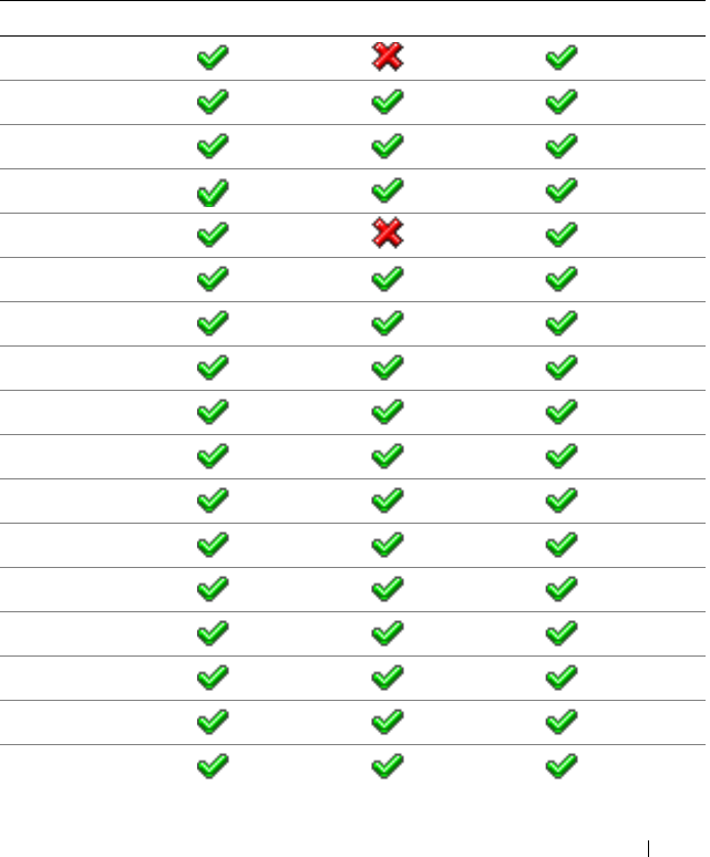
Supported RACADM Interfaces 411
C
Supported RACADM Interfaces
The following table provides an overview of RACADM subcommands and their
corresponding interface support.
Table C-1. RACADM Subcommand Interface Support
Subcommand Telnet/SSH/Serial Local RACADM Remote RACADM
arp
clearasrscreen
clrraclog
clrsel
coredump
coredumpdelete
fwupdate
getconfig
getniccfg
getraclog
getractime
getsel
getssninfo
getsvctag
getsysinfo
gettracelog
help
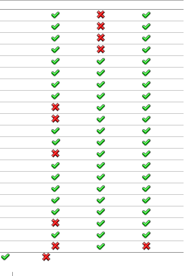
412 Supported RACADM Interfaces
ifconfig
netstat
ping
racdump
racreset
racresetcfg
serveraction
setniccfg
sslcertdownload
sslcertupload
sslcertview
sslcsrgen
sslkeyupload
sslresetcfg
testemail
testtrap
vmdisconnect
vmkey
usercertupload
usercertview
localConRedirDisable
= Supported; =Not supported
Table C-1. RACADM Subcommand Interface Support
(continued)
Subcommand Telnet/SSH/Serial Local RACADM Remote RACADM

Index 413
Index
A
Active Directory
adding DRAC 5 users, 124
configuring access to the DRAC
5, 117
extending schemas, 117
logging in to the DRAC 5, 142
objects, 113
schema extensions, 112
using with extended schema, 112
using with standard schema, 106
using with the DRAC 5, 105
B
BIOS setup
configuring on a managed
system, 51
Boot Once, 389
bootable image file
creating, 203
C
Certificate Signing Request
(CSR)
about, 216
generating a new certificate, 218
certificates
exporting the root CA
certificate, 138
SSL and digital, 215
uploading a server certificate, 219
viewing a server certificate, 220
configuration file
creating, 85
configuring
serial mode, 275
serial over LAN, 275
terminal mode, 275
connect com2
using, 50
console redirection
configuring, 163
opening a session, 164
using, 161
D
DRAC 5
accessing through a network, 73
adding and configuring users, 95
configuring, 38, 109, 126
configuring network settings, 72
configuring properties, 47
configuring the NIC, 75
creating a configuration file, 85
downloading firmware, 41
enabling security options, 225

414 Index
enabling serial/telnet/ssh
console, 57
securing communications, 215
updating the firmware, 40
E
e-mail alerts
configuring, 263
configuring using RACADM
CLI, 264
configuring using the web user
interface, 263
enabling
single sign-on, 151
example
see sample
extended schema
using with Active Directory, 112
F
features
DRAC 5, 29
DRAC 5 hardware, 26
firmware
downloading, 41
updating, 40
frequently asked questions
managing and recovering a remote
system, 92
using console redirection, 173
using the DRAC 5 with Active
Directory, 144
using Virtual Media, 205
H
hardware
installing, 35
hardware specifications, 26
connectors, 26
DRAC 5 ports, 27
power requirements, 26
I
IP blocking
about, 228
enabling, 229
IPMI
configuring, 61, 267
configuring using the RACADM
CLI, 270
configuring using the Web-based
interface, 267
IpRange
about, 225
enabling, 226
K
kerberos authentication, 147
prerequisites, 147

Index 415
L
last crash screen
capturing on the managed
system, 257
Linux XTerm
configuring for telnet console
redirection, 68
logs
operating system boot, 283
POST, 283
M
managed system
accessing through the local serial
port, 64
capturing the last crash
screen, 257
configuring BIOS setup, 51
enabling serial or telnet
console, 50
installing software, 38
management station
configuring, 162
configuring a Red Hat Enterprise
Linux management
station, 39
configuring terminal
emulation, 65
installing and removing
RACADM, 40
installing the software, 39
mouse pointer
synchronizing, 172
N
network properties
configuring manually, 90
configuring using racadm, 90
O
operating system boot, 283
Operating System Boot Capture
Logs, 283
other documents you may
need, 30
P
parsing rules, 87
PEF
configuring, 259
configuring using RACACM
CLI, 260
configuring using the web user
interface, 259
PET
configuring, 261
configuring using RACADM
CLI, 262
configuring using the web user
interface, 261
platform events
configuring, 258
prerequisites
setting up kerberos
authentication, 147

416 Index
setting up single sign-on, 151
property database groups
cfcRacManagedNodesOs, 383
cfgActiveDirectory, 391
cfgEmailAlert, 361
cfgIpmiLan, 404
cfgIpmiPef, 406
cfgIpmiPet, 408
cfgIpmiSerial, 398
cfgIpmiSol, 402
cfgLanNetworking, 347
cfgNetTuning, 370
cfgOobSnmp, 372
cfgRacSecurity, 384
cfgRacTuning, 373
cfgRacVirtual, 387
cfgRemoteHosts, 355
cfgSerial, 365
cfgSessionManagement, 362
cfgUserAdmin, 357
idRacInfo, 345
R
RAC serial
configuring, 61
RAC serial interface
about, 51
RACADM
attaching virtual media, 191
configuring serial and telnet, 58
installing and removing, 40
supported interfaces, 411
RACADM CLI
configuring e-mail alerts, 264
configuring PEF, 260
configuring PET, 262
RACADM subcommands
arp, 296
clearasrscreen, 296
clrraclog, 323
clrsel, 324
config, 297
coredump, 302
coredumpdelete, 303
fwupdate, 303
getconfig, 299
getniccfg, 315
getraclog, 321
getractime, 311
getsel, 323
getssninfo, 306
getsvctag, 316
getsysinfo, 308
gettracelog, 325
help, 295
ifconfig, 312
localConRedirDisable, 343
netstat, 312
ping, 313
racdump, 317
racreset, 318
racresetcfg, 319
serveraction, 320
setniccfg, 314
sslcertupload, 328, 333
sslcertview, 331
sslcsrgen, 326
testemail, 336

Index 417
testtrap, 337
usercertupload, 340
userertview, 342
vmdisconnect, 339
vmkey, 340
racadm utility
configuring network
properties, 90
parsing rules, 87
subcommands, 295
reboot option
disabling, 258
Red Hat Enterprise Linux
configuring for serial console
redirection, 52
remote access connections
supported, 28
S
Secure Shell (SSH)
using, 71, 220
Secure Sockets Layer (SSL)
about, 215
importing the firmware
certificate, 140
security
enabling, 225
using SSL and digital
certificates, 215
serial console
connecting the DB-9 cable, 65
using, 70
serial mode
configuring, 61
Serial Over LAN (SOL)
configuring, 275
server certificate
uploading, 219
viewing, 220
Server Management Command
Line Protocol (SM-CLP)
about, 233
support, 233
services
configuring, 221
Single Sign-On, 143
single sign-on
configuring the DRAC 5, 151
logging into the DRAC 5, 152
prerequisites, 151
snap-in
installing the Dell extension, 123
software
configuring, 37
installing, 37
Specify Server, 131
sslcertdownload, 329
standard schema
using with Active Directory, 106
system
configuring to use a DRAC 5, 36

418 Index
T
telnet console
using, 70
terminal mode
configuring, 61, 63
U
usercertupload, 340
V
video viewer
accessing the viewer menu
bar, 168
using, 167
virtual flash
configuring, 195
disabling, 194
enabling, 194
using, 194
virtual media
about, 183
attaching, 190
booting, 192
detaching, 190
installing the operating
system, 193
installing the plug-in, 185
running, 186
supported configurations, 186
VM-CLI
about, 196
deploying the operating
system, 204
operating system shell
options, 201
parameters, 198
using, 196
W
web browser
configuring, 43
web user interface
accessing, 48
configuring e-mail alerts, 263
configuring PEF, 259
configuring PET, 261
