Dell Fcx624 E Users Manual Configuration Guide
2015-02-09
: Dell Dell-Fcx624-E-Users-Manual-543953 dell-fcx624-e-users-manual-543953 dell pdf
Open the PDF directly: View PDF ![]() .
.
Page Count: 1494 [warning: Documents this large are best viewed by clicking the View PDF Link!]
- Contents
- About This Document
- Getting Familiar with Management Applications
- Configuring Basic Software Features
- Configuring basic system parameters
- Entering system administration information
- Configuring Simple Network Management Protocol (SNMP) parameters
- Disabling Syslog messages and traps for CLI access
- Cancelling an outbound Telnet session
- Specifying a Simple Network Time Protocol (SNTP) server
- Setting the system clock
- Limiting broadcast, multicast, and unknown unicast traffic
- Configuring CLI banners
- Configuring a local MAC address for Layer 2 management traffic
- Configuring basic port parameters
- Assigning a port name
- Modifying port speed and duplex mode
- Enabling auto-negotiation maximum port speed advertisement and down-shift
- Modifying port duplex mode
- Configuring MDI/MDIX
- Disabling or re-enabling a port
- Configuring flow control
- Configuring symmetric flow control on PowerConnect B-Series FCX devices
- Configuring PHY FIFO Rx and Tx depth
- Configuring the IPG on PowerConnect Stackable devices
- Enabling and disabling support for 100BaseTX
- Enabling and disabling support for 100BaseFX
- Changing the Gbps fiber negotiation mode
- Modifying port priority (QoS)
- Dynamic configuration of Voice over IP (VoIP) phones
- Configuring port flap dampening
- Port loop detection
- Configuring basic system parameters
- Operations, Administration, and Maintenance
- Overview
- Determining the software versions installed and running on a device
- Image file types
- Viewing the contents of flash files
- Using SNMP to upgrade software
- Changing the block size for TFTP file transfers
- Rebooting
- Displaying the boot preference
- Loading and saving configuration files
- Replacing the startup configuration with the running configuration
- Replacing the running configuration with the startup configuration
- Logging changes to the startup-config file
- Copying a configuration file to or from a TFTP server
- Dynamic configuration loading
- Maximum file sizes for startup-config file and running-config
- Loading and saving configuration files with IPv6
- Scheduling a system reload
- Diagnostic error codes and remedies for TFTP transfers
- Testing network connectivity
- Software-based Licensing
- Software license terminology
- Software-based licensing overview
- Non-licensed features
- Licensed features and part numbers
- Configuration tasks
- Deleting a license
- Other licensing options available from the Brocade Software Portal
- Transferring a license
- Syslog messages and trap information
- Viewing information about software licenses
- Stackable Devices
- IronStack overview
- Building an IronStack
- IronStack topologies
- Software requirements
- IronStack construction methods
- Scenario 1 - Configuring a three-member IronStack in a ring topology using secure-setup
- Scenario 2 - Configuring a three-member IronStack in a ring topology using the automatic setup process
- Scenario 3 - Configuring a three-member IronStack in a ring topology using the manual configuration process
- Configuring an FCX IronStack
- Configuring PowerConnect B-Series FCX stacking ports
- Configuring a default stacking port to function as a data port
- Verifying an IronStack configuration
- Managing your IronStack
- Logging in through the CLI
- Logging in through Brocade Network Advisor
- Logging in through the console port
- IronStack management MAC address
- Removing MAC address entries
- CLI command syntax
- IronStack CLI commands
- Copying the flash image to a stack unit from the Active Controller
- Reloading a stack unit
- Controlling stack topology
- Managing IronStack partitioning
- MIB support for the IronStack
- Persistent MAC address
- Unconfiguring an IronStack
- Displaying IronStack information
- Adding, removing, or replacing units in an IronStack
- Renumbering stack units
- Syslog, SNMP, and traps
- Troubleshooting an IronStack
- Stack mismatches
- Image mismatches
- More about IronStack technology
- PowerConnect B-Series FCX hitless stacking
- Supported events
- Non-supported events
- Supported protocols and services
- Configuration notes and feature limitations
- What happens during a hitless stacking switchover or failover
- Standby Controller role in hitless stacking
- Support during stack formation, stack merge, and stack split
- Hitless stacking default behavior
- Hitless stacking failover
- Hitless stacking switchover
- Displaying information about hitless stacking
- Syslog messages for hitless stacking failover and switchover
- Displaying hitless stacking diagnostic information
- Monitoring Hardware Components
- Configuring IPv6 Management on PowerConnect B-Series FCXSwitches
- Configuring Spanning Tree Protocol (STP) Related Features
- Configuring Basic Layer 2 Features
- About port regions
- Enabling or disabling the Spanning Tree Protocol (STP)
- MAC learning rate control
- Changing the MAC age time and disabling MAC address learning
- Configuring static MAC entries
- Configuring VLAN-based static MAC entries
- Clearing MAC address entries
- Flow-based MAC address learning
- Enabling port-based VLANs
- Defining MAC address filters
- Locking a port to restrict addresses
- Displaying and modifying system parameter default settings
- TDynamic Buffer Allocation for an IronStack
- Remote Fault Notification (RFN) on 1G fiber connections
- Link Fault Signaling (LFS) for 10G
- Jumbo frame support
- Configuring Metro Features
- Configuring Uni-Directional Link Detection (UDLD) and Protected Link Groups
- Configuring Trunk Groups and Dynamic Link Aggregation
- Trunk group overview
- Configuring a trunk group
- CLI syntax for configuring consecutive ports in a trunk group
- CLI syntax for configuring non-consecutive ports in a trunk group
- Example 1: Configuring the trunk groups shown in Figure 78
- Example 2: Configuring a trunk group that spans two Gbps Ethernet modules in a chassis device
- Example 3: Configuring a multi-slot trunk group with one port per module
- Example 4: Configuring a trunk group of 10 Gbps Ethernet ports
- Additional trunking options
- Displaying trunk group configuration information
- Dynamic link aggregation
- IronStack LACP trunk group configuration example
- Examples of valid LACP trunk groups
- Configuration notes and limitations
- Adaptation to trunk disappearance
- Flexible trunk eligibility
- Enabling dynamic link aggregation
- How changing the VLAN membership of a port affects trunk groups and dynamic keys
- Additional trunking options for LACP trunk ports
- Link aggregation parameters
- Displaying and determining the status of aggregate links
- Clearing the negotiated aggregate links table
- Configuring single link LACP
- Configuring Virtual LANs (VLANs)
- VLAN overview
- Routing between VLANs
- Virtual routing interfaces (Layer 3 Switches only)
- Routing between VLANs using virtual routing interfaces (Layer 3 Switches only)
- Dynamic port assignment (Layer 2 Switches and Layer 3 Switches)
- Assigning a different VLAN ID to the default VLAN
- Assigning different VLAN IDs to reserved VLANs 4091 and 4092
- Assigning trunk group ports
- Configuring port-based VLANs
- Modifying a port-based VLAN
- Enable spanning tree on a VLAN
- Configuring IP subnet, IPX network and protocol-based VLANs
- Configuring IP subnet, IPX network, and protocol-based VLANs within port-based VLANs
- Configuring an IPv6 protocol VLAN
- Routing between VLANs using virtual routing interfaces (Layer 3 Switches only)
- Configuring protocol VLANs with dynamic ports
- Configuring uplink ports within a port-based VLAN
- Configuring the same IP subnet address on multiple port-based VLANs
- Configuring VLAN groups and virtual routing interface groups
- Configuring super aggregated VLANs
- Configuring 802.1Q-in-Q tagging
- Configuring private VLANs
- Dual-mode VLAN ports
- Displaying VLAN information
- Displaying VLANs in alphanumeric order
- Displaying system-wide VLAN information
- Displaying global VLAN information
- Displaying VLAN information for specific ports
- Displaying a port VLAN membership
- Displaying a port dual-mode VLAN membership
- Displaying port default VLAN IDs (PVIDs)
- Displaying PVLAN information
- Configuring GARP VLAN Registration Protocol (GVRP)
- Configuring MAC-based VLANs
- Overview
- Dynamic MAC-based VLAN
- Configuration notes and feature limitations
- Configuring MAC-based VLANs
- Using MAC-based VLANs and 802.1X security on the same port
- Configuring generic and Dell vendor-specific attributes on the RADIUS server
- Aging for MAC-based VLAN
- Disabling aging for MAC-based VLAN sessions
- Configuring the maximum MAC addresses per port
- Configuring a MAC-based VLAN for a static host
- Configuring MAC-based VLAN for a dynamic host
- Configuring dynamic MAC-based VLAN
- Configuring MAC-based VLANs using SNMP
- Displaying Information about MAC-based VLANs
- Displaying the MAC-VLAN table
- Displaying the MAC-VLAN table for a specific MAC address
- Displaying allowed MAC addresses
- Displaying denied MAC addresses
- Displaying detailed MAC-VLAN data
- Displaying MAC-VLAN information for a specific interface
- Displaying MAC addresses in a MAC-based VLAN
- Displaying MAC-based VLAN logging
- Clearing MAC-VLAN information
- Sample application
- Configuring Rule-Based IP Access Control Lists (ACLs)
- ACL overview
- How hardware-based ACLs work
- Configuration considerations
- Configuring standard numbered ACLs
- Configuring standard named ACLs
- Configuring extended numbered ACLs
- Configuring extended named ACLs
- Preserving user input for ACL TCP/UDP port numbers
- Managing ACL comment text
- Applying an ACL to a virtual interface in a protocol- or subnet-based VLAN
- Enabling ACL logging
- Enabling strict control of ACL filtering of fragmented packets
- Enabling ACL support for switched traffic in the router image
- Enabling ACL filtering based on VLAN membership or VE port membership
- Using ACLs to filter ARP packets
- Filtering on IP precedence and ToS values
- QoS options for IP ACLs
- ACL-based rate limiting
- ACL statistics
- Using ACLs to control multicast features
- Enabling and viewing hardware usage statistics for an ACL
- Displaying ACL information
- Troubleshooting ACLs
- Policy-based routing (PBR)
- Configuring Quality of Service
- Configuring Traffic Policies
- Configuring Base Layer 3 and Enabling Routing Protocols
- Configuring Port Mirroring and Monitoring
- Configuring Rate Limiting and Rate Shaping on PowerConnect B-Series FCX Switches
- Configuring IP Multicast Traffic Reduction for PowerConnect B-Series FCX Switches
- Enabling the Foundry Discovery Protocol (FDP) and Reading Cisco Discovery Protocol (CDP) Packets
- Configuring LLDP and LLDP-MED
- Terms used in this chapter
- LLDP overview
- LLDP-MED overview
- General operating principles
- MIB support
- Syslog messages
- Configuring LLDP
- Configuration notes and considerations
- Enabling and disabling LLDP
- Enabling support for tagged LLDP packets
- Changing a port LLDP operating mode
- Specifying the maximum number of LLDP neighbors
- Enabling LLDP SNMP notifications and syslog messages
- Changing the minimum time between LLDP transmissions
- Changing the interval between regular LLDP transmissions
- Changing the holdtime multiplier for transmit TTL
- Changing the minimum time between port reinitializations
- LLDP TLVs advertised by the Dell PowerConnect device
- Configuring LLDP-MED
- LLDP-MED attributes advertised by the Dell PowerConnect device
- Resetting LLDP statistics
- Clearing cached LLDP neighbor information
- Configuring IP Multicast Protocols
- Overview of IP multicasting
- Changing global IP multicast parameters
- Adding an interface to a multicast group
- PIM Dense
- PIM Sparse
- PIM Passive
- Passive multicast route insertion
- Configuring an IP tunnel
- Using ACLs to control multicast features
- Disabling CPU processing for select multicast groups
- Displaying the multicast configuration for another multicast router
- IGMP V3
- Default IGMP version
- Compatibility with IGMP V1 and V2
- Globally enabling the IGMP version
- Enabling the IGMP version per interface setting
- Enabling the IGMP version on a physical port within a virtual routing interface
- Enabling membership tracking and fast leave
- Setting the query interval
- Setting the group membership time
- Setting the maximum response time
- IGMP V3 and source specific multicast protocols
- Displaying IGMP V3 information on Layer 3 Switches
- Clearing IGMP statistics
- IGMP Proxy
- IP multicast protocols and IGMP snooping on the same device
- Configuring IP
- Basic configuration
- Overview
- Basic IP parameters and defaults – Layer 3 Switches
- Basic IP parameters and defaults – Layer 2 Switches
- Configuring IP parameters – Layer 3 Switches
- Configuring IP addresses
- Configuring Domain Name Server (DNS) resolver
- Configuring packet parameters
- Changing the router ID
- Configuring ARP parameters
- Configuring forwarding parameters
- Disabling ICMP messages
- Disabling ICMP Redirect Messages
- Configuring static routes
- Configuring a default network route
- Configuring IP load sharing
- Configuring IRDP
- Configuring RARP
- Configuring UDP broadcast and IP helper parameters
- Configuring BootP/DHCP relay parameters
- DHCP Server
- Displaying DHCP server information
- DHCP Client-Based Auto-Configuration and Flash image update
- Configuring IP parameters – Layer 2 Switches
- Displaying IP configuration information and statistics
- Configuring Multicast Listening Discovery (MLD) Snooping on PowerConnect B-Series FCX Switches
- Overview
- Configuring MLD snooping
- Configuring the hardware and software resource limits
- Disabling transmission and receipt of MLD packets on a port
- Configuring the global MLD mode
- Modifying the age interval
- Modifying the query interval (Active MLD snooping mode only)
- Configuring the global MLD version
- Configuring report control
- Modifying the wait time before stopping traffic when receiving a leave message
- Modifying the multicast cache (mcache) aging time
- Disabling error and warning messages
- Configuring the MLD mode for a VLAN
- Disabling MLD snooping for the VLAN
- Configuring the MLD version for the VLAN
- Configuring the MLD version for individual ports
- Configuring static groups to the entire VLAN or to individual ports
- Configuring static router ports
- Turning off static group proxy
- Enabling MLDv2 membership tracking and fast leave for the VLAN
- Configuring fast leave for MLDv1
- Enabling fast convergence
- Displaying MLD snooping information
- Clear MLD snooping commands
- Configuring RIP (IPv4)
- Configuring OSPF Version 2 (IPv4)
- Overview of OSPF
- OSPF graceful restart
- Configuring OSPF
- Configuration rules
- OSPF parameters
- Enabling OSPF on the router
- Assigning OSPF areas
- Assigning an area range (optional)
- Assigning interfaces to an area
- Modifying interface defaults
- Changing the timer for OSPF authentication changes
- Block flooding of outbound LSAs on specific OSPF interfaces
- Configuring an OSPF non-broadcast interface
- Assigning virtual links
- Modifying virtual link parameters
- Changing the reference bandwidth for the cost on OSPF interfaces
- Defining redistribution filters
- Preventing specific OSPF routes from being installed in the IP route table
- Modifying the default metric for redistribution
- Enabling route redistribution
- Disabling or re-enabling load sharing
- Configuring external route summarization
- Configuring default route origination
- Modifying SPF timers
- Modifying the redistribution metric type
- Modifying the administrative distance
- Configuring OSPF group Link State Advertisement (LSA) pacing
- Modifying OSPF traps generated
- Specifying the types of OSPF Syslog messages to log
- Modifying the OSPF standard compliance setting
- Modifying the exit overflow interval
- Configuring an OSPF point-to-point link
- Configuring OSPF graceful restart
- Clearing OSPF information
- Displaying OSPF information
- Displaying general OSPF configuration information
- Displaying CPU utilization statistics
- Displaying OSPF area information
- Displaying OSPF neighbor information
- Displaying OSPF interface information
- Displaying OSPF route information
- Displaying OSPF external link state information
- Displaying OSPF link state information
- Displaying the data in an LSA
- Displaying OSPF virtual neighbor information
- Displaying OSPF virtual link information
- Displaying OSPF ABR and ASBR information
- Displaying OSPF trap status
- Displaying OSPF graceful restart information
- Configuring BGP4 (IPv4)
- Overview of BGP4
- BGP4 graceful restart
- Basic configuration and activation for BGP4
- BGP4 parameters
- Memory considerations
- Basic configuration tasks
- Optional configuration tasks
- Changing the Keep Alive Time and Hold Time
- Changing the BGP4 next-hop update timer
- Enabling fast external fallover
- Changing the maximum number of paths for BGP4 load sharing
- Customizing BGP4 load sharing
- Specifying a list of networks to advertise
- Changing the default local preference
- Using the IP default route as a valid next hop for a BGP4 route
- Advertising the default route
- Changing the default MED (Metric) used for route redistribution
- Enabling next-hop recursion
- Changing administrative distances
- Requiring the first AS to be the neighbor AS
- Disabling or re-enabling comparison of the AS-Path length
- Enabling or disabling comparison of the router IDs
- Configuring the Layer 3 Switch to always compare Multi-Exit Discriminators (MEDs)
- Treating missing MEDs as the worst MEDs
- Configuring route reflection parameters
- Configuration notes
- Aggregating routes advertised to BGP4 neighbors
- Configuring BGP4 graceful restart
- BGP null0 routing
- Modifying redistribution parameters
- Filtering
- Configuring route flap dampening
- Globally configuring route flap dampening
- Using a route map to configure route flap dampening for specific routes
- Using a route map to configure route flap dampening for a specific neighbor
- Removing route dampening from a route
- Removing route dampening from a neighbor routes suppressed due to aggregation
- Displaying and clearing route flap dampening statistics
- Generating traps for BGP
- Displaying BGP4 information
- Displaying summary BGP4 information
- Displaying the active BGP4 configuration
- Displaying CPU utilization statistics
- Displaying summary neighbor information
- Displaying BGP4 neighbor information
- Displaying peer group information
- Displaying summary route information
- Displaying the BGP4 route table
- Displaying BGP4 route-attribute entries
- Displaying the routes BGP4 has placed in the IP route table
- Displaying route flap dampening statistics
- Displaying the active route map configuration
- Displaying BGP4 graceful restart neighbor information
- Updating route information and resetting a neighbor session
- Clearing traffic counters
- Clearing route flap dampening statistics
- Removing route flap dampening
- Clearing diagnostic buffers
- Configuring VRRP and VRRPE
- Overview
- Comparison of VRRP and VRRPE
- VRRP and VRRPE parameters
- Configuring basic VRRP parameters
- Configuring basic VRRPE parameters
- Note regarding disabling VRRP or VRRPE
- Configuring additional VRRP and VRRPE parameters
- Forcing a Master router to abdicate to a standby router
- Displaying VRRP and VRRPE information
- Configuration examples
- Securing Access to Management Functions
- Securing access methods
- Restricting remote access to management functions
- Using ACLs to restrict remote access
- Defining the console idle time
- Restricting remote access to the device to specific IP addresses
- Restricting access to the device based on IP or MAC address
- Defining the Telnet idle time
- Changing the login timeout period for Telnet sessions
- Specifying the maximum number of login attempts for Telnet access
- Changing the login timeout period for Telnet sessions
- Restricting remote access to the device to specific VLAN IDs
- Designated VLAN for Telnet management sessions to a Layer 2 Switch
- Device management security
- Disabling specific access methods
- Setting passwords
- Setting up local user accounts
- Configuring SSL security for the Web Management Interface
- Configuring TACACS/TACACS+ security
- How TACACS+ differs from TACACS
- TACACS/TACACS+ authentication, authorization, and accounting
- TACACS authentication
- TACACS/TACACS+ configuration considerations
- Enabling TACACS
- Identifying the TACACS/TACACS+ servers
- Specifying different servers for individual AAA functions
- Setting optional TACACS/TACACS+ parameters
- Configuring authentication-method lists for TACACS/TACACS+
- Configuring TACACS+ authorization
- Configuring TACACS+ accounting
- Configuring an interface as the source for all TACACS/TACACS+ packets
- Displaying TACACS/TACACS+ statistics and configuration information
- Configuring RADIUS security
- RADIUS authentication, authorization, and accounting
- RADIUS configuration considerations
- RADIUS configuration procedure
- Configuring Dell-specific attributes on the RADIUS server
- Enabling SNMP to configure RADIUS
- Identifying the RADIUS server to the Dell PowerConnect device
- Specifying different servers for individual AAA functions
- Configuring a RADIUS server per port
- Mapping a RADIUS server to individual ports
- Setting RADIUS parameters
- Configuring authentication-method lists for RADIUS
- Configuring RADIUS authorization
- Configuring RADIUS accounting
- Configuring an interface as the source for all RADIUS packets
- Displaying RADIUS configuration information
- Configuring authentication-method lists
- TCP Flags - edge port security
- Configuring SSH2 and SCP
- Configuring 802.1X Port Security
- IETF RFC support
- How 802.1X port security works
- Configuring 802.1X port security
- Configuring an authentication method list for 802.1X
- Setting RADIUS parameters
- Configuring dynamic VLAN assignment for 802.1X ports
- Dynamically applying IP ACLs and MAC address filters to 802.1X ports
- Enabling 802.1X port security
- Setting the port control
- Configuring periodic re-authentication
- Re-authenticating a port manually
- Setting the quiet period
- Specifying the wait interval and number of EAP-request/ identity frame retransmissions from the Dell PowerConnect device
- Specifying the wait interval and number of EAP-request/ identity frame retransmissions from the RADIUS server
- Specifying a timeout for retransmission of messages to the authentication server
- Initializing 802.1X on a port
- Allowing access to multiple hosts
- Defining MAC address filters for EAP frames
- Configuring VLAN access for non-EAP-capable clients
- Configuring 802.1X accounting
- Displaying 802.1X information
- Sample 802.1X configurations
- Using multi-device port authentication and 802.1X security on the same port
- Using the MAC Port Security Feature
- Configuring Multi-Device Port Authentication
- How multi-device port authentication works
- Using multi-device port authentication and 802.1X security on the same port
- Configuring multi-device port authentication
- Enabling multi-device port authentication
- Specifying the format of the MAC addresses sent to the RADIUS server
- Specifying the authentication-failure action
- Generating traps for multi-device port authentication
- Defining MAC address filters
- Configuring dynamic VLAN assignment
- Dynamically applying IP ACLs to authenticated MAC addresses
- Enabling source guard protection
- Clearing authenticated MAC addresses
- Disabling aging for authenticated MAC addresses
- Changing the hardware aging period for blocked MAC addresses
- Specifying the aging time for blocked MAC addresses
- Specifying the RADIUS timeout action
- Multi-device port authentication password override
- Limiting the number of authenticated MAC addresses
- Displaying multi-device port authentication information
- Displaying authenticated MAC address information
- Displaying multi-device port authentication configuration information
- Displaying multi-device port authentication information for a specific MAC address or port
- Displaying the authenticated MAC addresses
- Displaying the non-authenticated MAC addresses
- Displaying multi-device port authentication information for a port
- Displaying multi-device port authentication settings and authenticated MAC addresses
- Displaying the MAC authentication table for PowerConnect B-Series FCX devices
- Example configurations
- Configuring Web Authentication
- Overview
- Configuration considerations
- Configuration tasks
- Enabling and disabling web authentication
- Configuring the web authentication mode
- Configuring web authentication options
- Enabling RADIUS accounting for web authentication
- Changing the login mode (HTTPS or HTTP)
- Specifying trusted ports
- Specifying hosts that are permanently authenticated
- Configuring the re-authentication period
- Defining the web authentication cycle
- Limiting the number of web authentication attempts
- Clearing authenticated hosts from the web authentication table
- Setting and clearing the block duration for web authentication attempts
- Manually blocking and unblocking a specific host
- Limiting the number of authenticated hosts
- Filtering DNS queries
- Forcing re-authentication when ports are down
- Forcing re-authentication after an inactive period
- Defining the web authorization redirect address
- Deleting a web authentication VLAN
- Web authentication pages
- Displaying web authentication information
- Protecting Against Denial of Service Attacks
- Inspecting and Tracking DHCP Packets
- Dynamic ARP inspection
- DHCP snooping
- How DHCP snooping works
- System reboot and the binding database
- Configuration notes and feature limitations
- Configuring DHCP snooping
- Clearing the DHCP binding database
- Displaying DHCP snooping status and ports
- Displaying the DHCP snooping binding database
- Displaying DHCP binding entry and status
- DHCP snooping configuration example
- DHCP relay agent information (DHCP Option 82)
- IP source guard
- Securing SNMP Access
- Using Syslog
- Overview
- Displaying Syslog messages
- Configuring the Syslog service
- Displaying the Syslog configuration
- Disabling or re-enabling Syslog
- Specifying a Syslog server
- Specifying an additional Syslog server
- Disabling logging of a message level
- Changing the number of entries the local buffer can hold
- Changing the log facility
- Displaying Interface names in Syslog messages
- Displaying TCP or UDP port numbers in Syslog messages
- Retaining Syslog messages after a soft reboot
- Clearing the Syslog messages from the local buffer
- Syslog messages
- Network Monitoring
- Software Specifications

53-1002266-01
18 March 2011
PowerConnect B-Series FCX
Configuration Guide

Information in this document is subject to change without notice.
© 2011 Dell Inc. All rights reserved.
Reproduction of these materials in any manner whatsoever without the written permission of Dell Inc. is strictly forbidden.
Trademarks used in this text: Dell, the DELL logo, Dell OpenManage and PowerConnect are trademarks of Dell Inc.; Microsoft,
Windows,and Windows Server are either trademarks or registered trademarks of Microsoft Corporation in the United States and/
or other countries.
Other trademarks and trade names may be used in this document to refer to either the entities claiming the marks and names or
their products. Dell Inc. disclaims any proprietary interest in trademarks and trade names other than its own.
Regulatory Model Code: FCX624-I, FCX624-E, FCX624-S, FCX648-I, FCX648-E, FCX648-S.

PowerConnect B-Series FCX Configuration Guide iii
53-1002266-01
Contents
About This Document
Introduction . . . . . . . . . . . . . . . . . . . . . . . . . . . . . . . . . . . . . . . . . . . xxxix
Device nomenclature . . . . . . . . . . . . . . . . . . . . . . . . . . . . . . . . . . . xxxix
Audience . . . . . . . . . . . . . . . . . . . . . . . . . . . . . . . . . . . . . . . . . . . . . xxxix
Document conventions. . . . . . . . . . . . . . . . . . . . . . . . . . . . . . . . . . . . . xl
Text formatting . . . . . . . . . . . . . . . . . . . . . . . . . . . . . . . . . . . . . . . . xl
Command syntax conventions . . . . . . . . . . . . . . . . . . . . . . . . . . .xl
Notes, cautions, and danger notices . . . . . . . . . . . . . . . . . . . . . .xl
Notice to the reader . . . . . . . . . . . . . . . . . . . . . . . . . . . . . . . . . . . . . . xli
Related publications . . . . . . . . . . . . . . . . . . . . . . . . . . . . . . . . . . . . . . xli
Getting technical help . . . . . . . . . . . . . . . . . . . . . . . . . . . . . . . . . . . . . xli
Contacting Dell. . . . . . . . . . . . . . . . . . . . . . . . . . . . . . . . . . . . . . . xli
Chapter 1 Getting Familiar with Management Applications
Using the management port . . . . . . . . . . . . . . . . . . . . . . . . . . . . . . . . 1
How the management port works. . . . . . . . . . . . . . . . . . . . . . . . . 1
CLI Commands for use with the management port. . . . . . . . . . . 2
Logging on through the CLI. . . . . . . . . . . . . . . . . . . . . . . . . . . . . . . . . . 3
On-line help . . . . . . . . . . . . . . . . . . . . . . . . . . . . . . . . . . . . . . . . . . 4
Command completion . . . . . . . . . . . . . . . . . . . . . . . . . . . . . . . . . . 4
Scroll control. . . . . . . . . . . . . . . . . . . . . . . . . . . . . . . . . . . . . . . . . . 4
Line editing commands . . . . . . . . . . . . . . . . . . . . . . . . . . . . . . . . . 5
Using stack-unit, slot number, and port number
with CLI commands. . . . . . . . . . . . . . . . . . . . . . . . . . . . . . . . . . . . . . . . 5
CLI nomenclature on Stackable devices . . . . . . . . . . . . . . . . . . . 6
Searching and filtering output from CLI commands . . . . . . . . . . 6
Using special characters in regular expressions . . . . . . . . . . . . . 8
Creating an alias for a CLI command . . . . . . . . . . . . . . . . . . . . . 10
Logging on through the Web Management Interface . . . . . . . . . . . . 11
Navigating the Web Management Interface . . . . . . . . . . . . . . .12
Logging on through Brocade Network Advisor . . . . . . . . . . . . . . . . . 16

iv PowerConnect B-Series FCX Configuration Guide
53-1002266-01
Chapter 2 Configuring Basic Software Features
Configuring basic system parameters . . . . . . . . . . . . . . . . . . . . . . . .18
Entering system administration information . . . . . . . . . . . . . . .18
Configuring Simple Network Management Protocol (SNMP)
parameters . . . . . . . . . . . . . . . . . . . . . . . . . . . . . . . . . . . . . . . . . .19
Disabling Syslog messages and traps for CLI access . . . . . . . .22
Cancelling an outbound Telnet session . . . . . . . . . . . . . . . . . . .23
Specifying a Simple Network Time Protocol (SNTP) server. . . .23
Setting the system clock . . . . . . . . . . . . . . . . . . . . . . . . . . . . . . .25
Limiting broadcast, multicast, and unknown unicast traffic. . . 27
Configuring CLI banners . . . . . . . . . . . . . . . . . . . . . . . . . . . . . . .29
Configuring a local MAC address for Layer 2 management traffic32
Configuring basic port parameters . . . . . . . . . . . . . . . . . . . . . . . . . .32
Assigning a port name. . . . . . . . . . . . . . . . . . . . . . . . . . . . . . . . .32
Modifying port speed and duplex mode. . . . . . . . . . . . . . . . . . .33
Enabling auto-negotiation maximum port speed
advertisement and down-shift . . . . . . . . . . . . . . . . . . . . . . . . . .33
Modifying port duplex mode . . . . . . . . . . . . . . . . . . . . . . . . . . . .36
Configuring MDI/MDIX. . . . . . . . . . . . . . . . . . . . . . . . . . . . . . . . . 37
Disabling or re-enabling a port . . . . . . . . . . . . . . . . . . . . . . . . . .38
Configuring flow control. . . . . . . . . . . . . . . . . . . . . . . . . . . . . . . .38
Configuring symmetric flow control on PowerConnect B-Series FCX
devices . . . . . . . . . . . . . . . . . . . . . . . . . . . . . . . . . . . . . . . . . . . . . 40
Configuring PHY FIFO Rx and Tx depth. . . . . . . . . . . . . . . . . . . .44
Configuring the IPG on PowerConnect Stackable devices . . . .44
Enabling and disabling support for 100BaseTX . . . . . . . . . . . .45
Enabling and disabling support for 100BaseFX . . . . . . . . . . . . 45
Changing the Gbps fiber negotiation mode . . . . . . . . . . . . . . . .46
Modifying port priority (QoS) . . . . . . . . . . . . . . . . . . . . . . . . . . . . 47
Dynamic configuration of Voice over IP (VoIP) phones . . . . . . . 47
Configuring port flap dampening . . . . . . . . . . . . . . . . . . . . . . . . 48
Port loop detection. . . . . . . . . . . . . . . . . . . . . . . . . . . . . . . . . . . .52
Chapter 3 Operations, Administration, and Maintenance
Overview . . . . . . . . . . . . . . . . . . . . . . . . . . . . . . . . . . . . . . . . . . . . . . . 57
Determining the software versions installed and running on a device58
Determining the flash image version running on the device . . 58
Determining the boot image version running on the device. . .59
Determining the image versions installed in flash memory . . . 59
Flash image verification . . . . . . . . . . . . . . . . . . . . . . . . . . . . . . . 59
Image file types . . . . . . . . . . . . . . . . . . . . . . . . . . . . . . . . . . . . . . . . . . 61
Viewing the contents of flash files . . . . . . . . . . . . . . . . . . . . . . . . . . . 61
Using SNMP to upgrade software . . . . . . . . . . . . . . . . . . . . . . . . . . .62
Changing the block size for TFTP file transfers. . . . . . . . . . . . . . . . .63
Rebooting. . . . . . . . . . . . . . . . . . . . . . . . . . . . . . . . . . . . . . . . . . . . . . . 64
Configuration notes . . . . . . . . . . . . . . . . . . . . . . . . . . . . . . . . . . .64
Displaying the boot preference . . . . . . . . . . . . . . . . . . . . . . . . . . . . .64

PowerConnect B-Series FCX Configuration Guide v
53-1002266-01
Loading and saving configuration files . . . . . . . . . . . . . . . . . . . . . . .65
Replacing the startup configuration with the running configuration
65
Replacing the running configuration with the startup configuration
66
Logging changes to the startup-config file. . . . . . . . . . . . . . . . . 66
Copying a configuration file to or from a TFTP server . . . . . . . . 66
Dynamic configuration loading . . . . . . . . . . . . . . . . . . . . . . . . . .67
Maximum file sizes for startup-config file and running-config .69
Loading and saving configuration files with IPv6 . . . . . . . . . . . . . . .69
Using the IPv6 copy command . . . . . . . . . . . . . . . . . . . . . . . . . .69
Copying a file from an IPv6 TFTP server. . . . . . . . . . . . . . . . . . .70
Using the IPv6 ncopy command . . . . . . . . . . . . . . . . . . . . . . . . . 71
Uploading files from an IPv6 TFTP server . . . . . . . . . . . . . . . . . 72
Using SNMP to save and load configuration information . . . . .73
Erasing image and configuration files . . . . . . . . . . . . . . . . . . . . 74
Scheduling a system reload . . . . . . . . . . . . . . . . . . . . . . . . . . . . . . . . 74
Reloading at a specific time . . . . . . . . . . . . . . . . . . . . . . . . . . . . 74
Reloading after a specific amount of time. . . . . . . . . . . . . . . . .75
Displaying the amount of time remaining before
a scheduled reload . . . . . . . . . . . . . . . . . . . . . . . . . . . . . . . . . . . 75
Canceling a scheduled reload. . . . . . . . . . . . . . . . . . . . . . . . . . .75
Diagnostic error codes and remedies for TFTP transfers. . . . . . . . .75
Testing network connectivity . . . . . . . . . . . . . . . . . . . . . . . . . . . . . . . 76
Pinging an IPv4 address . . . . . . . . . . . . . . . . . . . . . . . . . . . . . . . 76
Tracing an IPv4 route . . . . . . . . . . . . . . . . . . . . . . . . . . . . . . . . . . 78
Chapter 4 Software-based Licensing
Software license terminology . . . . . . . . . . . . . . . . . . . . . . . . . . . . . . .79
Software-based licensing overview . . . . . . . . . . . . . . . . . . . . . . . . . .80
How software-based licensing works . . . . . . . . . . . . . . . . . . . . .80
License types . . . . . . . . . . . . . . . . . . . . . . . . . . . . . . . . . . . . . . . . 80
Non-licensed features. . . . . . . . . . . . . . . . . . . . . . . . . . . . . . . . . . . . .80
Licensed features and part numbers . . . . . . . . . . . . . . . . . . . . . . . . 81
Licensing rules . . . . . . . . . . . . . . . . . . . . . . . . . . . . . . . . . . . . . . . 81
Configuration tasks. . . . . . . . . . . . . . . . . . . . . . . . . . . . . . . . . . . . . . . 83
Obtaining a license . . . . . . . . . . . . . . . . . . . . . . . . . . . . . . . . . . .83
Installing a license file . . . . . . . . . . . . . . . . . . . . . . . . . . . . . . . . .88
Verifying the license file installation . . . . . . . . . . . . . . . . . . . . . . 88
Deleting a license . . . . . . . . . . . . . . . . . . . . . . . . . . . . . . . . . . . . . . . .88
Other licensing options available from the
Brocade Software Portal. . . . . . . . . . . . . . . . . . . . . . . . . . . . . . . . . . . 89
Viewing software license information. . . . . . . . . . . . . . . . . . . . .89
Transferring a license . . . . . . . . . . . . . . . . . . . . . . . . . . . . . . . . . . . . .90
Syslog messages and trap information . . . . . . . . . . . . . . . . . . . . . . . 90

vi PowerConnect B-Series FCX Configuration Guide
53-1002266-01
Viewing information about software licenses . . . . . . . . . . . . . . . . . . 91
Viewing the License ID (LID) . . . . . . . . . . . . . . . . . . . . . . . . . . . . 91
Viewing the license database . . . . . . . . . . . . . . . . . . . . . . . . . . .92
Viewing software packages installed in the device . . . . . . . . . .93
Chapter 5 Stackable Devices
IronStack overview . . . . . . . . . . . . . . . . . . . . . . . . . . . . . . . . . . . . . . .95
IronStack technology features . . . . . . . . . . . . . . . . . . . . . . . . . .95
Stackable models . . . . . . . . . . . . . . . . . . . . . . . . . . . . . . . . . . . .96
IronStack terminology . . . . . . . . . . . . . . . . . . . . . . . . . . . . . . . . .96
Building an IronStack . . . . . . . . . . . . . . . . . . . . . . . . . . . . . . . . . . . . .98
IronStack topologies . . . . . . . . . . . . . . . . . . . . . . . . . . . . . . . . . .98
Software requirements . . . . . . . . . . . . . . . . . . . . . . . . . . . . . . .100
IronStack construction methods. . . . . . . . . . . . . . . . . . . . . . . .100
Scenario 1 - Configuring a three-member IronStack
in a ring topology using secure-setup. . . . . . . . . . . . . . . . . . . .101
Scenario 2 - Configuring a three-member IronStack
in a ring topology using the automatic setup process. . . . . . .105
Scenario 3 - Configuring a three-member IronStack
in a ring topology using the manual configuration process . .108
Configuring an FCX IronStack . . . . . . . . . . . . . . . . . . . . . . . . . .109
Configuring PowerConnect B-Series FCX stacking ports. . . . .109
Configuring a default stacking port to function as
a data port . . . . . . . . . . . . . . . . . . . . . . . . . . . . . . . . . . . . . . . . .115
Verifying an IronStack configuration. . . . . . . . . . . . . . . . . . . . .116
Managing your IronStack . . . . . . . . . . . . . . . . . . . . . . . . . . . . . . . . .118
Logging in through the CLI. . . . . . . . . . . . . . . . . . . . . . . . . . . . .118
Logging in through Brocade Network Advisor . . . . . . . . . . . . .118
Logging in through the console port. . . . . . . . . . . . . . . . . . . . .118
IronStack management MAC address . . . . . . . . . . . . . . . . . . .120
Removing MAC address entries . . . . . . . . . . . . . . . . . . . . . . . .122
CLI command syntax . . . . . . . . . . . . . . . . . . . . . . . . . . . . . . . . .124
IronStack CLI commands . . . . . . . . . . . . . . . . . . . . . . . . . . . . .124
Copying the flash image to a stack unit from
the Active Controller. . . . . . . . . . . . . . . . . . . . . . . . . . . . . . . . . .126
Reloading a stack unit. . . . . . . . . . . . . . . . . . . . . . . . . . . . . . . .126
Controlling stack topology . . . . . . . . . . . . . . . . . . . . . . . . . . . . .126
Managing IronStack partitioning. . . . . . . . . . . . . . . . . . . . . . . .127
MIB support for the IronStack. . . . . . . . . . . . . . . . . . . . . . . . . .128
Persistent MAC address . . . . . . . . . . . . . . . . . . . . . . . . . . . . . .128
Unconfiguring an IronStack. . . . . . . . . . . . . . . . . . . . . . . . . . . .130
Displaying IronStack information . . . . . . . . . . . . . . . . . . . . . . .131
Adding, removing, or replacing units in an IronStack . . . . . . . 147
Renumbering stack units . . . . . . . . . . . . . . . . . . . . . . . . . . . . .149
Syslog, SNMP, and traps . . . . . . . . . . . . . . . . . . . . . . . . . . . . . .151
Troubleshooting an IronStack. . . . . . . . . . . . . . . . . . . . . . . . . . . . . .151
Troubleshooting an unsuccessful stack build . . . . . . . . . . . . .152
Troubleshooting image copy issues . . . . . . . . . . . . . . . . . . . . .153
Stack mismatches. . . . . . . . . . . . . . . . . . . . . . . . . . . . . . . . . . . . . . .154

PowerConnect B-Series FCX Configuration Guide vii
53-1002266-01
Image mismatches . . . . . . . . . . . . . . . . . . . . . . . . . . . . . . . . . . . . . .154
Advanced feature privileges (PowerConnect B-Series FCX ) . .154
Configuration mismatch . . . . . . . . . . . . . . . . . . . . . . . . . . . . . .155
Memory allocation failure . . . . . . . . . . . . . . . . . . . . . . . . . . . . .156
Recovering from a mismatch . . . . . . . . . . . . . . . . . . . . . . . . . .156
Troubleshooting secure-setup. . . . . . . . . . . . . . . . . . . . . . . . . .157
Troubleshooting unit replacement issues . . . . . . . . . . . . . . . .158
More about IronStack technology . . . . . . . . . . . . . . . . . . . . . . . . . .158
Configuration, startup configuration files and stacking flash.158
IronStack topologies . . . . . . . . . . . . . . . . . . . . . . . . . . . . . . . . .159
Port down and aging . . . . . . . . . . . . . . . . . . . . . . . . . . . . . . . . .159
Device roles and elections . . . . . . . . . . . . . . . . . . . . . . . . . . . .159
PowerConnect B-Series FCX hitless stacking . . . . . . . . . . . . . . . . .162
Supported events. . . . . . . . . . . . . . . . . . . . . . . . . . . . . . . . . . . .163
Non-supported events . . . . . . . . . . . . . . . . . . . . . . . . . . . . . . . .163
Supported protocols and services . . . . . . . . . . . . . . . . . . . . . .163
Configuration notes and feature limitations . . . . . . . . . . . . . .165
What happens during a hitless stacking switchover or
failover . . . . . . . . . . . . . . . . . . . . . . . . . . . . . . . . . . . . . . . . . . . .166
Standby Controller role in hitless stacking. . . . . . . . . . . . . . . .168
Support during stack formation, stack merge,
and stack split . . . . . . . . . . . . . . . . . . . . . . . . . . . . . . . . . . . . . .169
Hitless stacking default behavior . . . . . . . . . . . . . . . . . . . . . . .173
Hitless stacking failover. . . . . . . . . . . . . . . . . . . . . . . . . . . . . . .175
Hitless stacking switchover . . . . . . . . . . . . . . . . . . . . . . . . . . . . 176
Displaying information about hitless stacking . . . . . . . . . . . . .183
Syslog messages for hitless stacking failover and switchover183
Displaying hitless stacking diagnostic information . . . . . . . . .184
Chapter 6 Monitoring Hardware Components
Virtual cable testing . . . . . . . . . . . . . . . . . . . . . . . . . . . . . . . . . . . . .189
Configuration notes . . . . . . . . . . . . . . . . . . . . . . . . . . . . . . . . . .189
Command syntax . . . . . . . . . . . . . . . . . . . . . . . . . . . . . . . . . . . .189
Viewing the results of the cable analysis . . . . . . . . . . . . . . . . .190
Supported Fiber Optic Transceivers. . . . . . . . . . . . . . . . . . . . . . . . .191
Digital optical monitoring . . . . . . . . . . . . . . . . . . . . . . . . . . . . . . . . .192
Configuration limitations . . . . . . . . . . . . . . . . . . . . . . . . . . . . . .192
Enabling digital optical monitoring . . . . . . . . . . . . . . . . . . . . . .192
Setting the alarm interval . . . . . . . . . . . . . . . . . . . . . . . . . . . . .193
Displaying information about installed media . . . . . . . . . . . . .193
Viewing optical monitoring information . . . . . . . . . . . . . . . . . .194
Syslog messages . . . . . . . . . . . . . . . . . . . . . . . . . . . . . . . . . . . .196
Chapter 7 Configuring IPv6 Management on
PowerConnect B-Series FCXSwitches
IPv6 management overview . . . . . . . . . . . . . . . . . . . . . . . . . . . . . . .198
IPv6 addressing. . . . . . . . . . . . . . . . . . . . . . . . . . . . . . . . . . . . . . . . .198
Enabling and disabling IPv6 . . . . . . . . . . . . . . . . . . . . . . . . . . .199

viii PowerConnect B-Series FCX Configuration Guide
53-1002266-01
IPv6 management features . . . . . . . . . . . . . . . . . . . . . . . . . . . . . . .199
IPv6 management ACLs . . . . . . . . . . . . . . . . . . . . . . . . . . . . . .199
IPv6 debug . . . . . . . . . . . . . . . . . . . . . . . . . . . . . . . . . . . . . . . . .200
IPv6 Web management using HTTP and HTTPS . . . . . . . . . . .200
IPv6 logging . . . . . . . . . . . . . . . . . . . . . . . . . . . . . . . . . . . . . . . .201
Name-to-IPv6 address resolution using IPv6 DNS server. . . .201
Defining an IPv6 DNS entry. . . . . . . . . . . . . . . . . . . . . . . . . . . .201
IPv6 ping. . . . . . . . . . . . . . . . . . . . . . . . . . . . . . . . . . . . . . . . . . .202
SNTP over IPv6. . . . . . . . . . . . . . . . . . . . . . . . . . . . . . . . . . . . . .203
SNMP3 over IPv6 . . . . . . . . . . . . . . . . . . . . . . . . . . . . . . . . . . . .203
Specifying an IPv6 SNMP trap receiver . . . . . . . . . . . . . . . . . .203
Secure Shell, SCP, and IPv6 . . . . . . . . . . . . . . . . . . . . . . . . . . .204
IPv6 Telnet . . . . . . . . . . . . . . . . . . . . . . . . . . . . . . . . . . . . . . . . .204
IPv6 traceroute. . . . . . . . . . . . . . . . . . . . . . . . . . . . . . . . . . . . . .205
IPv6 management commands . . . . . . . . . . . . . . . . . . . . . . . . . . . . .205
Chapter 8 Configuring Spanning Tree Protocol (STP) Related Features
STP overview . . . . . . . . . . . . . . . . . . . . . . . . . . . . . . . . . . . . . . . . . . .207
Configuring standard STP parameters. . . . . . . . . . . . . . . . . . . . . . .208
STP parameters and defaults . . . . . . . . . . . . . . . . . . . . . . . . . .208
Enabling or disabling the Spanning Tree Protocol (STP) . . . . .209
Changing STP bridge and port parameters . . . . . . . . . . . . . . .210
STP protection enhancement . . . . . . . . . . . . . . . . . . . . . . . . . .212
Displaying STP information . . . . . . . . . . . . . . . . . . . . . . . . . . . .214
Configuring STP related features . . . . . . . . . . . . . . . . . . . . . . . . . . .223
Fast port span . . . . . . . . . . . . . . . . . . . . . . . . . . . . . . . . . . . . . .223
Fast Uplink Span . . . . . . . . . . . . . . . . . . . . . . . . . . . . . . . . . . . .225
802.1W Rapid Spanning Tree (RSTP). . . . . . . . . . . . . . . . . . . .227
802.1W Draft 3 . . . . . . . . . . . . . . . . . . . . . . . . . . . . . . . . . . . . .265
Single Spanning Tree (SSTP) . . . . . . . . . . . . . . . . . . . . . . . . . . .269
STP per VLAN group . . . . . . . . . . . . . . . . . . . . . . . . . . . . . . . . . . 271
PVST/PVST+ compatibility . . . . . . . . . . . . . . . . . . . . . . . . . . . . . . . .275
Overview of PVST and PVST+ . . . . . . . . . . . . . . . . . . . . . . . . . . 276
VLAN tags and dual mode. . . . . . . . . . . . . . . . . . . . . . . . . . . . .277
Configuring PVST+ support . . . . . . . . . . . . . . . . . . . . . . . . . . . .278
Displaying PVST+ support information. . . . . . . . . . . . . . . . . . .278
Configuration examples. . . . . . . . . . . . . . . . . . . . . . . . . . . . . . .279
PVRST compatibility . . . . . . . . . . . . . . . . . . . . . . . . . . . . . . . . . . . . .282
BPDU guard . . . . . . . . . . . . . . . . . . . . . . . . . . . . . . . . . . . . . . . . . . . .282
Enabling BPDU protection by port. . . . . . . . . . . . . . . . . . . . . . .282
Re-enabling ports disabled by BPDU guard . . . . . . . . . . . . . . .283
Displaying the BPDU guard status . . . . . . . . . . . . . . . . . . . . . .283
Example console messages . . . . . . . . . . . . . . . . . . . . . . . . . . .284
Root guard . . . . . . . . . . . . . . . . . . . . . . . . . . . . . . . . . . . . . . . . . . . . .284
Enabling STP root guard . . . . . . . . . . . . . . . . . . . . . . . . . . . . . .285
Displaying the STP root guard . . . . . . . . . . . . . . . . . . . . . . . . . .285
Displaying the root guard by VLAN . . . . . . . . . . . . . . . . . . . . . .285

PowerConnect B-Series FCX Configuration Guide ix
53-1002266-01
Error disable recovery . . . . . . . . . . . . . . . . . . . . . . . . . . . . . . . . . . . .286
Enabling error disable recovery . . . . . . . . . . . . . . . . . . . . . . . .286
Setting the recovery interval . . . . . . . . . . . . . . . . . . . . . . . . . . .286
Displaying the error disable recovery state by interface . . . . .287
Displaying the recovery state for all conditions . . . . . . . . . . . .287
Displaying the recovery state by port number and cause. . . .287
Errdisable Syslog messages . . . . . . . . . . . . . . . . . . . . . . . . . . .288
802.1s Multiple Spanning Tree Protocol . . . . . . . . . . . . . . . . . . . . .288
Multiple spanning-tree regions . . . . . . . . . . . . . . . . . . . . . . . . .288
Configuration notes . . . . . . . . . . . . . . . . . . . . . . . . . . . . . . . . . .290
Configuring MSTP mode and scope . . . . . . . . . . . . . . . . . . . . .290
Reduced occurrences of MSTP reconvergence . . . . . . . . . . . .291
Configuring additional MSTP parameters . . . . . . . . . . . . . . . .293
Chapter 9 Configuring Basic Layer 2 Features
About port regions. . . . . . . . . . . . . . . . . . . . . . . . . . . . . . . . . . . . . . .306
PowerConnect B-Series FCX device port regions. . . . . . . . . . .306
Enabling or disabling the Spanning Tree Protocol (STP). . . . . . . . .306
Modifying STP bridge and port parameters . . . . . . . . . . . . . . .307
MAC learning rate control . . . . . . . . . . . . . . . . . . . . . . . . . . . . . . . . .307
Changing the MAC age time and disabling MAC address learning 307
Disabling the automatic learning of MAC addresses . . . . . . .308
Displaying the MAC address table . . . . . . . . . . . . . . . . . . . . . .308
Configuring static MAC entries . . . . . . . . . . . . . . . . . . . . . . . . . . . . .308
Multi-port static MAC address. . . . . . . . . . . . . . . . . . . . . . . . . .309
Configuring VLAN-based static MAC entries . . . . . . . . . . . . . . . . . .310
Clearing MAC address entries . . . . . . . . . . . . . . . . . . . . . . . . . . . . .310
Flow-based MAC address learning. . . . . . . . . . . . . . . . . . . . . . . . . .311
Feature overview . . . . . . . . . . . . . . . . . . . . . . . . . . . . . . . . . . . .311
The benefits of flow-based learning . . . . . . . . . . . . . . . . . . . . .311
How flow-based learning works . . . . . . . . . . . . . . . . . . . . . . . .312
Configuration considerations . . . . . . . . . . . . . . . . . . . . . . . . . .312
Configuring flow-based MAC address learning . . . . . . . . . . . .313
Displaying information about flow-based MACs. . . . . . . . . . . . 314
Clearing flow-based MAC address entries . . . . . . . . . . . . . . . .314
Enabling port-based VLANs . . . . . . . . . . . . . . . . . . . . . . . . . . . . . . .314
Assigning IEEE 802.1Q tagging to a port . . . . . . . . . . . . . . . . .315
Defining MAC address filters . . . . . . . . . . . . . . . . . . . . . . . . . . . . . .316
Configuration notes and limitations . . . . . . . . . . . . . . . . . . . . .316
Command syntax . . . . . . . . . . . . . . . . . . . . . . . . . . . . . . . . . . . . 316
Enabling logging of management traffic permitted by MAC address
filters. . . . . . . . . . . . . . . . . . . . . . . . . . . . . . . . . . . . . . . . . . . . . .318
MAC address filter override for 802.1X-enabled ports . . . . . .319
Locking a port to restrict addresses . . . . . . . . . . . . . . . . . . . . . . . .320
Configuration notes . . . . . . . . . . . . . . . . . . . . . . . . . . . . . . . . . .320
Command syntax . . . . . . . . . . . . . . . . . . . . . . . . . . . . . . . . . . . .320

xPowerConnect B-Series FCX Configuration Guide
53-1002266-01
Displaying and modifying system parameter default settings . . . .321
Configuration considerations . . . . . . . . . . . . . . . . . . . . . . . . . .321
Displaying system parameter default values . . . . . . . . . . . . . .321
Modifying system parameter default values . . . . . . . . . . . . . .325
TDynamic Buffer Allocation for an IronStack. . . . . . . . . . . . . . . . . .326
Generic buffer profiles on PowerConnect Stackable devices .329
Remote Fault Notification (RFN) on 1G fiber connections . . . . . . .329
Enabling and disabling remote fault notification. . . . . . . . . . .330
Link Fault Signaling (LFS) for 10G . . . . . . . . . . . . . . . . . . . . . . . . . .330
Jumbo frame support . . . . . . . . . . . . . . . . . . . . . . . . . . . . . . . . . . . .331
Chapter 10 Configuring Metro Features
Topology groups. . . . . . . . . . . . . . . . . . . . . . . . . . . . . . . . . . . . . . . . .333
Master VLAN and member VLANs . . . . . . . . . . . . . . . . . . . . . .334
Control ports and free ports . . . . . . . . . . . . . . . . . . . . . . . . . . .334
Configuration considerations . . . . . . . . . . . . . . . . . . . . . . . . . .334
Configuring a topology group . . . . . . . . . . . . . . . . . . . . . . . . . .335
Displaying topology group information . . . . . . . . . . . . . . . . . . .336
Metro Ring Protocol (MRP) . . . . . . . . . . . . . . . . . . . . . . . . . . . . . . . .337
Configuration notes . . . . . . . . . . . . . . . . . . . . . . . . . . . . . . . . . .339
MRP rings without shared interfaces (MRP Phase 1) . . . . . . .339
MRP rings with shared interfaces (MRP Phase 2). . . . . . . . . .340
Ring initialization . . . . . . . . . . . . . . . . . . . . . . . . . . . . . . . . . . . .341
How ring breaks are detected and healed . . . . . . . . . . . . . . . .346
Master VLANs and customer VLANs . . . . . . . . . . . . . . . . . . . . .348
Configuring MRP . . . . . . . . . . . . . . . . . . . . . . . . . . . . . . . . . . . .349
Using MRP diagnostics . . . . . . . . . . . . . . . . . . . . . . . . . . . . . . .352
Displaying MRP information . . . . . . . . . . . . . . . . . . . . . . . . . . .353
MRP CLI example . . . . . . . . . . . . . . . . . . . . . . . . . . . . . . . . . . . .355
Virtual Switch Redundancy Protocol (VSRP) . . . . . . . . . . . . . . . . . .357
Configuration notes and feature limitations . . . . . . . . . . . . . .358
Layer 2 and Layer 3 redundancy . . . . . . . . . . . . . . . . . . . . . . .359
Master election and failover . . . . . . . . . . . . . . . . . . . . . . . . . . .359
VSRP-Aware security features. . . . . . . . . . . . . . . . . . . . . . . . . .364
VSRP parameters. . . . . . . . . . . . . . . . . . . . . . . . . . . . . . . . . . . .364
Configuring basic VSRP parameters. . . . . . . . . . . . . . . . . . . . .367
Configuring optional VSRP parameters . . . . . . . . . . . . . . . . . .368
Displaying VSRP information. . . . . . . . . . . . . . . . . . . . . . . . . . . 376
VSRP fast start . . . . . . . . . . . . . . . . . . . . . . . . . . . . . . . . . . . . . .379
VSRP and MRP signaling. . . . . . . . . . . . . . . . . . . . . . . . . . . . . .380

PowerConnect B-Series FCX Configuration Guide xi
53-1002266-01
Chapter 11 Configuring Uni-Directional Link Detection (UDLD) and Protected
Link Groups
UDLD overview . . . . . . . . . . . . . . . . . . . . . . . . . . . . . . . . . . . . . . . . .383
UDLD for tagged ports . . . . . . . . . . . . . . . . . . . . . . . . . . . . . . . .384
Configuration notes and feature limitations . . . . . . . . . . . . . .384
Enabling UDLD . . . . . . . . . . . . . . . . . . . . . . . . . . . . . . . . . . . . . .385
Enabling UDLD for tagged ports . . . . . . . . . . . . . . . . . . . . . . . .385
Changing the Keepalive interval . . . . . . . . . . . . . . . . . . . . . . . .385
Changing the Keepalive retries. . . . . . . . . . . . . . . . . . . . . . . . .386
Displaying UDLD information . . . . . . . . . . . . . . . . . . . . . . . . . .386
Clearing UDLD statistics . . . . . . . . . . . . . . . . . . . . . . . . . . . . . .388
Protected link groups . . . . . . . . . . . . . . . . . . . . . . . . . . . . . . . . . . . .388
About active ports . . . . . . . . . . . . . . . . . . . . . . . . . . . . . . . . . . .389
Using UDLD with protected link groups . . . . . . . . . . . . . . . . . .389
Configuration notes . . . . . . . . . . . . . . . . . . . . . . . . . . . . . . . . . .389
Creating a protected link group and assigning
an active port . . . . . . . . . . . . . . . . . . . . . . . . . . . . . . . . . . . . . . .390
Chapter 12 Configuring Trunk Groups and Dynamic Link Aggregation
Trunk group overview . . . . . . . . . . . . . . . . . . . . . . . . . . . . . . . . . . . .393
Trunk group connectivity to a server. . . . . . . . . . . . . . . . . . . . .394
Trunk group rules . . . . . . . . . . . . . . . . . . . . . . . . . . . . . . . . . . . .395
Trunk group configuration examples . . . . . . . . . . . . . . . . . . . .396
Support for flexible trunk group membership . . . . . . . . . . . . .398
Trunk group load sharing. . . . . . . . . . . . . . . . . . . . . . . . . . . . . .398
Configuring a trunk group. . . . . . . . . . . . . . . . . . . . . . . . . . . . . . . . .400
CLI syntax for configuring consecutive ports in a trunk group400
CLI syntax for configuring non-consecutive ports in a trunk group401
Example 1: Configuring the trunk groups shown
in Figure 78 . . . . . . . . . . . . . . . . . . . . . . . . . . . . . . . . . . . . . . . .401
Example 2: Configuring a trunk group that spans
two Gbps Ethernet modules in a chassis device . . . . . . . . . . .402
Example 3: Configuring a multi-slot trunk group
with one port per module . . . . . . . . . . . . . . . . . . . . . . . . . . . . .403
Example 4: Configuring a trunk group of 10 Gbps
Ethernet ports . . . . . . . . . . . . . . . . . . . . . . . . . . . . . . . . . . . . . .403
Additional trunking options . . . . . . . . . . . . . . . . . . . . . . . . . . . .404
Displaying trunk group configuration information . . . . . . . . . . . . .408
Viewing the first and last ports in a trunk group . . . . . . . . . . .409

xii PowerConnect B-Series FCX Configuration Guide
53-1002266-01
Dynamic link aggregation . . . . . . . . . . . . . . . . . . . . . . . . . . . . . . . . . 410
IronStack LACP trunk group configuration example . . . . . . . .411
Examples of valid LACP trunk groups . . . . . . . . . . . . . . . . . . . .411
Configuration notes and limitations . . . . . . . . . . . . . . . . . . . . .412
Adaptation to trunk disappearance . . . . . . . . . . . . . . . . . . . . .413
Flexible trunk eligibility . . . . . . . . . . . . . . . . . . . . . . . . . . . . . . .413
Enabling dynamic link aggregation. . . . . . . . . . . . . . . . . . . . . .414
How changing the VLAN membership of a port
affects trunk groups and dynamic keys . . . . . . . . . . . . . . . . . . 416
Additional trunking options for LACP trunk ports. . . . . . . . . . .416
Link aggregation parameters . . . . . . . . . . . . . . . . . . . . . . . . . .416
Displaying and determining the status of aggregate links . . . . . . .421
Events that affect the status of ports in an aggregate link. . .422
Displaying link aggregation and port status information . . . .422
Displaying LACP status information . . . . . . . . . . . . . . . . . . . . .424
Clearing the negotiated aggregate links table . . . . . . . . . . . . . . . .425
Configuring single link LACP . . . . . . . . . . . . . . . . . . . . . . . . . . . . . . .425
Configuration notes . . . . . . . . . . . . . . . . . . . . . . . . . . . . . . . . . .425
CLI syntax . . . . . . . . . . . . . . . . . . . . . . . . . . . . . . . . . . . . . . . . . .425
Chapter 13 Configuring Virtual LANs (VLANs)
VLAN overview . . . . . . . . . . . . . . . . . . . . . . . . . . . . . . . . . . . . . . . . . .427
Types of VLANs . . . . . . . . . . . . . . . . . . . . . . . . . . . . . . . . . . . . . .427
Default VLAN . . . . . . . . . . . . . . . . . . . . . . . . . . . . . . . . . . . . . . .433
802.1Q tagging . . . . . . . . . . . . . . . . . . . . . . . . . . . . . . . . . . . . .434
Spanning Tree Protocol (STP) . . . . . . . . . . . . . . . . . . . . . . . . . .437
Virtual routing interfaces. . . . . . . . . . . . . . . . . . . . . . . . . . . . . .437
VLAN and virtual routing interface groups . . . . . . . . . . . . . . . .439
Dynamic, static, and excluded port membership . . . . . . . . . .439
Super aggregated VLANs. . . . . . . . . . . . . . . . . . . . . . . . . . . . . .441
Trunk group ports and VLAN membership . . . . . . . . . . . . . . . .441
Summary of VLAN configuration rules . . . . . . . . . . . . . . . . . . .442
Routing between VLANs . . . . . . . . . . . . . . . . . . . . . . . . . . . . . . . . . .443
Virtual routing interfaces (Layer 3 Switches only) . . . . . . . . . .443
Routing between VLANs using virtual routing interfaces
(Layer 3 Switches only) . . . . . . . . . . . . . . . . . . . . . . . . . . . . . . .443
Dynamic port assignment (Layer 2 Switches and
Layer 3 Switches). . . . . . . . . . . . . . . . . . . . . . . . . . . . . . . . . . . .444
Assigning a different VLAN ID to the default VLAN . . . . . . . . .444
Assigning different VLAN IDs to reserved VLANs
4091 and 4092 . . . . . . . . . . . . . . . . . . . . . . . . . . . . . . . . . . . . .445
Assigning trunk group ports . . . . . . . . . . . . . . . . . . . . . . . . . . .446
Configuring port-based VLANs . . . . . . . . . . . . . . . . . . . . . . . . .446
Modifying a port-based VLAN . . . . . . . . . . . . . . . . . . . . . . . . . .450
Enable spanning tree on a VLAN . . . . . . . . . . . . . . . . . . . . . . .451
Configuring IP subnet, IPX network and
protocol-based VLANs . . . . . . . . . . . . . . . . . . . . . . . . . . . . . . . . . . . .452
Configuration example. . . . . . . . . . . . . . . . . . . . . . . . . . . . . . . .452

PowerConnect B-Series FCX Configuration Guide xiii
53-1002266-01
Configuring IP subnet, IPX network, and protocol-based
VLANs within port-based VLANs. . . . . . . . . . . . . . . . . . . . . . . . . . . .454
Configuring an IPv6 protocol VLAN . . . . . . . . . . . . . . . . . . . . . . . . .458
Routing between VLANs using virtual routing
interfaces (Layer 3 Switches only) . . . . . . . . . . . . . . . . . . . . . . . . . .458
Configuring protocol VLANs with dynamic ports . . . . . . . . . . . . . . .464
Aging of dynamic ports . . . . . . . . . . . . . . . . . . . . . . . . . . . . . . .465
Configuration guidelines . . . . . . . . . . . . . . . . . . . . . . . . . . . . . .466
Configuring an IP, IPX, or AppleTalk Protocol
VLAN with Dynamic Ports . . . . . . . . . . . . . . . . . . . . . . . . . . . . .466
Configuring an IP subnet VLAN with dynamic ports . . . . . . . .466
Configuring an IPX network VLAN with dynamic ports . . . . . .467
Configuring uplink ports within a port-based VLAN . . . . . . . . . . . .468
Configuration considerations . . . . . . . . . . . . . . . . . . . . . . . . . .468
Configuration syntax . . . . . . . . . . . . . . . . . . . . . . . . . . . . . . . . .468
Configuring the same IP subnet address on
multiple port-based VLANs. . . . . . . . . . . . . . . . . . . . . . . . . . . . . . . .469
Configuring VLAN groups and virtual routing interface groups . . .472
Configuring a VLAN group . . . . . . . . . . . . . . . . . . . . . . . . . . . . .472
Configuring a virtual routing interface group . . . . . . . . . . . . . . 474
Displaying the VLAN group and virtual routing
interface group information . . . . . . . . . . . . . . . . . . . . . . . . . . .475
Allocating memory for more VLANs or virtual
routing interfaces. . . . . . . . . . . . . . . . . . . . . . . . . . . . . . . . . . . . 476
Configuring super aggregated VLANs . . . . . . . . . . . . . . . . . . . . . . .477
Configuration notes . . . . . . . . . . . . . . . . . . . . . . . . . . . . . . . . . .480
Configuring aggregated VLANs . . . . . . . . . . . . . . . . . . . . . . . . .480
Verifying the configuration. . . . . . . . . . . . . . . . . . . . . . . . . . . . .481
Complete CLI examples . . . . . . . . . . . . . . . . . . . . . . . . . . . . . . .481
Configuring 802.1Q-in-Q tagging . . . . . . . . . . . . . . . . . . . . . . . . . . .484
Configuration rules . . . . . . . . . . . . . . . . . . . . . . . . . . . . . . . . . .485
Enabling 802.1Q-in-Q tagging . . . . . . . . . . . . . . . . . . . . . . . . . .485
Example configuration. . . . . . . . . . . . . . . . . . . . . . . . . . . . . . . .487
Configuring 802.1Q-in-Q tag profiles . . . . . . . . . . . . . . . . . . . .488
Configuring private VLANs . . . . . . . . . . . . . . . . . . . . . . . . . . . . . . . .488
Configuration notes . . . . . . . . . . . . . . . . . . . . . . . . . . . . . . . . . .491
Enabling broadcast or unknown unicast traffic
to the PVLAN. . . . . . . . . . . . . . . . . . . . . . . . . . . . . . . . . . . . . . . .495
CLI example for a general PVLAN network . . . . . . . . . . . . . . . .496
CLI example for a PVLAN network with switch-switch
link ports. . . . . . . . . . . . . . . . . . . . . . . . . . . . . . . . . . . . . . . . . . .496
Dual-mode VLAN ports . . . . . . . . . . . . . . . . . . . . . . . . . . . . . . . . . . .497

xiv PowerConnect B-Series FCX Configuration Guide
53-1002266-01
Displaying VLAN information . . . . . . . . . . . . . . . . . . . . . . . . . . . . . .500
Displaying VLANs in alphanumeric order . . . . . . . . . . . . . . . . .500
Displaying system-wide VLAN information . . . . . . . . . . . . . . . .501
Displaying global VLAN information . . . . . . . . . . . . . . . . . . . . .502
Displaying VLAN information for specific ports . . . . . . . . . . . .502
Displaying a port VLAN membership . . . . . . . . . . . . . . . . . . . .503
Displaying a port dual-mode VLAN membership . . . . . . . . . . .503
Displaying port default VLAN IDs (PVIDs). . . . . . . . . . . . . . . . .503
Displaying PVLAN information. . . . . . . . . . . . . . . . . . . . . . . . . .504
Chapter 14 Configuring GARP VLAN Registration Protocol (GVRP)
GVRP overview. . . . . . . . . . . . . . . . . . . . . . . . . . . . . . . . . . . . . . . . . .505
Application examples . . . . . . . . . . . . . . . . . . . . . . . . . . . . . . . . . . . .506
Dynamic core and fixed edge . . . . . . . . . . . . . . . . . . . . . . . . . .506
Dynamic core and dynamic edge . . . . . . . . . . . . . . . . . . . . . . .507
Fixed core and dynamic edge . . . . . . . . . . . . . . . . . . . . . . . . . .508
Fixed core and fixed edge . . . . . . . . . . . . . . . . . . . . . . . . . . . . .508
VLAN names . . . . . . . . . . . . . . . . . . . . . . . . . . . . . . . . . . . . . . . . . . .508
Configuration notes. . . . . . . . . . . . . . . . . . . . . . . . . . . . . . . . . . . . . .508
Configuring GVRP . . . . . . . . . . . . . . . . . . . . . . . . . . . . . . . . . . . . . . . 510
Changing the GVRP base VLAN ID . . . . . . . . . . . . . . . . . . . . . .510
Increasing the maximum configurable value of the Leaveall timer
510
Enabling GVRP . . . . . . . . . . . . . . . . . . . . . . . . . . . . . . . . . . . . . .511
Disabling VLAN advertising . . . . . . . . . . . . . . . . . . . . . . . . . . . .511
Disabling VLAN learning . . . . . . . . . . . . . . . . . . . . . . . . . . . . . .512
Changing the GVRP timers . . . . . . . . . . . . . . . . . . . . . . . . . . . .512
Converting a VLAN created by GVRP into a statically-configured VLAN514
Displaying GVRP information . . . . . . . . . . . . . . . . . . . . . . . . . . . . . . 514
Displaying GVRP configuration information . . . . . . . . . . . . . . .515
Displaying GVRP VLAN information. . . . . . . . . . . . . . . . . . . . . . 517
Displaying GVRP statistics. . . . . . . . . . . . . . . . . . . . . . . . . . . . .519
Displaying CPU utilization statistics . . . . . . . . . . . . . . . . . . . . .520
Displaying GVRP diagnostic information . . . . . . . . . . . . . . . . .522
Clearing GVRP statistics . . . . . . . . . . . . . . . . . . . . . . . . . . . . . . . . . .522
CLI examples . . . . . . . . . . . . . . . . . . . . . . . . . . . . . . . . . . . . . . . . . . .522
Dynamic core and fixed edge . . . . . . . . . . . . . . . . . . . . . . . . . .523
Dynamic core and dynamic edge . . . . . . . . . . . . . . . . . . . . . . .524
Fixed core and dynamic edge . . . . . . . . . . . . . . . . . . . . . . . . . .524
Fixed core and fixed edge . . . . . . . . . . . . . . . . . . . . . . . . . . . . .525
Chapter 15 Configuring MAC-based VLANs
Overview . . . . . . . . . . . . . . . . . . . . . . . . . . . . . . . . . . . . . . . . . . . . . .527
Static and dynamic hosts . . . . . . . . . . . . . . . . . . . . . . . . . . . . .527
MAC-based VLAN feature structure . . . . . . . . . . . . . . . . . . . . .527
Dynamic MAC-based VLAN . . . . . . . . . . . . . . . . . . . . . . . . . . . . . . . .528

PowerConnect B-Series FCX Configuration Guide xv
53-1002266-01
Configuration notes and feature limitations . . . . . . . . . . . . . . . . . .529
Configuration example. . . . . . . . . . . . . . . . . . . . . . . . . . . . . . . .530
Configuring MAC-based VLANs. . . . . . . . . . . . . . . . . . . . . . . . . . . . .531
Using MAC-based VLANs and 802.1X security on the same port531
Configuring generic and Dell vendor-specific attributes on the
RADIUS server . . . . . . . . . . . . . . . . . . . . . . . . . . . . . . . . . . . . . .532
Aging for MAC-based VLAN . . . . . . . . . . . . . . . . . . . . . . . . . . . .533
Disabling aging for MAC-based VLAN sessions . . . . . . . . . . . .534
Configuring the maximum MAC addresses per port . . . . . . . .535
Configuring a MAC-based VLAN for a static host . . . . . . . . . . .535
Configuring MAC-based VLAN for a dynamic host . . . . . . . . . .536
Configuring dynamic MAC-based VLAN . . . . . . . . . . . . . . . . . .536
Configuring MAC-based VLANs using SNMP . . . . . . . . . . . . . . . . . .537
Displaying Information about MAC-based VLANs . . . . . . . . . . . . . .537
Displaying the MAC-VLAN table. . . . . . . . . . . . . . . . . . . . . . . . .537
Displaying the MAC-VLAN table for a specific MAC address . .537
Displaying allowed MAC addresses . . . . . . . . . . . . . . . . . . . . .538
Displaying denied MAC addresses . . . . . . . . . . . . . . . . . . . . . .538
Displaying detailed MAC-VLAN data . . . . . . . . . . . . . . . . . . . . .539
Displaying MAC-VLAN information for a specific interface . . .541
Displaying MAC addresses in a MAC-based VLAN . . . . . . . . . .542
Displaying MAC-based VLAN logging . . . . . . . . . . . . . . . . . . . .543
Clearing MAC-VLAN information. . . . . . . . . . . . . . . . . . . . . . . . . . . .543
Sample application . . . . . . . . . . . . . . . . . . . . . . . . . . . . . . . . . . . . . .543
Chapter 16 Configuring Rule-Based IP Access Control Lists (ACLs)
ACL overview . . . . . . . . . . . . . . . . . . . . . . . . . . . . . . . . . . . . . . . . . . .548
Types of IP ACLs . . . . . . . . . . . . . . . . . . . . . . . . . . . . . . . . . . . . .548
ACL IDs and entries . . . . . . . . . . . . . . . . . . . . . . . . . . . . . . . . . .548
Numbered and named ACLs . . . . . . . . . . . . . . . . . . . . . . . . . . .549
Default ACL action . . . . . . . . . . . . . . . . . . . . . . . . . . . . . . . . . . .549
How hardware-based ACLs work . . . . . . . . . . . . . . . . . . . . . . . . . . .550
How fragmented packets are processed . . . . . . . . . . . . . . . . .550
Hardware aging of Layer 4 CAM entries . . . . . . . . . . . . . . . . . .550
Configuration considerations . . . . . . . . . . . . . . . . . . . . . . . . . . . . . .550
Configuring standard numbered ACLs. . . . . . . . . . . . . . . . . . . . . . .551
Standard numbered ACL syntax . . . . . . . . . . . . . . . . . . . . . . . .551
Configuration example for standard numbered ACLs . . . . . . .553
Configuring standard named ACLs . . . . . . . . . . . . . . . . . . . . . . . . .553
Standard named ACL syntax . . . . . . . . . . . . . . . . . . . . . . . . . . .554
Configuration example for standard named ACLs . . . . . . . . . .555
Configuring extended numbered ACLs . . . . . . . . . . . . . . . . . . . . . .556
Extended numbered ACL syntax . . . . . . . . . . . . . . . . . . . . . . . .556
Configuration examples for extended numbered ACLs . . . . . .560
Configuring extended named ACLs . . . . . . . . . . . . . . . . . . . . . . . . .562
Extended named ACL syntax. . . . . . . . . . . . . . . . . . . . . . . . . . .562
Configuration example for extended named ACLs. . . . . . . . . .566

xvi PowerConnect B-Series FCX Configuration Guide
53-1002266-01
Preserving user input for ACL TCP/UDP port numbers. . . . . . . . . .566
Managing ACL comment text . . . . . . . . . . . . . . . . . . . . . . . . . . . . . .567
Adding a comment to an entry in a numbered ACL. . . . . . . . .567
Adding a comment to an entry in a named ACL. . . . . . . . . . . .568
Deleting a comment from an ACL entry . . . . . . . . . . . . . . . . . .568
Viewing comments in an ACL . . . . . . . . . . . . . . . . . . . . . . . . . .568
Applying an ACL to a virtual interface in a protocol-
or subnet-based VLAN . . . . . . . . . . . . . . . . . . . . . . . . . . . . . . . . . . .569
Enabling ACL logging. . . . . . . . . . . . . . . . . . . . . . . . . . . . . . . . . . . . .570
Enabling strict control of ACL filtering of fragmented packets. . . .572
Enabling ACL support for switched traffic in the router image . . .573
Enabling ACL filtering based on VLAN membership or VE port
membership . . . . . . . . . . . . . . . . . . . . . . . . . . . . . . . . . . . . . . . . . . .573
Configuration notes . . . . . . . . . . . . . . . . . . . . . . . . . . . . . . . . . . 574
Applying an IPv4 ACL to specific VLAN members on
a port (Layer 2 devices only) . . . . . . . . . . . . . . . . . . . . . . . . . . . 574
Applying an IPv4 ACL to a subset of ports on a virtual
interface (Layer 3 devices only) . . . . . . . . . . . . . . . . . . . . . . . .575
Using ACLs to filter ARP packets . . . . . . . . . . . . . . . . . . . . . . . . . . .576
Configuration considerations . . . . . . . . . . . . . . . . . . . . . . . . . .576
Configuring ACLs for ARP filtering . . . . . . . . . . . . . . . . . . . . . . .576
Displaying ACL filters for ARP . . . . . . . . . . . . . . . . . . . . . . . . . .577
Clearing the filter count . . . . . . . . . . . . . . . . . . . . . . . . . . . . . . .578
Filtering on IP precedence and ToS values . . . . . . . . . . . . . . . . . . .578
TCP flags - edge port security . . . . . . . . . . . . . . . . . . . . . . . . . .578
QoS options for IP ACLs . . . . . . . . . . . . . . . . . . . . . . . . . . . . . . . . . .579
Configuration notes for PowerConnect B-Series FCX devices.579
Using an IP ACL to mark DSCP values (DSCP marking). . . . . .580
DSCP matching . . . . . . . . . . . . . . . . . . . . . . . . . . . . . . . . . . . . .581
ACL-based rate limiting . . . . . . . . . . . . . . . . . . . . . . . . . . . . . . . . . . .582
ACL statistics . . . . . . . . . . . . . . . . . . . . . . . . . . . . . . . . . . . . . . . . . . .582
Using ACLs to control multicast features. . . . . . . . . . . . . . . . . . . . .582
Enabling and viewing hardware usage statistics for an ACL . . . . .582
Displaying ACL information. . . . . . . . . . . . . . . . . . . . . . . . . . . . . . . .583
Troubleshooting ACLs . . . . . . . . . . . . . . . . . . . . . . . . . . . . . . . . . . . .583
Policy-based routing (PBR) . . . . . . . . . . . . . . . . . . . . . . . . . . . . . . . .584
Chapter 17 Configuring Quality of Service
Classification . . . . . . . . . . . . . . . . . . . . . . . . . . . . . . . . . . . . . . . . . . .591
Processing of classified traffic . . . . . . . . . . . . . . . . . . . . . . . . .591

PowerConnect B-Series FCX Configuration Guide xvii
53-1002266-01
QoS for stackable devices . . . . . . . . . . . . . . . . . . . . . . . . . . . . . . . .595
QoS profile restrictions in an IronStack . . . . . . . . . . . . . . . . . .595
QoS behavior for trusting Layer 2 (802.1p) in an IronStack . .595
QoS behavior for trusting Layer 3 (DSCP) in an IronStack . . .595
QoS behavior on port priority and VLAN priority
in an IronStack . . . . . . . . . . . . . . . . . . . . . . . . . . . . . . . . . . . . . .596
QoS behavior for 802.1p marking in an IronStack . . . . . . . . .596
QoS queues . . . . . . . . . . . . . . . . . . . . . . . . . . . . . . . . . . . . . . . . . . . .596
Assigning QoS priorities to traffic. . . . . . . . . . . . . . . . . . . . . . . . . . .596
Changing a port priority . . . . . . . . . . . . . . . . . . . . . . . . . . . . . . .597
Assigning static MAC entries to priority queues. . . . . . . . . . . .597
Buffer allocation/threshold for QoS queues . . . . . . . . . . . . . .598
802.1p priority override . . . . . . . . . . . . . . . . . . . . . . . . . . . . . . . . . .598
Configuration notes and feature limitations . . . . . . . . . . . . . .598
Enabling 802.1p priority override . . . . . . . . . . . . . . . . . . . . . . .598
Marking . . . . . . . . . . . . . . . . . . . . . . . . . . . . . . . . . . . . . . . . . . . . . . .599
Configuring DSCP-based QoS. . . . . . . . . . . . . . . . . . . . . . . . . . . . . .599
Application notes . . . . . . . . . . . . . . . . . . . . . . . . . . . . . . . . . . . .599
Using ACLs to honor DSCP-based QoS . . . . . . . . . . . . . . . . . . .599
Configuring the QoS mappings. . . . . . . . . . . . . . . . . . . . . . . . . . . . .600
Default DSCP to internal forwarding priority mappings. . . . . .600
Changing the DSCP to internal forwarding
priority mappings . . . . . . . . . . . . . . . . . . . . . . . . . . . . . . . . . . . .601
Changing the VLAN priority 802.1p to hardware
forwarding queue mappings . . . . . . . . . . . . . . . . . . . . . . . . . . .602
8 to 4 queue mapping . . . . . . . . . . . . . . . . . . . . . . . . . . . . . . . .602
Scheduling. . . . . . . . . . . . . . . . . . . . . . . . . . . . . . . . . . . . . . . . . . . . .603
QoS queuing methods . . . . . . . . . . . . . . . . . . . . . . . . . . . . . . . .603
Selecting the QoS queuing method . . . . . . . . . . . . . . . . . . . . .605
Configuring the QoS queues . . . . . . . . . . . . . . . . . . . . . . . . . . .605
Viewing QoS settings. . . . . . . . . . . . . . . . . . . . . . . . . . . . . . . . . . . . .608
Viewing DSCP-based QoS settings. . . . . . . . . . . . . . . . . . . . . . . . . .608
Chapter 18 Configuring Traffic Policies
Traffic policies overview . . . . . . . . . . . . . . . . . . . . . . . . . . . . . . . . . .611
Configuration notes and feature limitations . . . . . . . . . . . . . . . . . .612
Maximum number of traffic policies supported on a device . . . . .612
Setting the maximum number of traffic policies
supported on a Layer 3 device . . . . . . . . . . . . . . . . . . . . . . . . .613
ACL-based rate limiting using traffic policies. . . . . . . . . . . . . . . . . .613
Support for fixed rate limiting and adaptive rate limiting . . . .614
Configuring ACL-based fixed rate limiting. . . . . . . . . . . . . . . . .614
Configuring ACL-based adaptive rate limiting . . . . . . . . . . . . .615
Specifying the action to be taken for packets that are
over the limit. . . . . . . . . . . . . . . . . . . . . . . . . . . . . . . . . . . . . . . . 617

xviii PowerConnect B-Series FCX Configuration Guide
53-1002266-01
ACL statistics and rate limit counting . . . . . . . . . . . . . . . . . . . . . . .619
Enabling ACL statistics . . . . . . . . . . . . . . . . . . . . . . . . . . . . . . .619
Enabling ACL statistics with rate limiting traffic policies. . . . .620
Viewing ACL and rate limit counters . . . . . . . . . . . . . . . . . . . . .620
Clearing ACL and rate limit counters . . . . . . . . . . . . . . . . . . . .621
Viewing traffic policies . . . . . . . . . . . . . . . . . . . . . . . . . . . . . . . . . . .622
Chapter 19 Configuring Base Layer 3 and Enabling Routing Protocols
Adding a static IP route. . . . . . . . . . . . . . . . . . . . . . . . . . . . . . . . . . .623
Adding a static ARP entry . . . . . . . . . . . . . . . . . . . . . . . . . . . . . . . . .624
Modifying and displaying layer 3 system parameter limits . . . . . .625
Configuration notes . . . . . . . . . . . . . . . . . . . . . . . . . . . . . . . . . .625
PowerConnect IPv6 models . . . . . . . . . . . . . . . . . . . . . . . . . . .625
Displaying Layer 3 system parameter limits . . . . . . . . . . . . . .625
Configuring RIP . . . . . . . . . . . . . . . . . . . . . . . . . . . . . . . . . . . . . . . . .626
Enabling RIP . . . . . . . . . . . . . . . . . . . . . . . . . . . . . . . . . . . . . . . .627
Enabling redistribution of IP static routes into RIP . . . . . . . . .627
Enabling redistribution . . . . . . . . . . . . . . . . . . . . . . . . . . . . . . .628
Enabling learning of default routes . . . . . . . . . . . . . . . . . . . . .629
Changing the route loop prevention method . . . . . . . . . . . . . .629
Other layer 3 protocols . . . . . . . . . . . . . . . . . . . . . . . . . . . . . . . . . . .629
Enabling or disabling routing protocols . . . . . . . . . . . . . . . . . . . . . .629
Enabling or disabling layer 2 switching . . . . . . . . . . . . . . . . . . . . . .630
Configuration Notes and Feature Limitations . . . . . . . . . . . . .630
Command syntax . . . . . . . . . . . . . . . . . . . . . . . . . . . . . . . . . . . .630
Chapter 20 Configuring Port Mirroring and Monitoring
Overview . . . . . . . . . . . . . . . . . . . . . . . . . . . . . . . . . . . . . . . . . . . . . .633
Configuring port mirroring and monitoring . . . . . . . . . . . . . . . . . . .633
Configuration notes . . . . . . . . . . . . . . . . . . . . . . . . . . . . . . . . . .634
Command syntax . . . . . . . . . . . . . . . . . . . . . . . . . . . . . . . . . . . .635
Configuring mirroring on an Ironstack . . . . . . . . . . . . . . . . . . . . . . .637
Configuration notes . . . . . . . . . . . . . . . . . . . . . . . . . . . . . . . . . .637
ACL-based inbound mirroring . . . . . . . . . . . . . . . . . . . . . . . . . . . . . .638
Creating an ACL-based inbound mirror clause for PowerConnect B-
Series FCX devices. . . . . . . . . . . . . . . . . . . . . . . . . . . . . . . . . . .638
MAC address filter-based mirroring . . . . . . . . . . . . . . . . . . . . . . . . .638
Configuring MAC address filter-based mirroring . . . . . . . . . . .638
VLAN-based mirroring . . . . . . . . . . . . . . . . . . . . . . . . . . . . . . . . . . . .639
Chapter 21 Configuring Rate Limiting and Rate Shaping on
PowerConnect B-Series FCX Switches
Rate limiting overview. . . . . . . . . . . . . . . . . . . . . . . . . . . . . . . . . . . .643

PowerConnect B-Series FCX Configuration Guide xix
53-1002266-01
Rate limiting in hardware . . . . . . . . . . . . . . . . . . . . . . . . . . . . . . . . .644
How Fixed rate limiting works . . . . . . . . . . . . . . . . . . . . . . . . . .644
Configuration notes . . . . . . . . . . . . . . . . . . . . . . . . . . . . . . . . . .645
Configuring a port-based rate limiting policy . . . . . . . . . . . . . .645
Configuring an ACL-based rate limiting policy . . . . . . . . . . . . .645
Displaying the fixed rate limiting configuration . . . . . . . . . . . .645
Rate shaping overview . . . . . . . . . . . . . . . . . . . . . . . . . . . . . . . . . . .646
Configuration notes . . . . . . . . . . . . . . . . . . . . . . . . . . . . . . . . . .646
Configuring outbound rate shaping for a port . . . . . . . . . . . . .647
Configuring outbound rate shaping for a specific priority. . . .647
Configuring outbound rate shaping for a trunk port . . . . . . . .647
Displaying rate shaping configurations . . . . . . . . . . . . . . . . . .648
Chapter 22 Configuring IP Multicast Traffic Reduction for
PowerConnect B-Series FCX Switches
IGMP snooping overview. . . . . . . . . . . . . . . . . . . . . . . . . . . . . . . . . .649
Configuration notes . . . . . . . . . . . . . . . . . . . . . . . . . . . . . . . . . .651
Configuring queriers and non-queriers. . . . . . . . . . . . . . . . . . .652
VLAN specific configuration . . . . . . . . . . . . . . . . . . . . . . . . . . .653
Using IGMPv2 with IGMPv3. . . . . . . . . . . . . . . . . . . . . . . . . . . .653
PIM SM traffic snooping overview . . . . . . . . . . . . . . . . . . . . . . . . . .653
Application example. . . . . . . . . . . . . . . . . . . . . . . . . . . . . . . . . .653
Configuring IGMP snooping . . . . . . . . . . . . . . . . . . . . . . . . . . . . . . .655
Displaying IGMP snooping information . . . . . . . . . . . . . . . . . . . . . .663
Displaying querier information . . . . . . . . . . . . . . . . . . . . . . . . .668
Clear IGMP snooping commands . . . . . . . . . . . . . . . . . . . . . . .671
Chapter 23 Enabling the Foundry Discovery Protocol (FDP) and Reading Cisco
Discovery Protocol (CDP) Packets
Using FDP . . . . . . . . . . . . . . . . . . . . . . . . . . . . . . . . . . . . . . . . . . . . .673
Configuring FDP . . . . . . . . . . . . . . . . . . . . . . . . . . . . . . . . . . . . .673
Displaying FDP information . . . . . . . . . . . . . . . . . . . . . . . . . . . .675
Clearing FDP and CDP information. . . . . . . . . . . . . . . . . . . . . .677
Reading CDP packets . . . . . . . . . . . . . . . . . . . . . . . . . . . . . . . . . . . .678
Enabling interception of CDP packets globally . . . . . . . . . . . .678
Enabling interception of CDP packets on an interface . . . . . .679
Displaying CDP information. . . . . . . . . . . . . . . . . . . . . . . . . . . .679
Clearing CDP information . . . . . . . . . . . . . . . . . . . . . . . . . . . . .681
Chapter 24 Configuring LLDP and LLDP-MED
Terms used in this chapter . . . . . . . . . . . . . . . . . . . . . . . . . . . . . . . .684
LLDP overview . . . . . . . . . . . . . . . . . . . . . . . . . . . . . . . . . . . . . . . . . .684
Benefits of LLDP . . . . . . . . . . . . . . . . . . . . . . . . . . . . . . . . . . . .685
LLDP-MED overview . . . . . . . . . . . . . . . . . . . . . . . . . . . . . . . . . . . . .686
Benefits of LLDP-MED . . . . . . . . . . . . . . . . . . . . . . . . . . . . . . . .686
LLDP-MED class . . . . . . . . . . . . . . . . . . . . . . . . . . . . . . . . . . . . .687

xx PowerConnect B-Series FCX Configuration Guide
53-1002266-01
General operating principles . . . . . . . . . . . . . . . . . . . . . . . . . . . . . .687
Operating modes . . . . . . . . . . . . . . . . . . . . . . . . . . . . . . . . . . . .687
LLDP packets . . . . . . . . . . . . . . . . . . . . . . . . . . . . . . . . . . . . . . .688
TLV support. . . . . . . . . . . . . . . . . . . . . . . . . . . . . . . . . . . . . . . . .689
MIB support . . . . . . . . . . . . . . . . . . . . . . . . . . . . . . . . . . . . . . . . . . . .692
Syslog messages. . . . . . . . . . . . . . . . . . . . . . . . . . . . . . . . . . . . . . . .692
Configuring LLDP. . . . . . . . . . . . . . . . . . . . . . . . . . . . . . . . . . . . . . . .692
Configuration notes and considerations . . . . . . . . . . . . . . . . .693
Enabling and disabling LLDP. . . . . . . . . . . . . . . . . . . . . . . . . . .693
Enabling support for tagged LLDP packets . . . . . . . . . . . . . . .694
Changing a port LLDP operating mode . . . . . . . . . . . . . . . . . .694
Specifying the maximum number of LLDP neighbors . . . . . . .696
Enabling LLDP SNMP notifications and syslog messages . . .697
Changing the minimum time between LLDP transmissions . .698
Changing the interval between regular LLDP transmissions .698
Changing the holdtime multiplier for transmit TTL . . . . . . . . .699
Changing the minimum time between port reinitializations. .699
LLDP TLVs advertised by the Dell PowerConnect device. . . . .699
Configuring LLDP-MED . . . . . . . . . . . . . . . . . . . . . . . . . . . . . . . . . . .707
Enabling LLDP-MED . . . . . . . . . . . . . . . . . . . . . . . . . . . . . . . . . .708
Enabling SNMP notifications and syslog messages
for LLDP-MED topology changes. . . . . . . . . . . . . . . . . . . . . . . .708
Changing the fast start repeat count . . . . . . . . . . . . . . . . . . . .708
Defining a location id. . . . . . . . . . . . . . . . . . . . . . . . . . . . . . . . .709
Defining an LLDP-MED network policy . . . . . . . . . . . . . . . . . . . 715
LLDP-MED attributes advertised by the Dell PowerConnect device717
Displaying LLDP statistics and configuration settings. . . . . . .718
LLDP configuration summary . . . . . . . . . . . . . . . . . . . . . . . . . .719
LLDP statistics . . . . . . . . . . . . . . . . . . . . . . . . . . . . . . . . . . . . . .719
LLDP neighbors . . . . . . . . . . . . . . . . . . . . . . . . . . . . . . . . . . . . .721
LLDP neighbors detail . . . . . . . . . . . . . . . . . . . . . . . . . . . . . . . .722
LLDP configuration details . . . . . . . . . . . . . . . . . . . . . . . . . . . .723
Resetting LLDP statistics . . . . . . . . . . . . . . . . . . . . . . . . . . . . . . . . .725
Clearing cached LLDP neighbor information. . . . . . . . . . . . . . . . . .725
Chapter 25 Configuring IP Multicast Protocols
Overview of IP multicasting . . . . . . . . . . . . . . . . . . . . . . . . . . . . . . .727
IPv4 multicast group addresses . . . . . . . . . . . . . . . . . . . . . . . .728
Mapping of IPv4 Multicast group addresses to
Ethernet MAC addresses . . . . . . . . . . . . . . . . . . . . . . . . . . . . . .728
Supported Layer 3 multicast routing protocols . . . . . . . . . . . .728
Suppression of unregistered multicast packets . . . . . . . . . . .729
Multicast terms . . . . . . . . . . . . . . . . . . . . . . . . . . . . . . . . . . . . .729
Changing global IP multicast parameters . . . . . . . . . . . . . . . . . . . .729
Changing dynamic memory allocation for IP
multicast groups . . . . . . . . . . . . . . . . . . . . . . . . . . . . . . . . . . . .729
Changing IGMP V1 and V2 parameters . . . . . . . . . . . . . . . . . .731
Adding an interface to a multicast group . . . . . . . . . . . . . . . . . . . .732

PowerConnect B-Series FCX Configuration Guide xxi
53-1002266-01
PIM Dense . . . . . . . . . . . . . . . . . . . . . . . . . . . . . . . . . . . . . . . . . . . . .733
Initiating PIM multicasts on a network . . . . . . . . . . . . . . . . . . .734
Pruning a multicast tree . . . . . . . . . . . . . . . . . . . . . . . . . . . . . .734
Grafts to a multicast Tree . . . . . . . . . . . . . . . . . . . . . . . . . . . . .736
PIM DM versions . . . . . . . . . . . . . . . . . . . . . . . . . . . . . . . . . . . .736
Configuring PIM DM. . . . . . . . . . . . . . . . . . . . . . . . . . . . . . . . . .737
Failover time in a multi-path topology . . . . . . . . . . . . . . . . . . . 741
Modifying the TTL. . . . . . . . . . . . . . . . . . . . . . . . . . . . . . . . . . . . 741
PIM Sparse . . . . . . . . . . . . . . . . . . . . . . . . . . . . . . . . . . . . . . . . . . . .742
PIM Sparse switch types . . . . . . . . . . . . . . . . . . . . . . . . . . . . . . 743
RP paths and SPT paths . . . . . . . . . . . . . . . . . . . . . . . . . . . . . .744
Configuring PIM Sparse. . . . . . . . . . . . . . . . . . . . . . . . . . . . . . . 744
Displaying PIM Sparse configuration information
and statistics . . . . . . . . . . . . . . . . . . . . . . . . . . . . . . . . . . . . . . .750
PIM Passive . . . . . . . . . . . . . . . . . . . . . . . . . . . . . . . . . . . . . . . . . . . .762
Passive multicast route insertion. . . . . . . . . . . . . . . . . . . . . . . . . . .763
. . . . . . . . . . . . . . . . . . . . . . . . . . . . . . . . . Configuring an IP tunnel763
Using ACLs to control multicast features. . . . . . . . . . . . . . . . . . . . .764
Using ACLs to limit static RP groups . . . . . . . . . . . . . . . . . . . . .764
Using ACLs to limit PIM RP candidate advertisement . . . . . . .766
Disabling CPU processing for select multicast groups . . . . . . . . . .767
CLI command syntax . . . . . . . . . . . . . . . . . . . . . . . . . . . . . . . . .768
Viewing disabled multicast addresses . . . . . . . . . . . . . . . . . . .768
Displaying the multicast configuration for
another multicast router. . . . . . . . . . . . . . . . . . . . . . . . . . . . . . . . . .769
IGMP V3 . . . . . . . . . . . . . . . . . . . . . . . . . . . . . . . . . . . . . . . . . . . . . . .770
Default IGMP version. . . . . . . . . . . . . . . . . . . . . . . . . . . . . . . . . 771
Compatibility with IGMP V1 and V2 . . . . . . . . . . . . . . . . . . . . . 771
Globally enabling the IGMP version . . . . . . . . . . . . . . . . . . . . . 771
Enabling the IGMP version per interface setting . . . . . . . . . . . 771
Enabling the IGMP version on a physical port within
a virtual routing interface . . . . . . . . . . . . . . . . . . . . . . . . . . . . .772
Enabling membership tracking and fast leave . . . . . . . . . . . .772
Setting the query interval . . . . . . . . . . . . . . . . . . . . . . . . . . . . .773
Setting the group membership time. . . . . . . . . . . . . . . . . . . . .773
Setting the maximum response time . . . . . . . . . . . . . . . . . . . .773
IGMP V3 and source specific multicast protocols . . . . . . . . . . 774
Displaying IGMP V3 information on Layer 3 Switches. . . . . . . 774
Clearing IGMP statistics . . . . . . . . . . . . . . . . . . . . . . . . . . . . . .778
IGMP Proxy. . . . . . . . . . . . . . . . . . . . . . . . . . . . . . . . . . . . . . . . . . . . .778
Configuration notes . . . . . . . . . . . . . . . . . . . . . . . . . . . . . . . . . .778
Configuring IGMP Proxy . . . . . . . . . . . . . . . . . . . . . . . . . . . . . . .779
Displaying IGMP Proxy traffic . . . . . . . . . . . . . . . . . . . . . . . . . .779
IP multicast protocols and IGMP snooping on the same device . .779
Configuration example. . . . . . . . . . . . . . . . . . . . . . . . . . . . . . . .780
CLI commands . . . . . . . . . . . . . . . . . . . . . . . . . . . . . . . . . . . . . .781

xxii PowerConnect B-Series FCX Configuration Guide
53-1002266-01
Chapter 26 Configuring IP
Basic configuration . . . . . . . . . . . . . . . . . . . . . . . . . . . . . . . . . . . . . .784
Overview . . . . . . . . . . . . . . . . . . . . . . . . . . . . . . . . . . . . . . . . . . . . . .784
Full Layer 3 support . . . . . . . . . . . . . . . . . . . . . . . . . . . . . . . . . .784
IP interfaces . . . . . . . . . . . . . . . . . . . . . . . . . . . . . . . . . . . . . . . .785
IP packet flow through a Layer 3 Switch. . . . . . . . . . . . . . . . . .785
IP route exchange protocols . . . . . . . . . . . . . . . . . . . . . . . . . . .790
IP multicast protocols . . . . . . . . . . . . . . . . . . . . . . . . . . . . . . . .790
IP interface redundancy protocols . . . . . . . . . . . . . . . . . . . . . .791
Access Control Lists and IP access policies. . . . . . . . . . . . . . .791
Basic IP parameters and defaults – Layer 3 Switches. . . . . . . . . .791
When parameter changes take effect . . . . . . . . . . . . . . . . . . .792
IP global parameters – Layer 3 Switches. . . . . . . . . . . . . . . . .792
IP interface parameters – Layer 3 Switches . . . . . . . . . . . . . .796
Basic IP parameters and defaults – Layer 2 Switches. . . . . . . . . .797
IP global parameters – Layer 2 Switches. . . . . . . . . . . . . . . . .797
Interface IP parameters – Layer 2 Switches . . . . . . . . . . . . . .799
Configuring IP parameters – Layer 3 Switches . . . . . . . . . . . . . . . .799
Configuring IP addresses. . . . . . . . . . . . . . . . . . . . . . . . . . . . . .799
Configuring Domain Name Server (DNS) resolver. . . . . . . . . .803
Configuring packet parameters . . . . . . . . . . . . . . . . . . . . . . . .806
Changing the router ID. . . . . . . . . . . . . . . . . . . . . . . . . . . . . . . .809
Configuring ARP parameters . . . . . . . . . . . . . . . . . . . . . . . . . . .810
Configuring forwarding parameters . . . . . . . . . . . . . . . . . . . . .815
Disabling ICMP messages . . . . . . . . . . . . . . . . . . . . . . . . . . . . .817
Disabling ICMP Redirect Messages . . . . . . . . . . . . . . . . . . . . .819
Configuring static routes . . . . . . . . . . . . . . . . . . . . . . . . . . . . . .819
Configuring a default network route . . . . . . . . . . . . . . . . . . . . .828
Configuring IP load sharing . . . . . . . . . . . . . . . . . . . . . . . . . . . .829
Configuring IRDP . . . . . . . . . . . . . . . . . . . . . . . . . . . . . . . . . . . .832
Configuring RARP. . . . . . . . . . . . . . . . . . . . . . . . . . . . . . . . . . . .834
Configuring UDP broadcast and IP helper parameters . . . . . .836
Configuring BootP/DHCP relay parameters . . . . . . . . . . . . . . .839
DHCP Server. . . . . . . . . . . . . . . . . . . . . . . . . . . . . . . . . . . . . . . .841
Displaying DHCP server information. . . . . . . . . . . . . . . . . . . . .851
DHCP Client-Based Auto-Configuration and Flash
image update . . . . . . . . . . . . . . . . . . . . . . . . . . . . . . . . . . . . . . .854
Configuring IP parameters – Layer 2 Switches . . . . . . . . . . . . . . . .862
Configuring the management IP address and specifying
the default gateway . . . . . . . . . . . . . . . . . . . . . . . . . . . . . . . . . .863
Configuring Domain Name Server (DNS) resolver. . . . . . . . . .863
Changing the TTL threshold . . . . . . . . . . . . . . . . . . . . . . . . . . .865
Configuring DHCP Assist . . . . . . . . . . . . . . . . . . . . . . . . . . . . . .865
Displaying IP configuration information and statistics . . . . . . . . . .869
Changing the network mask display to prefix format . . . . . . .869
Displaying IP information – Layer 3 Switches . . . . . . . . . . . . .869
Displaying IP information – Layer 2 Switches . . . . . . . . . . . . .883
. . . . . . . . . . . . . . . . . . . . . . . . . . . . . . . . . . . . . . . . . . . . . . . . . . . . . .887

PowerConnect B-Series FCX Configuration Guide xxiii
53-1002266-01
Chapter 27 Configuring Multicast Listening Discovery (MLD) Snooping on
PowerConnect B-Series FCX Switches
Overview . . . . . . . . . . . . . . . . . . . . . . . . . . . . . . . . . . . . . . . . . . . . . .889
Configuration notes . . . . . . . . . . . . . . . . . . . . . . . . . . . . . . . . . .891
Configuring queriers and non-queriers. . . . . . . . . . . . . . . . . . .892
VLAN specific configuration . . . . . . . . . . . . . . . . . . . . . . . . . . .892
Using MLDv1 with MLDv2 . . . . . . . . . . . . . . . . . . . . . . . . . . . . .892
Configuring MLD snooping . . . . . . . . . . . . . . . . . . . . . . . . . . . . . . . .893
Configuring the hardware and software resource limits . . . . .893
Disabling transmission and receipt of MLD packets on a port894
Configuring the global MLD mode . . . . . . . . . . . . . . . . . . . . . .894
Modifying the age interval. . . . . . . . . . . . . . . . . . . . . . . . . . . . .894
Modifying the query interval (Active MLD snooping mode only)895
Configuring the global MLD version . . . . . . . . . . . . . . . . . . . . .895
Configuring report control . . . . . . . . . . . . . . . . . . . . . . . . . . . . .895
Modifying the wait time before stopping traffic when receiving a
leave message . . . . . . . . . . . . . . . . . . . . . . . . . . . . . . . . . . . . . .896
Modifying the multicast cache (mcache) aging time. . . . . . . .896
Disabling error and warning messages . . . . . . . . . . . . . . . . . .896
Configuring the MLD mode for a VLAN. . . . . . . . . . . . . . . . . . .896
Disabling MLD snooping for the VLAN . . . . . . . . . . . . . . . . . . .897
Configuring the MLD version for the VLAN. . . . . . . . . . . . . . . .897
Configuring the MLD version for individual ports . . . . . . . . . .897
Configuring static groups to the entire VLAN or to individual ports
897
Configuring static router ports . . . . . . . . . . . . . . . . . . . . . . . . .898
Turning off static group proxy . . . . . . . . . . . . . . . . . . . . . . . . . .898
Enabling MLDv2 membership tracking and fast leave for the VLAN
898
Configuring fast leave for MLDv1 . . . . . . . . . . . . . . . . . . . . . . .899
Enabling fast convergence . . . . . . . . . . . . . . . . . . . . . . . . . . . .899
Displaying MLD snooping information . . . . . . . . . . . . . . . . . . .900
Clear MLD snooping commands. . . . . . . . . . . . . . . . . . . . . . . .904
Chapter 28 Configuring RIP (IPv4)
RIP overview . . . . . . . . . . . . . . . . . . . . . . . . . . . . . . . . . . . . . . . . . . .907
ICMP host unreachable message for undeliverable ARPs . . .908
RIP parameters and defaults . . . . . . . . . . . . . . . . . . . . . . . . . . . . . .908
RIP global parameters . . . . . . . . . . . . . . . . . . . . . . . . . . . . . . . .908
RIP interface parameters . . . . . . . . . . . . . . . . . . . . . . . . . . . . .909

xxiv PowerConnect B-Series FCX Configuration Guide
53-1002266-01
Configuring RIP parameters . . . . . . . . . . . . . . . . . . . . . . . . . . . . . . .910
Enabling RIP . . . . . . . . . . . . . . . . . . . . . . . . . . . . . . . . . . . . . . . .910
Configuring metric parameters . . . . . . . . . . . . . . . . . . . . . . . . .910
Changing the administrative distance. . . . . . . . . . . . . . . . . . .911
Configuring redistribution . . . . . . . . . . . . . . . . . . . . . . . . . . . . .912
Configuring route learning and advertising parameters . . . . .914
Changing the route loop prevention method . . . . . . . . . . . . . .915
Suppressing RIP route advertisement on a VRRP or
VRRPE backup interface . . . . . . . . . . . . . . . . . . . . . . . . . . . . . . 916
Configuring RIP route filters . . . . . . . . . . . . . . . . . . . . . . . . . . .916
Displaying RIP filters . . . . . . . . . . . . . . . . . . . . . . . . . . . . . . . . . . . . . 917
Displaying CPU utilization statistics . . . . . . . . . . . . . . . . . . . . . . . . .918
Chapter 29 Configuring OSPF Version 2 (IPv4)
Overview of OSPF . . . . . . . . . . . . . . . . . . . . . . . . . . . . . . . . . . . . . . .922
OSPF point-to-point links . . . . . . . . . . . . . . . . . . . . . . . . . . . . . .923
Designated routers in multi-access networks . . . . . . . . . . . . .924
Designated router election in multi-access networks . . . . . . .924
OSPF RFC 1583 and 2178 compliance . . . . . . . . . . . . . . . . . .925
Reduction of equivalent AS External LSAs . . . . . . . . . . . . . . . .926
Support for OSPF RFC 2328 Appendix E . . . . . . . . . . . . . . . . .928
Dynamic OSPF activation and configuration . . . . . . . . . . . . . .929
Dynamic OSPF memory . . . . . . . . . . . . . . . . . . . . . . . . . . . . . . .930
OSPF graceful restart . . . . . . . . . . . . . . . . . . . . . . . . . . . . . . . . . . . .930

PowerConnect B-Series FCX Configuration Guide xxv
53-1002266-01
Configuring OSPF . . . . . . . . . . . . . . . . . . . . . . . . . . . . . . . . . . . . . . .930
Configuration rules . . . . . . . . . . . . . . . . . . . . . . . . . . . . . . . . . .931
OSPF parameters . . . . . . . . . . . . . . . . . . . . . . . . . . . . . . . . . . . .931
Enabling OSPF on the router. . . . . . . . . . . . . . . . . . . . . . . . . . .932
Assigning OSPF areas . . . . . . . . . . . . . . . . . . . . . . . . . . . . . . . .933
Assigning an area range (optional). . . . . . . . . . . . . . . . . . . . . .937
Assigning interfaces to an area . . . . . . . . . . . . . . . . . . . . . . . .937
Modifying interface defaults . . . . . . . . . . . . . . . . . . . . . . . . . . .937
Changing the timer for OSPF authentication changes . . . . . .940
Block flooding of outbound LSAs on specific OSPF interfaces941
Configuring an OSPF non-broadcast interface. . . . . . . . . . . . .941
Assigning virtual links . . . . . . . . . . . . . . . . . . . . . . . . . . . . . . . .942
Modifying virtual link parameters . . . . . . . . . . . . . . . . . . . . . . .944
Changing the reference bandwidth for the cost on OSPF interfaces
946
Defining redistribution filters . . . . . . . . . . . . . . . . . . . . . . . . . .947
Preventing specific OSPF routes from being installed in the IP route
table . . . . . . . . . . . . . . . . . . . . . . . . . . . . . . . . . . . . . . . . . . . . . .950
Modifying the default metric for redistribution . . . . . . . . . . . .953
Enabling route redistribution. . . . . . . . . . . . . . . . . . . . . . . . . . .953
Disabling or re-enabling load sharing. . . . . . . . . . . . . . . . . . . .955
Configuring external route summarization. . . . . . . . . . . . . . . .956
Configuring default route origination . . . . . . . . . . . . . . . . . . . .957
Modifying SPF timers. . . . . . . . . . . . . . . . . . . . . . . . . . . . . . . . .958
Modifying the redistribution metric type . . . . . . . . . . . . . . . . .959
Modifying the administrative distance . . . . . . . . . . . . . . . . . . .959
Configuring OSPF group Link State Advertisement
(LSA) pacing . . . . . . . . . . . . . . . . . . . . . . . . . . . . . . . . . . . . . . . .960
Modifying OSPF traps generated . . . . . . . . . . . . . . . . . . . . . . .961
Specifying the types of OSPF Syslog messages to log . . . . . .962
Modifying the OSPF standard compliance setting. . . . . . . . . .962
Modifying the exit overflow interval . . . . . . . . . . . . . . . . . . . . .962
Configuring an OSPF point-to-point link . . . . . . . . . . . . . . . . . .963
Configuring OSPF graceful restart . . . . . . . . . . . . . . . . . . . . . .963
Clearing OSPF information . . . . . . . . . . . . . . . . . . . . . . . . . . . . . . . .964
Clearing OSPF neighbor information . . . . . . . . . . . . . . . . . . . .965
Clearing OSPF topology information . . . . . . . . . . . . . . . . . . . . .965
Clearing redistributed routes from the OSPF routing table. . .965
Clearing information for OSPF areas . . . . . . . . . . . . . . . . . . . .966

xxvi PowerConnect B-Series FCX Configuration Guide
53-1002266-01
Displaying OSPF information . . . . . . . . . . . . . . . . . . . . . . . . . . . . . .966
Displaying general OSPF configuration information . . . . . . . .967
Displaying CPU utilization statistics . . . . . . . . . . . . . . . . . . . . .968
Displaying OSPF area information . . . . . . . . . . . . . . . . . . . . . .969
Displaying OSPF neighbor information . . . . . . . . . . . . . . . . . . .969
Displaying OSPF interface information. . . . . . . . . . . . . . . . . . . 971
Displaying OSPF route information . . . . . . . . . . . . . . . . . . . . . .973
Displaying OSPF external link state information . . . . . . . . . . .975
Displaying OSPF link state information . . . . . . . . . . . . . . . . . . 976
Displaying the data in an LSA . . . . . . . . . . . . . . . . . . . . . . . . . . 976
Displaying OSPF virtual neighbor information . . . . . . . . . . . . .977
Displaying OSPF virtual link information . . . . . . . . . . . . . . . . .977
Displaying OSPF ABR and ASBR information . . . . . . . . . . . . . .977
Displaying OSPF trap status . . . . . . . . . . . . . . . . . . . . . . . . . . .978
Displaying OSPF graceful restart information . . . . . . . . . . . . .978
Chapter 30 Configuring BGP4 (IPv4)
Overview of BGP4 . . . . . . . . . . . . . . . . . . . . . . . . . . . . . . . . . . . . . . .982
Relationship between the BGP4 route table and
the IP route table . . . . . . . . . . . . . . . . . . . . . . . . . . . . . . . . . . . .982
How BGP4 selects a path for a route . . . . . . . . . . . . . . . . . . . .983
BGP4 message types. . . . . . . . . . . . . . . . . . . . . . . . . . . . . . . . .985
BGP4 graceful restart . . . . . . . . . . . . . . . . . . . . . . . . . . . . . . . . . . . .987
Basic configuration and activation for BGP4 . . . . . . . . . . . . . . . . .987
Note regarding disabling BGP4. . . . . . . . . . . . . . . . . . . . . . . . .988
BGP4 parameters . . . . . . . . . . . . . . . . . . . . . . . . . . . . . . . . . . . . . . .988
When parameter changes take effect . . . . . . . . . . . . . . . . . . .989
Memory considerations . . . . . . . . . . . . . . . . . . . . . . . . . . . . . . . . . .991
Memory configuration options obsoleted by
dynamic memory . . . . . . . . . . . . . . . . . . . . . . . . . . . . . . . . . . . .991
Basic configuration tasks . . . . . . . . . . . . . . . . . . . . . . . . . . . . . . . . .992
Enabling BGP4 on the router . . . . . . . . . . . . . . . . . . . . . . . . . .992
Changing the router ID. . . . . . . . . . . . . . . . . . . . . . . . . . . . . . . .992
Setting the local AS number . . . . . . . . . . . . . . . . . . . . . . . . . . .993
Adding a loopback interface . . . . . . . . . . . . . . . . . . . . . . . . . . .993
Adding BGP4 neighbors. . . . . . . . . . . . . . . . . . . . . . . . . . . . . . .993
Adding a BGP4 peer group . . . . . . . . . . . . . . . . . . . . . . . . . . 1000

PowerConnect B-Series FCX Configuration Guide xxvii
53-1002266-01
Optional configuration tasks . . . . . . . . . . . . . . . . . . . . . . . . . . . . 1004
Changing the Keep Alive Time and Hold Time . . . . . . . . . . . 1004
Changing the BGP4 next-hop update timer . . . . . . . . . . . . . 1005
Enabling fast external fallover. . . . . . . . . . . . . . . . . . . . . . . . 1005
Changing the maximum number of paths for
BGP4 load sharing . . . . . . . . . . . . . . . . . . . . . . . . . . . . . . . . . 1006
Customizing BGP4 load sharing . . . . . . . . . . . . . . . . . . . . . . .1007
Specifying a list of networks to advertise. . . . . . . . . . . . . . . 1008
Changing the default local preference . . . . . . . . . . . . . . . . . 1009
Using the IP default route as a valid next hop for
a BGP4 route . . . . . . . . . . . . . . . . . . . . . . . . . . . . . . . . . . . . . .1010
Advertising the default route. . . . . . . . . . . . . . . . . . . . . . . . . .1010
Changing the default MED (Metric) used for
route redistribution . . . . . . . . . . . . . . . . . . . . . . . . . . . . . . . . .1010
Enabling next-hop recursion . . . . . . . . . . . . . . . . . . . . . . . . . .1011
Changing administrative distances . . . . . . . . . . . . . . . . . . . .1014
Requiring the first AS to be the neighbor AS . . . . . . . . . . . . .1015
Disabling or re-enabling comparison of the AS-Path length .1015
Enabling or disabling comparison of the router IDs . . . . . . .1016
Configuring the Layer 3 Switch to always compare
Multi-Exit Discriminators (MEDs) . . . . . . . . . . . . . . . . . . . . . .1016
Treating missing MEDs as the worst MEDs . . . . . . . . . . . . . .1017
Configuring route reflection parameters . . . . . . . . . . . . . . . .1017
Configuration notes . . . . . . . . . . . . . . . . . . . . . . . . . . . . . . . . .1021
Aggregating routes advertised to BGP4 neighbors . . . . . . . .1024
Configuring BGP4 graceful restart . . . . . . . . . . . . . . . . . . . . . . . . 1025
Configuring BGP4 graceful restart . . . . . . . . . . . . . . . . . . . . 1025
Configuring timers for BGP4 graceful restart (optional) . . . 1025
BGP null0 routing . . . . . . . . . . . . . . . . . . . . . . . . . . . . . . . . . . . . . 1026
Configuration steps . . . . . . . . . . . . . . . . . . . . . . . . . . . . . . . . .1027
Configuration examples. . . . . . . . . . . . . . . . . . . . . . . . . . . . . 1028
Show commands . . . . . . . . . . . . . . . . . . . . . . . . . . . . . . . . . . 1029
Modifying redistribution parameters . . . . . . . . . . . . . . . . . . . . . . 1030
Redistributing connected routes. . . . . . . . . . . . . . . . . . . . . . .1031
Redistributing RIP routes. . . . . . . . . . . . . . . . . . . . . . . . . . . . .1031
Redistributing OSPF external routes. . . . . . . . . . . . . . . . . . . .1031
Redistributing static routes . . . . . . . . . . . . . . . . . . . . . . . . . . 1032
Disabling or re-enabling re-advertisement of all learned
BGP4 routes to all BGP4 neighbors . . . . . . . . . . . . . . . . . . . 1032
Redistributing IBGP routes into RIP and OSPF. . . . . . . . . . . 1033
Filtering . . . . . . . . . . . . . . . . . . . . . . . . . . . . . . . . . . . . . . . . . . . . . 1033
Filtering specific IP addresses . . . . . . . . . . . . . . . . . . . . . . . 1033
Filtering AS-paths . . . . . . . . . . . . . . . . . . . . . . . . . . . . . . . . . . 1035
Filtering communities . . . . . . . . . . . . . . . . . . . . . . . . . . . . . . 1038
Defining IP prefix lists . . . . . . . . . . . . . . . . . . . . . . . . . . . . . . .1041
Defining neighbor distribute lists . . . . . . . . . . . . . . . . . . . . . 1042
Defining route maps . . . . . . . . . . . . . . . . . . . . . . . . . . . . . . . 1042
Using a table map to set the rag value. . . . . . . . . . . . . . . . . 1050
Configuring cooperative BGP4 route filtering. . . . . . . . . . . . .1051

xxviii PowerConnect B-Series FCX Configuration Guide
53-1002266-01
Configuring route flap dampening . . . . . . . . . . . . . . . . . . . . . . . . 1054
Globally configuring route flap dampening . . . . . . . . . . . . . 1055
Using a route map to configure route flap dampening
for specific routes . . . . . . . . . . . . . . . . . . . . . . . . . . . . . . . . . 1055
Using a route map to configure route flap dampening for
a specific neighbor. . . . . . . . . . . . . . . . . . . . . . . . . . . . . . . . . 1056
Removing route dampening from a route. . . . . . . . . . . . . . . .1057
Removing route dampening from a neighbor routes
suppressed due to aggregation . . . . . . . . . . . . . . . . . . . . . . .1057
Displaying and clearing route flap dampening statistics . . 1059
Generating traps for BGP . . . . . . . . . . . . . . . . . . . . . . . . . . . . . . . 1060
Displaying BGP4 information . . . . . . . . . . . . . . . . . . . . . . . . . . . . .1061
Displaying summary BGP4 information . . . . . . . . . . . . . . . . .1061
Displaying the active BGP4 configuration . . . . . . . . . . . . . . 1064
Displaying CPU utilization statistics . . . . . . . . . . . . . . . . . . . 1064
Displaying summary neighbor information . . . . . . . . . . . . . 1066
Displaying BGP4 neighbor information. . . . . . . . . . . . . . . . . 1067
Displaying peer group information . . . . . . . . . . . . . . . . . . . . .1078
Displaying summary route information . . . . . . . . . . . . . . . . .1079
Displaying the BGP4 route table. . . . . . . . . . . . . . . . . . . . . . 1080
Displaying BGP4 route-attribute entries. . . . . . . . . . . . . . . . 1086
Displaying the routes BGP4 has placed in the
IP route table . . . . . . . . . . . . . . . . . . . . . . . . . . . . . . . . . . . . . .1087
Displaying route flap dampening statistics . . . . . . . . . . . . . 1088
Displaying the active route map configuration . . . . . . . . . . 1089
Displaying BGP4 graceful restart neighbor information . . . 1090
Updating route information and resetting a neighbor session . 1090
Using soft reconfiguration . . . . . . . . . . . . . . . . . . . . . . . . . . . .1091
Dynamically requesting a route refresh from
a BGP4 neighbor . . . . . . . . . . . . . . . . . . . . . . . . . . . . . . . . . . 1093
Closing or resetting a neighbor session . . . . . . . . . . . . . . . . 1096
Clearing and resetting BGP4 routes in the IP route table . . .1097
Clearing traffic counters . . . . . . . . . . . . . . . . . . . . . . . . . . . . . . . . .1097
Clearing route flap dampening statistics. . . . . . . . . . . . . . . . . . . 1098
Removing route flap dampening . . . . . . . . . . . . . . . . . . . . . . . . . 1098
Clearing diagnostic buffers. . . . . . . . . . . . . . . . . . . . . . . . . . . . . . 1098
Chapter 31 Configuring VRRP and VRRPE
Overview . . . . . . . . . . . . . . . . . . . . . . . . . . . . . . . . . . . . . . . . . . . . .1101
Overview of VRRP. . . . . . . . . . . . . . . . . . . . . . . . . . . . . . . . . . 1102
Overview of VRRPE. . . . . . . . . . . . . . . . . . . . . . . . . . . . . . . . . 1106
Configuration note . . . . . . . . . . . . . . . . . . . . . . . . . . . . . . . . . 1109
Comparison of VRRP and VRRPE. . . . . . . . . . . . . . . . . . . . . . . . . 1109
VRRP . . . . . . . . . . . . . . . . . . . . . . . . . . . . . . . . . . . . . . . . . . . . 1109
VRRPE. . . . . . . . . . . . . . . . . . . . . . . . . . . . . . . . . . . . . . . . . . . 1109
Architectural differences . . . . . . . . . . . . . . . . . . . . . . . . . . . . 1109
VRRP and VRRPE parameters . . . . . . . . . . . . . . . . . . . . . . . . . . . .1110

PowerConnect B-Series FCX Configuration Guide xxix
53-1002266-01
Configuring basic VRRP parameters . . . . . . . . . . . . . . . . . . . . . . 1113
Configuring the Owner. . . . . . . . . . . . . . . . . . . . . . . . . . . . . . 1113
Configuring a Backup. . . . . . . . . . . . . . . . . . . . . . . . . . . . . . . 1113
Configuration rules for VRRP. . . . . . . . . . . . . . . . . . . . . . . . . 1113
Configuring basic VRRPE parameters . . . . . . . . . . . . . . . . . . . . . 1113
Configuration rules for VRRPE . . . . . . . . . . . . . . . . . . . . . . . .1114
Note regarding disabling VRRP or VRRPE . . . . . . . . . . . . . . . . . . .1114
Configuring additional VRRP and VRRPE parameters . . . . . . . . .1114
Forcing a Master router to abdicate to a standby router . . . . . . 1121
Displaying VRRP and VRRPE information . . . . . . . . . . . . . . . . . . 1122
Displaying summary information . . . . . . . . . . . . . . . . . . . . . 1122
Displaying detailed information . . . . . . . . . . . . . . . . . . . . . . 1123
Displaying statistics . . . . . . . . . . . . . . . . . . . . . . . . . . . . . . . . 1128
Clearing VRRP or VRRPE statistics . . . . . . . . . . . . . . . . . . . . 1130
Displaying CPU utilization statistics . . . . . . . . . . . . . . . . . . . 1130
Configuration examples . . . . . . . . . . . . . . . . . . . . . . . . . . . . . . . . .1131
VRRP example . . . . . . . . . . . . . . . . . . . . . . . . . . . . . . . . . . . . .1131
VRRPE example . . . . . . . . . . . . . . . . . . . . . . . . . . . . . . . . . . . 1132
Chapter 32 Securing Access to Management Functions
Securing access methods . . . . . . . . . . . . . . . . . . . . . . . . . . . . . . 1135
Restricting remote access to management functions . . . . . . . . .1137
Using ACLs to restrict remote access . . . . . . . . . . . . . . . . . . 1138
Defining the console idle time . . . . . . . . . . . . . . . . . . . . . . . 1140
Restricting remote access to the device to
specific IP addresses. . . . . . . . . . . . . . . . . . . . . . . . . . . . . . . .1141
Restricting access to the device based on IP or
MAC address . . . . . . . . . . . . . . . . . . . . . . . . . . . . . . . . . . . . . 1142
Defining the Telnet idle time . . . . . . . . . . . . . . . . . . . . . . . . . 1143
Changing the login timeout period for Telnet sessions . . . . 1143
Specifying the maximum number of login attempts
for Telnet access . . . . . . . . . . . . . . . . . . . . . . . . . . . . . . . . . . 1144
Changing the login timeout period for Telnet sessions . . . . 1144
Restricting remote access to the device to
specific VLAN IDs . . . . . . . . . . . . . . . . . . . . . . . . . . . . . . . . . . 1144
Designated VLAN for Telnet management sessions
to a Layer 2 Switch. . . . . . . . . . . . . . . . . . . . . . . . . . . . . . . . . 1145
Device management security . . . . . . . . . . . . . . . . . . . . . . . . 1146
Disabling specific access methods. . . . . . . . . . . . . . . . . . . . 1148
Setting passwords. . . . . . . . . . . . . . . . . . . . . . . . . . . . . . . . . . . . . 1149
Setting a Telnet password . . . . . . . . . . . . . . . . . . . . . . . . . . . 1149
Setting passwords for management privilege levels . . . . . . 1150
Recovering from a lost password . . . . . . . . . . . . . . . . . . . . . 1152
Displaying the SNMP community string . . . . . . . . . . . . . . . . 1153
Disabling password encryption . . . . . . . . . . . . . . . . . . . . . . . 1153
Specifying a minimum password length. . . . . . . . . . . . . . . . 1153

xxx PowerConnect B-Series FCX Configuration Guide
53-1002266-01
Setting up local user accounts. . . . . . . . . . . . . . . . . . . . . . . . . . . 1154
Enhancements to username and password . . . . . . . . . . . . 1154
Configuring a local user account . . . . . . . . . . . . . . . . . . . . . 1158
Create password option. . . . . . . . . . . . . . . . . . . . . . . . . . . . . 1160
Changing a local user password . . . . . . . . . . . . . . . . . . . . . . .1161
Configuring SSL security for the Web Management Interface. . .1161
Enabling the SSL server on the Dell PowerConnect device .1161
Changing the SSL server certificate key size . . . . . . . . . . . . 1162
Support for SSL digital certificates larger than 2048 bytes 1162
Importing digital certificates and RSA private key files. . . . 1162
Generating an SSL certificate . . . . . . . . . . . . . . . . . . . . . . . . 1163
Configuring TACACS/TACACS+ security . . . . . . . . . . . . . . . . . . . . 1163
How TACACS+ differs from TACACS. . . . . . . . . . . . . . . . . . . . 1164
TACACS/TACACS+ authentication, authorization,
and accounting . . . . . . . . . . . . . . . . . . . . . . . . . . . . . . . . . . . 1164
TACACS authentication . . . . . . . . . . . . . . . . . . . . . . . . . . . . . 1166
TACACS/TACACS+ configuration considerations . . . . . . . . . 1169
Enabling TACACS . . . . . . . . . . . . . . . . . . . . . . . . . . . . . . . . . . .1170
Identifying the TACACS/TACACS+ servers. . . . . . . . . . . . . . . .1170
Specifying different servers for individual AAA functions . . .1171
Setting optional TACACS/TACACS+ parameters . . . . . . . . . . .1172
Configuring authentication-method lists for
TACACS/TACACS+. . . . . . . . . . . . . . . . . . . . . . . . . . . . . . . . . . .1173
Configuring TACACS+ authorization . . . . . . . . . . . . . . . . . . . .1175
Configuring TACACS+ accounting . . . . . . . . . . . . . . . . . . . . . .1178
Configuring an interface as the source for all
TACACS/TACACS+ packets. . . . . . . . . . . . . . . . . . . . . . . . . . . .1179
Displaying TACACS/TACACS+ statistics and
configuration information . . . . . . . . . . . . . . . . . . . . . . . . . . . 1180
Configuring RADIUS security . . . . . . . . . . . . . . . . . . . . . . . . . . . . 1181
RADIUS authentication, authorization, and accounting . . . 1181
RADIUS configuration considerations. . . . . . . . . . . . . . . . . . 1184
RADIUS configuration procedure . . . . . . . . . . . . . . . . . . . . . 1185
Configuring Dell-specific attributes on the
RADIUS server . . . . . . . . . . . . . . . . . . . . . . . . . . . . . . . . . . . . 1185
Enabling SNMP to configure RADIUS . . . . . . . . . . . . . . . . . . .1187
Identifying the RADIUS server to the Dell PowerConnect device1188
Specifying different servers for individual AAA functions . . 1188
Configuring a RADIUS server per port . . . . . . . . . . . . . . . . . 1189
Mapping a RADIUS server to individual ports . . . . . . . . . . . 1190
Setting RADIUS parameters . . . . . . . . . . . . . . . . . . . . . . . . . 1190
Configuring authentication-method lists for RADIUS. . . . . . 1192
Configuring RADIUS authorization . . . . . . . . . . . . . . . . . . . . 1194
Configuring RADIUS accounting . . . . . . . . . . . . . . . . . . . . . . 1195
Configuring an interface as the source for all
RADIUS packets . . . . . . . . . . . . . . . . . . . . . . . . . . . . . . . . . . . 1196
Displaying RADIUS configuration information . . . . . . . . . . . 1196
Configuring authentication-method lists . . . . . . . . . . . . . . . . . . . 1198
Configuration considerations for authentication-
method lists . . . . . . . . . . . . . . . . . . . . . . . . . . . . . . . . . . . . . . 1199
Examples of authentication-method lists. . . . . . . . . . . . . . . 1199

PowerConnect B-Series FCX Configuration Guide xxxi
53-1002266-01
TCP Flags - edge port security . . . . . . . . . . . . . . . . . . . . . . . . . . . 1201
Using TCP Flags in combination with other ACL features . . 1202
Chapter 33 Configuring SSH2 and SCP
SSH version 2 support . . . . . . . . . . . . . . . . . . . . . . . . . . . . . . . . . 1203
Tested SSH2 clients. . . . . . . . . . . . . . . . . . . . . . . . . . . . . . . . 1204
Supported features . . . . . . . . . . . . . . . . . . . . . . . . . . . . . . . . 1204
Unsupported features . . . . . . . . . . . . . . . . . . . . . . . . . . . . . . 1204
AES encryption for SSH2 . . . . . . . . . . . . . . . . . . . . . . . . . . . . . . . 1205
Configuring SSH2 . . . . . . . . . . . . . . . . . . . . . . . . . . . . . . . . . . . . . 1205
Recreating SSH keys . . . . . . . . . . . . . . . . . . . . . . . . . . . . . . . 1206
Generating a host key pair . . . . . . . . . . . . . . . . . . . . . . . . . . 1206
Configuring DSA challenge-response authentication . . . . . 1207
Setting optional parameters. . . . . . . . . . . . . . . . . . . . . . . . . . . . . 1209
Setting the number of SSH authentication retries . . . . . . . .1210
Deactivating user authentication . . . . . . . . . . . . . . . . . . . . . .1210
Enabling empty password logins. . . . . . . . . . . . . . . . . . . . . . .1210
Setting the SSH port number . . . . . . . . . . . . . . . . . . . . . . . . 1211
Setting the SSH login timeout value. . . . . . . . . . . . . . . . . . . 1211
Designating an interface as the source for all SSH packets 1211
Configuring the maximum idle time for SSH sessions . . . . 1211
Filtering SSH access using ACLs . . . . . . . . . . . . . . . . . . . . . . . . . 1212
Terminating an active SSH connection . . . . . . . . . . . . . . . . . . . . 1212
Displaying SSH connection information . . . . . . . . . . . . . . . . . . . 1212
Using Secure copy with SSH2 . . . . . . . . . . . . . . . . . . . . . . . . . . . 1213
Enabling and disabling SCP . . . . . . . . . . . . . . . . . . . . . . . . . 1213
Configuration notes . . . . . . . . . . . . . . . . . . . . . . . . . . . . . . . . .1214
Example file transfers using SCP . . . . . . . . . . . . . . . . . . . . . .1214
Chapter 34 Configuring 802.1X Port Security
IETF RFC support. . . . . . . . . . . . . . . . . . . . . . . . . . . . . . . . . . . . . . .1217
How 802.1X port security works . . . . . . . . . . . . . . . . . . . . . . . . . 1218
Device roles in an 802.1X configuration . . . . . . . . . . . . . . . 1218
Communication between the devices . . . . . . . . . . . . . . . . . 1219
Controlled and uncontrolled ports . . . . . . . . . . . . . . . . . . . . 1219
Message exchange during authentication . . . . . . . . . . . . . . 1220
Authenticating multiple hosts connected to the same port 1223
802.1X port security and sFlow . . . . . . . . . . . . . . . . . . . . . . 1226
802.1X accounting. . . . . . . . . . . . . . . . . . . . . . . . . . . . . . . . . 1226

xxxii PowerConnect B-Series FCX Configuration Guide
53-1002266-01
Configuring 802.1X port security . . . . . . . . . . . . . . . . . . . . . . . . . 1227
Configuring an authentication method list for 802.1X . . . . 1227
Setting RADIUS parameters . . . . . . . . . . . . . . . . . . . . . . . . . 1228
Configuring dynamic VLAN assignment for 802.1X ports . . 1230
Dynamically applying IP ACLs and MAC address filters
to 802.1X ports . . . . . . . . . . . . . . . . . . . . . . . . . . . . . . . . . . . 1234
Enabling 802.1X port security. . . . . . . . . . . . . . . . . . . . . . . . 1237
Setting the port control . . . . . . . . . . . . . . . . . . . . . . . . . . . . . 1238
Configuring periodic re-authentication . . . . . . . . . . . . . . . . . 1239
Re-authenticating a port manually . . . . . . . . . . . . . . . . . . . . 1239
Setting the quiet period . . . . . . . . . . . . . . . . . . . . . . . . . . . . . 1240
Specifying the wait interval and number of EAP-request/
identity frame retransmissions from the Dell PowerConnect device
1240
Specifying the wait interval and number of EAP-request/
identity frame retransmissions from the RADIUS server . . .1241
Specifying a timeout for retransmission of messages
to the authentication server . . . . . . . . . . . . . . . . . . . . . . . . . 1242
Initializing 802.1X on a port . . . . . . . . . . . . . . . . . . . . . . . . . 1242
Allowing access to multiple hosts . . . . . . . . . . . . . . . . . . . . . 1242
Defining MAC address filters for EAP frames. . . . . . . . . . . . 1245
Configuring VLAN access for non-EAP-capable clients . . . . 1245
Configuring 802.1X accounting . . . . . . . . . . . . . . . . . . . . . . . . . . 1246
802.1X Accounting attributes for RADIUS . . . . . . . . . . . . . . 1246
Enabling 802.1X accounting . . . . . . . . . . . . . . . . . . . . . . . . . .1247
Displaying 802.1X information. . . . . . . . . . . . . . . . . . . . . . . . . . . .1247
Displaying 802.1X configuration information . . . . . . . . . . . .1247
Displaying 802.1X statistics . . . . . . . . . . . . . . . . . . . . . . . . . 1250
Clearing 802.1X statistics . . . . . . . . . . . . . . . . . . . . . . . . . . . 1251
Displaying dynamically assigned VLAN information . . . . . . 1251
Displaying information about dynamically applied
MAC address filters and IP ACLs. . . . . . . . . . . . . . . . . . . . . . 1252
Displaying 802.1X multiple-host authentication information1255
Sample 802.1X configurations. . . . . . . . . . . . . . . . . . . . . . . . . . . 1258
Point-to-point configuration. . . . . . . . . . . . . . . . . . . . . . . . . . 1259
Hub configuration . . . . . . . . . . . . . . . . . . . . . . . . . . . . . . . . . 1260
802.1X Authentication with dynamic VLAN assignment . . . 1261
Using multi-device port authentication and 802.1X
security on the same port. . . . . . . . . . . . . . . . . . . . . . . . . . . . . . . 1262
Chapter 35 Using the MAC Port Security Feature
Overview . . . . . . . . . . . . . . . . . . . . . . . . . . . . . . . . . . . . . . . . . . . . 1263
Local and global resources . . . . . . . . . . . . . . . . . . . . . . . . . . 1264
Configuration notes and feature limitations . . . . . . . . . . . . 1264

PowerConnect B-Series FCX Configuration Guide xxxiii
53-1002266-01
Configuring the MAC port security feature . . . . . . . . . . . . . . . . . 1264
Enabling the MAC port security feature . . . . . . . . . . . . . . . . 1265
Setting the maximum number of secure MAC addresses
for an interface. . . . . . . . . . . . . . . . . . . . . . . . . . . . . . . . . . . . 1265
Setting the port security age timer . . . . . . . . . . . . . . . . . . . . 1265
Specifying secure MAC addresses . . . . . . . . . . . . . . . . . . . . 1266
Autosaving secure MAC addresses to the
startup-config file. . . . . . . . . . . . . . . . . . . . . . . . . . . . . . . . . . 1266
Specifying the action taken when a security
violation occurs . . . . . . . . . . . . . . . . . . . . . . . . . . . . . . . . . . . 1267
Clearing port security statistics . . . . . . . . . . . . . . . . . . . . . . . . . . 1268
Clearing restricted MAC addresses. . . . . . . . . . . . . . . . . . . . 1268
Clearing violation statistics . . . . . . . . . . . . . . . . . . . . . . . . . . 1268
Displaying port security information . . . . . . . . . . . . . . . . . . . . . . 1268
Displaying port security settings . . . . . . . . . . . . . . . . . . . . . . 1269
Displaying the secure MAC addresses . . . . . . . . . . . . . . . . . 1269
Displaying port security statistics . . . . . . . . . . . . . . . . . . . . . 1270
Displaying restricted MAC addresses on a port . . . . . . . . . . .1271
Chapter 36 Configuring Multi-Device Port Authentication
How multi-device port authentication works. . . . . . . . . . . . . . . . .1274
RADIUS authentication . . . . . . . . . . . . . . . . . . . . . . . . . . . . . .1274
Authentication-failure actions . . . . . . . . . . . . . . . . . . . . . . . . .1274
Supported RADIUS attributes . . . . . . . . . . . . . . . . . . . . . . . . 1275
Support for dynamic VLAN assignment . . . . . . . . . . . . . . . . 1275
Support for dynamic ACLs . . . . . . . . . . . . . . . . . . . . . . . . . . . 1275
Support for authenticating multiple MAC addresses
on an interface. . . . . . . . . . . . . . . . . . . . . . . . . . . . . . . . . . . . 1275
Support for source guard protection. . . . . . . . . . . . . . . . . . . .1276
Using multi-device port authentication and 802.1X
security on the same port. . . . . . . . . . . . . . . . . . . . . . . . . . . . . . . .1276
Configuring Dell-specific attributes on the
RADIUS server . . . . . . . . . . . . . . . . . . . . . . . . . . . . . . . . . . . . .1277

xxxiv PowerConnect B-Series FCX Configuration Guide
53-1002266-01
Configuring multi-device port authentication . . . . . . . . . . . . . . . 1278
Enabling multi-device port authentication . . . . . . . . . . . . . . 1278
Specifying the format of the MAC addresses sent to the
RADIUS server . . . . . . . . . . . . . . . . . . . . . . . . . . . . . . . . . . . . 1279
Specifying the authentication-failure action . . . . . . . . . . . . 1279
Generating traps for multi-device port authentication . . . . 1280
Defining MAC address filters. . . . . . . . . . . . . . . . . . . . . . . . . 1280
Configuring dynamic VLAN assignment . . . . . . . . . . . . . . . . 1280
Dynamically applying IP ACLs to authenticated
MAC addresses . . . . . . . . . . . . . . . . . . . . . . . . . . . . . . . . . . . 1283
Enabling source guard protection . . . . . . . . . . . . . . . . . . . . . 1286
Clearing authenticated MAC addresses . . . . . . . . . . . . . . . . 1287
Disabling aging for authenticated MAC addresses . . . . . . . 1288
Changing the hardware aging period for blocked
MAC addresses . . . . . . . . . . . . . . . . . . . . . . . . . . . . . . . . . . . 1288
Specifying the aging time for blocked MAC addresses . . . . 1289
Specifying the RADIUS timeout action . . . . . . . . . . . . . . . . . 1289
Multi-device port authentication password override . . . . . . 1291
Limiting the number of authenticated MAC addresses. . . . 1291
Displaying multi-device port authentication information . . . . . . 1291
Displaying authenticated MAC address information . . . . . . 1292
Displaying multi-device port authentication
configuration information . . . . . . . . . . . . . . . . . . . . . . . . . . . 1292
Displaying multi-device port authentication information
for a specific MAC address or port . . . . . . . . . . . . . . . . . . . . 1293
Displaying the authenticated MAC addresses . . . . . . . . . . . 1294
Displaying the non-authenticated MAC addresses . . . . . . . 1294
Displaying multi-device port authentication information
for a port . . . . . . . . . . . . . . . . . . . . . . . . . . . . . . . . . . . . . . . . . 1295
Displaying multi-device port authentication settings
and authenticated MAC addresses . . . . . . . . . . . . . . . . . . . 1295
Displaying the MAC authentication table for PowerConnect B-Series
FCX devices . . . . . . . . . . . . . . . . . . . . . . . . . . . . . . . . . . . . . . 1298
Example configurations . . . . . . . . . . . . . . . . . . . . . . . . . . . . . . . . 1299
Multi-device port authentication with dynamic
VLAN assignment. . . . . . . . . . . . . . . . . . . . . . . . . . . . . . . . . . 1300
Examples of multi-device port authentication and 802.1X
authentication configuration on the same port. . . . . . . . . . 1302
Chapter 37 Configuring Web Authentication
Overview . . . . . . . . . . . . . . . . . . . . . . . . . . . . . . . . . . . . . . . . . . . . .1307
Configuration considerations . . . . . . . . . . . . . . . . . . . . . . . . . . . . 1308
Configuration tasks. . . . . . . . . . . . . . . . . . . . . . . . . . . . . . . . . . . . 1309
Enabling and disabling web authentication . . . . . . . . . . . . . . . . .1311
Configuring the web authentication mode . . . . . . . . . . . . . . . . . .1311
Using local user databases . . . . . . . . . . . . . . . . . . . . . . . . . . 1312
Using passcodes . . . . . . . . . . . . . . . . . . . . . . . . . . . . . . . . . . .1315
Using automatic authentication . . . . . . . . . . . . . . . . . . . . . . 1320

PowerConnect B-Series FCX Configuration Guide xxxv
53-1002266-01
Configuring web authentication options . . . . . . . . . . . . . . . . . . . 1320
Enabling RADIUS accounting for web authentication . . . . . 1320
Changing the login mode (HTTPS or HTTP) . . . . . . . . . . . . . 1321
Specifying trusted ports. . . . . . . . . . . . . . . . . . . . . . . . . . . . . 1321
Specifying hosts that are permanently authenticated . . . . 1321
Configuring the re-authentication period . . . . . . . . . . . . . . . 1322
Defining the web authentication cycle . . . . . . . . . . . . . . . . . 1322
Limiting the number of web authentication attempts. . . . . 1322
Clearing authenticated hosts from the web
authentication table . . . . . . . . . . . . . . . . . . . . . . . . . . . . . . . 1323
Setting and clearing the block duration for web
authentication attempts . . . . . . . . . . . . . . . . . . . . . . . . . . . . 1323
Manually blocking and unblocking a specific host . . . . . . . 1323
Limiting the number of authenticated hosts . . . . . . . . . . . . 1324
Filtering DNS queries. . . . . . . . . . . . . . . . . . . . . . . . . . . . . . . 1324
Forcing re-authentication when ports are down . . . . . . . . . 1324
Forcing re-authentication after an inactive period . . . . . . . 1325
Defining the web authorization redirect address . . . . . . . . 1325
Deleting a web authentication VLAN . . . . . . . . . . . . . . . . . . 1326
Web authentication pages . . . . . . . . . . . . . . . . . . . . . . . . . . 1326
Displaying web authentication information. . . . . . . . . . . . . . . . . 1333
Displaying the web authentication configuration . . . . . . . . 1333
Displaying a list of authenticated hosts . . . . . . . . . . . . . . . . 1335
Displaying a list of hosts attempting to authenticate . . . . . 1336
Displaying a list of blocked hosts . . . . . . . . . . . . . . . . . . . . . 1336
Displaying a list of local user databases . . . . . . . . . . . . . . . 1337
Displaying a list of users in a local user database . . . . . . . 1337
Displaying passcodes . . . . . . . . . . . . . . . . . . . . . . . . . . . . . . 1338
Chapter 38 Protecting Against Denial of Service Attacks
Protecting against Smurf attacks. . . . . . . . . . . . . . . . . . . . . . . . . 1339
Avoiding being an intermediary in a Smurf attack. . . . . . . . 1340
Avoiding being a victim in a Smurf attack . . . . . . . . . . . . . . 1340
Protecting against TCP SYN attacks. . . . . . . . . . . . . . . . . . . . . . . .1341
TCP security enhancement . . . . . . . . . . . . . . . . . . . . . . . . . . 1342
Displaying statistics about packets dropped
because of DoS attacks . . . . . . . . . . . . . . . . . . . . . . . . . . . . 1343
Chapter 39 Inspecting and Tracking DHCP Packets
Dynamic ARP inspection. . . . . . . . . . . . . . . . . . . . . . . . . . . . . . . . 1345
ARP poisoning . . . . . . . . . . . . . . . . . . . . . . . . . . . . . . . . . . . . 1345
How DAI works . . . . . . . . . . . . . . . . . . . . . . . . . . . . . . . . . . . . 1346
Configuration notes and feature limitations . . . . . . . . . . . . .1347
Configuring DAI. . . . . . . . . . . . . . . . . . . . . . . . . . . . . . . . . . . . .1347
Displaying ARP inspection status and ports . . . . . . . . . . . . 1349
Displaying the ARP table . . . . . . . . . . . . . . . . . . . . . . . . . . . . 1349

xxxvi PowerConnect B-Series FCX Configuration Guide
53-1002266-01
DHCP snooping . . . . . . . . . . . . . . . . . . . . . . . . . . . . . . . . . . . . . . . 1349
How DHCP snooping works . . . . . . . . . . . . . . . . . . . . . . . . . . 1350
System reboot and the binding database . . . . . . . . . . . . . . .1351
Configuration notes and feature limitations . . . . . . . . . . . . .1351
Configuring DHCP snooping . . . . . . . . . . . . . . . . . . . . . . . . . .1351
Clearing the DHCP binding database . . . . . . . . . . . . . . . . . . 1352
Displaying DHCP snooping status and ports . . . . . . . . . . . . 1353
Displaying the DHCP snooping binding database . . . . . . . . 1353
Displaying DHCP binding entry and status. . . . . . . . . . . . . . 1353
DHCP snooping configuration example . . . . . . . . . . . . . . . . 1353
DHCP relay agent information (DHCP Option 82) . . . . . . . . . . . . 1354
Configuration notes . . . . . . . . . . . . . . . . . . . . . . . . . . . . . . . . 1355
DHCP Option 82 sub-options . . . . . . . . . . . . . . . . . . . . . . . . 1355
Configuring DHCP option 82 . . . . . . . . . . . . . . . . . . . . . . . . . 1357
Viewing information about DHCP option 82 processing . . . 1359
IP source guard . . . . . . . . . . . . . . . . . . . . . . . . . . . . . . . . . . . . . . . 1360
Configuration notes and feature limitations . . . . . . . . . . . . 1361
Enabling IP source guard on a port . . . . . . . . . . . . . . . . . . . 1362
Defining static IP source bindings . . . . . . . . . . . . . . . . . . . . 1362
Enabling IP source guard per-port-per-VLAN . . . . . . . . . . . . 1363
Enabling IP source guard on a VE. . . . . . . . . . . . . . . . . . . . . 1363
Displaying learned IP addresses. . . . . . . . . . . . . . . . . . . . . . 1363
Chapter 40 Securing SNMP Access
SNMP overview . . . . . . . . . . . . . . . . . . . . . . . . . . . . . . . . . . . . . . . 1365
Establishing SNMP community strings . . . . . . . . . . . . . . . . . . . . 1366
Encryption of SNMP community strings. . . . . . . . . . . . . . . . 1366
Adding an SNMP community string . . . . . . . . . . . . . . . . . . . 1366
Displaying the SNMP community strings . . . . . . . . . . . . . . . 1368
Using the user-based security model. . . . . . . . . . . . . . . . . . . . . . 1369
Configuring your NMS . . . . . . . . . . . . . . . . . . . . . . . . . . . . . . 1369
Configuring SNMP version 3 on Dell PowerConnect devices1369
Defining the engine id . . . . . . . . . . . . . . . . . . . . . . . . . . . . . . 1370
Defining an SNMP group . . . . . . . . . . . . . . . . . . . . . . . . . . . . 1370
Defining an SNMP user account. . . . . . . . . . . . . . . . . . . . . . .1371
Defining SNMP views . . . . . . . . . . . . . . . . . . . . . . . . . . . . . . . . . . 1373
SNMP version 3 traps . . . . . . . . . . . . . . . . . . . . . . . . . . . . . . . . . . .1374
Defining an SNMP group and specifying which
view is notified of traps . . . . . . . . . . . . . . . . . . . . . . . . . . . . . .1374
Defining the UDP port for SNMP v3 traps . . . . . . . . . . . . . . 1375
Trap MIB changes . . . . . . . . . . . . . . . . . . . . . . . . . . . . . . . . . 1375
Specifying an IPv6 host as an SNMP trap receiver . . . . . . . .1376
SNMP v3 over IPv6 . . . . . . . . . . . . . . . . . . . . . . . . . . . . . . . . .1376
Specifying an IPv6 host as an SNMP trap receiver . . . . . . . .1376
Viewing IPv6 SNMP server addresses . . . . . . . . . . . . . . . . . .1376

PowerConnect B-Series FCX Configuration Guide xxxvii
53-1002266-01
Displaying SNMP Information. . . . . . . . . . . . . . . . . . . . . . . . . . . . .1377
Displaying the Engine ID . . . . . . . . . . . . . . . . . . . . . . . . . . . . .1377
Displaying SNMP groups . . . . . . . . . . . . . . . . . . . . . . . . . . . . .1377
Displaying user information. . . . . . . . . . . . . . . . . . . . . . . . . . 1378
Interpreting varbinds in report packets . . . . . . . . . . . . . . . . 1378
SNMP v3 Configuration examples . . . . . . . . . . . . . . . . . . . . . . . . 1379
Simple SNMP v3 configuration . . . . . . . . . . . . . . . . . . . . . . . 1379
More detailed SNMP v3 configuration . . . . . . . . . . . . . . . . . 1379
Chapter 41 Using Syslog
Overview . . . . . . . . . . . . . . . . . . . . . . . . . . . . . . . . . . . . . . . . . . . . 1381
Displaying Syslog messages. . . . . . . . . . . . . . . . . . . . . . . . . . . . . 1382
Enabling real-time display of Syslog messages . . . . . . . . . . 1383
Enabling real-time display for a Telnet or SSH session . . . . 1383
Show log on all terminals . . . . . . . . . . . . . . . . . . . . . . . . . . . 1383
Configuring the Syslog service . . . . . . . . . . . . . . . . . . . . . . . . . . . 1383
Displaying the Syslog configuration . . . . . . . . . . . . . . . . . . . 1384
Disabling or re-enabling Syslog. . . . . . . . . . . . . . . . . . . . . . . 1387
Specifying a Syslog server. . . . . . . . . . . . . . . . . . . . . . . . . . . 1388
Specifying an additional Syslog server . . . . . . . . . . . . . . . . . 1388
Disabling logging of a message level . . . . . . . . . . . . . . . . . . 1388
Changing the number of entries the local buffer can hold . 1389
Changing the log facility . . . . . . . . . . . . . . . . . . . . . . . . . . . . 1389
Displaying Interface names in Syslog messages. . . . . . . . . 1390
Displaying TCP or UDP port numbers in Syslog messages . 1390
Retaining Syslog messages after a soft reboot . . . . . . . . . . 1391
Clearing the Syslog messages from the local buffer . . . . . . 1391
Syslog messages. . . . . . . . . . . . . . . . . . . . . . . . . . . . . . . . . . . . . . 1391
Appendix A Network Monitoring
Basic management. . . . . . . . . . . . . . . . . . . . . . . . . . . . . . . . . . . . .1417
Viewing system information . . . . . . . . . . . . . . . . . . . . . . . . . .1417
Viewing configuration information . . . . . . . . . . . . . . . . . . . . .1418
Viewing port statistics . . . . . . . . . . . . . . . . . . . . . . . . . . . . . . .1419
Viewing STP statistics . . . . . . . . . . . . . . . . . . . . . . . . . . . . . . .1421
Clearing statistics. . . . . . . . . . . . . . . . . . . . . . . . . . . . . . . . . . .1421
Viewing egress queue counters on PowerConnect B-Series FCX
devices . . . . . . . . . . . . . . . . . . . . . . . . . . . . . . . . . . . . . . . . . . 1422
RMON support. . . . . . . . . . . . . . . . . . . . . . . . . . . . . . . . . . . . . . . . 1423
Maximum number of entries allowed in the
RMON control table . . . . . . . . . . . . . . . . . . . . . . . . . . . . . . . . 1423
Statistics (RMON group 1). . . . . . . . . . . . . . . . . . . . . . . . . . . .1424
History (RMON group 2). . . . . . . . . . . . . . . . . . . . . . . . . . . . . 1426
Alarm (RMON group 3). . . . . . . . . . . . . . . . . . . . . . . . . . . . . . 1426
Event (RMON group 9). . . . . . . . . . . . . . . . . . . . . . . . . . . . . . 1426

xxxviii PowerConnect B-Series FCX Configuration Guide
53-1002266-01
sFlow . . . . . . . . . . . . . . . . . . . . . . . . . . . . . . . . . . . . . . . . . . . . . . . .1427
sFlow version 5 . . . . . . . . . . . . . . . . . . . . . . . . . . . . . . . . . . . .1427
sFlow support for IPv6 packets. . . . . . . . . . . . . . . . . . . . . . . 1428
Configuration considerations . . . . . . . . . . . . . . . . . . . . . . . . 1429
Configuring and enabling sFlow . . . . . . . . . . . . . . . . . . . . . . 1430
Configuring sFlow version 5 features . . . . . . . . . . . . . . . . . . 1436
Displaying sFlow information . . . . . . . . . . . . . . . . . . . . . . . . 1439
Configuring a utilization list for an uplink port . . . . . . . . . . . . . . 1442
Command syntax . . . . . . . . . . . . . . . . . . . . . . . . . . . . . . . . . . 1443
Displaying utilization percentages for an uplink . . . . . . . . . 1443
Appendix B Software Specifications
IEEE compliance . . . . . . . . . . . . . . . . . . . . . . . . . . . . . . . . . . . . . . 1445
RFC support. . . . . . . . . . . . . . . . . . . . . . . . . . . . . . . . . . . . . . . . . . 1445
Internet drafts . . . . . . . . . . . . . . . . . . . . . . . . . . . . . . . . . . . . . . . . 1452

PowerConnect B-Series FCX Configuration Guide xxxix
53-1002266-01
About This Document
Introduction
This guide describes the following product families from Dell:
•PowerConnect B-Series FCX Stackable Switches.
This guide includes procedures for configuring the software. The software procedures show how to
perform tasks using the CLI. This guide also describes how to monitor Dell products using statistics
and summary screens.
This guide applies to the PowerConnect models listed in Table 1.
Device nomenclature
Table 1 lists the terms (product names) contained in this guide and the specific set of devices to
which each term refers.
Audience
This document is designed for system administrators with a working knowledge of Layer 2 and
Layer 3 switching and routing.
If you are using a Layer 3 Switch, you should be familiar with the following protocols if applicable to
your network – IP, RIP, OSPF, BGP, ISIS, IGMP, PIM, DVMRP, and VRRP.
TABLE 1 PowerConnect family of switches
This name Refers to these devices
PowerConnect Stackable Devices
NOTE: The PowerConnect Stackable Devices include the PowerConnect B-Series FCX devices.
PowerConnect B-Series FCX PowerConnect B-FCX624s,PowerConnect B-FCX648s,PowerConnect B-FCX624-E,
PowerConnect B-FCX624-I, PowerConnect B-FCX648-E, PowerConnect B-FCX648-I
NOTE: All PowerConnect B-Series FCX devices can be ordered from the factory as
-ADV models. ADV models include support for Layer 3 BGP. PowerConnect B-FCXE
and PowerConnect B-FCXI models require an optional SFP+ module to support
stacking.

xl PowerConnect B-Series FCX Configuration Guide
53-1002266-01
Document conventions
This section describes text formatting conventions and important notice formats used in this
document.
Text formatting
The narrative-text formatting conventions that are used are as follows:
For readability, command names in the narrative portions of this guide are presented in bold:
for example, show version.
Command syntax conventions
Command syntax in this manual follows these conventions:
Notes, cautions, and danger notices
The following notices and statements are used in this manual. They are listed below in order of
increasing severity of potential hazards.
bold text Identifies command names
Identifies the names of user-manipulated GUI elements
Identifies keywords
Identifies text to enter at the GUI or CLI
italic text Provides emphasis
Identifies variables
Identifies document titles
code text Identifies CLI output
TABLE 2 Command syntax conventions
Convention Description
bold face font Commands and keywords.
italic Variables for which you supply values.
[ ] Keywords or arguments that appear within square brackets are
optional.
{x | y | z} A choice of required keywords appears in braces separated by vertical
bars. You must select one.
screen font Examples of information displayed on the screen.
<> Nonprinting characters, for example passwords, appear in angle
brackets
[ ] Default responses to system prompts appear in square brackets.

PowerConnect B-Series FCX Configuration Guide xli
53-1002266-01
NOTE
A note provides a tip, guidance or advice, emphasizes important information, or provides a
reference to related information.
CAUTION
A Caution statement alerts you to situations that can be potentially hazardous to you or
cause damage to hardware, firmware, software, or data.
DANGER
A Danger statement indicates conditions or situations that can be potentially lethal or
extremely hazardous to you. Safety labels are also attached directly to products to warn of
these conditions or situations.
Notice to the reader
This document may contain references to the trademarks of the following corporations. These
trademarks are the properties of their respective companies and corporations.
Related publications
The following Dell documents supplement the information in this guide:
•PowerConnect B-FCX Switch Hardware Installation Guide
•PowerConnect B-MLXe MIB Reference
•PowerConnect B-Series FCX Web Management Interface User Guide
NOTE
For the latest edition of these documents, which contain the most up-to-date information, refer
to support.dell.com.
Getting technical help
Dell is committed to ensuring that your investment in our products remains cost-effective. If
you need assistance, or find errors in the manuals, contact Dell Technical Support.
Contacting Dell
For customers in the United States, call 800-WWW.DELL (800.999.3355).

xlii PowerConnect B-Series FCX Configuration Guide
53-1002266-01
NOTE
If you do not have an active Internet connection, you can find contact information on your
purchase invoice, packing slip, bill, or Dell product catalog.
Dell provides several online and telephone-based support and service options. Availability
varies by country and product, and some services may not be available in your area. To contact
Dell for sales, technical support, or customer service issues:
1. Visit http://support.dell.com.
2. Click your country or region at the bottom of the page. For a full listing of countries and
regions, click All.
3. In the Support menu, click All Support.
Choose the method of contacting Dell that is convenient for you.

PowerConnect B-Series FCX Configuration Guide 1
53-1002266-01
Chapter
1
Getting Familiar with Management Applications
Table 3 lists the individual Dell PowerConnect switches and the management application features
they support.
16
Using the management port
NOTE
The management port applies to PowerConnect B-Series FCX devices.
The management port is an out-of-band port that customers can use to manage their devices
without interfering with the in-band ports. The management port is widely used to download
images and configurations, for Telnet sessions, and for Web management.
For PowerConnect B-Series FCX devices, the MAC address for the management port is derived from
the base MAC address of the unit, plus the number of ports in the base module. For example, on a
48-port PowerConnect B-Series FCX standalone device, the base MAC address is
0000.1234.2200. The management port MAC address for this device would be 0000.1234.2200
plus 0x30, or 0000.1234.2230. The 0x30 in this case equals the 48 ports on the base module.
How the management port works
The following rules apply to management ports:
•Only packets that are specifically addressed to the management port MAC address or the
broadcast MAC address are processed by the Layer 2 or Layer 3 switch. All other packets are
filtered out.
TABLE 3 Supported management application features
Feature PowerConnect B-Series FCX
Management port Yes
industry-standard Command Line
Interface (CLI), including support for:
•Serial and Telnet access
•Alias command
•On-line help
•Command completion
•Scroll control
•Line editing
•Searching and filtering output
•Special characters
Yes
Web-based GUI
•Web Management Interface
Yes
Brocade Network Advisor Yes

2PowerConnect B-Series FCX Configuration Guide
53-1002266-01
Using the management port
1
•No packet received on a management port is sent to any in-band ports, and no packets
received on in-band ports are sent to a management port.
•A management port is not part of any VLAN
•Protocols are not supported on the management port.
•Creating a management VLAN disables the management port on the device.
•For PowerConnect B-Series FCX devices, all features that can be configured from the global
configuration mode can also be configured from the interface level of the management port.
Features that are configured through the management port take effect globally, not on the
management port itself.
For switches, any in-band port may be used for management purposes. A router sends Layer 3
packets using the MAC address of the port as the source MAC address.
For stacking devices, (for example, an PowerConnect B-Series FCX stack) each stack unit has one
out-of band management port. Only the management port on the Active Controller will actively send
and receive packets. If a new Active Controller is elected, the new Active Controller management
port will become the active management port. In this situation, the MAC address of the old Active
Controller and the MAC address of the new controller will be different.
CLI Commands for use with the management port
The following CLI commands can be used with a management port.
To display the current configuration, use the show running-config interface management
command.
Syntax: show running-config interface management <num>
PowerConnect(config-if-mgmt)#ip addr 10.44.9.64/24
PowerConnect(config)#show running-config interface management 1
interface management 1
ip address 10.44.9/64 255.255.255.0
To display the current configuration, use the show interfaces management command.
Syntax: show interfaces management <num>
PowerConnect(config)#show interfaces management 1
GigEthernetmgmt1 is up, line protocol is up
Hardware is GigEthernet, address is 0000.9876.544a (bia 0000.9876.544a)
Configured speed auto, actual 1Gbit, configured duplex fdx, actual fdx
Configured mdi mode AUTO, actual none
BPRU guard is disabled, ROOT protect is disabled
Link Error Dampening is Disabled
STP configured to OFF, priority is level0, mac-learning is enabled
Flow Control is config disabled, oper enabled
Mirror disabled, Monitor disabled
Not member of any active trunks
Not member of any configured trunks
No port name
IPG MII 0 bits-time, IPG GMII 0 bits-time
IP MTU 1500 bytes
300 second input rate: 83728 bits/sec, 130 packets/sec, 0.01% utilization
300 second output rate: 24 bits/sec, 0 packets/sec, 0.00% utilization
39926 packets input, 3210077 bytes, 0 no buffer
Received 4353 broadcasts, 32503 multicasts, 370 unicasts
0 input errors, 0 CRC, 0 frame, 0 ignored
0 runts, 0 giants

PowerConnect B-Series FCX Configuration Guide 3
53-1002266-01
Logging on through the CLI 1
22 packets output, 1540 bytres, 0 underruns
Transmitted 0 broadcasts, 6 multicasts, 16 unicasts
0 output errors, 0 collisions
To display the management interface information in brief form, enter the show interfaces brief
management command.
Syntax: show interfaces brief management <num>
PowerConnect(config)#show interfaces brief management 1
Port Link State Dupl Speed Trunk Tag Pri MAC Name
mgmt1 Up None Full 1G None No 0 0000.9876.544a
To display management port statistics, enter the show statistics management command.
Syntax: show statistics management <num>
PowerConnect(config)#show statistics management 1
Port Link State Dupl Speed Trunk Tag Pri MAC Name
mgmt1 Up None Full 1G None No 0 0000.9876.544a
Port mgmt1 Counters:
InOctets 3210941 OutOctets 1540
InPkts 39939 OutPackets 22
InBroadcastPkts 4355 OutbroadcastPkts 0
InMultiastPkts 35214 OutMulticastPkts 6
InUnicastPkts 370 OutUnicastPkts 16
InBadPkts 0
InFragments 0
InDiscards 0 OutErrors 0
CRC 0 Collisions 0
InErrors 0 LateCollisions 0
InGiantPkts 0
InShortPkts 0
InJabber 0
InFlowCtrlPkts 0 OutFlowCtrlPkts 0
InBitsPerSec 83728 OutBitsPerSec 24
InPktsPerSec 130 OutPktsPerSec 0
InUtilization 0.01% OutUtilization 0.00%
To display the management interface statistics in brief form, enter the show statistics brief
management command.
Syntax: show statistics brief management <num>
PowerConnect(config)#show statistics brief management 1
Port In Packets Out PacketsTrunk In Errors Out Errors
mgmt1 39946 22 0 0
Total 39945 22 0 0
Logging on through the CLI
Once an IP address is assigned to a Dell PowerConnect device running Layer 2 software or to an
interface on the Dell PowerConnect device running Layer 3 software, you can access the CLI either
through the direct serial connection to the device or through a local or remote Telnet session.

4PowerConnect B-Series FCX Configuration Guide
53-1002266-01
Logging on through the CLI
1
You can initiate a local Telnet or SNMP connection by attaching a cable to a port and specifying the
assigned management station IP address.
The commands in the CLI are organized into the following levels:
•User EXEC – Lets you display information and perform basic tasks such as pings and
traceroutes.
•Privileged EXEC – Lets you use the same commands as those at the User EXEC level plus
configuration commands that do not require saving the changes to the system-config file.
•CONFIG – Lets you make configuration changes to the device. To save the changes across
reboots, you need to save them to the system-config file. The CONFIG level contains sub-levels
for individual ports, for VLANs, for routing protocols, and other configuration areas.
NOTE
By default, any user who can open a serial or Telnet connection to the Dell PowerConnect device can
access all these CLI levels. To secure access, you can configure Enable passwords or local user
accounts, or you can configure the device to use a RADIUS or TACACS/TACACS+ server for
authentication. Refer to Chapter 32, “Securing Access to Management Functions”.
On-line help
To display a list of available commands or command options, enter “?” or press Tab. If you have not
entered part of a command at the command prompt, all the commands supported at the current
CLI level are listed. If you enter part of a command, then enter “?” or press Tab, the CLI lists the
options you can enter at this point in the command string.
If you enter an invalid command followed by ?, a message appears indicating the command was
unrecognized. An example is given below.
PowerConnect(config)#rooter ip
Unrecognized command
Command completion
The CLI supports command completion, so you do not need to enter the entire name of a command
or option. As long as you enter enough characters of the command or option name to avoid
ambiguity with other commands or options, the CLI understands what you are typing.
Scroll control
By default, the CLI uses a page mode to paginate displays that are longer than the number of rows
in your terminal emulation window. For example, if you display a list of all the commands at the
global CONFIG level but your terminal emulation window does not have enough rows to display
them all at once, the page mode stops the display and lists your choices for continuing the display.
An example is given below.
aaa
all-client
appletalk
arp
boot
some lines omitted for brevity...

PowerConnect B-Series FCX Configuration Guide 5
53-1002266-01
Using stack-unit, slot number, and port number with CLI commands 1
ipx
lock-address
logging
mac
--More--, next page: Space, next line:
Return key, quit: Control-c
The software provides the following scrolling options:
•Press the Space bar to display the next page (one screen at a time).
•Press the Return or Enter key to display the next line (one line at a time).
•Press Ctrl+C or Ctrl+Q to cancel the display.
Line editing commands
The CLI supports the following line editing commands. To enter a line-editing command, use the
CTRL+key combination for the command by pressing and holding the CTRL key, then pressing the
letter associated with the command.
Using stack-unit, slot number, and port number
with CLI commands
Many CLI commands require users to enter port numbers as part of the command syntax, and
many show command outputs display port numbers. The port numbers are entered and displayed
in one of the following formats:
•port number only
TABLE 4 CLI line editing commands
Ctrl+Key combination Description
Ctrl+A Moves to the first character on the command line.
Ctrl+B Moves the cursor back one character.
Ctrl+C Escapes and terminates command prompts and ongoing tasks (such as
lengthy displays), and displays a fresh command prompt.
Ctrl+D Deletes the character at the cursor.
Ctrl+E Moves to the end of the current command line.
Ctrl+F Moves the cursor forward one character.
Ctrl+K Deletes all characters from the cursor to the end of the command line.
Ctrl+L; Ctrl+R Repeats the current command line on a new line.
Ctrl+N Enters the next command line in the history buffer.
Ctrl+P Enters the previous command line in the history buffer.
Ctrl+U; Ctrl+X Deletes all characters from the cursor to the beginning of the command line.
Ctrl+W Deletes the last word you typed.
Ctrl+Z Moves from any CONFIG level of the CLI to the Privileged EXEC level; at the
Privileged EXEC level, moves to the User EXEC level.

6PowerConnect B-Series FCX Configuration Guide
53-1002266-01
Using stack-unit, slot number, and port number with CLI commands
1
•slot number and port number
•stack-unit, slot number, and port number
The following sections show which format is supported on which devices. The ports are labelled on
the front panels of the devices.
CLI nomenclature on Stackable devices
Stackable devices (PowerConnect B-Series FCX) use the stack-unit/slot/port nomenclature. When
you enter CLI commands that include the port number as part of the syntax, you must use the
stack-unit/slot/port number format. For example, the following commands change the CLI from
the global CONFIG level to the configuration level for the first port on the device:
PowerConnect(config)#interface e 1/1/1
PowerConnect(config-if-e1000-1/1/1)#
Syntax: ethernet <stack-unit>/<slotnum>/<portnum>
Refer to Chapter 5, “Stackable Devices” for more information about these devices.
Searching and filtering output from CLI commands
You can filter CLI output from show commands and at the --More-- prompt. You can search for
individual characters, strings, or construct complex regular expressions to filter the output.
Searching and filtering output from Show commands
You can filter output from show commands to display lines containing a specified string, lines that
do not contain a specified string, or output starting with a line containing a specified string. The
search string is a regular expression consisting of a single character or string of characters. You
can use special characters to construct complex regular expressions. Refer to “Using special
characters in regular expressions” on page 8 for information on special characters used with
regular expressions.
Displaying lines containing a specified string
The following command filters the output of the show interface command for port 3/11 so it
displays only lines containing the word “Internet”. This command can be used to display the IP
address of the interface.
Syntax: <show-command> | include <regular-expression>
NOTE
The vertical bar ( | ) is part of the command.
Note that the regular expression specified as the search string is case sensitive. In the example
above, a search string of “Internet” would match the line containing the IP address, but a search
string of “internet” would not.
PowerConnect#show interface e 3/11 | include Internet
Internet address is 192.168.1.11/24, MTU 1518 bytes, encapsulation ethernet

PowerConnect B-Series FCX Configuration Guide 7
53-1002266-01
Using stack-unit, slot number, and port number with CLI commands 1
Displaying lines that do not contain a specified string
The following command filters the output of the show who command so it displays only lines that
do not contain the word “closed”. This command can be used to display open connections to the
Dell PowerConnect device.
Syntax: <show-command> | exclude <regular-expression>
Displaying lines starting with a specified string
The following command filters the output of the show who command so it displays output starting
with the first line that contains the word “SSH”. This command can be used to display information
about SSH connections to the Dell PowerConnect device.
Syntax: <show-command> | begin <regular-expression>
Searching and filtering output at the --More-- prompt
The --More-- prompt displays when output extends beyond a single page. From this prompt, you can
press the Space bar to display the next page, the Return or Enter key to display the next line, or
Ctrl+C or Q to cancel the display. In addition, you can search and filter output from this prompt.
At the --More-- prompt, you can press the forward slash key ( / ) and then enter a search string. The
Dell PowerConnect device displays output starting from the first line that contains the search
string, similar to the begin option for show commands. An example is given below.
PowerConnect#show who | exclude closed
Console connections:
established
you are connecting to this session
2 seconds in idle
Telnet connections (inbound):
1 established, client ip address 192.168.9.37
27 seconds in idle
Telnet connection (outbound):
SSH connections:
PowerConnect#show who | begin SSH
SSH connections:
1 established, client ip address 192.168.9.210
7 seconds in idle
2 closed
3 closed
4 closed
5 closed

8PowerConnect B-Series FCX Configuration Guide
53-1002266-01
Using stack-unit, slot number, and port number with CLI commands
1
To display lines containing only a specified search string (similar to the include option for show
commands) press the plus sign key ( + ) at the --More-- prompt and then enter the search string.
The filtered results are displayed.
To display lines that do not contain a specified search string (similar to the exclude option for show
commands) press the minus sign key ( - ) at the --More-- prompt and then enter the search string.
The filtered results are displayed.
As with the commands for filtering output from show commands, the search string is a regular
expression consisting of a single character or string of characters. You can use special characters
to construct complex regular expressions. See the next section for information on special
characters used with regular expressions.
Using special characters in regular expressions
You use a regular expression to specify a single character or multiple characters as a search string.
In addition, you can include special characters that influence the way the software matches the
output against the search string. These special characters are listed in the following table.
--More--, next page: Space, next line: Return key, quit: Control-c
/telnet
The results of the search are displayed.
searching...
telnet Telnet by name or IP address
temperature temperature sensor commands
terminal display syslog
traceroute TraceRoute to IP node
undebug Disable debugging functions (see also 'debug')
undelete Undelete flash card files
whois WHOIS lookup
write Write running configuration to flash or terminal
--More--, next page: Space, next line: Return key, quit: Control-c
+telnet
filtering...
telnet Telnet by name or IP address
--More--, next page: Space, next line: Return key, quit: Control-c
-telnet
filtering...
temperature temperature sensor commands
terminal display syslog
traceroute TraceRoute to IP node
undebug Disable debugging functions (see also 'debug')
undelete Undelete flash card files
whois WHOIS lookup
write Write running configuration to flash or terminal

PowerConnect B-Series FCX Configuration Guide 9
53-1002266-01
Using stack-unit, slot number, and port number with CLI commands 1
TABLE 5 Special characters for regular expressions
Character Operation
. The period matches on any single character, including a blank space.
For example, the following regular expression matches “aaz”, “abz”, “acz”, and so on, but not just
“az”:
a.z
* The asterisk matches on zero or more sequential instances of a pattern.
For example, the following regular expression matches output that contains the string “abc”,
followed by zero or more Xs:
abcX*
+ The plus sign matches on one or more sequential instances of a pattern.
For example, the following regular expression matches output that contains "de", followed by a
sequence of “g”s, such as “deg”, “degg”, “deggg”, and so on:
deg+
? The question mark matches on zero occurrences or one occurrence of a pattern.
For example, the following regular expression matches output that contains "dg" or "deg":
de?g
NOTE: Normally when you type a question mark, the CLI lists the commands or options at that CLI
level that begin with the character or string you entered. However, if you enter Ctrl+V and
then type a question mark, the question mark is inserted into the command line, allowing
you to use it as part of a regular expression.
^ A caret (when not used within brackets) matches on the beginning of an input string.
For example, the following regular expression matches output that begins with “deg”:
^deg
$ A dollar sign matches on the end of an input string.
For example, the following regular expression matches output that ends with “deg”:
deg$
_ An underscore matches on one or more of the following:
•, (comma)
•{ (left curly brace)
•} (right curly brace)
•( (left parenthesis)
•) (right parenthesis)
•The beginning of the input string
•The end of the input string
•A blank space
For example, the following regular expression matches on “100” but not on “1002”, “2100”, and
so on.
_100_
[ ] Square brackets enclose a range of single-character patterns.
For example, the following regular expression matches output that contains “1”, “2”, “3”, “4”, or
“5”:
[1-5]
You can use the following expression symbols within the brackets. These symbols are allowed
only inside the brackets.
•^ – The caret matches on any characters except the ones in the brackets. For example, the
following regular expression matches output that does not contain “1”, “2”, “3”, “4”, or “5”:
[^1-5]
•- The hyphen separates the beginning and ending of a range of characters. A match occurs if
any of the characters within the range is present. See the example above.

10 PowerConnect B-Series FCX Configuration Guide
53-1002266-01
Using stack-unit, slot number, and port number with CLI commands
1
If you want to filter for a special character instead of using the special character as described in the
table above, enter “\” (backslash) in front of the character. For example, to filter on output
containing an asterisk, enter the asterisk portion of the regular expression as “\*”.
PowerConnect#show ip route bgp | include \*
Creating an alias for a CLI command
You can create aliases for CLI commands. An alias serves as a shorthand version of a longer CLI
command. For example, you can create an alias called shoro for the CLI command show ip route.
Then when you enter shoro at the command prompt, the show ip route command is executed.
To create an alias called shoro for the CLI command show ip route, enter the following command.
PowerConnect(config)#alias shoro = show ip route
Syntax: [no] alias <alias-name> = <cli-command>
The <alias-name> must be a single word, without spaces.
After the alias is configured, entering shoro at either the Privileged EXEC or CONFIG levels of the
CLI, executes the show ip route command.
To create an alias called wrsbc for the CLI command copy running-config tftp 10.10.10.10 test.cfg,
enter the following command.
PowerConnect(config)#alias wrsbc = copy running-config tftp 10.10.10.10 test.cfg
To remove the wrsbc alias from the configuration, enter one of the following commands.
PowerConnect(config)#no alias wrsbc
or
PowerConnect(config)#unalias wrsbc
Syntax: unalias <alias-name>
The specified <alias-name> must be the name of an alias already configured on the Dell
PowerConnect device.
To display the aliases currently configured on the Dell PowerConnect device, enter the following
command at either the Privileged EXEC or CONFIG levels of the CLI.
PowerConnect#alias
wrsbc copy running-config tftp 10.10.10.10 test.cfg
shoro show ip route
Syntax: alias
| A vertical bar separates two alternative values or sets of values. The output can match one or the
other value.
For example, the following regular expression matches output that contains either “abc” or “defg”:
abc|defg
( ) Parentheses allow you to create complex expressions.
For example, the following complex expression matches on “abc”, “abcabc”, or “defg”, but not on
“abcdefgdefg”:
((abc)+)|((defg)?)
TABLE 5 Special characters for regular expressions (Continued)
Character Operation
PowerConnect B-Series FCX Configuration Guide 11
53-1002266-01
Logging on through the Web Management Interface 1
Configuration notes
The following configuration notes apply to this feature:
•You cannot include additional parameters with the alias at the command prompt. For example,
after you create the shoro alias, shoro bgp would not be a valid command.
•If configured on the Dell PowerConnect device, authentication, authorization, and accounting
is performed on the actual command, not on the alias for the command.
•To save an alias definition to the startup-config file, use the write memory command.
Logging on through the Web Management Interface
To use the Web Management Interface, open a Web browser and enter the IP address of the
management port on the Dell PowerConnect device in the Location or Address field. The Web
browser contacts the Dell PowerConnect device and displays a Login panel, such as the one shown
below.
FIGURE 1 Web Management Interface login panel
NOTE
If you are unable to connect with the device through a Web browser due to a proxy problem, it may
be necessary to set your Web browser to direct Internet access instead of using a proxy. For
information on how to change a proxy setting, refer to the on-line help provided with your Web
browser.
To log in, click on the Login link. The following dialog box is displayed.
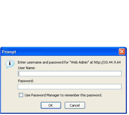
12 PowerConnect B-Series FCX Configuration Guide
53-1002266-01
Logging on through the Web Management Interface
1
FIGURE 2 Web Management Interface login dialog
The login username and password you enter depends on whether your device is configured with
AAA authentication for SNMP. If AAA authentication for SNMP is not configured, you can use the
user name “get” and the default read-only password “public” for read-only access. However, for
read-write access, you must enter “set” for the user name, and enter a read-write community string
you have configured on the device for the password. There is no default read-write community
string. You must add one using the CLI.
As an alternative to using the SNMP community strings to log in, you can configure the Dell
PowerConnect device to secure Web management access using local user accounts or Access
Control Lists (ACLs).
Navigating the Web Management Interface
When you log into a device, the System configuration panel is displayed. This panel allows you to
enable or disable major system features. You can return to this panel from any other panel by
selecting the Home link.
The Site Map link gives you a view of all available options on a single screen.
Figure 3 displays the first Web Management Interface panel for Layer 3 Switch features, while
Figure 4 displays the first panel for Layer 2 Switch features. These panels allow you to configure the
features supported by the Layer 3 Switch and Layer 2 Switch software.

PowerConnect B-Series FCX Configuration Guide 13
53-1002266-01
Logging on through the Web Management Interface 1
FIGURE 3 First panel for Layer 3 Switch features
NOTE
If you are using Internet Explorer 6.0 to view the Web Management Interface, make sure the version
you are running includes the latest service packs. Otherwise, the navigation tree (the left-most pane
in Figure 3) will not display properly. For information on how to load the latest service packs, refer
to the on-line help provided with your Web browser.
FIGURE 4 First panel for Layer 2 Switch features
NOTE
If you are using Internet Explorer 6.0 to view the Web Management Interface, make sure the version
you are running includes the latest service packs. Otherwise, the navigation tree (the left-most pane
in Figure 3) will not display properly. For information on how to load the latest service packs, refer
to the on-line help provided with your Web browser.
The left pane of the Web Management Interface window contains a “tree view,” similar to the one
found in Windows Explorer. Configuration options are grouped into folders in the tree view. These
folders, when expanded, reveal additional options. To expand a folder, click on the plus sign to the
left of the folder icon.
You can configure the appearance of the Web Management Interface by using one of the following
methods.

14 PowerConnect B-Series FCX Configuration Guide
53-1002266-01
Logging on through the Web Management Interface
1
Using the CLI, you can modify the appearance of the Web Management Interface with the
web-management command.
To cause the Web Management Interface to display the List view by default, enter the following
command.
PowerConnect(config)#web-management list-menu
To disable the front panel frame, enter the following command.
PowerConnect(config)#no web-management front-panel
When you save the configuration with the write memory command, the changes will take place the
next time you start the Web Management Interface, or if you are currently running the Web
Management Interface, the changes will take place when you click the Refresh button on your
browser.
Using the Web Management Interface
1. Click on the plus sign next to Configure in the tree view to expand the list of configuration
options.
2. Click on the plus sign next to System in the tree view to expand the list of system configuration
links.
3. Click on the plus sign next to Management in the tree view to expand the list of system
management links.
4. Click on the Web Preference link to display the Web Management Preferences panel.
5. Enable or disable elements on the Web Management Interface by clicking on the appropriate
radio buttons on the panel. The following figure identifies the elements you can change.
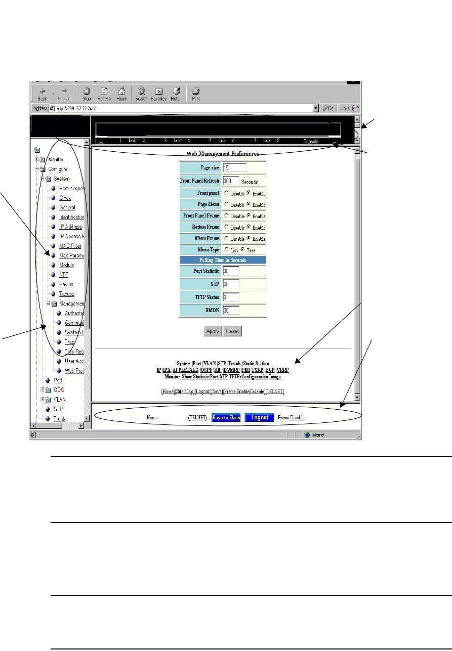
PowerConnect B-Series FCX Configuration Guide 15
53-1002266-01
Logging on through the Web Management Interface 1
NOTE
The tree view is available when you use the Web Management Interface with Netscape 4.0 or
higher or Internet Explorer 4.0 or higher browsers. If you use the Web Management Interface
with an older browser, the Web Management Interface displays the List view only, and the Web
Management Preferences panel does not include an option to display the tree view.
6. When you have finished, click the Apply button on the panel, then click the Refresh button on
your browser to activate the changes.
7. To save the configuration, click the plus sign next to the Command folder, then click the Save to
Flash link.
NOTE
The only changes that become permanent are the settings to the Menu Type and the Front
Panel Frame. Any other elements you enable or disable will go back to their default settings
the next time you start the Web Management Interface.
Front Panel Frame
Front Panel
Page Menu
Bottom Frame
Menu Frame
Menu Type
(Tree View shown)
Device
Device

16 PowerConnect B-Series FCX Configuration Guide
53-1002266-01
Logging on through Brocade Network Advisor
1
Logging on through Brocade Network Advisor
Refer to the Brocade® Network Advisor manual for information about using Brocade Network
Advisor.

PowerConnect B-Series FCX Configuration Guide 17
53-1002266-01
Chapter
2
Configuring Basic Software Features
Table 6 lists the individual Dell PowerConnect switches and the basic software features they
support.
TABLE 6 Supported basic software features
Feature PowerConnect B-Series FCX
Basic System Parameters
System name, contact, and location Yes
SNMP trap receiver and trap source
address
Yes
Disable Syslog messages and traps for
CLI access
Yes
Cancelling an outbound Telnet session Yes
System time using a Simple Network
Time Protocol (SNTP) server or local
system counter
Yes
System clock Yes
Packet-based broadcast, multicast, and
unknown-unicast limits
Yes
CLI banners Yes
Local MAC address for Layer 2
management traffic
Yes
Basic Port Parameters
Port name Yes
10/100/1000 port speed Yes
Auto-negotiation Yes
Auto-negotiation maximum port speed
advertisement and down-shift
Yes
Duplex mode Yes
Auto MDI/MDIX detection Yes
Port status (enable or disable) Yes
Flow control:
•Responds to flow control packets,
but does not generate them
Yes
Symmetric flow control
•Can transmit and receive 802.1x
PAUSE frames
Yes

18 PowerConnect B-Series FCX Configuration Guide
53-1002266-01
Configuring basic system parameters
2
Configuring basic system parameters
Dell PowerConnect devices are configured at the factory with default parameters that allow you to
begin using the basic features of the system immediately. However, many of the advanced features
such as VLANs or routing protocols for the device must first be enabled at the system (global) level
before they can be configured. If you use the Command Line Interface (CLI) to configure system
parameters, you can find these system level parameters at the Global CONFIG level of the CLI.
NOTE
Before assigning or modifying any router parameters, you must assign the IP subnet (interface)
addresses for each port.
NOTE
For information about configuring IP addresses, DNS resolver, DHCP assist, and other IP-related
parameters, refer to Chapter 26, “Configuring IP”.
NOTE
For information about the Syslog buffer and messages, refer to Chapter 41, “Using Syslog”.
The procedures in this section describe how to configure the basic system parameters listed in
Table 6.
Entering system administration information
You can configure a system name, contact, and location for a Dell PowerConnect device and save
the information locally in the configuration file for future reference. This information is not required
for system operation but is suggested. When you configure a system name, the name replaces the
default system name in the CLI command prompt.
The name, contact, and location each can be up to 32 alphanumeric characters.
Here is an example of how to configure a system name, system contact, and location.
Auto-negotiation and advertisement of
flow control
Yes
PHY FIFO Rx and TX Depth Yes
Interpacket Gap (IPG) adjustment Yes
CLI support for 100BaseTX and
100BaseFX
Yes
Gbps fiber negotiate mode Yes
QoS priority Yes
VOIP autoconfiguration and CDP Yes
Port flap dampening Yes
Port loop detection Yes
TABLE 6 Supported basic software features
Feature PowerConnect B-Series FCX

PowerConnect B-Series FCX Configuration Guide 19
53-1002266-01
Configuring basic system parameters 2
PowerConnect(config)# hostname zappa
zappa(config)# snmp-server contact Support Services
zappa(config)# snmp-server location Centerville
zappa(config)# end
zappa# write memory
Syntax: hostname <string>
Syntax: snmp-server contact <string>
Syntax: snmp-server location <string>
The text strings can contain blanks. The SNMP text strings do not require quotation marks when
they contain blanks but the host name does.
NOTE
The chassis name command does not change the CLI prompt. Instead, the command assigns an
administrative ID to the device.
Configuring Simple Network Management Protocol (SNMP) parameters
Use the procedures in this section to perform the following configuration tasks:
•Specify an SNMP trap receiver.
•Specify a source address and community string for all traps sent by the device.
•Change the holddown time for SNMP traps
•Disable individual SNMP traps. (All traps are enabled by default.)
•Disable traps for CLI access that is authenticated by a local user account, a RADIUS server, or
a TACACS/TACACS+ server.
NOTE
To add and modify “get” (read-only) and “set” (read-write) community strings, refer to Chapter 32,
“Securing Access to Management Functions”.
Specifying an SNMP trap receiver
You can specify a trap receiver to ensure that all SNMP traps sent by the Dell PowerConnect device
go to the same SNMP trap receiver or set of receivers, typically one or more host devices on the
network. When you specify the host, you also specify a community string. The Dell PowerConnect
device sends all the SNMP traps to the specified hosts and includes the specified community
string. Administrators can therefore filter for traps from a Dell PowerConnect device based on IP
address or community string.
When you add a trap receiver, the software automatically encrypts the community string you
associate with the receiver when the string is displayed by the CLI or Web Management Interface.
If you want the software to show the community string in the clear, you must explicitly specify this
when you add a trap receiver. In either case, the software does not encrypt the string in the SNMP
traps sent to the receiver.
To specify the host to which the device sends all SNMP traps, use one of the following methods.
To add a trap receiver and encrypt the display of the community string, enter commands such as
the following.

20 PowerConnect B-Series FCX Configuration Guide
53-1002266-01
Configuring basic system parameters
2
To specify an SNMP trap receiver and change the UDP port that will be used to receive traps, enter
a command such as the following.
PowerConnect(config)# snmp-server host 2.2.2.2 0 mypublic port 200
PowerConnect(config)# write memory
Syntax: snmp-server host <ip-addr> [0 | 1] <string> [port <value>]
The <ip-addr> parameter specifies the IP address of the trap receiver.
The 0 | 1 parameter specifies whether you want the software to encrypt the string (1) or show the
string in the clear (0). The default is 0.
The <string> parameter specifies an SNMP community string configured on the Dell PowerConnect
device. The string can be a read-only string or a read-write string. The string is not used to
authenticate access to the trap host but is instead a useful method for filtering traps on the host.
For example, if you configure each of your Dell PowerConnect devices that use the trap host to send
a different community string, you can easily distinguish among the traps from different Dell
PowerConnect devices based on the community strings.
The command in the example above adds trap receiver 2.2.2.2 and configures the software to
encrypt display of the community string. When you save the new community string to the
startup-config file (using the write memory command), the software adds the following command
to the file.
snmp-server host 2.2.2.2 1 <encrypted-string>
To add a trap receiver and configure the software to encrypt display of the community string in the
CLI and Web Management Interface, enter commands such as the following.
PowerConnect(config)# snmp-server host 2.2.2.2 0 PowerConnect-12
PowerConnect(config)# write memory
The port <value> parameter allows you to specify which UDP port will be used by the trap receiver.
This parameter allows you to configure several trap receivers in a system. With this parameter,
Brocade Network Advisor Network Manager and another network management application can
coexist in the same system. Dell PowerConnect devices can be configured to send copies of traps
to more than one network management application.
Specifying a single trap source
You can specify a single trap source to ensure that all SNMP traps sent by the Layer 3 switch use
the same source IP address. For configuration details, refer to “Configuring ARP parameters” on
page 810
Setting the SNMP trap holddown time
When a Dell PowerConnect device starts up, the software waits for Layer 2 convergence (STP) and
Layer 3 convergence (OSPF) before beginning to send SNMP traps to external SNMP servers. Until
convergence occurs, the device might not be able to reach the servers, in which case the messages
are lost.
By default, a Dell PowerConnect device uses a one-minute holddown time to wait for the
convergence to occur before starting to send SNMP traps. After the holddown time expires, the
device sends the traps, including traps such as “cold start” or “warm start” that occur before the
holddown time expires.
You can change the holddown time to a value from one second to ten minutes.

PowerConnect B-Series FCX Configuration Guide 21
53-1002266-01
Configuring basic system parameters 2
To change the holddown time for SNMP traps, enter a command such as the following at the global
CONFIG level of the CLI.
PowerConnect(config)# snmp-server enable traps holddown-time 30
The command in this example changes the holddown time for SNMP traps to 30 seconds. The
device waits 30 seconds to allow convergence in STP and OSPF before sending traps to the SNMP
trap receiver.
Syntax: [no] snmp-server enable traps holddown-time <secs>
The <secs> parameter specifies the number of seconds and can be from 1 – 600 (ten minutes).
The default is 60 seconds.
Disabling SNMP traps
Dell PowerConnect devices come with SNMP trap generation enabled by default for all traps. You
can selectively disable one or more of the following traps.
NOTE
By default, all SNMP traps are enabled at system startup.
Layer 2 traps
The following traps are generated on devices running Layer 2 software:
•SNMP authentication keys
•Power supply failure
•Fan failure
•Cold start
•Link up
•Link down
•Bridge new root
•Bridge topology change
•Locked address violation
Layer 3 traps
The following traps are generated on devices running Layer 3 software:
•SNMP authentication key
•Power supply failure
•Fan failure
•Cold start
•Link up
•Link down
•Bridge new root
•Bridge topology change
•Locked address violation
•BGP4

22 PowerConnect B-Series FCX Configuration Guide
53-1002266-01
Configuring basic system parameters
2
•OSPF
•VRRP
•VRRPE
To stop link down occurrences from being reported, enter the following.
PowerConnect(config)# no snmp-server enable traps link-down
Syntax: [no] snmp-server enable traps <trap-type>
Disabling Syslog messages and traps for CLI access
Dell PowerConnect devices send Syslog messages and SNMP traps when a user logs into or out of
the User EXEC or Privileged EXEC level of the CLI. The feature applies to users whose access is
authenticated by an authentication-method list based on a local user account, RADIUS server, or
TACACS/TACACS+ server.
NOTE
The Privileged EXEC level is sometimes called the “Enable” level, because the command for
accessing this level is enable.
The feature is enabled by default.
Examples of Syslog messages for CLI access
When a user whose access is authenticated by a local user account, a RADIUS server, or a
TACACS/TACACS+ server logs into or out of the CLI User EXEC or Privileged EXEC mode, the
software generates a Syslog message and trap containing the following information:
•The time stamp
•The user name
•Whether the user logged in or out
•The CLI level the user logged into or out of (User EXEC or Privileged EXEC level)
NOTE
Messages for accessing the User EXEC level apply only to access through Telnet. The device does
not authenticate initial access through serial connections but does authenticate serial access to the
Privileged EXEC level. Messages for accessing the Privileged EXEC level apply to access through the
serial connection or Telnet.
The following examples show login and logout messages for the User EXEC and Privileged EXEC
levels of the CLI.

PowerConnect B-Series FCX Configuration Guide 23
53-1002266-01
Configuring basic system parameters 2
Syntax: show logging
The first message (the one on the bottom) indicates that user “dg” logged in to the CLI User EXEC
level on October 15 at 5:38 PM and 3 seconds (Oct 15 17:38:03). The same user logged into the
Privileged EXEC level four seconds later.
The user remained in the Privileged EXEC mode until 5:59 PM and 22 seconds. (The user could
have used the CONFIG modes as well. Once you access the Privileged EXEC level, no further
authentication is required to access the CONFIG levels.) At 6:01 PM and 11 seconds, the user
ended the CLI session.
Disabling the Syslog messages and traps
Logging of CLI access is enabled by default. If you want to disable the logging, enter the following
commands.
PowerConnect(config)# no logging enable user-login
PowerConnect(config)# write memory
PowerConnect(config)# end
PowerConnect# reload
Syntax: [no] logging enable user-login
Cancelling an outbound Telnet session
If you want to cancel a Telnet session from the console to a remote Telnet server (for example, if the
connection is frozen), you can terminate the Telnet session by doing the following.
1. At the console, press Ctrl+^ (Ctrl+Shift-6).
2. Press the X key to terminate the Telnet session.
Pressing Ctrl+^ twice in a row causes a single Ctrl+^ character to be sent to the Telnet server. After
you press Ctrl+^, pressing any key other than X or Ctrl+^ returns you to the Telnet session.
Specifying a Simple Network Time Protocol (SNTP) server
You can configure the Dell PowerConnect device to consult SNTP servers for the current system
time and date.
PowerConnect# show logging
Syslog logging: enabled (0 messages dropped, 0 flushes, 0 overruns)
Buffer logging: level ACDMEINW, 12 messages logged
level code: A=alert C=critical D=debugging M=emergency E=error
I=informational N=notification W=warning
Static Log Buffer:
Dec 15 19:04:14:A:Fan 1, fan on right connector, failed
Dynamic Log Buffer (50 entries):
Oct 15 18:01:11:info:dg logout from USER EXEC mode
Oct 15 17:59:22:info:dg logout from PRIVILEGE EXEC mode
Oct 15 17:38:07:info:dg login to PRIVILEGE EXEC mode
Oct 15 17:38:03:info:dg login to USER EXEC mode

24 PowerConnect B-Series FCX Configuration Guide
53-1002266-01
Configuring basic system parameters
2
NOTE
Dell PowerConnect devices do not retain time and date information across power cycles. Unless you
want to reconfigure the system time counter each time the system is reset, Dell PowerConnect
recommends that you use the SNTP feature.
To identify an SNTP server with IP address 208.99.8.95 to act as the clock reference for a Dell
PowerConnect device, enter the following.
PowerConnect(config)# sntp server 208.99.8.95
Syntax: sntp server <ip-addr> | <hostname> [<version>]
The <version> parameter specifies the SNTP version the server is running and can be from 1 – 4.
The default is 1. You can configure up to three SNTP servers by entering three separate sntp server
commands.
By default, the Dell PowerConnect device polls its SNTP server every 30 minutes (1800 seconds).
To configure the Dell PowerConnect device to poll for clock updates from a SNTP server every 15
minutes, enter the following.
PowerConnect(config)# sntp poll-interval 900
Syntax: [no] sntp poll-interval <1-65535>
To display information about SNTP associations, enter the following command.
Syntax: show sntp associations
The following table describes the information displayed by the show sntp associations command.
To display information about SNTP status, enter the following command.
TABLE 7 Output from the show sntp associations command
This field... Displays...
(leading character) One or both of the following:
*Synchronized to this peer
~ Peer is statically configured
address IP address of the peer
ref clock IP address of the peer reference clock
st NTP stratum level of the peer
when Amount of time since the last NTP packet was received from the peer
poll Poll interval in seconds
delay Round trip delay in milliseconds
disp Dispersion in seconds
PowerConnect# show sntp associations
address ref clock st when poll delay disp
~207.95.6.102 0.0.0.0 16 202 4 0.0 5.45
~207.95.6.101 0.0.0.0 16 202 0 0.0 0.0
* synced, ~ configured

PowerConnect B-Series FCX Configuration Guide 25
53-1002266-01
Configuring basic system parameters 2
Syntax: show sntp status
The following table describes the information displayed by the show sntp status command.
Setting the system clock
In addition to SNTP support, Dell PowerConnect switches and routers also allow you to set the
system time counter. The time counter setting is not retained across power cycles and is not
automatically synchronized with an SNTP server. The counter merely starts the system time and
date clock with the time and date you specify.
NOTE
You can synchronize the time counter with your SNTP server time by entering the sntp sync
command from the Privileged EXEC level of the CLI.
NOTE
Unless you identify an SNTP server for the system time and date, you will need to re-enter the time
and date following each reboot.
For more details about SNTP, refer to “Specifying a Simple Network Time Protocol (SNTP) server” on
page 23.
To set the system time and date to 10:15:05 on October 15, 2003, enter the following command.
PowerConnect# clock set 10:15:05 10-15-2003
Syntax: [no] clock set <hh:mm:ss> <mm-dd-yy> | <mm-dd-yyyy>
TABLE 8 Output from the show sntp status command
This field... Indicates...
unsynchronized System is not synchronized to an NTP peer.
synchronized System is synchronized to an NTP peer.
stratum NTP stratum level of this system
reference clock IP Address of the peer (if any) to which the unit is synchronized
precision Precision of this system's clock (in Hz)
reference time Reference time stamp
clock offset Offset of clock to synchronized peer
root delay Total delay along the path to the root clock
root dispersion Dispersion of the root path
peer dispersion Dispersion of the synchronized peer
sntp poll-interval Shows how often the Dell PowerConnect device polls for clock
updates from an SNTP server.
PowerConnect# show sntp status
Clock is synchronized, stratum = 4, reference clock = 10.70.20.23
precision is 2**-20
reference time is 3489354594.3780510747
clock offset is 0.0000 msec, root delay is 0.41 msec
root dispersion is 0.11 msec, peer dispersion is 0.00 msec
sntp poll-interval is 10 secs

26 PowerConnect B-Series FCX Configuration Guide
53-1002266-01
Configuring basic system parameters
2
By default, Dell PowerConnect switches and routers do not change the system time for daylight
saving time. To enable daylight saving time, enter the following command.
PowerConnect# clock summer-time
Syntax: clock summer-time
Although SNTP servers typically deliver the time and date in Greenwich Mean Time (GMT), you can
configure the Dell PowerConnect device to adjust the time for any one-hour offset from GMT or for
one of the following U.S. time zones:
•US Pacific
•Alaska
•Aleutian
•Arizona
•Central
•East-Indiana
•Eastern
•Hawaii
•Michigan
•Mountain
•Pacific
•Samoa
To change the time zone to Australian East Coast time (which is normally 10 hours ahead of GMT),
enter the following command.
PowerConnect(config)# clock timezone gmt gmt+10
Syntax: clock timezone gmt | us <time-zone>
You can enter one of the following values for <time-zone>:
•US time zones (us): alaska, aleutian, arizona, central, east-indiana, eastern, hawaii, michigan,
mountain, pacific, samoa.
•GMT time zones (gmt): gmt+0:00 to gmt+12:00 in increments of 1, and gmt-0:00 to gmt-12:00
in decrements of 1 are supported.
New start and end dates for US daylight saving time
NOTE
This feature applies to US time zones only.
The system will automatically change the system clock to Daylight Saving Time (DST), in compliance
with the new federally mandated start of daylight saving time, which is extended one month
beginning in 2007. The DST will start at 2:00am on the second Sunday in March and will end at
2:00am on the first Sunday in November.
The DST feature is automatic, but to trigger the device to the correct time, the device must be
configured to the US time zone, not the GMT offset. To configure your device to use the US time
zone, enter the following command.
PowerConnect (config)# clock timezone us pacific

PowerConnect B-Series FCX Configuration Guide 27
53-1002266-01
Configuring basic system parameters 2
Syntax: [no] clock timezone us <timezone-type>
Enter pacific, eastern, central, or mountain for <timezone-type>.
This command must be configured on every device that follows the US DST.
To verify the change, run a show clock command.
PowerConnect # show clock
Refer to October 19, 2006 - Daylight Saving Time 2007 Advisory, posted on kp.foundrynet.com for
more information
Limiting broadcast, multicast, and unknown unicast traffic
Dell PowerConnect devices can forward all flooded traffic at wire speed within a VLAN. However,
some third-party networking devices cannot handle high rates of broadcast, multicast, or
unknown-unicast traffic. If high rates of traffic are being received by the Dell PowerConnect device
on a given port of that VLAN, you can limit the number of broadcast, multicast, or unknown-unicast
packets or bytes received each second on that port. This can help to control the number of such
packets or bytes that are flooded on the VLAN to other devices.
Configuration notes and feature limitationss:
•PowerConnect B-Series FCX devices
-To enable unknown-unicast limiting or multicast limiting, enable it after enabling
broadcast limiting. Unknown-unicast limiting and multicast limiting use the limit defined in
broadcast limiting. You cannot set a separate limit for unknown-unicast limiting and
multicast limiting.
-PowerConnect B-Series FCX devices support packet-based limiting only.
Command syntax for packet-based limiting on PowerConnect B-Series FCX
devices
To enable broadcast limiting on a group of ports by counting the number of packets received, enter
commands such as the following.
PowerConnect(config)# interface ethernet 1/1/1 to 1/1/8
PowerConnect(config-mif-e1000-1/1/1-1/1/8)# broadcast limit 65536
To include unknown unicast limiting by counting the number of packets received, enter commands
such as the following.
PowerConnect(config-mif-e1000-1/1/1-1/1/8)# unknown-unicast limit
To include multicasts limiting, enter the following command after enabling broadcast limiting.
PowerConnect(config-mif-e1000-1-8)# multicast limit
Syntax: [no] broadcast limit <num>
Syntax: [no] multicast limit
Syntax: [no] unknown-unicast limit

28 PowerConnect B-Series FCX Configuration Guide
53-1002266-01
Configuring basic system parameters
2
The <num> variable specifies the maximum number of packets per second. It can be any number
that is a multiple of 65536, up to a maximum value of 2147418112. If you enter the multicast limit
command, multicast packets are included in the corresponding limit. If you specify 0, limiting is
disabled. If you specify a number that is not a multiple of 65536, the software rounds the number
to the next multiple of 65536. Limiting is disabled by default.
Viewing broadcast, multicast, and unknown unicast limits
You can use the show run interface command to display the broadcast, multicast, and
unknown-unicast limits configured on the device.
You can use the following commands, in addition to the show run interface command, to display
the broadcast, multicast, and unknown-unicast limits configured on the device:
•show rate-limit unknown-unicast
•show rate-limit broadcast
Use the show run interface command to view the broadcast, multicast, and unknown-unicast limit
configured on each port.
Example
Syntax: show run interface
Use the show rate-limit unknown-unicast command to display the unknown unicast limit for each
port region to which it applies.
Example
PowerConnect# show run interface
interface ethernet 4
broadcast limit 1245184 bytes
multicast limit
!
interface ethernet 5
broadcast limit 1245184 bytes
multicast limit
!
interface ethernet 12
unknown-unicast limit 524288
!
interface ethernet 13
unknown-unicast limit 65536 bytes
!
interface ethernet 14
broadcast limit 65536
!
interface ethernet 23
broadcast limit 131072
multicast limit
!
PowerConnect# show rate-limit unknown-unicast
Unknown Unicast Limit Settings:
Port Region Combined Limit Packets/Bytes
1 - 12 524288 Packets
13 - 24 65536 Bytes

PowerConnect B-Series FCX Configuration Guide 29
53-1002266-01
Configuring basic system parameters 2
Syntax: show rate-limit unknown-unicast
Use the show rate-limit broadcast command to display the broadcast limit or broadcast and
multicast limit for each port to which it applies.
Example
Syntax: show rate-limit broadcast
Configuring CLI banners
Dell PowerConnect devices can be configured to display a greeting message on users’ terminals
when they enter the Privileged EXEC CLI level or access the device through Telnet. In addition, a
Dell PowerConnect device can display a message on the Console when an incoming Telnet CLI
session is detected.
Setting a message of the day banner
You can configure the Dell PowerConnect device to display a message on a user terminal when he
or she establishes a Telnet CLI session. For example, to display the message “Welcome to
PowerConnect!” when a Telnet CLI session is established.
PowerConnect(config)# banner motd $ (Press Return)
Enter TEXT message, End with the character '$'.
Welcome to PowerConnect!! $
A delimiting character is established on the first line of the banner motd command. You begin and
end the message with this delimiting character. The delimiting character can be any character
except “ (double-quotation mark) and cannot appear in the banner text. In this example, the
delimiting character is $ (dollar sign). The text in between the dollar signs is the contents of the
banner. The banner text can be up to 4000 characters long, which can consist of multiple lines.
Syntax: [no] banner motd <delimiting-character>
To remove the banner, enter the no banner motd command.
NOTE
The banner <delimiting-character> command is equivalent to the banner motd
<delimiting-character> command.
When you access the Web Management Interface, the banner is displayed.
PowerConnect# show rate-limit broadcast
Broadcast/Multicast Limit Settings:
Port Limit Packets/Bytes Packet Type(s)
4 1245184 Bytes Broadcast + Multicast
5 1245184 Bytes Broadcast + Multicast
14 65536 Packets Broadcast only
23 131072 Packets Broadcast + Multicast
30 PowerConnect B-Series FCX Configuration Guide
53-1002266-01
Configuring basic system parameters
2
NOTE
If you are using a Web client to view the message of the day, and your banners are very wide, with
large borders, you may need to set your PC display resolution to a number greater than the width of
your banner. For example, if your banner is 100 characters wide and the display is set to 80
characters, the banner may distort, or wrap, and be difficult to read. If you set your display resolution
to 120 characters, the banner will display correctly.
Requiring users to press the Enter key after the message of the day banner
In earlier IronWare software releases, users were required to press the Enter key after the Message
of the Day (MOTD) was displayed, prior to logging in to the Dell PowerConnect device on a console
or from a Telnet session. Now, this requirement is disabled by default. Unless configured, users do
not have to press Enter after the MOTD banner is displayed.
For example, if the MOTD "Authorized Access Only" is configured, by default, the following
messages are displayed when a user tries to access the Dell PowerConnect device from a Telnet
session.
Authorized Access Only ...
Username:
The user can then login to the device.
However, if the requirement to press the Enter key is enabled, the following messages are displayed
when accessing the switch from Telnet.
Authorized Access Only ...
Press <Enter> to accept and continue the login process....
The user must press the Enter key before the login prompt is displayed.
Also, on the console, the following messages are displayed if the requirement to press the Enter
key is disabled.
Press Enter key to login
Authorized Access Only ...
User Access Verification
Please Enter Login Name:
However, if the requirement to press the Enter key after a MOTD is enabled, the following messages
are displayed when accessing the switch on the console.
Press Enter key to login
Authorized Access Only ...
Press <Enter> to accept and continue the login process....
The user must press the Enter key to continue to the login prompt.

PowerConnect B-Series FCX Configuration Guide 31
53-1002266-01
Configuring basic system parameters 2
To enable the requirement to press the Enter key after the MOTD is displayed, enter a command
such as the following.
PowerConnect(config)# banner motd require-enter-key
Syntax: [no] banner motd require-enter-key
Use the no form of the command to disable the requirement.
Setting a privileged EXEC CLI level banner
You can configure the Dell PowerConnect device to display a message when a user enters the
Privileged EXEC CLI level.
Example
PowerConnect(config)# banner exec_mode # (Press Return)
Enter TEXT message, End with the character '#'.
You are entering Privileged EXEC level
Do not foul anything up! #
As with the banner motd command, you begin and end the message with a delimiting character; in
this example, the delimiting character is #(pound sign). The delimiting character can be any
character except “ (double-quotation mark) and cannot appear in the banner text. The text in
between the pound signs is the contents of the banner. Banner text can be up to 4000 characters,
which can consist of multiple lines.
Syntax: [no] banner exec_mode <delimiting-character>
To remove the banner, enter the no banner exec_mode command.
Displaying a console message when an incoming Telnet session is detected
You can configure the Dell PowerConnect device to display a message on the Console when a user
establishes a Telnet session. This message indicates where the user is connecting from and
displays a configurable text message.
Example
PowerConnect(config)# banner incoming $ (Press Return)
Enter TEXT message, End with the character '$'.
Incoming Telnet Session!! $
When a user connects to the CLI using Telnet, the following message appears on the Console.
Telnet from 209.157.22.63
Incoming Telnet Session!!
As with the banner motd command, you begin and end the message with a delimiting character; in
this example, the delimiting character is $(dollar sign). The delimiting character can be any
character except “ (double-quotation mark) and cannot appear in the banner text. The text in
between the dollar signs is the contents of the banner. Banner text can be up to 4000 characters,
which can consist of multiple lines.
Syntax: [no] banner incoming <delimiting-character>
To remove the banner, enter the no banner incoming command.

32 PowerConnect B-Series FCX Configuration Guide
53-1002266-01
Configuring basic port parameters
2
Configuring a local MAC address for Layer 2 management traffic
By default, Layer 2 devices use the MAC address of the first port as the MAC address for Layer 2
management traffic. For example, when the Dell PowerConnect device receives an ARP request for
its management IP address, it responds with the first port MAC address. This may cause problems
in some configurations where the Dell PowerConnect device uses the same MAC address for
management traffic as for switched traffic.
You can configure the Dell PowerConnect device to use a different MAC address for Layer 2
management traffic than for switched traffic. When you issue the use-local-management-mac, the
Dell PowerConnect device changes a local bit in the first port MAC address and uses this MAC
address for management traffic. The second bit of the first port MAC address is changed to 2. For
example, if the MAC address is 00e0.5201.9900 after the feature is enabled, the switch uses
02e0.5201.9900 for management functions. Switched traffic will continue to use the first port
MAC address without the local bit setting.
Example
PowerConnect(config)# use-local-management-mac
PowerConnect(config)# write memory
PowerConnect(config)# end
PowerConnect# reload
Syntax: [no] use-local-management-mac
NOTE
You must save the configuration and reload the software to place the change into effect.
NOTE
This feature is only available for the switch code. It is not available for router code.
Configuring basic port parameters
The procedures in this section describe how to configure the port parameters shown in Table 6.
All Dell PowerConnect ports are pre-configured with default values that allow the device to be fully
operational at initial startup without any additional configuration. However, in some cases,
changes to the port parameters may be necessary to adjust to attached devices or other network
requirements.
Assigning a port name
A port name can be assigned to help identify interfaces on the network. You can assign a port
name to physical ports, virtual interfaces, and loopback interfaces.
To assign a name to a port.
PowerConnect(config)# interface ethernet 2
PowerConnect(config-if-e1000-2)# port-name Marsha
Syntax: port-name <text>
The <text> parameter is an alphanumeric string. The name can be up to 64 characters long. The
name can contain blanks. You do not need to use quotation marks around the string, even when it
contains blanks.

PowerConnect B-Series FCX Configuration Guide 33
53-1002266-01
Configuring basic port parameters 2
Modifying port speed and duplex mode
The Gigabit Ethernet copper ports are designed to auto-sense and auto-negotiate the speed and
duplex mode of the connected device. If the attached device does not support this operation, you
can manually enter the port speed to operate at either 10, 100, or 1000 Mbps. The default and
recommended setting is 10/100/1000 auto-sense.
NOTE
You can modify the port speed of copper ports only; this feature does not apply to fiber ports.
NOTE
For optimal link operation, copper ports on devices that do not support 803.3u must be configured
with like parameters, such as speed (10,100,1000), duplex (half, full), MDI/MDIX, and Flow Control.
Configuration syntax
The following commands change the port speed of copper interface 8 on a PowerConnect from the
default of 10/100/1000 auto-sense, to 100 Mbps operating in full-duplex mode.
PowerConnect(config)# interface ethernet 8
PowerConnect(config-if-e1000-8)# speed-duplex 100-full
Syntax: speed-duplex <value>
where <value> can be one of the following:
•10-full – 10 Mbps, full duplex
•10-half – 10 Mbps, half duplex
•100-full – 100 Mbps, full duplex
•100-half – 100 Mbps, half duplex
•1000-full-master – 1 Gbps, full duplex master
•1000-full-slave – 1 Gbps, full duplex slave
•auto – auto-negotiation
The default is auto (auto-negotiation).
Use the no form of the command to restore the default.
NOTE
On PowerConnect devices, when setting the speed and duplex-mode of an interface to 1000-full,
configure one side of the link as master (1000-full-master) and the other side as slave
(1000-full-slave).
Enabling auto-negotiation maximum port speed
advertisement and down-shift
NOTE
For optimal link operation, link ports on devices that do not support 803.3u must be configured with
like parameters, such as speed (10,100,1000), duplex (half, full), MDI/MDIX, and Flow Control.

34 PowerConnect B-Series FCX Configuration Guide
53-1002266-01
Configuring basic port parameters
2
Maximum Port speed advertisement and Port speed down-shift are enhancements to the
auto-negotiation feature, a mechanism for accommodating multi-speed network devices by
automatically configuring the highest performance mode of inter-operation between two connected
devices.
Port speed down-shift enables Gbps copper ports on the Dell PowerConnect device to establish a
link at 1000 Mbps over a 4-pair wire when possible, or to down-shift to 100 Mbps if the medium is
a 2-pair wire.
Maximum port speed advertisement enables you to configure an auto-negotiation maximum speed
that Gbps copper ports on the Dell PowerConnect device will advertise to the connected device.
You can configure a port to advertise a maximum speed of either 100 Mbps or 10 Mbps. When the
maximum port speed advertisement feature is configured on a port that is operating at 100 Mbps
maximum speed, the port will advertise 10/100 Mbps capability to the connected device.
Similarly, if a port is configured at 10 Mbps maximum speed, the port will advertise 10 Mbps
capability to the connected device.
The port speed down-shift and maximum port speed advertisement features operate dynamically
at the physical link layer between two connected network devices. They examine the cabling
conditions and the physical capabilities of the remote link, then configure the speed of the link
segment according to the highest physical-layer technology that both devices can accommodate.
The port speed down-shift and maximum port speed advertisement features operate dynamically
at the physical link layer, independent of logical trunk group configurations. Although Dell
recommends that you use the same cable types and auto-negotiation configuration on all
members of a trunk group, you could utilize the auto-negotiation features conducive to your cabling
environment. For example, in certain circumstances, you could configure each port in a trunk
group to have its own auto-negotiation maximum port speed advertisement or port speed
down-shift configuration.
Application notes
•Port speed down-shift and maximum port speed advertisement work only when
auto-negotiation is enabled (CLI command speed-duplex auto). If auto-negotiation is OFF, the
device will reject the port speed down-shift and maximum port speed advertisement
configuration.
•When port speed down-shift or maximum port speed advertisement is enabled on a port, the
device will reject any configuration attempts to set the port to a forced speed mode (100 Mbps
or 1000 Mbps).
•When the port speed down-shift feature is enabled on a combo port, the port will not support
true media automatic detection, meaning the device will not be able to detect and select the
fiber or copper connector based on link availability.
Enabling port speed down-shift
To enable port speed down-shift on a port that has auto-negotiation enabled, enter a command
such as the following at the Global CONFIG level of the CLI.
PowerConnect(config)# link-config gig copper autoneg-control down-shift ethernet
1 ethernet 2
The above command configures Gbps copper ports 1 and 2 to establish a link at 1000 Mbps over a
4-pair wire when possible, or to down-shift (reduce the speed) to 100 Mbps when the medium is a
2-pair wire.

PowerConnect B-Series FCX Configuration Guide 35
53-1002266-01
Configuring basic port parameters 2
Syntax: [no] link-config gig copper autoneg-control down-shift ethernet <port> [ethernet <port>] |
to <port>...
Specify the <port> variable in the following formats:
•PowerConnect B-Series FCX stackable switches – <stack-unit/slotnum/portnum>
You can list all of the ports individually, use the keyword to to specify ranges of ports, or a
combination of both.
You can enable port speed down-shift on one or two ports at a time.
To disable port speed down-shift after it has been enabled, enter the no form of the command.
Configuring port speed down-shift and auto-negotiation for a range of ports
Port speed down-shift and auto-negotiation can be configured for an entire range of ports with a
single command.
For example, to configure down-shift on ports 0/1/1 to 0/1/10 and 0/1/15 to 0/1/20 on the
device, enter the following.
PowerConnect(config)# link-config gig copper autoneg-control down-shift ethernet
0/1/1 to 0/1/10 ethernet 0/1/15 to 0/1/20
To configure down-shift on ports 5 to 13 and 17 to 19 on a compact switch, enter the following.
PowerConnect(config)# link-config gig copper autoneg-control down-shift ethernet
5 to 13 ethernet 17 to 19
Syntax: [no] link-config gig copper autoneg-control [down-shift | 100m-auto | 10m-auto] ethernet
<port-list>
The <port-list> is the list of ports to which the command will be applied.
For <port-list>, specify the ports in the following formats:
•PowerConnect B-Series FCX stackable switches – <stack-unit/slotnum/portnum>
You can list all of the ports individually, use the keyword to to specify ranges of ports, or a
combination of both. To apply the configuration to all ports on the device, use the keyword all
instead of listing the ports individually.
The output from the show run command for this configuration will resemble the following.
PowerConnect# show run
Current configuration:
!
ver 7.2.00a
!
module 1 FCX-48-port-management-module
module 2 FCX-cx4-2-port-16G-module
!
link-config gig copper autoneg-control down-shift ethernet 0/1/1 to 0/1/10
ethernet 0/1/15 to 0/1/20
!
!
ip address 10.44.9.11 255.255.255.0
ip default-gateway 10.44.9.1
!
end

36 PowerConnect B-Series FCX Configuration Guide
53-1002266-01
Configuring basic port parameters
2
To disable selective auto-negotiation of 100m-auto on ports 0/1/21 to 0/1/25 and 0/1/30, enter
the following.
PowerConnect(config)# no link-config gig copper autoneg-control 100m-auto
ethernet 0/1/21 to 0/1/25 ethernet 0/1/30
Configuring maximum port speed advertisement
To configure a maximum port speed advertisement of 10 Mbps on a port that has auto-negotiation
enabled, enter a command such as the following at the Global CONFIG level of the CLI.
PowerConnect(config)# link-config gig copper autoneg-control 10m ethernet 1
To configure a maximum port speed advertisement of 100 Mbps on a port that has
auto-negotiation enabled, enter the following command at the Global CONFIG level of the CLI.
PowerConnect(config)# link-config gig copper autoneg-control 100m ethernet 2
Syntax: [no] link-config gig copper autoneg-control 10m | 100m ethernet <port> [ethernet
[<port>]
Specify the <port> variable in the following formats:
•PowerConnect B-Series FCX stackable switches – <stack-unit/slotnum/portnum>
You can list all of the ports individually, use the keyword to to specify ranges of ports, or a
combination of both.
You can enable maximum port speed advertisement on one or two ports at a time.
To disable maximum port speed advertisement after it has been enabled, enter the no form of the
command.
Modifying port duplex mode
You can manually configure a 10/100 Mbps port to accept either full-duplex (bi-directional) or
half-duplex (uni-directional) traffic.
NOTE
You can modify the port duplex mode of copper ports only. This feature does not apply to fiber ports.
Port duplex mode and port speed are modified by the same command.
Configuration syntax
To change the port speed of interface 8 from the default of 10/100/1000 auto-sense to 10 Mbps
operating at full-duplex, enter the following.
PowerConnect(config)# interface ethernet 8
PowerConnect(config-if-e1000-8)# speed-duplex 10-full
Syntax: speed-duplex <value>
The <value> can be one of the following:
•10-full
•10-half
•100-full

PowerConnect B-Series FCX Configuration Guide 37
53-1002266-01
Configuring basic port parameters 2
•100-half
•auto (default)
Configuring MDI/MDIX
Dell PowerConnect devices support automatic Media Dependent Interface (MDI) and Media
Dependent Interface Crossover (MDIX) detection on all Gbps Ethernet Copper ports.
MDI/MDIX is a type of Ethernet port connection using twisted pair cabling. The standard wiring for
end stations is MDI, whereas the standard wiring for hubs and switches is MDIX. MDI ports
connect to MDIX ports using straight-through twisted pair cabling. For example, an end station
connected to a hub or a switch uses a straight-through cable. MDI-to-MDI and MDIX-to-MDIX
connections use crossover twisted pair cabling. So, two end stations connected to each other, or
two hubs or switches connected to each other, use crossover cable.
The auto MDI/MDIX detection feature can automatically correct errors in cable selection, making
the distinction between a straight-through cable and a crossover cable insignificant.
Configuration notes
•This feature applies to copper ports only.
•The mdi-mdix mdi and mdi-mdix mdix commands work independently of auto-negotiation.
Thus, these commands work whether auto-negotiation is turned ON or OFF.
•Do not use the mdi-mdix commands on ports that are manually configured with a speed and
duplex of 100-full. In this case, make sure the other port (remote end of the connection) is
also configured to 100-full and a cross-over cable is used if the connected device is another
switch, hub, or router, or a straight-through cable if the connected device is a host NIC.
Configuration syntax
The auto MDI/MDIX detection feature is enabled on all Gbps copper ports by default. For each
port, you can disable auto MDI/MDIX, designate the port as an MDI port, or designate the port as
an MDIX port.
To turn off automatic MDI/MDIX detection and define a port as an MDI only port.
PowerConnect(config-if-e1000-2)# mdi-mdix mdi
To turn off automatic MDI/MDIX detection and define a port as an MDIX only port.
PowerConnect(config-if-e1000-2)# mdi-mdix mdix
To turn on automatic MDI/MDIX detection on a port that was previously set as an MDI or MDIX port.
PowerConnect(config-if-e1000-2)# mdi-mdix auto
Syntax: mdi-mdix <mdi | mdix | auto>
After you enter the mdi-mdix command, the Dell PowerConnect device resets the port and applies
the change.
To display the MDI/MDIX settings, including the configured value and the actual resolved setting
(for mdi-mdix auto), enter the command show interface at any level of the CLI.

38 PowerConnect B-Series FCX Configuration Guide
53-1002266-01
Configuring basic port parameters
2
Disabling or re-enabling a port
A port can be made inactive (disable) or active (enable) by selecting the appropriate status option.
The default value for a port is enabled.
To disable port 8 of a Dell PowerConnect device, enter the following.
PowerConnect(config)# interface ethernet 8
PowerConnect(config-if-e1000-8)# disable
You also can disable or re-enable a virtual interface. To do so, enter commands such as the
following.
PowerConnect(config)# interface ve v1
PowerConnect(config-vif-1)# disable
Syntax: disable
To re-enable a virtual interface, enter the enable command at the Interface configuration level. For
example, to re-enable virtual interface v1, enter the following command.
PowerConnect(config-vif-1)# enable
Syntax: enable
Configuring flow control
Flow control (802.3x) is a QoS mechanism created to manage the flow of data between two
full-duplex Ethernet devices. Specifically, a device that is oversubscribed (is receiving more traffic
than it can handle) sends an 802.3x PAUSE frame to its link partner to temporarily reduce the
amount of data the link partner is transmitting. Without flow control, buffers would overflow,
packets would be dropped, and data retransmission would be required.
All PowerConnect devices support asymmetric flow control, meaning they can receive PAUSE
frames but cannot transmit them. In addition, FCX devices also support symmetric flow control,
meaning they can both receive and transmit 802.3x PAUSE frames. For details about symmetric
flow control, refer to “Configuring symmetric flow control on PowerConnect B-Series FCX devices”
on page 40.
Configuration notes
•Auto-negotiation of flow control is not supported on 10 Gbps ports, fiber ports, and copper or
fiber combination ports.
•When any of the flow control commands are applied to a port that is up, the port will be
disabled and re-enabled.
•For 10 Gbps ports, the show interface <port> display shows Flow Control is enabled or Flow
Control is disabled, depending on the configuration.
•When flow-control is enabled, the hardware can only advertise PAUSE frames. It does not
advertise Asym.

PowerConnect B-Series FCX Configuration Guide 39
53-1002266-01
Configuring basic port parameters 2
Disabling or re-enabling flow control
You can configure the Dell PowerConnect device to operate with or without flow control. Flow
control is enabled by default globally and on all full-duplex ports. You can disable and re-enable
flow control at the Global CONFIG level for all ports. When enabled globally, you can disable and
re-enable flow control on individual ports.
To disable flow control, enter the following command.
PowerConnect(config)# no flow-control
To turn the feature back on, enter the following command.
PowerConnect(config)# flow-control
Syntax: [no] flow-control
NOTE
For optimal link operation, link ports on devices that do not support 803.3u must be configured with
like parameters, such as speed (10,100,1000), duplex (half, full), MDI/MDIX, and Flow Control.
Negotiation and advertisement of flow control
By default, when flow control is enabled globally and auto-negotiation is ON, flow control is enabled
and advertised on 10/100/1000M ports. If auto-negotiation is OFF or if the port speed was
configured manually, then flow control is not negotiated with or advertised to the peer. For details
about auto-negotiation, refer to “Modifying port speed and duplex mode” on page 33.
To disable the advertisement of flow control capability on a port, enter the following commands.
PowerConnect(config)# interface ethernet 0/1/21
PowerConnect(config-if-e1000-0/1/21)# no flow-control
To also disable flow control negotiation, enter the following commands.
PowerConnect(config)# interface ethernet 0/1/21
PowerConnect(config-if-e1000-0/1/21)# no flow-control neg-on
Syntax: [no] flow-control [neg-on]
•flow-control [default] - Enable flow control, flow control negotiation, and advertise flow control
•no flow-control neg-on - Disable flow control negotiation
•no flow-control - Disable flow control, flow control negotiation, and advertising of flow control
Commands may be entered in IF (single port) or MIF (multiple ports at once) mode.
Example
PowerConnect(config)# interface ethernet 0/1/21
PowerConnect(config-if-e1000-0/1/21)# no flow-control
This command disables flow control on port 0/1/21.
PowerConnect(config)# interface ethernet 0/1/11 to 0/1/15
PowerConnect(config-mif-0/1/11-0/1/15)# no flow-control
This command disables flow control on ports 0/1/11 to 0/1/15.

40 PowerConnect B-Series FCX Configuration Guide
53-1002266-01
Configuring basic port parameters
2
Displaying flow-control status
The show interface <port> command displays configuration, operation, and negotiation status
where applicable.
For example, on a PowerConnect Stackable device, issuing the command for 10/100/1000M port
0/1/21 displays the following output.
PowerConnect# show interfaces ethernet 0/1/21
GigabitEthernet0/1/21 is up, line protocol is up
Hardware is GigabitEthernet, address is 00e0.5204.4014 (bia 00e0.5204.4014)
Configured speed auto, actual 100Mbit, configured duplex fdx, actual fdx
Configured mdi mode AUTO, actual MDIX
Member of L2 VLAN ID 1, port is untagged, port state is LISTENING
BPDU Guard is disabled, Root Protect is disabled
STP configured to ON, priority is level0
Flow Control is config enabled, oper enabled, negotiation disabled
Mirror disabled, Monitor disabled
Not member of any active trunks
Not member of any configured trunks
No port name
Inter-Packet Gap (IPG) is 96 bit times
300 second input rate: 0 bits/sec, 0 packets/sec, 0.00% utilization
300 second output rate: 0 bits/sec, 0 packets/sec, 0.00% utilization
0 packets input, 0 bytes, 0 no buffer
Received 0 broadcasts, 0 multicasts, 0 unicasts
0 input errors, 0 CRC, 0 frame, 0 ignored
0 runts, 0 giants
5 packets output, 320 bytes, 0 underruns
Transmitted 0 broadcasts, 5 multicasts, 0 unicasts
0 output errors, 0 collisions
The line highlighted in bold will resemble one of the following, depending on the configuration:
•If flow-control negotiation is enabled (and a neighbor does not negotiate flow control), the
display shows:
Flow Control is config enabled, oper disabled, negotiation enabled
•If flow control is enabled, and flow-control negotiation is disabled, the output shows.
Flow Control is config enabled, oper enabled, negotiation disabled
•If flow control is disabled, the display shows.
Flow Control is config disabled, oper disabled
Configuring symmetric flow control on PowerConnect B-Series FCX
devices
In addition to asymmetric flow control, PowerConnect B-Series FCX devices support symmetric flow
control, meaning they can both receive and transmit 802.3x PAUSE frames.
By default on PowerConnect B-Series FCX devices, packets are dropped from the end of the queue
at the egress port (tail drop mode), when the maximum queue limit is reached. Conversely, when
symmetric flow control is enabled, packets are guaranteed delivery since they are managed at the
ingress port and no packets are dropped.

PowerConnect B-Series FCX Configuration Guide 41
53-1002266-01
Configuring basic port parameters 2
Symmetric flow control addresses the requirements of a lossless service class in an Internet Small
Computer System Interface (iSCSI) environment. It is supported on FCX standalone units as well as
on all FCX units in an IronStack.
About XON and XOFF thresholds
An 802.3x PAUSE frame is generated when the buffer limit at the ingress port reaches or exceeds
the port’s upper watermark threshold (XOFF limit). The PAUSE frame requests that the sender stop
transmitting traffic for a period of time. The time allotted enables the egress and ingress queues to
be cleared. When the ingress queue falls below the port’s lower watermark threshold (XON limit),
an 802.3x PAUSE frame with a quanta of 0 (zero) is generated. The PAUSE frame requests that the
sender resume sending traffic normally.
Each 1G and 10G port is configured with a default total number of buffers as well as a default XOFF
and XON threshold. The defaults are different for 1G ports versus 10G ports. Also, the default XOFF
and XON thresholds are different for jumbo mode versus non-jumbo mode. The defaults are shown
in Table 9.
If necessary, you can change the total buffer limits and the XON and XOFF default thresholds. Refer
to “Changing the total buffer limits” on page 43 and “Changing the XON and XOFF thresholds” on
page 42, respectively.
Configuration notes and feature limitations for symmetric flow control
Note the following configuration notes and feature limitations before enabling symmetric flow
control.
•Symmetric flow control is supported on PowerConnect B-Series FCX devices only.
•Symmetric flow control is supported on all PowerConnect B-Series FCX 1G and 10G data ports.
•Symmetric flow control is not supported on stacking ports or across units in a stack.
•To use this feature, 802.3x flow control must be enabled globally and per interface on the
PowerConnect B-Series FCX . By default, 802.3x flow control is enabled, but can be disabled
with the no flow-control command.
TABLE 9 XON and XOFF default thresholds
Limit when Jumbo disabled /
% of buffer limit
Limit when Jumbo enabled /
% of buffer limit
1G ports
Total buffers 272 272
XOFF 240 / 91% 216 / 82%
XON 200 / 75% 184 / 70%
10G ports
Total buffers 416 416
XOFF 376 / 91% 336 / 82%
XON 312 / 75% 288 / 70%

42 PowerConnect B-Series FCX Configuration Guide
53-1002266-01
Configuring basic port parameters
2
•The following QoS features are not supported together with symmetric flow control:
-Dynamic buffer allocation (CLI commands qd-descriptor and qd-buffer)
-Buffer profiles (CLI command buffer-profile port-region)
-DSCP-based QoS (CLI command trust dscp)
NOTE
Although the above QoS features are not supported with symmetric flow control, the CLI will
still accept these commands. The last command issued will be the one placed into effect on
the device. For example, if trust dscp is enabled after symmetric-flow-control is enabled,
symmetric flow control will be disabled and trust dscp will be placed into effect. Make sure you
do not enable incompatible QoS features when symmetric flow control is enabled on the
device.
•Head of Line (HOL) blocking may occur when symmetric flow control is enabled. This means
that a peer can stop transmitting traffic streams unrelated to the congestion stream.
Enabling and disabling symmetric flow control
By default, symmetric flow control is disabled and tail drop mode is enabled. However, because
flow control is enabled by default on all full-duplex ports, these ports will always honor received
802.3x Pause frames, whether or not symmetric flow control is enabled.
To enable symmetric flow control globally on all full-duplex data ports of a standalone unit, enter
the following command.
PowerConnect(config)# symmetric-flow-control enable
To enable symmetric flow control globally on all full-duplex data ports of a particular unit in an
IronStack, enter a command such as the following.
PowerConnect(config)# symmetric-flow-control enable unit 4
Syntax: [no] symmetric-flow-control enable [unit <stack-unit>]
The <stack-unit> parameter specifies one of the units in a stacking system.
Master/Standby/Members are examples of a stack-unit
To disable symmetric flow control once it has been enabled, use the no form of the command.
Changing the XON and XOFF thresholds
This section describes how to change the XON and XOFF thresholds described in “About XON and
XOFF thresholds” on page 41.
To change the thresholds for all 1G ports, enter a command such as the following.
PowerConnect(config)# symmetric-flow-control set 1 xoff 91 xon 75
To change the thresholds for all 10G ports, enter a command such as the following.
PowerConnect(config)# symmetric-flow-control set 2 xoff 91 xon 75
In the above configuration examples, when the XOFF limit of 91% is reached or exceeded, the Dell
PowerConnect device will send PAUSE frames to the sender telling it to stop transmitting data
temporarily. When the XON limit of 75% is reached, the Dell PowerConnect device will send PAUSE
frames to the sender telling it to resume sending data.

PowerConnect B-Series FCX Configuration Guide 43
53-1002266-01
Configuring basic port parameters 2
Syntax: symmetric-flow-control set 1 | 2 xoff <%> xon <%>
symmetric-flow-control set 1 sets the XOFF and XON limits for 1G ports.
symmetric-flow-control set 2 sets the XOFF and XON limits for 10G ports.
For xoff <%>, the <%> minimum value is 60% and the maximum value is 95%.
For xon <%>, the <%> minimum value is 50% and the maximum value is 90%.
Use the show symmetric command to view the default or configured XON and XOFF thresholds.
Refer to “Displaying symmetric flow control status” on page 43.
Changing the total buffer limits
This section describes how to change the total buffer limits described in “About XON and XOFF
thresholds” on page 41. You can change the limits for all 1G ports and for all 10G ports.
To change the total buffer limit for all 1G ports, enter a command such as the following.
PowerConnect(config)# symmetric-flow-control set 1 buffers 320
Total buffers modified, 1G: 320, 10G: 128
To change the total buffer limit for all 10G ports, enter a command such as the following.
PowerConnect(config)# symmetric-flow-control set 2 buffers 128
Total buffers modified, 1G: 320, 10G: 128
Syntax: symmetric-flow-control set 1 | 2 buffers <value>
symmetric-flow-control set 1 buffers <value> sets the total buffer limits for 1G ports. The default
<value> is 272. You can specify a number from 64 – 320.
symmetric-flow-control set 2 buffers <value> sets the total buffer limits for 10G ports. The default
<value> is 416. You can specify a number from 64 – 1632.
Use the show symmetric command to view the default or configured total buffer limits. Refer to
“Displaying symmetric flow control status” on page 43.
Displaying symmetric flow control status
The show symmetric-flow-control command displays the status of symmetric flow control as well as
the default or configured total buffer limits and XON and XOFF thresholds.
Syntax: show symmetric-flow-control
PowerConnect(config)# show symmetric
Symmetric Flow Control Information:
-----------------------------------
Symmetric Flow Control is enabled on units: 2 3
Buffer parameters:
1G Ports:
Total Buffers : 272
XOFF Limit : 240(91%)
XON Limit : 200(75%)
10G Ports:
Total Buffers : 416
XOFF Limit : 376(91%)
XON Limit : 312(75%)

44 PowerConnect B-Series FCX Configuration Guide
53-1002266-01
Configuring basic port parameters
2
Configuring PHY FIFO Rx and Tx depth
PHY devices on PowerConnect B-Series FCX devices contain transmit and receive synchronizing
FIFOs to adjust for frequency differences between clocks. The phy-fifo-depth command allows you
to configure the depth of the transmit and receive FIFOs. There are 4 settings (0-3) with 0 as the
default. A higher setting indicates a deeper FIFO.
The default setting works for most connections. However, if the clock differences are greater than
the default will handle, CRCs and errors will begin to appear on the ports. Raising the FIFO depth
setting will adjust for clock differences.
Dell recommends that you disable the port before applying this command, and re-enable the port.
Applying the command while traffic is flowing through the port can cause CRC and other errors for
any packets that are actually passing through the PHY while the command is being applied.
Syntax: [no] phy-fifo-depth <setting>
• <setting> is a value between 0 and 3. (0 is the default.)
This command can be issued for a single port from the IF config mode or for multiple ports from the
MIF config mode.
NOTE
Higher settings give better tolerance for clock differences with the partner phy, but may marginally
increase latency as well.
Configuring the IPG on PowerConnect Stackable devices
On PowerConnect B-Series FCX devices, you can configure an IPG for each port. An IPG is a
configurable time delay between successive data packets.
You can configure an IPG with a range from 48-120 bit times in multiples of 8, with a default of 96.
The IPG may be set from either the interface configuration level or the multiple interface level.
Configuration notes
•This section describes the configuration procedures for PowerConnect Stackable devices.
•When an IPG is applied to a trunk group, it applies to all ports in the trunk group. When you are
creating a new trunk group, the IPG setting on the primary port is automatically applied to the
secondary ports.
•This feature is supported on 10/100/1000M ports.
Configuring IPG on a 10/100/1000M port
To configure an IPG of 112 on Ethernet interface 0/1/21, for example, enter the following
command.
PowerConnect(config)# interface ethernet 0/1/21
PowerConnect(config-if-e1000-0/1/21)# ipg 112
For multiple interface levels, to configure IPG for ports 0/1/11 and 0/1/14 through 0/1/17, enter
the following commands.
PowerConnect(config)# interface ethernet 0/1/11 ethernet 0/1/14 to 0/1/17
PowerConnect(config-mif-0/1/11,0/1/14-0/1/17)# ipg 104

PowerConnect B-Series FCX Configuration Guide 45
53-1002266-01
Configuring basic port parameters 2
Syntax: [no] ipg <value>
For value, enter a number in the range from 48-120 bit times in multiples of 8. The default is 96.
As a result of the above configuration, the output from the show interface Ethernet 0/1/21
command is as follows.
PowerConnect# show interfaces ethernet 0/1/21
GigabitEthernet 0/1/21 is up, line protocol is up
Hardware is GigabitEthernet, address is 00e0.5204.4014 (bia 00e0.5204.4014)
Configured speed auto, actual 100Mbit, configured duplex fdx, actual fdx
Configured mdi mode AUTO, actual MDIX
Member of L2 VLAN ID 1, port is untagged, port state is FORWARDING
BPDU Guard is disabled, Root Protect is disabled
STP configured to ON, priority is level0
Flow Control is config enabled, oper enabled, negotiation disabled
Mirror disabled, Monitor disabled
Not member of any active trunks
Not member of any configured trunks
No port name
Inter-Packet Gap (IPG) is 112 bit times
IP MTU 10222 bytes
300 second input rate: 0 bits/sec, 0 packets/sec, 0.00% utilization
300 second output rate: 248 bits/sec, 0 packets/sec, 0.00% utilization
0 packets input, 0 bytes, 0 no buffer
Received 0 broadcasts, 0 multicasts, 0 unicasts
0 input errors, 0 CRC, 0 frame, 0 ignored
0 runts, 0 giants
80 packets output, 5120 bytes, 0 underruns
Transmitted 0 broadcasts, 80 multicasts, 0 unicasts
0 output errors, 0 collisions
Enabling and disabling support for 100BaseTX
Configuration notes
•This feature requires that autonegotiation be enabled on the other end of the link.
•Although combo ports (ports 1 – 4) on Hybrid Fiber (HF) models support the 1000Base-TX SFP,
they cannot be configured to operate at 100 Mbps. The 100 Mbps operating speed is
supported only with non-combo ports (ports 5-24).
•1000Base-TX modules must be configured individually, one interface at a time.
•1000Base-TX modules do not support Digital Optical Monitoring.
•This module requires a Cat5 cable and uses an RJ45 connector.
Enabling and disabling support for 100BaseFX
Some Dell PowerConnect devices support 100BaseFX fiber transceivers. After you physically
install a 100BaseFX transceiver, you must enter a CLI command to enable it. .

46 PowerConnect B-Series FCX Configuration Guide
53-1002266-01
Configuring basic port parameters
2
Chassis-based and Stackable devices
NOTE
The following procedure applies to Stackable devices and to Chassis-based 100/1000 Fiber
interface modules only. The CLI syntax for enabling and disabling 100BaseFX support on these
devices differs than on a Compact device. Make sure you refer to the appropriate procedures.
PowerConnect devices support the following types of SFPs for 100BaseFX:
•Multimode SFP – maximum distance is 2 kilometers
•Bidirectional single mode SFP – maximum distance is 10 kilometers
•Long Reach (LR) – maximum distance is 40 kilometers
•Intermediate Reach (IR) – maximum distance is 15 kilometers
NOTE
Connect the 100BaseFX fiber transceiver after configuring both sides of the link. Otherwise, the
link could become unstable, fluctuating between up and down states.
To enable support for 100BaseFX on an fiber port or on a Stackable switch, enter commands such
as the following.
PowerConnect(config)# interface ethernet 1/6
PowerConnect(config-if-1/6)# 100-fx
The above commands enable 100BaseFX on port 6 in slot 1.
Syntax: [no] 100-fx
To disable 100BaseFX support on a fiber port, enter the no form of the command. Note that you
must disable 100BaseFX support before inserting a different type of module In the same port.
Otherwise, the device will not recognize traffic traversing the port.
Changing the Gbps fiber negotiation mode
The globally configured Gbps negotiation mode is the default mode for all Gbps fiber ports. You
can override the globally configured default and set individual ports to the following:
•Negotiate-full-auto – The port first tries to perform a handshake with the other port to
exchange capability information. If the other port does not respond to the handshake attempt,
the port uses the manually configured configuration information (or the defaults if an
administrator has not set the information). This is the default.
•Auto-Gbps – The port tries to perform a handshake with the other port to exchange capability
information.
•Negotiation-off – The port does not try to perform a handshake. Instead, the port uses
configuration information manually configured by an administrator.
To change the mode for individual ports, enter commands such as the following.
PowerConnect(config)# interface ethernet 1 to 4
PowerConnect(config-mif-1-4)# gig-default auto-gig
This command overrides the global setting and sets the negotiation mode to auto-Gbps for ports 1
– 4.
Syntax: gig-default neg-full-auto | auto-gig | neg-off

PowerConnect B-Series FCX Configuration Guide 47
53-1002266-01
Configuring basic port parameters 2
NOTE
When Gbps negotiation mode is turned off (CLI command gig-default neg-off), the Dell device may
inadvertently take down both ends of a link. This is a hardware limitation for which there is currently
no workaround.
Modifying port priority (QoS)
You can give preference to the inbound traffic on specific ports by changing the Quality of Service
(QoS) level on those ports. For information and procedures, refer to Chapter 17, “Configuring
Quality of Service”.
Dynamic configuration of Voice over IP (VoIP) phones
You can configure a PowerConnect device to automatically detect and re-configure a VoIP phone
when it is physically moved from one port to another within the same device. To do so, you must
configure a voice VLAN ID on the port to which the VoIP phone is connected. The software stores
the voice VLAN ID in the port database for retrieval by the VoIP phone.
The dynamic configuration of a VoIP phone works in conjunction with the VoiP phone discovery
process. Upon installation, and sometimes periodically, a VoIP phone will query the Dell
PowerConnect device for VoIP information and will advertise information about itself, such as,
device ID, port ID, and platform. When the Dell PowerConnect device receives the VoIP phone
query, it sends the voice VLAN ID in a reply packet back to the VoIP phone. The VoIP phone then
configures itself within the voice VLAN.
As long as the port to which the VoIP phone is connected has a voice VLAN ID, the phone will
configure itself into that voice VLAN. If you change the voice VLAN ID, the software will immediately
send the new ID to the VoIP phone, and the VoIP phone will re-configure itself with the new voice
VLAN.
Configuration notes
•This feature works with any VoIP phone that:
-Runs CDP
-Sends a VoIP VLAN query message
-Can configure its voice VLAN after receiving the VoIP VLAN reply
•Automatic configuration of a VoIP phone will not work if one of the following applies:
-You do not configure a voice VLAN ID for a port with a VoIP phone
-You remove the configured voice VLAN ID from a port without configuring a new one
-You remove the port from the voice VLAN
•Make sure the port is able to intercept CDP packets (cdp run command).
•Some VoIP phones may require a reboot after configuring or re-configuring a voice VLAN ID.
For example, if your VoIP phone queries for VLAN information only once upon boot up, you must
reboot the VoIP phone before it can accept the VLAN configuration.
•Dell PowerConnect devices do not currently support Cisco 7970 VOIP phones.

48 PowerConnect B-Series FCX Configuration Guide
53-1002266-01
Configuring basic port parameters
2
Enabling dynamic configuration of a Voice over IP (VoIP) phone
You can create a voice VLAN ID for a port, or for a group of ports.
To create a voice VLAN ID for a port, enter commands such as the following.
PowerConnect(config)# interface ethernet 2
PowerConnect(config-if-e1000-2)# voice-vlan 1001
To create a voice VLAN ID for a group of ports, enter commands such as the following.
PowerConnect(config)# interface ethernet 1-8
PowerConnect(config-mif-1-8)# voice-vlan 1001
Syntax: [no] voice-vlan <voice-vlan-num>
where <voice-vlan-num> is a valid VLAN ID between 1 – 4095.
To remove a voice VLAN ID, use the no form of the command.
Viewing voice VLAN configurations
You can view the configuration of a voice VLAN for a particular port or for all ports.
To view the voice VLAN configuration for a port, specify the port number with the show voice-vlan
command. The following example shows the command output results.
The following example shows the message that appears when the port does not have a configured
voice VLAN.
To view the voice VLAN for all ports, use the show voice-vlan command. The following example
shows the command output results.
Syntax: show voice-vlan [ethernet <port>]
Specify the <port> variable in the following formats:
•PowerConnect B-Series FCX stackable switches – <stack-unit/slotnum/portnum>
You can list all of the ports individually, use the keyword to to specify ranges of ports, or a
combination of both.
Configuring port flap dampening
Port Flap Dampening increases the resilience and availability of the network by limiting the number
of port state transitions on an interface.
PowerConnect# show voice-vlan ethernet 2
Voice vlan ID for port 2: 1001
PowerConnect# show voice-vlan ethernet 2
Voice vlan is not configured for port 2.
PowerConnect# show voice-vlan
Port ID Voice-vlan
2 1001
8 150
15 200

PowerConnect B-Series FCX Configuration Guide 49
53-1002266-01
Configuring basic port parameters 2
If the port link state toggles from up to down for a specified number of times within a specified
period, the interface is physically disabled for the specified wait period. Once the wait period
expires, the port link state is re-enabled. However, if the wait period is set to zero (0) seconds, the
port link state will remain disabled until it is manually re-enabled.
Configuration notes
•When a flap dampening port becomes a member of a trunk group, that port, as well as all
other member ports of that trunk group, will inherit the primary port configuration. This means
that the member ports will inherit the primary port flap dampening configuration, regardless of
any previous configuration.
•The Dell PowerConnect device counts the number of times a port link state toggles from "up to
down", and not from "down to up".
•The sampling time or window (the time during which the specified toggle threshold can occur
before the wait period is activated) is triggered when the first "up to down" transition occurs.
•"Up to down" transitions include UDLD-based toggles, as well as the physical link state.
Configuring port flap dampening on an interface
This feature is configured at the interface level.
PowerConnect(config)# interface ethernet 2/1
PowerConnect(config-if-e10000-2/1)# link-error-disable 10 3 10
Syntax: [no] link-error-disable <toggle-threshold> <sampling-time-in-sec> <wait-time-in-sec>
The <toggle-threshold> is the number of times a port link state goes from up to down and down to
up before the wait period is activated. Enter a value from 1 - 50.
The <sampling-time-in-sec> is the amount of time during which the specified toggle threshold can
occur before the wait period is activated. The default is 0 seconds. Enter 1 – 65535 seconds.
The <wait-time-in-sec> is the amount of time the port remains disabled (down) before it becomes
enabled. Enter a value from 0 – 65535 seconds; 0 indicates that the port will stay down until an
administrative override occurs.
Configuring port flap dampening on a trunk
You can configure the port flap dampening feature on the primary port of a trunk using the
link-error-disable command. Once configured on the primary port, the feature is enabled on all
ports that are members of the trunk. You cannot configure port flap dampening on port members
of the trunk.
Enter commands such as the following on the primary port of a trunk.
PowerConnect(config)# interface ethernet 2/1
PowerConnect(config-if-e10000-2/1)# link-error-disable 10 3 10
Re-enabling a port disabled by port flap dampening
A port disabled by port flap dampening is automatically re-enabled once the wait period expires;
however, if the wait period is set to zero (0) seconds, you must re-enable the port by entering the
following command on the disabled port.

50 PowerConnect B-Series FCX Configuration Guide
53-1002266-01
Configuring basic port parameters
2
PowerConnect(config)# interface ethernet 2/1
PowerConnect(config-if-e10000-2/1)# no link-error-disable 10 3 10
Displaying ports configured with port flap dampening
Ports that have been disabled due to the port flap dampening feature are identified in the output of
the show link-error-disable command. The following shows an example output.
Use the show link-error-disable all command to display the ports with the port flap dampening
feature enabled.
For PowerConnect Stackable devices, the output of the command shows the following.
Table 10 defines the port flap dampening statistics displayed by the show link-error-disable all
command.
TABLE 10 Output of show link-error-disable
This column... Displays...
Port # The port number.
Threshold The number of times the port link state will go from up to down and
down to up before the wait period is activated.
Sampling-Time The number of seconds during which the specified toggle threshold can
occur before the wait period is activated.
Shutoff-Time The number of seconds the port will remain disabled (down) before it
becomes enabled. A zero (0) indicates that the port will stay down until
an administrative override occurs.
PowerConnect# show link-error-disable
Port 2/1 is forced down by link-error-disable.
PowerConnect# show link-error-disable all
Port8/1 is configured for link-error-disable
threshold:1, sampling_period:10, waiting_period:0
Port8/2 is configured for link-error-disable
threshold:1, sampling_period:10, waiting_period:0
Port8/3 is configured for link-error-disable
threshold:1, sampling_period:10, waiting_period:0
Port8/4 is configured for link-error-disable
threshold:1, sampling_period:10, waiting_period:0
Port8/5 is configured for link-error-disable
threshold:4, sampling_period:10, waiting_period:2
Port8/9 is configured for link-error-disable
threshold:2, sampling_period:20, waiting_period:0

PowerConnect B-Series FCX Configuration Guide 51
53-1002266-01
Configuring basic port parameters 2
Syntax: show link-error-disable [all]
Example
The line “Link Error Dampening” displays “Enabled” if port flap dampening is enabled on the port
or “Disabled” if the feature is disabled on the port. The feature is enabled on the ports in the two
examples above. Also, the characters “ERR-DISABLED” is displayed for the “GbpsEthernet” line if
the port is disabled because of link errors.
Syntax: show interface ethernet <port-number>
The ERR-DIS entry under the “Link” column indicates the port is down due to link errors.
Syslog messages for port flap dampening
The following Syslog messages are generated for port flap dampening.
•If the threshold for the number of times that a port link toggles from “up” to “down” then
“down” to “up” has been exceeded, the following Syslog message is displayed.
0d00h02m10s:I:ERR_DISABLE: Link flaps on port ethernet 16 exceeded threshold;
port in err-disable state
•If the wait time (port is down) expires and the port is brought up the following Syslog message
is displayed.
0d00h02m41s:I:ERR_DISABLE: Interface ethernet 16, err-disable recovery timeout
State The port state can be one of the following:
•Idle – The link is normal and no link state toggles have been
detected or sampled.
•Down – The port is disabled because the number of sampled errors
exceeded the configured threshold.
•Err – The port sampled one or more errors.
Counter •If the port state is Idle, this field displays N/A.
•If the port state is Down, this field shows the remaining value of the
shutoff timer.
•If the port state is Err, this field shows the number of errors
sampled.
TABLE 10 Output of show link-error-disable (Continued)
This column... Displays...
PowerConnect# show interface ethernet 15
GigabitEthernet15 is up, line protocol is up
Link Error Dampening is Enabled
Hardware is GigabitEthernet, address is 00e0.5200.010e (bia 00e0.5200.010e)
Configured speed auto, actual 1Gbit, configured duplex fdx, actual fdx
Configured mdi mode AUTO, actual MDIX
PowerConnect# show interface ethernet 17
GigabitEthernet17 is ERR-DISABLED, line protocol is down
Link Error Dampening is Enabled
Hardware is GigabitEthernet, address is 00e0.5200.010e (bia 00e0.5200.010e)
Configured speed auto, actual unknown, configured duplex fdx, actual unknown

52 PowerConnect B-Series FCX Configuration Guide
53-1002266-01
Configuring basic port parameters
2
Port loop detection
This feature allows the Dell PowerConnect device to disable a port that is on the receiving end of a
loop by sending test packets. You can configure the time period during which test packets are sent.
Strict mode and loose mode
There are two types of loop detection; Strict Mode and Loose Mode. In Strict Mode, a port is
disabled only if a packet is looped back to that same port. Strict Mode overcomes specific
hardware issues where packets are echoed back to the input port. In Strict Mode, loop detection
must be configured on the physical port.
In Loose Mode, loop detection is configured on the VLAN of the receiving port. Loose Mode
disables the receiving port if packets originate from any port or VLAN on the same device. The VLAN
of the receiving port must be configured for loop detection in order to disable the port.
Recovering disabled ports
Once a loop is detected on a port, it is placed in Err-Disable state. The port will remain disabled
until one of the following occurs:
•You manually disable and enable the port at the Interface Level of the CLI.
•You enter the command clear loop-detection. This command clears loop detection statistics
and enables all Err-Disabled ports.
•The device automatically re-enables the port. To set your device to automatically re-enable
Err-Disabled ports, refer to “Configuring the device to automatically re-enable ports” on
page 53.
Configuration notes
•Loopback detection packets are sent and received on both tagged and untagged ports.
Therefore, this feature cannot be used to detect a loop across separate devices.
The following information applies to Loose Mode loop detection:
•With Loose Mode, two ports of a loop are disabled.
•Different VLANs may disable different ports. A disabled port affects every VLAN using it.
•Loose Mode floods test packets to the entire VLAN. This can impact system performance if too
many VLANs are configured for Loose Mode loop detection.
NOTE
Dell recommends that you limit the use of Loose Mode. If you have a large number of VLANS,
configuring loop detection on all of them can significantly affect system performance because of the
flooding of test packets to all configured VLANs. An alternative to configuring loop detection in a
VLAN-group of many VLANs is to configure a separate VLAN with the same tagged port and
configuration, and enable loop detection on this VLAN only.
NOTE
When loop detection is used with L2 loop prevention protocols, such as spanning tree (STP), the L2
protocol takes higher priority. Loop detection cannot send or receive probe packets if ports are
blocked by L2 protocols, so it does not detect L2 loops when STP is running because loops within a
VLAN have been prevented by STP. Loop detection running in Loose Mode can detect and break L3

PowerConnect B-Series FCX Configuration Guide 53
53-1002266-01
Configuring basic port parameters 2
loops because STP cannot prevent loops across different VLANs. In these instances, the ports are
not blocked and loop detection is able to send out probe packets in one VLAN and receive packets
in another VLAN. In this way, loop detection running in Loose Mode disables both ingress and egress
ports.
Enabling loop detection
Use the loop-detection command to enable loop detection on a physical port (Strict Mode) or a
VLAN (Loose Mode). Loop detection is disabled by default. The following example shows a Strict
Mode configuration.
PowerConnect(config)# interface ethernet 1/1
PowerConnect(config-if-e1000-1/1)# loop-detection
The following example shows a Loose Mode configuration.
PowerConnect(config)# vlan20
PowerConnect(config-vlan-20)# loop-detection
By default, the port will send test packets every one second, or the number of seconds specified by
the loop-detection-interval command. Refer to “Configuring a global loop detection interval” on
page 53.
Syntax: [no] loop-detection
Use the [no] form of the command to disable loop detection.
Configuring a global loop detection interval
The loop detection interval specifies how often a test packet is sent on a port. When loop detection
is enabled, the loop detection time unit is 0.1 second, with a default of 10 (one second). The range
is from 1 (one tenth of a second) to 100 (10 seconds). You can use the show loop-detection status
command to view the loop detection interval.
To configure the global loop detection interval, enter a command similar to the following.
PowerConnect(config)# loop-detection-interval 50
This command sets the loop-detection interval to 5 seconds (50 x 0.1).
To revert to the default global loop detection interval of 10, enter one of the following.
PowerConnect(config)# loop-detection-interval 10
OR
PowerConnect(config)# no loop-detection-interval 50
Syntax: [no] loop-detection-interval <number>
where <number> is a value from 1 to 100. The system multiplies your entry by 0.1 to calculate the
interval at which test packets will be sent.
Configuring the device to automatically re-enable ports
To configure the Dell PowerConnect device to automatically re-enable ports that were disabled
because of a loop detection, enter the following command.
PowerConnect(config)# errdisable recovery cause loop-detection

54 PowerConnect B-Series FCX Configuration Guide
53-1002266-01
Configuring basic port parameters
2
The above command will cause the Dell PowerConnect device to automatically re-enable ports that
were disabled because of a loop detection. By default, the device will wait 300 seconds before
re-enabling the ports. You can optionally change this interval to a value from 10 to 65535
seconds. Refer to “Specifying the recovery time interval” on page 54.
Syntax: [no] errdisable recovery cause loop-detection
Use the [no] form of the command to disable this feature.
Specifying the recovery time interval
The recovery time interval specifies the number of seconds the Dell PowerConnect device will wait
before automatically re-enabling ports that were disabled because of a loop detection. (Refer to
“Configuring the device to automatically re-enable ports” on page 53.) By default, the device will
wait 300 seconds. To change the recovery time interval, enter a command such as the following.
PowerConnect(config)# errdisable recovery interval 120
The above command configures the device to wait 120 seconds (2 minutes) before re-enabling the
ports.
To revert back to the default recovery time interval of 300 seconds (5 minutes), enter one of the
following commands.
PowerConnect(config)# errdisable recovery interval 300
OR
PowerConnect(config)# no errdisable recovery interval 120
Syntax: [no] errdisable recovery interval <seconds>
where <seconds> is a number from 10 to 65535.
Clearing loop-detection
To clear loop detection statistics and re-enable all ports that are in Err-Disable state because of a
loop detection, enter the following command.
PowerConnect# clear loop-detection
Displaying loop-detection information
Use the show loop-detection status command to display loop detection status, as shown.
PowerConnect# show loop-detection status
loop detection packets interval: 10 (unit 0.1 sec)
Number of err-disabled ports: 3
You can re-enable err-disable ports one by one by "disable" then "enable"
under interface config, re-enable all by "clear loop-detect", or
configure "errdisable recovery cause loop-detection" for automatic recovery
index port/vlan status #errdis sent-pkts recv-pkts
1 1/13 untag, LEARNING 0 0 0
2 1/15 untag, BLOCKING 0 0 0
3 1/17 untag, DISABLED 0 0 0
4 1/18 ERR-DISABLE by itself 1 6 1
5 1/19 ERR-DISABLE by vlan 12 0 0 0
6 vlan12 2 ERR-DISABLE ports 2 24 2

PowerConnect B-Series FCX Configuration Guide 55
53-1002266-01
Configuring basic port parameters 2
If a port is errdisabled in Strict mode, it shows “ERR-DISABLE by itself”. If it is errdisabled due to its
associated vlan, it shows “ERR-DISABLE by vlan ?”
The following command displays the current disabled ports, including the cause and the time.
PowerConnect# show loop-detection disable
Number of err-disabled ports: 3
You can re-enable err-disable ports one by one by "disable" then "enable"
under interface config, re-enable all by "clear loop-detect", or
configure "errdisable recovery cause loop-detection" for automatic recovery
index port caused-by disabled-time
1 1/18 itself 00:13:30
2 1/19 vlan 12 00:13:30
3 1/20 vlan 12 00:13:30
This example shows the disabled ports, the cause, and the time the port was disabled. If
loop-detection is configured on a physical port, the disable cause will show “itself”. For VLANs
configured for loop-detection, the cause will be a VLAN.
The following command shows the hardware and software resources being used by the
loop-detection feature.
Vlans configured loop-detection use 1 HW MAC
Vlans not configured but use HW MAC: 1 10
alloc in-use avail get-fail limit get-mem size init
configuration pool 16 6 10 0 3712 6 15 16
linklist pool 16 10 6 0 3712 10 16 16
Displaying loop detection resource information
Use the show loop-detection resource command to display the hardware and software resource
information on loop detection.
PowerConnect# show loop-detection resource
Vlans configured loop-detection use 1 HW MAC
Vlans not configured but use HW MAC: 1 10
alloc in-use avail get-fail limit get-mem size init
configuration pool 16 6 10 0 3712 6 15 16
linklist pool 16 10 6 0 3712 10 16 16
Syntax: show loop-detection resource
Table 11 describes the output fields for this command.
TABLE 11 Field definitions for the show loop-detection resource command
This field... Describes...
This command displays the following information for the configuration pool and the linklist pool.
alloc Memory allocated
in-use Memory in use
avail Available memory
get-fail The number of get requests that have failed
limit The maximum memory allocation

56 PowerConnect B-Series FCX Configuration Guide
53-1002266-01
Configuring basic port parameters
2
Syslog message
The following message is logged when a port is disabled due to loop detection. This message also
appears on the console.
loop-detect: port ?\?\? vlan ?, into errdisable state
The Errdisable function logs a message whenever it re-enables a port.
get-mem The number of get-memory requests
size The size
init The number of requests initiated
TABLE 11 Field definitions for the show loop-detection resource command (Continued)
This field... Describes...

PowerConnect B-Series FCX Configuration Guide 57
53-1002266-01
Chapter
3
Operations, Administration, and Maintenance
Table 12 lists the individual Dell PowerConnect switches and the operations, administration, and
maintenance features they support.
Overview
For easy software image management, all Dell PowerConnect devices support the download and
upload of software images between the flash modules on the devices and a Trivial File Transfer
Protocol (TFTP) server on the network.
Dell PowerConnect devices have two flash memory modules:
•Primary flash – The default local storage device for image files and configuration files.
•Secondary flash – A second flash storage device. You can use the secondary flash to store
redundant images for additional booting reliability or to preserve one software image while
testing another one.
Only one flash device is active at a time. By default, the primary image will become active upon
reload.
TABLE 12 Supported operations, administration, and maintenance features
Feature PowerConnect B-Series FCX
Flash and boot code verification Yes
Flash image verification Yes
Software upgrade via CLI Yes
Software upgrade via SNMP Yes
Hitless management:
•Hitless switchover
•Hitless failover
•Hitless OS upgrade
Yes
Refer to“PowerConnect B-Series FCX hitless
stacking” on page 162
Block size for TFTP file transfers Yes
Software reboot Yes
Show boot preference Yes
Load and save configuration files Yes
System reload scheduling Yes
Diagnostic error codes and remedies for
TFTP transfers
Yes
IPv4 ping Yes
IPv4 traceroute Yes

58 PowerConnect B-Series FCX Configuration Guide
53-1002266-01
Determining the software versions installed and running on a device
3
You can update the software contained on a flash module using TFTP to copy the update image
from a TFTP server onto the flash module. In addition, you can copy software images and
configuration files from a flash module to a TFTP server.
NOTE
Dell PowerConnect devices are TFTP clients but not TFTP servers. You must perform the TFTP
transaction from the Dell PowerConnect device. You cannot “put” a file onto the Dell PowerConnect
device using the interface of your TFTP server.
NOTE
If you are attempting to transfer a file using TFTP but have received an error message, refer to
“Diagnostic error codes and remedies for TFTP transfers” on page 75.
Determining the software versions installed and running on a device
Use the following methods to display the software versions running on the device and the versions
installed in flash memory.
Determining the flash image version running on the device
To determine the flash image version running on a device, enter the show version command at any
level of the CLI. Some examples are shown below.
Compact devices
To determine the flash image version running on a Compact device, enter the show version
command at any level of the CLI. The following shows an example output.
PowerConnect#show version
SW: Version 7.2.00aT53 Copyright (c) 2009 Brocade Communications Systems, Inc.
Compiled on Mar 26 2003 at 13:50:31 labeled as FER0 7.2.00a
(3089381 bytes) from Primary fer 7.2.00a.bin
HW: Stackable FES2402-PREM-ILP
==========================================================================
330 MHz Power PC processor 8245 (version 129/1014) 66 MHz bus
512 KB boot flash memory
16384 KB code flash memory
128 MB DRAM
Monitor Option is on
The system uptime is 4 days 4 hours 8 minutes 33 seconds
The system : started=warm start
The version information is shown in bold type in this example:
•“ 7.2.00aT53” indicates the flash code version number. The “T53” is used by Dell for record
keeping.
•“labeled as FER07200a” indicates the flash code image label. The label indicates the image
type and version and is especially useful if you change the image file name.
•“Primary fer07200a.bin” indicates the flash code image file name that was loaded.

PowerConnect B-Series FCX Configuration Guide 59
53-1002266-01
Determining the software versions installed and running on a device 3
Determining the boot image version running on the device
To determine the boot image running on a device, enter the show flash command at any level of the
CLI. The following shows an example output.
PowerConnect#show flash
Active Management Module (Slot 9):
Compressed Pri Code size = 3613675, Version 03.1.00aT3e3 (sxr03100a.bin)
Compressed Sec Code size = 2250218, Version 03.1.00aT3e1 (sxs03100a.bin)
Compressed BootROM Code size = 524288, Version 03.0.01T3e5
Code Flash Free Space = 9699328
Standby Management Module (Slot 10):
Compressed Pri Code size = 3613675, Version 03.1.00aT3e3 (sxr03100a.bin)
Compressed Sec Code size = 2250218, Version 03.1.00aT3e1 (sxs03100a.bin)
Compressed BootROM Code size = 524288, Version 03.0.01T3e5
Code Flash Free Space = 524288
The boot code version is shown in bold type.
Determining the image versions installed in flash memory
Enter the show flash command to display the boot and flash images installed on the device. An
example of the command output is shown in “Determining the boot image version running on the
device” on page 59:
•The “Compressed Pri Code size” line lists the flash code version installed in the primary flash
area.
•The “Compressed Sec Code size” line lists the flash code version installed in the secondary
flash area.
•The “Boot Monitor Image size” line lists the boot code version installed in flash memory. The
device does not have separate primary and secondary flash areas for the boot image. The
flash memory module contains only one boot image.
If TFTP was used to install the file on the Dell PowerConnect device, the path may also be displayed
with the filename in the show flash output. For example (path1/SXR05100.bin).
NOTE
To minimize the boot-monitor image size on PowerConnect devices, the ping and tftp
operations performed in the boot-monitor mode are restricted to copper ports on the
PowerConnect Chassis management modules and to copper ports on the PowerConnect
stackable switch combination copper and fiber ports. The fiber ports on these devices do not
have the ability to ping or tftp from the boot-monitor mode.
Flash image verification
The Flash Image Verification feature allows you to verify boot images based on hash codes, and to
generate hash codes where needed. This feature lets you select from three data integrity
verification algorithms:
•MD5 - Message Digest algorithm (RFC 1321)
•SHA1 - US Secure Hash Algorithm (RFC 3174)
•CRC - Cyclic Redundancy Checksum algorithm

60 PowerConnect B-Series FCX Configuration Guide
53-1002266-01
Determining the software versions installed and running on a device
3
CLI commands
Use the following command syntax to verify the flash image:
Syntax: verify md5 | sha1 | crc32 <ASCII string> | primary | secondary [<hash code>]
•md5 – Generates a 16-byte hash code
•sha1 – Generates a 20-byte hash code
•crc32 – Generates a 4 byte checksum
•ascii string – A valid image filename
•primary – The primary boot image (primary.img)
•secondary – The secondary boot image (secondary.img)
•hash code – The hash code to verify
The following examples show how the verify command can be used in a variety of circumstances.
To generate an MD5 hash value for the secondary image, enter the following command.
PowerConnect#verify md5 secondary
PowerConnect#.........................Done
Size = 2044830, MD5 01c410d6d153189a4a5d36c955653862
To generate a SHA-1 hash value for the secondary image, enter the following command.
PowerConnect#verify sha secondary
PowerConnect#.........................Done
Size = 2044830, SHA1 49d12d26552072337f7f5fcaef4cf4b742a9f525
To generate a CRC32 hash value for the secondary image, enter the following command.
PowerConnect#verify crc32 secondary
PowerConnect#.........................Done
Size = 2044830, CRC32 b31fcbc0
To verify the hash value of a secondary image with a known value, enter the following commands.
PowerConnect#verify md5 secondary 01c410d6d153189a4a5d36c955653861
PowerConnect#.........................Done
Size = 2044830, MD5 01c410d6d153189a4a5d36c955653862
Verification FAILED.
In the previous example, the codes did not match, and verification failed. If verification succeeds,
the output will look like this.
PowerConnect#verify md5 secondary 01c410d6d153189a4a5d36c955653861
PowerConnect#.........................Done
Size = 2044830, MD5 01c410d6d153189a4a5d36c955653861
Verification SUCEEDED.
The following examples show this process for SHA-1 and CRC32 algorithms.
PowerConnect#verify sha secondary 49d12d26552072337f7f5fcaef4cf4b742a9f525
PowerConnect#.........................Done
Size = 2044830, sha 49d12d26552072337f7f5fcaef4cf4b742a9f525
Verification SUCCEEDED.
and
PowerConnect#verify crc32 secondary b31fcbc0
PowerConnect#.........................Done
Size = 2044830, CRC32 b31fcbc0
Verification SUCCEEDED.

PowerConnect B-Series FCX Configuration Guide 61
53-1002266-01
Image file types 3
Image file types
This section lists the boot and flash image file types supported and how to install them on the
PowerConnect family of switches. For information about a specific version of code, refer to the
release notes.
Viewing the contents of flash files
The copy flash console command can be used to display the contents of a configuration file,
backup file, or renamed file stored in flash memory. The file contents are displayed on the console
when the command is entered at the CLI.
To display a list of files stored in flash memory, do one of the following:
•For PowerConnect B-Series FCX devices, enter the show dir command at any level of the CLI, or
enter the dir command at the boot-monitor mode.
The following shows an example command output.
Syntax: show dir
To display the contents of a flash configuration file, enter a command such as the following from
the User EXEC or Privileged EXEC mode of the CLI:
TABLE 13 Software image files
Product Boot image1
1.
Flash image
PowerConnect B-Series FCX GRZxxxxxx.bin FCXSxxxxx.bin (Layer 2) or
FCXRxxxxx.bin (Layer 3)
PowerConnect#show dir
133 [38f4] boot-parameter
0 [ffff] bootrom
3802772 [0000] primary
4867691 [0000] secondary
163 [dd8e] stacking.boot
1773 [0d2d] startup-config
1808 [acfa] startup-config.backup
8674340 bytes 7 File(s)
56492032 bytes free

62 PowerConnect B-Series FCX Configuration Guide
53-1002266-01
Using SNMP to upgrade software
3
Syntax: copy flash console <filename>
For <filename>, enter the name of a file stored in flash memory.
Using SNMP to upgrade software
You can use a third-party SNMP management application to upgrade software on a PowerConnect
device.
NOTE
Dell recommends that you make a backup copy of the startup-config file before you upgrade the
software. If you need to run an older release, you will need to use the backup copy of the
startup-config file.
PowerConnect#copy flash console startup-config.backup
ver ver 7.2.00aT7f1!
stack unit 1
module 1 FCX-24-port-management-module
module 2 FCX-cx4-2-port-16g-module
module 3 FCX-xfp-2-port-16g-module
priority 80
stack-port 1/2/1 1/2/2
stack unit 2
module 1 FCX-48-port-management-module
module 2 FCX-cx4-2-port-16g-module
module 3 FCX-xfp-2-port-16g-module
stack-port 2/2/1 2/2/2
stack enable
!
!
!
!
vlan 1 name DEFAULT-VLAN by port
no spanning-tree
metro-rings 1
metro-ring 1
master
ring-interfaces ethernet 1/1/2 ethernet 1/1/3
enable
!
vlan 10 by port
mac-vlan-permit ethe 1/1/5 to 1/1/6 ethe 2/1/5 to 2/1/6 no spanning-tree !
vlan 20 by port
untagged ethe 1/1/7 to 1/1/8
no spanning-tree
pvlan type primary
pvlan mapping 40 ethe 1/1/8
pvlan mapping 30 ethe 1/1/7
!
vlan 30 by port
untagged ethe 1/1/9 to 1/1/10
no spanning-tree
pvlan type community
!
...
some lines omitted for brevity...

PowerConnect B-Series FCX Configuration Guide 63
53-1002266-01
Changing the block size for TFTP file transfers 3
1. Configure a read-write community string on the Dell PowerConnect device, if one is not already
configured. To configure a read-write community string, enter the following command from the
global CONFIG level of the CLI.
snmp-server community <string> ro | rw
where <string> is the community string and can be up to 32 characters long.
2. On the Dell PowerConnect device, enter the following command from the global CONFIG level
of the CLI.
no snmp-server pw-check
This command disables password checking for SNMP set requests. If a third-party SNMP
management application does not add a password to the password field when it sends SNMP
set requests to a Dell PowerConnect device, by default the Dell PowerConnect device rejects
the request.
Changing the block size for TFTP file transfers
When you use TFTP to copy a file to or from a Dell PowerConnect device, the device transfers the
data in blocks of 8192 bytes by default. You can change the block size to one of the following if
needed:
•4096
•2048
•1024
•512
•256
•128
•64
•32
•16
To change the block size for TFTP file transfers, enter a command such as the following at the
global CONFIG level of the CLI.
PowerConnect(config)#flash 2047
set flash copy block size to 2048
Syntax: [no] flash <num>
The software rounds up the <num> value you enter to the next valid power of two, and displays the
resulting value. In this example, the software rounds the value up to 2048.
NOTE
If the value you enter is one of the valid powers of two for this parameter, the software still rounds
the value up to the next valid power of two. Thus, if you enter 2048, the software rounds the value
up to 4096.

64 PowerConnect B-Series FCX Configuration Guide
53-1002266-01
Rebooting
3
Rebooting
You can use boot commands to immediately initiate software boots from a software image stored
in primary or secondary flash on a Dell PowerConnect device or from a BootP or TFTP server. You
can test new versions of code on a Dell PowerConnect device or choose the preferred boot source
from the console boot prompt without requiring a system reset.
NOTE
It is very important that you verify a successful TFTP transfer of the boot code before you reset the
system. If the boot code is not transferred successfully but you try to reset the system, the system
will not have the boot code with which to successfully boot.
By default, the Dell device first attempts to boot from the image stored in its primary flash, then its
secondary flash, and then from a TFTP server. You can modify this booting sequence at the global
CONFIG level of the CLI using the boot system… command.
To initiate an immediate boot from the CLI, enter one of the boot system… commands.
Configuration notes
•If you are booting the device from a TFTP server through a fiber connection, use the following
command: boot system tftp <ip-address> <filename> fiber-port.
•In an IronStack, the boot system tftp <ip-address> <filename> command will cause the
system to boot the active unit with the image specified in the command. The rest of the units in
the stack will boot with the primary or secondary image, depending on their boot configuration.
Displaying the boot preference
Use the show boot-preference command to display the boot sequence in the startup config and
running config files. The boot sequence displayed is also identified as either user-configured or the
default.
The following example shows the default boot sequence preference.
PowerConnect #show boot-preference
Boot system preference (Configured):
Use Default
Boot system preference(Default):
Boot system flash primary
Boot system flash secondary
The following example shows a user-configured boot sequence preference.
PowerConnect #show boot-preference
Boot system preference(Configured):
Boot system flash secondary
Boot system tftp 10.1.1.1 FCX04000b1.bin
Boot system flash primary
Boot system preference (Default)
Boot system flash primary
Boot system flash secondary
Syntax: show boot-preference

PowerConnect B-Series FCX Configuration Guide 65
53-1002266-01
Loading and saving configuration files 3
The results of the show run command for the configured example above appear as follows.
PowerConnect #show run
Current Configuration:
!
ver 7.2.00aT7f1
!
module 1 FCX-48-port-management-module
module 2 FCX-xfp-2-port-16g-module
module 3 FCX-xfp-2-port-16g-module
!
alias cp=copy tf 10.1.1.1 FCX04000bl.bin pri
!
!
boot sys fl sec
boot sys df 10.1.1.1 FCX04000bl.bin
boot sys fl pri
ip address 10.1.1.4 255.255.255.0
snmp-client 10.1.1.1
!
end
Loading and saving configuration files
For easy configuration management, all Dell PowerConnect devices support both the download and
upload of configuration files between the devices and a TFTP server on the network.
You can upload either the startup configuration file or the running configuration file to the TFTP
server for backup and use in booting the system:
•Startup configuration file – This file contains the configuration information that is currently
saved in flash. To display this file, enter the show configuration command at any CLI prompt.
•Running configuration file – This file contains the configuration active in the system RAM but
not yet saved to flash. These changes could represent a short-term requirement or general
configuration change. To display this file, enter the show running-config or write terminal
command at any CLI prompt.
Each device can have one startup configuration file and one running configuration file. The startup
configuration file is shared by both flash modules. The running configuration file resides in DRAM.
When you load the startup-config file, the CLI parses the file three times.
1. During the first pass, the parser searches for system-max commands. A system-max
command changes the size of statically configured memory.
2. During the second pass, the parser implements the system-max commands if present and also
implements trunk configuration commands (trunk command) if present.
3. During the third pass, the parser implements the remaining commands.
Replacing the startup configuration with the running configuration
After you make configuration changes to the active system, you can save those changes by writing
them to flash memory. When you write configuration changes to flash memory, you replace the
startup configuration with the running configuration.

66 PowerConnect B-Series FCX Configuration Guide
53-1002266-01
Loading and saving configuration files
3
To replace the startup configuration with the running configuration, enter the following command
at any Enable or CONFIG command prompt.
PowerConnect#write memory
Replacing the running configuration with the startup configuration
If you want to back out of the changes you have made to the running configuration and return to
the startup configuration, enter the following command at the Privileged EXEC level of the CLI.
PowerConnect#reload
Logging changes to the startup-config file
You can configure a Dell PowerConnect device to generate a Syslog message when the
startup-config file is changed. The trap is enabled by default.
The following Syslog message is generated when the startup-config file is changed.
startup-config was changed
If the startup-config file was modified by a valid user, the following Syslog message is generated.
startup-config was changed by <username>
To disable or re-enable Syslog messages when the startup-config file is changed, use the following
command.
Syntax: [no] logging enable config-changed
Copying a configuration file to or from a TFTP server
To copy the startup-config or running-config file to or from a TFTP server, use one of the following
methods.
NOTE
For details about the copy and ncopy commands used with IPv6, refer to “Using the IPv6 copy
command” on page 69and “Using the IPv6 ncopy command” on page 71.
NOTE
You can name the configuration file when you copy it to a TFTP server. However, when you copy a
configuration file from the server to a Dell PowerConnect device, the file is always copied as
“startup-config” or “running-config”, depending on which type of file you saved to the server.
To initiate transfers of configuration files to or from a TFTP server using the CLI, enter one of the
following commands:
•copy startup-config tftp <tftp-ip-addr> <filename> – Use this command to upload a copy of the
startup configuration file from the Layer 2 Switch or Layer 3 Switch to a TFTP server.
•copy running-config tftp <tftp-ip-addr> <filename> – Use this command to upload a copy of
the running configuration file from the Layer 2 Switch or Layer 3 Switch to a TFTP server.
•copy tftp startup-config <tftp-ip-addr> <filename> – Use this command to download a copy of
the startup configuration file from a TFTP server to a Layer 2 Switch or Layer 3 Switch.

PowerConnect B-Series FCX Configuration Guide 67
53-1002266-01
Loading and saving configuration files 3
Dynamic configuration loading
You can load dynamic configuration commands (commands that do not require a reload to take
effect) from a file on a TFTP server into the running-config on the Dell PowerConnect device. You
can make configuration changes off-line, then load the changes directly into the device
running-config, without reloading the software.
Usage considerations
•Use this feature only to load configuration information that does not require a software reload
to take effect. For example, you cannot use this feature to change statically configured
memory (system-max command) or to enter trunk group configuration information into the
running-config.
•Do not use this feature if you have deleted a trunk group but have not yet placed the changes
into effect by saving the configuration and then reloading. When you delete a trunk group, the
command to configure the trunk group is removed from the device running-config, but the
trunk group remains active. To finish deleting a trunk group, save the configuration (to the
startup-config file), then reload the software. After you reload the software, then you can load
the configuration from the file.
•Do not load port configuration information for secondary ports in a trunk group. Since all ports
in a trunk group use the port configuration settings of the primary port in the group, the
software cannot implement the changes to the secondary port.
Preparing the configuration file
A configuration file that you create must follow the same syntax rules as the startup-config file the
device creates.
•The configuration file is a script containing CLI configuration commands. The CLI reacts to
each command entered from the file in the same way the CLI reacts to the command if you
enter it. For example, if the command results in an error message or a change to the CLI
configuration level, the software responds by displaying the message or changing the CLI level.
•The software retains the running-config that is currently on the device, and changes the
running-config only by adding new commands from the configuration file. If the running config
already contains a command that is also in the configuration file you are loading, the CLI
rejects the new command as a duplicate and displays an error message. For example, if the
running-config already contains a a command that configures ACL 1, the software rejects ACL
1 in the configuration file, and displays a message that ACL 1 is already configured.
•The file can contain global CONFIG commands or configuration commands for interfaces,
routing protocols, and so on. You cannot enter User EXEC or Privileged EXEC commands.
•The default CLI configuration level in a configuration file is the global CONFIG level. Thus, the
first command in the file must be a global CONFIG command or “ ! ”. The ! (exclamation point)
character means “return to the global CONFIG level”.
NOTE
You can enter text following “ ! “ as a comment. However, the “ !” is not a comment marker. It
returns the CLI to the global configuration level.

68 PowerConnect B-Series FCX Configuration Guide
53-1002266-01
Loading and saving configuration files
3
NOTE
If you copy-and-paste a configuration into a management session, the CLI ignores the “ ! “
instead of changing the CLI to the global CONFIG level. As a result, you might get different
results if you copy-and-paste a configuration instead of loading the configuration using TFTP.
•Make sure you enter each command at the correct CLI level. Since some commands have
identical forms at both the global CONFIG level and individual configuration levels, if the CLI
response to the configuration file results in the CLI entering a configuration level you did not
intend, then you can get unexpected results.
For example, if a trunk group is active on the device, and the configuration file contains a
command to disable STP on one of the secondary ports in the trunk group, the CLI rejects the
commands to enter the interface configuration level for the port and moves on to the next
command in the file you are loading. If the next command is a spanning-tree command whose
syntax is valid at the global CONFIG level as well as the interface configuration level, then the
software applies the command globally. Here is an example.
The configuration file contains these commands.
interface ethernet 2
no spanning-tree
The CLI responds like this.
PowerConnect(config)#interface ethernet 2
Error - cannot configure secondary ports of a trunk
PowerConnect(config)#no spanning-tree
PowerConnect(config)#
•If the file contains commands that must be entered in a specific order, the commands must
appear in the file in the required order. For example, if you want to use the file to replace an IP
address on an interface, you must first remove the old address using “no” in front of the ip
address command, then add the new address. Otherwise, the CLI displays an error message
and does not implement the command. Here is an example.
The configuration file contains these commands.
interface ethernet 11
ip address 10.10.10.69/24
The running-config already has a command to add an address to port 11, so the CLI responds
like this.
PowerConnect(config)#interface ethernet 11
PowerConnect(config-if-e1000-11)#ip add 10.10.10.69/24
Error: can only assign one primary ip address per subnet
PowerConnect(config-if-e1000-11)#
To successfully replace the address, enter commands into the file as follows.
interface ethernet 11
no ip address 20.20.20.69/24
ip address 10.10.10.69/24
This time, the CLI accepts the command, and no error message is displayed.
PowerConnect(config)#interface ethernet 11
PowerConnect(config-if-e1000-11)#no ip add 20.20.20.69/24
PowerConnect(config-if-e1000-111)#ip add 10.10.10.69/24
PowerConnect(config-if-e1000-11)

PowerConnect B-Series FCX Configuration Guide 69
53-1002266-01
Loading and saving configuration files with IPv6 3
•Always use the end command at the end of the file. The end command must appear on the
last line of the file, by itself.
Loading the configuration information into the running-config
To load the file from a TFTP server, use either of the following commands:
•copy tftp running-config <ip-addr> <filename>
•ncopy tftp <ip-addr> <filename> running-config
NOTE
If you are loading a configuration file that uses a truncated form of the CLI command access-list, the
software will not go into batch mode.
For example, the following command line will initiate batch mode.
access-list 131 permit host pc1 host pc2
The following command line will not initiate batch mode.
acc 131 permit host pc1 host pc2
Maximum file sizes for startup-config file and running-config
Each Dell PowerConnect device has a maximum allowable size for the running-config and the
startup-config file. If you use TFTP to load additional information into a device running-config or
startup-config file, it is possible to exceed the maximum allowable size. If this occurs, you will not
be able to save the configuration changes.
The maximum size for the running-config and the startup-config file is 64K each.
To determine the size of a running-config or startup-config file, copy it to a TFTP server, then use the
directory services on the server to list the size of the copied file. To copy the running-config or
startup-config file to a TFTP server, use one of the following commands:
•Commands to copy the running-config to a TFTP server:
•copy running-config tftp <ip-addr> <filename>
•ncopy running-config tftp <ip-addr> <from-name>
•Commands to copy the startup-config file to a TFTP server:
•copy startup-config tftp <ip-addr> <filename>
•ncopy startup-config tftp <ip-addr> <from-name>
Loading and saving configuration files with IPv6
This section describes the IPv6 copy and ncopy commands.
Using the IPv6 copy command
The copy command for IPv6 allows you to do the following:
•Copy a file from a specified source to an IPv6 TFTP server

70 PowerConnect B-Series FCX Configuration Guide
53-1002266-01
Loading and saving configuration files with IPv6
3
•Copy a file from an IPv6 TFTP server to a specified destination
Copying a file to an IPv6 TFTP server
You can copy a file from the following sources to an IPv6 TFTP server:
•Flash memory
•Running configuration
•Startup configuration
Copying a file from flash memory
For example, to copy the primary or secondary boot image from the device flash memory to an IPv6
TFTP server, enter a command such as the following.
PowerConnect#copy flash tftp 2001:7382:e0ff:7837::3 test.img secondary
This command copies the secondary boot image named test.img from flash memory to a TFTP
server with the IPv6 address of 2001:7382:e0ff:7837::3.
Syntax: copy flash tftp <ipv6-address> <source-file-name> primary | secondary
The <ipv6-address> parameter specifies the address of the TFTP server. You must specify this
address in hexadecimal using 16-bit values between colons as documented in RFC 2373.
The <source-file-name> parameter specifies the name of the file you want to copy to the IPv6 TFTP
server.
The primary keyword specifies the primary boot image, while the secondary keyword specifies the
secondary boot image.
Copying a file from the running or startup configuration
For example, to copy the running configuration to an IPv6 TFTP server, enter a command such as
the following.
PowerConnect#copy running-config tftp 2001:7382:e0ff:7837::3 newrun.cfg
This command copies the running configuration to a TFTP server with the IPv6 address of
2001:7382:e0ff:7837::3 and names the file on the TFTP server newrun.cfg.
Syntax: copy running-config | startup-config tftp <ipv6-address> <destination-file-name>
Specify the running-config keyword to copy the running configuration file to the specified IPv6 TFTP
server.
Specify the startup-config keyword to copy the startup configuration file to the specified IPv6 TFTP
server.
The tftp <ipv6-address> parameter specifies the address of the TFTP server. You must specify this
address in hexadecimal using 16-bit values between colons as documented in RFC 2373.
The <destination-file-name> parameter specifies the name of the file that is copied to the IPv6
TFTP server.
Copying a file from an IPv6 TFTP server
You can copy a file from an IPv6 TFTP server to the following destinations:

PowerConnect B-Series FCX Configuration Guide 71
53-1002266-01
Loading and saving configuration files with IPv6 3
•Flash memory
•Running configuration
•Startup configuration
Copying a file to flash memory
For example, to copy a boot image from an IPv6 TFTP server to the primary or secondary storage
location in the device flash memory, enter a command such as the following.
PowerConnect#copy tftp flash 2001:7382:e0ff:7837::3 test.img secondary
This command copies a boot image named test.img from an IPv6 TFTP server with the IPv6
address of 2001:7382:e0ff:7837::3 to the secondary storage location in the device flash memory.
Syntax: copy tftp flash <ipv6-address> <source-file-name> primary | secondary
The <ipv6-address> parameter specifies the address of the TFTP server. You must specify this
address in hexadecimal using 16-bit values between colons as documented in RFC 2373.
The <source-file-name> parameter specifies the name of the file you want to copy from the IPv6
TFTP server.
The primary keyword specifies the primary storage location in the device flash memory, while the
secondary keyword specifies the secondary storage location in the device flash memory.
Copying a file to the running or startup configuration
For example, to copy a configuration file from an IPv6 TFTP server to the running or startup
configuration, enter a command such as the following.
PowerConnect#copy tftp running-config 2001:7382:e0ff:7837::3 newrun.cfg overwrite
This command copies the newrun.cfg file from the IPv6 TFTP server and overwrites the running
configuration file with the contents of newrun.cfg.
NOTE
To activate this configuration, you must reload (reset) the device.
Syntax: copy tftp running-config | startup-config <ipv6-address> <source-file-name> [overwrite]
Specify the running-config keyword to copy the running configuration from the specified IPv6 TFTP
server.
The <ipv6-address> parameter specifies the address of the TFTP server. You must specify this
address in hexadecimal using 16-bit values between colons as documented in RFC 2373.
The <source-file-name> parameter specifies the name of the file that is copied from the IPv6 TFTP
server.
The overwrite keyword specifies that the device should overwrite the current configuration file with
the copied file. If you do not specify this parameter, the device copies the file into the current
running or startup configuration but does not overwrite the current configuration.
Using the IPv6 ncopy command
The ncopy command for IPv6 allows you to do the following:

72 PowerConnect B-Series FCX Configuration Guide
53-1002266-01
Loading and saving configuration files with IPv6
3
•Copy a primary or secondary boot image from flash memory to an IPv6 TFTP server.
•Copy the running configuration to an IPv6 TFTP server.
•Copy the startup configuration to an IPv6 TFTP server
•Upload various files from an IPv6 TFTP server.
Copying a primary or secondary boot Image from flash memory to an IPv6 TFTP
server
For example, to copy the primary or secondary boot image from the device flash memory to an IPv6
TFTP server, enter a command such as the following.
PowerConnect#ncopy flash primary tftp 2001:7382:e0ff:7837::3 primary.img
This command copies the primary boot image named primary.img from flash memory to a TFTP
server with the IPv6 address of 2001:7382:e0ff:7837::3.
Syntax: ncopy flash primary | secondary tftp <ipv6-address> <source-file-name>
The primary keyword specifies the primary boot image, while the secondary keyword specifies the
secondary boot image.
The tftp <ipv6-address> parameter specifies the address of the TFTP server. You must specify this
address in hexadecimal using 16-bit values between colons as documented in RFC 2373.
The <source-file-name> parameter specifies the name of the file you want to copy from flash
memory.
Copying the running or startup configuration to an IPv6 TFTP server
For example, to copy a device running or startup configuration to an IPv6 TFTP server, enter a
command such as the following.
PowerConnect#ncopy running-config tftp 2001:7382:e0ff:7837::3 bakrun.cfg
This command copies a device running configuration to a TFTP server with the IPv6 address of
2001:7382:e0ff:7837::3 and names the destination file bakrun.cfg.
Syntax: ncopy running-config | startup-config tftp <ipv6-address> <destination-file-name>
Specify the running-config keyword to copy the device running configuration or the startup-config
keyword to copy the device startup configuration.
The tftp <ipv6-address> parameter specifies the address of the TFTP server. You must specify this
address in hexadecimal using 16-bit values between colons as documented in RFC 2373.
The <destination-file-name> parameter specifies the name of the running configuration that is
copied to the IPv6 TFTP server.
Uploading files from an IPv6 TFTP server
You can upload the following files from an IPv6 TFTP server:
•Primary boot image.
•Secondary boot image.
•Running configuration.

PowerConnect B-Series FCX Configuration Guide 73
53-1002266-01
Loading and saving configuration files with IPv6 3
•Startup configuration.
Uploading a primary or secondary boot image from an IPv6 TFTP server
For example, to upload a primary or secondary boot image from an IPv6 TFTP server to a device
flash memory, enter a command such as the following.
PowerConnect#ncopy tftp 2001:7382:e0ff:7837::3 primary.img flash primary
This command uploads the primary boot image named primary.img from a TFTP server with the
IPv6 address of 2001:7382:e0ff:7837::3 to the device primary storage location in flash memory.
Syntax: ncopy tftp <ipv6-address> <source-file-name> flash primary | secondary
The tftp <ipv6-address> parameter specifies the address of the TFTP server. You must specify this
address in hexadecimal using 16-bit values between colons as documented in RFC 2373.
The <source-file-name> parameter specifies the name of the file you want to copy from the TFTP
server.
The primary keyword specifies the primary location in flash memory, while the secondary keyword
specifies the secondary location in flash memory.
Uploading a running or startup configuration from an IPv6 TFTP server
For example to upload a running or startup configuration from an IPv6 TFTP server to a device,
enter a command such as the following.
PowerConnect#ncopy tftp 2001:7382:e0ff:7837::3 newrun.cfg running-config
This command uploads a file named newrun.cfg from a TFTP server with the IPv6 address of
2001:7382:e0ff:7837::3 to the device.
Syntax: ncopy tftp <ipv6-address> <source-file-name> running-config | startup-config
The tftp <ipv6-address> parameter specifies the address of the TFTP server. You must specify this
address in hexadecimal using 16-bit values between colons as documented in RFC 2373.
The <source-file-name> parameter specifies the name of the file you want to copy from the TFTP
server.
Specify the running-config keyword to upload the specified file from the IPv6 TFTP server to the
device. The device copies the specified file into the current running configuration but does not
overwrite the current configuration.
Specify the startup-config keyword to upload the specified file from the IPv6 TFTP server to the
device. The the device copies the specified file into the current startup configuration but does not
overwrite the current configuration.
Using SNMP to save and load configuration information
You can use a third-party SNMP management application to save and load a configuration on a Dell
PowerConnect device.

74 PowerConnect B-Series FCX Configuration Guide
53-1002266-01
Scheduling a system reload
3
1. Configure a read-write community string on the Dell PowerConnect device, if one is not already
configured. To configure a read-write community string, enter the following command from the
global CONFIG level of the CLI.
snmp-server community <string> ro | rw
where <string> is the community string and can be up to 32 characters long.
2. On the Dell device, enter the following command from the global CONFIG level of the CLI.
no snmp-server pw-check
This command disables password checking for SNMP set requests. If a third-party SNMP
management application does not add a password to the password field when it sends SNMP
set requests to a device, by default the Dell device rejects the request.
Erasing image and configuration files
To erase software images or configuration files, use the commands described below. These
commands are valid at the Privileged EXEC level of the CLI:
•erase flash primary erases the image stored in primary flash of the system.
•erase flash secondary erases the image stored in secondary flash of the system.
•erase startup-config erases the configuration stored in the startup configuration file; however,
the running configuration remains intact until system reboot.
Scheduling a system reload
In addition to reloading the system manually, you can configure the Dell PowerConnect device to
reload itself at a specific time or after a specific amount of time has passed.
NOTE
The scheduled reload feature requires the system clock. You can use a Simple Network Time
Protocol (SNTP) server to set the clock or you can set the device clock manually. Refer to “Specifying
a Simple Network Time Protocol (SNTP) server” on page 23 or “Setting the system clock” on
page 25.
Reloading at a specific time
To schedule a system reload for a specific time, use the reload at command. For example, to
schedule a system reload from the primary flash module for 6:00:00 AM, April 1, 2003, enter the
following command at the global CONFIG level of the CLI.
PowerConnect#reload at 06:00:00 04-01-03
Syntax: reload at <hh:mm:ss> <mm-dd-yy> [primary | secondary]
<hh:mm:ss> is the hours, minutes, and seconds.
<mm-dd-yy> is the month, day, and year.
primary | secondary specifies whether the reload is to occur from the primary code flash module or
the secondary code flash module. The default is primary.

PowerConnect B-Series FCX Configuration Guide 75
53-1002266-01
Diagnostic error codes and remedies for TFTP transfers 3
Reloading after a specific amount of time
To schedule a system reload to occur after a specific amount of time has passed on the system
clock, use reload after command. For example, to schedule a system reload from the secondary
flash one day and 12 hours later, enter the following command at the global CONFIG level of the
CLI.
PowerConnect#reload after 01:12:00 secondary
Syntax: reload after <dd:hh:mm> [primary | secondary]
<dd:hh:mm> is the number of days, hours, and minutes.
primary | secondary specifies whether the reload is to occur from the primary code flash module or
the secondary code flash module.
Displaying the amount of time remaining before
a scheduled reload
To display how much time is remaining before a scheduled system reload, enter the following
command from any level of the CLI.
PowerConnect#show reload
Canceling a scheduled reload
To cancel a scheduled system reload using the CLI, enter the following command at the global
CONFIG level of the CLI.
PowerConnect#reload cancel
Diagnostic error codes and remedies for TFTP transfers
If an error occurs with a TFTP transfer to or from a Layer 2 Switch or Layer 3 switch, one of the
following error codes displays on the console.
Error
code
Message Explanation and action
1 Flash read preparation failed. A flash error occurred during the download.
Retry the download. If it fails again, contact customer support.
2Flash read failed.
3 Flash write preparation failed.
4 Flash write failed.
5 TFTP session timeout. TFTP failed because of a time out.
Check IP connectivity and make sure the TFTP server is running.
6 TFTP out of buffer space. The file is larger than the amount of room on the device or TFTP server.
If you are copying an image file to flash, first copy the other image to
your TFTP server, then delete it from flash. (Use the erase flash... CLI
command at the Privileged EXEC level to erase the image in the flash.)
If you are copying a configuration file to flash, edit the file to remove
unneeded information, then try again.

76 PowerConnect B-Series FCX Configuration Guide
53-1002266-01
Testing network connectivity
3
Testing network connectivity
After you install the network cables, you can test network connectivity to other devices by pinging
those devices. You also can observe the LEDs related to network connection and perform trace
routes.
Pinging an IPv4 address
NOTE
This section describes the IPv4 ping command. For details about IPv6 ping, refer to “IPv6 ping” on
page 255.
To verify that a Dell PowerConnect device can reach another device through the network, enter a
command such as the following at any level of the CLI on the Dell PowerConnect device:
PowerConnect> ping 192.33.4.7
Syntax: ping <ip addr> | <hostname> [source <ip addr>] [count <num>] [timeout <msec>] [ttl
<num>] [size <byte>] [quiet] [numeric] [no-fragment] [verify] [data <1-to-4 byte hex>]
[brief [max-print-per-sec <number>] ]
NOTE
If the device is a Layer 2 Switch or Layer 3 Switch, you can use the host name only if you have already
enabled the Domain Name Server (DNS) resolver feature on the device from which you are sending
the ping. Refer to “Configuring IP” on page 783.
The required parameter is the IP address or host name of the device.
7 TFTP busy, only one TFTP
session can be active.
Another TFTP transfer is active on another CLI session, or Web
management session, or Brocade Network Advisor session.
Wait, then retry the transfer.
8 File type check failed. You accidentally attempted to copy the incorrect image code into the
system. For example, you might have tried to copy a Chassis image into
a Compact device.
Retry the transfer using the correct image.
16 TFTP remote - general error. The TFTP configuration has an error. The specific error message
describes the error.
Correct the error, then retry the transfer.
17 TFTP remote - no such file.
18 TFTP remote - access violation.
19 TFTP remote - disk full.
20 TFTP remote - illegal operation.
21 TFTP remote - unknown
transfer ID.
22 TFTP remote - file already
exists.
23 TFTP remote - no such user.
Error
code
Message Explanation and action

PowerConnect B-Series FCX Configuration Guide 77
53-1002266-01
Testing network connectivity 3
The source <ip addr> specifies an IP address to be used as the origin of the ping packets.
The count <num> parameter specifies how many ping packets the device sends. You can specify
from 1 – 4294967296. The default is 1.
The timeout <msec> parameter specifies how many milliseconds the Dell PowerConnect device
waits for a reply from the pinged device. You can specify a timeout from 1 – 4294967296
milliseconds. The default is 5000 (5 seconds).
The ttl <num> parameter specifies the maximum number of hops. You can specify a TTL from 1 –
255. The default is 64.
The size <byte> parameter specifies the size of the ICMP data portion of the packet. This is the
payload and does not include the header. You can specify from 0 – 4000. The default is 16.
The no-fragment parameter turns on the “don’t fragment” bit in the IP header of the ping packet.
This option is disabled by default.
The quiet parameter hides informational messages such as a summary of the ping parameters
sent to the device and instead only displays messages indicating the success or failure of the ping.
This option is disabled by default.
The verify parameter verifies that the data in the echo packet (the reply packet) is the same as the
data in the echo request (the ping). By default the device does not verify the data.
The data <1 – 4 byte hex> parameter lets you specify a specific data pattern for the payload
instead of the default data pattern, “abcd”, in the packet data payload. The pattern repeats itself
throughout the ICMP message (payload) portion of the packet.
NOTE
For numeric parameter values, the CLI does not check that the value you enter is within the allowed
range. Instead, if you do exceed the range for a numeric value, the software rounds the value to the
nearest valid value.
The brief parameter causes ping test characters to be displayed. The following ping test characters
are supported:
!Indicates that a reply was received.
.Indicates that the network server timed out while waiting for a reply.
UIndicates that a destination unreachable error PDU was received.
IIndicates that the user interrupted ping.
NOTE
The number of ! characters displayed may not correspond to the number of successful replies
by the ping command. Similarly, the number of . characters displayed may not correspond to
the number of server timeouts that occurred while waiting for a reply. The "success" or
"timeout" results are shown in the display as “Success rate is XX percent (X/Y)".
The optional max-print-per-sec <number> parameter specifies the maximum number of target
responses the Dell PowerConnect device can display per second while in brief mode. You can
specify from 0 – 2047. The default is 511.
NOTE
If you address the ping to the IP broadcast address, the device lists the first four responses to the
ping.

78 PowerConnect B-Series FCX Configuration Guide
53-1002266-01
Testing network connectivity
3
Tracing an IPv4 route
NOTE
This section describes the IPv4 traceroute command. For details about IPv6 traceroute, refer to
“IPv6 Traceroute” on page 253.
Use the traceroute command to determine the path through which a Dell PowerConnect device can
reach another device. Enter the command at any level of the CLI.
The CLI displays trace route information for each hop as soon as the information is received.
Traceroute requests display all responses to a given TTL. In addition, if there are multiple equal-cost
routes to the destination, the Dell PowerConnect device displays up to three responses by default.
PowerConnect> traceroute 192.33.4.7
Syntax: traceroute <host-ip-addr> [maxttl <value>] [minttl <value>] [numeric] [timeout <value>]
[source-ip <ip-addr>]
Possible and default values are as follows.
minttl – minimum TTL (hops) value: Possible values are 1 – 255. Default value is 1 second.
maxttl – maximum TTL (hops) value: Possible values are 1 – 255. Default value is 30 seconds.
timeout – Possible values are 1 – 120. Default value is 2 seconds.
numeric – Lets you change the display to list the devices by their IP addresses instead of their
names.
source-ip <ip-addr> – Specifies an IP address to be used as the origin for the traceroute.

PowerConnect B-Series FCX Configuration Guide 79
53-1002266-01
Chapter
4
Software-based Licensing
Table 14 lists the individual Dell PowerConnect switches and the software licensing features they
support.
Software license terminology
This section defines the key terms used in this chapter.
•Entitlement certificate – The proof-of-purchase certificate (paper-pack) issued by Dell when a
license is purchased. The certificate contains a unique transaction key that is used in
conjunction with the License ID of the Dell PowerConnect device to generate and download a
software license from the Brocade software portal.
•License file – The file produced by the Brocade software portal when the license is generated.
The file is uploaded to the Dell PowerConnect device and controls access to a licensed feature
or feature set.
•License ID (LID) – This is a number that uniquely identifies the Dell PowerConnect device. The
LID is used in conjunction with a transaction key to generate and download a software license
from the Brocade software portal. The software license is tied to the LID of the Dell
PowerConnect device for which the license was ordered and generated.
•Licensed feature – Any hardware or software feature or set of features that require a valid
software license in order to operate on the device.
•Transaction key – This unique key, along with the LID, is used to generate a software license
from the Brocade software portal. The transaction key is issued by Dell when a license is
purchased. The transaction key is delivered according to the method specified when the order
is placed:
•Paper-pack – The transaction key is recorded on an entitlement certificate, which is
mailed to the customer.
If a delivery method was not specified at the time of the order, the key will be delivered via
paper-pack.
TABLE 14 Supported software licensing features
Feature PowerConnect B-Series FCX
Software-based licensing Yes
License generation
License query
Deleting a license

80 PowerConnect B-Series FCX Configuration Guide
53-1002266-01
Software-based licensing overview
4
Software-based licensing overview
With the introduction of software-based licensing, one or more valid software licenses are required
to run such licensed features on the device.
Dell PowerConnect devices support software-based licensing will use software-based licensing
only, eliminating the need for a customer- or factory-installed EEPROM on the management module
or switch backplane.
Software-based licensing provides increased scalability and rapid deployment of hardware and
software features on the supported Dell family of switches. For example, for premium upgrades, it
is no longer necessary to physically open the chassis and install an EEPROM to upgrade the
system. Instead, the Web is used to generate, download, and install a software license that will
enable premium features on the device.
How software-based licensing works
A permanent license can be ordered pre-installed in a Dell PowerConnect device when first shipped
from the factory, or later ordered and installed by the customer. In either case, additional licenses
can be ordered as needed.
When a license is ordered separately (not pre-installed), an entitlement certificate, along with a
transaction key, are issued to the customer by Dell as proof of purchase. The transaction key and
LID of the Dell PowerConnect device are used to generate a license key from the Brocade software
licensing portal. The license key is contained within a license file, which is downloaded to the
customer’s PC, where the file can then be transferred to a TFTP or SCP server, then uploaded to the
Dell PowerConnect device.
Once a license is installed on the Dell PowerConnect device, it has the following effect:
•For PowerConnect B-Series FCX devices, the license unlocks the licensed feature and it
becomes available immediately. There is no need to reload the software.
License types
The following license types are supported on PowerConnect devices:
•Application-related – Enables premium or advanced features on the device, for example,
advanced Layer 3 for the PowerConnect B-Series FCX devices.
•Normal license – Also called a permanent license, this enables a license-controlled feature to
run on the device indefinitely.
Non-licensed features
Table 15 lists the PowerConnect software images that do not require a license to run on the
device.
=
TABLE 15 Software image files that do not require a license
Product Image filename - No license required
PowerConnect B-Series FCX FCXSxxxxx.bin (Layer 2) or
FCXRxxxxx.bin (Layer 3)

PowerConnect B-Series FCX Configuration Guide 81
53-1002266-01
Licensed features and part numbers 4
For a list of features supported with these images, refer to the release notes.
Licensed features and part numbers
Table 16 lists the supported licensed features, associated image filenames, and related part
numbers.
NOTE
There are no changes to the part numbers for products with pre-installed (factory-installed) licenses.
These part numbers are listed for reference in the last column of Table 16.
Licensing rules
This section lists the software licensing rules and caveats related to the Dell PowerConnect devices
that support software-based licensing.
General notes
The following licensing rules apply to all PowerConnect devices that support software licensing:
•A license is tied to the unique LID of the management module or fixed configuration switch for
which the license was ordered. Therefore, a license can be used on one particular device only.
It cannot be used on any other device.
PowerConnect B-Series FCX devices
The following licensing rules apply to PowerConnect B-Series FCX devices:
•Each stack unit in an PowerConnect B-Series FCX IronStack must have a separate software
license for the same licensed feature. For example, if there are eight units in an IronStack,
eight separate licenses must be purchased to run BGP in the stack. Any unit in a stack that
does not have a license to run BGP will be non-operational.
•All joining stack members, as well as the Standby Controller, must have an equal or more
advanced license compared to the Active Controller. A unit with a license that is “inferior” to the
Active Controller will not be able to join the IronStack. A unit with a “superior” license will be
able to join the IronStack, however, that member will not be elected as the Standby Controller.
TABLE 16 Licensed features and part numbers
Product Licensed feature or feature set Image filename Part numbers for
software license only
Part numbers for hardware with
pre-installed software license
PowerConne
ct B-Series
FCX
ADV Layer 3:
•BGP4
N/A15D4KF(DL-FCX-ADV-
LIC-SW)
9P0D4(DL-FCX624-E-ADV)
GWGVP(DL-FCX-624-I-ADV)
9G27R(DL-FCX624S-ADV)
9WYV5(DL-FCX648-E-ADV)
N2F2W(DL-FCX648-I-ADV)
9464V(DL-FCX648S-ADV)

82 PowerConnect B-Series FCX Configuration Guide
53-1002266-01
Licensed features and part numbers
4
For example, if stack member unit 4 does not have a license to run BGP whereas the Active
controller does, unit 4 has an inferior license and will not be allowed to join the stack. Likewise,
if unit 4 has a license to run BGP whereas the Active controller does not, unit 4 has a superior
license and will be allowed to join the stack, but will not be elected as the Standby Controller.
•For hitless stacking limitations with software-based licensing, refer to “Configuration notes and
feature limitations” on page 165.

PowerConnect B-Series FCX Configuration Guide 83
53-1002266-01
Configuration tasks 4
Configuration tasks
This section describes the configuration tasks for generating and obtaining a software license,
then installing it on the Dell PowerConnect device. Perform the tasks in the order listed in Table 17.
Obtaining a license
The procedures in this section show how to generate and obtain a software license.
1. Order a license for the desired licensed feature. Refer to Table 16 for a list of valid part
numbers and licensed features.
2. When you receive the paper-pack transaction key, retrieve the LID of your Dell PowerConnect
device by entering the show version command on the device. Example command output is
shown in “Viewing the License ID (LID)” on page 91.”
If you received a paper-pack transaction key, write the LID in the space provided on the
entitlement certificate.
NOTE
Do not discard the entitlement certificate with electronic key. Keep it in a safe place in case it
is needed for technical support or product replacement (RMAs).
3. Log in to the brocade software portal at http://swportal.brocade.com and complete the
software license request. If you do not have a login ID and password, request access by
following the instructions on the screen.
TABLE 17 Configuration tasks for software licensing
Configuration task See...
1 Order the desired license. For a list of available licenses and associated part
numbers, see “Licensed features and part numbers”
on page 81.
2 When you receive the transaction key, retrieve
the LID of the Dell PowerConnect device.
If you received the transaction key via
paper-pack, record the LID on the entitlement
certificate in the space provided.
“Viewing the License ID (LID)” on page 91
3 Log in to the Brocade software portal to
generate and obtain the license file.
“Obtaining a license” on page 83
4 Upload the license file to the Dell PowerConnect
device.
“Installing a license file” on page 88
5 Verify that the license is installed. “Verifying the license file installation” on page 88

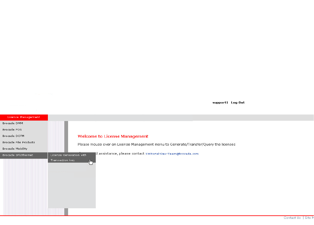
PowerConnect B-Series FCX Configuration Guide 85
53-1002266-01
Configuration tasks 4
Figure 6 shows the License Management Welcome window that appears after logging in to the
software portal. From this window, mouse over the License Management banner, then
IP/Ethernet, then click on License Generation with Transaction key.
FIGURE 6 License Management Welcome window
License Query

86 PowerConnect B-Series FCX Configuration Guide
53-1002266-01
Configuration tasks
4
Figure 7 shows the IP/Ethernet License Generation window for generating a license using a
transaction key and LID.
FIGURE 7 IP Ethernet License Generation window
Enter the required information in each text box shown in Figure 7.
•For a description of the field, move the mouse pointer over the text box.
•An asterisk next to a field indicates that the information is required.
•You can generate more than one license at a time. For each license request, enter the Unit
Information (Unit ID and transaction key) then click on the Add button.
When you have finished entering the required information, read the End User License
Agreement, then click on the check box to indicate that you have read and accept it.
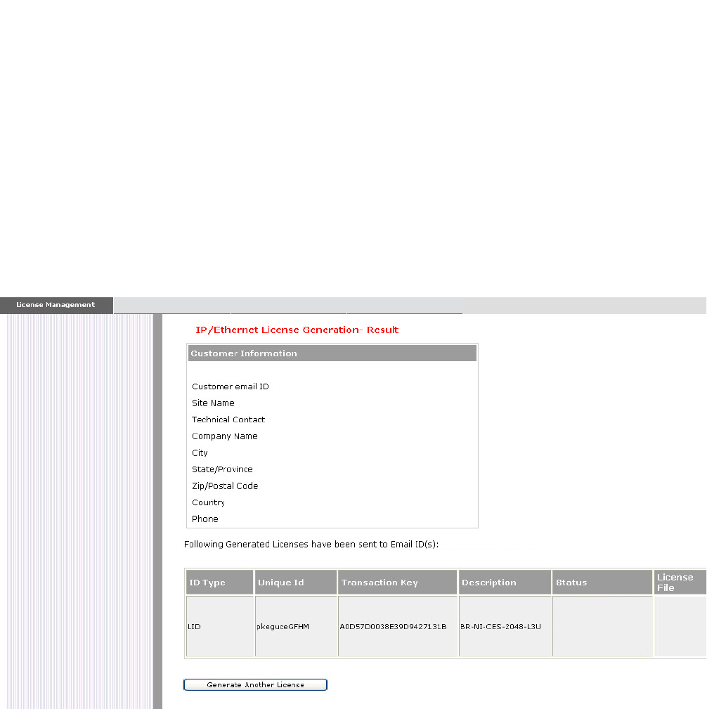
PowerConnect B-Series FCX Configuration Guide 87
53-1002266-01
Configuration tasks 4
Press the Generate button to generate the license. Figure 8 shows the results window, which
displays an order summary and the results of the license request.
•If the license request was successful, the “Status” field will indicate Success and the
“License File” field will contain a hyperlink to the generated license file. The license file will
also be automatically e-mailed to the specified Customer e-mail ID.
•If the license request failed, the “Status” field will indicate the reason it failed and the
action to be taken.
FIGURE 8 IP/Ethernet License Generation Results window
4. Download the license file to your PC by either clicking on the hyperlink or saving it from the
e-mail attachment.
5. Upload the license file to the PowerConnect device as instructed in the section “Installing a
license file” on page 88.
partner501@company.com
partner501@company.com
Success License Key

88 PowerConnect B-Series FCX Configuration Guide
53-1002266-01
Deleting a license
4
Installing a license file
Once you obtain a license file, place it on a TFTP or SCP server to which the Dell PowerConnect
device has access, then use TFTP or SCP to copy the file to the license database of the Dell
PowerConnect device.
Using TFTP to install a license file
To copy a license file from a TFTP server to the license database of the Dell PowerConnect device,
enter a command such as the following at the Privileged EXEC level of the CLI:
PowerConnect# copy tftp license 10.1.1.1 lic.xml
Syntax: copy tftp license <IP_address> <license_filename_on_host>
<IP_address> is the address of the IPv4 TFTP server.
<license_filename_on_host> is the filename of the license file.
Using Secure Copy (SCP) to install a license
SSH and SCP must be enabled on the Dell PowerConnect device before the procedures in this
section can be performed. For details, see the chapter “Configuring SSH2 and SCP” on page 1423.
To copy a license file from an SCP-enabled client to the license database of the Dell PowerConnect
device, enter a command such as the following on the SCP-enabled client.
c:\scp c:\license\license101 terry@10.1.1.1:license
Syntax: scp <license_file_on_host> <user>@<IP_address>:license
Verifying the license file installation
Use the show license command to verify that the license is installed on the device. Details about
this command are in the section “Viewing the license database” on page 92.
Deleting a license
A license will remain in the license database until it is deleted. If you want to delete a license, Dell
recommends that you first disable the licensed feature before deleting the associated license.
To delete a license, enter a command such as the following at the Privileged EXEC level of the CLI:
PowerConnect# license delete 7
This command immediately removes the license from the license database. The CLI commands
related to the licensed feature will no longer be available from the CLI. The licensed feature will
continue to run as configured until the software is reloaded, at which time the feature will be
disabled and removed from the system. Syslog and trap messages are generated when the license
is deleted.
Syntax: license delete <index_number>
<index_number> is a valid license index number. This information can be retrieved from the show
license command output. For more information, refer to “Viewing information about software
licenses” on page 91.
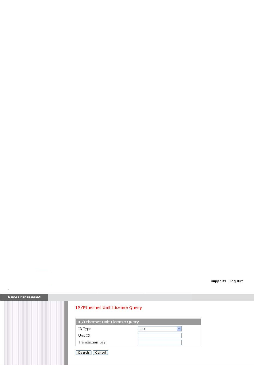
PowerConnect B-Series FCX Configuration Guide 89
53-1002266-01
Other licensing options available from the Brocade Software Portal 4
Other licensing options available from the
Brocade Software Portal
This section describes other software licensing tasks supported from the Brocade software portal.
Viewing software license information
You can use the License Query option to view software license information for a particular unit,
transaction key, or both. You can export the report to Excel for sharing or archiving purposes.
Depending on the status of the license, for example whether or not the license was generated, the
report will include the following Information:
•Hardware part number, serial number, and description
•Software part number, serial number, and description
•Date the license was installed
•Transaction key
•LID
•Feature name
•Product line
To access the License Query option, select it from the License Management Welcome window
shown in Figure 6.
Figure 9 shows the License Query window.
FIGURE 9 License Query window
•To view software license information for a particular unit, enter the LID in the Unit ID field then
click on Search.
•To view software license information for a particular transaction key, enter the unique number
in the Transaction key field then click on Search.
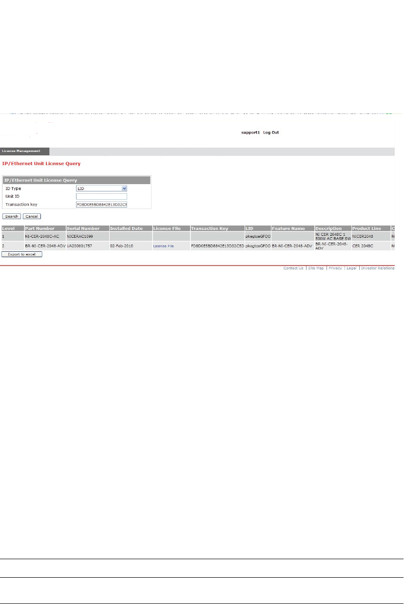
90 PowerConnect B-Series FCX Configuration Guide
53-1002266-01
Transferring a license
4
Figure 10 shows an example of the license query results.
FIGURE 10 License Query results window
In this example, the line items for Level 1 display hardware-related information and the line items
for Level 2 display software-related information. If the query was performed before the transaction
key was generated, the first row (Level 1) would not appear as part of the search results. Similarly,
if the query was performed before the license was generated, some of the information in the
second row would not be displayed.
Transferring a license
A license can be transferred between Dell PowerConnect devices if the following conditions are
true:
•The device is under an active support contract, and
•The license is being transferred between two like-models (e.g., from a 24-port model to another
24-port model or from a 48-port model to another 48-port model).
Contact your Dell representative for more information.
Syslog messages and trap information
The following Syslog messages and traps are supported for software-based licensing.
TABLE 18 Syslog messages
Message level Message Explanation
Informational License: Package <package_name> with LID
<LID_number> is added
Indicates that the license package has
been added.
Informational License: Package <package_name> with LID
<LID_number> is removed
Indicates that the license package has
been deleted.

PowerConnect B-Series FCX Configuration Guide 91
53-1002266-01
Viewing information about software licenses 4
Viewing information about software licenses
This section describes the show commands associated with software licensing. These commands
are issued on the Dell PowerConnect device, at any level of the CLI.
NOTE
You can also view information about software licenses from the Brocade software portal. Refer to
“Viewing software license information” on page 89.
Viewing the License ID (LID)
Dell PowerConnect devices that ship during and after the release of software licensing will have the
LID imprinted on the label affixed to the device. You also can use the CLI command show version to
view the LID on these devices, and on devices that shipped before the release of software
licensing.
Use the show version command to display the serial number, license, and LID of the device. The
following is example output from an PowerConnect B-Series FCX unit with the license
FCX-ADV-LIC-SW installed.
Warning License: Package <package_name> with LID
<LID_number> expires in <number> days
The trial license is about to expire. This
message will begin to display 3 days before
the expiration date, and every 2 hours on
the last day that the license will expire.
Notification License: Package <package_name> with LID
<LID_number> has expired
The trial license has expired.
TABLE 18 Syslog messages
Message level Message Explanation
PowerConnect#show version
Copyright (c) 1996-2010 Brocade Communications Systems, Inc.
UNIT 1: compiled on Mar 30 2010 at 18:39:20 labeled as FCXR07000b1
(5245400 bytes) from Secondary FCXR07000b1.bin
SW: Version 07.0.00b1T7f3
Boot-Monitor Image size = 369286, Version:07.0.01T7f5 (grz07001)
HW: Stackable FCX624SF
==========================================================================
UNIT 1: SL 1: FCX-24GS 24-port Management Module
Serial #: PR320400289
license: FCX_adv_router_soft_package (lid: rtihfjffhno)
P-ENGINE 0: type DB10, rev 01
==========================================================================
UNIT 1: SL 2: FCX-2XGC 2-port 16G Module (2-CX4)
==========================================================================
800 MHz Power PC processor 8544E (version 33/0022) 400 MHz bus
65536 KB flash memory
256 MB DRAM
Monitor Option is on
STACKID 1 system uptime is 16 hours 35 minutes 25 seconds
The system : started=warm start reloaded=by "reload"

92 PowerConnect B-Series FCX Configuration Guide
53-1002266-01
Viewing information about software licenses
4
Viewing the license database
To display general information about all software licenses in the license database, use the show
license command. The following shows example output.
To display detailed information about a particular license, use the show license <index_number>
command. The following shows example output.
Syntax: show license [<index_number>]
The following table describes the information displayed by the show license command.
TABLE 19 Output from the show license command
This field... Displays...
Index The license hash number that uniquely identifies the license.
Package Name The package name for the license.
Lid The license ID. This number is embedded in the Dell PowerConnect
device.
Status Indicates the status of the license:
•Valid – A license is valid if the LID matches the serial number of the
device for which the license was purchased, and the package name
is recognized by the system.
•Invalid – The LID does not match the serial number of the device
for which the license was purchased.
•Active – The license is valid and in effect on the device.
•Not used – The license is not in effect on the device.
•Expired – For trial licenses only, this indicates that the trial license
has expired.
License Type Indicates whether the license is normal (permanent) or trial (temporary).
License Period If the license type is trial (temporary), this field will display the number of
days the license is valid. If the license type is normal (permanent), this
field will display “unlimited”.
Trial license information
The following details display in the output of the show license <Index_number> command.
+ days used The number of days the trial license has been in effect.
+ hours used The number of hours the trial license has been in effect.
+ days left The number of days left before the trial license expires.
+ hours left The number of hours left before the trial license expires.
PowerConnect#show license
------------------------------------------------------------------------------
Index Package Lid Status License License
Name Type Period
------------------------------------------------------------------------------
1 FCX624-ADV-LIC-SW egut-cd0J active normal unlimited
2 FCX624-ADV-LIC-SW egut-cd0J valid normal unlimited
PowerConnect#show license 1

PowerConnect B-Series FCX Configuration Guide 93
53-1002266-01
Viewing information about software licenses 4
Viewing software packages installed in the device
Use the show version command to view the software packages that are currently installed in the
device.
NOTE
The software package name is not the same as the license name.
Table 20 lists the supported software packages.
TABLE 20 Software packages
Product Software package name License needed?
PowerConnect B-Series
FCX
BASE_SOFT_PACKAGE No
FCX_FULL_ROUTER_SOFT_PACKAGE No
FCX_ADV_ROUTER_SOFT_PACKAGE Yes
PowerConnect#show version
Copyright (c) 1996-2010 Brocade Communications Systems, Inc.
UNIT 1: compiled on Mar 30 2010 at 18:39:20 labeled as FCXR07000b1
(5245400 bytes) from Secondary FCXR07000b1.bin
SW: Version 07.0.00b1T7f3
Boot-Monitor Image size = 369286, Version:07.0.01T7f5 (grz07001)
HW: Stackable FCX624SF
==========================================================================
UNIT 1: SL 1: FCX-24GS 24-port Management Module
Serial #: PR320400289
license: FCX_adv_router_soft_package (lid: rtihfjffhno)
P-ENGINE 0: type DB10, rev 01
==========================================================================
UNIT 1: SL 2: FCX-2XGC 2-port 16G Module (2-CX4)
==========================================================================
800 MHz Power PC processor 8544E (version 33/0022) 400 MHz bus
65536 KB flash memory
256 MB DRAM
Monitor Option is on
STACKID 1 system uptime is 16 hours 35 minutes 25 seconds
The system : started=warm start reloaded=by "reload"

94 PowerConnect B-Series FCX Configuration Guide
53-1002266-01
Viewing information about software licenses
4

PowerConnect B-Series FCX Configuration Guide 95
53-1002266-01
Chapter
5
Stackable Devices
Table 21 lists the individual Dell PowerConnect switches and the Ironstack features they support.
IronStack overview
This section gives a brief overview of IronStack technology, including IronStack terminology. This
section also lists the PowerConnect B-Series FCX models that support stacking.
IronStack technology features
A stack is a group of devices that are connected so that they operate as a single chassis. Dell
IronStack technology features include:
•Management by a single IP address
•Support for up to eight units per stack
•Flexible stacking ports
•Linear and ring stack topology support
•Secure-setup utility to make stack setup easy and secure
TABLE 21 Supported Ironstack features
Feature PowerConnect B-Series FCX1
1. All PowerConnect B-Series FCX models can be ordered from the factory as -ADV models.
ADV models include support for Layer 3 BGP. PowerConnect B-Series FCX-E and
PowerConnect B-Series FCX-I models require an optional 10 Gbps SFP+ module to support
stacking.
Building an IronStack
•Secure-setup
•Automatic configuration
•Manual configuration
Yes
Ironstack management Yes
Ironstack management MAC address Yes
Ironstack partitioning Yes
Persistent MAC address Yes
Ironstack software upgrade Yes
Ironstack and stack mismatch
troubleshooting
Yes
Hitless stacking:
•Hitless failover
•Hitless switchover
Yes

96 PowerConnect B-Series FCX Configuration Guide
53-1002266-01
IronStack overview
5
•Active Controller, Standby Controller, and member units in a stack
•Active Controller management of entire stack
•Active Controller download of software images to all stack units
•Standby Controller for stack redundancy
•Active Controller maintenance of information database for all stack units
•Packet switching in hardware between ports on stack units
•All protocols operate on an IronStack in the same way as on a chassis system.
Stackable models
PowerConnect B-Series FCX devices
All PowerConnect B-Series FCXdevices can be active members of a IronStack. PowerConnect
B-Series FCX-E and PowerConnect B-Series FCX-I models require an optional 10 Gbps SFP+ module
to support stacking. For information about how to install PowerConnect B-Series FCX devices, see
the PowerConnect B-FCX Switch Hardware Installation Guide.
All PowerConnect B-Series FCX devices can be ordered from the factory as -ADV models with
support for Layer 3 BGP.
IronStack terminology
Stack unit roles:
•Active Controller - Handles stack management and configures all system- and interface-level
features.
•Future Active Controller - The unit that will take over as Active Controller after the next
reload, if its priority has been changed to the highest priority. When a priority for a stack
unit is changed to be higher than the existing Active Controller, the takeover does not
happen immediately to prevent disruptions in the stack operation.
•Standby Controller - The stack member with the highest priority after the Active Controller. The
Standby Controller takes over if the current Active Controller fails.
•Stack Member - A unit functioning in the stack in a capacity other than Active or Standby
Controller.
•Stack Unit - Any device functioning within the stack, including the Active Controller and Standby
Controller.
•Upstream Stack Unit - An upstream unit is connected to the first stacking port on the
Active Controller. (The left-hand port as you face the stacking ports.)
•Downstream Stack Unit - A downstream unit is connected to the second stacking port on
the Active Controller. (The right-hand port as you face the stacking ports.) General
terminology
•Bootup Role - the role a unit takes during the boot sequence. This role can be standalone,
Active Controller, Standby Controller, or stack member. The Active Controller or a standalone
unit can access the full range of the CLI. Until a stack is formed, the local consoles on the
Standby Controller and stack members provide access to a limited form of the CLI, such as the

PowerConnect B-Series FCX Configuration Guide 97
53-1002266-01
IronStack overview 5
show, stack, and a few debug commands. When the stack is formed, all local consoles are
directed to the Active Controller, which can access the entire CLI. The last line of output from
the show version command indicates the role of a unit, unless it is a standalone unit, in which
case it is not shown. For example:
My stack unit ID = 1, bootup role = active
•Clean Unit - A unit that contains no startup flash configuration or run time configuration. To
erase old configuration information, enter the erase startup-config command and reset the
unit. For PowerConnect B-Series FCX devices, the run-time configuration on a clean unit may
also contain default-port information,
•Control Path - A path across stacking links dedicated to carrying control traffic such as
commands to program hardware or software image data for upgrades. A stack unit must join
the control path to operate fully in the stack.
•Default Port - PowerConnect B-Series FCX devices use the default-port command to define
stacking port candidates.
•Interprocessor Communications (IPC) - The process by which proprietary packets are
exchanged between stack unit CPUs.
•IronStack - A set of stackable units (maximum of eight) and their connected stacking links so
that: all units can be accessed through their common connections, a single unit can manage
the entire stack, and configurable entities, such as VLANs and trunk groups, can have
members on multiple stack units.
•Non-Functioning Stack Unit - A stack unit that is recognized as a stack member, and is
communicating with the Active Controller over the Control Path, but is in a non-functioning
state. Because of this state, traffic from the non-stack ports will not be forwarded into the
stack - they will be dropped or discarded. This may be caused by an image or configuration
mismatch.
•Sequential Connection - Stack unit IDs, beginning with the Active Controller, are sequential. For
example, 1, 3, 4, 6, 7 is sequential if Active Controller is 1. 1, 7, 6, 4, 3 are non-sequential in a
linear topology, but become sequential in a ring topology when counted from the other
direction as: 1, 3, 4, 6, 7. Gaps in numbering are allowed.
•Standalone Unit - A unit that is not enabled for stacking, or an Active Controller without any
Standby Controller or stack members.
•Stacking Link - A cable that connects a stacking port on one unit to a stacking port on another
unit.
•Stack Path - A data path formed across the stacking links to determine the set of stack
members that are present in the stack topology, and their locations in the stack.
•Stacking Port - A physical interface on a stack unit that connects a stacking link. Stacking ports
are point-to-point links that exchange proprietary packets. Stacking ports must be 10 Gbps
Ethernet ports, and cannot be configured for any other purpose while operating as stacking
ports. Dell stacking units contain two ports that can be stacking ports. However, the flexible
stacking port feature also allows you to use one port as a stacking port and the other port as a
regular data port. Refer to “Controlling stack topology” on page 126.
•Stack Slot - slot in a stack is synonymous with line module in a chassis. Table 22 shows the
port and slot designations for PowerConnect stackable devices.
•Stack Topology - A contiguously-connected set of stack units in an IronStack that are currently
communicating with each other. All units that are present in the stack topology appear in
output from the show stack command.

98 PowerConnect B-Series FCX Configuration Guide
53-1002266-01
Building an IronStack
5
•Static Configuration - A configuration that remains in the database of the Active Controller even
if the unit it refers to is removed from the stack. Static configurations are derived from the
startup configuration file during the boot sequence, are manually entered, or are converted
from dynamic configurations after a write memory command is issued.
•Dynamic Configuration - A unit configuration that is dynamically learned by a new stack unit
from the Active Controller. A dynamic configuration disappears when the unit leaves the stack.
Building an IronStack
This section describes how to build an IronStack. Before you begin, you should be familiar with the
supported stack topologies and the software requirements. When you are ready to build your stack,
you can go directly to the instructions.
IronStack topologies
IronStack technology supports linear and ring stack topologies. Although stackable units may be
connected in a simple linear topology, Dell recommends a ring topology because it offers the best
redundancy and the most resilient operation.
Mixed unit topologies
For more information about PowerConnect B-Series FCX stack topologies, see “PowerConnect
B-Series FCX stack topologies” on page 98.
PowerConnect B-Series FCX stack topologies
A IronStack can contain all one model, or any combination of the PowerConnect B-Series FCX
models. You can mix 24-port and 48-port FCX devices in a single stack, to a maximum of eight units
per stack.
The procedure for cabling a stack of PowerConnect B-Series FCX devices differs depending on
whether your stack contains PowerConnect B-Series FCX-E and PowerConnect B-Series FCX-I
devices. Figure 11 shows PowerConnect B-FCX-S devices cabled in linear and ring stack topologies.
Note that these devices are cabled from the rear panel. Figure 12 shows PowerConnect B-FCX-E
devices in a ring topology stack. Figure 13 shows PowerConnect B-FCX-E devices in a linear
topology stack.
Figure 14 shows a mixed linear topology stack of PowerConnect B-FCX-S, and PowerConnect
B-FCX-E or PowerConnect B-FCX-I devices. Because the PowerConnect B- FCX-E and PowerConnect
B-FCX-I devices are cabled from the front panel, and PowerConnect B-FCX-S and devices are cabled
from the rear panel by default, you need to reconfigure the default stacking ports on PowerConnect
B-FCX-S devices to the ports on the front panel. For more information about reconfiguring default
stacking ports, see “Configuring default ports on FCX devices” on page 111.
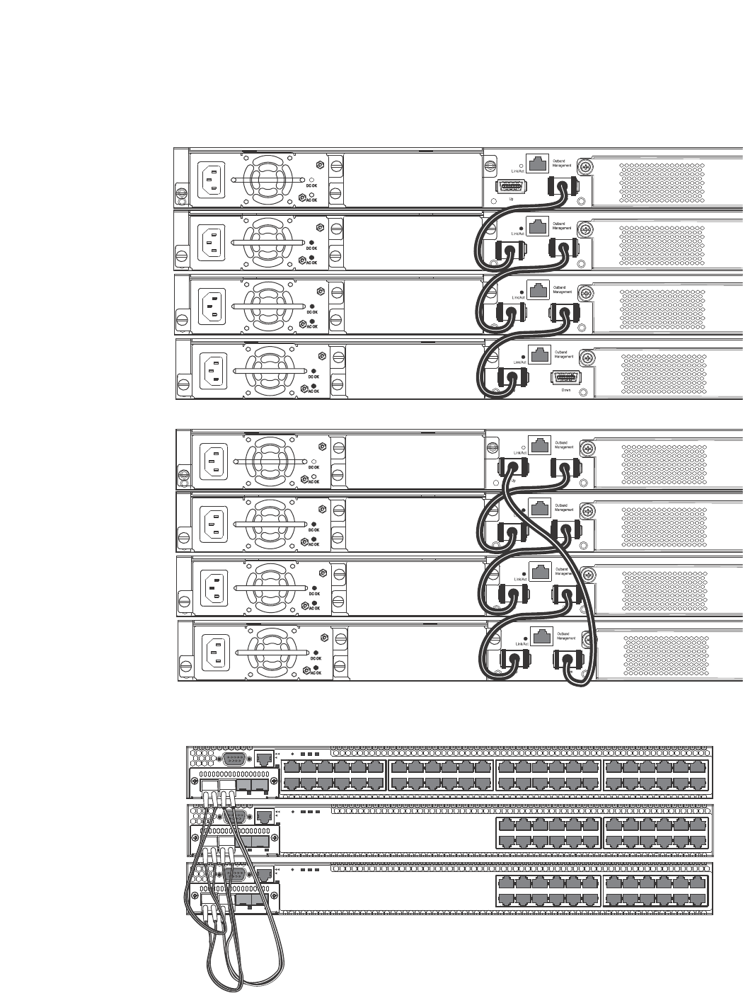
PowerConnect B-Series FCX Configuration Guide 99
53-1002266-01
Building an IronStack 5
FIGURE 11 PowerConnect B-Series FCX linear and ring stack topologies
FIGURE 12 PowerConnect B-FCX-E ring topology stack using SFP+ module ports
1357 911 131517192123
2 4 6 8 10 12 14 16 18 20 22 24
Reset
1
PS
2Diag
Console
Mgmt
25 27 29 31 33 35 37 39 41 43 45 47
26 28 30 32 34 36 38 40 42 44 46 48
135 7911 131517192123
2 4 6 8 10 12 14 16 18 20 22 24
Reset
1
PS
2 Diag
Console
Mgmt
1357 911 131517192123
2 4 6 8 10 12 14 16 18 20 22 24
Reset
1
PS
2Diag
Console
Mgmt
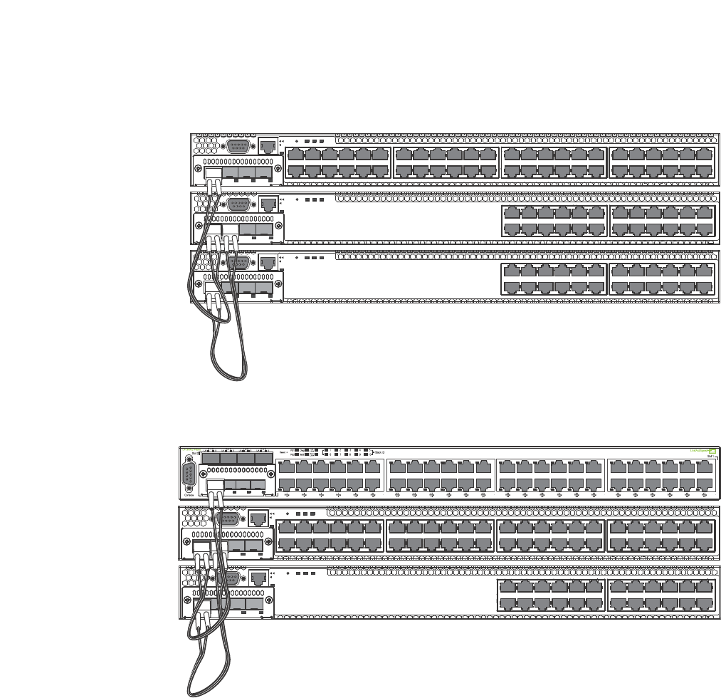
100 PowerConnect B-Series FCX Configuration Guide
53-1002266-01
Building an IronStack
5
FIGURE 13 PowerConnect B-FCX-E linear topology stack using SFP+ module ports
FIGURE 14 Mixed linear stack of PowerConnect B-FCX-E devices and PowerConnect B-FCX-S
devices
Software requirements
All units in an IronStack must be running the same software version. See “Troubleshooting an
IronStack” on page 151 for more information.
IronStack construction methods
There are three ways to build an IronStack.
1357 911 131517192123
2 4 6 8 10 12 14 16 18 20 22 24
Reset
1
PS
2Diag
Console
Mgmt
25 27 29 31 33 35 37 39 41 43 45 47
26 28 30 32 34 36 38 40 42 44 46 48
135 7911 131517192123
2 4 6 8 10 12 14 16 18 20 22 24
Reset
1
PS
2 Diag
Console
Mgmt
1357 911 131517192123
2 4 6 8 10 12 14 16 18 20 22 24
Reset
1
PS
2Diag
Console
Mgmt
1357 911 131517192123
2 4 6 8 10 12 14 16 18 20 22 24
Reset
1
PS
2 Diag
Console
Mgmt
25 27 29 31 33 35 37 39 41 43 45 47
26 28 30 32 34 36 38 40 42 44 46 48
135 7911 131517192123
2 4 6 8 10 12 14 16 18 20 22 24
Reset
1
PS
2Diag
Console
Mgmt
Device

PowerConnect B-Series FCX Configuration Guide 101
53-1002266-01
Building an IronStack 5
1. Use the secure-setup utility to form your stack. Secure-setup gives you control over the design
of your stack topology and provides security through password verification. For the
secure-setup procedure, refer to “Scenario 1 - Configuring a three-member IronStack in a ring
topology using secure-setup” on page 101.
2. Automatic stack configuration. With this method, you enter all configuration information,
including the module type and the priorities of all members into the unit you decide will be the
Active Controller and set its priority to be the highest. When you enable stacking on the Active
Controller the stack then forms automatically. This method requires that you start with clean
units (except for the Active Controller) that do not contain startup or run time configurations.
Refer to “Scenario 2 - Configuring a three-member IronStack in a ring topology using the
automatic setup process” on page 105.
3. Manual stack configuration. With this method, you configure every unit individually, and enable
stacking on each unit. Once the units are connected together, they will automatically operate
as an IronStack. With this method the unit with the highest priority becomes the Active
Controller, and ID assignment is determined by the sequence in which you physically connect
the units. Refer to “Scenario 3 - Configuring a three-member IronStack in a ring topology using
the manual configuration process” on page 108.
Configuration notes
Before you configure your IronStack, consider the following guidelines:
•Consider the number of units, and the mix of units your stack will contain, and how the
stacking ports on the units will be connected. For more information about PowerConnect
B-Series FCX devices, refer to the PowerConnect B-FCX Switch Hardware Installation Guide.
•The stack should be physically cabled in a linear or ring topology. Connect only those units that
will be active in the stack.
•When you have a full stack of 8 units, you may need to increase the trap hold time from the
default, which is 60 seconds, to five minutes (300 seconds). This will prevent the loss of initial
boot traps. To increase the trap hold time, use the following command.
PowerConnect# snmp-server enable traps hold 300
Syntax: snmp-server enable traps hold <seconds>
NOTE
The router image requires more time to boot than the switch image.
Scenario 1 - Configuring a three-member IronStack
in a ring topology using secure-setup
NOTE
.For more detailed information about configuring an PowerConnect B-FCX IronStack, see
“Configuring an FCX IronStack” on page 109.
This scenario describes how to build an IronStack using the secure-setup utility. Secure-setup lets
you easily configure your entire stack through the Active Controller, which propagates the
configuration to all stack members. Secure-setup is the most secure way to build an IronStack, and
gives you the most control over how your stack is built. For example, secure-setup offers three
security features that prevent unauthorized devices from accessing or joining an IronStack:

102 PowerConnect B-Series FCX Configuration Guide
53-1002266-01
Building an IronStack
5
•Authentication of secure-setup packets provides verification that these packets are from
genuine Dell stack unit. MD5-based port verification confirms stacking ports.
•Superuser password is required to allow password-protected devices to become members of
an IronStack.
•The stack disable command. When this command is issued, a unit does not listen for or send
stacking packets, which means that no other device in the network can force the
stacking-disabled unit to join an IronStack.
Secure-setup can also be used to add units to an existing IronStack (refer to “Adding, removing, or
replacing units in an IronStack” on page 147) and to change the stack IDs of stack members (refer
to “IronStack unit identification” on page 122).
When secure-setup is issued on a unit that is not already the Active Controller, this unit becomes
the Active Controller, and, if it does not have an assigned priority, secure-setup assigns it a priority
of 128. Any unit that then tries to join the stack must have an assigned priority less than 128. If
secure-setup discovers a unit with a priority of 128 or higher, it changes the priority to 118.
When secure-setup is issued on a unit that is not already the Active Controller, this unit becomes
the Active Controller. If this unit does not already have an assigned priority, secure-setup will assign
this unit a priority of 128 by default, if no other units in the stack have a priority higher than 128. If
another unit in the stack has a priority of 128 or higher, secure-setup will give the Active Controller
a priority equal to the highest priority unit in the stack (which is by default the Standby Controller).
When the Active Controller and the Standby Controller have identical priorities, during a reset, the
old Active Controller cannot reassume its role from the Standby Controller (which has become the
Active Controller at the reset).
If the previous Active Controller again becomes active, and you want it to resume the role of Active
Controller, you should set the priority for the Standby Controller to a priority lower than 128. If you
do not want the previous Active Controller to remain Active Controller, you can set the same priority
for both Active and Standby Controllers (higher than, or equal to 128). For details, refer to
“IronStack unit priority” on page 123.
NOTE
Secure-setup works for units within a single stack. It does not work across stacks.
Follow the steps given below to configure a three-member stack in a ring topology using
secure-setup.
1. Connect the devices using the stacking ports and stack cabling. For more information refer to
the appropriate hardware installation guides.
2. Power on the units.
3. Connect your console to the intended Active Controller. The unit through which you run
secure-setup becomes the Active Controller by default.
4. Issue the stack enable command on the intended Active Controller.
PowerConnect# config t
PowerConnect(config)# stack enable
PowerConnect(config)# exit
PowerConnect#

PowerConnect B-Series FCX Configuration Guide 103
53-1002266-01
Building an IronStack 5
5. Enter the stack secure-setup command. As shown In the following example, this command
triggers a Dell proprietary discovery protocol that begins the discovery process in both
upstream and downstream directions. The discovery process produces a list of upstream and
downstream devices that are available to join the stack. Secure-setup can detect up to 7 units
in each direction (14 total), but since the maximum number of units in a stack is 8, you must
select a maximum of 7 units from both directions.
NOTE
To exit the secure-setup, enter ^C at any time.
You should see output similar to the following.
PowerConnect# stack secure-setup
PowerConnect# Discovering the stack topology...
Current Discovered Topology - RING
Available UPSTREAM units
Hop(s) Type Mac Address
1 FCX624 0012.f239.2d40
2 FCX624 0012.f2d5.2100
Available DOWNSTREAM units
Hop(s) Type Mac Address
1 FCX624 0012.f2d5.2100
2 FCX624 0012.f239.2d40
Do you accept the topology (RING) (y/n)?: y
If you accept the topology, you will see output similar to the following.
Selected Topology:
Active Id Type Mac Address
1 FCX648 00e0.52ab.cd00
Selected UPSTREAM units
Hop(s) Id Type Mac Address
1 3 FCX624 0012.f239.2d40
2 2 FCX624 0012.f2d5.2100
Selected DOWNSTREAM units
Hop(s) Id Type Mac Address
1 2 FCX624 0012.f2d5.2100
2 3 FCX624 0012.f239.2d40
Do you accept the unit ids (y/n)?: y
To accept the unit ID assignments, type y. If you do not want to accept the ID assignments, type
n. You can use secure-setup to renumber the units in your stack. Refer to “Renumbering stack
units” on page 149.
If you accept the unit IDs, the stack is formed, and you can see the stack topology using the
show stack command.
PowerConnect# show stack
alone: standalone, D: dynamic config, S: static config
ID Type Role Mac Address Pri State Comment

104 PowerConnect B-Series FCX Configuration Guide
53-1002266-01
Building an IronStack
5
1 S FCX648 active 00e0.52ab.cd00 128 local Ready
2 D FCX624 standby 0012.f2d5.2100 60 remote Ready
3 D FCX624 member 0012.f239.2d40 0 remote Ready
active standby
+---+ +---+ +---+
-2/1| 1 |3/1--2/1| 2 |3/1--2/2| 3 |2/1-
+---+ +---+ +---+
Current stack management MAC is 00e0.52ab.cd00
NOTE
For field descriptions for the show stack command, refer to “Displaying stack information” on
page 135.
NOTE
In this output, D indicates a dynamic configuration. After you perform a write memory, this display
will change to S, for static configuration.
6. The Active Controller automatically checks all prospective stack members to see if they are
password protected. If a unit is password protected, you will be asked to enter the password
before you can add the unit. If you do not know the password, take one of the following actions:
•Discontinue secure-setup by entering ^C
•Obtain the device password from the administrator
•Continue secure-setup for your stack. The password-protected device and all devices
connected behind it will not be included in the setup process.
In the following example, the second unit is password protected, so you are asked for the
password.
PowerConnect# stack secure-setup
PowerConnect# Discovering the stack topology...
Verifying password for the password protected units...
Found UPSTREAM units
Hop(s) Type Mac Address
1 2 FCX648 001b.ed5e.c480
2 3 FCX648 00e0.5205.0000
Enter password for FCX648 located at 2 hop(s): ****
Enter the number of the desired UPSTREAM units (1-2)[1]: 2
Selected Topology:
Active Id Type Mac Address
1 FCX624 00e0.5201.4000
Selected UPSTREAM units
Hop(s) Id Type Mac Address
1 2 FCX648 001b.ed5e.c480
2 3 FCX648 00e0.5205.0000
Do you accept the unit id's (y/n)?: y

PowerConnect B-Series FCX Configuration Guide 105
53-1002266-01
Building an IronStack 5
7. When the Active Controller has finished the authentication process, you will see output that
shows the suggested assigned stack IDs for each member. You can accept these
recommendations, or you can manually configure stack IDs. Enter the show stack command to
verify that all units are in the ready state.
PowerConnect# show stack
alone: standalone, D: dynamic config, S: static config
ID Type Role Mac Address Pri State Comment
1 S FCX624 active 00e0.5201.4000 128 local Ready
2 S FCX648 standby 001b.ed5e.c480 0 remote Ready
3 S FCX648 member 00e0.5205.0000 0 remote Ready
active standby
+---+ +---+ +---+
-2/1| 1 |3/1--2/1| 2 |3/1--2/2| 3 |2/1-
| +---+ +---+ +---+ |
| |
|-------------------------------------|
Current stack management MAC is 00e0.5201.4000
PowerConnect#
NOTE
For field descriptions for the show stack command, refer to “Displaying stack information” on
page 135.
8. Enter the write memory command on the Active Controller once all of the stack units are
active. This command initiates configuration synchronization, which copies the configuration
file of the Active Controller to the rest of the stack units.
NOTE
The secure-setup process may modify your configuration with information about new units,
stacking ports, etc. For this reason, it is very important to save this information by issuing the
write memory command. If you do not do this, you may lose your configuration information the
next time the stack reboots.
The secure-setup process for your stack is now complete.
NOTE
During the secure-setup process, after 1 minute of inactivity, authentication for stack members will
expire and you will need to restart the process.
Scenario 2 - Configuring a three-member IronStack
in a ring topology using the automatic setup process
PowerConnect B-Series FCX devices determine stacking port candidates through the default-port
setting. An PowerConnect B-Series FCX stackable device with the default port configuration is still
considered a clean unit. To ensure that the device remains a clean unit, do not do a write memory
on the device.
For more detailed information about configuring an FCX IronStack, see “Configuring an FCX
IronStack” on page 109.

106 PowerConnect B-Series FCX Configuration Guide
53-1002266-01
Building an IronStack
5
Follow the steps given below to configure a three-member IronStack in a ring topology using
automatic setup process.
1. Power on the devices.
2. This process requires clean devices (except for the Active Controller) that do not contain any
configuration information. To change a device to a clean device, enter the erase startup-config
command and reset the device. When all of the devices are clean, continue with the next step.
NOTE
The physical connections must be sequential, and must match the stack configuration.
3. Log in to the device that you want to be the Active Controller.
4. Configure the rest of the units by assigning ID numbers and module information on each
unit.The stack ID can be any number from 1 through 8.
PowerConnect# config t
PowerConnect(config)# stack unit 2
PowerConnect(config-unit-2)# module 1 FCX-24-port-management-module
PowerConnect(config-unit-2)# module 2 FCX-xfp-1-port-16g-module
PowerConnect(config-unit-2)# module 3 FCX-xfp-1-port-16g-module
PowerConnect(config-unit-2)# stack unit 3
PowerConnect(config-unit-3)# module 1 FCX-24-port-management-module
PowerConnect(config-unit-3)# module 2 FCX-xfp-1-port-16g-module
PowerConnect(config-unit-3)# module 3 FCX-xfp-1-port-16g-module
NOTE
Each stack unit must have a unique ID number.
5. Assign a priority to the Active Controller using the priority command, as shown.
PowerConnect(config)# stack unit 1
PowerConnect(config-stack-1)# priority 255
Syntax: priority <num>
•<num> is a value from 0-255. 255 is the highest priority
6. Assign a priority to the unit that will act as Standby Controller.
PowerConnect# config t
PowerConnect(config)# stack unit 2
PowerConnect(config-unit-2)# priority 240
7. Do a write memory command to save your settings.
8. Enter the stack enable command.
9. Physically connect the devices in a stack topology, which triggers an election during which the
stack is automatically configured. For more information about cabling the devices, refer to the
appropriate hardware installation guides.
NOTE
When you are configuring individual stack units, you can skip ID numbers. However, the
sequence in which the units are connected must match the order in which you configure them.
Verify your stack configuration by entering the show running config command.

PowerConnect B-Series FCX Configuration Guide 107
53-1002266-01
Building an IronStack 5
PowerConnect# show running config
Current configuration:
!
ver 07.2.00a
!
stack unit 1
module 1 FCX-24-port-management-module
priority 255
stack unit 2
module 1 FCX-24-port-management-module
priority 240
stack unit 3
module 1 FCX-24-port-management-module
stack enable
!
NOTE
For field descriptions for the show running config command, refer to “Displaying running
configuration information” on page 143.
10. To see information about your stack, enter the show stack command.
PowerConnect# show stack
alone: standalone, D: dynamic config, S: static config
ID Type Role Mac Address Pri State Comment
1 S FCX624 active 00e0.5200.0100 255 local Ready
2 S FCX624 standby 0012.f2eb.afc0 240 remote Ready
3 S FCX624 member 001b.ed5d.a1c0 0 remote Ready
active standby
+---+ +---+ +---+
-2/1| 1 |3/1--2/1| 2 |3/1--2/2| 3 |2/1-
| +---+ +---+ +---+ |
| |
|-------------------------------------|
Current stack management MAC is 00e0.5200.0100
PowerConnect#
NOTE
For field descriptions for the show stack command, refer to “Displaying stack information” on
page 135.
Configuration notes for scenario 2
Consider the following items when building a stack using the automatic setup process:
•If a new unit configuration matches other unit configurations, the Active Controller gives this
unit the lowest sequential ID.
•In a ring topology, the same new unit might assume either ID if either direction produces
sequential IDs. For example, in a four-member stack where IDs 2 and 4 are reserved, a new
unit could assume either I2 or ID 4 because either ID 1,2,3 or 1, 3, 4 is sequential.

108 PowerConnect B-Series FCX Configuration Guide
53-1002266-01
Building an IronStack
5
Scenario 3 - Configuring a three-member IronStack
in a ring topology using the manual configuration process
NOTE
For more detailed information about configuring an PowerConnect B-Series FCX IronStack, see
“Configuring an FCX IronStack” on page 109
Follow the steps given below to configure a three-member IronStack in a ring topology using the
manual configuration process.
1. Power on the devices. Do not connect the stacking cables at this point.
2. Assign a priority of 255 to unit 1, and a priority of 240 to unit 3 using the priority command. You
do not have to assign a priority to the third device. Enter the stack enable command on each
device. In this example, device 1 will be the Active Controller and device 2 will be the Standby
Controller.
Unit 1
PowerConnect# config t
PowerConnect(config)# stack unit 1
PowerConnect(config-unit-1)# priority 255
PowerConnect(config-unit-1)# stack enable
Enable stacking. This unit actively participates in stacking
PowerConnect(config-unit-1)# write memory
Write startup-config done.
PowerConnect(config-unit-1)# Flash Memory Write (8192 bytes per dot) .Flash to
Flash Done.
PowerConnect(config-unit-1)# end
Unit 2
PowerConnect# config t
PowerConnectconfig)# stack enable
Enable stacking. This unit actively participates in stacking
PowerConnect(config)# Handle election, was standalone --> member,
assigned-ID=2, T=261285 ms.
Write startup-config done.
FCX624-STK Switch(config-unit-1)# Flash Memory Write (8192 bytes per dot)
.Flash to Flash Done.
PowerConnect(config-unit-1)# end
PowerConnect# config t
Unit 3
PowerConnect# config t
PowerConnect(config)# stack unit 1
PowerConnect(config-unit-1)# priority 240
PowerConnect(config-unit-1)# stack enable
Enable stacking. This unit actively participates in stacking
PowerConnect(config-unit-1)# end
3. Connect the devices in a stack topology. The Active Controller will retain its ID. The rest of the
units are assigned unique ID numbers depending on the sequence in which you connected
them.

PowerConnect B-Series FCX Configuration Guide 109
53-1002266-01
Building an IronStack 5
For more information about cabling the devices, refer to the appropriate hardware installation
guides.
NOTE
This method does not guarantee sequential stack IDs. If you want to change stack IDs to make them
sequential, you can use secure-setup. Refer to “Renumbering stack units” on page 149.
Configuring an FCX IronStack
Every PowerConnect B-Series FCX-S device contains two default 16 Gbps stacking ports on the rear
panel and two 10 Gbps ports on the front panel that can also be used as stacking ports.
NOTE
PowerConnect B-Series FCX-I and PowerConnect B-Series FCX-E devices can only be used for
stacking if they have an optional 10 Gbps SFP+ module installed in the front panel. These devices
do not have stacking ports on the rear panels.
An PowerConnect B-Series FCX IronStack may contain up to eight 24-port and 48-port devices,
using any combination of the rear panel stacking ports and the front panel optional stacking ports.
For PowerConnect B-Series FCXs devices, to use ports other than the factory-default 16 Gbps ports,
you must define the ports for each device in the run time configuration. You can also configure the
16 Gbps ports to operate as 10 Gbps ports. See “Configuring PowerConnect B-Series FCX stacking
ports” on page 109.
An PowerConnect B-Series FCX “clean unit” may contain a default port configuration, but it is still
considered a clean unit. To preserve this state, do not do a write memory on the unit before you
build the stack. An PowerConnect B-Series FCX device with the default port configuration is still
considered a clean unit. To ensure that the device remains a clean unit, do not do a write memory
on the device. (Write memory adds a startup-config, and the device is no longer a clean unit.)
NOTE
The automatic setup process will not work for PowerConnect B-Series FCX devices that do not
contain the default port information in their clean unit configurations.
Configuring PowerConnect B-Series FCX stacking ports
PowerConnect B-Series FCX-S devices have two 10 Gbps ports on the front panel and two 16 Gbps
ports on the rear panel. All of these ports may be used as stacking ports, however the non-default
ports must be configured as stacking ports when setting up your PowerConnect B-Series FCX-S
IronStack.
PowerConnect B-Series FCX-I and PowerConnect B-Series FCX-E devices do not have 16 Gpbs ports
on the rear panel. These devices may be used in an IronStack by installing the 10 Gbps 4-port SFP+
module in the module slot on the front panel. Once you have installed one of these modules, ports
1 and 2 act as the default stacking ports. However, you can also use these ports to pass regular
traffic, after disabling the stacking default. See “Changing default stacking port configurations” on
page 112.

110 PowerConnect B-Series FCX Configuration Guide
53-1002266-01
Building an IronStack
5
NOTE
If you are adding PowerConnect B-Series FCX-E or PowerConnect B-Series FCX-I devices to a stack
containing PowerConnect B-Series FCX-S devices, you must reconfigure the stacking ports on the
PowerConnect B-Series FCX-S devices to be the 10 Gbps ports on the front panel. You can then
connect all of the devices in a stack using front panel ports.
Changing PowerConnect B-Series FCX-S and CX4 ports from 16 Gbps to 10 Gbps
You can configure the 16 Gbps PowerConnect B-Series FCX4 ports to operate as 10 Gbps ports
using the speed-duplex command, as shown in the following example.
Syntax: speed-duplex [10-full | 10-half | 100-full | 100-half | 1000-full-master | 1000-full-slave
|10g-full | auto]
•10-full - 10M, full duplex
•10-half - 10M, half duplex
•100-full - 100M, full duplex
•100-half - 100M, half duplex
•1000-full-master - 1G, full duplex, master
•1000-full-slave - 1G, full duplex, slave
•10g-full - 10G, full duplex
•auto - Autonegotiation
NOTE
Both ends of a link must be configured for 10 Gbps for the link to operate as 10 Gbps. If you want
the link to operate as a 16 Gbps link, both ends of the link must be configured for 16 Gbps.
PowerConnect(config-if-e10000-cx4-1/2/1)# speed-duplex 10g-full
PowerConnect(config-if-e10000-cx4-1/2/1)# end
PowerConnect# show int br | in Up
1/1/4 Up Forward Full 1G None No 1 0 001b.f288.0003
1/2/1 Up Forward Full 10G None No 1 0 001b.f288.0019
1/3/1 Up Forward Full 10G None No N/A 0 001b.f288.001b
3/3/1 Up Forward Full 10G None No N/A 0 0024.3814.9df3
mgmt1 Up None Full 1G None No 1 0 001b.f288.0018
PowerConnect# show interface e 1/2/1
16GigabitEthernet1/2/1 is up, line protocol is up
Hardware is 16GigabitEthernet, address is 001b.f288.0019 (bia 001b.f288.0019)
Interface type is 16Gig CX4
Configured speed 10Gbit, actual 10Gbit, configured duplex fdx, actual fdx
Member of L2 VLAN ID 1, port is untagged, port state is FORWARDING
BPDU guard is Disabled, ROOT protect is Disabled
Link Error Dampening is Disabled
STP configured to ON, priority is level0, mac-learning is enabled
Flow Control is enabled
mirror disabled, monitor disabled
Not member of any active trunks
Not member of any configured trunks
No port name
IP MTU 1500 bytes, encapsulation ethernet
300 second input rate: 0 bits/sec, 0 packets/sec, 0.00% utilization
300 second output rate: 0 bits/sec, 0 packets/sec, 0.00% utilization
0 packets input, 0 bytes, 0 no buffer
Received 0 broadcasts, 0 multicasts, 0 unicasts
0 input errors, 0 CRC, 0 frame, 0 ignored

PowerConnect B-Series FCX Configuration Guide 111
53-1002266-01
Building an IronStack 5
0 runts, 0 giants
0 packets output, 0 bytes, 0 underruns
Transmitted 0 broadcasts, 0 multicasts, 0 unicasts
0 output errors, 0 collisions
Relay Agent Information option: Disabled
Changing PowerConnect B-Series FCX-S and PowerConnect B-Series
FCXS-PowerConnect B-Series FCX4 ports from 10 Gbps to 16 Gbps
To change the PowerConnect B-Series FCX4 ports from 10 Gbps back to 16 Gbps, enter the no
speed-duplex 10g command at the interface level of the CLI, as shown in this example.
PowerConnect(config-if-e10000-cx4-1/2/1)# no speed-duplex 10g
PowerConnect(config-if-e10000-cx4-1/2/1)# show interface br | in Up
1/1/4 Up Forward Full 1G None No 1 0 001b.f288.0003
1/2/1 Up Forward Full 16G None No 1 0 001b.f288.0019
1/3/1 Up Forward Full 10G None No N/A 0 001b.f288.001b
3/3/1 Up Forward Full 10G None No N/A 0 0024.3814.9df3
mgmt1 Up None Full 1G None No 1 0 001b.f288.0018
PowerConnect(config-if-e10000-cx4-1/2/1)# show interface e 1/2/1
16GigabitEthernet1/2/1 is up, line protocol is up
Hardware is 16GigabitEthernet, address is 001b.f288.0019 (bia 001b.f288.0019)
Interface type is 16Gig CX4
Configured speed 16Gbit, actual 16Gbit, configured duplex fdx, actual fdx
Member of L2 VLAN ID 1, port is untagged, port state is FORWARDING
BPDU guard is Disabled, ROOT protect is Disabled
Link Error Dampening is Disabled
STP configured to ON, priority is level0, mac-learning is enabled
Flow Control is enabled
mirror disabled, monitor disabled
Not member of any active trunks
Not member of any configured trunks
No port name
IP MTU 1500 bytes, encapsulation ethernet
300 second input rate: 0 bits/sec, 0 packets/sec, 0.00% utilization
300 second output rate: 0 bits/sec, 0 packets/sec, 0.00% utilization
0 packets input, 0 bytes, 0 no buffer
Received 0 broadcasts, 0 multicasts, 0 unicasts
0 input errors, 0 CRC, 0 frame, 0 ignored
0 runts, 0 giants
0 packets output, 0 bytes, 0 underruns
Transmitted 0 broadcasts, 0 multicasts, 0 unicasts
0 output errors, 0 collisions
Relay Agent Information option: Disabled
PowerConnect(config-if-e10000-cx4-1/2/1)#
Configuring default ports on FCX devices
On FCX devices, the default-port command is used to define stacking port candidates. A stacking
port is always a default port, but a default port may not necessarily be a stacking port. Default
ports can become stacking ports using the secure-setup utility, or through automatic stack
building.

112 PowerConnect B-Series FCX Configuration Guide
53-1002266-01
Building an IronStack
5
Secure-setup probe packets can be received by a default port whether or not it is acting as a
stacking port. Stacking packets can be only received by a stacking port (which is also always a
default port). In order to use stacking ports that are not defined in the default configuration, you
must define the port settings for each unit using the default-port command, so that secure-setup
can discover the topology of the stack.
The 4-byte Ethernet preamble for the Ethernet frame is used when a port is configured as a default
stacking port. For non-default ports, the standard 8-byte Ethernet preamble is used. For a default
port that is used as a regular data port, the standard 8-byte Ethernet preamble must be explicitly
enabled on the port using the longpreamble command. For details, refer to “Configuring a default
stacking port to function as a data port” on page 115.
Stackable devices ship with two default stacking ports configured. Use the stack-port command to
select only one of these factory default ports as the stacking port. If you do not configure
stack-port, both default ports will operate as stacking ports.
Use the default-port command to use ports other than the factory default ports as stacking ports.
You must configure default-port on each unit before building a stack. Once you have configured
default-port on all units, you can then use any of the three stack construction methods to build a
stack. The Active Controller then learns the port configuration for each unit.
NOTE
You cannot change the setting for a default port if the port is in use.
Changing default stacking port configurations
For PowerConnect B-Series FCX-E and PowerConnect B-Series FCX-I devices, ports 1 and 2 of the
optional 10 Gbps SFP+ module (slot 2) act as the default stacking ports. You can change the
default stacking ports to 3 and 4 on this module, or disable stacking, on all of the module ports.
The following example changes the default ports on a 10 Gbps module from 1 and 2 to 3 and 4.
PowerConnect 10g-1(config)# stack unit 1
10g-1(config-unit-1)#
10g-1(config-unit-1)# default-ports 1/2/3 - 1/2/4
Table 22 identifies the slot and port designations for each model.
NOTE
PowerConnect B-Series FCX-I and PowerConnect B-Series FCX-E models cannot be used in an
IronStack without the addition of an optional 10 Gbps SFP+ module.
NOTE
The two left ports on the Four-port 10 Gpbs SFP+ module do not pass regular Ethernet traffic by
default. If stacking is not required the stack disable comand must be entered at the global level and
the stack disable CLI command must be configured on these two ports in order for them to pass
regular traffic.
NOTE
If stacking is needed but not all default stacking ports are needed. Specify the stack ports per unit.
For non-stacking ports to be used as regular data port, the long-preamble command should be used
on the non-stacking port interface.

PowerConnect B-Series FCX Configuration Guide 113
53-1002266-01
Building an IronStack 5
NOTE
Do not connect stacking ports to non-stacking ports. Stacking ports have a proprietary packet
format that renders them incompatible with regular ports even when they are forwarding regular
packets. In linear topologies, make sure that end units have only one stacking port configured
(secure-setup automatically configures only one stacking port for an end unit).
Configuring a single stack port
NOTE
The two left ports on the Four-port 10 Gpbs SFP+ module do not pass regular Ethernet traffic by
default. The stack disable must be entered at the global level and the long preamble command must
be configured on these two ports in order for them to pass regular traffic. Use show stack stack-port
command to confirm port mode.
To configure a single stack port, enter a command similar to the following.
PowerConnect(config)# stack unit 3
PowerConnect(config-unit-3)# stack-port 3/2/1
Syntax: [no] stack-port <stack-unit/slotnum/portnum>
TABLE 22 Slot and port designations for PowerConnect stackable devices
Device Slot 1 Slot 2 Slot 3 Slot 4
PowerConnect
B-Series
FCX624S
24 10/100/1000 ports
on front panel
Two 16 Gbps ports on rear
panel
Two 10 Gbps ports
on front panel
N/A
PowerConnect
B-Series
FCX648S
48 10/100/1000 ports
on front panel
Two 16 Gbps ports on rear
panel
Two 10 Gbps ports
on front panel
N/A
PowerConnect
B-Series FCX-E
devices with
four-port 1 Gbps
SFP module
Four-port 1 Gbps SFP
module plus the first four
copper ports act as a
combo port. Slot 1 also
contains the remaining
20 10/100/1000 ports.
N/A N/A N/A
PowerConnect
B-Series FCX-I
devices with
four-port 1 Gbps
SFP module
Four-port 1 Gbps SFP
module plus the first four
copper ports act as a
combo port. Slot 1 also
contains the remaining
20 10/100/1000 ports.
N/A N/A N/A
PowerConnect
B-Series FCX-E
devices with
four-port 10
Gbps SFP+
module
48 10/100/1000 ports
on front panel
Four-port 10 Gbps SFP+
module (supports
stacking)
N/A N/A
PowerConnect
B-Series FCX-I
devices with
four-port 10
Gbps SFP+
module
48 10/100/1000 ports
on front panel
Four-port 10 Gbps SFP+
module (supports
stacking)
N/A N/A

114 PowerConnect B-Series FCX Configuration Guide
53-1002266-01
Building an IronStack
5
If you enter an incorrect stack port number, you will get an error similar to the following.
PowerConnectconfig-unit-3)# stack-port 3/4/1
Error! port 3/4/1 is invalid
PowerConnect(config-unit-3)# stack-port 3/2/1
To return both ports to stacking status, enter the no stack-port command on the single stacking
port. This converts both ports to stacking ports. By default, if both ports are stacking ports, they are
displayed by the system only when stacking is enabled. If only one port is configured as a stacking
port, the system always displays this port.
Using secure-setup to build an FCX IronStack
You can use the secure-setup utility to build an PowerConnect B-Series FCX IronStack by
performing the following steps.
1. When you have designated the desired stacking ports and connected your PowerConnect
B-Series FCX units together, on stack unit 1, enter stack enable and stack secure-setup, as
shown.
PowerConnect# stack enable
PowerConnect# stack secure-setup
PowerConnect# Discovering the stack topology...
Available UPSTREAM units
Hop(s) Id Type Mac Address
1 new FCX648 0012.f2d6.0511
2 new FCX624 0200.9999.0000
Enter the number of the desired UPSTREAM units (0-2)[0]: 2
Selected Topology:
Active Id Type Mac Address
1 FCX624 001b.f2e5.0100
Selected UPSTREAM units
Hop(s) Id Type Mac Address
1 2 FCX648 0012.f2d6.0511
2 3 FCX624 0200.9999.0000
Do you accept the unit ids (y/n)?: y
PowerConnect# Election, was alone --> active, assigned-ID=1, total 3 units, my
priority=128
Election, was active, no role change, assigned-ID=1, total 3 units, my
priority=128
reset unit 2: diff bootup id=1
reset unit 3: diff bootup id=1
Election, was alone --> active, assigned-ID=1, total 3 units, my priority=128
Detect stack member 2 capable
Detect stack unit 2 has different startup config flash, will synchronize it
Detect stack unit 3 has different startup config flash, will synchronize it
Done hot swap: Set stack unit 3 to Ready
Done hot swap: Set stack unit 2 to Ready
Synchronize startup config to stack unit 2
Flash Memory Write (8192 bytes per dot).Synchronize startup config to stack
unit 3
Flash Memory Write (8192 bytes per dot). Stack unit 2 Power supply 1 with 4
10000 mwatts capacity is up
Stack unit 2 Power supply 2 is down

PowerConnect B-Series FCX Configuration Guide 115
53-1002266-01
Building an IronStack 5
Stack unit 3 Power supply 1 is up
Stack unit 3 Power supply 2 is down
Config changed due to add/del units. Do write mem if you want to keep it
Election, was active, no role change, assigned-ID=1, total 3 units, my
priority=128
PowerConnect#
Config changed due to add/del units. Do write mem if you want to keep it
PowerConnect# show stack
alone: standalone, D: dynamic config, S: static config
ID Type Role Mac Address Pri State Comment
1 S FCX624 active 001b.f2e5.0100 128 local Ready
2 D FCX648 standby 0012.f2d6.0511 0 remote Ready
3 D FCX624 member 0200.9999.0000 0 remote Ready
standby active
+---+ +---+ +---+
| 3 |3/1--3/1| 2 |2/1--2/1| 1 |
+---+ +---+ +---+
Current stack management MAC is 001b.f2e5.0100
PowerConnect# write mem
Write startup-config done.
PowerConnect# Flash Memory Write (8192 bytes per dot) .Flash to Flash Done.
PowerConnect#show stack
alone: standalone, D: dynamic config, S: static config
ID Type Role Mac Address Pri State Comment
1 S FCX624 active 001b.f2e5.0100 128 local Ready
2 S FCX648 standby 0012.f2d6.0511 0 remote Ready
3 S FCX624 member 0200.9999.0000 0 remote Ready
standby active
+---+ +---+ +---+
| 3 |3/1--3/1| 2 |2/1--2/1| 1 |
+---+ +---+ +---+
Current stack management MAC is 001b.f2e5.0100
PowerConnect#
Configuring a default stacking port to function as
a data port
You can configure one of the two default stacking ports as a stacking port and the other port as a
regular data port. By default, the 4-byte Ethernet preamble for the Ethernet frame is used when a
port is configured as a default stacking port. This is done to compensate for extra overhead caused
by stacking protocol. To use a default stacking port as a regular data port, the Ethernet preamble
must be set to 8 bytes.
To configure a default port to use the long preamble, enter the following command at the Interface
level of the CLI:
PowerConnect(config)#int e 1/2/1
PowerConnect(config-if-e10000-1/2/1)#longpreamble
Syntax: [no] longpreamble

116 PowerConnect B-Series FCX Configuration Guide
53-1002266-01
Building an IronStack
5
Use the no form of the command to revert to the 4-byte Ethernet preamble.
Verifying an IronStack configuration
Verifying an PowerConnect B-Series FCX IronStack configuration
The following output shows an example configuration of an PowerConnect B-Series FCX IronStack.
PowerConnect# show stack
alone: standalone, D: dynamic config, S: static config
ID Type Role Mac Address Pri State Comment
2 S FCX648 standby 00e0.5202.0000 0 remote Ready
3 S FCX624 member 00e0.5203.0000 0 remote Ready
4 S FCX648 member 00e0.5204.0000 0 remote Ready
5 S FCX648 member 0000.0000.0000 0 remoteReady
8 S FCX648 active 00e0.5201.0000 128 local Ready
active standby
+---+ +---+ +---+ +---+
-2/1| 8 |2/2--2/1| 4 |2/2--2/1| 3 |2/2--2/1| 2 |2/2-
| +---+ +---+ +---+ +---+ |
|--------------------------------------------------|
Current stack management MAC is 00e0.5201.0000
The next example shows output from the show version command for the same FCX stack.
PowerConnect# show version
Copyright (c) 1996-2009 Brocade Communications Systems, Inc.
UNIT 8: compiled on Jun 17 2009 at 06:23:29 labeled as FCX06000a359
(3578117 bytes) from Primary FCX06000a359.bin
SW: Version 7.2.0a
UNIT 2: compiled on Jun 17 2009 at 06:23:29 labeled as FCX06000a359
(3578117 bytes) from Primary FCX06000a359.bin
SW: Version 7.2.0a
UNIT 3: compiled on Jun 17 2009 at 06:23:29 labeled as FCX06000a359
(3578117 bytes) from Primary FCX06000a359.bin
SW: Version 7.2.0a
UNIT 4: compiled on Jun 17 2009 at 06:23:29 labeled as FCX06000a359
(3578117 bytes) from Primary FCX06000a359.bin
SW: Version 7.2.0a
Boot-Monitor Image size = 365257, Version:06.0.00T7f5 (grz06000)
HW: Stackable FCX648P
==========================================================================
UNIT 2: SL 1: FCX-48G 48-port Management Module
P-ENGINE 0: type DB90, rev 01
P-ENGINE 1: type DB90, rev 01
==========================================================================
UNIT 2: SL 2: FCX-2XGC 2-port 16G Module (2-CX4)
==========================================================================
UNIT 3: SL 1: FCX-24G 24-port Management Module
P-ENGINE 0: type DB90, rev 01
==========================================================================
UNIT 3: SL 2: FCX-2XGC 2-port 16G Module (2-CX4)
==========================================================================
UNIT 3: SL 3: FCX-2XG 2-port 16G Module (2-XFP)
==========================================================================
UNIT 4: SL 1: FCX-48G 48-port Management Module
P-ENGINE 0: type DB90, rev 01

PowerConnect B-Series FCX Configuration Guide 117
53-1002266-01
Building an IronStack 5
P-ENGINE 1: type DB90, rev 01
==========================================================================
UNIT 4: SL 2: FCX-2XGC 2-port 16G Module (2-CX4)
==========================================================================
UNIT 4: SL 3: FCX-2XG 2-port 16G Module (2-XFP)
==========================================================================
UNIT 8: SL 1: FCX-48G 48-port Management Module
P-ENGINE 0: type DB90, rev 01
P-ENGINE 1: type DB90, rev 01
==========================================================================
UNIT 8: SL 2: FCX-2XGC 2-port 16G Module (2-CX4)
==========================================================================
800 MHz Power PC processor (version 33/0022) 144 MHz bus
65536 KB flash memory
256 MB DRAM
Monitor Option is on
STACKID 8 system uptime is 21 hours 2 minutes 23 seconds
STACKID 2 system uptime is 21 hours 2 minutes 22 seconds
STACKID 3 system uptime is 21 hours 2 minutes 23 seconds
STACKID 4 system uptime is 21 hours 2 minutes 22 seconds
The system : started=warm start reloaded=by "reload"
My stack unit ID = 8, bootup role = active
*** NOT FOR PRODUCTION ***
NOTE
For field descriptions for the show running config command, refer to “Displaying running
configuration information” on page 143.
NOTE
For field descriptions for the show stack and show stack detail commands, refer to “Displaying
stack information” on page 135.
The output from the show stack command contains a visual diagram of the stack. The dashed
line between ports 1/2/1 and 3/2/1 indicates that this stack is configured in a ring topology. If
the link between ports 1/2/1 and 3/2/1 is lost, the stack topology changes to linear, and the
diagram changes to resemble the following.
active standby
+---+ +---+ +---+
-2/1| 1 |3/1--2/1| 2 |3/1--2/2| 3 |2/1-
+---+ +---+ +---+
The interfaces at either of a stack member are stacking ports. If no interface is displayed, it
indicates that there is no stacking port configured. For example, the following diagram shows
that stack units 1 and 3 each have only one stacking port configured.
active standby
+---+ +---+ +---+
| 1 |3/1--2/1| 2 |3/1--2/2| 3 |
+---+ +---+ +---+
For more detailed information, you can enter the show stack detail command.

118 PowerConnect B-Series FCX Configuration Guide
53-1002266-01
Managing your IronStack
5
Managing your IronStack
Your IronStack can be managed through a single IP address. You can manage the stack using this
IP address even if you remove the Active Controller or any member from the stack. You can also
connect to the Active Controller through Telnet or SSH using this address. All management
functions, such as SNMP, use this IP address to acquire MIB information and other management
data.
A Dell IronStack can be configured and managed using the command line interface (CLI) over a
serial connection to a console port, or using Brocade Network Advisor. To determine what version
of Brocade Network Advisor supports IronStack refer to the Brocade Network Advisor User Guide.
Logging in through the CLI
You can access the IronStack and the CLI in two ways:
•Through a direct serial connection to the console port
•Through a local or remote Telnet session using the stack IP address
You can initiate a local Telnet or SNMP connection by attaching a cable to a port and specifying the
assigned management station IP address.
The stacking commands in the CLI are organized into the following levels:
•Global – Commands issued in the global mode are applied to the entire stack.
•Stack Member Configuration Mode – Commands issued in this mode apply to the specified
stack member. Configuration information resides in the Active Controller.
•Configuration Mode – This is where you make configuration changes to the unit. To save
changes across reloads, you need to save them to the Active Controller startup-config file. The
configuration mode contains sub-levels for individual ports, for VLANs, for routing protocols,
and other configuration areas.
NOTE
By default, any user who can open a serial or Telnet connection to the IronStack can access all of
these CLI levels. To secure access, you can configure Enable passwords or local user accounts, or
you can configure the Active Controller to use a RADIUS or TACACS/TACACS+ server for
authentication. Refer to Chapter 32, “Securing Access to Management Functions”.
Logging in through Brocade Network Advisor
Brocade Network Advisor supports stack technology. To determine what version of Brocade
Network Advisor supports stack technology and to find information on Brocade Network Advisor,
refer to the Brocade Network Advisor manual.
Logging in through the console port
When a device becomes a stack member in the IronStack, it establishes a remote connection to a
virtual console port on the Active Controller. Input and output are relayed between the physical
console port on the stack member and the virtual console port on the Active Controller. Since each
stack member connects to an independent virtual console port on the Active Controller, the
console ports on multiple stack units may be used simultaneously. However, messages displayed

PowerConnect B-Series FCX Configuration Guide 119
53-1002266-01
Managing your IronStack 5
on the Active Controller physical console port during a reload will not be visible on the console ports
of the stack members because the remote connections are not established until the software
loading process is complete. It is preferable to connect a cable to the console port on the stack unit
that will normally be the Active Controller, rather than to the console port of one of the other stack
units.
When a stack unit establishes communication with the Active Controller, it also establishes a
remote console session to the Active Controller. In a normally functioning IronStack, a console
cable may be connected to any of the stack units and provide access to the same commands on
the Active Controller.
You can terminate a session by entering Ctrl+O followed by 'x' or 'X', or by entering the 'exit'
command from the User EXEC level, or by entering the 'logout' command at any level.
NOTE
For the rconsole connections from the stack units to the Active Controller, the escape sequence and
other methods of terminating the session are not available.
NOTE
Error messages that are generated during a reload of the Active Controller will not appear on
rconsole connections from the stack units to the Active Controller. To see these error messages, you
must connect a console cable to the Active Controller itself.
To establish an rconsole session, enter the rconsole command as shown:
PowerConnect# rconsole 1
Syntax: rconsole <stack-unit>
The following example shows how to establish rconsole sessions to stack members. Notice that the
show stack command on the stack members displays different information than what is shown
when the show stack command is entered on the Active Controller.
To see the status of your stack units, enter the show stack command on the Active Controller.
PowerConnect# show stack
alone: standalone, D: dynamic config, S: static config
ID Type Role Mac Address Pri State Comment
1 S FCX648 active 0012.f2de.8100 128 local Ready
2 S FCX624 standby 0012.f2e2.ba40 0 remote Ready
3 S FCX624 member 001b.ed7a.22c0 0 remote Ready
active standby
+---+ +---+ +---+
-2/1| 1 |3/1--2/1| 2 |3/1--2/2| 3 |2/1-
| +---+ +---+ +---+ |
| |
|-------------------------------------|
Current stack management MAC is 0012.f2de.8100
PowerConnect#
NOTE
For field descriptions for the show stack command, refer to “Displaying stack information” on
page 135.
Establish a remote console session with stack unit 2.

120 PowerConnect B-Series FCX Configuration Guide
53-1002266-01
Managing your IronStack
5
PowerConnect# rconsole 2
Connecting to unit 2... (Press Ctrl-O X to exit)
rconsole-2@PowerConnect#show stack
ID Type Role Mac Address Prio State Comment
2 S FCX624P standby 0012.f2e2.ba40 0 local Ready
rconsole-2@PowerConnect# exit
rconsole-2@PowerConnect> exit
Disconnected. Returning to local session...
Establish a remote console session with stack unit 3.
PowerConnect# rconsole 3
Connecting to unit 3... (Press Ctrl-O X to exit)
rconsole-3@PowerConnect# show stack
ID Type Role Mac Address Prio State Comment
3 S FCX624P member 001b.ed7a.22c0 0 local Ready
rconsole-3@PowerConnect# logout
Disconnected. Returning to local session...
PowerConnect#
IronStack management MAC address
The IronStack is identified in the network by a single MAC address, usually the MAC address of the
Active Controller (the default). If a new Active Controller is elected, the MAC address of the new
Active Controller (by default) becomes the MAC address for the entire stack. However, you can
manually configure your stack to use a specified MAC address. Refer to “Manual allocation of the
IronStack MAC address” on page 120.
In an IronStack, the management MAC address is generated by the software, and is always the
MAC address of the first port of the Active Controller. This ensures that the management MAC
address remains consistent across stack reboots, and helps prevent frequent topology changes as
a result of protocol enable, disable, and configuration changes.
When you are configuring Layer 2 protocols on stack units, such as STP, RSTP, and MSTP, the
management MAC address of the Active Controller acts as the Bridge ID.
You can also configure the IronStack to retain its original MAC address, or wait for a specified
amount of time before assuming the address of a new Active Controller, using the Persistent MAC
Address feature (refer to “Persistent MAC address” on page 128).
NOTE
All physical IP interfaces on IronStack devices share the same MAC address. It is not recommended
to connect two or more physical IP interfaces between two routers.
Manual allocation of the IronStack MAC address
You can manually configure your IronStack to use a specific MAC address. This overrides the
default condition where the stack uses the MAC address of whatever unit is currently serving as
Active Controller.
NOTE
This command is useful for administration purposes, however it should be used with caution to
prevent duplication of MAC addresses.

PowerConnect B-Series FCX Configuration Guide 121
53-1002266-01
Managing your IronStack 5
NOTE
For hitless stacking failover, Dell recommends that you configure the IronStack MAC address using
the stack mac command. Without this configuration, the MAC address of the stack will change to
the new base MAC address of the Active Controller. This could cause a spanning tree root change.
Even without a spanning tree change, a client (for example, a personal computer) pinging the stack
might encounter a long delay depending on the client MAC aging time. The client won’t work until it
ages out the old MAC address and sends ARP requests to relearn the new stack MAC address.
To configure a stack MAC address manually, enter the following command.
PowerConnect(config)# stack mac 0000.0000.0011
Syntax: [no] stack mac <mac-address>
mac-address - a hexidecimal MAC address in the xxxx.xxxx.xxxx format
Enter the no form of this command to return the MAC address to that of the Active Controller.
Output for this command resembles the following.
PowerConnect(config)# stack mac 0000.0000.0011
PowerConnect(config)# show running-config
Current configuration:
!
ver 7.2.00a 100T7e1
!
stack 1
module 1 FCX-48-port-management-module
module 2 FCX-cx4-2-port-16g-module
priority 80
stack 2
module 1 FCX-24-port-management-module
module 2 FCX-cx4-2-port-16g-module
module 3 FCX-cx4-2-port-16g-module
stack enable
stack mac 0000.0000.0011
To display the stack MAC address, enter the show chassis command.
PowerConnect# show chassis
The stack unit 1 chassis info:
Power supply 1 (NA - AC - Regular) present, status ok
Power supply 2 not present
Fan 1 ok
Fan 2 ok
Exhaust Side Temperature Readings:
Current temperature : 35.5 deg-C
Warning level.......: 80.0 deg-C
Shutdown level......: 90.0 deg-C
Intake Side Temperature Readings:
Current temperature : 33.5 deg-C
Boot Prom MAC: 0012.f2de.9440
Management MAC: 0000.0000.0011
The stack unit 2 chassis info:
Power supply 1 (NA - AC - Regular) present, status ok
Power supply 2 not present

122 PowerConnect B-Series FCX Configuration Guide
53-1002266-01
Managing your IronStack
5
Fan 1 ok
Fan 2 ok
--More--, next page: Space, next line: Return key, quit: Control-c
NOTE
For field descriptions for the show chassis command, refer to “Displaying chassis information” on
page 133.
Removing MAC address entries
You can remove the following types of learned MAC address entries from the Dell system MAC
address table:
•All MAC address entries
•All MAC address entries for a specified Ethernet port
•All MAC address entries for a specified VLAN
•A specified MAC address entry in all VLANs
For example, to remove entries for the MAC address 000d.cb80.00d in all VLANs, enter the
following command at the Privileged EXEC level of the CLI.
PowerConnect# clear mac-address 000d.cb80.00d0
Syntax: clear mac-address <mac-address> | ethernet <port> | vlan <number>
•If you enter the clear mac-address command without any parameters, the software removes all
MAC entries.
•Use the <mac-address> parameter to remove a specified MAC address from all VLANs. Specify
the MAC address in the following format: HHHH.HHHH.HHHH.
•Use the ethernet <port> parameter to remove all MAC addresses for a specified Ethernet port.
Specify the <port> variable in the format <stack-unit/slotnum/portnum>.
•Use the vlan <number> parameter to remove all MAC addresses for a specified VLAN.
IronStack unit identification
Stack units are identified by numbers 1 though 8. You can display stack unit IDs by entering the
show stack command (refer to “Displaying IronStack information” on page 131).
A new device (one that has not been connected in an IronStack or has not been manually assigned
a stack unit number) ships with a default number of 1. Once you enable stacking and the unit
becomes part of an IronStack, its default stack unit number changes to the lowest available
number in the stack.
Stack units must each have a unique identification number. Every stack member, including any
standalone units, retains its stack unit number unless that number is already being used in the
stack, or until you manually renumber the unit using secure-setup. For more information about how
to renumber stack IDs using secure-setup, refer to “Renumbering stack units” on page 149

PowerConnect B-Series FCX Configuration Guide 123
53-1002266-01
Managing your IronStack 5
IronStack unit priority
A unit with a higher priority is more likely to be elected Active Controller. The priority value can be 0
to 255 with a priority of 255 being the highest. The default priority value assigned to the Active
Controller and Standby is 128.
You can assign the highest priority value to the stack unit you want to function as the Active
Controller. When you enter a new priority value for a stack unit, that value takes effect immediately,
but does not affect the current Active Controller until the next reset. For details, refer to “Changing
the priority of a stack unit” on page 123.
You can give your Active and Standby Controllers the same priority, or different priorities (Active
highest, Standby second-highest). When Active and Standby Controllers have the same priority, if
the Active fails and the Standby takes over, then the original Active becomes operational again, it
will not be able to resume its original role if the new Active Controller has more members.
NOTE
For two unit stacks, this behavior does not apply. When the Active and Standby Controllers have the
same priority, the Active Controller will always resume its original role.
In the same situation, when the priorities of the Active and Standby Controllers are different, the
old Active Controller will regain its role and will reset the other units.
For example, suppose both Active and Standby Controllers have the same priority. If there are more
than two units in a stack and the Active Controller leaves and comes back, it cannot win back the
Active role because the new Active Controller has more members than the old Active Controller,
which has no members. If there are only two units in a stack, the old Active Controller may win back
the Active role if it has a lower unit ID. In this case, both the old Active Contoller and new Active
Controller have no members, so the unit with the lower unit ID wins the Active role.
If you want to assign the same priority to the Active and Standby Controllers, you must do so after
the stack is formed. This prevents the intended Standby Controller from becoming the Active
Controller during stack construction.
Changing the priority of a stack member will trigger an election that takes effect immediately
unless the Active Controller role changes. If this is the case, the changes will not take effect until
after the next stack reload.
To display stack member priority values, enter the show stack command.
PowerConnect(config-unit-3)# show stack
alone: standalone, D: dynamic config, S: static config
ID Type Role Mac Address Pri State Comment
1 S FCX624 active 0012.f2eb.a900 128 local Ready
2 S FCX624 standby 00f0.424f.4243 0 remote Ready, member after reload
3 S FCX624 member 001b.ed5d.a100 200 remote Ready, active after reload
PowerConnect(config-unit-3)#
Changing the priority of a stack unit
To change the priority value for a stack unit, enter the priority command.
PowerConnect(Config)# stack unit 1
PowerConnect(Config-unit-1)# priority 128
Syntax: priority <num>
•<num> is a value from 0 - 255. 255 is the highest priority.

124 PowerConnect B-Series FCX Configuration Guide
53-1002266-01
Managing your IronStack
5
CLI command syntax
CLI syntax that refers to stack units must contain all of the following parameters:
<stack-unit>/<slotnum>/<portnum>
•<stack-unit> - If the device is operating as a standalone, the stack-unit will be 0 or 1. Stack IDs
can be 0 or any number from 1 through 8.
•<slotnum> - Refers to a specific group of ports on each device.
•<portnum>- A valid port number. You can list all of the ports individually, use the keyword to to
specify ranges of ports, or a combination of both. To apply the configuration to all ports on the
device, use the keyword all in
IronStack CLI commands
CLI commands specific to stacking are listed in Table 23, with a link to the description for each
command. For more information about CLI commands and syntax conventions, refer to Chapter 1,
“Getting Familiar with Management Applications”.
TABLE 23 Stacking CLI commands
Command Description location...
copy flash flash “Copying the flash image to a stack unit from the Active Controller” on
page 126
clear stack ipc “Troubleshooting an unsuccessful stack build” on page 152
cx4-10g “Changing PowerConnect B-Series FCX-S and CX4 ports from 16 Gbps to 10
Gbps” on page 110
kill console “Configuring TACACS/TACACS+ for devices in a Dell IronStack” on page 1165
priority “Changing the priority of a stack unit” on page 123
rconsole “Logging in through the console port” on page 118
reload stack unit “Reloading a stack unit” on page 126
show chassis “Displaying chassis information” on page 133
show flash “Displaying flash information” on page 131
show memory “Displaying memory information” on page 132
show module “Displaying stack module information” on page 134
show running-config “Displaying running configuration information” on page 143
show stack “Displaying stack information” on page 135
show stack detail “Displaying stack information” on page 135
show stack flash “Displaying stack flash information” on page 137
show stack ipc “Troubleshooting an unsuccessful stack build” on page 152
show stack neighbors “Displaying stack neighbors” on page 142
show stack resource “Displaying stack information” on page 135
show stack rel-ipc stats “Displaying stack rel-IPC statistics” on page 138
show stack rel-ipc stats unit # “Displaying stack rel-IPC statistics for a specific stack unit” on page 141
show stack stack-port “Displaying stack port information” on page 143

PowerConnect B-Series FCX Configuration Guide 125
53-1002266-01
Managing your IronStack 5
Stacking mode
When a unit is stack-enabled or joins a stack either actively or passively, it reserves priority queue 7
for stacking traffic control, assigns buffers for the stacking ports, and configures the first two 10
Gbps ports as stacking ports.
NOTE
Designated stacking ports cannot contain any configuration information, such as VLAN
membership, etc. If configuration information exists, stack enable will fail. You must remove all
configuration information from the port and re-issue the stack enable command.
To enable stacking mode on a new unit before you add it to the stack, enter the following
command.
PowerConnect(config)# stack enable
Enable stacking. This unit actively participates in stacking
Syntax: [no] stack enable
To see the configuration of the stack at any time, enter the show stacking configuration command.
To remove stacking capability, enter the no stack enable command. This prevents the unit from
actively sending out probe messages, however the unit could still be called to join a stack by an
Active Controller. To prevent this, enter the stack disable command.
The stack disable command prevents a unit from sending or listening for any stacking probe
messages. In this mode, the unit cannot be forced to join a stack.
PowerConnect(config)# stack disable
Syntax: [no] stack disable
To remove this restriction, enter the no stack disable command.
show statistics stack-port “Displaying stacking port statistics” on page 146
show interfaces stack-ports “Displaying stacking port interface information” on page 145
show version “Displaying software version information” on page 144
stack enable “Stacking mode” on page 125
stack disable “Stacking mode” on page 125
stack mac [mac-address] “IronStack management MAC address” on page 120
stack persistent-mac-timer “Persistent MAC address” on page 128
stack-port “Changing default stacking port configurations” on page 112
default-ports “Changing default stacking port configurations” on page 112
stack secure-setup “Scenario 1 - Configuring a three-member IronStack in a ring topology using
secure-setup” on page 101
stack unconfigure “Unconfiguring an IronStack” on page 130
hitless-failover enable “Enabling hitless stacking” on page 174
stack-switchover “Executing a hitless stacking switchover” on page 177
debug stacking sync_rel_msg “Displaying hitless stacking diagnostic information” on page 184
TABLE 23 Stacking CLI commands (Continued)
Command Description location...

126 PowerConnect B-Series FCX Configuration Guide
53-1002266-01
Managing your IronStack
5
NOTE
The two left ports on the Four-port 10Gbps SFP+ module do not pass regular Ethernet traffic by
default. The stack disable command must be entered at the global level and the stack disable
command must be configured on these two ports in order for them to pass regular traffic.
Copying the flash image to a stack unit from
the Active Controller
To copy the flash image to a stack unit from the Active Controller primary or secondary flash, enter
the following command.
PowerConnect# copy flash flash unit-id-pri 2
Syntax: copy flash flash [primary | secondary | unit-id-pri <unit-num>| unit-id-sec <unit-num>]
• primary - Copy secondary to primary
• secondary - Copy primary to secondary
• unit-id-pri - Copy active primary image to unit-id
• unit-id-sec - Copy active secondary image to unit-id
The unit-id-pri or unit-id-sec keywords are used to copy images to a stack member from the Active
Controller primary and secondary flash, respectively. For <unit-num>, enter a value from 1 through
8. For FCXS devices, the unit range is from 1 through 10.
Reloading a stack unit
To reload a stack unit, enter the following command.
PowerConnect# reload
Syntax: reload [after | at | cancel | unit-id <unit-list>]
• after - schedule reloading after certain time period
• at - schedule reloading at an exact later time
• cancel - cancel scheduled reload
• unit-id - stack members to reload
•The unit-id <unit-list> can be a combination, such as 2,4-6,8. Tokens must be separated by a
comma and there is no space.
Controlling stack topology
Because Stackable devices allow you to use one of the two ports intended for stacking as a regular
data port, you can control the size of your stack. The following example shows a stack where the
existing ring topology is changed so that only one unit in the upstream direction is connected
through a stacking port, which limits the size of the stack to two units.
PowerConnect# stack secure-setup
PowerConnect# Discovering the stack topology...
Current Discovered Topology - RING

PowerConnect B-Series FCX Configuration Guide 127
53-1002266-01
Managing your IronStack 5
Available UPSTREAM units
Hop(s) Type Mac Address
1 FCX624 0012.f2d5.2100
2 FCX624 001b.ed5d.9940
Available DOWNSTREAM units
Hop(s) Type Mac Address
1 FCX624 001b.ed5d.9940
2 FCX624 0012.f2d5.2100
Do you accept the topology (RING) (y/n)?: n
Available UPSTREAM units
Hop(s) Type Mac Address
1 FCX624 0012.f2d5.2100
2 FCX624 001b.ed5d.9940
Available DOWNSTREAM units
Hop(s) Type Mac Address
1 FCX624 001b.ed5d.9940
2 FCX624 0012.f2d5.2100
Enter the number of the desired UPSTREAM units (0-2)[0]: 1
Enter the number of the desired DOWNSTREAM units (0-1)[0]:
Selected Topology:
Active Id Type Mac Address
1 FCX624 0012.f239.2d40
Selected UPSTREAM units
Hop(s) Id Type Mac Address
1 2 FCX624 0012.f2d5.2100
Do you accept the unit ids (y/n)?: y
PowerConnect#Election, was alone --> active, assigned-ID=1
reset unit 2: diff bootup id=1
PowerConnect# show stack
alone: standalone, D: dynamic config, S: static config
ID Type Role Mac Address Pri State Comment
1 S FCX624 active 0012.f239.2d40 128 local Ready
2 S FCX624 standby 0012.f2d5.2100 0 remote Ready
Managing IronStack partitioning
When a unit in an IronStack with a linear topology fails, the IronStack divides (partitions) into two or
more separate stacks that all have the same configuration. This may cause an IP address conflict
in the network. If you want to keep the stacks separate, you will need to change the IP address of
each new stack.
When a stack breaks into partitions, the partition with the Active Controller remains operational. If
a partition contains the Standby Controller, this partition will become operational because the
Standby Controller will assume the Active role and will reload the partition units. A partition without
an Active or Standby Controller will not function. To reconfigure these units to act in standalone
mode, you must first do a stack unconfigure me command on each unit. Refer to “Unconfiguring an
IronStack” on page 130.

128 PowerConnect B-Series FCX Configuration Guide
53-1002266-01
Managing your IronStack
5
To reverse the partitioning, reconnect all of the units into the original stack topology using the
stacking ports. This is the same as merging stacks. If the original Active Controller again has the
highest priority, it will regain its role. If two partition Active Controllers have the same priority, the
Active Controller with the most stack members will win the election. This process helps minimize
traffic interruption.
Ring topology stacks do not partition in the event of a member failure. Operation is interrupted
briefly while the stack recalculates a new path. Ring topologies are more stable than linear
topologies because they provide redundant pathways in case of accidental failure.
Merging IronStacks
IronStacks may be merged, but the total number of stack units must not exceed 8. For example,
you could combine two stacks with 4 units each into a single stack of 8 units.
You can merge stacks by connecting them together using the stacking ports. Before doing this,
make sure that none of the stacking ports have been reconfigured as data ports (for example,
ports on an end unit in a linear stack topology). You cannot use secure-setup to merge stacks
because secure-setup does not work across stack boundaries.
When stacks are merged, an election is held among the Active Controllers. The winner retains its
configuration and the IDs of all of its original stack members. The remaining stack units lose their
configuration and are reset. If the IDs of the losing stack units conflict with the IDs of the winning
units they may change, and the IDs will no longer be sequential. You can use secure-setup to
renumber the members in the newly merged stack. The following examples show how stack
merging works:
•If a stack partitions into multiple stacks because of a connection failure, and you fix the
connection, the stack partitions will merge back into the original stack with no change to stack
IDs, because in this case all stack IDs are distinct.
•In a linear stack topology, the end units of the stack will have only one stacking port
configured. Before you can merge two linear stacks, you must reconfigure the end units so that
both ports are stacking ports.
MIB support for the IronStack
All statistics about packets received and sent, RMON, jumbo frames, runts, giants, and other
instances are gathered through the stack interfaces and are accessible through SNMP. The
functionality for an IronStack is the same as that for a standard 10 Gbps interface. Information
includes types of modules, including optics modules.
NOTE
A type counter has been added to count the number of packets greater than 1518 bytes (jumbo
frames).
For detailed information about stacking MIBs, refer to the MIB Reference Guide.
Persistent MAC address
The MAC address for the entire IronStack is determined by the MAC address of the Active
Controller. When an Active Controller is removed from the stack, and a new Active Controller is
elected, by default the MAC address of the new Active Controller becomes the MAC address for the
IronStack. When you enable the Persistent MAC Address feature, you configure a time delay before

PowerConnect B-Series FCX Configuration Guide 129
53-1002266-01
Managing your IronStack 5
the stack MAC address changes. During this configured interval, if the previous Active Controller is
reinstalled in the stack, the stack continues to use the MAC address of this unit, even though it may
no longer be the Active Controller. If the previous Active Controller does not rejoin the stack during
the specified time interval, the stack assumes the address of the new Active Controller as the stack
MAC address.
The Persistent MAC Address feature allows you to configure a period of time during which the
original base MAC address will not change if the Active Controller fails, or is removed for
maintenance. This timer is triggered when the Standby Controller becomes the Active Controller.
When the timer expires, the new Active Controller will change the previous MAC address to its base
MAC address and advertise this MAC address to management VLANs to update the ARP peer table.
If you want to use the new address, you will have to re-enter the stack-persistent-mac-timer
command again to reactivate the persistent MAC address,
To enable Persistent MAC Address, enter the following command.
PowerConnect(config)# stack persistent-mac-timer 120
Syntax: [no] stack persistent-mac-timer <number>
The <number> variable is the number of minutes during which the IronStack will retain the original
MAC Address if the Active Controller fails or is removed for service. The valid value range is from 5 -
6000 minutes. If you enter a 0, it means “keep this address forever”. The default is 60 minutes.
To disable Persistent MAC Address, enter the following command.
PowerConnect(config)# no stack persistent-mac-timer
NOTE
If you enter the [no] version of this command while the persistent MAC address timer is active, the
stack will disregard the persistent MAC address and will assume the MAC address of the new Active
Controller.
NOTE
Persistent MAC and stack MAC cannot be used together.
In the following example, the persistent MAC timer has been set to the default of 60 minutes.
PowerConnect(config)# stack persistent-mac 60
PowerConnect(config)# show running-config
Current configuration:
!
ver 7.2.00aT7f1
!
stack 1
module 1 fcx-48-port-managment-module
module 2 fcx-cx4-2-port-16g-module
priority 80
stack 2
module 1 fcx-48-port-managment-module
module 2 fcx-cx4-2-port-16g-module
module 3 fcx-cx4-2-port-16g-module
stack 3
module 1 fcx-48-port-managment-module
module 2 fcx-cx4-2-port-16g-module

130 PowerConnect B-Series FCX Configuration Guide
53-1002266-01
Managing your IronStack
5
priority 40
stack enable
stack persistent-mac 60
To display the stack MAC addresses, enter the show stack command.
PowerConnect(config)# show stack
alone: standalone, D: dynamic config, S: static config
ID Type Role Mac Address Prio State Comment
1 S FCX648S active 0012.f2d5.9380 80 local Ready
2 S FCX648 member 00e0.6666.8880 0 remote Ready
3 S FCX624 standby 0012.f2dc.0ec0 40 remote Ready
Current persistent MAC is 0012.f2d5.9380
PowerConnect(config)# stack mac 111.111.111
Error: persistent stacking MAC address timer is configured
PowerConnect(config)#
The following example shows what the Persistent MAC information looks like in the output of the
show stack command when the Standby Controller becomes the Active Controller.
PowerConnect# show stack
alone: standalone, D: dynamic config, S: static config
ID Type Role Mac Address Prio State Comment
1 S FCX648P active 0000.0000.0000 80 reserved
2 S FCX648 standby 00e0.6666.8880 0 remote Ready
3 S FCX624 master 0012.f2dc.0ec0 40 local Ready
PowerConnect#Persistent MAC timer expires in 59 minutes 52 seconds.
Current persistent MAC is 0012.f2d5.9380
Unconfiguring an IronStack
The stack unconfigure command is a run time command that returns stack units to their
pre-stacking state. When a stack unit is unconfigured, its stacking flash is removed, and its
startup-config.txt flash file is recovered. These actions apply to all units to which this command is
applied, regardless of the role of the unit in the stack.
When the stack unconfigure command is applied to the Active Controller, it removes stack enable
from the run time configuration but not from the startup configuration. If you want to remove stack
enable from the Active Controller permanently, you must enter the write memory command.
When the stack unconfigure command is applied to the Standby Controller or a stack member
(besides the Active Controller) it removes stack enable from the recovered startup-config.txt and
resets the unit.
When a stack unit that did not have an original startup-config file is unconfigured, it becomes a
clean unit. It is possible that this unit could automatically rejoin the stack if its module
configuration matches that of the Active Controller. To prevent this from happening accidentally, it
is best to first disconnect the unit, and then issue the stack unconfigure me command on it.
To remove the configuration from a specific IronStack unit, or from the entire stack, enter a
command similar to the following.
PowerConnect# stack unconfigure 3
Syntax: stack unconfigure <stack-unit> | all | me | clean| rollback]
•stack unit - unconfigure the stack member with this ID
•all - unconfigure every unit including this unit

PowerConnect B-Series FCX Configuration Guide 131
53-1002266-01
Managing your IronStack 5
•me - unconfigure this unit only
•clean - removes all startup configuration files including v4 and v5 and makes this a clean unit
NOTE
The stack unconfigure me command is available to all units, while stack unconfigure all and stack
unconfigure <stack-unit> are available on the Active Controller only.
The following example shows a session where stack unit 2 is unconfigured.
PowerConnect# show stack
alone: standalone, D: dynamic config, S: static config
ID Type Role Mac Address Pri State Comment
1 S FCX624 active 0012.f2eb.a900 128 local Ready
2 S FCX648 standby 00f0.424f.4243 0 remote Ready
3 S FCX624 member 00e0.5201.0100 0 remote Ready
PowerConnect# stack unconfigure 2
Will recover pre-stacking startup config of this unit, and reset it. Are you sure?
(enter 'y' or 'n'): y
Stack 2 deletes stack bootup flash and recover startup-config.txt from .old
PowerConnect# show stack
alone: standalone, D: dynamic config, S: static config
ID Type Role Mac Address Pri State Comment
1 S FCX624 active 0012.f2eb.a900 128 local Ready
2 S FCX648 member 0000.0000.0000 0 reserved
3 S FCX624 standby 00e0.5201.0100 0 remote Ready
When the stack unconfigure 2 command is issued, stack unit 2 recovers the startup-config.txt from
the startup-config.old configuration file that was saved when this unit downloaded its configuration
from the Active Controller. As the output shows, stack member 2 has been removed from the stack,
and ID 2 is now is reserved for a replacement unit. Stack member 3 is now the Standby Controller.
Displaying IronStack information
This section describes the show commands for an IronStack, including output examples and field
descriptions.
Displaying flash information
Use the show flash command to display flash memory information for all members of a stack, or for
a specified stack member.
Syntax: show flash <stack-unit>
Output from the show flash command for a stack resembles the following (for a stack with three
members).
From the Active Controller for the entire stack:
PowerConnect# show flash
Stack unit 1:
Compressed Pri Code size = 3034232, Version 05.0.00T7e1 (FCX05000.bin)
Compressed Sec Code size = 2873568, Version 04.2.00T7e1 (FCX04200.bin)
Compressed BootROM Code size = 405217, Version 04.0.00T7e5
Code Flash Free Space = 2146304
Stack unit 2:

132 PowerConnect B-Series FCX Configuration Guide
53-1002266-01
Managing your IronStack
5
Compressed Pri Code size = 3034232, Version 05.0.00T7e1 (FCX05000.bin)
Compressed Sec Code size = 2873523, Version 04.2.00aT7e1 (FCX04200a.bin)
Compressed BootROM Code size = 403073, Version 03.0.00T7e5
Code Flash Free Space = 24117248
Stack unit 3:
Compressed Pri Code size = 3034232, Version 05.0.00T7e1 (FCX05000.bin)
Compressed Sec Code size = 2873568, Version 04.2.00T7e1 (FCX04200.bin)
Compressed BootROM Code size = 405217, Version 04.0.00T7e5
Code Flash Free Space = 2252800
PowerConnect#
For stack member 3 only:
PowerConnect# show flash stack 3
Stack unit 3:
Compressed Pri Code size = 3034232, Version 05.0.00T7e1 (FCX05000.bin)
Compressed Sec Code size = 2873568, Version 04.2.00T7e1 (FCX04200.bin)
Compressed BootROM Code size = 405217, Version 04.0.00T7e5
Code Flash Free Space = 2252800
PowerConnect#
Table 24 describes the fields displayed in this example.
Displaying memory information
The show memory command displays information about stack units. The following example shows
output from this command for a stack with eight units.
PowerConnect# show memory
Stack unit 1:
Total DRAM: 268435456 bytes
Dynamic memory: 238026752 bytes total, 182820476 bytes free, 23% used
Stack unit 2:
Total DRAM: 268435456 bytes
Dynamic memory: 238026752 bytes total, 172751776 bytes free, 27% used
Stack unit 3:
Total DRAM: 268435456 bytes
Dynamic memory: 238026752 bytes total, 172751776 bytes free, 27% used
Stack unit 4:
Total DRAM: 268435456 bytes
Dynamic memory: 238026752 bytes total, 172751776 bytes free, 27% used
Stack unit 5:
Total DRAM: 268435456 bytes
Dynamic memory: 238026752 bytes total, 107140664 bytes free, 54% used
Stack unit 6:
Total DRAM: 268435456 bytes
Dynamic memory: 238026752 bytes total, 172751740 bytes free, 27% used
Stack unit 7:
Total DRAM: 268435456 bytes
TABLE 24 Field definitions for the show flash command
This field... Describes...
Compressed Pri Code size The compressed size, version, and image name for the Primary Code
Compressed Sec Code size The compressed size, version, and image name for the Secondary
Code
Compressed BootROM Code size The compressed size and version for the BootROM Code
Code Flash Free Space The amount of available free space on the Flash memory

PowerConnect B-Series FCX Configuration Guide 133
53-1002266-01
Managing your IronStack 5
Dynamic memory: 238026752 bytes total, 182820504 bytes free, 23% used
Stack unit 8:
Total DRAM: 268435456 bytes
Dynamic memory: 238026752 bytes total, 182811440 bytes free, 23% used
PowerConnect#
Syntax: show memory
Table 25 describes the fields displayed in this output example.
Displaying chassis information
The show chassis command displays chassis information for each stack unit. Output resembles the
following (in this example, a three member stack).
PowerConnect# show chassis
The stack unit 1 chassis info:
Power supply 1 (NA - AC - Regular) present, status ok
Power supply 2 not present
Fan 1 ok
Fan 2 ok
Exhaust Side Temperature Readings:
Current temperature : 33.0 deg-C
Warning level.......: 85.0 deg-C
Shutdown level......: 90.0 deg-C
Intake Side Temperature Readings:
Current temperature : 31.0 deg-C
Boot Prom MAC: 0012.f2e4.6e00
Management MAC: 0012.f2e4.6e00
The stack unit 2 chassis info:
Power supply 1 (NA - AC - Regular) present, status ok
Power supply 2 not present
Fan 1 ok
Fan 2 ok
Exhaust Side Temperature Readings:
Current temperature : 32.5 deg-C
Warning level.......: 85.0 deg-C
Shutdown level......: 90.0 deg-C
Intake Side Temperature Readings:
Current temperature : 31.0 deg-C
Boot Prom MAC: 0012.f2e3.11c0
The stack unit 3 chassis info:
Power supply 1 (NA - AC - Regular) present, status ok
Power supply 2 not present
TABLE 25 Field definitions for the show memory command
This field... Describes...
Total DRAM The size (in bytes) of DRAM
Dynamic memory The total number of bytes in dynamic memory, including the number of bytes
that are available (free, or unused), and the percentage of memory used.

134 PowerConnect B-Series FCX Configuration Guide
53-1002266-01
Managing your IronStack
5
Fan 1 ok
Fan 2 ok
Exhaust Side Temperature Readings:
Current temperature : 31.5 deg-C
Warning level.......: 85.0 deg-C
Shutdown level......: 90.0 deg-C
Intake Side Temperature Readings:
Current temperature : 32.0 deg-C
Boot Prom MAC: 0012.f2db.e500
Syntax: show chassis
Table 26 describes the fields displayed in this output example.
Displaying stack module information
The show module command displays information about the stack unit modules. Output resembles
the following.
PowerConnect(config)# show module
Module Status Ports Starting MAC
S1:M1 FCX-24G 24-port Management Module OK 24 00e0.5201.4000
S1:M2 FCX-2XGC 2-port 16G Module (2-CX4) OK 2 00e0.5201.4018
S1:M3 FCX-1XG 1-port 16G Module (1-XFP) OK 1 00e0.5201.401a
S3:M1 FCX-48G 48-port Management Module OK 48 001b.ed5e.c480
S3:M2 FCX-1XG 1-port 16G Module (1-XFP) OK 1 001b.ed5e.c4b0
S3:M3 FCX-1XGC 1-port 16G Module (1-CX4) OK 1 001b.ed5e.c4b1
S4:M1 FCX-48G 48-port Management Module OK 48 001b.ed5e.ac00
S4:M2 FCX-1XGC 1-port 16G Module (1-CX4) OK 1 001b.ed5e.ac30
S4:M3 FCX-1XG 1-port 16G Module (1-XFP) OK 1 001b.ed5e.ac31
S5:M1 FCX-24G 24-port Management Module OK 24 001b.ed5d.a180
S5:M2 FCX-1XG 1-port 16G Module (1-XFP) OK 1 001b.ed5d.a198
S5:M3 FCX-1XG 1-port 16G Module (1-XFP) OK 1 001b.ed5d.a199
S5:M4 FCX-1XG 1-port 16G Module (1-XFP) OK 1 001b.ed5d.a19a
S6:M1 FCX-24G 24-port Management Module OK 24 00e0.5200.3000
S6:M2 FCX-1XGC 1-port 16G Module (1-CX4) OK 1 00e0.5200.3018
S6:M3 FCX-1XGC 1-port 16G Module (1-CX4) OK 1 00e0.5200.3019
S7:M1 FCX-48G 48-port Management Module OK 48 00e0.4444.0000
S7:M2 FCX-1XGC 1-port 16G Module (1-CX4) OK 1 00e0.4444.0030
S7:M3 FCX-1XGC 1-port 16G Module (1-CX4) OK 1 00e0.4444.0031
S8:M1 FCX-48G 48-port Management Module OK 48 0012.f2eb.d540
TABLE 26 Field definitions for the show chassis command
This field... Describes...
Power Supply 1 The status of the primary power supply.
Power Supply 2 The status of the secondary power supply, if present.
Fan 1 and Fan 2 The status of the cooling fans
Exhaust Side Temperature
Readings
From the air exhaust side of the chassis, the current temperature reading, the
warning level temperature setting, and the shutdown level temperature
setting.
Intake Side Temperature Reading The current temperature reading from the air intake side of the chassis.
Boot Prom MAC The MAC address of the boot prom
Management MAC For the Active Controller only, the management MAC address

PowerConnect B-Series FCX Configuration Guide 135
53-1002266-01
Managing your IronStack 5
S8:M2 FCX-1XG 1-port 16G Module (1-XFP) OK 1 0012.f2eb.d570
S8:M3 FCX-1XG 1-port 16G Module (1-XFP) OK 1 0012.f2eb.d571
PowerConnect(config)#
Syntax: show module
Table 27 describes the fields displayed in this output example.
Displaying stack resource information
Use the show stack resource command to display stack resource information, as shown in this
example.
PowerConnect# show stack resource
alloc in-use avail get-fail limit get-mem size init
register attribute 2400 2347 53 0 556800 3089 142 2400
general 12B data 32 8 24 0 7424 8 12 32
RB-tree node 4096 2347 1749 0 237568 2702 18 1024
PowerConnect#
Syntax: show stack resource
Table 28 describes the output fields for this command.
Displaying stack information
You can display information about any and all of the members in an IronStack by entering show
commands from the Active Controller console port. If you enter show commands from a unit that is
not the Active Controller, the information may not be displayed correctly.
TABLE 27 Field definitions for the show module command
This field... Describes...
Module Identifies the module, by stack unit ID, module number, module type
Status The status of this module
Ports The number of ports in this module
Starting MAC The starting MAC address for this module
TABLE 28 Field definitions for the show stack resource command
This field... Describes...
This command displays the following information for register attributes, general 12B data, and RB-tree node
alloc Memory allocated
in-use Memory in use
avail Available memory
get-fail The number of get requests that have failed.
limit The maximum memory allocation
get-mem The number of get-memory requests
size The size
init The number of requests initiated.

136 PowerConnect B-Series FCX Configuration Guide
53-1002266-01
Managing your IronStack
5
The show stack command displays general information about an IronStack, for all members, for a
specified member, and with additional detail if required.
The following output covers the entire stack.
PowerConnect(config)# show stack
alone: standalone, D: dynamic config, S: static config
ID Type Role Mac Address Pri State Comment
1 S FCX648 active 0012.f2eb.a900 130 local Ready
2 S FCX648 standby 00f0.424f.4243 0 remote Ready
3 S FCX624 member 00e0.5201.0100 0 remote Ready
4 S FCX624 member 0000.0000.0000 0 reserved
If you add a stack member ID, output is displayed for that member only.
PowerConnect# show stack 1
ID Type Role Mac Address Prio State Comment
1 S FCX648 active 0012.f2eb.a900 130 local Ready
PowerConnect# show stack 2
ID Type Role Mac Address Prio State Comment
2 S FCX648 standby 00f0.424f.4243 0 remote Ready, member after reload
PowerConnect#show stack 3
ID Type Role Mac Address Prio State Comment
3 S FCX624 member 00f0.424f.4243 0 remote Ready
If you add detail to the show stack command, output resembles the following.
PowerConnect(config)# show stack detail
ID Type Role Mac Address Prio State Comment
1 S FCX624 member 00e0.5201.4000 0 remote Ready
2 S FCX624 member 00e0.5205.0000 0 remote Ready
3 S FCX624 member 001b.ed5e.c480 0 remote Ready
4 S FCX624 active 001b.ed5e.ac00 128 local Ready
5 S FCX624 standby 001b.ed5d.a180 0 remote Ready
6 S FCX624 member 00e0.5200.3000 0 remote Ready
7 S FCX624 member 00e0.4444.0000 0 remote Ready
8 S FCX624 member 0012.f2eb.d540 0 remote Ready
Stack Port Status Neighbors
ID Stack-port1 Stack-port2 Stack-port1 Stack-port2
1 up (1/2/1) up (1/2/2) 3 6
2 up (2/2/1) up (2/2/2) 5 3
3 up (3/2/1) up (3/3/1) 2 1
4 up (4/2/1) up (4/3/1) 7 8
5 up (5/2/1) up (5/3/1) 8 2
6 up (6/2/1) up (6/3/1) 1 7
7 up (7/2/1) up (7/3/1) 6 4
8 up (8/2/1) up (8/3/1) 4 5
Syntax: show stack <stack-unit> | <detail>
Table 29 describes the fields displayed by the show stack command.

PowerConnect B-Series FCX Configuration Guide 137
53-1002266-01
Managing your IronStack 5
Table 30 describes the output from the show stack detail command (in addition to the show stack
command fields shown in the previous table).
Displaying stack flash information
Use the show stack flash command to display information about flash memory for stack members,
as shown in this example.
PowerConnect# show stack flash
There is no startup-config.old
There was no stack flash read during bootup
Current written stack flash:
FCX624S, ID =1, role= active, priority=128, config=1, jumbo=X PPVLAN=X S2M=
stack p: [0]=1/2/1 [1]=1/2/2 , , hash-chain=X vlan#=X
active-chg=0
Syntax: show stack flash
TABLE 29 Field descriptions for the show stack command
This field Indicates...
alone: Standalone This device is operating as a standalone device
S: static configuration The configuration for this unit is static (has been saved with a write
memory command).
D: dynamic configuration The configuration for this unit is dynamic and may be overwritten by a new
stack unit. To change to a static configuration, enter the write memory
command.
ID The stack identification number for this unit.
Type The model of this unit.
Role The role of this unit within the stack.
MAC address The MAC address of this unit.
Priority The priority assigned to this unit.
State The operational state of this unit.
Comments Additional information about this unit (optional).
TABLE 30 Field descriptions for the show stack detail command
This field Indicates...
Stack Port Status Indicates stacking port status for each stack unit.
Neighbors Identifies stack neighbors (by unit ID) for each stack unit.
ID The stack identification number for this unit.
Stack-port 1 Indicates the port state (up or down) and identifies the port by number
(stack-ID/slot/port).
Stack-port 2 Indicates the port state (up or down) and identifies the port by number
(stack-ID/slot/port).

138 PowerConnect B-Series FCX Configuration Guide
53-1002266-01
Managing your IronStack
5
Syntax: show stack flash
Displaying stack rel-IPC statistics
Use the show stack rel-ipc stats command to display session statistics for stack units.
PowerConnect# show stack rel-ipc stats
Reliable IPC statistics:
Global statistics:
Pkts rcvd w/no session: 2
Msgs rcvd w/no handler: 0
Unit statistics:
Unit 2 statistics:
Msgs sent: 1678 Msgs received: 470, Pkt sends failed: 0
Message types sent:
[9]=1571, [10]=2, [11]=50, [13]=2,
[19]=53,
Message types received:
[9]=467, [10]=1, [13]=2,
Session statistics, unit 2, channel 0:
Session state: established (last established 31 minutes 7 seconds ago)
Connections established: 1
Remote resets: 0, Reset packets sent: 0
Connection statistics (for current connection, if established):
Msgs sent: 1440, Msgs received: 467
Atomic batches sent: 0, Atomic batches received: 0
Pkts sent: 1242, Pkts received: 1094
Msg bytes sent: 68013, Msg bytes received: 16812
Pkt bytes sent: 291680, Pkt bytes received: 31808
Flushes requested: 108, Suspends: 0, Resumes: 0
Packets sent with data (DAT), ACKs, and window updates (WND):
Other: 1, ACK: 467, WND: 6, ACK+WND: 0
DAT: 768, DAT+ACK: 0, DAT+WND: 0, DAT+ACK+WND: 0
Data retransmits done: 160, Zero-window probes sent: 0
Dup ACK pkts rcvd: 19, Pkts rcvd w/dup data: 0
Pkts rcvd w/data past window: 0
Session statistics, unit 2, channel 2:
Session state: established (last established 31 minutes 5 seconds ago)
Connections established: 1
Remote resets: 0, Reset packets sent: 0
Connection statistics (for current connection, if established):
TABLE 31 Field descriptions for the show stack flash command
This field Indicates...
ID Device ID
role The role of this device in the stack
priority The priority of this device in the stack
config Indicates the port state (up or down) and identifies the port by number
(stack-ID/slot/port).

PowerConnect B-Series FCX Configuration Guide 139
53-1002266-01
Managing your IronStack 5
Msgs sent: 0, Msgs received: 0
Atomic batches sent: 0, Atomic batches received: 0
Pkts sent: 1, Pkts received: 6
Msg bytes sent: 0, Msg bytes received: 0
Pkt bytes sent: 12, Pkt bytes received: 72
Flushes requested: 0, Suspends: 0, Resumes: 0
Packets sent with data (DAT), ACKs, and window updates (WND):
Other: 1, ACK: 0, WND: 0, ACK+WND: 0
DAT: 0, DAT+ACK: 0, DAT+WND: 0, DAT+ACK+WND: 0
Data retransmits done: 0, Zero-window probes sent: 0
Dup ACK pkts rcvd: 6, Pkts rcvd w/dup data: 0
Pkts rcvd w/data past window: 0
Session statistics, unit 2, channel 3:
Session state: established (last established 31 minutes 7 seconds ago)
Connections established: 1
Remote resets: 0, Reset packets sent: 0
Connection statistics (for current connection, if established):
Msgs sent: 234, Msgs received: 0
Atomic batches sent: 0, Atomic batches received: 0
Pkts sent: 255, Pkts received: 241
Msg bytes sent: 8424, Msg bytes received: 0
Pkt bytes sent: 13220, Pkt bytes received: 2892
Flushes requested: 0, Suspends: 0, Resumes: 0
Packets sent with data (DAT), ACKs, and window updates (WND):
Other: 1, ACK: 0, WND: 0, ACK+WND: 0
DAT: 254, DAT+ACK: 0, DAT+WND: 0, DAT+ACK+WND: 0
Data retransmits done: 20, Zero-window probes sent: 0
Dup ACK pkts rcvd: 7, Pkts rcvd w/dup data: 0
Pkts rcvd w/data past window: 0
Session statistics, unit 2, channel 5:
Session state: established (last established 31 minutes 5 seconds ago)
Connections established: 1
Remote resets: 0, Reset packets sent: 0
Connection statistics (for current connection, if established):
Msgs sent: 2, Msgs received: 2
Atomic batches sent: 0, Atomic batches received: 0
Pkts sent: 7, Pkts received: 11
Msg bytes sent: 123, Msg bytes received: 20
Pkt bytes sent: 260, Pkt bytes received: 216
Flushes requested: 2, Suspends: 0, Resumes: 0
Packets sent with data (DAT), ACKs, and window updates (WND):
Other: 3, ACK: 1, WND: 0, ACK+WND: 0
DAT: 3, DAT+ACK: 0, DAT+WND: 0, DAT+ACK+WND: 0
Data retransmits done: 1, Zero-window probes sent: 0
Dup ACK pkts rcvd: 6, Pkts rcvd w/dup data: 0
Pkts rcvd w/data past window: 0
Unit 3 statistics:
Msgs sent: 1193 Msgs received: 492, Pkt sends failed: 0
Message types sent:
[9]=1158, [10]=2, [11]=2, [13]=2,
[19]=29,
Message types received:
[9]=489, [10]=1, [13]=2,
Session statistics, unit 3, channel 0:

140 PowerConnect B-Series FCX Configuration Guide
53-1002266-01
Managing your IronStack
5
Session state: established (last established 31 minutes 11 seconds ago)
Connections established: 1
Remote resets: 0, Reset packets sent: 0
Connection statistics (for current connection, if established):
Msgs sent: 955, Msgs received: 489
Atomic batches sent: 0, Atomic batches received: 0
Pkts sent: 1172, Pkts received: 1054
Msg bytes sent: 43705, Msg bytes received: 18696
Pkt bytes sent: 236968, Pkt bytes received: 33564
Flushes requested: 59, Suspends: 0, Resumes: 0
Packets sent with data (DAT), ACKs, and window updates (WND):
Other: 2, ACK: 487, WND: 7, ACK+WND: 0
DAT: 675, DAT+ACK: 1, DAT+WND: 0, DAT+ACK+WND: 0
Data retransmits done: 129, Zero-window probes sent: 0
Dup ACK pkts rcvd: 17, Pkts rcvd w/dup data: 0
Pkts rcvd w/data past window: 0
Session statistics, unit 3, channel 2:
Session state: established (last established 31 minutes 10 seconds ago)
Connections established: 1
Remote resets: 0, Reset packets sent: 0
Connection statistics (for current connection, if established):
Msgs sent: 0, Msgs received: 0
Atomic batches sent: 0, Atomic batches received: 0
Pkts sent: 1, Pkts received: 7
Msg bytes sent: 0, Msg bytes received: 0
Pkt bytes sent: 12, Pkt bytes received: 84
Flushes requested: 0, Suspends: 0, Resumes: 0
Packets sent with data (DAT), ACKs, and window updates (WND):
Other: 1, ACK: 0, WND: 0, ACK+WND: 0
DAT: 0, DAT+ACK: 0, DAT+WND: 0, DAT+ACK+WND: 0
Data retransmits done: 0, Zero-window probes sent: 0
Dup ACK pkts rcvd: 7, Pkts rcvd w/dup data: 0
Pkts rcvd w/data past window: 0
Session statistics, unit 3, channel 3:
Session state: established (last established 31 minutes 11 seconds ago)
Connections established: 1
Remote resets: 0, Reset packets sent: 0
Connection statistics (for current connection, if established):
Msgs sent: 234, Msgs received: 0
Atomic batches sent: 0, Atomic batches received: 0
Pkts sent: 235, Pkts received: 238
Msg bytes sent: 8424, Msg bytes received: 0
Pkt bytes sent: 12180, Pkt bytes received: 2856
Flushes requested: 0, Suspends: 0, Resumes: 0
Packets sent with data (DAT), ACKs, and window updates (WND):
Other: 1, ACK: 0, WND: 0, ACK+WND: 0
DAT: 234, DAT+ACK: 0, DAT+WND: 0, DAT+ACK+WND: 0
Data retransmits done: 0, Zero-window probes sent: 0
Dup ACK pkts rcvd: 4, Pkts rcvd w/dup data: 0
Pkts rcvd w/data past window: 0
Session statistics, unit 3, channel 6:
Session state: established (last established 31 minutes 10 seconds ago)
Connections established: 1
Remote resets: 0, Reset packets sent: 0
Connection statistics (for current connection, if established):
Msgs sent: 2, Msgs received: 2
Atomic batches sent: 0, Atomic batches received: 0

PowerConnect B-Series FCX Configuration Guide 141
53-1002266-01
Managing your IronStack 5
Pkts sent: 8, Pkts received: 13
Msg bytes sent: 123, Msg bytes received: 20V
Pkt bytes sent: 232, Pkt bytes received: 296
Flushes requested: 2, Suspends: 0, Resumes: 0
Packets sent with data (DAT), ACKs, and window updates (WND)
Other: 5, ACK: 1, WND: 0, ACK+WND: 0
DAT: 2, DAT+ACK: 0, DAT+WND: 0, DAT+ACK+WND: 0
Data retransmits done: 0, Zero-window probes sent: 0
Dup ACK pkts rcvd: 6, Pkts rcvd w/dup data: 0
Pkts rcvd w/data past window: 0
Syntax: show stack rel-ipc stats
Displaying stack rel-IPC statistics for a specific stack unit
To display IPC statistics for a specific unit, enter the following command:
PowerConnect# show stack rel-ipc stats unit 3
Unit 3 statistics:
Msgs sent: 1217 Msgs received: 509, Pkt sends failed: 0
Message types sent:
[9]=1182, [10]=2, [11]=2, [13]=2,
[19]=29,
Message types received:
[9]=506, [10]=1, [13]=2,
Session statistics, unit 3, channel 0:
Session state: established (last established 32 minutes 19 seconds ago)
Connections established: 1
Remote resets: 0, Reset packets sent: 0
Connection statistics (for current connection, if established):
Msgs sent: 971, Msgs received: 506
Atomic batches sent: 0, Atomic batches received: 0
Pkts sent: 1205, Pkts received: 1088
Msg bytes sent: 44281, Msg bytes received: 19308
Pkt bytes sent: 238004, Pkt bytes received: 34652
Flushes requested: 59, Suspends: 0, Resumes: 0
Packets sent with data (DAT), ACKs, and window updates (WND):
Other: 2, ACK: 504, WND: 7, ACK+WND: 0
DAT: 691, DAT+ACK: 1, DAT+WND: 0, DAT+ACK+WND: 0
Data retransmits done: 129, Zero-window probes sent: 0
Dup ACK pkts rcvd: 18, Pkts rcvd w/dup data: 0
Pkts rcvd w/data past window: 0
Session statistics, unit 3, channel 2:
Session state: established (last established 32 minutes 17 seconds ago)
Connections established: 1
Remote resets: 0, Reset packets sent: 0
Connection statistics (for current connection, if established):
Msgs sent: 0, Msgs received: 0
Atomic batches sent: 0, Atomic batches received: 0
Pkts sent: 1, Pkts received: 7
Msg bytes sent: 0, Msg bytes received: 0
Pkt bytes sent: 12, Pkt bytes received: 84
Flushes requested: 0, Suspends: 0, Resumes: 0
Packets sent with data (DAT), ACKs, and window updates (WND):

142 PowerConnect B-Series FCX Configuration Guide
53-1002266-01
Managing your IronStack
5
Other: 1, ACK: 0, WND: 0, ACK+WND: 0
DAT: 0, DAT+ACK: 0, DAT+WND: 0, DAT+ACK+WND: 0
Data retransmits done: 0, Zero-window probes sent: 0
Dup ACK pkts rcvd: 7, Pkts rcvd w/dup data: 0
Pkts rcvd w/data past window: 0
Session statistics, unit 3, channel 3:
Session state: established (last established 32 minutes 19 seconds ago)
Connections established: 1
Remote resets: 0, Reset packets sent: 0
Connection statistics (for current connection, if established):
Msgs sent: 242, Msgs received: 0
Atomic batches sent: 0, Atomic batches received: 0
Pkts sent: 243, Pkts received: 246
Msg bytes sent: 8712, Msg bytes received: 0
Pkt bytes sent: 12596, Pkt bytes received: 2952
Flushes requested: 0, Suspends: 0, Resumes: 0
Packets sent with data (DAT), ACKs, and window updates (WND):
Other: 1, ACK: 0, WND: 0, ACK+WND: 0
DAT: 242, DAT+ACK: 0, DAT+WND: 0, DAT+ACK+WND: 0
Data retransmits done: 0, Zero-window probes sent: 0
Dup ACK pkts rcvd: 4, Pkts rcvd w/dup data: 0
Pkts rcvd w/data past window: 0
Session statistics, unit 3, channel 6:
Session state: established (last established 32 minutes 17 seconds ago)
Connections established: 1
Remote resets: 0, Reset packets sent: 0
Connection statistics (for current connection, if established):
Msgs sent: 2, Msgs received: 2
Atomic batches sent: 0, Atomic batches received: 0
Pkts sent: 8, Pkts received: 13
Msg bytes sent: 123, Msg bytes received: 20
Pkt bytes sent: 232, Pkt bytes received: 296
Flushes requested: 2, Suspends: 0, Resumes: 0
Packets sent with data (DAT), ACKs, and window updates (WND):
Other: 5, ACK: 1, WND: 0, ACK+WND: 0
DAT: 2, DAT+ACK: 0, DAT+WND: 0, DAT+ACK+WND: 0
Data retransmits done: 0, Zero-window probes sent: 0
Dup ACK pkts rcvd: 6, Pkts rcvd w/dup data: 0
Pkts rcvd w/data past window: 0
PowerConnect#
Syntax: show stack rel-ipc unit num
Displaying stack neighbors
The show stack neighbors command displays information about stack member neighbors.
PowerConnect# show stack neighbors
ID Stack-port1 Stack-port2
1 3 2
2 1 3
3 2 1
The topology of stack system is ring, and has 3 stack unit(s)
From left to right (starting with active unit): 1 2 3
Syntax: show stack neighbors

PowerConnect B-Series FCX Configuration Guide 143
53-1002266-01
Managing your IronStack 5
Table 32 describes the output from the show stack neighbors command.
Displaying stack port information
The show stack stack-ports command displays information about stack port status.
Syntax: show stack stack-ports
Table 33 describes the output from the show stack stack-ports command.
Displaying running configuration information
The show running-config command displays information about the current stack configuration.
PowerConnect(config)# show running-config
Current configuration:
!
ver 7.2.0.a
!
stack unit 1
module 1 FCX-24-port-management-module
module 2 FCX-cx4-2-port-16g-module
module 3 FCX-xfp-1-port-16g-module
stack-port 1/2/1 1/3/1
stack unit 2
module 1 FCX-48-port-management-module
module 2 FCX-xfp-2-port-16g-module
stack unit 3
module 1 FCX-48-port-management-module
module 2 FCX-xfp-1-port-16g-module
module 3 FCX-cx4-1-port-16g-module
stack unit 4
module 1 FCX-48-port-management-module
module 2 FCX-cx4-1-port-16g-module
TABLE 32 Field descriptions for the show stack neighbors command
This field Indicates...
ID The stack identification number for this unit.
Stack-port1 Identifies the neighbor stack unit for stack-port1 for this unit id
Stack-port2 Identifies the neighbor stack unit for stack-port2 for this unit id
TABLE 33 Field descriptions for the show stack stack-ports command
This field Indicates...
ID The stack identification number for this unit
Stack-port1 Indicates port state (up or down) and identifies the port by number (stack-ID/slot/port)
Stack-port 2 Indicates port state (up or down) and identifies the port by number (stack-ID/slot/port)
PowerConnect(config)# show stack stack-ports
ID Stack-port1 Stack-port2
1 up (1/2/1) up (1/2/2)
2 up (2/2/1) up (2/2/2)
3 up (3/2/1) up (3/3/1)
4 up (4/2/1) up (4/3/1)
5 up (5/2/1) up (5/3/1)

144 PowerConnect B-Series FCX Configuration Guide
53-1002266-01
Managing your IronStack
5
module 3 FCX-xfp-1-port-16g-module
priority 128
stack enable
!
Syntax: show running-config
Table 34 describes the output from the show running-config command.
Displaying configured stacking ports
The stacking ports may display in the output from the show running-config command in three
different ways.
1. When stacking is enabled, the output shows both stacking ports.
stack unit 1
module 1 FCX-24-port-management-module
module 2 FCX-cx4-2-port-16g-module
module 3 FCX-xfp-1-port-16g-module
stack-port 1/2/1 1/3/1
2. When stacking is not enabled, neither stacking port is displayed.
stack unit 1
module 1 FCX-24-port-management-module
module 2 FCX-cx4-2-port-16g-module
module 3 FCX-xfp-1-port-16g-module
3. If one stacking port is configured, that port will be displayed regardless of whether or not
stacking is enabled.
stack unit 1
module 1 FCX-24-port-management-module
module 2 FCX-cx4-2-port-16g-module
module 3 FCX-xfp-1-port-16g-module
stack-port 1/3/1
Displaying software version information
The show version command shows the software version that the stack is running. Note that the last
line of this output shows the bootup ID and role for this unit. Output resembles the following.
PowerConnect(config)# show version
SW: Version 07.2.00aT7e1 Copyright (c) 2009 Brocade Communications Systems, Inc.
Compiled on Jul 23 2008 at 02:38:03 labeled as FCX05002
(3054675 bytes) from Primary FCX05002.bin
STACKID 1: compiled on Jul 23 2008 at 02:38:03 labeled as FCX05000
(3054675 bytes) from Primary FCX05000.bin
STACKID 2: compiled on Jul 23 2008 at 02:38:03 labeled as FCX05000
(3054675 bytes) from Primary FCX05000.bin
STACKID 3: compiled on Jul 23 2008 at 02:38:03 labeled as FCX05000
TABLE 34 Field descriptions for the show running-config command
This field Indicates...
Stack unit <#> The stack identification number for this unit.
Module <#> Identifies the configuration for modules on this unit.
Pri Indicates that a priority has been assigned to this stack unit

PowerConnect B-Series FCX Configuration Guide 145
53-1002266-01
Managing your IronStack 5
(3054675 bytes) from Primary FCX05000.bin
BootROM: Version 04.0.00T7e5 (FEv2)
HW: Chassis FCX648
==========================================================================
STACKID 1: SL 1: FCX-24G 24-port Management Module
Serial #: PR11060248
P-ASIC 0: type D804, rev 01
==========================================================================
STACKID 1: SL 2: FCX-2XGC 2-port 16G Module (2-CX4)
==========================================================================
STACKID 1: SL 3: FCX-1XG 1-port 16G Module (1-XFP)
==========================================================================
STACKID 2: SL 1: FCX-48G 48-port Management Module
Serial #: AN07510010
P-ASIC 0: type D804, rev 01
P-ASIC 1: type D804, rev 01
==========================================================================
STACKID 2: SL 2: FCX-1XG 1-port 16G Module (1-XFP)
==========================================================================
STACKID 2: SL 3: FCX-1XGC 1-port 16G Module (1-CX4)
==========================================================================
STACKID 3: SL 1: FCX-48G 48-port Management Module
Serial #: AN07510269
P-ASIC 0: type D804, rev 01
P-ASIC 1: type D804, rev 01
==========================================================================
STACKID 3: SL 2: FCX-1XGC 1-port 16G Module (1-CX4)
==========================================================================
STACKID 3: SL 3: FCX-1XG 1-port 16G Module (1-XFP)
==========================================================================
==========================================================================
400 MHz Power PC processor 8248 (version 130/2014) 66 MHz bus
512 KB boot flash memory
30720 KB code flash memory
128 MB DRAM
Monitor Option is on
The system uptime is 18 minutes 4 seconds
STACKID 1 system uptime 18 minutes 4 seconds
STACKID 2 system uptime 18 minutes 3 seconds
STACKID 3 system uptime 18 minutes 3 seconds
The system started at 21:08:51 GMT+00 Fri Jul 25 2008
The system : started=warm start reloaded=by "reload"
My stack unit ID = 1, bootup role = active
Syntax: show version
Displaying stacking port interface information
The show interfaces stack-ports command displays information about the stacking ports on all
stack units.

146 PowerConnect B-Series FCX Configuration Guide
53-1002266-01
Managing your IronStack
5
Syntax: show interfaces stack-ports
Table 35 describes the fields displayed by the show interfaces stack-ports command.
Displaying stacking port statistics
The show statistics stack-ports command displays information about all stacking ports in an
IronStack topology.
PowerConnect# show statistics stack-ports
Port In Packets Out Packets In Errors Out Errors
1/2/1 22223 4528 0 0
1/2/2 35506 3844 0 0
2/2/1 3161 34173 0 0
2/2/2 24721 3676 0 0
3/2/1 3048 23881 0 0
3/2/2 13540 2857 0 0
4/2/1 2862 13537 0 0
4/2/2 3626 3184 0 0
5/2/1 3183 3621 0 0
5/2/2 3265 13508 0 0
6/2/1 14020 3655 0 0
6/3/1 3652 17705 0 0
7/2/1 17705 3658 0 0
7/3/1 4047 21802 0 0
TOTAL 154559 153629 0 0
TABLE 35 Field descriptions for the show interfaces stack-ports command
This field Indicates...
Port The stack identification number for this unit.
Link Identifies the configuration for modules on this unit.
State Indicates that a priority has been assigned to this stack unit
Dupl Indicates whether the port is configured as half or full duplex
Speed Indicates the port speed
Trunk Indicates whether the port is part of a trunk
Tag Indicates whether the port is tagged or untagged
P Port priority
MAC The MAC address of the port
Name An optional name assigned to the port
PowerConnect# show interfaces stack-ports
Port Link State Dupl Speed Trunk Tag P MAC Name
1/2/1 Up Forward Full 10G-CX4 None No l 0012.f2e4.6e30
1/2/2 Up Forward Full 10G-CX4 None No l 0012.f2e4.6e31
2/2/1 Up Forward Full 10G-CX4 None No l 0012.f2e3.11f0
2/2/2 Up Forward Full 10G-CX4 None No l 0012.f2e3.11f1
3/2/1 Up Forward Full 10G-CX4 None No l 0012.f2db.e530
3/2/2 Up Forward Full 10G-CX4 None No l 0012.f2db.e531
4/2/1 Up Forward Full 10G-CX4 None No l 0012.f2e2.c770
4/2/2 Up Forward Full 10G-CX4 None No l 0012.f2e2.c771

PowerConnect B-Series FCX Configuration Guide 147
53-1002266-01
Managing your IronStack 5
Syntax: show statistics stack-ports
Table 36 describes the fields displayed by the show statistics stack-ports command.
Adding, removing, or replacing units in an IronStack
The following sections describe how to add, remove, or replace units in an IronStack. The
recommended method is to connect units to the stack before you supply power to the units,
however, you can also connect powered units.
Installing a new unit in an IronStack using secure-setup
This method can be applied to clean units, or units that have existing configurations.
1. Connect the new unit to the stack by connecting the 10 Gbps stacking ports.
2. Run secure-setup on the Active Controller and assign an ID to the new unit. The Active
Controller will reset the new unit.
3. Once the new unit boots and joins the stack, do a write memory on the Active Controller.
Installing a new unit using static configuration
If the new unit is a clean unit and the connection is sequential you can add it using the static setup
process.
1. Enter the module configuration of the new unit into the Active Controller configuration.
2. Connect the new unit to the stack using the 10Gbps stacking ports. The sequence in which you
connect the unit must match that of the Active Controller configuration. The Active Controller
automatically resets the unit.
3. Once the new unit boots and joins the stack, do a write memory on the Active Controller. You
should see the following message.
Done hot swap: Set stack unit 3 to Fully-Operational:16
Configuration notes
Configuration on a new unit can be accomplished in three ways:
•If the Active Controller has no configuration information for the new unit, it learns the new
unit's configuration. This is a dynamic configuration and will disappear if the new unit leaves
the stack. In order for the configuration to stay on the Active Controller (to make it a static
configuration), you must do a write memory on the Active Controller.
TABLE 36 Field definitions for the show statistics stack-ports command
This field Indicates...
Port The stack identification number for this unit.
In Packets The number of incoming packets on this port
Out Packets The number of outgoing packets on this port
In Errors The number of incoming errors on this port
Out Errors The number of outgoing errors on this port

148 PowerConnect B-Series FCX Configuration Guide
53-1002266-01
Managing your IronStack
5
•If the Active Controller has configuration information for a new unit, and it matches the base
module (module 1) of the new unit, no action is necessary. If configuration information for
non-base modules on the new unit does not match the information on the Active Controller, the
Active Controller learns the configuration for the new unit module types and merges it with the
information it has for the base module. This merged configuration remains static and will stay
on the Active Controller even if the new unit leaves the stack.
•If the Active Controller has configuration information for the new unit, but it does not match the
base module of the new unit, a configuration mismatch can occur where the configuration
related to this unit is removed even after the mismatch is resolved. Refer to “Recovering from a
mismatch” on page 156 for more information.
Removing a unit from an IronStack
To remove a unit from the stack, disconnect the cables from the stacking ports. This can be done
whether the units are powered-on or powered-off. When you remove a unit that is powered-on, it is
still in stacking enabled mode. To remove the stacking files, enter the stack unconfigure me or
stack unconfigure clean command. When the unit reboots, it will operate as a standalone unit.
Refer to “Unconfiguring an IronStack” on page 130.
When a unit is removed from a stack, the Active Controller deletes this unit configuration if it is
dynamically learned. Refer to “IronStack terminology” on page 96 for definitions of static and
dynamic configurations.
Replacing an IronStack unit
Replacing with a clean unit
If the stack unit ID numbering is sequential, you can easily swap a failed unit with an identical clean
unit using this procedure.
1. Remove the old unit from the stack.
2. Make sure that the hardware (module) configuration of the replacement unit is identical to that
of the failed unit.
3. Connect the new unit to the stack using the same stacking ports used by the old unit.
4. If the configuration of the replacement unit matches the configuration on the Active Controller,
the Active Controller resets the new unit, which automatically becomes active in the stack, and
the stack retains its original topology.
Replacing with multiple clean units
If you are replacing multiple old units with clean units, the Active Controller replaces the unit with
the lowest ID first. You must use secure-setup If the replacement is not a clean unit, the connection
is not sequential, or you do not want the Active Controller to trigger an automatic replacement. Use
the following steps.
1. Remove the old stack unit from the stack
2. Connect the new unit to the existing stack using the same stacking ports used by the old unit.
3. Run secure-setup to select the ID of the old unit for the new unit. The Active Controller resets
the unit, and it joins the stack.

PowerConnect B-Series FCX Configuration Guide 149
53-1002266-01
Managing your IronStack 5
NOTE
Adding, removing or replacing a stack unit which is not at the end of linear topology may cause the
other units in the stack to reset if these units lose their path to the Active Controller during the
process. Adding or removing a unit in a ring topology should not cause the other units to reset
because each unit can still find a path to the Active Controller.
Moving a unit to another stack
Moving a member from a stack and to another stack can result in non-sequential ID assignment.
The Active Controller will honor the new unit original ID if that ID is not being used in the new stack.
The Active Controller will assign a new ID if the original ID is already being used. To prevent
non-sequential stack ID assignments, configure the unit that is moving as a clean unit before
adding it to the new stack.
Removing an Active Controller from a powered stack
To remove an Active Controller from a powered stack, disconnect the Active Controller. The Standby
Controller waits for 30 seconds and then assumes the role of Active Controller. A single Active
Controller device functions as a standalone unit even it is still stacking-enabled. You do not have to
issue a stack unconfigure me command for an Active Controller.
Renumbering stack units
You can use secure-setup to renumber stack units in a previously constructed stack. In the
following example, three units make up a stack, yet two of the units are numbered 5 and 6 (the
Active Controller is numbered 1). Since this stack is only going to contain 3 units, you can renumber
the other units so that they are unit 2 and unit 3.
The most effective way to number your stack members is sequentially. You can skip numbers, but
they should still be sequential, from 1 to 8. Sequential numbering makes it easy to replace stack
units, and easier to troubleshoot issues.
NOTE
In a ring topology, 1, 2, 4, 5, and 1, 5, 4, 2 are both sequential.
Example
PowerConnect# stack secure-setup
PowerConnect#Discovering the stack topology...
Available UPSTREAM units
Hop(s) Type Mac Address
1 FCX624 0012.f2d5.2100
2 FCX624 001b.ed5d.9940
Enter the number of the desired UPSTREAM units (1-2)[1]: 2
Selected topology:
Active id Type Mac Address
1 FCX624 0012.f239.2d40
Selected UPSTREAM units
Hop(s) id Type Mac Address
1 5 FCX624 0012.f2d5.2100

150 PowerConnect B-Series FCX Configuration Guide
53-1002266-01
Managing your IronStack
5
2 6 FCX624 001b.ed5d.9940
Do you accept the unit ids? (y/n)?: n
Enter an unused id for the UPSTREAM FCX623 unit a 1 hop(s) (1-8)[5]: 2
Enter an unused id for the UPSTREAM FCX624 unit at 2 hop(s) (1-8) [6]: 3
PowerConnect# Election, was active, no role change, assigned-ID=1
reset unit 2: diff bootup id=5
reset unit 3: diff bootup id=6
Election, was active, no role change, assigned-ID=1
PowerConnect# show stack
ID Type Role Mac Address Pri State Comment
1 S FCX624 active 0012.f239.2d40 128 local Ready
2 S FCX624 standby 0012.f2d5.2100 0 remote Ready
3 S FCX624 member 001b.ed5d.9940 0 remote Ready
Configuration Notes:
•Renumbering may result in the removal of a unit configuration if the stack unit base module
does not match the configuration on the Active Controller. However, secure-setup renumbering
never changes the interface configuration. For example, if you switch the IDs of identical units
2 and 3, the Active Controller does not change 2/1/5 to 3/1/5 and vice versa.
•If the configuration for the ID you select for a specific unit does not match the configuration on
that unit, secure-setup will change the static configuration into a dynamic configuration so it
can be overwritten by the learned configuration.
•When swapping IDs for two or more identical units - for example, if units 2, 3, and 4 are
identical, changing 2 to 3, 3 to 4, and 4 to 2 will not affect the configurations of the units
except that the units will reset and assume the new IDs.
•If you swap IDs for two units that are not identical -The Active Controller removes the
configurations and resets both units. When both units boot with new IDs, the Active Controller
learns their module types and creates new unit configurations for both. However, all interface
configuration information related to units 2 and 3 is gone.
•When you renumber identical units using secure-setup, the configurations are not mapped to
the new units (since the configurations match exactly). However, if you switch the IDs of units
that are not identical, a configuration mismatch occurs. Refer to “Recovering from a mismatch”
on page 156
•When you assign an unused ID to a stack unit, the unit is reset with the new ID. All unit and
interface configuration information related to the old stack ID is deleted. The Active Controller
learns the configuration for the new unit (instead of creating interface configuration for the
new unit.
•Release 5.0 does not support user changes to the Active Controller ID.
•Secure-setup does not swap configuration information for units that have had their IDs
changed. For example, it does not change the 2/1/3 interface configuration or VLAN
membership information into 3/1/3 information if the unit ID changes from 2 to 3.
•If the configuration for a unit being replaced does not match the new unit type, the Active
Controller removes the unit configuration and associated interface configuration.
•All learned configurations due to mismatches or the addition of new units are dynamic
configurations. To convert them into static configurations, do a write memory to preserve the
configurations if a unit is removed from the stack.

PowerConnect B-Series FCX Configuration Guide 151
53-1002266-01
Troubleshooting an IronStack 5
Syslog, SNMP, and traps
Syslog messages from stack units are forwarded to, and can be viewed from, the Active Controller.
All stack units support SNMP gets, sets, and traps, which are managed by the Active Controller. An
SNMP trap is sent from a stack unit to the stack Active Controller, and forwarded from the Active
Controller to an SNMP-configured server. An external network management station can execute
SNMP gets and sets for MIBs and collect information about any port on the stack.
SNMP traps can be configured for the insertion or removal of a stack unit or uplink module, and for
optic identification.
For more information about Syslog messages, refer to Chapter 41, “Using Syslog”.
Configuring SNMP for an IronStack
SNMP server and feature configuration is the same for an IronStack as it is for standalone units. In
an IronStack, SNMP gets and sets are processed by the Active Controller for the Standby Controller
and all stack members. SNMP traps generated by the Standby Controller and stack members are
propagated to the configured SNMP server through the Active Controller. For more information
about how to configure an SNMP server for PowerConnect devices, refer to Chapter 40, “Securing
SNMP Access”.
SNMP engine IDs for stackable devices
For Dell stacking devices, if an engine ID is not manually created or a stack MAC address is not
specified and saved, the stack will lose its engine ID if the Active Controller fails and the Standby
Controller takes over, because the Standby Controller creates a new engine ID at bootup. To
prevent this from happening, you will need to either create a new engine ID or create a new stack
MAC address to ensure that the engine ID is saved to the startup configuration. This should be
done before the SNMPv3 user is created.
If a new Active Controller is elected (for example, the Standby Controller becomes the Active
Controller) you will see the following results:
•If you have configured the engineID saved it to the startup configuration file, the new stack
configuration will use the saved engine ID.
•If you have not configured an engineID, but a stack MAC address is configured, the new stack
configuration will retain the original engineID since it is based on the stack MAC address.
•If you have not configured an engineID, and no stack MAC address is configured, the new stack
configuration will use the default engineID, which is based on its own management MAC
address of the new Active Controller. Since the engine ID will have changed, any SNMPv3
Clients will need to be reconfigured with the new engineID.
Troubleshooting an IronStack
The most common reason for an unsuccessful stack build is either a software configuration
mismatch, a hardware configuration mismatch, or a combination of both.
The following sections describe common troubleshooting procedures for an IronStack.

152 PowerConnect B-Series FCX Configuration Guide
53-1002266-01
Troubleshooting an IronStack
5
Troubleshooting an unsuccessful stack build
If you are unable to build a stack, (for example, the show stack command does not display any
stack units), perform the following steps.
1. Enter the show run command on each unit to make sure the configuration contains “stack
enable”. If it does not, enter the stack enable command on the unit. Before a stack is formed,
you can still access the console port on each device. Once a stack is successfully formed, you
are redirected to the Active Controller.
NOTE
If you are building a stack using secure-setup, you do not have to enter stack enable on each
unit.
2. Check that all of your stacking port connections are secure and working properly. Enter the
show interface stack on each device to confirm that the stacking port links are up and the
ports are in the forward state.
PowerConnect# show interfaces stack
Port Link State Dupl Speed Trunk Tag P MAC Name
1/2/1 Up Forward Full 10G None No 1 0012.f2eb.a902
1/2/2 Up Forward Full 10G None No 1 0012.f2eb.a904
3. Confirm that all of the devices are running the same software image
4. Use the show log command to display any IPC version mismatch messages. These messages
appear in one minute when receiving mismatched probe packets, and then once every 10
minutes.
5. Type show stack ipc to see if any traffic has been sent or received. Enter clear stack ipc to clear
the traffic statistics and then enter show stack ipc again so you can easily see differences in
traffic flow.
PowerConnect# show stack ipc
Recv IPC 330 packets
Message types have callbacks:
1 : Reliable IPC message 2 : Reliable IPC atomic batch
.... more message types removed.
Send message types:
[5]=190, [6]=10, [9]=636, [11]=2,
[14]=126,
Recv message types:
[5]=224, [6]=6, [14]=90, [18]=2,
[20]=1, [27]=9,
Statistics:
send pkt num : 964, recv pkt num : 330,
send msg num : 964, recv msg num : 330,
send frag pkt num : 0, recv frag pkt num : 0,
pkt buf alloc : 964,
Reliable-mail send success receive time us
target ID 0 0 0 0
target MAC 0 0 2 0
There is 0 current jumbo IPC session
Possible errors:
*** state not ready : 1,

PowerConnect B-Series FCX Configuration Guide 153
53-1002266-01
Troubleshooting an IronStack 5
If the send message types: field is empty, it means that stack enable has not been configured.
If the number of Recv IPC packets increases, but there are no Recv message types, then the
packets are being dropped for various reasons, including the wrong IPC version, or a checksum
error. The Possible errors field will list reasons for packet loss.
NOTE
A small “***state not ready” count is normal, but if it continues to increase a problem is
indicated.
6. If the results of a show stack command show other stack members, but lists them as
non-operational, this could be due to an image mismatch, or a configuration mismatch. In the
event of an image mismatch, you can download the correct images to the entire stack from the
Active Controller. Refer to “Configuration mismatch” on page 155 for more information about
configuration mismatches.
NOTE
If your intended stacking ports are connected in a ring topology, they will not all appear to be in
the forwarding state because of spanning tree, but secure-setup can still build the stack.
7. If you run out of flash memory while doing a write memory, your stack devices may contain very
large startup-config.v4 or startup-config.old files, which are preserved for recovery purposes
(refer to “Unconfiguring an IronStack” on page 130 for more information). If you do not need
these files, you can delete them using the flash delete command. Enter the show dir command
to see all flash files.
8. Check to be sure you do not have any stacking to non-stacking connections. If you see the
following message.
Warning! Proc ???? packet in 2m from 0012.f2222.8300, Wrong dev/port: dev=4,
port=18, DSA=4971100 497--E
You might have stacking to non-stacking port connections
This indicates that you may have a connection between a stacking port and a non-stacking
port. This message will appear every 10 minutes after the first display. If you see this message
once only, and your connections are correct, your stack should be operating properly. Only
repeat displays of this message indicate a problem.
Troubleshooting image copy issues
The copy tftp flash command copies the image to all stack units including the Active Controller. The
copy flash flash command copies the image from the primary or secondary flash on the Active
Controller to the primary or secondary flash image of a stack member, respectively. If you are
unable to copy an image to one or more stack units, check the following:
•Make sure the unit is actually part of the stack. Use the show stack command.
•If a unit joins a stack after the image copy command was issued, you will need to copy the
image to this unit separately.

154 PowerConnect B-Series FCX Configuration Guide
53-1002266-01
Stack mismatches
5
Stack mismatches
When a stack mismatch occurs, the Active Controller can put any stack member into a
non-operational state, which disables all of the ports except the stacking ports. Stack mismatches
can occur for a variety of reasons, which are discussed in this section.
NOTE
The Active Controller can still download an image to the non-operational unit.
The Active Controller generates a log message whenever it puts a stack unit into a non-operational
state. The following examples describe the types of mismatches and the related log message:
•Advanced feature mismatch - The Active Controller is enabled for advanced features (such as
BGP) and the stack unit is not enabled.
Stack: Unit 2 00e0.1020.0100 doesn’t have the matching advanced feature
privileges
•Image mismatch - A stack unit is running a different software image than that of the Active
Controller.
Stack: Unit 2 00c0.1020.0100 image mismatch
•Configuration mismatch - The module configuration for a stack unit does not match the
reserved configuration on the Active Controller.
Stack: Unit 2 00e0.1020.0100 config mismatch
•Memory allocation mismatch - The Active Controller does not have enough memory to
accommodate the stack unit.
Stack: Malloc failure for unit 2.00e0.1020.0100
These mismatches are described in the following sections.
Image mismatches
Advanced feature privileges (PowerConnect B-Series FCX )
For PowerConnect B-Series FCX stack units, advanced feature privileges must be enabled to run
advanced features such as BGP. Both Active and Standby units must be enabled for advanced
features for these features to operate across the stack. A unit that is not enabled for these features
is put into a non-operational state.
If the Active Controller is not enabled for advanced features, these features will not operate on the
stack.
IronStack technology requires that all stack units run the same version of the software image. In
cases where the software version differs, there are two levels of mismatch, major and minor.

PowerConnect B-Series FCX Configuration Guide 155
53-1002266-01
Image mismatches 5
Major mismatch
A major mismatch indicates an Interprocessor Communications (IPC)-related data structure
change, or an election algorithm change, or that a version of the software that does not support
stacking is installed on a unit. This can happen when the software undergoes a major change
(such as a change from 05.0.00 to 05.1.00). When a major mismatch occurs, the system logs and
prints a message similar to the following.
Warning! Recv 424 IPC in 1m from 0012.f21b.a900 e1/1/25: wrong version 5 !=6.
Please make sure all units run the same image.
In a major mismatch, the stack cannot be built and will not operate. You must download the correct
version of the software to the mismatched units individually.
Minor mismatch
With a minor mismatch, an operating stack can still exist, but traffic is dropped from all ports
except for the stacking ports for units with the mismatched software. You can download the correct
image to the mismatched devices from the Active Controller. A minor software mismatch means
that there is no IPC or election algorithm change, but there is a release version disparity. Minor
software mismatches can happen with patch release upgrades. The system logs and prints a
message similar to the following.
Warning! put stack unit 2 to non-operational reason=image mismatch
The show stack command displays output similar to the following.
PowerConnect# show stack
alone: standalone, D: dynamic config, S: static config
ID Type Role Mac Address Pri State Comment
1 S FCX624 active 0012.f2eb.a900 128 local Ready
2 S FCX648 standby 00f0.424f.4243 0 remote NON-OP: image mismatch
3 S FCX624 member 00e0.5201.0100 0 remote Ready
If the configuration of a stack unit does not match the configuration of the Active Controller, the
stack unit will not function. You must manually correct the configuration error for the unit to
become operational within the stack. In this example, unit 2 is non-operational due to an image
mismatch. To correct this situation, use the copy flash flash command (refer to “Copying the flash
image to a stack unit from the Active Controller” on page 126).
Configuration mismatch
Generally, when a stack unit is added to or removed from the stack, its static configuration is not
overwritten by the Active Controller. However, secure-setup allows you to overwrite a static
configuration on a unit, in which case the Active Controller deletes the configuration for the old unit,
and adds the configuration of the new unit.
A configuration mismatch occurs when the base module configuration for a replacement stack unit
does not match the run time configuration on the Active Controller .If the configuration on the
Active Controller is static, it cannot be overwritten by the new configuration, and a configuration
mismatch occurs.

156 PowerConnect B-Series FCX Configuration Guide
53-1002266-01
Image mismatches
5
Configuration mismatches can happen during manual setups, or when moving a unit from one
stack to another stack. Secure-setup will try to overwrite a configuration mismatch even if the
configuration is static. The overwrite attempt may fail if there are multi-slot trunk or LACP
configurations on the ports of the unit to be overwritten. If this is the case, secure-setup will be
unable to resolve the mismatch.
When you renumber identical units using secure-setup, the configurations are not mapped to the
new units (since they match exactly). However, if you switch the IDs of units that are not identical, a
configuration mismatch occurs.
Configuration mismatches can also occur when LACP or multi-slot trunking configurations exist on
the modules of replacement units. In these cases, you will need to manually remove the LACP or
multi-slot trunking configuration on the replacement unit before you try to add it to the stack.
When a configuration mismatch occurs, port-related functions on all ports are disabled on the
mismatched unit (except for the stacking ports). All other functions are unaffected. For example,
the Active Controller can still copy the unit's image or reset the unit. Please refer to “Recovering
from a mismatch” on page 156.
Memory allocation failure
A memory allocation (malloc) failure occurs when the Active Controller does not have enough
memory to run a stack unit. This failure may occur if you configure large numbers (for example, 4 K
of VLANs, or STP instances (for example, 255).in the router image. This message means that the
Active Controller is low on memory after allocating these resources and does not have enough
remaining memory to control a stack member. You can correct this by reducing the number of
VLANs or STP instances.
NOTE
After you make configuration changes such as number of VLANs or STP instances, you must reset
the stack.
Recovering from a mismatch
When a configuration mismatch occurs, the Active Controller logs and displays a configuration
mismatch message, and puts the mismatched unit into a non-operational state. In the following
example, the original stack unit 3 has failed, and a replacement unit has been installed that does
not match the configuration of the original unit. You should see the following message.
Warning! put stack unit 3 to non-operational reason= config mismatch
Follow the steps given below to recover from a configuration or image mismatch.
1. Enter the stack secure-setup command.
2. Enter the show stack command to see the status of the stack, and a show running-config
command to see the configurations of the stack units. If secure-setup does not resolve the
configuration mismatch, proceed to step 3.
PowerConnect# show stack
alone: standalone, D: dynamic config, S: static config
ID Type Role Mac Address Pri State Comment
1 FCX624 active 0012.f2eb.a900 128 local Ready
2 FCX648 member 00f0.424f.4243 0 remote Ready
3 FCX624 standby 00e0.5201.0100 0 remote NON-OP: config mismatch

PowerConnect B-Series FCX Configuration Guide 157
53-1002266-01
Image mismatches 5
PowerConnectt# show running config
stack unit 1
module 1 FCX-24-port-management-module
module 3 FCX-cx4-2-port-16g-module
module 4 FCX-xfp-2-port-16g-module
priority 128
stack unit 2
module 1 FCX-24-port-management-module
module 3 FCX-xfp-2-port-16g-module
stack unit 3
module 1 FCX-48-port-management-module
module 2 FCX-cx4-2-port-16g-module
module 3 FCX-cx4-2-port-16g-module
stack enable
3. To resolve the mismatch, you must remove the configuration for stack unit 3. Use the following
command.
PowerConnect# no stack unit 3
If you are unable to remove the configuration because of a multi-slot trunk configuration, it
means secure-setup cannot overwrite the Active Controller configuration due to multi-slot
trunking configurations on the ports of the unit to be overwritten. You must first manually
remove the multi-slot trunk configuration.
4. When you have successfully deleted the mismatched stack unit, a re-election is triggered, and
the Active Controller learns the correct module configuration from the Standby Controller or
from other stack members.
Follow the steps given below to recover from an image mismatch.
1. Use the copy flash flash command to replace a mis-matched image with the correct image.
Refer to “Copying the flash image to a stack unit from the Active Controller” on page 126.
2. Reset the unit. After the reset, the unit will contain the new image and the mis-match condition
will not exist. To verify, use the show stack command.
Troubleshooting secure-setup
Secure-setup can be used to form linear and ring stack topologies. For information about the
procedure, refer to “Scenario 1 - Configuring a three-member IronStack in a ring topology using
secure-setup” on page 101. During this procedure, if secure-setup does not detect all the units that
should be detected, perform the following checks:
•Make sure that all the cables are properly connected
•Make sure that all the relevant ports are in UP state
•Make sure that all the units are running the same image
•Make sure that you issue the stack enable command only on the unit that will serve as the
Active Controller
•Make sure that stack disable is not configured on any prospective members
•Make sure that the connection is sequential (refer to “IronStack terminology” on page 96,
Sequential Connection)

158 PowerConnect B-Series FCX Configuration Guide
53-1002266-01
More about IronStack technology
5
If secure-setup times out (this may happen due to inactivity), you will not be able to make any
changes in your configuration or stack topology until you restart the session by entering the stack
secure-setup command.
The unit discovery process is triggered when secure-setup is initiated. However, if the stack unit is
placed in a topology where another unit in the stack is already running the discovery process, the
current discovery process is terminated. If this is the case, you will see a message similar to the
following.
"Topology discovery is already in progress originated from <mac-address>. Please
try later."
This means a discovery process is already active and was initiated from the unit with the
<mac-address> mentioned in the message. You will need to re-issue secure-setup.
If there is already an active discovery process, secure-setup may not discover all the intended units.
If this is the case, you will need to restart the secure-setup process.
Troubleshooting unit replacement issues
If you are unsuccessful in building a stack using the automatic setup process (refer to “Scenario 2 -
Configuring a three-member IronStack in a ring topology using the automatic setup process” on
page 105), or adding or replacing a unit in a stack, consider the following issues:
•Make sure that the number of units in your stack does not exceed the maximum of 8
•Make sure that the replacement unit is a clean unit (does not contain a startup-config.txt file)
•Make sure that the replacement unit running configuration does not contain “stack enable”
•Make sure the replacement unit running configuration does not contain “stack disable”
•Make sure that the configurations of the stack ports on the Active Controller match the
physical connections to the unit
More about IronStack technology
This section discusses stacking technology in greater detail than the information presented in
Section 1.
Configuration, startup configuration files and stacking flash
Stacking system behavior is defined by the run time configuration, which can be displayed using
the show run command. The write memory command stores the run time configuration in a flash
file called startup-config.txt. During bootup, the system reads and applies the startup-config.txt file
to the run time configuration. The startup-config.txt file can be shown using the show config
command.
The stacking system installs a stacking.boot file on each unit that tells the unit what its role is
during the boot process. The stacking.boot file is generated whenever there is an election that
defines the roles for all units.
When an Active Controller is booted, or a write memory command is issued, the Active Controller
synchronizes its startup-config.txt file to every stack unit. The original startup-config.txt files in the
Standby Controller and other stack members are renamed to startup-config.old. If you issue the
“stack unconfigure me” command on the Standby Controller or stack member directly, these units

PowerConnect B-Series FCX Configuration Guide 159
53-1002266-01
More about IronStack technology 5
will recover their original startup-config.txt files and reboot as standalone devices. If you enter the
stack unconfigure all command from the Active Controller all devices will recover their old
startup-config.txt files and become standalone devices. When this happens, the startup-config.old
file is renamed to startup-config.txt, and the stacking.boot file is removed. For more information,
refer to “Unconfiguring an IronStack” on page 130.
Whenever a change is made to a stack unit's configuration, such as priority, (which could affect
stack elections) an election is held, and the result is written into the stacking.boot file. A prompt
message appears on the console that suggests you do a write memory. For an Active Controller role
change to take effect, you will need to reset the entire stack.
If you do not do a write memory, and reset the stack, the stack units will continue to operate in their
roles as defined by the stacking.boot file. After the reset, each unit readjusts based on the current
run time configuration. However, you may get different results depending on what has not been
saved. If you have renumbered the stack unit IDs, you may see a configuration mismatch, because
your changes no longer match the Active Controller configuration.
If you change priorities to elect an Active Controller, the new Active Controller will assume its role
after a reboot whether you have done a write memory or not. If you do not save your priority change
before the next reboot, the reboot will trigger an election that may result in a different winner based
on the priority in the unsaved configuration. The new winner assumes its role after the next reboot.
If you change the stacking port configuration and do not save your changes, you may encounter
connectivity errors. To recover from a configuration error, run Secure Startup to define the correct
stacking port.
NOTE
You should always do a write memory after making stacking-related configuration changes such as
priority and stacking ports. If you do not want to keep the changes, change the configuration back
to the previous version, and do a write memory. Do not discard configuration changes by using the
reset without a write memory.
IronStack topologies
IronStack technology supports both linear and ring stack topologies. Because the unicast switching
follows the shortest path in a ring topology, this topology offers the strongest redundancy. When the
ring is broken, the stack recalculates the forwarding path the resumes the flow of traffic within a
few seconds. In a ring topology, all stack members must have two stacking ports, however, In a
linear topology, both end units use only one stacking port, leaving the other port available as a data
port. To see an illustrated example of each topology, refer to “IronStack topologies” on page 98.
Port down and aging
If a unit is powered down, or the stacking link is removed, the system immediately detects the port
down and knows that its neighbor is gone. That unit is immediately removed from the Active
Controller. If a unit is gone or no longer stack-enabled, but its stacking link is still on, it will take 20
seconds to age the neighbor out. The following message will be logged and displayed.
Warning! my mac=00f0.424f.4243, age out up-stream
Device roles and elections
There are three distinct roles played by units that are part of an IronStack:

160 PowerConnect B-Series FCX Configuration Guide
53-1002266-01
More about IronStack technology
5
•Active Controller
•Standby Controller
•Stack member
Active Controller
The Active Controller contains the saved and running configuration files for each stack member.
The configuration files include the system-level settings for the stack, and the interface-level
settings for each stack member, as well as MIB counters and port status. The Standby Controller
also has a synchronized copy of the Active Controller startup config file for use in the event the
Active Controller fails.
When a stack is formed, the console function for each stack member is automatically redirected to
the Active Controller console. The Active Controller console port handles all stack management
functions, as well as ping, Telnet sessions, and tftp image downloads for every stack member. If
you connect to the console port on a stack member that is not the Active Controller, you are
automatically directed through the console of the Active Controller.
The Active Controller synchronizes its start-up configuration with the Standby Controller and the
rest of the stack members. You can recover the previous flash configuration of the Standby
Controller and the stack members by issuing the stack unconfigure command. For an example of
this command and the output generated, refer to “Unconfiguring an IronStack” on page 130.
The Active Controller may reset the rest of the stack members, if necessary. However, if the Active
Controller itself must be reset because of a role or ID change, you must issue the reset command.
If the Active Controller fails, the Standby Controller waits 30 seconds, and then takes over as Active
Controller, resetting itself and all other stack members. If the old Active Controller becomes
operational, it may or may not resume its role as Active, depending on the configured priorities.
Standby Controller
In addition to the Active Controller, another stack member is elected as the Standby Controller.
After a default interval of 30 seconds, the Standby Controller takes over if the Active Controller
fails.
NOTE
Because it can take as long as 20 seconds to age out a neighbor, the Standby takeover period may
last up to 50 seconds. Refer to “Port down and aging” on page 159.)
The Standby Controller synchronizes its configuration with the Active Controller at each reset.
Bootup role
When a stack unit boots, it boots in a particular role, such as standalone, Active Controller, Standby
Controller, or stack member. When the bootup role is Standby Controller or stack member, the CLI
available to the unit is limited to show and stack commands. A unit in the role of Standby or stack
member will not act without instructions from the Active Controller. To convert a Standby Controller
or stack member into a standalone device, use the stack unconfigure me command, (refer to
“Unconfiguring an IronStack” on page 130).
The last line of the show version output identifies the unit role unless the unit is in standalone
mode.

PowerConnect B-Series FCX Configuration Guide 161
53-1002266-01
More about IronStack technology 5
Example
My stack unit ID = 1, bootup role = active
My stack unit ID = 3, bootup role = standby
Active Controller and Standby Controller elections
Whenever there is a topology change in the stack (a reset, unit failure, or the addition or removal of
members), elections are held to determine the status of the Active Controller and Standby
Controller. The results of the election take effect after the next stack reset.
The following conditions, in the order shown, determine which units will serve as Active Controller
and Standby Controller after an election:
•Boot as Active Controller - Indicates that a unit was previously Active Controller before the
current boot sequence and will again assume the role of Active Controller when two standalone
units are combined into a stack. When a third standalone unit joins the stack, a current Active
Controller becomes subject to the other factors in this list. The reason for this hierarchy of
factors is to achieve a predictable winner regardless of the boot up sequence for a unit. You
can upgrade your current Active Controller to “boot as active controller” status by performing a
write memory. The system interprets the write memory action as a directive to maintain the
current Active Controller role regardless of resets or a new unit joining the stack.
•Priority - The unit with the highest priority value.
•Greater number of members - The unit that has control over the greater number of stack
members.
•Lowest boot stack ID - The unit that has the lowest boot stack ID (1-8, 1 is the lowest).
•MAC address - The member with the lowest MAC address.
Active Controller and Standby Controller resets
If the Active Controller is reset or removed from the stack, the entire stack reloads and Active
Controller and Standby Controller elections are initiated. If the unit functioning as the previous
Active Controller is no longer part of the stack, the Standby Controller unit becomes the new Active
Controller. After a reset, if no stack member qualifies as Active Controller, the existing Standby
Controller waits 30 seconds and then assumes the role of Active Controller.
If both Active and Standby Controllers are removed the rest of the stack will continue to function
because they are operating on whatever is programmed in the hardware. The stack members will
not be able to learn any new addresses. You will see the following message every few minutes.
Stack member is non-operational because of no Active or Standby Controller
You can recover to standalone mode by “stack unconfigure me”
Use stack unconfigure me to restore the units into standalone devices with a pre-stacking
configuration.
Selecting a standby unit
You can choose a Standby Controller by configuring a stack unit priority to be the second highest, or
the same as the Active Controller. If the priorities are configured the same for both, when the
original Active Controller fails, the Standby Controller takes over. If the original Active Controller
becomes active again, it will not win back its active role, which helps to minimize interruption of the
stack. However, if the original Active Controller has the higher priority, it will win back its role and
reset all of the stack units.

162 PowerConnect B-Series FCX Configuration Guide
53-1002266-01
PowerConnect B-Series FCX hitless stacking
5
Standby Controller election criteria
The Standby Controller election is based on the following criteria.
1. The highest priority
2. Bootup as Active Controller
3. Bootup as Standby Controller
4. The lowest boot ID
5. The lowest MAC address
Since Standby election candidates must have startup configurations that have been synchronized
with the Active Controller, if the Active Controller does not have a startup-config.txt file, there will
not be a Standby Controller. Once a write memory is performed on the Active Controller, the
startup-config.txt file is written and synchronized to all stack members, and a Standby Controller
can be elected.
PowerConnect B-Series FCX hitless stacking
Hitless stacking is supported on FCX units in an IronStack. It is a high-availability feature set that
ensures sub-second or no loss of data traffic during the following events:
•Active Controller failure or role change
•Software failure
•Addition or removal of units in a stack
•Removal or disconnection of the stacking cable between the Active and Standby Controllers
During such events, the Standby Controller takes over the active role and the system continues to
forward traffic seamlessly, as if no failure or topology change has occurred. In software releases
that do not support hitless stacking, events such as these could cause most of the units in a stack
to reset, resulting in an impact to data traffic.
The following hitless stacking features are supported:
Hitless stacking switchover – A manually-controlled (CLI-driven) or automatic switchover of the
Active and Standby Controllers without reloading the stack and without any packet loss to the
services and protocols that are supported by hitless stacking. A switchover is activated by the CLI
command stack switch-over. A switchover might also be activated by the CLI command priority,
depending on the configured priority value.
Hitless stacking failover – An automatic, forced switchover of the Active and Standby Controllers
because of a failure or abnormal termination of the Active Controller. In the event of a failover, the
Active Controller abruptly leaves the stack and the Standby Controller immediately assumes the
active role. Like a switchover, a failover occurs without reloading the stack. Unlike a switchover, a
failover generally happens without warning and will likely have sub-second packet loss (packets
traversing the stacking link may be lost) for a brief period of time.
The services and protocols supported by hitless stacking are listed in Table 37 on page 164.
Hitless stacking is disabled by default. To enable it, refer to “Enabling hitless stacking” on
page 174.

PowerConnect B-Series FCX Configuration Guide 163
53-1002266-01
PowerConnect B-Series FCX hitless stacking 5
Supported events
The following events are supported by hitless stacking:
•Failover
•Switchover
•Priority change
•Role change
Non-supported events
The following events are not supported by hitless stacking. These events require a software reload,
resulting in an impact to data traffic.
•Unit ID change – When a stack is formed or when a unit is renumbered using secure-setup.
•Stack merge – When the old Active Controller comes back up, it reboots. If it has fewer number
of members than the Active Controller, it loses the election, regardless of its priority. If it has a
higher priority, it becomes the Standby Controller after the reboot and is synchronized with the
Active Controller. Next, a switchover occurs and it becomes the new Active Controller.
Supported protocols and services
Table 37 lists the services and protocols that are supported by hitless stacking. Table 37 also
highlights the impact of a hitless switchover or failover to the system’s major functions.
NOTE
Services and protocols that are not listed in Table 37 will encounter disruptions, but will resume
normal operation once the new Active Controller is back up and running.

164 PowerConnect B-Series FCX Configuration Guide
53-1002266-01
PowerConnect B-Series FCX hitless stacking
5
TABLE 37 Hitless-supported services and protocols – PowerConnect B-Series FCX
Traffic type Supported protocols and services Impact
Layer 2 switched traffic,
including unicast and
multicast
+
System-level
+
Layer 4
•802.1p and 802.1Q
•802.3ad – LACP
•DSCP honoring and Diffserv
•Dual-mode VLAN
•IGMP v1, v2, and v3 snooping
•IPv4 ACLs
•Layer 2 ACLs
•Layer 2 switching (VLAN and 802.1Q-in-Q)
•MAC-based VLANs
•MLD v1 and v2 snooping
•MRP
•Multiple spanning tree (MSTP)
•Physical port/link state
•PIM SM snooping
•Port mirroring and monitoring
•Port trunking
•Rapid spanning tree (RSTP)
•Spanning tree (STP)
•ToS-based QoS
•Traffic policies
•UDLD
•VSRP
Layer 2 switched traffic is not impacted during a hitless
stacking event. All existing switched traffic flows
continue uninterrupted.
New switched flows are not learned by the switch
during the switchover process and are flooded to the
VLAN members in hardware. After the new Active
Controller becomes operational, new switched flows
are learned and forwarded accordingly. The Layer 2
control protocol states are not interrupted during the
switchover process.
Layer 3 IPv4 routed traffic
(unicast)
•BGP4
•IPv4 unicast forwarding
•OSPF v2
•OSPF v2 with ECMP
•Static routes
•VRRP
•VRRP-E
Layer 3 routed traffic for supported protocols is not
impacted during a hitless stacking event.
All existing Layer 3 IPv4 multicast flows and receivers
may be interrupted. Traffic will converge to normalcy
after the new active module becomes operational.
Other Layer 3 protocols that are not supported will be
interrupted during the switchover or failover.
If BGP4 graceful restart or OSPF graceful restart is
enabled, it will be gracefully restarted and traffic will
converge to normalcy after the new active module
becomes operational. For details about OSPF graceful
restart, refer to “OSPF graceful restart” on page 930.
For details about BGP4 graceful restart, refer to “BGP4
graceful restart” on page 987.
Management traffic N/A All existing management sessions (SNMP, TELNET,
HTTP, HTTPS, FTP, TFTP, SSH etc.), are interrupted
during the switchover process. All such sessions are
terminated and can be re-established after the new
Active Controller takes over.

PowerConnect B-Series FCX Configuration Guide 165
53-1002266-01
PowerConnect B-Series FCX hitless stacking 5
Configuration notes and feature limitations
•For hitless stacking on the PowerConnect B-Series FCX, Dell recommends that you configure
the IronStack MAC address using the stack mac command. Without this configuration, the
MAC address of the stack will change to the new base MAC address of the Active Controller.
This could cause a spanning tree root change. Even without a spanning tree change, a client
Security •802.1X, including use with dynamic ACLs
and VLANs
•EAP with RADIUS
•IPv4 ACLs
•DHCP snooping
•Dynamic ARP inspection
•IP source guard
•Multi-device port authentication (MDPA),
including use with dynamic ACLs and
VLANs
•MAC port security
Supported security protocols and services are not
impacted during a switchover or failover, with the
following exceptions:
•802.1X is impacted if re-authentication does not
occur in a specific time window.
•MDPA is impacted if re-authentication does not
occur in a variable-length time window.
•In some cases, a few IP source guard packets may
be permitted or dropped.
•If 802.1X and MDPA are enabled together on the
same port, both will be impacted during a
switchover or failover. Hitless support for these
features applies to ports with 802.1X only or
multi-device port authentication only.
•For MAC port security, secure MACs are
synchronized between the Active and Standby
Controllers, so they are hitless. However, denied
MACs are lost during a switchover or failover but
may be relearned if traffic is present.
Configured ACLs will operate in a hitless manner,
meaning the system will continue to permit and deny
traffic during the switchover or failover process.
After a switchover or failover, the new Active Controller
will re-authenticate 802.1X or MDPA sessions that
were being forwarded in hardware. The hardware
continues to forward them (even with dynamic ACL,
dynamic VLAN, or both) while re-authentication occurs.
After trying to re-authenticate for a certain amount of
time (depending on the number of sessions to
re-authorize), sessions that did not re-authenticate are
removed.
Other services to
Management
•AAA
•DHCP
•sFlow
•SNMP v1, v2, and v3
•SNMP traps
•SNTP
•Traceroute
Supported protocols and services are not impacted
during a switchover or failover.
DNS lookups will continue after a switchover or failover.
This information is not synchronized.
Ping traffic will be minimally impacted.
NOTE: If the FCX stack is rebooted, sFlow is disabled
on standby and member units until the
configuration is synchronized between the
Active and Standby Controllers.
TABLE 37 Hitless-supported services and protocols – PowerConnect B-Series FCX
Traffic type Supported protocols and services Impact

166 PowerConnect B-Series FCX Configuration Guide
53-1002266-01
PowerConnect B-Series FCX hitless stacking
5
(for example, a personal computer) pinging the stack might encounter a long delay depending
on the client MAC aging time. The client won’t work until it ages out the old MAC address and
sends ARP requests to relearn the new stack MAC address. Refer to “Manual allocation of the
IronStack MAC address” on page 120.
•PBR is not supported by hitless stacking. When PBR is configured in an FCX IronStack, the
stack will reload in the event of a failover. Also, manual switchover or internal switchover due to
a higher priority standby is not allowed.
•Layer 3 multicast traffic is not supported by hitless stacking.
•After a switchover or failover, the Syslog may contain invalid (non-existent) port numbers in
messages such as “Interface<portnum> state up". This is because some messages from the
old Active Controller will remain in the Syslog after a switchover or failover.
•Failover for devices connected to the management port is not supported. For example, if during
a failover, an end station is connected to the stack through the management port of the Active
Controller, the connection will be shut down. After the failover, the management port on the
new Active Controller will work.
•The following describes hitless stacking limitations with software-based licensing:
•If the Active Controller has a superior license (for example, BGP support) compared to all
other units in the stack, all of the units except for the Active Controller will be placed in a
non-operational state.
•The Standby Controller cannot have a “superior” license compared to the Active Controller.
For example, if unit 2 has a license to run BGP whereas the Active Controller does not, unit
2 has a superior license and will be allowed to join the stack, but will not be elected as the
Standby Controller.
•If software-based licensing is installed on the Active Controller after the stack is up and
running, the licensed feature will function on the Active Controller ports, but will not
function on ports on other units of the stack.
What happens during a hitless stacking switchover or
failover
This section describes the internal events that enable a controlled or forced switchover to take
place in a hitless manner, as well as the events that occur during the switchover.
Real-time synchronization among all PowerConnect B-Series FCX units in a stack
Hitless stacking requires that the Active Controller, Standby Controller, and stack members are fully
synchronized at any given point in time. This is accomplished by baseline and dynamic
synchronization of all units in a stack.
When an PowerConnect B-Series FCX stack is first booted and becomes operational, baseline
synchronization occurs across all of the units in the stack. The Active Controller copies the current
state of its CPU to all units of the stack, including the Standby Controller. The information received
from the Active Controller is programmed locally in hardware on all units. The information includes:
•Start-up and run-time configuration (CLI) – These files are copied to the Standby Controller
only.
•Layer 2 protocols – Layer 2 protocols such as STP, RSTP, MRP, and VSRP run concurrently on
both the Active and Standby Controller.

PowerConnect B-Series FCX Configuration Guide 167
53-1002266-01
PowerConnect B-Series FCX hitless stacking 5
•Hardware Abstraction Layer (HAL) – This includes the prefix-based routing table, next hop
information for outgoing interfaces, and tunnel information.
•Layer 3 IP forwarding information – This includes the routing table, IP cache table, and ARP
table, as well as static and connected routes.
•Layer 3 routing protocols are not copied to any of the units in the stack, but remain in init state
on the Standby Controller until a switchover occurs. Peer adjacency will be restored after a
switchover. If BGP4 or OSPF graceful restart are enabled during a switchover, the Standby
Controller (new Active Controller) will initiate a graceful restart and a new set of routes will be
relearned. The new set of routes will be the same as the old routes, except in the case of a
network change.
When control protocols are synchronized and protocol synchronization timers have expired, the
Standby Controller will be in hot-standby mode, meaning the Standby Controller will be ready to
take over as the Active Controller. In the event of a switchover, the Standby Controller will pick up
where the active module left off, without interrupting data traffic.
After baseline synchronization, any new events that occur on the Active Controller will be
dynamically synchronized on the Standby Controller. Examples of such events include:
•CLI/HTTP/SNMP configurations
•CPU receive packets
•Link events
•Interrupts
•Layer 2 and Layer 3 forwarding table updates
•Dynamic user authentication updates such as 802.1X or multi-device port authentication
Dynamic events are synchronized in such a way that if the Active Controller fails before fully
executing an event, the Standby Controller (newly Active Controller) will execute the event after the
failover. Also, if the Active Controller aborts the event, the Standby Controller will abort the event as
well.
After a switchover, the new Active Controller receives updates from the stack members and sends
verification information to the stack members to ensure that they are synchronized.
NOTE
If there is no Active Controller after a reload, the bootup standby assumes the active role in
approximately 60 seconds without a reload. A bootup standby is the device that was the Standby
Controller before the reload. It may not be the current Standby Controller.
NOTE
The events described above occur internally and do not create or affect the external network
topology.
How a Hitless switchover or failover impacts system functions
Fora description of the feature’s impact to major system functions, refer to Table 37 on page 164.

168 PowerConnect B-Series FCX Configuration Guide
53-1002266-01
PowerConnect B-Series FCX hitless stacking
5
Standby Controller role in hitless stacking
In software releases that do not support hitless stacking, the Standby Controller functions as a
dummy device, meaning it provides limited access to the CLI, such as show, stack, and a few debug
commands. The Active Controller can access the full range of the CLI. The Standby Controller
synchronizes its configuration with the Active Controller at each reset.
With the introduction of hitless stacking, the Standby Controller shadows the Active Controller. The
role or behavior of the Standby Controller with hitless stacking is as follows:
•The local console on the Standby Controller still accepts only show, stack, and a few debug
commands.
•The runtime configuration on the Standby Controller is synchronized with the Active Controller
whenever there is a configuration change.
•Protocols are configured in the runtime configuration, but no protocol packets are sent out on
the Standby.
•The state of every unit is known, including the state of the Active Controller. The show
commands will display current information, such as STP or port states.
•When a failover occurs, the Standby Controller will use its current runtime configuration. The
configuration could be different from the Active Controller if the last configuration transmission
was lost.
•After a failover, the new Active Controller (old standby) programs all other units in hardware,
based on its runtime configuration.
Standby Controller election
Candidates for Standby Controller must meet the following criteria:
•The unit is operational and the image and module configuration match that of the Active
Controller
•The runtime configuration matches that of the Active Controller
•The unit does not have a “superior” license compared to the Active Controller. For example, if
unit 2 has a license to run BGP whereas the Active Controller does not, unit 2 has a superior
license and will be allowed to join the stack, but will not be elected as the Standby Controller.
If more than one unit in the stack meets this criteria, the Standby Controller is chosen according to
the following criteria, in the order shown:
•Priority – The unit with the highest priority value.
•Current standby – The unit that is currently the Standby Controller.
•Bootup master – The unit that was the Active Controller before the stack was reloaded.
•Bootup standby – The unit that was the Standby Controller before the stack was reloaded.
Once the Standby Controller is identified, the following internal events take place.
1. The Standby Controller is assigned by the Active Controller 30 to 60 seconds after election (60
seconds if the Active Controller boots up in less than 120 seconds).
2. The Standby Controller receives and processes the runtime configuration sent by the Active
Controller.
3. The Standby Controller learns the protocols within 70 seconds.

PowerConnect B-Series FCX Configuration Guide 169
53-1002266-01
PowerConnect B-Series FCX hitless stacking 5
When the Standby Controller is fully synchronized, the system will be ready for a switchover or
failover.
Runtime configuration mismatch
In some cases, such as a runtime configuration mismatch between the Active Controller and
candidate Standby Controller, the Standby Controller cannot be assigned by the Active Controller
unless the candidate Standby Controller is reloaded.
As illustrated below, the show stack command output will indicate whether there is a runtime
configuration mismatch.
Support during stack formation, stack merge,
and stack split
This section illustrates hitless stacking support during stack formation, stack merge, and stack
split.
PowerConnect#sh stack
alone: standalone, D: dynamic config, S: static config
ID Type Role Mac Address Pri State Comment
1 S FCX624S active 00e0.5201.0000 30 local Ready
active
+---+ +---+
-2/1| 2 |2/2--2/1| 1 |2/2-
+---+ +---+
Note: There is no standby. Reason: u2: diff run-time config
Current stack management MAC is 00e0.5201.0000
Note: no "stack mac" config. My MAC will change after failover.
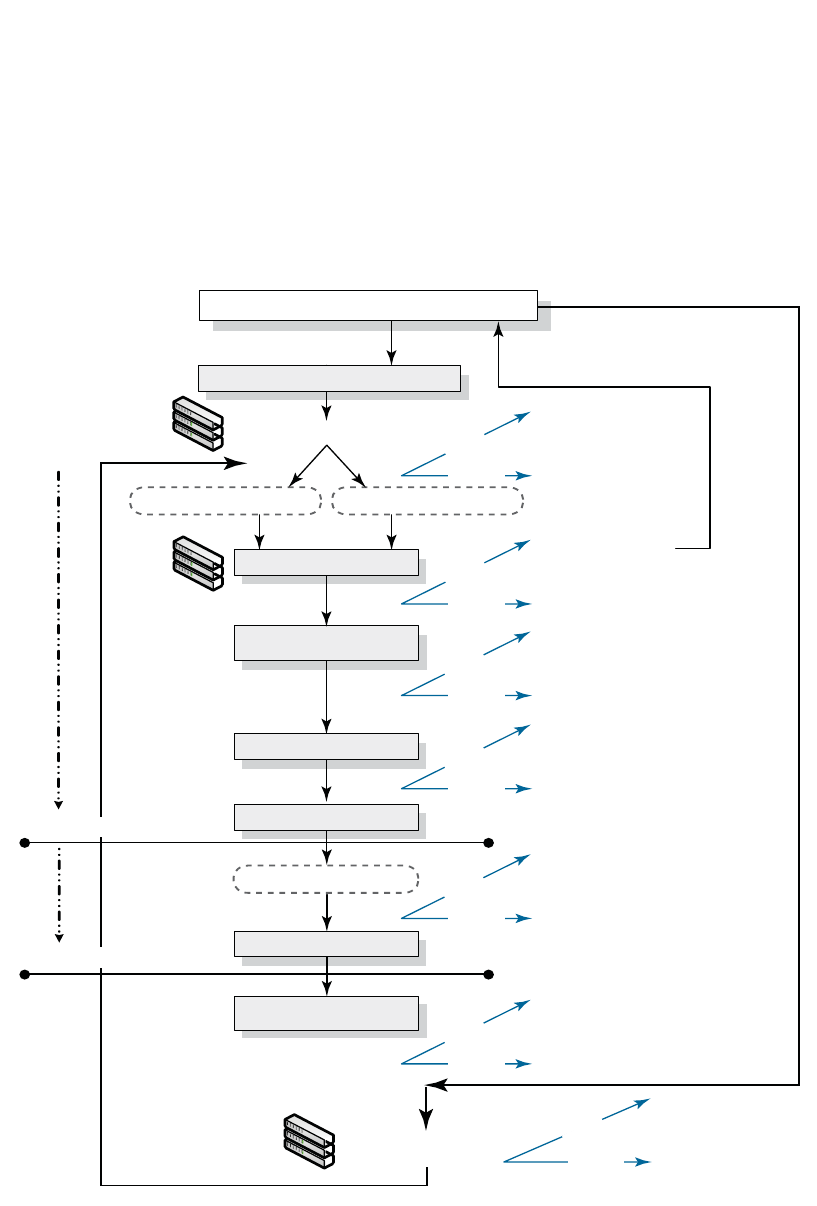
170 PowerConnect B-Series FCX Configuration Guide
53-1002266-01
PowerConnect B-Series FCX hitless stacking
5
Figure 15 illustrates hitless stacking support during stack formation. Operational stages 1 and 2
are also shown in this illustration.
FIGURE 15 Hitless stacking support during stack formation
Standby becomes Active immediately, no reboot
occurs, hot swap take place. The Standby is
assigned after 30 seconds. Traffic loss is expected.
Not allowed
Switchover
Failover
Standby becomes Active immediately (no delay),
no reboot occurs, configuration parsing and
hot swap take place. The Standby is assigned
after 30 seconds. Traffic loss is expected.
Not allowed
Switchover
Failover
Standby becomes Active immediately, no reboot
occurs. The Standby is assigned after 30 seconds.
Traffic loss is expected.
Not allowed
Switchover
Standby becomes Active (no delay), no reboot.
Standby is assigned after 30 seconds.
No traffic loss is expected.
Allowed. No traffic loss is expected.
Switchover
Failover
The boot up Standby waits
for 40 seconds then reboots
all units including itself.
Not allowed
Switchover
Failover
All units (including Standby)
are rebooted
Not allowed
Switchover
Failover
Member 2 and 3 become “orphans”
Not allowed
Switchover
Failover
The stack is fully operational and ready
for rapid failover and switchover
After the stack boots up, Member 2
is a “boot up Standby”. There is
no Standby assigned yet.
Protocol ready
70 sec. for protocol learning
Wait for 30 sec. (if the Active is up > 2 min.) Wait for 60 sec. (if the Active is up < 2 min.)
Other units are hot swapped
Existing stack (after “write mem” and “reload”)
Configuration parsed on Standby
Configuration synchronized (running
config is copied from the Active)
Standby assigned by the Active
A stack is created using secure setup or “stack enable”
New Stack
Failover
1
Active 1
Member 2
Member 3
1
Active 1
Member 2
Member 3
The stack is formed and fully operational after
all units except the Active controller is rebooted
1
Active 1
Member 2
Member 3
FCX stack formation
End of Stage 1
End of Stage 2
Device stack formation
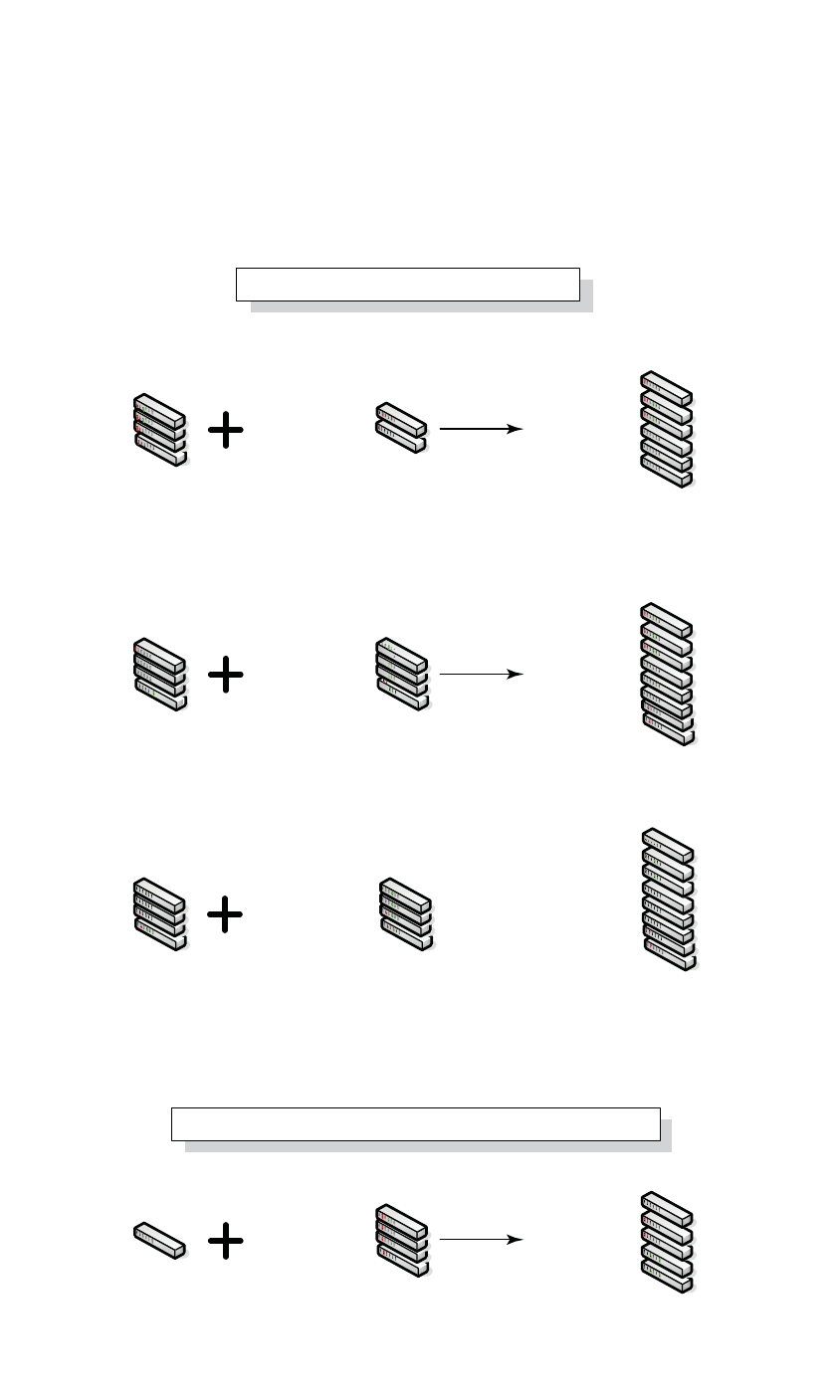
PowerConnect B-Series FCX Configuration Guide 171
53-1002266-01
PowerConnect B-Series FCX hitless stacking 5
Figure 16 illustrates hitless stacking support during a stack merge.
FIGURE 16 Hitless stacking support during a stack merge
Active 1 (pri=30)
Standby 2 (pri=20)
Member 3 (pri=10)
Member 4 (pri=0)
Member 1 (pri=30)
Member 2 (pri=20)
Member 3 (pri=10)
Member 4 (pri=0)
Active 5 (pri=100)
Standby 6 (pri=50)
Active 1 (pri=100)
Standby 2 (pri=50)
Member 3 (pri=10)
Member 4 (pri=0)
Member 5 (pri=0)
Member 6 (pri=0)
Active 1 (pri=100)
Standby 2 (pri=50)
Member 3 (pri=0)
Member 4 (pri=0)
Member 5 (pri=30)
Member 6 (pri=20)
Member 7 (pri=10)
Member 8 (pri=0)
Active 1 (pri=100)
Member 2 (pri=20)
Member 3 (pri=10)
Member 4 (pri=0)
Standby 5 (pri=100)
Member 6 (pri=50)
Member 7 (pri=0)
Member 8 (pri=0)
Active 1 (pri=100)
Standby 2 (pri=50)
Active 1 (pri=30)
Standby 2 (pri=20)
Member 3 (pri=10)
Member 4 (pri=0)
Active 1 (pri=100)
Standby 2 (pri=50)
Member 3 (pri=0)
Member 4 (pri=0)
Active 1 (pri=100)
Standby 2 (pri=50)
Member 3 (pri=0)
Member 4 (pri=0)
Active 2 (pri=50)
Standby 3 (pri=10)
Member 4 (pri=0)
Member 5 (pri=0)
Active 1 (pri=100)
Active 1 (pri=100)
Standby 2 (pri=20)
Member 3 (pri=10)
Member 4 (pri=0)
1
Stack 1 Stack 2
Stack 1
Stack 1/MAC A Stack 2/MAC B
Stack 2
1
When hitless failover is enabled, the stack with
more units will win. Stack 2 will reload and merge
with Stack 1. Stack 2 will retain its IDs.
If the number of units in both stacks are the same,
the stack with the highest active priority will win.
Stack 1 will reload and merge with Stack 2.
If the number of units in both stacks is the same
and both Active controllers have the same priority,
the stack with the longer system up time (by 30
seconds or more) will win. Otherwise, the lowest MAC
address will win. Stack 2 will reload and merge with
Stack 1.
1
1
1
1
1
1
11
11
When hitless failover is enabled, the stack with
more units will win. Active 1 will reboot and merge
with the stack.
Device stack merge when the old Active controller comes back up
Device stack merge
1
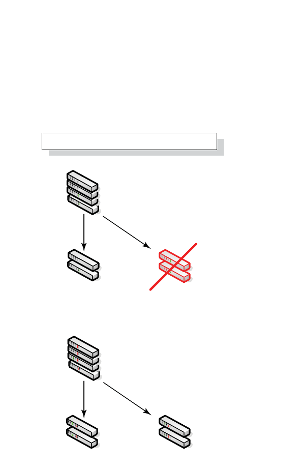
172 PowerConnect B-Series FCX Configuration Guide
53-1002266-01
PowerConnect B-Series FCX hitless stacking
5
Figure 17 illustrates hitless stacking support in a stack split.
FIGURE 17 Hitless stacking support in a stack split
1
1
The stack splits into one operational stack
and two “orphan” units.
1
The stack splits into two operational stacks.
Active 1 (pri=30)
Standby 2 (pri=20)
Member 3 (pri=10)
Member 4 (pri=0)
Active 1 (pri=30)
Member 2 (pri=10)
Standby 3 (pri=20)
Member 4 (pri=0)
Active 1 (pri=30)
Standby 2 (pri=10)
Active 3 (pri=20)
Standby 2 (pri=0)
Active 1 (pri=30)
Standby 2 (pri=20)
Member 3 (pri=10)
Member 4 (pri=0)
stack split

PowerConnect B-Series FCX Configuration Guide 173
53-1002266-01
PowerConnect B-Series FCX hitless stacking 5
Hitless stacking default behavior
Hitless stacking is disabled by default. When disabled, the following limitations are in effect:
•If a failover occurs, every unit in the stack will reload
•Manual switchover is not allowed. If the CLI command stack switch-over is entered, the
following message will appear on the console:
Switch-over is not allowed. Reason: hitless-failover not configured.
•Internal switchover resulting from a priority change is blocked until the entire stack is reloaded
or hitless stacking is enabled. A priority change will trigger an election, but the newly-elected
winner will not immediately assume its role. For more information, refer to “Displaying pending
device roles” on page 174.
•If there is no Active Controller after a reload, the bootup standby will assume the active role
after reloading every unit in the stack, including itself.
•During a stack merge, the Active Controller with the highest priority will win the election and
reload every unit of the losing stack.
NOTE
Synchronization between the Active Controller, Standby Controller, and stack members will occur
whether or not hitless stacking is enabled.
When hitless stacking is enabled, the following behavior takes effect immediately:
•If a failover occurs, the stack will not reload.
•Manual switchover (CLI command stack switch-over) is allowed.
•If a priority change occurred while hitless stacking was disabled, and the configured priority
value requires a switchover, the system will start a 60-second timer before performing a
switchover. After the switchover, the highest priority standby will become the Active Controller.
•If there is no Active Controller after a reload, the bootup standby will assume the active role in
approximately 60 seconds without a reload.
•During a stack merge, the Active Controller with the larger number of units will win the election
and reload every unit of the losing stack. If two stacks have the same number of units, then the
priority, system up time, ID, then MAC address is compared. If two stacks have the same
number of units and the same priority, then the stack with the longest system up-time (by 30
seconds or more) will win the election. Otherwise, the smallest ID is compared next, followed
by MAC address. If the losing Active Controller has the highest priority, it will become a standby
after reloading and relearning the protocols. Finally, it will become the Active Controller after an
internal switchover.
NOTE
If the Active Controllers of two merging stacks have different hitless stacking settings (i.e.,
hitless stacking is enabled in one stack and disabled in the other), the default behavior (hitless
stacking disabled) will be used in the stack merge. After the merge, the winner will retain its
hitless stacking setting and runtime configuration for the merged stack.
You can use the show stack command to view whether or not hitless stacking is enabled. Refer to
“Displaying hitless stacking status” on page 174.

174 PowerConnect B-Series FCX Configuration Guide
53-1002266-01
PowerConnect B-Series FCX hitless stacking
5
Enabling hitless stacking
Hitless stacking is disabled by default. To enable it, enable hitless failover as described in
“Enabling hitless failover” on page 175.
Displaying hitless stacking status
You can use the show stack command to view whether or not hitless stacking is enabled. The
following example shows that hitless stacking is disabled.
Syntax: show stack
Displaying pending device roles
When hitless stacking is disabled, a priority change will trigger an election, but the newly-elected
winner will not assume its role until the entire stack is reloaded or hitless stacking is enabled.
You can use the show stack command to view pending device roles. The “Role” column displays the
current role for each unit. The “Comment” column displays the role that will take effect after a
reload or when hitless stacking is enabled.
PowerConnect#show stack
alone: standalone, D: dynamic config, S: static config
ID Type Role Mac Address Pri State Comment
2 S FCX648S member 0000.0000.0000 0 reserve
3 S FCX624 member 0024.3876.2640 0 remote Ready
5 S FCX624 standby 00e0.5200.0400 100 remote Ready
8 S FCX648 active 0024.3877.7980 128 local Ready
active standby
+---+ +---+ +---+
-2/1| 8 |2/2--2/2| 3 |2/1--2/1| 5 |2/2-
| +---+ +---+ +---+ |
| |
|-------------------------------------|
Standby u5 - No hitless failover. Reason: hitless-failover not configured
PowerConnect#show stack
alone: standalone, D: dynamic config, S: static config
ID Type Role Mac Address Pri State Comment
2 S FCX648S member 0000.0000.0000 0 reserve
3 S FCX624 standby 0024.3876.2640 200 remote Ready, active if reloaded
5 S FCX624 member 00e0.5200.0400 128 remote Ready, standby if reloaded
8 S FCX648 active 0024.3877.7980 128 local Ready, member if reloaded
active standby
+---+ +---+ +---+
-2/1| 8 |2/2--2/2| 3 |2/1--2/1| 5 |2/2-
| +---+ +---+ +---+ |
| |
|-------------------------------------|
Standby u3 - No hitless failover. Reason: hitless-failover not configured

PowerConnect B-Series FCX Configuration Guide 175
53-1002266-01
PowerConnect B-Series FCX hitless stacking 5
Syntax: show stack
Hitless stacking failover
Hitless stacking failover provides automatic failover from the Active Controller to the Standby
Controller without resetting any of the units in the stack and with sub-second or no packet loss to
hitless stacking-supported services and protocols.
For a description of the events that occur during a hitless failover, refer to “What happens during a
hitless stacking switchover or failover” on page 166.
For a description this feature’s impact to major system functions, refer to Table 37 on page 164.
For an example of hitless failover operation, refer to “Hitless stacking failover example” on
page 176.
For feature limitations and configuration notes, refer to “Configuration notes and feature
limitations” on page 165.
Enabling hitless failover
To enable hitless failover, enter the following command at the Global CONFIG level of the CLI:
PowerConnect(config)#hitless-failover enable
The command takes effect immediately. Hitless switchover is allowed, and in the event of a failover,
the standby controller will take over the active role without reloading the stack.
Syntax: [no] hitless-failover enable
Use the no form of the command to disable hitless stacking once it has been enabled.
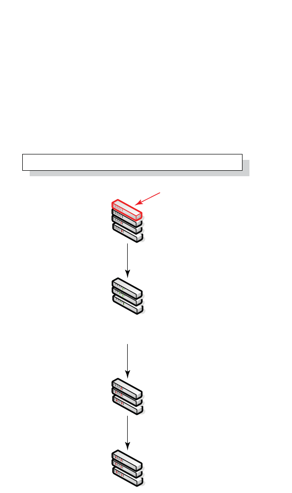
176 PowerConnect B-Series FCX Configuration Guide
53-1002266-01
PowerConnect B-Series FCX hitless stacking
5
Hitless stacking failover example
Figure 18 illustrates hitless stacking failover operation when the Active Controller fails.
FIGURE 18 Hitless stacking failover when the Active Controller fails
Hitless stacking switchover
Hitless stacking switchover is a manually-controlled (CLI-driven) or automatic switchover of the
Active and Standby Controllers without reloading the stack and without any packet loss to the
services and protocols that are supported by hitless stacking. A switchover is activated by the CLI
command stack switch-over. A switchover might also be activated by the CLI command priority,
depending on the configured priority value.
By default, hitless switchover is not allowed. The default behavior is described in “Hitless stacking
default behavior” on page 173.
Hitless switchover can be used by a system administrator, for example, to perform maintenance on
a controller that has been functioning as the Active Controller.
For a description of the events that occur during a hitless stacking switchover, refer to “What
happens during a hitless stacking switchover or failover” on page 166.
1
The Active controller fails
after the stack reloads
The bootup Standby will become the Active controller
in 50 seconds. The stack will not reload.
1
1
1
.
50 sec.
30-60 sec.
The stack comes back without the Active controller
Active 1
Member 2 = bootup Standby
Member 3
Member 4
Active 2
Member 3
Member 4
Active 2
Standby 3
Member 4
Member 2 = bootup Standby
Member 3
Member 4

PowerConnect B-Series FCX Configuration Guide 177
53-1002266-01
PowerConnect B-Series FCX hitless stacking 5
For a description this feature’s impact to major system functions, refer to Table 37 on page 164.
For examples of hitless stacking switchover operation, refer to “Hitless stacking switchover
examples” on page 178.
Executing a hitless stacking switchover
The following must be in effect before a hitless switchover (switch over to the Standby Controller) is
allowed:
•Hitless stacking is enabled
•The stack has a Standby Controller
•The Standby Controller has learned the protocols
•The Standby Controller has the same priority as the Active Controller
•More than 120 seconds have passed since the previous switchover or failover
You can use the show stack command to view whether or not these properties are in effect. For
more information, see “Displaying information about hitless stacking” on page 183.
To perform a switchover, enter the following command:
PowerConnect# stack switch-over
Standby unit 8 will become Active Controller, and unit 1 will become standby
Are you sure? (enter 'y' or 'n'): y
Unit 1 is no longer the Active Controller
Syntax: stack switch-over
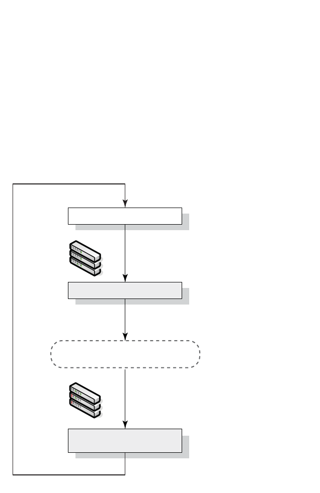
178 PowerConnect B-Series FCX Configuration Guide
53-1002266-01
PowerConnect B-Series FCX hitless stacking
5
Hitless stacking switchover examples
This section illustrates hitless stacking failover and switchover operation during a CLI-driven
switchover or priority change.
Figure 19 illustrates a hitless stacking switchover triggered by the stack switch-over command.
FIGURE 19 Manual switchover
1
1
Standby 1
Active 2
Member 3
Active 1
Standby 2
Member 3
No waiting period
The Active and Standby priorities must
match or the command is rejected
The Active and Standby controllers switch roles
immediately (no waiting period). No traffic loss
is expected.
Device stack manual
switchover
Execute “stack
switch-over”
Next switchover allowed in
120 seconds
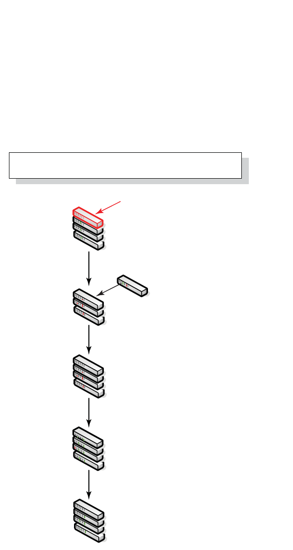
PowerConnect B-Series FCX Configuration Guide 179
53-1002266-01
PowerConnect B-Series FCX hitless stacking 5
Figure 20 illustrates a hitless stacking switchover when the Active Controller goes down then
comes back up. The stack in this example has user-configured priorities.
FIGURE 20 Hitless stacking switchover when the Active Controller comes back up
1
1
Active (Unit 1 with priority 200)
comes back up
1
The Active controller fails
1
1
Unit 1 (priority 200) reloads because
it loses the election. After the reload,
It joins the stack as a member.
The Active controller assigns Unit 1
(priority 200) as the Standby controller.
Stages 1 and 2 are complete.
A switchover occurs. Unit 1
becomes the Active controller.
30 sec.
70 sec.
.
Active controller comes back (in a
stack with user-assigned priorities)
Active 1 (pri=200)
Standby 2 (pri=100)
Member 3 (pri=0)
Member 4 (pri=0)
Active 2 (pri=100)
Standby 3 (pri=0)
Member 4 (pri=0)
Member 1 (pri=200)
Active 2 (pri=100)
Standby 3 (pri=0)
Member 4 (pri=0)
Standby 1 (pri=200)
Active 2 (pri=100)
Member 3 (pri=0)
Member 4 (pri=0)
Active 1 (pri=200)
Standby 2 (pri=100)
Member 3 (pri=0)
Member 4 (pri=0)
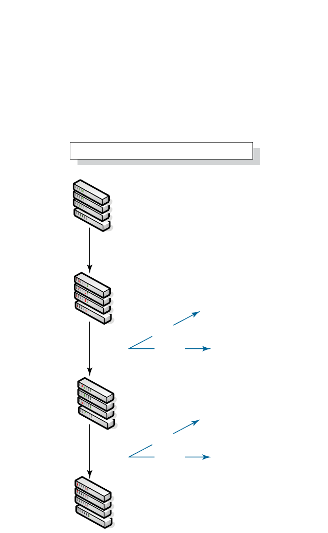
180 PowerConnect B-Series FCX Configuration Guide
53-1002266-01
PowerConnect B-Series FCX hitless stacking
5
Figure 21 illustrates a hitless stacking switchover after the network administrator increases the
priority value of the Standby Controller.
FIGURE 21 Scenario 1 – Hitless stacking switchover after a priority change
1
1
1
1
120 sec.
Standby 2 becomes the Active controller
without a reload.
Not allowed because priorities do
not match.
Priority 200 assigned to Unit 2 (Standby)
The priority change triggers re-election
of the Active controller
The Standby controller is re-assigned
and a switchover occurs.
Stages 1 and 2 are bypassed.
Standby 1 (pri=100)
Active 2 (pri=200)
Member 3 (pri=0)
Member 4 (pri=0)
Active 1 (pri=100)
Standby 2 (pri=200)
Member 3 (pri=0)
Member 4 (pri=0)
Active 1 (pri=100)
Standby 2 (pri=200)
Member 3 (pri=0)
Member 4 (pri=0)
Active 1 (pri=100)
Standby 2 (pri=0)
Member 3 (pri=0)
Member 4 (pri=0)
60 sec.
Switchover
Failover
Standby 2 becomes the Active controller
without a reload.
Not allowed because priorities do
not match.
Switchover
Failover
FCX stack formation
Device stack priority change - Scenario 1
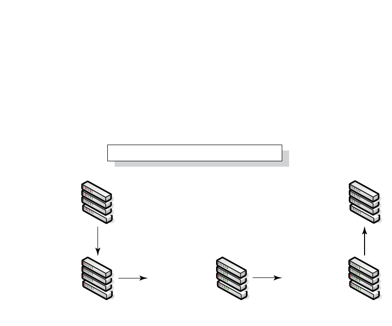
PowerConnect B-Series FCX Configuration Guide 181
53-1002266-01
PowerConnect B-Series FCX hitless stacking 5
Figure 22 illustrates a hitless stacking switchover after the network administrator increases the
priority value of one of the stack members.
FIGURE 22 Scenario 2 – Hitless stacking switchover after a priority change
1
11
1
Priority 200 assigned
to Unit 3
A switchover occurs.
Stages 1 and 2
are complete.
The Standby controller
is re-assigned
The priority change triggers
re-election of the Active controller
1
FCX stack formation
Device stack priority change - Scenario 2
Active 1 (pri=100)
Standby 2 (pri=0)
Member 3 (pri=0)
Member 4 (pri=0)
Active 1 (pri=100)
Standby 2 (pri=0)
Member 3 (pri=200)
Member 4 (pri=0)
Active 1 (pri=100)
Standby 2 (pri=0)
Member 3 (pri=200)
Member 4 (pri=0)
Active 1 (pri=100)
Member 2 (pri=0)
Standby 3 (pri=200)
Member 4 (pri=0)
Standby 1 (pri=100)
Member 2 (pri=0)
Active 3 (pri=200)
Member 4 (pri=0)
120 sec. 60 sec.
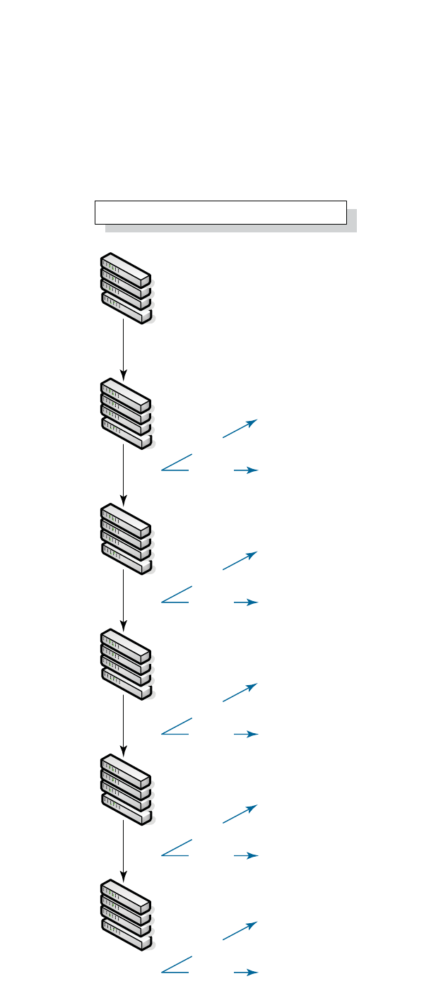
182 PowerConnect B-Series FCX Configuration Guide
53-1002266-01
PowerConnect B-Series FCX hitless stacking
5
Figure 23 illustrates a hitless stacking switchover after the network administrator increases the
priority value for two of the stack members.
FIGURE 23 Scenario 3 – Hitless stacking switchover after a priority change
Not allowed because priorities do not match
Switchover
Failover
Standby 2 becomes the Active controller
without a reload
Not allowed because priorities do not match
Switchover
Failover
Standby 2 becomes the Active controller
without a reload
Not allowed because priorities do not match
Switchover
Failover
Standby 4 becomes the Active controller
without a reload
Not allowed because priorities do not match
Switchover
Failover
Standby 1 becomes the Active controller
without a reload
Not allowed because priorities do not match
Switchover
Failover
Standby 3 becomes the Active controller
without a reload
Priority 150 assigned to Unit 3 (Member 3)
Priority 200 assigned to Unit 4 (Member 4)
1
Active 1 (pri=100)
Standby 2 (pri=0)
Member 3 (pri=0)
Member 4 (pri=0)
1
Active 1 (pri=100)
Standby 2 (pri=0)
Member 3 (pri=150)
Member 4 (pri=200)
1
Active 1 (pri=100)
Standby 2 (pri=0)
Member 3 (pri=150)
Member 4 (pri=200)
1
Active 1 (pri=100)
Member 2 (pri=0)
Member 3 (pri=150)
Standby 4 (pri=200)
1
Standby 1 (pri=100)
Member 2 (pri=0)
Member 3 (pri=150)
Active 4 (pri=200)
1
Member 1 (pri=100)
Member 2 (pri=0)
Standby 3 (pri=150)
Active 4 (pri=200)
The priority change triggers re-election
of the Active controller
Standby re-assigned
Switchover occurs
Standby re-assigned
120 sec.
30 sec.
30 sec.
Stage 1&2. Switchover
FCX stack formation
Device stack priority change - Scenario 3
60 sec.

PowerConnect B-Series FCX Configuration Guide 183
53-1002266-01
PowerConnect B-Series FCX hitless stacking 5
Displaying information about hitless stacking
Use the show stack command to view information pertinent to a hitless stacking switchover or
failover. The command output illustrates the Active and Standby Controllers, as well as the
readiness of the Standby Controller to take over the role of Active Controller, if needed.
NOTE
The text in bold highlights the information added for hitless stacking failover and switchover. For a
description of the fields in this output, see “Field descriptions for the show stack command” on
page 137.
Syslog messages for hitless stacking failover and switchover
Syslog messages are generated for the following events:
•Switchover
•Failover
•Standby Controller assignment
Table 38 lists the supported Syslog messages.
TABLE 38 Syslog messages
Message level Message Explanation
Informational Stack: Stack unit <unit_number> has been
assigned as STANDBY unit of the stack
system
Indicates that the unit has been assigned
as the Standby Controller.
Informational Stack: Stack is operational due to
SWITCH-OVER
Indicates that a switchover has occurred.
Informational Stack: Stack is operational due to FAIL-OVER Indicates that a failover has occurred.
PowerConnect#show stack
alone: standalone, D: dynamic config, S: static config
ID Type Role Mac Address Pri State Comment
1 S FCX624S active 00e0.5200.2900 128 local Ready
2 S FCX624S standby 00e0.5200.0100 128 remote Ready
3 S FCX624S member 0000.0000.0000 128 reserve
active standby
+---+ +---+ +---+
-1/3| 1 |1/5--1/5| 2 |1/3--1/5| 3 |1/3-
| +---+ +---+ +---+ |
| |
|-------------------------------------|
Standby unit 2: protocols ready, can failover or manually switch over
Current stack management MAC is 0000.5200.1100

184 PowerConnect B-Series FCX Configuration Guide
53-1002266-01
PowerConnect B-Series FCX hitless stacking
5
To view the System log or the traps logged on an SNMP trap receiver, enter the show log command
at any level of the CLI. The following example output shows what the log might look like after a
switchover or assignment of the Standby Controller.
The following example output shows what the log might look like after a failover of the Active
Controller.
Displaying hitless stacking diagnostic information
Use the debug stacking sync_rel_msg command to display diagnostic information for hitless
stacking switchover or failover. Example display outputs are shown below.
PowerConnect# show log
Syslog logging: enabled (0 messages dropped, 1 flushes, 0 overruns)
Buffer logging: level ACDMEINW, 8 messages logged
level code: A=alert C=critical D=debugging M=emergency E=error
I=informational N=notification W=warningDynamic Log Buffer (50 lines):
0d00h05m34s:I:System: Interface ethernet mgmt1, state up
0d00h05m33s:I:Stack: Stack unit 8 has been assigned as STANDBY unit of the stack system
0d00h05m33s:I:Stack: Stack is operational due to SWITCH-OVER
0d00h05m32s:I:Stack: Stack unit 1 has been elected as ACTIVE unit of the stack system
0d00h05m29s:W:System:Stack unit 2 Fan speed changed automatically to 2
0d00h05m25s:W:System:Stack unit 5 Fan speed changed automatically to 2
0d00h05m00s:I:System: Interface ethernet mgmt1, state down
0d00h05m00s:I:Security: Telnet server enabled by from session
PowerConnect# show log
Syslog logging: enabled (0 messages dropped, 0 flushes, 0 overruns)
Buffer logging: level ACDMEINW, 12 messages logged
level code: A=alert C=critical D=debugging M=emergency E=error
I=informational N=notification W=warning
Dynamic Log Buffer (50 lines):
0d00h04m41s:I:Stack: Stack unit 3 has been assigned as STANDBY unit of the stack system
0d00h04m12s:I:System: Interface ethernet mgmt1, state up
0d00h04m10s:I:System: Interface ethernet mgmt1, state down
0d00h04m10s:I:System: Interface ethernet mgmt1, state up
0d00h04m09s:I:STP: VLAN 1 Bridge is RootBridge: 800000e052010000 (MgmtPriChg)
0d00h04m09s:I:System: Management MAC address changed to 00e0.5201.0000
0d00h04m09s:I:Stack: Stack is operational due to FAIL-OVER
0d00h04m08s:I:Stack: Stack unit 1 has been elected as ACTIVE unit of the stack system
0d00h04m08s:I:STP: VLAN 1 Port 8/1/1 STP State -> DISABLED (PortDown)
0d00h04m08s:I:STP: VLAN 1 Port 8/1/1 STP State -> FORWARDING (PortDown)
0d00h04m08s:I:System: Interface ethernet 1/2/2, state down
0d00h04m06s:I:System: Interface ethernet 8/2/2, state down
PowerConnect# debug stacking sync_rel_msg 1
stk_sync_rel_msg_create_ipc_session:session created for stack_id=1
stk_sync_rel_msg_send():sent msg_type = 16, len 1203
stk_sync_rel_msg_free:msg freed
start runing config sync
stk_sync_rel_msg_send():sent msg_type = 3, len 1024
stk_sync_rel_msg_free:msg freed

PowerConnect B-Series FCX Configuration Guide 185
53-1002266-01
PowerConnect B-Series FCX hitless stacking 5
Syntax: debug stacking sync_rel_msg <num>
PowerConnect# debug stacking sync_rel_msg 4
stk_sync_trunk_mapping:sending trunk mapping...
start running config sync
sync_cdb:send cdb:sess = 0, pBuf = 2132f068
sync_cdb:send cdb:sess = 0, pBuf = 2132f57c
...
stk_sync_cdb:finished cdb sync
PowerConnect# debug stacking sync_rel_msg 8
Hitless sync: TRUNK INFO size (1282)
*************************************
Trunk ID: 10 (1 based), (Hw Trunk ID: 1),
g_sw_sys.trunk_config.trunk_entry[#9]
:number_of_ports = 2; creator = 0
g_sw_sys.trunk_config.trunk_entry[#9] MEMBER PORTS
port_list[0]=#009
port_list[1]=#010

186 PowerConnect B-Series FCX Configuration Guide
53-1002266-01
PowerConnect B-Series FCX hitless stacking
5

PowerConnect B-Series FCX Configuration Guide 187
53-1002266-01
PowerConnect B-Series FCX hitless stacking 5

188 PowerConnect B-Series FCX Configuration Guide
53-1002266-01
PowerConnect B-Series FCX hitless stacking
5

PowerConnect B-Series FCX Configuration Guide 189
53-1002266-01
Chapter
6
Monitoring Hardware Components
Table 39 lists the individual Dell PowerConnect switches and the hardware monitoring features
they support.
The procedures in this chapter describe how to configure the software to monitor hardware
components.
Virtual cable testing
PowerConnect devices support Virtual Cable Test (VCT) technology. VCT technology enables the
diagnosis of a conductor (wire or cable) by sending a pulsed signal into the conductor, then
examining the reflection of that pulse. This method of cable analysis is referred to as Time Domain
Reflectometry (TDR). By examining the reflection, the Dell PowerConnect device can detect and
report cable statistics such as local and remote link pair, cable length, and link status.
Configuration notes
•This feature is supported on copper ports only. It is not supported on fiber ports.
•The port to which the cable is connected must be enabled when you issue the command to
diagnose the cable. If the port is disabled, the command is rejected.
•If the port is operating at 100 Mbps half-duplex, the TDR test on one pair will fail.
•If the remote pair is set to forced 100 Mbps, any change in MDI/MDIX may cause the device to
interpret the Multilevel Threshold-3 (MLT-3) as a reflected pulse, in which case, the device will
report a faulty condition. In this scenario, it is recommended that you run the TDR test a few
times for accurate results.
Command syntax
To diagnose a cable using TDR, enter commands such as the following at the Privileged EXEC level
of the CLI.
PowerConnect#phy cable-diag tdr 1
The above command diagnoses the cable attached to port 1.
When you issue the phy-cable-diag command, the command brings the port down for a second or
two, then immediately brings the port back up.
TABLE 39 Supported hardware monitoring features
Feature PowerConnect B-Series FCX
Virtual cable testing (VCT) Yes
Digital optical monitoring Yes
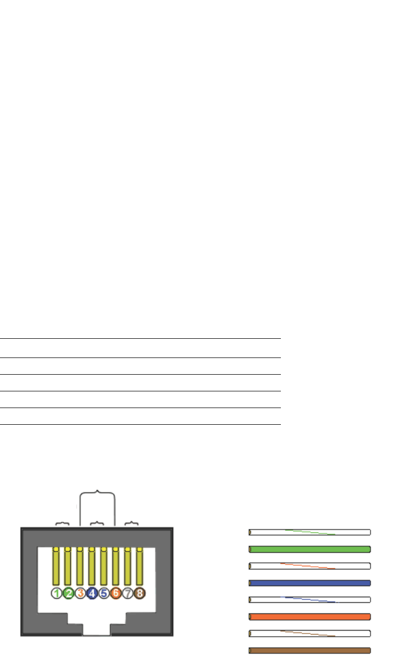
190 PowerConnect B-Series FCX Configuration Guide
53-1002266-01
Virtual cable testing
6
Syntax: phy cable-diag tdr <port>
Specify the <port> variable in the following formats:
•PowerConnect B-Series FCX stackable switches – <stack-unit/slotnum/portnum>
Viewing the results of the cable analysis
To display the results of the cable analysis, enter a command such as the following at the Privileged
EXEC level of the CLI.
PowerConnect>show cable-diag tdr 1
Port Speed Local pair Pair Length Remote pair Pair status
--------- ----- ---------- ----------- ----------- -----------
01 1000M Pair A <50M Pair B Terminated
Pair B <50M Pair A Terminated
Pair C <50M Pair D Terminated
Pair D <50M Pair C Terminated
In the above output, Local pair indicates the assignment of wire pairs from left to right, where Pair
A is the left-most pair. Table 40 shows the Local pair mapping to the T568A pin/pair and color
assignment from the TIA/EIA-568-B standard.
Figure 24 illustrates the T568A pin/pair assignment.
FIGURE 24 T568A pin/pair assignment
Syntax: show cable-diag tdr <port>
TABLE 40 Local pair definition
Local pair T568A pair and color assignment
Pair A Pair 3 (green)
Pair B Pair 2 (orange)
Pair C Pair 1 (blue)
Pair D Pair 4 (brown)
RJ-45 JACK
T568A STANDARD
Pair 3
Green
Pair 1
Blue
Pair 4
Brown
Pair 2
Orange
PC STRAIGHT-THRU HUB
TX+ 1
TX- 2
RX+ 3
4
5
RX- 6
7
8
1 RX+
2 RX-
3 TX+
4
5
6 TX-
7
8

PowerConnect B-Series FCX Configuration Guide 191
53-1002266-01
Supported Fiber Optic Transceivers 6
Specify the <port> variable in the following formats:
•PowerConnect B-Series FCX stackable switches – <stack-unit/slotnum/portnum>
Table 41 defines the fields shown in the command output.
Supported Fiber Optic Transceivers
Table 42 lists the Small Form-Factor Pluggable (SFP) and 10-Gigabit Small Form Factor Pluggable
(XFP) fiber optic transceivers supported on PowerConnect devices.
TABLE 41 Cable statistics
This line... Displays...
Port The port that was tested.
Speed The port current line speed.
Local pair The local link name. Refer to Table 40.
Pair Length The cable length when terminated, or the distance to the point of fault
when the line is not up.
Remote pair The remote link name.
Pair status The status of the link. This field displays one of the following:
•Terminated: The link is up.
•Shorted: A short is detected in the cable.
•Open: An opening is detected in the cable.
•ImpedMis: The impedance is mismatched.
•Failed: The TDR test failed.
TABLE 42 Supported fiber optic transceivers
Label Manufacturing part number Type Dell part number Supports Digital
Optical Monitoring?
E1MG-BXD TRPBG1LXDBVS2FY 1000Base-BXD PYD7H No
E1MG-BXU TRPBG1LXDBBSHFY 1000Base-BXU Y0WGM No
E1MG-LHA-OM WST-S5CCIU-502FD 1000Base-LHA 3TP6Y Yes
E1MG-LX-OM FTLF1318P2BTL-F1
AFCT-5715PZ-FD
1000Base-LX 6JCR4 Yes
E1MG-100FX-OM FTLF1217P2BTL-F1 100Base-FX JCGF5 Yes
E1MG-100FX-IR-OM FTLF1323P1BTR-FD 100Base-FX-IR, 15 km X5FD3 Yes
E1MG-SX-OM FTLF8519P2BNL-F1
AFBR-5715PZ-FD
1000Base-SX XR0H5 Yes
10G-XFP-ER FTRX-1611-3-F1
FIM31110/210
FIM3112/230
10GBase-ER XFP, 40 km V0396 Yes
10G-XFP-LR FTLX1412D3BCL-F1
AFCT 721XPDZ-FD1
JXPR01LG081FY
10GBase-LR XFP, 10 km 98CPC Yes

192 PowerConnect B-Series FCX Configuration Guide
53-1002266-01
Digital optical monitoring
6
Digital optical monitoring
You can configure your Brocade device to monitor optical transceivers in the system, either globally
or by specified ports. When this feature is enabled, the system will monitor the temperature and
signal power levels for the optical transceivers in the specified ports. Console messages and
Syslog messages are sent when optical operating conditions fall below or rise above the XFP or SFP
manufacturer recommended thresholds.
Table 42 on page 191 specifies which Dell-qualified media types support digital optical monitoring.
Configuration limitations
A Dell chassis device can monitor a maximum of 24 SFPs and 12 XFPs.
Enabling digital optical monitoring
To enable optical monitoring on all Dell-qualified optics installed in the device, use the following
command.
PowerConnect(config)#optical-monitor
To enable optical monitoring on a specific port, use the following command.
PowerConnect(config)#interface ethernet 1/1
PowerConnect(config-if-e10000-1/1)#optical-monitor
To enable optical monitoring on a range of ports, use the following command.
PowerConnect(config)#interface ethernet 1/1 to 1/2
PowerConnect(config-mif-e10000-1/1-1/2)#optical-monitor
Syntax: [no] optical-monitor
10G-XFP-SR FTLX8511D3-F1
AFBR-720XPDZ-FD1
PLRXXL-SC-S43-59
TRF2001EN-GA250
10GBase-SR XFP YY0VX Yes
10G-SFPP-SR FTLX8571D3BNL-B2
AFBR-703ASDZ-BR2
10GE SR SFP+ DR7C1 Yes
10G-SFPP-LR FTLX1471D3BNL-B2
AFCT-701ASDZ-BR2
10GE LR SFP+ 6D0R3 Yes
XDL-10G-SFPP-TWX-0
101
579890006
2GSPWWA-BEB-EN
DIRECT ATTACHED SFPP
COPPER,1M,1-PACK
60HMX No
XDL-10G-SFPP-TWX-0
301
579890004
2GSPWWB-BFB-EN
DIRECT ATTACHED SFPP
COPPER,3M,1-PACK
GPPHR No
XDL-10G-SFPP-TWX-0
501
579890001
2GSPWWC-BGB-EN
DIRECT ATTACHED SFPP
COPPER,5M,1-PACK
D93W5 No
TABLE 42 Supported fiber optic transceivers (Continued)
Label Manufacturing part number Type Dell part number Supports Digital
Optical Monitoring?

PowerConnect B-Series FCX Configuration Guide 193
53-1002266-01
Digital optical monitoring 6
Use the no form of the command to disable digital optical monitoring.
Setting the alarm interval
You can optionally change the interval between which alarms and warning messages are sent. The
default interval is three minutes. To change the interval, use the following command.
PowerConnect(config)#interface ethernet 1/1 to 1/2
PowerConnect(config-mif-e10000-1/1-1/2)#optical-monitor 10
Syntax: [no] optical-monitor [<alarm-interval>]
For <alarm-interval>, enter a value between 1 and 65535. Enter 0 to disable alarms and warning
messages.
NOTE
The commands no optical-monitor and optical-monitor 0 perform the same function. That is, they
both disable digital optical monitoring.
Displaying information about installed media
Use the show media, show media slot, and show media ethernet commands to obtain information
about the media devices installed per device, per slot, and per port. The results displayed from
these commands provide the Type, Vendor, Part number, Version and Serial number of the SFP or
XFP optical device installed in the port. 1G M-C indicates 1b Gbps copper media. If no SFP or XFP
device is installed in a port, the “Type” field will display “EMPTY”.
Use the show media command to obtain information about the media devices installed in a device.
PowerConnect#show media
Port 1: Type : 1G M-SX2(SFP)
Vendor: Brocade Communications, Inc. Version: 0000
Part# : TRPAG1XRPBSS-FY Serial#: 0635000468
Port 2: Type : EMPTY
Port 3: Type : EMPTY
Port 4: Type : 100M M-FX-SR(SFP)
Vendor: Brocade Communications, Inc. Version: A
Part# : FTLF1217P2BTL-F1 Serial#: UCQ003A
Port 5: Type : 1G M-C
Port 6: Type : 1G M-C
Port 7: Type : 1G M-C
Port 8: Type : 1G M-C
Port 9: Type : 1G M-C
Port 10: Type : 1G M-C
Port 11: Type : 1G M-C
Port 12: Type : 1G M-C
Port 13: Type : 1G M-C
Port 14: Type : 1G M-C
Port 15: Type : 1G M-C
Port 16: Type : 1G M-C
Port 17: Type : 1G M-C
Port 18: Type : 1G M-C
Port 19: Type : 1G M-C
Port 20: Type : 1G M-C
Port 21: Type : 1G M-C
Port 22: Type : 1G M-C
Port 23: Type : 1G M-C

194 PowerConnect B-Series FCX Configuration Guide
53-1002266-01
Digital optical monitoring
6
Port 24: Type : 1G M-C
Port 25: Type : 10G XG-SR(XFP)
Vendor: Brocade Communications Inc. Version: 02
Part# : JXPR01SW05306 Serial#: F617604000A3
Port 26: Type : EMPTY
Use the show media slot command to obtain information about the media device installed in a slot.
PowerConnect#show media slot 1
Port 1/1: Type : 1G M-SX(SFP)
Vendor: Brocade Communications, Inc. Version:
Part# : PL-XPL-VC-S13-19 Serial#: 425HC109
Port 1/2: Type : 1G M-SX(SFP)
Vendor: Brocade Communications, Inc. Version:
Part# : PL-XPL-VC-S13-19 Serial#: 411HC0AH
Port 1/3: Type : EMPTY
Port 1/4: Type : 1G M-SX(SFP)
Vendor: Brocade Communications, Inc. Version: X1
Part# : FTRJ-8519-3 Serial#: H11654K
Port 1/5: Type : EMPTY
Port 1/6: Type : EMPTY
Port 1/7: Type : 100M M-FX-IR(SFP)
Vendor: Brocade Communications, Inc. Version: A
Part# : FTLF1323P1BTR-FD Serial#: UCT000T
Port 1/8: Type : EMPTY
Port 1/9: Type : 100M M-FX-LR(SFP)
Vendor: Brocade Communications, Inc. Version: A
Part# : FTLF1323P1BTL-FD Serial#: UD3085J
Port 1/10: Type : EMPTY
Port 1/11: Type : 100M M-FX-SR(SFP)
Vendor: Brocade Communications, Inc. Version: A
Part# : FTLF1217P2BTL-F1 Serial#: UCQ003J
Port 1/12: Type : EMPTY
Port 1/13: Type : 100M M-FX-IR(SFP)
Vendor: Brocade Communications, Inc. Version: A
Part# : FTLF1323P1BTR-F1 Serial#: PCA2XC5
Use the show media ethernet command to obtain information about the media device installed in a
port.
PowerConnect#show media e 1/17
Port 1/17: Type : 1G M-SX(SFP)
Vendor: Brocade Communications, Inc. Version:
Part# : PL-XPL-VC-S13-19 Serial#: 425HC109
Syntax: show media [slot <slot-num> | ethernet [<slot-num>/]<port-num>]
Viewing optical monitoring information
You can view temperature and power information for qualified XFPs and SFPs installed in a
PowerConnect device.
Use the show optic <port-number> command to view information about an XFP or SFP installed in
a particular port. The following shows example output.
PowerConnect#show optic 13
Port Temperature Tx Power Rx Power Tx Bias Current
+----+-----------+----------+------------+-------------------+
13 33.2968 C -005.4075 dBm -007.4328 dBm 6.306 mA

PowerConnect B-Series FCX Configuration Guide 195
53-1002266-01
Digital optical monitoring 6
Normal Normal Normal Normal
Syntax: show optic <port-number>
NOTE
The show optic function takes advantage of information stored and supplied by the manufacturer of
the XFP or SFP transceiver. This information is an optional feature of the Multi-Source Agreement
standard defining the optical interface. Not all component suppliers have implemented this feature
set. In such cases where the XFP or SFP transceiver does not supply the information, a “Not
Available” message will be displayed for the specific port on which the module is installed.
The following table describes the information displayed by the show optic command.
For Temperature, Tx Power, Rx Power, and Tx Bias Current in the show optic command output,
values are displayed along with one of the following alarm status values: Low-Alarm, Low-Warn,
Normal, High-Warn or High-Alarm. The thresholds that determine these status values are set by the
manufacturer of the optical transceivers. Table 44 describes each of these status values.
TABLE 43 Output from the show optic command
This field... Displays...
Port The Dell port number.
Temperature •The operating temperature, in degrees Celsius, of the optical
transceiver.
•The alarm status, as described in Table 44.
Tx Power •The transmit power signal, in decibels (dB), of the measured power
referenced to one milliwatt (mW).
•The alarm status, as described in Table 44.
Rx Power •The receive power signal, in decibels (dB), of the measured power
referenced to one milliwatt (mW).
•The alarm status, as described in Table 44
Tx Bias Current •The transmit bias power signal, in milliamperes (mA).
•The alarm status, as described in Table 44.
TABLE 44 Alarm status value description
Status value Description
Low-Alarm Monitored level has dropped below the "low-alarm" threshold set by the manufacturer of the
optical transceiver.
Low-Warn Monitored level has dropped below the "low-warn" threshold set by the manufacturer of the
optical transceiver.
Normal Monitored level is within the "normal" range set by the manufacturer of the optical transceiver.
High-Warn Monitored level has climbed above the "high-warn" threshold set by the manufacturer of the
optical transceiver.
High-Alarm Monitored level has climbed above the "high-alarm" threshold set by the manufacturer of the
optical transceiver.

196 PowerConnect B-Series FCX Configuration Guide
53-1002266-01
Digital optical monitoring
6
Viewing optical transceiver thresholds
The thresholds that determine the alarm status values for an optical transceiver are set by the
manufacturer of the XFP or SFP. To view the thresholds for a qualified optical transceiver in a
particular port, use the show optic threshold command as shown below.
Syntax: show optic threshold <port>
Specify the <port> variable in the following formats:
•PowerConnect B-Series FCX stackable switches – <stack-unit/slotnum/portnum>
For Temperature, Supply Voltage, TX Bias, TX Power, and RX Power, values are displayed for each of
the following four alarm and warning settings: High alarm, Low alarm, High warning, and Low
warning. The hexadecimal values are the manufacturer internal calibrations, as defined in the
SFF-8472 standard. The other values indicate at what level (above the high setting or below the
low setting) the system should send a warning message or an alarm. Note that these values are
set by the manufacturer of the optical transceiver, and cannot be configured.
Syslog messages
The system generates Syslog messages for optical transceivers in the following circumstances:
•The temperature, supply voltage, TX Bias, TX power, or TX power value goes above or below the
high or low warning or alarm threshold set by the manufacturer.
•The optical transceiver does not support digital optical monitoring.
•The optical transceiver is not qualified, and therefore not supported by Dell.
For details about the above Syslog messages, refer to Chapter 41, “Using Syslog”.
PowerConnect>show optic threshold 2/2
Port 2/2 sfp monitor thresholds:
Temperature High alarm 5a00 90.0000 C
Temperature Low alarm d300 -45.0000 C
Temperature High warning 5500 85.0000 C
Temperature Low warning d800 -40.0000 C
Supply Voltage High alarm 9088
Supply Voltage Low alarm 7148
Supply Voltage High warning 8ca0
Supply Voltage Low warning 7530
TX Bias High alarm 7530 60.000 mA
TX Bias Low alarm 01f4 1.000 mA
TX Bias High warning 61a8 50.000 mA
TX Bias Low warning 05dc 3.000 mA
TX Power High alarm 1f07 -001.0001 dBm
TX Power Low alarm 02c4 -011.4996 dBm
TX Power High warning 18a6 -001.9997 dBm
TX Power Low warning 037b -010.5012 dBm
RX Power High alarm 2710 000.0000 dBm
RX Power Low alarm 0028 -023.9794 dBm
RX Power High warning 1f07 -001.0001 dBm
RX Power Low warning 0032 -023.0102 dBm

PowerConnect B-Series FCX Configuration Guide 197
53-1002266-01
Chapter
7
Configuring IPv6 Management on
PowerConnect B-Series FCXSwitches
Table 45 lists the individual Dell PowerConnect switches and the IPv6 management features they
support.
NOTE
The following table only shows the IPv6 management features that are supported. Full IPv6 L2/L3
support will be added in a future release.
1The following IPv6 management features, listed in Table 45, are documented in other chapters of
this guide:
•IPv6 copy – “Using the IPv6 copy command” on page 69
•IPv6 ncopy – “Using the IPv6 ncopy command” on page 71
•RADIUS – “RADIUS over IPv6” on page 1191
•TFTP – “Loading and saving configuration files with IPv6” on page 69
TABLE 45 Supported IPv6 management features
Feature PowerConnect B-Series FCX
Link-Local IPv6 address Yes
IPv6 copy1 Yes
IPv6 ncopy1Yes
IPv6 debug Yes
IPv6 access-list (management
ACLs)
Yes
IPv6 ping Yes
IPv6 traceroute Yes
DNS server name resolution Yes
HTTP/HTTPS Yes
Logging (Syslog) Yes
RADIUS1Yes
SCP Yes
SSH Yes
SNMP Yes
SNMP traps Yes
SNTP Yes
Telnet Yes
TFTP1Yes

198 PowerConnect B-Series FCX Configuration Guide
53-1002266-01
IPv6 management overview
7
This chapter describes the IPv6 management features, including command syntax and
management examples.
IPv6 management overview
IPv6 was designed to replace IPv4, the Internet protocol that is most commonly used currently
throughout the world. IPv6 increases the number of network address bits from 32 (IPv4) to 128,
which provides more than enough unique IP addresses to support all of the network devices on the
planet into the future. IPv6 is expected to quickly become the network standard.
Dell PowerConnect devices that support IPv6 may be used as management hosts. Interfaces on
these devices are configured with IPv6 addresses, but do not have full IPv6 routing enabled. IPv6 is
available on all Dell PowerConnect devices that are running Layer 2, base Layer 3, or full Layer 3
software images.
NOTE
Dell PowerConnect devices can serve as management hosts on an IPv6 network. However, IPv6
routing functionality is not supported for these devices.
IPv6 addressing
IPv4 is limited because of the 32-bit addressing format, which cannot satisfy potential increases in
the number of users, geographical needs, and emerging applications. To address this limitation,
IPv6 introduces a new 128-bit addressing format.
An IPv6 address is composed of 8 fields of 16-bit hexadecimal values separated by colons (:).
Figure 25 shows the IPv6 address format.
FIGURE 25 IPv6 address format
As shown in Figure 25, HHHH is a 16-bit hexadecimal value, while H is a 4-bit hexadecimal
value.The following is an example of an IPv6 address.
2001:0000:0000:0200:002D:D0FF:FE48:4672
Note that this IPv6 address includes hexadecimal fields of zeros. To make the address less
cumbersome, you can do the following:
•Omit the leading zeros; for example, 2001:0:0:200:2D:D0FF:FE48:4672.
•Compress the successive groups of zeros at the beginning, middle, or end of an IPv6 address
to two colons (::) once per address; for example, 2001::200:2D:D0FF:FE48:4672.
When specifying an IPv6 address in a command syntax, keep the following in mind:
•You can use the two colons (::) only once in the address to represent the longest successive
hexadecimal fields of zeros
Network Prefix Interface ID
HHHH = Hex Value 0000 – FFFF
128 Bits
HHHH HHHH HHHH HHHH HHHH HHHH HHHH HHHH

PowerConnect B-Series FCX Configuration Guide 199
53-1002266-01
IPv6 management features 7
•The hexadecimal letters in IPv6 addresses are not case-sensitive
As shown in Figure 25, the IPv6 network prefix is composed of the left-most bits of the address. As
with an IPv4 address, you can specify the IPv6 prefix using the <prefix>/<prefix-length> format,
where the following applies.
The <prefix> parameter is specified as 16-bit hexadecimal values separated by a colon.
The <prefix-length> parameter is specified as a decimal value that indicates the left-most bits of
the IPv6 address.
The following is an example of an IPv6 prefix.
2001:FF08:49EA:D088::/64
Enabling and disabling IPv6
IPv6 is enabled by default for Dell PowerConnect devices that support it. If desired, you can disable
IPv6 on a global basis on an device by entering the following command at the Global CONFIG level
of the CLI.
PowerConnect(config)#no ipv6 enable
Syntax: no ipv6 enable
To re-enable IPv6 after it has been disabled, enter the ipv6 enable command.
IPv6 management features
This section describes the CLI management commands that are available to Dell PowerConnect
devices that support IPv6.
IPv6 management ACLs
When you enter the ipv6 access-list command, the Dell PowerConnect device enters the IPv6
Access List configuration level, where you can access several commands for configuring IPv6 ACL
entries. After configuring the ACL entries, you can apply them to network management access
features such as Telnet, SSH, Web, and SNMP.
NOTE
Unlike IPv4, there is no distinction between standard and extended ACLs in IPv6.
Example
PowerConnect(config)#ipv6 access-list netw
PowerConnect(config-ipv6-access-list-netw)#
Syntax: [no] ipv6 access-list <ACL name>
The <ACL name> variable specifies a name for the IPv6 ACL. An IPv6 ACL name cannot start with a
numeral, for example, 1access. Also, an IPv4 ACL and an IPv6 ACL cannot share the same name.

200 PowerConnect B-Series FCX Configuration Guide
53-1002266-01
IPv6 management features
7
IPv6 debug
The debug ipv6 commands enable the collection of information about IPv6 configurations for
troubleshooting.
Syntax: debug ipv6 <address> <cache> <icmp> <mld> <nd> <packet> <ra>
•address - IPv6 address
•cache - IPv6 cache entry
•icmp - ICMPv6
•mld - MLD protocol activity
•<add-del-oif>[<all><clear>] <clear> <detail> <down-port> <error> <group> <level>
<mcache-group> <mcache-source> <packet> <phy-port> <prime-port> <show>
<source> <timer> <vlan>
•nd - neighbor discovery
•packet - IPv6 packet
•ra - router add
IPv6 Web management using HTTP and HTTPS
When you have an IPv6 management station connected to a switch with an IPv6 address applied to
the management port, you can manage the switch from a Web browser by entering http://[<ipv6
address>] or
https://[<ipv6 address>] in the browser address field.
NOTE
You must enclose the IPv6 address with square brackets [ ] in order for the Web browser to work.
Restricting web access
You can restrict Web management access to include only management functions on a Dell
PowerConnect device that is acting as an IPv6 host, or restrict access so that the PowerConnect
host can be reached by a specified IPv6 device.
Restricting Web management access by specifying an IPv6 ACL
You can specify an IPv6 ACL that restricts Web management access to management functions on
the device that is acting as the IPv6 host.
Example
PowerConnect(config)#access-list 12 deny host 2000:2383:e0bb::2/128 log
PowerConnect(config)#access-list 12 deny 30ff:3782::ff89/128 log
PowerConnect(config)#access-list 12 deny 3000:4828::fe19/128 log
PowerConnect(config)#access-list 12 permit any
PowerConnect(config)#web access-group ipv6 12
Syntax: web access-group ipv6 <ipv6 ACL name>
where <ipv6 ACL name> is a valid IPv6 ACL.

PowerConnect B-Series FCX Configuration Guide 201
53-1002266-01
IPv6 management features 7
Restricting Web management access to an IPv6 host
You can specify a single device with an IPv6 address to have Web management access to the host
device. No other device except the one with the specified IPv6 address can access the Web
Management Interface.
Example
PowerConnect(config)#web client ipv6 3000:2383:e0bb::2/128
Syntax: web client ipv6 <ipv6-address>
The <ipv6-address> you specify must be in hexadecimal format using 16-bit values between colons
as documented in RFC 2373.
IPv6 logging
This feature allows you to specify an IPv6 server as the Syslog server.
Specifying an IPv6 Syslog server
To specify an IPv6 Syslog server, enter the log host ipv6 command as shown below.
Example
PowerConnect(config)#log host ipv6 2000:2383:e0bb::4/128
Syntax: [no] log host ipv6 <ipv6-address> [<udp-port-num>]
The <ipv6-address> must be in hexadecimal using 16-bit values between colons as documented in
RFC 2373.
The <udp-port-num> optional parameter specifies the UDP application port used for the Syslog
facility.
Name-to-IPv6 address resolution using IPv6 DNS server
The Domain Name Server (DNS) resolver feature lets you use a host name to perform Telnet, ping,
and traceroute commands. You can also define a DNS domain on a Dell PowerConnect device and
thereby recognize all hosts within that domain. After you define a domain name, the Dell
PowerConnect device automatically appends the appropriate domain to the host and forwards it to
the domain name server.
For example, if the domain “newyork.com” is defined on a Dell PowerConnect device, and you want
to initiate a ping to host “NYC01” on that domain, you need to reference only the host name in the
command instead of the host name and its domain name. For example, you could enter either of
the following commands to initiate the ping.
PowerConnect#ping nyc01
PowerConnect#ping nyc01.newyork.com
Defining an IPv6 DNS entry
IPv6 defines new DNS record types to resolve queries for domain names to IPv6 addresses, as well
as IPv6 addresses to domain names. Dell PowerConnect devices running IPv6 software support
AAAA DNS records, which are defined in RFC 1886.

202 PowerConnect B-Series FCX Configuration Guide
53-1002266-01
IPv6 management features
7
AAAA DNS records are analogous to the A DNS records used with IPv4. They store a complete IPv6
address in each record. AAAA records have a type value of 28.
To establish an IPv6 DNS entry for the device, enter the following command.
PowerConnect(config)#ipv6 dns domain-name companynet.com
Syntax: [no] ipv6 dns domain-name <domain name>
To define an IPv6 DNS server address, enter the following command.
PowerConnect(config)#ipv6 dns server-address 200::1
Syntax: [no] ipv6 dns server-address <ipv6-addr> [<ipv6-addr>] [<ipv6-addr>] [<ipv6-addr>]
As an example, in a configuration where ftp6.companynet.com is a server with an IPv6 protocol
stack, when a user pings ftp6.companynet.com, the Dell PowerConnect device attempts to resolve
the AAAA DNS record. In addition, if the DNS server does not have an IPv6 address, as long as it is
able to resolve AAAA records, it can still respond to DNS queries.
IPv6 ping
The ping command allows you to verify the connectivity from a Dell PowerConnect device to an IPv6
device by performing an ICMP for IPv6 echo test.
For example, to ping a device with the IPv6 address of 2001:3424:847f:a385:34dd::45 from the
Dell PowerConnect device, enter the following command:
PowerConnect#ping ipv6 2001:3424:847f:a385:34dd::45
Syntax: ping ipv6 <ipv6-address> [outgoing-interface [<port> | ve <number>]] [source
<ipv6-address>] [count <number>] [timeout <milliseconds>] [ttl <number>] [size
<bytes>] [quiet] [numeric] [no-fragment] [verify]
[data <1-to-4 byte hex>] [brief]
•The <ipv6-address> parameter specifies the address of the router. You must specify this
address in hexadecimal using 16-bit values between colons as documented in RFC 2373.
•The outgoing-interface keyword specifies a physical interface over which you can verify
connectivity. If you specify a physical interface, such as an Ethernet interface, you must also
specify the port number of the interface. If you specify a virtual interface, such as a VE, you
must specify the number associated with the VE.
•The source <ipv6-address> parameter specifies an IPv6 address to be used as the origin of
the ping packets.
NOTE
The outgoing-interface and source options are available only on Layer 3 code and not on Layer
2 code.
•The count <number> parameter specifies how many ping packets the router sends. You can
specify from 1 - 4294967296. The default is 1.
•The timeout <milliseconds> parameter specifies how many milliseconds the router waits for a
reply from the pinged device. You can specify a timeout from 1 - 4294967294 milliseconds.
The default is 5000 (5 seconds).
•The ttl <number> parameter specifies the maximum number of hops. You can specify a TTL
from 1 - 255. The default is 64.

PowerConnect B-Series FCX Configuration Guide 203
53-1002266-01
IPv6 management features 7
•The size <bytes> parameter specifies the size of the ICMP data portion of the packet. This is
the payload and does not include the header. You can specify from 0 - 10173. The default is
16.
•The no-fragment keyword turns on the "do not fragment" bit in the IPv6 header of the ping
packet. This option is disabled by default.
•The quiet keyword hides informational messages such as a summary of the ping parameters
sent to the device, and instead only displays messages indicating the success or failure of the
ping. This option is disabled by default.
•The verify keyword verifies that the data in the echo packet (the reply packet) is the same as
the data in the echo request (the ping). By default the device does not verify the data.
•The data <1 - 4 byte hex> parameter lets you specify a specific data pattern for the payload
instead of the default data pattern, "abcd", in the packet's data payload. The pattern repeats
itself throughout the ICMP message (payload) portion of the packet.
NOTE
For parameters that require a numeric value, the CLI does not check whether the value you
enter is within the allowed range. Instead, if you do exceed the range for a numeric value, the
software rounds the value to the nearest valid value.
•The brief keyword causes ping test characters to be displayed. The following ping test
characters are supported.
! Indicates that a reply was received.
. Indicates that the network server timed out while waiting for a reply.
U Indicates that a destination unreachable error PDU was received.
I Indicates that the user interrupted ping.
SNTP over IPv6
To enable the Dell PowerConnect device to send SNTP packets over IPv6, enter a command such
as the following at the Global CONFIG level of the CLI.
PowerConnect(config)#sntp server ipv6 3000::400
Syntax: sntp server ipv6 <ipv6-address>
The <ipv6-address> is the IPv6 address of the SNTP server. When you enter the IPv6 address, you
do not need to specify the prefix length. A prefix length of 128 is implied.
SNMP3 over IPv6
Dell PowerConnect devices support IPv6 for SNMP version 3. For more information about how to
configure SNMP, refer to Chapter 40, “Securing SNMP Access”.
Specifying an IPv6 SNMP trap receiver
You can specify an IPv6 host as a trap receiver to ensure that all SNMP traps sent by the device will
go to the same SNMP trap receiver or set of receivers, typically one or more host devices on the
network. To do so, enter a command such as the following.
PowerConnect(config)#snmp-server host ipv6 2001:efff:89::13

204 PowerConnect B-Series FCX Configuration Guide
53-1002266-01
IPv6 management features
7
Syntax: snmp-server host ipv6 <ipv6-address>
The <ipv6-address> you specify must be in hexadecimal format using 16-bit values between colons
as documented in RFC 2373.
Secure Shell, SCP, and IPv6
Secure Shell (SSH) is a mechanism that allows secure remote access to management functions on
the Dell PowerConnect device. SSH provides a function similar to Telnet. You can log in to and
configure the Dell PowerConnect device using a publicly or commercially available SSH client
program, just as you can with Telnet. However, unlike Telnet, which provides no security, SSH
provides a secure, encrypted connection to the Dell PowerConnect device.
To open an SSH session between an IPv6 host running an SSH client program and the Dell
PowerConnect device, open the SSH client program and specify the IPv6 address of the device. For
more information about configuring SSH on the Dell PowerConnect device, refer to “Configuring
SSH2 and SCP” on page 1203.
IPv6 Telnet
Telnet sessions can be established between a Dell PowerConnect device to a remote IPv6 host, and
from a remote IPv6 host to the Dell PowerConnect device using IPv6 addresses.
The telnet command establishes a Telnet connection from a Dell PowerConnect device to a remote
IPv6 host using the console. Up to five read-access Telnet sessions are supported on the router at
one time. Write-access through Telnet is limited to one session, and only one outgoing Telnet
session is supported on the router at one time. To see the number of open Telnet sessions at any
time, enter the show telnet command.
Example
To establish a Telnet connection to a remote host with the IPv6 address of 3001:2837:3de2:c37::6,
enter the following command.
PowerConnect#telnet 3001:2837:3de2:c37::6
Syntax: telnet <ipv6-address> [<port-number> | outgoing-interface ethernet <port> | ve
<number>]
The <ipv6-address> parameter specifies the address of a remote host. You must specify this
address in hexadecimal using 16-bit values between colons as documented in RFC 2373.
The <port-number> parameter specifies the port number on which the Dell PowerConnect device
establishes the Telnet connection. You can specify a value between 1 - 65535. If you do not specify
a port number, the Dell PowerConnect device establishes the Telnet connection on port 23.
If the IPv6 address you specify is a link-local address, you must specify the outgoing-interface
ethernet <port> | ve <number> parameter. This parameter identifies the interface that must be
used to reach the remote host. If you specify an Ethernet interface, you must also specify the port
number associated with the interface. If you specify a VE interface, also specify the VE number.
Establishing a Telnet session from an IPv6 host
To establish a Telnet session from an IPv6 host to the Dell PowerConnect device, open your Telnet
application and specify the IPv6 address of the Layer 3 Switch.

PowerConnect B-Series FCX Configuration Guide 205
53-1002266-01
IPv6 management commands 7
IPv6 traceroute
The traceroute command allows you to trace a path from the Dell PowerConnect device to an IPv6
host.
The CLI displays trace route information for each hop as soon as the information is received.
Traceroute requests display all responses to a minimum TTL of 1 second and a maximum TTL of 30
seconds. In addition, if there are multiple equal-cost routes to the destination, the Dell
PowerConnect device displays up to three responses.
For example, to trace the path from the Dell PowerConnect device to a host with an IPv6 address of
3301:23dd:349e:a384::34, enter the following command.
PowerConnect#traceroute ipv6 3301:23dd:349e:a384::34
Syntax: traceroute ipv6 <ipv6-address>
The <ipv6-address> parameter specifies the address of a host. You must specify this address in
hexadecimal using 16-bit values between colons as documented in RFC 2373.
IPv6 management commands
The following management CLI commands are available in Dell PowerConnect devices that support
IPv6:
•show ipv6 traffic
•clear ipv6 traffic
•show ipv6 TCP
•show ipv6 access-list
•show ipv6 neighbor
•clear ipv6 neighbor

206 PowerConnect B-Series FCX Configuration Guide
53-1002266-01
IPv6 management commands
7

PowerConnect B-Series FCX Configuration Guide 207
53-1002266-01
Chapter
8
Configuring Spanning Tree Protocol (STP) Related Features
Table 46 lists the individual Dell PowerConnect switches and the Spanning Tree Protocol (STP)
features they support.
STP overview
The Spanning Tree Protocol (STP) eliminates Layer 2 loops in networks, by selectively blocking
some ports and allowing other ports to forward traffic, based on global (bridge) and local (port)
parameters you can configure.
STP related features, such as RSTP and PVST, extend the operation of standard STP, enabling you
to fine-tune standard STP and avoid some of its limitations.
You can enable or disable STP on a global basis (for the entire device), a port-based VLAN basis (for
the individual Layer 2 broadcast domain), or an individual port basis.
Configuration procedures are provided for the standard STP bridge and port parameters as well as
Dell features listed in Table 52.
TABLE 46 Supported STP features
Feature PowerConnect B-Series FCX
802.1s Multiple Spanning Tree Yes
802.1W Rapid Spanning Tree (RSTP) Yes
802.1D Spanning Tree Support Yes
Enhanced IronSpan support includes
Fast Port Span, Fast Uplink Span, and
Single-instance Span
Yes
PowerConnect Layer 2 devices
(switches) support up to 254 spanning
tree instances for VLANs.
Yes
PowerConnect Layer 3 devices (routers)
support up to 254 spanning tree
instances for VLANs.
Yes
PVST/PVST+ compatibility Yes
PVRST+ compatibility Yes
BPDU Guard Yes
Root Guard Yes
Error disable recovery Yes

208 PowerConnect B-Series FCX Configuration Guide
53-1002266-01
Configuring standard STP parameters
8
Configuring standard STP parameters
Layer 2 Switches and Layer 3 Switches support standard STP as described in the IEEE 802.1D
specification. STP is enabled by default on Layer 2 Switches but disabled by default on Layer 3
Switches.
By default, each port-based VLAN on a Dell PowerConnect device runs a separate spanning tree (a
separate instance of STP). A Dell PowerConnect device has one port-based VLAN (VLAN 1) by
default that contains all the device ports. Thus, by default each Dell PowerConnect device has one
spanning tree. However, if you configure additional port-based VLANs on a Dell PowerConnect
device, then each of those VLANs on which STP is enabled and VLAN 1 all run separate spanning
trees.
If you configure a port-based VLAN on the device, the VLAN has the same STP state as the default
STP state on the device. Thus, on Layer 2 Switches, new VLANs have STP enabled by default. On
Layer 3 Switches, new VLANs have STP disabled by default. You can enable or disable STP in each
VLAN separately. In addition, you can enable or disable STP on individual ports.
STP parameters and defaults
Table 47 lists the default STP states for Dell PowerConnect devices.
Table 48 lists the default STP bridge parameters. The bridge parameters affect the entire spanning
tree. If you are using MSTP, the parameters affect the VLAN. If you are using SSTP, the parameters
affect all VLANs that are members of the single spanning tree.
TABLE 47 Default STP states
Device type Default STP type Default STP state Default STP state of new
VLANs1
1. When you create a port-based VLAN, the new VLAN STP state is the same as the default STP state on the
device. The new VLAN does not inherit the STP state of the default VLAN.
Layer 2 Switch MSTP2
2. MSTP stands for “Multiple Spanning Tree Protocol”. In this type of STP, each port-based VLAN, including the
default VLAN, has its own spanning tree. References in this documentation to “STP” apply to MSTP. The Single
Spanning Tree Protocol (SSTP) is another type of STP. SSTP includes all VLANs on which STP is enabled in a single
spanning tree. Refer to “Single Spanning Tree (SSTP)” on page 269.
Enabled Enabled
Layer 3 Switch MSTP Disabled Disabled
TABLE 48 Default STP bridge parameters
Parameter Description Default and valid values
Forward Delay The period of time spent by a port in the listening and
learning state before moving on to the learning or
forwarding state, respectively.
The forward delay value is also used for the age time of
dynamic entries in the filtering database, when a topology
change occurs.
15 seconds
Possible values: 4 – 30
seconds
Maximum Age The interval a bridge will wait for a configuration BPDU
from the root bridge before initiating a topology change.
20 seconds
Possible values: 6 – 40
seconds

PowerConnect B-Series FCX Configuration Guide 209
53-1002266-01
Configuring standard STP parameters 8
NOTE
If you plan to change STP bridge timers, Dell recommends that you stay within the following ranges,
from section 8.10.2 of the IEEE STP specification.
2 * (forward_delay -1) >= max_age
max_age >= 2 * (hello_time +1)
Table 49 lists the default STP port parameters. The port parameters affect individual ports and are
separately configurable on each port.
Enabling or disabling the Spanning Tree Protocol (STP)
STP is enabled by default on devices running Layer 2 code. STP is disabled by default on devices
running Layer 3 code.
You can enable or disable STP on the following levels:
•Globally – Affects all ports and port-based VLANs on the device.
•Port-based VLAN – Affects all ports within the specified port-based VLAN. When you enable or
disable STP within a port-based VLAN, the setting overrides the global setting. Thus, you can
enable STP for the ports within a port-based VLAN even when STP is globally disabled, or
disable the ports within a port-based VLAN when STP is globally enabled.
•Individual port – Affects only the individual port. However, if you change the STP state of the
primary port in a trunk group, the change affects all ports in the trunk group.
Hello Time The interval of time between each configuration BPDU
sent by the root bridge.
2 seconds
Possible values: 1 – 10
seconds
Priority A parameter used to identify the root bridge in a spanning
tree (instance of STP). The bridge with the lowest value
has the highest priority and is the root.
A higher numerical value means a lower priority; thus, the
highest priority is 0.
32768
Possible values: 0 – 65535
TABLE 49 Default STP port parameters
Parameter Description Default and valid values
Priority The preference that STP gives this port relative to other
ports for forwarding traffic out of the spanning tree.
A higher numerical value means a lower priority.
128
Possible values: 0 – 240
(configurable in increments of
16)
Path Cost The cost of using the port to reach the root bridge. When
selecting among multiple links to the root bridge, STP
chooses the link with the lowest path cost and blocks the
other paths. Each port type has its own default STP path
cost.
10 Mbps – 100
100 Mbps – 19
Gbps – 4
10 Gbps – 2
Possible values are 0 – 65535
TABLE 48 Default STP bridge parameters (Continued)
Parameter Description Default and valid values

210 PowerConnect B-Series FCX Configuration Guide
53-1002266-01
Configuring standard STP parameters
8
NOTE
The CLI converts the STP groups into topology groups when you save the configuration. For
backward compatibility, you can still use the STP group commands. However, the CLI converts the
commands into the topology group syntax. Likewise, the show stp-group command displays STP
topology groups.
Enabling or disabling STP globally
Use the following method to enable or disable STP on a device on which you have not configured
port-based VLANs.
NOTE
When you configure a VLAN, the VLAN inherits the global STP settings. However, once you begin to
define a VLAN, you can no longer configure standard STP parameters globally using the CLI. From
that point on, you can configure STP only within individual VLANs.
To enable STP for all ports in all VLANs on a Dell PowerConnect device, enter the following
command.
PowerConnect(config)#spanning-tree
This command enables a separate spanning tree in each VLAN, including the default VLAN.
Syntax: [no] spanning-tree
Enabling or disabling STP in a port-based VLAN
Use the following procedure to disable or enable STP on a device on which you have configured a
port-based VLAN. Changing the STP state in a VLAN affects only that VLAN.
To enable STP for all ports in a port-based VLAN, enter commands such as the following.
PowerConnect(config)#vlan 10
PowerConnect(config-vlan-10)#spanning-tree
Syntax: [no] spanning-tree
Enabling or disabling STP on an individual port
Use the following procedure to disable or enable STP on an individual port.
NOTE
If you change the STP state of the primary port in a trunk group, it affects all ports in the trunk group.
To enable STP on an individual port, enter commands such as the following.
PowerConnect(config)#interface 1/1
PowerConnect(config-if-e1000-1/1)#spanning-tree
Syntax: [no] spanning-tree
Changing STP bridge and port parameters
Table 48 on page 208 and Table 49 on page 209 list the default STP parameters. If you need to
change the default value for an STP parameter, use the following procedures.

PowerConnect B-Series FCX Configuration Guide 211
53-1002266-01
Configuring standard STP parameters 8
Changing STP bridge parameters
NOTE
If you plan to change STP bridge timers, Dell recommends that you stay within the following ranges,
from section 8.10.2 of the IEEE STP specification.
2 * (forward_delay -1) >= max_age
max_age >= 2 * (hello_time +1)
To change a STP bridge priority on a Dell PowerConnect device to the highest value to make the
device the root bridge, enter the following command.
PowerConnect(config)#spanning-tree priority 0
The command in this example changes the priority on a device on which you have not configured
port-based VLANs. The change applies to the default VLAN. If you have configured a port-based
VLAN on the device, you can configure the parameters only at the configuration level for individual
VLANs. Enter commands such as the following.
PowerConnect(config)#vlan 20
PowerConnect(config-vlan-20)#spanning-tree priority 0
To make this change in the default VLAN, enter the following commands.
PowerConnect(config)#vlan 1
PowerConnect(config-vlan-1)#spanning-tree priority 0
Syntax: [no] spanning-tree [forward-delay <value>] | [hello-time <value>] | [maximum-age
<value>] | [priority <value>]
The forward-delay <value> parameter specifies the forward delay and can be a value from 4 – 30
seconds. The default is 15 seconds.
NOTE
You can configure a Dell PowerConnect device for faster convergence (including a shorter forward
delay) using Fast Span or Fast Uplink Span. Refer to “Configuring STP related features” on
page 223.
The hello-time <value> parameter specifies the hello time and can be a value from 1 – 10 seconds.
The default is 2 seconds.
NOTE
This parameter applies only when this device or VLAN is the root bridge for its spanning tree.
The maximum-age <value> parameter specifies the amount of time the device waits for receipt of a
configuration BPDU from the root bridge before initiating a topology change. You can specify from
6 – 40 seconds. The default is 20 seconds.
The priority <value> parameter specifies the priority and can be a value from 0 – 65535. A higher
numerical value means a lower priority. Thus, the highest priority is 0. The default is 32768.
You can specify some or all of these parameters on the same command line. If you specify more
than one parameter, you must specify them in the order shown above, from left to right.

212 PowerConnect B-Series FCX Configuration Guide
53-1002266-01
Configuring standard STP parameters
8
Changing STP port parameters
To change the path and priority costs for a port, enter commands such as the following.
PowerConnect(config)#vlan 10
PowerConnect(config-vlan-10)#spanning-tree ethernet 5 path-cost 15 priority 64
Syntax: spanning-tree ethernet <port> path-cost <value> | priority <value> | disable | enable
Specify the <port> variable in the following formats:
•PowerConnect B-Series FCX stackable switches – <stack-unit/slotnum/portnum>
The path-cost <value> parameter specifies the port cost as a path to the spanning tree root bridge.
STP prefers the path with the lowest cost. You can specify a value from 0 – 65535.
The default depends on the port type:
•10 Mbps – 100
•100 Mbps – 19
•Gbps – 4
•10 Gbps – 2
•The priority <value> parameter specifies the preference that STP gives this port relative to
other ports for forwarding traffic out of the spanning tree. You can specify a value from 0 –
240, in increments of 16. If you enter a value that is not divisible by 16, the software returns an
error message. The default value is 128. A higher numerical value means a lower priority;
thus, the highest priority is 0.
•If you are upgrading a device that has a configuration saved under an earlier software release,
and the configuration contains a value from 0 – 7 for a port STP priority, the software changes
the priority to the default when you save the configuration while running the new release.
The disable | enable parameter disables or re-enables STP on the port. The STP state change
affects only this VLAN. The port STP state in other VLANs is not changed.
STP protection enhancement
STP protection provides the ability to prohibit an end station from initiating or participating in an
STP topology change.
The 802.1W Spanning Tree Protocol (STP) detects and eliminates logical loops in a redundant
network by selectively blocking some data paths (ports) and allowing only the best data paths to
forward traffic.
In an STP environment, switches, end stations, and other Layer 2 devices use Bridge Protocol Data
Units (BPDUs) to exchange information that STP will use to determine the best path for data flow.
When a Layer 2 device is powered ON and connected to the network, or when a Layer 2 device goes
down, it sends out an STP BPDU, triggering an STP topology change.
In some instances, it is unnecessary for a connected device, such as an end station, to initiate or
participate in an STP topology change. In this case, you can enable the STP Protection feature on
the Dell PowerConnect port to which the end station is connected. STP Protection disables the
connected device ability to initiate or participate in an STP topology change, by dropping all BPDUs
received from the connected device.

PowerConnect B-Series FCX Configuration Guide 213
53-1002266-01
Configuring standard STP parameters 8
Enabling STP protection
You can enable STP Protection on a per-port basis.
To prevent an end station from initiating or participating in STP topology changes, enter the
following command at the Interface level of the CLI.
PowerConnect#(config) interface e 2
PowerConnect#(config-if-e1000-2)#stp-protect
This command causes the port to drop STP BPDUs sent from the device on the other end of the
link.
Syntax: [no] stp-protect
Enter the no form of the command to disable STP protection on the port.
Clearing BPDU drop counters
For each port that has STP Protection enabled, the Dell PowerConnect device counts and records
the number of dropped BPDUs. You can use CLI commands to clear the BPDU drop counters for all
ports on the device, or for a specific port on the device.
To clear the BPDU drop counters for all ports on the device that have STP Protection enabled, enter
the following command at the Global CONFIG level of the CLI.
PowerConnect(config)#clear stp-protect-statistics
To clear the BPDU drop counter for a specific port that has STP Protection enabled, enter the
following command at the Global CONFIG level of the CLI.
PowerConnect#clear stp-protect-statistics e 2
Syntax: clear stp-protect-statistics [ethernet [<port>] | [ethernet [<port>]
Specify the <port> variable in the following formats:
•PowerConnect B-Series FCX stackable switches – <stack-unit/slotnum/portnum>
Viewing the STP Protection Configuration
You can view the STP Protection configuration for all ports on a device, or for a specific port only.
The show stp-protect command output shows the port number on which STP Protection is enabled,
and the number of BPDUs dropped by each port.
To view the STP Protection configuration for all ports on the device, enter the following command at
any level of the CLI.
To view STP Protection configuration for a specific port, enter the following command at any level of
the CLI.
PowerConnect#show stp-protect
Port ID BPDU Drop Count
3 478
5 213
6 0
12 31

214 PowerConnect B-Series FCX Configuration Guide
53-1002266-01
Configuring standard STP parameters
8
If you enter the show stp-protect command for a port that does not have STP protection enabled,
the following message displays on the console.
Syntax: show stp-protect [ethernet <port>]
Specify the <port> variable in the following formats:
•PowerConnect B-Series FCX stackable switches – <stack-unit/slotnum/portnum>
Displaying STP information
You can display the following STP information:
•All the global and interface STP settings
•CPU utilization statistics
•Detailed STP information for each interface
•STP state information for a port-based VLAN
•STP state information for an individual interface
PowerConnect#show stp-protect e 3
STP-protect is enabled on port 3. BPDU drop count is 478
PowerConnect#show stp-protect e 4
STP-protect is not enabled on port 4.

PowerConnect B-Series FCX Configuration Guide 215
53-1002266-01
Configuring standard STP parameters 8
Displaying STP information for an entire device
To display STP information, enter the following command at any level of the CLI.
Syntax: show span [vlan <vlan-id>] | [pvst-mode] | [<num>] | [detail [vlan <vlan-id> [ethernet
[<port>] | <num>]]
The vlan <vlan-id> parameter displays STP information for the specified port-based VLAN.
The pvst-mode parameter displays STP information for the device Per VLAN Spanning Tree (PVST+)
compatibility configuration. Refer to “PVST/PVST+ compatibility” on page 275
Specify the <port> variable in the following formats:
•PowerConnect B-Series FCX stackable switches – <stack-unit/slotnum/portnum>
The <num> parameter displays only the entries after the number you specify. For example, on a
device with three port-based VLANs, if you enter 1, then information for the second and third VLANs
is displayed, but information for the first VLAN is not displayed. Information is displayed according
to VLAN number, in ascending order. The entry number is not the same as the VLAN number. For
example, if you have port-based VLANs 1, 10, and 2024, then the command output has three STP
entries. To display information for VLANs 10 and 2024 only, enter show span 1.
The detail parameter and its additional optional parameters display detailed information for
individual ports. Refer to “Displaying detailed STP information for each interface” on page 219.
The show span command shows the following information.
PowerConnect#show span
VLAN 1 BPDU cam_index is 3 and the Master DMA Are(HEX)
STP instance owned by VLAN 1
Global STP (IEEE 802.1D) Parameters:
VLAN Root Root Root Prio Max He- Ho- Fwd Last Chg Bridge
ID ID Cost Port rity Age llo ld dly Chang cnt Address
Hex sec sec sec sec sec
1 800000e0804d4a00 0 Root 8000 20 2 1 15 689 1 00e0804d4a00
Port STP Parameters:
Port Prio Path State Fwd Design Designated Designated
Num rity Cost Trans Cost Root Bridge
Hex
1 80 19 FORWARDING 1 0 800000e0804d4a00 800000e0804d4a00
2 80 0 DISABLED 0 0 0000000000000000 0000000000000000
3 80 0 DISABLED 0 0 0000000000000000 0000000000000000
4 80 0 DISABLED 0 0 0000000000000000 0000000000000000
5 80 19 FORWARDING 1 0 800000e0804d4a00 800000e0804d4a00
6 80 19 BLOCKING 0 0 800000e0804d4a00 800000e0804d4a00
7 80 0 DISABLED 0 0 0000000000000000 0000000000000000
<lines for remaining ports excluded for brevity>

216 PowerConnect B-Series FCX Configuration Guide
53-1002266-01
Configuring standard STP parameters
8
TABLE 50 CLI display of STP information
This field... Displays...
Global STP parameters
VLAN ID The port-based VLAN that contains this spanning tree (instance of STP). VLAN 1 is
the default VLAN. If you have not configured port-based VLANs on this device, all
STP information is for VLAN 1.
Root ID The ID assigned by STP to the root bridge for this spanning tree.
Root Cost The cumulative cost from this bridge to the root bridge. If this device is the root
bridge, then the root cost is 0.
Root Port The port on this device that connects to the root bridge. If this device is the root
bridge, then the value is “Root” instead of a port number.
Priority Hex This device or VLAN STP priority. The value is shown in hexadecimal format.
NOTE: If you configure this value, specify it in decimal format. Refer to “Changing
STP bridge parameters” on page 211.
Max age sec The number of seconds this device or VLAN waits for a configuration BPDU from
the root bridge before deciding the root has become unavailable and performing a
reconvergence.
Hello sec The interval between each configuration BPDU sent by the root bridge.
Hold sec The minimum number of seconds that must elapse between transmissions of
consecutive Configuration BPDUs on a port.
Fwd dly sec The number of seconds this device or VLAN waits following a topology change and
consequent reconvergence.
Last Chang sec The number of seconds since the last time a topology change occurred.
Chg cnt The number of times the topology has changed since this device was reloaded.
Bridge Address The STP address of this device or VLAN.
NOTE: If this address is the same as the Root ID, then this device or VLAN is the
root bridge for its spanning tree.
Port STP parameters
Port Num The port number.
Priority Hex The port STP priority, in hexadecimal format.
NOTE: If you configure this value, specify it in decimal format. Refer to “Changing
STP port parameters” on page 212.
Path Cost The port STP path cost.

PowerConnect B-Series FCX Configuration Guide 217
53-1002266-01
Configuring standard STP parameters 8
Displaying CPU utilization statistics
You can display CPU utilization statistics for STP and the IP protocols.
To display CPU utilization statistics for STP for the previous one-second, one-minute, five-minute,
and fifteen-minute intervals, enter the following command at any level of the CLI.
If the software has been running less than 15 minutes (the maximum interval for utilization
statistics), the command indicates how long the software has been running. Here is an example.
State The port STP state. The state can be one of the following:
•BLOCKING – STP has blocked Layer 2 traffic on this port to prevent a loop.
The device or VLAN can reach the root bridge using another port, whose state
is FORWARDING. When a port is in this state, the port does not transmit or
receive user frames, but the port does continue to receive STP BPDUs.
•DISABLED – The port is not participating in STP. This can occur when the
port is disconnected or STP is disabled on the port.
•FORWARDING – STP is allowing the port to send and receive frames.
•LISTENING – STP is responding to a topology change and this port is listening
for a BPDU from neighboring bridges in order to determine the new topology.
No user frames are transmitted or received during this state.
•LEARNING – The port has passed through the LISTENING state and will
change to the FORWARDING state, depending on the results of STP
reconvergence. The port does not transmit or receive user frames during this
state. However, the device can learn the MAC addresses of frames that the
port receives during this state and make corresponding entries in the MAC
table.
Fwd Trans The number of times STP has changed the state of this port between BLOCKING
and FORWARDING.
Design Cost The cost to the root bridge as advertised by the designated bridge that is
connected to this port. If the designated bridge is the root bridge itself, then the
cost is 0. The identity of the designated bridge is shown in the Design Bridge field.
Designated Root The root bridge as recognized on this port. The value is the same as the root
bridge ID listed in the Root ID field.
Designated Bridge The designated bridge to which this port is connected. The designated bridge is
the device that connects the network segment on the port to the root bridge.
TABLE 50 CLI display of STP information (Continued)
This field... Displays...
PowerConnect#show process cpu
Process Name 5Sec(%) 1Min(%) 5Min(%) 15Min(%) Runtime(ms)
ARP 0.01 0.03 0.09 0.22 9
BGP 0.04 0.06 0.08 0.14 13
GVRP 0.00 0.00 0.00 0.00 0
ICMP 0.00 0.00 0.00 0.00 0
IP 0.00 0.00 0.00 0.00 0
OSPF 0.00 0.00 0.00 0.00 0
RIP 0.00 0.00 0.00 0.00 0
STP 0.00 0.03 0.04 0.07 4
VRRP 0.00 0.00 0.00 0.00 0

218 PowerConnect B-Series FCX Configuration Guide
53-1002266-01
Configuring standard STP parameters
8
To display utilization statistics for a specific number of seconds, enter a command such as the
following.
When you specify how many seconds’ worth of statistics you want to display, the software selects
the sample that most closely matches the number of seconds you specified. In this example,
statistics are requested for the previous two seconds. The closest sample available is actually for
the previous 1 second plus 80 milliseconds.
Syntax: show process cpu [<num>]
The <num> parameter specifies the number of seconds and can be from 1 – 900. If you use this
parameter, the command lists the usage statistics only for the specified number of seconds. If you
do not use this parameter, the command lists the usage statistics for the previous one-second,
one-minute, five-minute, and fifteen-minute intervals.
Displaying the STP state of a port-based VLAN
When you display information for a port-based VLAN, that information includes the STP state of the
VLAN.
To display information for a port-based VLAN, enter a command such as the following at any level of
the CLI. The STP state is shown in bold type in this example.
PowerConnect#show process cpu
The system has only been up for 6 seconds.
Process Name 5Sec(%) 1Min(%) 5Min(%) 15Min(%) Runtime(ms)
ARP 0.01 0.00 0.00 0.00 0
BGP 0.00 0.00 0.00 0.00 0
GVRP 0.00 0.00 0.00 0.00 0
ICMP 0.01 0.00 0.00 0.00 1
IP 0.00 0.00 0.00 0.00 0
OSPF 0.00 0.00 0.00 0.00 0
RIP 0.00 0.00 0.00 0.00 0
STP 0.00 0.00 0.00 0.00 0
VRRP 0.00 0.00 0.00 0.00 0
PowerConnect#show process cpu 2
Statistics for last 1 sec and 80 ms
Process Name Sec(%) Time(ms)
ARP 0.00 0
BGP 0.00 0
GVRP 0.00 0
ICMP 0.01 1
IP 0.00 0
OSPF 0.00 0
RIP 0.00 0
STP 0.01 0
VRRP 0.00 0

PowerConnect B-Series FCX Configuration Guide 219
53-1002266-01
Configuring standard STP parameters 8
Syntax: show vlan [<vlan-id> | ethernet <port>]
The <vlan-id> parameter specifies a VLAN for which you want to display the configuration
information.
The ethernet <port> parameter specifies a port. If you use this parameter, the command lists all
the VLAN memberships for the port. Specify the <port> variable in the following formats:
•PowerConnect B-Series FCX stackable switches – <stack-unit/slotnum/portnum>
Displaying detailed STP information for each interface
To display the detailed STP information, enter the following command at any level of the CLI.
NOTE
The line in the above output, VLAN 1 - MULTIPLE SPANNING TREE (MSTP) ACTIVE, is not the 802.1s
standard. It is the same Global STP (IEEE 802.1D) type as shown in the output of the show span CLI
command.
PowerConnect#show vlans
Total PORT-VLAN entries: 2
Maximum PORT-VLAN entries: 16
legend: [S=Slot]
PORT-VLAN 1, Name DEFAULT-VLAN, Priority level0, Spanning tree On
Untagged Ports: (S3) 1 2 3 4 5 6 7 8 9 10 11 12 13 14 15 16
Untagged Ports: (S3) 17 18 19 20 21 22 23 24
Untagged Ports: (S4) 2 3 4 5 6 7 8 9 10 11 12 13 14 15 16 17
Untagged Ports: (S4) 18 19 20 21 22 23 24
Tagged Ports: None
Uplink Ports: None
PORT-VLAN 2, Name greenwell, Priority level0, Spanning tree Off
Untagged Ports: (S1) 1 2 3 4 5 6 7 8
Untagged Ports: (S4) 1
Tagged Ports: None
Uplink Ports: None
PowerConnect#show span detail
======================================================================
VLAN 1 - MULTIPLE SPANNING TREE (MSTP) ACTIVE
======================================================================
Bridge identifier - 0x800000e0804d4a00
Active global timers - Hello: 0
Port 1/1 is FORWARDING
Port - Path cost: 19, Priority: 128, Root: 0x800000e052a9bb00
Designated - Bridge: 0x800000e052a9bb00, Interface: 1, Path cost: 0
Active Timers - None
BPDUs - Sent: 11, Received: 0
Port 1/2 is DISABLED
Port 1/3 is DISABLED
Port 1/4 is DISABLED
<lines for remaining ports excluded for brevity>

220 PowerConnect B-Series FCX Configuration Guide
53-1002266-01
Configuring standard STP parameters
8
If a port is disabled, the only information shown by this command is “DISABLED”. If a port is
enabled, this display shows the following information.
Syntax: show span detail [vlan <vlan-id> [ethernet <port>| <num>]
The vlan <vlan-id> parameter specifies a VLAN.
Specify the <port> variable in the following formats:
•PowerConnect B-Series FCX stackable switches – <stack-unit/slotnum/portnum>
The <num> parameter specifies the number of VLANs you want the CLI to skip before displaying
detailed STP information. For example, if the device has six VLANs configured (VLAN IDs 1, 2, 3,
99, 128, and 256) and you enter the command show span detail 4, detailed STP information is
displayed for VLANs 128 and 256 only.
NOTE
If the configuration includes VLAN groups, the show span detail command displays the master
VLANs of each group but not the member VLANs within the groups. However, the command does
indicate that the VLAN is a master VLAN. The show span detail vlan <vlan-id> command displays
the information for the VLAN even if it is a member VLAN. To list all the member VLANs within a VLAN
group, enter the show vlan-group [<group-id>] command.
The show span detail command shows the following information.
TABLE 51 CLI display of detailed STP information for ports
This field... Displays...
Active Spanning Tree protocol The VLAN that contains the listed ports and the active Spanning Tree protocol.
The STP type can be one of the following:
•MULTIPLE SPANNNG TREE (MSTP)
•GLOBAL SINGLE SPANNING TREE (SSTP)
NOTE: If STP is disabled on a VLAN, the command displays the following
message instead: “Spanning-tree of port-vlan <vlan-id> is disabled.”
Bridge identifier The STP identity of this device.
Active global timers The global STP timers that are currently active, and their current values. The
following timers can be listed:
•Hello – The interval between Hello packets. This timer applies only to the
root bridge.
•Topology Change (TC) – The amount of time during which the topology
change flag in Hello packets will be marked, indicating a topology
change. This timer applies only to the root bridge.
•Topology Change Notification (TCN) – The interval between Topology
Change Notification packets sent by a non-root bridge toward the root
bridge. This timer applies only to non-root bridges.

PowerConnect B-Series FCX Configuration Guide 221
53-1002266-01
Configuring standard STP parameters 8
Displaying detailed STP information for a single port in a specific VLAN
Enter a command such as the following to display STP information for an individual port in a
specific VLAN.
Port number and STP state The internal port number and the port STP state.
The internal port number is one of the following:
•The port interface number, if the port is the designated port for the LAN.
•The interface number of the designated port from the received BPDU, if
the interface is not the designated port for the LAN.
The state can be one of the following:
•BLOCKING – STP has blocked Layer 2 traffic on this port to prevent a
loop. The device or VLAN can reach the root bridge using another port,
whose state is FORWARDING. When a port is in this state, the port does
not transmit or receive user frames, but the port does continue to
receive STP BPDUs.
•DISABLED – The port is not participating in STP. This can occur when the
port is disconnected or STP is administratively disabled on the port.
•FORWARDING – STP is allowing the port to send and receive frames.
•LISTENING – STP is responding to a topology change and this port is
listening for a BPDU from neighboring bridges in order to determine the
new topology. No user frames are transmitted or received during this
state.
•LEARNING – The port has passed through the LISTENING state and will
change to the BLOCKING or FORWARDING state, depending on the
results of STP reconvergence. The port does not transmit or receive user
frames during this state. However, the device can learn the MAC
addresses of frames that the port receives during this state and make
corresponding entries in the MAC table.
NOTE: If the state is DISABLED, no further STP information is displayed for
the port.
Port Path cost The STP path cost for the port.
Port Priority This STP priority for the port. The value is shown as a hexadecimal number.
Root The ID assigned by STP to the root bridge for this spanning tree.
Designated Bridge The MAC address of the designated bridge to which this port is connected.
The designated bridge is the device that connects the network segment on
the port to the root bridge.
Designated Port The port number sent from the designated bridge.
Designated Path Cost The cost to the root bridge as advertised by the designated bridge that is
connected to this port. If the bridge is the root bridge itself, then the cost is 0.
The identity of the designated bridge is shown in the Designated Bridge field.
Active Timers The current values for the following timers, if active:
•Message age – The number of seconds this port has been waiting for a
hello message from the root bridge.
•Forward delay – The number of seconds that have passed since the last
topology change and consequent reconvergence.
•Hold time – The number of seconds that have elapsed since
transmission of the last Configuration BPDU.
BPDUs Sent and Received The number of BPDUs sent and received on this port since the software was
reloaded.
TABLE 51 CLI display of detailed STP information for ports (Continued)
This field... Displays...

222 PowerConnect B-Series FCX Configuration Guide
53-1002266-01
Configuring standard STP parameters
8
Syntax: show span detail [vlan <vlan-id> ethernet <port>
Specify the <port> variable in the following formats:
•PowerConnect B-Series FCX stackable switches – <stack-unit/slotnum/portnum>
Displaying STP state information for an individual interface
To display STP state information for an individual port, you can use the methods in “Displaying STP
information for an entire device” on page 215 or “Displaying detailed STP information for each
interface” on page 219. You also can display STP state information for a specific port using the
following method.
To display information for a specific port, enter a command such as the following at any level of the
CLI.
The STP information is shown in bold type in this example.
Syntax: show interfaces [ethernet<port>] | [loopback <num>] | [slot <slot-num>] | [ve <num>] |
[brief]
Specify the <port> variable in the following formats:
•PowerConnect B-Series FCX stackable switches – <stack-unit/slotnum/portnum>
You also can display the STP states of all ports by entering a command such as the following, which
uses the brief parameter.
PowerConnect#show span detail vlan 1 ethernet 7/1
Port 7/1 is FORWARDING
Port - Path cost: 19, Priority: 128, Root: 0x800000e052a9bb00
Designated - Bridge: 0x800000e052a9bb00, Interface: 7, Path cost: 0
Active Timers - None
BPDUs - Sent: 29, Received: 0
PowerConnect#show interface ethernet 3/11
FastEthernet3/11 is up, line protocol is up
Hardware is FastEthernet, address is 00e0.52a9.bb49 (bia 00e0.52a9.bb49)
Configured speed auto, actual 100Mbit, configured duplex fdx, actual fdx
Member of L2 VLAN ID 1, port is untagged, port state is FORWARDING
STP configured to ON, priority is level0, flow control enabled
mirror disabled, monitor disabled
Not member of any active trunks
Not member of any configured trunks
No port name
MTU 1518 bytes, encapsulation ethernet
5 minute input rate: 352 bits/sec, 0 packets/sec, 0.00% utilization
5 minute output rate: 0 bits/sec, 0 packets/sec, 0.00% utilization
1238 packets input, 79232 bytes, 0 no buffer
Received 686 broadcasts, 0 runts, 0 giants
0 input errors, 0 CRC, 0 frame, 0 ignored
529 multicast
918 packets output, 63766 bytes, 0 underruns
0 output errors, 0 collisions

PowerConnect B-Series FCX Configuration Guide 223
53-1002266-01
Configuring STP related features 8
In the example above, only one port, 3/11, is forwarding traffic toward the root bridge.
Configuring STP related features
STP features extend the operation of standard STP, enabling you to fine tune standard STP and
avoid some of its limitations.
This section describes how to configure these parameters on Layer 3 Switches using the CLI.
Fast port span
When STP is running on a device, message forwarding is delayed during the spanning tree
recalculation period following a topology change. The STP forward delay parameter specifies the
period of time a bridge waits before forwarding data packets. The forward delay controls the
listening and learning periods of STP reconvergence. You can configure the forward delay to a
value from 4 – 30 seconds. The default is 15 seconds. Thus, using the standard forward delay,
convergence requires 30 seconds (15 seconds for listening and an additional 15 seconds for
learning) when the default value is used.
This slow convergence is undesirable and unnecessary in some circumstances. The Fast Port
Span feature allows certain ports to enter the forwarding state in four seconds. Specifically, Fast
Port Span allows faster convergence on ports that are attached to end stations and thus do not
present the potential to cause Layer 2 forwarding loops. Because the end stations cannot cause
forwarding loops, they can safely go through the STP state changes (blocking to listening to learning
to forwarding) more quickly than is allowed by the standard STP convergence time. Fast Port Span
performs the convergence on these ports in four seconds (two seconds for listening and two
seconds for learning).
In addition, Fast Port Span enhances overall network performance in the following ways:
•Fast Port Span reduces the number of STP topology change notifications on the network.
When an end station attached to a Fast Span port comes up or down, the Dell PowerConnect
device does not generate a topology change notification for the port. In this situation, the
notification is unnecessary since a change in the state of the host does not affect the network
topology.
PowerConnect#show interface brief
Port Link State Dupl Speed Trunk Tag Priori MAC Name
1/1 Down None None None None No level0 00e0.52a9.bb00
1/2 Down None None None None No level0 00e0.52a9.bb01
1/3 Down None None None None No level0 00e0.52a9.bb02
1/4 Down None None None None No level0 00e0.52a9.bb03
1/5 Down None None None None No level0 00e0.52a9.bb04
1/6 Down None None None None No level0 00e0.52a9.bb05
1/7 Down None None None None No level0 00e0.52a9.bb06
1/8 Down None None None None No level0 00e0.52a9.bb07
.
. some rows omitted for brevity
.
3/10 Down None None None None No level0 00e0.52a9.bb4a
3/11 Up Forward Full 100M None No level0 00e0.52a9.bb49

224 PowerConnect B-Series FCX Configuration Guide
53-1002266-01
Configuring STP related features
8
•Fast Port Span eliminates unnecessary MAC cache aging that can be caused by topology
change notifications. Bridging devices age out the learned MAC addresses in their MAC caches
if the addresses are unrefreshed for a given period of time, sometimes called the MAC aging
interval. When STP sends a topology change notification, devices that receive the notification
use the value of the STP forward delay to quickly age out their MAC caches. For example, if a
device normal MAC aging interval is 5 minutes, the aging interval changes temporarily to the
value of the forward delay (for example, 15 seconds) in response to an STP topology change.
In normal STP, the accelerated cache aging occurs even when a single host goes up or down.
Because Fast Port Span does not send a topology change notification when a host on a Fast
Port Span port goes up or down, the unnecessary cache aging that can occur in these
circumstances under normal STP is eliminated.
Fast Port Span is a system-wide parameter and is enabled by default. Thus, when you boot a
device, all the ports that are attached only to end stations run Fast Port Span. For ports that are not
eligible for Fast Port Span, such as ports connected to other networking devices, the device
automatically uses the normal STP settings. If a port matches any of the following criteria, the port
is ineligible for Fast Port Span and uses normal STP instead:
•The port is 802.1Q tagged
•The port is a member of a trunk group
•The port has learned more than one active MAC address
•An STP Configuration BPDU has been received on the port, thus indicating the presence of
another bridge on the port.
You also can explicitly exclude individual ports from Fast Port Span if needed. For example, if the
only uplink ports for a wiring closet switch are Gbps ports, you can exclude the ports from Fast Port
Span.
Disabling and re-enabling fast port span
Fast Port Span is a system-wide parameter and is enabled by default. Thus all ports that are
eligible for Fast Port Span use it.
To disable or re-enable Fast Port Span, enter the following commands.
PowerConnect(config)#no fast port-span
PowerConnect(config)#write memory
Syntax: [no] fast port-span
NOTE
The fast port-span command has additional parameters that let you exclude specific ports. These
parameters are shown in the following section.
To re-enable Fast Port Span, enter the following commands.
PowerConnect(config)#fast port-span
PowerConnect(config)#write memory
Excluding specific ports from fast port span
To exclude a port from Fast Port Span while leaving Fast Port Span enabled globally, enter
commands such as the following.
PowerConnect(config)#fast port-span exclude ethernet 1
PowerConnect(config)#write memory

PowerConnect B-Series FCX Configuration Guide 225
53-1002266-01
Configuring STP related features 8
To exclude a set of ports from Fast Port Span, enter commands such as the following.
PowerConnect(config)#fast port-span exclude ethernet 1 ethernet 2 ethernet 3
PowerConnect(config)#write memory
To exclude a contiguous (unbroken) range of ports from Fast Span, enter commands such as the
following.
PowerConnect(config)#fast port-span exclude ethernet 1 to 24
PowerConnect(config)#write memory
Syntax: [no] fast port-span [exclude ethernet <port> [ethernet <port>] | to [<port>]]
Specify the <port> variable in the following formats:
•PowerConnect B-Series FCX stackable switches – <stack-unit/slotnum/portnum>
To re-enable Fast Port Span on a port, enter a command such as the following.
PowerConnect(config)#no fast port-span exclude ethernet 1
PowerConnect(config)#write memory
This command re-enables Fast Port Span on port 1 only and does not re-enable Fast Port Span on
other excluded ports. You also can re-enable Fast Port Span on a list or range of ports using the
syntax shown above this example.
To re-enable Fast Port Span on all excluded ports, disable and then re-enable Fast Port Span by
entering the following commands.
PowerConnect(config)#no fast port-span
PowerConnect(config)#fast port-span
PowerConnect(config)#write memory
Disabling and then re-enabling Fast Port Span clears the exclude settings and thus enables Fast
Port Span on all eligible ports. To make sure Fast Port Span remains enabled on the ports
following a system reset, save the configuration changes to the startup-config file after you
re-enable Fast Port Span. Otherwise, when the system resets, those ports will again be excluded
from Fast Port Span.
Fast Uplink Span
The Fast Port Span feature described in the previous section enhances STP performance for end
stations. The Fast Uplink feature enhances STP performance for wiring closet switches with
redundant uplinks. Using the default value for the standard STP forward delay, convergence
following a transition from an active link to a redundant link can take 30 seconds (15 seconds for
listening and an additional 15 seconds for learning).
You can use the Fast Uplink feature on a Dell PowerConnect device deployed as a wiring closet
switch to decrease the convergence time for the uplink ports to another device to just four seconds
(two seconds for listening and two seconds for learning). The wiring closet switch must be a Dell
PowerConnect device but the device at the other end of the link can be a Dell PowerConnect device
or another vendor’s switch.
Configuration of the Fast Uplink Span feature takes place entirely on the Dell PowerConnect device.
To configure the Fast Uplink Span feature, specify a group of ports that have redundant uplinks on
the wiring closet switch. If the active link becomes unavailable, the Fast Uplink Span feature
transitions the forwarding to one of the other redundant uplink ports in four seconds. All Fast
Uplink Span-enabled ports are members of a single Fast Uplink Span group.

226 PowerConnect B-Series FCX Configuration Guide
53-1002266-01
Configuring STP related features
8
NOTE
To avoid the potential for temporary bridging loops, recommends that you use the Fast Uplink feature
only for wiring closet switches (switches at the edge of the network cloud). In addition, enable the
feature only on a group of ports intended for redundancy, so that at any given time only one of the
ports is expected to be in the forwarding state.
NOTE
When the wiring closet switch first comes up or when STP is first enabled, the uplink ports still must
go through the standard STP state transition without any acceleration. This behavior guards against
temporary routing loops as the switch tries to determine the states for all the ports. Fast Uplink Span
acceleration applies only when a working uplink becomes unavailable.
Active uplink port failure
The active uplink port is the port elected as the root port using the standard STP rules. All other
ports in the group are redundant uplink ports. If an active uplink port becomes unavailable, Fast
Uplink Span transitions the forwarding of traffic to one of the redundant ports in the Fast Uplink
Span group in four seconds.
Switchover to the active uplink port
When a failed active uplink port becomes available again, switchover from the redundant port to
the active uplink port is delayed by 30 seconds. The delay allows the remote port to transition to
forwarding mode using the standard STP rules. After 30 seconds, the blocked active uplink port
begins forwarding in four seconds and the redundant port is blocked.
NOTE
Use caution when changing the spanning tree priority. If the switch becomes the root bridge, Fast
Uplink Span will be disabled automatically.
Fast Uplink Span Rules for Trunk Groups
If you add a port to a Fast Uplink Span group that is a member of a trunk group, the following rules
apply:
•If you add the primary port of a trunk group to the Fast Uplink Span group, all other ports in the
trunk group are automatically included in the group. Similarly, if you remove the primary port in
a trunk group from the Fast Uplink Span group, the other ports in the trunk group are
automatically removed from the Fast Uplink Span group.
•You cannot add a subset of the ports in a trunk group to the Fast Uplink Span group. All ports
in a trunk group have the same Fast Uplink Span property, as they do for other port properties.
•If the working trunk group is partially down but not completely down, no switch-over to the
backup occurs. This behavior is the same as in the standard STP feature.
•If the working trunk group is completely down, a backup trunk group can go through an
accelerated transition only if the following are true:
•The trunk group is included in the fast uplink group.
•All other ports except those in this trunk group are either disabled or blocked. The
accelerated transition applies to all ports in this trunk group.

PowerConnect B-Series FCX Configuration Guide 227
53-1002266-01
Configuring STP related features 8
When the original working trunk group comes back (partially or fully), the transition back to the
original topology is accelerated if the conditions listed above are met.
Configuring a Fast Uplink Port Group
To configure a group of ports for Fast Uplink Span, enter the following commands:
PowerConnect(config)# fast uplink-span ethernet 4/1 to 4/4
PowerConnect(config)# write memory
Syntax: [no] fast uplink-span [ethernet <port> [ethernet <port>… | to <port>]]
Specify the <port> variable in the following formats:
•PowerConnect B-Series FCX stackable switches – <stack-unit/slotnum/portnum>
This example configures four ports, 4/1 – 4/4, as a Fast Uplink Span group. In this example, all
four ports are connected to a wiring closet switch. Only one of the links is expected to be active at
any time. The other links are redundant. For example, if the link on port 4/1 is the active link on
the wiring closet switch but becomes unavailable, one of the other links takes over. Because the
ports are configured in a Fast Uplink Span group, the STP convergence takes about four seconds
instead of taking 30 seconds or longer using the standard STP forward delay.
You can add ports to a Fast Uplink Span group by entering the fast uplink-span command
additional times with additional ports. The device can have only one Fast Uplink Span group, so all
the ports you identify as Fast Uplink Span ports are members of the same group.
To remove a Fast Uplink Span group or to remove individual ports from a group, use “no” in front of
the appropriate fast uplink-span command. For example, to remove ports 4/3 and 4/4 from the
Fast Uplink Span group configured above, enter the following commands:
PowerConnect(config)# no fast uplink-span ethernet 4/3 to 4/4
PowerConnect(config)# write memory
802.1W Rapid Spanning Tree (RSTP)
Rapid Spanning Tree Protocol (RSTP), which was 802.1W Draft 3, provided only a subset of the
IEEE 802.1W standard; whereas the 802.1W RSTP feature provides the full standard. The
implementation of the 802.1W Draft 3 is referred to as RSTP Draft 3.
RSTP Draft3 will continue to be supported on Dell PowerConnect devices for backward
compatibility. However, customers who are currently using RSTP Draft 3 should migrate to 802.1W.
The 802.1W feature provides rapid traffic reconvergence for point-to-point links within a few
milliseconds (0 – 500 milliseconds), following the failure of a bridge or bridge port. This
reconvergence occurs more rapidly than the reconvergence provided by the 802.1D Spanning Tree
Protocol (STP)) or by RSTP Draft 3.
NOTE
This rapid convergence will not occur on ports connected to shared media devices, such as hubs. To
take advantage of the rapid convergence provided by 802.1W, make sure to explicitly configure all
point-to-point links in a topology.
The convergence provided by the standard 802.1W protocol occurs more rapidly than the
convergence provided by previous spanning tree protocols because of the following:

228 PowerConnect B-Series FCX Configuration Guide
53-1002266-01
Configuring STP related features
8
•Classic or legacy 802.1D STP protocol requires a newly selected Root port to go through
listening and learning stages before traffic convergence can be achieved. The 802.1D traffic
convergence time is calculated using the following formula.
2 x FORWARD_DELAY + BRIDGE_MAX_AGE.
If default values are used in the parameter configuration, convergence can take up to 50
seconds. (In this document STP will be referred to as 802.1D.)
•RSTP Draft 3 works only on bridges that have Alternate ports, which are the precalculated
“next best root port”. (Alternate ports provide back up paths to the root bridge.) Although
convergence occurs from 0 – 500 milliseconds in RSTP Draft 3, the spanning tree topology
reverts to the 802.1D convergence if an Alternate port is not found.
•Convergence in 802.1w bridge is not based on any timer values. Rather, it is based on the
explicit handshakes between Designated ports and their connected Root ports to achieve
convergence in less than 500 milliseconds.
Bridges and bridge port roles
A bridge in an 802.1W rapid spanning tree topology is assigned as the root bridge if it has the
highest priority (lowest bridge identifier) in the topology. Other bridges are referred to as non-root
bridges.
Unique roles are assigned to ports on the root and non-root bridges. Role assignments are based
on the following information contained in the Rapid Spanning Tree Bridge Packet Data Unit (RST
BPDU):
•Root bridge ID
•Path cost value
•Transmitting bridge ID
•Designated port ID
The 802.1W algorithm uses this information to determine if the RST BPDU received by a port is
superior to the RST BPDU that the port transmits. The two values are compared in the order as
given above, starting with the Root bridge ID. The RST BPDU with a lower value is considered
superior. The superiority and inferiority of the RST BPDU is used to assign a role to a port.
If the value of the received RST BPDU is the same as that of the transmitted RST BPDU, then the
port ID in the RST BPDUs are compared. The RST BPDU with the lower port ID is superior. Port roles
are then calculated appropriately.
The port role is included in the BPDU that it transmits. The BPDU transmitted by an 802.1W port is
referred to as an RST BPDU, while it is operating in 802.1W mode.
Ports can have one of the following roles:
•Root – Provides the lowest cost path to the root bridge from a specific bridge
•Designated – Provides the lowest cost path to the root bridge from a LAN to which it is
connected
•Alternate – Provides an alternate path to the root bridge when the root port goes down
•Backup – Provides a backup to the LAN when the Designated port goes down
•Disabled – Has no role in the topology

PowerConnect B-Series FCX Configuration Guide 229
53-1002266-01
Configuring STP related features 8
Assignment of port roles
At system start-up, all 802.1W-enabled bridge ports assume a Designated role. Once start-up is
complete, the 802.1W algorithm calculates the superiority or inferiority of the RST BPDU that is
received and transmitted on a port.
On a root bridge, each port is assigned a Designated port role, except for ports on the same bridge
that are physically connected together. In these type of ports, the port that receives the superior
RST BPDU becomes the Backup port, while the other port becomes the Designated port.
On non-root bridges, ports are assigned as follows:
•The port that receives the RST BPDU with the lowest path cost from the root bridge becomes
the Root port.
•If two ports on the same bridge are physically connected, the port that receives the superior
RST BPDU becomes the Backup port, while the other port becomes the Designated port.
•If a non-root bridge already has a Root port, then the port that receives an RST BPDU that is
superior to those it can transmit becomes the Alternate port.
•If the RST BPDU that a port receives is inferior to the RST BPDUs it transmits, then the port
becomes a Designated port.
•If the port is down or if 802.1W is disabled on the port, that port is given the role of Disabled
port. Disabled ports have no role in the topology. However, if 802.1W is enabled on a port with
a link down and the link of that port comes up, then that port assumes one of the following
port roles: Root, Designated, Alternate, or Backup.
The following example (Figure 26) explains role assignments in a simple RSTP topology.
NOTE
All examples in this document assume that all ports in the illustrated topologies are point-to-point
links and are homogeneous (they have the same path cost value) unless otherwise specified.
The topology in Figure 26 contains four bridges. Switch 1 is the root bridge since it has the lowest
bridge priority. Switch 2 through Switch 4 are non-root bridges.
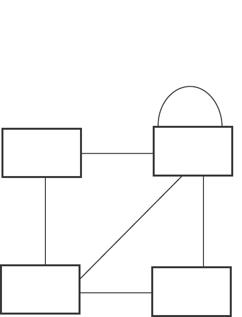
230 PowerConnect B-Series FCX Configuration Guide
53-1002266-01
Configuring STP related features
8
FIGURE 26 Simple 802.1W topology
Ports on Switch 1
All ports on Switch 1, the root bridge, are assigned Designated port roles.
Ports on Switch 2
Port2 on Switch 2 directly connects to the root bridge; therefore, Port2 is the Root port.
The bridge priority value on Switch 2 is superior to that of Switch 3 and Switch 4; therefore, the
ports on Switch 2 that connect to Switch 3 and Switch 4 are given the Designated port role.
Furthermore, Port7 and Port8 on Switch 2 are physically connected. The RST BPDUs transmitted
by Port7 are superior to those Port8 transmits. Therefore, Port8 is the Backup port and Port7 is the
Designated port.
Ports on Switch 3
Port2 on Switch 3 directly connects to the Designated port on the root bridge; therefore, it assumes
the Root port role.
The root path cost of the RST BPDUs received on Port4/Switch 3 is inferior to the RST BPDUs
transmitted by the port; therefore, Port4/Switch 3 becomes the Designated port.
Similarly Switch 3 has a bridge priority value inferior to Switch 2. Port3 on Switch 3 connects to Port
3 on Switch 2. This port will be given the Alternate port role, since a Root port is already established
on this bridge.
Ports Switch 4
Switch 4 is not directly connected to the root bridge. It has two ports with superior incoming RST
BPDUs from two separate LANs: Port3 and Port4. The RST BPDUs received on Port3 are superior to
the RST BPDUs received on port 4; therefore, Port3 becomes the Root port and Port4 becomes the
Alternate port.
Switch 1
Bridge priority = 100
Switch 2
Bridge priority = 200
Switch 3
Bridge priority = 300 Switch 4
Bridge priority = 400
Port2 Port2
Port2
Port3
Port3 Port3
Port3
Port4 Port4
Port4
Port7 Port8
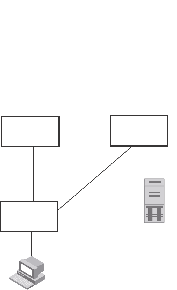
PowerConnect B-Series FCX Configuration Guide 231
53-1002266-01
Configuring STP related features 8
Edge ports and edge port roles
The Dell implementation of 802.1W allows ports that are configured as Edge ports to be present in
an 802.1W topology. (Figure 27). Edge ports are ports of a bridge that connect to workstations or
computers. Edge ports do not register any incoming BPDU activities.
Edge ports assume Designated port roles. Port flapping does not cause any topology change
events on Edge ports since 802.1W does not consider Edge ports in the spanning tree calculations.
FIGURE 27 Topology with edge ports
However, if any incoming RST BPDU is received from a previously configured Edge port, 802.1W
automatically makes the port as a non-edge port. This is extremely important to ensure a loop free
Layer 2 operation since a non-edge port is part of the active RSTP topology.
The 802.1W protocol can auto-detect an Edge port and a non-edge port. An administrator can also
configure a port to be an Edge port using the CLI. It is recommended that Edge ports are
configured explicitly to take advantage of the Edge port feature, instead of allowing the protocol to
auto-detect them.
Point-to-point ports
To take advantage of the 802.1W features, ports on an 802.1W topology should be explicitly
configured as point-to-point links using the CLI. Shared media should not be configured as
point-to-point links.
Switch 1
Bridge priority = 600
Switch 2
Bridge priority = 1000
Switch 3
Bridge priority = 2000
Port2 Port2
Port3 Port3
Port3
Port2
Port5
Edge Port
Port5
Edge Port
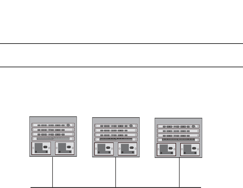
232 PowerConnect B-Series FCX Configuration Guide
53-1002266-01
Configuring STP related features
8
NOTE
Configuring shared media or non-point-to-point links as point-to-point links could lead to Layer 2
loops.
The topology in Figure 28 is an example of shared media that should not be configured as
point-to-point links. In Figure 28, a port on a bridge communicates or is connected to at least two
ports.
FIGURE 28 Example of shared media
Bridge port states
Ports roles can have one of the following states:
•Forwarding – 802.1W is allowing the port to send and receive all packets.
•Discarding – 802.1W has blocked data traffic on this port to prevent a loop. The device or
VLAN can reach the root bridge using another port, whose state is forwarding. When a port is
in this state, the port does not transmit or receive data frames, but the port does continue to
receive RST BPDUs. This state corresponds to the listening and blocking states of 802.1D.
•Learning – 802.1W is allowing MAC entries to be added to the filtering database but does not
permit forwarding of data frames. The device can learn the MAC addresses of frames that the
port receives during this state and make corresponding entries in the MAC table.
•Disabled – The port is not participating in 802.1W. This can occur when the port is
disconnected or 802.1W is administratively disabled on the port.
A port on a non-root bridge with the role of Root port is always in a forwarding state. If another port
on that bridge assumes the Root port role, then the old Root port moves into a discarding state as
it assumes another port role.
A port on a non-root bridge with a Designated role starts in the discarding state. When that port
becomes elected to the Root port role, 802.1W quickly places it into a forwarding state. However, if
the Designated port is an Edge port, then the port starts and stays in a forwarding state and it
cannot be elected as a Root port.
A port with an Alternate or Backup role is always in a discarding state. If the port role changes to
Designated, then the port changes into a forwarding state.
If a port on one bridge has a Designated role and that port is connected to a port on another bridge
that has an Alternate or Backup role, the port with a Designated role cannot be given a Root port
role until two instances of the forward delay timer expires on that port.

PowerConnect B-Series FCX Configuration Guide 233
53-1002266-01
Configuring STP related features 8
Edge port and non-edge port states
As soon as a port is configured as an Edge port using the CLI, it goes into a forwarding state
instantly (in less than 100 msec).
When the link to a port comes up and 802.1W detects that the port is an Edge port, that port
instantly goes into a forwarding state.
If 802.1W detects that port as a non-edge port, the port state is changed as determined by the
result of processing the received RST BPDU. The port state change occurs within four seconds of
link up or after two hello timer expires on the port.
Changes to port roles and states
To achieve convergence in a topology, a port role and state changes as it receives and transmits
new RST BPDUs. Changes in a port role and state constitute a topology change. Besides the
superiority and inferiority of the RST BPDU, bridge-wide and per-port state machines are used to
determine a port role as well as a port state. Port state machines also determine when port role
and state changes occur.
State machines
The bridge uses the Port Role Selection state machine to determine if port role changes are
required on the bridge. This state machine performs a computation when one of the following
events occur:
•New information is received on any port on the bridge
•The timer expires for the current information on a port on the bridge
Each port uses the following state machines:
•Port Information – This state machine keeps track of spanning-tree information currently used
by the port. It records the origin of the information and ages out any information that was
derived from an incoming BPDU.
•Port Role Transition – This state machine keeps track of the current port role and transitions
the port to the appropriate role when required. It moves the Root port and the Designated port
into forwarding states and moves the Alternate and Backup ports into discarding states.
•Port Transmit – This state machine is responsible for BPDU transmission. It checks to ensure
only the maximum number of BPDUs per hello interval are sent every second. Based on what
mode it is operating in, it sends out either legacy BPDUs or RST BPDUs. In this document
legacy BPDUs are also referred to as STP BPDUs.
•Port Protocol Migration – This state machine deals with compatibility with 802.1D bridges.
When a legacy BPDU is detected on a port, this state machine configures the port to transmit
and receive legacy BPDUs and operate in the legacy mode.
•Topology Change – This state machine detects, generates, and propagates topology change
notifications. It acknowledges Topology Change Notice (TCN) messages when operating in
802.1D mode. It also flushes the MAC table when a topology change event takes place.
•Port State Transition – This state machine transitions the port to a discarding, learning, or
forwarding state and performs any necessary processing associated with the state changes.
•Port Timers – This state machine is responsible for triggering any of the state machines
described above, based on expiration of specific port timers.

234 PowerConnect B-Series FCX Configuration Guide
53-1002266-01
Configuring STP related features
8
In contrast to the 802.1D standard, the 802.1W standard does not have any bridge specific timers.
All timers in the CLI are applied on a per-port basis, even though they are configured under bridge
parameters.
802.1W state machines attempt to quickly place the ports into either a forwarding or discarding
state. Root ports are quickly placed in forwarding state when both of the following events occur:
•It is assigned to be the Root port.
•It receives an RST BPDU with a proposal flag from a Designated port. The proposal flag is sent
by ports with a Designated role when they are ready to move into a forwarding state.
When a the role of Root port is given to another port, the old Root port is instructed to reroot. The
old Root port goes into a discarding state and negotiates with its peer port for a new role and a new
state. A peer port is the port on the other bridge to which the port is connected. For example, in
Figure 29, Port1 of Switch 200 is the peer port of Port2 of Switch 100.
A port with a Designated role is quickly placed into a forwarding state if one of the following occurs:
•The Designated port receives an RST BPDU that contains an agreement flag from a Root port
•The Designated port is an Edge port
However, a Designated port that is attached to an Alternate port or a Backup port must wait until
the forward delay timer expires twice on that port while it is still in a Designated role, before it can
proceed to the forwarding state.
Backup ports are quickly placed into discarding states.
Alternate ports are quickly placed into discarding states.
A port operating in 802.1W mode may enter a learning state to allow MAC entries to be added to
the filtering database; however, this state is transient and lasts only a few milliseconds, if the port
is operating in 802.1W mode and if the port meets the conditions for rapid transition.
Handshake mechanisms
To rapidly transition a Designated or Root port into a forwarding state, the Port Role Transition state
machine uses handshake mechanisms to ensure loop free operations. It uses one type of
handshake if no Root port has been assigned on a bridge, and another type if a Root port has
already been assigned.
Handshake when no root port is elected
If a Root port has not been assigned on a bridge, 802.1W uses the Proposing -> Proposed -> Sync
-> Synced -> Agreed handshake:
•Proposing – The Designated port on the root bridge sends an RST BPDU packet to its peer port
that contains a proposal flag. The proposal flag is a signal that indicates that the Designated
port is ready to put itself in a forwarding state (Figure 29). The Designated port continues to
send this flag in its RST BPDU until it is placed in a forwarding state (Figure 32) or is forced to
operate in 802.1D mode. (Refer to “Compatibility of 802.1W with 802.1D” on page 255).
•Proposed – When a port receives an RST BPDU with a proposal flag from the Designated port
on its point-to-point link, it asserts the Proposed signal and one of the following occurs
(Figure 29):
•If the RST BPDU that the port receives is superior to what it can transmit, the port
assumes the role of a Root port. (Refer to the section on “Bridges and bridge port roles” on
page 228.)
•If the RST BPDU that the port receives is inferior to what it can transmit, then the port is
given the role of Designated port.
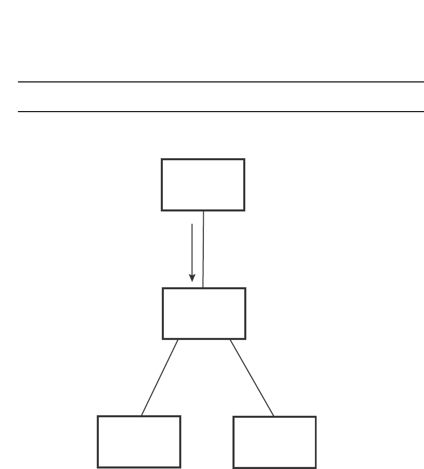
PowerConnect B-Series FCX Configuration Guide 235
53-1002266-01
Configuring STP related features 8
NOTE
Proposed will never be asserted if the port is connected on a shared media link.
In Figure 29, Port3/Switch 200 is elected as the Root port
FIGURE 29 Proposing and proposed stage
•Sync – Once the Root port is elected, it sets a sync signal on all the ports on the bridge. The
signal tells the ports to synchronize their roles and states (Figure 30). Ports that are non-edge
ports with a role of Designated port change into a discarding state. These ports have to
negotiate with their peer ports to establish their new roles and states.
Switch 100
Root Bridge
Switch 200
Switch 300 Switch 400
Port2
Designated port
Proposing
Port1
Root port
Proposed
Port2
Port2
Port3
Port3
RST BPDU
sent with a
Proposal
flag

236 PowerConnect B-Series FCX Configuration Guide
53-1002266-01
Configuring STP related features
8
FIGURE 30 Sync stage
•Synced – Once the Designated port changes into a discarding state, it asserts a synced signal.
Immediately, Alternate ports and Backup ports are synced. The Root port monitors the synced
signals from all the bridge ports. Once all bridge ports asserts a synced signal, the Root port
asserts its own synced signal (Figure 31).
BigIron
Switch 100
Root Bridge
Port1
Designated port
Port1
Root port
Sync
Switch 200
Switch 300 Switch 400
Port2
Sync
Discarding
Port3
Sync
Discarding
Port2 Port3
Indicates a signal
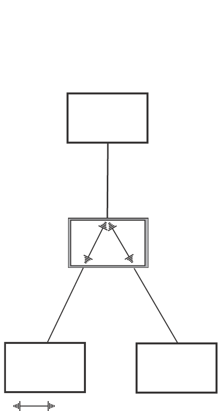
PowerConnect B-Series FCX Configuration Guide 237
53-1002266-01
Configuring STP related features 8
FIGURE 31 Synced stage
•Agreed – The Root port sends back an RST BPDU containing an agreed flag to its peer
Designated port and moves into the forwarding state. When the peer Designated port receives
the RST BPDU, it rapidly transitions into a forwarding state.
BigIron
Switch 100
Root Bridge
Switch 200
Switch 300 Switch 400
Port1
Designated port
Port1
Root port
Synced
Port2 Port3
Indicates a signal
Port2
Synced
Discarding
Port3
Synced
Discarding
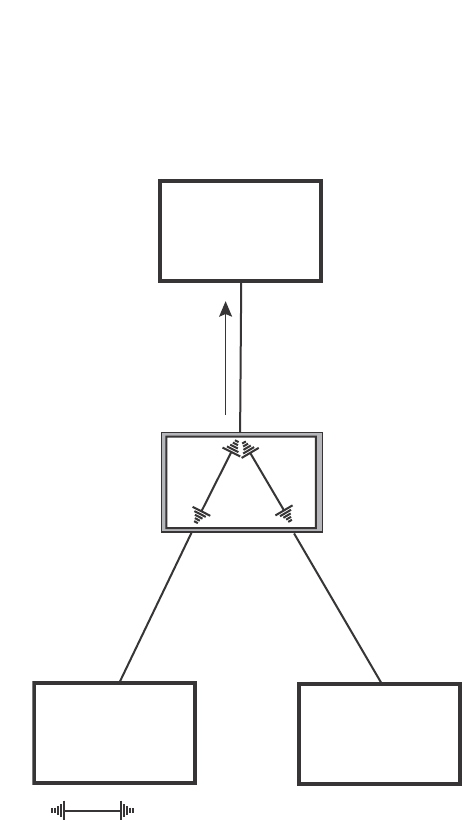
238 PowerConnect B-Series FCX Configuration Guide
53-1002266-01
Configuring STP related features
8
FIGURE 32 Agree stage
At this point, the handshake mechanism is complete between Switch 100, the root bridge, and
Switch 200.
Switch 200 updates the information on the Switch 200 Designated ports (Port2 and Port3) and
identifies the new root bridge. The Designated ports send RST BPDUs, containing proposal flags, to
their downstream bridges, without waiting for the hello timers to expire on them. This process
starts the handshake with the downstream bridges.
For example, Port2/Switch 200 sends an RST BPDU to Port2/Switch 300 that contains a proposal
flag. Port2/Switch 300 asserts a proposed signal. Ports in Switch 300 then set sync signals on the
ports to synchronize and negotiate their roles and states. Then the ports assert a synced signal and
when the Root port in Switch 300 asserts its synced signal, it sends an RST BPDU to Switch 200
with an agreed flag.
This handshake is repeated between Switch 200 and Switch 400 until all Designated and Root
ports are in forwarding states.
Handshake when a root port has been elected
If a non-root bridge already has a Root port, 802.1W uses a different type of handshake. For
example, in Figure 33, a new root bridge is added to the topology.
BigIron
Switch 100
Root Bridge
Port1
Designated port
Forwarding
Port1
Root port
Synced
Forwarding
RST BPDU
sent with
an Agreed
flag
Switch 200
Switch 300 Switch 400
Indicates a signal
Port2
Synced
Discarding
Port3
Synced
Discarding
Port2 Port3
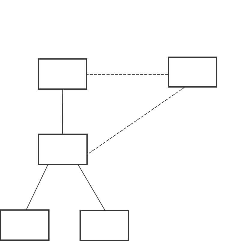
PowerConnect B-Series FCX Configuration Guide 239
53-1002266-01
Configuring STP related features 8
FIGURE 33 Addition of a new root bridge
The handshake that occurs between Switch 60 and Switch 100 follows the one described in the
previous section (“Handshake when no root port is elected” on page 234). The former root bridge
becomes a non-root bridge and establishes a Root port (Figure 34).
However, since Switch 200 already had a Root port in a forwarding state, 802.1W uses the
Proposing -> Proposed -> Sync and Reroot -> Sync and Rerooted -> Rerooted and Synced ->
Agreed handshake:
•Proposing and Proposed – The Designated port on the new root bridge (Port4/Switch 60)
sends an RST BPDU that contains a proposing signal to Port4/Switch 200 to inform the port
that it is ready to put itself in a forwarding state (Figure 34). 802.1W algorithm determines
that the RST BPDU that Port4/Switch 200 received is superior to what it can generate, so
Port4/Switch 200 assumes a Root port role.
Switch 100
Port2
Designated
port Switch 60
Port4
Designated port
Port2
Port1
Root port
Port4
Port3
Port2
Switch 200
Port2 Port3
Switch 300 Switch 400
Port1
Designated port
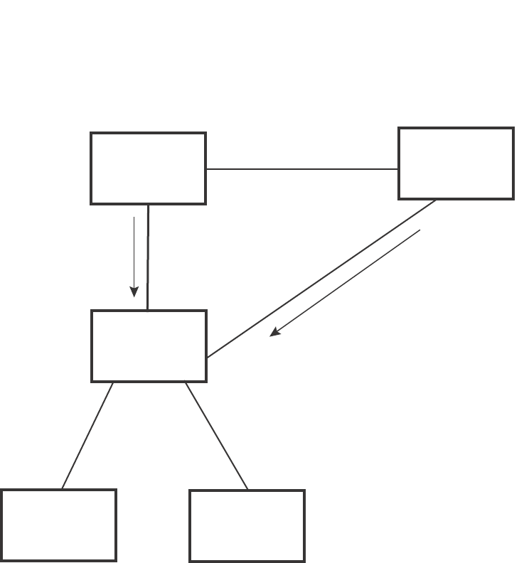
240 PowerConnect B-Series FCX Configuration Guide
53-1002266-01
Configuring STP related features
8
FIGURE 34 New root bridge sending a proposal flag
•Sync and Reroot – The Root port then asserts a sync and a reroot signal on all the ports on the
bridge. The signal tells the ports that a new Root port has been assigned and they are to
renegotiate their new roles and states. The other ports on the bridge assert their sync and
reroot signals. Information about the old Root port is discarded from all ports. Designated
ports change into discarding states (Figure 35).
Switch 100
Port2
Designated
port Switch 60
Port1
Port2
Root port
Handshake
Completed
Port4
Designated port
Proposing
Proposing
Port1
Root port
Forwarding
RST BPDU
sent with
a Proposing
flag
Port4
Designated port
Proposed
Switch 200
Port2 Port3
Port2 Port3
Switch 300 Switch 400

PowerConnect B-Series FCX Configuration Guide 241
53-1002266-01
Configuring STP related features 8
FIGURE 35 Sync and reroot
•Sync and Rerooted – When the ports on Switch 200 have completed the reroot phase, they
assert their rerooted signals and continue to assert their sync signals as they continue in their
discarding states. They also continue to negotiate their roles and states with their peer ports
(Figure 36).
BigIron
Switch 100 Por t2
Root port
Port2
Designated
port
Port1
Switch 60
Port4
Designated port
Proposing
Proposing Por t1
Root port
Sync
Reroot
Forwarding
Port4
Root port
Sync
Reroot
Discarding
Port3
Sync
Reroot
Discarding
Port2
Sync
Reroot
Discarding
Switch 200
Switch 300 Switch 400
Port2 Port3
Indicates a signal
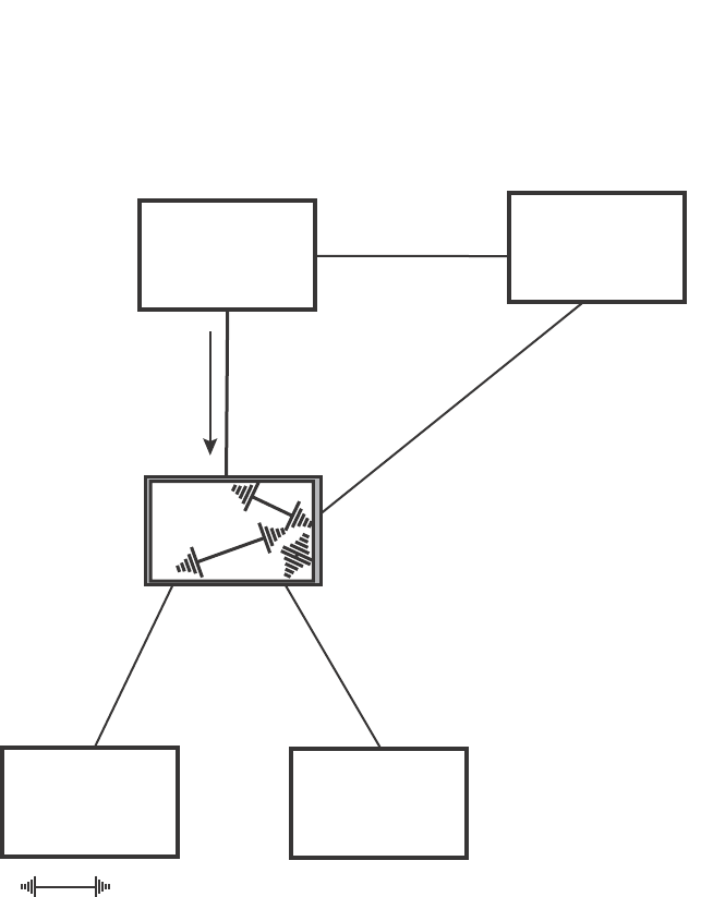
242 PowerConnect B-Series FCX Configuration Guide
53-1002266-01
Configuring STP related features
8
FIGURE 36 Sync and rerooted
•Synced and Agree – When all the ports on the bridge assert their synced signals, the new Root
port asserts its own synced signal and sends an RST BPDU to Port4/Switch 60 that contains
an agreed flag (Figure 36). The Root port also moves into a forwarding state.
BigIron
Switch 100
Port2
Designated
port Switch 60
Port4
Designated port
Port2
Root port
Port1
Port1
Designated port
Sync
Rerooted
Discarding
Port4
Root port
Sync
Rerooted
Discarding
Port3
Sync
Rerooted
Discarding
Port2
Sync
Rerooted
Discarding
Switch 200
Proposing
Port2 Port3
Switch 300 Switch 400
Indicates an 802.1W signal controlled by the current Root port
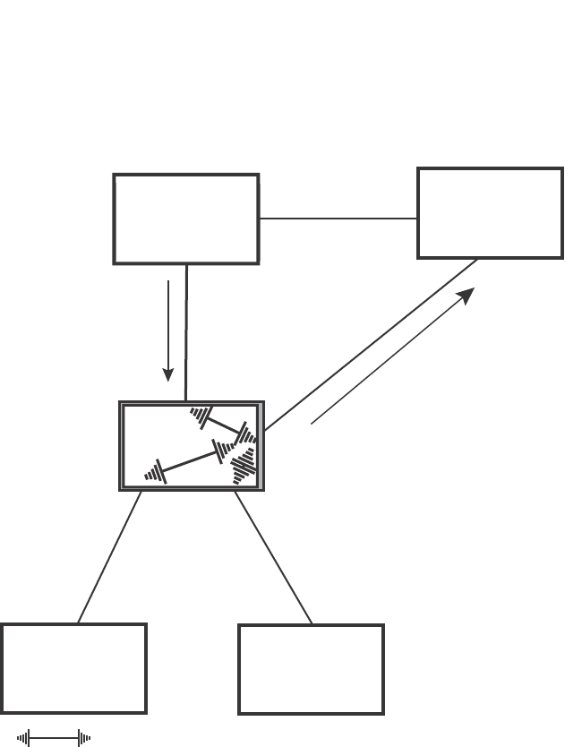
PowerConnect B-Series FCX Configuration Guide 243
53-1002266-01
Configuring STP related features 8
FIGURE 37 Rerooted, synced, and agreed
The old Root port on Switch 200 becomes an Alternate Port (Figure 38). Other ports on that bridge
are elected to appropriate roles.
The Designated port on Switch 60 goes into a forwarding state once it receives the RST BPDU with
the agreed flag.
BigIron
Switch 100
Port2
Designated
port Switch 60
Port4
Designated port
Forwarding
Port 2
Root port
Port1
Proposing
Port1
Rerooted
Synced
Discarding
Port4
Root port
Rerooted
Synced
Forwarding
Port3
Rerooted
Synced
Discarding
Port2
Rerooted
Synced
Discarding
Port2 Port3
Switch 300
Indicates a signal
Switch 200
Switch 400
RST BPDU
sent with
an Agreed
flag
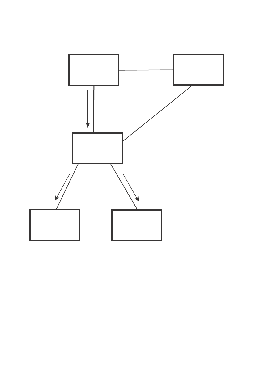
244 PowerConnect B-Series FCX Configuration Guide
53-1002266-01
Configuring STP related features
8
FIGURE 38 Handshake completed after election of new root port
Recall that Switch 200 sent the agreed flag to Port4/Switch 60 and not to Port1/Switch 100 (the
port that connects Switch 100 to Switch 200). Therefore, Port1/Switch 100 does not go into
forwarding state instantly. It waits until two instances of the forward delay timer expires on the port
before it goes into forwarding state.
At this point the handshake between the Switch 60 and Switch 200 is complete.
The remaining bridges (Switch 300 and Switch 400) may have to go through the reroot handshake
if a new Root port needs to be assigned.
Convergence in a simple topology
The examples in this section illustrate how 802.1W convergence occurs in a simple Layer 2
topology at start-up.
NOTE
The remaining examples assume that the appropriate handshake mechanisms occur as port roles
and states change.
Convergence at start up
In Figure 39, two bridges Switch 2 and Switch 3 are powered up. There are point-to-point
connections between Port3/Switch 2 and Port3/Switch 3.
Switch 100
Port2
Designated
port
Port2
Root port
Switch 60
Port4
Designated port
Port1
Proposing
Port1
Alternate port
Port4
Root port
Switch 200
Port2
Port2
Port3
Port3
Proposing Proposing
Switch 300 Switch 400
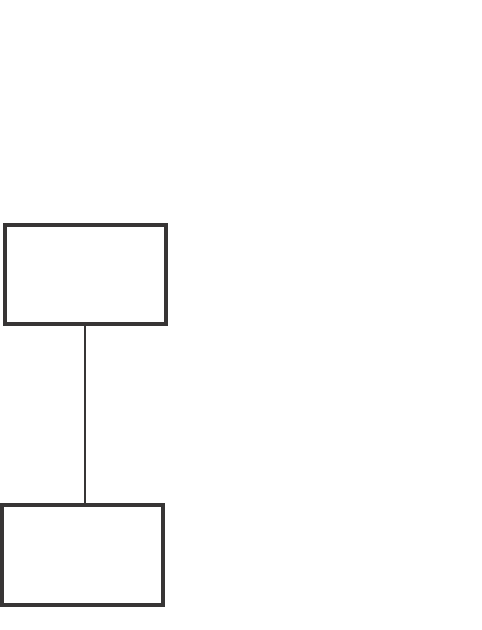
PowerConnect B-Series FCX Configuration Guide 245
53-1002266-01
Configuring STP related features 8
FIGURE 39 Convergence between two bridges
At power up, all ports on Switch 2 and Switch 3 assume Designated port roles and are at discarding
states before they receive any RST BPDU.
Port3/Switch 2, with a Designated role, transmits an RST BPDU with a proposal flag to
Port3/Switch 3. A ports with a Designated role sends the proposal flag in its RST BPDU when they
are ready to move to a forwarding state.
Port3/Switch 3, which starts with a role of Designated port, receives the RST BPDU and finds that it
is superior to what it can transmit; therefore, Port3/Switch 3 assumes a new port role, that of a
Root port. Port3/Switch 3 transmits an RST BPDU with an agreed flag back to Switch 2 and
immediately goes into a forwarding state.
Port3/Switch 2 receives the RST BPDU from Port3/Switch 3 and immediately goes into a
forwarding state.
Now 802.1W has fully converged between the two bridges, with Port3/Switch 3 as an operational
root port in forwarding state and Port3/Switch 2 as an operational Designated port in forwarding
state.
Next, Switch 1 is powered up (Figure 40).
Port3
Designated
port
Port3
Root port
Bridge priority = 1500
Bridge priority = 2000
Switch 2
Switch 3
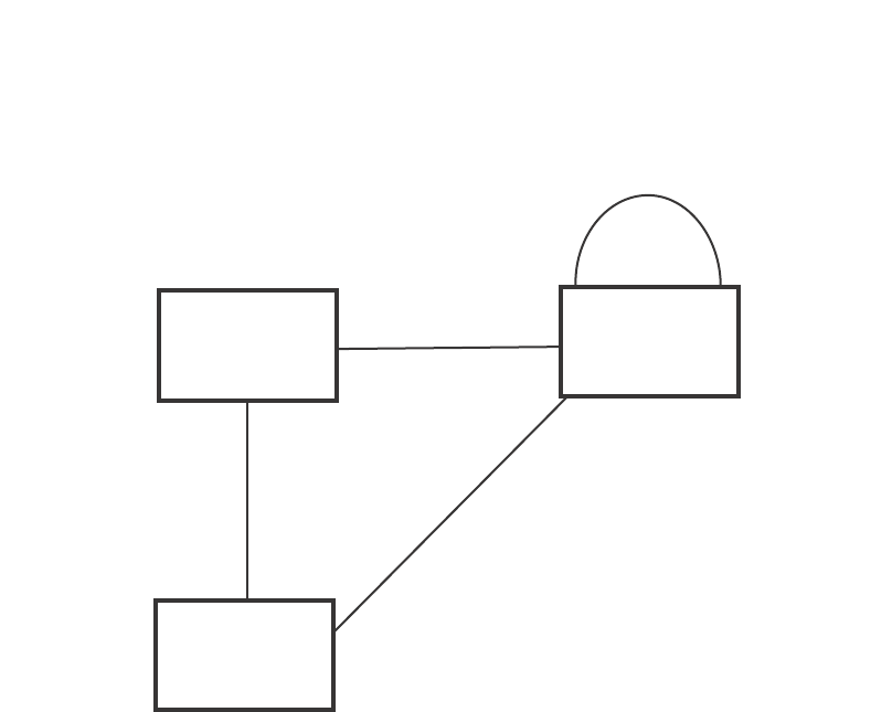
246 PowerConnect B-Series FCX Configuration Guide
53-1002266-01
Configuring STP related features
8
FIGURE 40 Simple Layer 2 topology
The point-to-point connections between the three bridges are as follows:
•Port2/Switch 1 and Port2/Switch 2
•Port4/Switch 1 and Port4/Switch 3
•Port3/Switch 2 and Port3/Switch 3
Ports 3 and 5 on Switch 1 are physically connected together.
At start up, the ports on Switch 1 assume Designated port roles, which are in discarding state. They
begin sending RST BPDUs with proposal flags to move into a forwarding state.
When Port4/Switch 3 receives these RST BPDUs 802.1W algorithm determines that they are better
than the RST BPDUs that were previously received on Port3/Switch 3. Port4/Switch 3 is now
selected as Root port. This new assignment signals Port3/Switch 3 to begin entering the discarding
state and to assume an Alternate port role. As it goes through the transition, Port3/Switch 3
negotiates a new role and state with its peer port, Port3/Switch 2.
Port4/Switch 3 sends an RST BPDU with an agreed flag to Port4/Switch 1. Both ports go into
forwarding states.
Port2/Switch 2 receives an RST BPDU. The 802.1W algorithm determines that these RST BPDUs
that are superior to any that any port on Switch 2 can transmit; therefore, Port2/Switch 2 assumes
the role of a Root port.
The new Root port then signals all ports on the bridge to start synchronization. Since none of the
ports are Edge ports, they all enter the discarding state and assume the role of Designated ports.
Port3/Switch 2, which previously had a Designated role with a forwarding state, starts the
discarding state. They also negotiate port roles and states with their peer ports. Port3/Switch 2
also sends an RST BPU to Port3/Switch 3 with a proposal flag to request permission go into a
forwarding state.
The Port2/Switch 2 bridge also sends an RST BPDU with an agreed flag Port2/Switch 1 that Port2
is the new Root port. Both ports go into forwarding states.
Switch 2
Switch 3
Switch 1
Port2
Designated
port
Port4
Designated port
Port3
Designated
port
Port3
Designated
port
Port5
Backup port
Port3
Alternate
port
Port2
Root port
Port4
Root port
Bridge priority = 1500
Bridge priority = 2000
Bridge priority = 1000
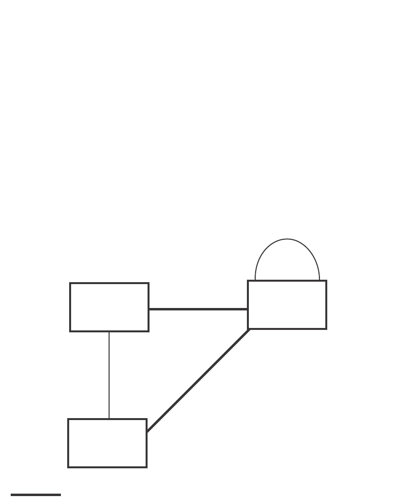
PowerConnect B-Series FCX Configuration Guide 247
53-1002266-01
Configuring STP related features 8
Now, Port3/Switch 3 is currently in a discarding state and is negotiating a port role. It received RST
BPDUs from Port3/Switch 2. The 802.1W algorithm determines that the RST BPDUs Port3/Switch
3 received are superior to those it can transmit; however, they are not superior to those that are
currently being received by the current Root port (Port4). Therefore, Port3 retains the role of
Alternate port.
Ports 3/Switch 1 and Port5/Switch 1 are physically connected. Port5/Switch 1 received RST
BPDUs that are superior to those received on Port3/Switch 1; therefore, Port5/Switch 1 is given
the Backup port role while Port3 is given the Designated port role. Port3/Switch 1, does not go
directly into a forwarding state. It waits until the forward delay time expires twice on that port before
it can proceed to the forwarding state.
Once convergence is achieved, the active Layer 2 forwarding path converges as shown in Figure 41.
FIGURE 41 Active Layer 2 path
Convergence after a link failure
What happens if a link in the 802.1W topology fails?
For example, Port2/Switch, which is the port that connects Switch 2 to the root bridge (Switch 1),
fails. Both Switch 2 and Switch 1 notice the topology change (Figure 42).
Switch 2
Port2
Root port
Port2
Designated
port
Port3
Designated
port
Switch 1
Port5
Backup port
Bridge priority = 1500 Bridge priority = 1000
Port4
Designated port
Port4
Root port
Port3
Designated
port
Port3
Alternate
port
Bridge priority = 2000
Switch 3
Indicates the active Layer 2 path
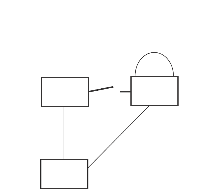
248 PowerConnect B-Series FCX Configuration Guide
53-1002266-01
Configuring STP related features
8
FIGURE 42 Link failure in the topology
Switch 1 sets its Port2 into a discarding state.
At the same time, Switch 2 assumes the role of a root bridge since its root port failed and it has no
operational Alternate port. Port3/Switch 2, which currently has a Designated port role, sends an
RST BPDU to Switch 3. The RST BPDU contains a proposal flag and a bridge ID of Switch 2 as its
root bridge ID.
When Port3/Switch 3 receives the RST BPDUs, 802.1W algorithm determines that they are inferior
to those that the port can transmit. Therefore, Port3/Switch 3 is given a new role, that of a
Designated port. Port3/Switch 3 then sends an RST BPDU with a proposal flag to Switch 2, along
with the new role information. However, the root bridge ID transmitted in the RST BPDU is still
Switch 1.
When Port3/Switch 2 receives the RST BPDU, 802.1W algorithm determines that it is superior to
the RST BPDU that it can transmit; therefore, Port3/Switch 2 receives a new role; that of a Root
port. Port3/Switch 2 then sends an RST BPDU with an agreed flag to Port3/Switch 3. Port3/Switch
2 goes into a forwarding state.
When Port3/Switch 3 receives the RST BPDU that Port3/Switch 2 sent, Port3/Switch 3 changes
into a forwarding state, which then completes the full convergence of the topology.
Convergence at link restoration
When Port2/Switch 2 is restored, both Switch 2 and Switch 1 recognize the change. Port2/Switch
1 starts assuming the role of a Designated port and sends an RST BPDU containing a proposal flag
to Port2/Switch 2.
Bridge priority = 1500
Bridge priority = 2000
Bridge priority = 1000
Switch 2
Switch 3
Switch 1
Port2 Port2
Port3
Port3
Port3
Port4
Port4
Port5

PowerConnect B-Series FCX Configuration Guide 249
53-1002266-01
Configuring STP related features 8
When Port2/Switch 2 receives the RST BPDUs, 802.1W algorithm determines that the RST BPDUs
the port received are better than those received on Port3/Switch 3; therefore, Port2/Switch 2 is
given the role of a Root port. All the ports on Switch 2 are informed that a new Root port has been
assigned which then signals all the ports to synchronize their roles and states. Port3/Switch 2,
which was the previous Root port, enters a discarding state and negotiates with other ports on the
bridge to establish its new role and state, until it finally assumes the role of a Designated port.
Next, the following happens:
•Port3/Switch 2, the Designated port, sends an RST BPDU, with a proposal flag to Port3/Switch
3.
•Port2/Switch 2 also sends an RST BPDU with an agreed flag to Port2/Switch 1 and then
places itself into a forwarding state.
When Port2/Switch 1 receives the RST BPDU with an agreed flag sent by Port2/Switch 2, it puts
that port into a forwarding state. The topology is now fully converged.
When Port3/Switch 3 receives the RST BPDU that Port3/Switch 2 sent, 802.1W algorithm
determines that these RST BPDUs are superior to those that Port3/Switch 3 can transmit.
Therefore, Port3/Switch 3 is given a new role, that of an Alternate port. Port3/Switch 3 immediately
enters a discarding state.
Now Port3/Switch 2 does not go into a forwarding state instantly like the Root port. It waits until the
forward delay timer expires twice on that port while it is still in a Designated role, before it can
proceed to the forwarding state. The wait, however, does not cause a denial of service, since the
essential connectivity in the topology has already been established.
When fully restored, the topology is the same as that shown on Figure 40.
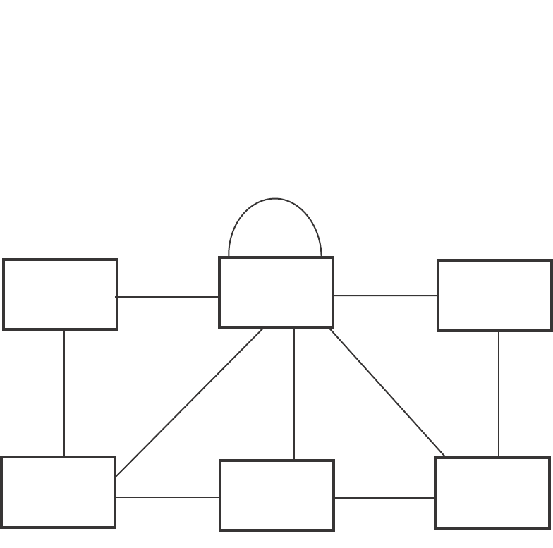
250 PowerConnect B-Series FCX Configuration Guide
53-1002266-01
Configuring STP related features
8
Convergence in a complex 802.1W topology
The following is an example of a complex 802.1W topology.
FIGURE 43 Complex 802.1W topology
In Figure 43, Switch 5 is selected as the root bridge since it is the bridge with the highest priority.
Lines in the figure show the point-to-point connection to the bridges in the topology.
Switch 5 sends an RST BPDU that contains a proposal flag to Port5/Switch 2. When handshakes
are completed in Switch 5, Port5/Switch 2 is selected as the Root port on Switch 2. All other ports
on Switch 2 are given Designated port role with discarding states.
Port5/Switch 2 then sends an RST BPDU with an agreed flag to Switch 5 to confirm that it is the
new Root port and the port enters a forwarding state. Port7 and Port8 are informed of the identity
of the new Root port. 802.1W algorithm selects Port7 as the Designated port while Port8 becomes
the Backup port.
Port3/Switch 5 sends an RST BPDU to Port3/Switch 6 with a proposal flag. When Port3/Switch 5
receives the RST BPDU, handshake mechanisms select Port3 as the Root port of Switch 6. All
other ports are given a Designated port role with discarding states. Port3/Switch 6 then sends an
RST BPDU with an agreed flag to Port3/Switch 5 to confirm that it is the Root port. The Root port
then goes into a forwarding state.
Now, Port4/Switch 6 receives RST BPDUs that are superior to what it can transmit; therefore, it is
given the Alternate port role. The port remains in discarding state.
Port5/Switch 6 receives RST BPDUs that are inferior to what it can transmit. The port is then given
a Designated port role.
Bridge priority = 1000
Bridge priority = 200
Bridge priority = 300 Bridge priority = 400
Bridge priority = 60
Bridge priority = 900
Port3 Port3
Port3 Port3
Port3
Port3
Port4 Port4
Port4
Port5 Port5
Port4
Port2
Port2
Port2 Port2
Port7
Port5
Port8
Switch 1
Switch 3 Switch 4
Switch 2 Switch 5
Switch 6

PowerConnect B-Series FCX Configuration Guide 251
53-1002266-01
Configuring STP related features 8
Next Switch 2 sends RST BPDUs with a proposal flag to Port3/Switch 4. Port3 becomes the Root
port for the bridge; all other ports are given a Designated port role with discarding states.
Port3/Switch 4 sends an RST BPDU with an agreed flag to Switch 2 to confirm that it is the new
Root port. The port then goes into a forwarding state.
Now Port4/Switch 4 receives an RST BPDU that is superior to what it can transmit. The port is then
given an Alternate port role, and remains in discarding state.
Likewise, Port5/Switch 4 receives an RST BPDU that is superior to what it can transmit. The port is
also given an Alternate port role, and remains in discarding state.
Port2/Switch 2 transmits an RST BPDU with a proposal flag to Port2/Switch 1. Port2/Switch 1
becomes the Root port. All other ports on Switch 1 are given Designated port roles with discarding
states.
Port2/Switch 1 sends an RST BPDU with an agreed flag to Port2/Switch 2 and Port2/Switch 1 goes
into a forwarding state.
Port3/Switch 1 receives an RST BPDUs that is inferior to what it can transmit; therefore, the port
retains its Designated port role and goes into forwarding state only after the forward delay timer
expires twice on that port while it is still in a Designated role.
Port3/Switch 2 sends an RST BPDU to Port3/Switch 3 that contains a proposal flag. Port3/Switch
3 becomes the Root port, while all other ports on Switch 3 are given Designated port roles and go
into discarding states. Port3/Switch 3 sends an RST BPDU with an agreed flag to Port3/Switch 2
and Port3/Switch 3 goes into a forwarding state.
Now, Port2/Switch 3 receives an RST BPDUs that is superior to what it can transmit so that port is
given an Alternate port state.
Port4/Switch 3 receives an RST BPDU that is inferior to what it can transmit; therefore, the port
retains its Designated port role.
Ports on all the bridges in the topology with Designated port roles that received RST BPDUs with
agreed flags go into forwarding states instantly. However, Designated ports that did not receive RST
BPDUs with agreed flags must wait until the forward delay timer expires twice on those port. Only
then will these port move into forwarding states.
The entire 802.1W topology converges in less than 300 msec and the essential connectivity is
established between the designated ports and their connected root ports.
After convergence is complete, Figure 44 shows the active Layer 2 path of the topology in
Figure 43.
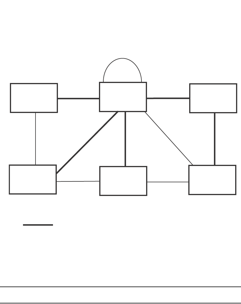
252 PowerConnect B-Series FCX Configuration Guide
53-1002266-01
Configuring STP related features
8
FIGURE 44 Active Layer 2 path in complex topology
Propagation of topology change
The Topology Change state machine generates and propagates the topology change notification
messages on each port. When a Root port or a Designated port goes into a forwarding state, the
Topology Change state machine on those ports send a topology change notice (TCN) to all the
bridges in the topology to propagate the topology change.
NOTE
Edge ports, Alternate ports, or Backup ports do not need to propagate a topology change.
The TCN is sent in the RST BPDU that a port sends. Ports on other bridges in the topology then
acknowledge the topology change once they receive the RST BPDU, and send the TCN to other
bridges until all the bridges are informed of the topology change.
For example, Port3/Switch 2 in Figure 45, fails. Port4/Switch 3 becomes the new Root port.
Port4/Switch 3 sends an RST BPDU with a TCN to Port4/Switch 4. To propagate the topology
change, Port4/Switch 4 then starts a TCN timer on itself, on the bridge Root port, and on other
ports on that bridge with a Designated role. Then Port3/Switch 4 sends RST BPDU with the TCN to
Port4/Switch 2. (Note the new active Layer 2 path in Figure 45.)
Bridge priority = 1000
Bridge priority = 200
Bridge priority = 60
Bridge priority = 300 Bridge priority = 400 Bridge priority = 900
Port3
Port3
Port3
Port3 Port3
Port3
Port2 Port2
Port2
Port2
Port4 Port4
Port4
Port4
Port5
Port5 Port5
Port7 Port8
Indicates the active Layer 2 path
Switch 1
Switch 3 Switch 4 Switch 6
Switch 5
Switch 2
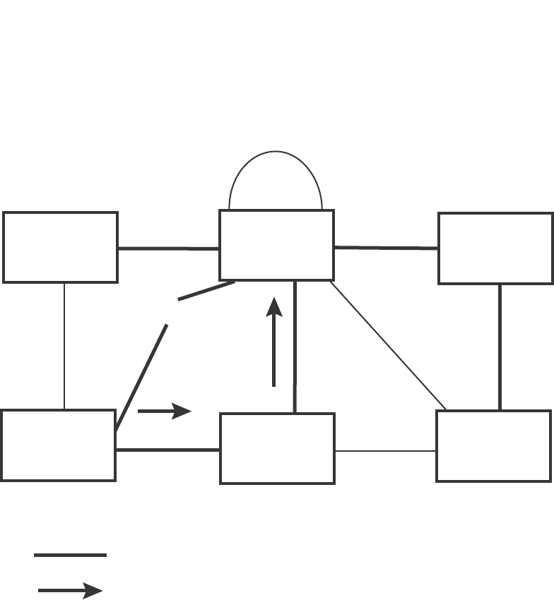
PowerConnect B-Series FCX Configuration Guide 253
53-1002266-01
Configuring STP related features 8
FIGURE 45 Beginning of topology change notice
Switch 2 then starts the TCN timer on the Designated ports and sends RST BPDUs that contain the
TCN as follows (Figure 46):
•Port5/Switch 2 sends the TCN to Port2/Switch 5
•Port4/Switch 2 sends the TCN to Port4/Switch 6
•Port2/Switch 2 sends the TCN to Port2/Switch 1
Bridge priority = 1000
Bridge priority = 200
Bridge priority = 60
Bridge priority = 900
Bridge priority = 400
Bridge priority = 300
Port2 Port2
Port2
Port2
Port3
Port3 Port3
Port3
Port3
Port3
Port4 Port4
Port4
Port4
Port5 Port 5
Port5
Port7 Port8
Indicates the active Layer 2 path
Indicates direction of TCN
Switch 1 Switch 2 Switch 5
Switch 3 Switch 4 Switch 6
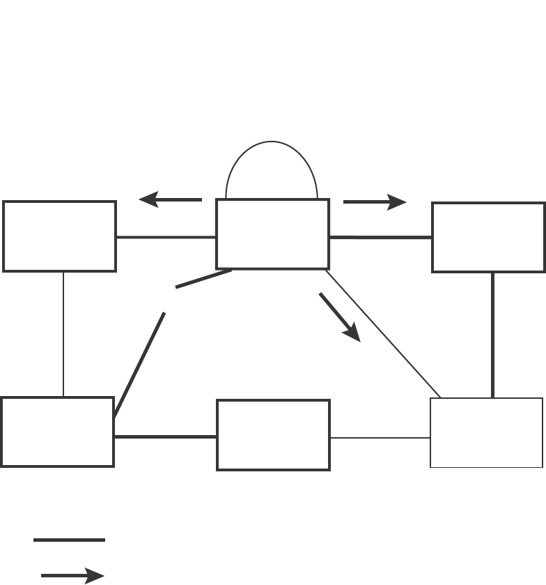
254 PowerConnect B-Series FCX Configuration Guide
53-1002266-01
Configuring STP related features
8
FIGURE 46 Sending TCN to bridges connected to Switch 2
Then Switch 1, Switch 5, and Switch 6 send RST BPDUs that contain the TCN to Switch 3 and
Switch 4 to complete the TCN propagation (Figure 47).
Bridge priority = 1000
Bridge priority = 200
Bridge priority = 60
Bridge priority = 900
Bridge priority = 400
Bridge priority = 300
Port3
Port3 Port3
Port3
Port3
Port3
Port4 Port4
Port4
Port4
Port2 Port2 Por t2
Port2
Port5 Port5
Port5
Indicates the active Layer 2 path
Indicates direction of TCN
Port 7 Port8
Switch 1
Switch 3 Switch 4 Switch 6
Switch 5
Switch 2
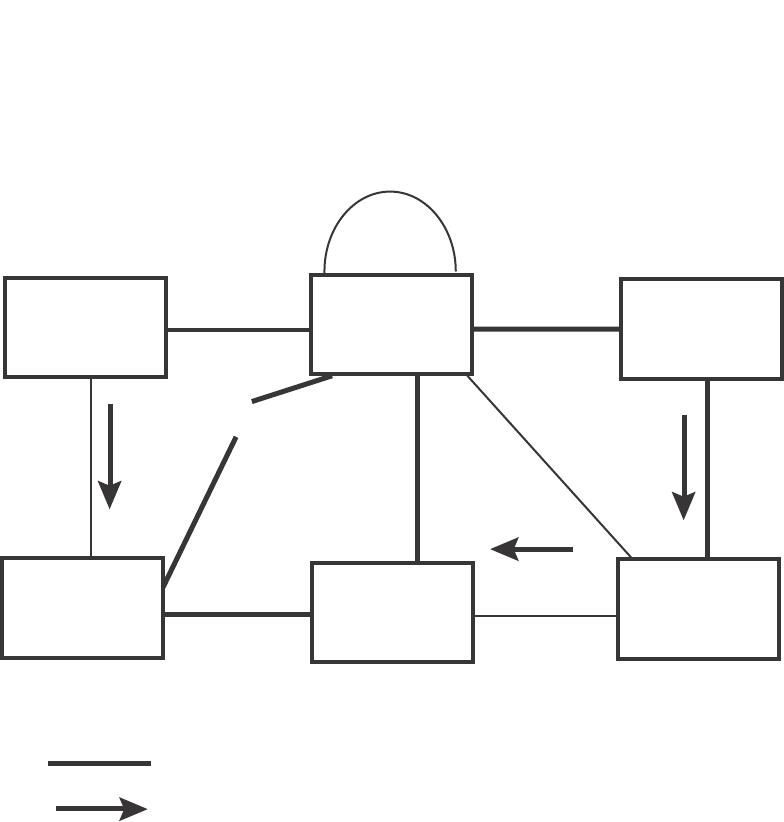
PowerConnect B-Series FCX Configuration Guide 255
53-1002266-01
Configuring STP related features 8
FIGURE 47 Completing the TCN propagation
Compatibility of 802.1W with 802.1D
802.1W-enabled bridges are backward compatible with IEEE 802.1D bridges. This compatibility is
managed on a per-port basis by the Port Migration state machine. However, intermixing the two
types of bridges in the network topology is not advisable if you want to take advantage of the rapid
convergence feature.
Compatibility with 802.1D means that an 802.1W-enabled port can send BPDUs in the STP or
802.1D format when one of the following events occur:
•The port receives a legacy BPDU. A legacy BPDU is an STP BPDU or a BPDU in an 802.1D
format. The port that receives the legacy BPDU automatically configures itself to behave like a
legacy port. It sends and receives legacy BPDUs only.
•The entire bridge is configured to operate in an 802.1D mode when an administrator sets the
bridge parameter to zero at the CLI, forcing all ports on the bridge to send legacy BPDUs only.
Once a port operates in the 802.1D mode, 802.1D convergence times are used and rapid
convergence is not realized.
For example, in Figure 48, Switch 10 and Switch 30 receive legacy BPDUs from Switch 20. Ports on
Switch 10 and Switch 30 begin sending BPDUs in STP format to allow them to operate
transparently with Switch 20.
Switch 1
Bridge priority = 1000 Switch 2
Bridge priority = 200
Switch 5
Bridge priority = 60
Switch 6
Bridge priority = 900
Switch 4
Bridge priority = 400
Switch 3
Bridge priority = 300
Port3
Port3 Port3 Port3
Port3
Port2 Port2
Port2
Port4 Port4
Port4
Port4
Port3
Port2
Port5
Port5 Port5
Port7 Port8
Indicates the active Layer 2 path
Indicates direction of TCN
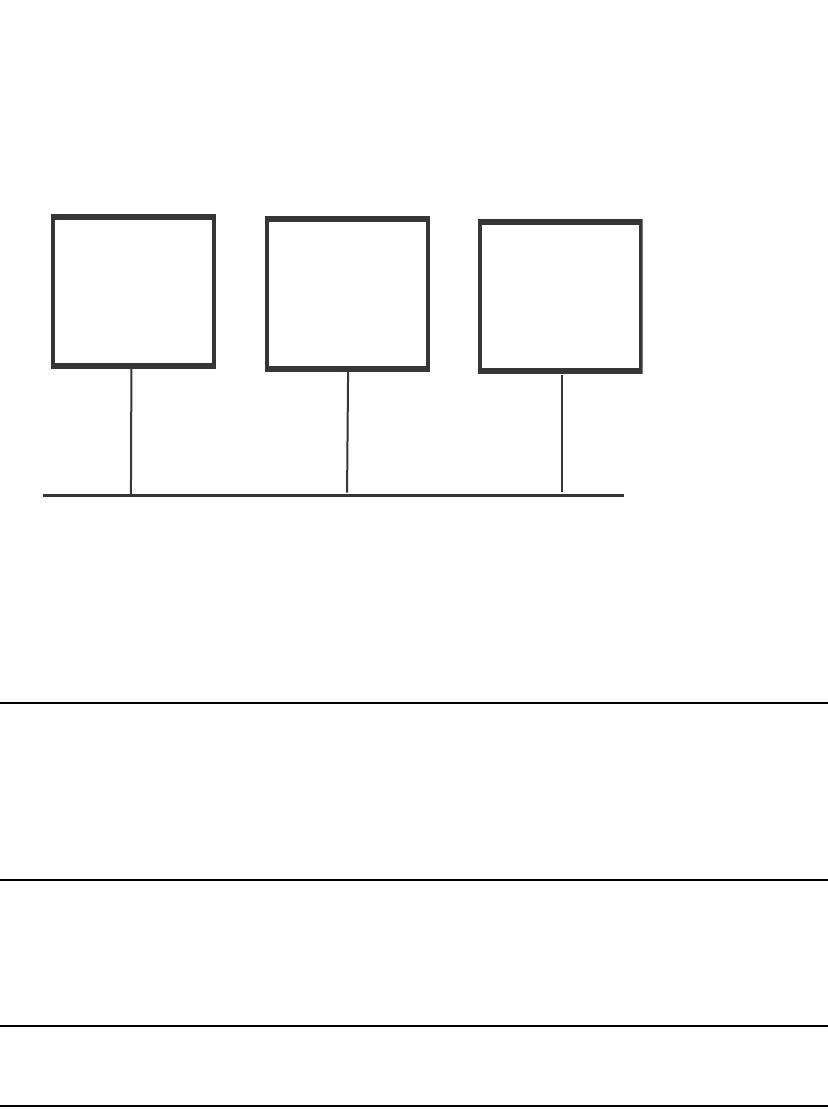
256 PowerConnect B-Series FCX Configuration Guide
53-1002266-01
Configuring STP related features
8
FIGURE 48 802.1W bridges with an 802.1D bridge
Once Switch 20 is removed from the LAN, Switch 10 and Switch 30 receive and transmit BPDUs in
the STP format to and from each other. This state will continue until the administrator enables the
force-migration-check command to force the bridge to send RSTP BPDU during a migrate time
period. If ports on the bridges continue to hear only STP BPDUs after this migrate time period,
those ports will return to sending STP BPDUs. However, when the ports receive RST BPDUs during
the migrate time period, the ports begin sending RST BPDUs. The migrate time period is
non-configurable. It has a value of three seconds.
NOTE
The IEEE standards state that 802.1W bridges need to interoperate with 802.1D bridges. IEEE
standards set the path cost of 802.1W bridges to be between 1 and 200,000,000; whereas path
cost of 802.1D bridges are set between 1 and 65,535. In order for the two bridge types to be able
to interoperate in the same topology, the administrator needs to configure the bridge path cost
appropriately. Path costs for either 802.1W bridges or 802.1D bridges need to be changed; in most
cases, path costs for 802.1W bridges need to be changed.
Configuring 802.1W parameters on a Dell PowerConnect device
The remaining 802.1W sections explain how to configure the 802.1W protocol in a Dell
PowerConnect device.
NOTE
With RSTP running, enabling static trunk on ports that are members of VLAN 4000 will keep the
system busy for 20 to 25 seconds.
Dell PowerConnect devices are shipped from the factory with 802.1W disabled. Use the following
methods to enable or disable 802.1W. You can enable or disable 802.1W at the following levels:
•Port-based VLAN – Affects all ports within the specified port-based VLAN. When you enable or
disable 802.1W within a port-based VLAN, the setting overrides the global setting. Thus, you
can enable 802.1W for the ports within a port-based VLAN even when 802.1W is globally
disabled, or disable the ports within a port-based VLAN when 802.1W is globally enabled.
•Individual port – Affects only the individual port. However, if you change the 802.1W state of
the primary port in a trunk group, the change affects all ports in the trunk group.
Switch 10 Switch 20 Switch 30
802.1W 802.1D 802.1W

PowerConnect B-Series FCX Configuration Guide 257
53-1002266-01
Configuring STP related features 8
Enabling or disabling 802.1W in a port-based VLAN
Use the following procedure to disable or enable 802.1W on a device on which you have configured
a port-based VLAN. Changing the 802.1W state in a VLAN affects only that VLAN.
To enable 802.1W for all ports in a port-based VLAN, enter commands such as the following.
PowerConnect(config)#vlan 10
PowerConnect(config-vlan-10)#spanning-tree 802-1w
Syntax: [no] spanning-tree 802-1w
Note regarding pasting 802.1W settings into the running configuration
If you paste 802.1W settings into the running configuration, and the pasted configuration includes
ports that are already up, the ports will initially operate in STP legacy mode before operating in
802.1W RSTP mode. For example, the following pasted configuration will cause ports e 1 and e 2
to temporarily operate in STP legacy mode, because these ports are already up and running.
conf t
vlan 120
tag e 1 to e 2
spanning-tree 802-1w
spanning-tree 802-1w priority 1001
end
To avoid this issue, 802.1W commands/settings that are pasted into the configuration should be in
the following order.
1. Ports that are not yet connected
2. 802.1W RSTP settings
3. Ports that are already up
Example
conf t
vlan 120
untag e 3
spanning-tree 802-1w
spanning-tree 802-1w priority 1001
tag e 1 to 2
end
In the above configuration, untagged port e3 is added to VLAN 120 before the 802.1W RSTP
settings, and ports e1 and e2 are added after the 802.1W RSTP settings. When these commands
are pasted into the running configuration, the ports will properly operate in 802.1W RSTP mode.
Enabling or disabling 802.1W on a single spanning tree
To enable 802.1W for all ports of a single spanning tree, enter a command such as the following.
PowerConnect(config-vlan-10)#spanning-tree single 802-1w
Syntax: [no] spanning-tree single 802-1w
Disabling or enabling 802.1W on an individual port
The spanning-tree 802-1w or spanning-tree single 802-1w command must be used to initially
enable 802.1W on ports. Both commands enable 802.1W on all ports that belong to the VLAN or to
the single spanning tree.

258 PowerConnect B-Series FCX Configuration Guide
53-1002266-01
Configuring STP related features
8
Once 802.1W is enabled on a port, it can be disabled on individual ports. 802.1W that have been
disabled on individual ports can then be enabled as required.
NOTE
If you change the 802.1W state of the primary port in a trunk group, the change affects all ports in
that trunk group.
To disable or enable 802.1W on an individual port, enter commands such as the following.
PowerConnect(config)#interface e 1
PowerConnect(config-if-e1000-1)#no spanning-tree
Syntax: [no] spanning-tree
Changing 802.1W bridge parameters
When you make changes to 802.1W bridge parameters, the changes are applied to individual ports
on the bridge. To change 802.1W bridge parameters, use the following methods.
To designate a priority for a bridge, enter a command such as the following.
PowerConnect(config)#spanning-tree 802-1w priority 10
The command in this example changes the priority on a device on which you have not configured
port-based VLANs. The change applies to the default VLAN. If you have configured a port-based
VLAN on the device, you can configure the parameters only at the configuration level for individual
VLANs. Enter commands such as the following.
PowerConnect(config)#vlan 20
PowerConnect(config-vlan-20)#spanning-tree 802-1w priority 0
To make this change in the default VLAN, enter the following commands.
PowerConnect(config)#vlan 1
PowerConnect(config-vlan-1)#spanning-tree 802-1w priority 0
Syntax: spanning-tree 802-1w [forward-delay <value>] | [hello-time <value>] | [max-age <time>]
| [force-version <value>] | [priority <value>]
The forward-delay <value> parameter specifies how long a port waits before it forwards an RST
BPDU after a topology change. This can be a value from 4 – 30 seconds. The default is 15
seconds.
The hello-time <value> parameter specifies the interval between two hello packets. This parameter
can have a value from 1 – 10 seconds. The default is 2 seconds.
The max-age <value> parameter specifies the amount of time the device waits to receive a hello
packet before it initiates a topology change. You can specify a value from 6 – 40 seconds. The
default is 20 seconds.
The value of max-age must be greater than the value of forward-delay to ensure that the
downstream bridges do not age out faster than the upstream bridges (those bridges that are closer
to the root bridge).
The force-version <value> parameter forces the bridge to send BPDUs in a specific format. You can
specify one of the following values:
•0 – The STP compatibility mode. Only STP (or legacy) BPDUs will be sent.
•2 – The default. RST BPDUs will be sent unless a legacy bridge is detected. If a legacy bridge is
detected, STP BPDUs will be sent instead.
The default is 2.

PowerConnect B-Series FCX Configuration Guide 259
53-1002266-01
Configuring STP related features 8
The priority <value> parameter specifies the priority of the bridge. You can enter a value from 0 –
65535. A lower numerical value means the bridge has a higher priority. Thus, the highest priority
is 0. The default is 32768.
You can specify some or all of these parameters on the same command line. If you specify more
than one parameter, you must specify them in the order shown above, from left to right.
Changing port parameters
The 802.1W port commands can be enabled on individual ports or on multiple ports, such as all
ports that belong to a VLAN.
The 802.1W port parameters are preconfigured with default values. If the default parameters
meet your network requirements, no other action is required.
You can change the following 802.1W port parameters using the following method.
PowerConnect(config)#vlan 10
PowerConnect(config-vlan-10)#spanning-tree 802-1w ethernet 5 path-cost 15
priority 64
Syntax: spanning-tree 802-1w ethernet <port> path-cost <value> | priority <value> |
[admin-edge-port] | [admin-pt2pt-mac] | [force-migration-check]
The ethernet <port> parameter specifies the interface used. Specify the <port> variable in the
following formats:
•PowerConnect B-Series FCX stackable switches – <stack-unit/slotnum/portnum>
The path-cost <value> parameter specifies the cost of the port path to the root bridge. 802.1W
prefers the path with the lowest cost. You can specify a value from 1 – 20,000,000. Table 52
shows the recommended path cost values from the IEEE standards.
•The priority <value> parameter specifies the preference that 802.1W gives to this port relative
to other ports for forwarding traffic out of the topology. You can specify a value from 0 – 240, in
increments of 16. If you enter a value that is not divisible by 16, the software returns an error
message. The default value is 128. A higher numerical value means a lower priority; thus, the
highest priority is 0.
•Set the admin-edge-port to enabled or disabled. If set to enabled, then the port becomes an
edge port in the domain.
TABLE 52 Recommended path cost values of 802.1W
Link speed Recommended (Default) 802.1W
path cost values
Recommended 802.1W patch cost range
Less than 100 kilobits per second 200,000,000 20,000,000 – 200,000,000
1 Megabit per second 20,000,000 2,000,000 – 200,000,000
10 Megabits per second 2,000,000 200,000 – 200,000,000
100 Megabits per second 200,000 20,000 – 200,000,000
1 Gbps per second 20,000 2,000 – 200,000,000
10 Gbps per second 2,000 200 – 20,000
100 Gbps per second 200 20 – 2,000
1 Terabits per second 20 2 – 200
10 Terabits per second 2 1 – 20

260 PowerConnect B-Series FCX Configuration Guide
53-1002266-01
Configuring STP related features
8
Set the admin-pt2pt-mac to enabled or disabled. If set to enabled, then a port is connected to
another port through a point-to-point link. The point-to-point link increases the speed of
convergence. This parameter, however, does not auto-detect whether or not the link is a physical
point-to-point link.
The force-migration-check parameter forces the specified port to sent one RST BPDU. If only STP
BPDUs are received in response to the sent RST BPDU, then the port will go return to sending STP
BPDUs.
Example
Suppose you want to enable 802.1W on a system with no active port-based VLANs and change the
hello-time from the default value of 2 to 8 seconds. Additionally, suppose you want to change the
path and priority costs for port 5 only. To do so, enter the following commands.
PowerConnect(config)#spanning-tree 802-1w hello-time 8
PowerConnect(config)#spanning-tree 802-1w ethernet 5 path-cost 15 priority 64
Displaying information about 802-1W
To display a summary of 802-1W, use the following command.
Syntax: show 802-1w [vlan <vlan-id>]
The vlan <vlan-id> parameter displays 802.1W information for the specified port-based VLAN.
The show 802.1w command shows the information listed in Table 53.
TABLE 53 CLI display of 802.1W summary
This field... Displays...
VLAN ID The port-based VLAN that owns the STP instance. VLAN 1 is the default
VLAN. If you have not configured port-based VLANs on this device, all
802.1W information is for VLAN 1.
PowerConnect#show 802-1w
--- VLAN 1 [ STP Instance owned by VLAN 1 ] ----------------------------
VLAN 1 BPDU cam_index is 2 and the IGC and DMA master Are(HEX) 0 1 2 3
Bridge IEEE 802.1W Parameters:
Bridge Bridge Bridge Bridge Force tx
Identifier MaxAge Hello FwdDly Version Hold
hex sec sec sec cnt
800000e080541700 20 2 15 Default 3
RootBridge RootPath DesignatedBri- Root Max Fwd Hel
Identifier Cost dge Identifier Port Age Dly lo
hex hex sec sec sec
800000e0804c9c00 200000 800000e0804c9c00 1 20 15 2
Port IEEE 802.1W Parameters:
<--- Config Params -->|<-------------- Current state ----------------->
Port Pri PortPath P2P Edge Role State Designa- Designated
Num Cost Mac Port ted cost bridge
1 128 200000 F F ROOT FORWARDING 0 800000e0804c9c00
2 128 200000 F F DESIGNATED FORWARDING 200000 800000e080541700
3 128 200000 F F DESIGNATED FORWARDING 200000 800000e080541700
4 128 200000 F F BACKUP DISCARDING 200000 800000e080541700

PowerConnect B-Series FCX Configuration Guide 261
53-1002266-01
Configuring STP related features 8
Bridge IEEE 802.1W parameters
Bridge Identifier The ID of the bridge.
Bridge Max Age The configured max age for this bridge. The default is 20.
Bridge Hello The configured hello time for this bridge.The default is 2.
Bridge FwdDly The configured forward delay time for this bridge. The default is 15.
Force-Version The configured force version value. One of the following value is
displayed:
•0 – The bridge has been forced to operate in an STP compatibility
mode.
•2 – The bridge has been forced to operate in an 802.1W mode.
(This is the default.)
txHoldCnt The number of BPDUs that can be transmitted per Hello Interval. The
default is 3.
Root Bridge Identifier ID of the Root bridge that is associated with this bridge
Root Path Cost The cost to reach the root bridge from this bridge. If the bridge is the root
bridge, then this parameter shows a value of zero.
Designated Bridge Identifier The bridge from where the root information was received.It can be from
the root bridge itself, but it could also be from another bridge.
Root Port The port on which the root information was received. This is the port
that is connected to the Designated Bridge.
Max Age The max age is derived from the Root port. An 802.1W-enabled bridge
uses this value, along with the hello and message age parameters to
compute the effective age of an RST BPDU.
The message age parameter is generated by the Designated port and
transmitted in the RST BPDU. RST BPDUs transmitted by a Designated
port of the root bridge contains a message value of zero.
Effective age is the amount of time the Root port, Alternate port, or
Backup port retains the information it received from its peer Designated
port. Effective age is reset every time a port receives an RST BPDU from
its Designated port. If a Root port does not receive an RST BPDU from its
peer Designated port for a duration more than the effective age, the
Root port ages out the existing information and recomputes the
topology.
If the port is operating in 802.1D compatible mode, then max age
functionality is the same as in 802.1D (STP).
Fwd Dly The number of seconds a non-edge Designated port waits until it can
apply any of the following transitions, if the RST BPDU it receives does
not have an agreed flag:
•Discarding state to learning state
•Learning state to forwarding state
When a non-edge port receives the RST BPDU it goes into forwarding
state within 4 seconds or after two hello timers expire on the port.
Fwd Dly is also the number of seconds that a Root port waits for an RST
BPDU with a proposal flag before it applies the state transitions listed
above.
If the port is operating in 802.1D compatible mode, then forward delay
functionality is the same as in 802.1D (STP).
TABLE 53 CLI display of 802.1W summary (Continued)
This field... Displays...

262 PowerConnect B-Series FCX Configuration Guide
53-1002266-01
Configuring STP related features
8
To display detailed information about 802-1W, using the following command.
Hello The hello value derived from the Root port. It is the number of seconds
between two Hello packets.
Port IEEE 802.1W parameters
Port Num The port number shown in a slot#/port# format.
Pri The configured priority of the port. The default is 128 or 0x80.
Port Path Cost The configured path cost on a link connected to this port.
P2P Mac Indicates if the point-to-point-mac parameter is configured to be a
point-to-point link:
•T – The link is configured as a point-to-point link.
•F – The link is not configured as a point-to-point link. This is the
default.
Edge port Indicates if the port is configured as an operational Edge port:
•T – The port is configured as an Edge port.
•F – The port is not configured as an Edge port. This is the default.
Role The current role of the port:
•Root
•Designated
•Alternate
•Backup
•Disabled
Refer to “Bridges and bridge port roles” on page 228 for definitions of
the roles.
State The port current 802.1W state. A port can have one of the following
states:
•Forwarding
•Discarding
•Learning
•Disabled
Refer to “Bridge port states” on page 232 and “Edge port and non-edge
port states” on page 233.
Designated Cost The best root path cost that this port received, including the best root
path cost that it can transmit.
Designated Bridge The ID of the bridge that sent the best RST BPDU that was received on
this port.
TABLE 53 CLI display of 802.1W summary (Continued)
This field... Displays...

PowerConnect B-Series FCX Configuration Guide 263
53-1002266-01
Configuring STP related features 8
Syntax: show 802-1w detail [vlan <vlan-id>]
The vlan <vlan-id> parameter displays 802.1W information for the specified port-based VLAN.
The show 802.1W command shows the following information.
TABLE 54 CLI display of show spanning-tree 802.1W
This field... Displays...
VLAN ID ID of the VLAN that owns the instance of 802.1W and whether or not it is
active.
Bridge ID ID of the bridge.
forceVersion the configured version of the bridge:
•0 – The bridge has been forced to operate in an STP compatible
mode.
•2 – The bridge has been forced to operate in an 802.1W mode.
txHoldCount The number of BPDUs that can be transmitted per Hello Interval. The
default is 3.
Port ID of the port in slot#/port#format.
Role The current role of the port:
•Root
•Designated
•Alternate
•Backup
•Disabled
Refer to “Bridges and bridge port roles” on page 228for definitions of
the roles.
PowerConnect#show 802-1w detail
======================================================================
VLAN 1 - MULTIPLE SPANNING TREE (MSTP - IEEE 802.1W) ACTIVE
======================================================================
BridgeId 800000e080541700, forceVersion 2, txHoldCount 3
Port 1 - Role: ROOT - State: FORWARDING
PathCost 200000, Priority 128, AdminOperEdge F, AdminPt2PtMac F
DesignatedPriority - Root: 0x800000e0804c9c00, Bridge: 0x800000e080541700
ActiveTimers - rrWhile 4 rcvdInfoWhile 4
MachineStates - PIM: CURRENT, PRT: ROOT_PORT, PST: FORWARDING
TCM: ACTIVE, PPM: SENDING_STP, PTX: TRANSMIT_IDLE
Received - RST BPDUs 0, Config BPDUs 1017, TCN BPDUs 0
Port 2 - Role: DESIGNATED - State: FORWARDING
PathCost 200000, Priority 128, AdminOperEdge F, AdminPt2PtMac F
DesignatedPriority - Root: 0x800000e0804c9c00, Bridge: 0x800000e080541700
ActiveTimers - helloWhen 0
MachineStates - PIM: CURRENT, PRT: DESIGNATED_PORT, PST: FORWARDING
TCM: ACTIVE, PPM: SENDING_RSTP, PTX: TRANSMIT_IDLE
Received - RST BPDUs 0, Config BPDUs 0, TCN BPDUs 0

264 PowerConnect B-Series FCX Configuration Guide
53-1002266-01
Configuring STP related features
8
State The port current 802.1W state. A port can have one of the following
states:
•Forwarding
•Discarding
•Learning
•Disabled
Refer to “Bridge port states” on page 232 and “Edge port and non-edge
port states” on page 233.
Path Cost The configured path cost on a link connected to this port.
Priority The configured priority of the port. The default is 128 or 0x80.
AdminOperEdge Indicates if the port is an operational Edge port. Edge ports may either
be auto-detected or configured (forced) to be Edge ports using the CLI:
•T – The port is and Edge port.
•F – The port is not an Edge port. This is the default.
AdminP2PMac Indicates if the point-to-point-mac parameter is configured to be a
point-to-point link:
•T – The link is a point-to-point link
•F – The link is not a point-to-point link. This is the default.
DesignatedPriority Shows the following:
•Root – Shows the ID of the root bridge for this bridge.
•Bridge – Shows the ID of the Designated bridge that is associated
with this port.
ActiveTimers Shows what timers are currently active on this port and the number of
seconds they have before they expire:
•rrWhile – Recent root timer. A non-zero value means that the port
has recently been a Root port.
•rcvdInfoWhile – Received information timer. Shows the time
remaining before the information held by this port expires (ages
out). This timer is initialized with the effective age parameter.
(Refer to “Max Age” on page 261.)
•rbWhile – Recent backup timer. A non-zero value means that the
port has recently been a Backup port.
•helloWhen – Hello period timer. The value shown is the amount of
time between hello messages.
•tcWhile – Topology change timer. The value shown is the interval
when topology change notices can be propagated on this port.
•fdWhile – Forward delay timer.
•mdelayWhile – Migration delay timer. The amount of time that a
bridge on the same LAN has to synchronize its migration state with
this port before another BPDU type can cause this port to change
the BPDU that it transmits.
TABLE 54 CLI display of show spanning-tree 802.1W (Continued)
This field... Displays...

PowerConnect B-Series FCX Configuration Guide 265
53-1002266-01
Configuring STP related features 8
802.1W Draft 3
As an alternative to full 802.1W, you can configure 802.1W Draft 3. 802.1W Draft 3 provides a
subset of the RSTP capabilities described in the 802.1W STP specification.
802.1W Draft 3 support is disabled by default. When the feature is enabled, if a root port on a Dell
PowerConnect device that is not the root bridge becomes unavailable, the device can automatically
Switch over to an alternate root port, without reconvergence delays. 802.1W Draft 3 does not
apply to the root bridge, since all the root bridge ports are always in the forwarding state.
Figure 49 shows an example of an optimal STP topology. In this topology, all the non-root bridges
have at least two paths to the root bridge (Switch 1 in this example). One of the paths is through
the root port. The other path is a backup and is through the alternate port. While the root port is in
the forwarding state, the alternate port is in the blocking state.
Machine States The current states of the various state machines on the port:
•PIM – State of the Port Information state machine.
•PRT – State of the Port Role Transition state machine.
•PST – State of the Port State Transition state machine.
•TCM – State of the Topology Change state machine.
•PPM – State of the Port Protocol Migration.
•PTX – State of the Port Transmit state machine.
Refer to the section “State machines” on page 233 for details on state
machines.
Received Shows the number of BPDU types the port has received:
•RST BPDU – BPDU in 802.1W format.
•Config BPDU – Legacy configuration BPDU (802.1D format).
•TCN BPDU – Legacy topology change BPDU (802.1D format).
TABLE 54 CLI display of show spanning-tree 802.1W (Continued)
This field... Displays...
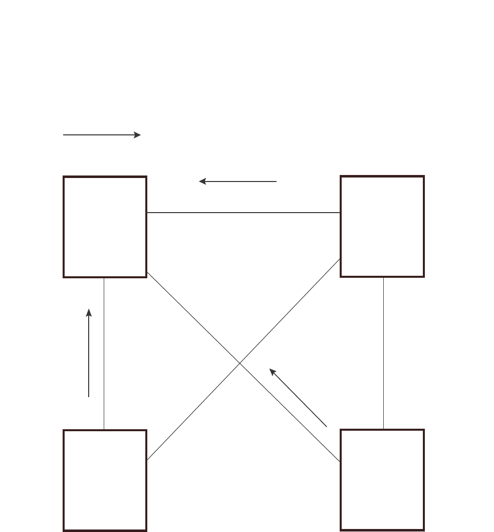
266 PowerConnect B-Series FCX Configuration Guide
53-1002266-01
Configuring STP related features
8
FIGURE 49 802.1W Draft 3 RSTP ready for failover
If the root port on a Switch becomes unavailable, 802.1W Draft 3 immediately fails over to the
alternate port, as shown in Figure 50.
Switch 1 Switch 2
Switch 4
Switch 3
Root Bridge
Bridge priority = 2 Bridge priority = 4
Root port = 2/2
Alternate = 2/3, 2/4
Bridge priority = 8
Root port = 4/4
Alternate = 4/3
Bridge priority = 6
Root port = 3/3
Alternate = 3/4
Port1/2
FWD
Port1/4
FWD
Port1/3
FWD
Port3/3
FWD
Port3/4
BLK Port4/4
FWD
Port4/3
BLK
Port2/3
FWD
Port2/4
FWD
Port2/2
FWD
The arrow shows the path
to the root bridge
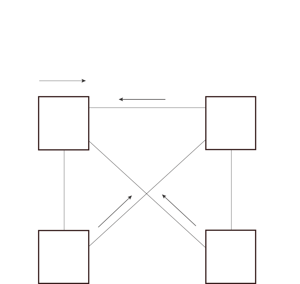
PowerConnect B-Series FCX Configuration Guide 267
53-1002266-01
Configuring STP related features 8
FIGURE 50 802.1W Draft 3 RSTP failover to alternate root port
In this example, port 3/3 on Switch 3 has become unavailable. In standard STP (802.1D), if the
root port becomes unavailable, the Switch must go through the listening and learning stages on the
alternate port to reconverge with the spanning tree. Thus, port 3/4 must go through the listening
and learning states before entering the forwarding state and thus reconverging with the spanning
tree.
802.1W Draft 3 avoids the reconvergence delay by calculating an alternate root port, and
immediately failing over to the alternate port if the root port becomes unavailable. The alternate
port is in the blocking state as long as the root port is in the forwarding state, but moves
immediately to the active state if the root port becomes unavailable. Thus, using 802.1W Draft 3,
Switch 3 immediately fails over to port 3/4, without the delays caused by the listening and learning
states.
802.1W Draft 3 selects the port with the next-best cost to the root bridge. For example, on Switch
3, port 3/3 has the best cost to the root bridge and thus is selected by STP as the root port. Port
3/4 has the next-best cost to the root bridge, and thus is selected by 802.1W Draft 3 as the
alternate path to the root bridge.
X
The arrow shows the path
to the root bridge
Switch 1 Switch 2
Switch 4
Switch 3
Port 1/2
FWD
Port 2/2
FWD
Port 1/4
FWD Port 2/4
FWD
Port 1/3
DISABLED
Root Bridge
Bridge priority = 2
Bridge priority = 6
Root port = 3/4 Bridge priority = 8
Root port = 4/4
Alternate = 4/3
Bridge priority = 4
Root port = 2/2
Alternate = 2/3, 2/4
Port 2/3
FWD
Port 4/3
BLK
Port 4/4
FWD
Port 3/4
FWD
Port 3/3
unavailable

268 PowerConnect B-Series FCX Configuration Guide
53-1002266-01
Configuring STP related features
8
Once a failover occurs, the Switch no longer has an alternate root port. If the port that was an
alternate port but became the root port fails, standard STP is used to reconverge with the network.
You can minimize the reconvergence delay in this case by setting the forwarding delay on the root
bridge to a lower value. For example, if the forwarding delay is set to 15 seconds (the default),
change the forwarding delay to a value from 3 – 10 seconds.
During failover, 802.1W Draft 3 flushes the MAC addresses leaned on the unavailable root port,
selects the alternate port as the new root port, and places that port in the forwarding state. If
traffic is flowing in both directions on the new root port, addresses are flushed (moved) in the rest
of the spanning tree automatically.
Reconvergence time
Spanning tree reconvergence using 802.1W Draft 3 can occur within one second.
After the spanning tree reconverges following the topology change, traffic also must reconverge on
all the bridges attached to the spanning tree. This is true regardless of whether 802.1W Draft 3 or
standard STP is used to reconverge the spanning tree.
Traffic reconvergence happens after the spanning tree reconvergence, and is achieved by flushing
the Layer 2 information on the bridges:
•Following 802.1W Draft 3 reconvergence of the spanning tree, traffic reconvergence occurs in
the time it takes for the bridge to detect the link changes plus the STP maximum age set on the
bridge.
•If standard STP reconvergence occurs instead, traffic reconvergence takes two times the
forward delay plus the maximum age.
NOTE
802.1W Draft 3 does not apply when a failed root port comes back up. When this happens, standard
STP is used.
Configuration considerations
802.1W Draft 3 is disabled by default. To ensure optimal performance of the feature before you
enable it,do the following:
•Configure the bridge priorities so that the root bridge is one that supports 802.1W Draft 3.
(Use a Dell PowerConnect device or third-party device that supports 802.1W Draft 3.)
•Change the forwarding delay on the root bridge to a value lower than the default 15 seconds.
Dell recommends a value from 3 – 10 seconds. The lower forwarding delay helps reduce
reconvergence delays in cases where 802.1W Draft 3 is not applicable, such as when a failed
root port comes back up.
•Configure the bridge priorities and root port costs so that each device has an active path to the
root bridge if its root port becomes unavailable. For example, port 3/4 is connected to port
2/4 on Switch 2, which has the second most favorable bridge priority in the spanning tree.
NOTE
If reconvergence involves changing the state of a root port on a bridge that supports 802.1D STP but
not 802.1W Draft 3, then reconvergence still requires the amount of time it takes for the ports on
the 802.1D bridge to change state to forwarding (as needed), and receive BPDUs from the root
bridge for the new topology.

PowerConnect B-Series FCX Configuration Guide 269
53-1002266-01
Configuring STP related features 8
Enabling 802.1W Draft 3
802.1W Draft 3 is disabled by default. The procedure for enabling the feature differs depending on
whether single STP is enabled on the device.
NOTE
STP must be enabled before you can enable 802.1W Draft 3.
Enabling 802.1W Draft 3 when single STP is not enabled
By default, each port-based VLAN on the device has its own spanning tree. To enable 802.1W Draft
3 in a port-based VLAN, enter commands such as the following.
PowerConnect(config)#vlan 10
PowerConnect(config-vlan-10)#spanning-tree rstp
Syntax: [no] spanning-tree rstp
This command enables 802.1W Draft 3. You must enter the command separately in each
port-based VLAN in which you want to run 802.1W Draft 3.
NOTE
This command does not also enable STP. To enable STP, first enter the spanning-tree command
without the rstp parameter. After you enable STP, enter the spanning-tree rstp command to enable
802.1W Draft 3.
To disable 802.1W Draft 3, enter the following command.
PowerConnect(config-vlan-10)#no spanning-tree rstp
Enabling 802.1W Draft 3 when single STP is enabled
To enable 802.1W Draft 3 on a device that is running single STP, enter the following command at
the global CONFIG level of the CLI.
PowerConnect(config)#spanning-tree single rstp
Syntax: [no] spanning-tree single rstp
This command enables 802.1W Draft 3 on the whole device.
NOTE
This command does not also enable single STP. To enable single STP, first enter the spanning-tree
single command without the rstp parameter. After you enable single STP, enter the spanning-tree
single rstp command to enable 802.1W Draft 3.
To disable 802.1W Draft 3 on a device that is running single STP, enter the following command.
PowerConnect(config)#no spanning-tree single rstp
Single Spanning Tree (SSTP)
By default, each port-based VLAN on a Dell PowerConnect device runs a separate spanning tree,
which you can enable or disable on an individual VLAN basis.

270 PowerConnect B-Series FCX Configuration Guide
53-1002266-01
Configuring STP related features
8
Alternatively, you can configure a Dell PowerConnect device to run a single spanning tree across all
ports and VLANs on the device. The Single STP feature (SSTP) is especially useful for connecting a
Dell PowerConnect device to third-party devices that run a single spanning tree in accordance with
the 802.1Q specification.
SSTP uses the same parameters, with the same value ranges and defaults, as the default STP
support on Dell PowerConnect devices. Refer to “STP parameters and defaults” on page 208.
SSTP defaults
SSTP is disabled by default. When you enable the feature, all VLANs on which STP is enabled
become members of a single spanning tree. All VLANs on which STP is disabled are excluded from
the single spanning tree.
To add a VLAN to the single spanning tree, enable STP on that VLAN.To remove a VLAN from the
single spanning tree, disable STP on that VLAN.
When you enable SSTP, all the ports that are in port-based VLANs with STP enabled become
members of a single spanning tree domain. Thus, the ports share a single BPDU broadcast
domain. The Dell PowerConnect device places all the ports in a non-configurable VLAN, 4094, to
implement the SSTP domain. However, this VLAN does not affect port membership in the
port-based VLANs you have configured. Other broadcast traffic is still contained within the
individual port-based VLANs. Therefore, you can use SSTP while still using your existing VLAN
configurations without changing your network. In addition, SSTP does not affect 802.1Q tagging.
Tagged and untagged ports alike can be members of the single spanning tree domain.
NOTE
When SSTP is enabled, the BPDUs on tagged ports go out untagged.
If you disable SSTP, all VLANs that were members of the single spanning tree run MSTP instead. In
MSTP, each VLAN has its own spanning tree. VLANs that were not members of the single spanning
tree were not enabled for STP. Therefore, STP remains disabled on those VLANs.
Enabling SSTP
To enable SSTP, use one of the following methods.
NOTE
If the device has only one port-based VLAN (the default VLAN), then the device is already running a
single instance of STP. In this case, you do not need to enable SSTP. You need to enable SSTP only
if the device contains more than one port-based VLAN and you want all the ports to be in the same
STP broadcast domain.
To configure the Dell PowerConnect device to run a single spanning tree, enter the following
command at the global CONFIG level.
PowerConnect(config)#spanning-tree single
NOTE
If the device has only one port-based VLAN, the CLI command for enabling SSTP is not listed in the
CLI. The command is listed only if you have configured a port-based VLAN.
To change a global STP parameter, enter a command such as the following at the global CONFIG
level.

PowerConnect B-Series FCX Configuration Guide 271
53-1002266-01
Configuring STP related features 8
PowerConnect(config) spanning-tree single priority 2
This command changes the STP priority for all ports to 2.
To change an STP parameter for a specific port, enter commands such as the following.
PowerConnect(config) spanning-tree single ethernet 1 priority 10
The commands shown above override the global setting for STP priority and set the priority to 10 for
port 1/1.
Here is the syntax for the global STP parameters.
Syntax: [no] spanning-tree single [forward-delay <value>] [hello-time <value>] | [maximum-age
<time>] | [priority <value>]
Here is the syntax for the STP port parameters.
Syntax: [no] spanning-tree single [ethernet <port> path-cost <value> | priority <value>]
NOTE
Both commands listed above are entered at the global CONFIG level.
Displaying SSTP information
To verify that SSTP is in effect, enter the following commands at any level of the CLI.
PowerConnect#show span
Syntax: show span [vlan <vlan-id>] | [pvst-mode] | [<num>] |
[detail [vlan <vlan-id> [ethernet <port>] | <num>]]
The vlan <vlan-id> parameter displays STP information for the specified port-based VLAN.
The pvst-mode parameter displays STP information for the device Per VLAN Spanning Tree (PVST+)
compatibility configuration. Refer to “PVST/PVST+ compatibility” on page 275.
Specify the <port> variable in the following formats:
•PowerConnect B-Series FCX stackable switches – <stack-unit/slotnum/portnum>
The <num> parameter displays only the entries after the number you specify. For example, on a
device with three port-based VLANs, if you enter 1, then information for the second and third VLANs
is displayed, but information for the first VLAN is not displayed. Information is displayed according
to VLAN number, in ascending order. The entry number is not the same as the VLAN number. For
example, if you have port-based VLANs 1, 10, and 2024, then the command output has three STP
entries. To display information for VLANs 10 and 2024 only, enter show span 1.
The detail parameter and its additional optional parameters display detailed information for
individual ports. Refer to “Displaying detailed STP information for each interface” on page 219.
STP per VLAN group
STP per VLAN group is an STP enhancement that provides scalability while overcoming the
limitations of the following scalability alternatives:
•Standard STP – You can configure up to 254 instances of standard STP on a Dell
PowerConnect device. It is possible to need more instances of STP than this in large
configurations. Using STP per VLAN group, you can aggregate STP instances.
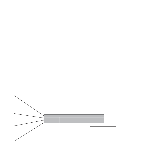
272 PowerConnect B-Series FCX Configuration Guide
53-1002266-01
Configuring STP related features
8
•Single STP – Single STP allows all the VLANs to run STP, but each VLAN runs the same instance
of STP, resulting in numerous blocked ports that do not pass any Layer 2 traffic. STP per VLAN
group uses all available links by load balancing traffic for different instances of STP on
different ports. A port that blocks traffic for one spanning tree forwards traffic for another
spanning tree.
STP per VLAN group allows you to group VLANs and apply the same STP parameter settings to all
the VLANs in the group. Figure 51 shows an example of a STP per VLAN group implementation.
FIGURE 51 STP per VLAN group example
A master VLAN contains one or more member VLANs. Each of the member VLANs in the STP Group
runs the same instance of STP and uses the STP parameters configured for the master VLAN. In
this example, the PowerConnect switch is configured with VLANs 3, 4, 13, and 14. VLANs 3 and 4
are grouped in master VLAN 2, which is in STP group 1. VLANs 13 and 14 are grouped in master
VLAN 12, which is in STP group 2. The VLANs in STP group 1 all share the same spanning tree. The
VLANs in STP group 2 share a different spanning tree.
All the portss are tagged. The ports must be tagged so that they can be in both a member VLAN
and the member's master VLAN. For example, ports 1/1 – 1/4 are in member VLAN 3 and also in
master VLAN 2 (since master VLAN 2 contains member VLAN 3).
STP load balancing
Notice that the STP groups each have different STP priorities. In configurations that use the STP
groups on multiple devices, you can use the STP priorities to load balance the STP traffic. By
setting the STP priorities for the same STP group to different values on each device, you can cause
each of the devices to be the root bridge for a different STP group. This type of configuration
distributes the traffic evenly across the devices and also ensures that ports that are blocked in one
STP group spanning tree are used by another STP group spanning tree for forwarding. Refer to
“Configuration example for STP load sharing” on page 274 for an example using STP load sharing.
Configuring STP per VLAN group
To configure STP per VLAN group,do the following:
•Configure the member VLANs.
•Optionally, configure master VLANs to contain the member VLANs. This is useful when you
have a lot of member VLANs and you do not want to individually configure STP on each one.
Each of the member VLANs in the STP group uses the STP settings of the master VLAN.
•Configure the STP groups. Each STP group runs a separate instance of STP.
Member
VLAN 3
Member
VLAN 4
Member
VLAN 13
Member
VLAN 14
STP group 1
Master VLAN 2
Member VLAN 3
Member VLAN 4
STP priority 1
STP group 2
Master VLAN 12
Member VLAN 13
Member VLAN 14
STP priority 2
Switch

PowerConnect B-Series FCX Configuration Guide 273
53-1002266-01
Configuring STP related features 8
Here are the CLI commands for implementing the STP per VLAN group configuration shown in
Figure 51. The following commands configure the member VLANs (3, 4, 13, and 14) and the
master VLANs (2 and 12). Notice that changes to STP parameters are made in the master VLANs
only, not in the member VLANs.
PowerConnect(config)#vlan 2
PowerConnect(config-vlan-2)#spanning-tree priority 1
PowerConnect(config-vlan-2)#tagged ethernet 1/1 to 1/4
PowerConnect(config-vlan-2)#vlan 3
PowerConnect(config-vlan-3)#tagged ethernet 1/1 to 1/4
PowerConnect(config-vlan-3)#vlan 4
PowerConnect(config-vlan-4)#tagged ethernet 1/1 to 1/4
PowerConnect(config-vlan-4)#vlan 12
PowerConnect(config-vlan-12)#spanning-tree priority 2
PowerConnect(config-vlan-12)#tagged ethernet 1/1 to 1/4
PowerConnect(config-vlan-12)#vlan 13
PowerConnect(config-vlan-13)#tagged ethernet 1/1 to 1/4
PowerConnect(config-vlan-13)#vlan 14
PowerConnect(config-vlan-14)#tagged ethernet 1/1 to 1/4
PowerConnect(config-vlan-14)#exit
The following commands configure the STP groups.
PowerConnect(config)#stp-group 1
PowerConnect(config-stp-group-1)#master-vlan 2
PowerConnect(config-stp-group-1)#member-vlan 3 to 4
PowerConnect(config-stp-group-1)#exit
PowerConnect(config)#stp-group 2
PowerConnect(config-stp-group-2)#master-vlan 12
PowerConnect(config-stp-group-2)#member-vlan 13 to 14
Syntax: [no] stp-group <num>
This command changes the CLI to the STP group configuration level. The following commands are
valid at this level. The <num> parameter specifies the STP group ID and can be from 1 – 32.
Syntax: [no] master-vlan <num>
This command adds a master VLAN to the STP group. The master VLAN contains the STP settings
for all the VLANs in the STP per VLAN group. The <num> parameter specifies the VLAN ID. An STP
group can contain one master VLAN.
NOTE
If you delete the master VLAN from an STP group, the software automatically assigns the first
member VLAN in the group to be the new master VLAN for the group.
Syntax: [no] member-vlan <num> [to <num>]
This command adds additional VLANs to the STP group. These VLANs also inherit the STP settings
of the master VLAN in the group.
Syntax: [no] member-group <num>
This command adds a member group (a VLAN group) to the STP group. All the VLANs in the
member group inherit the STP settings of the master VLAN in the group. The <num> parameter
specifies the VLAN group ID.
NOTE
This command is optional and is not used in the example above. For an example of this command,
refer to “Configuration example for STP load sharing”.
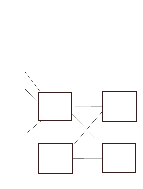
274 PowerConnect B-Series FCX Configuration Guide
53-1002266-01
Configuring STP related features
8
Configuration example for STP load sharing
Figure 52 shows another example of a STP per VLAN group implementation.
FIGURE 52 More complex STP per VLAN group example
In this example, each of the devices in the core is configured with a common set of master VLANs,
each of which contains one or more member VLANs. Each of the member VLANs in an STP group
runs the same instance of STP and uses the STP parameters configured for the master VLAN.
The STP group ID identifies the STP instance. All VLANs within an STP group run the same instance
of STP. The master VLAN specifies the bridge STP parameters for the STP group, including the
bridge priority. In this example, each of the devices in the core is configured to be the default root
bridge for a different master VLAN. This configuration ensures that each link can be used for
forwarding some traffic. For example, all the ports on the root bridge for master VLAN 1 are
configured to forward BPDUs for master VLAN spanning tree. Ports on the other devices block or
forward VLAN 1 traffic based on STP convergence. All the ports on the root bridge for VLAN 2
forward VLAN 2 traffic, and so on.
All the portss are tagged. The ports must be tagged so that they can be in both a member VLAN
and the member's master VLAN. For example, port 1/1 – and ports 5/1, 5/2, and 5/3 are in
member VLAN 2 and master VLAN 1 (since master VLAN a contains member VLAN 2).
Here are the commands for configuring the root bridge for master VLAN 1 in figure Figure 51 for
STP per VLAN group. The first group of commands configures the master VLANs. Notice that the
STP priority is set to a different value for each VLAN. In addition, the same VLAN has a different
STP priority on each device. This provides load balancing by making each of the devices a root
bridge for a different spanning tree.
PowerConnect(config)#vlan 1
PowerConnect(config-vlan-1)#spanning-tree priority 1
PowerConnect(config-vlan-1)#tag ethernet 1/1 ethernet 5/1 to 5/3
PowerConnect(config-vlan-1)#vlan 201
PowerConnect(config-vlan-201)#spanning-tree priority 2
Member VLANs
2 - 200
Member VLANs
202 - 400
Member VLANs
402 - 600
Member VLANs
3802 - 4000
Root bridge
for master VLAN 1 Root bridge
for master VLAN 201
Root bridge
for master VLAN 401 Root bridge
for master VLAN 3801
FWD 1
FWD 1
FWD 1
BLK 1
BLK 1
5/1
5/2
5/3

PowerConnect B-Series FCX Configuration Guide 275
53-1002266-01
PVST/PVST+ compatibility 8
PowerConnect(config-vlan-201)#tag ethernet 1/2 ethernet 5/1 to 5/3
PowerConnect(config-vlan-201)#vlan 401
PowerConnect(config-vlan-401)#spanning-tree priority 3
PowerConnect(config-vlan-401)#tag ethernet 1/3 ethernet 5/1 to 5/3
...
PowerConnect(config-vlan-3601)#vlan 3801
PowerConnect(config-vlan-3801)#spanning-tree priority 20
PowerConnect(config-vlan-3801)#tag ethernet 1/20 ethernet 5/1 to 5/3
PowerConnect(config-vlan-3801)#exit
The next group of commands configures VLAN groups for the member VLANs. Notice that the VLAN
groups do not contain the VLAN numbers assigned to the master VLANs. Also notice that no STP
parameters are configured for the groups of member VLANs. Each group of member VLANs will
inherit its STP settings from its master VLAN.
Set the bridge priority for each master VLAN to the highest priority (1) on one of the devices in the
STP per VLAN group configuration. By setting the bridge priority to the highest priority, you make
the device the default root bridge for the spanning tree. To ensure STP load balancing, make each
of the devices the default root bridge for a different master VLAN.
PowerConnect(config)#vlan-group 1 vlan 2 to 200
PowerConnect(config-vlan-group-1)#tag ethernet 1/1 ethernet 5/1 to 5/3
PowerConnect(config-vlan-group-1)#vlan-group 2 vlan 202 to 400
PowerConnect(config-vlan-group-2)#tag ethernet 1/2 ethernet 5/1 to 5/3
PowerConnect(config-vlan-group-2)#vlan-group 3 vlan 402 to 600
PowerConnect(config-vlan-group-2)#tag ethernet 1/3 ethernet 5/1 to 5/3
...
PowerConnect(config-vlan-group-19)#vlan-group 20 vlan 3082 to 4000
PowerConnect(config-vlan-group-20)#tag ethernet 1/20 ethernet 5/1 to 5/3
PowerConnect(config-vlan-group-20)#exit
The following group of commands configures the STP groups. Each STP group in this configuration
contains one master VLAN, which contains a VLAN group. This example shows that an STP group
also can contain additional VLANs (VLANs not configured in a VLAN group).
PowerConnect(config)#stp-group 1
PowerConnect(config-stp-group-1)#master-vlan 1
PowerConnect(config-stp-group-1)#member-group 1
PowerConnect(config-stp-group-1)#member-vlan 4001 4004 to 4010
PowerConnect(config-stp-group-1)#stp-group 2
PowerConnect(config-stp-group-2)#master-vlan 201
PowerConnect(config-stp-group-2)#member-group 2
PowerConnect(config-stp-group-2)#member-vlan 4002 4003 4011 to 4015
PowerConnect(config-stp-group-2)#stp-group 3
PowerConnect(config-stp-group-3)#master-vlan 401
PowerConnect(config-stp-group-3)#member-group 3
...
PowerConnect(config-stp-group-19)#stp-group 20
PowerConnect(config-stp-group-20)#master-vlan 3081
PowerConnect(config-stp-group-20)#member-group 20
PVST/PVST+ compatibility
The PowerConnect family of switches support Cisco's Per VLAN Spanning Tree plus (PVST+), by
allowing the device to run multiple spanning trees (MSTP) while also interoperating with IEEE
802.1Q devices1.

276 PowerConnect B-Series FCX Configuration Guide
53-1002266-01
PVST/PVST+ compatibility
8
NOTE
Dell PowerConnect ports automatically detect PVST+ BPDUs and enable support for the BPDUs once
detected. You do not need to perform any configuration steps to enable PVST+ support. However,
to support the IEEE 802.1Q BPDUs, you might need to enable dual-mode support.
Support for Cisco's Per VLAN Spanning Tree plus (PVST+), allows a Dell PowerConnect device to run
multiple spanning trees (MSTP) while also interoperating with IEEE 802.1Q devices. Dell
PowerConnect ports automatically detect PVST+ BPDUs and enable support for the BPDUs once
detected. The enhancement allows a port that is in PVST+ compatibility mode due to
auto-detection to revert to the default MSTP mode when one of the following events occurs:
•The link is disconnected or broken
•The link is administratively disabled
•The link is disabled by interaction with the link-keepalive protocol
This enhancement allows a port that was originally interoperating with PVST+ to revert to MSTP
when connected to a Dell PowerConnect device.
Overview of PVST and PVST+
Per VLAN Spanning Tree (PVST) is a Cisco proprietary protocol that allows a Cisco device to have
multiple spanning trees. The Cisco device can interoperate with spanning trees on other PVST
devices but cannot interoperate with IEEE 802.1Q devices. An IEEE 802.1Q device has all its ports
running a single spanning tree. PVST+ is an extension of PVST that allows a Cisco device to also
interoperate with devices that are running a single spanning tree (IEEE 802.1Q).
Enhanced PVST+ support allows a Dell PowerConnect device to interoperate with PVST spanning
trees and the IEEE 802.1Q spanning tree at the same time.
IEEE 802.1Q and PVST regions cannot interoperate directly but can interoperate indirectly through
PVST+ regions. PVST BPDUs are tunnelled through 802.1Q regions, while PVST BPDUs for VLAN 1
(the IEEE 802.1Q VLAN) are processed by PVST+ regions. Figure 53 shows the interaction of IEEE
802.1Q, PVST, and PVST+ regions.
1. Cisco user documentation for PVST/PVST+ refers to the IEEE 802.1Q spanning tree as the
Common Spanning Tree (CST).
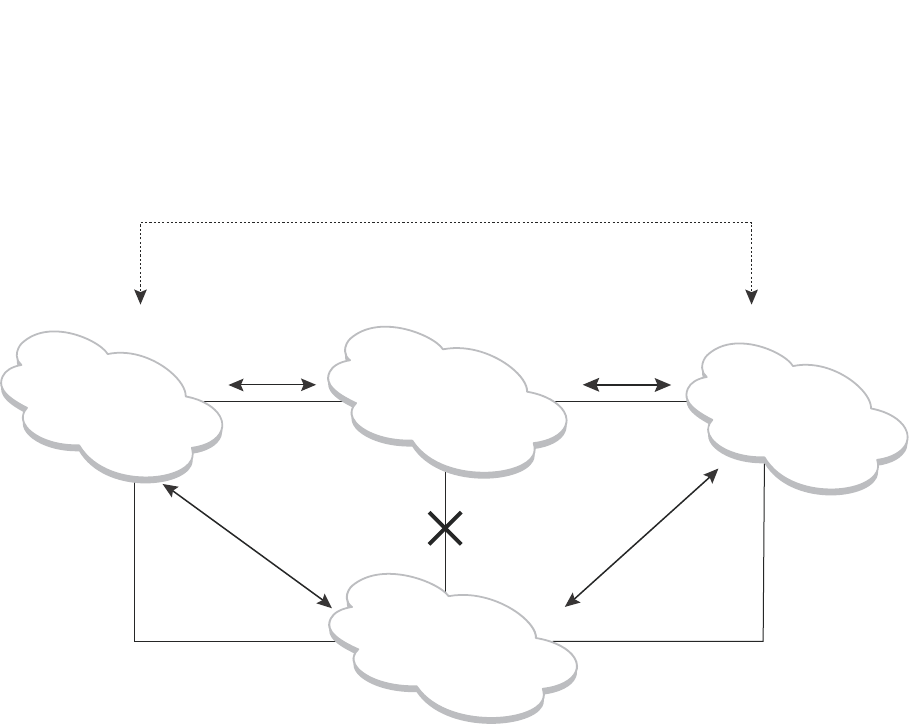
PowerConnect B-Series FCX Configuration Guide 277
53-1002266-01
PVST/PVST+ compatibility 8
FIGURE 53 Interaction of IEEE 802.1Q, PVST, and PVST+ regions
VLAN tags and dual mode
The dual-mode feature enables a port to send and receive both tagged and untagged frames.
When the dual-mode feature is enabled on a port, the port is an untagged member of one of its
VLANs and is at the same time a tagged member of all its other VLANs. The untagged frames are
supported on the port Port Native VLAN.
The dual-mode feature must be enabled on a Dell PowerConnect port in order to interoperate with
another vendor device. Some vendors use VLAN 1 by default to support the IEEE 802.1Q-based
standard spanning tree protocols, such as 802.1d and 802.1w for sending untagged frames on
VLAN 1. On Dell PowerConnect switches, by default, the Port Native VLAN is the same as the
Default VLAN, which is VLAN 1. Thus, to support IEEE 802.1Q in a typical configuration, a port must
be able to send and receive untagged frames for VLAN 1 and tagged frames for the other VLANs,
and interoperate with other vendor devices using VLAN 1.
If you want to use tagged frames on VLAN 1, you can change the default VLAN ID to an ID other
than 1. You also can specify the VLAN on which you want the port to send and receive untagged
frames (the Port Native VLAN). The Port Native VLAN ID does not need to be the same as the
default VLAN. Make sure that the untagged (native) VLAN is also changed on the interoperating
vendor side to match that on the Dell PowerConnect side.
To support the IEEE 802.1Q with non-standard proprietary protocols such as PVST and PVST+, a
port must always send and receive untagged frames on VLAN 1 on both sides. In this case, enable
the dual-mode 1 feature to allow untagged BPDUs on VLAN 1and use Native VLAN 1 on the
interoperating vendor side. You should not use VLAN 1 for tagged frames in this case.
PVST+Region IEEE 802.1Q Region PVST+Region
PVST Region
PVST BPDUs
(over ISL trunks)
PVST BPDUs
(over ISL trunks)
Do not
connect
dual mode
port
dual mode
port
802.1D BPDUs 802.1D BPDUs
PVST BPDUs tunneled through
the IEEE 802.1Q region

278 PowerConnect B-Series FCX Configuration Guide
53-1002266-01
PVST/PVST+ compatibility
8
Configuring PVST+ support
PVST+ support is automatically enabled when the port receives a PVST BPDU. You can manually
enable the support at any time or disable the support if desired.
If you want a tagged port to also support IEEE 802.1Q BPDUs, you need to enable the dual-mode
feature on the port. The dual-mode feature is disabled by default and must be enabled manually.
A port that is in PVST+ compatibility mode due to auto-detection reverts to the default MSTP mode
when one of the following events occurs:
•The link is disconnected or broken
•The link is administratively disabled
•The link is disabled by interaction with the link-keepalive protocol
This allows a port that was originally interoperating with PVST+ to revert to MSTP when connected
to a Dell PowerConnect device.
Enabling PVST+ support manually
To immediately enable PVST+ support on a port, enter commands such as the following.
PowerConnect(config)#interface ethernet 1/1
PowerConnect(config-if-1/1)#pvst-mode
Syntax: [no] pvst-mode
NOTE
If you disable PVST+ support, the software still automatically enables PVST+ support if the port
receives a BPDU with PVST+ format.
NOTE
If 802.1W and pvst-mode (either by auto-detection or by explicit configuration) are enabled on a
tagged VLAN port, 802.1W will treat the PVST BPDUs as legacy 802.1D BPDUs.
Enabling dual-mode support
To enable the dual-mode feature on a port, enter the following command at the interface
configuration level for the port.
PowerConnect(config-if-1/1)#dual-mode
Syntax: [no] dual-mode [<vlan-id>]
The <vlan-id> specifies the port Port Native VLAN. This is the VLAN on which the port will support
untagged frames. By default, the Port Native VLAN is the same as the default VLAN (which is VLAN
1 by default).
For more information about the dual-mode feature, refer to “Dual-mode VLAN ports” on page 497.
Displaying PVST+ support information
To display PVST+ information for ports on a Dell PowerConnect device, enter the following
command at any level of the CLI.
PowerConnect B-Series FCX Configuration Guide 279
53-1002266-01
PVST/PVST+ compatibility 8
Syntax: show span pvst-mode
This command displays the following information.
Configuration examples
The following examples show configuration examples for two common configurations:
•Untagged IEEE 802.1Q BPDUs on VLAN 1 and tagged PVST+ BPDUs on other VLANs
•Tagged IEEE 802.1Q BPDUs on VLAN 1 and untagged BPDUs on another VLAN
Tagged port using default VLAN 1 as its port native VLAN
Figure 54 shows an example of a PVST+ configuration that uses VLAN 1 as the untagged default
VLAN and VLANs 2, 3, and 4 as tagged VLANs.
FIGURE 54 Default VLAN 1 for untagged BPDU
To implement this configuration, enter the following commands.
TABLE 55 CLI display of PVST+ information
This field... Displays...
Port The Dell PowerConnect port number.
NOTE: The command lists information only for the ports on which
PVST+ support is enabled.
Method The method by which PVST+ support was enabled on the port. The
method can be one of the following:
•Set by configuration – You enabled the support.
•Set by auto-detect – The support was enabled automatically when
the port received a PVST+ BPDU.
PowerConnect#show span pvst-mode
PVST+ Enabled on:
Port Method
1/1 Set by configuration
1/2 Set by configuration
2/10 Set by auto-detect
3/12 Set by configuration
4/24 Set by auto-detect
Port1/2
Port1/1
Untagged IEEE BPDU for VLAN 1
Untagged PVST BPDU for VLAN 1
Tagged PVST BPDUs for VLANs 2, 3, 4
Another
device
280 PowerConnect B-Series FCX Configuration Guide
53-1002266-01
PVST/PVST+ compatibility
8
Commands on the Dell PowerConnect Device
PowerConnect(config)#vlan-group 1 vlan 2 to 4
PowerConnect(config-vlan-group-1)#tagged ethernet 1/1
PowerConnect(config-vlan-group-1)#exit
PowerConnect(config)#interface ethernet 1/1
PowerConnect(config-if-1/1)#dual-mode
PowerConnect(config-if-1/1)#pvst-mode
These commands configure a VLAN group containing VLANs 2, 3, and 4, add port 1/1 as a tagged
port to the VLANs, and enable the dual-mode feature and PVST+ support on the port. The
dual-mode feature allows the port to send and receive untagged frames for the default VLAN (VLAN
1 in this case) in addition to tagged frames for VLANs 2, 3, and 4. Enabling the PVST+ support
ensures that the port is ready to send and receive PVST+ BPDUs. If you do not manually enable
PVST+ support, the support is not enabled until the port receives a PVST+ BPDU.
The configuration leaves the default VLAN and the port Port Native VLAN unchanged. The default
VLAN is 1 and the port Port Native VLAN also is 1. The dual-mode feature supports untagged
frames on the default VLAN only. Thus, port 1/1 can send and receive untagged BPDUs for VLAN 1
and can send and receive tagged BPDUs for the other VLANs.
Port 1/1 will process BPDUs as follows:
•Process IEEE 802.1Q BPDUs for VLAN 1.
•Process tagged PVST BPDUs for VLANs 2, 3, and 4.
•Drop untagged PVST BPDUs for VLAN 1.
Untagged port using VLAN 2 as port native VLAN
Figure 55 shows an example in which a port Port Native VLAN is not VLAN 1. In this case, VLAN 1
uses tagged frames and VLAN 2 uses untagged frames.
FIGURE 55 Port Native VLAN 2 for Untagged BPDUs
To implement this configuration, enter the following commands.
Commands on the Dell PowerConnect Device
PowerConnect(config)#default-vlan-id 4000
PowerConnect(config)#vlan 1
PowerConnect(config-vlan-1)#tagged ethernet 1/1
PowerConnect(config-vlan-1)#exit
PowerConnect(config)#vlan 2
PowerConnect(config-vlan-2)#tagged ethernet 1/1
PowerConnect(config-vlan-2)#exit
PowerConnect(config)#interface ethernet 1/1
PowerConnect(config-if-1/1)#dual-mode 2
PowerConnect(config-if-1/1)#pvst-mode
PowerConnect(config-if-1/1)#exit
Port3/2
Port1/1
Untagged IEEE BPDU for VLAN 1
Tagged PVST BPDU for VLAN 1
Untagged PVST BPDUs for VLAN 2
Another
device

PowerConnect B-Series FCX Configuration Guide 281
53-1002266-01
PVST/PVST+ compatibility 8
These commands change the default VLAN ID, configure port 1/1 as a tagged member of VLANs 1
and 2, and enable the dual-mode feature and PVST+ support on port 1/1. Since VLAN 1 is tagged
in this configuration, the default VLAN ID must be changed from VLAN 1 to another VLAN ID.
Changing the default VLAN ID from 1 allows the port to process tagged frames for VLAN 1. VLAN 2
is specified with the dual-mode command, which makes VLAN 2 the port Port Native VLAN. As a
result, the port processes untagged frames and untagged PVST BPDUs on VLAN 2.
NOTE
Although VLAN 2 becomes the port untagged VLAN, the CLI still requires that you add the port to the
VLAN as a tagged port, since the port is a member of more than one VLAN.
Port 1/1 will process BPDUs as follows:
•Process IEEE 802.1Q BPDUs for VLAN 1.
•Process untagged PVST BPDUs for VLAN 2.
•Drop tagged PVST BPDUs for VLAN 1.
Note that when VLAN 1 is not the default VLAN, the ports must have the dual-mode feature enabled
in order to process IEEE 802.1Q BPDUs.
For example, the following configuration is incorrect.
PowerConnect(config)#default-vlan-id 1000
PowerConnect(config)#vlan 1
PowerConnect(config-vlan-1)#tagged ethernet 1/1 to 1/2
PowerConnect(config-vlan-1)#exit
PowerConnect(config)#interface ethernet 1/1
PowerConnect(config-if-1/1)#pvst-mode
PowerConnect(config-if-1/1)#exit
PowerConnect(config)#interface ethernet 1/2
PowerConnect(config-if-1/2)#pvst-mode
PowerConnect(config-if-1/2)#exit
In the configuration above, all PVST BPDUs associated with VLAN 1 would be discarded. Since IEEE
BPDUs associated with VLAN 1 are untagged, they are discarded because the ports in VLAN 1 are
tagged. Effectively, the BPDUs are never processed by the Spanning Tree Protocol. STP assumes
that there is no better bridge on the network and sets the ports to FORWARDING. This could cause
a Layer 2 loop.
The following configuration is correct.
PowerConnect(config)#default-vlan-id 1000
PowerConnect(config)#vlan 1
PowerConnect(config-vlan-1)#tagged ethernet 1/1 to 1/2
PowerConnect(config-vlan-1)#exit
PowerConnect(config)#interface ethernet 1/1
PowerConnect(config-if-1/1)#pvst-mode
PowerConnect(config-if-1/1)#dual-mode
PowerConnect(config-if-1/1)#exit
PowerConnect(config)#interface ethernet 1/2
PowerConnect(config-if-1/2)#pvst-mode
PowerConnect(config-if-1/2)#dual-mode
PowerConnect(config-if-1/2)#exit
Setting the ports as dual-mode ensures that the untagged IEEE 802.1Q BPDUs reach the VLAN 1
instance.

282 PowerConnect B-Series FCX Configuration Guide
53-1002266-01
PVRST compatibility
8
PVRST compatibility
PVRST, the "rapid" version of per-VLAN spanning tree (PVST), is a Cisco proprietary protocol. PVRST
corresponds to the Dell PowerConnect full implementation of IEEE 802.1w (RSTP). Likewise, PVST,
also a Cisco proprietary protocol, corresponds to the Dell PowerConnect implementation of IEEE
802.1D (STP). When a Dell PowerConnect device receives PVRST BPDUs on a port configured to
run 802.1w, it recognizes and processes these BPDUs and continues to operate in 802.1w mode.
PVRST compatibility is automatically enabled when a port receives a PVRST BPDU.
BPDU guard
In an STP environment, switches, end stations, and other Layer 2 devices use Bridge Protocol Data
Units (BPDUs) to exchange information that STP will use to determine the best path for data flow.
The BPDU guard, an enhancement to STP, removes a node that reflects BPDUs back in the
network. It enforces the STP domain borders and keeps the active topology predictable by not
allowing any network devices behind a BPDU guard-enabled port to participate in STP.
In some instances, it is unnecessary for a connected device, such as an end station, to initiate or
participate in an STP topology change. In this case, you can enable the STP BPDU guard feature on
the Dell PowerConnect port to which the end station is connected. STP BPDU guard shuts down the
port and puts it into an errdisable state. This disables the connected device's ability to initiate or
participate in an STP topology. A log message is then generated for a BPDU guard violation, and a
CLI message is displayed to warn the network administrator of a severe invalid configuration. The
BPDU guard feature provides a secure response to invalid configurations because the
administrator must manually put the interface back in service if errdisable recovery is not enabled.
NOTE
BPDU guard is not supported on tagged ports. It can be configured on a tagged port, but the
configuration will have no effect.
Enabling BPDU protection by port
You enable STP BPDU guard on individual interfaces. The feature is disabled by default.
To enable STP BPDU guard on a specific port, enter commands such as the following.
PowerConnect(config) interface ethe 2/1
PowerConnect(config-if-e1000-2/1)#stp-bpdu-guard
Syntax: [no] stp-bpdu-guard
The no parameter disables the BPDU guard on this interface.
You can also use the multiple interface command to enable this feature on multiple ports at once.
Example
PowerConnect(config)#interface ethernet 1/1 to 1/9
PowerConnect(config-mif-1/1-1/9)#stp-bpdu-guard
PowerConnect(config-mif-1/1-1/9)#
This will enable stp-bpdu-guard on ports 0/1/1 to 0/1/9

PowerConnect B-Series FCX Configuration Guide 283
53-1002266-01
BPDU guard 8
Re-enabling ports disabled by BPDU guard
When a BPSU Guard-enabled port is disabled by BPDU Guard, the Dell PowerConnect device will
place the port in errdisable state and display a message on the console indicating that the port is
errdisabled (refer to “Example console messages” on page 284). In addition, the show interface
command output will indicate that the port is errdisabled.
Example
PowerConnect#show int e 2
Gigabit Ethernet2 is ERR-DISABLED (bpduguard), line protocol is down
To re-enable a port that is in errdisable state, you must first disable the port then re-enable it.
Enter commands such as the following.
PowerConnect(config)#int e 2
PowerConnect(config-if-e1000-2)#disable
PowerConnect(config-if-e1000-2)#enable
If you attempt to enable an errdisabled port without first disabling it, the following error message
will appear on the console.
PowerConnect(config-if-e1000-2)#enable
Port 2 is errdisabled, do disable first and then enable to enable it
Displaying the BPDU guard status
To display the BPDU guard state, enter the show running configuration or the show stp-bpdu-guard
command.
For PowerConnect B-Series FCXdevices, enter the following commands.
PowerConnect#show stp-bpdu-guard
BPDU Guard Enabled on:
Ports: (Stk0/S1) 2 3 4 5 9 10 11 12 13 14 15 16
Ports: (Stk0/S1) 17 18 19 20 21 22 23 24
Syntax: show stp-bpdu-guard
Example configurations
Example
The following example shows how to configure BPDU guard at the interface level and to verify the
configuration by issuing the show stp-bpdu-guard and the show interface commands.
PowerConnect Router(config)#interface ethernet 1
PowerConnect Router(config-if-e1000-1)#stp-bpdu-guard
PowerConnect Router(config-if-e1000-1)#
PowerConnect Router(config-if-e1000-1)#show stp-bpdu-guard
BPDU Guard Enabled on:
Port
1
PowerConnect(config-if-e1000-1)#
PowerConnect(config-if-e1000-1)#show interfaces ethernet 1
GigabitEthernet1 is up, line protocol is up
Hardware is GigabitEthernet, address is 000c.dba0.7100 (bia 000c.dba0.7100)
Configured speed auto, actual 100Mbit, configured duplex fdx, actual fdx
Configured mdi mode AUTO, actual MDI
Member of L2 VLAN ID 2, port is untagged, port state is FORWARDING
BPDU guard is Enabled, ROOT protect is Disabled

284 PowerConnect B-Series FCX Configuration Guide
53-1002266-01
Root guard
8
STP configured to ON, priority is level0, flow control enabled
mirror disabled, monitor disabled
Not member of any active trunks
Not member of any configured trunks
No port name
IPG MII 96 bits-time, IPG GMII 96 bits-time
IP MTU 1500 bytes
300 second input rate: 8 bits/sec, 0 packets/sec, 0.00% utilization
300 second output rate: 256 bits/sec, 0 packets/sec, 0.00% utilization
88 packets input, 15256 bytes, 0 no buffer
Received 75 broadcasts, 13 multicasts, 0 unicasts
1 input errors, 0 CRC, 0 frame, 0 ignored
0 runts, 0 giants
4799 packets output, 313268 bytes, 0 underruns
Transmitted 90 broadcasts, 4709
Example console messages
A console message such as the following is generated after a BPDU guard violation occurs on a
system that is running MSTP.
PowerConnect(config-if-e1000-23)#MSTP: Received BPDU on BPDU guard enabled Port
23,errdisable Port 23
A console message such as the following is generated after a BPDU guard violation occurs on a
system that is running STP.
PowerConnect(config)#STP: Received BPDU on BPDU guard enabled Port 23 (vlan=1),
errdisable Port 23
A console message such as the following is generated after a BPDU guard violation occurs on a
system that is running RSTP.
PowerConnect(config-vlan-1)#RSTP: Received BPDU on BPDU guard enabled Port 23
(vlan=1),errdisable Port 23
Root guard
The standard STP (802.1D), RSTP (802.1W) or 802.1S does not provide any way for a network
administrator to securely enforce the topology of a switched layer 2 network. The forwarding
topology of a switched network is calculated based on the root bridge position, along with other
parameters. This means any switch can be the root bridge in a network as long as it has the lowest
bridge ID. The administrator cannot enforce the position of the root bridge. A better forwarding
topology comes with the requirement to place the root bridge at a specific predetermined location.
Root Guard can be used to predetermine a root bridge location and prevent rogue or unwanted
switches from becoming the root bridge.
When root guard is enabled on a port, it keeps the port in a designated role. If the port receives a
superior STP Bridge Protocol Data Units (BPDU), it puts the port into a ROOT-INCONSISTANT state
and triggers a log message and an SNMP trap. The ROOT-INCONSISTANT state is equivalent to the
BLOCKING state in 802.1D and to the DISCARDING state in 802.1W. No further traffic is forwarded
on this port. This allows the bridge to prevent traffic from being forwarded on ports connected to
rogue or misconfigured STP bridges.
Once the port stops receiving superior BPDUs, root guard automatically sets the port back to
learning, and eventually to a forwarding state through the spanning-tree algorithm.

PowerConnect B-Series FCX Configuration Guide 285
53-1002266-01
Root guard 8
Configure root guard on all ports where the root bridge should not appear. This establishes a
protective network perimeter around the core bridged network, cutting it off from the user network.
NOTE
Root guard may prevent network connectivity if it is improperly configured. Root guard must be
configured on the perimeter of the network rather than the core.
NOTE
Root guard is not supported when MSTP is enabled.
Enabling STP root guard
An STP root guard is configured on an interface by entering commands similar to the following.
PowerConnect(config)#interface ethernet 5/5
PowerConnect(config-if-e10000-5/5)spanning-tree root-protect
Syntax: [no] spanning-tree root-protect
Enter the no form of the command to disable STP root guard on the port.
Displaying the STP root guard
To display the STP root guard state, enter the show running configuration or the show spanning-tree
root-protect command.
PowerConnect#show spanning-tree root-protect
Root Protection Enabled on:
Port 1
Syntax: show spanning-tree root-protect
Displaying the root guard by VLAN
You can display root guard information for all VLANs or for a specific VLAN. For example, to display
root guard violation information for VLAN 7.
Syntax: show spanning-tree [<vlan-id>]
If you do not specify a <vlan-id>, information for all VLANs is displayed. For example, to display root
guard violation information for VLAN 7.
PowerConnect#show spanning-tree vlan 7
STP instance owned by VLAN 7
Global STP (IEEE 802.1D) Parameters:
VLAN Root Root Root Prio Max He- Ho- Fwd Last Chg Bridge
ID ID Cost Port rity Age llo ld dly Chang cnt Address
Hex sec sec sec sec sec
7 a000000011112220 0 Root a000 20 2 1 15 4 4 000011112220
Port STP Parameters:
Port Prio Path State Fwd Design Designated Designated
Num rity Cost Trans Cost Root Bridge
Hex
1 80 19 ROOT-INCONS 2 0 a000000011112220 a000000011112220

286 PowerConnect B-Series FCX Configuration Guide
53-1002266-01
Error disable recovery
8
Error disable recovery
In case a BPDU guard violation occurs, a port is placed into an errdisable state which is functionally
equivalent to a Disable state. Once in an errdiable state, it remains in that state until one of the
following methods is used to return the port to an Enabled state.
1. Manually disabling and enabling that interface
2. Automatically, through the errdisable recovery mechanism
The errdisable recovery interval command is used to configure a time-out for ports in errdisable
state, after which the ports are re-enabled automatically.
When BPDU guard puts a port into errdisabled state, the port remains in errdisabled state unless it
is enabled manually by issuing a disable command and then the enable command on the
associated interface or you have errdisable recovery turned on. The errdisable command allows
you to choose the type of error that automatically reenables the port after a specified amount of
time.
Enabling error disable recovery
To enable errdisable recovery for BPDU Guard, enter a command such as the following.
PowerConnect(config)#errdisable recovery cause bpduguard
To enable error disable recovery for any reason, enter a command such as the following.
PowerConnect(config)#errdisable recovery cause all
Syntax: errdisable recovery [cause bpduguard l all]
The cause is the reason why the port is in the errdisable state. Valid values are bpduguard and all.
Use the bpduguard parameter to allow the port to recover from the errdisabled state, if the state
was caused by a BPDU guard violation.
The all parameter allows ports to recover from an errdisabled state caused by any reason, for
example, a BPDU Guard violation or loop detection violation.
Setting the recovery interval
The errdisable recovery interval command allows you to configure a timeout for ports in errdisable
state, after which the ports are reenabled automatically. To set the errdisable recovery time-out
interval, enter a command such as the following.
PowerConnect(config)#errdisable recovery interval 20
Syntax: [no] errdisable recovery interval <seconds>
The seconds paramter allows you to set the timeout value for the recovery mechanism when the
port is in an errdisabled state. Once this timeout value expires, the ports are automatically
re-enabled. Valid values are from 10 to 65535 seconds (10 seconds to 24 hours).

PowerConnect B-Series FCX Configuration Guide 287
53-1002266-01
Error disable recovery 8
Displaying the error disable recovery state by interface
The port status of errdisabled displays in the output of the show interface and the show interface
brief commands. In this example, errdisable is enabled on interface ethernet 1 and errdisable is
enabled because of a BPDU guard violation.
PowerConnect#show interfaces ethernet 1
GigabitEthernet1 is ERR-DISABLED (bpduguard), line protocol is down
BPDU guard is Enabled, ROOT protect is Disabled
Hardware is GigabitEthernet, address is 000c.dba0.7100 (bia 000c.dba0.7100)
Configured speed auto, actual unknown, configured duplex fdx, actual unknown
Configured mdi mode AUTO, actual unknown
Member of L2 VLAN ID 2, port is untagged, port state is DISABLED
STP configured to ON, priority is level0, flow control enabled
mirror disabled, monitor disabled
Not member of any active trunks
Not member of any configured trunks
No port name
IPG MII 96 bits-time, IPG GMII 96 bits-time
IP MTU 1500 bytes
300 second input rate: 0 bits/sec, 0 packets/sec, 0.00% utilization
300 second output rate: 0 bits/sec, 0 packets/sec, 0.00% utilization
145 packets input, 23561 bytes, 0 no buffer
Received 124 broadcasts, 21 multicasts, 0 unicasts
1 input errors, 0 CRC, 0 frame, 0 ignored
0 runts, 0 giants
5067 packets output, 330420 bytes, 0 underruns
Transmitted 90 broadcasts, 4977 multicasts, 0 unicasts
0 output errors, 0 collisions
Displaying the recovery state for all conditions
Use the show errdisable recovery command to display all the default error disable recovery state
for all possible conditions. In this example, port 6 is undergoing a recovery.
PowerConnect#show errdisable recovery
ErrDisable Reason Timer Status
--------------------------------------
all reason Disabled
bpduguard Enabled
Timeout Value: 300 seconds
Interface that will be enabled at the next timeout:
Interface Errdisable reason Time left (sec)
-------------- ----------------- ---------------
Port 6 bpduguard 297
Syntax: show errdisable recovery
Displaying the recovery state by port number and cause
To see which ports are under an errdisabled state, use the show errdisable summary command.
This command not only shows the port number, but also displays the reason why the port is in an
errdisable state and the method used to recover the port. In this example, port 6 is errdisabled for
a BPDU guard violation.
PowerConnect#show errdisable summary
Port 6 ERR_DiSABLED for bpduguard

288 PowerConnect B-Series FCX Configuration Guide
53-1002266-01
802.1s Multiple Spanning Tree Protocol
8
Syntax: show errdisable summary
Errdisable Syslog messages
When the system places a port into an errdisabled state for BPDU guard, a log message is
generated. When the errdisable recovery timer expires, a log message is also generated.
A Syslog message such as the following is generated after a port is placed into an errdisable state
for BPDU guard.
STP: VLAN 50 BPDU-guard port 3 detect (Received BPDU), putting into err-disable
state
A Syslog message such as the following is generated after the recovery timer expires.
ERR_DISABLE: Interface ethernet 3, err-disable recovery timeout
802.1s Multiple Spanning Tree Protocol
Multiple Spanning Tree Protocol (MSTP), as defined in IEEE 802.1s, allows multiple VLANs to be
managed by a single STP instance and supports per-VLAN STP. As a result, several VLANs can be
mapped to a reduced number of spanning-tree instances. This ensures loop-free topology for one
or more VLANs that have the similar layer-2 topology. The Dell implementation supports up to 16
spanning tree instances in an MSTP enabled bridge which means that it can support up to 16
different Layer 2 topologies. The spanning tree algorithm used by MSTP is RSTP which provides
quick convergence.
Multiple spanning-tree regions
Using MSTP, the entire network runs a common instance of RSTP. Within that common instance,
one or more VLANs can be individually configured into distinct regions. The entire network runs the
common spanning tree instance (CST) and the regions run a local instance. The local instance is
known as Internal Spanning Tree (IST). The CST treats each instance of IST as a single bridge.
Consequently, ports are blocked to prevent loops that might occur within an IST and also
throughout the CST. With the exception of the provisions for multiple instances, MSTP operates
exactly like RSTP.
For example, in Figure 56 a network is configured with two regions: Region 1 and Region 2. The
entire network is running an instance of CST. Each of the regions is running an instance of IST. In
addition, this network contains Switch 1 running MSTP that is not configured in a region and
consequently is running in the CIST instance. In this configuration, the regions are each regarded
as a single bridge to the rest of the network, as is Switch 1. The CST prevents loops from occurring
across the network. Consequently, a port is blocked at port 1/2 of switch 4.
Additionally, loops must be prevented in each of the IST instances. Within the IST Region 1, a port is
blocked at port 1/2 of switch 4 to prevent a loop in that region. Within Region 2, a port is blocked at
port 3/2 of switch 3 to prevent a loop in that region.

PowerConnect B-Series FCX Configuration Guide 289
53-1002266-01
802.1s Multiple Spanning Tree Protocol 8
FIGURE 56 MSTP configured network
The following definitions describe the STP instances that define an MSTP configuration.
Common Spanning (CST) – CST is defined in 802.1q and assumes one spanning-tree instance
for the entire bridged network regardless of the number of VLANs. In MSTP, an MSTP region
appears as a virtual bridge that runs CST.
Internal Spanning Tree (IST) – IST is a new terminology introduced in 802.1s. An MSTP bridge
must handle at least these two instances: one IST and one or more MSTIs (Multiple Spanning
Tree Instances). Within each MST region, the MSTP maintains multiple spanning-tree
instances. Instance 0 is a special instance known as IST, which extends CST inside the MST
region. IST always exists if the switch runs MSTP. Besides IST, this implementation supports up
to 15 MSTIs, numbered from 1 to 4094.
Common and Internal Spanning Trees (CIST) – CIST is a collection of the ISTs in each MST
region and the CST that interconnects the MST regions and single spanning trees.
Multiple Spanning Tree Instance (MSTI) – The MSTI is identified by an MST identifier (MSTid)
value between 1 and 4094.
MSTP Region – These are clusters of bridges that run multiple instances of the MSTP protocol.
Multiple bridges detect that they are in the same region by exchanging their configuration
(instance to VLAN mapping), name, and revision-level. Therefore, if you need to have two
bridges in the same region, the two bridges must have identical configurations, names, and
revision-levels. Also, one or more VLANs can be mapped to one MSTP instance (IST or MSTI)
but a VLAN cannot be mapped to multiple MSTP instances.
NOTE
One or more VLANs can be mapped to one MSTP instance (IST or MSTI) but a VLAN cannot be
mapped to multiple MSTP instances.
BigIron
BigIron
BigIron
BigIron
BigIron
BigIron
BigIron
BigIron
BigIron
BigIron
Switch 1
Switch 2
Switch 3
Switch 4
Switch 5
Switch 6
Switch 2
Switch 3
Switch 4
Switch 5
Region 1 Region 2
Port2/1
Port2/2
Port2/3
Port2/3
Port2/1 Port2/1
Port1/2
Port1/1
Port1/3
Port1/4
Port1/2
Port1/1
Port1/2
Port2/2
Port1/1
Port1/4
Port1/5
Port1/3
Port1/2
Port3/1
Port3/3
Port3/2
Port3/1
Port3/2

290 PowerConnect B-Series FCX Configuration Guide
53-1002266-01
802.1s Multiple Spanning Tree Protocol
8
Configuration notes
When configuring MSTP, note the following:
•With MSTP running, enabling static trunk on ports that are members of many VLANs (4000 or
more VLANs) will keep the system busy for 20 to 25 seconds.
Configuring MSTP mode and scope
With the introduction of MSTP, a system can be either under MSTP mode or not under MSTP mode.
The default state is to not be under MSTP mode. MSTP configuration can only be performed in a
system under MSTP mode.
With a system configured under MSTP mode, there is a concept called MSTP scope. MSTP scope
defines the VLANs that are under direct MSTP control. You cannot run 802.1D or 802.1w on any
VLAN (even outside of MSTP scope) and you cannot create topology groups when a system is under
MSTP mode. While a VLAN group will still be supported when a system is under MSTP mode, the
member VLAN should either be all in the MSTP scope or all out of the MSTP scope.
When a system is configured from non-MSTP mode to MSTP mode, the following changes are made
to the system configuration:
•All 802.1D and 802.1w STP instances are deleted regardless of whether the VLAN is inside the
MSTP scope or not
•All topology groups are deleted
•Any GVRP configuration is deleted
•Any VSRP configuration is deleted
•Single-span (if configured) is deleted
•MRP running on a VLAN inside MSTP scope is deleted
•The CIST is created and all VLANS inside the MSTP scope are attached with the CIST
Make sure that no physical layer-2 loops exist prior to switching from non-MSTP mode to MSTP
mode. If, for example, you have an L2 loop topology configured as a redundancy mechanism before
you perform the switch, a Layer 2 storm should be expected.
To configure a system into MSTP mode, use the following command at the Global Configuration
level.
PowerConnect(config)#mstp scope all
Syntax: [no] mstp scope all
NOTE
MSTP is not operational however until the mstp start command is issued as described in “Activating
MSTP on a switch” on page 297.
Once the system is configured into MSTP mode, CIST (sometimes referred to as “instance 0”) is
created and all existing VLANs inside the MSTP scope are controlled by CIST. In addition, whenever
you create a new VLAN inside MSTP scope, it is put under CIST control by default. In the Dell MSTP
implementation however, a VLAN ID can be pre-mapped to another MSTI as described in
“Configuring an MSTP instance” on page 294. A VLAN whose ID is pre-mapped, will attach to the
specified MSTI instead of to the CIST when created.

PowerConnect B-Series FCX Configuration Guide 291
53-1002266-01
802.1s Multiple Spanning Tree Protocol 8
NOTE
Once under MSTP mode, CIST always controls all ports in the system. If you do not want a port to run
MSTP, configure the no spanning-tree command under the specified interface configuration.
Using the [no] option on a system that is configured for MSTP mode changes the system to
non-MSTP mode. When this switch is made, all MSTP instances are deleted together with all MSTP
configurations. ALL VLANs inside the original MSTP scope will not run any Layer-2 protocols after
the switch.
Reduced occurrences of MSTP reconvergence
When a VLAN is deleted, the Dell PowerConnect device retains the associated VLAN to MSTI
mapping instead of deleting it from the configuration. This way, a VLAN can be pre-mapped to an
MSTI and MSTP reconvergence may not be necessary when a VLAN is added to or deleted from the
configuration. As long as the VLAN being created or deleted is pre-mapped to an MSTI, and the
VLAN to MSTI mapping has not changed, MSTP reconvergence will not occur.
NOTE
MSTP reconvergence occurs when the VLAN to MSTI mapping is changed using the mstp instance
command.
You can optionally remove VLAN to MSTI mappings from the configuration. Refer to “Deleting a
VLAN to MSTI mapping” on page 292.
The following shows an example application.
Example application
The following example shows the running configuration file before and after deleting a VLAN from
the configuration. The VLAN to MSTI mapping is retained in the running configuration, even after
the VLAN is deleted.

292 PowerConnect B-Series FCX Configuration Guide
53-1002266-01
802.1s Multiple Spanning Tree Protocol
8
Deleting a VLAN to MSTI mapping
You can optionally remove a VLAN to MSTI mapping using the no mstp instance command. To do
so, enter a command such as the following.
PowerConnect(config)#no mstp instance 7 vlan 4 to 7
This command deletes the VLAN to MSTI mapping from the running configuration and triggers an
MSTP reconvergence.
Syntax: no mstp instance <instance-number> vlan <vlan-id> | vlan-group <group-id> ]
PowerConnect(config-vlan-20)#show run
Current configuration:
!
ver 7.2.00aT7f1
!
!
vlan 1 name DEFAULT-VLAN by port
no spanning-tree
!
vlan 10 by port
tagged ethe 1 to 2
no spanning tree
!
vlan 20 by port <----- VLAN 20 configuration
tagged ethe 1 to 2
no spanning-tree
!
mstp scope all
mstp instance 0 vlan 1
mstp instance 1 vlan 20
mstp start
some lines ommitted for brevity...
PowerConnect(config-vlan-20)#no vlan 20 <----- VLAN 20 deleted
PowerConnect(config-vlan-20)#show run
Current configuration:
!
ver 7.2.00aT7f1
!
!
vlan 1 name DEFAULT-VLAN by port
no spanning-tree
!
vlan 10 by port
tagged ethe 1 to 2
no spanning-tree
!
mstp scope all
mstp instance 0 vlan 1
mstp instance 1 vlan 10
mstp instance 1 vlan 20 <----- VLAN to MSTI mapping kept in
mstp start running configuration, even though
VLAN 20 was deleted
some lines ommitted for brevity...

PowerConnect B-Series FCX Configuration Guide 293
53-1002266-01
802.1s Multiple Spanning Tree Protocol 8
The instance parameter defines the number for the instance of MSTP that you are deleting.
The vlan parameter identifies one or more VLANs or a range of VLANs to the instance defined in
this command.
The vlan-group parameter identifies one or more VLAN groups to the instance defined in this
command.
Viewing the MSTP configuration digest
The MSTP Configuration Digest indicates the occurrence of an MSTP reconvergence. The
Configuration Digest is recalculated whenever an MSTP reconvergence occurs. To view the
Configuration Digest, use the show mstp config command. The following shows an example
output.
Syntax: show mstp config
Configuring additional MSTP parameters
To configure a switch for MSTP, you could configure the name and the revision on each switch that
is being configured for MSTP. You must then create an MSTP Instance and assign an ID. VLANs are
then assigned to MSTP instances. These instances must be configured on all switches that
interoperate with the same VLAN assignments. Port cost, priority and global parameters can then
be configured for individual ports and instances. In addition, operational edge ports and
point-to-point links can be created and MSTP can be disabled on individual ports.
Each of the commands used to configure and operate MSTP are described in the following:
•“Setting the MSTP name”
•“Setting the MSTP revision number”
•“Configuring an MSTP instance”
•“Configuring bridge priority for an MSTP instance”
•“Setting the MSTP global parameters”
•“Setting ports to be operational edge ports”
•“Setting automatic operational edge ports”
•“Setting point-to-point link”
•“Disabling MSTP on a port”
PowerConnect(config-vlan-20)# show mstp config
MSTP CONFIGURATION
------------------
Scope : all system
Name :
Revision : 0
Version : 3 (MSTP mode)
Config Digest: 0x9bbda9c70d91f633e1e145fbcbf8d321
Status : Started
Instance VLANs
-------- ------------------------------------------------------
0 1
1 10 20

294 PowerConnect B-Series FCX Configuration Guide
53-1002266-01
802.1s Multiple Spanning Tree Protocol
8
•“Forcing ports to transmit an MSTP BPDU”
•“Activating MSTP on a switch”
Setting the MSTP name
Each switch that is running MSTP is configured with a name. It applies to the switch which can have
many different VLANs that can belong to many different MSTP regions.
To configure an MSTP name, use a command such as the following at the Global Configuration
level.
PowerConnect(config)#mstp name Dell
Syntax: [no] mstp name <name>
The name parameter defines an ASCII name for the MSTP configuration. The default name is for
the name variable to be blank.
Setting the MSTP revision number
Each switch that is running MSTP is configured with a revision number. It applies to the switch
which can have many different VLANs that can belong to many different MSTP regions.
To configure an MSTP revision number, use a command such as the following at the Global
Configuration level.
PowerConnect(config)#mstp revision 4
Syntax: [no] mstp revision <revision-number>
The revision parameter specifies the revision level for MSTP that you are configuring on the switch.
It can be a number from 0 and 65535. The default revision number is 0.
Configuring an MSTP instance
An MSTP instance is configured with an MSTP ID for each region. Each region can contain one or
more VLANs. The Dell implementation of MSTP allows you to assign VLANS or ranges of VLANs to
an MSTP instance before or after they have been defined. If pre-defined, a VLAN will be placed in
the MSTI that it was assigned to immediately when the VLAN is created. Otherwise, the default
operation is to condition of assign all new VLANs to the CIST. VLANs assigned to the CIST by default
can be moved later to a specified MSTI.
To configure an MSTP instance and map one or more VLANs to that MSTI, use a command such as
the following at the Global Configuration level.
PowerConnect(config)#mstp instance 7 vlan 4 to 7
Syntax: [no] mstp instance <instance-number> [ vlan <vlan-id> | vlan-group <group-id> ]
The instance parameter defines the number for the instance of MSTP that you are configuring. The
value 0 (which identifies the CIST) cannot be used. You can have up to 15 instances, number 1 –
4094.
The vlan parameter assigns one or more VLANs or a range of VLANs to the instance defined in this
command.
The vlan-group parameter assigns one or more VLAN groups to the instance defined in this
command.

PowerConnect B-Series FCX Configuration Guide 295
53-1002266-01
802.1s Multiple Spanning Tree Protocol 8
The no option moves a VLAN or VLAN group from its assigned MSTI back into the CIST.
NOTE
The system does not allow an MSTI without any VLANs mapped to it. Consequently, removing all
VLANs from an MSTI, deletes the MSTI from the system. The CIST by contrast will exist regardless of
whether or not any VLANs are assigned to it or not. Consequently, if all VLANs are moved out of a
CIST, the CIST will still exist and functional.
Configuring bridge priority for an MSTP instance
Priority can be configured for a specified instance. To configure priority for an MSTP instance, use a
command such as the following at the Global Configuration level.
PowerConnect(config)#mstp instance 1 priority 8192
Syntax: [no] mstp instance <instance-number> priority <priority-value>
The <instance-number> variable is the number for the instance of MSTP that you are configuring.
You can set a priority to the instance that gives it forwarding preference over lower priority
instances within a VLAN or on the switch. A higher number for the priority variable means a lower
forwarding priority. Acceptable values are 0 - 61440 in increments of 4096. The default value is
32768.
Setting the MSTP global parameters
MSTP has many of the options available in RSTP as well as some unique options. To configure
MSTP Global parameters for all instances on a switch.
PowerConnect(config)#mstp force-version 0 forward-delay 10 hello-time 4 max-age
12 max-hops 9
Syntax: [no] mstp force-version <mode-number> forward-delay <value> hello-time <value>
max-age <value> max-hops <value>
The force-version parameter forces the bridge to send BPDUs in a specific format. You can specify
one of the following <mode-number> values:
•0 – The STP compatibility mode. Only STP BPDUs will be sent. This is equivalent to single STP.
•2 – The RSTP compatibility mode. Only RSTP BPDUS will be sent. This is equivalent to single
STP.
•3 – MSTP mode. In this default mode, only MSTP BPDUS will be sent.
The forward-delay <value> specifies how long a port waits before it forwards an RST BPDU after a
topology change. This can be a value from 4 – 30 seconds. The default is 15 seconds.
The hello-time <value> parameter specifies the interval between two hello packets. The parameter
can have a value from 1 – 10 seconds. The default is 2 seconds.
The max-age <value> parameter specifies the amount of time the device waits to receive a hello
packet before it initiates a topology change. You can specify a value from 6 – 40 seconds, where
the value adheres to the following formula.
max age equal to or greater than 2 x (hello-time + 1) AND max age equal to or greater than 2 x
(forward-delay – 1)
The default max-age is 20 seconds.

296 PowerConnect B-Series FCX Configuration Guide
53-1002266-01
802.1s Multiple Spanning Tree Protocol
8
The max-hops <value> parameter specifies the maximum hop count. You can specify a value from
1 – 40 hops. The default value is 20 hops.
Setting ports to be operational edge ports
You can define specific ports as edge ports for the region in which they are configured to connect to
devices (such as a host) that are not running STP, RSTP, or MSTP. If a port is connected to an end
device such as a PC, the port can be configured as an edge port. To configure ports as operational
edge ports enter a command such as the following.
PowerConnect(config)#mstp admin-edge-port ethernet 3/1
Syntax: [no] mstp admin-edge-port ethernet <port>
Specify the <port> variable in the following formats:
•PowerConnect B-Series FCX stackable switches – <stack-unit/slotnum/portnum>
Setting automatic operational edge ports
You can configure a Layer 3 switch to automatically set a port as an operational edge port if the
port does not receive any BPDUs since link-up. If the port receives a BPDU later, it is automatically
reset to become an operational non-edge port. This feature is set globally to apply to all ports on a
router where it is configured. This feature is configured as shown in the following.
PowerConnect(config)#mstp edge-port-auto-detect
Syntax: [no] mstp edge-port-auto-detect
NOTE
If this feature is enabled, it takes the port about 3 seconds longer to come to the enable state.
Setting point-to-point link
You can set a point-to-point link between ports to increase the speed of convergence. To create a
point-to-point link between ports, use a command such as the following at the Global Configuration
level.
PowerConnect(config)#mstp admin-pt2pt-mac ethernet 2/5 ethernet 4/5
Syntax: [no] mstp admin-pt2pt-mac ethernet <port>
Specify the <port> variable in the following formats:
•PowerConnect B-Series FCX stackable switches – <stack-unit/slotnum/portnum>
Disabling MSTP on a port
To disable MSTP on a specific port, use a command such as the following at the Global
Configuration level.
PowerConnect(config)#mstp disable ethernet 2/1
Syntax: [no] mstp disable ethernet <port>
The <port> variable specifies the location of the port for which you want to disable MSTP. Specify
the <port> variable in the following formats:

PowerConnect B-Series FCX Configuration Guide 297
53-1002266-01
802.1s Multiple Spanning Tree Protocol 8
•PowerConnect B-Series FCX stackable switches – <stack-unit/slotnum/portnum>
When a port is disabled for MSTP, it behaves as blocking for all the VLAN traffic that is controlled by
MSTIs and the CIST.
Forcing ports to transmit an MSTP BPDU
To force a port to transmit an MSTP BPDU, use a command such as the following at the Global
Configuration level.
PowerConnect(config)#mstp force-migration-check ethernet 3/1
Syntax: [no] mstp force-migration-check ethernet <port>
The <port> variable specifies the port or ports from which you want to transmit an MSTP BPDU.
Specify the <port> variable in the following formats:
•PowerConnect B-Series FCX stackable switches – <stack-unit/slotnum/portnum>
Activating MSTP on a switch
MSTP scope must be enabled on the switch as described in “Configuring MSTP mode and scope”
on page 290 before MSTP can be enabled.
To enable MSTP on your switch, use the following at the Global Configuration level.
PowerConnect(config)#mstp start
Syntax: [no] mstp start
The [no] option disables MSTP from operating on a switch.
Example
In Figure 57 four Brocade device routers are configured in two regions. There are four VLANs in four
instances in Region 2. Region 1 is in the CIST.
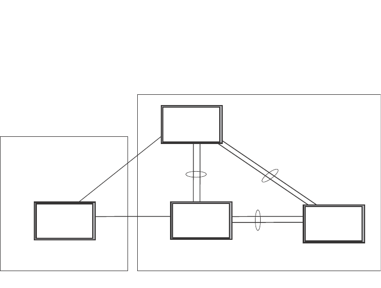
298 PowerConnect B-Series FCX Configuration Guide
53-1002266-01
802.1s Multiple Spanning Tree Protocol
8
FIGURE 57 Sample MSTP configuration
RTR1 configuration
PowerConnect(config-vlan-4093)#tagged ethernet 10/1 to 10/2
PowerConnect(config-vlan-4093)#exit
PowerConnect(config)#mstp scope all
PowerConnect(config)#mstp name Reg1
PowerConnect(config)#mstp revision 1
PowerConnect(config)#mstp admin-pt2pt-mac ethernet 10/1 to 10/2
PowerConnect(config)#mstp start
PowerConnect(config)#hostname RTR1
Core 1 configuration
PowerConnect(config)#trunk ethernet 2/9 to 2/12 ethernet 2/13 to 2/14
PowerConnect(config-vlan-1)#name DEFAULT-VLAN by port
PowerConnect(config-vlan-1)#exit
PowerConnect(config)#vlan 20 by port
PowerConnect(config-vlan-20)#tagged ethernet 2/9 to 2/14 ethernet 2/16
PowerConnect(config-vlan-20)#exit
PowerConnect(config)#vlan 21 by port
PowerConnect(config-vlan-21)#tagged ethernet 2/9 to 2/14 ethernet 2/16
PowerConnect(config-vlan-21)#exit
PowerConnect(config)#vlan 22 by port
PowerConnect(config-vlan-22)#tagged ethernet 2/9 to 2/14 ethernet 2/16
PowerConnect(config-vlan-22)#exit
PowerConnect(config)#vlan 23 by port
PowerConnect(config)#mstp scope all
PowerConnect(config)#mstp name HR
PowerConnect(config)#mstp revision 2
PowerConnect(config)#mstp instance 20 vlan 20
PowerConnect(config)#mstp instance 21 vlan 21
PowerConnect(config)#mstp instance 22 vlan 22
PowerConnect(config)#mstp instance 0 priority 8192
PowerConnect(config)#mstp admin-pt2pt-mac ethernet 2/9 to 2/14
PowerConnect(config)#mstp admin-pt2pt-mac ethernet 2/16
PowerConnect(config)#mstp disable ethernet 2/240.
PowerConnect(config)#mstp start
PowerConnect(config)#hostname CORE1
BigIron
BigIron
BigIron
BigIron
Core1
Core2 LAN4
RTR1
Region 1
Region 2
Port10/1
Port10/2 Port3/10
Ports
3/1-3/2
Ports
2/13-2/14
Ports
2/9-2/12
Ports
3/17-3/20
Ports
3/5-3/6
Ports
3/5-3/6
Port
2/16

PowerConnect B-Series FCX Configuration Guide 299
53-1002266-01
802.1s Multiple Spanning Tree Protocol 8
Core2 configuration
PowerConnect(config)#trunk ethernet 3/5 to 3/6 ethernet 3/17 to 3/20
PowerConnect(config)#vlan 1 name DEFAULT-VLAN by port
PowerConnect(config-vlan-1)#exit
PowerConnect(config)#vlan 20 by port
PowerConnect(config-vlan-20)#tagged ethernet 3/5 to 3/6 ethernet 3/17 to 3/20
PowerConnect(config-vlan-20)#exit
PowerConnect(config)#vlan 21 by port
PowerConnect(config-vlan-21)#tagged ethernet 3/5 to 3/6 ethernet 3/17 to 3/20
PowerConnect(config-vlan-21)#exit
PowerConnect(config)#vlan 22 by port
PowerConnect(config-vlan-22)#tagged ethernet 3/5 to 3/6 ethernet 3/17 to 3/20
PowerConnect(config-vlan-22)#exit
PowerConnect(config)#mstp scope all
PowerConnect(config)#mstp name HR
PowerConnect(config)#mstp revision 2
PowerConnect(config)#mstp instance 20 vlan 20
PowerConnect(config)#mstp instance 21 vlan 21
PowerConnect(config)#mstp instance 22 vlan 22
PowerConnect(config)#mstp admin-pt2pt-mac ethernet 3/17 to 3/20 ethernet 3/5 to
3/6
PowerConnect(config)#mstp admin-pt2pt-mac ethernet 3/10
PowerConnect(config)#mstp disable ethernet 3/7 ethernet 3/24
PowerConnect(config)#mstp start
PowerConnect(config)#hostname CORE2
LAN 4 configuration
PowerConnect(config)#trunk ethernet 3/5 to 3/6 ethernet 3/1 to 3/2
PowerConnect(config)#vlan 1 name DEFAULT-VLAN by port
PowerConnect(config-vlan-1)#exit
PowerConnect(config)#vlan 20 by port
PowerConnect(config-vlan-20)#tagged ethernet 3/1 to 3/2 ethernet 3/5 to 3/6
PowerConnect(config)#exit
PowerConnect(config)#vlan 21 by port
PowerConnect(config-vlan-21)#tagged ethernet 3/1 to 3/2 ethernet 3/5 to 3/6
PowerConnect(config-vlan-21)#exit
PowerConnect(config)#vlan 22 by port
PowerConnect(config-vlan-22)#tagged ethernet 3/1 to 3/2 ethernet 3/5 to 3/6
PowerConnect(config)#mstp scope all
PowerConnect(config)#mstp config name HR
PowerConnect(config)#mstp revision 2
PowerConnect(config)#mstp instance 20 vlan 20
PowerConnect(config)#mstp instance 21 vlan 21
PowerConnect(config)#mstp instance 22 vlan 22
PowerConnect(config)#mstp admin-pt2pt-mac ethernet 3/5 to 3/6 ethernet 3/1 to 3/2
PowerConnect(config)#mstp start
PowerConnect(config)#hostname LAN4
Displaying MSTP statistics
MSTP statistics can be displayed using the commands shown below.
To display all general MSTP information, enter the following command.

300 PowerConnect B-Series FCX Configuration Guide
53-1002266-01
802.1s Multiple Spanning Tree Protocol
8
Syntax: show mstp <instance-number>
The <instance-number> variable specifies the MSTP instance that you want to display information
for.
TABLE 56 Output from Show MSTP
This field... Displays...
MSTP Instance The ID of the MSTP instance whose statistics are being displayed. For
the CIST, this number is 0.
VLANs The number of VLANs that are included in this instance of MSTP. For the
CIST this number will always be 1.
Bridge Identifier The MAC address of the bridge.
Bridge MaxAge sec Displays configured Max Age.
Bridge Hello sec Displays configured Hello variable.
Bridge FwdDly sec Displays configured FwdDly variable.
Bridge Hop cnt Displays configured Max Hop count variable.
Root MaxAge sec Max Age configured on the root bridge.
Root Hello sec Hello interval configured on the root bridge.
Root FwdDly sec FwdDly interval configured on the root bridge.
Root Hop Cnt Current hop count from the root bridge.
Root Bridge Bridge identifier of the root bridge.
PowerConnect#show mstp
MSTP Instance 0 (CIST) - VLANs: 1
----------------------------------------------------------------------------
Bridge Bridge Bridge Bridge Bridge Root Root Root Root
Identifier MaxAge Hello FwdDly Hop MaxAge Hello FwdDly Hop
hex sec sec sec cnt sec sec sec cnt
8000000cdb80af01 20 2 15 20 20 2 15 19
Root ExtPath RegionalRoot IntPath Designated Root
Bridge Cost Bridge Cost Bridge Port
hex hex hex
8000000480bb9876 2000 8000000cdb80af01 0 8000000480bb9876 3/1
Port Pri PortPath P2P Edge Role State Designa- Designated
Num Cost Mac Port ted cost bridge
3/1 128 2000 T F ROOT FORWARDING 0 8000000480bb9876
MSTP Instance 1 - VLANs: 2
----------------------------------------------------------------------------
Bridge Max RegionalRoot IntPath Designated Root Root
Identifier Hop Bridge Cost Bridge Port Hop
hex cnt hex hex cnt
8001000cdb80af01 20 8001000cdb80af01 0 8001000cdb80af01 Root 20
Port Pri PortPath Role State Designa- Designated
Num Cost ted cost bridge
3/1 128 2000 MASTER FORWARDING 0 8001000cdb80af01

PowerConnect B-Series FCX Configuration Guide 301
53-1002266-01
802.1s Multiple Spanning Tree Protocol 8
Displaying MSTP information for a specified instance
The following example displays MSTP information specified for an MSTP instance.
ExtPath Cost The configured path cost on a link connected to this port to an external
MSTP region.
Regional Root Bridge The Regional Root Bridge is the MAC address of the Root Bridge for the
local region.
IntPath Cost The configured path cost on a link connected to this port within the
internal MSTP region.
Designated Bridge The MAC address of the bridge that sent the best BPDU that was
received on this port.
Root Port Port indicating shortest path to root. Set to "Root" if this bridge is the root
bridge.
Port Num The port number of the interface.
Pri The configured priority of the port. The default is 128.
PortPath Cost Configured or auto detected path cost for port.
P2P Mac Indicates if the port is configured with a point-to-point link:
•T – The port is configured in a point-to-point link
•F – The port is not configured in a point-to-point link
Edge Indicates if the port is configured as an operational edge port:
•T – indicates that the port is defined as an edge port.
•F – indicates that the port is not defined as an edge port
Role The current role of the port:
•Master
•Root
•Designated
•Alternate
•Backup
•Disabled
State The port current spanning tree state. A port can have one of the
following states:
•Forwarding
•Discarding
•Learning
•Disabled
Designated Cost Port path cost to the root bridge.
Max Hop cnt The maximum hop count configured for this instance.
Root Hop cnt Hop count from the root bridge.
TABLE 56 Output from Show MSTP (Continued)
This field... Displays...

302 PowerConnect B-Series FCX Configuration Guide
53-1002266-01
802.1s Multiple Spanning Tree Protocol
8
Refer to Table 56 for details about the display parameters.
Displaying MSTP information for CIST instance 0
Instance 0 is the Common and Internal Spanning Tree Instance (CIST). When you display
information for this instance there are some differences with displaying other instances. The
following example displays MSTP information for CIST Instance 0.
To display details about the MSTP configuration, enter the following command.
To display details about the MSTP that is configured on the device, enter the following command.
PowerConnect#show mstp 1
MSTP Instance 1 - VLANs: 2
----------------------------------------------------------------------------
Bridge Max RegionalRoot IntPath Designated Root Root
Identifier Hop Bridge Cost Bridge Port Hop
hex cnt hex hex cnt
8001000cdb80af01 20 8001000cdb80af01 0 8001000cdb80af01 Root 20
Port Pri PortPath Role State Designa- Designated
Num Cost ted cost bridge
3/1 128 2000 MASTER FORWARDING 0 8001000cdb80af01
PowerConnect#show mstp 0
MSTP Instance 0 (CIST) - VLANs: 1
----------------------------------------------------------------------------
Bridge Bridge Bridge Bridge Bridge Root Root Root Root
Identifier MaxAge Hello FwdDly Hop MaxAge Hello FwdDly Hop
hex sec sec sec cnt sec sec sec cnt
8000000cdb80af01 20 2 15 20 20 2 15 19
Root ExtPath RegionalRoot IntPath Designated Root
Bridge Cost Bridge Cost Bridge Port
hex hex hex
8000000480bb9876 2000 8000000cdb80af01 0 8000000480bb9876 3/1
Port Pri PortPath P2P Edge Role State Designa- Designated
Num Cost Mac Port ted cost bridge
3/1 128 2000 T F ROOT FORWARDING 0 8000000480bb9876
PowerConnect#show mstp conf
MSTP CONFIGURATION
------------------
Name : Reg1
Revision : 1
Version : 3 (MSTP mode)
Status : Started
Instance VLANs
-------- ------------------------------------------------------
0 4093

PowerConnect B-Series FCX Configuration Guide 303
53-1002266-01
802.1s Multiple Spanning Tree Protocol 8
Refer to Table 56 for explanation about the parameters in the output.
Syntax: show mstp [<mstp-id> | configuration | detail] [ | begin <string> | exclude <string> |
include <string>]
Enter an MSTP ID for <mstp-id>.
PowerConnect#show mstp detail
MSTP Instance 0 (CIST) - VLANs: 4093
----------------------------------------------------------------------------
Bridge: 800000b000c00000 [Priority 32768, SysId 0, Mac 00b000c00000]
FwdDelay 15, HelloTime 2, MaxHops 20, TxHoldCount 6
Port 6/54 - Role: DESIGNATED - State: FORWARDING
PathCost 20000, Priority 128, OperEdge T, OperPt2PtMac F, Boundary T
Designated - Root 800000b000c00000, RegionalRoot 800000b000c00000,
Bridge 800000b000c00000, ExtCost 0, IntCost 0
ActiveTimers - helloWhen 1
MachineState - PRX-DISCARD, PTX-IDLE, PPM-SENDING_RSTP, PIM-CURRENT
PRT-ACTIVE_PORT, PST-FORWARDING, TCM-INACTIVE
BPDUs - Rcvd MST 0, RST 0, Config 0, TCN 0
Sent MST 6, RST 0, Config 0, TCN 0

304 PowerConnect B-Series FCX Configuration Guide
53-1002266-01
802.1s Multiple Spanning Tree Protocol
8

PowerConnect B-Series FCX Configuration Guide 305
53-1002266-01
Chapter
9
Configuring Basic Layer 2 Features
Table 57 lists the individual Dell PowerConnect switches and the basic Layer 2 features they
support.
The procedures in this chapter describe how to configure basic Layer 2 parameters.
Dell PowerConnect devices are configured at the factory with default parameters that allow you to
begin using the basic features of the system immediately. However, many of the advanced features
such as VLANs or routing protocols for the device must first be enabled at the system (global) level
before they can be configured. If you use the Command Line Interface (CLI) to configure system
parameters, you can find these system level parameters at the Global CONFIG level of the CLI.
NOTES:
•Before assigning or modifying any router parameters, you must assign the IP subnet
(interface) addresses for each port.
TABLE 57 Supported basic Layer 2 features
Feature PowerConnect B-Series FCX
16,000 MAC addresses per switch Yes
32,000 MAC addresses per switch Yes
MAC learning rate control Yes
Multi-port static MAC address Yes
Static MAC entries with option to set
traffic priority
Yes
Flow-based MAC address learning Yes
Enabled by default on PowerConnect B-Series FCX
devices. There is no CLI command to enable or
disable it.
Port-based VLANs Yes
Address locking (for MAC addresses) Yes
MAC address filter override of 802.1X Yes
MAC address filtering (filtering on source
and destination MAC addresses)
Yes
Ability to disable MAC learning Yes
Dynamic buffer allocation for QoS
priorities
Yes
Remote Fault Notificatoin (RFN) for 1G
fiber
Yes
Link Fault Signaling (LFS) for 10G Yes
Layer 2 jumbo frames Yes
Generic buffer profile Yes

306 PowerConnect B-Series FCX Configuration Guide
53-1002266-01
About port regions
9
•For information about configuring IP addresses, DNS resolver, DHCP assist, and other
IP-related parameters, refer to Chapter 26, “Configuring IP”.
•For information about the Syslog buffer and messages, refer to Chapter 41, “Using
Syslog”.
About port regions
This section describes port regions on PowerConnect switches.
PowerConnect B-Series FCX device port regions
The port region rules for PowerConnect B-Series FCX devices are as follows:
•For all platforms, a 24-port Gbps module has one port region. In addition, any 10 Gbps ports
on the device also belong to this single port region.
•For all platforms, the 48-port Gbps module has two port regions:
-Ports 1 - 24 belong to port region 0
-Ports 25 - 48 belong to port region 1
•For PowerConnect B-FCX648 devices with two 10 Gbps XFP ports, and a two 10 Gbps CX4
stacking ports:
-The two 10 Gbps XFP ports belong to port region 0 (along with ports 1 -24 )
-The two 10 Gbps CX4 stacking ports belong to port region 1 (along with ports 25 - 48)
•For PowerConnect B-FCX648 devices with four 10 Gbps SFP+ ports:
-10 Gbps SFP+ ports 3 and 4 belong to port region 0 (along with ports 1 -24 )
-10 Gbps SFP+ ports 1 and 2 ports belong to port region 1 (along with ports 25 - 48)
Enabling or disabling the Spanning Tree Protocol (STP)
STP (IEEE 802.1D bridge protocol) is supported on all Dell PowerConnect devices. STP detects and
eliminates logical loops in the network. STP also ensures that the least cost path is taken when
multiple paths exist between ports or VLANs. If the selected path fails, STP searches for and then
establishes an alternate path to prevent or limit retransmission of data.
NOTE
This section provides instructions for enabling and disabling STP. For configuration procedures and
more information about STP, refer to Chapter 8, “Configuring Spanning Tree Protocol (STP) Related
Features” in this guide.
STP must be enabled at the system level to allow assignment of this capability on the VLAN level.
On devices running Layer 2 code, STP is enabled by default. On devices running Layer 3 code, STP
is disabled by default.
To enable STP for all ports on a Dell PowerConnect device, enter the following command.
PowerConnect(config)#spanning tree
Syntax: [no] spanning-tree

PowerConnect B-Series FCX Configuration Guide 307
53-1002266-01
MAC learning rate control 9
You can also enable and disable spanning tree on a port-based VLAN and on an individual port
basis, and enable advanced STP features. Refer to Chapter 8, “Configuring Spanning Tree Protocol
(STP) Related Features”.
Modifying STP bridge and port parameters
You can modify the following STP Parameters:
•Bridge parameters – forward delay, maximum age, hello time, and priority
•Port parameters – priority and path cost
For configuration details, refer to “Changing STP bridge and port parameters” on page 210.
MAC learning rate control
You can set a rate limit to control CPU address updating. The range for this rate limit is 200 -
50,000 per second. The MAC learning rate limit applies to each packet processor, which means
that for a system with two packet processors, each processor can send address messages to the
CPU at the established rate limit.
Syntax: [no] cpu-limit addr-msgs <msgsRateLimit>
NOTE
Actual rates in hardware may have a variance of +200 or -100.
Changing the MAC age time and disabling MAC address learning
To change the MAC address age timer, enter a command such as the following.
PowerConnect(config)#mac-age-time 60
Syntax: [no] mac-age-time <secs>
<secs> specifies the number of seconds. Possible values differ depending on the version of
software running on your device, as follows:
•On PowerConnect B-Series FCX devices, learned MAC address entries do not age out until they
are unused for 300 – 600 seconds. If necessary, you can change the MAC address age timer
to 0 or a value from 60 – 600 (seconds), in 60-second intervals. For example, you can specify
60 or 120, but not 100. If you set the MAC age time to 0, aging is disabled.
NOTES: Usually, the actual MAC age time is from one to two times the configured value. For
example, if you set the MAC age timer to 60 seconds, learned MAC entries age out after remaining
unused for between 60 – 120 seconds. However, if all of the following conditions are met, then the
MAC entries age out after a longer than expected duration:
•The MAC age timer is greater than 630 seconds.
•The number of MAC entries is over 6000.
•All MAC entries are learned from the same packet processor.
•All MAC entries age out at the same time.

308 PowerConnect B-Series FCX Configuration Guide
53-1002266-01
Configuring static MAC entries
9
Disabling the automatic learning of MAC addresses
By default, when a packet with an unknown Source MAC address is received on a port, the Dell
PowerConnect device learns this MAC address on the port.
You can prevent a physical port from learning MAC addresses by entering the following command.
PowerConnect(config)#interface ethernet 3/1
PowerConnect(config-if-e1000-3/1)#mac-learn-disable
Syntax: [no] mac-learn disable
Use the no form of the command to allow a physical port to learn MAC addresses.
Configuration notes and feature limitations
•This command is not available on virtual routing interfaces. Also, if this command is configured
on the primary port of a trunk, MAC address learning will be disabled on all the ports in the
trunk.
•Entering the mac-learn-disable command on tagged ports disables MAC learning for that port
in all VLANs to which that port is a member. For example, if tagged port 3/1 is a member of
VLAN 10, 20, and 30 and you issue the mac-learn-disable command on port 3/1, port 3/1 will
not learn MAC addresses, even if it is a member of VLAN 10, 20, and 30.
Displaying the MAC address table
To display the MAC table, enter the following command.
In the output of the show mac-address command, the Type column indicates whether the MAC
entry is static or dynamic. A static entry is one you create using the static-mac-address command.
A dynamic entry is one that is learned by the software from network traffic.
NOTE
The show mac-address command output does not include MAC addresses for management ports,
since these ports do not support typical MAC learning and MAC-based forwarding.
Configuring static MAC entries
Static MAC addresses can be assigned to Dell PowerConnect devices.
PowerConnect#show mac-address
Total active entries from all ports = 3
Total static entries from all ports = 1
MAC-Address Port Type VLAN
1234.1234.1234 15 Static 1
0004.8038.2f24 14 Dynamic 1
0004.8038.2f00 13 Dynamic 1
0010.5a86.b159 10 Dynamic 1

PowerConnect B-Series FCX Configuration Guide 309
53-1002266-01
Configuring static MAC entries 9
NOTE
Dell PowerConnect devices running Layer 3 code also support the assignment of static IP Routes,
static ARP, and static RARP entries. For details on configuring these types of static entries, refer to
“Configuring static routes” on page 819 and “Creating static ARP entries” on page 814.
You can manually input the MAC address of a device to prevent it from being aged out of the system
address table.
This option can be used to prevent traffic for a specific device, such as a server, from flooding the
network with traffic when it is down. Additionally, the static MAC address entry is used to assign
higher priorities to specific MAC addresses.
You can specify traffic priority (QoS) and VLAN membership (VLAN ID) for the MAC Address as well
as specify the device type of either router or host.
The default and maximum configurable MAC table sizes can differ depending on the device. To
determine the default and maximum MAC table sizes for your device, display the system parameter
values. Refer to “Displaying and modifying system parameter default settings” on page 321.
Multi-port static MAC address
Many applications, such as Microsoft NLB, Juniper IPS, and Netscreen Firewall, use the same MAC
address to announce load-balancing services. As a result, a switch must be able to learn the same
MAC address on several ports. Multi-port static MAC allows you to statically configure a MAC
address on multiple ports using a single command.
Configuration notes
•This feature is applicable for Layer 2 traffic.
•This feature can be used to configure unicast as well as IPv4 and IPv6 multicast MAC
addresses on one or more ports. However, when a multicast MAC address is configured, the
corresponding MAC address entry cannot be used for IGMP snooping. For IPv4 multicast
addresses (range 0100.5e00.000 to 0100.5e7f.ffff) and IPv6 multicast addresses (range
3333.0000.0000 to 3333.ffff.ffff), use IGMP/MLD snooping. Other multicast addresses can
also be configured on the ports using this feature.
•PowerConnect devices support a maximum of 15 multi-port static MAC addresses.
•Hosts or physical interfaces normally join multicast groups dynamically, but you can also
statically configure a host or an interface to join a multicast group.
Configuring a multi-port static MAC address
For example, to add a static entry for a server with a MAC address of 0045.5563.67ff and a priority
of 7, enter the following command.
PowerConnect(config)#static-mac-address 0045.5563.67ff ethernet 4/2 ethernet 4/3
ethernet 4/4 priority 7
To specify a range of ports, enter the following command.
PowerConnect(config)#static-mac-address 0045.5563.67ff ethernet 4/2 to 4/6
priority 7
Syntax: [no] static-mac-address <mac-addr> ethernet [<slotnum>/]<portnum> ethernet
[<slotnum>/]<portnum> ethernet [<slotnum>/]<portnum> …. [priority <num>]

310 PowerConnect B-Series FCX Configuration Guide
53-1002266-01
Configuring VLAN-based static MAC entries
9
or
Syntax: [no] static-mac-address <mac-addr> ethernet [<slotnum>/]<portnum> to ethernet
[<slotnum>]<portnum> [priority <num>]
The <slotnum> parameter is required on chassis devices.
The <portnum> parameter is a valid port number.
The priority <num> is optional and can be a value from 0 – 7 (0 is lowest priority and 7 is highest
priority). The default priority is 0.
NOTE
The location of the static-mac-address command in the CLI depends on whether you configure
port-based VLANs on the device. If the device does not have more than one port-based VLAN (VLAN
1, which is the default VLAN that contains all the ports), the static-mac-address command is at the
global CONFIG level of the CLI. If the device has more than one port-based VLAN, then the
static-mac-address command is not available at the global CONFIG level. In this case, the command
is available at the configuration level for each port-based VLAN.
Configuring VLAN-based static MAC entries
You can configure a VLAN to drop packets that have a particular source or destination MAC
address.
You can configure a maximum of 2048 static MAC address drop entries on a Dell PowerConnect
device.
Use the CLI command show running-config to view the static MAC address drop entries currently
configured on the device.
Command syntax
To configure a VLAN to drop packets with a source or destination MAC address of 1145.5563.67FF,
enter the following commands.
PowerConnect(config)#vlan 2
PowerConnect(config-vlan-2)#static-mac-address 1145.5563.67FF drop
Syntax: [no] static-mac-address <mac-addr> drop
Use the no form of the command to remove the static MAC address drop configuration.
Clearing MAC address entries
You can remove learned MAC address entries from the MAC address table. The types of MAC
address can be removed are as follows:
•All MAC address entries
•All MAC address entries for a specified Ethernet port
•All MAC address entries for a specified VLAN
•All specified MAC address entry in all VLANs

PowerConnect B-Series FCX Configuration Guide 311
53-1002266-01
Flow-based MAC address learning 9
For example, to remove entries for the MAC address 000d.cd80.00d0 in all VLANs, enter the
following command at the Privilege EXEC level of the CLI.
PowerConnect#clear mac-address 000d.cb80.00d0
Syntax: clear mac-address <mac-address> | ethernet <port-num> | vlan <vlan-num>
If you enter clear mac-address without any parameter, the software removes all MAC address
entries.
Use the <mac-address> parameter to remove a specific MAC address from all VLANs. Specify the
MAC address in the following format: HHHH.HHHH.HHHH.
Use the ethernet <port-num> parameter to remove all MAC addresses for a specific Ethernet port.
Use the vlan <num> parameter to remove all MAC addresses for a specific VLAN.
Flow-based MAC address learning
NOTE
Flow-based MAC address learning is supported on PowerConnect B-Series FCX Series devices.
However, on PowerConnect B-Series FCX Series , this feature is enabled by default. There is no
command to enable or disable it.
Feature overview
With regular MAC address learning, when a new MAC address is learned, it is programmed in the
same location (hardware index) in all packet processors in a PowerConnect Layer 2 or Layer 3
switch. There are multiple packet processors (one per port region) in a compact switch, and in
each module in a chassis-based switch. With regular MAC address learning, MAC addresses are
global, meaning the hardware MAC table is identical across all packet processors.
With the introduction of flow-based MAC address learning, when a new source MAC address is
learned, it is programmed only in the source packet processor (the processor that received the
packet). The destination MAC address gets added to other packet processors on demand,
whenever a traffic flow that needs it is detected. With flow-based MAC address learning, the MAC
address is programmed in different hardware locations and the hardware MAC table is different
across all packet processors.
The benefits of flow-based learning
With global MAC address learning, all MAC addresses are programmed in all packet processors,
even though they may not be required and are never used by all packet processors. Global MAC
address learning wastes some space in the hardware MAC table and limits the number of
supported MAC addresses to 16K.
With flow-based MAC address learning, MAC addresses are learned and programmed selectively,
only in the packet processors that need them. Since the MAC addresses are distributed across
several packet processors, flow-based learning frees up space in the hardware MAC table and
increases the number of supported MAC addresses from 16K to 32K.

312 PowerConnect B-Series FCX Configuration Guide
53-1002266-01
Flow-based MAC address learning
9
How flow-based learning works
When a packet processor, let call it PP 1, receives an incoming packet with source MAC address X,
it sends a new address message to the CPU. The system learns MAC address X by adding it to the
software MAC table in the CPU, then programming it in the hardware MAC table in the source
packet processor, in this case PP 1. If the MAC address is learned on a trunk port, the MAC
address is also programmed on all of the packet processors that have ports in the same trunk
group.
When another packet processor, let call it PP 2, receives an incoming packet and the packet
destination MAC address matches source MAC address X, it floods the packet in hardware as an
unknown unicast packet and copies the packet to the CPU. The system locates the MAC address in
the software MAC table, then programs the MAC address in the hardware MAC table in PP 2. If the
MAC address is learned on a trunk port, the MAC address is also programmed on all of the packet
processors that have ports in the same trunk group. Once the MAC address is programmed in
hardware, subsequent packets with this destination MAC are forwarded as known unicast packets
and are not copied to the CPU.
Flow-based MAC addresses are aged out by the source packet processor according to the MAC age
time learned on the local port. Furthermore, when a flow-based MAC address is aged out from the
source packet processor, it is also aged out from all other packet processors on which the address
is programmed. In the above example, when MAC address X is aged out from PP 1, it is also aged
out from PP2.
NOTE
Even when flow-based MAC address learning is enabled, some MAC addresses, including but not
limited to control MACs, static MACs, multicast MACs, and MAC addresses resolved through ARP, will
continue to be global MAC addresses. These MAC addresses are always programmed in all packet
processors in a Layer 2 or Layer 3 switch.
NOTE
Global MAC addresses have priority over dynamic flow-based MAC addresses. To ensure that global
MAC addresses are in sync across all packet processors, flow-based MAC addresses may be
overwritten in one or more packet processors. The MAC addresses will be relearned and
reprogrammed using the flow-based method as needed by incoming traffic flows.
Configuration considerations
When configuring flow-based MAC learning, consider the rules and limitations in this section.
•Flow-based MAC learning is not supported with the following features:
•Disabling the automatic learning of MAC addresses (CLI command mac-learn-disable).
•Globally disabling Layer 2 switching (CLI command route-only)
•When flow-based MAC learning is enabled, unknown unicast packets are copied to the CPU.
Therefore, flow-based MAC learning should not be enabled if a continuous high rate of
unknown unicast packet flooding is expected, as this will cause high CPU utilization.
•Unknown unicast flooding can occur for a known destination MAC address, if the system fails
to program that destination MAC address because the hardware MAC table or hash bucket is
full. This condition can also lead to high CPU utilization.

PowerConnect B-Series FCX Configuration Guide 313
53-1002266-01
Flow-based MAC address learning 9
•A source MAC address is learned only on the ingress (source) packet processor. The MAC
address is added to other packet processors as needed by their incoming traffic flows. During
a brief period until the destination MAC address is successfully added to the hardware MAC
table, unknown unicast flooding is expected on the VLAN.
•When a flow-based MAC address moves, it is deleted from all of the packet processors, then
relearned on each packet processor individually, as needed by incoming traffic flows.
•The software MAC address table in the CPU uses a hashing algorithm. Because hash collisions
can occur and may consume software resources, the PowerConnect may not be able to
support up to 32K MAC addresses.
•The system can scale up to 32K MAC addresses, however, each packet processor is limited to
a maximum of 16K MAC addresses. This limit still applies, as this is a hardware limitation.
Configuring flow-based MAC address learning
To configure flow-based MAC address learning, simply enable it globally. If necessary, increase the
capacity of the MAC address table as well.
Enabling flow-based MAC address learning
To enable flow-based MAC address learning, enter the following command at the Global CONFIG
level of the CLI.
PowerConnect(config)#mac-learning-flow-based
This command enables flow-based MAC address learning. All dynamically-learned MAC addresses
are flushed from the hardware and software MAC tables and are subsequently learned using
flow-based MAC address learning.
Syntax: [no] mac-learning-flow-based
Use the no form of the command to disable flow-based MAC address learning. When disabled, all
dynamically-learned MAC addresses are flushed from the hardware and software MAC tables and
are subsequently learned using global MAC address learning.
Increasing the capacity of the MAC address table (optional)
After enabling support for flow-based MACs, you can increase the capacity of the MAC address
table of up to 32K MAC addresses. By default, up to 16K MAC addresses are supported.
NOTE
The system can scale up to 32K MAC addresses when flow-based MAC address learning is enabled.
If flow-based learning is disabled, the system cannot scale more than 16K MAC addresses.
To increase the capacity of the MAC table, enter commands such as the following.
PowerConnect(config)#system-max mac 32768
PowerConnect(config)#write memory
PowerConnect(config)#exit
PowerConnect#reload
NOTE
You must save the configuration and reload the software to place the system-max mac change into
effect.

314 PowerConnect B-Series FCX Configuration Guide
53-1002266-01
Enabling port-based VLANs
9
Syntax: system-max mac <max-flow-MACs>
The <max-flow-MACs> parameter specifies the maximum number of MAC addresses in the MAC
table. For flow-based MACs, the minimum value is 16K and the maximum value is 32K. The
default is 16K.
Use the command show default values to display the default, maximum, and currently configured
values for the MAC address table.
Displaying information about flow-based MACs
The show mac-address command includes information related to flow-based MAC address
learning. The following shows an example show mac output.
PowerConnect# show mac
Total active entries from all ports = 15
MAC-Address Port Type Index
0000.0000.0001 1/1 Dynamic NA
0000.0000.0002 1/1 Dynamic NA
In the above example, since both MAC address entries are flow-based and are located on different
packet processors (hardware index), the Index field displays NA (not applicable).
Syntax: show mac
To display all of the packet processors that have a particular flow-based MAC address, use the
show mac-address vlan command.
PowerConnect#show mac-address vlan 1 0000.0000.0001
Total active entries from all ports = 16
MAC-Address Port Type Index
0000.0000.0001 1/1 Dynamic NA
Present in following devices (at hw index) :-
0 (8196 ) 4 (8196 )
In the above example, the MAC address 0000.0000.0001 is programmed in packet processors 0
and 4, and the hardware index is 8196.
Syntax: show mac-address vlan <vlan-num> <mac address>
Clearing flow-based MAC address entries
To remove dynamically-learned MAC addresses from the MAC table, use the CLI command clear
mac. This command clears all dynamically-learned MACs from the hardware and software MAC
tables.
Enabling port-based VLANs
When using the CLI, port and protocol-based VLANs are created by entering one of the following
commands at the global CONFIG level of the CLI.
To create a port-based VLAN, enter commands such as the following.
PowerConnect(config)#vlan 222 by port
PowerConnect(config)#vlan 222 name Mktg

PowerConnect B-Series FCX Configuration Guide 315
53-1002266-01
Enabling port-based VLANs 9
Syntax: vlan <num> by port
Syntax: vlan <num> name <string>
The <num> parameter specifies the VLAN ID. The valid range for VLAN IDs starts at 1 on all
systems but the upper limit of the range differs depending on the device. In addition, you can
change the upper limit on some devices using the system max-vlans... command.
The <string> parameter is the VLAN name and can be a string up to 32 characters. You can use
blank spaces in the name if you enclose the name in double quotes (for example, “Product
Marketing”.)
You can configure up to 4063 port-based VLANs on a device running Layer 2 code or 4061
port-based VLANs on a device running Layer 3 code. Each port-based VLAN can contain either
tagged or untagged ports. A port cannot be a member of more than one port-based VLAN unless
the port is tagged. On both device types, valid VLAN IDs are 1 – 4095. You can configure up to the
maximum number of VLANs within that ID range.
NOTE
VLAN IDs 4087, 4090, and 4093 are reserved for Dell internal use only. VLAN 4094 is reserved for
use by Single STP. Also, if you are running an earlier release, VLAN IDs 4091 and 4092 may be
reserved for Dell internal use only. If you want to use VLANs 4091 and 4092 as configurable VLANs,
you can assign them to different VLAN IDs. For more information, refer to “Assigning different VLAN
IDs to reserved VLANs 4091 and 4092” on page 445.
NOTE
The second command is optional and also creates the VLAN if the VLAN does not already exist. You
can enter the first command after you enter the second command if you first exit to the global
CONFIG level of the CLI.
Assigning IEEE 802.1Q tagging to a port
When a port is tagged, it allows communication among the different VLANs to which it is assigned.
A common use for this might be to place an email server that multiple groups may need access to
on a tagged port, which in turn, is resident in all VLANs that need access to the server.
NOTE
Tagging does not apply to the default VLAN.
When using the CLI, ports are defined as either tagged or untagged at the VLAN level.
Command syntax
Suppose you want to make port 5 a member of port-based VLAN 4, a tagged port. To do so, enter
the following.
PowerConnect(config)#vlan 4
PowerConnect(config-vlan-4)#tagged e 5
Syntax: tagged ethernet [<slotnum>/]<portnum> [to [<slotnum>/]<portnum> [ethernet
[<slotnum>/]<portnum>...]]
The <slotnum> parameter is required on chassis devices.

316 PowerConnect B-Series FCX Configuration Guide
53-1002266-01
Defining MAC address filters
9
Defining MAC address filters
MAC layer filtering enables you to build access lists based on MAC layer headers in the
Ethernet/IEEE 802.3 frame. You can filter on the source and destination MAC addresses. The
filters apply to incoming traffic only.
You configure MAC address filters globally, then apply them to individual interfaces. To apply MAC
address filters to an interface, you add the filters to that interface MAC address filter group.
The device takes the action associated with the first matching filter. If the packet does not match
any of the filters in the access list, the default action is to drop the packet. If you want the system
to permit traffic by default, you must specifically indicate this by making the last entry in the access
list a permit filter. An example is given below.
Syntax: mac filter <last-index-number> permit any any.
For devices running Layer 3 code, the MAC address filter is applied to all inbound Ethernet packets,
including routed traffic. This includes those port associated with a virtual routing interface.
However, the filter is not applied to the virtual routing interface. It is applied to the physical port.
When you create a MAC address filter, it takes effect immediately. You do not need to reset the
system. However, you do need to save the configuration to flash memory to retain the filters across
system resets.
Configuration notes and limitations
•MAC address filtering on PowerConnect devices is performed in hardware.
•MAC address filtering on PowerConnect devices differ from other Dell PowerConnect devices
in that you can only filter on source and destination MAC addresses. Other Dell PowerConnect
devices allow you to also filter on the encapsulation type and frame type.
•MAC address filtering applies to all traffic, including management traffic. To exclude
management traffic from being filtered, configure a MAC address filter that explicitly permits
all traffic headed to the management MAC (destination) address. The MAC address for
management traffic is always the MAC address of port 1.
•MAC address filters that have a global deny statement can cause the device to block all
BPDUs. In this case, include exception statements for control protocols in the MAC address
filter configuration.
The following configuration notes apply to Layer 3 devices:
•MAC address filters apply to both switched and routed traffic. If a routing protocol (for
example, OSPF) is configured on an interface, the configuration must include a MAC address
filter rule that allows the routing protocol MAC and the neighbor system MAC address.
•You cannot use MAC address filters to filter Layer 4 information.
•MAC address filters are supported on tagged ports in the base Layer 3, edge Layer 3, and full
Layer 3 software images.
Command syntax
To configure and apply a MAC address filter, enter commands such as the following.
PowerConnect(config)# mac filter 1 deny 3565.3475.3676 ffff.0000.0000
PowerConnect(config)# mac filter 2 deny any ffff.ffff.ffff ffff.ffff.ffff

PowerConnect B-Series FCX Configuration Guide 317
53-1002266-01
Defining MAC address filters 9
PowerConnect(config)# mac filter 3 deny any 0180.c200.0000 ffff.ffff.fff0
PowerConnect(config)# mac filter 4 deny any 0000.1234.5678 ffff.ffff.ffff
PowerConnect(config)# mac filter 5 deny any 0000.2345.6789 ffff.ffff.ffff
PowerConnect(config)# mac filter 1024 permit any any
PowerConnect(config)# int e 1
PowerConnect(config-if-e1000-1)# mac filter-group 1 to 5 1024
These commands configure filter 1 to deny traffic with a source MAC address that begins with
“3565” to any destination, and configure filters 2 through 5 to deny traffic with the specified
destination MAC addresses. Filter 1024 permits all traffic that is not denied by any other filter.
NOTE
Once you apply a MAC address filter to a port, the device drops all Ethernet traffic on the port that
does not match a MAC permit filter on the port.
Syntax: [no] mac filter <filter-num> permit | deny <src-mac> <mask> | any <dest-mac> <mask |
any
The permit | deny argument determines the action the software takes when a match occurs.
The <src-mac> <mask> | any parameter specifies the source MAC address. You can enter a
specific address value and a comparison mask or the keyword any to filter on all MAC addresses.
Specify the mask using f (ones) and zeros. For example, to match on the first two bytes of the
address aabb.ccdd.eeff, use the mask ffff.0000.0000. In this case, the filter matches on all MAC
addresses that contain "aabb" as the first two bytes. The filter accepts any value for the remaining
bytes of the MAC address. If you specify any, do not specify a mask. In this case, the filter matches
on all MAC addresses.
The <dest-mac> <mask> | any parameter specifies the destination MAC address. The syntax rules
are the same as those for the <src-mac> <mask> | any parameter.
Syntax: [no] mac filter log-enable
Globally enables logging for filtered packets.
Syntax: [no] mac filter-group log-enable
Enables logging for filtered packets on a specific port.
Syntax: [no] mac filter-group <filter-number> [to <filter-number> | <filter-number>...]
Applies MAC address filters to a port.
When applying the filter-group to the interface, specify each line to be applied separately or use the
to keyword to apply a consecutive range of filter lines, for example, 1 3 to 8 10.
NOTE
The filters must be applied as a group. For example, if you want to apply four filters to an interface,
they must all appear on the same command line.
NOTE
You cannot add or remove individual filters in the group. To add or remove a filter on an interface,
apply the filter group again containing all the filters you want to apply to the port.
NOTE
If you apply a filter group to a port that already has a filter group applied, the older filter group is
replaced by the new filter group.

318 PowerConnect B-Series FCX Configuration Guide
53-1002266-01
Defining MAC address filters
9
When a MAC address filter is applied to or removed from an interface, a Syslog message such as
the following is generated.
SYSLOG: <14>Jan 1 00:00:00 10.44.9.11 MAC Filter applied to port 0/1/2 by tester
from telnet session (filter id=5 ).
SYSLOG: <14>Jan 1 00:00:00 10.44.9.11 MAC Filter removed from port 0/1/2 by tester
from telnet session (filter id=5 ).
The Syslog messages indicate that a MAC address filter was applied to the specified port by the
specified user during the specified session type. Session type can be Console, Telnet, SSH, Web,
SNMP, or others. The filter IDs that were added or removed are listed.
Enabling logging of management traffic permitted by MAC address
filters
You can configure the Dell PowerConnect device to generate Syslog entries and SNMP traps for
management traffic that is permitted by MAC address filters. Management traffic applies to
packets that are destined for the CPU, such as control packets. You can enable logging of
permitted management traffic on a global basis or an individual port basis.
The first time an entry in a MAC address filter permits a management packet and logging is
enabled for that entry, the software generates a Syslog message and an SNMP trap. Messages for
management packets permitted by MAC address filters are at the warning level of the Syslog.
When the first Syslog entry for a management packet permitted by a MAC address filter is
generated, the software starts a five-minute timer. After this, the software sends Syslog messages
every five minutes. The messages list the number of management packets permitted by each MAC
address filter during the previous five-minute interval. If a MAC address filter does not permit any
packets during the five-minute interval, the software does not generate a Syslog entry for that MAC
address filter.
NOTE
For a MAC address filter to be eligible to generate a Syslog entry for permitted management packets,
logging must be enabled for the filter. The Syslog contains entries only for the MAC address filters
that permit packets and have logging enabled.
When the software places the first entry in the log, the software also starts the five-minute timer for
subsequent log entries. Thus, five minutes after the first log entry, the software generates another
log entry and SNMP trap for permitted management packets.
Command syntax
To configure MAC address filter logging globally, enter the following CLI commands at the global
CONFIG level.
PowerConnect(config)#mac filter log-enable
PowerConnect(config)#write memory
Syntax: [no] mac filter log-enable
To configure MAC address filter logging for MAC address filters applied to ports 1 and 3, enter the
following CLI commands.

PowerConnect B-Series FCX Configuration Guide 319
53-1002266-01
Defining MAC address filters 9
PowerConnect(config)#int ethernet 1
PowerConnect(config-if-e1000-1)#mac filter-group log-enable
PowerConnect(config-if-e1000-1)#int ethernet 3
PowerConnect(config-if-e1000-3)#mac filter-group log-enable
PowerConnect(config-if-e1000-3)#write memory
Syntax: [no] mac filter-group log-enable
MAC address filter override for 802.1X-enabled ports
The MAC address filtering feature on an 802.1X-enabled port allows 802.1X and non-802.1X
devices to share the same physical port. For example, this feature enables you to connect a PC and
a non-802.1X device, such as a Voice Over IP (VOIP) phone, to the same 802.1X-enabled port on
the Dell PowerConnect device. The IP phone will bypass 802.1X authentication and the PC will
require 802.1X authentication.
To enable this feature, first create a MAC address filter, then bind it to an interface on which 802.1X
is enabled. The MAC address filter includes a mask that can match on any number of bytes in the
MAC address. The mask can eliminate the need to enter MAC addresses for all non-802.1X devices
connected to the Dell PowerConnect device, and the ports to which these devices are connected.
Configuration notes
•This feature is supported on untagged, tagged, and dual-mode ports.
•You can configure this feature on ports that have ACLs and MAC address filters defined.
Configuration syntax
To configure MAC address filtering on an 802.1X-enabled port, enter commands such as the
following.
PowerConnect#(config)#mac filter 1 permit 0050.04ab.9429 ffff.ffff.0000 any
PowerConnect#(config)#int e1/2
PowerConnect#(config-if-e1000-1/2)#dot1x auth-filter 1 3 to 5 10
The first line defines a MAC address filter that matches on the first four bytes (ffff.ffff.0000) of the
source MAC address 0050.04ab.9429, and any destination MAC address. The permit action
creates an 802.1X session in the FORCE AUTHORIZE state, meaning that the device is placed
unconditionally in the authorized state, bypassing 802.1X authentication and allowing all traffic
from the specified MAC address. If no match is found, the implicit action is to authenticate the
client.
The last line binds MAC address filters 1, 3, 4, 5, and 10 to interface 2.
Syntax: mac filter <filter-num> permit | deny <src-mac> <mask> | any <dest-mac> <mask | any
Syntax: dot1x auth-filter <filter-list>
The permit | deny argument determines the action the software takes when a match occurs. In the
previous example, the permit action creates an 802.1X session in the FORCE AUTHORIZE state,
meaning that the device is placed unconditionally in the authorized state, bypassing 802.1X
authentication and allowing all traffic from the specified MAC address. The deny action creates an
802.1X session in the FORCE UNAUTHORIZE state, meaning that the device will never be
authorized, even if it has the appropriate credentials.

320 PowerConnect B-Series FCX Configuration Guide
53-1002266-01
Locking a port to restrict addresses
9
The <src-mac> <mask> | any parameter specifies the source MAC address. You can enter a
specific address value and a comparison mask, or the keyword any to filter on all MAC addresses.
Specify the mask using f (ones) and zeros. For example, to match on the first two bytes of the
address aabb.ccdd.eeff, use the mask ffff.0000.0000. The filter matches on all MAC addresses
that contain aabb as the first two bytes and accepts any value for the remaining bytes of the MAC
address. If you specify any, do not specify a mask. In this case, the filter matches on all MAC
addresses. If no match is found, the implicit action is to authenticate the client.
The <dest-mac> <mask> | any parameter specifies the destination MAC address. The syntax rules
are the same as those for the <src-mac> <mask> | any parameter. Note that the 802.1x
Authentication filter (dot1x auth-filter) does not use the destination MAC address in the MAC
address filter.
The <filter-num> command identifies the MAC address filter. The maximum number of supported
MAC address filters is determined by the mac-filter-sys default or configured value.
The dot1x auth-filter <filter-list> command binds MAC address filters to a port.
The following rules apply when using the dot1x auth-filter command:
•When you add filters to or modify the dot1x auth-filter, the system clears all 802.1X sessions
on the port. Consequently, all users that are logged in will need to be re-authenticated.
•The maximum number of filters that can be bound to a port is limited by the mac-filter-port
default or configured value.
•The filters must be applied as a group. For example, if you want to apply four filters to an
interface, they must all appear on the same command line.
•You cannot add or remove individual filters in the group. To add or remove a filter on an
interface, apply the filter group again containing all the filters you want to apply to the port.
If you apply a filter group to a port that already has a filter group applied, the older filter group is
replaced by the new filter group.
Locking a port to restrict addresses
Address-lock filters allow you to limit the number of devices that have access to a specific port.
Access violations are reported as SNMP traps. This feature is disabled by default. A maximum of
2048 entries can be specified for access. The default address count is eight.
Configuration notes
•Static trunk ports and link-aggregation configured ports do not support the lock-address
option.
•The MAC port security feature is a more robust version of this feature. Refer to Chapter 35,
“Using the MAC Port Security Feature”.
Command syntax
To enable address locking for port 2 and place a limit of 15 entries, enter a command such as the
following.
PowerConnect(config)#lock e 2 addr 15

PowerConnect B-Series FCX Configuration Guide 321
53-1002266-01
Displaying and modifying system parameter default settings 9
Syntax: lock-address ethernet [<port> [addr-count <num>]
Specify the <port> variable in the following formats:
•PowerConnect B-Series FCX stackable switches – <stack-unit/slotnum/portnum>
The <num> parameter is a value from 1 – 2048.
Displaying and modifying system parameter default settings
Dell PowerConnect devices have default table sizes for the system parameters shown in the
following display outputs. The table sizes determine the maximum number of entries the tables can
hold. You can adjust individual table sizes to accommodate your configuration needs.
The tables you can configure, as well as the default values and valid ranges for each table, differ
depending on the Dell PowerConnect device you are configuring. To display the adjustable tables
on your Dell PowerConnect device, use the show default values command. The following shows
example outputs.
Configuration considerations
•Changing the table size for a parameter reconfigures the device memory. Whenever you
reconfigure the memory on a Dell PowerConnect device, you must save the change to the
startup-config file, then reload the software to place the change into effect.
•Configurable tables and their defaults and maximum values differ on Dell PowerConnect IPv4
devices versus IPv6-capable devices.
•For more information about Layer 3 system parameter limits, refer to “Modifying and displaying
layer 3 system parameter limits” on page 625.
Displaying system parameter default values
To display the configurable tables and their defaults and maximum values, enter the show default
values command at any level of the CLI.

322 PowerConnect B-Series FCX Configuration Guide
53-1002266-01
Displaying and modifying system parameter default settings
9
The following shows an example output of the show default values command on a PowerConnect
Layer 2 device.
PowerConnect#show default values
sys log buffers:50 mac age time:300 sec telnet sessions:5
System Parameters Default Maximum Current
igmp-max-group-addr 4096 8192 1024
ip-filter-sys 2048 4096 4096
l3-vlan 32 1024 1024
mac 32768 32768 32768
vlan 64 4095 4095
spanning-tree 32 255 255
mac-filter-port 32 256 256
mac-filter-sys 64 512 512
view 10 65535 65535
rmon-entries 1024 32768 32768
mld-max-group-addr 8192 32768 32768
igmp-snoop-mcache 512 8192 8192
mld-snoop-mcache 512 8192 8192

PowerConnect B-Series FCX Configuration Guide 323
53-1002266-01
Displaying and modifying system parameter default settings 9
The following shows an example output on a PowerConnect IPV4 device running Layer 3 software.
PowerConnect#show default values
sys log buffers:50 mac age time:300 sec telnet sessions:5
ip arp age:10 min bootp relay max hops:4 ip ttl:64 hops
ip addr per intf:24
when multicast enabled :
igmp group memb.:260 sec igmp query:125 sec hardware drop: enabled
when ospf enabled :
ospf dead:40 sec ospf hello:10 sec ospf retrans:5 sec
ospf transit delay:1 sec
when bgp enabled :
bgp local pref.:100 bgp keep alive:60 sec bgp hold:180 sec
bgp metric:10 bgp local as:1 bgp cluster id:0
bgp ext. distance:20 bgp int. distance:200 bgp local distance:200
System Parameters Default Maximum Current
ip-arp 6000 64000 6000
ip-static-arp 512 6000 512
multicast-route 64 8192 64
dvmrp-route 2048 32000 2048
dvmrp-mcache 512 4096 512
pim-mcache 1024 4096 1024
igmp-max-group-addr 4096 8192 4096
ip-cache 10000 32768 10000
ip-filter-port 1015 1015 1015
ip-filter-sys 2048 8192 2048
l3-vlan 32 1024 32
ip-qos-session 1024 16000 1024
mac 16384 32768 16384
ip-route 80000 262144 80000
ip-static-route 64 2048 64
vlan 64 4095 64
spanning-tree 32 255 32
mac-filter-port 16 256 16
mac-filter-sys 32 512 32
ip-subnet-port 24 128 24
session-limit 65536 160000 65536
view 10 65535 10
virtual-interface 255 512 255
hw-ip-next-hop 2048 6144 2048
hw-logical-interface 4096 4096 4096
hw-ip-mcast-mll 1024 4096 1024
hw-traffic-condition 50 1024 50
rmon-entries 2048 32768 2048
mld-max-group-addr 8192 32768 8192
igmp-snoop-mcache 512 8192 512
mld-snoop-mcache 512 8192 512
msdp-sa-cache 4096 8192 4096

324 PowerConnect B-Series FCX Configuration Guide
53-1002266-01
Displaying and modifying system parameter default settings
9
The following shows an example output on a PowerConnect B-Series FCX devices serving as a
management host in an IPv6 network and running the Layer 3 software image.
Table 58 defines the system parameters in the show default values command output.
TABLE 58 System parameters in show default values command
This system parameter... Defines the maximum number of...
dvmrp-mcache PIM and DVMRP multicast cache flows stored in CAM
dvmrp-route DVMRP routes
PowerConnect#show default values
sys log buffers:50 mac age time:300 sec telnet sessions:5
ip arp age:10 min bootp relay max hops:4 ip ttl:64 hops
ip addr per intf:24
when multicast enabled :
igmp group memb.:260 sec igmp query:125 sec hardware drop: enabled
when ospf enabled :
ospf dead:40 sec ospf hello:10 sec ospf retrans:5 sec
ospf transit delay:1 sec
when bgp enabled :
bgp local pref.:100 bgp keep alive:60 sec bgp hold:180 sec
bgp metric:10 bgp local as:1 bgp cluster id:0
bgp ext. distance:20 bgp int. distance:200 bgp local distance:200
System Parameters Default Maximum Current
ip-arp 4000 64000 64000
ip-static-arp 512 6000 6000
multicast-route 64 8192 8192
pim-mcache 1024 4096 4096
igmp-max-group-addr 4096 8192 8192
ip-cache 10000 32768 32768
ip-filter-port 4093 4093 4093
ip-filter-sys 2048 4096 4096
l3-vlan 32 1024 1024
ip-qos-session 1024 16000 16000
mac 32768 32768 32768
ip-route 12000 16100 16100
ip-static-route 64 2048 2048
vlan 64 4095 4095
spanning-tree 32 255 255
mac-filter-port 16 256 256
mac-filter-sys 32 512 512
ip-subnet-port 24 128 128
session-limit 8192 16384 16384
view 10 65535 65535
virtual-interface 255 512 512
rmon-entries 1024 32768 32768
mld-max-group-addr 8192 32768 32768
igmp-snoop-mcache 512 8192 8192
mld-snoop-mcache 512 8192 8192
hw-ip-route-tcam 16384 16384 16384

PowerConnect B-Series FCX Configuration Guide 325
53-1002266-01
Displaying and modifying system parameter default settings 9
Modifying system parameter default values
Information for the configurable tables appears under the columns that are shown in bold type in
the above examples. To simplify configuration, the command parameter you enter to configure the
table is used for the table name. For example, to increase the capacity of the IP route table, enter
the following commands.
hw-ip-mcast-mll Multicast output interfaces (clients)
hw-ip-next-hop IP next hops and routes, including unicast next hops and multicast route
entries
hw-logical-interface Hardware logical interface pairs (physical port and VLAN pairs)
hw-traffic-conditioner Traffic policies
ip-arp ARP entries
ip-cache IP forwarding cache entries
ip-filter-port IP ACL entries per port
ip-filter-sys IP ACL entries per system
ip-qos-session Layer 4 session table entries
ip-route Learned IP routes
ip-static-arp Static IP ARP entries
ip-static-route Static IP routes
ip-subnet-port IP subnets per port
l3-vlan Layer 3 VLANs
mac MAC entries
mac-filter-port MAC address filter entries per port
mac-filter-sys MAC address filter entries per system
multicast-route Multicast routes
pim-mcache PIM multicast cache entries
rmon-entries RMON control table entries
session-limit Session entries
spanning-tree Spanning tree instances
view SNMP views
virtual-interface Virtual routing interfaces
vlan VLANs
mld-max-group-addr MLD group limit
igmp-snoop-mcache IGMP snooping cache entries
mld-snoop-mcache MLD snooping cache entries
TABLE 58 System parameters in show default values command (Continued)
This system parameter... Defines the maximum number of...

326 PowerConnect B-Series FCX Configuration Guide
53-1002266-01
TDynamic Buffer Allocation for an IronStack
9
PowerConnect(config)#system-max ip-route 120000
PowerConnect(config)#write memory
PowerConnect(config)#exit
PowerConnect#reload
Syntax: system-max ip-route <num>
The <num> parameter specifies the maximum number of routes in the IP route table. The
minimum value is 4096. The maximum value is 524288 (subject to route patterns for SuperX/SX).
The default is 80000 IP routes.
NOTE
If you accidentally enter a value that is not within the valid range of values, the CLI will display the
valid range for you.
To increase the number of IP subnet interfaces you can configure on each port on a device running
Layer 3 code from 24 to 64, enter the following commands.
Syntax: system-max ip-subnet-port <num>
The <num> parameter specifies the maximum number of subnet addresses per port and can be
from 24 – 128. The default is 24.
TDynamic Buffer Allocation for an IronStack
The IronStack architecture by default allocates fixed buffers on a per-priority-queue per packet-
processor basis. In instances of heavy traffic bursts to aggregation links, such as in stacking
configurations or mixed speed environments, momentary oversubscription of buffers and
descriptors may occur. This can lead to dropped packets during egress queuing.
Dell PowerConnect stackable devices provide the capability to allocate additional egress buffering
and descriptors to handle momentary bursty traffic periods, especially when other priority queues
may not be in use, or may not be experiencing heavy levels of traffic. This allows users to allocate
and fine tune the depth of priority buffer queues for each packet processor. The CLI commands for
this feature are qd-descriptor and qd-buffer. A descriptor points to one or more packet buffers.
The PowerConnect B-Series FCX is configured by default to have a fixed and shared pool of buffers
and descriptors on a per-packet processor basis. The shared pool is apportioned among the 1G,
10G, 16G, and stacking ports. This is in addition to the fixed pool of buffers and descriptors. The
shared pool is useful in scenarios of heavy traffic bursts to aggregation links. When qd commands
(qd-descriptor and qd-buffer) for the port are configured, the shared pool is disabled and the
user-defined buffer and descriptor thresholds are applied. The system will fall back to the default
behavior when the qd commands are un-configured.
The 48-port PowerConnect stackable switch has 2 packet processors. The 24-port PowerConnect
stackable switch has a single packet processor. In an IronStack, each stack unit has the possibility
of two packet processors, but the second processor for a 24-port stack unit cannot be configured.
The number of actual available packet processors depends on the type and number of switches in
the stack.
PowerConnect(config)#system-max ip-subnet-port 64
PowerConnect(config)#write memory
PowerConnect(config)#exit
PowerConnect#reload

PowerConnect B-Series FCX Configuration Guide 327
53-1002266-01
TDynamic Buffer Allocation for an IronStack 9
For example, for an 8-unit stack of 48 ports, the packet processor numbering scheme is as follows:.
Stack unit 1 - packet processors 0 and 1
Stack unit 2 - packet processors 2 and 3
Stack unit 3 - packet processors 4 and 5
Stack unit 4 - packet processors 6 and 7
Stack unit 5 - packet processors 8 and 9
Stack unit 6 - packet processors 10 and 11
Stack unit 7 - packet processors 12 and 13
Stack unit 8 - packet processors 14 and 15
In this configuration, if stack unit 3 and stack unit 7 are 24-port devices, the odd-numbered packet
processors 5 and 13 cannot be configured, and do not exist, although they are reserved.
Configuration Steps
The buffer and descriptor allocation process occurs in four sequential steps using the qd-descriptor
command.
PowerConnect# qd-descriptor
Syntax: qd-descriptor <stack-unit> <x> <y>
NOTE
For PowerConnect B-Series FCX devices, when you reset buffer values for the 10 Gpbs ports, the
buffer values for the rear-panel 10 Gbps/16 Gbps ports are also reset.
1. Configure the allowable port descriptors by entering a command similar to the following:
PowerConnect#qd-descriptor 1 2 -
Syntax: qd-descriptor <DeviceNum> <PortTypeVal> <NumDescriptors>
"DeviceNum: 1-x
"PortTypeVal : 1 for 1Gbps, 2 for 10Gbps
"NumDescriptors : Number of descriptors to allocate (minimum 1, maximum 4095
2. Configure the port descriptors for the queue by entering a command similar to the following:
PowerConnect#qd-descriptor 1 2 76 2
Syntax: qd-descriptor <DeviceNum> <PortTypeVal> <NumDescriptors>
<PriorityQueue>
"DeviceNum: 1-x
"PortTypeVal : 1 for 1Gbps, 2 for 10Gbps
"NumDescriptors : Number of descriptors to allocate (minimum 1, maximum 4095)
"PriorityQueue: Designates a specific queue (0 to 7)
3.Configure the allowable packet buffers by entering a command similar to the
following:
PowerConnect#qd-buffer 1 2 76
Syntax: qd-buffer <DeviceNum> <PortTypeVal> <NumBuffers>
"DeviceNum: 1-x
"PortTypeVal : 1 for 1Gbps, 2 for 10Gbps
"NumDescriptors : Number of descriptors to allocate (minimum 1, maximum 4095)
3. Configure the allowable packet buffers for the queue by entering a command similar to the
following:

328 PowerConnect B-Series FCX Configuration Guide
53-1002266-01
TDynamic Buffer Allocation for an IronStack
9
PowerConnect#qd-buffer 1 2 76 2
Syntax: qd-buffer <DeviceNum> <PortTypeVal> <NumBuffers> <PriorityQueue>
"DeviceNum: 0-x
"PortTypeVal: 1 for 1 Gbps or 2 for 10 Gbps
"NumBuffers: Number of buffers to allocate (minimum 1, maximum 4095)
"PriorityQueue: Designates a specific queue (0 to 7).
Sample Configuration
This sample configuration assumes a four-unit stack with the following topology. Note that there is
no packet processor number 3 or 7, because stack units 2 and 4 are 24-port devices.
Stack unit 1, 48 ports - packet processor numbers 0 and 1
Stack unit 2, 24 ports - packet processor number 2
Stack unit 3, 48 ports - packet processors 4 and 5
Stack unit 4, 24 ports - packet processor number 6
Configuration Command Example
The following commands allocate available buffers to be used by priority 0 queues in the four-unit
stack:
qd-descriptor 0 1 4095
qd-descriptor 1 1 4095
qd-descriptor 2 1 4095
qd-descriptor 4 1 4095
qd-descriptor 5 1 4095
qd-descriptor 6 1 4095
qd-descriptor 0 2 4095
qd-descriptor 1 2 4095
qd-descriptor 2 2 4095
qd-descriptor 4 2 4095
qd-descriptor 5 2 4095
qd-descriptor 6 2 4095
qd-descriptor 0 1 4095 0
qd-descriptor 1 1 4095 0
qd-descriptor 2 1 4095 0
qd-descriptor 4 1 4095 0
qd-descriptor 5 1 4095 0
qd-descriptor 6 1 4095 0
qd-descriptor 0 2 4095 0
qd-descriptor 1 2 4095 0
qd-descriptor 2 2 4095 0
qd-descriptor 4 2 4095 0
qd-descriptor 5 2 4095 0
qd-descriptor 6 2 4095 0
qd-buffer 0 1 4095
qd-buffer 1 1 4095
qd-buffer 2 1 4095
qd-buffer 4 1 4095
qd-buffer 5 1 4095
qd-buffer 6 1 4095
qd-buffer 0 2 4095
qd-buffer 1 2 4095
qd-buffer 2 2 4095
qd-buffer 4 2 4095
qd-buffer 5 2 4095
qd-buffer 6 2 4095

PowerConnect B-Series FCX Configuration Guide 329
53-1002266-01
Remote Fault Notification (RFN) on 1G fiber connections 9
qd-buffer 0 1 4095 0
qd-buffer 1 1 4095 0
qd-buffer 2 1 4095 0
qd-buffer 4 1 4095 0
qd-buffer 5 1 4095 0
qd-buffer 6 1 4095 0
qd-buffer 0 2 4095 0
qd-buffer 1 2 4095 0
qd-buffer 2 2 4095 0
qd-buffer 4 2 4095 0
qd-buffer 5 2 4095 0
qd-buffer 6 2 4095 0
Generic buffer profiles on PowerConnect Stackable devices
Default buffer settings are currently optimized for 1 GbE-to-1 GbE traffic. This feature adds buffer
profiles for 1 GbE-to-100Mbit traffic, simplifying configuration and improving performance.
This feature allows users to configure a pre-defined set of buffers and descriptors for priority 0 and
7. The buffer profile supports VoIP traffic that uses priority 7, with 10/100 uplink ports and 1000
downlink ports.
NOTE
In previous versions, users could manually configure buffers and descriptors using QD commands.
This feature cannot co-exist with QD commands. You may use one or the other, but not both types
at the same time.
Configuring buffer profiles
To configure predefined buffers, enter a command similar to the following.
PowerConnect#buffer-profile port-region 0 voip downlink 100 uplink 1000
Syntax: [no] buffer-profile port-region <num> voip downlink 100 uplink 1000
NOTE
The port-region num can be either 0 (ports 0/1/1 to 0/1/24) or 1 (ports 0/1/25 to 0/1/48).
Deleting buffer profiles
To delete an existing buffer profile configuration, use the [no] form of the command.
PowerConnect#no buffer-profile port-region 0 voip downlink 100 uplink 1000
Syntax: no buffer-profile port-region <num> voip downlink 100 uplink 1000
Remote Fault Notification (RFN) on 1G fiber connections
NOTE
This feature is only available for Gbps Ethernet Fiber ports. It is not available for 10/100 ports and
Gbps Ethernet Copper ports.

330 PowerConnect B-Series FCX Configuration Guide
53-1002266-01
Link Fault Signaling (LFS) for 10G
9
For fiber-optic connections, you can optionally configure a transmit port to notify the receive port on
the remote device whenever the transmit port becomes disabled.
When you enable this feature, the transmit port notifies the remote port whenever the fiber cable is
either physically disconnected or has failed. When this occurs and the feature is enabled, the
device disables the link and turns OFF both LEDs associated with the ports.
By default, RFN is enabled.
You can configure RFN as follows:
•Globally, on the entire device
•On a trunk group
•On an individual interface
Enabling and disabling remote fault notification
RFN is ON by default. To disable RFN, use the following command.
PowerConnect(config)#interface e 0/1/1
PowerConnect(config-if-e1000-0/1/1)#gig-default neg-off
To re-enable RFN, use the following command.
PowerConnect(config)#interface e 0/1/1
PowerConnect(config-if-e1000-0/1/1)#gig-default auto-gig
Syntax: gig-default neg-off | auto-gig
For more information about the parameters supported with the gig-default command, see
“Changing the Gbps fiber negotiation mode” on page 46.
Link Fault Signaling (LFS) for 10G
Link Fault Signaling (LFS) is a physical layer protocol that enables communication on a link
between two 10 Gbps Ethernet devices. When configured on a Dell PowerConnect 10 Gbps
Ethernet port, the port can detect and report fault conditions on transmit and receive ports. Dell
recommends enabling LFS on both ends of a link.
When LFS is enabled on an interface, the following Syslog messages are generated when the link
goes up or down, or when the TX or RX fiber is removed from one or both sides of the link that has
LFS enabled.
Interface ethernet1/1, state down - link down
Interface ethernet1/1, state up
When a link fault occurs, the Link and Activity LEDs turn OFF.
The Link and Activity LEDs turn ON when there is traffic traversing the link after the fiber is
installed.
Enabling LFS
To enable LFS between two 10 Gbps Ethernet devices, enter commands such as the following on
both ends of the link.

PowerConnect B-Series FCX Configuration Guide 331
53-1002266-01
Jumbo frame support 9
PowerConnect(config)#interface e 1/1
PowerConnect(config-if-e1000-1/1)#link-fault-signal
Syntax: [no] link-fault-signal
Use the no form of the command to disable LFS.
LFS is OFF by default.
Viewing the status of LFS-enabled links
The status of an LFS-enabled link is shown in the output of the show interface and show interface
brief commands, as shown in the following examples.
The bold text in the above output shows that the LFS-enabled link (port 10/1) is down because of
an error on the remote port, as indicated by remote fault.
Syntax: show interface ethernet <port>
Specify the <port> variable in the following formats:
•PowerConnect B-Series FCX stackable switches – <stack-unit/slotnum/portnum>
.
The bold text in the above output indicates that there is an error on the LFS-enabled link on port
10/1 and the link is down.
Syntax: show interfaces brief
Jumbo frame support
Ethernet traffic moves in units called frames. The maximum size of frames is called the Maximum
Transmission Unit (MTU). When a network device receives a frame larger than its MTU, the data is
either fragmented or dropped. Historically, Ethernet has a maximum frame size of 1500 bytes, so
most devices use 1500 as their default MTU.
Jumbo frames are Ethernet frames with more than 1,500 bytes MTU. Conventionally, jumbo
frames can carry up to 9,000 bytes MTU. Dell PowerConnect devices support Layer 2 jumbo frames
on 10/100, 100/100/1000, and 10GbE ports.
PowerConnect#show interface e 10/1
10GigabitEthernet10/1 is down (remote fault), line protocol is down
Hardware is 10GigabitEthernet, address is 0012.f227.79d8 (bia 0012.f227.79d8)
Configured speed 10Gbit, actual unknown, configured duplex fdx, actual unknown
Member of L2 VLAN ID 1, port is untagged, port state is BLOCKING
BPDU guard is Disabled, ROOT protect is Disabled
Link Fault Signaling is Enabled, Link Error Dampening is Disabled
STP configured to ON, priority is level0
Flow Control is disabled
mirror disabled, monitor disabled
some lines omitted for brevity...
PowerConnect#show interfaces brief
Port Link State Dupl Speed Trunk Tag Pvid Pri MAC Name
10/1 Err-LFS None None None None No 1 0 0012.f227.79d8

332 PowerConnect B-Series FCX Configuration Guide
53-1002266-01
Jumbo frame support
9

PowerConnect B-Series FCX Configuration Guide 333
53-1002266-01
Chapter
10
Configuring Metro Features
Table 59 lists the individual Dell PowerConnect switches and the metro features they support.
T
Topology groups
A topology group is a named set of VLANs that share a Layer 2 topology. Topology groups simplify
configuration and enhance scalability of Layer 2 protocols by allowing you to run a single instance
of a Layer 2 protocol on multiple VLANs.
You can use topology groups with the following Layer 2 protocols:
•STP
•MRP
•VSRP
•802.1W
Topology groups simplify Layer 2 configuration and provide scalability by enabling you to use the
same instance of a Layer 2 protocol for multiple VLANs. For example, if a Dell PowerConnect device
is deployed in a Metro network and provides forwarding for two MRP rings that each contain 128
VLANs, you can configure a topology group for each ring. If a link failure in a ring causes a topology
change, the change is applied to all the VLANs in the ring topology group. Without topology groups,
you would need to configure a separate ring for each VLAN.
TABLE 59 Supported metro features
Feature PowerConnect B-Series FCX
Topology groups Yes
Metro Ring Protocol 1 (MRP 1) Yes
Metro Ring Protocol 2 (MRP 2) Yes
Extended MRP ring IDs from 1 – 1023 Yes
Virtual Switch Redundancy Protocol
(VSRP)
Yes
VSRP-Aware security features Yes
VSRP and MRP signaling Yes
VSRP Fast Start Yes
VSRP timer scaling Yes

334 PowerConnect B-Series FCX Configuration Guide
53-1002266-01
Topology groups
10
Master VLAN and member VLANs
Each topology group contains a master VLAN and can contain one or more member VLANs and
VLAN groups:
•Master VLAN – The master VLAN contains the configuration information for the Layer 2
protocol. For example, if you plan to use the topology group for MRP, the topology group master
VLAN contains the ring configuration information.
•Member VLANs – The member VLANs are additional VLANs that share ports with the master
VLAN. The Layer 2 protocol settings for the ports in the master VLAN apply to the same ports in
the member VLANs. A change to the master VLAN Layer 2 protocol configuration or Layer 2
topology affects all the member VLANs. Member VLANs do not independently run a Layer 2
protocol.
•Member VLAN groups – A VLAN group is a named set of VLANs. The VLANs within a VLAN
group have the same ports and use the same values for other VLAN parameters.
When a Layer 2 topology change occurs on a port in the master VLAN, the same change is applied
to that port in all the member VLANs that contain the port. For example, if you configure a topology
group whose master VLAN contains ports 1/1 and 1/2, a Layer 2 state change on port 1/1 applies
to port 1/1 in all the member VLANs that contain that port. However, the state change does not
affect port 1/1 in VLANs that are not members of the topology group.
Control ports and free ports
A port that is in a topology group can be a control port or a free port:
•Control port – A control port is a port in the master VLAN, and is therefore controlled by the
Layer 2 protocol configured in the master VLAN. The same port in all the member VLANs is
controlled by the master VLAN Layer 2 protocol. Each member VLAN must contain all of the
control ports and can contain additional ports.
•Free port – A free port is not controlled by the master VLAN Layer 2 protocol. The master VLAN
can contain free ports. (In this case, the Layer 2 protocol is disabled on those ports.) In
addition, any ports in the member VLANs that are not also in the master VLAN are free ports.
NOTE
Since free ports are not controlled by the master port Layer 2 protocol, they are assumed to
always be in the Forwarding state.
Configuration considerations
•You must configure the master VLAN and member VLANs or member VLAN groups before you
configure the topology group.
•You can configure up to 256 topology groups. Each group can control up to 4096 VLANs. A
VLAN cannot be controlled by more than one topology group.
•The topology group must contain a master VLAN and can also contain individual member
VLANs, VLAN groups, or a combination of individual member VLANs and VLAN groups.
•If you add a new master VLAN to a topology group that already has a master VLAN, the new
master VLAN replaces the older master VLAN. All member VLANs and VLAN groups follow the
Layer 2 protocol settings of the new master VLAN.

PowerConnect B-Series FCX Configuration Guide 335
53-1002266-01
Topology groups 10
•If you remove the master VLAN (by entering no master-vlan <vlan-id>), the software selects the
new master VLAN from member VLANs. A new candidate master VLAN will be in configured
order to a member VLAN so that the first added member VLAN will be a new candidate master
VLAN. Once you save and reload, a member-vlan with the youngest VLAN ID will be the new
candidate master. The new master VLAN inherits the Layer 2 protocol settings of the older
master VLAN.
•Once you add a VLAN as a member of a topology group, all the Layer 2 protocol information on
the VLAN is deleted.
Configuring a topology group
To configure a topology group, enter commands such as the following.
PowerConnect(config)#topology-group 2
PowerConnect(config-topo-group-2)#master-vlan 2
PowerConnect(config-topo-group-2)#member-vlan 3
PowerConnect(config-topo-group-2)#member-vlan 4
PowerConnect(config-topo-group-2)#member-vlan 5
PowerConnect(config-topo-group-2)#member-group 2
These commands create topology group 2 and add the following:
•Master VLAN 2
•Member VLANs 2, 3, and 4
•Member VLAN group 2
Syntax: [no] topology-group <group-id>
The <group-id> parameter specifies the topology group ID and can be from 1 – 256.
Syntax: [no] master-vlan <vlan-id>
This command adds the master VLAN. The VLAN must already be configured. Make sure all the
Layer 2 protocol settings in the VLAN are correct for your configuration before you add the VLAN to
the topology group. A topology group can have only one master VLAN.
NOTE
If you remove the master VLAN (by entering no master-vlan <vlan-id>), the software selects the new
master VLAN from member VLANs. For example, if you remove master VLAN 2 from the example
above, the CLI converts member VLAN 3 into the new master VLAN. The new master VLAN inherits
the Layer 2 protocol settings of the older master VLAN.
NOTE
If you add a new master VLAN to a topology group that already has a master VLAN, the new master
VLAN replaces the older master VLAN. All member VLANs and VLAN groups follow the Layer 2
protocol settings of the new master VLAN.
Syntax: [no] member-vlan <vlan-id>
The <vlan-id> parameter specifies a VLAN ID. The VLAN must already be configured.
Syntax: [no] member-group <num>
The <num> specifies a VLAN group ID. The VLAN group must already be configured.

336 PowerConnect B-Series FCX Configuration Guide
53-1002266-01
Topology groups
10
NOTE
Once you add a VLAN or VLAN group as a member of a topology group, all the Layer 2 protocol
configuration information for the VLAN or group is deleted. For example, if STP is configured on a
VLAN and you add the VLAN to a topology group, the STP configuration is removed from the VLAN.
Once you add the VLAN to a topology group, the VLAN uses the Layer 2 protocol settings of the
master VLAN.
If you remove a member VLAN or VLAN group from a topology group, you will need to reconfigure the
Layer 2 protocol information in the VLAN or VLAN group.
Displaying topology group information
The following sections show how to display STP information and topology group information for
VLANS.
Displaying STP information
To display STP information for a VLAN, enter a command such as the following.
This example shows STP information for VLAN 4. The line shown in bold type indicates that the
VLAN STP configuration is controlled by VLAN 2. This information indicates that VLAN 4 is a
member of a topology group and VLAN 2 is the master VLAN in that topology group.
Displaying topology group information
To display topology group information, enter the following command.
Syntax: show topology-group [<group-id>]
This display shows the following information.
PowerConnect#show span vlan 4
VLAN 4 BPDU cam_index is 14344 and the Master DMA Are(HEX) 18 1A
STP instance owned by VLAN 2
PowerConnect#show topology-group
Topology Group 3
=================
master-vlan 2
member-vlan none
Common control ports L2 protocol
ethernet 1/1 MRP
ethernet 1/2 MRP
ethernet 1/5 VSRP
ethernet 2/22 VSRP
Per vlan free ports
ethernet 2/3 Vlan 2
ethernet 2/4 Vlan 2
ethernet 2/11 Vlan 2
ethernet 2/12 Vlan 2

PowerConnect B-Series FCX Configuration Guide 337
53-1002266-01
Metro Ring Protocol (MRP) 10
Metro Ring Protocol (MRP)
MRP is a Dell proprietary protocol that prevents Layer 2 loops and provides fast reconvergence in
Layer 2 ring topologies. It is an alternative to STP and is especially useful in Metropolitan Area
Networks (MANs) where using STP has the following drawbacks:
•STP allows a maximum of seven nodes. Metro rings can easily contain more nodes than this.
•STP has a slow reconvergence time, taking many seconds or even minutes. MRP can detect
and heal a break in the ring in sub-second time.
Figure 58 shows an example of an MRP metro ring.
TABLE 60 CLI display of topology group information
This field... Displays...
master-vlan The master VLAN for the topology group. The settings for STP, MRP, or VSRP on
the control ports in the master VLAN apply to all control ports in the member
VLANs within the topology group.
member-vlan The member VLANs in the topology group.
Common control ports The master VLAN ports that are configured with Layer 2 protocol information.
The Layer 2 protocol configuration and state of these ports in the master VLAN
applies to the same port numbers in all the member VLANs.
L2 protocol The Layer 2 protocol configured on the control ports. The Layer 2 protocol can
be one of the following:
•MRP
•STP
•VSRP
Per vlan free ports The ports that are not controlled by the Layer 2 protocol information in the
master VLAN.

338 PowerConnect B-Series FCX Configuration Guide
53-1002266-01
Metro Ring Protocol (MRP)
10
FIGURE 58 Metro ring – normal state
The ring in this example consists of four MRP nodes (Dell PowerConnect switches). Each node has
two interfaces with the ring. Each node also is connected to a separate customer network. The
nodes forward Layer 2 traffic to and from the customer networks through the ring. The ring
interfaces are all in one port-based VLAN. Each customer interface can be in the same VLAN as
the ring or in a separate VLAN.
One node is configured as the master node of the MRP ring. One of the two interfaces on the
master node is configured as the primary interface; the other is the secondary interface. The
primary interface originates Ring Health Packets (RHPs), which are used to monitor the health of
the ring. An RHP is forwarded on the ring to the next interface until it reaches the secondary
interface of the master node. The secondary interface blocks the packet to prevent a Layer 2 loops.
F
FF
Customer A
Switch B
Customer A
Customer A
Customer A
Switch A
Switch C
Switch D
Master
Node
B
F
F
F
F
F
F
F
F
This interface blocks
Layer 2 traffic
to prevent a loop
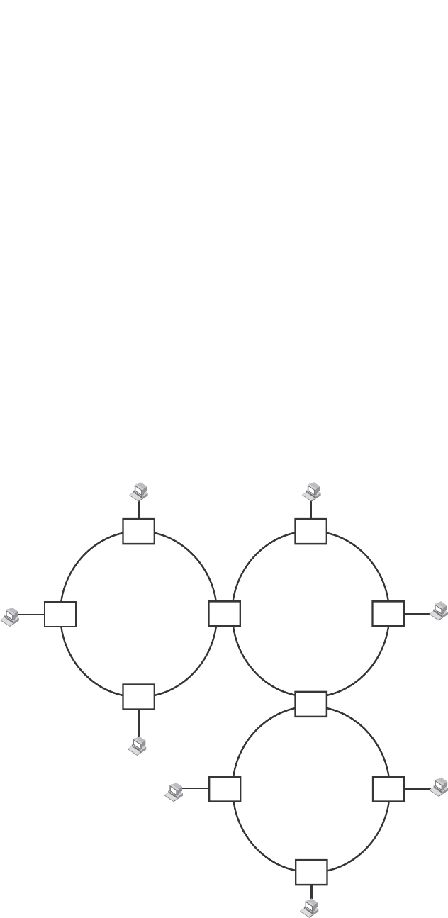
PowerConnect B-Series FCX Configuration Guide 339
53-1002266-01
Metro Ring Protocol (MRP) 10
Configuration notes
•When you configure MRP, Dell recommends that you disable one of the ring interfaces before
beginning the ring configuration. Disabling an interface prevents a Layer 2 loop from occurring
while you are configuring MRP on the ring nodes. Once MRP is configured and enabled on all
the nodes, you can re-enable the interface.
•The above configurations can be configured as MRP masters or MRP members (for different
rings).
MRP rings without shared interfaces (MRP Phase 1)
MRP Phase 1 allows you to configure multiple MRP rings, as shown in Figure 59, but the rings
cannot share the same link. For example, you cannot configure ring 1 and ring 2 to each have
interfaces 1/1 and 1/2.
Also, when you configure an MRP ring, any node on the ring can be designated as the master node
for the ring. A master node can be the master node of more than one ring. (Refer to Figure 59.)
Each ring is an independent ring and RHP packets are processed within each ring.
FIGURE 59 Metro ring – multiple rings
In this example, two nodes are each configured with two MRP rings. Any node in a ring can be the
master for its ring. A node also can be the master for more than one ring.
Ring 1 Ring 2
Ring 3
Port1/1
Port1/2 Port4/2
Port4/1
Master
Node
Master
Node
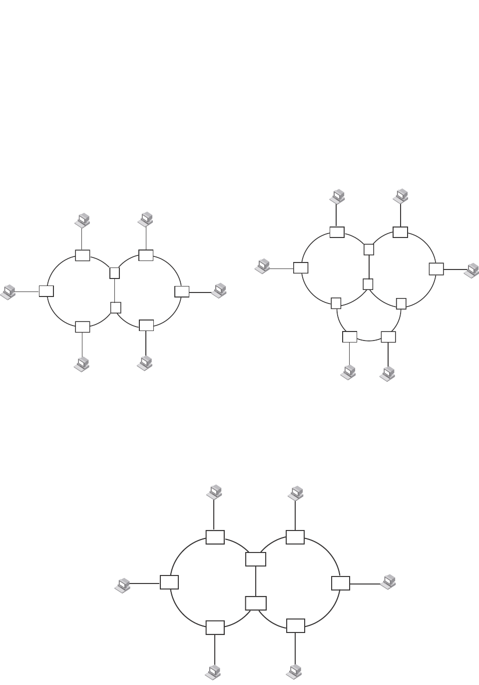
340 PowerConnect B-Series FCX Configuration Guide
53-1002266-01
Metro Ring Protocol (MRP)
10
MRP rings with shared interfaces (MRP Phase 2)
With MRP Phase 2, MRP rings can be configured to share the same interfaces as long as the
interfaces belong to the same VLAN. Figure 60 shows examples of multiple MRP rings that share
the same interface.
FIGURE 60 Examples of multiple rings sharing the same interface - MRP Phase 2
On each node that will participate in the ring, you specify the ring ID and the interfaces that will be
used for ring traffic. In a multiple ring configuration, a ring ID determines its priority. The lower the
ring ID, the higher priority of a ring.
A ring ID is also used to identify the interfaces that belong to a ring.
FIGURE 61 Interface IDs and types
Example 1 Example 2
Ring 1 Ring 2
Port1/1
VLAN 2
Port2/2
VLAN 2
S1
S2
Ring 1 Ring 2
Port1/1
VLAN 2
Port2/2
VLAN 2
S2
S1
S4
S3
Ring 3
Ring 1 Ring 2
S1
S2
1
1
1
1
111
1T
T222
2
2
2
2
2
1,2
1,2 Port1/1
Port2/2
C = customer port

PowerConnect B-Series FCX Configuration Guide 341
53-1002266-01
Metro Ring Protocol (MRP) 10
For example, in Figure 61, the ID of all interfaces on all nodes on Ring 1 is 1 and all interfaces on
all nodes on Ring 2 is 2. Port 1/1 on node S1 and Port 2/2 on S2 have the IDs of 1 and 2 since the
interfaces are shared by Rings 1 and 2.
The ring ID is also used to determine an interface priority. Generally, a ring ID is also the ring priority
and the priority of all interfaces on that ring. However, if the interface is shared by two or more
rings, then the highest priority (lowest ID) becomes the priority of the interface. For example, in
Figure 61, all interfaces on Ring 1, except for Port 1/1 on node S1 and Port 2/2 on node S2 have a
priority of 1. Likewise, all interfaces on Ring 2, except for Port 1/1 on node S1 and Port 2/2 on
node S2 have a priority of 2. Port 1/1 on S1 and Port 2/2 on S2 have a priority of 1 since 1 is the
highest priority (lowest ID) of the rings that share the interface.
If a node has interfaces that have different IDs, the interfaces that belong to the ring with the
highest priority become regular ports. Those interfaces that do not belong to the ring with the
highest priority become tunnel ports. In Figure 61, nodes S1 and S2 have interfaces that belong to
Rings 1 and 2. Those interfaces with a priority of 1 are regular ports. The interfaces with a priority
of 2 are the tunnel ports since they belong to Ring 2, which has a lower priority than Ring 1.
Selection of master node
Allowing MRP rings to share interfaces limits the nodes that can be designated as the master node.
Any node on an MRP ring that does not have a shared interface can be designated as the ring
master node. However, if all nodes on the ring have shared interfaces, nodes that do not have
tunnel ports can be designated as the master node of that ring. If none of the nodes meet these
criteria, you must change the rings’ priorities by reconfiguring the rings’ ID.
In Figure 61, any of the nodes on Ring 1, even S1 or S2, can be a master node since none of its
interfaces are tunnel ports. However in Ring 2, neither S1 nor S2 can be a master node since these
nodes contain tunnel ports.
Ring initialization
The ring shown in Figure 58 shows the port states in a fully initialized ring without any broken links.
Figure 62 shows the initial state of the ring, when MRP is first enabled on the ring switches. All ring
interfaces on the master node and member nodes begin in the Preforwarding state (PF).

342 PowerConnect B-Series FCX Configuration Guide
53-1002266-01
Metro Ring Protocol (MRP)
10
FIGURE 62 Metro ring – initial state
MRP uses Ring Health Packets (RHPs) to monitor the health of the ring. An RHP is an MRP protocol
packet. The source address is the MAC address of the master node and the destination MAC
address is a protocol address for MRP. The Master node generates RHPs and sends them on the
ring. The state of a ring port depends on the RHPs.
RHP processing in MRP Phase 1
A ring interface can have one of the following MRP states:
•Preforwarding (PF) – The interface can forward RHPS but cannot forward data. All ring ports
begin in this state when you enable MRP.
Customer A
Customer A
Customer A
Customer A
Switch B
Switch A
Switch C
Switch D
F
F
F
F
PF
PF
PF PF
PF PF
PF
PF
All ports start in
Preforwarding state.
Primary port on Master
node sends RHP 1
Master
Node

PowerConnect B-Series FCX Configuration Guide 343
53-1002266-01
Metro Ring Protocol (MRP) 10
•Forwarding (F) – The interface can forward data as well as RHPs. An interface changes from
Preforwarding to Forwarding when the port preforwarding time expires. This occurs if the port
does not receive an RHP from the Master, or if the forwarding bit in the RHPs received by the
port is off. This indicates a break in the ring. The port heals the ring by changing its state to
Forwarding. The preforwarding time is the number of milliseconds the port will remain in the
Preforwarding state before changing to the Forwarding state, even without receiving an RHP.
•Blocking (B) – The interface cannot forward data. Only the secondary interface on the Master
node can be Blocking.
When MRP is enabled, all ports begin in the Preforwarding state. The primary interface on the
Master node, although it is in the Preforwarding state like the other ports, immediately sends an
RHP onto the ring. The secondary port on the Master node listens for the RHP.
•If the secondary port receives the RHP, all links in the ring are up and the port changes its state
to Blocking. The primary port then sends another MRP with its forwarding bit set on. As each
of the member ports receives the RHP, the ports changes their state to Forwarding. Typically,
this occurs in sub-second time. The ring very quickly enters the fully initialized state.
•If the secondary port does not receive the RHP by the time the preforwarding time expires, a
break has occurred in the ring. The port changes its state to Forwarding. The member ports
also change their states from Preforwarding to Forwarding as their preforwarding timers expire.
The ring is not intact, but data can still travel among the nodes using the links that are up.
Figure 63 shows an example.
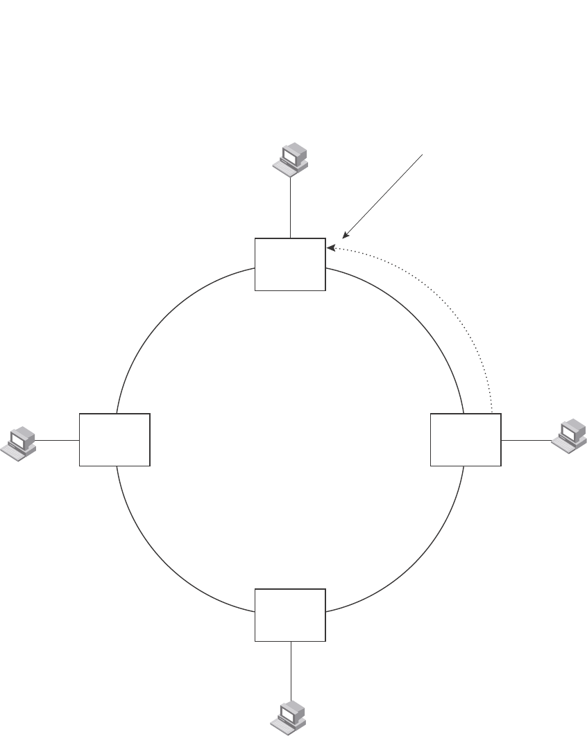
344 PowerConnect B-Series FCX Configuration Guide
53-1002266-01
Metro Ring Protocol (MRP)
10
FIGURE 63 Metro ring – from preforwarding to forwarding
Each RHP also has a sequence number. MRP can use the sequence number to determine the
round-trip time for RHPs in the ring. Refer to “Using MRP diagnostics” on page 352.
Customer A
Customer A
Customer A
Customer A
Switch B
Switch A
Switch C
Switch D
F
F
F
F
PF
PF
PF PF
PF
F
F
B
Secondary port
receives RHP 1
and changes to
Blocking
Primary port then
sends RHP 2 with
forwarding bit on
Master
Node
Forwarding bit is on.
Each port changes from
Preforwarding to Forwarding
when it receives this RHP.
RHP 2
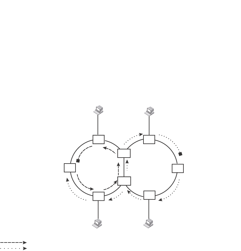
PowerConnect B-Series FCX Configuration Guide 345
53-1002266-01
Metro Ring Protocol (MRP) 10
RHP processing in MRP Phase 2
Figure 64 shows an example of how RHP packets are processed normally in MRP rings with shared
interfaces.
FIGURE 64 Flow of RHP packets on MRP rings with shared interfaces
Port 2/1 on Ring 1 master node is the primary interface of the master node. The primary interface
forwards an RHP packet on the ring. Since all the interfaces on Ring 1 are regular ports, the RHP
packet is forwarded to all the interfaces until it reaches Port 2/2, the secondary interface of the
master node. Port 2/2 then blocks the packet to complete the process.
On Ring 2, Port 3/1, is the primary interface of the master node. It sends an RHP packet on the
ring. Since all ports on S4 are regular ports, the RHP packet is forwarded on those interfaces.
When the packet reaches S2, the receiving interface is a tunnel port. The port compares the packet
priority to its priority. Since the packet priority is the same as the tunnel port priority, the packet is
forwarded up the link shared by Rings 1 and 2.
When the RHP packet reaches the interface on node S2 shared by Rings 1 and 2, the packet is
forwarded since its priority is less than the interface priority. The packet continues to be forwarded
to node S1 until it reaches the tunnel port on S1. That tunnel port determines that the RHP packet
priority is equal to the port priority and forwards the packet. The RHP packet is forwarded to the
remaining interfaces on Ring 2 until it reaches port 3/2, the secondary interface of the master
node. Port 3/2 then blocks the packet to prevent a loop.
When the RHP packet from Ring 2 reached S2, it was also forwarded from S2 to S3 on Ring 1 since
the port on S2 has a higher priority than the RHP packet. The packets is forwarded around Ring 1
until it reaches port 2/2, Ring 1 the secondary port. The RHP packet is then blocked by that port.
Ring 1 Ring 2
S3 S4
S1
S2
1
1
1
1
1
1
1
1
2
2
2
22
2
2
2
1,2
1,2
Master node
(secondary interface)
P
ort2/2
(primary interface)
P
ort2/1
Master node
Port3/2 (secondary interface)
P
ort3/1 (primary interface)
= Ring 1 RHP packet
= Ring 2 RHP packet
T
T
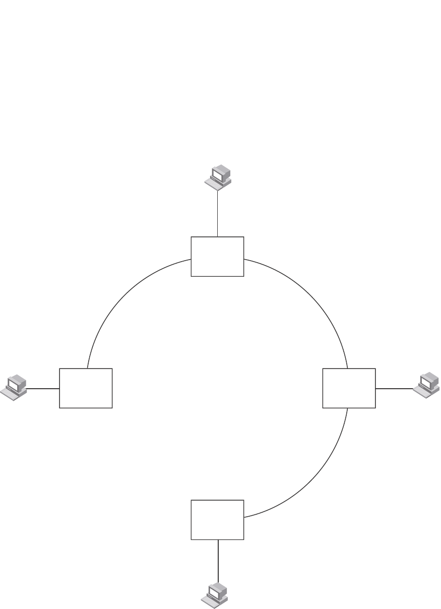
346 PowerConnect B-Series FCX Configuration Guide
53-1002266-01
Metro Ring Protocol (MRP)
10
How ring breaks are detected and healed
Figure 65 shows ring interface states following a link break. MRP quickly heals the ring and
preserves connectivity among the customer networks.
FIGURE 65 Metro ring – ring break
If a break in the ring occurs, MRP heals the ring by changing the states of some of the ring
interfaces:
•Blocking interface – The Blocking interface on the Master node has a dead timer. If the dead
time expires before the interface receives one of its ring RHPs, the interface changes state to
Preforwarding. Once the secondary interface changes state to Preforwarding:
F
FF
Customer A
Switch B
Customer A
Customer A
Customer A
Switch A
Switch C
Switch D
Master
Node
F
F
F
F
F
F
F
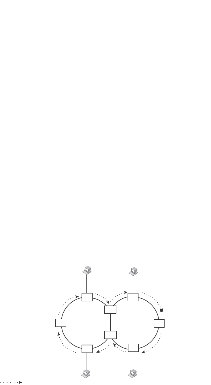
PowerConnect B-Series FCX Configuration Guide 347
53-1002266-01
Metro Ring Protocol (MRP) 10
•If the interface receives an RHP, the interface changes back to the Blocking state and
resets the dead timer.
•If the interface does not receive an RHP for its ring before the Preforwarding time expires,
the interface changes to the Forwarding state, as shown in Figure 65.
•Forwarding interfaces – Each member interface remains in the Forwarding state.
When the broken link is repaired, the link interfaces come up in the Preforwarding state, which
allows RHPs to travel through the restored interfaces and reach the secondary interface on the
Master node:
•If an RHP reaches the Master node secondary interface, the ring is intact. The secondary
interface changes to Blocking. The Master node sets the forwarding bit on in the next RHP.
When the restored interfaces receive this RHP, they immediately change state to Forwarding.
•If an RHP does not reach the Master node secondary interface, the ring is still broken. The
Master node does not send an RHP with the forwarding bit on. In this case, the restored
interfaces remain in the Preforwarding state until the preforwarding timer expires, then change
to the Forwarding state.
If the link between shared interfaces breaks (Figure 66), the secondary interface on Ring 1 master
node changes to a preforwarding state. The RHP packet sent by port 3/1 on Ring 2 is forwarded
through the interfaces on S4, then to S2. The packet is then forwarded through S2 to S3, but not
from S2 to S1 since the link between the two nodes is not available. When the packet reaches Ring
1 master node, the packet is forwarded through the secondary interface since it is currently in a
preforwarding state. A secondary interface in preforwarding mode ignores any RHP packet that is
not from its ring. The secondary interface changes to blocking mode only when the RHP packet
forwarded by its primary interface is returned.
The packet then continues around Ring 1, through the interfaces on S1 to Ring 2 until it reaches
Ring 2 master node. Port 3/2, the secondary interface on Ring 2 changes to blocking mode since it
received its own packet, then blocks the packet to prevent a loop.
FIGURE 66 Flow of RHP packets when a link for shared interfaces breaks
RHP packets follow this flow until the link is restored; then the RHP packet returns to it normal flow
as shown in Figure 64.
X
Ring 1 Ring 2
S3 S4
S1
S2
1
1
1
1
1
11
1
2
2
2
22
2
2
2
1,2
1,2
Master node
P
ort2/2 changes
to preforwarding
(primary interface)
P
ort2/1
Master node
Port3/2
P
ort3/1 (primary interface)
= Ring 2 RHP packet
T
T
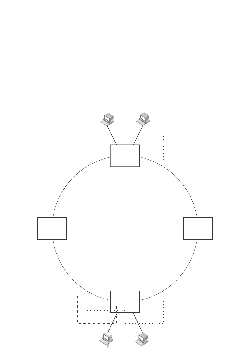
348 PowerConnect B-Series FCX Configuration Guide
53-1002266-01
Metro Ring Protocol (MRP)
10
Master VLANs and customer VLANs
All the ring ports must be in the same VLAN. Placing the ring ports in the same VLAN provides
Layer 2 connectivity for a given customer across the ring. Figure 67 shows an example.
FIGURE 67 Metro ring – ring VLAN and customer VLANs
Notice that each customer has their own VLAN. Customer A has VLAN 30 and Customer B has
VLAN 40. Customer A host attached to Switch D can reach the Customer A host attached to Switch
B at Layer 2 through the ring. Since Customer A and Customer B are on different VLANs, they will
not receive each other traffic.
You can configure MRP separately on each customer VLAN. However, this is impractical if you have
many customers. To simplify configuration when you have a lot of customers (and therefore a lot of
VLANs), you can use a topology group.
======
======
Customer A
VLAN 30
Customer B
VLAN 40
Customer A
VLAN 30
Customer B
VLAN 40
Switch B
Switch D
Port2/1 Port4/1
Port1/2 Port1/1
Port2/1 Port4/1
Port1/2 Port1/1
Switch D
ring 1
interfaces 1/1, 1/2
topology group 2
master VLAN 2 (1/1, 1/2)
member VLAN 30 (1/1, 1/2, 2/1)
member VLAN 40 (1/1, 1/2, 4/1)
ring 1
interfaces 1/1, 1/2
topology group 2
master VLAN 2 (1/1, 1/2)
member VLAN 30 (1/1, 1/2, 2/1)
member VLAN 40 (1/1, 1/2, 4/1)
Switch B

PowerConnect B-Series FCX Configuration Guide 349
53-1002266-01
Metro Ring Protocol (MRP) 10
A topology group enables you to control forwarding in multiple VLANs using a single instance of a
Layer 2 protocol such as MRP. A topology group contains a master VLAN and member VLANs. The
master VLAN contains all the configuration parameters for the Layer 2 protocol (STP, MRP, or
VSRP). The member VLANs use the Layer 2 configuration of the master VLAN.
In Figure 67, VLAN 2 is the master VLAN and contains the MRP configuration parameters for ring 1.
VLAN 30 and VLAN 40, the customer VLANs, are member VLANs in the topology group. Since a
topology group is used, a single instance of MRP provides redundancy and loop prevention for both
the customer VLANs.
If you use a topology group:
•The master VLAN must contain the ring interfaces. The ports must be tagged, since they will
be shared by multiple VLANs.
•The member VLAN for a customer must contain the two ring interfaces and the interfaces for
the customer. Since these interfaces are shared with the master VLAN, they must be tagged.
Do not add another customer interfaces to the VLAN.
For more information about topology groups, refer to “Topology groups” on page 333.
Refer to “MRP CLI example” on page 355 for the configuration commands required to implement
the MRP configuration shown in Figure 67.
Configuring MRP
To configure MRP, perform the following tasks. You need to perform the first task on only one of the
nodes. Perform the remaining tasks on all the nodes.
NOTE
There are no new commands or parameters to configure MRP with shared interfaces (MRP Phase 2).
•Disable one of the ring interfaces. This prevents a Layer 2 loop from occurring while you are
configuring the devices for MRP.
•Add an MRP ring to a port-based VLAN. When you add a ring, the CLI changes to the
configuration level for the ring, where you can perform the following tasks.
•Optionally, specify a name for the ring.
•On the master node only, enable the device to be the master for the ring. Each ring can
have only one master node.
•Specify the MRP interfaces. Each device has two interfaces to an MRP ring.
•Optionally, change the hello time and the preforwarding time. These parameters control
how quickly failover occurs following a change in the state of a link in the ring.
•Enable the ring.
•Optionally, add the ring VLAN to a topology group to add more VLANs to the ring. If you use a
topology group, make sure you configure MRP on the group master VLAN. Refer to “Topology
groups” on page 333.
•Re-enable the interface you disabled to prevent a Layer 2 loop. Once MRP is enabled, MRP will
prevent the Layer 2 loop.
•On PowerConnect B-Series FCX devices, when configuring MRP-1 or MRP-2 rings on a VLAN,
using the metro-rings command in addition to the metro-ring command is highly
recommended. Since these devices do not support mac-range filtering, the metro-rings
command greatly reduces the number of FDB entries.

350 PowerConnect B-Series FCX Configuration Guide
53-1002266-01
Metro Ring Protocol (MRP)
10
Adding an MRP ring to a VLAN
To add an MRP ring to a VLAN, enter commands such as the following.
NOTE
If you plan to use a topology group to add VLANs to the ring, make sure you configure MRP on the
topology group master VLAN.
PowerConnect(config)#vlan 2
PowerConnect(config-vlan-2)#metro-ring 1
PowerConnect(config-vlan-2-mrp-1)#name CustomerA
PowerConnect(config-vlan-2-mrp-1)#master
PowerConnect(config-vlan-2-mrp-1)#ring-interface ethernet 1/1 ethernet 1/2
PowerConnect(config-vlan-2-mrp-1)#enable
These commands configure an MRP ring on VLAN 2. The ring ID is 1, the ring name is CustomerA,
and this node (this Dell PowerConnect device) is the master for the ring. The ring interfaces are
1/1 and 1/2. Interface 1/1 is the primary interface and 1/2 is the secondary interface. The
primary interface will initiate RHPs by default. The ring takes effect in VLAN 2.
PowerConnect(config)#vlan 2
PowerConnect(config-vlan-2)#metro-ring 1
PowerConnect(config-vlan-2-mrp-1)#name CustomerA
PowerConnect(config-vlan-2-mrp-1)#ring-interface ethernet 1/1 ethernet 1/2
PowerConnect(config-vlan-2-mrp-1)#enable
PowerConnect(config-vlan-2-mrp-1)#metro-ring 2
PowerConnect(config-vlan-2-mrp-2)#name CustomerB
PowerConnect(config-vlan-2-mrp-2)#ring-interface ethernet 1/1 ethernet 1/2
PowerConnect(config-vlan-2-mrp-2)#enable
Syntax: [no] metro-ring <ring id>
The <ring-id> parameter specifies the ring ID.The <ring-id> can be from 1 – 1023; ID 256 is
reserved for VSRP.
OnPowerConnect B-Series FCX devices, enter the metro-rings in addition to the metro-ring
command as shown below.
PowerConnect(config)#vlan 2
PowerConnect(config-vlan-2)#metro-rings 1 2
PowerConnect(config-vlan-2)#metro-ring 1
PowerConnect(config-vlan-2-mrp-1)#name CustomerA
PowerConnect(config-vlan-2-mrp-1)#ring-interface ethernet 1/1 ethernet 1/2
PowerConnect(config-vlan-2-mrp-1)#enable
PowerConnect(config-vlan-2-mrp-1)#metro-ring 2
PowerConnect(config-vlan-2-mrp-2)#name CustomerB
PowerConnect(config-vlan-2-mrp-2)#ring-interface ethernet 1/1 ethernet 1/2
PowerConnect(config-vlan-2-mrp-2)#enable
Syntax: [no] metro-rings <ring id> <ring id>. . .
The <ring id> variables identify the metro rings you want to configure on the VLAN.
Syntax: [no] name <string>
The <string> parameter specifies a name for the ring. The name is optional, but it can be up to 20
characters long and can include blank spaces. If you use a name that has blank spaces, enclose
the name in double quotation marks (for example: “Customer A”).
Syntax: [no] master

PowerConnect B-Series FCX Configuration Guide 351
53-1002266-01
Metro Ring Protocol (MRP) 10
Configures this node as the master node for the ring. Enter this command only on one node in the
ring. The node is a member (non-master) node by default.
Syntax: [no] ring-interface ethernet <primary-if> ethernet <secondary-if>
The ethernet <primary-if> parameter specifies the primary interface. On the master node, the
primary interface is the one that originates RHPs. Ring control traffic and Layer 2 data traffic will
flow in the outward direction from this interface by default. On member nodes, the direction of
traffic flow depends on the traffic direction selected by the master node. Therefore, on a member
node, the order in which you enter the interfaces does not matter.
The ethernet <secondary-if> parameter specifies the secondary interface.
NOTE
To take advantage of every interface in a Metro network, you can configure another MRP ring and
either configure a different Master node for the ring or reverse the configuration of the primary and
secondary interfaces on the Master node. Configuring multiple rings enables you to use all the ports
in the ring. The same port can forward traffic one ring while blocking traffic for another ring.
Syntax: [no] enable
The enable command enables the ring.
Changing the hello and preforwarding times
You also can change the RHP hello time and preforwarding time. To do so, enter commands such
as the following.
PowerConnect(config-vlan-2-mrp-1)#hello-time 200
PowerConnect(config-vlan-2-mrp-1)#preforwarding-time 400
These commands change the hello time to 200 ms and change the preforwarding time to 400 ms.
Syntax: [no] hello-time <ms>
Syntax: [no] preforwarding-time <ms>
The <ms> specifies the number of milliseconds. For the hello time, you can specify from 100 –
1000 (one second). The default hello time is 100 ms. The preforwarding time can be from 200 –
5000 ms, but must be at least twice the value of the hello time and must be a multiple of the hello
time. The default preforwarding time is 300 ms. A change to the hello time or preforwarding time
takes effect as soon as you enter the command.
Configuration notes
•The preforwarding time must be at least twice the value of the hello time and must be a
multiple of the hello time.
•If UDLD is also enabled on the device, Dell recommends that you set the MRP preforwarding
time slightly higher than the default of 300 ms; for example, to 400 or 500 ms.
•You can use MRP ring diagnostics to determine whether you need to change the hello time and
preforwarding time. Refer to “Using MRP diagnostics”.

352 PowerConnect B-Series FCX Configuration Guide
53-1002266-01
Metro Ring Protocol (MRP)
10
Using MRP diagnostics
The MRP diagnostics feature calculates how long it takes for RHP packets to travel through the ring.
When you enable MRP diagnostics, the software tracks RHP packets according to their sequence
numbers and calculates how long it takes an RHP packet to travel one time through the entire ring.
When you display the diagnostics, the CLI shows the average round-trip time for the RHP packets
sent since you enabled diagnostics. The calculated results have a granularity of 1 microsecond.
Enabling MRP diagnostics
To enable MRP diagnostics for a ring, enter the following command on the Master node, at the
configuration level for the ring.
PowerConnect(config-vlan-2-mrp-1)#diagnostics
Syntax: [no] diagnostics
NOTE
This command is valid only on the master node.
Displaying MRP diagnostics
To display MRP diagnostics results, enter the following command on the Master node.
Syntax: show metro <ring-id> diag
This display shows the following information.
TABLE 61 CLI display of MRP ring diagnostic information
This field... Displays...
Ring id The ring ID.
Diag state The state of ring diagnostics.
RHP average time The average round-trip time for an RHP packet on the ring. The
calculated time has a granularity of 1 microsecond.
Recommended hello time The hello time recommended by the software based on the RHP average
round-trip time.
Recommended Prefwing time The preforwarding time recommended by the software based on the
RHP average round-trip time.
PowerConnect#show metro 1 diag
Metro Ring 1 - CustomerA
=============
diagnostics results
Ring Diag RHP average Recommended Recommended
id state time(microsec) hello time(ms) Prefwing time(ms)
2 enabled 125 100 300
Diag frame sent Diag frame lost
1230 0

PowerConnect B-Series FCX Configuration Guide 353
53-1002266-01
Metro Ring Protocol (MRP) 10
If the recommended hello time and preforwarding time are different from the actual settings and
you want to change them, refer to “Configuring MRP” on page 349.
Displaying MRP information
You can display the following MRP information:
•Topology group configuration information
•Ring configuration information and statistics
Displaying topology group information
To display topology group information, enter the following command.
Syntax: show topology-group [<group-id>]
Refer to “Displaying topology group information” on page 336 for more information.
Displaying ring information
To display ring information, enter the following command.
Syntax: show metro [<ring-id>]
This display shows the following information.
Diag frame sent The number of diagnostic RHPs sent for the test.
Diag frame lost The number of diagnostic RHPs lost during the test.
TABLE 61 CLI display of MRP ring diagnostic information (Continued)
This field... Displays...
PowerConnect#show metro
Metro Ring 1
=============
Ring State Ring Master Topo Hello Prefwing
id role vlan group time(ms) time(ms)
2 enabled member 2 not conf 100 300
Ring interfaces Interface role Forwarding state Active interface
Interface Type
ethernet 1/1 primary disabled none
Regular
ethernet 1/2 secondary forwarding ethernet 2 Tunnel
RHPs sent RHPs rcvd TC RHPs rcvd State changes
3 0 0 4

354 PowerConnect B-Series FCX Configuration Guide
53-1002266-01
Metro Ring Protocol (MRP)
10
TABLE 62 CLI display of MRP ring information
This field... Displays...
Ring id The ring ID
State The state of MRP. The state can be one of the following:
•enabled – MRP is enabled
•disabled – MRP is disabled
Ring role Whether this node is the master for the ring. The role can be one of the
following:
•master
•member
Master vlan The ID of the master VLAN in the topology group used by this ring. If a
topology group is used by MRP, the master VLAN controls the MRP
settings for all VLANs in the topology group.
NOTE: The topology group ID is 0 if the MRP VLAN is not the master
VLAN in a topology group. Using a topology group for MRP
configuration is optional.
Topo group The topology group ID.
Hello time The interval, in milliseconds, at which the Forwarding port on the ring
master node sends Ring Hello Packets (RHPs).
Prefwing time The number of milliseconds an MRP interface that has entered the
Preforwarding state will wait before changing to the Forwarding state.
If a member port in the Preforwarding state does not receive an RHP
within the Preforwarding time (Prefwing time), the port assumes that a
topology change has occurred and changes to the Forwarding state.
The secondary port on the Master node changes to Blocking if it receives
an RHP, but changes to Forwarding if the port does not receive an RHP
before the preforwarding time expires.
NOTE: A member node Preforwarding interface also changes from
Preforwarding to Forwarding if it receives an RHP whose
forwarding bit is on.
Ring interfaces The device two interfaces with the ring.
NOTE: If the interfaces are trunk groups, only the primary ports of the
groups are listed.
Interface role The interface role can be one of the following:
•primary
•Master node – The interface generates RHPs.
•Member node – The interface forwards RHPs received on the
other interface (the secondary interface).
•secondary – The interface does not generate RHPs.
•Master node – The interface listens for RHPs.
•Member node – The interface receives RHPs.
Forwarding state Whether MRP Forwarding is enabled on the interface. The forwarding
state can be one of the following:
•blocking – The interface is blocking Layer 2 data traffic and RHPs
•disabled – The interface is down
•forwarding – The interface is forwarding Layer 2 data traffic and
RHPs
•preforwarding – The interface is listening for RHPs but is blocking
Layer 2 data traffic

PowerConnect B-Series FCX Configuration Guide 355
53-1002266-01
Metro Ring Protocol (MRP) 10
MRP CLI example
The following examples show the CLI commands required to implement the MRP configuration
shown in Figure 67 on page 348.
NOTE
For simplicity, the figure shows the VLANs on only two switches. The CLI examples implement the
ring on all four switches.
Commands on Switch A (master node)
The following commands configure a VLAN for the ring. The ring VLAN must contain both of the
node interfaces with the ring. Add these interfaces as tagged interfaces, since the interfaces also
must be in each of the customer VLANs configured on the node.
PowerConnect(config)#vlan 2
PowerConnect(config-vlan-2)#tag ethernet 1/1 to 1/2
PowerConnect(config-vlan-2)#metro-ring 1
PowerConnect(config-vlan-2-mrp-1)#name “Metro A”
PowerConnect(config-vlan-2-mrp-1)#master
PowerConnect(config-vlan-2-mrp-1)#ring-interface ethernet 1/1 ethernet 1/2
PowerConnect(config-vlan-2-mrp-1)#enable
PowerConnect(config-vlan-2-mrp-1)#exit
PowerConnect(config-vlan-2)#exit
Active interface The physical interfaces that are sending and receiving RHPs.
NOTE: If a port is disabled, its state is shown as “disabled”.
NOTE: If an interface is a trunk group, only the primary port of the group
is listed.
Interface Type Shows if the interface is a regular port or a tunnel port.
RHPs sent The number of RHPs sent on the interface.
NOTE: This field applies only to the master node. On non-master nodes,
this field contains 0. This is because the RHPs are forwarded in
hardware on the non-master nodes.
RHPs rcvd The number of RHPs received on the interface.
NOTE: On most Dell PowerConnect devices, this field applies only to the
master node. On non-master nodes, this field contains 0. This is
because the RHPs are forwarded in hardware on the non-master
nodes. However, on the PowerConnect devices, the RHP
received counter on non-master MRP nodes increment. This is
because, on PowerConnect devices, the CPU receives a copy of
the RHPs forwarded in hardware.
TC RHPs rcvd The number of Topology Change RHPs received on the interface. A
Topology Change RHP indicates that the ring topology has changed.
State changes The number of MRP interface state changes that have occurred. The
state can be one of the states listed in the Forwarding state field.
Interface Type Shows if the interface is a regular port or a tunnel port.
TABLE 62 CLI display of MRP ring information (Continued)
This field... Displays...

356 PowerConnect B-Series FCX Configuration Guide
53-1002266-01
Metro Ring Protocol (MRP)
10
The following commands configure the customer VLANs. The customer VLANs must contain both
the ring interfaces as well as the customer interfaces.
PowerConnect(config)#vlan 30
PowerConnect(config-vlan-30)#tag ethernet 1/1 to 1/2
PowerConnect(config-vlan-30)#tag ethernet 2/1
PowerConnect(config-vlan-30)#exit
PowerConnect(config)#vlan 40
PowerConnect(config-vlan-40)#tag ethernet 1/1 to 1/2
PowerConnect(config-vlan-40)#tag ethernet 4/1
PowerConnect(config-vlan-40)#exit
The following commands configure topology group 1 on VLAN 2. The master VLAN is the one that
contains the MRP configuration. The member VLANs use the MRP parameters of the master VLAN.
The control interfaces (the ones shared by the master VLAN and member VLAN) also share MRP
state.
PowerConnect(config)#topology-group 1
PowerConnect(config-topo-group-1)#master-vlan 2
PowerConnect(config-topo-group-1)#member-vlan 30
PowerConnect(config-topo-group-1)#member-vlan 40
Commands on Switch B
The commands for configuring Switches B, C, and D are similar to the commands for configuring
Switch A, with two differences: the nodes are not configured to be the ring master. Omitting the
master command is required for non-master nodes.
PowerConnect(config)#vlan 2
PowerConnect(config-vlan-2)#tag ethernet 1/1 to 1/2
PowerConnect(config-vlan-2)#metro-ring 1
PowerConnect(config-vlan-2-mrp-1)#name “Metro A”
PowerConnect(config-vlan-2-mrp-1)#ring-interface ethernet 1/1 ethernet 1/2
PowerConnect(config-vlan-2-mrp-1)#enable
PowerConnect(config-vlan-2)#exit
PowerConnect(config)#vlan 30
PowerConnect(config-vlan-30)#tag ethernet 1/1 to 1/2
PowerConnect(config-vlan-30)#tag ethernet 2/1
PowerConnect(config-vlan-30)#exit
PowerConnect(config)#vlan 40
PowerConnect(config-vlan-40)#tag ethernet 1/1 to 1/2
PowerConnect(config-vlan-40)#tag ethernet 4/1
PowerConnect(config-vlan-40)#exit
PowerConnect(config)#topology-group 1
PowerConnect(config-topo-group-1)#master-vlan 2
PowerConnect(config-topo-group-1)#member-vlan 30
PowerConnect(config-topo-group-1)#member-vlan 40
Commands on Switch C
PowerConnect(config)#vlan 2
PowerConnect(config-vlan-2)#tag ethernet 1/1 to 1/2
PowerConnect(config-vlan-2)#metro-ring 1
PowerConnect(config-vlan-2-mrp-1)#name “Metro A”
PowerConnect(config-vlan-2-mrp-1)#ring-interface ethernet 1/1 ethernet 1/2
PowerConnect(config-vlan-2-mrp-1)#enable
PowerConnect(config-vlan-2)#exit

PowerConnect B-Series FCX Configuration Guide 357
53-1002266-01
Virtual Switch Redundancy Protocol (VSRP) 10
PowerConnect(config)#vlan 30
PowerConnect(config-vlan-30)#tag ethernet 1/1 to 1/2
PowerConnect(config-vlan-30)#tag ethernet 2/1
PowerConnect(config-vlan-30)#exit
PowerConnect(config)#vlan 40
PowerConnect(config-vlan-40)#tag ethernet 1/1 to 1/2
PowerConnect(config-vlan-40)#tag ethernet 4/1
PowerConnect(config-vlan-40)#exit
PowerConnect(config)#topology-group 1
PowerConnect(config-topo-group-1)#master-vlan 2
PowerConnect(config-topo-group-1)#member-vlan 30
PowerConnect(config-topo-group-1)#member-vlan 40
Commands on Switch D
PowerConnect(config)#vlan 2
PowerConnect(config-vlan-2)#tag ethernet 1/1 to 1/2
PowerConnect(config-vlan-2)#metro-ring 1
PowerConnect(config-vlan-2-mrp-1)#name “Metro A”
PowerConnect(config-vlan-2-mrp-1)#ring-interface ethernet 1/1 ethernet 1/2
PowerConnect(config-vlan-2-mrp-1)#enable
PowerConnect(config-vlan-2)#exit
PowerConnect(config)#vlan 30
PowerConnect(config-vlan-30)#tag ethernet 1/1 to 1/2
PowerConnect(config-vlan-30)#tag ethernet 2/1
PowerConnect(config-vlan-30)#exit
PowerConnect(config)#vlan 40
PowerConnect(config-vlan-40)#tag ethernet 1/1 to 1/2
PowerConnect(config-vlan-40)#tag ethernet 4/1
PowerConnect(config-vlan-40)#exit
PowerConnect(config)#topology-group 1
PowerConnect(config-topo-group-1)#master-vlan 2
PowerConnect(config-topo-group-1)#member-vlan 30
PowerConnect(config-topo-group-1)#member-vlan 40
Virtual Switch Redundancy Protocol (VSRP)
Virtual Switch Redundancy Protocol (VSRP) is a Dell proprietary protocol that provides redundancy
and sub-second failover in Layer 2 and Layer 3 mesh topologies. Based on the Dell Virtual Router
Redundancy Protocol Extended (VRRPE), VSRP provides one or more backups for a Layer 2 Switch
or Layer 3 Switch. If the active Layer 2 Switch or Layer 3 Switch becomes unavailable, one of the
backups takes over as the active device and continues forwarding traffic for the network.
The PowerConnect family of switches support full VSRP as well as VSRP-awareness. A Dell
PowerConnect device that is not itself configured for VSRP but is connected to a Dell PowerConnect
device that is configured for VSRP, is VSRP aware.
You can use VSRP for Layer 2, Layer 3, or for both layers. On Layer 3 Switches, Layer 2 and Layer 3
share the same VSRP configuration information. On Layer 2 Switches, VSRP applies only to Layer
2.
Figure 68 shows an example of a VSRP configuration.
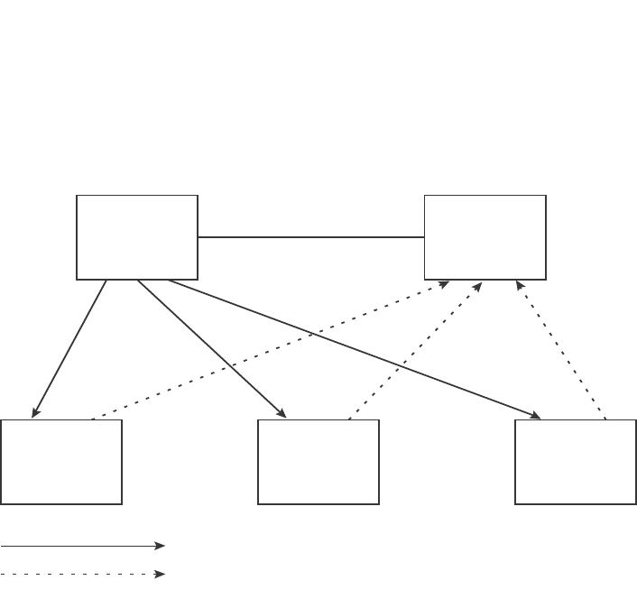
358 PowerConnect B-Series FCX Configuration Guide
53-1002266-01
Virtual Switch Redundancy Protocol (VSRP)
10
FIGURE 68 VSRP mesh – redundant paths for Layer 2 and Layer 3 traffic
In this example, two Dell PowerConnect devices are configured as redundant paths for VRID 1. On
each of the devices, a Virtual Router ID (VRID) is configured on a port-based VLAN. Since VSRP is
primarily a Layer 2 redundancy protocol, the VRID applies to the entire VLAN. However, you can
selectively remove individual ports from the VRID if needed.
Following Master election (described below), one of the Dell PowerConnect devices becomes the
Master for the VRID and sets the state of all the VLAN ports to Forwarding. The other device is a
Backup and sets all the ports in its VRID VLAN to Blocking.
If a failover occurs, the Backup becomes the new Master and changes all its VRID ports to the
Forwarding state.
Other Dell PowerConnect devices can use the redundant paths provided by the VSRP devices. In
this example, three Dell PowerConnect devices use the redundant paths. A Dell PowerConnect
device that is not itself configured for VSRP but is connected to a Dell PowerConnect device that is
configured for VSRP, is VSRP aware. In this example, the three Dell PowerConnect devices
connected to the VSRP devices are VSRP aware. A Dell PowerConnect device that is VSRP aware
can failover its link to the new Master in sub-second time, by changing the MAC address associated
with the redundant path.
When you configure VSRP, make sure each of the non-VSRP Dell PowerConnect devices connected
to the VSRP devices has a separate link to each of the VSRP devices.
Configuration notes and feature limitations
•VSRP and 802.1Q-n-Q tagging are not supported together on the same device.
•VSRP and Super Aggregated VLANs are not supported together on the same device.
•When VSRP or VSRP-aware is configured on a VLAN, the VLAN will support IGMP snooping
version 2 only. IGMP version 3 will not be supported on the VLAN.
VSRP
Master
VSRP
Backup
optional link
VSRP
Aware
VSRP
Aware
VSRP
Aware
Hello packets
FFFBBB

PowerConnect B-Series FCX Configuration Guide 359
53-1002266-01
Virtual Switch Redundancy Protocol (VSRP) 10
Layer 2 and Layer 3 redundancy
You can configure VSRP to provide redundancy for Layer 2 only or also for Layer 3:
•Layer 2 only – The Layer 2 links are backed up but specific IP addresses are not backed up.
•Layer 2 and Layer 3 – The Layer 2 links are backed up and a specific IP address is also backed
up. Layer 3 VSRP is the same as VRRPE. However, using VSRP provides redundancy at both
layers at the same time.
Layer 2 Switches support Layer 2 VSRP only. Layer 3 Switches support Layer 2 and Layer 3
redundancy. You can configure a Layer 3 Switch for either Layer 2 only or Layer 2 and Layer 3. To
configure for Layer 3, specify the IP address you are backing up.
NOTE
If you want to provide Layer 3 redundancy only, disable VSRP and use VRRPE.
Master election and failover
Each VSRP device advertises its VSRP priority in Hello messages. During Master election, the VSRP
device with the highest priority for a given VRID becomes the Master for that VRID. After Master
election, the Master sends Hello messages at regular intervals to inform the Backups that the
Master is healthy.
If there is a tie for highest VSRP priority, the tie is resolved as follows:
•Layer 2 Switches – The Layer 2 Switch with the higher management IP address becomes the
Master.
•Switches with management IP addresses are preferred over switches without
management IP addresses.
•If neither of the switches has a management IP address, then the switch with the higher
MAC address becomes the Master. (VSRP compares the MAC addresses of the ports
configured for the VRID, not the base MAC addresses of the switches.)
•Layer 3 Switches – The Layer 3 Switch whose virtual routing interface has a higher IP address
becomes the master.
VSRP failover
Each Backup listens for Hello messages from the Master. The Hello messages indicate that the
Master is still available. If the Backups stop receiving Hello messages from the Master, the election
process occurs again and the Backup with the highest priority becomes the new Master.
Each Backup waits for a specific period of time, the Dead Interval, to receive a new Hello message
from the Master. If the Backup does not receive a Hello message from the Master by the time the
Dead Interval expires, the Backup sends a Hello message of its own, which includes the Backup's
VSRP priority, to advertise the Backup's intent to become the Master. If there are multiple Backups
for the VRID, each Backup sends a Hello message.
When a Backup sends a Hello message announcing its intent to become the Master, the Backup
also starts a hold-down timer. During the hold-down time, the Backup listens for a Hello message
with a higher priority than its own.
•If the Backup receives a Hello message with a higher priority than its own, the Backup resets
its Dead Interval and returns to normal Backup status.
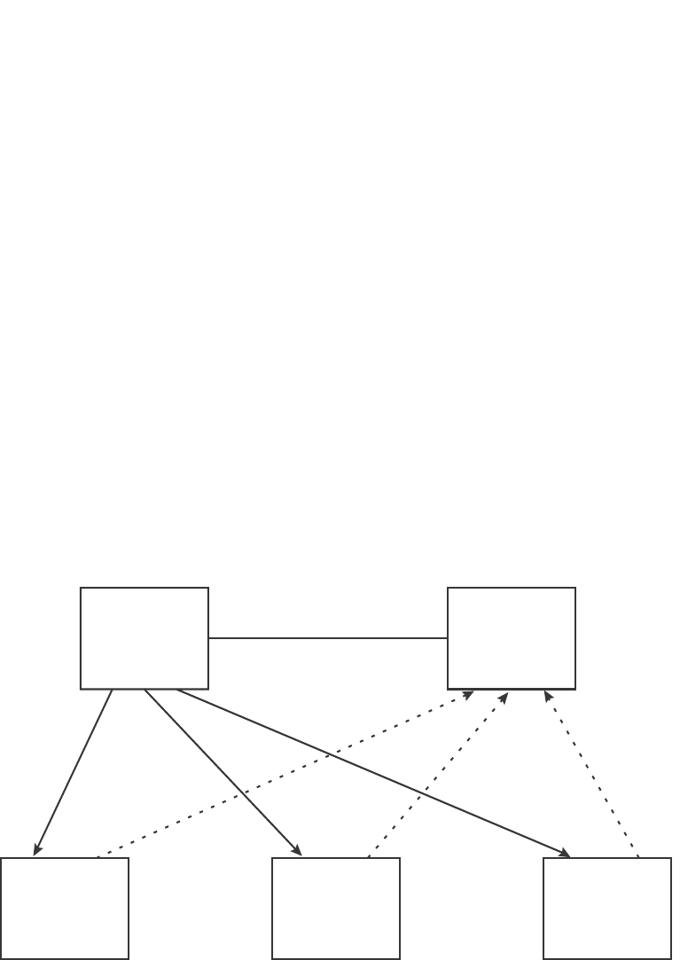
360 PowerConnect B-Series FCX Configuration Guide
53-1002266-01
Virtual Switch Redundancy Protocol (VSRP)
10
•If the Backup does not receive a Hello message with a higher priority than its own by the time
the hold-down timer expires, the Backup becomes the new Master and starts forwarding Layer
2 traffic on all ports.
If you increase the timer scale value, each timer value is divided by the scale value. To achieve
sub-second failover times, you can change the scale to a value up to 10. This shortens all the VSRP
timers to 10 percent of their configured values.
VSRP priority calculation
Each VSRP device has a VSRP priority for each VRID and its VLAN. The VRID is used during Master
election for the VRID. By default, a device VSRP priority is the value configured on the device
(which is 100 by default). However, to ensure that a Backup with a high number of up ports for a
given VRID is elected, the device reduces the priority if a port in the VRID VLAN goes down. For
example, if two Backups each have a configured priority of 100, and have three ports in VRID 1 in
VLAN 10, each Backup begins with an equal priority, 100. This is shown in Figure 69
FIGURE 69 VSRP priority
However, if one of the VRID ports goes down on one of the Backups, that Backup priority is
reduced. If the Master priority is reduced enough to make the priority lower than a Backup priority,
the VRID fails over to the Backup. Figure 70 shows an example.
VSRP
Master
VSRP
Backup
optional link
VSRP
Aware
VSRP
Aware
VSRP
Aware
FFFBBB
Configured priority = 100
Actual priority = 100 * (3/3) = 100
Configured priority = 100
Actual priority = 100 * (3/3) = 100
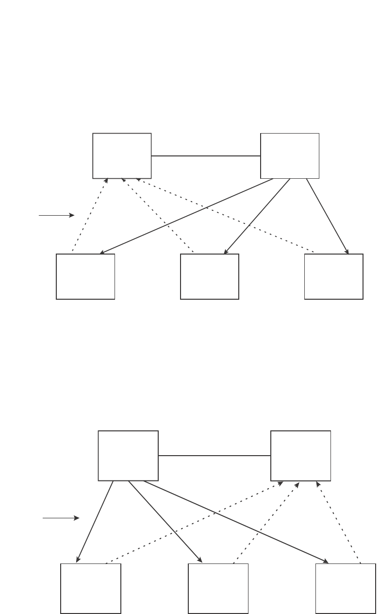
PowerConnect B-Series FCX Configuration Guide 361
53-1002266-01
Virtual Switch Redundancy Protocol (VSRP) 10
FIGURE 70 VSRP priority recalculation
You can reduce the sensitivity of a VSRP device to failover by increasing its configured VSRP
priority. For example, you can increase the configured priority of the VSRP device on the left in
Figure 70 to 150. In this case, failure of a single link does not cause failover. The link failure
caused the priority to be reduced to 100, which is still equal to the priority of the other device. This
is shown in Figure 71.
FIGURE 71 VSRP priority bias
Track ports
Optionally, you can configure track ports to be included during VSRP priority calculation. In VSRP, a
track port is a port that is not a member of the VRID VLAN, but whose state is nonetheless
considered when the priority is calculated. Typically, a track port represents the exit side of traffic
received on the VRID ports. By default, no track ports are configured.
X
VSRP
Backup
VSRP
Master
optional link
VSRP
Aware
VSRP
Aware
VSRP
Aware
Configured priority = 100
Actual priority = 100 * (2/3) = 67
Configured priority = 100
Actual priority = 100 * (3/3) = 100
BBBFFF
Link down
X
VSRP
Master
VSRP
Backup
optional link
VSRP
Aware
VSRP
Aware
VSRP
Aware
FFFBBB
Configured priority = 150
Actual priority = 150 * (2/3) = 100
Configured priority = 100
Actual priority = 100 * (3/3) = 100
Link down
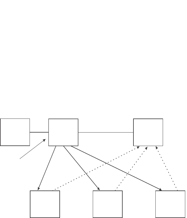
362 PowerConnect B-Series FCX Configuration Guide
53-1002266-01
Virtual Switch Redundancy Protocol (VSRP)
10
When you configure a track port, you assign a priority value to the port. If the port goes down, VSRP
subtracts the track port priority value from the configured VSRP priority. For example, if the you
configure a track port with priority 20 and the configured VSRP priority is 100, the software
subtracts 20 from 100 if the track port goes down, resulting in a VSRP priority of 80. The new
priority value is used when calculating the VSRP priority. Figure 72 shows an example.
FIGURE 72 Track port priority
In Figure 72, the track port is up. SInce the port is up, the track priority does not affect the VSRP
priority calculation. If the track port goes down, the track priority does affect VSRP priority
calculation, as shown in Figure 73.
VSRP
Master
VSRP
Backup
optional link
VSRP
Aware
VSRP
Aware
VSRP
Aware
FFFBBB
Configured priority = 100
Track priority 20
Actual priority = (100 - 0) * (3/3) = 100
Configured priority = 100
Actual priority = 100 * (3/3) = 100
Track port
is up
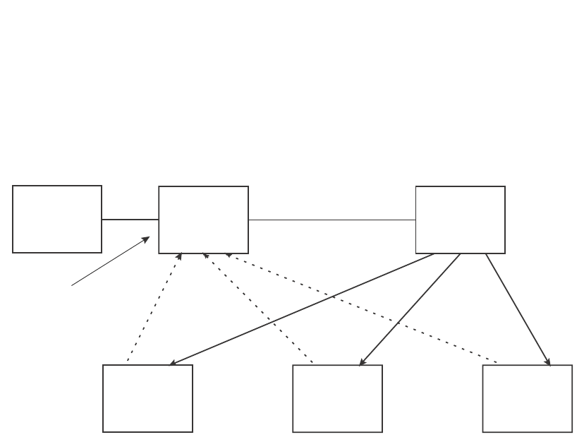
PowerConnect B-Series FCX Configuration Guide 363
53-1002266-01
Virtual Switch Redundancy Protocol (VSRP) 10
FIGURE 73 Track port priority subtracted during priority calculation
MAC address failover on VSRP-aware devices
VSRP-aware devices maintain a record of each VRID and its VLAN. When the device has received a
Hello message for a VRID in a given VLAN, the device creates a record for that VRID and VLAN and
includes the port number in the record. Each subsequent time the device receives a Hello
message for the same VRID and VLAN, the device checks the port number:
•If the port number is the same as the port that previously received a Hello message, the
VSRP-aware device assumes that the message came from the same VSRP Master that sent
the previous message.
•If the port number does not match, the VSRP-aware device assumes that a VSRP failover has
occurred to a new Master, and moves the MAC addresses learned on the previous port to the
new port.
The VRID records age out if unused. This can occur if the VSRP-aware device becomes
disconnected from the Master. The VSRP-aware device will wait for a Hello message for the period
of time equal to the following.
VRID Age = Dead Interval + Hold-down Interval + (3 x Hello Interval)
The values for these timers are determined by the VSRP device sending the Hello messages. If the
Master uses the default timer values, the age time for VRID records on the VSRP-aware devices is
as follows.
3 + 2 + (3 x 1) = 8 seconds
In this case, if the VSRP-aware device does not receive a new Hello message for a VRID in a given
VLAN, on any port, the device assumes the connection to the Master is unavailable and removes
the VRID record.
XVSRP
Backup
VSRP
Master
optional link
VSRP
Aware
VSRP
Aware
VSRP
Aware
Configured priority = 100
Track priority 20
Actual priority = (100 - 20) * (3/3) = 80
Configured priority = 100
Actual priority = 100 * (3/3) = 100
Track link
is down
BBBFFF

364 PowerConnect B-Series FCX Configuration Guide
53-1002266-01
Virtual Switch Redundancy Protocol (VSRP)
10
Timer scale
The VSRP Hello interval, Dead interval, Backup Hello interval, and Hold-down interval timers are
individually configurable. You also can easily change all the timers at the same time while
preserving the ratios among their values. To do so, change the timer scale. The timer scale is a
value used by the software to calculate the timers. The software divides a timer value by the timer
scale value. By default, the scale is 1. This means the VSRP timer values are the same as the
values in the configuration.
VSRP-Aware security features
This feature protects against unauthorized VSRP hello packets by enabling you to configure
VSRP-aware security parameters. Without VSRP-aware security, a VSRP-aware device passively
learns the authentication method conveyed by the received VSRP hello packet. The VSRP-aware
device then stores the authentication method until it ages out with the aware entry.
The VSRP-aware security feature enables you to perform the following:
•Define the specific authentication parameters that a VSRP-aware device will use on a VSRP
backup switch. The authentication parameters that you define will not age out.
•Define a list of ports that have authentic VSRP backup switch connections. For ports included
in the list, the VSRP-aware switch will process VSRP hello packets using the VSRP-aware
security configuration. Conversely, for ports not included in the list, the VSRP-aware switch will
not use the VSRP-aware security configuration.
If VSRP hello packets do not meet the acceptance criteria, the VSRP-aware device forwards the
packets normally, without any VSRP-aware security processing.
To configure VSRP-Aware Security features, refer to “Configuring security features on a VSRP-aware
device” on page 369.
VSRP parameters
Table 63 lists the VSRP parameters.
TABLE 63 VSRP parameters
Parameter Description Default See page...
Protocol VSRP state
NOTE: On a Layer 3 Switch, you must disable VSRP to
use VRRPE or VRRP.
Enabled page 368
Virtual Router ID
(VRID)
The ID of the virtual switch you are creating by
configuring multiple devices as redundant links. You
must configure the same VRID on each device that
you want to use to back up the links.
None page 367
Timer scale The value used by the software to calculate all VSRP
timers. Increasing the timer scale value decreases
the length of all the VSRP timers equally, without
changing the ratio of one timer to another.
1page 368

PowerConnect B-Series FCX Configuration Guide 365
53-1002266-01
Virtual Switch Redundancy Protocol (VSRP) 10
Interface parameters
Authentication
type
The type of authentication the VSRP devices use to
validate VSRP packets. On Layer 3 Switches, the
authentication type must match the authentication
type the VRID port uses with other routing protocols
such as OSPF.
•No authentication – The interfaces do not use
authentication. This is the VRRP default.
•Simple – The interface uses a simple text-string
as a password in packets sent on the interface.
If the interface uses simple password
authentication, the VRID configured on the
interface must use the same authentication type
and the same password.
NOTE: MD5 is not supported.
No authentication page 369
VSRP-Aware Security Parameters
VSRP-Aware
Authentication
type
The type of authentication the VSRP-aware devices
will use on a VSRP backup switch:
•No authentication – The device does not accept
incoming packets that have authentication
strings.
•Simple – The device uses a simple text-string as
the authentication string for accepting incoming
packets.
Not configured page 369
VRID parameters
VSRP device
type
Whether the device is a VSRP Backup for the VRID.
All VSRP devices for a given VRID are Backups.
Not configured page 367
VSRP ports The ports in the VRID VLAN that you want to use as
VRID interfaces. You can selectively exclude
individual ports from VSRP while allowing them to
remain in the VLAN.
All ports in the VRID
VLAN
page 370
VRID IP address A gateway address you are backing up. Configuring
an IP address provides VRRPE Layer 3 redundancy in
addition to VSRP LAyer 2 redundancy.
The VRID IP address must be in the same subnet as a
real IP address configured on the VSRP interface, but
cannot be the same as a real IP address configured
on the interface.
NOTE: This parameter is valid only on Layer 3
Switches.
None page 370
Backup priority A numeric value that determines a Backup
preferability for becoming the Master for the VRID.
During negotiation, the device with the highest priority
becomes the Master.
In VSRP, all devices are Backups and have the same
priority by default.
If two or more Backups are tied with the highest
priority, the Backup with the highest IP address
becomes the Master for the VRID.
100 for all Backups page 371
TABLE 63 VSRP parameters (Continued)
Parameter Description Default See page...

366 PowerConnect B-Series FCX Configuration Guide
53-1002266-01
Virtual Switch Redundancy Protocol (VSRP)
10
Preference of
timer source
When you save a Backup configuration, the software
can save the configured VSRP timer values or the
VSRP timer values received from the Master.
Saving the current timer values instead of the
configured ones helps ensure consistent timer usage
for all the VRID devices.
NOTE: The Backup always gets its timer scale value
from the Master.
Configured timer
values are saved
page 371
Time-to-Live
(TTL)
The maximum number of hops a VSRP Hello packet
can traverse before being dropped. You can specify
from 1 – 255.
2page 372
Hello interval The amount of time between Hello messages from the
Master to the Backups for a given VRID.
The interval can be from 1 – 84 seconds.
One second page 372
Dead interval The amount of time a Backup waits for a Hello
message from the Master for the VRID before
determining that the Master is no longer active.
If the Master does not send a Hello message before
the dead interval expires, the Backups negotiate
(compare priorities) to select a new Master for the
VRID.
Three times the Hello
Interval
page 373
Backup Hello
state and
interval
The amount of time between Hello messages from a
Backup to the Master.
The message interval can be from 60 – 3600
seconds.
You must enable the Backup to send the messages.
The messages are disabled by default on Backups.
The current Master sends Hello messages by default.
Disabled
60 seconds when
enabled
page 373
Hold-down
interval
The amount of time a Backup that has sent a Hello
packet announcing its intent to become Master waits
before beginning to forward traffic for the VRID. The
hold-down interval prevents Layer 2 loops from
occurring during VSRP rapid failover.
The interval can from 1 – 84 seconds.
2 seconds page 374
Track priority A VSRP priority value assigned to the tracked ports. If
a tracked port link goes down, the VRID port VSRP
priority is reduced by the amount of the tracked port
priority.
5page 374
Track port A track port is a port or virtual routing interface that is
outside the VRID but whose link state is tracked by
the VRID. Typically, the tracked interface represents
the other side of VRID traffic flow through the device.
If the link for a tracked interface goes down, the VSRP
priority of the VRID interface is changed, causing the
devices to renegotiate for Master.
None page 374
Backup preempt
mode
Prevents a Backup with a higher VSRP priority from
taking control of the VRID from another Backup that
has a lower priority but has already assumed control
of the VRID.
Enabled page 375
VRID active state The active state of the VSRP VRID. Disabled page 367
TABLE 63 VSRP parameters (Continued)
Parameter Description Default See page...

PowerConnect B-Series FCX Configuration Guide 367
53-1002266-01
Virtual Switch Redundancy Protocol (VSRP) 10
Configuring basic VSRP parameters
To configure VSRP, perform the following required tasks:
•Configure a port-based VLAN containing the ports for which you want to provide VSRP service.
NOTE
If you already have a port-based VLAN but only want to use VSRP on a sub-set of the VLANs
ports, you can selectively remove ports from VSRP service in the VLAN. Refer to “Removing a
port from the VRID VLAN” on page 370.
•Configure a VRID:
•Specify that the device is a backup. Since VSRP, like VRRPE, does not have an “owner”, all
VSRP devices are backups. The active device for a VRID is elected based on the VRID
priority, which is configurable.
•Activate the VRID.
The following example shows a simple VSRP configuration.
PowerConnect(config)#vlan 200
PowerConnect(config-vlan-200)#tag ethernet 1/1 to 1/8
PowerConnect(config-vlan-200)#vsrp vrid 1
PowerConnect(config-vlan-200-vrid-1)#backup
PowerConnect(config-vlan-200-vrid-1)#activate
Syntax: [no] vsrp vrid <num>
The <num> parameter specifies the VRID and can be from 1 – 255.
Syntax: [no] backup [priority <value>] [track-priority <value>]
This command is required. In VSRP, all devices on which a VRID are configured are Backups. The
Master is then elected based on the VSRP priority of each device. There is no “owner” device as
there is in VRRP.
For information about the command optional parameters, refer to the following:
•“Changing the backup priority” on page 371
•“Changing the default track priority” on page 374
Syntax: [no] activate
or
RIP parameters
Suppression of
RIP
advertisements
A Layer 3 Switch that is running RIP normally
advertises routes to a backed up VRID even when the
Layer 3 Switch is not currently the active Layer 3
Switch for the VRID. Suppression of these
advertisements helps ensure that other Layer 3
Switches do not receive invalid route paths for the
VRID.
NOTE: This parameter is valid only on Layer 3
Switches.
Disabled
(routes are advertised)
page 375
TABLE 63 VSRP parameters (Continued)
Parameter Description Default See page...

368 PowerConnect B-Series FCX Configuration Guide
53-1002266-01
Virtual Switch Redundancy Protocol (VSRP)
10
Syntax: enable | disable
Configuring optional VSRP parameters
The following sections describe how to configure optional VSRP parameters.
Disabling or re-enabling VSRP
VSRP is enabled by default on Layer 2 Switches and Layer 3 Switches. On a Layer 3 Switch, if you
want to use VRRP or VRRPE for Layer 3 redundancy instead of VSRP, you need to disable VSRP first.
To do so, enter the following command at the global CONFIG level.
PowerConnect(config)#no router vsrp
router vsrp is disabled. All vsrp config data will be lost when writing to flash
To re-enable the protocol, enter the following command.
PowerConnect(config)#router vsrp
Syntax: [no] router vsrp
Since VRRP and VRRPE do not apply to Layer 2 Switches, there is no need to disable VSRP and
there is no command to do so. The protocol is always enabled.
Changing the timer scale
To achieve sub-second failover times, you can shorten the duration of all scale timers for VSRP,
VRRP, and VRRP-E by adjusting the timer scale. The timer scale is a value used by the software to
calculate the timers. By default, the scale value is 1. If you increase the timer scale, each timer
value is divided by the scale value. Using the timer scale to adjust timer values enables you to
easily change all the timers while preserving the ratios among their values. Here is an example.
If you configure the device to receive its timer values from the Master, the Backup also receives the
timer scale value from the Master.
NOTE
The Backups always use the value of the timer scale received from the Master, regardless of whether
the timer values that are saved in the configuration are the values configured on the Backup or the
values received from the Master.
Timer Timer scale Timer value
Hello interval 1 1 second
20.5 seconds
Dead interval 1 3 seconds
21.5 seconds
Backup Hello interval 1 60 seconds
2 30 seconds
Hold-down interval 1 2 seconds
21 second

PowerConnect B-Series FCX Configuration Guide 369
53-1002266-01
Virtual Switch Redundancy Protocol (VSRP) 10
To change the timer scale, enter a command such as the following at the global CONFIG level of the
CLI.
PowerConnect(config)# scale-timer 2
This command changes the scale to 2. All VSRP, VRRP, and VRRP-E timer values will be divided by
2.
Syntax: [no] scale-timer <num>
The <num> parameter specifies the multiplier. You can specify a timer scale from 1 – 10.
Configuring authentication
If the interfaces on which you configure the VRID use authentication, the VSRP packets on those
interfaces also must use the same authentication. VSRP supports the following authentication
types:
•No authentication – The interfaces do not use authentication. This is the default.
•Simple – The interfaces use a simple text-string as a password in packets sent on the
interface. If the interfaces use simple password authentication, the VRID configured on the
interfaces must use the same authentication type and the same password.
To configure a simple password, enter a command such as the following at the interface
configuration level.
PowerConnect(config-if-1/6)#ip vsrp auth-type simple-text-auth ourpword
This command configures the simple text password “ourpword”.
Syntax: [no] ip vsrp auth-type no-auth | simple-text-auth <auth-data>
The auth-type no-auth parameter indicates that the VRID and the interface it is configured on do
not use authentication.
The auth-type simple-text-auth <auth-data> parameter indicates that the VRID and the interface it
is configured on use a simple text password for authentication. The <auth-data> value is the
password. If you use this parameter, make sure all interfaces on all the devices supporting this
VRID are configured for simple password authentication and use the same password.
Configuring security features on a VSRP-aware device
This section shows how to configure security features on a VSRP-aware device. For an overview of
this feature, refer to “VSRP-Aware security features” on page 364.
Specifying an authentication string for VSRP hello packets
The following configuration defines pri-key as the authentication string for accepting incoming
VSRP hello packets. In this example, the VSRP-aware device will accept all incoming packets that
have this authorization string.
PowerConnect(config)#vlan 10
PowerConnect(config-vlan-10)#vsrp-aware vrid 3 simple-text-auth pri-key
Syntax: vsrp-aware vrid <vrid number> simple text auth <string>

370 PowerConnect B-Series FCX Configuration Guide
53-1002266-01
Virtual Switch Redundancy Protocol (VSRP)
10
Specifying no authentication for VSRP hello packets
The following configuration specifies no authentication as the preferred VSRP-aware security
method. In this case, the VSRP device will not accept incoming packets that have authentication
strings.
PowerConnect(config)#vlan 10
PowerConnect(config-vlan-10)#vsrp-aware vrid 2 no-auth
Syntax: vsrp-aware vrid <vrid number> no-auth
The following configuration specifies no authentication for VSRP hello packets received on ports
1/1, 1/2, 1/3, and 1/4 in VRID 4. For these ports, the VSRP device will not accept incoming
packets that have authentication strings.
PowerConnect(config)#vlan 10
PowerConnect(config-vlan-10)#vsrp-aware vrid 4 no-auth port-list ethe 1/1 to 1/4
Syntax: vsrp-aware vrid <vrid number> no-auth port-list <port range>
<vrid number> is a valid VRID (from 1 to 255).
no-auth specifies no authentication as the preferred VSRP-aware security method. The VSRP
device will not accept incoming packets that have authentication strings.
simple-text-auth <string> specifies the authentication string for accepting VSRP hello packets,
where <string> can be up to 8 characters.
port-list <port range> specifies the range of ports to include in the configuration.
Removing a port from the VRID VLAN
By default, all the ports on which you configure a VRID are interfaces for the VRID. You can remove
a port from the VRID while allowing it to remain in the VLAN.
Removing a port is useful in the following cases:
•There is no risk of a loop occurring, such as when the port is attached directly to an end host.
•You plan to use a port in an MRP ring.
To remove a port from a VRID, enter a command such as the following at the configuration level for
the VRID.
PowerConnect(config-vlan-200-vrid-1)#no include-port ethernet 1/2
Syntax: [no] include-port ethernet [<slotnum>/]<portnum>
The <slotnum> parameter is required on chassis devices.
The <portnum> parameter specifies the port you are removing from the VRID. The port remains in
the VLAN but its forwarding state is not controlled by VSRP. If you are configuring a chassis device,
specify the slot number as well as the port number (<slotnum>/<portnum>).
Configuring a VRID IP address
If you are configuring a Layer 3 Switch for VSRP, you can specify an IP address to back up. When
you specify an IP address, VSRP provides redundancy for the address. This is useful if you want to
back up the gateway address used by hosts attached to the VSRP Backups.

PowerConnect B-Series FCX Configuration Guide 371
53-1002266-01
Virtual Switch Redundancy Protocol (VSRP) 10
VSRP does not require you to specify an IP address. If you do not specify an address, VSRP
provides Layer 2 redundancy. If you do specify an address, VSRP provides Layer 2 and Layer 3
redundancy.
The Layer 3 redundancy support is the same as VRRPE support. For information, refer to Chapter
31, “Configuring VRRP and VRRPE”.
NOTE
The VRID IP address must be in the same subnet as a real IP address configured on the VSRP
interface, but cannot be the same as a real IP address configured on the interface.
NOTE
Failover applies to both Layer 2 and Layer 3.
To specify an IP address to back up, enter a command such as the following at the configuration
level for the VRID.
PowerConnect(config-vlan-200-vrid-1)#ip-address 10.10.10.1
Syntax: [no] ip-address <ip-addr>
Changing the backup priority
When you enter the backup command to configure the device as a VSRP Backup for the VRID, you
also can change the backup priority and the track priority:
•The backup priority is used for election of the Master. The VSRP Backup with the highest
priority value for the VRID is elected as the Master for that VRID. The default priority is 100. If
two or more Backups are tied with the highest priority, the Backup with the highest IP address
becomes the Master for the VRID.
•The track priority is used with the track port feature. Refer to “VSRP priority calculation” on
page 360 and “Changing the default track priority” on page 374.
To change the backup priority, enter a command such as the following at the configuration level for
the VRID.
PowerConnect(config-vlan-200-vrid-1)#backup priority 75
Syntax: [no] backup [priority <value>] [track-priority <value>]
The priority <value> parameter specifies the backup priority for this interface and VRID. Specify a
value as follows:
•For VRRP, specify a value from 3 – 254. The default is 100.
•For VSRP and VRRP-E, specify a value from 6 – 255. The default is 100.
For a description of the track-priority <value> parameter, refer to “Changing the default track
priority” on page 374.
Saving the timer values received from the master
The Hello messages sent by a VRID master contain the VRID values for the following VSRP timers:
•Hello interval
•Dead interval
•Backup Hello interval

372 PowerConnect B-Series FCX Configuration Guide
53-1002266-01
Virtual Switch Redundancy Protocol (VSRP)
10
•Hold-down interval
By default, each Backup saves the configured timer values to its startup-config file when you save
the device configuration.
You can configure a Backup to instead save the current timer values received from the Master
when you save the configuration. Saving the current timer values instead of the configured ones
helps ensure consistent timer usage for all the VRID devices.
NOTE
The Backups always use the value of the timer scale received from the Master, regardless of whether
the timer values that are saved in the configuration are the values configured on the Backup or the
values received from the Master.
To configure a Backup to save the VSRP timer values received from the Master instead of the timer
values configured on the Backup, enter the following command.
PowerConnect(config-vlan-200-vrid-1)#save-current-values
Syntax: [no] save-current-values
Changing the Time-To-Live (TTL)
A VSRP Hello packet TTL specifies how many hops the packet can traverse before being dropped. A
hop can be a Layer 3 Switch or a Layer 2 Switch. You can specify from 1 – 255. The default TTL is
2. When a VSRP device (Master or Backup) sends a VSRP HEllo packet, the device subtracts one
from the TTL. Thus, if the TTL is 2, the device that originates the Hello packet sends it out with a
TTL of 1. Each subsequent device that receives the packet also subtracts one from the packet TTL.
When the packet has a TTL of 1, the receiving device subtracts 1 and then drops the packet
because the TTL is zero.
NOTE
An MRP ring is considered to be a single hop, regardless of the number of nodes in the ring.
To change the TTL for a VRID, enter a command such as the following at the configuration level for
the VRID.
PowerConnect(config-vlan-200-vrid-1)#initial-ttl 5
Syntax: [no] initial-ttl <num>
The <num> parameter specifies the TTL and can be from 1 – 255. The default TTL is 2.
Changing the hello interval
The Master periodically sends Hello messages to the Backups. To change the Hello interval, enter
a command such as the following at the configuration level for the VRID.
PowerConnect(config-vlan-200-vrid-1)#hello-interval 10
Syntax: [no] hello-interval <num>
The <num> parameter specifies the interval and can be from 1 – 84 seconds. The default is 1
second.

PowerConnect B-Series FCX Configuration Guide 373
53-1002266-01
Virtual Switch Redundancy Protocol (VSRP) 10
NOTE
The default Dead interval is three times the Hello interval plus one-half second. Generally, if you
change the Hello interval, you also should change the Dead interval on the Backups.
NOTE
If you change the timer scale, the change affects the actual number of seconds.
Changing the dead interval
The Dead interval is the number of seconds a Backup waits for a Hello message from the Master
before determining that the Master is dead. The default is 3 seconds. This is three times the
default Hello interval.
To change the Dead interval, enter a command such as the following at the configuration level for
the VRID.
PowerConnect(config-vlan-200-vrid-1)#dead-interval 30
Syntax: [no] dead-interval <num>
The <num> parameter specifies the interval and can be from 1 – 84 seconds. The default is 3
seconds.
NOTE
If you change the timer scale, the change affects the actual number of seconds.
Changing the backup hello state and interval
By default, Backups do not send Hello messages to advertise themselves to the Master. You can
enable these messages if desired and also change the message interval.
To enable a Backup to send Hello messages to the Master, enter a command such as the following
at the configuration level for the VRID.
PowerConnect(config-vlan-200-vrid-1)#advertise backup
Syntax: [no] advertise backup
When a Backup is enabled to send Hello messages, the Backup sends a Hello message to the
Master every 60 seconds by default. You can change the interval to be up to 3600 seconds.
To change the Backup Hello interval, enter a command such as the following at the configuration
level for the VRID.
PowerConnect(config-vlan-200-vrid-1)#backup-hello-interval 180
Syntax: [no] backup-hello-interval <num>
The <num> parameter specifies the message interval and can be from 60 – 3600 seconds. The
default is 60 seconds.
NOTE
If you change the timer scale, the change affects the actual number of seconds.

374 PowerConnect B-Series FCX Configuration Guide
53-1002266-01
Virtual Switch Redundancy Protocol (VSRP)
10
Changing the hold-down interval
The hold-down interval prevents Layer 2 loops from occurring during failover, by delaying the new
Master from forwarding traffic long enough to ensure that the failed Master is really unavailable.
To change the Hold-down interval, enter a command such as the following at the configuration level
for the VRID.
PowerConnect(config-vlan-200-vrid-1)#hold-down-interval 4
Syntax: [no] hold-down-interval <num>
The <num> parameter specifies the hold-down interval and can be from 1 – 84 seconds. The
default is 2 seconds.
NOTE
If you change the timer scale, the change affects the actual number of seconds.
Changing the default track priority
When you configure a VRID to track the link state of other interfaces, if one of the tracked interface
goes down, the software changes the VSRP priority of the VRID interface.
The software reduces the VRID priority by the amount of the priority of the tracked interface that
went down. For example, if the VSRP interface priority is 100 and a tracked interface with track
priority 60 goes down, the software changes the VSRP interface priority to 40. If another tracked
interface goes down, the software reduces the VRID priority again, by the amount of the tracked
interface track priority.
The default track priority for all track ports is 1. You can change the default track priority or
override the default for an individual track port.
•To change the default track priority, use the backup track-priority command, described below.
•To override the default track priority for a specific track port, use the track-port command.
Refer to “Specifying a track port” on page 374.
To change the track priority, enter a command such as the following at the configuration level for
the VRID.
PowerConnect(config-vlan-200-vrid-1)#backup track-priority 2
Syntax: [no] backup [priority <value>] [track-priority <value>]
Specifying a track port
You can configure the VRID on one interface to track the link state of another interface on the
device. This capability is useful for tracking the state of the exit interface for the path for which the
VRID is providing redundancy. Refer to “VSRP priority calculation” on page 360.
To configure a VRID to track an interface, enter a command such as the following at the
configuration level for the VRID.
PowerConnect(config-vlan-200-vrid-1)#track-port e 2/4
Syntax: [no] track-port ethernet [<slotnum>/]<portnum> | ve <num> [priority <num>]
The priority <num> parameter changes the VSRP priority of the interface. If this interface goes
down, the VRID VSRP priority is reduced by the amount of the track port priority you specify here.

PowerConnect B-Series FCX Configuration Guide 375
53-1002266-01
Virtual Switch Redundancy Protocol (VSRP) 10
NOTE
The priority <num> option changes the priority of the specified interface, overriding the default track
port priority. To change the default track port priority, use the backup track-priority <num>
command.
Disabling or re-enabling backup pre-emption
By default, a Backup that has a higher priority than another Backup that has become the Master
can preempt the Master, and take over the role of Master. If you want to prevent this behavior,
disable preemption.
Preemption applies only to Backups and takes effect only when the Master has failed and a
Backup has assumed ownership of the VRID. The feature prevents a Backup with a higher priority
from taking over as Master from another Backup that has a lower priority but has already become
the Master of the VRID.
Preemption is especially useful for preventing flapping in situations where there are multiple
Backups and a Backup with a lower priority than another Backup has assumed ownership, because
the Backup with the higher priority was unavailable when ownership changed.
If you enable the non-preempt mode (thus disabling the preemption feature) on all the Backups,
the Backup that becomes the Master following the disappearance of the Master continues to be
the Master. The new Master is not preempted.
To disable preemption on a Backup, enter a command such as the following at the configuration
level for the VRID.
PowerConnect(config-vlan-200-vrid-1)#non-preempt-mode
Syntax: [no] non-preempt-mode
Suppressing RIP advertisement from backups
Normally, for Layer 3 a VSRP Backup includes route information for a backed up IP address in RIP
advertisements. As a result, other Layer 3 Switches receive multiple paths for the backed up
interface and might sometimes unsuccessfully use the path to the Backup rather than the path to
the Master.
You can prevent the Backups from advertising route information for the backed up interface by
enabling suppression of the advertisements.
NOTE
This parameter applies only if you specified an IP address to back up and is valid only on Layer 3
Switches.
To suppress RIP advertisements, enter the following commands.
Router2(config)#router rip
Router2(config-rip-router)#use-vrrp-path
Syntax: [no] use-vrrp-path

376 PowerConnect B-Series FCX Configuration Guide
53-1002266-01
Virtual Switch Redundancy Protocol (VSRP)
10
VSRP-aware interoperablilty
The vsrp-aware tc-vlan-flush command should be used in network configurations in which the Dell
PowerConnect switch operates as the VSRP-Aware device connecting to a other devices as a VSRP
Master.
The command is available at the VLAN level, and is issued per a specific VRID, as shown here for
VRID 11.
PowerConnect(config-vlan-10)#vsrp-aware vrid 11 tc-vlan-flush
Syntax: vsrp-aware vrid <num> tc-vlan-flush
When this command is enabled, MAC addresses will be flushed at the VLAN level, instead of at the
port level. MAC addresses will be flushed for every topology change (TC) received on the
VSRP-aware ports.
When this command is enabled, the results of the show vsrp-aware vlan command resemble the
following.
PowerConnect(config-vlan-10)#vsrp-aware vrid 11 tc-vlan-flush
PowerConnect(config-vlan-10)#show vsrp aware vlan 10
Aware Port Listing
VLAN ID VRID Last Port Auth Type Mac-Flush Age
10 11 N/A no-auth Configured Enabled 00:00:00.0
Displaying VSRP information
You can display the following VSRP information:
•Configuration information and current parameter values for a VRID or VLAN
•The interfaces on a VSRP-aware device that are active for the VRID
Displaying VRID information
To display VSRP information, enter the following command.
Syntax: show vsrp [vrid <num> | vlan <vlan-id>]
PowerConnect#show vsrp vrid 1
Total number of VSRP routers defined: 2
VLAN 200
auth-type no authentication
VRID 1
State Administrative-status Advertise-backup Preempt-mode save-current
standby enabled disabled true false
Parameter Configured Current Unit
priority 100 80 (100-0)*(4.0/5.0)
hello-interval 1 1 sec/1
dead-interval 3 3 sec/1
hold-interval 3 3 sec/1
initial-ttl 2 2 hops
next hello sent in 00:00:00.8
Member ports: ethe 1/1 to 1/5
Operational ports: ethe 1/1 to 1/4
Forwarding ports: ethe 1/1 to 1/4

PowerConnect B-Series FCX Configuration Guide 377
53-1002266-01
Virtual Switch Redundancy Protocol (VSRP) 10
This display shows the following information when you use the vrid <num> or vlan <vlan-id>
parameter. For information about the display when you use the aware parameter, refer to
“Displaying the active interfaces for a VRID” on page 378.
TABLE 64 CLI display of VSRP VRID or VLAN information
This field... Displays...
Total number of VSRP
routers defined
The total number of VRIDs configured on this device.
VLAN The VLAN on which VSRP is configured.
auth-type The authentication type in effect on the ports in the VSRP VLAN.
VRID parameters
VRID The VRID for which the following information is displayed.
state This device VSRP state for the VRID. The state can be one of the following:
•initialize – The VRID is not enabled (activated). If the state remains “initialize”
after you activate the VRID, make sure that the VRID is also configured on the
other routers and that the routers can communicate with each other.
NOTE: If the state is “initialize” and the mode is incomplete, make sure you have
specified the IP address for the VRID.
•standby – This device is a Backup for the VRID.
•master – This device is the Master for the VRID.
Administrative-status The administrative status of the VRID. The administrative status can be one of the
following:
•disabled – The VRID is configured on the interface but VSRP or VRRPE has not
been activated on the interface.
•enabled – VSRP has been activated on the interface.
Advertise-backup Whether the device is enabled to send VSRP Hello messages when it is a Backup.
This field can have one of the following values:
•disabled – The device does not send Hello messages when it is a Backup.
•enabled – The device does send Hello messages when it is a Backup.
Preempt-mode Whether the device can be pre-empted by a device with a higher VSRP priority after
this device becomes the Master. This field can have one of the following values:
•disabled – The device cannot be pre-empted.
•enabled – The device can be pre-empted.
save-current The source of VSRP timer values preferred when you save the configuration. This
field can have one of the following values:
•false – The timer values configured on this device are saved.
•true – The timer values most recently received from the Master are saved
instead of the locally configured values.
NOTE: For the following fields:
•Configured – indicates the parameter value configured on this device.
•Current – indicates the parameter value received from the Master.
•Unit – indicates the formula used tor calculating the VSRP priority and the timer scales in effect for the VSRP
timers. A timer true value is the value listed in the Configured or Current field divided by the scale value.
priority The device preferability for becoming the Master for the VRID. During negotiation,
the Backup with the highest priority becomes the Master.
If two or more Backups are tied with the highest priority, the Backup interface with
the highest IP address becomes the Master for the VRID.
hello-interval The number of seconds between Hello messages from the Master to the Backups
for a given VRID.

378 PowerConnect B-Series FCX Configuration Guide
53-1002266-01
Virtual Switch Redundancy Protocol (VSRP)
10
Displaying the active interfaces for a VRID
On a VSRP-aware device, you can display VLAN and port information for the connections to the
VSRP devices (Master and Backups).
To display the active VRID interfaces, enter the following command on the VSRP-aware device.
PowerConnect#show vsrp aware
Aware port listing
VLAN ID VRID Last Port
100 1 3/2
200 2 4/1
Syntax: show vsrp aware
This display shows the following information when you use the aware parameter. For information
about the display when you use the vrid <num> or vlan <vlan-id> parameter, refer to “Displaying
VRID information” on page 376.
dead-interval The configured value for the dead interval. The dead interval is the number of
seconds a Backup waits for a Hello message from the Master for the VRID before
determining that the Master is no longer active.
If the Master does not send a Hello message before the dead interval expires, the
Backups negotiate (compare priorities) to select a new Master for the VRID.
NOTE: If the value is 0, then you have not configured this parameter.
hold-interval The number of seconds a Backup that intends to become the Master will wait
before actually beginning to forward Layer 2 traffic for the VRID.
If the Backup receives a Hello message with a higher priority than its own before the
hold-down interval expires, the Backup remains in the Backup state and does not
become the new Master.
initial-ttl The number of hops a Hello message can traverse after leaving the device before
the Hello message is dropped.
NOTE: An MRP ring counts as one hop, regardless of the number of nodes in the
ring.
next hello sent in The amount of time until the Master dead interval expires. If the Backup does not
receive a Hello message from the Master by the time the interval expires, either the
IP address listed for the Master will change to the IP address of the new Master, or
this Layer 3 Switch itself will become the Master.
NOTE: This field applies only when this device is a Backup.
Member ports The ports in the VRID.
Operational ports The member ports that are currently up.
Forwarding ports The member ports that are currently in the Forwarding state. Ports that are
forwarding on the Master are listed. Ports on the Standby, which are in the Blocking
state, are not listed.
TABLE 65 CLI display of VSRP-aware information
This field... Displays...
VLAN ID The VLAN that contains the VSRP-aware device connection with the VSRP
Master and Backups.
TABLE 64 CLI display of VSRP VRID or VLAN information (Continued)
This field... Displays...

PowerConnect B-Series FCX Configuration Guide 379
53-1002266-01
Virtual Switch Redundancy Protocol (VSRP) 10
VSRP fast start
VSRP fast start allows non-Dell PowerConnect or non-VSRP aware devices that are connected to a
Dell PowerConnect device that is the VSRP Master to quickly switchover to the new Master when a
VSRP failover occurs
This feature causes the port on a VSRP Master to restart when a VSRP failover occurs. When the
port shuts down at the start of the restart, ports on the non-VSRP aware devices that are
connected to the VSRP Master flush the MAC address they have learned for the VSRP master. After
a specified time, the port on the previous VSRP Master (which now becomes the Backup) returns
back online. Ports on the non-VSRP aware devices switch over to the new Master and learn its MAC
address.
Configuring VSRP fast start
The VSRP fast start feature can be enabled on a VSRP-configured Dell PowerConnect device, either
on the VLAN to which the VRID of the VSRP-configured device belongs (globally) or on a port that
belongs to the VRID.
To globally configure a VSRP-configured device to shut down its ports when a failover occurs, then
restart after five seconds, enter the following command.
PowerConnect(configure)#vlan 100
PowerConnect(configure-vlan-100)#vsrp vrid 1
PowerConnect(configure-vlan-100-vrid-1)#restart-ports 5
Syntax: [no] restart-ports <seconds>
This command shuts down all the ports that belong to the VLAN when a failover occurs. All the
ports will have the specified VRID.
To configure a single port on a VSRP-configured device to shut down when a failover occurs, then
restart after a period of time, enter the following command.
PowerConnect(configure)#interface ethernet 1/1
PowerConnect(configure-if-1/1)#vsrp restart-port 5
Syntax: [no] vsrp restart-port <seconds>
In both commands, the <seconds> parameter instructs the VSRP Master to shut down its port for
the specified number of seconds before it starts back up. Enter a value between 1 – 120 seconds.
The default is 1 second.
Displaying ports that Have the VSRP fast start feature enabled
The show vsrp vrid command shows the ports on which the VSRP fast start feature is enabled.
VRID The VRID.
Last Port The most recent active port connection to the VRID. This is the port connected
to the current Master. If a failover occurs, the VSRP-aware device changes the
port to the port connected to the new Master. The VSRP-aware device uses
this port to send and receive data through the backed up node.
TABLE 65 CLI display of VSRP-aware information (Continued)
This field... Displays...
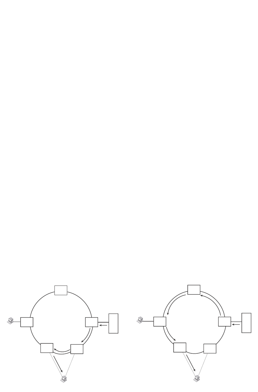
380 PowerConnect B-Series FCX Configuration Guide
53-1002266-01
Virtual Switch Redundancy Protocol (VSRP)
10
The "Restart ports:" line lists the ports that have the VSRP fast start enabled, and the downtime for
each port. Refer to Table 64 on page 377 to interpret the remaining information on the display.
VSRP and MRP signaling
A device may connect to an MRP ring through VSRP to provide a redundant path between the
device and the MRP ring. VSRP and MRP signaling ensures rapid failover by flushing MAC
addresses appropriately. The host on the MRP ring learns the MAC addresses of all devices on the
MRP ring and VSRP link. From these MAC addresses, the host creates a MAC database (table),
which is used to establish a data path from the host to a VSRP-linked device. Figure 74 below
shows two possible data paths from the host to Device 1.
FIGURE 74 Two data paths from host on an MRP ring to a VSRP-linked device
If a VSRP failover from master to backup occurs, VSRP needs to inform MRP of the topology
change; otherwise, data from the host continues along the obsolete learned path and never reach
the VSRP-linked device, as shown in Figure 75.
PowerConnect#show vsrp vrid 100
VLAN 100
auth-type no authentication
VRID 100
========
State Administrative-status Advertise-backup Preempt-mode save-current
master enabled disabled true false
Parameter Configured Current Unit/Formula
priority 100 50 (100-0)*(2.0/4.0)
hello-interval 1 1 sec/1
dead-interval 3 3 sec/1
hold-interval 3 3 sec/1
initial-ttl 2 2 hops
next hello sent in 00:00:00.3
Member ports: ethe 2/5 to 2/8
Operational ports: ethe 2/5 ethe 2/8
Forwarding ports: ethe 2/5 ethe 2/8
Restart ports: 2/5(1) 2/6(1) 2/7(1) 2/8(1)
Path 1 Path 2
MRP
Member
MRP
Master
MRP
Member
MRP
Member
MRP
VSRP Master
VSRP
Host
VSRP Backup
MRP
Member
MRP
Member
MRP
VSRP Master
VSRP
VSRP Backup
Device 1
Device 1
Host
MRP
Member MRP
Member
MRP
Master
MRP
Member
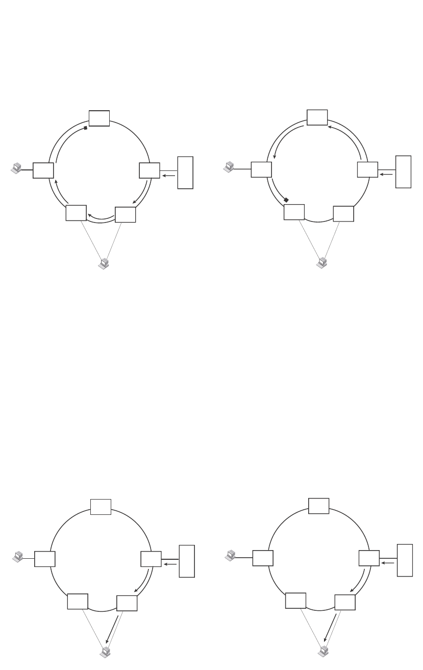
PowerConnect B-Series FCX Configuration Guide 381
53-1002266-01
Virtual Switch Redundancy Protocol (VSRP) 10
FIGURE 75 VSRP on MRP rings that failed over
A signaling process for the interaction between VSRP and MRP ensures that MRP is informed of the
topology change and achieves convergence rapidly. When a VSRP node fails, a new VSRP master is
selected. The new VSRP master finds all MRP instances impacted by the failover. Then each MRP
instance does the following:
•The MRP node sends out an MRP PDU with the mac-flush flag set three times on the MRP ring.
•The MRP node that receives this MRP PDU empties all the MAC entries from its interfaces that
participate on the MRP ring.
•The MRP node then forwards the MRP PDU with the mac-flush flag set to the next MRP node
that is in forwarding state.
The process continues until the Master MRP node secondary (blocking) interface blocks the
packet. Once the MAC address entries have been flushed, the MAC table can be rebuilt for the new
path from the host to the VSRP-linked device (Figure 76).
FIGURE 76 New path established
There are no CLI commands used to configure this process.
XX
Path 1 Path 2
MRP
Member
MRP
Master
MRP
Member
MRP
Member
MRP
MRP Member
VSRP Backup
VSRP
Host
MRP Member
VSRP Master
MRP
Member
MRP
Member
MRP
MRP Master
VSRP Backup
VSRP
MRP Member
VSRP Master
Device 1
Device 1
Host
XX
Path 1 Path 2
MRP
Member
MRP
Master
MRP
Member
MRP
Member
MRP
VSRP Backup
VSRP
Host
VSRP Master
MRP
Member
MRP
Member
MRP
VSRP Backup
VSRP
VSRP Master
Device 1
Device 1
Host
MRP
Member MRP
Member
MRP
Master
MRP
Member

382 PowerConnect B-Series FCX Configuration Guide
53-1002266-01
Virtual Switch Redundancy Protocol (VSRP)
10

PowerConnect B-Series FCX Configuration Guide 383
53-1002266-01
Chapter
11
Configuring Uni-Directional Link Detection (UDLD) and
Protected Link Groups
Table 66 lists the individual Dell PowerConnect switches and the UDLD and protected link group
features they support. These features are supported in the Layer 2, base Layer 3, edge Layer 3,
and full Layer 3 software images, except where explicitly noted.
UDLD overview
Uni-Directional Link Detection (UDLD) monitors a link between two Dell PowerConnect devices and
brings the ports on both ends of the link down if the link goes down at any point between the two
devices. This feature is useful for links that are individual ports and for trunk links. Figure 77
shows an example.
FIGURE 77 UDLD example
TABLE 66 Supported UDLD and protected link group features
Feature PowerConnect B-Series FCX
Uni-directional Link Detection (UDLD)
(Link keepalive)
Yes
UDLD on tagged ports Yes
Protected link groups Yes
X
Without link keepalive, the ports remain
enabled. Traffic continues to be load balanced to the
ports connected to the failed link.
When link keepalive is enabled, the feature
brings down the ports connected
to the failed link.
Switch Switch

384 PowerConnect B-Series FCX Configuration Guide
53-1002266-01
UDLD overview
11
Normally, a Dell PowerConnect device load balances traffic across the ports in a trunk group. In
this example, each Dell PowerConnect device load balances traffic across two ports. Without the
UDLD feature, a link failure on a link that is not directly attached to one of the Dell PowerConnect
devices is undetected by the Dell PowerConnect devices. As a result, the Dell PowerConnect
devices continue to send traffic on the ports connected to the failed link.
When UDLD is enabled on the trunk ports on each Dell PowerConnect device, the devices detect
the failed link, disable the ports connected to the failed link, and use the remaining ports in the
trunk group to forward the traffic.
Ports enabled for UDLD exchange proprietary health-check packets once every second (the
keepalive interval). If a port does not receive a health-check packet from the port at the other end
of the link within the keepalive interval, the port waits for two more intervals. If the port still does
not receive a health-check packet after waiting for three intervals, the port concludes that the link
has failed and takes the port down.
UDLD for tagged ports
The default implementation of UDLD sends the packets untagged, even across tagged ports. If the
untagged UDLD packet is received by a third-party switch, that switch may reject the packet. As a
result, UDLD may be limited only to Dell PowerConnect devices, since UDLD may not function on
third-party switches.
To solve this issue, you can configure ports to send out UDLD control packets that are tagged with a
specific VLAN ID. This feature also enables third party switches to receive the control packets that
are tagged with the specified VLAN. For tagged operation, all of the following conditions must be
met:
•A VLAN is specified when UDLD is configured
•The port belongs to the configured VLAN as tagged member
•All the devices across the UDLD link are in the same VLAN
For configuration details, refer to “Enabling UDLD for tagged ports” on page 385.
Configuration notes and feature limitations
•UDLD is supported only on Ethernet ports.
•UDLD can be enabled on only one VLAN for tagged port.
•To configure UDLD on a trunk group, you must enable and configure the feature on each port
of the group individually. Configuring UDLD on a trunk group primary port enables the feature
on that port only.
•When UDLD is enabled on a trunk port, trunk threshold is not supported.
•Dynamic trunking is not supported. If you want to configure a trunk group that contains ports
on which UDLD is enabled, you must remove the UDLD configuration from the ports. After you
create the trunk group, you can re-add the UDLD configuration.
•If MRP is also enabled on the device, Dell recommends that you set the MRP preforwarding
time slightly higher than the default of 300 ms; for example, to 400 or 500 ms. Refer to
“Changing the hello and preforwarding times” on page 351.

PowerConnect B-Series FCX Configuration Guide 385
53-1002266-01
UDLD overview 11
Enabling UDLD
NOTE
This section shows how to configure UDLD for untagged control packets. To configure UDLD for
tagged control packets, refer to “Enabling UDLD for tagged ports”.
To enable UDLD on a port, enter a command such as the following at the global CONFIG level of the
CLI.
PowerConnect(config)#link-keepalive ethernet 0/1/1
To enable the feature on a trunk group, enter commands such as the following.
PowerConnect(config)#link-keepalive ethernet 0/1/1 ethernet 0/1/2
PowerConnect(config)#link-keepalive ethernet 0/1/3 ethernet 0/1/4
Syntax: [no] link-keepalive ethernet <port> [to <port> | ethernet <port>]
Specify the <port> variable in the following formats:
•PowerConnect B-Series FCX stackable switches – <stack-unit/slotnum/portnum>
Enabling UDLD for tagged ports
To enable ports to receive and send UDLD control packets tagged with a specific VLAN ID, enter
commands such as the following.
PowerConnect(config)#link-keepalive ethernet 1/18 vlan 22
This command enables UDLD on port 1/18 and allows UDLD control packet tagged with VLAN 22
to be received and sent on port 1/18.
Syntax: [no] link-keepalive ethernet <port> [vlan <vlan-ID>]
Specify the <port> variable in the following formats:
•PowerConnect B-Series FCX stackable switches – <stack-unit/slotnum/portnum>
For the <vlan-ID> variable, enter the ID of the VLAN that the UDLD control packets can contain to
be received and sent on the port. If a VLAN ID is not specified, then UDLD control packets are sent
out of the port as untagged packets.
NOTE
You must configure the same VLANs that will be used for UDLD on all devices across the network;
otherwise, the UDLD link cannot be maintained.
Changing the Keepalive interval
By default, ports enabled for UDLD send a link health-check packet once every 500 ms. You can
change the interval to a value from 1 – 60, where 1 is 100 ms, 2 is 200 ms, and so on. To change
the interval, enter a command such as the following.
PowerConnect(config)#link-keepalive interval 3
Syntax: [no] link-keepalive interval <num>
The <num> parameter specifies how often the ports send a UDLD packet. You can specify from 1
– 60, in 100 ms increments. The default is 5 (500 ms).

386 PowerConnect B-Series FCX Configuration Guide
53-1002266-01
UDLD overview
11
Changing the Keepalive retries
By default, a port waits one second to receive a health-check reply packet from the port at the
other end of the link. If the port does not receive a reply, the port tries four more times by sending
up to four more health-check packets. If the port still does not receive a reply after the maximum
number of retries, the port goes down.
You can change the maximum number of keepalive attempts to a value from 3 – 64. To change the
maximum number of attempts, enter a command such as the following.
PowerConnect(config)#link-keepalive retries 4
Syntax: [no] link-keepalive retries <num>
The <num> parameter specifies the maximum number of times the port will try the health check.
You can specify a value from 3 – 64. The default is 7.
Displaying UDLD information
This section describes the commands used to display information about a UDLD configuration.
Displaying information for all ports
To display UDLD information for all ports, enter the following command.
Syntax: show link-keepalive
TABLE 67 CLI display of UDLD information
This field... Displays...
Total link-keepalive enabled ports The total number of ports on which UDLD is enabled.
Keepalive Retries The number of times a port will attempt the health check before concluding
that the link is down.
Keepalive Interval The number of seconds between health check packets.
Port The port number.
Physical Link The state of the physical link. This is the link between the Dell
PowerConnect port and the directly connected device.
Logical Link The state of the logical link. This is the state of the link between this Dell
PowerConnect port and the Dell PowerConnect port on the other end of the
link.
State The traffic state of the port.
Link-vlan The ID of the tagged VLAN in the UDLD packet.
PowerConnect#show link-keepalive
Total link-keepalive enabled ports: 4
Keepalive Retries: 3 Keepalive Interval: 1 Sec.
Port Physical Link Logical Link State Link-vlan
4/1 up up FORWARDING 3
4/2 up up FORWARDING
4/3 down down DISABLED
4/4 up down DISABLED

PowerConnect B-Series FCX Configuration Guide 387
53-1002266-01
UDLD overview 11
If a port is disabled by UDLD, the change also is indicated in the output of the show interfaces brief
command. An example is given below.
If the port was already down before you enabled UDLD for the port, the port state is listed as None.
Syntax: show interfaces brief
Displaying information for a single port
To display detailed UDLD information for a specific port, enter a command such as the following.
Syntax: show link-keepalive [ethernet [<slotnum>/]<portnum>]
TABLE 68 CLI display of detailed UDLD information
This field... Displays...
Current State The state of the logical link. This is the link between this Dell PowerConnect port and the
Dell PowerConnect port on the other end of the link.
Remote MAC Addr The MAC address of the port or device at the remote end of the logical link.
Local Port The port number on this Dell PowerConnect device.
Remote Port The port number on the Dell PowerConnect device at the remote end of the link.
Local System ID A unique value that identifies this Dell PowerConnect device. The ID can be used by Dell
technical support for troubleshooting.
Remote System ID A unique value that identifies the Dell PowerConnect device at the remote end of the link.
Packets sent The number of UDLD health-check packets sent on this port.
Packets received The number of UDLD health-check packets received on this port.
Transitions The number of times the logical link state has changed between up and down.
Port blocking Information used by Dell technical support for troubleshooting.
Link-vlan The ID of the tagged VLAN in the UDLD packet.
BM disabled Information used by Dell technical support for troubleshooting.
PowerConnect#show interfaces brief
Port Link State Dupl Speed Trunk Tag Priori MAC Name
1/1 Up LK-DISABLE None None None No level0 00e0.52a9.bb00
1/2 Down None None None None No level0 00e0.52a9.bb01
1/3 Down None None None None No level0 00e0.52a9.bb02
1/4 Down None None None None No level0 00e0.52a9.bb03
PowerConnect#show link-keepalive ethernet 4/1
Current State : up Remote MAC Addr : 00e0.52d2.5100
Local Port : 4/1 Remote Port : 2/1
Local System ID : e0927400 Remote System ID : e0d25100
Packets sent : 254 Packets received : 255
Transitions : 1 Link-vlan : 100
Port blocking : No BM disabled : No

388 PowerConnect B-Series FCX Configuration Guide
53-1002266-01
Protected link groups
11
The show interface ethernet command also displays the UDLD state for an individual port. In
addition, the line protocol state listed in the first line will say “down” if UDLD has brought the port
down. An example is given below.
In this example, the port has been brought down by UDLD. Notice that in addition to the
information in the first line, the port state on the fourth line of the display is listed as DISABLED.
Clearing UDLD statistics
To clear UDLD statistics, enter the following command.
PowerConnect#clear link-keepalive statistics
Syntax: clear link-keepalive statistics
This command clears the Packets sent, Packets received, and Transitions counters in the show link
keepalive ethernet [<slotnum>/]<portnum> display.
Protected link groups
A protected link group minimizes disruption to the network by protecting critical links from loss of
data and power. In a protected link group, one port in the group acts as the primary or active link,
and the other ports act as secondary or standby links. The active link carries the traffic. If the
active link goes down, one of the standby links takes over.
During normal operation, the active port in a protected link group is enabled and the standby ports
are logically disabled. If the active port fails, the Dell PowerConnect device immediately enables
one of the standby ports, and switches traffic to the standby port. The standby port becomes the
new, active port.
PowerConnect#show interface ethernet 1/1
FastEthernet1/1 is down, line protocol is down, link keepalive is enabled
Hardware is FastEthernet, address is 00e0.52a9.bbca (bia 00e0.52a9.bbca)
Configured speed auto, actual unknown, configured duplex fdx, actual unknown
Member of L2 VLAN ID 1, port is untagged, port state is DISABLED
STP configured to ON, priority is level0, flow control enabled
mirror disabled, monitor disabled
Not member of any active trunks
Not member of any configured trunks
No port name
300 second input rate: 0 bits/sec, 0 packets/sec, 0.00% utilization
300 second output rate: 0 bits/sec, 0 packets/sec, 0.00% utilization
0 packets input, 0 bytes, 0 no buffer
Received 0 broadcasts, 0 multicasts, 0 unicasts
0 input errors, 0 CRC, 0 frame, 0 ignored
0 runts, 0 giants, DMA received 0 packets
19 packets output, 1216 bytes, 0 underruns
Transmitted 0 broadcasts, 19 multicasts, 0 unicasts
0 output errors, 0 collisions, DMA transmitted 19 packets

PowerConnect B-Series FCX Configuration Guide 389
53-1002266-01
Protected link groups 11
About active ports
When you create a protected link group, you can optionally specify which port in the protected link
group is the active port. If you do not explicitly configure an active port, the Dell PowerConnect
device dynamically assigns one. A dynamic active port is the first port in the protected link group
that comes up (usually the lowest numbered port in the group).
Static and dynamic active ports operate as follows:
•A static active port (an active port that you explicitly configured) pre-empts other ports in the
protected link group. So, if a static active link comes back up after a failure, the Dell
PowerConnect device will revert to this link as the active link.
•A dynamic active port (an active port assigned by the software) is non-pre-emptive. Therefore,
if a dynamic active link comes back up after a failure, the Dell PowerConnect device does not
revert to this link, but continues carrying traffic on the current active link.
Using UDLD with protected link groups
You can use UDLD with protected link groups to detect uni-directional link failures and to improve
the speed at which the device detects a failure in the link.
NOTE
When UDLD and protected links are configured on a port and the link goes down, protected links will
not come up after UDLD becomes “healthy” again without first physically disabling then re-enabling
the link.
Configuration notes
•You can configure a maximum of 32 protected link groups.
•There is no restriction on the number of ports in a protected link group.
•Each port can belong to one protected link group at a time.
•PowerConnect B-Series FCX Series devices support protected link groups consisting of Gbps
fiber ports, 10/100/1000 copper ports, and 10/100 ports, or any combination thereof. These
devices do not support protected link groups on 10-GbE ports.
•This feature is supported with tagged and untaggedports.
•This feature is supported with trunk ports.
•The protected link groups feature is not supported with LACP.
•There is no restriction on the properties of ports in a protected link group. For example,
member ports can be in the same VLAN or in different VLANs.
•When two switches are connected together with links in a protected link group, and the ports
connecting the switches together are part of a protected link group, you must configure two
connecting ports (one port on each switch) as active ports of the protected link group. The
following example illustrates this scenario.
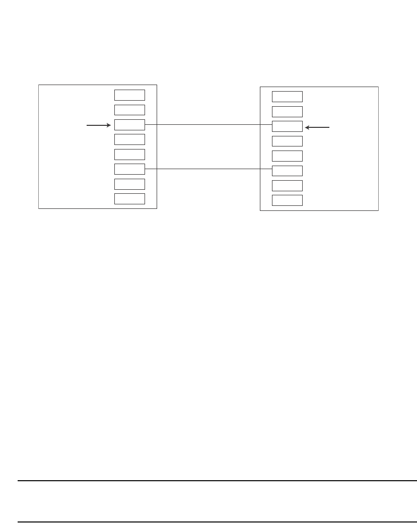
390 PowerConnect B-Series FCX Configuration Guide
53-1002266-01
Protected link groups
11
The configuration for the above illustration is as follows.
Switch 1
PowerConnect(config)# protected-link-group 1 e 1/3 e 1/6
PowerConnect(config)# protected-link-group 1 active-port e 1/3
Switch 2
PowerConnect(config)# protected-link-group 1 e 1/12 e 1/15
PowerConnect(config)# protected-link-group 1 active-port e 1/12
Creating a protected link group and assigning
an active port
Follow the steps given below to create a protected link group.
1. Specify the member ports in the protected link group. Enter a command such as the following.
PowerConnect(config)#protected-link-group 10 e 1 to 4
2. Optionally specify which port will be the active port for the protected link group. Enter a
command such as the following.
PowerConnect(config)#protected-link-group 10 active-port e 1
NOTE
If you do not explicitly configure an active port, the Dell PowerConnect device automatically
assigns one as the first port in the protected link group to come up.
These commands configure port e1 as the active port and ports e2 – e4 as standby ports. If port 1
goes down, the Dell PowerConnect device enables the first available standby port, and switches the
traffic to that port. Since the above configuration consists of a statically configured active port, the
active port pre-empts other ports in the protected link group. Refer to “About active ports” on
page 389.
Syntax: [no] protected-link-group <group-ID> ethernet <port> to <port>
The <group-ID> parameter specifies the protected link group number. Enter a number from 1 – 32.
Each ethernet <port> to <port> specifies the ports in the protected link group. Specify the <port>
variable in the following formats:
•PowerConnect B-Series FCX stackable switches – <stack-unit/slotnum/portnum>
[no] protected-link-group <group-ID> active-port ethernet <port>
Port1/1
Port1/2
Port1/3
Port1/4
Port1/5
Port1/6
Port1/7
Port1/8
Port1/10
Port1/11
Port1/12
Port1/13
Port1/14
Port1/15
Port1/16
Port1/17
active port
Switch 1
active port
Switch 2

PowerConnect B-Series FCX Configuration Guide 391
53-1002266-01
Protected link groups 11
The <group-ID> parameter specifies the protected link group number. Enter a number from 1 – 32.
The active-port ethernet <port> defines the active port. Specify the <port> variable in the following
formats:
•PowerConnect B-Series FCX stackable switches – <stack-unit/slotnum/portnum>
Viewing information about protected link groups
You can use the following show commands to view information about protected link groups:
•show protected-link-group
•show interface brief
•show interface
The following shows example output for the show protected-link-group command.
Syntax: show protected-link-group [<group-ID>]
The show interface brief command also displays information about protected link groups.
Example
In the above output, the State of port 3 is Inactive, which means port 3 is an inactive port in a
protected link group. For active ports in a protected link group, the State will be Active.
Syntax: show interface brief ethernet <port>
Specify the <port> variable in the following formats:
•PowerConnect B-Series FCX stackable switches – <stack-unit/slotnum/portnum>
The show interface command also displays information about protected link groups.
TABLE 69 CLI display of protected link group information
This field... Displays...
Group ID The ID number of the protected link group.
Member Port(s) The ports that are members of the protected link group.
Configured Active Port The statically configured active port. If you do not statically configure an active
port, this value will be "None".
Current Active Port The current active port for the protected link group. If all member ports are
down, this value will be "None".
Standby Port(s) The member ports that are on standby.
PowerConnect#show protected-link-group
Group ID: 1
Member Port(s): ethe 1 to 7
Configured Active Port: 7
Current Active Port: 7
Standby Port(s): ethe 5
Total Number of Protected Link Groups: 1
PowerConnect#show int brief e 3 to 4
Port Link State Dupl Speed Trunk Tag Priori MAC Name
3 Up Inactive Full Auto None Yes level0 0012.f2a8.7140
4 Up Forward Full 1G None Yes level0 0012.f2a8.7140

392 PowerConnect B-Series FCX Configuration Guide
53-1002266-01
Protected link groups
11
In the above output, the port state is protected-link-inactive which means port 3 is an inactive port
in a protected link group.
Syntax: show interface ethernet <port>
Specify the <port> variable in the following formats:
•PowerConnect B-Series FCX stackable switches – <stack-unit/slotnum/portnum>
PowerConnect#show int e 3
GigabitEthernet3 is up, line protocol is up, link keepalive is enabled
Hardware is GigabitEthernet, address is 0012.f2a8.7140 (bia 0012.f2a8.7142)
Configured speed auto, actual 1Gbit, configured duplex fdx, actual fdx
Configured mdi mode AUTO, actual MDIX
Member of 3 L2 VLANs, port is tagged, port state is protected-link-inactive
BPDU guard is Disabled, ROOT protect is Disabled
Link Error Dampening is Disabled
STP configured to ON, priority is level0
....
some lines ommitted for brevity

PowerConnect B-Series FCX Configuration Guide 393
53-1002266-01
Chapter
12
Configuring Trunk Groups and Dynamic Link Aggregation
Table 70 lists the individual Dell PowerConnect switches and the trunk groups and dynamic link
aggregation features they support.
Trunk group overview
The Trunk group feature allows you to manually configure multiple high-speed load-sharing links
between two Layer 2 Switches or Layer 3 Switches or between a Layer 2 Switch and Layer 3 Switch
and a server.
In addition to enabling load sharing of traffic, trunk groups provide redundant, alternate paths for
traffic if any of the segments fail.
•Trunk groups are manually-configured aggregate links containing multiple ports.
•802.3ad link aggregation is a protocol that dynamically creates and manages trunk groups.
NOTE
You can use both types of trunking on the same device. However, you can use only one type of
trunking for a given port. For example, you can configure port 1/1 as a member of a static trunk
group or you can enable 802.3ad link aggregation on the port, but you cannot do both.
Figure 78 shows an example of a configuration that uses trunk groups.
TABLE 70 Supported trunk group and dynamic link aggregation features
Feature PowerConnect B-Series FCX
Trunk groups Yes
Trunk threshold for static trunk groups Yes
Flexible trunk group membership Yes
Option to include Layer 2 in trunk hash
calculation
Yes
802.3ad link aggregation (dynamic trunk
groups)
Yes
Link Aggregation Control Protocol (LACP) Yes
Single link LACP Yes
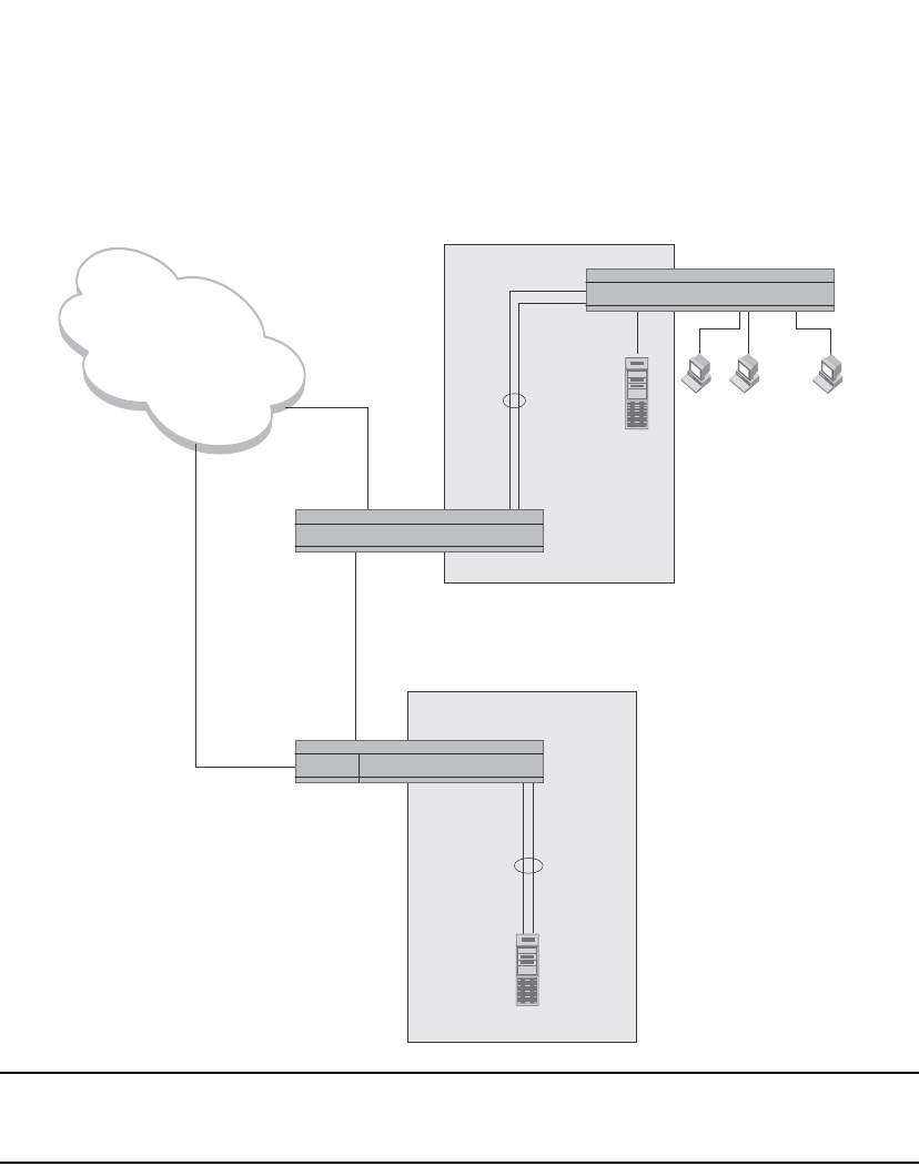
394 PowerConnect B-Series FCX Configuration Guide
53-1002266-01
Trunk group overview
12
FIGURE 78 Trunk group application within a PowerConnect network
NOTE
The ports in a trunk group make a single logical link. Therefore, all the ports in a trunk group must
be connected to the same device at the other end.
Trunk group connectivity to a server
To support termination of a trunk group, the server must have either multiple network interface
cards (NICs) or either a dual or quad interface card installed. The trunk server is designated as a
server with multiple adapters or a single adapter with multiple ports that share the same MAC and
IP address.
Figure 79 shows an example of a trunk group between a server and a Dell PowerConnect device.
...
Gigabit
Backbone
Trunk
Group
Server
Power Users
Dedicated 100 Mbps
Trunk
Group
Switch2
Switch1
Switch
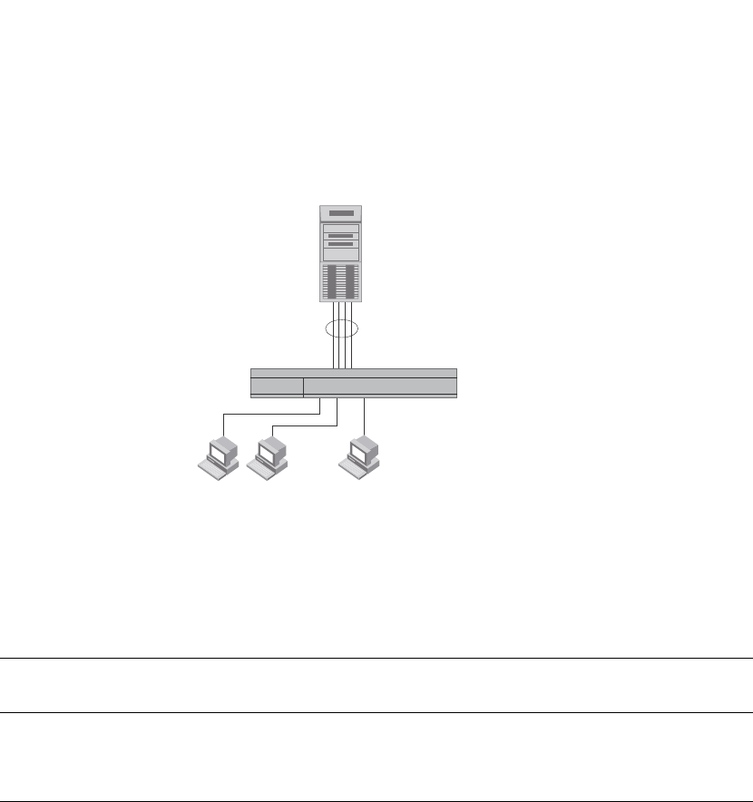
PowerConnect B-Series FCX Configuration Guide 395
53-1002266-01
Trunk group overview 12
FIGURE 79 Trunk group between a server and a compact Layer 2 Switch or Layer 3 Switch
Trunk group rules
Table lists the maximum number of trunk groups you can configure on a Dell PowerConnect device
and the valid number of ports in a trunk group. The table applies to static and LACP trunk ports.
•In a hardware configuration with a IPv4 and IPv6 interface modules or management modules
with user ports, legacy ports and 48 Gbps copper ports cannot be members of the same trunk
group.
•You cannot configure a port as a member of a trunk group if 802.3ad link aggregation is
enabled on the port.
•Dell PowerConnect devices, trunk groups on devices listed in Table are not classified as switch
trunk groups or server trunk groups.
•Trunking is supported on 10-GbE ports.
•You cannot combine 1-Gbps and 10-Gbps ports in the same trunk group.
•Port assignment on a module need not be consecutive. The port range can contain gaps. For
example, you can configure ports 1, 3, and 4 (excluding 2). Refer to “Support for flexible trunk
group membership” on page 398.
•Although the PowerConnect devices have port ranges, they do not apply to trunk groups.
•You can select any port to be the primary port of the trunk group.
•All the ports must be connected to the same device at the other end.
•All trunk group member properties must match the lead port of the trunk group with respect to
the following parameters:
•port tag type (untagged or tagged port)
TABLE 71 Trunk group support
Model Maximum number of Gbps
trunk groups
Valid number of ports in a group
PowerConnect
B-FCX624
PowerConnect
B-FCX648
32 2, 3, 4, 5, 6, 7, or 8
Multi-homing adapter
has the same IP and MAC address
Multi-homing
Server
Trunk Group
Switch
...

396 PowerConnect B-Series FCX Configuration Guide
53-1002266-01
Trunk group overview
12
•statically configured port speed and duplex
•QoS priority
To change port parameters, you must change them on the primary port. The software
automatically applies the changes to the other ports in the trunk group.
Configuration notes for Dell PowerConnect devices in an IronStack
In a Dell IronStack system, a trunk group may have port members distributed across multiple stack
units. Both static and dynamic trunking are supported.
NOTE
Cascaded trunks between stack units are not currently supported.
To configure trunk groups for PowerConnect devices in an IronStack, use the CLI syntax in “CLI
syntax for configuring consecutive ports in a trunk group” on page 400.
These notes apply to FastIron Stackable devices that are part of an IronStack.
•If a stack unit fails, or is removed from the stack its static trunk configuration becomes a
reserved configuration on the Active Controller. Any remaining ports of the static trunk in the
IronStack continue to function.
•When a new stack unit is added to an IronStack, the new unit receives running configuration
and trunk-related information, including a list of ports that are up and are members of a trunk,
from the Active Controller.
•Before merging two IronStacks, make sure that there are no static trunks configured between
them. This can result in self-looped ports.
•When an IronStack with static trunks partitions into multiple IronStacks, loops and forwarding
errors may occur. In these cases, user intervention is required to remove the loops.
•10 Gbps links support up to eight ports in a trunk for stackable units.
Trunk group configuration examples
Figure 80 shows some examples of valid 2-port trunk group links between devices. The trunk
groups in this example are switch trunk groups between two Dell PowerConnect devices. Ports in a
valid 2-port trunk group on one device are connected to two ports in a valid 2-port trunk group on
another device. The same rules apply to 3-port, 4-port, etc., trunk groups.
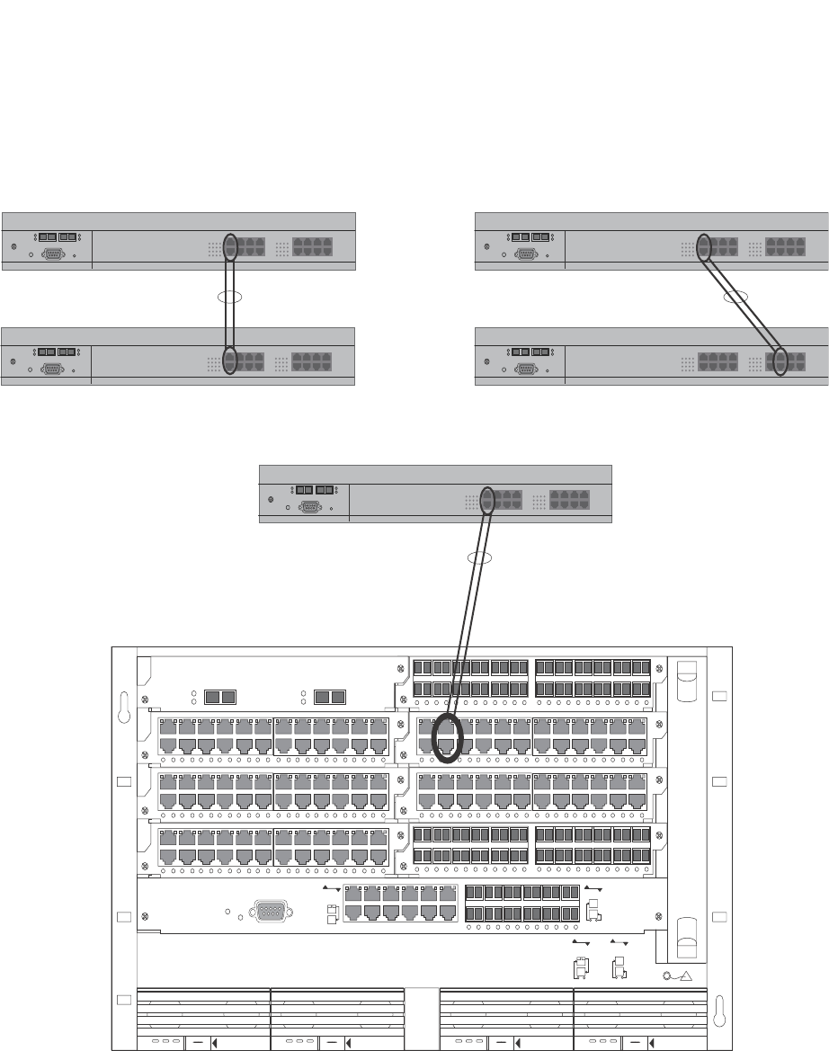
PowerConnect B-Series FCX Configuration Guide 397
53-1002266-01
Trunk group overview 12
FIGURE 80 Examples of 2-port and 3-port trunk groups
Figure 81 shows two IronStacks connected by multi-slot trunk groups.
424F
42XG Lnk
Act
Lnk
Act
12
424C424C
424C424C
424F
424C
8X-12GM-4
Console
Pwr
Lnk
Odd
Even
SYSEJECT
DC OK ALMAC OK DC OK ALMAC OK
SYSEJECT
DC OK ALMAC OK
SYSEJECT
DC OK ALMAC OK
SYSEJECT
Odd
Even
Lnk
Lnk
POE
424C 424F
Odd
Even
Odd
Even
Lnk
Device
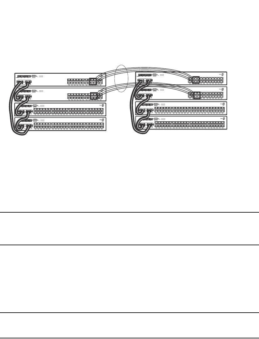
398 PowerConnect B-Series FCX Configuration Guide
53-1002266-01
Trunk group overview
12
FIGURE 81 Two IronStacks connected by multi-slot trunk groups
Support for flexible trunk group membership
PowerConnect devices support flexible trunk group membership, which eliminates the
requirement for port membership to be consecutive, and allows the trunking of ports on
non-consecutive interfaces. For example, you can configure ports e 2/4, 2/6, and 2/7 (excluding e
2/5) together on a module as a trunk group. This feature is supported on static and LACP trunk
ports, as well as GbE and 10-GbE ports. Flexible trunk ports follow the same rules as listed in
“Trunk group rules” on page 395.
NOTE
For PowerConnect B-Series FCXPowerConnect B-Series FCXdevices only, this feature is supported
from Web Management, but not from SNMP. For all other PowerConnect devices, this feature is not
supported from SNMP or Web management.
For configuration details, see “CLI syntax for configuring non-consecutive ports in a trunk group” on
page 401.
Trunk group load sharing
Dell PowerConnect devices load-share across the ports in the trunk group. The method used for the
load sharing depends on the device type and traffic type (Layer 2 or Layer 3).
NOTE
Layer 2 and Layer 3 AppleTalk traffic is not load-balanced. Layer 3 routed IP or IPX traffic also is not
load balanced. These traffic types will however still be forwarded on the trunk ports.
Support for IPv6
Dell PowerConnect devices that support IPv6 take the IPv6 address for a packet into account when
sharing traffic across a trunk group. The load sharing is performed in the same way it is for IPv4
addresses; that is; trunk types whose traffic load is shared based on IPv4 address information can
now use IPv6 addresses to make the load sharing decision.
Load sharing occurs as described in Table 72.
1F 2F 3F 4F Console
Lnk
PS1 PS2 Pwr
25 26
Act
Lnk
Act
5678
123
Stack
4
31
246
5
8
79
10
11
12
13
14
15
16
17
18
19
20
21
22 24
23
Odd
Even
Lnk-Act
1F 2F 3F 4F Console
Lnk
Act PS1 PS2 Pwr
25 26
Lnk
Act
5678
123
Stack
4
1
2
3
4
5
6
7
8
9
10
11
12 14
13 15
16
17
18
19
20
21
22
23
24
Odd
Even
Lnk-Act
Odd
Even
Lnk-Act
Odd
Even
Lnk-Act
34 36 38 40 42 44 46 48
33 35 37 39 41 43 45 47
18 20 22 24 26 28 30 32
17 19 21 23 25 27 29 31
2 4 6 8 10 12 14 16
1357 911 1315
49
1F 2F 3F 4F
50
Lnk
Act
Lnk
Act
Console
PS1 PS2 Pwr
5678
123
Stack
4
30 32 34 36 38 40 42 44 46 48
29 31 33 35 37 39 41 43 45 47
81012 141618202224 2628
57911 131517192123 2527
246
13
49
1F 2F 3F 4F Console
50
Lnk
Act PS1 PS2 Pwr
Lnk
Act
5678
123
Stack
4
1F 2F 3F 4F Console
Lnk
Act PS1 PS2 Pwr 5678
25 26
Lnk
Act
123
Stack
4
1357 911 13
2 4 6 8 10 12 14
15 17 19 21 23
16 18 20 22 24
Odd
Even
Lnk-Act
1F 2F 3F 4F Console
Lnk
Act PS1 PS2 Pwr
25 26
Lnk
Act
5678
123
Stack
4
1357 911 131517192123
2 4 6 8 10 12 14 16 18 20 22 24
Odd
Even
Lnk-Act
49
1F 2F 3F 4F Console
50
Lnk
Act PS1 PS2 Pwr
5678
123
Stack
4
Lnk
Act
1357 911 131517192123
2 4 6 8 10 12 14 16 18 20 22 24
25 27 29 31 33 35 37 39 41 43 45 47
26 28 30 32 34 36 38 40 42 44 46 48
Odd
Even
Lnk-Act
49
1F 2F 3F 4F Console
50
Lnk
Act PS1 PS2 Pwr
5678
123
Stack
4
Lnk
Act
13 5 7 9 11 13 15 17 19 21 23
2 4 6 8 10 12 14 16 18 20 22 24 26 28 30 32
25 27 29 31 33 35 37 39 41 43
34 36 38 40 42 44 46 48
45 47
Odd
Even
Lnk-Act

PowerConnect B-Series FCX Configuration Guide 399
53-1002266-01
Trunk group overview 12
Load sharing for unknown unicast, multicast, and broadcast traffic
Dell PowerConnect devices load balance unknown unicast, multicast, and broadcast traffic based
on the source port and VLAN ID and not on any source or destination information in the packet.
For example, when the switch receives unknown unicast, multicast, and broadcast packets, and
the packets are from the same source port, the packets are forwarded to the same port of the
trunk group. Conversely, when the switch receives unknown unicast, multicast, and broadcast
packets, and the packets are from different source ports, the packets are load-balanced across all
the ports of the trunk group.
Note that this does not apply to known unicast traffic, which is always load balanced across all the
ports of a trunk group based on the traffic's Layer 2 and Layer 3 source and destination
parameters.
How trunk load sharing works
The load balancing method for bridged traffic varies depending on the traffic type. Load balancing
for routed traffic is always based on the source and destination IP addresses and protocol field (not
applicable for FastIron Stackable devices).
NOTE
Table 72 do not include unknown unicast, multicast, and broadcast traffic. Refer to “Load sharing
for unknown unicast, multicast, and broadcast traffic”.
Table 72 describes how the FastIron Stackable devices load balance traffic.
Adding Layer 2 information to trunk hash output
FastIron Stackable devices support the option to include Layer 2 information in the trunk hash
calculation for IP packets. Use the following CLI command.
PowerConnect(config)# trunk hash-options include-layer2
This command adds Layer 2 information (text in bold) to the following load-balancing parameters.
1. Non-IP: Source MAC, Destination MAC
2. IPv4 TCP/UDP: Source IP, Destination IP, Source TCP/UDP Port, Destination TCP/UDP Port,
Source MAC, Destination MAC
3. IPv4 Non-TCP/UDP: Source IP, Destination IP, Source MAC, Destination MAC
TABLE 72 Trunk group load sharing on FastIron Stackable devices
Traffic type Load balancing method
L2 Bridged Non-IP Source MAC, Destination MAC
L2 Bridged IPv4 TCP/UDP Source IP, Destination IP, Source TCP/UDP Port,
Destination TCP/UDP Port
L2 Bridged IPv4 Non-TCP/UDP Source IP, Destination IP
L2 Bridged IPv6 TCP/UDP Source IP, Destination IP, Flow Label, Source TCP/UDP
Port, Destination TCP/UDP Port
L2 Bridged IPv6 Non-TCP/UDP Source IP, Destination IP, Flow Label

400 PowerConnect B-Series FCX Configuration Guide
53-1002266-01
Configuring a trunk group
12
4. IPv6 TCP/UDP: Source IP, Destination IP, Flow Label, Source TCP/UDP Port, Destination
TCP/UDP Port, Source MAC, Destination MAC
5. IPv6 Non-TCP/UDP: Source IP, Destination IP, Flow Label, Source MAC, Destination MAC
Syntax: [no] trunk hash-options include-layer2
Configuring a trunk group
Follow the steps given below to configure a trunk group.
1. Disconnect the cables from those ports on both systems that will be connected by the trunk
group. Do not configure the trunk groups with the cables connected.
NOTE
If you connect the cables before configuring the trunk groups and then rebooting, the traffic on
the ports can create a spanning tree loop.
2. Configure the trunk group on one of the two Layer 2 Switches or Layer 3 Switches involved in
the configuration.
NOTE
Downtime is incurred when adding a new port to a trunk group. It is suggested that you
schedule the addition of ports to a trunk group to minimize downtime and its impact to the
production network.
3. Save the configuration changes to the startup-config file.
4. Dynamically place the new trunk configuration into effect by entering the trunk deploy
command at the global CONFIG level of the CLI.
5. If the device at the other end of the trunk group is another Layer 2 Switch or Layer 3 Switch,
repeat Steps 2 – 4 for the other device.
6. When the trunk groups on both devices are operational, reconnect the cables to those ports
that are now configured as trunk groups, starting with the first port (lead port) of each trunk
group.
7. To verify the link is operational, use the show trunk command.
CLI syntax for configuring consecutive ports in a trunk group
This section describes the CLI syntax for configuring consecutive ports in a trunk group. To
configure non-consecutive ports, refer to “CLI syntax for configuring non-consecutive ports in a
trunk group” on page 401. Configuration examples are shown in later sections of this chapter.
To configure a trunk group consisting of two groups of two ports each, enter commands such as the
following.
PowerConnect(config)#trunk ethernet 1/1 to 1/2 ethernet 3/3 to 3/4
Trunk will be created in next trunk deploy
PowerConnect(config)#write memory
PowerConnect(config)#trunk deploy
Syntax: [no] trunk ethernet <primary-port> to <port> [ethernet <primary-port> to <port>]...

PowerConnect B-Series FCX Configuration Guide 401
53-1002266-01
Configuring a trunk group 12
Syntax: trunk deploy
Each ethernet parameter introduces a port group.
The <primary-port> variable specifies the primary port. Notice that each port group must begin
with a primary port.. The primary port of the first port group specified (which must be the group
with the lower port numbers) becomes the primary port for the entire trunk group.
Specify the <primary-port> and <port> variable in one of the following formats:
•PowerConnect B-Series FCX stackable switches – <stack-unit/slotnum/portnum>
You can list all of the ports individually, use the keyword to to specify ranges of ports, or a
combination of both.
CLI syntax for configuring non-consecutive ports in a trunk group
This section describes the CLI syntax for configuring non-consecutive ports in a trunk group.
Configuration examples are shown in later sections of this chapter.
To configure a 4-port trunk with non-consecutive ports on a PowerConnect Chassis device, enter a
command such as the following.
PowerConnect(config)#trunk ethe 1/7 ethe 1/9 ethe 1/11 ethe 1/21
This creates a 4-port trunk group with the following members.
1/7, 1/9, 1/11, 1/21
To configure a 4-port trunk with non-consecutive ports on a FastIron Stackable device, enter a
command similar to the following.
PowerConnect(config)#trunk ethe 1/1/7 ethe 1/1/9 ethe 1/1/11 ethe 1/1/21
This creates a 4-port trunk group with the following members.
1/1/7, 1/1/9, 1/1/11, 1/1/21
Syntax: [no] trunk ethernet <port> ethernet <port> | to ethernet <port>...
The <port> variable specifies an individual port. Specify the <port> variable in the following
formats:
•PowerConnect B-Series FCX stackable switches – <stack-unit/slotnum/portnum>
You can enter the ethernet <port> parameter multiple times to specify a list.
The to keyword indicates that you are specifying a range of ports. Specify the lower port number in
the range first, then to, then the higher port number in the range.
Example 1: Configuring the trunk groups shown
in Figure 78
To configure the trunk groups shown in Figure 78, enter the following commands. Notice that the
commands are entered on multiple devices.
To configure the trunk group link between device1 and the device2, enter the following commands.

402 PowerConnect B-Series FCX Configuration Guide
53-1002266-01
Configuring a trunk group
12
NOTE
The text shown in italics in the CLI example below shows messages echoed to the screen in answer
to the CLI commands entered.
PowerConnect(config)#trunk e 1/5 to 1/8
Trunk will be created in next trunk deploy
PowerConnect(config)#write memory
PowerConnect(config)#trunk deploy
To configure the trunk group link between device2 and the server, enter the following commands
PowerConnect(config)#trunk e 1/2 to 1/4
Trunk will be created in next trunk deploy
PowerConnect(config)#write memory
PowerConnect(config)#trunk deploy
You then configure the trunk group on the Device.
PowerConnect(config)#trunk ethernet 17 to 18
Trunk will be created in next trunk deploy
PowerConnect(config)#write memory
PowerConnect(config)#trunk deploy
NOTE
The trunk deploy command dynamically places trunk configuration changes into effect, without a
software reload.
Example 2: Configuring a trunk group that spans
two Gbps Ethernet modules in a chassis device
This section shows how to configure a trunk group that spans two modules in a Chassis device.
Multi-slot trunk groups are supported on 1-GbE ports, 10-GbE ports, as well as on static and LACP
trunk ports. For multi-slot trunk group rules, refer to Table 74 on page 414.
To configure a trunk group consisting of two groups of ports, 1/1 – 1/2 on module 1 and 4/5 – 4/6
on module 4, enter the following commands.
PowerConnect(config)#trunk ethernet 1/1 to 1/2 ethernet 4/5 to 4/6
Trunk will be created in next trunk deploy
PowerConnect(config)#write memory
PowerConnect(config)#trunk deploy
NOTE
The trunk deploy command dynamically places trunk configuration changes into effect, without a
software reload.
NOTE
If you disable a module that is part of a multi-slot trunk group, the corresponding trunk ports will
remain up and running. However, when you re-enable the module, all of the trunk ports will go down
then come back up. In other words, trunk ports are re-deployed when a module is re-enabled.

PowerConnect B-Series FCX Configuration Guide 403
53-1002266-01
Configuring a trunk group 12
Example 3: Configuring a multi-slot trunk group
with one port per module
You can select one port per module in a multi-slot trunk group. This feature is supported on GbE
and 10-GbE ports, as well as on static and LACP trunk ports. For multi-slot trunk group rules, refer
to Table 74 on page 414.
To configure a two-port multi-slot trunk group consisting of ports 1/1 on module 1 and 2/1 on
module 2, enter the following commands.
PowerConnect(config)#trunk ethernet 1/1 to 1/1 ethernet 2/1 to 2/1
Trunk will be created in next trunk deploy
PowerConnect(config)#write memory
PowerConnect(config)#trunk deploy
NOTE
The trunk deploy command dynamically places trunk configuration changes into effect, without a
software reload.
NOTE
If you disable a module that is part of a multi-slot trunk group, the corresponding trunk ports will
remain up and running. However, when you re-enable the module, all of the trunk ports will go down
then come back up. In other words, trunk ports are re-deployed when a module is re-enabled.
Example 4: Configuring a trunk group of 10 Gbps
Ethernet ports
You can configure 10 Gbps Ethernet ports together in a trunk group.
To configure a trunk group containing two 10 Gbps Ethernet ports, enter commands such as the
following.
PowerConnect(config)#trunk ethernet 1/1 to 2/1
PowerConnect(config-trunk-1/1-2/1)# write memory
PowerConnect(config-trunk-1/1-2/1)# exit
PowerConnect(config)#trunk deploy
These commands configure a trunk group consisting of 10 Gbps Ethernet ports 1/1 and 2/1, then
deploy the trunk group. The trunk configuration does not take effect until you deploy it.
Example 5: Configuring a static trunk group for devices in an
IronStack
The following example shows how to configure a static trunk group for units in an IronStack, and
the result of the configured trunk group in the show trunk output.

404 PowerConnect B-Series FCX Configuration Guide
53-1002266-01
Configuring a trunk group
12
Additional trunking options
The following trunking options can be performed on ports in deployed trunks. These options are
supported on static trunk ports. Except where noted, these options are also supported on dynamic
(LACP) trunk ports on PowerConnect B-Series FCX Series devices.
The additional trunking options are as follows:
•Naming a trunk port
•Disabling or re-enabling a trunk port
•Deleting a static trunk group (applies to static trunks only)
•Specifying the minimum number of ports in a trunk group (applies to static trunks only)
•Monitoring a trunk port
•Configuring outbound rate shaping on a trunk port
•Enabling sFlow forwarding on an individual port in a trunk
STK1(config)#trunk ethe 1/1/1 ethe 2/1/4 ethe 3/1/7 ethe 4/1/2 ethe 5/1/5 ethe
6/1/7 ethe 7/1/2 ethe 7/1/5
Trunk will be created in next trunk deploy.
STK1(config)#trunk deploy
STK1(config)#show trunk
Configured trunks:
Trunk ID: 1
Hw Trunk ID: 1
Ports_Configured: 8
Primary Port Monitored: Jointly
Ports 1/1/1 2/1/4 3/1/7 4/1/2 5/1/5 6/1/7 7/1/2 7/1/5
Port Names none none none none none none none none
Port_Status enable enable enable enable enable enable enable enable
Monitor off off off off off off off off
Rx Mirr Port N/A N/A N/A N/A N/A N/A N/A N/A
Tx Mirr Port N/A N/A N/A N/A N/A N/A N/A N/A
Monitor Dir N/A N/A N/A N/A N/A N/A N/A N/A
Operational trunks:
Trunk ID: 1
Hw Trunk ID: 1
Duplex: None
Speed: None
Tag: Yes
Priority: level0
Active Ports: 0
Ports 1/1/1 2/1/4 3/1/7 4/1/2 5/1/5 6/1/7 7/1/2 7/1/5
Link_Status active active active active active active active active
port_state Forward Forward Forward Forward Forward Forward Forward Forward

PowerConnect B-Series FCX Configuration Guide 405
53-1002266-01
Configuring a trunk group 12
•Setting the sFlow sampling rate on an individual port in a trunk
NOTE
Depending on the operational state of LACP-enabled ports, at any time, these ports may join a trunk
group, change trunk group membership, exit a trunk group, or possibly never join a trunk group.
Therefore, before configuring trunking options on LACP-enabled ports (e.g., naming the port,
disabiling the port, etc.), verify the actual trunk group port membership using the show trunk
command. To view the status of LACP, use the show link-aggregate command.
Naming a trunk port
This feature is supported on individual ports of a static trunk group.
To name an individual port in a trunk group, enter a command such as the following at the trunk
group configuration level.
PowerConnect(config)#trunk e 4/1 to 4/4
PowerConnect(config-trunk-4/1-4/4)#port-name customer1 ethernet 4/2
This command assigns the name “customer1” to port 4/2 in the trunk group consisting of ports
4/1 – 4/4.
Syntax: [no] port-name <ASCII string> ethernet <port>
The <ASCII string> parameter specifies the port name. The name can be up to 49 characters long.
The <portnum> parameter is a valid port in the trunk group.
Specify the <port> variable in the following formats:
•PowerConnect B-Series FCX stackable switches – <stack-unit/slotnum/portnum>
Disabling or re-enabling a trunk port
This feature is supported on individual ports of a static trunk group.
You can disable or re-enable individual ports in a trunk group. To disable an individual port in a
trunk group, enter commands such as the following at the trunk group configuration level.
PowerConnect(config)#trunk e 4/1 to 4/4
PowerConnect(config-trunk-4/1-4/4)#config-trunk-ind
PowerConnect(config-trunk-4/1-4/4)#disable ethernet 4/2
Syntax: [no] config-trunk-ind
Syntax: [no] disable ethernet <port>
Specify the <port> variable in the following formats:
•PowerConnect B-Series FCX stackable switches – <stack-unit/slotnum/portnum>
The config-trunk-ind command enables configuration of individual ports in the trunk group. If you
do not use this command, the disable and enable commands will be valid only for the primary port
in the trunk group and will disable or enable all ports in the trunk group. You need to enter the
config-trunk-ind command only once in a trunk group. After you enter the command, all applicable
port configuration commands apply to individual ports only.

406 PowerConnect B-Series FCX Configuration Guide
53-1002266-01
Configuring a trunk group
12
NOTE
If you enter no config-trunk-ind, all port configuration commands are removed from the individual
ports and the configuration of the primary port is applied to all the ports. Also, once you enter the
no config-trunk-ind command, the enable, disable, and monitor commands are valid only on the
primary port and apply to the entire trunk group.
The disable command disables the port. The states of other ports in the trunk group are not
affected.
If you have configured a name for the trunk port, you can specify the port name, as shown in the
following example.
PowerConnect(config-trunk-4/1-4/4)#config-trunk-ind
PowerConnect(config-trunk-4/1-4/4)#disable customer1
Syntax: disable <portname>
To enable an individual port in a trunk group, enter commands such as the following at the trunk
group configuration level.
PowerConnect(config-trunk-4/1-4/4)#config-trunk-ind
PowerConnect(config-trunk-4/1-4/4)#enable ethernet 4/2
Syntax: enable ethernet <port>]
Specify the <port> variable in the following formats:
•PowerConnect B-Series FCX stackable switches – <stack-unit/slotnum/portnum>
Syntax: enable <portname>
Disabling or re-enabling a range or list of trunk ports
To disable a range of ports in a trunk group, enter commands such as the following.
PowerConnect(config)#trunk ethernet 2/1 to 2/4
PowerConnect(config-trunk-2/1-2/4)#config-trunk-ind
PowerConnect(config-trunk-2/1-2/4)#disable ethernet 2/3 to 2/4
This command disables ports 2/3 – 2/4 in trunk group 2/1 – 2/4.
To disable a list of ports, enter a command such as the following.
PowerConnect(config-trunk-2/1-2/4)#disable ethernet 2/1 ethernet 2/3 ethernet 2/4
This command disables ports 2/1, 2/3, and 2/4 in the trunk group.
You can specify a range and a list on the same command line. For example, to re-enable some
trunk ports, enter a command such as the following.
PowerConnect(config-trunk-2/1-2/4)#enable ethernet 2/1 to 2/2 ethernet 2/4
Syntax: [no] config-trunk-ind
Syntax: [no] disable ethernet <port> to <port> | ethernet <port>
Syntax: [no] enable ethernet <port> to <port> | ethernet <port>
The <port> variable specifies an individual port. Specify the <port> variable in the following
formats:
•PowerConnect B-Series FCX stackable switches – <stack-unit/slotnum/portnum>
You can enter the ethernet <port> parameter multiple times to specify a list.

PowerConnect B-Series FCX Configuration Guide 407
53-1002266-01
Configuring a trunk group 12
The to keyword indicates that you are specifying a range. Specify the lower port number in the
range first, then to, then the higher port number in the range.
Deleting a static trunk group
Use the command in this section to delete a static trunk group.
NOTE
To delete an LACP trunk group, use the CLI command no link-aggregate active | passive.
To delete a trunk group, use no in front of the command you used to create the trunk group. For
example, to remove one of the trunk groups configured in the examples above, enter the following
command.
PowerConnect(config)#no trunk ethernet 1/1 to 1/2 ethernet 3/3 to 3/4
Syntax: no trunk ethernet <port> to <port> [ethernet <port> to <port>]...
The <port> variable specifies an individual port. Specify the <port> variable in the following
formats:
•PowerConnect B-Series FCX stackable switches – <stack-unit/slotnum/portnum>
You can enter the ethernet <port> parameter multiple times to specify a list.
The to keyword indicates that you are specifying a range of ports. Specify the lower port number in
the range first, then to, then the higher port number in the range.
Specifying the minimum number of ports in a static trunk group
You can configure Dell PowerConnect devices to disable all of the ports in a trunk group when the
number of active member ports drops below a specified threshold value. For example, if a trunk
group has 4 ports, and the threshold for the trunk group is 3, then the trunk group is disabled if the
number of available ports in the trunk group drops below 3. If the trunk group is disabled, then
traffic is forwarded over a different link or trunk group.
For example, the following commands establish a trunk group consisting of 4 ports, then establish
a threshold for this trunk group of three ports.
PowerConnect(config)#trunk e 3/31 to 3/34
PowerConnect(config-trunk-3/31-3/34)#threshold 3
In this example, if the number of active ports drops below three, then all the ports in the trunk
group are disabled.
Syntax: [no] threshold <number>
•<number> - Specify a threshold number from 2 (default) up to the number of ports in a trunk
group. The total number of threshold ports must be greater than 1.
NOTE
When using the no threshold command, it is not necessary to enter a number.
Configuration notes:
•This feature is supported on static trunk groups only. It is not supported on LACP trunk groups.
•When UDLD is enabled on a trunk port, trunk threshold is not supported.

408 PowerConnect B-Series FCX Configuration Guide
53-1002266-01
Displaying trunk group configuration information
12
•The disable module command can be used to disable the ports on a module. However, on 10
Gbps modules, the disable module command does not cause the remote connection to be
dropped. If a trunk group consists of 10 Gbps ports, and you use the disable module command
to disable ports in the trunk group, which then causes the number of active ports in the trunk
group to drop below the threshold value, the trunk group is not disabled.
•If you establish a threshold for a trunk used in conjunction with Metro Ring Protocol (MRP) on
10 Gbps interfaces, then you must also enable Link Fault Signaling (LFS).
•If you specify a threshold for a trunk group, the other end of the trunk group must also have the
same threshold configuration.
Monitoring a trunk port
You can monitor the traffic on an individual port of a static trunk group. For configuration details,
refer to “Monitoring an individual trunk port” on page 636.
Configuring outbound rate shaping for a trunk port
You can configure the maximum rate at which outbound traffic is sent out on a static trunk port. For
configuration details, refer to “Configuring outbound rate shaping for a trunk port” on page 647.
Enabling sFlow forwarding on a trunk port
You can enable sFlow forwarding on individual ports of a static trunk group. For configuration
details, refer to “Enabling sFlow forwarding on individual trunk ports” on page 1435.
Setting the sFlow sampling rate on a trunk port
You can configure an individual trunk port to use a different sampling rate than the global default
sampling rate. This feature is supported on static trunk ports. For configuration details, refer to
“Changing the sampling rate for a trunk port” on page 1434.
Displaying trunk group configuration information
To display configuration information for the trunk groups, use the show trunk command. This
command displays information for configured trunk groups and operational trunk groups. A
configured trunk group is one that has been configured in the software but has not been placed
into operation by a reset or reboot. An operational trunk group is one that has been placed into
operation by a reset or reboot.
Enter the following command at any CLI level.
Syntax: show trunk [ethernet <port> to <port>]
The ethernet parameter introduces a port or port group.
The <port> variable specifies an individual port. Specify the <port> variable in the following
formats:
•PowerConnect B-Series FCX stackable switches – <stack-unit/slotnum/portnum>
The to keyword indicates that you are specifying a range of ports. Specify the lower port number in
the range first, then to, then the higher port number in the range.

PowerConnect B-Series FCX Configuration Guide 409
53-1002266-01
Displaying trunk group configuration information 12
NOTE
The show trunk command does not display any form of trunk when links are up.
Table 73 describes the information displayed by the show trunk command.
Viewing the first and last ports in a trunk group
Output for many of the show commands will show the first and last port in a trunk as
FirstPort-LastPort, if the ports are consecutive, and FirstPort*LastPort if the ports are not
consecutive.
With the configuration above, output from the show mac command resembles the following, which
shows the first and last ports.
TABLE 73 CLI trunk group information
This field... Displays...
Trunk ID The trunk group number. The software numbers the groups in the display to make the
display easy to use.
HW Trunk ID The trunk ID.
Duplex The mode of the port, which can be one of the following:
•None – The link on the primary trunk port is down.
•Full – The primary port is running in full-duplex.
•Half – The primary port is running in half-duplex.
NOTE: This field and the following fields apply only to operational trunk groups.
Speed The speed set for the port. The value can be one of the following:
•None – The link on the primary trunk port is down.
•10 – The port speed is 10 Mbps.
•100 – The port speed is 100 Mbps.
•IG – The port speed is 1000 Mbps.
Tag Indicates whether the ports have 802.1Q VLAN tagging. The value can be Yes or No.
Priority Indicates the Quality of Service (QoS) priority of the ports. The priority can be a value
from 0 – 7.
Active Ports The number of ports in the trunk group that are currently active.
Ports The ports in the trunk group.
Link_Status The link status or each port in the trunk group.
LACP_Status For more information about this feature, refer to the section “Displaying and
determining the status of aggregate links” on page 421:
•Ready - The port is functioning normally in the trunk group and is able to transmit
and receive LACP packets.
•Expired - The time has expired (as determined by timeout values) and the port has
shut down because the port on the other side of the link has stopped transmitting
packets.
•Down - The port physical link is down.
Load Sharing The number of traffic flows currently being load balanced on the trunk ports. All traffic
exchanged within the flow is forwarded on the same trunk port. For information about
trunk load sharing, refer to “Trunk group load sharing” on page 398.

410 PowerConnect B-Series FCX Configuration Guide
53-1002266-01
Dynamic link aggregation
12
PowerConnect#show mac
Total active entries from all ports = 1
MAC-Address Port Type Index
0007.e910.c201 1/1/7*1/1/21 Dynamic 2920
For a trunk group with members 1/1/7 to 1/1/9, the output from the show mac command
resembles the following.
PowerConnect#show mac
Total active entries from all ports = 1
MAC-Address Port Type Index
0007.e910.c201 1/1/7-1/1/9 Dynamic 2920
Dynamic link aggregation
Dell software supports the IEEE 802.3ad standard for link aggregation. This standard describes the
Link Aggregation Control Protocol (LACP), a mechanism for allowing ports on both sides of a
redundant link to form a trunk link (aggregate link), without the need for manual configuration of
the ports into trunk groups.
When you enable link aggregation on a group of Dell PowerConnect ports, the Dell PowerConnect
ports can negotiate with the ports at the remote ends of the links to establish trunk groups.
The link aggregation feature automates trunk configuration but can coexist with the Dell trunk
group feature. Link aggregation parameters do not interfere with trunk group parameters.
NOTE
Use the link aggregation feature only if the device at the other end of the link you want to aggregate
also supports IEEE 802.3ad link aggregation. Otherwise, you need to manually configure the trunk
links.
Link aggregation support is disabled by default. You can enable the feature on an individual port
basis, in active or passive mode:
•Active mode – When you enable a port for active link aggregation, the Dell PowerConnect port
can exchange standard LACP Protocol Data Unit (LACPDU) messages to negotiate trunk group
configuration with the port on the other side of the link. In addition, the Dell PowerConnect port
actively sends LACPDU messages on the link to search for a link aggregation partner at the
other end of the link, and can initiate an LACPDU exchange to negotiate link aggregation
parameters with an appropriately configured remote port.
•Passive mode – When you enable a port for passive link aggregation, the Dell PowerConnect
port can exchange LACPDU messages with the port at the remote end of the link, but the Dell
PowerConnect port cannot search for a link aggregation port or initiate negotiation of an
aggregate link. Thus, the port at the remote end of the link must initiate the LACPDU exchange.
NOTE
Dell recommends that you disable or remove the cables from the ports you plan to enable for
dynamic link aggregation. Doing so prevents the possibility that LACP will use a partial configuration
to talk to the other side of a link. A partial configuration does not cause errors, but does sometimes
require LACP to be disabled and re-enabled on both sides of the link to ensure that a full
configuration is used. It's easier to disable a port or remove its cable first. This applies both for active
link aggregation and passive link aggregation.

PowerConnect B-Series FCX Configuration Guide 411
53-1002266-01
Dynamic link aggregation 12
•With LACP trunk configurations, the LACP system id is the MAC address of the Active Controller.
If the LACP system id changes, the entire trunk flaps and an STP re-convergence occurs.
•Link aggregation can be used to form multi-slot aggregate links on stack units, but the link
aggregation keys must match for the port groups on each stack unit. For example, to configure
an aggregate link containing ports 1/1/1 through 1/1/4, and 3/1/5 through 3/1/8, you must
change the link aggregation key on one or both port groups so that the key is the same for all 8
ports. See the following example.
IronStack LACP trunk group configuration example
To configure a trunk group consisting of two groups of two ports each on an IronStack, enter
commands similar to the following.
PowerConnect(config)#interface ethernet 1/1/1 to 1/1/4
PowerConnect(config-mif-1/1/1-1/1/4)#link-aggregate off
PowerConnect(config-mif-1/1/1-1/1/4)#link-aggregate configure key 10000
PowerConnect(config-mif-1/1/1-1/1/4)#link-aggregate active
PowerConnect(config-mif-1/1/1-1/1/4)#interface ethernet 3/1/5 to 3/1/8
PowerConnect(config-mif-3/1/5-3/1/8)#link-aggregate off
PowerConnect(config-mif-3/1/5-3/1/8)#link-aggregate configure key 10000
PowerConnect(config-mif-3/1/5-3/1/8)#link-aggregate active
This command sequence changes the key for ports 1/1/1-1/1/4 and 3/1/5-3/1/8 to 10000.
Since all ports in an aggregate link must have the same key, this example forms a multi-slot
aggregate link for ports 1/1/1-1/1/4 and
3/1/5-3/1/8.
Examples of valid LACP trunk groups
Dell PowerConnect ports follow the same configuration rules for dynamically created aggregate
links as they do for statically configured trunk groups. Refer to “Trunk group rules” on page 395
and “Trunk group load sharing” on page 398.
Figure 82 on page 412 shows some examples of valid aggregate links.
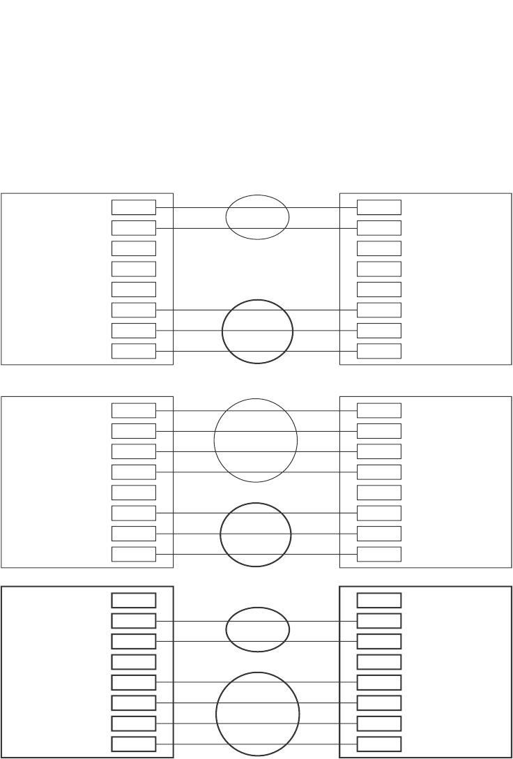
412 PowerConnect B-Series FCX Configuration Guide
53-1002266-01
Dynamic link aggregation
12
FIGURE 82 Examples of valid aggregate links
In this example, assume that link aggregation is enabled on all of the links between the Dell
PowerConnect device on the left and the device on the right (which can be either a Dell
PowerConnect device or another vendor device). The ports that are members of aggregate links in
this example are following the configuration rules for trunk links on Dell PowerConnect devices.
The Dell rules apply to a Dell PowerConnect device even if the device at the other end is from
another vendor and uses different rules. Refer to “Trunk group rules” on page 395.
Configuration notes and limitations
This section lists the configuration considerations and limitations for dynamic link aggregation.
Port1/1
Port1/2
Port1/3
Port1/4
Port1/5
Port1/6
Port1/7
Port1/8
Port1/1
Port1/2
Port1/3
Port1/4
Port1/5
Port1/6
Port1/7
Port1/8
Port1/1
Port1/2
Port1/3
Port1/4
Port1/5
Port1/6
Port1/7
Port1/8
Ports enabled for link
aggregation follow the same rules
as ports configured for trunk groups.

PowerConnect B-Series FCX Configuration Guide 413
53-1002266-01
Dynamic link aggregation 12
FastIron Stackable devices
The following notes and feature limitations apply to the PowerConnect B-Series FCX devices.
•The dynamic link aggregation (802.3ad) implementation allows any number of ports up to
eight to be aggregated into a link.
•The default key assigned to an aggregate link is based on the port type (1 Gbps port or 10
Gbps port). The device assigns different keys to 10 Gbps ports than on 1 Gbps ports so that
ports with different physical capabilities will not be able to form a trunk.
NOTE
The trunks that will be formed by link aggregation will strictly adhere to the static trunking rules
on the Stackable devices. Be careful in selecting keys if you are manually configuring link
aggregation keys. Make sure that the possible trunks that you expect to be formed conform to
the static trunking rules.
•When you enable link aggregation (LACP) on a group of Dell PowerConnect ports, you must also
assign a unique key (other than the default key) to all of the ports in the aggregate link.
•10 Gbps links only support two port trunks.
FastIron Stackable devices in an IronStack
• If a stack unit fails, or is removed from the stack, its LACP configuration becomes a reserved
configuration on the Active Controller. Any remaining ports of the dynamic trunk in the
IronStack continue to function.
•Merging two IronStacks with a dynamic trunk configured between them results in self-looped
ports, which are detected and corrected by the Spanning Tree Protocol (STP). LACP
configuration on the winning Active Controller is not affected by the LACP configuration on the
losing Active Controller is lost after the merge.
•When an IronStack with dynamic trunks partitions into multiple IronStacks, the protocol will
take care of splitting the dynamic trunk in the partner. No user intervention is required.
Adaptation to trunk disappearance
The Dell PowerConnect device will tear down an aggregate link if the device at the other end of the
link reboots or brings all the links down. Tearing the aggregate link down prevents a mismatch if the
other device has a different trunk configuration following the reboot or re-establishment of the
links. Once the other device recovers, 802.3 can renegotiate the link without a mismatch.
Flexible trunk eligibility
The criteria for trunk port eligibility in an aggregate link are flexible. A range of ports can contain
down ports and still be eligible to become an aggregate link.
The device places the ports into 2-port groups by default, consisting of an odd-numbered port and
the next even-numbered port. For example, ports 1/1 and 1/2 are a two-port group, as are ports
1/3 and 1/4, 9/1 and 9/2, and so on. If either of the ports in a two-port group is up, the device
considers both ports to be eligible to be in an aggregate link.

414 PowerConnect B-Series FCX Configuration Guide
53-1002266-01
Dynamic link aggregation
12
Figure 83 shows an example of 2-port groups in a range of four ports on which link aggregation is
enabled. Based on the states of the ports, some or all of them will be eligible to be used in an
aggregate link.
FIGURE 83 Two-port groups used to determine aggregation eligibility
Table 74 shows examples of the ports from Figure 83 that will be eligible for an aggregate link
based on individual port states.
As shown in these examples, all or a subset of the ports within a port range will be eligible for
formation into an aggregate link based on port states. Notice that the sets of ports that are eligible
for the aggregate link must be valid static trunk configurations.
Enabling dynamic link aggregation
By default, link aggregation is disabled on all ports. To enable link aggregation on a set of ports,
enter commands such as the following at the Interface configuration level of the CLI.
TABLE 74 Port eligibility for link aggregation
Port group 1 Port group 2 Trunk eligibility
1/1 1/2 1/3 1/4
Link StateUpUpUpUp4-port
1/1 – 1/4
Up Up Up Down 4-port
1/1 – 1/4
Up Down Up Down 4-port
1/1 – 1/4
Up Up Down Up 4-port
1/1 – 1/4
Down Down Down Up 2-port
1/3 – 1/4
Up Down Down Down 2-port
1/1 – 1/2
Port1/1
Port1/2
Port1/3
Port1/4
Group 1
Group 2

PowerConnect B-Series FCX Configuration Guide 415
53-1002266-01
Dynamic link aggregation 12
NOTE
Configuration commands for link aggregation differ depending on whether you are using the default
link aggregation key automatically assigned by the software, or if you are assigning a different,
unique key. Follow the commands below, according to the type of key you are using. For more
information about keys, refer to “Key” on page 417.
Using the default key assigned by the software
PowerConnect(config)#interface ethernet 1/1
PowerConnect(config-if-e1000-1/1)#link-aggregate active
PowerConnect(config)#interface ethernet 1/2
PowerConnect(config-if-e1000-1/2)#link-aggregate active
The commands in this example enable the active mode of link aggregation on ports 1/1 and 1/2.
The ports can send and receive LACPDU messages. Note that these ports will use the default key,
since one has not been explicitly configured.
NOTE
In conformance with the 802.3ad specification, the default key assigned to an aggregate link is
based on the port type (1 Gbps port or 10 Gbps port). The Dell PowerConnect device assigns
different keys to 10 Gbps ports than 1 Gbps ports, so that ports with different physical capabilities
will not be able to form a trunk.
Assigning a unique key
PowerConnect(config)#interface ethernet 1/1
PowerConnect(config-if-e1000-1/1)#link-aggregate configure key 10000
PowerConnect(config-if-e1000-1/1)#link-aggregate active
PowerConnect(config)#interface ethernet 1/2
PowerConnect(config-if-e1000-1/2)#link-aggregate configure key 10000
PowerConnect(config-if-e1000-1/2)#link-aggregate active
The commands in this example assign the key 10000 and enable the active mode of link
aggregation on ports 1/1 and 1/2. The ports can send and receive LACPDU messages.
NOTE
As shown in this example, when configuring a key, it is pertinent that you assign the key prior to
enabling link aggregation.
The following commands enable passive link aggregation on ports 1/5 – 1/8.
PowerConnect(config)#interface ethernet 1/5 to 1/8
PowerConnect(config-mif-1/5-1/8)#link-aggregate passive
The commands in this example enable the passive mode of link aggregation on ports 1/5 – 1/8.
These ports wait for the other end of the link to contact them. After this occurs, the ports can send
and receive LACPDU messages.
To disable link aggregation on a port, enter a command such as the following.
PowerConnect(config-if-e1000-1/8)#link-aggregate off
Syntax: [no] link-aggregate active | passive | off
Syntax: [no] link-aggregate configure [system-priority <num>] | [port-priority <num>] | [key
<num>]

416 PowerConnect B-Series FCX Configuration Guide
53-1002266-01
Dynamic link aggregation
12
NOTE
For more information about keys, including details about the syntax shown above, refer to
“Key” on page 417.
How changing the VLAN membership of a port
affects trunk groups and dynamic keys
When you change a port VLAN membership and the port is currently a member of a trunk group,
the following changes occur to the trunk group:
•The Dell PowerConnect device tears down the existing trunk group.
•All ports in the trunk group get a new key.
•The new key group aggregates into a new trunk group.
When you change a port VLAN membership, and the port is not a member of a trunk group, the
following changes occur:
•The port gets a new key depending on changes to the port VLAN tag type, as follows:
•Tagged to Tagged VLAN – The primary port of the trunk group gets a new key.
•Tagged to Untagged VLAN –The port gets the default key for untagged ports.
•Untagged to Tagged VLAN – If the Dell PowerConnect device finds a port with matching
port properties, the port gets that port key. If it does not find one, the port gets a new key.
•Untagged to Untagged VLAN – The port gets a new key depending on whether it is in the
default VLAN or not. If there is a trunk group associated with the key, it is not affected.
•All other ports keep their existing key.
•The new key groups try to aggregate into trunk groups.
Additional trunking options for LACP trunk ports
Additional trunking options are supported on individual ports that are part of an 802.3ad
aggregate link. Refer to “Additional trunking options” on page 404.
Link aggregation parameters
You can change the settings on individual ports for the following link aggregation parameters:
•System priority
•Port priority
•Timeout
•Key
System priority
The system priority parameter specifies the link aggregation priority on the Dell PowerConnect
device, relative to the devices at the other ends of the links on which link aggregation is enabled. A
higher value indicates a lower priority. You can specify a priority from 0 – 65535. The default is 1.

PowerConnect B-Series FCX Configuration Guide 417
53-1002266-01
Dynamic link aggregation 12
NOTE
If you are connecting the Dell PowerConnect device to another vendor device and the link
aggregation feature is not working, set the system priority on the Dell PowerConnect device to a
lower priority (a higher priority value). In some cases, this change allows the link aggregation feature
to operate successfully between the two devices.
Port priority
The port priority parameter determines the active and standby links. When a group of ports is
negotiating with a group of ports on another device to establish a trunk group, the Dell
PowerConnect port with the highest priority becomes the default active port. The other ports (with
lower priorities) become standby ports in the trunk group. You can specify a priority from 0 –
65535. A higher value indicates a lower priority. The default is 1.
NOTE
This parameter is not supported in the current software release. The primary port in the port group
becomes the default active port. The primary port is the lowest-numbered port in a valid trunk-port
group.
Timeout
You can specify a timeout mode, which determines how fast ports are removed from a trunk. You
can specify a short timeout mode.
Key
Every port that is 802.3ad-enabled has a key. The key identifies the group of potential trunk ports
to which the port belongs. Ports with the same key are called a key group and are eligible to be in
the same trunk group.
When you enable link-aggregation on an untagged port, the software assigns a default key to the
port. For tagged ports, you must manually configure link-aggregation keys. Refer to “Configuring
keys for ports with link aggregation enabled” on page 420.
All ports within an aggregate link must have the same key. However, if the device has ports that are
connected to two different devices, and the port groups allow the ports to form into separate
aggregate links with the two devices, then each group of ports can have the same key while
belonging to separate aggregate links with different devices. Figure 84 on page 418 shows an
example.
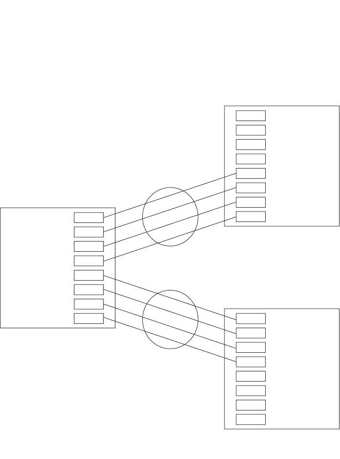
418 PowerConnect B-Series FCX Configuration Guide
53-1002266-01
Dynamic link aggregation
12
FIGURE 84 Ports with the same key in different aggregate links
Notice that the keys between one device and another do not need to match. The only requirement
for key matching is that all the ports within an aggregate link on a given device must have the same
key.
Devices that support multi-slot trunk groups can form multi-slot aggregate links using link
aggregation. However, the link aggregation keys for the groups of ports on each module must
match. For example, if you want to allow link aggregation to form an aggregate link containing ports
1/1 – 1/4 and 3/5 – 3/8, you must change the link aggregation key on one or both groups of ports
so that the key is the same on all eight ports. Figure 85 on page 419 shows an example.
All these ports have
the same key, but are
in two separate
aggregate links with
two other devices.
System ID: aaaa.bbbb.cccc
Ports 1/1 - 1/8 Key 0
System ID: 1111.2222.3333
Ports 1/5 - 1/8: Key 69
System ID: dddd.eeee.ffff
Ports 1/5 - 1/8: Key 4
Port1/1
Port1/2
Port1/3
Port1/4
Port1/5
Port1/6
Port1/7
Port1/8
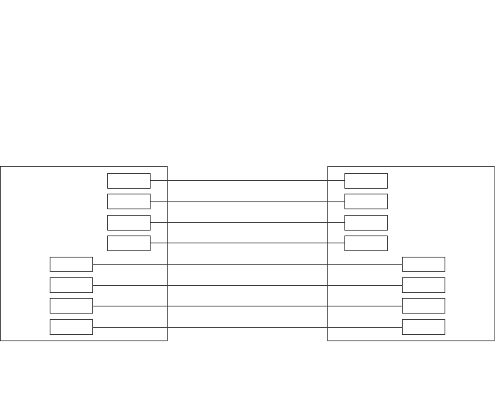
PowerConnect B-Series FCX Configuration Guide 419
53-1002266-01
Dynamic link aggregation 12
FIGURE 85 Multi-slot aggregate link
By default, the device ports are divided into 4-port groups. The software dynamically assigns a
unique key to each 4-port group. If you need to divide a 4-port group into two 2-port groups, change
the key in one of the groups so that the two 2-port groups have different keys. For example, if you
plan to use ports 1/1 and 1/2 in VLAN 1, and ports 1/3 and 1/4 in VLAN 2, change the key for
ports 1/3 and 1/4.
Viewing keys for tagged ports
To display link aggregation information, including the key for a specific port, enter a command such
as the following at any level of the CLI.
The command in this example shows the key and other link aggregation information for port 1/1.
To display link aggregation information, including the key for all ports on which link aggregation is
enabled, enter the following command at any level of the CLI.
System ID: aaaa.bbbb.cccc
Ports 1/1 - 1/4: Key 0
Ports 3/5 - 3/8: Key 0
All ports in a multi-slot
aggregate link have
the same key.
Port1/1
Port1/2
Port1/3
Port1/4
Port3/5
Port3/6
Port3/7
Port3/8
PowerConnect#show link-aggregate ethernet 1/1
System ID: 00e0.52a9.bb00
Port [Sys P] [Port P] [ Key ] [Act][Tio][Agg][Syn][Col][Dis][Def][Exp]
1/1 0 0 0 No L No No No No No No

420 PowerConnect B-Series FCX Configuration Guide
53-1002266-01
Dynamic link aggregation
12
Syntax: show link-aggregate [ethernet <port>]
Specify the <port> variable in the following formats:
•PowerConnect B-Series FCX stackable switches – <stack-unit/slotnum/portnum>
Configuring link aggregation parameters
You can configure one or more parameters on the same command line, and in any order.
NOTE
For key configuration only, configuration commands differ depending on whether or not link
aggregation is enabled on the ports. Follow the appropriate set of commands below, according to
your system configuration.
Configuring a port group key if link aggregation is disabled
Use this command sequence to change the key for ports that do not have link aggregation enabled,
and for all other link aggregation parameters (i.e., system priority, port priority).
For example, to change the software-assigned key for a port group to another value, enter
commands similar to the following.
PowerConnect(config)#interface ethernet 1/1 to 1/4
PowerConnect(config-mif-1/1-1/4)#link-aggregate configure key 10000
PowerConnect(config-mif-1/1-1/4)#interface ethernet 3/5 to 3/8
PowerConnect(config-mif-3/5-3/8)#link-aggregate configure key 10000
Configuring keys for ports with link aggregation enabled
As shown in this command sequence, to change the key on ports that already have link aggregation
enabled, you must first turn OFF link aggregation, configure the new key, then re-enable link
aggregation.
PowerConnect(config)#interface ethernet 1/1 to 1/4
PowerConnect(config-mif-1/1-1/4)#link-aggregate off
PowerConnect(config-mif-1/1-1/4)#link-aggregate configure key 10000
PowerConnect(config-mif-1/1-1/4)#link-aggregate active
PowerConnect#show link-aggregate
System ID: 0004.8055.b200
Long timeout: 90, default: 90
Short timeout: 3, default: 3
Port [Sys P] [Port P] [ Key ] [Act][Tio][Agg][Syn][Col][Dis][Def][Exp][Ope]
1/1 1 1 10000 Yes S Agg Syn Col Dis Def No Dwn
1/2 1 1 10000 Yes S Agg Syn Col Dis Def No Dwn
2/1 1 1 10000 Yes S Agg Syn Col Dis Def No Dwn
2/2 1 1 10000 Yes S Agg Syn Col Dis Def No Dwn
4/1 1 1 480 Yes S Agg Syn Col Dis Def No Dwn
4/2 1 1 480 Yes S Agg Syn Col Dis Def No Dwn
4/3 1 1 480 Yes S Agg Syn Col Dis Def No Dwn
4/4 1 1 480 Yes S Agg Syn Col Dis Def No Dwn
4/17 1 1 481 Yes S Agg Syn Col Dis Def No Ope
4/18 1 1 481 Yes S Agg Syn Col Dis Def No Ope
4/19 1 1 481 Yes S Agg Syn Col Dis Def No Ope
4/20 1 1 481 Yes S Agg Syn Col Dis Def No Ope

PowerConnect B-Series FCX Configuration Guide 421
53-1002266-01
Displaying and determining the status of aggregate links 12
PowerConnect(config-mif-1/1-1/4)#interface ethernet 3/5 to 3/8
PowerConnect(config-mif-3/5-3/8)#link-aggregate off
PowerConnect(config-mif-3/5-3/8)#link-aggregate configure key 10000
PowerConnect(config-mif-3/5-3/8)#link-aggregate active
These commands change the key for ports 1/1 – 1/4 and 3/5 – 3/8 to 10000. Since all ports in
an aggregate link must have the same key, the command in this example enables ports 1/1 – 1/4
and 3/5 – 3/8 to form a multi-slot aggregate link.
Syntax: [no] link-aggregate configure [system-priority <num>] | [port-priority <num>] | [key
<num>]
The system-priority <num> parameter specifies the Dell PowerConnect device link aggregation
priority. A higher value indicates a lower priority. You can specify a priority from 0 – 65535. The
default is 1.
The port-priority <num> parameter specifies an individual port priority within the port group. A
higher value indicates a lower priority. You can specify a priority from 0 – 65535. The default is 1.
The key <num> parameter identifies the group of ports that are eligible to be aggregated into a
trunk group. The software automatically assigns a key to each group of ports. The software assigns
the keys in ascending numerical order, beginning with 0. You can change a port group key to a
value from 10000 – 65535.
Configuring port timeout
You can control the time it takes to remove ports from a trunk with link aggregation enabled by
configuring the link aggregated port with a “short” timeout mode. Once a port is configured with a
timeout mode, it will remain in that timeout mode whether it is up or down or whether or not it is
part of a trunk.
All ports in a trunk should have the same timeout mode, which is checked when link aggregation is
enabled on ports.
To configure a port with a short timeout mode, enter a command such as the following.
PowerConnect(config)#interface ethernet8/1
PowerConnect(config-if-e1000-8/1)#link-aggregate configure timeout short
Syntax: [no] link-aggregate configure timeout [short]
If the timeout mode is not configured for a port and link aggregation is enabled, the port starts with
a short timeout mode. Once a trunk is formed, the timeout mode is changed to the long timeout
mode. The value for “long” and “short” is displayed in the output for the show link-aggregate
command.
Displaying and determining the status of aggregate links
The show link-aggregate command provides the ability to view the status of dynamic links. You can
determine the status of ports that are members of an aggregate link, and whether LACPDU
messages are being transmitted between the ports.
The following section provides details about the events that can affect the status of ports in an
aggregate link and the status of LACP messages exchanged between the ports. Later sections
provide instructions for viewing these status reports.

422 PowerConnect B-Series FCX Configuration Guide
53-1002266-01
Displaying and determining the status of aggregate links
12
Events that affect the status of ports in an aggregate link
Dell PowerConnect devices can block traffic on a port or shut down a port that is part of a trunk
group or aggregate link, when a port joins a trunk group and the port on the other end of the link
shuts down or stops transmitting LACP packets. Depending on the timeout value set on the port,
the link aggregation information expires. If this occurs, the Dell PowerConnect device shuts down
the port and notifies all the upper layer protocols that the port is down.
Dell PowerConnect devices can also block traffic on a port that is initially configured with link
aggregation. The port is blocked until it joins a trunk group. In this case, traffic is blocked, but the
port is still operational.
A port remains blocked until one of the following events occurs:
•Both ports in the aggregate link have the same key
•LACP brings the port back up
•The port joins a trunk group
Displaying link aggregation and port status information
Use the show link-aggregate command to determine the operational status of ports associated
with aggregate links.
To display the link aggregation information for a specific port, enter a command such as the
following at any level of the CLI.
The command in this example shows the link aggregation information for port 1/1.
To display the link aggregation information for all ports on which link aggregation is enabled, enter
the following command at any level of the CLI.
Syntax: show link-aggregate [ethernet <port>]
Specify the <port> variable in the following formats:
•PowerConnect B-Series FCX stackable switches – <stack-unit/slotnum/portnum>
PowerConnect#show link-aggregate ethernet 1/1
System ID: 00e0.52a9.bb00
Port [Sys P] [Port P] [ Key ] [Act][Tio][Agg][Syn][Col][Dis][Def][Exp] [Ope]
1/1 0 0 0 No L No No No No No No Ope
PowerConnect#show link-aggregate
System ID: 00e0.52a9.bb00
Long timeout: 120, default: 120 Short timeout: 3, default: 3
Port [Sys P] [Port P] [ Key ] [Act][Tio][Agg][Syn][Col][Dis][Def][Exp][Ope]
1/1 1 1 0 No L Agg Syn No No Def Exp Ope
1/2 1 1 0 No L Agg Syn No No Def Exp Ina
1/3 1 1 0 No L Agg Syn No No Def Exp Ina
1/4 1 1 0 No L Agg Syn No No Def Exp Blo
1/5 1 1 1 No L Agg No No No Def Exp Ope
1/6 1 1 1 No L Agg No No No Def Exp Ope
1/7 1 1 1 No L Agg No No No Def Exp Dwn
1/8 1 1 1 No L Agg No No No Def Exp Dwn

PowerConnect B-Series FCX Configuration Guide 423
53-1002266-01
Displaying and determining the status of aggregate links 12
NOTE
Ports that are configured as part of an aggregate link must also have the same key. For more
information about assigning keys, refer to the section “Link aggregation parameters” on page 416.
The show link-aggregate command shows the following information.
TABLE 75 CLI display of link aggregation information
This field... Displays...
System ID Lists the base MAC address of the device. This is also the MAC address of port 1 (or 1/1).
Port Lists the port number.
Sys P Lists the system priority configured for this port.
Port P Lists the port link aggregation priority.
Key Lists the link aggregation key.
This column displays “singleton” if the port is configured with a Single Instance of LACP. (Refer to
“Configuring single link LACP” on page 425 for more details.
Act Indicates the link aggregation mode, which can be one of the following:
•No – The mode is passive or link aggregation is disabled (off) on the port.
If link aggregation is enabled (and the mode is passive), the port can send and receive
LACPDU messages to participate in negotiation of an aggregate link initiated by another
port, but cannot search for a link aggregation port or initiate negotiation of an aggregate
link.
•Yes – The mode is active. The port can send and receive LACPDU messages.
Tio Indicates the timeout value of the port. The timeout value can be one of the following:
•L – Long. The trunk group has already been formed and the port is therefore using a longer
message timeout for the LACPDU messages exchanged with the remote port. Typically,
these messages are used as confirmation of the health of the aggregate link.
•S – Short. The port has just started the LACPDU message exchange process with the port
at the other end of the link. The S timeout value also can mean that the link aggregation
information received from the remote port has expired and the ports are starting a new
information exchange.
Agg Indicates the link aggregation state of the port. The state can be one of the following:
•Agg – Link aggregation is enabled on the port.
•No – Link aggregation is disabled on the port.
Syn Indicates the synchronization state of the port. The state can be one of the following:
•No – The port is out of sync with the remote port. The port does not understand the status
of the LACPDU process and is not prepared to enter a trunk link.
•Syn – The port is in sync with the remote port. The port understands the status of the
LACPDU message exchange process, and therefore knows the trunk group to which it
belongs, the link aggregation state of the remote port, and so on.
Col Indicates the collection state of the port, which determines whether the port is ready to send
traffic over the trunk link.
•Col – The port is ready to send traffic over the trunk link.
•No – The port is not ready to send traffic over the trunk link.
Dis Indicates the distribution state of the port, which determines whether the port is ready to receive
traffic over the trunk link.
•Dis – The port is ready to receive traffic over the trunk link.
•No – The port is not ready to receive traffic over the trunk link.

424 PowerConnect B-Series FCX Configuration Guide
53-1002266-01
Displaying and determining the status of aggregate links
12
Displaying link aggregation and port status information for PowerConnect
Stackable devices
To display link aggregation information for devices in an IronStack, enter the show link-aggregate
command. The output for an Ironstack resembles the following.
Displaying LACP status information
Use the show trunk command to determine the status of LACP. Refer to “Displaying trunk group
configuration information” on page 408.
Def Indicates whether the port is using default link aggregation values. The port uses default values
if it has not received link aggregation information through LACP from the port at the remote end
of the link. This field can have one of the following values:
•Def – The port has not received link aggregation values from the port at the other end of the
link and is therefore using its default link aggregation LACP settings.
•No – The port has received link aggregation information from the port at the other end of
the link and is using the settings negotiated with that port.
Exp Indicates whether the negotiated link aggregation settings have expired. The settings expire if
the port does not receive an LACPDU message from the port at the other end of the link before
the message timer expires. This field can have one of the following values:
•Exp – The link aggregation settings this port negotiated with the port at the other end of the
link have expired. The port is now using its default link aggregation settings.
•No – The link aggregation values that this port negotiated with the port at the other end of
the link have not expired, so the port is still using the negotiated settings.
Ope •Ope (operational) - The port is operating normally.
•Ina (inactive) - The port is inactive because the port on the other side of the link is down or
has stopped transmitting LACP packets.
•Blo (blocked) - The port is blocked because the adjacent port is not configured with link
aggregation or because it is not able to join a trunk group. To unblock the port and bring it to
an operational state, enable link aggregation on the adjacent port and ensure that the ports
have the same key.
TABLE 75 CLI display of link aggregation information (Continued)
This field... Displays...
PowerConnect(config)#show link-aggregate
System ID: 0012.f2e5.a200
Long timeout: 120, default: 120
Short timeout: 3, default: 3
Port [Sys P] [Port P] [ Key ] [Act][Tio][Agg][Syn][Col][Dis][Def][Exp][Ope]
1/1/1 1 1 13000 Yes L Agg Syn Col Dis No No Ope
2/1/1 1 1 13000 Yes L Agg Syn Col Dis No No Ope
3/1/1 1 1 13000 Yes L Agg Syn Col Dis No No Ope
4/1/1 1 1 13000 Yes L Agg Syn Col Dis No No Ope

PowerConnect B-Series FCX Configuration Guide 425
53-1002266-01
Clearing the negotiated aggregate links table 12
Clearing the negotiated aggregate links table
When a group of ports negotiates a trunk group configuration, the software stores the negotiated
configuration in a table. You can clear the negotiated link aggregation configurations from the
software. When you clear the information, the software does not remove link aggregation
parameter settings you have configured. Only the configuration information negotiated using LACP
is removed.
NOTE
The software automatically updates the link aggregation configuration based on LACPDU messages.
However, clearing the link aggregation information can be useful if you are troubleshooting a
configuration.
To clear the link aggregation information, enter the following command at the Privileged EXEC level
of the CLI.
PowerConnect#clear link-aggregate
Syntax: clear link-aggregate
Configuring single link LACP
A single instance of link aggregation (or single link LACP) can be used for unidirectional link
detection. Single link LACP is based on the 802.3ad LACP protocol; but allows you to form an
aggregated link with only one Ethernet port. It is the preferred method for detecting unidirectional
links across multi-vendor devices, instead of link-keepalive (UDLD), since it is based on a standard
rather than on a proprietary solution.
Configuration notes
•This feature is supported on 1-GbE and 10-GbE ports, as well as across modules.
•This feature is not supported on static trunk ports.
•This feature is not intended for the creation of trunk groups.
•The single link LACP timer is always short (3 seconds) and is not configurable. PDUs are sent
out every three seconds.
•This feature is not supported on ports that have the link-keepalive command (UDLD)
configured.
CLI syntax
To form a single link LACP, the port on both sides of the link must have LACP enabled. You can then
define a single link LACP at the interface level of the device by entering the following command.
PowerConnect(config)#interface ethernet 8/1
PowerConnect(config-if-e1000-8/1)#link-aggregate configure singleton
Link-aggregation active
Syntax: [no] link-aggregate configure singleton
When single link LACP is configured, the show link-aggregate command displays the following
information.

426 PowerConnect B-Series FCX Configuration Guide
53-1002266-01
Configuring single link LACP
12
If singleton is configured on the port, the “Key” column displays “singleton”. Refer to “CLI display of
link aggregation information” on page 423 to interpret the information on the displayed output.
Also, when ports are logically brought up or down while singleton is configured on the port, the
following Syslog messages are generated:
•Logical link on interface ethernet <slot#/port#> is up.
•Logical link on interface ethernet <slot#/port#> is down.
PowerConnect#show link-agg
System ID: 00e0.5200.0118
Long timeout: 120, default: 120 Short timeout: 3, default: 3
Port [Sys P] [Port P] [ Key ] [Act][Tio][Agg][Syn][Col][Dis][Def][Exp][Ope]
2/1 1 1 1 Yes S Agg Syn No No Def Exp Ina
2/2 1 1 1 Yes S Agg Syn No No Def Exp Ina
2/3 1 1 singleton Yes S Agg Syn No No Def Exp Ina
2/4 1 1 singleton Yes S Agg Syn No No Def Exp Dwn

PowerConnect B-Series FCX Configuration Guide 427
53-1002266-01
Chapter
13
Configuring Virtual LANs (VLANs)
Table 76 lists the individual Dell PowerConnect PowerConnect switches and the VLAN features they
support.
VLAN overview
The following sections provide details about the VLAN types and features supported on the
PowerConnect family of switches.
Types of VLANs
This section describes the VLAN types supported on Dell PowerConnect devices.
VLAN support on Dell PowerConnect devices
You can configure the following types of VLANs on PowerConnect devices:
•Layer 2 port-based VLAN – a set of physical ports that share a common, exclusive Layer 2
broadcast domain
TABLE 76 Supported VLAN features
Feature PowerConnect B-Series FCX
VLAN Support Yes
4096 maximum VLANs Yes
802.1Q with tagging Yes
802.1Q-in-Q tagging Yes
802.1Q-in-Q tag profiles Yes
Dual-mode VLANs Yes
Port-based VLANs Yes
Uplink Ports Within a Port-Based VLAN Yes
Protocol VLANs (AppleTalk, IPv4, dynamic
IPv6, and IPX
Yes
Layer 3 Subnet VLANs (Appletalk, IP
subnet network, and IPX)
Yes
VLAN groups Yes
Private VLANs (PVLANs) Yes
Super Aggregated VLANs Yes
VLAN Q-in-Q Tagging (tag-type 8100 over
8100 encapsulation)
Yes

428 PowerConnect B-Series FCX Configuration Guide
53-1002266-01
VLAN overview
13
•Layer 3 protocol VLANs – a subset of ports within a port-based VLAN that share a common,
exclusive broadcast domain for Layer 3 broadcasts of the specified protocol type
•IP subnet VLANs – a subset of ports in a port-based VLAN that share a common, exclusive
subnet broadcast domain for a specified IP subnet
•IPv6 VLANs – a subset of ports in a port-based VLAN that share a common, exclusive network
broadcast domain for IPv6 packets
•IPX network VLANs – a subset of ports in a port-based VLAN that share a common, exclusive
network broadcast domain for a specified IPX network
•AppleTalk cable VLANs – a subset of ports in a port-based-based VLAN that share a common,
exclusive network broadcast domain for a specified AppleTalk cable range
When a PowerConnect device receives a packet on a port that is a member of a VLAN, the device
forwards the packet based on the following VLAN hierarchy:
•If the port belongs to an IP subnet VLAN, IPX network VLAN, or AppleTalk cable VLAN and the
packet belongs to the corresponding IP subnet, IPX network, or AppleTalk cable range, the
device forwards the packet to all the ports within that VLAN.
•If the packet is a Layer 3 packet but cannot be forwarded as described above, but the port is a
member of a Layer 3 protocol VLAN for the packet protocol, the device forwards the packet on
all the Layer 3 protocol VLAN ports.
•If the packet cannot be forwarded based on either of the VLAN membership types listed above,
but the packet can be forwarded at Layer 2, the device forwards the packet on all the ports
within the receiving port port-based VLAN.
Protocol VLANs differ from IP subnet, IPX network, and AppleTalk VLANs in an important way.
Protocol VLANs accept any broadcast of the specified protocol type. An IP subnet, IPX network, or
AppleTalk VLAN accepts only broadcasts for the specified IP subnet, IPX network, or AppleTalk
cable range.
NOTE
Protocol VLANs are different from IP subnet, IPX network, and AppleTalk cable VLANs. A port-based
VLAN cannot contain both an IP subnet, IPX network, or AppleTalk cable VLAN and a protocol VLAN
for the same protocol. For example, a port-based VLAN cannot contain both an IP protocol VLAN and
an IP subnet VLAN.
Layer 2 port-based VLANs
On all Dell PowerConnect devices, you can configure port-based VLANs. A port-based VLAN is a
subset of ports on a Dell PowerConnect device that constitutes a Layer 2 broadcast domain.
By default, all the ports on a Dell PowerConnect device are members of the default VLAN. Thus, all
the ports on the device constitute a single Layer 2 broadcast domain. You can configure multiple
port-based VLANs. When you configure a port-based VLAN, the device automatically removes the
ports you add to the VLAN from the default VLAN.
You can configure up to 4094 port-based VLANs on a Layer 2 Switch or Layer 3 Switch. On both
device types, valid VLAN IDs are 1 – 4095. You can configure up to the maximum number of VLANs
within that ID range.

PowerConnect B-Series FCX Configuration Guide 429
53-1002266-01
VLAN overview 13
NOTE
VLAN IDs 4087, 4090, and 4093 are reserved for Dell internal use only. VLAN 4094 is reserved for
use by Single STP. Also, if you are running an earlier release, VLAN IDs 4091 and 4092 may be
reserved for Dell internal use only. If you want to use VLANs 4091 and 4092 as configurable VLANs,
you can assign them to different VLAN IDs. For more information, refer to “Assigning different VLAN
IDs to reserved VLANs 4091 and 4092” on page 445.
Each port-based VLAN can contain either tagged or untagged ports. A port cannot be a member of
more than one port-based VLAN unless the port is tagged. 802.1Q tagging allows the port to add a
four-byte tag field, which contains the VLAN ID, to each packet sent on the port. You also can
configure port-based VLANs that span multiple devices by tagging the ports within the VLAN. The
tag enables each device that receives the packet to determine the VLAN the packet belongs to.
802.1Q tagging applies only to Layer 2 VLANs, not to Layer 3 VLANs.
Because each port-based VLAN is a separate Layer 2 broadcast domain, by default each VLAN runs
a separate instance of the Spanning Tree Protocol (STP).
Layer 2 traffic is bridged within a port-based VLAN and Layer 2 broadcasts are sent to all the ports
within the VLAN.
Figure 86 shows an example of a Dell PowerConnect device on which a Layer 2 port-based VLAN
has been configured.

430 PowerConnect B-Series FCX Configuration Guide
53-1002266-01
VLAN overview
13
FIGURE 86 Dell PowerConnect device containing user-defined Layer 2 port-based VLAN
Layer 3 protocol-based VLANs
If you want some or all of the ports within a port-based VLAN to be organized according to Layer 3
protocol, you must configure a Layer 3 protocol-based VLAN within the port-based VLAN.
You can configure each of the following types of protocol-based VLAN within a port-based VLAN. All
the ports in the Layer 3 VLAN must be in the same Layer 2 VLAN.
Layer 3 protocol-based VLANs are as follows:
•AppleTalk – The device sends AppleTalk broadcasts to all ports within the AppleTalk protocol
VLAN.
•IP – The device sends IP broadcasts to all ports within the IP protocol VLAN.
•IPv6 – The device sends IPv6 broadcasts to all ports within the IPv6 protocol VLAN.
•IPX – The device sends IPX broadcasts to all ports within the IPX protocol VLAN.
•DECnet – The device sends DECnet broadcasts to all ports within the DECnet protocol VLAN.
•NetBIOS – The device sends NetBIOS broadcasts to all ports within the NetBIOS protocol VLAN.
When you add a port-based VLAN,
the device removes all the ports in the
new VLAN from DEFAULT-VLAN.
User-configured port-based VLAN
DEFAULT-VLAN
VLAN ID = 1
Layer 2 Port-based VLAN

PowerConnect B-Series FCX Configuration Guide 431
53-1002266-01
VLAN overview 13
•Other – The device sends broadcasts for all protocol types other than those listed above to all
ports within the VLAN.
Figure 87 shows an example of Layer 3 protocol VLANs configured within a Layer 2 port-based
VLAN.
FIGURE 87 Layer 3 protocol VLANs within a Layer 2 port-based VLAN
DEFAULT-VLAN
VLAN ID = 1
Layer 2 Port-based VLAN
User-configured port-based VLAN
User-configured protocol VLAN, IP sub-net VLAN,
IPX network VLAN, or Apple Talk cable VLAN
You can add Layer 3 protocol VLANs or
IP sub-net, IPX network, and AppleTalk
cable VLANs to port-based VLANs.
Layer 3 VLANs cannot span Layer 2 port-based
VLANs.
However, Layer 3 VLANs can overlap within
a Layer 2 port-based VLAN.

432 PowerConnect B-Series FCX Configuration Guide
53-1002266-01
VLAN overview
13
Integrated Switch Routing (ISR)
The Dell Integrated Switch Routing (ISR) feature enables VLANs configured on Layer 3 Switches to
route Layer 3 traffic from one protocol VLAN or IP subnet, IPX network, or AppleTalk cable VLAN to
another. Normally, to route traffic from one IP subnet, IPX network, or AppleTalk cable VLAN to
another, you would need to forward the traffic to an external router. The VLANs provide Layer 3
broadcast domains for these protocols but do not in themselves provide routing services for these
protocols. This is true even if the source and destination IP subnets, IPX networks, or AppleTalk
cable ranges are on the same device.
ISR eliminates the need for an external router by allowing you to route between VLANs using virtual
routing interfaces (ves). A virtual routing interface is a logical port on which you can configure Layer
3 routing parameters. You configure a separate virtual routing interface on each VLAN that you
want to be able to route from or to. For example, if you configure two IP subnet VLANs on a Layer 3
Switch, you can configure a virtual routing interface on each VLAN, then configure IP routing
parameters for the subnets. Thus, the Layer 3 Switch forwards IP subnet broadcasts within each
VLAN at Layer 2 but routes Layer 3 traffic between the VLANs using the virtual routing interfaces.
NOTE
The Layer 3 Switch uses the lowest MAC address on the device (the MAC address of port 1 or 1/1)
as the MAC address for all ports within all virtual routing interfaces you configure on the device.
The routing parameters and the syntax for configuring them are the same as when you configure a
physical interface for routing. The logical interface allows the Layer 3 Switch to internally route
traffic between the protocol-based VLANs without using physical interfaces.
All the ports within a protocol-based VLAN must be in the same port-based VLAN. The
protocol-based VLAN cannot have ports in multiple port-based VLANs, unless the ports in the
port-based VLAN to which you add the protocol-based VLAN are 802.1Q tagged.
You can configure multiple protocol-based VLANs within the same port-based VLAN. In addition, a
port within a port-based VLAN can belong to multiple protocol-based VLANs of the same type or
different types. For example, if you have a port-based VLAN that contains ports 1 – 10, you can
configure port 5 as a member of an AppleTalk protocol VLAN, an IP protocol VLAN, and an IPX
protocol VLAN, and so on.
IP subnet, IPX network, and AppleTalk cable VLANs
The protocol-based VLANs described in the previous section provide separate protocol broadcast
domains for specific protocols. For IP, IPX, and AppleTalk, you can provide more granular broadcast
control by instead creating the following types of VLAN:
•IP subnet VLAN – An IP subnet broadcast domain for a specific IP subnet.
•IPX network VLAN – An IPX network broadcast domain for a specific IPX network.
•AppleTalk cable VLAN – An AppleTalk broadcast domain for a specific cable range.
You can configure these types of VLANs on Layer 3 Switches only. The Layer 3 Switch sends
broadcasts for the IP subnet, IPX network, or AppleTalk cable range to all ports within the IP subnet,
IPX network, or AppleTalk cable VLAN at Layer 2.
The Layer 3 Switch routes packets between VLANs at Layer 3. To configure an IP subnet, IPX
network, or AppleTalk cable VLAN to route, you must add a virtual routing interface to the VLAN,
then configure the appropriate routing parameters on the virtual routing interface.

PowerConnect B-Series FCX Configuration Guide 433
53-1002266-01
VLAN overview 13
NOTE
The Layer 3 Switch routes packets between VLANs of the same protocol. The Layer 3 Switch cannot
route from one protocol to another.
NOTE
IP subnet VLANs are not the same thing as IP protocol VLANs. An IP protocol VLAN sends all IP
broadcasts on the ports within the IP protocol VLAN. An IP subnet VLAN sends only the IP subnet
broadcasts for the subnet of the VLAN. You cannot configure an IP protocol VLAN and an IP subnet
VLAN within the same port-based VLAN.
This note also applies to IPX protocol VLANs and IPX network VLANs, and to AppleTalk protocol VLANs
and AppleTalk cable VLANs.
Default VLAN
By default, all the ports on a PowerConnect device are in a single port-based VLAN. This VLAN is
called the DEFAULT-VLAN and is VLAN number 1. PowerConnect devices do not contain any
protocol VLANs or IP subnet, IPX network, or AppleTalk cable VLANs by default.
Figure 88 shows an example of the default Layer 2 port-based VLAN.
FIGURE 88 Default Layer 2 port-based VLAN
DEFAULT-VLAN
VLAN ID = 1
Layer 2 Port-based VLAN
By default, all ports belong to a single
port-based VLAN, DEFAULT-VLAN.
Thus, all ports belong to a single
Layer 2 broadcast domain.

434 PowerConnect B-Series FCX Configuration Guide
53-1002266-01
VLAN overview
13
When you configure a port-based VLAN, one of the configuration items you provide is the ports that
are in the VLAN. When you configure the VLAN, the Dell PowerConnect device automatically
removes the ports that you place in the VLAN from DEFAULT-VLAN. By removing the ports from the
default VLAN, the Dell PowerConnect device ensures that each port resides in only one Layer 2
broadcast domain.
NOTE
Information for the default VLAN is available only after you define another VLAN.
Some network configurations may require that a port be able to reside in two or more Layer 2
broadcast domains (port-based VLANs). In this case, you can enable a port to reside in multiple
port-based VLANs by tagging the port. Refer to the following section.
If your network requires that you use VLAN ID 1 for a user-configured VLAN, you can reassign the
default VLAN to another valid VLAN ID. Refer to “Assigning a different VLAN ID to the default VLAN”
on page 444.
802.1Q tagging
802.1Q tagging is an IEEE standard that allows a networking device to add information to a Layer 2
packet in order to identify the VLAN membership of the packet. Dell PowerConnect devices tag a
packet by adding a four-byte tag to the packet. The tag contains the tag value, which identifies the
data as a tag, and also contains the VLAN ID of the VLAN from which the packet is sent.
•The default tag value is 8100 (hexadecimal). This value comes from the 802.1Q specification.
You can change this tag value on a global basis on Dell PowerConnect devices if needed to be
compatible with other vendors’ equipment.
•The VLAN ID is determined by the VLAN on which the packet is being forwarded.
Figure 89 shows the format of packets with and without the 802.1Q tag. The tag format is
vendor-specific. To use the tag for VLANs configured across multiple devices, make sure all the
devices support the same tag format.
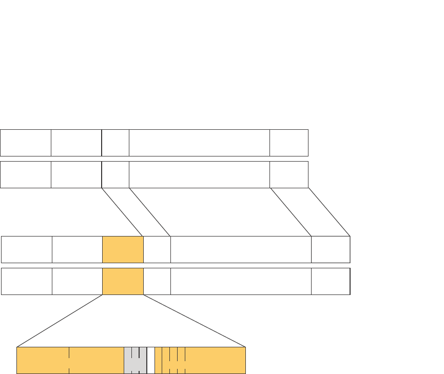
PowerConnect B-Series FCX Configuration Guide 435
53-1002266-01
VLAN overview 13
FIGURE 89 Packet containing a Dell 802.1Q VLAN tag
If you configure a VLAN that spans multiple devices, you need to use tagging only if a port
connecting one of the devices to the other is a member of more than one port-based VLAN. If a port
connecting one device to the other is a member of only a single port-based VLAN, tagging is not
required.
If you use tagging on multiple devices, each device must be configured for tagging and must use
the same tag value. In addition, the implementation of tagging must be compatible on the devices.
The tagging on all Dell PowerConnect devices is compatible with other Dell PowerConnect devices.
Figure 90 shows an example of two devices that have the same Layer 2 port-based VLANs
configured across them. Notice that only one of the VLANs requires tagging.
Untagged Packet Format
6 bytes
Destination
Address
6 bytes
Source
Address
2 bytes
Type
Field
Up to 1500 bytes
Data Field
4 bytes
CRC Ethernet II
IEEE 802.3
802.1q Tagged Packet Format
4 bytes
802.1q
Tag
Ethernet II with 802.1q tag
IEEE 802.3 with 802.1q tag
Tag Protocol Id (TPID)
Octet 1 Octet 2
802.1p
(3 bits)VLAN ID (12 bits)
Octet 4
12345678
6 bytes
Destination
Address
6 bytes
Source
Address
2 bytes
Length
Field
Up to 1496 bytes
Data Field
4 bytes
CRC
6 bytes
Destination
Address
6 bytes
Destination
Address
6 bytes
Source
Address
6 bytes
Source
Address
4 bytes
802.1q
Tag
2 bytes
Type
Field
2 bytes
Length
Field
Up to 1500 bytes
Data Field
Up to 1496 bytes
Data Field
4 bytes
CRC
4 bytes
CRC
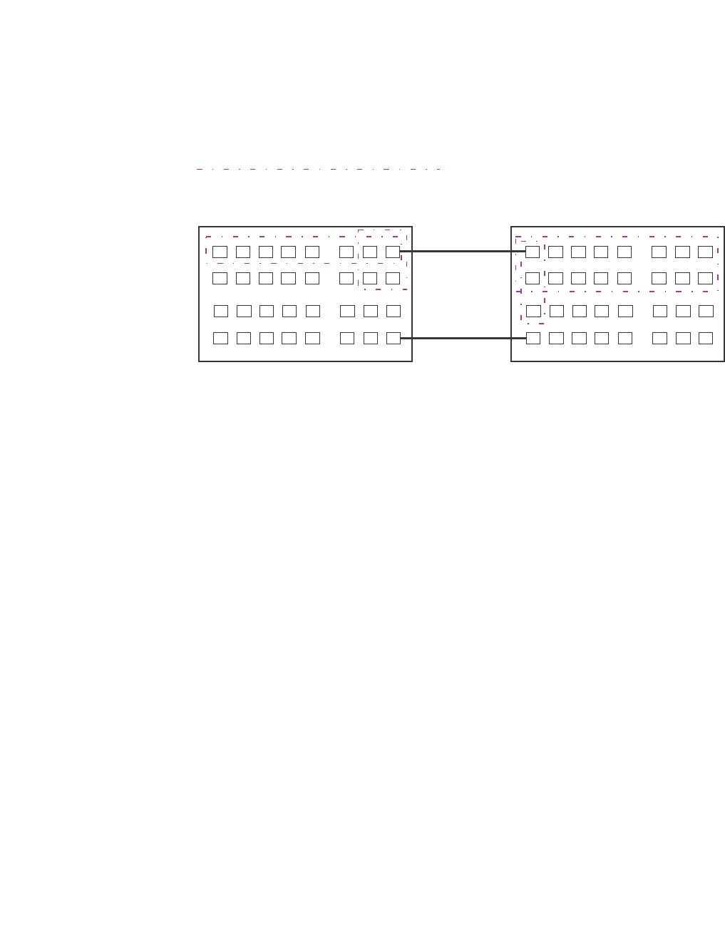
436 PowerConnect B-Series FCX Configuration Guide
53-1002266-01
VLAN overview
13
FIGURE 90 VLANs configured across multiple devices
Support for 802.1Q-in-Q tagging
Dell PowerConnect devices provide finer granularity for configuring 802.1Q tagging, enabling you to
configure 802.1Q tag-types on a group of ports, thereby enabling the creation of two identical
802.1Q tags (802.1Q-in-Q tagging) on a single device. This enhancement improves SAV
interoperability between Dell PowerConnect devices and other vendors’ devices that support the
802.1Q tag-types, but are not very flexible with the tag-types they accept.
•PowerConnect B-Series FCX devices support one value for tag-type, which is defined at the
global level, and one value for tag-profile, which is defined at the global and interface level of
the CLI.
802.1 Q-in-Q tagging for PowerConnect B-Series FCX Series devices
The following enhancements allow the PowerConnect B-Series FCX devices, including those in an
IronStack, to use Q-in-Q and SAV, by allowing the changing of a tag profile for ports:
•In addition to the default tag type 0x8100, you can now configure one additional global tag
profile with a number from 0xffff.
•Tag profiles on a single port, or a group of ports can be configured to point to the global tag
profile.
For example applications and configuration details, refer to “Configuring 802.1Q-in-Q tagging” on
page 484.
To configure a global tag profile, enter the following command in the configuration mode.
PowerConnect(config)# tag-profile 9500
Syntax: [no] tag-profile <tag-no>
<tag-no> - the number of the tag, can be 0x8100 (default), or 0xffff
User-configured port-based VLAN
T = 802.1Q tagged port
TT
TT
T
T
Segment 1
Segment 2
T
Segment 2
Segment 1
Tagging is required for the ports
on Segment 1 because the ports
are in multiple port-based VLANs.
Without tagging, a device receiving
VLAN traffic from the other device
would not be sure which VLAN the
traffic is for.
Tagging is not required for the ports
on Segment 2 because each port is
in only one port-based VLAN.

PowerConnect B-Series FCX Configuration Guide 437
53-1002266-01
VLAN overview 13
To direct individual ports or on a range of ports to this tag profile, enter commands similar to the
following.
PowerConnect(config)# interface ethernet 1/1/1
PowerConnect(config-if-e1000-1/1/1)# tag-profile enable
PowerConnect(config-mif-1/1/1,1/2/1)# tag-profile enable
Spanning Tree Protocol (STP)
The default state of STP depends on the device type:
•STP is disabled by default on Layer 3 Switches.
•STP is enabled by default on Layer 2 Switches.
Also by default, each port-based VLAN has a separate instance of STP. Thus, when STP is globally
enabled, each port-based VLAN on the device runs a separate spanning tree.
You can enable or disable STP on the following levels:
•Globally – Affects all ports on the device.
NOTE
If you configure a port-based VLAN on the device, the VLAN has the same STP state as the
default STP state on the device. Thus, on Layer 2 Switches, new VLANs have STP enabled by
default. On Layer 3 Switches, new VLANs have STP disabled by default. You can enable or
disable STP in each VLAN separately. In addition, you can enable or disable STP on individual
ports.
•Port-based VLAN – Affects all ports within the specified port-based VLAN.
STP is a Layer 2 protocol. Thus, you cannot enable or disable STP for individual protocol VLANs or
for IP subnet, IPX network, or AppleTalk cable VLANs. The STP state of a port-based VLAN
containing these other types of VLANs determines the STP state for all the Layer 2 broadcasts
within the port-based VLAN. This is true even though Layer 3 protocol broadcasts are sent on Layer
2 within the VLAN.
It is possible that STP will block one or more ports in a protocol VLAN that uses a virtual routing
interface to route to other VLANs. For IP protocol and IP subnet VLANs, even though some of the
physical ports of the virtual routing interface are blocked, the virtual routing interface can still route
so long as at least one port in the virtual routing interface protocol VLAN is not blocked by STP.
If you enable Single STP (SSTP) on the device, the ports in all VLANs on which STP is enabled
become members of a single spanning tree. The ports in VLANs on which STP is disabled are
excluded from the single spanning tree.
For more information, refer to Chapter 8, “Configuring Spanning Tree Protocol (STP) Related
Features”.
Virtual routing interfaces
A virtual routing interface is a logical routing interface that Layer 3 Switches use to route Layer 3
protocol traffic between protocol VLANs.
Dell PowerConnect devices send Layer 3 traffic at Layer 2 within a protocol VLAN. However, Layer 3
traffic from one protocol VLAN to another must be routed.

438 PowerConnect B-Series FCX Configuration Guide
53-1002266-01
VLAN overview
13
If you want the device to be able to send Layer 3 traffic from one protocol VLAN to another, you
must configure a virtual routing interface on each protocol VLAN, then configure routing
parameters on the virtual routing interfaces. For example, to enable a Layer 3 Switch to route IP
traffic from one IP subnet VLAN to another, you must configure a virtual routing interface on each IP
subnet VLAN, then configure the appropriate IP routing parameters on each of the virtual routing
interfaces.
Figure 91 shows an example of Layer 3 protocol VLANs that use virtual routing interfaces for
routing.
FIGURE 91 Use virtual routing interfaces for routing between Layer 3 protocol VLANs
User-configured port-based VLAN
User-configured protocol VLAN, IP sub-net VLAN,
IPX network VLAN, or AppleTalk cable VLAN
VE = virtual interface
(“VE” stands for “Virtual Ethernet”)
VE 1
VE 2
VE 3
VE 4
Layer 2 and Layer 3 traffic within a VLAN
is bridged at Layer 2.
Layer 3 traffic between protocol VLANs
is routed using virtual interfaces (VE).
To route to one another, each protocol
VLAN must have a virtual interface.

PowerConnect B-Series FCX Configuration Guide 439
53-1002266-01
VLAN overview 13
VLAN and virtual routing interface groups
Dell PowerConnect devices support the configuration of VLAN groups. To simplify configuration,
you can configure VLAN groups and virtual routing interface groups. When you create a VLAN group,
the VLAN parameters you configure for the group apply to all the VLANs within the group.
Additionally, you can easily associate the same IP subnet interface with all the VLANs in a group by
configuring a virtual routing interface group with the same ID as the VLAN group.
For configuration information, refer to “Configuring VLAN groups and virtual routing interface
groups” on page 472.
Dynamic, static, and excluded port membership
When you add ports to a protocol VLAN, IP subnet VLAN, IPX network VLAN, or AppleTalk cable
VLAN, you can add them dynamically or statically:
•Dynamic ports
•Static ports
You also can explicitly exclude ports.
Dynamic ports
Dynamic ports are added to a VLAN when you create the VLAN. However, if a dynamically added
port does not receive any traffic for the VLAN protocol within ten minutes, the port is removed from
the VLAN. However, the port remains a candidate for port membership. Thus, if the port receives
traffic for the VLAN protocol, the device adds the port back to the VLAN.
After the port is added back to the VLAN, the port can remain an active member of the VLAN up to
20 minutes without receiving traffic for the VLAN protocol. If the port ages out, it remains a
candidate for VLAN membership and is added back to the VLAN when the VLAN receives protocol
traffic. At this point, the port can remain in the VLAN up to 20 minutes without receiving traffic for
the VLAN protocol, and so on.
Unless you explicitly add a port statically or exclude a port, the port is a dynamic port and thus can
be an active member of the VLAN, depending on the traffic it receives.
NOTE
You cannot configure dynamic ports in an AppleTalk cable VLAN. The ports in an AppleTalk cable
VLAN must be static. However, ports in an AppleTalk protocol VLAN can be dynamic or static.
Figure 92 shows an example of a VLAN with dynamic ports. Dynamic ports not only join and leave
the VLAN according to traffic, but also allow some broadcast packets of the specific protocol to
“leak” through the VLAN. Refer to “Broadcast leaks” on page 441.
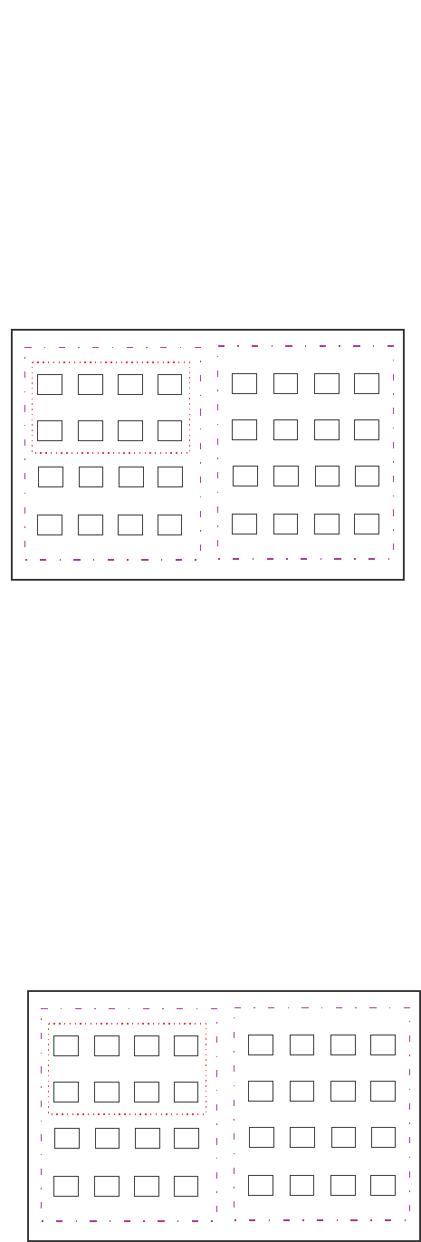
440 PowerConnect B-Series FCX Configuration Guide
53-1002266-01
VLAN overview
13
FIGURE 92 VLAN with dynamic ports—all ports are active when you create the VLAN
SUBNET Ports in a new protocol VLAN that do not receive traffic for the VLAN protocol age out after
10 minutes and become candidate ports. Figure 93 shows what happens if a candidate port
receives traffic for the VLAN protocol.
FIGURE 93 VLAN with dynamic ports—candidate ports become active again if they receive
protocol traffic
A = active port
C = candidate port
When you add ports dynamically,
all the ports are added when you add
the VLAN.
AAA
A
AA
AA
Por
ts that time out remain candidates
for membership in the VLAN and become active
again if they receive traffic for the VLAN’s
protocol, IP sub-net, IPX network, or
AppleTalk cable range.
When a candidate port rejoins a VLAN,
the timeout for that port becomes 20 minutes.
Thus, the port remains an active member of
the VLAN even if it does not receive traffic
for 20 minutes. After that, the port becomes
a candidate port again.
CC
AAAA
AA

PowerConnect B-Series FCX Configuration Guide 441
53-1002266-01
VLAN overview 13
Static ports
Static ports are permanent members of the protocol VLAN. The ports remain active members of
the VLAN regardless of whether the ports receive traffic for the VLAN protocol. You must explicitly
identify the port as a static port when you add it to the VLAN. Otherwise, the port is dynamic and is
subject to aging out.
Excluded ports
If you want to prevent a port in a port-based VLAN from ever becoming a member of a protocol, IP
subnet, IPX network, or AppleTalk cable VLAN configured in the port-based VLAN, you can explicitly
exclude the port. You exclude the port when you configure the protocol, IP subnet, IPX network, or
AppleTalk cable VLAN.
Excluded ports do not leak broadcast packets. Refer to “Broadcast leaks” on page 441.
Broadcast leaks
A dynamic port becomes a member of a Layer 3 protocol VLAN when traffic from the VLAN's
protocol is received on the port. After this point, the port remains an active member of the protocol
VLAN, unless the port does not receive traffic from the VLAN's protocol for 20 minutes. If the port
does not receive traffic for the VLAN's protocol for 20 minutes, the port ages out and is no longer
an active member of the VLAN.
To enable a host that has been silent for awhile to send and receive packets, the dynamic ports
that are currently members of the Layer 3 protocol VLAN "leak" Layer 3 broadcast packets to the
ports that have aged out. When a host connected to one of the aged out ports responds to a leaked
broadcast, the port is added to the protocol VLAN again.
To "leak" Layer 3 broadcast traffic, an active port sends 1/8th of the Layer 3 broadcast traffic to the
inactive (aged out) ports.
Static ports do not age out and do not leak broadcast packets.
Super aggregated VLANs
Dell PowerConnect devices support Super Aggregated VLANs. You can aggregate multiple VLANs
within another VLAN. This feature allows you to construct Layer 2 paths and channels. This feature
is particularly useful for Virtual Private Network (VPN) applications in which you need to provide a
private, dedicated Ethernet connection for an individual client to transparently reach its subnet
across multiple networks.
For an application example and configuration information, refer to “Configuring super aggregated
VLANs” on page 477.
Trunk group ports and VLAN membership
A trunk group is a set of physical ports that are configured to act as a single physical interface.
Each trunk group port configuration is based on the configuration of the lead port, which is the
lowest numbered port in the group.
If you add a trunk group lead port to a VLAN, all of the ports in the trunk group become members of
that VLAN.

442 PowerConnect B-Series FCX Configuration Guide
53-1002266-01
VLAN overview
13
Summary of VLAN configuration rules
A hierarchy of VLANs exists between the Layer 2 and Layer 3 protocol-based VLANs:
•Port-based VLANs are at the lowest level of the hierarchy.
•Layer 3 protocol-based VLANs, IP, IPv6, IPX, AppleTalk, Decnet, and NetBIOS are at the middle
level of the hierarchy.
•IP subnet, IPX network, and AppleTalk cable VLANs are at the top of the hierarchy.
NOTE
You cannot have a protocol-based VLAN and a subnet or network VLAN of the same protocol type in
the same port-based VLAN. For example, you can have an IPX protocol VLAN and IP subnet VLAN in
the same port-based VLAN, but you cannot have an IP protocol VLAN and an IP subnet VLAN in the
same port-based VLAN, nor can you have an IPX protocol VLAN and an IPX network VLAN in the same
port-based VLAN.
As a Dell PowerConnect device receives packets, the VLAN classification starts from the highest
level VLAN first. Therefore, if an interface is configured as a member of both a port-based VLAN and
an IP protocol VLAN, IP packets coming into the interface are classified as members of the IP
protocol VLAN because that VLAN is higher in the VLAN hierarchy.
Multiple VLAN membership rules
•A port can belong to multiple, unique, overlapping Layer 3 protocol-based VLANs without VLAN
tagging.
•A port can belong to multiple, overlapping Layer 2 port-based VLANs only if the port is a tagged
port. Packets sent out of a tagged port use an 802.1Q-tagged frame.
•When both port and protocol-based VLANs are configured on a given device, all protocol VLANs
must be strictly contained within a port-based VLAN. A protocol VLAN cannot include ports from
multiple port-based VLANs. This rule is required to ensure that port-based VLANs remain
loop-free Layer 2 broadcast domains.
•IP protocol VLANs and IP subnet VLANs cannot operate concurrently on the system or within
the same port-based VLAN.
•IPX protocol VLANs and IPX network VLANs cannot operate concurrently on the system or
within the same port-based VLAN.
•If you first configure IP and IPX protocol VLANs before deciding to partition the network by IP
subnet and IPX network VLANs, then you need to delete those VLANs before creating the IP
subnet and IPX network VLANs.
•One of each type of protocol VLAN is configurable within each port-based VLAN on the Layer 2
Switch.
•Multiple IP subnet and IPX network VLANs are configurable within each port-based VLAN on
the Layer 2 Switch.
•Removing a configured port-based VLAN from a Layer 2 Switch or Layer 3 Switch automatically
removes any protocol-based VLAN, IP subnet VLAN, AppleTalk cable VLAN, or IPX network
VLAN, or any Virtual Ethernet router interfaces defined within the Port-based VLAN.

PowerConnect B-Series FCX Configuration Guide 443
53-1002266-01
Routing between VLANs 13
Routing between VLANs
Layer 3 Switches can locally route IP, IPX, and Appletalk between VLANs defined within a single
router. All other routable protocols or protocol VLANs (for example, DecNet) must be routed by
another external router capable of routing the protocol.
Virtual routing interfaces (Layer 3 Switches only)
You need to configure virtual routing interfaces if an IP, IPX, or Appletalk protocol VLAN, IP subnet
VLAN, AppleTalk cable VLAN, or IPX network VLAN needs to route protocols to another port-based
VLAN on the same router. A virtual routing interface can be associated with the ports in only a
single port-based VLAN. Virtual router interfaces must be defined at the highest level of the VLAN
hierarchy.
If you do not need to further partition the port-based VLAN by defining separate Layer 3 VLANs, you
can define a single virtual routing interface at the port-based VLAN level and enable IP, IPX, and
Appletalk routing on a single virtual routing interface.
Some configurations may require simultaneous switching and routing of the same single protocol
across different sets of ports on the same router. When IP, IPX, or Appletalk routing is enabled on a
Layer 3 Switch, you can route these protocols on specific interfaces while bridging them on other
interfaces. In this scenario, you can create two separate backbones for the same protocol, one
bridged and one routed.
To bridge IP, IPX, or Appletalk at the same time these protocols are being routed, you need to
configure an IP protocol, IP subnet, IPX protocol, IPX network, or Appletalk protocol VLAN and not
assign a virtual routing interface to the VLAN. Packets for these protocols are bridged or switched
at Layer 2 across ports on the router that are included in the Layer 3 VLAN. If these VLANs are built
within port-based VLANs, they can be tagged across a single set of backbone fibers to create
separate Layer 2 switched and Layer 3 routed backbones for the same protocol on a single physical
backbone.
Routing between VLANs using virtual routing interfaces
(Layer 3 Switches only)
Dell calls the ability to route between VLANs with virtual routing interfaces Integrated Switch
Routing (ISR). There are some important concepts to understand before designing an ISR
backbone.
Virtual router interfaces can be defined on port-based, IP protocol, IP subnet, IPX protocol, IPX
network, AppleTalk protocol, and AppleTalk cable VLANs.
To create any type of VLAN on a Layer 3 Switch, Layer 2 forwarding must be enabled. When Layer 2
forwarding is enabled, the Layer 3 Switch becomes a Switch on all ports for all non-routable
protocols.
If the router interfaces for IP, IPX, or AppleTalk are configured on physical ports, then routing occurs
independent of the Spanning Tree Protocol (STP). However, if the router interfaces are defined for
any type VLAN, they are virtual routing interfaces and are subject to the rules of STP.

444 PowerConnect B-Series FCX Configuration Guide
53-1002266-01
Routing between VLANs
13
If your backbone consists of virtual routing interfaces all within the same STP domain, it is a
bridged backbone, not a routed one. This means that the set of backbone interfaces that are
blocked by STP will be blocked for routed protocols as well. The routed protocols will be able to
cross these paths only when the STP state of the link is FORWARDING. This problem is easily
avoided by proper network design.
When designing an ISR network, pay attention to your use of virtual routing interfaces and the
spanning-tree domain. If Layer 2 switching of your routed protocols (IP, IPX, AppleTalk) is not
required across the backbone, then the use of virtual routing interfaces can be limited to edge
switch ports within each router. Full backbone routing can be achieved by configuring routing on
each physical interface that connects to the backbone. Routing is independent of STP when
configured on a physical interface.
If your ISR design requires that you switch IP, IPX, or Appletalk at Layer 2 while simultaneously
routing the same protocols over a single backbone, then create multiple port-based VLANs and use
VLAN tagging on the backbone links to separate your Layer 2 switched and Layer 3 routed
networks.
There is a separate STP domain for each port-based VLAN. Routing occurs independently across
port-based VLANs or STP domains. You can define each end of each backbone link as a separate
tagged port-based VLAN. Routing will occur independently across the port-based VLANs. Because
each port-based VLAN STP domain is a single point-to-point backbone connection, you are
guaranteed to never have an STP loop. STP will never block the virtual router interfaces within the
tagged port-based VLAN, and you will have a fully routed backbone.
Dynamic port assignment (Layer 2 Switches and
Layer 3 Switches)
All Switch ports are dynamically assigned to any Layer 3 VLAN on Layer 2 Switches and any
non-routable VLAN on Layer 3 Switches. To maintain explicit control of the VLAN, you can explicitly
exclude ports when configuring any Layer 3 VLAN on a Layer 2 Switch or any non-routable Layer 3
VLAN on a Layer 3 Switch.
If you do not want the ports to have dynamic membership, you can add them statically. This
eliminates the need to explicitly exclude the ports that you do not want to participate in a particular
Layer 3 VLAN.
Assigning a different VLAN ID to the default VLAN
When you enable port-based VLANs, all ports in the system are added to the default VLAN. By
default, the default VLAN ID is “VLAN 1”. The default VLAN is not configurable. If you want to use
the VLAN ID “VLAN 1” as a configurable VLAN, you can assign a different VLAN ID to the default
VLAN.
To reassign the default VLAN to a different VLAN ID, enter the following command.
PowerConnect(config)# default-vlan-id 4095
Syntax: [no] default-vlan-d <vlan-id>
You must specify a valid VLAN ID that is not already in use. For example, if you have already defined
VLAN 10, do not try to use “10” as the new VLAN ID for the default VLAN. Valid VLAN IDs are
numbers from 1 – 4095.

PowerConnect B-Series FCX Configuration Guide 445
53-1002266-01
Routing between VLANs 13
NOTE
does not change the properties of the default VLAN. Changing the name allows you to use the VLAN
ID “1” as a configurable VLAN.
Assigning different VLAN IDs to reserved VLANs
4091 and 4092
If you want to use VLANs 4091 and 4092 as configurable VLANs, you can assign them to different
VLAN IDs.
For example, to reassign reserved VLAN 4091 to VLAN 10, enter the following commands.
PowerConnect(config)# reserved-vlan-map vlan 4091 new-vlan 10
Reload required. Please write memory and then reload or power cycle.
PowerConnect(config)# write mem
PowerConnect(config)# exit
PowerConnect# reload
NOTE
You must save the configuration (write mem) and reload the software to place the change into effect.
The above configuration changes the VLAN ID of 4091 to 10. After saving the configuration and
reloading the software, you can configure VLAN 4091 as you would any other VLAN.
Syntax: [no] reserved-vlan-map vlan 4091 | 4092 new-vlan <vlan-id>
For <vlan-id>, enter a valid VLAN ID that is not already in use. For example, if you have already
defined VLAN 20, do not try to use “20 as the new VLAN ID. Valid VLAN IDs are numbers from 1 –
4090, 4093, and 4095. VLAN ID 4094 is reserved for use by the Single Spanning Tree feature.
Viewing reassigned VLAN IDs for reserved VLANs 4091 and 4092
To view the assigned VLAN IDs for reserved VLANs 4091 and 4092, use the show
reserved-vlan-map command. The reassigned VLAN IDs also display in the output of the show
running-config and show config commands.
The following shows example output for the show reserved-vlan-map command.
Syntax: show reserved-vlan-map
The following table defines the fields in the output of the show reserved-vlan-map command.
TABLE 77 Output of the show reserved-vlan-map command
This field Displays
Reserved Purpose Describes for what the VLAN is reserved. Note that the description is for
Dell internal VLAN management.
Default The default VLAN ID of the reserved VLAN.
PowerConnect # show reserved-vlan-map
Reserved Purpose Default Re-assign Current
CPU VLAN 4091 10 10
All Ports VLAN 4092 33 33

446 PowerConnect B-Series FCX Configuration Guide
53-1002266-01
Routing between VLANs
13
Assigning trunk group ports
When a “lead” trunk group port is assigned to a VLAN, all other members of the trunk group are
automatically added to that VLAN. A lead port is the first port of a trunk group port range; for
example, “1” in 1 – 4 or “5” in
5 – 8. Refer to “Trunk group rules” on page 395 for more information.
Configuring port-based VLANs
Port-based VLANs allow you to provide separate spanning tree protocol (STP) domains or broadcast
domains on a port-by-port basis.
This section describes how to perform the following tasks for port-based VLANs using the CLI:
•Create a VLAN
•Delete a VLAN
•Modify a VLAN
•Change a VLAN priority
•Enable or disable STP on the VLAN
Example 1
Figure 94 shows a simple port-based VLAN configuration using a single Layer 2 Switch. All ports
within each VLAN are untagged. One untagged port within each VLAN is used to connect the Layer
2 Switch to a Layer 3 Switch for Layer 3 connectivity between the two port-based VLANs.
Re-assign The VLAN ID to which the reserved VLAN was reassigned.1
Current The current VLAN ID for the reserved VLAN.1
1. If you reassign a reserved VLAN without saving the configuration and
reloading the software, the reassigned VLAN ID will display in the
Re-assign column. However, the previously configured or default VLAN
ID will display in the Current column until the configuration is saved and
the device reloaded.
TABLE 77 Output of the show reserved-vlan-map command (Continued)
This field Displays
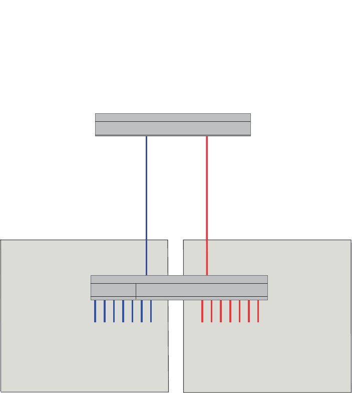
PowerConnect B-Series FCX Configuration Guide 447
53-1002266-01
Routing between VLANs 13
FIGURE 94 Port-based VLANs 222 and 333
To create the two port-based VLANs shown in Figure 94, enter the following commands.
PowerConnect(config)# vlan 222 by port
PowerConnect(config-vlan-222)# untagged ethernet 1 to 8
PowerConnect(config-vlan-222)# vlan 333 by port
PowerConnect(config-vlan-333)# untagged ethernet 9 to 16
Syntax: vlan <vlan-id> by port
Syntax: untagged ethernet [<slotnum>/]<portnum> [to [<slotnum>/]<portnum> | ethernet
[<slotnum>/]<portnum>]
Example 2
Figure 95 shows a more complex port-based VLAN configuration using multiple Layer 2 Switches
and IEEE 802.1Q VLAN tagging. The backbone link connecting the three Layer 2 Switches is
tagged. One untagged port within each port-based VLAN on device-A connects each separate
network wide Layer 2 broadcast domain to the router for Layer 3 forwarding between broadcast
domains. The STP priority is configured to force device-A to be the root bridge for VLANs RED and
BLUE. The STP priority on device-B is configured so that device-B is the root bridge for VLANs
GREEN and BROWN.
Device
Layer 3 Switch
interface e 1
IP Subnet 1
IPX Network 1
Appletalk Cable-Range 100
Appletalk Zone Prepress
VLAN 222
Ports 1 - 8
VLAN 333
Ports 9 - 16
Port1 Port9
interface e 2
IP Subnet 2
IPX Network 2
Appletalk Cable-Range 200
Appletalk Zone CTP
Ports 1 - 8
IP Subnet 1
IPX Network 1
Appletalk Cable-Range 100
Appletalk Zone Prepress
Ports 9 - 16
IP Subnet 2
IPX Network 2
Appletalk Cable-Range 200
Appletalk Zone CTP
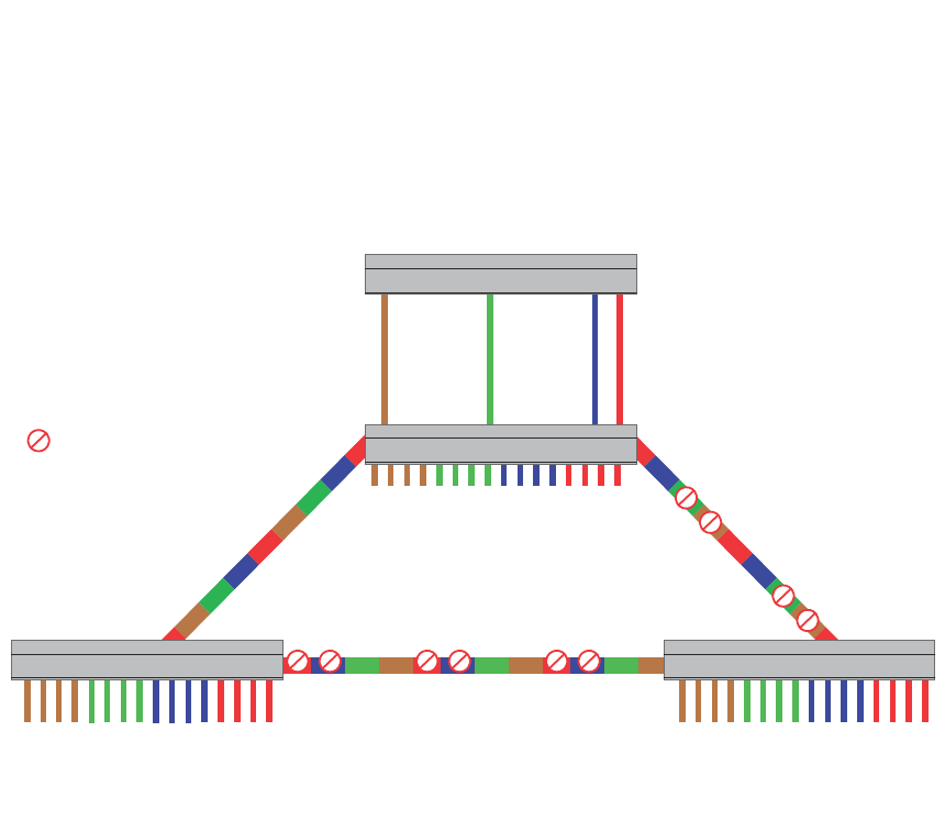
448 PowerConnect B-Series FCX Configuration Guide
53-1002266-01
Routing between VLANs
13
FIGURE 95 More complex port-based VLAN
To configure the Port-based VLANs on the Layer 2 Switches in Figure 95, use the following method.
Configuring device-A
Enter the following commands to configure device-A.
PowerConnect> enable
PowerConnect# configure terminal
PowerConnect(config)# hostname PowerConnect-A
PowerConnect-A(config)# vlan 2 name BROWN
PowerConnect-A(config-vlan-2)# untagged ethernet 1 to 4 ethernet 17
PowerConnect-A(config-vlan-2)# tagged ethernet 25 to 26
PowerConnect-A(config-vlan-2)# spanning-tree
PowerConnect-A(config-vlan-2)# vlan 3 name GREEN
PowerConnect-A(config-vlan-3)# untagged ethernet 5 to 8 ethernet 18
PowerConnect-A(config-vlan-3)# tagged ethernet 25 to 26
PowerConnect-A(config-vlan-3)# spanning-tree
PowerConnect-A(config-vlan-3)# vlan 4 name BLUE
PowerConnect-A(config-vlan-4)# untagged ethernet 9 to 12 ethernet 19
PowerConnect-A(config-vlan-4)# tagged ethernet 25 to 26
PowerConnect-A(config-vlan-4)# spanning-tree
PowerConnect-A(config-vlan-4)# spanning-tree priority 500
PowerConnect-A(config-vlan-4)# vlan 5 name RED
PowerConnect-A(config-vlan-5)# untagged ethernet 13 to 16 ethernet 20
PowerConnect-A(config-vlan-5)# tagged ethernet 25 to 26
PowerConnect-A(config-vlan-5)# spanning-tree
PowerConnect-A(config-vlan-5)# spanning-tree priority 500
PowerConnect-A(config-vlan-5)# end
PowerConnect-A# write memory
IP Subnet1
IPX Net 1
Atalk 100.1
Zone “A”
IP Subnet2
IPX Net 2
Atalk 200.1
Zone “B”
IP Subnet3
IPX Net 3
Atalk 300.1
Zone “C”
IP Subnet4
IPX Net 4
Atalk 400.1
Zone “D”
Port17 Port18 Port19 Port20
= STP Blocked VLAN
VLAN 2
Port 1-4
IP Sub1
IPXnet1
AT 100
Zone A
VLAN 3
Port 5-8
IP Sub2
IPXnet2
AT 200
Zone B
VLAN 4
Port 9-12
IP Sub3
IPXnet3
AT 300
Zone C
VLAN 5
Port 13-16
IP Sub4
IPXnet4
AT 400
Zone D
VLAN 2
Port 1-4
IP Sub1
IPXnet1
AT 100
Zone A
VLAN 3
Port 5-8
IP Sub2
IPXnet2
AT 200
Zone B
VLAN 4
Port 9-12
IP Sub3
IPXnet3
AT 300
Zone C
VLAN 5
Port 13-16
IP Sub4
IPXnet4
AT 400
Zone D
VLAN 4
Port 9-12
IP Sub3
IPXnet3
AT 300
Zone C
VLAN 5
Port 13-16
IP Sub4
IPXnet4
AT 400
Zone D
ROOT BRIDGE
FOR
VLAN - BLUE
VLAN - RED
ROOT BRIDGE
FOR
VLAN - BROWN
VLAN - GREEN
VLAN 2
Port 1-4
IP Sub1
IPXnet1
AT 100
Zone A
VLAN 3
Port 5-8
IP Sub2
IPXnet2
AT 200
Zone B
Device-A
Device-B
Device
Device-A
Device-B Device-C

PowerConnect B-Series FCX Configuration Guide 449
53-1002266-01
Routing between VLANs 13
Configuring device-B
Enter the following commands to configure device-B.
PowerConnect> en
PowerConnect# configure terminal
PowerConnect(config)# hostname PowerConnect-B
PowerConnect-B(config)# vlan 2 name BROWN
PowerConnect-B(config-vlan-2)# untagged ethernet 1 to 4
PowerConnect-B(config-vlan-2)# tagged ethernet 25 to 26
PowerConnect-B(config-vlan-2)# spanning-tree
PowerConnect-B(config-vlan-2)# spanning-tree priority 500
PowerConnect-B(config-vlan-2)# vlan 3 name GREEN
PowerConnect-B(config-vlan-3)# untagged ethernet 5 to 8
PowerConnect-B(config-vlan-3)# tagged ethernet 25 to 26
PowerConnect-B(config-vlan-3)# spanning-tree
PowerConnect-B(config-vlan-3)# spanning-tree priority 500
PowerConnect-B(config-vlan-3)# vlan 4 name BLUE
PowerConnect-B(config-vlan-4)# untagged ethernet 9 to 12
PowerConnect-B(config-vlan-4)# tagged ethernet 25 to 26
PowerConnect-B(config-vlan-4)# vlan 5 name RED
PowerConnect-B(config-vlan-5)# untagged ethernet 13 to 16
PowerConnect-B(config-vlan-5)# tagged ethernet 25 to 26
PowerConnect-B(config-vlan-5)# end
PowerConnect-B# write memory
Configuring device-C
Enter the following commands to configure device-C.
PowerConnect> en
PowerConnect# configure terminal
PowerConnect(config)# hostname PowerConnect-C
PowerConnect-C(config)# vlan 2 name BROWN
PowerConnect-C(config-vlan-2)# untagged ethernet 1 to 4
PowerConnect-C(config-vlan-2)# tagged ethernet 25 to 26
PowerConnect-C(config-vlan-2)# vlan 3 name GREEN
PowerConnect-C(config-vlan-3)# untagged ethernet 5 to 8
PowerConnect-C(config-vlan-3)# tagged ethernet 25 to 26
PowerConnect-C(config-vlan-3)# vlan 4 name BLUE
PowerConnect-C(config-vlan-4)# untagged ethernet 9 to 12
PowerConnect-C(config-vlan-4)# tagged ethernet 25 to 26
PowerConnect-C(config-vlan-4)# vlan 5 name RED
PowerConnect-C(config-vlan-5)# untagged ethernet 13 to 16
PowerConnect-C(config-vlan-5)# tagged ethernet 25 to 26
PowerConnect-C(config-vlan-5)# end
PowerConnect-C# write memory
Syntax: vlan <vlan-id> by port
Syntax: untagged ethernet [<slotnum>/]<portnum> [to [<slotnum>/]<portnum> | ethernet
[<slotnum>/]<portnum>]
Syntax: tagged ethernet [<slotnum>/]<portnum> [to <[<slotnum>/]portnum> | ethernet
[<slotnum>/]<portnum>]
Syntax: [no] spanning-tree
Syntax: spanning-tree [ethernet [<slotnum>/]<portnum> path-cost <value> priority <value>]
forward-delay <value> hello-time <value> maximum-age <time> priority <value>

450 PowerConnect B-Series FCX Configuration Guide
53-1002266-01
Routing between VLANs
13
Modifying a port-based VLAN
You can make the following modifications to a port-based VLAN:
•Add or delete a VLAN port.
•Enable or disable STP.
Removing a port-based VLAN
Suppose you want to remove VLAN 5 from the example in Figure 95. To do so, use the following
procedure.
1. Access the global CONFIG level of the CLI on device-A by entering the following commands.
PowerConnect-A> enable
No password has been assigned yet...
PowerConnect-A# configure terminal
PowerConnect-A(config)#
2. Enter the following command.
PowerConnect-A(config)# no vlan 5
PowerConnect-A(config)#
3. Enter the following commands to exit the CONFIG level and save the configuration to the
system-config file on flash memory.
PowerConnect-A(config)#
PowerConnect-A(config)# end
PowerConnect-A# write memory
PowerConnect-A#
4. Repeat steps 1 – 3 on device-B.
Syntax: no vlan <vlan-id> by port
Removing a port from a VLAN
Suppose you want to remove port 11 from VLAN 4 on device-A shown in Figure 95. To do so, use
the following procedure.
1. Access the global CONFIG level of the CLI on device-A by entering the following command.
PowerConnect-A> enable
No password has been assigned yet...
PowerConnect-A# configure terminal
PowerConnect-A(config)#
2. Access the level of the CLI for configuring port-based VLAN 4 by entering the following
command.
PowerConnect-A(config)#
PowerConnect-A(config)# vlan 4
PowerConnect-A(config-vlan-4)#
3. Enter the following commands.
PowerConnect-A(config-vlan-4)#
PowerConnect-A(config-vlan-4)# no untagged ethernet 11
deleted port ethe 11 from port-vlan 4.
PowerConnect-A(config-vlan-4)#

PowerConnect B-Series FCX Configuration Guide 451
53-1002266-01
Routing between VLANs 13
4. Enter the following commands to exit the VLAN CONFIG mode and save the configuration to the
system-config file on flash memory.
PowerConnect-A(config-vlan-4)#
PowerConnect-A(config-vlan-4)# end
PowerConnect-A# write memory
You can remove all the ports from a port-based VLAN without losing the rest of the VLAN
configuration. However, you cannot configure an IP address on a virtual routing interface unless the
VLAN contains ports. If the VLAN has a virtual routing interface, the virtual routing interface IP
address is deleted when the ports associated with the interface are deleted. The rest of the VLAN
configuration is retained.
Enable spanning tree on a VLAN
The spanning tree bridge and port parameters are configurable using one CLI command set at the
Global Configuration Level of each Port-based VLAN. Suppose you want to enable the IEEE 802.1D
STP across VLAN 3. To do so, use the following method.
NOTE
When port-based VLANs are not operating on the system, STP is set on a system-wide level at the
global CONFIG level of the CLI.
1. Access the global CONFIG level of the CLI on device-A by entering the following commands.
PowerConnect-A> enable
No password has been assigned yet...
PowerConnect-A# configure terminal
PowerConnect-A(config)#
2. Access the level of the CLI for configuring port-based VLAN 3 by entering the following
command.
PowerConnect-A(config)#
PowerConnect-A(config)# vlan 3
PowerConnect-A(config-vlan-3)#
3. From VLAN 3 configuration level of the CLI, enter the following command to enable STP on all
tagged and untagged ports associated with VLAN 3.
PowerConnect-B(config-vlan-3)#
PowerConnect-B(config-vlan-3)# spanning-tree
PowerConnect-B(config-vlan-3)#
4. Enter the following commands to exit the VLAN CONFIG mode and save the configuration to the
system-config file on flash memory.
PowerConnect-B(config-vlan-3)#
PowerConnect-B(config-vlan-3)# end
PowerConnect-B# write memory
PowerConnect-B#
5. Repeat steps 1 – 4 on device-B.
NOTE
You do not need to configure values for the STP parameters. All parameters have default values as
noted below. Additionally, all values will be globally applied to all ports on the system or on the
port-based VLAN for which they are defined.

452 PowerConnect B-Series FCX Configuration Guide
53-1002266-01
Configuring IP subnet, IPX network and protocol-based VLANs
13
To configure a specific path-cost or priority value for a given port, enter those values using the key
words in the brackets [ ] shown in the syntax summary below. If you do not want to specify values
for any given port, this portion of the command is not required.
Syntax: vlan <vlan-id> by port
Syntax: [no] spanning-tree
Syntax: spanning-tree [ethernet [<slotnum>/]<portnum> path-cost <value> priority <value>]
forward-delay <value> hello-time <value> maximum-age <time> priority <value>
Bridge STP parameters (applied to all ports within a VLAN):
•Forward Delay – the period of time a bridge will wait (the listen and learn period) before
forwarding data packets. Possible values: 4 – 30 seconds. Default is 15.
•Maximum Age – the interval a bridge will wait for receipt of a hello packet before initiating a
topology change. Possible values: 6 – 40 seconds. Default is 20.
•Hello Time – the interval of time between each configuration BPDU sent by the root bridge.
Possible values: 1 – 10 seconds. Default is 2.
•Priority – a parameter used to identify the root bridge in a network. The bridge with the lowest
value has the highest priority and is the root. Possible values: 1 – 65,535. Default is 32,678.
Port parameters (applied to a specified port within a VLAN):
•Path Cost – a parameter used to assign a higher or lower path cost to a port. Possible values: 1
– 65535. Default is (1000/Port Speed) for Half-Duplex ports and is (1000/Port Speed)/2 for
Full-Duplex ports.
•Priority – value determines when a port will be rerouted in relation to other ports. Possible
values: 0 – 255. Default is 128.
Configuring IP subnet, IPX network and
protocol-based VLANs
Protocol-based VLANs provide the ability to define separate broadcast domains for several unique
Layer 3 protocols within a single Layer 2 broadcast domain. Some applications for this feature
might include security between departments with unique protocol requirements. This feature
enables you to limit the amount of broadcast traffic end-stations, servers, and routers need to
accept.
Configuration example
Suppose you want to create five separate Layer 3 broadcast domains within a single Layer 2 STP
broadcast domain:
•Three broadcast domains, one for each of three separate IP subnets
•One for IPX Network 1
•One for the Appletalk protocol
Also suppose you want a single router interface to be present within all of these separate broadcast
domains, without using IEEE 802.1Q VLAN tagging or any proprietary form of VLAN tagging.
Figure 96 shows this configuration.
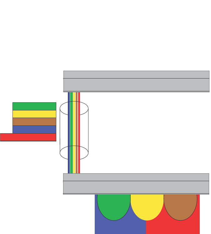
PowerConnect B-Series FCX Configuration Guide 453
53-1002266-01
Configuring IP subnet, IPX network and protocol-based VLANs 13
FIGURE 96 Protocol-based (Layer 3) VLANs
To configure the VLANs shown in Figure 96, use the following procedure.
1. To permanently assign ports 1 – 8 and port 25 to IP subnet VLAN 1.1.1.0, enter the following
commands.
PowerConnect(config-vlan-2)# ip-subnet 1.1.1.0/24 name Green
PowerConnect(config-vlan-ip-subnet)# no dynamic
PowerConnect(config-vlan-ip-subnet)# static ethernet 1 to 8 ethernet 25
2. To permanently assign ports 9 – 16 and port 25 to IP subnet VLAN 1.1.2.0, enter the following
commands.
PowerConnect(config-vlan-3)# ip-subnet 1.1.2.0/24 name Yellow
PowerConnect(config-vlan-ip-subnet)# no dynamic
PowerConnect(config-vlan-ip-subnet)# static ethernet 9 to 16 ethernet 25
3. To permanently assign ports 17 – 25 to IP subnet VLAN 1.1.3.0, enter the following commands.
PowerConnect(config-vlan-4)# ip-subnet 1.1.3.0/24 name Brown
PowerConnect(config-vlan-ip-subnet)# no dynamic
PowerConnect(config-vlan-ip-subnet)# static ethernet 17 to 25
4. To permanently assign ports 1 – 12 and port 25 to IPX network 1 VLAN, enter the following
commands.
PowerConnect(config-ip-subnet)# ipx-network 1 ethernet_802.3 name Blue
PowerConnect(config-ipx-network)# no dynamic
PowerConnect(config-ipx-network)# static ethernet 1 to 12 ethernet 25
PowerConnect(config-ipx-network)#
5. To permanently assign ports 12 – 25 to Appletalk VLAN, enter the following commands.
Port25
Port25
IP-Subnet 1
IP-Subnet 2
IP-Subnet 3
IPX Net 1
Appletalk Cable 100
IP-Subnet 1 IP-Subnet 2 IP-Subnet 3
Ports 1-16, 25
IPX Net 1
Ports 17-25
Appletalk Cable 100
Device
Layer 3 Switch

454 PowerConnect B-Series FCX Configuration Guide
53-1002266-01
Configuring IP subnet, IPX network, and protocol-based VLANs within port-based VLANs
13
PowerConnect(config-ipx-proto)# atalk-proto name Red
PowerConnect(config-atalk-proto)# no dynamic
PowerConnect(config-atalk-proto)# static ethernet 13 to 25
PowerConnect(config-atalk-proto)# end
PowerConnect# write memory
PowerConnect#
Syntax: ip-subnet <ip-addr> <ip-mask> [name <string>]
Syntax: ipx-network <ipx-network-number> <frame-encapsulation-type> netbios-allow |
netbios-disallow
[name <string>]
Syntax: ip-proto | ipx-proto | atalk-proto | decnet-proto | netbios-proto | other-proto static |
exclude | dynamic ethernet [<slotnum>/]<portnum> [to [<slotnum>/]<portnum>] [name
<string>]
Configuring IP subnet, IPX network, and protocol-based
VLANs within port-based VLANs
If you plan to use port-based VLANs in conjunction with protocol-based VLANs, you must create the
port-based VLANs first. Once you create a port-based VLAN, then you can assign Layer 3 protocol
VLANs within the boundaries of the port-based VLAN. Generally, you create port-based VLANs to
allow multiple separate STP domains.
Example
Suppose you need to provide three separate STP domains across an enterprise campus backbone.
The first STP domain (VLAN 2) requires a set of ports at each Layer 2 Switch location to be statically
mapped to IP only. No other protocols can enter the switches on this set of ports.
A second set of ports within STP domain VLAN 2 will be restricted to only IPX traffic. The IP and IPX
protocol VLANs will overlap on Port 1 of device-A to support both protocols on the same router
interface. The IP subnets and IPX network that span the two protocol VLANs will be determined by
the PowerConnect router configuration. The IP and IPX Protocol VLANs ensure that only the ports
included in the each Layer 3 protocol VLAN will see traffic from the PowerConnect router.
The second STP domain (VLAN 3) requires that half the ports in the domain are dedicated to IP
subnet 1.1.1.0/24 and the other ports are dedicated to IPX network 1. Similar to VLAN 2, Port 9
from VLAN 3 will be used to carry this IP subnet and IPX network to the PowerConnect router. No
other protocols will be allowed to enter the network on VLAN 3. Also, no IP packets with a source
address on subnet 1.1.1.0/24 or IPX packets with a source address on network 1 will be allowed to
enter the switches on VLAN 3.
There is no need to segment Layer 3 broadcast domains within the STP broadcast domain (VLAN
4). The PowerConnect router will dictate the IP subnets and IPX network that are on VLAN 4. There
are no Layer 3 protocol restrictions on VLAN 4; however, the PowerConnect router is configured to
only forward IP and IPX between STP domains.
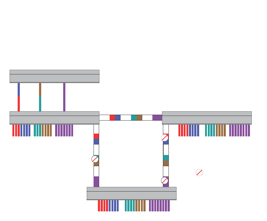
PowerConnect B-Series FCX Configuration Guide 455
53-1002266-01
Configuring IP subnet, IPX network, and protocol-based VLANs within port-based VLANs 13
FIGURE 97 More protocol-based VLANs
To configure the Layer 3 VLANs on the Layer 2 Switches in Figure 97, use the following procedure.
Configuring device-A
Enter the following commands to configure device-A.
1. Create port-based VLAN 2 and assign the untagged and tagged ports that will participate in
this VLAN.
PowerConnect-A >en
PowerConnect-A# config t
PowerConnect-A(config)# vlan 2 name IP_IPX_Protocol
PowerConnect-A(config-vlan-2)# untagged e1 to 8
PowerConnect-A(config-vlan-2)# tagged e25 to 26
2. Enable STP and set the priority to force device-A to be the root bridge for VLAN 2.
PowerConnect-A(config-vlan-2)# spanning-tree
PowerConnect-A(config-vlan-2)# spanning-tree priority 500
PowerConnect-A(config-vlan-2)#
3. Create the IP and IPX protocol-based VLANs and statically assign the ports within VLAN 2 that
will be associated with each protocol-based VLAN.
PowerConnect-A(config-vlan-2)# ip-proto name Red
PowerConnect-A(config-vlan-ip-proto)# no dynamic
PowerConnect-A(config-vlan-ip-proto)# static e1 to 4 e25 to 26
PowerConnect-A(config-vlan-ip-proto)# exclude e5 to 8
PowerConnect-A(config-vlan-ip-proto)# ipx-proto name Blue
PowerConnect-A(config-vlan-ipx-proto)# no dynamic
PowerConnect-A(config-vlan-ipx-proto)# static e1 e5 to 8 e25 to 26
PowerConnect-A(config-vlan-ipx-proto)# exclude e2 to 4
VLAN 2 VLAN 3 VLAN 4
VLAN 2 VLAN 3 VLAN 4
VLAN 2 VLAN 3 VLAN 4
Port1 Port9 Port17
Device
Device-A
Device-C
Device-B
= STP Blocked VLAN
V2 V3 V4
V2 V3 V4
V2 V3 V4
Device-A Device-B
Device-C
Device

456 PowerConnect B-Series FCX Configuration Guide
53-1002266-01
Configuring IP subnet, IPX network, and protocol-based VLANs within port-based VLANs
13
4. To prevent machines with non-IP protocols from getting into the IP portion of VLAN 2, create
another Layer 3 protocol VLAN to exclude all other protocols from the ports that contains the
IP-protocol VLAN. To do so, enter the following commands.
PowerConnect-A(config-vlan-ipx-proto)# other-proto name Block_other_proto
PowerConnect-A(config-vlan-other-proto)# no dynamic
PowerConnect-A(config-vlan-other-proto)# exclude e1 to 8
PowerConnect-A(config-vlan-other-proto)#
5. Create port-based VLAN 3. Note that device-B will be the root for this STP domain, so you do
not need to adjust the STP priority.
PowerConnect-A(config-vlan-other-proto)# vlan 3 name IP-Sub_IPX-Net_Vlans
PowerConnect-A(config-vlan-3)# untagged e9 to 16
PowerConnect-A(config-vlan-3)# tagged e25 to 26
PowerConnect-A(config-vlan-3)# spanning-tree
PowerConnect-A(config-vlan-3)#
6. Create IP subnet VLAN 1.1.1.0/24, IPX network 1, and other-protocol VLANs
PowerConnect-A(config-vlan-3)# ip-subnet 1.1.1.0/24 name Green
PowerConnect-A(config-vlan-ip-subnet)# no dynamic
PowerConnect-A(config-vlan-ip-subnet)# static e9 to 12 e25 to 26
PowerConnect-A(config-vlan-ip-subnet)# exclude e13 to 16
PowerConnect-A(config-vlan-ip-subnet)# ipx-net 1 ethernet_802.3 name Brown
PowerConnect-A(config-vlan-ipx-network)# no dynamic
PowerConnect-A(config-vlan-ipx-network)# static e9 e13 to 16 e25 to 26
PowerConnect-A(config-vlan-ipx-network)# exclude e10 to 12
PowerConnect-A(config-vlan-ipx-network)# other-proto name Block_other_proto
PowerConnect-A(config-vlan-other-proto)# no dynamic
PowerConnect-A(config-vlan-other-proto)# exclude e9 to 16
PowerConnect-A(config-vlan-other-proto)#
7. Configure the last port-based VLAN 4. You need to set the STP priority for this VLAN because
device-A will be the root bridge for this VLAN. Because you do not need to partition this STP
domain into multiple Layer 3 broadcast domains, this is the only configuration required for
VLAN 4.
PowerConnect-A(config-vlan-other-proto)# vlan 4 name Purple_ALL-Protocols
PowerConnect-A(config-vlan-4)# untagged e17 to 24
PowerConnect-A(config-vlan-4)# tagged e25 to 26
PowerConnect-A(config-vlan-4)# spanning-tree
PowerConnect-A(config-vlan-4)# spanning-tree priority 500
PowerConnect-A(config-vlan-4)#
Configuring device-B
Enter the following commands to configure device-B.
PowerConnect# config t
PowerConnect(config)# host PowerConnect-B
PowerConnect-B(config)#vlan 2 name IP_IPX_Protocol
PowerConnect-B(config-vlan-2)# untagged e1 to 8
PowerConnect-B(config-vlan-2)# tagged e25 to 26
PowerConnect-B(config-vlan-2)# spanning-tree
PowerConnect-B(config-vlan-2)# ip-proto name Red
PowerConnect-B(config-vlan-ip-proto)# # no dynamic
PowerConnect-B(config-vlan-ip-proto)# static e1 to 4 e25 to 26
PowerConnect-B(config-vlan-ip-proto)# exclude e5 to 8
PowerConnect-B(config-vlan-ip-proto)# ipx-proto name Blue
PowerConnect-B(config-vlan-ipx-proto)# no dynamic

PowerConnect B-Series FCX Configuration Guide 457
53-1002266-01
Configuring IP subnet, IPX network, and protocol-based VLANs within port-based VLANs 13
PowerConnect-B(config-vlan-ipx-proto)# static e5 to 8 e25 to 26
PowerConnect-B(config-vlan-ipx-proto)# exclude e1 to 4
PowerConnect-B(config-vlan-other-proto)# vlan 3 name IP-Sub_IPX-Net_VLANs
PowerConnect-B(config-vlan-3)# untagged e9 to 16
PowerConnect-B(config-vlan-3)# tagged e25 to 26
PowerConnect-B(config-vlan-3)# spanning-tree
PowerConnect-B(config-vlan-3)# spanning-tree priority 500
PowerConnect-B(config-vlan-3)# ip-sub 1.1.1.0/24 name Green
PowerConnect-B(config-vlan-ip-subnet)# no dynamic
PowerConnect-B(config-vlan-ip-subnet)# static e9 to 12 e25 to 26
PowerConnect-B(config-vlan-ip-subnet)# exclude e13 to 16
PowerConnect-B(config-vlan-ip-subnet)# ipx-net 1 ethernet_802.3 name Brown
PowerConnect-B(config-vlan-ipx-network)# no dynamic
PowerConnect-B(config-vlan-ipx-network)# static e13 to 16 e25 to 26
PowerConnect-B(config-vlan-ipx-network)# exclude e9 to 12
PowerConnect-B(config-vlan-ipx-network)# vlan 4 name Purple_ALL-Protocols
PowerConnect-B(config-vlan-4)# untagged e17 to 24
PowerConnect-B(config-vlan-4)# tagged e25 to 26
PowerConnect-B(config-vlan-4)# spanning-tree
Configuring device-C
Enter the following commands to configure device-C.
PowerConnect# config t
PowerConnect(config)# host PowerConnect-C
PowerConnect-C(config)# vlan 2 name IP_IPX_Protocol
PowerConnect-C(config-vlan-2)# untagged e1 to 8
PowerConnect-C(config-vlan-2)# tagged e25 to 26
PowerConnect-C(config-vlan-2)# spanning-tree
PowerConnect-C(config-vlan-2)# ip-proto name Red
PowerConnect-C(config-vlan-ip-proto)# no dynamic
PowerConnect-C(config-vlan-ip-proto)# static e1 to 4 e25 to 26
PowerConnect-C(config-vlan-ip-proto)# exclude e5 to 8
PowerConnect-C(config-vlan-ip-proto)# ipx-proto name Blue
PowerConnect-C(config-vlan-ipx-proto)# no dynamic
PowerConnect-C(config-vlan-ipx-proto)# static e5 to 8 e25 to 26
PowerConnect-C(config-vlan-ipx-proto)# exclude e1 to 4
PowerConnect-C(config-vlan-other-proto)# vlan 3 name IP-Sub_IPX-Net_VLANs
PowerConnect-C(config-vlan-3)# untagged e9 to 16
PowerConnect-C(config-vlan-3)# tagged e25 to 26
PowerConnect-C(config-vlan-3)# spanning-tree
PowerConnect-C(config-vlan-3)# ip-sub 1.1.1.0/24 name Green
PowerConnect-C(config-vlan-ip-subnet)# no dynamic
PowerConnect-C(config-vlan-ip-subnet)# static e9 to 12 e25 to 26
PowerConnect-C(config-vlan-ip-subnet)# exclude e13 to 16
PowerConnect-C(config-vlan-ip-subnet)# ipx-net 1 ethernet_802.3 name Brown
PowerConnect-C(config-vlan-ipx-network)# no dynamic
PowerConnect-C(config-vlan-ipx-network)# static e13 to 16 e25 to 26
PowerConnect-C(config-vlan-ipx-network)# exclude e9 to 12
PowerConnect-C(config-vlan-ipx-network)# vlan 4 name Purple_ALL-Protocols
PowerConnect-C(config-vlan-4)# untagged e17 to 24
PowerConnect-C(config-vlan-4)# tagged e25 to 26
PowerConnect-C(config-vlan-4)# spanning-tree

458 PowerConnect B-Series FCX Configuration Guide
53-1002266-01
Configuring an IPv6 protocol VLAN
13
Configuring an IPv6 protocol VLAN
You can configure a protocol-based VLAN as a broadcast domain for IPv6 traffic. When the Layer 3
Switch receives an IPv6 multicast packet (a packet with 06 in the version field and 0xFF as the
beginning of the destination address), the Layer 3 Switch forwards the packet to all other ports.
NOTE
The Layer 3 Switch forwards all IPv6 multicast packets to all ports except the port that received the
packet, and does not distinguish among subnet directed multicasts.
You can add the VLAN ports as static ports or dynamic ports. A static port is always an active
member of the VLAN. Dynamic ports within any protocol VLAN age out after 10 minutes if no
member protocol traffic is received on a port within the VLAN. The aged out port, however, remains
as a candidate dynamic port for that VLAN. The port becomes active in the VLAN again if member
protocol traffic is received on that port.
Once a port is re-activated, the aging out period for the port is reset to 20 minutes. Each time a
member protocol packet is received by a candidate dynamic port (aged out port) the port becomes
active again and the aging out period is reset for 20 minutes.
NOTE
You can disable VLAN membership aging of dynamically added ports. Refer to “Disabling
membership aging of dynamic VLAN ports” on page 465).
To configure an IPv6 VLAN, enter commands such as the following.
PowerConnect(config)# vlan 2
PowerConnect(config-vlan-2)# untagged ethernet 1/1 to 1/8
PowerConnect(config-vlan-2)# ipv6-proto name V6
PowerConnect(config-ipv6-subnet)# static ethernet 1/1 to 1/6
PowerConnect(config-ipv6-subnet)# dynamic
The first two commands configure a port-based VLAN and add ports 1/1 – 1/8 to the VLAN. The
remaining commands configure an IPv6 VLAN within the port-based VLAN. The static command
adds ports 1/1 – 1/6 as static ports, which do not age out. The dynamic command adds the
remaining ports, 1/7 – 1/8, as dynamic ports. These ports are subject to aging as described
above.
Syntax: [no] ipv6-proto [name <string>]
Routing between VLANs using virtual routing
interfaces (Layer 3 Switches only)
Layer 3 Switches offer the ability to create a virtual routing interface within a Layer 2 STP
port-based VLAN or within each Layer 3 protocol, IP subnet, or IPX network VLAN. This combination
of multiple Layer 2 or Layer 3 broadcast domains, or both, and virtual routing interfaces are the
basis for Brocade’ very powerful Integrated Switch Routing (ISR) technology. ISR is very flexible and
can solve many networking problems. The following example is meant to provide ideas by
demonstrating some of the concepts of ISR.
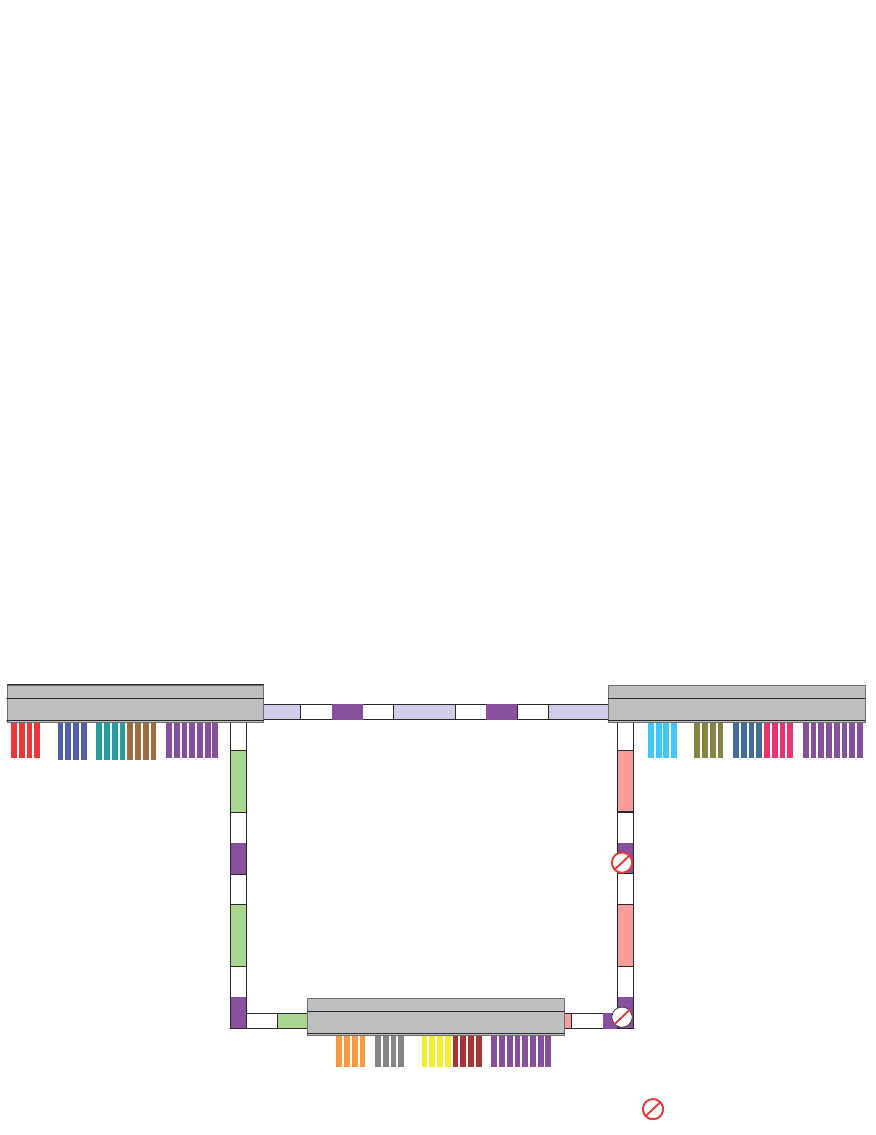
PowerConnect B-Series FCX Configuration Guide 459
53-1002266-01
Routing between VLANs using virtual routing interfaces (Layer 3 Switches only) 13
Example
Suppose you want to move routing out to each of three buildings in a network. Remember that the
only protocols present on VLAN 2 and VLAN 3 are IP and IPX. Therefore, you can eliminate tagged
ports 25 and 26 from both VLAN 2 and VLAN 3 and create new tagged port-based VLANs to
support separate IP subnets and IPX networks for each backbone link.
You also need to create unique IP subnets and IPX networks within VLAN 2 and VLAN 3 at each
building. This will create a fully routed IP and IPX backbone for VLAN 2 and VLAN 3. However, VLAN
4 has no protocol restrictions across the backbone. In fact there are requirements for NetBIOS and
DecNet to be bridged among the three building locations. The IP subnet and IPX network that exists
within VLAN 4 must remain a flat Layer 2 switched STP domain. You enable routing for IP and IPX
on a virtual routing interface only on device-A. This will provide the flat IP and IPX segment with
connectivity to the rest of the network. Within VLAN 4 IP and IPX will follow the STP topology. All
other IP subnets and IPX networks will be fully routed and have use of all paths at all times during
normal operation.
Figure 98 shows the configuration described above.
FIGURE 98 Routing between protocol-based VLANs
To configure the Layer 3 VLANs and virtual routing interfaces on the Layer 3 Switch in Figure 98,
use the following procedure.
Configuring device-A
Enter the following commands to configure device-A. The following commands enable OSPF or RIP
routing.
IP
/IPX
Device-A
Device-C
Device-B
Building 1 Building 2
Building 3
Vlan2 Vlan8 Vlan3 Vlan4
Vlan2 Vlan8 Vlan3 Vlan4
Vlan2 Vlan8 Vlan3 Vlan4
= STP Blocked VLAN
V4
V4
V4
V4V4
V4
V5 V4IP/IPX
V6 IP/IPX V6
V6
IP/IPX
V7 IP/IPX V7 IP/IPX
V5 IP/IPX
Device-A Device-B
Device-C

460 PowerConnect B-Series FCX Configuration Guide
53-1002266-01
Routing between VLANs using virtual routing interfaces (Layer 3 Switches only)
13
PowerConnect>en
No password has been assigned yet...
PowerConnect# configure terminal
PowerConnect(config)# hostname PowerConnect-A
PowerConnect-A(config)# router ospf
PowerConnect-A(config-ospf-router)# area 0.0.0.0 normal
Please save configuration to flash and reboot.
PowerConnect-A(config-ospf-router)#
The following commands create the port-based VLAN 2. In the previous example, an external device
defined the router interfaces for VLAN 2. With ISR, routing for VLAN 2 is done locally within each
device. Therefore, there are two ways you can solve this problem. One way is to create a unique IP
subnet and IPX network VLAN, each with its own virtual routing interface and unique IP or IPX
address within VLAN 2 on each device. In this example, this is the configuration used for VLAN 3.
The second way is to split VLAN 2 into two separate port-based VLANs and create a virtual router
interface within each port-based VLAN. Later in this example, this second option is used to create a
port-based VLAN 8 to show that there are multiple ways to accomplish the same task with ISR.
You also need to create the Other-Protocol VLAN within port-based VLAN 2 and 8 to prevent
unwanted protocols from being Layer 2 switched within port-based VLAN 2 or 8. Note that the only
port-based VLAN that requires STP in this example is VLAN 4. You will need to configure the rest of
the network to prevent the need to run STP.
PowerConnect-A(config-ospf-router)# vlan 2 name IP-Subnet_1.1.2.0/24
PowerConnect-A(config-vlan-2)# untagged ethernet 1 to 4
PowerConnect-A(config-vlan-2)# no spanning-tree
PowerConnect-A(config-vlan-2)# router-interface ve1
PowerConnect-A(config-vlan-2)# other-proto name block_other_protocols
PowerConnect-A(config-vlan-other-proto)# no dynamic
PowerConnect-A(config-vlan-other-proto)# exclude ethernet 1 to 4
Once you have defined the port-based VLAN and created the virtual routing interface, you need to
configure the virtual routing interface just as you would configure a physical interface.
PowerConnect-A(config-vlan-other-proto)# interface ve1
PowerConnect-A(config-vif-1)# ip address 1.1.2.1/24
PowerConnect-A(config-vif-1)# ip ospf area 0.0.0.0
Do the same thing for VLAN 8.
PowerConnect-A(config-vif-1)# vlan 8 name IPX_Network2
PowerConnect-A(config-vlan-8)# untagged ethernet 5 to 8
PowerConnect-A(config-vlan-8)# no spanning-tree
PowerConnect-A(config-vlan-8)# router-interface ve 2
PowerConnect-A(config-vlan-8)# other-proto name block-other-protocols
PowerConnect-A(config-vlan-other-proto)# no dynamic
PowerConnect-A(config-vlan-other-proto)# exclude ethernet 5 to 8
PowerConnect-A(config-vlan-other-proto)# interface ve2
PowerConnect-A(config-vif-2)# ipx network 2 ethernet_802.3
PowerConnect-A(config-vif-2)#
The next thing you need to do is create VLAN 3. This is very similar to the previous example with the
addition of virtual routing interfaces to the IP subnet and IPX network VLANs. Also there is no need
to exclude ports from the IP subnet and IPX network VLANs on the router.
PowerConnect-A(config-vif-2)# vlan 3 name IP_Sub_&_IPX_Net_VLAN
PowerConnect-A(config-vlan-3)# untagged ethernet 9 to 16
PowerConnect-A(config-vlan-3)# no spanning-tree
PowerConnect-A(config-vlan-3)# ip-subnet 1.1.1.0/24
PowerConnect-A(config-vlan-ip-subnet)# static ethernet 9 to 12
PowerConnect-A(config-vlan-ip-subnet)# router-interface ve3

PowerConnect B-Series FCX Configuration Guide 461
53-1002266-01
Routing between VLANs using virtual routing interfaces (Layer 3 Switches only) 13
PowerConnect-A(config-vlan-ip-subnet)# ipx-network 1 ethernet_802.3
PowerConnect-A(config-vlan-ipx-network)# static ethernet 13 to 16
PowerConnect-A(config-vlan-ipx-network)# router-interface ve4
PowerConnect-A(config-vlan-ipx-network)# other-proto name block-other-protocols
PowerConnect-A(config-vlan-other-proto)# exclude ethernet 9 to 16
PowerConnect-A(config-vlan-other-proto)# no dynamic
PowerConnect-A(config-vlan-other-proto)# interface ve 3
PowerConnect-A(config-vif-3)# ip addr 1.1.1.1/24
PowerConnect-A(config-vif-3)# ip ospf area 0.0.0.0
PowerConnect-A(config-vif-3)# interface ve4
PowerConnect-A(config-vif-4)# ipx network 1 ethernet_802.3
PowerConnect-A(config-vif-4)#
Now configure VLAN 4. Remember this is a flat segment that, in the previous example, obtained its
IP default gateway and IPX router services from an external device. In this example, device-A will
provide the routing services for VLAN 4. You also want to configure the STP priority for VLAN 4 to
make device-A the root bridge for this VLAN.
PowerConnect-A(config-vif-4)# vlan 4 name Bridged_ALL_Protocols
PowerConnect-A(config-vlan-4)# untagged ethernet 17 to 24
PowerConnect-A(config-vlan-4)# tagged ethernet 25 to 26
PowerConnect-A(config-vlan-4)# spanning-tree
PowerConnect-A(config-vlan-4)# spanning-tree priority 500
PowerConnect-A(config-vlan-4)# router-interface ve5
PowerConnect-A(config-vlan-4)# interface ve5
PowerConnect-A(config-vif-5)# ip address 1.1.3.1/24
PowerConnect-A(config-vif-5)# ip ospf area 0.0.0.0
PowerConnect-A(config-vif-5)# ipx network 3 ethernet_802.3
PowerConnect-A(config-vif-5)#
It is time to configure a separate port-based VLAN for each of the routed backbone ports (Ethernet
25 and 26).
If you do not create a separate tagged port-based VLAN for each point-to-point backbone link, you
need to include tagged interfaces for Ethernet 25 and 26 within VLANs 2, 3, and 8. This type of
configuration makes the entire backbone a single STP domain for each VLAN 2, 3, and 8. This is
the configuration used in the example in “Configuring IP subnet, IPX network and protocol-based
VLANs” on page 452. In this scenario, the virtual routing interfaces within port-based VLANs 2, 3,
and 8 will be accessible using only one path through the network. The path that is blocked by STP is
not available to the routing protocols until it is in the STP FORWARDING state.
PowerConnect-A(config-vif-5)# vlan 5 name Rtr_BB_to_Bldg.2
PowerConnect-A(config-vlan-5)# tagged ethernet 25
PowerConnect-A(config-vlan-5)# no spanning-tree
PowerConnect-A(config-vlan-5)# router-interface ve6
PowerConnect-A(config-vlan-5)# vlan 6 name Rtr_BB_to_Bldg.3
PowerConnect-A(config-vlan-6)# tagged ethernet 26
PowerConnect-A(config-vlan-6)# no spanning-tree
PowerConnect-A(config-vlan-6)# router-interface ve7
PowerConnect-A(config-vlan-6)# interface ve6
PowerConnect-A(config-vif-6)# ip addr 1.1.4.1/24
PowerConnect-A(config-vif-6)# ip ospf area 0.0.0.0
PowerConnect-A(config-vif-6)# ipx network 4 ethernet_802.3
PowerConnect-A(config-vif-6)# interface ve7
PowerConnect-A(config-vif-7)# ip addr 1.1.5.1/24
PowerConnect-A(config-vif-7)# ip ospf area 0.0.0.0
PowerConnect-A(config-vif-7)# ipx network 5 ethernet_802.3
PowerConnect-A(config-vif-7)#

462 PowerConnect B-Series FCX Configuration Guide
53-1002266-01
Routing between VLANs using virtual routing interfaces (Layer 3 Switches only)
13
This completes the configuration for device-A. The configuration for device-B and C is very similar
except for a few issues which are as follows:
•IP subnets and IPX networks configured on device-B and device-C must be unique across the
entire network, except for the backbone port-based VLANs 5, 6, and 7 where the subnet is the
same but the IP address must change.
•There is no need to change the default priority of STP within VLAN 4.
•There is no need to include a virtual router interface within VLAN 4.
•The backbone VLAN between device-B and device-C must be the same at both ends and
requires a new VLAN ID. The VLAN ID for this port-based VLAN is VLAN 7.
Configuration for device-B
Enter the following commands to configure device-B.
PowerConnect> en
No password has been assigned yet...
PowerConnect# config t
PowerConnect(config)# hostname PowerConnect-B
PowerConnect-B(config)# router ospf
PowerConnect-B(config-ospf-router)# area 0.0.0.0 normal
PowerConnect-B(config-ospf-router)# router ipx
PowerConnect-B(config-ospf-router)# vlan 2 name IP-Subnet_1.1.6.0/24
PowerConnect-B(config-vlan-2)# untagged ethernet 1 to 4
PowerConnect-B(config-vlan-2)# no spanning-tree
PowerConnect-B(config-vlan-2)# router-interface ve1
PowerConnect-B(config-vlan-2)# other-proto name block-other-protocols
PowerConnect-B(config-vlan-other-proto)# no dynamic
PowerConnect-B(config-vlan-other-proto)# exclude ethernet 1 to 4
PowerConnect-B(config-vlan-other-proto)# interface ve1
PowerConnect-B(config-vif-1)# ip addr 1.1.6.1/24
PowerConnect-B(config-vif-1)# ip ospf area 0.0.0.0
PowerConnect-B(config-vif-1)# vlan 8 name IPX_Network6
PowerConnect-B(config-vlan-8)# untagged ethernet 5 to 8
PowerConnect-B(config-vlan-8)# no span
PowerConnect-B(config-vlan-8)# router-interface ve2
PowerConnect-B(config-vlan-8)# other-proto name block-other-protocols
PowerConnect-B(config-vlan-other-proto)# no dynamic
PowerConnect-B(config-vlan-other-proto)# exclude ethernet 5 to 8
PowerConnect-B(config-vlan-other-proto)# interface ve2
PowerConnect-B(config-vif-2)# ipx net 6 ethernet_802.3
PowerConnect-B(config-vif-2)# vlan 3 name IP_Sub_&_IPX_Net_VLAN
PowerConnect-B(config-vlan-3)# untagged ethernet 9 to 16
PowerConnect-B(config-vlan-3)# no spanning-tree
PowerConnect-B(config-vlan-3)# ip-subnet 1.1.7.0/24
PowerConnect-B(config-vlan-ip-subnet)# static ethernet 9 to 12
PowerConnect-B(config-vlan-ip-subnet)# router-interface ve3
PowerConnect-B(config-vlan-ip-subnet)# ipx-network 7 ethernet_802.3
PowerConnect-B(config-vlan-ipx-network)# static ethernet 13 to 16
PowerConnect-B(config-vlan-ipx-network)# router-interface ve4
PowerConnect-B(config-vlan-ipx-network)# other-proto name block-other-protocols
PowerConnect-B(config-vlan-other-proto)# exclude ethernet 9 to 16
PowerConnect-B(config-vlan-other-proto)# no dynamic
PowerConnect-B(config-vlan-other-proto)# interface ve 3
PowerConnect-B(config-vif-3)# ip addr 1.1.7.1/24
PowerConnect-B(config-vif-3)# ip ospf area 0.0.0.0
PowerConnect-B(config-vif-3)# interface ve4

PowerConnect B-Series FCX Configuration Guide 463
53-1002266-01
Routing between VLANs using virtual routing interfaces (Layer 3 Switches only) 13
PowerConnect-B(config-vif-4)# ipx network 7 ethernet_802.3
PowerConnect-B(config-vif-4)# vlan 4 name Bridged_ALL_Protocols
PowerConnect-B(config-vlan-4)# untagged ethernet 17 to 24
PowerConnect-B(config-vlan-4)# tagged ethernet 25 to 26
PowerConnect-B(config-vlan-4)# spanning-tree
PowerConnect-B(config-vlan-4)# vlan 5 name Rtr_BB_to_Bldg.1
PowerConnect-B(config-vlan-5)# tagged ethernet 25
PowerConnect-B(config-vlan-5)# no spanning-tree
PowerConnect-B(config-vlan-5)# router-interface ve5
PowerConnect-B(config-vlan-5)# vlan 7 name Rtr_BB_to_Bldg.3
PowerConnect-B(config-vlan-7)# tagged ethernet 26
PowerConnect-B(config-vlan-7)# no spanning-tree
PowerConnect-B(config-vlan-7)# router-interface ve6
PowerConnect-B(config-vlan-7)# interface ve5
PowerConnect-B(config-vif-5)# ip addr 1.1.4.2/24
PowerConnect-B(config-vif-5)# ip ospf area 0.0.0.0
PowerConnect-B(config-vif-5)# ipx network 4 ethernet_802.3
PowerConnect-B(config-vif-5)# interface ve6
PowerConnect-B(config-vif-6)# ip addr 1.1.8.1/24
PowerConnect-B(config-vif-6)# ip ospf area 0.0.0.0
PowerConnect-B(config-vif-6)# ipx network 8 ethernet_802.3
PowerConnect-B(config-vif-6)#
Configuration for device-C
Enter the following commands to configure device-C.
PowerConnect> en
No password has been assigned yet...
PowerConnect# config t
PowerConnect(config)# hostname PowerConnect-C
PowerConnect-C(config)# router ospf
PowerConnect-C(config-ospf-router)# area 0.0.0.0 normal
PowerConnect-C(config-ospf-router)# router ipx
PowerConnect-C(config-ospf-router)# vlan 2 name IP-Subnet_1.1.9.0/24
PowerConnect-C(config-vlan-2)# untagged ethernet 1 to 4
PowerConnect-C(config-vlan-2)# no spanning-tree
PowerConnect-C(config-vlan-2)# router-interface ve1
PowerConnect-C(config-vlan-2)# other-proto name block-other-protocols
PowerConnect-C(config-vlan-other-proto)# no dynamic
PowerConnect-C(config-vlan-other-proto)# exclude ethernet 1 to 4
PowerConnect-C(config-vlan-other-proto)# interface ve1
PowerConnect-C(config-vif-1)# ip addr 1.1.9.1/24
PowerConnect-C(config-vif-1)# ip ospf area 0.0.0.0
PowerConnect-C(config-vif-1)# vlan 8 name IPX_Network9
PowerConnect-C(config-vlan-8)# untagged ethernet 5 to 8
PowerConnect-C(config-vlan-8)# no span
PowerConnect-C(config-vlan-8)# router-interface ve2
PowerConnect-C(config-vlan-8)# other-proto name block-other-protocols
PowerConnect-C(config-vlan-other-proto)# no dynamic
PowerConnect-C(config-vlan-other-proto)# exclude ethernet 5 to 8
PowerConnect-C(config-vlan-other-proto)# interface ve2
PowerConnect-C(config-vif-2)# ipx net 9 ethernet_802.3
PowerConnect-C(config-vif-2)# vlan 3 name IP_Sub_&_IPX_Net_VLAN
PowerConnect-C(config-vlan-3)# untagged ethernet 9 to 16
PowerConnect-C(config-vlan-3)# no spanning-tree
PowerConnect-C(config-vlan-3)# ip-subnet 1.1.10.0/24
PowerConnect-C(config-vlan-ip-subnet)# static ethernet 9 to 12
PowerConnect-C(config-vlan-ip-subnet)# router-interface ve3

464 PowerConnect B-Series FCX Configuration Guide
53-1002266-01
Configuring protocol VLANs with dynamic ports
13
PowerConnect-C(config-vlan-ip-subnet)# ipx-network 10 ethernet_802.3
PowerConnect-C(config-vlan-ipx-network)# static ethernet 13 to 16
PowerConnect-C(config-vlan-ipx-network)# router-interface ve4
PowerConnect-C(config-vlan-ipx-network)# other-proto name block-other-protocols
PowerConnect-C(config-vlan-other-proto)# exclude ethernet 9 to 16
PowerConnect-C(config-vlan-other-proto)# no dynamic
PowerConnect-C(config-vlan-other-proto)# interface ve 3
PowerConnect-C(config-vif-3)# ip addr 1.1.10.1/24
PowerConnect-C(config-vif-3)# ip ospf area 0.0.0.0
PowerConnect-C(config-vif-3)# interface ve4
PowerConnect-C(config-vif-4)# ipx network 10 ethernet_802.3
PowerConnect-C(config-vif-4)# vlan 4 name Bridged_ALL_Protocols
PowerConnect-C(config-vlan-4)# untagged ethernet 17 to 24
PowerConnect-C(config-vlan-4)# tagged ethernet 25 to 26
PowerConnect-C(config-vlan-4)# spanning-tree
PowerConnect-C(config-vlan-4)# vlan 7 name Rtr_BB_to_Bldg.2
PowerConnect-C(config-vlan-7)# tagged ethernet 25
PowerConnect-C(config-vlan-7)# no spanning-tree
PowerConnect-C(config-vlan-7)# router-interface ve5
PowerConnect-C(config-vlan-7)# vlan 6 name Rtr_BB_to_Bldg.1
PowerConnect-C(config-vlan-6)# tagged ethernet 26
PowerConnect-C(config-vlan-6)# no spanning-tree
PowerConnect-C(config-vlan-6)# router-interface ve6
PowerConnect-C(config-vlan-6)# interface ve5
PowerConnect-C(config-vif-5)# ip addr 1.1.8.2/24
PowerConnect-C(config-vif-5)# ip ospf area 0.0.0.0
PowerConnect-C(config-vif-5)# ipx network 8 ethernet_802.3
PowerConnect-C(config-vif-5)# interface ve6
PowerConnect-C(config-vif-6)# ip addr 1.1.5.2/24
PowerConnect-C(config-vif-6)# ip ospf area 0.0.0.0
PowerConnect-C(config-vif-6)# ipx network 5 ethernet_802.3
PowerConnect-C(config-vif-6)#
Configuring protocol VLANs with dynamic ports
The configuration examples for protocol VLANs in the sections above show how to configure the
VLANs using static ports. You also can configure the following types of protocol VLANs with dynamic
ports:
•AppleTalk protocol
•IP protocol
•IPX protocol
•IP subnet
•IPX network
NOTE
The software does not support dynamically adding ports to AppleTalk cable VLANs. Conceptually, an
AppleTalk cable VLAN consists of a single network cable, connected to a single port. Therefore,
dynamic addition and removal of ports is not applicable.
NOTE
You cannot route to or from protocol VLANs with dynamically added ports.

PowerConnect B-Series FCX Configuration Guide 465
53-1002266-01
Configuring protocol VLANs with dynamic ports 13
Aging of dynamic ports
When you add the ports to the VLAN, the software automatically adds them all to the VLAN.
However, dynamically added ports age out. If the age time for a dynamic port expires, the software
removes the port from the VLAN. If that port receives traffic for the IP subnet or IPX network, the
software adds the port to the VLAN again and starts the aging timer over. Each time the port
receives traffic for the VLAN's IP subnet or IPX network, the aging timer starts over.
NOTE
You can disable VLAN membership aging of dynamically added ports. Refer to “Disabling
membership aging of dynamic VLAN ports” on page 465).
Dynamic ports within any protocol VLAN age out after 10 minutes, if no member protocol traffic is
received on a port within the VLAN. The aged out port, however, remains as a candidate dynamic
port for that VLAN. The port becomes active in the VLAN again if member protocol traffic is received
on that port.
Once a port is re-activated, the aging out period for the port is reset to 20 minutes. Each time a
member protocol packet is received by a candidate dynamic port (aged out port) the port becomes
active again and the aging out period is reset for 20 minutes.
Disabling membership aging of dynamic VLAN ports
You can disable VLAN membership aging of ports that are dynamically assigned to protocol or
subnet-based VLANs. This feature resolves the connectivity issue that may occur in certain
configurations when protocol or subnet VLANs are configured with dynamic port membership.
NOTE
This issue does not occur with statically assigned VLAN memberships. Thus, enable this feature only
if your configuration includes dynamically assigned VLAN memberships for protocol or subnet
VLANs.
To enable this feature, enter commands such as the following.
PowerConnect(config)# vlan 10 by port
PowerConnect(config-vlan-10)# interface ethernet 1/1 to 1/5
PowerConnect(config-vlan-10)# ip-proto name IP_Prot_VLAN
PowerConnect(config-vlan-ip-proto)# no-dynamic-aging
PowerConnect(config-vlan-ip-proto)# write memory
These commands create an IP protocol VLAN and disable the VLAN membership aging of ports that
are dynamically assigned to the protocol VLAN.
Syntax: [no] no-dynamic-aging
Enter the no form of the command to disable this feature after it has been enabled.
By default, VLAN membership of dynamically assigned ports will age out after a period of time if no
packets belonging to that protocol or subnet VLAN are received by the CPU.
The output of the show running-config command indicates if the no-dynamic-aging feature is
enabled for a specific protocol or subnet VLAN.

466 PowerConnect B-Series FCX Configuration Guide
53-1002266-01
Configuring protocol VLANs with dynamic ports
13
Configuration guidelines
•You cannot dynamically add a port to a protocol VLAN if the port has any routing configuration
parameters. For example, the port cannot have a virtual routing interface, IP subnet address,
IPX network address, or AppleTalk network address configured on it.
•Once you dynamically add a port to a protocol VLAN, you cannot configure routing parameters
on the port.
•Dynamic VLAN ports are not required or supported on AppleTalk cable VLANs.
•When protocol VLANs with dynamic ports are configured, the output of the show running-config
command in the Router image will show the “dynamic” keyword. In the Switch image, the
keyword is not shown in the output of the show running-config command.
Configuring an IP, IPX, or AppleTalk Protocol
VLAN with Dynamic Ports
To configure an IP, IPX, or AppleTalk protocol VLAN with dynamic ports, use the following method.
To configure port-based VLAN 10, then configure an IP protocol VLAN within the port-based VLAN
with dynamic ports, enter the following commands such as the following.
PowerConnect(config)# vlan 10 by port
PowerConnect(config-vlan-10)# untagged ethernet 1/1 to 1/6
added untagged port ethe 1/1 to 1/6 to port-vlan 30.
PowerConnect(config-vlan-10)# ip-proto name IP_Prot_VLAN
PowerConnect(config-vlan-10)# dynamic
PowerConnect(config)# write memory
Syntax: vlan <vlan-id> by port [name <string>]
Syntax: untagged ethernet [<slotnum>/]<portnum> to [<slotnum>/]<portnum>
or
Syntax: untagged ethernet [<slotnum>/]<portnum> ethernet [<slotnum>/]<portnum>
NOTE
Use the first untagged command for adding a range of ports. Use the second command for adding
separate ports (not in a range).
Syntax: ip-proto [name <string>]
Syntax: ipx-proto [name <string>]
Syntax: appletalk-cable-vlan <num> [name <string>]
Syntax: dynamic
The procedure is similar for IPX and AppleTalk protocol VLANs. Enter ipx-proto or atalk-proto instead
of ip-proto.
Configuring an IP subnet VLAN with dynamic ports
To configure port-based VLAN 10, then configure an IP subnet VLAN within the port-based VLAN
with dynamic ports, enter commands such as the following.

PowerConnect B-Series FCX Configuration Guide 467
53-1002266-01
Configuring protocol VLANs with dynamic ports 13
PowerConnect(config)# vlan 10 by port name IP_VLAN
PowerConnect(config-vlan-10)# untagged ethernet 1/1 to 1/6
added untagged port ethe 1/1 to 1/6 to port-vlan 10.
PowerConnect(config-vlan-10)# ip-subnet 1.1.1.0/24 name Mktg-LAN
PowerConnect(config-vlan-10)# dynamic
PowerConnect(config)# write memory
These commands create a port-based VLAN on chassis ports 1/1 – 1/6 named “Mktg-LAN”,
configure an IP subnet VLAN within the port-based VLAN, and then add ports from the port-based
VLAN dynamically.
Syntax: vlan <vlan-id> by port [name <string>]
Syntax: untagged ethernet [<slotnum>/]<portnum> to [<slotnum>/]<portnum>
or
Syntax: untagged ethernet [<slotnum>/]<portnum> ethernet [<slotnum>/]<portnum>
NOTE
Use the first untagged command for adding a range of ports. Use the second command for adding
separate ports (not in a range).
Syntax: ip-subnet <ip-addr> <ip-mask> [name <string>]
or
Syntax: ip-subnet <ip-addr>/<mask-bits> [name <string>]
Syntax: dynamic
Configuring an IPX network VLAN with dynamic ports
To configure port-based VLAN 20, then configure an IPX network VLAN within the port-based VLAN
with dynamic ports, enter commands such as the following.
PowerConnect(config)# vlan 20 by port name IPX_VLAN
PowerConnect(config-vlan-10)# untagged ethernet 2/1 to 2/6
added untagged port ethe 2/1 to 2/6 to port-vlan 20.
PowerConnect(config-vlan-10)# ipx-network abcd ethernet_ii name Eng-LAN
PowerConnect(config-vlan-10)# dynamic
PowerConnect(config)# write memory
These commands create a port-based VLAN on chassis ports 2/1 – 2/6 named “Eng-LAN”,
configure an IPX network VLAN within the port-based VLAN, and then add ports from the port-based
VLAN dynamically.
Syntax: vlan <vlan-id> by port [name <string>]
Syntax: untagged ethernet [<slotnum>/]<portnum> to [<slotnum>/]<portnum>
or
Syntax: untagged ethernet [<slotnum>/]<portnum> ethernet [<slotnum>/]<portnum>
NOTE
Use the first untagged command for adding a range of ports. Use the second command for adding
separate ports (not in a range).

468 PowerConnect B-Series FCX Configuration Guide
53-1002266-01
Configuring uplink ports within a port-based VLAN
13
Syntax: ipx-network <network-addr> ethernet_ii | ethernet_802.2 | ethernet_802.3 |
ethernet_snap
[name <string>]
Syntax: dynamic
Configuring uplink ports within a port-based VLAN
You can configure a subset of the ports in a port-based VLAN as uplink ports. When you configure
uplink ports in a port-based VLAN, the device sends all broadcast and unknown-unicast traffic from
a port in the VLAN to the uplink ports, but not to other ports within the VLAN. Thus, the uplink ports
provide tighter broadcast control within the VLAN.
This uplink port feature behaves the same as the private VLAN (PVLAN) feature, but with the ability
to support tagged ports. This feature also supports two PVLAN modes: the Primary ports (uplink
ports) and Isolated ports (host ports).
For example, if two ports within a port-based VLAN are Gbps ports attached to the network and the
other ports are 10/100 ports attached to clients, you can configure the two ports attached to the
network as uplink ports. In this configuration, broadcast and unknown-unicast traffic in the VLAN
does not go to all ports. The traffic goes only to the uplink ports. The clients on the network do not
receive broadcast and unknown-unicast traffic from other ports, including other clients.
Configuration considerations
•When this feature is enabled, flooded traffic (unknown unicast, unregistered multicast, and
broadcast traffic) is software forwarded.
•This feature should not be enabled with protocol VLANs or PVLANs in the same VLAN.
Configuration syntax
To configure a port-based VLAN containing uplink ports, enter commands such as the following.
PowerConnect(config)# vlan 10 by port
PowerConnect(config-vlan-10)# untagged ethernet 1/1 to 1/24
PowerConnect(config-vlan-10)# untagged ethernet 2/1 to 2/2
PowerConnect(config-vlan-10)# uplink-switch ethernet 2/1 to 2/2
Syntax: [no] uplink-switch ethernet [<slotnum>/]<portnum> [to [<slotnum>/]<portnum> |
ethernet [<slotnum>/]<portnum>]
In this example, 24 ports on a 10/100 module and two Gbps ports on a Gbps module are added to
port-based VLAN 10. The two Gbps ports are then configured as uplink ports.

PowerConnect B-Series FCX Configuration Guide 469
53-1002266-01
Configuring the same IP subnet address on multiple port-based VLANs 13
Configuring the same IP subnet address on
multiple port-based VLANs
For a Dell PowerConnect device to route between port-based VLANs, you must add a virtual routing
interface to each VLAN. Generally, you also configure a unique IP subnet address on each virtual
routing interface. For example, if you have three port-based VLANs, you add a virtual routing
interface to each VLAN, then add a separate IP subnet address to each virtual routing interface.
The IP address on each of the virtual routing interfaces must be in a separate subnet. The Dell
PowerConnect device routes Layer 3 traffic between the subnets using the subnet addresses.
NOTE
This feature applies only to Layer 3 Switches.
NOTE
Before using the method described in this section, refer to “Configuring VLAN groups and virtual
routing interface groups” on page 472. You might be able to achieve the results you want using the
methods in that section instead.
Figure 99 shows an example of this type of configuration.
FIGURE 99 Multiple port-based VLANs with separate protocol addresses
As shown in this example, each VLAN has a separate IP subnet address. If you need to conserve IP
subnet addresses, you can configure multiple VLANs with the same IP subnet address, as shown in
Figure 100.
VLAN 2
VLAN 3
VLAN 4
VLAN 2
VE 1
-IP 10.0.0.1/24
VLAN 3
VE 2
-IP 10.0.1.1/24
VLAN 4
VE 3
-IP 10.0.2.1/24
Switch

470 PowerConnect B-Series FCX Configuration Guide
53-1002266-01
Configuring the same IP subnet address on multiple port-based VLANs
13
FIGURE 100 Multiple port-based VLANs with the same protocol address
Each VLAN still requires a separate virtual routing interface. However, all three VLANs now use the
same IP subnet address.
In addition to conserving IP subnet addresses, this feature allows containment of Layer 2
broadcasts to segments within an IP subnet. For ISP environments where the same IP subnet is
allocated to different customers, placing each customer in a separate VLAN allows all customers to
share the IP subnet address, while at the same time isolating them from one another Layer 2
broadcasts.
NOTE
You can provide redundancy to an IP subnet address that contains multiple VLANs using a pair of
Layer 3 Switches configured for Dell VRRP (Virtual Router Redundancy Protocol).
The Dell PowerConnect device performs proxy Address Resolution Protocol (ARP) for hosts that
want to send IP traffic to hosts in other VLANs that are sharing the same IP subnet address. If the
source and destination hosts are in the same VLAN, the Dell PowerConnect device does not need
to use ARP:
•If a host attached to one VLAN sends an ARP message for the MAC address of a host in one of
the other VLANs using the same IP subnet address, the Dell PowerConnect device performs a
proxy ARP on behalf of the other host. The Dell PowerConnect device then replies to the ARP by
sending the virtual routing interface MAC address. The Dell PowerConnect device uses the
same MAC address for all virtual routing interfaces.
When the host that sent the ARP then sends a unicast packet addressed to the virtual routing
interface MAC address, the device switches the packet on Layer 3 to the destination host on
the VLAN.
VLAN 2
VLAN 3
VLAN 4
VLAN 2
VE 1
-IP 10.0.0.1/24
VLAN 3
VE 2
-Follow VE 1
VLAN 4
VE 3
-Follow VE 1
Switch

PowerConnect B-Series FCX Configuration Guide 471
53-1002266-01
Configuring the same IP subnet address on multiple port-based VLANs 13
NOTE
If the Dell PowerConnect device ARP table does not contain the requested host, the Dell
PowerConnect device forwards the ARP request on Layer 2 to the same VLAN as the one that
received the ARP request. Then the device sends an ARP for the destination to the other VLANs
that are using the same IP subnet address.
•If the destination is in the same VLAN as the source, the Dell PowerConnect device does not
need to perform a proxy ARP.
To configure multiple VLANs to use the same IP subnet address:
•Configure each VLAN, including adding tagged or untagged ports.
•Configure a separate virtual routing interface for each VLAN, but do not add an IP subnet
address to more than one of the virtual routing interfaces.
•Configure the virtual routing interfaces that do not have the IP subnet address to “follow” the
virtual routing interface that does have the address.
To configure the VLANs shown in Figure 100, you could enter the following commands.
PowerConnect(config)# vlan 1 by port
PowerConnect(config-vlan-1)# untagged ethernet 1/1
PowerConnect(config-vlan-1)# tagged ethernet 1/8
PowerConnect(config-vlan-1)# router-interface ve 1
Syntax: router-interface ve <number>
The commands above configure port-based VLAN 1. The VLAN has one untagged port (1/1) and a
tagged port (1/8). In this example, all three VLANs contain port 1/8 so the port must be tagged to
allow the port to be in multiple VLANs. You can configure VLANs to share a Layer 3 protocol
interface regardless of tagging. A combination of tagged and untagged ports is shown in this
example to demonstrate that sharing the interface does not change other VLAN features.
Notice that each VLAN still requires a unique virtual routing interface.
The following commands configure port-based VLANs 2 and 3.
PowerConnect(config-vlan-1)# vlan 2 by port
PowerConnect(config-vlan-2)# untagged ethernet 1/2
PowerConnect(config-vlan-2)# tagged ethernet 1/8
PowerConnect(config-vlan-2)# router-interface ve 2
PowerConnect(config-vlan-2)# vlan 3 by port
PowerConnect(config-vlan-3)# untagged ethernet 1/5 to 1/6
PowerConnect(config-vlan-3)# tagged ethernet 1/8
PowerConnect(config-vlan-3)# router-interface ve 3
The following commands configure an IP subnet address on virtual routing interface 1.
PowerConnect(config-vlan-3)# interface ve 1
PowerConnect(config-vif-1)# ip address 10.0.0.1/24
The following commands configure virtual routing interfaces 2 and 3 to “follow” the IP subnet
address configured on virtual routing interface 1.
PowerConnect(config-vif-1)# interface ve 2
PowerConnect(config-vif-2)# ip follow ve 1
PowerConnect(config-vif-2)# interface ve 3
PowerConnect(config-vif-3)# ip follow ve 1

472 PowerConnect B-Series FCX Configuration Guide
53-1002266-01
Configuring VLAN groups and virtual routing interface groups
13
NOTE
Because virtual routing interfaces 2 and 3 do not have their own IP subnet addresses but instead
are “following” virtual routing interface a IP address, you still can configure an IPX or AppleTalk
interface on virtual routing interfaces 2 and 3.
Configuring VLAN groups and virtual routing interface groups
To simplify configuration when you have many VLANs with the same configuration, you can
configure VLAN groups and virtual routing interface groups.
NOTE
VLAN groups are supported on Layer 3 Switches and Layer 2 Switches. Virtual routing interface
groups are supported only on Layer 3 Switches.
When you create a VLAN group, the VLAN parameters you configure for the group apply to all the
VLANs within the group. Additionally, you can easily associate the same IP subnet interface with all
the VLANs in a group by configuring a virtual routing interface group with the same ID as the VLAN
group.
•The VLAN group feature allows you to create multiple port-based VLANs with identical port
members. Because the member ports are shared by all the VLANs within the group, you must
add the ports as tagged ports. This feature not only simplifies VLAN configuration but also
allows you to have a large number of identically configured VLANs in a startup-config file on the
device flash memory module. Normally, a startup-config file with a large number of VLANs
might not fit on the flash memory module. By grouping the identically configured VLANs, you
can conserve space in the startup-config file so that it fits on the flash memory module.
•The virtual routing interface group feature is useful when you want to configure the same IP
subnet address on all the port-based VLANs within a VLAN group. You can configure a virtual
routing interface group only after you configure a VLAN group with the same ID. The virtual
routing interface group automatically applies to the VLANs in the VLAN group that has the
same ID and cannot be applied to other VLAN groups or to individual VLANs.
You can create up to 32 VLAN groups and 32 virtual routing interface groups. A virtual routing
interface group always applies only to the VLANs in the VLAN group with the same ID.
NOTE
Depending on the size of the VLAN ID range you want to use for the VLAN group, you might need to
allocate additional memory for VLANs. On Layer 3 Switches, if you allocate additional memory for
VLANs, you also need to allocate the same amount of memory for virtual routing interfaces. This is
true regardless of whether you use the virtual routing interface groups. To allocate additional
memory, refer to “Allocating memory for more VLANs or virtual routing interfaces” on page 476.
Configuring a VLAN group
To configure a VLAN group, enter commands such as the following.
PowerConnect(config)# vlan-group 1 vlan 2 to 257
PowerConnect(config-vlan-group-1)# tagged 1/1 to 1/2

PowerConnect B-Series FCX Configuration Guide 473
53-1002266-01
Configuring VLAN groups and virtual routing interface groups 13
The first command in this example begins configuration for VLAN group 1, and assigns VLANs 2
through 257 to the group. The second command adds ports 1/1 and 1/2 as tagged ports. Because
all the VLANs in the group share the ports, you must add the ports as tagged ports.
Syntax: vlan-group <num> vlan <vlan-id> to <vlan-id>
Syntax: tagged ethernet [<slotnum>/]<portnum> [to [<slotnum>/]<portnum> | ethernet
[<slotnum>/]<portnum>]
The vlan-group <num> parameter specifies the VLAN group ID and can be from 1 – 32. The vlan
<vlan-id> to <vlan-id> parameters specify a contiguous range (a range with no gaps) of individual
VLAN IDs. Specify the low VLAN ID first and the high VLAN ID second. The command adds all of the
specified VLANs to the VLAN group. You can add up to 256 VLANs at a time. To add more than 256
VLANs, do so using separate commands. For example, to configure VLAN group 1 and add 512
VLANs to the group, enter the following commands:
PowerConnect(config)# vlan group 1 vlan 2 to 257
PowerConnect(config-vlan-group-1)# add vlan 258 to 514
NOTE
The device memory must be configured to contain at least the number of VLANs you specify for the
higher end of the range. For example, if you specify 2048 as the VLAN ID at the high end of the range,
you first must increase the memory allocation for VLANs to 2048 or higher. Additionally, on Layer 3
Switches, if you allocate additional memory for VLANs, you also need to allocate the same amount
of memory for virtual routing interfaces, before you configure the VLAN groups. This is true
regardless of whether you use the virtual routing interface groups. The memory allocation is required
because the VLAN groups and virtual routing interface groups have a one-to-one mapping. Refer to
“Allocating memory for more VLANs or virtual routing interfaces” on page 476.
If a VLAN within the range you specify is already configured, or if the range contains more than 256
VLANs, the CLI does not add the group but instead displays an error message. In this case, create
the group by specifying a valid contiguous range. Then add more VLANs to the group after the CLI
changes to the configuration level for the group. See the following example.
You can add and remove individual VLANs or VLAN ranges from at the VLAN group configuration
level. For example, if you want to add VLANs 1001 and 1002 to VLAN group 1 and remove VLANs
900 through 1000, enter the following commands.
PowerConnect(config-vlan-group-1)# add-vlan 1001 to 1002
PowerConnect(config-vlan-group-1)# remove-vlan 900 to 1000
Syntax: add-vlan <vlan-id> [to <vlan-id>]
Syntax: remove-vlan <vlan-id> [to <vlan-id>]
The <vlan-id> to <vlan-id> parameters specify a contiguous range (a range with no gaps) of
individual VLAN IDs. Specify the low VLAN ID first and the high VLAN ID second. You can add or
remove up to 256 VLANs at a time. To add or remove more than 256 VLANs, do so using separate
commands. For example, to remove 512 VLANs from VLAN group 1, enter the following commands.
PowerConnect(config-vlan-group-1)# remove-vlan 400 to 656
PowerConnect(config-vlan-group-1)# remove-vlan 657 to 913
Displaying information about VLAN groups
To display VLAN group configuration information, use the show vlan-group command.

474 PowerConnect B-Series FCX Configuration Guide
53-1002266-01
Configuring VLAN groups and virtual routing interface groups
13
Syntax: show vlan-group [<group-id>]
The <group-id> specifies a VLAN group. If you do not use this parameter, the configuration
information for all the configured VLAN groups is displayed.
Configuring a virtual routing interface group
A virtual routing interface group allows you to associate the same IP subnet interface with multiple
port-based VLANs. For example, if you associate a virtual routing interface group with a VLAN
group, all the VLANs in the group have the IP interface of the virtual routing interface group.
Configuration notes and feature limitations
•When you configure a virtual routing interface group, all members of the group have the same
IP subnet address. This feature is useful in collocation environments where the device has
many IP addresses and you want to conserve the IP address space.
•The group-router-interface command creates router interfaces for each VLAN in the VLAN
group by using the VLAN IDs of each of the VLANs as the corresponding virtual interface
number. Therefore, if a VLAN group contains VLAN IDs greater than the maximum virtual
interface number allowed, the group-router-interface command will be rejected.
CLI syntax
To configure a virtual routing interface group, enter commands such as the following.
PowerConnect(config)# vlan-group 1
PowerConnect(config-vlan-group-1)# group-router-interface
PowerConnect(config-vlan-group-1)# exit
PowerConnect(config)# interface group-ve 1
PowerConnect(config-vif-group-1)# ip address 10.10.10.1/24
These commands enable VLAN group 1 to have a group virtual routing interface, then configure
virtual routing interface group 1. The software always associates a virtual routing interface group
only with the VLAN group that has the same ID. In this example, the VLAN group ID is 1, so the
corresponding virtual routing interface group also must have ID 1.
Syntax: group-router-interface
Syntax: interface group-ve <num>
Syntax: [no] ip address <ip-addr> <ip-mask> [secondary]
or
Syntax: [no] ip address <ip-addr>/<mask-bits> [secondary]
PowerConnect# show vlan-group
vlan-group 1 vlan 2 to 20
tagged ethe 1/1 to 1/2
!
vlan-group 2 vlan 21 to 40
tagged ethe 1/1 to 1/2
!

PowerConnect B-Series FCX Configuration Guide 475
53-1002266-01
Configuring VLAN groups and virtual routing interface groups 13
The router-interface-group command enables a VLAN group to use a virtual routing interface group.
Enter this command at the configuration level for the VLAN group. This command configures the
VLAN group to use the virtual routing interface group that has the same ID as the VLAN group. You
can enter this command when you configure the VLAN group for the first time or later, after you
have added tagged ports to the VLAN and so on.
The <num> parameter in the interface group-ve <num> command specifies the ID of the VLAN
group with which you want to associate this virtual routing interface group. The VLAN group must
already be configured and enabled to use a virtual routing interface group. The software
automatically associates the virtual routing interface group with the VLAN group that has the same
ID. You can associate a virtual routing interface group only with the VLAN group that has the same
ID.
NOTE
IPv6 is not supported with group-ve.
NOTE
Dell PowerConnect devices do not support ACLs with group-ve.
NOTE
PowerConnect devices support group-ve with OSPF and VRRP protocols only.
The syntax and usage for the ip address command is the same as when you use the command at
the interface level to add an IP interface.
Displaying the VLAN group and virtual routing
interface group information
To verify configuration of VLAN groups and virtual routing interface groups, display the
running-config file. If you have saved the configuration to the startup-config file, you also can verify
the configuration by displaying the startup-config file. The following example shows the
running-config information for the VLAN group and virtual routing interface group configured in the
previous examples. The information appears in the same way in the startup-config file.
PowerConnect# show running-config
lines not related to the VLAN group omitted...
vlan-group 1 vlan 2 to 900
add-vlan 1001 to 1002
tagged ethe 1/1 to 1/2
router-interface-group
lines not related to the virtual routing interface group omitted...
interface group-ve 1
ip address 10.10.10.1 255.255.255.0
NOTE
If you have enabled display of subnet masks in CIDR notation, the IP address information is shown
as follows: 10.10.10.1/24.

476 PowerConnect B-Series FCX Configuration Guide
53-1002266-01
Configuring VLAN groups and virtual routing interface groups
13
Allocating memory for more VLANs or virtual
routing interfaces
Layer 2 and Layer 3 Switches support up to 4095 VLANs. In addition, Layer 3 switches support up
to 512 virtual routing interfaces.
The number of VLANs and virtual routing interfaces supported on your product depends on the
device and, for Chassis devices, the amount of DRAM on the management module. Table 78 lists
the default and configurable maximum numbers of VLANs and virtual routing interfaces for Layer 2
and Layer 3 Switches. Unless otherwise noted, the values apply to both types of switches.
NOTE
If many of your VLANs will have an identical configuration, you might want to configure VLAN groups
and virtual routing interface groups after you increase the system capacity for VLANs and virtual
routing interfaces. Refer to “Configuring VLAN groups and virtual routing interface groups” on
page 472.
Increasing the number of VLANs you can configure
NOTE
Although you can specify up to 4095 VLANs, you can configure only 4094 VLANs. VLAN ID 4094 is
reserved for use by the Single Spanning Tree feature.
To increase the maximum number of VLANs you can configure, enter commands such as the
following at the global CONFIG level of the CLI.
PowerConnect(config)# system-max vlan 2048
PowerConnect(config)# write memory
PowerConnect(config)# end
PowerConnect# reload
Syntax: system-max vlan <num>
The <num> parameter indicates the maximum number of VLANs. The range of valid values
depends on the device you are configuring. Refer to Table 78.
Increasing the number of virtual routing interfaces you can configure
To increase the maximum number of virtual routing interfaces you can configure, enter commands
such as the following at the global CONFIG level of the CLI.
PowerConnect(config)# system-max virtual-interface 512
PowerConnect(config)# write memory
PowerConnect(config)# end
PowerConnect# reload
Syntax: system-max virtual-interface <num>
TABLE 78 VLAN and virtual routing interface support
VLANs Virtual routing interfaces
Default maximum Configurable maximum Default maximum Configurable maximum
64 4094 255 512

PowerConnect B-Series FCX Configuration Guide 477
53-1002266-01
Configuring super aggregated VLANs 13
The <num> parameter indicates the maximum number of virtual routing interfaces. The range of
valid values depends on the device you are configuring. Refer to Table 78.
Configuring super aggregated VLANs
You can aggregate multiple VLANs within another VLAN. This feature allows you to construct Layer 2
paths and channels. This feature is particularly useful for Virtual Private Network (VPN)
applications in which you need to provide a private, dedicated Ethernet connection for an individual
client to transparently reach its subnet across multiple networks.
Conceptually, the paths and channels are similar to Asynchronous Transfer Mode (ATM) paths and
channels. A path contains multiple channels, each of which is a dedicated circuit between two end
points. The two devices at the end points of the channel appear to each other to be directly
attached. The network that connects them is transparent to the two devices.
You can aggregate up to 4094 VLANs within another VLAN. This provides a total VLAN capacity on
one Dell PowerConnect device of 16,760,836 channels (4094 * 4094).
The devices connected through the channel are not visible to devices in other channels. Therefore,
each client has a private link to the other side of the channel.
The feature allows point-to-point and point-to-multipoint connections.
Figure 101 shows a conceptual picture of the service that aggregated VLANs provide. Aggregated
VLANs provide a path for multiple client channels. The channels do not receive traffic from other
channels. Thus, each channel is a private link.
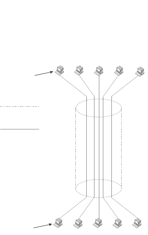
478 PowerConnect B-Series FCX Configuration Guide
53-1002266-01
Configuring super aggregated VLANs
13
FIGURE 101 Conceptual model of the super aggregated VLAN application
Each client connected to the edge device is in its own port-based VLAN, which is like an ATM
channel. All the clients’ VLANs are aggregated by the edge device into a single VLAN for connection
to the core. The single VLAN that aggregates the clients’ VLANs is like an ATM path.
The device that aggregates the VLANs forwards the aggregated VLAN traffic through the core. The
core can consist of multiple devices that forward the aggregated VLAN traffic. The edge device at
the other end of the core separates the aggregated VLANs into the individual client VLANs before
forwarding the traffic. The edge devices forward the individual client traffic to the clients. For the
clients’ perspective, the channel is a direct point-to-point link.
Figure 102 shows an example application that uses aggregated VLANs. This configuration includes
the client connections shown in Figure 101.
Client 1 Client 3 Client 5
...
...
Client 1
192.168.1.69/24
Path =
Channel =
sub-net
192.168.1.0/24
a client VLAN nested
inside a Path
a single VLAN into which
client VLANs are aggregated
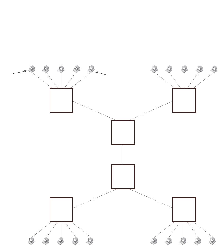
PowerConnect B-Series FCX Configuration Guide 479
53-1002266-01
Configuring super aggregated VLANs 13
FIGURE 102 Example of a super aggregated VLAN application
In this example, a collocation service provides private channels for multiple clients. Although the
same devices are used for all the clients, the VLANs ensure that each client receives its own Layer
2 broadcast domain, separate from the broadcast domains of other clients. For example, client 1
cannot ping client 5.
The clients at each end of a channel appear to each other to be directly connected and thus can be
on the same subnet and use network services that require connection to the same subnet. In this
example, client 1 is in subnet 192.168.1.0/24 and so is the device at the other end of client 1
channel.
Because each VLAN configured on the core devices is an aggregate of multiple client VLANs, the
aggregated VLANs greatly increase the number of clients a core device can accommodate.
This example shows a single link between the core devices. However, you can use a trunk group to
add link-level redundancy.
Client 1
Port1/1
VLAN 101
Client 3
Port1/3
VLAN 103
Client 5
Port1/5
VLAN 105
...
...
Client 1
192.168.1.69/24
209.157.2.12/24
Client 6
Port1/1
VLAN 101
Client 8
Port1/3
VLAN 103
Client 10
Port1/5
VLAN 105
... ...
Ports 1/1 - 1/5
Untagged Ports 1/1 - 1/5
Untagged
Device A
Tag Type 8100
Port2/1
Tagged
Port2/1
Tagged
Device B
Tag Type 8100
Port3/1
Untagged
Port3/2
Untagged
VLAN Aggregation
Enabled
Port4/1
Tagged
Port4/1
Tagged
VLAN Aggregation
Enabled
Port3/1
Untagged
Port3/2
Untagged
Port2/1
Tagged Port2/1
Tagged
Device E
Tag Type 8100
Device F
Tag Type 8100
Ports 1/1 - 1/5
Untagged Ports 1/1 - 1/5
Untagged
192.168.1.129/24
Device C
Tag Type 9100
Device D
Tag Type 9100

480 PowerConnect B-Series FCX Configuration Guide
53-1002266-01
Configuring super aggregated VLANs
13
Configuration notes
•Super Aggregated VLANs and VSRP are not supported together on the same device.
Configuring aggregated VLANs
To configure aggregated VLANs, perform the following tasks:
•On each edge device, configure a separate port-based VLAN for each client connected to the
edge device. In each client VLAN:
•Add the port connected to the client as an untagged port.
•Add the port connected to the core device (the device that will aggregate the VLANs) as a
tagged port. This port must be tagged because all the client VLANs share the port as an
uplink to the core device.
•On each core device:
•Enable VLAN aggregation. This support allows the core device to add an additional tag to
each Ethernet frame that contains a VLAN packet from the edge device. The additional tag
identifies the aggregate VLAN (the path). However, the additional tag can cause the frame
to be longer than the maximum supported frame size. The larger frame support allows
Ethernet frames up to 1530 bytes long.
NOTE
Enable the VLAN aggregation option only on the core devices.
•Configure a VLAN tag type (tag ID) that is different than the tag type used on the edge
devices. If you use the default tag type (8100) on the edge devices, set the tag type on the
core devices to another value, such as 9100. The tag type must be the same on all the
core devices. The edge devices also must have the same tag type but the type must be
different from the tag type on the core devices.
NOTE
You can enable the Spanning Tree Protocol (STP) on the edge devices or the core devices, but not
both. If you enable STP on the edge devices and the core devices, STP will prevent client traffic from
travelling through the core to the other side.
Configuring aggregated VLANs on an edge device
To configure the aggregated VLANs on device A in Figure 102 on page 479, enter the following
commands.
PowerConnect(config)# vlan 101 by port
PowerConnect(config-vlan-101)# tagged ethernet 2/1
PowerConnect(config-vlan-101)# untagged ethernet 1/1
PowerConnect(config-vlan-101)# exit
PowerConnect(config)# vlan 102 by port
PowerConnect(config-vlan-102)# tagged ethernet 2/1
PowerConnect(config-vlan-102)# untagged ethernet 1/2
PowerConnect(config-vlan-102)# exit
PowerConnect(config)# vlan 103 by port
PowerConnect(config-vlan-103)# tagged ethernet 2/1
PowerConnect(config-vlan-103)# untagged ethernet 1/3
PowerConnect(config-vlan-103)# exit
PowerConnect(config)# vlan 104 by port

PowerConnect B-Series FCX Configuration Guide 481
53-1002266-01
Configuring super aggregated VLANs 13
PowerConnect(config-vlan-104)# tagged ethernet 2/1
PowerConnect(config-vlan-104)# untagged ethernet 1/4
PowerConnect(config-vlan-104)# exit
PowerConnect(config)# vlan 105 by port
PowerConnect(config-vlan-105)# tagged ethernet 2/1
PowerConnect(config-vlan-105)# untagged ethernet 1/5
PowerConnect(config-vlan-105)# exit
PowerConnect(config)# write memory
Syntax: [no] vlan <vlan-id> [by port]
Syntax: [no] tagged ethernet [<slotnum>/]<portnum> [to [<slotnum>/]<portnum> | ethernet
[<slotnum>/]<portnum>]
Syntax: [no] untagged ethernet [<slotnum>/]<portnum> [to [<slotnum>/]<portnum> | ethernet
[<slotnum>/]<portnum>]
Use the tagged command to add the port that the device uses for the uplink to the core device. Use
the untagged command to add the ports connected to the individual clients.
Configuring aggregated VLANs on a core device
To configure the aggregated VLANs on device C in Figure 102 on page 479, enter the following
commands.
PowerConnect(config)# tag-type 9100
PowerConnect(config)# aggregated-vlan
PowerConnect(config)# vlan 101 by port
PowerConnect(config-vlan-101)# tagged ethernet 4/1
PowerConnect(config-vlan-101)# untagged ethernet 3/1
PowerConnect(config-vlan-101)# exit
PowerConnect(config)# vlan 102 by port
PowerConnect(config-vlan-102)# tagged ethernet 4/1
PowerConnect(config-vlan-102)# untagged ethernet 3/2
PowerConnect(config-vlan-102)# exit
PowerConnect(config)# write memory
Syntax: [no] tag-type <num>
Syntax: [no] aggregated-vlan
The <num> parameter specifies the tag type can be a hexadecimal value from 0 – ffff. The default
is 8100.
Verifying the configuration
You can verify the VLAN, VLAN aggregation option, and tag configuration by viewing the
running-config. To display the running-config, enter the show running-config command from any CLI
prompt. After you save the configuration changes to the startup-config, you also can display the
settings in that file by entering the show configuration command from any CLI prompt.
Complete CLI examples
The following sections show all the Aggregated VLAN configuration commands on the devices in
Figure 102 on page 479.

482 PowerConnect B-Series FCX Configuration Guide
53-1002266-01
Configuring super aggregated VLANs
13
NOTE
In these examples, the configurations of the edge devices (A, B, E, and F) are identical. The
configurations of the core devices (C and D) also are identical. The aggregated VLAN configurations
of the edge and core devices on one side must be symmetrical (in fact, a mirror image) to the
configurations of the devices on the other side. For simplicity, the example in Figure 102 on
page 479 is symmetrical in terms of the port numbers. This allows the configurations for both sides
of the link to be the same. If your configuration does not use symmetrically arranged port numbers,
the configurations should not be identical but must use the correct port numbers.
Commands for device A
PowerConnectA(config)# vlan 101 by port
PowerConnectA(config-vlan-101)# tagged ethernet 2/1
PowerConnectA(config-vlan-101)# untagged ethernet 1/1
PowerConnectA(config-vlan-101)# exit
PowerConnectA(config)# vlan 102 by port
PowerConnectA(config-vlan-102)# tagged ethernet 2/1
PowerConnectA(config-vlan-102)# untagged ethernet 1/2
PowerConnectA(config-vlan-102)# exit
PowerConnectA(config)# vlan 103 by port
PowerConnectA(config-vlan-103)# tagged ethernet 2/1
PowerConnectA(config-vlan-103)# untagged ethernet 1/3
PowerConnectA(config-vlan-103)# exit
PowerConnectA(config)# vlan 104 by port
PowerConnectA(config-vlan-104)# tagged ethernet 2/1
PowerConnectA(config-vlan-104)# untagged ethernet 1/4
PowerConnectA(config-vlan-104)# exit
PowerConnectA(config)# vlan 105 by port
PowerConnectA(config-vlan-105)# tagged ethernet 2/1
PowerConnectA(config-vlan-105)# untagged ethernet 1/5
PowerConnectA(config-vlan-105)# exit
PowerConnectA(config)# write memory
Commands for device B
The commands for configuring device B are identical to the commands for configuring device A.
Notice that you can use the same channel VLAN numbers on each device. The devices that
aggregate the VLANs into a path can distinguish between the identically named channel VLANs
based on the ID of the path VLAN.
PowerConnectB(config)# vlan 101 by port
PowerConnectB(config-vlan-101)# tagged ethernet 2/1
PowerConnectB(config-vlan-101)# untagged ethernet 1/1
PowerConnectB(config-vlan-101)# exit
PowerConnectB(config)# vlan 102 by port
PowerConnectB(config-vlan-102)# tagged ethernet 2/1
PowerConnectB(config-vlan-102)# untagged ethernet 1/2
PowerConnectB(config-vlan-102)# exit
PowerConnectB(config)# vlan 103 by port
PowerConnectB(config-vlan-103)# tagged ethernet 2/1
PowerConnectB(config-vlan-103)# untagged ethernet 1/3
PowerConnectB(config-vlan-103)# exit
PowerConnectB(config)# vlan 104 by port
PowerConnectB(config-vlan-104)# tagged ethernet 2/1
PowerConnectB(config-vlan-104)# untagged ethernet 1/4
PowerConnectB(config-vlan-104)# exit

PowerConnect B-Series FCX Configuration Guide 483
53-1002266-01
Configuring super aggregated VLANs 13
PowerConnectB(config)# vlan 105 by port
PowerConnectB(config-vlan-105)# tagged ethernet 2/1
PowerConnectB(config-vlan-105)# untagged ethernet 1/5
PowerConnectB(config-vlan-105)# exit
PowerConnectB(config)# write memory
Commands for device C
Because device C is aggregating channel VLANs from devices A and B into a single path, you need
to change the tag type and enable VLAN aggregation.
PowerConnectC(config)# tag-type 9100
PowerConnectC(config)# aggregated-vlan
PowerConnectC(config)# vlan 101 by port
PowerConnectC(config-vlan-101)# tagged ethernet 4/1
PowerConnectC(config-vlan-101)# untagged ethernet 3/1
PowerConnectC(config-vlan-101)# exit
PowerConnectC(config)# vlan 102 by port
PowerConnectC(config-vlan-102)# tagged ethernet 4/1
PowerConnectC(config-vlan-102)# untagged ethernet 3/2
PowerConnectC(config-vlan-102)# exit
PowerConnectC(config)# write memory
Commands for device D
Device D is at the other end of path and separates the channels back into individual VLANs. The
tag type must be the same as tag type configured on the other core device (Device C). In addition,
VLAN aggregation also must be enabled.
PowerConnectD(config)# tag-type 9100
PowerConnectD(config)# aggregated-vlan
PowerConnectD(config)# vlan 101 by port
PowerConnectD(config-vlan-101)# tagged ethernet 4/1
PowerConnectD(config-vlan-101)# untagged ethernet 3/1
PowerConnectD(config-vlan-101)# exit
PowerConnectD(config)# vlan 102 by port
PowerConnectD(config-vlan-102)# tagged ethernet 4/1
PowerConnectD(config-vlan-102)# untagged ethernet 3/2
PowerConnectD(config-vlan-102)# exit
PowerConnectD(config)# write memory
Commands for device E
Because the configuration in Figure 102 on page 479 is symmetrical, the commands for
configuring device E are identical to the commands for configuring device A.
PowerConnectE(config)# vlan 101 by port
PowerConnectE(config-vlan-101)# tagged ethernet 2/1
PowerConnectE(config-vlan-101)# untagged ethernet 1/1
PowerConnectE(config-vlan-101)# exit
PowerConnectE(config)# vlan 102 by port
PowerConnectE(config-vlan-102)# tagged ethernet 2/1
PowerConnectE(config-vlan-102)# untagged ethernet 1/2
PowerConnectE(config-vlan-102)# exit
PowerConnectE(config)# vlan 103 by port
PowerConnectE(config-vlan-103)# tagged ethernet 2/1
PowerConnectE(config-vlan-103)# untagged ethernet 1/3
PowerConnectE(config-vlan-103)# exit

484 PowerConnect B-Series FCX Configuration Guide
53-1002266-01
Configuring 802.1Q-in-Q tagging
13
PowerConnectE(config)# vlan 104 by port
PowerConnectE(config-vlan-104)# tagged ethernet 2/1
PowerConnectE(config-vlan-104)# untagged ethernet 1/4
PowerConnectE(config-vlan-104)# exit
PowerConnectE(config)# vlan 105 by port
PowerConnectE(config-vlan-105)# tagged ethernet 2/1
PowerConnectE(config-vlan-105)# untagged ethernet 1/5
PowerConnectE(config-vlan-105)# exit
PowerConnectE(config)# write memory
Commands for device F
The commands for configuring device F are identical to the commands for configuring device E. In
this example, Because the port numbers on each side of the configuration in Figure 102 on
page 479 are symmetrical, the configuration of device F is also identical to the configuration of
device A and device B.
PowerConnectF(config)# vlan 101 by port
PowerConnectF(config-vlan-101)# tagged ethernet 2/1
PowerConnectF(config-vlan-101)# untagged ethernet 1/1
PowerConnectF(config-vlan-101)# exit
PowerConnectF(config)# vlan 102 by port
PowerConnectF(config-vlan-102)# tagged ethernet 2/1
PowerConnectF(config-vlan-102)# untagged ethernet 1/2
PowerConnectF(config-vlan-102)# exit
PowerConnectF(config)# vlan 103 by port
PowerConnectF(config-vlan-103)# tagged ethernet 2/1
PowerConnectF(config-vlan-103)# untagged ethernet 1/3
PowerConnectF(config-vlan-103)# exit
PowerConnectF(config)# vlan 104 by port
PowerConnectF(config-vlan-104)# tagged ethernet 2/1
PowerConnectF(config-vlan-104)# untagged ethernet 1/4
PowerConnectF(config-vlan-104)# exit
PowerConnectF(config)# vlan 105 by port
PowerConnectF(config-vlan-105)# tagged ethernet 2/1
PowerConnectF(config-vlan-105)# untagged ethernet 1/5
PowerConnectF(config-vlan-105)# exit
PowerConnectF(config)# write memory
Configuring 802.1Q-in-Q tagging
802.1Q-in-Q tagging provides finer granularity for configuring 802.1Q tagging, enabling you to
configure 802.1Q tag-types on a group of ports. This feature allows you to create two identical
802.1Q tags (802.1Q-in-Q tagging) on a single device. This enhancement improves SAV
interoperability between Dell PowerConnect devices and other vendors’ devices that support the
802.1Q tag-types, but are not very flexible with the tag-types they accept.
NOTE
Dell PowerConnect devices treat a double-tagged Ethernet frame as a Layer 2 only frame. The
packets are not inspected for Layer 3 and Layer 4 information, and operations are not performed on
the packet utilizing Layer 3 or Layer 4 information.
Figure 103 shows an example application with 802.1Q-in-Q tagging.
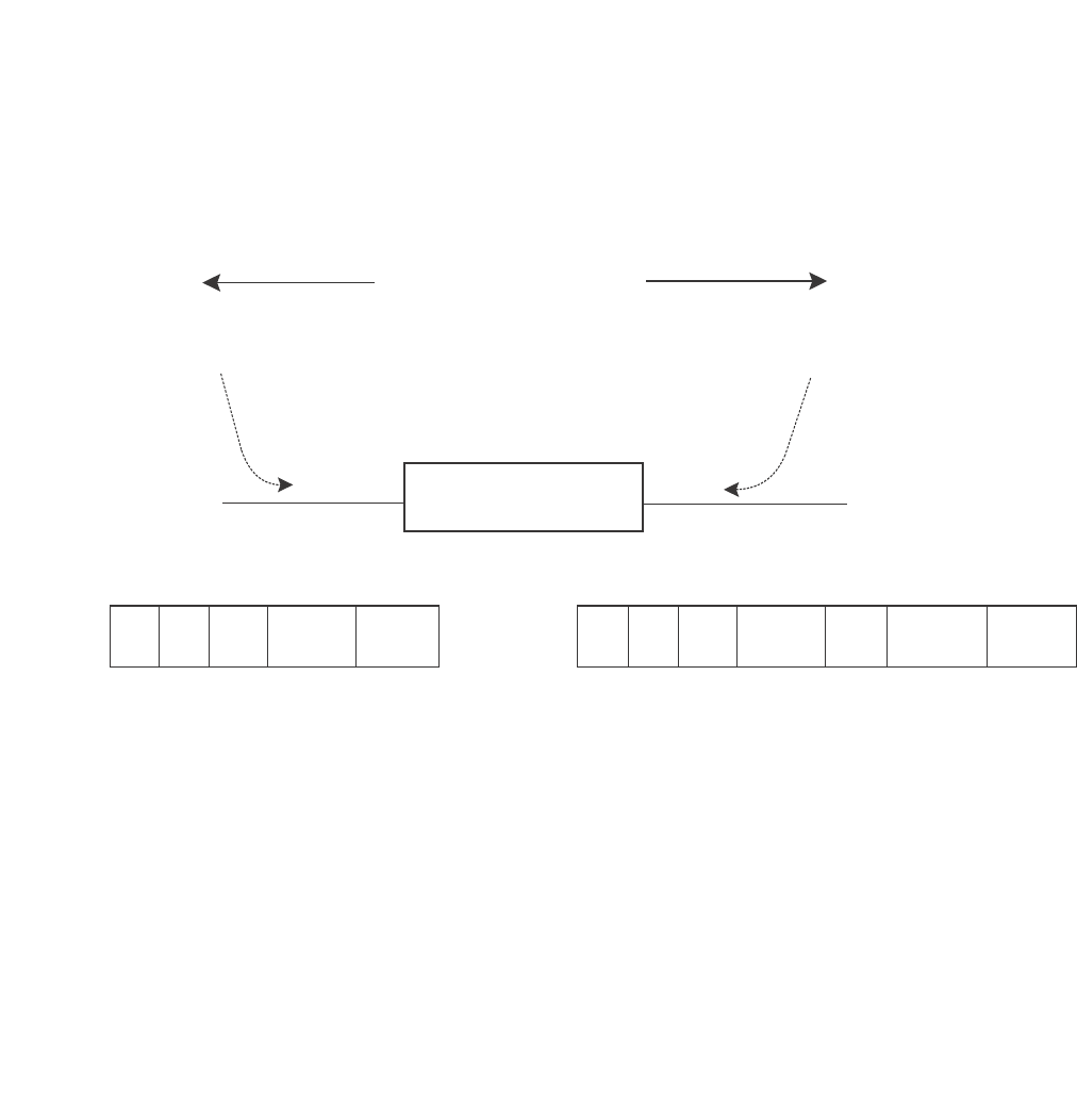
PowerConnect B-Series FCX Configuration Guide 485
53-1002266-01
Configuring 802.1Q-in-Q tagging 13
FIGURE 103 802.1Q-in-Q configuration example
In Figure 103, the untagged ports (to customer interfaces) accept frames that have any
802.1Q tag other than the configured tag-type 9100. These packets are considered untagged
on this incoming port and are re-tagged when they are sent out of the uplink towards the
provider. The 802.1Q tag-type on the uplink port is 8100, so the Dell PowerConnect device will
switch the frames to the uplink device with an additional 8100 tag, thereby supporting devices
that only support this method of VLAN tagging.
Configuration rules
•Because the uplink (to the provider cloud) and the edge link (to the customer port) must have
different 802.1Q tags, make sure the uplink and edge link are in different port regions. Refer to
“About port regions” on page 306 for a list of valid port regions.
•On devices that support port regions, if you configure a port with an 802.1Q tag-type, the Dell
PowerConnect device automatically applies the 802.1Q tag-type to all ports within the same
port region. Likewise, if you remove the 802.1Q tag-type from a port, the Dell PowerConnect
device automatically removes the 802.1Q tag-type from all ports within the same port region.
•802.1Q-in-Q tagging and VSRP are not supported together on the same device.
•In addition to tag-type, PowerConnect B-Series FCX devices support tag-profile. For more
information, refer to “Configuring 802.1Q-in-Q tag profiles” on page 488.
Enabling 802.1Q-in-Q tagging
To enable 802.1Q-in-Q tagging, configure an 802.1Q tag on the untagged edge links (the customer
ports) to any value other than the 802.1Q tag for incoming traffic. For example, in Figure 104, the
802.1Q tag on the untagged edge links (ports 11 and 12) is 9100, whereas, the 802.1Q tag for
incoming traffic is 8100.
To configure 802.1 Q-in-Q tagging as shown in Figure 104, enter commands such as the following
on the untagged edge links of devices C and D.
To customer interface
Uplink to provider cloud
Untagged Tagged
DA SA 8100 Customer
VLAN
DA SA 8100 Customer
VLAN
Provider
VLAN
8100
Configured tag-type 9100 Default tag-type 8100
Provider Edge Switch

486 PowerConnect B-Series FCX Configuration Guide
53-1002266-01
Configuring 802.1Q-in-Q tagging
13
PowerConnect(config)# tag-type 9100 ethernet 11 to 12
PowerConnect(config)# aggregated-vlan
Note that because ports 11 and 12 belong to the port region 1 – 12, the 802.1Q tag actually
applies to ports 1 – 12.
Syntax: [no] tag-type <num> [ethernet <port> [to <port>]]
Specify the <port> variable in the following formats:
•PowerConnect B-Series FCX stackable switches – <stack-unit/slotnum/portnum>
The ethernet <port> to <port> parameter specifies the ports that will use the defined 802.1Q tag.
This parameter operates with the following rules:
•If you specify a single port number, the 802.1Q tag applies to all ports within the port region.
For example, if you enter the command tag-type 9100 ethernet 1, the Dell PowerConnect
device automatically applies the 802.1Q tag to ports 1 – 12 because all of these ports are in
the same port region. You can use the show running-config command to view how the
command has been applied.
•If you do not specify a port or range of ports, the 802.1Q tag applies to all Ethernet ports on the
device.
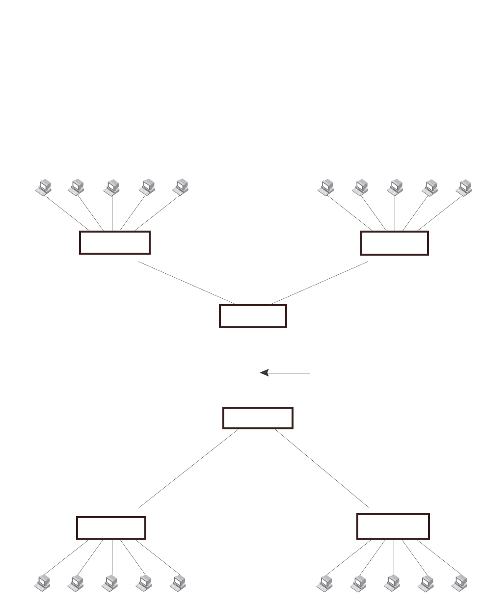
PowerConnect B-Series FCX Configuration Guide 487
53-1002266-01
Configuring 802.1Q-in-Q tagging 13
Example configuration
Figure 104 shows an example 802.1Q-in-Q configuration.
FIGURE 104 Example 802.1Q-in-Q configuration
Client 1
Port1
VLAN 101
Client 3
Port3
VLAN 103
Client 5
Port5
VLAN 105
...
...
Client 1
192.168.1.69/24
Client 5
209.157.2.12/24
Client 6
Port1
VLAN 101
Client 8
Port3
VLAN 103
Client 10
Port5
VLAN 105
... ...
Ports 1 - 5
Untagged Ports 1 - 5
Untagged
Device A
Port6
Tagged
Port6
Tagged
Device B
Port11
Untagged Port12
Untagged
Port17
Tagged
Port17
Tagged
Port11
Untagged
Port12
Untagged
Port6
Tagged Port6
Tagged
Device E Device F
Ports 1 - 5
Untagged
Ports 1 - 5
Untagged
192.168.1.129/24
Device C
Device D
Tag Type 8100
Tag Type 9100
on ports 11 and 12
9100
9100
9100
9100
8100
8100
Tag Type 9100
on ports 11 and 12
Tag Type 8100 Tag Type 8100
This is the link over which 802.1Q-in-Q
applies. This link can also be replaced
by a cloud or core of other vendors’
devices that use the 802.1Q tag type of
8100.
Tag Type 8100

488 PowerConnect B-Series FCX Configuration Guide
53-1002266-01
Configuring private VLANs
13
Configuring 802.1Q-in-Q tag profiles
The 802.1Q-in-Q tagging feature supports a tag-profile command that allows you to add a tag
profile with a value of 0 to 0xffff in addition to the default tag-type 0x8100. This enhancement also
allows you to add a tag profile for a single port, or to direct a group of ports to a globally-configured
tag profile.
Configuration notes
•One global tag profile with a number between 0 and 0xffff can be configured on stackable
devices.
•On individual ports, if tag-profile is enabled, it points to the global tag profile.
•Tag-profile can also be enabled for provisional ports.
•Tag-type and tag-profile cannot be configured at the same time. You will see the message
“un-configure the tag-type to set the tag-profile.” It tag-type is already configured, you will
need to unconfigure it and then add the tag-profile.
•Do not use the tag-type command in conjunction with the tag-profile command. If a tag-type
has already been configured and you try to use the tag-profile command, you will see an error
message telling you to remove the tag-type before you add the tag-profile.
•For devices operating in an IronStack topology, when a tag-type for a port is changed, the
tag-type for all of the ports on a stack unit also changes. Because of this limitation, SAV and
Q-in-Q cannot be used at the same time on stacking devices.
CLI Syntax
To add a global tag-profile enter the following command.
PowerConnect(config)# tag-profile 9500
This command adds a profile in addition to the default profile of 0x8100.
Syntax: [no] tag-profile <tag-no>
where <tag-no> can be 0x8100 (the default) or 0xffff.
To enable the new profile on individual ports, enter commands similar to the following.
PowerConnect(config)# interface ethernet 1/1/1
PowerConnect(config-if-e1000-1/1/1)# tag-profile enable
PowerConnect(config-mif-1/1/1,1/2/1)# tag-profile enable
Syntax: [no] tag-profile enable
Configuring private VLANs
NOTE
Dell PowerConnect devices support private VLANs on both tagged and untagged ports. Tagged ports
are supported only on the PowerConnect B-Series FCX platform.
A private VLAN (PVLAN) is a VLAN that has the properties of standard Layer 2 port-based VLANs but
also provides additional control over flooding packets on a VLAN. Figure 105 shows an example of
an application using a PVLAN.
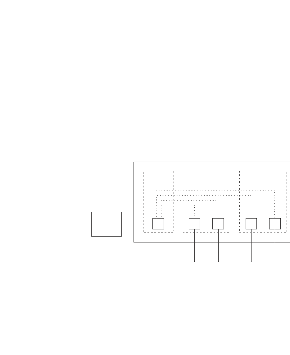
PowerConnect B-Series FCX Configuration Guide 489
53-1002266-01
Configuring private VLANs 13
FIGURE 105 PVLAN used to secure communication between a workstation and servers
This example uses a PVLAN to secure traffic between hosts and the rest of the network through a
firewall. Five ports in this example are members of a PVLAN. The first port (port 3/2) is attached to
a firewall. The next four ports (ports 3/5, 3/6, 3/9, and 3/10) are attached to hosts that rely on the
firewall to secure traffic between the hosts and the rest of the network. In this example, two of the
hosts (on ports 3/5 and 3/6) are in a community PVLAN, and thus can communicate with one
another as well as through the firewall. The other two hosts (on ports 3/9 and 3/10), are in an
isolated VLAN and thus can communicate only through the firewall. The two hosts are secured from
communicating with one another even though they are in the same VLAN.
By default, in the PowerConnect B-Series FCX platform, the device will forward broadcast,
unregistered multicast, and unknown unicast packets from outside sources into the PVLAN.
By default, in PowerConnect platforms other than the PowerConnect B-Series FCX , the device will
not forward broadcast, unregistered multicast, and unknown unicast packets from outside sources
into the PVLAN. If needed, you can override this behavior for broadcast packets, unknown-unicast
packets, or both. (Refer to “Displaying PVLAN information” on page 504.)
You can configure a combination of the following types of PVLANs:
•Primary – The primary PVLAN ports are “promiscuous”. They can communicate with all the
isolated PVLAN ports and community PVLAN ports in the isolated and community VLANs that
are mapped to the promiscuous port.
•Isolated – Broadcasts and unknown unicasts received on isolated ports are sent only to the
promiscuous ports and switch – switch ports. They are not flooded to other ports in the
isolated VLAN.
Private VLAN
Port-based VLAN
Forwarding among
private VLAN ports
A private VLAN secures traffic
between a primary port and host
ports.
Traffic between the hosts and
the rest of the network must
travel through the primary port.
VLAN 7
primary
VLAN 901, 903
community
VLAN 902
isolated
3/9 3/103/2 3/5 3/6
Firewall
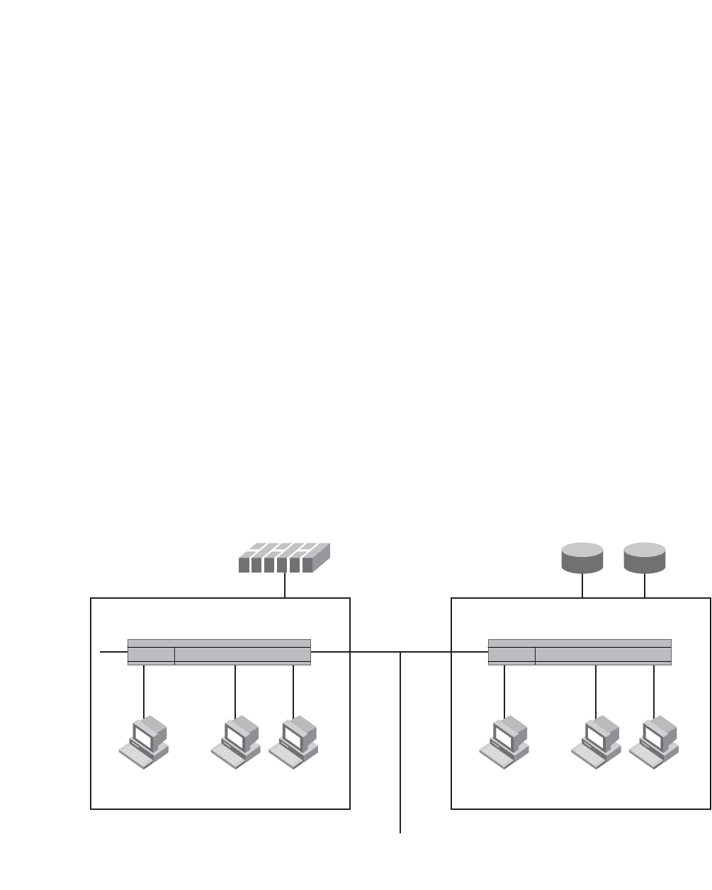
490 PowerConnect B-Series FCX Configuration Guide
53-1002266-01
Configuring private VLANs
13
•Community – Broadcasts and unknown unicasts received on community ports are sent to the
primary port and also are flooded to the other ports in the community VLAN.
Each PVLAN must have a primary VLAN. The primary VLAN is the interface between the secured
ports and the rest of the network. The PVLAN can have any combination of community and isolated
VLANs.
As with regular VLANs, PVLANs can span multiple switches. The PVLAN is treated like any other
VLAN by the PVLAN-trunk ports. The PVLAN-trunk port is added to both the primary and the
secondary VLANs as a tagged member through the pvlan-trunk command. Figure 106 shows an
example of a PVLAN network across switches:
•Broadcast, unknown unicast or unregistered multicast traffic from the primary VLAN port is
forwarded to all ports in isolated and community VLANs in both the switches.
•Broadcast, unknown unicast or unregistered multicast traffic from an isolated port in switch A
is not forwarded to an isolated port in switch A. It will not be forwarded to an isolated port in
switch B across the PVLAN-trunk port.
•Broadcast, unknown unicast or unregistered multicast traffic from a community port in switch
A will be forwarded to a community port in switch B through the PVLAN-trunk port. It is
forwarded to the promiscuous ports and switch – switch ports of the primary VLAN.
FIGURE 106 PVLAN across switches
Figure 107 shows an example PVLAN network with tagged switch-switch link ports.
Switch A Switch B
PVLAN-Trunk Port - carries traffic
for VLAN 10, 20 and 100
RoutersFirewall
PVLAN-Trunk Ports
1/11 1/10 1/20
1/5 1/15 1/16
1/1 1/2 1/3 1/11 1/12 1/13
VLAN 10
Isolated VLAN
VLAN 100
Primary VLAN
VLAN 20
Community VLAN
VLAN 10
Isolated VLAN
VLAN 20
Community VLAN
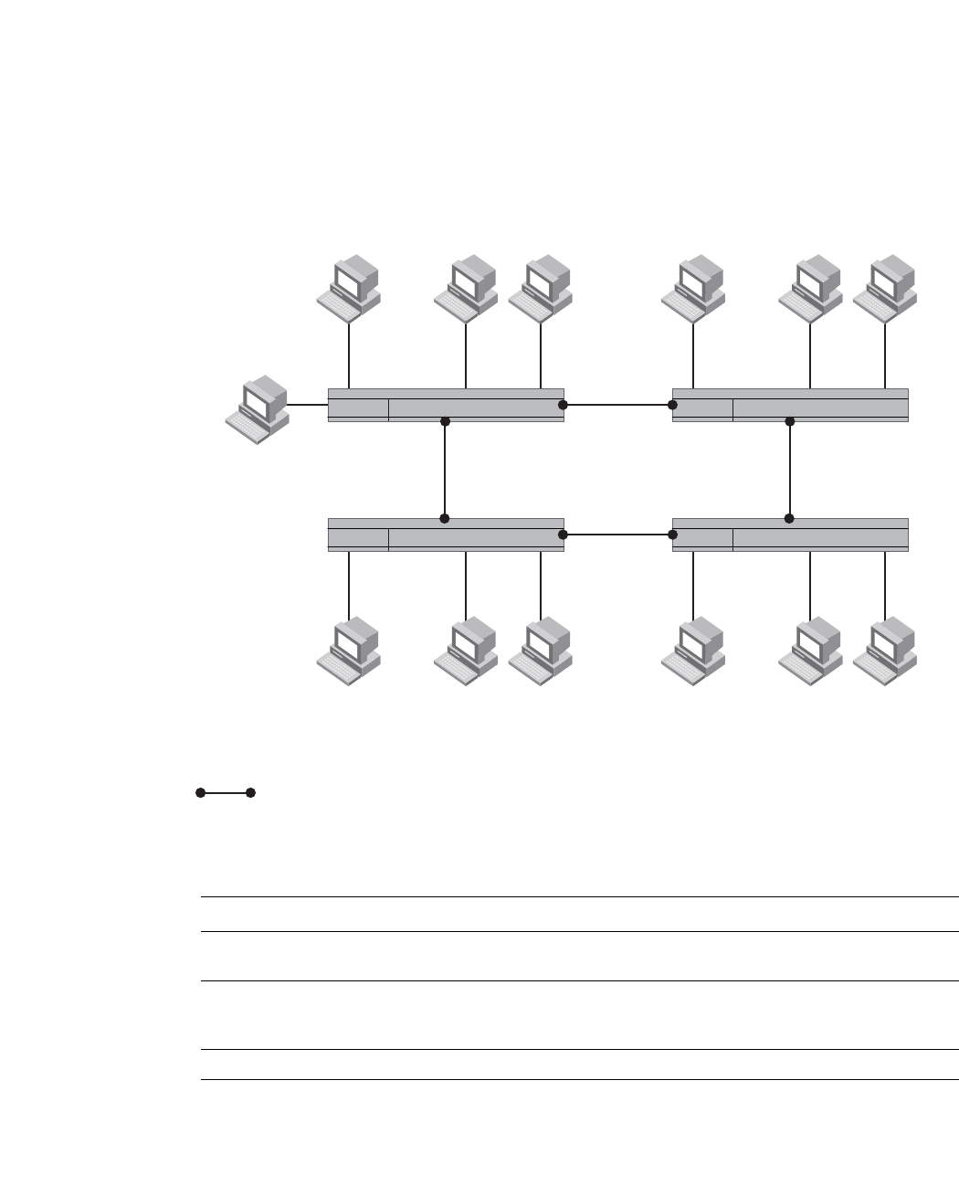
PowerConnect B-Series FCX Configuration Guide 491
53-1002266-01
Configuring private VLANs 13
FIGURE 107 Example PVLAN network with tagged ports
Table 79 lists the differences between PVLANs and standard VLANs.
Configuration notes
•PVLANs are supported on untagged ports on all PowerConnect platforms. PVLANs are also
supported on tagged ports on the PowerConnect B-Series FCX platform only.
•Normally, in any port-based VLAN, the Dell PowerConnect device floods unknown unicast,
unregistered multicast, and broadcast packets in hardware, although selective packets, such
as IGMP, may be sent only to the CPU for analysis, based on the IGMP snooping configuration.
When protocol or subnet VLANs are enabled, or if PVLAN mappings are enabled, the Dell
3
4
21
VLAN 101
Isolated VLAN/Ports
VLAN 100
Promiscuous Ports
VLAN 102
Community VLAN/Ports
11
11
10 10
321
10 10
321
VLAN 101
Isolated VLAN/Ports
VLAN 102
Community VLAN/Ports
VLAN 101
Isolated VLAN/Ports
VLAN 102
Community VLAN/Ports
VLAN 101
Isolated VLAN/Ports
VLAN 102
Community VLAN/Ports
11
11
321
VLAN 100 - switch - switch link Ports
Switch 1 Switch 2
Switch 4 Switch 3
TABLE 79 Comparison of PVLANs and standard port-based VLANs
Forwarding behavior Private VLANs Standard VLANs
All ports within a VLAN constitute a
common layer broadcast domain
No Yes
Broadcasts and unknown unicasts are
forwarded to all the VLAN ports by
default
No (isolated VLAN)
Yes (community VLAN)
Yes
Known unicasts Yes Yes

492 PowerConnect B-Series FCX Configuration Guide
53-1002266-01
Configuring private VLANs
13
PowerConnect device will flood unknown unicast, unregistered multicast, and broadcast
packets in software. The flooding of broadcast or unknown unicast from the community or
isolated VLANs to other secondary VLANs will be governed by the PVLAN forwarding rules. The
switching is done in hardware and thus the CPU does not enforce packet restrictions.The
hardware forwarding behavior is supported on the PowerConnect B-Series FCX platforms only.
•There is currently no support for IGMP snooping within PVLANs. In order for clients in PVLANs
to receive multicast traffic, IGMP snooping must be disabled so that all multicast packets are
treated as unregistered packets and are flooded in software to all the ports.
•The PowerConnect forwards all known unicast traffic in hardware. This differs from the way the
BigIron implements PVLANs, in that the BigIron uses the CPU to forward packets on the primary
VLAN "promiscuous" port. In addition, on the BigIron, support for the hardware forwarding
sometimes results in multiple MAC address entries for the same MAC address in the device
MAC address table. On the PowerConnect , multiple MAC entries do not appear in the MAC
address table because the PowerConnect transparently manages multiple MAC entries in
hardware.
•To configure a PVLAN, configure each of the component VLANs (isolated, community, and
public) as a separate port-based VLAN:
-Use standard VLAN configuration commands to create the VLAN and add ports.
-Identify the PVLAN type (isolated, community, or public)
-For the primary VLAN, map the other PVLANs to the ports in the primary VLAN
•A primary VLAN can have multiple ports. All these ports are active, but the ports that will be
used depends on the PVLAN mappings. Also, secondary VLANs (isolated and community
VLANs) can be mapped to multiple primary VLAN ports.
•You can configure PVLANs and dual-mode VLAN ports on the same device. However, the
dual-mode VLAN ports cannot be members of PVLANs.
•VLAN identifiers configured as part of a PVLAN (primary, isolated, or community) should be
consistent across the switched network. The same VLAN identifiers cannot be configured as a
normal VLAN or a part of any other PVLAN.
•Promiscuous and switch-switch link ports are member ports of the primary VLAN only. All
switch-switch link ports are tagged ports.
•Member ports of isolated and community VLANs cannot be member ports of any other VLAN.
•All member ports that are part of the PVLAN (isolated or secondary) will perform VLAN
classification based on the PVLAN ID (PVID) only (no VLAN classification by port, protocol, ACL
and so on, if any).
•PVST, when needed in PVLANs, should be enabled on all (primary and secondary) private
VLANs.
Configuring the primary VLAN
To configure a primary VLAN, enter commands such as the following.
PowerConnect(config)# vlan 7
PowerConnect(config-vlan-7)# untagged ethernet 3/2
PowerConnect(config-vlan-7)# pvlan type primary
PowerConnect(config-vlan-7)# pvlan mapping 901 ethernet 3/2
These commands create port-based VLAN 7, add port 3/2 as an untagged port, identify the VLAN
as the primary VLAN in a PVLAN, and map the other secondary VLANs to the ports in this VLAN.

PowerConnect B-Series FCX Configuration Guide 493
53-1002266-01
Configuring private VLANs 13
To map the secondary VLANs to the primary VLAN and to configure the tagged switch link port,
enter commands such as the following.
PowerConnect(config)# vlan 100
PowerConnect(config-vlan-100)# tagged ethernet 1/1/10 to 1/1/11
PowerConnect(config-vlan-100)# untagged ethernet 1/1/4
PowerConnect(config-vlan-100)# pvlan type primary
PowerConnect(config-vlan-100)# pvlan mapping 101 ethernet 1/1/4
PowerConnect(config-vlan-100)# pvlan mapping 102 ethernet 1/1/4
PowerConnect(config-vlan-100)# pvlan pvlan-trunk 101 ethernet 1/1/10 to 1/1/11
These commands create port-based VLAN 100, add port 1/1/10 to 1/1/11 as a tagged port,
identify the VLAN as the primary VLAN in a PVLAN, map the other secondary VLANs to the ports in
this VLAN, and configure the tagged switch link port.
Syntax: untagged ethernet [<stack-unit>/<slotnum>/]<portnum> [to
[<stack-unit>/<slotnum>/]<portnum> | ethernet [<stack-unit>/<slotnum>/]<portnum>]
or
Syntax: tagged ethernet [<stack-unit>/<slotnum>/]<portnum> [to
[<stack-unit>/<slotnum>/]<portnum> | ethernet [<stack-unit>/<slotnum>/]<portnum>]
Syntax: [no] pvlan type community | isolated | primary
Syntax: [no] pvlan mapping <vlan-id> ethernet [<stack-unit>/<slotnum>/]<portnum>
Syntax: [no] pvlan pvlan-trunk <vlan-id> ethernet [<stack-unit>/<slotnum>/]<portnum> [to
[<stack-unit>/<slotnum>/]<portnum>]
The untagged or tagged command adds the ports to the VLAN.
The pvlan type command specifies that this port-based VLAN is a PVLAN. Specify primary as the
type.
The pvlan mapping command identifies the other PVLANs for which this VLAN is the primary. The
command also specifies the primary VLAN ports to which you are mapping the other secondary
VLANs. The mapping command is not allowed on the secondary VLANs. The parameters of the
pvlan mapping command are as follows:
•The <vlan-id> parameter specifies another PVLAN. The other PVLAN you want to specify must
already be configured.
•The ethernet <portnum> parameter specifies the primary VLAN port to which you are mapping
all the ports in the other PVLAN (the one specified by <vlan-id>).
The pvlan pvlan-trunk command identifies the switch-switch link for the PVLAN. There can be more
than one switch-switch link for a single community VLAN.
Configuring an isolated or community PVLAN
You can use the pvlan type command to configure the PVLAN as an isolated or community PVLAN.
The following are some configuration considerations to be noted for configuring isolated and
community PVLANs.
Isolated VLANs
•A port being added to the isolated VLAN can be either a tagged port or an untagged port.
•A member port of an isolated VLAN classifies a frame based on PVID only.
•An isolated port (member of an isolated VLAN) communicates only with the promiscuous port,
if a promiscuous port is configured.

494 PowerConnect B-Series FCX Configuration Guide
53-1002266-01
Configuring private VLANs
13
•An isolated VLAN must be associated with the primary VLAN for traffic from the isolated port to
be switched. An isolated VLAN is associated with only one primary VLAN and to the same
primary VLAN in the entire switched network.
•An isolated port communicates only with the configured switch-switch link port if there are no
promiscuous ports configured for the isolated VLAN.
•A primary VLAN is associated with only one isolated VLAN. An isolated VLAN can only be
mapped to a promiscuous port and a switch-switch link port that belong to the same primary
VLAN.
•Link Aggregation Group (LAG) ports are not allowed as member ports of an isolated VLAN.
Community VLANs
•A port being added to the community VLAN can be either a tagged port or an untagged port.
•A member port of a community VLAN classifies a frame based on PVID only.
•A community VLAN is associated with only one primary VLAN and to the same primary VLAN in
the entire switched network. A primary VLAN is associated with multiple community VLANs.
•A community VLAN must be associated with the primary VLAN for traffic from the community
port to be switched.
•LAG ports are not allowed as member ports of a community VLAN.
To configure a community PVLAN, enter commands such as the following.
PowerConnect(config)# vlan 901
PowerConnect(config-vlan-901)# untagged ethernet 3/5 to 3/6
PowerConnect(config-vlan-901)# pvlan type community
These commands create port-based VLAN 901, add ports 3/5 and 3/6 to the VLAN as untagged
ports, then specify that the VLAN is a community PVLAN.
Syntax: untagged ethernet [<slotnum>/]<portnum> [to [<slotnum>/]<portnum> | ethernet
[<slotnum>/]<portnum>]
or
Syntax: tagged ethernet [<slotnum>/]<portnum> [to [<slotnum>/]<portnum> | ethernet
[<slotnum>/]<portnum>]
Syntax: [no] pvlan type community | isolated | primary
The untagged ethernet or taggd ethernet command adds the ports to the VLAN.
The pvlan type command specifies that this port-based VLAN is a PVLAN and can be of the
following types:
•community – Broadcasts and unknown unicasts received on community ports are sent to the
primary port and also are flooded to the other ports in the community VLAN.
•isolated – Broadcasts and unknown unicasts received on isolated ports are sent only to the
primary port. They are not flooded to other ports in the isolated VLAN.
•primary – The primary PVLAN ports are “promiscuous”. They can communicate with all the
isolated PVLAN ports and community PVLAN ports in the isolated and community VLANs that
are mapped to the promiscuous port.
Changing from one PVLAN type to another (for example, from primary to community or vice versa) is
allowed but the mapping will be removed.

PowerConnect B-Series FCX Configuration Guide 495
53-1002266-01
Configuring private VLANs 13
Enabling broadcast or unknown unicast traffic
to the PVLAN
To enhance PVLAN security, the primary PVLAN does not forward broadcast or unknown unicast
packets to its community and isolated VLANs, and other ports in the primary VLAN. For example, if
port 3/2 in Figure 105 on page 489 receives a broadcast packet from the firewall, the port does
not forward the packet to the other PVLAN ports (3/5, 3/6, 3/9, and 3/10).
This forwarding restriction does not apply to traffic from the PVLAN. The primary port does forward
broadcast and unknown unicast packets that are received from the isolated and community VLANs.
For example, if the host on port 3/9 sends an unknown unicast packet, port 3/2 forwards the
packet to the firewall.
If you want to remove the forwarding restriction, you can enable the primary port to forward
broadcast or unknown unicast traffic, if desired, using the following CLI method. You can enable or
disable forwarding of broadcast or unknown unicast packets separately.
NOTE
On Layer 2 Switches and Layer 3 Switches, you also can use MAC address filters to control the traffic
forwarded into and out of the PVLAN. In addition, if you are using a Layer 2 Switch, you also can use
ACLs.
NOTE
PowerConnect B-Series FCX devices do not support ACLs on interface groups.
Command syntax
To configure the ports in the primary VLAN to forward broadcast or unknown unicast and multicast
traffic received from sources outside the PVLAN, enter the following commands at the global
CONFIG level of the CLI.
PowerConnect(config)# pvlan-preference broadcast flood
PowerConnect(config)# pvlan-preference unknown-unicast flood
These commands enable forwarding of broadcast and unknown-unicast packets to ports within the
PVLAN. To again disable forwarding, enter a command such as the following.
PowerConnect(config)# no pvlan-preference broadcast flood
This command disables forwarding of broadcast packets within the PVLAN.
Syntax: [no] pvlan-preference broadcast | unknown-unicast flood
NOTE
The pvlan-preference broadcast and pvlan-preference unknown-unicast commands are not
supported on the PowerConnect B-Series FCX platform. These are supported for all the other
PowerConnect platforms.
Table 80 lists the platforms that support Hardware forwarding PVLAN.
TABLE 80 Supported platforms for Hardware forwarding PVLAN
Product Untagged port Tagged port Switch-link
PowerConnect B-Series
FCX family
Supported Supported Supported

496 PowerConnect B-Series FCX Configuration Guide
53-1002266-01
Configuring private VLANs
13
CLI example for a general PVLAN network
To configure the PVLANs shown in Figure 105 on page 489, enter the following commands.
PowerConnect(config)# vlan 901
PowerConnect(config-vlan-901)# untagged ethernet 3/5 to 3/6
PowerConnect(config-vlan-901)# pvlan type community
PowerConnect(config-vlan-901)# exit
PowerConnect(config)# vlan 902
PowerConnect(config-vlan-902)# untagged ethernet 3/9 to 3/10
PowerConnect(config-vlan-902)# pvlan type isolated
PowerConnect(config-vlan-902)# exit
PowerConnect(config)# vlan 903
PowerConnect(config-vlan-903)# untagged ethernet 3/7 to 3/8
PowerConnect(config-vlan-903)# pvlan type community
PowerConnect(config-vlan-903)# exit
PowerConnect(config)# vlan 7
PowerConnect(config-vlan-7)# untagged ethernet 3/2
PowerConnect(config-vlan-7)# pvlan type primary
PowerConnect(config-vlan-7)# pvlan mapping 901 ethernet 3/2
PowerConnect(config-vlan-7)# pvlan mapping 902 ethernet 3/2
PowerConnect(config-vlan-7)# pvlan mapping 903 ethernet 3/2
CLI example for a PVLAN network with switch-switch
link ports
To configure the PVLANs with tagged switch-switch link ports as shown in Figure 107 on page 491,
enter the following commands.
PowerConnect B-Series FCX Switch 1
PowerConnect(config)# vlan 101 by port
PowerConnect(config-vlan-101)# untagged ethernet 1/1/3
PowerConnect(config-vlan-101)# pvlan type isolated
PowerConnect(config)# vlan 102 by port
PowerConnect(config-vlan-102)# untagged ethernet 1/1/1 to 1/1/2
PowerConnect(config-vlan-102)# pvlan type community
PowerConnect(config)# vlan 100 by port
PowerConnect(config-vlan-100)# tagged ethernet 1/1/10 to 1/1/11
PowerConnect(config-vlan-100)# untagged ethernet 1/1/4
PowerConnect(config-vlan-100)# pvlan type primary
PowerConnect(config-vlan-100)# pvlan mapping 101 ethernet 1/1/4
PowerConnect(config-vlan-100)# pvlan mapping 102 ethernet 1/1/4
PowerConnect(config-vlan-100)# pvlan pvlan-trunk 101 ethernet 1/1/10 to 1/1/11
PowerConnect(config-vlan-100)# pvlan pvlan-trunk 102 ethernet 1/1/10 to 1/1/11
PowerConnect B-Series FCX 2
PowerConnect(config)# vlan 101 by port
PowerConnect(config-vlan-101)# untagged ethernet 1/1/3
PowerConnect(config-vlan-101)# pvlan type isolated
PowerConnect(config)# vlan 102 by port
PowerConnect(config-vlan-102)# untagged ethernet 1/1/1 to 1/1/2
PowerConnect(config-vlan-102)# pvlan type community

PowerConnect B-Series FCX Configuration Guide 497
53-1002266-01
Dual-mode VLAN ports 13
PowerConnect(config)# vlan 100 by port
PowerConnect(config-vlan-100)# tagged ethernet 1/1/10 to 1/1/11
PowerConnect(config-vlan-100)# pvlan type primary
PowerConnect(config-vlan-100)# pvlan pvlan-trunk 102 ethernet 1/1/10 to 1/1/11
PowerConnect(config-vlan-100)# pvlan pvlan-trunk 101 ethernet 1/1/10 to 1/1/11
PowerConnect B-Series FCX 3
PowerConnect(config)# vlan 101 by port
PowerConnect(config-vlan-101)# untagged ethernet 1/1/3
PowerConnect(config-vlan-101)# pvlan type isolated
PowerConnect(config)# vlan 102 by port
PowerConnect(config-vlan-102)# untagged ethernet 1/1/1 to 1/1/2
PowerConnect(config-vlan-102)# pvlan type community
PowerConnect(config)# vlan 100 by port
PowerConnect(config-vlan-100)# tagged ethernet 1/1/10 to 1/1/11
PowerConnect(config-vlan-100)# pvlan type primary
PowerConnect(config-vlan-100)# pvlan pvlan-trunk 102 ethernet 1/1/10 to 1/1/11
PowerConnect(config-vlan-100)# pvlan pvlan-trunk 101 ethernet 1/1/10 to 1/1/11
PowerConnect B-Series FCX 4
PowerConnect(config)# vlan 101 by port
PowerConnect(config-vlan-101)# untagged ethernet 1/1/3
PowerConnect(config-vlan-101)# pvlan type isolated
PowerConnect(config)# vlan 102 by port
PowerConnect(config-vlan-102)# untagged ethernet 1/1/1 to 1/1/2
PowerConnect(config-vlan-102)# pvlan type community
PowerConnect(config)# vlan 100 by port
PowerConnect(config-vlan-100)# tagged ethernet 1/1/10 to 1/1/11
PowerConnect(config-vlan-100)# pvlan type primary
PowerConnect(config-vlan-100)# pvlan pvlan-trunk 102 ethernet 1/1/10 to 1/1/11
PowerConnect(config-vlan-100)# pvlan pvlan-trunk 101 ethernet 1/1/10 to 1/1/11
Dual-mode VLAN ports
Configuring a tagged port as a dual-mode port allows it to accept and transmit both tagged traffic
and untagged traffic at the same time. A dual-mode port accepts and transmits frames belonging
to VLANs configured for the port, as well as frames belonging to the default VLAN (that is, untagged
traffic).
For example, in Figure 108, port 2/11 is a dual-mode port belonging to VLAN 20. Traffic for VLAN
20, as well as traffic for the default VLAN, flows from a hub to this port. The dual-mode feature
allows traffic for VLAN 20 and untagged traffic to go through the port at the same time.
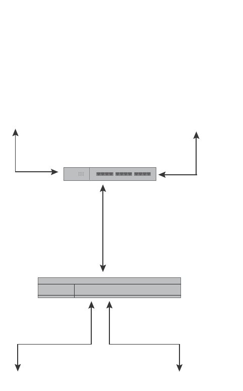
498 PowerConnect B-Series FCX Configuration Guide
53-1002266-01
Dual-mode VLAN ports
13
FIGURE 108 Dual-mode VLAN port example
To enable the dual-mode feature on port 2/11 in Figure 108,enter the following commands.
PowerConnect(config)# vlan 20
PowerConnect(config-vlan-20)# tagged ethernet 2/11
PowerConnect(config-vlan-20)# tagged ethernet 2/9
PowerConnect(config-vlan-20)# interface ethernet 2/11
PowerConnect(config-if-e1000-2/11)# dual-mode
PowerConnect(config-if-e1000-2/11)# exit
Syntax: [no] dual-mode
You can configure a dual-mode port to transmit traffic for a specified VLAN (other than the
DEFAULT-VLAN) as untagged, while transmitting traffic for other VLANs as tagged. Figure 109
illustrates this enhancement.
VLAN 20
Traffic
Untagged
Traffic
Port2/11
Tagged, VLAN 20
dual-mode
Port2/9
Tagged, VLAN 20
Port2/10
Untagged
VLAN 20
Traffic
Untagged
Traffic
Hub
Switch
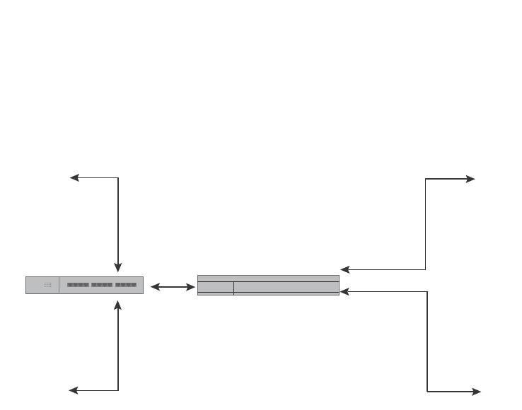
PowerConnect B-Series FCX Configuration Guide 499
53-1002266-01
Dual-mode VLAN ports 13
FIGURE 109 Specifying a default VLAN ID for a dual-mode port
In Figure 109, tagged port 2/11 is a dual-mode port belonging to VLANs 10 and 20. The default
VLAN assigned to this dual-mode port is 10. This means that the port transmits tagged traffic on
VLAN 20 (and all other VLANs to which the port belongs) and transmits untagged traffic on VLAN
10.
The dual-mode feature allows tagged traffic for VLAN 20 and untagged traffic for VLAN 10 to go
through port 2/11 at the same time. A dual-mode port transmits only untagged traffic on its default
VLAN (that is, either VLAN 1, or a user-specified VLAN ID), and only tagged traffic on all other
VLANs.
The following commands configure VLANs 10 and 20 in Figure 109. Tagged port 2/11 is added to
VLANs 10 and 20, then designated a dual-mode port whose specified default VLAN is 10. In this
configuration, port 2/11 transmits only untagged traffic on VLAN 10 and only tagged traffic on
VLAN 20.
PowerConnect(config)# vlan 10 by port
PowerConnect(config-vlan-10)# untagged ethernet 2/10
PowerConnect(config-vlan-10)# tagged ethernet 2/11
PowerConnect(config-vlan-10)# exit
PowerConnect(config)# vlan 20 by port
PowerConnect(config-vlan-20)# tagged ethernet 2/9
PowerConnect(config-vlan-20)# tagged ethernet 2/11
PowerConnect(config-vlan-20)# exit
PowerConnect(config)# interface ethernet 2/11
PowerConnect(config-if-e1000-2/11)# dual-mode 10
PowerConnect(config-if-e1000-2/11)# exit
Syntax: [no] dual-mode [<vlan-id>]
Notes:
•If you do not specify a <vlan-id> in the dual mode command, the port default VLAN is set to 1.
The port transmits untagged traffic on the DEFAULT-VLAN.
•The dual-mode feature is disabled by default. Only tagged ports can be configured as
dual-mode ports.
•In trunk group, either all of the ports must be dual-mode, or none of them can be.
VLAN 10
Untagged
Traffic
VLAN 10
Untagged
Traffic
VLAN 20
Tagged
Traffic
VLAN 20
Tagged
Traffic
Dual-mode Port2/11
Default VLAN ID 10
Tagged, VLAN 20
Port2/10
Untagged, VLAN 10
Port2/9
Tagged, VLAN 20
Hub
Switch

500 PowerConnect B-Series FCX Configuration Guide
53-1002266-01
Displaying VLAN information
13
The show vlan command displays a separate row for dual-mode ports on each VLAN.
Example
Displaying VLAN information
After you configure the VLANs, you can verify the configuration using the show commands
described in this section.
NOTE
If a VLAN name begins with “GVRP_VLAN_“, the VLAN was created by the GARP VLAN Registration
Protocol (GVRP). If a VLAN name begins with “STATIC_VLAN_“, the VLAN was created by GVRP and
then was converted into a statically configured VLAN.
Displaying VLANs in alphanumeric order
By default, VLANs are displayed in alphanumeric order, as shown in the following example.
PowerConnect# show vlan
Total PORT-VLAN entries: 3
Maximum PORT-VLAN entries: 16
legend: [S=Slot]
PORT-VLAN 1, Name DEFAULT-VLAN, Priority level0, Spanning tree Off
Untagged Ports: (S1) 1 2 3 4 5 6 7 8
Untagged Ports: (S2) 1 2 3 4 5 6 7 8 12 13 14 15 16 17 18 19
Untagged Ports: (S2) 20 21 22 23 24
Tagged Ports: None
Uplink Ports: None
DualMode Ports: None
PORT-VLAN 10, Name [None], Priority level0, Spanning tree Off
Untagged Ports: (S2) 10
Tagged Ports: None
Uplink Ports: None
DualMode Ports: (S2) 11
PORT-VLAN 20, Name [None], Priority level0, Spanning tree Off
Untagged Ports: None
Tagged Ports: (S2) 9
Uplink Ports: None
DualMode Ports: (S2) 11
PowerConnect# show run
...
vlan 2 by port
...
vlan 10 by port
...
vlan 100 by port
...

PowerConnect B-Series FCX Configuration Guide 501
53-1002266-01
Displaying VLAN information 13
Displaying system-wide VLAN information
Use the show vlans command to display VLAN information for all the VLANs configured on the
device.
The following example shows the display for the IP subnet and IPX network VLANs configured in the
examples in “Configuring an IP subnet VLAN with dynamic ports” on page 466 and “Configuring an
IPX network VLAN with dynamic ports” on page 467.
In the show vlans output, ports that are tagged but are not dual-mode ports are listed as tagged
ports. In the following example display output, ports 7 and 8 are dual-mode ports in port-based
VLAN 4. Ports 7 and 8 also belong to port-based VLAN 3, but they are tagged ports only in VLAN 3
and are not configured as dual-mode ports.
PowerConnect# show vlans
Total PORT-VLAN entries: 2
Maximum PORT-VLAN entries: 8
legend: [S=Slot]
PORT-VLAN 1, Name DEFAULT-VLAN, Priority level0, Spanning tree Off
Untagged Ports: (S2) 1 2 3 4 5 6 7 8 9 10 11 12 13 14 15 16
Untagged Ports: (S2) 17 18 19 20 21 22 23 24
Untagged Ports: (S4) 1 2 3 4 5 6 7 8 9 10 11 12 13 14 15 16
Untagged Ports: (S4) 17 18 19 20 21 22 23 24
Tagged Ports: None
PORT-VLAN 10, Name IP_VLAN, Priority level0, Spanning tree Off
Untagged Ports: (S1) 1 2 3 4 5 6
Tagged Ports: None
IP-subnet VLAN 1.1.1.0 255.255.255.0, Dynamic port enabled
Name: Mktg-LAN
Static ports: None
Exclude ports: None
Dynamic ports: (S1) 1 2 3 4 5 6
PORT-VLAN 20, Name IPX_VLAN, Priority level0, Spanning tree Off
Untagged Ports: (S2) 1 2 3 4 5 6
Tagged Ports: None
IPX-network VLAN 0000ABCD, frame type ethernet_ii, Dynamic port enabled
Name: Eng-LAN
Static ports: None
Exclude ports: None
Dynamic ports: (S2) 1 2 3 4 5 6

502 PowerConnect B-Series FCX Configuration Guide
53-1002266-01
Displaying VLAN information
13
Syntax: show vlans [<vlan-id> | ethernet [<slotnum>/]<portnum>]
The <vlan-id> parameter specifies a VLAN for which you want to display the configuration
information.
The <slotnum> parameter is required on chassis devices.
The <portnum> parameter specifies a port. If you use this parameter, the command lists all the
VLAN memberships for the port.
Displaying global VLAN information
The show vlan brief command displays the following information:
•The system-max VLAN values (maximum, default, and current )
•The default VLAN ID number
•The total number of VLANs configured on the device
•The VLAN ID numbers of the VLANs configured on the device
The following shows example output.
Syntax: show vlan brief
Displaying VLAN information for specific ports
Use one of the following methods to display VLAN information for specific ports.
To display VLAN information for all the VLANs of which port 7/1 is a member, enter the following
command.
PowerConnect# show vlan 4
Total PORT-VLAN entries: 5
Maximum PORT-VLAN entries: 3210
PORT-VLAN 4, Name [None], Priority level0, Spanning tree Off
Untagged Ports: None
Tagged Ports: 6 9 10 11
Uplink Ports: None
DualMode Ports: 7 8
PowerConnect# show vlan 3
Total PORT-VLAN entries: 5
Maximum PORT-VLAN entries: 3210
PORT-VLAN 3, Name [None], Priority level0, Spanning tree Off
Untagged Ports: None
Tagged Ports: 6 7 8 9 10
Uplink Ports: None
DualMode Ports: None
PowerConnect# show vlan brief
System-max vlan Params: Max(4095) Default(64) Current(3210)
Default vlan Id :1
Total Number of Vlan Configured :5
VLANs Configured :1 to 4 10

PowerConnect B-Series FCX Configuration Guide 503
53-1002266-01
Displaying VLAN information 13
Syntax: show vlans [<vlan-id> | ethernet [<slotnum>/]<portnum>
The <vlan-id> parameter specifies a VLAN for which you want to display the configuration
information.
The <slotnum> parameter is required on chassis devices.
The <portnum> parameter specifies a port. If you use this parameter, the command lists all the
VLAN memberships for the port.
Displaying a port VLAN membership
To display VLAN membership for a specific port on the device, enter a command such as the
following.
Syntax: show vlan brief ethernet [<slotnum>/]<portnum>
The <slotnum> parameter is required on chassis devices.
Displaying a port dual-mode VLAN membership
The output of the show interfaces command lists dual-mode configuration and corresponding VLAN
numbers. The following shows an example output.
Syntax: show interfaces ethernet [<slotnum>/]<portnum> [to [<slotnum>/]<portnum> [ethernet
[<slotnum>/]<portnum>...]]
The <slotnum> parameter is required on chassis devices.
Displaying port default VLAN IDs (PVIDs)
The output of the show interfaces brief command lists the port default VLAN IDs (PVIDs) for each
port. PVIDs are displayed as follows:
PowerConnect# show vlans ethernet 7/1
Total PORT-VLAN entries: 3
Maximum PORT-VLAN entries: 8
legend: [S=Slot]
PORT-VLAN 100, Name [None], Priority level0, Spanning tree Off
Untagged Ports: (S7) 1 2 3 4
Tagged Ports: None
PowerConnect# show vlan brief ethernet 7
Port 7 is a member of 3 VLANs
VLANs 3 to 4 10
PowerConnect# show interfaces ethernet 7
GigabitEthernet7 is down, line protocol is down
Hardware is GigabitEthernet, address is 0012.f2a8.4706 (bia 0012.f2a8.4706)
Configured speed auto, actual unknown, configured duplex fdx, actual unknown
Configured mdi mode AUTO, actual unknown
Member of 3 L2 VLANs, port is dual mode in Vlan 4, port state is BLOCKING

504 PowerConnect B-Series FCX Configuration Guide
53-1002266-01
Displaying VLAN information
13
•For untagged ports, the PVID is the VLAN ID number.
•For dual-mode ports, the PVID is the dual-mode VLAN ID number.
•For tagged ports without dual-mode, the PVID is always Not Applicable (NA).
Syntax: show interfaces brief [ethernet [<slotnum>/]<portnum> [to [<slotnum>/]<portnum>
[ethernet [<slotnum>/]<portnum>...]]]
The <slotnum> parameter is required on chassis devices.
Displaying PVLAN information
To display the PVLAN configuration with respect to the primary VLAN and its associated secondary
VLANs and to display the member ports, promiscous ports, and the switch-switch link ports of a
PVLAN, enter a command such as the following.
Syntax: show pvlan <vid>
The <vid> variable specifies the VLAN ID of the PVLAN. If the VLAN ID is not specified, the
command displays the default VLAN ID.
PowerConnect# show interfaces brief
Port Link State Dupl Speed Trunk Tag Pvid Pri MAC Name
1 Up Forward Full 1G None No 1 0 0012.f2a8.4700 a12345678901
2 Up Forward Full 1G None Yes 1 0 0012.f2a8.4701
3 Up Forward Full 1G None Yes NA 0 0012.f2a8.4702
4 Up Forward Full 1G None Yes NA 0 0012.f2a8.4703
5 Up Forward Full 1G None No 2 0 0012.f2a8.4704
6 Down None None None None Yes NA 0 0012.f2a8.4705
7 Down None None None None Yes 4 0 0012.f2a8.4706
8 Down None None None None Yes 4 0 0012.f2a8.4707
9 Down None None None None Yes NA 0 0012.f2a8.4708
10 Down None None None None Yes NA 0 0012.f2a8.4709
PowerConnect# show pvlan
PVLAN: primary VLAN 100
Port 1/1/4 1/1/10 1/1/11
Community VLAN 102
Port 1/1/1 1/1/2 1/1/10 1/1/11
Promiscuous Port: 1/1/4
Inter switch link Port: 1/1/10 1/1/11
BpduGuard enabled Port: 1/1/1 1/1/2
Isolate VLAN 101
Port 1/1/3 1/1/10 1/1/11
Promiscuous Port: 1/1/4
Inter switch link Port: 1/1/10 1/1/11
BpduGuard enabled Port: 1/1/1 1/1/2

PowerConnect B-Series FCX Configuration Guide 505
53-1002266-01
Chapter
14
Configuring GARP VLAN Registration Protocol (GVRP)
Table 81 lists the individual Dell PowerConnect switches and the GVRP features they support.
GVRP overview
GARP VLAN Registration Protocol (GVRP) is a Generic Attribute Registration Protocol (GARP)
application that provides VLAN registration service by means of dynamic configuration
(registration) and distribution of VLAN membership information.
A Dell PowerConnect device enabled for GVRP can do the following:
•Learn about VLANs from other Dell PowerConnect devices and configure those VLANs on the
ports that learn about the VLANs. The device listens for GVRP Protocol Data Units (PDUs) from
other devices, and implements the VLAN configuration information in the PDUs.
•Advertise VLANs configured on the device to other Dell PowerConnect devices. The device
sends GVRP PDUs advertising its VLANs to other devices. GVRP advertises statically configured
VLANs and VLANs learned from other devices through GVRP.
GVRP enables a Dell PowerConnect device to dynamically create 802.1Q-compliant VLANs on links
with other devices that are running GVRP. GVRP reduces the chances for errors in VLAN
configuration by automatically providing VLAN ID consistency across the network. You can use
GVRP to propagate VLANs to other GVRP-aware devices automatically, without the need to manually
configure the VLANs on each device. In addition, if the VLAN configuration on a device changes,
GVRP automatically changes the VLAN configurations of the affected devices.
The Dell PowerConnect implementation of GARP and GVRP is based on the following standards:
•ANSI/IEEE standard 802.1D, 1998 edition
•IEEE standard 802.1Q, 1998 edition; approved December 8, 1998
•IEEE draft P802.1w/D10, March 26, 2001
•IEEE draft P802.1u/D9, November 23, 2000
TABLE 81 Supported GVRP features
Feature PowerConnect B-Series FCX
GVRP Yes
Configurable GVRP base VLAN ID Yes
Leaveall timer Yes
Ability to disable VLAN advertising Yes
Ability to disable VLAN learning Yes
GVRP timers Yes
Conversion of a GVRP VLAN to a
statically-configured VLAN
Yes
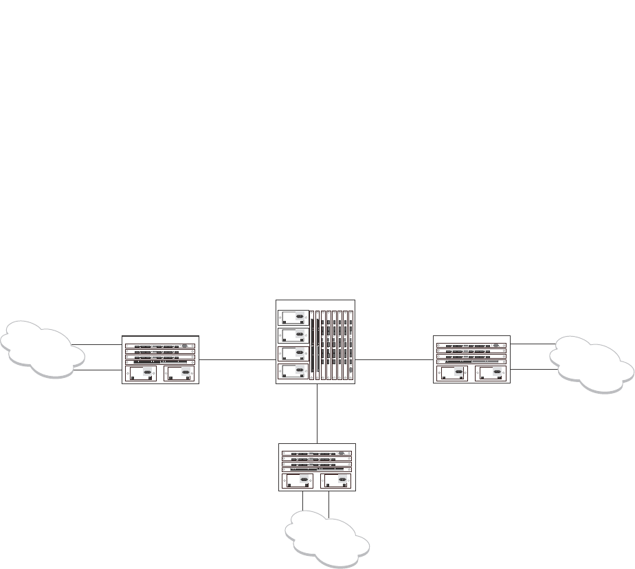
506 PowerConnect B-Series FCX Configuration Guide
53-1002266-01
Application examples
14
•IEEE draft P802.1t/D10, November 20, 2000
Application examples
Figure 110 shows an example of a network that uses GVRP. This section describes various ways
you can use GVRP in a network such as this one. “CLI examples” on page 522 lists the CLI
commands to implement the applications of GVRP described in this section.
FIGURE 110 Example of GVRP
In this example, a core device is attached to three edge devices. Each of the edge devices is
attached to other edge devices or host stations (represented by the clouds).
The effects of GVRP in this network depend on which devices the feature is enabled on, and
whether both learning and advertising are enabled. In this type of network (a core device and edge
devices), you can have the following four combinations:
•Dynamic core and fixed edge
•Dynamic core and dynamic edge
•Fixed core and dynamic edge
•Fixed core and fixed edge
Dynamic core and fixed edge
In this configuration, all ports on the core device are enabled to learn and advertise VLAN
information. The edge devices are configured to advertise their VLAN configurations on the ports
connected to the core device. GVRP learning is disabled on the edge devices.
Port2/1
Port4/1
Port4/1
Port4/1
Port4/24 Port4/24
Port2/24
Port4/24
Port2/24
Port1/24 Port6/24
Edge Device A
Edge Device C
Edge Device B
Core Device
Port8/17

PowerConnect B-Series FCX Configuration Guide 507
53-1002266-01
Application examples 14
In this configuration, the edge devices are statically (manually) configured with VLAN information.
The core device dynamically configures itself to be a member of each of the edge device VLANs.
The operation of GVRP on the core device results in the following VLAN configuration on the device:
•VLAN 20
•1/24 (tagged)
•6/24 (tagged)
•VLAN 30
•6/24 (tagged)
•8/17 (tagged)
•VLAN 40
•1/24 (tagged)
•8/17 (tagged)
VLAN 20 traffic can now travel through the core between edge devices A and B. Likewise, VLAN 30
traffic can travel between B and C and VLAN 40 traffic can travel between A and C. If an edge
device is moved to a different core port or the VLAN configuration of an edge device is changed, the
core device automatically reconfigures itself to accommodate the change.
Notice that each of the ports in the dynamically created VLANs is tagged. All GVRP VLAN ports
configured by GVRP are tagged, to ensure that the port can be configured for additional VLANs.
NOTE
This example assumes that the core device has no static VLANs configured. However, you can have
static VLANs on a device that is running GVRP. GVRP can dynamically add other ports to the statically
configured VLANs but cannot delete statically configured ports from the VLANs.
Dynamic core and dynamic edge
GVRP is enabled on the core device and on the edge devices. This type of configuration is useful if
the devices in the edge clouds are running GVRP and advertise their VLANs to the edge devices.
The edge devices learn the VLANs and also advertise them to the core. In this configuration, you do
not need to statically configure the VLANs on the edge or core devices, although you can have
statically configured VLANs on the devices. The devices learn the VLANs from the devices in the
edge clouds.
Core device Edge device A Edge device B Edge device C
•GVRP is enabled on all
ports.
•Both learning and
advertising are
enabled.
NOTE: Since learning is
disabled on all the
edge devices,
advertising on the
core device has no
effect in this
configuration.
•GVRP is enabled on
port 4/24. Learning
is disabled.
•VLAN 20
•Port 2/1 (untagged)
•Port 4/24 (tagged)
•VLAN 40
•Port 4/1 (untagged)
•Port 4/24 (tagged)
•GVRP is enabled on
port 4/1. Learning is
disabled.
•VLAN 20
•Port 2/24 (untagged)
•Port 4/1 (tagged)
•VLAN 30
•Port 4/24 (untagged)
•Port 4/1 (tagged)
•GVRP is enabled on
port 4/1. Learning
is disabled.
•VLAN 30
•Port 2/24
(untagged)
•Port 4/1 (tagged)
•VLAN 40
•Port 4/24
(untagged)
•Port 4/1 (tagged)

508 PowerConnect B-Series FCX Configuration Guide
53-1002266-01
VLAN names
14
Fixed core and dynamic edge
GVRP learning is enabled on the edge devices. The VLANs on the core device are statically
configured, and the core device is enabled to advertise its VLANs but not to learn VLANs. The edge
devices learn the VLANs from the core.
Fixed core and fixed edge
The VLANs are statically configured on the core and edge devices. On each edge device, VLAN
advertising is enabled but learning is disabled. GVRP is not enabled on the core device. This
configuration enables the devices in the edge clouds to learn the VLANs configured on the edge
devices.
VLAN names
The show vlans command lists VLANs created by GVRP as “GVRP_VLAN_<vlan-id>”. VLAN names
for statically configured VLANs are not affected. To distinguish between statically-configured VLANs
that you add to the device and VLANs that you convert from GVRP-configured VLANs into
statically-configured VLANs, the show vlans command displays a converted VLAN name as
“STATIC_VLAN_<vlan-id>”.
Configuration notes
•If you disable GVRP, all GVRP configuration information is lost if you save the configuration
change (write memory command) and then reload the software. However, if you reload the
software without first saving the configuration change, the GVRP configuration is restored
following a software reload.
•The maximum number of VLANS supported on a device enabled for GVRP is the same as the
maximum number on a device that is not enabled for GVRP.
•To display the maximum number of VLANs allowed on your device, enter the show default
values command. See the “vlan” row in the System Parameters section. Make sure you
allow for the default VLAN (1), the GVRP base VLAN (4093), and the Single STP VLAN
(4094). These VLANs are maintained as “Registration Forbidden” in the GVRP database.
Registration Forbidden VLANs cannot be advertised or learned by GVRP.
•To increase the maximum number of VLANs supported on the device, enter the
system-max vlan <num> command at the global CONFIG level of the CLI, then save the
configuration and reload the software. The maximum number you can specify is listed in
the Maximum column of the show default values display.
•The default VLAN (VLAN 1) is not advertised by the Dell implementation of GVRP. The default
VLAN contains all ports that are not members of statically configured VLANs or VLANs enabled
for GVRP.
NOTE
The default VLAN has ID 1 by default. You can change the VLAN ID of the default VLAN, but only
before GVRP is enabled. You cannot change the ID of the default VLAN after GVRP is enabled.

PowerConnect B-Series FCX Configuration Guide 509
53-1002266-01
Configuration notes 14
•Single STP must be enabled on the device. Dell implementation of GVRP requires Single STP.
If you do not have any statically configured VLANs on the device, you can enable Single STP as
follows.
PowerConnect(config)#vlan 1
PowerConnect(config-vlan-1)#exit
PowerConnect(config)#span
PowerConnect(config)#span single
These commands enable configuration of the default VLAN (VLAN 1), which contains all the
device ports, and enable STP and Single STP.
•All VLANs that are learned dynamically through GVRP are added to the single spanning tree.
•All ports that are enabled for GVRP become tagged members of the GVRP base VLAN (4093). If
you need to use this VLAN ID for another VLAN, you can change the GVRP VLAN ID. Refer to
“Changing the GVRP base VLAN ID” on page 510. The software adds the GVRP base VLAN to
the single spanning tree.
•All VLAN ports added by GVRP are tagged.
•GVRP is supported only for tagged ports or for untagged ports that are members of the default
VLAN. GVRP is not supported for ports that are untagged and are members of a VLAN other
than the default VLAN.
•To configure GVRP on a trunk group, enable the protocol on the primary port in the trunk group.
The GVRP configuration of the primary port is automatically applied to the other ports in the
trunk group.
•You can use GVRP on a device even if the device has statically configured VLANs. GVRP does
not remove any ports from the statically configured VLANs, although GVRP can add ports to the
VLANS. GVRP advertises the statically configured VLANs. Ports added by GVRP do not appear
in the running-config and will not appear in the startup-config file when save the configuration.
You can manually add a port to make the port a permanent member of the VLAN. After you
manually add the port, the port will appear in the running-config and be saved to the
startup-config file when you save the configuration.
•VLANs created by GVRP do not support virtual routing interfaces or protocol-based VLANs.
virtual routing interfaces and protocol-based VLANs are still supported on statically configured
VLANs even if GVRP adds ports to those VLANs.
•You cannot manually configure any parameters on a VLAN that is created by GVRP. For
example, you cannot change STP parameters for the VLAN.
•The GVRP timers (Join, Leave, and Leaveall) must be set to the same values on all the devices
that are exchanging information using GVRP.
•If the network has a large number of VLANs, the GVRP traffic can use a lot of CPU resources. If
you notice high CPU utilization after enabling GVRP, set the GVRP timers to longer values. In
particular, set the Leaveall timer to a longer value. Refer to “Changing the GVRP timers” on
page 512.
•The feature is supported only on Ethernet ports.
NOTE
If you plan to change the GVRP base VLAN ID (4093) or the maximum configurable value for the
Leaveall timer (300000 ms by default), you must do so before you enable GVRP.

510 PowerConnect B-Series FCX Configuration Guide
53-1002266-01
Configuring GVRP
14
Configuring GVRP
To configure a device for GVRP, globally enable support for the feature, then enable the feature on
specific ports. Optionally, you can disable VLAN learning or advertising on specific interfaces.
You can also change the protocol timers and the GVRP base VLAN ID.
Changing the GVRP base VLAN ID
By default, GVRP uses VLAN 4093 as a base VLAN for the protocol. All ports that are enabled for
GVRP become tagged members of this VLAN. If you need to use VLAN ID 4093 for a statically
configured VLAN, you can change the GVRP base VLAN ID.
NOTE
If you want to change the GVRP base VLAN ID, you must do so before enabling GVRP.
To change the GVRP base VLAN ID, enter a command such as the following at the global CONFIG
level of the CLI.
PowerConnect(config)#gvrp-base-vlan-id 1001
This command changes the GVRP VLAN ID from 4093 to 1001.
Syntax: [no] gvrp-base-vlan-id <vlan-id>
The <vlan-id> parameter specifies the new VLAN ID. You can specify a VLAN ID from 2 – 4092 or
4095.
Increasing the maximum configurable value of the Leaveall timer
By default, the highest value you can specify for the Leaveall timer is 300000 ms. You can increase
the maximum configurable value of the Leaveall timer to 1000000 ms.
NOTE
You must enter this command before enabling GVRP. Once GVRP is enabled, you cannot change the
maximum Leaveall timer value.
NOTE
This command does not change the default value of the Leaveall timer itself. The command only
changes the maximum value to which you can set the Leaveall timer.
To increase the maximum value you can specify for the Leaveall timer, enter a command such as
the following at the global CONFIG level of the CLI.
PowerConnect(config)#gvrp-max-leaveall-timer 1000000
Syntax: [no] gvrp-max-leaveall-timer <ms>
The <ms> parameter specifies the maximum number of ms to which you can set the Leaveall timer.
You can specify from 300000 – 1000000 (one million) ms. The value must be a multiple of 100
ms. The default is 300000 ms.

PowerConnect B-Series FCX Configuration Guide 511
53-1002266-01
Configuring GVRP 14
Enabling GVRP
To enable GVRP, enter commands such as the following at the global CONFIG level of the CLI.
PowerConnect(config)#gvrp-enable
PowerConnect(config-gvrp)#enable all
The first command globally enables support for the feature and changes the CLI to the GVRP
configuration level. The second command enables GVRP on all ports on the device.
The following command enables GVRP on ports 1/24, 2/24, and 4/17.
PowerConnect(config-gvrp)#enable ethernet 1/24 ethernet 2/24 ethernet 4/17
Syntax: [no] gvrp-enable
Syntax: [no] enable all | ethernet <port> [ethernet <port> | to <port>]
The all keyword enables GVRP on all ports.
ethernet <port> specifies a port. Specify the <port> variable in the following formats:
•PowerConnect B-Series FCX stackable switches – <stack-unit/slotnum/portnum>
To specify a list of ports, enter each port as ethernet <port> followed by a space. For example,
ethernet 1/24 ethernet 6/24 ethernet 8/17
To specify a range of ports, enter the first port in the range as ethernet <port> followed by the last
port in the range. For example, ethernet 1/1 to 1/8.
You can combine lists and ranges in the same command. For example: enable ethernet 1/1 to 1/8
ethernet 1/24 ethernet 6/24 ethernet 8/17.
Disabling VLAN advertising
To disable VLAN advertising on a port enabled for GVRP, enter a command such as the following at
the GVRP configuration level.
PowerConnect(config-gvrp)#block-applicant ethernet 1/24 ethernet 6/24 ethernet
8/17
This command disables advertising of VLAN information on ports 1/24, 6/24, and 8/17.
Syntax: [no] block-applicant all | ethernet <port> [ethernet <port> | to <port>]
NOTE
Leaveall messages are still sent on the GVRP ports.
The all keyword disables VLAN advertising on all ports enabled for GVRP.
ethernet <port> specifies a port. Specify the <port> variable in the following formats:
•PowerConnect B-Series FCX stackable switches – <stack-unit/slotnum/portnum>
To specify a list of ports, enter each port as ethernet <port> followed by a space. For example,
ethernet 1/24 ethernet 6/24 ethernet 8/17
To specify a range of ports, enter the first port in the range as ethernet <port> followed by the last
port in the range. For example, ethernet 1/1 to 1/8.
You can combine lists and ranges in the same command. For example: enable ethernet 1/1 to 1/8
ethernet 1/24 ethernet 6/24 ethernet 8/17.

512 PowerConnect B-Series FCX Configuration Guide
53-1002266-01
Configuring GVRP
14
Disabling VLAN learning
To disable VLAN learning on a port enabled for GVRP, enter a command such as the following at the
GVRP configuration level.
PowerConnect(config-gvrp)#block-learning ethernet 6/24
This command disables learning of VLAN information on port 6/24.
NOTE
The port still advertises VLAN information unless you also disable VLAN advertising.
Syntax: [no] block-learning all | ethernet <port> [ethernet <port> | to <port>]
The all keyword disables VLAN learning on all ports enabled for GVRP.
ethernet <port> specifies a port. Specify the <port> variable in the following formats:
•PowerConnect B-Series FCX stackable switches – <stack-unit/slotnum/portnum>
To specify a list of ports, enter each port as ethernet <port> followed by a space. For example,
ethernet 1/24 ethernet 6/24 ethernet 8/17
To specify a range of ports, enter the first port in the range as ethernet <port> followed by the last
port in the range. For example, ethernet 1/1 to 1/8.
You can combine lists and ranges in the same command. For example: enable ethernet 1/1 to 1/8
ethernet 1/24 ethernet 6/24 ethernet 8/17.
Changing the GVRP timers
GVRP uses the following timers:
•Join – The maximum number of milliseconds (ms) a device GVRP interfaces wait before
sending VLAN advertisements on the interfaces. The actual interval between Join messages is
randomly calculated to a value between 0 and the maximum number of milliseconds specified
for Join messages. You can set the Join timer to a value from 200 – one third the value of the
Leave timer. The default is 200 ms.
•Leave – The number of ms a GVRP interface waits after receiving a Leave message on the port
to remove the port from the VLAN indicated in the Leave message. If the port receives a Join
message before the Leave timer expires, GVRP keeps the port in the VLAN. Otherwise, the port
is removed from the VLAN. When a port receives a Leave message, the port GVRP state is
changed to Leaving. Once the Leave timer expires, the port GVRP state changes to Empty. You
can set the Leave timer to a value from three times the Join timer – one fifth the value of the
Leaveall timer. The default is 600 ms.
NOTE
When all ports in a dynamically created VLAN (one learned through GVRP) leave the VLAN, the
VLAN is immediately deleted from the device's VLAN database. However, this empty VLAN is
still maintained in the GVRP database for an amount of time equal to the following.
(number-of-GVRP-enabled-up-ports) * (2 * join-timer)
While the empty VLAN is in the GVRP database, the VLAN does not appear in the show vlans
display but does still appear in the show gvrp vlan all display.

PowerConnect B-Series FCX Configuration Guide 513
53-1002266-01
Configuring GVRP 14
•Leaveall – The minimum interval at which GVRP sends Leaveall messages on all GVRP
interfaces. Leaveall messages ensure that the GVRP VLAN membership information is current
by aging out stale VLAN information and adding information for new VLAN memberships, if the
information is missing. A Leaveall message instructs the port to change the GVRP state for all
its VLANs to Leaving, and remove them unless a Join message is received before the Leave
timer expires. By default, you can set the Leaveall timer to a value from five times the Leave
timer – maximum value allowed by software (configurable from 300000 – 1000000 ms). The
default is 10000.
NOTE
The actual interval is a random value between the Leaveall interval and 1.5 * the Leaveall time
or the maximum Leaveall time, whichever is lower.
NOTE
You can increase the maximum configurable value of the Leaveall timer from 300000 ms up to
1000000 ms using the gvrp-max-leaveall-timer command. (Refer to “Increasing the maximum
configurable value of the Leaveall timer” on page 510.)
Timer configuration requirements
•All timer values must be in multiples of 100 ms.
•The Leave timer must be >= 3* the Join timer.
•The Leaveall timer must be >= 5* the Leave timer.
•The GVRP timers must be set to the same values on all the devices that are exchanging
information using GVRP.
Changing the Join, Leave, and Leaveall timers
The same CLI command controls changes to the Join, Leave, and Leaveall timers. To change values
to the timers, enter a command such as the following.
PowerConnect(config-gvrp)#join-timer 1000 leave-timer 3000 leaveall-timer 15000
This command changes the Join timer to 1000 ms, the Leave timer to 3000 ms, and the Leaveall
timer to 15000.
Syntax: [no] join-timer <ms> leave-timer <ms> leaveall-timer <ms>
NOTE
When you enter this command, all the running GVRP timers are canceled and restarted using the
new times specified by the command.
Resetting the timers to their defaults
To reset the Join, Leave, and Leaveall timers to their default values, enter the following command.
PowerConnect(config-gvrp)#default-timers
Syntax: default-timers
This command resets the timers to the following values:
•Join – 200 ms

514 PowerConnect B-Series FCX Configuration Guide
53-1002266-01
Converting a VLAN created by GVRP into a statically-configured VLAN
14
•Leave – 600 ms
•Leaveall – 10000 ms
Converting a VLAN created by GVRP into a statically-configured VLAN
You cannot configure VLAN parameters on VLANs created by GVRP. Moreover, VLANs and VLAN
ports added by GVRP do not appear in the running-config and cannot be saved in the startup-config
file.
To be able to configure and save VLANs or ports added by GVRP, you must convert the VLAN ports
to statically-configured ports.
To convert a VLAN added by GVRP into a statically-configured VLAN, add the ports using commands
such as the following.
PowerConnect(config)#vlan 22
PowerConnect(config-vlan-222)#tagged ethernet 1/1 to 1/8
These commands convert GVRP-created VLAN 22 containing ports 1/1 through 1/8 into
statically-configured VLAN 22.
Syntax: [no] vlan <vlan-id>
Syntax: [no] tagged ethernet <port> [to <port> | ethernet <port>]
Use the same commands to statically add ports that GVRP added to a VLAN.
NOTE
You cannot add the VLAN ports as untagged ports.
NOTE
After you convert the VLAN, the VLAN name changes from “‘GVRP_VLAN_<vlan-id>“ to
“STATIC_VLAN_<vlan-id>“.
ethernet <port> specifies a port. Specify the <port> variable in the following formats:
•PowerConnect B-Series FCX stackable switches – <stack-unit/slotnum/portnum>
To specify a list of ports, enter each port as ethernet <port> followed by a space. For example,
ethernet 1/24 ethernet 6/24 ethernet 8/17
To specify a range of ports, enter the first port in the range as ethernet <port> followed by the last
port in the range. For example, ethernet 1/1 to 1/8.
You can combine lists and ranges in the same command. For example: enable ethernet 1/1 to 1/8
ethernet 1/24 ethernet 6/24 ethernet 8/17.
Displaying GVRP information
You can display the following GVRP information:
•GVRP configuration information
•GVRP VLAN information
•GVRP statistics

PowerConnect B-Series FCX Configuration Guide 515
53-1002266-01
Displaying GVRP information 14
•CPU utilization statistics
•GVRP diagnostic information
Displaying GVRP configuration information
To display GVRP configuration information, enter a command such as the following.
Syntax: show gvrp [ethernet <port>]
Specify the <port> variable in the following formats:
•PowerConnect B-Series FCX stackable switches – <stack-unit/slotnum/portnum>
This display shows the following information.
TABLE 82 CLI display of summary GVRP information
This field... Displays...
Protocol state The state of GVRP. The display shows one of the following:
•GVRP is disabled on the system
•GVRP is enabled on the system
GVRP BASE VLAN ID The ID of the base VLAN used by GVRP.
GVRP MAX Leaveall Timer The maximum number of ms to which you can set the Leaveall timer.
NOTE: To change the maximum value, refer to “Increasing the maximum
configurable value of the Leaveall timer” on page 510.
PowerConnect#show gvrp
GVRP is enabled on the system
GVRP BASE VLAN ID : 4093
GVRP MAX Leaveall Timer : 300000 ms
GVRP Join Timer : 200 ms
GVRP Leave Timer : 600 ms
GVRP Leave-all Timer : 10000 ms
===========================================================================
Configuration that is being used:
block-learning ethe 1/3
block-applicant ethe 2/7 ethe 2/11
enable ethe 1/1 to 1/7 ethe 2/1 ethe 2/7 ethe 2/11
===========================================================================
Spanning Tree: SINGLE SPANNING TREE
Dropped Packets Count: 0
===========================================================================
Number of VLANs in the GVRP Database: 15
Maximum Number of VLANs that can be present: 4095
===========================================================================

516 PowerConnect B-Series FCX Configuration Guide
53-1002266-01
Displaying GVRP information
14
To display detailed GVRP information for an individual port, enter a command such as the following.
GVRP Join Timer The value of the Join timer.
NOTE: For descriptions of the Join, Leave, and Leaveall timers or to change the
timers, refer to “Changing the GVRP timers” on page 512.
GVRP Leave Timer The value of the Leave timer.
GVRP Leave-all Timer The value of the Leaveall timer.
Configuration that is being used The configuration commands used to enable GVRP on individual ports. If GVRP
learning or advertising is disabled on a port, this information also is displayed.
Spanning Tree The type of STP enabled on the device.
NOTE: The current release supports GVRP only with Single STP.
Dropped Packets Count The number of GVRP packets that the device has dropped. A GVRP packet can
be dropped for either of the following reasons:
•GVRP packets are received on a port on which GVRP is not enabled.
NOTE: If GVRP support is not globally enabled, the device does not drop the
GVRP packets but instead forwards them at Layer 2.
•GVRP packets are received with an invalid GARP Protocol ID. The protocol
ID must always be 0x0001.
Number of VLANs in the GVRP
Database
The number of VLANs in the GVRP database.
NOTE: This number includes the default VLAN (1), the GVRP base VLAN
(4093), and the single STP VLAN (4094). These VLANs are not
advertised by GVRP but are maintained as “Registration Forbidden”.
Maximum Number of VLANs that
can be present
The maximum number of VLANs that can be configured on the device. This
number includes statically configured VLANs, VLANs learned through GVRP,
and VLANs 1, 4093, and 4094.
To change the maximum number of VLANs the device can have, use the
system-max vlan <num> command. Refer to “Displaying and modifying system
parameter default settings” on page 321.
TABLE 82 CLI display of summary GVRP information (Continued)
This field... Displays...

PowerConnect B-Series FCX Configuration Guide 517
53-1002266-01
Displaying GVRP information 14
This display shows the following information.
Displaying GVRP VLAN information
To display information about all the VLANs on the device, enter the following command.
TABLE 83 CLI display of detailed GVRP information for a port
This field... Displays...
Port number The port for which information is being displayed.
GVRP Enabled Whether GVRP is enabled on the port.
GVRP Learning Whether the port can learn VLAN information from GVRP.
GVRP Applicant Whether the port can advertise VLAN information into GVRP.
Port State The port link state, which can be UP or DOWN.
Forwarding Whether the port is in the GVRP Forwarding state:
•NO – The port is in the Blocking state.
•YES – The port is in the Forwarding state.
VLAN Membership The VLANs of which the port is a member. For each VLAN, the following information is
shown:
•VLAN ID – The VLAN ID.
•Mode – The type of VLAN, which can be one of the following:
•FIXED – The port will always be a member of this VLAN and the VLAN will always
be advertised on this port by GVRP. A port becomes FIXED when you configure
the port as a tagged member of a statically configured VLAN.
•FORBIDDEN – The VLAN is one of the special VLANs that is not advertised or
learned by GVRP. In the current release, the following VLANs are forbidden: the
default VLAN (1), the GVRP base VLAN (4093), or the Single STP VLAN (4094).
•NORMAL – The port became a member of this VLAN after learning about the
VLAN through GVRP. The port membership in the VLAN depends on GVRP. If the
VLAN is removed from the ports that send GVRP advertisements to this device,
then the port will stop being a member of the VLAN.
PowerConnect#show gvrp ethernet 2/1
Port 2/1 -
GVRP Enabled : YES
GVRP Learning : ALLOWED
GVRP Applicant : ALLOWED
Port State : UP
Forwarding : YES
VLAN Membership: [VLAN-ID] [MODE]
1 FORBIDDEN
2 FIXED
1001 NORMAL
1003 NORMAL
1004 NORMAL
1007 NORMAL
1009 NORMAL
1501 NORMAL
2507 NORMAL
4001 NORMAL
4093 FORBIDDEN
4094 FORBIDDEN

518 PowerConnect B-Series FCX Configuration Guide
53-1002266-01
Displaying GVRP information
14
Syntax: show gvrp vlan all | brief | <vlan-id>
This display shows the following information.
To display detailed information for a specific VLAN, enter a command such as the following.
TABLE 84 CLI display of summary VLAN information for GVRP
This field... Displays...
Number of VLANs in the GVRP
Database
The number of VLANs in the GVRP database.
NOTE: This number includes the default VLAN (1), the GVRP base VLAN
(4093), and the single STP VLAN (4094). These VLANs are not
advertised by GVRP but are included in the total count.
Maximum Number of VLANs that
can be present
The maximum number of VLANs that can be configured on the device. This
number includes statically configured VLANs, VLANs learned through GVRP,
and VLANs 1, 4093, and 4094.
To change the maximum number of VLANs the device can have, use the
system-max vlan <num> command. Refer to “Displaying and modifying system
parameter default settings” on page 321.
VLAN-ID The VLAN ID.
MODE The type of VLAN, which can be one of the following:
•STATIC – The VLAN is statically configured and cannot be removed by
GVRP. This includes VLANs you have configured as well as the default
VLAN (1), base GVRP VLAN (4093), and Single STP VLAN (4094).
•DYNAMIC – The VLAN was learned through GVRP.
VLAN-INDEX A number used as an index into the internal database.
PowerConnect#show gvrp vlan brief
Number of VLANs in the GVRP Database: 7
Maximum Number of VLANs that can be present: 4095
[VLAN-ID] [MODE] [VLAN-INDEX]
1 STATIC-DEFAULT 0
7 STATIC 2
11 STATIC 4
1001 DYNAMIC 7
1003 DYNAMIC 8
4093 STATIC-GVRP-BASE-VLAN 6
4094 STATIC-SINGLE-SPAN-VLAN 5
===========================================================================
PowerConnect#show gvrp vlan 1001
VLAN-ID: 1001, VLAN-INDEX: 7, STATIC: NO, DEFAULT: NO, BASE-VLAN: NO
Timer to Delete Entry Running: NO
Legend: [S=Slot]
Forbidden Members: None
Fixed Members: None
Normal(Dynamic) Members: (S2) 1

PowerConnect B-Series FCX Configuration Guide 519
53-1002266-01
Displaying GVRP information 14
This display shows the following information.
To display detailed information for all VLANs, enter the show gvrp vlan all command.
Displaying GVRP statistics
To display GVRP statistics for a port, enter a command such as the following.
Syntax: show gvrp statistics all | ethernet <port>
Specify the <port> variable in the following formats:
TABLE 85 CLI display of summary VLAN information for GVRP
This field... Displays...
VLAN-ID The VLAN ID.
VLAN-INDEX A number used as an index into the internal database.
STATIC Whether the VLAN is a statically configured VLAN.
DEFAULT Whether this is the default VLAN.
BASE-VLAN Whether this is the base VLAN for GVRP.
Timer to Delete Entry Running Whether all ports have left the VLAN and the timer to delete the VLAN itself is
running. The timer is described in the note for the Leave timer in “Changing the
GVRP timers” on page 512.
Legend The meanings of the letter codes used in other parts of the display.
Forbidden Members The ports that cannot become members of a VLAN advertised or leaned by
GVRP.
Fixed Members The ports that are statically configured members of the VLAN. GVRP cannot
remove these ports.
Normal(Dynamic) Members The ports that were added by GVRP. These ports also can be removed by GVRP.
MODE The type of VLAN, which can be one of the following:
•STATIC – The VLAN is statically configured and cannot be removed by
GVRP. This includes VLANs you have configured as well as the default
VLAN (1), base GVRP VLAN (4093), and Single STP VLAN (4094).
•DYNAMIC – The VLAN was learned through GVRP.
PowerConnect#show gvrp statistics ethernet 2/1
PORT 2/1 Statistics:
Leave All Received : 147
Join Empty Received : 4193
Join In Received : 599
Leave Empty Received : 0
Leave In Received : 0
Empty Received : 588
Leave All Transmitted : 157
Join Empty Transmitted : 1794
Join In Transmitted : 598
Leave Empty Transmitted : 0
Leave In Transmitted : 0
Empty Transmitted : 1248
Invalid Messages/Attributes Skipped : 0
Failed Registrations : 0

520 PowerConnect B-Series FCX Configuration Guide
53-1002266-01
Displaying GVRP information
14
•PowerConnect B-Series FCX stackable switches – <stack-unit/slotnum/portnum>
This display shows the following information for the port.
To display GVRP statistics for all ports, enter the show gvrp statistics all command.
Displaying CPU utilization statistics
You can display CPU utilization statistics for GVRP.
To display CPU utilization statistics for GVRP for the previous one-second, one-minute, five-minute,
and fifteen-minute intervals, enter the following command at any level of the CLI.
TABLE 86 CLI display of GVRP statistics
This field... Displays...
Leave All Received The number of Leaveall messages received.
Join Empty Received The number of Join Empty messages received.
Join In Received The number of Join In messages received.
Leave Empty Received The number of Leave Empty messages received.
Leave In Received The number of Leave In messages received.
Empty Received The number of Empty messages received.
Leave All Transmitted The number of Leaveall messages sent.
Join Empty Transmitted The number of Join Empty messages sent.
Join In Transmitted The number of Join In messages sent.
Leave Empty Transmitted The number of Leave Empty messages sent.
Leave In Transmitted The number of Leave In messages sent.
Empty Transmitted The number of Empty messages sent.
Invalid Messages/Attributes
Skipped
The number of invalid messages or attributes received or skipped. This can
occur in the following cases:
•The incoming GVRP PDU has an incorrect length.
•"End of PDU" was reached before the complete attribute could be parsed.
•The Attribute Type of the attribute that was being parsed was not the
GVRP VID Attribute Type (0x01).
•The attribute that was being parsed had an invalid attribute length.
•The attribute that was being parsed had an invalid GARP event.
•The attribute that was being parsed had an invalid VLAN ID. The valid
range is 1 – 4095.
Failed Registrations The number of failed registrations that have occurred. A failed registration can
occur for the following reasons:
•Join requests were received on a port that was blocked from learning
dynamic VLANs (GVRP Blocking state).
•An entry for a new GVRP VLAN could not be created in the GVRP database.

PowerConnect B-Series FCX Configuration Guide 521
53-1002266-01
Displaying GVRP information 14
If the software has been running less than 15 minutes (the maximum interval for utilization
statistics), the command indicates how long the software has been running. An example is given
below.
To display utilization statistics for a specific number of seconds, enter a command such as the
following.
When you specify how many seconds’ worth of statistics you want to display, the software selects
the sample that most closely matches the number of seconds you specified. In this example,
statistics are requested for the previous two seconds. The closest sample available is actually for
the previous 1 second plus 80 milliseconds.
Syntax: show process cpu [<num>]
The <num> parameter specifies the number of seconds and can be from 1 – 900. If you use this
parameter, the command lists the usage statistics only for the specified number of seconds. If you
do not use this parameter, the command lists the usage statistics for the previous one-second,
one-minute, five-minute, and fifteen-minute intervals.
PowerConnect#show process cpu
Process Name 5Sec(%) 1Min(%) 5Min(%) 15Min(%) Runtime(ms)
ARP 0.01 0.03 0.09 0.22 9
BGP 0.00 0.00 0.00 0.00 0
GVRP 0.00 0.03 0.04 0.07 4
ICMP 0.00 0.00 0.00 0.00 0
IP 0.00 0.00 0.00 0.00 0
OSPF 0.00 0.00 0.00 0.00 0
RIP 0.00 0.00 0.00 0.00 0
STP 0.00 0.00 0.00 0.00 0
VRRP 0.00 0.00 0.00 0.00 0
PowerConnect#show process cpu
The system has only been up for 6 seconds.
Process Name 5Sec(%) 1Min(%) 5Min(%) 15Min(%) Runtime(ms)
ARP 0.01 0.00 0.00 0.00 0
BGP 0.00 0.00 0.00 0.00 0
GVRP 0.00 0.00 0.00 0.00 0
ICMP 0.01 0.00 0.00 0.00 1
IP 0.00 0.00 0.00 0.00 0
OSPF 0.00 0.00 0.00 0.00 0
RIP 0.00 0.00 0.00 0.00 0
STP 0.00 0.00 0.00 0.00 0
VRRP 0.00 0.00 0.00 0.00 0
PowerConnect#show process cpu 2
Statistics for last 1 sec and 80 ms
Process Name Sec(%) Time(ms)
ARP 0.00 0
BGP 0.00 0
GVRP 0.01 1
ICMP 0.00 0
IP 0.00 0
OSPF 0.00 0
RIP 0.00 0
STP 0.01 1
VRRP 0.00 0

522 PowerConnect B-Series FCX Configuration Guide
53-1002266-01
Clearing GVRP statistics
14
Displaying GVRP diagnostic information
To display diagnostic information, enter the following command.
Syntax: debug gvrp packets
Clearing GVRP statistics
To clear the GVRP statistics counters, enter a command such as the following.
PowerConnect#clear gvrp statistics all
This command clears the counters for all ports. To clear the counters for a specific port only, enter
a command such as the following.
PowerConnect#clear gvrp statistics ethernet 2/1
Syntax: clear gvrp statistics all | ethernet <port>
Specify the <port> variable in the following formats:
•PowerConnect B-Series FCX stackable switches – <stack-unit/slotnum/portnum>
CLI examples
The following sections show the CLI commands for implementing the applications of GVRP
described in “Application examples” on page 506.
NOTE
Although some of the devices in these configuration examples do not have statically configured
VLANs, this is not a requirement. You always can have statically configured VLANs on a device that
is running GVRP.
PowerConnect#debug gvrp packets
GVRP: Packets debugging is on
GVRP: 0x2095ced4: 01 80 c2 00 00 21 00 e0 52 ab 87 40 00 3a 42 42
GVRP: 0x2095cee4: 03 00 01 01 02 00 04 05 00 02 04 05 00 07 04 05
GVRP: 0x2095cef4: 00 09 04 05 00 0b 04 02 03 e9 04 01 03 eb 04 01
GVRP: 0x2095cf04: 03 ec 04 01 03 ef 04 01 03 f1 04 01 05 dd 04 01
GVRP: 0x2095cf14: 09 cb 04 01 0f a1 00 00
GVRP: Port 2/1 RCV
GVRP: 0x2095ced4: 01 80 c2 00 00 21 00 e0 52 ab 87 40 00 28 42 42
GVRP: 0x2095cee4: 03 00 01 01 04 02 03 e9 04 01 03 eb 04 01 03 ec
GVRP: 0x2095cef4: 04 01 03 ef 04 01 03 f1 04 01 05 dd 04 01 09 cb
GVRP: 0x2095cf04: 04 01 0f a1 00 00
GVRP: Port 2/1 TX
GVRP: 0x207651b8: 01 80 c2 00 00 21 00 04 80 2c 0e 20 00 3a 42 42
GVRP: 0x207651c8: 03 00 01 01 02 00 04 05 03 e9 04 05 03 eb 04 05
GVRP: 0x207651d8: 03 ec 04 05 03 ef 04 05 03 f1 04 05 05 dd 04 05
GVRP: 0x207651e8: 09 cb 04 05 0f a1 04 02 00 02 04 01 00 07 04 01
GVRP: 0x207651f8: 00 09 04 01 00 0b 00 00
GVRP: Port 2/1 TX
GVRP: 0x207651b8: 01 80 c2 00 00 21 00 04 80 2c 0e 20 00 18 42 42
GVRP: 0x207651c8: 03 00 01 01 04 02 00 02 04 01 00 07 04 01 00 09
GVRP: 0x207651d8: 04 01 00 0b 00 00

PowerConnect B-Series FCX Configuration Guide 523
53-1002266-01
CLI examples 14
Dynamic core and fixed edge
In this configuration, the edge devices advertise their statically configured VLANs to the core
device. The core device does not have any statically configured VLANs but learns the VLANs from
the edge devices.
Enter the following commands on the core device.
PowerConnect> enable
PowerConnect#configure terminal
PowerConnect(config)#gvrp-enable
PowerConnect(config-gvrp)#enable all
These commands globally enable GVRP support and enable the protocol on all ports.
Enter the following commands on edge device A.
PowerConnect> enable
PowerConnect#configure terminal
PowerConnect(config)#vlan 20
PowerConnect(config-vlan-20)#untag ethernet 2/1
PowerConnect(config-vlan-20)#tag ethernet 4/24
PowerConnect(config-vlan-20)#vlan 40
PowerConnect(config-vlan-40)#untag ethernet 2/1
PowerConnect(config-vlan-40)#tag ethernet 4/24
PowerConnect(config-vlan-40)#exit
PowerConnect(config)#gvrp-enable
PowerConnect(config-gvrp)#enable ethernet 4/24
PowerConnect(config-gvrp)#block-learning ethernet 4/24
These commands statically configure two port-based VLANs, enable GVRP on port 4/24, and block
GVRP learning on the port. The device will advertise the VLANs but will not learn VLANs from other
devices.
Enter the following commands on edge device B.
PowerConnect> enable
PowerConnect#configure terminal
PowerConnect(config)#vlan 20
PowerConnect(config-vlan-20)#untag ethernet 2/24
PowerConnect(config-vlan-20)#tag ethernet 4/1
PowerConnect(config-vlan-20)#vlan 30
PowerConnect(config-vlan-30)#untag ethernet 4/24
PowerConnect(config-vlan-30)#tag ethernet 4/1
PowerConnect(config-vlan-30)#exit
PowerConnect(config)#gvrp-enable
PowerConnect(config-gvrp)#enable ethernet 4/1
PowerConnect(config-gvrp)#block-learning ethernet 4/1
Enter the following commands on edge device C.
PowerConnect> enable
PowerConnect#configure terminal
PowerConnect(config)#vlan 30
PowerConnect(config-vlan-30)#untag ethernet 2/24
PowerConnect(config-vlan-30)#tag ethernet 4/1
PowerConnect(config-vlan-20)#vlan 40
PowerConnect(config-vlan-40)#untag ethernet 4/24
PowerConnect(config-vlan-40)#tag ethernet 4/1

524 PowerConnect B-Series FCX Configuration Guide
53-1002266-01
CLI examples
14
PowerConnect(config-vlan-40)#exit
PowerConnect(config)#gvrp-enable
PowerConnect(config-gvrp)#enable ethernet 4/1
PowerConnect(config-gvrp)#block-learning ethernet 4/1
Dynamic core and dynamic edge
In this configuration, the core and edge devices have no statically configured VLANs and are
enabled to learn and advertise VLANs. The edge and core devices learn the VLANs configured on
the devices in the edge clouds. To enable GVRP on all the ports, enter the following command on
each edge device and on the core device.
PowerConnect> enable
PowerConnect#configure terminal
PowerConnect(config)#gvrp-enable
PowerConnect(config-gvrp)#enable all
Fixed core and dynamic edge
In this configuration, GVRP learning is enabled on the edge devices. The VLANs on the core device
are statically configured, and the core device is enabled to advertise its VLANs but not to learn
VLANs. The edge devices learn the VLANs from the core.
Enter the following commands on the core device.
PowerConnect> enable
PowerConnect#configure terminal
PowerConnect(config)#vlan 20
PowerConnect(config-vlan-20)#tag ethernet 1/24
PowerConnect(config-vlan-20)#tag ethernet 6/24
PowerConnect(config-vlan-20)#vlan 30
PowerConnect(config-vlan-30)#tag ethernet 6/24
PowerConnect(config-vlan-30)#tag ethernet 8/17
PowerConnect(config-vlan-30)#vlan 40
PowerConnect(config-vlan-40)#tag ethernet 1/5
PowerConnect(config-vlan-40)#tag ethernet 8/17
PowerConnect(config-vlan-40)#vlan 50
PowerConnect(config-vlan-50)#untag ethernet 6/1
PowerConnect(config-vlan-50)#tag ethernet 1/11
PowerConnect(config-vlan-50)#exit
PowerConnect(config)#gvrp-enable
PowerConnect(config-gvrp)#enable ethernet 1/24 ethernet 6/24 ethernet 8/17
PowerConnect(config-gvrp)#block-learning ethernet 1/24 ethernet 6/24 ethernet
8/17
These VLAN commands configure VLANs 20, 30, 40, and 50. The GVRP commands enable the
protocol on the ports that are connected to the edge devices, and disable VLAN learning on those
ports. All the VLANs are advertised by GVRP.
Enter the following commands on edge devices A, B, and C.
PowerConnect> enable
PowerConnect#configure terminal
PowerConnect(config)#gvrp-enable
PowerConnect(config-gvrp)#enable all
PowerConnect(config-gvrp)#block-applicant all

PowerConnect B-Series FCX Configuration Guide 525
53-1002266-01
CLI examples 14
Fixed core and fixed edge
The VLANs are statically configured on the core and edge devices. On each edge device, VLAN
advertising is enabled but learning is disabled. GVRP is not configured on the core device. This
configuration enables the devices in the edge clouds to learn the VLANs configured on the edge
devices.
This configuration does not use any GVRP configuration on the core device.
The configuration on the edge device is the same as in “Dynamic core and fixed edge” on
page 523.

526 PowerConnect B-Series FCX Configuration Guide
53-1002266-01
CLI examples
14

PowerConnect B-Series FCX Configuration Guide 527
53-1002266-01
Chapter
15
Configuring MAC-based VLANs
Table 87 lists the individual Dell PowerConnect switches and the MAC-based VLAN features they
support.
Overview
The MAC-based VLAN feature controls network access by authenticating a host source MAC
address, and mapping the incoming packet source MAC to a VLAN. Mapping is based on the MAC
address of the end station connected to the physical port. Users who relocate can remain on the
same VLAN as long as they connect to any switch in the same domain, on a port which is permitted
in the VLAN. The MAC-based VLAN feature may be enabled for two types of hosts: static and
dynamic.
MAC-based VLAN activity is determined by authentication through a RADIUS server. Incoming traffic
that originates from a specific MAC address is forwarded only if the source MAC address-to-VLAN
mapping is successfully authenticated. While multi-device port authentication is in progress, all
traffic from the new MAC address will be blocked or dropped until the authentication succeeds.
Traffic is dropped if the authentication fails.
Static and dynamic hosts
Static hosts are devices on the network that do not speak until spoken to. Static hosts may not
initiate a request for authentication on their own. Such static hosts can be managed through a link
up or link down notification.
Dynamic hosts are “chatty” devices that generate packets whenever they are in the link up state.
Dynamic hosts must be authenticated before they can switch or forward traffic.
MAC-based VLAN feature structure
The MAC-based VLAN feature operates in two stages:
TABLE 87 Supported MAC-based VLAN features
Feature PowerConnect B-Series FCX
MAC-Based VLANs:
•Source MAC address authentication
•Policy-based classification and
forwarding
Yes
MAC-based VLANs and 802.1X security
on the same port
Yes
MAC-based VLAN aging Yes
Dynamic MAC-Based VLANs Yes

528 PowerConnect B-Series FCX Configuration Guide
53-1002266-01
Dynamic MAC-based VLAN
15
•Source MAC Address Authentication
•Policy-Based Classification and Forwarding
Source MAC address authentication
Source MAC address authentication is performed by a central RADIUS server when it receives a
PAP request with a username and password that match the MAC address being authenticated.
When the MAC address is successfully authenticated, the server must return the VLAN identifier,
which is carried in the Tunnel-Type, Tunnel-Medium-Type, and Tunnel-Private-Group-ID attributes of
the RADIUS packets. If the Tunnel-Type is tagged, the MAC address will be blocked or restricted. If
the identified VLAN does not exist, then the authentication is considered a failure, and action is
taken based on the configured failure options. (The default failure action is to drop the traffic.) The
RADIUS server may also optionally return the QoS attribute for the authenticated MAC address.
Refer to Table 90 on page 533 for more information about attributes.
Policy-based classification and forwarding
Once the authentication stage is complete, incoming traffic is classified based on the response
from the RADIUS server. There are three possible actions:
•Incoming traffic from a specific source MAC is dropped because authentication failed
•Incoming traffic from a specific source MAC is classified as untagged into a specific VLAN
•Incoming traffic from a specific source MAC is classified as untagged into a restricted VLAN
Traffic classification is performed by programming incoming traffic and RADIUS-returned attributes
in the hardware. Incoming traffic attributes include the source MAC address and the port on which
the feature is enabled. The RADIUS-returned attributes are the VLAN into which the traffic is to be
classified, and the QoS priority.
NOTE
This feature drops any incoming tagged traffic on the port, and classifies and forwards untagged
traffic into the appropriate VLANs.
This feature supports up to a maximum of 32 MAC addresses per physical port, with a default of 2.
Once a client MAC address is successfully authenticated and registered, the MAC-to-VLAN
association remains until the port connection is dropped, or the MAC entry expires.
MAC-based VLAN and port up or down events
When the state of a port is changed to down, all authorized and unauthorized MAC addresses are
removed from the MAC-to-VLAN mapping table, any pending authentication requests are cancelled.
Dynamic MAC-based VLAN
When enabled, this feature allows the dynamic addition of mac-vlan-permit ports to the VLAN table
only after successful RADIUS authentication. Ports that fail RADIUS authentication are not added to
the VLAN table.

PowerConnect B-Series FCX Configuration Guide 529
53-1002266-01
Configuration notes and feature limitations 15
When this feature is not enabled, the physical port is statically added to the hardware table,
regardless of the outcome of the authentication process. This feature prevents the addition of
un-authenticated ports to the VLAN table. For information about how to configure Dynamic
MAC-based VLAN, refer to “Configuring dynamic MAC-based VLAN” on page 536.
Configuration notes and feature limitations
The following guidelines apply to MAC-based VLAN configurations:
•MAC-based VLAN is not currently supported for trunk ports and LACP.
•MAC-based VLAN is not supported for VLAN groups, topology groups and dual-mode
configuration.
•MAC-based VLAN is not supported together with ACLs or MAC address filters.
•Dell PowerConnect devices do not support UDLD link-keepalives on ports with MAC-based
VLAN enabled.
•Dell PowerConnect devices do not support STP BPDU packets on ports with MAC-based VLAN
enabled.
•MAC-to-VLAN mapping must be associated with VLANs that exist on the switch. Create the
VLANs before you configure the MAC-based VLAN feature.
•Ports participating in MAC-based VLANs must first be configured as mac-vlan-permit ports
under the VLAN configuration.
•In the RADIUS server configuration file, a MAC address cannot be configured to associate with
more than one VLAN.
•This feature does not currently support dynamic assignment of a port to a VLAN. Users must
pre-configure VLANs and port membership before enabling the feature.
•Multi-device port authentication filters will not work with MAC-based VLANs on the same port.
The following table describes the CLI commands used to configure MAC-based VLANs.
TABLE 88 CLI commands for MAC-based VLANs
CLI command Description CLI level
mac-auth mac-vlan enable Enables per-port MAC-based VLAN Interface
mac-auth mac-vlan disable Disables per-port MAC-based VLAN interface
mac-auth mac-vlan-dyn-activation Enables Dynamic MAC-based VLAN global
no mac-auth mac-vlan-dyn-activation Disables Dynamic MAC-based VLAN global
no mac-auth mac-vlan Removes the MAC-VLAN configuration from the
port
interface
mac-auth mac-vlan max-mac-entries
<num of entries>
The maximum number of allowed and denied
MAC addresses (static and dynamic) that can be
learned on a port. The default is 2.
interface
mac-auth mac-vlan <mac-addr>
vlan <vlan id> priority <0-7>
Adds a static MAC-VLAN mapping to the
MAC-based VLAN table (for static hosts)
interface
clear table-mac-vlan Clears the contents of the authenticated MAC
address table
global
clear table-mac-vlan ethernet <port> Clears all MAC-based VLAN mapping on a port global

530 PowerConnect B-Series FCX Configuration Guide
53-1002266-01
Configuration notes and feature limitations
15
Configuration example
The following example shows a MAC-based VLAN configuration.
PowerConnect#show run
Current configuration:
ver 7.2.00aT7f1
fan-threshold mp speed-3 35 100
module 1 FCX-24-port-management-module
module 4 FCX-xfp-2-port-16g-module
vlan 1 by port
untagged ethe 0/1/10
mac-vlan-permit ethe 0/1/1 to 0/1/3
no spanning-tree
vlan 2 by port
untagged ethe 0/1/24
mac-vlan-permit ethe 0/1/1 to 0/1/3
no spanning-tree
vlan 222 name RESTRICTED_MBV by port
untagged ethe 0/1/4
mac-vlan-permit ethe 0/1/1 to 0/1/3
vlan 666 name RESTRICTED_MAC_AUTH by port
untagged ethe 0/1/20
mac-vlan-permit ethe 0/1/1 to 0/1/3
spanning-tree 802-1w
vlan 4000 name DEFAULT-VLAN by port
vlan 4004 by port
mac-vlan-permit ethe 0/1/1 ethe 0/1/3
default-vlan-id 4000
ip address 10.44.3.3 255.255.255.0
ip default-gateway 10.44.3.1
radius-server host 10.44.3.111
radius-server key 1 $-ndUno
mac-authentication enable
mac-authentication mac-vlan-dyn-activation
mac-authentication max-age 60
mac-authentication hw-deny-age 30
mac-authentication auth-passwd-format xxxx.xxxx.xxxx
show table-mac-vlan Displays information about allowed and denied
MAC addresses on ports with MAC-based VLAN
enabled.
global
show table-mac-vlan allowed-mac Displays MAC addresses that have been
successfully authenticated
global
show table-mac-vlan denied-mac Displays MAC addresses for which
authentication failed
global
show table-mac-vlan detailed Displays detailed MAC-VLAN settings and
classified MAC addresses for a port with the
feature enabled
global
show table-mac-vlan <mac-address> Displays status and details for a specific MAC
address
global
show table-mac-vlan ethernet <port> Displays all MAC addresses allowed or denied
on a specific port
global
TABLE 88 CLI commands for MAC-based VLANs (Continued)
CLI command Description CLI level

PowerConnect B-Series FCX Configuration Guide 531
53-1002266-01
Configuring MAC-based VLANs 15
mac-authentication auth-fail-vlan-id 666
interface ethernet 0/1/1
mac-authentication mac-vlan max-mac-entries 5
mac-authentication mac-vlan 0030.4888.b9fe vlan 1 priority 1
mac-authentication mac-vlan enable
interface ethernet 0/1/2
mac-authentication mac-vlan max-mac-entries 10
mac-authentication mac-vlan enable
mac-authentication auth-fail-action restrict-vlan 222
interface ethernet 0/1/3
mac-authentication mac-vlan enable
mac-authentication auth-fail-action restrict-vlan
!
end
Configuring MAC-based VLANs
Configure MAC-based VLAN mapping on the switch statically for static hosts, or dynamically for
non-static hosts, by directing the RADIUS server to authenticate the incoming packet.
To configure the a MAC-based VLAN, first perform the following tasks:
•In the VLANs, configure mac-vlan-permit for each port that will be participating in the
MAC-based VLAN
•If a port has been MAC-based VLAN-enabled, but has not been added as mac-vlan-permit in
any of the VLANs, any MAC addresses learned on this port will be blocked in the reserved
VLAN. To prevent this, you must create all of the VLANs and add all ports as mac-vlan-permit
before enabling MAC-based VLAN on any ports.
•Disable any multi-device port authentication on ports you will be using for MAC-to-VLAN
mapping
NOTE
Do not configure MAC-based VLAN on ports that are tagged to any VLAN. Do not use ports on which
MAC-based VLAN is configured as tagged ports.
NOTE
For PowerConnect B-Series FCX devices, MAC-based VLAN with 802.1X will not work on the same
port if 802.1X has the RADIUS VLAN attribute defined as an untagged VLAN (for example U:1, U:2).
NOTE
MAC-based VLAN is not supported on trunk or LACP ports. Do not configure trunks on MAC-based
VLAN-enabled ports.
Using MAC-based VLANs and 802.1X security on the same port
On Dell PowerConnect devices, MAC-based VLANs and 802.1X security can be configured on the
same port. When both of these features are enabled on the same port, MAC-based VLAN is
performed prior to 802.1X authentication. If MAC-based VLAN is successful, 802.1X authentication
may be performed, based on the configuration of a vendor-specific attribute (VSA) in the profile for
the MAC address on the RADIUS server.

532 PowerConnect B-Series FCX Configuration Guide
53-1002266-01
Configuring MAC-based VLANs
15
When both features are configured on a port, a device connected to the port is authenticated as
follows.
1. MAC-based VLAN is performed on the device to authenticate the device MAC address.
2. If MAC-based VLAN is successful, the device then checks to see if the RADIUS server included
the Foundry-802_1x-enable VSA (described in Table 90) in the Access-Accept message that
authenticated the device.
3. If the Foundry-802_1x-enable VSA is not present in the Access-Accept message, or is present
and set to 1, then 802.1X authentication is performed for the device.
4. If the Foundry-802_1x-enable VSA is present in the Access-Accept message, and is set to 0,
then 802.1X authentication is skipped.
Configuring generic and Dell vendor-specific attributes on the RADIUS
server
If the RADIUS authentication process is successful, the RADIUS server sends an Access-Accept
message to the Dell PowerConnect device, authenticating the device. The Access-Accept message
includes Vendor-Specific Attributes (VSAs) that specify additional information about the device.
Add Dell vendor-specific attributes to your RADIUS server configuration, and configure the
attributes in the individual or group profiles of the devices that will be authenticated. Dell.
vendor-ID is 1991, vendor-type 1. Table 89 lists generic RADIUS attributes. Table 90 lists Dell
Vendor-Specific Attributes.
TABLE 89 Generic RADIUS attributes
Attribute name Attribute ID Data type Optional or
mandatory
Description
Tunnel-Type 64 13
decimal
VLAN
Mandatory RFC 2868.
Tunnel-Medium-Type 65 6
decimal
802
Mandatory RFC 2868.
Tunnel-Private-Group-I
D
81 decimal Mandatory RFC 2868. <vlan-id> or U:<vlan -id> – a
MAC-based VLAN ID configured on the Dell
PowerConnect device.

PowerConnect B-Series FCX Configuration Guide 533
53-1002266-01
Configuring MAC-based VLANs 15
Aging for MAC-based VLAN
The aging process for MAC-based VLAN works as described below.
For permitted hosts
For permitted hosts, as long as the Dell PowerConnect device is receiving traffic aging does not
occur. The age column in the output of the show table-mac-vlan command displays Ena or S
<num>. If the Dell PowerConnect device stops receiving traffic, the entry first ages out from the
MAC table (in the hardware) and then the aging cycle for MAC-based VLAN begins. Aging in the
MAC-based VLAN continues for 2 minutes (the default is 120 seconds) after which the MAC-based
VLAN session is flushed out.
For blocked hosts
For blocked hosts, as long as the Dell PowerConnect device is receiving traffic, aging does not
occur. In the output of the show table-mac-vlan command, the age column displays H0 to H70, S0,
and H0 to H70, etc. Aging of the MAC-based VLAN MAC occurs in two phases: hardware aging and
software aging. The hardware aging period can be configured using the mac-authentication
hw-deny-age command in config mode. The default is 70 seconds. The software aging time for
MAC-based VLAN MACs can be configured using the mac-authentication max-age command. When
the Dell PowerConnect device is no longer receiving traffic from a MAC-based VLAN MAC address,
the hardware aging period begins and lasts for a fixed length of time (default or user-configured).
TABLE 90 Dell vendor-specific attributes for RADIUS
Attribute name Attribute ID Data type Optional or
mandatory
Description
Foundry-MAC-based
VLAN-QoS
8 decimal Optional The QoS attribute specifies the priority of the
incoming traffic based on any value between 0
(lowest priority) and 7 (highest priority). Default
is 0.
Foundry-802_1x-en
able
6 integer Optional Specifies whether 802.1X authentication is
performed when MAC-based VLAN is successful
for a device. This attribute can be set to one of
the following:
0 - Do not perform 802.1X authentication on a
device that passes MAC-based VLAN. Set the
attribute to zero (0) for devices that do not
support 802.1X authentication.
1 - Perform 802.1X authentication when a
device passes MAC-based VLAN. Set the
attribute to one (1) for devices that support
802.1X authentication.
Foundry-802_1x-val
id
7 integer Optional Specifies whether the RADIUS record is valid
only for MAC-based VLAN, or for both
MAC-based VLAN and 802.1X authentication.
This attribute can be set to one of the following:
0 - The RADIUS record is valid only for
MAC-based VLAN. Set this attribute to zero (0) to
prevent a user from using their MAC address as
username and password for 802.1X
authentication
1 - The RADIUS record is valid for both
MAC-based VLAN and 802.1X authentication.

534 PowerConnect B-Series FCX Configuration Guide
53-1002266-01
Configuring MAC-based VLANs
15
When the hardware aging period ends, the software aging period begins. The software aging period
lasts for a configurable amount of time (the default is 120 seconds). After the software aging
period ends, the MAC-based VLAN session is flushed, and the MAC address can be authenticated
or denied if the Dell PowerConnect device again receives traffic from that MAC address.
For MAC-based dynamic activation
If all of the sessions age out on a port, the port is dynamically removed from the VLAN table. When
any new session is established, the port is dynamically added back to the VLAN table.
NOTE
If the Dell PowerConnect device receives a packet from an authenticated MAC address, and the
MAC-based VLAN software aging is still in progress (hardware aging has already occurred), a RADIUS
message is NOT sent to the RADIUS server. Instead the MAC address is reentered in the hardware
along with the parameters previously returned from the RADIUS server. A RADIUS message is sent
only when the MAC-based VLAN session ages out from the software.
To change the length of the software aging period
To change the length of the software aging period for blocked MAC addresses, enter a command
such as the following.
PowerConnect(config)#mac-authentication max-age 180
Syntax: [no] mac-authentication max-age <seconds>
You can specify from 1 – 65535 seconds. The default is 120 seconds.
Disabling aging for MAC-based VLAN sessions
MAC addresses that have been authenticated or denied by a RADIUS server are aged out if no
traffic is received from the MAC address for a certain period of time.
You can optionally disable aging for MAC-based VLAN session subject to authentication, either for
all MAC addresses or for those learned on a specified interface.
Globally disabling aging
On most devices, you can disable aging on all interfaces where MAC-based VLAN has been
enabled, by entering the following command.
PowerConnect(config)#mac-authentication disable-aging
Syntax: mac-authentication disable-aging
Enter the command at the global or interface configuration level.
The denied-mac-only parameter prevents denied sessions from being aged out, but ages out
permitted sessions.
The permitted-mac-only parameter prevents permitted (authenticated and restricted) sessions
from being aged out and ages denied sessions.
Disabling the aging on interfaces
To disable aging on a specific interface where MAC-based VLAN has been enabled, enter the
command at the interface level.

PowerConnect B-Series FCX Configuration Guide 535
53-1002266-01
Configuring MAC-based VLANs 15
PowerConnect(config)#interface e 3/1
PowerConnect(config-if-e1000-3/1)#mac-authentication disable-aging
Syntax: [no] mac-authentication disable-aging
Configuring the maximum MAC addresses per port
To configure the maximum number of MAC addresses allowed per port, use the following
commands:
PowerConnect(config)#interface e 0/1/1
PowerConnect(config-if-e1000-0/1/1)#mac-authentication mac-vlan
max-mac-entries 24
NOTE
32 MAC addresses maximum are allowed per port. This total includes both static and dynamic hosts.
The default number of allowed MACs is 2.
NOTE
To change the maximum MAC addresses per port, you must first disable MAC-based VLAN on that
port.
Configuring a MAC-based VLAN for a static host
Follow the steps given below to configure a MAC-based VLAN for a static host.
1. Enable multi-device port authentication globally using the following command.
PowerConnect(config)#mac-authentication enable
2. Add each port on which you want MAC-based VLAN enabled as mac-vlan-permit for a specific
VLAN.
PowerConnect(config)#vlan 10 by port
PowerConnect(config-vlan-10)#mac-vlan-permit ethernet 0/1/1 to 0/1/6
added mac-vlan-permit ports ethe 0/1/1 to 0/1/6 to port-vlan 10.
3. Add the static MAC-based VLAN configuration on the port.
PowerConnect(config)#interface e 0/1/1
PowerConnect(config-if-e1000-0/1/1)#mac-authentication mac-vlan
0000.0010.0011 vlan 10 priority 5
4. To enable MAC-based VLAN on the port.
PowerConnect(config)#interface e 0/1/1
PowerConnect(config-if-e1000-0/1/1)#mac-authentication mac-vlan enable
5. To disable MAC-based VLAN on the port.
PowerConnect(config)#interface e 0/1/1
PowerConnect(interface-0/1/1)#mac-auth mac-vlan disable
6. To remove and disable the MAC-based VLAN configuration.
PowerConnect(config)#interface e 0/1/1
PowerConnect(config-if-e1000-0/1/1)#no mac-auth mac-vlan

536 PowerConnect B-Series FCX Configuration Guide
53-1002266-01
Configuring MAC-based VLANs
15
Configuring MAC-based VLAN for a dynamic host
Follow the steps given below to configure MAC-based VLAN for a dynamic host.
1. Enable multi-device port authentication globally using the following command.
PowerConnect(config)#mac-authentication enable
2. Add each port on which you want MAC-based VLAN enabled as mac-vlan-permit for a specific
VLAN.
PowerConnect(config)#vlan 10 by port
PowerConnect(config-vlan-10)#mac-vlan-permit ethernet 0/1/1 to 0/1/6
3. Enable MAC-based VLAN on the port.
PowerConnect(config)#interface e 0/1/1
PowerConnect(config-if-e1000-0/1/1)#mac-authentication mac-vlan enable
4. Disable MAC-based VLAN on the port.
PowerConnect(config)#interface e 0/1/1
PowerConnect(config-if-e1000-0/1/1)#mac-auth mac-vlan disable
5. Remove and disable the MAC-based VLAN configuration.
PowerConnect(config)#interface e 0/1/1
PowerConnect(config-if-e1000-0/1/1)#no mac-auth mac-vlan
Configuring dynamic MAC-based VLAN
To globally enable MAC-based VLAN globally (for all MAC-based VLAN ports), enter the following
commands.
PowerConnect(config)#mac-authentication enable
PowerConnect(config)#mac-authentication mac-vlan-dyn-activation
To configure Dynamic MAC-based VLAN to add a specific port to a specific VLAN, enter commands
similar to the following.
PowerConnect(config)#vlan 10
PowerConnect(config-vlan-10)#mac-vlan-permit e 0/1/35
Syntax: mac-vlan-permit ethernet <stack-unit/slotnum/portnum>
To disable Dynamic MAC-based VLAN, enter the following command.
PowerConnect(config)#no mac-authentication mac-vlan-dyn-activation
NOTE
If static Mac-Based VLAN is configured on a port, the port will be added only to the VLAN table for
which the static MAC-based VLAN configuration exists.
NOTE
If the Dynamic MAC-based VLAN is enabled after any MAC-based VLAN sessions are established, all
sessions are flushed and the mac-vlan-permit ports are removed from the VLAN. The ports are then
added back to the VLAN dynamically after they successfully pass the RADIUS authentication
process.

PowerConnect B-Series FCX Configuration Guide 537
53-1002266-01
Configuring MAC-based VLANs using SNMP 15
Configuring MAC-based VLANs using SNMP
Several MIB objects have been developed to allow the configuration of MAC-based VLANs using
SNMP. For more information, refer to the IronWare MIB Reference Guide.
Displaying Information about MAC-based VLANs
This section describes the show commands that display information related to MAC-based VLANs.
Displaying the MAC-VLAN table
Enter the following command to display the MAC-VLAN table.
PowerConnect(config)#show table-mac-vlan
----------------------------------------------------------------
Port Vlan Accepted Rejected Attempted Static Static Max
Macs Macs Macs Macs Conf Macs
----------------------------------------------------------------
1/1/1 N/A 1 1 0 0 1 10
Syntax: show table-mac-vlan
The following table describes the information in this output.
Displaying the MAC-VLAN table for a specific MAC address
Enter the following command to display the MAC-VLAN table information for a specific MAC
address.
PowerConnect(config)#show table-mac-vlan 0000.0010.1001
-------------------------------------------------------------------------------
MAC Address Port Vlan Authenticated Time Age dot1x
-------------------------------------------------------------------------------
0000.0010.1001 1/1/1 2 Yes 00d00h05m45s Ena Dis
Syntax: show table-mac-vlan <mac-address>
The following table describes the information in this output.
This field... Displays...
Port The port number where MAC-based VLAN is enabled.
Vlan Not applicable for this feature, will always display n/a.
Accepted Macs The number of MAC addresses that have been successfully authenticated (dynamic hosts)
combined with the number of active static MAC addresses (static hosts).
Rejected Macs The number of MAC addresses for which authentication has failed for dynamic hosts.
Attempted Macs The number of attempts made to authenticate MAC addresses.
Static Macs The number of currently connected active static hosts.
Static Conf The number of static hosts that are configured on the physical port.
Max Macs The maximum number of allowed MAC addresses.

538 PowerConnect B-Series FCX Configuration Guide
53-1002266-01
Displaying Information about MAC-based VLANs
15
Displaying allowed MAC addresses
Enter the following command to display information about successfully authenticated MAC
addresses.
PowerConnect#show table-mac-vlan allowed-mac
-------------------------------------------------------------------------------
MAC Address Port Vlan Authenticated Time Age dot1x
-------------------------------------------------------------------------------
0030.4874.3181 2/1/17 76 Yes 00d01h17m22s Ena Dis
Syntax: show table-mac-vlan allowed-mac
The following table describes the information in this output.
Displaying denied MAC addresses
Enter the following command to display information about denied (authentication failed) MAC
addresses.
This field... Displays...
MAC Address The MAC address for which this information is displayed.
Port The port where MAC-based VLAN is enabled.
Vlan The VLAN to which the MAC address has been assigned.
Authenticated Yes indicates authentication is successful.
No indicates authentication has failed.
Inp indicates authentication in progress
Rst indicates a restricted VLAN
Time The time at which the MAC address was authenticated. If the clock is set on the Dell
PowerConnect device, then the actual date and time are displayed. If the clock has not been
set, then the time is displayed relative to when the device was last restarted.
Age The age of the MAC address entry in the authenticated MAC address list.
Dot1x Indicates if 802.1X authentication is enabled or disabled for the MAC address.
This field... Displays...
MAC Address The allowed MAC addresses for which the information is displayed.
Port The port where MAC-based VLAN is enabled.
Vlan The VLAN to which the MAC address has been assigned.
Authenticated Yes indicates authentication has been successful.
Inp indicates authentication is in progress.
Time The time at which each MAC address was authenticated. If the clock is set on the Dell
PowerConnect device, then the actual date and time are displayed. If the clock has not been set,
then the time is displayed relative to when the device was last restarted.
Age The age of the MAC address entry in the authenticated MAC address list.
Dot1x Indicates whether 802.1X authentication is enabled or disabled for each MAC address.

PowerConnect B-Series FCX Configuration Guide 539
53-1002266-01
Displaying Information about MAC-based VLANs 15
PowerConnect(config)#show table-mac-vlan denied-mac
-------------------------------------------------------------------------------
MAC Address Port Vlan Authenticated Time Age dot1x
-------------------------------------------------------------------------------
0000.0030.1002 1/1/1 4092 No 00d00h11m57s H40 Dis
Syntax: show table-mac-vlan denied-mac
The following table describes the information in this output.
Displaying detailed MAC-VLAN data
Enter the following command to display a detailed version of MAC-VLAN information.
This field... Displays...
MAC Address The denied MAC address for which the information is displayed.
Port The port where MAC-based VLAN is enabled.
Vlan This field displays VLAN 4092 for blocked hosts, or the restricted VLAN ID if it is configured on
the port.
Authenticated No indicates that authentication has failed.
Inp indicates that authentication is in progress.
Time The time at which authenticated failed.
Age The age of the MAC address entry in the authenticated MAC address list.
Dot1x Indicates whether 802.1X authentication is disabled (Dis) or enabled (Ena) for this MAC address.

540 PowerConnect B-Series FCX Configuration Guide
53-1002266-01
Displaying Information about MAC-based VLANs
15
.
PowerConnect#show table-mac-vlan detailed e 0/1/2
Port : 0/1/2
Dynamic-Vlan Assignment : Disabled
RADIUS failure action : Block Traffic
Failure restrict use dot1x : No
Override-restrict-vlan : Yes
Vlan : (MAC-PERMIT-VLAN )
Port Vlan State : DEFAULT
802.1X override Dynamic PVID : NO
Original PVID : 1
DOS attack protection : Disabled
Accepted Mac Addresses : 32
Rejected Mac Addresses : 0
Authentication in progress : 0
Authentication attempts : 54
RADIUS timeouts : 16817
Num of MAC entries in TCAM : 32
Num of MAC entries in MAC : 32
Aging of MAC-sessions : Enabled
Port move-back vlan : Port-configured-vlan
Max-Age of sw mac session : 60 seconds
hw age for denied mac : 30 seconds
MAC Filter applied : No
------------------------------------------------------------------------------
MAC Address RADIUS Authenticated Time Age CAM MAC Dot1x Type Pri
Index Index
------------------------------------------------------------------------------
0000.0200.0012 0.0.0.0 No 00d00h00m00s S12 N/A N/A Dis Dyn 0
0000.0200.0017 0.0.0.0 No 00d00h00m00s S20 N/A N/A Dis Dyn 0
0000.0200.0018 0.0.0.0 No 00d00h00m00s S20 N/A N/A Dis Dyn 0
0000.0100.000a 10.44.3.111 Yes 00d19h38m30s Ena 000b 22d4 Dis Dyn 5
0000.0200.0019 0.0.0.0 No 00d00h00m00s S20 N/A N/A Dis Dyn 0
0000.0200.001a 0.0.0.0 No 00d00h00m00s S20 N/A N/A Dis Dyn 0
0000.0200.001b 0.0.0.0 No 00d00h00m00s S20 N/A N/A Dis Dyn 0
0000.0200.001c 0.0.0.0 No 00d00h00m00s S20 N/A N/A Dis Dyn 0
0000.0200.001d 0.0.0.0 No 00d00h00m00s S20 N/A N/A Dis Dyn 0
------------------------------------------------------------------------------
MAC Address RADIUS Authenticated Time Age CAM MAC Dot1x Type Pri
Index Index
------------------------------------------------------------------------------
0000.feed.1111 0.0.0.0 No 07d17h00m43s S0 0000 4000 Dis Sta 1
0000.feed.1112 0.0.0.0 No 07d17h01m51s S0 0001 4000 Dis Sta 2
0000.feed.1113 0.0.0.0 No 07d17h03m00s S0 0002 4000 Dis Sta 3

PowerConnect B-Series FCX Configuration Guide 541
53-1002266-01
Displaying Information about MAC-based VLANs 15
Displaying MAC-VLAN information for a specific interface
Enter the following command to display MAC-VLAN information for a specific interface.
The following table describes the information in this output.
This field... Displays...
MAC Address The MAC addresses related to the specified interface.
Port The interface for which this information is displayed.
Vlan The VLAN to which the interface has been assigned.
Authenticated Yes indicates authentication is successful.
No indicates authentication has failed.
Inp indicates authentication in progress
Rst indicates a restricted VLAN
Time The time at which the MAC address was authenticated. If the clock is set on the Dell
PowerConnect device, then the actual date and time are displayed. If the clock has not been
set, then the time is displayed relative to when the device was last restarted.
Age The age of the MAC address entry in the authenticated MAC address list.
CAM Index This field displays the index of the CAM entry. The index value will be between 0 and 31. A value
of “ff” indicates that the index is not used.
MAC Index The index of the entry in the hardware MAC table.
Dot1x Indicates whether 802.1X authentication is enabled or disabled for this MAC address.
Type Dyn Indicates a dynamic host. Sta indicates a static host.
Pri This field indicates the value set for Foundry-MAC-based VLAN-QoS attribute in the RADIUS
configuration for dynamic hosts, if configured. If the Foundry-MAC-based VLAN-QoS attribute is
not configured, the value will be zero. For static hosts, the user-configured priority value for the
MAC address is displayed.
PowerConnect#show table-mac-vlan e 0/1/1
-------------------------------------------------------------------------------
MAC Address Port Vlan Authenticated Time Age CAM MAC Dot1x Type Pri
Index Index
-------------------------------------------------------------------------------
0000.0100.0001 0/1/1 1 Yes 00d19h38m29s Ena 0008 0970 Dis Dyn 0
0000.0100.0002 0/1/1 1 Yes 00d19h38m29s Ena 0009 0a40 Dis Dyn 1
0000.0100.0003 0/1/1 1 Yes 00d19h38m30s Ena 000a 2b44 Dis Dyn 2
0000.0100.0004 0/1/1 1 Yes 00d19h38m49s S96 0013 4000 Dis Dyn 3
0000.0100.0005 0/1/1 1 Yes 00d19h38m53s Ena 0014 2d24 Dis Dyn 4
0000.0100.0006 0/1/1 1 Yes 00d19h38m53s Ena 0015 2e14 Dis Dyn 5
0000.0100.0007 0/1/1 1 Yes 00d19h38m41s S80 000f 4000 Dis Dyn 6
0000.0100.0008 0/1/1 1 Yes 00d19h39m07s Ena 001f 00e0 Dis Dyn 7
0000.0100.000a 0/1/1 1 Yes 00d19h38m30s Ena 000b 22d4 Dis Dyn 0
0000.0100.0009 0/1/1 1 Yes 00d19h38m19s Ena 0001 21e4 Dis Dyn 0
0000.0100.000a 0/1/1 1 Yes 00d19h38m30s Ena 000b 22d4 Dis Dyn 0
0000.0100.000b 0/1/1 1 Yes 00d19h38m19s Ena 0002 03d0 Dis Dyn 0
0000.0100.000c 0/1/1 1 Yes 00d19h38m57s Ena 001a 24b4 Dis Dyn 0
0000.0100.000d 0/1/1 1 Yes 00d19h38m19s Ena 0003 05b0 Dis Dyn 0
0000.0100.000e 0/1/1 1 Yes 00d19h38m31s S120 000c 4000 Dis Dyn 0
0000.0100.000f 0/1/1 1 Yes 00d19h38m20s Ena 0004 2784 Dis Dyn 0
0000.0100.0010 0/1/1 1 Yes 00d19h39m04s S32 001d 4000 Dis Dyn 0
0000.0100.0011 0/1/1 1 Yes 00d19h38m43s Ena 0010 3864 Dis Dyn 0
0000.0100.0012 0/1/1 1 Yes 00d19h38m39s Ena 000d 3b54 Dis Dyn 0

542 PowerConnect B-Series FCX Configuration Guide
53-1002266-01
Displaying Information about MAC-based VLANs
15
Displaying MAC addresses in a MAC-based VLAN
Enter the following command to display a list of MAC addresses in a MAC-based VLAN.
NOTE
In this output, (MBV) indicates MAC-based VLAN is enabled.
The following table describes the output from this command.
This field... Displays...
Total active entries The total number of active entries for all ports.
MAC Address The MAC addresses assigned to this VLAN.
Port The interface for which this information is displayed.
Type Dynamic (MBV) Indicates a dynamic host. Static (MBV) indicates a static host.
Index The index of the entry in the hardware MAC table.
VLAN The VLAN to which these addresses are assigned.
PowerConnect#show mac-address
Total active entries from all ports = 1541
MAC-Address Port Type Index VLAN
0000.2000.0001 0/1/32 Dynamic(MBV) 1048 1
0000.2000.0002 0/1/32 Dynamic(MBV) 1832 1
0000.2000.0003 0/1/32 Dynamic(MBV) 9772 1
0000.2000.0004 0/1/32 Static(MBV) 328 1
0000.2000.0005 0/1/32 Dynamic(MBV) 8268 1
0000.2000.0006 0/1/32 Dynamic(MBV) 9084 1
0000.2000.0007 0/1/32 Dynamic(MBV) 632 1
0000.2000.0008 0/1/32 Dynamic(MBV) 3464 1
0000.2000.0009 0/1/32 Dynamic(MBV) 11404 1
0000.2000.000a 0/1/32 Dynamic(MBV) 12220 1
0000.2000.000b 0/1/32 Dynamic(MBV) 3768 1

PowerConnect B-Series FCX Configuration Guide 543
53-1002266-01
Clearing MAC-VLAN information 15
Displaying MAC-based VLAN logging
Enter the following command to display MAC-based VLAN logging activity.
Clearing MAC-VLAN information
Enter the following command to clear MAC-VLAN information. Add the interface id to clear
information for a specific interface.
PowerConnect#clear table-mac-vlan <interface>
Sample application
Figure 111 illustrates a sample configuration that uses MAC-based VLAN on port e 0/1/1 on the
Dell PowerConnect device. In this configuration, three host PCs are connected to port e 0/1/1
through a hub.
Host A MAC address is statically configured on port e 0/1/1. The profile for Host B MAC address on
the RADIUS server specifies that the PC should be assigned to VLAN 2. Host C profile does not exist
in the RADIUS server, and will be put into a restricted VLAN.
PowerConnect#show logging
Syslog logging: enabled (0 messages dropped, 0 flushes, 15 overruns)
Buffer logging: level ACDMEINW, 50 messages logged
level code: A=alert C=critical D=debugging M=emergency E=error
Static Log Buffer
0d00h00m12s:A:System: Power supply 1 is up
Dynamic Log Buffer (50 lines):
0d18h46m28s:I:running-config was changed from console
0d02h12m25s:A:MAC Based Vlan Mapping failed for [0000.1111.0108 ] on port 0/2/1
(Invalid User)
0d02h08m52s:A:MAC Based Vlan Mapping failed for [0000.1111.011b ] on port 0/2/1
(Invalid User)
0d02h05m01s:A:MAC Based Vlan Mapping failed for [0000.1111.00df ] on port 0/2/1
(Invalid User)
0d02h01m15s:A:MAC Based Vlan Mapping failed for [0000.1111.0108 ] on port 0/2/1
(Invalid User)
0d02h01m15s:A:MAC Based Vlan Mapping failed for [0000.1111.0107 ] on port 0/2/1
(Invalid User)
0d01h58m43s:N:MAC Based Vlan Enabled on port 0/2/1
0d01h58m32s:N:MAC Based Vlan Disabled on port 0/2/1
0d01h39m00s:I:running-config was changed from console
0d01h38m28s:I:System: Interface ethernet 0/1/47, state up
0d01h38m27s:I:System: Interface ethernet 0/1/46, state up
0d01h38m27s:I:System: Interface ethernet 0/1/34, state up
0d01h38m27s:I:System: Interface ethernet 0/1/25, state up
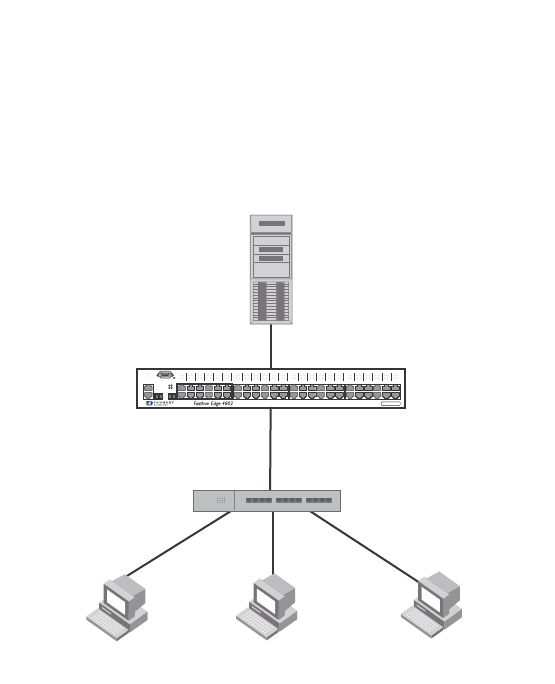
544 PowerConnect B-Series FCX Configuration Guide
53-1002266-01
Sample application
15
FIGURE 111 Sample MAC-based VLAN configuration
Host A MAC address is statically mapped to VLAN 1 with priority 1 and is not subjected to RADIUS
authentication. When Host B MAC address is authenticated, the Access-Accept message from the
RADIUS server specifies that Host B MAC address be placed into VLAN 2. Since Host C MAC
address is not present in the RADIUS server, Host C will be rejected by the server and its MAC
address will be placed into a restricted VLAN.
Below is the configuration for this example.
module 1 FCX-48-port-management-module
module 2 FCX-xfp-1-cx4-2-port-16g-module
vlan 1 by port
untagged ethe 0/1/10
mac-vlan-permit ethe 0/1/1 to 0/1/2
no spanning-tree
vlan 2 by port
untagged ethe 0/1/30
mac-vlan-permit ethe 0/1/1 to 0/1/2
no spanning-tree
vlan 666 name mac_restricted by port
untagged ethe 0/1/20
mac-vlan-permit ethe 0/1/1 to 0/1/2
no spanning-tree
vlan 4000 name DEFAULT-VLAN by port
no spanning-tree
vlan 4004 by port
mac-vlan-permit ethe 0/1/1
default-vlan-id 4000
ip address 10.44.3.8 255.255.255.0
ip default-gateway 10.44.3.1
radius-server host 10.44.3.111
radius-server key 1 $-ndUno
mac-authentication enable
mac-authentication max-age 60
RADIUS Server
User: 0030.4875.3f73 (Host B)
Tunnel-Private-Group-ID = VLAN2
No profile for MAC 0030.4875.3ff5
(Host C)
Port e1
mac-vlan-permit
PS1
PS2 37
38
13
14
25
26
Lnk
Act
Power
Lnk/
Act FDX
FDX
Lnk/
Act
Console
Hub
Untagged
Untagged
Untagged
Host station A
MAC: 0030.4888.b9fe
Host station B
MAC: 0030.4875.3f73
Host station C
MAC: 0030.4875.3ff5
Device
49C
50C
49F 50F
1
2

PowerConnect B-Series FCX Configuration Guide 545
53-1002266-01
Sample application 15
mac-authentication hw-deny-age 30
mac-authentication auth-passwd-format xxxx.xxxx.xxxx
interface ethernet 0/1/1
mac-authentication mac-vlan max-mac-entries 5
mac-authentication mac-vlan 0030.4888.b9fe vlan 1 priority 1
mac-authentication mac-vlan enable
!
interface ethernet 0/1/2
mac-authentication mac-vlan max-mac-entries 5
mac-authentication mac-vlan enable
!
!
end
The show table-mac-vlan command returns the following results for all ports in this configuration.
The show table-mac-vlan e 0/1/1 command returns the following results for port 0/1/1 in this
configuration.
PowerConnect#show table-mac-vlan
---------------------------------------------------------------
Port Vlan Accepted Rejected Attempted Static Static Max
Macs Macs Macs Macs Conf Macs
----------------------------------------------------------------
0/1/1 N/A 2 1 0 1 1 5
0/1/2 N/A 0 0 0 0 0 5
PowerConnect#show table-mac-vlan e 0/1/1
-------------------------------------------------------------------------------
MAC Address Port Vlan Authenticated Time Age CAM MAC Dot1x Type Pri
Index Index
-------------------------------------------------------------------------------
0030.4875.3f73 0/1/1 2 Yes 00d00h00m46s S32 0001 3728 Dis Dyn 4
0030.4888.b9fe 0/1/1 1 Yes 00d00h00m08s Dis 0000 0970 Dis Sta 1
0030.4875.3ff5 0/1/1 666 Rst 01d18h47m58s S8 0002 1ee4 Dis Dyn 0

546 PowerConnect B-Series FCX Configuration Guide
53-1002266-01
Sample application
15

PowerConnect B-Series FCX Configuration Guide 547
53-1002266-01
Chapter
16
Configuring Rule-Based IP Access Control Lists (ACLs)
Table 91 lists the individual Dell PowerConnect switches and ACL features they support.
This chapter describes how Access Control Lists (ACLs) are implemented and configured in the Dell
PowerConnect devices.
TABLE 91 Supported ACL features
Feature PowerConnect B-Series FCX
Hardware-based ACLs Yes
Standard named and numbered ACLs Yes
Extended named and numbered ACLs Yes
User input preservation for ACL TCP/UDP
port numbers
Yes
ACL comment text Yes
ACL logging of denied packets Yes
ACL logging with traffic rate limiting (to
prevent CPU overload)
Yes
This feature is enabled by default on PowerConnect
B-Series FCX devices. There is no CLI command to enable
or disable it.
Strict control of ACL filtering of
fragmented packets
Yes
ACL support for switched traffic in the
router image
Yes
This feature is enabled by default on PowerConnect
B-Series FCX devices. There is no CLI command to enable
or disable it.
ACL filtering based on VLAN membership
or VE port membership
Yes
ACLs to filter ARP packets Yes
Filtering on IP precedence and ToS value Yes
Combined DSCP and internal marking in
one ACL rule
No
QoS options for IP ACLs Yes
Priority mapping using ACLs Yes
Hardware usage statistics Yes
Policy-based routing (PBR)
(Supported in the full Layer 3 code only)
Yes

548 PowerConnect B-Series FCX Configuration Guide
53-1002266-01
ACL overview
16
NOTE
For information about IPv6 ACLs, refer to Chapter 19, “Configuring IPv6 Access Control Lists (ACLs)”.
ACL overview
Dell PowerConnect devices support rule-based ACLs (sometimes called hardware-based ACLs),
where the decisions to permit or deny packets are processed in hardware and all permitted packets
are switched or routed in hardware. All denied packets are also dropped in hardware. In addition,
PowerConnect devices support inbound ACLs only. Outbound ACLs are not supported.
NOTE
PowerConnect devices do not support flow-based ACLs.
Rule-based ACLs program the ACL entries you assign to an interface into Content Addressable
Memory (CAM) space allocated for the ports. The ACLs are programmed into hardware at startup
(or as new ACLs are entered and bound to ports). Devices that use rule-based ACLs program the
ACLs into the CAM entries and use these entries to permit or deny packets in the hardware, without
sending the packets to the CPU for processing.
Rule-based ACLs are supported on the following interface types:
•Gbps Ethernet ports
•10 Gbps Ethernet ports
•Trunk groups
•Virtual routing interfaces
Types of IP ACLs
You can configure the following types of IP ACLs:
•Standard – Permits or denies packets based on source IP address. Valid standard ACL IDs are
1 – 99 or a character string.
•Extended – Permits or denies packets based on source and destination IP address and also
based on IP protocol information. Valid extended ACL IDs are a number from 100 – 199 or a
character string.
ACL IDs and entries
ACLs consist of ACL IDs and ACL entries:
•ACL ID – An ACL ID is a number from 1 – 99 (for a standard ACL) or 100 – 199 (for an extended
ACL) or a character string. The ACL ID identifies a collection of individual ACL entries. When
you apply ACL entries to an interface, you do so by applying the ACL ID that contains the ACL
entries to the interface, instead of applying the individual entries to the interface. This makes
applying large groups of access filters (ACL entries) to interfaces simple. Refer to “Numbered
and named ACLs” on page 549.

PowerConnect B-Series FCX Configuration Guide 549
53-1002266-01
ACL overview 16
NOTE
This is different from IP access policies. If you use IP access policies, you apply the individual
policies to interfaces.
•ACL entry – Also called an ACL rule, this is a filter command associated with an ACL ID. The
maximum number of ACL rules you can configure is a system-wide parameter and depends on
the device you are configuring. You can configure up to the maximum number of entries in any
combination in different ACLs. The total number of entries in all ACLs cannot exceed the
system maximum listed in Table 92.
You configure ACLs on a global basis, then apply them to the incoming traffic on specific ports. The
software applies the entries within an ACL in the order they appear in the ACL configuration. As
soon as a match is found, the software takes the action specified in the ACL entry (permit or deny
the packet) and stops further comparison for that packet.
Numbered and named ACLs
When you configure an ACL, you can refer to the ACL by a numeric ID or by an alphanumeric name.
The commands to configure numbered ACLs are different from the commands for named ACLs.
•Numbered ACL – If you refer to the ACL by a numeric ID, you can use 1 – 99 for a standard ACL
or 100 – 199 for an extended ACL.
•Named ACL – If you refer to the ACL by a name, you specify whether the ACL is a standard ACL
or an extended ACL, then specify the name.
You can configure up to 99 standard numbered IP ACLs and 100 extended numbered IP ACLs. You
also can configure up to 99 standard named ACLs and 100 extended named ACLs by number.
Default ACL action
The default action when no ACLs are configured on a device is to permit all traffic. However, once
you configure an ACL and apply it to a port, the default action for that port is to deny all traffic that
is not explicitly permitted on the port:
•If you want to tightly control access, configure ACLs consisting of permit entries for the access
you want to permit. The ACLs implicitly deny all other access.
•If you want to secure access in environments with many users, you might want to configure
ACLs that consist of explicit deny entries, then add an entry to permit all access to the end of
each ACL. The software permits packets that are not denied by the deny entries.
TABLE 92 Maximum number of ACL entries
System Maximum ACL rules per port region Maximum ACL
entries per system
PowerConnect B-Series FCX Layer 2 or Layer 3
Switch
4093 4093 (24-port)
8186 (48-port)

550 PowerConnect B-Series FCX Configuration Guide
53-1002266-01
How hardware-based ACLs work
16
How hardware-based ACLs work
When you bind an ACL to inbound traffic on an interface, the device programs the Layer 4 CAM with
the ACL. Permit and deny rules are programmed. Most ACL rules require one Layer 4 CAM entry.
However, ACL rules that match on more than one TCP or UDP application port may require several
CAM entries. The Layer 4 CAM entries for ACLs do not age out. They remain in the CAM until you
remove the ACL:
•If a packet received on the interface matches an ACL rule in the Layer 4 CAM, the device
permits or denies the packet according to the ACL.
•If a packet does not match an ACL rule, the packet is dropped, since the default action on an
interface that has ACLs is to deny the packet.
How fragmented packets are processed
The descriptions above apply to non-fragmented packets. The default processing of fragments by
hardware-based ACLs is as follows:
•The first fragment of a packet is permitted or denied using the ACLs. The first fragment is
handled the same way as non-fragmented packets, since the first fragment contains the Layer
4 source and destination application port numbers. The device uses the Layer 4 CAM entry if
one is programmed, or applies the interface's ACL entries to the packet and permits or denies
the packet according to the first matching ACL.
•For other fragments of the same packet, they are subject to a rule only if there is no Layer 4
information in the rule or in any preceding rules.
The fragments are forwarded even if the first fragment, which contains the Layer 4 information,
was denied. Generally, denying the first fragment of a packet is sufficient, since a transaction
cannot be completed without the entire packet.
For tighter control, you can configure the port to drop all packet fragments. Refer to “Enabling strict
control of ACL filtering of fragmented packets” on page 572.
Hardware aging of Layer 4 CAM entries
Rule-based ACLs use Layer 4 CAM entries. The device permanently programs rule-based ACLs into
the CAM. The entries never age out.
Configuration considerations
•PowerConnect devices support inbound ACLs. Outbound ACL are not supported.
•Hardware-based ACLs are supported on:
•Gbps Ethernet ports
•10 Gbps Ethernet ports
•Trunk groups
•Virtual routing interfaces

PowerConnect B-Series FCX Configuration Guide 551
53-1002266-01
Configuring standard numbered ACLs 16
NOTE
PowerConnect B-Series FCX devices do not support ACLs on Group VEs, even though the CLI
contains commands for this action.
•ACLs apply to all traffic, including management traffic.
•The number of ACLs supported per device is listed in Table 92.
•Hardware-based ACLs support only one ACL per port. The ACL of course can contain multiple
entries (rules). For example, hardware-based ACLs do not support ACLs 101 and 102 on port
1, but hardware-based ACLs do support ACL 101 containing multiple entries.
•ACLs are affected by port regions. Each ACL group must contain one entry for the implicit deny
all IP traffic clause. Also, each ACL group uses a multiple of 8 ACL entries. For example, if all
ACL groups contain 5 ACL entries, you could add 127ACL groups (1016/8) in that port region. If
all your ACL groups contain 8 ACL entries, you could add 63 ACL groups, since you must
account for the implicit deny entry.
•By default, the first fragment of a fragmented packet received by the Dell PowerConnect device
is permitted or denied using the ACLs, but subsequent fragments of the same packet are
forwarded in hardware. Generally, denying the first fragment of a packet is sufficient, since a
transaction cannot be completed without the entire packet.
•ACLs are supported on member ports of a VLAN on which DHCP snooping and Dynamic ARP
Inspection (DAI) are enabled. Also, IP source guard and ACLs are supported together on the
same port, as long as both features are configured at the port-level or per-port-per-VLAN level.
Dell PowerConnect ports do not support IP source guard and ACLs on the same port if one is
configured at the port-level and the other is configured at the per-port-per-VLAN level.
•The following ACL features and options are not supported on the PowerConnect devices:
•Applying an ACL on a device that has Super Aggregated VLANs (SAVs) enabled.
•ACL logging of permitted packets– ACL logging is supported for packets that are sent to the
CPU for processing (denied packets). ACL logging is not supported for packets that are
processed in hardware (permitted packets).
•Flow-based ACLs
•Layer 2 ACLs
•You can apply an ACL to a port that has TCP SYN protection or ICMP smurf protection, or both,
enabled.
Configuring standard numbered ACLs
This section describes how to configure standard numbered ACLs with numeric IDs and provides
configuration examples.
Standard ACLs permit or deny packets based on source IP address. You can configure up to 99
standard numbered ACLs. There is no limit to the number of ACL entries an ACL can contain except
for the system-wide limitation. For the number of ACL entries supported on a device, refer to “ACL
IDs and entries” on page 548.
Standard numbered ACL syntax
Syntax: [no] access-list <ACL-num> deny | permit <source-ip> | <hostname> <wildcard> [log]

552 PowerConnect B-Series FCX Configuration Guide
53-1002266-01
Configuring standard numbered ACLs
16
or
Syntax: [no] access-list <ACL-num> deny | permit <source-ip>/<mask-bits> | <hostname> [log]
Syntax: [no] access-list <ACL-num> deny | permit host <source-ip> | <hostname> [log]
Syntax: [no] access-list <ACL-num> deny | permit any [log]
Syntax: [no] ip access-group <ACL-num> in
The <ACL-num> parameter is the access list number from 1 – 99.
The deny | permit parameter indicates whether packets that match a policy in the access list are
denied (dropped) or permitted (forwarded).
The <source-ip> parameter specifies the source IP address. Alternatively, you can specify the host
name.
NOTE
To specify the host name instead of the IP address, the host name must be configured using the
DNS resolver on the Dell PowerConnect device. To configure the DNS resolver name, use the ip dns
server-address… command at the global CONFIG level of the CLI.
The <wildcard> parameter specifies the mask value to compare against the host address specified
by the <source-ip> parameter. The <wildcard> is in dotted-decimal notation (IP address format). It
is a four-part value, where each part is 8 bits (one byte) separated by dots, and each bit is a one or
a zero. Each part is a number ranging from 0 to 255, for example 0.0.0.255. Zeros in the mask
mean the packet source address must match the <source-ip>. Ones mean any value matches. For
example, the <source-ip> and <wildcard> values 209.157.22.26 0.0.0.255 mean that all hosts in
the Class C subnet 209.157.22.x match the policy.
If you prefer to specify the wildcard (mask value) in CIDR format, you can enter a forward slash after
the IP address, then enter the number of significant bits in the mask. For example, you can enter
the CIDR equivalent of “209.157.22.26 0.0.0.255” as “209.157.22.26/24”. The CLI automatically
converts the CIDR number into the appropriate ACL mask (where zeros instead of ones are the
significant bits) and changes the non-significant portion of the IP address into ones. For example,
if you specify 209.157.22.26/24 or 209.157.22.26 0.0.0.255, then save the changes to the
startup-config file, the value appears as 209.157.22.0/24 (if you have enabled display of subnet
lengths) or 209.157.22.0 0.0.0.255 in the startup-config file.
If you enable the software to display IP subnet masks in CIDR format, the mask is saved in the file
in “/<mask-bits>” format. To enable the software to display the CIDR masks, enter the ip
show-subnet-length command at the global CONFIG level of the CLI. You can use the CIDR format
to configure the ACL entry regardless of whether the software is configured to display the masks in
CIDR format.
NOTE
If you use the CIDR format, the ACL entries appear in this format in the running-config and
startup-config files, but are shown with subnet mask in the display produced by the show ip
access-list command.
The host <source-ip> | <hostname> parameter lets you specify a host IP address or name. When
you use this parameter, you do not need to specify the mask. A mask of all zeros (0.0.0.0) is
implied.
The any parameter configures the policy to match on all host addresses.

PowerConnect B-Series FCX Configuration Guide 553
53-1002266-01
Configuring standard named ACLs 16
The log argument configures the device to generate Syslog entries and SNMP traps for packets that
are denied by the access policy.
NOTE
You can enable logging on ACLs and filters that support logging even when the ACLs and filters are
already in use. To do so, re-enter the ACL or filter command and add the log parameter to the end
of the ACL or filter. The software replaces the ACL or filter command with the new one. The new ACL
or filter, with logging enabled, takes effect immediately.
The in parameter applies the ACL to incoming traffic on the interface to which you apply the ACL.
You can apply the ACL to an Ethernet port or virtual interface.
NOTE
If the ACL is for a virtual routing interface, you also can specify a subset of ports within the VLAN
containing that interface when assigning an ACL to the interface.
Configuration example for standard numbered ACLs
To configure a standard ACL and apply it to incoming traffic on port 1/1, enter the following
commands.
PowerConnect(config)#access-list 1 deny host 209.157.22.26 log
PowerConnect(config)#access-list 1 deny 209.157.29.12 log
PowerConnect(config)#access-list 1 deny host IPHost1 log
PowerConnect(config)#access-list 1 permit any
PowerConnect(config)#int eth 1/1
PowerConnect(config-if-1/1)#ip access-group 1 in
PowerConnect(config)#write memory
The commands in this example configure an ACL to deny packets from three source IP addresses
from being received on port 1/1. The last ACL entry in this ACL permits all packets that are not
explicitly denied by the first three ACL entries.
Configuring standard named ACLs
This section describes how to configure standard named ACLs with alphanumeric IDs. This section
also provides configuration examples.
Standard ACLs permit or deny packets based on source IP address. You can configure up to 99
standard named ACLs. There is no limit to the number of ACL entries an ACL can contain except
for the system-wide limitation. For the number of ACL entries supported on a device, refer to “ACL
IDs and entries” on page 548.
The commands for configuring named ACL entries are different from the commands for configuring
numbered ACL entries. The command to configure a numbered ACL is access-list. The command
for configuring a named ACL is ip access-list. In addition, when you configure a numbered ACL
entry, you specify all the command parameters on the same command. When you configure a
named ACL, you specify the ACL type (standard or extended) and the ACL name with one command,
which places you in the configuration level for that ACL. Once you enter the configuration level for
the ACL, the command syntax is the same as the syntax for numbered ACLs.

554 PowerConnect B-Series FCX Configuration Guide
53-1002266-01
Configuring standard named ACLs
16
Standard named ACL syntax
Syntax: [no] ip access-list standard <ACL-name> | <ACL-num>
Syntax: deny | permit <source-ip> | <hostname> <wildcard> [log]
or
Syntax: deny | permit <source-ip>/<mask-bits> | <hostname> [log]
Syntax: deny | permit host <source-ip> | <hostname> [log]
Syntax: deny | permit any [log]
Syntax: [no] ip access-group <ACL-name> in
The <ACL-name> parameter is the access list name. You can specify a string of up to 256
alphanumeric characters. You can use blanks in the ACL name if you enclose the name in
quotation marks (for example, “ACL for Net1”).
The <ACL-num> parameter allows you to specify an ACL number if you prefer. If you specify a
number, you can specify from 1 – 99 for standard ACLs.
NOTE
For convenience, the software allows you to configure numbered ACLs using the syntax for named
ACLs. The software also still supports the older syntax for numbered ACLs. Although the software
allows both methods for configuring numbered ACLs, numbered ACLs are always formatted in the
startup-config and running-config files in using the older syntax, as follows.
access-list 1 deny host 209.157.22.26 log
access-list 1 deny 209.157.22.0 0.0.0.255 log
access-list 1 permit any
access-list 101 deny tcp any any eq http log
The deny | permit parameter indicates whether packets that match a policy in the access list are
denied (dropped) or permitted (forwarded).
The <source-ip> parameter specifies the source IP address. Alternatively, you can specify the host
name.
NOTE
To specify the host name instead of the IP address, the host name must be configured using the
DNS resolver on the Dell PowerConnect device. To configure the DNS resolver name, use the ip dns
server-address… command at the global CONFIG level of the CLI.
The <wildcard> parameter specifies the mask value to compare against the host address specified
by the <source-ip> parameter. The <wildcard> is in dotted-decimal notation (IP address format). It
is a four-part value, where each part is 8 bits (one byte) separated by dots, and each bit is a one or
a zero. Each part is a number ranging from 0 to 255, for example 0.0.0.255. Zeros in the mask
mean the packet source address must match the <source-ip>. Ones mean any value matches. For
example, the <source-ip> and <wildcard> values 209.157.22.26 0.0.0.255 mean that all hosts in
the Class C subnet 209.157.22.x match the policy.
If you prefer to specify the wildcard (mask value) in CIDR format, you can enter a forward slash after
the IP address, then enter the number of significant bits in the mask. For example, you can enter
the CIDR equivalent of “209.157.22.26 0.0.0.255” as “209.157.22.26/24”. The CLI automatically
converts the CIDR number into the appropriate ACL mask (where zeros instead of ones are the

PowerConnect B-Series FCX Configuration Guide 555
53-1002266-01
Configuring standard named ACLs 16
significant bits) and changes the non-significant portion of the IP address into ones. For example,
if you specify 209.157.22.26/24 or 209.157.22.26 0.0.0.255, then save the changes to the
startup-config file, the value appears as 209.157.22.0/24 (if you have enabled display of subnet
lengths) or 209.157.22.0 0.0.0.255 in the startup-config file.
If you enable the software to display IP subnet masks in CIDR format, the mask is saved in the file
in “/<mask-bits>” format. To enable the software to display the CIDR masks, enter the ip
show-subnet-length command at the global CONFIG level of the CLI. You can use the CIDR format
to configure the ACL entry regardless of whether the software is configured to display the masks in
CIDR format.
NOTE
If you use the CIDR format, the ACL entries appear in this format in the running-config and
startup-config files, but are shown with subnet mask in the display produced by the show ip
access-list command.
The host <source-ip> | <hostname> parameter lets you specify a host IP address or name. When
you use this parameter, you do not need to specify the mask. A mask of all zeros (0.0.0.0) is
implied.
The any parameter configures the policy to match on all host addresses.
The log argument configures the device to generate Syslog entries and SNMP traps for packets that
are denied by the access policy.
NOTE
You can enable logging on ACLs and filters that support logging even when the ACLs and filters are
already in use. To do so, re-enter the ACL or filter command and add the log parameter to the end
of the ACL or filter. The software replaces the ACL or filter command with the new one. The new ACL
or filter, with logging enabled, takes effect immediately.
The in parameter applies the ACL to incoming traffic on the interface to which you apply the ACL.
You can apply the ACL to an Ethernet port or virtual interface.
NOTE
If the ACL is bound to a virtual routing interface, you also can specify a subset of ports within the
VLAN containing that interface when assigning an ACL to the interface.
Configuration example for standard named ACLs
To configure a standard named ACL, enter commands such as the following.
PowerConnect(config)#ip access-list standard Net1
PowerConnect(config-std-nACL)#deny host 209.157.22.26 log
PowerConnect(config-std-nACL)#deny 209.157.29.12 log
PowerConnect(config-std-nACL)#deny host IPHost1 log
PowerConnect(config-std-nACL)#permit any
PowerConnect(config-std-nACL)#exit
PowerConnect(config)#int eth 1/1
PowerConnect(config-if-e1000-1/1)#ip access-group Net1 in

556 PowerConnect B-Series FCX Configuration Guide
53-1002266-01
Configuring extended numbered ACLs
16
The commands in this example configure a standard ACL named “Net1”. The entries in this ACL
deny packets from three source IP addresses from being forwarded on port 1. Since the implicit
action for an ACL is “deny”, the last ACL entry in this ACL permits all packets that are not explicitly
denied by the first three ACL entries. For an example of how to configure the same entries in a
numbered ACL, refer to “Configuring standard numbered ACLs” on page 551.
Notice that the command prompt changes after you enter the ACL type and name. The “std” in the
command prompt indicates that you are configuring entries for a standard ACL. For an extended
ACL, this part of the command prompt is “ext“. The “nACL” indicates that you are configuring a
named ACL.
Configuring extended numbered ACLs
This section describes how to configure extended numbered ACLs.
Extended ACLs let you permit or deny packets based on the following information:
•IP protocol
•Source IP address or host name
•Destination IP address or host name
•Source TCP or UDP port (if the IP protocol is TCP or UDP)
•Destination TCP or UDP port (if the IP protocol is TCP or UDP)
The IP protocol can be one of the following well-known names or any IP protocol number from 0 –
255:
•Internet Control Message Protocol (ICMP)
•Internet Group Management Protocol (IGMP)
•Internet Gateway Routing Protocol (IGRP)
•Internet Protocol (IP)
•Open Shortest Path First (OSPF)
•Transmission Control Protocol (TCP)
•User Datagram Protocol (UDP)
For TCP and UDP, you also can specify a comparison operator and port name or number. For
example, you can configure a policy to block web access to a specific website by denying all TCP
port 80 (HTTP) packets from a specified source IP address to the website IP address.
Extended numbered ACL syntax
Syntax: [no] access-list <ACL-num> deny | permit <ip-protocol> <source-ip> | <hostname>
<wildcard> [<operator> <source-tcp/udp-port>] <destination-ip> | <hostname>
[<icmp-num> | <icmp-type>] <wildcard> [<tcp/udp comparison operator>
<destination-tcp/udp-port>] [802.1p-priority-matching <0 –7>] [dscp-cos-mapping ]
[dscp-marking <0-63> [802.1p-priority-marking <0 –7>... | dscp-cos-mapping]]
[dscp-matching <0-63>] [log] [precedence <name> | <0 – 7>] [tos <0 – 63> | <name>]
[traffic policy <name>]
Syntax: [no] access-list <ACL-num> deny | permit host <ip-protocol> any any
Syntax: [no] ip access-group <ACL-num> in

PowerConnect B-Series FCX Configuration Guide 557
53-1002266-01
Configuring extended numbered ACLs 16
The <ACL-num> parameter is the extended access list number. Specify a number from 100 – 199.
The deny | permit parameter indicates whether packets that match the policy are dropped or
forwarded.
The <ip-protocol> parameter indicates the type of IP packet you are filtering. You can specify a
well-known name for any protocol whose number is less than 255. For other protocols, you must
enter the number. Enter “?” instead of a protocol to list the well-known names recognized by the
CLI.
The <source-ip> | <hostname> parameter specifies the source IP host for the policy. If you want
the policy to match on all source addresses, enter any.
The <wildcard> parameter specifies the portion of the source IP host address to match against.
The <wildcard> is in dotted-decimal notation (IP address format). It is a four-part value, where
each part is 8 bits (one byte) separated by dots, and each bit is a one or a zero. Each part is a
number ranging from 0 to 255, for example 0.0.0.255. Zeros in the mask mean the packet’s
source address must match the <source-ip>. Ones mean any value matches. For example, the
<source-ip> and <wildcard> values 209.157.22.26 0.0.0.255 mean that all hosts in the Class C
subnet 209.157.22.x match the policy.
If you prefer to specify the wildcard (mask value) in Classless Interdomain Routing (CIDR) format,
you can enter a forward slash after the IP address, then enter the number of significant bits in the
mask. For example, you can enter the CIDR equivalent of “209.157.22.26 0.0.0.255” as
“209.157.22.26/24”. The CLI automatically converts the CIDR number into the appropriate ACL
mask (where zeros instead of ones are the significant bits) and changes the non-significant portion
of the IP address into zeros. For example, if you specify 209.157.22.26/24 or 209.157.22.26
0.0.0.255, then save the changes to the startup-config file, the value appears as 209.157.22.0/24
(if you have enabled display of subnet lengths) or 209.157.22.0 0.0.0.255 in the startup-config file.
If you enable the software to display IP subnet masks in CIDR format, the mask is saved in the file
in “/<mask-bits>” format. To enable the software to display the CIDR masks, enter the ip
show-subnet-length command at the global CONFIG level of the CLI. You can use the CIDR format
to configure the ACL entry regardless of whether the software is configured to display the masks in
CIDR format.
NOTE
If you use the CIDR format, the ACL entries appear in this format in the running-config and
startup-config files, but are shown with subnet mask in the display produced by the show ip
access-list command.
The <destination-ip> | <hostname> parameter specifies the destination IP host for the policy. If
you want the policy to match on all destination addresses, enter any.
The <icmp-type> | <icmp-num> parameter specifies the ICMP protocol type:
•This parameter applies only if you specified icmp as the <ip-protocol> value.
•If you use this parameter, the ACL entry is sent to the CPU for processing.
•If you do not specify a message type, the ACL applies to all types of ICMP messages.
The <icmp-num> parameter can be a value from 0 – 255.
The <icmp-type> parameter can have one of the following values, depending on the software
version the device is running:
•any-icmp-type
•echo

558 PowerConnect B-Series FCX Configuration Guide
53-1002266-01
Configuring extended numbered ACLs
16
•echo-reply
•information-request
•log
•mask-reply
•mask-request
•parameter-problem
•redirect
•source-quench
•time-exceeded
•timestamp-reply
•timestamp-request
•traffic policy
•unreachable
•<num>
The <tcp/udp comparison operator> parameter specifies a comparison operator for the TCP or
UDP port number. This parameter applies only when you specify tcp or udp as the IP protocol. For
example, if you are configuring an entry for HTTP, specify tcp eq http. You can enter one of the
following operators:
•eq – The policy applies to the TCP or UDP port name or number you enter after eq.
•established – This operator applies only to TCP packets. If you use this operator, the policy
applies to TCP packets that have the ACK (Acknowledgment) or RST (Reset) bits set on (set to
“1”) in the Control Bits field of the TCP packet header. Thus, the policy applies only to
established TCP sessions, not to new sessions. Refer to Section 3.1, “Header Format”, in RFC
793 for information about this field.
NOTE
This operator applies only to destination TCP ports, not source TCP ports.
•gt – The policy applies to TCP or UDP port numbers greater than the port number or the
numeric equivalent of the port name you enter after gt.
•lt – The policy applies to TCP or UDP port numbers that are less than the port number or the
numeric equivalent of the port name you enter after lt.
•neq – The policy applies to all TCP or UDP port numbers except the port number or port name
you enter after neq.
•range – The policy applies to all TCP or UDP port numbers that are between the first TCP or
UDP port name or number and the second one you enter following the range parameter. The
range includes the port names or numbers you enter. For example, to apply the policy to all
ports between and including 23 (Telnet) and 53 (DNS), enter the following: range 23 53. The
first port number in the range must be lower than the last number in the range.
The <tcp/udp-port> parameter specifies the TCP or UDP port number or well-known name. You can
specify a well-known name for any application port whose number is less than 1024. For other
application ports, you must enter the number. Enter “?” instead of a port to list the well-known
names recognized by the CLI.
The in parameter specifies that the ACL applies to incoming traffic on the interface to which you
apply the ACL. You can apply the ACL to an Ethernet port or a virtual interface.

PowerConnect B-Series FCX Configuration Guide 559
53-1002266-01
Configuring extended numbered ACLs 16
NOTE
If the ACL is for a virtual routing interface, you also can specify a subset of ports within the VLAN
containing that interface when assigning an ACL to the interface. Refer to “Configuring standard
numbered ACLs” on page 551.
The precedence <name> | <num> parameter of the ip access-list command specifies the IP
precedence. The precedence option for of an IP packet is set in a three-bit field following the
four-bit header-length field of the packet’s header. You can specify one of the following:
•critical or 5 – The ACL matches packets that have the critical precedence. If you specify the
option number instead of the name, specify number 5.
•flash or 3 – The ACL matches packets that have the flash precedence. If you specify the option
number instead of the name, specify number 3.
•flash-override or 4 – The ACL matches packets that have the flash override precedence. If you
specify the option number instead of the name, specify number 4.
•immediate or 2 – The ACL matches packets that have the immediate precedence. If you
specify the option number instead of the name, specify number 2.
•internet or 6 – The ACL matches packets that have the internetwork control precedence. If you
specify the option number instead of the name, specify number 6.
•network or 7 – The ACL matches packets that have the network control precedence. If you
specify the option number instead of the name, specify number 7.
•priority or 1 – The ACL matches packets that have the priority precedence. If you specify the
option number instead of the name, specify number 1.
•routine or 0 – The ACL matches packets that have the routine precedence. If you specify the
option number instead of the name, specify number 0.
The tos <name> | <num> parameter of the ip access-list command specifies the IP ToS. You can
specify one of the following:
•max-reliability or 2 – The ACL matches packets that have the maximum reliability ToS. The
decimal value for this option is 2.
•max-throughput or 4 – The ACL matches packets that have the maximum throughput ToS. The
decimal value for this option is 4.
•min-delay or 8 – The ACL matches packets that have the minimum delay ToS. The decimal
value for this option is 8.
•min-monetary-cost or 1 – The ACL matches packets that have the minimum monetary cost
ToS. The decimal value for this option is 1.
NOTE
This value is not supported on 10 Gigabit Ethernet modules.
•normal or 0 – The ACL matches packets that have the normal ToS. The decimal value for
this option is 0.
•<num> – A number from 0 – 15 that is the sum of the numeric values of the options you
want. The ToS field is a four-bit field following the Precedence field in the IP header. You
can specify one or more of the following. To select more than one option, enter the
decimal value that is equivalent to the sum of the numeric values of all the ToS options
you want to select. For example, to select the max-reliability and min-delay options, enter
number 10. To select all options, select 15.

560 PowerConnect B-Series FCX Configuration Guide
53-1002266-01
Configuring extended numbered ACLs
16
The 802.1p-priority-matching option inspects the 802.1p bit in the ACL that can be used with
adaptive rate limiting. Enter a value from 0 – 7. For details, refer to “Inspecting the 802.1p bit in the
ACL for adaptive rate limiting” on page 765.
The dscp-marking option enables you to configure an ACL that marks matching packets with a
specified DSCP value Enter a value from 0 – 63. Refer to “Using an IP ACL to mark DSCP values
(DSCP marking)” on page 580.
The dscp-matching option matches on the packet’s DSCP value. Enter a value from 0 – 63. This
option does not change the packet’s forwarding priority through the device or mark the packet.
Refer to “DSCP matching” on page 581.
The log parameter enables SNMP traps and Syslog messages for packets denied by the ACL:
•You can enable logging on ACLs and filters that support logging even when the ACLs and filters
are already in use. To do so, re-enter the ACL or filter command and add the log parameter to
the end of the ACL or filter. The software replaces the ACL or filter command with the new one.
The new ACL or filter, with logging enabled, takes effect immediately.
The traffic-policy option enables the device to rate limit inbound traffic and to count the packets
and bytes per packet to which ACL permit or deny clauses are applied. For configuration
procedures and examples, refer to the chapter “Configuring Traffic Policies” on page 759.
Configuration examples for extended numbered ACLs
To configure an extended access list that blocks all Telnet traffic received on port 1/1 from IP host
209.157.22.26, enter the following commands.
Here is another example of commands for configuring an extended ACL and applying it to an
interface. These examples show many of the syntax choices. Notice that some of the entries are
configured to generate log entries while other entries are not thus configured.
The first entry permits ICMP traffic from hosts in the 209.157.22.x network to hosts in the
209.157.21.x network.
The second entry denies IGMP traffic from the host device named “rkwong” to the 209.157.21.x
network.
The third entry denies IGMP traffic from the 209.157.21.x network to the host device named
“rkwong”.
The fourth entry denies all IP traffic from host 209.157.21.100to host 209.157.22.1 and generates
Syslog entries for packets that are denied by this entry.
PowerConnect(config)#access-list 101 deny tcp host 209.157.22.26 any eq telnet
log
PowerConnect(config)#access-list 101 permit ip any any
PowerConnect(config)#int eth 1/1
PowerConnect(config-if-e1000-1/1)#ip access-group 101 in
PowerConnect(config)#access-list 102 perm icmp 209.157.22.0/24 209.157.21.0/24
PowerConnect(config)#access-list 102 deny igmp host rkwong 209.157.21.0/24 log
PowerConnect(config)#access-list 102 deny igrp 209.157.21.0/24 host rkwong log
PowerConnect(config)#access-list 102 deny ip host 209.157.21.100 host
209.157.22.1 log
PowerConnect(config)#access-list 102 deny ospf any any log
PowerConnect(config)#access-list 102 permit ip any any

PowerConnect B-Series FCX Configuration Guide 561
53-1002266-01
Configuring extended numbered ACLs 16
The fifth entry denies all OSPF traffic and generates Syslog entries for denied traffic.
The sixth entry permits all packets that are not explicitly denied by the other entries. Without this
entry, the ACL would deny all incoming or outgoing IP traffic on the ports to which you assign the
ACL.
The following commands apply ACL 102 to the incoming traffic on port 1/2 and to the incoming
traffic on port 4/3.
Here is another example of an extended ACL.
The first entry in this ACL denies TCP traffic from the 209.157.21.x network to the 209.157.22.x
network.
The second entry denies all FTP traffic from the 209.157.21.x network to the 209.157.22.x
network.
The third entry denies TCP traffic from the 209.157.21.x network to the 209.157.22.x network, if
the TCP port number of the traffic is less than the well-known TCP port number for Telnet (23), and
if the TCP port is not equal to 5. Thus, TCP packets whose TCP port numbers are 5 or are greater
than 23 are allowed.
The fourth entry denies UDP packets from any source to the 209.157.22.x network, if the UDP port
number from the source network is 5 or 6 and the destination UDP port is 7 or 8.
The fifth entry permits all packets that are not explicitly denied by the other entries. Without this
entry, the ACL would deny all incoming or outgoing IP traffic on the ports to which you assign the
ACL.
The following commands apply ACL 103 to the incoming traffic on ports 2/1 and 2/2.
PowerConnect(config)#int eth 1/2
PowerConnect(config-if-1/2)#ip access-group 102 in
PowerConnect(config-if-1/2)#exit
PowerConnect(config)#int eth 4/3
PowerConnect(config-if-4/3)#ip access-group 102 in
PowerConnect(config)#write memory
PowerConnect(config)#access-list 103 deny tcp 209.157.21.0/24 209.157.22.0/24
PowerConnect(config)#access-list 103 deny tcp 209.157.21.0/24 eq ftp
209.157.22.0/24
PowerConnect(config)#access-list 103 deny tcp 209.157.21.0/24 209.157.22.0/24 lt
telnet neq 5
PowerConnect(config)#access-list 103 deny udp any range 5 6 209.157.22.0/24
PowerConnect(config)#int eth 2/1
PowerConnect(config-if-2/1)#ip access-group 103 in
PowerConnect(config-if-2/1)#exit
PowerConnect(config)#int eth 0/2/2
PowerConnect(config-if-2/2)#ip access-group 103 in
PowerConnect(config)#write memory

562 PowerConnect B-Series FCX Configuration Guide
53-1002266-01
Configuring extended named ACLs
16
Configuring extended named ACLs
The commands for configuring named ACL entries are different from the commands for configuring
numbered ACL entries. The command to configure a numbered ACL is access-list. The command
for configuring a named ACL is ip access-list. In addition, when you configure a numbered ACL
entry, you specify all the command parameters on the same command. When you configure a
named ACL, you specify the ACL type (standard or extended) and the ACL number with one
command, which places you in the configuration level for that ACL. Once you enter the
configuration level for the ACL, the command syntax is the same as the syntax for numbered ACLs.
Extended ACLs let you permit or deny packets based on the following information:
•IP protocol
•Source IP address or host name
•Destination IP address or host name
•Source TCP or UDP port (if the IP protocol is TCP or UDP)
•Destination TCP or UDP port (if the IP protocol is TCP or UDP)
The IP protocol can be one of the following well-known names or any IP protocol number from 0 –
255:
•Internet Control Message Protocol (ICMP)
•Internet Group Management Protocol (IGMP)
•Internet Gateway Routing Protocol (IGRP)
•Internet Protocol (IP)
•Open Shortest Path First (OSPF)
•Transmission Control Protocol (TCP)
•User Datagram Protocol (UDP)
For TCP and UDP, you also can specify a comparison operator and port name or number. For
example, you can configure a policy to block web access to a specific website by denying all TCP
port 80 (HTTP) packets from a specified source IP address to the website’s IP address.
Extended named ACL syntax
Syntax: [no] ip access-list extended <ACL-name> deny | permit <ip-protocol> <source-ip> |
<hostname> <wildcard> [<operator> <source-tcp/udp-port>] <destination-ip> |
<hostname> [<icmp-num> | <icmp-type>] <wildcard> [<tcp/udp comparison operator>
<destination-tcp/udp-port>] [802.1p-priority-matching <0 –7>] [dscp-marking <0-63>
[802.1p-priority-marking <0 –7>... ] [dscp-matching <0-63>] [log] [precedence <name> |
<0 – 7>] [tos <0 – 63> | <name>] [traffic policy <name>]
Syntax: [no] ip access-group <num> in
The <ACL-name> parameter is the access list name. You can specify a string of up to 256
alphanumeric characters. You can use blanks in the ACL name if you enclose the name in
quotation marks (for example, “ACL for Net1”).
The deny | permit parameter indicates whether packets that match the policy are dropped or
forwarded.

PowerConnect B-Series FCX Configuration Guide 563
53-1002266-01
Configuring extended named ACLs 16
The <ip-protocol> parameter indicates the type of IP packet you are filtering. You can specify a
well-known name for any protocol whose number is less than 255. For other protocols, you must
enter the number. Enter “?” instead of a protocol to list the well-known names recognized by the
CLI.
The <source-ip> | <hostname> parameter specifies the source IP host for the policy. If you want
the policy to match on all source addresses, enter any.
The <wildcard> parameter specifies the portion of the source IP host address to match against.
The <wildcard> is in dotted-decimal notation (IP address format). It is a four-part value, where
each part is 8 bits (one byte) separated by dots, and each bit is a one or a zero. Each part is a
number ranging from 0 to 255, for example 0.0.0.255. Zeros in the mask mean the packet’s
source address must match the <source-ip>. Ones mean any value matches. For example, the
<source-ip> and <wildcard> values 209.157.22.26 0.0.0.255 mean that all hosts in the Class C
subnet 209.157.22.x match the policy.
If you prefer to specify the wildcard (mask value) in Classless Interdomain Routing (CIDR) format,
you can enter a forward slash after the IP address, then enter the number of significant bits in the
mask. For example, you can enter the CIDR equivalent of “209.157.22.26 0.0.0.255” as
“209.157.22.26/24”. The CLI automatically converts the CIDR number into the appropriate ACL
mask (where zeros instead of ones are the significant bits) and changes the non-significant portion
of the IP address into zeros. For example, if you specify 209.157.22.26/24 or 209.157.22.26
0.0.0.255, then save the changes to the startup-config file, the value appears as 209.157.22.0/24
(if you have enabled display of subnet lengths) or 209.157.22.0 0.0.0.255 in the startup-config file.
If you enable the software to display IP subnet masks in CIDR format, the mask is saved in the file
in “/<mask-bits>” format. To enable the software to display the CIDR masks, enter the ip
show-subnet-length command at the global CONFIG level of the CLI. You can use the CIDR format
to configure the ACL entry regardless of whether the software is configured to display the masks in
CIDR format.
NOTE
If you use the CIDR format, the ACL entries appear in this format in the running-config and
startup-config files, but are shown with subnet mask in the display produced by the show ip
access-list command.
The <destination-ip> | <hostname> parameter specifies the destination IP host for the policy. If
you want the policy to match on all destination addresses, enter any.
The <icmp-type> | <icmp-num> parameter specifies the ICMP protocol type:
•This parameter applies only if you specified icmp as the <ip-protocol> value.
•If you use this parameter, the ACL entry is sent to the CPU for processing.
•If you do not specify a message type, the ACL applies to all types of ICMP messages.
The <icmp-num> parameter can be a value from 0 – 255.
The <icmp-type> parameter can have one of the following values, depending on the software
version the device is running:
•any-icmp-type
•echo
•echo-reply
•information-request
•log

564 PowerConnect B-Series FCX Configuration Guide
53-1002266-01
Configuring extended named ACLs
16
•mask-reply
•mask-request
•parameter-problem
•redirect
•source-quench
•time-exceeded
•timestamp-reply
•timestamp-request
•traffic policy
•unreachable
•<num>
The <tcp/udp comparison operator> parameter specifies a comparison operator for the TCP or
UDP port number. This parameter applies only when you specify tcp or udp as the IP protocol. For
example, if you are configuring an entry for HTTP, specify tcp eq http. You can enter one of the
following operators:
•eq – The policy applies to the TCP or UDP port name or number you enter after eq.
•established – This operator applies only to TCP packets. If you use this operator, the policy
applies to TCP packets that have the ACK (Acknowledgment) or RST (Reset) bits set on (set to
“1”) in the Control Bits field of the TCP packet header. Thus, the policy applies only to
established TCP sessions, not to new sessions. Refer to Section 3.1, “Header Format”, in RFC
793 for information about this field.
NOTE
This operator applies only to destination TCP ports, not source TCP ports.
•gt – The policy applies to TCP or UDP port numbers greater than the port number or the
numeric equivalent of the port name you enter after gt.
•lt – The policy applies to TCP or UDP port numbers that are less than the port number or the
numeric equivalent of the port name you enter after lt.
•neq – The policy applies to all TCP or UDP port numbers except the port number or port name
you enter after neq.
•range – The policy applies to all TCP or UDP port numbers that are between the first TCP or
UDP port name or number and the second one you enter following the range parameter. The
range includes the port names or numbers you enter. For example, to apply the policy to all
ports between and including 23 (Telnet) and 53 (DNS), enter the following: range 23 53. The
first port number in the range must be lower than the last number in the range.
The <tcp/udp-port> parameter specifies the TCP or UDP port number or well-known name. You can
specify a well-known name for any application port whose number is less than 1024. For other
application ports, you must enter the number. Enter “?” instead of a port to list the well-known
names recognized by the CLI.
The in parameter specifies that the ACL applies to incoming traffic on the interface to which you
apply the ACL. You can apply the ACL to an Ethernet port or a virtual interface.

PowerConnect B-Series FCX Configuration Guide 565
53-1002266-01
Configuring extended named ACLs 16
NOTE
If the ACL is for a virtual routing interface, you also can specify a subset of ports within the VLAN
containing that interface when assigning an ACL to the interface. Refer to “Configuring standard
numbered ACLs” on page 551.
The precedence <name> | <num> parameter of the ip access-list command specifies the IP
precedence. The precedence option for of an IP packet is set in a three-bit field following the
four-bit header-length field of the packet’s header. You can specify one of the following:
•critical or 5 – The ACL matches packets that have the critical precedence. If you specify the
option number instead of the name, specify number 5.
•flash or 3 – The ACL matches packets that have the flash precedence. If you specify the option
number instead of the name, specify number 3.
•flash-override or 4 – The ACL matches packets that have the flash override precedence. If you
specify the option number instead of the name, specify number 4.
•immediate or 2 – The ACL matches packets that have the immediate precedence. If you
specify the option number instead of the name, specify number 2.
•internet or 6 – The ACL matches packets that have the internetwork control precedence. If you
specify the option number instead of the name, specify number 6.
•network or 7 – The ACL matches packets that have the network control precedence. If you
specify the option number instead of the name, specify number 7.
•priority or 1 – The ACL matches packets that have the priority precedence. If you specify the
option number instead of the name, specify number 1.
•routine or 0 – The ACL matches packets that have the routine precedence. If you specify the
option number instead of the name, specify number 0.
The tos <name> | <num> parameter of the ip access-list command specifies the IP ToS. You can
specify one of the following:
•max-reliability or 2 – The ACL matches packets that have the maximum reliability ToS. The
decimal value for this option is 2.
•max-throughput or 4 – The ACL matches packets that have the maximum throughput ToS. The
decimal value for this option is 4.
•min-delay or 8 – The ACL matches packets that have the minimum delay ToS. The decimal
value for this option is 8.
•min-monetary-cost or 1 – The ACL matches packets that have the minimum monetary cost
ToS. The decimal value for this option is 1.
NOTE
This value is not supported on 10 Gigabit Ethernet modules.
•normal or 0 – The ACL matches packets that have the normal ToS. The decimal value for
this option is 0.
•<num> – A number from 0 – 15 that is the sum of the numeric values of the options you
want. The ToS field is a four-bit field following the Precedence field in the IP header. You
can specify one or more of the following. To select more than one option, enter the
decimal value that is equivalent to the sum of the numeric values of all the ToS options
you want to select. For example, to select the max-reliability and min-delay options, enter
number 10. To select all options, select 15.

566 PowerConnect B-Series FCX Configuration Guide
53-1002266-01
Preserving user input for ACL TCP/UDP port numbers
16
The 802.1p-priority-matching option inspects the 802.1p bit in the ACL that can be used with
adaptive rate limiting. Enter a value from 0 – 7. For details, refer to “Inspecting the 802.1p bit in the
ACL for adaptive rate limiting” on page 765.
The dscp-marking option enables you to configure an ACL that marks matching packets with a
specified DSCP value Enter a value from 0 – 63. Refer to “Using an IP ACL to mark DSCP values
(DSCP marking)” on page 580.
The dscp-matching option matches on the packet’s DSCP value. Enter a value from 0 – 63. This
option does not change the packet’s forwarding priority through the device or mark the packet.
Refer to “DSCP matching” on page 581.
The log parameter enables SNMP traps and Syslog messages for packets denied by the ACL:
•You can enable logging on ACLs and filters that support logging even when the ACLs and filters
are already in use. To do so, re-enter the ACL or filter command and add the log parameter to
the end of the ACL or filter. The software replaces the ACL or filter command with the new one.
The new ACL or filter, with logging enabled, takes effect immediately.
The traffic-policy option enables the device to rate limit inbound traffic and to count the packets
and bytes per packet to which ACL permit or deny clauses are applied. For configuration
procedures and examples, refer to the chapter “Configuring Traffic Policies” on page 759.
Configuration example for extended named ACLs
To configure an extended named ACL, enter commands such as the following.
The options at the ACL configuration level and the syntax for the ip access-group command are the
same for numbered and named ACLs and are described in “Configuring extended numbered ACLs”
on page 556 and “Configuring extended numbered ACLs” on page 556.
Preserving user input for ACL TCP/UDP port numbers
ACL implementations automatically display the TCP/UDP port name instead of the port number,
regardless of user preference, unless the device is configured to preserve user input. When the
option to preserve user input is enabled, the system will display either the port name or the
number.
To enable this feature, enter the following command.
PowerConnect(config)#ip preserve-ACL-user-input-format
Syntax: ip preserve-ACL-user-input-format
PowerConnect(config)#ip access-list extended “block Telnet”
PowerConnect(config-ext-nACL)#deny tcp host 209.157.22.26 any eq telnet log
PowerConnect(config-ext-nACL)#permit ip any any
PowerConnect(config-ext-nACL)#exit
PowerConnect(config)#int eth 1/1
PowerConnect(config-if-1/1)#ip access-group “block Telnet” in

PowerConnect B-Series FCX Configuration Guide 567
53-1002266-01
Managing ACL comment text 16
The following example shows how this feature works for a TCP port (this feature works the same
way for UDP ports). In this example, the user identifies the TCP port by number (80) when
configuring ACL group 140. However, show ip access-list 140 reverts back to the port name for the
TCP port (http in this example). After the user issues the new ip preserve-ACL-user-input-format
command, show ip access-list 140 displays either the TCP port number or name, depending on
how it was configured by the user.
PowerConnect(config)#access-list 140 permit tcp any any eq 80
PowerConnect(config)#access-list 140 permit tcp any any eq ftp
PowerConnect#show ip access-lists 140
Extended IP access list 140
permit tcp any any eq http
permit tcp any any eq ftp
PowerConnect(config)#ip preserve-ACL-user-input-format
PowerConnect#show ip access-lists 140
Extended IP access list 140
permit tcp any any eq 80
permit tcp any any eq ftp
Managing ACL comment text
ACL comment text describes entries in an ACL. The comment text appears in the output of show
commands that display ACL information.
This section describes how to add delete, and view ACL comments.
Adding a comment to an entry in a numbered ACL
To add comments to entries in a numbered ACL, enter commands such as the following.
You can add comments to entries in a numbered ACL using the syntax for named ACLs. For
example, using the same example configuration above, you could instead enter the following
commands.
Syntax: [no] access-list <ACL-num> remark <comment-text>
or
Syntax: [no] ip access-list standard | extended <ACL-num>
Syntax: remark <comment-text>
For <ACL-num>, enter the number of the ACL.
PowerConnect(config)#access-list 100 remark The following line permits TCP
packets
PowerConnect(config)#access-list 100 permit tcp 192.168.4.40/24 2.2.2.2/24
PowerConnect(config)#access-list 100 remark The following permits UDP packets
PowerConnect(config)#access-list 100 permit udp 192.168.2.52/24 2.2.2.2/24
PowerConnect(config)#access-list 100 deny ip any any
PowerConnect(config)#ip access-list extended 100
PowerConnect(config-ext-nACL)#remark The following line permits TCP packets
PowerConnect(config-ext-nACL)#permit tcp 192.168.4.40/24 2.2.2.2/24
PowerConnect(config-ext-nACL)#remark The following permits UDP packets
PowerConnect(config-ext-nACL)#permit udp 192.168.2.52/24 2.2.2.2/24
PowerConnect(config-ext-nACL)#deny ip any any

568 PowerConnect B-Series FCX Configuration Guide
53-1002266-01
Managing ACL comment text
16
The <comment-text> can be up to 128 characters in length. The comment must be entered
separately from the actual ACL entry; that is, you cannot enter the ACL entry and the ACL comment
with the same access-list or ip access-list command. Also, in order for the remark to be displayed
correctly in the output of show commands, the comment must be entered immediately before the
ACL entry it describes. Note that an ACL comment is tied to the ACL entry immediately following the
comment. Therefore, if the ACL entry is removed, the ACL comment is also removed.
The standard | extended parameter indicates the ACL type.
Adding a comment to an entry in a named ACL
To add comments to entries in a named ACL, enter commands such as the following.
Syntax: [no] access-list standard | extended <ACL-name>
Syntax: remark <comment-text>
The standard | extended parameter indicates the ACL type.
For <ACL-name>, enter the name of the ACL.
The <comment-text> can be up to 128 characters in length. The comment must be entered
separately from the actual ACL entry; that is, you cannot enter the ACL entry and the ACL comment
with the same ip access-list command. Also, in order for the remark to be displayed correctly in the
output of show commands, the comment must be entered immediately before the ACL entry it
describes. Note that an ACL comment is tied to the ACL entry immediately following the comment.
Therefore, if the ACL entry is removed, the ACL comment is also removed.
Deleting a comment from an ACL entry
To delete a comment from an ACL entry, enter commands such as the following.
PowerConnect(config)#ip access-list standard 99
PowerConnect(config)#no remark The following line permits TCP packets
Syntax: no remark <comment-text>
Viewing comments in an ACL
You can use the following commands to display comments for ACL entries:
•show running-config
•show access-list
•show ip access-list
The following shows the comment text for a numbered ACL, ACL 100, in a show running-config
display.
PowerConnect(config)#ip access-list extended TCP/UDP
PowerConnect(config-ext-nACL)#remark The following line permits TCP packets
PowerConnect(config-ext-nACL)#permit tcp 192.168.4.40/24 2.2.2.2/24
PowerConnect(config-ext-nACL)#remark The following permits UDP packets
PowerConnect(config-ext-nACL)#permit udp 192.168.2.52/24 2.2.2.2/24
PowerConnect(config-ext-nACL)#deny ip any any

PowerConnect B-Series FCX Configuration Guide 569
53-1002266-01
Applying an ACL to a virtual interface in a protocol- or subnet-based VLAN 16
Syntax: show running-config
The following example shows the comment text for an ACL in a show access-list display. The output
is identical in a show ip access-list display.
Syntax: show access-list <ACL-num> | <ACL-name> | all
or
Syntax: show ip access-list <ACL-num> | <ACL-name> | all
Applying an ACL to a virtual interface in a protocol-
or subnet-based VLAN
By default, when you apply an ACL to a virtual interface in a protocol-based or subnet-based VLAN,
the ACL takes effect on all protocol or subnet VLANs to which the untagged port belongs. To
prevent the device from denying packets on other virtual interfaces that do not have an ACL
applied, configure an ACL that permits packets in the IP subnet of the virtual interface in all
protocol-based or subnet-based VLANs to which the untagged port belongs. The following is an
example configuration.
PowerConnect#conf t
PowerConnect(config)#vlan 1 name DEFAULT-VLAN by port
PowerConnect(config-vlan-1)#ip-subnet 192.168.10.0 255.255.255.0
PowerConnect(config-vlan-ip-subnet)#static ethe 1
PowerConnect(config-vlan-ip-subnet)#router-interface ve 10
PowerConnect(config-vlan-ip-subnet)#ip-subnet 10.15.1.0 255.255.255.0
PowerConnect(config-vlan-ip-subnet)#static ethe 1
PowerConnect(config-vlan-ip-subnet)#router-interface ve 20
PowerConnect(config-vlan-ip-subnet)#logging console
PowerConnect(config-vlan-ip-subnet)#exit
PowerConnect(config-vlan-1)#no vlan-dynamic-discovery
Vlan dynamic discovery is disabled
PowerConnect(config-vlan-1)#int e 2
PowerConnect(config-if-e1000-2)#disable
PowerConnect(config-if-e1000-2)#interface ve 10
PowerConnect(config-vif-10)#ip address 192.168.10.254 255.255.255.0
PowerConnect#show running-config
…
access-list 100 remark The following line permits TCP packets
access-list 100 permit tcp 192.168.4.40/24 2.2.2.2/24
access-list 100 remark The following line permits UDP packets
access-list 100 permit udp 192.168.2.52/24 2.2.2.2/24
access-list 100 deny ip any any
PowerConnect#show access-list
IP access list rate-limit 100 aaaa.bbbb.cccc
Extended IP access list TCP/UDP (Total flows: N/A, Total packets: N/A)
ACL Remark: The following line permits TCP packets
permit tcp 0.0.0.40 255.255.255.0 0.0.0.2 255.255.255.0 (Flows: N/A, Packets:
N/A)
ACL Remark: The following line permits UDP packets
permit udp 0.0.0.52 255.255.255.0 0.0.0.2 255.255.255.0 (Flows: N/A, Packets:
N/A)
deny ip any any (Flows: N/A, Packets: N/A)

570 PowerConnect B-Series FCX Configuration Guide
53-1002266-01
Enabling ACL logging
16
PowerConnect(config-vif-10)#int ve 20
PowerConnect(config-vif-20)#ip access-group test1 in
PowerConnect(config-vif-20)#ip address 10.15.1.10 255.255.255.0
PowerConnect(config-vif-20)#exit
PowerConnect(config)#ip access-list extended test1
PowerConnect(config-ext-nACL)#permit ip 10.15.1.0 0.0.0.255 any log
PowerConnect(config-ext-nACL)#permit ip 192.168.10.0 0.0.0.255 any log
PowerConnect(config-ext-nACL)#end
PowerConnect#
Enabling ACL logging
You may want the software to log entries in the Syslog for packets that are denied by ACL filters.
ACL logging is disabled by default; it must be explicitly enabled on a port.
When you enable logging for ACL entries, statistics for packets that match the deny conditions of
the ACL entries are logged. For example, if you configure a standard ACL entry to deny all packets
from source address 209.157.22.26, statistics for packets that are explicitly denied by the ACL
entry are logged in the Syslog buffer and in SNMP traps sent by the Brocade device.
The first time an ACL entry denies a packet, the software immediately generates a Syslog entry and
an SNMP trap. The software also starts a five-minute timer. The timer keeps track of all packets
explicitly denied by the ACL entries. After five minutes, the software generates a single Syslog entry
for each ACL entry that denied a packet. The Syslog entry (message) indicates the number of
packets denied by the ACL entry during the previous five minutes. Note however that packet count
may be inaccurate if the packet rate is high and exceeds the CPU processing rate.
If no ACL entries explicitly deny packets during an entire five-minute timer interval, the timer stops.
The timer restarts when an ACL entry explicitly denies a packet.
NOTE
The timer for logging packets denied by MAC address filters is a different timer than the ACL logging
timer.
Configuration notes
Note the following before configuring ACL logging:
•ACL logging is supported for denied packets, which are sent to the CPU for logging. ACL logging
is not supported for permitted packets.
•ACL logging is not supported for dynamic ACLs with multi-device port authentication and
802.1X.
•Packets that are denied by ACL filters are logged in the Syslog based on a sample time-period.
•You can enable ACL logging on physical and virtual interfaces.
•When ACL logging is disabled, packets that match the ACL rule are forwarded or dropped in
hardware.
•ACL logging is supported on PowerConnect B-Series FCX devices for ACLs that are applied to
network management access features such as Telnet, SSH, Web, and SNMP.
PowerConnect(config)#traffic-policy TPD1 rate-limit fixed 100 exceed-action
drop
PowerConnect(config)#access-list 101 deny ip host 210.10.12.2 any
traffic-policy TPD1 log

PowerConnect B-Series FCX Configuration Guide 571
53-1002266-01
Enabling ACL logging 16
•ACL logging is intended for debugging purposes. Dell recommends that you disable ACL logging
after the debug session is over.
Configuration Tasks
To enable ACL logging, complete the following steps:
1. Create ACL entries with the log option
2. Enable ACL logging on individual ports
NOTE
The command syntax for enabling ACL logging is different on IPv4 devices than on IPv6
devices. See the configuration examples in the next section.
3. Bind the ACLs to the ports on which ACL logging is enabled
Example Configuration
The following shows an example configuration on an IPv4 device.
PowerConnect(config)#access-list 1 deny host 209.157.22.26 log
PowerConnect(config)#access-list 1 deny 209.157.29.12 log
PowerConnect(config)#access-list 1 deny host IPHost1 log
PowerConnect(config)#access-list 1 permit any
PowerConnect(config)#interface e 1/4
PowerConnect(config-if-e1000-1/4)#ACL-logging
PowerConnect(config-if-e1000-1/4)#ip access-group 1 in
The above commands create ACL entries that include the log option, enable ACL logging on
interface e 1/4, then bind the ACL to interface e 1/4. Statistics for packets that match the deny
statements will be logged.
Syntax: ACL-logging
The ACL-logging command applies to IPv4 devices only. For IPv6 devices, use the logging-enable
command as shown in the following example.
The following shows an example configuration on an IPv6 device.
PowerConnect(config)#ipv6 acc ACL_log_v6
PowerConnect(config-ipv6-access-list ACL_log_v6)#logging-enable
PowerConnect(config-ipv6-access-list ACL_log_v6)# deny ipv6 host 2001::1 any log
PowerConnect(config-ipv6-access-list ACL_log_v6)#inter e 9/12
PowerConnect(config-if-e1000-9/12)#ipv6 traffic-filter ACL_log_v6 in
The above commands create ACL entries that include the log option, then bind the ACL to interface
e 9/12. Statistics for packets that match the deny statement will be logged.
Syntax: logging-enable
NOTE
The logging-enabled command applies to IPv6 devices only. For IPv4 devices, use the ACL-logging
command as shown in the previous example.

572 PowerConnect B-Series FCX Configuration Guide
53-1002266-01
Enabling strict control of ACL filtering of fragmented packets
16
Displaying ACL Log Entries
The first time an entry in an ACL permits or denies a packet and logging is enabled for that entry,
the software generates a Syslog message and an SNMP trap. Messages for packets permitted or
denied by ACLs are at the warning level of the Syslog.
When the first Syslog entry for a packet permitted or denied by an ACL is generated, the software
starts an ACL timer. After this, the software sends Syslog messages every five minutes. If an ACL
entry does not permit or deny any packets during the timer interval, the software does not generate
a Syslog entry for that ACL entry.
NOTE
For an ACL entry to be eligible to generate a Syslog entry for denied packets, logging must be
enabled for the entry. The Syslog contains entries only for the ACL entries that deny packets and
have logging enabled.
To display Syslog entries, enter the following command from any CLI prompt:
Syntax: show log
Enabling strict control of ACL filtering of fragmented packets
The default processing of fragments by hardware-based ACLs is as follows:
•The first fragment of a packet is permitted or denied using the ACLs. The first fragment is
handled the same way as non-fragmented packets, since the first fragment contains the Layer
4 source and destination application port numbers. The device uses the Layer 4 CAM entry if
one is programmed, or applies the interface's ACL entries to the packet and permits or denies
the packet according to the first matching ACL.
•For other fragments of the same packet, they are subject to a rule only if there is no Layer 4
information in the rule or in any preceding rules.
PowerConnect#show log
Syslog logging: enabled (0 messages dropped, 2 flushes, 0 overruns)
Buffer logging: level ACDMEINW, 9 messages logged
level code: A=alert C=critical D=debugging M=emergency E=error
I=informational N=notification W=warning
Dynamic Log Buffer (50 lines):
0d00h12m18s:W:ACL: ACL: List 122 denied tcp 20.20.15.6(0)(Ethernet 4 0000.0804.01
20.20.18.6(0), 1 event(s)
0d00h12m18s:W:ACL: ACL: List 122 denied tcp 20.20.15.2(0)(Ethernet 4 0000.0804.01
20.20.18.2(0), 1 event(s)
0d00h12m18s:W:ACL: ACL: List 122 denied tcp 20.20.15.4(0)(Ethernet 4 0000.0804.01
20.20.18.4(0), 1 event(s)
0d00h12m18s:W:ACL: ACL: List 122 denied tcp 20.20.15.3(0)(Ethernet 4 0000.0804.01
20.20.18.3(0), 1 event(s)
0d00h12m18s:W:ACL: ACL: List 122 denied tcp 20.20.15.5(0)(Ethernet 4 0000.0804.01
20.20.18.5(0), 1 event(s)
0d00h12m18s:I:ACL: 122 applied to port 4 by from console session
0d00h10m12s:I:ACL: 122 removed from port 4 by from console session
0d00h09m56s:I:ACL: 122 removed from port 4 by from console session
0d00h09m38s:I:ACL: 122 removed from port 4 by from console session

PowerConnect B-Series FCX Configuration Guide 573
53-1002266-01
Enabling ACL support for switched traffic in the router image 16
The fragments are forwarded even if the first fragment, which contains the Layer 4 information,
was denied. Generally, denying the first fragment of a packet is sufficient, since a transaction
cannot be completed without the entire packet.
For tighter control, you can configure the port to drop all packet fragments. To do so, enter
commands such as the following.
PowerConnect(config)#interface ethernet 1/1
PowerConnect(config-if-1/1)#ip access-group frag deny
This option begins dropping all fragments received by the port as soon as you enter the command.
This option is especially useful if the port is receiving an unusually high rate of fragments, which
can indicate a hacker attack.
Syntax: [no] ip access-group frag deny
Enabling ACL support for switched traffic in the router image
NOTE
PowerConnect B-Series FCX Series devices, ACL support for switched traffic in the router image is
enabled by default. There is no command to enable or disable it.
By default, when an ACL is applied to a physical or virtual routing interface, the Layer 3 device
filters routed traffic only. It does not filter traffic that is switched from one port to another within
the same VLAN or virtual routing interface, even if an ACL is applied to the interface.
You can enable the device to filter switched traffic within a VLAN or virtual routing interface. When
filtering is enabled, the device uses the ACLs applied to inbound traffic to filter traffic received by a
port from another port in the same virtual routing interface..
In this case, all of the Layer 3 traffic (bridged and routed) are filtered by the ACL. The following
shows an example configuration.
PowerConnect(config)#vlan 101 by port
PowerConnect(config-vlan-101)#tagged ethernet 1 to 4
PowerConnect(config-vlan-101)#router-interface ve 101
PowerConnect(config-vlan-101)#exit
PowerConnect(config)#enable ACL-per-port-per-vlan
PowerConnect(config)#ip access-list 101 bridged-routed
PowerConnect(config)#write memory
PowerConnect(config)#exit
PowerConnect#reload
...
PowerConnect(config-vif-101)#ip access group 1 in ethernet 1 ethernet 3 ethernet 4
Enabling ACL filtering based on VLAN membership or VE port
membership
NOTE
This section applies to IPv4 ACLs only. IPv6 ACLs do not support ACL filtering based on VLAN
membership or VE port membership.

574 PowerConnect B-Series FCX Configuration Guide
53-1002266-01
Enabling ACL filtering based on VLAN membership or VE port membership
16
You can apply an inbound IPv4 ACL to specific VLAN members on a port (Layer 2 devices only) or to
specific ports on a virtual interface (VE) (Layer 3 Devices only). By default, this feature support is
disabled. To enable it, enter the following commands at the Global CONFIG level of the CLI.
PowerConnect(config)#enable ACL-per-port-per-vlan
PowerConnect(config)#write memory
PowerConnect(config)#exit
PowerConnect#reload
NOTE
For complete configuration examples, see “Applying an IPv4 ACL to specific VLAN members on a port
(Layer 2 devices only)” on page 574 and “Applying an IPv4 ACL to a subset of ports on a virtual
interface (Layer 3 devices only)” on page 575.
Syntax: [no] enable ACL-per-port-per-vlan
Enter the no form of the command to disable this feature.
Configuration notes
•Before enabling this feature on an IPv4 device, make sure the VLAN numbers are contiguous.
For example, the VLAN numbers can be 201, 202, 203, and 204, but not 300, 401, 600, and
900.
•Dell PowerConnect devices do not support a globally-configured PBR policy together with
per-port-per-VLAN ACLs.
•IPv4 ACLs that filter based on VLAN membership or VE port membership
(ACL-per-port-per-VLAN), are supported together with IPv6 ACLs on the same device, as long as
they are not bound to the same port or virtual interface.
Applying an IPv4 ACL to specific VLAN members on
a port (Layer 2 devices only)
NOTE
This section applies to IPv4 ACLs only. IPv6 ACLs do not support ACL filtering based on VLAN
membership.
When you bind an IPv4 ACL to a port, the port filters all inbound traffic on the port. However, on a
tagged port, there may be a need to treat packets for one VLAN differently from packets for another
VLAN. In this case, you can configure a tagged port on a Layer 2 device to filter packets based on
the packets’ VLAN membership.
To apply an IPv4 ACL to a specific VLAN on a port, enter commands such as the following.
PowerConnect(config)#enable ACL-per-port-per-vlan
...
PowerConnect(config)#vlan 12 name vlan12
PowerConnect(config-vlan-12)#untag ethernet 5 to 8
PowerConnect(config-vlan-12)#tag ethernet 23 to 24
PowerConnect(config-vlan-12)#exit
PowerConnect(config)#access-list 10 deny host 209.157.22.26 log
PowerConnect(config)#access-list 10 deny 209.157.29.12 log
PowerConnect(config)#access-list 10 deny host IPHost1 log

PowerConnect B-Series FCX Configuration Guide 575
53-1002266-01
Enabling ACL filtering based on VLAN membership or VE port membership 16
PowerConnect(config)#access-list 10 permit
PowerConnect(config)#int e 1/23
PowerConnect(config-if-e1000-1/23))#per-vlan 12
PowerConnect(config-if-e1000-1/23-vlan-12))#ip access-group 10 in
The commands in this example configure port-based VLAN 12, and add ports e 5 – 8 as untagged
ports and ports e 23 – 24 as tagged ports to the VLAN. The commands following the VLAN
configuration commands configure ACL 10. Finally, the last three commands apply ACL 10 on
VLAN 12 for which port e 23 is a member.
Syntax: per-vlan <VLAN ID>
Syntax: [no] ip access-group <ACL ID>
The <VLAN ID> parameter specifies the VLAN name or number to which you will bind the ACL.
The <ACL ID> parameter is the access list name or number.
Applying an IPv4 ACL to a subset of ports on a virtual
interface (Layer 3 devices only)
NOTE
This section applies to IPv4 ACLs only. IPv6 ACLs do not support ACL filtering based on VE port
membership.
You can apply an IPv4 ACL to a virtual routing interface. The virtual interface is used for routing
between VLANs and contains all the ports within the VLAN. The IPv4 ACL applies to all the ports on
the virtual routing interface. You also can specify a subset of ports within the VLAN containing a
specified virtual interface when assigning an ACL to that virtual interface.
Use this feature when you do not want the IPv4 ACLs to apply to all the ports in the virtual interface
VLAN or when you want to streamline IPv4 ACL performance for the VLAN.
To apply an ACL to a subset of ports within a virtual interface, enter commands such as the
following.
PowerConnect(config)#enable ACL-per-port-per-vlan
...
PowerConnect(config)#vlan 10 name IP-subnet-vlan
PowerConnect(config-vlan-10)#untag ethernet 1/1 to 2/12
PowerConnect(config-vlan-10)#router-interface ve 1
PowerConnect(config-vlan-10)#exit
PowerConnect(config)#access-list 1 deny host 209.157.22.26 log
PowerConnect(config)#access-list 1 deny 209.157.29.12 log
PowerConnect(config)#access-list 1 deny host IPHost1 log
PowerConnect(config)#access-list 1 permit any
PowerConnect(config)#interface ve 1/1
PowerConnect(config-vif-1/1)#ip access-group 1 in ethernet 1/1 ethernet 1/3
ethernet 2/1 to 2/4
The commands in this example configure port-based VLAN 10, add ports 1/1 – 2/12 to the VLAN,
and add virtual routing interface 1 to the VLAN. The commands following the VLAN configuration
commands configure ACL 1. Finally, the last two commands apply ACL 1 to a subset of the ports
associated with virtual interface 1.
Syntax: [no] ip access-group <ACL ID> in ethernet <port> [to <port>]
The <ACL ID> parameter is the access list name or number.

576 PowerConnect B-Series FCX Configuration Guide
53-1002266-01
Using ACLs to filter ARP packets
16
Specify the <port> variable in the following formats:
•PowerConnect B-Series FCX stackable switches – <stack-unit/slotnum/portnum>
Using ACLs to filter ARP packets
You can use ACLs to filter ARP packets. Without this feature, ACLs cannot be used to permit or deny
incoming ARP packets. Although an ARP packet contains an IP address just as an IP packet does,
an ARP packet is not an IP packet; therefore, it is not subject to normal filtering provided by ACLs.
When a Dell PowerConnect device receives an ARP request, the source MAC and IP addresses are
stored in the device ARP table. A new record in the ARP table overwrites existing records that
contain the same IP address. This behavior can cause a condition called "ARP hijacking", when two
hosts with the same IP address try to send an ARP request to the device.
Normally ARP hijacking is not a problem because IP assignments are done dynamically; however, in
some cases, ARP hijacking can occur, such as when a configuration allows a router interface to
share the IP address of another router interface. Since multiple VLANs and the router interfaces
that are associated with each of the VLANs share the same IP segment, it is possible for two hosts
in two different VLANs to fight for the same IP address in that segment. ARP filtering using ACLs
protects an IP host record in the ARP table from being overwritten by a hijacking host. Using ACLs to
filter ARP requests checks the source IP address in the received ARP packet. Only packets with the
permitted IP address will be allowed to be to be written in the ARP table; others are dropped.
Configuration considerations
•This feature is available on devices running Layer 3 code. This filtering occurs on the
management processor.
•The feature is available on physical interfaces and virtual routing interfaces. It is supported on
the following physical interface types Ethernet and trunks.
•ACLs used to filter ARP packets on a virtual routing interface can be inherited from a previous
interface if the virtual routing interface is defined as a follower virtual routing interface.
Configuring ACLs for ARP filtering
To implement the ACL ARP filtering feature, enter commands such as the following.
PowerConnect(config)# access-list 101 permit ip host 192.168.2.2 any
PowerConnect(config)# access-list 102 permit ip host 192.168.2.3 any
PowerConnect(config)# access-list 103 permit ip host 192.168.2.4 any
PowerConnect(config)# vlan 2
PowerConnect(config-vlan-2)# tag ethe 1/1 to 1/2
PowerConnect(config-vlan-2)# router-interface ve 2
PowerConnect(config-vlan-2)# vlan 3
PowerConnect(config-vlan-3)# tag ethe 1/1 to 1/2
PowerConnect(config-vlan-3)#router-int ve 3
PowerConnect(config-vlan-3)# vlan 4
PowerConnect(config-vlan-4)# tag ethe 1/1 to 1/2
PowerConnect(config-vlan-4)# router-int ve 4
PowerConnect(config-vlan-4)# interface ve 2
PowerConnect(config-ve-2)# ip access-group 101 in
PowerConnect(config-ve-2)# ip address 192.168.2.1/24
PowerConnect(config-ve-2)# ip use-ACL-on-arp 103

PowerConnect B-Series FCX Configuration Guide 577
53-1002266-01
Using ACLs to filter ARP packets 16
PowerConnect(config-ve-2)# exit
PowerConnect(config)# interface ve 3
PowerConnect(config-ve-3)# ip access-group 102 in
PowerConnect(config-ve-3)# ip follow ve 2
PowerConnect(config-ve-3)# ip use-ACL-on-arp
PowerConnect(config-ve-3)# exit
PowerConnect(config-vlan-4)# interface ve 4
PowerConnect(config-ve-4)# ip follow ve 2
PowerConnect(config-ve-4)# ip use-ACL-on-arp
PowerConnect(config-ve-4)# exit
Syntax: [no] ip use-ACL-on-arp [ <access-list-number> ]
When the use-ACL-on-arp command is configured, the ARP module checks the source IP address of
the ARP request packets received on the interface. It then applies the specified ACL policies to the
packet. Only the packet with the IP address that the ACL permits will be allowed to be to be written
in the ARP table; those that are not permitted will be dropped.
The <access-list-number> parameter identifies the ID of the standard ACL that will be used to filter
the packet. Only the source and destination IP addresses will be used to filter the ARP packet. You
can do one of the following for <access-list-number>:
•Enter an ACL ID to explicitly specify the ACL to be used for filtering. In the example above, the
line PowerConnect(config-ve-2)# ip use-ACL-on-arp 103 specifies ACL 103 to
be used as the filter.
•Allow the ACL ID to be inherited from the IP ACLs that have been defined for the device. In the
example above, the line PowerConnect(config-ve-4)# ip use-ACL-on-arp allows
the ACL to be inherited from IP ACL 101 because of the ip follow relationship between virtual
routing interface 2 and virtual routing interface 4. Virtual routing interface 2 is configured with
IP ACL 101; thus virtual routing interface 4 inherits IP ACL 101.
ARP requests will not be filtered by ACLs if one of the following conditions occur:
•If the ACL is to be inherited from an IP ACL, but there is no IP ACL defined.
•An ACL ID is specified for the use-ACL-on-arp command, but no IP address or “any any” filtering
criteria have been defined under the ACL ID.
Displaying ACL filters for ARP
To determine which ACLs have been configured to filter ARP requests, enter a command such as
the following.
PowerConnect(config)# show ACL-on-arp
Port ACL ID Filter Count
2 103 10
3 102 23
4 101 12
Syntax: show ACL-on-arp [ethernet <port> | loopback [ <num> ] | ve [ <num> ] ]
Specify the <port> variable in the following formats:
•PowerConnect B-Series FCX stackable switches – <stack-unit/slotnum/portnum>
If the <port> variable is not specified, all ports on the device that use ACLs for ARP filtering will be
included in the display.
The Filter Count column shows how many ARP packets have been dropped on the interface since
the last time the count was cleared.

578 PowerConnect B-Series FCX Configuration Guide
53-1002266-01
Filtering on IP precedence and ToS values
16
Clearing the filter count
To clear the filter count for all interfaces on the device, enter a command such as the following.
PowerConnect(config)# clear ACL-on-arp
The above command resets the filter count on all interfaces in a device back to zero.
Syntax: clear ACL-on-arp
Filtering on IP precedence and ToS values
To configure an extended IP ACL that matches based on IP precedence, enter commands such as
the following.
The first entry in this ACL denies TCP traffic from the 209.157.21.x network to the 209.157.22.x
network, if the traffic has the IP precedence option “internet” (equivalent to “6”).
The second entry denies all FTP traffic from the 209.157.21.x network to the 209.157.22.x
network, if the traffic has the IP precedence value “6” (equivalent to “internet”).
The third entry permits all packets that are not explicitly denied by the other entries. Without this
entry, the ACL would deny all incoming or outgoing IP traffic on the ports to which you assign the
ACL.
To configure an IP ACL that matches based on ToS, enter commands such as the following.
The first entry in this IP ACL denies TCP traffic from the 209.157.21.x network to the 209.157.22.x
network, if the traffic has the IP ToS option “normal” (equivalent to “0”).
The second entry denies all FTP traffic from the 209.157.21.x network to the 209.157.22.x
network, if the traffic has the IP ToS value “13” (equivalent to “max-throughput”, “min-delay”, and
“min-monetary-cost”).
The third entry permits all packets that are not explicitly denied by the other entries. Without this
entry, the ACL would deny all incoming or outgoing IP traffic on the ports to which you assign the
ACL.
TCP flags - edge port security
The ege port security feature works in combination with IP ACL rules and can be combined with
other ACL functions (such as dscp-marking and traffic policies), giving you greater flexibility when
designing ACLs.
PowerConnect(config)#access-list 103 deny tcp 209.157.21.0/24 209.157.22.0/24
precedence internet
PowerConnect(config)#access-list 103 deny tcp 209.157.21.0/24 eq ftp
209.157.22.0/24 precedence 6
PowerConnect(config)#access-list 103 permit ip any any
PowerConnect(config)#access-list 104 deny tcp 209.157.21.0/24 209.157.22.0/24
tos normal
PowerConnect(config)#access-list 104 deny tcp 209.157.21.0/24 eq ftp
209.157.22.0/24 tos 13
PowerConnect(config)#access-list 104 permit ip any any

PowerConnect B-Series FCX Configuration Guide 579
53-1002266-01
QoS options for IP ACLs 16
For details about the edge port security feature, refer to “Using TCP Flags in combination with other
ACL features” on page 1202.
QoS options for IP ACLs
Quality of Service (QoS) options enable you to perform QoS for packets that match the ACLs. Using
an ACL to perform QoS is an alternative to directly setting the internal forwarding priority based on
incoming port, VLAN membership, and so on. (This method is described in “Assigning QoS
priorities to traffic” on page 596.)
The following QoS ACL options are supported:
•dscp-cos-mapping – This option is similar to the dscp-matching command (described below).
This option maps the DSCP value in incoming packets to a hardware table that provides
mapping of each of the 0 – 63 DSCP values, and distributes them among eight traffic classes
(internal priorities) and eight 802.1p priorities.
By default, the Dell PowerConnect device does the 802.1p to CoS mapping. If you want to
change the priority mapping to DSCP to CoS mapping, you must enter the following ACL
statement.
permit ip any any dscp-cos-mapping
•dscp-marking – Marks the DSCP value in the outgoing packet with the value you specify.
•internal-priority-marking and 802.1p-priority-marking – Supported with the DSCP marking
option, these commands assign traffic that matches the ACL to a hardware forwarding queue
(internal-priority-marking), and re-mark the packets that match the ACL with the 802.1p priority
(802.1p-priority-marking).
•dscp-matching – Matches on the packet DSCP value. This option does not change the packet
forwarding priority through the device or mark the packet.
•802.1p-priority-matching – Inspects the 802.1p bit in the ACL that can be used with adaptive
rate limiting. For details, refer to “Inspecting the 802.1p bit in the ACL for adaptive rate
limiting” on page 617.
Configuration notes for PowerConnect B-Series FCX devices
•These devices do not support marking and prioritization simultaneously with the same rule. To
achieve this, you need to create two separate rules. In other words, you can mark a rule with
DSCP or 802.1p information, or you can prioritize a rule based on DSCP or 802.1p information.
You can enable only one of the following ACL options per rule:
•802.1p-priority-marking
•dscp-marking
•internal-priority-marking
For example, any one of the following commands is supported.
PowerConnect(config)#access-list 101 permit ip any any dscp-marking 43
or
PowerConnect(config)#access-list 101 permit ip any any 802.1p-priority-marking
or

580 PowerConnect B-Series FCX Configuration Guide
53-1002266-01
QoS options for IP ACLs
16
PowerConnect(config)#access-list 101 permit ip any any
internal-priority-marking 6
The following command is not supported.
PowerConnect(config)#access-list 101 permit ip any any dscp-marking 43
802.1p-priority-marking 4 internal-priority-marking 6
Using an IP ACL to mark DSCP values (DSCP marking)
The dscp-marking option for extended ACLs allows you to configure an ACL that marks matching
packets with a specified DSCP value. You also can use DSCP marking to assign traffic to a specific
hardware forwarding queue (refer to “Using an ACL to change the forwarding queue” on page 581).
For example, the following commands configure an ACL that marks all IP packets with DSCP value
5. The ACL is then applied to incoming packets on interface 7. Consequently, all inbound packets
on interface 7 are marked with the specified DSCP value.
PowerConnect(config)#access-list 120 permit ip any any dscp-marking 5
dscp-cos-mapping
PowerConnect(config)#interface 1/7
PowerConnect(config-if-e1000-1/7)#ip access-group 120 in
Syntax: ...dscp-marking <dscp-value>
The dscp-marking <dscp-value> parameter maps a DSCP value to an internal forwarding priority.
The DSCP value can be from 0 – 63.
Combined ACL for 802.1p marking
Dell PowerConnect devices support a simple method for assigning an 802.1p priority value to
packets without affecting the actual packet or the DSCP. In early IronWare software releases,
users were required to provide DSCP-marking and DSCP-matching information in order to assign
802.1p priority values, which required the deployment of a 64-line ACL to match all possible DSCP
values. Users were also required to configure an internal priority marking value. Now, users can
easily specify 802.1p priority marking values directly, and change internal priority marking from
required to optional. If the user does not set a specific internal marking priority, the default value is
the same as the 802.1p priority marking value. Priority values range from 0 to 7.
Two new ACL parameters support this feature, one required for priority marking and one optional
for internal priority marking. These parameters apply to IP, and TCP, and UDP.
For IP
PowerConnect(config)#acc 104 per ip any any 802.1p-priority-marking 1
or the following command, which also assigns an optional internal-priority-marking value.
PowerConnect(config)#acc 104 per ip any any 802.1p-priority-marking 1
internal-priority-marking 5
Syntax: access-list <num(100-199)> permit ip any any 802.1p-priority-marking <priority value
(0-7)> [internal-priority-marking <value (0-7)>]
For TCP
PowerConnect(config)#acc 105 per tcp any any 802.1p-priority-marking 1
or the following command, which also assigns an optional internal-priority-marking value.

PowerConnect B-Series FCX Configuration Guide 581
53-1002266-01
QoS options for IP ACLs 16
PowerConnect(config)#acc 105 per tcp any any 802.1p-priority-marking 1
internal-priority-marking 5
Syntax: access-list <num(100-199)> permit tcp any any 802.1p-priority-marking <priority value
(0-7)> [internal-priority-marking <value (0-7)>]
For UDP
PowerConnect(config) #acc 105 per udp any any 802.1p-priority-marking 1
or the following command, which also assigns an optional internal-priority-marking value.
PowerConnect(config) #acc 105 per udp any any 802.1p-priority-marking 1
internal-priority-marking 5
Syntax: access-list <num(100-199)> permit udp any any 802.1p-priority-marking <priority value
(0-7)> [internal-priority-marking <value (0-7)>]
In each of these examples, in the first command the internal-priority value is not specified, which
means it maintains a default value of 1 (equal to that of the 802.1p value). In the second
command, the internal-priority value has been configured by the user to 5.
Using an ACL to change the forwarding queue
The 802.1p-priority-marking <0 – 7> parameter re-marks the packets of the 802.1Q traffic that
match the ACL with this new 802.1p priority, or marks the packets of the non-802.1Q traffic that
match the ACL with this 802.1p priority, later at the outgoing 802.1Q interface.
The internal-priority-marking <0 – 7> parameter assigns traffic that matches the ACL to a specific
hardware forwarding queue (qosp0 – qosp7>.
NOTE
The internal-priority-marking parameter overrides port-based priority settings.
In addition to changing the internal forwarding priority, if the outgoing interface is an 802.1Q
interface, this parameter maps the specified priority to its equivalent 802.1p (CoS) priority and
marks the packet with the new 802.1p priority.
The complete CLI syntax for 802.1p priority marking and internal priority marking is shown in
“Configuring extended numbered ACLs” on page 556 and “Configuring extended named ACLs” on
page 562. The following shows the syntax specific to these features.
Syntax: ... dscp-marking <0 – 63> 802.1p-priority-marking <0 – 7> internal-priority-marking <0 –
7>]
DSCP matching
The dscp-matching option matches on the packet DSCP value. This option does not change the
packet forwarding priority through the device or mark the packet.
To configure an ACL that matches on a packet with DSCP value 29, enter a command such as the
following.
PowerConnect(config)#access-list 112 permit ip 1.1.1.0 0.0.0.255 2.2.2.x
0.0.0.255 dscp-matching 29
The complete CLI syntax for this feature is shown in “Configuring extended numbered ACLs” on
page 556 and “Configuring extended named ACLs” on page 562. The following shows the syntax
specific to this feature.

582 PowerConnect B-Series FCX Configuration Guide
53-1002266-01
ACL-based rate limiting
16
Syntax: ...dscp-matching <0 – 63>
NOTE
For complete syntax information, refer to “Extended numbered ACL syntax” on page 556.
ACL-based rate limiting
ACL-based rate limiting provides the facility to limit the rate for IP traffic that matches the permit
conditions in extended IP ACLs. This feature is available in the Layer 2 and Layer 3 code.
For more details, including configuration procedures, refer to Chapter 18, “Configuring Traffic
Policies”.
ACL statistics
ACL statistics is a mechanism for counting the number of packets and the number of bytes per
packet to which ACL filters are applied.
To see the configuration procedures for ACL statistics, refer to Chapter 18, “Configuring Traffic
Policies”.
NOTE
The terms ACL statistics and ACL counting are used interchangeably in this guide and mean the
same thing.
Using ACLs to control multicast features
You can use ACLs to control the following multicast features:
•Limit the number of multicast groups that are covered by a static rendezvous point (RP)
•Control which multicast groups for which candidate RPs sends advertisement messages to
bootstrap routers
•Identify which multicast group packets will be forwarded or blocked on an interface
For configuration procedures, refer to Chapter 25, “Configuring IP Multicast Protocols”.
Enabling and viewing hardware usage statistics for an ACL
The number of configured ACL rules can affect the rate at which hardware resources are used. You
can use the show access-list hw-usage on command to enable hardware usage statistics, followed
by the show access-list <access-list-id> command to determine the hardware usage for an ACL. To
gain more hardware resources, you can modify the ACL rules so that it uses less hardware
resource.
To enable and view hardware usage statistics, enter commands such as the following:
PowerConnect#show access-list hw-usage on

PowerConnect B-Series FCX Configuration Guide 583
53-1002266-01
Displaying ACL information 16
PowerConnect#show access-list 100
Extended IP access list 100 (hw usage : 2)
deny ip any any (hw usage : 1
The first command enables hardware usage statistics, and the second command displays the
hardware usage for IP access list 100.4
Syntax: show access-list hw-usage on | off
Syntax: show access-list <access-list-id> | all
By default, hardware usage statistics are disabled. To disable hardware usage statistics after is has
been enabled, use the show access-list hw-usage off command.
The <access-list-id> variable is a valid ACL name or number.
Displaying ACL information
To display the number of Layer 4 CAM entries used by each ACL, enter the following command.
Syntax: show access-list <ACL-num> | <ACL-name> | all
The Rule cam use field lists the number of CAM entries used by the ACL or entry. The number of
CAM entries listed for the ACL itself is the total of the CAM entries used by the ACL entries.
For flow-based ACLs, the Total flows and Flows fields list the number of Layer 4 session table flows
in use for the ACL.
The Total packets and Packets fields apply only to flow-based ACLs.
Troubleshooting ACLs
Use the following methods to troubleshoot ACLs:
•To display the number of Layer 4 CAM entries being used by each ACL, enter the show
access-list <ACL-num> | <ACL-name> | all command. Refer to “Displaying ACL information”
on page 583.
•To determine whether the issue is specific to fragmentation, remove the Layer 4 information
(TCP or UDP application ports) from the ACL, then reapply the ACL.
If you are using another feature that requires ACLs, either use the same ACL entries for filtering and
for the other feature, or change to flow-based ACLs.
PowerConnect#show access-list all
Extended IP access list 100 (Total flows: N/A, Total packets: N/A, Total rule cam
use: 3)
permit udp host 192.168.2.169 any (Flows: N/A, Packets: N/A, Rule cam use: 1)
permit icmp any any (Flows: N/A, Packets: N/A, Rule cam use: 1)
deny ip any any (Flows: N/A, Packets: N/A, Rule cam use: 1)

584 PowerConnect B-Series FCX Configuration Guide
53-1002266-01
Policy-based routing (PBR)
16
Policy-based routing (PBR)
Policy-Based Routing (PBR) allows you to use ACLs and route maps to selectively modify and route
IP packets in hardware. The ACLs classify the traffic. Route maps that match on the ACLs set
routing attributes for the traffic.
A PBR policy specifies the next hop for traffic that matches the policy. Using standard ACLs with
PBR, you can route IP packets based on their source IP address. With extended ACLs, you can route
IP packets based on all of the clauses in the extended ACL.
You can configure the Dell PowerConnect device to perform the following types of PBR based on a
packet Layer 3 and Layer 4 information:
•Select the next-hop gateway.
•Send the packet to the null interface (null0).
When a PBR policy has multiple next hops to a destination, PBR selects the first live next hop
specified in the policy that is up. If none of the policy's direct routes or next hops are available, the
packet is routed in the normal way.
Configuration considerations
•PBR is supported in the full Layer 3 code only.
•PBR is not supported together with ACLs on the same port.
•Global PBR is not supported when IP Follow is configured on an interface.
•Global PBR is not supported with per-port-per-VLAN ACLs.
•A PBR policy on an interface takes precedence over a global PBR policy.
•You cannot apply PBR on a port if that port already has ACLs, ACL-based rate limiting,
DSCP-based QoS, MAC address filtering.
•The number of route maps that you can define is limited by the available system memory,
which is determined by the system configuration and how much memory other features use.
When a route map is used in a PBR policy, the PBR policy uses up to six instances of a route
map, up to five ACLs in a matching policy of each route map instance, and up to six next hops
in a set policy of each route map instance. Note that the CLI will allow you configure more than
six next hops in a route map; however, the extra next hops will not be placed in the PBR
database. The route map could be used by other features like BGP or OSPF, which may use
more than six next hops.
•ACLs with the log option configured should not be used for PBR purposes.
•PBR ignores explicit or implicit deny ip any any ACL entries, to ensure that for route maps that
use multiple ACLs, the traffic is compared to all the ACLs. PBR also ignores any deny clauses in
an ACL. Traffic that matches a deny clause is routed normally using Layer 3 paths.
•PBR always selects the first next hop from the next hop list that is up. If a PBR policy's next hop
goes down, the policy uses another next hop if available. If no next hops are available, the
device routes the traffic in the normal way.
•PBR is not supported for fragmented packets. If the PBR ACL filters on Layer 4 information like
TCP/UDP ports, fragmented packed are routed normally.
•You can change route maps or ACL definitions dynamically and do not need to rebind the PBR
policy to an interface.

PowerConnect B-Series FCX Configuration Guide 585
53-1002266-01
Policy-based routing (PBR) 16
Configuring a PBR policy
To configure PBR, you define the policies using IP ACLs and route maps, then enable PBR globally
or on individual interfaces. The device programs the ACLs into the packet processor on the
interfaces and routes traffic that matches the ACLs according to the instructions in the route maps.
To configure a PBR policy:
•Configure ACLs that contain the source IP addresses for the IP traffic you want to route using
PBR.
•Configure a route map that matches on the ACLs and sets the route information.
•Apply the route map to an interface.
Configure the ACLs
PBR uses route maps to change the routing attributes in IP traffic. This section shows an example
of how to configure a standard ACL to identify the source subnet for IP traffic.
To configure a standard ACL to identify a source subnet, enter a command such as the following.
PowerConnect(config)#access-list 99 permit 209.157.23.0 0.0.0.255
The command in this example configures a standard ACL that permits traffic from subnet
209.157.23.0/24. After you configure a route map that matches based on this ACL, the software
uses the route map to set route attributes for the traffic, thus enforcing PBR.
NOTE
Do not use an access group to apply the ACL to an interface. Instead, use a route map to apply the
ACL globally or to individual interfaces for PBR, as shown in the following sections.
Syntax: [no]access-list <num> deny | permit <source-ip> | <hostname> <wildcard>
or
Syntax: [no]access-list <num> deny | permit <source-ip>/<mask-bits> | <hostname>
Syntax: [no]access-list <num> deny | permit host <source-ip> | <hostname>
Syntax: [no]access-list <num> deny | permit any
The <num> parameter is the access list number and can be from 1 – 99.
The deny | permit parameter indicates whether packets that match a policy in the access list are
denied (dropped) or permitted (forwarded).
NOTE
If you are configuring the ACL for use in a route map, always specify permit. Otherwise, the Brocade
device will ignore deny clauses and packets that match deny clauses are routed normally.
The <source-ip> parameter specifies the source IP address. Alternatively, you can specify the host
name.
NOTE
To specify the host name instead of the IP address, the host name must be configured using the
DNS resolver on the Dell PowerConnect device. To configure the DNS resolver name, use the ip dns
server-address… command at the global CONFIG level of the CLI.

586 PowerConnect B-Series FCX Configuration Guide
53-1002266-01
Policy-based routing (PBR)
16
The <wildcard> parameter specifies the mask value to compare against the host address specified
by the <source-ip> parameter. The <wildcard> is in dotted-decimal notation (IP address format). It
is a four-part value, where each part is 8 bits (one byte) separated by dots, and each bit is a one or
a zero. Each part is a number ranging from 0 to 255, for example 0.0.0.255. Zeros in the mask
mean the packet source address must match the <source-ip>. Ones mean any value matches. For
example, the <source-ip> and <wildcard> values 209.157.22.26 0.0.0.255 mean that all hosts in
the Class C subnet 209.157.22.x match the policy.
If you prefer to specify the wildcard (mask value) in CIDR format, you can enter a forward slash after
the IP address, then enter the number of significant bits in the mask. For example, you can enter
the CIDR equivalent of “209.157.22.26 0.0.0.255” as “209.157.22.26/24”. The CLI automatically
converts the CIDR number into the appropriate ACL mask (where zeros instead of ones are the
significant bits) and changes the non-significant portion of the IP address into zeros. For example, if
you specify 209.157.22.26/24 or 209.157.22.26 0.0.0.255, then save the changes to the
startup-config file, the value appears as 209.157.22.0/24 (if you have enabled display of subnet
lengths) or 209.157.22.0 0.0.0.255 in the startup-config file.
If you enable the software to display IP subnet masks in CIDR format, the mask is saved in the file
in “/<mask-bits>” format. To enable the software to display the CIDR masks, enter the ip
show-subnet-length command at the global CONFIG level of the CLI. You can use the CIDR format to
configure the ACL entry regardless of whether the software is configured to display the masks in
CIDR format.
NOTE
If you use the CIDR format, the ACL entries appear in this format in the running-config and
startup-config files, but are shown with subnet mask in the display produced by the show ip
access-list command.
The host <source-ip> | <hostname> parameter lets you specify a host IP address or name. When
you use this parameter, you do not need to specify the mask. A mask of all zeros (0.0.0.0) is
implied.
The any parameter configures the policy to match on all host addresses.
NOTE
Do not use the log option in ACLs that will be used for PBR.
Configure the route map
After you configure the ACLs, you can configure a PBR route map that matches based on the ACLs
and sets routing information in the IP traffic.
NOTE
The match and set statements described in this section are the only route-map statements
supported for PBR. Other route-map statements described in the documentation apply only to the
protocols with which they are described.
To configure a PBR route map, enter commands such as the following.
PowerConnect(config)#route-map test-route permit 99
PowerConnect(config-routemap test-route)#match ip address 99
PowerConnect(config-routemap test-route)#set ip next-hop 192.168.2.1
PowerConnect(config-routemap test-route)#exit

PowerConnect B-Series FCX Configuration Guide 587
53-1002266-01
Policy-based routing (PBR) 16
The commands in this example configure an entry in a route map named “test-route”. The match
statement matches on IP information in ACL 99. The set statement changes the next-hop IP
address for packets that match to 192.168.2.1.
Syntax: [no]route-map <map-name> permit | deny <num>
The <map-name> is a string of characters that names the map. Map names can be up to 32
characters in length. You can define an unlimited number of route maps on the Dell PowerConnect
device, as long as system memory is available.
The permit | deny parameter specifies the action the Dell PowerConnect device will take if a route
matches a match statement:
•If you specify deny, the Dell PowerConnect device does not apply a PBR policy to packets that
match the ACLs in a match clause. Those packets are routed normally,
•If you specify permit, the Dell PowerConnect device applies the match and set statements
associated with this route map instance.
The <num> parameter specifies the instance of the route map you are defining. Routes are
compared to the instances in ascending numerical order. For example, a route is compared to
instance 1, then instance 2, and so on.
PBR uses up to six route map instances for comparison and ignores the rest.
Syntax: [no] match ip address <ACL-num-or-name>
The <ACL-num> parameter specifies a standard or extended ACL number or name.
Syntax: [no] set ip next hop <ip-addr>
This command sets the next-hop IP address for traffic that matches a match statement in the route
map.
Syntax: [no] set interface null0
This command sends the traffic to the null0 interface, which is the same as dropping the traffic.
Enabling PBR
After you configure the ACLs and route map entries, you can enable PBR globally, on individual
interfaces, or both as described in this section. To enable PBR, you apply a route map you have
configured for PBR globally or locally.
Enabling PBR globally
To enable PBR globally, enter a command such as the following at the global CONFIG level.
PowerConnect(config)#ip policy route-map test-route
This command applies a route map named “test-route” to all interfaces on the device for PBR.
Syntax: ip policy route-map <map-name>
Enabling PBR locally
To enable PBR locally, enter commands such as the following.
PowerConnect(config)#interface ve 1
PowerConnect(config-vif-1)#ip policy route-map test-route

588 PowerConnect B-Series FCX Configuration Guide
53-1002266-01
Policy-based routing (PBR)
16
The commands in this example change the CLI to the Interface level for virtual interface 1, then
apply the “test-route” route map to the interface. You can apply a PBR route map to Ethernet ports
or virtual interfaces.
Syntax: ip policy route-map <map-name>
Enter the name of the route map you want to use for the route-map <map-name> parameter.
Configuration examples
This section presents configuration examples for configuring and applying a PBR policy.
Basic example
The following commands configure and apply a PBR policy that routes HTTP traffic received on
virtual routing interface 1 from the 10.10.10.x/24 network to 5.5.5.x/24 through next-hop IP
address 1.1.1.1/24 or, if 1.1.1.x is unavailable, through 2.2.2.1/24.
Syntax: [no] route-map <map-name> permit | deny <num>
Syntax: [no] set ip next hop <ip-addr>
This command sets the next-hop IP address for traffic that matches a match statement in the route
map.
Setting the next hop
The following commands configure the Brocade device to apply PBR to traffic from IP subnets
209.157.23.x, 209.157.24.x, and 209.157.25.x. In this example, route maps specify the next-hop
gateway for packets from each of these subnets:
•Packets from 209.157.23.x are sent to 192.168.2.1.
•Packets from 209.157.24.x are sent to 192.168.2.2.
•Packets from 209.157.25.x are sent to 192.168.2.3.
The following commands configure three standard ACLs. Each ACL contains one of the ACLs listed
above. Make sure you specify permit instead of deny in the ACLs, so that the Brocade device
permits the traffic that matches the ACLs to be further evaluated by the route map. If you specify
deny, the traffic that matches the deny statements are routed normally. Notice that these ACLs
specify any for the destination address.
PowerConnect(config)#access-list 101 permit tcp 10.10.10.0 0.0.0.255 eq http
5.5.5.0 0.0.0.255
PowerConnect(config)#route-map net10web permit 101
PowerConnect(config-routemap net10web)#match ip address 101
PowerConnect(config-routemap net10web)#set ip next-hop 1.1.1.1
PowerConnect(config-routemap net10web)#set ip next-hop 2.2.2.2
PowerConnect(config-routemap net10web)#exit
PowerConnect(config)#vlan 10
PowerConnect(config-vlan-10)#tagged ethernet 1/1 to 1/4
PowerConnect(config-vlan-10)#router-interface ve 1
PowerConnect(config)#interface ve 1
PowerConnect(config-vif-1)#ip policy route-map net10web

PowerConnect B-Series FCX Configuration Guide 589
53-1002266-01
Policy-based routing (PBR) 16
PowerConnect(config)#access-list 50 permit 209.157.23.0 0.0.0.255
PowerConnect(config)#access-list 51 permit 209.157.24.0 0.0.0.255
PowerConnect(config)#access-list 52 permit 209.157.25.0 0.0.0.255
The following commands configure three entries in a route map called “test-route”. The first entry
(permit 50) matches on the IP address information in ACL 50 above. For IP traffic from subnet
209.157.23.0/24, this route map entry sets the next-hop IP address to 192.168.2.1.
PowerConnect(config)#route-map test-route permit 50
PowerConnect(config-routemap test-route)#match ip address 50
PowerConnect(config-routemap test-route)#set ip next-hop 192.168.2.1
PowerConnect(config-routemap test-route)#exit
The following commands configure the second entry in the route map. This entry (permit 51)
matches on the IP address information in ACL 51 above. For IP traffic from subnet
209.157.24.0/24, this route map entry sets the next-hop IP address to 192.168.2.2.
PowerConnect(config)#route-map test-route permit 51
PowerConnect(config-routemap test-route)#match ip address 51
PowerConnect(config-routemap test-route)#set ip next-hop 192.168.2.2
PowerConnect(config-routemap test-route)#exit
The following commands configure the third entry in the test-route route map. This entry (permit
52) matches on the IP address information in ACL 52 above. For IP traffic from subnet
209.157.25.0/24, this route map entry sets the next-hop IP address to 192.168.2.3.
PowerConnect(config)#route-map test-route permit 52
PowerConnect(config-routemap test-route)#match ip address 52
PowerConnect(config-routemap test-route)#set ip next-hop 192.168.2.3
PowerConnect(config-routemap test-route)#exit
The following command enables PBR by globally applying the test-route route map to all interfaces.
PowerConnect(config)#ip policy route-map test-route
Alternatively, you can enable PBR on specific interfaces, as shown in the following example. The
commands in this example configure IP addresses in the three source subnets identified in ACLs
50, 51, and 52, then apply route map test-route to the interface.
PowerConnect(config)#interface ve 1
PowerConnect(config-vif-1)#ip address 209.157.23.1/24
PowerConnect(config-vif-1)#ip address 209.157.24.1/24
PowerConnect(config-vif-1)#ip address 209.157.25.1/24
PowerConnect(config-vif-1)#ip policy route-map test-route
Setting the output interface to the null interface
The following commands configure a PBR policy to send all traffic from 192.168.1.204/32 to the
null interface, thus dropping the traffic instead of forwarding it.
PowerConnect(config)#access-list 56 permit 209.168.1.204 0.0.0.0
The following commands configure an entry in a route map called “file-13”. The first entry (permit
56) matches on the IP address information in ACL 56 above. For IP traffic from the host
209.168.1.204/32, this route map entry sends the traffic to the null interface instead of
forwarding it, thus sparing the rest of the network the unwanted traffic.
PowerConnect(config)#route-map file-13 permit 56
PowerConnect(config-routemap file-13)#match ip address 56
PowerConnect(config-routemap file-13)#set interface null0
PowerConnect(config-routemap file-13)#exit

590 PowerConnect B-Series FCX Configuration Guide
53-1002266-01
Policy-based routing (PBR)
16
The following command enables PBR by globally applying the route map to all interfaces.
PowerConnect(config)#ip policy route-map file-13
Alternatively, you can enable PBR on specific interfaces, as shown in the following example. The
commands in this example configure IP addresses in the source subnet identified in ACL 56, then
apply route map file-13 to the interface.
PowerConnect(config)#interface ethernet 3/11
PowerConnect(config-if-e10000-3/11)#ip address 192.168.1.204/32
PowerConnect(config-if-e10000-3/11)#ip policy route-map file-13
Trunk formation
When a trunk is formed, the PBR policy on the primary port applies to all the secondary ports. If a
different PBR policy exists on a secondary port at the time of a trunk formation, that policy is
overridden by the PBR policy on the primary port. If the primary port does not have a PBR policy,
then the secondary ports will not have a PBR policy.
When a trunk is removed, the PBR policy that was applied to the trunk interface is unbound
(removed) from former secondary ports. If global PBR is configured, the secondary ports adhere to
the global PBR; otherwise, no PBR policy is bound to former secondary ports.

PowerConnect B-Series FCX Configuration Guide 591
53-1002266-01
Chapter
17
Configuring Quality of Service
Table 93 lists the individual Dell PowerConnect switches and the Quality of Service (QoS) features
they support.
8802.1
Classification
Quality of Service (QoS) features are used to prioritize the use of bandwidth in a switch. When QoS
features are enabled, traffic is classified as it arrives at the switch, and processed through on the
basis of configured priorities. Traffic can be dropped, prioritized for guaranteed delivery, or subject
to limited delivery options as configured by a number of different mechanisms.
This chapter describes how QoS is implemented and configured in PowerConnect devices.
Classification is the process of selecting packets on which to perform QoS, reading the QoS
information and assigning a priority to the packets. The classification process assigns a priority to
packets as they enter the switch. These priorities can be determined on the basis of information
contained within the packet or assigned to the packet as it arrives at the switch. Once a packet or
traffic flow is classified, it is mapped to a forwarding priority queue.
Packets on Dell PowerConnect devices are classified in up to eight traffic classes with values
between 0 and 7. Packets with higher priority classifications are given a precedence for forwarding.
Processing of classified traffic
The trust level in effect on an interface determines the type of QoS information the device uses for
performing QoS. The Dell PowerConnect device establishes the trust level based on the
configuration of various features and whether the traffic is switched or routed. The trust level can
be one of the following:
•Ingress port default priority
TABLE 93 Supported QoS features
Feature PowerConnect B-Series FCX
802.1p Quality of Service (QoS):
•Strict Priority (SP)
•Weighted Round Robin (WRR)
•Combined SP and WRR
•8 priority queues
Yes
802.1p priority override Yes
802.1p marking Yes
DiffServ support Yes
DSCP-based QoS Yes
QoS mappings Yes

592 PowerConnect B-Series FCX Configuration Guide
53-1002266-01
Classification
17
•Static MAC address
•Layer 2 Class of Service (CoS) value – This is the 802.1p priority value in the Ethernet frame. It
can be a value from 0 through 7. The 802.1p priority is also called the Class of Service.
•Layer 3 Differentiated Services Code Point (DSCP) – This is the value in the six most significant
bits of the IP packet header 8-bit DSCP field. It can be a value from 0 through 63. These values
are described in RFCs 2472 and 2475. The DSCP value is sometimes called the DiffServ value.
The device automatically maps the DSCP value of a packet to a hardware forwarding queue.
Refer to “Viewing QoS settings” on page 608.
•ACL keyword – An ACL can also prioritize traffic and mark it before sending it along to the next
hop. This is described in the ACL chapter in the section “QoS options for IP ACLs” on page 579.
Given the variety of different criteria, there are many possibilities for traffic classification within a
stream of network traffic. For this reason, the priority of packets must be resolved based on which
criteria takes precedence. Precedence follows the scheme illustrated in Figure through
Figure 112.
Determining the trust level of a packet
Figure 112 illustrates how PowerConnect B-Series FCX devices determine the trust level of a
packet. As shown in the flowchart, the first criteria considered is whether the packet matches on an
ACL that defines a priority. If this is not the case and the MAC address of the packet matches a
static entry, the packet is classified with the priority of the static MAC entry. If neither of these are
true, the packet is next classified with the 802.1p CoS value, ingress port default priority, or the
default priority of zero (0).
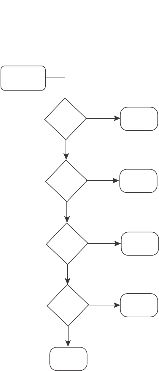
PowerConnect B-Series FCX Configuration Guide 593
53-1002266-01
Classification 17
FIGURE 112 Determining a packet trust level - PowerConnect B-Series FCX devices
Once a packet is classified, it is mapped to an internal forwarding queue. There are eight queues
designated 0 through 7. The internal forwarding priority maps to one of these eight queues as
shown in Table 94 through Table 97. The mapping between the internal priority and the forwarding
queue cannot be changed.
Table 94 through Table 97 show the default QoS mappings that are used if the trust level for CoS or
DSCP is enabled.
Packet received on
ingress port
Does the
port have a
default
priority?
Use the default
priority of 0
Tr ust the port’s
default priority
Tr ust the DSCP-
CoS-mapping or
the DSCP-marking
Ye s
Does the
MAC address
match a static
entry?
Tr ust the priority
of the static
MAC entry
Ye s
Ye s
No
No
No
No
Ye sTr ust the 802.1p
CoS value
Is the packet
tagged?
Does the
packet match an
ACL that defines
a priority?

594 PowerConnect B-Series FCX Configuration Guide
53-1002266-01
Classification
17
Mapping between DSCP value and forwarding queue cannot be changed. However, mapping
between DSCP values and other properties can be changed as follows:
TABLE 94 Default QoS mappings, columns 0 to 15
DSCP value 0123456789101112121415
802.1p (CoS)
value
0000000011111111
DSCP value0123456789101112121415
Internal
forwarding
priority
0000000011111111
Forwarding
queue
0000000011111111
TABLE 95 Default QoS mappings, columns 16 to 31
DSCP value 16171819202122232425262728293031
802.1p (CoS)
value
2222222233333333
DSCP value 16171819202122232425262728293031
Internal
forwarding
priority
2222222233333333
Forwarding
queue
2222222233333333
TABLE 96 Default QoS mappings, columns 32 to 47
DSCP value 32333435363738394041424344454647
802.1p (CoS)
value
4444444455555555
DSCP value 32333435363738394041424344454647
Internal
forwarding
priority
4444444455555555
Forwarding
queue
4444444455555555
TABLE 97 Default QoS mappings, columns 48 to 63
DSCP value 48495051525354555657585960616263
802.1p (CoS)
value
6666666677777777
DSCP value 48495051525354555657585960616263
Internal
forwarding
priority
6666666677777777
Forwarding
queue
6666666677777777

PowerConnect B-Series FCX Configuration Guide 595
53-1002266-01
QoS for stackable devices 17
•DSCP to internal forwarding priority mapping – You can change the mapping between the
DSCP value and the internal forwarding priority value from the default values shown in
Table 94 through Table 97. This mapping is used for CoS marking and determining the internal
priority when the trust level is DSCP. Refer to “Changing the DSCP to internal forwarding priority
mappings” on page 601.
•VLAN priority (802.1p) to hardware forwarding queue - You can change the mapping between
the 802.1p value and hardware forwarding queue from the default value. Refer to “Changing
the VLAN priority 802.1p to hardware forwarding queue mappings” on page 602.
QoS for stackable devices
PowerConnect units in an IronStack support QoS. Units in a stack communicate the stack topology
information and other proprietary control information through the stacking links. For more
information about stacking links and IronStack technology, refer to Chapter 5, “Stackable Devices”.
In addition to control information, the stacking links also carry user network data packets. In an
IronStack topology, the priority of stacking-specific control packets is elevated above that of data
path packets, preventing loss of control packets, and timed retries that affect performance. This
prioritization also prevents stack topology changes that may occur if enough stack topology
information packets are lost.
IronStack technology reserves one QoS profile to provide a higher priority for stack topology and
control traffic.
QoS profile restrictions in an IronStack
In a stacking topology, because CoS level 7 is reserved for stacking, quality profiles for qosp7
cannot be configured. If an attempt is made to configure a profile for qosp7, the system ignores the
configuration.
NOTE
This applies only when the device is operating in stacking mode. It does not apply to standalone
devices.
QoS behavior for trusting Layer 2 (802.1p) in an IronStack
By default, Layer 2 Trust is enabled. Because priority 7 is reserved for stacking control packets, any
ingress data traffic with priority 7 is mapped to internal hardware queue 6. All other priorities are
mapped to their corresponding queues.
QoS behavior for trusting Layer 3 (DSCP) in an IronStack
When the trust dscp mode is enabled, packets arriving with DSCP values 56 to 63 are mapped to
internal hardware queue 6. All other DSCP values are mapped to their corresponding internal
hardware queues.

596 PowerConnect B-Series FCX Configuration Guide
53-1002266-01
QoS queues
17
QoS behavior on port priority and VLAN priority
in an IronStack
Port priority and VLAN priority have a higher precedence than the 802.1p priority examination. If
port priority is set to 7, all incoming traffic is mapped to internal hardware queue 6.
When stacking is not enabled on a device, all priorities are mapped to their corresponding queues
without restrictions.
QoS behavior for 802.1p marking in an IronStack
By default in stacking mode, 802.1p marking is not enabled. Outgoing tagged traffic is not marked
with 802.1p in the VLAN tag based on the internal hardware queue into which ingress traffic was
classified.
When stacking is disabled on a device, outgoing traffic is marked with 802.1p based on the
internal hardware queue.
QoS queues
Dell PowerConnect devices support the eight QoS queues (qosp0 through qosp7) listed in Table 98.
The queue names listed in Table 98 are the default names. If desired, you can rename the queues
as shown in “Renaming the queues” on page 605.
Packets are classified and assigned to specific queues based on the criteria shown in Figure 112.
Assigning QoS priorities to traffic
By default, all traffic is in the best-effort queue (qosp0) and is honored on tagged ports on all
PowerConnect switches. You can assign traffic to a higher queue based on the following:
•Incoming port (sometimes called the ingress port)
•Static MAC entry
TABLE 98 QoS queues
QoS priority level QoS queue
0 qosp0 (lowest priority queue)
1qosp1
2qosp2
3qosp3
4qosp4
5qosp5
6qosp6
7 qosp7 (highest priority queue)

PowerConnect B-Series FCX Configuration Guide 597
53-1002266-01
Assigning QoS priorities to traffic 17
When you change the priority, you specify a number from 0 through 7. The priority number specifies
the IEEE 802.1 equivalent to one of the eight QoS queues on Dell PowerConnect devices. The
numbers correspond to the queues as shown in Table 98.
Although it is possible for a packet to qualify for an adjusted QoS priority based on more than one of
the criteria listed In the section above, the system always gives a packet the highest priority for
which it qualifies. Thus, if a packet is entitled to the premium queue because of its IP source and
destination addresses, but is entitled only to the high queue because of its incoming port, the
system places the packet in the premium queue on the outgoing port.
Changing a port priority
To change the QoS priority of port 1/1 to the premium queue (qosp7), enter the following
commands.
PowerConnect(config)#interface ethernet 1/1
PowerConnect(config-if-e1000-1/1)#priority 7
The device will assign priority 7 to untagged switched traffic received on port 1/1.
Syntax: [no] priority <num>
The <num> variable can be from 0 through 7 and specifies the IEEE 802.1 equivalent to one of
eight QoS queues listed in Table 98.
Assigning static MAC entries to priority queues
By default, all MAC entries are in the best-effort queue. When you configure a static MAC entry, you
can assign the entry to a higher QoS level.
To configure a static MAC entry and assign the entry to the premium queue, enter commands such
as the following.
PowerConnect(config)#vlan 9
PowerConnect(config-vlan-9)#static-mac-address 1145.1163.67FF ethernet 1/1
priority 7
PowerConnect(config-vlan-9)#write memory
Syntax: [no] static-mac-address <mac-addr> ethernet <port> [priority <num>]
[host-type | router-type | fixed-host]
Specify the <port> variable in the following formats:
•PowerConnect B-Series FCX stackable switches – <stack-unit/slotnum/portnum>
The priority <num> variable can be from 0 through 7 and specifies the IEEE 802.1 equivalent to
one of the eight QoS queues.
NOTE
The location of the static-mac-address command in the CLI depends on whether you configure
port-based VLANs on the device. If the device does not have more than one port-based VLAN (VLAN
1, which is the default VLAN containing all ports), the static-mac-address command is at the global
CONFIG level of the CLI. If the device has more than one port-based VLAN, then the
static-mac-address command is not available at the global CONFIG level. In this case, the command
is available at the configuration level for each port-based VLAN.

598 PowerConnect B-Series FCX Configuration Guide
53-1002266-01
802.1p priority override
17
Buffer allocation/threshold for QoS queues
By default, Dell Ironware software allocates a certain number of buffers to the outbound transport
queue for each port based on QoS priority. The buffers control the total number of packets
permitted in the outbound queue for the port. If desired, you can increase or decrease the
maximum number of outbound transmit buffers allocated to all QoS queues, or to specific QoS
queues on a port or group of ports. For more information, refer to “TDynamic Buffer Allocation for
an IronStack” on page 326.
802.1p priority override
You can configure a port to ignore the 802.1p priority for traffic classification for an incoming
packet. When this feature is enabled, packets will be classified as follows:
•If the packet matches an ACL that defines the priority, then ACL priority will be used.
•If the packet source or destination MAC address matches a configured static MAC address with
priority, then static MAC priority will be used.
•If the ingress port has a configured priority, then port priority will be used.
•Otherwise, the configured or default port priority (0) will be used.
Note that the original 802.1p priority in the packet will be retained. This feature does not re-mark
the 802.1p value.
Configuration notes and feature limitations
•This feature is supported on physical ports and trunk ports. When applied to the primary port
of a trunk group, the configuration applies to all members of the trunk group.
•This feature is not supported together with trust dscp.
Enabling 802.1p priority override
To enable 802.1p priority override, enter the following command at the interface level of the CLI.
PowerConnect(config-if-e1000-2)#priority ignore-8021p
Syntax: [no] priority ignore-802.1p
Use the following command to show whether 802.1p priority override is enabled on a port.
Syntax: show run interface ethernet <port>
Specify the <port> variable in the following formats:
•PowerConnect B-Series FCX stackable switches – <stack-unit/slotnum/portnum>
PowerConnect#show run interface ethernet 1
interface ethernet 1
priority ignore-8021p

PowerConnect B-Series FCX Configuration Guide 599
53-1002266-01
Marking 17
Marking
Marking is the process of changing the packet QoS information (the 802.1p and DSCP information
in a packet) for the next hop. For example, for traffic coming from a device that does not support
Differentiated Services (DiffServ), you can change the packet IP precedence value into a DSCP
value before forwarding the packet.
You can mark a packet Layer 2 CoS value, its Layer 3 DSCP value, or both values. The Layer 2 CoS
or DSCP value the device marks in the packet is the same value that results from mapping the
packet QoS value into a Layer 2 CoS or DSCP value.
Marking is optional and is disabled by default. Marking is performed using ACLs. When marking is
not used, the device still performs the mappings listed in “Classification” on page 591 for
scheduling the packet, but leaves the packet QoS values unchanged when the device forwards the
packet.
For configuration syntax, rules, and examples of QoS marking, refer to “QoS options for IP ACLs” on
page 579.
Configuring DSCP-based QoS
Dell IronWare releases support basic DSCP-based QoS (also called Type of Service (ToS)-based
QoS) as described in this chapter. However, the PowerConnect family of switches does not support
other advanced DSCP-based QoS features as described in the Enterprise Configuration and
Management Guide.
Dell IronWare releases also support marking of the DSCP value. The software can read Layer 3
Quality of Service (QoS) information in an IP packet and select a forwarding queue for the packet
based on the information. The software interprets the value in the six most significant bits of the IP
packet header 8-bit ToS field as a Diffserv Control Point (DSCP) value, and maps that value to an
internal forwarding priority.
The internal forwarding priorities are mapped to one of the eight forwarding queues (qosp0 through
qosp7) on the Dell PowerConnect device. During a forwarding cycle, the device gives more
preference to the higher numbered queues, so that more packets are forwarded from these
queues. For example, queue qosp7 receives the highest preference while queue qosp0, the
best-effort queue, receives the lowest preference.
Application notes
•DSCP-based QoS is not automatically honored for routed and switched traffic. The default is
802.1p to CoS mapping. To honor DSCP-based QoS, you must either use ACL or enable trust
DSCP. Refer to “Using ACLs to honor DSCP-based QoS” on page 599.
•When DSCP marking is enabled, the device changes the contents of the inbound packet ToS
field to match the DSCP-based QoS value. This differs from BigIron, which marks the outbound
packet ToS field.
Using ACLs to honor DSCP-based QoS
This section shows how to configure Dell PowerConnect devices to honor DSCP-based QoS for
routed and switched traffic.

600 PowerConnect B-Series FCX Configuration Guide
53-1002266-01
Configuring the QoS mappings
17
PowerConnect stackable devices
PowerConnect B-Series FCX devices support DSCP-based QoS on a per-port basis. DSCP-based
QoS is not automatically honored for switched traffic. The default is 802.1p to CoS mapping. To
honor DSCP-based QoS, enter the following command at the interface level of the CLI.
PowerConnect(config-if-e1000-11)#trust dscp
Syntax: trust dscp
When trust dscp is enabled, the interface honors the Layer 3 DSCP value. By default, the interface
honors the Layer 2 CoS value.
NOTE
This feature is not supported together with 802.1p priority override.
Configuring the QoS mappings
You can optionally change the following QoS mappings:
•DSCP to internal forwarding priority
•VLAN priority (802.1p) to hardware forwarding queue
The mappings are globally configurable and apply to all interfaces.
Default DSCP to internal forwarding priority mappings
The DSCP values are described in RFCs 2474 and 2475. Table 99 lists the default mappings of
DSCP values to internal forwarding priority values.
Notice that DSCP values range from 0 through 63, whereas the internal forwarding priority values
range from 0 through 7. Any DSCP value within a given range is mapped to the same internal
forwarding priority value. For example, any DSCP value from 8 through 15 maps to priority 1.
After performing this mapping, the device maps the internal forwarding priority value to one of the
hardware forwarding queues.
Table 100 lists the default mappings of internal forwarding priority values to the hardware
forwarding queues.
TABLE 99 Default DSCP to internal forwarding priority mappings
Internal forwarding priority DSCP value
0 (lowest priority queue) 0 – 7
18 – 15
2 16 – 23
3 24 – 31
4 32 – 39
5 40 – 47
6 48 – 55
7 (highest priority queue) 56 – 63

PowerConnect B-Series FCX Configuration Guide 601
53-1002266-01
Configuring the QoS mappings 17
1You can change the DSCP to internal forwarding mappings. You also can change the internal forwarding priority to
hardware forwarding queue mappings.
Changing the DSCP to internal forwarding
priority mappings
To change the DSCP to internal forwarding priority mappings for all the DSCP ranges, enter
commands such as the following at the global CONFIG level of the CLI.
PowerConnect(config)#qos-tos map dscp-priority 0 2 3 4 to 1
PowerConnect(config)#qos-tos map dscp-priority 8 to 5
PowerConnect(config)#qos-tos map dscp-priority 16 to 4
PowerConnect(config)#qos-tos map dscp-priority 24 to 2
PowerConnect(config)#qos-tos map dscp-priority 32 to 0
PowerConnect(config)#qos-tos map dscp-priority 40 to 7
PowerConnect(config)#qos-tos map dscp-priority 48 to 3
PowerConnect(config)#qos-tos map dscp-priority 56 to 6
Syntax: [no] qos-tos map dscp-priority <dscp-value> [<dscp-value> ...] to <priority>
The <dscp-value> [<dscp-value> ...] variable specifies the DSCP value ranges you are remapping.
You can specify up to eight DSCP values in the same command, to map to the same forwarding
priority. For example PowerConnect(config)#qos-tos map dscp-priority 1 2 3 4 5 6 7 8 to
6.
The <priority> variable specifies the internal forwarding priority.
The first command in the example maps priority 1 to DSCP values 0, 2, 3, and 4.
These commands configure the mappings displayed in the DSCP to forwarding priority portion of
the QoS information display. To read this part of the display, select the first part of the DSCP value
from the d1 column and select the second part of the DSCP value from the d2 row. For example, to
read the DSCP to forwarding priority mapping for DSCP value 24, select 2 from the d1 column and
select 4 from the d2 row. The mappings that are changed by the command above are shown below
in bold type.
TABLE 100 Default mappings of internal forwarding priority values
Internal forwarding priority Forwarding queues
0 (lowest priority queue) qosp0
11 qosp1
2qosp2
3qosp3
4qosp4
5qosp5
6qosp6
7 (highest priority queue) qosp7

602 PowerConnect B-Series FCX Configuration Guide
53-1002266-01
Configuring the QoS mappings
17
Changing the VLAN priority 802.1p to hardware
forwarding queue mappings
To map a VLAN priority to a different hardware forwarding queue, enter commands such as the
following at the global CONFIG level of the CLI.
PowerConnect(config)#qos tagged-priority 2 qosp0
Syntax: [no] qos tagged-priority <num> <queue>
The <num> variable can be from 0 through 7 and specifies the VLAN priority.
The <queue> variable specifies the hardware forwarding queue to which you are reassigning the
priority. The default queue names are as follows:
•qosp7
•qosp6
•qosp5
•qosp4
•qosp3
•qosp2
•qosp1
•qosp0
8 to 4 queue mapping
The default scheduling configuration for Weighted Round Robin (WRR), Hybrid WRR and Strict
Priority (SP), and SP mode for 8 to 4 queues is described in Table 101.
TABLE 101 Default configuration for 8 to 4 queues
PowerConnect#show qos-tos
...portions of table omitted for simplicity...
DSCP-Priority map: (dscp = d1d2)
d2| 0 1 2 3 4 5 6 7 8 9
d1 |
-----+----------------------------------------
0 | 1 0 1 1 1 0 0 0 5 1
1 | 6 1 1 1 1 1 4 2 2 2
2 | 2 2 2 2 2 3 3 3 3 3
3 | 3 3 0 4 4 4 4 4 4 4
4 | 7 5 5 5 5 5 5 5 3 6
5 | 6 6 6 6 6 6 6 7 7 7
6 | 7 7 7 7

PowerConnect B-Series FCX Configuration Guide 603
53-1002266-01
Scheduling 17
The example configuration described below is for a default, non-jumbo mode. The hardware
queues for WRR mode is calculated as follows.
Front end queue 3= 75%+7% = 82%
Front end queue 2 = 3%+3% = 6%
Front end queue 1 = 3%+3% = 6%
Front end queue 0 = 3%+3% = 6%
The hardware queues for Hybrid WRR and SP mode is calculated as follows.
Front end queue 3 is strict priority
Front end queue 2 = 25%+15% = 40%
Front end queue 1 = 15%+15% = 30%
Front end queue 0 = 15%+15% = 30%
Scheduling
Scheduling is the process of mapping a packet to an internal forwarding queue based on its QoS
information, and servicing the queues according to a mechanism.
QoS queuing methods
The following QoS queuing methods are supported in all IronWare releases for the PowerConnect
devices:
•Weighted round robin (WRR) – WRR ensures that all queues are serviced during each cycle. A
WRR algorithm is used to rotate service among the eight queues on the PowerConnect
devices. The rotation is based on the weights you assign to each queue. This method rotates
service among the queues, forwarding a specific number of packets in one queue before
moving on to the next one.
NOTE
In stacking mode, the qosp7 queue is reserved as strict priority (SP) under weighted queuing.
Attempts to change the qosp7 setting will be ignored.
WRR is the default queuing method and uses a default set of queue weights.
The number of packets serviced during each visit to a queue depends on the percentages you
configure for the queues. The software automatically converts the percentages you specify into
weights for the queues.
Hardware Queue Weighted Round
Robin (WRR)
mode
Hybrid WRR and
SP
Strict Priority (SP)
mode
3 Weight 82% Strict Priority Strict Priority
2 Weight 6% Weight 40% Strict Priority
1 Weight 6% Weight 30% Strict Priority
0 Weight 6% Weight 30% Strict Priority

604 PowerConnect B-Series FCX Configuration Guide
53-1002266-01
Scheduling
17
NOTE
Queue cycles on the PowerConnect devices are based on bytes. These devices service a given
number of bytes (based on weight) in each queue cycle. FES and BI/FI queue cycles are based
on packets. The bytes-based scheme is more accurate than a packets-based scheme if
packets vary greatly in size.
•Strict priority (SP) – SP ensures service for high priority traffic. The software assigns the
maximum weights to each queue, to cause the queuing mechanism to serve as many packets
in one queue as possible before moving to a lower queue. This method biases the queuing
mechanism to favor the higher queues over the lower queues.
For example, strict queuing processes as many packets as possible in qosp3 before processing
any packets in qosp2, then processes as many packets as possible in qosp2 before processing
any packets in qosp1, and so on.
•Hybrid WRR and SP – This configurable queueing mechanism combines both the strict priority
and weighted round robin mechanisms. The combined method enables the Dell PowerConnect
device to give strict priority to delay-sensitive traffic such as VoIP traffic, and weighted round
robin priority to other traffic types.
By default, when you select the combined SP and WRR queueing method, the Dell
PowerConnect device assigns strict priority to traffic in qosp7 and qosp6, and weighted round
robin priority to traffic in qosp0 through qosp5. Thus, the Dell PowerConnect device schedules
traffic in queue 7 and queue 6 first, based on the strict priority queueing method. When there
is no traffic in queue 7 and queue 6, the device schedules the other queues in round-robin
fashion from the highest priority queue to the lowest priority queue.
NOTE
Stackable devices that are operating as members of a stack reserve queue 7 for stacking
functions. For more information, see “QoS for stackable devices” on page 595.
By default, when you specify the combined SP and WRR queuing method, the system balances
the traffic among the queues as shown in Table 102. If desired, you can change the default
bandwidth values as shown in the section “Bandwidth allocations of the hybrid WRR and SP
queues.” on page 607.
TABLE 102 Default bandwidth for combined SP and WRR queueing methods
Queue Default bandwidth
qosp7 Strict priority (highest priority)
qosp6 Strict priority
qosp5 25%
qosp4 15%
qosp3 15%
qosp2 15%
qosp1 15%
qosp0 15% (lowest priority)

PowerConnect B-Series FCX Configuration Guide 605
53-1002266-01
Scheduling 17
Selecting the QoS queuing method
By default, Dell PowerConnect devices use the WRR method of packet prioritization. To change the
method to strict priority, enter the following command at the global CONFIG level of the CLI.
PowerConnect(config)#qos mechanism strict
To change the method back to weighted round robin, enter the following command.
PowerConnect(config)#qos mechanism weighted
Syntax: [no] qos mechanism strict | weighted
To change the queuing mechanism to the combined SP and WRR method, enter the following
command at the global CONFIG level of the CLI.
PowerConnect(config)#qos mechanism mixed-sp-wrr
Syntax: qos mechanism mixed-sp-wrr
Configuring the QoS queues
Each of the queues has the following configurable parameters:
•The queue name
•The minimum percentage of a port outbound bandwidth guaranteed to the queue
Renaming the queues
The default queue names are qosp7, qosp6, qosp5, qosp4, qosp3, qosp2, qosp1, and qosp0. You
can change one or more of the names if desired.
To rename queue “qosp3” to “92-octane”, enter the following command.
PowerConnect(config)#qos name qosp3 92-octane
Syntax: qos name <old-name> <new-name>
The <old-name> variable specifies the name of the queue before the change.
The <new-name> variable specifies the new name of the queue. You can specify an alphanumeric
string up to 32 characters long.
Changing the minimum bandwidth percentages of the WRR queues
If you are using the weighted round robin mechanism instead of the strict priority mechanism, you
can change the weights for each queue by changing the minimum percentage of bandwidth you
want each queue to guarantee for its traffic.
By default, the eight QoS queues on PowerConnect devices receive the minimum guaranteed
percentages of a port total bandwidth, as shown in Table 103. Note that the defaults differ when
jumbo frames are enabled.

606 PowerConnect B-Series FCX Configuration Guide
53-1002266-01
Scheduling
17
When the queuing method is weighted round robin, the software internally translates the
percentages into weights. The weight associated with each queue controls how many packets are
processed for the queue at a given stage of a cycle through the weighted round robin algorithm.
NOTE
Queue cycles on the PowerConnect devices are based on bytes. These devices service a given
number of bytes (based on the weight) in each queue cycle. FES and BI/FI queue cycles are based
on packets. The bytes-based scheme is more accurate than a packets-based scheme if packets vary
greatly in size.
The bandwidth allocated to each queue is based on the relative weights of the queues. You can
change the bandwidth percentages allocated to the queues by changing the queue weights.
There is no minimum bandwidth requirement for a given queue. For example, queue qosp3 is not
required to have at least 50% of the bandwidth.
To change the bandwidth percentages for the queues, enter commands such as the following.
Note that this example uses the default queue names.
Syntax: [no] qos profile <queue> <percentage> <queue> <percentage> <queue> <percentage>
<queue> <percentage> <queue> <percentage> <queue> <percentage> <queue>
<percentage> <queue> <percentage>
Each <queue> variable specifies the name of a queue. You can specify the queues in any order on
the command line, but you must specify each queue.
TABLE 103 Default minimum bandwidth percentages on Dell PowerConnect devices
Queue Default minimum percentage of bandwidth
Without jumbo frames With jumbo frames
qosp7 75% 44%
qosp6 7% 8%
qosp5 3% 8%
qosp4 3% 8%
qosp3 3% 8%
qosp2 3% 8%
qosp1 3% 8%
qosp0 3% 8%
PowerConnect(config)#qos profile qosp7 25 qosp6 15 qosp5 12 qosp4 12 qosp3 10
qosp2 10 qosp1 10 qosp0 6
Profile qosp7 : Priority7 bandwidth requested 25% calculated 25%
Profile qosp6 : Priority6 bandwidth requested 15% calculated 15%
Profile qosp5 : Priority5 bandwidth requested 12% calculated 12%
Profile qosp4 : Priority4 bandwidth requested 12% calculated 12%
Profile qosp3 : Priority3 bandwidth requested 10% calculated 10%
Profile qosp2 : Priority2 bandwidth requested 10% calculated 10%
Profile qosp1 : Priority1 bandwidth requested 10% calculated 10%
Profile qosp0 : Priority0 bandwidth requested 6% calculated 6%

PowerConnect B-Series FCX Configuration Guide 607
53-1002266-01
Scheduling 17
The <percentage> variable specifies a number for the percentage of the device outbound
bandwidth that is allocated to the queue. Dell QoS queues require a minimum bandwidth
percentage of 3 percent for each priority. When jumbo frames are enabled, the minimum
bandwidth requirement is 8 percent. If these minimum values are not met, QoS may not be
accurate.
Configuration notes
•The total of the percentages you enter must equal 100.
•PowerConnect devices do not adjust the bandwidth percentages you enter. BigIron QoS does
adjust the bandwidth percentages to ensure that each queue has at least its required
minimum bandwidth percentage.
On PowerConnect B-Series FCX devices, you can use QoS queue 1 for priority traffic, even when
sFlow is enabled on the port.
Bandwidth allocations of the hybrid WRR and SP queues.
To change the default bandwidth percentages for the queues when the device is configured to use
the combined SP and WRR queuing mechanism, enter commands such as the following. Note that
this example uses the default queue names.
PowerConnect(config)#qos profile qosp7 sp qosp6 sp qosp5 20 qosp4 16 qosp3 16
qosp2 16 qosp1 16 qosp0 16
Syntax: [no] qos profile <queue 7> sp <queue 6> sp | <percentage> <queue 5> <percentage>
<queue 4> <percentage> <queue 3> <percentage> <queue 2> <percentage> <queue 1>
<percentage> <queue 0> <percentage>]
Each <queue x> variable specifies the name of a queue. You can specify the queues in any order
on the command line, but you must specify each queue. Note that queue 7 supports strict priority
only, queue 6 supports both the strict priority and WRR queuing mechanisms, and queues 0
through 5 support the WRR queuing mechanism only.
NOTE
Stackable devices that are operating as members of a stack reserve queue 7 for stacking functions.
The sp parameter configures strict priority as the queuing mechanism. Note that only queue 7 and
queue 6 support this method.
The <percentage> variable configures WRR as the queuing mechanism and specifies the
percentage of the device outbound bandwidth allocated to the queue. The queues require a
minimum bandwidth percentage of 3 percent for each priority. When jumbo frames are enabled,
the minimum bandwidth requirement is 8 percent. If these minimum values are not met, QoS may
not be accurate.
NOTE
The percentages must add up to 100. The Dell PowerConnect devices do not adjust the bandwidth
percentages you enter. In contrast, the BigIron QoS does adjust the bandwidth percentages to
ensure that each queue has at least its required minimum bandwidth percentage.

608 PowerConnect B-Series FCX Configuration Guide
53-1002266-01
Viewing QoS settings
17
Viewing QoS settings
To display the QoS settings for all of the queues, enter the show qos-profiles command.
Syntax: show qos-profiles all | <name>
The all parameter displays the settings for all eight queues.
The <name> variable displays the settings for the specified queue.
Viewing DSCP-based QoS settings
To display configuration information for DSCP-based QoS, enter the following command at any level
of the CLI.
Syntax: show qos-tos
Table 104 shows the output information for the show qos-tos command.
PowerConnect#show qos-profiles all
bandwidth scheduling mechanism: weighted priority
Profile qosp7 : Priority7 bandwidth requested 25% calculated 25%
Profile qosp6 : Priority6 bandwidth requested 15% calculated 15%
Profile qosp5 : Priority5 bandwidth requested 12% calculated 12%
Profile qosp4 : Priority4 bandwidth requested 12% calculated 12%
Profile qosp3 : Priority3 bandwidth requested 10% calculated 10%
Profile qosp2 : Priority2 bandwidth requested 10% calculated 10%
Profile qosp1 : Priority1 bandwidth requested 10% calculated 10%
Profile qosp0 : Priority0 bandwidth requested 6% calculated 6%
PowerConnect#show qos-tos
DSCP-->Traffic-Class map: (DSCP = d1d2: 00, 01...63)
d2| 0 1 2 3 4 5 6 7 8 9
d1 |
-----+----------------------------------------
0 | 0 0 0 0 0 0 0 0 1 1
1 | 1 1 1 1 1 1 2 2 2 2
2 | 2 2 2 2 3 3 3 3 3 3
3 | 3 3 4 4 4 4 4 4 4 4
4 | 5 5 5 5 5 5 5 5 6 6
5 | 6 6 6 6 6 6 7 7 7 7
6 | 7 7 7 7
Traffic-Class-->802.1p-Priority map (use to derive DSCP--802.1p-Priority):
Traffic | 802.1p
Class | Priority
--------+---------
0 | 0
1 | 1
2 | 2
3 | 3
4 | 4
5 | 5
6 | 6
7 | 7
--------+---------

PowerConnect B-Series FCX Configuration Guide 609
53-1002266-01
Viewing DSCP-based QoS settings 17
The show qos-tos command can also be used to display configuration information for 8 to 4 queue
mapping. The following example displays 8 to 4 queue mapping configuration.
TABLE 104 DSCP-based QoS configuration information
This field... Displays...
DSCP to traffic class map
d1 and d2 The DSCP to forwarding priority mappings that are currently in effect.
NOTE: The example shows the default mappings. If you change the mappings,
the command displays the changed mappings
Traffic class to 802.1 priority map
Traffic Class and 802.1p
Priority
The traffic class to 802.1p priority mappings that are currently in effect.
NOTE: The example shows the default mappings. If you change the mappings,
the command displays the changed mappings.

610 PowerConnect B-Series FCX Configuration Guide
53-1002266-01
Viewing DSCP-based QoS settings
17
Syntax: show qos-tos
The show qos-tos command displays the following information about 8 to 4 queue mapping.
TABLE 105 8 to 4 queue mapping configuration information
This field... Displays...
Priority-> Hardware Queue
Priority and Hardware Queue The priority to hardware queues that are currently in effect for 8 to 4 queue. QoS
priority 7 is the highest priority, and QoS 0 is the lowest priority
PowerConnect#show qos-tos
DSCP-->Traffic-Class map: (DSCP = d1d2: 00, 01...63)
d2| 0 1 2 3 4 5 6 7 8 9
d1 |
-----+----------------------------------------
0 | 0 0 0 0 0 0 0 0 1 1
1 | 1 1 1 1 1 1 2 2 2 2
2 | 2 2 2 2 3 3 3 3 3 3
3 | 3 3 4 4 4 4 4 4 4 4
4 | 5 5 5 5 5 5 5 5 6 6
5 | 6 6 6 6 6 6 7 7 7 7
6 | 7 7 7 7
Traffic-Class-->802.1p-Priority map (use to derive DSCP--802.1p-Priority):
Traffic | 802.1p
Class | Priority
--------+---------
0 | 0
1 | 1
2 | 2
3 | 3
4 | 4
5 | 5
6 | 6
7 | 7
--------+---------
8to4 queue mapping:
Priority| Hardware Queue
--------+---------
0 | 0
1 | 0
2 | 1
3 | 1
4 | 2
5 | 2
6 | 3
7 | 3
--------+---------

PowerConnect B-Series FCX Configuration Guide 611
53-1002266-01
Chapter
18
Configuring Traffic Policies
Table 106 lists the individual Dell PowerConnect switches and the traffic policy features they
support.
Traffic policies overview
This chapter describes how traffic policies are implemented and configured in the PowerConnect
devices.
Dell devices use traffic policies for the following:
•To rate limit inbound traffic
•To count the packets and bytes per packet to which ACL permit or deny clauses are applied
Traffic policies consist of policy names and policy definitions:
•Traffic policy name – A string of up to eight alphanumeric characters that identifies individual
traffic policy definitions.
•Traffic policy definition (TPD) – The command filter associated with a traffic policy name. A
TPD can define any one of the following:
•Rate limiting policy
•ACL counting policy
•Combined rate limiting and ACL counting policy
The maximum number of supported active TPDs is a system-wide parameter and depends on
the device you are configuring. The total number of active TPDs cannot exceed the system
maximum. Refer to “Maximum number of traffic policies supported on a device” on page 612.
When you apply a traffic policy to an interface, you do so by adding a reference to the traffic policy
in an ACL entry, instead of applying the individual traffic policy to the interface. The traffic policy
becomes an active traffic policy or active TPD when you bind its associated ACL to an interface.
To configure traffic policies for ACL-based rate limiting, refer to “Configuring ACL-based fixed rate
limiting” on page 614 and “Configuring ACL-based adaptive rate limiting” on page 615.
To configure traffic policies for ACL counting, refer to “Enabling ACL statistics” on page 619.
TABLE 106 Supported traffic policy features
Feature PowerConnect B-Series FCX
Traffic policies Yes
ACL-based fixed rate limiting Yes
ACL-based adaptive rate limiting Yes
802.1p priority bit inspection in the ACL
for adaptive rate limiting
Yes
ACL statistics Yes

612 PowerConnect B-Series FCX Configuration Guide
53-1002266-01
Configuration notes and feature limitations
18
Configuration notes and feature limitations
Note the following when configuring traffic policies:
•Traffic policies applies to IP ACLs only.
•The maximum number of supported active TPDs is a system-wide parameter and depends on
the device you are configuring. The total number of active TPDs cannot exceed the system
maximum. Refer to “Maximum number of traffic policies supported on a device” on page 612.
•You can reference the same traffic policy in more than one ACL entry within an ACL. For
example, two or more ACL statements in ACL 101 can reference a TPD named TPD1.
•You can reference the same traffic policy in more than one ACL. For example, ACLs 101 and
102 could both reference a TPD named TPD1.
•To modify or delete an active traffic policy, you must first unbind the ACL that references the
traffic policy.
•When you define a TPD (when you enter the CLI command traffic-policy), explicit marking of
CoS parameters, such as traffic class and 802.1p priority, are not available on the device. In
the case of a TPD defining rate limiting, the device re-marks CoS parameters based on the
DSCP value in the packet header and the determined conformance level of the rate limited
traffic, as shown in Table 107.
•When you define a TPD, reference the TPD in an ACL entry, and then apply the ACL to a VE in
the Layer 3 router code, the rate limit policy is accumulative for all of the ports in the port
region. If the VE or VLAN contains ports that are in different port regions, the rate limit policy is
applied per port region.
For example, TPD1 has a rate limit policy of 600M and is referenced in ACL 101. ACL 101 is
applied to VE 1, which contains ports e 1/11 to e 1/14. Because ports e 1/11 and 1/12 are
in a different port region than e 1/13 and 1/14, the rate limit policy will be 600M for ports e
1/11 and 1/12, and 600M for ports e 1/13 and 1/14.
Maximum number of traffic policies supported on a device
The maximum number of supported active traffic policies is a system-wide parameter and depends
on the device you are configuring, as follows:
TABLE 107 CoS parameters for packets that use rate limiting traffic policies
Packet conformance level Packet DSCP value Traffic class and 802.1p priority
0 (Green)
or
1 (Yellow)
0 – 7 0 (lowest priority queue)
8 – 15 1
16 – 23 2
24 – 31 3
32 – 39 4
40 – 47 5
48 – 55 6
56 – 63 7 (highest priority queue)
2 (Red) N/A 0 (lowest priority queue)

PowerConnect B-Series FCX Configuration Guide 613
53-1002266-01
ACL-based rate limiting using traffic policies 18
•By default, up to 1024 active traffic policies are supported on Layer 2 switches. This value is
fixed on Layer 2 switches and cannot be modified.
•On PowerConnect B-Series FCX devices, up to 1024 active traffic policies are supported on
Layer 3 switches. This is the default value as well as the maximum value.
Setting the maximum number of traffic policies
supported on a Layer 3 device
NOTE
This configuration is supported on Dell PowerConnect devices with the exception of the
PowerConnect B-Series FCX platforms. Setting the system-max for traffic policies is not required on
PowerConnect B-Series FCX platforms as the default number of traffic policies is also the maximum
number.
If desired, you can adjust the maximum number of active traffic policies that a Layer 3 device will
support. To do so, enter commands such as the following at the global CONFIG level of the CLI.
PowerConnect(config)#system-max hw-traffic-conditioner 25
PowerConnect(config)#write memory
PowerConnect(config)#reload
NOTE
You must save the configuration and reload the software to place the change into effect.
Syntax: [no] system-max hw-traffic-conditioner <num>
The <num> variable is a value from 0 through n, where 0 disables hardware resources for traffic
policies, and n is a number up to 50. The maximum number you can configure depends on the
configuration and available memory on your device. If the configuration you enter causes the
device to exceed the available memory, the device will reject the configuration and display a
warning message on the console.
NOTE
Dell does not recommend setting the system maximum for traffic policies to 0 (zero), because this
renders traffic policies ineffective.
ACL-based rate limiting using traffic policies
ACL-based rate limiting provides the facility to limit the rate for IP traffic that matches the permit
conditions in extended IP ACLs. This feature is available in the Layer 2 and Layer 3 code.
To configure ACL-based rate limiting, you create individual traffic policies, and then reference the
traffic policies in one or more ACL entries (also called clauses or statements). The traffic policies
become effective on ports to which the ACLs are bound.
When you configure a traffic policy for rate limiting, the device automatically enables rate limit
counting, similar to the two-rate three-color marker (trTCM) mechanism described in RFC 2698 for
adaptive rate limiting, and the single-rate three-color marker (srTCM) mechanism described in RFC
2697 for fixed rate limiting. This feature counts the number of bytes and trTCM or srTCM
conformance level per packet to which rate limiting traffic policies are applied. Refer to “ACL
statistics and rate limit counting” on page 619.

614 PowerConnect B-Series FCX Configuration Guide
53-1002266-01
ACL-based rate limiting using traffic policies
18
You can configure ACL-based rate limiting on the following interface types:
•Physical Ethernet interfaces
•Virtual interfaces
•Trunk por ts
•Specific VLAN members on a port (refer to “Applying an IPv4 ACL to specific VLAN members on
a port (Layer 2 devices only)” on page 574)
•A subset of ports on a virtual interface (refer to “Applying an IPv4 ACL to a subset of ports on a
virtual interface (Layer 3 devices only)” on page 575)
Support for fixed rate limiting and adaptive rate limiting
NOTE
ACL-based fixed rate limiting is supported on all PowerConnect devices. ACL-based adaptive rate
limiting is supported on PowerConnect B-Series FCX devices only.
PowerConnect devices support the following types of ACL-based rate limiting:
•Fixed rate limiting – Enforces a strict bandwidth limit. The device forwards traffic that is within
the limit but either drops all traffic that exceeds the limit, or forwards all traffic that exceeds
the limit at the lowest priority level, according to the action specified in the traffic policy.
•Adaptive rate limiting – Enforces a flexible bandwidth limit that allows for bursts above the
limit. You can configure adaptive rate limiting to forward traffic, modify the IP precedence of
and forward traffic, or drop traffic based on whether the traffic is within the limit or exceeds the
limit.
Configuring ACL-based fixed rate limiting
Use the procedures in this section to configure ACL-based fixed rate limiting. Before configuring
this feature, see what to consider in “Configuration notes and feature limitations” on page 612.
Fixed rate limiting enforces a strict bandwidth limit. The port forwards traffic that is within the limit.
If the port receives more than the specified number of fragments in a one-second interval, the
device either drops or forwards subsequent fragments in hardware, depending on the action you
specify.
To implement the ACL-based fixed rate limiting feature, first create a traffic policy, and then
reference the policy in an extended ACL statement. Lastly, bind the ACL to an interface. Complete
the following steps.
1. Create a traffic policy. Enter a command such as the following.
PowerConnect(config)#traffic-policy TPD1 rate-limit fixed 100 exceed-action
drop
2. Create an extended ACL entry or modify an existing extended ACL entry that references the
traffic policy. Enter a command such as the following.
PowerConnect(config)#access-list 101 permit ip host 210.10.12.2 any
traffic-policy TPD1
3. Bind the ACL to an interface.Enter commands such as the following.

PowerConnect B-Series FCX Configuration Guide 615
53-1002266-01
ACL-based rate limiting using traffic policies 18
PowerConnect(config)#interface ethernet 5
PowerConnect(config-if-e5)#ip access-group 101 in
PowerConnect(config-if-e5)#exit
The previous commands configure a fixed rate limiting policy that allows port e5 to receive a
maximum traffic rate of 100 kbps. If the port receives additional bits during a given one-second
interval, the port drops the additional inbound packets that are received within that one-second
interval.
Syntax: [no] traffic-policy <TPD name> rate-limit fixed <cir value> exceed-action <action> [count]
Syntax: access-list <num> permit | deny.... traffic policy <TPD name>
Syntax: [no] ip access-group <num> in
NOTE
For brevity, some parameters were omitted from the access-list syntax.
The software allows you to add a reference to a non-existent TPD in an ACL statement and to bind
that ACL to an interface. The software does not issue a warning or error message for non-existent
TPDs.
Use the no form of the command to delete a traffic policy definition. Note that you cannot delete a
traffic policy definition if it is currently in use on a port. To delete a traffic policy, first unbind the
associated ACL.
The traffic-policy <TPD name> parameter is the name of the traffic policy definition. This value can
be eight or fewer alphanumeric characters.
The rate-limit fixed <cir value>parameter specifies that the traffic policy will enforce a strict
bandwidth.The <cir value> variable is the committed information rate in kbps. This value can be
from 64 through 1,000,000 Kbps.
The exceed-action <action> parameter specifies the action to be taken when packets exceed the
configured committed information rate (CIR) value. Refer to “Specifying the action to be taken for
packets that are over the limit” on page 617.
The count parameter is optional and enables ACL counting. Refer to “ACL statistics and rate limit
counting” on page 619.
Configuring ACL-based adaptive rate limiting
NOTE
ACL-based adaptive rate limiting is supported on PowerConnect B-Series FCX devices.
Use the procedures in this section to configure ACL-based adaptive rate limiting. Before configuring
this feature, see what to consider in “Configuration notes and feature limitations” on page 612.
Table 108 lists the configurable parameters for ACL-based adaptive rate limiting.

616 PowerConnect B-Series FCX Configuration Guide
53-1002266-01
ACL-based rate limiting using traffic policies
18
If a port receives more than the configured bit or byte rate in a one-second interval, the port will
either drop or forward subsequent data in hardware, depending on the action you specify.
To implement the ACL-based adaptive rate limiting feature, first create a traffic policy, and then
reference the policy in an extended ACL statement. Lastly, bind the ACL to an interface. Complete
the following steps.
1. Create a traffic policy. Enter a command such as the following.
PowerConnect(config)#traffic-policy TPDAfour rate-limit adaptive cir 10000 cbs
1600 pir 20000 pbs 4000 exceed-action drop
2. Create a new extended ACL entry or modify an existing extended ACL entry that references the
traffic policy. Enter a command such as the following.
PowerConnect(config)#access-list 104 permit ip host 210.10.12.2 any
traffic-policy TPDAfour
3. Bind the ACL to an interface. Enter commands such as the following.
PowerConnect(config)#interface ethernet 7
PowerConnect(config-if-e7)#ip access-group 104 in
PowerConnect(config-if-e7)#exit
The previous commands configure an adaptive rate limiting policy that enforces a guaranteed
committed rate of 10000 kbps on port e7 and allows bursts of up to 1600 bytes. It also enforces a
peak rate of 20000 kbps and allows bursts of 4000 bytes above the PIR limit. If the port receives
additional bits during a given one-second interval, the port drops all packets on the port until the
next one-second interval starts.
Syntax: [no] traffic-policy <TPD name> rate-limit adaptive cir <cir value> cbs <cbs value> pir <pir
value> pbs <pbs value> exceed-action <action> [count]
Syntax: access-list <num> permit | deny.... traffic policy <TPD name>
Syntax: [no] ip access-group <num> in
NOTE
For brevity, some parameters were omitted from the access-list syntax.
The software allows you to add a reference to a non-existent TPD in an ACL statement and to bind
that ACL to an interface. The software does not issue a warning or error message for non-existent
TPDs.
TABLE 108 ACL based adaptive rate limiting parameters
Parameter Definition
Committed Information Rate (CIR) The guaranteed kilobit rate of inbound traffic that is allowed on a port.
Committed Burst Size (CBS) The number of bytes per second allowed in a burst before some packets will
exceed the committed information rate. Larger bursts are more likely to
exceed the rate limit. The CBS must be a value greater than zero (0). Dell
recommends that this value be equal to or greater than the size of the
largest possible IP packet in a stream.
Peak Information Rate (PIR) The maximum kilobit rate for inbound traffic on a port. The PIR must be
equal to or greater than the CIR.
Peak Burst Size (PBS) The number of bytes per second allowed in a burst before all packets will
exceed the peak information rate. The PBS must be a value greater than
zero (0). Dell recommends that this value be equal to or greater than the
size of the largest possible IP packet in the stream.

PowerConnect B-Series FCX Configuration Guide 617
53-1002266-01
ACL-based rate limiting using traffic policies 18
Use the no form of the command to delete a traffic policy definition. Note that you cannot delete a
traffic policy definition if it is currently in use on a port. To delete a traffic policy, first unbind the
associated ACL.
The traffic-policy <TPD name> parameter is the name of the traffic policy definition. This value can
be eight or fewer alphanumeric characters.
The rate-limit adaptive cir <cir value> specifies that the policy will enforce a flexible bandwidth limit
that allows for bursts above the limit.The <cir value> variable is the committed information rate in
kbps. Refer to Table 108.
The cbs <cbs value> parameter is the committed burst size in bytes. Refer to Table 108.
The pir <pir value> parameter is the peak information rate in kbps. Refer to Table 108.
The pbs <pbs value> parameter is the peak burst size in bytes. Refer to Table 108.
The exceed-action <action> parameter specifies the action to be taken when packets exceed the
configured values. Refer to “Specifying the action to be taken for packets that are over the limit” on
page 617.
The count parameter is optional and enables ACL counting. Refer to “ACL statistics and rate limit
counting” on page 619.
Inspecting the 802.1p bit in the ACL for adaptive rate limiting
NOTE
This feature is supported on PowerConnect B-Series FCX devices only.
You can configure the Dell device to rate limit traffic for a specified 802.1p priority value. To do so,
complete the following configuration steps.
1. Create an adaptive rate limiting traffic policy. Enter command such as the following:
PowerConnect(config)#traffic-policy adap rate-limit adaptive cir 1000 cbs 1000
pir 2000 pbs 10000 exceed-action drop
2. Create an IPv4 extended ACL or IPv6 ACL that includes the traffic policy and 802.1p priority
matching value. Enter a command such as the following:
PowerConnect(config)#access-list 136 permit ip any any 802.1p-priority
matching 3 traffic-policy adap
3. Bind the ACL to an interface.Enter commands such as the following,.
PowerConnect(config)#interface ethernet 7
PowerConnect(config-if-e7)#ip access-group 136 in
PowerConnect(config-if-e7)#exit
Use the show access-list accounting command to view accounting statistics. For more information,
refer to “Viewing ACL and rate limit counters” on page 620.
Specifying the action to be taken for packets that are
over the limit
You can specify the action to be taken when packets exceed the configured CIR value for fixed rate
limiting, or the CIR, CBS, PIR, and PBS values for adaptive rate limiting. You can specify one of the
following actions:

618 PowerConnect B-Series FCX Configuration Guide
53-1002266-01
ACL-based rate limiting using traffic policies
18
•Drop packets that exceed the limit.
•Permit packets that exceed the limit and forward them at the lowest priority level.
Dropping packets that exceed the limit
This section shows some example configurations and provides the CLI syntax for configuring a port
to drop packets that exceed the configured limits for rate limiting.
The following example shows a fixed rate limiting configuration.
PowerConnect(config)#traffic-policy TPD1 rate-limit fixed 10000 exceed-action
drop
The command sets the fragment threshold at 10,000 packet fragments per second. If the port
receives more than 10,000 packet fragments in a one-second interval, the device drops the excess
fragments.
Syntax: [no] traffic-policy <TPD name> rate-limit fixed <cir value> exceed-action drop
The following example shows an adaptive rate limiting configuration.
PowerConnect(config)#traffic-policy TPDAfour rate-limit adaptive cir 10000 cbs
1600 pir 20000 pbs 4000 exceed-action drop
The command configures an adaptive rate limiting policy that enforces a guaranteed committed
rate of 10000 kbps and allows bursts of up to 1600 bytes. It also enforces a peak rate of 20000
kbps and allows bursts of 4000 bytes above the PIR limit. If the port receives additional bits during
a given one-second interval, the port drops all packets on the port until the next one-second
interval starts.
Syntax: [no] traffic-policy <TPD name> rate-limit adaptive cir <cir value> cbs <cbs value> pir <pir
value> pbs <pbs value> exceed-action drop
Permitting packets that exceed the limit
This section shows some example configurations and provides the CLI syntax for configuring a port
to permit packets that exceed the configured limit for rate limiting.
The following example shows a fixed rate limiting configuration.
PowerConnect(config)#traffic-policy TPD1 rate-limit fixed 10000 exceed-action
permit-at-low-pri
The command sets the fragment threshold at 10,000 packet fragments per second. If the port
receives more than 10,000 packet fragments in a one-second interval, the device takes the
specified action. The action specified with this command is to permit excess fragments and forward
them at the lowest priority level.
Syntax: [no] traffic-policy <TPD name> rate-limit fixed <cir value> exceed-action permit-at-low-pri
The following example shows an adaptive rate limiting configuration.
PowerConnect(config)#traffic-policy TPDAfour rate-limit adaptive cir 10000 cbs
1600 pir 20000 pbs 4000 exceed-action permit-at-low-pri
The command configures an adaptive rate limiting policy that enforces a guaranteed committed
rate of 10000 kbps and allows bursts of up to 1600 bytes. It also enforces a peak rate of 20000
kbps and allows bursts of 4000 bytes above the PIR limit. If the port receives additional bits during
a given one-second interval, the port permits all packets on the port and forwards the packets at
the lowest priority level.

PowerConnect B-Series FCX Configuration Guide 619
53-1002266-01
ACL statistics and rate limit counting 18
Syntax: [no] traffic-policy <TPD name> rate-limit adaptive cir <cir value> cbs <cbs value> pir <pir
value> pbs <pbs value> exceed-action permit-at-low-pri
ACL statistics and rate limit counting
ACL statistics, also called ACL counting, enables the Dell device to count the number of packets
and the number of bytes per packet to which ACL filters are applied.
Rate limit counting counts the number of bytes and the conformance level per packet to which rate
limiting traffic policies are applied. The device uses the counting method similar to the two-rate
three-color marker (trTCM) mechanism described in RFC 2698 for adaptive rate limiting, and the
single-rate three-color marker (srTCM) mechanism described in RFC 2697 for fixed rate limiting.
Rate limit counting is automatically enabled when a traffic policy is enforced (active). You can view
these counters using the show commands listed in “Viewing traffic policies” on page 622.
Enabling ACL statistics
NOTE
ACL statistics and ACL counting are used interchangeably throughout this chapter and mean the
same thing.
Use the procedures in this section to configure ACL statistics. Before configuring ACL statistics, see
what to consider in “Configuration notes and feature limitations” on page 612.
You also can enable ACL statistics when you create a traffic policy for rate limiting. Refer to
“Enabling ACL statistics with rate limiting traffic policies” on page 620.
Complete the following steps to implement the ACL statistics feature.
1. Create a traffic policy. Enter a command such as the following.
PowerConnect(config)#traffic-policy TPD5 count
2. Create an extended ACL entry or modify an existing extended ACL entry that references the
traffic policy definition. Enter a command such as the following.
PowerConnect(config)#access-list 101 permit ip host 210.10.12.2 any
traffic-policy TPD5
3. Bind the ACL to an interface. Enter commands such as the following.
PowerConnect(config)#interface ethernet 4
PowerConnect(config-if-e4)#ip access-group 101 in
PowerConnect(config-if-e4)#exit
The previous commands configure an ACL counting policy and apply it to port e4. Port e4 counts
the number of packets and the number of bytes on the port that were permitted or denied by ACL
filters.
Syntax: [no] traffic-policy <TPD name> count
Syntax: access-list <num> permit | deny.... traffic policy <TPD name>
Syntax: [no] ip access-group <num> in
NOTE
For brevity, some parameters were omitted from the access-list syntax.

620 PowerConnect B-Series FCX Configuration Guide
53-1002266-01
ACL statistics and rate limit counting
18
The software allows you to add a reference to a non-existent TPD in an ACL statement and to bind
that ACL to an interface. The software does not issue a warning or error message for non-existent
TPDs.
Use the no form of the command to delete a traffic policy definition. Note that you cannot delete a
traffic policy definition if it is currently in use on a port. To delete a traffic policy, first unbind the
associated ACL.
The <TPD name> variable is the name of the traffic policy definition. This value can be eight
alphanumeric characters or less.
Enabling ACL statistics with rate limiting traffic policies
The configuration example in the section “Enabling ACL statistics” on page 619 shows how to
enable ACL counting without having to configure parameters for rate limiting. You also can enable
ACL counting while defining a rate limiting traffic policy, as illustrated in the following configuration
examples.
To enable ACL counting while defining traffic policies for fixed rate limiting, enter commands such
as the following at the global CONFIG level of the CLI.
PowerConnect(config)#traffic-policy TPD1 rate-limit fixed 1000 count
PowerConnect(config)#traffic-policy TPD2 rate-limit fixed 10000 exceed-action
drop count
Syntax: [no] traffic-policy <TPD name> rate-limit fixed <cir value> count
Syntax: [no] traffic-policy <TPD name> rate-limit fixed <cir value> exceed-action <action> count
To enable ACL counting while defining traffic policies for adaptive rate limiting, enter commands
such as the following at the global CONFIG level of the CLI.
PowerConnect(config)#traffic-policy TPDA4 rate-limit adaptive cir 10000 cbs 1600
pir 20000 pbs 4000 count
PowerConnect(config)#traffic-policy TPDA5 rate-limit adaptive cir 10000 cbs 1600
pir 20000 pbs 4000 exceed-action permit-at-low-pri count
Syntax: [no] traffic-policy <TPD name> rate-limit adaptive cir <cir value> cbs <cbs value> pir <pir
value> pbs <pbs value> count
Syntax: [no] traffic-policy <TPD name> rate-limit adaptive cir <cir value> cbs <cbs value> pir <pir
value> pbs <pbs value> exceed-action <action> count
Viewing ACL and rate limit counters
When ACL counting is enabled on the Dell device, you can use show commands to display the total
packet count and byte count of the traffic filtered by ACL statements. The output of the show
commands also displays the rate limiting traffic counters, which are automatically enabled for
active rate limiting traffic policies.
Use either the show access-list accounting traffic-policy command or the show statistics
traffic-policy command to display ACL and traffic policy counters. The outputs of these commands
is identical.
The following example shows the output from the show access-list accounting command.

PowerConnect B-Series FCX Configuration Guide 621
53-1002266-01
ACL statistics and rate limit counting 18
Syntax: show access-list accounting traffic-policy [<TPD name>]
or
Syntax: show statistics traffic-policy [<TPD name>]
The <TPD name> variable is the name of the traffic policy definition for which you want to display
ACL and traffic policy counters.
Table 109 explains the output of the show access-list accounting traffic-policy and show statistics
traffic-policy commands.
Clearing ACL and rate limit counters
The Dell device keeps a running tally of the number of packets and the number of bytes per packet
that are filtered by ACL statements and rate limiting traffic policies. You can clear these
accumulated counters, essentially resetting them to zero. To do so, use either the clear access-list
accounting traffic-policy command or the clear statistics traffic-policy command.
To clear the counters for ACL counting and rate limit counting, enter commands such as the
following.
PowerConnect(config)#clear access-list accounting traffic-policy CountOne
PowerConnect(config)#clear statistics traffic-policy CountTwo
Syntax: clear access-list accounting traffic-policy <TPD name>
TABLE 109 ACL and rate limit counting statistics
This line... Displays...
Traffic Policy The name of the traffic policy.
General Counters
Port Region # The port region to which the active traffic policy applies.
Byte Count The number of bytes that were filtered (matched ACL clauses).
Packet Count The number of packets that were filtered (matched ACL clauses).
Rate Limiting Counters
Port Region# The port region to which the active traffic policy applies.
Green Conformance The number of bytes that did not exceed the CIR packet rate.
Yellow Conformance The number of bytes that exceeded the CIR packet rate.
Red Conformance The number of bytes that exceeded the PIR packet rate.
PowerConnect#show access-list accounting traffic-policy g_voip
Traffic Policy - g_voip:
General Counters:
Port Region# Byte Count Packet Count
------------------ -------------------- ----------------------
7 (4/1 - 4/12) 85367040 776064
All port regions 84367040 776064
Rate Limiting Counters:
Port Region# Green Conformance Yellow Conformance Red Conformance
------------------ ------------------ ------------------ ------------------
7 (4/1 - 4/12) 329114195612139520 37533986897781760 0
All port regions 329114195612139520 37533986897781760 0

622 PowerConnect B-Series FCX Configuration Guide
53-1002266-01
Viewing traffic policies
18
or
Syntax: clear statistics traffic-policy <TPD name>
The <TPD name> is the name of the traffic policy definition for which you want to clear traffic policy
counters.
Viewing traffic policies
To view traffic policies that are currently defined on the Dell device, enter the show traffic-policy
command. The following example shows displayed output.Table 110 explains the output of the
show traffic-policy command.
Syntax: show traffic-policy [<TPD name>]
To display all traffic policies, enter the show traffic-policy command without entering a TPD name.
TABLE 110 Traffic policy information
This line... Displays...
Traffic Policy The name of the traffic policy.
Metering Shows whether or not rate limiting was configured as part of the traffic policy:
•Enabled – The traffic policy includes a rate limiting configuration.
•Disabled – The traffic policy does not include a rate limiting configuration.
Mode If rate limiting is enabled, this field shows the type of metering enabled on the port:
•Fixed Rate-Limiting
•Adaptive Rate-Limiting
cir The committed information rate, in kbps, for the adaptive rate limiting policy.
cbs The committed burst size, in bytes per second, for the adaptive rate- imiting policy.
pir The peak information rate, in kbps, for the adaptive rate limiting policy.
pbs The peak burst size, in bytes per second, for the adaptive rate limiting policy.
Counting Shows whether or not ACL counting was configured as part of the traffic policy:
•Enabled – Traffic policy includes an ACL counting configuration.
•Disabled – Traffic policy does not include an ACL traffic counting configuration.
Number of
References/Bindings
The number of port regions to which this traffic policy applies. For example, if the traffic
policy is applied to a trunk group that includes ports e 9/9, 9/10, 9/11, and 9/12, the
value in this field would be 2, because these four trunk ports are in two different port
regions.
PowerConnect#show traffic-policy t_voip
Traffic Policy - t_voip:
Metering Enabled, Parameters:
Mode: Adaptive Rate-Limiting
cir: 100 kbps, cbs: 2000 bytes, pir: 200 kbps, pbs: 4000
bytes
Counting Not Enabled
Number of References/Bindings:1

PowerConnect B-Series FCX Configuration Guide 623
53-1002266-01
Chapter
19
Configuring Base Layer 3 and Enabling Routing Protocols
Table 111 lists the individual Dell PowerConnect switches and the base Layer 3 features they
support.
NOTE
Layer 2 with base Layer 3 images provide static RIP support. The device does not learn RIP routes
from other Layer 3 devices. However, the device does advertise directly connected routes and can
be configured to dynamically learn default routes. Dell recommends that you deploy these devices
only at the edge of your network, since incoming traffic can learn directly-connected routes
advertised by the Dell PowerConnect device, but outgoing traffic to other devices must use statically
configured or default routes.
Adding a static IP route
To add a static IP route, enter a command such as the following at the global CONFIG level of the
CLI.
PowerConnect(config)#ip route 209.157.2.0 255.255.255.0 192.168.2.1
This command adds a static IP route to the 209.157.2.x/24 subnet.
Syntax: [no] ip route <dest-ip-addr> <dest-mask> <next-hop-ip-addr> [<metric>] [tag <num>]
TABLE 111 Supported base Layer 3 features
Feature PowerConnect B-Series FCX
Static IP routing Yes
Layer 3 system parameter limits Yes
Static ARP entries Yes
(up to 1,000)
RIP V1 and V2
(Static RIP support only in the base layer
3 image. The Dell PowerConnect device
with base Layer 3 does not learn RIP
routes from other Layer 3 devices.
However, the device does advertise
directly connected routes.)
Yes
Redistribution of IP static routes into RIP Yes
RIP default route learning Yes
Route loop prevention:
•Split horizon
•Poison revers
Yes
Route-only support (supported with edge
Layer 3 and full Layer 3 images only)
Yes

624 PowerConnect B-Series FCX Configuration Guide
53-1002266-01
Adding a static ARP entry
19
or
Syntax: [no] ip route <dest-ip-addr>/<mask-bits> <next-hop-ip-addr> [<metric>] [tag <num>]
The <dest-ip-addr> is the route destination. The <dest-mask> is the network mask for the route
destination IP address. Alternatively, you can specify the network mask information by entering a
forward slash followed by the number of bits in the network mask. For example, you can enter
192.0.0.0 255.255.255.0 as 192.0.0.0/.24. To configure a default route, enter 0.0.0.0 for
<dest-ip-addr> and 0.0.0.0 for <dest-mask> (or 0 for the <mask-bits> if you specify the address in
CIDR format). Specify the IP address of the default gateway using the <next-hop-ip-addr>
parameter.
The <next-hop-ip-addr> is the IP address of the next-hop router (gateway) for the route.
The <metric> parameter specifies the cost of the route and can be a number from 1 – 16. The
default is 1. The metric is used by RIP. If you do not enable RIP, the metric is not used.
The tag <num> parameter specifies the tag value of the route. Possible values: 0 - 4294967295.
Default: 0.
NOTE
You cannot specify null0 or another interface as the next hop in the base Layer 3 image.
Adding a static ARP entry
Static entries are useful in cases where you want to pre-configure an entry for a device that is not
connected to the Dell PowerConnect device, or you want to prevent a particular entry from aging
out. The software removes a dynamic entry from the ARP cache if the ARP aging interval expires
before the entry is refreshed. Static entries do not age out, regardless of whether the Dell
PowerConnect device receives an ARP request from the device that has the entry address. The
software places a static ARP entry into the ARP cache as soon as you create the entry.
To add a static ARP entry, enter a command such as the following at the global CONFIG level of the
CLI.
PowerConnect(config)#arp 1 209.157.22.3 aaaa.bbbb.cccc ethernet 3
This command adds a static ARP entry that maps IP address 209.157.22.3 to MAC address
aaaa.bbbb.cccc. The entry is for a MAC address connected to PowerConnect port 3.
Syntax: y[no] arp <num> <ip-addr> <mac-addr> ethernet <port>
The <num> parameter specifies the entry number. You can specify a number from 1 up to the
maximum number of static entries allowed on the device. You can allocate more memory to
increase this amount. To do so, enter the system-max ip-static-arp <num> command at the global
CONFIG level of the CLI.
The <ip-addr> command specifies the IP address of the device that has the MAC address of the
entry.
The <mac-addr> parameter specifies the MAC address of the entry.
The ethernet <port> command specifies the port number attached to the device that has the MAC
address of the entry. Specify the <port> variable in the following formats:
•PowerConnect B-Series FCX stackable switches – <stack-unit/slotnum/portnum>
The clear arp command clears learned ARP entries but does not remove any static ARP entries.

PowerConnect B-Series FCX Configuration Guide 625
53-1002266-01
Modifying and displaying layer 3 system parameter limits 19
Modifying and displaying layer 3 system parameter limits
This section shows how to view and configure some of the Layer 3 system parameter limits.
Configuration notes
•Changing the system parameters reconfigures the device memory. Whenever you reconfigure
the memory on a Dell PowerConnect device, you must save the change to the startup-config
file, then reload the software to place the change into effect.
•The Layer 3 system parameter limits for PowerConnect IPv6 models are automatically
adjusted by the system and cannot be manually modified. Refer to “PowerConnect IPv6
models” on page 625.
PowerConnect IPv6 models
PowerConnect IPv6 models support the same Layer 3 system parameters that use hardware
memory, as do PowerConnect IPv4 models. However, there are some configuration differences for
IPv6 models versus IPv4 models. The differences are as follows:
•Number of IP next hops and IP route entries – 6144 maximum and default value. The system
automatically calculates this value, based on the maximum number of VLANs supported
system-wide.
•Number of hardware logical interfaces (physical port and VLAN pairs) – This value is the same
as the maximum number of VLANs supported system-wide, so it is not configurable nor
displayed in the show default values output in IPv6 models.
•Number of multicast output interfaces (clients) – 3072 maximum. This value is fixed in IPv6
models and cannot be modified. This system parameter occupies its own hardware memory
space.
To display the current settings for the Layer 3 system parameters, use the show default value
command. Refer to “Displaying Layer 3 system parameter limits” on page 625.
Displaying Layer 3 system parameter limits
To display the Layer 3 system parameter defaults, maximum values, and current values, enter the
show default value command at any level of the CLI.
The following shows an example output on a IPV4 device.

626 PowerConnect B-Series FCX Configuration Guide
53-1002266-01
Configuring RIP
19
The following shows an example output on a IPV6 device.
Configuring RIP
If you want the Dell PowerConnect device to use RIP, you must enable the protocol globally, then
enable RIP on individual ports. When you enable RIP on a port, you also must specify the version
(version 1 only, version 2 only, or version 1 compatible with version 2).
Optionally, you also can set or change the following parameters:
PowerConnect#show default value
sys log buffers:50 mac age time:300 sec telnet sessions:5
ip arp age:10 min bootp relay max hops:4 ip ttl:64 hops
ip addr per intf:24
igmp group memb.:140 sec igmp query:60 sec
ospf dead:40 sec ospf hello:10 sec ospf retrans:5 sec
ospf transit delay:1 sec
System Parameters Default Maximum Current
ip-arp 4000 64000 4000
ip-static-arp 512 1024 512
some lines omitted for brevity....
hw-ip-next-hop 2048 6144 2048
hw-logical-interface 4096 4096 4096
hw-ip-mcast-mll 1024 4096 1024
PowerConnect#show default value
sys log buffers:50 mac age time:300 sec telnet sessions:5
ip arp age:10 min bootp relay max hops:4 ip ttl:64 hops
ip addr per intf:24
igmp group memb.:140 sec igmp query:60 sec
ospf dead:40 sec ospf hello:10 sec ospf retrans:5 sec
ospf transit delay:1 sec
System Parameters Default Maximum Current
ip-arp 4000 64000 4000
ip-static-arp 512 1024 512
some lines omitted for brevity....
hw-ip-next-hop 6144 6144 6144
hw-ip-mcast-mll 1024 4096 1024
hw-traffic-condition 50 1024 50

PowerConnect B-Series FCX Configuration Guide 627
53-1002266-01
Configuring RIP 19
•Route redistribution – You can enable the software to redistribute static routes from the IP
route table into RIP. Redistribution is disabled by default.
•Learning of default routes – The default is disabled.
•Loop prevention (split horizon or poison reverse) – The default is poison reverse.
Enabling RIP
RIP is disabled by default. To enable it, use the following CLI method. You must enable the protocol
both globally and on the ports on which you want to use RIP.
To enable RIP globally, enter the following command.
PowerConnect(config)#router rip
Syntax: [no] router rip
To enable RIP on a port and specify the RIP version, enter commands such as the following.
PowerConnect(config-rip-router)#interface ethernet 1
PowerConnect(config-if-e1000-1)#ip rip v1-only
This command changes the CLI to the configuration level for port 1 and enables RIP version 1 on
the interface. You must specify the version.
Syntax: interface ethernet <port>
Syntax: [no] ip rip v1-only | v1-compatible-v2 | v2-only
Specify the <port> variable in the following formats:
•PowerConnect B-Series FCX stackable switches – <stack-unit/slotnum/portnum>
Enabling redistribution of IP static routes into RIP
By default, the software does not redistribute the IP static routes in the route table into RIP. To
configure redistribution, perform the following tasks:
•Configure redistribution filters (optional). You can configure filters to permit or deny
redistribution for a route based on the route metric. You also can configure a filter to change
the metric. You can configure up to 64 redistribution filters. The software uses the filters in
ascending numerical order and immediately takes the action specified by the filter. Thus, if
filter 1 denies redistribution of a given route, the software does not redistribute the route,
regardless of whether a filter with a higher ID permits redistribution of that route.
NOTE
The default redistribution action is permit, even after you configure and apply a permit or deny
filter. To deny redistribution of specific routes, you must configure a deny filter.
NOTE
The option to set the metric is not applicable to static routes.
•Enable redistribution.
NOTE
If you plan to configure redistribution filters, do not enable redistribution until you have
configured the filters.

628 PowerConnect B-Series FCX Configuration Guide
53-1002266-01
Configuring RIP
19
When you enable redistribution, all IP static routes are redistributed by default. If you want to deny
certain routes from being redistributed into RIP, configure deny filters for those routes before you
enable redistribution. You can configure up to 64 RIP redistribution filters. They are applied in
ascending numerical order.
NOTE
The default redistribution action is still permit, even after you configure and apply redistribution
filters to the port. If you want to tightly control redistribution, apply a filter to deny all routes as the
last filter (filter ID 64), then apply filters with lower filter IDs to allow specific routes.
To configure a redistribution filter, enter a command such as the following.
PowerConnect(config-rip-router)#deny redistribute 1 static address 207.92.0.0
255.255.0.0
This command denies redistribution of all 207.92.x.x IP static routes.
Syntax: [no] permit | deny redistribute <filter-num> static address <ip-addr> <ip-mask>
[match-metric <value> | set-metric <value>]
The <filter-num> specifies the redistribution filter ID. Specify a number from 1 – 64. The software
uses the filters in ascending numerical order. Thus, if filter 1 denies a route from being
redistributed, the software does not redistribute that route even if a filter with a higher ID permits
redistribution of the route.
The address <ip-addr> <ip-mask> parameters apply redistribution to the specified network and
subnet address. Use 0 to specify “any”. For example, “207.92.0.0 255.255.0.0“ means “any
207.92.x.x subnet”. However, to specify any subnet (all subnets match the filter), enter “address
255.255.255.255 255.255.255.255”.
The match-metric <value> parameter applies redistribution to those routes with a specific metric
value; possible values are from 1 – 15.
The set-metric <value> parameter sets the RIP metric value that will be applied to the routes
imported into RIP.
NOTE
The set-metric parameter does not apply to static routes.
The following command denies redistribution of a 207.92.x.x IP static route only if the route metric
is 5.
PowerConnect(config-rip-router)#deny redistribute 2 static address 207.92.0.0
255.255.0.0 match-metric 5
The following commands deny redistribution of all routes except routes for 10.10.10.x and
20.20.20.x.
PowerConnect(config-rip-router)#deny redistribute 64 static address
255.255.255.255 255.255.255.255
PowerConnect(config-rip-router)#permit redistribute 1 static address 10.10.10.0
255.255.255.0
PowerConnect(config-rip-router)#permit redistribute 2 static address 20.20.20.0
255.255.255.0
Enabling redistribution
After you configure redistribution parameters, you need to enable redistribution.

PowerConnect B-Series FCX Configuration Guide 629
53-1002266-01
Other layer 3 protocols 19
To enable RIP redistribution, enter the following command.
PowerConnect(config-rip-router)#redistribution
Syntax: [no] redistribution
Enabling learning of default routes
By default, the software does not learn RIP default routes.
To enable learning of default RIP routes, enter commands such as the following.
PowerConnect(config)#interface ethernet 0/1/1
PowerConnect(config-if-e1000-1)#ip rip learn-default
Syntax: [no] ip rip learn-default
Changing the route loop prevention method
RIP can use the following methods to prevent routing loops:
•Split horizon – The Dell PowerConnect device does not advertise a route on the same interface
as the one on which it learned the route.
•Poison reverse – The Dell PowerConnect device assigns a cost of 16 (“infinite” or
“unreachable”) to a route before advertising it on the same interface as the one on which it
learned the route. This is the default.
NOTE
These methods are in addition to RIP maximum valid route cost of 15.
To enable split horizon, enter commands such as the following .
PowerConnect(config)#interface ethernet 0/1/1
PowerConnect(config-if-e1000-1)#no ip rip poison-reverse
Syntax: [no] ip rip poison-reverse
Other layer 3 protocols
For information about other IP configuration commands in the Layer 2 with base Layer 3 image that
are not included in this chapter, refer to Chapter 26, “Configuring IP”.
For information about enabling or disabling Layer 3 routing protocols, refer to “Enabling or disabling
routing protocols” on page 629. For complete configuration information about the routing
protocols, refer to the other chapters in this book.
Enabling or disabling routing protocols
This section describes how to enable or disable routing protocols. For complete configuration
information about the routing protocols, refer to the other chapters in this book.
The full Layer 3 code supports the following protocols:
•BGP4

630 PowerConnect B-Series FCX Configuration Guide
53-1002266-01
Enabling or disabling layer 2 switching
19
•IGMP
•IP
•IP multicast (DVMRP, PIM-SM, PIM-DM)
•OSPF
•RIPV1 and V2
•VRRP
•VRRPE
•VSRP
IP routing is enabled by default on devices running Layer 3 code. All other protocols are disabled,
so you must enable them to configure and use them.
To enable a protocol on a device running full Layer 3 code, enter router at the global CONFIG level,
followed by the protocol to be enabled. The following example shows how to enable OSPF.
PowerConnect(config)#router ospf
Syntax: router bgp | dvmrp | ospf | pim | rip | vrrp | vrrpe | vsrp
Enabling or disabling layer 2 switching
By default, Layer 3 Switches support Layer 2 switching. These devices switch the routing protocols
that are not supported on the devices. If you want to disable Layer 2 switching, you can do so
globally or on individual ports, depending on the version of software your device is running.
NOTE
Make sure you really want to disable all Layer 2 switching operations before you use this option.
Consult Dell for information.
Configuration Notes and Feature Limitations
•This feature is supported in the edge Layer 3 and full Layer software images only.
•PowerConnect B-Series FCX devices support disabling Layer 2 Switching at the CLI Interface
level as well as the Global CONFIG level.
•This feature is not supported on virtual interfaces.
Command syntax
To globally disable Layer 2 switching on a Layer 3 Switch, enter commands such as the following.
PowerConnect(config)#route-only
PowerConnect(config)#exit
PowerConnect#write memory
PowerConnect#reload
To re-enable Layer 2 switching on a Layer 3 Switch, enter the following.
PowerConnect(config)#no route-only
PowerConnect(config)#exit
PowerConnect#write memory
PowerConnect#reload

PowerConnect B-Series FCX Configuration Guide 631
53-1002266-01
Enabling or disabling layer 2 switching 19
Syntax: no route-only
To disable Layer 2 switching only on a specific interface, go to the Interface configuration level for
that interface, then disable the feature. The following commands show how to disable Layer 2
switching on port 2.
PowerConnect(config)#interface ethernet 2
PowerConnect(config-if-e1000-2)#route-only
Syntax: route-only
To re-enable Layer 2 switching, enter the command with “no”, as in the following example.
PowerConnect(config-if-e1000-2)#no route-only

632 PowerConnect B-Series FCX Configuration Guide
53-1002266-01
Enabling or disabling layer 2 switching
19

PowerConnect B-Series FCX Configuration Guide 633
53-1002266-01
Chapter
20
Configuring Port Mirroring and Monitoring
Table 112 lists the individual Dell PowerConnect switches and the mirroring features they support.
The procedures in this chapter describe how to configure port mirroring on Dell PowerConnect
devices.
Overview
Port mirroring is a method of monitoring network traffic that forwards a copy of each incoming or
outgoing packet from one port on a network switch to another port where the packet can be
analyzed. Port mirroring may be used as a diagnostic tool or debugging feature, especially for
preventing attacks. Port mirroring can be managed locally or remotely.
Configure port mirroring by assigning a port from which to copy all packets, and a “mirror” port
where the copies of the packets are sent (also known as the monitor port). A packet received on, or
issued from, the first port is forwarded to the second port as well. Attach a protocol analyzer on the
mirror port to monitor each segment separately. The analyzer captures and evaluates the data
without affecting the client on the original port.
The mirror port may be a port on the same switch with an attached RMON probe, a port on a
different switch in the same hub, or the switch processor.
Configuring port mirroring and monitoring
To configure port monitoring, first specify the mirror port, then enable monitoring on the monitored
port.
The mirror port is the port to which the monitored traffic is copied. Attach your protocol analyzer to
the mirror port.The monitored port is the port whose traffic you want to monitor.
TABLE 112 Supported port mirroring and monitoring features
Feature PowerConnect B-Series FCX
Port mirroring and monitoring (mirroring
of both inbound and outbound traffic on
individual ports)
Yes
ACL-based mirroring of denied traffic Yes
ACL-based mirroring of permitted traffic Yes
MAC address filter-based mirroring Yes
VLAN-based mirroring Yes

634 PowerConnect B-Series FCX Configuration Guide
53-1002266-01
Configuring port mirroring and monitoring
20
Configuration notes
Refer to the following rules when configuring port mirroring and monitoring:
•Port monitoring and sFlow support:
•PowerConnect B-Series FCX devices support sFlow and port monitoring together on the
same port.
•If you configure both ACL mirroring and ACL based rate limiting on the same port, then all
packets that match are mirrored, including the packets that exceed the rate limit.
•Table 113 lists the number of mirror and monitor ports supported on the Dell PowerConnect
devices. For more information about port regions, refer to “About port regions” on page 306.
.
NOTE
For PowerConnect B-Series FCX devices , it is possible to configure more than 8 egress ports,
although only the first 8 are operational. This is also true for mirrored VLANs - more than 8 can be
configured, but only the first 8 are operational.
•You can configure a mirror port specifically as an ingress port, an egress port, or both.
•Mirror ports can run at any speed and are not related to the speed of the ingress or egress
monitored ports.
•The same port cannot be both a monitored port and the mirror port.
•The same port can be monitored by one mirror port for ingress traffic and another mirror port
for egress traffic.
•The mirror port cannot be a trunk port.
•The monitored port and its mirror port do not need to belong to the same port-based VLAN:
•If the mirror port is in a different VLAN from the monitored port, the packets are tagged
with the monitor port VLAN ID.
•If the mirror port is in the same VLAN as the monitored port, the packets are tagged or
untagged, depending on the mirror port configuration.
•More than one monitored port can be assigned to the same mirror port.
•If the primary interface of a trunk is enabled for monitoring, the entire trunk will be monitored.
You can also enable an individual trunk port for monitoring using the config-trunk-ind
command.
•For stacked devices, if the ingress and egress analyzer ports are always network ports on the
local device, each device may configure the ingress and egress analyzer port independently.
However, if you need to mirror to a remote port, then only one ingress and one egress analyzer
port are supported for the enitre system.
TABLE 113 Number of mirror and monitored ports supported
Port type Maximum number supported on...
PowerConnect B-Series FCX
Ingress mirror ports 1 per port region
Egress mirror ports 1 per port region
Ingress monitored ports no limit
Egress monitored ports no limit

PowerConnect B-Series FCX Configuration Guide 635
53-1002266-01
Configuring port mirroring and monitoring 20
•For ingress ACL mirroring, the previous ingress rule also applies. The analyzer port setting
command acl-mirror-port must be specified for each port, even though the hardware only
supports one port per device. This applies whether the analyzer port is on the local device or
on a remote device. For example, when port mirroring is set to a remote device, any mirroring
(ACL, MAC address filter, or VLAN) enabled ports are globally set to a single analyzer port, as
shown in the following example.
PowerConnect(config)# mirror ethernet 1/1/24
PowerConnect(config)# mirror ethernet 2/1/48
PowerConnect(config)# interface ethernet 1/1/1
PowerConnect(config-if-e1000-1/1/1)# monitor ethernet 2/1/48 both
The analyzer port (2/1/48) is set to all devices in the system
PowerConnect(config)# interface ethernet 1/1/2
PowerConnect(config-if-e1000-1/1/2)# ip access-group 101 in
PowerConnect(config-if-e1000-1/1/2)# interface ethernet 1/1/1
PowerConnect(config-if-e1000-1/1/1)# acl-mirror-port ethernet 2/1/48
The previous command is required even though the analyzer port is already set globally by the
port mirroring command.
PowerConnect(config)# interface ethernet 1/1/3
PowerConnect(config-if-e1000-1/1/3)# ip access-group 101
PowerConnect(config-if-e1000-1/1/3)# acl-mirror-port ethernet 2/1/48
PowerConnect(config-if-e1000-1/1/3)# permit ip any any mirror
PowerConnect(config-if-e1000-1/1/3)# ip access-group 102
PowerConnect(config-if-e1000-1/1/3)# deny ip any any log
Command syntax
This section describes how to configure port mirroring and monitoring.
Monitoring a port
To configure port monitoring on an individual port on a device, enter commands similar to the
following.
PowerConnect(config)#mirror-port ethernet 1/2/4
PowerConnect(config)#interface ethernet 1/2/11
PowerConnect(config-if-e1000-11)#monitor ethernet 1/2/4 both
Traffic on port e 1/2/11 will be monitored, and the monitored traffic will be copied to port e 1/2/4,
the mirror port.
Syntax: [no] mirror-port ethernet <port> [input | output]
Syntax: [no] monitor ethernet <port> both | in | out
The <port> variable for mirror-port ethernet specifies the port to which the monitored traffic will be
copied. The <port> variable for monitor ethernet specifies the port on which traffic will be
monitored.
Specify the <port> variable in the following formats:
•PowerConnect B-Series FCX stackable switches – <stack-unit/slotnum/portnum>
The input and output parameters configure the mirror port exclusively for ingress or egress traffic.
If you do not specify one, both types of traffic apply.

636 PowerConnect B-Series FCX Configuration Guide
53-1002266-01
Configuring port mirroring and monitoring
20
The both, in, and out parameters specify the traffic direction you want to monitor on the mirror port.
There is no default.
To display the port monitoring configuration, enter the show monitor and show mirror commands.
Monitoring an individual trunk port
You can monitor the traffic on an individual port of a static trunk group, and on an individual port of
an LACP trunk group.
By default, when you monitor the primary port in a trunk group, aggregated traffic for all the ports in
the trunk group is copied to the mirror port. You can configure the device to monitor individual ports
in a trunk group. You can monitor the primary port or a secondary port individually.
To configure port monitoring on an individual port in a trunk group, enter commands such as the
following.
PowerConnect(config)#mirror-port ethernet 2/6
PowerConnect(config)#trunk e 2/2 to 2/5
PowerConnect(config-trunk-2/2-2/5)#config-trunk-ind
PowerConnect(config-trunk-2/2-2/5)#monitor ethernet 2/4 ethernet 2/6 in
Traffic on trunk port e 2/4 will be monitored, and the monitored traffic will be copied to port e 2/6,
the mirror port.
Syntax: [no] mirror-port ethernet <port> [input | output]
Syntax: [no] config-trunk-ind
Syntax: [no] monitor ethernet <port> both | in | out
The <port> variable for mirror-port ethernet specifies the port to which the monitored traffic will be
copied. The <port> variable for monitor ethernet specifies the port on which traffic will be
monitored.
Specify the <port> variable in the following formats:
•PowerConnect B-Series FCX stackable switches – <stack-unit/slotnum/portnum>
The input or output parameters configure the mirror port exclusively for ingress or egress traffic. If
you do not specify one, both types of traffic apply.
The config-trunk-ind command enables configuration of individual ports in the trunk group. You
enter the config-trunk-ind command only once in a trunk group. After you enter the command, all
applicable port configuration commands apply to individual ports only.
NOTE
If you enter no config-trunk-ind, all port configuration commands are removed from the individual
ports and the configuration of the primary port is applied to all the ports. Also, once you enter the
no config-trunk-ind command, the enable, disable, and monitor commands are valid only on the
primary port and apply to the entire trunk group.
The both, in, and out parameters specify the traffic direction you want to monitor on the mirror port.
There is no default.
To display the port monitoring configuration, enter the show monitor and show mirror commands.

PowerConnect B-Series FCX Configuration Guide 637
53-1002266-01
Configuring mirroring on an Ironstack 20
Configuring mirroring on an Ironstack
You can configure mirroring on a Dell IronStack. An IronStack consists of up to 8 PowerConnect
B-Series FCX devices. The stack operates as a chassis. The following examples show how to
configure mirroring for ports that are on different members of a stack, and for ports that are on the
same stack member as the mirror port.
Configuration notes
The following mirroring configuration information applies to PowerConnect B-Series FCX devices
connected in an IronStack topology:
•The input or output mirroring port can be on different ports.
•An IronStack can have one mirroring port that monitors multiple ports, but cannot have
multiple mirror ports for one monitored port.
•If the mirror port and the monitored ports are on different stack units, only one active mirror
port is allowed for the entire IronStack.
•If the mirror port and the monitored ports are on the same port region, multiple active mirror
ports are allowed for the entire IronStack. Devices in an IronStack support 24 ports per port
region.
•The maximum number of monitored VLANs on an IronStack is 8.
Example 1. Configuring mirroring for ports on different members in an IronStack
In this example, although 2 ports are configured as active ports, only one active mirror port (port
1/1/24) is allowed for the entire stack since the mirror ports and the monitored ports are on
different stack members.
PowerConnect(config)#mirror-port ethernet 1/1/24
PowerConnect(config)#mirror-port ethernet 2/1/24
PowerConnect(config)#interface ethernet 1/1/1
PowerConnect(config-if-e1000-1/1/1)#monitor ethernet 1/1/24 both
PowerConnect(config)#interface ethernet 2/1/1
PowerConnect(config-if-e1000-2/1/1)#monitor ethernet 1/1/24 both
PowerConnect(config)#int ethernet 4/1/1
PowerConnect(config-if-e1000-4/1/1)#monitor ethernet 1/1/24 both
Example 2. Configuring mirroring for ports on the same stack member in an
IronStack
PowerConnect(config)#mirror-port ethernet 1/1/24
PowerConnect(config)#mirror-port ethernet 2/1/24
PowerConnect(config)#mirror-port ethernet 3/1/24
PowerConnect(config)#mirror-port ethernet 4/1/24
PowerConnect(config)#interface ethernet 1/1/1
PowerConnect(config-if-e1000-1/1/1)#monitor ethernet 1/1/24 both
PowerConnect(config)#interface ethernet 2/1/1
PowerConnect(config-if-e1000-2/1/1)#monitor ethernet 2/1/24 both
PowerConnect(config)#int ethernet 4/1/1
PowerConnect(config-if-e1000-4/1/1)#monitor ethernet 4/1/24 both

638 PowerConnect B-Series FCX Configuration Guide
53-1002266-01
ACL-based inbound mirroring
20
ACL-based inbound mirroring
This section describes ACL-based inbound mirroring for PowerConnect devices.
Creating an ACL-based inbound mirror clause for PowerConnect
B-Series FCX devices
The following example shows how to configure an ACL-based inbound mirror clause.
1. Configure the mirror port.
PowerConnect(config)#mirror-port ethernet 1/1/2
2. Configure the ACL inbound mirror clause.
PowerConnect(config)#access-list 101 permit ip any any mirror
3. Apply the ACL inbound clause to the monitor port.
PowerConnect(config)#int e 1/1/5
PowerConnect(config-if-e1000-1/1/5)#ip access-group 101 in
4. Create the ACL mirror port.
PowerConnect(config-if-e1000-1/1/5)#acl-mirror-port ethernet 1/1/2
To display ACL mirror settings, enter the show access-list all command.
PowerConnect#show access-list all
Extended IP access list 101
permit ip any any mirror
The configuration process is now complete.
MAC address filter-based mirroring
This feature allows traffic entering an ingress port to be monitored from a mirror port connected to
a data analyzer, based on specific source and destination MAC addresses. This feature supports
mirroring of inbound traffic only. Outbound mirroring is not supported.
MAC-Filter-Based Mirroring allows a user to specify a particular stream of data for mirroring using a
filter. This eliminates the need to analyze all incoming data to the monitored port. To configure
MAC-Filter-Based Mirroring, the user must perform three steps:
•Define a mirror port
•Create a MAC address filter with a mirroring clause
•Apply the MAC address filter to an interface
The following sections describe these steps.
Configuring MAC address filter-based mirroring
Follow the steps below to configure MAC address filter-based mirroring.

PowerConnect B-Series FCX Configuration Guide 639
53-1002266-01
VLAN-based mirroring 20
1. Define a mirror port
To activate mirroring on a port, use the mirror command in the global configuration mode.
Example
PowerConnect(config)#mirror e 0/1/14
Configuration Notes
•If there is no input mirror port configured, MAC-Filter Based Mirroring does not take effect. It
remains in the configuration, but is not activated.
•Port-Based Mirroring, VLAN Mirroring, and MAC-Filter-Based Mirroring can be enabled on a port
at the same time. In this case, the preference order is Port, VLAN, and MAC-Filter.
2. Create a MAC address filter with a mirroring clause
The keyword mirror is added to MAC address filter clauses to direct desired traffic to the mirror
port. In the following examples, the MACC address filter directs traffic to a mirror port.
PowerConnect(config)#mac filter 1 permit 0000.1111.2222.ffff.ffff.ffff
0000.2222.3333.ffff.ffff.fff mirror
In this example, any flow matching the SA (source address) 0000.1111.2222 and the DA
(destination address) 0000.2222.3333 will be mirrored. Other flows will not be mirrored.
3. Apply the MAC address filter to an interface
Apply the MAC address filter to an interface using the mac-filter-group command, as shown.
PowerConnect(config)#interface ethernet 0/1/1
PowerConnect(config-if-e10000-0/1/1)#mac filter-group 1
4. Configure the monitor port to use the mirror port
PowerConnect(config)#interface ethernet 0/1/5
PowerConnect(config-if-e10000-0/1/5)#acl-mirror-port ethernet 0/1/14
VLAN-based mirroring
The VLAN-Based MIrroring feature allows users to monitor all incoming traffic in one or more VLANs
by sending a mirror image of that traffic to a configured mirror port. This feature meets the
requirements of CALEA (Communications Assistance for Law Enforcement Act of 1994).
Configuring VLAN-based mirroring
Configure this feature using the monitor ethernet command in VLAN configuration mode. For
example, to enable mirroring on VLANs 10 and 20, to mirror port e 0/1/21, enter the following
commands.

640 PowerConnect B-Series FCX Configuration Guide
53-1002266-01
VLAN-based mirroring
20
PowerConnect(config)#mirror-port ethernet 1/1/21 input
PowerConnect(config)#vlan 10
PowerConnect(config-VLAN-10)#monitor ethernet 1/1/21
PowerConnect(config)#vlan 20
PowerConnect(config-VLAN-20)#monitor ethernet 1/1/21
PowerConnect(config-VLAN-20)#end
Syntax: [no] monitor ethernet <port>
NOTE
For PowerConnect B-Series FCX devices, since it is possible to have multiple mirror ports, monitor
ports must specify which mirror port they are monitoring.
To disable mirroring on VLAN 20, enter the following commands.
PowerConnect(config)#vlan 20
PowerConnect(config-VLAN-20)#no monitor ethernet 1/1/21
PowerConnect(config-VLAN-20)#end
Displaying VLAN mirroring status
The show vlan command displays the VLAN mirroring status.
PowerConnect#show vlans
Total PORT-VLAN entries: 4
Maximum PORT-VLAN entries: 4060
Legend: [Stk=Stack-Unit, S=Slot]
PORT-VLAN 1, Name DEFAULT-VLAN, Priority level0, Spanning tree On
Untagged Ports: (Stk0/S1) 3 4 5 6 7 8 9 10 11 12 13 14
Untagged Ports: (Stk0/S1) 15 16 17 18 19 20 21 22 23 24 25 26
Untagged Ports: (Stk0/S1) 27 28 29 30 31 32 33 34 35 36 37 38
Untagged Ports: (Stk0/S1) 39 40 41 42 43 44 45 46 47 48
Untagged Ports: (Stk0/S2) 1 2
Tagged Ports: None
Uplink Ports: None
DualMode Ports: None
Mac-Vlan Ports: None
Monitoring: Disabled
PORT-VLAN 10, Name [None], Priority level0, Spanning tree On
Untagged Ports: (Stk0/S1) 1
Tagged Ports: None
Uplink Ports: None
DualMode Ports: None
Mac-Vlan Ports: None
Monitoring: Enabled
PORT-VLAN 20, Name [None], Priority level0, Spanning tree On
Untagged Ports: (Stk0/S1) 2
Tagged Ports: None
Uplink Ports: None
DualMode Ports: None
Mac-Vlan Ports: None
Monitoring: Disabled

PowerConnect B-Series FCX Configuration Guide 641
53-1002266-01
VLAN-based mirroring 20
Configuration notes
The following rules apply to VLAN-Based Mirroring configurations.
•A VLAN must have at least one port member configured before “monitor” can be configured.
•Multiple VLANs can have monitor enabled at the same time, and the maximum number of
monitor-configured VLANs is 8.
•The mirror port is subject to the same scheduling and bandwidth management as the other
ports in the system. If the amount of traffic being sent to the mirror port exceeds the available
bandwidth, some of that traffic may be dropped.
•All incoming traffic (tagged and untagged) in the VLAN is mirrored. Mirroring is “as-is”, and is
not affected by the configuration of the mirror port itself. Incoming tagged traffic is sent out
tagged and incoming untagged traffic is sent out untagged, regardless of which VLANs the
mirror port belongs to, and whether the mirror port is tagged or untagged.
•This feature is supported on Layer 2 and Layer 3 images.

642 PowerConnect B-Series FCX Configuration Guide
53-1002266-01
VLAN-based mirroring
20

PowerConnect B-Series FCX Configuration Guide 643
53-1002266-01
Chapter
21
Configuring Rate Limiting and Rate Shaping on
PowerConnect B-Series FCX Switches
Table 114 lists the individual Dell PowerConnect switches and the rate limiting and rate shaping
features they support.
This chapter describes how to configure rate limiting and rate shaping on Dell PowerConnect
B-Series FCX devices.
Rate limiting applies to inbound ports and rate shaping applies to outbound ports.
Rate limiting overview
Port-based fixed rate limiting is supported on inbound ports. This feature allows you to specify the
maximum number of bytes a given port can receive. The port drops bytes that exceed the limit you
specify. You can configure a Fixed rate limiting policy on a port inbound direction only. Fixed rate
limiting applies to all traffic on the rate limited port.
Fixed rate limiting is at line rate and occurs in hardware. Refer to “Rate limiting in hardware” on
page 644.
When you specify the maximum number of bytes, you specify it in bits per second (bps). The Fixed
rate limiting policy applies to one-second intervals and allows the port to receive the number of
bytes you specify in the policy, but drops additional bytes. Unused bandwidth is not carried over
from one interval to the next.
NOTE
Dell recommends that you do not use Fixed rate limiting on ports that receive route control traffic or
Spanning Tree Protocol (STP) control traffic. If the port drops control packets due to the Fixed rate
limiting policy, routing or STP can be disrupted.
TABLE 114 Supported rate limiting and rate shaping features
Feature PowerConnect B-Series FCX
Inbound rate limiting (Port-based rate
limiting on inbound ports)
Yes
Outbound rate shaping Yes
ACL-based rate limiting Yes

644 PowerConnect B-Series FCX Configuration Guide
53-1002266-01
Rate limiting in hardware
21
Rate limiting in hardware
Each Dell PowerConnect device supports line-rate rate limiting in hardware. The device creates
entries in Content Addressable Memory (CAM) for the rate limiting policies. The CAM entries
enable the device to perform the rate limiting in hardware instead of sending the traffic to the CPU.
The device sends the first packet in a given traffic flow to the CPU, which creates a CAM entry for
the traffic flow. A CAM entry consists of the source and destination addresses of the traffic. The
device uses the CAM entry for rate limiting all the traffic within the same flow. A rate limiting CAM
entry remains in the CAM for two minutes before aging out.
How Fixed rate limiting works
Fixed rate limiting counts the number of bytes that a port receives, in one second intervals. If the
number exceeds the maximum number you specify when you configure the rate, the port drops all
further inbound packets for the duration of the one-second interval.
Once the one-second interval is complete, the port clears the counter and re-enables traffic.
Figure 113 shows an example of how Fixed rate limiting works. In this example, a Fixed rate
limiting policy is applied to a port to limit the inbound traffic to 500000 bits (62500 bytes) a
second. During the first two one-second intervals, the port receives less than 500000 bits in each
interval. However, the port receives more than 500000 bits during the third and fourth one-second
intervals, and consequently drops the excess traffic.
FIGURE 113 Fixed rate limiting
NOTE
The software counts the bytes by polling statistics counters for the port every 100 milliseconds,
which provides 10 readings each second. Due to the polling interval, the Fixed Rate Limiting policy
has an accuracy of within 10% of the port's line rate. It is therefore possible for the policy to
sometimes allow more traffic than the limit you specify, but the extra traffic is never more than 10%
of the port's line rate.
Zero bps
Beginning of
one-second
interval
500000 bps (62500 bytes)
The Fixed Rate Limiting policy
allows up to 500000 bits
(62500 bytes) of inbound traffic
during each one-second interval.
Once the maximum rate is reached,
all additional traffic within the
one-second interval is dropped.
One-second
interval
One-second
interval
One-second
interval
One-second
interval

PowerConnect B-Series FCX Configuration Guide 645
53-1002266-01
Rate limiting in hardware 21
Configuration notes
•Rate limiting is available only on inbound ports.
•The rate limit on IPv6 hardware takes several seconds to take effect at higher configured rate
limit values. For example, if the configured rate limit is 750 Mbps, line-rate limiting could take
up to 43 seconds to take effect.
Configuring a port-based rate limiting policy
To configure rate limiting on a port, enter commands such as the following.
PowerConnect(config)#interface ethernet 24
PowerConnect(config-if-e1000-24)#rate input fixed 500000
These commands configure a fixed rate limiting policy that allows port 24 to receive a maximum of
500000 bits per second (62500 bytes per second). If the port receives additional bytes during a
given one-second interval, the port drops all inbound packets on the port until the next one-second
interval starts.
Syntax: [no] rate-limit input fixed <average-rate>
For PowerConnect devices, the <average-rate> parameter specifies the maximum number of bits
per second (bps) the port can receive. The minimum rate that can be configured is 64,000 bits per
second.
Configuring an ACL-based rate limiting policy
IP ACL-based rate limiting of inbound traffic provides the facility to limit the rate for IP traffic that
matches the permit conditions in extended IP ACLs. This feature is available in the Layer 2 and
Layer 3 code.
To configure ACL-based rate limiting on a Dell PowerConnect device, you create individual traffic
policies, then reference the traffic policies in one or more ACL entries (also called clauses or
statements). The traffic policies become effective on ports to which the ACLs are bound.
For configuration procedures for ACL-based rate limiting,refer to Chapter 18, “Configuring Traffic
Policies”.
Displaying the fixed rate limiting configuration
To display the fixed rate limiting configuration on the device, enter the following command.

646 PowerConnect B-Series FCX Configuration Guide
53-1002266-01
Rate shaping overview
21
Syntax: show rate-limit fixed
The command lists the ports on which fixed rate limiting is configured, and provides the
information listed in Table 115 for each of the ports.
Rate shaping overview
Outbound Rate Shaping is a port- level feature that is used to shape the rate and control the
bandwidth of outbound traffic on a port. This feature smooths out excess and bursty traffic to the
configured maximum limit before it is sent out on a port. Packets are stored in available buffers
and then forwarded at a rate no greater than the configured limit. This process provides for better
control over the inbound traffic of neighboring devices.
The device has one global rate shaper for a port and one rate shaper for each port priority queue.
Rate shaping is done on a single-token basis, where each token is defined to be 1 byte.
Configuration notes
The following rules apply when configuring outbound rate shapers:
•Outbound rate shapers can be configured only on physical ports, not on virtual or loopback
ports.
•For trunk ports, the rate shaper must be configured on individual ports of a trunk using the
config-trunk-ind command (trunk configuration level); you cannot configure a rate shaper for a
trunk.
•This feature is supported on PowerConnect B-Series FCX devices only.
TABLE 115 CLI display of Fixed rate limiting information
This field... Displays...
Total rate-limited interface count The total number of ports that are configured for Fixed rate limiting.
Port The port number.
Configured Input Rate The maximum rate requested for inbound traffic. The rate is measured
in bits per second (bps).
Actual Input Rate The actual maximum rate provided by the hardware. The rate is
measured in bps.
PowerConnect#show rate-limit fixed
Total rate-limited interface count: 11.
Port Configured Input Rate Actual Input Rate
1 1000000 1000000
3 10000000 10005000
7 10000000 10000000
9 7500000 7502000
11 8000000 7999000
12 8000000 7999000
13 8000000 7999000
14 8000000 7999000
15 8000000 7999000
21 8000000 8000000
25 7500000 7502000

PowerConnect B-Series FCX Configuration Guide 647
53-1002266-01
Rate shaping overview 21
•When outbound rate shaping is enabled on a port on an IPv4 device, the port QoS queuing
method (qos mechanism) will be strict mode. This applies to IPv4 devices only. On IPv6
devices, the QoS mechanism is whatever method is configured on the port, even when
outbound rate shaping is enabled.
•You can configure a rate shaper for a port and for the individual priority queues of that port.
However, if a port rate shaper is configured, that value overrides the rate shaper value of a
priority queue if the priority queue rate shaper is greater than the rate shaper for the port.
•On PowerConnect B-Series FCX devices, configured rate shaper values are rounded up to the
nearest values programmable by the hardware.
Configuring outbound rate shaping for a port
To configure the maximum rate at which outbound traffic is sent out on a port, enter commands
such as the following.
PowerConnect(config)#interface e 1/2
PowerConnect(config-if-e1000-2)#rate-limit output shaping 1300
•On PowerConnect B-Series FCX devices, the configured outbound rate shaper of 651 Kbps on
port 1/15 is rounded to 616 Kbps. The configured 1300 Kbps limit on port 15 is rounded to
1232 Kbps..
Syntax: [no] rate-limit output shaping <value>
On PowerConnect B-Series FCX devices, you can specify a value up to the port line rate for <value>.
Configuring outbound rate shaping for a specific priority
To configure the maximum rate at which outbound traffic is sent out on a port priority queue, enter
commands such as the following.
PowerConnect(config)#interface e 1/2
PowerConnect(config-if-e1000-2)#rate-limit output shaping 500 priority 7
•OnPowerConnect B-Series FCX devices, the configured 500 Kbps limit for outbound traffic on
priority queue 7 on port 2 is rounded to a value that is programmable by the hardware, which is
440 Kbps.
Syntax: [no] rate-limit output shaping <value> priority <priority-queue>
On PowerConnect B-Series FCX devices, you can specify a value up to the port line rate for <value>.
Specify 0-7 for <priority-queue>
Configuring outbound rate shaping for a trunk port
This feature is supported on individual ports of a static trunk group and on LACP trunk ports.
However, it is not supported on LACP trunk ports for PowerConnect B-Series FCX .
To configure the maximum rate at which outbound traffic is sent out on a trunk port, enter the
following on each trunk port where outbound traffic will be shaped.
PowerConnect(config)#trunk e 1/13 to 1/16
PowerConnect(config-trunk-13-16)#config-trunk-ind
PowerConnect(config-trunk-13-16)#rate-limit output shaping ethe 1/15 651
PowerConnect(config-trunk-13-16)#rate-limit output shaping ethe 1/14 1300

648 PowerConnect B-Series FCX Configuration Guide
53-1002266-01
Rate shaping overview
21
The above commands configure an outbound rate shaper on port 1/14 and port 1/15.
•On PowerConnect B-Series FCX devices, the configured outbound rate shaper (651 Kbps) on
port 1/15 is the rounded to 616 Kbps. The configured 1300 Kbps limit on port 14 is rounded
to 1232 Kbps.
Syntax: [no] rate-limit output shaping ethernet <port> <value>
Specify the <port> variable in the following formats:
•PowerConnect B-Series FCX stackable switches – <stack-unit/slotnum/portnum>
Specify the <value> variable as follows:
•On PowerConnect B-Series FCX devices, you can specify a <value> up to the port line rate.
Displaying rate shaping configurations
To display the configured outbound rate shaper on a device, enter the following command.
The display lists the ports on a device, the configured outbound rate shaper on a port and for a
priority for a port.
PowerConnect#show rate-limit output-shaping
Outbound Rate Shaping Limits in Kbps:
Port PortMax Prio0 Prio1 Prio2 Prio3 Prio4 Prio5 Prio6 Prio7
1 - - - - - - - - 651
2 1302 - - - - - - - -
15 651 - - - - - - - -

PowerConnect B-Series FCX Configuration Guide 649
53-1002266-01
Chapter
22
Configuring IP Multicast Traffic Reduction for
PowerConnect B-Series FCX Switches
Table 116 lists the individual Dell PowerConnect switches and the IP multicast traffic reduction
features they support.
IGMP snooping overview
When a device processes a multicast packet, by default, the device broadcasts the packets to all
ports except the incoming port of a VLAN. Packets are flooded by hardware without going to the
CPU. This behavior causes some clients to receive unwanted traffic.
IGMP snooping provides multicast containment by forwarding traffic to only the ports that have
IGMP receivers for a specific multicast group (destination address). A device maintains the IGMP
group membership information by processing the IGMP reports and leave messages, so traffic can
be forwarded to ports receiving IGMP reports.
An IPv4 multicast address is a destination address in the range of 224.0.0.0 to 239.255.255.255.
Addresses of 224.0.0.X are reserved. Because packets destined for these addresses may require
VLAN flooding, devices do not do snooping in the reserved range. Data packets destined to
addresses in reserved range are flooded to the entire VLAN by hardware, and mirrored to the CPU.
Multicast data packets destined for the non-reserved range of addresses are snooped. A client
must send IGMP reports in order to receive traffic. If an application outside the reserved range
requires VLAN flooding, the user must configure a static group that applies to the entire VLAN. In
addition, a static group with the drop option can discard multicast data packets to a specified
group in hardware, including addresses in the reserved range.
TABLE 116 Supported IP multicast reduction features
Feature PowerConnect B-Series FCX
IGMP v1/v2 Snooping Global Yes
IGMP v3 Snooping Global Yes
(S,G)
IGMP v1/v2/v3 Snooping per VLAN Yes
IGMP v2/v3 Fast Leave
(membership tracking)
Yes
PIM-SM V2 Snooping Yes
Multicast static group traffic filtering
(for snooping scenarios)
Yes

650 PowerConnect B-Series FCX Configuration Guide
53-1002266-01
IGMP snooping overview
22
An IGMP device is responsible for broadcasting general queries periodically, and sending group
queries when it receives a leave message, to confirm that none of the clients on the port still want
specific traffic before removing the traffic from the port. IGMPv2 lets clients specify what group
(destination address) will receive the traffic but not to specify the source of the traffic. IGMPv3 is
for source-specific multicast traffic, adding the capability for clients to INCLUDE or EXCLUDE
specific traffic sources. An IGMPv3 device port state could be INCLUDE or EXCLUDE, and there are
different types of group records for client reports.
The interfaces respond to general or group queries by sending a membership report that contains
one or more of the following records associated with a specific group:
•Current-state record that indicates from which sources the interface wants to receive and not
receive traffic. This record contains the source address of interfaces and whether or not traffic
will be included (IS_IN) or not excluded (IS_EX) from this source.
•Filter-mode-change record. If the interface state changes from IS_IN to IS_EX, a TO_EX record
is included in the membership report. Likewise, if the interface state changes from IS_EX to
IS_IN, a TO_IN record appears in the membership report.
•An IGMPv2 leave report is equivalent to a TO_IN (empty) record in IGMPv3. This record means
that no traffic from this group will be received regardless of the source.
•An IGMPv2 group report is equivalent to an IS_EX (empty) record in IGMPv3. This record means
that all traffic from this group will be received regardless of source.
•Source-list-change record. If the interface wants to add or remove traffic sources from its
membership report, the report can contain an ALLOW record, which includes a list of new
sources from which the interface wishes to receive traffic. It can also contain a BLOCK record,
which lists the current traffic sources from which the interface wants to stop receiving traffic.
IGMP protocols provide a method for clients and a device to exchange messages, and let the device
build a database indicating which port wants what traffic. The protocols do not specify forwarding
methods. They require IGMP snooping or multicast protocols such as PIM or DVMRP to handle
packet forwarding. PIM and DVMRP can route multicast packets within and outside a VLAN, while
IGMP snooping can switch packets only within a VLAN. Currently,PowerConnect B-Series FCX
devices do not support multicast routing.
If a VLAN is not IGMP snooping-enabled, it floods multicast data and control packets to the entire
VLAN in hardware. When snooping is enabled, IGMP packets are trapped to the CPU. Data packets
are mirrored to the CPU in addition to being VLAN flooded. The CPU then installs hardware
resources, so that subsequent data packets can be switched to desired ports in hardware without
going to the CPU. If there is no client report or port to queriers for a data stream, the hardware
resource drops it. The hardware can either match the group address only (* G), or both the source
and group (S G) of the data stream. If any IGMPv3 is configured in any port of a VLAN, this VLAN
uses (S G) match; otherwise, it uses (* G). This is 32-bit IP address matching, not 23-bit multicast
MAC address 01-00-5e-xx-xx-xx matching.
PowerConnect B-Series FCX devices have 16K of hardware resources allocated to MAC learning,
IGMP, and MLD snooping. If a data packet does not match any of these resources, it might be sent
to the CPU, which increases the CPU burden. This can happen if the device runs out of hardware
resource, or is unable to install resources for a specific matching address due to hashing collision.
The hardware hashes addresses into 16K entries, with some addresses hashed into the same
entry. If the collision number in an entry is more than the hardware chain length, the resource
cannot be installed. The chain length can be configured using the hash-chain-length command.
PowerConnect(config)# hash-chain-length 8
Syntax: [no] hash-chain-length <num>

PowerConnect B-Series FCX Configuration Guide 651
53-1002266-01
IGMP snooping overview 22
The <num> value can be 4, 8, 16, or 32. Any other value is truncated to the closest lower ceiling.
For example, a value of 15 is changed to 8. The default hash chain length is 4. A chain length of
more than 4 may affect line rate switching.
NOTE
For this command to take effect, you must save the configuration and reload the switch.
The hardware resource limit applies only to the VLANs where IGMP snooping is enabled. Multicast
streams are switched in hardware without using any pre-installed resources in a VLAN where
snooping is not enabled.
PowerConnect B-Series FCX devices support up to 32K of IGMP groups, which are produced by
client membership reports.
Configuration notes
•Servers (traffic sources) are not required to send IGMP memberships.
•The default IGMP version is V2.
•Hardware resource is installed only when there is data traffic. If a VLAN is configured for
IGMPv3, the hardware matches (S G), otherwise it matches (* G).
•A user can configure the maximum numbers of groups and hardware switched data streams.
•The device supports static groups that apply to the entire VLAN, or to just a few ports. The
device acts as a proxy to send IGMP reports for the static groups when receiving queries. The
static group has a drop option to discard multicast data packets in hardware.
•A user can configure static router ports to force all multicast traffic to these specific ports.
•The devices support fast leave for IGMPv2. Fast leave stops traffic immediately when the port
receives a leave message.
•The devices support tracking and fast leave for IGMPv3, tracking all IGMPv3 clients. If the only
client on a port leaves, traffic is stopped immediately.
•An IGMP device can be configured as a querier (active) or non-querier (passive). Queriers send
queries. Non-queriers listen for queries and forward them to the entire VLAN.
•Every VLAN can be independently configured to be a querier or a non-querier.
•If a VLAN has a connection to a PIM or DVMRP-enabled port on another router, this VLAN must
be configured as a non-querier (passive). When multiple snooping devices connect together
and there is no connection to PIM or DVMRP ports, one device must be configured as a querier
(active). If multiple devices are configured as active (queriers), only one will keep sending
queries after exchanging queries.
•An IGMP device can be configured to rate-limit the forwarding IGMPv2 membership reports to
queriers.
•The querier must configure an IP address to send out queries.
•When VSRP or VSRP-aware is configured on a VLAN, the VLAN will support IGMP snooping
version 2 only. IGMP version 3 will not be supported on the VLAN.
•When OSPF/PIM/VRRP is configured on a VLAN on the PowerConnect B-Series FCX , the VLAN
will support IGMP snooping version 1 and version 2. IGMP snooping version 3 will not be
supported on the VLAN.

652 PowerConnect B-Series FCX Configuration Guide
53-1002266-01
IGMP snooping overview
22
The implementation allows snooping on some VLANs or all VLANs. Each VLAN can independently
enable or disable IGMP, or configure V2 or V3. In general, global configuration commands ip
multicast apply to every VLAN except those that have local multicast configurations (which
supersede the global configuration). IGMP also allows independent configuration of individual
ports in a VLAN for either IGMPv2 or IGMPv3. Configuring a specific version on a port or a VLAN
only applies to the device's sent queries. The device always processes client reports of any version
regardless of the configured version.
IGMP snooping requires hardware resources. If resources are inadequate, the data stream without
a resource is mirrored to CPU in addition to being VLAN flooded, which can cause high CPU usage.
Dell recommends that you avoid global enabling of snooping unless necessary.
When any port in a VLAN is configured for IGMPv3, the VLAN matches both source and group (S G)
in hardware switching. If no ports are configured for IGMPv3, the VLAN matches group only (* G).
Matching (S G) requires more hardware resources than matching (* G) when there are multiple
servers sharing the same group. For example, two data streams from different sources to the same
group require two (S G) entries in IGMPv3, but only one (* G) in IGMPv2. To conserve resources,
IGMPv3 must be used only in source-specific applications. When VLANs are independently
configured for versions, some VLANs can match (* G) while others match (S G).
IGMP snooping requires clients to send membership reports in order to receive data traffic. If a
client application does not send reports, you must configure static groups to force traffic to client
ports. A static group can apply to only some ports or to the entire VLAN.
Configuring queriers and non-queriers
An IGMP snooping-enabled device can be configured as a querier (active) or non-querier (passive).
An IGMP querier sends queries; a non-querier listens for IGMP queries and forwards them to the
entire VLAN. Also, VLANs can be independently configured to be queriers or non-queriers. If a VLAN
has a connection to a PIM or DVMRP-enabled port on another router, the VLAN must be configured
as a non-querier. When multiple IGMP snooping devices are connected together, and there is no
connection to a PIM or DVMRP-enabled port, one of the devices must be configured as a querier. If
multiple devices are configured as queriers, after these devices exchange queries, then all except
the winner stop sending queries. The device with the lowest address becomes the querier. Although
the system will work when multiple devices are configured as queriers, Dell recommends that only
one device (preferably the one with the traffic source) is configured as a querier.
The non-queriers always forward multicast data traffic and IGMP messages to router ports which
receive IGMP queries or PIM or DVMRP hellos. Dell recommends that you configure the device with
the data traffic source (server) as a querier. If a server is attached to a non-querier, the non-querier
always forwards traffic to the querier regardless of whether there are any clients on the querier.
NOTE
In a topology of one or more connecting devices, at least one device must be running PIM or DVMRP,
or configured as active. Otherwise, none of the devices can send out queries, and traffic cannot be
forwarded to clients.

PowerConnect B-Series FCX Configuration Guide 653
53-1002266-01
PIM SM traffic snooping overview 22
VLAN specific configuration
You can configure IGMP snooping on some VLANs or on all VLANs. Each VLAN can be
independently enabled or disabled for IGMP snooping, and can be configured for IGMPv2 or
IGMPv3. In general, the ip multicast commands apply globally to all VLANs except those configured
with VLAN-specific multicast commands. The VLAN-specific multicast commands supersede the
global ip multicast commands.
Using IGMPv2 with IGMPv3
IGMP snooping can be configured for IGMPv2 or IGMPv3 on individual ports on a VLAN. An
interface or router sends the queries and reports that include its IGMP version specified on it. The
version configuration only applies to sending queries. The snooping device recognizes and
processes IGMPv2 and IGMPv3 packets regardless of the version configuration.
To avoid version deadlock, an interface retains its version configuration even when it receives a
report with a lower version.
PIM SM traffic snooping overview
When multiple PIM sparse routers connect through a snooping-enabled device, the device always
forwards multicast traffic to these routers. For example, PIM sparse routers R1, R2, and R3
connect through a device. Assume R2 needs traffic, and R1 sends it to the device, which forwards
it to both R2 and R3, even though R3 does not need it. A PIM snooping-enabled device listens to
join and prune messages exchanged by PIM sparse routers, and stops traffic to the router that
sends prune messages. This allows the device to forward the data stream to R2 only.
PIM SM traffic snooping requires IP multicast traffic reduction to be enabled on the device. IP
multicast traffic reduction configures the device to listen for IGMP messages. PIM SM traffic
snooping provides a finer level of multicast traffic control by configuring the device to listen
specifically for PIM SM join and prune messages sent from one PIM SM router to another through
the device.
NOTE
This feature applies only to PIM SM version 2 (PIM V2).
Application example
Figure 114 shows an example application of the PIM SM traffic snooping feature. In this example, a
device is connected through an IP router to a PIM SM group source that is sending traffic for two
PIM SM groups. The device also is connected to a receiver for each of the groups.
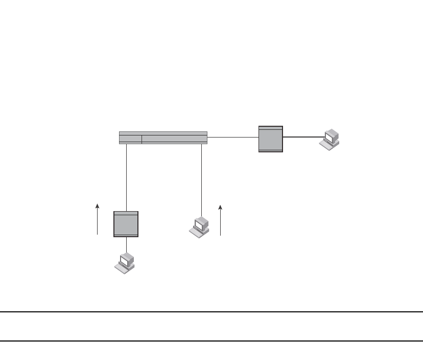
654 PowerConnect B-Series FCX Configuration Guide
53-1002266-01
PIM SM traffic snooping overview
22
FIGURE 114 PIM SM traffic reduction in an enterprise network
NOTE
IP address 239.192.0.0/14 must be used for IPv4 Organization Local Scope.
When PIM SM traffic snooping is enabled, the device starts listening for PIM SM join and prune
messages and IGMP group membership reports. Until the device receives a PIM SM join message
or an IGMP group membership report, the device forwards IP multicast traffic out all ports. Once
the device receives a join message or group membership report for a group, the device forwards
subsequent traffic for that group only on the ports from which the join messages or IGMP reports
were received.
In this example, the router connected to the receiver for group 239.255.162.1 sends a join
message toward the group source. Because PIM SM traffic snooping is enabled on the device, the
device examines the join message to learn the group ID, then makes a forwarding entry for the
group ID and the port connected to the receiver router. The next time the device receives traffic for
239.255.162.1 from the group source, the device forwards the traffic only on port 5/1, because
that is the only port connected to a receiver for the group.
Notice that the receiver for group 239.255.162.69 is directly connected to the device. As a result,
the device does not see a join message on behalf of the client. However, since IP multicast traffic
reduction also is enabled, the device uses the IGMP group membership report from the client to
select the port for forwarding traffic to group 239.255.162.69 receivers.
The IP multicast traffic reduction feature and the PIM SM traffic snooping feature together build a
list of groups and forwarding ports for the VLAN. The list includes PIM SM groups learned through
join messages as well as MAC addresses learned through IGMP group membership reports. In this
case, even though the device never sees a join message for the receiver for group
239.255.162.69, the device nonetheless learns about the receiver and forwards group traffic to
the receiver.
The device stops forwarding IP multicast traffic on a port for a group if the port receives a prune
message for the group.
Router
Router Client
Client
Client
20.20.20.510.10.10.5
10.10.10.6
30.30.30.6
10.10.10.7
VLAN 2
Port5/1
VLAN 2
Port7/1
VLAN 2
Port1/1
Receiver for Group
239.255.162.69
Receiver for Group
239.255.162.1
Client sends an
IGMP group
membership report for
239.255.162.69
Source for Groups
239.255.162.1
239.255.162.69
Router sends a PIM SM
join message for
239.255.162.1
Switch snoops for PIM SM
join and prune messages.
Detects source on port1/1
and receiver for source group
on 5/1. Forwards multicast
data from source on 1/1 to
receiver via 5/1 only.
Without PIM SM traffic reduction,
switch forwards traffic from source
out all ports on VLAN.
Layer 2 Switch

PowerConnect B-Series FCX Configuration Guide 655
53-1002266-01
Configuring IGMP snooping 22
Notice that the ports connected to the source and the receivers are all in the same port-based
VLAN on the device. This is required for the PIM SM snooping feature. The devices on the edge of
the Global Ethernet cloud are configured for IP multicast traffic reduction and PIM SM traffic
snooping. Although this application uses multiple devices, the feature has the same requirements
and works the same way as it does on a single device.
Configuring IGMP snooping
To configure IGMP snooping on an PowerConnect B-Series FCX devices, you need to perform the
following global and VLAN-specific tasks.
Global tasks
Perform the following global tasks:
•“Configuring the hardware and software resource limits” on page 656
•“Enabling or disabling transmission and receipt of IGMP packets on a port” on page 656
•“Configuring the global IGMP mode” on page 656 (Must be enabled for IGMP snooping)
•“Modifying the age interval” on page 657
•“Modifying the query interval (active IGMP snooping mode only)” on page 657
•“Configuring the global IGMP version” on page 657
•“Configuring report control” on page 657 (rate limiting)
•“Modifying the wait time before stopping traffic when receiving a leave message” on page 658
•“Modifying the multicast cache age time” on page 658
•“Enabling or disabling error and warning messages” on page 658
•“Enabling or disabling PIM sparse snooping” on page 658
VLAN-specific tasks
Perform the following VLAN-specific tasks:
•“Configuring the IGMP mode for a VLAN” on page 659 (active or passive)
•“Disabling IGMP snooping for the VLAN” on page 659
•“Disabling PIM sparse mode snooping for the VLAN” on page 659
•“Configuring the IGMP version for the VLAN” on page 660
•“Configuring the IGMP version for individual ports” on page 660
•“Configuring static groups to the entire VLAN or to specific ports” on page 660
•“Configuring static router ports” on page 661
•“Turning off static group proxy” on page 661
•“Enabling IGMPv3 membership tracking and fast leave for the VLAN” on page 661
•“Configuring fast leave for IGMPv2” on page 662
•“Enabling fast convergence” on page 662

656 PowerConnect B-Series FCX Configuration Guide
53-1002266-01
Configuring IGMP snooping
22
Configuring the hardware and software resource limits
The system supports up to 8K of hardware-switched multicast streams. The configurable range is
from 256 through 8192 with a default of 512. Enter the following command to define the maximum
number of IGMP snooping cache entries.
PowerConnect(config)# system-max igmp-snoop-mcache 8000
Syntax: [no] system-max igmp-snoop-mcache <num>
The system supports up to 32K of groups. The configurable range is from 256 through 32768 and
the default is 8192. The configured number is the upper limit of an expandable database. Client
memberships exceeding the group limits are not processed. Enter the following command to define
the maximum number of IGMP group addresses.
PowerConnect(config)# system-max igmp-max-group-addr 1600
Syntax: [no] system-max igmp-max-group-addr <num>
Enabling or disabling transmission and receipt of IGMP packets on a port
When a VLAN is snooping-enabled, all IGMP packets are trapped to CPU without hardware VLAN
flooding. The CPU can block IGMP packets to and from a multicast-disabled port, and does not add
it to the output interfaces of hardware resources. This prevents the disabled port from receiving
multicast traffic. However, if static groups to the entire VLAN are defined, the traffic from these
groups is VLAN flooded, including to disabled ports. Traffic from disabled ports cannot be blocked
in hardware, and is switched in the same way as traffic from enabled ports.
This command has no effect on a VLAN that is not snooping-enabled because all multicast traffic is
VLAN flooded.
PowerConnect(config)# interface ethernet 0/1/3
PowerConnect(config-if-e1000-0/1/3)# ip-multicast-disable
Syntax: [no] ip-multicast-disable
Configuring the global IGMP mode
You can configure active or passive IGMP modes on an PowerConnect B-Series FCX device. The
default mode is passive. If you specify an IGMP mode for a VLAN, it overrides the global setting.
•Active - When active IGMP mode is enabled, an PowerConnect B-Series FCX device actively
sends out IGMP queries to identify multicast groups on the network, and makes entries in the
IGMP table based on the group membership reports it receives.
•Passive - When passive IGMP mode is enabled, it forwards reports to the router ports which
receive queries. IGMP snooping in the passive mode does not send queries. However, it
forwards queries to the entire VLAN.
To globally set the IGMP mode to active, enter the following command.
PowerConnect(config)# ip multicast active
Syntax: [no] ip multicast [active | passive]
If you do not enter either active or passive, the passive mode is assumed.

PowerConnect B-Series FCX Configuration Guide 657
53-1002266-01
Configuring IGMP snooping 22
Modifying the age interval
When the device receives a group membership report, it makes an entry for that group in the IGMP
group table. The age interval specifies how long the entry can remain in the table before the device
receives another group membership report. When multiple devices connect together, all devices
must be configured for the same age interval, which must be at least twice the length of the query
interval, so that missing one report won't stop traffic. Non-querier age intervals must be the same
as the age interval of the querier.
To modify the age interval, enter the following command.
PowerConnect(config)# ip multicast age-interval 280
Syntax: [no] ip multicast age-interval <interval>
The <interval> parameter specifies the aging time. You can specify a value from 20 through 7200
seconds. The default is 140 seconds.
Modifying the query interval (active IGMP snooping mode only)
For a device with an active IGMP mode, you can modify the query interval to specify how often the
device sends general queries. When multiple queriers connect together, they must all be
configured with the same query interval.
To modify the query interval, enter the following command.
PowerConnect(config)# ip multicast query-interval 120
Syntax: [no] ip multicast query-interval <interval>
The <interval> parameter specifies the time between queries. You can specify a value from 10
through 3600 seconds. The default is 125 seconds.
Configuring the global IGMP version
You can globally specify IGMPv2 or IGMPv3 for the device. The default is IGMPv2. For example, the
following command causes the device to use IGMPv3.
PowerConnect(config)# ip multicast version 3
Syntax: [no] ip multicast version 2 | 3
You can also optionally specify the IGMP version for individual VLANs, or individual ports within
VLANs. When no IGMP version is specified for a VLAN, the global IGMP version is used. When an
IGMP version is specified for individual ports within a VLAN, the ports use that version, instead of
the VLAN version or the global version. The default is IGMPv2.
Configuring report control
A device in passive mode forwards reports and leave messages from clients to the upstream router
ports that are receiving queries.
You can configure report control to rate-limit report forwarding within the same group to no more
than once every 10 seconds. This rate-limiting does not apply to the first report answering a
group-specific query.
NOTE
This feature applies to IGMPv2 only. The leave messages are not rate limited.

658 PowerConnect B-Series FCX Configuration Guide
53-1002266-01
Configuring IGMP snooping
22
IGMPv2 membership reports of the same group from different clients are considered to be the
same and are rate-limited.
Use the following command to alleviate report storms from many clients answering the upstream
router query.
PowerConnect(config)# ip multicast report-control
Syntax: [no] ip multicast report-control
The original command, ip igmp-report-control, has been renamed to ip multicast report-control. The
original command is still accepted; however, it is renamed when you issue a show configuration
command.
Modifying the wait time before stopping traffic when receiving a leave message
You can define the wait time before stopping traffic to a port when a leave message is received.
The device sends group-specific queries once per second to ask if any client in the same port still
needs this group. The value range is from 1 through 5, and the default is 2. Due to internal timer
granularity, the actual wait time is between n and (n+1) seconds (n is the configured value).
PowerConnect(config)# ip multicast leave-wait-time 1
Syntax: [no] ip multicast leave-wait-time <num>
Modifying the multicast cache age time
You can set the time for an mcache to age out when it does not receive traffic. The traffic is
hardware switched. One minute before aging out an mcache, the device mirrors a packet of this
mcache to CPU to reset the age. If no data traffic arrives within one minute, this mcache is deleted.
A lower value quickly removes resources consumed by idle streams, but it mirrors packets to CPU
often. A higher value is recommended only data streams are continually arriving. The range is from
60 through 3600 seconds, and the default is 60 seconds.
PowerConnect(config)# ip multicast mcache-age 180
Syntax: [no] ip multicast mcache-age <num>
Enabling or disabling error and warning messages
The device prints error or warning messages when it runs out of software resources or when it
receives packets with the wrong checksum or groups. These messages are rate-limited. You can
turn off these messages by entering the following command.
PowerConnect(config)# ip multicast verbose-off
Syntax: [no] ip multicast verbose-off
Enabling or disabling PIM sparse snooping
PIM snooping must be used only in topologies where multiple PIM sparse routers connect through
a device. PIM snooping does not work on a PIM dense mode router which does not send join
messages, and traffic to PIM dense ports is stopped. A PIM snooping-enabled device displays a
warning if it receives PIM dense join or prune messages. Configure PIM sparse snooping by
entering the following command.
PowerConnect(config)# ip pimsm-snooping

PowerConnect B-Series FCX Configuration Guide 659
53-1002266-01
Configuring IGMP snooping 22
Syntax: [no] ip pimsm-snooping
NOTE
The device must be in passive mode before it can be configured for PIM snooping.
Configuring the IGMP mode for a VLAN
You can configure a VLAN to use the active or passive IGMP mode. The default mode is passive.
The setting specified for the VLAN overrides the global setting:
•Active - An active IGMP mode device actively sends out IGMP queries to identify multicast
groups on the network, and makes entries in the IGMP table based on the group membership
reports received.
•Passive - A passive IGMP mode device forwards reports to the router ports which receive
queries. IGMP snooping in the passive mode forwards queries to the entire VLAN, but it does
not send queries.
To set the IGMP mode for VLAN 20 to active, enter the following commands.
PowerConnect(config)# vlan 20
PowerConnect(config-vlan-20)# multicast active
Syntax: [no] multicast active | passive
Disabling IGMP snooping for the VLAN
When IGMP snooping is enabled globally, you can still disable it for a specific VLAN. For example,
the following commands cause IGMP snooping to be disabled for VLAN 20. This setting overrides
the global setting.
PowerConnect(config)# vlan 20
PowerConnect(config-vlan-20)# multicast disable-multicast-snoop
Syntax: [no] multicast disable-multicast-snoop
Enabling PIM sparse mode snooping for the VLAN
You can enable PIM snooping for a specific VLAN. For example, the following commands enable
PIM snooping on VLAN 20.
PowerConnect(config)# vlan 20
PowerConnect(config-vlan-20)# multicast pimsm-snooping
Syntax: [no] multicast pimsm-snooping
Disabling PIM sparse mode snooping for the VLAN
When PIM snooping is enabled globally, you can still disable it for a specific VLAN. For example, the
following commands disable PIM snooping for VLAN 20. This setting overrides the global setting.
PowerConnect(config)# vlan 20
PowerConnect(config-vlan-20)# multicast disable-pimsm-snoop
Syntax: [no] multicast disable-pimsm-snoop

660 PowerConnect B-Series FCX Configuration Guide
53-1002266-01
Configuring IGMP snooping
22
Configuring the IGMP version for the VLAN
You can specify the IGMP version for a VLAN. For example, the following commands configure VLAN
20 to use IGMPv3.
PowerConnect(config)# vlan 20
PowerConnect(config-vlan-20)# multicast version 3
Syntax: [no] multicast version 2 | 3
If no IGMP version is specified, then the globally-configured IGMP version is used. If an IGMP
version is specified for individual ports, those ports use that version, instead of the VLAN version.
Configuring the IGMP version for individual ports
You can specify the IGMP version for individual ports in a VLAN. For example, the following
commands configure ports 0/1/4, 0/1/5, 0/1/6 and 0/2/1 to use IGMPv3. The other ports either
use the IGMP version specified with the multicast version command, or the globally-configured
IGMP version.
PowerConnect(config)# vlan 20
PowerConnect(config-vlan-20)# multicast port-version 3 ethernet 0/2/1 ethernet
0/1/4 to 0/1/6
Syntax: [no] multicast port-version 2 | 3 <port-numbers>
Configuring static groups to the entire VLAN or to specific ports
A snooping-enabled VLAN cannot forward multicast traffic to ports that do not receive IGMP
membership reports. If clients cannot send reports, you can configure a static group which applies
to the entire VLAN or only to specific ports. The static group allows packets to be forwarded to the
static group ports even though they have no client membership reports. The static group to the
entire VLAN is used in VLAN flooding, which consumes less hardware resource than the static
group to ports.
The static group drop option discards data traffic to a group in hardware. The group can be any
multicast group including groups in the reserved range of 224.0.0.X. The drop option does not
apply to IGMP packets, which are always trapped to CPU when snooping is enabled. The drop
option applies to the entire VLAN, and cannot be configured for a port list. When the drop option is
not specified, the group must exist outside the reserved range.
PowerConnect(config)# vlan 20
PowerConnect(config-vlan-20)# multicast static-group 224.1.1.1 count 2 ethernet
0/1/3 ethernet 0/1/5 to 0/1/7
PowerConnect(config-vlan-20)# multicast static-group 239.1.1.1 count 3 drop
PowerConnect(config-vlan-20)# multicast static-group 239.1.1.1
Syntax: [no] multicast static-group <ipv4-address> [count <num>] [<port-numbers> | drop]
The <ipv4-address> parameter is the address of the multicast group.
The count is optional, which allows a contiguous range of groups. Omitting the count <num> is
equivalent to the count being 1.
If no <port-numbers> are entered, the static groups apply to the entire VLAN.

PowerConnect B-Series FCX Configuration Guide 661
53-1002266-01
Configuring IGMP snooping 22
Configuring static router ports
FastIron Stackable devices forward all multicast control and data packets to router ports which
receive queries. Although router ports are learned, you can force multicast traffic to specified ports
even though these ports never receive queries. To configure static router ports, enter the following
commands.
PowerConnect(config)# vlan 70
PowerConnect(config-vlan-70)# multicast router-port ethernet 0/1/4 to 0/1/5
ethernet 0/1/8
Syntax: [no] multicast router-port ethernet <port> [ethernet <port> | to <port>]
Specify the <port> variable in the format <stack-unit/slotnum/portnum>.
To specify a list of ports, enter each port as ethernet <port> followed by a space. For example,
ethernet 0/1/4 ethernet 0/1/5 ethernet 0/1/8
To specify a range of ports, enter the first port in the range as ethernet <port> followed by the last
port in the range. For example, ethernet 0/1/1 to 0/1/8.
You can combine lists and ranges in the same command. For example: enable ethernet 0/1/1 to
0/1/8 ethernet 0/1/24 ethernet 0/2/2 ethernet 0/2/4.
Turning off static group proxy
If a device has been configured for static groups, it acts as a proxy and sends membership reports
for the static groups when it receives general or group-specific queries. When a static group
configuration is removed, it is deleted from active group table immediately. However, leave
messages are not sent to the querier, and the querier must age the group out. Proxy activity can be
turned off. The default is on. To turn proxy activity off for VLAN 20, enter the following commands.
PowerConnect(config)# vlan 20
PowerConnect(config-vlan-20)# multicast proxy-off
Syntax: [no] multicast proxy-off
Enabling IGMPv3 membership tracking and fast leave for the VLAN
IGMPv3 gives clients membership tracking and fast leave capability. In IGMPv2, only one client on
an interface needs to respond to a router's queries. This can leave some clients invisible to the
router, making it impossible to track the membership of all clients in a group. When a client leaves
the group, the device sends group-specific queries to the interface to see if other clients on that
interface need the data stream of the client who is leaving. If no client responds, the device waits a
few seconds before it stops the traffic. You can configure the wait time using the ip multicast
leave-wait-time command.
IGMPv3 requires every client to respond to queries, allowing the device to track all clients. When
tracking is enabled, and an IGMPv3 client sends a leave message and there is no other client, the
device immediately stops forwarding traffic to the interface. This feature requires the entire VLAN
be configured for IGMPv3 with no IGMPv2 clients. If a client does not send a report during the
specified group membership time (the default is 140 seconds), that client is removed from the
tracking list.

662 PowerConnect B-Series FCX Configuration Guide
53-1002266-01
Configuring IGMP snooping
22
Every group on a physical port keeps its own tracking record. However, it can only track group
membership; it cannot track by (source, group). For example, Client A and Client B belong to group1
but each receives traffic streams from different sources. Client A receives a stream from (source_1,
group1) and Client B receives a stream from (source_2, group1). The device still waits for the
configured leave-wait-time before it stops the traffic because these two clients are in the same
group. If the clients are in different groups, then the waiting period is not applied and traffic is
stopped immediately.
To enable the tracking and fast leave feature for VLAN 20, enter the following commands.
PowerConnect(config)# vlan 20
PowerConnect(config-vlan-20)# multicast tracking
Syntax: [no] multicast tracking
The membership tracking and fast leave features are supported for IGMPv3 only. If any port or any
client is not configured for IGMPv3, then the multicast tracking command is ignored.
Configuring fast leave for IGMPv2
When a device receives an IGMPv2 leave message, it sends out multiple group-specific queries. If
no other client replies within the waiting period, the device stops forwarding traffic. When
fast-leave-v2 is configured, and when the device receives a leave message, it immediately stops
forwarding to that port. The device does not send group specific-queries. You must ensure that no
snooping-enabled ports have multiple clients. When two devices connect together, the querier
must not be configured for fast-leave-v2, because the port might have multiple clients through the
non-querier. The number of queries, and the waiting period (in seconds) can be configured using
the ip multicast leave-wait-time command. The default is 2 seconds.
To configure fast leave for IGMPv2, enter the following commands.
PowerConnect(config)# vlan 20
PowerConnect(config-vlan-20)# multicast fast-leave-v2
Syntax: [no] multicast fast-leave-v2
Enabling fast convergence
In addition to sending periodic general queries, an active device sends general queries when it
detects a new port. However, because the device does not recognize the other device's port up
event, multicast traffic might still require up to the query-interval time to resume after a topology
change. Fast convergence allows the device to listen to topology change events in Layer 2 protocols
such as spanning tree, and then send general queries to shorten the convergence time.
If the Layer 2 protocol cannot detect a topology change, fast convergence may not work in some
cases. For example, if the direct connection between two devices switches from one interface to
another, the rapid spanning tree protocol (802.1w) considers this optimization, rather than a
topology change. In this example, other devices will not receive topology change notifications, and
will be unable to send queries to speed up the convergence. Fast convergence works well with the
regular spanning tree protocol in this case.
To enable fast-convergency, enter the following commands.
PowerConnect(config)# vlan 70
PowerConnect(config-vlan-70)# multicast fast-convergence
Syntax: multicast fast-convergence

PowerConnect B-Series FCX Configuration Guide 663
53-1002266-01
Displaying IGMP snooping information 22
Displaying IGMP snooping information
This section describes the show commands for IGMP snooping.
Displaying IGMP errors
To display information about possible IGMP errors, enter the following commands.
PowerConnect# show ip multicast error
snoop SW processed pkt: 173, up-time 160 sec
Syntax: show ip multicast error
The following table describes the output from the show ip multicast error command.
Displaying IGMP group information
To display information about IGMP groups, enter the following command.
In this example, an IGMPv2 group is in EXCLUDE mode with a source of 0. The group only excludes
traffic from the 0 (zero) source list, which actually means that all traffic sources are included.
To display detailed IGMP group information, enter the following command.
If the tracking and fast leave features are enabled, you can display the list of clients that belong to
a particular group by entering the following command.
Field Description
SW processed pkt The number of multicast packets processed by IGMP snooping.
up-time The time since the IGMP snooping is enabled.
PowerConnect# show ip multicast group
p-:physical, ST:static, QR:querier, EX:exclude, IN:include, Y:yes, N:no
VL70 : 3 groups, 4 group-port, tracking_enabled
group p-port ST QR life mode source
1 224.1.1.2 0/1/33 no yes 120 EX 0
2 224.1.1.1 0/1/33 no yes 120 EX 0
3 226.1.1.1 0/1/35 yes yes 100 EX 0
4 226.1.1.1 0/1/33 yes yes 100 EX 0
PowerConnect# show ip multicast group 226.1.1.1 detail
Display group 226.1.1.1 in all interfaces in details.
p-:physical, ST:static, QR:querier, EX:exclude, IN:include, Y:yes, N:no
VL70 : 1 groups, 2 group-port, tracking_enabled
group p-port ST QR life mode source
1 226.1.1.1 0/1/35 yes yes 120 EX 0
group: 226.1.1.1, EX, permit 0 (source, life):
life=120, deny 0:
group p-port ST QR life mode source
2 226.1.1.1 0/1/33 yes yes 120 EX 0
group: 226.1.1.1, EX, permit 0 (source, life):
life=120, deny 0:

664 PowerConnect B-Series FCX Configuration Guide
53-1002266-01
Displaying IGMP snooping information
22
Syntax: show ip multicast group [<group-address> [detail] [tracking]]
If you want a report for a specific multicast group, enter that group's address for <group-address>.
Enter detail to display the source list of a specific VLAN.
Enter tracking for information on interfaces that have tracking enabled.
The following table describes the information displayed by the show ip multicast group command.
Displaying IGMP snooping mcache information
The IGMP snooping mcache contains multicast forwarding information for VLANs. To display
information in the multicast forwarding mcache, enter the following command.
Field Description
group The address of the group (destination address in this case, 224.1.1.1)
p-port The physical port on which the group membership was received.
ST Yes indicates that the IGMP group was configured as a static group; No means the address
was learned from reports.
QR Yes means the port is a querier port; No means it is not. A port becomes a non-querier port
when it receives a query from a source with a lower source IP address than the device.
life The number of seconds the group can remain in EXCLUDE mode. An EXCLUDE mode changes
to INCLUDE mode if it does not receive an "IS_EX" or "TO_EX" message during a certain period
of time. The default is 140 seconds. There is no life displayed in INCLUDE mode.
mode Indicates current mode of the interface: INCLUDE or EXCLUDE. If the interface is in INCLUDE
mode, it admits traffic only from the source list. If an interface is in EXCLUDE mode, it denies
traffic from the source list and accepts the rest.
source Identifies the source list that will be included or excluded on the interface.
For example, if an IGMPv2 group is in EXCLUDE mode with a source of 0, the group excludes
traffic from the 0 (zero) source list, which actually means that all traffic sources are included.
PowerConnect# show ip multicast group 224.1.1.1 tracking
Display group 224.1.1.1 in all interfaces with tracking enabled.
p-:physical, ST:static, QR:querier, EX:exclude, IN:include, Y:yes, N:no
VL70 : 1 groups, 1 group-port, tracking_enabled
group p-port ST QR life mode source
*** Note: has 1 static groups to the entire vlan, not displayed here
1 224.1.1.1 0/1/33 no yes 100 EX 0
receive reports from 1 clients: (age)
(2.2.100.2 60)
PowerConnect# show ip multicast mcache
Example: (S G) cnt=: cnt: SW proc. count
OIF: 0/1/22 TR(0/1/32,0/1/33), TR is trunk, 0/1/32 primary, 0/1/33 output
vlan 1, 1 caches. use 1 VIDX
1 (1.2.10.102 225.1.1.1) cnt=46
OIF: 0/1/4
age=0m up-time=45m vidx=4130 (ref-cnt=1)
vlan 70, 1 caches. use 1 VIDX
1 (* 226.1.2.3) cnt=69
OIF: 0/1/14
age=0m up-time=59m vidx=4129 (ref-cnt=1)

PowerConnect B-Series FCX Configuration Guide 665
53-1002266-01
Displaying IGMP snooping information 22
Syntax: show ip multicast mcache
The following table describes the output of the show ip multicast mcache command.
Displaying PIM sparse snooping information
PIM sparse mode snooping allows a device to listen for join or prune messages exchanged between
PIM routers, which helps reduce unwanted traffic. To display PIM snooping information, enter the
following command.
This output shows the number of OIF due to PIM out of the total OIF. The join or prune messages
are source-specific. In this case, if the mcache is in (* G), the display function will also print the
traffic source information.
Displaying software resource usage for VLANs
To display information about the software resources used, enter the following command.
Field Description
(source group) Source and group addresses of this data stream. (* group) means match group only; (source
group) means match both.
cnt The number of packets processed in software. Packets are switched in hardware, which
increases this number slowly.
OIF The output interfaces. If entire vlan is displayed, this indicates that static groups apply to
the entire VLAN.
age The mcache age. The mcache will be reset to 0 if traffic continues to arrive, otherwise the
mcache will be aged out when it reaches the time defined by the ip multicast mcache-age
command.
uptime The up time of this mcache in minutes.
vidx Vidx specifies output port list index. Range is from 4096 to 8191
ref-cnt The vidx is shared among mcaches having the same output interfaces. Ref-cnt indicates the
number of mcaches using this vidx.
PowerConnect# show ip multicast pimsm-snooping
vlan 1, has 1 caches.
1 (1.2.10.102 225.1.1.1) has 0 pim join ports out of 1 OIF
vlan 70, has 1 caches.
1 (* 226.1.2.3) has 2 pim join ports out of 2 OIF
0/1/14 (age=60), 0/1/13 (age=60),
0/1/14 has 1 src: 1.1.30.99(60)
0/1/13 has 1 src: 1.1.30.99(60)
PowerConnect# show ip multicast resource
alloc in-use avail get-fail limit get-mem size init
igmp group 256 1 255 0 32000 1 16 256
igmp phy port 1024 1 1023 0 200000 1 22 1024
…. entries deleted …
snoop mcache entry 128 2 126 0 8192 3 56 128
total pool memory 109056 bytes
has total 2 forwarding hash
VIDX sharing hash : size=2 anchor=997 2nd-hash=no fast-trav=no
Available vidx: 4060. IGMP/MLD use 2

666 PowerConnect B-Series FCX Configuration Guide
53-1002266-01
Displaying IGMP snooping information
22
Syntax: show ip multicast resource
The following table describes the output from the show ip multicast resource command.
Displaying status of IGMP snooping traffic
To display status information for IGMP snooping traffic, enter the following command.
Syntax: show ip multicast traffic
The following table describes the information displayed by the show ip multicast traffic command.
Field Description
alloc The allocated number of units.
in-use The number of units which are currently being used.
avail The number of available units.
get-fail This displays the number of resource failures.
NOTE: It is important to pay attention to this field.
limit The upper limit of this expandable field. The limit of multicast group is configured by the
system-max igmp-max-group-addr command. The limit of snoop mcache entry is
configured by the system-max multicast-snoop-mcache command.
get-mem The number of memory allocation. This number should continue to increase.
size The size of a unit (in bytes).
init The initial allocated amount of memory. More memory can be allocated if resources run out.
Available vidx The output interface (OIF) port mask used by mcache. The entire device has a maximum of
4096 vidx. Different mcaches with the same OIF share the same vidx. If vidx is not available,
the stream cannot be hardware-switched.
Field Description
QQuery
Qry General Query
QryV2 Number of general IGMPv2 queries received or sent.
QryV3 Number of general IGMPv3 queries received or sent.
G-Qry Number of group-specific queries received or sent.
PowerConnect# show ip multicast traffic
IGMP snooping: Total Recv: 22, Xmit: 26
Q: query, Qry: general Q, G-Qry: group Q, GSQry: group-source Q, Mbr: member
Recv QryV2 QryV3 G-Qry GSQry MbrV2 MbrV3 Leave
VL1 0 0 0 0 4 0 0
VL70 18 0 0 0 0 0 0
Recv IsIN IsEX ToIN ToEX ALLOW BLOCK Pkt-Err
VL1 0 4 0 0 0 0 0
VL70 0 0 0 0 0 0 0
Send QryV2 QryV3 G-Qry GSQry MbrV2 MbrV3
VL1 0 0 8 0 0 0
VL70 0 0 0 0 0 18
VL70 pimsm-snooping, Hello: 12, Join/Prune: 9

PowerConnect B-Series FCX Configuration Guide 667
53-1002266-01
Displaying IGMP snooping information 22
Displaying IGMP snooping information by VLAN
You can display IGMP snooping information for all VLANs or for a specific VLAN. For example, to
display IGMP snooping information for VLAN 70, enter the following command.
Syntax: show ip multicast vlan [<vlan-id>]
If you do not specify a <vlan-id>, information for all VLANs is displayed.
The following table describes the information displayed by the show ip multicast vlan command.
GSQry Number of group source-specific queries received or sent.
Mbr The membership report.
MbrV2 The IGMPv2 membership report.
MbrV3 The IGMPv3 membership report.
IsIN Number of source addresses that were included in the traffic.
IsEX Number of source addresses that were excluded in the traffic.
ToIN Number of times the interface mode changed from EXCLUDE to INCLUDE.
ToEX Number of times the interface mode changed from INCLUDE to EXCLUDE.
ALLO Number of times that additional source addresses were allowed on the interface.
BLK Number of times that sources were removed from an interface.
Pkt-Err Number of packets having errors, such as checksum.
Pimsm-snooping hello, join,
prune
Number of PIM sparse hello, join, and prune packets
Field Description
version The IGMP version number
query-t How often a querier sends a general query on the interface.
group-aging-t The number of seconds membership groups can be members of this group before aging out.
rtr-port The router ports which are the ports receiving queries. The display router ports:
0/1/13(140) 1.1.70.3 means port 0/1/13 has a querier with 1.1.70.3 address, and a
remaining life of 140 seconds.
max-resp-t The maximum number of seconds a client waits before it replies to the query.
non-QR Indicates that the port is a non-querier.
Field Description
PowerConnect# show ip multicast vlan 70
version=2, query-t=30, group-aging-t=140, max-resp-t=3, other-qr-present-t=63
VL70: dft V2, vlan cfg passive, , pimsm (vlan cfg), track, 0 grp, 1 (*G) cache,
rtr ports,
router ports: 0/1/13(140) 1.1.70.3, 0/1/20(180) 1.1.70.2, 0/1/14(180)
0/1/13 has 0 groups, non-QR (passive), default V2
0/1/14 has 0 groups, non-QR (passive), default V2
0/1/20 has 0 groups, non-QR (passive), default V2

668 PowerConnect B-Series FCX Configuration Guide
53-1002266-01
Displaying IGMP snooping information
22
Displaying querier information
You can use the show ip multicast vlan command to display the querier information for a VLAN. This
command displays the VLAN interface status and if there is any other querier present with the
lowest IP address. The following list provides the combinations of querier possibilities:
•Active interface with no other querier present
•Passive interface with no other querier present
•Active interface with other querier present
•Passive interface with other querier present
Active interface with no other querier present
The following example shows the output in which the VLAN interface is active and no other querier
is present with the lowest IP address.
PowerConnect# show ip multicast vlan 10
Version=2, Intervals: Query=125, Group Age=260, Max Resp=10, Other Qr=260
VL10: dft V2, vlan cfg active, 0 grp, 0 (*G) cache, no rtr port,
1/1/16 has 0 groups,
This interface is Querier
default V2
1/1/24 has 0 groups,
This interface is Querier
default V2
2/1/16 has 0 groups,
This interface is Querier
default V2
2/1/24 has 0 groups,
This interface is Querier
default V2
3/1/1 has 0 groups,
This interface is Querier
default V2
3/1/4 has 0 groups,
This interface is Querier
default V2
Syntax: show ip multicast vlan <vlan-id>
If you do not specify a <vlan-id>, information for all VLANs is displayed.
QR Indicates that the port is a querier.
dft The IGMP version for the specified VLAN. In this example, VL70: dft V2 indicates that the
default IGMP version V2 is set for VLAN 70.
Field Description

PowerConnect B-Series FCX Configuration Guide 669
53-1002266-01
Displaying IGMP snooping information 22
Passive interface with no other querier present
The following example shows the output in which the VLAN interface is passive and no other
querier is present with the lowest IP address.
PowerConnect# show ip multicast vlan 10
Version=2, Intervals: Query=125, Group Age=260, Max Resp=10, Other Qr=260
VL10: dft V2, vlan cfg passive, 0 grp, 0 (*G) cache, no rtr port,
1/1/16 has 0 groups,
This interface is non-Querier (passive)
default V2
1/1/24 has 0 groups,
This interface is non-Querier (passive)
default V2
2/1/16 has 0 groups,
This interface is non-Querier (passive)
default V2
2/1/24 has 0 groups,
This interface is non-Querier (passive)
default V2
3/1/1 has 0 groups,
This interface is non-Querier (passive)
default V2
3/1/4 has 0 groups,
This interface is non-Querier (passive)
default V2
Active interface with other querier present
The following example shows the output in which the VLAN interface is active and another querier
is present with the lowest IP address.
PowerConnect# show ip multicast vlan 10
Version=2, Intervals: Query=125, Group Age=260, Max Resp=10, Other Qr=260
VL10: dft V2, vlan cfg active, 7 grp, 6 (*G) cache, rtr ports,
router ports: 2/1/24(260) 5.5.5.5, 3/1/4(260) 8.8.8.8,
1/1/16 has 4 groups,
This interface is Querier
default V2
group: 226.6.6.6, life = 240
group: 228.8.8.8, life = 240
group: 230.0.0.0, life = 240
group: 224.4.4.4, life = 240
1/1/24 has 1 groups,
This interface is Querier
default V2
group: 228.8.8.8, life = 240
2/1/16 has 4 groups,

670 PowerConnect B-Series FCX Configuration Guide
53-1002266-01
Displaying IGMP snooping information
22
This interface is Querier
default V2
group: 226.6.6.6, life = 240
group: 228.8.8.8, life = 240
group: 230.0.0.0, life = 240
group: 224.4.4.4, life = 240
2/1/24 has 2 groups,
This interface is non-Querier
Querier is 5.5.5.5
Age is 0
Max response time is 100
default V2
**** Warning! has V3 (age=0) nbrs
group: 234.4.4.4, life = 260
group: 226.6.6.6, life = 260
3/1/1 has 4 groups,
This interface is Querier
default V2
group: 238.8.8.8, life = 260
group: 228.8.8.8, life = 260
group: 230.0.0.0, life = 260
group: 224.4.4.4, life = 260
3/1/4 has 1 groups,
This interface is non-Querier
Querier is 8.8.8.8
Age is 0
Max response time is 100
default V2
**** Warning! has V3 (age=0) nbrs
group: 236.6.6.6, life = 260
Passive interface with other querier present
The following example shows the output in which the VLAN interface is passive and another querier
is present with the lowest IP address.
PowerConnect# show ip multicast vlan 10
Version=2, Intervals: Query=125, Group Age=260, Max Resp=10, Other Qr=260
VL10: dft V2, vlan cfg passive, 7 grp, 6 (*G) cache, rtr ports,
router ports: 2/1/24(260) 5.5.5.5, 3/1/4(260) 8.8.8.8,
1/1/16 has 4 groups,
This interface is non-Querier (passive)
default V2
group: 226.6.6.6, life = 260
group: 228.8.8.8, life = 260
group: 230.0.0.0, life = 260
group: 224.4.4.4, life = 260
1/1/24 has 1 groups,
This interface is non-Querier (passive)
default V2
group: 228.8.8.8, life = 260
2/1/16 has 4 groups,

PowerConnect B-Series FCX Configuration Guide 671
53-1002266-01
Displaying IGMP snooping information 22
This interface is non-Querier (passive)
default V2
group: 226.6.6.6, life = 260
group: 228.8.8.8, life = 260
group: 230.0.0.0, life = 260
group: 224.4.4.4, life = 260
2/1/24 has 2 groups,
This interface is non-Querier (passive)
Querier is 5.5.5.5
Age is 0
Max response time is 100
default V2
**** Warning! has V3 (age=0) nbrs
group: 234.4.4.4, life = 260
group: 226.6.6.6, life = 260
3/1/1 has 4 groups,
This interface is non-Querier (passive)
default V2
group: 238.8.8.8, life = 260
group: 228.8.8.8, life = 260
group: 230.0.0.0, life = 260
group: 224.4.4.4, life = 260
3/1/4 has 1 groups,
This interface is non-Querier (passive)
Querier is 8.8.8.8
Age is 0
Max response time is 100
default V2
**** Warning! has V3 (age=0) nbrs
group: 236.6.6.6, life = 260
Clear IGMP snooping commands
The clear IGMP snooping commands must be used only in troubleshooting conditions, or to recover
from errors.
Clear IGMP counters on VLANs
To clear IGMP snooping on error and traffic counters for all VLANs, enter the following command.
PowerConnect# clear ip multicast counters
Syntax: clear ip multicast counters
Clear IGMP mcache
To clear the mcache on all VLANs, enter the following command.
PowerConnect# clear ip multicast mcache
Syntax: clear ip multicast mcache

672 PowerConnect B-Series FCX Configuration Guide
53-1002266-01
Displaying IGMP snooping information
22
Clear mcache on a specific VLAN
To clear the mcache on a specific VLAN, enter the following command.
PowerConnect# clear ip multicast vlan 10 mcache
Syntax: clear ip multicast vlan <vlan-id> mcache
The <vlan-id> parameter specifies the specific VLAN in which to clear the mcache.
Clear traffic on a specific VLAN
To clear the traffic counters on a specific VLAN, enter the following command.
PowerConnect# clear ip multicast vlan 10 traffic
Syntax: clear ip multicast vlan <vlan-id> traffic
The <vlan-id> parameter specifies the specific VLAN in which to clear the traffic counters.

PowerConnect B-Series FCX Configuration Guide 673
53-1002266-01
Chapter
23
Enabling the Foundry Discovery Protocol (FDP) and Reading
Cisco Discovery Protocol (CDP) Packets
Table 117 lists individual Dell PowerConnect switches and the discovery protocols they support.
Using FDP
The Foundry Discovery Protocol (FDP) enables Dell PowerConnect devices to advertise themselves
to other Dell PowerConnect devices on the network. When you enable FDP on a Dell PowerConnect
device, the device periodically advertises information including the following:
•Hostname (device ID)
•Product platform and capability
•Software version
•VLAN and Layer 3 protocol address information for the port sending the update. IP, IPX, and
AppleTalk Layer 3 information is supported.
A Dell PowerConnect device running FDP sends FDP updates on Layer 2 to MAC address
01-E0-52-CC-CC-CC. Other Dell PowerConnect devices listening on that address receive the
updates and can display the information in the updates. Dell PowerConnect devices can send and
receive FDP updates on Ethernet interfaces.
FDP is disabled by default.
NOTE
If FDP is not enabled on a Dell PowerConnect device that receives an FDP update or the device is
running a software release that does not support FDP, the update passes through the device at
Layer 2.
Configuring FDP
The following sections describe how to enable FDP and how to change the FDP update and hold
timers.
Enabling FDP globally
To enable a Dell PowerConnect device to globally send FDP packets, enter the following command
at the global CONFIG level of the CLI.
TABLE 117 Supported discovery protocol features
Feature PowerConnect B-Series FCX
Foundry Discovery Protocol (FDP) for IPv4
and IPv6 traffic
Yes
Cisco Discovery Protocol (CDP) for IPv4
and IPV6 traffic
Yes

674 PowerConnect B-Series FCX Configuration Guide
53-1002266-01
Using FDP
23
PowerConnect(config)# fdp run
Syntax: [no] fdp run
The feature is disabled by default.
Enabling FDP at the interface level
You can enable FDP at the interface level by entering commands such as the following.
PowerConnect(config)# int e 2/1
PowerConnect(config-if-2/1)# fdp enable
Syntax: [no] fdp enable
By default, the feature is enabled on an interface once FDP is enabled on the device.
Specifying the IP management address to advertise
When FDP is enabled, by default, the device advertises one IPv4 address and one IPv6 address to
its FDP neighbors. If desired, you can configure the device to advertise only the IPv4 management
address or only the IPv6 management address. You can set the configuration globally on a Layer 2
switch, or on an interface on a Layer 3 switch.
For example, to configure a Layer 2 switch to advertise the IPv4 address, enter the following
command at the Global CONFIG level of the CLI:
PowerConnect(config)# fdp advertise ipv4
To configure a Layer 3 switch to advertise the IPv6 address, enter the following command at the
Interface level of the CLI:
PowerConnect(config-if-2/1)# fdp advertise ipv6
Syntax: fdp advertise ipv4 | ipv6
Changing the FDP update timer
By default, a Dell PowerConnect device enabled for FDP sends an FDP update every 60 seconds.
You can change the update timer to a value from 5 – 900 seconds.
To change the FDP update timer, enter a command such as the following at the global CONFIG level
of the CLI.
PowerConnect(config)# fdp timer 120
Syntax: [no] fdp timer <secs>
The <secs> parameter specifies the number of seconds between updates and can be from 5 –
900 seconds. The default is 60 seconds.
Changing the FDP hold time
By default, a Dell PowerConnect device that receives an FDP update holds the information until one
of the following events occurs:
•The device receives a new update.
•180 seconds have passed since receipt of the last update. This is the hold time.
Once either of these events occurs, the device discards the update.

PowerConnect B-Series FCX Configuration Guide 675
53-1002266-01
Using FDP 23
To change the FDP hold time, enter a command such as the following at the global CONFIG level of
the CLI.
PowerConnect(config)# fdp holdtime 360
Syntax: [no] fdp holdtime <secs>
The <secs> parameter specifies the number of seconds a Dell PowerConnect device that receives
an FDP update can hold the update before discarding it. You can specify from 10 – 255 seconds.
The default is 180 seconds.
Displaying FDP information
You can display the following FDP information:
•FDP entries for Dell PowerConnect neighbors
•Individual FDP entries
•FDP information for an interface on the device you are managing
•FDP packet statistics
NOTE
If the Dell PowerConnect device has intercepted CDP updates, then the CDP information is also
displayed.
Displaying neighbor information
To display a summary list of all the Dell PowerConnect neighbors that have sent FDP updates to this
Dell PowerConnect device, enter the following command.
Syntax: show fdp neighbor [ethernet <port>] [detail]
The ethernet <port> parameter lists the information for updates received on the specified port.
The detail parameter lists detailed information for each device.
The show fdp neighbor command, without optional parameters, displays the following information.
TABLE 118 Summary FDP and CDP neighbor information
This line... Displays...
Device ID The hostname of the neighbor.
Local Int The interface on which this Dell PowerConnect device received an FDP
or CDP update for the neighbor.
Holdtm The maximum number of seconds this device can keep the information
received in the update before discarding it.
PowerConnectA# show fdp neighbor
Capability Codes: R - Router, T - Trans Bridge, B - Source Route Bridge
S - Switch, H - Host, I - IGMP, r - Repeater
(*) indicates a CDP device
Device ID Local Int Holdtm Capability Platform Port ID
-------------- ------------ ------ ---------- ----------- -------------
PowerConnect B Eth 2/9 178 Router PowerConnect Rou Eth 2/9

676 PowerConnect B-Series FCX Configuration Guide
53-1002266-01
Using FDP
23
To display detailed information, enter the following command.
The show fdp neighbor detail command displays the following information.
Displaying FDP entries
To display the detailed neighbor information for a specific device, enter a command such as the
following.
Capability The role the neighbor is capable of playing in the network.
Platform The product platform of the neighbor.
Port ID The interface through which the neighbor sent the update.
TABLE 119 Detailed FDP and CDP neighbor information
This line... Displays...
Device ID The hostname of the neighbor. In addition, this line lists the VLAN
memberships and other VLAN information for the neighbor port that
sent the update to this device.
Entry address(es) The Layer 3 protocol addresses configured on the neighbor port that
sent the update to this device. If the neighbor is a Layer 2 Switch, this
field lists the management IP address.
Platform The product platform of the neighbor.
Capabilities The role the neighbor is capable of playing in the network.
Interface The interface on which this device received an FDP or CDP update for
the neighbor.
Port ID The interface through which the neighbor sent the update.
Holdtime The maximum number of seconds this device can keep the information
received in the update before discarding it.
Version The software version running on the neighbor.
TABLE 118 Summary FDP and CDP neighbor information (Continued)
This line... Displays...
PowerConnectA# show fdp neighbor detail
Device ID: PowerConnect B configured as default VLAN1, tag-type8100
Entry address(es):
IP address: 192.168.0.13
IPv6 address (Global): c:a:f:e:c:a:f:e
Platform: PowerConnect Router, Capabilities: Router
Interface: Eth 2/9
Port ID (outgoing port): Eth 2/9 is TAGGED in following VLAN(s):
9 10 11
Holdtime : 176 seconds
Version :
Foundry, Inc. Router, IronWare Version 07.6.01b1T53 Compiled on Aug 29
2002 at 10:35:21 labeled as B2R07601b1

PowerConnect B-Series FCX Configuration Guide 677
53-1002266-01
Using FDP 23
Syntax: show fdp entry * | <device-id>
The * | <device-id> parameter specifies the device ID. If you enter *, the detailed updates for all
neighbor devices are displayed. If you enter a specific device ID, the update for that device is
displayed. For information about the display, refer to Table 119.
Displaying FDP information for an interface
To display FDP information for an interface, enter a command such as the following.
This example shows information for Ethernet port 2/3. The port sends FDP updates every 5
seconds. Neighbors that receive the updates can hold them for up to 180 seconds before
discarding them.
Syntax: show fdp interface [ethernet <port>]
The ethernet <port> parameter lists the information only for the specified interface.
Displaying FDP and CDP statistics
To display FDP and CDP packet statistics, enter the following command.
Syntax: show fdp traffic
Clearing FDP and CDP information
You can clear the following FDP and CDP information:
•Information received in FDP and CDP updates
•FDP and CDP statistics
PowerConnectA# show fdp entry PowerConnect B
Device ID: PowerConnect B configured as default VLAN1, tag-type8100
Entry address(es):
Platform: PowerConnect Router, Capabilities: Router
Interface: Eth 2/9
Port ID (outgoing port): Eth 2/9 is TAGGED in following VLAN(s):
9 10 11
Holdtime : 176 seconds
Version :
Foundry, Inc. Router, IronWare Version 07.6.01b1T53 Compiled on Aug 29
2002 at 10:35:21 labeled as B2R07601b1
PowerConnectA# show fdp interface ethernet 2/3
FastEthernet2/3 is up, line protocol is up
Encapsulation ethernet
Sending FDP packets every 5 seconds
Holdtime is 180 seconds
PowerConnectA# show fdp traffic
CDP/FDP counters:
Total packets output: 6, Input: 5
Hdr syntax: 0, Chksum error: 0, Encaps failed: 0
No memory: 0, Invalid packet: 0, Fragmented: 0
Internal errors: 0

678 PowerConnect B-Series FCX Configuration Guide
53-1002266-01
Reading CDP packets
23
The same commands clear information for both FDP and CDP.
Clearing FDP and CDP neighbor information
To clear the information received in FDP and CDP updates from neighboring devices, enter the
following command.
PowerConnect# clear fdp table
Syntax: clear fdp table
NOTE
This command clears all the updates for FDP and CDP.
Clearing FDP and CDP statistics
To clear FDP and CDP statistics, enter the following command.
PowerConnect# clear fdp counters
Syntax: clear fdp counters
Reading CDP packets
Cisco Discovery Protocol (CDP) packets are used by Cisco devices to advertise themselves to other
Cisco devices. By default, Dell PowerConnect devices forward these packets without examining
their contents. You can configure a Dell PowerConnect device to intercept and display the contents
of CDP packets. This feature is useful for learning device and interface information for Cisco
devices in the network.
Dell PowerConnect devices support intercepting and interpreting CDP version 1 and version 2
packets.
NOTE
The Dell PowerConnect device can interpret only the information fields that are common to both CDP
version 1 and CDP version 2.
NOTE
When you enable interception of CDP packets, the Dell PowerConnect device drops the packets. As
a result, Cisco devices will no longer receive the packets.
Enabling interception of CDP packets globally
To enable the device to intercept and display CDP packets, enter the following command at the
global CONFIG level of the CLI.
PowerConnect(config)# cdp run
Syntax: [no] cdp run
The feature is disabled by default.

PowerConnect B-Series FCX Configuration Guide 679
53-1002266-01
Reading CDP packets 23
Enabling interception of CDP packets on an interface
You can disable and enable CDP at the interface level.
You can enter commands such as the following.
PowerConnect(config)# int e 2/1
PowerConnect(config-if-2/1)# cdp enable
Syntax: [no] cdp enable
By default, the feature is enabled on an interface once CDP is enabled on the device.
Displaying CDP information
You can display the following CDP information:
•Cisco neighbors
•CDP entries for all Cisco neighbors or a specific neighbor
•CDP packet statistics
Displaying neighbors
To display the Cisco neighbors the Dell PowerConnect device has learned from CDP packets, enter
the following command.
To display detailed information for the neighbors, enter the following command.
To display information about a neighbor attached to a specific port, enter a command such as the
following.
PowerConnect# show fdp neighbors
Capability Codes: R - Router, T - Trans Bridge, B - Source Route Bridge
S - Switch, H - Host, I - IGMP, r - Repeater
(*) indicates a Cisco device
Device ID Local Int Holdtm Capability Platform Port ID
-------------- ------------ ------ ---------- ----------- -------------
(*)Router Eth 1/1 124 R cisco RSP4
FastEthernet5/0/0
PowerConnect# show fdp neighbors detail
Device ID: Router
Entry address(es):
IP address: 207.95.6.143
Platform: cisco RSP4, Capabilities: Router
Interface: Eth 1/1, Port ID (outgoing port): FastEthernet5/0/0
Holdtime : 150 seconds
Version :
Cisco Internetwork Operating System Software
IOS (tm) RSP Software (RSP-JSV-M), Version 12.0(5)T1, RELEASE SOFTWARE
(fc1)
Copyright (c) 1986-1999 by cisco Systems, Inc.
Compiled Thu 19-Aug-99 04:12 by cmong

680 PowerConnect B-Series FCX Configuration Guide
53-1002266-01
Reading CDP packets
23
Syntax: show fdp neighbors [detail | ethernet <port>]
Displaying CDP entries
To display CDP entries for all neighbors, enter the following command.
To display CDP entries for a specific device, specify the device ID. Here is an example.
Syntax: show fdp entry * | <device-id>
Displaying CDP statistics
To display CDP packet statistics, enter the following command.
PowerConnect# show fdp neighbors ethernet 1/1
Device ID: Router
Entry address(es):
IP address: 207.95.6.143
Platform: cisco RSP4, Capabilities: Router
Interface: Eth 1/1, Port ID (outgoing port): FastEthernet5/0/0
Holdtime : 127 seconds
Version :
Cisco Internetwork Operating System Software
IOS (tm) RSP Software (RSP-JSV-M), Version 12.0(5)T1, RELEASE SOFTWARE
(fc1)
Copyright (c) 1986-1999 by cisco Systems, Inc.
Compiled Thu 19-Aug-99 04:12 by cmong
PowerConnect# show fdp entry *
Device ID: Router
Entry address(es):
IP address: 207.95.6.143
Platform: cisco RSP4, Capabilities: Router
Interface: Eth 1/1, Port ID (outgoing port): FastEthernet5/0/0
Holdtime : 124 seconds
Version :
Cisco Internetwork Operating System Software
IOS (tm) RSP Software (RSP-JSV-M), Version 12.0(5)T1, RELEASE SOFTWARE
(fc1)
Copyright (c) 1986-1999 by cisco Systems, Inc.
Compiled Thu 19-Aug-99 04:12 by cmong
PowerConnect# show fdp entry Router1
Device ID: Router1
Entry address(es):
IP address: 207.95.6.143
Platform: cisco RSP4, Capabilities: Router
Interface: Eth 1/1, Port ID (outgoing port): FastEthernet5/0/0
Holdtime : 156 seconds
Version :
Cisco Internetwork Operating System Software
IOS (tm) RSP Software (RSP-JSV-M), Version 12.0(5)T1, RELEASE SOFTWARE
(fc1)
Copyright (c) 1986-1999 by cisco Systems, Inc.
Compiled Thu 19-Aug-99 04:12 by cmong

PowerConnect B-Series FCX Configuration Guide 681
53-1002266-01
Reading CDP packets 23
PowerConnect# show fdp traffic
CDP counters:
Total packets output: 0, Input: 3
Hdr syntax: 0, Chksum error: 0, Encaps failed: 0
No memory: 0, Invalid packet: 0, Fragmented: 0
Syntax: show fdp traffic
Clearing CDP information
You can clear the following CDP information:
•Cisco Neighbor information
•CDP statistics
To clear the Cisco neighbor information, enter the following command.
PowerConnect# clear fdp table
Syntax: clear fdp table
To clear CDP statistics, enter the following command.
PowerConnect# clear fdp counters
Syntax: clear fdp counters

682 PowerConnect B-Series FCX Configuration Guide
53-1002266-01
Reading CDP packets
23

PowerConnect B-Series FCX Configuration Guide 683
53-1002266-01
Chapter
24
Configuring LLDP and LLDP-MED
Table 120 lists the individual Dell PowerConnect switches and the Link Layer Discovery Protocol
(LLDP) features they support.
This chapter describes how to configure the following protocols:
Link layer discovery protocol (LLDP) – The Layer 2 network discovery protocol described in the IEEE
802.1AB standard, Station and Media Access Control Connectivity Discovery. This protocol
enables a station to advertise its capabilities to, and to discover, other LLDP-enabled stations in the
same 802 LAN segments.
LLDP media endpoint devices (LLDP-MED) – The Layer 2 network discovery protocol extension
described in the ANSI/TIA-1057 standard, LLDP for Media Endpoint Devices. This protocol enables
a switch to configure and manage connected Media Endpoint devices that need to send media
streams across the network (e.g., IP telephones and security cameras).
LLDP enables network discovery between Network Connectivity devices (such as switches),
whereas LLDP-MED enables network discovery at the edge of the network, between Network
Connectivity devices and media Endpoint devices (such as IP phones).
TABLE 120 Supported LLDP features
Feature PowerConnect B-Series FCX
LLDP Yes
LLDP-MED Yes
Support for tagged LLDP packets Yes
IPv4 management address
advertisement
Yes
IPv6 management address
advertisement
Yes
LLDP operating mode setting per port Yes
Setting the maximum number of LLDP
neighbors
Yes
SNMP and Syslog messages Yes
LLDP transmission intervals Yes
Holdtime multiplier for transmit TTL Yes
Configuring the minimum time between
port reinitializations
Yes
Fast start repeat count for LLDP-MED Yes
Location ID for LLDP-MED Yes
LLDP-MED network policy Yes
LLDP statistics and configuration details Yes

684 PowerConnect B-Series FCX Configuration Guide
53-1002266-01
Terms used in this chapter
24
The information generated by LLDP and LLDP-MED can be used to diagnose and troubleshoot
misconfigurations on both sides of a link. For example, the information generated can be used to
discover devices with misconfigured or unreachable IP addresses, and to detect port speed and
duplex mismatches.
LLDP and LLDP-MED facilitate interoperability across multiple vendor devices. Dell PowerConnect
devices running LLDP can interoperate with third-party devices running LLDP.
The Dell LLDP and LLDP-MED implementation adheres to the IEEE 802.1AB and TIA-1057
standards.
Terms used in this chapter
Endpoint device – An LLDP-MED device located at the network edge, that provides some aspect of
IP communications service based on IEEE 802 LAN technology. An Endpoint device is classified in
one of three class types (I, II, or III) and can be an IP telephone, softphone, VoIP gateway, or
conference bridge, among others.
LLDP agent – The protocol entity that implements LLDP for a particular IEEE 802 device.
Depending on the configured LLDP operating mode, an LLDP agent can send and receive LLDP
advertisements (frames), or send LLDP advertisements only, or receive LLDP advertisements only.
LLDPDU (LLDP Data Unit) – A unit of information in an LLDP packet that consists of a sequence of
short variable length information elements, known as TLVs. LLDP pass-through is not supported in
conformance to IEEE standard.
MIB (Management Information Base) – A virtual database that identifies each manageable object
by its name, syntax, accessibility, and status, along with a text description and unique object
identifier (OID). The database is accessible by a Network Management Station (NMS) using a
management protocol such as the Simple Network Management Protocol (SNMP).
Network connectivity device – A forwarding 802 LAN device, such as a router, switch, or wireless
access point.
Station – A node in a network.
TLV (Type-Length-Value) – An information element in an LLDPDU that describes the type of
information being sent, the length of the information string, and the value (actual information) that
will be transmitted.
TTL (Time-to-Live) – Specifies the length of time that the receiving device should maintain the
information acquired through LLDP in its MIB.
LLDP overview
LLDP enables a station attached to an IEEE 802 LAN/MAN to advertise its capabilities to, and to
discover, other stations in the same 802 LAN segments.
The information distributed by LLDP (the advertisement) is stored by the receiving device in a
standard Management Information Base (MIB), accessible by a Network Management System
(NMS) using a management protocol such as the Simple Network Management Protocol (SNMP).
The information also can be viewed from the CLI, using show LLDP commands.
Figure 115 illustrates LLDP connectivity
.
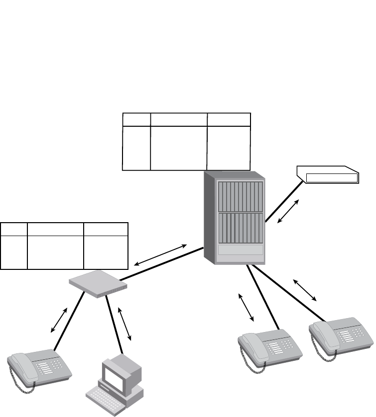
PowerConnect B-Series FCX Configuration Guide 685
53-1002266-01
LLDP overview 24
FIGURE 115 LLDP connectivity
Benefits of LLDP
LLDP provides the following benefits:
•Network Management:
•Simplifies the use of and enhances the ability of network management tools in
multi-vendor environments
•Enables discovery of accurate physical network topologies such as which devices are
neighbors and through which ports they connect
•Enables discovery of stations in multi-vendor environments
•Network Inventory Data:
•Supports optional system name, system description, system capabilities and management
address
•System description can contain the device product name or model number, version of
hardware type, and operating system
•Provides device capability, such as switch, router, or WLAN access point
•Network troubleshooting:
•Information generated by LLDP can be used to detect speed and duplex mismatches
I’m a PC
I’m a switch
I’m a switch
I’m a switch
I’m a switch
I’m a switch
I’m a switch
I’m a switch
I’m an IP Phone
I’m an IP Phone
I’m an IP Phone
I’m a PBX
port device info
A19 Switch xxxx
C2
D2
F3 OP-PBX
IP-Phone
IP-Phone
xxxx
xxxx
xxxx
port device info
A4 IP-Phone xxxx
B6
PC
xxxx
B21 Switch xxxx
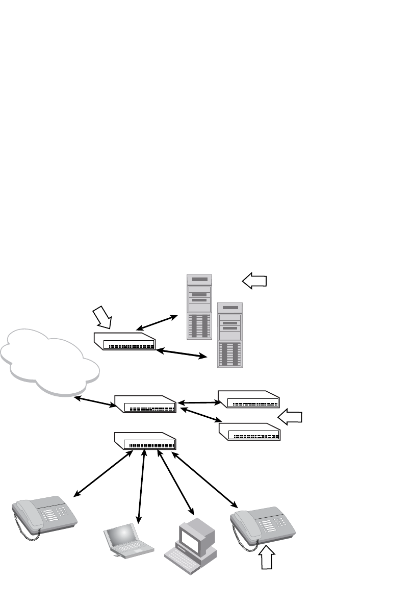
686 PowerConnect B-Series FCX Configuration Guide
53-1002266-01
LLDP-MED overview
24
•Accurate topologies simplify troubleshooting within enterprise networks
•Can discover devices with misconfigured or unreachable IP addresses
LLDP-MED overview
LLDP-MED is an extension to LLDP. This protocol enables advanced LLDP features in a Voice over
IP (VoIP) network. Whereas LLDP enables network discovery between Network Connectivity
devices, LLDP-MED enables network discovery between Network Connectivity devices and media
Endpoints such as, IP telephones, softphones, VoIP gateways and conference bridges
.Figure 116 demonstrates LLDP-MED connectivity.
FIGURE 116 LLDP-MED connectivity
Benefits of LLDP-MED
LLDP-MED provides the following benefits:
•Vendor-independent management capabilities, enabling different IP telephony systems to
interoperate in one network.
LLDP-MED Network Connectivity Devices
(e.g., L2/L3 switch, bridge, etc.) provide IEEE
802 network access to LLDP-MED endpoints
LLDP-MED Generic Endpoints (Class I)
act as basic participants in LLDP-MED.
Example Class I device: Communications
controller
LLDP-MED Media Endpoints
(Class II) support IP media
streams.
Example Class II devices:
media gateway, conference
bridge
LLDP-MED Comunication Device Endpoints
(Class III) support end user IP communication.
Example Class III devices: IP telephone,
softphone
IP Network
Infrastructure
(IEEE 802 LAN)

PowerConnect B-Series FCX Configuration Guide 687
53-1002266-01
General operating principles 24
•Automatically deploys network policies, such as Layer 2 and Layer 3 QoS policies and Voice
VLANs.
•Supports E-911 Emergency Call Services (ECS) for IP telephony
•Collects Endpoint inventory information
•Network troubleshooting
•Helps to detect improper network policy configuration
LLDP-MED class
An LLDP-MED class specifies an Endpoint type and its capabilities. An Endpoint can belong to one
of three LLDP-MED class types:
•Class 1 (Generic endpoint) – A Class 1 Endpoint requires basic LLDP discovery services, but
does not support IP media nor does it act as an end-user communication appliance. A Class 1
Endpoint can be an IP communications controller, other communication-related server, or
other device requiring basic LLDP discovery services.
•Class 2 (Media endpoint) – A Class 2 Endpoint supports media streams and may or may not be
associated with a particular end user. Device capabilities include media streaming, as well as
all of the capabilities defined for Class 1 Endpoints. A Class 2 Endpoint can be a voice/media
gateway, conference, bridge, media server, etc..
•Class 3 (Communication endpoint) – A Class 3 Endpoint supports end user IP communication.
Capabilities include aspects related to end user devices, as well as all of the capabilities
defined for Class 1 and Class 2 Endpoints. A Class 3 Endpoint can be an IP telephone,
softphone (PC-based phone), or other communication device that directly supports the end
user.
Discovery services defined in Class 3 include location identifier (ECS/E911) information and
inventory management.
The LLDP-MED device class is advertised when LLDP-MED is enabled on a port.
Figure 116 illustrates LLDP-MED connectivity and supported LLDP-MED classes.
General operating principles
LLDP and LLDP-MED use the services of the Data Link sublayers, Logical Link Control and Media
Access Control, to transmit and receive information to and from other LLDP Agents (protocol
entities that implement LLDP).
LLDP is a one-way protocol. An LLDP agent can transmit and receive information to and from
another LLDP agent located on an adjacent device, but it cannot solicit information from another
LLDP agent, nor can it acknowledge information received from another LLDP agent.
Operating modes
When LLDP is enabled on a global basis, by default, each port on the Dell device will be capable of
transmitting and receiving LLDP packets. You can disable a port’s ability to transmit and receive
LLDP packets, or change the operating mode to one of the following:
•Transmit LLDP information only

688 PowerConnect B-Series FCX Configuration Guide
53-1002266-01
General operating principles
24
•Receive LLDP information only
Transmit mode
An LLDP agent sends LLDP packets to adjacent LLDP-enabled devices. The LLDP packets contain
information about the transmitting device and port.
An LLDP agent initiates the transmission of LLDP packets whenever the transmit countdown timing
counter expires, or whenever LLDP information has changed. When a transmit cycle is initiated,
the LLDP manager extracts the MIB objects and formats this information into TLVs. The TLVs are
inserted into an LLDPDU, addressing parameters are prepended to the LLDPDU, and the
information is sent out LLDP-enabled ports to adjacent LLDP-enabled devices.
Receive mode
An LLDP agent receives LLDP packets from adjacent LLDP-enabled devices. The LLDP packets
contain information about the transmitting device and port.
When an LLDP agent receives LLDP packets, it checks to ensure that the LLDPDUs contain the
correct sequence of mandatory TLVs, then validates optional TLVs. If the LLDP agent detects any
errors in the LLDPDUs and TLVs, it drops them in software. TLVs that are not recognized but do not
contain basic formatting errors, are assumed to be valid and are assigned a temporary
identification index and stored for future possible alter retrieval by network management. All
validated TLVs are stored in the neighbor database.
LLDP packets
LLDP agents transmit information about a sending device/port in packets called LLDP Data Units
(LLDPDUs). All the LLDP information to be communicated by a device is contained within a single
1500 byte packet. A device receiving LLDP packets is not permitted to combine information from
multiple packets.
As shown in Figure 117, each LLDPDU has three mandatory TLVs, an End of LLDPDU TLV, plus
optional TLVs as selected by network management.
FIGURE 117 LLDPDU packet format
Each LLDPDU consists of an untagged Ethernet header and a sequence of short, variable length
information elements known as TLVs.
TLVs have Type, Length, and Value fields, where:
•Type identifies the kind of information being sent
•Length indicates the length (in octets) of the information string
•Value is the actual information being sent (for example, a binary bit map or an alpha-numeric
string containing one or more fields).
Chassis ID
TLV
Port ID
TLV
Time to
Live TLV
Optional
TLV
Optional
TLV
End of
LLDPDU TLV
...
MM M M
M = mandatory TLV (required for all LLDPDUs)

PowerConnect B-Series FCX Configuration Guide 689
53-1002266-01
General operating principles 24
TLV support
This section lists the LLDP and LLDP-MED TLV support.
LLDP TLVs
There are two types of LLDP TLVs, as specified in the IEEE 802.3AB standard:
•Basic management TLVs consist of both optional general system information TLVs as well as
mandatory TLVs.
Mandatory TLVs cannot be manually configured. They are always the first three TLVs in the
LLDPDU, and are part of the packet header.
General system information TLVs are optional in LLDP implementations and are defined by the
Network Administrator.
Dell PowerConnect devices support the following Basic Management TLVs:
•Chassis ID (mandatory)
•Port ID (mandatory)
•Time to Live (mandatory)
•Port description
•System name
•System description
•System capabilities
•Management address
•End of LLDPDU
•Organizationally-specific TLVs are optional in LLDP implementations and are defined and
encoded by individual organizations or vendors. These TLVs include support for, but are not
limited to, the IEEE 802.1 and 802.3 standards and the TIA-1057 standard.
Dell PowerConnect devices support the following Organizationally-specific TLVs:
•802.1 organizationally-specific TLVs
Port VLAN ID
VLAN name TLV
•802.3 organizationally-specific TLVs
MAC/PHY configuration/status
Power through MDI
Link aggregation
Maximum frame size
LLDP-MED TLVs
Dell PowerConnect devices honor and send the following LLDP-MED TLVs, as defined in the
TIA-1057 standard:
•LLDP-MED capabilities
•Network policy

690 PowerConnect B-Series FCX Configuration Guide
53-1002266-01
General operating principles
24
•Location identification
•Extended power-via-MDI
Mandatory TLVs
When an LLDP agent transmits LLDP packets to other agents in the same 802 LAN segments, the
following mandatory TLVs are always included:
•Chassis ID
•Port ID
•Time to Live (TTL)
This section describes the above TLVs in detail.
Chassis ID
The Chassis ID identifies the device that sent the LLDP packets.
There are several ways in which a device may be identified. A chassis ID subtype, included in the
TLV and shown in Table 121, indicates how the device is being referenced in the Chassis ID field.
Dell PowerConnect devices use chassis ID subtype 4, the base MAC address of the device. Other
third party devices may use a chassis ID subtype other than 4. The chassis ID will appear similar to
the following on the remote device, and in the CLI display output on the Dell PowerConnect device
(show lldp local-info).
Chassis ID (MAC address): 0012.f233.e2c0
The chassis ID TLV is always the first TLV in the LLDPDU.
Port ID
The Port ID identifies the port from which LLDP packets were sent.
There are several ways in which a port may be identified, as shown in Figure 122. A port ID
subtype, included in the TLV, indicates how the port is being referenced in the Port ID field.
TABLE 121 Chassis ID subtypes
ID subtype Description
0Reserved
1 Chassis component
2Interface alias
3Port component
4MAC address
5Network address
6Interface name
7 Locally assigned
8 – 255 Reserved

PowerConnect B-Series FCX Configuration Guide 691
53-1002266-01
General operating principles 24
Dell PowerConnect devices use port ID subtype 3, the permanent MAC address associated with the
port. Other third party devices may use a port ID subtype other than 3. The port ID appears similar
to the following on the remote device, and in the CLI display output on the Dell PowerConnect
device (show lldp local-info).
Port ID (MAC address): 0012.f233.e2d3
The LLDPDU format is shown in “LLDPDU packet format” on page 688.
The Port ID TLV format is shown below.
FIGURE 118 Port ID TLV packet format
TTL value
The Time to Live (TTL) Value is the length of time the receiving device should maintain the
information acquired by LLDP in its MIB.
The TTL value is automatically computed based on the LLDP configuration settings. The TTL value
will appear similar to the following on the remote device, and in the CLI display output on the Dell
PowerConnect device (show lldp local-info).
Time to live: 40 seconds
If the TTL field has a value other than zero, the receiving LLDP agent is notified to completely
replace all information associated with the LLDP agent/port with the information in the received
LLDPDU.
If the TTL field value is zero, the receiving LLDP agent is notified that all system information
associated with the LLDP agent/port is to be deleted. This TLV may be used, for example, to signal
that the sending port has initiated a port shutdown procedure.
The LLDPDU format is shown in “LLDPDU packet format” on page 688.
The TTL TLV format is shown below.
TABLE 122 Port ID subtypes
ID subtype Description
0Reserved
1Interface alias
2Port component
3MAC address
4Network address
5Interface name
6 Agent circuit ID
7 Locally assigned
8 – 255 Reserved
TLV Type = 3 TLV Information
String Length = 2 Time to Live (TTL)
7 bits9 bits2 octets

692 PowerConnect B-Series FCX Configuration Guide
53-1002266-01
MIB support
24
FIGURE 119 TTL TLV packet format
MIB support
Dell PowerConnect devices support the following standard MIB modules:
•LLDP-MIB
•LLDP-EXT-DOT1-MIB
•LLDP-EXT-DOT3-MIB
•LLDP-EXT-MED-MIB
Syslog messages
Syslog messages for LLDP provide management applications with information related to MIB data
consistency and general status. These Syslog messages correspond to the lldpRemTablesChange
SNMP notifications. Refer to “Enabling LLDP SNMP notifications and syslog messages” on
page 697.
Syslog messages for LLDP-MED provide management applications with information related to
topology changes. These Syslog messages correspond to the lldpXMedTopologyChangeDetected
SNMP notifications. Refer to “Enabling SNMP notifications and syslog messages for LLDP-MED
topology changes” on page 708.
Configuring LLDP
This section describes how to enable and configure LLDP.
Table 123 lists the LLDP global-level tasks and the default behavior/value for each task.
TLV Type = 3 TLV Information
String Length = 2 Time to Live (TTL)
7 bits9 bits2 octets
TABLE 123 LLDP global configuration tasks and default behavior /value
Global task Default behavior / value when LLDP is enabled
Enabling LLDP on a global basis Disabled
Specifying the maximum number of LLDP
neighbors per device
Automatically set to 392 neighbors per device
Specifying the maximum number of LLDP
neighbors per port
Automatically set to 4 neighbors per port
Enabling SNMP notifications and Syslog messages Disabled
Changing the minimum time between SNMP traps
and Syslog messages
Automatically set to 2 seconds when SNMP notifications and
Syslog messages for LLDP are enabled

PowerConnect B-Series FCX Configuration Guide 693
53-1002266-01
Configuring LLDP 24
Configuration notes and considerations
•LLDP is supported on Ethernet interfaces only.
•If a port is 802.1X-enabled, the transmission and reception of LLDP packets will only take
place while the port is authorized.
•Cisco Discovery Protocol (CDP) and Brocade Discovery Protocol (FDP) run independently of
LLDP. Therefore, these discovery protocols can run simultaneously on the same device.
•By default, the Dell PowerConnect device limits the number of neighbors per port to four, and
staggers the transmission of LLDP packets on different ports, in order to minimize any
high-usage spikes to the CPU.
•By default, the Dell PowerConnect device forwards
•Ports that are in blocking mode (spanning tree) can still receive LLDP packets from a
forwarding port.
•Auto-negotiation status indicates what is being advertised by the port for 802.3
auto-negotiation.
Enabling and disabling LLDP
LLDP is enabled by default on individual ports. However, to run LLDP, you must first enable it on a
global basis (on the entire device).
To enable LLDP globally, enter the following command at the global CONFIG level of the CLI.
PowerConnect(config)#lldp run
Syntax: [no] lldp run
Enabling and disabling TLV advertisements When LLDP transmit is enabled, by default, the Dell
PowerConnect device will automatically advertise LLDP
capabilities, except for the system description, VLAN name,
and power-via-MDI information, which may be configured by
the system administrator.
Also, if desired, you can disable the advertisement of
individual TLVs.
Changing the minimum time between LLDP
transmissions
Automatically set to 2 seconds
Changing the interval between regular LLDP
transmissions
Automatically set to 30 seconds
Changing the holdtime multiplier for transmit TTL Automatically set to 4
Changing the minimum time between port
reinitializations
Automatically set to 2 seconds
TABLE 123 LLDP global configuration tasks and default behavior /value (Continued)
Global task Default behavior / value when LLDP is enabled

694 PowerConnect B-Series FCX Configuration Guide
53-1002266-01
Configuring LLDP
24
Enabling support for tagged LLDP packets
By default, Dell PowerConnect devices do not accept tagged LLDP packets from other vendors’
devices. To enable support, apply the command lldp tagged-packets process at the Global CONFIG
level of the CLI. When enabled, the device will accept incoming LLDP tagged packets if the VLAN
tag matches any of the following:
•a configured VLAN on the port
•the default VLAN for a tagged port
•the configured untagged VLAN for a dual-mode port
To enable support for tagged LLDP packets, enter the following command.
PowerConnect(config)#lldp tagged-packets process
Syntax: [no] lldp tagged-packets process
Changing a port LLDP operating mode
LLDP packets are not exchanged until LLDP is enabled on a global basis. When LLDP is enabled on
a global basis, by default, each port on the Dell device will be capable of transmitting and receiving
LLDP packets. You can disable a port’s ability to transmit and receive LLDP packets, or change the
operating mode to one of the following:
•Transmit LLDP information only
•Receive LLDP information only
You can configure a different operating mode for each port on the Dell PowerConnect device. For
example, you could disable the receipt and transmission of LLDP packets on port e 2/1, configure
port e 2/3 to only receive LLDP packets, and configure port e 2/5 to only transmit LLDP packets.
The following sections show how to change the operating mode.
Enabling and disabling receive and transmit mode
To disable the receipt and transmission of LLDP packets on individual ports, enter a command
such as the following at the Global CONFIG level of the CLI.
PowerConnect(config)#no lldp enable ports e 2/4 e 2/5
The above command disables LLDP on ports 2/4 and 2/5. These ports will not transmit nor
receive LLDP packets.
To enable LLDP on a port after it has been disabled, enter the following command.
PowerConnect(config)#lldp enable ports e 2/4
Syntax: [no] lldp enable ports ethernet <port-list> | all
Use the [no] form of the command to disable the receipt and transmission of LLDP packets on a
port.
For <port-list>, specify the ports in the following formats:
•PowerConnect B-Series FCX stackable switches – <stack-unit/slotnum/portnum>
You can list all of the ports individually, use the keyword to to specify ranges of ports, or a
combination of both. To apply the configuration to all ports on the device, use the keyword all
instead of listing the ports individually.

PowerConnect B-Series FCX Configuration Guide 695
53-1002266-01
Configuring LLDP 24
NOTE
When a port is configured to both receive and transmit LLDP packets and the MED capabilities TLV
is enabled, LLDP-MED is enabled as well. LLDP-MED is not enabled if the operating mode is set to
receive only or transmit only.
Enabling and disabling receive only mode
When LLDP is enabled on a global basis, by default, each port on the Dell PowerConnect device will
be capable of transmitting and receiving LLDP packets. To change the LLDP operating mode from
receive and transmit mode to receive only mode, simply disable the transmit mode. Enter a
command such as the following at the Global CONFIG level of the CLI.
PowerConnect(config)#no lldp enable transmit ports e 2/4 e 2/5 e 2/6
The above command changes the LLDP operating mode on ports 2/4, 2/5, and 2/6 from transmit
and receive mode to receive only mode.
To change a port LLDP operating mode from transmit only to receive only, first disable the transmit
only mode, then enable the receive only mode. Enter commands such as the following.
PowerConnect(config)#no lldp enable transmit ports e 2/7 e 2/8 e 2/9
PowerConnect(config)#lldp enable receive ports e 2/7 e 2/8 e 2/9
The above commands change the LLDP operating mode on ports 2/7, 2/8, and 2/9, from transmit
only to receive only. Note that if you do not disable the transmit only mode, you will configure the
port to both transmit and receive LLDP packets.
NOTE
LLDP-MED is not enabled when you enable the receive only operating mode. To enable LLDP-MED,
you must configure the port to both receive and transmit LLDP packets. Refer to “Enabling and
disabling receive and transmit mode” on page 694.
Syntax: [no] lldp enable receive ports ethernet <port-list> | all
Use the [no] form of the command to disable the receive only mode.
For <port-list>, specify the ports in the following formats:
•PowerConnect B-Series FCX stackable switches – <stack-unit/slotnum/portnum>
You can list all of the ports individually, use the keyword to to specify ranges of ports, or a
combination of both. To apply the configuration to all ports on the device, use the keyword all
instead of listing the ports individually.
Enabling and Disabling Transmit Only Mode
When LLDP is enabled on a global basis, by default, each port on the Dell PowerConnect device will
be capable of transmitting and receiving LLDP packets. To change the LLDP operating mode to
transmit only mode, simply disable the receive mode. Enter a command such as the following at
the Global CONFIG level of the CLI.
PowerConnect(config)#no lldp enable receive ports e 2/4 e 2/5 e 2/6
The above command changes the LLDP operating mode on ports 2/4, 2/5, and 2/6 from transmit
and receive mode to transmit only mode. Any incoming LLDP packets will be dropped in software.
To change a port LLDP operating mode from receive only to transmit only, first disable the receive
only mode, then enable the transmit only mode. For example, enter commands such as the
following at the Global CONFIG level of the CLI.

696 PowerConnect B-Series FCX Configuration Guide
53-1002266-01
Configuring LLDP
24
PowerConnect(config)#no lldp enable receive ports e 2/7 e 2/8
PowerConnect(config)#lldp enable transmit ports e 2/7 e 2/8
The above commands change the LLDP operating mode on ports 2/7 and 2/8 from receive only
mode to transmit only mode. Any incoming LLDP packets will be dropped in software. Note that if
you do not disable receive only mode, you will configure the port to both receive and transmit LLDP
packets.
NOTE
LLDP-MED is not enabled when you enable the transmit only operating mode. To enable LLDP-MED,
you must configure the port to both receive and transmit LLDP packets. Refer to “Enabling and
disabling receive and transmit mode” on page 694.
Syntax: [no] lldp enable transmit ports ethernet <port-list> | all
Use the [no] form of the command to disable the transmit only mode.
For <port-list>, specify the ports in the following formats:
•PowerConnect B-Series FCX stackable switches – <stack-unit/slotnum/portnum>
You can list all of the ports individually, use the keyword to to specify ranges of ports, or a
combination of both. To apply the configuration to all ports on the device, use the keyword all
instead of listing the ports individually.
Specifying the maximum number of LLDP neighbors
You can change the limit of the number of LLDP neighbors for which LLDP data will be retained, per
device as well as per port.
Per device
You can change the maximum number of neighbors for which LLDP data will be retained for the
entire system.
For example, to change the maximum number of LLDP neighbors for the entire device to 26, enter
the following command.
PowerConnect(config)#lldp max-total-neighbors 26
Syntax: [no] lldp max-total-neighbors <value>
Use the [no] form of the command to remove the static configuration and revert to the default
value of 392.
where <value> is a number between 16 and 8192. The default number of LLDP neighbors per
device is 392.
Use the show lldp command to view the configuration.
Per port
You can change the maximum number of LLDP neighbors for which LLDP data will be retained for
each port. By default, the maximum number is four and you can change this to a value between
one and 64.
For example, to change the maximum number of LLDP neighbors to six, enter the following
command.

PowerConnect B-Series FCX Configuration Guide 697
53-1002266-01
Configuring LLDP 24
PowerConnect(config)#lldp max-neighbors-per-port 6
Syntax: [no] lldp max-neighbors-per-port <value>
Use the [no] form of the command to remove the static configuration and revert to the default
value of four.
where <value> is a number from 1 to 64. The default is number of LLDP neighbors per port is four.
Use the show lldp command to view the configuration.
Enabling LLDP SNMP notifications and syslog messages
SNMP notifications and Syslog messages for LLDP provide management applications with
information related to MIB data updates and general status.
When you enable LLDP SNMP notifications, corresponding Syslog messages are enabled as well.
When you enable LLDP SNMP notifications, the device will send traps and corresponding Syslog
messages whenever there are changes to the LLDP data received from neighboring devices.
LLDP SNMP notifications and corresponding Syslog messages are disabled by default. To enable
them, enter a command such as the following at the Global CONFIG level of the CLI.
PowerConnect(config)#lldp enable snmp notifications ports e 4/2 to 4/6
The above command enables SNMP notifications and corresponding Syslog messages on ports
4/2 and 4/6. By default, the device will send no more than one SNMP notification and Syslog
message within a five second period. If desired, you can change this interval. Refer to “Specifying
the minimum time between SNMP traps and syslog messages” on page 697.
Syntax: [no] lldp enable snmp notifications ports ethernet <port-list> | all
For <port-list>, specify the ports in the following formats:
•PowerConnect B-Series FCX stackable switches – <stack-unit/slotnum/portnum>
You can list all of the ports individually, use the keyword to to specify ranges of ports, or a
combination of both. To apply the configuration to all ports on the device, use the keyword all
instead of listing the ports individually.
Specifying the minimum time between SNMP traps and syslog messages
When SNMP notifications and Syslog messages for LLDP are enabled, the device will send no more
than one SNMP notification and corresponding Syslog message within a five second period. If
desired, you can throttle the amount of time between transmission of SNMP traps
(lldpRemTablesChange) and Syslog messages from five seconds up to a value equal to one hour
(3600 seconds).
NOTE
Because LLDP Syslog messages are rate limited, some LLDP information given by the system will
not match the current LLDP statistics (as shown in the show lldp statistics command output).
To change the minimum time interval between traps and Syslog messages, enter a command such
as the following.
PowerConnect(config)#lldp snmp-notification-interval 60
When the above command is applied, the LLDP agent will send no more than one SNMP
notification and Syslog message every 60 seconds.

698 PowerConnect B-Series FCX Configuration Guide
53-1002266-01
Configuring LLDP
24
Syntax: [no] lldp snmp-notification-interval <seconds>
where <seconds> is a value between 5 and 3600. The default is 5 seconds.
Changing the minimum time between LLDP transmissions
The LLDP transmit delay timer limits the number of LLDP frames an LLDP agent can send within a
specified time frame. When you enable LLDP, the system automatically sets the LLDP transmit
delay timer to two seconds. If desired, you can change the default behavior from two seconds to a
value between 1 and 8192 seconds.
NOTE
The LLDP transmit delay timer must not be greater than one quarter of the LLDP transmission
interval (CLI command lldp transmit-interval).
The LLDP transmit delay timer prevents an LLDP agent from transmitting a series of successive
LLDP frames during a short time period, when rapid changes occur in LLDP. It also increases the
probability that multiple changes, rather than single changes, will be reported in each LLDP frame.
To change the LLDP transmit delay timer, enter a command such as the following at the Global
CONFIG level of the CLI.
PowerConnect(config)#lldp transmit-delay 7
The above command causes the LLDP agent to wait a minimum of seven seconds after
transmitting an LLDP frame and before sending another LLDP frame.
Syntax: [no] lldp transmit-delay <seconds>
where <seconds> is a value between 1 and 8192. The default is two seconds. Note that this value
must not be greater than one quarter of the LLDP transmission interval (CLI command lldp
transmit-interval).
Changing the interval between regular LLDP transmissions
The LLDP transmit interval specifies the number of seconds between regular LLDP packet
transmissions. When you enable LLDP, by default, the device will wait 30 seconds between regular
LLDP packet transmissions. If desired, you can change the default behavior from 30 seconds to a
value between 5 and 32768 seconds.
To change the LLDP transmission interval, enter a command such as the following at the Global
CONFIG level of the CLI.
PowerConnect(config)#lldp transmit-interval 40
The above command causes the LLDP agent to transmit LLDP frames every 40 seconds.
Syntax: [no] lldp transmit-interval <seconds>
where <seconds> is a value from 5 to 32768. The default is 30 seconds.
NOTE
Setting the transmit interval or transmit holdtime multiplier, or both, to inappropriate values can
cause the LLDP agent to transmit LLDPDUs with TTL values that are excessively high. This in turn
can affect how long a receiving device will retain the information if it is not refreshed.

PowerConnect B-Series FCX Configuration Guide 699
53-1002266-01
Configuring LLDP 24
Changing the holdtime multiplier for transmit TTL
The holdtime multiplier for transmit TTL is used to compute the actual time-to-live (TTL) value used
in an LLDP frame. The TTL value is the length of time the receiving device should maintain the
information in its MIB. When you enable LLDP, the device automatically sets the holdtime
multiplier for TTL to four. If desired, you can change the default behavior from four to a value
between two and ten.
To compute the TTL value, the system multiplies the LLDP transmit interval by the holdtime
multiplier. For example, if the LLDP transmit interval is 30 and the holdtime multiplier for TTL is 4,
then the value 120 is encoded in the TTL field in the LLDP header.
To change the holdtime multiplier, enter a command such as the following at the Global CONFIG
level of the CLI.
PowerConnect (config)#lldp transmit-hold 6
Syntax: [no] lldp transmit-hold <value>
where <value> is a number from 2 to 10. The default value is 4.
NOTE
Setting the transmit interval or transmit holdtime multiplier, or both, to inappropriate values can
cause the LLDP agent to transmit LLDPDUs with TTL values that are excessively high. This in turn
can affect how long a receiving device will retain the information if it is not refreshed.
Changing the minimum time between port reinitializations
The LLDP re-initialization delay timer specifies the minimum number of seconds the device will wait
from when LLDP is disabled on a port, until it will honor a request to re-enable LLDP on that port.
When you enable LLDP, the system sets the re-initialization delay timer to two seconds. If desired,
you can change the default behavior from two seconds to a value between one and ten seconds.
To set the re-initialization delay timer, enter a command such as the following at the Global CONFIG
level of the CLI.
PowerConnect(config)#lldp reinit-delay 5
The above command causes the device to wait five seconds after LLDP is disabled, before
attempting to honor a request to re-enable it.
Syntax: [no] lldp reinit-delay <seconds>
where <seconds> is a value from 1 – 10. The default is two seconds.
LLDP TLVs advertised by the Dell PowerConnect device
When LLDP is enabled on a global basis, the Dell PowerConnect device will automatically advertise
the following information, except for the features noted:
General system information:
•Management address
•Port description
•System capabilities
•System description (not automatically advertised)

700 PowerConnect B-Series FCX Configuration Guide
53-1002266-01
Configuring LLDP
24
•System name
802.1 capabilities:
•VLAN name (not automatically advertised)
•Untagged VLAN ID
802.3 capabilities:
•Link aggregation information
•MAC/PHY configuration and status
•Maximum frame size
•Power-via-MDI information (not automatically advertised)
The above TLVs are described in detail in the following sections.
NOTE
The system description, VLAN name, and power-via-MDI information TLVs are not automatically
enabled. The following sections show how to enable these advertisements.
General system information
Except for the system description, the Dell PowerConnect device will advertise the following system
information when LLDP is enabled on a global basis:
•Management address
•Port description
•System capabilities
•System description (not automatically advertised)
•System name
Management Address
A management address is normally an IPv4 or IPv6 address that can be used to manage the
device. Management address advertising has two modes: default, or explicitly configured. The
default mode is used when no addresses are configured to be advertised for a given port. If any
addresses are configured to be advertised for a given port, then only those addresses are
advertised. This applies across address types, so for example, if just one IPv4 address is explicitly
configured to be advertised for a port, then no IPv6 addresses will be advertised for that port (since
none were configured to be advertised), even if IPv6 addresses are configured within the system.
If no management address is explicitly configured to be advertised, the device will use the first
available IPv4 address and the first available IPv6 address (so it may advertise IPv4, IPv6 or both).
A Layer 3 switch will select the first available address of each type from those configured on the
following types of interfaces, in the following order of preference:
•Physical port on which LLDP will be transmitting the packet
•Virtual router interface (VE) on a VLAN that the port is a member of
•Dedicated management port
•Loopback interface
•Virtual router interface (VE) on any other VLAN
•Other physical port

PowerConnect B-Series FCX Configuration Guide 701
53-1002266-01
Configuring LLDP 24
•Other interface
For IPv6 addresses, link-local and anycast addresses will be excluded from these searches.
If no IP address is configured on any of the above, the port's current MAC address will be
advertised.
To advertise a IPv4 management address, enter a command such as the following:
PowerConnect(config)#lldp advertise management-address ipv4 209.157.2.1 ports e
1/4
The management address will appear similar to the following on the remote device, and in the CLI
display output on the PowerConnect device (show lldp local-info):
Management address (IPv4): 209.157.2.1
Syntax: [no] lldp advertise management-address ipv4 <ipv4 address> ports ethernet <port list> |
all
To support an IPv6 management address, there is a similar command that has equivalent behavior
as the IPv4 command.
To advertise an IPv6 management address, enter a command such as the following:
PowerConnect(config)#lldp advertise management-address ipv6 1234:5678::90 ports e
2/7
Syntax: [no] lldp advertise management-address ipv6 <ipv6 address> ports ethernet <port list> |
all
<ipv4 address> or <ipv6 address> or both are the addresses that may be used to reach higher
layer entities to assist discovery by network management. In addition to management addresses,
the advertisement will include the system interface number associated with the management
address.
For <port list>, specify the port(s) in the format [<slotnum>/]<portnum>, where <slotnum> is
required on chassis devices only. You can list all of the ports individually; use the keyword to
specify a range of ports, or a combination of both. To apply the configuration to all ports on the
device, use the keyword all instead of listing the ports individually.
Port description
The port description TLV identifies the port from which the LLDP agent transmitted the
advertisement. The port description is taken from the ifDescr MIB object from MIB-II.
By default, the port description is automatically advertised when LLDP is enabled on a global basis.
To disable advertisement of the port description, enter a command such as the following.
PowerConnect(config)#no lldp advertise port-description ports e 2/4 to 2/12
The port description will appear similar to the following on the remote device, and in the CLI display
output on the device (show lldp local-info).
Port description: “GigabitEthernet20”
Syntax: [no] lldp advertise port-description ports ethernet <port-list> | all
For <port-list>, specify the ports in one of the following formats:
•PowerConnect B-Series FCX stackable switches – <stack-unit/slotnum/portnum>

702 PowerConnect B-Series FCX Configuration Guide
53-1002266-01
Configuring LLDP
24
You can list all of the ports individually, use the keyword to to specify ranges of ports, or a
combination of both. To apply the configuration to all ports on the device, use the keyword all
instead of listing the ports individually. Note that using the keyword all may cause undesirable
effects on some ports. For example, if you configure all ports to advertise their VLAN name, and
the configuration includes ports that are not members of any VLAN, the system will warn of the
misconfigurations on non-member VLAN ports. The configuration will be applied to all ports,
however, the ports that are not members of any VLAN will not send VLAN name advertisements.
System capabilities
The system capabilities TLV identifies the primary functions of the device and indicates whether
these primary functions are enabled. The primary functions can be one or more of the following
(more than one for example, if the device is both a bridge and a router):
•Repeater
•Bridge
•WLAN access point
•Router
•Telephone
•DOCSIS cable device
•Station only (devices that implement end station capability)
•Other
System capabilities for Dell PowerConnect devices are based on the type of software image in use
(e.g., Layer 2 switch or Layer 3 router). The enabled capabilities will be the same as the available
capabilities, except that when using a router image (base or full Layer 3), if the global route-only
feature is turned on, the bridge capability will not be included, since no bridging takes place.
By default, the system capabilities are automatically advertised when LLDP is enabled on a global
basis. To disable this advertisement, enter a command such as the following.
PowerConnect(config)#no lldp advertise system-capabilities ports e 2/4 to 2/12
The system capabilities will appear similar to the following on the remote device, and in the CLI
display output on the Dell PowerConnect device (show lldp local-info).
System capabilities : bridge
Enabled capabilities: bridge
Syntax: [no] lldp advertise system-capabilities ports ethernet <port-list> | all
For <port-list>, specify the ports in one of the following formats:
•PowerConnect B-Series FCX stackable switches – <stack-unit/slotnum/portnum>
You can list all of the ports individually, use the keyword to to specify ranges of ports, or a
combination of both. To apply the configuration to all ports on the device, use the keyword all
instead of listing the ports individually. Note that using the keyword all may cause undesirable
effects on some ports. For example, if you configure all ports to advertise their VLAN name, and
the configuration includes ports that are not members of any VLAN, the system will warn of the
misconfigurations on non-member VLAN ports. The configuration will be applied to all ports,
however, the ports that are not members of any VLAN will not send VLAN name advertisements.

PowerConnect B-Series FCX Configuration Guide 703
53-1002266-01
Configuring LLDP 24
System description
The system description is the network entity, which can include information such as the product
name or model number, the version of the system hardware type, the software operating system
level, and the networking software version. The information corresponds to the sysDescr MIB
object in MIB-II.
To advertise the system description, enter a command such as the following.
PowerConnect(config)#lldp advertise system-description ports e 2/4 to 2/12
The system description will appear similar to the following on the remote device, and in the CLI
display output on the Dell PowerConnect device (show lldp local-info).
+ System description : "Brocade Communications, Inc., IronWare Version
04.0.00b256T3e1 Compiled on Sep 04 2007 at 0\
3:54:29 labeled as SXS04000b256"
NOTE
The contents of the show command output will vary depending on which TLVs are configured to be
advertised.
Syntax: [no] lldp advertise system-description ports ethernet <port-list> | all
For <port-list>, specify the ports in one of the following formats:
•PowerConnect B-Series FCX stackable switches – <stack-unit/slotnum/portnum>
You can list all of the ports individually, use the keyword to to specify ranges of ports, or a
combination of both. To apply the configuration to all ports on the device, use the keyword all
instead of listing the ports individually. Note that using the keyword all may cause undesirable
effects on some ports. For example, if you configure all ports to advertise their VLAN name, and
the configuration includes ports that are not members of any VLAN, the system will warn of the
misconfigurations on non-member VLAN ports. The configuration will be applied to all ports,
however, the ports that are not members of any VLAN will not send VLAN name advertisements.
System name
The system name is the system administratively assigned name, taken from the sysName MIB
object in MIB-II. The sysName MIB object corresponds to the name defined with the CLI command
hostname.
By default, the system name is automatically advertised when LLDP is enabled on a global basis.
To disable this advertisement, enter a command such as the following.
PowerConnect(config)#no lldp advertise system-name ports e 2/4 to 2/12
The system name will appear similar to the following on the remote device, and in the CLI display
output on the Dell PowerConnect device (show lldp local-info).
System name: “PowerConnect”
Syntax: [no] lldp advertise system-name ports ethernet <port-list> | all
For <port-list>, specify the ports in one of the following formats:
•PowerConnect B-Series FCX stackable switches – <stack-unit/slotnum/portnum>

704 PowerConnect B-Series FCX Configuration Guide
53-1002266-01
Configuring LLDP
24
You can list all of the ports individually, use the keyword to to specify ranges of ports, or a
combination of both. To apply the configuration to all ports on the device, use the keyword all
instead of listing the ports individually. Note that using the keyword all may cause undesirable
effects on some ports. For example, if you configure all ports to advertise their VLAN name, and
the configuration includes ports that are not members of any VLAN, the system will warn of the
misconfigurations on non-member VLAN ports. The configuration will be applied to all ports,
however, the ports that are not members of any VLAN will not send VLAN name advertisements.
802.1 capabilities
Except for the VLAN name, the Dell PowerConnect device will advertise the following 802.1
attributes when LLDP is enabled on a global basis:
•VLAN name (not automatically advertised)
•Untagged VLAN ID
VLAN name
The VLAN name TLV contains the name and VLAN ID of a VLAN configured on a port. An LLDPDU
may include multiple instances of this TLV, each for a different VLAN.
To advertise the VLAN name, enter a command such as the following.
PowerConnect(config)#lldp advertise vlan-name vlan 99 ports e 2/4 to 2/12
The VLAN name will appear similar to the following on the remote device, and in the CLI display
output on the Dell PowerConnect device (show lldp local-info).
VLAN name (VLAN 99): “Voice-VLAN-99”
Syntax: [no] lldp advertise vlan-name vlan <vlan ID> ports ethernet <port-list> | all
For <vlan ID>, enter the VLAN ID to advertise.
For <port-list>, specify the ports in one of the following formats:
•PowerConnect B-Series FCX stackable switches – <stack-unit/slotnum/portnum>
You can list all of the ports individually, use the keyword to to specify ranges of ports, or a
combination of both. To apply the configuration to all ports on the device, use the keyword all
instead of listing the ports individually. Note that using the keyword all may cause undesirable
effects on some ports. For example, if you configure all ports to advertise their VLAN name, and
the configuration includes ports that are not members of any VLAN, the system will warn of the
misconfigurations on non-member VLAN ports. The configuration will be applied to all ports,
however, the ports that are not members of any VLAN will not send VLAN name advertisements.
Untagged VLAN id
The port VLAN ID TLV advertises the Port VLAN Identifier (PVID) that will be associated with
untagged or priority-tagged frames. If the port is not an untagged member of any VLAN (i.e., the
port is strictly a tagged port), the value zero will indicate that.
By default, the port VLAN ID is automatically advertised when LLDP is enabled on a global basis. To
disable this advertisement, enter a command such as the following.
PowerConnect(config)#no lldp advertise port-vlan-id ports e 2/4 to 2/12
The untagged VLAN ID will appear similar to the following on the remote device, and in the CLI
display output on the Dell PowerConnect device (show lldp local-info).
Port VLAN ID: 99

PowerConnect B-Series FCX Configuration Guide 705
53-1002266-01
Configuring LLDP 24
Syntax: [no] lldp advertise port-vlan-id ports ethernet <port-list> | all
For <port-list>, specify the ports in one of the following formats:
•PowerConnect B-Series FCX stackable switches – <stack-unit/slotnum/portnum>
You can list all of the ports individually, use the keyword to to specify ranges of ports, or a
combination of both. To apply the configuration to all ports on the device, use the keyword all
instead of listing the ports individually. Note that using the keyword all may cause undesirable
effects on some ports. For example, if you configure all ports to advertise their VLAN name, and
the configuration includes ports that are not members of any VLAN, the system will warn of the
misconfigurations on non-member VLAN ports. The configuration will be applied to all ports,
however, the ports that are not members of any VLAN will not send VLAN name advertisements.
802.3 capabilities
Except for Power-via-MDI information, the Dell PowerConnect device will advertise the following
802.3 attributes when LLDP is enabled on a global basis:
•Link aggregation information
•MAC/PHY configuration and status
•Maximum frame size
•Power-via-MDI information (not automatically advertised)
Link aggregation
The link-aggregation TLV indicates the following:
•Whether the link is capable of being aggregated
•Whether the link is currently aggregated
•The primary trunk port
Dell PowerConnect devices advertise link aggregation information about standard link aggregation
(LACP) as well as static trunk configuration.
By default, link-aggregation information is automatically advertised when LLDP is enabled on a
global basis. To disable this advertisement, enter a command such as the following.
PowerConnect(config)#no lldp advertise link-aggregation ports e 2/12
Syntax: [no] lldp advertise link-aggregation ports ethernet <port-list> | all
The link aggregation advertisement will appear similar to the following on the remote device, and in
the CLI display output on the Dell PowerConnect device (show lldp local-info).
Link aggregation: not capable
For <port-list>, specify the ports in one of the following formats:
•PowerConnect B-Series FCX stackable switches – <stack-unit/slotnum/portnum>
You can list all of the ports individually, use the keyword to to specify ranges of ports, or a
combination of both. To apply the configuration to all ports on the device, use the keyword all
instead of listing the ports individually. Note that using the keyword all may cause undesirable
effects on some ports. For example, if you configure all ports to advertise their VLAN name, and
the configuration includes ports that are not members of any VLAN, the system will warn of the
misconfigurations on non-member VLAN ports. The configuration will be applied to all ports,
however, the ports that are not members of any VLAN will not send VLAN name advertisements.

706 PowerConnect B-Series FCX Configuration Guide
53-1002266-01
Configuring LLDP
24
MAC/PHY configuration status
The MAC/PHY configuration and status TLV includes the following information:
•Auto-negotiation capability and status
•Speed and duplex mode
•Flow control capabilities for auto-negotiation
•Port speed down-shift and maximum port speed advertisement
•If applicable, indicates if the above settings are the result of auto-negotiation during link
initiation or of a manual set override action
The advertisement reflects the effects of the following CLI commands:
•speed-duplex
•flow-control
•gig-default
•link-config
By default, the MAC/PHY configuration and status information are automatically advertised when
LLDP is enabled on a global basis. To disable this advertisement, enter a command such as the
following.
PowerConnect(config)#no lldp advertise mac-phy-config-status ports e 2/4 to 2/12
The MAC/PHY configuration advertisement will appear similar to the following on the remote
device, and in the CLI display output on the Dell PowerConnect device (show lldp local-info).
Syntax: [no] lldp advertise mac-phy-config-status ports ethernet <port-list> | all
For <port-list>, specify the ports in one of the following formats:
•PowerConnect B-Series FCX stackable switches – <stack-unit/slotnum/portnum>
You can list all of the ports individually, use the keyword to to specify ranges of ports, or a
combination of both. To apply the configuration to all ports on the device, use the keyword all
instead of listing the ports individually. Note that using the keyword all may cause undesirable
effects on some ports. For example, if you configure all ports to advertise their VLAN name, and
the configuration includes ports that are not members of any VLAN, the system will warn of the
misconfigurations on non-member VLAN ports. The configuration will be applied to all ports,
however, the ports that are not members of any VLAN will not send VLAN name advertisements.
Maximum frame size
The maximum frame size TLV provides the maximum 802.3 frame size capability of the port. This
value is expressed in octets and includes the four-octet Frame Check Sequence (FCS). The default
maximum frame size is 1522. The advertised value may change depending on whether the
aggregated-vlan or jumbo CLI commands are in effect.
By default, the maximum frame size is automatically advertised when LLDP is enabled on a global
basis. To disable this advertisement, enter a command such as the following.
PowerConnect(config)#no lldp advertise max-frame-size ports e 2/4 to 2/12
+ 802.3 MAC/PHY : auto-negotiation enabled
Advertised capabilities: 10baseT-HD, 10baseT-FD, 100baseTX-HD,
100baseTX-FD,
fdxSPause, fdxBPause, 1000baseT-HD, 1000baseT-FD
Operational MAU type: 100BaseTX-FD

PowerConnect B-Series FCX Configuration Guide 707
53-1002266-01
Configuring LLDP-MED 24
The maximum frame size advertisement will appear similar to the following on the remote device,
and in the CLI display output on the Dell PowerConnect device (show lldp local-info).
Maximum frame size: 1522 octets
Syntax: [no] lldp advertise max-frame-size ports ethernet <port-list> | all
For <port-list>, specify the ports in one of the following formats:
•PowerConnect B-Series FCX stackable switches – <stack-unit/slotnum/portnum>
You can list all of the ports individually, use the keyword to to specify ranges of ports, or a
combination of both. To apply the configuration to all ports on the device, use the keyword all
instead of listing the ports individually. Note that using the keyword all may cause undesirable
effects on some ports. For example, if you configure all ports to advertise their VLAN name, and
the configuration includes ports that are not members of any VLAN, the system will warn of the
misconfigurations on non-member VLAN ports. The configuration will be applied to all ports,
however, the ports that are not members of any VLAN will not send VLAN name advertisements.
Configuring LLDP-MED
This section provides the details for configuring LLDP-MED.
Table 124 lists the global and interface-level tasks and the default behavior/value for each task.
Enabling LLDP-MED
When LLDP is enabled globally, LLDP-MED is enabled if the LLDP-MED capabilities TLV is also
enabled. By default, the LLDP-MED capabilities TLV is automatically enabled. To enable LLDP,
refer to “Enabling and disabling LLDP” on page 693.
TABLE 124 LLDP-MED configuration tasks and default behavior / value
Task Default behavior / value
Global CONFIG-level tasks
Enabling LLDP-MED on a global basis Disabled
Enabling SNMP notifications and Syslog messages
for LLDP-MED topology change
Disabled
Changing the Fast Start Repeat Count The system automatically sets the fast start repeat count to
3 when a Network Connectivity Device receives an LLDP
packet from an Endpoint that is newly connected to the
network.
NOTE: The LLDP-MED fast start mechanism is only intended
to run on links between Network Connectivity devices
and Endpoint devices. It does not apply to links
between LAN infrastructure elements, including
between Network Connectivity devices, or to other
types of links.
Interface-level tasks
Defining a location ID Not configured
Defining a network policy Not configured

708 PowerConnect B-Series FCX Configuration Guide
53-1002266-01
Configuring LLDP-MED
24
NOTE
LLDP-MED is not enabled on ports where the LLDP operating mode is receive only or transmit only.
LLDP-MED is enabled on ports that are configured to both receive and transmit LLDP packets and
have the LLDP-MED capabilities TLV enabled.
Enabling SNMP notifications and syslog messages
for LLDP-MED topology changes
SNMP notifications and Syslog messages for LLDP-MED provide management applications with
information related to topology changes. For example, SNMP notifications can alert the system
whenever a remote Endpoint device is connected to or removed from a local port. SNMP
notifications identify the local port where the topology change occurred, as well as the device
capability of the remote Endpoint device that was connected to or removed from the port.
When you enable LLDP-MED SNMP notifications, corresponding Syslog messages are enabled as
well. When you enable LLDP-MED SNMP notifications, the device will send traps and Syslog
messages when an LLDP-MED Endpoint neighbor entry is added or removed.
SNMP notifications and corresponding Syslog messages are disabled by default. To enable them,
enter a command such as the following at the Global CONFIG level of the CLI.
PowerConnect(config)#lldp enable snmp med-topo-change-notifications ports e 4/4
to 4/6
Syntax: [no] lldp enable snmp med-topo-change-notifications ports ethernet <port-list> | all
For <port-list>, specify the ports in one of the following formats:
•PowerConnect B-Series FCX stackable switches – <stack-unit/slotnum/portnum>
You can list all of the ports individually, use the keyword to to specify ranges of ports, or a
combination of both. To apply the configuration to all ports on the device, use the keyword all
instead of listing the ports individually. Note that using the keyword all may cause undesirable
effects on some ports. For example, if you configure all ports to advertise their VLAN name, and
the configuration includes ports that are not members of any VLAN, the system will warn of the
misconfigurations on non-member VLAN ports. The configuration will be applied to all ports,
however, the ports that are not members of any VLAN will not send VLAN name advertisements.
Changing the fast start repeat count
The fast start feature enables a Network Connectivity Device to initially advertise itself at a faster
rate for a limited time when an LLDP-MED Endpoint has been newly detected or connected to the
network. This feature is important within a VoIP network, for example, where rapid availability is
crucial for applications such as emergency call service location (E911).
The fast start timer starts when a Network Connectivity Device receives the first LLDP frame from a
newly detected Endpoint.
The LLDP-MED fast start repeat count specifies the number of LLDP packets that will be sent
during the LLDP-MED fast start period. By default, the device will send three packets at
one-second intervals. If desired, you can change the number of packets the device will send per
second, up to a maximum of 10.

PowerConnect B-Series FCX Configuration Guide 709
53-1002266-01
Configuring LLDP-MED 24
NOTE
The LLDP-MED fast start mechanism is only intended to run on links between Network Connectivity
devices and Endpoint devices. It does not apply to links between LAN infrastructure elements,
including between Network Connectivity devices, or to other types of links.
To change the LLDP-MED fast start repeat count, enter commands such as the following.
PowerConnect(config)#lldp med fast-start-repeat-count 5
The above command causes the device to send five LLDP packets during the LLDP-MED fast start
period.
Syntax: [no] lldp med fast-start-repeat-count <value>
where value is a number from 1 to 10, which specifies the number of packets that will be sent
during the LLDP-MED fast start period. The default is 3.
Defining a location id
The LLDP-MED Location Identification extension enables the Dell PowerConnect device to set the
physical location that an attached Class III Endpoint will use for location-based applications. This
feature is important for applications such as IP telephony, for example, where emergency
responders need to quickly determine the physical location of a user in North America that has just
dialed 911.
For each port, you can define one or more of the following location ID formats:
•Geographic location (coordinate-based)
•Civic address
•Emergency Call Services (ECS) Emergency Location Identification Number (ELIN)
The above location ID formats are defined in the following sections.
Coordinate-based location
Coordinate-based location is based on the IETF RFC 3825 [6] standard, which specifies a Dynamic
Host Configuration Protocol (DHCP) option for the coordinate-based geographic location of a client.
When you configure an Endpoint location information using the coordinate-based location, you
specify the latitude, longitude, and altitude, along with resolution indicators (a measure of the
accuracy of the coordinates), and the reference datum (the map used for the given coordinates).
To configure a coordinate-based location for an Endpoint device, enter a command such as the
following at the Global CONFIG level of the CLI.
PowerConnect(config)#lldp med location-id coordinate-based latitude
-78.303 resolution 20 longitude 34.27 resolution 18 altitude meters 50 resolution
16 wgs84
Syntax: [no] lldp med location-id coordinate-based
latitude <degrees> resolution <bits>
longitude <degrees> resolution <bits>
altitude floors <number> resolution <bits> | meters <number> resolution <bits>
<datum>

710 PowerConnect B-Series FCX Configuration Guide
53-1002266-01
Configuring LLDP-MED
24
latitude <degrees> is the angular distance north or south from the earth equator measured
through 90 degrees. Positive numbers indicate a location north of the equator and negative
numbers indicate a location south of the equator.
resolution <bits> specifies the precision of the value given for latitude. A smaller value increases
the area within which the device is located. For latitude, enter a number between 1 and 34.
longitude <degrees> is the angular distance from the intersection of the zero meridian. Positive
values indicate a location east of the prime meridian and negative numbers indicate a location
west of the prime meridian.
resolution <bits> specifies the precision of the value given for longitude. A smaller value increases
the area within which the device is located. For longitude resolution, enter a number between 1
and 34.
altitude floors <number> is the vertical elevation of a building above the ground, where 0
represents the floor level associated with the ground level at the main entrance and larger values
represent floors that are above (higher in altitude) floors with lower values. For example, 2 for the
2nd floor. Sub-floors can be represented by non-integer values. For example, a mezzanine
between floor 1 and floor 2 could be represented as 1.1. Similarly, the mezzanines between floor 4
and floor 5 could be represented as 4.1 and 4.2 respectively. Floors located below ground level
could be represented by negative values.
resolution <bits> specifies the precision of the value given for altitude. A smaller value increases
the area within which the device is located. For floors resolution, enter the value 0 if the floor is
unknown, or 30 if a valid floor is being specified.
altitude meters <number> is the vertical elevation in number of meters, as opposed to floors.
resolution <bits> specifies the precision of the value given for altitude. A smaller value increases
the area within which the device is located. For meters resolution, enter a value from 0 to 30.
<Datum> is the map used as the basis for calculating the location. Specify one of the following:
•wgs84 – (geographical 3D) – World Geodesic System 1984, CRS Code 4327, Prime Meridian
Name: Greenwich
•nad83-navd88 – North American Datum 1983, CRS Code 4269, Prime Meridian Name:
Greenwich; The associated vertical datum is the North American Vertical Datum of 1988
(NAVD88). Use this datum when referencing locations on land. If land is near tidal water, use
nad83-mllw (below).
•nad83-mllw – North American Datum 1983, CRS Code 4269, Prime Meridian Name:
Greenwich; The associated vertical datum is mean lower low water (MLLW). Use this datum
when referencing locations on water, sea, or ocean.
Example coordinate-based location configuration
The following shows an example coordinate-based location configuration for the Sears Tower, at the
following location.
103rd Floor
233 South Wacker Drive
Chicago, IL 60606
The above configuration shows the following:
PowerConnect(config)#lldp med location-id coordinate-based latitude 41.87884
resolution 18 longitude 87.63602 resolution 18 altitude floors 103 resolution 30
wgs84

PowerConnect B-Series FCX Configuration Guide 711
53-1002266-01
Configuring LLDP-MED 24
•Latitude is 41.87884 degrees north (or 41.87884 degrees).
•Longitude is 87.63602 degrees west (or 87.63602 degrees).
•The latitude and longitude resolution of 18 describes a geo-location area that is latitude
41.8769531 to latitude 41.8789062 and extends from -87.6367188 to -87.6347657 degrees
longitude. This is an area of approximately 373412 square feet (713.3 ft. x 523.5 ft.).
•The location is inside a structure, on the 103rd floor.
•The WGS 84 map was used as the basis for calculating the location.
Example coordinate-based location advertisement
The coordinate-based location advertisement will appear similar to the following on the remote
device, and in the CLI display output on the Dell PowerConnect device (show lldp local-info).
Civic address location
When you configure a media Endpoint location using the address-based location, you specify the
location the entry refers to, the country code, and the elements that describe the civic or postal
address.
To configure a civic address-based location for LLDP-MED, enter commands such as the following
at the Global CONFIG level of the CLI.
PowerConnect(config)#lldp med location-id civic-address refers-to client country
US elem 1 CA elem 3 “Santa Clara” elem 6 “4980 Great America Pkwy” elem 24 95054
elem 27 5 elem 28 551 elem 29 office elem 23 “John Doe”
Syntax: [no] lldp med location-id civic-address refers-to <elem> country <country code> elem <CA
type> <value> [elem <CA type> <value>] [elem <CA type> <value>]....
refers-to <elem> describes the location that the entry refers to. Specify one of the following:
•client
•dhcp-server
•network-element
where dhcp-server or network-element should only be used if it is known that the Endpoint is in
close physical proximity to the DHCP server or network element.
<country code> is the two-letter ISO 3166 country code in capital ASCII letters.
Example
•CA – Canada
•DE – Germany
•JP – Japan
+ MED Location ID
Data Format: Coordinate-based
Latitude Resolution : 20 bits
Latitude Value : -78.303 degrees
Longitude Resolution : 18 bits
Longitude Value : 34.27 degrees
Altitude Resolution : 16 bits
Altitude Value : 50. meters
Datum : WGS 84

712 PowerConnect B-Series FCX Configuration Guide
53-1002266-01
Configuring LLDP-MED
24
•KR – Korea
•US – United States
<CA type> is a value from 0 – 255, that describes the civic address element. For example, a CA
type of 24 specifies a postal or zip code. Valid elements and their types are listed in Table 125.
<value> is the actual value of the elem <CA type>, above. For example, 95123 for the postal or zip
code. Acceptable values are listed in Table 125, below.
NOTE
If the value of an element contains one or more spaces, use double quotation marks (“) at the
beginning and end of the string. For example, elem 3 “Santa Clara”.
TABLE 125 Elements used with civic address
Civic Address (CA)
type
Description Acceptable values / examples
0 Language The ISO 639 language code used for presenting the address
information.
1 National subdivisions (state,
canton, region, province, or
prefecture)
Examples:
Canada – Province
Germany – State
Japan – Metropolis
Korea – Province
United States – State
2 County, parish, gun (JP), or
district (IN)
Examples:
Canada – County
Germany – County
Japan – City or rural area
Korea – County
United States – County
3 City, township, or shi (JP) Examples:
Canada – City or town
Germany – City
Japan – Ward or village
Korea – City or village
United States – City or town
4 City division, borough, city
district, ward, or chou (JP)
Examples:
Canada – N/A
Germany – District
Japan – Town
Korea – Urban district
United States – N/A
5 Neighborhood or block Examples:
Canada – N/A
Germany – N/A
Japan – City district
Korea – Neighborhood
United States – N/A

PowerConnect B-Series FCX Configuration Guide 713
53-1002266-01
Configuring LLDP-MED 24
6Street Examples:
Canada – Street
Germany – Street
Japan – Block
Korea – Street
United States – Street
16 Leading street direction N (north), E (east), S (south), W (west), NE, NW, SE, SW
17 Trailing street suffix N (north), E (east), S (south), W (west), NE, NW, SE, SW
18 Street suffix Acceptable values for the United States are listed in the United
States Postal Service Publication 28 [18], Appendix C.
Example: Ave, Place
19 House number The house number (street address)
Example: 1234
20 House number suffix A modifier to the house number. It does not include parts of
the house number.
Example: A, 1/2
21 Landmark or vanity address A string name for a location. It conveys a common local
designation of a structure, a group of buildings, or a place that
helps to locate the place.
Example: UC Berkeley
22 Additional location
information
An unstructured string name that conveys additional
information about the location.
Example: west wing
23 Name (residence and office
occupant)
Identifies the person or organization associated with the
address.
Example: Textures Beauty Salon
24 Postal / zip code The valid postal / zip code for the address.
Example: 95054-1234
25 Building (structure) The name of a single building if the street address includes
more than one building or if the building name is helpful in
identifying the location.
Example: Law Library
26 Unit (apartment, suite) The name or number of a part of a structure where there are
separate administrative units, owners, or tenants, such as
separate companies or families who occupy that structure.
Common examples include suite or apartment designations.
Example: Apt 27
27 Floor Example: 4
28 Room number The smallest identifiable subdivision of a structure.
Example: 7A
29 Placetype The type of place described by the civic coordinates. For
example, a home, office, street, or other public space.
Example: Office
TABLE 125 Elements used with civic address (Continued)
Civic Address (CA)
type
Description Acceptable values / examples

714 PowerConnect B-Series FCX Configuration Guide
53-1002266-01
Configuring LLDP-MED
24
Example civic address location advertisement
The Civic address location advertisement will appear similar to the following on the remote device,
and in the CLI display output on the Dell PowerConnect device (show lldp local-info).
Emergency call services
The Emergency Call Service (ECS) location is used specifically for Emergency Call Services
applications.
30 Postal community name When the postal community name is defined, the civic
community name (typically CA type 3) is replaced by this value.
Example: Alviso
31 Post office box (P.O. box) When a P.O. box is defined, the street address components (CA
types 6, 16, 17, 18, 19, and 20) are replaced with this value.
Example: P.O. Box 1234
32 Additional code An additional country-specific code that identifies the location.
For example, for Japan, this is the Japan Industry Standard (JIS)
address code. The JIS address code provides a unique
address inside of Japan, down to the level of indicating the
floor of the building.
128 Script The script (from ISO 15924 [14]) used to present the address
information.
Example: Latn
NOTE: If not manually configured, the system assigns the
default value Latn
255 Reserved
TABLE 125 Elements used with civic address (Continued)
Civic Address (CA)
type
Description Acceptable values / examples
+ MED Location ID
Data Format: Civic Address
Location of: Client
Country : "US"
CA Type : 1
CA Value : "CA"
CA Type : 3
CA Value : "Santa Clara"
CA Type : 6
CA Value : "4980 Great America Pkwy."
CA Type : 24
CA Value : "95054"
CA Type : 27
CA Value : "5"
CA Type : 28
CA Value : "551"
CA Type : 29
CA Value : "office"
CA Type : 23
CA Value : "John Doe"

PowerConnect B-Series FCX Configuration Guide 715
53-1002266-01
Configuring LLDP-MED 24
When you configure a media Endpoint location using the emergency call services location, you
specify the Emergency Location Identification Number (ELIN) from the North America Numbering
Plan format, supplied to the Public Safety Answering Point (PSAP) for ECS purposes.
To configure an ECS-based location for LLDP-MED, enter a command such as the following at the
Global CONFIG level of the CLI.
PowerConnect(config)#lldp med location-id ecs-elin 4082071700
Syntax: [no] lldp med location-id ecs-elin <number> ports ethernet <port-list> | all
<number> is a number from 10 to 25 digits in length.
For <port-list>, specify the ports in the following formats:
•PowerConnect B-Series FCX stackable switches – <stack-unit/slotnum/portnum>
You can list all of the ports individually, use the keyword to to specify ranges of ports, or a
combination of both. To apply the configuration to all ports on the device, use the keyword all
instead of listing the ports individually.
Example ECS ELIN location advertisements
The ECS ELIN location advertisement will appear similar to the following on the remote device, and
in the CLI display output on the Dell PowerConnect device (show lldp local-info).
Defining an LLDP-MED network policy
An LLDP-MED network policy defines an Endpoint VLAN configuration (VLAN type and VLAN ID) and
associated Layer 2 and Layer 3 priorities that apply to a specific set of applications on a port.
NOTE
This feature applies to applications that have specific real-time network policy requirements, such
as interactive voice or video services. It is not intended to run on links other than between Network
Connectivity devices and Endpoints, and therefore does not advertise the multitude of network
policies that frequently run on an aggregated link.
To define an LLDP-MED network policy for an Endpoint, enter a command such as the following.
PowerConnect(config)#lldp med network-policy application voice tagged vlan 99
priority 3 dscp 22 port e 2/6
The network policy advertisement will appear similar to the following on the remote device, and in
the CLI display output on the Dell PowerConnect device (show lldp local-info).
+ MED Location ID
Data Format: ECS ELIN
Value : 4082071700
+ MED Network Policy
Application Type : Voice
Policy Flags : Known Policy, Tagged
VLAN ID : 99
L2 Priority : 3
DSCP Value : 22

716 PowerConnect B-Series FCX Configuration Guide
53-1002266-01
Configuring LLDP-MED
24
NOTE
Endpoints will advertise a policy as “unknown” in the show lldp neighbor detail command output, if
it is a policy that is required by the Endpoint and the Endpoint has not yet received it.
Configuration syntax
The CLI syntax for defining an LLDP-MED network policy differs for tagged, untagged, and priority
tagged traffic. Refer to the appropriate syntax, below.
For tagged traffic
Syntax: [no] lldp med network-policy application <application type> tagged vlan <vlan ID> priority
<0 – 7> dscp <0 – 63> ports ethernet <port-list> | all
For untagged traffic
Syntax: [no] lldp med network-policy application <application type> untagged dscp <0 – 63> ports
ethernet <port-list> | all
For priority-tagged traffic
Syntax: [no] lldp med network-policy application <application type> priority-tagged priority <0 – 7>
dscp <0 – 63> ports ethernet <port-list> | all
For <port-list>, specify the ports in the following formats:
•PowerConnect B-Series FCX stackable switches – <stack-unit/slotnum/portnum>
You can list all of the ports individually, use the keyword to to specify ranges of ports, or a
combination of both. To apply the configuration to all ports on the device, use the keyword all
instead of listing the ports individually.
<application type> indicates the primary function of the applications defined by this network policy.
Application type can be one of the following:
•guest-voice – Limited voice service for guest users and visitors with their own IP telephony
handsets or similar devices that support interactive voice services.
•guest-voice-signaling – Limited voice service for use in network topologies that require a
different policy for guest voice signaling than for guest voice media.
•softphone-voice – Softphone voice service for use with multi-media applications that work in
association with VoIP technology, enabling phone calls direct from a PC or laptop. Softphones
do not usually support multiple VLANs, and are typically configured to use an untagged VLAN
or a single tagged data-specific VLAN. Note that when a network policy is defined for use with
an untagged VLAN, the Layer 2 priority field is ignored and only the DSCP value is relevant.
•streaming-video – Applies to broadcast- or multicast-based video content distribution and
similar applications that support streaming video services requiring specific network policy
treatment. Video applications that rely on TCP without buffering would not be an intended use
of this application type.
•video-conferencing – Applies to dedicated video conferencing equipment and similar devices
that support real-time interactive video/audio services.
•video-signaling – For use in network topologies that require a separate policy for video
signaling than for video media. Note that this application type should not be advertised if all
the same network policies apply as those advertised in the video conferencing policy TLV.

PowerConnect B-Series FCX Configuration Guide 717
53-1002266-01
LLDP-MED attributes advertised by the Dell PowerConnect device 24
•voice – For use by dedicated IP telephony handsets and similar devices that support
interactive voice services.
•voice-signaling – For use in network topologies that require a different policy for voice signaling
than for voice media. Note that this application type should not be advertised if all the same
network policies apply as those advertised in the voice policy TLV.
•tagged vlan <vlan id> specifies the tagged VLAN that the specified application type will use.
•untagged indicates that the device is using an untagged frame format.
•priority-tagged indicates that the device uses priority-tagged frames. In this case, the device
uses the default VLAN (PVID) of the ingress port.
•priority <0 –7> indicates the Layer 2 priority value to be used for the specified application type.
Enter 0 to use the default priority.
•dscp <0 – 63> specifies the Layer 3 Differentiated Service codepoint priority value to be used
for the specified application type. Enter 0 to use the default priority.
For <port-list>, specify the ports in one of the following formats:
•PowerConnect B-Series FCX stackable switches – <stack-unit/slotnum/portnum>
You can list all of the ports individually, use the keyword to to specify ranges of ports, or a
combination of both. To apply the configuration to all ports on the device, use the keyword all
instead of listing the ports individually. Note that using the keyword all may cause undesirable
effects on some ports. For example, if you configure all ports to advertise their VLAN name, and
the configuration includes ports that are not members of any VLAN, the system will warn of the
misconfigurations on non-member VLAN ports. The configuration will be applied to all ports,
however, the ports that are not members of any VLAN will not send VLAN name advertisements.
LLDP-MED attributes advertised by the Dell PowerConnect device
LLDP-MED attributes are only advertised on a port if LLDP-MED is enabled (which is done by
enabling the LLDP-MED capabilities TLV), the port operating mode is receive and transmit (the
default), and the port has received an LLDP-MED advertisement from an Endpoint. By default, the
Dell PowerConnect device will automatically advertise the following LLDP-MED attributes when the
above criteria are met:
•LLDP-MED capabilities
•Location ID
•Network policy
NOTE
Although the Location ID and Network policy attributes are automatically advertised, they will have
no effect until they are actually defined.
LLDP-MED capabilities
When enabled, LLDP-MED is enabled, and the LLDP-MED capabilities TLV is sent whenever any
other LLDP-MED TLV is sent. When disabled, LLDP-MED is disabled and no LLDP-MED TLVs are
sent.
The LLDP-MED capabilities advertisement includes the following information:
•The supported LLDP-MED TLVs

718 PowerConnect B-Series FCX Configuration Guide
53-1002266-01
LLDP-MED attributes advertised by the Dell PowerConnect device
24
•The device type (Network Connectivity device or Endpoint (Class 1, 2, or 3))
By default, LLDP-MED information is automatically advertised when LLDP-MED is enabled. To
disable this advertisement, enter a command such as the following.
PowerConnect(config)#no lldp advertise med-capabilities ports e 2/4 to 2/12
NOTE
Disabling the LLDP-MED capabilities TLV disables LLDP-MED.
To re-enable the LLDP-MED Capabilities TLV (and LLDP-MED) after it has been disabled, enter a
command such as the following.
PowerConnect(config)#lldp advertise med-capabilities ports e 2/4 to 2/12
The LLDP-MED capabilities advertisement will appear similar to the following on the remote device,
and in the CLI display output on the Dell PowerConnect device (show lldp local-info).
Syntax: [no] lldp advertise med-capabilities ports ethernet <port-list> | all
For <port-list>, specify the ports in one of the following formats:
•PowerConnect B-Series FCX stackable switches – <stack-unit/slotnum/portnum>
You can list all of the ports individually, use the keyword to to specify ranges of ports, or a
combination of both. To apply the configuration to all ports on the device, use the keyword all
instead of listing the ports individually. Note that using the keyword all may cause undesirable
effects on some ports. For example, if you configure all ports to advertise their VLAN name, and
the configuration includes ports that are not members of any VLAN, the system will warn of the
misconfigurations on non-member VLAN ports. The configuration will be applied to all ports,
however, the ports that are not members of any VLAN will not send VLAN name advertisements.
Displaying LLDP statistics and configuration settings
You can use the following CLI show commands to display information about LLDP settings and
statistics:
•show lldp – Displays a summary of the LLDP configuration settings.
•show lldp statistics – Displays LLDP global and per-port statistics.
•show lldp neighbors – Displays a list of the current LLDP neighbors.
•show lldp neighbors detail – Displays the details of the latest advertisements received from
LLDP neighbors.
•show lldp local-info – Displays the details of the LLDP advertisements that will be transmitted
on each port.
This above show commands are described in this section.
LLDP configuration summary
To display a summary of the LLDP configuration settings on the device, enter the show lldp
command at any level of the CLI.
The following shows an example report.
+ MED capabilities: capabilities, networkPolicy, location, extendedPSE
MED device type : Network Connectivity

PowerConnect B-Series FCX Configuration Guide 719
53-1002266-01
LLDP-MED attributes advertised by the Dell PowerConnect device 24
Syntax: show lldp
The following table describes the information displayed by the show lldp statistics command.
LLDP statistics
The show lldp statistics command displays an overview of LLDP neighbor detection on the device,
as well as packet counters and protocol statistics. The statistics are displayed on a global basis.
The following shows an example report.
This field... Displays...
LLDP transmit interval The number of seconds between regular LLDP packet transmissions.
LLDP transmit hold
multiplier
The multiplier used to compute the actual time-to-live (TTL) value of an LLDP
advertisement. The TTL value is the transmit interval multiplied by the transmit hold
multiplier.
LLDP transmit delay The number of seconds the LLDP agent will wait after transmitting an LLDP frame and
before transmitting another LLDP frame.
LLDP SNMP notification
interval
The number of seconds between transmission of SNMP LLDP traps
(lldpRemTablesChange) and SNMP LLDP-MED traps
(lldpXMedTopologyChangeDetected).
LLDP reinitialize delay The minimum number of seconds the device will wait from when LLDP is disabled on a
port, until a request to re-enable LLDP on that port will be honored.
LLDP-MED fast start
repeat count
The number of seconds between LLDP frame transmissions when an LLDP-MED
Endpoint is newly detected.
LLDP maximum
neighbors
The maximum number of LLDP neighbors for which LLDP data will be retained, per
device.
LLDP maximum
neighbors per port
The maximum number of LLDP neighbors for which LLDP data will be retained, per port.
PowerConnect#show lldp
LLDP transmit interval : 10 seconds
LLDP transmit hold multiplier : 4 (transmit TTL: 40 seconds)
LLDP transmit delay : 1 seconds
LLDP SNMP notification interval : 5 seconds
LLDP reinitialize delay : 1 seconds
LLDP-MED fast start repeat count : 3
LLDP maximum neighbors : 392
LLDP maximum neighbors per port : 4

720 PowerConnect B-Series FCX Configuration Guide
53-1002266-01
LLDP-MED attributes advertised by the Dell PowerConnect device
24
Syntax: show lldp statistics
NOTE
You can reset LLDP statistics using the CLI command clear LLDP statistics. Refer to “Resetting LLDP
statistics” on page 725.
The following table describes the information displayed by the show lldp statistics command.
This field... Displays...
Last neighbor change
time
The elapsed time (in hours, minutes, and seconds) since a neighbor last advertised
information. For example, the elapsed time since a neighbor was last added, deleted, or
its advertised information changed.
Neighbor entries added The number of new LLDP neighbors detected since the last reboot or since the last time
the clear lldp statistics all command was issued.
Neighbor entries
deleted
The number of LLDP neighbors deleted since the last reboot or since the last time the
clear lldp statistics all command was issued.
Neighbor entries aged
out
The number of LLDP neighbors dropped on all ports after the time-to-live expired.
Note that LLDP entries age out naturally when a port cable or module is disconnected or
when a port becomes disabled. However, if a disabled port is re-enabled, the system will
delete the old LLDP entries.
Neighbor
advertisements
dropped
The number of valid LLDP neighbors the device detected, but could not add. This can
occur, for example, when a new neighbor is detected and the device is already
supporting the maximum number of neighbors possible. This can also occur when an
LLDPDU is missing a mandatory TLV or is not formatted correctly.
Port The local port number.
Tx Pkts Total The number of LLDP packets the port transmitted.
Rx Pkts Total The number of LLDP packets the port received.
PowerConnect#show lldp statistics
Last neighbor change time: 23 hours 50 minutes 40 seconds ago
Neighbor entries added : 14
Neighbor entries deleted : 5
Neighbor entries aged out : 4
Neighbor advertisements dropped : 0
Port Tx Pkts Rx Pkts Rx Pkts Rx Pkts Rx TLVs Rx TLVs Neighbors
Total Total w/Errors Discarded Unrecognz Discarded Aged Out
1 60963 75179 0 0 0 0 4
2 0 0 0 0 0 0 0
3 60963 60963 0 0 0 0 0
4 60963 121925 0 0 0 0 0
5 0 0 0 0 0 0 0
6 0 0 0 0 0 0 0
7 0 0 0 0 0 0 0
8 0 0 0 0 0 0 0
9 0 0 0 0 0 0 0
10 60974 0 0 0 0 0 0
11 0 0 0 0 0 0 0
12 0 0 0 0 0 0 0
13 0 0 0 0 0 0 0
14 0 0 0 0 0 0 0

PowerConnect B-Series FCX Configuration Guide 721
53-1002266-01
LLDP-MED attributes advertised by the Dell PowerConnect device 24
LLDP neighbors
The show lldp neighbors command displays a list of the current LLDP neighbors per port.
The following shows an example report.
Syntax: show lldp neighbors
The following table describes the information displayed by the show lldp neighbors command.
Rx Pkts w/Errors The number of LLDP packets the port received that have one or more detectable errors.
Rx Pkts Discarded The number of LLDP packets the port received then discarded.
Rx TLVs Unrecognz The number of TLVs the port received that were not recognized by the LLDP local agent.
Unrecognized TLVs are retained by the system and can be viewed in the output of the
show LLDP neighbors detail command or retrieved through SNMP.
Rx TLVs Discarded The number of TLVs the port received then discarded.
Neighbors Aged Out The number of times a neighbor information was deleted because its TTL timer expired.
This field... Displays...
Lcl Port The local LLDP port number.
Chassis ID The identifier for the chassis.
Dell PowerConnect devices use the base MAC address of the device as the Chassis ID.
Port ID The identifier for the port.
Dell PowerConnect devices use the permanent MAC address associated with the port as the
port ID.
Port
Description
The description for the port.
Dell PowerConnect devices use the ifDescr MIB object from MIB-II as the port description.
System Name The administratively-assigned name for the system.
Dell PowerConnect devices use the sysName MIB object from MIB-II, which corresponds to the
CLI hostname command setting.
NOTE: A tilde (~) at the end of a line indicates that the value in the field is too long to display in
full and is truncated.
This field... Displays...
PowerConnect#show lldp neighbors
Lcl Port Chassis ID Port ID Port Description System Name
1 0004.1234.0fc0 0004.1234.0fc0 GigabitEthernet9/1 FastIron Supe~
1 00e0.5201.4000 00e0.5201.4000 GigabitEthernet0/1/1 FCX624XGP Swi~
3 00e0.5211.0200 00e0.5211.0203 GigabitEthernet4 FESX424+2XG S~
4 00e0.5211.0200 00e0.5211.0202 GigabitEthernet3 FESX424+2XG S~
4 00e0.5211.0200 00e0.5211.0210 GigabitEthernet17 FESX424+2XG S~
15 00e0.5211.0200 00e0.5211.020f GigabitEthernet16 FESX424+2XG S~
16 00e0.5211.0200 00e0.5211.020e GigabitEthernet15 FESX424+2XG S~
17 00e0.5211.0200 00e0.5211.0211 GigabitEthernet18 FESX424+2XG S~
18 00e0.5211.0200 00e0.5211.0210 GigabitEthernet17 FESX424+2XG S~

722 PowerConnect B-Series FCX Configuration Guide
53-1002266-01
LLDP-MED attributes advertised by the Dell PowerConnect device
24
LLDP neighbors detail
The show lldp neighbors detail command displays the LLDP advertisements received from LLDP
neighbors.
The following shows an example show lldp neighbors detail report.
NOTE
The show lldp neighbors detail output will vary depending on the data received. Also, values that
are not recognized or do not have a recognizable format, may be displayed in hexadecimal binary
form.
A backslash (\) at the end of a line indicates that the text continues on the next line.
Except for the following field, the fields in the above output are described in the individual TLV
advertisement sections in this chapter.
PowerConnect#show lldp neighbors detail ports e 1/9
Local port: 1/9
Neighbor: 0800.0f18.cc03, TTL 101 seconds
+ Chassis ID (network address): 10.43.39.151
+ Port ID (MAC address): 0800.0f18.cc03
+ Time to live: 120 seconds
+ Port description : "LAN port"
+ System name : "regDN 1015,MITEL 5235 DM"
+ System description : "regDN 1015,MITEL 5235 DM,h/w rev 2,ASIC rev 1,f/w\
Boot 02.01.00.11,f/w Main 02.01.00.11"
+ System capabilities : bridge, telephone
Enabled capabilities: bridge, telephone
+ Management address (IPv4): 10.43.39.151
+ 802.3 MAC/PHY : auto-negotiation enabled
Advertised capabilities: 10BaseT-HD, 10BaseT-FD, 100BaseTX-HD,
100BaseTX-FD
Operational MAU type : 100BaseTX-FD
+ MED capabilities: capabilities, networkPolicy, extendedPD
MED device type : Endpoint Class III
+ MED Network Policy
Application Type : Voice
Policy Flags : Known Policy, Tagged
VLAN ID : 300
L2 Priority : 7
DSCP Value : 7
+ MED Extended Power via MDI
Power Type : PD device
Power Source : Unknown Power Source
Power Priority : High (2)
Power Value : 6.2 watts (PSE equivalent: 6656 mWatts)
+ MED Hardware revision : "PCB Version: 2"
+ MED Firmware revision : "Boot 02.01.00.11"
+ MED Software revision : "Main 02.01.00.11"
+ MED Serial number : ""
+ MED Manufacturer : "Mitel Corporation"
+ MED Model name : "MITEL 5235 DM"
+ MED Asset ID : ""
PowerConnect B-Series FCX Configuration Guide 723
53-1002266-01
LLDP-MED attributes advertised by the Dell PowerConnect device 24
Syntax: show lldp neighbors detail [ports ethernet <port-list> | all]
If you do not specify any ports or use the keyword all, by default, the report will show the LLDP
neighbor details for all ports.
For <port-list>, specify the ports in the following formats:
•PowerConnect B-Series FCX stackable switches – <stack-unit/slotnum/portnum>
You can list all of the ports individually, use the keyword to to specify ranges of ports, or a
combination of both. To apply the configuration to all ports on the device, use the keyword all
instead of listing the ports individually.
LLDP configuration details
The show lldp local-info command displays the local information advertisements (TLVs) that will be
transmitted by the LLDP agent.
NOTE
The show lldp local-info output will vary based on LLDP configuration settings.
The following shows an example report.
PowerConnect#show lldp local-info ports e 20
Local port: 20
+ Chassis ID (MAC address): 0012.f233.e2c0
+ Port ID (MAC address): 0012.f233.e2d3
+ Time to live: 40 seconds
+ System name: "PowerConnect"
+ Port description: "GigabitEthernet20"
+ System description : "Brocade Communications, Inc. IronWare V\
ersion 04.0.00b256T3e1 Compiled on Sep 04 2007 at 0\
3:54:29 labeled as SXS04000b256"
+ System capabilities : bridge
Enabled capabilities: bridge
+ 802.3 MAC/PHY : auto-negotiation enabled
Advertised capabilities: 10BaseT-HD, 10BaseT-FD, 100BaseTX-HD,
100BaseTX-FD, fdxSPause, fdxBPause, 1000BaseT-HD,
1000BaseT-FD
Operational MAU type: 100BaseTX-FD
+ 802.3 Power via MDI: PSE port, power enabled, class 2
Power Pair : A (not controllable)
+ Link aggregation: not capable
+ Maximum frame size: 1522 octets
+ MED capabilities: capabilities, networkPolicy, location, extendedPSE
MED device type : Network Connectivity
+ MED Network Policy
Application Type : Voice
Policy Flags : Known Policy, Tagged
VLAN ID : 99
L2 Priority : 3
DSCP Value : 22
+ MED Network Policy
This field... Displays...
Neighbor The source MAC address from which the packet was received, and the remaining TTL for the
neighbor entry.

724 PowerConnect B-Series FCX Configuration Guide
53-1002266-01
LLDP-MED attributes advertised by the Dell PowerConnect device
24
Application Type : Video Conferencing
Policy Flags : Known Policy, Tagged
VLAN ID : 100
L2 Priority : 5
DSCP Value : 10
+ MED Location ID
Data Format: Coordinate-based location
Latitude Resolution : 20 bits
Latitude Value : -78.303 degrees
Longitude Resolution : 18 bits
Longitude Value : 34.27 degrees
Altitude Resolution : 16 bits
Altitude Value : 50. meters
Datum : WGS 84
+ MED Location ID
Data Format: Civic Address
Location of: Client
Country : "US"
CA Type : 1
CA Value : "CA"
CA Type : 3
CA Value : "Santa Clara"
CA Type : 6
CA Value : "4980 Great America Pkwy."
CA Type : 24
CA Value : "95054"
CA Type : 27
CA Value : "5"
CA Type : 28
CA Value : "551"
CA Type : 29
CA Value : "office"
CA Type : 23
CA Value : "John Doe"
+ MED Location ID
Data Format: ECS ELIN
Value : "1234567890"
+ MED Extended Power via MDI
Power Type : PSE device
Power Source : Unknown Power Source
Power Priority : Low (3)
Power Value : 6.5 watts (PSE equivalent: 7005 mWatts) + Port VLAN ID: 99
+ Management address (IPv4): 192.1.1.121
+ VLAN name (VLAN 99): "Voice-VLAN-99"
NOTE
The contents of the show output will vary depending on which TLVs are configured to be advertised.
A backslash (\) at the end of a line indicates that the text continues on the next line.
The fields in the above output are described in the individual TLV advertisement sections in this
chapter.
Syntax: show lldp local-info [ports ethernet <port-list> | all]
If you do not specify any ports or use the keyword all, by default, the report will show the local
information advertisements for all ports.
For <port-list>, specify the ports in the following formats:

PowerConnect B-Series FCX Configuration Guide 725
53-1002266-01
Resetting LLDP statistics 24
•PowerConnect B-Series FCX stackable switches – <stack-unit/slotnum/portnum>
You can list all of the ports individually, use the keyword to to specify ranges of ports, or a
combination of both. To apply the configuration to all ports on the device, use the keyword all
instead of listing the ports individually.
Resetting LLDP statistics
To reset LLDP statistics, enter the clear lldp statistics command at the Global CONFIG level of the
CLI. The Dell PowerConnect device will clear the global and per-port LLDP neighbor statistics on
the device (refer to “LLDP statistics” on page 719).
PowerConnect #clear lldp statistics
Syntax: clear lldp statistics [ports ethernet <port-list> | all]
If you do not specify any ports or use the keyword all, by default, the system will clear lldp statistics
on all ports.
For <port-list>, specify the ports in the following formats:
•PowerConnect B-Series FCX stackable switches – <stack-unit/slotnum/portnum>
You can list all of the ports individually, use the keyword to to specify ranges of ports, or a
combination of both. To apply the configuration to all ports on the device, use the keyword all
instead of listing the ports individually.
Clearing cached LLDP neighbor information
The Dell PowerConnect device clears cached LLDP neighbor information after a port becomes
disabled and the LLDP neighbor information ages out. However, if a port is disabled then
re-enabled before the neighbor information ages out, the device will clear the cached LLDP
neighbor information when the port is re-enabled.
If desired, you can manually clear the cache. For example, to clear the cached LLDP neighbor
information for port e 20, enter the following command at the Global CONFIG level of the CLI.
PowerConnect #clear lldp neighbors ports e 20
Syntax: clear lldp neighbors [ports ethernet <port-list> | all]
If you do not specify any ports or use the keyword all, by default, the system will clear the cached
LLDP neighbor information for all ports.
For <port-list>, specify the ports in the following formats:
•PowerConnect B-Series FCX stackable switches – <stack-unit/slotnum/portnum>
You can list all of the ports individually, use the keyword to to specify ranges of ports, or a
combination of both. To apply the configuration to all ports on the device, use the keyword all
instead of listing the ports individually.

726 PowerConnect B-Series FCX Configuration Guide
53-1002266-01
Clearing cached LLDP neighbor information
24

PowerConnect B-Series FCX Configuration Guide 727
53-1002266-01
Chapter
25
Configuring IP Multicast Protocols
Table 126 lists the individual Dell PowerConnect switches and the IP multicast features they
support. These features are supported in the full Layer 3 software image only.
This chapter describes how to configure Layer 3 Switches for Protocol Independent Multicast (PIM).
NOTE
Each multicast protocol uses IGMP. IGMP is automatically enabled on an interface when you
configure PIM or DVMRP and is disabled on the interface if you disable PIM or DVMRP.
NOTE
This chapter applies only to IP multicast routing. To configure Layer 2 multicast features, refer to
Chapter 22, “Configuring IP Multicast Traffic Reduction for PowerConnect B-Series FCX Switches”.
Overview of IP multicasting
Multicast protocols allow a group or channel to be accessed over different networks by multiple
stations (clients) for the receipt and transmit of multicast data.
Distribution of stock quotes, video transmissions such as news services and remote classrooms,
and video conferencing are all examples of applications that use multicast routing.
TABLE 126 Supported IP multicast features
Feature PowerConnect B-Series FCX
Internet Group Management Protocol
(IGMP) V1, V2, and V3 (for multicast
routing scenarios)
Yes
IGMPv3 fast leave (for routing) Yes
Protocol Independent Multicast Dense
mode (PIM-DM) V1 (draft-ietf-pim-dm-05)
and V2 (draft-ietf-pim-v2-dm-03)
Yes
Protocol Independent Multicast Sparse
mode (PIM-SM) V2 (RFC 2362)
Yes
PIM passive Yes
IGMP proxy Yes
Passive multicast route insertion (PMRI) Yes
IP multicast and IGMP snooping on the
same device
Yes
ACLs to control multicast features Yes
Static mullticast groups Yes

728 PowerConnect B-Series FCX Configuration Guide
53-1002266-01
Overview of IP multicasting
25
IPv4 multicast group addresses
In IPv4 Multicast, host groups are identified by Class D addresses, i.e., those with “1110” as their
higher-order four bits. In Internet standard "dotted decimal" notation, these group addresses range
from 224.0.0.0 to 239.255.255.255. However, the IANA IPv4 Multicast Address Registry
(referencing RFC 3171) stipulates that the range 224.0.0.0 through 224.0.0.255 should not be
used for regular multicasting applications.
“The range of addresses between 224.0.0.0 and 224.0.0.255, inclusive, is reserved for the use of
routing protocols and other low-level topology discovery or maintenance protocols, such as gateway
discovery and group membership reporting. Multicast routers should not forward any multicast
datagram with destination addresses in this range, regardless of its TTL.”
Mapping of IPv4 Multicast group addresses to
Ethernet MAC addresses
The IANA owns a block of Ethernet MAC addresses for Multicast usage that are in the range
0100.5e00.0000 through 0100.5e7F.FFFF. For a given IPv4 Multicast group, there is a simple way
of obtaining the appropriate Ethernet Destination MAC address that must be used in Layer 2
encapsulation. This is defined in RFC 1112, as follows:
“An IP host group address is mapped to an Ethernet multicast address by placing the low-order
23-bits of the IP address into the low-order 23 bits of the Ethernet multicast address
01-00-5E-00-00-00 (hex). Because there are 28 significant bits in an IP host group address, more
than one host group address may map to the same Ethernet multicast address.”
NOTE
Since there are 5 bits in the IPv4 Group address that are not used in the mapping, there is a
possibility for up to 32 IPv4 Multicast Groups to use the same Ethernet Destination MAC address.
Taking this into account along with the reserved IPv4 Group address range, it is discouraged for
applications to use IPv4 Multicast Group Addresses that may conflict with the reserved addresses
at the Layer 2 level. This is because some devices may use just the Ethernet Destination MAC
address to take actions on the packet.
Supported Layer 3 multicast routing protocols
Layer 3 Switches support t multicast routing protocol- Protocol-Independent Multicast (PIM)
protocol along with the Internet Group Membership Protocol (IGMP).
PIM is broadcast and pruning multicast protocols that deliver IP multicast datagrams. The
protocols employ reverse path lookup check and pruning to allow source-specific multicast delivery
trees to reach all group members. PIM build a different multicast tree for each source and
destination host group.
NOTE
Both DVMRP and PIM can concurrently operate on different ports of a Layer 3 Switch.

PowerConnect B-Series FCX Configuration Guide 729
53-1002266-01
Changing global IP multicast parameters 25
Suppression of unregistered multicast packets
Be default, unregistered multicast packets are always forwarded in hardware but not copied to the
CPU. However, if Layer 2 multicast (IGMP or MLD) is enabled, then unregistered multicast packets
are forwarded in hardware and also copied to the CPU.
Multicast terms
The following are commonly used terms in discussing multicast-capable routers. These terms are
used throughout this chapter:
•Node: Refers to a router or Layer 3 Switch.
•Root Node: The node that initiates the tree building process. It is also the router that sends the
multicast packets down the multicast delivery tree.
•Upstream: Represents the direction from which a router receives multicast data packets. An
upstream router is a node that sends multicast packets.
•Downstream: Represents the direction to which a router forwards multicast data packets. A
downstream router is a node that receives multicast packets from upstream transmissions.
•Group Presence: Means that a multicast group has been learned from one of the directly
connected interfaces. Members of the multicast group are present on the router.
•Intermediate nodes: Routers that are in the path between source routers and leaf routers.
•Leaf nodes: Routers that do not have any downstream routers.
•Multicast Tree: A unique tree is built for each source group (S,G) pair. A multicast tree is
comprised of a root node and one or more nodes that are leaf or intermediate nodes.
Changing global IP multicast parameters
The following configurable parameters apply to PIM-DM, PIM-SM, and DVMRP:
•Maximum number of PIM groups – You can change the maximum number of groups of each
type for which the software will allocate memory. .PowerConnect B-Series FCX Layer 3
switches support up to 4000 PIM groups.
•Maximum number of DVMRP groups – You can change the maximum number of groups for
which the software will allocate memory.
•Internet Group Membership Protocol (IGMP) V1 and V2 parameters – You can change the
query interval, group membership time, and maximum response time.
•Hardware forwarding of fragmented IP multicast packets – You can enable the Layer 3 Switch
to forward all fragments of fragmented IP multicast packets in hardware.
Changing dynamic memory allocation for IP
multicast groups
Layer 3 Switches support up to 1024 PIM groups and 1024 DVMRP groups by default. Memory for
the groups is allocated dynamically as needed. For each protocol, previous releases support a
maximum of 255 groups and 255 IGMP memberships.

730 PowerConnect B-Series FCX Configuration Guide
53-1002266-01
Changing global IP multicast parameters
25
NOTE
The number of interface groups you can configure for DVMRP and PIM is unlimited; therefore, the
system-max dvmrp-max-int-group and the system-max pim-max-int-group commands that define
their maximum table sizes have been removed.
The software allocates memory globally for each group, and also allocates memory separately for
each interface IGMP membership in a multicast group. An interface becomes a member of a
multicast group when the interface receives an IGMP group membership report. For example, if the
Layer 3 Switch learns about one multicast group, global memory for one group is used. In addition,
if three interfaces on the device receive IGMP group membership reports for the group, interface
memory for three IGMP memberships also is used.
Since the same group can use multiple allocations of memory (one for the group itself and one for
each interface membership in the group), you can increase the maximum number of IGMP
memberships, up to 8192.
NOTE
The total for IGMP memberships applies to the device, not to individual interfaces. You can have up
to 8192 IGMP memberships on all the individual interfaces, not up to 8192 IGMP memberships on
each interface.
Increasing the number of IGMP memberships
To increase the number of IGMP membership interfaces for PIM, enter commands such as the
following.
PowerConnect(config)#system-max pim-max-int-group 4000
PowerConnect(config)#write memory
This command enables the device to have up to 4000 IGMP memberships for PIM.
NOTE
The system-max pim-max-int-group command is no longer available since you can configure an
unlimited number of PIM interface groups for DVMRP.
Syntax: [no] system-max pim-max-int-group <num>
The <num> parameter specifies the maximum number of IGMP memberships for PIM, and can be
from 256 – 8192.
To increase the number of IGMP memberships interfaces you can have for DVMRP, enter
commands such as the following.
PowerConnect(config)#system-max dvmrp-max-int-group 3000
PowerConnect(config)#write memory
NOTE
The system-max dvmrp-max-int-group command is no longer available since you can configure an
unlimited number of DVMRP interface groups.
Syntax: [no] system-max dvmrp-max-int-group <num>
The <num> parameter specifies the maximum number of IGMP memberships for DVMRP, and can
be from 256 – 8192.

PowerConnect B-Series FCX Configuration Guide 731
53-1002266-01
Changing global IP multicast parameters 25
NOTE
You do not need to reload the software for these changes to take effect.
Defining the maximum number of DVMRP cache entries
The DVMRP cache system parameter defines the maximum number of repeated DVMRP traffic
being sent from the same source address and being received by the same destination address. To
define this maximum, enter a command such as the following.
PowerConnect(config)#system-max dvmrp-mcache 500
Syntax: system-max dvmrp-mcache <num>
The <num> parameter specifies the maximum number of multicast cache entries for DVMRP.
Enter a number from 128 – 4096. The default is 512.
Defining the maximum number of PIM cache entries
The PIM cache system parameter defines the maximum number of repeated PIM traffic being sent
from the same source address and being received by the same destination address. To define this
maximum, enter a command such as the following.
PowerConnect(config)#system-max pim-mcache 999
Syntax: system-max pim-mcache <num>
The <num> parameter specifies the maximum number of multicast cache entries for PIM. Enter a
number from 256 – 4096. The default is 1024.
Changing IGMP V1 and V2 parameters
IGMP allows routers to limit the multicast of IGMP packets to only those ports on the router that are
identified as IP Multicast members. This section applies to Dell PowerConnect devices that support
IGMP versions 1 and 2.
The router actively sends out host queries to identify IP Multicast groups on the network, inserts
the group information in an IGMP packet, and forwards the packet to IP Multicast neighbors.
The following IGMP V1 and V2 parameters apply to PIM and DVMRP:
•IGMP query interval – Specifies how often the Layer 3 Switch queries an interface for group
membership.
•IGMP group membership time – Specifies how many seconds an IP Multicast group can remain
on a Layer 3 Switch interface in the absence of a group report.
•IGMP maximum response time – Specifies how many seconds the Layer 3 Switch will wait for
an IGMP response from an interface before concluding that the group member on that
interface is down and then removing the interface from the group.
To change these parameters, you must first enable IP multicast routing by entering the following CLI
command at the global CLI level.
PowerConnect(config)#ip multicast-routing
Syntax: [no] ip multicast-routing

732 PowerConnect B-Series FCX Configuration Guide
53-1002266-01
Adding an interface to a multicast group
25
NOTE
You must enter the ip multicast-routing command before changing the global IP Multicast
parameters. Otherwise, the changes do not take effect and the software uses the default values.
Modifying IGMP (V1 and V2) query interval period
The IGMP query interval period defines how often a router will query an interface for group
membership.
To modify the default value for the IGMP (V1 and V2) query interval, enter the following.
PowerConnect(config)#ip igmp query-interval 120
Syntax: ip igmp query-interval <num>
The <num> variable specifies the IGMP query interval in number of seconds. Enter a value from 10
through 3600. The default value is 125.
Modifying IGMP (V1 and V2) membership time
The group membership time defines how long a group will remain active on an interface in the
absence of a group report.
To define an IGMP (V1 and V2) membership time of 240 seconds, enter the following.
PowerConnect(config)#ip igmp group-membership-time 240
Syntax: ip igmp group-membership-time <num>
The <num> variable specifies the IGMP group membership time in number of seconds. Enter a
value from 20 through 7200 seconds. The value you enter must be a little more than two times the
query interval (2*query-interval +10). The default value is 260.
Modifying IGMP (V1 and V2) maximum response time
Maximum response time defines how long the Layer 3 Switch will wait for an IGMP (V1 and V2)
response from an interface before concluding that the group member on that interface is down,
and then removing the interface from the group.
To change the IGMP (V1 and V2) maximum response time, enter a command such as the following
at the global CONFIG level of the CLI.
PowerConnect(config)#ip igmp max-response-time 8
Syntax: [no] ip igmp max-response-time <num>
The <num> parameter specifies the IGMP maximum response time in number of seconds. Enter a
value from 1 through 10. The default is 10.
Adding an interface to a multicast group
You can manually add an interface to a multicast group. This is useful in the following cases:
•Hosts attached to the interface are unable to add themselves as members of the group using
IGMP.
•There are no members for the group attached to the interface.

PowerConnect B-Series FCX Configuration Guide 733
53-1002266-01
PIM Dense 25
When you manually add an interface to a multicast group, the Dell PowerConnect device forwards
multicast packets for the group but does not itself accept packets for the group.
You can manually add a multicast group to individual ports only. If the port is a member of a virtual
routing interface, you must add the ports to the group individually.
To manually add a port to a multicast group, enter a command such as the following at the
configuration level for the port.
PowerConnect(config-if-1/1)#ip igmp static-group 224.2.2.2
This command adds port 1/1 to multicast group 224.2.2.2.
To add a port that is a member of a virtual routing interface to a multicast group, enter a command
such as the following at the configuration level for the virtual routing interface.
PowerConnect(config-vif-1)#ip igmp static-group 224.2.2.2 ethernet 5/2
This command adds port 5/2 in virtual routing interface 1 to multicast group 224.2.2.2.
Syntax: [no] ip igmp static-group <ip-addr> [ethernet <portnum>]
The <ip-addr> parameter specifies the group number.
The ethernet <portnum> parameter specifies the port number. Use this parameter if the port is a
member of a virtual routing interface, and you are entering this command at the configuration level
for the virtual routing interface.
Manually added groups are included in the group information displayed by the following
commands:
•show ip igmp group
•show ip pim group
PIM Dense
NOTE
This section describes the “dense” mode of PIM, described in RFC 1075. Refer to “PIM Sparse” on
page 742 for information about PIM Sparse.
PIM was introduced to simplify some of the complexity of the routing protocol at the cost of
additional overhead tied with a greater replication of forwarded multicast packets. PIM is similar to
DVMRP in that PIM builds source-routed multicast delivery trees and employs reverse path check
when forwarding multicast packets.
There are two modes in which PIM operates: Dense and Sparse. The Dense Mode is suitable for
densely populated multicast groups, primarily in the LAN environment. The Sparse Mode is
suitable for sparsely populated multicast groups with the focus on WAN.
PIM primarily differs from DVMRP by using the IP routing table instead of maintaining its own,
thereby being routing protocol independent.

734 PowerConnect B-Series FCX Configuration Guide
53-1002266-01
PIM Dense
25
Initiating PIM multicasts on a network
Once PIM is enabled on each router, a network user can begin a video conference multicast from
the server on R1 as shown in Figure 120. When a multicast packet is received on a PIM-capable
router interface, the interface checks its IP routing table to determine whether the interface that
received the message provides the shortest path back to the source. If the interface does provide
the shortest path back to the source, the multicast packet is then forwarded to all neighboring PIM
routers. Otherwise, the multicast packet is discarded and a prune message is sent back upstream.
In Figure 120, the root node (R1) is forwarding multicast packets for group 229.225.0.1, which it
receives from the server, to its downstream nodes, R2, R3, and R4. Router R4 is an intermediate
router with R5 and R6 as its downstream routers. Because R5 and R6 have no downstream
interfaces, they are leaf nodes. The receivers in this example are those workstations that are
resident on routers R2, R3, and R6.
Pruning a multicast tree
As multicast packets reach these leaf routers, the routers check their IGMP databases for the
group. If the group is not in a router IGMP database, the router discards the packet and sends a
prune message to the upstream router. The router that discarded the packet also maintains the
prune state for the source, group (S,G) pair. The branch is then pruned (removed) from the
multicast tree. No further multicast packets for that specific (S,G) pair will be received from that
upstream router until the prune state expires. You can configure the PIM Prune Timer (the length of
time that a prune state is considered valid).
For example, in Figure 120 the sender with address 207.95.5.1 is sending multicast packets to the
group 229.225.0.1. If a PIM switch receives any groups other than that group, the switch discards
the group and sends a prune message to the upstream PIM switch.
In Figure 121, switch S5 is a leaf node with no group members in its IGMP database. Therefore, the
switch must be pruned from the multicast tree. S5 sends a prune message upstream to its
neighbor switch S4 to remove itself from the multicast delivery tree and install a prune state, as
seen in Figure 121. Switch S5 will not receive any further multicast traffic until the prune age
interval expires.
When a node on the multicast delivery tree has all of its downstream branches (downstream
interfaces) in the prune state, a prune message is sent upstream. In the case of S4, if both S5 and
S6 are in a prune state at the same time, S4 becomes a leaf node with no downstream interfaces
and sends a prune message to S1. With S4 in a prune state, the resulting multicast delivery tree
would consist only of leaf nodes S2 and S3.
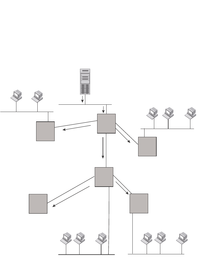
PowerConnect B-Series FCX Configuration Guide 735
53-1002266-01
PIM Dense 25
FIGURE 120 Transmission of multicast packets from the source to host group members
...
... ...
229.225.0.1
Group
Member
Group
Member
Video Conferencing
Server
(207.95.5.1, 229.225.0.1)
(Source, Group)
229.225.0.1
Group
Member
Group
Member
Group
Member
Group
Member
Group
Member
Group
Member
229.225.0.1
Leaf Node
Leaf Node
Leaf Node
(No Group Members)
Intermediate Node
(No Group Members)
R2 R1
R3
R4
R5
R6
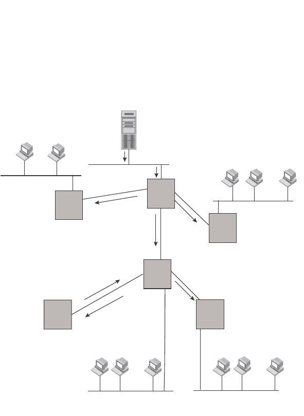
736 PowerConnect B-Series FCX Configuration Guide
53-1002266-01
PIM Dense
25
FIGURE 121 Pruning leaf nodes from a multicast tree
Grafts to a multicast Tree
A PIM switch restores pruned branches to a multicast tree by sending graft messages towards the
upstream switch. Graft messages start at the leaf node and travel up the tree, first sending the
message to its neighbor upstream switch.
In the example above, if a new 229.255.0.1 group member joins on switch S6, which was
previously pruned, a graft is sent upstream to S4. Since the forwarding state for this entry is in a
prune state, S4 sends a graft to S1. Once S4 has joined the tree, S4 and S6 once again receive
multicast packets.
Prune and graft messages are continuously used to maintain the multicast delivery tree. No
configuration is required on your part.
PIM DM versions
Dell PowerConnect devices support PIM DM V1 and V2. The default is V2. You can specify the
version on an individual interface basis.
The primary difference between PIM DM V1 and V2 is the methods the protocols use for
messaging:
•PIM DM V1 – uses the Internet Group Management Protocol (IGMP) to send messages
...
... ...
229.225.0.1
Group
Member
Group
Member
Video Conferencing
Server
(207.95.5.1, 229.225.0.1)
(Source, Group)
229.225.0.1
Group
Member
Group
Member
Group
Member
Group
Member
Group
Member
Group
Member
229.225.0.1
Leaf Node
(No Group Members)
Intermediate Node
(No Group Members)
R2 R1
R3
R4
R5
R6
Prune Message
sent to upstream router (R4)

PowerConnect B-Series FCX Configuration Guide 737
53-1002266-01
PIM Dense 25
•PIM DM V2 – sends messages to the multicast address 224.0.0.13 (ALL-PIM-ROUTERS) with
protocol number 103
The CLI commands for configuring and managing PIM DM are the same for V1 and V2. The only
difference is the command you use to enable the protocol on an interface.
NOTE
Version 2 is the default PIM DM version. The only difference between version 1 and version 2 is the
way the protocol sends messages. The change is not apparent in most configurations. You can use
version 2 instead of version 1 with no impact to your network. However, if you want to continue to
use PIM DM V1 on an interface, you must change the version, then save the configuration.
NOTE
The note above does not mean you can run different PIM versions on devices that are connected to
each other. The devices must run the same version of PIM. If you want to connect a Layer 3 Switch
running PIM to a device that is running PIM V1, you must change the version on the Layer 3 Switch
to V1 (or change the version on the device to V2, if supported).
Configuring PIM DM
NOTE
This section describes how to configure the “dense” mode of PIM, described in RFC 1075. Refer to
“Configuring PIM Sparse” on page 744 for information about configuring PIM Sparse.
Enabling PIM on the router and an interface
By default, PIM is disabled. To enable PIM,perform the following:
•Enable the feature globally.
•Configure the IP interfaces that will use PIM.
•Enable PIM locally on the ports that have the IP interfaces you configured for PIM.
Suppose you want to initiate the use of desktop video for fellow users on a sprawling campus
network. All destination workstations have the appropriate hardware and software but the Dell
PowerConnect routers that connect the various buildings need to be configured to support PIM
multicasts from the designated video conference server as shown in Figure 120 on page 735.
PIM is enabled on each of the routers shown in Figure 120, on which multicasts are expected. You
can enable PIM on each router independently or remotely from one of the routers with a Telnet
connection. Follow the same steps for each router. A reset of the router is required when PIM is first
enabled. Thereafter, all changes are dynamic.
Globally enabling and disabling PIM
To globally enable PIM, enter the following command.
PowerConnect(config)#router pim
Syntax: [no] router pim
The behavior of the [no] router pim command is as follows:
•Entering router pim command to enable PIM does not require a software reload.

738 PowerConnect B-Series FCX Configuration Guide
53-1002266-01
PIM Dense
25
•Entering a no router pim command removes all configuration for PIM multicast on a Layer 3
Switch (router pim level) only.
Globally Enabling and Disabling PIM without Deleting Multicast Configuration
As stated above entering a no router pim command deletes the PIM configuration. If you want to
disable PIM without deleting any PIM configuration, enter the following command.
PowerConnect(config)#router pim
PowerConnect(config-pim-router)#disable-pim
Syntax: [no] disable-pim
Use the [no] version of the command to re-enable PIM.
Enabling a PIM version
Using the CLI
To enable PIM on an interface, globally enable PIM, then enable PIM on interface 3, enter the
following commands.
PowerConnect(config)#router pim
PowerConnect(config)#int e 3
PowerConnect(config-if-e1000-3)#ip address 207.95.5.1/24
PowerConnect(config-if-e1000-3)#ip pim
Syntax: [no] ip pim [version 1 | 2]
The version 1 | 2 parameter specifies the PIM DM version. The default version is 2.
If you have enabled PIM version 1 but need to enable version 2 instead, enter either of the
following commands at the configuration level for the interface.
PowerConnect(config-if-1/1)#ip pim version 2
PowerConnect(config-if-1/1)#no ip pim version 1
To disable PIM DM on the interface, enter the following command.
PowerConnect(config-if-1/1)#no ip pim
Modifying PIM global parameters
PIM global parameters come with preset values. The defaults work well in most networks, but you
can modify the following parameters if you need to:
•Neighbor timeout
•Hello timer
•Prune timer
•Prune wait timer
•Graft retransmit timer
•Inactivity timer
Modifying neighbor timeout
Neighbor timeout is the interval after which a PIM router will consider a neighbor to be absent.
Absence of PIM hello messages from a neighboring router indicates that a neighbor is not present.
The default value is 180 seconds.

PowerConnect B-Series FCX Configuration Guide 739
53-1002266-01
PIM Dense 25
To apply a PIM neighbor timeout value of 360 seconds to all ports on the router operating with PIM,
enter the following.
PowerConnect(config)#router pim
PowerConnect(config-pim-router)#nbr-timeout 360
Syntax: nbr-timeout <60-8000>
The default is 180 seconds.
Modifying hello timer
This parameter defines the interval at which periodic hellos are sent out PIM interfaces. Routers
use hello messages to inform neighboring routers of their presence. The default rate is 60
seconds.
To apply a PIM hello timer of 120 seconds to all ports on the router operating with PIM, enter the
following.
PowerConnect(config)#router pim
PowerConnect(config-pim-router)#hello-timer 120
Syntax: hello-timer <10-3600>
The default is 60 seconds.
Modifying prune timer
This parameter defines how long a PIM router will maintain a prune state for a forwarding entry.
The first received multicast interface is forwarded to all other PIM interfaces on the router. If there
is no presence of groups on that interface, the leaf node sends a prune message upstream and
stores a prune state. This prune state travels up the tree and installs a prune state.
A prune state is maintained until the prune timer expires or a graft message is received for the
forwarding entry. The default value is 180 seconds.
To set the PIM prune timer to 90, enter the following.
PowerConnect(config)#router pim
PowerConnect(config-pim-router)##prune-timer 90
Syntax: prune-timer <10-3600>
The default is 180 seconds.
Modifying the prune wait timer
The CLI command prune-wait allows you to configure the amount of time a PIM router will wait
before stopping traffic to neighbor routers that do not want the traffic. The value can be from zero
to three seconds. The default is three seconds. A smaller prune wait value reduces flooding of
unwanted traffic.
A prune wait value of zero causes the PIM router to stop traffic immediately upon receiving a prune
message. If there are two or more neighbors on the physical port, then the prune-wait command
should not be used because one neighbor may send a prune message while the other sends a join
message at the during time or in less than three seconds.
To set the prune wait time to zero, enter the following commands.
PowerConnect(config)#router pim
PowerConnect(config-pim-router)#prune-wait 0
Syntax: prune-wait <time>

740 PowerConnect B-Series FCX Configuration Guide
53-1002266-01
PIM Dense
25
where <time> can be 0 - 3 seconds. A value of 0 causes the PIM router to stop traffic immediately
upon receiving a prune message. The default is 3 seconds.
Viewing the prune wait time
To view the prune wait time, enter the show ip pim dense command at any level of the CLI.
Modifying graft retransmit timer
The Graft Retransmit Timer defines the interval between the transmission of graft messages.
A graft message is sent by a router to cancel a prune state. When a router receives a graft
message, the router responds with a Graft Ack (acknowledge) message. If this Graft Ack message
is lost, the router that sent the graft message will resend it.
To change the graft retransmit timer from the default of 180 to 90 seconds, enter the following.
PowerConnect(config)#router pim
PowerConnect(config-pim-router)#graft-retransmit-timer 10
Syntax: graft-retransmit-timer <2 -10>
The default is 3 seconds.
Modifying inactivity timer
The router deletes a forwarding entry if the entry is not used to send multicast packets. The PIM
inactivity timer defines how long a forwarding entry can remain unused before the router deletes it.
To apply a PIM inactivity timer of 90 seconds to all PIM interfaces, enter the following.
PowerConnect(config)#router pim
PowerConnect(config-pim-router)#inactivity-timer 90
Syntax: inactivity-timer <10-3600>
The default is 180 seconds.
Selection of shortest path back to source
By default, when a multicast packet is received on a PIM-capable router interface in a multi-path
topology, the interface checks its IP routing table to determine the shortest path back to the
source. If the alternate paths have the same cost, the first alternate path in the table is picked as
the path back to the source. For example, in the table below, the first four routes have the same
cost back to the source. However, 137.80.127.3 will be chosen as the path to the source since it is
the first one on the list. The router rejects traffic from any port other than Port V11 on which
137.80.127.3 resides.
PowerConnect#show ip pim dense
Global PIM Dense Mode Settings
Hello interval: 60, Neighbor timeout: 180
Graft Retransmit interval: 10, Inactivity interval: 180
Route Expire interval: 200, Route Discard interval: 340
Prune age: 180, Prune wait: 3

PowerConnect B-Series FCX Configuration Guide 741
53-1002266-01
PIM Dense 25
When the Highest IP RPF feature is enabled, the selection of the shortest path back to the source is
based on which Reverse Path Forwarding (RPF) neighbor in the IP routing table has the highest IP
address, if the cost of the routes are the same. For example, in the table above, Gateway
137.80.129.1 will be chosen as the shortest path to the source because it is the RPF neighbor with
the highest IP address.
When choosing the RPF, the router first checks the Multicast Routing Table. If the table is not
available, it chooses an RPF from the IP Routing Table. Multicast route is configured using the ip
mroute command.
To enable the Highest IP RPF feature, enter commands such as the following.
PowerConnect(config)#router pim
PowerConnect(config-pim-router)#highest-ip-rpf
The command immediately enables the Highest IP RPF feature; there is no need to reboot the
device.
Syntax: [no] highest-ip-rpf
Entering the no version of the command disables the feature; the shortest path back to the source
will be based on the first entry in the IP routing table. If some PIM traffic paths were selected based
on the highest IP RPF, these paths are changed immediately to use the first RPF in the routing
table.
Failover time in a multi-path topology
When a port in a multi-path topology fails, and the failed port is the input port of the downstream
router, a new path is re-established within a few seconds, depending on the routing protocol being
used.
No configuration is required for this feature.
Modifying the TTL
The TTL defines the minimum value required in a packet for it to be forwarded out of the interface.
For example, if the TTL for an interface is set at 10, it means that only those packets with a TTL
value of 10 or more will be forwarded. Likewise, if an interface is configured with a TTL Threshold
value of 1, all packets received on that interface will be forwarded. Possible TTL values are 1 to 31.
The default TTL value is 1.
Total number of IP routes: 19
B:BGP D:Connected R:RIP S:Static O:OSPF *:Candidate default
Destination NetMask Gateway Port Cost Type
..
9 172.17.41.4 255.255.255.252*137.80.127.3 v11 2 O
172.17.41.4 255.255.255.252 137.80.126.3 v10 2 O
172.17.41.4 255.255.255.252 137.80.129.1 v13 2 O
172.17.41.4 255.255.255.252 137.80.128.3 v12 2 O
10 172.17.41.8 255.255.255.252 0.0.0.0 1/2 1 D

742 PowerConnect B-Series FCX Configuration Guide
53-1002266-01
PIM Sparse
25
Configuration notes
•If the TTL for an interface is greater than 1, PIM packets received on the interface are always
forwarded in software because each packet TTL must be examined. Therefore, Dell does not
recommend modifying the TTL under normal operating conditions.
•Multicast packets with a TTL value of 1 are switched within the same VLAN. These packets
cannot be routed between different VLANs.
Configuration syntax
To configure a TTL of 24, enter the following.
PowerConnect(config-if-3/24)#ip pim ttl 24
Syntax: ip pim ttl <1-31>
Dropping PIM traffic in hardware
Unwanted PIM Dense or PIM Sparse multicast traffic can be dropped in hardware on Layer 3
Switches. This feature does not apply to DVMRP traffic. Refer to “Passive multicast route insertion”
on page 763.
PIM Sparse
Dell PowerConnect devices support Protocol Independent Multicast (PIM) Sparse version 2. PIM
Sparse provides multicasting that is especially suitable for widely distributed multicast
environments. The Dell implementation is based on RFC 2362.
In a PIM Sparse network, a PIM Sparse router that is connected to a host that wants to receive
information for a multicast group must explicitly send a join request on behalf of the receiver (host).
PIM Sparse routers are organized into domains. A PIM Sparse domain is a contiguous set of routers
that all implement PIM and are configured to operate within a common boundary. Figure 122
shows a simple example of a PIM Sparse domain. This example shows three Layer 3 Switches
configured as PIM Sparse routers. The configuration is described in detail following the figure.
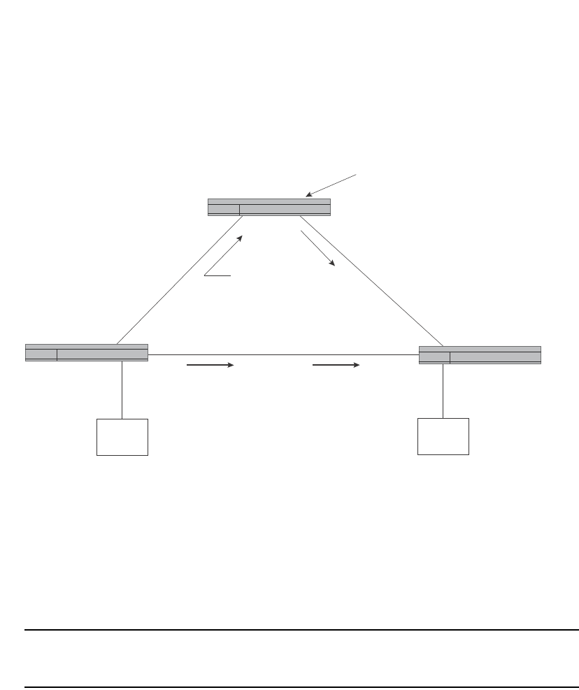
PowerConnect B-Series FCX Configuration Guide 743
53-1002266-01
PIM Sparse 25
FIGURE 122 Example of a PIM Sparse domain
PIM Sparse switch types
Switches that are configured with PIM Sparse interfaces also can be configured to fill one or more
of the following roles:
•PMBR – A PIM switch that has some interfaces within the PIM domain and other interface
outside the PIM domain. PBMRs connect the PIM domain to the Internet.
NOTE
You cannot configure a Dell routing interface as a PMBR interface for PIM Sparse in the current
software release.
•BSR – The Bootstrap Router (BSR) distributes RP information to the other PIM Sparse switches
within the domain. Each PIM Sparse domain has one active BSR. For redundancy, you can
configure ports on multiple switches as candidate BSRs. The PIM Sparse protocol uses an
election process to select one of the candidate BSRs as the BSR for the domain. The BSR with
the highest BSR priority (a user-configurable parameter) is elected. If the priorities result in a
tie, then the candidate BSR interface with the highest IP address is elected. In the example in
Figure 122, PIM Sparse switch B is the BSR. Port 2/2 is configured as a candidate BSR.
•RP – The RP is the meeting point for PIM Sparse sources and receivers. A PIM Sparse domain
can have multiple RPs, but each PIM Sparse multicast group address can have only one active
RP. PIM Sparse switches learn the addresses of RPs and the groups for which they are
responsible from messages that the BSR sends to each of the PIM Sparse switches. In the
example in Figure 122, PIM Sparse Switch B is the RP. Port 2/2 is configured as a candidate
Rendezvous Point (RP).
PIM Sparse
Switch B
Port2/1
207.95.8.10
Port2/2
207.95.7.1
Rendezvous Point (RP) path
Port3/8
207.95.8.1
Port3/8
207.95.7.2
VE 1
207.95.6.1
VE 1
207.95.6.2
Shortest Path Tree (SPT) path
PIM Sparse
Switch A PIM Sparse
Switch C
209.157.24.162
Source for Group
239.255.162.1
Receiver for Group
239.255.162.1
This interface is also the
Bootstrap Router (BR) for
this PIM Sparse domain, and
the Rendezvous Point (RP) for the
PIM Sparse groups in this domain.

744 PowerConnect B-Series FCX Configuration Guide
53-1002266-01
PIM Sparse
25
To enhance overall network performance, Layer 3 Switches use the RP to forward only the first
packet from a group source to the group receivers. After the first packet, the Layer 3 Switch
calculates the shortest path between the receiver and source (the Shortest Path Tree, or SPT)
and uses the SPT for subsequent packets from the source to the receiver. The Layer 3 Switch
calculates a separate SPT for each source-receiver pair.
NOTE
Dell recommends that you configure the same ports as candidate BSRs and RPs.
RP paths and SPT paths
Figure 122 shows two paths for packets from the source for group 239.255.162.1 and a receiver
for the group. The source is attached to PIM Sparse Switch A and the recipient is attached to PIM
Sparse Switch C. PIM Sparse Switch B in is the RP for this multicast group. As a result, the default
path for packets from the source to the receiver is through the RP. However, the path through the
RP sometimes is not the shortest path. In this case, the shortest path between the source and the
receiver is over the direct link between Switch A and Switch C, which bypasses the RP (Switch B).
To optimize PIM traffic, the protocol contains a mechanism for calculating the Shortest Path Tree
(SPT) between a given source and receiver. PIM Sparse switches can use the SPT as an alternative
to using the RP for forwarding traffic from a source to a receiver. By default, Layer 3 Switches
forward the first packet they receive from a given source to a given receiver using the RP path, but
forward subsequent packets from that source to that receiver through the SPT. In Figure 122,
Switch A forwards the first packet from group 239.255.162.1 source to the destination by sending
the packet to Switch B, which is the RP. Switch B then sends the packet to Switch C. For the second
and all future packets that Switch A receives from the source for the receiver, Switch A forwards
them directly to Switch C using the SPT path.
Configuring PIM Sparse
To configure a Layer 3 Switch for PIM Sparse, perform the following tasks:
•Configure the following global parameter:
•Enable the PIM Sparse mode of multicast routing.
•Configure the following interface parameters:
•Configure an IP address on the interface
•Enable PIM Sparse.
•Identify the interface as a PIM Sparse border, if applicable.
NOTE
You cannot configure a routing interface as a PMBR interface for PIM Sparse.
•Configure the following PIM Sparse global parameters:
•Identify the Layer 3 Switch as a candidate PIM Sparse Bootstrap Router (BSR), if
applicable.
•Identify the Layer 3 Switch as a candidate PIM Sparse Rendezvous Point (RP), if
applicable.
•Specify the IP address of the RP (if you want to statically select the RP).

PowerConnect B-Series FCX Configuration Guide 745
53-1002266-01
PIM Sparse 25
NOTE
Dell recommends that you configure the same Layer 3 Switch as both the BSR and the RP.
Limitations
The implementation of PIM Sparse in the current software release has the following limitations:
•PIM Border Routers (PMBRs) are not supported. Thus, you cannot configure a Dell routing
interface as a PMBR interface for PIM Sparse.
•PIM Sparse and regular PIM (dense mode) cannot be used on the same interface.
•You cannot configure or display PIM Sparse information using the Web Management Interface.
(You can display some general PIM information, but not specific PIM Sparse information.)
Configuring Global PIM Sparse parameters
To configure the PIM Sparse global parameters, use either of the following methods.
To configure basic global PIM Sparse parameters, enter commands such as the following on each
Layer 3 Switch within the PIM Sparse domain.
PowerConnect(config)#router pim
Syntax: [no] router pim
NOTE
You do not need to globally enable IP multicast routing when configuring PIM Sparse.
The command in this example enables IP multicast routing, and enables the PIM Sparse mode of IP
multicast routing. The command does not configure the Layer 3 Switch as a candidate PIM Sparse
Bootstrap Router (BSR) and candidate Rendezvous Point (RP). You can configure a Layer 3 Switch
as a PIM Sparse switch without configuring the it as a candidate BSR and RP. However, if you do
configure the Layer 3 Switch as one of these, Dell recommends that you configure it as both. Refer
to “Configuring BSRs” on page 746.
The behavior of the [no] router pim command is as follows:
•Entering no router pim command to disable PIM or DVMRP does not require a software reload.
•Entering a no router pim command removes all configuration for PIM multicast on a Layer 3
Switch (router pim level) only.
Globally enabling and disabling PIM without deleting the multicast configuration
As stated above entering a no router pim command deletes the PIM configuration. If you want to
disable PIM without deleting any PIM configuration, enter the following command.
PowerConnect(config)#router pim
PowerConnect(config-pim-router)#disable-pim
Syntax: [no] disable-pim
Use the [no] version of the command to re-enable PIM.

746 PowerConnect B-Series FCX Configuration Guide
53-1002266-01
PIM Sparse
25
Configuring PIM interface parameters
After you enable IP multicast routing and PIM Sparse at the global level, you must enable it on the
individual interfaces connected to the PIM Sparse network. To do so, use the following CLI method.
To enable PIM Sparse mode on an interface, enter commands such as the following.
PowerConnect(config)#interface ethernet 2/2
PowerConnect(config-if-2/2)#ip address 207.95.7.1 255.255.255.0
PowerConnect(config-if-2/2)#ip pim-sparse
Syntax: [no] ip pim-sparse
The commands in this example add an IP interface to port 2/2, then enable PIM Sparse on the
interface.
If the interface is on the border of the PIM Sparse domain, you also must enter the following
command.
PowerConnect(config-if-2/2)#ip pim border
Syntax: [no] ip pim border
NOTE
You cannot configure a Dell routing interface as a PMBR interface for PIM Sparse in the current
software release.
Configuring BSRs
In addition to the global and interface parameters in the sections above, you need to identify an
interface on at least one Layer 3 Switch as a candidate PIM Sparse Bootstrap router (BSR) and
candidate PIM Sparse Rendezvous Point (RP).
NOTE
It is possible to configure the Layer 3 Switch as only a candidate BSR or RP, but Dell recommends
that you configure the same interface on the same Layer 3 Switch as both a BSR and an RP.
This section presents how to configure BSRs. Refer to “Configuring RPs” on page 747 for
instructions on how to configure RPs.
To configure the Layer 3 Switch as a candidate BSR and RP, enter commands such as the following.
PowerConnect(config)#router pim
PowerConnect(config-pim-router)#bsr-candidate ethernet 2/2 30 255
BSR address: 207.95.7.1, hash mask length: 30, priority: 255
This command configures the PIM Sparse interface on port 2/2 as a BSR candidate, with a hash
mask length of 30 and a priority of 255. The information shown in italics above is displayed by the
CLI after you enter the candidate BSR configuration command.
Syntax: [no] bsr-candidate ethernet [<slotnum>/]<portnum> | loopback <num> | ve <num>
<hash-mask-length> [<priority>]
The <slotnum> parameter is required on chassis devices.
The <portnum> | loopback <num> | ve <num> parameter specifies the interface. The Layer 3
Switch will advertise the specified interface IP address as a candidate BSR:
•Enter ethernet [<slotnum>/] <portnum> for a physical interface (port).

PowerConnect B-Series FCX Configuration Guide 747
53-1002266-01
PIM Sparse 25
•Enter ve <num> for a virtual interface.
•Enter loopback <num> for a loopback interface.
The <hash-mask-length> parameter specifies the number of bits in a group address that are
significant when calculating the group-to-RP mapping. You can specify a value from 1 – 32.
NOTE
Dell recommends you specify 30 for IP version 4 (IPv4) networks.
The <priority> specifies the BSR priority. You can specify a value from 0 – 255. When the election
process for BSR takes place, the candidate BSR with the highest priority becomes the BSR. The
default is 0.
Configuring RPs
Enter a command such as the following to configure the Layer 3 Switch as a candidate RP.
PowerConnect(config-pim-router)#rp-candidate ethernet 2/2
Syntax: [no] rp-candidate ethernet [<slotnum>/]<portnum> | loopback <num> | ve <num>
The <slotnum> parameter is required on chassis devices.
The <portnum> | loopback <num> | ve <num> parameter specifies the interface. The Layer 3
Switch will advertise the specified interface IP address as a candidate RP:
•Enter ethernet [<slotnum>/]<portnum> for a physical interface (port).
•Enter ve <num> for a virtual interface.
•Enter loopback <num> for a loopback interface.
By default, this command configures the Layer 3 Switch as a candidate RP for all group numbers
beginning with 224. As a result, the Layer 3 Switch is a candidate RP for all valid PIM Sparse group
numbers. You can change this by adding or deleting specific address ranges. The following example
narrows the group number range for which the Layer 3 Switch is a candidate RP by explicitly adding
a range.
PowerConnect(config-pim-router)#rp-candidate add 224.126.0.0 16
Syntax: [no] rp-candidate add <group-addr> <mask-bits>
The <group-addr> <mask-bits> specifies the group address and the number of significant bits in
the subnet mask. In this example, the Layer 3 Switch is a candidate RP for all groups that begin
with 224.126. When you add a range, you override the default. The Layer 3 Switch then becomes a
candidate RP only for the group address ranges you add.
You also can change the group numbers for which the Layer 3 Switch is a candidate RP by deleting
address ranges. For example, to delete all addresses from 224.126.22.0 – 224.126.22.255, enter
the following command.
PowerConnect(config-pim-router)#rp-candidate delete 224.126.22.0 24
Syntax: rp-candidate delete <group-addr> <mask-bits>
The usage of the <group-addr> <mask-bits> parameter is the same as for the rp-candidate add
command.
If you enter both commands shown in the example above, the net effect is that the Layer 3 Switch
becomes a candidate RP for groups 224.126.0.0 – 224.126.21.255 and groups 224.126.23.0 –
224.126.255.255.

748 PowerConnect B-Series FCX Configuration Guide
53-1002266-01
PIM Sparse
25
Updating PIM-Sparse forwarding entries with new RP configuration
If you make changes to your static RP configuration, the entries in the PIM-Sparse multicast
forwarding table continue to use the old RP configuration until they are aged out.
The clear pim rp-map command allows you to update the entries in the static multicast forwarding
table immediately after making RP configuration changes. This command is meant to be used with
rp-address command.
To update the entries in a PIM sparse static multicast forwarding table with new RP configuration,
enter the following command at the privileged EXEC level of the CLI.
PowerConnect#clear pim rp-map
Syntax: clear pim rp-map
Statically specifying the RP
Dell recommends that you use the PIM Sparse protocol RP election process so that a backup RP
can automatically take over if the active RP router becomes unavailable. However, if you do not
want the RP to be selected by the RP election process but instead you want to explicitly identify the
RP by its IP address, you can do using the following CLI method.
If you explicitly specify the RP, the Layer 3 Switch uses the specified RP for all group-to-RP
mappings and overrides the set of candidate RPs supplied by the BSR.
NOTE
Specify the same IP address as the RP on all PIM Sparse routers within the PIM Sparse domain.
Make sure the router is on the backbone or is otherwise well connected to the rest of the network.
To specify the IP address of the RP, enter commands such as the following.
PowerConnect(config)#router pim
PowerConnect(config-pim-router)#rp-address 207.95.7.1
Syntax: [no] rp-address <ip-addr>
The <ip-addr> parameter specifies the IP address of the RP.
The command in the example above identifies the router interface at IP address 207.95.7.1 as the
RP for the PIM Sparse domain. The Layer 3 Switch will use the specified RP and ignore group-to-RP
mappings received from the BSR.
Changing the Shortest Path Tree (SPT) threshold
In a typical PIM Sparse domain, there may be two or more paths from a DR (designated router) for
a multicast source to a PIM group receiver:
•Path through the RP – This is the path the Layer 3 Switch uses the first time it receives traffic
for a PIM group. However, the path through the RP may not be the shortest path from the Layer
3 Switch to the receiver.
•Shortest Path – Each PIM Sparse router that is a DR for a multicast source calculates a
shortest path tree (SPT) to all the PIM Sparse group receivers within the domain, with the Layer
3 Switch itself as the root of the tree. The first time a Layer 3 Switch configured as a PIM router
receives a packet for a PIM receiver, the Layer 3 Switch sends the packet to the RP for the
group. The Layer 3 Switch also calculates the SPT from itself to the receiver. The next time the
Layer 3 Switch receives a PIM Sparse packet for the receiver, the Layer 3 Switch sends the
packet toward the receiver using the shortest route, which may not pass through the RP.

PowerConnect B-Series FCX Configuration Guide 749
53-1002266-01
PIM Sparse 25
By default, the device switches from the RP to the SPT after receiving the first packet for a given
PIM Sparse group. The Layer 3 Switch maintains a separate counter for each PIM Sparse
source-group pair.
After the Layer 3 Switch receives a packet for a given source-group pair, the Layer 3 Switch starts a
PIM data timer for that source-group pair. If the Layer 3 Switch does not receive another packet for
the source-group pair before the timer expires, it reverts to using the RP for the next packet
received for the source-group pair. In accordance with the PIM Sparse RFC recommendation, the
timer is 210 seconds and is not configurable. The counter is reset to zero each time the Layer 3
Switch receives a packet for the source-group pair.
You can change the number of packets that the Layer 3 Switch sends using the RP before switching
to using the SPT. To do so, use the following CLI method.
PowerConnect(config)#router pim
PowerConnect(config-pim-router)#spt-threshold 1000
Syntax: [no] spt-threshold infinity | <num>
The infinity | <num> parameter specifies the number of packets. If you specify infinity, the Layer 3
Switch sends packets using the RP indefinitely and does not switch over to the SPT. If you enter a
specific number of packets, the Layer 3 Switch does not switch over to using the SPT until it has
sent the number of packets you specify using the RP.
Changing the PIM join and prune message interval
By default, the Layer 3 Switch sends PIM Sparse Join/Prune messages every 60 seconds. These
messages inform other PIM Sparse routers about clients who want to become receivers (Join) or
stop being receivers (Prune) for PIM Sparse groups.
You can change the Join/Prune message interval using the following CLI method.
NOTE
Use the same Join/Prune message interval on all the PIM Sparse routers in the PIM Sparse domain.
If the routers do not all use the same timer interval, the performance of PIM Sparse can be adversely
affected.
To change the Join/Prune interval, enter commands such as the following.
PowerConnect(config)#router pim
PowerConnect(config-pim-router)#message-interval 30
Syntax: [no] message-interval <num>
The <num> parameter specifies the number of seconds and can from 1 – 65535. The default is
60.
Dropping PIM traffic in hardware
Unwanted PIM Dense or PIM Sparse multicast traffic can be dropped in hardware on Layer 3
Switches. This feature does not apply to DVMRP traffic. Refer to “Passive multicast route insertion”
on page 763.

750 PowerConnect B-Series FCX Configuration Guide
53-1002266-01
PIM Sparse
25
Displaying PIM Sparse configuration information
and statistics
You can display the following PIM Sparse information:
•Basic PIM Sparse configuration information
•Group information
•BSR information
•Candidate RP information
•RP-to-group mappings
•RP information for a PIM Sparse group
•RP set list
•PIM Neighbor information
•The PIM flow cache
•The PIM multicast cache
•PIM traffic statistics
Displaying basic PIM Sparse configuration information
To display basic configuration information for PIM Sparse, enter the following command at any CLI
level.
Syntax: show ip pim sparse
This example shows the PIM Sparse configuration information on PIM Sparse router A in
Figure 122.
This display shows the following information.
TABLE 127 Output of show ip pim sparse
This field... Displays...
Global PIM Sparse mode settings
Hello interval How frequently the Layer 3 Switch sends PIM Sparse hello messages to its PIM Sparse
neighbors. This field show the number of seconds between hello messages. PIM Sparse
routers use hello messages to discover one another.
PowerConnect#show ip pim sparse
Global PIM Sparse Mode Settings
Hello interval: 60, Neighbor timeout: 180
Bootstrap Msg interval: 130, Candidate-RP Advertisement interval: 60
Join/Prune interval: 60, SPT Threshold: 1
Interface Ethernet e3/8
TTL Threshold: 1, Enabled
Local Address: 207.95.8.1
Interface Ve 1
TTL Threshold: 1, Enabled
Local Address: 207.95.6.1

PowerConnect B-Series FCX Configuration Guide 751
53-1002266-01
PIM Sparse 25
Displaying a list of multicast groups
To display a list of the IP multicast groups the Layer 3 Switch is forwarding, enter the following
command at any CLI level.
Neighbor timeout How many seconds the Layer 3 Switch will wait for a hello message from a neighbor
before determining that the neighbor is no longer present and removing cached PIM
Sparse forwarding entries for the neighbor.
Bootstrap Msg
interval
How frequently the BSR configured on the Layer 3 Switch sends the RP set to the RPs
within the PIM Sparse domain. The RP set is a list of candidate RPs and their group
prefixes. A candidate RP group prefix indicates the range of PIM Sparse group numbers
for which it can be an RP.
NOTE: This field contains a value only if an interface on the Layer 3 Switch is elected to
be the BSR. Otherwise, the field is blank.
Candidate-RP
Advertisement
interval
How frequently the candidate PR configured on the Layer 3 Switch sends candidate RP
advertisement messages to the BSR.
NOTE: This field contains a value only if an interface on the Layer 3 Switch is configured
as a candidate RP. Otherwise, the field is blank.
Join/Prune interval How frequently the Layer 3 Switch sends PIM Sparse Join/Prune messages for the
multicast groups it is forwarding. This field show the number of seconds between
Join/Prune messages.
The Layer 3 Switch sends Join/Prune messages on behalf of multicast receivers who
want to join or leave a PIM Sparse group. When forwarding packets from PIM Sparse
sources, the Layer 3 Switch sends the packets only on the interfaces on which it has
received join requests in Join/Prune messages for the source group.
You can change the Join/Prune interval if needed. Refer to “Changing the PIM join and
prune message interval” on page 749.
SPT Threshold The number of packets the Layer 3 Switch sends using the path through the RP before
switching to using the SPT path.
PIM Sparse interface information
NOTE: You also can display IP multicast interface information using the show ip pim interface command.
However, this command lists all IP multicast interfaces, including regular PIM (dense mode) and DVMRP
interfaces. The show ip pim sparse command lists only the PIM Sparse interfaces.
Interface The type of interface and the interface number. The interface type can be one of the
following:
•Ethernet
•VE
The number is either a port number (and slot number if applicable) or the virtual interface
(VE) number.
TTL Threshold Following the TTL threshold value, the interface state is listed. The interface state can be
one of the following:
•Disabled
•Enabled
Local Address Indicates the IP address configured on the port or virtual interface.
TABLE 127 Output of show ip pim sparse (Continued)
This field... Displays...

752 PowerConnect B-Series FCX Configuration Guide
53-1002266-01
PIM Sparse
25
Syntax: show ip pim group
This display shows the following information.
Displaying BSR information
To display BSR information, enter the following command at any CLI level.
This example show information displayed on a Layer 3 Switch that has been elected as the BSR.
The following example shows information displayed on a Layer 3 Switch that is not the BSR. Notice
that some fields shown in the example above do not appear in the example below.
PowerConnect#show ip pim bsr
PIMv2 Bootstrap information
local BSR address = 207.95.7.1
local BSR priority = 5
Syntax: show ip pim bsr
This display shows the following information.
TABLE 128 Output of show ip pim group
This field... Displays...
Total number of Groups Lists the total number of IP multicast groups the Layer 3 Switch is forwarding.
NOTE: This list can include groups that are not PIM Sparse groups. If interfaces on
the Layer 3 Switch are configured for regular PIM (dense mode) or DVMRP,
these groups are listed too.
Index The index number of the table entry in the display.
Group The multicast group address
Ports The Layer 3 Switch ports connected to the receivers of the groups.
PowerConnect#show ip pim group
Total number of Groups: 2
Index 1 Group 239.255.162.1 Ports e3/11
PowerConnect#show ip pim bsr
PIMv2 Bootstrap information
This system is the elected Bootstrap Router (BSR)
BSR address: 207.95.7.1
Uptime: 00:33:52, BSR priority: 5, Hash mask length: 32
Next bootstrap message in 00:00:20
Next Candidate-RP-advertisement in 00:00:10
RP: 207.95.7.1
group prefixes:
224.0.0.0 / 4
Candidate-RP-advertisement period: 60

PowerConnect B-Series FCX Configuration Guide 753
53-1002266-01
PIM Sparse 25
Displaying Pim resources
To display the hardware resource information such as hardware allocation, availability, and limit for
software data structure, enter the following command.
TABLE 129 Output of show ip pim bsr
This field... Displays...
BSR address
or
local BSR address
The IP address of the interface configured as the PIM Sparse Bootstrap Router (BSR).
NOTE: If the word “local” does not appear in the field, this Layer 3 Switch is the BSR. If the
word “local” does appear, this Layer 3 Switch is not the BSR.
Uptime The amount of time the BSR has been running.
NOTE: This field appears only if this Layer 3 Switch is the BSR.
BSR priority
or
local BSR priority
The priority assigned to the interface for use during the BSR election process. During BSR
election, the priorities of the candidate BSRs are compared and the interface with the
highest BSR priority becomes the BSR.
NOTE: If the word “local” does not appear in the field, this Layer 3 Switch is the BSR. If the
word “local” does appear, this Layer 3 Switch is not the BSR.
Hash mask length The number of significant bits in the IP multicast group comparison mask. This mask
determines the IP multicast group numbers for which the Layer 3 Switch can be a BSR.
The default is 32 bits, which allows the Layer 3 Switch to be a BSR for any valid IP
multicast group number.
NOTE: This field appears only if this Layer 3 Switch is the BSR.
Next bootstrap
message in
Indicates how many seconds will pass before the BSR sends its next Bootstrap message.
NOTE: This field appears only if this Layer 3 Switch is the BSR.
Next
Candidate-PR-adverti
sement message in
Indicates how many seconds will pass before the BSR sends its next candidate PR
advertisement message.
NOTE: This field appears only if this Layer 3 Switch is the BSR.
RP Indicates the IP address of the Rendezvous Point (RP).
NOTE: This field appears only if this Layer 3 Switch is the BSR.
group prefixes Indicates the multicast groups for which the RP listed by the previous field is a candidate
RP.
NOTE: This field appears only if this Layer 3 Switch is the BSR.
Candidate-RP-adverti
sement period
Indicates how frequently the BSR sends candidate RP advertisement messages.
NOTE: This field appears only if this Layer 3 Switch is the BSR.

754 PowerConnect B-Series FCX Configuration Guide
53-1002266-01
PIM Sparse
25
Syntax: show ip pim resource
For each software data structure listed in the output, the following information is shown.
TABLE 130 Output of show ip pim resource
This field... Displays...
alloc Number of nodes of that data that are currently allocated in memory.
in-use Number of allocated nodes in use
avail Number of allocated nodes are not in use
allo-fail Number of allocated notes that failed
up-limit Maximum number of nodes that can be allocated for a data structure. This may or may not be
configurable, depending on the data structure
get-mem Number of attempts made to use allocated nodes
#of PIM ports Total number of PIM ports, by port type, on the device
Total, allocated,
and available
Mils
In Layer 3 multicast, this refers to the Multicast Linked List that contains information on where
(S,G) gets forwarded. Each (S,G) entry requires a single MLL entry to forward traffic to all
physical, untagged ports. Also, one MLL entry is required per VLAN that has tagged outbound
ports. There can be up to 1024 MLL entries.
PowerConnect#show ip pim resource
alloc in-use avail allo-fail up-limit get-mem
NBR list 64 0 64 0 512 0
timer 256 0 256 0 4096 0
pimsm J/P elem 0 0 0 0 48960 0
pimsm group2rp 0 0 0 0 4096 0
pimsm L2 reg xmt 64 0 64 0 no-limit 0
mcache 256 0 256 0 1024 0
mcache hash link 997 0 997 0 no-limit 0
mcache 2nd hash 9 0 9 0 997 0
graft if no mcache 197 0 197 0 no-limit 0
pim/dvm global group 256 0 256 0 no-limit 0
pim/dvmrp prune 128 0 128 0 40960 0
Output intf-vlan 2000 0 2000 0 no-limit 0
group hash link 97 0 97 0 no-limit 0
2D vlan for nbr, glb 2000 0 2000 0 no-limit 0
Output intf. 1024 0 1024 0 no-limit 0
2D for glb grp 1024 0 1024 0 no-limit 0
pim/dvm config. intf 128 2 126 0 no-limit 2
Prune rate limit 256 0 256 0 no-limit 0
Distributed add cpu 128 0 128 0 no-limit 0
L2 VIDX 256 0 256 0 4096 0
L2 VIDX hash 997 0 997 0 no-limit 0
igmp group 256 0 256 0 4096 0
igmp phy port 1024 0 1024 0 no-limit 0
igmp exist phy port 1024 4 1020 0 no-limit 4
igmp G/GS query 128 0 128 0 no-limit 0
igmp v3 source 2000 0 2000 0 500000 0
igmp v3 tracking 0 0 0 0 no-limit 0
igmp glb sorted list 2000 0 2000 0 500000 0
total pool memory 286918 bytes
#of PIM ports: physical 2, VEs 0 (max: 512), loopback 0, tunnels 0
Total Mlls in pool: 943 Allocated MLL: 0 Available MLL: 943
SW processed pkts 0

PowerConnect B-Series FCX Configuration Guide 755
53-1002266-01
PIM Sparse 25
NOTE
When the product of the number of active PIM interfaces multiplied by the number of multicast
streams exceeds the total number of MLL, the CLI displays the message, “MLL pool out of memory”.
NOTE
The total number of MLL available changes according to the hardware configuration.
Displaying candidate RP information
To display candidate RP information, enter the following command at any CLI level.
This example show information displayed on a Layer 3 Switch that is a candidate RP. The following
example shows the message displayed on a Layer 3 Switch that is not a candidate RP.
PowerConnect#show ip pim rp-candidate
This system is not a Candidate-RP.
Syntax: show ip pim rp-candidate
This display shows the following information.
Displaying RP-to-group mappings
To display RP-to-group-mappings, enter the following command at any CLI level.
PowerConnect#show ip pim rp-map
Number of group-to-RP mappings: 6
Group address RP address
-------------------------------
TABLE 131 Output of show ip pim rp-candidate
This field... Displays...
Candidate-RP-advertisement
in
Indicates how many seconds will pass before the BSR sends its next RP
message.
NOTE: This field appears only if this Layer 3 Switch is a candidate RP.
RP Indicates the IP address of the Rendezvous Point (RP).
NOTE: This field appears only if this Layer 3 Switch is a candidate RP.
group prefixes Indicates the multicast groups for which the RP listed by the previous field is a
candidate RP.
NOTE: This field appears only if this Layer 3 Switch is a candidate RP.
Candidate-RP-advertisement
period
Indicates how frequently the BSR sends candidate RP advertisement messages.
NOTE: This field appears only if this Layer 3 Switch is a candidate RP.
PowerConnect#show ip pim rp-candidate
Next Candidate-RP-advertisement in 00:00:10
RP: 207.95.7.1
group prefixes:
224.0.0.0 / 4
Candidate-RP-advertisement period: 60

756 PowerConnect B-Series FCX Configuration Guide
53-1002266-01
PIM Sparse
25
1 239.255.163.1 99.99.99.5
2 239.255.163.2 99.99.99.5
3 239.255.163.3 99.99.99.5
4 239.255.162.1 99.99.99.5
5 239.255.162.2 43.43.43.1
6 239.255.162.3 99.99.99.5
Syntax: show ip pim rp-map
This display shows the following information.
Displaying RP information for a PIM Sparse group
To display RP information for a PIM Sparse group, enter the following command at any CLI level.
Syntax: show ip pim rp-hash <group-addr>
The <group-addr> parameter is the address of a PIM Sparse IP multicast group.
This display shows the following information.
Displaying the RP set list
To display the RP set list, enter the following command at any CLI level.
Syntax: show ip pim rp-set
TABLE 132 Output of show ip pim rp-map
This field... Displays...
Group address Indicates the PIM Sparse multicast group address using the listed RP.
RP address Indicates the IP address of the Rendezvous Point (RP) for the listed PIM Sparse group.
TABLE 133 Output of show ip pim rp-hash
This field... Displays...
RP Indicates the IP address of the Rendezvous Point (RP) for the specified PIM Sparse group.
Following the IP address is the port or virtual interface through which this Layer 3 Switch learned
the identity of the RP.
Info source Indicates the IP address on which the RP information was received.
Following the IP address is the method through which this Layer 3 Switch learned the identity of
the RP.
PowerConnect#show ip pim rp-hash 239.255.162.1
RP: 207.95.7.1, v2
Info source: 207.95.7.1, through bootstrap
PowerConnect#show ip pim rp-set
Group address Static-RP-address Override
---------------------------------------------------
Access-List 44 99.99.99.5 On
Number of group prefixes Learnt from BSR: 1
Group prefix = 239.255.162.0/24 #RPs expected: 1
#RPs received: 1
RP 1: 43.43.43.1 priority=0 age=0

PowerConnect B-Series FCX Configuration Guide 757
53-1002266-01
PIM Sparse 25
This display shows the following information.
Displaying multicast neighbor information
To display information about the Layer 3 Switch PIM neighbors, enter the following command at any
CLI level.
Syntax: show ip pim nbr
This display shows the following information.
TABLE 134 Output of show ip pim rp-set
This field... Displays...
Number of group prefixes The number f PIM Sparse group prefixes for which the RP is responsible.
Group prefix Indicates the multicast groups for which the RP listed by the previous field is a
candidate RP.
RPs expected/received Indicates how many RPs were expected and received in the latest Bootstrap
message.
RP <num> Indicates the RP number. If there are multiple RPs in the PIM Sparse domain, a
line of information for each of them is listed, and they are numbered in ascending
numerical order.
priority The RP priority of the candidate RP. During the election process, the candidate RP
with the highest priority is elected as the RP.
age The age (in seconds) of this RP-set.
NOTE: If this Layer 3 Switch is not a BSR, this field contains zero. Only the BSR
ages the RP-set.
TABLE 135 Output of show ip pim nbr
This field... Displays...
Port The interface through which the Layer 3 Switch is connected to the neighbor.
Neighbor The IP interface of the PIM neighbor interface.
Holdtime sec Indicates how many seconds the neighbor wants this Layer 3 Switch to hold the entry for
this neighbor in memory. The neighbor sends the Hold Time in its Hello packets:
•If the Layer 3 Switch receives a new Hello packet before the Hold Time received in the
previous packet expires, the Layer 3 Switch updates its table entry for the neighbor.
•If the Layer 3 Switch does not receive a new Hello packet from the neighbor before the
Hold time expires, the Layer 3 Switch assumes the neighbor is no longer available and
removes the entry for the neighbor.
PowerConnect#show ip pim nbr
Port Neighbor Holdtime Age UpTime
sec sec sec
e3/8 207.95.8.10 180 60 900
Port Neighbor Holdtime Age UpTime
sec sec sec
v1 207.95.6.2 180 60 900
758 PowerConnect B-Series FCX Configuration Guide
53-1002266-01
PIM Sparse
25
Displaying information about an upstream neighbor device
You can view information about the upstream neighbor device for a given source IP address for IP
Protocol Independent Multicast (PIM). For PIM, the software uses the IP route table or multicast
route table to lookup the upstream neighbor device.
Enter the following command at the Privileged EXEC level of the CLI.
PowerConnect#show ip pim rpf 1.1.20.2
directly connected or through an L2 neighbor
Syntax: show ip pim | dvmrp rpf <IP address>
where <IP address> is a valid source IP address
NOTE
If there are multiple equal cost paths to the source, the show ip pim rpf command output may not
be accurate. If your system has multiple equal cost paths, use the command show ip pim mcache
to view information about the upstream neighbor.
Displaying the PIM flow cache
To display the PIM flow cache, enter the following command at any CLI level.
Syntax: show ip pim flowcache
This display shows the following information.
Age sec The number of seconds since the Layer 3 Switch received the last hello message from the
neighbor.
UpTime sec The number of seconds the PIM neighbor has been up. This timer starts when the Layer 3
Switch receives the first Hello messages from the neighbor.
TABLE 136 Output of show ip pim flowcache
This field... Displays...
Source Indicates the source of the PIM Sparse group.
Group Indicates the PIM Sparse group.
Parent Indicates the port or virtual interface from which the Layer 3 Switch receives packets from the
group source.
CamFlags This field is used for troubleshooting.
CamIndex This field is used for troubleshooting.
TABLE 135 Output of show ip pim nbr (Continued)
This field... Displays...
PowerConnect#show ip pim flowcache
Source Group Parent CamFlags CamIndex Fid Flags
1 209.157.24.162 239.255.162.1 v2 00000700 2023 00004411 F
2 209.157.24.162 239.255.162.1 v2 00000700 201b 00004411 F
3 209.157.24.162 239.255.162.1 v2 00000700 201d 00004411 F
4 209.157.24.162 239.255.162.1 v2 00000700 201e 00004411 F

PowerConnect B-Series FCX Configuration Guide 759
53-1002266-01
PIM Sparse 25
Displaying the PIM multicast cache
To display the PIM multicast cache, enter the following command at any CLI level.
Syntax: show ip pim mcache
This display shows the following information.
Fid This field is used for troubleshooting.
Flags This field is used for troubleshooting.
TABLE 137 Output of show ip pim mcache
This field... Displays...
(<source>, <group>) The comma-separated values in parentheses is a source-group pair.
The <source> is the PIM source for the multicast <group>. For example, the following entry
means source 209.157.24.162 for group 239.255.162.1:
(209.157.24.162,239.255.162.1)
If the <source> value is * (asterisk), this cache entry uses the RP path. The * value means
“all sources”.
If the <source> is a specific source address, this cache entry uses the SPT path.
RP<ip-addr> Indicates the RP for the group for this cache entry.
NOTE: The RP address appears only if the RPT flag is set to 1 and the SPT flag is set to 0
(see below).
forward port The port through which the Layer 3 Switch reaches the source.
Count The number of packets forwarded using this cache entry.
Sparse Mode Indicates whether the cache entry is for regular PIM (dense mode) or PIM Sparse. This flag
can have one of the following values:
•0 – The entry is not for PIM Sparse (and is therefore for the dense mode of PIM).
•1– The entry is for PIM Sparse.
TABLE 136 Output of show ip pim flowcache (Continued)
This field... Displays...
PowerConnect#show ip pim mcache
1 (*,239.255.162.1) RP207.95.7.1 forward port v1, Count 2
member ports ethe 3/3
virtual ports v2
prune ports
virtual prune ports
2 (209.157.24.162,239.255.162.4) forward port v2, flags 00004900 Count 130
member ports
virtual ports
prune ports
virtual prune ports
3 (209.157.24.162,239.255.162.1) forward port v2, flags 00005a01 Count 12
member ports ethe 3/8
virtual ports
prune ports
virtual prune ports

760 PowerConnect B-Series FCX Configuration Guide
53-1002266-01
PIM Sparse
25
RPT Indicates whether the cache entry uses the RP path or the SPT path. The RPT flag can have
one of the following values:
•0 – The SPT path is used instead of the RP path.
•1– The RP path is used instead of the SPT path.
NOTE: The values of the RP and SPT flags are always opposite (one is set to 0 and the
other is set to 1).
SPT Indicates whether the cache entry uses the RP path or the SPT path. The SP flag can have
one of the following values:
•0 – The RP path is used instead of the SPT path.
•1– The SPT path is used instead of the RP path.
NOTE: The values of the RP and SPT flags are always opposite (one is set to 0 and the
other is set to 1).
Register Suppress Indicates whether the Register Suppress timer is running. This field can have one of the
following values:
•0 – The timer is not running.
•1 – The timer is running.
member ports Indicates the Layer 3 Switch physical ports to which the receivers for the source and group
are attached. The receivers can be directly attached or indirectly attached through other
PIM Sparse routers.
virtual ports Indicates the virtual interfaces to which the receivers for the source and group are
attached. The receivers can be directly attached or indirectly attached through other PIM
Sparse routers.
prune ports Indicates the physical ports on which the Layer 3 Switch has received a prune notification
(in a Join/Prune message) to remove the receiver from the list of recipients for the group.
virtual prune ports Indicates the virtual interfaces ports on which the Layer 3 Switch has received a prune
notification (in a Join/Prune message) to remove the receiver from the list of recipients for
the group.
TABLE 137 Output of show ip pim mcache (Continued)
This field... Displays...

PowerConnect B-Series FCX Configuration Guide 761
53-1002266-01
PIM Sparse 25
Displaying PIM traffic statistics
To display PIM traffic statistics, use the following CLI method.
Syntax: show ip pim traffic
NOTE
If you have configured interfaces for standard PIM (dense mode) on the Layer 3 Switch, statistics for
these interfaces are listed first by the display.
This display shows the following information.
Displaying and clearing PIM errors
If you want to determine how many PIM errors there are on the device, enter the following
command.
PowerConnect#show ip pim error
**** Warning counter pim route change = 1
HW tagged replication enabled, SW processed pkts 0
TABLE 138 Output of show ip pim traffic
This field... Displays...
Port The port or virtual interface on which the PIM interface is configured.
Hello The number of PIM Hello messages sent or received on the interface.
J/P The number of Join/Prune messages sent or received on the interface.
NOTE: Unlike PIM dense, PIM Sparse uses the same messages for Joins and Prunes.
Register The number of Register messages sent or received on the interface.
RegStop The number of Register Stop messages sent or received on the interface.
Assert The number of Assert messages sent or received on the interface.
Total Recv/Xmit The total number of IGMP messages sent and received by the Layer 3 Switch.
Total Discard/chksum The total number of IGMP messages discarded, including a separate counter for those
that failed the checksum comparison.
PowerConnect#show ip pim traffic
Port Hello J/P Register RegStop Assert
[Rx Tx] [Rx Tx] [Rx Tx] [Rx Tx] [Rx Tx]
e3/8 19 19 32 0 0 0 37 0 0 0
Port Hello J/P Register RegStop Assert
[Rx Tx] [Rx Tx] [Rx Tx] [Rx Tx] [Rx Tx]
v1 18 19 0 20 0 0 0 0 0 0
Port Hello J/P Register RegStop Assert
[Rx Tx] [Rx Tx] [Rx Tx] [Rx Tx] [Rx Tx]
v2 0 19 0 0 0 16 0 0 0 0
Total 37 57 32 0 0 0 0 0 0 0
IGMP Statistics:
Total Recv/Xmit 85/110
Total Discard/chksum 0/0

762 PowerConnect B-Series FCX Configuration Guide
53-1002266-01
PIM Passive
25
Syntax: show ip pim error
This command displays the number of warnings and non-zero PIM errors on the device. This count
can increase during transition periods such as reboots and topology changes; however, if the
device is stable, the number of errors should not increase. If warnings keep increasing in a stable
topology, then there may be a configuration error or problems on the device.
To clear the counter for PIM errors, enter the following command.
PowerConnect#clear pim counters
Syntax: clear pim counters
PIM Passive
PIM Passive is used to reduce and minimize unnecessary PIM Hello and other PIM control
messages.
PIM Passive allows you to specify that the interface is “passive” in regards to PIM. No PIM control
packets are sent or processed (if received), but hosts can still send and receive multicast traffic
and IGMP control traffic on that interface. Also, PIM Passive prevents any malicious router from
taking over as the designated router (DR), which can prevent all hosts on the LAN from joining
multicast traffic outside the LAN.
The following guidelines apply to PIM Passive:
1. This is a Layer 3 interface [Ethernet/Ve] level feature.
2. Since the loopback interfaces are never used to form PIM neighbors, this feature is not
supported on loopback interface.
3. Both PIM SM and PIM DM modes support this feature.
4. Applying the PIM Passive on an interface requires PIM to be enabled on that interface.
5. The sent and received statistics of a PIM Hello message are not changed for an interface,
while it is configured as PIM passive.
To enable PIM Passive on an interface, enter the following command:
Syntax: [no] ip pim passive
Use the show ip pim interface command to display multicast boundary information related to PIM
passive.
PowerConnect# config term
PowerConnect(config)#router pim
PowerConnect(config-pim-router)#exit
PowerConnect(config)#interface ethernet 2
PowerConnect(config-if-e1000-2)#ip pim
PowerConnect(config-if-e1000-2)#ip pim passive
PowerConnect(config-if-e1000-2)#exit
PowerConnect(config)#interface ve 2
PowerConnect(config-vif-2)#ip pim-sparse
PowerConnect(config-vif-2)#ip pim passive
PowerConnect(config-vif-2)#exit

PowerConnect B-Series FCX Configuration Guide 763
53-1002266-01
Passive multicast route insertion 25
Passive multicast route insertion
Passive Multicast Route Insertion (PMRI) enables a Layer 3 switch running PIM Sparse to create an
entry for a multicast route (e.g., (S,G)), with no directly attached clients or when connected to
another PIM router (transit network).
PMRI is critical for Service Providers wanting to deliver IP-TV services or multicast-based video
services. Service Providers, who have transit networks, distribute multicast-based video services to
other Service Providers, regardless of whether a client subscribes to a video service.
PMRI is enabled by default. To disable it, enter the following command at the router pim level of the
CLI.
PowerConnect(config)#router pim
PowerConnect#(config-pim-router)#no hardware-drop
Syntax: [no] hardware-drop
When PMRI is enabled, the show ip pim mcache command output displays the multicast cache
entry along with a drop flag, indicating that the device is dropping packets in hardware. If the HW
flag is set to 1 (HW=1), it implies that the packets are being dropped in hardware. If the HW flag is
set to 0, (HW=0), it indicates that the packets are being processed in software. The following
shows an example display output.
Configuring an IP tunnel
IP tunnels are used to send traffic through routers that do not support IP multicasting. IP Multicast
datagrams are encapsulated within an IP packet and then sent to the remote address. Routers
that are not configured for IP Multicast route the packet as a normal IP packet. When the IP
Multicast router at the remote end of the tunnel receives the packet, the router strips off the IP
encapsulation and forwards the packet as an IP Multicast packet.
NOTE
An IP tunnel must have a remote IP interface at each end. Also, for IP tunneling to work, the remote
routers must be reachable by an IP routing protocol.
NOTE
Multiple tunnels configured on a router cannot share the same remote address.
Example
To configure an IP tunnel as seen in Figure 123, enter the IP tunnel destination address on an
interface of the router.
To configure an IP address on Router A, enter the following.
PowerConnect#show ip pim mcache
1 (10.10.10.18 226.0.1.56) in v10 (e1), cnt=2
Source is directly connected
Sparse Mode, RPT=0 SPT=1 REG=1 MSDP Adv=0 MSDP Create=0
fast=0 slow=0 pru=1 graft age drop
age=0s up-time=2m HW=1 L2-vidx=8191
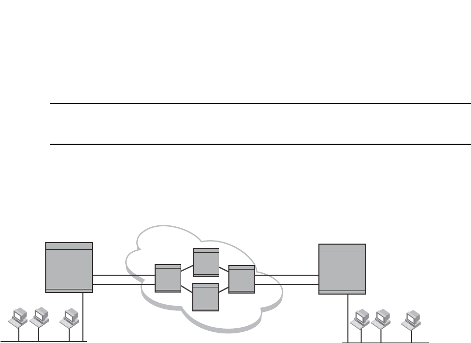
764 PowerConnect B-Series FCX Configuration Guide
53-1002266-01
Using ACLs to control multicast features
25
PowerConnect(config)#int e1
PowerConnect(config-if-1)#ip tunnel 192.3.45.6
NOTE
The IP tunnel address represents the configured IP tunnel address of the destination router. In the
case of Router A, its destination router is Router B. Router A is the destination router of Router B.
For router B, enter the following.
PowerConnect (config-if-1)#ip tunnel 192.58.4.1
FIGURE 123 IP in IP tunneling on multicast packets in a unicast network
Using ACLs to control multicast features
You can use ACLs to control the following multicast features:
•Limit the number of multicast groups that are covered by a static rendezvous point (RP)
•Control which multicast groups for which candidate RPs sends advertisement messages to
bootstrap routers
•Identify which multicast group packets will be forwarded or blocked on an interface
Using ACLs to limit static RP groups
You can limit the number of multicast groups covered by a static RP using standard ACLs. In the
ACL, you specify the group to which the RP address applies. The following examples set the RP
address to be applied to multicast groups with some minor variations.
To configure an RP that covers multicast groups in 239.255.162.x, enter commands such as the
following.
PowerConnect(config)#access-list 2 permit 239.255.162.0 0.0.0.255
PowerConnect(config)#router pim
PowerConnect(config-pim-router)#rp-address 43.43.43.1 2
To configure an RP that covers multicast groups in the 239.255.162.x range, except the
239.255.162.2 group, enter commands such as the following.
PowerConnect(config)#access-list 5 deny host 239.255.162.2
PowerConnect(config)#access-list 5 permit 239.255.0.0 0.0.255.255
Router Router
Router
Router A Router B
Router
Group
Member
Group
Member
Group
Member
Group
Member
Group
Member
Group
Member
Multicast Capable Router
Non-Multicast
Capable Routers Multicast Capable Router
... ...
192.58.4.1 192.3.45.6
IP Tunnel IP Tunnel

PowerConnect B-Series FCX Configuration Guide 765
53-1002266-01
Using ACLs to control multicast features 25
PowerConnect(config)#router pim
PowerConnect(config-pim-router)#bsr-candidate ve 43 32 100
PowerConnect(config-pim-router)#rp-candidate ve 43
PowerConnect(config-pim-router)#rp-address 99.99.99.5 5
To configure an RP for multicast groups using the override switch, enter commands such as the
following.
PowerConnect(config)#access-list 44 permit 239.255.162.0 0.0.0.255
PowerConnect(config)#router pim
PowerConnect(config-pim-router)#rp-address 43.43.43.1
PowerConnect(config-pim-router)#rp-address 99.99.99.5 44 override
Syntax: [no] rp-address <ip-address> [<access-list-num>] [override]
The access-list-num parameter is the number of the standard ACL that will filter the multicast
group.
NOTE
Extended ACLs cannot be used to limit static RP groups.
The override parameter directs the Layer 3 Switch to ignore the information learned by a BSR if
there is a conflict between the RP configured in this command and the information that is learned
by the BSR. In previous releases, static RP configuration precedes the RP address learned from the
PIM Bootstrap protocol. With this enhancement, an RP address learned dynamically from PIM
Bootstrap protocol takes precedence over static RP configuration unless the override parameter is
used.
You can use the show ip pim rp-set command to display the ACLs used to filter the static RP groups.
Example
In the example above, the display shows the following information:
•The Group Address table shows the static RP address that is covered by the access list, and
whether or not the override parameter has been enabled.
•The Group prefix line shows the multicast group prefix for the static RP.
•The RP #line shows the configured IP address of the RP candidate.
The show ip pim rp-map to show the group-to-RP mapping.
PowerConnect#show ip pim rp-set
Group address Static-RP-address Override
---------------------------------------------------
Access-List 44 99.99.99.5 On
Number of group prefixes Learnt from BSR: 1
Group prefix = 224.0.0.0/4 #RPs: 1
RP 1: 43.43.43.1 priority=0 age=0

766 PowerConnect B-Series FCX Configuration Guide
53-1002266-01
Using ACLs to control multicast features
25
The display shows the multicast group addresses covered by the RP candidate and the IP address
of the RP for the listed multicast group. In the example above, you see the following:
•The first three lines show the multicast group addresses that are covered by the RP candidate.
•The last three lines show the multicast group addresses covered by the static RP.
Using ACLs to limit PIM RP candidate advertisement
You can use standard ACLs to control the groups for which the candidate RP will send
advertisement messages to the bootstrap router. For example, ACL 5 can be configured to be
applied to the multicast groups within the IP address 239.x.x.x range. You can configure the Layer 3
Switch to advertise itself as a candidate RP to the bootstrap router only for groups in the range of
239.x.x.x. Enter commands such as the following.
PowerConnect(config)#interface ethernet 1/1
PowerConnect(config-if-1/1)#ip address 99.99.99.5 255.255.255.0
PowerConnect(config-if-1/1)#ip pim-sparse
PowerConnect(config-if-1/1)#exit
PowerConnect(config)#access-list 5 deny host 239.255.162.2
PowerConnect(config)#access-list 5 permit 239.0.0.0 0.0.255.255
PowerConnect(config)#router pim
PowerConnect(config-pim-router)#bsr-candidate ethernet 1/1 32 100
PowerConnect(config-pim-router)#rp-candidate ethernet 1/1 group-list 5
The example above shows a configuration for an Ethernet interface. To configure ACLs that are
applied to a virtual routing interface, enter commands such as the following.
PowerConnect(config)#interface ve 16
PowerConnect(config-vif-16)#ip address 16.16.16.1 255.255.255.0
PowerConnect(config-vif-16)#ip pim-sparse
PowerConnect(config-vif-16)#exit
PowerConnect(config)#access-list 5 deny host 239.255.162.2
PowerConnect(config)#access-list 5 permit 239.255.0.0 0.0.255.255
PowerConnect(config)#router pim
PowerConnect(config-pim-router)#bsr-candidate ve 16 32 100
PowerConnect(config-pim-router)#rp-candidate ve 16 group-list 5
To configure ACLs that are applied to a loopback interface, enter commands such as the following.
PowerConnect(config)#interface loopback 1
PowerConnect(config-lbif-1)#ip address 88.88.88.8 255.255.255.0
PowerConnect(config-lbif-1)#ip pim-sparse
PowerConnect(config-lbif-1)#exit
PowerConnect(config)#access-list 5 deny host 239.255.162.2
PowerConnect(config)#access-list 5 permit 239.255.0.0 0.0.255.255
PowerConnect#show ip pim rp-map
Number of group-to-RP mappings: 6
Group address RP address
-------------------------------
1 239.255.163.1 43.43.43.1
2 239.255.163.2 43.43.43.1
3 239.255.163.3 43.43.43.1
4 239.255.162.1 99.99.99.5
5 239.255.162.2 99.99.99.5
6 239.255.162.3 99.99.99.5

PowerConnect B-Series FCX Configuration Guide 767
53-1002266-01
Disabling CPU processing for select multicast groups 25
PowerConnect(config)#router pim
PowerConnect(config-pim-router)#bsr-candidate loopback 1 32 100
PowerConnect(config-pim-router)#rp-candidate loopback 1 group-list 5
Syntax: [no] rp-candidate ethernet [<slotnum>/]<portnum> | loopback <num> | ve <num>
[group-list <access-list-num>]
The <slotnum> parameter is required on chassis devices.
The <portnum> | loopback <num> | ve <num> parameter specifies the interface. The Layer 3
Switch will advertise the specified interface IP address as a candidate RP:
•Enter ethernet [<slotnum>/]<portnum> for a physical interface (port).
•Enter ve <num> for a virtual interface.
•Enter loopback <num> for a loopback interface.
The group-list <access-list-num> indicates that a standard ACL is used to filter for which multicast
group the advertisement will be made.
NOTE
Extended ACLs cannot be used for group-list.
Disabling CPU processing for select multicast groups
In IPv4 multicast, Layer 3 switches do not forward multicast packets with destination addresses in
the range between 224.0.0.0 and 224.0.0.255. These group addresses are reserved for various
routing protocols. By default, packets destined to these groups are processed by the CPU.
However, when a large number of packets for these groups are received by the Dell PowerConnect
device all at once, CPU resources may be overloaded. To alleviate the load on the CPU, you could
disable CPU processing of packets for these groups. When applied, this feature protects the CPU
from traffic sent to IPV4 multicast addresses in the range 224.0.0.1 - 224.0.0.254, and instead
floods these packets in hardware within the incoming VLAN.
This feature can be applied on a VLAN or a VLAN-group. If applied on a VLAN, traffic received on a
port of the VLAN will be flooded to all other ports of the VLAN. If applied on a VLAN-group, traffic
will be flooded only at the individual VLAN level. Once this feature is applied on a VLAN or
VLAN-group, ports that are statically or dynamically added to the VLAN or VLAN-group will inherit
the configuration. Likewise, ports that are statically or dynamically removed from the VLAN or
VLAN-group will drop the configuration.
This feature can be enabled for packets destined to a multicast group or set of groups in the range
224.0.0.1 – 224.0.0.254, except for the reserved multicast addresses listed in the following table.
TABLE 139 Reserved multicast addresses
Multicast address Reserved for...
224.0.0.1 all nodes
224.0.0.2 PIM
224.0.0.3 DVMRP
224.0.0.4 DVMRP
224.0.0.5 OSPF
224.0.0.6 OSPF

768 PowerConnect B-Series FCX Configuration Guide
53-1002266-01
Disabling CPU processing for select multicast groups
25
CLI command syntax
To disable CPU processing for selective multicast groups, enter commands such as the following.
PowerConnect# config t
PowerConnect(config)# vlan 5
PowerConnect(config-vlan-5)# disable multicast-to-cpu 224.0.0.5
PowerConnect(config-vlan-5)# disable multicast-to-cpu 224.0.0.14 224.0.0.230
PowerConnect(config-vlan-5)# vlan 10
PowerConnect(config-vlan-10)# disable multicast-to-cpu 224.0.0.23
PowerConnect(config-vlan-10)# vlan 20
PowerConnect(config-vlan-20)# disable multicast-to-cpu 224.0.0.50 224.0.0.140
Syntax: [no] disable multicast-to-cpu <multicast group address> [<multicast group range end
address>]
The <multicast group address> must be in the range 224.0.0.1 - 224.0.0.254, but cannot be one
of the reserved multicast addresses listed in Table 139 on page 767.
Viewing disabled multicast addresses
To display disabled multicast addresses for all configured VLANs, enter the command show
disabled-multicast-to-cpu. The following shows an example display.
To display disabled multicast addresses for a particular VLAN, include the VLAN ID with the show
disabled-multicast-to-cpu command. The following shows an example display
.
Syntax: show disabled-multicast-to-cpu [<vlan-id>]
For <vlan-id>, enter a valid VLAN ID. Note that each VLAN must have at least one port added to it.
224.0.0.9 RIP V2
224.0.0.13 PIM V2
224.0.0.18 VRRP
224.0.0.22 IGMP V3 reports
TABLE 139 Reserved multicast addresses (Continued)
Multicast address Reserved for...
PowerConnect# show disabled-multicast-to-cpu
Disabled multicast addresses to cpu for PORT-VLAN 5 :
224.0.0.5
224.0.0.14 to 224.0.0.230
Disabled multicast addresses to cpu for PORT-VLAN 10 :
224.0.0.23
Disabled multicast addresses to cpu for PORT-VLAN 20 :
224.0.0.50 to 224.0.0.140
PowerConnect # show disabled-multicast-to-cpu 5
Disabled multicast addresses to cpu for PORT-VLAN 5 :
224.0.0.5
224.0.0.14 to 224.0.0.230

PowerConnect B-Series FCX Configuration Guide 769
53-1002266-01
Displaying the multicast configuration for another multicast router 25
Displaying the multicast configuration for
another multicast router
The Dell implementation of Mrinfo is based on the DVMRP Internet draft by T. Pusateri, but applies
to PIM and not to DVMRP. To display the PIM configuration of another PIM router, use the following
CLI method.
To display another PIM router PIM configuration, enter a command such as the following.
PowerConnect#mrinfo 207.95.8.1
207.95.8.1 -> 207.95.8.10 [PIM/0 /1]
207.95.10.2 -> 0.0.0.0 [PIM/0 /1 /leaf]
209.157.25.1 -> 0.0.0.0 [PIM/0 /1 /leaf]
209.157.24.1 -> 0.0.0.0 [PIM/0 /1 /leaf]
207.95.6.1 -> 0.0.0.0 [PIM/0 /1 /leaf]
128.2.0.1 -> 0.0.0.0 [PIM/0 /1 /leaf]
Syntax: mrinfo <ip-addr>
The <ip-addr> parameter specifies the IP address of the PIM router.
The output in this example is based on the PIM group. The output shows the PIM interfaces
configured on PIM router C (207.95.8.1). In this example, the PIM router has six PIM interfaces. One
of the interfaces goes to PIM router B. The other interfaces go to leaf nodes, which are multicast
end nodes attached to the router PIM interfaces. (For simplicity, the figure shows only one leaf
node.)
When the arrow following an interface in the display points to a router address, this is the address
of the next hop PIM router on that interface. In this example, PIM interface 207.95.8.1 on PIM
router 207.95.8.1 is connected to PIM router 207.95.8.10. The connection can be a direct one or
can take place through non-PIM routers. In this example, the PIM routers are directly connected.
When the arrow following an interface address points to zeros (0.0.0.0), the interface is not
connected to a PIM router. The interface is instead connected to a leaf node.
NOTE
This display shows the PIM interface configuration information, but does not show the link states for
the interfaces.
The information in brackets indicates the following:
•The multicast interface type (always PIM; this display is not supported for DVMRP)
•The Time-to-Live (TTL) for the interface.
•The metric for the interface
•Whether the interface is connected to a leaf node (“leaf” indicates a leaf node and blank
indicates another PIM router)
For example, the information for the first interface listed in the display is “PIM/0 /1”. This
information indicates that the interface is a PIM interface, has a TTL of 0, and a metric of 1. The
interface is not a leaf node interface and thus is an interface to another PIM router.
The information for the second interface in the display is “PIM/0 /1/leaf”. This information
indicates that the interface is a PIM interface, has a TTL of 0 and a metric of 1, and is connected to
a leaf node.

770 PowerConnect B-Series FCX Configuration Guide
53-1002266-01
IGMP V3
25
IGMP V3
The Internet Group Management Protocol (IGMP) allows an IPV4 interface to communicate IP
Multicast group membership information to its neighboring routers. The routers in turn limit the
multicast of IP packets with multicast destination addresses to only those interfaces on the router
that are identified as IP Multicast group members. This release introduces the support of IGMP
version 3 (IGMP V3) on Layer 3 Switches.
In IGMP V2, when a router sent a query to the interfaces, the clients on the interfaces respond with
a membership report of multicast groups to the router. The router can then send traffic to these
groups, regardless of the traffic source. When an interface no longer needs to receive traffic from a
group, it sends a leave message to the router which in turn sends a group-specific query to that
interface to see if any other clients on the same interface is still active.
In contrast, IGMP V3 provides selective filtering of traffic based on traffic source. A router running
IGMP V3 sends queries to every multicast enabled interface at the specified interval. These queries
determine if any interface wants to receive traffic from the router. The queries include the IP
address of the traffic source (S) or the ID of the multicast group (G, or both).
The interfaces respond to these queries by sending a membership report that contains one or
more of the following records that are associated with a specific group:
•Current-State Record that indicates from which sources the interface wants to receive and not
receive traffic. The record contains source address of interfaces and whether or not traffic will
be received or included (IS_IN) or not received or excluded (IS_EX) from that source.
•Filter-mode-change record. If the interface changes its current state from IS_IN to IS_EX, a
TO_EX record is included in the membership report. Likewise, if an interface current state
changes from IS_EX to IS_IN, a TO_IN record appears in the membership report.
IGMP V2 Leave report is equivalent to a TO_IN(empty) record in IGMP V3. This record means
that no traffic from this group will be received regardless of the source.
An IGMP V2 group report is equivalent to an IS_EX(empty) record in IGMP V3. This record
means that all traffic from this group will be received regardless of source.
•Source-List-Change Record. If the interface wants to add or remove traffic sources from its
membership report, the membership report can have an ALLOW record, which contains a list
of new sources from which the interface wishes to receive traffic. It can also contains a BLOCK
record, which lists current traffic sources from which the interfaces wants to stop receiving
traffic.
In response to membership reports from the interfaces, the router sends a Group-Specific or a
Group-and-Source Specific query to the multicast interfaces. Each query is sent three times with a
one-second interval in between each transmission to ensure the interfaces receive the query. For
example, a router receives a membership report with a Source-List-Change record to block old
sources from an interface. The router sends Group-and-Source Specific Queries to the source and
group (S,G) identified in the record. If none of the interfaces is interested in the (S,G), it is removed
from (S,G) list for that interface on the router.
Each IGMP V3-enabled router maintains a record of the state of each group and each physical port
within a virtual routing interface. This record contains the group, group-timer, filter mode, and
source records information for the group or interface. Source records contain information on the
source address of the packet and source timer. If the source timer expires when the state of the
group or interface is in Include mode, the record is removed.

PowerConnect B-Series FCX Configuration Guide 771
53-1002266-01
IGMP V3 25
Default IGMP version
IGMP V3 is available on Dell PowerConnect devices; however, the devices are shipped with IGMP
V2 enabled. You must enable IGMP V3 globally or per interface.
Also, you must specify what version of IGMP you want to run on a device globally, on each interface
(physical port or virtual routing interface), and on each physical port within a virtual routing
interface. If you do not specify an IGMP version, IGMP V2 will be used.
Compatibility with IGMP V1 and V2
Different multicast groups, interfaces, and routers can run their own version of IGMP. Their version
of IGMP is reflected in the membership reports that the interfaces send to the router. Routers and
interfaces must be configured to recognized the version of IGMP you want them to process.
An interface or router sends the queries and reports that include its IGMP version specified on it. It
may recognize a query or report that has a different version, but it may not process them. For
example, an interface running IGMP V2 can recognize IGMP V3 packets, but cannot process them.
Also, a router running IGMP V3 can recognize and process IGMP V2 packet, but when that router
sends queries to an IGMP V2 interface, the host on that interface may not recognize the IGMP V3
queries. The interface or router does not automatically downgrade the IGMP version running on
them to avoid version deadlock.
If an interface continuously receives queries from routers that are running versions of IGMP that
are different from what is on the interface, the interface logs warning messages in the syslog every
five minutes. Reports sent by interfaces to routers that contain different versions of IGMP do not
trigger warning messages; however, you can see the versions of the packets using the show ip igmp
traffic command.
The version of IGMP can be specified globally, per interface (physical port or virtual routing
interface), and per physical port within a virtual routing interface. The IGMP version set on a
physical port within a virtual routing interface supersedes the version set on a physical or virtual
routing interface. Likewise, the version on a physical or virtual routing interface supersedes the
version set globally on the device. The sections below present how to set the version of IGMP.
Globally enabling the IGMP version
Using the CLI
To globally identify the IGMP version on a Dell PowerConnect device, enter the following command.
PowerConnect(config)#ip igmp version 3
Syntax: ip igmp version <version-number>
Enter 1, 2, or 3 for <version-number>. Version 2 is the default version.
Enabling the IGMP version per interface setting
To specify the IGMP version for a physical port, enter a command such as the following.
PowerConnect(config)#interface eth 1/5
PowerConnect(config-if-1/5)#ip igmp version 3

772 PowerConnect B-Series FCX Configuration Guide
53-1002266-01
IGMP V3
25
To specify the IGMP version for a virtual routing interface on a physical port, enter a command such
as the following.
PowerConnect(config)#interface ve 3
PowerConnect(config-vif-1) ip igmp version 3
Syntax: [no] ip igmp version <version-number>
Enter 1, 2, or 3 for <version-number>. Version 2 is the default version.
Enabling the IGMP version on a physical port within
a virtual routing interface
To specify the IGMP version recognized by a physical port that is a member of a virtual routing
interface, enter a command such as the following.
PowerConnect(config)#interface ve 3
PowerConnect(config-vif-3)#ip igmp version 2
PowerConnect(config-vif-3)#ip igmp port-version 3 e1/3-e1/7 e2/9
In this example, the second line sets IGMP V2 on virtual routing interface 3. However, the third line
set IGMP V3 on ports 1/3 through 1/7 and port e2/9. All other ports in this virtual routing interface
are configured with IGMP V2.
Syntax: ip igmp port-version <version-number> ethernet [<slotnum>/]<port-number>
Enter 1, 2, or 3 for <version-number>. IGMP V2 is the default version.
The ethernet <port-number> parameter specifies which physical port within a virtual routing
interface is being configured. If you are entering this command on a chassis device, specify the
slot number as well as the port number.
Enabling membership tracking and fast leave
IGMP V3 provides membership tracking and fast leave to clients. In IGMP V2, only one client on an
interface needs to respond to a router queries; therefore, some of the clients may be invisible to
the router, making it impossible for the router to track the membership of all clients in a group.
Also, when a client leaves the group, the router sends group specific queries to the interface to see
if other clients on that interface need the data stream of the client who is leaving. If no client
responds, the router waits three seconds before it stops the traffic.
IGMP V3 contains the tracking and fast leave feature that you enable on virtual routing interfaces.
Once enabled, all physical ports on that virtual routing interface will have the feature enabled.
IGMP V3 requires all clients to respond to general and group specific queries so that all clients on
an interface can be tracked. Fast leave allows clients to leave the group without the three second
waiting period, if the following conditions are met:
•If the interface, to which the client belongs, has IGMP V3 clients only. Therefore, all physical
ports on a virtual routing interface must have IGMP V3 enabled and no IGMP V1 or V2 clients
can be on the interface. (Although IGMP V3 can handle V1 and V2 clients, these two clients
cannot be on the interface in order for fast leave to take effect.)
•No other client on the interface is receiving traffic from the group to which the client belongs.
Every group on the physical interface of a virtual routing interface keeps its own tracking
record. However, it can track group membership only; it cannot track by (source, group).

PowerConnect B-Series FCX Configuration Guide 773
53-1002266-01
IGMP V3 25
For example, two clients (Client A and Client B) belong to group1 but each is receiving traffic
streams from different sources. Client A receives a stream from (source_1, group1) and Client B
receives it from (source_2, group1). The router still waits for three seconds before it stops the
traffic because the two clients are in the same group. If the clients are in different groups, then the
three second waiting period is not applied and traffic is stopped immediately. The show ip igmp
group tracking command displays that clients in a group that are being tracked.
If a client sends a leave message, the client is immediately removed from the group. If a client does
not send a report during the the specified group membership time (the default is 140 seconds),
that client is removed from the tracking list.
Using the CLI
To enable the tracking and fast leave feature, enter commands such as the following.
PowerConnect(config)#interface ve 13
PowerConnect(config-vif-13)#ip igmp tracking
Syntax: ip igmp tracking
Setting the query interval
The IGMP query interval period defines how often a router will query an interface for group
membership.
To modify the default value for the IGMP query interval, enter the following.
PowerConnect(config)#ip igmp query-interval 120
Syntax: ip igmp query-interval <num>
The <num> variable specifies the IGMP query interval in number of seconds. Enter a value from 10
through 3600. The default value is 125.
Setting the group membership time
The group membership time defines how long a group will remain active on an interface in the
absence of a group report.
To define an IGMP membership time of 240 seconds, enter the following.
PowerConnect(config)#ip igmp group-membership-time 240
Syntax: ip igmp group-membership-time <num>
The <num> variable specifies the IGMP group membership time in number of seconds. Enter a
value from 20 through 7200 seconds. The value you enter must be a little more than two times the
query interval (2*query-interval +10). The default value is 260.
Setting the maximum response time
Maximum response time defines how long the Layer 3 Switch will wait for an IGMP (V1 and V2)
response from an interface before concluding that the group member on that interface is down,
and then removing the interface from the group.
To change the IGMP maximum response time, enter a command such as the following at the global
CONFIG level of the CLI.

774 PowerConnect B-Series FCX Configuration Guide
53-1002266-01
IGMP V3
25
PowerConnect(config)#ip igmp max-response-time 8
Syntax: [no] ip igmp max-response-time <num>
The <num> parameter specifies the IGMP maximum response time in number of seconds. Enter a
value from 1 through 10. The default is 10.
IGMP V3 and source specific multicast protocols
Enabling IGMP V3 enables source specific multicast (SSM) filtering for DVMRP and PIM Dense
(PIM-DM) for multicast group addresses in the 224.0.1.0 through 239.255.255.255 address
range. However, if PIM Sparse is used as the multicast protocol, the SSM protocol should be
enabled if you want to filter unwanted traffic before the Shortest Path Tree protocol switchover
occurs for groups in the 232/8 range. Not configuring the SSM protocol in PIM Sparse may cause
the switch or router to leak unwanted packets with the same group, but containing undesired
sources, to clients. After SPT switch over, the leak stops and source specific multicast works
correctly even without configuring the SSM protocol.
If the SSM protocol is not enabled and before the SPT switchover, the multicast router creates one
(*, G) entry for the entire multicast group, which can have many sources. If the SSM protocol is
enabled, one (S,G) entry is created for every member of the multicast group, even for members
with non-existent traffic. For example, if there are 1,000 members in the group, 1,000 (S,G) entries
will be created. Therefore, enabling the SSM protocol for PIM-SM requires more resources than
leaving the protocol disabled.
Enabling SSM
To enable the SSM protocol on a Dell PowerConnect device running PIM-SM, enter a command
such as the following.
PowerConnect(config)#router pim
PowerConnect(config-pim-router)#ssm-enable
Syntax: [no] ssm-enable
Enter the ssm-enable command under the router pim level to globally enable the SSM protocol on a
Layer 3 Switch.
Displaying IGMP V3 information on Layer 3 Switches
The sections below present the show commands available for IGMP V3 on Layer 3 Switches. For
show commands on Layer 2 Switches, use the show ip multicast commands which are discussed in
the section “IGMP snooping show commands” on page 853.
Displaying IGMP group status
NOTE
This report is available on Layer 3 Switches.
To display the status of all IGMP multicast groups on a device, enter the following command.

PowerConnect B-Series FCX Configuration Guide 775
53-1002266-01
IGMP V3 25
To display the status of one IGMP multicast group, enter a command such as the following.
If the tracking and fast leave feature is enabled, you can display the list of clients that belong to a
particular group by entering commands such as the following.
Syntax: show ip igmp group [ <group-address> ] [ detail | tracking ]
If you want a report for a specific multicast group, enter that group address for <group-address>.
Omit the <group-address> if you want a report for all multicast groups.
Enter detail if you want to display the source list of the multicast group.
Enter tracking if you want information on interfaces that have tracking enabled.
The following table defines the statistics for the show ip igmp group command output.
TABLE 140 Output of show ip igmp group
This field Displays
Group The address of the multicast group
Phy-port The physical port on which the multicast group was received.
PowerConnect#show ip igmp group
Interface v18 : 1 groups
group phy-port static querier life mode #_src
1 239.0.0.1 e4/20 no yes include 19
Interface v110 : 3 groups
group phy-port static querier life mode #_src
2 239.0.0.1 e4/5 no yes include 10
3 239.0.0.1 e4/6 no yes 100 exclude 13
4 224.1.10.1 e4/5 no yes include 1
PowerConnect#show ip igmp group 239.0.0.1 detail
Display group 239.0.0.1 in all interfaces.
Interface v18 : 1 groups
group phy-port static querier life mode #_src
1 239.0.0.1 e4/20 no yes include 19
group: 239.0.0.1, include, permit 19 (source, life):
(3.3.3.1 40) (3.3.3.2 40) (3.3.3.3 40) (3.3.3.4 40) (3.3.3.5 40)
(3.3.3.6 40) (3.3.3.7 40) (3.3.3.8 40) (3.3.3.9 40) (3.3.3.10 40)
(3.3.3.11 40) (3.3.3.12 40) (3.3.3.13 40) (3.3.3.14 40) (3.3.3.15 40)
(3.3.3.16 40) (3.3.3.17 40) (3.3.3.18 40) (3.3.3.19 40)
Interface v110 : 1 groups
group phy-port static querier life mode #_src
2 239.0.0.1 e4/5 no yes include 10
group: 239.0.0.1, include, permit 10 (source, life):
(2.2.3.0 80) (2.2.3.1 80) (2.2.3.2 80) (2.2.3.3 80) (2.2.3.4 80)
(2.2.3.5 80) (2.2.3.6 80) (2.2.3.7 80) (2.2.3.8 80) (2.2.3.9 80)
PowerConnect#show ip igmp group 224.1.10.1 tracking
Display group 224.1.10.1 in all interfaces with tracking enabled.
Interface v13 : 1 groups, tracking_enabled
group phy-port static querier life mode #_src
1 224.1.10.1 e4/15 no yes include 3
receive reports from 3 clients:
110.110.110.7 110.110.110.8 110.110.110.9

776 PowerConnect B-Series FCX Configuration Guide
53-1002266-01
IGMP V3
25
Displaying the IGMP status of an interface
You can display the status of a multicast enabled port by entering a command such as the
following.
NOTE
This report is available on Layer 3 Switches.
Syntax: show ip igmp interface [ ve | ethernet <number> <group-address>]
Static A “yes” entry in this column indicates that the multicast group was configured as a
static group; “No” means it was not. Static multicast groups can be configured in IGMP
V2 using the ip igmp static command. In IGMP V3, static sources cannot be configured
in static groups.
Querier “Yes” means that the port is a querier port; “No” means it is not. A port becomes a
non-querier port when it receives a query from a source with a lower source IP address
than the port.
Life Shows the number of seconds the interface can remain in exclude mode. An exclude
mode changes to include mode if it does not receive an "IS_EX" or "TO_EX" message
during a certain period of time. The default is 140 seconds. There is no "life" displayed
in include mode.
Mode Indicates current mode of the interface: Include or Exclude. If the interface is in
Include mode, it admits traffic only from the source list. If an interface is in Exclude
mode, it denies traffic from the source list and accepts the rest.
#_src Identifies the source list that will be included or excluded on the interface.
If IGMP V2 group is in Exclude mode with a #_src of 0, the group excludes traffic from
0 (zero) source list, which means that all traffic sources are included.
Group: If you requested a detailed report, the following information is displayed:
•The multicast group address
•The mode of the group
•A list of sources from which traffic will be admitted (include) or denied (exclude)
on the interface is listed.
•The life of each source list.
If you requested a tracking report, the clients from which reports were received are
identified.
TABLE 140 Output of show ip igmp group (Continued)
This field Displays
PowerConnect#show ip igmp interface
query interval = 60, max response time= 3, group membership time=140
v5: default V2, PIM dense, addr=1.1.1.2
e4/12 has 0 groups, non-Querier (age=40), default V2
v18: default V2, DVMRP, addr=2.2.2.1
e4/20 has 0 groups, Querier, default V2
v20: configured V3, PIM dense (port down), addr=1.1.20.1
v110: configured V3, PIM dense, addr=110.110.110.1
e4/6 has 2 groups, Querier, default V3
group: 239.0.0.1, exclude, life=100, deny 13
group: 224.1.10.1, include, permit 2
e4/5 has 3 groups, Querier, default V3
group: 224.2.2.2, include, permit 100
group: 239.0.0.1, include, permit 10
group: 224.1.10.1, include, permit 1

PowerConnect B-Series FCX Configuration Guide 777
53-1002266-01
IGMP V3 25
Enter ve and its <number> or ethernet and its <number> to display information for a specific
virtual routing interface or ethernet interface.
Entering an address for <group-address> displays information for a specified group on the
specified interface.
The report shows the following information.
Displaying IGMP traffic status
To display the traffic status on each virtual routing interface, enter the following command.
NOTE
This report is available on Layer 3 Switches.
Syntax: show ip igmp traffic
The report shows the following information.
TABLE 141 Output of show ip igmp interface
This field Displays
Query interval Displays how often a querier sends a general query on the interface.
Max response The maximum number of seconds a client can wait before it replies to the query.
Group membership
time
The number of seconds multicast groups can be members of this group before aging out.
(details) The following is displayed for each interface:
•The ID of the interface
•The IGMP version that it is running (default IGMP V2 or configured IGMP V3)
•The multicast protocol it is running: DVMRP, PIM-DM, PIM-SM
•Address of the multicast group on the interface
•If the interface is a virtual routing interface, the physical port to which that interface
belongs, the number of groups on that physical port, whether or not the port is a
querier or a non-querier port, the age of the port, and other multicast information for
the port are displayed.
TABLE 142 Output of show ip igmp traffic
This field Displays
QryV2 Number of general IGMP V2 query received or sent by the virtual routing interface.
QryV3 Number of general IGMP V3 query received or sent by the virtual routing interface.
G-Qry Number of group specific query received or sent by the virtual routing interface.
GSQry Number of source specific query received or sent by the virtual routing interface.
PowerConnect#show ip igmp traffic
Recv QryV2 QryV3 G-Qry GSQry MbrV2 MbrV3 Leave IsIN IsEX ToIN ToEX ALLOW BLK
v5 29 0 0 0 0 0 0 0 0 0 0 0 0
v18 15 0 0 0 0 30 0 60 0 0 0 0 0
v110 0 0 0 0 0 97 0 142 37 2 2 3 2
Send QryV1 QryV2 QryV3 G-Qry GSQry
v5 0 2 0 0 0
v18 0 0 30 30 0
v110 0 0 30 44 11

778 PowerConnect B-Series FCX Configuration Guide
53-1002266-01
IGMP Proxy
25
Clearing IGMP statistics
To clear statistics for IGMP traffic, enter the following command.
PowerConnect#clear igmp traffic
Syntax: clear igmp traffic
This command clears all the multicast traffic information on all interfaces on the device.
IGMP Proxy
IGMP Proxy provides a means for the routers to receive any or all multicast traffic from an upstream
device if the router is not able to run PIM.
IGMP Proxy enables the router to issue IGMP host messages on behalf of hosts that the router
discovered through standard PIM interfaces. The router acts as a proxy for its hosts and performs
the host portion of the IGMP task on the upstream interface as follows:
•When queried, the router sends group membership reports for the groups learned
•When one of its hosts joins a multicast address group to which none of its other hosts belong,
the router sends unsolicited membership reports to that group.
Configuration notes
When using IGMP Proxy, you must do the following.
1. Configure PIM on all multicast client ports to build the group membership table. The group
membership table will be reported by the proxy interface. Refer to “Globally enabling and
disabling PIM” on page 737.
Also note the following limitations:
•IGMP Proxy cannot be enabled on the same interface on which PIM SM, PIM DM, or DVMRP is
enabled.
MbrV2 The IGMP V2 membership report.
MbrV3 The IGMP V3 membership report.
Leave Number of IGMP V2 “leave” messages on the interface. (See ToEx for IGMP V3.)
IsIN Number of source addresses that were included in the traffic.
IsEX Number of source addresses that were excluded in the traffic.
ToIN Number of times the interface mode changed from exclude to include.
ToEX Number of times the interface mode changed from include to exclude.
ALLOW Number of times that additional source addresses were allowed or denied on the interface.
BLK Number of times that sources were removed from an interface.
TABLE 142 Output of show ip igmp traffic (Continued)
This field Displays

PowerConnect B-Series FCX Configuration Guide 779
53-1002266-01
IP multicast protocols and IGMP snooping on the same device 25
•IGMP Proxy is only supported in a PIM Dense environment where there are IGMP clients
connected to the Dell PowerConnect device. The Dell PowerConnect device will not send IGMP
reports on an IGMP proxy interface for remote clients connected to a PIM neighbor, as it will not
be aware of groups that the remote clients are interested in.
Configuring IGMP Proxy
Follow the steps given below to configure IGMP Proxy.
1. Configure router PIM globally.
PowerConnect(config)#router pim
2. Configure an IP address on the interface (physical or virtual routing interface) that will serve as
the IGMP proxy for an upstream device by entering commands such as the following.
PowerConnect(config)#int e 1/3
PowerConnect(config-if-e1000-1/3)#ip address 207.95.5.1/24
3. Enable IGMP Proxy on the interface.
PowerConnect(config-if-e1000-1/3)#ip igmp proxy
Syntax: [no] ip igmp proxy
Displaying IGMP Proxy traffic
Use the show ip igmp traffic command to see traffic for IGMP Proxy.
Syntax: show ip igmp traffic
Refer to “Displaying IGMP traffic status” on page 777 to interpret the information in the output. The
fields in bold show information for IGMP Proxy.
IP multicast protocols and IGMP snooping on the same device
The PowerConnect device supports global Layer 2 IP multicast traffic reduction (IGMP snooping)
and Layer 3 multicast routing (DVMRP or PIM-Sparse or PIM-Dense) together on the same device in
the full Layer 3 software image, as long as the Layer 2 feature configuration is at the VLAN level.
For Layer 2 multicast traffic reduction, IGMP snooping is performed independently within all VLANs
that have the feature configured. Layer 3 multicast routing is performed between the IP interfaces
that are configured for DVMRP/PIM-Sparse/PIM-Dense. A Layer 3 interface could be a physical,
loopback, or VE port configured with an IP address.
PowerConnect#show ip igmp traffic
Recv QryV2 QryV3 G-Qry GSQry MbrV2 MbrV3 Leave IsIN IsEX ToIN ToEX ALLO BLK
e1/14 0 0 0 0 27251 0 12 0 27251 12 0 0 0
v10 250 0 0 0 244 0 0 0 244 0 0 0 0
Send QryV1 QryV2 QryV3 G-Qry GSQry MbrV1 Mbrv2 Leave
e1/14 0 1365 0 48 0 0 0 0
v10 0 1 0 0 0 0 25602 1
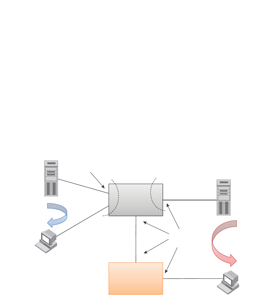
780 PowerConnect B-Series FCX Configuration Guide
53-1002266-01
IP multicast protocols and IGMP snooping on the same device
25
If there are two sources for a single group, where one source sends traffic into a VLAN with IGMP
snooping enabled, while the other source sends traffic to a PIM enabled Layer 3 interface, a client
for the group in the same VLAN as the first source will only receive traffic from that source. It will
not receive traffic from the second source connected to the Layer 3 interface. Similarly, if there is
another IP interface with a Layer 3 client or PIM/DVMRP neighbor that requests traffic for the same
group, it will only receive traffic from the second source and not the first.
Configuration example
Figure 124 and Figure 125 show an example IGMP snooping and PIM forwarding configuration.
FIGURE 124 Example 1: IGMP Snooping and PIM forwarding
Vlan A
Vlan B
(with VE)
“ip pim”
Interfaces
Client 1
Client 2
Server 1
Server 2
PIM
Forwarding
“multicast active” Vlan
I
GMP Snooping
PIM-DM
Neighbor
Device
(DUT)
Physical
port
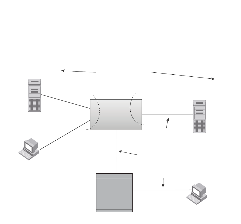
PowerConnect B-Series FCX Configuration Guide 781
53-1002266-01
IP multicast protocols and IGMP snooping on the same device 25
FIGURE 125 Example 2: IGMP Snooping and PIM Forwarding
CLI commands
The following are the CLI commands for the configuration example shown in Figure 124 and
Figure 125.
1. On the device, configure IGMP Snooping on VLAN 10.
PowerConnect(config)#vlan 10 by port
PowerConnect(config-vlan-10)#untagged e 1 to 4
Added untagged port(s) ethe 1 to 4 to port-vlan 10.
PowerConnect(config-vlan-10)#router-interface ve 10
PowerConnect(config-vlan-10)#ip multicast active
PowerConnect(config-vlan-10)#interface ve 10
PowerConnect(config-vif-10)#ip address 10.10.10.10/24
2. On the device, enable PIM routing between VLAN/VE 20 and Interface e 13.
PowerConnect(config)#vlan 20 by port
PowerConnect(config-vlan-20)#untagged e 21 to 24
Added untagged port(s) ethe 21 to 24 to port-vlan 20.
PowerConnect(config-vlan-20)#router-interface ve 20
PowerConnect(config-vlan-20)#exit
PowerConnect(config)#router pim
PowerConnect(config-pim-router)#exit
PowerConnect(config)#interface ve 20
PowerConnect(config-vif-20)#ip address 20.20.20.10/24
PowerConnect(config-vif-20)#ip pim
Device
(DUT)
Router
Vlan 20
(with VE 20)
e13
Client 10.10.10.1
for 230.1.1.1
Client 40.40.40.1
for 230.1.1.1
S
erver 10.10.10.100
Server 20.20.20.1
Both Sources for
Group 230.1.1.1
e4
e1
e21
Vlan 10
20.20.20.x/24
30.30.30.x/24
40.40.40.x/24
e3
e4

782 PowerConnect B-Series FCX Configuration Guide
53-1002266-01
IP multicast protocols and IGMP snooping on the same device
25
PowerConnect(config-vif-20)#exit
PowerConnect(config)#interface e 13
PowerConnect(config-if-e1000-13)#ip address 30.30.30.10/24
PowerConnect(config-if-e1000-13)#ip pim
3. Configure the neighboring device.
PowerConnect(config)#ip route 20.20.20.0 255.255.255.0 30.30.30.10
PowerConnect(config)#router pim
PowerConnect(config-pim-router)#exit
PowerConnect(config)#interface ethernet 3
PowerConnect(config-if-e1000-3)#ip address 30.30.30.20/24
PowerConnect(config-if-e1000-3)#ip pim
PowerConnect(config-if-e1000-3)#interface ethernet 4
PowerConnect(config-if-e1000-4)#ip address 40.40.40.20/24
PowerConnect(config-if-e1000-4)#ip pim

PowerConnect B-Series FCX Configuration Guide 783
53-1002266-01
Chapter
26
Configuring IP
Table 143 lists the individual Dell PowerConnect switches and the IP features they support.
TABLE 143 Supported IP features
Feature PowerConnect B-Series FCX
BootP/DHCP relay Yes
Specifying which IP address will be
included in a DHCP/BootP reply packet
Yes
DHCP Server Yes
DHCP Client-Based Auto-Configuration Yes
DHCP Client-Based Flash image
Auto-update
Yes
DHCP assist Yes
Equal Cost Multi Path (ECMP) load
sharing
Yes
IP helper Yes
Routes in hardware maximum:
PowerConnect B-Series FCX– Up to 16K
routes
Yes
Routing for directly connected IP subnets Yes
Virtual Interfaces:
•Up to 512 virtual interfaces
Yes
Address Resolution Protocol (ARP) Yes
Reverse Address Resolution Protocol
(RARP)
Yes
IP follow Yes
Proxy ARP Yes
Local proxy ARP Yes
Jumbo frames
•Up to 10,240 bytes, or
•Up to 10,232 bytes in an IronStack
Yes
IP MTU (individual port setting) Yes
Path MTU discovery Yes
ICMP Router Discovery Protocol (IRDP) Yes
Domain Name Server (DNS) resolver Yes

784 PowerConnect B-Series FCX Configuration Guide
53-1002266-01
Basic configuration
26
NOTE
The terms Layer 3 Switch and router are used interchangeably in this chapter and mean the same.
Basic configuration
IP is enabled by default. Basic configuration consists of adding IP addresses for Layer 3 Switches,
enabling a route exchange protocol, such as the Routing Information Protocol (RIP).
If you are configuring a Layer 3 Switch, refer to “Configuring IP addresses” on page 799 to add IP
addresses, then enable and configure the route exchange protocols, as described in other chapters
of this guide.
If you are configuring a Layer 2 Switch, refer to “Configuring the management IP address and
specifying the default gateway” on page 863 to add an IP address for management access through
the network and to specify the default gateway.
The rest of this chapter describes IP and how to configure it in more detail. Use the information in
this chapter if you need to change some of the IP parameters from their default values or you want
to view configuration information or statistics.
Overview
Layer 2 Switches and Layer 3 Switches support Internet Protocol version 4 (IPv4) and IPv6. IP
support on Layer 2 Switches consists of basic services to support management access and access
to a default gateway.
Full Layer 3 support
NOTE
Full Layer 3 images are supported on PowerConnect B-Series FCX devices only.
IP support on full Layer 3 Switches includes all of the following, in addition to a highly configurable
implementation of basic IP services including Address Resolution Protocol (ARP), ICMP Router
Discovery Protocol (IRDP), and Reverse ARP (RARP):
•Route exchange protocols:
-Routing Information Protocol (RIP)
-Open Shortest Path First (OSPF)
-Border Gateway Protocol version 4 (BGP4)
•Multicast protocols:
-Internet Group Membership Protocol (IGMP)
-Protocol Independent Multicast Dense (PIM-DM)
-Protocol Independent Multicast Sparse (PIM-SM)
•Router redundancy protocols:
-Virtual Router Redundancy Protocol Extended (VRRPE)
-Virtual Router Redundancy Protocol (VRRP)

PowerConnect B-Series FCX Configuration Guide 785
53-1002266-01
Overview 26
IP interfaces
NOTE
This section describes IPv4 addresses. For information about IPv6 addresses on all other
PowerConnect devices, refer to “IPv6 addressing” on page 198.
Layer 3 Switches and Layer 2 Switches allow you to configure IP addresses. On Layer 3 Switches, IP
addresses are associated with individual interfaces. On Layer 2 Switches, a single IP address
serves as the management access address for the entire device.
All Layer 3 Switches and Layer 2 Switches support configuration and display of IP addresses in
classical subnet format (for example: 192.168.1.1 255.255.255.0) and Classless Interdomain
Routing (CIDR) format (for example: 192.168.1.1/24). You can use either format when configuring
IP address information. IP addresses are displayed in classical subnet format by default but you
can change the display format to CIDR. Refer to “Changing the network mask display to prefix
format” on page 869.
Layer 3 Switches
Layer 3 Switches allow you to configure IP addresses on the following types of interfaces:
•Ethernet ports
•Virtual routing interfaces (used by VLANs to route among one another)
•Loopback interfaces
Each IP address on a Layer 3 Switch must be in a different subnet. You can have only one interface
that is in a given subnet. For example, you can configure IP addresses 192.168.1.1/24 and
192.168.2.1/24 on the same Layer 3 Switch, but you cannot configure 192.168.1.1/24 and
192.168.1.2/24 on the same Layer 3 Switch.
You can configure multiple IP addresses on the same interface.
The number of IP addresses you can configure on an individual interface depends on the Layer 3
Switch model. To display the maximum number of IP addresses and other system parameters you
can configure on a Layer 3 Switch, refer to “Displaying and modifying system parameter default
settings” on page 321.
You can use any of the IP addresses you configure on the Layer 3 Switch for Telnet, Web
management, or SNMP access.
Layer 2 Switches
You can configure an IP address on a Layer 2 Switch for management access to the Layer 2 Switch.
An IP address is required for Telnet access, Web management access, and SNMP access.
You also can specify the default gateway for forwarding traffic to other subnets.
IP packet flow through a Layer 3 Switch
Figure 126 shows how an IP packet moves through a Layer 3 Switch.
FIGURE 126 IP Packet flow through a Layer 3 Switch
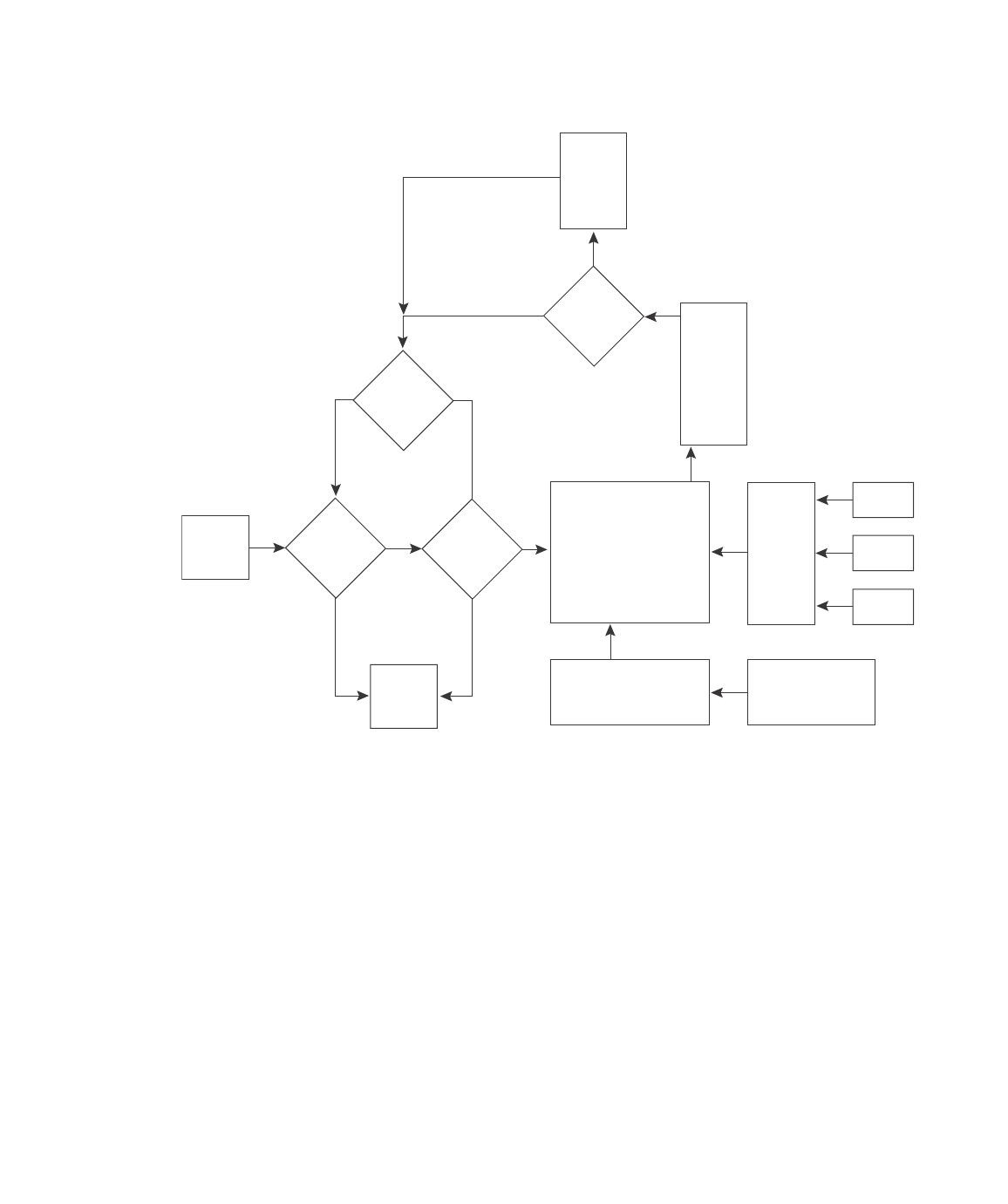
786 PowerConnect B-Series FCX Configuration Guide
53-1002266-01
Overview
26
Figure 126 shows the following packet flow:
1. When the Layer 3 Switch receives an IP packet, the Layer 3 Switch checks for filters on the
receiving interface.1 If a deny filter on the interface denies the packet, the Layer 3 Switch
discards the packet and performs no further processing, except generating a Syslog entry and
SNMP message, if logging is enabled for the filter.
2. If the packet is not denied at the incoming interface, the Layer 3 Switch looks in the session
table for an entry that has the same source IP address and TCP or UDP port as the packet. If
the session table contains a matching entry, the Layer 3 Switch immediately forwards the
packet, by addressing it to the destination IP address and TCP or UDP port listed in the session
table entry and sending the packet to a queue on the outgoing ports listed in the session table.
The Layer 3 Switch selects the queue based on the Quality of Service (QoS) level associated
with the session table entry.
3. If the session table does not contain an entry that matches the packet source address and TCP
or UDP port, the Layer 3 Switch looks in the IP forwarding cache for an entry that matches the
packet destination IP address. If the forwarding cache contains a matching entry, the Layer 3
Switch forwards the packet to the IP address in the entry. The Layer 3 Switch sends the packet
to a queue on the outgoing ports listed in the forwarding cache. The Layer 3 Switch selects the
queue based on the Quality of Service (QoS) level associated with the forwarding cache entry.
Incoming
Port
Outgoing
Port
Session
Table
N
Y
Fwding
Cache
N
Y
N
Y
Y
N
PBR
or
IP acc
policy
IP Route
Table
ARP
Cache
Load
Balancing
Algorithm
Mult.
Equal-
cost
Paths
Lowest
Admin.
Distance
Lowest
Metric
Static ARP
Table
RIP
OSPF
BGP4
1. The filter can be an Access Control List (ACL) or an IP access policy.

PowerConnect B-Series FCX Configuration Guide 787
53-1002266-01
Overview 26
4. If the IP forwarding cache does not have an entry for the packet, the Layer 3 Switch checks the
IP route table for a route to the packet destination. If the IP route table has a route, the Layer 3
Switch makes an entry in the session table or the forwarding cache, and sends the route to a
queue on the outgoing ports:
•If the running-config contains an IP access policy for the packet, the software makes an
entry in the session table. The Layer 3 Switch uses the new session table entry to forward
subsequent packets from the same source to the same destination.
•If the running-config does not contain an IP access policy for the packet, the software
creates a new entry in the forwarding cache. The Layer 3 Switch uses the new cache entry
to forward subsequent packets to the same destination.
The following sections describe the IP tables and caches:
•ARP cache and static ARP table
•IP route table
•IP forwarding cache
•Layer 4 session table
The software enables you to display these tables. You also can change the capacity of the tables on
an individual basis if needed by changing the memory allocation for the table.
ARP cache and static ARP table
The ARP cache contains entries that map IP addresses to MAC addresses. Generally, the entries
are for devices that are directly attached to the Layer 3 Switch.
An exception is an ARP entry for an interface-based static IP route that goes to a destination that is
one or more router hops away. For this type of entry, the MAC address is either the destination
device MAC address or the MAC address of the router interface that answered an ARP request on
behalf of the device, using proxy ARP.
ARP cache
The ARP cache can contain dynamic (learned) entries and static (user-configured) entries. The
software places a dynamic entry in the ARP cache when the Layer 3 Switch learns a device MAC
address from an ARP request or ARP reply from the device.
The software can learn an entry when the Layer 2 Switch or Layer 3 Switch receives an ARP request
from another IP forwarding device or an ARP reply. Here is an example of a dynamic entry:
Each entry contains the destination device IP address and MAC address.
Static ARP table
In addition to the ARP cache, Layer 3 Switches have a static ARP table. Entries in the static ARP
table are user-configured. You can add entries to the static ARP table regardless of whether or not
the device the entry is for is connected to the Layer 3 Switch.
NOTE
Layer 3 Switches have a static ARP table. Layer 2 Switches do not.
IP Address MAC Address Type Age Port
1 207.95.6.102 0800.5afc.ea21 Dynamic 0 6

788 PowerConnect B-Series FCX Configuration Guide
53-1002266-01
Overview
26
The software places an entry from the static ARP table into the ARP cache when the entry interface
comes up.
Here is an example of a static ARP entry.
Index IP Address MAC Address Port
1 207.95.6.111 0800.093b.d210 1/1
Each entry lists the information you specified when you created the entry.
To display ARP entries, refer to the following sections:
•“Displaying the ARP cache” on page 874 – Layer 3 Switch
•“Displaying the static ARP table” on page 876 – Layer 3 Switch only
•“Displaying ARP entries” on page 884 – Layer 2 Switch
To configure other ARP parameters, refer to the following sections:
•“Configuring ARP parameters” on page 810 – Layer 3 Switch only
To increase the size of the ARP cache and static ARP table, refer to the following:
•For dynamic entries, refer to the section “Displaying and modifying system parameter default
settings” on page 321. The <ip-arp> parameter controls the ARP cache size.
•Static entries, “Changing the maximum number of entries the static ARP table can hold” on
page 814 (Layer 3 Switches only). The <ip-static-arp> parameter controls the static ARP table
size.
IP route table
The IP route table contains paths to IP destinations.
NOTE
Layer 2 Switches do not have an IP route table. A Layer 2 Switch sends all packets addressed to
another subnet to the default gateway, which you specify when you configure the basic IP
information on the Layer 2 Switch.
The IP route table can receive the paths from the following sources:
•A directly-connected destination, which means there are no router hops to the destination
•A static IP route, which is a user-configured route
•A route learned through RIP
•A route learned through OSPF
•A route learned through BGP4
The IP route table contains the best path to a destination:
•When the software receives paths from more than one of the sources listed above, the
software compares the administrative distance of each path and selects the path with the
lowest administrative distance. The administrative distance is a protocol-independent value
from 1 through 255.
•When the software receives two or more best paths from the same source and the paths have
the same metric (cost), the software can load share traffic among the paths based on
destination host or network address (based on the configuration and the Layer 3 Switch
model).
Here is an example of an entry in the IP route table.

PowerConnect B-Series FCX Configuration Guide 789
53-1002266-01
Overview 26
Each IP route table entry contains the destination IP address and subnet mask and the IP address
of the next-hop router interface to the destination. Each entry also indicates the port attached to
the destination or the next-hop to the destination, the route IP metric (cost), and the type. The type
indicates how the IP route table received the route:
•To display the IP route table, refer to “Displaying the IP route table” on page 878 (Layer 3
Switch only).
•To configure a static IP route, refer to “Configuring static routes” on page 819 (Layer 3 Switch
only).
•To clear a route from the IP route table, refer to “Clearing IP routes” on page 880 (Layer 3
Switch only).
•To increase the size of the IP route table for learned and static routes, refer to the section
“Displaying and modifying system parameter default settings” on page 321:
-For learned routes, modify the <ip-route> parameter.
-For static routes, modify the <ip-static-route> parameter.
IP forwarding cache
The IP forwarding cache provides a fast-path mechanism for forwarding IP packets. The cache
contains entries for IP destinations. When a Layer 3 Switch has completed processing and
addressing for a packet and is ready to forward the packet, the device checks the IP forwarding
cache for an entry to the packet destination:
•If the cache contains an entry with the destination IP address, the device uses the information
in the entry to forward the packet out the ports listed in the entry. The destination IP address is
the address of the packet final destination. The port numbers are the ports through which the
destination can be reached.
•If the cache does not contain an entry and the traffic does not qualify for an entry in the
session table instead, the software can create an entry in the forwarding cache.
Each entry in the IP forwarding cache has an age timer. If the entry remains unused for ten
minutes, the software removes the entry. The age timer is not configurable.
Here is an example of an entry in the IP forwarding cache.
Each IP forwarding cache entry contains the IP address of the destination, and the IP address and
MAC address of the next-hop router interface to the destination. If the destination is actually an
interface configured on the Layer 3 Switch itself, as shown here, then next-hop information
indicates this. The port through which the destination is reached is also listed, as well as the VLAN
and Layer 4 QoS priority associated with the destination if applicable.
To display the IP forwarding cache, refer to “Displaying the forwarding cache” on page 877.
Destination NetMask Gateway Port Cost Type
1.1.0.0 255.255.0.0 99.1.1.2 1/1 2 R
IP Address Next Hop MAC Type Port Vlan Pri
1 192.168.1.11 DIRECT 0000.0000.0000 PU n/a 0

790 PowerConnect B-Series FCX Configuration Guide
53-1002266-01
Overview
26
NOTE
You cannot add static entries to the IP forwarding cache, although you can increase the number of
entries the cache can contain. Refer to the section “Displaying and modifying system parameter
default settings” on page 321.
Layer 4 session table
The Layer 4 session provides a fast path for forwarding packets. A session is an entry that contains
complete Layer 3 and Layer 4 information for a flow of traffic. Layer 3 information includes the
source and destination IP addresses. Layer 4 information includes the source and destination TCP
and UDP ports. For comparison, the IP forwarding cache contains the Layer 3 destination address
but does not contain the other source and destination address information of a Layer 4 session
table entry.
The Layer 2 Switch or Layer 3 Switch selects the session table instead of the IP forwarding table for
fast-path forwarding for the following features:
•Layer 4 Quality-of-Service (QoS) policies
•IP access policies
To increase the size of the session table, refer to the section “Displaying and modifying system
parameter default settings” on page 321. The ip-qos-session parameter controls the size of the
session table.
IP route exchange protocols
Layer 3 Switches support the following IP route exchange protocols:
•Routing Information Protocol (RIP)
•Open Shortest Path First (OSPF)
•Border Gateway Protocol version 4 (BGP4)
All these protocols provide routes to the IP route table. You can use one or more of these protocols,
in any combination. The protocols are disabled by default. For configuration information, refer to
the following:
•Chapter 28, “Configuring RIP (IPv4)”
•Chapter 29, “Configuring OSPF Version 2 (IPv4)”
•Chapter 30, “Configuring BGP4 (IPv4)”
IP multicast protocols
Layer 3 Switches also support the following Internet Group Membership Protocol (IGMP) based IP
multicast protocols:
•Protocol Independent Multicast – Dense mode (PIM-DM)
•Protocol Independent Multicast – Sparse mode (PIM-SM)
For configuration information, refer to Chapter 25, “Configuring IP Multicast Protocols”.

PowerConnect B-Series FCX Configuration Guide 791
53-1002266-01
Basic IP parameters and defaults – Layer 3 Switches 26
NOTE
Layer 2 Switches support IGMP and can forward IP multicast packets. Refer to Chapter 22,
“Configuring IP Multicast Traffic Reduction for PowerConnect B-Series FCX Switches”.
IP interface redundancy protocols
You can configure a Layer 3 Switch to back up an IP interface configured on another Layer 3
Switch. If the link for the backed up interface becomes unavailable, the other Layer 3 Switch can
continue service for the interface. This feature is especially useful for providing a backup to a
network default gateway.
Layer 3 Switches support the following IP interface redundancy protocols:
•Virtual Router Redundancy Protocol (VRRP) – A standard router redundancy protocol based on
RFC 2338. You can use VRRP to configure Layer 3 Switches and third-party routers to back up
IP interfaces on other Layer 3 Switches or third-party routers.
•Virtual Router Redundancy Protocol Extended (VRRPE) – A Dell extension to standard VRRP
that adds additional features and overcomes limitations in standard VRRP. You can use VRRPE
only on Layer 3 Switches.
For configuration information, refer to the Chapter 31, “Configuring VRRP and VRRPE”.
Access Control Lists and IP access policies
Layer 3 Switches provide two mechanisms for filtering IP traffic:
•Access Control Lists (ACLs)
•IP access policies
Both methods allow you to filter packets based on Layer 3 and Layer 4 source and destination
information.
ACLs also provide great flexibility by providing the input to various other filtering mechanisms such
as route maps, which are used by BGP4.
IP access policies allow you to configure QoS based on sessions (Layer 4 traffic flows).
Only one of these filtering mechanisms can be enabled on a Dell PowerConnect device at a time.
Dell PowerConnect devices can store forwarding information for both methods of filtering in the
session table.
For configuration information, Chapter 16, “Configuring Rule-Based IP Access Control Lists (ACLs)”
Basic IP parameters and defaults – Layer 3 Switches
IP is enabled by default. The following IP-based protocols are all disabled by default:
•Routing protocols:
-Routing Information Protocol (RIP) – refer to Chapter 28, “Configuring RIP (IPv4)”
-Open Shortest Path First (OSPF) – refer to Chapter 29, “Configuring OSPF Version 2 (IPv4)”
-Border Gateway Protocol version 4 (BGP4) – refer to Chapter 30, “Configuring BGP4
(IPv4)”

792 PowerConnect B-Series FCX Configuration Guide
53-1002266-01
Basic IP parameters and defaults – Layer 3 Switches
26
•Multicast protocols:
-Internet Group Membership Protocol (IGMP) – refer to “Changing global IP multicast
parameters” on page 729
-Protocol Independent Multicast Dense (PIM-DM) – refer to “PIM Dense” on page 733
-Protocol Independent Multicast Sparse (PIM-SM) – refer to “PIM Sparse” on page 742
•Router redundancy protocols:
-Virtual Router Redundancy Protocol Extended (VRRPE) – refer to Chapter 31, “Configuring
VRRP and VRRPE”
-Virtual Router Redundancy Protocol (VRRP) – refer to Chapter 31, “Configuring VRRP and
VRRPE”
The following tables list the Layer 3 Switch IP parameters, their default values, and where to find
configuration information.
NOTE
For information about parameters in other protocols based on IP, such as RIP, OSPF, and so on, refer
to the configuration chapters for those protocols.
When parameter changes take effect
Most IP parameters described in this chapter are dynamic. They take effect immediately, as soon
as you enter the CLI command or select the Web Management Interface option. You can verify that
a dynamic change has taken effect by displaying the running-config. To display the running-config,
enter the show running-config or write terminal command at any CLI prompt. (You cannot display
the running-config from the Web Management Interface.)
To save a configuration change permanently so that the change remains in effect following a
system reset or software reload, save the change to the startup-config file:
•To save configuration changes to the startup-config file, enter the write memory command
from the Privileged EXEC level of any configuration level of the CLI.
•To save the configuration changes using the Web Management Interface, select the Save link
at the bottom of the dialog. Select Yes when prompted to save the configuration change to the
startup-config file on the device flash memory. You also can access the dialog for saving
configuration changes by clicking on Command in the tree view, then clicking on Save to Flash.
Changes to memory allocation require you to reload the software after you save the changes to the
startup-config file. When reloading the software is required to complete a configuration change
described in this chapter, the procedure that describes the configuration change includes a step
for reloading the software.
IP global parameters – Layer 3 Switches
Table 144 lists the IP global parameters for Layer 3 Switches.

PowerConnect B-Series FCX Configuration Guide 793
53-1002266-01
Basic IP parameters and defaults – Layer 3 Switches 26
TABLE 144 IP global parameters – Layer 3 Switches
Parameter Description Default See page...
IP state The Internet Protocol, version 4 Enabled
NOTE: You cannot
disable IP.
n/a
IP address and
mask notation
Format for displaying an IP address and its network
mask information. You can enable one of the
following:
•Class-based format; example: 192.168.1.1
255.255.255.0
•Classless Interdomain Routing (CIDR) format;
example: 192.168.1.1/24
Class-based
NOTE: Changing this
parameter
affects the
display of IP
addresses, but
you can enter
addresses in
either format
regardless of the
display setting.
page 869
Router ID The value that routers use to identify themselves to
other routers when exchanging route information.
OSPF and BGP4 use router IDs to identify routers.
RIP does not use the router ID.
The IP address
configured on the
lowest-numbered
loopback interface.
If no loopback interface
is configured, then the
lowest-numbered IP
address configured on
the device.
page 809
Maximum
Transmission
Unit (MTU)
The maximum length an Ethernet packet can be
without being fragmented.
1500 bytes for Ethernet
II encapsulation
1492 bytes for SNAP
encapsulation
page 807
Address
Resolution
Protocol (ARP)
A standard IP mechanism that routers use to learn
the Media Access Control (MAC) address of a device
on the network. The router sends the IP address of a
device in the ARP request and receives the device
MAC address in an ARP reply.
Enabled page 810
ARP rate
limiting
Lets you specify a maximum number of ARP packets
the device will accept each second. If the device
receives more ARP packets than you specify, the
device drops additional ARP packets for the
remainder of the one-second interval.
Disabled page 811
ARP age The amount of time the device keeps a MAC address
learned through ARP in the device ARP cache. The
device resets the timer to zero each time the ARP
entry is refreshed and removes the entry if the timer
reaches the ARP age.
NOTE: You also can change the ARP age on an
individual interface basis. Refer to Table 145
on page 796.
Ten minutes page 812
Proxy ARP An IP mechanism a router can use to answer an ARP
request on behalf of a host, by replying with the
router own MAC address instead of the host.
Disabled page 812
Static ARP
entries
An ARP entry you place in the static ARP table. Static
entries do not age out.
No entries page 814

794 PowerConnect B-Series FCX Configuration Guide
53-1002266-01
Basic IP parameters and defaults – Layer 3 Switches
26
Time to Live
(TTL)
The maximum number of routers (hops) through
which a packet can pass before being discarded.
Each router decreases a packet TTL by 1 before
forwarding the packet. If decreasing the TTL causes
the TTL to be 0, the router drops the packet instead
of forwarding it.
64 hops page 815
Directed
broadcast
forwarding
A directed broadcast is a packet containing all ones
(or in some cases, all zeros) in the host portion of
the destination IP address. When a router forwards
such a broadcast, it sends a copy of the packet out
each of its enabled IP interfaces.
NOTE: You also can enable or disable this
parameter on an individual interface basis.
Refer to Table 145 on page 796.
Disabled page 815
Directed
broadcast
mode
The packet format the router treats as a directed
broadcast. The following formats can be directed
broadcast:
•All ones in the host portion of the packet
destination address.
•All zeroes in the host portion of the packet
destination address.
All ones
NOTE: If you enable
all-zeroes
directed
broadcasts,
all-ones directed
broadcasts
remain enabled.
page 817
Source-routed
packet
forwarding
A source-routed packet contains a list of IP
addresses through which the packet must pass to
reach its destination.
Enabled page 816
Internet Control
Message
Protocol (ICMP)
messages
The Layer 3 Switch can send the following types of
ICMP messages:
•Echo messages (ping messages)
•Destination Unreachable messages
Enabled page 817
ICMP Router
Discovery
Protocol (IRDP)
An IP protocol a router can use to advertise the IP
addresses of its router interfaces to directly
attached hosts. You can enable or disable the
protocol, and change the following protocol
parameters:
•Forwarding method (broadcast or multicast)
•Hold time
•Maximum advertisement interval
•Minimum advertisement interval
•Router preference level
NOTE: You also can enable or disable IRDP and
configure the parameters on an individual
interface basis. Refer to Table 145 on
page 796.
Disabled page 832
Reverse ARP
(RARP)
An IP mechanism a host can use to request an IP
address from a directly attached router when the
host boots.
Enabled page 834
TABLE 144 IP global parameters – Layer 3 Switches (Continued)
Parameter Description Default See page...

PowerConnect B-Series FCX Configuration Guide 795
53-1002266-01
Basic IP parameters and defaults – Layer 3 Switches 26
Static RARP
entries
An IP address you place in the RARP table for RARP
requests from hosts.
NOTE: You must enter the RARP entries manually.
The Layer 3 Switch does not have a
mechanism for learning or dynamically
generating RARP entries.
No entries page 836
Maximum
BootP relay
hops
The maximum number of hops away a BootP server
can be located from a router and still be used by the
router clients for network booting.
Four page 840
Domain name
for Domain
Name Server
(DNS) resolver
A domain name (example: brocade.router.com) you
can use in place of an IP address for certain
operations such as IP pings, trace routes, and Telnet
management connections to the router.
None configured page 803
DNS default
gateway
addresses
A list of gateways attached to the router through
which clients attached to the router can reach DNSs.
None configured page 803
IP load sharing A Dell feature that enables the router to balance
traffic to a specific destination across multiple
equal-cost paths.
IP load sharing uses a hashing algorithm based on
the source IP address, destination IP address, and
protocol field in the IP header.
NOTE: Load sharing is sometimes called Equal Cost
Multi Path (ECMP).
Enabled page 829
Maximum IP
load sharing
paths
The maximum number of equal-cost paths across
which the Layer 3 Switch is allowed to distribute
traffic.
Four page 832
Origination of
default routes
You can enable a router to originate default routes
for the following route exchange protocols, on an
individual protocol basis:
•RIP
•OSPF
•BGP4
Disabled page 915
page 957
page 1010
Default network
route
The router uses the default network route if the IP
route table does not contain a route to the
destination and also does not contain an explicit
default route (0.0.0.0 0.0.0.0 or 0.0.0.0/0).
None configured page 828
Static route An IP route you place in the IP route table. No entries page 819
Source
interface
The IP address the router uses as the source
address for Telnet, RADIUS, or TACACS/TACACS+
packets originated by the router. The router can
select the source address based on either of the
following:
•The lowest-numbered IP address on the
interface the packet is sent on.
•The lowest-numbered IP address on a specific
interface. The address is used as the source for
all packets of the specified type regardless of
interface the packet is sent on.
The lowest-numbered IP
address on the interface
the packet is sent on.
page 810
TABLE 144 IP global parameters – Layer 3 Switches (Continued)
Parameter Description Default See page...

796 PowerConnect B-Series FCX Configuration Guide
53-1002266-01
Basic IP parameters and defaults – Layer 3 Switches
26
IP interface parameters – Layer 3 Switches
Table 145 lists the interface-level IP parameters for Layer 3 Switches.
TABLE 145 IP interface parameters – Layer 3 Switches
Parameter Description Default See page...
IP state The Internet Protocol, version 4 Enabled
NOTE: You cannot
disable IP.
n/a
IP address A Layer 3 network interface address
NOTE: Layer 2 Switches have a single IP address
used for management access to the entire
device. Layer 3 Switches have separate IP
addresses on individual interfaces.
None configured1page 799
Encapsulation type The format of the packets in which the router
encapsulates IP datagrams. The encapsulation
format can be one of the following:
•Ethernet II
•SNAP
Ethernet II page 806
Maximum
Transmission Unit
(MTU)
The maximum length (number of bytes) of an
encapsulated IP datagram the router can forward.
1500 for Ethernet II
encapsulated packets
1492 for SNAP
encapsulated packets
page 808
ARP age Locally overrides the global setting. Refer to
Table 144 on page 793.
Ten minutes page 812
Metric A numeric cost the router adds to RIP routes
learned on the interface. This parameter applies
only to RIP routes.
1 (one) page 910
Directed broadcast
forwarding
Locally overrides the global setting. Refer to
Table 144 on page 793.
Disabled page 815
ICMP Router
Discovery Protocol
(IRDP)
Locally overrides the global IRDP settings. Refer to
Table 144 on page 793.
Disabled page 834
DHCP gateway
stamp
The router can assist DHCP/BootP Discovery
packets from one subnet to reach DHCP/BootP
servers on a different subnet by placing the IP
address of the router interface that receives the
request in the request packet Gateway field.
You can override the default and specify the IP
address to use for the Gateway field in the
packets.
NOTE: UDP broadcast forwarding for client
DHCP/BootP requests (bootps) must be
enabled (this is enabled by default) and
you must configure an IP helper address
(the server IP address or a directed
broadcast to the server subnet) on the port
connected to the client.
The lowest-numbered IP
address on the interface
that receives the
request
page 840
DHCP Client-Based
Auto-Configuration
Allows the switch to obtain IP addresses from a
DHCP host automatically, for either a specified
(leased) or infinite period of time.
Enabled page 854

PowerConnect B-Series FCX Configuration Guide 797
53-1002266-01
Basic IP parameters and defaults – Layer 2 Switches 26
Basic IP parameters and defaults – Layer 2 Switches
IP is enabled by default. The following tables list the Layer 2 Switch IP parameters, their default
values, and where to find configuration information.
NOTE
Layer 2 Switches also provide IP multicast forwarding, which is enabled by default.
IP global parameters – Layer 2 Switches
Table 146 lists the IP global parameters for Layer 2 Switches.
DHCP Server All PowerConnect devices can be configured to
function as DHCP servers.
Disabled page 841
UDP broadcast
forwarding
The router can forward UDP broadcast packets for
UDP applications such as BootP. By forwarding the
UDP broadcasts, the router enables clients on one
subnet to find servers attached to other subnets.
NOTE: To completely enable a client UDP
application request to find a server on
another subnet, you must configure an IP
helper address consisting of the server IP
address or the directed broadcast address
for the subnet that contains the server. See
the next row.
The router helps forward
broadcasts for the
following UDP
application protocols:
•bootps
•dns
•netbios-dgm
•netbios-ns
•tacacs
•tftp
•time
page 837
IP helper address The IP address of a UDP application server (such
as a BootP or DHCP server) or a directed broadcast
address. IP helper addresses allow the router to
forward requests for certain UDP applications from
a client on one subnet to a server on another
subnet.
None configured page 838
1. Some devices have a factory default, such as 209.157.22.154, used for troubleshooting during installation. For
Layer 3 Switches, the address is on module 1 port 1 (or 1/1).
TABLE 145 IP interface parameters – Layer 3 Switches (Continued)
Parameter Description Default See page...

798 PowerConnect B-Series FCX Configuration Guide
53-1002266-01
Basic IP parameters and defaults – Layer 2 Switches
26
TABLE 146 IP global parameters – Layer 2 Switches
Parameter Description Default See page...
IP address
and mask
notation
Format for displaying an IP address and its network
mask information. You can enable one of the
following:
•Class-based format; example: 192.168.1.1
255.255.255.0
•Classless Interdomain Routing (CIDR) format;
example: 192.168.1.1/24
Class-based
NOTE: Changing this
parameter affects
the display of IP
addresses, but you
can enter
addresses in either
format regardless
of the display
setting.
page 869
IP address A Layer 3 network interface address
NOTE: Layer 2 Switches have a single IP address
used for management access to the entire
device. Layer 3 Switches have separate IP
addresses on individual interfaces.
None configured1page 863
Default
gateway
The IP address of a locally attached router (or a router
attached to the Layer 2 Switch by bridges or other
Layer 2 Switches). The Layer 2 Switch and clients
attached to it use the default gateway to
communicate with devices on other subnets.
None configured page 863
Address
Resolution
Protocol (ARP)
A standard IP mechanism that networking devices
use to learn the Media Access Control (MAC) address
of another device on the network. The Layer 2 Switch
sends the IP address of a device in the ARP request
and receives the device MAC address in an ARP reply.
Enabled
NOTE: You cannot disable
ARP.
n/a
ARP age The amount of time the device keeps a MAC address
learned through ARP in the device ARP cache. The
device resets the timer to zero each time the ARP
entry is refreshed and removes the entry if the timer
reaches the ARP age.
Ten minutes
NOTE: You cannot change
the ARP age on
Layer 2 Switches.
n/a
Time to Live
(TTL)
The maximum number of routers (hops) through
which a packet can pass before being discarded.
Each router decreases a packet TTL by 1 before
forwarding the packet. If decreasing the TTL causes
the TTL to be 0, the router drops the packet instead of
forwarding it.
64 hops page 865
Domain name
for Domain
Name Server
(DNS) resolver
A domain name (example: brocade.router.com) you
can use in place of an IP address for certain
operations such as IP pings, trace routes, and Telnet
management connections to the router.
None configured page 863
DNS default
gateway
addresses
A list of gateways attached to the router through
which clients attached to the router can reach DNSs.
None configured page 863
Source
interface
The IP address the Layer 2 Switch uses as the source
address for Telnet, RADIUS, or TACACS/TACACS+
packets originated by the router. The Layer 2 Switch
uses its management IP address as the source
address for these packets.
The management IP
address of the Layer 2
Switch.
NOTE: This parameter is
not configurable
on Layer 2
Switches.
n/a

PowerConnect B-Series FCX Configuration Guide 799
53-1002266-01
Configuring IP parameters – Layer 3 Switches 26
Interface IP parameters – Layer 2 Switches
Table 147 lists the interface-level IP parameters for Layer 2 Switches.
Configuring IP parameters – Layer 3 Switches
The following sections describe how to configure IP parameters. Some parameters can be
configured globally while others can be configured on individual interfaces. Some parameters can
be configured globally and overridden for individual interfaces.
NOTE
This section describes how to configure IP parameters for Layer 3 Switches. For IP configuration
information for Layer 2 Switches, refer to “Configuring IP parameters – Layer 2 Switches” on
page 862.
Configuring IP addresses
You can configure an IP address on the following types of Layer 3 Switch interfaces:
•Ethernet port
DHCP gateway
stamp
The device can assist DHCP/BootP Discovery packets
from one subnet to reach DHCP/BootP servers on a
different subnet by placing the IP address of the
router interface that forwards the packet in the
packet Gateway field.
You can specify up to 32 gateway lists. A gateway list
contains up to eight gateway IP addresses. You
activate DHCP assistance by associating a gateway
list with a port.
When you configure multiple IP addresses in a
gateway list, the Layer 2 Switch inserts the addresses
into the DHCP Discovery packets in a round robin
fashion.
None configured page 868
DHCP
Client-Based
Auto-Configura
tion
Allows the switch to obtain IP addresses from a DHCP
host automatically, for either a specified (leased) or
infinite period of time.
Enabled page 854
1. Some devices have a factory default, such as 209.157.22.154, used for troubleshooting during installation. For
Layer 3 Switches, the address is on port 1 (or 1/1).
TABLE 147 Interface IP parameters – Layer 2 Switches
Parameter Description Default See page...
DHCP
gateway
stamp
You can configure a list of DHCP stamp addresses for a port.
When the port receives a DHCP/BootP Discovery packet from a
client, the port places the IP addresses in the gateway list into
the packet Gateway field.
None configured page 868
TABLE 146 IP global parameters – Layer 2 Switches (Continued)
Parameter Description Default See page...

800 PowerConnect B-Series FCX Configuration Guide
53-1002266-01
Configuring IP parameters – Layer 3 Switches
26
•Virtual routing interface (also called a Virtual Ethernet or “VE”)
•Loopback interface
By default, you can configure up to 24 IP addresses on each interface.
You can increase this amount to up to 128 IP subnet addresses per port by increasing the size of
the ip-subnet-port table.
Refer to the section “Displaying and modifying system parameter default settings” on page 321.
NOTE
Once you configure a virtual routing interface on a VLAN, you cannot configure Layer 3 interface
parameters on individual ports. Instead, you must configure the parameters on the virtual routing
interface itself.
Dell PowerConnect devices support both classical IP network masks (Class A, B, and C subnet
masks, and so on) and Classless Interdomain Routing (CIDR) network prefix masks:
•To enter a classical network mask, enter the mask in IP address format. For example, enter
“209.157.22.99 255.255.255.0” for an IP address with a Class-C subnet mask.
•To enter a prefix network mask, enter a forward slash ( / ) and the number of bits in the mask
immediately after the IP address. For example, enter “209.157.22.99/24” for an IP address
that has a network mask with 24 significant bits (ones).
By default, the CLI displays network masks in classical IP address format (example:
255.255.255.0). You can change the display to prefix format. Refer to “Changing the network mask
display to prefix format” on page 869.
Assigning an IP address to an Ethernet port
To assign an IP address to port 1/1, enter the following commands.
PowerConnect(config)# interface ethernet 1/1
PowerConnect(config-if-1/1)# ip address 192.45.6.1 255.255.255.0
You also can enter the IP address and mask in CIDR format, as follows.
PowerConnect(config-if-1/1)# ip address 192.45.6.1/24
Syntax: [no] ip address <ip-addr> <ip-mask> [ospf-ignore | ospf-passive | secondary]
or
Syntax: [no] ip address <ip-addr>/<mask-bits> [ospf-ignore | ospf-passive | secondary]
The ospf-ignore | ospf-passive parameters modify the Layer 3 Switch defaults for adjacency
formation and interface advertisement. Use one of these parameters if you are configuring multiple
IP subnet addresses on the interface but you want to prevent OSPF from running on some of the
subnets:
•ospf-passive – This option disables adjacency formation with OSPF neighbors. By default,
when OSPF is enabled on an interface, the software forms OSPF router adjacencies between
each primary IP address on the interface and the OSPF neighbor attached to the interface.
•ospf-ignore – This option disables OSPF adjacency formation and also disables advertisement
of the interface into OSPF. The subnet is completely ignored by OSPF.

PowerConnect B-Series FCX Configuration Guide 801
53-1002266-01
Configuring IP parameters – Layer 3 Switches 26
NOTE
The ospf-passive option disables adjacency formation but does not disable advertisement of the
interface into OSPF. To disable advertisement in addition to disabling adjacency formation, you must
use the ospf-ignore option.
Use the secondary parameter if you have already configured an IP address within the same subnet
on the interface.
NOTE
When you configure more than one address in the same subnet, all but the first address are
secondary addresses and do not form OSPF adjacencies.
NOTE
All physical IP interfaces on Layer 3 devices share the same MAC address. For this reason, if more
than one connection is made between two devices, one of which is a Layer 3 device, Dell
recommends the use of virtual interfaces. It is not recommended to connect two or more physical
IP interfaces between two routers.
Assigning an IP address to a loopback interface
Loopback interfaces are always up, regardless of the states of physical interfaces. They can add
stability to the network because they are not subject to route flap problems that can occur due to
unstable links between a Layer 3 Switch and other devices. You can configure up to eight loopback
interfaces on a Chassis Layer 3 Switch. You can configure up to four loopback interfaces on a
Compact Layer 3 Switch.
You can add up to 24 IP addresses to each loopback interface.
NOTE
If you configure the Layer 3 Switch to use a loopback interface to communicate with a BGP4
neighbor, you also must configure a loopback interface on the neighbor and configure the neighbor
to use that loopback interface to communicate with the Layer 3 Switch. Refer to “Adding a loopback
interface” on page 993.
To add a loopback interface, enter commands such as those shown in the following example.
PowerConnect(config-bgp-router)# exit
PowerConnect(config)# interface loopback 1
PowerConnect(config-lbif-1)# ip address 10.0.0.1/24
Syntax: interface loopback <num>
The <num> parameter specifies the virtual interface number. You can specify from 1 to the
maximum number of virtual interfaces supported on the device. To display the maximum number
of virtual interfaces supported on the device, enter the show default values command. The
maximum is listed in the System Parameters section, in the Current column of the virtual-interface
row.
Refer to the syntax description in “Assigning an IP address to an Ethernet port” on page 800.

802 PowerConnect B-Series FCX Configuration Guide
53-1002266-01
Configuring IP parameters – Layer 3 Switches
26
Assigning an IP address to a virtual interface
A virtual interface is a logical port associated with a Layer 3 Virtual LAN (VLAN) configured on a
Layer 3 Switch. You can configure routing parameters on the virtual interface to enable the Layer 3
Switch to route protocol traffic from one Layer 3 VLAN to the other, without using an external
router.1
You can configure IP routing interface parameters on a virtual interface. This section describes how
to configure an IP address on a virtual interface. Other sections in this chapter that describe how to
configure interface parameters also apply to virtual interfaces.
NOTE
The Layer 3 Switch uses the lowest MAC address on the device (the MAC address of port 1 or 1/1)
as the MAC address for all ports within all virtual interfaces you configure on the device.
To add a virtual interface to a VLAN and configure an IP address on the interface, enter commands
such as the following.
PowerConnect(config)# vlan 2 name IP-Subnet_1.1.2.0/24
PowerConnect(config-vlan-2)# untag ethernet 1 to 4
PowerConnect(config-vlan-2)# router-interface ve1
PowerConnect(config-vlan-2)# interface ve1
PowerConnect(config-vif-1)# ip address 1.1.2.1/24
The first two commands in this example create a Layer 3 protocol-based VLAN name
“IP-Subnet_1.1.2.0/24” and add a range of untagged ports to the VLAN. The router-interface
command creates virtual interface 1 as the routing interface for the VLAN.
Syntax: router-interface ve <num>
The <num> variable specifies the virtual interface number. You can enter a number from 1 through
4095.
When configuring virtual routing interfaces on a device, you can specify a number from 1 through
4095. However, the total number of virtual routing interfaces that are configured must not exceed
the system-max limit of 512. For more information on the number of virtual routing interfaces
supported, refer to “Allocating memory for more VLANs or virtual routing interfaces” on page 476.
The last two commands change to the interface configuration level for the virtual interface and
assign an IP address to the interface.
Syntax: interface ve <num>
Refer to the syntax description in “Assigning an IP address to an Ethernet port” on page 800.
Configuring IP follow on a virtual routing interface
IP Follow allows multiple virtual routing interfaces to share the same IP address. With this feature,
one virtual routing interface is configured with an IP address, while the other virtual routing
interfaces are configured to use that IP address, thus, they “follow” the virtual routing interface
that has the IP address. This feature is helpful in conserving IP address space.
1. The Dell feature that allows routing between VLANs within the same device, without the need for
external routers, is called Integrated Switch Routing (ISR).

PowerConnect B-Series FCX Configuration Guide 803
53-1002266-01
Configuring IP parameters – Layer 3 Switches 26
Configuration limitations and feature limitations
•When configuring IP Follow, the primary virtual routing interface should not have ACL or DoS
Protection configured. It is recommended that you create a dummy virtual routing interface as
the primary and use the IP-follow virtual routing interface for the network.
•Global Policy Based Routing is not supported when IP Follow is configured.
•IPv6 is not supported with ip-follow.
•PowerConnect devices support ip-follow with OSPF and VRRP protocols only.
Configuration syntax
Configure IP Follow by entering commands such as the following.
PowerConnect(config)# vlan 2 name IP-Subnet_1.1.2.0/24
PowerConnect(config-vlan-2)# untag ethernet 1 to 4
PowerConnect(config-vlan-2)# router-interface ve1
PowerConnect(config-vlan-2)# interface ve 1
PowerConnect(config-vif-1)# ip address 10.10.2.1/24
PowerConnect(config-vif-1)# interface ve 2
PowerConnect(config-vif-2)# ip follow ve 1
PowerConnect(config-vif-2)# interface ve 3
PowerConnect(config-vif-3)# ip follow ve 1
Syntax: [no] ip follow ve <number>
For <number> enter the ID of the virtual routing interface.
Use the no form of the command to disable the configuration.
Virtual routing interface 2 and 3 do not have their own IP subnet address, but are sharing the IP
address of virtual routing interface 1.
Deleting an IP address
To delete an IP address, enter a command such as the following.
PowerConnect(config-if-e1000-1)# no ip address 1.1.2.1
This command deletes IP address 1.1.2.1. You do not need to enter the subnet mask.
To delete all IP addresses from an interface, enter the following command.
PowerConnect(config-if-e1000-1)# no ip address *
Syntax: no ip address <ip-addr> | *
Configuring Domain Name Server (DNS) resolver
The DNS resolver is a feature in a Layer 2 Switch or Layer 3 Switch that sends and receives queries
to and from the DNS server on behalf of a client:
You can create a list of domain names that can be used to resolve host names. This list can have
more than one domain name. When a client performs a DNS query, all hosts within the domains in
the list can be recognized and queries can be sent to any domain on the list.
When a client performs a DNS query, all hosts within that domain can be recognized. After you
define a domain name, the Dell PowerConnect device automatically appends the appropriate
domain to a host and forwards it to the DNS servers for resolution.
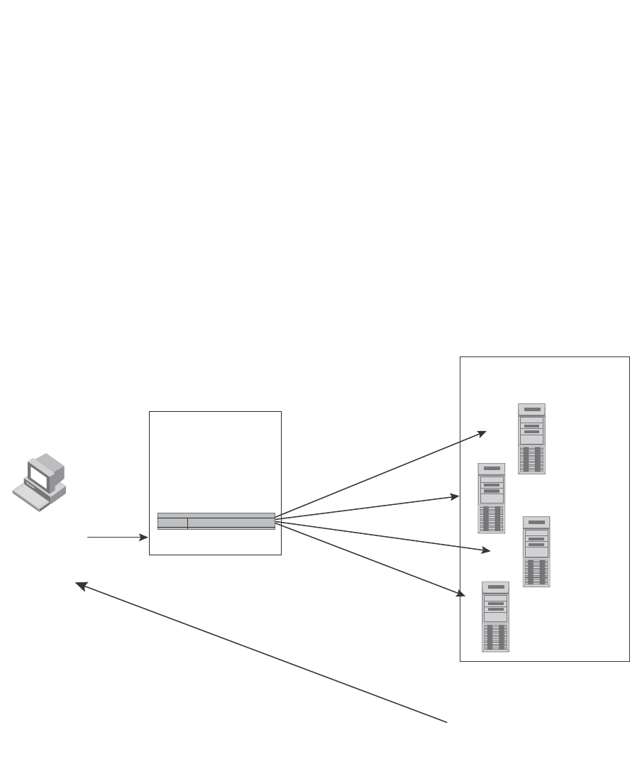
804 PowerConnect B-Series FCX Configuration Guide
53-1002266-01
Configuring IP parameters – Layer 3 Switches
26
For example, if the domain “ds.company.com” is defined on a Layer 2 Switch or Layer 3 Switch and
you want to initiate a ping to “mary”. You need to reference only the host name instead of the host
name and its domain name. For example, you could enter the following command to initiate the
ping.
U:> ping mary
The Layer 2 Switch or Layer 3 Switch qualifies the host name by appending a domain name. For
example, mary.ds1.company.com. This qualified name is sent to the DNS server for resolution. If
there are four DNS servers configured, it is sent to the first DNS server. If the host name is not
resolved, it is sent to the second DNS server. If a match is found, a response is sent back to the
client with the host IP address. If no match is found, an “unknown host” message is returned.
(Refer to Figure 127.)
FIGURE 127 DNS resolution with one domain name
Defining a domain name
To define a domain to resolve host names, enter a command such as the following.
PowerConnect(config)# ip dns domain-name ds.company.com
Syntax: [no] ip dns domain-name <domain-name>
Enter the domain name for <domain-name>.
1. Client sends a
command to ping
"mary"
Domain name
eng.company.com is
configured in the
device
DNS Servers with host
names and IP addresses
configured
DNS Server 1
DNS Server 2
DNS Server 3
DNS Server 4
2. Device sends
"mary.eng.company.com
to DNS servers for resolution.
4. If “mary.eng.company.com”
is in the DNS servers, its IP
address is returned. If it is not
found, a “unknown host”
message is returned.
3. Beginning with DNS Server 1,
DNS Servers are checked
in sequential order to see if
“mary.eng.company.com”
is configured in the server.
This server has
“mary.eng.company.com”

PowerConnect B-Series FCX Configuration Guide 805
53-1002266-01
Configuring IP parameters – Layer 3 Switches 26
Defining DNS server addresses
You can configure the Dell PowerConnect device to recognize up to four DNS servers. The first entry
serves as the primary default address. If a query to the primary address fails to be resolved after
three attempts, the next DNS address is queried (also up to three times). This process continues for
each defined DNS address until the query is resolved. The order in which the default DNS
addresses are polled is the same as the order in which you enter them.
To define DNS servers, enter a command such as the following.
PowerConnect(config)# ip dns server-address 209.157.22.199 205.96.7.15
208.95.7.25 201.98.7.15
Syntax: [no] ip dns server-address <ip-addr> [<ip-addr>] [<ip-addr>] [<ip-addr>]
In this example, the first IP address entered becomes the primary DNS address and all others are
secondary addresses. Because IP address 201.98.7.15 is the last address listed, it is also the last
address consulted to resolve a query.
Defining a domain list
If you want to use more than one domain name to resolve host names, you can create a list of
domain names. For example, enter the commands such as the following.
PowerConnect(config)# ip dns domain-list company.com
PowerConnect(config)# ip dns domain-list ds.company.com
PowerConnect(config)# ip dns domain-list hw_company.com
PowerConnect(config)# ip dns domain-list qa_company.com
PowerConnect(config)#
The domain names are tried in the order you enter them
Syntax: [no] ip dns domain-list <domain-name>
Using a DNS name to initiate a trace route
Suppose you want to trace the route from a Layer 3 Switch to a remote server identified as NYC02
on domain newyork.com. Because the NYC02@ds1.newyork.com domain is already defined on the
Layer 3 Switch, you need to enter only the host name, NYC02, as noted in the following example.
PowerConnect# traceroute nyc02
Syntax: traceroute <host-ip-addr> [maxttl <value>] [minttl <value>] [numeric] [timeout <value>]
[source-ip <ip addr>]
The only required parameter is the IP address of the host at the other end of the route.
After you enter the command, a message indicating that the DNS query is in process and the
current gateway address (IP address of the domain name server) being queried appear on the
screen.
Type Control-c to abort
Sending DNS Query to 209.157.22.199
Tracing Route to IP node 209.157.22.80
To ABORT Trace Route, Please use stop-traceroute command.
Traced route to target IP node 209.157.22.80:
IP Address Round Trip Time1 Round Trip Time2
207.95.6.30 93 msec 121 msec

806 PowerConnect B-Series FCX Configuration Guide
53-1002266-01
Configuring IP parameters – Layer 3 Switches
26
NOTE
In the previousexample, 209.157.22.199 is the IP address of the domain name server (default DNS
gateway address), and 209.157.22.80 represents the IP address of the NYC02 host.
Configuring packet parameters
You can configure the following packet parameters on Layer 3 Switches. These parameters control
how the Layer 3 Switch sends IP packets to other devices on an Ethernet network. The Layer 3
Switch always places IP packets into Ethernet packets to forward them on an Ethernet port.
•Encapsulation type – The format for the Layer 2 packets within which the Layer 3 Switch sends
IP packets.
•Maximum Transmission Unit (MTU) – The maximum length of IP packet that a Layer 2 packet
can contain. IP packets that are longer than the MTU are fragmented and sent in multiple
Layer 2 packets. You can change the MTU globally or an individual ports:
-Global MTU – The default MTU value depends on the encapsulation type on a port and is
1500 bytes for Ethernet II encapsulation and 1492 bytes for SNAP encapsulation.
-Port MTU – A port default MTU depends on the encapsulation type enabled on the port.
Changing the encapsulation type
The Layer 3 Switch encapsulates IP packets into Layer 2 packets, to send the IP packets on the
network. (A Layer 2 packet is also called a MAC layer packet or an Ethernet frame.) The source
address of a Layer 2 packet is the MAC address of the Layer 3 Switch interface sending the packet.
The destination address can be one of the following:
•The MAC address of the IP packet destination. In this case, the destination device is directly
connected to the Layer 3 Switch.
•The MAC address of the next-hop gateway toward the packet destination.
•An Ethernet broadcast address.
The entire IP packet, including the source and destination address and other control information
and the data, is placed in the data portion of the Layer 2 packet. Typically, an Ethernet network
uses one of two different formats of Layer 2 packet:
•Ethernet II
•Ethernet SNAP (also called IEEE 802.3)
The control portions of these packets differ slightly. All IP devices on an Ethernet network must use
the same format. Layer 3 Switches use Ethernet II by default. You can change the IP encapsulation
to Ethernet SNAP on individual ports if needed.
NOTE
All devices connected to the Layer 3 Switch port must use the same encapsulation type.
To change the IP encapsulation type on interface 5 to Ethernet SNAP, enter the following
commands.
PowerConnect(config)# interface ethernet 5
PowerConnect(config-if-e1000-5)# ip encapsulation snap
Syntax: ip encapsulation snap | ethernet_ii

PowerConnect B-Series FCX Configuration Guide 807
53-1002266-01
Configuring IP parameters – Layer 3 Switches 26
Changing the Maximum Transmission Unit (MTU)
The Maximum Transmission Unit (MTU) is the maximum length of IP packet that a Layer 2 packet
can contain. IP packets that are longer than the MTU are fragmented and sent in multiple Layer 2
packets. You can change the MTU globally or on individual ports.
The default MTU is 1500 bytes for Ethernet II packets and 1492 for Ethernet SNAP packets.
MTU enhancements
Dell PowerConnect devices contain the following enhancements to jumbo packet support:
•Hardware forwarding of Layer 3 jumbo packets – Layer 3 IP unicast jumbo packets received on
a port that supports the frame MTU size and forwarded to another port that also supports the
frame MTU size are forwarded in hardware. Previous releases support hardware forwarding of
Layer 2 jumbo frames only.
•ICMP unreachable message if a frame is too large to be forwarded – If a jumbo packet has the
Do not Fragment (DF) bit set, and the outbound interface does not support the packet MTU
size, the Dell PowerConnect device sends an ICMP unreachable message to the device that
sent the packet.
NOTE
These enhancements apply only to transit traffic forwarded through the Dell PowerConnect device.
Configuration considerations for increasing the MTU
•The MTU command is applicable to VEs and physical IP interfaces. It applies to traffic routed
between networks.
•You cannot use this command to set Layer 2 maximum frame sizes per interface. The global
jumbo command causes all interfaces to accept Layer 2 frames.
•When you increase the MTU size of a port, the increase uses system resources. Increase the
MTU size only on the ports that need it. For example, if you have one port connected to a server
that uses jumbo frames and two other ports connected to clients that can support the jumbo
frames, increase the MTU only on those three ports. Leave the MTU size on the other ports at
the default value (1500 bytes). Globally increase the MTU size only if needed.
Forwarding traffic to a port with a smaller MTU size
In order to forward traffic from a port with 1500 MTU configured to a port that has a smaller MTU
(for example, 750) size, you must apply the mtu-exceed forward global command. To remove this
setting, enter the mtu-exceed hard-drop command. MTU-exceed hard-drop is the default state of
the router.
Syntax:mtu-exceed [ forward | hard-drop ]
•forward - forwards a packet from a port with a larger MTU to a port with a smaller MTU
•hard-drop - resets to default, removes the forward function.
Globally changing the Maximum Transmission Unit
The Maximum Transmission Unit (MTU) is the maximum size an IP packet can be when
encapsulated in a Layer 2 packet. If an IP packet is larger than the MTU allowed by the Layer 2
packet, the Layer 3 Switch fragments the IP packet into multiple parts that will fit into the Layer 2
packets, and sends the parts of the fragmented IP packet separately, in different Layer 2 packets.
The device that receives the multiple fragments of the IP packet reassembles the fragments into
the original packet.

808 PowerConnect B-Series FCX Configuration Guide
53-1002266-01
Configuring IP parameters – Layer 3 Switches
26
You can increase the MTU size to accommodate jumbo packet sizes up to up to 10,232 bytes in an
IronStack. Devices that are not part of an IronStack support up to 10,240 bytes.
To globally enable jumbo support on all ports of a PowerConnect device, enter commands such as
the following.
PowerConnect(config)# jumbo
PowerConnect(config)# write memory
PowerConnect(config)# end
PowerConnect# reload
Syntax: [no] jumbo
NOTE
You must save the configuration change and then reload the software to enable jumbo support.
Changing the MTU on an individual port
By default, the maximum Ethernet MTU sizes are as follows:
•1500 bytes – The maximum for Ethernet II encapsulation
•1492 bytes – The maximum for SNAP encapsulation
When jumbo mode is enabled, the maximum Ethernet MTU sizes are as follows:
•10,240 bytes– The maximum for Ethernet II encapsulation
•10,240 bytes – The maximum for SNAP encapsulation
NOTE
If you set the MTU of a port to a value lower than the global MTU and from 576 through 1499, the
port fragments the packets. However, if the port MTU is exactly 1500 and this is larger than the
global MTU, the port drops the packets.
NOTE
You must save the configuration change and then reload the software to enable jumbo support.
To change the MTU for interface 1/5 to 1000, enter the following commands.
PowerConnect(config)# interface ethernet 1/5
PowerConnect(config-if-1/5)# ip mtu 1000
PowerConnect(config-if-1/5)# write memory
PowerConnect(config-if-1/5)# end
PowerConnect# reload
Syntax: [no] ip mtu <num>
The <num> parameter specifies the MTU. Ethernet II packets can hold IP packets from 576 through
1500 bytes long. If jumbo mode is enabled, Ethernet II packets can hold IP packets up to 10,240
bytes long. Ethernet SNAP packets can hold IP packets from 576 through 1492 bytes long. If jumbo
mode is enabled, SNAP packets can hold IP packets up to 10,240 bytes long. The default MTU for
Ethernet II packets is 1500. The default MTU for SNAP packets is 1492.

PowerConnect B-Series FCX Configuration Guide 809
53-1002266-01
Configuring IP parameters – Layer 3 Switches 26
Path MTU discovery (RFC 1191) support
When the Dell PowerConnect device receives an IP packet that has its Do not Fragment (DF) bit set,
and the packet size is greater than the MTU value of the outbound interface, then the Dell
PowerConnect device returns an ICMP Destination Unreachable message to the source of the
packet, with the Code indicating "fragmentation needed and DF set". The ICMP Destination
Unreachable message includes the MTU of the outbound interface. The source host can use this
information to help determine the maximum MTU of a path to a destination.
RFC 1191 is supported on all interfaces.
Changing the router ID
In most configurations, a Layer 3 Switch has multiple IP addresses, usually configured on different
interfaces. As a result, a Layer 3 Switch identity to other devices varies depending on the interface
to which the other device is attached. Some routing protocols, including Open Shortest Path First
(OSPF) and Border Gateway Protocol version 4 (BGP4), identify a Layer 3 Switch by just one of the
IP addresses configured on the Layer 3 Switch, regardless of the interfaces that connect the Layer
3 Switches. This IP address is the router ID.
NOTE
Routing Information Protocol (RIP) does not use the router ID.
NOTE
If you change the router ID, all current BGP4 sessions are cleared.
By default, the router ID on a Layer 3 Switch is one of the following:
•If the router has loopback interfaces, the default router ID is the IP address configured on the
lowest numbered loopback interface configured on the Layer 3 Switch. For example, if you
configure loopback interfaces 1, 2, and 3 as follows, the default router ID is 9.9.9.9/24:
-Loopback interface 1, 9.9.9.9/24
-Loopback interface 2, 4.4.4.4/24
-Loopback interface 3, 1.1.1.1/24
•If the device does not have any loopback interfaces, the default router ID is the lowest
numbered IP interface configured on the device.
If you prefer, you can explicitly set the router ID to any valid IP address. The IP address cannot be in
use on another device in the network.
NOTE
Layer 3 Switches use the same router ID for both OSPF and BGP4. If the router is already configured
for OSPF, you may want to use the router ID that is already in use on the router rather than set a new
one. To display the router ID, enter the show ip command at any CLI level or select the IP->General
links from the Configure tree in the Web Management Interface.
To change the router ID, enter a command such as the following.
PowerConnect(config)# ip router-id 209.157.22.26
Syntax: ip router-id <ip-addr>
The <ip-addr> can be any valid, unique IP address.

810 PowerConnect B-Series FCX Configuration Guide
53-1002266-01
Configuring IP parameters – Layer 3 Switches
26
NOTE
You can specify an IP address used for an interface on the Layer 3 Switch, but do not specify an IP
address in use by another device.
Configuring ARP parameters
Address Resolution Protocol (ARP) is a standard IP protocol that enables an IP Layer 3 Switch to
obtain the MAC address of another device interface when the Layer 3 Switch knows the IP address
of the interface. ARP is enabled by default and cannot be disabled.
NOTE
Layer 2 Switches also support ARP. The description in “How ARP works” also applies to ARP on Layer
2 Switches. However, the configuration options described later in this section apply only to Layer 3
Switches, not to Layer 2 Switches.
How ARP works
A Layer 3 Switch needs to know a destination MAC address when forwarding traffic, because the
Layer 3 Switch encapsulates the IP packet in a Layer 2 packet (MAC layer packet) and sends the
Layer 2 packet to a MAC interface on a device directly attached to the Layer 3 Switch. The device
can be the packet final destination or the next-hop router toward the destination.
The Layer 3 Switch encapsulates IP packets in Layer 2 packets regardless of whether the ultimate
destination is locally attached or is multiple router hops away. Since the Layer 3 Switch IP route
table and IP forwarding cache contain IP address information but not MAC address information, the
Layer 3 Switch cannot forward IP packets based solely on the information in the route table or
forwarding cache. The Layer 3 Switch needs to know the MAC address that corresponds with the IP
address of either the packet locally attached destination or the next-hop router that leads to the
destination.
For example, to forward a packet whose destination is multiple router hops away, the Layer 3
Switch must send the packet to the next-hop router toward its destination, or to a default route or
default network route if the IP route table does not contain a route to the packet destination. In
each case, the Layer 3 Switch must encapsulate the packet and address it to the MAC address of a
locally attached device, the next-hop router toward the IP packet destination.
To obtain the MAC address required for forwarding a datagram, the Layer 3 Switch does the
following:
•First, the Layer 3 Switch looks in the ARP cache (not the static ARP table) for an entry that lists
the MAC address for the IP address. The ARP cache maps IP addresses to MAC addresses. The
cache also lists the port attached to the device and, if the entry is dynamic, the age of the
entry. A dynamic ARP entry enters the cache when the Layer 3 Switch receives an ARP reply or
receives an ARP request (which contains the sender IP address and MAC address). A static
entry enters the ARP cache from the static ARP table (which is a separate table) when the
interface for the entry comes up.
To ensure the accuracy of the ARP cache, each dynamic entry has its own age timer. The timer
is reset to zero each time the Layer 3 Switch receives an ARP reply or ARP request containing
the IP address and MAC address of the entry. If a dynamic entry reaches its maximum
allowable age, the entry times out and the software removes the entry from the table. Static
entries do not age out and can be removed only by you.

PowerConnect B-Series FCX Configuration Guide 811
53-1002266-01
Configuring IP parameters – Layer 3 Switches 26
•If the ARP cache does not contain an entry for the destination IP address, the Layer 3 Switch
broadcasts an ARP request out all its IP interfaces. The ARP request contains the IP address of
the destination. If the device with the IP address is directly attached to the Layer 3 Switch, the
device sends an ARP response containing its MAC address. The response is a unicast packet
addressed directly to the Layer 3 Switch. The Layer 3 Switch places the information from the
ARP response into the ARP cache.
ARP requests contain the IP address and MAC address of the sender, so all devices that
receive the request learn the MAC address and IP address of the sender and can update their
own ARP caches accordingly.
NOTE
The ARP request broadcast is a MAC broadcast, which means the broadcast goes only to
devices that are directly attached to the Layer 3 Switch. A MAC broadcast is not routed to other
networks. However, some routers, including Layer 3 Switches, can be configured to reply to
ARP requests from one network on behalf of devices on another network. Refer to “Enabling
proxy ARP” on page 812.
NOTE
If the router receives an ARP request packet that it is unable to deliver to the final destination
because of the ARP timeout and no ARP response is received (the Layer 3 Switch knows of no route
to the destination address), the router sends an ICMP Host Unreachable message to the source.
Rate limiting ARP packets
You can limit the number of ARP packets the Dell PowerConnect device accepts during each
second. By default, the software does not limit the number of ARP packets the device can receive.
Since the device sends ARP packets to the CPU for processing, if a device in a busy network
receives a high number of ARP packets in a short period of time, some CPU processing might be
deferred while the CPU processes the ARP packets.
To prevent the CPU from becoming flooded by ARP packets in a busy network, you can restrict the
number of ARP packets the device will accept each second. When you configure an ARP rate limit,
the device accepts up to the maximum number of packets you specify, but drops additional ARP
packets received during the one-second interval. When a new one-second interval starts, the
counter restarts at zero, so the device again accepts up to the maximum number of ARP packets
you specified, but drops additional packets received within the interval.
To limit the number of ARP packets the device will accept each second, enter a command such as
the following at the global CONFIG level of the CLI.
PowerConnect(config)# rate-limit-arp 100
This command configures the device to accept up to 100 ARP packets each second. If the device
receives more than 100 ARP packets during a one-second interval, the device drops the additional
ARP packets during the remainder of that one-second interval.
Syntax: [no] rate-limit-arp <num>
The <num> parameter specifies the number of ARP packets and can be from 0 through 100. If you
specify 0, the device will not accept any ARP packets.

812 PowerConnect B-Series FCX Configuration Guide
53-1002266-01
Configuring IP parameters – Layer 3 Switches
26
NOTE
If you want to change a previously configured the ARP rate limiting policy, you must remove the
previously configured policy using the no rate-limit-arp <num> command before entering the new
policy.
Changing the ARP aging period
When the Layer 3 Switch places an entry in the ARP cache, the Layer 3 Switch also starts an aging
timer for the entry. The aging timer ensures that the ARP cache does not retain learned entries that
are no longer valid. An entry can become invalid when the device with the MAC address of the entry
is no longer on the network.
The ARP age affects dynamic (learned) entries only, not static entries. The default ARP age is ten
minutes. On Layer 3 Switches, you can change the ARP age to a value from 0 through 240 minutes.
You cannot change the ARP age on Layer 2 Switches. If you set the ARP age to zero, aging is
disabled and entries do not age out.
To globally change the ARP aging parameter to 20 minutes, enter the following command.
PowerConnect(config)# ip arp-age 20
Syntax: ip arp-age <num>
The <num> parameter specifies the number of minutes and can be from 0 through 240. The
default is 10. If you specify 0, aging is disabled.
To override the globally configured IP ARP age on an individual interface, enter a command such as
the following at the interface configuration level.
PowerConnect(config-if-e1000-1/1)# ip arp-age 30
Syntax: [no] ip arp-age <num>
The <num> parameter specifies the number of minutes and can be from 0 through 240. The
default is the globally configured value, which is 10 minutes by default. If you specify 0, aging is
disabled.
Enabling proxy ARP
Proxy ARP allows a Layer 3 Switch to answer ARP requests from devices on one network on behalf
of devices in another network. Since ARP requests are MAC-layer broadcasts, they reach only the
devices that are directly connected to the sender of the ARP request. Thus, ARP requests do not
cross routers.
For example, if Proxy ARP is enabled on a Layer 3 Switch connected to two subnets, 10.10.10.0/24
and 20.20.20.0/24, the Layer 3 Switch can respond to an ARP request from 10.10.10.69 for the
MAC address of the device with IP address 20.20.20.69. In standard ARP, a request from a device
in the 10.10.10.0/24 subnet cannot reach a device in the 20.20.20.0 subnet if the subnets are on
different network cables, and thus is not answered.
NOTE
An ARP request from one subnet can reach another subnet when both subnets are on the same
physical segment (Ethernet cable), because MAC-layer broadcasts reach all the devices on the
segment.

PowerConnect B-Series FCX Configuration Guide 813
53-1002266-01
Configuring IP parameters – Layer 3 Switches 26
Proxy ARP is disabled by default on Layer 3 Switches. This feature is not supported on Layer 2
Switches.
You can enable proxy ARP at the Interface level, as well as at the Global CONFIG level, of the CLI.
NOTE
Configuring proxy ARP at the Interface level overrides the global configuration.
Enabling proxy ARP globally
To enable IP proxy ARP on a global basis, enter the following command.
PowerConnect(config)# ip proxy-arp
To again disable IP proxy ARP on a global basis, enter the following command.
PowerConnect(config)# no ip proxy-arp
Syntax: [no] ip proxy-arp
Enabling IP ARP on an interface
NOTE
Configuring proxy ARP at the Interface level overrides the global configuration.
To enable IP proxy ARP on an interface, enter the following command.
PowerConnect(config)# interface ethernet 5
PowerConnect(config-if-e1000-5)# ip proxy-arp enable
To again disable IP proxy ARP on an interface, enter the following command.
PowerConnect(config)# interface ethernet 5
PowerConnect(config-if-e1000-5)# ip proxy-arp disable
Syntax: [no] ip proxy-arp enable | disable
Enabling local proxy ARP
Dell PowerConnect devices support Proxy Address Resolution Protocol (Proxy ARP), a feature that
enables router ports to respond to ARP requests for subnets it can reach. However, router ports will
not respond to ARP requests for IP addresses in the same subnet as the incoming ports, unless
Local Proxy ARP per IP interface is enabled. Local Proxy ARP enables router ports to reply to ARP
requests for IP addresses within the same subnet and to forward all traffic between hosts in the
subnet.
When Local Proxy ARP is enabled on a router port, the port will respond to ARP requests for IP
addresses within the same subnet, if it has ARP entries for the destination IP addresses in the ARP
cache. If it does not have ARP entries for the IP addresses, the port will attempt to resolve them by
broadcasting its own ARP requests.
Local Proxy ARP is disabled by default. To use Local Proxy ARP, Proxy ARP (ip proxy-arp command)
must be enabled globally on the Dell PowerConnect device. You can enter the CLI command to
enable Local Proxy ARP even though Proxy ARP is not enabled, however, the configuration will not
take effect until you enable Proxy ARP.
Use the show run command to view the ports on which Local Proxy ARP is enabled.
To enable Local Proxy ARP, enter commands such as the following.

814 PowerConnect B-Series FCX Configuration Guide
53-1002266-01
Configuring IP parameters – Layer 3 Switches
26
PowerConnect(config)# interface ethernet 4
PowerConnect(config-if-e1000-4)# ip local-proxy-arp
Syntax: [no] ip local-proxy-arp
Use the no form of the command to disable Local Proxy ARP.
Creating static ARP entries
Layer 3 Switches have a static ARP table, in addition to the regular ARP cache. The static ARP table
contains entries that you configure.
Static entries are useful in cases where you want to pre-configure an entry for a device that is not
connected to the Layer 3 Switch, or you want to prevent a particular entry from aging out. The
software removes a dynamic entry from the ARP cache if the ARP aging interval expires before the
entry is refreshed. Static entries do not age out, regardless of whether the Dell PowerConnect
device receives an ARP request from the device that has the entry address.
NOTE
You cannot create static ARP entries on a Layer 2 Switch.
The maximum number of static ARP entries you can configure depends on the software version
running on the device. Refer to “Changing the maximum number of entries the static ARP table can
hold” on page 814.
To display the ARP cache and static ARP table, refer to the following:
•To display the ARP table, refer to “Displaying the ARP cache” on page 874.
•To display the static ARP table, refer to “Displaying the static ARP table” on page 876.
To create a static ARP entry, enter a command such as the following.
PowerConnect(config)# arp 1 192.53.4.2 1245.7654.2348 ethernet 1/2
Syntax: arp <num> <ip-addr> <mac-addr> ethernet <port>
The <num> parameter specifies the entry number. You can specify a number from 1 up to the
maximum number of static entries allowed on the device.
The <ip-addr> parameter specifies the IP address of the device that has the MAC address of the
entry.
The <mac-addr> parameter specifies the MAC address of the entry.
The ethernet <port> command specifies the port number attached to the device that has the MAC
address of the entry. Specify the <port> variable in the following formats:
•PowerConnect B-Series FCX stackable switches – <stack-unit/slotnum/portnum>
Changing the maximum number of entries the static ARP table can hold
Table 148 on page 815 lists the default maximum and configurable maximum number of entries in
the static ARP table that are supported on a Layer 3 Switch. If you need to change the maximum
number of entries supported on a Layer 3 Switch, use the method described in this section.
NOTE
The basic procedure for changing the static ARP table size is the same as the procedure for changing
other configurable cache or table sizes. Refer to the section “Displaying and modifying system
parameter default settings” on page 321.

PowerConnect B-Series FCX Configuration Guide 815
53-1002266-01
Configuring IP parameters – Layer 3 Switches 26
To increase the maximum number of static ARP table entries you can configure on a Layer 3
Switch, enter commands such as the following at the global CONFIG level of the CLI.
PowerConnect(config)# system-max ip-static-arp 1000
PowerConnect(config)# write memory
PowerConnect(config)# end
PowerConnect# reload
NOTE
You must save the configuration to the startup-config file and reload the software after changing the
static ARP table size to place the change into effect.
Syntax: system-max ip-static-arp <num>
The <num> parameter indicates the maximum number of static ARP entries and can be within one
of the ranges shown in Table 148, depending on the software version running on the device.
Configuring forwarding parameters
The following configurable parameters control the forwarding behavior of Layer 3 Switches:
•Time-To-Live (TTL) threshold
•Forwarding of directed broadcasts
•Forwarding of source-routed packets
•Ones-based and zero-based broadcasts
All these parameters are global and thus affect all IP interfaces configured on the Layer 3 Switch.
To configure these parameters, use the procedures in the following sections.
Changing the TTL threshold
The TTL threshold prevents routing loops by specifying the maximum number of router hops an IP
packet originated by the Layer 3 Switch can travel through. Each device capable of forwarding IP
that receives the packet decrements (decreases) the packet TTL by one. If a device receives a
packet with a TTL of 1 and reduces the TTL to zero, the device drops the packet.
The default TTL is 64. You can change the TTL to a value from 1 through 255.
To modify the TTL threshold to 25, enter the following commands.
PowerConnect(config)# ip ttl 25
Syntax: ip ttl <1-255>
Enabling forwarding of directed broadcasts
A directed broadcast is an IP broadcast to all devices within a single directly-attached network or
subnet. A net-directed broadcast goes to all devices on a given network. A subnet-directed
broadcast goes to all devices within a given subnet.
TABLE 148 Static ARP entry support
Default maximum Configurable minimum Configurable maximum
PowerConnect B-Series FCX devices
512 512 6000

816 PowerConnect B-Series FCX Configuration Guide
53-1002266-01
Configuring IP parameters – Layer 3 Switches
26
NOTE
A less common type, the all-subnets broadcast, goes to all directly-attached subnets. Forwarding for
this broadcast type also is supported, but most networks use IP multicasting instead of all-subnet
broadcasting.
Forwarding for all types of IP directed broadcasts is disabled by default. You can enable forwarding
for all types if needed. You cannot enable forwarding for specific broadcast types.
To enable forwarding of IP directed broadcasts, enter the following command.
PowerConnect(config)# ip directed-broadcast
Syntax: [no] ip directed-broadcast
Dell software makes the forwarding decision based on the router's knowledge of the destination
network prefix. Routers cannot determine that a message is unicast or directed broadcast apart
from the destination network prefix. The decision to forward or not forward the message is by
definition only possible in the last hop router.
To disable the directed broadcasts, enter the following command in the CONFIG mode.
PowerConnect(config)# no ip directed-broadcast
To enable directed broadcasts on an individual interface instead of globally for all interfaces, enter
commands such as the following.
PowerConnect(config)# interface ethernet 1/1
PowerConnect(config-if-1/1)# ip directed-broadcast
Syntax: [no] ip directed-broadcast
Disabling forwarding of IP source-routed packets
A source-routed packet specifies the exact router path for the packet. The packet specifies the path
by listing the IP addresses of the router interfaces through which the packet must pass on its way to
the destination. The Layer 3 Switch supports both types of IP source routing:
•Strict source routing – requires the packet to pass through only the listed routers. If the Layer 3
Switch receives a strict source-routed packet but cannot reach the next hop interface specified
by the packet, the Layer 3 Switch discards the packet and sends an ICMP Source-Route-Failure
message to the sender.
NOTE
The Layer 3 Switch allows you to disable sending of the Source-Route-Failure messages. Refer
to “Disabling ICMP messages” on page 817.
•Loose source routing – requires that the packet pass through all of the listed routers but also
allows the packet to travel through other routers, which are not listed in the packet.
The Layer 3 Switch forwards both types of source-routed packets by default. To disable the feature,
use either of the following methods. You cannot enable or disable strict or loose source routing
separately.
To disable forwarding of IP source-routed packets, enter the following command.
PowerConnect(config)# no ip source-route
Syntax: [no] ip source-route
To re-enable forwarding of source-routed packets, enter the following command.

PowerConnect B-Series FCX Configuration Guide 817
53-1002266-01
Configuring IP parameters – Layer 3 Switches 26
PowerConnect(config)# ip source-route
Enabling support for zero-based IP subnet broadcasts
By default, the Layer 3 Switch treats IP packets with all ones in the host portion of the address as IP
broadcast packets. For example, the Layer 3 Switch treats IP packets with 209.157.22.255/24 as
the destination IP address as IP broadcast packets and forwards the packets to all IP hosts within
the 209.157.22.x subnet (except the host that sent the broadcast packet to the Layer 3 Switch).
Most IP hosts are configured to receive IP subnet broadcast packets with all ones in the host
portion of the address. However, some older IP hosts instead expect IP subnet broadcast packets
that have all zeros instead of all ones in the host portion of the address. To accommodate this type
of host, you can enable the Layer 3 Switch to treat IP packets with all zeros in the host portion of
the destination IP address as broadcast packets.
NOTE
When you enable the Layer 3 Switch for zero-based subnet broadcasts, the Layer 3 Switch still treats
IP packets with all ones the host portion as IP subnet broadcasts too. Thus, the Layer 3 Switch can
be configured to support all ones only (the default) or all ones and all zeroes.
NOTE
This feature applies only to IP subnet broadcasts, not to local network broadcasts. The local network
broadcast address is still expected to be all ones.
To enable the Layer 3 Switch for zero-based IP subnet broadcasts in addition to ones-based IP
subnet broadcasts, enter the following command.
PowerConnect(config)# ip broadcast-zero
PowerConnect(config)# write memory
PowerConnect(config)# end
PowerConnect# reload
NOTE
You must save the configuration and reload the software to place this configuration change into
effect.
Syntax: [no] ip broadcast-zero
Disabling ICMP messages
Dell PowerConnect devices are enabled to reply to ICMP echo messages and send ICMP
Destination Unreachable messages by default.
You can selectively disable the following types of Internet Control Message Protocol (ICMP)
messages:
•Echo messages (ping messages) – The Layer 3 Switch replies to IP pings from other IP devices.
•Destination Unreachable messages – If the Layer 3 Switch receives an IP packet that it cannot
deliver to its destination, the Layer 3 Switch discards the packet and sends a message back to
the device that sent the packet to the Layer 3 Switch. The message informs the device that the
destination cannot be reached by the Layer 3 Switch.

818 PowerConnect B-Series FCX Configuration Guide
53-1002266-01
Configuring IP parameters – Layer 3 Switches
26
Disabling replies to broadcast ping requests
By default, Dell PowerConnect devices are enabled to respond to broadcast ICMP echo packets,
which are ping requests.
To disable response to broadcast ICMP echo packets (ping requests), enter the following command.
PowerConnect(config)# no ip icmp echo broadcast-request
Syntax: [no] ip icmp echo broadcast-request
If you need to re-enable response to ping requests, enter the following command.
PowerConnect(config)# ip icmp echo broadcast-request
Disabling ICMP destination unreachable messages
By default, when a Dell PowerConnect device receives an IP packet that the device cannot deliver,
the device sends an ICMP Unreachable message back to the host that sent the packet. You can
selectively disable a Dell PowerConnect device response to the following types of ICMP
Unreachable messages:
•Administration – The packet was dropped by the Dell PowerConnect device due to a filter or
ACL configured on the device.
•Fragmentation-needed – The packet has the Do not Fragment bit set in the IP Flag field, but
the Dell PowerConnect device cannot forward the packet without fragmenting it.
•Host – The destination network or subnet of the packet is directly connected to the Dell
PowerConnect device, but the host specified in the destination IP address of the packet is not
on the network.
•Port – The destination host does not have the destination TCP or UDP port specified in the
packet. In this case, the host sends the ICMP Port Unreachable message to the Dell
PowerConnect device, which in turn sends the message to the host that sent the packet.
•Protocol – The TCP or UDP protocol on the destination host is not running. This message is
different from the Port Unreachable message, which indicates that the protocol is running on
the host but the requested protocol port is unavailable.
•Source-route-failure – The device received a source-routed packet but cannot locate the
next-hop IP address indicated in the packet Source-Route option.
You can disable the Dell PowerConnect device from sending these types of ICMP messages on an
individual basis. To do so, use the following CLI method.
NOTE
Disabling an ICMP Unreachable message type does not change the Dell PowerConnect device ability
to forward packets. Disabling ICMP Unreachable messages prevents the device from generating or
forwarding the Unreachable messages.
To disable all ICMP Unreachable messages, enter the following command.
PowerConnect(config)# no ip icmp unreachable
Syntax: [no] ip icmp unreachable [host | protocol | administration | fragmentation-needed | port
| source-route-fail]
•If you enter the command without specifying a message type (as in the example above), all
types of ICMP Unreachable messages listed above are disabled. If you want to disable only
specific types of ICMP Unreachable messages, you can specify the message type. To disable
more than one type of ICMP message, enter the no ip icmp unreachable command for each
messages type.

PowerConnect B-Series FCX Configuration Guide 819
53-1002266-01
Configuring IP parameters – Layer 3 Switches 26
•The administration parameter disables ICMP Unreachable (caused by Administration action)
messages.
•The fragmentation-needed parameter disables ICMP Fragmentation-Needed But Do
not-Fragment Bit Set messages.
•The host parameter disables ICMP Host Unreachable messages.
•The port parameter disables ICMP Port Unreachable messages.
•The protocol parameter disables ICMP Protocol Unreachable messages.
•The source-route-fail parameter disables ICMP Unreachable (caused by Source-Route-Failure)
messages.
To disable ICMP Host Unreachable messages but leave the other types of ICMP Unreachable
messages enabled, enter the following commands instead of the command shown above.
PowerConnect(config)# no ip icmp unreachable host
If you have disabled all ICMP Unreachable message types but you want to re-enable certain types,
for example ICMP Host Unreachable messages, you can do so by entering the following command.
PowerConnect(config)# ip icmp unreachable host
Disabling ICMP Redirect Messages
You can disable or re-enable ICMP redirect messages. By default, a Layer 3 Switch sends an ICMP
redirect message to the source of a misdirected packet in addition to forwarding the packet to the
appropriate router. You can disable ICMP redirect messages on a global basis or on an individual
port basis.
NOTE
The device forwards misdirected traffic to the appropriate router, even if you disable the redirect
messages.
To disable ICMP redirect messages globally, enter the following command at the global CONFIG
level of the CLI:
PowerConnect(config)# no ip icmp redirect
Syntax: [no] ip icmp redirects
To disable ICMP redirect messages on a specific interface, enter the following command at the
configuration level for the interface:
PowerConnect(config)# interface ethernet 3/11
PowerConnect(config-if-e1000-3/11)# no ip redirect
Syntax: [no] ip redirect
Configuring static routes
The IP route table can receive routes from the following sources:
•Directly-connected networks – When you add an IP interface, the Layer 3 Switch automatically
creates a route for the network the interface is in.

820 PowerConnect B-Series FCX Configuration Guide
53-1002266-01
Configuring IP parameters – Layer 3 Switches
26
•RIP – If RIP is enabled, the Layer 3 Switch can learn about routes from the advertisements
other RIP routers send to the Layer 3 Switch. If the route has a lower administrative distance
than any other routes from different sources to the same destination, the Layer 3 Switch
places the route in the IP route table.
•OSPF – Refer to RIP, but substitute “OSPF” for “RIP”.
•BGP4 – Refer to RIP, but substitute “BGP4” for “RIP”.
•Default network route – A statically configured default route that the Layer 3 Switch uses if
other default routes to the destination are not available. Refer to “Configuring a default
network route” on page 828.
•Statically configured route – You can add routes directly to the route table. When you add a
route to the IP route table, you are creating a static IP route. This section describes how to add
static routes to the IP route table.
Static route types
You can configure the following types of static IP routes:
•Standard – the static route consists of the destination network address and network mask,
and the IP address of the next-hop gateway. You can configure multiple standard static routes
with the same metric for load sharing or with different metrics to provide a primary route and
backup routes.
•Interface-based – the static route consists of the destination network address and network
mask, and the Layer 3 Switch interface through which you want the Layer 3 Switch to send
traffic for the route. Typically, this type of static route is for directly attached destination
networks.
•Null – the static route consists of the destination network address and network mask, and the
“null0” parameter. Typically, the null route is configured as a backup route for discarding traffic
if the primary route is unavailable.
Static IP route parameters
When you configure a static IP route, you must specify the following parameters:
•The IP address and network mask for the route destination network.
•The route path, which can be one of the following:
-The IP address of a next-hop gateway
-An Ethernet port
-A virtual interface (a routing interface used by VLANs for routing Layer 3 protocol traffic
among one another)
-A “null” interface. The Layer 3 Switch drops traffic forwarded to the null interface.
You also can specify the following optional parameters:
•The metric for the route – The value the Layer 3 Switch uses when comparing this route to
other routes in the IP route table to the same destination. The metric applies only to routes that
the Layer 3 Switch has already placed in the IP route table. The default metric for static IP
routes is 1.

PowerConnect B-Series FCX Configuration Guide 821
53-1002266-01
Configuring IP parameters – Layer 3 Switches 26
•The administrative distance for the route – The value that the Layer 3 Switch uses to compare
this route with routes from other route sources to the same destination before placing a route
in the IP route table. This parameter does not apply to routes that are already in the IP route
table. The default administrative distance for static IP routes is 1.
The default metric and administrative distance values ensure that the Layer 3 Switch always
prefers static IP routes over routes from other sources to the same destination.
Multiple static routes to the same destination provide load sharing and
redundancy
You can add multiple static routes for the same destination network to provide one or more of the
following benefits:
•IP load balancing – When you add multiple IP static routes for the same destination to different
next-hop gateways, and the routes each have the same metric and administrative distance, the
Layer 3 Switch can load balance traffic to the routes’ destination. For information about IP load
balancing, refer to “Configuring IP load sharing” on page 829.
•Path redundancy – When you add multiple static IP routes for the same destination, but give
the routes different metrics or administrative distances, the Layer 3 Switch uses the route with
the lowest administrative distance by default, but uses another route to the same destination if
the first route becomes unavailable.
Refer to the following sections for examples and configuration information:
•“Configuring load balancing and redundancy using multiple static routes to the same
destination” on page 824
•“Configuring standard static IP routes and interface or null static routes to the same
destination” on page 825
Static route states follow port states
IP static routes remain in the IP route table only so long as the port or virtual interface used by the
route is available. If the port or virtual routing interface becomes unavailable, the software removes
the static route from the IP route table. If the port or virtual routing interface becomes available
again later, the software adds the route back to the route table.
This feature allows the Layer 3 Switch to adjust to changes in network topology. The Layer 3 Switch
does not continue trying to use routes on unavailable paths but instead uses routes only when their
paths are available.
Figure 128 shows an example of a network containing a static route. The static route is configured
on Switch A, as shown in the CLI example following the figure.
FIGURE 128 Example of a static route
The following command configures a static route to 207.95.7.0, using 207.95.6.157 as the
next-hop gateway.
207.95.7.69/24
207.95.7.7/24
Switch A Switch B
207.95.6.188/24 207.95.6.157/24
e 1/2

822 PowerConnect B-Series FCX Configuration Guide
53-1002266-01
Configuring IP parameters – Layer 3 Switches
26
PowerConnect(config)# ip route 207.95.7.0/24 207.95.6.157
When you configure a static IP route, you specify the destination address for the route and the
next-hop gateway or Layer 3 Switch interface through which the Layer 3 Switch can reach the route.
The Layer 3 Switch adds the route to the IP route table. In this case, Switch A knows that
207.95.6.157 is reachable through port 1/2, and also assumes that local interfaces within that
subnet are on the same port. Switch A deduces that IP interface 207.95.7.188 is also on port 1/2.
The software automatically removes a static IP route from the IP route table if the port used by that
route becomes unavailable. When the port becomes available again, the software automatically
re-adds the route to the IP route table.
Configuring a static IP route
To configure an IP static route with a destination address of 192.0.0.0 255.0.0.0 and a next-hop
router IP address of 195.1.1.1, enter the following commands.
PowerConnect(config)# ip route 192.0.0.0 255.0.0.0 195.1.1.1
To configure a static IP route with an Ethernet port instead of a next-hop address, enter a command
such as the following.
PowerConnect(config)# ip route 192.128.2.69 255.255.255.0 ethernet 4/1
The command in the previous example configures a static IP route for destination network
192.128.2.69/24. Since an Ethernet port is specified instead of a gateway IP address as the next
hop, the Layer 3 Switch always forwards traffic for the 192.128.2.69/24 network to port 4/1. The
command in the following example configures an IP static route that uses virtual interface 3 as its
next hop.
PowerConnect(config)# ip route 192.128.2.71 255.255.255.0 ve 3
The command in the following example configures an IP static route that uses port 2/2 as its next
hop.
PowerConnect(config)# ip route 192.128.2.73 255.255.255.0 ethernet 2/2
Syntax: ip route <dest-ip-addr> <dest-mask>
<next-hop-ip-addr> |
ethernet [<slotnum>/]<portnum> | ve <num>
[<metric>] [distance <num>]
or
Syntax: ip route <dest-ip-addr>/<mask-bits>
<next-hop-ip-addr> |
ethernet [<slotnum>/]<portnum> | ve <num>
[<metric>] [distance <num>]
The <dest-ip-addr> is the route destination. The <dest-mask> is the network mask for the route
destination IP address. Alternatively, you can specify the network mask information by entering a
forward slash followed by the number of bits in the network mask. For example, you can enter
192.0.0.0 255.255.255.0 as 192.0.0.0/.24.
The <next-hop-ip-addr> is the IP address of the next-hop router (gateway) for the route.

PowerConnect B-Series FCX Configuration Guide 823
53-1002266-01
Configuring IP parameters – Layer 3 Switches 26
If you do not want to specify a next-hop IP address, you can instead specify a port or interface
number on the Layer 3 Switch. The <num> parameter is a virtual interface number. If you instead
specify an Ethernet port, the <portnum> is the port number (including the slot number, if you are
configuring a Chassis device). In this case, the Layer 3 Switch forwards packets destined for the
static route destination network to the specified interface. Conceptually, this feature makes the
destination network like a directly connected network, associated with a specific Layer 3 Switch
interface.
NOTE
The port or virtual interface you use for the static route next hop must have at least one IP address
configured on it. The address does not need to be in the same subnet as the destination network.
The <metric> parameter can be a number from 1 through 16. The default is 1.
NOTE
If you specify 16, RIP considers the metric to be infinite and thus also considers the route to be
unreachable.
The distance <num> parameter specifies the administrative distance of the route. When
comparing otherwise equal routes to a destination, the Layer 3 Switch prefers lower administrative
distances over higher ones, so make sure you use a low value for your default route. The default is
1.
NOTE
The Layer 3 Switch will replace the static route if the it receives a route with a lower administrative
distance. Refer to “Changing administrative distances” on page 1014 for a list of the default
administrative distances for all types of routes.
NOTE
You can also assign the default router as the destination by entering 0.0.0.0 0.0.0.0 xxx.xxx.xxx.xxx.
Configuring a “Null” route
You can configure the Layer 3 Switch to drop IP packets to a specific network or host address by
configuring a “null” (sometimes called “null0”) static route for the address. When the Layer 3
Switch receives a packet destined for the address, the Layer 3 Switch drops the packet instead of
forwarding it.
To configure a null static route, use the following CLI method.
To configure a null static route to drop packets destined for network 209.157.22.x, enter the
following commands.
PowerConnect(config)# ip route 209.157.22.0 255.255.255.0 null0
PowerConnect(config)# write memory
Syntax: ip route <ip-addr> <ip-mask> null0 [<metric>] [distance <num>]
or
Syntax: ip route <ip-addr>/<mask-bits> null0 [<metric>] [distance <num>]
To display the maximum value for your device, enter the show default values command. The
maximum number of static IP routes the system can hold is listed in the ip-static-route row in the
System Parameters section of the display. To change the maximum value, use the system-max
ip-static-route <num> command at the global CONFIG level.

824 PowerConnect B-Series FCX Configuration Guide
53-1002266-01
Configuring IP parameters – Layer 3 Switches
26
The <ip-addr> parameter specifies the network or host address. The Layer 3 Switch will drop
packets that contain this address in the destination field instead of forwarding them.
The <ip-mask> parameter specifies the network mask. Ones are significant bits and zeros allow
any value. For example, the mask 255.255.255.0 matches on all hosts within the Class C subnet
address specified by <ip-addr>. Alternatively, you can specify the number of bits in the network
mask. For example, you can enter 209.157.22.0/24 instead of 209.157.22.0 255.255.255.0.
The null0 parameter indicates that this is a null route. You must specify this parameter to make this
a null route.
The <metric> parameter adds a cost to the route. You can specify from 1 through 16. The default is
1.
The distance <num> parameter configures the administrative distance for the route. You can
specify a value from 1 through 255. The default is 1. The value 255 makes the route unusable.
NOTE
The last two parameters are optional and do not affect the null route, unless you configure the
administrative distance to be 255. In this case, the route is not used and the traffic might be
forwarded instead of dropped.
Configuring load balancing and redundancy using multiple static routes to the
same destination
You can configure multiple static IP routes to the same destination, for the following benefits:
•IP load sharing – If you configure more than one static route to the same destination, and the
routes have different next-hop gateways but have the same metrics, the Layer 3 Switch load
balances among the routes using basic round-robin. For example, if you configure two static
routes with the same metrics but to different gateways, the Layer 3 Switch alternates between
the two routes. For information about IP load balancing, refer to “Configuring IP load sharing”
on page 829.
•Backup Routes – If you configure multiple static IP routes to the same destination, but give the
routes different next-hop gateways and different metrics, the Layer 3 Switch will always use the
route with the lowest metric. If this route becomes unavailable, the Layer 3 Switch will fail over
to the static route with the next-lowest metric, and so on.
NOTE
You also can bias the Layer 3 Switch to select one of the routes by configuring them with different
administrative distances. However, make sure you do not give a static route a higher administrative
distance than other types of routes, unless you want those other types to be preferred over the static
route. For a list of the default administrative distances, refer to “Changing administrative distances”
on page 1014.
The steps for configuring the static routes are the same as described in the previous section. The
following sections provide examples.
To configure multiple static IP routes, enter commands such as the following.
PowerConnect(config)# ip route 192.128.2.69 255.255.255.0 209.157.22.1
PowerConnect(config)# ip route 192.128.2.69 255.255.255.0 192.111.10.1

PowerConnect B-Series FCX Configuration Guide 825
53-1002266-01
Configuring IP parameters – Layer 3 Switches 26
The commands in the previous example configure two static IP routes. The routes go to different
next-hop gateways but have the same metrics. These commands use the default metric value (1),
so the metric is not specified. These static routes are used for load sharing among the next-hop
gateways.
The following commands configure static IP routes to the same destination, but with different
metrics. The route with the lowest metric is used by default. The other routes are backups in case
the first route becomes unavailable. The Layer 3 Switch uses the route with the lowest metric if the
route is available.
PowerConnect(config)# ip route 192.128.2.69 255.255.255.0 209.157.22.1
PowerConnect(config)# ip route 192.128.2.69 255.255.255.0 192.111.10.1 2
PowerConnect(config)# ip route 192.128.2.69 255.255.255.0 201.1.1.1 3
In this example, each static route has a different metric. The metric is not specified for the first
route, so the default (1) is used. A metric is specified for the second and third static IP routes. The
second route has a metric of two and the third route has a metric of 3. Thus, the second route is
used only of the first route (which has a metric of 1) becomes unavailable. Likewise, the third route
is used only if the first and second routes (which have lower metrics) are both unavailable.
For complete syntax information, refer to “Configuring a static IP route” on page 822.
Configuring standard static IP routes and interface or null static routes to the
same destination
You can configure a null0 or interface-based static route to a destination and also configure a
normal static route to the same destination, so long as the route metrics are different.
When the Layer 3 Switch has multiple routes to the same destination, the Layer 3 Switch always
prefers the route with the lowest metric. Generally, when you configure a static route to a
destination network, you assign the route a low metric so that the Layer 3 Switch prefers the static
route over other routes to the destination.
This feature is especially useful for the following configurations. These are not the only allowed
configurations but they are typical uses of this enhancement:
•When you want to ensure that if a given destination network is unavailable, the Layer 3 Switch
drops (forwards to the null interface) traffic for that network instead of using alternate paths to
route the traffic. In this case, assign the normal static route to the destination network a lower
metric than the null route.
•When you want to use a specific interface by default to route traffic to a given destination
network, but want to allow the Layer 3 Switch to use other interfaces to reach the destination
network if the path that uses the default interface becomes unavailable. In this case, give the
interface route a lower metric than the normal static route.
NOTE
You cannot add a null or interface-based static route to a network if there is already a static route of
any type with the same metric you specify for the null or interface-based route.
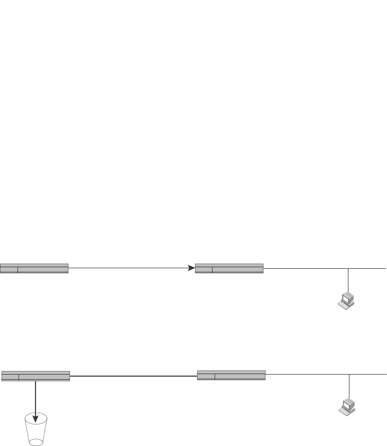
826 PowerConnect B-Series FCX Configuration Guide
53-1002266-01
Configuring IP parameters – Layer 3 Switches
26
Figure 129 shows an example of two static routes configured for the same destination network. In
this example, one of the routes is a standard static route and has a metric of 1. The other static
route is a null route and has a higher metric than the standard static route. The Layer 3 Switch
always prefers the static route with the lower metric. In this example, the Layer 3 Switch always
uses the standard static route for traffic to destination network 192.168.7.0/24, unless that route
becomes unavailable, in which case the Layer 3 Switch sends traffic to the null route instead.
FIGURE 129 Standard and null static routes to the same destination network
Figure 130 shows another example of two static routes. In this example, a standard static route
and an interface-based static route are configured for destination network 192.168.6.0/24. The
interface-based static route has a lower metric than the standard static route. As a result, the Layer
3 Switch always prefers the interface-based route when the route is available. However, if the
interface-based route becomes unavailable, the Layer 3 Switch still forwards the traffic toward the
destination using an alternate route through gateway 192.168.8.11/24.
X
Two static routes to 192.168.7.0/24:
--Standard static route through
gateway 192.168.6.157, with metric 1
--Null route, with metric 2
Switch A
Switch A
Switch B
Switch B
192.168.6.188/24 192.168.6.157/24 192.168.7.7/24
192.168.7.69/24
When standard static route
is good, Switch A uses that
route.
192.168.6.188/24 192.168.6.157/24 192.168.7.7/24
192.168.7.69/24
If standard static route is
unavailable, Switch A uses
the null route (in effect dropping
instead of forwarding the packets).
Null
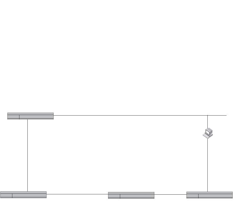
PowerConnect B-Series FCX Configuration Guide 827
53-1002266-01
Configuring IP parameters – Layer 3 Switches 26
FIGURE 130 Standard and interface routes to the same destination network
To configure a standard static IP route and a null route to the same network as shown in Figure 129
on page 826, enter commands such as the following.
PowerConnect(config)# ip route 192.168.7.0/24 192.168.6.157/24 1
PowerConnect(config)# ip route 192.168.7.0/24 null0 3
The first command configures a standard static route, which includes specification of the next-hop
gateway. The command also gives the standard static route a metric of 1, which causes the Layer 3
Switch to always prefer this route when the route is available.
The second command configures another static route for the same destination network, but the
second route is a null route. The metric for the null route is 3, which is higher than the metric for the
standard static route. If the standard static route is unavailable, the software uses the null route.
For complete syntax information, refer to “Configuring a static IP route” on page 822.
To configure a standard static route and an interface-based route to the same destination, enter
commands such as the following.
PowerConnect(config)# ip route 192.168.6.0/24 ethernet 1/1 1
PowerConnect(config)# ip route 192.168.6.0/24 192.168.8.11/24 3
The first command configured an interface-based static route through Ethernet port 1/1. The
command assigns a metric of 1 to this route, causing the Layer 3 Switch to always prefer this route
when it is available. If the route becomes unavailable, the Layer 3 Switch uses an alternate route
through the next-hop gateway 192.168.8.11/24.
Two static routes to 192.168.7.0/24:
--Interface-based route through
Port1/1, with metric 1.
--Standard static route through
gateway 192.168.8.11, with metric 3.
192.168.6.69/24
192.168.6.188/24
Port1/1
192.168.8.12/24
Port4/4
192.168.8.11/24
If route through interface
1/1 becomes unavailable,
Switch A uses alternate
route through gateway
192.168.8.11/24.
When route through interface
1/1 is available, Switch A always
uses that route.
Switch A
Switch B Switch C Switch D

828 PowerConnect B-Series FCX Configuration Guide
53-1002266-01
Configuring IP parameters – Layer 3 Switches
26
Configuring a default network route
The Layer 3 Switch enables you to specify a candidate default route without the need to specify the
next hop gateway. If the IP route table does not contain an explicit default route (for example,
0.0.0.0/0) or propagate an explicit default route through routing protocols, the software can use
the default network route as a default route instead.
When the software uses the default network route, it also uses the default network route's next hop
gateway as the gateway of last resort.
This feature is especially useful in environments where network topology changes can make the
next hop gateway unreachable. This feature allows the Layer 3 Switch to perform default routing
even if the default network route's default gateway changes.
The feature thus differs from standard default routes. When you configure a standard default route,
you also specify the next hop gateway. If a topology change makes the gateway unreachable, the
default route becomes unusable.
For example, if you configure 10.10.10.0/24 as a candidate default network route, if the IP route
table does not contain an explicit default route (0.0.0.0/0), the software uses the default network
route and automatically uses that route's next hop gateway as the default gateway. If a topology
change occurs and as a result the default network route's next hop gateway changes, the software
can still use the default network route. To configure a default network route, use the following CLI
method.
If you configure more than one default network route, the Layer 3 Switch uses the following
algorithm to select one of the routes.
1. Use the route with the lowest administrative distance.
2. If the administrative distances are equal:
•Are the routes from different routing protocols (RIP, OSPF, or BGP4)? If so, use the route
with the lowest IP address.
•If the routes are from the same routing protocol, use the route with the best metric. The
meaning of “best” metric depends on the routing protocol:
•RIP – The metric is the number of hops (additional routers) to the destination. The best
route is the route with the fewest hops.
•OSPF – The metric is the path cost associated with the route. The path cost does not
indicate the number of hops but is instead a numeric value associated with each route.
The best route is the route with the lowest path cost.
•BGP4 – The metric is the Multi-exit Discriminator (MED) associated with the route. The
MED applies to routes that have multiple paths through the same AS. The best route is the
route with the lowest MED.
Configuring a default network route
You can configure up to four default network routes.
To configure a default network route, enter commands such as the following.
PowerConnect(config)# ip default-network 209.157.22.0
PowerConnect(config)# write memory
Syntax: ip default-network <ip-addr>
The <ip-addr> parameter specifies the network address.

PowerConnect B-Series FCX Configuration Guide 829
53-1002266-01
Configuring IP parameters – Layer 3 Switches 26
To verify that the route is in the route table, enter the following command at any level of the CLI.
This example shows two routes. Both of the routes are directly attached, as indicated in the Type
column. However, one of the routes is shown as type “*D”, with an asterisk (*). The asterisk
indicates that this route is a candidate default network route.
Configuring IP load sharing
The IP route table can contain more than one path to a given destination. When this occurs, the
Layer 3 Switch selects the path with the lowest cost as the path for forwarding traffic to the
destination. If the IP route table contains more than one path to a destination and the paths each
have the lowest cost, then the Layer 3 Switch uses IP load sharing to select a path to the
destination.1
IP load sharing uses a hashing algorithm based on the source IP address, destination IP address,
and protocol field in the IP header.
NOTE
IP load sharing is based on next-hop routing, and not on source routing.
NOTE
The term “path” refers to the next-hop router to a destination, not to the entire route to a destination.
Thus, when the software compares multiple equal-cost paths, the software is comparing paths that
use different next-hop routers, with equal costs, to the same destination.
In many contexts, the terms “route” and ”path” mean the same thing. Most of the user
documentation uses the term “route” throughout. The term “path” is used in this section to refer to
an individual next-hop router to a destination, while the term “route” refers collectively to the
multiple paths to the destination. Load sharing applies when the IP route table contains multiple,
equal-cost paths to a destination.
NOTE
Dell PowerConnect devices also perform load sharing among the ports in aggregate links. Refer to
“Trunk group load sharing” on page 398.
How multiple equal-cost paths enter the IP route table
IP load sharing applies to equal-cost paths in the IP route table. Routes that are eligible for load
sharing can enter the table from any of the following sources:
•IP static routes
•Routes learned through RIP
•Routes learned through OSPF
1. IP load sharing is also called “Equal-Cost Multi-Path (ECMP)” load sharing or just “ECMP”
PowerConnect# show ip route
Total number of IP routes: 2
Start index: 1 B:BGP D:Connected R:RIP S:Static O:OSPF *:Candidate default
Destination NetMask Gateway Port Cost Type
1 209.157.20.0 255.255.255.0 0.0.0.0 lb1 1 D
2 209.157.22.0 255.255.255.0 0.0.0.0 4/11 1 *D

830 PowerConnect B-Series FCX Configuration Guide
53-1002266-01
Configuring IP parameters – Layer 3 Switches
26
•Routes learned through BGP4
Administrative distance
The administrative distance is a unique value associated with each type (source) of IP route. Each
path has an administrative distance. The administrative distance is not used when performing IP
load sharing, but the administrative distance is used when evaluating multiple equal-cost paths to
the same destination from different sources, such as RIP, OSPF and so on.
The value of the administrative distance is determined by the source of the route. The Layer 3
Switch is configured with a unique administrative distance value for each IP route source.
When the software receives multiple paths to the same destination and the paths are from
different sources, the software compares the administrative distances of the paths and selects the
path with the lowest distance. The software then places the path with the lowest administrative
distance in the IP route table. For example, if the Layer 3 Switch has a path learned from OSPF and
a path learned from RIP for a given destination, only the path with the lower administrative distance
enters the IP route table.
Here are the default administrative distances on the Layer 3 Switch:
•Directly connected – 0 (this value is not configurable)
•Static IP route – 1 (applies to all static routes, including default routes and default network
routes)
•Exterior Border Gateway Protocol (EBGP) – 20
•OSPF – 110
•RIP – 120
•Interior Gateway Protocol (IBGP) – 200
•Local BGP – 200
•Unknown – 255 (the router will not use this route)
Lower administrative distances are preferred over higher distances. For example, if the router
receives routes for the same network from OSPF and from RIP, the router will prefer the OSPF route
by default.
NOTE
You can change the administrative distances individually. Refer to the configuration chapter for the
route source for information.
Since the software selects only the path with the lowest administrative distance, and the
administrative distance is determined by the path source, IP load sharing does not apply to paths
from different route sources. IP load sharing applies only when the IP route table contains multiple
paths to the same destination, from the same IP route source.
IP load sharing does not apply to paths that come from different sources.
Path cost
The cost parameter provides a common basis of comparison for selecting from among multiple
paths to a given destination. Each path in the IP route table has a cost. When the IP route table
contains multiple paths to a destination, the Layer 3 Switch chooses the path with the lowest cost.
When the IP route table contains more than one path with the lowest cost to a destination, the
Layer 3 Switch uses IP load sharing to select one of the lowest-cost paths.

PowerConnect B-Series FCX Configuration Guide 831
53-1002266-01
Configuring IP parameters – Layer 3 Switches 26
The source of a path cost value depends on the source of the path:
•IP static route – The value you assign to the metric parameter when you configure the route.
The default metric is 1. Refer to “Configuring load balancing and redundancy using multiple
static routes to the same destination” on page 824.
•RIP – The number of next-hop routers to the destination.
•OSPF – The Path Cost associated with the path. The paths can come from any combination of
inter-area, intra-area, and external Link State Advertisements (LSAs).
•BGP4 – The path Multi-Exit Discriminator (MED) value.
NOTE
If the path is redistributed between two or more of the above sources before entering the IP route
table, the cost can increase during the redistribution due to settings in redistribution filters.
Static route, OSPF, and BGP4 load sharing
IP load sharing and load sharing for static routes, OSPF routes, and BGP4 routes are individually
configured. Multiple equal-cost paths for a destination can enter the IP route table only if the
source of the paths is configured to support multiple equal-cost paths. For example, if BGP4 allows
only one path with a given cost for a given destination, the BGP4 route table cannot contain
equal-cost paths to the destination. Consequently, the IP route table will not receive multiple
equal-cost paths from BGP4.
Table 149 lists the default and configurable maximum numbers of paths for each IP route source
that can provide equal-cost paths to the IP route table. The table also lists where to find
configuration information for the route source load sharing parameters.
The load sharing state for all the route sources is based on the state of IP load sharing. Since IP
load sharing is enabled by default on all Layer 3 Switches, load sharing for static IP routes, RIP
routes, OSPF routes, and BGP4 routes also is enabled by default.
How IP load sharing works
When the Layer 3 Switch receives traffic for a destination and the IP route table contains multiple,
equal-cost paths to that destination, the device checks the IP forwarding cache for a forwarding
entry for the destination. The IP forwarding cache provides a fast path for forwarding IP traffic,
including load-balanced traffic. The cache contains entries that associate a destination host or
network with a path (next-hop router).
TABLE 149 Default load sharing parameters for route sources
Route source
Default maximum number of paths
Maximum
number of
paths
See...
PowerConne
ct B-Series
FCX
Static IP route 41
1. This value depends on the value for IP load sharing, and is not separately configurable.
81page 832
RIP 4181page 832
OSPF 4 8 page 832
BGP4 1 4 page 1006

832 PowerConnect B-Series FCX Configuration Guide
53-1002266-01
Configuring IP parameters – Layer 3 Switches
26
•If the IP forwarding sharing cache contains a forwarding entry for the destination, the device
uses the entry to forward the traffic.
•If the IP load forwarding cache does not contain a forwarding entry for the destination, the
software selects a path from among the available equal-cost paths to the destination, then
creates a forwarding entry in the cache based on the calculation. Subsequent traffic for the
same destination uses the forwarding entry.
Response to path state changes
If one of the load-balanced paths to a cached destination becomes unavailable, or the IP route
table receives a new equal-cost path to a cached destination, the software removes the
unavailable path from the IP route table. Then the software selects a new path.Disabling or
re-enabling load sharing
To disable IP load sharing, enter the following commands.
PowerConnect(config)# no ip load-sharing
Syntax: [no] ip load-sharing
Changing the maximum number of ECMP (load sharing) paths
You can change the maximum number of paths the Layer 3 Switch supports to a value from 2
through 8. Table 150 shows the maximum number of paths supported per device.
For optimal results, set the maximum number of paths to a value at least as high as the maximum
number of equal-cost paths your network typically contains. For example, if the Layer 3 Switch you
are configuring for IP load sharing has six next-hop routers, set the maximum paths value to six.
NOTE
If the setting for the maximum number of paths is lower than the actual number of equal-cost paths,
the software does not use all the paths for load sharing.
To change the number of IP load sharing paths, enter a command such as the following.
PowerConnect(config)# ip load-sharing 6
Syntax: [no] ip load-sharing [<num>]
The <num> parameter specifies the number of paths and can be from 2 through 8, depending on
the device you are configuring.
Configuring IRDP
The ICMP Router Discovery Protocol (IRDP) is used by Layer 3 Switches to advertise the IP
addresses of its router interfaces to directly attached hosts. IRDP is disabled by default. You can
enable the feature on a global basis or on an individual port basis:
•If you enable the feature globally, all ports use the default values for the IRDP parameters.
TABLE 150 Maximum number of ECMP load sharing paths per device
PowerConnect B-Series FCX
8

PowerConnect B-Series FCX Configuration Guide 833
53-1002266-01
Configuring IP parameters – Layer 3 Switches 26
•If you leave the feature disabled globally but enable it on individual ports, you also can
configure the IRDP parameters on an individual port basis.
NOTE
You can configure IRDP parameters only an individual port basis. To do so, IRDP must be
disabled globally and enabled only on individual ports. You cannot configure IRDP parameters
if the feature is globally enabled.
When IRDP is enabled, the Layer 3 Switch periodically sends Router Advertisement messages out
the IP interfaces on which the feature is enabled. The messages advertise the Layer 3 Switch IP
addresses to directly attached hosts who listen for the messages. In addition, hosts can be
configured to query the Layer 3 Switch for the information by sending Router Solicitation messages.
Some types of hosts use the Router Solicitation messages to discover their default gateway. When
IRDP is enabled on the Layer 3 Switch, the Layer 3 Switch responds to the Router Solicitation
messages. Some clients interpret this response to mean that the Layer 3 Switch is the default
gateway. If another router is actually the default gateway for these clients, leave IRDP disabled on
the Layer 3 Switch.
IRDP uses the following parameters. If you enable IRDP on individual ports instead of enabling the
feature globally, you can configure these parameters on an individual port basis:
•Packet type – The Layer 3 Switch can send Router Advertisement messages as IP broadcasts
or as IP multicasts addressed to IP multicast group 224.0.0.1. The packet type is IP broadcast.
•Maximum message interval and minimum message interval – When IRDP is enabled, the
Layer 3 Switch sends the Router Advertisement messages every 450 – 600 seconds by
default. The time within this interval that the Layer 3 Switch selects is random for each
message and is not affected by traffic loads or other network factors. The random interval
minimizes the probability that a host will receive Router Advertisement messages from other
routers at the same time. The interval on each IRDP-enabled Layer 3 Switch interface is
independent of the interval on other IRDP-enabled interfaces. The default maximum message
interval is 600 seconds. The default minimum message interval is 450 seconds.
•Hold time – Each Router Advertisement message contains a hold time value. This value
specifies the maximum amount of time the host should consider an advertisement to be valid
until a newer advertisement arrives. When a new advertisement arrives, the hold time is reset.
The hold time is always longer than the maximum advertisement interval. Therefore, if the hold
time for an advertisement expires, the host can reasonably conclude that the router interface
that sent the advertisement is no longer available. The default hold time is three times the
maximum message interval.
•Preference – If a host receives multiple Router Advertisement messages from different
routers, the host selects the router that sent the message with the highest preference as the
default gateway. The preference can be a number from 0-4294967296 to 0-4294967295.
The default is 0.
Enabling IRDP globally
To globally enable IRDP, enter the following command.
PowerConnect(config)# ip irdp
This command enables IRDP on the IP interfaces on all ports. Each port uses the default values for
the IRDP parameters. The parameters are not configurable when IRDP is globally enabled.

834 PowerConnect B-Series FCX Configuration Guide
53-1002266-01
Configuring IP parameters – Layer 3 Switches
26
Enabling IRDP on an individual port
To enable IRDP on an individual interface and change IRDP parameters, enter commands such as
the following.
PowerConnect(config)# interface ethernet 1/3
PowerConnect(config-if-1/3)# ip irdp maxadvertinterval 400
This example shows how to enable IRDP on a specific port and change the maximum
advertisement interval for Router Advertisement messages to 400 seconds.
NOTE
To enable IRDP on individual ports, you must leave the feature globally disabled.
Syntax: [no] ip irdp [broadcast | multicast] [holdtime <seconds>] [maxadvertinterval <seconds>]
[minadvertinterval <seconds>] [preference <number>]
The broadcast | multicast parameter specifies the packet type the Layer 3 Switch uses to send
Router Advertisement:
•broadcast – The Layer 3 Switch sends Router Advertisement as IP broadcasts. This is the
default.
•multicast – The Layer 3 Switch sends Router Advertisement as multicast packets addressed to
IP multicast group 224.0.0.1.
The holdtime <seconds> parameter specifies how long a host that receives a Router
Advertisement from the Layer 3 Switch should consider the advertisement to be valid. When a host
receives a new Router Advertisement message from the Layer 3 Switch, the host resets the hold
time for the Layer 3 Switch to the hold time specified in the new advertisement. If the hold time of
an advertisement expires, the host discards the advertisement, concluding that the router
interface that sent the advertisement is no longer available. The value must be greater than the
value of the maxadvertinterval parameter and cannot be greater than 9000. The default is three
times the value of the maxadvertinterval parameter.
The maxadvertinterval parameter specifies the maximum amount of time the Layer 3 Switch waits
between sending Router Advertisements. You can specify a value from 1 to the current value of the
holdtime parameter. The default is 600 seconds.
The minadvertinterval parameter specifies the minimum amount of time the Layer 3 Switch can
wait between sending Router Advertisements. The default is three-fourths (0.75) the value of the
maxadvertinterval parameter. If you change the maxadvertinterval parameter, the software
automatically adjusts the minadvertinterval parameter to be three-fourths the new value of the
maxadvertinterval parameter. If you want to override the automatically configured value, you can
specify an interval from 1 to the current value of the maxadvertinterval parameter.
The preference <number> parameter specifies the IRDP preference level of this Layer 3 Switch. If
a host receives Router Advertisements from multiple routers, the host selects the router interface
that sent the message with the highest interval as the host default gateway. The valid range is
0-4294967296 to 0-4294967295. The default is 0.
Configuring RARP
The Reverse Address Resolution Protocol (RARP) provides a simple mechanism for
directly-attached IP hosts to boot over the network. RARP allows an IP host that does not have a
means of storing its IP address across power cycles or software reloads to query a directly-attached
router for an IP address.

PowerConnect B-Series FCX Configuration Guide 835
53-1002266-01
Configuring IP parameters – Layer 3 Switches 26
RARP is enabled by default. However, you must create a RARP entry for each host that will use the
Layer 3 Switch for booting. A RARP entry consists of the following information:
•The entry number – the entry sequence number in the RARP table.
•The MAC address of the boot client.
•The IP address you want the Layer 3 Switch to give to the client.
When a client sends a RARP broadcast requesting an IP address, the Layer 3 Switch responds to
the request by looking in the RARP table for an entry that contains the client MAC address:
•If the RARP table contains an entry for the client, the Layer 3 Switch sends a unicast response
to the client that contains the IP address associated with the client MAC address in the RARP
table.
•If the RARP table does not contain an entry for the client, the Layer 3 Switch silently discards
the RARP request and does not reply to the client.
How RARP Differs from BootP/DHCP
RARP and BootP/DHCP are different methods for providing IP addresses to IP hosts when they
boot. These methods differ in the following ways:
•Location of configured host addresses:
-RARP requires static configuration of the host IP addresses on the Layer 3 Switch. The
Layer 3 Switch replies directly to a host request by sending an IP address you have
configured in the RARP table.
-The Layer 3 Switch forwards BootP and DHCP requests to a third-party BootP/DHCP server
that contains the IP addresses and other host configuration information.
•Connection of host to boot source (Layer 3 Switch or BootP/DHCP server):
-RARP requires the IP host to be directly attached to the Layer 3 Switch.
-An IP host and the BootP/DHCP server can be on different networks and on different
routers, so long as the routers are configured to forward (“help”) the host boot request to
the boot server.
-You can centrally configure other host parameters on the BootP/DHCP server, in addition
to the IP address, and supply those parameters to the host along with its IP address.
To configure the Layer 3 Switch to forward BootP/DHCP requests when boot clients and the boot
servers are on different subnets on different Layer 3 Switch interfaces, refer to “Configuring
BootP/DHCP relay parameters” on page 839.
Disabling RARP
RARP is enabled by default. To disable RARP, enter the following command at the global CONFIG
level.
PowerConnect(config)# no ip rarp
Syntax: [no] ip rarp
To re-enable RARP, enter the following command.
PowerConnect(config)# ip rarp

836 PowerConnect B-Series FCX Configuration Guide
53-1002266-01
Configuring IP parameters – Layer 3 Switches
26
Creating static RARP entries
You must configure the RARP entries for the RARP table. The Layer 3 Switch can send an IP
address in reply to a client RARP request only if create a RARP entry for that client.
To assign a static IP RARP entry for static routes on a router, enter a command such as the
following.
PowerConnect(config)# rarp 1 1245.7654.2348 192.53.4.2
This command creates a RARP entry for a client with MAC address 1245.7654.2348. When the
Layer 3 Switch receives a RARP request from this client, the Layer 3 Switch replies to the request by
sending IP address 192.53.4.2 to the client.
Syntax: rarp <number> <mac-addr>.<ip-addr>
The <number> parameter identifies the RARP entry number. You can specify an unused number
from 1 to the maximum number of RARP entries supported on the device. To determine the
maximum number of entries supported on the device, refer to the section “Displaying and
modifying system parameter default settings” on page 321.
The <mac-addr> parameter specifies the MAC address of the RARP client.
The <ip-addr> parameter specifies the IP address the Layer 3 Switch will give the client in response
to the client RARP request.
Changing the maximum number of static RARP entries supported
The number of RARP entries the Layer 3 Switch supports depends on how much memory the Layer
3 Switch has. To determine how many RARP entries your Layer 3 Switch can have, display the
system default information using the procedure in the section “Displaying and modifying system
parameter default settings” on page 321.
If your Layer 3 Switch allows you to increase the maximum number of RARP entries, you can use a
procedure in the same section to do so.
NOTE
You must save the configuration to the startup-config file and reload the software after changing the
RARP cache size to place the change into effect.
Configuring UDP broadcast and IP helper parameters
Some applications rely on client requests sent as limited IP broadcasts addressed to the UDP
application port. If a server for the application receives such a broadcast, the server can reply to
the client. Routers do not forward subnet directed broadcasts, so the client and server must be on
the same network for the broadcast to reach the server. If the client and server are on different
networks (on opposite sides of a router), the client request cannot reach the server.
You can configure the Layer 3 Switch to forward clients‘ requests to UDP application servers. To do
so:
•Enable forwarding support for the UDP application port, if forwarding support is not already
enabled.

PowerConnect B-Series FCX Configuration Guide 837
53-1002266-01
Configuring IP parameters – Layer 3 Switches 26
•Configure a helper adders on the interface connected to the clients. Specify the helper
address to be the IP address of the application server or the subnet directed broadcast
address for the IP subnet the server is in. A helper address is associated with a specific
interface and applies only to client requests received on that interface. The Layer 3 Switch
forwards client requests for any of the application ports the Layer 3 Switch is enabled to
forward to the helper address.
Forwarding support for the following application ports is enabled by default:
•bootps (port 67)
•dns (port 53)
•tftp (port 69)
•time (port 37)
•netbios-ns (port 137)
•netbios-dgm (port 138)
•tacacs (port 65)
NOTE
The application names are the names for these applications that the Layer 3 Switch software
recognizes, and might not match the names for these applications on some third-party devices. The
numbers listed in parentheses are the UDP port numbers for the applications. The numbers come
from RFC 1340.
NOTE
Forwarding support for BootP/DHCP is enabled by default. If you are configuring the Layer 3 Switch
to forward BootP/DHCP requests, refer to “Configuring BootP/DHCP relay parameters” on page 839.
You can enable forwarding for other applications by specifying the application port number.
You also can disable forwarding for an application.
NOTE
If you disable forwarding for a UDP application, forwarding of client requests received as broadcasts
to helper addresses is disabled. Disabling forwarding of an application does not disable other
support for the application. For example, if you disable forwarding of Telnet requests to helper
addresses, other Telnet support on the Layer 3 Switch is not also disabled.
Enabling forwarding for a UDP application
If you want the Layer 3 Switch to forward client requests for UDP applications that the Layer 3
Switch does not forward by default, you can enable forwarding support for the port. To enable
forwarding support for a UDP application, use the following method. You also can disable
forwarding for an application using this method.
NOTE
You also must configure a helper address on the interface that is connected to the clients for the
application. The Layer 3 Switch cannot forward the requests unless you configure the helper
address. Refer to “Configuring an IP helper address” on page 840.
To enable the forwarding of SNMP trap broadcasts, enter the following command.
PowerConnect(config)# ip forward-protocol udp snmp-trap

838 PowerConnect B-Series FCX Configuration Guide
53-1002266-01
Configuring IP parameters – Layer 3 Switches
26
Syntax: [no] ip forward-protocol udp <udp-port-name> | <udp-port-num>
The <udp-port-name> parameter can have one of the following values. For reference, the
corresponding port numbers from RFC 1340 are shown in parentheses. If you specify an
application name, enter the name only, not the parentheses or the port number shown here:
•bootpc (port 68)
•bootps (port 67)
•discard (port 9)
•dns (port 53)
•dnsix (port 90)
•echo (port 7)
•mobile-ip (port 434)
•netbios-dgm (port 138)
•netbios-ns (port 137)
•ntp (port 123)
•tacacs (port 65)
•talk (port 517)
•time (port 37)
•tftp (port 69)
In addition, you can specify any UDP application by using the application UDP port number.
The <udp-port-num> parameter specifies the UDP application port number. If the application you
want to enable is not listed above, enter the application port number. You also can list the port
number for any of the applications listed above.
To disable forwarding for an application, enter a command such as the following.
PowerConnect(config)# no ip forward-protocol udp snmp
This command disables forwarding of SNMP requests to the helper addresses configured on Layer
3 Switch interfaces.
Configuring an IP helper address
To forward a client broadcast request for a UDP application when the client and server are on
different networks, you must configure a helper address on the interface connected to the client.
Specify the server IP address or the subnet directed broadcast address of the IP subnet the server
is in as the helper address.
You can configure up to 16 helper addresses on each interface. You can configure a helper
address on an Ethernet port or a virtual interface.
To configure a helper address on interface 2 on chassis module 1, enter the following commands.
PowerConnect(config)# interface ethernet 1/2
PowerConnect(config-if-1/2)# ip helper-address 1 207.95.7.6
The commands in this example change the CLI to the configuration level for port 1/2, then add a
helper address for server 207.95.7.6 to the port. If the port receives a client request for any of the
applications that the Layer 3 Switch is enabled to forward, the Layer 3 Switch forwards the client
request to the server.

PowerConnect B-Series FCX Configuration Guide 839
53-1002266-01
Configuring IP parameters – Layer 3 Switches 26
Syntax: ip helper-address <num> <ip-addr>
The <num> parameter specifies the helper address number and can be from 1 through 16.
The <ip-addr> command specifies the server IP address or the subnet directed broadcast address
of the IP subnet the server is in.
Configuring BootP/DHCP relay parameters
A host on an IP network can use BootP/DHCP to obtain its IP address from a BootP/DHCP server.
To obtain the address, the client sends a BootP/DHCP request. The request is a subnet directed
broadcast and is addressed to UDP port 67. A limited IP broadcast is addressed to IP address
255.255.255.255 and is not forwarded by the Layer 3 Switch or other IP routers.
When the BootP/DHCP client and server are on the same network, the server receives the
broadcast request and replies to the client. However, when the client and server are on different
networks, the server does not receive the client request, because the Layer 3 Switch does not
forward the request.
You can configure the Layer 3 Switch to forward BootP/DHCP requests. To do so, configure a
helper address on the interface that receives the client requests, and specify the BootP/DHCP
server IP address as the address you are helping the BootP/DHCP requests to reach. Instead of
the server IP address, you can specify the subnet directed broadcast address of the IP subnet the
server is in.
BootP/DHCP relay parameters
The following parameters control the Layer 3 Switch forwarding of BootP/DHCP requests:
•Helper address – The BootP/DHCP server IP address. You must configure the helper address
on the interface that receives the BootP/DHCP requests from the client. The Layer 3 Switch
cannot forward a request to the server unless you configure a helper address for the server.
•Gateway address – The Layer 3 Switch places the IP address of the interface that received the
BootP/DHCP request in the request packet Gateway Address field (sometimes called the
Router ID field). When the server responds to the request, the server sends the response as a
unicast packet to the IP address in the Gateway Address field. (If the client and server are
directly attached, the Gateway ID field is empty and the server replies to the client using a
unicast or broadcast packet, depending on the server.)
By default, the Layer 3 Switch uses the lowest-numbered IP address on the interface that
receives the request as the Gateway address. You can override the default by specifying the IP
address you want the Layer 3 Switch to use.
•Hop count – Each router that forwards a BootP/DHCP packet increments the hop count by 1.
Routers also discard a forwarded BootP/DHCP request instead of forwarding the request if the
hop count is greater than the maximum number of BootP/DHCP hops allows by the router. By
default, a Layer 3 Switch forwards a BootP/DHCP request if its hop count is four or less, but
discards the request if the hop count is greater than four. You can change the maximum
number of hops the Layer 3 Switch will allow to a value from 1 through 15.
NOTE
The BootP/DHCP hop count is not the TTL parameter.

840 PowerConnect B-Series FCX Configuration Guide
53-1002266-01
Configuring IP parameters – Layer 3 Switches
26
Configuring an IP helper address
The procedure for configuring a helper address for BootP/DHCP requests is the same as the
procedure for configuring a helper address for other types of UDP broadcasts. Refer to
“Configuring an IP helper address” on page 838.
Configuring the BOOTP/DHCP reply source address
NOTE
This feature is supported on PowerConnect B-Series FCX devices.
You can configure the Dell PowerConnect device so that a BOOTP/DHCP reply to a client contains
the server IP address as the source address instead of the router IP address. To do so, enter the
following command at the Global CONFIG level of the CLI.
PowerConnect(config)# ip helper-use-responder-ip
Syntax: [no] ip helper-use-responder-ip
Changing the IP address used for stamping BootP/DHCP requests
When the Layer 3 Switch forwards a BootP/DHCP request, the Layer 3 Switch “stamps” the
Gateway Address field. The default value the Layer 3 Switch uses to stamp the packet is the
lowest-numbered IP address configured on the interface that received the request. If you want the
Layer 3 Switch to use a different IP address to stamp requests received on the interface, use either
of the following methods to specify the address.
The BootP/DHCP stamp address is an interface parameter. Change the parameter on the interface
that is connected to the BootP/DHCP client.
To change the IP address used for stamping BootP/DHCP requests received on interface 1/1, enter
commands such as the following.
PowerConnect(config)# interface ethernet 1/1
PowerConnect(config-if-1/1)# ip bootp-gateway 109.157.22.26
These commands change the CLI to the configuration level for port 1/1, then change the
BootP/DHCP stamp address for requests received on port 1/1 to 192.157.22.26. The Layer 3
Switch will place this IP address in the Gateway Address field of BootP/DHCP requests that the
Layer 3 Switch receives on port 1/1 and forwards to the BootP/DHCP server.
Syntax: ip bootp-gateway <ip-addr>
Changing the maximum number of hops to a BootP relay server
Each BootP/DHCP request includes a field Hop Count field. The Hop Count field indicates how
many routers the request has passed through. When the Layer 3 Switch receives a BootP/DHCP
request, the Layer 3 Switch looks at the value in the Hop Count field:
•If the hop count value is equal to or less than the maximum hop count the Layer 3 Switch
allows, the Layer 3 Switch increments the hop count by one and forwards the request.
•If the hop count is greater than the maximum hop count the Layer 3 Switch allows, the Layer 3
Switch discards the request.
To change the maximum number of hops the Layer 3 Switch allows for forwarded BootP/DHCP
requests, use either of the following methods.

PowerConnect B-Series FCX Configuration Guide 841
53-1002266-01
Configuring IP parameters – Layer 3 Switches 26
NOTE
The BootP/DHCP hop count is not the TTL parameter.
To modify the maximum number of BootP/DHCP hops, enter the following command.
PowerConnect(config)# bootp-relay-max-hops 10
This command allows the Layer 3 Switch to forward BootP/DHCP requests that have passed
through ten previous hops before reaching the Layer 3 Switch. Requests that have traversed 11
hops before reaching the switch are dropped. Since the hop count value initializes at zero, the hop
count value of an ingressing DHCP Request packet is the number of Layer 3 routers that the packet
has already traversed.
Syntax: bootp-relay-max-hops <1 through 15>
DHCP Server
NOTE
The DHCP server is platform independent and has no differences in behavior or configuration across
all PowerConnect platforms .
Dynamic Host Configuration Protocol (DHCP) is a computer networking protocol used by devices
(DHCP clients) to obtain leased (or permanent) IP addresses. DHCP is an extension of the
Bootstrap Protocol (BOOTP). The differences between DHCP and BOOTP are the address allocation
and renewal process.
DHCP introduces the concept of a lease on an IP address. Refer to “How DHCP Client-Based
Auto-Configuration and Flash image update works” on page 856. The DHCP server can allocate an
IP address for a specified amount of time, or can extend a lease for an indefinite amount of time.
DHCP provides greater control of address distribution within a subnet. This feature is crucial if the
subnet has more devices than available IP address. In contrast to BOOTP, which has two types of
messages that can be used for leased negotiation, DHCP provides 7 types of messages. Refer to
“Supported Options for DHCP Servers” on page 859.
DHCP allocates temporary or permanent network IP addresses to clients. When a client requests
the use of an address for a time interval, the DHCP server guarantees not to reallocate that
address within the requested time and tries to return the same network address each time the
client makes a request. The period of time for which a network address is allocated to a client is
called a lease. The client may extend the lease through subsequent requests. When the client is
done with the address, they can release the address back to the server. By asking for an indefinite
lease, clients may receive a permanent assignment.
In some environments, it may be necessary to reassign network addresses due to exhaustion of the
available address pool. In this case, the allocation mechanism reuses addresses with expired
leases.
Configuration Notes
•DHCP server is supported in the Layer 2, edge Layer 3, and full Layer 3 software images. It is
not supported in the base Layer 3 image. The base Layer 3 image supports DHCP client only.
•In the event of a controlled or forced switchover, a DHCP client will request from the DHCP
server the same IP address and lease assignment that it had before the switchover. After the
switchover, the DHCP Server feature will be automatically re-initialized on the new active
controller or management module.

842 PowerConnect B-Series FCX Configuration Guide
53-1002266-01
Configuring IP parameters – Layer 3 Switches
26
•For DHCP client hitless support in an IronStack, the stack mac command must be used to
configure the IronStack MAC address, so that the MAC address does not change in the event of
a switchover or failover. If stack mac is not configured, the MAC address/IP address pair
assigned to a DHCP client will not match after a switchover or failover. Furthermore, in the
Layer 3 router image, if the stack mac configuration is changed or removed and the
management port has a dynamic IP address, when a DHCP client tries to renew its lease from
the DHCP server, the DHCP server will assign a different IP address.
•If any address from the configured DHCP pool is used, for example by the DHCP server, TFTP
server, etc., you must exclude the address from the network pool. For configuration
instructions, refer to “Specify addresses to exclude from the address pool” on page 850.
DHCP Option 82 support
The DHCP relay agent information option (DHCP option 82) enables a DHCP relay agent to include
information about itself when forwarding client-originated DHCP packets to a DHCP server. The
DHCP server uses this information to implement IP address or other parameter-assignment
policies.
In a metropolitan Ethernet-access environment, the DHCP server can centrally manage IP address
assignments for a large number of subscribers. If DHCP option 82 is disabled, a DHCP policy can
only be applied per subnet, rather than per physical port. When DCHP option 82 is enabled, a
subscriber is identified by the physical port through which it connects to the network.
DHCP Server options
A PowerConnect configured as a DHCP server can support up to 1000 DHCP clients, offering them
the following options:
•NetBIOS over TCP/IP Name Server - Specifies a list of RFC1001/1002 NBNS name servers
listed in order of preference.
•Domain Name Server - Specifies a list of Domain Name System (RFC 1035) name servers
available to the client. Servers are listed in order of preference.
•Domain Name - Specifies the domain name the client should use when resolving hostnames
using the Domain Name system.
•Router Option - specifies a list of IP addresses for routers on the client subnet. Routers are
listed in order of preference.
•Subnet Mask - Specifies the client subnet mask (per RFC950).
•Vendor Specific Information - Allows clients and servers to exchange vendor-specific
information.
•Boot File - Specifies a boot image to be used by the client
•Next Bootstrap Server - Configures the IP address of the next server to be used for startup by
the client.
•TFTP Server - Configures the address of the TFTP server available to the client.
A DHCP server assigns and manages IPv4 addresses from multiple address pools, using dynamic
address allocation. The DHCP server also contains the relay agent to forward DHCP broadcast
messages to network segments that do not support these types of messages.
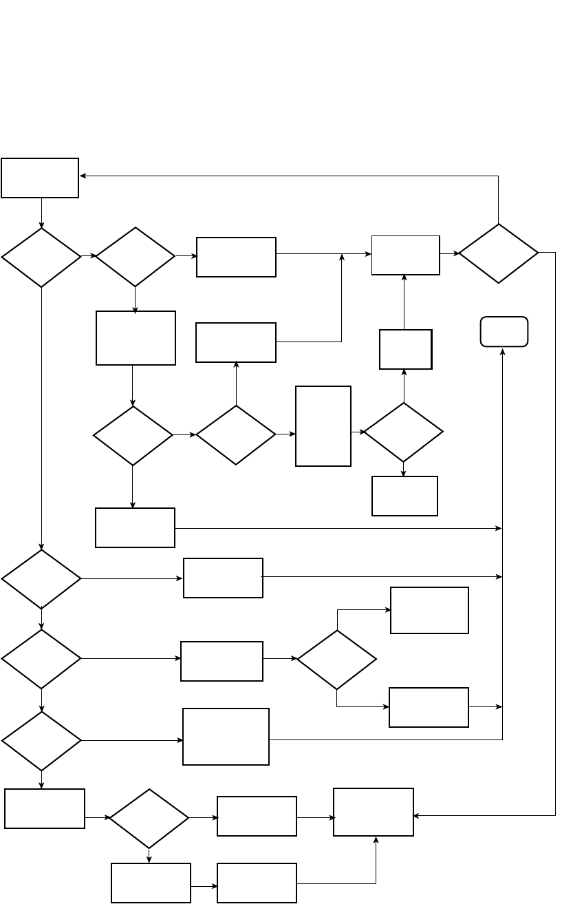
PowerConnect B-Series FCX Configuration Guide 843
53-1002266-01
Configuring IP parameters – Layer 3 Switches 26
FIGURE 131 DHCP Server configuration flow chart
Classify
incoming
message
DHCP
enabled?
Ye s
No
previous
allocation in
DB for this
host?
No
Ye s
Use RX Portnum,
Ciaddr field, and
Giaddr field to select
proper address
pool
Reserve the
previous
allocated address
Reserve an
address from the
address pool
No
Ye s
Ye s
No
No
Send offer to host
and listen for
response
Reserve
the
address
End
Log error in
system log and
send DHCP NAK
to host
Host
responds?
Requested
address
available?
Check for
requested
address
from host
options
parameters
(Requested IP
Address)
Host options
requested
address?
Log error to
system log
Mark address as
available to
another hostMark address as
no available and
log config error
in system log
No
Ye s
Match found?
Log warning to
system log
Check host decline
address against
address pool
DHCP
request
DHCP
inform?
DHCP
decline?
DHCP
release?
No
Ye s
Ye s
No
Ye s
No
No
Ye s
Ye s
No
Is request
response to
DHCP offer?
Send ACK to host
with all configured
options. Do not include
lease expiration
or yiaddr
accepting
assigned
address/lease
parameters
Request to
extend or
renew lease
Renew or extend
the lease
Send ACK to
host and listen
for request to
extend, renew, or
release lease
Ye s
Available
address in the
pool?

844 PowerConnect B-Series FCX Configuration Guide
53-1002266-01
Configuring IP parameters – Layer 3 Switches
26
Configuring DHCP Server on a device
Perform the following steps to configure the DHCP Server feature on your PowerConnect device.
1. Enable DHCP Server by entering a command similar to the following.
PowerConnect(config)# ip dhcp-server enable
2. Create a DHCP Server address pool by entering a command similar to the following.
PowerConnect(config)# ip dhcp-server pool cabo
3. Configure the DHCP Server address pool by entering commands similar to the following.
PowerConnect(config-dhcp-cabo)# network 172.16.1.0/24
PowerConnect(config-dhcp-cabo)# domain-name dell.com
PowerConnect(config-dhcp-cabo)# dns-server 172.16.1.2 172.16.1.3
PowerConnect(config-dhcp-cabo)# netbios-name-server 172.16.1.2
PowerConnect(config-dhcp-cabo)# lease 0 0 5
4. To disable DHCP, enter a command similar to the following.
PowerConnect(config)# no ip dhcp-server enable
The following sections describe the default DHCP settings, CLI commands and the options you can
configure for the DHCP Server feature.

PowerConnect B-Series FCX Configuration Guide 845
53-1002266-01
Configuring IP parameters – Layer 3 Switches 26
Default DHCP server settings
Table 151 shows the default DHCP server settings.
DHCP server CLI commands
This section describes the CLI commands that are available in the DHCP Server feature.
TABLE 151 DHCP server default settings
Parameter Default Value
DHCP server Disabled
Lease database expiration time 86400 seconds
The duration of the lease for an assigned IP address 43200 seconds (one day)
Maximum lease database expiration time 86400 seconds
DHCP server with option 82 Disabled
DHCP server unknown circuit-ID for Option 82 Permit range lookup
IP distribution mechanism Linear
TABLE 152 DHCP server optional parameters commands
Command Description
dbexpire Specifies how long, in seconds, the DHCP server should wait before
aborting a database transfer
option domain-name Specifies the domain name for the DHCP clients.
option
domain-nameservers
Specifies the Domain Name System (DNS) IP servers that are
available to the DHCP clients.
option merit-dump Specifies the path name of a file into which the client’s core image
should be placed in the event that the client crashes (the DHCP
application issues an exception in case of errors such as division by
zero).
option root-path Specifies the name of the path that contains the client’s root
filesystem in NFS notation.
option router Adds the default router and gateway for the DHCP clients.
option subnet-mask Defines the subnet mask for the network.
option
broadcastaddress
Defines a broadcast address for the network.
option wins-server Defines the NetBIOS Windows Internet Naming Service (WINS) name
servers that are available to Microsoft DHCP clients.
option log-servers Defines a list of log servers available to the client.
option
bootstrapserver
Specifies the IP address of the bootstrap server (the command fills
the “siaddr” field in the DHCP packet).

846 PowerConnect B-Series FCX Configuration Guide
53-1002266-01
Configuring IP parameters – Layer 3 Switches
26
TABLE 153 DHCP Server CLI commands
Command Description
ip dhcp-server arp-ping-timeout <#> Specifies the time (in seconds) the server will wait for a response to an
arp-ping packet before deleting the client from the binding database. The
minimum setting is 5 seconds and the maximum time is 30 seconds.
NOTE: Do not alter the default value unless it is necessary. Increasing
the value of this timer may increase the time to get console
access after a reboot.
clear ip dhcp-server binding Deletes a specific, or all leases from the binding database. Refer to
“Removing DHCP leases” on page 847.
ip dhcp-server enable Enables the DHCP server feature. Refer to “Enabling DHCP Server” on
page 847.
no ip dhcp-server mgmt Disables DHCP server on the management port. Refer to “Disabling DHCP
Server on the management port” on page 847.
ip dhcp-server pool <name> Switches to pool configuration mode (config-dhcp-name# prompt) and
creates an address pool. Refer to “Creating an address pool” on
page 848.
ip dhcp-server relay-agent-echo
enable
Enables relay agent echo (Option 82). Refer to “Enabling relay agent echo
(Option 82)” on page 848.
ip dhcp-server <server-id> <address> Specifies the IP address of the selected DHCP server. Refer to
“Configuring the IP address of the DHCP server” on page 848.
show ip dhcp-server binding
[<address>]
Displays a specific lease entry, or all lease entries. Refer to “Display active
lease entries” on page 851.
show ip dhcp-server address-pool
<name>
Displays a specific address pool or all address pools. Refer to “Display
address-pool information” on page 851.
show ip dhcp-server flash Displays the lease binding database that is stored in flash memory. Refer
to “Display lease-binding information in flash memory” on page 852.
show ip dhcp-server summary Displays a summary of active leases, deployed address pools,
undeployed address pools, and server uptime.“Display summary DHCP
server information” on page 853.
bootfile <name> Specifies a boot image to be used by the client. Refer to “Configure the
boot image” on page 849.
deploy Deploys an address pool configuration to the server. Refer to “Deploy an
address pool configuration to the server” on page 849.
dhcp-default-router <addresses> Specifies the IP address of the default router or routers for a client. Refer
to “Specify default routers available to the client” on page 849.
dns-server <addresses> Specifies the IP addresses of a DNS server or servers available to the
client. Refer to “Specify DNS servers available to the client” on page 849.
domain-name <domain> Configures the domain name for the client. Refer to “Configure the
domain name for the client” on page 849.
lease <days><hours><minutes> Specifies the lease duration for an address pool. The default is a one-day
lease. Refer to“Configure the lease duration for the address pool” on
page 849.
excluded-address [<address>
|<address-low> | <address-high>]
Specifies an address or range of addresses to be excluded from the
address pool. Refer to“Specify addresses to exclude from the address
pool” on page 850.

PowerConnect B-Series FCX Configuration Guide 847
53-1002266-01
Configuring IP parameters – Layer 3 Switches 26
Removing DHCP leases
The clear ip dhcp-server binding command can be used to delete a specific lease, or all lease
entries from the lease binding database.
PowerConnect(config)# clear ip dhcp-server binding *
Syntax: clear ip dhcp-server binding [<address> | <*>]
•<address> - The IP address to be deleted
•<*> - Clears all IP addresses
Enabling DHCP Server
The ip dhcp-server enable command enables DHCP Server, which is disabled by default.
Syntax: [no] ip dhcp-server enable
The no version of this command disables DHCP server.
Disabling DHCP Server on the management port
By default, when DHCP Server is enabled, it responds to DHCP client requests received on the
management port. If desired, you can prevent the response to DHCP client requests received on
the management port, by disabling DHCP Server support on the port. When disabled, DHCP client
requests that are received on the management port are silently discarded.
To disable DHCP Server on the management port, enter the following command at the global
Config level of the CLI:
PowerConnect(config)# no ip dhcp-server mgmt
Syntax: no ip dhcp-server mgmt
To re-enable DHCP Server on the management port after it has been disabled, enter the following
command:
PowerConnect(config)# ip dhcp-server mgmt
Syntax: ip dhcp-server mgmt
netbios-name-server <address>
[<address2> |<address3>]
Specifies the IP address of a NetBIOS WINS server or servers that are
available to Microsoft DHCP clients. Refer to “Configure the NetBIOS
server for DHCP clients” on page 850.
network <subnet>/<mask> Configures the subnet network and mask of the DHCP address pool.
Refer to “Configure the subnet and mask of a DHCP address pool” on
page 850.
next-bootstrap-server <address> Configures the IP address of the next server to be used for startup by the
client. Refer to “Configure a next-bootstrap server” on page 850.
tftp-server <address> Configures the address of the TFTP server available to the client. Refer to
“Configure the TFTP server” on page 850.
vendor-class <[<ascii> | <ip> | <hex>
]> <value>
Specifies the vendor type and configuration value for the DHCP client.
Refer to “Configure a vendor type and configuration value for a DHCP
client” on page 850.
TABLE 153 DHCP Server CLI commands
Command Description

848 PowerConnect B-Series FCX Configuration Guide
53-1002266-01
Configuring IP parameters – Layer 3 Switches
26
Setting the wait time for ARP-ping response
At startup, the server reconciles the lease-binding database by sending an ARP-ping packet out to
every client. If there is no response to the ARP-ping packet within a set amount of time (set in
seconds), the server deletes the client from the lease-binding database. The minimum setting is 5
seconds and the maximum is 30 seconds.
Syntax: ip dhcp-server arp-ping-timeout <num>
•<num> - The number of seconds to wait for a response to an ARP-ping packet.
NOTE
Do not alter the default value unless it is necessary. Increasing the value of this timer may increase
the time to get console access after a reboot.
Creating an address pool
The dhcp-server pool command puts you in pool configuration mode, and allows you to create an
address pool.
PowerConnect(config)# dhcp-server pool
PowerConnect(config-dhcp-name)# dhcp-server pool monterey
PowerConnect(config-dhcp-monterey)#
These commands create an address pool named monterey.
Syntax: dhcp-server pool <name>
Configuration notes
•If the DHCP server address is part of a configured DHCP address pool, you must exclude the
DHCP server address from the network pool. Refer to “Specify addresses to exclude from the
address pool” on page 850.
•While in DHCP server pool configuration mode, the system will place the DHCP server pool in
pending mode and the DHCP server will not use the address pool to distribute information to
clients. To activate the pool, use the deploy command. Refer to “Deploy an address pool
configuration to the server” on page 849.
Enabling relay agent echo (Option 82)
The ip dhcp-server relay-agent-echo enable command activates DHCP Option 82, and enables the
DHCP server to echo relay agent information in all replies.
PowerConnect(config)# ip dhcp-server relay-agent-echo enable
Syntax: ip dhcp-server relay-agent-echo enable
Configuring the IP address of the DHCP server
The ip dhcp-server command specifies the IP address of the selected DHCP server, as shown in this
example:
PowerConnect(config)# ip dhcp-server cabo 102.1.1.144
Syntax: ip dhcp-server <server-identifier> <address>
•<server-identifier> - The name of the DHCP server

PowerConnect B-Series FCX Configuration Guide 849
53-1002266-01
Configuring IP parameters – Layer 3 Switches 26
•<address> - The IP address of the DHCP server
This command assigns an IP address to the selected DHCP server.
Configure the boot image
The bootfile command specifies a boot image name to be used by the DHCP client.
PowerConnect(config-dhcp-cabo)# bootfile foxhound
In this example, the DHCP client should use the boot image called “foxhound”.
Syntax: bootfile <name>
Deploy an address pool configuration to the server
The deploy command sends an address pool configuration to the DHCP server.
PowerConnect(config-dhcp-cabo)# deploy
Syntax: deploy
Specify default routers available to the client
The dhcp-default-router command specifies the ip addresses of the default routers for a client.
Syntax: dhcp-default-router <address> [<address>, <address>]
Specify DNS servers available to the client
The dns-server command specifies DNS servers that are available to DHCP clients.
PowerConnect(config-dhcp-cabo)# dns-server 102.2.1.143, 101.2.2.142
Syntax: dns-server <address> [<address>. <address>]
Configure the domain name for the client
The domain-name command configures the domain name for the client.
PowerConnect(config-dhcp-cabo)# domain-name sierra
Syntax: domain-name <domain>
Configure the lease duration for the address pool
The lease command specifies the lease duration for the address pool. The default is a one-day
lease.
PowerConnect(config-dhcp-cabo)# lease 1 4 32
In this example, the lease duration has been set to one day, four hours, and 32 minutes. You can
set a lease duration for just days, just hours, or just minutes, or any combination of the three.
Syntax: lease <days> <hours> <minutes>

850 PowerConnect B-Series FCX Configuration Guide
53-1002266-01
Configuring IP parameters – Layer 3 Switches
26
Specify addresses to exclude from the address pool
The excluded-address command specifies either a single address, or a range of addresses that are
to be excluded from the address pool.
PowerConnect(config-dhcp-cabo)# excluded-address 101.2.3.44
Syntax: excluded-address <[<address> | <address-low address-high>]>
•<address> - Specifies a single address
•<address-low address-high> - Specifies a range of addresses
Configure the NetBIOS server for DHCP clients
The netbios-name-server command specifies the IP address of a NetBIOS WINS server or servers
that are available to Microsoft DHCP clients.
PowerConnect(config-dhcp-cabo)# netbios-name-server 192.168.1.55
Syntax: netbios-name-server <address> [<address2>, <address3>]
Configure the subnet and mask of a DHCP address pool
This network command configures the subnet network and mask of the DHCP address pool.
PowerConnect(config-dhcp-cabo)# network 101.2.3.44/24
Syntax: network <subnet>/<mask>
Configure a next-bootstrap server
The next-bootstrap-server command specifies the IP address of the next server the client should
use for boot up.
PowerConnect(config-dhcp-cabo)# next-bootstrap-server 101.2.5.44
Syntax: next-bootstrap-server <address>
Configure the TFTP server
This tftp-server command specifies the address of the TFTP server to be used by the DHCP clients.
PowerConnect(config-dhcp-cabo)# tftp-server 101.7.5.48
Syntax: tftp-server <address>
Configure a vendor type and configuration value for a DHCP client
The vendor-class command specifies the vendor-type and configuration value for a DHCP client.
PowerConnect(config-dhcp-cabo)# vendor class ascii waikiki
Syntax: vendor-class <[<ascii> | <ip> | <hex> ]> <value>

PowerConnect B-Series FCX Configuration Guide 851
53-1002266-01
Configuring IP parameters – Layer 3 Switches 26
Displaying DHCP server information
The following DHCP show commands may be entered from any level of the CLI.
Display active lease entries
The show ip dhcp-server binding command displays a specific active lease, or all active leases, as
shown in this example:
PowerConnect# show ip dhcp-server binding
The following output is displayed:
PowerConnect# show ip dhcp-server bind
Bindings from all pools:
IP Address Client-ID/ Lease expiration Type
Hardware address
192.168.1.2 001b.ed5d.a440 0d:0h:29m:31s Automatic
192.168.1.3 0012.f2e1.26c0 0d:0h:29m:38s Automatic
Syntax: show ip dhcp-server binding [<address>]
•<address> - Displays entries for this address only
The following table describes this output.
Display address-pool information
This show ip dhcp-server address-pool command displays information about a specific address
pool, or for all address pools.
PowerConnect# show ip dhcp-server address-pools
Output similar to the following is displayed, as shown here.
Showing all address pool(s):
Pool Name: one
Time elapsed since last save: 0d:0h:6m:52s
Total number of active leases: 2
Address Pool State: active
IP Address Exclusions: 192.168.1.45
IP Address Exclusions: 192.168.1.99 192.168.1.103
Pool Configured Options:
bootfile: example.bin
dhcp-default-router: 192.168.1.1
dns-server: 192.168.1.100
domain-name: example.com
lease: 0 0 30
TABLE 154 CLI display of show ip dhcp-server binding command
This field... Displays...
IP address The IP addresses currently in the binding database
Client ID/Hardware address The hardware address for the client
Lease expiration The time when this lease will expire
Type The type of lease

852 PowerConnect B-Series FCX Configuration Guide
53-1002266-01
Configuring IP parameters – Layer 3 Switches
26
netbios-name-server: 192.168.1.101
network: 192.168.1.0 255.255.255.0
next-bootstrap-server: 192.168.1.102
tftp-server: 192.168.1.103
Syntax: show ip dhcp-server address-pool[s] [<name>]
•address-pool[s] - If you enter address-pools, the display will show all address pools
•<name> - Displays information about a specific address pool
The following table describes this output.
Display lease-binding information in flash memory
The show ip dhcp-server flash command displays the lease-binding database that is stored in flash
memory.
PowerConnect# show ip dhcp-server flash
The following information is displayed.
PowerConnect# show ip dhcp-server flash
Address Pool Binding:
IP Address Client-ID/ Lease expiration Type
Hardware address
192.168.1.2 001b.ed5d.a440 0d:0h:18m:59s Automatic
192.168.1.3 0012.f2e1.26c0 0d:0h:19m:8s Automatic
Syntax: show ip dhcp-server flash
The following table describes this output.
TABLE 155 CLI display of show ip dhcp-server address pools command
This field... Displays...
Pool name The name of the address pool
Time elapsed since last save The time that has elapsed since the last save.
Total number of active leases The number of leases that are currently active.
Address pool state The state of the address pool (active or inactive).
IP Address exclusions IP addresses that are not included in the address pool
Pool configured options
bootfile The name of the bootfile
dhcp-server-router The address of the DHCP server router
dns-server The address of the dns server
domain-name The name of the domain
lease The identifier for the lease
netbios-name server The address of the netbios name server
network The address of the network
next-bootstrap-server The address of the next-bootstrap server
tftp-server The address of the TFTP server

PowerConnect B-Series FCX Configuration Guide 853
53-1002266-01
Configuring IP parameters – Layer 3 Switches 26
Display summary DHCP server information
The show ip dhcp-server summary command displays information about active leases, deployed
address-pools, undeployed address-pools, and server uptime.
PowerConnect# show ip dhcp-server summary
The following information is displayed.
DHCP Server Summary:
Total number of active leases: 2
Total number of deployed address-pools: 1
Total number of undeployed address-pools: 0
Server uptime: 0d:0h:8m:27s
Syntax: show ip dhcp-server summary
The following table describes this output.
TABLE 156 CLI display of show ip dhcp-server flash command
This field... Displays...
IP address The IP address of the flash memory lease-binding database
Client-ID/Hardware address The address of the client
Lease expiration The time when the lease will expire
Type The type of lease

854 PowerConnect B-Series FCX Configuration Guide
53-1002266-01
Configuring IP parameters – Layer 3 Switches
26
DHCP Client-Based Auto-Configuration and Flash
image update
NOTE
The DHCP Client-Based Auto-Configuration and Flash image update are platform independent and
have no differences in behavior or configuration across all platforms.
DHCP Client-Based Auto-Configuration allows Layer 2 and base Layer 3 devices to automatically
obtain leased IP addresses through a DHCP server, negotiate address lease renewal, and obtain
flash image and configuration files.
DHCP Client-Based Auto-Configuration occurs as follows.
1. The IP address validation and lease negotiation enables the DHCP client (a Layer 2 or
Base-Layer 3 device) to automatically obtain and configure an IP address, as follows:
•One lease is granted for each Layer 2 device. if the device is configured with a static IP
address, the DHCP Auto-Configuration feature is automatically disabled.
•For a base Layer 3 devices, one leased address is granted (per device) to the interface that
first receives a response from the DHCP server.
TABLE 157 CLI display of show ip dhcp-server summary command
This field... Displays...
Total number of active leases Indicates the number of leases that are currently active
Total number of deployed address-pools The number of address pools currently in use.
Total number of undeployed address-pools The number of address-pools being held in reserve.
Server uptime The amount of time that the server has been active.
TABLE 158 DHCP Server commands
Command Description
option
bootstrapfilename
Sets the name of the bootstrap file. The no form of this command removes the
name of the bootstrap file.
default-lease-time Specifies the duration of the lease for an IP address that is assigned from a
DHCP server to a DHCP client.
database tftp Defines the TFTP IP address server for storing the DHCP database, the name of
the stored file and the time period at which the stored database is synchronized
with the database on the device.
database ftp Defines the FTP IP address server for storing the DHCP database, the name of
the stored file and the time period at which the stored database is synchronized
with the database on the device.
max-lease-time Specifies the maximal duration of the leases in seconds.
option
bootfile-name
Specifies the pathname of the boot file.
option tftp-server Specifies the IP address of a TFTP server.
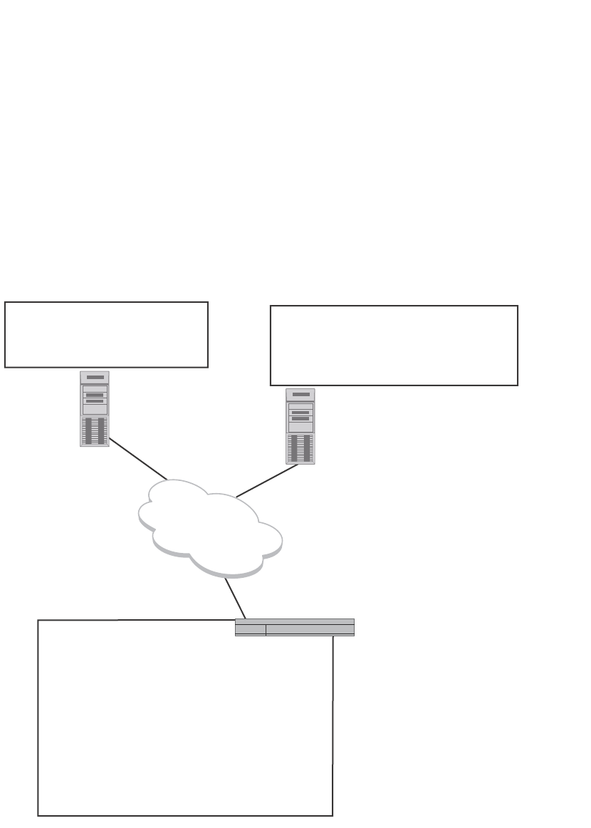
PowerConnect B-Series FCX Configuration Guide 855
53-1002266-01
Configuring IP parameters – Layer 3 Switches 26
2. If auto-update is enabled, the TFTP flash image is downloaded and updated. The device
compares the filename of the requested flash image with the image stored in flash. If the
filenames are different, then the device will download the new image from a TFTP server, write
the downloaded image to flash, then reload the device or stack.
3. In the final step, TFTP configuration download and update, the device downloads a
configuration file from a TFTP server and saves it as the running configuration.
Figure 132 shows how DHCP Client-Based Auto Configuration works.
FIGURE 132 DHCP Client-Based Auto-Configuration
Configuration notes and feature limitations
•For base Layer 3 devices, this feature is available for the default VLAN only. For Layer 2
devices, this feature is available for default VLANs and management VLANs. This feature is not
supported on virtual interfaces (VEs), trunked ports, or LACP ports.
•Although the DHCP server may provide multiple addresses, only one IP address is installed at a
time.
•This feature is not supported together with DHCP snooping.
PowerConnect(config)#show run
Current configuration:
!
ver 7.2.00aT7f1
!
module 1 fcx-24-port-copper-base-module
!
!
ip dns domain-name test.com
ip address 192.168.1.100 255.255.255.0 dynamic
ip dns server-address 192.168.1.3
ip dhcp-client lease 174
ip default-gateway 192.168.1.1
!
!
end
fCX07000.bin
newswitch.cfg
FCX-Switch.cfg
brocade.cfg
FCX-Switch.cfg
003 Router: 192.168.1.1
006 DNS Server: 192.168.1.3
067 bootfile name:
FCX
.bin
015 DNS Domain Name: test.com
150 TFTP Server IP Address: 192.168.1.5
Device
IP addr: 192.168.1.100
MAC addr: 001b.ed5e.4d00
DHCP Server
192.168.1.2
TFTP Server
192.168.1.5
Network

856 PowerConnect B-Series FCX Configuration Guide
53-1002266-01
Configuring IP parameters – Layer 3 Switches
26
The following configuration rules apply to flash image update:
•To enable flash image update (ip dhcp-client auto-update enable command), also enable
auto-configuration (ip dhcp-client enable command).
•The image filename to be updated must have the extension .bin.
•The DHCP option 067 bootfile name will be used for image update if it has the extension .bin.
•The DHCP option 067 bootfile name will be used for configuration download if it does not have
the extension .bin.
•If the DHCP option 067 bootfile name is not configured or does not have the extension .bin,
then the auto-update image will not occur.
How DHCP Client-Based Auto-Configuration and Flash image update works
Auto-Configuration and Auto-update are enabled by default. To disable this feature, refer to
“Disabling or re-enabling Auto-Configuration” on page 860 and “Disabling or re-enabling
Auto-Update” on page 860, respectively.
The steps of the Auto-Configuration and Auto-update process are described in Figure 133, and in
the description that follows the flowchart.
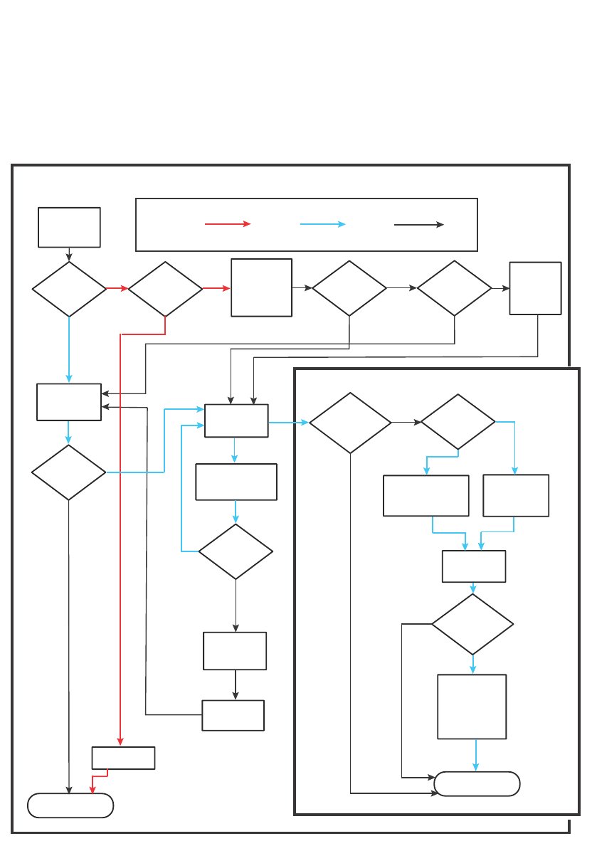
PowerConnect B-Series FCX Configuration Guide 857
53-1002266-01
Configuring IP parameters – Layer 3 Switches 26
FIGURE 133 The DHCP Client-Based Auto-Configuration steps
The IP address validation and lease negotiation step
1. At boot-up, the device automatically checks its configuration for an IP address.
2. If the device does not have a static IP address, it requests the lease of an address from the
DHCP server:
•If the server responds, it leases an IP address to the device for the specified lease period.
•If the server does not respond (after four tries) the DHCP Client process is ended.
IP Address Validation and Lease Negotiation
Legend: Typical process (may change depending on environment)
Existing Device New Device Other Possible Events
Has IP
address?
Ye s
No
Ye s
No
Ye s
No
Ye s
Ye s
No
Ye s
No
No
Ye s
No
Ye s
No
System boot/
feature enable
(start)
Static
Static or
dynamic
address?
Dynamic
Requests new
IP address from
DHCP server
Server
responds?
(4 tries)
DHCP Client
process ends
Static address
is kept
Asks server if
address is valid?
(in pool and
not leased)
DHCP
server responds?
(4 tries)
Is IP address
valid?
Continue lease
Continue until
renewal time
Server
responds?
(4 tries)
Continue until
lease expires
IP address
is released
Dynamic IP
is re-leased
to system
TFTP Configuration Download and Update
TFTP info from
DHCP server?
Use TFTP server name
or server IP address
provided by server
Use DHCP server
address as TFTP
server address
Reboot or
feature re-enable?
Request files
from TFTP
Merge file
with running config
(server file takes
precedence to
resolve conflicts)
TFTP download
process ends
TFTP server
responds and
has requested
file?

858 PowerConnect B-Series FCX Configuration Guide
53-1002266-01
Configuring IP parameters – Layer 3 Switches
26
3. If the device has a dynamic address, the device asks the DHCP server to validate that address.
If the server does not respond, the device will continue to use the existing address until the
lease expires. If the server responds, and the IP address is outside of the DHCP address pool
or has been leased to another device, it is automatically rejected, and the device receives a
new IP address from the server. If the existing address is valid, the lease continues.
NOTE
The lease time interval is configured on the DHCP server, not on the client device. The ip
dhcp-client lease command is set by the system, and is non-operational to a user.
4. If the existing address is static, the device keeps it and the DHCP Client process is ended.
5. For a leased IP address, when the lease interval reaches the renewal point, the device
requests a renewal from the DHCP server:
•If the device is able to contact the DHCP server at the renewal point in the lease, the DHCP
server extends the lease. This process can continue indefinitely.
•If the device is unable to reach the DHCP server after four attempts, it continues to use the
existing IP address until the lease expires. When the lease expires, the dynamic IP address
is removed and the device contacts the DHCP server for a new address. If the device is
still unable to contact the DHCP server after four attempts, the process is ended.
The TFTP Flash image download and update step
NOTE
This process only occurs when the client device reboots, or when DHCP-client has been disabled and
then re-enabled.
Once a lease is obtained from the server (described in “The IP address validation and lease
negotiation step” on page 857), the device compares the filename of the requested flash image
with the image stored in flash. In a stacking configuration, the device compares the filename with
the image stored in the Active controller only.
•If the .bin filenames match, then the DHCP client skips the flash image download. If
auto-configuration is enabled, the DHCP client proceeds with downloading the configuration
files as described in “The TFTP configuration download and update step”.
•If the .bin filenames are different, then the DHCP client downloads the new image from a TFTP
server, then writes the downloaded image to flash. In a stacking configuration, the device
copies the flash image to flash in all stack member units.
The code determines which flash (i.e., primary or secondary) to use based on how the device is
booted. In a stacking configuration, the member units use the same flash as the Active
controller. Once the flash is updated with the newer flash image, the device is reloaded and
any member units in a stacking configuration are reloaded as well. If auto-configuration is
enabled, the DHCP client then proceeds to download the configuration files described in “The
TFTP configuration download and update step”.
NOTE
In a stacking environment, the DHCP client flash image download waits 5 minutes for all
member units to join and update. Then the DHCP client downloads the new image from the
TFTP server using the TFTP server IP address (option 150), if it is available. If the TFTP server IP
address is not available, the DHCP client requests the TFTP file from the DHCP server.

PowerConnect B-Series FCX Configuration Guide 859
53-1002266-01
Configuring IP parameters – Layer 3 Switches 26
The TFTP configuration download and update step
NOTE
This process only occurs when the client device reboots, or when Auto-Configuration has been
disabled and then re-enabled.
1. When the device reboots, or the Auto-Configuration feature has been disabled and then
re-enabled, the device uses information from the DHCP server to contact the TFTP server to
update the running-configuration file:
•If the DHCP server provides a TFTP server name or IP address, the device uses this
information to request files from the TFTP server.
•If the DHCP server does not provide a TFTP server name or IP address, the device requests
the configuration files from the DHCP server.
2. The device requests the configuration files from the TFTP server by asking for filenames in the
following order:
•bootfile name provided by the DHCP server (if configured)
•hostnameMAC-config.cfg, for example:
PowerConnect-Switch001b.ed5e.4d00-config.cfg
•hostnameMAC.cfg, for example:
PowerConnect-Switch001b.ed5e.4d00.cfg
•<PowerConnect >-<switch | router>.cfg (applies to Layer 2 or base Layer 3 devices), for
example:
PowerConnect-switch.cfg(FCX Layer 2)
PowerConnect-router.cfg(FCX Layer 3)
If the device is successful in contacting the TFTP server and the server has the configuration
file, the files are merged. If there is a conflict, the server file takes precedence.
If the device is unable to contact the TFTP server or if the files are not found on the server, the
TFTP part of the configuration download process ends.
Supported Options for DHCP Servers
DHCP Client supports the following options:
•001 - subnetmask
•003 - router ip
•015 - domain name
•006 - domain name server
•012 - hostname (optional)
•066 - TFTP server name (only used for Client-Based Auto Configuration)
•067 - bootfile name
•150 - TFTP server IP address (private option, datatype = IP Address)

860 PowerConnect B-Series FCX Configuration Guide
53-1002266-01
Configuring IP parameters – Layer 3 Switches
26
Configuration notes
•When using DHCP on a router, if you have a DHCP address for one interface, and you want to
connect to the DHCP server from another interface, you must disable DHCP on the first
interface, then enable DHCP on the second interface.
•When DHCP is disabled, and then re-enabled, or if the system is rebooted, the TFTP process
requires approximately three minutes to run in the background before file images can be
downloaded manually.
•Once a port is assigned a leased IP address, it is bound by the terms of the lease regardless of
the link state of the port.
Disabling or re-enabling Auto-Configuration
For a switch, you can disable or enable this feature using the following commands.
PowerConnect(config)# ip dhcp-client enable
PowerConnect(config)# no ip dhcp-client enable
For a router, you can disable or enable this feature using the following commands.
PowerConnect(config-if-e1000-0/1/1)# ip dhcp-client enable
PowerConnect(config-if-e1000-0/1/1)# no ip dhcp-client enable
Syntax: [no] ip dhcp-client enable
Disabling or re-enabling Auto-Update
Auto-update is enabled by default. To disable it, use the following command.
PowerConnect(config)# no ip dhcp-client auto-update enabled
To re-enable auto-update after it has been disabled, use the following command.
PowerConnect(config)# ip dhcp-client auto-update enabled
Syntax: [no] ip dhcp-client auto-update enabled
The auto-update will not appear in the running-config under certain circumstances. It will appear in
the running-config when the DHCP-client service is started. Once the dhcp-client service stops, the
command will get removed from the running-config. This has a dependency over the dhcp-client
service. If the dhcp-client feature is disabled, then this issue will not occur. If the configuration
includes no ip dhcp-client enable and no ip dhcp-client auto-update enable, then both commands
will appear in the running-config.
Displaying DHCP configuration information
The following example shows output from the show ip command for Layer 2 devices).

PowerConnect B-Series FCX Configuration Guide 861
53-1002266-01
Configuring IP parameters – Layer 3 Switches 26
The following example shows output from the show ip address command for a Layer 2 device.
The following example shows output from the show ip address command for a base Layer 3 device.
The following example shows a Layer 2 device configuration as a result of the show run command.
The following example shows a base Layer 3 device configuration as a result of the show run
command.
PowerConnect(config)# show ip
Switch IP address: 10.44.16.116
Subnet mask: 255.255.255.0
Default router address: 10.44.16.1
TFTP server address: 10.44.16.41
Configuration filename: foundry.cfg
Image filename: None
PowerConnect(config)# show ip address
IP Address Type Lease Time Interface
10.44.16.116 Dynamic 174 0/1/1
PowerConnect(config)# show ip address
IP Address Type Lease Time Interface
10.44.3.233 Dynamic 672651 0/1/2
1.0.0.1 Static N/A 0/1/15
PowerConnect(config)# show run
Current configuration:
!
ver 7.2.00aT7f1
!
module 1 FCX-24-port-management-module
!
!
ip address 10.44.16.116 255.255.255.0 dynamic
ip dns server-address 10.44.16.41
ip dhcp-client lease 174
ip default-gateway 10.44.16.1
!
!
end

862 PowerConnect B-Series FCX Configuration Guide
53-1002266-01
Configuring IP parameters – Layer 2 Switches
26
DHCP Log messages
The following DHCP notification messages are sent to the log file.
2d01h48m21s:I: DHCPC: existing ip address found, no further action needed by DHCPC
2d01h48m21s:I: DHCPC: Starting DHCP Client service
2d01h48m21s:I: DHCPC: Stopped DHCP Client service
2d01h48m21s:I: DHCPC: FCX624P Switch running-configuration changed
2d01h48m21s:I: DHCPC: sending TFTP request for bootfile name FCX-switch.cfg
2d01h48m21s:I: DHCPC: TFTP unable to download running-configuration
2d01h48m21s:I: DHCPC: Found static IP Address 1.1.1.1 subnet mask 255.255.255.0 on
port 0/1/5
2d01h48m21s:I: DHCPC: Client service found no DHCP server(s) on 3 possible subnet
2d01h48m21s:I: DHCPC: changing 0/1/3 protocol from stopped to running
Configuring IP parameters – Layer 2 Switches
The following sections describe how to configure IP parameters on a Layer 2 Switch.
NOTE
This section describes how to configure IP parameters for Layer 2 Switches. For IP configuration
information for Layer 3 Switches, refer to “Configuring IP parameters – Layer 3 Switches” on
page 799.
PowerConnect(config)# show run
Current configuration:
!
ver 7.2.00aT7f1
!
module 1 FCX-24-port-management-module
module 2 FCX-cx4-2-port-16g-module
module 3 FCX-xfp-1-port-16g-module
!
vlan 1 name DEFAULT-VLAN by port
!
ip dns domain-name test.com
ip dns server-address 10.44.3.111
interface ethernet 0/1/2
ip address 10.44.3.233 255.255.255.0 dynamic
ip dhcp-client lease 691109
!
interface ethernet 0/1/15
ip address 1.0.0.1 255.0.0.0
ip helper-address 1 10.44.3.111
!
end

PowerConnect B-Series FCX Configuration Guide 863
53-1002266-01
Configuring IP parameters – Layer 2 Switches 26
Configuring the management IP address and specifying
the default gateway
To manage a Layer 2 Switch using Telnet or Secure Shell (SSH) CLI connections or the Web
Management Interface, you must configure an IP address for the Layer 2 Switch. Optionally, you
also can specify the default gateway.
Dell PowerConnect devices support both classical IP network masks (Class A, B, and C subnet
masks, and so on) and Classless Interdomain Routing (CIDR) network prefix masks:
•To enter a classical network mask, enter the mask in IP address format. For example, enter
“209.157.22.99 255.255.255.0” for an IP address with a Class-C subnet mask.
•To enter a prefix network mask, enter a forward slash ( / ) and the number of bits in the mask
immediately after the IP address. For example, enter “209.157.22.99/24” for an IP address
that has a network mask with 24 significant bits (ones).
By default, the CLI displays network masks in classical IP address format (example:
255.255.255.0). You can change the display to prefix format. Refer to “Changing the network
mask display to prefix format” on page 869.
To assign an IP address to a Layer 2 Switch, enter a command such as the following at the global
CONFIG level.
PowerConnect(config)# ip address 192.45.6.110 255.255.255.0
Syntax: ip address <ip-addr> <ip-mask>
or
Syntax: ip address <ip-addr>/<mask-bits>
You also can enter the IP address and mask in CIDR format, as follows.
PowerConnect(config)# ip address 192.45.6.1/24
To specify the Layer 2 Switch default gateway, enter a command such as the following.
PowerConnect(config)# ip default-gateway 192.45.6.1 255.255.255.0
Syntax: ip default-gateway <ip-addr>
or
Syntax: ip default-gateway <ip-addr>/<mask-bits>
NOTE
When configuring an IP address on a Layer 2 switch that has multiple VLANs, make sure the
configuration includes a designated management VLAN that identifies the VLAN to which the global
IP address belongs. Refer to “Designated VLAN for Telnet management sessions to a Layer 2
Switch” on page 1145.
Configuring Domain Name Server (DNS) resolver
The Domain Name Server (DNS) resolver feature lets you use a host name to perform Telnet, ping,
and traceroute commands. You can also define a DNS domain on a Layer 2 Switch or Layer 3
Switch and thereby recognize all hosts within that domain. After you define a domain name, the
Layer 2 Switch or Layer 3 Switch automatically appends the appropriate domain to the host and
forwards it to the domain name server.

864 PowerConnect B-Series FCX Configuration Guide
53-1002266-01
Configuring IP parameters – Layer 2 Switches
26
For example, if the domain “newyork.com” is defined on a Layer 2 Switch or Layer 3 Switch and you
want to initiate a ping to host “NYC01” on that domain, you need to reference only the host name in
the command instead of the host name and its domain name. For example, you could enter either
of the following commands to initiate the ping.
PowerConnect# ping nyc01
PowerConnect# ping nyc01.newyork.com
Defining a DNS entry
You can define up to four DNS servers for each DNS entry. The first entry serves as the primary
default address. If a query to the primary address fails to be resolved after three attempts, the next
gateway address is queried (also up to three times). This process continues for each defined
gateway address until the query is resolved. The order in which the default gateway addresses are
polled is the same as the order in which you enter them.
Suppose you want to define the domain name of newyork.com on a Layer 2 Switch and then define
four possible default DNS gateway addresses. To do so, enter the following commands.
PowerConnect(config)# ip dns domain-name newyork.com
PowerConnect(config)# ip dns server-address 209.157.22.199 205.96.7.15
208.95.7.25 201.98.7.15
Syntax: ip dns server-address <ip-addr> [<ip-addr>] [<ip-addr>] [<ip-addr>]
In this example, the first IP address in the ip dns server-address... command becomes the primary
gateway address and all others are secondary addresses. Because IP address 201.98.7.15 is the
last address listed, it is also the last address consulted to resolve a query.
Using a DNS name To initiate a trace route
Suppose you want to trace the route from a Layer 2 Switch to a remote server identified as NYC02
on domain newyork.com. Because the newyork.com domain is already defined on the Layer 2
Switch, you need to enter only the host name, NYC02, as noted in the following command.
PowerConnect# traceroute nyc02
Syntax: traceroute <host-ip-addr> [maxttl <value>] [minttl <value>] [numeric] [timeout <value>]
[source-ip <ip addr>]
The only required parameter is the IP address of the host at the other end of the route.
After you enter the command, a message indicating that the DNS query is in process and the
current gateway address (IP address of the domain name server) being queried appear on the
screen.
Type Control-c to abort
Sending DNS Query to 209.157.22.199
Tracing Route to IP node 209.157.22.80
To ABORT Trace Route, Please use stop-traceroute command.
Traced route to target IP node 209.157.22.80:
IP Address Round Trip Time1 Round Trip Time2
207.95.6.30 93 msec 121 msec
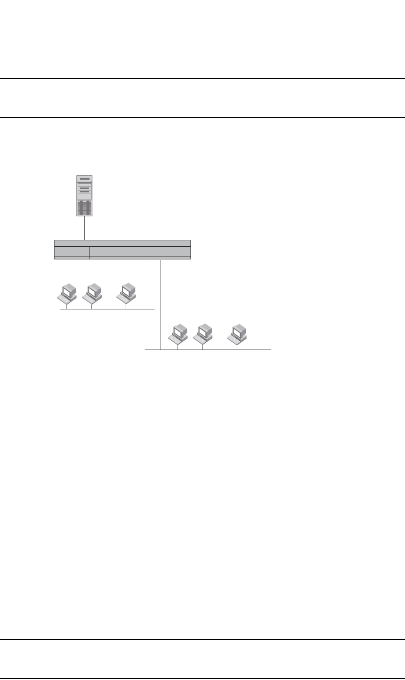
PowerConnect B-Series FCX Configuration Guide 865
53-1002266-01
Configuring IP parameters – Layer 2 Switches 26
NOTE
In the previous example, 209.157.22.199 is the IP address of the domain name server (default DNS
gateway address), and 209.157.22.80 represents the IP address of the NYC02 host.
FIGURE 134 Querying a Host on the newyork.com Domain
Changing the TTL threshold
The TTL threshold prevents routing loops by specifying the maximum number of router hops an IP
packet originated by the Layer 2 Switch can travel through. Each device capable of forwarding IP
that receives the packet decrements (decreases) the packet TTL by one. If a router receives a
packet with a TTL of 1 and reduces the TTL to zero, the router drops the packet.
The default TTL is 64. You can change the TTL to a value from 1 through 255.
To modify the TTL threshold to 25, enter the following commands.
PowerConnect(config)# ip ttl 25
PowerConnect(config)# exit
Syntax: ip ttl <1-255>
Configuring DHCP Assist
DHCP Assist allows a Layer 2 Switch to assist a router that is performing multi-netting on its
interfaces as part of its DHCP relay function.
DHCP Assist ensures that a DHCP server that manages multiple IP subnets can readily recognize
the requester IP subnet, even when that server is not on the client local LAN segment. The Layer 2
Switch does so by stamping each request with its IP gateway address in the DHCP discovery packet.
NOTE
Layer 3 Switches provide BootP/DHCP assistance by default on an individual port basis. Refer to
“Changing the IP address used for stamping BootP/DHCP requests” on page 840.
...
...
[
Layer 3 Switch
Domain Name Server
nyc02
nyc01
nyc01
nyc02
207.95.6.199
newyork.com
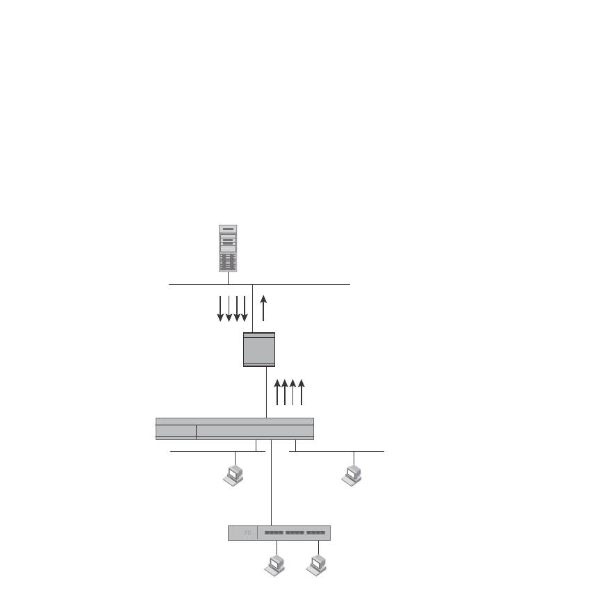
866 PowerConnect B-Series FCX Configuration Guide
53-1002266-01
Configuring IP parameters – Layer 2 Switches
26
By allowing multiple subnet DHCP requests to be sent on the same wire, you can reduce the
number of router ports required to support secondary addressing as well as reduce the number of
DHCP servers required, by allowing a server to manage multiple subnet address assignments.
FIGURE 135 DHCP requests in a network without DHCP Assist on the Layer 2 Switch
In a network operating without DHCP Assist, hosts can be assigned IP addresses from the wrong
subnet range because a router with multiple subnets configured on an interface cannot distinguish
among DHCP discovery packets received from different subnets.
For example, in Figure 135, a host from each of the four subnets supported on a Layer 2 Switch
requests an IP address from the DHCP server. These requests are sent transparently to the router.
Because the router is unable to determine the origin of each packet by subnet, it assumes the
lowest IP address or the ‘primary address’ is the gateway for all ports on the Layer 2 Switch and
stamps the request with that address.
When the DHCP request is received at the server, it assigns all IP addresses within that range only.
With DHCP Assist enabled on a Layer 2 Switch, correct assignments are made because the Layer 2
Switch provides the stamping service.
Step 3:
DHCP Server generates IP
addresses for Hosts 1,2,3 and 4.
All IP address are assigned
in the 192.95.5.1 range.
DHCP requests for the other sub-nets
were not recognized by
the non-DHCP assist router causing
incorrect address assignments.
DHCP
Server
207.95.7.6
192.95.5.35
192.95.5.5
192.95.5.30
192.95.5.10
Router
Layer 2 Switch
Host 1 Host 2
Host 3 Host 4
192.95.5.x
Subnet 1
200.95.6.x
Subnet 2
202.95.1.x
Subnet 3
202.95.5.x
Subnet 4
Hub
Step 1:
DHCP IP address requests
for Hosts 1, 2, 3 and 4 in
Sub-nets 1, 2, 3 and 4.
Step 2:
Router assumes the lowest
IP address (192.95.5.1) is the
gateway address.
192.95.5.1
200.95.6.1
202.95.1.1
202.95.5.1
IP addresses configured
on the router interface.
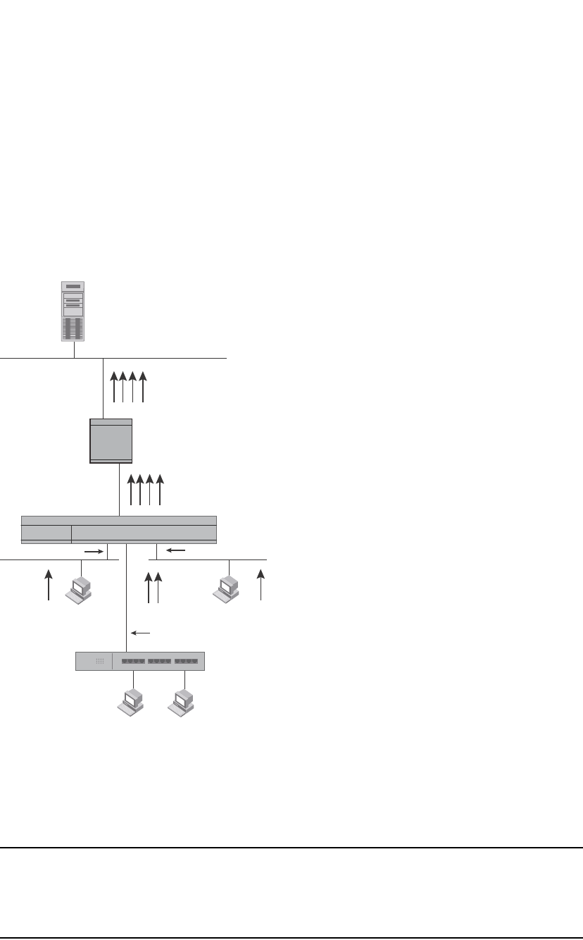
PowerConnect B-Series FCX Configuration Guide 867
53-1002266-01
Configuring IP parameters – Layer 2 Switches 26
How DHCP Assist works
Upon initiation of a DHCP session, the client sends out a DHCP discovery packet for an address
from the DHCP server as seen in Figure 136. When the DHCP discovery packet is received at a
Layer 2 Switch with the DHCP Assist feature enabled, the gateway address configured on the
receiving interface is inserted into the packet. This address insertion is also referred to as
stamping.
FIGURE 136 DHCP requests in a network with DHCP Assist operating on a PowerConnect Switch
When the stamped DHCP discovery packet is then received at the router, it is forwarded to the
DHCP server. The DHCP server then extracts the gateway address from each request and assigns
an available IP address within the corresponding IP subnet (Figure 137). The IP address is then
forwarded back to the workstation that originated the request.
NOTE
When DHCP Assist is enabled on any port, Layer 2 broadcast packets are forwarded by the CPU.
Unknown unicast and multicast packets are still forwarded in hardware, although selective packets
such as IGMP, are sent to the CPU for analysis. When DHCP Assist is not enabled, Layer 2 broadcast
packets are forwarded in hardware.
DHCP
Server
Hub
207.95.7.6
Router
Host 1 Host 2
Host 3 Host 4
192.95.5.x
Subnet 1
200.95.6.x
Subnet 2
202.95.1.x
Subnet 3
202.95.5.x
Subnet 4
Interface 2 Interface 14
Interface 8
Step 1:
DHCP IP address requests
for Hosts 1, 2, 3 and 4 in
Subnets 1, 2, 3 and 4.
Gateway addresses:
192.95.5.1
200.95.6.1
202.95.1.1
202.95.5.1
Step 2:
Switch stamps each DHCP request
with the gateway address of the
corresponding subnet of the
receiving port.
Step 3:
Router forwards the DHCP request to the
server without touching the gateway
address inserted in the packet by the switch.
Layer 2 Switch
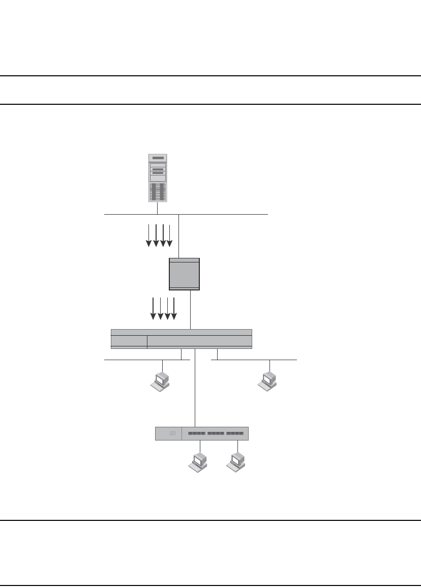
868 PowerConnect B-Series FCX Configuration Guide
53-1002266-01
Configuring IP parameters – Layer 2 Switches
26
NOTE
The DHCP relay function of the connecting router must be turned on.
FIGURE 137 DHCP offers are forwarded back toward the requestors
NOTE
When DHCP Assist is enabled on any port, Layer 2 broadcast packets are forwarded by the CPU.
Unknown unicast and multicast packets are still forwarded in hardware, although selective packets
such as IGMP are sent to the CPU for analysis. When DHCP Assist is not enabled, Layer 2 broadcast
packets are forwarded in hardware.
Configuring DHCP Assist
You can associate a gateway list with a port. You must configure a gateway list when DHCP Assist is
enabled on a Layer 2 Switch. The gateway list contains a gateway address for each subnet that will
be requesting addresses from a DHCP server. The list allows the stamping process to occur. Each
gateway address defined on the Layer 2 Switch corresponds to an IP address of the router interface
or other router involved.
Step 4:
DHCP Server extracts the gateway
address from each packet and
assigns IP addresses for each
host within the appropriate
range.
DHCP response with IP addresses
for Subnets 1, 2, 3 and 4
Step 5:
IP addresses are distributed
to the appropriate hosts.
192.95.5.10 200.95.6.15
202.95.1.35 202.95.5.25
Host 1 Host 2
192.95.5.x
Subnet 1
200.95.6.x
Subnet 2
Host 3 Host 4
202.95.1.x
Subnet 3
202.95.5.x
Subnet 4
Router
DHCP
Server
207.95.7.6
192.95.5.10
200.95.6.15
202.95.1.35
202.95.5.25
Layer 2 Switch
Hub

PowerConnect B-Series FCX Configuration Guide 869
53-1002266-01
Displaying IP configuration information and statistics 26
Up to eight addresses can be defined for each gateway list in support of ports that are
multi-homed. When multiple IP addresses are configured for a gateway list, the Layer 2 Switch
inserts the addresses into the discovery packet in a round robin fashion.
Up to 32 gateway lists can be defined for each Layer 2 Switch.
Example
To create the configuration indicated in Figure 136 and Figure 137, enter commands such as the
following.
PowerConnect(config)# dhcp-gateway-list 1 192.95.5.1
PowerConnect(config)# dhcp-gateway-list 2 200.95.6.1
PowerConnect(config)# dhcp-gateway-list 3 202.95.1.1 202.95.5.1
PowerConnect(config)# interface ethernet 2
PowerConnect(config-if-e1000-2)# dhcp-gateway-list 1
PowerConnect(config-if-e1000-2)# interface ethernet 8
PowerConnect(config-if-e1000-8)# dhcp-gateway-list 3
PowerConnect(config-if-e1000-8)# interface ethernet 14
PowerConnect(config-if-e1000-14)# dhcp-gateway-list 2
Syntax: dhcp-gateway-list <num> <ip-addr>
Displaying IP configuration information and statistics
The following sections describe IP display options for Layer 3 Switches and Layer 2 Switches:
•To display IP information on a Layer 3 Switch, refer to “Displaying IP information – Layer 3
Switches” on page 869.
•To display IP information on a Layer 2 Switch, refer to “Displaying IP information – Layer 2
Switches” on page 883.
Changing the network mask display to prefix format
By default, the CLI displays network masks in classical IP address format (example:
255.255.255.0). You can change the displays to prefix format (example: /18) on a Layer 3 Switch
or Layer 2 Switch using the following CLI method.
NOTE
This option does not affect how information is displayed in the Web Management Interface.
To enable CIDR format for displaying network masks, entering the following command at the global
CONFIG level of the CLI.
PowerConnect(config)# ip show-subnet-length
Syntax: [no] ip show-subnet-length
Displaying IP information – Layer 3 Switches
You can display the following IP configuration information statistics on Layer 3 Switches:
•Global IP parameter settings and IP access policies – refer to “Displaying global IP
configuration information” on page 870.
•CPU utilization statistics – refer to “Displaying CPU utilization statistics” on page 872.

870 PowerConnect B-Series FCX Configuration Guide
53-1002266-01
Displaying IP configuration information and statistics
26
•IP interfaces – refer to “Displaying IP interface information” on page 873.
•ARP entries – refer to “Displaying ARP entries” on page 874.
•Static ARP entries – refer to “Displaying ARP entries” on page 874.
•IP forwarding cache – refer to “Displaying the forwarding cache” on page 877.
•IP route table – refer to “Displaying the IP route table” on page 878.
•IP traffic statistics – refer to “Displaying IP traffic statistics” on page 881.
The following sections describe how to display this information.
In addition to the information described below, you can display the following IP information. This
information is described in other parts of this guide:
•RIP
•OSPF
•BGP4
•DVMRP
•PIM
•VRRP or VRRPE
Displaying global IP configuration information
To display IP configuration information, enter the following command at any CLI level.
Syntax: show ip
NOTE
This command has additional options, which are explained in other sections in this guide, including
the sections following this one.
This display shows the following information.
PowerConnect# show ip
Global Settings
ttl: 64, arp-age: 10, bootp-relay-max-hops: 4
router-id : 207.95.11.128
enabled : UDP-Broadcast-Forwarding IRDP Proxy-ARP RARP OSPF
disabled: BGP4 Load-Sharing RIP DVMRP FSRP VRRP
Static Routes
Index IP Address Subnet Mask Next Hop Router Metric Distance
1 0.0.0.0 0.0.0.0 209.157.23.2 1 1
Policies
Index Action Source Destination Protocol Port Operator
1 deny 209.157.22.34 209.157.22.26 tcp http =
64 permit any any
PowerConnect B-Series FCX Configuration Guide 871
53-1002266-01
Displaying IP configuration information and statistics 26
TABLE 159 CLI display of global IP configuration information – Layer 3 Switch
This field... Displays...
Global settings
ttl The Time-To-Live (TTL) for IP packets. The TTL specifies the maximum number of router hops
a packet can travel before reaching the router. If the packet TTL value is higher than the
value specified in this field, the router drops the packet.
To change the maximum TTL, refer to “Changing the TTL threshold” on page 815.
arp-age The ARP aging period. This parameter specifies how many minutes an inactive ARP entry
remains in the ARP cache before the router ages out the entry.
To change the ARP aging period, refer to “Changing the ARP aging period” on page 812.
bootp-relay-max-ho
ps
The maximum number of hops away a BootP server can be located from the router and still
be used by the router clients for network booting.
To change this value, refer to “Changing the maximum number of hops to a BootP relay
server” on page 840.
router-id The 32-bit number that uniquely identifies the router.
By default, the router ID is the numerically lowest IP interface configured on the router. To
change the router ID, refer to “Changing the router ID” on page 809.
enabled The IP-related protocols that are enabled on the router.
disabled The IP-related protocols that are disabled on the router.
Static routes
Index The row number of this entry in the IP route table.
IP Address The IP address of the route destination.
Subnet Mask The network mask for the IP address.
Next Hop Router The IP address of the router interface to which the router sends packets for the route.
Metric The cost of the route. Usually, the metric represents the number of hops to the destination.
Distance The administrative distance of the route. The default administrative distance for static IP
routes in routers is 1.
To list the default administrative distances for all types of routes or to change the
administrative distance of a static route, refer to “Changing administrative distances” on
page 1014.
Policies
Index The policy number. This is the number you assigned the policy when you configured it.
Action The action the router takes if a packet matches the comparison values in the policy. The
action can be one of the following:
•deny – The router drops packets that match this policy.
•permit – The router forwards packets that match this policy.
Source The source IP address the policy matches.
Destination The destination IP address the policy matches.
Protocol The IP protocol the policy matches. The protocol can be one of the following:
•ICMP
•IGMP
•IGRP
•OSPF
•TCP
•UDP
ChecksumVer Protocol Type
Reserved0 Checksum
(optional)
Reserved
(optional)

872 PowerConnect B-Series FCX Configuration Guide
53-1002266-01
Displaying IP configuration information and statistics
26
Displaying CPU utilization statistics
You can display CPU utilization statistics for IP protocols using the show process cpu command.
The show process cpu command includes CPU utilization statistics for ACL, 802.1x, and L2VLAN.
L2VLAN contains any packet transmitted to a VLAN by the CPU, including unknown unicast,
multicast, broadcast, and CPU forwarded Layer 2 traffic.
To display CPU utilization statistics for the previous one-second, one-minute, five-minute, and
fifteen-minute intervals, enter the following command at any level of the CLI.
If the software has been running less than 15 minutes (the maximum interval for utilization
statistics), the command indicates how long the software has been running. Here is an example.
Port The Layer 4 TCP or UDP port the policy checks for in packets. The port can be displayed by
its number or, for port types the router recognizes, by the well-known name. For example,
TCP port 80 can be displayed as HTTP.
NOTE: This field applies only if the IP protocol is TCP or UDP.
Operator The comparison operator for TCP or UDP port names or numbers.
NOTE: This field applies only if the IP protocol is TCP or UDP.
TABLE 159 CLI display of global IP configuration information – Layer 3 Switch (Continued)
This field... Displays...
PowerConnect# show process cpu
Process Name 5Sec(%) 1Min(%) 5Min(%) 15Min(%) Runtime(ms)
ACL 0.00 0.00 0.00 0.00 0
ARP 0.01 0.01 0.01 0.01 714
BGP 0.00 0.00 0.00 0.00 0
DOT1X 0.00 0.00 0.00 0.00 0
GVRP 0.00 0.00 0.00 0.00 0
ICMP 0.00 0.00 0.00 0.00 161
IP 0.00 0.00 0.00 0.00 229
L2VLAN 0.01 0.00 0.00 0.01 673
OSPF 0.00 0.00 0.00 0.00 0
RIP 0.00 0.00 0.00 0.00 9
STP 0.00 0.00 0.00 0.00 7
VRRP 0.00 0.00 0.00 0.00 0
PowerConnect# show process cpu
The system has only been up for 6 seconds.
Process Name 5Sec(%) 1Min(%) 5Min(%) 15Min(%) Runtime(ms)
ACL 0.00 0.00 0.00 0.00 0
ARP 0.01 0.01 0.01 0.01 714
BGP 0.00 0.00 0.00 0.00 0
DOT1X 0.00 0.00 0.00 0.00 0
GVRP 0.00 0.00 0.00 0.00 0
ICMP 0.00 0.00 0.00 0.00 161
IP 0.00 0.00 0.00 0.00 229
L2VLAN 0.01 0.00 0.00 0.01 673
OSPF 0.00 0.00 0.00 0.00 0
RIP 0.00 0.00 0.00 0.00 9
STP 0.00 0.00 0.00 0.00 7
VRRP 0.00 0.00 0.00 0.00 0

PowerConnect B-Series FCX Configuration Guide 873
53-1002266-01
Displaying IP configuration information and statistics 26
To display utilization statistics for a specific number of seconds, enter a command such as the
following.
When you specify how many seconds’ worth of statistics you want to display, the software selects
the sample that most closely matches the number of seconds you specified. In this example,
statistics are requested for the previous two seconds. The closest sample available is actually for
the previous 1 second plus 80 milliseconds.
Syntax: show process cpu [<num>]
The <num> parameter specifies the number of seconds and can be from 1 through 900. If you use
this parameter, the command lists the usage statistics only for the specified number of seconds. If
you do not use this parameter, the command lists the usage statistics for the previous one-second,
one-minute, five-minute, and fifteen-minute intervals.
Displaying IP interface information
To display IP interface information, enter the following command at any CLI level.
Syntax: show ip interface [ethernet [<slotnum>/]<portnum>] | [loopback <num>] | [ve <num>]
This display shows the following information.
TABLE 160 CLI display of interface IP configuration information
This field... Displays...
Interface The type and the slot and port number of the interface.
IP-Address The IP address of the interface.
NOTE: If an “s” is listed following the address, this is a secondary address. When the address
was configured, the interface already had an IP address in the same subnet, so the
software required the “secondary” option before the software could add the interface.
OK? Whether the IP address has been configured on the interface.
PowerConnect# show process cpu 2
Statistics for last 1 sec and 80 ms
Process Name Sec(%) Time(ms)
ACL 0 0.00
ARP 1 0.01
BGP 0 0.00
DOT1X 0 0.00
GVRP 0 0.00
ICMP 0 0.00
IP 0 0.00
L2VLAN 1 0.01
OSPF 0 0.00
RIP 0 0.00
STP 0 0.00
VRRP 0 0.00
PowerConnect# show ip interface
Interface IP-Address OK? Method Status Protocol
Ethernet 1/1 207.95.6.173 YES NVRAM up up
Ethernet 1/2 3.3.3.3 YES manual up up
Loopback 1 1.2.3.4 YES NVRAM down down

874 PowerConnect B-Series FCX Configuration Guide
53-1002266-01
Displaying IP configuration information and statistics
26
To display detailed IP information for a specific interface, enter a command such as the following.
Displaying ARP entries
You can display the ARP cache and the static ARP table. The ARP cache contains entries for
devices attached to the Layer 3 Switch. The static ARP table contains the user-configured ARP
entries. An entry in the static ARP table enters the ARP cache when the entry interface comes up.
The tables require separate display commands or Web management options.
Displaying the ARP cache
To display the contents of the ARP cache, enter the following command at any CLI level.
Syntax: show arp [ethernet [<slotnum>/]<portnum> | mac-address <xxxx.xxxx.xxxx> [<mask>] |
<ip-addr> [<ip-mask>]] [<num>]
The <slotnum> parameter is required on chassis devices.
The <portnum> parameter lets you restrict the display to entries for a specific port.
Method Whether the IP address has been saved in NVRAM. If you have set the IP address for the
interface in the CLI or Web Management Interface, but have not saved the configuration, the
entry for the interface in the Method field is “manual”.
Status The link status of the interface. If you have disabled the interface with the disable command,
the entry in the Status field will be “administratively down”. Otherwise, the entry in the Status
field will be either “up” or “down”.
Protocol Whether the interface can provide two-way communication. If the IP address is configured, and
the link status of the interface is up, the entry in the protocol field will be “up”. Otherwise the
entry in the protocol field will be “down”.
TABLE 160 CLI display of interface IP configuration information (Continued)
This field... Displays...
PowerConnect# show ip interface ethernet 1/1
Interface Ethernet 1/1
port state: UP
ip address: 192.168.9.51 subnet mask: 255.255.255.0
encapsulation: ETHERNET, mtu: 1500, metric: 1
directed-broadcast-forwarding: disabled
proxy-arp: disabled
ip arp-age: 10 minutes
Ip Flow switching is disabled
No Helper Addresses are configured.
No inbound ip access-list is set
No outgoing ip access-list is set
PowerConnect# show arp
Total number of ARP entries: 5, maximum capacity: 6000
No. IP Address MAC Address Type Age Port Status
1 207.95.6.102 0800.5afc.ea21 Dynamic 0 6 Valid
2 207.95.6.18 00a0.24d2.04ed Dynamic 3 6 Pend
3 207.95.6.54 00a0.24ab.cd2b Dynamic 0 6 Pend
4 207.95.6.101 0800.207c.a7fa Dynamic 0 6 Valid
5 207.95.6.211 00c0.2638.ac9c Dynamic 0 6 Valid

PowerConnect B-Series FCX Configuration Guide 875
53-1002266-01
Displaying IP configuration information and statistics 26
The mac-address <xxxx.xxxx.xxxx> parameter lets you restrict the display to entries for a specific
MAC address.
The <mask> parameter lets you specify a mask for the mac-address <xxxx.xxxx.xxxx> parameter, to
display entries for multiple MAC addresses. Specify the MAC address mask as “f”s and “0”s, where
“f”s are significant bits.
The <ip-addr> and <ip-mask> parameters let you restrict the display to entries for a specific IP
address and network mask. Specify the IP address masks in standard decimal mask format (for
example, 255.255.0.0).
NOTE
The <ip-mask> parameter and <mask> parameter perform different operations. The <ip-mask>
parameter specifies the network mask for a specific IP address, whereas the <mask> parameter
provides a filter for displaying multiple MAC addresses that have specific values in common.
The <num> parameter lets you display the table beginning with a specific entry number.
NOTE
The entry numbers in the ARP cache are not related to the entry numbers for static ARP table entries.
This display shows the following information. The number in the left column of the CLI display is
the row number of the entry in the ARP cache. This number is not related to the number you assign
to static MAC entries in the static ARP table.
TABLE 161 CLI display of ARP cache
This field... Displays...
Total number
of ARP
Entries
The number of entries in the ARP cache.
Maximum
capacity
The total number of ARP entries supported on the device.
IP Address The IP address of the device.
MAC Address The MAC address of the device.
Type The ARP entry type, which can be one of the following:
•Dynamic – The Layer 3 Switch learned the entry from an incoming packet.
•Static – The Layer 3 Switch loaded the entry from the static ARP table when the device for the
entry was connected to the Layer 3 Switch.
•DHCP – The Layer 3 Switch learned the entry from the DHCP binding address table.
NOTE: If the type is DHCP, the port number will not be available until the entry gets resolved
through ARP.
Age The number of minutes the entry has remained unused. If this value reaches the ARP aging
period, the entry is removed from the table.
To display the ARP aging period, refer to “Displaying global IP configuration information” on
page 870. To change the ARP aging interval, refer to “Changing the ARP aging period” on
page 812.
NOTE: Static entries do not age out.

876 PowerConnect B-Series FCX Configuration Guide
53-1002266-01
Displaying IP configuration information and statistics
26
Displaying the static ARP table
To display the static ARP table instead of the ARP cache, enter the following command at any CLI
level.
This example shows two static entries. Note that because you specify an entry index number when
you create the entry, it is possible for the range of index numbers to have gaps, as shown in this
example.
NOTE
The entry number you assign to a static ARP entry is not related to the entry numbers in the ARP
cache.
Syntax: show ip static-arp [ethernet [<slotnum>/]<portnum> | mac-address <xxxx.xxxx.xxxx>
[<mask>] |
<ip-addr> [<ip-mask>]] [<num>]
The <slotnum> parameter is required on chassis devices.
The <portnum> parameter lets you restrict the display to entries for a specific port.
The mac-address <xxxx.xxxx.xxxx> parameter lets you restrict the display to entries for a specific
MAC address.
The <mask> parameter lets you specify a mask for the mac-address <xxxx.xxxx.xxxx> parameter, to
display entries for multiple MAC addresses. Specify the MAC address mask as “f”s and “0”s, where
“f”s are significant bits.
The <ip-addr> and <ip-mask> parameters let you restrict the display to entries for a specific IP
address and network mask. Specify the IP address masks in standard decimal mask format (for
example, 255.255.0.0).
NOTE
The <ip-mask> parameter and <mask> parameter perform different operations. The <ip-mask>
parameter specifies the network mask for a specific IP address, whereas the <mask> parameter
provides a filter for displaying multiple MAC addresses that have specific values in common.
The <num> parameter lets you display the table beginning with a specific entry number.
Port The port on which the entry was learned.
NOTE: If the ARP entry type is DHCP, the port number will not be available until the entry gets
resolved through ARP.
Status The status of the entry, which can be one of the following:
•Valid – This a valid ARP entry.
•Pend – The ARP entry is not yet resolved.
TABLE 161 CLI display of ARP cache (Continued)
This field... Displays...
PowerConnect# show ip static-arp
Static ARP table size: 512, configurable from 512 to 1024
Index IP Address MAC Address Port
1 207.95.6.111 0800.093b.d210 1/1
3 207.95.6.123 0800.093b.d211 1/1

PowerConnect B-Series FCX Configuration Guide 877
53-1002266-01
Displaying IP configuration information and statistics 26
Displaying the forwarding cache
To display the IP forwarding cache, enter the following command at any CLI level.
Syntax: show ip cache [<ip-addr>] | [<num>]
The <ip-addr> parameter displays the cache entry for the specified IP address.
The <num> parameter displays the cache beginning with the row following the number you enter.
For example, to begin displaying the cache at row 10, enter the following command.
show ip cache 9
The show ip cache command displays the following information.
TABLE 162 CLI display of static ARP table
This field... Displays...
Static ARP table size The maximum number of static entries that can be configured on the device using the
current memory allocation. The range of valid memory allocations for static ARP entries is
listed after the current allocation. To change the memory allocation for static ARP entries,
refer to “Changing the maximum number of entries the static ARP table can hold” on
page 814.
Index The number of this entry in the table. You specify the entry number when you create the
entry.
IP Address The IP address of the device.
MAC Address The MAC address of the device.
Port The port attached to the device the entry is for.
TABLE 163 CLI display of IP forwarding cache – Layer 3 Switch
This field... Displays...
IP Address The IP address of the destination.
Next Hop The IP address of the next-hop router to the destination. This field contains either an IP address
or the value DIRECT. DIRECT means the destination is either directly attached or the destination
is an address on this Dell PowerConnect device. For example, the next hop for loopback
addresses and broadcast addresses is shown as DIRECT.
MAC The MAC address of the destination.
NOTE: If the entry is type U (indicating that the destination is this Dell PowerConnect device), the
address consists of zeroes.
PowerConnect# show ip cache
Total number of cache entries: 3
D:Dynamic P:Permanent F:Forward U:Us C:Complex Filter
W:Wait ARP I:ICMP Deny K:Drop R:Fragment S:Snap Encap
IP Address Next Hop MAC Type Port Vlan Pri
1 192.168.1.11 DIRECT 0000.0000.0000 PU n/a 0
2 192.168.1.255 DIRECT 0000.0000.0000 PU n/a 0
3 255.255.255.255 DIRECT 0000.0000.0000 PU n/a 0

878 PowerConnect B-Series FCX Configuration Guide
53-1002266-01
Displaying IP configuration information and statistics
26
Displaying the IP route table
To display the IP route table, enter the following command at any CLI level.
Syntax: show ip route [<ip-addr> [<ip-mask>] [longer] [none-bgp]] | <num> | bgp | direct | ospf |
rip | static
The <ip-addr> parameter displays the route to the specified IP address.
The <ip-mask> parameter lets you specify a network mask or, if you prefer CIDR format, the
number of bits in the network mask. If you use CIDR format, enter a forward slash immediately
after the IP address, then enter the number of mask bits (for example: 209.157.22.0/24 for
209.157.22.0 255.255.255.0).
The longer parameter applies only when you specify an IP address and mask. This option displays
only the routes for the specified IP address and mask. Refer to the following example.
The none-bgp parameter displays only the routes that did not come from BGP4.
The <num> option display the route table entry whose row number corresponds to the number you
specify. For example, if you want to display the tenth row in the table, enter “10”.
Type The type of host entry, which can be one or more of the following:
•D – Dynamic
•P – Permanent
•F – Forward
•U – Us
•C – Complex Filter
•W – Wait ARP
•I – ICMP Deny
•K – Drop
•R – Fragment
•S – Snap Encap
Port The port through which this device reaches the destination. For destinations that are located on
this device, the port number is shown as “n/a”.
VLAN Indicates the VLANs the listed port is in.
Pri The QoS priority of the port or VLAN.
TABLE 163 CLI display of IP forwarding cache – Layer 3 Switch (Continued)
This field... Displays...
PowerConnect# show ip route
Total number of IP routes: 514
Start index: 1 B:BGP D:Connected R:RIP S:Static O:OSPF *:Candidate default
Destination NetMask Gateway Port Cost Type
1.1.0.0 255.255.0.0 99.1.1.2 1/1 2 R
1.2.0.0 255.255.0.0 99.1.1.2 1/1 2 R
1.3.0.0 255.255.0.0 99.1.1.2 1/1 2 R
1.4.0.0 255.255.0.0 99.1.1.2 1/1 2 R
1.5.0.0 255.255.0.0 99.1.1.2 1/1 2 R
1.6.0.0 255.255.0.0 99.1.1.2 1/1 2 R
1.7.0.0 255.255.0.0 99.1.1.2 1/1 2 R
1.8.0.0 255.255.0.0 99.1.1.2 1/1 2 R
1.9.0.0 255.255.0.0 99.1.1.2 1/1 2 R
1.10.0.0 255.255.0.0 99.1.1.2 1/1 2 S

PowerConnect B-Series FCX Configuration Guide 879
53-1002266-01
Displaying IP configuration information and statistics 26
The bgp option displays the BGP4 routes.
The direct option displays only the IP routes that are directly attached to the Layer 3 Switch.
The ospf option displays the OSPF routes.
The rip option displays the RIP routes.
The static option displays only the static IP routes.
The default routes are displayed first.
Here is an example of how to use the direct option. To display only the IP routes that go to devices
directly attached to the Layer 3 Switch, enter the following command.
Notice that the route displayed in this example has “D” in the Type field, indicating the route is to a
directly connected device.
Here is an example of how to use the static option. To display only the static IP routes, enter the
following command.
Notice that the route displayed in this example has “S” in the Type field, indicating the route is
static.
Here is an example of how to use the longer option. To display only the routes for a specified IP
address and mask, enter a command such as the following.
This example shows all the routes for networks beginning with 209.159. The mask value and
longer parameter specify the range of network addresses to be displayed. In this example, all
routes within the range 209.159.0.0 – 209.159.255.255 are listed.
The summary option displays a summary of the information in the IP route table. The following is
an example of the output from this command.
PowerConnect# show ip route direct
Start index: 1 B:BGP D:Connected R:RIP S:Static O:OSPF *:Candidate default
Destination NetMask Gateway Port Cost Type
209.157.22.0 255.255.255.0 0.0.0.0 4/11 1 D
PowerConnect# show ip route static
Start index: 1 B:BGP D:Connected R:RIP S:Static O:OSPF *:Candidate default
Destination NetMask Gateway Port Cost Type
192.144.33.11 255.255.255.0 209.157.22.12 1/1 2 S
PowerConnect# show ip route 209.159.0.0/16 longer
Starting index: 1 B:BGP D:Directly-Connected R:RIP S:Static O:OSPF
Destination NetMask Gateway Port Cost Type
52 209.159.38.0 255.255.255.0 207.95.6.101 1/1 1 S
53 209.159.39.0 255.255.255.0 207.95.6.101 1/1 1 S
54 209.159.40.0 255.255.255.0 207.95.6.101 1/1 1 S
55 209.159.41.0 255.255.255.0 207.95.6.101 1/1 1 S
56 209.159.42.0 255.255.255.0 207.95.6.101 1/1 1 S
57 209.159.43.0 255.255.255.0 207.95.6.101 1/1 1 S
58 209.159.44.0 255.255.255.0 207.95.6.101 1/1 1 S
59 209.159.45.0 255.255.255.0 207.95.6.101 1/1 1 S
60 209.159.46.0 255.255.255.0 207.95.6.101 1/1 1 S

880 PowerConnect B-Series FCX Configuration Guide
53-1002266-01
Displaying IP configuration information and statistics
26
Example
Syntax: show ip route summary
In this example, the IP route table contains 35 entries. Of these entries, 6 are directly connected
devices, 28 are static routes, and 1 route was calculated through OSPF. One of the routes has a
zero-bit mask (this is the default route), 27 have a 22-bit mask, 5 have a 24-bit mask, and 1 has a
32-bit mask.
The following table lists the information displayed by the show ip route command.
Clearing IP routes
If needed, you can clear the entire route table or specific individual routes.
To clear all routes from the IP route table, enter the following command.
PowerConnect# clear ip route
TABLE 164 CLI display of IP route table
This field... Displays...
Destination The destination network of the route.
NetMask The network mask of the destination address.
Gateway The next-hop router.
An asterisk (*) next to the next-hop router indicates that it is one of multiple Equal-Cost
Multi-Path (ECMP) next hops for a given route. The asterisk will initially appear next to the first
next hop for each route with multiple ECMP next hops. If the ARP entry for the next hop* ages
out or is cleared, then the next packet to be routed through the PowerConnect device whose
destination matches that route can cause the asterisk to move to the next hop down the list of
ECMP next hops for that route. This means that if the next hop* goes down, the asterisk can
move to another next hop with equal cost.
Port The port through which this router sends packets to reach the route's destination.
Cost The route's cost.
Type The route type, which can be one of the following:
•B – The route was learned from BGP.
•D – The destination is directly connected to this Layer 3 Switch.
•R – The route was learned from RIP.
•S – The route is a static route.
•* – The route and next-hop gateway are resolved through the ip default-network setting.
•O – The route is an OSPF route. Unless you use the ospf option to display the route table,
“O” is used for all OSPF routes. If you do use the ospf option, the following type codes are
used:
•O – OSPF intra area route (within the same area).
•IA – The route is an OSPF inter area route (a route that passes from one area into
another).
•E1 – The route is an OSPF external type 1 route.
•E2 – The route is an OSPF external type 2 route.
PowerConnect# show ip route summary
IP Routing Table - 35 entries:
6 connected, 28 static, 0 RIP, 1 OSPF, 0 BGP, 0 ISIS, 0 MPLS
Number of prefixes:
/0: 1 /16: 27 /22: 1 /24: 5 /32: 1

PowerConnect B-Series FCX Configuration Guide 881
53-1002266-01
Displaying IP configuration information and statistics 26
To clear route 209.157.22.0/24 from the IP routing table, enter the following command.
PowerConnect# clear ip route 209.157.22.0/24
Syntax: clear ip route [<ip-addr> <ip-mask>]
or
Syntax: clear ip route [<ip-addr>/<mask-bits>]
Displaying IP traffic statistics
To display IP traffic statistics, enter the following command at any CLI level.
The show ip traffic command displays the following information.
TABLE 165 CLI display of IP traffic statistics – Layer 3 Switch
This field... Displays...
IP statistics
received The total number of IP packets received by the device.
sent The total number of IP packets originated and sent by the device.
forwarded The total number of IP packets received by the device and forwarded to other devices.
filtered The total number of IP packets filtered by the device.
PowerConnect# show ip traffic
IP Statistics
139 received, 145 sent, 0 forwarded
0 filtered, 0 fragmented, 0 reassembled, 0 bad header
0 no route, 0 unknown proto, 0 no buffer, 0 other errors
ICMP Statistics
Received:
0 total, 0 errors, 0 unreachable, 0 time exceed
0 parameter, 0 source quench, 0 redirect, 0 echo,
0 echo reply, 0 timestamp, 0 timestamp reply, 0 addr mask
0 addr mask reply, 0 irdp advertisement, 0 irdp solicitation
Sent:
0 total, 0 errors, 0 unreachable, 0 time exceed
0 parameter, 0 source quench, 0 redirect, 0 echo,
0 echo reply, 0 timestamp, 0 timestamp reply, 0 addr mask
0 addr mask reply, 0 irdp advertisement, 0 irdp solicitation
UDP Statistics
1 received, 0 sent, 1 no port, 0 input errors
TCP Statistics
0 active opens, 0 passive opens, 0 failed attempts
0 active resets, 0 passive resets, 0 input errors
138 in segments, 141 out segments, 4 retransmission
RIP Statistics
0 requests sent, 0 requests received
0 responses sent, 0 responses received
0 unrecognized, 0 bad version, 0 bad addr family, 0 bad req format
0 bad metrics, 0 bad resp format, 0 resp not from rip port
0 resp from loopback, 0 packets rejected

882 PowerConnect B-Series FCX Configuration Guide
53-1002266-01
Displaying IP configuration information and statistics
26
fragmented The total number of IP packets fragmented by this device to accommodate the MTU of this
device or of another device.
reassembled The total number of fragmented IP packets that this device re-assembled.
bad header The number of IP packets dropped by the device due to a bad packet header.
no route The number of packets dropped by the device because there was no route.
unknown proto The number of packets dropped by the device because the value in the Protocol field of the
packet header is unrecognized by this device.
no buffer This information is used by Dell customer support.
other errors The number of packets dropped due to error types other than those listed above.
ICMP statistics
The ICMP statistics are derived from RFC 792, “Internet Control Message Protocol”, RFC 950, “Internet Standard
Subnetting Procedure”, and RFC 1256, “ICMP Router Discovery Messages”. Statistics are organized into Sent and
Received. The field descriptions below apply to each.
total The total number of ICMP messages sent or received by the device.
errors This information is used by Dell customer support.
unreachable The number of Destination Unreachable messages sent or received by the device.
time exceed The number of Time Exceeded messages sent or received by the device.
parameter The number of Parameter Problem messages sent or received by the device.
source quench The number of Source Quench messages sent or received by the device.
redirect The number of Redirect messages sent or received by the device.
echo The number of Echo messages sent or received by the device.
echo reply The number of Echo Reply messages sent or received by the device.
timestamp The number of Timestamp messages sent or received by the device.
timestamp
reply
The number of Timestamp Reply messages sent or received by the device.
addr mask The number of Address Mask Request messages sent or received by the device.
addr mask
reply
The number of Address Mask Replies messages sent or received by the device.
irdp
advertisement
The number of ICMP Router Discovery Protocol (IRDP) Advertisement messages sent or received
by the device.
irdp solicitation The number of IRDP Solicitation messages sent or received by the device.
UDP statistics
received The number of UDP packets received by the device.
sent The number of UDP packets sent by the device.
no port The number of UDP packets dropped because they did not have a valid UDP port number.
input errors This information is used by Dell customer support.
TCP statistics
The TCP statistics are derived from RFC 793, “Transmission Control Protocol”.
active opens The number of TCP connections opened by sending a TCP SYN to another device.
TABLE 165 CLI display of IP traffic statistics – Layer 3 Switch (Continued)
This field... Displays...

PowerConnect B-Series FCX Configuration Guide 883
53-1002266-01
Displaying IP configuration information and statistics 26
Displaying IP information – Layer 2 Switches
You can display the following IP configuration information statistics on Layer 2 Switches:
passive opens The number of TCP connections opened by this device in response to connection requests (TCP
SYNs) received from other devices.
failed attempts This information is used by Dell customer support.
active resets The number of TCP connections this device reset by sending a TCP RESET message to the device
at the other end of the connection.
passive resets The number of TCP connections this device reset because the device at the other end of the
connection sent a TCP RESET message.
input errors This information is used by Dell customer support.
in segments The number of TCP segments received by the device.
out segments The number of TCP segments sent by the device.
retransmission The number of segments that this device retransmitted because the retransmission timer for the
segment had expired before the device at the other end of the connection had acknowledged
receipt of the segment.
RIP statistics
The RIP statistics are derived from RFC 1058, “Routing Information Protocol”.
requests sent The number of requests this device has sent to another RIP router for all or part of its RIP routing
table.
requests
received
The number of requests this device has received from another RIP router for all or part of this
device RIP routing table.
responses sent The number of responses this device has sent to another RIP router request for all or part of this
device RIP routing table.
responses
received
The number of responses this device has received to requests for all or part of another RIP
router routing table.
unrecognized This information is used by Dell customer support.
bad version The number of RIP packets dropped by the device because the RIP version was either invalid or
is not supported by this device.
bad addr family The number of RIP packets dropped because the value in the Address Family Identifier field of
the packet header was invalid.
bad req format The number of RIP request packets this router dropped because the format was bad.
bad metrics This information is used by Dell customer support.
bad resp
format
The number of responses to RIP request packets dropped because the format was bad.
resp not from
rip port
This information is used by Dell customer support.
resp from
loopback
The number of RIP responses received from loopback interfaces.
packets
rejected
This information is used by Dell customer support.
TABLE 165 CLI display of IP traffic statistics – Layer 3 Switch (Continued)
This field... Displays...

884 PowerConnect B-Series FCX Configuration Guide
53-1002266-01
Displaying IP configuration information and statistics
26
•Global IP settings – refer to “Displaying global IP configuration information” on page 884.
•ARP entries – refer to “Displaying ARP entries” on page 884.
•IP traffic statistics – refer to “Displaying IP traffic statistics” on page 885.
Displaying global IP configuration information
To display the Layer 2 Switch IP address and default gateway, enter the following command.
Syntax: show ip
This display shows the following information.
Displaying ARP entries
To display the entries the Layer 2 Switch has placed in its ARP cache, enter the following command
from any level of the CLI.
TABLE 166 CLI display of global IP configuration information – Layer 2 Switch
This field... Displays...
IP configuration
Switch IP address The management IP address configured on the Layer 2 Switch. Specify this
address for Telnet or Web management access.
Subnet mask The subnet mask for the management IP address.
Default router address The address of the default gateway, if you specified one.
Most recent TFTP access
TFTP server address The IP address of the most-recently contacted TFTP server, if the switch has
contacted a TFTP server since the last time the software was reloaded or the
switch was rebooted.
Configuration filename The name under which the Layer 2 Switch startup-config file was uploaded or
downloaded during the most recent TFTP access.
Image filename The name of the Layer 2 Switch flash image (system software file) that was
uploaded or downloaded during the most recent TFTP access.
PowerConnect# show ip
Switch IP address: 192.168.1.2
Subnet mask: 255.255.255.0
Default router address: 192.168.1.1
TFTP server address: None
Configuration filename: None
Image filename: None
PowerConnect# show arp
Total Arp Entries : 1, maximum capacity: 1000
No.
1 IP Mac Port Age VlanId
192.168.1.170 0010.5a11.d042 7 0 1

PowerConnect B-Series FCX Configuration Guide 885
53-1002266-01
Displaying IP configuration information and statistics 26
Syntax: show arp
This display shows the following information.
Displaying IP traffic statistics
To display IP traffic statistics on a Layer 2 Switch, enter the following command at any CLI level.
Syntax: show ip traffic
TABLE 167 CLI display of ARP cache
This field... Displays...
Total ARP Entries The number of entries in the ARP cache.
Maximum
capacity
The total number of ARP entries supported on the device.
IP The IP address of the device.
Mac The MAC address of the device.
NOTE: If the MAC address is all zeros, the entry is for the default gateway, but the Layer 2
Switch does not have a link to the gateway.
Port The port on which the entry was learned.
Age The number of minutes the entry has remained unused. If this value reaches the ARP aging
period, the entry is removed from the cache.
VlanId The VLAN the port that learned the entry is in.
NOTE: If the MAC address is all zeros, this field shows a random VLAN ID, since the Layer 2
Switch does not yet know which port the device for this entry is attached to.
PowerConnect# show ip traffic
IP Statistics
27 received, 24 sent
0 fragmented, 0 reassembled, 0 bad header
0 no route, 0 unknown proto, 0 no buffer, 0 other errors
ICMP Statistics
Received:
0 total, 0 errors, 0 unreachable, 0 time exceed
0 parameter, 0 source quench, 0 redirect, 0 echo,
0 echo reply, 0 timestamp, 0 timestamp rely, 0 addr mask
0 addr mask reply, 0 irdp advertisement, 0 irdp solicitation
Sent:
0 total, 0 errors, 0 unreachable, 0 time exceed
0 parameter, 0 source quench, 0 redirect, 0 echo,
0 echo reply, 0 timestamp, 0 timestamp rely, 0 addr mask
0 addr mask reply, 0 irdp advertisement, 0 irdp solicitation
UDP Statistics
0 received, 0 sent, 0 no port, 0 input errors
TCP Statistics
1 current active tcbs, 4 tcbs allocated, 0 tcbs freed 0 tcbs protected
0 active opens, 0 passive opens, 0 failed attempts
0 active resets, 0 passive resets, 0 input errors
27 in segments, 24 out segments, 0 retransmission

886 PowerConnect B-Series FCX Configuration Guide
53-1002266-01
Displaying IP configuration information and statistics
26
The show ip traffic command displays the following information.
TABLE 168 CLI display of IP traffic statistics – Layer 2 Switch
This field... Displays...
IP statistics
received The total number of IP packets received by the device.
sent The total number of IP packets originated and sent by the device.
fragmented The total number of IP packets fragmented by this device to accommodate the MTU of this
device or of another device.
reassembled The total number of fragmented IP packets that this device re-assembled.
bad header The number of IP packets dropped by the device due to a bad packet header.
no route The number of packets dropped by the device because there was no route.
unknown proto The number of packets dropped by the device because the value in the Protocol field of the
packet header is unrecognized by this device.
no buffer This information is used by Dell customer support.
other errors The number of packets that this device dropped due to error types other than the types listed
above.
ICMP statistics
The ICMP statistics are derived from RFC 792, “Internet Control Message Protocol”, RFC 950, “Internet Standard
Subnetting Procedure”, and RFC 1256, “ICMP Router Discovery Messages”. Statistics are organized into Sent and
Received. The field descriptions below apply to each.
total The total number of ICMP messages sent or received by the device.
errors This information is used by Dell customer support.
unreachable The number of Destination Unreachable messages sent or received by the device.
time exceed The number of Time Exceeded messages sent or received by the device.
parameter The number of Parameter Problem messages sent or received by the device.
source quench The number of Source Quench messages sent or received by the device.
redirect The number of Redirect messages sent or received by the device.
echo The number of Echo messages sent or received by the device.
echo reply The number of Echo Reply messages sent or received by the device.
timestamp The number of Timestamp messages sent or received by the device.
timestamp reply The number of Timestamp Reply messages sent or received by the device.
addr mask The number of Address Mask Request messages sent or received by the device.
addr mask reply The number of Address Mask Replies messages sent or received by the device.
irdp advertisement The number of ICMP Router Discovery Protocol (IRDP) Advertisement messages sent or
received by the device.
irdp solicitation The number of IRDP Solicitation messages sent or received by the device.
UDP statistics
received The number of UDP packets received by the device.
sent The number of UDP packets sent by the device.

PowerConnect B-Series FCX Configuration Guide 887
53-1002266-01
26
no port The number of UDP packets dropped because the packet did not contain a valid UDP port
number.
input errors This information is used by Dell customer support.
TCP statistics
The TCP statistics are derived from RFC 793, “Transmission Control Protocol”.
current active tcbs The number of TCP Control Blocks (TCBs) that are currently active.
tcbs allocated The number of TCBs that have been allocated.
tcbs freed The number of TCBs that have been freed.
tcbs protected This information is used by Dell customer support.
active opens The number of TCP connections opened by this device by sending a TCP SYN to another
device.
passive opens The number of TCP connections opened by this device in response to connection requests
(TCP SYNs) received from other devices.
failed attempts This information is used by Dell customer support.
active resets The number of TCP connections this device reset by sending a TCP RESET message to the
device at the other end of the connection.
passive resets The number of TCP connections this device reset because the device at the other end of the
connection sent a TCP RESET message.
input errors This information is used by Dell customer support.
in segments The number of TCP segments received by the device.
out segments The number of TCP segments sent by the device.
retransmission The number of segments that this device retransmitted because the retransmission timer for
the segment had expired before the device at the other end of the connection had
acknowledged receipt of the segment.
TABLE 168 CLI display of IP traffic statistics – Layer 2 Switch (Continued)
This field... Displays...

888 PowerConnect B-Series FCX Configuration Guide
53-1002266-01
26

PowerConnect B-Series FCX Configuration Guide 889
53-1002266-01
Chapter
27
Configuring Multicast Listening Discovery (MLD) Snooping
on PowerConnect B-Series FCX Switches
Table 169 lists the individual Dell PowerConnect switches and the MLD snooping features they
support..
Overview
The default method a PowerConnect uses to process an IPv6 multicast packet is to broadcast it to
all ports except the incoming port of a VLAN. Packets are flooded by hardware without going to
CPU, which may result in some clients receiving unwanted traffic.
MLD Snooping provides multicast containment by forwarding traffic only to those clients that have
MLD receivers for a specific multicast group (destination address). The PowerConnect maintains
the MLD group membership information by processing MLD reports and generating messages so
traffic can be forwarded to ports receiving MLD reports. This is analogous to IGMP Snooping on the
Layer3 switches.
An IPv6 multicast address is a destination address in the range of FF00::/8. A limited number of
multicast addresses are reserved. Since packets destined for the reserved addresses may require
VLAN flooding, these devices do not snoop in the FF0X::000X range (where X is from 0 to F). Data
packets destined to these addresses are flooded to the entire VLAN by hardware, and mirrored to
CPU. Multicast data packets destined to addresses outside the FF0X::000X range are snooped. A
client must send MLD reports in order to receive traffic. If an application outside the FF0X::000X
range requires VLAN flooding, you must configure a static group for the entire VLAN.
An MLD device periodically broadcasts general queries, and sends group queries upon receiving a
leave message to ensure no other clients at the same port still want this specific traffic before
removing it. MLDv1 allows clients to specify which group (destination IPv6 address) on which to
receive traffic. (MLDv1 cannot choose the source of the traffic.) MLDv2 deals with source-specific
multicasts, adding the capability for clients to INCLUDE or EXCLUDE specific traffic sources. An
MLDv2 device's port state can either be in INCLUDE or EXCLUDE mode. There are different types of
group records for client reports.
TABLE 169 Supported MLD snooping features
Feature PowerConnect B-Series FCX
MLD V1/V2 snooping (global and
local)
Yes
MLD fast leave for V1 Yes
MLD tracking and fast leave for V2 Yes
Static MLD and IGMP groups with
support for proxy
Yes

890 PowerConnect B-Series FCX Configuration Guide
53-1002266-01
Overview
27
The interfaces respond to general queries by sending a membership report containing one or more
of the following records associated with a specific group:
•Current-state record - Indicates the sources from which the interface wants to receive or not
receive traffic. This record contains the source addresses of the interfaces and whether or not
traffic will be included (IS_IN) or excluded (IS_EX) from that source address.
•Filter-mode-change record - If the interface changes its current state from IS_IN to IS_EX, a
TO_EX record is included in the membership report. Likewise, if an interface current state
changes from IS_EX to IS_IN, a TO_IN record appears in the membership report.
•MLDv1 leave report - Equivalent to a TO_IN (empty) record in MLDv2. This record means that
no traffic from this group will be received regardless of the source.
•An MLDv1 group report - Equivalent to an IS_EX (empty) record in MLDv2. This record means
that all traffic from this group will be received regardless of source.
•Source-list-change record - If the interface wants to add or remove traffic sources from its
membership report, the report can include an ALLOW record, which contains a list of new
sources from which the interface wishes to receive traffic. The report can also contain a BLOCK
record, which lists current traffic sources from which the interface wants to stop receiving
traffic.
MLD protocols provide a way for clients and a device to exchange messages, and allow the device
to build a database indicating which port wants what traffic. Since the MLD protocols do not specify
forwarding methods, MLD Snooping or multicast protocols such as IPv6 PIM-Sparse Mode (PIM
SM) are required to handle packet forwarding. PIM SM can route multicast packets within and
outside a VLAN, while MLD Snooping can switch packets only within a VLAN. These devices do not
support PIM-SM routing.
If a VLAN is not MLD Snooping-enabled, it floods IPv6 multicast data and control packets to the
entire VLAN in hardware. When snooping is enabled, MLD packets are trapped to the CPU. Data
packets are mirrored to the CPU and VLAN flooded. The CPU then installs hardware resources so
subsequent data packets can be hardware-switched to desired ports without going through the
CPU. If there is no client report, the hardware resource drops the data stream. The hardware can
either match group addresses only (* G), or both source and group (S G) addresses in the data
stream. If MLDv2 is configured in any port of a VLAN, the VLAN uses an (S G) match, otherwise it
uses (* G). Because the hardware can match only the lowest 32 bits of a 128 bit IPv6 address, the
output interfaces (OIF) of a hardware resource are the superset of the OIF of all data streams
sharing the same lowest 32 bits. For example, if groups ff10::1234:5678:abcd and
ff20::5678:abcd share the same hardware resource, then the OIF of the hardware matching (*
5678:abcd) is the superset of these two groups.
Stackable devices allocate 16K of hardware resources for MAC learning, IGMP, and MLD snooping.
If a data packet does not match any of these resources, it might be sent to the CPU, increasing the
CPU burden. This can happen if the device runs out of hardware resources, or is unable to install a
resource for a specific matching address due to a hashing collision. Because the hardware hashes
addresses into 16K entries, some addresses may be hashed into the same entry. If the collision
number in an entry is more than the hardware chain length, the resource cannot be installed. The
chain length can be configured using the hash-chain-length command, as follows.
PowerConnect(config)#hash-chain-length 8
Syntax: [no] hash-chain-length <num>
The <num> parameter range is 4 to 32, in multiples of 4. If the input value is not a multiple of 4,
then it will be changed to the multiple of 4 lower than then the input value (e.g. 11 will be changed
to 8). The default hash chain length is 4. A chain length of more than 4 may affect line rate
switching.

PowerConnect B-Series FCX Configuration Guide 891
53-1002266-01
Overview 27
NOTE
For this command to take effect, you must save the configuration and reload the switch.
The hardware resource limit applies only to snooping-enabled VLANs. In VLANs where snooping is
not enabled, multicast streams are switched in hardware without using any pre-installed resources.
The Dell PowerConnect device supports up to 32K of MLD groups. They are produced by client
membership reports.
Configuration notes
•Servers (traffic sources) are not required to send MLD memberships.
•The default MLD version is V1.
•Hardware resources are installed only when there is data traffic. If a VLAN is configured for
MLDv2, the hardware matches (S G), otherwise it matches (* G).
•You can configure the maximum number of groups and hardware-switched data streams.
•The device supports static groups applying to the entire VLAN, or to specific ports. The device
acts as a proxy to send MLD reports for the static groups when receiving queries.
•A user can configure static router ports, forcing all multicast traffic to be sent to these ports.
•All devices support fast leave for MLDv1, which stops traffic immediately to any port that has
received a leave message.
•All devices support tracking and fast leave for MLDv2, which tracks all MLDv2 clients. If the
only client on a port leaves, traffic is stopped immediately.
•An MLD device can be configured as a querier (active) or non-querier (passive). Queriers send
queries. Non-queriers listen for queries and forward them to the entire VLAN.
•Every VLAN can be independently configured as a querier or a non-querier.
•A VLAN that has a connection to an IPv6 PIM-enabled port on another router should be
configured as a non-querier. When multiple snooping devices connect together and there is no
connection to IPv6 PIM ports, only one device should be configured as the querier. If multiple
devices are configured as active, only one will continue to send queries after the devices have
exchanged queries. Refer to “Configuring queriers and non-queriers” on page 892.
•An MLD device can be configured to rate-limit the forwarding of MLDv1 membership reports to
queriers.
•Because these devices use an IPv6 link-local address as the source address when sending
queries, no global address is required.
The MLD implementation allows snooping on some VLANs or on all VLANs. MLD can be enabled or
disabled independently for each VLAN. In addition, individual ports of a VLAN can be configured as
MSLv1 and MLDv2. In general, global configuration commands such as ipv6 mld-snooping... apply
to all VLANs except those with a local mld-snooping.. configuration, which supersedes the global
configuration. Configuring the version on a port or a VLAN only affects the device sent query
version. The device always processes all versions of client reports regardless of the version
configured.
MLD Snooping requires hardware resources. If the device has insufficient resources, the data
stream without a resource is mirrored to the CPU in addition to being VLAN flooded, which can
cause high CPU usage. To avoid this situation, Dell recommends that you avoid enabling snooping
globally unless necessary.

892 PowerConnect B-Series FCX Configuration Guide
53-1002266-01
Overview
27
When any port of a VLAN is configured for MLDv2, the VLAN matches both source and group (S G)
in hardware switching. If no port is configured for MLDv2, the VLAN matches group only (* G).
Matching (S G) requires more hardware resources than (* G) when there are multiple servers
sharing the same group. For example, two data streams from different sources to the same group
require two (S G) entries in MLDv2, compared to only one (* G) in MLDv1. Dell recommends that
you use MLDv2 only in a source-specific application. Because each VLAN can be configured for the
version independently, some VLANs might match (* G) while others match (S G).
To receive data traffic, MLD Snooping requires clients to send membership reports. If a client does
not send reports, you must configure a static group to force traffic to client ports. The static group
can either apply to some ports or to the entire VLAN.
Configuring queriers and non-queriers
An MLD Snooping-enabled device can be configured as a querier (active) or non-querier (passive).
An MLD querier sends queries; a non-querier listens for MLD queries and forwards them to the
entire VLAN. VLANs can be independently configured as queriers or non-queriers. If a VLAN has a
connection to an IPv6 PIM-enabled port on another router, the VLAN should be configured as a
non-querier. When multiple MLD snooping devices are connected together, and there is no
connection to an IPv6 PIM-enabled port, one of the devices should be configured as a querier. If
multiple devices are configured as queriers, after multiple devices exchange queries, then all
devices except the winner (the device with the lowest address) stop sending queries. Although the
system works when multiple devices are configured as queriers, Dell recommends that only one
device, preferably the one with the traffic source, is configured as the querier.
Because non-queriers always forward multicast data traffic and MLD messages to router ports
which receive MLD queries or IPv6 PIM hellos, Dell recommends that you configure the devices
with the data traffic source (server) as queriers. If a server is attached to a non-querier, the
non-querier always forwards traffic to the querier regardless of whether or not there are clients on
the querier.
NOTE
In a topology with one or more connected devices, at least one device must be running PIM, or
configured as active. Otherwise, no devices can send queries, and traffic cannot be forwarded to
clients.
VLAN specific configuration
You can configure MLD snooping on some VLANs or all VLANs. Each VLAN can be independently
enabled or disabled for MLD snooping, or can be configured with MLDv1 or MLDv2. In general, the
ipv6 mld-snooping... commands apply globally to all VLANs except those configured with
VLAN-specific mld-snooping... commands. VLAN-specific mld-snooping commands supersede
global ipv6 mld-snooping commands.
Using MLDv1 with MLDv2
MLD snooping can be configured as MLDv1 or MLDv2 on individual ports on a VLAN. An interface
or router sends queries and reports that include the MLD version with which it has been
configured. The version configuration applies only to the sending of queries. The snooping device
recognizes and processes MLDv1 and MLDv2 packets regardless of the version configured.

PowerConnect B-Series FCX Configuration Guide 893
53-1002266-01
Configuring MLD snooping 27
NOTE
To avoid version deadlock, when an interface receives a report with a lower version than that for
which it has been configured, the interface does not automatically downgrade the running MLD
version.
Configuring MLD snooping
Configuring MLD Snooping on Stackable devices consists of the following global and VLAN-specific
tasks.
Global tasks:
•Configuring hardware and software resource limits
•Disabling transmission and receipt of MLD packets on a port
•Configuring the MLD mode: active or passive (must be enabled for MLD Snooping)
•Modifying the age interval
•Specifying the interval for query messages (active MLD mode only)
•Specifying the global MLD version
•Enabling and disabling report control (rate limiting)
•Modifying the leave-wait time
•Modifying the mcache age interval
•Disabling error and warning messages
VLAN-specific tasks:
•Configuring the MLD mode for the VLAN: active or passive
•Enabling or disabling MLD Snooping for the VLAN
•Configuring the MLD version for the VLAN
•Configuring the MLD version for individual ports
•Configuring static groups to the entire VLAN or some ports
•Configuring static router ports
•Enabling client tracking and the fast leave feature for MLDv2
•Configuring fast leave for MLDv1
•Configuring fast-convergence
Configuring the hardware and software resource limits
The system supports up to 8K of hardware-switched multicast streams. The configurable range is
from 256 to 8192 and the default is 512. Enter a command such as the following to define the
maximum number of MLD Snooping cache entries.
PowerConnect(config)#system-max mld-snoop-mcache 8000
Syntax: [no] system-max mld-snoop-mcache <num>

894 PowerConnect B-Series FCX Configuration Guide
53-1002266-01
Configuring MLD snooping
27
The system supports up to 32K of groups. The configurable range is 256 to 32768 and the default
is 8192. The configured number is the upper limit of an expandable database. Client memberships
exceeding the group limits are not processed.
Disabling transmission and receipt of MLD packets on a port
When a VLAN is snooping-enabled, all MLD packets are trapped to the CPU without hardware VLAN
flooding. The CPU can block MLD packets to and from a multicast-disabled port, and will not add
that port to the output interfaces or hardware resources, which prevents the disabled port from
receiving multicast traffic. However, if static groups to the entire VLAN are defined, the traffic for
these groups is flooded to the entire VLAN, including to the disabled ports. Since the hardware
cannot block traffic from disabled ports, hardware traffic is switched in the same way as traffic
from enabled ports.
NOTE
This command has no effect on a VLAN that is not snooping-enabled because all multicast traffic is
VLAN flooded.
PowerConnect(config)#interface ethernet 0/1/3
PowerConnect(config-if-e1000-0/1/3)#ipv6-multicast-disable
Syntax: [no] ipv6-multicast-disable
Configuring the global MLD mode
You can configure a device for either active or passive (default) MLD mode. If you specify an MLD
mode for a VLAN, the MLD mode overrides the global setting:
•Active – In active MLD mode, the device actively sends out MLD queries to identify IPv6
multicast groups on the network, and makes entries in the MLD table based on the group
membership reports it receives from the network.
•Passive – In passive MLD mode, the device forwards reports to the router ports which receive
queries. MLD Snooping in passive mode does not send queries, but does forward queries to
the entire VLAN.
To globally set the MLD mode to active for the device, enter the following command.
PowerConnect(config)#ipv6 mld-snooping active
Syntax: [no] ipv6 mld-snooping [active | passive]
Omitting both the active and passive keywords is the same as entering ipv6 mld-snooping passive.
Modifying the age interval
When the device receives a group membership report, it makes an entry in the MLD group table for
the group in the report. The age interval specifies how long the entry can remain in the table
without the device receiving another group membership report. When multiple devices connect
together, all devices should be configured with the same age interval. The age interval should be at
least twice that of the query interval, so that missing one report will not stop traffic. For a
non-querier, the query interval should equal that of the querier.
To modify the age interval, enter a command such as the following.
PowerConnect(config)#ipv6 mld-snooping age-interval 280

PowerConnect B-Series FCX Configuration Guide 895
53-1002266-01
Configuring MLD snooping 27
Syntax: [no] ipv6 mld-snooping age-interval <interval>
The <interval> parameter specifies the aging time. You can specify a value from 20 – 7200
seconds. The default is 140 seconds.
Modifying the query interval (Active MLD snooping mode only)
If the MLD mode is set to active, you can modify the query interval, which specifies how often the
device sends group membership queries. When multiple queriers connect together, all queriers
should be configured with the same interval.
To modify the query interval, enter a command such as the following.
PowerConnect(config)#ipv6 mld-snooping query-interval 120
Syntax: [no] ipv6 mld-snooping query-interval <interval>
The <interval> parameter specifies the interval between queries. You can specify a value from 10 –
3600 seconds. The default is 60 seconds.
Configuring the global MLD version
The default version is MLDv1. You can specify the global MLD version on the device as either
MLDv1 or MLDv2. For example, the following command configures the device to use MLDv2.
PowerConnect(config)#ipv6 mld-snooping version 2
Syntax: [no] ipv6 mld-snooping version 1 | 2
You can also specify the MLD version for individual VLANs, or individual ports within VLANs. If no
MLD version is specified for a VLAN, then the globally configured MLD version is used. If an MLD
version is specified for individual ports in a VLAN, those ports use that version instead of the
version specified for the VLAN or the globally specified version. The default is MLDv1.
Configuring report control
When a device is in passive mode, it forwards reports and leave messages from clients to the
upstream router ports that are receiving queries.
You can configure report control to rate-limit report forwarding for the same group to no more than
once per 10 seconds. This rate limiting does not apply to the first report answering a group-specific
query.
NOTE
This feature applies to MLDv1 only. The leave messages are not rate limited.
MLDv1 membership reports for the same group from different clients are considered to be the
same, and are rate-limited. This alleviates the report storm caused by multiple clients answering
the upstream router query. To enable report-control, use a command similar to the following.
PowerConnect(config)#ipv6 mld-snooping report-control
Syntax: [no] ipv6 mld-snooping report-control

896 PowerConnect B-Series FCX Configuration Guide
53-1002266-01
Configuring MLD snooping
27
Modifying the wait time before stopping traffic when receiving a leave
message
You can define the wait time before stopping traffic to a port when the device receives a leave
message for that port. The device sends group-specific queries once per second to determine if any
client on the same port still needs the group. The value range is from 1 to 5, and the default is 2.
Due to the internal timer accuracy, the actual wait time is between n and (n+1) seconds, where n is
the configured value.
PowerConnect(config)#ipv6 mld-snooping leave-wait-time 1
Syntax: [no] ipv6 mld-snooping leave-wait-time <num>
Modifying the multicast cache (mcache) aging time
You can set the time for an mcache to age out when it does not receive traffic. The traffic is
hardware-switched. One minute before an mcache is aged out, the device mirrors a packet of the
mcache to the CPU to reset the age. If no data traffic arrives within one minute, the mcache is
deleted. If you configure a lower value, the resource consumed by idle streams is quickly removed,
but packets are mirrored to the CPU more frequently. Configure a higher value only when data
streams are arriving consistently. The range is 60 to 3600 seconds, and the default is 60 seconds.
PowerConnect(config)#ipv6 mld-snooping mcache-age 180
Syntax: [no] ipv6 mld-snooping mcache-age <num>
Disabling error and warning messages
The device prints error or warning messages when it runs out of software resources or when it
receives packets with the wrong checksum or groups. These messages are rate limited. You can
turn off these messages by entering a command such as the following.
PowerConnect(config)#ipv6 mld-snooping verbose-off
Syntax: [no] ipv6 mld-snooping verbose-off
Configuring the MLD mode for a VLAN
You can configure a VLAN for either the active or passive (default) MLD mode. The VLAN setting
overrides the global setting:
•Active – In active MLD mode, a device actively sends out MLD queries to identify IPv6 multicast
groups on the network, and makes entries in the MLD table based on the group membership
reports it receives from the network.
•Passive – In passive MLD mode, the device forwards reports to router ports which receive
queries. MLD snooping in the passive mode does not send queries. However, it does forward
queries to the entire VLAN.
To set the MLD mode for VLAN 20 to active, enter the following commands.
PowerConnect(config)#vlan 20
PowerConnect(config-vlan-20)#mld-snooping active
Syntax: [no] mld-snooping active | passive

PowerConnect B-Series FCX Configuration Guide 897
53-1002266-01
Configuring MLD snooping 27
Disabling MLD snooping for the VLAN
When MLD snooping is enabled globally, you can disable it for a specific VLAN. For example, the
following commands disable MLD snooping for VLAN 20. This setting overrides the global setting
for VLAN 20.
PowerConnect(config)#vlan 20
PowerConnect(config-vlan-20)#mld-snooping disable-mld-snoop
Syntax: [no] mld-snooping disable-mld-snoop
Configuring the MLD version for the VLAN
You can specify the MLD version for a VLAN. For example, the following commands configure VLAN
20 to use MLDv2.
PowerConnect(config)#vlan 20
PowerConnect(config-vlan-20)#mld-snooping version 2
Syntax: [no] mld-snooping version 1 | 2
When no MLD version is specified, the globally-configured MLD version is used. If an MLD version
is specified for individual ports, these ports use that version, instead of the version specified for
the VLAN.
Configuring the MLD version for individual ports
You can specify the MLD version for individual ports in a VLAN. For example, the following
commands configure ports 0/1/4, 0/1/5, 0/1/6 and 0/2/1 to use MLDv2. The other ports use the
MLD version specified with the mld-snooping version command, or the globally configured MLD
version.
PowerConnect(config)#vlan 20
PowerConnect(config-vlan-20)#mld-snooping port-version 2 ethe 0/2/1 ethe 0/1/4 to
0/1/6
Syntax: [no]mld-snooping port-version 1 | 2 ethernet <stack-unit/slot/port> [ethernet
<stack-unit/slot/port>] [to ethernet <stack-unit/slot/port>]
Configuring static groups to the entire VLAN or to individual ports
A snooping-enabled VLAN cannot forward multicast traffic to ports that do not receive MLD
membership reports. To allow clients to send reports, you can configure a static group which
applies to the entire VLAN, or to individual ports on the VLAN. The static group forwards packets to
the static group ports even if they have no client membership reports. The static group for the
entire VLAN is used in VLAN flooding because it uses fewer hardware resources than the static
group for individual ports. Configure a static group for specific ports on VLAN 20 using commands
similar to the following.
PowerConnect(config)#vlan 20
PowerConnect(config-vlan-20)#mld-snooping static-group ff05::100 count 2 ethe
0/1/3 ethe 0/1/5 to 0/1/7
PowerConnect(config-vlan-20)#mld-snooping static-group ff10::200
Syntax: [no] mld-snooping static-group <ipv6-address> [count <num>] [<stack-unit/slot/port>]

898 PowerConnect B-Series FCX Configuration Guide
53-1002266-01
Configuring MLD snooping
27
The ipv6-address parameter is the IPv6 address of the multicast group.
The count is optional, which allows a contiguous range of groups. Omitting the count <num> is
equivalent to the count being 1.
If there are no <stack-unit/slot/port> numbers, the static groups apply to the entire VLAN.
Configuring static router ports
A device always forwards all multicast control and data packets to router ports that receive queries.
Although router ports are learned, you can configure static router ports to force multicast traffic to
specific ports, even though these ports never receive queries. To configure static router ports, enter
commands such as the following.
PowerConnect(config)#vlan 70
PowerConnect(config-vlan-70)#mld-snooping router-port e 0/1/4 to 0/1/5 e 0/1/8
Syntax: [no] mld-snooping router-port <stack-unit/slot/port>
Turning off static group proxy
A device with static groups configured acts as a proxy and sends membership reports for its static
groups when it receives general or group-specific queries. When a static group configuration is
removed, the group is deleted from active group table immediately. However, the device does not
send leave messages to the querier. The querier should age the group out. The proxy activity can be
turned off (the default is on). For example.
PowerConnect(config)#vlan 20
PowerConnect(config-vlan-20)#mld-snooping proxy-off
Syntax: [no] mld-snooping proxy-off
Enabling MLDv2 membership tracking and fast leave for the VLAN
MLDv2 provides membership tracking and fast leave services to clients. In MLDv1, only one client
per interface must respond to a router queries; leaving some clients invisible to the router, which
makes it impossible for the device to track the membership of all clients in a group. In addition,
when a client leaves the group, the device sends group-specific queries to the interface to see if
other clients on that interface need the data stream of the client who is leaving. If no client
responds, the device waits a few seconds before stopping the traffic. You can configure the wait
time with the ipv6 mld-snooping leave-wait-time command.
MLDv2 requires that every client respond to queries, allowing the device is able to track every
client. When the tracking feature is enabled, the device immediately stops forwarding traffic to the
interface if an MLDv2 client sends a leave message, and there is no other client. This feature
requires the entire VLAN to be configured for MLDv2 and have no MLDv1 clients. If a client does
not send a report during the specified group membership time (the default is 140 seconds), that
client is removed from the tracking list.

PowerConnect B-Series FCX Configuration Guide 899
53-1002266-01
Configuring MLD snooping 27
Every group on a physical port keeps its own tracking record. However, it can track group
membership only; it cannot track by (source, group). For example, Client A and Client B belong to
group1 but each is receiving traffic from different sources. Client A receives a traffic stream from
(source_1, group1) and Client B receives a traffic stream from (source_2, group1). The device waits
for the configured leave-wait-time before it stops the traffic because the two clients are in the same
group. If the clients are in different groups, the waiting period is ignored and traffic is stopped
immediately.
To enable tracking and fast leave for VLAN 20, enter the following commands.
PowerConnect(config)#vlan 20
PowerConnect(config-vlan-20)#mld-snooping tracking
Syntax: [no] mld-snooping tracking
The membership tracking and fast leave features are supported for MLDv2 only. If a port or client is
not configured for MLDv2, the mld-snooping tracking command is ignored.
Configuring fast leave for MLDv1
When a device receives an MLDv1 leave message, it sends out multiple group-specific queries. If
no other client replies within the waiting period, the device stops forwarding traffic to this port.
Configuring fast-leave-v1 allows the device to stop forwarding traffic to a port immediately upon
receiving a leave message. The device does not send group-specific queries. It is important that no
snooping ports have multiple clients. When two devices connect, the querier device should not be
configured for fast-leave-v1 because the port to the non-querier device could have multiple clients.
The number of queries and the waiting period (in seconds) can be configured using the ipv6
mld-snooping leave-wait-time command. The default is 2 seconds. To configure fast leave for
MLDv1, use commands such as the following.
PowerConnect(config)#vlan 20
PowerConnect(config-vlan-20)#mld-snooping fast-leave-v1
Syntax: [no] mld-snooping fast-leave-v1
Enabling fast convergence
In addition to periodically sending general queries, an active (querier) device sends out general
queries when it detects a new port. However, since it does not recognize the other device port-up
event, the multicast traffic might still use the query-interval time to resume after a topology
change. Configuring fast-convergence allows the device to listen to topology change events in L2
protocols, such as spanning tree, and send general queries to shorten the convergence time.
If the L2 protocol is unable to detect a topology change, the fast-convergence feature may not work.
For example, if the direct connection between two devices switches from one interface to another,
the rapid spanning tree protocol (802.1w) considers this an optimization action, rather than a
topology change. In this case, other devices will not receive topology change notifications and will
be unable to send queries to speed up the convergence. The original spanning tree protocol does
not recognize optimization actions, and fast-convergence works in all cases.
To enable fast-convergence, enter commands such as the following.
PowerConnect(config)#vlan 70
PowerConnect(config-vlan-70)#mld-snooping fast-convergence
Syntax: mld-snooping fast-convergence

900 PowerConnect B-Series FCX Configuration Guide
53-1002266-01
Configuring MLD snooping
27
Displaying MLD snooping information
You can display the following MLD Snooping information:
•MLD Snooping error information
•Information about VLANs
•Group and forwarding information for VLANs
•MLD memory pool usage
•Status of MLD traffic
•MLD information by VLAN
Displaying MLD snooping error information
To display information about possible MLD errors, enter the following command.
PowerConnect#show ipv6 mld-snooping error
snoop SW processed pkt: 173, up-time 160 sec
Syntax: show ipv6 mld-snooping error
The following table describes the output from the show ipv6 mld-snooping error command.
Displaying MLD group information
To display MLD group information, enter the following command.
NOTE
In this example, an MLDv1 group is in EXCLUDE mode with a source of 0. The group excludes traffic
from the 0 (zero) source list, which actually means that all traffic sources are included.
To display detailed MLD group information, enter the following command.
This field... Displays...
SW processed pkt The number of IPv6 multicast packets processed by MLD snooping.
up-time The time since the MLD snooping last occurred is enabled.
PowerConnect#show ipv6 mld-snooping group
p-:physical, ST:static, QR:querier, EX:exclude, IN:include, Y:yes, N:no
VL1 : 263 grp, 263 grp-port, tracking_enabled
group p-port ST QR life mode source
1 ff0e::ef00:a0e3 0/1/7 N Y 120 EX 0
2 ff01::1:f123:f567 0/1/9 N Y IN 1
PowerConnect#show ipv6 mld-snooping group ff0e::ef00:a096 detail
Display group ff0e::ef00:a096 in all interfaces in details.
p-:physical, ST:static, QR:querier, EX:exclude, IN:include, Y:yes, N:no
VL1 : 1 grp, 1 grp-port, tracking_enabled
group p-port ST QR life mode source
1 ff0e::ef00:a096 0/1/7 N Y 100 EX 0
group: ff0e::ef00:a096, EX, permit 0 (source, life):
life=100, deny 0:

PowerConnect B-Series FCX Configuration Guide 901
53-1002266-01
Configuring MLD snooping 27
If tracking and fast leave are enabled, you can display the list of clients for a particular group by
entering the following command.
Syntax: show ipv6 mld-snooping group [<group-address> [detail] [tracking]]
To receive a report for a specific multicast group, enter that group address for <group-address>.
Enter detail to display the source list of a specific VLAN.
Enter tracking for information on interfaces that are tracking-enabled.
The following table describes the information displayed by the show ipv6 mld-snooping group
command.
Displaying MLD snooping mcache information
The MLD snooping mcache contains multicast forwarding information for VLANs. To display
information in the multicast forwarding mcache, enter the following command.
This field... Displays...
group The address of the IPv6 group (destination IPv6 address).
p-port The physical port on which the group membership was received.
ST Yes indicates that the MLD group was configured as a static group; No means it was learned
from reports.
QR Yes means the port is a querier port; No means it is not. A port becomes a non-querier port
when it receives a query from a source with a lower source IP address than the port.
life The number of seconds the group can remain in EXCLUDE mode. An EXCLUDE mode changes
to INCLUDE if it does not receive an IS_EX or TO_EX message during a specified period of time.
The default is 140 seconds. There is no life displayed in INCLUDE mode.
mode The current mode of the interface: INCLUDE or EXCLUDE. If the interface is in INCLUDE mode,
it admits traffic only from the source list. If the interface is in EXCLUDE mode, it denies traffic
from the source list and accepts the rest.
source Identifies the source list that will be included or excluded on the interface.
An MLDv1 group is in EXCLUDE mode with a source of 0. The group excludes traffic from 0
(zero) source list, which actually means that all traffic sources are included.
group If you requested a detailed report, the following information is displayed:
•The multicast group address
•The mode of the group
•Sources from which traffic will be admitted (INCLUDE) or denied (EXCLUDE) on the
interface.
•The life of each source list.
If you requested a tracking/fast leave report, the clients from which reports were received are
identified.
PowerConnect#show ipv6 mld-snooping group ff0e::ef00:a096 tracking
Display group ff0e::ef00:a096 in all interfaces with tracking enabled.
p-:physical, ST:static, QR:querier, EX:exclude, IN:include, Y:yes, N:no
VL1 : 1 grp, 1 grp-port, tracking_enabled
group p-port ST QR life mode source
1 ff0e::ef00:a096 0/1/7 N Y 80 EX 0
receive reports from 1 clients: (age)
(fe80::1011:1213:1415 60)

902 PowerConnect B-Series FCX Configuration Guide
53-1002266-01
Configuring MLD snooping
27
Syntax: show ipv6 mld-snooping mcache
The following table describes the output from the ipv6 mld-snooping mcache command.
Displaying software resource usage for VLANs
To display information about the software resources used, enter the following command.
Syntax: show ipv6 mld-snooping resource
The following table describes the output from the show ipv6 mld-snooping resource command.
This field... DIsplays...
(abcd:ef50 0:100): The lowest 32 bits of source and group. It is displayed in XXXX:XXXX hex format. Here XXXX is
a 16-bit hex number.
cnt The number of packets processed in software. IPv6 packets are switched in software,
causing this number to increase slowly.
OIF Output interfaces. Entire vlan means that static groups apply to the entire VLAN.
age The mcache age. The mcache is reset to 0 if traffic continues to arrive, otherwise it is aged
out when it reaches the time defined by ipv6 mld-snooping mcache-age.
uptime The up time of this mcache in minutes.
vidx The vidx is shared among mcaches using the same output interfaces. The vidx specifies the
output port list, which shows the index. Valid range is from 4096 to 8191.
ref-cnt The number of mcaches using this vidx.
This field... Displays...
alloc The allocated number of units.
in-use The number of units which are currently used.
avail The number of available units.
PowerConnect#show ipv6 mld-snooping mcache
Example: (S G) cnt=: (S G) are the lowest 32 bits, cnt: SW proc. count
OIF: 0/1/22 TR(0/1/32,0/1/33), TR is trunk, 0/1/32 primary, 0/1/33 output
vlan 1, has 2 cache
1 (abcd:ef50 0:100), cnt=121
OIF: 0/1/11 0/1/9
age=0s up-time=120m vidx=4130 (ref-cnt=1)
2 (abcd:ef50 0:101), cnt=0
OIF: entire vlan
age=0s up-time=0m vidx=8191 (ref-cnt=1)
vlan 70, has 0 cache
PowerConnect#show ipv6 mld-snooping resource
alloc in-use avail get-fail limit get-mem size init
mld group 512 9 503 0 32000 272 28 256
mld phy port 1024 16 1008 0 200000 279 21 1024
snoop group hash 512 9 503 0 59392 272 20 256
…. Entries deleted
total pool memory 194432 bytes
has total 1 forwarding hash
Available vidx: 4061

PowerConnect B-Series FCX Configuration Guide 903
53-1002266-01
Configuring MLD snooping 27
Displaying status of MLD snooping traffic
To display status information for MLD snooping traffic, enter the following command.
Syntax: show ipv6 mld-snooping traffic
The following table describes the information displayed by the show ipv6 mld-snooping traffic
command.
get-fail Displays the number of resource failures.
NOTE: It is important to pay close attention to this field.
limit The upper limit of this expandable field. The MLD group limit is configured using the system-max
mld-max-group-addr command. The snoop mcache entry limit is configured using the
system-max mld-snoop-mcache command.
get-mem The number of memory allocation. This number should continue to increase.
size The size of a unit (in bytes).
init The initial allocated amount of memory.
NOTE: This number can be increased. More memory can be allocated if necessary.
Available vidx The output interface (OIF) port mask used by mcache. The entire device has a maximum of
4096 vidx. Different mcaches with the same OIF share the same vidx. If vidx is not available, the
stream cannot be hardware-switched.
This field Displays
QQuery
Qry General Query
QryV1 Number of general MLDv1 queries received or sent.
QryV2 Number of general MLDv2 snooping queries received or sent.
G-Qry Number of group specific queries received or sent.
GSQry Number of group source specific queries received or sent.
MBR The membership report.
MbrV1 The MLDv1 membership report.
MbrV2 The MLDv2 membership report.
IsIN Number of source addresses that were included in the traffic.
This field... Displays...
PowerConnect#show ipv6 mld-snooping traffic
MLD snooping: Total Recv: 32208, Xmit: 166
Q: query, Qry: general Q, G-Qry: group Q, GSQry: group-source Q, Mbr: member
Recv QryV1 QryV2 G-Qry GSQry MbrV1 MbrV2 Leave
VL1 0 0 0 0 31744 208 256
VL70 0 0 0 0 0 0 0
Recv IsIN IsEX ToIN ToEX ALLOW BLOCK Pkt-Err
VL1 1473 31784 0 1 1 7 0
VL70 0 0 0 0 0 0 0
Send QryV1 QryV2 G-Qry GSQry MbrV1 MbrV2
VL1 0 0 166 0 0 0
VL70 0 0 0 0 0 0

904 PowerConnect B-Series FCX Configuration Guide
53-1002266-01
Configuring MLD snooping
27
Displaying MLD snooping information by VLAN
You can display MLD snooping information for all VLANs or for a specific VLAN. For example, to
display MLD snooping information for VLAN 70, enter the following command.
Syntax: show ipv6 mld-snooping vlan [<vlan-id>]
If you do not specify a vlan-id, information for all VLANs is displayed.
The following table describes information displayed by the show ipv6 mld-snooping vlan command.
Clear MLD snooping commands
The clear commands for MLD snooping should only be used in troubleshooting situations or when
recovering from error conditions.
IsEX Number of source addresses that were excluded in the traffic.
ToIN Number of times the interface mode changed from EXCLUDE to INCLUDE.
ToEX Number of times the interface mode changed from INCLUDE to EXCLUDE.
ALLO Number of times additional source addresses were allowed on the interface.
BLK Number of times sources were removed from an interface.
Pkt-Err Number of packets having errors such as checksum errors.
This field Displays
version The MLD version number.
query-t How often a querier sends a general query on the interface.
group-aging-t Number of seconds membership groups can be members of this group before aging out.
rtr-port The router ports which are the ports receiving queries. The display router ports:
0/1/36(120) fe80::2e0:52ff:fe00:9900 means port 0/1/36 has a querier with
fe80::2e0:52ff:fe00:9900 as the link-local address, and the remaining life is 120 seconds.
max-resp-t The maximum number of seconds a client can wait before it replies to the query.
non-QR Indicates that the port is a non-querier.
QR Indicates that the port is a querier.
This field Displays
PowerConnect#show ipv6 mld-snooping vlan 70
version=1, query-t=60, group-aging-t=140, max-resp-t=3, other-qr-present-t=123
VL70: cfg V2, vlan cfg passive, 2 grp, 0 (SG) cache, rtr ports,
router ports: 0/1/36(120) fe80::2e0:52ff:fe00:9900,
0/1/26 has 2 grp, non-QR (passive), cfg V1
0/1/26 has 2 grp, non-QR (passive), cfg V1
group: ff10:1234::5679, life = 100
group: ff10:1234::5678, life = 100
0/1/35 has 0 grp, non-QR (QR=fe80::2e0:52ff:fe00:9900, age=20), dft V2 trunk

PowerConnect B-Series FCX Configuration Guide 905
53-1002266-01
Configuring MLD snooping 27
Clear MLD counters on VLANs
To clear MLD Snooping error and traffic counters on all VLANs, enter a command similar to the
following.
PowerConnect#clear ipv6 mld-snooping counters
Syntax: clear ipv6 mld-snooping counters
Clear MLD mcache
To clear the mcache on all VLANs, enter the following command.
PowerConnect#clear ipv6 mld-snooping mcache
Syntax: clear ipv6 mld-snooping mcache
Clear mcache on a specific VLAN
To clear the mcache on a specific VLAN, enter the following command.
PowerConnect#clear ipv6 mld-snooping vlan 10 mcache
Syntax: clear ipv6 mld-snooping vlan <vlan-id> mcache
The <vlan-id> parameter specifies the specific VLAN from which to clear the cache.
Clear Traffic on a specific VLAN
To clear the traffic counters on a specific VLAN, enter the following command.
PowerConnect#clear ipv6 mld-snooping vlan 10 traffic
Syntax: clear ipv6 mld-snooping vlan <vlan-id> traffic
The <vlan-id> parameter specifies the specific VLAN from which to clear the traffic counters.

906 PowerConnect B-Series FCX Configuration Guide
53-1002266-01
Configuring MLD snooping
27

PowerConnect B-Series FCX Configuration Guide 907
53-1002266-01
Chapter
28
Configuring RIP (IPv4)
Table 170 lists the individual Dell PowerConnect switches and the RIP features they support.
RIP overview
Routing Information Protocol (RIP) is an IP route exchange protocol that uses a distance vector (a
number representing a distance) to measure the cost of a given route. The cost is a distance
vector because the cost often is equivalent to the number of router hops between the Layer 3
Switch and the destination network.
A Layer 3 Switch can receive multiple paths to a destination. The software evaluates the paths,
selects the best path, and saves the path in the IP route table as the route to the destination.
Typically, the best path is the path with the fewest hops. A hop is another router through which
packets must travel to reach the destination. If the Layer 3 Switch receives a RIP update from
another router that contains a path with fewer hops than the path stored in the Layer 3 Switch
route table, the Layer 3 Switch replaces the older route with the newer one. The Layer 3 Switch
then includes the new path in the updates it sends to other RIP routers, including Layer 3 Switches.
RIP routers, including the Layer 3 Switch, also can modify a route cost, generally by adding to it, to
bias the selection of a route for a given destination. In this case, the actual number of router hops
may be the same, but the route has an administratively higher cost and is thus less likely to be
used than other, lower-cost routes.
A RIP route can have a maximum cost of 15. Any destination with a higher cost is considered
unreachable. Although limiting to larger networks, the low maximum hop count prevents endless
loops in the network.
Layer 3 Switches support the following RIP versions:
TABLE 170 Supported RIP features
Feature PowerConnect B-Series FCX
RIP V1 and V2 Yes
Route learning and advertising Yes
Route redistribution into RIP Yes
Route metrics Yes
Route loop prevention:
•Poison reverse
•Split horizon
Yes
RIP route advertisement suppression on
a VRRP or VRRPE backup interface
Yes
Route filters Yes
CPU utilization statistics for RIP Yes

908 PowerConnect B-Series FCX Configuration Guide
53-1002266-01
RIP parameters and defaults
28
•Version (V1)
•V1 compatible with V2
•Version (V2) (the default)
ICMP host unreachable message for undeliverable ARPs
If the router receives an ARP request packet that it is unable to deliver to the final destination
because of the ARP timeout and no ARP response is received (the router knows of no route to the
destination address), the router sends an ICMP Host Unreachable message to the source.
RIP parameters and defaults
The following tables list the RIP parameters, their default values, and where to find configuration
information.
RIP global parameters
Table 171 lists the global RIP parameters and their default values, and indicates where you can
find configuration information.
TABLE 171 RIP global parameters
Parameter Description Default Reference
RIP state The global state of the protocol.
NOTE: You also must enable the protocol on individual
interfaces. Globally enabling the protocol does not
allow interfaces to send and receive RIP information.
Refer to Table 172 on page 909.
Disabled page 910
Administrative
distance
The administrative distance is a numeric value assigned to
each type of route on the router.
When the router is selecting from among multiple routes
(sometimes of different origins) to the same destination, the
router compares the administrative distances of the routes and
selects the route with the lowest administrative distance.
This parameter applies to routes originated by RIP. The
administrative distance stays with a route when it is
redistributed into other routing protocols.
120 page 911
Redistribution RIP can redistribute routes from other routing protocols such as
OSPF and BGP4 into RIP. A redistributed route is one that a
router learns through another protocol, then distributes into RIP.
Disabled page 912
Redistribution
metric
RIP assigns a RIP metric (cost) to each external route
redistributed from another routing protocol into RIP. An external
route is a route with at least one hop (packets must travel
through at least one other router to reach the destination).
This parameter applies to routes that are redistributed from
other protocols into RIP.
1 (one) page 913
Update interval How often the router sends route updates to its RIP neighbors. 30 seconds page 914

PowerConnect B-Series FCX Configuration Guide 909
53-1002266-01
RIP parameters and defaults 28
RIP interface parameters
Table 172 lists the interface-level RIP parameters and their default values, and indicates where you
can find configuration information.
.
Learning
default routes
The router can learn default routes from its RIP neighbors.
NOTE: You also can enable or disable this parameter on an
individual interface basis. Refer to Table 172 on
page 909.
Disabled page 915
Advertising
and learning
with specific
neighbors
The Layer 3 Switch learns and advertises RIP routes with all its
neighbors by default. You can prevent the Layer 3 Switch from
advertising routes to specific neighbors or learning routes from
specific neighbors.
Learning and
advertising
permitted for
all neighbors
page 915
TABLE 172 RIP interface parameters
Parameter Description Default Reference
RIP state and
version
The state of the protocol and the version that is
supported on the interface. The version can be
one of the following:
•Version 1 only
•Version 2 only
•Version 1, but also compatible with version 2
NOTE: You also must enable RIP globally.
Disabled page 910
Metric A numeric cost the router adds to RIP routes
learned on the interface. This parameter applies
only to RIP routes.
1 (one) page 910
Learning default
routes
Locally overrides the global setting. Refer to
Table 171 on page 908.
Disabled page 915
Loop prevention The method a router uses to prevent routing loops
caused by advertising a route on the same
interface as the one on which the router learned
the route.
•Split horizon – The router does not advertise
a route on the same interface as the one on
which the router learned the route.
•Poison reverse – The router assigns a cost of
16 (“infinite” or “unreachable”) to a route
before advertising it on the same interface
as the one on which the router learned the
route.
Poison reverse
NOTE: Enabling split
horizon disables
poison reverse on
the interface.
page 915
Advertising and
learning specific
routes
You can control the routes that a Layer 3 Switch
learns or advertises.
The Layer 3 Switch learns
and advertises all RIP
routes on all interfaces.
page 916
TABLE 171 RIP global parameters (Continued)
Parameter Description Default Reference

910 PowerConnect B-Series FCX Configuration Guide
53-1002266-01
Configuring RIP parameters
28
Configuring RIP parameters
Use the following procedures to configure RIP parameters on a system-wide and individual
interface basis.
Enabling RIP
RIP is disabled by default. To enable it, use the following method.
NOTE
You must enable the protocol globally and also on individual interfaces on which you want to
advertise RIP. Globally enabling the protocol does not enable it on individual interfaces.
To enable RIP globally, enter the following command.
PowerConnect(config)#router rip
Syntax: [no] router rip
After globally enabling the protocol, you must enable it on individual interfaces. You can enable the
protocol on physical interfaces as well as virtual routing interfaces. To enable RIP on an interface,
enter commands such as the following.
PowerConnect(config)#interface ethernet 0/1/1
PowerConnect(config-if-0/1/1)#ip rip v1-only
Syntax: [no] ip rip v1-only | v1-compatible-v2 | v2-only
NOTE
You must specify the RIP version.
Configuring metric parameters
By default, a Layer 3 Switch port increases the cost of a RIP route that is learned on the port by
one. You can configure individual ports to add more than one to a learned route cost. In addition,
you can configure a RIP offset list to increase the metric for learned or advertised routes based on
network address.
Changing the cost of routes learned on a port
By default, a Layer 3 Switch port increases the cost of a RIP route that is learned on the port. The
Layer 3 Switch increases the cost by adding one to the route metric before storing the route.
You can change the amount that an individual port adds to the metric of RIP routes learned on the
port. To do so, use the following method.
NOTE
RIP considers a route with a metric of 16 to be unreachable. Use this metric only if you do not want
the route to be used. You can prevent the Layer 3 Switch from using a specific port for routes learned
though that port by setting its metric to 16.
To increase the cost a port adds to RIP routes learned in that port, enter commands such as the
following.

PowerConnect B-Series FCX Configuration Guide 911
53-1002266-01
Configuring RIP parameters 28
PowerConnect(config)#interface ethernet 0/6/1
PowerConnect(config-if-0/6/1)#ip metric 5
These commands configure port 6/1 to add 5 to the cost of each route learned on the port.
Syntax: ip metric <1-16>
Configuring a RIP offset list
A RIP offset list allows you to add to the metric of specific inbound or outbound routes learned or
advertised by RIP. RIP offset lists provide a simple method for adding to the cost of specific routes
and therefore biasing the Layer 3 Switch route selection away from those routes.
A RIP offset list consists of the following parameters:
•An access control list (ACL) that specifies the routes to which to add the metric.
•The direction:
-In applies to routes the Layer 3 Switch learns from RIP neighbors.
-Out applies to routes the Layer 3 Switch is advertising to its RIP neighbors.
•The type and number of a specific port to which the RIP offset list applies (optional).
The software adds the offset value to the routing metric (cost) of the routes that match the ACL. If
a route matches both a global offset list and an interface-based offset list, the interface-based
offset list takes precedence. The interface-based offset list metric is added to the route in this
case.
You can configure up to 24 global RIP offset lists and up to 24 RIP offset lists on each interface.
To configure a global RIP offset list, enter commands such as the following.
PowerConnect(config)#access-list 21 deny 160.1.0.0 0.0.255.255
PowerConnect(config)#access-list 21 permit any
PowerConnect(config)#router rip
PowerConnect(config-rip-router)#offset-list 21 out 10
The commands in this example configure a standard ACL. The ACL matches on all IP networks
except 160.1.x.x. When the Layer 3 Switch advertises a route that matches ACL 21, the offset list
adds 10 to the route metric.
Syntax: [no] offset-list <ACL-number-or-name> in | out [ethernet <port>]
Specify the <port> variable in the following formats:
•PowerConnect B-Series FCX stackable switches – <stack-unit/slotnum/portnum>
In the following example, the Layer 3 Switch uses ACL 21 to add 10 to the metric of routes received
on Ethernet port 0/2/1.
PowerConnect(config-rip-router)#offset-list 21 in 10 ethernet 0/2/1
Changing the administrative distance
By default, the Layer 3 Switch assigns the default RIP administrative distance (120) to RIP routes.
When comparing routes based on administrative distance, the Layer 3 Switch selects the route with
the lower distance. You can change the administrative distance for RIP routes.

912 PowerConnect B-Series FCX Configuration Guide
53-1002266-01
Configuring RIP parameters
28
NOTE
Refer to “Changing administrative distances” on page 1014 for the default distances for all route
sources.
To change the administrative distance for RIP routes, enter a command such as the following.
PowerConnect(config-rip-router)#distance 140
This command changes the administrative distance to 140 for all RIP routes.
Syntax: [no] distance <num>
The <num> variable specifies a range from 1 through 255.
Configuring redistribution
You can configure the Layer 3 Switch to redistribute routes learned through Open Shortest Path
First (OSPF) or Border Gateway Protocol version 4 (BGP4) into RIP. When you redistribute a route
from one of these other protocols into RIP, the Layer 3 Switch can use RIP to advertise the route to
its RIP neighbors.
To configure redistribution, perform the following tasks:
•Configure redistribution filters (optional). You can configure filters to permit or deny
redistribution for a route based on its origin (OSPF, BGP4, and so on), the destination network
address, and the route metric. You also can configure a filter to set the metric based on these
criteria.
•Change the default redistribution metric (optional). The Layer 3 Switch assigns a RIP metric of
1 to each redistributed route by default. You can change the default metric to a value up to 16.
•Enable redistribution.
NOTE
Do not enable redistribution until you configure the other redistribution parameters.
Configuring redistribution filters
RIP redistribution filters apply to all interfaces. The software uses the filters in ascending
numerical order and immediately takes the action specified by the filter. Thus, if filter 1 denies
redistribution of a given route, the software does not redistribute the route, regardless of whether a
filter with a higher ID would permit redistribution of that route.
NOTE
The default redistribution action is permit, even after you configure and apply redistribution filters
to the virtual routing interface. If you want to tightly control redistribution, apply a filter to deny all
routes as the last filter (the filter with the highest ID), and then apply filters with lower filter IDs to
allow specific routes.
To configure a redistribution filter, enter a command such as the following.
PowerConnect(config-rip-router)#deny redistribute 2 all address 207.92.0.0
255.255.0.0
This command denies redistribution for all types of routes to the 207.92.x.x network.

PowerConnect B-Series FCX Configuration Guide 913
53-1002266-01
Configuring RIP parameters 28
Syntax: [no] permit | deny redistribute <filter-num> all | bgp | ospf | static address <ip-addr>
<ip-mask> [match-metric <value> | set-metric <value>]
The <filter-num> variable specifies the redistribution filter ID. The software uses the filters in
ascending numerical order. Thus, if filter 1 denies a route from being redistributed, the software
does not redistribute that route even if a filter with a higher ID permits redistribution of the route.
The all parameter applies redistribution to all route types.
The bgp parameter applies redistribution to BGP4 routes only.
The ospf parameter applies redistribution to OSPF routes only.
The static parameter applies redistribution to IP static routes only.
The address <ip-addr> <ip-mask> parameters apply redistribution to the specified network and
subnet address. Use 0 to specify “any”. For example, “207.92.0.0 255.255.0.0“ means “any
207.92.x.x subnet”. However, to specify any subnet (all subnets match the filter), enter “address
255.255.255.255 255.255.255.255”.
The match-metric <value> parameter applies the redistribution filter only to those routes with the
specified metric value; possible values are from 1 through 15.
The set-metric <value> parameter sets the RIP metric value that will be applied to those routes
imported into RIP.
The following command denies redistribution into RIP for all OSPF routes.
PowerConnect(config-rip-router)#deny redistribute 3 ospf address 207.92.0.0
255.255.0.0
The following command denies redistribution for all OSPF routes that have a metric of 10.
PowerConnect(config-rip-router)#deny redistribute 3 ospf address 207.92.0.0
255.255.0.0 match-metric 10
The following commands deny redistribution of all routes except routes for 10.10.10.x and
20.20.20.x.
NOTE
This example assumes that the highest RIP redistribution filter ID configured on the device is 64.
Changing the redistribution metric
When the Layer 3 Switch redistributes a route into RIP, the software assigns a RIP metric (cost) to
the route. By default, the software assigns a metric of 1 to each route that is redistributed into RIP.
You can increase the metric that the Layer 3 Switch assigns up to 15.
To change the RIP metric the Layer 3 Switch assigns to redistributed routes, enter a command such
as the following.
PowerConnect(config-rip-router)#default-metric 10
PowerConnect(config-rip-router)#deny redistribute 64 static address
255.255.255.255 255.255.255.255
PowerConnect(config-rip-router)#permit redistribute 1 static address 10.10.10.0
255.255.255.0
PowerConnect(config-rip-router)#permit redistribute 2 static address 20.20.20.0
255.255.255.0

914 PowerConnect B-Series FCX Configuration Guide
53-1002266-01
Configuring RIP parameters
28
This command assigns a RIP metric of 10 to each route that is redistributed into RIP.
Syntax: [no] default-metric <1-15>
Enabling redistribution
After you configure redistribution parameters, you need to enable redistribution.
To enable RIP redistribution, enter the following command.
PowerConnect(config-rip-router)#redistribution
Syntax: [no] redistribution
The no form of this command disables RIP redistribution.
Removing a RIP redistribution deny filter
To remove a previously configured RIP redistribution deny filter, do the following.
1. Remove the RIP redistribution deny filter.
2. Disable the redistribution function.
3. Re-enable redistribution.
The following shows an example of how to remove a RIP redistribution deny filter.
Configuring route learning and advertising parameters
By default, a Layer 3 Switch learns routes from all its RIP neighbors and advertises RIP routes to
those neighbors.
You can configure the following learning and advertising parameters:
•Update interval – The update interval specifies how often the Layer 3 Switch sends RIP route
advertisements to its neighbors You can change the interval to a value from 1 through 1000
seconds. The default is 30 seconds.
•Learning and advertising of RIP default routes – The Layer 3 Switch learns and advertises RIP
default routes by default. You can disable learning and advertising of default routes on a
global or individual interface basis.
•Learning of standard RIP routes – By default, the Layer 3 Switch learns RIP routes from all its
RIP neighbors. You can configure RIP neighbor filters to explicitly permit or deny learning from
specific neighbors.
Changing the update interval for route advertisements
The update interval specifies how often the Layer 3 Switch sends route advertisements to its RIP
neighbors. You can specify an interval from 1 through 1000 seconds. The default is 30 seconds.
To change the RIP update interval, enter a command such as the following.
PowerConnect(config-rip-router)#no deny redistribute 2 all address 207.92.0.0
255.255.0.0
PowerConnect(config-rip-router)#no redistribution
PowerConnect(config-rip-router)#redistribution

PowerConnect B-Series FCX Configuration Guide 915
53-1002266-01
Configuring RIP parameters 28
PowerConnect(config-rip-router)#update-time 120
This command configures the Layer 3 Switch to send RIP updates every 120 seconds.
Syntax: update-time <1-1000>
Enabling learning of RIP default routes
You can enable learning of RIP default routes on a global or individual interface basis.
To enable learning of default RIP routes on a global basis, enter the following command.
PowerConnect(config-rip-router)#learn-default
Syntax: [no] learn-default
To enable learning of default RIP routes on an individual interface basis, enter commands such as
the following.
PowerConnect(config)#interface ethernet 0/1/1
PowerConnect(config-if-0/1/1)#ip rip learn-default
Syntax: [no] ip rip learn-default
Configuring a RIP neighbor filter
By default, a Layer 3 Switch learns RIP routes from all its RIP neighbors. Neighbor filters allow you
to specify the neighbor routers from which the Dell PowerConnect device can receive RIP routes.
Neighbor filters apply globally to all ports.
To configure a RIP neighbor filter, enter a command such as the following.
PowerConnect(config-rip-router)#neighbor 1 deny any
This command configures the Layer 3 Switch so that the device does not learn any RIP routes from
any RIP neighbors.
Syntax: [no] neighbor <filter-num> permit | deny <source-ip-address> | any
The following commands configure the Layer 3 Switch to learn routes from all neighbors except
192.168.1.170. Once you define a RIP neighbor filter, the default action changes from learning all
routes from all neighbors to denying all routes from all neighbors except the ones you explicitly
permit. To deny learning from a specific neighbor but allow all other neighbors, you must add a
filter that allows learning from all neighbors. Be sure to add the filter to permit all neighbors last
(the one with the highest filter number). Otherwise, the software can match on the permit all filter
instead of a filter that denies a specific neighbor, and learn routes from that neighbor.
PowerConnect(config-rip-router)#neighbor 2 deny 192.16.1.170
PowerConnect(config-rip-router)#neighbor 1024 permit any
Changing the route loop prevention method
RIP can use the following methods to prevent routing loops:
•Split horizon – The Layer 3 Switch does not advertise a route on the same interface as the one
on which the router learned the route.
•Poison reverse – The Layer 3 Switch assigns a cost of 16 (“infinite” or “unreachable”) to a
route before advertising it on the same interface as the one on which the router learned the
route. This is the default.

916 PowerConnect B-Series FCX Configuration Guide
53-1002266-01
Configuring RIP parameters
28
These loop prevention methods are configurable on an individual interface basis. One of the
methods is always in effect on an interface enabled for RIP. If you disable one method, the other
method is enabled.
NOTE
These methods may be used in addition to the RIP maximum valid route cost of 15.
To disable poison reverse and enable split horizon on an interface, enter commands such as the
following.
PowerConnect(config)#interface ethernet 0/1/1
PowerConnect(config-if-0/1/1)#no ip rip poison-reverse
Syntax: [no] ip rip poison-reverse
To disable split horizon and enable poison reverse on an interface, enter commands such as the
following.
PowerConnect(config)#interface ethernet 0/1/1
PowerConnect(config-if-0/1/1)#ip rip poison-reverse
Suppressing RIP route advertisement on a VRRP or
VRRPE backup interface
NOTE
This section applies only if you configure the Layer 3 Switch for Virtual Router Redundancy Protocol
(VRRP) or VRRP Extended (VRRPE). Refer to Chapter 31, “Configuring VRRP and VRRPE”.
Normally, a VRRP or VRRPE backup includes route information for the virtual IP address (the
backed-up interface) in RIP advertisements. As a result, other routers receive multiple paths for
the backed-up interface and might sometimes unsuccessfully use the path to the backup rather
than the path to the master.
You can prevent the backups from advertising route information for the backed-up interface by
enabling suppression of the advertisements.
To suppress RIP advertisements for the backed-up interface, enter the following commands.
PowerConnect(config)#router rip
PowerConnect(config-rip-router)#use-vrrp-path
Syntax: [no] use-vrrp-path
The syntax is the same for VRRP and VRRPE.
Configuring RIP route filters
You can configure RIP route filters to permit or deny learning or advertising of specific routes.
Configure the filters globally, then apply them to individual interfaces. When you apply a RIP route
filter to an interface, you specify whether the filter applies to learned routes (in) or advertised
routes (out).
NOTE
A route is defined by the destination IP address and network mask.

PowerConnect B-Series FCX Configuration Guide 917
53-1002266-01
Displaying RIP filters 28
NOTE
By default, routes that do not match a route filter are learned or advertised. To prevent a route from
being learned or advertised, you must configure a filter to deny the route.
To configure RIP filters, enter commands such as the following.
PowerConnect(config-rip-router)#filter 1 permit 192.53.4.1 255.255.255.0
PowerConnect(config-rip-router)#filter 2 permit 192.53.5.1 255.255.255.0
PowerConnect(config-rip-router)#filter 3 permit 192.53.6.1 255.255.255.0
PowerConnect(config-rip-router)#filter 4 deny 192.53.7.1 255.255.255.0
These commands explicitly permit RIP routes to three networks, and deny the route to one network.
Because the default action is permit, all other routes (routes not explicitly permitted or denied by
the filters) can be learned or advertised.
Syntax: filter <filter-num> permit | deny <source-ip-address> | any <source-mask> | any [log]
Applying a RIP route filter to an interface
Once you define RIP route filters, you must assign them to individual interfaces. The filters do not
take effect until you apply them to interfaces. When you apply a RIP route filter, you also specify
whether the filter applies to learned routes or advertised routes:
•Out filters apply to routes the Layer 3 Switch advertises to its neighbor on the interface.
•In filters apply to routes the Layer 3 Switch learns from its neighbor on the interface.
To apply RIP route filters to an interface, enter commands such as the following.
PowerConnect(config)#interface ethernet 0/1/2
PowerConnect(config-if-0/1/2)#ip rip filter-group in 2 3 4
These commands apply RIP route filters 2, 3, and 4 to all routes learned from the RIP neighbor on
port 1/2.
Syntax: [no] ip rip filter-group in | out <filter-list>
Displaying RIP filters
To display the RIP filters configured on the router, enter the following command at any CLI level.
Syntax: show ip rip
Table 173 describes the information displayed by the show ip rip command.
PowerConnect#show ip rip
RIP Route Filter Table
Index Action Route IP Address Subnet Mask
1 deny any any
RIP Neighbor Filter Table
Index Action Neighbor IP Address
1 permit any

918 PowerConnect B-Series FCX Configuration Guide
53-1002266-01
Displaying CPU utilization statistics
28
Displaying CPU utilization statistics
You can display CPU utilization statistics for RIP and other IP protocols.
To display CPU utilization statistics for RIP for the previous five-second, one-minute, five-minute,
fifteen-minute, and runtime intervals, enter the following command at any level of the CLI.
TABLE 173 CLI display of RIP filter information
This field... Displays...
Route filters
The rows underneath “RIP Route Filter Table” list the RIP route filters. If no RIP route filters are configured on the
device, the following message is displayed: “No Filters are configured in RIP Route Filter Table”.
Index The filter number. You assign this number when you configure the filter.
Action The action the router takes if a RIP route packet matches the IP address and subnet mask of
the filter. The action can be one of the following:
•deny – RIP route packets that match the address and network mask information in the
filter are dropped. If applied to an interface outbound filter group, the filter prevents the
router from advertising the route on that interface. If applied to an interface inbound
filter group, the filter prevents the router from adding the route to its IP route table.
•permit – RIP route packets that match the address and network mask information are
accepted. If applied to an interface outbound filter group, the filter allows the router to
advertise the route on that interface. If applied to an interface inbound filter group, the
filter allows the router to add the route to its IP route table.
Route IP Address The IP address of the route destination network or host.
Subnet Mask The network mask for the IP address.
Neighbor filters
The rows underneath “RIP Neighbor Filter Table” list the RIP neighbor filters. If no RIP neighbor filters are
configured on the device, the following message is displayed: “No Filters are configured in RIP Neighbor Filter
Table”.
Index The filter number. You assign this number when you configure the filter.
Action The action the router takes for RIP route packets to or from the specified neighbor:
•deny – If the filter is applied to an interface outbound filter group, the filter prevents the
router from advertising RIP routes to the specified neighbor on that interface. If the
filter is applied to an interface inbound filter group, the filter prevents the router from
receiving RIP updates from the specified neighbor.
•permit – If the filter is applied to an interface outbound filter group, the filter allows the
router to advertise RIP routes to the specified neighbor on that interface. If the filter is
applied to an interface inbound filter group, the filter allows the router to receive RIP
updates from the specified neighbor.
Neighbor IP
Address
The IP address of the RIP neighbor.

PowerConnect B-Series FCX Configuration Guide 919
53-1002266-01
Displaying CPU utilization statistics 28
If the software has been running less than 15 minutes (the maximum interval for utilization
statistics), the command indicates how long the software has been running, as shown in the
following example.
To display utilization statistics for a specific number of seconds, enter a command such as the
following.
When you specify how many seconds’ worth of statistics you want to display, the software selects
the sample that most closely matches the number of seconds you specified. In this example,
statistics are requested for the previous two seconds. The closest sample available is for the
previous 1 second and 80 milliseconds.
Syntax: show process cpu [<num>]
The <num> parameter specifies the number of seconds and can be from 1 through 900. If you use
this parameter, the command lists the usage statistics only for the specified number of seconds. If
you do not use this parameter, the command lists the usage statistics for the previous five-second,
one-minute, five-minute, and fifteen-minute intervals.
PowerConnect#show process cpu
Process Name 5Sec(%) 1Min(%) 5Min(%) 15Min(%) Runtime(ms)
ARP 0.01 0.03 0.09 0.22 9
BGP 0.04 0.06 0.08 0.14 13
GVRP 0.00 0.00 0.00 0.00 0
ICMP 0.00 0.00 0.00 0.00 0
IP 0.00 0.00 0.00 0.00 0
OSPF 0.00 0.00 0.00 0.00 0
RIP 0.04 0.07 0.08 0.09 7
STP 0.00 0.00 0.00 0.00 0
VRRP 0.00 0.00 0.00 0.00 0
PowerConnect#show process cpu
The system has only been up for 6 seconds.
Process Name 5Sec(%) 1Min(%) 5Min(%) 15Min(%) Runtime(ms)
ARP 0.01 0.00 0.00 0.00 0
BGP 0.00 0.00 0.00 0.00 0
GVRP 0.00 0.00 0.00 0.00 0
ICMP 0.01 0.00 0.00 0.00 1
IP 0.00 0.00 0.00 0.00 0
OSPF 0.00 0.00 0.00 0.00 0
RIP 0.00 0.00 0.00 0.00 0
STP 0.00 0.00 0.00 0.00 0
VRRP 0.00 0.00 0.00 0.00 0
PowerConnect#show process cpu 2
Statistics for last 1 sec and 80 ms
Process Name Sec(%) Time(ms)
ARP 0.00 0
BGP 0.00 0
GVRP 0.00 0
ICMP 0.01 1
IP 0.00 0
OSPF 0.00 0
RIP 0.00 0
STP 0.01 0
VRRP 0.00 0

920 PowerConnect B-Series FCX Configuration Guide
53-1002266-01
Displaying CPU utilization statistics
28

PowerConnect B-Series FCX Configuration Guide 921
53-1002266-01
Chapter
29
Configuring OSPF Version 2 (IPv4)
Table 174 lists the individual Dell PowerConnect switches and the OSPF Version 2 features they
support.
TABLE 174 Supported OSPF V2 features
Feature PowerConnect B-Series FCX
OSPF V2 Yes
OSPF point-to-point links Yes
RFC 1583 and RFC 2178 compliant Yes
Support for OSPF RFC 2328 Appendix E Yes
Dynamic OSPF activation and configura-
tion
Yes
Dynamic OSPFmemory Yes
OSPF graceful restart Yes
(PowerConnect B-Series FCX stack only)
Assigning OSPF V2 areas Yes
Assigning interfaces to an area Yes
Timer for OSPF authentication changes Yes
Block flooding of outbound LSAs on spe-
cific interfaces
Yes
OSPF non-broadcast interface Yes
Virtual links Yes
Changing the reference bandwidth for
the cost on OSPF interfaces
Yes
Route redistribution filters Yes
Prevent specific OSPF routes from being
installed in the IP route table
Yes
Load sharing Yes
Configuring default route origination Yes
SPF timers Yes
Modifying redistribution metric type Yes
Modifying administrative distance Yes
OSPF group LSA pacing Yes
OSPF traps Yes
Exit overflow interval Yes

922 PowerConnect B-Series FCX Configuration Guide
53-1002266-01
Overview of OSPF
29
This chapter describes how to configure OSPF Version 2 on Layer 3 Switches using the CLI. OSPF
Version 2 is supported on devices running IPv4.
NOTE
The terms Layer 3 Switch and router are used interchangeably in this chapter and mean the same
thing.
Overview of OSPF
OSPF is a link-state routing protocol. The protocol uses link-state advertisements (LSAs) to update
neighboring routers regarding its interfaces and information on those interfaces. The router floods
these LSAs to all neighboring routers to update them regarding the interfaces. Each router
maintains an identical database that describes its area topology to help a router determine the
shortest path between it and any neighboring router.
Layer 3 Switches support the following types of LSAs, which are described in RFC 1583:
•Router link
•Network link
•Summary link
•Autonomous system (AS) summary link
•AS external link
•Not-So-Stubby Area (NSSA) external link
•Grace LSAs
OSPF is built upon a hierarchy of network components. The highest level of the hierarchy is the
Autonomous System (AS). An autonomous system is defined as a number of networks, all of which
share the same routing and administration characteristics.
An AS can be divided into multiple areas as shown in Figure 138 on page 923. Each area
represents a collection of contiguous networks and hosts. Areas limit the area to which link-state
advertisements are broadcast, thereby limiting the amount of flooding that occurs within the
network. An area is represented in OSPF by either an IP address or a number.
You can further limit the broadcast area of flooding by defining an area range. The area range
allows you to assign an aggregate value to a range of IP addresses. This aggregate value becomes
the address that is advertised instead all of the individual addresses it represents being
advertised. You can assign up to 32 ranges in an OSPF area.
An OSPF router can be a member of multiple areas. Routers with membership in multiple areas
are known as Area Border Routers (ABRs). Each ABR maintains a separate topological database
for each area the router is in. Each topological database contains all of the LSA databases for each
router within a given area. The routers within the same area have identical topological databases.
The ABR is responsible for forwarding routing information or changes between its border areas.
Syslog messages Yes
Clearing OSPF information Yes
TABLE 174 Supported OSPF V2 features (Continued)
Feature PowerConnect B-Series FCX
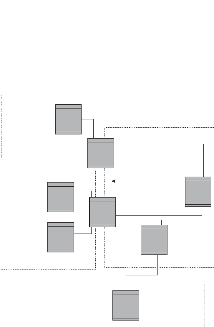
PowerConnect B-Series FCX Configuration Guide 923
53-1002266-01
Overview of OSPF 29
An Autonomous System Boundary Router (ASBR) is a router that is running multiple protocols and
serves as a gateway to routers outside an area and those operating with different protocols. The
ASBR is able to import and translate different protocol routes into OSPF through a process known
as redistribution. For more details on redistribution and configuration examples, refer to “Enabling
route redistribution” on page 953.
FIGURE 138 OSPF operating in a network
OSPF point-to-point links
One important OSPF process is Adjacency. Adjacency occurs when a relationship is formed
between neighboring routers for the purpose of exchanging routing information. Adjacent OSPF
neighbor routers go beyond the simple Hello packet exchange; they exchange database
information. In order to minimize the amount of information exchanged on a particular segment,
one of the first steps in creating adjacency is to assign a Designated Router (DR) and a Backup
Designated Router (BDR). The Designated Router ensures that there is a central point of contact,
thereby improving convergence time within a multi-access segment.
Area 0.0.0.0 Backbone
Area 192.5.1.0
Area 200.5.0.0
Area 195.5.0.0
Router A
Router B
Router C
Router D
Router E
Router F
Router G
208.5.1.1
Area Border
Router (ABR)
Virtual Link
Area Border
Router (ABR)
Autonomous System
Border Router (ASBR)
RIP Router
206.5.1.1
e8
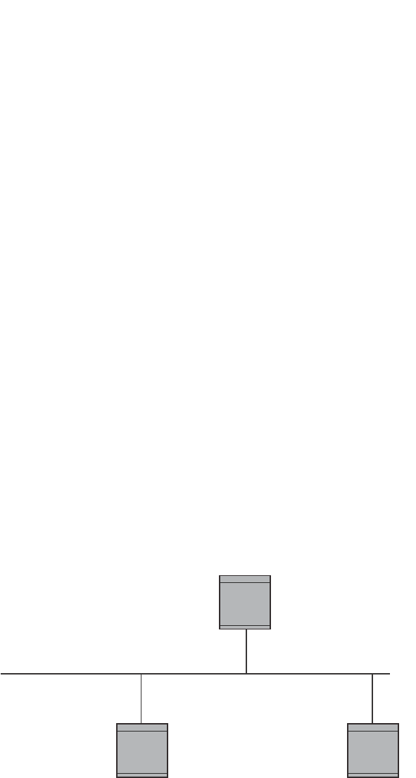
924 PowerConnect B-Series FCX Configuration Guide
53-1002266-01
Overview of OSPF
29
In an OSPF point-to-point network, where a direct Layer 3 connection exists between a single pair of
OSPF routers, there is no need for Designated and Backup Designated Routers, as is the case in
OSPF multi-access networks. Without the need for Designated and Backup Designated routers, a
point-to-point network establishes adjacency and converges faster. The neighboring routers
become adjacent whenever they can communicate directly. In contrast, in broadcast and
non-broadcast multi-access (NBMA) networks, the Designated Router and Backup Designated
Router become adjacent to all other routers attached to the network.
To configure an OSPF point-to-point link, refer to “Configuring an OSPF point-to-point link” on
page 963.
Designated routers in multi-access networks
In a network that has multiple routers attached, OSPF elects one router to serve as the designated
router (DR) and another router on the segment to act as the backup designated router (BDR). This
arrangement minimizes the amount of repetitive information that is forwarded on the network by
forwarding all messages to the designated router and backup designated routers responsible for
forwarding the updates throughout the network.
Designated router election in multi-access networks
In a network with no designated router and no backup designated router, the neighboring router
with the highest priority is elected as the DR, and the router with the next largest priority is elected
as the BDR, as shown in Figure 139
FIGURE 139 Designated and backup router election
If the DR goes off-line, the BDR automatically becomes the DR. The router with the next highest
priority becomes the new BDR. This process is shown in Figure 140.
Router A
Router B
Router C
priority 10
priority 20
priority 5
Designated Backup Router
Designated Router
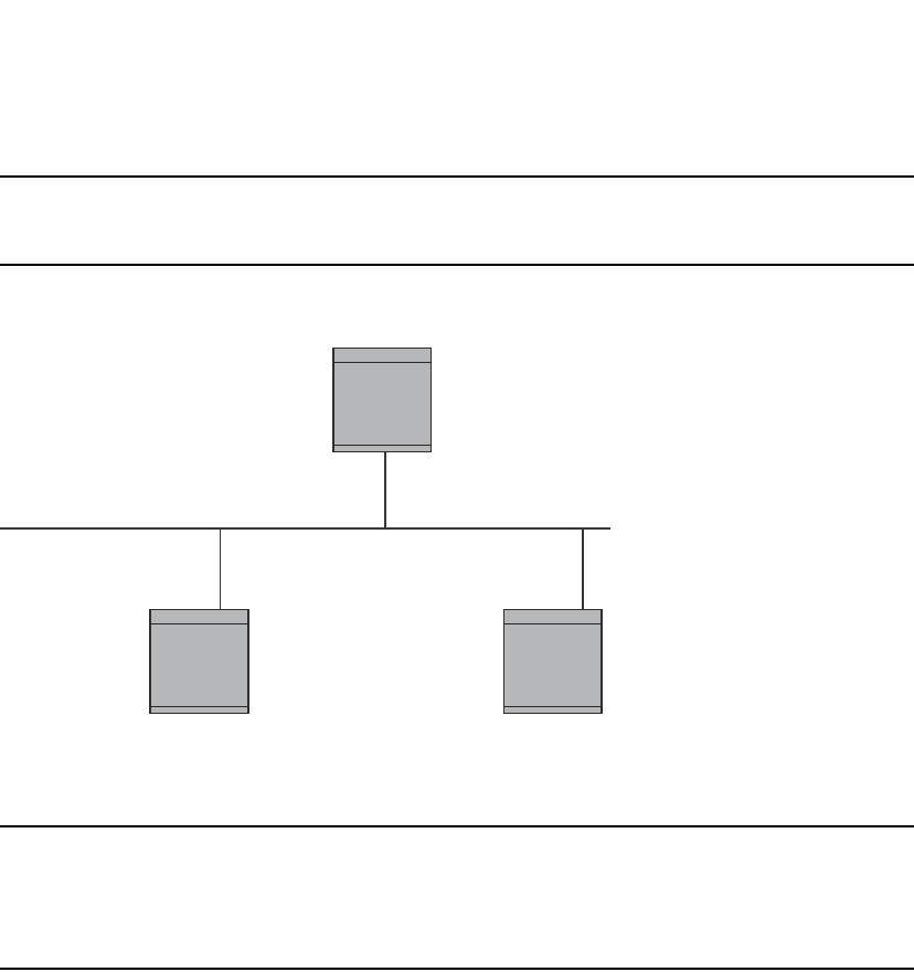
PowerConnect B-Series FCX Configuration Guide 925
53-1002266-01
Overview of OSPF 29
NOTE
Priority is a configurable option at the interface level. You can use this parameter to help bias one
router as the DR.
FIGURE 140 Backup designated router becomes designated router
If two neighbors share the same priority, the router with the highest router ID is designated as the
DR. The router with the next highest router ID is designated as the BDR.
NOTE
By default, the Dell router ID is the IP address configured on the lowest numbered loopback
interface. If the Layer 3 Switch does not have a loopback interface, the default router ID is the lowest
numbered IP address configured on the device. For more information or to change the router ID,
refer to “Changing the router ID” on page 809.
When multiple routers on the same network are declaring themselves as DRs, then both priority
and router ID are used to select the designated router and backup designated routers.
When only one router on the network claims the DR role despite neighboring routers with higher
priorities or router IDs, this router remains the DR. This is also true for BDRs.
The DR and BDR election process is performed when one of the following events occurs:
•An interface is in a waiting state and the wait time expires
•An interface is in a waiting state and a hello packet is received that addresses the BDR
•A change in the neighbor state occurs, such as:
-A neighbor state transitions from 2 or higher
-Communication to a neighbor is lost
-A neighbor declares itself to be the DR or BDR for the first time
OSPF RFC 1583 and 2178 compliance
Dell routers are configured, by default, to be compliant with the RFC 1583 OSPF V2 specification.
Dell routers can also be configured to operate with the latest OSPF standard, RFC 2178.
X
Designated Backup Router
Router C
priority 5
Router B
priority 20
Designated Router
priority 10
Router A

926 PowerConnect B-Series FCX Configuration Guide
53-1002266-01
Overview of OSPF
29
NOTE
For details on how to configure the system to operate with the RFC 2178, refer to “Modifying the
OSPF standard compliance setting” on page 962.
Reduction of equivalent AS External LSAs
An OSPF ASBR uses AS External link advertisements (AS External LSAs) to originate advertisements
of a route to another routing domain, such as a BGP4 or RIP domain. The ASBR advertises the
route to the external domain by flooding AS External LSAs to all the other OSPF routers (except
those inside stub networks) within the local OSPF Autonomous System (AS).
In some cases, multiple ASBRs in an AS can originate equivalent LSAs. The LSAs are equivalent
when they have the same cost, the same next hop, and the same destination. Dell PowerConnect
devices optimize OSPF by eliminating duplicate AS External LSAs in this case. The Layer 3 Switch
with the lower router ID flushes the duplicate External LSAs from its database and thus does not
flood the duplicate External LSAs into the OSPF AS. AS External LSA reduction therefore reduces
the size of the Layer 3 Switch link state database.
This enhancement implements the portion of RFC 2328 that describes AS External LSA reduction.
This enhancement is enabled by default, requires no configuration, and cannot be disabled.
Figure 141 shows an example of the AS External LSA reduction feature. In this example, Dell Layer
3 Switches D and E are OSPF ASBRs, and thus communicate route information between the OSPF
AS, which contains Routers A, B, and C, and another routing domain, which contains Router F. The
other routing domain is running another routing protocol, such as BGP4 or RIP. Routers D, E, and F,
therefore, are each running both OSPF and either BGP4 or RIP.
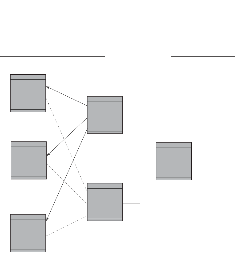
PowerConnect B-Series FCX Configuration Guide 927
53-1002266-01
Overview of OSPF 29
FIGURE 141 AS External LSA reduction
Notice that both Router D and Router E have a route to the other routing domain through Router F.
In earlier software releases, if Routers D and E have equal-cost routes to Router F, then both Router
D and Router E flood AS External LSAs to Routers A, B, and C advertising the route to Router F.
Since both routers are flooding equivalent routes, Routers A, B, and C receive multiple routes with
the same cost to the same destination (Router F). For Routers A, B, and C, either route to Router F
(through Router D or through Router E) is equally good.
OSPF eliminates the duplicate AS External LSAs. When two or more Layer 3 Switches configured as
ASBRs have equal-cost routes to the same next-hop router in an external routing domain, the ASBR
with the highest router ID floods the AS External LSAs for the external domain into the OSPF AS,
while the other ASBRs flush the equivalent AS External LSAs from their databases. As a result, the
overall volume of route advertisement traffic within the AS is reduced and the Layer 3 Switches
Router B
Router A
Router C
Router D
Router ID: 2.2.2.2
OSPF A
utonomous System (AS)
Router E
Router ID: 1.1.1.1
Routers D, E, and F
are OSPF ASBRs
and EBGP routers.Another routing domain
(such as BGP4 or RIP)
Router F

928 PowerConnect B-Series FCX Configuration Guide
53-1002266-01
Overview of OSPF
29
that flush the duplicate AS External LSAs have more memory for other OSPF data. In Figure 141,
since Router D has a higher router ID than Router E, Router D floods the AS External LSAs for
Router F to Routers A, B, and C. Router E flushes the equivalent AS External LSAs from its
database.
Algorithm for AS External LSA reduction
Figure 141 shows an example in which the normal AS External LSA reduction feature is in effect.
The behavior changes under the following conditions:
•There is one ASBR advertising (originating) a route to the external destination, but one of the
following happens:
•A second ASBR comes on-line
•A second ASBR that is already on-line begins advertising an equivalent route to the same
destination.
In either case above, the router with the higher router ID floods the AS External LSAs and the
other router flushes its equivalent AS External LSAs. For example, if Router D is offline, Router
E is the only source for a route to the external routing domain. When Router D comes on-line, it
takes over flooding of the AS External LSAs to Router F, while Router E flushes its equivalent AS
External LSAs to Router F.
•One of the ASBRs starts advertising a route that is no longer equivalent to the route the other
ASBR is advertising. In this case, the ASBRs each flood AS External LSAs. Since the LSAs
either no longer have the same cost or no longer have the same next-hop router, the LSAs are
no longer equivalent, and the LSA reduction feature no longer applies.
•The ASBR with the higher router ID becomes unavailable or is reconfigured so that it is no
longer an ASBR. In this case, the other ASBR floods the AS External LSAs. For example, if
Router D goes off-line, then Router E starts flooding the AS with AS External LSAs for the route
to Router F.
Support for OSPF RFC 2328 Appendix E
Dell PowerConnect devices provide support for Appendix E in OSPF RFC 2328. Appendix E
describes a method to ensure that an OSPF router (such as a Layer 3 Switch) generates unique link
state IDs for type-5 (External) link state advertisements (LSAs) in cases where two networks have
the same network address but different network masks.
NOTE
Support for Appendix E of RFC 2328 is enabled automatically and cannot be disabled. No user
configuration is required.
Normally, an OSPF router uses the network address alone for the link state ID of the link state
advertisement (LSA) for the network. For example, if the router needs to generate an LSA for
network 10.1.2.3 255.0.0.0, the router generates ID 10.1.2.3 for the LSA.
However, suppose that an OSPF router needs to generate LSAs for all the following networks:
•10.0.0.0 255.0.0.0
•10.0.0.0 255.255.0.0
•10.0.0.0 255.255.255.0

PowerConnect B-Series FCX Configuration Guide 929
53-1002266-01
Overview of OSPF 29
All three networks have the same network address, 10.0.0.0. Without support for RFC 2328
Appendix E, an OSPF router uses the same link state ID, 10.0.0.0, for the LSAs for all three
networks. For example, if the router generates an LSA with ID 10.0.0.0 for network 10.0.0.0
255.0.0.0, this LSA conflicts with the LSA generated for network 10.0.0.0 255.255.0.0 or 10.0.0.0
255.255.255.0. The result is multiple LSAs that have the same ID but that contain different route
information.
When Appendix E is supported, the router generates the link state ID for a network as follows.
1. Does an LSA with the network address as its ID already exist?
•No – Use the network address as the ID.
•Yes – Go to step 2.
2. Compare the networks that have the same network address, to determine which network is
more specific. The more specific network is the one that has more contiguous one bits in its
network mask. For example, network 10.0.0.0 255.255.0.0 is more specific than network
10.0.0.0 255.0.0.0, because the first network has 16 ones bits (255.255.0.0) whereas the
second network has only 8 ones bits (255.0.0.0):
•For the less specific network, use the networks address as the ID.
•For the more specific network, use the network broadcast address as the ID. The
broadcast address is the network address, with all ones bits in the host portion of the
address. For example, the broadcast address for network 10.0.0.0 255.255.0.0 is
10.0.255.255.
If this comparison results in a change to the ID of an LSA that has already been generated, the
router generates a new LSA to replace the previous one. For example, if the router has already
generated an LSA for network with ID 10.0.0.0 for network 10.0.0.0 255.255.255.0, the router
must generate a new LSA for the network, if the router needs to generate an LSA for network
10.0.0.0 255.255.0.0 or 10.0.0.0 255.0.0.0.
Dynamic OSPF activation and configuration
OSPF is automatically activated when you enable it. The protocol does not require a software
reload.
You can configure and save the following OSPF changes without resetting the system:
•All OSPF interface-related parameters (for example: area, hello timer, router dead time cost,
priority, re-transmission time, transit delay)
•All area parameters
•All area range parameters
•All virtual-link parameters
•All global parameters
•Creation and deletion of an area, interface or virtual link
In addition, you can make the following changes without a system reset by first disabling and then
re-enabling OSPF operation:
•Changes to address ranges
•Changes to global values for redistribution
•Addition of new virtual links

930 PowerConnect B-Series FCX Configuration Guide
53-1002266-01
OSPF graceful restart
29
You also can change the amount of memory allocated to various types of LSA entries. However,
these changes require a system reset or reboot.
Dynamic OSPF memory
PowerConnect devices dynamically allocate memory for Link State Advertisements (LSAs) and
other OSPF data structures. This eliminates overflow conditions and does not require a reload to
change OSPF memory allocation. So long as the Layer 3 Switch has free (unallocated) dynamic
memory, OSPF can use the memory.
To display the current allocations of dynamic memory, use the show memory command.
OSPF graceful restart
OSPF graceful restart is a high-availability routing feature that minimizes disruption in traffic
forwarding, diminishes route flapping, and provides continuous service during a system restart,
including restart events that occur during a switchover, failover, or hitless OS upgrade. During such
events, routes remain available between devices.
When OSPF graceful restart is enabled, a restarting router sends special LSAs, called grace LSAs,
to its neighbors either before a planned OSPF restart or immediately after an unplanned restart.
The grace LSAs specify a grace period for neighbors of the restarting router to continue using the
existing routes to and through the router after a restart. When the restarting router comes back up,
it continues to use its existing OSPF routes as if nothing happened. In the background, the router
relearns its neighbors prior to the restart, recalculates its OSPF routes, and replaces existing routes
with new routes as necessary. Once the grace period has passed, adjacent routers resume normal
operation.
OSPF graceful restart is enabled globally by default. In this configuration, all OSPF neighbors are
subject to the graceful restart capability. Neighbor routers must support the helper mode of OSPF
graceful restart, which is enabled by default on all PowerConnect Layer 3 switches.
NOTE
If a PowerConnect device is configured for OSPF graceful restart and is intended to be used in
switchover or hitless upgrade, the OSPF dead-interval should be changed to 60 seconds on OSPF
interfaces to ensure that the graceful restart process succeeds without a timeout. Instructions for
changing the OSPF dead-interval are provided in “Modifying interface defaults” on page 937.
The Dell implementation of OSPF graceful restart supports RFC 3623: Graceful OSPF Restart.
For details on how to configure OSPF graceful restart, refer to “Configuring OSPF graceful restart”
on page 963.
Configuring OSPF
Perform the following steps to begin using OSPF on the router.
1. Enable OSPF on the router.
2. Assign the areas to which the router will be attached.
3. Assign individual interfaces to the OSPF areas.

PowerConnect B-Series FCX Configuration Guide 931
53-1002266-01
Configuring OSPF 29
4. Define redistribution filters, if desired.
5. Enable redistribution, if you defined redistribution filters.
6. Modify default global and port parameters as required.
7. Modify OSPF standard compliance, if desired.
NOTE
OSPF is automatically enabled without a system reset.
Configuration rules
•Dell PowerConnect devices support a maximum of 676 OSPF interfaces.
•If a router is to operate as an ASBR, you must enable the ASBR capability at the system level.
•Redistribution must be enabled on routers configured to operate as ASBRs.
•All router ports must be assigned to one of the defined areas on an OSPF router. When a port
is assigned to an area, all corresponding subnets on that port are automatically included in the
assignment.
OSPF parameters
You can modify or set the following global and interface OSPF parameters.
Global parameters:
•Modify OSPF standard compliance setting.
•Assign an area.
•Define an area range.
•Define the area virtual link.
•Set global default metric for OSPF.
•Change the reference bandwidth for the default cost of OSPF interfaces.
•Disable or re-enable load sharing.
•Enable or disable default-information-originate.
•Modify Shortest Path First (SPF) timers
•Define external route summarization
•Define redistribution metric type.
•Define deny redistribution.
•Define permit redistribution.
•Enable redistribution.
•Change the LSA pacing interval.
•Modify OSPF Traps generated.
•Modify database overflow interval.

932 PowerConnect B-Series FCX Configuration Guide
53-1002266-01
Configuring OSPF
29
Interface parameters:
•Assign interfaces to an area.
•Define the authentication key for the interface.
•Change the authentication-change interval
•Modify the cost for a link.
•Modify the dead interval.
•Modify MD5 authentication key parameters.
•Modify the priority of the interface.
•Modify the retransmit interval for the interface.
•Modify the transit delay of the interface.
NOTE
When using the CLI, you set global level parameters at the OSPF CONFIG level of the CLI. To reach
that level, enter router ospf… at the global CONFIG level. Interface parameters for OSPF are set at
the interface CONFIG level using the CLI command, ip ospf…
When using the Web Management Interface, you set OSPF global parameters using the OSPF
configuration panel. All other parameters are accessed through links accessed from the OSPF
configuration sheet.
Enabling OSPF on the router
When you enable OSPF on the router, the protocol is automatically activated. To enable OSPF on
the router, enter the following CLI command.
PowerConnect(config)#router ospf
This command launches you into the OSPF router level where you can assign areas and modify
OSPF global parameters.
Syntax: router ospf
Note regarding disabling OSPF
If you disable OSPF, the Layer 3 Switch removes all the configuration information for the disabled
protocol from the running-config. Moreover, when you save the configuration to the startup-config
file after disabling one of these protocols, all the configuration information for the disabled protocol
is removed from the startup-config file.
NOTE
If you do not want to delete the OSPF configuration information, use the CLI command clear ip ospf
all instead of no router ospf. Refer to “Resetting OSPF” on page 933.
When you enter the no router ospf command, the CLI displays a warning message such as the
following.
PowerConnect(config-ospf-router)#no router ospf
router ospf mode now disabled. All ospf config data will be lost when writing to
flash!
The Web Management Interface does not display a warning message.

PowerConnect B-Series FCX Configuration Guide 933
53-1002266-01
Configuring OSPF 29
If you have disabled the protocol but have not yet saved the configuration to the startup-config file
and reloaded the software, you can restore the configuration information by re-entering the
command to enable the protocol (for example, router ospf), or by selecting the Web management
option to enable the protocol. If you have already saved the configuration to the startup-config file
and reloaded the software, the information is gone.
If you are testing an OSPF configuration and are likely to disable and re-enable the protocol, you
might want to make a backup copy of the startup-config file containing the protocol configuration
information. This way, if you remove the configuration information by saving the configuration after
disabling the protocol, you can restore the configuration by copying the backup copy of the
startup-config file onto the flash memory.
Resetting OSPF
The clear ip ospf all command globally resets (disables then re-enables) OSPF without deleting the
OSPF configuration information. This command is equivalent to entering the commands no router
ospf followed by router ospf. Whereas the no router ospf command disables OSPF and removes all
the configuration information for the disabled protocol from the running-config, the router ospf
command re-enables OSPF and restores the OSPF configuration information.
The clear ip ospf all command is useful If you are testing an OSPF configuration and are likely to
disable and re-enable the protocol. This way, you do not have to save the configuration after
disabling the protocol, and you do not have to restore the configuration by copying the backup copy
of the startup-config file onto the flash memory.
To reset OSPF without deleting the OSPF configuration, enter the following command at the Global
CONFIG level or at the Router OSPF level of the CLI.
PowerConnect#clear ip ospf all
Syntax: clear ip ospf all
Assigning OSPF areas
Once OSPF is enabled on the system, you can assign areas. Assign an IP address or number as the
area ID for each area. The area ID is representative of all IP addresses (subnets) on a router port.
Each port on a router can support one area.
An area can be normal, a stub, or a Not-So-Stubby Area (NSSA):
•Normal – OSPF routers within a normal area can send and receive External Link State
Advertisements (LSAs).
•Stub – OSPF routers within a stub area cannot send or receive External LSAs. In addition,
OSPF routers in a stub area must use a default route to the area Area Border Router (ABR) or
Autonomous System Boundary Router (ASBR) to send traffic out of the area.
•NSSA – The ASBR of an NSSA can import external route information into the area:
-ASBRs redistribute (import) external routes into the NSSA as type 7 LSAs. Type-7 External
LSAs are a special type of LSA generated only by ASBRs within an NSSA, and are flooded
to all the routers within only that NSSA.
-ABRs translate type 7 LSAs into type 5 External LSAs, which can then be flooded
throughout the AS. You can configure address ranges on the ABR of an NSSA so that the
ABR converts multiple type-7 External LSAs received from the NSSA into a single type-5
External LSA.

934 PowerConnect B-Series FCX Configuration Guide
53-1002266-01
Configuring OSPF
29
When an NSSA contains more than one ABR, OSPF elects one of the ABRs to perform the
LSA translation for NSSA. OSPF elects the ABR with the highest router ID. If the elected
ABR becomes unavailable, OSPF automatically elects the ABR with the next highest router
ID to take over translation of LSAs for the NSSA. The election process for NSSA ABRs is
automatic.
Example
To set up the OSPF areas shown in Figure 138 on page 923, enter the following commands.
PowerConnect(config-ospf-router)#area 192.5.1.0
PowerConnect(config-ospf-router)#area 200.5.0.0
PowerConnect(config-ospf-router)#area 195.5.0.0
PowerConnect(config-ospf-router)#area 0.0.0.0
PowerConnect(config-ospf-router)#write memory
Syntax: area <num> | <ip-addr>
The <num> | <ip-addr> parameter specifies the area number, which can be a number or in IP
address format. If you specify a number, the number can be from 0 through 18.
NOTE
You can assign one area on a router interface. For example, if the system or chassis module has 16
ports, 16 areas are supported on the chassis or module.
Assigning a totally stubby area
By default, the Layer 3 Switch sends summary LSAs (LSA type 3) into stub areas. You can further
reduce the number of link state advertisements (LSAs) sent into a stub area by configuring the
Layer 3 Switch to stop sending summary LSAs (type 3 LSAs) into the area. You can disable the
summary LSAs when you are configuring the stub area or later after you have configured the area.
This feature disables origination of summary LSAs, but the Layer 3 Switch still accepts summary
LSAs from OSPF neighbors and floods them to other neighbors. The Layer 3 Switch can form
adjacencies with other routers regardless of whether summarization is enabled or disabled for
areas on each router.
When you enter a command or apply a Web management option to disable the summary LSAs, the
change takes effect immediately. If you apply the option to a previously configured area, the Layer
3 Switch flushes all of the summary LSAs it has generated (as an ABR) from the area.
NOTE
This feature applies only when the Layer 3 Switch is configured as an Area Border Router (ABR) for
the area. To completely prevent summary LSAs from being sent to the area, disable the summary
LSAs on each OSPF router that is an ABR for the area.
This feature does not apply to Not-So-Stubby Areas (NSSAs).
To disable summary LSAs for a stub area, enter commands such as the following.
PowerConnect(config-ospf-router)#area 40 stub 99 no-summary
Syntax: area <num> | <ip-addr> stub <cost> [no-summary]
The <num> | <ip-addr> parameter specifies the area number, which can be a number or in IP
address format. If you specify a number, the number can be from 0 through 18.

PowerConnect B-Series FCX Configuration Guide 935
53-1002266-01
Configuring OSPF 29
The stub <cost> parameter specifies an additional cost for using a route to or from this area and
can be from 1 through 16777215. There is no default. Normal areas do not use the cost
parameter.
The no-summary parameter applies only to stub areas and disables summary LSAs from being sent
into the area.
NOTE
You can assign one area on a router interface. For example, if the system or chassis module has 16
ports, 16 areas are supported on the chassis or module.
Assigning a Not-So-Stubby Area (NSSA)
The OSPF Not-So-Stubby Area (NSSA) feature enables you to configure OSPF areas that provide the
benefits of stub areas, but that also are capable of importing external route information. OSPF
does not flood external routes from other areas into an NSSA, but does translate and flood route
information from the NSSA into other areas such as the backbone.
NSSAs are especially useful when you want to summarize Type-5 External LSAs (external routes)
before forwarding them into an OSPF area. The OSPF specification (RFC 2328) prohibits
summarization of Type-5 LSAs and requires OSPF to flood Type-5 LSAs throughout a routing
domain. When you configure an NSSA, you can specify an address range for aggregating the
external routes that the NSSA's ABR exports into other areas.
The Dell implementation of NSSA is based on RFC 1587.
Figure 142 shows an example of an OSPF network containing an NSSA.
FIGURE 142 OSPF network containing an NSSA
This example shows two routing domains, a RIP domain and an OSPF domain. The ASBR inside the
NSSA imports external routes from RIP into the NSSA as Type-7 LSAs, which the ASBR floods
throughout the NSSA.
RIP Domain
Layer 3
Switch
Layer 3
Switch
Layer 3
Switch
NSSA
Area 1.1.1.1
Internal ASBR OSPF ABR
OSPF Area 0
Backbone

936 PowerConnect B-Series FCX Configuration Guide
53-1002266-01
Configuring OSPF
29
The ABR translates the Type-7 LSAs into Type-5 LSAs. If an area range is configured for the NSSA,
the ABR also summarizes the LSAs into an aggregate LSA before flooding the Type-5 LSAs into the
backbone.
Since the NSSA is partially “stubby” the ABR does not flood external LSAs from the backbone into
the NSSA. To provide access to the rest of the Autonomous System (AS), the ABR generates a
default Type-7 LSA into the NSSA.
Configuring an NSSA
To configure OSPF area 1.1.1.1 as an NSSA, enter the following commands.
PowerConnect(config)#router ospf
PowerConnect(config-ospf-router)#area 1.1.1.1 nssa 1
PowerConnect(config-ospf-router)#write memory
Syntax: area <num> | <ip-addr> nssa <cost> | default-information-originate
The <num> | <ip-addr> parameter specifies the area number, which can be a number or in IP
address format. If you specify a number, the number can be from 0 through 18.
The nssa <cost> | default-information-originate parameter specifies that this is a Not-So-Stubby
Area (NSSA). The <cost> specifies an additional cost for using a route to or from this NSSA and can
be from 1 through 16777215. There is no default. Normal areas do not use the cost parameter.
Alternatively, the default-information-originate parameter causes the Layer 3 Switch to inject the
default route into the NSSA.
NOTE
The Layer 3 Switch does not inject the default route into an NSSA by default.
NOTE
You can assign one area on a router interface. For example, if the system or chassis module has 16
ports, 16 areas are supported on the chassis or module.
To configure additional parameters for OSPF interfaces in the NSSA, use the ip ospf area…
command at the interface level of the CLI.
Configuring a summary address for the NSSA
If you want the ABR that connects the NSSA to other areas to summarize the routes in the NSSA
before translating them into Type-5 LSAs and flooding them into the other areas, configure a
summary address. The ABR creates an aggregate value based on the summary address. The
aggregate value becomes the address that the ABR advertises instead of advertising the individual
addresses represented by the aggregate.
To configure a summary address in NSSA 1.1.1.1, enter the following commands. This example
assumes that you have already configured NSSA 1.1.1.1.
PowerConnect(config)#router ospf
PowerConnect(config-ospf-router)#summary-address 209.157.22.1 255.255.0.0
PowerConnect(config-ospf-router)#write memory
Syntax: [no] summary-address <ip-addr> <ip-mask>
The <ip-addr> parameter specifies the IP address portion of the range. The software compares the
address with the significant bits in the mask. All network addresses that match this comparison
are summarized in a single route advertised by the router.

PowerConnect B-Series FCX Configuration Guide 937
53-1002266-01
Configuring OSPF 29
The <ip-mask> parameter specifies the portions of the IP address that a route must contain to be
summarized in the summary route. In the example above, all networks that begin with 209.157 are
summarized into a single route.
Assigning an area range (optional)
You can assign a range for an area, but it is not required. Ranges allow a specific IP address and
mask to represent a range of IP addresses within an area, so that only that reference range
address is advertised to the network, instead of all the addresses within that range. Each area can
have up to 32 range addresses.
Example
To define an area range for subnets on 193.45.5.1 and 193.45.6.2, enter the following commands.
PowerConnect(config)#router ospf
PowerConnect(config-ospf-router)#area 192.45.5.1 range 193.45.0.0 255.255.0.0
PowerConnect(config-ospf-router)#area 193.45.6.2 range 193.45.0.0 255.255.0.0
Syntax: area <num> | <ip-addr> range <ip-addr> <ip-mask>
The <num> | <ip-addr> parameter specifies the area number, which can be in IP address format.
The range <ip-addr> parameter specifies the IP address portion of the range. The software
compares the address with the significant bits in the mask. All network addresses that match this
comparison are summarized in a single route advertised by the router.
The <ip-mask> parameter specifies the portions of the IP address that a route must contain to be
summarized in the summary route. In the example above, all networks that begin with 193.45 are
summarized into a single route.
Assigning interfaces to an area
Once you define OSPF areas, you can assign interfaces to the areas. All router ports must be
assigned to one of the defined areas on an OSPF router. When a port is assigned to an area, all
corresponding subnets on that port are automatically included in the assignment.
To assign interface 1/8 to area 195.5.0.0 and then save the changes, enter the following
commands.
PowerConnect(config-ospf-router)#interface e 1/8
PowerConnect(config-if-1/8)#ip ospf area 195.5.0.0
PowerConnect(config-if-1/8)#write memory
Modifying interface defaults
OSPF has interface parameters that you can configure. For simplicity, each of these parameters
has a default value. No change to these default values is required except as needed for specific
network configurations.
Port default values can be modified using the following commands at the interface configuration
level of the CLI:
•ip ospf area <ip-addr>
•ip ospf auth-change-wait-time <secs>
•ip ospf authentication-key [0 | 1] <string>

938 PowerConnect B-Series FCX Configuration Guide
53-1002266-01
Configuring OSPF
29
•ip ospf cost <num>
•ip ospf dead-interval <value>
•ip ospf hello-interval <value>
•ip ospf md5-authentication key-activation-wait-time <num> | key-id <num> [0 | 1] key
<string>
•ip ospf passive
•ip ospf priority <value>
•ip ospf retransmit-interval <value>
•ip ospf transmit-delay <value>
For a complete description of these parameters, see the summary of OSPF port parameters in the
next section.
OSPF interface parameters
The following parameters apply to OSPF interfaces.
Area: Assigns an interface to a specific area. You can assign either an IP address or number to
represent an OSPF Area ID. If you assign a number, it can be any value from 0 through
2,147,483,647.
Auth-change-wait-time: OSPF gracefully implements authentication changes to allow all routers to
implement the change and thus prevent disruption to neighbor adjacencies. During the
authentication-change interval, both the old and new authentication information is supported. The
default authentication-change interval is 300 seconds (5 minutes). You change the interval to a
value from 0 through 14400 seconds.
Authentication-key: OSPF supports three methods of authentication for each interface—none,
simple password, and MD5. Only one method of authentication can be active on an interface at a
time. The default authentication value is none, meaning no authentication is performed.
The simple password method of authentication requires you to configure an alphanumeric
password on an interface. The simple password setting takes effect immediately. All OSPF packets
transmitted on the interface contain this password. Any OSPF packet received on the interface is
checked for this password. If the password is not present, then the packet is dropped. The
password can be up to eight characters long.
The MD5 method of authentication requires you to configure a key ID and an MD5 Key. The key ID
is a number from 1 through 255 and identifies the MD5 key that is being used. The MD5 key can
be up to sixteen alphanumeric characters long.
Cost: Indicates the overhead required to send a packet across an interface. You can modify the
cost to differentiate between 100 Mbps and 1000 Mbps (1 Gbps) links. The default cost is
calculated by dividing 100 million by the bandwidth. For 10 Mbps links, the cost is 10. The cost for
both 100 Mbps and 1000 Mbps links is 1, because the speed of 1000 Mbps was not in use at the
time the OSPF cost formula was devised.
Dead-interval: Indicates the number of seconds that a neighbor router waits for a hello packet from
the current router before declaring the router down. The value can be from 1 through 65535
seconds. The default is 40 seconds.
Hello-interval: Represents the length of time between the transmission of hello packets. The value
can be from 1 through 65535 seconds. The default is 10 seconds.

PowerConnect B-Series FCX Configuration Guide 939
53-1002266-01
Configuring OSPF 29
MD5-authentication activation wait time: The number of seconds the Layer 3 Switch waits until
placing a new MD5 key into effect. The wait time provides a way to gracefully transition from one
MD5 key to another without disturbing the network. The wait time can be from 0 through 14400
seconds. The default is 300 seconds (5 minutes).
MD5-authentication key ID and key: A method of authentication that requires you to configure a key
ID and an MD5 key. The key ID is a number from 1 through 255 and identifies the MD5 key that is
being used. The MD5 key consists of up to 16 alphanumeric characters. The MD5 is encrypted
and included in each OSPF packet transmitted.
Passive: When you configure an OSPF interface to be passive, that interface does not send or
receive OSPF route updates. By default, all OSPF interfaces are active and thus can send and
receive OSPF route information. Since a passive interface does not send or receive route
information, the interface is in effect a stub network. OSPF interfaces are active by default.
NOTE
This option affects all IP subnets configured on the interface. If you want to disable OSPF updates
only on some of the IP subnets on the interface, use the ospf-ignore or ospf-passive parameter with
the ip address command. Refer to “Assigning an IP address to an Ethernet port” on page 800.
Priority: Allows you to modify the priority of an OSPF router. The priority is used when selecting the
designated router (DR) and backup designated routers (BDRs). The value can be from 0 through
255. The default is 1. If you set the priority to 0, the Layer 3 Switch does not participate in DR and
BDR election.
Retransmit-interval: The time between retransmissions of link-state advertisements (LSAs) to
adjacent routers for this interface. The value can be from 0 through 3600 seconds. The default is
5 seconds.
Transit-delay: The time it takes to transmit Link State Update packets on this interface. The value
can be from 0 through 3600 seconds. The default is 1 second.
Encrypted display of the authentication string or MD5 authentication key
The optional 0 | 1 parameter with the authentication-key and md5-authentication key-id
parameters affects encryption.
For added security, PowerConnect devices encrypt display of the password or authentication
string. Encryption is enabled by default. The software also provides an optional parameter to
disable encryption of a password or authentication string, on an individual OSPF area or OSPF
interface basis.
When encryption of the passwords or authentication strings is enabled, they are encrypted in the
CLI regardless of the access level you are using. In the Web Management Interface, the passwords
or authentication strings are encrypted at the read-only access level but are visible at the
read-write access level.
The encryption option can be omitted (the default) or can be one of the following:
•0 – Disables encryption for the password or authentication string you specify with the
command. The password or string is shown as clear text in the running-config and the
startup-config file. Use this option of you do not want display of the password or string to be
encrypted.
•1 – Assumes that the password or authentication string you enter is the encrypted form, and
decrypts the value before using it.

940 PowerConnect B-Series FCX Configuration Guide
53-1002266-01
Configuring OSPF
29
NOTE
If you want the software to assume that the value you enter is the clear-text form, and to encrypt
display of that form, do not enter 0 or 1. Instead, omit the encryption option and allow the software
to use the default behavior.
If you specify encryption option 1, the software assumes that you are entering the encrypted form
of the password or authentication string. In this case, the software decrypts the password or string
you enter before using the value for authentication. If you accidentally enter option 1 followed by
the clear-text version of the password or string, authentication will fail because the value used by
the software will not match the value you intended to use.
Changing the timer for OSPF authentication changes
When you make an OSPF authentication change, the software uses the authentication-change
timer to gracefully implement the change. The software implements the change in the following
ways:
•Outgoing OSPF packets – After you make the change, the software continues to use the old
authentication to send packets, during the remainder of the current authentication-change
interval. After this, the software uses the new authentication for sending packets.
•Inbound OSPF packets – The software accepts packets containing the new authentication and
continues to accept packets containing the older authentication for two authentication-change
intervals. After the second interval ends, the software accepts packets only if they contain the
new authentication key.
The default authentication-change interval is 300 seconds (5 minutes). You change the interval to
a value from 0 through 14400 seconds.
OSPF provides graceful authentication change for all the following types of authentication changes
in OSPF:
•Changing authentication methods from one of the following to another of the following:
-Simple text password
-MD5 authentication
-No authentication
•Configuring a new simple text password or MD5 authentication key
•Changing an existing simple text password or MD5 authentication key
To change the authentication-change interval, enter a command such as the following at the
interface configuration level of the CLI.
PowerConnect(config-if-2/5)#ip ospf auth-change-wait-time 400
Syntax: [no] ip ospf auth-change-wait-time <secs>
The <secs> parameter specifies the interval and can be from 0 through 14400 seconds. The
default is 300 seconds (5 minutes).
NOTE
For backward compatibility, the ip ospf md5-authentication key-activation-wait-time <seconds>
command is still supported.

PowerConnect B-Series FCX Configuration Guide 941
53-1002266-01
Configuring OSPF 29
Block flooding of outbound LSAs on specific OSPF interfaces
By default, the Layer 3 Switch floods all outbound LSAs on all the OSPF interfaces within an area.
You can configure a filter to block outbound LSAs on an OSPF interface. This feature is particularly
useful when you want to block LSAs from some, but not all, of the interfaces attached to the area.
After you apply filters to block the outbound LSAs, the filtering occurs during the database
synchronization and flooding.
If you remove the filters, the blocked LSAs are automatically re-flooded. You do not need to reset
OSPF to re-flood the LSAs.
NOTE
You cannot block LSAs on virtual links.
To apply a filter to an OSPF interface to block flooding of outbound LSAs on the interface, enter the
following commands at the Interface configuration level for that interface.
PowerConnect(config-if-1/1)#ip ospf database-filter all out
PowerConnect(config-if-1/1)#clear ip ospf all
The first command in this example blocks all outbound LSAs on the OSPF interface configured on
port 1/1. The second command resets OSPF and places the command into effect immediately.
Syntax: [no] ip ospf database-filter all out
To remove the filter, enter a command such as the following.
PowerConnect(config-if-1/1)#no ip ospf database-filter all out
Configuring an OSPF non-broadcast interface
Layer 3 switches support Non-Broadcast Multi-Access (NBMA) networks. This feature enables you
to configure an interface on a Dell PowerConnect device to send OSPF traffic to its neighbor as
unicast packets rather than broadcast packets.
OSPF routers generally use broadcast packets to establish neighbor relationships and broadcast
route updates on Ethernet and virtual interfaces (VEs). In this release, as an alternative, you can
configure the Dell PowerConnect device to use unicast packets for this purpose. This can be useful
in situations where multicast traffic is not feasible (for example when a firewall does not allow
multicast packets).
On a non-broadcast interface, the routers at the other end of this interface must also be configured
as non-broadcast and neighbor routers. There is no restriction on the number of routers sharing a
non-broadcast interface (for example, through a hub or switch).
NOTE
Only Ethernet interfaces or VEs can be configured as non-broadcast interfaces.
To configure an OSPF interface as a non-broadcast interface, enable the feature on a physical
interface or a VE, following the ip ospf area statement, and then specify the IP address of the
neighbor in the OSPF configuration. The non-broadcast interface configuration must be done on
the OSPF routers on both ends of the link.
For example, the following commands configure VE 20 as a non-broadcast interface.

942 PowerConnect B-Series FCX Configuration Guide
53-1002266-01
Configuring OSPF
29
PowerConnect(config)#int ve 20
PowerConnect(config-vif-20)#ip ospf area 0
PowerConnect(config-vif-20)#ip ospf network non-broadcast
PowerConnect(config-vif-20)#exit
Syntax: [no] ip ospf network non-broadcast
The following commands specify 1.1.20.1 as an OSPF neighbor address. The address specified
must be in the same subnet as a non-broadcast interface.
PowerConnect(config)#router ospf
PowerConnect(config-ospf-router)#neighbor 1.1.20.1
For example, to configure the feature in a network with three routers connected by a hub or switch,
each router must have the linking interface configured as a non-broadcast interface, and both of
the other routers must be specified as neighbors.
The output of the show ip ospf interface command has been enhanced to display information
about non-broadcast interfaces and neighbors that are configured in the same subnet.
Example
PowerConnect#show ip ospf interface
v20,OSPF enabled
IP Address 1.1.20.4, Area 0
OSPF state BD, Pri 1, Cost 1, Options 2, Type non-broadcast Events 6
Timers(sec): Transit 1, Retrans 5, Hello 10, Dead 40
DR: Router ID 1.1.13.1 Interface Address 1.1.20.5
BDR: Router ID 2.2.2.1 Interface Address 1.1.20.4
Neighbor Count = 1, Adjacent Neighbor Count= 2
Non-broadcast neighbor config: 1.1.20.1, 1.1.20.2, 1.1.20.3, 1.1.20.5,
Neighbor: 1.1.20.5
Authentication-Key:None
MD5 Authentication: Key None, Key-Id None, Auth-change-wait-time 300
In the Type field, “non-broadcast” indicates that this is a non-broadcast interface. When the
interface type is non-broadcast, the Non-broadcast neighbor config field displays the neighbors
that are configured in the same subnet. If no neighbors are configured in the same subnet, a
message such as the following is displayed.
***Warning! no non-broadcast neighbor config in 1.1.100.1 255.255.255.0
Assigning virtual links
All ABRs (area border routers) must have either a direct or indirect link to the OSPF backbone area
(0.0.0.0 or 0). If an ABR does not have a physical link to the area backbone, the ABR can configure
a virtual link to another router within the same area, which has a physical connection to the area
backbone.
The path for a virtual link is through an area shared by the neighbor ABR (router with a physical
backbone connection), and the ABR requiring a logical connection to the backbone.
Two parameters fields must be defined for all virtual links—transit area ID and neighbor router:
•The transit area ID represents the shared area of the two ABRs and serves as the connection
point between the two routers. This number should match the area ID value.
•The neighbor router field is the router ID (IP address) of the router that is physically connected
to the backbone, when assigned from the router interface requiring a logical connection.
When assigning the parameters from the router with the physical connection, the router ID is
the IP address of the router requiring a logical connection to the backbone.
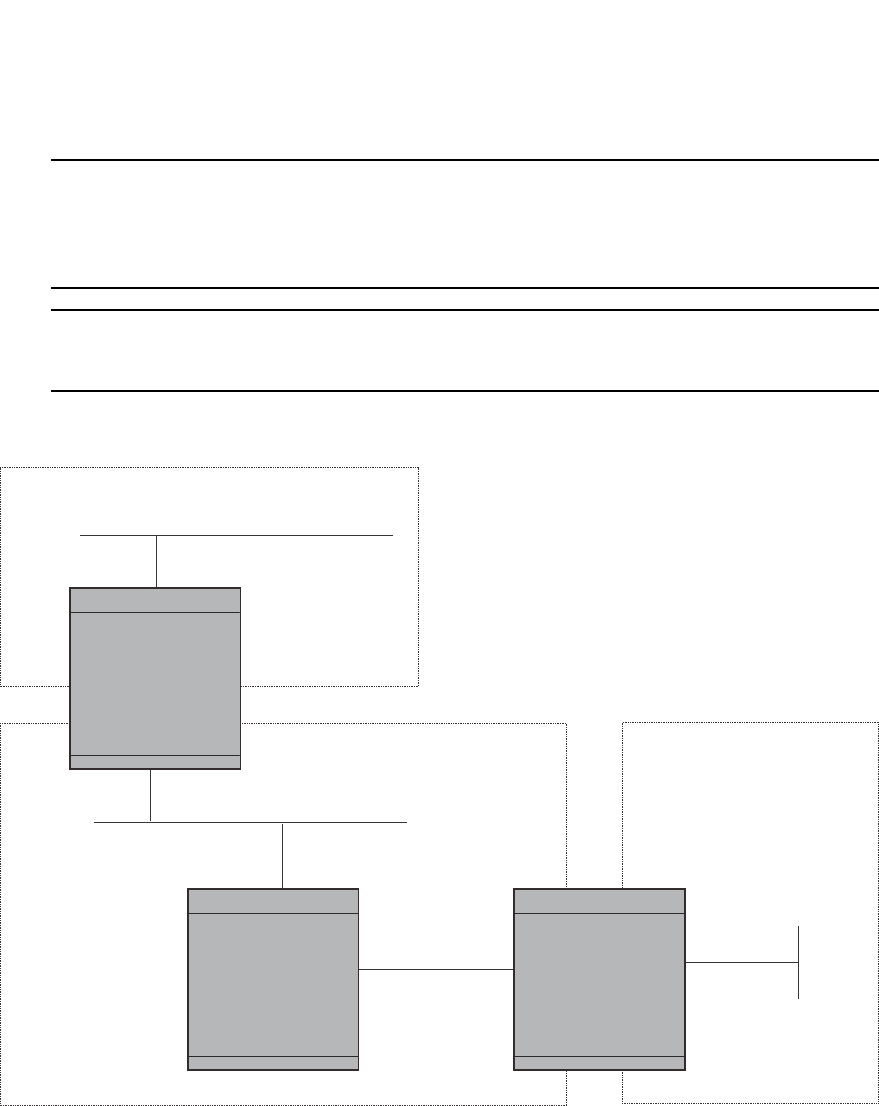
PowerConnect B-Series FCX Configuration Guide 943
53-1002266-01
Configuring OSPF 29
NOTE
By default, the Dell router ID is the IP address configured on the lowest numbered loopback
interface. If the Layer 3 Switch does not have a loopback interface, the default router ID is the lowest
numbered IP address configured on the device. For more information or to change the router ID,
refer to “Changing the router ID” on page 809.
NOTE
When you establish an area virtual link, you must configure it on both of the routers (both ends of
the virtual link).
FIGURE 143 Defining OSPF virtual links within a network
Example
Figure 143 shows an OSPF area border router, PowerConnect A, that is cut off from the backbone
area (area 0). To provide backbone access to PowerConnect A, you can add a virtual link between
PowerConnect A and PowerConnect C using area 1 as a transit area. To configure the virtual link,
you define the link on the router that is at each end of the link. No configuration for the virtual link
is required on the routers in the transit area.
To define the virtual link on PowerConnect A, enter the following commands.
PowerConnectA(config-ospf-router)#area 1 virtual-link 209.157.22.1
PowerConnectA(config-ospf-router)#write memory
Enter the following commands to configure the virtual link on PowerConnect C.
OSPF Area 0
OSPF Area 1
“transit area”
OSPF Area 2
Router ID 209.157.22.1
Router ID 10.0.0.1
DeviceC
DeviceB DeviceA

944 PowerConnect B-Series FCX Configuration Guide
53-1002266-01
Configuring OSPF
29
PowerConnectC(config-ospf-router)#area 1 virtual-link 10.0.0.1
PowerConnectC(config-ospf-router)#write memory
Syntax: area <ip-addr> | <num> virtual-link <router-id>
[authentication-key | dead-interval | hello-interval | retransmit-interval | transmit-delay
<value>]
The area <ip-addr> | <num> parameter specifies the transit area.
The <router-id> parameter specifies the router ID of the OSPF router at the remote end of the
virtual link. To display the router ID on a Layer 3 Switch, enter the show ip command.
Refer to “Modifying virtual link parameters” on page 944 for descriptions of the optional
parameters.
Modifying virtual link parameters
OSPF has some parameters that you can modify for virtual links. Notice that these are the same
parameters as the ones you can modify for physical interfaces.
You can modify default values for virtual links using the following CLI command at the OSPF router
level of the CLI, as shown in the following syntax.
Syntax: area <num> | <ip-addr> virtual-link <ip-addr> [authentication-key [0 | 1] <string>]
[dead-interval <num>]
[hello-interval <num>] [md5-authentication key-activation-wait-time <num> | key-id
<num> [0 | 1] key <string>]
[retransmit-interval <num>] [transmit-delay <num>]
The parameters are described in the next section.
Virtual link parameter descriptions
You can modify the following virtual link interface parameters.
Authentication Key: This parameter allows you to assign different authentication methods on a
port-by-port basis. OSPF supports three methods of authentication for each interface—none,
simple password, and MD5. Only one method of authentication can be active on an interface at a
time.
The simple password method of authentication requires you to configure an alphanumeric
password on an interface. The password can be up to eight characters long. The simple password
setting takes effect immediately. All OSPF packets transmitted on the interface contain this
password. All OSPF packets received on the interface are checked for this password. If the
password is not present, the packet is dropped.
The MD5 method of authentication encrypts the authentication key you define. The authentication
is included in each OSPF packet transmitted.
MD5 Authentication Key: When simple authentication is enabled, the key is an alphanumeric
password of up to eight characters. When MD5 is enabled, the key is an alphanumeric password of
up to 16 characters that is later encrypted and included in each OSPF packet transmitted. You
must enter a password in this field when the system is configured to operate with either simple or
MD5 authentication.
MD5 Authentication Key ID: The Key ID is a number from 1 through 255 and identifies the MD5
key that is being used. This parameter is required to differentiate among multiple keys defined on
a router.

PowerConnect B-Series FCX Configuration Guide 945
53-1002266-01
Configuring OSPF 29
MD5 Authentication Wait Time: This parameter determines when a newly configured MD5
authentication key is valid. This parameter provides a graceful transition from one MD5 key to
another without disturbing the network. All new packets transmitted after the key activation wait
time interval use the newly configured MD5 Key. OSPF packets that contain the old MD5 key are
accepted for up to five minutes after the new MD5 key is in operation.
The range for the key activation wait time is from 0 through 14400 seconds. The default value is
300 seconds.
Hello Interval: The length of time between the transmission of hello packets. The range is 1
through 65535 seconds. The default is 10 seconds.
Retransmit Interval: The interval between the re-transmission of link state advertisements to
router adjacencies for this interface. The range is 0 through 3600 seconds. The default is 5
seconds.
Transmit Delay: The period of time it takes to transmit Link State Update packets on the interface.
The range is 0 through 3600 seconds. The default is 1 second.
Dead Interval: The number of seconds that a neighbor router waits for a hello packet from the
current router before declaring the router down. The range is 1 through 65535 seconds. The
default is 40 seconds.
Encrypted display of the authentication string or MD5 authentication key
The optional 0 | 1 parameter with the authentication-key and md5-authentication key-id
parameters affects encryption.
For added security, PowerConnect devices encrypt display of the password or authentication
string. Encryption is enabled by default. The software also provides an optional parameter to
disable encryption of a password or authentication string, on an individual OSPF area or OSPF
interface basis.
When encryption of the passwords or authentication strings is enabled, they are encrypted in the
CLI regardless of the access level you are using. In the Web Management Interface, the passwords
or authentication strings are encrypted at the read-only access level but are visible at the
read-write access level.
The encryption option can be omitted (the default) or can be one of the following:
•0 – Disables encryption for the password or authentication string you specify with the
command. The password or string is shown as clear text in the running-config and the
startup-config file. Use this option of you do not want display of the password or string to be
encrypted.
•1 – Assumes that the password or authentication string you enter is the encrypted form, and
decrypts the value before using it.
NOTE
If you want the software to assume that the value you enter is the clear-text form, and to encrypt
display of that form, do not enter 0 or 1. Instead, omit the encryption option and allow the software
to use the default behavior.
If you specify encryption option 1, the software assumes that you are entering the encrypted form
of the password or authentication string. In this case, the software decrypts the password or string
you enter before using the value for authentication. If you accidentally enter option 1 followed by
the clear-text version of the password or string, authentication will fail because the value used by
the software will not match the value you intended to use.

946 PowerConnect B-Series FCX Configuration Guide
53-1002266-01
Configuring OSPF
29
Changing the reference bandwidth for the cost on OSPF interfaces
Each interface on which OSPF is enabled has a cost associated with it. The Layer 3 Switch
advertises its interfaces and their costs to OSPF neighbors. For example, if an interface has an
OSPF cost of ten, the Layer 3 Switch advertises the interface with a cost of ten to other OSPF
routers.
By default, an interface OSPF cost is based on the port speed of the interface. The cost is
calculated by dividing the reference bandwidth by the port speed. The default reference bandwidth
is 100 Mbps, which results in the following default costs:
•10 Mbps port – 10
•All other port speeds – 1
You can change the reference bandwidth, to change the costs calculated by the software.
The software uses the following formula to calculate the cost.
Cost = reference-bandwidth/interface-speed
If the resulting cost is less than 1, the software rounds the cost up to 1. The default reference
bandwidth results in the following costs:
•10 Mbps port cost = 100/10 = 10
•100 Mbps port cost = 100/100 = 1
•1000 Mbps port cost = 100/1000 = 0.10, which is rounded up to 1
•155 Mbps port cost = 100/155 = 0.65, which is rounded up to 1
•622 Mbps port cost = 100/622 = 0.16, which is rounded up to 1
•2488 Mbps port cost = 100/2488 = 0.04, which is rounded up to 1
For 10 Gbps OSPF interfaces, in order to differentiate the costs between 100 Mbps, 1000 Mbps,
and 10,000 Mbps interfaces, you can set the auto-cost reference bandwidth to 10000, whereby
each slower link is given a higher cost, as follows:
•10 Mbps port cost = 10000/10 = 1000
•100 Mbps port cost = 10000/100 = 100
•1000 Mbps port cost = 10000/1000 = 10
•10000 Mbps port cost = 10000/10000 = 1
The bandwidth for interfaces that consist of more than one physical port is calculated as follows:
•Trunk group – The combined bandwidth of all the ports.
•Virtual interface – The combined bandwidth of all the ports in the port-based VLAN that
contains the virtual interface.
The default reference bandwidth is 100 Mbps. You can change the reference bandwidth to a value
from 1 through 4294967.
If a change to the reference bandwidth results in a cost change to an interface, the Layer 3 Switch
sends a link-state update to update the costs of interfaces advertised by the Layer 3 Switch.
NOTE
If you specify the cost for an individual interface, the cost you specify overrides the cost calculated
by the software.

PowerConnect B-Series FCX Configuration Guide 947
53-1002266-01
Configuring OSPF 29
Interface types to which the reference bandwidth does not apply
Some interface types are not affected by the reference bandwidth and always have the same cost
regardless of the reference bandwidth in use:
•The cost of a loopback interface is always 0.
•The cost of a virtual link is calculated using the Shortest Path First (SPF) algorithm and is not
affected by the auto-cost feature.
•The bandwidth for tunnel interfaces is 9 Kbps and is not affected by the auto-cost feature.
Changing the reference bandwidth
To change the reference bandwidth, enter a command such as the following at the OSPF
configuration level of the CLI.
PowerConnect(config-ospf-router)#auto-cost reference-bandwidth 500
The reference bandwidth specified in this example results in the following costs:
•10 Mbps port cost = 500/10 = 50
•100 Mbps port cost = 500/100 = 5
•1000 Mbps port cost = 500/1000 = 0.5, which is rounded up to 1
•155 Mbps port cost = 500/155 = 3.23, which is rounded up to 4
•622 Mbps port cost = 500/622 = 0.80, which is rounded up to 1
•2488 Mbps port cost = 500/2488 = 0.20, which is rounded up to 1
The costs for 10 Mbps, 100 Mbps, and 155 Mbps ports change as a result of the changed
reference bandwidth. Costs for higher-speed interfaces remain the same.
Syntax: [no] auto-cost reference-bandwidth <num>
The <num> parameter specifies the reference bandwidth and can be a value from 1 through
4294967. The default is 100. For 10 Gbps OSPF interfaces, in order to differentiate the costs
between 100 Mbps, 1000 Mbps, and 10,000 Mbps interfaces, set the auto-cost reference
bandwidth to 10000, whereby each slower link is given a higher cost
To restore the reference bandwidth to its default value and thus restore the default costs of
interfaces to their default values, enter the following command.
PowerConnect(config-ospf-router)#no auto-cost reference-bandwidth
Defining redistribution filters
Route redistribution imports and translates different protocol routes into a specified protocol type.
On Dell routers, redistribution is supported for static routes, OSPF, RIP, and BGP4. When you
configure redistribution for RIP, you can specify that static, OSPF, or BGP4 routes are imported into
RIP routes. Likewise, OSPF redistribution supports the import of static, RIP, and BGP4 routes into
OSPF routes. BGP4 supports redistribution of static, RIP, and OSPF routes into BGP4.
NOTE
The Layer 3 Switch advertises the default route into OSPF even if redistribution is not enabled, and
even if the default route is learned through an IBGP neighbor. IBGP routes (including the default
route) are not redistributed into OSPF by OSPF redistribution (for example, by the OSPF redistribute
command).
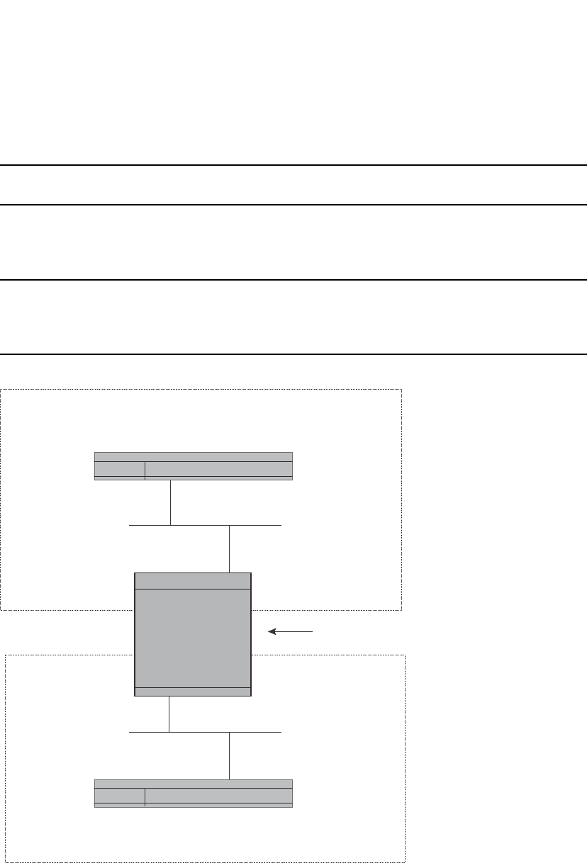
948 PowerConnect B-Series FCX Configuration Guide
53-1002266-01
Configuring OSPF
29
In Figure 144 on page 948, an administrator wants to configure the PowerConnect Layer 3 Switch
acting as the ASBR (Autonomous System Boundary Router) between the RIP domain and the OSPF
domain to redistribute routes between the two domains.
NOTE
The ASBR must be running both RIP and OSPF protocols to support this activity.
To configure for redistribution, define the redistribution tables with deny and permit redistribution
filters. Use the deny redistribute and permit redistribute commands for OSPF at the OSPF router
level.
NOTE
Do not enable redistribution until you have configured the redistribution filters. If you enable
redistribution before you configure the redistribution filters, the filters will not take affect and all
routes will be distributed.
FIGURE 144 Redistributing OSPF and static routes to RIP routes
Example
To configure the PowerConnect Layer 3 Switch acting as an ASBR in Figure 144 to redistribute
OSPF, BGP4, and static routes into RIP, enter the following commands.
PowerConnectASBR(config)#router rip
PowerConnectASBR(config-rip-router)#permit redistribute 1 all
PowerConnectASBR(config-rip-router)#write memory
OSPF Domain
RIP Domain
Switch
Switch
ASBR (Autonomous
System Border
Router)

PowerConnect B-Series FCX Configuration Guide 949
53-1002266-01
Configuring OSPF 29
NOTE
Redistribution is permitted for all routes by default, so the permit redistribute 1 all command in the
example above is shown for clarity but is not required.
You also have the option of specifying import of just OSPF, BGP4, or static routes, as well as
specifying that only routes for a specific network or with a specific cost (metric) be imported, as
shown in the following command syntax.
Syntax: deny | permit redistribute <filter-num> all | bgp | connected | rip | static
[address <ip-addr> <ip-mask> [match-metric <value> [set-metric <value>]]]
Example
To redistribute RIP, static, and BGP4 routes into OSPF, enter the following commands on the Layer 3
Switch acting as an ASBR.
PowerConnectASBR(config)#router ospf
PowerConnectASBR(config-ospf-router)#permit redistribute 1 all
PowerConnectASBR(config-ospf-router)#write memory
Syntax: deny | permit redistribute <filter-num> all | bgp | connected | rip | static
address <ip-addr> <ip-mask>
[match-metric <value> | set-metric <value>]
NOTE
Redistribution is permitted for all routes by default, so the permit redistribute 1 all command in the
example above is shown for clarity but is not required.
You also have the option of specifying import of just OSPF, BGP4, or static routes, as well as
specifying that only routes for a specific network or with a specific cost (metric) be imported, as
shown in the following command syntax.
For example, to enable redistribution of RIP and static IP routes into OSPF, enter the following
commands.
PowerConnect(config)#router ospf
PowerConnect(config-ospf-router)#redistribution rip
PowerConnect(config-ospf-router)#redistribution static
PowerConnect(config-ospf-router)#write memory
Syntax: [no] redistribution bgp | connected | rip | static [route-map <map-name>]
NOTE
The redistribution command does not perform the same function as the permit redistribute and
deny redistribute commands. The redistribute commands allow you to control redistribution of
routes by filtering on the IP address and network mask of a route. The redistribution commands
enable redistribution for routes of specific types (static, directly connected, and so on). Configure
all your redistribution filters before enabling redistribution.
NOTE
Do not enable redistribution until you have configured the redistribution filters. If you enable
redistribution before you configure the redistribution filters, the filters will not take affect and all
routes will be distributed.

950 PowerConnect B-Series FCX Configuration Guide
53-1002266-01
Configuring OSPF
29
Preventing specific OSPF routes from being installed in the IP route
table
By default, all OSPF routes in the OSPF route table are eligible for installation in the IP route table.
You can configure a distribution list to explicitly deny specific routes from being eligible for
installation in the IP route table.
NOTE
This feature does not block receipt of LSAs for the denied routes. The Layer 3 Switch still receives
the routes and installs them in the OSPF database. The feature only prevents the software from
installing the denied OSPF routes into the IP route table.
To configure an OSPF distribution list:
•Configure a standard or extended ACL that identifies the routes you want to deny. Using a
standard ACL lets you deny routes based on the destination network, but does not filter based
on the network mask. To also filter based on the destination network network mask, use an
extended ACL.
•Configure an OSPF distribution list that uses the ACL as input.
NOTE
If you change the ACL after you configure the OSPF distribution list, you must clear the IP route table
to place the changed ACL into effect. To clear the IP route table, enter the clear ip route command
at the Privileged EXEC level of the CLI.
The following sections show how to use the CLI to configure an OSPF distribution list. Separate
examples are provided for standard and extended ACLs.
NOTE
The examples show named ACLs. However, you also can use a numbered ACL as input to the OSPF
distribution list.
Using a standard ACL as input to the distribution list
To use a standard ACL to configure an OSPF distribution list for denying specific routes, enter
commands such as the following.
PowerConnect(config)#ip access-list standard no_ip
PowerConnect(config-std-nACL)#deny 4.0.0.0 0.255.255.255
PowerConnect(config-std-nACL)#permit any any
PowerConnect(config-std-nACL)#exit
PowerConnect(config)#router ospf
PowerConnect(config-ospf-router)#distribute-list no_ip in
The first three commands configure a standard ACL that denies routes to any 4.x.x.x destination
network and allows all other routes for eligibility to be installed in the IP route table. The last three
commands change the CLI to the OSPF configuration level and configure an OSPF distribution list
that uses the ACL as input. The distribution list prevents routes to any 4.x.x.x destination network
from entering the IP route table. The distribution list does not prevent the routes from entering the
OSPF database.
Syntax: [no] distribute-list <ACL-name> | <ACL-id> in [<interface type>] [<interface number>]
Syntax: [no] ip access-list standard <ACL-name> | <ACL-id>

PowerConnect B-Series FCX Configuration Guide 951
53-1002266-01
Configuring OSPF 29
Syntax: deny | permit <source-ip> <wildcard>
The <ACL-name> | <ACL-id> parameter specifies the ACL name or ID.
The in command applies the ACL to incoming route updates.
The <interface number> parameter specifies the interface number on which to apply the ACL.
Enter only one valid interface number. If necessary, use the show interface brief command to
display a list of valid interfaces. If you do not specify an interface, the Dell PowerConnect device
applies the ACL to all incoming route updates.
If you do not specify an interface type and interface number, the device applies the OSPF
distribution list to all incoming route updates.
The deny | permit parameter indicates whether packets that match the policy are dropped or
forwarded.
The <source-ip> parameter specifies the source address for the policy. Because this ACL is input to
an OSPF distribution list, the <source-ip> parameter actually is specifying the destination network
of the route.
The <wildcard> parameter specifies the portion of the source address to match against. The
<wildcard> is in dotted-decimal notation (IP address format). It is a four-part value, where each
part is 8 bits (one byte) separated by dots, and each bit is a one or a zero. Each part is a number
ranging from 0 to 255, for example 0.0.0.255. Zeros in the mask mean the packet source address
must match the <source-ip>. Ones mean any value matches. For example, the <source-ip> and
<wildcard> values 4.0.0.0 0.255.255.255 mean that all 4.x.x.x networks match the ACL.
If you want the policy to match on all destination networks, enter any any.
If you prefer to specify the wildcard (mask value) in Classless Interdomain Routing (CIDR) format,
you can enter a forward slash after the IP address, then enter the number of significant bits in the
mask. For example, you can enter the CIDR equivalent of “4.0.0.0 0.255.255.255” as “4.0.0.0/8”.
The CLI automatically converts the CIDR number into the appropriate ACL mask (where zeros
instead of ones are the significant bits) and changes the non-significant portion of the IP address
into zeros.
NOTE
If you enable the software to display IP subnet masks in CIDR format, the mask is saved in the file in
“/<mask-bits>” format. To enable the software to display the CIDR masks, enter the ip
show-subnet-length command at the global CONFIG level of the CLI. You can use the CIDR format
to configure the ACL entry regardless of whether the software is configured to display the masks in
CIDR format.
If you use the CIDR format, the ACL entries appear in this format in the running-config and
startup-config files, but are shown with subnet mask in the display produced by the show ip
access-list command.
Using an extended ACL as input to the distribution list
You can use an extended ACL with an OSPF distribution list to filter OSPF routes based on the
network mask of the destination network.
To use an extended ACL to configure an OSPF distribution list for denying specific routes, enter
commands such as the following.

952 PowerConnect B-Series FCX Configuration Guide
53-1002266-01
Configuring OSPF
29
The first three commands configure an extended ACL that denies routes to any 4.x.x.x destination
network with a 255.255.0.0 network mask and allows all other routes for eligibility to be installed
in the IP route table. The last three commands change the CLI to the OSPF configuration level and
configure an OSPF distribution list that uses the ACL as input. The distribution list prevents routes
to any 4.x.x.x destination network with network mask 255.255.0.0 from entering the IP route table.
The distribution list does not prevent the routes from entering the OSPF database.
Syntax: [no] ip access-list extended <ACL-name> | <ACL-id>
Syntax: deny | permit <ip-protocol> <source-ip> <wildcard> <destination-ip> <wildcard>
The <ACL-name> | <ACL-id> parameter specifies the ACL name or ID.
The deny | permit parameter indicates whether packets that match the policy are dropped or
forwarded.
The <ip-protocol> parameter indicates the type of IP packet you are filtering. When using an
extended ACL as input for an OSPF distribution list, specify ip.
Because this ACL is input to an OSPF distribution list, the <source-ip> parameter actually specifies
the destination network of the route.
The <wildcard> parameter specifies the portion of the source address to match against. The
<wildcard> is in dotted-decimal notation (IP address format). It is a four-part value, where each
part is 8 bits (one byte) separated by dots, and each bit is a one or a zero. Each part is a number
ranging from 0 to 255, for example 0.0.0.255. Zeros in the mask mean the packet source address
must match the <source-ip>. Ones mean any value matches. For example, the <source-ip> and
<wildcard> values 4.0.0.0 0.255.255.255 mean that all 4.x.x.x networks match the ACL.
If you want the policy to match on all network addresses, enter any any.
If you prefer to specify the wildcard (mask value) in Classless Interdomain Routing (CIDR) format,
you can enter a forward slash after the IP address, then enter the number of significant bits in the
mask. For example, you can enter the CIDR equivalent of “4.0.0.0 0.255.255.255” as “4.0.0.0/8”.
The CLI automatically converts the CIDR number into the appropriate ACL mask (where zeros
instead of ones are the significant bits) and changes the non-significant portion of the IP address
into zeros.
NOTE
If you enable the software to display IP subnet masks in CIDR format, the mask is saved in the file in
“/<mask-bits>” format. To enable the software to display the CIDR masks, enter the ip
show-subnet-length command at the global CONFIG level of the CLI. You can use the CIDR format
to configure the ACL entry regardless of whether the software is configured to display the masks in
CIDR format.
If you use the CIDR format, the ACL entries appear in this format in the running-config and
startup-config files, but are shown with subnet mask in the display produced by the show ip
access-list commands.
PowerConnect(config)#ip access-list extended no_ip
PowerConnect(config-ext-nACL)#deny ip 4.0.0.0 0.255.255.255 255.255.0.0
0.0.255.255
PowerConnect(config-ext-nACL)#permit ip any any
PowerConnect(config-ext-nACL)#exit
PowerConnect(config)#router ospf

PowerConnect B-Series FCX Configuration Guide 953
53-1002266-01
Configuring OSPF 29
Because this ACL is input to an OSPF distribution list, the <destination-ip> parameter actually
specifies the subnet mask of the route.
The <wildcard> parameter specifies the portion of the subnet mask to match against. For
example, the <destination-ip> and <wildcard> values 255.255.255.255 0.0.0.255 mean that
subnet mask /24 and longer match the ACL.
If you want the policy to match on all network masks, enter any any.
Modifying the default metric for redistribution
The default metric is a global parameter that specifies the cost applied to all OSPF routes by
default. The default value is 10. You can assign a cost from 1 through 15.
NOTE
You also can define the cost on individual interfaces. The interface cost overrides the default cost.
To assign a default metric of 4 to all routes imported into OSPF, enter the following commands.
PowerConnect(config)#router ospf
PowerConnect(config-ospf-router)#default-metric 4
Syntax: default-metric <value>
The <value> can be from 1 through 16,777,215. The default is 10.
Enabling route redistribution
To enable route redistribution, use one of the following methods.
NOTE
Do not enable redistribution until you have configured the redistribution filters. Otherwise, you might
accidentally overload the network with routes you did not intend to redistribute.
To enable redistribution of RIP and static IP routes into OSPF, enter the following commands.
Example using a route map
To configure a route map and use it for redistribution of routes into OSPF, enter commands such as
the following.
PowerConnect(config)#router ospf
PowerConnect(config-ospf-router)#redistribution rip
PowerConnect(config-ospf-router)#redistribution static
PowerConnect(config-ospf-router)#write memory

954 PowerConnect B-Series FCX Configuration Guide
53-1002266-01
Configuring OSPF
29
The commands in this example configure some static IP routes, then configure a route map and
use the route map for redistributing static IP routes into OSPF.
The ip route commands configure the static IP routes. The route-map command begins
configuration of a route map called “abc”. The number indicates the route map entry (called the
“instance”) you are configuring. A route map can contain multiple entries. The software compares
packets to the route map entries in ascending numerical order and stops the comparison once a
match is found.
The match command in the route map matches on routes that have 5 for their metric value (cost).
The set command changes the metric in routes that match the route map to 8.
The redistribution static command enables redistribution of static IP routes into OSPF, and uses
route map “abc“ to control the routes that are redistributed. In this example, the route map allows
a static IP route to be redistributed into OSPF only if the route has a metric of 5, and changes the
metric to 8 before placing the route into the OSPF route table.
Syntax: [no] redistribution bgp | connected | rip | static [route-map <map-name>]
The bgp | connected | rip | static parameter specifies the route source.
The route-map <map-name> parameter specifies the route map name. The following match
parameters are valid for OSPF redistribution:
•match ip address | next-hop <ACL-num>
•match metric <num>
•match tag <tag-value>
The following set parameters are valid for OSPF redistribution:
•set ip next hop <ip-addr>
•set metric [+ | - ]<num> | none
•set metric-type type-1 | type-2
•set tag <tag-value>
NOTE
You must configure the route map before you configure a redistribution filter that uses the route
map.
NOTE
When you use a route map for route redistribution, the software disregards the permit or deny action
of the route map.
PowerConnect(config)#ip route 1.1.0.0 255.255.0.0 207.95.7.30
PowerConnect(config)#ip route 1.2.0.0 255.255.0.0 207.95.7.30
PowerConnect(config)#ip route 1.3.0.0 255.255.0.0 207.95.7.30
PowerConnect(config)#ip route 4.1.0.0 255.255.0.0 207.95.6.30
PowerConnect(config)#ip route 4.2.0.0 255.255.0.0 207.95.6.30
PowerConnect(config)#ip route 4.3.0.0 255.255.0.0 207.95.6.30
PowerConnect(config)#ip route 4.4.0.0 255.255.0.0 207.95.6.30 5
PowerConnect(config)#route-map abc permit 1
PowerConnect(config-routemap abc)#match metric 5
PowerConnect(config-routemap abc)#set metric 8
PowerConnect(config-routemap abc)#router ospf
PowerConnect(config-ospf-router)#redistribution static route-map abc

PowerConnect B-Series FCX Configuration Guide 955
53-1002266-01
Configuring OSPF 29
NOTE
For an external route that is redistributed into OSPF through a route map, the metric value of the
route remains the same unless the metric is set by a set metric command inside the route map. The
default-metric <num> command has no effect on the route. This behavior is different from a route
that is redistributed without using a route map. For a route redistributed without using a route map,
the metric is set by the default-metric <num> command.
The following command shows the result of the redistribution filter. Because only one of the static
IP routes configured above matches the route map, only one route is redistributed. Notice that the
route metric is 5 before redistribution but is 8 after redistribution.
Disabling or re-enabling load sharing
Dell routers can load share among up to eight equal-cost IP routes to a destination. By default, IP
load sharing is enabled. The default is 4 equal-cost paths but you can specify from 2 to 6 paths.
The router software can use the route information it learns through OSPF to determine the paths
and costs. Figure 145 shows an example of an OSPF network containing multiple paths to a
destination (in this case, R1).
FIGURE 145 Example OSPF network with four equal-cost paths
In the example in Figure 145, the Dell PowerConnect switch has four paths to R1:
•PowerConnect>R3
PowerConnect#show ip ospf database external extensive
Index Aging LS ID Router Netmask Metric Flag
1 2 4.4.0.0 10.10.10.60 ffff0000 80000008 0000
OSPF Area 0
H1
H2
H3
H4
R1
R3
R4
R5
R6
Device

956 PowerConnect B-Series FCX Configuration Guide
53-1002266-01
Configuring OSPF
29
•PowerConnect->R4
•PowerConnect->R5
•PowerConnect->R6
Normally, the Dell PowerConnect switch will choose the path to the R1 with the lower metric. For
example, if R3 metric is 1400 and R4 metric is 600, the Dell PowerConnect switch will always
choose R4.
However, suppose the metric is the same for all four routers in this example. If the costs are the
same, the switch now has four equal-cost paths to R1. To allow the switch to load share among the
equal cost routes, enable IP load sharing. The software supports four equal-cost OSPF paths by
default when you enable load sharing. You can specify from 2 to 6 paths.
NOTE
The Dell PowerConnect switch is not source routing in these examples. The switch is concerned only
with the paths to the next-hop routers, not the entire paths to the destination hosts.
OSPF load sharing is enabled by default when IP load sharing is enabled. To configure IP load
sharing parameters, refer to “Configuring IP load sharing” on page 829.
Configuring external route summarization
When the Layer 3 Switch is an OSPF Autonomous System Boundary Router (ASBR), you can
configure it to advertise one external route as an aggregate for all redistributed routes that are
covered by a specified address range.
When you configure an address range, the range takes effect immediately. All the imported routes
are summarized according to the configured address range. Imported routes that have already
been advertised and that fall within the range are flushed out of the AS and a single route
corresponding to the range is advertised.
If a route that falls within a configured address range is imported by the Layer 3 Switch, no action is
taken if the Layer 3 Switch has already advertised the aggregate route; otherwise the Layer 3
Switch advertises the aggregate route. If an imported route that falls with in a configured address
range is removed by the Layer 3 Switch, no action is taken if there are other imported routes that
fall with in the same address range; otherwise the aggregate route is flushed.
You can configure up to 32 address ranges. The Layer 3 Switch sets the forwarding address of the
aggregate route to zero and sets the tag to zero.
If you delete an address range, the advertised aggregate route is flushed and all imported routes
that fall within the range are advertised individually.
If an external LSDB overflow condition occurs, all aggregate routes are flushed out of the AS, along
with other external routes. When the Layer 3 Switch exits the external LSDB overflow condition, all
the imported routes are summarized according to the configured address ranges.
NOTE
If you use redistribution filters in addition to address ranges, the Layer 3 Switch applies the
redistribution filters to routes first, then applies them to the address ranges.
NOTE
If you disable redistribution, all the aggregate routes are flushed, along with other imported routes.
To configure a summary address for OSPF routes, enter commands such as the following.

PowerConnect B-Series FCX Configuration Guide 957
53-1002266-01
Configuring OSPF 29
PowerConnect(config-ospf-router)#summary-address 10.1.0.0 255.255.0.0
The command in this example configures summary address 10.1.0.0, which includes addresses
10.1.1.0, 10.1.2.0, 10.1.3.0, and so on. For all of these networks, only the address 10.1.0.0 (the
parent route) is advertised in external LSAs. However, if the parent route has not been configured
with a summary address, or if the summary address for the parent route is configured after the
child route, the Layer 3 switch will advertise all routes. For example:
router ospf
area 0
summary-address 10.1.1.0 255.255.0.0 -> Advertised
summary-address 10.1.2.0 255.255.0.0 -> Advertised
summary-address 10.0.0.0 255.0.0.0 -> Advertised
Syntax: summary-address <ip-addr> <ip-mask>
The <ip-addr> parameter specifies the network address.
The <ip-mask> parameter specifies the network mask.
To display the configured summary addresses, use the show ip ospf config command at any level of
the CLI. The summary addresses display at the bottom of the output as shown in the following
example.
Syntax: show ip ospf config
Configuring default route origination
When the Layer 3 Switch is an OSPF Autonomous System Boundary Router (ASBR), you can
configure it to automatically generate a default external route into an OSPF routing domain. This
feature is called “default route origination” or “default information origination”.
By default, Layer 3 Switches do not advertise the default route into the OSPF domain. If you want
the Layer 3 Switch to advertise the OSPF default route, you must explicitly enable default route
origination.
When you enable OSPF default route origination, the Layer 3 Switch advertises a type 5 default
route that is flooded throughout the AS (except stub areas and NSSAs). In addition, internal NSSA
ASBRs advertise their default routes as translatable type 7 default routes.
The Layer 3 Switch advertises the default route into OSPF even if OSPF route redistribution is not
enabled, and even if the default route is learned through an IBGP neighbor.
NOTE
Layer 3 Switches never advertise the OSPF default route, regardless of other configuration
parameters, unless you explicitly enable default route origination using the following method.
PowerConnect#show ip ospf config
some lines omitted for brevity...
OSPF Redistribution Address Ranges currently defined:
Range-Address Subnetmask
1.0.0.0 255.0.0.0
1.0.1.0 255.255.255.0
1.0.2.0 255.255.255.0

958 PowerConnect B-Series FCX Configuration Guide
53-1002266-01
Configuring OSPF
29
If the Layer 3 Switch is an ASBR, you can use the “always” option when you enable the default route
origination. The always option causes the ASBR to create and advertise a default route if it does
not already have one configured.
If default route origination is enabled and you disable it, the default route originated by the Layer 3
Switch is flushed. Default routes generated by other OSPF routers are not affected. If you
re-enable the feature, the feature takes effect immediately and thus does not require you to reload
the software.
NOTE
The ABR (Layer 3 Switch) will not inject the default route into an NSSA by default and the command
described in this section will not cause the Layer 3 Switch to inject the default route into the NSSA.
To inject the default route into an NSSA, use the area <num> | <ip-addr> nssa
default-information-originate command. Refer to “Assigning a Not-So-Stubby Area (NSSA)” on
page 935.
To enable default route origination, enter the following command.
PowerConnect(config-ospf-router)#default-information-originate
To disable the feature, enter the following command.
PowerConnect(config-ospf-router)#no default-information-originate
Syntax: [no] default-information-originate [always] [metric <value>] [metric-type <type>]
The always parameter advertises the default route regardless of whether the router has a default
route. This option is disabled by default.
The metric <value> parameter specifies a metric for the default route. If this option is not used, the
default metric is used for the route.
The metric-type <type> parameter specifies the external link type associated with the default route
advertised into the OSPF routing domain. The <type> can be one of the following:
•1 – Type 1 external route
•2 – Type 2 external route
If you do not use this option, the default redistribution metric type is used for the route type.
NOTE
If you specify a metric and metric type, the values you specify are used even if you do not use the
always option.
Modifying SPF timers
The Layer 3 Switch uses the following timers when calculating the shortest path for OSPF routes:
•SPF delay – When the Layer 3 Switch receives a topology change, the software waits before it
starts a Shortest Path First (SPF) calculation. By default, the software waits five seconds. You
can configure the SPF delay to a value from 0 through 65535 seconds. If you set the SPF delay
to 0 seconds, the software immediately begins the SPF calculation after receiving a topology
change.
•SPF hold time – The Layer 3 Switch waits for a specific amount of time between consecutive
SPF calculations. By default, the Layer 3 Switch waits ten seconds. You can configure the SPF
hold time to a value from 0 through 65535 seconds. If you set the SPF hold time to 0 seconds,
the software does not wait between consecutive SPF calculations.

PowerConnect B-Series FCX Configuration Guide 959
53-1002266-01
Configuring OSPF 29
You can set the delay and hold time to lower values to cause the Layer 3 Switch to change to
alternate paths more quickly in the event of a route failure. Note that lower values require more
CPU processing time.
You can change one or both of the timers. To do so, enter commands such as the following.
PowerConnect(config-ospf-router)#timers spf 10 20
The command in this example changes the SPF delay to 10 seconds and changes the SPF hold
time to 20 seconds.
Syntax: timers spf <delay> <hold-time>
The <delay> parameter specifies the SPF delay.
The <hold-time> parameter specifies the SPF hold time.
To set the timers back to their default values, enter a command such as the following.
PowerConnect(config-ospf-router)#no timers spf 10 20
Modifying the redistribution metric type
The redistribution metric type is used by default for all routes imported into OSPF unless you
specify different metrics for individual routes using redistribution filters. Type 2 specifies a big
metric (three bytes). Type 1 specifies a small metric (two bytes). The default value is type 2.
To modify the default value to type 1, enter the following command.
PowerConnect(config-ospf-router)#metric-type type1
Syntax: metric-type type1 | type2
Modifying the administrative distance
Layer 3 Switches can learn about networks from various protocols, including Border Gateway
Protocol version 4 (BGP4), RIP, and OSPF. Consequently, the routes to a network may differ
depending on the protocol from which the routes were learned. The default administrative
distance for OSPF routes is 110. Refer to “Changing administrative distances” on page 1014 for a
list of the default distances for all route sources.
The router selects one route over another based on the source of the route information. To do so,
the router can use the administrative distances assigned to the sources. You can bias the Layer 3
Switch decision by changing the default administrative distance for RIP routes.
Configuring administrative distance based on route type
You can configure a unique administrative distance for each type of OSPF route. For example, you
can use this feature to prefer a static route over an OSPF inter-area route but you also want to
prefer OSPF intra-area routes to static routes.
The distance you specify influences the choice of routes when the Layer 3 Switch has multiple
routes for the same network from different protocols. The Layer 3 Switch prefers the route with the
lower administrative distance.
You can specify unique default administrative distances for the following route types:
•Intra-area routes

960 PowerConnect B-Series FCX Configuration Guide
53-1002266-01
Configuring OSPF
29
•Inter-area routes
•External routes
The default for all these OSPF route types is 110.
NOTE
This feature does not influence the choice of routes within OSPF. For example, an OSPF intra-area
route is always preferred over an OSPF inter-area route, even if the intra-area route distance is
greater than the inter-area route distance.
To change the default administrative distances for inter-area routes, intra-area routes, and external
routes, enter the following command.
PowerConnect(config-ospf-router)#distance external 100
PowerConnect(config-ospf-router)#distance inter-area 90
PowerConnect(config-ospf-router)#distance intra-area 80
Syntax: [no] distance external | inter-area | intra-area <distance>
The external | inter-area | intra-area parameter specifies the route type for which you are changing
the default administrative distance.
The <distance> parameter specifies the new distance for the specified route type. Unless you
change the distance for one of the route types using commands such as those shown above, the
default is 110.
To reset the administrative distance to its system default (110), enter a command such as the
following.
PowerConnect(config-ospf-router)#no distance external 100
Configuring OSPF group Link State Advertisement
(LSA) pacing
The Layer 3 Switch paces LSA refreshes by delaying the refreshes for a specified time interval
instead of performing a refresh each time an individual LSA refresh timer expires. The
accumulated LSAs constitute a group, which the Layer 3 Switch refreshes and sends out together
in one or more packets.
The pacing interval, which is the interval at which the Layer 3 Switch refreshes an accumulated
group of LSAs, is configurable to a range from 10 through 1800 seconds (30 minutes). The default
is 240 seconds (four minutes). Thus, every four minutes, the Layer 3 Switch refreshes the group of
accumulated LSAs and sends the group together in the same packets.
Usage guidelines
The pacing interval is inversely proportional to the number of LSAs the Layer 3 Switch is refreshing
and aging. For example, if you have approximately 10,000 LSAs, decreasing the pacing interval
enhances performance. If you have a very small database (40 to 100 LSAs), increasing the pacing
interval to 10 to 20 minutes might enhance performance slightly.
Changing the LSA pacing interval
To change the LSA pacing interval to two minutes (120 seconds), enter the following command.
PowerConnect(config-ospf-router)#timers lsa-group-pacing 120

PowerConnect B-Series FCX Configuration Guide 961
53-1002266-01
Configuring OSPF 29
Syntax: [no] timers lsa-group-pacing <secs>
The <secs> parameter specifies the number of seconds and can be from 10 through 1800 (30
minutes). The default is 240 seconds (4 minutes).
To restore the pacing interval to its default value, enter the following command.
PowerConnect(config-ospf-router)#no timers lsa-group-pacing
Modifying OSPF traps generated
OSPF traps as defined by RFC 1850 are supported on Dell routers. OSPF trap generation is
enabled on the router, by default.
When using the CLI, you can disable all or specific OSPF trap generation by entering the following
CLI command.
PowerConnect(config-ospf-router)#no snmp-server trap ospf
Syntax: [no] snmp-server trap ospf
To later re-enable the trap feature, enter snmp-server trap ospf.
To disable a specific OSPF trap, enter the command as no snmp-server trap ospf <ospf-trap>.
These commands are at the OSPF router level of the CLI.
Here is a summary of OSPF traps supported on Dell routers, their corresponding CLI commands,
and their associated MIB objects from RFC 1850:
•interface-state-change-trap – [MIB object: OspfIfstateChange]
•virtual-interface-state-change-trap – [MIB object: OspfVirtIfStateChange
•neighbor-state-change-trap – [MIB object:ospfNbrStateChange]
•virtual-neighbor-state-change-trap – [MIB object: ospfVirtNbrStateChange]
•interface-config-error-trap – [MIB object: ospfIfConfigError]
•virtual-interface-config-error-trap – [MIB object: ospfVirtIfConfigError]
•interface-authentication-failure-trap – [MIB object: ospfIfAuthFailure]
•virtual-interface-authentication-failure-trap – [MIB object: ospfVirtIfAuthFailure]
•interface-receive-bad-packet-trap – [MIB object: ospfIfrxBadPacket]
•virtual-interface-receive-bad-packet-trap – [MIB object: ospfVirtIfRxBadPacket]
•interface-retransmit-packet-trap – [MIB object: ospfTxRetransmit]
•virtual-interface-retransmit-packet-trap – [MIB object: ospfVirtIfTxRetransmit]
•originate-lsa-trap – [MIB object: ospfOriginateLsa]
•originate-maxage-lsa-trap – [MIB object: ospfMaxAgeLsa]
•link-state-database-overflow-trap – [MIB object: ospfLsdbOverflow]
•link-state-database-approaching-overflow-trap – [MIB object: ospfLsdbApproachingOverflow
Example
To stop an OSPF trap from being collected, use the CLI command: no trap <ospf-trap>, at the OSPF
router level of the CLI. To disable reporting of the neighbor-state-change-trap, enter the following
command.
PowerConnect(config-ospf-router)#no trap neighbor-state-change-trap

962 PowerConnect B-Series FCX Configuration Guide
53-1002266-01
Configuring OSPF
29
Example
To reinstate the trap, enter the following command.
PowerConnect(config-ospf-router)#trap neighbor-state-change-trap
Syntax: [no] trap <ospf-trap>
Specifying the types of OSPF Syslog messages to log
You can specify which kinds of OSPF-related Syslog messages are logged. By default, the only
OSPF messages that are logged are those indicating possible system errors. If you want other
kinds of OSPF messages to be logged, you can configure the Dell PowerConnect device to log them.
For example, to specify that all OSPF-related Syslog messages be logged, enter the following
commands.
PowerConnect(config)#router ospf
PowerConnect(config-ospf-router)#log all
Syntax: [no] log all | adjacency | bad_packet [checksum] | database | memory | retransmit
The all option causes all OSPF-related Syslog messages to be logged. If you later disable this
option with the no log all command, the OSPF logging options return to their default settings.
The adjacency option logs essential OSPF neighbor state changes, especially on error cases. This
option is disabled by default.
The bad_packet checksum option logs all OSPF packets that have checksum errors. This option is
enabled by default.
The bad_packet option logs all other bad OSPF packets. This option is disabled by default.
The database option logs OSPF LSA-related information. This option is disabled by default.
The memory option logs abnormal OSPF memory usage. This option is enabled by default.
The retransmit option logs OSPF retransmission activities. This option is disabled by default.
Modifying the OSPF standard compliance setting
Dell PowerConnect routers are configured, by default, to be compliant with the RFC 1583 OSPF V2
specification.
To configure a router to operate with the latest OSPF standard, RFC 2178, enter the following
commands.
PowerConnect(config)#router ospf
PowerConnect(config-ospf-router)#no rfc1583-compatibility
Syntax: [no] rfc1583-compatibility
Modifying the exit overflow interval
If a database overflow condition occurs on a router, the router eliminates the condition by removing
entries that originated on the router. The exit overflow interval allows you to set how often a Layer
3 Switch checks to see if the overflow condition has been eliminated. The default value is 0. The
range is 0 through 86400 seconds (24 hours). If the configured value of the database overflow
interval is zero, then the router never leaves the database overflow condition.

PowerConnect B-Series FCX Configuration Guide 963
53-1002266-01
Configuring OSPF 29
NOTE
PowerConnect devices dynamically allocate OSPF memory as needed. Refer to “Dynamic OSPF
memory” on page 930.
To modify the exit overflow interval to 60 seconds, enter the following command.
PowerConnect(config-ospf-router)#database-overflow-interval 60
Syntax: database-overflow-interval <value>
The <value> can be from 0 through 86400 seconds. The default is 0 seconds.
Configuring an OSPF point-to-point link
In an OSPF point-to-point link, a direct Layer 3 connection exists between a single pair of OSPF
routers, without the need for Designated and Backup Designated routers. In a point-to-point link,
neighboring routers become adjacent whenever they can communicate directly. In contrast, in
broadcast and non-broadcast multi-access (NBMA) networks, the Designated Router and the
Backup Designated Router become adjacent to all other routers attached to the network.
Configuration notes and limitations
•This feature is supported on Gbps Ethernet and 10 Gbps Ethernet interfaces.
•This feature is supported on physical interfaces. It is not supported on virtual interfaces.
•Dell supports numbered point-to-point networks, meaning the OSPF router must have an IP
interface address which uniquely identifies the router over the network. Dell does not support
unnumbered point-to-point networks.
Configuration syntax
To configure an OSPF point-to-point link, enter commands such as the following.
PowerConnect(config)#interface eth 1/5
PowerConnect(config-if-1/5)#ip ospf network point-to-point
This command configures an OSPF point-to-point link on Interface 5 in slot 1.
Syntax: [no] ip ospf network point-to-point
Viewing configured OSPF point-to-point links
Refer to “Displaying OSPF neighbor information” on page 969 and “Displaying OSPF interface
information” on page 971.
Configuring OSPF graceful restart
By default, OSPF graceful restart is enabled for the global instance.
For information about how to display OSPF graceful restart information, refer to “Displaying OSPF
graceful restart information” on page 978.

964 PowerConnect B-Series FCX Configuration Guide
53-1002266-01
Clearing OSPF information
29
Enabling and disabling OSPF graceful restart
OSPF graceful restart is enabled by default on a PowerConnect Layer 3 switch. To disable it, use
the following commands.
PowerConnect (config)# router ospf
PowerConnect (config-ospf-router)# no graceful-restart
To re-enable OSPF graceful restart after it has been disabled, enter the following commands.
PowerConnect (config)# router ospf
PowerConnect (config-ospf-router)# graceful-restart
Syntax: [no] graceful-restart
Configuring the OSPF graceful restart time
Use the following commands to specify the maximum amount of time advertised to a neighbor
router to maintain routes from and forward traffic to a restarting router.
PowerConnect (config) router ospf
PowerConnect (config-ospf-router)# graceful-restart restart-time 120
Syntax: [no] graceful-restart restart-time <seconds>
The <seconds> variable sets the maximum restart wait time advertised to neighbors.
Possible values are from 10 through 1800 seconds.
The default value is 120 seconds.
Disabling OSPF graceful restart helper mode
By default, a PowerConnect Layer 3 switch supports other restarting routers as a helper. You can
prevent your PowerConnect router from participating in OSPF graceful restart by using the
following commands.
PowerConnect (config) router ospf
PowerConnect (config-ospf-router)# graceful-restart helper-disable
Syntax: [no] graceful-restart helper-disable
This command disables OSPF graceful restart helper mode.
The default behavior is to help the restarting neighbors.
Clearing OSPF information
The following kinds of OSPF information can be cleared from a Dell OSPF link state database and
OSPF routing table:
•Routes received from OSPF neighbors. You can clear routes from all OSPF neighbors, or an
individual OSPF neighbor, specified either by the neighbor IP address or its router ID
•OSPF topology information, including all routes in the OSPF routing table
•All routes in the OSPF routing table that were redistributed from other protocols

PowerConnect B-Series FCX Configuration Guide 965
53-1002266-01
Clearing OSPF information 29
•OSPF area information, including routes received from OSPF neighbors within an area, as well
as routes imported into the area. You can clear area information for all OSPF areas, or for a
specified OSPF area
The OSPF information is cleared dynamically when you enter the command; you do not need to
remove statements from the Dell PowerConnect configuration or reload the software for the
change to take effect.
Clearing OSPF neighbor information
To clear information on the Dell PowerConnect device about all OSPF neighbors, enter the following
command.
PowerConnect#clear ip ospf neighbor
Syntax: clear ip ospf neighbor [ip <ip-addr> | id <ip-addr>]
This command clears all OSPF neighbors and the OSPF routes exchanged with the neighbors in the
Dell PowerConnect OSPF link state database. After this information is cleared, adjacencies with all
neighbors are re-established, and routes with these neighbors exchanged again.
To clear information on the Dell PowerConnect device about OSPF neighbor 10.10.10.1, enter the
following command.
PowerConnect#clear ip ospf neighbor ip 10.10.10.1
This command clears the OSPF neighbor and the OSPF routes exchanged with neighbor 10.10.10.1
in the OSPF link state database in the Dell PowerConnect device. After this information is cleared,
the adjacency with the neighbor is re-established, and routes are exchanged again.
The neighbor router can be specified either by its IP address or its router ID. To specify the neighbor
router using its IP address, use the ip <ip-addr> parameter. To specify the neighbor router using its
router ID, use the id <ip-addr> parameter.
Clearing OSPF topology information
To clear OSPF topology information on the Dell PowerConnect device, enter the following command.
PowerConnect#clear ip ospf topology
Syntax: clear ip ospf topology
This command clears all OSPF routes from the OSPF routing table, including intra-area, (which
includes ABR and ASBR intra-area routes), inter-area, external type 1, external type 2, OSPF default,
and OSPF summary routes.
After you enter this command, the OSPF routing table is rebuilt, and valid routes are recomputed
from the OSPF link state database. When the OSPF routing table is cleared, OSPF routes in the
global routing table are also recalculated. If redistribution is enabled, the routes are imported
again.
Clearing redistributed routes from the OSPF routing table
To clear all routes in the OSPF routing table that were redistributed from other protocols, enter the
following command.
PowerConnect#clear ospf redistribution

966 PowerConnect B-Series FCX Configuration Guide
53-1002266-01
Displaying OSPF information
29
Syntax: clear ospf redistribution
This command clears all routes in the OSPF routing table that are redistributed from other
protocols, including direct connected, static, RIP, and BGP. To import redistributed routes from
other protocols, use the redistribution command at the OSPF configuration level.
Clearing information for OSPF areas
To clear information on the Dell PowerConnect device about all OSPF areas, enter the following
command.
PowerConnect#clear ip ospf
This command clears all OSPF areas, all OSPF neighbors, and the entire OSPF routing table. After
this information has been cleared, adjacencies with all neighbors are re-established, and all OSPF
routes are re-learned.
To clear information on the Dell PowerConnect device about OSPF area 1, enter the following
command.
PowerConnect#clear ip ospf area 1
This command clears information about the specified area ID. Information about other OSPF areas
is not affected. The command clears information about all OSPF neighbors belonging to the
specified area, as well as all routes imported into the specified area. Adjacencies with neighbors
belonging to the area are re-established, and routes imported into the area are re-learned.
Syntax: clear ip ospf [area <area-id>]
The <area-id> can be specified in decimal format or in IP address format.
Displaying OSPF information
You can use CLI commands and Web management options to display the following OSPF
information:
•Trap, area, and interface information – refer to “Displaying general OSPF configuration
information” on page 967.
•CPU utilization statistics – refer to “Displaying CPU utilization statistics” on page 968.
•Area information – refer to “Displaying OSPF area information” on page 969.
•Neighbor information – refer to “Displaying OSPF neighbor information” on page 969.
•Interface information – refer to “Displaying OSPF interface information” on page 971.
•Route information – refer to “Displaying OSPF route information” on page 973.
•External link state information – refer to “Displaying OSPF external link state information” on
page 975.
•Link state information – refer to “Displaying OSPF link state information” on page 976.
•Virtual Neighbor information – refer to “Displaying OSPF virtual neighbor information” on
page 977.
•Virtual Link information – refer to “Displaying OSPF virtual link information” on page 977.
•ABR and ASBR information – refer to “Displaying OSPF ABR and ASBR information” on
page 977.

PowerConnect B-Series FCX Configuration Guide 967
53-1002266-01
Displaying OSPF information 29
•Trap state information – refer to “Displaying OSPF trap status” on page 978.
•OSPF graceful restart - refer to “Displaying OSPF graceful restart information” on page 978.
Displaying general OSPF configuration information
To display general OSPF configuration information, enter the following command at any CLI level.
PowerConnect#show ip ospf config
Router OSPF: Enabled
Redistribution: Disabled
Default OSPF Metric: 10
OSPF Redistribution Metric: Type2
OSPF External LSA Limit: 25000
OSPF Database Overflow Interval: 0
RFC 1583 Compatibility: Enabled
Router id: 192.85.2.1
Interface State Change Trap: Enabled
Virtual Interface State Change Trap: Enabled
Neighbor State Change Trap: Enabled
Virtual Neighbor State Change Trap: Enabled
Interface Configuration Error Trap: Enabled
Virtual Interface Configuration Error Trap: Enabled
Interface Authentication Failure Trap: Enabled
Virtual Interface Authentication Failure Trap: Enabled
Interface Receive Bad Packet Trap: Enabled
Virtual Interface Receive Bad Packet Trap: Enabled
Interface Retransmit Packet Trap: Enabled
Virtual Interface Retransmit Packet Trap: Enabled
Originate LSA Trap: Enabled
Originate MaxAge LSA Trap: Enabled
Link State Database Overflow Trap: Enabled
Link State Database Approaching Overflow Trap: Enabled
OSPF Area currently defined:
Area-ID Area-Type Cost
0 normal 0
OSPF Interfaces currently defined:
Ethernet Interface: 3/1-3/2
ip ospf md5-authentication-key-activation-wait-time 300
ip ospf area 0
Ethernet Interface: v1
ip ospf md5-authentication-key-activation-wait-time 300
ip ospf area 0
Ethernet Interface: 2/1
ip ospf auth-change-wait-time 300
ip ospf cost 40
ip ospf area 0
Syntax: show ip ospf config

968 PowerConnect B-Series FCX Configuration Guide
53-1002266-01
Displaying OSPF information
29
Displaying CPU utilization statistics
You can display CPU utilization statistics for OSPF and other IP protocols.
To display CPU utilization statistics for OSPF for the previous one-second, one-minute, five-minute,
and fifteen-minute intervals, enter the following command at any level of the CLI.
If the software has been running less than 15 minutes (the maximum interval for utilization
statistics), the command indicates how long the software has been running. Here is an example.
To display utilization statistics for a specific number of seconds, enter a command such as the
following.
When you specify how many seconds’ worth of statistics you want to display, the software selects
the sample that most closely matches the number of seconds you specified. In this example,
statistics are requested for the previous two seconds. The closest sample available is actually for
the previous 1 second plus 80 milliseconds.
Syntax: show process cpu [<num>]
PowerConnect#show process cpu
Process Name 5Sec(%) 1Min(%) 5Min(%) 15Min(%) Runtime(ms)
ARP 0.01 0.03 0.09 0.22 9
BGP 0.04 0.06 0.08 0.14 13
GVRP 0.00 0.00 0.00 0.00 0
ICMP 0.00 0.00 0.00 0.00 0
IP 0.00 0.00 0.00 0.00 0
OSPF 0.03 0.06 0.09 0.12 11
RIP 0.00 0.00 0.00 0.00 0
STP 0.00 0.00 0.00 0.00 0
VRRP 0.00 0.00 0.00 0.00 0
PowerConnect#show process cpu
The system has only been up for 6 seconds.
Process Name 5Sec(%) 1Min(%) 5Min(%) 15Min(%) Runtime(ms)
ARP 0.01 0.00 0.00 0.00 0
BGP 0.00 0.00 0.00 0.00 0
GVRP 0.00 0.00 0.00 0.00 0
ICMP 0.01 0.00 0.00 0.00 1
IP 0.00 0.00 0.00 0.00 0
OSPF 0.00 0.00 0.00 0.00 0
RIP 0.00 0.00 0.00 0.00 0
STP 0.00 0.00 0.00 0.00 0
VRRP 0.00 0.00 0.00 0.00 0
PowerConnect#show process cpu 2
Statistics for last 1 sec and 80 ms
Process Name Sec(%) Time(ms)
ARP 0.00 0
BGP 0.00 0
GVRP 0.00 0
ICMP 0.01 1
IP 0.00 0
OSPF 0.00 0
RIP 0.00 0
STP 0.01 0
VRRP 0.00 0

PowerConnect B-Series FCX Configuration Guide 969
53-1002266-01
Displaying OSPF information 29
The <num> parameter specifies the number of seconds and can be from 1 through 900. If you use
this parameter, the command lists the usage statistics only for the specified number of seconds. If
you do not use this parameter, the command lists the usage statistics for the previous one-second,
one-minute, five-minute, and fifteen-minute intervals.
Displaying OSPF area information
To display OSPF area information, enter the following command at any CLI level.
Syntax: show ip ospf area [<area-id>] | [<num>]
The <area-id> parameter shows information for the specified area.
The <num> parameter displays the entry that corresponds to the entry number you enter. The
entry number identifies the entry position in the area table.
This display shows the following information.
Displaying OSPF neighbor information
To display OSPF neighbor information, enter the following command at any CLI level.
To display detailed OSPF neighbor information, enter the following command at any CLI level.
TABLE 175 CLI display of OSPF area information
Field Definition
Indx The row number of the entry in the router OSPF area table.
Area The area number.
Type The area type, which can be one of the following:
•nssa
•normal
•stub
Cost The area cost.
SPFR The SPFR value.
ABR The ABR number.
ASBR The ABSR number.
LSA The LSA number.
Chksum(Hex) The checksum for the LSA packet. The checksum is based on all the fields in the packet
except the age field. The Layer 3 Switch uses the checksum to verify that the packet is
not corrupted.
PowerConnect#show ip ospf area
Indx Area Type Cost SPFR ABR ASBR LSA Chksum(Hex)
1 0.0.0.0 normal 0 1 0 0 1 0000781f
2 192.147.60.0 normal 0 1 0 0 1 0000fee6
3 192.147.80.0 stub 1 1 0 0 2 000181cd
PowerConnect#show ip ospf neighbor
Port Address Pri State Neigh Address Neigh ID
8 212.76.7.251 1 full 212.76.7.200 173.35.1.220

970 PowerConnect B-Series FCX Configuration Guide
53-1002266-01
Displaying OSPF information
29
Syntax: show ip ospf neighbor [router-id <ip-addr>] | [<num>] | [detail]
The router-id <ip-addr> parameter displays only the neighbor entries for the specified router.
The <num> parameter displays only the entry in the specified index position in the neighbor table.
For example, if you enter “1”, only the first entry in the table is displayed.
The detail parameter displays detailed information about the neighbor routers.
These displays show the following information.
TABLE 176 CLI display of OSPF neighbor information
Field Description
Port The port through which the Layer 3 Switch is connected to the neighbor.
The port on which an OSPF point-to-point link is configured.
Address The IP address of this Layer 3 Switch interface with the neighbor.
Pri The OSPF priority of the neighbor:
•For multi-access networks, the priority is used during election of the Designated Router
(DR) and Backup designated Router (BDR).
•For point-to-point links, this field shows one of the following values:
•1 = point-to-point link
•3 = point-to-point link with assigned subnet
PowerConnect#show ip ospf neighbor detail
Port Address Pri State Neigh Address Neigh ID Ev Op Cnt
9/1 20.2.0.2 1 FULL/DR 20.2.0.1 2.2.2.2 6 2 0
Second-to-dead:39
10/1 20.3.0.2 1 FULL/BDR 20.3.0.1 3.3.3.3 5 2 0
Second-to-dead:36
1/1-1/8 23.5.0.1 1 FULL/DR 23.5.0.2 16.16.16.16 6 2 0
Second-to-dead:33
2/1-2/2 23.2.0.1 1 FULL/DR 23.2.0.2 15.15.15.15 6 2 0
Second-to-dead:33

PowerConnect B-Series FCX Configuration Guide 971
53-1002266-01
Displaying OSPF information 29
Displaying OSPF interface information
To display OSPF interface information, enter the following command at any CLI level.
State The state of the conversation between the Layer 3 Switch and the neighbor. This field can have
one of the following values:
•Down – The initial state of a neighbor conversation. This value indicates that there has
been no recent information received from the neighbor.
•Attempt – This state is only valid for neighbors attached to non-broadcast networks. It
indicates that no recent information has been received from the neighbor.
•Init – A Hello packet has recently been seen from the neighbor. However, bidirectional
communication has not yet been established with the neighbor. (The router itself did not
appear in the neighbor's Hello packet.) All neighbors in this state (or higher) are listed in
the Hello packets sent from the associated interface.
•2-Way – Communication between the two routers is bidirectional. This is the most
advanced state before beginning adjacency establishment. The Designated Router and
Backup Designated Router are selected from the set of neighbors in the 2-Way state or
greater.
•ExStart – The first step in creating an adjacency between the two neighboring routers. The
goal of this step is to decide which router is the master, and to decide upon the initial
Database Description (DD) sequence number. Neighbor conversations in this state or
greater are called adjacencies.
•Exchange – The router is describing its entire link state database by sending Database
Description packets to the neighbor. Each Database Description packet has a DD
sequence number, and is explicitly acknowledged. Only one Database Description packet
can be outstanding at any time. In this state, Link State Request packets can also be sent
asking for the neighbor's more recent advertisements. All adjacencies in Exchange state
or greater are used by the flooding procedure. In fact, these adjacencies are fully capable
of transmitting and receiving all types of OSPF routing protocol packets.
•Loading – Link State Request packets are sent to the neighbor asking for the more recent
advertisements that have been discovered (but not yet received) in the Exchange state.
•Full – The neighboring routers are fully adjacent. These adjacencies will now appear in
router links and network link advertisements.
Neigh Address The IP address of the neighbor:
For point-to-point links, the value is as follows:
•If the Pri field is "1", this value is the IP address of the neighbor router interface.
•If the Pri field is "3", this is the subnet IP address of the neighbor router interface.
Neigh ID The neighbor router ID.
Ev The number of times the neighbor state changed.
Opt The sum of the option bits in the Options field of the Hello packet. This information is used by
Dell technical support. Refer to Section A.2 in RFC 2178 for information about the Options field
in Hello packets.
Cnt The number of LSAs that were retransmitted.
Second-to-dead The amount of time the Dell PowerConnect device will wait for a HELLO message from each
OSPF neighbor before assuming the neighbor is dead.
TABLE 176 CLI display of OSPF neighbor information (Continued)
Field Description

972 PowerConnect B-Series FCX Configuration Guide
53-1002266-01
Displaying OSPF information
29
Syntax: show ip ospf interface [<ip-addr>]
The <ip-addr> parameter displays the OSPF interface information for the specified IP address.
The following table defines the highlighted fields shown in the above example output of the show ip
ospf interface command.
TABLE 177 Output of the show ip ospf interface command
Field Definition
IP Address The IP address of the interface.
OSPF state ptr2ptr (point to point)
Pri The link ID as defined in the router-LSA. This value can be one of the
following:
•1 = point-to-point link
•3 = point-to-point link with an assigned subnet
Cost The configured output cost for the interface.
Options OSPF Options (Bit7 - Bit0):
•unused:1
•opaque:1
•summary:1
•dont_propagate:1
•nssa:1
•multicast:1
•externals:1
•tos:1
Type The area type, which can be one of the following:
•Broadcast = 0x01
•NBMA = 0x02
•Point to Point = 0x03
•Virtual Link = 0x04
•Point to Multipoint = 0x05
PowerConnect#show ip ospf interface 192.168.1.1
Ethernet 2/1,OSPF enabled
IP Address 192.168.1.1, Area 0
OSPF state ptr2ptr, Pri 1, Cost 1, Options 2, Type pt-2-pt Events 1
Timers(sec): Transit 1, Retrans 5, Hello 10, Dead 40
DR: Router ID 0.0.0.0 Interface Address 0.0.0.0
BDR: Router ID 0.0.0.0 Interface Address 0.0.0.0
Neighbor Count = 0, Adjacent Neighbor Count= 1
Neighbor: 2.2.2.2
Authentication-Key:None
MD5 Authentication: Key None, Key-Id None, Auth-change-wait-time 300

PowerConnect B-Series FCX Configuration Guide 973
53-1002266-01
Displaying OSPF information 29
Displaying OSPF route information
To display OSPF route information for the router, enter the following command at any CLI level.
Syntax: show ip ospf routes [<ip-addr>]
The <ip-addr> parameter specifies a destination IP address. If you use this parameter, only the
route entries for that destination are shown.
This display shows the following information.
Events OSPF Interface Event:
•Interface_Up = 0x00
•Wait_Timer = 0x01
•Backup_Seen = 0x02
•Neighbor_Change = 0x03
•Loop_Indication = 0x04
•Unloop_Indication = 0x05
•Interface_Down = 0x06
•Interface_Passive = 0x07
Adjacent Neighbor Count The number of adjacent neighbor routers.
Neighbor: The neighbor router ID.
TABLE 178 CLI Display of OSPF route information
Field Definition
Index The row number of the entry in the router OSPF route table.
Destination The IP address of the route's destination.
Mask The network mask for the route.
Path_Cost The cost of this route path. (A route can have multiple paths. Each path represents a
different exit port for the Layer 3 Switch.)
Type2_Cost The type 2 cost of this path.
TABLE 177 Output of the show ip ospf interface command (Continued)
Field Definition
PowerConnect#show ip ospf routes
Index Destination Mask Path_Cost Type2_Cost Path_Type
1 212.95.7.0 255.255.255.0 1 0 Intra
Adv_Router Link_State Dest_Type State Tag Flags
173.35.1.220 212.95.7.251 Network Valid 00000000 7000
Paths Out_Port Next_Hop Type Arp_Index State
1 5/6 209.95.7.250 OSPF 8 84 00
Index Destination Mask Path_Cost Type2_Cost Path_Type
2 11.3.63.0 255.255.255.0 11 0 Inter
Adv_Router Link_State Dest_Type State Tag Flags
209.95.7.250 11.3.63.0 Network Valid 00000000 0000
Paths Out_Port Next_Hop Type Arp_Index State
1 5/6 209.95.7.250 OSPF 8 84 00

974 PowerConnect B-Series FCX Configuration Guide
53-1002266-01
Displaying OSPF information
29
Displaying the routes that have been redistributed into OSPF
You can display the routes that have been redistributed into OSPF. To display the redistributed
routes, enter the following command at any level of the CLI.
In this example, four routes have been redistributed. Three of the routes were redistributed from
static IP routes and one route was redistributed from a directly connected IP route.
Syntax: show ip ospf redistribute route [<ip-addr> <ip-mask>]
The <ip-addr> <ip-mask> parameter specifies a network prefix and network mask. Here is an
example.
Path_Type The type of path, which can be one of the following:
•Inter – The path to the destination passes into another area.
•Intra – The path to the destination is entirely within the local area.
•External1 – The path to the destination is a type 1 external route.
•External2 – The path to the destination is a type 2 external route.
Adv_Router The OSPF router that advertised the route to this Layer 3 Switch.
Link-State The link state from which the route was calculated.
Dest_Type The destination type, which can be one of the following:
•ABR – Area Border Router
•ASBR – Autonomous System Boundary Router
•Network – the network
State The route state, which can be one of the following:
•Changed
•Invalid
•Valid
This information is used by Dell technical support.
Tag The external route tag.
Flags State information for the route entry. This information is used by Dell technical support.
Paths The number of paths to the destination.
Out_Port The router port through which the Layer 3 Switch reaches the next hop for this route path.
Next_Hop The IP address of the next-hop router for this path.
Type The route type, which can be one of the following:
•OSPF
•Static Replaced by OSPF
Arp_Index The index position in the ARP table of the ARP entry for this path's IP address.
State State information for the path. This information is used by Dell technical support.
TABLE 178 CLI Display of OSPF route information (Continued)
Field Definition
PowerConnect#show ip ospf redistribute route
4.3.0.0 255.255.0.0 static
3.1.0.0 255.255.0.0 static
10.11.61.0 255.255.255.0 connected
4.1.0.0 255.255.0.0 static

PowerConnect B-Series FCX Configuration Guide 975
53-1002266-01
Displaying OSPF information 29
Displaying OSPF external link state information
To display external link state information, enter the following command at any CLI level.
Syntax: show ip ospf database external-link-state [advertise <num>] | [extensive] | [link-state-id
<ip-addr>] | [router-id <ip-addr>] | [sequence-number <num(Hex)>] | [status <num>]
The advertise <num> parameter displays the hexadecimal data in the specified LSA packet. The
<num> parameter identifies the LSA packet by its position in the router External LSA table. To
determine an LSA packet position in the table, enter the show ip ospf external-link-state command
to display the table. Refer to “Displaying the data in an LSA” on page 976 for an example.
The extensive option displays the LSAs in decrypted format.
NOTE
You cannot use the extensive option in combination with other display options. The entire database
is displayed.
The link-state-id <ip-addr> parameter displays the External LSAs for the LSA source specified by
<IP-addr>.
The router-id <ip-addr> parameter shows the External LSAs for the specified OSPF router.
The sequence-number <num(Hex)> parameter displays the External LSA entries for the specified
hexadecimal LSA sequence number.
The status <num> option shows status information.
This display shows the following information.
TABLE 179 CLI display of OSPF external link state information
Field Definition
Area ID The OSPF area the router is in.
Aging The age of the LSA, in seconds.
LS ID The ID of the link-state advertisement from which the Layer 3 Switch learned this route.
Router The router IP address.
PowerConnect#show ip ospf redistribute route 3.1.0.0 255.255.0.0
3.1.0.0 255.255.0.0 static
PowerConnect#show ip ospf database external-link-state
Index Aging LS ID Router Netmask Metric Flag
1 1794 1.168.64.0 192.85.0.3 ffffe000 000003e8 b500 0.0.0.0
2 1794 3.215.0.0 192.85.0.3 ffff0000 000003e8 b500 0.0.0.0
3 1794 1.27.250.0 192.85.0.3 fffffe00 000003e8 b500 0.0.0.0
4 1794 1.24.23.0 192.85.0.3 ffffff00 000003e8 b500 0.0.0.0
5 1794 1.21.52.0 192.85.0.3 ffffff00 000003e8 b500 0.0.0.0
6 1794 1.18.81.0 192.85.0.3 ffffff00 000003e8 b500 0.0.0.0
7 1794 1.15.110.0 192.85.0.3 ffffff00 000003e8 b500 0.0.0.0
8 1794 1.12.139.0 192.85.0.3 ffffff00 000003e8 b500 0.0.0.0
9 1794 1.9.168.0 192.85.0.3 ffffff00 000003e8 b500 0.0.0.0

976 PowerConnect B-Series FCX Configuration Guide
53-1002266-01
Displaying OSPF information
29
Displaying OSPF link state information
To display link state information, enter the following command at any CLI level.
PowerConnect#show ip ospf database link-state
Syntax: show ip ospf database link-state [advertise <num>] | [asbr] | [extensive] | [link-state-id
<ip-addr>] | [network] | [nssa] | [opaque-area] | [router] | [router-id <ip-addr>] |
[sequence-number <num(Hex)>] | [status <num>] | [summary]
The advertise <num> parameter displays the hexadecimal data in the specified LSA packet. The
<num> parameter identifies the LSA packet by its position in the router External LSA table. To
determine an LSA packet position in the table, enter the show ip ospf external-link-state command
to display the table. Refer to “Displaying the data in an LSA” on page 976 for an example.
The asbr option shows ASBR information.
The extensive option displays the LSAs in decrypted format.
NOTE
You cannot use the extensive option in combination with other display options. The entire database
is displayed.
The link-state-id <ip-addr> parameter displays the External LSAs for the LSA source specified by
<IP-addr>.
The network option shows network information.
The nssa option shows network information.
The opaque-area option shows information for opaque areas.
The router-id <ip-addr> parameter shows the External LSAs for the specified OSPF router.
The sequence-number <num(Hex)> parameter displays the External LSA entries for the specified
hexadecimal LSA sequence number.
The status <num> option shows status information.
The summary option shows summary information.
Displaying the data in an LSA
You can use the CLI to display the data the Layer 3 Switch received in a specific External LSA
packet or other type of LSA packet. For example, to display the LSA data in entry 3 in the External
LSA table, enter the following command.
Seq(hex) The sequence number of the LSA. The OSPF neighbor that sent the LSA stamps it with a
sequence number to enable the Layer 3 Switch and other OSPF routers to determine which
LSA for a given route is the most recent.
Chksum A checksum for the LSA packet, which is based on all the fields in the packet except the age
field. The Layer 3 Switch uses the checksum to verify that the packet is not corrupted.
Type The route type, which is always EXTR (external).
TABLE 179 CLI display of OSPF external link state information (Continued)
Field Definition

PowerConnect B-Series FCX Configuration Guide 977
53-1002266-01
Displaying OSPF information 29
Syntax: show ip ospf database external-link-state [advertise <num>] | [link-state-id <ip-addr>] |
[router-id <ip-addr>] | [sequence-number <num(Hex)>] | [status <num>]
To determine an external LSA or other type of LSA index number, enter one of the following
commands to display the appropriate LSA table:
•show ip ospf database link-state advertise <num> – This command displays the data in the
packet for the specified LSA.
•show ip ospf database external-link-state advertise <num> – This command displays the data
in the packet for the specified external LSA.
For example, to determine an external LSA index number, enter the following command.
Displaying OSPF virtual neighbor information
To display OSPF virtual neighbor information, enter the following command at any CLI level.
PowerConnect#show ip ospf virtual-neighbor
Syntax: show ip ospf virtual-neighbor [<num>]
The <num> parameter displays the table beginning at the specified entry number.
Displaying OSPF virtual link information
To display OSPF virtual link information, enter the following command at any CLI level.
PowerConnect#show ip ospf virtual-link
Syntax: show ip ospf virtual-link [<num>]
The <num> parameter displays the table beginning at the specified entry number.
Displaying OSPF ABR and ASBR information
To display OSPF ABR and ASBR information, enter the following command at any CLI level.
PowerConnect#show ip ospf database external-link-state advertise 3
Index Aging LS ID Router Netmask Metric Flag
3 619 1.27.250.0 192.85.0.3 fffffe00 000003e8 b500 0.0.0.0
LSA Header: age: 619, options: 0x02, seq-nbr: 0x80000003, length: 36
NetworkMask: 255.255.254.0
TOS 0: metric_type: 1, metric: 1000
forwarding_address: 0.0.0.0
external_route_tag: 0
PowerConnect#show ip ospf external-link-state
Index Aging LS ID Router Netmask Metric Flag
1 1809 1.18.81.0 103.103.103.6 ffffff00 000003e8 b500 0.0.0.0
2 8 1.27.250.0 103.103.103.6 fffffe00 000003e8 b500 0.0.0.0
3 8 3.215.0.0 103.103.103.6 ffff0000 000003e8 b500 0.0.0.0
4 18 1.33.192.0 102.102.102.6 fffffc00 000003e8 b500 0.0.0.0
5 959 1.9.168.0 102.102.102.6 ffffff00 00002710 b500 0.0.0.0
6 1807 1.3.226.0 192.85.0.3 ffffff00 000003e8 b500 0.0.0.0
7 1809 1.6.197.0 192.85.3.3 ffffff00 000003e8 b500 0.0.0.0

978 PowerConnect B-Series FCX Configuration Guide
53-1002266-01
Displaying OSPF information
29
PowerConnect#show ip ospf border-routers
Syntax: show ip ospf border-routers [<ip-addr>]
The <ip-addr> parameter displays the ABR and ASBR entries for the specified IP address.
Displaying OSPF trap status
All traps are enabled by default when you enable OSPF. To disable or re-enable an OSPF trap, refer
to “Modifying OSPF traps generated” on page 961.
To display the state of each OSPF trap, enter the following command at any CLI level.
Syntax: show ip ospf trap
Displaying OSPF graceful restart information
To display OSPF graceful restart information for OSPF neighbors, use the show ip ospf neighbors
command.
PowerConnect#show ip ospf neighbors
Port Address Pri State Neigh Address Neigh ID Ev Opt Cnt
2/7 50.50.50.10 0 FULL/OTHER 50.50.50.1 10.10.10.30 21 66 0
< in graceful restart state, helping 1, timer 60 sec >
Syntax: show ip ospf neighbor
Use the following command to display Type 9 grace LSAs on a PowerConnect Layer 3 switch.
PowerConnect#show ip ospf database grace-link-state
Graceful Link States
Area Interface Adv Rtr Age Seq(Hex) Prd Rsn Nbr Intf IP
0 eth 1/2 2.2.2.2 7 80000001 60 SW 6.1.1.2
Syntax: show ip ospf database grace-link-state
PowerConnect#show ip ospf trap
Interface State Change Trap: Enabled
Virtual Interface State Change Trap: Enabled
Neighbor State Change Trap: Enabled
Virtual Neighbor State Change Trap: Enabled
Interface Configuration Error Trap: Enabled
Virtual Interface Configuration Error Trap: Enabled
Interface Authentication Failure Trap: Enabled
Virtual Interface Authentication Failure Trap: Enabled
Interface Receive Bad Packet Trap: Enabled
Virtual Interface Receive Bad Packet Trap: Enabled
Interface Retransmit Packet Trap: Enabled
Virtual Interface Retransmit Packet Trap: Enabled
Originate LSA Trap: Enabled
Originate MaxAge LSA Trap: Enabled
Link State Database Overflow Trap: Enabled
Link State Database Approaching Overflow Trap: Enabled

PowerConnect B-Series FCX Configuration Guide 979
53-1002266-01
Displaying OSPF information 29
Table 180 defines the fields in the show output.
TABLE 180 CLI display of OSPF database grace LSA information
Field Definition
Area The OSPF area that the interface configured for OSPF graceful restart is
in.
Interface The interface that is configured for OSPF graceful restart.
Adv Rtr The ID of the advertised route.
Age The age of the LSA in seconds.
Seq (Hex) The sequence number of the LSA. The OSPF neighbor that sent the LSA
stamps the LSA with a sequence number. This number enables the
PowerConnect and other OSPF routers to determine the most recent LSA
for a given route.
Prd The grace period. The number of seconds that the neighbor routers
should continue to advertise the router as fully adjacent, regardless of
the state of database synchronization between the router and its
neighbors. Since this time period begins when the grace LSA LS age is
equal to 0, the grace period terminates when either the LS age of the
grace LSA exceeds the value of a grace period or the grace LSA is flushed.
Rsn The reason for the graceful restart. Possible values:
•UK – Unknown
•RS – Software restart
•UP – Software upgrade or reload
•SW – Switch to redundant control processor
Nbr Intf IP The IP address of the OSPF graceful restart neighbor.

980 PowerConnect B-Series FCX Configuration Guide
53-1002266-01
Displaying OSPF information
29

PowerConnect B-Series FCX Configuration Guide 981
53-1002266-01
Chapter
30
Configuring BGP4 (IPv4)
Table 181 lists individual Dell PowerConnect switches and the BGP4 features they support. BGP4
features are supported on PowerConnect B-Series FCX ADV devices running the full Layer 3
software image.
This chapter provides details on how to configure Border Gateway Protocol version 4 (BGP4) on Dell
products using the CLI.
BGP4 is described in RFC 1771. The Dell implementation fully complies with RFC 1771. The Dell
BGP4 implementation also supports the following RFCs:
•RFC 1745 (OSPF Interactions)
•RFC 1997 (BGP Communities Attributes)
•RFC 2385 (TCP MD5 Signature Option)
•RFC 2439 (Route Flap Dampening)
•RFC 2796 (Route Reflection)
•RFC 2842 (Capability Advertisement)
•RFC 3065 (BGP4 Confederations)
To display BGP4 configuration information and statistics, refer to “Displaying BGP4 information” on
page 1061.
NOTE
Your Layer 3 Switch management module must have 32 MB or higher to run BGP4.
TABLE 181 Supported BGP4 features
Feature PowerConnect B-Series FCX
(-ADV models only)
BGP4 Yes
BGP4 graceful restart Yes
((FCX stack only)
BGP4 peer group Yes
Route redistribution Yes
Route aggregation Yes
BGP null0 routing Yes
Route reflection Yes
BGP filters Yes
Cooperative BGP4 route filtering Yes
Route flap dampening Yes
Multipath load sharing Yes
Traps for BGP4 Yes
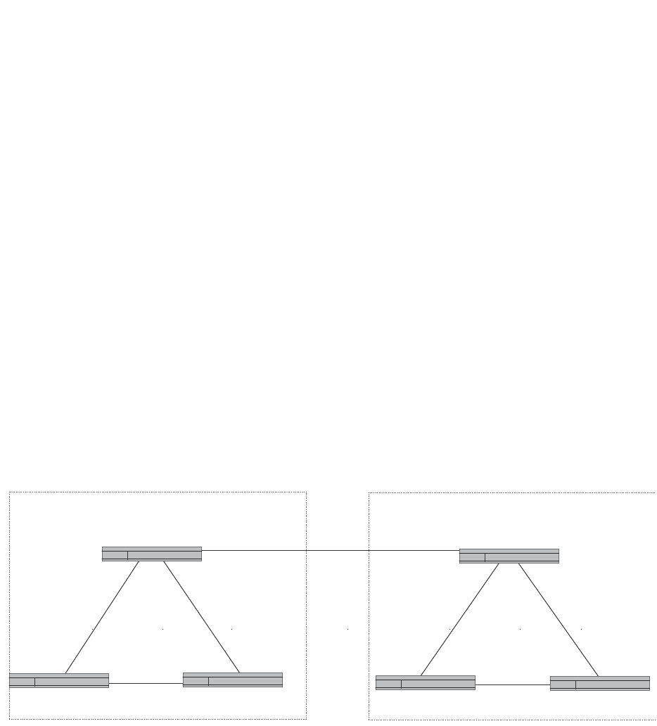
982 PowerConnect B-Series FCX Configuration Guide
53-1002266-01
Overview of BGP4
30
Overview of BGP4
BGP4 is the standard Exterior Gateway Protocol (EGP) used on the Internet to route traffic between
Autonomous Systems (AS) and to maintain loop-free routing. An autonomous system is a collection
of networks that share the same routing and administration characteristics. For example, a
corporate intranet consisting of several networks under common administrative control might be
considered an AS. The networks in an AS can but do not need to run the same routing protocol to
be in the same AS, nor do they need to be geographically close.
Routers within an AS can use different Interior Gateway Protocols (IGPs) such as RIP and OSPF to
communicate with one another. However, for routers in different autonomous systems to
communicate, they need to use an EGP. BGP4 is the standard EGP used by Internet routers and
therefore is the EGP implemented on Layer 3 Switches.
Figure 146 on page 982 shows a simple example of two BGP4 autonomous systems. Each AS
contains three BGP4 switches. All of the BGP4 switches within an AS communicate using IBGP.
BGP4 switches communicate with other autonomous systems using EBGP. Notice that each of the
switches also is running an Interior Gateway Protocol (IGP). The switches in AS1 are running OSPF
and the switches in AS2 are running RIP. Layer 3 Switches can be configured to redistribute routes
among BGP4, RIP, and OSPF. They also can redistribute static routes.
FIGURE 146 Example BGP4 autonomous systems
Relationship between the BGP4 route table and
the IP route table
The Layer 3 Switch BGP4 route table can have multiple routes to the same destination, which are
learned from different BGP4 neighbors. A BGP4 neighbor is another switch that also is running
BGP4. BGP4 neighbors communicate using Transmission Control Protocol (TCP) port 179 for BGP
communication. When you configure the Layer 3 Switch for BGP4, one of the configuration tasks
you perform is to identify the Layer 3 Switch BGP4 neighbors.
AS 1 AS 2
EBGP
IBGP
OSPF
OSPF
IBGP
IBGP
OSPF
RIP
RIP RIP
IBGP
IBGP
IBGP
BGP4 Switch BGP4 Switch
BGP4 Switch
BGP4 Switch
BGP4 Switch BGP4 Switch

PowerConnect B-Series FCX Configuration Guide 983
53-1002266-01
Overview of BGP4 30
Although a Layer 3 Switch BGP4 route table can have multiple routes to the same destination, the
BGP4 protocol evaluates the routes and chooses only one of the routes to send to the IP route
table. The route that BGP4 chooses and sends to the IP route table is the preferred route and will
be used by the Layer 3 Switch. If the preferred route goes down, BGP4 updates the route
information in the IP route table with a new BGP4 preferred route.
NOTE
If IP load sharing is enabled and you enable multiple equal-cost paths for BGP4, BGP4 can select
more than one equal-cost path to a destination.
A BGP4 route consists of the following information:
•Network number (prefix) – A value comprised of the network mask bits and an IP address (<IP
address>/ <mask bits>); for example, 192.215.129.0/18 indicates a network mask of 18 bits
applied to the IP address 192.215.129.0. When a BGP4 Layer 3 Switch advertises a route to
one of its neighbors, the route is expressed in this format.
•AS-path – A list of the other autonomous systems through which a route passes. BGP4 routers
can use the AS-path to detect and eliminate routing loops. For example, if a route received by a
BGP4 router contains the AS that the router is in, the router does not add the route to its own
BGP4 table. (The BGP4 RFCs refer to the AS-path as “AS_PATH”.)
•Additional path attributes – A list of additional parameters that describe the route. The route
origin and next hop are examples of these additional path attributes.
NOTE
The Layer 3 Switch re-advertises a learned best BGP4 route to the Layer 3 Switch neighbors even
when the software does not select that route for installation in the IP route table. The best BGP4
route is the route that the software selects based on comparison of the BGP4 route path attributes.
After a Layer 3 Switch successfully negotiates a BGP4 session with a neighbor (a BGP4 peer), the
Layer 3 Switch exchanges complete BGP4 route tables with the neighbor. After this initial exchange,
the Layer 3 Switch and all other RFC 1771-compliant BGP4 routers send UPDATE messages to
inform neighbors of new, changed, or no longer feasible routes. BGP4 routers do not send regular
updates. However, if configured to do so, a BGP4 router does regularly send KEEPALIVE messages
to its peers to maintain BGP4 sessions with them if the router does not have any route information
to send in an UPDATE message.Refer to “BGP4 message types” on page 985 for information about
BGP4 messages.
How BGP4 selects a path for a route
When multiple paths for the same route are known to a BGP4 router, the router uses the following
algorithm to weigh the paths and determine the optimal path for the route. The optimal path
depends on various parameters, which can be modified. (Refer to “Optional configuration tasks” on
page 1004.)
1. Is the next hop accessible though an Interior Gateway Protocol (IGP) route? If not, ignore the
route.
NOTE
The device does not use the default route to resolve BGP4 next hop. Also refer to “Enabling
next-hop recursion” on page 1011.
2. Use the path with the largest weight.

984 PowerConnect B-Series FCX Configuration Guide
53-1002266-01
Overview of BGP4
30
3. If the weights are the same, prefer the route with the largest local preference.
4. If the routes have the same local preference, prefer the route that was originated locally (by
this BGP4 Layer 3 Switch).
5. If the local preferences are the same, prefer the route with the shortest AS-path. An AS-SET
counts as 1. A confederation path length, if present, is not counted as part of the path length.
6. If the AS-path lengths are the same, prefer the route with the lowest origin type. From low to
high, route origin types are valued as follows:
•IGP is lowest
•EGP is higher than IGP but lower than INCOMPLETE
•INCOMPLETE is highest
7. If the routes have the same origin type, prefer the route with the lowest MED. For a definition of
MED, refer to “Configuring the Layer 3 Switch to always compare Multi-Exit Discriminators
(MEDs)” on page 1016.
BGP4 compares the MEDs of two otherwise equivalent paths if and only if the routes were
learned from the same neighboring AS. This behavior is called deterministic MED.
Deterministic MED is always enabled and cannot be disabled. In addition, you can enable the
Layer 3 Switch to always compare the MEDs, regardless of the AS information in the paths. To
enable this comparison, enter the always-compare-med command at the BGP4 configuration
level of the CLI. This option is disabled by default.
NOTE
By default, value 0 (most favorable) is used in MED comparison when the MED attribute is not
present. The default MED comparison results in the Layer 3 Switch favoring the route paths
that are missing their MEDs. You can use the med-missing-as-worst command to make the
Layer 3 Switch regard a BGP route with a missing MED attribute as the least favorable route,
when comparing the MEDs of the routes.
NOTE
MED comparison is not performed for internal routes originated within the local AS or
confederation.
8. Prefer routes in the following order:
•Routes received through EBGP from a BGP4 neighbor outside of the confederation
•Routes received through EBGP from a BGP4 router within the confederation
•Routes received through IBGP
9. If all the comparisons above are equal, prefer the route with the lowest IGP metric to the BGP4
next hop. This is the closest internal path inside the AS to reach the destination.
10. If the internal paths also are the same and BGP4 load sharing is enabled, load share among
the paths. Otherwise, prefer the route that comes from the BGP4 router with the lowest router
ID.

PowerConnect B-Series FCX Configuration Guide 985
53-1002266-01
Overview of BGP4 30
NOTE
Layer 3 Switches support BGP4 load sharing among multiple equal-cost paths. BGP4 load
sharing enables the Layer 3 Switch to balance the traffic across the multiple paths instead of
choosing just one path based on router ID. For EBGP routes, load sharing applies only when
the paths are from neighbors within the same remote AS. EBGP paths from neighbors in
different autonomous systems are not compared.
BGP4 message types
BGP4 routers communicate with their neighbors (other BGP4 routers) using the following types of
messages:
•OPEN
•UPDATE
•KEEPALIVE
•NOTIFICATION
OPEN message
After a BGP4 router establishes a TCP connection with a neighboring BGP4 router, the routers
exchange OPEN messages. An OPEN message indicates the following:
•BGP version – Indicates the version of the protocol that is in use on the router. BGP version 4
supports Classless Interdomain Routing (CIDR) and is the version most widely used in the
Internet. Version 4 also is the only version supported on Layer 3 Switches.
•AS number – A two-byte number that identifies the AS to which the BGP4 router belongs.
•Hold Time – The number of seconds a BGP4 router will wait for an UPDATE or KEEPALIVE
message (described below) from a BGP4 neighbor before assuming that the neighbor is dead.
BGP4 routers exchange UPDATE and KEEPALIVE messages to update route information and
maintain communication. If BGP4 neighbors are using different Hold Times, the lowest Hold
Time is used by the neighbors. If the Hold Time expires, the BGP4 router closes its TCP
connection to the neighbor and clears any information it has learned from the neighbor and
cached.
You can configure the Hold Time to be 0, in which case a BGP4 router will consider its
neighbors to always be up. For directly-attached neighbors, you can configure the Layer 3
Switch to immediately close the TCP connection to the neighbor and clear entries learned from
an EBGP neighbor if the interface to that neighbor goes down. This capability is provided by the
fast external fallover feature, which is disabled by default.
•BGP Identifier – The router ID. The BGP Identifier (router ID) identifies the BGP4 router to other
BGP4 routers. Layer 3 Switches use the same router ID for OSPF and BGP4. If you do not set a
router ID, the software uses the IP address on the lowest numbered loopback interface
configured on the router. If the Layer 3 Switch does not have a loopback interface, the default
router ID is the lowest numbered IP address configured on the device. For more information or
to change the router ID, refer to “Changing the router ID” on page 809.
•Parameter list – An optional list of additional parameters used in peer negotiation with BGP4
neighbors.

986 PowerConnect B-Series FCX Configuration Guide
53-1002266-01
Overview of BGP4
30
UPDATE message
After BGP4 neighbors establish a BGP4 connection over TCP and exchange their BGP4 routing
tables, they do not send periodic routing updates. Instead, a BGP4 neighbor sends an update to its
neighbor when it has a new route to advertise or routes have changed or become unfeasible. An
UPDATE message can contain the following information:
•Network Layer Reachability Information (NLRI) – The mechanism by which BGP4 supports
Classless Interdomain Routing (CIDR). An NLRI entry consists of an IP prefix that indicates a
network being advertised by the UPDATE message. The prefix consists of an IP network
number and the length of the network portion of the number. For example, an UPDATE
message with the NLRI entry 192.215.129.0/18 indicates a route to IP network
192.215.129.0 with network mask 255.255.192.0. The binary equivalent of this mask is 18
consecutive one bits, thus “18” in the NLRI entry.
•Path attributes – Parameters that indicate route-specific information such as path information,
route preference, next hop values, and aggregation information. BGP4 uses the path
attributes to make filtering and routing decisions.
•Unreachable routes – A list of routes that have been in the sending router BGP4 table but are
no longer feasible. The UPDATE message lists unreachable routes in the same format as new
routes.
KEEPALIVE message
BGP4 routers do not regularly exchange UPDATE messages to maintain the BGP4 sessions. For
example, if a Layer 3 Switch configured to perform BGP4 routing has already sent the latest route
information to its peers in UPDATE messages, the router does not send more UPDATE messages.
Instead, BGP4 routers send KEEPALIVE messages to maintain the BGP4 sessions. KEEPALIVE
messages are 19 bytes long and consist only of a message header; they contain no routing data.
BGP4 routers send KEEPALIVE messages at a regular interval, the Keep Alive Time. The default
Keep Alive Time on Layer 3 Switches is 60 seconds.
A parameter related to the Keep Alive Time is the Hold Time. A BGP4 router Hold Time determines
how many seconds the router will wait for a KEEPALIVE or UPDATE message from a BGP4 neighbor
before deciding that the neighbor is dead. The Hold Time is negotiated when BGP4 routers
exchange OPEN messages; the lower Hold Time is then used by both neighbors. For example, if
BGP4 Router A sends a Hold Time of 5 seconds and BGP4 Router B sends a Hold Time of 4
seconds, both routers use 4 seconds as the Hold Time for their BGP4 session. The default Hold
Time is 180 seconds. Generally, the Hold Time is configured to three times the value of the Keep
Alive Time.
If the Hold Time is 0, a BGP4 router assumes that its neighbor is alive regardless of how many
seconds pass between receipt of UPDATE or KEEPALIVE messages.
NOTIFICATION message
When you close the router BGP4 session with a neighbor, or the router detects an error in a
message received from the neighbor, or an error occurs on the router, the router sends a
NOTIFICATION message to the neighbor. No further communication takes place between the BGP4
router that sent the NOTIFICATION and the neighbors that received the NOTIFICATION.

PowerConnect B-Series FCX Configuration Guide 987
53-1002266-01
BGP4 graceful restart 30
BGP4 graceful restart
BGP4 graceful restart is a high-availability routing feature that minimizes disruption in traffic
forwarding, diminishes route flapping, and provides continuous service during a system restart,
switchover, failover, or hitless OS upgrade. During such events, routes remain available between
devices. BGP4 graceful restart operates between a device and its peers, and must be configured
on each participating device.
Under normal operation, when a BGP4 device is restarted, the network is automatically
reconfigured. Routes available through the restarting device are deleted when the device goes
down, and are then rediscovered and added back to the routing tables when the device is back up
and running. In a network with devices that are regularly restarted, performance can degrade
significantly and the availability of network resources can be limited.
BGP4 graceful restart is enabled globally by default. A BGP4 graceful restart-enabled device
advertises this capability to establish peering relationships with other devices. When a restart
begins, neighbor devices mark all of the routes from the restarting device as stale, but continue to
use the routes for the length of time specified by the restart timer. After the device is restarted, it
begins to receive routing updates from the peers. When it receives the end-of-RIB marker that
indicates it has received all of the BGP4 route updates, it recomputes the new routes and replaces
the stale routes in the route map with the newly computed routes. If the device does not come back
up within the time configured for the purge timer, the stale routes are removed.
NOTE
BGP4 graceful restart is supported in PowerConnect B-Series FCX switches in a stack . If the switch
will function as a restart helper device only, a secondary management module is not required.
This implementation of BGP4 graceful restart supports the Internet Draft-ietf-idr-restart-10.txt:
restart mechanism for BGP4
For details concerning configuration of BGP4 graceful restart, refer to “Configuring BGP4 graceful
restart” on page 1025.
Basic configuration and activation for BGP4
BGP4 is disabled by default. Follow the steps below to enable BGP4 and place your Layer 3 Switch
into service as a BGP4 router.
1. Enable the BGP4 protocol.
2. Set the local AS number.
NOTE
You must specify the local AS number for BGP4 to become functional.
3. Add each BGP4 neighbor (peer BGP4 router) and identify the AS the neighbor is in.
4. Save the BGP4 configuration information to the system configuration file.

988 PowerConnect B-Series FCX Configuration Guide
53-1002266-01
BGP4 parameters
30
NOTE
By default, the router ID is the IP address configured on the lowest numbered loopback interface. If
the Layer 3 Switch does not have a loopback interface, the default router ID is the lowest numbered
IP interface address configured on the device. For more information or to change the router ID, refer
to “Changing the router ID” on page 809. If you change the router ID, all current BGP4 sessions are
cleared.
PowerConnect> enable
PowerConnect#configure terminal
PowerConnect(config)#router bgp
BGP4: Please configure 'local-as' parameter in order to enable BGP4.
PowerConnect(config-bgp-router)#local-as 10
PowerConnect(config-bgp-router)#neighbor 209.157.23.99 remote-as 100
PowerConnect(config-bgp-router)#write memory
NOTE
When BGP4 is enabled on a Layer 3 Switch, you do not need to reset the system. The protocol is
activated as soon as you enable it. Moreover, the router begins a BGP4 session with a BGP4
neighbor as soon as you add the neighbor.
Note regarding disabling BGP4
If you disable BGP4, the Layer 3 Switch removes all the running configuration information for the
disabled protocol from the running-config. To restore the BGP4 configuration, you must reload the
software to load the configuration from the startup-config. Moreover, when you save the
configuration to the startup-config file after disabling the protocol, all the configuration information
for the disabled protocol is removed from the startup-config file.
The CLI displays a warning message such as the following.
PowerConnect(config-bgp-router)#no router bgp
router bgp mode now disabled. All bgp config data will be lost when writing to
flash!
If you are testing a BGP4 configuration and are likely to disable and re-enable the protocol, you
might want to make a backup copy of the startup-config file containing the protocol configuration
information. This way, if you remove the configuration information by saving the configuration after
disabling the protocol, you can restore the configuration by copying the backup copy of the
startup-config file onto the flash memory.
NOTE
To disable BGP4 without losing the BGP4 configuration information, remove the local AS (for
example, by entering the no local-as <num> command). In this case, BGP4 retains the other
configuration information but is not operational until you set the local AS again.
BGP4 parameters
You can modify or set the following BGP4 parameters:
•Optional – Define the router ID. (The same router ID also is used by OSPF.)
•Required – Specify the local AS number.
•Optional – Add a loopback interface for use with neighbors.

PowerConnect B-Series FCX Configuration Guide 989
53-1002266-01
BGP4 parameters 30
•Required – Identify BGP4 neighbors.
•Optional – Change the Keep Alive Time and Hold Time.
•Optional – Change the update timer for route changes.
•Optional – Enable fast external fallover.
•Optional – Specify a list of individual networks in the local AS to be advertised to remote
autonomous systems using BGP4.
•Optional – Change the default local preference for routes.
•Optional – Enable the default route (default-information-originate).
•Optional – Enable use of a default route to resolve a BGP4 next-hop route.
•Optional – Change the default MED (metric).
•Optional – Enable next-hop recursion.
•Optional – Change the default administrative distances for EBGP, IBGP, and locally originated
routes.
•Optional – Require the first AS in an Update from an EBGP neighbor to be the neighbor AS.
•Optional – Change MED comparison parameters.
•Optional – Disable comparison of the AS-Path length.
•Optional – Enable comparison of the router ID.
•Optional – Enable auto summary to summarize routes at an IP class boundary (A, B, or C).
•Optional – Aggregate routes in the BGP4 route table into CIDR blocks.
•Optional – Configure the router as a BGP4 router reflector.
•Optional – Configure the Layer 3 Switch as a member of a BGP4 confederation.
•Optional – Change the default metric for routes that BGP4 redistributes into RIP or OSPF.
•Optional – Change the parameters for RIP, OSPF, or static routes redistributed into BGP4.
•Optional – Change the number of paths for BGP4 load sharing.
•Optional – Change other load-sharing parameters
•Optional – Define BGP4 address filters.
•Optional – Define BGP4 AS-path filters.
•Optional – Define BGP4 community filters.
•Optional – Define IP prefix lists.
•Optional – Define neighbor distribute lists.
•Optional – Define BGP4 route maps for filtering routes redistributed into RIP and OSPF.
•Optional – Define route flap dampening parameters.
NOTE
When using the CLI, you set global level parameters at the BGP CONFIG level of the CLI. You can
reach the BGP CONFIG level by entering router bgp… at the global CONFIG level.
When parameter changes take effect
Some parameter changes take effect immediately while others do not take full effect until the
router sessions with its neighbors are reset. Some parameters do not take effect until the router is
rebooted.

990 PowerConnect B-Series FCX Configuration Guide
53-1002266-01
BGP4 parameters
30
Immediately
The following parameter changes take effect immediately:
•Enable or disable BGP.
•Set or change the local AS.
•Add neighbors.
•Change the update timer for route changes.
•Disable or enable fast external fallover.
•Specify individual networks that can be advertised.
•Change the default local preference, default information originate setting, or administrative
distance.
•Enable or disable use of a default route to resolve a BGP4 next-hop route.
•Enable or disable MED (metric) comparison.
•Require the first AS in an Update from an EBGP neighbor to be the neighbor AS.
•Change MED comparison parameters.
•Disable comparison of the AS-Path length.
•Enable comparison of the router ID.
•Enable next-hop recursion.
•Enable or disable auto summary.
•Change the default metric.
•Disable or re-enable route reflection.
•Configure confederation parameters.
•Disable or re-enable load sharing.
•Change the maximum number of load-sharing paths.
•Change other load-sharing parameters.
•Define route flap dampening parameters.
•Add, change, or negate redistribution parameters (except changing the default MED; see
below).
•Add, change, or negate route maps (when used by the network command or a redistribution
command).
After resetting neighbor sessions
The following parameter changes take effect only after the router BGP4 sessions are cleared, or
reset using the “soft” clear option. (Refer to “Closing or resetting a neighbor session” on
page 1096.)
The parameter are as follows:
•Change the Hold Time or Keep Alive Time.
•Aggregate routes.
•Add, change, or negate filter tables.

PowerConnect B-Series FCX Configuration Guide 991
53-1002266-01
Memory considerations 30
After disabling and re-enabling redistribution
The following parameter change takes effect only after you disable and then re-enable
redistribution:
•Change the default MED (metric).
Memory considerations
BGP4 handles a very large number of routes and therefore requires a lot of memory. For example,
in a typical configuration with just a single BGP4 neighbor, a BGP4 router may need to be able to
hold up to 80,000 routes. Many configurations, especially those involving more than one neighbor,
can require the router to hold even more routes. Layer 3 Switches provide dynamic memory
allocation for BGP4 data. These devices automatically allocate memory when needed to support
BGP4 neighbors, routes, and route attribute entries. Dynamic memory allocation is performed
automatically by the software and does not require a reload.
The memory amounts for all BGP4 data, including routes received from neighbors, BGP route
advertisements (routes sent to neighbors), and BGP route attribute entries. The routes sent to and
received from neighbors use the most BGP4 memory. Generally, the actual limit to the number of
neighbors, routes, or route attribute entries the device can accommodate depends on how many
routes the Layer 3 Switch sends to and receives from the neighbors.
In some cases, where most of the neighbors do not send or receive a full BGP route table (about
80,000 routes), the memory can support a larger number of BGP4 neighbors. However, if most of
the BGP4 neighbors send or receive full BGP route tables, the number of BGP neighbors the
memory can support is less than in configurations where the neighbors send smaller route tables.
As a guideline, Layer 3 Switches with a 512 MB Management 4 module can accommodate 150
through 200 neighbors, with the assumption that the Layer 3 Switch receives about one million
routes total from all neighbors and sends about eight million routes total to neighbors. For each
additional one million incoming routes, the capacity for outgoing routes decreases by around two
million.
Memory configuration options obsoleted by
dynamic memory
Devices that support dynamic BGP4 memory allocation do not require or even support static
configuration of memory for BGP4 neighbors, routes, or route attributes. Consequently, the
following CLI commands and equivalent Web management options are not supported on these
devices:
•max-neighbors <num>
•max-routes <num>
•max-attribute-entries <num>
If you boot a device that has a startup-config file that contains these commands, the software
ignores the commands and uses dynamic memory allocation for BGP4. The first time you save the
device running configuration (running-config) to the startup-config file, the commands are removed
from the file.

992 PowerConnect B-Series FCX Configuration Guide
53-1002266-01
Basic configuration tasks
30
Basic configuration tasks
The following sections describe how to perform the configuration tasks that are required to use
BGP4 on the Layer 3 Switch. You can modify many parameters in addition to the ones described in
this section. Refer to “Optional configuration tasks” on page 1004.
Enabling BGP4 on the router
When you enable BGP4 on the router, BGP4 is automatically activated. To enable BGP4 on the
router, enter the following commands.
PowerConnect> enable
PowerConnect#configure terminal
PowerConnect(config)#router bgp
BGP4: Please configure 'local-as' parameter in order to enable BGP4.
PowerConnect(config-bgp-router)#local-as 10
PowerConnect(config-bgp-router)#neighbor 209.157.23.99 remote-as 100
PowerConnect(config-bgp-router)#write memory
Changing the router ID
The OSPF and BGP4 protocols use router IDs to identify the routers that are running the protocols.
A router ID is a valid, unique IP address and sometimes is an IP address configured on the router.
The router ID cannot be an IP address in use by another device.
By default, the router ID on a Layer 3 Switch is one of the following:
•If the router has loopback interfaces, the default router ID is the IP address configured on the
lowest numbered loopback interface configured on the Layer 3 Switch. For example, if you
configure loopback interfaces 1, 2, and 3 as follows, the default router ID is 9.9.9.9/24:
•Loopback interface 1, 9.9.9.9/24
•Loopback interface 2, 4.4.4.4/24
•Loopback interface 3, 1.1.1.1/24
•If the device does not have any loopback interfaces, the default router ID is the lowest
numbered IP interface address configured on the device.
NOTE
Layer 3 Switches use the same router ID for both OSPF and BGP4. If the router is already configured
for OSPF, you may want to use the router ID that is already in use on the router rather than set a new
one. To display the router ID, enter the show ip CLI command at any CLI level.
To change the router ID, enter a command such as the following.
PowerConnect(config)#ip router-id 209.157.22.26
Syntax: ip router-id <ip-addr>
The <ip-addr> can be any valid, unique IP address.
NOTE
You can specify an IP address used for an interface on the Layer 3 Switch, but do not specify an IP
address in use by another device.

PowerConnect B-Series FCX Configuration Guide 993
53-1002266-01
Basic configuration tasks 30
Setting the local AS number
The local AS number identifies the AS the Dell BGP4 router is in. The AS number can be from 1
through 65535. There is no default. AS numbers 64512 through 65535 are the well-known
private BGP4 AS numbers and are not advertised to the Internet community.
To set the local AS number, enter commands such as the following.
PowerConnect(config)#router bgp
BGP4: Please configure 'local-as' parameter in order to enable BGP4.
PowerConnect(config-bgp-router)#local-as 10
PowerConnect(config-bgp-router)#write memory
Syntax: [no] local-as <num>
The <num> parameter specifies the local AS number.
Adding a loopback interface
You can configure the router to use a loopback interface instead of a specific port or virtual routing
interface to communicate with a BGP4 neighbor. A loopback interface adds stability to the network
by working around route flap problems that can occur due to unstable links between the router and
its neighbors.
Loopback interfaces are always up, regardless of the states of physical interfaces. Loopback
interfaces are especially useful for IBGP neighbors (neighbors in the same AS) that are multiple
hops away from the router. When you configure a BGP4 neighbor on the router, you can specify
whether the router uses the loopback interface to communicate with the neighbor. As long as a
path exists between the router and its neighbor, BGP4 information can be exchanged. The BGP4
session is not associated with a specific link but instead is associated with the virtual interfaces.
You can add up to 24 IP addresses to each loopback interface.
NOTE
If you configure the Layer 3 Switch to use a loopback interface to communicate with a BGP4
neighbor, the peer IP address on the remote router pointing to your loopback address must be
configured.
To add a loopback interface, enter commands such as those shown in the following example.
PowerConnect(config-bgp-router)#exit
PowerConnect(config)#int loopback 1
PowerConnect(config-lbif-1)#ip address 10.0.0.1/24
Syntax: interface loopback <num>
The <num> value can be from 1 through 8 on Chassis Layer 3 Switches. The value can be from 1
through 4 on the Compact Layer 3 Switch.
Adding BGP4 neighbors
The BGP4 protocol does not contain a peer discovery process. Therefore, for each of the router
BGP4 neighbors (peers), you must indicate the neighbor IP address and the AS each neighbor is in.
Neighbors that are in different autonomous systems communicate using EBGP. Neighbors within
the same AS communicate using IBGP.

994 PowerConnect B-Series FCX Configuration Guide
53-1002266-01
Basic configuration tasks
30
NOTE
If the Layer 3 Switch has multiple neighbors with similar attributes, you can simplify configuration by
configuring a peer group, then adding individual neighbors to it. The configuration steps are similar,
except you specify a peer group name instead of a neighbor IP address when configuring the
neighbor parameters, then add individual neighbors to the peer group. Refer to “Adding a BGP4 peer
group” on page 1000.
NOTE
The Layer 3 Switch attempts to establish a BGP4 session with a neighbor as soon as you enter a
command specifying the neighbor IP address. If you want to completely configure the neighbor
parameters before the Layer 3 Switch establishes a session with the neighbor, you can
administratively shut down the neighbor. Refer to “Administratively shutting down a session with a
BGP4 neighbor” on page 1003.
To add a BGP4 neighbor with IP address 209.157.22.26, enter the following command.
PowerConnect(config-bgp-router)#neighbor 209.157.22.26
The neighbor <ip-addr> must be a valid IP address.
The neighbor command has some additional parameters, as shown in the following syntax:
Syntax: [no] neighbor <ip-addr> | <peer-group-name>
[advertisement-interval <num>]
[capability orf prefixlist [send | receive]]
[default-originate [route-map <map-name>]]
[description <string>]
[distribute-list in | out <num,num,...> | <ACL-num> in | out]
[ebgp-multihop [<num>]]
[filter-list in | out <num,num,...> | <ACL-num> in | out | weight]
[maximum-prefix <num> [<threshold>] [teardown]]
[next-hop-self]
[nlri multicast | unicast | multicast unicast]
[password [0 | 1] <string>]
[prefix-list <string> in | out]
[remote-as <as-number>]
[remove-private-as]
[route-map in | out <map-name>]
[route-reflector-client]
[send-community]
[soft-reconfiguration inbound]
[shutdown]
[timers keep-alive <num> hold-time <num>]
[unsuppress-map <map-name>]
[update-source <ip-addr> | ethernet <port> | loopback <num> | ve <num>]
[weight <num>]
The <ip-addr> | <peer-group-name> parameter indicates whether you are configuring an individual
neighbor or a peer group. If you specify a neighbor IP address, you are configuring that individual
neighbor. If you specify a peer group name, you are configuring a peer group. Refer to “Adding a
BGP4 peer group” on page 1000.
advertisement-interval <num> specifies the minimum delay (in seconds) between messages to the
specified neighbor. The default is 30 for EBGP neighbors (neighbors in other autonomous systems).
The default is 5 for IBGP neighbors (neighbors in the same AS). The range is 0 through 600.

PowerConnect B-Series FCX Configuration Guide 995
53-1002266-01
Basic configuration tasks 30
NOTE
The Layer 3 Switch applies the advertisement interval only under certain conditions. The Layer 3
Switch does not apply the advertisement interval when sending initial updates to a BGP4 neighbor.
As a result, the Layer 3 Switch sends the updates one immediately after another, without waiting for
the advertisement interval.
capability orf prefixlist [send | receive] configures cooperative router filtering. The send | receive
parameter specifies the support you are enabling:
•send – The Layer 3 Switch sends the IP prefix lists as Outbound Route Filters (ORFs) to the
neighbor.
•receive – The Layer 3 Switch accepts filters as Outbound Route Filters (ORFs) from the
neighbor.
If you do not specify the capability, both capabilities are enabled. The prefixlist parameter specifies
the type of filter you want to send to the neighbor.
For more information, refer to “Configuring cooperative BGP4 route filtering” on page 1051.
NOTE
The current release supports cooperative filtering only for filters configured using IP prefix lists.
default-originate [route-map <map-name>] configures the Layer 3 Switch to send the default route
0.0.0.0 to the neighbor. If you use the route-map <map-name> parameter, the route map injects
the default route conditionally, based on the match conditions in the route map.
description <string> specifies a name for the neighbor. You can enter an alphanumeric text string
up to 80 characters long.
distribute-list in | out <num,num,...> specifies a distribute list to be applied to updates to or from
the specified neighbor. The in | out keyword specifies whether the list is applied on updates
received from the neighbor or sent to the neighbor. The <num,num,...> parameter specifies the list
of address-list filters. The router applies the filters in the order in which you list them and stops
applying the filters in the distribute list when a match is found.
Alternatively, you can specify distribute-list <ACL-num> in | out to use an IP ACL instead of a
distribute list. In this case, <ACL-num> is an IP ACL.
NOTE
By default, if a route does not match any of the filters, the Layer 3 Switch denies the route. To change
the default behavior, configure the last filter as “permit any any”.
NOTE
The address filter must already be configured. Refer to “Filtering specific IP addresses” on
page 1033.
ebgp-multihop [<num>] specifies that the neighbor is more than one hop away and that the
session type with the neighbor is thus EBGP-multihop. This option is disabled by default. The
<num> parameter specifies the TTL you are adding for the neighbor. You can specify a number
from 0 through 255. The default is 0. If you leave the EBGP TTL value set to 0, the software uses
the IP TTL value.

996 PowerConnect B-Series FCX Configuration Guide
53-1002266-01
Basic configuration tasks
30
filter-list in | out <num,num,...> specifies an AS-path filter list or a list of AS-path ACLs. The in | out
keyword specifies whether the list is applied on updates received from the neighbor or sent to the
neighbor. If you specify in or out, The <num,num,...> parameter specifies the list of AS-path filters.
The router applies the filters in the order in which you list them and stops applying the filters in the
AS-path filter list when a match is found. The weight <num> parameter specifies a weight that the
Layer 3 Switch applies to routes received from the neighbor that match the AS-path filter or ACL.
You can specify a number from 0 through 65535.
Alternatively, you can specify filter-list <ACL-num> in | out | weight to use an AS-path ACL instead of
an AS-path filter list. In this case, <ACL-num> is an AS-path ACL.
NOTE
By default, if an AS-path does not match any of the filters or ACLs, the Layer 3 Switch denies the
route. To change the default behavior, configure the last filter or ACL as “permit any any”.
NOTE
The AS-path filter or ACL must already be configured. Refer to “Filtering AS-paths” on page 1035.
maximum-prefix <num> specifies the maximum number of IP network prefixes (routes) that can be
learned from the specified neighbor or peer group. You can specify a value from 0 through
4294967295. The default is 0 (unlimited):
•The <num> parameter specifies the maximum number. You can specify a value from 0 through
4294967295. The default is 0 (unlimited).
•The <threshold> parameter specifies the percentage of the value you specified for the
maximum-prefix <num>, at which you want the software to generate a Syslog message. You
can specify a value from 1 (one percent) to 100 (100 percent). The default is 100.
•The teardown parameter tears down the neighbor session if the maximum-prefix limit is
exceeded. The session remains shutdown until you clear the prefixes using the clear ip bgp
neighbor all or clear ip bgp neighbor <ip-addr> command, or change the neighbor
maximum-prefix configuration. The software also generates a Syslog message.
next-hop-self specifies that the router should list itself as the next hop in updates sent to the
specified neighbor. This option is disabled by default.
The nlri multicast | unicast | multicast unicast parameter specifies whether the neighbor is a
multicast neighbor or a unicast neighbor. Optionally, you also can specify unicast if you want the
Layer 3 Switch to exchange unicast (BGP4) routes as well as multicast routes with the neighbor.
The default is unicast only.
password [0 | 1] <string> specifies an MD5 password for securing sessions between the Layer 3
Switch and the neighbor. You can enter a string up to 80 characters long. The string can contain
any alphanumeric characters, but the first character cannot be a number. If the password contains
a number, do not enter a space following the number.
The 0 | 1 parameter is the encryption option, which you can omit (the default) or which can be one
of the following:
•0 – Disables encryption for the authentication string you specify with the command. The
password or string is shown as clear text in the output of commands that display neighbor or
peer group configuration information.
•1 – Assumes that the authentication string you enter is the encrypted form, and decrypts the
value before using it.
For more information, refer to “Encryption of BGP4 MD5 authentication keys” on page 998.

PowerConnect B-Series FCX Configuration Guide 997
53-1002266-01
Basic configuration tasks 30
NOTE
If you want the software to assume that the value you enter is the clear-text form, and to encrypt
display of that form, do not enter 0 or 1. Instead, omit the encryption option and allow the software
to use the default behavior.
If you specify encryption option 1, the software assumes that you are entering the encrypted form
of the password or authentication string. In this case, the software decrypts the password or string
you enter before using the value for authentication. If you accidentally enter option 1 followed by the
clear-text version of the password or string, authentication will fail because the value used by the
software will not match the value you intended to use.
prefix-list <string> in | out specifies an IP prefix list. You can use IP prefix lists to control routes to
and from the neighbor. IP prefix lists are an alternative method to AS-path filters. The in | out
keyword specifies whether the list is applied on updates received from the neighbor or sent to the
neighbor. You can configure up to 1000 prefix list filters. The filters can use the same prefix list or
different prefix lists. To configure an IP prefix list, refer to “Defining IP prefix lists” on page 1041.
remote-as <as-number> specifies the AS the remote neighbor is in. The <as-number> can be a
number from 1 through 65535. There is no default.
remove-private-as configures the router to remove private AS numbers from UPDATE messages the
router sends to this neighbor. The router will remove AS numbers 64512 through 65535 (the
well-known BGP4 private AS numbers) from the AS-path attribute in UPDATE messages the Layer 3
Switch sends to the neighbor. This option is disabled by default.
route-map in | out <map-name> specifies a route map the Layer 3 Switch will apply to updates
sent to or received from the specified neighbor. The in | out keyword specifies whether the list is
applied on updates received from the neighbor or sent to the neighbor.
NOTE
The route map must already be configured. Refer to “Defining route maps” on page 1042.
route-reflector-client specifies that this neighbor is a route-reflector client of the router. Use the
parameter only if this router is going to be a route reflector. For information, refer to “Configuring
route reflection parameters” on page 1017. This option is disabled by default.
send-community enables sending the community attribute in updates to the specified neighbor. By
default, the router does not send the community attribute.
shutdown administratively shuts down the session with this neighbor. Shutting down the session
allows you to completely configure the neighbor and save the configuration without actually
establishing a session with the neighbor. This option is disabled by default.
soft-reconfiguration inbound enables the soft reconfiguration feature, which stores all the route
updates received from the neighbor. If you request a soft reset of inbound routes, the software
performs the reset by comparing the policies against the stored route updates, instead of
requesting the neighbor BGP4 route table or resetting the session with the neighbor. Refer to
“Using soft reconfiguration” on page 1091.
timers keep-alive <num> hold-time <num> overrides the global settings for the Keep Alive Time
and Hold Time. For the Keep Alive Time, you can specify from 0 through 65535 seconds. For the
Hold Time, you can specify 0 or
3 through 65535 (1 and 2 are not allowed). If you set the Hold Time to 0, the router waits

998 PowerConnect B-Series FCX Configuration Guide
53-1002266-01
Basic configuration tasks
30
indefinitely for messages from a neighbor without concluding that the neighbor is dead. The
defaults for these parameters are the currently configured global Keep Alive Time and Hold Time.
For more information about these parameters, refer to “Changing the Keep Alive Time and Hold
Time” on page 1004.
unsuppress-map <map-name> removes route dampening from a neighbor routes when those
routes have been dampened due to aggregation. Refer to “Removing route dampening from a
neighbor routes suppressed due to aggregation” on page 1057.
update-source <ip-addr> | ethernet <port> | loopback <num> | ve <num> configures the router to
communicate with the neighbor through the specified interface. There is no default.
weight <num> specifies a weight the Layer 3 Switch will add to routes received from the specified
neighbor. BGP4 prefers larger weights over smaller weights. The default weight is 0.
Encryption of BGP4 MD5 authentication keys
When you configure a BGP4 neighbor or neighbor peer group, you can specify an MD5
authentication string for authenticating packets exchanged with the neighbor or peer group of
neighbors.
For added security, the software encrypts display of the authentication string by default. The
software also provides an optional parameter to disable encryption of the authentication string, on
an individual neighbor or peer group basis. By default, the MD5 authentication strings are
displayed in encrypted format in the output of the following commands:
•show running-config (or write terminal)
•show configuration
•show ip bgp config
When encryption of the authentication string is enabled, the string is encrypted in the CLI
regardless of the access level you are using.
If you display the running-config after reloading, the BGP4 commands that specify an
authentication string show the string in encrypted form.
In addition, when you save the configuration to the startup-config file, the file contains the new
BGP4 command syntax and encrypted passwords or strings.
NOTE
Dell recommends that you save a copy of the startup-config file for each switch you plan to upgrade.
Encryption example
The following commands configure a BGP4 neighbor and a peer group, and specify MD5
authentication strings (passwords) for authenticating packets exchanged with the neighbor or peer
group.
Here is how the commands appear when you display the BGP4 configuration commands.
PowerConnect(config-bgp-router)#local-as 2
PowerConnect(config-bgp-router)#neighbor xyz peer-group
PowerConnect(config-bgp-router)#neighbor xyz password abc
PowerConnect(config-bgp-router)#neighbor 10.10.200.102 peer-group xyz
PowerConnect(config-bgp-router)#neighbor 10.10.200.102 password test

PowerConnect B-Series FCX Configuration Guide 999
53-1002266-01
Basic configuration tasks 30
Notice that the software has converted the commands that specify an authentication string into
the new syntax (described below), and has encrypted display of the authentication strings.
Command syntax
Since the default behavior does not affect the BGP4 configuration itself but does encrypt display of
the authentication string, the CLI does not list the encryption options.
Syntax: [no] neighbor <ip-addr> | <peer-group-name> password [0 | 1] <string>
The <ip-addr> | <peer-group-name> parameter indicates whether you are configuring an individual
neighbor or a peer group. If you specify a neighbor IP address, you are configuring that individual
neighbor. If you specify a peer group name, you are configuring a peer group.
The password <string> parameter specifies an MD5 authentication string for securing sessions
between the Layer 3 Switch and the neighbor. You can enter a string up to 80 characters long. The
string can contain any alphanumeric characters, but the first character cannot be a number. If the
password contains a number, do not enter a space following the number.
The 0 | 1 parameter is the encryption option, which you can omit (the default) or which can be one
of the following:
•0 – Disables encryption for the authentication string you specify with the command. The
password or string is shown as clear text in the output of commands that display neighbor or
peer group configuration information.
•1 – Assumes that the authentication string you enter is the encrypted form, and decrypts the
value before using it.
NOTE
If you want the software to assume that the value you enter is the clear-text form, and to encrypt
display of that form, do not enter 0 or 1. Instead, omit the encryption option and allow the software
to use the default behavior.
If you specify encryption option 1, the software assumes that you are entering the encrypted form
of the password or authentication string. In this case, the software decrypts the password or string
you enter before using the value for authentication. If you accidentally enter option 1 followed by the
clear-text version of the password or string, authentication will fail because the value used by the
software will not match the value you intended to use.
Displaying the Authentication String
If you want to display the authentication string, enter the following commands.
PowerConnect(config)#enable password-display
PowerConnect#show ip bgp neighbors
PowerConnect#show ip bgp config
Current BGP configuration:
router bgp
local-as 2
neighbor xyz peer-group
neighbor xyz password 1 $!2d
neighbor 10.10.200.102 peer-group xyz
neighbor 10.10.200.102 remote-as 1
neighbor 10.10.200.102 password 1 $on-o

1000 PowerConnect B-Series FCX Configuration Guide
53-1002266-01
Basic configuration tasks
30
The enable password-display command enables display of the authentication string, but only in the
output of the show ip bgp neighbors command. Display of the string is still encrypted in the
startup-config file and running-config. Enter the command at the global CONFIG level of the CLI.
NOTE
The command also displays SNMP community strings in clear text, in the output of the show snmp
server command.
Adding a BGP4 peer group
A peer group is a set of BGP4 neighbors that share common parameters. Peer groups provide the
following benefits:
•Simplified neighbor configuration – You can configure a set of neighbor parameters and then
apply them to multiple neighbors. You do not need to individually configure the common
parameters individually on each neighbor.
•Flash memory conservation – Using peer groups instead of individually configuring all the
parameters for each neighbor requires fewer configuration commands in the startup-config
file.
You can perform the following tasks on a peer-group basis:
•Reset neighbor sessions
•Perform soft-outbound resets (the Layer 3 Switch updates outgoing route information to
neighbors but does not entirely reset the sessions with those neighbors)
•Clear BGP message statistics
•Clear error buffers
Peer group parameters
You can set all neighbor parameters in a peer group. When you add a neighbor to the peer group,
the neighbor receives all the parameter settings you set in the group, except parameter values you
have explicitly configured for the neighbor. If you do not set a neighbor parameter in the peer group
and the parameter also is not set for the individual neighbor, the neighbor uses the default value.
Configuration rules
The following rules apply to peer group configuration:
•You must configure a peer group before you can add neighbors to the peer group.
•If you remove a parameter from a peer group, the value for that parameter is reset to the
default for all the neighbors within the peer group, unless you have explicitly set that parameter
on individual neighbors. In this case, the value you set on the individual neighbors applies to
those neighbors, while the default value applies to neighbors for which you have not explicitly
set the value.

PowerConnect B-Series FCX Configuration Guide 1001
53-1002266-01
Basic configuration tasks 30
NOTE
If you enter a command to remove the remote AS parameter from a peer group, the software
checks to ensure that the peer group does not contain any neighbors. If the peer group does
contain neighbors, the software does not allow you to remove the remote AS. The software
prevents removing the remote AS in this case so that the neighbors in the peer group that are
using the remote AS do not lose connectivity to the Layer 3 Switch.
•Once you add a neighbor to a peer group, you cannot configure the following outbound
parameters (the parameters governing outbound traffic) for the neighbor:
•Default-information-originate
•Next-hop-self
•Outbound route map
•Outbound filter list
•Outbound distribute list
•Outbound prefix list
•Remote AS, if configured for the peer group
•Remove private AS
•Route reflector client
•Send community
•Timers
•Update source
If you want to change an outbound parameter for an individual neighbor, you must first remove
the neighbor from the peer group. In this case, you cannot re-add the neighbor to the same
peer group, but you can add the neighbor to a different peer group. All the neighbors within a
peer group must have the same values for the outbound parameters. To change an outbound
parameter to the same value for all neighbors within a peer group, you can change the
parameter on a peer-group basis. In this case, you do not need to remove the neighbors and
change the parameter individually for each neighbor.
•If you add an outbound parameter to a peer group, that parameter is automatically applied to
all neighbors within the peer group.
•When you add a neighbor to a peer group, the software removes any outbound parameters for
that neighbor from the running configuration (running-config). As a result, when you save the
configuration to the startup-config file, the file does not contain any outbound parameters for
the individual neighbors you have placed in a peer group. The only outbound parameters the
startup-config file contains for neighbors within a peer group are the parameters associated
with the peer group itself. However, the running-config and the startup-config file can contain
individual parameters listed in the previous section as well as the settings for those
parameters within a peer group.
You can override neighbor parameters that do not affect outbound policy on an individual neighbor
basis.
•If you do not specify a parameter for an individual neighbor, the neighbor uses the value in the
peer group.
•If you set the parameter for the individual neighbor, that value overrides the value you set in
the peer group.

1002 PowerConnect B-Series FCX Configuration Guide
53-1002266-01
Basic configuration tasks
30
•If you add a parameter to a peer group that already contains neighbors, the parameter value is
applied to neighbors that do not already have the parameter explicitly set. If a neighbor has the
parameter explicitly set, the explicitly set value overrides the value you set for the peer group.
•If you remove the setting for a parameter from a peer group, the value for that parameter
changes to the default value for all the neighbors in the peer group that do not have that
parameter individually set.
Configuring a peer group
To configure a BGP4 peer group, enter commands such as the following at the BGP configuration
level.
PowerConnect(config-bgp-router)#neighbor PeerGroup1 peer-group
PowerConnect(config-bgp-router)#neighbor PeerGroup1 description “EastCoast
Neighbors”
PowerConnect(config-bgp-router)#neighbor PeerGroup1 remote-as 100
PowerConnect(config-bgp-router)#neighbor PeerGroup1 distribute-list out 1
The commands in this example configure a peer group called “PeerGroup1” and set the following
parameters for the peer group:
•A description, “EastCoast Neighbors”
•A remote AS number, 100
•A distribute list for outbound traffic
The software applies these parameters to each neighbor you add to the peer group. You can
override the description parameter for individual neighbors. If you set the description parameter for
an individual neighbor, the description overrides the description configured for the peer group.
However, you cannot override the remote AS and distribute list parameters for individual neighbors.
Since these parameters control outbound traffic, the parameters must have the same values for all
neighbors within the peer group.
Syntax: neighbor <peer-group-name> peer-group
The <peer-group-name> parameter specifies the name of the group and can be up to 80
characters long. The name can contain special characters and internal blanks. If you use internal
blanks, you must use quotation marks around the name. For example, the command neighbor “My
Three Peers” peer-group is valid, but the command neighbor My Three Peers peer-group is not
valid.
Syntax: [no] neighbor <ip-addr> | <peer-group-name>
[advertisement-interval <num>]
[default-originate [route-map <map-name>]]
[description <string>]
[distribute-list in | out <num,num,...> | <ACL-num> in | out]
[ebgp-multihop [<num>]]
[filter-list in | out <num,num,...> | <ACL-num> in | out | weight]
[maximum-prefix <num> [<threshold>] [teardown]]
[next-hop-self]
[password [0 | 1] <string>]
[prefix-list <string> in | out]
[remote-as <as-number>]
[remove-private-as]
[route-map in | out <map-name>]
[route-reflector-client]

PowerConnect B-Series FCX Configuration Guide 1003
53-1002266-01
Basic configuration tasks 30
[send-community]
[soft-reconfiguration inbound]
[shutdown]
[timers keep-alive <num> hold-time <num>]
[update-source loopback <num>]
[weight <num>]
The <ip-addr> | <peer-group-name> parameter indicates whether you are configuring a peer group
or an individual neighbor. You can specify a peer group name or IP address with the neighbor
command. If you specify a peer group name, you are configuring a peer group. If you specify a
neighbor IP address, you are configuring that individual neighbor. Use the <ip-addr> parameter if
you are configuring an individual neighbor instead of a peer group. Refer to “Adding BGP4
neighbors” on page 993.
The remaining parameters are the same ones supported for individual neighbors. Refer to “Adding
BGP4 neighbors” on page 993.
Applying a peer group to a neighbor
After you configure a peer group, you can add neighbors to the group. When you add a neighbor to
a peer group, you are applying all the neighbor attributes specified in the peer group to the
neighbor.
To add neighbors to a peer group, enter commands such as the following.
PowerConnect(config-bgp-router)#neighbor 192.168.1.12 peer-group PeerGroup1
PowerConnect(config-bgp-router)#neighbor 192.168.2.45 peer-group PeerGroup1
PowerConnect(config-bgp-router)#neighbor 192.168.3.69 peer-group PeerGroup1
The commands in this example add three neighbors to the peer group “PeerGroup1”. As members
of the peer group, the neighbors automatically receive the neighbor parameter values configured
for the peer group. You also can override the parameters (except parameters that govern outbound
traffic) on an individual neighbor basis. For neighbor parameters not specified for the peer group,
the neighbors use the default values.
Syntax: neighbor <ip-addr> peer-group <peer-group-name>
The <ip-addr> parameter specifies the IP address of the neighbor.
The <peer-group-name> parameter specifies the peer group name.
NOTE
You must add the peer group before you can add neighbors to it.
Administratively shutting down a session with a BGP4 neighbor
You can prevent the Layer 3 Switch from starting a BGP4 session with a neighbor by
administratively shutting down the neighbor. This option is very useful for situations in which you
want to configure parameters for a neighbor but are not ready to use the neighbor. You can shut
the neighbor down as soon as you have added it the Layer 3 Switch, configure the neighbor
parameters, then allow the Layer 3 Switch to re-establish a session with the neighbor by removing
the shutdown option from the neighbor.
When you apply the new option to shut down a neighbor, the option takes place immediately and
remains in effect until you remove the option. If you save the configuration to the startup-config file,
the shutdown option remains in effect even after a software reload.

1004 PowerConnect B-Series FCX Configuration Guide
53-1002266-01
Optional configuration tasks
30
NOTE
The software also contains an option to end the session with a BGP4 neighbor and thus clear the
routes learned from the neighbor. Unlike this clear option, the option for shutting down the neighbor
can be saved in the startup-config file and thus can prevent the Layer 3 Switch from establishing a
BGP4 session with the neighbor even after reloading the software.
NOTE
If you notice that a particular BGP4 neighbor never establishes a session with the Layer 3 Switch,
check the Layer 3 Switch running-config and startup-config files to see whether the configuration
contains a command that is shutting down the neighbor. The neighbor may have been shut down
previously by an administrator.
To shut down a BGP4 neighbor, enter commands such as the following.
PowerConnect(config)#router bgp
PowerConnect(config-bgp-router)#neighbor 209.157.22.26 shutdown
PowerConnect(config-bgp-router)#write memory
Syntax: [no] neighbor <ip-addr> shutdown
The <ip-addr> parameter specifies the IP address of the neighbor.
Optional configuration tasks
The following sections describe how to perform optional BGP4 configuration tasks.
Changing the Keep Alive Time and Hold Time
The Keep Alive Time specifies how frequently the router will send KEEPALIVE messages to its BGP4
neighbors. The Hold Time specifies how long the router will wait for a KEEPALIVE or UPDATE
message from a neighbor before concluding that the neighbor is dead. When the router concludes
that a BGP4 neighbor is dead, the router ends the BGP4 session and closes the TCP connection to
the neighbor.
The default Keep Alive time is 60 seconds. The default Hold Time is 180 seconds. To change the
timers, use either of the following methods.
NOTE
Generally, you should set the Hold Time to three times the value of the Keep Alive Time.
NOTE
You can override the global Keep Alive Time and Hold Time on individual neighbors. Refer to “Adding
BGP4 neighbors” on page 993.
To change the Keep Alive Time to 30 and Hold Time to 90, enter the following command.
PowerConnect(config-bgp-router)#timers keep-alive 30 hold-time 90
Syntax: timers keep-alive <num> hold-time <num>

PowerConnect B-Series FCX Configuration Guide 1005
53-1002266-01
Optional configuration tasks 30
For each keyword, <num> indicates the number of seconds. The Keep Alive Time can be 0 through
65535. The Hold Time can be 0 or 3 through 65535 (1 and 2 are not allowed). If you set the Hold
Time to 0, the router waits indefinitely for messages from a neighbor without concluding that the
neighbor is dead.
Changing the BGP4 next-hop update timer
By default, the Layer 3 Switch updates its BGP4 next-hop tables and affected BGP4 routes five
seconds after IGP route changes. You can change the update timer to a value from 1 through 30
seconds.
To change the BGP4 update timer value, enter a command such as the following at the BGP
configuration level of the CLI.
PowerConnect(config-bgp-router)#update-time 15
This command changes the update timer to 15 seconds.
Syntax: [no] update-time <secs>
The <secs> parameter specifies the number of seconds and can be from 1 through 30. The default
is 5.
Enabling fast external fallover
BGP4 routers rely on KEEPALIVE and UPDATE messages from neighbors to signify that the
neighbors are alive. For BGP4 neighbors that are two or more hops away, such messages are the
only indication that the BGP4 protocol has concerning the alive state of the neighbors. As a result,
if a neighbor dies, the router will wait until the Hold Time expires before concluding that the
neighbor is dead and closing its BGP4 session and TCP connection with the neighbor.
The router waits for the Hold Time to expire before ending the connection to a directly-attached
BGP4 neighbor that dies.
For directly attached neighbors, the router immediately senses loss of a connection to the neighbor
from a change of state of the port or interface that connects the router to its neighbor. For directly
attached EBGP neighbors, the router can use this information to immediately close the BGP4
session and TCP connection to locally attached neighbors that die.
NOTE
The fast external fallover feature applies only to directly attached EBGP neighbors. The feature does
not apply to IBGP neighbors.
If you want to enable the router to immediately close the BGP4 session and TCP connection to
locally attached neighbors that die, use either of the following methods.
To enable fast external fallover, enter the following command.
PowerConnect(config-bgp-router)#fast-external-fallover
To disable fast external fallover again, enter the following command.
PowerConnect(config-bgp-router)#no fast-external-fallover
Syntax: [no] fast-external-fallover

1006 PowerConnect B-Series FCX Configuration Guide
53-1002266-01
Optional configuration tasks
30
Changing the maximum number of paths for
BGP4 load sharing
Load sharing enables the Layer 3 Switch to balance traffic to a route across multiple equal-cost
paths of the same type (EBGP or IBGP) for the route.
To configure the Layer 3 Switch to perform BGP4 load sharing:
•Enable IP load sharing if it is disabled.
•Set the maximum number of paths. The default maximum number of BGP4 load sharing paths
is 1, which means no BGP4 load sharing takes place by default.
NOTE
The maximum number of BGP4 load sharing paths cannot be greater than the maximum
number of IP load sharing paths.
How load sharing affects route selection
During evaluation of multiple paths to select the best path to a given destination for installment in
the IP route table, the last comparison the Layer 3 Switch performs is a comparison of the internal
paths:
•When IP load sharing is disabled, the Layer 3 Switch prefers the path to the router with the
lower router ID.
•When IP load sharing and BGP4 load sharing are enabled, the Layer 3 Switch balances the
traffic across the multiple paths instead of choosing just one path based on router ID.
Refer to “How BGP4 selects a path for a route” on page 983 for a description of the BGP4
algorithm.
When you enable IP load sharing, the Layer 3 Switch can load balance BGP4 or OSPF routes across
up to four equal paths by default. You can change the number of IP load sharing paths to a value
from 2 through 6.
How load sharing works
Load sharing is performed in round-robin fashion and is based on the destination IP address only.
The first time the router receives a packet destined for a specific IP address, the router uses a
round-robin algorithm to select the path that was not used for the last newly learned destination IP
address. Once the router associates a path with a particular destination IP address, the router will
always use that path as long as the router contains the destination IP address in its cache.
NOTE
The Layer 3 Switch does not perform source routing. The router is concerned only with the paths to
the next-hop routers, not the entire paths to the destination hosts.
A BGP4 destination can be learned from multiple BGP4 neighbors, leading to multiple BGP4 paths
to reach the same destination. Each of the paths may be reachable through multiple IGP paths
(multiple OSPF or RIP paths). In this case, the software installs all the multiple equal-cost paths in
the BGP4 route table, up to the maximum number of BGP4 equal-cost paths allowed. The IP load
sharing feature then distributes traffic across the equal-cost paths to the destination.

PowerConnect B-Series FCX Configuration Guide 1007
53-1002266-01
Optional configuration tasks 30
If an IGP path used by a BGP4 next-hop route path installed in the IP route table changes, then the
BGP4 paths and IP paths are adjusted accordingly. For example, if one of the OSPF paths to reach
the BGP4 next hop goes down, the software removes this path from the BGP4 route table and the
IP route table. Similarly, if an additional OSPF path becomes available to reach the BGP4 next-hop
router for a particular destination, the software adds the additional path to the BGP4 route table
and the IP route table.
Changing the maximum number of shared BGP4 paths
When IP load sharing is enabled, BGP4 can balance traffic to a specific destination across up to
four equal paths. You can set the maximum number of paths to a value from 1 through 4. The
default is 1.
NOTE
The maximum number of BGP4 load sharing paths cannot be greater than the maximum number of
IP load sharing paths. To increase the maximum number of IP load sharing paths, use the ip load
sharing <num> command at the global CONFIG level of the CLI.
To change the maximum number of shared paths, enter commands such as the following.
PowerConnect(config)#router bgp
PowerConnect(config-bgp-router)#maximum-paths 4
PowerConnect(config-bgp-router)#write memory
Syntax: [no] maximum-paths <num>
The <num> parameter specifies the maximum number of paths across which the Layer 3 Switch
can balance traffic to a given BGP4 destination. You can change the maximum number of paths to
a value from 2 through 4. The default is 1.
Customizing BGP4 load sharing
By default, when BGP4 load sharing is enabled, both IBGP and EBGP paths are eligible for load
sharing, while paths from different neighboring autonomous systems are not eligible. You can
change load sharing to apply only to IBGP or EBGP paths, or to support load sharing among paths
from different neighboring autonomous systems.
To enable load sharing of IBGP paths only, enter the following command at the BGP configuration
level of the CLI.
PowerConnect(config-bgp-router)#multipath ibgp
To enable load sharing of EBGP paths only, enter the following command at the BGP configuration
level of the CLI.
PowerConnect(config-bgp-router)#multipath ebgp
To enable load sharing of paths from different neighboring autonomous systems, enter the
following command at the BGP configuration level of the CLI.
PowerConnect(config-bgp-router)#multipath multi-as
Syntax: [no] multipath ebgp | ibgp | multi-as
The ebgp | ibgp | multi-as parameter specifies the change you are making to load sharing:
•ebgp – Load sharing applies only to EBGP paths. Load sharing is disabled for IBGP paths.
•ibgp – Load sharing applies only to IBGP paths. Load sharing is disabled for EBGP paths.

1008 PowerConnect B-Series FCX Configuration Guide
53-1002266-01
Optional configuration tasks
30
•multi-as – Load sharing is enabled for paths from different autonomous systems.
By default, load sharing applies to EBGP and IBGP paths, and does not apply to paths from
different neighboring autonomous systems.
Specifying a list of networks to advertise
By default, the router sends BGP4 routes only for the networks you identify using the network
command or that are redistributed into BGP4 from RIP or OSPF. You can specify up to 600
networks.
To specify a network to be advertised, use either of the following methods.
NOTE
The exact route must exist in the IP route table before the Layer 3 Switch can create a local BGP
route.
To configure the Layer 3 Switch to advertise network 209.157.22.0/24, enter the following
command.
PowerConnect(config-bgp-router)#network 209.157.22.0 255.255.255.0
Syntax: network <ip-addr> <ip-mask> [nlri multicast | unicast | multicast unicast]
[route-map <map-name>] | [weight <num>] | [backdoor]
The <ip-addr> is the network number and the <ip-mask> specifies the network mask.
The nlri multicast | unicast | multicast unicast parameter specifies whether the neighbor is a
multicast neighbor or a unicast neighbor. Optionally, you also can specify unicast if you want the
Layer 3 Switch to exchange unicast (BGP4) routes as well as multicast routes with the neighbor.
The default is unicast only.
The route-map <map-name> parameter specifies the name of the route map you want to use to set
or change BGP4 attributes for the network you are advertising. The route map must already be
configured.
The weight <num> parameter specifies a weight to be added to routes to this network.
The backdoor parameter changes the administrative distance of the route to this network from the
EBGP administrative distance (20 by default) to the Local BGP weight (200 by default), thus tagging
the route as a backdoor route. Use this parameter when you want the router to prefer IGP routes
such as RIP or OSPF routes over the EBGP route for the network.
Specifying a route map name when configuring BGP4 network information
You can specify a route map as one of the parameters when you configure a BGP4 network to be
advertised. The Layer 3 Switch can use the route map to set or change BGP4 attributes when
creating a local BGP4 route.
To configure network information and use a route map to set or change BGP4 attributes, use the
following CLI method.
NOTE
You must configure the route map before you can specify the route map name in a BGP4 network
configuration.

PowerConnect B-Series FCX Configuration Guide 1009
53-1002266-01
Optional configuration tasks 30
To configure a route map, and use it to set or change route attributes for a network you define for
BGP4 to advertise, enter commands such as the following.
PowerConnect(config)#route-map set_net permit 1
PowerConnect(config-routemap set_net)#set community no-export
PowerConnect(config-routemap set_net)#exit
PowerConnect(config)#router bgp
PowerConnect(config-bgp-router)#network 100.100.1.0/24 route-map set_net
The first two commands in this example create a route map named “set_net” that sets the
community attribute for routes that use the route map to “NO_EXPORT”. The next two commands
change the CLI to the BGP4 configuration level. The last command configures a network for
advertising from BGP4, and associates the “set_net” route map with the network. When BGP4
originates the 100.100.1.0/24 network, BGP4 also sets the community attribute for the network to
“NO_EXPORT”.
Syntax: network <ip-addr> <ip-mask> [route-map <map-name>] | [weight <num>] | [backdoor]
The route-map <map-name> parameter specifies the name of the route map you want to use to set
or change BGP4 attributes for the network you are advertising. The route map must already be
configured.
For information about the other parameters, refer to “Defining route maps” on page 1042.
Changing the default local preference
When the router uses the BGP4 algorithm to select a route to send to the IP route table, one of the
parameters the algorithm uses is the local preference. Local preference is an attribute that
indicates a degree of preference for a route relative to other routes. BGP4 neighbors can send the
local preference value as an attribute of a route in an UPDATE message.
Local preference applies only to routes within the local AS. BGP4 routers can exchange local
preference information with neighbors who also are in the local AS, but BGP4 routers do not
exchange local preference information with neighbors in remote autonomous systems.
The default local preference is 100. For routes learned from EBGP neighbors, the default local
preference is assigned to learned routes. For routes learned from IBGP neighbors, the local
preference value is not changed for the route.
When the BGP4 algorithm compares routes on the basis of local preferences, the route with the
higher local preference is chosen.
NOTE
To set the local preference for individual routes, use route maps. Refer to “Defining route maps” on
page 1042. Refer to “How BGP4 selects a path for a route” on page 983 for information about the
BGP4 algorithm.
To change the default local preference to 200, enter the following command.
PowerConnect(config-bgp-router)#default-local-preference 200
Syntax: default-local-preference <num>
The <num> parameter indicates the preference and can be a value from 0 through 4294967295.

1010 PowerConnect B-Series FCX Configuration Guide
53-1002266-01
Optional configuration tasks
30
Using the IP default route as a valid next hop for
a BGP4 route
By default, the Layer 3 Switch does not use a default route to resolve a BGP4 next-hop route. If the
IP route lookup for the BGP4 next hop does not result in a valid IGP route (including static or direct
routes), the BGP4 next hop is considered to be unreachable and the BGP4 route is not used.
In some cases, such as when the Layer 3 Switch is acting as an edge router, you might want to
allow the device to use the default route as a valid next hop. To do so, enter the following command
at the BGP4 configuration level of the CLI.
PowerConnect(config-bgp-router)#next-hop-enable-default
Syntax: [no] next-hop-enable-default
Advertising the default route
By default, the Layer 3 Switch does not originate and advertise a default route using BGP4. A BGP4
default route is the IP address 0.0.0.0 and the route prefix 0 or network mask 0.0.0.0. For example,
0.0.0.0/0 is a default route. You can enable the router to advertise a default BGP4 route using
either of the following methods.
NOTE
The Layer 3 Switch checks for the existence of an IGP route for 0.0.0.0/0 in the IP route table before
creating a local BGP route for 0.0.0.0/0.
To enable the router to originate and advertise a default BGP4 route, enter the following command.
PowerConnect(config-bgp-router)#default-information-originate
Syntax: [no] default-information-originate
Changing the default MED (Metric) used for
route redistribution
The Layer 3 Switch can redistribute directly connected routes, static IP routes, RIP routes, and
OSPF routes into BGP4. The MED (metric) is a global parameter that specifies the cost that will be
applied to all routes by default when they are redistributed into BGP4. When routes are selected,
lower metric values are preferred over higher metric values. The default BGP4 MED value is 0 and
can be assigned a value from 0 through 4294967295.
NOTE
RIP and OSPF also have default metric parameters. The parameters are set independently for each
protocol and have different ranges.
To change the default metric to 40, enter the following command.
PowerConnect(config-bgp-router)#default-metric 40
Syntax: default-metric <num>
The <num> indicates the metric and can be a value from 0 through 4294967295.

PowerConnect B-Series FCX Configuration Guide 1011
53-1002266-01
Optional configuration tasks 30
Enabling next-hop recursion
For each BGP4 route a Layer 3 Switch learns, the Layer 3 Switch performs a route lookup to obtain
the IP address of the route next hop. A BGP4 route becomes eligible for installation into the IP route
table only if the following conditions are true:
•The lookup succeeds in obtaining a valid next-hop IP address for the route.
•The path to the next-hop IP address is an Interior Gateway Protocol (IGP) path or a static route
path.
By default, the software performs only one lookup for a BGP route next-hop IP address. If the
next-hop lookup does not result in a valid next-hop IP address or the path to the next-hop IP
address is a BGP path, the software considers the BGP route destination to be unreachable. The
route is not eligible to be installed in the IP route table.
It is possible for the BGP route table to contain a route whose next-hop IP address is not reachable
through an IGP route, even though a hop farther away can be reached by the Layer 3 Switch
through an IGP route. This can occur when the IGPs do not learn a complete set of IGP routes,
resulting in the Layer 3 Switch learning about an internal route through IBGP instead of through an
IGP. In this case, the IP route table does not contain a route that can be used to reach the BGP
route destination.
To enable the Layer 3 Switch to find the IGP route to a BGP route next-hop gateway, enable
recursive next-hop lookups. When you enable recursive next-hop lookup, if the first lookup for a
BGP route results in an IBGP path originated within the same Autonomous System (AS), rather than
an IGP path or static route path, the Layer 3 Switch performs a lookup on the next-hop gateway
next-hop IP address. If this second lookup results in an IGP path, the software considers the BGP
route to be valid and thus eligible for installation in the IP route table. Otherwise, the Layer 3 Switch
performs a lookup on the next-hop IP address of the next-hop gateway next hop, and so on, until
one of the lookups results in an IGP route.
NOTE
The software does not support using the default route to resolve a BGP4 route's next hop. Instead,
you must configure a static route or use an IGP to learn the route to the EBGP multihop peer.
Previous software releases support use of the default route to resolve routes learned from EBGP
multihop neighbors. However, even in this case Dell recommends that you use a static route for the
EBGP multihop neighbor instead. In general, we recommend that you do not use the default route
as the next hop for BGP4 routes, especially when there are two or more BGP4 neighbors. Using the
default route can cause loops.
Example when recursive route lookups are disabled
Here is an example of the results of an unsuccessful next-hop lookup for a BGP route. In this case,
next-hop recursive lookups are disabled. The example is for the BGP route to network
240.0.0.0/24.

1012 PowerConnect B-Series FCX Configuration Guide
53-1002266-01
Optional configuration tasks
30
In this example, the Layer 3 Switch cannot reach 240.0.0.0/24, because the next-hop IP address
for the route is an IBGP route instead of an IGP route, and thus is considered unreachable by the
Layer 3 Switch. Here is the IP route table entry for the BGP route next-hop gateway (102.0.0.1/24).
The route to the next-hop gateway is a BGP route, not an IGP route, and thus cannot be used to
reach 240.0.0.0/24. In this case, the Layer 3 Switch tries to use the default route, if present, to
reach the subnet that contains the BGP route next-hop gateway.
Example when recursive route lookups are enabled
When recursive next-hop lookups are enabled, the Layer 3 Switch recursively looks up the next-hop
gateways along the route until the Layer 3 Switch finds an IGP route to the BGP route destination.
Here is an example.
PowerConnect#show ip bgp route
Total number of BGP Routes: 5
Status A:AGGREGATE B:BEST b:NOT-INSTALLED-BEST C:CONFED_EBGP D:DAMPED
H:HISTORY I:IBGP L:LOCAL M:MULTIPATH S:SUPPRESSED
Prefix Next Hop Metric LocPrf Weight Status
1 0.0.0.0/0 10.1.0.2 0 100 0 BI
AS_PATH: 65001 4355 701 80
2 102.0.0.0/24 10.0.0.1 1 100 0 BI
AS_PATH: 65001 4355 1
3 104.0.0.0/24 10.1.0.2 0 100 0 BI
AS_PATH: 65001 4355 701 1 189
4 240.0.0.0/24 102.0.0.1 1 100 0 I
AS_PATH: 65001 4355 3356 7170 1455
5 250.0.0.0/24 209.157.24.1 1 100 0 I
AS_PATH: 65001 4355 701
PowerConnect#show ip route 102.0.0.1
Total number of IP routes: 37
Network Address NetMask Gateway Port Cost Type
102.0.0.0 255.255.255.0 10.0.0.1 1/1 1 B
PowerConnect#show ip route 240.0.0.0/24
Total number of IP routes: 37
Network Address NetMask Gateway Port Cost Type
0.0.0.0 0.0.0.0 10.0.0.202 1/1 1 S

PowerConnect B-Series FCX Configuration Guide 1013
53-1002266-01
Optional configuration tasks 30
The first lookup results in an IBGP route, to network 102.0.0.0/24.
Since the route to 102.0.0.1/24 is not an IGP route, the Layer 3 Switch cannot reach the next hop
through IP, and thus cannot use the BGP route. In this case, since recursive next-hop lookups are
enabled, the Layer 3 Switch next performs a lookup for 102.0.0.1 next-hop gateway, 10.0.0.1.
The next-hop IP address for 102.0.0.1 is not an IGP route, which means the BGP route destination
still cannot be reached through IP. The recursive next-hop lookup feature performs a lookup on
10.0.0.1 next-hop gateway.
This lookup results in an IGP route. In fact, this route is a directly-connected route. As a result, the
BGP route destination is now reachable through IGP, which means the BGP route is eligible for
installation in the IP route table. Here is the BGP route in the IP route table.
PowerConnect#show ip bgp route
Total number of BGP Routes: 5
Status A:AGGREGATE B:BEST b:NOT-INSTALLED-BEST C:CONFED_EBGP D:DAMPED
H:HISTORY I:IBGP L:LOCAL M:MULTIPATH S:SUPPRESSED
Prefix Next Hop Metric LocPrf Weight Status
1 0.0.0.0/0 10.1.0.2 0 100 0 BI
AS_PATH: 65001 4355 701 80
2 102.0.0.0/24 10.0.0.1 1 100 0 BI
AS_PATH: 65001 4355 1
3 104.0.0.0/24 10.1.0.2 0 100 0 BI
AS_PATH: 65001 4355 701 1 189
4 240.0.0.0/24 102.0.0.1 1 100 0 BI
AS_PATH: 65001 4355 3356 7170 1455
5 250.0.0.0/24 209.157.24.1 1 100 0 I
AS_PATH: 65001 4355 701
PowerConnect#show ip route 102.0.0.1
Total number of IP routes: 38
Network Address NetMask Gateway Port Cost Type
102.0.0.0 255.255.255.0 10.0.0.1 1/1 1 B
AS_PATH: 65001 4355 1
PowerConnect#show ip bgp route 102.0.0.0
Number of BGP Routes matching display condition : 1
Status A:AGGREGATE B:BEST b:NOT-INSTALLED-BEST C:CONFED_EBGP D:DAMPED
H:HISTORY I:IBGP L:LOCAL M:MULTIPATH S:SUPPRESSED
Prefix Next Hop Metric LocPrf Weight Status
1 102.0.0.0/24 10.0.0.1 1 100 0 BI
AS_PATH: 65001 4355 1
PowerConnect#show ip route 10.0.0.1
Total number of IP routes: 38
Network Address NetMask Gateway Port Cost Type
10.0.0.0 255.255.255.0 0.0.0.0 1/1 1 D
AS_PATH: 65001 4355 1
PowerConnect#show ip route 240.0.0.0/24
Total number of IP routes: 38
Network Address NetMask Gateway Port Cost Type
240.0.0.0 255.255.255.0 10.0.0.1 1/1 1 B
AS_PATH: 65001 4355 1

1014 PowerConnect B-Series FCX Configuration Guide
53-1002266-01
Optional configuration tasks
30
This Layer 3 Switch can use this route because the Layer 3 Switch has an IP route to the next-hop
gateway. Without recursive next-hop lookups, this route would not be in the IP route table.
Enabling recursive next-hop lookups
The recursive next-hop lookups feature is disabled by default. To enable recursive next-hop
lookups, enter the following command at the BGP configuration level of the CLI.
PowerConnect(config-bgp-router)#next-hop-recursion
Syntax: [no] next-hop-recursion
Changing administrative distances
BGP4 routers can learn about networks from various protocols, including the EBGP portion of BGP4
and IGPs such as OSPF and RIP. Consequently, the routes to a network may differ depending on the
protocol from which the routes were learned.
To select one route over another based on the source of the route information, the Layer 3 Switch
can use the administrative distances assigned to the sources. The administrative distance is a
protocol-independent metric that IP routers use to compare routes from different sources.
The Layer 3 Switch re-advertises a learned best BGP4 route to the Layer 3 Switch neighbors even
when the software does not also select that route for installation in the IP route table. The best
BGP4 routes is the BGP4 path that the software selects based on comparison of the paths’ BGP4
route parameters. Refer to “How BGP4 selects a path for a route” on page 983.
When selecting a route from among different sources (BGP4, OSPF, RIP, static routes, and so on),
the software compares the routes on the basis of each route administrative distance. If the
administrative distance of the paths is lower than the administrative distance of paths from other
sources (such as static IP routes, RIP, or OSPF), the BGP4 paths are installed in the IP route table.
NOTE
The software will replace a statically configured default route with a learned default route if the
learned route administrative distance is lower than the statically configured default route distance.
However, the default administrative distance for static routes is changed to 1, so only
directly-connected routes are preferred over static routes when the default administrative distances
for the routes are used.
The following default administrative distances are found on the Dell Layer 3 Switch:
•Directly connected – 0 (this value is not configurable)
•Static – 1 (applies to all static routes, including default routes)
•EBGP – 20
•OSPF – 110
•RIP – 120
•IBGP – 200
•Local BGP – 200
•Unknown – 255 (the router will not use this route)

PowerConnect B-Series FCX Configuration Guide 1015
53-1002266-01
Optional configuration tasks 30
Lower administrative distances are preferred over higher distances. For example, if the router
receives routes for the same network from OSPF and from RIP, the router will prefer the OSPF route
by default. The administrative distances are configured in different places in the software. The
Layer 3 Switch re-advertises a learned best BGP4 route to neighbors by default, regardless of
whether the route administrative distance is lower than other routes from different route sources to
the same destination.
•To change the EBGP, IBGP, and Local BGP default administrative distances, see the
instructions in this section.
•To change the default administrative distance for OSPF, refer to “Modifying the administrative
distance” on page 959.
•To change the default administrative distance for RIP, refer to “Changing the administrative
distance” on page 911.
•To change the default administrative distance for static routes, refer to “Configuring static
routes” on page 819.
You can change the default EBGP, IBGP, and Local BGP administrative distances using either of the
following methods.
To change the default administrative distances for EBGP, IBGP, and Local BGP, enter a command
such as the following.
PowerConnect(config-bgp-router)#distance 180 160 40
Syntax: distance <external-distance> <internal-distance> <local-distance>
The <external-distance> sets the EBGP distance and can be a value from 1 through 255.
The <internal-distance> sets the IBGP distance and can be a value from 1 through 255.
The <local-distance> sets the Local BGP distance and can be a value from 1 through 255.
Requiring the first AS to be the neighbor AS
By default, the Dell PowerConnect device does not require the first AS listed in the AS_SEQUENCE
field of an AS path Update from an EBGP neighbor to be the AS that the neighbor who sent the
Update is in. You can enable the Dell PowerConnect device for this requirement.
When you enable the Dell PowerConnect device to require the AS that an EBGP neighbor is in to be
the same as the first AS in the AS_SEQUENCE field of an Update from the neighbor, the Dell
PowerConnect device accepts the Update only if the autonomous systems match. If the
autonomous systems do not match, the Dell PowerConnect device sends a Notification message to
the neighbor and closes the session. The requirement applies to all Updates received from EBGP
neighbors.
To enable this feature, enter the following command at the BGP configuration level of the CLI.
PowerConnect(config-bgp-router)#enforce-first-as
Syntax: [no] enforce-first-as
Disabling or re-enabling comparison of the AS-Path length
AS-Path comparison is Step 5 in the algorithm BGP4 uses to select the next path for a route.
Comparison of the AS-Path length is enabled by default. To disable it, enter the following command
at the BGP configuration level of the CLI.

1016 PowerConnect B-Series FCX Configuration Guide
53-1002266-01
Optional configuration tasks
30
PowerConnect(config-bgp-router)#as-path-ignore
This command disables comparison of the AS-Path lengths of otherwise equal paths. When you
disable AS-Path length comparison, the BGP4 algorithm shown in “How BGP4 selects a path for a
route” on page 983 skips from Step 4 to Step 6.
Syntax: [no] as-path-ignore
Enabling or disabling comparison of the router IDs
Router ID comparison is Step 10 in the algorithm BGP4 uses to select the next path for a route.
NOTE
Comparison of router IDs is applicable only when BGP4 load sharing is disabled.
When router ID comparison is enabled, the path comparison algorithm compares the router IDs of
the neighbors that sent the otherwise equal paths:
•If BGP4 load sharing is disabled (maximum-paths 1), the Layer 3 Switch selects the path that
came from the neighbor with the lower router ID.
•If BGP4 load sharing is enabled, the Layer 3 Switch load shares among the remaining paths. In
this case, the router ID is not used to select a path.
NOTE
Router ID comparison is disabled by default. In previous releases, router ID comparison is enabled
by default and cannot be disabled.
To enable router ID comparison, enter the following command at the BGP configuration level of the
CLI.
PowerConnect(config-bgp-router)#compare-routerid
Syntax: [no] compare-routerid
For more information, refer to “How BGP4 selects a path for a route” on page 983.
Configuring the Layer 3 Switch to always compare
Multi-Exit Discriminators (MEDs)
A Multi-Exit Discriminator (MED) is a value that the BGP4 algorithm uses when comparing multiple
paths received from different BGP4 neighbors in the same AS for the same route. In BGP4, a route
MED is equivalent to its “metric”:
•BGP4 compares the MEDs of two otherwise equivalent paths if and only if the routes were
learned from the same neighboring AS. This behavior is called deterministic MED.
Deterministic MED is always enabled and cannot be disabled.
In addition, you can enable the Layer 3 Switch to always compare the MEDs, regardless of the
AS information in the paths. To enable this comparison, enter the always-compare-med
command at the BGP4 configuration level of the CLI. This option is disabled by default.
•The Layer 3 Switch compares the MEDs based on one or more of the following conditions. By
default, the Layer 3 Switch compares the MEDs of paths only if the first AS in the paths is the
same. (The Layer 3 Switch skips over the AS-CONFED-SEQUENCE if present.)

PowerConnect B-Series FCX Configuration Guide 1017
53-1002266-01
Optional configuration tasks 30
You can enable the Layer 3 Switch to always compare the MEDs, regardless of the AS information
in the paths. For example, if the router receives UPDATES for the same route from neighbors in
three autonomous systems, the router would compare the MEDs of all the paths together, rather
than comparing the MEDs for the paths in each AS individually.
NOTE
By default, value 0 (most favorable) is used in MED comparison when the MED attribute is not
present. The default MED comparison results in the Layer 3 Switch favoring the route paths that are
missing their MEDs. You can use the med-missing-as-worst command to make the Layer 3 Switch
regard a BGP route with a missing MED attribute as the least favorable route, when comparing the
MEDs of the routes.
NOTE
MED comparison is not performed for internal routes originated within the local AS or confederation.
To configure the router to always compare MEDs, enter the following command.
PowerConnect(config-bgp-router)#always-compare-med
Syntax: [no] always-compare-med
Treating missing MEDs as the worst MEDs
By default, the Layer 3 Switch favors a lower MED over a higher MED during MED comparison.
Since the Layer 3 Switch assigns the value 0 to a route path MED if the MED value is missing, the
default MED comparison results in the Layer 3 Switch favoring the route paths that are missing
their MEDs.
To change this behavior so that the Layer 3 Switch favors a route that has a MED over a route that
is missing its MED, enter the following command at the BGP4 configuration level of the CLI.
PowerConnect(config-bgp-router)#med-missing-as-worst
Syntax: [no] med-missing-as-worst
NOTE
This command affects route selection only when route paths are selected based on MED
comparison. It is still possible for a route path that is missing its MED to be selected based on other
criteria. For example, a route path with no MED can be selected if its weight is larger than the weights
of the other route paths.
Configuring route reflection parameters
Normally, all the BGP routers within an AS are fully meshed. Each of the routers has an IBGP
session with each of the other BGP routers in the AS. Each IBGP router thus has a route for each of
its IBGP neighbors. For large autonomous systems containing many IBGP routers, the IBGP route
information in each of the fully-meshed IBGP routers can introduce too much administrative
overhead.
To avoid this problem, you can hierarchically organize your IGP routers into clusters:

1018 PowerConnect B-Series FCX Configuration Guide
53-1002266-01
Optional configuration tasks
30
•A cluster is a group of IGP routers organized into route reflectors and route reflector clients. You
configure the cluster by assigning a cluster ID on the route reflector and identifying the IGP
neighbors that are members of that cluster. All the configuration for route reflection takes
place on the route reflectors. The clients are unaware that they are members of a route
reflection cluster. All members of the cluster must be in the same AS. The cluster ID can be any
number from 0 through 4294967295. The default is the router ID, expressed as a 32-bit
number.
NOTE
If the cluster contains more than one route reflector, you need to configure the same cluster ID
on all the route reflectors in the cluster. The cluster ID helps route reflectors avoid loops within
the cluster.
•A route reflector is an IGP router configured to send BGP route information to all the clients
(other BGP4 routers) within the cluster. Route reflection is enabled on all Dell BGP4 routers by
default but does not take effect unless you add route reflector clients to the router.
•A route reflector client is an IGP router identified as a member of a cluster. You identify a router
as a route reflector client on the router that is the route reflector, not on the client. The client
itself requires no additional configuration. In fact, the client does not know that it is a route
reflector client. The client just knows that it receives updates from its neighbors and does not
know whether one or more of those neighbors are route reflectors.
NOTE
Route reflection applies only among IBGP routers within the same AS. You cannot configure a cluster
that spans multiple autonomous systems.
Figure 147 shows an example of a route reflector configuration. In this example, two Layer 3
Switches are configured as route reflectors for the same cluster. The route reflectors provide
redundancy in case one of the reflectors becomes unavailable. Without redundancy, if a route
reflector becomes unavailable, its clients are cut off from BGP4 updates.
AS1 contains a cluster with two route reflectors and two clients. The route reflectors are fully
meshed with other BGP4 routers, but the clients are not fully meshed. They rely on the route
reflectors to propagate BGP4 route updates.
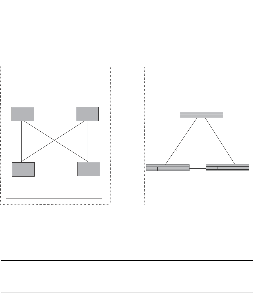
PowerConnect B-Series FCX Configuration Guide 1019
53-1002266-01
Optional configuration tasks 30
FIGURE 147 Example of a route reflector configuration
Support for RFC 2796
Route reflection on Dell PowerConnect devices is based on RFC 2796. This updated RFC helps
eliminate routing loops that are possible in some implementations of the older specification, RFC
1966.
NOTE
The configuration procedure for route reflection is the same regardless of whether your software
release is using RFC 1966 or RFC 2796. However, the operation of the feature is different as
explained below.
RFC 2796 provides more details than RFC 1966 regarding the use of the route reflection attributes,
ORIGINATOR_ID and CLUSTER_LIST, to help prevent loops:
•ORIGINATOR_ID – Specifies the router ID of the BGP4 switch that originated the route. The
route reflector inserts this attribute when reflecting a route to an IBGP neighbor. If a BGP4
switch receives an advertisement that contains its own router ID as the ORIGINATOR_ID, the
switch discards the advertisement and does not forward it.
•CLUSTER_LIST – A list of the route reflection clusters through which the advertisement has
passed. A cluster contains a route reflector and its clients. When a route reflector reflects a
route, the route reflector adds its cluster ID to the front of the CLUSTER_LIST. If a route reflector
receives a route that has its own cluster ID, the switch discards the advertisement and does
not forward it.
The Dell PowerConnect device handles the attributes as follows:
•The Layer 3 Switch adds the attributes only if it is a route reflector, and only when advertising
IBGP route information to other IBGP neighbors. The attributes are not used when
communicating with EBGP neighbors.
Route
Reflector 1
Route
Reflector 2
Route
Reflector
Client 1
Route
Reflector
Client 2
EBGP
IBGP
IBGP
IBGP
AS 1 AS 2
Cluster 1
10.0.1.0 10.0.2.0
Switch Switch
Switch

1020 PowerConnect B-Series FCX Configuration Guide
53-1002266-01
Optional configuration tasks
30
•A Layer 3 Switch configured as a route reflector sets the ORIGINATOR_ID attribute to the router
ID of the router that originated the route. Moreover, the route reflector sets the attribute only if
this is the first time the route is being reflected (sent by a route reflector). In previous software
releases, the route reflector set the attribute to the router ID of the route reflector itself. When
a Layer 3 Switch receives a route that already has the ORIGINATOR_ID attribute set, the Layer 3
Switch does not change the value of the attribute.
•If a Layer 3 Switch receives a route whose ORIGINATOR_ID attribute has the value of the Layer
3 Switch own router ID, the Layer 3 Switch discards the route and does not advertise it. By
discarding the route, the Layer 3 Switch prevents a routing loop. The Layer 3 Switch did not
discard the route in previous software releases.
•The first time a route is reflected by a Layer 3 Switch configured as a route reflector, the route
reflector adds the CLUSTER_LIST attribute to the route. Other route reflectors who receive the
route from an IBGP neighbor add their cluster IDs to the front of the route CLUSTER_LIST. If the
route reflector does not have a cluster ID configured, the Layer 3 Switch adds its router ID to
the front of the CLUSTER_LIST.
•If Layer 3 Switch configured as a route reflector receives a route whose CLUSTER_LIST
contains the route reflector own cluster ID, the route reflector discards the route and does not
forward it.
Configuration procedures
To configure a Layer 3 Switch to be a BGP4 route reflector, use either of the following methods.
NOTE
All configuration for route reflection takes place on the route reflectors, not on the clients.
Enter the following commands to configure a Layer 3 Switch as route reflector 1 in Figure 147 on
page 1019. To configure route reflector 2, enter the same commands on the Layer 3 Switch that
will be route reflector 2. The clients require no configuration for route reflection.
PowerConnect(config-bgp-router)#cluster-id 1
PowerConnect(config-bgp-router)#neighbor 10.0.1.0 route-reflector-client
PowerConnect(config-bgp-router)#neighbor 10.0.2.0 route-reflector-client
Syntax: [no] cluster-id <num> | <ip-addr>
The <num> | <ip-addr> parameter specifies the cluster ID and can be a number from 0 through
4294967295 or an IP address. The default is the router ID. You can configure one cluster ID on the
router. All route-reflector clients for the router are members of the cluster.
NOTE
If the cluster contains more than one route reflector, you need to configure the same cluster ID on
all the route reflectors in the cluster. The cluster ID helps route reflectors avoid loops within the
cluster.
To add an IBGP neighbor to the cluster, enter the following command.
Syntax: neighbor <ip-addr> route-reflector-client
For more information about the neighbor command, refer to “Adding BGP4 neighbors” on
page 993.
By default, the clients of a route reflector are not required to be fully meshed; the routes from a
client are reflected to other clients. However, if the clients are fully meshed, route reflection is not
required between clients.

PowerConnect B-Series FCX Configuration Guide 1021
53-1002266-01
Optional configuration tasks 30
If you need to disable route reflection between clients, enter the following command. When the
feature is disabled, route reflection does not occur between clients but reflection does still occur
between clients and non-clients.
PowerConnect(config-bgp-router)#no client-to-client-reflection
Enter the following command to re-enable the feature.
PowerConnect(config-bgp-router)#client-to-client-reflection
Syntax: [no] client-to-client-reflection
Configuration notes
A confederation is a BGP4 Autonomous System (AS) that has been subdivided into multiple,
smaller autonomous systems. Subdividing an AS into smaller autonomous systems simplifies
administration and reduces BGP-related traffic, thus reducing the complexity of the Interior Border
Gateway Protocol (IBGP) mesh among the BGP routers in the AS.
The Dell implementation of this feature is based on RFC 3065.
Normally, all BGP routers within an AS must be fully meshed, so that each BGP router has
interfaces to all the other BGP routers within the AS. This is feasible in smaller autonomous
systems but becomes unmanageable in autonomous systems containing many BGP routers.
When you configure BGP routers into a confederation, all the routers within a sub-AS (a subdivision
of the AS) use IBGP and must be fully meshed. However, routers use EBGP to communicate
between different sub-autonomous systems.
NOTE
Another method for reducing the complexity of an IBGP mesh is to use route reflection. However, if
you want to run different Interior Gateway Protocols (IGPs) within an AS, configure a confederation.
You can run a separate IGP within each sub-AS.
To configure a confederation, configure groups of BGP routers into sub-autonomous systems. A
sub-AS is simply an AS. The term “sub-AS” distinguishes autonomous systems within a
confederation from autonomous systems that are not in a confederation. For the viewpoint of
remote autonomous systems, the confederation ID is the AS ID. Remote autonomous systems do
not know that the AS represents multiple sub-autonomous systems with unique AS IDs.
NOTE
You can use any valid AS numbers for the sub-autonomous systems. If your AS is connected to the
Internet, Dell recommends that you use numbers from within the private AS range (64512 through
65535). These are private autonomous systems numbers and BGP4 routers do not propagate these
AS numbers to the Internet.
Figure 148 shows an example of a BGP4 confederation.
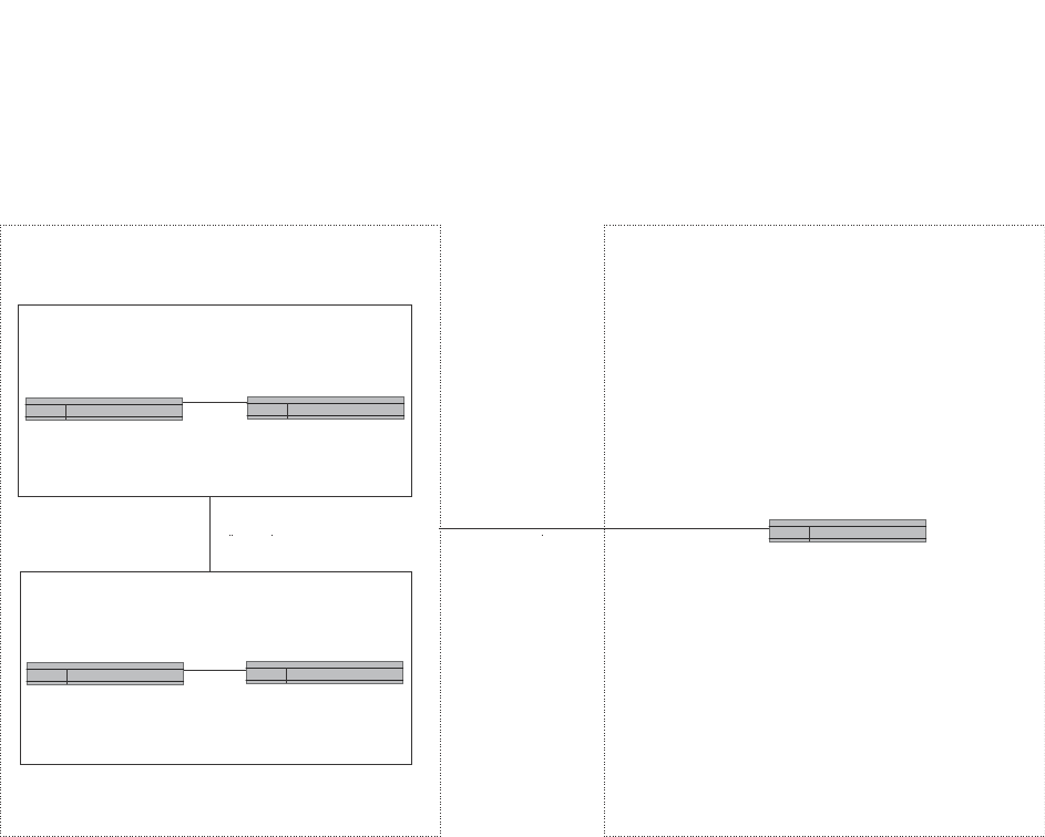
1022 PowerConnect B-Series FCX Configuration Guide
53-1002266-01
Optional configuration tasks
30
FIGURE 148 Example of a BGP4 confederation
In this example, four switches are configured into two sub-autonomous systems, each containing
two of the switches. The sub-autonomous systems are members of confederation 10. Switches
within a sub-AS must be fully meshed and communicate using IBGP. In this example, Switches A
and B use IBGP to communicate. Switches C and D also use IBGP. However, the sub-autonomous
systems communicate with one another using EBGP. For example, Switch A communicates with
Switch C using EBGP. The switches in the confederation communicate with other autonomous
systems using EBGP.
Switches in other autonomous systems are unaware that Switches A through D are configured in a
confederation. In fact, when switches in confederation 10 send traffic to switches in other
autonomous systems, the confederation ID is the same as the AS number for the switches in the
confederation. Thus, switches in other autonomous systems see traffic from AS 10 and are
unaware that the switches in AS 10 are subdivided into sub-autonomous systems within a
confederation.
Configuring a BGP confederation
Perform the following configuration tasks on each BGP router within the confederation:
•Configure the local AS number. The local AS number indicates membership in a sub-AS. All
BGP switches with the same local AS number are members of the same sub-AS. BGP switches
use the local AS number when communicating with other BGP switches within the
confederation.
Switch A
Switch C Switch D
BGP4 Switch
Switch B
IBGP
IBGP
EBGP
Sub-AS 64513
Sub-AS 64512
EBGP
Confederation 10 AS 20
This BGP4 switch sees all
traffic from Confederation 10
as traffic from AS 10.
Switches outside the confederation
do not know or care that the switches
are subdivided into sub-ASs within a
confederation.

PowerConnect B-Series FCX Configuration Guide 1023
53-1002266-01
Optional configuration tasks 30
•Configure the confederation ID. The confederation ID is the AS number by which BGP switches
outside the confederation know the confederation. Thus, a BGP switch outside the
confederation is not aware and does not care that your BGP switches are in multiple
sub-autonomous systems. BGP switches use the confederation ID when communicating with
switches outside the confederation. The confederation ID must be different from the sub-AS
numbers.
•Configure the list of the sub-AS numbers that are members of the confederation. All the
switches within the same sub-AS use IBGP to exchange switch information. Switches in
different sub-autonomous systems within the confederation use EBGP to exchange switch
information.
To configure four Layer 3 Switches to be a member of confederation 10 (as shown in Figure 148),
consisting of two sub-autonomous systems (64512 and 64513), enter commands such as the
following.
Commands for router A
PowerConnectA(config)#router bgp
PowerConnectA(config-bgp-router)#local-as 64512
PowerConnectA(config-bgp-router)#confederation identifier 10
PowerConnectA(config-bgp-router)#confederation peers 64512 64513
PowerConnectA(config-bgp-router)#write memory
Syntax: local-as <num>
The <num> parameter with the local-as command indicates the AS number for the BGP switches
within the sub-AS. You can specify a number from 1 through 65535. Dell recommends that you use
a number within the range of well-known private autonomous systems, 64512 through 65535.
Syntax: confederation identifier <num>
The <num> parameter with the confederation identifier command indicates the confederation
number. The confederation ID is the AS number by which BGP switches outside the confederation
know the confederation. Thus, a BGP switch outside the confederation is not aware and does not
care that your BGP switches are in multiple sub-autonomous systems. BGP switches use the
confederation ID when communicating with switches outside the confederation. The confederation
ID must be different from the sub-AS numbers. You can specify a number from 1 through 65535.
Syntax: confederation peers <num> [<num> …]
The <num> parameter with the confederation peers command indicates the sub-AS numbers for
the sub-autonomous systems in the confederation. You must specify all the sub-autonomous
systems contained in the confederation. All the switches within the same sub-AS use IBGP to
exchange switch information. Switches in different sub-autonomous systems within the
confederation use EBGP to exchange switch information. You can specify a number from 1 through
65535.
Commands for router B
PowerConnectB(config)#router bgp
PowerConnectB(config-bgp-router)#local-as 64512
PowerConnectB(config-bgp-router)#confederation identifier 10
PowerConnectB(config-bgp-router)#confederation peers 64512 64513
PowerConnectB(config-bgp-router)#write memory

1024 PowerConnect B-Series FCX Configuration Guide
53-1002266-01
Optional configuration tasks
30
Commands for router C
PowerConnectC(config)#router bgp
PowerConnectC(config-bgp-router)#local-as 64513
PowerConnectC(config-bgp-router)#confederation identifier 10
PowerConnectC(config-bgp-router)#confederation peers 64512 64513
PowerConnectC(config-bgp-router)#write memory
Commands for router D
PowerConnectD(config)#router bgp
PowerConnectD(config-bgp-router)#local-as 64513
PowerConnectD(config-bgp-router)#confederation identifier 10
PowerConnectD(config-bgp-router)#confederation peers 64512 64513
PowerConnectD(config-bgp-router)#write memory
Aggregating routes advertised to BGP4 neighbors
By default, the Layer 3 Switch advertises individual routes for all the networks. The aggregation
feature allows you to configure the Layer 3 Switch to aggregate routes in a range of networks into a
single CIDR number. For example, without aggregation, the Layer 3 Switch will individually advertise
routes for networks 207.95.1.0, 207.95.2.0, and 207.95.3.0. You can configure the Layer 3 Switch
to instead send a single, aggregate route for the networks. The aggregate route would be
advertised as 207.95.0.0.
NOTE
To summarize CIDR networks, you must use the aggregation feature. The auto summary feature
does not summarize networks that use CIDR numbers instead of class A, B, or C numbers.
To aggregate routes for 209.157.22.0, 209.157.23.0, and 209.157.24.0, enter the following
command.
PowerConnect(config-bgp-router)#aggregate-address 209.157.0.0 255.255.0.0
Syntax: aggregate-address <ip-addr> <ip-mask> [as-set] [nlri multicast | unicast | multicast
unicast]
[summary-only] [suppress-map <map-name>] [advertise-map <map-name>]
[attribute-map <map-name>]
The <ip-addr> and <ip-mask> parameters specify the aggregate value for the networks. Specify 0
for the host portion and for the network portion that differs among the networks in the aggregate.
For example, to aggregate 10.0.1.0, 10.0.2.0, and 10.0.3.0, enter the IP address 10.0.0.0 and the
network mask 255.255.0.0.
The as-set parameter causes the router to aggregate AS-path information for all the routes in the
aggregate address into a single AS-path.
The nlri multicast | unicast | multicast unicast parameter specifies whether the neighbor is a
multicast neighbor or a unicast neighbor. Optionally, you also can specify unicast if you want the
Layer 3 Switch to exchange unicast (BGP4) routes as well as multicast routes with the neighbor.
The default is unicast only.
The summary-only parameter prevents the router from advertising more specific routes contained
within the aggregate route.
The suppress-map <map-name> parameter prevents the more specific routes contained in the
specified route map from being advertised.

PowerConnect B-Series FCX Configuration Guide 1025
53-1002266-01
Configuring BGP4 graceful restart 30
The advertise-map <map-name> parameter configures the router to advertise the more specific
routes in the specified route map.
The attribute-map <map-name> parameter configures the router to set attributes for the aggregate
routes based on the specified route map.
NOTE
For the suppress-map, advertise-map, and attribute-map parameters, the route map must already
be defined. Refer to “Defining route maps” on page 1042 for information on defining a route map.
Configuring BGP4 graceful restart
By default, BGP4 graceful restart is enabled for the global routing instance. This section describes
how to disable and re-enable the BGP4 restart feature and change the default values for
associated timers.
For information about displaying BGP4 graceful restart neighbor information, refer to “Displaying
BGP4 graceful restart neighbor information” on page 1090.
Configuring BGP4 graceful restart
BGP4 graceful restart is enabled by default on a PowerConnect Layer 3 switch. To disable it, use
the following commands:
PowerConnect (config)# router bgp
PowerConnect (config-bgp)# no graceful-restart
To re-enable BGP4 graceful restart after it has been disabled, enter the following commands.
PowerConnect (config)# router bgp
PowerConnect (config-bgp)# graceful-restart
Syntax: [no] graceful-restart
Configuring timers for BGP4 graceful restart (optional)
You can change the default values for the following timers:
•Restart timer
•Stale routes timer
•Purge timer
Configuring the restart timer for BGP4 graceful restart
Use the following command to specify the maximum amount of time a device will maintain routes
from and forward traffic to a restarting device.
PowerConnect (config-bgp)# graceful-restart restart-timer 150
Syntax: [no] graceful-restart restart-timer <seconds>
The <seconds> variable is the maximum restart wait time advertised to neighbors. Possible values
are from 1 through 3600 seconds. The default value is 120 seconds.

1026 PowerConnect B-Series FCX Configuration Guide
53-1002266-01
BGP null0 routing
30
Configuring the BGP4 graceful restart stale routes timer
Use the following command to specify the maximum amount of time a helper device will wait for an
end-of-RIB message from a peer before deleting routes from that peer.
PowerConnect (config-bgp)# graceful-restart stale-routes-time 120
Syntax: [no] graceful-restart stale-routes-time <seconds>
The <seconds> variable is the maximum time before a helper device cleans up stale routes.
Possible values are from 1 through 3600 seconds. The default value is 360 seconds.
Configuring the BGP4 graceful restart purge timer
Use the following command to specify the maximum amount of time a device will maintain stale
routes in its routing table before purging them.
PowerConnect (config-bgp)# graceful-restart purge-time 900
Syntax: [no] graceful-restart purge-time <seconds>
The <seconds> variable sets the maximum time before a restarting device cleans up stale routes.
Possible values are from 1 through 3600 seconds. The default value is 600 seconds.
BGP null0 routing
The null0 routes were previously treated as invalid routes for BGP next hop resolution. BGP now
uses the null0 route to resolve its next hop. Thus, null0 route in the routing table (for example,
static route) is considered as a valid route by BGP. If the next hop for BGP resolves into a null0
route, the BGP route is also installed as a null0 route in the routing table.
The null0 routing feature allows network administrators to block certain network prefixes, by using
null0 routes and route-maps. The combined use of null0 routes and route maps blocks traffic from
a particular network prefix, telling a remote router to drop all traffic for this network prefix by
redistributing a null0 route into BGP.
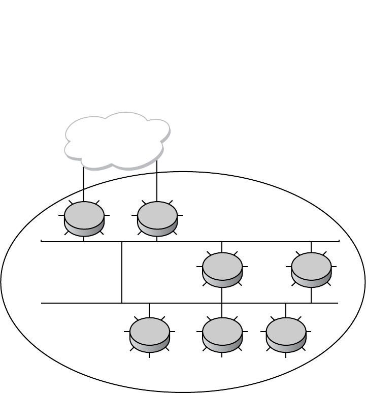
PowerConnect B-Series FCX Configuration Guide 1027
53-1002266-01
BGP null0 routing 30
Figure 149 shows a topology for a null0 routing application example.
FIGURE 149 Example of a null0 routing application
The following steps configure a null0 routing application for stopping denial of service attacks from
remote hosts on the internet.
Configuration steps
1. Select one switch, S6, to distribute null0 routes throughout the BGP network.
2. Configure a route-map to match a particular tag (50) and set the next-hop address to an
unused network address (199.199.1.1).
3. Set the local-preference to a value higher than any possible internal or external
local-preference (50).
4. Complete the route map by setting origin to IGP.
5. On S6, redistribute the static routes into BGP, using route-map <route-map-name>
(redistribute static route-map block user).
6. On S1, the router facing the internet, configure a null0 route matching the next-hop address in
the route-map (ip route 199.199.1.1/32 null0).
7. Repeat step 3 for all switches interfacing with the internet (edge corporate routers). In this
case, S2 has the same null0 route as S1.
8. On S6, configure the network prefixes associated with the traffic you want to drop. The static
route IP address references a destination address. You are required to point the static route to
the egress port, for example, Ethernet 3/7, and specify the tag 50, matching the route-map
configuration.
R1
AS 100
R2
R3
R6 R7R5
R4
Internet

1028 PowerConnect B-Series FCX Configuration Guide
53-1002266-01
BGP null0 routing
30
Configuration examples
S6
The following configuration defines specific prefixes to filter.
PowerConnect(config)#ip route 110.0.0.40/29 ethernet 3/7 tag 50
PowerConnect(config)#ip route 115.0.0.192/27 ethernet 3/7 tag 50
PowerConnect(config)#ip route 120.014.0/23 ethernet 3/7 tag 50
The following configuration redistributes routes into BGP.
PowerConnect(config)#router bgp
PowerConnect(config-bgp-router)#local-as 100
PowerConnect(config-bgp-router)#neighbor <router1_int_ip address> remote-as 100
PowerConnect(config-bgp-router)#neighbor <router2_int_ip address> remote-as 100
PowerConnect(config-bgp-router)#neighbor <router3_int_ip address> remote-as 100
PowerConnect(config-bgp-router)#neighbor <router4_int_ip address> remote-as 100
PowerConnect(config-bgp-router)#neighbor <router5_int_ip address> remote-as 100
PowerConnect(config-bgp-router)#neighbor <router7_int_ip address> remote-as 100
PowerConnect(config-bgp-router)#redistribute static route-map blockuser
PowerConnect(config-bgp-router)#exit
The following configuration defines the specific next hop address and sets the local preference to
preferred.
PowerConnect(config)#route-map blockuser permit 10
PowerConnect(config-routemap blockuser)#match tag 50
PowerConnect(config-routemap blockuser)#set ip next-hop 199.199.1.1
PowerConnect(config-routemap blockuser)#set local-preference 1000000
PowerConnect(config-routemap blockuser)#set origin igp
PowerConnect(config-routemap blockuser)#exit
S1
The following configuration defines the null0 route to the specific next hop address. The next hop
address 199.199.1.1 points to the null0 route.
PowerConnect(config)#ip route 199.199.1.1/32 null0
PowerConnect(config)#router bgp
PowerConnect(config-bgp-router)#local-as 100
PowerConnect(config-bgp-router)#neighbor <router2_int_ip address> remote-as 100
PowerConnect(config-bgp-router)#neighbor <router3_int_ip address> remote-as 100
PowerConnect(config-bgp-router)#neighbor <router4_int_ip address> remote-as 100
PowerConnect(config-bgp-router)#neighbor <router5_int_ip address> remote-as 100
PowerConnect(config-bgp-router)#neighbor <router6_int_ip address> remote-as 100
PowerConnect(config-bgp-router)#neighbor <router7_int_ip address> remote-as 100
S2
The following configuration defines a null0 route to the specific next hop address. The next hop
address 199.199.1.1 points to the null0 route, which gets blocked.
PowerConnect(config)#ip route 199.199.1.1/32 null0
PowerConnect(config)#router bgp
PowerConnect(config-bgp-router)#local-as 100
PowerConnect(config-bgp-router)#neighbor <router1_int_ip address> remote-as 100
PowerConnect(config-bgp-router)#neighbor <router3_int_ip address> remote-as 100
PowerConnect(config-bgp-router)#neighbor <router4_int_ip address> remote-as 100
PowerConnect (config-bgp-router)#neighbor <router5_int_ip address> remote-as 100
PowerConnect(config-bgp-router)#neighbor <router6_int_ip address> remote-as 100
PowerConnect(config-bgp-router)#neighbor <router7_int_ip address> remote-as 100

PowerConnect B-Series FCX Configuration Guide 1029
53-1002266-01
BGP null0 routing 30
Show commands
After configuring the null0 application, you can display the output.
S6
The following is the show ip route static output for S6.
S1 and S2
The following is the show ip route static output for S1 and S2.
S6
The following is the show ip bgp route output for S6
PowerConnect#show ip route static
Type Codes - B:BGP D:Connected S:Static R:RIP O:OSPF; Cost - Dist/Metric
Destination Gateway Port Cost Type
1 110.0.0.40/29 DIRECT eth 3/7 1/1 S
2 115.0.0.192/27 DIRECT eth 3/7 1/1 S
3 120.0.14.0/23 DIRECT eth 3/7 1/1 S
PowerConnect#show ip route static
Type Codes - B:BGP D:Connected S:Static R:RIP O:OSPF; Cost - Dist/Metric
Destination Gateway Port Cost Type
1 199.199.1.1/32 DIRECT drop 1/1 S
PowerConnect#show ip bgp route
Total number of BGP Routes: 126
Status A:AGGREGATE B:BEST b:NOT-INSTALLED-BEST C:CONFED_EBGP D:DAMPED E:EBGP
H:HISTORY I:IBGP L:LOCAL M:MULTIPATH S:SUPPRESSED s:STALE
Prefix Next Hop Metric LocPrf Weight Status
1 30.0.1.0/24 40.0.1.3 0 100 0 BI
AS_PATH:
. .. . . .
.
9 110.0.0.16/30 90.0.1.3 100 0 I
AS_PATH: 85
10 110.0.0.40/29 199.199.1.1/32 1 1000000 32768 BL
AS_PATH:
11 110.0.0.80/28 90.0.1.3 100 0 I
. .. . . . .
. .. . . .
.
36 115.0.0.96/28 30.0.1.3 100 0 I
AS_PATH: 50
37 115.0.0.192/27 199.199.1.1/32 1 10000000 32768 BL
AS_PATH:
. .. . . .
.
64 120.0.7.0/24 70.0.1.3 100 0 I
AS_PATH: 10
65 120.0.14.0/23 199.199.1.1/32 1 1000000 32768 BL
AS_PATH: .. . . . .

1030 PowerConnect B-Series FCX Configuration Guide
53-1002266-01
Modifying redistribution parameters
30
S1 and S2
The show ip route output for S1 and S2 shows "drop" under the Port column for the network
prefixes you configured with null0 routing.
Modifying redistribution parameters
By default, the Layer 3 Switch does not redistribute route information between BGP4 and the IP
IGPs (RIP and OSPF). You can configure the switch to redistribute OSPF routes, RIP routes, directly
connected routes, or static routes into BGP4 by using the following methods.
To enable redistribution of all OSPF routes and directly attached routes into BGP4, enter the
following commands.
PowerConnect(config)#router bgp
PowerConnect(config-bgp-router)#redistribute ospf
PowerConnect(config-bgp-router)#redistribute connected
PowerConnect(config-bgp-router)#write memory
Syntax: [no] redistribute connected | ospf | rip | static
The connected parameter indicates that you are redistributing routes to directly attached devices
into BGP.
The ospf parameter indicates that you are redistributing OSPF routes into BGP4.
NOTE
Entering redistribute ospf simply redistributes internal OSPF routes. If you want to redistribute
external OSPF routes also, you must use the redistribute ospf match external... command.
Refer to “Redistributing OSPF external routes” on page 1031.
The rip parameter indicates that you are redistributing RIP routes into BGP4.
The static parameter indicates that you are redistributing static routes into BGP.
PowerConnect#show ip route
Total number of IP routes: 133
Type Codes - B:BGP D:Connected S:Static R:RIP O:OSPF; Cost - Dist/Metric
Destination Gateway Port Cost Type
1 9.0.1.24/32 DIRECT loopback 1 0/0 D
2 30.0.1.0/24 DIRECT eth 2/7 0/0 D
3 40.0.1.0/24 DIRECT eth 2/1 0/0 D
.
13 110.0.0.6/31 90.0.1.3 eth 2/2 20/1 B
14 110.0.0.16/30 90.0.1.3 eth 2/2 20/1 B
15 110.0.0.40/29 DIRECT drop 200/0 B
. .. . . . .
42 115.0.0.192/27 DIRECT drop 200/0 B
43 115.0.1.128/26 30.0.1.3 eth 2/7 20/1 B
. .. . . . .
69 120.0.7.0/24 70.0.1.3 eth 2/10 20/1 B
70 120.0.14.0/23 DIRECT drop 200/0 B
. .. . . . .
. .. . . . .
131 130.144.0.0/12 80.0.1.3 eth 3/4 20/1 B
132 199.199.1.1/32 DIRECT drop 1/1 S

PowerConnect B-Series FCX Configuration Guide 1031
53-1002266-01
Modifying redistribution parameters 30
Refer to the following sections for details on redistributing specific routes using the CLI:
•“Redistributing connected routes” on page 1031
•“Redistributing RIP routes” on page 1031
•“Redistributing OSPF external routes” on page 1031
•“Redistributing static routes” on page 1032
Redistributing connected routes
To configure BGP4 to redistribute directly connected routes, enter the following command.
PowerConnect(config-bgp-router)#redistribute connected
Syntax: redistribute connected [metric <num>] [route-map <map-name>]
The connected parameter indicates that you are redistributing routes to directly attached devices
into BGP4.
The metric <num> parameter changes the metric. You can specify a value from 0 through
4294967295. The default is 0.
The route-map <map-name> parameter specifies a route map to be consulted before adding the
RIP route to the BGP4 route table.
NOTE
The route map you specify must already be configured on the switch. Refer to “Defining route maps”
on page 1042 for information about defining route maps.
Redistributing RIP routes
To configure BGP4 to redistribute RIP routes and add a metric of 10 to the redistributed routes,
enter the following command.
PowerConnect(config-bgp-router)#redistribute rip metric 10
Syntax: redistribute rip [metric <num>] [route-map <map-name>]
The rip parameter indicates that you are redistributing RIP routes into BGP4.
The metric <num> parameter changes the metric. Specify a value from 0 through 4294967295.
The default is 0.
The route-map <map-name> parameter specifies a route map to be consulted before adding the
RIP route to the BGP4 route table.
NOTE
The route map you specify must already be configured on the switch. Refer to “Defining route maps”
on page 1042 for information about defining route maps.
Redistributing OSPF external routes
To configure the Layer 3 Switch to redistribute OSPF external type 1 routes, enter the following
command.
PowerConnect(config-bgp-router)#redistribute ospf match external1

1032 PowerConnect B-Series FCX Configuration Guide
53-1002266-01
Modifying redistribution parameters
30
Syntax: redistribute ospf [match internal | external1 | external2] [metric <num>] [route-map
<map-name>]
The ospf parameter indicates that you are redistributing OSPF routes into BGP4.
The match internal | external1 | external2 parameter applies only to OSPF. This parameter
specifies the types of OSPF routes to be redistributed into BGP4. The default is internal.
NOTE
If you do not enter a value for the match parameter, (for example, you enter redistribute ospf only)
then only internal OSPF routes will be redistributed.
The metric <num> parameter changes the metric. Specify a value from 0 through 4294967295.
The default is 0.
The route-map <map-name> parameter specifies a route map to be consulted before adding the
OSPF route to the BGP4 route table.
NOTE
The route map you specify must already be configured on the switch. Refer to “Defining route maps”
on page 1042 for information about defining route maps.
NOTE
If you use both the redistribute ospf route-map <map-name> command and the redistribute ospf
match internal | external1 | external2 command, the software uses only the route map for filtering.
Redistributing static routes
To configure the Layer 3 Switch to redistribute static routes, enter the following command.
PowerConnect(config-bgp-router)#redistribute static
Syntax: redistribute static [metric <num>] [route-map <map-name>]
The static parameter indicates that you are redistributing static routes into BGP4.
The metric <num> parameter changes the metric. Specify a value from 0 through 4294967295.
The default is 0.
The route-map <map-name> parameter specifies a route map to be consulted before adding the
static route to the BGP4 route table.
NOTE
The route map you specify must already be configured on the switch. Refer to “Defining route maps”
on page 1042 for information about defining route maps.
Disabling or re-enabling re-advertisement of all learned
BGP4 routes to all BGP4 neighbors
By default, the Layer 3 Switch re-advertises all learned best BGP4 routes to BGP4 neighbors,
unless the routes are discarded or blocked by route maps or other filters.
If you want to prevent the Layer 3 Switch from re-advertising a learned best BGP4 route unless that
route also is installed in the IP route table, use the following CLI method.

PowerConnect B-Series FCX Configuration Guide 1033
53-1002266-01
Filtering 30
To disable re-advertisement of BGP4 routes to BGP4 neighbors except for routes that the software
also installs in the route table, enter the following command.
PowerConnect(config-bgp-router)#no readvertise
Syntax: [no] readvertise
To re-enable re-advertisement, enter the following command.
PowerConnect(config-bgp-router)#readvertise
Redistributing IBGP routes into RIP and OSPF
By default, the Layer 3 Switch does not redistribute IBGP routes from BGP4 into RIP or OSPF. This
behavior helps eliminate routing loops. However, if your network can benefit from redistributing the
IBGP routes from BGP4 into OSPF or RIP, you can enable the Layer 3 Switch to redistribute the
routes. To do so, use the following CLI method.
To enable the Layer 3 Switch to redistribute BGP4 routes into OSPF and RIP, enter the following
command.
PowerConnect(config-bgp-router)#bgp-redistribute-internal
Syntax: [no] bgp-redistribute-internal
To disable redistribution of IBGP routes into RIP and OSPF, enter the following command.
PowerConnect(config-bgp-router)#no bgp-redistribute-internal
Filtering
This section describes the following:
•“Filtering specific IP addresses” on page 1033
•“Filtering AS-paths” on page 1035
•“Filtering communities” on page 1038
•“Defining IP prefix lists” on page 1041
•“Defining neighbor distribute lists” on page 1042
•“Defining route maps” on page 1042
•“Using a table map to set the rag value” on page 1050
•“Configuring cooperative BGP4 route filtering” on page 1051
Filtering specific IP addresses
You can configure the router to explicitly permit or deny specific IP addresses received in updates
from BGP4 neighbors by defining IP address filters. The router permits all IP addresses by default.
You can define up to 100 IP address filters for BGP4.
•If you want permit to remain the default behavior, define individual filters to deny specific IP
addresses.
•If you want to change the default behavior to deny, define individual filters to permit specific IP
addresses.

1034 PowerConnect B-Series FCX Configuration Guide
53-1002266-01
Filtering
30
NOTE
Once you define a filter, the default action for addresses that do not match a filter is “deny”. To
change the default action to “permit”, configure the last filter as “permit any any”.
Address filters can be referred to by a BGP neighbor's distribute list number as well as by match
statements in a route map.
NOTE
If the filter is referred to by a route map match statement, the filter is applied in the order in which
the filter is listed in the match statement.
NOTE
You also can filter on IP addresses by using IP ACLs.
To define an IP address filter to deny routes to 209.157.0.0, enter the following command.
PowerConnect(config-bgp-router)#address-filter 1 deny 209.157.0.0 255.255.0.0
Syntax: address-filter <num> permit | deny <ip-addr> <wildcard> <mask> <wildcard>
The <num> parameter is the filter number.
The permit | deny parameter indicates the action the Layer 3 Switch takes if the filter match is true.
•If you specify permit, the Layer 3 Switch permits the route into the BGP4 table if the filter
match is true.
•If you specify deny, the Layer 3 Switch denies the route from entering the BGP4 table if the
filter match is true.
NOTE
Once you define a filter, the default action for addresses that do not match a filter is “deny”. To
change the default action to “permit”, configure the last filter as “permit any any”.
The <ip-addr> parameter specifies the IP address. If you want the filter to match on all addresses,
enter any.
The <wildcard> parameter specifies the portion of the IP address to match against. The <wildcard>
is in dotted-decimal notation (IP address format). It is a four-part value, where each part is 8 bits
(one byte) separated by dots, and each bit is a one or a zero. Each part is a number ranging from 0
to 255, for example 0.0.0.255. Zeros in the mask mean the packet source address must match the
<source-ip>. Ones mean any value matches. For example, the
<ip-addr> and <wildcard> values 209.157.22.26 0.0.0.255 mean that all hosts in the Class C
subnet 209.157.22.x match the policy.
If you prefer to specify the wildcard (mask value) in Classless Interdomain Routing (CIDR) format,
you can enter a forward slash after the IP address, then enter the number of significant bits in the
mask. For example, you can enter the CIDR equivalent of “209.157.22.26 0.0.0.255” as
“209.157.22.26/24”. The CLI automatically converts the CIDR number into the appropriate mask
(where zeros instead of ones are the significant bits) and changes the non-significant portion of the
IP address into zeros. For example, if you specify 209.157.22.26/24 or 209.157.22.26 0.0.0.255,
then save the changes to the startup-config file, the value appears as 209.157.22.0/24 (if you
have enabled display of subnet lengths) or 209.157.22.0 0.0.0.255 in the startup-config file.

PowerConnect B-Series FCX Configuration Guide 1035
53-1002266-01
Filtering 30
If you enable the software to display IP subnet masks in CIDR format, the mask is saved in the file
in “/<mask-bits>” format. To enable the software to display the CIDR masks, enter the ip
show-subnet-length command at the global CONFIG level of the CLI. You can use the CIDR format to
configure the filter regardless of whether the software is configured to display the masks in CIDR
format.
The <mask> parameter specifies the network mask. If you want the filter to match on all
destination addresses, enter any. The wildcard works the same as described above.
Filtering AS-paths
You can filter updates received from BGP4 neighbors based on the contents of the AS-path list
accompanying the updates. For example, if you want to deny routes that have the AS 4.3.2.1 in the
AS-path from entering the BGP4 route table, you can define a filter to deny such routes.
The Layer 3 Switch provides the following methods for filtering on AS-path information:
•AS-path filters
•AS-path ACLs
NOTE
The Layer 3 Switch cannot actively support AS-path filters and AS-path ACLs at the same time. Use
one method or the other but do not mix methods.
NOTE
Once you define a filter or ACL, the default action for updates that do not match a filter is “deny”. To
change the default action to “permit”, configure the last filter or ACL as “permit any any”.
AS-path filters or AS-path ACLs can be referred to by a BGP neighbor's filter list number as well as
by match statements in a route map.
Defining an AS-path filter
To define AS-path filter 4 to permit AS 2500, enter the following command.
PowerConnect(config-bgp-router)#as-path-filter 4 permit 2500
Syntax: as-path-filter <num> permit | deny <as-path>
The <num> parameter identifies the filter position in the AS-path filter list and can be from 1
through 100. Thus, the AS-path filter list can contain up to 100 filters. The Layer 3 Switch applies
the filters in numerical order, beginning with the lowest-numbered filter. When a filter match is true,
the Layer 3 Switch stops and does not continue applying filters from the list.
NOTE
If the filter is referred to by a route map match statement, the filter is applied in the order in which
the filter is listed in the match statement.
The permit | deny parameter indicates the action the router takes if the filter match is true.
•If you specify permit, the router permits the route into the BGP4 table if the filter match is true.
•If you specify deny, the router denies the route from entering the BGP4 table if the filter match
is true.

1036 PowerConnect B-Series FCX Configuration Guide
53-1002266-01
Filtering
30
The <as-path> parameter indicates the AS-path information. You can enter an exact AS-path string
if you want to filter for a specific value. You also can use regular expressions in the filter string.
Defining an AS-path ACL
To configure an AS-path list that uses ACL 1, enter a command such as the following.
PowerConnect(config)#ip as-path access-list 1 permit 100
PowerConnect(config)#router bgp
PowerConnect(config-bgp-router)#neighbor 10.10.10.1 filter-list 1 in
The ip as-path command configures an AS-path ACL that permits routes containing AS number 100
in their AS paths. The neighbor command then applies the AS-path ACL to advertisements and
updates received from neighbor 10.10.10.1. In this example, the only routes the Layer 3 Switch
permits from neighbor 10.10.10.1 are those whose AS-paths contain AS-path number 100.
Syntax: ip as-path access-list <string> [seq <seq-value>] deny | permit <regular-expression>
The <string> parameter specifies the ACL name. (If you enter a number, the CLI interprets the
number as a text string.)
The seq <seq-value> parameter is optional and specifies the AS-path list sequence number. You
can configure up to 199 entries in an AS-path list. If you do not specify a sequence number, the
software numbers them in increments of 5, beginning with number 5. The software interprets the
entries in an AS-path list in numerical order, beginning with the lowest sequence number.
The deny | permit parameter specifies the action the software takes if a route AS-path list matches
a match statement in this ACL. To configure the AS-path match statements in a route map, use the
match as-path command. Refer to “Matching based on AS-path ACL” on page 1045.
The <regular-expression> parameter specifies the AS path information you want to permit or deny
to routes that match any of the match statements within the ACL. You can enter a specific AS
number or use a regular expression. For the regular expression syntax, refer to “Using regular
expressions” on page 1036.
The neighbor command uses the filter-list parameter to apply the AS-path ACL to the neighbor.
Refer to “Adding BGP4 neighbors” on page 993.
Using regular expressions
You use a regular expression for the <as-path> parameter to specify a single character or multiple
characters as a filter pattern. If the AS-path matches the pattern specified in the regular
expression, the filter evaluation is true; otherwise, the evaluation is false.
In addition, you can include special characters that influence the way the software matches the
AS-path against the filter value.
To filter on a specific single-character value, enter the character for the <as-path> parameter. For
example, to filter on AS-paths that contain the letter “z”, enter the following command.
PowerConnect(config-bgp-router)#as-path-filter 1 permit z
To filter on a string of multiple characters, enter the characters in brackets. For example, to filter on
AS-paths that contain “x”, “y”, or “z”, enter the following command.
PowerConnect(config-bgp-router)#as-path-filter 1 permit [xyz]

PowerConnect B-Series FCX Configuration Guide 1037
53-1002266-01
Filtering 30
Special characters
When you enter as single-character expression or a list of characters, you also can use the
following special characters. Table 182 on page 1037 lists the special characters. The description
for each special character includes an example. Notice that you place some special characters in
front of the characters they control but you place other special characters after the characters they
control. In each case, the examples show where to place the special character.
TABLE 182 BGP4 special characters for regular expressions
Character Operation
. The period matches on any single character, including a blank space. For example, the
following regular expression matches for “aa”, “ab”, “ac”, and so on, but not just “a”.
a.
* The asterisk matches on zero or more sequences of a pattern. For example, the following
regular expression matches on an AS-path that contains the string “1111” followed by any
value:
1111*
+ The plus sign matches on one or more sequences of a pattern. For example, the following
regular expression matches on an AS-path that contains a sequence of “g”s, such as “deg”,
“degg”, “deggg”, and so on:
deg+
? The question mark matches on zero occurrences or one occurrence of a pattern. For example,
the following regular expression matches on an AS-path that contains “dg” or “deg”:
de?g
^ A caret (when not used within brackets) matches on the beginning of an input string. For
example, the following regular expression matches on an AS-path that begins with “3”:
^3
$ A dollar sign matches on the end of an input string. For example, the following regular
expression matches on an AS-path that ends with “deg”:
deg$
_ An underscore matches on one or more of the following:
•, (comma)
•{ (left curly brace)
•} (right curly brace)
•( (left parenthesis)
•) (right parenthesis)
•The beginning of the input string
•The end of the input string
•A blank space
For example, the following regular expression matches on “100” but not on “1002”, “2100”,
and so on.
_100_

1038 PowerConnect B-Series FCX Configuration Guide
53-1002266-01
Filtering
30
If you want to filter for a special character instead of using the special character, enter “\”
(backslash) in front of the character. For example, to filter on AS-path strings containing an
asterisk, enter the asterisk portion of the regular expression as “\*”.
PowerConnect(config-bgp-router)#as-path-filter 2 deny \*
To use the backslash as a string character, enter two slashes. For example, to filter on AS-path
strings containing a backslash, enter the backslash portion of the regular expression as “\\”.
PowerConnect(config-bgp-router)#as-path-filter 2 deny \\
Filtering communities
You can filter routes received from BGP4 neighbors based on community names. Use either of the
following methods to do so.
A community is an optional attribute that identifies the route as a member of a user-defined class
of routes. Community names are arbitrary values made of two five-digit integers joined by a colon.
You determine what the name means when you create the community name as one of a route
attributes. Each string in the community name can be a number from 0 through 65535.
This format allows you to easily classify community names. For example, a common convention
used in community naming is to configure the first string as the local AS and the second string as
the unique community within that AS. Using this convention, communities 1:10, 1:20, and 1:30
can be easily identified as member communities of AS 1.
The Layer 3 Switch provides the following methods for filtering on community information:
•Community filters
•Community list ACLs
[ ]Square brackets enclose a range of single-character patterns. For example, the following
regular expression matches on an AS-path that contains “1”, “2”, “3”, “4”, or “5”:
[1-5]
You can use the following expression symbols within the brackets. These symbols are allowed
only inside the brackets:
•^ – The caret matches on any characters except the ones in the brackets. For example,
the following regular expression matches on an AS-path that does not contain “1”, “2”,
“3”, “4”, or “5”:
[^1-5]
•- The hyphen separates the beginning and ending of a range of characters. A match
occurs if any of the characters within the range is present. See the example above.
| A vertical bar (sometimes called a pipe or a “logical or”) separates two alternative values or
sets of values. The AS-path can match one or the other value. For example, the following
regular expression matches on an AS-path that contains either “abc” or “defg”:
(abc)|(defg)
NOTE: The parentheses group multiple characters to be treated as one value. See the
following row for more information about parentheses.
( ) Parentheses allow you to create complex expressions. For example, the following complex
expression matches on “abc”, “abcabc”, or “abcabcabcdefg”, but not on “abcdefgdefg”:
((abc)+)|((defg)?)
TABLE 182 BGP4 special characters for regular expressions (Continued)
Character Operation

PowerConnect B-Series FCX Configuration Guide 1039
53-1002266-01
Filtering 30
NOTE
The Layer 3 Switch cannot actively support community filters and community list ACLs at the same
time. Use one method or the other but do not mix methods.
NOTE
Once you define a filter or ACL, the default action for communities that do not match a filter or ACL
is “deny”. To change the default action to “permit”, configure the last filter or ACL entry as “permit
any any”.
Community filters or ACLs can be referred to by match statements in a route map.
Defining a community filter
To define filter 3 to permit routes that have the NO_ADVERTISE community, enter the following
command.
PowerConnect(config-bgp-router)#community-filter 3 permit no-advertise
Syntax: community-filter <num> permit | deny <num>:<num> | internet | local-as | no-advertise
| no-export
The <num> parameter identifies the filter position in the community filter list and can be from 1
through 100. Thus, the community filter list can contain up to 100 filters. The router applies the
filters in numerical order, beginning with the lowest-numbered filter. When a filter match is true, the
router stops and does not continue applying filters from the list.
NOTE
If the filter is referred to by a route map match statement, the filter is applied in the order in which
the filter is listed in the match statement.
The permit | deny parameter indicates the action the router takes if the filter match is true.
•If you specify permit, the router permits the route into the BGP4 table if the filter match is true.
•If you specify deny, the router denies the route from entering the BGP4 table if the filter match
is true.
The <num>:<num> parameter indicates a specific community number to filter. Use this parameter
to filter for a private (administrator-defined) community. You can enter up to 20 community
numbers with the same command.
If you want to filter for the well-known communities “LOCAL_AS”, “NO_EXPORT” or
“NO_ADVERTISE”, use the corresponding keyword (described below).
The internet keyword checks for routes that do not have the community attribute. Routes without a
specific community are considered by default to be members of the largest community, the
Internet.
The local-as keyword checks for routes with the well-known community “LOCAL_AS”. This
community applies only to confederations. The Layer 3 Switch advertises the route only within the
sub-AS. For information about confederations, refer to “Configuration notes” on page 1021.
The no-advertise keyword filters for routes with the well-known community “NO_ADVERTISE”. A
route in this community should not be advertised to any BGP4 neighbors.

1040 PowerConnect B-Series FCX Configuration Guide
53-1002266-01
Filtering
30
The no-export keyword filters for routes with the well-known community “NO_EXPORT”. A route in
this community should not be advertised to any BGP4 neighbors outside the local AS. If the router
is a member of a confederation, the Layer 3 Switch advertises the route only within the
confederation. For information about confederations, refer to “Configuration notes” on page 1021.
Defining a community ACL
To configure community ACL 1, enter a command such as the following.
PowerConnect(config)#ip community-list 1 permit 123:2
This command configures a community ACL that permits routes that contain community 123:2.
NOTE
Refer to “Matching based on community ACL” on page 1045 for information about how to use a
community list as a match condition in a route map.
Syntax: ip community-list standard <string> [seq <seq-value>] deny | permit <community-num>
Syntax: ip community-list extended <string> [seq <seq-value>] deny | permit
<community-num> | <regular-expression>
The <string> parameter specifies the ACL name. (If you enter a number, the CLI interprets the
number as a text string.)
The standard or extended parameter specifies whether you are configuring a standard community
ACL or an extended one. A standard community ACL does not support regular expressions whereas
an extended one does. This is the only difference between standard and extended IP community
lists.
The seq <seq-value> parameter is optional and specifies the community list sequence number. You
can configure up to 199 entries in a community list. If you do not specify a sequence number, the
software numbers them in increments of 5, beginning with number 5. The software interprets the
entries in a community list in numerical order, beginning with the lowest sequence number.
The deny | permit parameter specifies the action the software takes if a route community list
matches a match statement in this ACL. To configure the community-list match statements in a
route map, use the match community command. Refer to “Matching based on community ACL” on
page 1045.
The <community-num> parameter specifies the community type or community number. This
parameter can have the following values:
•<num>:<num> – A specific community number
•internet – The Internet community
•no-export – The community of sub-autonomous systems within a confederation. Routes with
this community can be exported to other sub-autonomous systems within the same
confederation but cannot be exported outside the confederation to other autonomous systems
or otherwise sent to EBGP neighbors.
•local-as – The local sub-AS within the confederation. Routes with this community can be
advertised only within the local subAS.
•no-advertise – Routes with this community cannot be advertised to any other BGP4 routers at
all.

PowerConnect B-Series FCX Configuration Guide 1041
53-1002266-01
Filtering 30
The <regular-expression> parameter specifies a regular expression for matching on community
names. For information about regular expression syntax, refer to “Using regular expressions” on
page 1036. You can specify a regular expression only in an extended community ACL.
Defining IP prefix lists
An IP prefix list specifies a list of networks. When you apply an IP prefix list to a neighbor, the Layer
3 Switch sends or receives only a route whose destination is in the IP prefix list. You can configure
up to 100 prefix lists. The software interprets the prefix lists in order, beginning with the lowest
sequence number.
To configure an IP prefix list and apply it to a neighbor, enter commands such as the following.
PowerConnect(config)#ip prefix-list Routesfor20 permit 20.20.0.0/24
PowerConnect(config)#router bgp
PowerConnect(config-bgp-router)#neighbor 10.10.10.1 prefix-list Routesfor20 out
These commands configure an IP prefix list named Routesfor20, which permits routes to network
20.20.0.0/24. The neighbor command configures the Layer 3 Switch to use IP prefix list
Routesfor20 to determine which routes to send to neighbor 10.10.10.1. The Layer 3 Switch sends
routes that go to 20.20.x.x to neighbor 10.10.10.1 because the IP prefix list explicitly permits these
routes to be sent to the neighbor.
Syntax: ip prefix-list <name> [seq <seq-value>] [description <string>] deny | permit
<network-addr>/<mask-bits> [ge <ge-value>] [le <le-value>]
The <name> parameter specifies the prefix list name. You use this name when applying the prefix
list to a neighbor.
The description <string> parameter is a text string describing the prefix list.
The seq <seq-value> parameter is optional and specifies the IP prefix list sequence number. You
can configure up to 100 prefix list entries. If you do not specify a sequence number, the software
numbers them in increments of 5, beginning with prefix list entry 5. The software interprets the
prefix list entries in numerical order, beginning with the lowest sequence number.
The deny | permit parameter specifies the action the software takes if a neighbor route is in this
prefix list.
The prefix-list matches only on this network unless you use the ge <ge-value> or le <le-value>
parameters. (See below.)
The <network-addr>/<mask-bits> parameter specifies the network number and the number of bits
in the network mask.
You can specify a range of prefix length for prefixes that are more specific than
<network-addr>/<mask-bits>.
•If you specify only ge <ge-value>, then the mask-length range is from <ge-value> to 32.
•If you specify only le <le-value>, then the mask-length range is from length to <le-value>.
The <ge-value> or <le-value> you specify must meet the following condition.
length < ge-value <= le-value <= 32
If you do not specify ge <ge-value> or le <le-value>, the prefix list matches only on the exact
network prefix you specify with the <network-addr>/<mask-bits> parameter.
For the syntax of the neighbor command shown in the example above, refer to “Adding BGP4
neighbors” on page 993.

1042 PowerConnect B-Series FCX Configuration Guide
53-1002266-01
Filtering
30
Defining neighbor distribute lists
A neighbor distribute list is a list of BGP4 address filters or ACLs that filter the traffic to or from a
neighbor. To configure a neighbor distribute list, use either of the following methods.
To configure a distribute list that uses ACL 1, enter a command such as the following.
PowerConnect(config-bgp-router)#neighbor 10.10.10.1 distribute-list 1 in
This command configures the Layer 3 Switch to use ACL 1 to select the routes that the Layer 3
Switch will accept from neighbor 10.10.10.1.
Syntax: neighbor <ip-addr> distribute-list <name-or-num> in | out
The <ip-addr> parameter specifies the neighbor.
The <name-or-num> parameter specifies the name or number of a standard, extended, or named
ACL.
The in | out parameter specifies whether the distribute list applies to inbound or outbound routes:
•in – controls the routes the Layer 3 Switch will accept from the neighbor.
•out – controls the routes sent to the neighbor.
NOTE
The command syntax shown above is new. However, the neighbor <ip-addr> distribute-list in | out
<num> command (where the direction is specified before the filter number) is the same as in earlier
software releases. Use the new syntax when you are using an IP ACL with the distribute list. Use the
old syntax when you are using a BGP4 address filter with the distribute list.
Defining route maps
A route map is a named set of match conditions and parameter settings that the router can use to
modify route attributes and to control redistribution of the routes into other protocols. A route map
consists of a sequence of up to 50 instances. If you think of a route map as a table, an instance is
a row in that table. The router evaluates a route according to a route map instances in ascending
numerical order. The route is first compared against instance 1, then against instance 2, and so
on. As soon as a match is found, the router stops evaluating the route against the route map
instances.
Route maps can contain match statements and set statements. Each route map contains a
“permit” or “deny” action for routes that match the match statements:
•If the route map contains a permit action, a route that matches a match statement is
permitted; otherwise, the route is denied.
•If the route map contains a deny action, a route that matches a match statement is denied.
•If a route does not match any match statements in the route map, the route is denied. This is
the default action. To change the default action, configure the last match statement in the last
instance of the route map to “permit any any”.
•If there is no match statement, the software considers the route to be a match.
•For route maps that contain address filters, AS-path filters, or community filters, if the action
specified by a filter conflicts with the action specified by the route map, the route map action
takes precedence over the individual filter action.

PowerConnect B-Series FCX Configuration Guide 1043
53-1002266-01
Filtering 30
If the route map contains set statements, routes that are permitted by the route map match
statements are modified according to the set statements.
Match statements compare the route against one or more of the following:
•The route BGP4 MED (metric)
•A sequence of AS-path filters
•A sequence of community filters
•A sequence of address filters
•The IP address of the next hop router
•The route tag
•For OSPF routes only, the route type (internal, external type-1, or external type-2)
•An AS-path ACL
•A community ACL
•An IP prefix list
•An IP ACL
For routes that match all of the match statements, the route map set statements can perform one
or more of the following modifications to the route attributes:
•Prepend AS numbers to the front of the route AS-path. By adding AS numbers to the AS-path,
you can cause the route to be less preferred when compared to other routes on the basis of the
length of the AS-path.
•Add a user-defined tag to the route or add an automatically calculated tag to the route.
•Set the community value.
•Set the local preference.
•Set the MED (metric).
•Set the IP address of the next hop router.
•Set the origin to IGP or INCOMPLETE.
•Set the weight.
For example, when you configure parameters for redistributing routes into RIP, one of the optional
parameters is a route map. If you specify a route map as one of the redistribution parameters, the
router will match the route against the match statements in the route map. If a match is found and
if the route map contains set statements, the router will set attributes in the route according to the
set statements.
To create a route map, you define instances of the map. Each instance is identified by a sequence
number. A route map can contain up to 50 instances.
To define a route map, use the procedures in the following sections.
Entering the route map into the software
To add instance 1 of a route map named “GET_ONE” with a permit action, enter the following
command.
PowerConnect(config)#route-map GET_ONE permit 1
PowerConnect(config-routemap GET_ONE)#
Syntax: [no] route-map <map-name> permit | deny <num>

1044 PowerConnect B-Series FCX Configuration Guide
53-1002266-01
Filtering
30
As shown in this example, the command prompt changes to the Route Map level. You can enter
the match and set statements at this level. Refer to “Specifying the match conditions” on
page 1044 and “Setting parameters in the routes” on page 1047.
The <map-name> is a string of characters that names the map. Map names can be up to 32
characters in length.
The permit | deny parameter specifies the action the router will take if a route matches a match
statement.
•If you specify deny, the Layer 3 Switch does not advertise or learn the route.
•If you specify permit, the Layer 3 Switch applies the match and set statements associated with
this route map instance.
The <num> parameter specifies the instance of the route map you are defining. Each route map
can have up to 50 instances.
To delete a route map, enter a command such as the following. When you delete a route map, all
the permit and deny entries in the route map are deleted.
PowerConnect(config)#no route-map Map1
This command deletes a route map named “Map1”. All entries in the route map are deleted.
To delete a specific instance of a route map without deleting the rest of the route map, enter a
command such as the following.
PowerConnect(config)#no route-map Map1 permit 10
This command deletes the specified instance from the route map but leaves the other instances of
the route map intact.
Specifying the match conditions
Use the following command to define the match conditions for instance 1 of the route map
GET_ONE. This instance compares the route updates against BGP4 address filter 11.
PowerConnect(config-routemap GET_ONE)#match address-filters 11
Syntax: match [as-path <num>] | [address-filters | as-path-filters | community-filters
<num,num,...>] | [community <num>] | [community <ACL> exact-match] | [ip address
<ACL> | prefix-list <string>] | [ip route-source <ACL> | prefix <name>] [metric <num>] |
[next-hop <address-filter-list>] | [nlri multicast | unicast | multicast unicast] | [route-type
internal | external-type1 | external-type2] | [tag <tag-value>]
The as-path <num> parameter specifies an AS-path ACL. You can specify up to five AS-path ACLs.
To configure an AS-path ACL, use the ip as-path access-list command. Refer to “Defining an
AS-path ACL” on page 1036.
The address-filters | as-path-filters | community-filters <num,num,...> parameter specifies a filter
or list of filters to be matched for each route. The router treats the first match as the best match. If
a route does not match any filter in the list, then the router considers the match condition to have
failed. To configure these types of filters, use commands at the BGP configuration level:
•To configure an address filter, refer to “Filtering specific IP addresses” on page 1033.
•To configure an AS-path filter or AS-path ACL, refer to “Filtering AS-paths” on page 1035.
•To configure a community filter or community ACL, refer to “Filtering communities” on
page 1038.
You can enter up to six community names on the same command line.

PowerConnect B-Series FCX Configuration Guide 1045
53-1002266-01
Filtering 30
NOTE
The filters must already be configured.
The community <num> parameter specifies a community ACL.
NOTE
The ACL must already be configured.
The community <ACL> exact-match parameter matches a route if (and only if) the route's
community attributes field contains the same community numbers specified in the match
statement.
The ip address | next-hop <ACL-num> | prefix-list <string> parameter specifies an ACL or IP prefix
list. Use this parameter to match based on the destination network or next-hop gateway. To
configure an IP ACL for use with this command, use the ip access-list command. Refer to “ACL
overview” on page 548. To configure an IP prefix list, use the ip prefix-list command. Refer to
“Defining IP prefix lists” on page 1041.
The ip route-source <ACL> | prefix <name> parameter matches based on the source of a route
(the IP address of the neighbor from which the Dell PowerConnect device learned the route).
The metric <num> parameter compares the route MED (metric) to the specified value.
The next-hop <address-filter-list> parameter compares the IP address of the route next hop to the
specified IP address filters. The filters must already be configured.
The nlri multicast | unicast | multicast unicast parameter specifies whether you want the route
map to match on multicast routes, unicast routes, or both route types.
NOTE
By default, route maps apply to both unicast and multicast traffic.
The route-type internal | external-type1 | external-type2 parameter applies only to OSPF routes.
This parameter compares the route type to the specified value.
The tag <tag-value> parameter compares the route tag to the specified value.
Match examples using ACLs
The following sections show some detailed examples of how to configure route maps that include
match statements that match on ACLs.
Matching based on AS-path ACL
To construct a route map that matches based on AS-path ACL 1, enter the following commands.
PowerConnect(config)#route-map PathMap permit 1
PowerConnect(config-routemap PathMap)#match as-path 1
Syntax: match as-path <num>
The <num> parameter specifies an AS-path ACL and can be a number from 1 through 199. You can
specify up to five AS-path ACLs. To configure an AS-path ACL, use the ip as-path access-list
command. Refer to “Defining an AS-path ACL” on page 1036.
Matching based on community ACL
To construct a route map that matches based on community ACL 1, enter the following commands.

1046 PowerConnect B-Series FCX Configuration Guide
53-1002266-01
Filtering
30
PowerConnect(config)#ip community-list 1 permit 123:2
PowerConnect(config)#route-map CommMap permit 1
PowerConnect(config-routemap CommMap)#match community 1
Syntax: match community <string>
The <string> parameter specifies a community list ACL. To configure a community list ACL, use the
ip community-list command. Refer to “Defining a community ACL” on page 1040.
Matching based on destination network
To construct match statements for a route map that match based on destination network, use the
following method. You can use the results of an IP ACL or an IP prefix list as the match condition.
PowerConnect(config)#route-map NetMap permit 1
PowerConnect(config-routemap NetMap)#match ip address 1
Syntax: match ip address <name-or-num>
Syntax: match ip address prefix-list <name>
The <name-or-num> parameter with the first command specifies an IP ACL and can be a number
from 1 through 199 or the ACL name if it is a named ACL. To configure an IP ACL, use the ip
access-list or access-list command. Refer to Chapter 16, “Configuring Rule-Based IP Access Control
Lists (ACLs)”.
The <name> parameter with the second command specifies an IP prefix list name. To configure an
IP prefix list, refer to “Defining IP prefix lists” on page 1041.
Matching based on next-hop router
To construct match statements for a route map that match based on the IP address of the next-hop
router, use either of the following methods. You can use the results of an IP ACL or an IP prefix list
as the match condition.
To construct a route map that matches based on the next-hop router, enter commands such as the
following.
PowerConnect(config)#route-map HopMap permit 1
PowerConnect(config-routemap HopMap)#match ip next-hop 2
Syntax: match ip next-hop <num>
Syntax: match ip next-hop prefix-list <name>
The <num> parameter with the first command specifies an IP ACL and can be a number from 1
through 199 or the ACL name if it is a named ACL. To configure an IP ACL, use the ip access-list or
access-list command. Refer to Chapter 16, “Configuring Rule-Based IP Access Control Lists (ACLs)”.
The <name> parameter with the second command specifies an IP prefix list name. To configure an
IP prefix list, refer to “Defining IP prefix lists” on page 1041.
Matching based on the route source
To match a BGP4 route based on its source, use the match ip route-source statement. Here is an
example.
PowerConnect(config)#access-list 10 permit 192.168.6.0 0.0.0.255
PowerConnect(config)#route-map bgp1 permit 1
PowerConnect(config-routemap bgp1)#match ip route-source 10

PowerConnect B-Series FCX Configuration Guide 1047
53-1002266-01
Filtering 30
The first command configures an IP ACL that matches on routes received from 192.168.6.0/24.
The remaining commands configure a route map that matches on all BGP4 routes advertised by
the BGP4 neighbors whose addresses match addresses in the IP prefix list. You can add a set
statement to change a route attribute in the routes that match. You also can use the route map as
input for other commands, such as the neighbor and network commands and some show
commands.
Syntax: match ip route-source <ACL> | prefix <name>
The <ACL> | prefix <name> parameter specifies the name or ID of an IP ACL, or an IP prefix list.
Matching on routes containing a specific set of communities
Dell software enables you to match routes based on the presence of a community name or number
in a route, and to match when a route contains exactly the set of communities you specify. To
match based on a set of communities, configure a community ACL that lists the communities, then
compare routes against the ACL.
Here is an example.
PowerConnect(config)#ip community-list standard std_1 permit 12:34 no-export
PowerConnect(config)#route-map bgp2 permit 1
PowerConnect(config-routemap bgp2)#match community std_1 exact-match
The first command configures a community ACL that contains community number 12:34 and
community name no-export. The remaining commands configure a route map that matches the
community attributes field in BGP4 routes against the set of communities in the ACL. A route
matches the route map only if the route contains all the communities in the ACL and no other
communities.
Syntax: match community <ACL> exact-match
The <ACL> parameter specifies the name of a community list ACL. You can specify up to five ACLs.
Separate the ACL names or IDs with spaces.
Here is another example.
These commands configure an additional community ACL, std_2, that contains community
numbers 23:45 and 57:68. Route map bgp3 compares each BGP4 route against the sets of
communities in ACLs std_1 and std_2. A BGP4 route that contains either but not both sets of
communities matches the route map. For example, a route containing communities 23:45 and
57:68 matches. However, a route containing communities 23:45, 57:68 and 12:34, or
communities 23:45, 57:68, 12:34, and no-export does not match. To match, the route
communities must be the same as those in exactly one of the community ACLs used by the match
community statement.
Setting parameters in the routes
Use the following command to define a set statement that prepends an AS number to the AS path
on each route that matches the corresponding match statement.
PowerConnect(config-routemap GET_ONE)#set as-path prepend 65535
Syntax: set [as-path [prepend <as-num,as-num,...>]] | [automatic-tag] | [comm-list <ACL> delete]
| [community <num>:<num> | <num> | internet | local-as | no-advertise | no-export] |
PowerConnect(config)#ip community-list standard std_2 permit 23:45 56:78
PowerConnect(config)#route-map bgp3 permit 1
PowerConnect(config-routemap bgp3)#match community std_1 std_2 exact-match

1048 PowerConnect B-Series FCX Configuration Guide
53-1002266-01
Filtering
30
[dampening [<half-life> <reuse> <suppress> <max-suppress-time>]] [[default] interface
null0 | [ip [default] next hop <ip-addr>] [ip next-hop peer-address] | [local-preference
<num>] | [metric [+ | - ]<num> | none] | [metric-type type-1 | type-2] | [metric-type
internal] | [next-hop <ip-addr>] | [nlri multicast | unicast | multicast unicast] | [origin igp
| incomplete] | [tag <tag-value>] | [weight <num>]
The as-path prepend <num,num,...> parameter adds the specified AS numbers to the front of the
AS-path list for the route.
The automatic-tag parameter calculates and sets an automatic tag value for the route.
NOTE
This parameter applies only to routes redistributed into OSPF.
The comm-list parameter deletes a community from a BGP4 route community attributes field.
The community parameter sets the community attribute for the route to the number or well-known
type you specify.
The dampening [<half-life> <reuse> <suppress> <max-suppress-time>] parameter sets route
dampening parameters for the route. The <half-life> parameter specifies the number of minutes
after which the route penalty becomes half its value. The <reuse> parameter specifies how low a
route penalty must become before the route becomes eligible for use again after being
suppressed. The <suppress> parameter specifies how high a route penalty can become before the
Layer 3 Switch suppresses the route. The <max-suppress-time> parameter specifies the maximum
number of minutes that a route can be suppressed regardless of how unstable it is. For information
and examples, refer to “Configuring route flap dampening” on page 1054.
The [default] interface null0 parameter redirects the traffic to the specified interface. You can send
the traffic to the null0 interface, which is the same as dropping the traffic. You can specify more
than one interface, in which case the Layer 3 Switch uses the first available port. If the first port is
unavailable, the Layer 3 Switch sends the traffic to the next port in the list. If you specify default,
the route map redirects the traffic to the specified interface only if the Layer 3 Switch does not
already have explicit routing information for the traffic. This option is used in Policy-Based Routing
(PBR).
The ip [default] next hop <ip-addr> parameter sets the next-hop IP address for traffic that matches
a match statement in the route map. If you specify default, the route map sets the next-hop
gateway only if the Layer 3 Switch does not already have explicit routing information for the traffic.
This option is used in Policy-Based Routing (PBR).
The ip next-hop peer-address parameter sets the BGP4 next hop for a route to the specified
neighbor address.
The local-preference <num> parameter sets the local preference for the route. You can set the
preference to a value from 0 through 4294967295.
The metric [+ | - ]<num> | none parameter sets the MED (metric) value for the route. The default
MED value is 0. You can set the preference to a value from 0 through 4294967295.
•set metric <num> – Sets the route metric to the number you specify.
•set metric +<num> – Increases route metric by the number you specify.
•set metric -<num> – Decreases route metric by the number you specify.
•set metric none – Removes the metric from the route (removes the MED attribute from the
BGP4 route).

PowerConnect B-Series FCX Configuration Guide 1049
53-1002266-01
Filtering 30
The metric-type type-1 | type-2 parameter changes the metric type of a route redistributed into
OSPF.
The metric-type internal parameter sets the route's MED to the same value as the IGP metric of the
BGP4 next-hop route. The parameter does this when advertising a BGP4 route to an EBGP
neighbor.
The next-hop <ip-addr> parameter sets the IP address of the route next hop router.
The nlri multicast | unicast | multicast unicast parameter redistributes routes into the multicast
Routing Information Base (RIB) instead of the unicast RIB.
NOTE
Setting the NLRI type to multicast applies only when you are using the route map to redistribute
directly-connected routes. Otherwise, the set option is ignored.
The origin igp | incomplete parameter sets the route origin to IGP or INCOMPLETE.
The tag <tag-value> parameter sets the route tag. You can specify a tag value from 0 through
4294967295.
NOTE
This parameter applies only to routes redistributed into OSPF.
NOTE
You also can set the tag value using a table map. The table map changes the value only when the
Layer 3 Switch places the route in the IP route table instead of changing the value in the BGP route
table. Refer to “Using a table map to set the rag value” on page 1050.
The weight <num> parameter sets the weight for the route. You can specify a weight value from
0 through 4294967295.
Setting a BP4 route MED to the same value as the IGP metric of the next-hop route
To set a route's MED to the same value as the IGP metric of the BGP4 next-hop route, when
advertising the route to a neighbor, enter commands such as the following.
PowerConnect(config)#access-list 1 permit 192.168.9.0 0.0.0.255
PowerConnect(config)#route-map bgp4 permit 1
PowerConnect(config-routemap bgp4)#match ip address 1
PowerConnect(config-routemap bgp4)#set metric-type internal
The first command configures an ACL that matches on routes with destination network
192.168.9.0. The remaining commands configure a route map that matches on the destination
network in ACL 1, then sets the metric type for those routes to the same value as the IGP metric of
the BGP4 next-hop route.
Syntax: set metric-type internal
Setting the next hop of a BGP4 route
To set the next hop address of a BGP4 route to a neighbor address, enter commands such as the
following.
PowerConnect(config)#route-map bgp5 permit 1
PowerConnect(config-routemap bgp5)#match ip address 1
PowerConnect(config-routemap bgp5)#set ip next-hop peer-address

1050 PowerConnect B-Series FCX Configuration Guide
53-1002266-01
Filtering
30
These commands configure a route map that matches on routes whose destination network is
specified in ACL 1, and sets the next hop in the routes to the neighbor address (inbound filtering) or
the local IP address of the BGP4 session (outbound filtering).
Syntax: set ip next-hop peer-address
The value that the software substitutes for peer-address depends on whether the route map is
used for inbound filtering or outbound filtering:
•When you use the set ip next-hop peer-address command in an inbound route map filter,
peer-address substitutes for the neighbor IP address.
•When you use the set ip next-hop peer-address command in an outbound route map filter,
peer-address substitutes for the local IP address of the BGP4 session.
NOTE
You can use this command for a peer group configuration.
Deleting a community from a BGP4 route
To delete a community from a BGP4 route community attributes field, enter commands such as the
following.
PowerConnect(config)#ip community-list standard std_3 permit 12:99 12:86
PowerConnect(config)#route-map bgp6 permit 1
PowerConnect(config-routemap bgp6)#match ip address 1
PowerConnect(config-routemap bgp6)#set comm-list std_3 delete
The first command configures a community ACL containing community numbers 12:99 and 12:86.
The remaining commands configure a route map that matches on routes whose destination
network is specified in ACL 1, and deletes communities 12:99 and 12:86 from those routes. The
route does not need to contain all the specified communities in order for them to be deleted. For
example, if a route contains communities 12:86, 33:44, and 66:77, community 12:86 is deleted.
Syntax: set comm-list <ACL> delete
The <ACL> parameter specifies the name of a community list ACL.
Using a table map to set the rag value
Route maps that contain set statements change values in routes when the routes are accepted by
the route map. For inbound route maps (route maps that filter routes received from neighbors), this
means that the routes are changed before they enter the BGP4 route table.
For tag values, if you do not want the value to change until a route enters the IP route table, you can
use a table map to change the value. A table map is a route map that you have associated with the
IP routing table. The Layer 3 Switch applies the set statements for tag values in the table map to
routes before adding them to the route table.
To configure a table map, you configure the route map, then identify it as a table map. The table
map does not require separate configuration. You create it simply by calling an existing route map a
table map. You can have one table map.
NOTE
Use table maps only for setting the tag value. Do not use table maps to set other attributes. To set
other route attributes, use route maps or filters.

PowerConnect B-Series FCX Configuration Guide 1051
53-1002266-01
Filtering 30
To create a route map and identify it as a table map, enter commands such as following. These
commands create a route map that uses an address filter. For routes that match the address filter,
the route map changes the tag value to 100. This route map is then identified as a table map. As a
result, the route map is applied only to routes that the Layer 3 Switch places in the IP route table.
The route map is not applied to all routes. This example assumes that address filter 11 has already
been configured.
PowerConnect(config)#route-map TAG_IP permit 1
PowerConnect(config-routemap TAG_IP)#match address-filters 11
PowerConnect(config-routemap TAG_IP)#set tag 100
PowerConnect(config-routemap TAG_IP)#router bgp
PowerConnect(config-bgp-router)#table-map TAG_IP
Configuring cooperative BGP4 route filtering
By default, the Layer 3 Switch performs all filtering of incoming routes locally, on the Layer 3 Switch
itself. You can use cooperative BGP4 route filtering to cause the filtering to be performed by a
neighbor before it sends the routes to the Layer 3 Switch. Cooperative filtering conserves resources
by eliminating unnecessary route updates and filter processing. For example, the Layer 3 Switch
can send a deny filter to its neighbor, which the neighbor uses to filter out updates before sending
them to the Layer 3 Switch. The neighbor saves the resources it would otherwise use to generate
the route updates, and the Layer 3 Switch saves the resources it would use to filter out the routes.
When you enable cooperative filtering, the Layer 3 Switch advertises this capability in its Open
message to the neighbor when initiating the neighbor session. The Open message also indicates
whether the Layer 3 Switch is configured to send filters, receive filters or both, and the types of
filters it can send or receive. The Layer 3 Switch sends the filters as Outbound Route Filters (ORFs)
in Route Refresh messages.
To configure cooperative filtering, perform the following tasks on the Layer 3 Switch and on its
BGP4 neighbor:
•Configure the filter.
NOTE
The current release supports cooperative filtering only for filters configured using IP prefix lists.
•Apply the filter as in inbound filter to the neighbor.
•Enable the cooperative route filtering feature on the Layer 3 Switch. You can enable the Layer 3
Switch to send ORFs to the neighbor, to receive ORFs from the neighbor, or both. The neighbor
uses the ORFs you send as outbound filters when it sends routes to the Layer 3 Switch.
Likewise, the Layer 3 Switch uses the ORFs it receives from the neighbor as outbound filters
when sending routes to the neighbor.
•Reset the BGP4 neighbor session to send and receive ORFs.
•Perform these steps on the other device.
NOTE
If the Layer 3 Switch has inbound filters, the filters are still processed even if equivalent filters have
been sent as ORFs to the neighbor.
Enabling cooperative filtering
To configure cooperative filtering, enter commands such as the following.

1052 PowerConnect B-Series FCX Configuration Guide
53-1002266-01
Filtering
30
PowerConnect(config)#ip prefix-list Routesfrom1234 deny 20.20.0.0/24
PowerConnect(config)#ip prefix-list Routesfrom1234 permit 0.0.0.0/0 le 32
PowerConnect(config)#router bgp
PowerConnect(config-bgp-router)#neighbor 1.2.3.4 prefix-list Routesfrom1234 in
PowerConnect(config-bgp-router)#neighbor 1.2.3.4 capability orf prefixlist send
The first two commands configure statements for the IP prefix list Routesfrom1234. The first
command configures a statement that denies routes to 20.20.20./24. The second command
configures a statement that permits all other routes. (Once you configure an IP prefix list
statement, all routes not explicitly permitted by statements in the prefix list are denied.)
The next two commands change the CLI to the BGP4 configuration level, then apply the IP prefix list
to neighbor 1.2.3.4. The last command enables the Layer 3 Switch to send the IP prefix list as an
ORF to neighbor 1.2.3.4. When the Layer 3 Switch sends the IP prefix list to the neighbor, the
neighbor filters out the 20.20.0.x routes from its updates to the Layer 3 Switch. (This assumes that
the neighbor also is configured for cooperative filtering.)
The <ip-addr> | <peer-group-name> parameter specifies the IP address of a neighbor or the name
of a peer group of neighbors.
The send | receive parameter specifies the support you are enabling:
•send – The Layer 3 Switch sends the IP prefix lists to the neighbor.
•receive – The Layer 3 Switch accepts filters from the neighbor.
If you do not specify the capability, both capabilities are enabled.
The prefixlist parameter specifies the type of filter you want to send to the neighbor.
NOTE
The current release supports cooperative filtering only for filters configured using IP prefix lists.
Sending and receiving ORFs
Cooperative filtering affects neighbor sessions that start after the filtering is enabled, but do not
affect sessions that are already established.
To activate cooperative filtering, reset the session with the neighbor. This is required because the
cooperative filtering information is exchanged in Open messages during the start of a session.
To place a prefix-list change into effect after activating cooperative filtering, perform a soft reset of
the neighbor session. A soft reset does not end the current session, but sends the prefix list to the
neighbor in the next route refresh message.
NOTE
Make sure cooperative filtering is enabled on the Layer 3 Switch and on the neighbor before you
send the filters.
To reset a neighbor session and send ORFs to the neighbor, enter a command such as the
following.
PowerConnect#clear ip bgp neighbor 1.2.3.4
This command resets the BGP4 session with neighbor 1.2.3.4 and sends the ORFs to the neighbor.
If the neighbor sends ORFs to the Layer 3 Switch, the Layer 3 Switch accepts them if the send
capability is enabled.

PowerConnect B-Series FCX Configuration Guide 1053
53-1002266-01
Filtering 30
To perform a soft reset of a neighbor session and send ORFs to the neighbor, enter a command
such as the following.
PowerConnect#clear ip bgp neighbor 1.2.3.4 soft in prefix-list
Syntax: clear ip bgp neighbor <ip-addr> [soft in prefix-filter]
If you use the soft in prefix-filter parameter, the Layer 3 Switch sends the updated IP prefix list to
the neighbor as part of its route refresh message to the neighbor.
NOTE
If the Layer 3 Switch or the neighbor is not configured for cooperative filtering, the command sends
a normal route refresh message.
Displaying cooperative filtering information
You can display the following cooperative filtering information:
•The cooperative filtering configuration on the Layer 3 Switch.
•The ORFs received from neighbors.
To display the cooperative filtering configuration on the Layer 3 Switch, enter a command such as
the following. The line shown in bold type shows the cooperative filtering status.
Syntax: show ip bgp neighbors <ip-addr>
To display the ORFs received from a neighbor, enter a command such as the following.
Syntax: show ip bgp neighbors <ip-addr> received prefix-filter
PowerConnect#show ip bgp neighbors 10.10.10.1
1 IP Address: 10.10.10.1, AS: 65200 (IBGP), RouterID: 10.10.10.1
State: ESTABLISHED, Time: 0h0m7s, KeepAliveTime: 60, HoldTime: 180
RefreshCapability: Received
CooperativeFilteringCapability: Received
Messages: Open Update KeepAlive Notification Refresh-Req
Sent : 1 0 1 0 1
Received: 1 0 1 0 1
Last Update Time: NLRI Withdraw NLRI Withdraw
Tx: --- --- Rx: --- ---
Last Connection Reset Reason:Unknown
Notification Sent: Unspecified
Notification Received: Unspecified
TCP Connection state: ESTABLISHED
Byte Sent: 110, Received: 110
Local host: 10.10.10.2, Local Port: 8138
Remote host: 10.10.10.1, Remote Port: 179
ISentSeq: 460 SendNext: 571 TotUnAck: 0
TotSent: 111 ReTrans: 0 UnAckSeq: 571
IRcvSeq: 7349 RcvNext: 7460 SendWnd: 16384
TotalRcv: 111 DupliRcv: 0 RcvWnd: 16384
SendQue: 0 RcvQue: 0 CngstWnd: 5325
PowerConnect#show ip bgp neighbors 10.10.10.1 received prefix-filter
ip prefix-list 10.10.10.1: 4 entries
seq 5 permit 10.10.0.0/16 ge 18 le 28
seq 10 permit 20.20.10.0/24
seq 15 permit 30.0.0.0/8 le 32
seq 20 permit 40.10.0.0/16 ge 18

1054 PowerConnect B-Series FCX Configuration Guide
53-1002266-01
Configuring route flap dampening
30
Configuring route flap dampening
A “route flap” is the change in a route state, from up to down or down to up. When a route state
changes, the state change causes changes in the route tables of the routers that support the route.
Frequent changes in a route state can cause Internet instability and add processing overhead to
the routers that support the route.
Route flap dampening is a mechanism that reduces the impact of route flap by changing a BGP4
router response to route state changes. When route flap dampening is configured, the Layer 3
Switch suppresses unstable routes until the route state changes reduce enough to meet an
acceptable degree of stability. The Dell implementation of route flap dampening is based on RFC
2439.
Route flap dampening is disabled by default. You can enable the feature globally or on an individual
route basis using route maps.
NOTE
The Layer 3 Switch applies route flap dampening only to routes learned from EBGP neighbors.
The route flap dampening mechanism is based on penalties. When a route exceeds a configured
penalty value, the Layer 3 Switch stops using that route and also stops advertising it to other
routers. The mechanism also allows a route penalties to reduce over time if the route stability
improves. The route flap dampening mechanism uses the following parameters:
•Suppression threshold – Specifies the penalty value at which the Layer 3 Switch stops using
the route. Each time a route becomes unreachable or is withdrawn by a BGP4 UPDATE from a
neighbor, the route receives a penalty of 1000. By default, when a route has a penalty value
greater than 2000, the Layer 3 Switch stops using the route. Thus, by default, if a route goes
down more than twice, the Layer 3 Switch stops using the route. You can set the suppression
threshold to a value from 1 through 20000. The default is 2000.
•Half-life – Once a route has been assigned a penalty, the penalty decreases exponentially and
decreases by half after the half-life period. The default half-life period is 15 minutes. The
software reduces route penalties every five seconds. For example, if a route has a penalty of
2000 and does not receive any more penalties (it does not go down again) during the half-life,
the penalty is reduced to 1000 after the half-life expires. You can configure the half-life to be
from 1 through 45 minutes. The default is 15 minutes.
•Reuse threshold – Specifies the minimum penalty a route can have and still be suppressed by
the Layer 3 Switch. If the route's penalty falls below this value, the Layer 3 Switch
un-suppresses the route and can use it again. The software evaluates the dampened routes
every ten seconds and un-suppresses the routes that have penalties below the reuse
threshold. You can set the reuse threshold to a value from 1 through 20000. The default is
750.
•Maximum suppression time – Specifies the maximum number of minutes a route can be
suppressed regardless of how unstable the route has been before this time. You can set the
parameter to a value from
1 through 20000 minutes. The default is four times the half-life. When the half-life value is set
to its default (15 minutes), the maximum suppression time defaults to 60 minutes.
You can configure route flap dampening globally or for individual routes using route maps. If you
configure route flap dampening parameters globally and also use route maps, the settings in the
route maps override the global values.

PowerConnect B-Series FCX Configuration Guide 1055
53-1002266-01
Configuring route flap dampening 30
Globally configuring route flap dampening
To enable route flap dampening using the default values, enter the following command.
PowerConnect(config-bgp-router)#dampening
Syntax: dampening [<half-life> <reuse> <suppress> <max-suppress-time>]
The <half-life> parameter specifies the number of minutes after which the route penalty becomes
half its value. The route penalty allows routes that have remained stable for a while despite earlier
instability to eventually become eligible for use again. The decay rate of the penalty is proportional
to the value of the penalty. After the half-life expires, the penalty decays to half its value. Thus, a
dampened route that is no longer unstable can eventually become eligible for use again. You can
configure the half-life to be from 1 - 45 minutes. The default is 15 minutes.
The <reuse> parameter specifies how low a route penalty must become before the route becomes
eligible for use again after being suppressed. You can set the reuse threshold to a value from 1
through 20000. The default is 750 (0.75, or three-fourths, of the penalty assessed for a one
“flap”).
The <suppress> parameter specifies how high a route penalty can become before the Layer 3
Switch suppresses the route. You can set the suppression threshold to a value from 1 through
20000. The default is 2000 (two “flaps”).
The <max-suppress-time> parameter specifies the maximum number of minutes that a route can
be suppressed regardless of how unstable it is. You can set the maximum suppression time to a
value from 1 through 20000 minutes. The default is four times the half-life setting. Thus, if you use
the default half-life of 15 minutes, the maximum suppression time is 60 minutes.
The following example shows how to change the dampening parameters.
PowerConnect(config-bgp-router)#dampening 20 200 2500 40
This command changes the half-life to 20 minutes, the reuse threshold to 200, the suppression
threshold to 2500, and the maximum number of minutes a route can be dampened to 40.
NOTE
To change any of the parameters, you must specify all the parameters with the command. If you want
to leave some parameters unchanged, enter their default values.
Using a route map to configure route flap dampening
for specific routes
Route maps enable you to fine tune route flap dampening parameters for individual routes. To
configure route flap dampening parameters using route maps, configure BGP4 address filters for
each route you want to set the dampening parameters for, then configure route map entries that
set the dampening parameters for those routes. The following sections show examples.
To configure address filters and a route map for dampening specific routes, enter commands such
as the following.

1056 PowerConnect B-Series FCX Configuration Guide
53-1002266-01
Configuring route flap dampening
30
The address-filter commands in this example configure two BGP4 address filters, for networks
209.157.22.0 and 209.157.23.0. The first route-map command creates an entry in a route map
called “DAMPENING_MAP”. Within this entry of the route map, the match command matches
based on address filter 9, and the set command sets the dampening parameters for the route that
matches. Thus, for BGP4 routes to 209.157.22.0, the Layer 3 Switch uses the route map to set the
dampening parameters. These parameters override the globally configured dampening
parameters.
The commands for the second entry in the route map (instance 10 in this example) perform the
same functions for route 209.157.23.0. Notice that the dampening parameters are different for
each route.
Using a route map to configure route flap dampening for
a specific neighbor
You can use a route map to configure route flap dampening for a specific neighbor by performing
the following tasks:
•Configure an empty route map with no match or set statements. This route map does not
specify particular routes for dampening but does allow you to enable dampening globally when
you refer to this route map from within the BGP configuration level.
•Configure another route map that explicitly enables dampening. Use a set statement within the
route map to enable dampening. When you associate this route map with a specific neighbor,
the route map enables dampening for all routes associated with the neighbor. You also can use
match statements within the route map to selectively perform dampening on some routes from
the neighbor.
NOTE
You still need to configure the first route map to enable dampening globally. The second route
map does not enable dampening by itself; it just applies dampening to a neighbor.
• Apply the route map to the neighbor.
To enable route flap dampening for a specific BGP4 neighbor, enter commands such as the
following.
PowerConnect(config)#router bgp
PowerConnect(config-bgp-router)#address-filter 9 permit 209.157.22.0
255.255.255.0 255.255.255.0 255.255.255.0
PowerConnect(config-bgp-router)#address-filter 10 permit 209.157.23.0
255.255.255.0 255.255.255.0 255.255.255.0
PowerConnect(config-bgp-router)#exit
PowerConnect(config)#route-map DAMPENING_MAP permit 9
PowerConnect(config-routemap DAMPENING_MAP)#match address-filters 9
PowerConnect(config-routemap DAMPENING_MAP)#set dampening 10 200 2500 40
PowerConnect(config-routemap DAMPENING_MAP)#exit
PowerConnect(config)#route-map DAMPENING_MAP permit 10
PowerConnect(config-routemap DAMPENING_MAP)#match address-filters 10
PowerConnect(config-routemap DAMPENING_MAP)#set dampening 20 200 2500 60
PowerConnect(config-routemap DAMPENING_MAP)#router bgp
PowerConnect(config-bgp-router)#dampening route-map DAMPENING_MAP

PowerConnect B-Series FCX Configuration Guide 1057
53-1002266-01
Configuring route flap dampening 30
PowerConnect(config)#route-map DAMPENING_MAP_ENABLE permit 1
PowerConnect(config-routemap DAMPENING_MAP_ENABLE)#exit
PowerConnect(config)#route-map DAMPENING_MAP_NEIGHBOR_A permit 1
PowerConnect(config-routemap DAMPENING_MAP_NEIGHBOR_A)#set dampening
PowerConnect(config-routemap DAMPENING_MAP_NEIGHBOR_A)#exit
PowerConnect(config)#router bgp
PowerConnect(config-bgp-router)#dampening route-map DAMPENING_MAP_ENABLE
PowerConnect(config-bgp-router)#neighbor 10.10.10.1 route-map in
DAMPENING_MAP_NEIGHBOR_A
In this example, the first command globally enables route flap dampening. This route map does not
contain any match or set statements. At the BGP configuration level, the dampening route-map
command refers to the DAMPENING_MAP_ENABLE route map created by the first command, thus
enabling dampening globally.
The third and fourth commands configure a second route map that explicitly enables dampening.
Notice that the route map does not contain a match statement. The route map implicitly applies to
all routes. Since the route map will be applied to a neighbor at the BGP configuration level, the
route map will apply to all routes associated with the neighbor.
Although the second route map enables dampening, the first route map is still required. The
second route map enables dampening for the neighbors to which the route map is applied.
However, unless dampening is already enabled globally by the first route map, the second route
map has no effect.
The last two commands apply the route maps. The dampening route-map command applies the
first route map, which enables dampening globally. The neighbor command applies the second
route map to neighbor 10.10.10.1. Since the second route map does not contain match statements
for specific routes, the route map enables dampening for all routes received from the neighbor.
Removing route dampening from a route
You can un-suppress routes by removing route flap dampening from the routes. The Layer 3 Switch
allows you to un-suppress all routes at once or un-suppress individual routes.
To un-suppress all the suppressed routes, enter the following command at the Privileged EXEC level
of the CLI.
PowerConnect#clear ip bgp damping
Syntax: clear ip bgp damping [<ip-addr> <ip-mask>]
The <ip-addr> parameter specifies a particular network.
The <ip-mask> parameter specifies the network mask.
To un-suppress a specific route, enter a command such as the following.
PowerConnect#clear ip bgp damping 209.157.22.0 255.255.255.0
This command un-suppresses only the routes for network 209.157.22.0/24.
Removing route dampening from a neighbor routes
suppressed due to aggregation
You can selectively unsuppress more-specific routes that have been suppressed due to
aggregation, and allow the routes to be advertised to a specific neighbor or peer group.

1058 PowerConnect B-Series FCX Configuration Guide
53-1002266-01
Configuring route flap dampening
30
Here is an example.
The aggregate-address command configures an aggregate address. The summary-only parameter
prevents the Layer 3 Switch from advertising more specific routes contained within the aggregate
route. The show ip bgp route command shows that the more specific routes aggregated into
209.1.0.0/16 have been suppressed. In this case, the route to 209.1.44.0/24 has been
suppressed. The following command indicates that the route is not being advertised to the Layer 3
Switch BGP4 neighbors.
If you want to override the summary-only parameter and allow a specific route to be advertised to a
neighbor, enter commands such as the following.
The ip prefix-list command configures an IP prefix list for network 209.1.44.0/24, which is the
route you want to unsuppress. The next two commands configure a route map that uses the prefix
list as input. The neighbor command enables the Layer 3 Switch to advertise the routes specified in
the route map to neighbor 10.1.0.2. The clear command performs a soft reset of the session with
the neighbor so that the Layer 3 Switch can advertise the unsuppressed route.
Syntax: [no] neighbor <ip-addr> | <peer-group-name> unsuppress-map <map-name>
The following command verifies that the route has been unsuppressed.
PowerConnect(config-bgp-router)#aggregate-address 209.1.0.0 255.255.0.0
summary-only
PowerConnect(config-bgp-router)#show ip bgp route 209.1.0.0/16 longer
Number of BGP Routes matching display condition : 2
Status A:AGGREGATE B:BEST b:NOT-INSTALLED-BEST C:CONFED_EBGP D:DAMPED
E:EBGP H:HISTORY I:IBGP L:LOCAL M:MULTIPATH S:SUPPRESSED F:FILTERED
Prefix Next Hop Metric LocPrf Weight Status
1 209.1.0.0/16 0.0.0.0 101 32768 BAL
AS_PATH:
2 209.1.44.0/24 10.2.0.1 1 101 32768 BLS
AS_PATH:
PowerConnect#show ip bgp route 209.1.44.0/24
Number of BGP Routes matching display condition : 1
Status A:AGGREGATE B:BEST b:NOT-INSTALLED-BEST C:CONFED_EBGP D:DAMPED
E:EBGP H:HISTORY I:IBGP L:LOCAL M:MULTIPATH S:SUPPRESSED F:FILTERED
Prefix Next Hop Metric LocPrf Weight Status
1 209.1.44.0/24 10.2.0.1 1 101 32768 BLS
AS_PATH:
Route is not advertised to any peers
PowerConnect(config)#ip prefix-list Unsuppress1 permit 209.1.44.0/24
PowerConnect(config)#route-map RouteMap1 permit 1
PowerConnect(config-routemap RouteMap1)#match prefix-list Unsuppress1
PowerConnect(config-routemap RouteMap1)#exit
PowerConnect(config)#router bgp
PowerConnect(config-bgp-router)#neighbor 10.1.0.2 unsuppress-map RouteMap1
PowerConnect(config-bgp-router)#clear ip bgp neighbor 10.1.0.2 soft-out

PowerConnect B-Series FCX Configuration Guide 1059
53-1002266-01
Configuring route flap dampening 30
Displaying and clearing route flap dampening statistics
The software provides many options for displaying and clearing route flap statistics. To display the
statistics, use either of the following methods.
Displaying route flap dampening statistics
To display route dampening statistics or all the dampened routes, enter the following command at
any level of the CLI.
Syntax: show ip bgp flap-statistics [regular-expression <regular-expression> | <address> <mask>
[longer-prefixes] | neighbor <ip-addr>]
The regular-expression <regular-expression> parameter is a regular expression. The regular
expressions are the same ones supported for BGP4 AS-path filters. Refer to “Using regular
expressions” on page 1036.
The <address> <mask> parameter specifies a particular route. If you also use the optional
longer-prefixes parameter, then all statistics for routes that match the specified route or have a
longer prefix than the specified route are displayed. For example, if you specify 209.157.0.0 longer,
then all routes with the prefix 209.157. or that have a longer prefix (such as 209.157.22.) are
displayed.
The neighbor <ip-addr> parameter displays route flap dampening statistics only for routes learned
from the specified neighbor. You also can display route flap statistics for routes learned from a
neighbor by entering the following command: show ip bgp neighbors <ip-addr> flap-statistics.
Table 183 shows the field definitions for the display output.
PowerConnect#show ip bgp route 209.1.44.0/24
Number of BGP Routes matching display condition : 1
Status A:AGGREGATE B:BEST b:NOT-INSTALLED-BEST C:CONFED_EBGP D:DAMPED
E:EBGP H:HISTORY I:IBGP L:LOCAL M:MULTIPATH S:SUPPRESSED F:FILTERED
Prefix Next Hop Metric LocPrf Weight Status
1 209.1.44.0/24 10.2.0.1 1 101 32768 BLS
AS_PATH:
Route is advertised to 1 peers:
10.1.0.2(4)
PowerConnect#show ip bgp flap-statistics
Total number of flapping routes: 414
Status Code >:best d:damped h:history *:valid
Network From Flaps Since Reuse Path
h> 192.50.206.0/23 166.90.213.77 1 0 :0 :13 0 :0 :0 65001 4355 1 701
h> 203.255.192.0/20 166.90.213.77 1 0 :0 :13 0 :0 :0 65001 4355 1 7018
h> 203.252.165.0/24 166.90.213.77 1 0 :0 :13 0 :0 :0 65001 4355 1 7018
h> 192.50.208.0/23 166.90.213.77 1 0 :0 :13 0 :0 :0 65001 4355 1 701
h> 133.33.0.0/16 166.90.213.77 1 0 :0 :13 0 :0 :0 65001 4355 1 701
*> 204.17.220.0/24 166.90.213.77 1 0 :1 :4 0 :0 :0 65001 4355 701 62

1060 PowerConnect B-Series FCX Configuration Guide
53-1002266-01
Generating traps for BGP
30
You also can display all the dampened routes by entering the show ip bgp dampened-paths
command.
Clearing route flap dampening statistics
To clear route flap dampening statistics, use the following CLI method.
NOTE
Clearing the dampening statistics for a route does not change the dampening status of the route.
To clear all the route dampening statistics, enter the following command at any level of the CLI.
PowerConnect#clear ip bgp flap-statistics
Syntax: clear ip bgp flap-statistics [regular-expression <regular-expression> | <address> <mask>
| neighbor <ip-addr>]
The parameters are the same as those for the show ip bgp flap-statistics command (except the
longer-prefixes option is not supported). Refer to “Displaying route flap dampening statistics” on
page 1059.
NOTE
The clear ip bgp damping command not only clears statistics but also un-suppresses the routes.
Refer to “Displaying route flap dampening statistics” on page 1059.
Generating traps for BGP
You can enable and disable SNMP traps for BGP. BGP traps are enabled by default.
To enable BGP traps after they have been disabled, enter the following command.
PowerConnect(config)#snmp-server enable traps bgp
TABLE 183 Route flap dampening statistics
Field Description
Total number of flapping routes Total number of routes in the Layer 3 Switch BGP4 route table that have
changed state and thus have been marked as flapping routes.
Status code Indicates the dampening status of the route, which can be one of the following:
•> – This is the best route among those in the BGP4 route table to the route
destination.
•d – This route is currently dampened, and thus unusable.
•h – The route has a history of flapping and is unreachable now.
•* – The route has a history of flapping but is currently usable.
Network The destination network of the route.
From The neighbor that sent the route to the Layer 3 Switch.
Flaps The number of flaps (state changes) the route has experienced.
Since The amount of time since the first flap of this route.
Reuse The amount of time remaining until this route will be un-suppressed and thus
be usable again.
Path Shows the AS-path information for the route.

PowerConnect B-Series FCX Configuration Guide 1061
53-1002266-01
Displaying BGP4 information 30
Syntax: [no] snmp-server enable traps bgp
Use the no form of the command to disable BGP traps.
Displaying BGP4 information
You can display the following configuration information and statistics for the BGP4 protocol on the
router:
•Summary BGP4 configuration information for the router
•Active BGP4 configuration information (the BGP4 information in the running-config)
•CPU utilization statistics
•Neighbor information
•Peer-group information
•Information about the paths from which BGP4 selects routes
•Summary BGP4 route information
•The router BGP4 route table
•Route flap dampening statistics
•Active route maps (the route map configuration information in the running-config)
•BGP4 graceful restart neighbor information
Displaying summary BGP4 information
You can display the local AS number, the maximum number of routes and neighbors supported,
and some BGP4 statistics.
To view summary BGP4 information for the router, enter the following command at any CLI prompt.

1062 PowerConnect B-Series FCX Configuration Guide
53-1002266-01
Displaying BGP4 information
30
Table 184 lists the field definitions for the command output.
TABLE 184 BGP4 summary information
Field Description
Router ID The Layer 3 Switch router ID.
Local AS Number The BGP4 AS number the router is in.
Confederation Identifier The AS number of the confederation the Layer 3 Switch is in.
Confederation Peers The numbers of the local autonomous systems contained in the confederation.
This list matches the confederation peer list you configure on the Layer 3 Switch.
Maximum Number of Paths
Supported for Load Sharing
The maximum number of route paths across which the device can balance traffic
to the same destination. The feature is enabled by default but the default number
of paths is 1. You can increase the number from 2 through 4 paths. Refer to
“Changing the maximum number of paths for BGP4 load sharing” on page 1006.
Number of Neighbors
Configured
The number of BGP4 neighbors configured on this Layer 3 Switch.
Number of Routes Installed The number of BGP4 routes in the router BGP4 route table.
To display the BGP4 route table, refer to “Displaying the BGP4 route table” on
page 1080.
Number of Routes Advertising
to All Neighbors
The total of the RtSent and RtToSend columns for all neighbors.
Number of Attribute Entries
Installed
The number of BGP4 route-attribute entries in the router route-attributes table. To
display the route-attribute table, refer to “Displaying BGP4 route-attribute entries”
on page 1086.
Neighbor Address The IP addresses of this router BGP4 neighbors.
AS# The AS number.
PowerConnect#show ip bgp summary
BGP4 Summary
Router ID: 101.0.0.1 Local AS Number : 4
Confederation Identifier : not configured
Confederation Peers: 4 5
Maximum Number of Paths Supported for Load Sharing : 1
Number of Neighbors Configured : 11
Number of Routes Installed : 2
Number of Routes Advertising to All Neighbors : 8
Number of Attribute Entries Installed : 6
Neighbor Address AS# State Time Rt:Accepted Filtered Sent ToSend
1.2.3.4 200 ADMDN 0h44m56s 0 0 0 2
10.0.0.2 5 ADMDN 0h44m56s 0 0 0 0
10.1.0.2 5 ESTAB 0h44m56s 1 11 0 0
10.2.0.2 5 ESTAB 0h44m55s 1 0 0 0
10.3.0.2 5 ADMDN 0h25m28s 0 0 0 0
10.4.0.2 5 ADMDN 0h25m31s 0 0 0 0
10.5.0.2 5 CONN 0h 0m 8s 0 0 0 0
10.7.0.2 5 ADMDN 0h44m56s 0 0 0 0
100.0.0.1 4 ADMDN 0h44m56s 0 0 0 2
102.0.0.1 4 ADMDN 0h44m56s 0 0 0 2
150.150.150.150 0 ADMDN 0h44m56s 0 0 0 2

PowerConnect B-Series FCX Configuration Guide 1063
53-1002266-01
Displaying BGP4 information 30
State The state of this router neighbor session with each neighbor. The states are from
this router perspective of the session, not the neighbor perspective. The state
values are based on the BGP4 state machine values described in RFC 1771 and
can be one of the following for each router:
•IDLE – The BGP4 process is waiting to be started. Usually, enabling BGP4 or
establishing a neighbor session starts the BGP4 process.
A minus sign (-) indicates that the session has gone down and the software is
clearing or removing routes.
•ADMND – The neighbor has been administratively shut down. Refer to
“Administratively shutting down a session with a BGP4 neighbor” on
page 1003.
A minus sign (-) indicates that the session has gone down and the software is
clearing or removing routes.
•CONNECT – BGP4 is waiting for the connection process for the TCP neighbor
session to be completed.
•ACTIVE – BGP4 is waiting for a TCP connection from the neighbor.
NOTE: If the state frequently changes between CONNECT and ACTIVE, there may
be a problem with the TCP connection.
•OPEN SENT – BGP4 is waiting for an Open message from the neighbor.
•OPEN CONFIRM – BGP4 has received an OPEN message from the neighbor
and is now waiting for either a KEEPALIVE or NOTIFICATION message. If the
router receives a KEEPALIVE message from the neighbor, the state changes
to Established. If the message is a NOTIFICATION, the state changes to Idle.
•ESTABLISHED – BGP4 is ready to exchange UPDATE packets with the
neighbor.
If there is more BGP data in the TCP receiver queue, a plus sign (+) is also
displayed.
NOTE: If you display information for the neighbor using the show ip bgp neighbors
<ip-addr> command, the TCP receiver queue value will be greater than 0.
Operational States:
Additional information regarding the BGP operational states described above may
be added as follows:
• (+) – is displayed if there is more BGP4 data in the TCP receiver queue.
Note: If you display information for the neighbor using the show ip bgp
neighbors <ip-addr> command, the TCP receiver queue value will be greater
than 0.
• (-) – indicates that the session has gone down and the software is clearing
or removing routes.
• (*) – indicates that the inbound or outbound policy is being updated for the
peer.
• (s) – indicates that the peer has negotiated restart, and the session is in a
stale state.
• (r) – indicates that the peer is restarting the BGP4 connection, through
restart.
• (^) – on the standby MP indicates that the peer is in the ESTABLISHED state
and has received restart capability (in the primary MP).
• (<) – indicates that the device is waiting to receive the “End of RIB” message
the peer.
Time The time that has passed since the state last changed.
Accepted The number of routes received from the neighbor that this router installed in the
BGP4 route table. Usually, this number is lower than the RoutesRcvd number.
The difference indicates that this router filtered out some of the routes received in
the UPDATE messages.
TABLE 184 BGP4 summary information (Continued)
Field Description

1064 PowerConnect B-Series FCX Configuration Guide
53-1002266-01
Displaying BGP4 information
30
Displaying the active BGP4 configuration
To view the active BGP4 configuration information contained in the running-config without
displaying the entire running-config, use the following CLI method.
To display the device active BGP4 configuration, enter the following command at any level of the
CLI.
Syntax: show ip bgp config
Displaying CPU utilization statistics
You can display CPU utilization statistics for BGP4 and other IP protocols.
To display CPU utilization statistics for BGP4 for the previous one-second, one-minute, five-minute,
and fifteen-minute intervals, enter the following command at any level of the CLI.
Filtered The routes or prefixes that have been filtered out:
•If soft reconfiguration is enabled, this field shows how many routes were
filtered out (not placed in the BGP4 route table) but retained in memory.
•If soft reconfiguration is not enabled, this field shows the number of BGP4
routes that have been filtered out.
Sent The number of BGP4 routes that the Layer 3 Switch has sent to the neighbor.
ToSend The number of routes the Layer 3 Switch has queued to send to this neighbor.
TABLE 184 BGP4 summary information (Continued)
Field Description
PowerConnect#show ip bgp config
Current BGP configuration:
router bgp
address-filter 1 deny any any
as-path-filter 1 permit ^65001$
local-as 65002
maximum-paths 4
neighbor pg1 peer-group
neighbor pg1 remote-as 65001
neighbor pg1 description "PowerConnect group 1"
neighbor pg1 distribute-list out 1
neighbor 192.169.100.1 peer-group pg1
neighbor 192.169.101.1 peer-group pg1
neighbor 192.169.102.1 peer-group pg1
neighbor 192.169.201.1 remote-as 65101
neighbor 192.169.201.1 shutdown
neighbor 192.169.220.3 remote-as 65432
network 1.1.1.0 255.255.255.0
network 2.2.2.0 255.255.255.0
redistribute connected

PowerConnect B-Series FCX Configuration Guide 1065
53-1002266-01
Displaying BGP4 information 30
If the software has been running less than 15 minutes (the maximum interval for utilization
statistics), the command indicates how long the software has been running. Here is an example.
To display utilization statistics for a specific number of seconds, enter a command such as the
following.
When you specify how many seconds’ worth of statistics you want to display, the software selects
the sample that most closely matches the number of seconds you specified. In this example,
statistics are requested for the previous two seconds. The closest sample available is actually for
the previous 1 second plus 80 milliseconds.
Syntax: show process cpu [<num>]
The <num> parameter specifies the number of seconds and can be from 1 through 900. If you use
this parameter, the command lists the usage statistics only for the specified number of seconds. If
you do not use this parameter, the command lists the usage statistics for the previous one-second,
one-minute, five-minute, and fifteen-minute intervals.
PowerConnect#show process cpu
Process Name 5Sec(%) 1Min(%) 5Min(%) 15Min(%) Runtime(ms)
ARP 0.01 0.03 0.09 0.22 9
BGP 0.04 0.06 0.08 0.14 13
GVRP 0.00 0.00 0.00 0.00 0
ICMP 0.00 0.00 0.00 0.00 0
IP 0.00 0.00 0.00 0.00 0
OSPF 0.00 0.00 0.00 0.00 0
RIP 0.00 0.00 0.00 0.00 0
STP 0.00 0.00 0.00 0.00 0
VRRP 0.00 0.00 0.00 0.00 0
PowerConnect#show process cpu
The system has only been up for 6 seconds.
Process Name 5Sec(%) 1Min(%) 5Min(%) 15Min(%) Runtime(ms)
ARP 0.01 0.00 0.00 0.00 0
BGP 0.00 0.00 0.00 0.00 0
GVRP 0.00 0.00 0.00 0.00 0
ICMP 0.01 0.00 0.00 0.00 1
IP 0.00 0.00 0.00 0.00 0
OSPF 0.00 0.00 0.00 0.00 0
RIP 0.00 0.00 0.00 0.00 0
STP 0.00 0.00 0.00 0.00 0
VRRP 0.00 0.00 0.00 0.00 0
PowerConnect#show process cpu 2
Statistics for last 1 sec and 80 ms
Process Name Sec(%) Time(ms)
ARP 0.00 0
BGP 0.00 0
GVRP 0.00 0
ICMP 0.01 1
IP 0.00 0
OSPF 0.00 0
RIP 0.00 0
STP 0.01 0
VRRP 0.00 0

1066 PowerConnect B-Series FCX Configuration Guide
53-1002266-01
Displaying BGP4 information
30
Displaying summary neighbor information
To display summary neighbor information, enter a command such as the following at any level of
the CLI.
Syntax: show ip bgp neighbors [<ip-addr>] | [routes-summary]
Table 185 lists the field definitions for the command output.
TABLE 185 BGP4 route summary information for a neighbor
Field Description
IP Address The IP address of the neighbor
Routes Received How many routes the Layer 3 Switch has received from the neighbor during the
current BGP4 session:
•Accepted/Installed – Indicates how many of the received routes the Layer 3
Switch accepted and installed in the BGP4 route table.
•Filtered/Kept – Indicates how many routes were filtered out, but were
nonetheless retained in memory for use by the soft reconfiguration feature.
•Filtered – Indicates how many of the received routes were filtered out.
Routes Selected as BEST
Routes
The number of routes that the Layer 3 Switch selected as the best routes to their
destinations.
BEST Routes not Installed in IP
Forwarding Table
The number of routes received from the neighbor that are the best BGP4 routes
to their destinations, but were nonetheless not installed in the IP route table
because the Layer 3 Switch received better routes from other sources (such as
OSPF, RIP, or static IP routes).
Unreachable Routes The number of routes received from the neighbor that are unreachable because
the Layer 3 Switch does not have a valid RIP, OSPF, or static route to the next
hop.
History Routes The number of routes that are down but are being retained for route flap
dampening purposes.
PowerConnect#show ip bgp neighbors 192.168.4.211 routes-summary
1 IP Address: 192.168.4.211
Routes Accepted/Installed:1, Filtered/Kept:11, Filtered:11
Routes Selected as BEST Routes:1
BEST Routes not Installed in IP Forwarding Table:0
Unreachable Routes (no IGP Route for NEXTHOP):0
History Routes:0
NLRIs Received in Update Message:24, Withdraws:0 (0), Replacements:1
NLRIs Discarded due to
Maximum Prefix Limit:0, AS Loop:0
Invalid Nexthop:0, Invalid Nexthop Address:0.0.0.0
Duplicated Originator_ID:0, Cluster_ID:0
Routes Advertised:0, To be Sent:0, To be Withdrawn:0
NLRIs Sent in Update Message:0, Withdraws:0, Replacements:0
Peer Out of Memory Count for:
Receiving Update Messages:0, Accepting Routes(NLRI):0
Attributes:0, Outbound Routes(RIB-out):0

PowerConnect B-Series FCX Configuration Guide 1067
53-1002266-01
Displaying BGP4 information 30
Displaying BGP4 neighbor information
To view BGP4 neighbor information including the values for all the configured parameters, enter
the following command.
NOTE
The display shows all the configured parameters for the neighbor. Only the parameters that have
values different from their defaults are shown.
NLRIs Received in Update
Message
The number of routes received in Network Layer Reachability (NLRI) format in
UPDATE messages:
•Withdraws – The number of withdrawn routes the Layer 3 Switch has
received.
•Replacements – The number of replacement routes the Layer 3 Switch has
received.
NLRIs Discarded due to Indicates the number of times the Layer 3 Switch discarded an NLRI for the
neighbor due to the following reasons:
•Maximum Prefix Limit – The Layer 3 Switch configured maximum prefix
amount had been reached.
•AS Loop – An AS loop occurred. An AS loop occurs when the BGP4 AS-path
attribute contains the local AS number.
•Invalid Nexthop – The next hop value was not acceptable.
•Duplicated Originator_ID – The originator ID was the same as the local
router ID.
•Cluster_ID – The cluster list contained the local cluster ID, or contained the
local router ID (see above) if the cluster ID is not configured.
Routes Advertised The number of routes the Layer 3 Switch has advertised to this neighbor:
•To be Sent – The number of routes the Layer 3 Switch has queued to send
to this neighbor.
•To be Withdrawn – The number of NLRIs for withdrawing routes the Layer 3
Switch has queued up to send to this neighbor in UPDATE messages.
NLRIs Sent in Update Message The number of NLRIs for new routes the Layer 3 Switch has sent to this neighbor
in UPDATE messages:
•Withdraws – The number of routes the Layer 3 Switch has sent to the
neighbor to withdraw.
•Replacements – The number of routes the Layer 3 Switch has sent to the
neighbor to replace routes the neighbor already has.
Peer Out of Memory Count for Statistics for the times the Layer 3 Switch has run out of BGP4 memory for the
neighbor during the current BGP4 session:
•Receiving Update Messages – The number of times UPDATE messages
were discarded because there was no memory for attribute entries.
•Accepting Routes(NLRI) – The number of NLRIs discarded because there
was no memory for NLRI entries. This count is not included in the
Receiving Update Messages count.
•Attributes – The number of times there was no memory for BGP4 attribute
entries.
•Outbound Routes(RIB-out) – The number of times there was no memory to
place a “best” route into the neighbor's route information base
(Adj-RIB-Out) for routes to be advertised.
TABLE 185 BGP4 route summary information for a neighbor (Continued)
Field Description

1068 PowerConnect B-Series FCX Configuration Guide
53-1002266-01
Displaying BGP4 information
30
This example shows how to display information for a specific neighbor, by specifying the neighbor IP
address with the command. None of the other display options are used; thus, all of the information
is displayed for the neighbor. The number in the far left column indicates the neighbor for which
information is displayed. When you list information for multiple neighbors, this number makes the
display easier to read.
The TCP statistics at the end of the display show status for the TCP session with the neighbor. Most
of the fields show information stored in the Layer 3 Switch Transmission Control Block (TCB) for the
TCP session between the Layer 3 Switch and its neighbor. These fields are described in detail in
section 3.2 of RFC 793, “Transmission Control Protocol Functional Specification”.
Syntax: show ip bgp neighbors [<ip-addr> [advertised-routes [detail [<ip-addr>[/<mask-bits>]]]] |
[attribute-entries [detail]] | [flap-statistics] | [last-packet-with-error] | [received
prefix-filter] |
[received-routes] | [routes [best] | [detail [best] | [not-installed-best] | [unreachable]] |
[rib-out-routes [<ip-addr>/<mask-bits> | <ip-addr> <net-mask> | detail]] |
[routes-summary]]
The <ip-addr> option lets you narrow the scope of the command to a specific neighbor.
The advertised-routes option displays only the routes that the Layer 3 Switch has advertised to the
neighbor during the current BGP4 neighbor session.
PowerConnect#show ip bgp neighbors 10.4.0.2
1 IP Address: 10.4.0.2, AS: 5 (EBGP), RouterID: 100.0.0.1
Description: neighbor 10.4.0.2
State: ESTABLISHED, Time: 0h1m0s, KeepAliveTime: 0, HoldTime: 0
PeerGroup: pg1
Multihop-EBGP: yes, ttl: 1
RouteReflectorClient: yes
SendCommunity: yes
NextHopSelf: yes
DefaultOriginate: yes (default sent)
MaximumPrefixLimit: 90000
RemovePrivateAs: : yes
RefreshCapability: Received
Route Filter Policies:
Distribute-list: (out) 20
Filter-list: (in) 30
Prefix-list: (in) pf1
Route-map: (in) setnp1 (out) setnp2
Messages: Open Update KeepAlive Notification Refresh-Req
Sent : 1 1 1 0 0
Received: 1 8 1 0 0
Last Update Time: NLRI Withdraw NLRI Withdraw
Tx: 0h0m59s --- Rx: 0h0m59s ---
Last Connection Reset Reason:Unknown
Notification Sent: Unspecified
Notification Received: Unspecified
TCP Connection state: ESTABLISHED
Local host: 10.4.0.1, Local Port: 179
Remote host: 10.4.0.2, Remote Port: 8053
ISentSeq: 52837276 SendNext: 52837392 TotUnAck: 0
TotSent: 116 ReTrans: 0 UnAckSeq: 52837392
IRcvSeq: 2155052043 RcvNext: 2155052536 SendWnd: 16384
TotalRcv: 493 DupliRcv: 0 RcvWnd: 16384
SendQue: 0 RcvQue: 0 CngstWnd: 1460

PowerConnect B-Series FCX Configuration Guide 1069
53-1002266-01
Displaying BGP4 information 30
The attribute-entries option shows the attribute-entries associated with routes received from the
neighbor.
The flap-statistics option shows the route flap statistics for routes received from or sent to the
neighbor.
The last-packet-with-error option displays the last packet from the neighbor that contained an error.
The packet's contents are displayed in decoded (human-readable) format.
The received prefix-filter option shows the Outbound Route Filters (ORFs) received from the
neighbor. This option applies to cooperative route filtering.
The received-routes option lists all the route information received in route updates from the
neighbor since the soft reconfiguration feature was enabled. Refer to “Using soft reconfiguration”
on page 1091.
The routes option lists the routes received in UPDATE messages from the neighbor. You can specify
the following additional options:
•best – Displays the routes received from the neighbor that the Layer 3 Switch selected as the
best routes to their destinations.
•not-installed-best – Displays the routes received from the neighbor that are the best BGP4
routes to their destinations, but were nonetheless not installed in the IP route table because
the Layer 3 Switch received better routes from other sources (such as OSPF, RIP, or static IP
routes).
•unreachable – Displays the routes that are unreachable because the Layer 3 Switch does not
have a valid RIP, OSPF, or static route to the next hop.
•detail – Displays detailed information for the specified routes. You can refine your information
request by also specifying one of the options above (best, not-installed-best, or unreachable).
The rib-out-routes option lists the route information base (RIB) for outbound routes. You can display
all the routes or specify a network address.
The routes-summary option displays a summary of the following information:
•Number of routes received from the neighbor
•Number of routes accepted by this Layer 3 Switch from the neighbor
•Number of routes this Layer 3 Switch filtered out of the UPDATES received from the neighbor
and did not accept
•Number of routes advertised to the neighbor
•Number of attribute entries associated with routes received from or advertised to the neighbor.
Table 186 lists the field definitions for the command output.
TABLE 186 BGP4 neighbor information
Field Description
IP Address The IP address of the neighbor.
AS The AS the neighbor is in.
EBGP/IBGP Whether the neighbor session is an IBGP session, an EBGP session, or a
confederation EBGP session:
•EBGP – The neighbor is in another AS.
•EBGP_Confed – The neighbor is a member of another sub-AS in the same
confederation.
•IBGP – The neighbor is in the same AS.

1070 PowerConnect B-Series FCX Configuration Guide
53-1002266-01
Displaying BGP4 information
30
RouterID The neighbor router ID.
Description The description you gave the neighbor when you configured it on the Layer 3
Switch.
State The state of the router session with the neighbor. The states are from this router
perspective of the session, not the neighbor perspective. The state values are
based on the BGP4 state machine values described in RFC 1771 and can be one
of the following for each router:
•IDLE – The BGP4 process is waiting to be started. Usually, enabling BGP4 or
establishing a neighbor session starts the BGP4 process.
A minus sign (-) indicates that the session has gone down and the software is
clearing or removing routes.
•ADMND – The neighbor has been administratively shut down. Refer to
“Administratively shutting down a session with a BGP4 neighbor” on
page 1003.
A minus sign (-) indicates that the session has gone down and the software is
clearing or removing routes.
•CONNECT – BGP4 is waiting for the connection process for the TCP neighbor
session to be completed.
•ACTIVE – BGP4 is waiting for a TCP connection from the neighbor.
NOTE: If the state frequently changes between CONNECT and ACTIVE, there may
be a problem with the TCP connection.
•OPEN SENT – BGP4 is waiting for an Open message from the neighbor.
•OPEN CONFIRM – BGP4 has received an OPEN message from the neighbor
and is now waiting for either a KEEPALIVE or NOTIFICATION message. If the
router receives a KEEPALIVE message from the neighbor, the state changes
to Established. If the message is a NOTIFICATION, the state changes to Idle.
•ESTABLISHED – BGP4 is ready to exchange UPDATE messages with the
neighbor.
If there is more BGP data in the TCP receiver queue, a plus sign (+) is also
displayed.
NOTE: If you display information for the neighbor using the show ip bgp neighbors
<ip-addr> command, the TCP receiver queue value will be greater than 0.
Time The amount of time this session has been in its current state.
KeepAliveTime The keep alive time, which specifies how often this router sends keep alive
messages to the neighbor. Refer to “Changing the Keep Alive Time and Hold Time”
on page 1004.
HoldTime The hold time, which specifies how many seconds the router will wait for a
KEEPALIVE or UPDATE message from a BGP4 neighbor before deciding that the
neighbor is dead. Refer to “Changing the Keep Alive Time and Hold Time” on
page 1004.
PeerGroup The name of the peer group the neighbor is in, if applicable.
Multihop-EBGP Whether this option is enabled for the neighbor.
RouteReflectorClient Whether this option is enabled for the neighbor.
SendCommunity Whether this option is enabled for the neighbor.
NextHopSelf Whether this option is enabled for the neighbor.
DefaultOriginate Whether this option is enabled for the neighbor.
MaximumPrefixLimit Lists the maximum number of prefixes the Layer 3 Switch will accept from this
neighbor.
TABLE 186 BGP4 neighbor information (Continued)
Field Description

PowerConnect B-Series FCX Configuration Guide 1071
53-1002266-01
Displaying BGP4 information 30
RemovePrivateAs Whether this option is enabled for the neighbor.
RefreshCapability Whether this Layer 3 Switch has received confirmation from the neighbor that the
neighbor supports the dynamic refresh capability.
CooperativeFilteringCapabilit
y
Whether the neighbor is enabled for cooperative route filtering.
Distribute-list Lists the distribute list parameters, if configured.
Filter-list Lists the filter list parameters, if configured.
Prefix-list Lists the prefix list parameters, if configured.
Route-map Lists the route map parameters, if configured.
Messages Sent The number of messages this router has sent to the neighbor. The display shows
statistics for the following message types:
•Open
•Update
•KeepAlive
•Notification
•Refresh-Req
Messages Received The number of messages this router has received from the neighbor. The
message types are the same as for the Message Sent field.
Last Update Time Lists the last time updates were sent and received for the following:
•NLRIs
•Withdraws
TABLE 186 BGP4 neighbor information (Continued)
Field Description

1072 PowerConnect B-Series FCX Configuration Guide
53-1002266-01
Displaying BGP4 information
30
Last Connection Reset
Reason
The reason the previous session with this neighbor ended. The reason can be one
of the following.
Reasons described in the BGP specifications:
•Message Header Error
•Connection Not Synchronized
•Bad Message Length
•Bad Message Type
•OPEN Message Error
•Unsupported Version Number
•Bad Peer AS Number
•Bad BGP Identifier
•Unsupported Optional Parameter
•Authentication Failure
•Unacceptable Hold Time
•Unsupported Capability
•UPDATE Message Error
•Malformed Attribute List
•Unrecognized Well-known Attribute
•Missing Well-known Attribute
•Attribute Flags Error
•Attribute Length Error
•Invalid ORIGIN Attribute
•Invalid NEXT_HOP Attribute
•Optional Attribute Error
•Invalid Network Field
•Malformed AS_PATH
•Hold Timer Expired
•Finite State Machine Error
•Rcv Notification
Last Connection Reset
Reason (cont.)
Reasons specific to the Dell implementation:
•Reset All Peer Sessions
•User Reset Peer Session
•Port State Down
•Peer Removed
•Peer Shutdown
•Peer AS Number Change
•Peer AS Confederation Change
•TCP Connection KeepAlive Timeout
•TCP Connection Closed by Remote
•TCP Data Stream Error Detected
TABLE 186 BGP4 neighbor information (Continued)
Field Description

PowerConnect B-Series FCX Configuration Guide 1073
53-1002266-01
Displaying BGP4 information 30
Notification Sent If the router receives a NOTIFICATION message from the neighbor, the message
contains an error code corresponding to one of the following errors. Some errors
have subcodes that clarify the reason for the error. Where applicable, the subcode
messages are listed underneath the error code messages.
Message Header Error:
•Connection Not Synchronized
•Bad Message Length
•Bad Message Type
•Unspecified
Open Message Error:
•Unsupported Version
•Bad Peer As
•Bad BGP Identifier
•Unsupported Optional Parameter
•Authentication Failure
•Unacceptable Hold Time
•Unspecified
Update Message Error:
•Malformed Attribute List
•Unrecognized Attribute
•Missing Attribute
•Attribute Flag Error
•Attribute Length Error
•Invalid Origin Attribute
•Invalid NextHop Attribute
•Optional Attribute Error
•Invalid Network Field
•Malformed AS Path
•Unspecified
Hold Timer Expired
Finite State Machine Error
Cease
Unspecified
Notification Received See above.
TABLE 186 BGP4 neighbor information (Continued)
Field Description

1074 PowerConnect B-Series FCX Configuration Guide
53-1002266-01
Displaying BGP4 information
30
TCP Connection state The state of the connection with the neighbor. The connection can have one of the
following states:
•LISTEN – Waiting for a connection request.
•SYN-SENT – Waiting for a matching connection request after having sent a
connection request.
•SYN-RECEIVED – Waiting for a confirming connection request
acknowledgment after having both received and sent a connection request.
•ESTABLISHED – Data can be sent and received over the connection. This is
the normal operational state of the connection.
•FIN-WAIT-1 – Waiting for a connection termination request from the remote
TCP, or an acknowledgment of the connection termination request previously
sent.
•FIN-WAIT-2 – Waiting for a connection termination request from the remote
TCP.
•CLOSE-WAIT – Waiting for a connection termination request from the local
user.
•CLOSING – Waiting for a connection termination request acknowledgment
from the remote TCP.
•LAST-ACK – Waiting for an acknowledgment of the connection termination
request previously sent to the remote TCP (which includes an
acknowledgment of its connection termination request).
•TIME-WAIT – Waiting for enough time to pass to be sure the remote TCP
received the acknowledgment of its connection termination request.
•CLOSED – There is no connection state.
Byte Sent The number of bytes sent.
Byte Received The number of bytes received.
Local host The IP address of the Layer 3 Switch.
Local port The TCP port the Layer 3 Switch is using for the BGP4 TCP session with the
neighbor.
Remote host The IP address of the neighbor.
Remote port The TCP port the neighbor is using for the BGP4 TCP session with the Layer 3
Switch.
ISentSeq The initial send sequence number for the session.
SendNext The next sequence number to be sent.
TotUnAck The number of sequence numbers sent by the Layer 3 Switch that have not been
acknowledged by the neighbor.
TotSent The number of sequence numbers sent to the neighbor.
ReTrans The number of sequence numbers that the Layer 3 Switch retransmitted because
they were not acknowledged.
UnAckSeq The current acknowledged sequence number.
IRcvSeq The initial receive sequence number for the session.
RcvNext The next sequence number expected from the neighbor.
SendWnd The size of the send window.
TotalRcv The number of sequence numbers received from the neighbor.
DupliRcv The number of duplicate sequence numbers received from the neighbor.
TABLE 186 BGP4 neighbor information (Continued)
Field Description

PowerConnect B-Series FCX Configuration Guide 1075
53-1002266-01
Displaying BGP4 information 30
Displaying route information for a neighbor
You can display routes based on the following criteria:
•A summary of the routes for a specific neighbor.
•The routes received from the neighbor that the Layer 3 Switch selected as the best routes to
their destinations.
•The routes received from the neighbor that are the best BGP4 routes to their destinations, but
were nonetheless not installed in the IP route table because the Layer 3 Switch received better
routes from other sources (such as OSPF, RIP, or static IP routes).
•The routes that are unreachable because the Layer 3 Switch does not have a valid RIP, OSPF,
or static route to the next hop.
•Routes for a specific network advertised by the Layer 3 Switch to the neighbor.
•The Routing Information Base (RIB) for a specific network advertised to the neighbor. You can
display the RIB regardless of whether the Layer 3 Switch has already sent it to the neighbor.
To display route information for a neighbor, use the following CLI methods.
Displaying summary route information
To display summary route information, enter a command such as the following at any level of the
CLI.
Table 187 lists the field definitions for the command output.
RcvWnd The size of the receive window.
SendQue The number of sequence numbers in the send queue.
RcvQue The number of sequence numbers in the receive queue.
CngstWnd The number of times the window has changed.
TABLE 186 BGP4 neighbor information (Continued)
Field Description
PowerConnect#show ip bgp neighbors 10.1.0.2 routes-summary
1 IP Address: 10.1.0.2
Routes Accepted/Installed:1, Filtered/Kept:11, Filtered:11
Routes Selected as BEST Routes:1
BEST Routes not Installed in IP Forwarding Table:0
Unreachable Routes (no IGP Route for NEXTHOP):0
History Routes:0
NLRIs Received in Update Message:24, Withdraws:0 (0), Replacements:1
NLRIs Discarded due to
Maximum Prefix Limit:0, AS Loop:0
Invalid Nexthop:0, Invalid Nexthop Address:0.0.0.0
Duplicated Originator_ID:0, Cluster_ID:0
Routes Advertised:0, To be Sent:0, To be Withdrawn:0
NLRIs Sent in Update Message:0, Withdraws:0, Replacements:0
Peer Out of Memory Count for:
Receiving Update Messages:0, Accepting Routes(NLRI):0
Attributes:0, Outbound Routes(RIB-out):0

1076 PowerConnect B-Series FCX Configuration Guide
53-1002266-01
Displaying BGP4 information
30
TABLE 187 BGP4 route summary information for a neighbor
Field Description
Routes Received How many routes the Layer 3 Switch has received from the neighbor during
the current BGP4 session:
•Accepted/Installed – Indicates how many of the received routes the
Layer 3 Switch accepted and installed in the BGP4 route table.
•Filtered – Indicates how many of the received routes the Layer 3 Switch
did not accept or install because they were denied by filters on the Layer
3 Switch.
Routes Selected as BEST Routes The number of routes that the Layer 3 Switch selected as the best routes to
their destinations.
BEST Routes not Installed in IP
Forwarding Table
The number of routes received from the neighbor that are the best BGP4
routes to their destinations, but were nonetheless not installed in the IP route
table because the Layer 3 Switch received better routes from other sources
(such as OSPF, RIP, or static IP routes).
Unreachable Routes The number of routes received from the neighbor that are unreachable
because the Layer 3 Switch does not have a valid RIP, OSPF, or static route to
the next hop.
History Routes The number of routes that are down but are being retained for route flap
dampening purposes.
NLRIs Received in Update
Message
The number of routes received in Network Layer Reachability (NLRI) format in
UPDATE messages:
•Withdraws – The number of withdrawn routes the Layer 3 Switch has
received.
•Replacements – The number of replacement routes the Layer 3 Switch
has received.
NLRIs Discarded due to Indicates the number of times the Layer 3 Switch discarded an NLRI for the
neighbor due to the following reasons:
•Maximum Prefix Limit – The Layer 3 Switch configured maximum prefix
amount had been reached.
•AS Loop – An AS loop occurred. An AS loop occurs when the BGP4
AS-path attribute contains the local AS number.
•Invalid Nexthop – The next hop value was not acceptable.
•Duplicated Originator_ID – The originator ID was the same as the local
router ID.
•Cluster_ID – The cluster list contained the local cluster ID, or contained
the local router ID (see above) if the cluster ID is not configured.
Routes Advertised The number of routes the Layer 3 Switch has advertised to this neighbor:
•To be Sent – The number of routes the Layer 3 Switch has queued to
send to this neighbor.
•To be Withdrawn – The number of NLRIs for withdrawing routes the Layer
3 Switch has queued up to send to this neighbor in UPDATE messages.

PowerConnect B-Series FCX Configuration Guide 1077
53-1002266-01
Displaying BGP4 information 30
Displaying advertised routes
To display the routes the Layer 3 Switch has advertised to a specific neighbor for a specific network,
enter a command such as the following at any level of the CLI.
You also can enter a specific route, as in the following example.
Syntax: show ip bgp neighbors <ip-addr> advertised-routes [<ip-addr>/<prefix>]
For information about the fields in this display, refer to Table 189 on page 1083. The fields in this
display also appear in the show ip bgp display.
Displaying the best routes
To display the routes received from a specific neighbor that are the “best” routes to their
destinations, enter a command such as the following at any level of the CLI.
PowerConnect#show ip bgp neighbors 192.168.4.211 routes best
Syntax: show ip bgp neighbors <ip-addr> routes best
For information about the fields in this display, refer to Table 189 on page 1083. The fields in this
display also appear in the show ip bgp display.
NLRIs Sent in Update Message The number of NLRIs for new routes the Layer 3 Switch has sent to this
neighbor in UPDATE messages:
•Withdraws – The number of routes the Layer 3 Switch has sent to the
neighbor to withdraw.
•Replacements – The number of routes the Layer 3 Switch has sent to the
neighbor to replace routes the neighbor already has.
Peer Out of Memory Count for Statistics for the times the Layer 3 Switch has run out of BGP4 memory for the
neighbor during the current BGP4 session:
•Receiving Update Messages – The number of times UPDATE messages
were discarded because there was no memory for attribute entries.
•Accepting Routes(NLRI) – The number of NLRIs discarded because there
was no memory for NLRI entries. This count is not included in the
Receiving Update Messages count.
•Attributes – The number of times there was no memory for BGP4
attribute entries.
•Outbound Routes(RIB-out) – The number of times there was no memory
to place a “best” route into the neighbor's route information base
(Adj-RIB-Out) for routes to be advertised.
TABLE 187 BGP4 route summary information for a neighbor (Continued)
Field Description
PowerConnect#show ip bgp neighbors 192.168.4.211 advertised-routes
There are 2 routes advertised to neighbor 192.168.4.211
Status A:AGGREGATE B:BEST b:NOT-INSTALLED-BEST I:IBGP L:LOCAL
Network Next Hop Metric LocPrf Weight Status
1 102.0.0.0/24 192.168.2.102 12 32768 BL
2 200.1.1.0/24 192.168.2.102 0 32768 BL
PowerConnect#show ip bgp neighbors 192.168.4.211 advertised 200.1.1.0/24
Status A:AGGREGATE B:BEST b:NOT-INSTALLED-BEST I:IBGP L:LOCAL
Network Next Hop Metric LocPrf Weight Status
1 200.1.1.0/24 192.168.2.102 0 32768 BL

1078 PowerConnect B-Series FCX Configuration Guide
53-1002266-01
Displaying BGP4 information
30
Displaying the best routes that were nonetheless not installed in the IP route table
To display the BGP4 routes received from a specific neighbor that are the “best” routes to their
destinations but are not installed in the Layer 3 Switch IP route table, enter a command such as the
following at any level of the CLI.
PowerConnect#show ip bgp neighbors 192.168.4.211 routes not-installed-best
Each of the displayed routes is a valid path to its destination, but the Layer 3 Switch received
another path from a different source (such as OSPF, RIP, or a static route) that has a lower
administrative distance. The Layer 3 Switch always selects the path with the lowest administrative
distance to install in the IP route table.
Syntax: show ip bgp neighbors <ip-addr> routes not-installed-best
For information about the fields in this display, refer to Table 189 on page 1083. The fields in this
display also appear in the show ip bgp display.
Displaying the routes whose destinations are unreachable
To display BGP4 routes whose destinations are unreachable using any of the BGP4 paths in the
BGP4 route table, enter a command such as the following at any level of the CLI.
PowerConnect#show ip bgp neighbors 192.168.4.211 routes unreachable
Syntax: show ip bgp neighbors <ip-addr> routes unreachable
For information about the fields in this display, refer to Table 189 on page 1083. The fields in this
display also appear in the show ip bgp display.
Displaying the Adj-RIB-Out for a neighbor
To display the Layer 3 Switch current BGP4 Routing Information Base (Adj-RIB-Out) for a specific
neighbor and a specific destination network, enter a command such as the following at any level of
the CLI.
The Adj-RIB-Out contains the routes that the Layer 3 Switch either has most recently sent to the
neighbor or is about to send to the neighbor.
Syntax: show ip bgp neighbors <ip-addr> rib-out-routes [<ip-addr>/<prefix>]
For information about the fields in this display, refer to Table 189 on page 1083. The fields in this
display also appear in the show ip bgp display.
Displaying peer group information
You can display configuration information for peer groups.
To display peer-group information, enter a command such as the following at the Privileged EXEC
level of the CLI.
PowerConnect#show ip bgp neighbors 192.168.4.211 rib-out-routes 192.168.1.0/24
Status A:AGGREGATE B:BEST b:NOT-INSTALLED-BEST I:IBGP L:LOCAL
Prefix Next Hop Metric LocPrf Weight Status
1 200.1.1.0/24 0.0.0.0 0 101 32768 BL

PowerConnect B-Series FCX Configuration Guide 1079
53-1002266-01
Displaying BGP4 information 30
Syntax: show ip bgp peer-group [<peer-group-name>]
Only the parameters that have values different from their defaults are listed.
Displaying summary route information
To display summary statistics for all the routes in the Layer 3 Switch BGP4 route table, enter a
command such as the following at any level of the CLI.
Syntax: show ip bgp routes summary
Table 188 lists the field definitions for the command output.
TABLE 188 BGP4 summary route information
Field Description
Total number of BGP routes (NLRIs)
Installed
The number of BGP4 routes the Layer 3 Switch has installed in the BGP4
route table.
Distinct BGP destination networks The number of destination networks the installed routes represent. The
BGP4 route table can have multiple routes to the same network.
Filtered BGP routes for soft reconfig The number of route updates received from soft-reconfigured neighbors or
peer groups that have been filtered out but retained. For information
about soft reconfiguration, refer to “Using soft reconfiguration” on
page 1091.
Routes originated by this router The number of routes in the BGP4 route table that this Layer 3 Switch
originated.
Routes selected as BEST routes The number of routes in the BGP4 route table that this Layer 3 Switch has
selected as the best routes to the destinations.
BEST routes not installed in IP
forwarding table
The number of BGP4 routes that are the best BGP4 routes to their
destinations but were not installed in the IP route table because the Layer
3 Switch received better routes from other sources (such as OSPF, RIP, or
static IP routes).
Unreachable routes (no IGP route for
NEXTHOP)
The number of routes in the BGP4 route table whose destinations are
unreachable because the next hop is unreachable.
PowerConnect#show ip bgp peer-group pg1
1 BGP peer-group is pg
Description: peer group abc
SendCommunity: yes
NextHopSelf: yes
DefaultOriginate: yes
Members:
IP Address: 192.168.10.10, AS: 65111
PowerConnect#show ip bgp routes summary
Total number of BGP routes (NLRIs) Installed : 20
Distinct BGP destination networks : 20
Filtered BGP routes for soft reconfig : 100178
Routes originated by this router : 2
Routes selected as BEST routes : 19
BEST routes not installed in IP forwarding table : 1
Unreachable routes (no IGP route for NEXTHOP) : 1
IBGP routes selected as best routes : 0
EBGP routes selected as best routes : 17

1080 PowerConnect B-Series FCX Configuration Guide
53-1002266-01
Displaying BGP4 information
30
Displaying the BGP4 route table
BGP4 uses filters you define as well as the algorithm described in “How BGP4 selects a path for a
route” on page 983 to determine the preferred route to a destination. BGP4 sends only the
preferred route to the router IP table. However, if you want to view all the routes BGP4 knows about,
you can display the BGP4 table using either of the following methods.
To view the BGP4 route table, enter the following command.
Syntax: show ip bgp routes [[network] <ip-addr>] | <num> | [age <secs>] | [as-path-access-list
<num>] | [best] | [cidr-only] | [community <num> | no-export | no-advertise | internet |
local-as] | [community-access-list <num>] | [community-list <num> | [detail <option>] |
[filter-list <num, num,...>] | [next-hop <ip-addr>] | [no-best] | [not-installed-best] |
[prefix-list <string>] | [regular-expression <regular-expression>] | [route-map
<map-name>] | [summary] | [unreachable]
The <ip-addr> option displays routes for a specific network. The network keyword is optional. You
can enter the network address without entering “network” in front of it.
The <num> option specifies the table entry with which you want the display to start. For example, if
you want to list entries beginning with table entry 100, specify 100.
The age <secs> parameter displays only the routes that have been received or updated more
recently than the number of seconds you specify.
The as-path-access-list <num> parameter filters the display using the specified AS-path ACL.
The best parameter displays the routes received from the neighbor that the Layer 3 Switch selected
as the best routes to their destinations.
The cidr-only option lists only the routes whose network masks do not match their class network
length.
IBGP routes selected as best routes The number of “best” routes in the BGP4 route table that are IBGP routes.
EBGP routes selected as best routes The number of “best” routes in the BGP4 route table that are EBGP routes.
TABLE 188 BGP4 summary route information (Continued)
Field Description
PowerConnect#show ip bgp routes
Total number of BGP Routes: 97371
Status A:AGGREGATE B:BEST b:NOT-INSTALLED-BEST C:CONFED_EBGP D:DAMPED
E:EBGP H:HISTORY I:IBGP L:LOCAL M:MULTIPATH S:SUPPRESSED
Prefix Next Hop Metric LocPrf Weight Status
1 3.0.0.0/8 192.168.4.106 100 0 BE
AS_PATH: 65001 4355 701 80
2 4.0.0.0/8 192.168.4.106 100 0 BE
AS_PATH: 65001 4355 1
3 4.60.212.0/22 192.168.4.106 100 0 BE
AS_PATH: 65001 4355 701 1 189
4 6.0.0.0/8 192.168.4.106 100 0 BE
AS_PATH: 65001 4355 3356 7170 1455
5 8.8.1.0/24 192.168.4.106 0 100 0 BE
AS_PATH: 65001

PowerConnect B-Series FCX Configuration Guide 1081
53-1002266-01
Displaying BGP4 information 30
The community option lets you display routes for a specific community. You can specify local-as,
no-export, no-advertise, internet, or a private community number. You can specify the community
number as either two five-digit integer values of 1 through 65535, separated by a colon (for
example, 12345:6789) or a single long integer value.
The community-access-list <num> parameter filters the display using the specified community ACL.
The community-list option lets you display routes that match a specific community filter.
The detail option lets you display more details about the routes. You can refine your request by also
specifying one of the other display options after the detail keyword.
The filter-list option displays routes that match a specific address filter list.
The next-hop <ip-addr> option displays the routes for a given next-hop IP address.
The no-best option displays the routes for which none of the routes to a given prefix were selected
as the best route. The IP route table does not contain a BGP4 route for any of the routes listed by
the command.
The not-installed-best option displays the routes received from the neighbor that are the best BGP4
routes to their destinations, but were nonetheless not installed in the IP route table because the
Layer 3 Switch received better routes from other sources (such as OSPF, RIP, or static IP routes).
The prefix-list <string> parameter filters the display using the specified IP prefix list.
The regular-expression <regular-expression> option filters the display based on a regular
expression. Refer to “Using regular expressions” on page 1036.
The route-map <map-name> parameter filters the display using the specified route map. The
software displays only the routes that match the match statements in the route map. The software
disregards the route map set statements.
The summary option displays summary information for the routes.
The unreachable option displays the routes that are unreachable because the Layer 3 Switch does
not have a valid RIP, OSPF, or static route to the next hop.
Displaying the best BGP4 routes
To display all the BGP4 routes in the Layer 3 Switch BGP4 route table that are the best routes to
their destinations, enter a command such as the following at any level of the CLI.
Syntax: show ip bgp routes best
PowerConnect#show ip bgp routes best
Searching for matching routes, use ^C to quit...
Status A:AGGREGATE B:BEST b:NOT-INSTALLED-BEST C:CONFED_EBGP D:DAMPED
E:EBGP H:HISTORY I:IBGP L:LOCAL M:MULTIPATH S:SUPPRESSED F:FILTERED
Prefix Next Hop Metric LocPrf Weight Status
1 3.0.0.0/8 192.168.4.106 100 0 BE
AS_PATH: 65001 4355 701 80
2 4.0.0.0/8 192.168.4.106 100 0 BE
AS_PATH: 65001 4355 1
3 4.60.212.0/22 192.168.4.106 100 0 BE
AS_PATH: 65001 4355 701 1 189
4 6.0.0.0/8 192.168.4.106 100 0 BE
AS_PATH: 65001 4355 3356 7170 1455
5 9.2.0.0/16 192.168.4.106 100 0 BE
AS_PATH: 65001 4355 701

1082 PowerConnect B-Series FCX Configuration Guide
53-1002266-01
Displaying BGP4 information
30
For information about the fields in this display, refer to Table 189 on page 1083. The fields in this
display also appear in the show ip bgp display.
Displaying the best BGP4 routes that are not in the IP route table
When the Layer 3 Switch has multiple routes to a destination from different sources (such as
BGP4, OSPF, RIP, or static routes), the Layer 3 Switch selects the route with the lowest
administrative distance as the best route, and installs that route in the IP route table.
To display the BGP4 routes that are the “best” routes to their destinations but are not installed in
the Layer 3 Switch IP route table, enter a command such as the following at any level of the CLI.
Each of the displayed routes is a valid path to its destination, but the Layer 3 Switch received
another path from a different source (such as OSPF, RIP, or a static route) that has a lower
administrative distance. The Layer 3 Switch always selects the path with the lowest administrative
distance to install in the IP route table.
Notice that the route status in this example is the new status, “b”. Refer to Table 189 on
page 1083 for a description.
Syntax: show ip bgp routes not-installed-best
For information about the fields in this display, refer to Table 189 on page 1083. The fields in this
display also appear in the show ip bgp display.
NOTE
To display the routes that the Layer 3 Switch has selected as the best routes and installed in the IP
route table, display the IP route table using the show ip route command.
Displaying BGP4 routes whose destinations are unreachable
To display BGP4 routes whose destinations are unreachable using any of the BGP4 paths in the
BGP4 route table, enter a command such as the following at any level of the CLI.
Syntax: show ip bgp routes unreachable
For information about the fields in this display, refer to Table 189 on page 1083. The fields in this
display also appear in the show ip bgp display.
PowerConnect#show ip bgp routes not-installed-best
Searching for matching routes, use ^C to quit...
Status A:AGGREGATE B:BEST b:NOT-INSTALLED-BEST C:CONFED_EBGP D:DAMPED
E:EBGP H:HISTORY I:IBGP L:LOCAL M:MULTIPATH S:SUPPRESSED F:FILTERED
Prefix Next Hop Metric LocPrf Weight Status
1 192.168.4.0/24 192.168.4.106 0 100 0 bE
AS_PATH: 65001
PowerConnect#show ip bgp routes unreachable
Searching for matching routes, use ^C to quit...
Status A:AGGREGATE B:BEST b:NOT-INSTALLED-BEST C:CONFED_EBGP D:DAMPED
H:HISTORY I:IBGP L:LOCAL M:MULTIPATH S:SUPPRESSED
Prefix Next Hop Metric LocPrf Weight Status
1 8.8.8.0/24 192.168.5.1 0 101 0
AS_PATH: 65001 4355 1

PowerConnect B-Series FCX Configuration Guide 1083
53-1002266-01
Displaying BGP4 information 30
Displaying information for a specific route
To display BGP4 network information by specifying an IP address within the network, enter a
command such as the following at any level of the CLI.
Syntax: show ip bgp [route] <ip-addr>/<prefix> [longer-prefixes] | <ip-addr>
If you use the route option, the display for the information is different, as shown in the following
example.
These displays show the following information.
TABLE 189 BGP4 network information
Field Description
Number of BGP Routes
matching display condition
The number of routes that matched the display parameters you entered. This is
the number of routes displayed by the command.
Status codes A list of the characters the display uses to indicate the route status. The status
code appears in the left column of the display, to the left of each route. The
status codes are described in the command output.
NOTE: This field appears only if you do not enter the route option.
Prefix The network address and prefix.
Next Hop The next-hop router for reaching the network from the Layer 3 Switch.
Metric The value of the route MED attribute. If the route does not have a metric, this
field is blank.
LocPrf The degree of preference for this route relative to other routes in the local AS.
When the BGP4 algorithm compares routes on the basis of local preferences,
the route with the higher local preference is chosen. The preference can have a
value from 0 through 4294967295.
PowerConnect#show ip bgp 9.3.4.0
Number of BGP Routes matching display condition : 1
Status codes: s suppressed, d damped, h history, * valid, > best, i internal
Origin codes: i - IGP, e - EGP, ? - incomplete
Network Next Hop Metric LocPrf Weight Path
*> 9.3.4.0/24 192.168.4.106 100 0 65001 4355 1 1221 ?
Last update to IP routing table: 0h11m38s, 1 path(s) installed:
Gateway Port
192.168.2.1 2/1
Route is advertised to 1 peers:
20.20.20.2(65300)
PowerConnect#show ip bgp route 9.3.4.0
Number of BGP Routes matching display condition : 1
Status A:AGGREGATE B:BEST b:NOT-INSTALLED-BEST C:CONFED_EBGP D:DAMPED
E:EBGP H:HISTORY I:IBGP L:LOCAL M:MULTIPATH S:SUPPRESSED F:FILTERED
Prefix Next Hop Metric LocPrf Weight Status
1 9.3.4.0/24 192.168.4.106 100 0 BE
AS_PATH: 65001 4355 1 1221
Last update to IP routing table: 0h12m1s, 1 path(s) installed:
Gateway Port
192.168.2.1 2/1
Route is advertised to 1 peers:
20.20.20.2(65300)

1084 PowerConnect B-Series FCX Configuration Guide
53-1002266-01
Displaying BGP4 information
30
Displaying route details
Here is an example of the information displayed when you use the detail option. In this example,
the information for one route is shown.
Weight The value that this router associates with routes from a specific neighbor. For
example, if the router receives routes to the same destination from two BGP4
neighbors, the router prefers the route from the neighbor with the larger weight.
Path The route AS path.
NOTE: This field appears only if you do not enter the route option.
Origin code A character the display uses to indicate the route origin. The origin code
appears to the right of the AS path (Path field). The origin codes are described
in the command output.
NOTE: This field appears only if you do not enter the route option.
Status The route status, which can be one or more of the following:
•A – AGGREGATE. The route is an aggregate route for multiple networks.
•B – BEST. BGP4 has determined that this is the optimal route to the
destination.
NOTE: If the “b” is shown in lowercase, the software was not able to install the
route in the IP route table.
•b – NOT-INSTALLED-BEST. The routes received from the neighbor are the
best BGP4 routes to their destinations, but were nonetheless not installed
in the IP route table because the Layer 3 Switch received better routes
from other sources (such as OSPF, RIP, or static IP routes).
•C – CONFED_EBGP. The route was learned from a neighbor in the same
confederation and AS, but in a different sub-AS within the confederation.
•D – DAMPED. This route has been dampened (by the route dampening
feature), and is currently unusable.
•H – HISTORY. Route dampening is configured for this route, and the route
has a history of flapping and is unreachable now.
•I – INTERNAL. The route was learned through BGP4.
•L – LOCAL. The route originated on this Layer 3 Switch.
•M – MULTIPATH. BGP4 load sharing is enabled and this route was selected
as one of the best ones to the destination. The best route among the
multiple paths also is marked with “B”.
NOTE: If the “m” is shown in lowercase, the software was not able to install the
route in the IP route table.
•S – SUPPRESSED. This route was suppressed during aggregation and
thus is not advertised to neighbors.
NOTE: This field appears only if you enter the route option.
TABLE 189 BGP4 network information (Continued)
Field Description
PowerConnect#show ip bgp routes detail
Total number of BGP Routes: 2
Status A:AGGREGATE B:BEST b:NOT-INSTALLED-BEST C:CONFED_EBGP D:DAMPED
E:EBGP H:HISTORY I:IBGP L:LOCAL M:MULTIPATH S:SUPPRESSED
1 Prefix: 10.5.0.0/24, Status: BME, Age: 0h28m28s
NEXT_HOP: 201.1.1.2, Learned from Peer: 10.1.0.2 (5)
LOCAL_PREF: 101, MED: 0, ORIGIN: igp, Weight: 10
AS_PATH: 5
Adj_RIB_out count: 4, Admin distance 20

PowerConnect B-Series FCX Configuration Guide 1085
53-1002266-01
Displaying BGP4 information 30
These displays show the following information.
TABLE 190 BGP4 route information
Field Description
Total number of BGP Routes The number of BGP4 routes.
Status codes A list of the characters the display uses to indicate the route status. The status
code is appears in the left column of the display, to the left of each route. The
status codes are described in the command output.
Prefix The network prefix and mask length.
Status The route status, which can be one or more of the following:
•A – AGGREGATE. The route is an aggregate route for multiple networks.
•B – BEST. BGP4 has determined that this is the optimal route to the
destination.
NOTE: If the “b” is shown in lowercase, the software was not able to install the
route in the IP route table.
•b – NOT-INSTALLED-BEST. The routes received from the neighbor are the
best BGP4 routes to their destinations, but were nonetheless not installed
in the IP route table because the Layer 3 Switch received better routes from
other sources (such as OSPF, RIP, or static IP routes).
•C – CONFED_EBGP. The route was learned from a neighbor in the same
confederation and AS, but in a different sub-AS within the confederation.
•D – DAMPED. This route has been dampened (by the route dampening
feature), and is currently unusable.
•H – HISTORY. Route dampening is configured for this route, and the route
has a history of flapping and is unreachable now.
•I – INTERNAL. The route was learned through BGP4.
•L – LOCAL. The route originated on this Layer 3 Switch.
•M – MULTIPATH. BGP4 load sharing is enabled and this route was selected
as one of the best ones to the destination. The best route among the
multiple paths also is marked with “B”.
NOTE: If the “m” is shown in lowercase, the software was not able to install the
route in the IP route table.
•S – SUPPRESSED. This route was suppressed during aggregation and thus
is not advertised to neighbors.
Age The last time an update occurred.
Next_Hop The next-hop router for reaching the network from the Layer 3 Switch.
Learned from Peer The IP address of the neighbor that sent this route.
Local_Pref The degree of preference for this route relative to other routes in the local AS.
When the BGP4 algorithm compares routes on the basis of local preferences,
the route with the higher local preference is chosen. The preference can have a
value from 0 through 4294967295.
MED The route metric. If the route does not have a metric, this field is blank.
Origin The source of the route information. The origin can be one of the following:
•EGP – The routes with this set of attributes came to BGP through EGP.
•IGP – The routes with this set of attributes came to BGP through IGP.
•INCOMPLETE – The routes came from an origin other than one of the
above. For example, they may have been redistributed from OSPF or RIP.
When BGP4 compares multiple routes to a destination to select the best route,
IGP is preferred over EGP and both are preferred over INCOMPLETE.

1086 PowerConnect B-Series FCX Configuration Guide
53-1002266-01
Displaying BGP4 information
30
Displaying BGP4 route-attribute entries
The route-attribute entries table lists the sets of BGP4 attributes stored in the router memory. Each
set of attributes is unique and can be associated with one or more routes. In fact, the router
typically has fewer route attribute entries than routes. To display the route-attribute entries table,
use one of the following methods.
To display the IP route table, enter the following command.
PowerConnect#show ip bgp attribute-entries
Syntax: show ip bgp attribute-entries
Here is an example of the information displayed by this command. A zero value indicates that the
attribute is not set.
Table 191 lists the field definitions for the command output.
Weight The value that this router associates with routes from a specific neighbor. For
example, if the router receives routes to the same destination from two BGP4
neighbors, the router prefers the route from the neighbor with the larger weight.
Atomic Whether network information in this route has been aggregated and this
aggregation has resulted in information loss.
NOTE: Information loss under these circumstances is a normal part of BGP4
and does not indicate an error.
Aggregation ID The router that originated this aggregator.
Aggregation AS The AS in which the network information was aggregated. This value applies
only to aggregated routes and is otherwise 0.
Originator The originator of the route in a route reflector environment.
Cluster List The route-reflector clusters through which this route has passed.
Learned From The IP address of the neighbor from which the Layer 3 Switch learned the route.
Admin Distance The administrative distance of the route.
Adj_RIB_out The number of neighbors to which the route has been or will be advertised. This
is the number of times the route has been selected as the best route and placed
in the Adj-RIB-Out (outbound queue) for a BGP4 neighbor.
Communities The communities the route is in.
TABLE 190 BGP4 route information (Continued)
Field Description
PowerConnect#show ip bgp attribute-entries
Total number of BGP Attribute Entries: 7753
1 Next Hop :192.168.11.1 Metric :0 Origin:IGP
Originator:0.0.0.0 Cluster List:None
Aggregator:AS Number :0 Router-ID:0.0.0.0 Atomic:FALSE
Local Pref:100 Communities:Internet
AS Path :(65002) 65001 4355 2548 3561 5400 6669 5548
2 Next Hop :192.168.11.1 Metric :0 Origin:IGP
Originator:0.0.0.0 Cluster List:None
Aggregator:AS Number :0 Router-ID:0.0.0.0 Atomic:FALSE
Local Pref:100 Communities:Internet
AS Path :(65002) 65001 4355 2548

PowerConnect B-Series FCX Configuration Guide 1087
53-1002266-01
Displaying BGP4 information 30
Displaying the routes BGP4 has placed in the
IP route table
The IP route table indicates the routes it has received from BGP4 by listing “BGP” as the route type.
To display the IP route table, enter the following command.
PowerConnect#show ip route
Syntax: show ip route [<ip-addr> | <num> | bgp | ospf | rip]
Here is an example of the information displayed by this command. Notice that most of the routes in
this example have type “B”, indicating that their source is BGP4.
TABLE 191 BGP4 route-attribute entries information
Field Description
Total number of BGP Attribute
Entries
The number of routes contained in this router BGP4 route table.
Next Hop The IP address of the next hop router for routes that have this set of attributes.
Metric The cost of the routes that have this set of attributes.
Origin The source of the route information. The origin can be one of the following:
•EGP – The routes with this set of attributes came to BGP through EGP.
•IGP – The routes with this set of attributes came to BGP through IGP.
•INCOMPLETE – The routes came from an origin other than one of the
above. For example, they may have been redistributed from OSPF or RIP.
When BGP4 compares multiple routes to a destination to select the best route,
IGP is preferred over EGP and both are preferred over INCOMPLETE.
Originator The originator of the route in a route reflector environment.
Cluster List The route-reflector clusters through which this set of attributes has passed.
Aggregator Aggregator information:
•AS Number shows the AS in which the network information in the attribute
set was aggregated. This value applies only to aggregated routes and is
otherwise 0.
•Router-ID shows the router that originated this aggregator.
Atomic Whether the network information in this set of attributes has been aggregated
and this aggregation has resulted in information loss:
•TRUE – Indicates information loss has occurred
•FALSE – Indicates no information loss has occurred
NOTE: Information loss under these circumstances is a normal part of BGP4
and does not indicate an error.
Local Pref The degree of preference for routes that use this set of attributes relative to
other routes in the local AS.
Communities The communities that routes with this set of attributes are in.
AS Path The autonomous systems through which routes with this set of attributes have
passed. The local AS is shown in parentheses.

1088 PowerConnect B-Series FCX Configuration Guide
53-1002266-01
Displaying BGP4 information
30
Displaying route flap dampening statistics
To display route dampening statistics or all the dampened routes, enter the following command at
any level of the CLI.
Syntax: show ip bgp flap-statistics [regular-expression <regular-expression> | <address> <mask>
[longer-prefixes] | neighbor <ip-addr> | filter-list <num>...]
The regular-expression <regular-expression> parameter is a regular expression. The regular
expressions are the same ones supported for BGP4 AS-path filters. Refer to “Using regular
expressions” on page 1036.
The <address> <mask> parameter specifies a particular route. If you also use the optional
longer-prefixes parameter, then all statistics for routes that match the specified route or have a
longer prefix than the specified route are displayed. For example, if you specify 209.157.0.0 longer,
then all routes with the prefix 209.157 or that have a longer prefix (such as 209.157.22) are
displayed.
The neighbor <ip-addr> parameter displays route flap dampening statistics only for routes learned
from the specified neighbor. You also can display route flap statistics for routes learned from a
neighbor by entering the following command: show ip bgp neighbors <ip-addr> flap-statistics.
The filter-list <num> parameter specifies one or more filters. Only the routes that have been
dampened and that match the specified filters are displayed.
Table 192 lists the field definitions for the command output.
PowerConnect#show ip route
Total number of IP routes: 50834
B:BGP D:Directly-Connected O:OSPF R:RIP S:Static
Network Address NetMask Gateway Port Cost Type
3.0.0.0 255.0.0.0 192.168.13.2 1/1 0 B
4.0.0.0 255.0.0.0 192.168.13.2 1/1 0 B
9.20.0.0 255.255.128.0 192.168.13.2 1/1 0 B
10.1.0.0 255.255.0.0 0.0.0.0 1/1 1 D
10.10.11.0 255.255.255.0 0.0.0.0 2/24 1 D
12.2.97.0 255.255.255.0 192.168.13.2 1/1 0 B
12.3.63.0 255.255.255.0 192.168.13.2 1/1 0 B
12.3.123.0 255.255.255.0 192.168.13.2 1/1 0 B
12.5.252.0 255.255.254.0 192.168.13.2 1/1 0 B
12.6.42.0 255.255.254.0 192.168.13.2 1/1 0 B
remaining 50824 entries not shown...
PowerConnect#show ip bgp flap-statistics
Total number of flapping routes: 414
Status Code >:best d:damped h:history *:valid
Network From Flaps Since Reuse Path
h> 192.50.206.0/23 166.90.213.77 1 0 :0 :13 0 :0 :0 65001 4355 1 701
h> 203.255.192.0/20 166.90.213.77 1 0 :0 :13 0 :0 :0 65001 4355 1 7018
h> 203.252.165.0/24 166.90.213.77 1 0 :0 :13 0 :0 :0 65001 4355 1 7018
h> 192.50.208.0/23 166.90.213.77 1 0 :0 :13 0 :0 :0 65001 4355 1 701
h> 133.33.0.0/16 166.90.213.77 1 0 :0 :13 0 :0 :0 65001 4355 1 701
*> 204.17.220.0/24 166.90.213.77 1 0 :1 :4 0 :0 :0 65001 4355 701 62

PowerConnect B-Series FCX Configuration Guide 1089
53-1002266-01
Displaying BGP4 information 30
You also can display all the dampened routes by entering the following command.
show ip bgp dampened-paths.
Displaying the active route map configuration
To view the device active route map configuration (contained in the running-config) without
displaying the entire running-config, enter the following command at any level of the CLI.
This example shows that the running-config contains six route maps. Notice that the match and set
statements within each route map are listed beneath the command for the route map itself. In this
simplified example, each route map contains only one match or set statement.
To display the active configuration for a specific route map, enter a command such as the following,
which specifies a route map name.
PowerConnect#show route-map setcomm
route-map setcomm permit 1
set community 1234:2345 no-export
TABLE 192 Route flap dampening statistics
Field Description
Total number of flapping routes The total number of routes in the Layer 3 Switch BGP4 route table that have
changed state and thus have been marked as flapping routes.
Status code Indicates the dampening status of the route, which can be one of the following:
•> – This is the best route among those in the BGP4 route table to the route
destination.
•d – This route is currently dampened, and thus unusable.
•h – The route has a history of flapping and is unreachable now.
•* – The route has a history of flapping but is currently usable.
Network The destination network of the route.
From The neighbor that sent the route to the Layer 3 Switch.
Flaps The number of flaps (state changes) the route has experienced.
Since The amount of time since the first flap of this route.
Reuse The amount of time remaining until this route will be un-suppressed and thus
be usable again.
Path Shows the AS-path information for the route.
PowerConnect#show route-map
route-map permitnet4 permit 10
match ip address prefix-list plist1
route-map permitnet1 permit 1
match ip address prefix-list plist2
route-map setcomm permit 1
set community 1234:2345 no-export
route-map test111 permit 111
match address-filters 11
set community 11:12 no-export
route-map permit1122 permit 12
match ip address 11
route-map permit1122 permit 13
match ip address std_22

1090 PowerConnect B-Series FCX Configuration Guide
53-1002266-01
Updating route information and resetting a neighbor session
30
This example shows the active configuration for a route map called “setcomm“.
Syntax: show route-map [<map-name>]
Displaying BGP4 graceful restart neighbor information
Use the show ip bgp neighbors command to display BGP4 restart information for BGP4 neighbors.
The text in bold is the BGP4 restart information for the specified neighbor.
Syntax: show ip bgp neighbors
Updating route information and resetting a neighbor session
The following sections describe ways to update route information with a neighbor, reset the session
with a neighbor, and close a session with a neighbor.
Whenever you change a policy (ACL, route map, and so on) that affects the routes that the Layer 3
Switch learns from a BGP4 neighbor or peer group of neighbors, you must enter a command to
place the changes into effect. The changes take place automatically, but only affect new route
updates. To make changes retroactive for routes received or sent before the changes were made,
you need to enter a clear command.
You can update the learned routes using either of the following methods:
•Request the complete BGP4 route table from the neighbor or peer group. You can use this
method if the neighbor supports the refresh capability (RFCs 2842 and 2858).
•Clear (reset) the session with the neighbor or peer group. This is the only method you can use if
the neighbor does not support the refresh capability.
Each of these methods is effective, but can be disruptive to the network. The first method adds
overhead while the Layer 3 Switch learns and filters the neighbor or group entire route table, while
the second method adds more overhead while the devices re-establish their BGP4 sessions.
You also can clear and reset the BGP4 routes that have been installed in the IP route table. Refer to
“Clearing and resetting BGP4 routes in the IP route table” on page 1097.
PowerConnect# show ip bgp neighbors
Total number of BGP Neighbors: 6
1 IP Address: 50.50.50.10, AS: 20 (EBGP), RouterID: 10.10.10.20
State: ESTABLISHED, Time: 0h0m18s, KeepAliveTime: 60, HoldTime: 180
KeepAliveTimer Expire in 34 seconds, HoldTimer Expire in 163 seconds
Minimum Route Advertisement Interval: 0 seconds
RefreshCapability: Received
GracefulRestartCapability: Received
Restart Time 120 sec, Restart bit 0
afi/safi 1/1, Forwarding bit 0
GracefulRestartCapability: Sent
Restart Time 120 sec, Restart bit 0
afi/safi 1/1, Forwarding bit 1
Messages: Open Update KeepAlive Notification Refresh-Req

PowerConnect B-Series FCX Configuration Guide 1091
53-1002266-01
Updating route information and resetting a neighbor session 30
Using soft reconfiguration
The soft reconfiguration feature places policy changes into effect without resetting the BGP4
session. Soft reconfiguration does not request the neighbor or group to send its entire BGP4 table,
nor does the feature reset the session with the neighbor or group. Instead, the soft reconfiguration
feature stores all the route updates received from the neighbor or group. When you request a soft
reset of inbound routes, the software performs route selection by comparing the policies against
the stored route updates, instead of requesting the neighbor BGP4 route table or resetting the
session with the neighbor.
When you enable the soft reconfiguration feature, it sends a refresh message to the neighbor or
group if the neighbor or group supports dynamic refresh. Otherwise, the feature resets the
neighbor session. This step is required to ensure that the soft reconfiguration feature has a
complete set of updates to use, and occurs only once, when you enable the feature. The feature
accumulates all the route updates from the neighbor, eliminating the need for additional refreshes
or resets when you change policies in the future.
To use soft reconfiguration:
•Enable the feature.
•Make the policy changes.
•Apply the changes by requesting a soft reset of the inbound updates from the neighbor or
group.
Use the following CLI methods to configure soft configuration, apply policy changes, and display
information for the updates that are filtered out by the policies.
Enabling soft reconfiguration
To configure a neighbor for soft reconfiguration, enter a command such as the following.
PowerConnect(config-bgp-router)#neighbor 10.10.200.102 soft-reconfiguration
inbound
This command enables soft reconfiguration for updates received from 10.10.200.102. The
software dynamically refreshes or resets the session with the neighbor, then retains all route
updates from the neighbor following the reset.
Syntax: [no] neighbor <ip-addr> | <peer-group-name> soft-reconfiguration inbound
NOTE
The syntax related to soft reconfiguration is shown. For complete command syntax, refer to “Adding
BGP4 neighbors” on page 993.
Placing a policy change into effect
To place policy changes into effect, enter a command such as the following.
PowerConnect(config-bgp-router)#clear ip bgp neighbor 10.10.200.102 soft in
This command updates the routes by comparing the route policies against the route updates that
the Layer 3 Switch has stored. The command does not request additional updates from the
neighbor or otherwise affect the session with the neighbor.
Syntax: clear ip bgp neighbor <ip-addr> | <peer-group-name> soft in

1092 PowerConnect B-Series FCX Configuration Guide
53-1002266-01
Updating route information and resetting a neighbor session
30
NOTE
If you do not specify “in”, the command applies to both inbound and outbound updates.
NOTE
The syntax related to soft reconfiguration is shown. For complete command syntax, refer to
“Dynamically refreshing routes” on page 1094.
Displaying the filtered routes received from the neighbor or peer group
When you enable soft reconfiguration, the Layer 3 Switch saves all updates received from the
specified neighbor or peer group. This includes updates that contain routes that are filtered out by
the BGP4 route policies in effect on the Layer 3 Switch. To display the routes that have been filtered
out, enter the following command at any level of the CLI.
The routes displayed by the command are the routes that the Layer 3 Switch BGP4 policies filtered
out. The Layer 3 Switch did not place the routes in the BGP4 route table, but did keep the updates.
If a policy change causes these routes to be permitted, the Layer 3 Switch does not need to request
the route information from the neighbor, but instead uses the information in the updates.
Syntax: show ip bgp filtered-routes [<ip-addr>] | [as-path-access-list <num>] | [detail] | [prefix-list
<string>]
The <ip-addr> parameter specifies the IP address of the destination network.
The as-path-access-list <num> parameter specifies an AS-path ACL. Only the routes permitted by
the AS-path ACL are displayed.
The detail parameter displays detailed information for the routes. (The example above shows
summary information.) You can specify any of the other options after detail to further refine the
display request.
The prefix-list <string> parameter specifies an IP prefix list. Only the routes permitted by the prefix
list are displayed.
NOTE
The syntax for displaying filtered routes is shown. For complete command syntax, refer to “Displaying
the BGP4 route table” on page 1080.
Displaying all the routes received from the neighbor
To display all the route information received in route updates from a neighbor since you enabled
soft reconfiguration, enter a command such as the following at any level of the CLI.
PowerConnect#show ip bgp filtered-routes
Searching for matching routes, use ^C to quit...
Status A:AGGREGATE B:BEST b:NOT-INSTALLED-BEST C:CONFED_EBGP D:DAMPED
E:EBGP H:HISTORY I:IBGP L:LOCAL M:MULTIPATH S:SUPPRESSED F:FILTERED
Prefix Next Hop Metric LocPrf Weight Status
1 3.0.0.0/8 192.168.4.106 100 0 EF
AS_PATH: 65001 4355 701 80
2 4.0.0.0/8 192.168.4.106 100 0 EF
AS_PATH: 65001 4355 1
3 4.60.212.0/22 192.168.4.106 100 0 EF
AS_PATH: 65001 4355 701 1 189

PowerConnect B-Series FCX Configuration Guide 1093
53-1002266-01
Updating route information and resetting a neighbor session 30
Syntax: show ip bgp neighbors <ip-addr> received-routes [detail]
The detail parameter displays detailed information for the routes. The example above shows
summary information.
NOTE
The syntax for displaying received routes is shown. For complete command syntax, refer to
“Displaying BGP4 neighbor information” on page 1067.
NOTE
The show ip bgp neighbors <ip-addr> received-routes syntax supported in previous software
releases is changed to the following syntax: show ip bgp neighbors <ip-addr> routes.
Dynamically requesting a route refresh from
a BGP4 neighbor
You can easily apply changes to filters that control BGP4 routes received from or advertised to a
neighbor, without resetting the BGP4 session between the Layer 3 Switch and the neighbor. For
example, if you add, change, or remove a BGP4 address filter that denies specific routes received
from a neighbor, you can apply the filter change by requesting a route refresh from the neighbor. If
the neighbor also supports dynamic route refreshes, the neighbor resends its Adj-RIB-Out, its table
of BGP4 routes. Using the route refresh feature, you do not need to reset the session with the
neighbor.
The route refresh feature is based on the following specifications:
•RFC 2842. This RFC specifies the Capability Advertisement, which a BGP4 router uses to
dynamically negotiate a capability with a neighbor.
•RFC 2858 for Multi-protocol Extension.
NOTE
The Dell implementation of dynamic route refresh supports negotiation of IP version 4 unicasts
only.
•RFC 2918, which describes the dynamic route refresh capability
The dynamic route refresh capability is enabled by default and cannot be disabled. When the Layer
3 Switch sends a BGP4 OPEN message to a neighbor, the Layer 3 Switch includes a Capability
Advertisement to inform the neighbor that the Layer 3 Switch supports dynamic route refresh.
PowerConnect#show ip bgp neighbors 192.168.4.106 received-routes
There are 97345 received routes from neighbor 192.168.4.106
Searching for matching routes, use ^C to quit...
Status A:AGGREGATE B:BEST b:NOT-INSTALLED-BEST C:CONFED_EBGP D:DAMPED
E:EBGP H:HISTORY I:IBGP L:LOCAL M:MULTIPATH S:SUPPRESSED F:FILTERED
Prefix Next Hop Metric LocPrf Weight Status
1 3.0.0.0/8 192.168.4.106 100 0 BE
AS_PATH: 65001 4355 701 80
2 4.0.0.0/8 192.168.4.106 100 0 BE
AS_PATH: 65001 4355 1
3 4.60.212.0/22 192.168.4.106 100 0 BE
AS_PATH: 65001 4355 701 1 189
4 6.0.0.0/8 192.168.4.106 100 0 BE

1094 PowerConnect B-Series FCX Configuration Guide
53-1002266-01
Updating route information and resetting a neighbor session
30
NOTE
The option for dynamically refreshing routes received from a neighbor requires the neighbor to
support dynamic route refresh. If the neighbor does not support this feature, the option does not
take effect and the software displays an error message. The option for dynamically re-advertising
routes to a neighbor does not require the neighbor to support dynamic route refresh.
To use the dynamic refresh feature, use either of the following methods.
Dynamically refreshing routes
The following sections describe how to dynamically refresh BGP4 routes to place new or changed
filters into effect.
To request a dynamic refresh of all routes from a neighbor, enter a command such as the following.
PowerConnect(config-bgp-router)#clear ip bgp neighbor 192.168.1.170 soft in
This command asks the neighbor to send its BGP4 table (Adj-RIB-Out) again. The Layer 3 Switch
applies its filters to the incoming routes and adds, modifies, or removes BGP4 routes as necessary.
Syntax: clear ip bgp neighbor all | <ip-addr> | <peer-group-name> | <as-num> [soft-outbound |
soft [in | out]]
The all | <ip-addr> | <peer-group-name> | <as-num> option specifies the neighbor. The <ip-addr>
parameter specifies a neighbor by its IP interface with the Layer 3 Switch. The <peer-group-name>
specifies all neighbors in a specific peer group. The <as-num> parameter specifies all neighbors
within the specified AS. The all parameter specifies all neighbors.
The soft-outbound parameter updates all outbound routes by applying the new or changed filters,
but sends only the existing routes affected by the new or changed filters to the neighbor.
The soft [in | out] parameter specifies whether you want to refresh the routes received from the
neighbor or sent to the neighbor:
•soft in does one of the following:
-If you enabled soft reconfiguration for the neighbor or peer group, soft in updates the
routes by comparing the route policies against the route updates that the Layer 3 Switch
has stored. Soft reconfiguration does not request additional updates from the neighbor or
otherwise affect the session with the neighbor. Refer to “Using soft reconfiguration” on
page 1091.
-If you did not enable soft reconfiguration, soft in requests the neighbor entire BGP4 route
table (Adj-RIB-Out), then applies the filters to add, change, or exclude routes.
-If a neighbor does not support dynamic refresh, soft in resets the neighbor session.
•soft out updates all outbound routes, then sends the Layer 3 Switch entire BGP4 route table
(Adj-RIB-Out) to the neighbor, after changing or excluding the routes affected by the filters.
If you do not specify in or out, the Layer 3 Switch performs both options.
NOTE
The soft-outbound parameter updates all outbound routes by applying the new or changed filters,
but sends only the existing routes affected by the new or changed filters to the neighbor. The soft
out parameter updates all outbound routes, then sends the Layer 3 Switch entire BGP4 route table
(Adj-RIB-Out) to the neighbor, after changing or excluding the routes affected by the filters. Use
soft-outbound if only the outbound policy is changed.

PowerConnect B-Series FCX Configuration Guide 1095
53-1002266-01
Updating route information and resetting a neighbor session 30
To dynamically resend all the Layer 3 Switch BGP4 routes to a neighbor, enter a command such as
the following.
PowerConnect(config-bgp-router)#clear ip bgp neighbor 192.168.1.170 soft out
This command applies its filters for outgoing routes to the Layer 3 Switch BGP4 route table
(Adj-RIB-Out), changes or excludes routes accordingly, then sends the resulting Adj-RIB-Out to the
neighbor.
NOTE
The Dell Layer 3 Switch does not automatically update outbound routes using a new or changed
outbound policy or filter when a session with the neighbor goes up or down. Instead, the Layer 3
Switch applies a new or changed policy or filter when a route is placed in the outbound queue
(Adj-RIB-Out).
To place a new or changed outbound policy or filter into effect, you must enter a clear ip bgp neighbor
command regardless of whether the neighbor session is up or down. You can enter the command
without optional parameters or with the soft out or soft-outbound option. Either way, you must
specify a parameter for the neighbor (<ip-addr>, <as-num>, <peer-group-name>, or all).
Displaying dynamic refresh information
You can use the show ip bgp neighbors command to display information for dynamic refresh
requests. For each neighbor, the display lists the number of dynamic refresh requests the Layer 3
Switch has sent to or received from the neighbor and indicates whether the Layer 3 Switch received
confirmation from the neighbor that the neighbor supports dynamic route refresh.
The RefreshCapability field indicates whether this Layer 3 Switch has received confirmation from
the neighbor that the neighbor supports the dynamic refresh capability. The statistics in the
Message Sent and Message Received rows under Refresh-Req indicate how many dynamic
refreshes have been sent to and received from the neighbor. The statistic is cumulative across
sessions.

1096 PowerConnect B-Series FCX Configuration Guide
53-1002266-01
Updating route information and resetting a neighbor session
30
Closing or resetting a neighbor session
You can close a neighbor session or resend route updates to a neighbor.
If you make changes to filters or route maps and the neighbor does not support dynamic route
refresh, use the following methods to ensure that neighbors contain only the routes you want them
to contain:
•If you close a neighbor session, the Layer 3 Switch and the neighbor clear all the routes they
learned from each other. When the Layer 3 Switch and neighbor establish a new BGP4
session, they exchange route tables again. Use this method if you want the Layer 3 Switch to
relearn routes from the neighbor and resend its own route table to the neighbor.
•If you use the soft-outbound option, the Layer 3 Switch compiles a list of all the routes it would
normally send to the neighbor at the beginning of a session. However, before sending the
updates, the Layer 3 Switch also applies the filters and route maps you have configured to the
list of routes. If the filters or route maps result in changes to the list of routes, the Layer 3
PowerConnect#show ip bgp neighbors 10.4.0.2
1 IP Address: 10.4.0.2, AS: 5 (EBGP), RouterID: 100.0.0.1
Description: neighbor 10.4.0.2
State: ESTABLISHED, Time: 0h1m0s, KeepAliveTime: 0, HoldTime: 0
PeerGroup: pg1
Mutihop-EBGP: yes, ttl: 1
RouteReflectorClient: yes
SendCommunity: yes
NextHopSelf: yes
DefaultOriginate: yes (default sent)
MaximumPrefixLimit: 90000
RemovePrivateAs: : yes
RefreshCapability: Received
Route Filter Policies:
Distribute-list: (out) 20
Filter-list: (in) 30
Prefix-list: (in) pf1
Route-map: (in) setnp1 (out) setnp2
Messages: Open Update KeepAlive Notification Refresh-Req
Sent : 1 1 1 0 0
Received: 1 8 1 0 0
Last Update Time: NLRI Withdraw NLRI Withdraw
Tx: 0h0m59s --- Rx: 0h0m59s ---
Last Connection Reset Reason:Unknown
Notification Sent: Unspecified
Notification Received: Unspecified
TCP Connection state: ESTABLISHED
Byte Sent: 115, Received: 492
Local host: 10.4.0.1, Local Port: 179
Remote host: 10.4.0.2, Remote Port: 8053
ISentSeq: 52837276 SendNext: 52837392 TotUnAck: 0
TotSent: 116 ReTrans: 0 UnAckSeq: 52837392
IRcvSeq: 2155052043 RcvNext: 2155052536 SendWnd: 16384
TotalRcv: 493 DupliRcv: 0 RcvWnd: 16384
SendQue: 0 RcvQue: 0 CngstWnd: 1460

PowerConnect B-Series FCX Configuration Guide 1097
53-1002266-01
Clearing traffic counters 30
Switch sends updates to advertise, change, or even withdraw routes on the neighbor as
needed. This ensures that the neighbor receives only the routes you want it to contain. Even if
the neighbor already contains a route learned from the Layer 3 Switch that you later decided to
filter out, using the soft-outbound option removes that route from the neighbor.
You can specify a single neighbor or a peer group.
To close a neighbor session and thus flush all the routes exchanged by the Layer 3 Switch and the
neighbor, enter the following command.
PowerConnect#clear ip bgp neighbor all
Syntax: clear ip bgp neighbor all | <ip-addr> | <peer-group-name> | <as-num> [soft-outbound |
soft [in | out]]
The all | <ip-addr> | <peer-group-name> | <as-num> option specifies the neighbor. The <ip-addr>
parameter specifies a neighbor by its IP interface with the Layer 3 Switch. The <peer-group-name>
specifies all neighbors in a specific peer group. The <as-num> parameter specifies all neighbors
within the specified AS. The all parameter specifies all neighbors.
To resend routes to a neighbor without closing the neighbor session, enter a command such as the
following.
PowerConnect#clear ip bgp neighbor 10.0.0.1 soft out
Clearing and resetting BGP4 routes in the IP route table
To clear BGP4 routes from the IP route table and reset the routes, enter a command such as the
following.
PowerConnect#clear ip bgp routes
Syntax: clear ip bgp routes [<ip-addr>/<prefix-length>]
NOTE
The clear ip bgp routes command has the same effect as the clear ip route command, but applies
only to routes that come from BGP4.
Clearing traffic counters
You can clear the counters (reset them to 0) for BGP4 messages. To do so, use one of the following
methods.
To clear the BGP4 message counter for all neighbors, enter the following command.
PowerConnect#clear ip bgp traffic
Syntax: clear ip bgp traffic
To clear the BGP4 message counter for a specific neighbor, enter a command such as the
following.
PowerConnect#clear ip bgp neighbor 10.0.0.1 traffic
To clear the BGP4 message counter for all neighbors within a peer group, enter a command such
as the following.
PowerConnect#clear ip bgp neighbor PeerGroup1 traffic

1098 PowerConnect B-Series FCX Configuration Guide
53-1002266-01
Clearing route flap dampening statistics
30
Syntax: clear ip bgp neighbor all | <ip-addr> | <peer-group-name> | <as-num> traffic
The all | <ip-addr> | <peer-group-name> | <as-num> option specifies the neighbor. The <ip-addr>
parameter specifies a neighbor by its IP interface with the Layer 3 Switch. The <peer-group-name>
specifies all neighbors in a specific peer group. The <as-num> parameter specifies all neighbors
within the specified AS. The all parameter specifies all neighbors.
Clearing route flap dampening statistics
To clear route flap dampening statistics, use the following CLI method.
NOTE
Clearing the dampening statistics for a route does not change the dampening status of the route.
To clear all the route dampening statistics, enter the following command at any level of the CLI.
PowerConnect#clear ip bgp flap-statistics
Syntax: clear ip bgp flap-statistics [regular-expression <regular-expression> | <address> <mask>
| neighbor <ip-addr>]
The parameters are the same as those for the show ip bgp flap-statistics command (except the
longer-prefixes option is not supported). Refer to “Displaying route flap dampening statistics” on
page 1059.
NOTE
The clear ip bgp damping command not only clears statistics but also un-suppresses the routes.
Refer to “Displaying route flap dampening statistics” on page 1059.
Removing route flap dampening
You can un-suppress routes by removing route flap dampening from the routes. The Layer 3 Switch
allows you to un-suppress all routes at once or un-suppress individual routes.
To un-suppress all the suppressed routes, enter the following command at the Privileged EXEC level
of the CLI.
PowerConnect#clear ip bgp damping
Syntax: clear ip bgp damping [<ip-addr> <ip-mask>]
The <ip-addr> parameter specifies a particular network.
The <ip-mask> parameter specifies the network mask.
To un-suppress a specific route, enter a command such as the following.
PowerConnect#clear ip bgp damping 209.157.22.0 255.255.255.0
This command un-suppresses only the routes for network 209.157.22.0/24.
Clearing diagnostic buffers
The Layer 3 Switch stores the following BGP4 diagnostic information in buffers:

PowerConnect B-Series FCX Configuration Guide 1099
53-1002266-01
Clearing diagnostic buffers 30
•The first 400 bytes of the last packet that contained an error
•The last NOTIFICATION message either sent or received by the Layer 3 Switch
To display these buffers, use options with the show ip bgp neighbors command. Refer to
“Displaying BGP4 neighbor information” on page 1067.
This information can be useful if you are working with Dell Technical Support to resolve a problem.
The buffers do not identify the system time when the data was written to the buffer. If you want to
ensure that diagnostic data in a buffer is recent, you can clear the buffers. You can clear the
buffers for a specific neighbor or for all neighbors.
If you clear the buffer containing the first 400 bytes of the last packet that contained errors, all the
bytes are changed to zeros. The Last Connection Reset Reason field of the BGP neighbor table also
is cleared.
If you clear the buffer containing the last NOTIFICATION message sent or received, the buffer
contains no data.
You can clear the buffers for all neighbors, for an individual neighbor, or for all the neighbors within
a specific peer group.
To clear these buffers for neighbor 10.0.0.1, enter the following commands.
PowerConnect#clear ip bgp neighbor 10.0.0.1 last-packet-with-error
PowerConnect#clear ip bgp neighbor 10.0.0.1 notification-errors
Syntax: clear ip bgp neighbor all | <ip-addr> | <peer-group-name> | <as-num>
last-packet-with-error | notification-errors
The all | <ip-addr> | <peer-group-name> | <as-num> option specifies the neighbor. The <ip-addr>
parameter specifies a neighbor by its IP interface with the Layer 3 Switch. The <peer-group-name>
specifies all neighbors in a specific peer group. The <as-num> parameter specifies all neighbors
within the specified AS. The all parameter specifies all neighbors.

1100 PowerConnect B-Series FCX Configuration Guide
53-1002266-01
Clearing diagnostic buffers
30

PowerConnect B-Series FCX Configuration Guide 1101
53-1002266-01
Chapter
31
Configuring VRRP and VRRPE
Table 193 lists the individual Dell PowerConnect switches and the VRRP and VRRPE features they
support.
This chapter describes how to configure Layer 3 Switches with the following router redundancy
protocols:
•Virtual Router Redundancy Protocol (VRRP) – The standard router redundancy protocol
described in RFC 2338.
•VRRP Extended (VRRPE) – An enhanced version of VRRP that overcomes limitations in the
standard protocol.
NOTE
VRRP and VRRPE are separate protocols. You cannot use them together.
NOTE
You can use a Layer 3 Switch configured for VRRP with another Layer 3 Switch or a third-party router
that is also configured for VRRP. However, you can use a Layer 3 Switch configured for VRRPE only
with another Layer 3 Switch that also is configured for VRRPE.
For a summary of how these two router redundancy protocols differ, refer to “Comparison of VRRP
and VRRPE” on page 1109.
Overview
The following sections describe VRRP and VRRPE. The protocols both provide redundant paths for
IP addresses. However, the protocols differ in a few important ways. For clarity, each protocol is
described separately.
TABLE 193 Supported VRRP and VRRPE features
Feature PowerConnect B-Series FCX
Virtual Router Redundancy Protocol
(VRRP)
Yes
VRRP timer scaling Yes
VRRP Extended (VRRP-E) Yes
VRRP-E slow start timer Yes
VRRP-E timer scale Yes
Forcing a Master router to abdicate to a
standby router
Yes
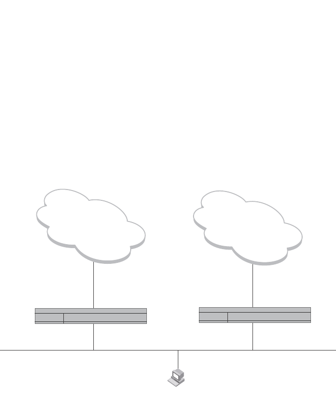
1102 PowerConnect B-Series FCX Configuration Guide
53-1002266-01
Overview
31
Overview of VRRP
VRRP is a protocol that provides redundancy to routers within a LAN. VRRP allows you to provide
alternate router paths for a host without changing the IP address or MAC address by which the host
knows its gateway. Consider the situation shown in Figure 150.
FIGURE 150 Switch 1 is Host1 default gateway but is a single point of failure
Switch 1 as the host default gateway out of the subnet. If this interface goes down, Host1 is cut off
from the rest of the network. Switch 1 is thus a single point of failure for Host1 access to other
networks.
If Switch 1 fails, you could configure Host1 to use Switch 2. Configuring one host with a different
default gateway might not require too much extra administration. However, consider a more
realistic network with dozens or even hundreds of hosts per subnet; reconfiguring the default
gateways for all the hosts is impractical. It is much simpler to configure a VRRP virtual router on
Switch 1 and Switch 2 to provide a redundant path for the hosts.
Figure 151 shows the same example network shown in Figure 150, but with a VRRP virtual router
configured on Switch 1 and Switch 2.
Host1
Default Gateway
102.53.5.1
Internet
or
Enterprise Intranet
Internet
or
Enterprise Intranet
e 2/4
e 1/6 192.53.5.1
Switch 1 Switch 2
e 3/2
e 1/5
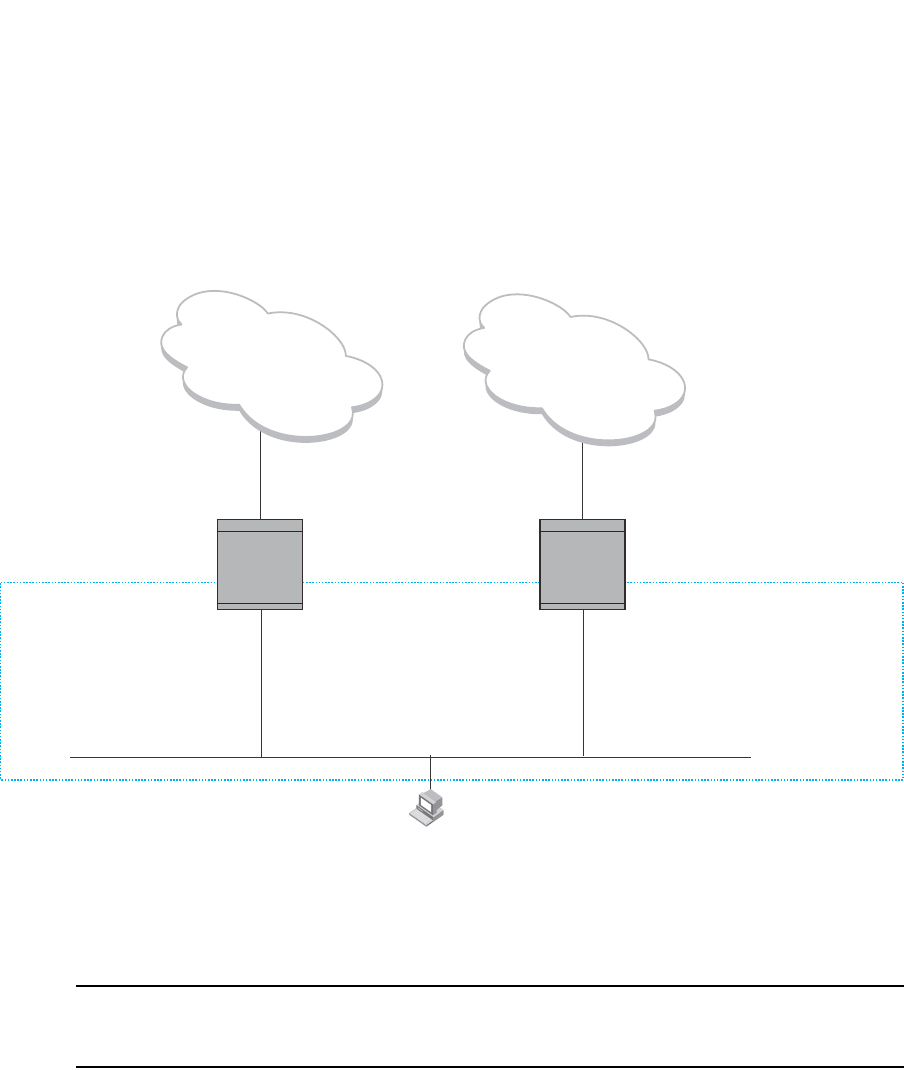
PowerConnect B-Series FCX Configuration Guide 1103
53-1002266-01
Overview 31
FIGURE 151 Switch 1 and Switch 2 are configured as a VRRP virtual router for redundant network
access for Host1
The dashed box in Figure 151 represents a VRRP virtual router. When you configure a virtual
router, one of the configuration parameters is the virtual router ID (VRID), which can be a number
from 1 – 255. In this example, the VRID is 1.
NOTE
You can provide more redundancy by also configuring a second VRID with Switch 2 as the Owner and
Switch 1 as the Backup. This type of configuration is sometimes called Multigroup VRRP.
Virtual Router ID (VRID)
A VRID consists of one Master router and one or more Backup routers. The Master router is the
router that owns the IP address(es) you associate with the VRID. For this reason, the Master router
is sometimes called the “Owner”. Configure the VRID on the router that owns the default gateway
interface. The other router in the VRID does not own the IP address(es) associated with VRID but
provides the backup path if the Master router becomes unavailable.
Virtual router MAC address
Notice the MAC address associated with VRID1. The first five octets of the address are the
standard MAC prefix for VRRP packets, as described in RFC 2338. The last octet is the VRID. THE
VRID number becomes the final octet in the virtual MAC address associated with the virtual router.
Internet
or
enterprise Intranet
Internet
or
enterprise Intranet
Host1
Default Gateway
192.53.5.1
192.53.5.1
e 1/6 e 1/5
192.53.5.3
e 3/2
e 2/4
VRID1
Router1 = Master
IP address = 192.53.5.1
MAC address = 00-00-5E-00-01-01
Priority = 255
VRID1
Router2 = Backup
IP address = 192.53.5.1
MAC address = 00-00-5E-00-01-01
Priority = 100
Owner
Router1 Router2
1104 PowerConnect B-Series FCX Configuration Guide
53-1002266-01
Overview
31
When you configure a VRID, the software automatically assigns its MAC address. When a VRID
becomes active, the Master router broadcasts a gratuitous ARP request containing the virtual
router MAC address for each IP address associated with the virtual router. In Figure 151, Switch 1
sends a gratuitous ARP with MAC address
00-00-5e-00-01-01 and IP address 192.53.5.1. Hosts use the virtual router MAC address in routed
traffic they send to their default IP gateway (in this example, 192.53.5.1).
Virtual router IP address
VRRP does not use virtual IP addresses. Thus, there is no virtual IP address associated with a
virtual router. Instead, you associate the virtual router with one or more real interface IP addresses
configured on the router that owns the real IP address(es). In Figure 151, the virtual router with
VRID1 is associated with real IP address 192.53.5.1, which is configured on interface e1/6 on
Switch 1. VRIDs are interface-level parameters, not system-level parameters, so the IP address you
associate with the VRID must already be a real IP address configured on the Owner interface.
NOTE
You also can associate a virtual router with a virtual interface. A virtual interface is a named set of
physical interfaces.
When you configure the Backup router for the VRID, specify the same IP address as the one you
specify on the Owner. This is the IP address used by the host as its default gateway. The IP
address cannot also exist on the Backup router. The interface on which you configure the VRID on
the Backup router must have an IP address in the same subnet.
NOTE
If you delete a real IP address used by a VRRP entry, the VRRP entry also is deleted automatically.
NOTE
When a Backup router takes over forwarding responsibilities from a failed Master router, the Backup
forwards traffic addressed to the VRID MAC address, which the host believes is the MAC address of
the router interface for its default gateway. However, the Backup cannot reply to IP pings sent to the
IP address(es) associated with the VRID. Because the IP address(es) are owned by the Owner, if the
Owner is unavailable, the IP addresses are unavailable as packet destinations.
Master negotiation
The routers within a VRID use the VRRP priority values associated with each router to determine
which router becomes the Master. When you configure the VRID on a router interface, you specify
whether the router is the Owner of the IP addresses you plan to associate with the VRID or a
Backup. If you indicate that the router is the Owner of the IP addresses, the software automatically
sets the router VRRP priority for the VRID to 255, the highest VRRP priority. The router with the
highest priority becomes the Master.
Backup routers can have a priority from 3 – 254, which you assign when you configure the VRID on
the Backup router interfaces. The default VRRP priority for Backup routers is 100.
Because the router that owns the IP addresses associated with the VRID always has the highest
priority, when all the routers in the virtual router are operating normally, the negotiation process
results in the Owner of the VRID IP addresses becoming the Master router. Thus, the VRRP
negotiation results in the normal case, in which the hosts’ path to the default route is to the router
that owns the interface for that route.

PowerConnect B-Series FCX Configuration Guide 1105
53-1002266-01
Overview 31
Hello messages
VRRP routers use Hello messages for negotiation to determine the Master router. VRRP routers
send Hello messages to IP Multicast address 224.0.0.18. The frequency with which the Master
sends Hello messages is the Hello Interval. Only the Master sends Hello messages. However, a
Backup uses the Hello interval you configure for the Backup if it becomes the Master.
The Backup routers wait for a period of time called the Dead Interval for a Hello message from the
Master. If a Backup router does not receive a Hello message by the time the dead interval expires,
the Backup router assumes that the Master router is dead and negotiates with the other Backups
to select a new Master router. The Backup router with the highest priority becomes the new Master.
If the Owner becomes unavailable, but then comes back online, the Owner again becomes the
Master router. The Owner becomes the Master router again because it has the highest priority.
The Owner always becomes the Master again when the Owner comes back online.
NOTE
If you configure a track port on the Owner and the track port is down, the Owner priority is changed
to the track priority. In this case, the Owner does not have a higher priority than the Backup that is
acting as Master and the Owner therefore does not resume its position as Master. For more
information about track ports, refer to “Track ports and track priority” on page 1105.
By default, if a Backup is acting as the Master, and the Master is still unavailable, another Backup
can “preempt” the Backup that is acting as the Master. This can occur if the new Backup has a
higher priority than the Backup who is acting as Master. You can disable this behavior if you want.
When you disable preemption, a Backup router that has a higher priority than the router who is
currently acting as Master does not preempt the new Master by initiating a new Master negotiation.
Refer to “Backup preempt” on page 1119.
NOTE
Regardless of the setting for the preempt parameter, the Owner always becomes the Master again
when it comes back online.
Track ports and track priority
The Dell implementation of VRRP enhances the protocol by giving a VRRP router the capability to
monitor the state of the interfaces on the other end of the route path through the router. For
example, in Figure 151 on page 1103, interface e1/6 on Switch 1 owns the IP address to which
Host1 directs route traffic on its default gateway. The exit path for this traffic is through Router1
e2/4 interface.
Suppose interface e2/4 goes down. Even if interface e1/6 is still up, Host1 is nonetheless cut off
from other networks. In conventional VRRP, Switch 1 would continue to be the Master router
despite the unavailability of the exit interface for the path the router is supporting. However, if you
configure interface e1/6 to track the state of interface e2/4, if e2/4 goes down, interface e1/6
responds by changing Switch 1 VRRP priority to the value of the track priority. In the configuration
shown in Figure 151 on page 1103, Switch 1 priority changes from 255 to 20. One of the
parameters contained in the Hello messages the Master router sends to its Backups is the Master
router priority. If the track port feature results in a change in the Master router priority, the Backup
routers quickly become aware of the change and initiate a negotiation for Master router.

1106 PowerConnect B-Series FCX Configuration Guide
53-1002266-01
Overview
31
In Figure 151 on page 1103, the track priority results in Switch 1 VRRP priority becoming lower
than Switch 2 VRRP priority. As a result, when Switch 2 learns that it now has a higher priority than
Switch 1, Switch 2 initiates negotiation for Master router and becomes the new Master router, thus
providing an open path for Host1 traffic. To take advantage of the track port feature, make sure
the track priorities are always lower than the VRRP priorities. The default track priority for the
router that owns the VRID IP addresses is 2. The default track priority for Backup routers is 1. If
you change the track port priorities, make sure you assign a higher track priority to the Owner of
the IP addresses than the track priority you assign on the Backup routers.
Suppression of RIP advertisements for backed up interfaces
The Dell implementation also enhances VRRP by allowing you to configure the protocol to suppress
RIP advertisements for the backed up paths from Backup routers. Normally, a VRRP Backup router
includes route information for the interface it is backing up in RIP advertisements. As a result,
other routers receive multiple paths for the interface and might sometimes unsuccessfully use the
path to the Backup rather than the path to the Master. If you enable the Dell implementation of
VRRP to suppress the VRRP Backup routers from advertising the backed up interface in RIP, other
routers learn only the path to the Master router for the backed up interface.
Authentication
The Dell implementation of VRRP can use simple passwords to authenticate VRRP packets. The
VRRP authentication type is not a parameter specific to the VRID. Instead, VRRP uses the
authentication type associated with the interfaces on which you define the VRID. For example, if
you configure your router interfaces to use a simple password to authenticate traffic, VRRP uses
the same simple password and VRRP packets that do not contain the password are dropped. If
your interfaces do not use authentication, neither does VRRP.
NOTE
The MD5 authentication type is not supported for VRRP.
Independent operation of VRRP alongside RIP, OSPF, and BGP4
VRRP operation is independent of the RIP, OSPF, and BGP4 protocols. Their operation is
unaffected when VRRP is enabled on a RIP, OSPF, or BGP4 interface.
Dynamic VRRP configuration
All VRRP global and interface parameters take effect immediately. You do not need to reset the
system to place VRRP configuration parameters into effect.
Overview of VRRPE
VRRPE is similar to VRRP, but differs in the following respects:
•Owners and Backup:
•VRRP has an Owner and one or more Backups for each VRID. The Owner is the router on
which the VRID's IP address is also configured as a real address. All the other routers
supporting the VRID are Backups.

PowerConnect B-Series FCX Configuration Guide 1107
53-1002266-01
Overview 31
•VRRPE does not use Owners. All routers are Backups for a given VRID. The router with the
highest priority becomes Master. If there is a tie for highest priority, the router with the
highest IP address becomes Master. The elected Master owns the virtual IP address and
answers ping and ARP requests and so on.
•VRID's IP address:
•VRRP requires that the VRID also be a real IP address configured on the VRID's interface
on the Owner.
•VRRPE requires only that the VRID be in the same subnet as an interface configured on
the VRID's interface. In fact, VRRPE does not allow you to specify a real IP address
configured on the interface as the VRID IP address.
•VRID's MAC Address:
•VRRP source MAC is a virtual MAC address defined as 00-00-5E-00-01-<vrid>, where
<vrid> is the VRID. The Master owns the Virtual MAC address.
•VRRPE uses the interface actual MAC address as the source MAC address. The MAC
address is
02-E0-52-<hash-value>-<vrid>, where <hash-value> is a two-octet hashed value for the IP
address and <vrid> is the VRID.
•Hello packets:
•VRRP sends Hello messages to IP Multicast address 224.0.0.18.
•VRRPE uses UDP to send Hello messages in IP multicast messages. The Hello packets use
the interface actual MAC address and IP address as the source addresses. The
destination MAC address is 01-00-5E-00-00-02, and the destination IP address is
224.0.0.2 (the well-known IP multicast address for “all routers”). Both the source and
destination UDP port number is 8888. VRRP messages are encapsulated in the data
portion of the packet.
•Track ports and track priority:
•VRRP changes the priority of the VRID to the track priority, which typically is lower than the
VRID priority and lower than the VRID priorities configured on the Backups. For example, if
the VRRP interface priority is 100 and a tracked interface with track priority 20 goes down,
the software changes the VRRP interface priority to 20.
•VRRPE reduces the priority of a VRRPE interface by the amount of a tracked interface
priority if the tracked interface link goes down. For example, if the VRRPE interface priority
is 200 and a tracked interface with track priority 20 goes down, the software changes the
VRRPE interface priority to 180. If another tracked interface goes down, the software
reduces the VRID priority again, by the amount of the tracked interface track priority.
The most important difference is that all VRRPE routers are Backups. There is no Owner router.
VRRPE overcomes the limitations in standard VRRP by removing the Owner.
Figure 152 shows an example of a VRRPE configuration.
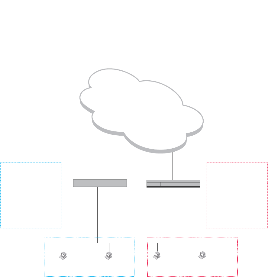
1108 PowerConnect B-Series FCX Configuration Guide
53-1002266-01
Overview
31
FIGURE 152 Router1 and Router2 are configured to provide dual redundant network access for
the host
In this example, Switch 1 and Switch 2 use VRRPE to load share as well as provide redundancy to
the hosts. The load sharing is accomplished by creating two VRRPE groups. Each group has its
own virtual IP addresses. Half of the clients point to VRID 1's virtual IP address as their default
gateway and the other half point to VRID 2's virtual IP address as their default gateway. This will
enable some of the outbound Internet traffic to go through Switch 1 and the rest to go through
Switch 2.
Switch 1 is the master for VRID 1 (backup priority = 110) and Switch 2 is the backup for VRID 1
(backup priority = 100). Switch 1 and Switch 2 both track the uplinks to the Internet. If an uplink
failure occurs on Switch 1, its backup priority is decremented by 20 (track priority = 20), so that all
traffic destined to the Internet is sent through Switch 2 instead.
Similarly, Switch 2 is the master for VRID 2 (backup priority = 110) and Switch 1 is the backup for
VRID 2 (backup priority = 100). Switch 1 and Switch 2 are both tracking the uplinks to the Internet.
If an uplink failure occurs on Switch 1, its backup priority is decremented by 20 (track priority = 20),
so that all traffic destined to the internet is sent through Switch 2 instead.
Internet
Switch 1 Switch 2
e 2/4
e 1/6 192.53.5.2 192.53.5.3
e 5/1
e 3/2
Host1
Default Gateway
192.53.5.254
Host2
Default Gateway
192.53.5.254
Host3
Default Gateway
192.53.5.253
Host4
Default Gateway
192.53.5.253
VRID 1
Switch 1 = Master
Virtual IP address 192.53.5.254
Priority = 110
Track Port = e 2/4
Track Priority = 20
VRID 2
Switch 1 = Backup
Virtual IP address 192.53.5.253
Priority = 100 (Default)
Track Port = e 2/4
Track Priority = 20
VRID 1
Switch 2 = Backup
Virtual IP address 192.53.5.254
Priority = 100 (Default)
Track port = e 3/2
Track priority = 20
VRID 2
Switch 2 = Master
Virtual IP address 192.53.5.253
Priority = 110
Track Port = e 3/2
Track Priority = 20

PowerConnect B-Series FCX Configuration Guide 1109
53-1002266-01
Comparison of VRRP and VRRPE 31
Configuration note
VRRP-E is supported in the edge Layer 3 and full Layer 3 code only. It is not supported in the base
Layer 3 code.
Comparison of VRRP and VRRPE
This section compares router redundancy protocols.
VRRP
VRRP is a standards-based protocol, described in RFC 2338. The Dell implementation of VRRP
contains the features in RFC 2338. The Dell implementation also provides the following additional
features:
•Track ports – A Dell feature that enables you to diagnose the health of all the Layer 3 Switch
ports used by the backed-up VRID, instead of only the port connected to the client subnet.
Refer to “Track ports and track priority” on page 1105.
•Suppression of RIP advertisements on Backup routes for the backed up interface – You can
enable the Layer 3 Switches to advertise only the path to the Master router for the backed up
interface. Normally, a VRRP Backup router includes route information for the interface it is
backing up in RIP advertisements.
Dell Layer 3 Switches configured for VRRP can interoperate with third-party routers using VRRP.
VRRPE
VRRPE is a Dell protocol that provides the benefits of VRRP without the limitations. VRRPE is unlike
VRRP in the following ways:
•There is no “Owner” router. You do not need to use an IP address configured on one of the
Layer 3 Switches as the virtual router ID (VRID), which is the address you are backing up for
redundancy. The VRID is independent of the IP interfaces configured in the Layer 3 Switches.
As a result, the protocol does not have an “Owner” as VRRP does.
•There is no restriction on which router can be the default master router. In VRRP, the “Owner”
(the Layer 3 Switch on which the IP interface that is used for the VRID is configured) must be
the default Master.
Dell Layer 3 Switches configured for VRRPE can interoperate only with other Dell Layer 3 Switches.
Architectural differences
The protocols have the following architectural differences:
Management protocol
•VRRP – VRRP routers send VRRP Hello and Hello messages to IP Multicast address
224.0.0.18.
•VRRPE – VRRPE sends messages to destination MAC address 01-00-5E-00-00-02 and
destination IP address 224.0.0.2 (the standard IP multicast address for “all routers”).

1110 PowerConnect B-Series FCX Configuration Guide
53-1002266-01
VRRP and VRRPE parameters
31
Virtual router IP address (the address you are backing up)
•VRRP – The virtual router IP address is the same as an IP address or virtual interface
configured on one of the Layer 3 Switches, which is the “Owner” and becomes the default
Master.
•VRRPE – The virtual router IP address is the gateway address you want to backup, but does not
need to be an IP interface configured on one of the Layer 3 Switch ports or a virtual interface.
Master and Backups
•VRRP – The “Owner” of the IP address of the VRID is the default Master and has the highest
priority (255). The precedence of the Backups is determined by their priorities. The default
Master is always the Owner of the IP address of the VRID.
•VRRPE – The Master and Backups are selected based on their priority. You can configure any
of the Layer 3 Switches to be the Master by giving it the highest priority. There is no Owner.
VRRP and VRRPE parameters
Table 194 lists the VRRP and VRRPE parameters. Most of the parameters and default values are
the same for both protocols. The exceptions are noted in the table.
TABLE 194 VRRP and VRRPE parameters
Parameter Description Default See page...
Protocol The Virtual Router Redundancy Protocol (VRRP) based on
RFC 2338 or VRRP-Extended, the Dell enhanced
implementation of VRRP
Disabled
NOTE: Only one of
the protocols
can be
enabled at a
time.
page 1113
page 1113
VRRP or VRRPE
router
The Layer 3 Switch active participation as a VRRP or
VRRPE router. Enabling the protocol does not activate the
Layer 3 Switch for VRRP or VRRPE. You must activate the
device as a VRRP or VRRPE router after you configure the
VRRP or VRRPE parameters.
Inactive page 1113
page 1113
Virtual Router
ID (VRID)
The ID of the virtual router you are creating by configuring
multiple routers to back up an IP interface. You must
configure the same VRID on each router that you want to
use to back up the address.
No default.
None page 1103
page 1113
page 1113
Virtual Router
IP address
This is the address you are backing up.
No default:
•VRRP – The virtual router IP address must be a real
IP address configured on the VRID interface on one
of the VRRP routers. This router is the IP address
Owner and is the default Master.
•VRRPE – The virtual router IP address must be in the
same subnet as a real IP address configured on the
VRRPE interface, but cannot be the same as a real IP
address configured on the interface.
None page 1104
page 1113
page 1113

PowerConnect B-Series FCX Configuration Guide 1111
53-1002266-01
VRRP and VRRPE parameters 31
VRID MAC
address
The source MAC address in VRRP or VRRPE packets sent
from the VRID interface, and the destination for packets
sent to the VRID:
•VRRP – A virtual MAC address defined as
00-00-5e-00-01-<vrid>. The Master owns the Virtual
MAC address.
•VRRPE – A virtual MAC address defined as
02-E0-52-<hash-value>-<vrid>, where <hash-value>
is a two-octet hashed value for the IP address and
<vrid> is the VRID.
Not configurable page 1103
Authentication
type
The type of authentication the VRRP or VRRPE routers use
to validate VRRP or VRRPE packets. The authentication
type must match the authentication type the VRID port
uses with other routing protocols such as OSPF:
•No authentication – The interfaces do not use
authentication. This is the VRRP default.
•Simple – The interface uses a simple text-string as a
password in packets sent on the interface. If the
interface uses simple password authentication, the
VRID configured on the interface must use the same
authentication type and the same password.
NOTE: MD5 is not supported by VRRP or VRRPE.
No authentication page 1106
page 1115
Router type Whether the router is an Owner or a Backup.
•Owner (VRRP only) – The router on which the real IP
address used by the VRID is configured.
•Backup – Routers that can provide routing services
for the VRID but do not have a real IP address
matching the VRID.
VRRP – The Owner is
always the router that
has the real IP
address used by the
VRID. All other
routers for the VRID
are Backups.
VRRPE – All routers
for the VRID are
Backups.
page 1116
Backup priority A numeric value that determines a Backup preferability
for becoming the Master for the VRID. During negotiation,
the router with the highest priority becomes the Master.
•VRRP – The Owner has the highest priority (255);
other routers can have a priority from 3 – 254.
•VRRPE – All routers are Backups and have the same
priority by default.
If two or more Backups are tied with the highest priority,
the Backup interface with the highest IP address
becomes the Master for the VRID.
VRRP – 255 for the
Owner; 100 for each
Backup
VRRPE – 100 for all
Backups
page 1116
Suppression of
RIP
advertisements
A router that is running RIP normally advertises routes to
a backed up VRID even when the router is not currently
the active router for the VRID. Suppression of these
advertisements helps ensure that other routers do not
receive invalid route paths for the VRID.
Disabled page 1117
Hello interval The number of seconds between Hello messages from
the Master to the Backups for a given VRID. The interval
can from 1 – 84 seconds.
One second page 1105
page 1117
TABLE 194 VRRP and VRRPE parameters (Continued)
Parameter Description Default See page...

1112 PowerConnect B-Series FCX Configuration Guide
53-1002266-01
VRRP and VRRPE parameters
31
Dead interval The number of seconds a Backup waits for a Hello
message from the Master for the VRID before determining
that the Master is no longer active.
If the Master does not send a Hello message before the
dead interval expires, the Backups negotiate (compare
priorities) to select a new Master for the VRID.
Three times the Hello
Interval plus one-half
second
page 1105
page 1118
Backup Hello
interval
The number of seconds between Hello messages from a
Backup to the Master.
The message interval can be from 60 – 3600 seconds.
You must enable the Backup to send the messages. The
messages are disabled by default on Backups. The
current Master (whether the VRRP Owner or a Backup)
sends Hello messages by default.
Disabled
60 seconds when
enabled
page 1105
page 1118
Track port Another Layer 3 Switch port or virtual interface whose link
status is tracked by the VRID interface.
If the link for a tracked interface goes down, the VRRP or
VRRPE priority of the VRID interface is changed, causing
the devices to renegotiate for Master.
None page 1105
page 1118
Track priority A VRRP or VRRPE priority value assigned to the tracked
ports. If a tracked port link goes down, the VRID port
VRRP or VRRPE priority changes:
•VRRP – The priority changes to the value of the
tracked port priority.
•VRRPE – The VRID port priority is reduced by the
amount of the tracked port priority.
VRRP – 2
VRRPE – 5
page 1105
page 1119
Backup
preempt mode
Prevents a Backup with a higher VRRP priority from taking
control of the VRID from another Backup that has a lower
priority but has already assumed control of the VRID.
Enabled page 1119
Timer scale Adjusts the timers for the Hello interval, Dead interval,
Backup Hello interval, and Hold-down interval.
1page 1120
VRRP-E slow
start timer
This feature causes a specified amount of time to elapse
between the time the Master is restored and when it
takes over from the Backup. This interval allows time for
OSPF convergence when the Master is restored.
Disabled page 1120
TABLE 194 VRRP and VRRPE parameters (Continued)
Parameter Description Default See page...

PowerConnect B-Series FCX Configuration Guide 1113
53-1002266-01
Configuring basic VRRP parameters 31
Configuring basic VRRP parameters
To implement a simple VRRP configuration using all the default values, enter commands such as
the following.
Configuring the Owner
Router1(config)#router vrrp
Router1(config)#inter e 1/6
Router1(config-if-1/6)#ip address 192.53.5.1
Router1(config-if-1/6)#ip vrrp vrid 1
Router1(config-if-1/6-vrid-1)#owner
Router1(config-if-1/6-vrid-1)#ip-address 192.53.5.1
Router1(config-if-1/6-vrid-1)#activate
Configuring a Backup
Router2(config)#router vrrp
Router2(config)#inter e 1/5
Router2(config-if-1/5)#ip address 192.53.5.3
Router2(config-if-1/5)#ip vrrp vrid 1
Router2(config-if-1/5-vrid-1)#backup
Router2(config-if-1/5-vrid-1)#advertise backup
Router2(config-if-1/5-vrid-1)#ip-address 192.53.5.1
Router2(config-if-1/5-vrid-1)#activate
Configuration rules for VRRP
•The interfaces of all routers in a VRID must be in the same IP subnet.
•The IP addresses associated with the VRID must already be configured on the router that will
be the Owner router.
•An IP address associated with the VRID must be on only one router.
•The Hello interval must be set to the same value on both the Owner and Backups for the VRID.
•The Dead interval must be set to the same value on both the Owner and Backups for the VRID.
•The track priority on a router must be lower than the router VRRP priority. Also, the track
priority on the Owner must be higher than the track priority on the Backups.
Configuring basic VRRPE parameters
To implement a simple VRRPE configuration using all the default values, enter commands such as
the following on each Layer 3 Switch.
Router2(config)#router vrrp-extended
Router2(config)#inter e 1/5
Router2(config-if-1/5)#ip address 192.53.5.3
Router2(config-if-1/5)#ip vrrp-extended vrid 1
Router2(config-if-1/5-vrid-1)#backup
Router2(config-if-1/5-vrid-1)#advertise backup
Router2(config-if-1/5-vrid-1)#ip-address 192.53.5.254
Router2(config-if-1/5-vrid-1)#activate

1114 PowerConnect B-Series FCX Configuration Guide
53-1002266-01
Note regarding disabling VRRP or VRRPE
31
NOTE
You also can use the enable command to activate the configuration. This command does the same
thing as the activate command.
Configuration rules for VRRPE
•The interfaces of all routers in a VRID must be in the same IP subnet.
•The IP address associated with the VRID cannot be configured on any of the Layer 3 Switches.
•The Hello interval must be set to the same value on all the Layer 3 Switches.
•The Dead interval must be set to the same value on all the Layer 3 Switches.
•The track priority for a VRID must be lower than the VRRPE priority.
Note regarding disabling VRRP or VRRPE
If you disable VRRP or VRRPE, the Layer 3 Switch removes all the configuration information for the
disabled protocol from the running-config. Moreover, when you save the configuration to the
startup-config file after disabling one of these protocols, all the configuration information for the
disabled protocol is removed from the startup-config file.
The CLI displays a warning message such as the following.
Router1(config-vrrp-router)#no router vrrp
router vrrp mode now disabled. All vrrp config data will be lost when writing to
flash!
If you have disabled the protocol but have not yet saved the configuration to the startup-config file
and reloaded the software, you can restore the configuration information by re-entering the
command to enable the protocol (ex: router vrrp). If you have already saved the configuration to the
startup-config file and reloaded the software, the information is gone.
If you are testing a VRRP or VRRPE configuration and are likely to disable and re-enable the
protocol, you might want to make a backup copy of the startup-config file containing the protocol
configuration information. This way, if you remove the configuration information by saving the
configuration after disabling the protocol, you can restore the configuration by copying the backup
copy of the startup-config file onto the flash memory.
Configuring additional VRRP and VRRPE parameters
You can modify the following VRRP and VRRPE parameters on an individual VRID basis. These
parameters apply to both protocols:
•Authentication type (if the interfaces on which you configure the VRID use authentication)
•Router type (Owner or Backup)
NOTE
For VRRP, change the router type only if you have moved the real IP address from one router to
another or you accidentally configured the IP address Owner as a Backup.
For VRRPE, the router type is always Backup. You cannot change the type to Owner.

PowerConnect B-Series FCX Configuration Guide 1115
53-1002266-01
Configuring additional VRRP and VRRPE parameters 31
•Backup priority
•Suppression of RIP advertisements on Backup routes for the backed up interface
•Hello interval
•Dead interval
•Backup Hello messages and message timer (Backup advertisement)
•Track port
•Track priority
•Backup preempt mode
•Timer scale
•VRRP-E slow start timer
For information about the fields, see the parameter descriptions in the following sections.
Refer to “VRRP and VRRPE parameters” on page 1110 for a summary of the parameters and their
defaults.
Authentication type
If the interfaces on which you configure the VRID use authentication, the VRRP or VRRPE packets
on those interfaces also must use the same authentication. The Dell implementation of VRRP and
VRRPE supports the following authentication types:
•No authentication – The interfaces do not use authentication. This is the default for VRRP and
VRRPE.
•Simple – The interfaces use a simple text-string as a password in packets sent on the
interface. If the interfaces use simple password authentication, the VRID configured on the
interfaces must use the same authentication type and the same password.
To configure the VRID interface on Router1 for simple-password authentication using the password
“ourpword”, enter the following commands.
Configuring Router 1
Router1(config)#inter e 1/6
Router1(config-if-1/6)#ip vrrp auth-type simple-text-auth ourpword
Configuring Router 2
Router2(config)#inter e 1/5
Router2(config-if-1/5)#ip vrrp auth-type simple-text-auth ourpword
VRRP syntax
Syntax: ip vrrp auth-type no-auth | simple-text-auth <auth-data>
The auth-type no-auth parameter indicates that the VRID and the interface it is configured on do
not use authentication.
The auth-type simple-text-auth <auth-data> parameter indicates that the VRID and the interface it
is configured on use a simple text password for authentication. The <auth-data> parameter is the
password. If you use this parameter, make sure all interfaces on all the routers supporting this
VRID are configured for simple password authentication and use the same password.
VRRPE syntax
Syntax: ip vrrp-extended auth-type no-auth | simple-text-auth <auth-data>

1116 PowerConnect B-Series FCX Configuration Guide
53-1002266-01
Configuring additional VRRP and VRRPE parameters
31
The parameter values are the same as for VRRP.
Router type
A VRRP interface is either an Owner or a Backup for a given VRID. By default, the Owner becomes
the Master following the negotiation. A Backup becomes the Master only if the Master becomes
unavailable.
A VRRPE interface is always a Backup for its VRID. The Backup with the highest VRRP priority
becomes the Master.
This section describes how to specify the interface type, how to change the type for VRRP, and how
to set or change the interface VRRP or VRRPE priority and track priority for the VRID.
NOTE
You can force a VRRP master router to abdicate (give away control) of the VRID to a Backup by
temporarily changing the Master VRRP priority to a value less than the Backup. Refer to “Forcing a
Master router to abdicate to a standby router” on page 1121.
NOTE
The type Owner is not applicable to VRRPE.
NOTE
The IP address(es) you associate with the Owner must be a real IP address (or addresses) on the
interface on which you configure the VRID.
When you configure a Backup router, the router interface on which you are configuring the VRID
must have a real IP address that is in the same subnet as the address associated with the VRID by
the Owner. However, the address cannot be the same.
To configure Router1 as a VRRP VRID Owner, enter the following commands.
Router1(config)#inter e 1/6
Router1(config-if-1/6)#ip vrrp vrid 1
Router1(config-if-1/6-vrid-1)#owner
To configure Router2 as a VRRP Backup for the same VRID, enter the following commands.
Router2(config)#inter e 1/5
Router2(config-if-1/5)#ip vrrp vrid 1
Router2(config-if-1/5-vrid-1)#backup
Router2(config-if-1/5-vrid-1)#advertise backup
To configure a VRRPE interface as a Backup for a VRID and set its VRRPE priority and track priority,
enter commands such as the following.
PowerConnect(config)#inter e 1/1
PowerConnect(config-if-1/1)#ip vrrp-extended vrid 1
PowerConnect(config-if-1/1-vrid-1)#backup priority 50 track-priority 10
Router2(config-if-1/1-vrid-1)#advertise backup
VRRP syntax
Syntax: owner [track-priority <value>]
The track-priority <value> parameter changes the track-port priority for this interface and VRID
from the default (2) to a value from 1 – 254.

PowerConnect B-Series FCX Configuration Guide 1117
53-1002266-01
Configuring additional VRRP and VRRPE parameters 31
Syntax: backup [priority <value>] [track-priority <value>]
The priority <value> parameter specifies the VRRP priority for this interface and VRID. You can
specify a value from 3 – 254. The default is 100.
The track-priority <value> parameter is the same as above.
NOTE
You cannot set the priority of a VRRP Owner. The Owner priority is always 255.
VRRPE syntax
Syntax: backup [priority <value>] [track-priority <value>]
The software requires you to identify a VRRPE interface as a Backup for its VRID before you can
activate the interface for the VRID. However, after you configure the VRID, you can use this
command to change its priority or track priority. The parameter values are the same as for VRRP.
Suppression of RIP advertisements on Backup routers for the Backup interface
Normally, a VRRP or VRRPE Backup includes route information for the virtual IP address (the
backed up interface) in RIP advertisements. As a result, other routers receive multiple paths for
the backed up interface and might sometimes unsuccessfully use the path to the Backup rather
than the path to the Master.
You can prevent the Backups from advertising route information for the backed up interface by
enabling suppression of the advertisements.
To suppress RIP advertisements for the backed up interface in Router2, enter the following
commands.
Router2(config)#router rip
Router2(config-rip-router)#use-vrrp-path
Syntax: use-vrrp-path
The syntax is the same for VRRP and VRRPE.
Hello interval
The Master periodically sends Hello messages to the Backups. The Backups use the Hello
messages as verification that the Master is still on-line. If the Backup routers stop receiving the
Hello messages for the period of time specified by the Dead interval, the Backup routers determine
that the Master router is dead. At this point, the Backup router with the highest priority becomes
the new Master router. The Hello interval can be from 1 – 84 seconds. The default is 1 second.
NOTE
The default Dead interval is three times the Hello Interval plus one-half second. Generally, if you
change the Hello interval, you also should change the Dead interval on the Backup routers.
To change the Hello interval on the Master to 10 seconds, enter the following commands.
Router1(config)#inter e 1/6
Router1(config-if-1/6)#ip vrrp vrid 1
Router1(config-if-1/6-vrid-1)#hello-interval 10
Syntax: hello-interval <value>
The syntax is the same for VRRP and VRRPE.

1118 PowerConnect B-Series FCX Configuration Guide
53-1002266-01
Configuring additional VRRP and VRRPE parameters
31
Dead interval
The Dead interval is the number of seconds a Backup waits for a Hello message from the Master
before determining that the Master is dead. When Backups determine that the Master is dead, the
Backup with the highest priority becomes the new Master. The Dead interval can be from 1 – 84
seconds. The default is 3.5 seconds. This is three times the default Hello interval (1 second) plus
one-half second added by the router software. The software automatically adds one-half second to
the Dead interval value you enter.
To change the Dead interval on a Backup to 30 seconds, enter the following commands.
Router2(config)#inter e 1/5
Router2(config-if-1/5)#ip vrrp vrid 1
Router2(config-if-1/5-vrid-1)#dead-interval 30
Syntax: dead-interval <value>
The syntax is the same for VRRP and VRRPE.
Backup Hello message state and interval
By default, Backup do not send Hello messages to advertise themselves to the Master. You can
enable these messages if desired and also change the message interval.
To enable a Backup to send Hello messages to the Master, enter commands such as the following.
PowerConnect(config)#router vrrp
PowerConnect(config)#inter e 1/6
PowerConnect(config-if-1/6)#ip vrrp vrid 1
PowerConnect(config-if-1/6-vrid-1)#advertise backup
Syntax: [no] advertise backup
When you enable a Backup to send Hello messages, the Backup sends a Hello messages to the
Master every 60 seconds by default. You can change the interval to be up to 3600 seconds. To do
so, enter commands such as the following.
PowerConnect(config)#router vrrp
PowerConnect(config)#inter e 1/6
PowerConnect(config-if-1/6)#ip vrrp vrid 1
PowerConnect(config-if-1/6-vrid-1)#backup-hello-interval 180
Syntax: [no] backup-hello-interval <num>
The <num> parameter specifies the message interval and can be from 60 – 3600 seconds. The
default is 60 seconds.
The syntax is the same for VRRP and VRRPE.
Track port
You can configure the VRID on one interface to track the link state of another interface on the Layer
3 Switch. This capability is quite useful for tracking the state of the exit interface for the path for
which the VRID is providing redundancy. Refer to “Track ports and track priority” on page 1105.
To configure 1/6 on Router1 to track interface 2/4, enter the following commands.
Router1(config)#inter e 1/6
Router1(config-if-1/6)#ip vrrp vrid 1
Router1(config-if-1/6-vrid-1)#track-port e 2/4

PowerConnect B-Series FCX Configuration Guide 1119
53-1002266-01
Configuring additional VRRP and VRRPE parameters 31
Syntax: track-port ethernet [<slotnum>/]<portnum> | ve <num>
The syntax is the same for VRRP and VRRPE.
Track priority
When you configure a VRID to track the link state of other interfaces, if one of the tracked interface
goes down, the software changes the VRRP or VRRPE priority of the VRID interface:
•For VRRP, the software changes the priority of the VRID to the track priority, which typically is
lower than the VRID priority and lower than the VRID priorities configured on the Backups. For
example, if the VRRPE interface priority is 100 and a tracked interface with track priority 60
goes down, the software changes the VRRPE interface priority to 60.
•For VRRPE, the software reduces the VRID priority by the amount of the priority of the tracked
interface that went down. For example, if the VRRPE interface priority is 100 and a tracked
interface with track priority 60 goes down, the software changes the VRRPE interface priority to
40. If another tracked interface goes down, the software reduces the VRID priority again, by
the amount of the tracked interface track priority.
The default track priority for a VRRP Owner is 2. The default track priority for Backups is 1.
You enter the track priority as a parameter with the owner or backup command. Refer to “Track
port” on page 1118.
Syntax: owner [track-priority <value>]
Syntax: backup [priority <value>] [track-priority <value>]
The syntax is the same for VRRP and VRRPE.
Backup preempt
By default, a Backup that has a higher priority than another Backup that has become the Master
can preempt the Master, and take over the role of Master. If you want to prevent this behavior,
disable preemption.
Preemption applies only to Backups and takes effect only when the Master has failed and a
Backup has assumed ownership of the VRID. The feature prevents a Backup with a higher priority
from taking over as Master from another Backup that has a lower priority but has already become
the Master of the VRID.
Preemption is especially useful for preventing flapping in situations where there are multiple
Backups and a Backup with a lower priority than another Backup has assumed ownership, because
the Backup with the higher priority was unavailable when ownership changed.
If you enable the non-preempt mode (thus disabling the preemption feature) on all the Backups,
the Backup that becomes the Master following the disappearance of the Master continues to be
the Master. The new Master is not preempted.
NOTE
In VRRP, regardless of the setting for the preempt parameter, the Owner always becomes the Master
again when it comes back online.
To disable preemption on a Backup, enter commands such as the following.
Router1(config)#inter e 1/6
Router1(config-if-1/6)#ip vrrp vrid 1
Router1(config-if-1/6-vrid-1)#non-preempt-mode

1120 PowerConnect B-Series FCX Configuration Guide
53-1002266-01
Configuring additional VRRP and VRRPE parameters
31
Syntax: non-preempt-mode
The syntax is the same for VRRP and VRRPE.
Changing the timer scale
To achieve sub-second failover times, you can shorten the duration of all scale timers for VSRP,
VRRP, and VRRP-E by adjusting the timer scale. The timer scale is a value used by the software to
calculate the timers. By default, the scale value is 1. If you increase the timer scale, each timer’s
value is divided by the scale value. Using the timer scale to adjust timer values enables you to
easily change all the timers while preserving the ratios among their values. Here is an example.
If you configure the device to receive its timer values from the Master, the Backup also receives the
timer scale value from the Master.
NOTE
The Backups always use the value of the timer scale received from the Master, regardless of whether
the timer values that are saved in the configuration are the values configured on the Backup or the
values received from the Master.
To change the timer scale, enter a command such as the following at the global CONFIG level of the
CLI.
PowerConnect (config)# scale-timer 2
This command changes the scale to 2. All VSRP, VRRP, and VRRP-E timer values will be divided by
2.
Syntax: [no] scale-timer <num>
The <num> parameter specifies the multiplier. You can specify a timer scale from 1 – 10.
VRRP-E slow start timer
In a VRRP-E configuration, if a Master router goes down, the Backup router with the highest priority
takes over. When the Master comes back up again, it takes over from the Backup. By default, this
transition from Backup back to Master takes place immediately. However, you can configure the
VRRP-E slow start timer feature, which causes a specified amount of time to elapse between the
time the Master is restored and when it takes over from the Backup. This interval allows time for
OSPF convergence when the Master is restored.
Timer Timer scale Timer value
Hello interval 1 1 second
20.5 seconds
Dead interval 1 3 seconds
21.5 seconds
Backup Hello interval 1 60 seconds
2 30 seconds
Hold-down interval 1 2 seconds
21 second

PowerConnect B-Series FCX Configuration Guide 1121
53-1002266-01
Forcing a Master router to abdicate to a standby router 31
To set the VRRP-E slow start timer to 30 seconds, enter the following commands.
PowerConnect(config)#router vrrp-e
PowerConnect(config-vrrpe-router)#slow-start 30
Syntax: [no] slow-start <seconds>
For <seconds>, enter a value from 1 – 255.
When the VRRP-E slow start timer is enabled, if the Master goes down, the Backup takes over
immediately. If the Master subsequently comes back up again, the amount of time specified by the
VRRP-E slow start timer elapses (in this example, 30 seconds) before the Master takes over from
the Backup.
The VRRP-E slow start timer is effective only if another VRRP-E Master (Standby) is detected. It is
not effective during the initial boot up.
NOTE
The VRRP-E slow start timer applies only to VRRP-E configurations. It does not apply to VRRP
configurations.
Forcing a Master router to abdicate to a standby router
You can force a VRRP Master to abdicate (give away control) of a VRID to a Backup by temporarily
changing the Master priority to a value less than the Backup.
The VRRP Owner always has priority 255. You can even use this feature to temporarily change the
Owner priority to a value from 1 – 254.
NOTE
When you change a VRRP Owner priority, the change takes effect only for the current power cycle.
The change is not saved to the startup-config file when you save the configuration and is not retained
across a reload or reboot. Following a reload or reboot, the VRRP Owner again has priority 255.
To temporarily change the Master priority, use the following CLI method.
To change the Master priority, enter commands such as the following.
PowerConnect(config)#ip int eth 1/6
PowerConnect(config-if-1/6)#ip vrrp vrid 1
PowerConnect(config-if-1/6-vrid-1)#owner priority 99
Syntax: [no] owner priority | track-priority <num>
The <num> parameter specifies the new priority and can be a number from 1 – 254.
When you press Enter, the software changes the priority of the Master to the specified priority. If
the new priority is lower than at least one Backup priority for the same VRID, the Backup takes over
and becomes the new Master until the next software reload or system reset.
To verify the change, enter the following command from any level of the CLI.
PowerConnect#show ip vrrp
Total number of VRRP routers defined: 1
Interface ethernet 1/6
auth-type no authentication
VRID 1
state backup
administrative-status enabled

1122 PowerConnect B-Series FCX Configuration Guide
53-1002266-01
Displaying VRRP and VRRPE information
31
mode owner
priority 99
current priority 99
hello-interval 1 sec
ip-address 192.53.5.1
backup routers 192.53.5.2
This example shows that even though this Layer 3 Switch is the Owner of the VRID (“mode owner”),
the Layer 3 Switch priority for the VRID is only 99 and the state is now “backup” instead of “active”.
In addition, the administrative status is “enabled”.
To change the Master priority back to the default Owner priority 255, enter “no” followed by the
command you entered to change the priority. For example, to change the priority of a VRRP Owner
back to 255 from 99, enter the following command.
PowerConnect(config-if-1/6-vrid-1)#no owner priority 99
You cannot set the priority to 255 using the owner priority command.
Displaying VRRP and VRRPE information
You can display the following information for VRRP or VRRPE:
•Summary configuration and status information
•Detailed configuration and status information
•VRRP and VRRPE Statistics
•CPU utilization statistics
Displaying summary information
To display summary information for a Layer 3 Switch, enter the following command at any level of
the CLI.
The above example is for VRRP. Here is an example for VRRPE.
Syntax: show ip vrrp brief | ethernet [<slotnum>/]<portnum> | ve <num> | stat
Syntax: show ip vrrp-extended brief | ethernet [<slotnum>/]<portnum> | ve <num> | stat
The brief parameter displays the summary information. If you do not use this parameter, detailed
information is displayed instead. Refer to “Displaying detailed information” on page 1123.
The <slotnum> parameter is required on chassis devices if you specify a port number.
PowerConnect#show ip vrrp brief
Total number of VRRP routers defined: 1
Interface VRID CurPri P State Master addr Backup addr VIP
1/6 1 255 P Init 192.53.5.1 192.53.5.3 192.53.5.1
PowerConnect#show ip vrrp-extended brief
Total number of VRRP-Extended routers defined: 1
Interface VRID CurPri P State Master addr Backup addr VIP
1/6 1 255 P Init 192.53.5.2 192.53.5.3 192.53.5.254

PowerConnect B-Series FCX Configuration Guide 1123
53-1002266-01
Displaying VRRP and VRRPE information 31
The <portnum> parameter specifies an Ethernet port. If you use this parameter, the command
displays VRRP or VRRPE information only for the specified port.
The ve <num> parameter specifies a virtual interface. If you use this parameter, the command
displays VRRP or VRRPE information only for the specified virtual interface.
The stat parameter displays statistics. Refer to “Displaying statistics” on page 1128.
This display shows the following information.
Displaying detailed information
To display detailed VRRP or VRRPE information, enter the following command at any level of the
CLI.
TABLE 195 CLI display of VRRP or VRRPE summary information
This field... Displays...
Total number of VRRP (or
VRRP-Extended) routers
defined
The total number of VRIDs configured on this Layer 3 Switch.
NOTE: The total applies only to the protocol the Layer 3 Switch is running. For
example, if the Layer 3 Switch is running VRRPE, the total applies only to
VRRPE routers.
Interface The interface on which VRRP or VRRPE is configured. If VRRP or VRRPE is configured
on multiple interfaces, information for each interface is listed separately.
VRID The VRID configured on this interface. If multiple VRIDs are configured on the
interface, information for each VRID is listed in a separate row.
CurPri The current VRRP or VRRPE priority of this Layer 3 Switch for the VRID.
P Whether the backup preempt mode is enabled. If the backup preempt mode is
enabled, this field contains a “P”. If the mode is disabled, this field is blank.
State This Layer 3 Switch VRRP or VRRPE state for the VRID. The state can be one of the
following:
•Init – The VRID is not enabled (activated). If the state remains Init after you
activate the VRID, make sure that the VRID is also configured on the other
routers and that the routers can communicate with each other.
NOTE: If the state is Init and the mode is incomplete, make sure you have specified
the IP address for the VRID.
•Backup – This Layer 3 Switch is a Backup for the VRID.
•Master – This Layer 3 Switch is the Master for the VRID.
Master addr IP address of the router interface that is currently Master for the VRID.
Backup addr IP addresses of router interfaces that are currently Backups for the VRID.
VIP The virtual IP address that is being backed up by the VRID.

1124 PowerConnect B-Series FCX Configuration Guide
53-1002266-01
Displaying VRRP and VRRPE information
31
This example is for a VRRP Owner. Here is an example for a VRRP Backup.
Here is an example for a VRRPE Backup.
Syntax: show ip vrrp brief | ethernet [<slotnum>/]<portnum> | ve <num> | stat
PowerConnect#show ip vrrp
Total number of VRRP routers defined: 1
Interface ethernet 1/6
auth-type no authentication
VRID 1
state master
administrative-status enabled
mode owner
priority 255
current priority 255
hello-interval 10000 msec
advertise backup: disabled
track-port 2/4
PowerConnect#show ip vrrp
Total number of VRRP routers defined: 1
Interface ethernet 1/5
auth-type no authentication
VRID 1
state backup
administrative-status enabled
mode non-owner(backup)
priority 100
current priority 100
hello-interval 10000 msec
dead-interval 30000 msec
current dead-interval 10000 msec
preempt-mode true
advertise backup: enabled
backup router 192.53.5.3 expires in 00:00:03.0
next hello sent in 00:00:02.0
track-port 3/2
PowerConnect#show ip vrrp-extended
Total number of VRRP-Extended routers defined: 1
Interface ethernet 1/6
auth-type no authentication
VRID 1
state master
administrative-status enabled
priority 200
current priority 200
hello-interval 10000 msec
dead-interval 30000 msec
current dead-interval 30000 msec
preempt-mode true
virtual ip address 192.53.5.254
advertise backup: enabled
master router 192.53.5.2 expires in 00:00:03.0
track-port 2/4

PowerConnect B-Series FCX Configuration Guide 1125
53-1002266-01
Displaying VRRP and VRRPE information 31
Syntax: show ip vrrp-extended brief | ethernet [<slotnum>/]<portnum> | ve <num> | stat
The brief parameter displays summary information. Refer to “Displaying summary information” on
page 1122.
The <portnum> parameter specifies an Ethernet port. If you use this parameter, the command
displays VRRP or VRRPE information only for the specified port. Also, you must specify the
<slotnum> on chassis devices.
The ve <num> parameter specifies a virtual interface. If you use this parameter, the command
displays VRRP or VRRPE information only for the specified virtual interface.
The stat parameter displays statistics. Refer to “Displaying statistics” on page 1128.
This display shows the following information.
TABLE 196 CLI display of VRRP or VRRPE detailed information
This field... Displays...
Total number of VRRP (or
VRRP-Extended) routers defined
The total number of VRIDs configured on this Layer 3 Switch.
NOTE: The total applies only to the protocol the Layer 3 Switch is running. For
example, if the Layer 3 Switch is running VRRPE, the total applies only
to VRRPE routers.
Interface parameters
Interface The interface on which VRRP or VRRPE is configured. If VRRP or VRRPE is
configured on multiple interfaces, information for each interface is listed
separately.
auth-type The authentication type enabled on the interface.
VRID parameters
VRID The VRID configured on this interface. If multiple VRIDs are configured on the
interface, information for each VRID is listed separately.
state This Layer 3 Switch VRRP or VRRPE state for the VRID. The state can be one of
the following:
•initialize – The VRID is not enabled (activated). If the state remains
“initialize” after you activate the VRID, make sure that the VRID is also
configured on the other routers and that the routers can communicate
with each other.
NOTE: If the state is “initialize” and the mode is incomplete, make sure you
have specified the IP address for the VRID.
•backup – This Layer 3 Switch is a Backup for the VRID.
•master – This Layer 3 Switch is the Master for the VRID.
administrative-status The administrative status of the VRID. The administrative status can be one of
the following:
•disabled – The VRID is configured on the interface but VRRP or VRRPE
has not been activated on the interface.
•enabled – VRRP or VRRPE has been activated on the interface.
mode Indicates whether the Layer 3 Switch is the Owner or a Backup for the VRID.
NOTE: If “incomplete” appears after the mode, configuration for this VRID is
incomplete. For example, you might not have configured the virtual IP
address that is being backed up by the VRID.
NOTE: This field applies only to VRRP. All Layer 3 Switches configured for
VRRPE are Backups.

1126 PowerConnect B-Series FCX Configuration Guide
53-1002266-01
Displaying VRRP and VRRPE information
31
priority The device preferability for becoming the Master for the VRID. During
negotiation, the router with the highest priority becomes the Master.
If two or more devices are tied with the highest priority, the Backup interface
with the highest IP address becomes the active router for the VRID.
current priority The current VRRP or VRRPE priority of this Layer 3 Switch for the VRID. The
current priority can differ from the configured priority (see the row above) for
the following reasons:
•The VRID is still in the initialization stage and has not become a Master or
Backup yet. In this case, the current priority is 0.
•The VRID is configured with track ports and the link on a tracked interface
has gone down. Refer to “Track ports and track priority” on page 1105.
hello-interval The configured value for the hello interval. This is the amount of time, in
milliseconds, between Hello messages from the Master to the Backups for a
given VRID.
dead-interval The configured value for the dead interval. This is the amount of time, in
milliseconds, that a Backup waits for a Hello message from the Master for the
VRID before determining that the Master is no longer active.
If the Master does not send a Hello message before the dead interval expires,
the Backups negotiate (compare priorities) to select a new Master for the VRID.
NOTE: If the value is 0, then you have not configured this parameter.
NOTE: This field does not apply to VRRP Owners.
current dead-interval The current value of the dead interval. This is the value, in number of
milliseconds, actually in use by this interface for the VRID.
NOTE: This field does not apply to VRRP Owners.
preempt-mode Whether the backup preempt mode is enabled.
NOTE: This field does not apply to VRRP Owners.
virtual ip address The virtual IP addresses that this VRID is backing up.
advertise backup The IP addresses of Backups that have advertised themselves to this Layer 3
Switch by sending Hello messages.
NOTE: Hello messages from Backups are disabled by default. You must
enable the Hello messages on the Backup for the Backup to advertise
itself to the current Master. Refer to “Hello messages” on page 1105.
backup router <ip-addr> expires
in <time>
The IP addresses of Backups that have advertised themselves to this Master
by sending Hello messages.
The <time> value indicates how long before the Backup expires. A Backup
expires if you disable the advertise backup option on the Backup or the
Backup becomes unavailable. Otherwise, the Backup next Hello message
arrives before the Backup expires. The Hello message resets the expiration
timer.
An expired Backup does not necessarily affect the Master. However, if you
have not disabled the advertise backup option on the Backup, then the
expiration may indicate a problem with the Backup.
NOTE: This field applies only when Hello messages are enabled on the
Backups (using the advertise backup option).
next hello sent in <time> How long until the Backup sends its next Hello message.
NOTE: This field applies only when this Layer 3 Switch is the Master and the
Backup is configured to send Hello messages (the advertise backup
option is enabled).
TABLE 196 CLI display of VRRP or VRRPE detailed information (Continued)
This field... Displays...

PowerConnect B-Series FCX Configuration Guide 1127
53-1002266-01
Displaying VRRP and VRRPE information 31
Displaying detailed information for an individual VRID
You can display information about the settings configured for a specified VRRP Virtual Router ID
(VRID). For example, to display information about VRID 1.
Syntax: show ip vrrp vrid <num> [ethernet <num> | ve <num>]
The <num> parameter specifies the VRID.
The ethernet <num> | ve <num> specifies an interface on which the VRID is configured. If you
specify an interface, VRID information is displayed for that interface only. Otherwise, information is
displayed for all the interfaces on which the specified VRID is configured.
This display shows the following information.
master router <ip-addr> expires
in <time>
The IP address of the Master and the amount of time until the Master dead
interval expires. If the Backup does not receive a Hello message from the
Master by the time the interval expires, either the IP address listed for the
Master will change to the IP address of the new Master, or this Layer 3 Switch
itself will become the Master.
NOTE: This field applies only when this Layer 3 Switch is a Backup.
track port The interfaces that the VRID interface is tracking. If the link for a tracked
interface goes down, the VRRP or VRRPE priority of the VRID interface is
changed, causing the devices to renegotiate for Master.
NOTE: This field is displayed only if track interfaces are configured for this
VRID.
TABLE 197 Output from the show ip vrrp vrid command
This field... Displays...
VRID The specified VRID.
Interface The interface on which VRRP is configured.
TABLE 196 CLI display of VRRP or VRRPE detailed information (Continued)
This field... Displays...
PowerConnect#show ip vrrp vrid 1
VRID 1
Interface ethernet 3/11
state initialize
administrative-status disabled
mode non-owner(backup)incomplete
priority 12
current priority 12
track-priority 22
hello-interval 1 sec
dead-interval 0 sec
current dead-interval 3.900 sec
preempt-mode true
advertise backup: disabled

1128 PowerConnect B-Series FCX Configuration Guide
53-1002266-01
Displaying VRRP and VRRPE information
31
Displaying statistics
To display statistics on most Dell devices, enter a command such as the following at any level of the
CLI.
The same statistics are listed for VRRP and VRRPE.
Syntax: show ip vrrp brief | ethernet [<slotnum>/]<portnum> | ve <num> | statistic
State This Layer 3 Switch VRRP state for the VRID. The state can be one of the
following:
•Init – The VRID is not enabled (activated). If the state remains Init after
you activate the VRID, make sure that the VRID is also configured on the
other routers and that the routers can communicate with each other.
NOTE: If the state is Init and the mode is incomplete, make sure you have
specified the IP address for the VRID:
•Backup – This Layer 3 Switch is a Backup for the VRID.
•Master – This Layer 3 Switch is the Master for the VRID.
priority The configured VRRP priority of this Layer 3 Switch for the VRID.
current priority The current VRRP priority of this Layer 3 Switch for the VRID.
track-priority The new VRRP priority that the router receives for this VRID if the interface goes
down
hello-interval How often the Master router sends Hello messages to the Backups.
dead-interval The amount of time a Backup waits for a Hello message from the Master before
determining that the Master is dead.
current dead-interval The current Dead interval. The software automatically adds one-half second to
the Dead interval value you enter.
preempt-mode Whether the backup preempt mode is enabled. If the backup preempt mode is
enabled, this field contains “true”. If the mode is disabled, this field contains
“false”.
advertise backup Whether Backup routers send Hello messages to the Master.
TABLE 197 Output from the show ip vrrp vrid command (Continued)
This field... Displays...
PowerConnect#show ip vrrp statistic
Interface ethernet 1/5
rxed vrrp header error count = 0
rxed vrrp auth error count = 0
rxed vrrp auth passwd mismatch error count = 0
rxed vrrp vrid not found error count = 0
VRID 1
rxed arp packet drop count = 0
rxed ip packet drop count = 0
rxed vrrp port mismatch count = 0
rxed vrrp ip address mismatch count = 0
rxed vrrp hello interval mismatch count = 0
rxed vrrp priority zero from master count = 0
rxed vrrp higher priority count = 0
transitioned to master state count = 1
transitioned to backup state count = 1

PowerConnect B-Series FCX Configuration Guide 1129
53-1002266-01
Displaying VRRP and VRRPE information 31
Syntax: show ip vrrp-extended brief | ethernet [<slotnum>/]<portnum> | ve <num> | stat
The brief parameter displays summary information. Refer to “Displaying summary information” on
page 1122.
If you specify a port, the <slotnum> parameter is required on chassis devices.
The <portnum> parameter specifies an Ethernet port. If you use this parameter, the command
displays detailed VRRP or VRRPE information only for the specified port. Refer to “Displaying
detailed information” on page 1123.
The ve <num> parameter specifies a virtual interface. If you use this parameter, the command
displays detailed VRRP or VRRPE information only for the specified virtual interface. Refer to
“Displaying detailed information” on page 1123.
The statistic parameter displays statistics. This parameter is required for displaying the statistics.
This display shows the following information.
TABLE 198 CLI display of VRRP or VRRPE statistics
This field... Displays...
Interface statistics
Interface The interface on which VRRP or VRRPE is configured. If VRRP or VRRPE is
configured on more than one interface, the display lists the statistics
separately for each interface.
rxed vrrp header error count The number of VRRP or VRRPE packets received by the interface that had a
header error.
rxed vrrp auth error count The number of VRRP or VRRPE packets received by the interface that had an
authentication error.
rxed vrrp auth passwd mismatch
error count
The number of VRRP or VRRPE packets received by the interface that had a
password value that does not match the password used by the interface for
authentication.
rxed vrrp vrid not found error
count
The number of VRRP or VRRPE packets received by the interface that
contained a VRID that is not configured on this interface.
VRID statistics
rxed arp packet drop count The number of ARP packets addressed to the VRID that were dropped.
rxed ip packet drop count The number of IP packets addressed to the VRID that were dropped.
rxed vrrp port mismatch count The number of packets received that did not match the configuration for the
receiving interface.
rxed vrrp ip address mismatch
count
The number of packets received that did not match the configured IP
addresses.
rxed vrrp hello interval mismatch
count
The number of packets received that did not match the configured Hello
interval.
rxed vrrp priority zero from
master count
The current Master has resigned.
rxed vrrp higher priority count The number of VRRP or VRRPE packets received by the interface that had a
higher backup priority for the VRID than this Layer 3 Switch backup priority for
the VRID.

1130 PowerConnect B-Series FCX Configuration Guide
53-1002266-01
Displaying VRRP and VRRPE information
31
Clearing VRRP or VRRPE statistics
Use the following methods to clear VRRP or VRRPE statistics.
To clear VRRP or VRRPE statistics, enter the following command at the Privileged EXEC level or any
configuration level of the CLI.
Router1#clear ip vrrp-stat
Syntax: clear ip vrrp-stat
Displaying CPU utilization statistics
You can display CPU utilization statistics for VRRP and other IP protocols.
To display CPU utilization statistics for the previous one-second, one-minute, five-minute, and
fifteen-minute intervals, enter the following command at any level of the CLI.
If the software has been running less than 15 minutes (the maximum interval for utilization
statistics), the command indicates how long the software has been running. Here is an example.
To display utilization statistics for a specific number of seconds, enter a command such as the
following.
transitioned to master state
count
The number of times this Layer 3 Switch has changed from the backup state to
the master state for the VRID.
transitioned to backup state
count
The number of times this Layer 3 Switch has changed from the master state to
the backup state for the VRID.
TABLE 198 CLI display of VRRP or VRRPE statistics (Continued)
This field... Displays...
PowerConnect#show process cpu
Process Name 5Sec(%) 1Min(%) 5Min(%) 15Min(%) Runtime(ms)
ARP 0.01 0.03 0.09 0.22 9
BGP 0.04 0.06 0.08 0.14 13
GVRP 0.00 0.00 0.00 0.00 0
ICMP 0.00 0.00 0.00 0.00 0
IP 0.00 0.00 0.00 0.00 0
OSPF 0.00 0.00 0.00 0.00 0
RIP 0.00 0.00 0.00 0.00 0
STP 0.00 0.00 0.00 0.00 0
VRRP 0.03 0.07 0.09 0.10 8
PowerConnect#show process cpu
The system has only been up for 6 seconds.
Process Name 5Sec(%) 1Min(%) 5Min(%) 15Min(%) Runtime(ms)
ARP 0.01 0.00 0.00 0.00 0
BGP 0.00 0.00 0.00 0.00 0
GVRP 0.00 0.00 0.00 0.00 0
ICMP 0.01 0.00 0.00 0.00 1
IP 0.00 0.00 0.00 0.00 0
OSPF 0.00 0.00 0.00 0.00 0
RIP 0.00 0.00 0.00 0.00 0
STP 0.00 0.00 0.00 0.00 0
VRRP 0.00 0.00 0.00 0.00 0

PowerConnect B-Series FCX Configuration Guide 1131
53-1002266-01
Configuration examples 31
When you specify how many seconds’ worth of statistics you want to display, the software selects
the sample that most closely matches the number of seconds you specified. In this example,
statistics are requested for the previous two seconds. The closest sample available is actually for
the previous 1 second plus 80 milliseconds.
Syntax: show process cpu [<num>]
The <num> parameter specifies the number of seconds and can be from 1 – 900. If you use this
parameter, the command lists the usage statistics only for the specified number of seconds. If you
do not use this parameter, the command lists the usage statistics for the previous one-second,
one-minute, five-minute, and fifteen-minute intervals.
Configuration examples
The following sections contain the CLI commands for implementing the VRRP and VRRPE
configurations shown in Figure 151 on page 1103 and Figure 152 on page 1108.
VRRP example
To implement the VRRP configuration shown in Figure 151 on page 1103, use the following
method.
Configuring Router1
To configure VRRP Router1, enter the following commands.
NOTE
When you configure the Master (Owner), the address you enter with the ip-address command must
already be configured on the interface.
PowerConnect#show process cpu 2
Statistics for last 1 sec and 80 ms
Process Name Sec(%) Time(ms)
ARP 0.00 0
BGP 0.00 0
GVRP 0.00 0
ICMP 0.01 1
IP 0.00 0
OSPF 0.00 0
RIP 0.00 0
STP 0.01 0
VRRP 0.00 0
Router1(config)#router vrrp
Router1(config)#inter e 1/6
Router1(config-if-1/6)#ip address 192.53.5.1
Router1(config-if-1/6)#ip vrrp vrid 1
Router1(config-if-1/6-vrid-1)#owner track-priority 20
Router1(config-if-1/6-vrid-1)#track-port ethernet 2/4
Router1(config-if-1/6-vrid-1)#ip-address 192.53.5.1
Router1(config-if-1/6-vrid-1)#activate

1132 PowerConnect B-Series FCX Configuration Guide
53-1002266-01
Configuration examples
31
The ip vrrp owner command specifies that this router owns the IP address you are associating with
the VRID. Because this router owns the IP address, this router is the default Master router and its
VRRP priority is thus 255.
Configuring Router2
To configure Router2 in Figure 151 on page 1103 after enabling VRRP, enter the following
commands.
The backup command specifies that this router is a VRRP Backup for virtual router VRID1. The IP
address entered with the ip-address command is the same IP address as the one entered when
configuring Router1. In this case, the IP address cannot also exist on Router2, but the interface on
which you are configuring the VRID Backup must have an IP address in the same subnet. By
entering the same IP address as the one associated with this VRID on the Owner, you are
configuring the Backup to back up the address, but you are not duplicating the address.
NOTE
When you configure a Backup router, the router interface on which you are configuring the VRID
must have a real IP address that is in the same subnet as the address associated with the VRID by
the Owner. However, the address cannot be the same.
The priority parameter establishes the router VRRP priority in relation to the other VRRP routers in
this virtual router. The track-priority parameter specifies the new VRRP priority that the router
receives for this VRID if the interface goes down. Refer to “Track ports and track priority” on
page 1105.
The activate command activates the VRID configuration on this interface. The interface does not
provide backup service for the virtual IP address until you activate the VRRP configuration.
Syntax: router vrrp
Syntax: ip vrrp vrid <vrid>
Syntax: owner [track-priority <value>]
Syntax: backup [priority <value>] [track-priority <value>]
Syntax: track-port ethernet [<slotnum>/]<portnum> | ve <num>
Syntax: ip-address <ip-addr>
Syntax: activate
VRRPE example
To implement the VRRPE configuration shown in Figure 152 on page 1108, use the following CLI
method.
Router2(config)#router vrrp
Router2(config)#inter e 1/5
Router2(config-if-1/5)#ip address 192.53.5.3
Router2(config-if-1/5)#ip vrrp vrid 1
Router2(config-if-1/5-vrid-1)#backup priority 100 track-priority 19
Router2(config-if-1/5-vrid-1)#track-port ethernet 3/2
Router2(config-if-1/5-vrid-1)#ip-address 192.53.5.1
Router2(config-if-1/5-vrid-1)#activate

PowerConnect B-Series FCX Configuration Guide 1133
53-1002266-01
Configuration examples 31
Configuring Router1
To configure VRRP Router1 in Figure 152 on page 1108, enter the following commands.
Router1(config)#router vrrp-extended
Router1(config)#interface ethernet 1/6
Router1(config-if-1/6)#ip address 192.53.5.2/24
Router1(config-if-1/6)#ip vrrp-extended vrid 1
Router1(config-if-1/6-vrid-1)#backup priority 110 track-priority 20
Router1(config-if-1/6-vrid-1)#track-port ethernet 2/4
Router1(config-if-1/6-vrid-1)#ip-address 192.53.5.254
Router1(config-if-1/6-vrid-1)#activate
VRRP router 1 for this interface is activating
Router1(config-if-1/6-vrid-1)#exit
Router1(config)#interface ethernet 1/6
Router1(config-if-1/6)#ip vrrp-extended vrid 2
Router1(config-if-1/6-vrid-1)#backup priority 100 track-priority 20
Router1(config-if-1/6-vrid-1)#track-port ethernet 2/4
Router1(config-if-1/6-vrid-1)#ip-address 192.53.5.253
Router1(config-if-1/6-vrid-1)#activate
VRRP router 2 for this interface is activating
NOTE
The address you enter with the ip-address command cannot be the same as a real IP address
configured on the interface.
Configuring Router2
To configure Router2, enter the following commands.
Router1(config)#router vrrp-extended
Router1(config)#interface ethernet 5/1
Router1(config-if-5/1)#ip address 192.53.5.3/24
Router1(config-if-5/1)#ip vrrp-extended vrid 1
Router1(config-if-5/1-vrid-1)#backup priority 100 track-priority 20
Router1(config-if-5/1-vrid-1)#track-port ethernet 3/2
Router1(config-if-5/1-vrid-1)#ip-address 192.53.5.254
Router1(config-if-5/1-vrid-1)#activate
VRRP router 1 for this interface is activating
Router1(config-if-5/1-vrid-1)#exit
Router1(config)#interface ethernet 5/1
Router1(config-if-5/1)#ip vrrp-extended vrid 2
Router1(config-if-5/1-vrid-1)#backup priority 110 track-priority 20
Router1(config-if-5/1-vrid-1)#track-port ethernet 2/4
Router1(config-if-5/1-vrid-1)#ip-address 192.53.5.253
Router1(config-if-5/1-vrid-1)#activate
VRRP router 2 for this interface is activating
The backup command specifies that this router is a VRRPE Backup for virtual router VRID1. The IP
address entered with the ip-address command is the same IP address as the one entered when
configuring Router1. In this case, the IP address cannot also exist on Router2, but the interface on
which you are configuring the VRID Backup must have an IP address in the same subnet. By
entering the same IP address as the one associated with this VRID on the Owner, you are
configuring the Backup to back up the address, but you are not duplicating the address.

1134 PowerConnect B-Series FCX Configuration Guide
53-1002266-01
Configuration examples
31
NOTE
When you configure a Backup router, the router interface on which you are configuring the VRID
must have a real IP address that is in the same subnet as the address associated with the VRID by
the Owner. However, the address cannot be the same.
The priority parameter establishes the router VRRPE priority in relation to the other VRRPE routers
in this virtual router. The track-priority parameter specifies the new VRRPE priority that the router
receives for this VRID if the interface goes down. Refer to “Track ports and track priority” on
page 1105.
The activate command activates the VRID configuration on this interface. The interface does not
provide backup service for the virtual IP address until you activate the VRRPE configuration.
Alternatively, you can use the enable command. The activate and enable commands do the same
thing.
Syntax: router vrrp-extended
Syntax: ip vrrp-extended vrid <vrid>
Syntax: backup [priority <value>] [track-priority <value>]
Syntax: track-port ethernet [<slotnum>/]<portnum> | ve <num>
Syntax: ip-address <ip-addr>
Syntax: activate

PowerConnect B-Series FCX Configuration Guide 1135
53-1002266-01
Chapter
32
Securing Access to Management Functions
Table 199 lists the individual Dell PowerConnect switches and the security access features they
support..
This chapter explains how to secure access to management functions on a Dell PowerConnect
device.
NOTE
For all Dell PowerConnect devices, RADIUS Challenge is supported for 802.1x authentication but not
for login authentication. Also, multiple challenges are supported for TACACS+ login authentication.
Securing access methods
The following table lists the management access methods available on a Dell PowerConnect
device, how they are secured by default, and the ways in which they can be secured.
TABLE 199 Supported security access features
Feature PowerConnect B-Series FCX
Authentication, Authorization and
Accounting (AAA):
•RADIUS
•TACACS/TACACS+
Yes
AAA support for console commands Yes
Restricting remote access to manage-
ment functions
Yes
Disabling TFTP access Yes
Using ACLs to restrict remote access Yes
Local user accounts Yes
Local user passwords Yes
SSL security for the Web Management
Interface
Yes
AAA authentication-method lists Yes
Packet filtering on TCP flags Yes

1136 PowerConnect B-Series FCX Configuration Guide
53-1002266-01
Securing access methods
32
TABLE 200 Ways to secure management access to Dell PowerConnect devices
Access method How the access
method is secured
by default
Ways to secure the access method See page
Serial access to the CLI Not secured Establish passwords for management privilege
levels
page 1150
Access to the Privileged
EXEC and CONFIG levels
of the CLI
Not secured Establish a password for Telnet access to the
CLI
page 1149
Establish passwords for management privilege
levels
page 1150
Set up local user accounts page 1154
Configure TACACS/TACACS+ security page 1163
Configure RADIUS security page 1181
Telnet access Not secured Regulate Telnet access using ACLs page 1138
Allow Telnet access only from specific IP
addresses
page 1141
Restrict Telnet access based on a client MAC
address
page 1142
Allow Telnet access only from specific MAC
addresses
page 1144
Define the Telnet idle time page 1143
Change the Telnet login timeout period page 1143
Specify the maximum number of login attempts
for Telnet access
page 1144
Disable Telnet access page 1148
Establish a password for Telnet access page 1149
Establish passwords for privilege levels of the
CLI
page 1150
Set up local user accounts page 1154
Configure TACACS/TACACS+ security page 1163
Configure RADIUS security page 1181
Secure Shell (SSH) access Not configured Configure SSH page 1419
Regulate SSH access using ACLs page 1139
Allow SSH access only from specific IP
addresses
page 1141
Allow SSH access only from specific MAC
addresses
page 1142
Establish passwords for privilege levels of the
CLI
page 1150
Set up local user accounts page 1154
Configure TACACS/TACACS+ security page 1163
Configure RADIUS security page 1181

PowerConnect B-Series FCX Configuration Guide 1137
53-1002266-01
Restricting remote access to management functions 32
Restricting remote access to management functions
You can restrict access to management functions from remote sources, including Telnet, the Web
Management Interface, and SNMP. The following methods for restricting remote access are
supported:
Web management access SNMP read or
read-write
community strings
Regulate Web management access using ACLs page 1139
Allow Web management access only from
specific IP addresses
page 1141
Allow Web management access only to clients
connected to a specific VLAN
page 1145
Disable Web management access page 1148
Configure SSL security for the Web
Management Interface
page 1161
Set up local user accounts page 1154
Establish SNMP read or read-write community
strings for SNMP versions 1 and 2
page 1365
Establishing user groups for SNMP version 3 page 1370
Configure TACACS/TACACS+ security page 1163
Configure RADIUS security page 1181
SNMP (Brocade Network
Advisor) access
SNMP read or
read-write
community strings
and the password
to the Super User
privilege level
NOTE: SNMP read
or
read-write
community
strings are
always
required
for SNMP
access to
the device.
Regulate SNMP access using ACLs page 1140
Allow SNMP access only from specific IP
addresses
page 1142
Disable SNMP access page 1149
Allow SNMP access only to clients connected to
a specific VLAN
page 1145
Establish passwords to management levels of
the CLI
page 1150
Set up local user accounts page 1154
Establish SNMP read or read-write community
strings
page 1163
TFTP access Not secured Allow TFTP access only to clients connected to a
specific VLAN
page 1145
Disable TFTP access page 1149
Access for Stacked
Devices
Access to multiple
consoles must be
secured after AAA
is enabled
Extra steps must be taken to secure multiple
consoles in an IronStack.
page 1165
TABLE 200 Ways to secure management access to Dell PowerConnect devices (Continued)
Access method How the access
method is secured
by default
Ways to secure the access method See page

1138 PowerConnect B-Series FCX Configuration Guide
53-1002266-01
Restricting remote access to management functions
32
•Using ACLs to restrict Telnet, Web Management Interface, or SNMP access
•Allowing remote access only from specific IP addresses
•Allowing Telnet and SSH access only from specific MAC addresses
•Allowing remote access only to clients connected to a specific VLAN
•Specifically disabling Telnet, Web Management Interface, or SNMP access to the device
The following sections describe how to restrict remote access to a Dell PowerConnect device using
these methods.
Using ACLs to restrict remote access
You can use standard ACLs to control the following access methods to management functions on a
Dell PowerConnect device:
•Telnet
•SSH
•Web management
•SNMP
Consider the following to configure access control for these management access methods.
1. Configure an ACL with the IP addresses you want to allow to access the device.
2. Configure a Telnet access group, SSH access group, Web access group, and SNMP community
strings. Each of these configuration items accepts an ACL as a parameter. The ACL contains
entries that identify the IP addresses that can use the access method.
The following sections present examples of how to secure management access using ACLs. Refer
to Chapter 16, “Configuring Rule-Based IP Access Control Lists (ACLs)” for more information on
configuring ACLs.
Using an ACL to restrict Telnet access
To configure an ACL that restricts Telnet access to the device, enter commands such as the
following.
PowerConnect(config)#access-list 10 deny host 209.157.22.32 log
PowerConnect(config)#access-list 10 deny 209.157.23.0 0.0.0.255 log
PowerConnect(config)#access-list 10 deny 209.157.24.0 0.0.0.255 log
PowerConnect(config)#access-list 10 deny 209.157.25.0/24 log
PowerConnect(config)#access-list 10 permit any
PowerConnect(config)#telnet access-group 10
PowerConnect(config)#write memory
Syntax: telnet access-group <num>
The <num> parameter specifies the number of a standard ACL and must be from 1 – 99.
The commands above configure ACL 10, then apply the ACL as the access list for Telnet access.
The device allows Telnet access to all IP addresses except those listed in ACL 10.
To configure a more restrictive ACL, create permit entries and omit the permit any entry at the end
of the ACL.

PowerConnect B-Series FCX Configuration Guide 1139
53-1002266-01
Restricting remote access to management functions 32
Example
PowerConnect(config)#access-list 10 permit host 209.157.22.32
PowerConnect(config)#access-list 10 permit 209.157.23.0 0.0.0.255
PowerConnect(config)#access-list 10 permit 209.157.24.0 0.0.0.255
PowerConnect(config)#access-list 10 permit 209.157.25.0/24
PowerConnect(config)#telnet access-group 10
PowerConnect(config)#write memory
The ACL in this example permits Telnet access only to the IP addresses in the permit entries and
denies Telnet access from all other IP addresses.
Using an ACL to restrict SSH access
To configure an ACL that restricts SSH access to the device, enter commands such as the following.
Syntax: ssh access-group <num>
The <num> parameter specifies the number of a standard ACL and must be from 1 – 99.
These commands configure ACL 12, then apply the ACL as the access list for SSH access. The
device denies SSH access from the IP addresses listed in ACL 12 and permits SSH access from all
other IP addresses. Without the last ACL entry for permitting all packets, this ACL would deny SSH
access from all IP addresses.
NOTE
In this example, the command ssh access-group 10 could have been used to apply the ACL
configured in the example for Telnet access. You can use the same ACL multiple times.
Using an ACL to restrict Web management access
To configure an ACL that restricts Web management access to the device, enter commands such
as the following.
Syntax: web access-group <num>
The <num> parameter specifies the number of a standard ACL and must be from 1 – 99.
These commands configure ACL 12, then apply the ACL as the access list for Web management
access. The device denies Web management access from the IP addresses listed in ACL 12 and
permits Web management access from all other IP addresses. Without the last ACL entry for
permitting all packets, this ACL would deny Web management access from all IP addresses.
PowerConnect(config)#access-list 12 deny host 209.157.22.98 log
PowerConnect(config)#access-list 12 deny 209.157.23.0 0.0.0.255 log
PowerConnect(config)#access-list 12 deny 209.157.24.0/24 log
PowerConnect(config)#access-list 12 permit any
PowerConnect(config)#ssh access-group 12
PowerConnect(config)#write memory
PowerConnect(config)#access-list 12 deny host 209.157.22.98 log
PowerConnect(config)#access-list 12 deny 209.157.23.0 0.0.0.255 log
PowerConnect(config)#access-list 12 deny 209.157.24.0/24 log
PowerConnect(config)#access-list 12 permit any
PowerConnect(config)#web access-group 12
PowerConnect(config)#write memory

1140 PowerConnect B-Series FCX Configuration Guide
53-1002266-01
Restricting remote access to management functions
32
Using ACLs to restrict SNMP access
To restrict SNMP access to the device using ACLs, enter commands such as the following.
NOTE
The syntax for using ACLs for SNMP access is different from the syntax for controlling Telnet, SSH,
and Web management access using ACLs.
Syntax: snmp-server community <string> ro | rw <num>
The <string> parameter specifies the SNMP community string the user must enter to gain SNMP
access.
The ro parameter indicates that the community string is for read-only (“get”) access. The rw
parameter indicates the community string is for read-write (“set”) access.
The <num> parameter specifies the number of a standard ACL and must be from 1 – 99.
These commands configure ACLs 25 and 30, then apply the ACLs to community strings.
ACL 25 is used to control read-only access using the “public” community string. ACL 30 is used to
control read-write access using the “private” community string.
NOTE
When snmp-server community is configured, all incoming SNMP packets are validated first by their
community strings and then by their bound ACLs.
Defining the console idle time
By default, a Dell PowerConnect device does not time out serial console sessions. A serial session
remains open indefinitely until you close it. You can however define how many minutes a serial
management session can remain idle before it is timed out.
NOTE
You must enable AAA support for console commands, AAA authentication, and Exec authorization in
order to set the console idle time.
To configure the idle time for a serial console session, use the following command.
PowerConnect(config)#console timeout 120
Syntax: [no] console timeout <0 – 240>
Possible values: 0 – 240 minutes
Default value: 0 minutes (no timeout)
PowerConnect(config)#access-list 25 deny host 209.157.22.98 log
PowerConnect(config)#access-list 25 deny 209.157.23.0 0.0.0.255 log
PowerConnect(config)#access-list 25 deny 209.157.24.0 0.0.0.255 log
PowerConnect(config)#access-list 25 permit any
PowerConnect(config)#access-list 30 deny 209.157.25.0 0.0.0.255 log
PowerConnect(config)#access-list 30 deny 209.157.26.0/24 log
PowerConnect(config)#access-list 30 permit any
PowerConnect(config)#snmp-server community public ro 25
PowerConnect(config)#snmp-server community private rw 30
PowerConnect(config)#write memory

PowerConnect B-Series FCX Configuration Guide 1141
53-1002266-01
Restricting remote access to management functions 32
NOTE
In RADIUS, the standard attribute Idle-Timeout is used to define the console session timeout value.
The attribute Idle-Timeout value is specified in seconds. Within the switch, it is truncated to the
nearest minute, because the switch configuration is defined in minutes.
Restricting remote access to the device to
specific IP addresses
By default, a Dell PowerConnect device does not control remote management access based on the
IP address of the managing device. You can restrict remote management access to a single IP
address for the following access methods:
•Telnet access
•SSH access
•Web management access
•SNMP access
In addition, you can restrict all access methods to the same IP address using a single command.
The following examples show the CLI commands for restricting remote access. You can specify only
one IP address with each command. However, you can enter each command ten times to specify
up to ten IP addresses.
NOTE
You cannot restrict remote management access using the Web Management Interface.
Restricting Telnet access to a specific IP address
To allow Telnet access to the Dell PowerConnect device only to the host with IP address
209.157.22.39, enter the following command.
PowerConnect(config)#telnet-client 209.157.22.39
Syntax: [no] telnet-client <ip-addr> | <ipv6-addr>
Restricting SSH access to a specific IP address
To allow SSH access to the Dell PowerConnect device only to the host with IP address
209.157.22.39, enter the following command.
PowerConnect(config)#ip ssh client 209.157.22.39
Syntax: [no] ip ssh client <ip-addr> | <ipv6-addr>
Restricting Web management access to a specific IP address
To allow Web management access to the Dell PowerConnect device only to the host with IP address
209.157.22.26, enter the following command.
PowerConnect(config)#web-client 209.157.22.26
Syntax: [no] web-client <ip-addr> | <ipv6-addr>

1142 PowerConnect B-Series FCX Configuration Guide
53-1002266-01
Restricting remote access to management functions
32
Restricting SNMP access to a specific IP address
To allow SNMP access (which includes Brocade Network Advisor) to the Dell PowerConnect device
only to the host with IP address 209.157.22.14, enter the following command.
PowerConnect(config)#snmp-client 209.157.22.14
Syntax: [no] snmp-client <ip-addr> | <ipv6-addr>
Restricting all remote management access to a specific IP address
To allow Telnet, Web, and SNMP management access to the Dell PowerConnect device only to the
host with IP address 209.157.22.69, enter three separate commands (one for each access type) or
enter the following command.
PowerConnect(config)#all-client 209.157.22.69
Syntax: [no] all-client <ip-addr> | <ipv6-addr>
Restricting access to the device based on IP or
MAC address
You can restrict remote management access to the Dell PowerConnect device, using Telnet, SSH,
HTTP, and HTTPS, based on the connecting client IP or MAC address.
Restricting Telnet connection
You can restrict Telnet connection to a device based on the client IP address or MAC address.
To allow Telnet access to the Dell PowerConnect device only to the host with IP address
209.157.22.39 and MAC address 0007.e90f.e9a0, enter the following command.
PowerConnect(config)#telnet client 209.157.22.39 0007.e90f.e9a0
Syntax: [no] telnet client <ip-addr> | <ipv6-addr> <mac-addr>
NOTE
For PowerConnect B-Series FCX devices, this feature applies only to IPv4 clients.
The following command allows Telnet access to the Dell PowerConnect device to a host with any IP
address and MAC address 0007.e90f.e9a0.
PowerConnect(config)#telnet client any 0007.e90f.e9a0
Syntax: [no] telnet client any <mac-addr>
Restricting SSH connection
You can restrict SSH connection to a device based on the client IP address or MAC address.
To allow SSH access to the Dell PowerConnect device only to the host with IP address
209.157.22.39 and MAC address 0007.e90f.e9a0, enter the following command.
PowerConnect(config)#ip ssh client 209.157.22.39 0007.e90f.e9a0
Syntax: [no] ip ssh client <ip-addr> | <ipv6-addr> <mac-addr>

PowerConnect B-Series FCX Configuration Guide 1143
53-1002266-01
Restricting remote access to management functions 32
To allow SSH access to the Dell PowerConnect device to a host with any IP address and MAC
address 0007.e90f.e9a0, enter the following command.
PowerConnect(config)#ip ssh client any 0007.e90f.e9a0
Syntax: [no] ip ssh client any <mac-addr>
Restricting HTTP and HTTPS connection
You can restrict an HTTP or HTTPS connection to a device based on the client IP address or MAC
address.
To allow HTTP and HTTPS access to the Dell PowerConnect device only to the host with IP address
209.157.22.40 and MAC address 0007.e90f.ab1c, enter the following command.
PowerConnect(config)#web client 209.157.22.40 0007.e90f.ab1c
Syntax: [no] web client <ip-addr> | <ipv6-addr> <mac-addr>
The following command allows HTTP and HTTPS access to the Dell PowerConnect device to a host
with any IP address and MAC address 0007.e90f.10ba.
PowerConnect(config)#web client any 0007.e90f.10ba
Syntax: [no] web client any <mac-addr>
Defining the Telnet idle time
You can define how many minutes a Telnet session can remain idle before it is timed out. An idle
Telnet session is a session that is still sending TCP ACKs in response to keepalive messages from
the device, but is not being used to send data.
To configure the idle time for a Telnet session, use the following command.
PowerConnect(config)#telnet timeout 120
Syntax: [no] telnet timeout <minutes>
For <minutes> enter a value from 0 – 240. The default value is 0 minutes (no timeout).
Changing the login timeout period for Telnet sessions
By default, the login timeout period for a Telnet session is 1 minute. To change the login timeout
period, use the following command.
PowerConnect(config)#telnet login-timeout 5
Syntax: [no] telnet login-timeout <minutes>
For <minutes>, enter a value from 1 to 10. The default timeout period is 1 minute.

1144 PowerConnect B-Series FCX Configuration Guide
53-1002266-01
Restricting remote access to management functions
32
Specifying the maximum number of login attempts
for Telnet access
If you are connecting to the device using Telnet, the device prompts you for a username and
password. By default, you have up to 4 chances to enter a correct username and password. If you
do not enter a correct username or password after 4 attempts, the Dell PowerConnect device
disconnects the Telnet session.
You can specify the number of attempts a Telnet user has to enter a correct username and
password before the device disconnects the Telnet session. For example, to allow a Telnet user up
to 5 chances to enter a correct username and password, enter the following command.
PowerConnect(config)#telnet login-retries 5
Syntax: [no] telnet login-retries <number>
You can specify from 0 – 5 attempts. The default is 4 attempts.
Changing the login timeout period for Telnet sessions
To change the login timeout period for Telnet sessions to 5 minutes, enter the following command:
PowerConnect(config)# telnet login-timeout 5
Syntax: [no] telnet login-timeout <minutes>
For <minutes>, specify a value from 1 – 10. The default is 2 minutes.
Restricting remote access to the device to
specific VLAN IDs
You can restrict management access to a Dell PowerConnect device to ports within a specific
port-based VLAN. VLAN-based access control applies to the following access methods:
•Telnet access
•Web management access
•SNMP access
•TFTP access
By default, access is allowed for all the methods listed above on all ports. Once you configure
security for a given access method based on VLAN ID, access to the device using that method is
restricted to only the ports within the specified VLAN.
VLAN-based access control works in conjunction with other access control methods. For example,
suppose you configure an ACL to permit Telnet access only to specific client IP addresses, and you
also configure VLAN-based access control for Telnet access. In this case, the only Telnet clients that
can access the device are clients that have one of the IP addresses permitted by the ACL and are
connected to a port that is in a permitted VLAN. Clients who have a permitted IP address but are
connected to a port in a VLAN that is not permitted still cannot access the device through Telnet.
Restricting Telnet access to a specific VLAN
To allow Telnet access only to clients in a specific VLAN, enter a command such as the following.
PowerConnect(config)#telnet server enable vlan 10

PowerConnect B-Series FCX Configuration Guide 1145
53-1002266-01
Restricting remote access to management functions 32
The command in this example configures the device to allow Telnet management access only to
clients connected to ports within port-based VLAN 10. Clients connected to ports that are not in
VLAN 10 are denied management access.
Syntax: [no] telnet server enable vlan <vlan-id>
Restricting Web management access to a specific VLAN
To allow Web management access only to clients in a specific VLAN, enter a command such as the
following.
PowerConnect(config)#web-management enable vlan 10
The command in this example configures the device to allow Web management access only to
clients connected to ports within port-based VLAN 10. Clients connected to ports that are not in
VLAN 10 are denied management access.
Syntax: [no] web-management enable vlan <vlan-id>
Restricting SNMP access to a specific VLAN
To allow SNMP access only to clients in a specific VLAN, enter a command such as the following.
PowerConnect(config)#snmp-server enable vlan 40
The command in this example configures the device to allow SNMP access only to clients
connected to ports within port-based VLAN 40. Clients connected to ports that are not in VLAN 40
are denied access.
Syntax: [no] snmp-server enable vlan <vlan-id>
Restricting TFTP access to a specific VLAN
To allow TFTP access only to clients in a specific VLAN, enter a command such as the following.
PowerConnect(config)#tftp client enable vlan 40
The command in this example configures the device to allow TFTP access only to clients connected
to ports within port-based VLAN 40. Clients connected to ports that are not in VLAN 40 are denied
access.
Syntax: [no] tftp client enable vlan <vlan-id>
Designated VLAN for Telnet management sessions
to a Layer 2 Switch
All Dell PowerConnect devices support the creation of management VLANs. By default, the
management IP address you configure on a Layer 2 Switch applies globally to all the ports on the
device. This is true even if you divide the device ports into multiple port-based VLANs.
If you want to restrict the IP management address to a specific port-based VLAN, you can make
that VLAN the designated management VLAN for the device. When you configure a VLAN to be the
designated management VLAN, the management IP address you configure on the device is
associated only with the ports in the designated VLAN. To establish a Telnet management session
with the device, a user must access the device through one of the ports in the designated VLAN.

1146 PowerConnect B-Series FCX Configuration Guide
53-1002266-01
Restricting remote access to management functions
32
You also can configure up to five default gateways for the designated VLAN, and associate a metric
with each one. The software uses the gateway with the lowest metric. The other gateways reside in
the configuration but are not used. To use one of the other gateways, modify the configuration so
that the gateway you want to use has the lowest metric.
If more than one gateway has the lowest metric, the gateway that appears first in the running-config
is used.
NOTE
If you have already configured a default gateway globally and you do not configure a gateway in the
VLAN, the software uses the globally configured gateway and gives the gateway a metric value of 1.
To configure a designated management VLAN, enter commands such as the following.
PowerConnect(config)#vlan 10 by port
PowerConnect(config-vlan-10)#untag ethernet 1/1 to 1/4
PowerConnect(config-vlan-10)#management-vlan
PowerConnect(config-vlan-10)#default-gateway 10.10.10.1 1
PowerConnect(config-vlan-10)#default-gateway 20.20.20.1 2
These commands configure port-based VLAN 10 to consist of ports 1/1 – 1/4 and to be the
designated management VLAN. The last two commands configure default gateways for the VLAN.
Since the 10.10.10.1 gateway has a lower metric, the software uses this gateway. The other
gateway remains in the configuration but is not used. You can use the other one by changing the
metrics so that the 20.20.20.1 gateway has the lower metric.
Syntax: [no] default-gateway <ip-addr> <metric>
The <ip-addr> parameters specify the IP address of the gateway router.
The <metric> parameter specifies the metric (cost) of the gateway. You can specify a value from 1 –
5. There is no default. The software uses the gateway with the lowest metric.
Device management security
By default, all management access is disabled. Each of the following management access methods
must be specifically enabled as required in your installation:
•SSHv2
•SNMP
•Web management through HTTP
•Web management through HTTPS
The commands for granting access to each of these management interfaces is described in the
following.
SSHv2
To allow SSHv2 access to the Dell PowerConnect device, you must generate a Crypto Key as shown
in the following command.
PowerConnect(config)#crypto key generate
Syntax: crypto key [generate | zeroize]
The generate parameter generates a dsa key pair.

PowerConnect B-Series FCX Configuration Guide 1147
53-1002266-01
Restricting remote access to management functions 32
The zeroize parameter deletes the currently operative dsa key pair.
In addition, you must use AAA authentication to create a password to allow SSHv2 access. For
example the following command configures AAA authentication to use TACACS+ for authentication
as the default or local if TACACS+ is not available.
PowerConnect(config)#aaa authentication login default tacacs+ local
SNMP
To allow SNMP access to the Dell PowerConnect device, enter the following command.
PowerConnect(config)#snmp-server
Syntax: [no] snmp-server
Web management through HTTP
To allow web management through HTTP for the Dell PowerConnect device, you enable web
management as shown in the following command.
PowerConnect(config)#web-management http
Syntax: [no] web-management http | https
When using the web-management command, specify the http or https parameters.
The http parameter specifies that web management is enabled for HTTP access.
The https parameter specifies that web management is enabled for HTTPS access.
Web management through HTTPS
To allow web management through HTTPS, you must enable web management as shown in “Web
management through HTTP”. Additionally, you must generate a crypto SSL certificate or import
digital certificates issued by a third-party Certificate Authority (CA).
To generate a crypto SSL certificate use the following command.
PowerConnect(config)#crypto-ssl certificate generate
Syntax: crypto-ssl certificate [generate | zeroize]
Using the web-management command without the http or https option makes web management
available for both.
The generate parameter generates an ssl certificate.
The zeroize parameter deletes the currently operative ssl certificate.
To import a digital certificate issued by a third-party Certificate Authority (CA) and save it in the
flash memory, use the following command.
PowerConnect(config)#ip ssl certificate-data-file tftp 10.10.10.1 cacert.pem
Syntax: ip ssl certificate-data-file tftp <ip-addr> <file-name>
The <ip-addr> variable is the IP address of the TFTP server from which the digital certificate file is
being downloaded.
The <file-name> variable is the file name of the digital certificate that you are importing to the
router.

1148 PowerConnect B-Series FCX Configuration Guide
53-1002266-01
Restricting remote access to management functions
32
Disabling specific access methods
You can specifically disable the following access methods:
•Telnet access
•Web management access
•SNMP access
•TFTP
NOTE
If you disable Telnet access, you will not be able to access the CLI except through a serial connection
to the management module. If you disable SNMP access, you will not be able to use Brocade
Network Advisor or third-party SNMP management applications.
Disabling Telnet access
You can use a Telnet client to access the CLI on the device over the network. If you do not plan to
use the CLI over the network and want to disable Telnet access to prevent others from establishing
CLI sessions with the device, enter the following command.
PowerConnect(config)#no telnet server
To re-enable Telnet operation, enter the following command.
PowerConnect(config)#telnet server
Syntax: [no] telnet server
Disabling Web management access
If you want to prevent access to the device through the Web Management Interface, you can
disable the Web Management Interface.
NOTE
As soon as you make this change, the device stops responding to Web management sessions. If you
make this change using your Web browser, your browser can contact the device, but the device will
not reply once the change takes place.
To disable the Web Management Interface, enter the following command.
PowerConnect(config)#no web-management
Syntax: [no] web-management [http | https]
Use the no web-management command with no option specified to disable both web management
through http access and web management through https access.
Use the command no web-management http to disable only web management through http
access.
Use the command no web-management https to disable only web management through https
access.

PowerConnect B-Series FCX Configuration Guide 1149
53-1002266-01
Setting passwords 32
Disabling SNMP access
SNMP is required if you want to manage a Dell PowerConnect device using Brocade Network
Advisor.
To disable SNMP management of the device.
PowerConnect(config)#no snmp-server
To later re-enable SNMP management of the device.
PowerConnect(config)#snmp-server
Syntax: no snmp-server
Disabling TFTP access
You can globally disable TFTP to block TFTP client access. By default, TFTP client access is enabled.
To disable TFTP client access, enter the following command at the Global CONFIG level of the CLI.
PowerConnect(config)#tftp disable
When TFTP is disabled, users are prohibited from using the copy tftp command to copy files to the
system flash. If users enter this command while TFTP is disabled, the system will reject the
command and display an error message.
To re-enable TFTP client access once it is disabled, enter the following command.
PowerConnect(config)#no tftp disable
Syntax: [no] tftp disable
Setting passwords
Passwords can be used to secure the following access methods:
•Telnet access can be secured by setting a Telnet password. Refer to “Setting a Telnet
password” on page 1149.
•Access to the Privileged EXEC and CONFIG levels of the CLI can be secured by setting
passwords for management privilege levels. Refer to “Setting passwords for management
privilege levels” on page 1150.
This section also provides procedures for enhancing management privilege levels, recovering from
a lost password, and disabling password encryption.
NOTE
You also can configure up to 16 user accounts consisting of a user name and password, and assign
each user account a management privilege level. Refer to “Setting up local user accounts” on
page 1154.
Setting a Telnet password
By default, the device does not require a user name or password when you log in to the CLI using
Telnet. You can assign a password for Telnet access using one of the following methods.

1150 PowerConnect B-Series FCX Configuration Guide
53-1002266-01
Setting passwords
32
Set the password “letmein” for Telnet access to the CLI using the following command at the global
CONFIG level.
PowerConnect(config)#enable telnet password letmein
Syntax: [no] enable telnet password <string>
Suppressing Telnet connection rejection messages
By default, if a Dell PowerConnect device denies Telnet management access to the device, the
software sends a message to the denied Telnet client. You can optionally suppress the rejection
message. When you enable the option, a denied Telnet client does not receive a message from the
Dell PowerConnect device. Instead, the denied client simply does not gain access.
To suppress the connection rejection message, use the following CLI method.
To suppress the connection rejection message sent by the device to a denied Telnet client, enter
the following command at the global CONFIG level of the CLI.
PowerConnect(config)#telnet server suppress-reject-message
Syntax: [no] telnet server suppress-reject-message
Setting passwords for management privilege levels
You can set one password for each of the following management privilege levels:
•Super User level – Allows complete read-and-write access to the system. This is generally for
system administrators and is the only management privilege level that allows you to configure
passwords.
•Port Configuration level – Allows read-and-write access for specific ports but not for global
(system-wide) parameters.
•Read Only level – Allows access to the Privileged EXEC mode and User EXEC mode of the CLI
but only with read access.
You can assign a password to each management privilege level. You also can configure up to 16
user accounts consisting of a user name and password, and assign each user account to one of
the three privilege levels. Refer to “Setting up local user accounts” on page 1154.
NOTE
You must use the CLI to assign a password for management privilege levels. You cannot assign a
password using the Web Management Interface.
If you configure user accounts in addition to privilege level passwords, the device will validate a
user access attempt using one or both methods (local user account or privilege level password),
depending on the order you specify in the authentication-method lists. Refer to “Configuring
authentication-method lists” on page 1198.
Follow the steps given below to set passwords for management privilege levels.
1. At the opening CLI prompt, enter the following command to change to the Privileged level of the
EXEC mode.
PowerConnect> enable
PowerConnect#
2. Access the CONFIG level of the CLI by entering the following command.

PowerConnect B-Series FCX Configuration Guide 1151
53-1002266-01
Setting passwords 32
PowerConnect#configure terminal
PowerConnect(config)#
3. Enter the following command to set the Super User level password.
PowerConnect(config)#enable super-user-password <text>
NOTE
You must set the Super User level password before you can set other types of passwords. The
Super User level password can be an alphanumeric string, but cannot begin with a number.
4. Enter the following commands to set the Port Configuration level and Read Only level
passwords.
PowerConnect(config)#enable port-config-password <text>
PowerConnect(config)#enable read-only-password <text>
Syntax: enable super-user-password <text>
Syntax: enable port-config-password <text>
Syntax: enable read-only-password <text>
NOTE
If you forget your Super User level password, refer to “Recovering from a lost password” on
page 1152.
Augmenting management privilege levels
Each management privilege level provides access to specific areas of the CLI by default:
•Super User level provides access to all commands and displays.
•Port Configuration level gives access to:
•The User EXEC and Privileged EXEC levels
•The port-specific parts of the CONFIG level
•All interface configuration levels
•Read Only level gives access to:
•The User EXEC and Privileged EXEC levels
You can grant additional access to a privilege level on an individual command basis. To grant the
additional access, you specify the privilege level you are enhancing, the CLI level that contains the
command, and the individual command.
NOTE
This feature applies only to management privilege levels on the CLI. You cannot augment
management access levels for the Web Management Interface.
Enhance the Port Configuration privilege level so users also can enter IP commands at the global
CONFIG level.
PowerConnect(config)#privilege configure level 4 ip

1152 PowerConnect B-Series FCX Configuration Guide
53-1002266-01
Setting passwords
32
In this command, configure specifies that the enhanced access is for a command at the global
CONFIG level of the CLI. The level 4 parameter indicates that the enhanced access is for
management privilege level 4 (Port Configuration). All users with Port Configuration privileges will
have the enhanced access. The ip parameter indicates that the enhanced access is for the IP
commands. Users who log in with valid Port Configuration level user names and passwords can
enter commands that begin with “ip” at the global CONFIG level.
Syntax: [no] privilege <cli-level> level <privilege-level> <command-string>
The <cli-level> parameter specifies the CLI level and can be one of the following values:
•exec – EXEC level; for example, PowerConnect> or PowerConnect#
•configure – CONFIG level; for example, PowerConnect(config)#
•interface – Interface level; for example, PowerConnect(config-if-6)#
•loopback-interface – loopback interface level
•virtual-interface – Virtual-interface level; for example, PowerConnect(config-vif-6)#
•dot1x – 802.1X configuration level
•ipv6-access-list – IPv6 access list configuration level
•rip-router – RIP router level; for example, PowerConnect(config-rip-router)#
•ospf-router – OSPF router level; for example, PowerConnect(config-ospf-router)#
•dvmrp-router – DVMRP router level; for example, PowerConnect(config-dvmrp-router)#
•pim-router – PIM router level; for example, PowerConnect(config-pim-router)#
•bgp-router – BGP4 router level; for example, PowerConnect(config-bgp-router)#
•vrrp-router – VRRP configuration level
•gvrp – GVRP configuration level
•trunk – trunk configuration level
•port-vlan – Port-based VLAN level; for example, PowerConnect(config-vlan)#
•protocol-vlan – Protocol-based VLAN level
The <privilege-level> indicates the number of the management privilege level you are augmenting.
You can specify one of the following:
•0 – Super User level (full read-write access)
•4 – Port Configuration level
•5 – Read Only level
The <command-string> parameter specifies the command you are allowing users with the
specified privilege level to enter. To display a list of the commands at a CLI level, enter “?” at that
level's command prompt.
Recovering from a lost password
Recovery from a lost password requires direct access to the serial port and a system reset.
NOTE
You can perform this procedure only from the CLI.
Follow the steps given below to recover from a lost password.

PowerConnect B-Series FCX Configuration Guide 1153
53-1002266-01
Setting passwords 32
1. Start a CLI session over the serial interface to the device.
2. Reboot the device.
3. At the initial boot prompt at system startup, enter b to enter the boot monitor mode.
4. Enter no password at the prompt. (You cannot abbreviate this command.) This command will
cause the device to bypass the system password check.
5. Enter boot system flash primary at the prompt.
6. After the console prompt reappears, assign a new password.
Displaying the SNMP community string
If you want to display the SNMP community string, enter the following commands.
PowerConnect(config)#enable password-display
PowerConnect#show snmp server
The enable password-display command enables display of the community string, but only in the
output of the show snmp server command. Display of the string is still encrypted in the
startup-config file and running-config. Enter the command at the global CONFIG level of the CLI.
Disabling password encryption
When you configure a password, then save the configuration to the flash memory on the Dell
PowerConnect device, the password is also saved to flash as part of the configuration file. By
default, the passwords are encrypted so that the passwords cannot be observed by another user
who displays the configuration file. Even if someone observes the file while it is being transmitted
over TFTP, the password is encrypted.
NOTE
You cannot disable password encryption using the Web Management Interface.
If you want to remove the password encryption, you can disable encryption by entering the following
command.
PowerConnect(config)#no service password-encryption
Syntax: [no] service password-encryption
NOTE
The no service password-encryption command will not work if service password-encryption was
configured previously by default. In this case, enter no service password-encryption then create a
username and password.
Specifying a minimum password length
By default, the Dell PowerConnect device imposes no minimum length on the Line (Telnet), Enable,
or Local passwords. You can configure the device to require that Line, Enable, and Local passwords
be at least a specified length.
For example, to specify that the Line, Enable, and Local passwords be at least 8 characters, enter
the following command.

1154 PowerConnect B-Series FCX Configuration Guide
53-1002266-01
Setting up local user accounts
32
PowerConnect(config)#enable password-min-length 8
Syntax: enable password-min-length <number-of-characters>
The <number-of-characters> can be from 1 – 48.
Setting up local user accounts
You can define up to 16 local user accounts on a Dell PowerConnect device. User accounts
regulate who can access the management functions in the CLI using the following methods:
•Telnet access
•Web management access
•SNMP access
Local user accounts provide greater flexibility for controlling management access to Dell
PowerConnect devices than do management privilege level passwords and SNMP community
strings of SNMP versions 1 and 2. You can continue to use the privilege level passwords and the
SNMP community strings as additional means of access authentication. Alternatively, you can
choose not to use local user accounts and instead continue to use only the privilege level
passwords and SNMP community strings. Local user accounts are backward-compatible with
configuration files that contain privilege level passwords. Refer to “Setting passwords for
management privilege levels” on page 1150.
If you configure local user accounts, you also need to configure an authentication-method list for
Telnet access, Web management access, and SNMP access. Refer to “Configuring
authentication-method lists” on page 1198.
For each local user account, you specify a user name. You also can specify the following
parameters:
•A password
•A management privilege level, which can be one of the following:
•Super User level (default) – Allows complete read-and-write access to the system. This is
generally for system administrators and is the only privilege level that allows you to
configure passwords.
•Port Configuration level – Allows read-and-write access for specific ports but not for global
parameters.
•Read Only level – Allows access to the Privileged EXEC mode and User EXEC mode with
read access only.
•You can set additional username and password rules. Refer to “Enhancements to username
and password”.
Enhancements to username and password
This section describes the enhancements to the username and password features introduced in
earlier releases.
The following rules are enabled by default:
•Users are required to accept the message of the day.

PowerConnect B-Series FCX Configuration Guide 1155
53-1002266-01
Setting up local user accounts 32
•Users are locked out (disabled) if they fail to login after three attempts. This feature is
automatically enabled. Use the disable-on-login-failure command to change the number of
login attempts (up to 10) before users are locked out.
The following rules are disabled by default:
•Enhanced user password combination requirements
•User password masking
•Quarterly updates of user passwords
•You can configure the system to store up to 15 previously configured passwords for each user.
•You can use the disable-on-login-failure command to change the number of login attempts (up
to 10) before users are locked out.
•A password can now be set to expire.
Enabling enhanced user password combination requirements
When strict password enforcement is enabled on the Dell PowerConnect device, you must enter a
minimum of eight characters containing the following combinations when you create an enable and
a user password:
•At least two upper case characters
•At least two lower case characters
•At least two numeric characters
•At least two special characters
NOTE
Password minimum and combination requirements are strictly enforced.
Use the enable strict-password-enforcement command to enable the password security feature.
PowerConnect(config)#enable strict-password-enforcement
Syntax: [no] enable strict-password-enforcement
This feature is disabled by default.
The following security upgrades apply to the enable strict-password-enforcement command:
•Passwords must not share four or more concurrent characters with any other password
configured on the router. If the user tries to create a password with four or more concurrent
characters, the following error message will be returned.
Error - The substring <str> within the password has been used earlier, please
choose a different password.
For example, the previous password was Ma!i4aYa&, the user cannot use any of the following
as his or her new password:
•Ma!imai$D because “Mail” were used consecutively in the previous password
•&3B9aYa& because “aYa&” were used consecutively in the previous password
•i4aYEv#8 because “i4aY“ were used consecutively in the previous password
•If the user tries to configure a password that was previously used, the Local User Account
configuration will not be allowed and the following message will be displayed.
This password was used earlier for same or different user, please choose a
different password.

1156 PowerConnect B-Series FCX Configuration Guide
53-1002266-01
Setting up local user accounts
32
Enabling user password masking
By default, when you use the CLI to create a user password, the password displays on the console
as you type it. For enhanced security, you can configure the Dell PowerConnect device to mask the
password characters entered at the CLI. When password masking is enabled, the CLI displays
asterisks (*) on the console instead of the actual password characters entered.
The following shows the default CLI behavior when configuring a username and password.
PowerConnect(config)#username kelly password summertime
The following shows the CLI behavior when configuring a username and password when
password-masking is enabled.
PowerConnect(config)#username kelly password
Enter Password: ********
NOTE
When password masking is enabled, press the [Enter] key before entering the password.
Syntax: username <name> password [Enter]
For [Enter], press the Enter key. Enter the password when prompted.
If strict-password-enforcement is enabled, enter a password which contains the required character
combination. Refer to “Enabling enhanced user password combination requirements” on
page 1155.
To enable password masking, enter the following command.
PowerConnect(config)#enable user password-masking
Syntax: [no] enable user password-masking
Enabling user password aging
For enhanced security, password aging enforces quarterly updates of all user passwords. After 180
days, the CLI will automatically prompt users to change their passwords when they attempt to sign
on.
When password aging is enabled, the software records the system time that each user password
was configured or last changed. The time displays in the output of the show running configuration
command, indicated by set-time <time>.
Example
The password aging feature uses the SNTP server clock to record the set-time. If the network does
not have an SNTP server, then set-time will appear as set-time 0 in the output of the show running
configuration command.
A username set-time configuration is removed when:
•The username and password is deleted from the configuration
PowerConnect#show run
Current configuration:
....
username waldo password .....
username raveen set-time 2086038248
....

PowerConnect B-Series FCX Configuration Guide 1157
53-1002266-01
Setting up local user accounts 32
•The username password expires
When a username set-time configuration is removed, it no longer appears in the show running
configuration output.
Note that if a username does not have an assigned password, the username will not have a
set-time configuration.
Password aging is disabled by default. To enable it, enter the following command at the global
CONFIG level of the CLI.
PowerConnect(config)#enable user password-aging
Syntax: [no] enable user password-aging
Configuring password history
By default, the Dell PowerConnect device stores the last five user passwords for each user. When
changing a user password, the user cannot use any of the five previously configured passwords.
For security purposes, you can configure the Dell PowerConnect device to store up to 15 passwords
for each user, so that users do not use the same password multiple times. If a user attempts to use
a password that is stored, the system will prompt the user to choose a different password.
To configure enhanced password history, enter a command such as the following at the global
CONFIG level of the CLI.
PowerConnect(config)#enable user password-history 15
Syntax: [no] enable user password-history <1 – 15>
Enhanced login lockout
The CLI provides up to three login attempts. If a user fails to login after three attempts, that user is
locked out (disabled). If desired, you can increase or decrease the number of login attempts before
the user is disabled. To do so, enter a command such as the following at the global CONFIG level of
the CLI.
PowerConnect(config)#enable user disable-on-login-failure 7
Syntax: enable user disable-on-login-failure <1 – 10>
To re-enable a user that has been locked out, do one of the following:
•Reboot the Brocade device to re-enable all disabled users.
•Enable the user by entering the following command.
PowerConnect(config)#username sandy enable
Example
Syntax: username <name> enable
PowerConnect(config)#user sandy enable
PowerConnect#show user
Username Password Encrypt Priv Status Expire Time
============================================================================
==
sandy $1$Gz...uX/$wQ44fVGtsqbKWkQknzAZ6. enabled 0 enabled 90 days

1158 PowerConnect B-Series FCX Configuration Guide
53-1002266-01
Setting up local user accounts
32
Setting passwords to expire
You can set a user password to expire. Once a password expires, the administrator must assign a
new password to the user. To configure a user password to expire, enter the following.
PowerConnect(config)#username sandy expires 20
Syntax: username <name> expires <days>
Enter 1 – 365 for number of days. The default is 90 days.
Example
Requirement to accept the message of the day
If a message of the day (MOTD) is configured, a user will be required to press the Enter key before
he or she can login. MOTD is configured using the banner motd command.
There are no new CLI commands for this feature.
NOTE
This requirement is disabled by default, unless configured. Users are not required to press Enter
after the MOTD banner is displayed. Refer to “Requiring users to press the Enter key after the
message of the day banner” on page 30.
Configuring a local user account
You can create accounts for local users with or without passwords. Accounts with passwords can
have encrypted or unencrypted passwords.
You can assign privilege levels to local user accounts, but on a new device, you must create a local
user account that has a Super User privilege before you can create accounts with other privilege
levels.
NOTE
You must grant Super User level privilege to at least one account before you add accounts with other
privilege levels. You need the Super User account to make further administrative changes.
Local user accounts with no passwords
To create a user account without a password, enter the following command at the global CONFIG
level of the CLI.
PowerConnect(config)#username wonka nopassword
Syntax: [no] username <user-string> privilege <privilege-level> nopassword
PowerConnect(config)#username sandy expires 20
PowerConnect#show user
Username Password Encrypt Priv Status Expire
Time
================================================================================
==
sandy $1$Gz...uX/$wQ44fVGtsqbKWkQknzAZ6. enabled 0 enabled 20 days

PowerConnect B-Series FCX Configuration Guide 1159
53-1002266-01
Setting up local user accounts 32
Local user accounts with unencrypted passwords
If you want to use unencrypted passwords for local user accounts, enter a command such as the
following at the global CONFIG level of the CLI.
PowerConnect(config)#username wonka password willy
If password masking is enabled, press the [Enter] key before entering the password.
PowerConnect(config)#username wonka
Enter Password: willy
The above commands add a local user account with the user name “wonka” and the password
“willy”. This account has the Super User privilege level; this user has full access to all configuration
and display features.
PowerConnect(config)#username waldo privilege 5 password whereis
This command adds a user account for user name “waldo”, password “whereis”, with the Read
Only privilege level. Waldo can look for information but cannot make configuration changes.
Syntax: [no] username <user-string> privilege <privilege-level> password | nopassword
<password-string>
You can enter up to 255 characters for <user-string>.
The privilege <privilege-level> parameter specifies the privilege level for the account. You can
specify one of the following:
•0 – Super User level (full read-write access)
•4 – Port Configuration level
•5 – Read Only level
The default privilege level is 0. If you want to assign Super User level access to the account, you can
enter the command without privilege 0, as shown in the command example above.
The password | nopassword parameter indicates whether the user must enter a password. If you
specify password, enter the string for the user's password. You can enter up to 255 characters for
<password-string>. If strict password enforcement is enabled on the device, you must enter a
minimum of eight characters containing the following combinations:
•At least two upper case characters
•At least two lower case characters
•At least two numeric characters
•At least two special characters
NOTE
You must be logged on with Super User access (privilege level 0) to add user accounts or configure
other access parameters.
To display user account information, enter the following command.
PowerConnect#show users
Syntax: show users

1160 PowerConnect B-Series FCX Configuration Guide
53-1002266-01
Setting up local user accounts
32
Local accounts with encrypted passwords
You can create local user accounts with MD5 encrypted passwords using one of the following
methods:
•Issuing the service password-encryption command after creating the local user account with a
username <user-string> [privilege <privilege-level>] password 0 command
•Using the username <user-string> create-password command
NOTE
To create an encrypted all-numeric password, use the username <user-string>
create-password command.
If you create a local user account using the commands discussed in “Local user accounts with
unencrypted passwords” on page 1159, you can issue the service password-encryption command
to encrypt all passwords that have been previously entered.
Example
PowerConnect(config)#username wonka privilege 5 password willy
PowerConnect(config)#service password-encryption
If password masking is enabled, enter the commands this way.
PowerConnect(config)#username wonka privilege 5 password
Enter Password: willy
PowerConnect(config)#service password-encryption
Syntax: [no] service password-encryption
Create password option
As an alternative to the commands above, the create-password option allows you to create an
encrypted password in one line of command. Also, this new option allows you to create an
all-numeric, encrypted password.
You can enter.
PowerConnect(config)#username wonka privilege 5 create-password willy
Syntax: [no] username <user-string> [privilege <privilege-level>] create-password
<password-string>
You can enter up to 255 characters for <user-string>. This string can be alphanumeric or
all-numeric.
The privilege parameter specifies the privilege level for the account. You can specify one of the
following:
•0 – Super User level (full read-write access)
•4 – Port Configuration level
•5 – Read Only level
Enter up to 255 alphanumeric characters for <password-string>.

PowerConnect B-Series FCX Configuration Guide 1161
53-1002266-01
Configuring SSL security for the Web Management Interface 32
Changing a local user password
To change a local user password for an existing local user account, enter a command such as the
following at the global CONFIG level of the CLI.
NOTE
You must be logged on with Super User access (privilege level 0) to change user passwords.
PowerConnect(config)#username wonka password willy
If password masking is enabled, enter the username, press the [Enter] key, then enter the
password.
PowerConnect(config)#username wonka password
Enter Password: willy
The above commands change wonka's user name password to “willy”.
Syntax: [no] username <user-string> password <password-string>
Enter up to 255 characters for <user-string>.
The <password-string> parameter is the user password. The password can be up to 255 characters
and must differ from the current password and two previously configured passwords.
When a password is changed, a message such as the following is sent to the Syslog.
SYSLOG: <14>Jan 1 00:00:00 10.44.9.11 Security: Password has been changed for user
tester from console session.
The message includes the name of the user whose password was changed and during which
session type, such as Console, Telnet, SSH, Web, SNMP, or others, the password was changed.
Configuring SSL security for the Web Management Interface
The Dell PowerConnect device supports Secure Sockets Layer / Transport Level Security (SSL 3.0 /
TLS 1.0) for configuring the device using the Web Management Interface.
When enabled, the SSL protocol uses digital certificates and public-private key pairs to establish a
secure connection to the Dell PowerConnect device. Digital certificates serve to prove the identity
of a connecting client, and public-private key pairs provide a means to encrypt data sent between
the device and the client.
Configuring SSL for the Web Management Interface consists of the following tasks:
•Optionally enabling the SSL server on the Dell PowerConnect device
NOTE
The SSL server is automatically enabled when an SSL certificate is generated.
•Importing an RSA certificate and private key file from a client (optional)
•Generating a certificate
Enabling the SSL server on the Dell PowerConnect device
To enable the SSL server on the Dell PowerConnect device, enter the following command.

1162 PowerConnect B-Series FCX Configuration Guide
53-1002266-01
Configuring SSL security for the Web Management Interface
32
PowerConnect(config)#web-management https
Syntax: [no] web-management http | https
You can enable either the HTTP or HTTPs servers with this command. You can disable both the
HTTP and HTTPs servers by entering the following command.
PowerConnect(config)#no web-management
Syntax: no web-management
Specifying a port for SSL communication
By default, SSL protocol exchanges occur on TCP port 443. You can optionally change the port
number used for SSL communication.
For example, the following command causes the device to use TCP port 334 for SSL
communication.
PowerConnect(config)#ip ssl port 334
Syntax: [no] ip ssl port <port-number>
The default port for SSL communication is 443.
Changing the SSL server certificate key size
The default key size for Dell-issued and imported digital certificates is 1024 bits. If desired, you can
change the default key size to a value between 512 and 4096 bits. To do so, enter a command
such as the following at the Global CONFIG level of the CLI.
PowerConnect(config)#ip ssl cert-key-size 3000
Syntax: ip ssl cert-key-size <512 – 4096>
NOTE
The SSL server certificate key size applies to digital certificates issued by Dell, as well as imported
certificates.
Support for SSL digital certificates larger than 2048 bytes
Dell PowerConnect devices have the ability to store and retrieve SSL digital certificates that are up
to 4000 bytes in size. Earlier releases support SSL certificates not larger than 2048 bytes.
Support for SSL certificates larger than 2048 bytes is automatically enabled. You do not need to
perform any configuration procedures to enable it.
Importing digital certificates and RSA private key files
To allow a client to communicate with other Dell PowerConnect device using an SSL connection,
you configure a set of digital certificates and RSA public-private key pairs on the device. A digital
certificate is used for identifying the connecting client to the server. It contains information about
the issuing Certificate Authority, as well as a public key. You can either import digital certificates
and private keys from a server, or you can allow the Dell PowerConnect device to create them.

PowerConnect B-Series FCX Configuration Guide 1163
53-1002266-01
Configuring TACACS/TACACS+ security 32
If you want to allow the Dell PowerConnect device to create the digital certificates, refer to the next
section, “Generating an SSL certificate”. If you choose to import an RSA certificate and private key
file from a client, you can use TFTP to transfer the files.
For example, to import a digital certificate using TFTP, enter a command such as the following.
PowerConnect(config)#ip ssl certificate-data-file tftp 192.168.9.210 certfile
Syntax: [no] ip ssl certificate-data-file tftp <ip-addr> <certificate-filename>
NOTE
The digital certificate can be up to 4096 bytes. Refer to “Support for SSL digital certificates larger
than 2048 bytes” on page 1162.
To import an RSA private key from a client using TFTP, enter a command such as the following.
PowerConnect(config)#ip ssl private-key-file tftp 192.168.9.210 keyfile
Syntax: [no] ip ssl private-key-file tftp <ip-addr> <key-filename>
The <ip-addr> is the IP address of a TFTP server that contains the digital certificate or private key.
Generating an SSL certificate
After you have imported the digital certificate, it should automatically generate.
If the certificate does not automatically generate, enter the following command to generate it.
PowerConnect(config)#crypto-ssl certificate generate
Syntax: [no] crypto-ssl certificate generate
If you did not already import a digital certificate from a client, the device can create a default
certificate. To do this, enter the following command.
PowerConnect(config)#crypto-ssl certificate generate default_cert
Syntax: [no] crypto-ssl certificate generate default_cert
Deleting the SSL certificate
To delete the SSL certificate, enter the following command.
PowerConnect(config)#crypto-ssl certificate zeroize
Syntax: [no] crypto-ssl certificate zeroize
Configuring TACACS/TACACS+ security
You can use the security protocol Terminal Access Controller Access Control System (TACACS) or
TACACS+ to authenticate the following kinds of access to the Dell PowerConnect device:
•Telnet access
•SSH access
•Console access
•Web management access
•Access to the Privileged EXEC level and CONFIG levels of the CLI

1164 PowerConnect B-Series FCX Configuration Guide
53-1002266-01
Configuring TACACS/TACACS+ security
32
NOTE
You cannot authenticate Brocade Network Advisor (SNMP) access to a Dell PowerConnect device
using TACACS/TACACS+.
The TACACS and TACACS+ protocols define how authentication, authorization, and accounting
information is sent between a Dell PowerConnect device and an authentication database on a
TACACS/TACACS+ server. TACACS/TACACS+ services are maintained in a database, typically on a
UNIX workstation or PC with a TACACS/TACACS+ server running.
How TACACS+ differs from TACACS
TACACS is a simple UDP-based access control protocol originally developed by BBN for MILNET.
TACACS+ is an enhancement to TACACS and uses TCP to ensure reliable delivery.
TACACS+ is an enhancement to the TACACS security protocol. TACACS+ improves on TACACS by
separating the functions of authentication, authorization, and accounting (AAA) and by encrypting
all traffic between the Dell PowerConnect device and the TACACS+ server. TACACS+ allows for
arbitrary length and content authentication exchanges, which allow any authentication mechanism
to be utilized with the Dell PowerConnect device. TACACS+ is extensible to provide for site
customization and future development features. The protocol allows the Dell PowerConnect device
to request very precise access control and allows the TACACS+ server to respond to each
component of that request.
NOTE
TACACS+ provides for authentication, authorization, and accounting, but an implementation or
configuration is not required to employ all three.
TACACS/TACACS+ authentication, authorization,
and accounting
When you configure a Dell PowerConnect device to use a TACACS/TACACS+ server for
authentication, the device prompts users who are trying to access the CLI for a user name and
password, then verifies the password with the TACACS/TACACS+ server.
If you are using TACACS+, Dell recommends that you also configure authorization, in which the Dell
PowerConnect device consults a TACACS+ server to determine which management privilege level
(and which associated set of commands) an authenticated user is allowed to use. You can also
optionally configure accounting, which causes the device to log information on the TACACS+ server
when specified events occur on the device.
NOTE
By default, a user logging into the device from Telnet or SSH would first enter the User EXEC level.
The user can enter the enable command to get to the Privileged EXEC level.
A user that is successfully authenticated can be automatically placed at the Privileged EXEC level
after login. Refer to “Entering privileged EXEC mode after a Telnet or SSH login” on page 1174.

PowerConnect B-Series FCX Configuration Guide 1165
53-1002266-01
Configuring TACACS/TACACS+ security 32
Configuring TACACS/TACACS+ for devices in a Dell IronStack
Because devices operating in a Dell IronStack topology present multiple console ports, you must
take additional steps to secure these ports when configuring TACACS/TACACS+.
The following is a sample AAA console configuration using TACACS+.
aaa authentication login default tacacs+ enable
aaa authentication login privilege-mode
aaa authorization commands 0 default tacacs+
aaa authorization exec default tacacs+
aaa accounting commands 0 default start-stop tacacs+
aaa accounting exec default start-stop tacacs+
aaa accounting system default start-stop tacacs+
enable aaa console
hostname Fred
ip address 144.10.6.56/255
tacacs-server host 255.253.255
tacacs-server key 1 $Gsig@U\
kill console
Syntax: kill console [all | unit]
•all - logs out all console port on stack units that are not the Active Controller
•unit - logs out the console port on a specified unit
Once AAA console is enabled, you should log out any open console ports on your IronStack using
the kill console command:
PowerConnecth(config)#kill console all
In case a user forgets to log out or a console is left unattended, you can also configure the console
timeout (in minutes) on all stack units (including the Active Controller).
PowerConnect(config)#stack unit 3
PowerConnect(config-unit-3)#console timeout 5
PowerConnect(config-unit-3)#exit
PowerConnect(config)#stack unit 4
PowerConnect(config-unit-4)#console timeout 5
Use the show who and the show telnet commands to confirm the status of console sessions.
stack9#show who
Console connections (by unit number):
1 established
you are connecting to this session
4 seconds in idle
2 established
1 hours 3 minutes 12 seconds in idle
3 established
1 hours 3 minutes 9 seconds in idle
4 established
1 hours 3 minutes 3 seconds in idle
Telnet connections (inbound):
1 closed
2 closed
3 closed
4 closed
5 closed
Telnet connection (outbound):

1166 PowerConnect B-Series FCX Configuration Guide
53-1002266-01
Configuring TACACS/TACACS+ security
32
6 closed
SSH connections:
1 closed
2 closed
3 closed
4 closed
5 closed
stack9#
stack9#show telnet
Console connections (by unit number):
1 established
you are connecting to this session
1 minutes 5 seconds in idle
2 established
1 hours 4 minutes 18 seconds in idle
3 established
1 hours 4 minutes 15 seconds in idle
4 established
1 hours 4 minutes 9 seconds in idle
Telnet connections (inbound):
1 closed
2 closed
3 closed
4 closed
5 closed
Telnet connection (outbound):
6 closed
SSH connections:
1 closed
2 closed
3 closed
4 closed
5 closed
stack9#
TACACS authentication
NOTE
Also, multiple challenges are supported for TACACS+ login authentication.
When TACACS authentication takes place, the following events occur.
1. A user attempts to gain access to the Dell PowerConnect device by doing one of the following:
•Logging into the device using Telnet, SSH, or the Web Management Interface
•Entering the Privileged EXEC level or CONFIG level of the CLI
2. The user is prompted for a username and password.
3. The user enters a username and password.
4. The Dell PowerConnect device sends a request containing the username and password to the
TACACS server.
5. The username and password are validated in the TACACS server database.
6. If the password is valid, the user is authenticated.

PowerConnect B-Series FCX Configuration Guide 1167
53-1002266-01
Configuring TACACS/TACACS+ security 32
TACACS+ authentication
When TACACS+ authentication takes place, the following events occur.
1. A user attempts to gain access to the Dell PowerConnect device by doing one of the following:
•Logging into the device using Telnet, SSH, or the Web Management Interface
•Entering the Privileged EXEC level or CONFIG level of the CLI
2. The user is prompted for a username.
3. The user enters a username.
4. The Dell PowerConnect device obtains a password prompt from a TACACS+ server.
5. The user is prompted for a password.
6. The user enters a password.
7. The Dell PowerConnect device sends the password to the TACACS+ server.
8. The password is validated in the TACACS+ server database.
9. If the password is valid, the user is authenticated.
TACACS+ authorization
Dell PowerConnect devices support two kinds of TACACS+ authorization:
•Exec authorization determines a user privilege level when they are authenticated
•Command authorization consults a TACACS+ server to get authorization for commands entered
by the user
When TACACS+ exec authorization takes place, the following events occur.
1. A user logs into the Dell PowerConnect device using Telnet, SSH, or the Web Management
Interface
2. The user is authenticated.
3. The Dell PowerConnect device consults the TACACS+ server to determine the privilege level of
the user.
4. The TACACS+ server sends back a response containing an A-V (Attribute-Value) pair with the
privilege level of the user.
5. The user is granted the specified privilege level.
When TACACS+ command authorization takes place, the following events occur.
1. A Telnet, SSH, or Web Management Interface user previously authenticated by a TACACS+
server enters a command on the Dell PowerConnect device.
2. The Dell PowerConnect device looks at its configuration to see if the command is at a privilege
level that requires TACACS+ command authorization.
3. If the command belongs to a privilege level that requires authorization, the Dell PowerConnect
device consults the TACACS+ server to see if the user is authorized to use the command.
4. If the user is authorized to use the command, the command is executed.

1168 PowerConnect B-Series FCX Configuration Guide
53-1002266-01
Configuring TACACS/TACACS+ security
32
TACACS+ accounting
TACACS+ accounting works as follows.
1. One of the following events occur on the Dell PowerConnect device:
•A user logs into the management interface using Telnet or SSH
•A user enters a command for which accounting has been configured
•A system event occurs, such as a reboot or reloading of the configuration file
2. The Dell PowerConnect device checks the configuration to see if the event is one for which
TACACS+ accounting is required.
3. If the event requires TACACS+ accounting, the Dell PowerConnect device sends a TACACS+
Accounting Start packet to the TACACS+ accounting server, containing information about the
event.
4. The TACACS+ accounting server acknowledges the Accounting Start packet.
5. The TACACS+ accounting server records information about the event.
6. When the event is concluded, the Dell PowerConnect device sends an Accounting Stop packet
to the TACACS+ accounting server.
7. The TACACS+ accounting server acknowledges the Accounting Stop packet.
AAA operations for TACACS/TACACS+
The following table lists the sequence of authentication, authorization, and accounting operations
that take place when a user gains access to a Dell PowerConnect device that has TACACS/TACACS+
security configured.
User action Applicable AAA operations
User attempts to gain access to the
Privileged EXEC and CONFIG levels
of the CLI
Enable authentication:
aaa authentication enable default <method-list>
Exec authorization (TACACS+):
aaa authorization exec default tacacs+
System accounting start (TACACS+):
aaa accounting system default start-stop <method-list>
User logs in using Telnet/SSH Login authentication:
aaa authentication login default <method-list>
Exec authorization (TACACS+):
aaa authorization exec default tacacs+
Exec accounting start (TACACS+):
aaa accounting exec default <method-list>
System accounting start (TACACS+):
aaa accounting system default start-stop <method-list>
User logs into the Web Management
Interface
Web authentication:
aaa authentication web-server default <method-list>
Exec authorization (TACACS+):
aaa authorization exec default tacacs+

PowerConnect B-Series FCX Configuration Guide 1169
53-1002266-01
Configuring TACACS/TACACS+ security 32
AAA security for commands pasted into the running-config
If AAA security is enabled on the device, commands pasted into the running-config are subject to
the same AAA operations as if they were entered manually.
When you paste commands into the running-config, and AAA command authorization or
accounting, or both, are configured on the device, AAA operations are performed on the pasted
commands. The AAA operations are performed before the commands are actually added to the
running-config. The server performing the AAA operations should be reachable when you paste the
commands into the running-config file. If the device determines that a pasted command is invalid,
AAA operations are halted on the remaining commands. The remaining commands may not be
executed if command authorization is configured.
TACACS/TACACS+ configuration considerations
•You must deploy at least one TACACS/TACACS+ server in your network.
•Dell PowerConnect devices support authentication using up to eight TACACS/TACACS+ servers.
The device tries to use the servers in the order you add them to the device configuration.
•You can select only one primary authentication method for each type of access to a device (CLI
through Telnet, CLI Privileged EXEC and CONFIG levels). For example, you can select TACACS+
as the primary authentication method for Telnet CLI access, but you cannot also select RADIUS
authentication as a primary method for the same type of access. However, you can configure
backup authentication methods for each access type.
User logs out of Telnet/SSH session Command accounting (TACACS+):
aaa accounting commands <privilege-level> default start-stop
<method-list>
EXEC accounting stop (TACACS+):
aaa accounting exec default start-stop <method-list>
User enters system commands
(for example, reload, boot system)
Command authorization (TACACS+):
aaa authorization commands <privilege-level> default <method-list>
Command accounting (TACACS+):
aaa accounting commands <privilege-level> default start-stop
<method-list>
System accounting stop (TACACS+):
aaa accounting system default start-stop <method-list>
User enters the command:
[no] aaa accounting system default
start-stop <method-list>
Command authorization (TACACS+):
aaa authorization commands <privilege-level> default <method-list>
Command accounting (TACACS+):
aaa accounting commands <privilege-level> default start-stop
<method-list>
System accounting start (TACACS+):
aaa accounting system default start-stop <method-list>
User enters other commands Command authorization (TACACS+):
aaa authorization commands <privilege-level> default <method-list>
Command accounting (TACACS+):
aaa accounting commands <privilege-level> default start-stop
<method-list>
User action Applicable AAA operations

1170 PowerConnect B-Series FCX Configuration Guide
53-1002266-01
Configuring TACACS/TACACS+ security
32
•You can configure the Dell PowerConnect device to authenticate using a TACACS or TACACS+
server, not both.
TACACS configuration procedure
Follow the procedure given below for TACACS configurations.
1. Identify TACACS servers. Refer to “Identifying the TACACS/TACACS+ servers” on page 1170.
2. Set optional parameters. Refer to “Setting optional TACACS/TACACS+ parameters” on
page 1172.
3. Configure authentication-method lists. Refer to “Configuring authentication-method lists for
TACACS/TACACS+” on page 1173.
TACACS+ configuration procedure
Follow the procedure given below for TACACS+ configurations.
1. Identify TACACS+ servers. Refer to “Identifying the TACACS/TACACS+ servers” on page 1170.
2. Set optional parameters. Refer to “Setting optional TACACS/TACACS+ parameters” on
page 1172.
3. Configure authentication-method lists. Refer to “Configuring authentication-method lists for
TACACS/TACACS+” on page 1173.
4. Optionally configure TACACS+ authorization. Refer to “Configuring TACACS+ authorization” on
page 1175.
5. Optionally configure TACACS+ accounting. Refer to “Configuring TACACS+ accounting” on
page 1178.
Enabling TACACS
TACACS is disabled by default. To configure TACACS/TACACS+ authentication parameters, you must
enable TACACS by entering the following command.
PowerConnect(config)#enable snmp config-tacacs
Syntax: [no] enable snmp <config-radius | config-tacacs>
The <config-radius> parameter specifies the RADIUS configuration mode. RADIUS is disabled by
default.
The <config-tacacs> parameter specifies the TACACS configuration mode. TACACS is disabled by
default.
Identifying the TACACS/TACACS+ servers
To use TACACS/TACACS+ servers to authenticate access to a Dell PowerConnect device, you must
identify the servers to the Dell PowerConnect device.
For example, to identify three TACACS/TACACS+ servers, enter commands such as the following.
PowerConnect(config)#tacacs-server host 207.94.6.161
PowerConnect(config)#tacacs-server host 207.94.6.191
PowerConnect(config)#tacacs-server host 207.94.6.122

PowerConnect B-Series FCX Configuration Guide 1171
53-1002266-01
Configuring TACACS/TACACS+ security 32
Syntax: tacacs-server host <ip-addr> | <ipv6-addr> | <hostname> [auth-port <number>]
The <ip-addr>|<ipv6-addr>|<hostname> parameter specifies the IP address or host name of the
server. You can enter up to eight tacacs-server host commands to specify up to eight different
servers.
NOTE
To specify the server's host name instead of its IP address, you must first identify a DNS server using
the ip dns server-address <ip-addr> command at the global CONFIG level.
If you add multiple TACACS/TACACS+ authentication servers to the Dell PowerConnect device, the
device tries to reach them in the order you add them. For example, if you add three servers in the
following order, the software tries the servers in the same order.
1. 207.94.6.161
2. 207.94.6.191
3. 207.94.6.122
You can remove a TACACS/TACACS+ server by entering no followed by the tacacs-server command.
For example, to remove 207.94.6.161, enter the following command.
PowerConnect(config)#no tacacs-server host 207.94.6.161
NOTE
If you erase a tacacs-server command (by entering “no” followed by the command), make sure you
also erase the aaa commands that specify TACACS/TACACS+ as an authentication method. (Refer
to “Configuring authentication-method lists for TACACS/TACACS+” on page 1173.) Otherwise, when
you exit from the CONFIG mode or from a Telnet session, the system continues to believe it is
TACACS/TACACS+ enabled and you will not be able to access the system.
The auth-port parameter specifies the UDP (for TACACS) or TCP (for TACACS+) port number of the
authentication port on the server. The default port number is 49.
Specifying different servers for individual AAA functions
In a TACACS+ configuration, you can designate a server to handle a specific AAA task. For example,
you can designate one TACACS+ server to handle authorization and another TACACS+ server to
handle accounting. You can set the TACACS+ key for each server.
To specify different TACACS+ servers for authentication, authorization, and accounting, enter the
command such as following.
Syntax: tacacs-server host <ip-addr> | <ipv6-addr> | <server-name> [auth-port <num>]
[authentication-only | authorization-only | accounting-only | default] [key 0 | 1 <string>]
The default parameter causes the server to be used for all AAA functions.
PowerConnect(config)#tacacs-server host 1.2.3.4 auth-port 49 authentication-only
key abc
PowerConnect(config)#tacacs-server host 1.2.3.5 auth-port 49 authorization-only
key def
PowerConnect(config)#tacacs-server host 1.2.3.6 auth-port 49 accounting-only key
ghi

1172 PowerConnect B-Series FCX Configuration Guide
53-1002266-01
Configuring TACACS/TACACS+ security
32
After authentication takes place, the server that performed the authentication is used for
authorization and accounting. If the authenticating server cannot perform the requested function,
then the next server in the configured list of servers is tried; this process repeats until a server that
can perform the requested function is found, or every server in the configured list has been tried.
Setting optional TACACS/TACACS+ parameters
You can set the following optional parameters in a TACACS/TACACS+ configuration:
•TACACS+ key – This parameter specifies the value that the Dell PowerConnect device sends to
the TACACS+ server when trying to authenticate user access.
•Retransmit interval – This parameter specifies how many times the Dell PowerConnect device
will resend an authentication request when the TACACS/TACACS+ server does not respond.
The retransmit value can be from 1 – 5 times. The default is 3 times.
•Dead time – This parameter specifies how long the Dell PowerConnect device waits for the
primary authentication server to reply before deciding the server is dead and trying to
authenticate using the next server. The dead-time value can be from 1 – 5 seconds. The
default is 3 seconds.
•Timeout – This parameter specifies how many seconds the Dell PowerConnect device waits for
a response from a TACACS/TACACS+ server before either retrying the authentication request,
or determining that the TACACS/TACACS+ servers are unavailable and moving on to the next
authentication method in the authentication-method list. The timeout can be from 1 – 15
seconds. The default is 3 seconds.
Setting the TACACS+ key
The key parameter in the tacacs-server command is used to encrypt TACACS+ packets before they
are sent over the network. The value for the key parameter on the Dell PowerConnect device should
match the one configured on the TACACS+ server. The key can be from 1 – 32 characters in length
and cannot include any space characters.
NOTE
The tacacs-server key command applies only to TACACS+ servers, not to TACACS servers. If you are
configuring TACACS, do not configure a key on the TACACS server and do not enter a key on the Dell
PowerConnect device.
To specify a TACACS+ server key, enter a command such as following.
PowerConnect(config)#tacacs-server key rkwong
Syntax: tacacs-server key [0 | 1] <string>
When you display the configuration of the Dell PowerConnect device, the TACACS+ keys are
encrypted. For example.
PowerConnect(config)#tacacs-server key 1 abc
PowerConnect(config)#write terminal
...
tacacs-server host 1.2.3.5 auth-port 49
tacacs key 1 $!2d
NOTE
Encryption of the TACACS+ keys is done by default. The 0 parameter disables encryption. The 1
parameter is not required; it is provided for backwards compatibility.

PowerConnect B-Series FCX Configuration Guide 1173
53-1002266-01
Configuring TACACS/TACACS+ security 32
Setting the retransmission limit
The retransmit parameter specifies how many times the Dell PowerConnect device will resend an
authentication request when the TACACS/TACACS+ server does not respond. The retransmit limit
can be from 1 – 5 times. The default is 3 times.
To set the TACACS/TACACS+ retransmit limit, enter a command such as the following.
PowerConnect(config)#tacacs-server retransmit 5
Syntax: tacacs-server retransmit <number>
Setting the timeout parameter
The timeout parameter specifies how many seconds the Dell PowerConnect device waits for a
response from the TACACS/TACACS+ server before either retrying the authentication request, or
determining that the TACACS/TACACS+ server is unavailable and moving on to the next
authentication method in the authentication-method list. The timeout can be from 1 – 15 seconds.
The default is 3 seconds.
PowerConnect(config)#tacacs-server timeout 5
Syntax: tacacs-server timeout <number>
Configuring authentication-method lists for
TACACS/TACACS+
You can use TACACS/TACACS+ to authenticate Telnet/SSH access and access to Privileged EXEC
level and CONFIG levels of the CLI. When configuring TACACS/TACACS+ authentication, you create
authentication-method lists specifically for these access methods, specifying TACACS/TACACS+ as
the primary authentication method.
Within the authentication-method list, TACACS/TACACS+ is specified as the primary authentication
method and up to six backup authentication methods are specified as alternates. If
TACACS/TACACS+ authentication fails due to an error, the device tries the backup authentication
methods in the order they appear in the list.
When you configure authentication-method lists for TACACS/TACACS+ authentication, you must
create a separate authentication-method list for Telnet/SSH CLI access, and for access to the
Privileged EXEC level and CONFIG levels of the CLI.
To create an authentication method list that specifies TACACS/TACACS+ as the primary
authentication method for securing Telnet/SSH access to the CLI.
PowerConnect(config)#enable telnet authentication
PowerConnect(config)#aaa authentication login default tacacs local
The commands above cause TACACS/TACACS+ to be the primary authentication method for
securing Telnet/SSH access to the CLI. If TACACS/TACACS+ authentication fails due to an error with
the server, authentication is performed using local user accounts instead.
To create an authentication-method list that specifies TACACS/TACACS+ as the primary
authentication method for securing access to Privileged EXEC level and CONFIG levels of the CLI.
PowerConnect(config)#aaa authentication enable default tacacs local none

1174 PowerConnect B-Series FCX Configuration Guide
53-1002266-01
Configuring TACACS/TACACS+ security
32
The command above causes TACACS/TACACS+ to be the primary authentication method for
securing access to Privileged EXEC level and CONFIG levels of the CLI. If TACACS/TACACS+
authentication fails due to an error with the server, local authentication is used instead. If local
authentication fails, no authentication is used; the device automatically permits access.
Syntax: [no] aaa authentication enable | login default <method1> [<method2>] [<method3>]
[<method4>] [<method5>] [<method6>] [<method7>]
The web-server | enable | login parameter specifies the type of access this authentication-method
list controls. You can configure one authentication-method list for each type of access.
NOTE
If you configure authentication for Web management access, authentication is performed each time
a page is requested from the server. When frames are enabled on the Web Management Interface,
the browser sends an HTTP request for each frame. The Dell PowerConnect device authenticates
each HTTP request from the browser. To limit authentications to one per page, disable frames on the
Web Management Interface.
The <method1> parameter specifies the primary authentication method. The remaining optional
<method> parameters specify additional methods to try if an error occurs with the primary method.
A method can be one of the values listed in the Method Parameter column in the following table.
NOTE
For examples of how to define authentication-method lists for types of authentication other than
TACACS/TACACS+, refer to “Configuring authentication-method lists” on page 1198.
Entering privileged EXEC mode after a Telnet or SSH login
By default, a user enters User EXEC mode after a successful login through Telnet or SSH.
Optionally, you can configure the device so that a user enters Privileged EXEC mode after a Telnet
or SSH login. To do this, use the following command.
TABLE 201 Authentication method values
Method parameter Description
line Authenticate using the password you configured for Telnet access. The Telnet password is
configured using the enable telnet password… command. Refer to “Setting a Telnet
password” on page 1149.
enable Authenticate using the password you configured for the Super User privilege level. This
password is configured using the enable super-user-password… command. Refer to “Setting
passwords for management privilege levels” on page 1150.
local Authenticate using a local user name and password you configured on the device. Local user
names and passwords are configured using the username… command. Refer to
“Configuring a local user account” on page 1158.
tacacs Authenticate using the database on a TACACS server. You also must identify the server to the
device using the tacacs-server command.
tacacs+ Authenticate using the database on a TACACS+ server. You also must identify the server to
the device using the tacacs-server command.
radius Authenticate using the database on a RADIUS server. You also must identify the server to the
device using the radius-server command.
none Do not use any authentication method. The device automatically permits access.

PowerConnect B-Series FCX Configuration Guide 1175
53-1002266-01
Configuring TACACS/TACACS+ security 32
PowerConnect(config)#aaa authentication login privilege-mode
Syntax: aaa authentication login privilege-mode
The user privilege level is based on the privilege level granted during login.
Configuring enable authentication to prompt for password only
If Enable authentication is configured on the device, when a user attempts to gain Super User
access to the Privileged EXEC and CONFIG levels of the CLI, by default he or she is prompted for a
username and password. You can configure the Dell PowerConnect device to prompt only for a
password. The device uses the username entered at login, if one is available. If no username was
entered at login, the device prompts for both username and password.
To configure the Dell PowerConnect device to prompt only for a password when a user attempts to
gain Super User access to the Privileged EXEC and CONFIG levels of the CLI.
PowerConnect(config)#aaa authentication enable implicit-user
Syntax: [no] aaa authentication enable implicit-user
Telnet/SSH prompts when the TACACS+ Server is unavailable
When TACACS+ is the first method in the authentication method list, the device displays the login
prompt received from the TACACS+ server. If a user attempts to login through Telnet or SSH, but
none of the configured TACACS+ servers are available, the following takes place:
•If the next method in the authentication method list is "enable", the login prompt is skipped,
and the user is prompted for the Enable password (that is, the password configured with the
enable super-user-password command).
•If the next method in the authentication method list is "line", the login prompt is skipped, and
the user is prompted for the Line password (that is, the password configured with the enable
telnet password command).
Configuring TACACS+ authorization
Dell PowerConnect devices support TACACS+ authorization for controlling access to management
functions in the CLI. Two kinds of TACACS+ authorization are supported:
•Exec authorization determines a user privilege level when they are authenticated
•Command authorization consults a TACACS+ server to get authorization for commands entered
by the user
Configuring exec authorization
When TACACS+ exec authorization is performed, the device consults a TACACS+ server to
determine the privilege level of the authenticated user. To configure TACACS+ exec authorization on
the Dell PowerConnect device, enter the following command.
PowerConnect(config)#aaa authorization exec default tacacs+
Syntax: aaa authorization exec default tacacs+ | none
If you specify none, or omit the aaa authorization exec command from the device configuration, no
exec authorization is performed.

1176 PowerConnect B-Series FCX Configuration Guide
53-1002266-01
Configuring TACACS/TACACS+ security
32
A user privilege level is obtained from the TACACS+ server in the “foundry-privlvl” A-V pair. If the aaa
authorization exec default tacacs command exists in the configuration, the device assigns the user
the privilege level specified by this A-V pair. If the command does not exist in the configuration,
then the value in the “foundry-privlvl” A-V pair is ignored, and the user is granted Super User
access.
NOTE
If the aaa authorization exec default tacacs+ command exists in the configuration, following
successful authentication the device assigns the user the privilege level specified by the
“foundry-privlvl” A-V pair received from the TACACS+ server. If the aaa authorization exec default
tacacs+ command does not exist in the configuration, then the value in the “foundry-privlvl” A-V pair
is ignored, and the user is granted Super User access.
Also note that in order for the aaa authorization exec default tacacs+ command to work, either the
aaa authentication enable default tacacs+ command, or the aaa authentication login
privilege-mode command must also exist in the configuration.
Configuring an Attribute-Value pair on the TACACS+ server
During TACACS+ exec authorization, the Dell PowerConnect device expects the TACACS+ server to
send a response containing an A-V (Attribute-Value) pair that specifies the privilege level of the
user. When the Dell PowerConnect device receives the response, it extracts an A-V pair configured
for the Exec service and uses it to determine the user privilege level.
To set a user privilege level, you can configure the “foundry-privlvl” A-V pair for the Exec service on
the TACACS+ server.
Example
user=bob {
default service = permit
member admin
#Global password
global = cleartext "cat"
service = exec {
foundry-privlvl = 0
}
}
In this example, the A-V pair foundry-privlvl = 0 grants the user full read-write access. The
value in the foundry-privlvl A-V pair is an integer that indicates the privilege level of the user.
Possible values are 0 for super-user level, 4 for port-config level, or 5 for read-only level. If a value
other than 0, 4, or 5 is specified in the foundry-privlvl A-V pair, the default privilege level of 5
(read-only) is used. The foundry-privlvl A-V pair can also be embedded in the group configuration for
the user. See your TACACS+ documentation for the configuration syntax relevant to your server.
If the foundry-privlvl A-V pair is not present, the Dell PowerConnect device extracts the last A-V pair
configured for the Exec service that has a numeric value. The Dell PowerConnect device uses this
A-V pair to determine the user privilege level.
Example
user=bob {
default service = permit
member admin
#Global password
global = cleartext "cat"

PowerConnect B-Series FCX Configuration Guide 1177
53-1002266-01
Configuring TACACS/TACACS+ security 32
service = exec {
privlvl = 15
}
}
The attribute name in the A-V pair is not significant; the Dell PowerConnect device uses the last one
that has a numeric value. However, the Dell PowerConnect device interprets the value for a
non-”foundry-privlvl” A-V pair differently than it does for a “foundry-privlvl” A-V pair. The following
table lists how the Dell PowerConnect device associates a value from a non-”foundry-privlvl” A-V
pair with a Dell PowerConnect privilege level.
In the example above, the A-V pair configured for the Exec service is privlvl = 15. The Dell
device uses the value in this A-V pair to set the user privilege level to 0 (super-user), granting the
user full read-write access.
In a configuration that has both a “foundry-privlvl” A-V pair and a non-”foundry-privlvl” A-V pair for
the Exec service, the non-”foundry-privlvl” A-V pair is ignored.
Example
user=bob {
default service = permit
member admin
#Global password
global = cleartext "cat"
service = exec {
foundry-privlvl = 4
privlvl = 15
}
}
In this example, the user would be granted a privilege level of 4 (port-config level). The privlvl =
15 A-V pair is ignored by the Dell PowerConnect device.
If the TACACS+ server has no A-V pair configured for the Exec service, the default privilege level of 5
(read-only) is used.
Configuring command authorization
When TACACS+ command authorization is enabled, the Dell PowerConnect device consults a
TACACS+ server to get authorization for commands entered by the user.
You enable TACACS+ command authorization by specifying a privilege level whose commands
require authorization. For example, to configure the Dell PowerConnect device to perform
authorization for the commands available at the Super User privilege level (that is, all commands
on the device), enter the following command.
PowerConnect(config)#aaa authorization commands 0 default tacacs+
Syntax: aaa authorization commands <privilege-level> default tacacs+ | radius | none
The <privilege-level> parameter can be one of the following:
TABLE 202 Dell equivalents for non-“foundry-privlvl” A-V pair values
Value for non-“foundry-privlvl” A-V pair Dell privilege level
15 0 (super-user)
From 14 – 1 4 (port-config)
Any other number or 0 5 (read-only)

1178 PowerConnect B-Series FCX Configuration Guide
53-1002266-01
Configuring TACACS/TACACS+ security
32
•0 – Authorization is performed for commands available at the Super User level (all commands)
•4 – Authorization is performed for commands available at the Port Configuration level
(port-config and read-only commands)
•5 – Authorization is performed for commands available at the Read Only level (read-only
commands)
NOTE
TACACS+ command authorization can be performed only for commands entered from Telnet or SSH
sessions, or from the console. No authorization is performed for commands entered at the Web
Management Interface or Brocade Network Advisor.
TACACS+ command authorization is not performed for the following commands:
•At all levels: exit, logout, end, and quit.
•At the Privileged EXEC level: enable or enable <text>, where <text> is the password configured
for the Super User privilege level.
If configured, command accounting is performed for these commands.
AAA support for console commands
AAA support for commands entered at the console includes the following:
•Login prompt that uses AAA authentication, using authentication-method Lists
•Exec Authorization
•Exec Accounting
•Command authorization
•Command accounting
•System Accounting
To enable AAA support for commands entered at the console, enter the following command.
PowerConnect(config)#enable aaa console
Syntax: [no] enable aaa console
Configuring TACACS+ accounting
Dell PowerConnect devices support TACACS+ accounting for recording information about user
activity and system events. When you configure TACACS+ accounting on a Dell device, information
is sent to a TACACS+ accounting server when specified events occur, such as when a user logs into
the device or the system is rebooted.
Configuring TACACS+ accounting for Telnet/SSH (Shell) access
To send an Accounting Start packet to the TACACS+ accounting server when an authenticated user
establishes a Telnet or SSH session on the Dell PowerConnect device, and an Accounting Stop
packet when the user logs out.
PowerConnect(config)#aaa accounting exec default start-stop tacacs+
Syntax: aaa accounting exec default start-stop radius | tacacs+ | none

PowerConnect B-Series FCX Configuration Guide 1179
53-1002266-01
Configuring TACACS/TACACS+ security 32
Configuring TACACS+ accounting for CLI commands
You can configure TACACS+ accounting for CLI commands by specifying a privilege level whose
commands require accounting. For example, to configure the Dell PowerConnect device to perform
TACACS+ accounting for the commands available at the Super User privilege level (that is; all
commands on the device), enter the following command.
PowerConnect(config)#aaa accounting commands 0 default start-stop tacacs+
An Accounting Start packet is sent to the TACACS+ accounting server when a user enters a
command, and an Accounting Stop packet is sent when the service provided by the command is
completed.
NOTE
If authorization is enabled, and the command requires authorization, then authorization is
performed before accounting takes place. If authorization fails for the command, no accounting
takes place.
Syntax: aaa accounting commands <privilege-level> default start-stop radius | tacacs+ | none
The <privilege-level> parameter can be one of the following:
•0 – Records commands available at the Super User level (all commands)
•4 – Records commands available at the Port Configuration level (port-config and read-only
commands)
•5 – Records commands available at the Read Only level (read-only commands)
Configuring TACACS+ accounting for system events
You can configure TACACS+ accounting to record when system events occur on the Dell
PowerConnect device. System events include rebooting and when changes to the active
configuration are made.
The following command causes an Accounting Start packet to be sent to the TACACS+ accounting
server when a system event occurs, and a Accounting Stop packet to be sent when the system
event is completed.
PowerConnect(config)#aaa accounting system default start-stop tacacs+
Syntax: aaa accounting system default start-stop radius | tacacs+ | none
Configuring an interface as the source for all
TACACS/TACACS+ packets
You can designate the lowest-numbered IP address configured an Ethernet port, loopback
interface, or virtual interface as the source IP address for all TACACS/TACACS+ packets from the
Layer 3 Switch. For configuration details, see “Configuring ARP parameters” on page 810.

1180 PowerConnect B-Series FCX Configuration Guide
53-1002266-01
Configuring TACACS/TACACS+ security
32
Displaying TACACS/TACACS+ statistics and
configuration information
The show aaa command displays information about all TACACS+ and RADIUS servers identified on
the device.
The following table describes the TACACS/TACACS+ information displayed by the show aaa
command.
The show web connection command displays the privilege level of Web Management Interface
users.
TABLE 203 Output of the show aaa command for TACACS/TACACS+
Field Description
Tacacs+ key The setting configured with the tacacs-server key command. At the Super User privilege level,
the actual text of the key is displayed. At the other privilege levels, a string of periods (....) is
displayed instead of the text.
Tacacs+ retries The setting configured with the tacacs-server retransmit command.
Tacacs+ timeout The setting configured with the tacacs-server timeout command.
Tacacs+
dead-time
The setting configured with the tacacs-server dead-time command.
Tacacs+ Server For each TACACS/TACACS+ server, the IP address, port, and the following statistics are
displayed:
•opens - Number of times the port was opened for communication with the server
•closes - Number of times the port was closed normally
•timeouts - Number of times port was closed due to a timeout
•errors - Number of times an error occurred while opening the port
•packets in - Number of packets received from the server
•packets out - Number of packets sent to the server
connection The current connection status. This can be “no connection” or “connection active”.
PowerConnect#show aaa
Tacacs+ key: foundry
Tacacs+ retries: 1
Tacacs+ timeout: 15 seconds
Tacacs+ dead-time: 3 minutes
Tacacs+ Server: 207.95.6.90 Port:49:
opens=6 closes=3 timeouts=3 errors=0
packets in=4 packets out=4
no connection
Radius key: networks
Radius retries: 3
Radius timeout: 3 seconds
Radius dead-time: 3 minutes
Radius Server: 207.95.6.90 Auth Port=1645 Acct Port=1646:
opens=2 closes=1 timeouts=1 errors=0
packets in=1 packets out=4
no connection

PowerConnect B-Series FCX Configuration Guide 1181
53-1002266-01
Configuring RADIUS security 32
Example
Syntax: show web connection
Use the following command to clear web connections:
PowerConnect#clear web-connection
Syntax: clear web connection
After issuing the clear web connection command, the show web connection command displays the
following output:
Configuring RADIUS security
You can use a Remote Authentication Dial In User Service (RADIUS) server to secure the following
types of access to the Layer 2 Switch or Layer 3 Switch:
•Telnet access
•SSH access
•Web management access
•Access to the Privileged EXEC level and CONFIG levels of the CLI
NOTE
Dell PowerConnect devices do not support RADIUS security for SNMP (Brocade Network Advisor)
access.
RADIUS authentication, authorization, and accounting
When RADIUS authentication is implemented, the Dell PowerConnect device consults a RADIUS
server to verify user names and passwords. You can optionally configure RADIUS authorization, in
which the Dell PowerConnect device consults a list of commands supplied by the RADIUS server to
determine whether a user can execute a command he or she has entered, as well as accounting,
which causes the Dell PowerConnect device to log information on a RADIUS accounting server
when specified events occur on the device.
RADIUS authentication
When RADIUS authentication takes place, the following events occur.
1. A user attempts to gain access to the Dell PowerConnect device by doing one of the following:
•Logging into the device using Telnet, SSH, or the Web Management Interface
•Entering the Privileged EXEC level or CONFIG level of the CLI
PowerConnect#show web-connection
We management Sessions:
User Privilege IP address MAC address Timeout(secs) Connection
roy READ-WRITE 10.1.1.3 0030.488.b84d9 279 HTTPS
PowerConnect#show web-connection
No WEB-MANAGEMENT sessions are currently established!

1182 PowerConnect B-Series FCX Configuration Guide
53-1002266-01
Configuring RADIUS security
32
2. The user is prompted for a username and password.
3. The user enters a username and password.
4. The Dell PowerConnect device sends a RADIUS Access-Request packet containing the
username and password to the RADIUS server.
5. The RADIUS server validates the Dell PowerConnect device using a shared secret (the RADIUS
key).
6. The RADIUS server looks up the username in its database.
7. If the username is found in the database, the RADIUS server validates the password.
8. If the password is valid, the RADIUS server sends an Access-Accept packet to the Dell
PowerConnect device, authenticating the user. Within the Access-Accept packet are three Dell
vendor-specific attributes that indicate:
•The privilege level of the user
•A list of commands
•Whether the user is allowed or denied usage of the commands in the list
The last two attributes are used with RADIUS authorization, if configured.
9. The user is authenticated, and the information supplied in the Access-Accept packet for the
user is stored on the Dell PowerConnect device. The user is granted the specified privilege
level. If you configure RADIUS authorization, the user is allowed or denied usage of the
commands in the list.
RADIUS authorization
When RADIUS authorization takes place, the following events occur.
1. A user previously authenticated by a RADIUS server enters a command on the Dell
PowerConnect device.
2. The Dell PowerConnect device looks at its configuration to see if the command is at a privilege
level that requires RADIUS command authorization.
3. If the command belongs to a privilege level that requires authorization, the Dell PowerConnect
device looks at the list of commands delivered to it in the RADIUS Access-Accept packet when
the user was authenticated. (Along with the command list, an attribute was sent that specifies
whether the user is permitted or denied usage of the commands in the list.)
NOTE
After RADIUS authentication takes place, the command list resides on the Dell PowerConnect
device. The RADIUS server is not consulted again once the user has been authenticated. This
means that any changes made to the user command list on the RADIUS server are not
reflected until the next time the user is authenticated by the RADIUS server, and the new
command list is sent to the Dell PowerConnect device.
4. If the command list indicates that the user is authorized to use the command, the command is
executed.
RADIUS accounting
RADIUS accounting works as follows.

PowerConnect B-Series FCX Configuration Guide 1183
53-1002266-01
Configuring RADIUS security 32
1. One of the following events occur on the Dell PowerConnect device:
•A user logs into the management interface using Telnet or SSH
•A user enters a command for which accounting has been configured
•A system event occurs, such as a reboot or reloading of the configuration file
2. The Dell PowerConnect device checks its configuration to see if the event is one for which
RADIUS accounting is required.
3. If the event requires RADIUS accounting, the Dell PowerConnect device sends a RADIUS
Accounting Start packet to the RADIUS accounting server, containing information about the
event.
4. The RADIUS accounting server acknowledges the Accounting Start packet.
5. The RADIUS accounting server records information about the event.
6. When the event is concluded, the Dell PowerConnect device sends an Accounting Stop packet
to the RADIUS accounting server.
7. The RADIUS accounting server acknowledges the Accounting Stop packet.
AAA operations for RADIUS
The following table lists the sequence of authentication, authorization, and accounting operations
that take place when a user gains access to a Dell PowerConnect device that has RADIUS security
configured.
User action Applicable AAA operations
User attempts to gain access to the
Privileged EXEC and CONFIG levels
of the CLI
Enable authentication:
aaa authentication enable default <method-list>
System accounting start:
aaa accounting system default start-stop <method-list>
User logs in using Telnet/SSH Login authentication:
aaa authentication login default <method-list>
EXEC accounting Start:
aaa accounting exec default start-stop <method-list>
System accounting Start:
aaa accounting system default start-stop <method-list>
User logs into the Web
Management Interface
Web authentication:
aaa authentication web-server default <method-list>
User logs out of Telnet/SSH
session
Command authorization for logout command:
aaa authorization commands <privilege-level> default <method-list>
Command accounting:
aaa accounting commands <privilege-level> default start-stop <method-list>
EXEC accounting stop:
aaa accounting exec default start-stop <method-list>

1184 PowerConnect B-Series FCX Configuration Guide
53-1002266-01
Configuring RADIUS security
32
AAA security for commands pasted Into the running-config
If AAA security is enabled on the device, commands pasted into the running-config are subject to
the same AAA operations as if they were entered manually.
When you paste commands into the running-config, and AAA command authorization or
accounting, or both, are configured on the device, AAA operations are performed on the pasted
commands. The AAA operations are performed before the commands are actually added to the
running-config. The server performing the AAA operations should be reachable when you paste the
commands into the running-config file. If the device determines that a pasted command is invalid,
AAA operations are halted on the remaining commands. The remaining commands may not be
executed if command authorization is configured.
NOTE
Since RADIUS command authorization relies on a list of commands received from the RADIUS server
when authentication is performed, it is important that you use RADIUS authentication when you also
use RADIUS command authorization.
RADIUS configuration considerations
•You must deploy at least one RADIUS server in your network.
•Dell PowerConnect devices support authentication using up to eight RADIUS servers, including
those used for 802.1X authentication and for management. The device tries to use the servers
in the order you add them to the device configuration. If one RADIUS server times out (does not
respond), the Dell PowerConnect device tries the next one in the list. Servers are tried in the
same sequence each time there is a request.
•You can optionally configure a RADIUS server as a port server, indicating that the server will be
used only to authenticate users on ports to which it is mapped, as opposed to globally
authenticating users on all ports of the device. In earlier releases, all configured RADIUS
servers are “global” servers and apply to users on all ports of the device. Refer to “Configuring
a RADIUS server per port” on page 1189.
User enters system commands
(for example, reload, boot system)
Command authorization:
aaa authorization commands <privilege-level> default <method-list>
Command accounting:
aaa accounting commands <privilege-level> default start-stop <method-list>
System accounting stop:
aaa accounting system default start-stop <method-list>
User enters the command:
[no] aaa accounting system default
start-stop <method-list>
Command authorization:
aaa authorization commands <privilege-level> default <method-list>
Command accounting:
aaa accounting commands <privilege-level> default start-stop <method-list>
System accounting start:
aaa accounting system default start-stop <method-list>
User enters other commands Command authorization:
aaa authorization commands <privilege-level> default <method-list>
Command accounting:
aaa accounting commands <privilege-level> default start-stop <method-list>
User action Applicable AAA operations

PowerConnect B-Series FCX Configuration Guide 1185
53-1002266-01
Configuring RADIUS security 32
•You can map up to eight RADIUS servers to each port on the Dell PowerConnect device. The
port will authenticate users using only the RADIUS servers to which it is mapped. If there are
no RADIUS servers mapped to a port, it will use the “global” servers for authentication. In
earlier releases, all RADIUS servers are “global” servers and cannot be bound to individual
ports. Refer to “Mapping a RADIUS server to individual ports” on page 1190.
•You can select only one primary authentication method for each type of access to a device (CLI
through Telnet, CLI Privileged EXEC and CONFIG levels). For example, you can select RADIUS as
the primary authentication method for Telnet CLI access, but you cannot also select TACACS+
authentication as the primary method for the same type of access. However, you can configure
backup authentication methods for each access type.
RADIUS configuration procedure
Follow the procedure given below to configure a Dell PowerConnect device for RADIUS.
1. Configure Dell vendor-specific attributes on the RADIUS server. Refer to “Configuring
Dell-specific attributes on the RADIUS server” on page 1185.
2. Identify the RADIUS server to the Dell PowerConnect device. Refer to “Identifying the RADIUS
server to the Dell PowerConnect device” on page 1188.
3. Optionally specify different servers for individual AAA functions. Refer to “Specifying different
servers for individual AAA functions” on page 1188.
4. Optionally configure the RADIUS server as a “port only” server. Refer to “Configuring a RADIUS
server per port” on page 1189.
5. Optionally bind the RADIUS servers to ports on the Dell PowerConnect device. Refer to
“Mapping a RADIUS server to individual ports” on page 1190.
6. Set RADIUS parameters. Refer to “Setting RADIUS parameters” on page 1190.
7. Configure authentication-method lists. Refer to “Configuring authentication-method lists for
RADIUS” on page 1192.
8. Optionally configure RADIUS authorization. Refer to “Configuring RADIUS authorization” on
page 1194.
9. Optionally configure RADIUS accounting. “Configuring RADIUS accounting” on page 1195.
Configuring Dell-specific attributes on the
RADIUS server
NOTE
For all Dell PowerConnect devices, RADIUS Challenge is supported for 802.1x authentication but not
for login authentication.
During the RADIUS authentication process, if a user supplies a valid username and password, the
RADIUS server sends an Access-Accept packet to the Dell PowerConnect device, authenticating the
user. Within the Access-Accept packet are three Dell vendor-specific attributes that indicate:
•The privilege level of the user
•A list of commands
•Whether the user is allowed or denied usage of the commands in the list

1186 PowerConnect B-Series FCX Configuration Guide
53-1002266-01
Configuring RADIUS security
32
You must add these three Dell vendor-specific attributes to your RADIUS server configuration, and
configure the attributes in the individual or group profiles of the users that will access the Dell
PowerConnect device.
Dell Vendor-ID is 1991, with Vendor-Type 1. The following table describes the Dell vendor-specific
attributes.
TABLE 204 Dell vendor-specific attributes for RADIUS
Attribute name Attribute ID Data type Description
foundry-privilege-level 1 integer Specifies the privilege level for the user. This
attribute can be set to one of the following:
•0 - Super User level – Allows complete
read-and-write access to the system. This is
generally for system administrators and is
the only management privilege level that
allows you to configure passwords.
•4 - Port Configuration level – Allows
read-and-write access for specific ports but
not for global (system-wide) parameters.
•5 - Read Only level – Allows access to the
Privileged EXEC mode and User EXEC mode
of the CLI but only with read access.
foundry-command-string 2 string Specifies a list of CLI commands that are
permitted or denied to the user when RADIUS
authorization is configured.
The commands are delimited by semi-colons (;).
You can specify an asterisk (*) as a wildcard at
the end of a command string.
For example, the following command list
specifies all show and debug ip commands, as
well as the write terminal command:
show *; debug ip *; write term*
foundry-command-exception-fl
ag
3 integer Specifies whether the commands indicated by
the foundry-command-string attribute are
permitted or denied to the user. This attribute can
be set to one of the following:
•0 - Permit execution of the commands
indicated by foundry-command-string, deny
all other commands.
•1 - Deny execution of the commands
indicated by foundry-command-string,
permit all other commands.
foundry-INM-privilege 4 integer Specifies the IronView Network Manager user
privilege level. This attribute can take a value
range from 0 to 15.
In IronView Network Manager, this attribute value
will be mapped to the preconfigured roles “AAA
privilege level 0” through “AAA privilege level 15”.
The admin user has to configure these roles with
the appropriate sets of privileges in order for the
AAA user to get the correct set of feature access.

PowerConnect B-Series FCX Configuration Guide 1187
53-1002266-01
Configuring RADIUS security 32
Enabling SNMP to configure RADIUS
To enable SNMP access to RADIUS MIB objects on the device, enter a command such as the
following.
PowerConnect(config)#enable snmp config-radius
foundry-access-list 5 string Specifies the access control list to be used for
RADIUS authorization. Enter the access control
list in the following format.
type=string, value="ipacl.[e|s].[in|out] =
[<acl-name>|<acl-number>] <separator>
macfilter.in = [<acl-name>|<acl-number>]
Where:
•separator can be a space, newline,
semicolon, comma, or null characater
•ipacl.e is an extended ACL; ipacl.s is a
standard ACL.
foundry-MAC-authent-needs-80
2x
6 integer Specifies whether or not 802.1x authentication is
required and enabled.
0 - Disabled
1 - Enabled
foundry-802.1x-valid-lookup 7 integer Specifies if 802.1x lookup is enabled:
0 - Disabled
1 - Enabled
foundry-MAC-based-VLAN-QOS 8 integer Specifies the priority for MAC-based VLAN QOS:
0 - qos_priority_0
1 - qos_priority_1
2 - qos_priority_2
3 - qos_priority_3
4 - qos_priority_4
5 - qos_priority_5
6 - qos_priority_6
7 - qos_priority_7
foundry-INM-Role-AOR-List 9 string Specifies the list of Roles and Area of
Responsibility (AOR) that are allowed for an
IronView Network Manager user. These values
are mapped to IronView Network Manager Roles
and AORs when the user logs in.
For example, to configure an IronView Network
Manager user to have “Administrator”
and”'Report User” roles and “New York Region”
and “Santa Clara Region” AORs, specify
“'InmRoles=Administrator, Report User;
InmAORs=New York Region, Santa Clara Region”.
The keys “InmRoles” and “InmAORs” are
delimited by semi colon (;) and the values for the
keys are delimited by a comma (,).
Refer to the IronView Network Manager User
Guide for details.
TABLE 204 Dell vendor-specific attributes for RADIUS (Continued)
Attribute name Attribute ID Data type Description

1188 PowerConnect B-Series FCX Configuration Guide
53-1002266-01
Configuring RADIUS security
32
Syntax: [no] enable snmp <config-radius | config-tacacs>
The <config-radius> parameter specifies the RADIUS configuration mode. RADIUS is disabled by
default.
The <config-tacacs> parameter specifies the TACACS configuration mode. TACACS is disabled by
default.
Identifying the RADIUS server to the Dell PowerConnect device
To use a RADIUS server to authenticate access to a Dell PowerConnect device, you must identify
the server to the Dell PowerConnect device.
Example
PowerConnect(config)#radius-server host 209.157.22.99
Syntax: radius-server host <ip-addr> | <iipv6-addr> | <server-name> [auth-port <number>]
[acct-port <number>]
The host <ip-addr> | <ipv6-addr> | <server-name> parameter is either an IP address or an ASCII
text string.
The <auth-port> parameter is the Authentication port number. The default is 1645.
The <acct-port> parameter is the Accounting port number. The default is 1646.
Specifying different servers for individual AAA functions
In a RADIUS configuration, you can designate a server to handle a specific AAA task. For example,
you can designate one RADIUS server to handle authorization and another RADIUS server to
handle accounting. You can specify individual servers for authentication and accounting, but not
for authorization. You can set the RADIUS key for each server.
To specify different RADIUS servers for authentication, authorization, and accounting, enter
commands such as the following.
PowerConnect(config)#radius-server host 1.2.3.4 authentication-only key abc
PowerConnect(config)#radius-server host 1.2.3.5 authorization-only key def
PowerConnect(config)#radius-server host 1.2.3.6 accounting-only key ghi
Syntax: radius-server host <ip-addr> | <ipv6-addr> | <server-name> [auth-port <number>]
[acct-port <number>] [authentication-only | accounting-only | default] [key 0 | 1
<string>]
The default parameter causes the server to be used for all AAA functions.
After authentication takes place, the server that performed the authentication is used for
authorization and accounting. If the authenticating server cannot perform the requested function,
then the next server in the configured list of servers is tried; this process repeats until a server that
can perform the requested function is found, or every server in the configured list has been tried.

PowerConnect B-Series FCX Configuration Guide 1189
53-1002266-01
Configuring RADIUS security 32
Configuring a RADIUS server per port
You can optionally configure a RADIUS server per port, indicating that it will be used only to
authenticate users on ports to which it is mapped. A RADIUS server that is not explicitly configured
as a RADIUS server per port is a global server, and can be used to authenticate users on ports to
which no RADIUS servers are mapped.
Configuration notes
•This feature works with 802.1X and multi-device port authentication only.
•You can define up to eight RADIUS servers per Dell PowerConnect device.
Configuration example and command syntax
The following shows an example configuration.
PowerConnect(config)#radius-server host 10.10.10.103 auth-port 1812 acct-port
1813 default key mykeyword dot1x port-only
PowerConnect(config)#radius-server host 10.10.10.104 auth-port 1812 acct-port
1813 default key mykeyword dot1x port-only
PowerConnect(config)#radius-server host 10.10.10.105 auth-port 1812 acct-port
1813 default key mykeyword dot1x
PowerConnect(config)#radius-server host 10.10.10.106 auth-port 1812 acct-port
1813 default key mykeyword dot1x
The above configuration has the following affect:
•RADIUS servers 10.10.10.103 and 10.10.10.104 will be used only to authenticate users on
ports to which the servers are mapped. To map a RADIUS server to a port, refer to “Mapping a
RADIUS server to individual ports” on page 1190.
•RADIUS servers 10.10.10.105 and 10.10.10.106 will be used to authenticate users on ports to
which no RADIUS servers are mapped. For example, port e 9, to which no RADIUS servers are
mapped, will send a RADIUS request to the first configured RADIUS server, 10.10.10.105. If
the request fails, it will go to the second configured RADIUS server, 10.10.10.106. It will not
send requests to 10.10.10.103 or 10.10.10.104, since these servers are configured as port
servers.
Syntax: radius-server host <ip-addr> | <server-name> [auth-port <number>] [acct-port
<number>] [default key <string> dot1x] [port-only]
The host <ip-addr> is the IPv4 address.
The auth-port <number> parameter is the Authentication port number; it is an optional parameter.
The default is 1645.
The acct-port <number> parameter is the Accounting port number; it is an optional parameter. The
default is 1646.
The default key <string> dot1x parameter indicates that this RADIUS server supports the 802.1X
standard. A RADIUS server that supports the 802.1X standard can also be used to authenticate
non-802.1X authentication requests.
The port-only parameter is optional and specifies that the server will be used only to authenticate
users on ports to which it is mapped.

1190 PowerConnect B-Series FCX Configuration Guide
53-1002266-01
Configuring RADIUS security
32
Mapping a RADIUS server to individual ports
You can map up to eight RADIUS servers to each port on the Dell PowerConnect device. The port
will authenticate users using only the RADIUS servers to which the port is mapped. If there are no
RADIUS servers mapped to a port, it will use the “global” servers for authentication.
As in previous releases, a port goes through the list of servers in the order in which it was mapped
or configured, until a server that can perform the requested function is found, or until every server
in the list has been tried.
Configuration notes
•This feature works with 802.1X and multic-device port authentication only.
•You can map a RADIUS server to a physical port only. You cannot map a RADIUS server to a VE.
Configuration example and command syntax
To map a RADIUS server to a port, enter commands such as the following.
PowerConnect(config)#int e 3
PowerConnect(config-if-e1000-3)#dot1x port-control auto
PowerConnect(config-if-e1000-3)#use-radius-server 10.10.10.103
PowerConnect(config-if-e1000-3)#use-radius-server 10.10.10.110
With the above configuration, port e 3 would send a RADIUS request to 10.10.10.103 first, since it
is the first server mapped to the port. If it fails, it will go to 10.10.10.110.
Syntax: use-radius-server <ip-addr>
The host <ip-addr> is an IPv4 address.
Setting RADIUS parameters
You can set the following parameters in a RADIUS configuration:
•RADIUS key – This parameter specifies the value that the Dell PowerConnect device sends to
the RADIUS server when trying to authenticate user access.
•Retransmit interval – This parameter specifies how many times the Dell PowerConnect device
will resend an authentication request when the RADIUS server does not respond. The
retransmit value can be from 1 – 5 times. The default is 3 times.
•Timeout – This parameter specifies how many seconds the Dell PowerConnect device waits for
a response from a RADIUS server before either retrying the authentication request, or
determining that the RADIUS servers are unavailable and moving on to the next authentication
method in the authentication-method list. The timeout can be from 1 – 15 seconds. The
default is 3 seconds.
Setting the RADIUS key
The key parameter in the radius-server command is used to encrypt RADIUS packets before they
are sent over the network. The value for the key parameter on the Dell PowerConnect device should
match the one configured on the RADIUS server. The key can be from 1 – 32 characters in length
and cannot include any space characters.
To specify a RADIUS server key, enter a command such as the following.

PowerConnect B-Series FCX Configuration Guide 1191
53-1002266-01
Configuring RADIUS security 32
PowerConnect(config)#radius-server key mirabeau
Syntax: radius-server key [0 | 1] <string>
When you display the configuration of the Dell PowerConnect device, the RADIUS key is encrypted.
Example
PowerConnect(config)#radius-server key 1 abc
PowerConnect(config)#write terminal
...
radius-server host 1.2.3.5
radius key 1 $!2d
NOTE
Encryption of the RADIUS keys is done by default. The 0 parameter disables encryption. The 1
parameter is not required; it is provided for backwards compatibility.
Setting the retransmission limit
The retransmit parameter specifies the maximum number of retransmission attempts. When an
authentication request times out, the Dell software will retransmit the request up to the maximum
number of retransmissions configured. The default retransmit value is 3 retries. The range of
retransmit values is from 1 – 5.
To set the RADIUS retransmit limit, enter a command such as the following.
PowerConnect(config)#radius-server retransmit 5
Syntax: radius-server retransmit <number>
Setting the timeout parameter
The timeout parameter specifies how many seconds the Dell PowerConnect device waits for a
response from the RADIUS server before either retrying the authentication request, or determining
that the RADIUS server is unavailable and moving on to the next authentication method in the
authentication-method list. The timeout can be from 1 – 15 seconds. The default is 3 seconds.
PowerConnect(config)#radius-server timeout 5
Syntax: radius-server timeout <number>
RADIUS over IPv6
Dell PowerConnect devices support the ability to send RADIUS packets over an IPv6 network.
To enable the Dell PowerConnect device to send RADIUS packets over IPv6, enter a command such
as the following at the Global CONFIG level of the CLI.
PowerConnect(config)#radius-server host ipv6 3000::300
Syntax: radius-server host ipv6 <ipv6-host address>
The <ipv6-host address> is the IPv6 address of the RADIUS server. When you enter the IPv6 host
address, you do not need to specify the prefix length. A prefix length of 128 is implied.

1192 PowerConnect B-Series FCX Configuration Guide
53-1002266-01
Configuring RADIUS security
32
Configuring authentication-method lists for RADIUS
You can use RADIUS to authenticate Telnet/SSH access and access to Privileged EXEC level and
CONFIG levels of the CLI. When configuring RADIUS authentication, you create
authentication-method lists specifically for these access methods, specifying RADIUS as the
primary authentication method.
Within the authentication-method list, RADIUS is specified as the primary authentication method
and up to six backup authentication methods are specified as alternates. If RADIUS authentication
fails due to an error, the device tries the backup authentication methods in the order they appear in
the list.
When you configure authentication-method lists for RADIUS, you must create a separate
authentication-method list for Telnet or SSH CLI access and for CLI access to the Privileged EXEC
level and CONFIG levels of the CLI.
To create an authentication-method list that specifies RADIUS as the primary authentication
method for securing Telnet access to the CLI.
PowerConnect(config)#enable telnet authentication
PowerConnect(config)#aaa authentication login default radius local
The commands above cause RADIUS to be the primary authentication method for securing Telnet
access to the CLI. If RADIUS authentication fails due to an error with the server, local authentication
is used instead.
To create an authentication-method list that specifies RADIUS as the primary authentication
method for securing access to Privileged EXEC level and CONFIG levels of the CLI.
PowerConnect(config)#aaa authentication enable default radius local none
The command above causes RADIUS to be the primary authentication method for securing access
to Privileged EXEC level and CONFIG levels of the CLI. If RADIUS authentication fails due to an error
with the server, local authentication is used instead. If local authentication fails, no authentication
is used; the device automatically permits access.
Syntax: [no] aaa authentication enable | login default <method1> [<method2>] [<method3>]
[<method4>] [<method5>] [<method6>] [<method7>]
The web-server | enable | login parameter specifies the type of access this authentication-method
list controls. You can configure one authentication-method list for each type of access.
NOTE
If you configure authentication for Web management access, authentication is performed each time
a page is requested from the server. When frames are enabled on the Web Management Interface,
the browser sends an HTTP request for each frame. The Dell PowerConnect device authenticates
each HTTP request from the browser. To limit authentications to one per page, disable frames on the
Web Management Interface.
The <method1> parameter specifies the primary authentication method. The remaining optional
<method> parameters specify additional methods to try if an error occurs with the primary method.
A method can be one of the values listed in the Method Parameter column in the following table.

PowerConnect B-Series FCX Configuration Guide 1193
53-1002266-01
Configuring RADIUS security 32
NOTE
For examples of how to define authentication-method lists for types of authentication other than
RADIUS, refer to “Configuring authentication-method lists” on page 1198.
Entering privileged EXEC mode after a Telnet or SSH login
By default, a user enters User EXEC mode after a successful login through Telnet or SSH.
Optionally, you can configure the device so that a user enters Privileged EXEC mode after a Telnet
or SSH login. To do this, use the following command.
PowerConnect(config)#aaa authentication login privilege-mode
Syntax: aaa authentication login privilege-mode
The user privilege level is based on the privilege level granted during login.
Configuring enable authentication to prompt for password only
If Enable authentication is configured on the device, when a user attempts to gain Super User
access to the Privileged EXEC and CONFIG levels of the CLI, by default he or she is prompted for a
username and password. You can configure the Dell PowerConnect device to prompt only for a
password. The device uses the username entered at login, if one is available. If no username was
entered at login, the device prompts for both username and password.
To configure the Dell PowerConnect device to prompt only for a password when a user attempts to
gain Super User access to the Privileged EXEC and CONFIG levels of the CLI.
PowerConnect(config)#aaa authentication enable implicit-user
Syntax: [no] aaa authentication enable implicit-user
TABLE 205 Authentication method values
Method parameter Description
line Authenticate using the password you configured for Telnet access. The Telnet password is
configured using the enable telnet password… command. Refer to “Setting a Telnet
password” on page 1149.
enable Authenticate using the password you configured for the Super User privilege level. This
password is configured using the enable super-user-password… command. Refer to
“Setting passwords for management privilege levels” on page 1150.
local Authenticate using a local user name and password you configured on the device. Local
user names and passwords are configured using the username… command. Refer to
“Configuring a local user account” on page 1158.
tacacs Authenticate using the database on a TACACS server. You also must identify the server to
the device using the tacacs-server command.
tacacs+ Authenticate using the database on a TACACS+ server. You also must identify the server to
the device using the tacacs-server command.
radius Authenticate using the database on a RADIUS server. You also must identify the server to
the device using the radius-server command.
none Do not use any authentication method. The device automatically permits access.

1194 PowerConnect B-Series FCX Configuration Guide
53-1002266-01
Configuring RADIUS security
32
Configuring RADIUS authorization
Dell PowerConnect devices support RADIUS authorization for controlling access to management
functions in the CLI. Two kinds of RADIUS authorization are supported:
•Exec authorization determines a user privilege level when they are authenticated
•Command authorization consults a RADIUS server to get authorization for commands entered
by the user
Configuring exec authorization
When RADIUS exec authorization is performed, the Dell PowerConnect device consults a RADIUS
server to determine the privilege level of the authenticated user. To configure RADIUS exec
authorization on the Dell PowerConnect device, enter the following command.
PowerConnect(config)#aaa authorization exec default radius
Syntax: aaa authorization exec default radius | none
If you specify none, or omit the aaa authorization exec command from the device configuration, no
exec authorization is performed.
NOTE
If the aaa authorization exec default radius command exists in the configuration, following
successful authentication the device assigns the user the privilege level specified by the
foundry-privilege-level attribute received from the RADIUS server. If the aaa authorization exec
default radius command does not exist in the configuration, then the value in the
foundry-privilege-level attribute is ignored, and the user is granted Super User access.
Also note that in order for the aaa authorization exec default radius command to work, either the
aaa authentication enable default radius command, or the aaa authentication login privilege-mode
command must also exist in the configuration.
Configuring command authorization
When RADIUS command authorization is enabled, the Dell PowerConnect device consults the list of
commands supplied by the RADIUS server during authentication to determine whether a user can
execute a command he or she has entered.
You enable RADIUS command authorization by specifying a privilege level whose commands
require authorization. For example, to configure the Dell PowerConnect device to perform
authorization for the commands available at the Super User privilege level (that is; all commands
on the device), enter the following command.
PowerConnect(config)#aaa authorization commands 0 default radius
Syntax: aaa authorization commands <privilege-level> default radius | tacacs+ | none
The <privilege-level> parameter can be one of the following:
•0 – Authorization is performed (that is, the Dell PowerConnect device looks at the command
list) for commands available at the Super User level (all commands)
•4 – Authorization is performed for commands available at the Port Configuration level
(port-config and read-only commands)

PowerConnect B-Series FCX Configuration Guide 1195
53-1002266-01
Configuring RADIUS security 32
•5 – Authorization is performed for commands available at the Read Only level (read-only
commands)
NOTE
RADIUS command authorization can be performed only for commands entered from Telnet or SSH
sessions, or from the console. No authorization is performed for commands entered at the Web
Management Interface or Brocade Network Advisor.
NOTE
Since RADIUS command authorization relies on the command list supplied by the RADIUS server
during authentication, you cannot perform RADIUS authorization without RADIUS authentication.
Command authorization and accounting for console commands
The Dell PowerConnect device supports command authorization and command accounting for CLI
commands entered at the console. To configure the device to perform command authorization and
command accounting for console commands, enter the following.
PowerConnect(config)#enable aaa console
Syntax: enable aaa console
CAUTION
If you have previously configured the device to perform command authorization using a RADIUS
server, entering the enable aaa console command may prevent the execution of any subsequent
commands entered on the console.
This happens because RADIUS command authorization requires a list of allowable commands
from the RADIUS server. This list is obtained during RADIUS authentication. For console sessions,
RADIUS authentication is performed only if you have configured Enable authentication and
specified RADIUS as the authentication method (for example, with the aaa authentication enable
default radius command). If RADIUS authentication is never performed, the list of allowable
commands is never obtained from the RADIUS server. Consequently, there would be no allowable
commands on the console.
Configuring RADIUS accounting
Dell PowerConnect devices support RADIUS accounting for recording information about user
activity and system events. When you configure RADIUS accounting on a Dell PowerConnect device,
information is sent to a RADIUS accounting server when specified events occur, such as when a
user logs into the device or the system is rebooted.
Configuring RADIUS accounting for Telnet/SSH (Shell) access
To send an Accounting Start packet to the RADIUS accounting server when an authenticated user
establishes a Telnet or SSH session on the Dell PowerConnect device, and an Accounting Stop
packet when the user logs out.
PowerConnect(config)#aaa accounting exec default start-stop radius
Syntax: aaa accounting exec default start-stop radius | tacacs+ | none

1196 PowerConnect B-Series FCX Configuration Guide
53-1002266-01
Configuring RADIUS security
32
Configuring RADIUS accounting for CLI commands
You can configure RADIUS accounting for CLI commands by specifying a privilege level whose
commands require accounting. For example, to configure the Dell PowerConnect device to perform
RADIUS accounting for the commands available at the Super User privilege level (that is; all
commands on the device), enter the following command.
PowerConnect(config)#aaa accounting commands 0 default start-stop radius
An Accounting Start packet is sent to the RADIUS accounting server when a user enters a
command, and an Accounting Stop packet is sent when the service provided by the command is
completed.
NOTE
If authorization is enabled, and the command requires authorization, then authorization is
performed before accounting takes place. If authorization fails for the command, no accounting
takes place.
Syntax: aaa accounting commands <privilege-level> default start-stop radius | tacacs | none
The <privilege-level> parameter can be one of the following:
•0 – Records commands available at the Super User level (all commands)
•4 – Records commands available at the Port Configuration level (port-config and read-only
commands)
•5 – Records commands available at the Read Only level (read-only commands)
Configuring RADIUS accounting for system events
You can configure RADIUS accounting to record when system events occur on the Dell
PowerConnect device. System events include rebooting and when changes to the active
configuration are made.
The following command causes an Accounting Start packet to be sent to the RADIUS accounting
server when a system event occurs, and a Accounting Stop packet to be sent when the system
event is completed.
PowerConnect(config)#aaa accounting system default start-stop radius
Syntax: aaa accounting system default start-stop radius | tacacs+ | none
Configuring an interface as the source for all
RADIUS packets
You can designate the lowest-numbered IP address configured an Ethernet port, loopback
interface, or virtual interface as the source IP address for all RADIUS packets from the Layer 3
Switch. For configuration details, see “Configuring ARP parameters” on page 810.
Displaying RADIUS configuration information
The show aaa command displays information about all TACACS/TACACS+ and RADIUS servers
identified on the device.

PowerConnect B-Series FCX Configuration Guide 1197
53-1002266-01
Configuring RADIUS security 32
Example
The following table describes the RADIUS information displayed by the show aaa command.
The show web connection command displays the privilege level of Web Management Interface
users.
Example
Syntax: show web connection
Use the following command to clear web connections:
TABLE 206 Output of the show aaa command for RADIUS
Field Description
Radius key The setting configured with the radius-server key command. At the Super User privilege level,
the actual text of the key is displayed. At the other privilege levels, a string of periods (....) is
displayed instead of the text.
Radius retries The setting configured with the radius-server retransmit command.
Radius timeout The setting configured with the radius-server timeout command.
Radius dead-time The setting configured with the radius-server dead-time command.
Radius Server For each RADIUS server, the IP address, and the following statistics are displayed:
Auth PortRADIUS authentication port number (default 1645)
Acct PortRADIUS accounting port number (default 1646)
•opens - Number of times the port was opened for communication with the server
•closes - Number of times the port was closed normally
•timeouts - Number of times port was closed due to a timeout
•errors - Number of times an error occurred while opening the port
•packets in - Number of packets received from the server
•packets out - Number of packets sent to the server
connection The current connection status. This can be “no connection” or “connection active”.
PowerConnect#show aaa
Tacacs+ key: foundry
Tacacs+ retries: 1
Tacacs+ timeout: 15 seconds
Tacacs+ dead-time: 3 minutes
Tacacs+ Server: 207.95.6.90 Port:49:
opens=6 closes=3 timeouts=3 errors=0
packets in=4 packets out=4
no connection
Radius key: networks
Radius retries: 3
Radius timeout: 3 seconds
Radius dead-time: 3 minutes
Radius Server: 207.95.6.90 Auth Port=1645 Acct Port=1646:
opens=2 closes=1 timeouts=1 errors=0
packets in=1 packets out=4
no connection
PowerConnect#show web-connection
We management Sessions:
User Privilege IP address MAC address Timeout(secs) Connection
roy READ-WRITE 10.1.1.3 0030.488.b84d9 279 HTTPS

1198 PowerConnect B-Series FCX Configuration Guide
53-1002266-01
Configuring authentication-method lists
32
PowerConnect#clear web-connection
Syntax: clear web connection
After issuing the clear web connection command, the show web connection command displays the
following output:
Configuring authentication-method lists
To implement one or more authentication methods for securing access to the device, you configure
authentication-method lists that set the order in which the authentication methods are consulted.
In an authentication-method list, you specify the access method (Telnet, Web, SNMP, and so on)
and the order in which the device tries one or more of the following authentication methods:
•Local Telnet login password
•Local password for the Super User privilege level
•Local user accounts configured on the device
•Database on a TACACS or TACACS+ server
•Database on a RADIUS server
•No authentication
NOTE
The TACACS/TACACS+, RADIUS, and Telnet login password authentication methods are not
supported for SNMP access.
NOTE
To authenticate Telnet access to the CLI, you also must enable the authentication by entering the
enable telnet authentication command at the global CONFIG level of the CLI. You cannot enable
Telnet authentication using the Web Management Interface.
NOTE
You do not need an authentication-method list to secure access based on ACLs or a list of IP
addresses. Refer to “Using ACLs to restrict remote access” on page 1138 or “Restricting remote
access to the device to specific IP addresses” on page 1141.
In an authentication-method list for a particular access method, you can specify up to seven
authentication methods. If the first authentication method is successful, the software grants
access and stops the authentication process. If the access is rejected by the first authentication
method, the software denies access and stops checking.
However, if an error occurs with an authentication method, the software tries the next method on
the list, and so on. For example, if the first authentication method is the RADIUS server, but the link
to the server is down, the software will try the next authentication method in the list.
PowerConnect#show web-connection
No WEB-MANAGEMENT sessions are currently established!

PowerConnect B-Series FCX Configuration Guide 1199
53-1002266-01
Configuring authentication-method lists 32
NOTE
If an authentication method is working properly and the password (and user name, if applicable) is
not known to that method, this is not an error. The authentication attempt stops, and the user is
denied access.
The software will continue this process until either the authentication method is passed or the
software reaches the end of the method list. If the Super User level password is not rejected after
all the access methods in the list have been tried, access is granted.
Configuration considerations for authentication-
method lists
•For CLI access, you must configure authentication-method lists if you want the device to
authenticate access using local user accounts or a RADIUS server. Otherwise, the device will
authenticate using only the locally based password for the Super User privilege level.
•When no authentication-method list is configured specifically for Web management access,
the device performs authentication using the SNMP community strings:
•For read-only access, you can use the user name “get” and the password “public”. The
default read-only community string is “public”.
•There is no default read-write community string. Thus, by default, you cannot open a
read-write management session using the Web Management Interface. You first must
configure a read-write community string using the CLI. Then you can log on using “set” as
the user name and the read-write community string you configure as the password. Refer
to “Configuring TACACS/TACACS+ security” on page 1163.
•If you configure an authentication-method list for Web management access and specify “local”
as the primary authentication method, users who attempt to access the device using the Web
Management Interface must supply a user name and password configured in one of the local
user accounts on the device. The user cannot access the device by entering “set” or “get” and
the corresponding SNMP community string.
•For devices that can be managed using Brocade Network Advisor, the default authentication
method (if no authentication-method list is configured for SNMP) is the CLI Super User level
password. If no Super User level password is configured, then access through Brocade
Network Advisor is not authenticated.
Examples of authentication-method lists
The following examples show how to configure authentication-method lists. In these examples, the
primary authentication method for each is “local”. The device will authenticate access attempts
using the locally configured usernames and passwords.
The command syntax for each of the following examples is provided in “Command Syntax” on
page 1200.
Example 1
To configure an authentication-method list for the Web Management Interface, enter a command
such as the following.
PowerConnect(config)#aaa authentication web-server default local

1200 PowerConnect B-Series FCX Configuration Guide
53-1002266-01
Configuring authentication-method lists
32
This command configures the device to use the local user accounts to authenticate access to the
device through the Web Management Interface. If the device does not have a user account that
matches the user name and password entered by the user, the user is not granted access.
Example 2
To configure an authentication-method list for SNMP, enter a command such as the following.
PowerConnect(config)#aaa authentication snmp-server default local
This command allows certain incoming SNMP SET operations to be authenticated using the locally
configured usernames and passwords. When this command is enabled, community string
validation is not performed for incoming SNMP V1 and V2c packets. This command takes effect as
long as the first varbind for SNMP packets is set to one of the following:
•snAgGblPassword=”<username> <password>” (for AAA method local)
•snAgGblPassword=”<password>” (for AAA method line, enable)
NOTE
Certain SNMP objects need additional validation. These objects include but are not limited to:
snAgReload, snAgWriteNVRAM, snAgConfigFromNVRAM, snAgImgLoad, snAgCfgLoad and
snAgGblTelnetPassword. For more information, see snAgGblPassword in the IronWare MIB
Reference Guide.
If AAA is set up to check both the username and password, the string contains the username,
followed by a space then the password. If AAA is set up to authenticate with the current Enable or
Line password, the string contains the password only.
Note that the above configuration can be overridden by the command no snmp-server pw-check,
which disables password checking for SNMP SET requests.
Example 3
To configure an authentication-method list for the Privileged EXEC and CONFIG levels of the CLI,
enter the following command.
PowerConnect(config)#aaa authentication enable default local
This command configures the device to use the local user accounts to authenticate attempts to
access the Privileged EXEC and CONFIG levels of the CLI.
Example 4
To configure the device to consult a RADIUS server first to authenticate attempts to access the
Privileged EXEC and CONFIG levels of the CLI, then consult the local user accounts if the RADIUS
server is unavailable, enter the following command.
PowerConnect(config)#aaa authentication enable default radius local
Command Syntax
The following is the command syntax for the preceding examples.
Syntax: [no] aaa authentication snmp-server | web-server | enable | login default <method1>
[<method2>] [<method3>] [<method4>] [<method5>] [<method6>] [<method7>]
The snmp-server | web-server | enable | login parameter specifies the type of access this
authentication-method list controls. You can configure one authentication-method list for each type
of access.

PowerConnect B-Series FCX Configuration Guide 1201
53-1002266-01
TCP Flags - edge port security 32
NOTE
TACACS/TACACS+ and RADIUS are supported only with the enable and login parameters.
The <method1> parameter specifies the primary authentication method. The remaining optional
<method> parameters specify additional methods to try if an error occurs with the primary method.
A method can be one of the values listed in the Method Parameter column in the following table.
TCP Flags - edge port security
The edge port security feature works in combination with IP ACL rules, and supports all 6 TCP flags
present in the offset 13 of the TCP header:
•+|- urg = Urgent
•+|- ack = Acknowledge
•+|- psh = Push
•+|- rst = Reset
•+|- syn = Synchronize
•+|- fin = Finish
TCP flags can be combined with other ACL functions (such as dscp-marking and traffic policies),
giving you greater flexibility when designing ACLs.
The TCP flags feature offers two options, match-all and match-any:
•Match-any - Indicates that incoming TCP traffic must be matched against any of the TCP flags
configured as part of the match-any ACL rule. In CAM hardware, the number of ACL rules will
match the number of configured flags.
TABLE 207 Authentication method values
Method parameter Description
line Authenticate using the password you configured for Telnet access. The Telnet password is
configured using the enable telnet password… command. Refer to “Setting a Telnet
password” on page 1149.
enable Authenticate using the password you configured for the Super User privilege level. This
password is configured using the enable super-user-password… command. Refer to
“Setting passwords for management privilege levels” on page 1150.
local Authenticate using a local user name and password you configured on the device. Local
user names and passwords are configured using the username… command. Refer to
“Configuring a local user account” on page 1158.
tacacs Authenticate using the database on a TACACS server. You also must identify the server to
the device using the tacacs-server command.
tacacs+ Authenticate using the database on a TACACS+ server. You also must identify the server to
the device using the tacacs-server command.
radius Authenticate using the database on a RADIUS server. You also must identify the server to
the device using the radius-server command. Refer to “Configuring RADIUS security” on
page 1181.
none Do not use any authentication method. The device automatically permits access.

1202 PowerConnect B-Series FCX Configuration Guide
53-1002266-01
TCP Flags - edge port security
32
•Match-all - Indicates that incoming TCP traffic must be matched against all of the TCP flags
configured as part of the match-all ACL rule. In CAM hardware, there will be only one ACL rule
for all configured flags.
Example
PowerConnect(config-ext-nACL)#permit tcp 1.1.1.1 0.0.0.255 eq 100 2.2.2.2
0.0.0.255 eq 300 match-all +urg +ack +syn -rst
This command configures a single rule in CAM hardware. This rule will contain all of the configured
TCP flags (urg, ack, syn, and rst).
Using TCP Flags in combination with other ACL features
The TCP Flags feature has the added capability of being combined with other ACL features.
Example
PowerConnect(config-ext-nACL)#permit tcp any any match-all +urg +ack +syn -rst
traffic-policy test
This command configures the ACL to match incoming traffic with the TCP Flags urg, ack, and syn
and also to apply the traffic policy (rate, limit, etc.) to the matched traffic.
PowerConnect(config-ext-nACL)#permit tcp any any match-all +urg +ack +syn -rst tos
normal
This command configures the ACL to match incoming traffic with the flags urg, ack, and syn, and
also sets the tos bit to normal when the traffic exits the device.
NOTE
TCP Flags combines the functionality of older features such as TCP Syn Attack and TCP Establish.
Avoid configuring these older features on a port where you have configured TCP Flags. TCP Flags can
perform all of the functions of TCP Syn Attack and TCP Establish, and more. However, if TCP Syn
Attack is configured on a port along with TCP Flags, TCP Syn Attack will take precedence.
NOTE
If an ACL clause with match-any exists, and the system runs out of CAM, if the total number of TCP
rules to TCP Flags will not fit within 1021 entries (the maximum rules allowed per device), then none
of the TCP Flag rules will be programmed into the CAM hardware.
NOTE
If a range option and match-any TCP-flags are combined in the same ACL, the total number of rules
will be calculated as: Total number of rules in CAM hardware = (number of rules for range)* (number
of rules for match-any TCP-flags).

PowerConnect B-Series FCX Configuration Guide 1203
53-1002266-01
Chapter
33
Configuring SSH2 and SCP
Table 208 lists individual Dell PowerConnect switches and the SSH2 and Secure Copy features
they support.
SSH version 2 support
Secure Shell (SSH) is a mechanism for allowing secure remote access to management functions on
a Dell PowerConnect device. SSH provides a function similar to Telnet. Users can log into and
configure the device using a publicly or commercially available SSH client program, just as they can
with Telnet. However, unlike Telnet, which provides no security, SSH provides a secure, encrypted
connection to the device.
The Dell SSH2 implementation is compatible with all versions of the SSH2 protocol (2.1, 2.2, and
so on). At the beginning of an SSH session, the Brocade device negotiates the version of SSH2 to
be used. The highest version of SSH2 supported by both the Brocade device and the client is the
version that is used for the session. Once the SSH2 version is negotiated, the encryption algorithm
with the highest security ranking is selected to be used for the session.
Brocade devices also support Secure Copy (SCP) for securely transferring files between a Brocade
device and SCP-enabled remote hosts.
NOTE
The SSH feature includes software that is copyright Allegro Software Development Corporation.
SSH2 is supported in the Layer 2 and Layer 3 codes.
SSH2 is a substantial revision of Secure Shell, comprising the following hybrid protocols and
definitions:
•SSH Transport Layer Protocol
•SSH Authentication Protocol
•SSH Connection Protocol
•SECSH Public Key File Format
TABLE 208 Supported SSH2 and Secure Copy features
Feature PowerConnect B-Series FCX
Secure Shell (SSH) version 2 Yes
AES encryption for SSH2 Yes
Optional parameters for SSH2 Yes
Using secure copy (SCP) with SSH2 Yes
Filtering SSH access using ACLs Yes
Terminating an active SSH connection Yes

1204 PowerConnect B-Series FCX Configuration Guide
53-1002266-01
SSH version 2 support
33
•SSH Fingerprint Format
•SSH Protocol Assigned Numbers
•SSH Transport Layer Encryption Modes
•SCP/SFTP/SSH URI Format
Tested SSH2 clients
The following SSH clients have been tested with SSH2:
•SSH Secure Shell 3.2.3
•Van Dyke SecureCRT 4.0 and 4.1
•F-Secure SSH Client 5.3 and 6.0
•PuTTY 0.54 and 0.56
•OpenSSH 3.5_p1 and 3.6.1p2
•Solaris Sun-SSH-1.0
NOTE
Dell PowerConnect devices support client public key sizes of 1024 bytes or less.
Supported features
SSH2 (Secure Shell version 2 protocol) provides an SSH server. The SSH server allows secure
remote access management functions on a Dell PowerConnect device. SSH provides a function
that is similar to Telnet, but unlike Telnet, SSH provides a secure, encrypted connection.
Dell SSH2 support includes the following:
•Key exchange methods are diffie-hellman-group1-sha1
•The public key algorithm is ssh-dss.
•Encryption is provided with 3des-cbc, aes128-cbc, aes192-cbc or aes256-cbc. AES encryption
has been adopted by the U.S. Government as an encryption standard.Refer to “AES encryption
for SSH2” on page 1205.
•Data integrity is ensured with hmac-sha1.
•Supported authentication methods are Password and publickey.
Unsupported features
The following are not supported with SSH2
•Compression
•TCP/IP port forwarding, X11 forwarding, and secure file transfer
•SSH version 1

PowerConnect B-Series FCX Configuration Guide 1205
53-1002266-01
AES encryption for SSH2 33
AES encryption for SSH2
Encryption is provided with 3des-cbc, aes128-cbc, aes192-cbc or aes256-cbc. AES encryption has
been adopted by the U.S. Government as an encryption standard.
A total of five SSH connections can be active on a Dell PowerConnect device. To display information
about SSH connections, enter the following command.
You can also use the show who command to display information about SSH connections
To terminate an active connection, enter the following command
PowerConnect#kill ssh 1
Syntax: kill ssh <connection-id>
Configuring SSH2
The Dell implementation of SSH2 supports two kinds of user authentication:
•DSA challenge-response authentication, where a collection of public keys are stored on the
device. Only clients with a private key that corresponds to one of the stored public keys can
gain access to the device using SSH.
NOTE
SSH2 supports and validates DSA keys only. It does not support or validate SSH1 RSA keys.
PowerConnect#show ip ssh
Connection Version Encryption Username
1 SSH-2 3des-cbc Raymond
2 SSH-2 3des-cbc Ron
3 SSH-2 aes128-cbc David
4 SSH-2 aes192-cbc Francesca
5 SSH-2 aes256-cbc Bob
PowerConnect#show who
Console connections:
Established
you are connecting to this session
2 minutes 56 seconds in idle
SSH connections:
1. established, client ip address 2.2.2.1, user is Raymond
1 minutes 15 seconds in idle
2. established, client ip addres 2.2.2.2, user is Ron
2 minutes 25 seconds in idle
3. established, client ip address 2.2.2.1, user is David
1 minutes 8 seconds in idle
4. established, client ip address 2.2.2.1, user is Franchesca
2 minutes 32 seconds in idle
5. established, client ip address 2.2.2.3, user is Bob
5 minutes 17 seconds in idle

1206 PowerConnect B-Series FCX Configuration Guide
53-1002266-01
Configuring SSH2
33
•Password authentication, where users attempting to gain access to the device using an SSH
client are authenticated with passwords stored on the device or on a TACACS/TACACS+ or
RADIUS server
Both kinds of user authentication are enabled by default. You can configure the device to use one
or both of them.
Follow the steps given below to configure Secure Shell on a Brocade device.
1. If necessary, recreate the SSH keys
2. Generate a host DSA public and private key pair for the device
3. Configure DSA challenge-response authentication
4. Set optional parameters
You can also view information about active SSH connections on the device as well as terminate
them.
Recreating SSH keys
You must recreate SSH keys after any one of the following events:
•After upgrading from a software release that supports SSH1, to a software release that
supports SSH2.
•After downgrading a software release that supports SSH2, to a software release that supports
SSH1
To recreate SSH keys, enter the following command.
PowerConnect(config)#crypto key generate
Syntax: crypto key generate
Generating a host key pair
When SSH is configured, a public and private host DSA key pair is generated for the Dell
PowerConnect device. The SSH server on the Brocade device uses this host DSA key pair, along
with a dynamically generated server DSA key pair, to negotiate a session key and encryption
method with the client trying to connect to it.
The host DSA key pair is stored in the system-config file of the Dell PowerConnect device. Only the
public key is readable. The public key should be added to a “known hosts” file (for example,
$HOME/.ssh/known_hosts on UNIX systems) on the clients who want to access the device. Some
SSH client programs add the public key to the known hosts file automatically; in other cases, you
must manually create a known hosts file and place the public key of the Dell PowerConnect device
in it.
While the SSH listener exists at all times, sessions can not be started from clients until a key is
generated. Once a key is generated, clients can start sessions. The keys are also not displayed in
the configuration file by default. To display the keys, use the ssh show-host-keys command in
Privileged EXEC mode.
To generate a public and private DSA host key pair on a Dell PowerConnect device, enter the
following command.
PowerConnect(config)#crypto key generate

PowerConnect B-Series FCX Configuration Guide 1207
53-1002266-01
Configuring SSH2 33
When a host key pair is generated, it is saved to the flash memory of all management modules.
To disable SSH2 on a Dell PowerConnect device, enter the following command.
PowerConnect(config)#crypto key zeroize
When SSH is disabled, it is deleted from the flash memory of all management modules.
Syntax: crypto key generate | zeroize
The generate keyword places a DSA host key pair in the flash memory and enables SSH on the
device.
The zeroize keyword deletes the DSA host key pair from the flash memory and disables SSH on the
device.
By default, public keys are hidden in the running configuration. You can optionally configure the
Dell PowerConnect device to display the DSA host key pair in the running configuration file, by
entering the following command.
PowerConnect#ssh show-host-keys
Syntax: ssh show-host-keys
To hide the public keys in the running configuration file, enter the following command.
PowerConnect#ssh no-show-host-keys
Syntax: ssh no-show-host-keys
Providing the public key to clients
If you are using SSH to connect to a Dell PowerConnect device from a UNIX system, you may need
to add the public key on the Dell PowerConnect device to a “known hosts” file; for example,
$HOME/.ssh/known_hosts. The following is an example of an entry in a known hosts file.
Configuring DSA challenge-response authentication
With DSA challenge-response authentication, a collection of clients’ public keys are stored on the
Dell PowerConnect device. Clients are authenticated using these stored public keys. Only clients
that have a private key that corresponds to one of the stored public keys can gain access to the
device using SSH.
When DSA challenge-response authentication is enabled, the following events occur when a client
attempts to gain access to the device using SSH.
AAAAB3NzaC1kc3MAAACBAPY8ZOHY2yFSJA6XYC9HRwNHxaehvx5wOJ0rzZdzoSOXxbET
W6ToHv8D1UJ/
z+zHo9Fiko5XybZnDIaBDHtblQ+Yp7StxyltHnXF1YLfKD1G4T6JYrdH YI14Om
1eg9e4NnCRleaqoZPF3UGfZia6bXrGTQf3gJq2e7Yisk/gF+1VAAAAFQDb8D5cv
wHWTZDPfX0D2s9Rd7NBvQAAAIEAlN92+Bb7D4KLYk3IwRbXblwXdkPggA4pfdtW9v
GfJ0/RHd+NjB4eo1D+0dix6tXwYGN7PKS5R/FXPNwxHPapcj9uL1Jn2AWQ2dsknf+i/FAA
vioUPkmdMc0zuWoSOEsSNhVDtX3WdvVcGcBq9cetzrtOKWOocJmJ80qadxTRHtUAAACB
AN7CY+KKv1gHpRzFwdQm7HK9bb1LAo2KwaoXnadFgeptNBQeSXG1vO+JsvphVMBJc9HS
n24VYtYtsMu74qXviYjziVucWKjjKEb11juqnF0GDlB3VVmxHLmxnAz643WK42Z7dLM5
sY29ouezv4Xz2PuMch5VGPP+CDqzCM4loWgV

1208 PowerConnect B-Series FCX Configuration Guide
53-1002266-01
Configuring SSH2
33
1. The client sends its public key to the Dell PowerConnect device.
2. The Brocade device compares the client public key to those stored in memory.
3. If there is a match, the Dell PowerConnect device uses the public key to encrypt a random
sequence of bytes.
4. The Dell PowerConnect device sends these encrypted bytes to the client.
5. The client uses its private key to decrypt the bytes.
6. The client sends the decrypted bytes back to the Dell PowerConnect device.
7. The Dell PowerConnect device compares the decrypted bytes to the original bytes it sent to the
client. If the two sets of bytes match, it means that the client private key corresponds to an
authorized public key, and the client is authenticated.
Setting up DSA challenge-response authentication consists of the following steps.
1. Importing authorized public keys into the Dell PowerConnect device.
2. Enabling DSA challenge response authentication
Importing authorized public keys into the Dell PowerConnect device
SSH clients that support DSA authentication normally provide a utility to generate an DSA key pair.
The private key is usually stored in a password-protected file on the local host; the public key is
stored in another file and is not protected. You should collect one public key from each client to be
granted access to the Dell PowerConnect device and place all of these keys into one file. This public
key file is imported into the Dell PowerConnect device.
The following is an example of a public key file containing one public key.
You can import the authorized public keys into the active configuration by loading them from a file
on a TFTP server. If you import a public key file from a TFTP server, the file is automatically loaded
into the active configuration the next time the device is booted.
To cause a public key file called pkeys.txt to be loaded from a TFTP server each time the Dell
PowerConnect device is booted, enter a command such as the following.
PowerConnect(config)#ip ssh pub-key-file tftp 192.168.1.234 pkeys.txt
Syntax: ip ssh pub-key-file tftp | <tftp-server-ip-addr> <filename> [remove]
The <tftp-server-ip-addr> variable is the IP address of the tftp server that contains the public key
file that you want to import into the Dell PowerConnect device.
---- BEGIN SSH2 PUBLIC KEY ----
Comment: DSA Public Key
AAAAB3NzaC1kc3MAAACBAPY8ZOHY2yFSJA6XYC9HRwNHxaehvx5wOJ0rzZdzoSOXxbET
W6ToHv8D1UJ/
z+zHo9Fiko5XybZnDIaBDHtblQ+Yp7StxyltHnXF1YLfKD1G4T6JYrdH YI14Om
1eg9e4NnCRleaqoZPF3UGfZia6bXrGTQf3gJq2e7Yisk/gF+1VAAAAFQDb8D5cv
wHWTZDPfX0D2s9Rd7NBvQAAAIEAlN92+Bb7D4KLYk3IwRbXblwXdkPggA4pfdtW9v
GfJ0/RHd+NjB4eo1D+0dix6tXwYGN7PKS5R/FXPNwxHPapcj9uL1Jn2AWQ2dsknf+i/FAA
vioUPkmdMc0zuWoSOEsSNhVDtX3WdvVcGcBq9cetzrtOKWOocJmJ80qadxTRHtUAAACB
AN7CY+KKv1gHpRzFwdQm7HK9bb1LAo2KwaoXnadFgeptNBQeSXG1vO+JsvphVMBJc9HS
n24VYtYtsMu74qXviYjziVucWKjjKEb11juqnF0GDlB3VVmxHLmxnAz643WK42Z7dLM5
sY29ouezv4Xz2PuMch5VGPP+CDqzCM4loWgV
---- END SSH2 PUBLIC KEY ----

PowerConnect B-Series FCX Configuration Guide 1209
53-1002266-01
Setting optional parameters 33
The <filename> variable is the name of the dsa public key file that you want to import into the Dell
PowerConnect device.
The remove parameter deletes the key from the system.
To display the currently loaded public keys, enter the following command.
Syntax: show ip client-pub-key [begin <expression> | exclude <expression> | include
<expression>]
To clear the public keys from the buffers, enter the following command.
PowerConnect#clear public-key
Syntax: clear public-key
Use the ip ssh pub-key remove command to delete the public key from the system.
Enabling DSA challenge-response authentication
DSA challenge-response authentication is enabled by default. You can disable or re-enable it
manually.
To enable DSA challenge-response authentication.
PowerConnect(config)#ip ssh key-authentication yes
To disable DSA challenge-response authentication.
PowerConnect(config)#ip ssh key-authentication no
Syntax: ip ssh key-authentication yes | no
Setting optional parameters
You can adjust the following SSH settings on the Dell PowerConnect device:
•The number of SSH authentication retries
•The user authentication method the Dell PowerConnect device uses for SSH connections
•Whether the Dell PowerConnect device allows users to log in without supplying a password
•The port number for SSH connections
•The SSH login timeout value
PowerConnect#show ip client-pub-key
---- BEGIN SSH2 PUBLIC KEY ----
Comment: DSA Public Key
AAAAB3NzaC1kc3MAAACBAPY8ZOHY2yFSJA6XYC9HRwNHxaehvx5wOJ0rzZdzoSOXxbET
W6ToHv8D1UJ/
z+zHo9Fiko5XybZnDIaBDHtblQ+Yp7StxyltHnXF1YLfKD1G4T6JYrdH YI14Om
1eg9e4NnCRleaqoZPF3UGfZia6bXrGTQf3gJq2e7Yisk/gF+1VAAAAFQDb8D5cv
wHWTZDPfX0D2s9Rd7NBvQAAAIEAlN92+Bb7D4KLYk3IwRbXblwXdkPggA4pfdtW9v
GfJ0/RHd+NjB4eo1D+0dix6tXwYGN7PKS5R/FXPNwxHPapcj9uL1Jn2AWQ2dsknf+i/FAA
vioUPkmdMc0zuWoSOEsSNhVDtX3WdvVcGcBq9cetzrtOKWOocJmJ80qadxTRHtUAAACB
AN7CY+KKv1gHpRzFwdQm7HK9bb1LAo2KwaoXnadFgeptNBQeSXG1vO+JsvphVMBJc9HS
n24VYtYtsMu74qXviYjziVucWKjjKEb11juqnF0GDlB3VVmxHLmxnAz643WK42Z7dLM5
sY29ouezv4Xz2PuMch5VGPP+CDqzCM4loWgV
---- END SSH2 PUBLIC KEY ----

1210 PowerConnect B-Series FCX Configuration Guide
53-1002266-01
Setting optional parameters
33
•A specific interface to be used as the source for all SSH traffic from the device
•The maximum idle time for SSH sessions
Setting the number of SSH authentication retries
By default, the Dell PowerConnect device attempts to negotiate a connection with the connecting
host three times. The number of authentication retries can be changed to between 1 – 5.
For example, the following command changes the number of authentication retries to 5.
PowerConnect(config)#ip ssh authentication-retries 5
Syntax: ip ssh authentication-retries <number>
Deactivating user authentication
After the SSH server on the Dell PowerConnect device negotiates a session key and encryption
method with the connecting client, user authentication takes place. The Dell implementation of
SSH supports DSA challenge-response authentication and password authentication.
With DSA challenge-response authentication, a collection of clients’ public keys are stored on the
Dell PowerConnect device. Clients are authenticated using these stored public keys. Only clients
that have a private key that corresponds to one of the stored public keys can gain access to the
device using SSH.
With password authentication, users are prompted for a password when they attempt to log into the
device (provided empty password logins are not allowed). If there is no user account that matches
the user name and password supplied by the user, the user is not granted access.
You can deactivate one or both user authentication methods for SSH. Note that deactivating both
authentication methods essentially disables the SSH server entirely.
To disable DSA challenge-response authentication, enter the following command.
PowerConnect(config)#ip ssh key-authentication no
Syntax: ip ssh key-authentication yes | no
The default is yes.
To deactivate password authentication, enter the following command.
PowerConnect(config)#ip ssh password-authentication no
Syntax: ip ssh password-authentication no | yes
The default is yes.
Enabling empty password logins
By default, empty password logins are not allowed. This means that users with an SSH client are
always prompted for a password when they log into the device. To gain access to the device, each
user must have a user name and password. Without a user name and password, a user is not
granted access.
If you enable empty password logins, users are not prompted for a password when they log in. Any
user with an SSH client can log in without being prompted for a password.

PowerConnect B-Series FCX Configuration Guide 1211
53-1002266-01
Setting optional parameters 33
To enable empty password logins, enter the following command.
PowerConnect(config)#ip ssh permit-empty-passwd yes
Syntax: ip ssh permit-empty-passwd no | yes
Setting the SSH port number
By default, SSH traffic occurs on TCP port 22. You can change this port number. For example, the
following command changes the SSH port number to 2200.
PowerConnect(config)#ip ssh port 2200
Note that if you change the default SSH port number, you must configure SSH clients to connect to
the new port. Also, you should be careful not to assign SSH to a port that is used by another
service. If you change the SSH port number, Dell recommends that you change it to a port number
greater than 1024.
Syntax: ip ssh port <number>
Setting the SSH login timeout value
When the SSH server attempts to negotiate a session key and encryption method with a connecting
client, it waits a maximum of 120 seconds for a response from the client. If there is no response
from the client after 120 seconds, the SSH server disconnects. You can change this timeout value
to between 1 – 120 seconds. For example, to change the timeout value to 60 seconds, enter the
following command.
PowerConnect(config)#ip ssh timeout 60
Syntax: ip ssh timeout <seconds>
Designating an interface as the source for all SSH packets
You can designate a loopback interface, virtual interface, or Ethernet port as the source for all SSH
packets from the device. For details, see “Configuring ARP parameters” on page 810.
Configuring the maximum idle time for SSH sessions
By default, SSH sessions do not time out. Optionally, you can set the amount of time an SSH
session can be inactive before the Dell PowerConnect device closes it. For example, to set the
maximum idle time for SSH sessions to 30 minutes, enter the following command.
PowerConnect(config)#ip ssh idle-time 30
Syntax: ip ssh idle-time <minutes>
If an established SSH session has no activity for the specified number of minutes, the Dell
PowerConnect device closes it. An idle time of 0 minutes (the default value) means that SSH
sessions never time out. The maximum idle time for SSH sessions is 240 minutes.

1212 PowerConnect B-Series FCX Configuration Guide
53-1002266-01
Filtering SSH access using ACLs
33
Filtering SSH access using ACLs
You can permit or deny SSH access to the Dell PowerConnect device using ACLs. To use ACLs, first
create the ACLs you want to use. You can specify a numbered standard IPv4 ACL, a named
standard IPv4 ACL
Enter commands such as the following.
PowerConnect(config)#access-list 10 permit host 192.168.144.241
PowerConnect(config)#access-list 10 deny host 192.168.144.242 log
PowerConnect(config)#access-list 10 permit host 192.168.144.243
PowerConnect(config)#access-list 10 deny any
PowerConnect(config)#ssh access-group 10
Syntax: ssh access-group <standard-named-acl> | <standard-numbered-acl>
Terminating an active SSH connection
To terminate one of the active SSH connections, enter the following command
PowerConnect#kill ssh 1
Syntax: kill ssh <connection-id>
Displaying SSH connection information
Up to five SSH connections can be active on the Dell PowerConnect device. To display information
about SSH connections, enter the following command.
Syntax: show ip ssh [begin <expression> | exclude <expression> | include <expression>]
This display shows the following information about the active SSH connections.
The show who command also displays information about SSH connections.
TABLE 209 SSH connection information
This field... Displays...
Connection The SSH connection ID. This can be from 1 – 5.
Version The SSH version number. This should always be 1.5.
Encryption The encryption method used for the connection.
Username The user name for the connection.
PowerConnect#show ip ssh
Connection Version Encryption Username
1 SSH-2 3des-cbc Hanuma
2 SSH-2 3des-cbc Mikaila
3 SSH-2 3des-cbc Jenny
4 SSH-2 3des-cbc Mariah
5 SSH-2 3des-cbc Logan

PowerConnect B-Series FCX Configuration Guide 1213
53-1002266-01
Using Secure copy with SSH2 33
Example
Syntax: show who [begin <expression> | exclude <expression> | include <expression>]
Using Secure copy with SSH2
Secure Copy (SCP) uses security built into SSH to transfer image and configuration files to and from
the device. SCP automatically uses the authentication methods, encryption algorithm, and data
compression level configured for SSH. For example, if password authentication is enabled for SSH,
the user is prompted for a user name and password before SCP allows a file to be transferred. No
additional configuration is required for SCP on top of SSH.
You can use SCP to copy files on the Dell PowerConnect device, including the startup configuration
and running configuration files, to or from an SCP-enabled remote host.
Enabling and disabling SCP
SCP is enabled by default and can be disabled. To disable SCP, enter the following command.
PowerConnect(config)#ip ssh scp disable
Syntax: ip ssh scp disable | enable
NOTE
If you disable SSH, SCP is also disabled.
PowerConnect#show who
Console connections:
established, monitor enabled, in config mode
2 minutes 17 seconds in idle
Telnet connections (inbound):
1 closed
2 closed
3 closed
4 closed
5 closed
Telnet connection (outbound):
6 closed
SSH connections:
1 established, client ip address 192.168.144.241, user is hanuma
1 minutes 16 seconds in idle
2 established, client ip address 192.168.144.241, user is Mikaila
you are connecting to this session
18 seconds in idle
3 established, client ip address 192.168.144.241, user is Jenny
1 minutes 39 seconds in idle
4 established, client ip address 192.168.144.242, user is Mariah
41 seconds in idle
5 established, client ip address 192.168.144.241, user is Logan
23 seconds in idle

1214 PowerConnect B-Series FCX Configuration Guide
53-1002266-01
Using Secure copy with SSH2
33
Configuration notes
•When using SCP, enter the scp commands on the SCP-enabled client, rather than the console
on the Dell PowerConnect device.
•Certain SCP client options, including -p and -r, are ignored by the SCP server on the Dell device.
If an option is ignored, the client is notified.
•An SCP AES copy of the running or start configuration file from the Dell PowerConnect device to
Linux WS 4 or 5 may fail if the configuration size is less than 700 bytes. To work around this
issue, use PuTTY to copy the file.
Example file transfers using SCP
The following are examples of using SCP to transfer files to and from a Dell PowerConnect device.
Copying a file to the running config
To copy a configuration file (c:\cfg\brocade.cfg) to the running configuration file on a Brocade
device at 192.168.1.50 and log in as user terry, enter the following command on the SCP-enabled
client.
C:\> scp c:\cfg\brocade.cfg terry@192.168.1.50:runConfig
If password authentication is enabled for SSH, the user is prompted for user terry password before
the file transfer takes place.
Copying a file to the startup config
To copy the configuration file to the startup configuration file, enter the following command.
C:\> scp c:\cfg\brocade.cfg terry@192.168.1.50:startConfig
Copying the running config file to an SCP-enabled client
To copy the running configuration file on the Brocade device to a file called c:\cfg\fdryrun.cfg on
the SCP-enabled client, enter the following command.
C:\> scp terry@192.168.1.50:runConfig c:\cfg\fdryrun.cfg
Copying the startup config file to an SCP-enabled client
To copy the startup configuration file on the Dell PowerConnect device to a file called
c:\cfg\fdrystart.cfg on the SCP-enabled client, enter the following command.
C:\> scp terry@192.168.1.50:startConfig c:\cfg\fdry
To overwrite the running configuration file
C:\> scp c:\cfg\brocade.cfg terry@192.168.1.50:runConfig-overwrite

PowerConnect B-Series FCX Configuration Guide 1215
53-1002266-01
Using Secure copy with SSH2 33
Copying a software image file to flash memory
PowerConnect B-Series FCX Devices
To copy a software image file from an SCP-enabled client to the primary flash on an PowerConnect
B-Series FCX device, enter one of the following commands.
C:\> scp FCXR07000.bin terry@192.168.1.50:flash:primary
or
C:\> scp terry@192.168.1.50:flash:primary FCXR07000.bin
To copy a software image file from an SCP-enabled client to the secondary flash on an FCX device,
enter one of the following commands.
C:\> scp FCXR07000.bin terry@192.168.1.50:flash:secondary
or
C:\> scp terry@192.168.1.50:flash:secondary FCXR07000.bin
NOTE
The Dell PowerConnect device supports only one SCP copy session at a time.
Copying a Software Image file from flash memory
The scp command syntax differs on a PowerConnect B-Series FCX device compared to all other
PowerConnect devices. Use the command syntax in the appropriate section, below.
PowerConnect B-Series FCX Devices
To copy a software image file from the primary flash on a PowerConnect B-Series FCX device to an
SCP-enabled client, enter a command such as the following..
C:\> scp terry@192.168.1.50:flash:primary FCXR07000.bin
To copy a software image file from the secondary flash on a PowerConnect B-Series FCX device to
an SCP-enabled client, enter a command such as the following.
C:\> scp terry@192.168.1.50:flash:secondary FCXR07000.bin
NOTE
The Dell PowerConnect device supports only one SCP copy session at a time.

1216 PowerConnect B-Series FCX Configuration Guide
53-1002266-01
Using Secure copy with SSH2
33

PowerConnect B-Series FCX Configuration Guide 1217
53-1002266-01
Chapter
34
Configuring 802.1X Port Security
Table 210 lists individual Dell PowerConnect switches and the 802.1X port security features they
support.
IETF RFC support
Dell PowerConnect devices support the IEEE 802.1X standard for authenticating devices attached
to LAN ports. Using 802.1X port security, you can configure a PowerConnect device to grant
access to a port based on information supplied by a client to an authentication server.
When a user logs on to a network that uses 802.1X port security, the PowerConnect device grants
(or does not grant) access to network services after the user is authenticated by an authentication
server. The user-based authentication in 802.1X port security provides an alternative to granting
network access based on a user IP address, MAC address, or subnetwork.
The 802.1X port security supports the following RFCs:
•RFC 2284 PPP Extensible Authentication Protocol (EAP)
•RFC 2865 Remote Authentication Dial In User Service (RADIUS)
•RFC 2869 RADIUS Extensions
TABLE 210 Supported 802.1X port security features
Feature PowerConnect B-Series FCX
802.1X port security Yes
Multiple host authentication Yes
EAP pass-through support Yes
802.1X accounting Yes
802.1X dynamic assignment for ACL,
MAC address filter, and VLAN
Yes
Automatic removal of Dynamic VLAN for
802.1X ports
Yes
RADIUS timeout action Yes
802.1X and multi-device port
authentication on the same port
Yes
802.1X and sFlow
•802.1X username export support
for encrypted and non-encrypted
EAP types
Yes
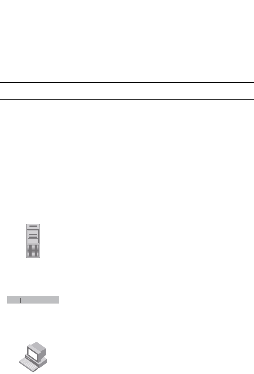
1218 PowerConnect B-Series FCX Configuration Guide
53-1002266-01
How 802.1X port security works
34
How 802.1X port security works
This section explains the basic concepts behind 802.1X port security, including device roles, how
the devices communicate, and the procedure used for authenticating clients.
NOTE
802.1X Port Security cannot be configured on MAC Port Security-enabled ports.
Device roles in an 802.1X configuration
The 802.1X standard defines the roles of Client/Supplicant, Authenticator, and Authentication
Server in a network.
The Client (known as a Supplicant in the 802.1X standard) provides username/password
information to the Authenticator. The Authenticator sends this information to the Authentication
Server. Based on the Client's information, the Authentication Server determines whether the Client
can use services provided by the Authenticator. The Authentication Server passes this information
to the Authenticator, which then provides services to the Client, based on the authentication result.
Figure 153 illustrates these roles.
FIGURE 153 Authenticator, client/supplicant, and authentication server in an 802.1X
configuration
Authenticator – The device that controls access to the network. In an 802.1X configuration, the
PowerConnect device serves as the Authenticator. The Authenticator passes messages between
the Client and the Authentication Server. Based on the identity information supplied by the Client,
and the authentication information supplied by the Authentication Server, the Authenticator either
grants or does not grant network access to the Client.
Client/Supplicant
RADIUS Server
(Authentication Server)
Switch
(Authenticator)
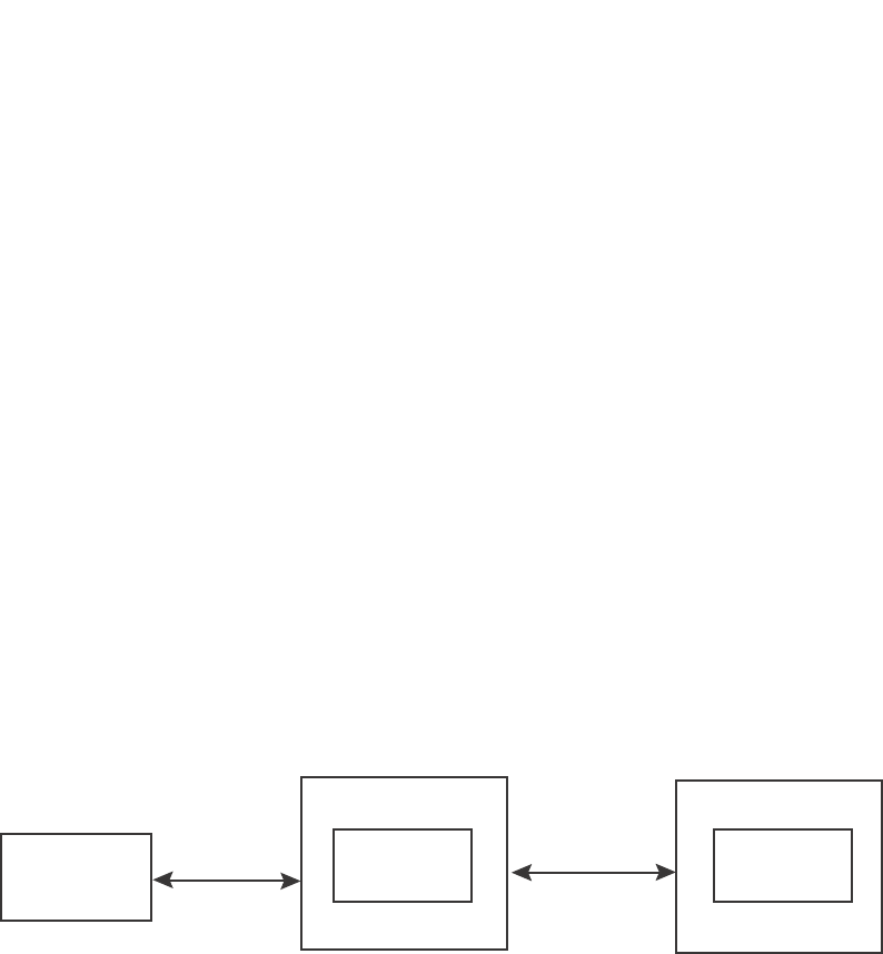
PowerConnect B-Series FCX Configuration Guide 1219
53-1002266-01
How 802.1X port security works 34
Client/Supplicant – The device that seeks to gain access to the network. Clients must be running
software that supports the 802.1X standard (for example, the Windows XP operating system).
Clients can either be directly connected to a port on the Authenticator, or can be connected by way
of a hub.
Authentication server – The device that validates the Client and specifies whether or not the Client
may access services on the device. Dell supports Authentication Servers running RADIUS.
Communication between the devices
For communication between the devices, 802.1X port security uses the Extensible Authentication
Protocol (EAP), defined in RFC 2284. The 802.1X standard specifies a method for encapsulating
EAP messages so that they can be carried over a LAN. This encapsulated form of EAP is known as
EAP over LAN (EAPOL). The standard also specifies a means of transferring the EAPOL information
between the Client/Supplicant, Authenticator, and Authentication Server.
EAPOL messages are passed between the Port Access Entity (PAE) on the Supplicant and the
Authenticator. Figure 154 shows the relationship between the Authenticator PAE and the
Supplicant PAE.
FIGURE 154 Authenticator PAE and supplicant PAE
Authenticator PAE – The Authenticator PAE communicates with the Supplicant PAE, receiving
identifying information from the Supplicant. Acting as a RADIUS client, the Authenticator PAE
passes the Supplicant information to the Authentication Server, which decides whether the
Supplicant can gain access to the port. If the Supplicant passes authentication, the Authenticator
PAE grants it access to the port.
Supplicant PAE – The Supplicant PAE supplies information about the Client to the Authenticator
PAE and responds to requests from the Authenticator PAE. The Supplicant PAE can also initiate the
authentication procedure with the Authenticator PAE, as well as send log off messages.
Controlled and uncontrolled ports
A physical port on the device used with 802.1X port security has two virtual access points a
controlled port and an uncontrolled port. The controlled port provides full access to the network.
The uncontrolled port provides access only for EAPOL traffic between the Client and the
Authentication Server. When a Client is successfully authenticated, the controlled port is opened to
the Client. Figure 155 illustrates this concept.
Authentication
Server
RADIUS
MessagesAuthenticator
PA E
Switch
(Authenticator)
Supplicant
PA E
802.1X-Enabled
Supplicant
EAPOL
Messages
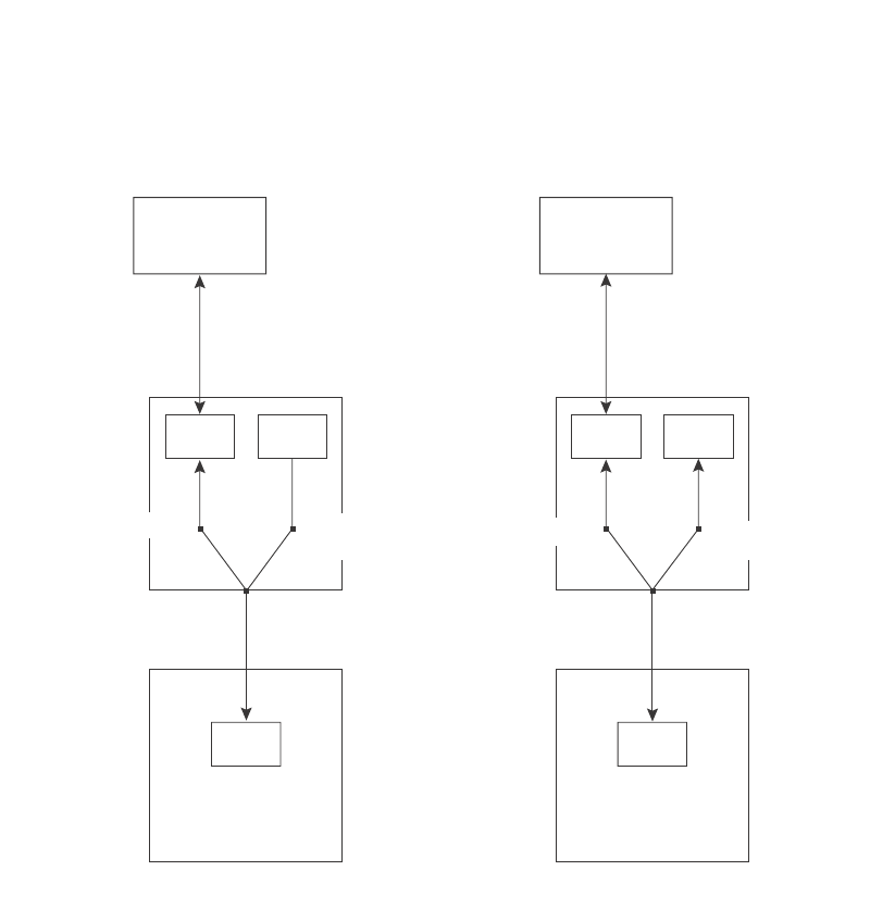
1220 PowerConnect B-Series FCX Configuration Guide
53-1002266-01
How 802.1X port security works
34
FIGURE 155 Controlled and uncontrolled ports before and after client authentication
Before a Client is authenticated, only the uncontrolled port on the Authenticator is open. The
uncontrolled port allows only EAPOL frames to be exchanged between the Client and the
Authentication Server. The controlled port is in the unauthorized state and allows no traffic to pass
through.
During authentication, EAPOL messages are exchanged between the Supplicant PAE and the
Authenticator PAE, and RADIUS messages are exchanged between the Authenticator PAE and the
Authentication Server.Refer to “Message exchange during authentication” on page 1220 for an
example of this process. If the Client is successfully authenticated, the controlled port becomes
authorized, and traffic from the Client can flow through the port normally.
By default, all controlled ports on the PowerConnect device are placed in the authorized state,
allowing all traffic. When authentication is activated on an 802.1X-enabled interface, the interface
controlled port is placed initially in the unauthorized state. When a Client connected to the port is
successfully authenticated, the controlled port is then placed in the authorized state until the
Client logs off.Refer to “Enabling 802.1X port security” on page 1237 for more information.
Message exchange during authentication
Figure 156 illustrates a sample exchange of messages between an 802.1X-enabled Client, a
PowerConnect switch acting as Authenticator, and a RADIUS server acting as an Authentication
Server.
Authentication
Server
Authentication
Server
802.1X-Enabled
Supplicant
802.1X-Enabled
Supplicant
PAE PAE
PAE PAE
Services Services
Uncontrolled Port
Physical Port
Controlled Port
(Unauthorized) Uncontrolled Port Controlled Port
(Authorized)
Physical Port
Before Authentication After Authentication
Switch
(Authenticator)
Switch
(Authenticator)

PowerConnect B-Series FCX Configuration Guide 1221
53-1002266-01
How 802.1X port security works 34
FIGURE 156 Message exchange between client/supplicant, authenticator, and authentication
server
In this example, the Authenticator (the PowerConnect switch) initiates communication with an
802.1X-enabled Client. When the Client responds, it is prompted for a username (255 characters
maximum) and password. The Authenticator passes this information to the Authentication Server,
which determines whether the Client can access services provided by the Authenticator. When the
Client is successfully authenticated by the RADIUS server, the port is authorized. When the Client
logs off, the port becomes unauthorized again.
The Dell 802.1X implementation supports dynamic VLAN assignment. If one of the attributes in the
Access-Accept message sent by the RADIUS server specifies a VLAN identifier, and this VLAN is
available on the PowerConnect device, the client port is moved from its default VLAN to the
specified VLAN. When the client disconnects from the network, the port is placed back in its
default VLAN.Refer to “Configuring dynamic VLAN assignment for 802.1X ports” on page 1230 for
more information.
If a Client does not support 802.1X, authentication cannot take place. The PowerConnect device
sends EAP-Request/Identity frames to the Client, but the Client does not respond to them.
When a Client that supports 802.1X attempts to gain access through a non-802.1X-enabled port, it
sends an EAP start frame to the PowerConnect device. When the device does not respond, the
Client considers the port to be authorized, and starts sending normal traffic.
PowerConnect devices support Identity and MD5-challenge requests in EAP Request/Response
messages as well as the following 802.1X authentication challenge types:
NOTE
Refer to also “EAP pass-through support” on page 1223.
•EAP-TLS (RFC 2716) – EAP Transport Level Security (TLS) provides strong security by requiring
both client and authentication server to be identified and validated through the use of public
key infrastructure (PKI) digital certificates. EAP-TLS establishes a tunnel between the client
and the authentication server to protect messages from unauthorized users’ eavesdropping
RADIUS Server
(Authentication Server)
Client/Supplicant
Port Unauthorized
EAP-Response/Identity
EAP-Request/Identity
EAP-Response/Identity
EAP-Request/MD5-Challenge
EAP-Success
EAP-Logoff
Port Authorized
Port Unauthorized
RADIUS Access-Request
RADIUS Access-Challenge
RADIUS Access-Request
RADIUS Access-Accept
Switch
(Authenticator)

1222 PowerConnect B-Series FCX Configuration Guide
53-1002266-01
How 802.1X port security works
34
activities. Since EAP-TLS requires PKI digital certificates on both the clients and the
authentication servers, the roll out, maintenance, and scalability of this authentication method
is much more complex than other methods. EAP-TLS is best for installations with existing PKI
certificate infrastructures.
•EAP-TTLS (Internet-Draft) – The EAP Tunnelled Transport Level Security (TTLS) is an extension
of EAP-TLS Like TLS, EAP-TTLS provides strong authentication; however it requires only the
authentication server to be validated by the client through a certificate exchange between the
server and the client. Clients are authenticated by the authentication server using user names
and passwords.
A TLS tunnel can be used to protect EAP messages and existing user credential services such
as Active Directory, RADIUS, and LDAP. Backward compatibility for other authentication
protocols such as PAP, CHAP, MS-CHAP, and MS-CHAP-V2 are also provided by EAP-TTLS.
EAP-TTLS is not considered foolproof and can be fooled into sending identity credentials if TLS
tunnels are not used. EAP-TTLS is suited for installations that require strong authentication
without the use of mutual PKI digital certificates.
•PEAP (Internet-Draft) – Protected EAP Protocol (PEAP) is an Internet-Draft that is similar to
EAP-TTLS. PEAP client authenticates directly with the backend authentication server. The
authenticator acts as a pass-through device, which does not need to understand the specific
EAP authentication protocols.
Unlike EAP-TTLS, PEAP does not natively support user name and password to authenticate
clients against an existing user database such as LDAP. PEAP secures the transmission
between the client and authentication server with a TLS encrypted tunnel. PEAP also allows
other EAP authentication protocols to be used. It relies on the mature TLS keying method for its
key creation and exchange. PEAP is best suited for installations that require strong
authentication without the use of mutual certificates.
Configuration for these challenge types is the same as for the EAP-MD5 challenge type.
NOTE
If the 802.1X Client will be sending a packet that is larger than 1500 bytes, you must enable jumbo
at the Global config level of the CLI. If the supplicant or the RADIUS server does not support jumbo
frames and jumbo is enabled on the switch, you can set the CPU IP MTU size. Refer to “Setting the
IP MTU size”, next.
Setting the IP MTU size
When jumbo frames are enabled on a PowerConnect device and the certificate in use is larger
than the standard packet size of 1500 bytes, 802.1X authentication will not work if the supplicant
or the RADIUS server does not support jumbo frames. In this case, you can change the IP MTU
setting so that the certificate will be fragmented before it is forwarded to the supplicant or server
for processing. It is supported in the Layer 3 router code.
To enable this feature, enter the following command at the Global CONFIG level of the CLI.
PowerConnect(config)# ip mtu 1500
Syntax: [no] ip mtu <num>
The <num> parameter specifies the MTU. Ethernet II packets can hold IP packets from 576 –
1500 bytes long. If jumbo mode is enabled, Ethernet II packets can hold IP packets from 576 –
10,222 bytes long. Ethernet SNAP packets can hold IP packets from 576 – 1492 bytes long. If
jumbo mode is enabled, SNAP packets can hold IP packets from 576 to 10,214 bytes long. The
default MTU is 1500 for Ethernet II packets and 1492 for SNAP packets.

PowerConnect B-Series FCX Configuration Guide 1223
53-1002266-01
How 802.1X port security works 34
EAP pass-through support
EAP pass-through is supported on PowerConnect devices that have 802.1X enabled. EAP
pass-through support is fully compliant with RFC 3748, in which, by default, compliant pass-through
authenticator implementations forward EAP challenge request packets of any type, including those
listed in the previous section.
Configuration notes
•If the 802.1X supplicant or authentication server will be sending packets that are greater than
1500 MTU, you should configure the device to accommodate a bigger buffer size.
Support for RADIUS user-name attribute in access-accept messages
Dell 802.1X-enabled ports support the RADIUS User-name (type 1) attribute in the Access-Accept
message returned during 802.1X authentication.
This feature is useful when the client/supplicant does not provide its user-name in the
EAP-response/identity frame, and the username is key to providing useful information. For
example, when the User-name attribute is sent in the Access-Accept message, it is then available
for display in sFlow sample messages sent to a collector, and in the output of some show dot1x CLI
commands, such as show dot1x mac-sessions.
To enable this feature, add the following attribute on the RADIUS server.
Authenticating multiple hosts connected to the same port
Dell PowerConnect devices support 802.1X authentication for ports with more than one host
connected to them. Figure 157 illustrates a sample configuration where multiple hosts are
connected to a single 802.1X port.
Attribute name Type Value
User-name 1 <name> (string)
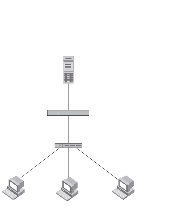
1224 PowerConnect B-Series FCX Configuration Guide
53-1002266-01
How 802.1X port security works
34
FIGURE 157 Multiple hosts connected to a single 802.1X-enabled port
If there are multiple hosts connected to a single 802.1X-enabled port, the Dell PowerConnect
device authenticates each of them individually. Each host authentication status is independent of
the others, so that if one authenticated host disconnects from the network, it has no effect on the
authentication status of any of the other authenticated hosts.
By default, traffic from hosts that cannot be authenticated by the RADIUS server is dropped in
hardware. You can optionally configure the Dell PowerConnect device to assign the port to a
“restricted” VLAN if authentication of the Client is unsuccessful.
How 802.1X Multiple-host authentication works
When multiple hosts are connected to a single 802.1X-enabled port on a Dell PowerConnect device
(as in Figure 157), 802.1X authentication is performed in the following way.
1. One of the 802.1X-enabled Clients attempts to log into a network in which a Dell PowerConnect
device serves as an Authenticator.
2. The Dell PowerConnect device creates an internal session (called a dot1x-mac-session) for the
Client. A dot1x-mac-session serves to associate a Client MAC address and username with its
authentication status.
3. The Dell PowerConnect device performs 802.1X authentication for the Client. Messages are
exchanged between the Dell PowerConnect device and the Client, and between the device and
the Authentication Server (RADIUS server). The result of this process is that the Client is either
successfully authenticated or not authenticated, based on the username and password
supplied by the client.
4. If the Client is successfully authenticated, the Client dot1x-mac-session is set to
“access-is-allowed”. This means that traffic from the Client can be forwarded normally.
RADIUS Server
(Authentication Server)
Switch
(Authenticator)
Clients/Supplicants running 802.1X-compliant client software
e2/1
192.168.9.22
Hub

PowerConnect B-Series FCX Configuration Guide 1225
53-1002266-01
How 802.1X port security works 34
5. If authentication for the Client is unsuccessful the first time, multiple attempts to authenticate
the client will be made as determined by the attempts variable in the auth-fail-max-attempts
command.
•Refer to “Specifying the number of authentication attempts the device makes before
dropping packets” on page 1243 for information on how to do this.
6. If authentication for the Client is unsuccessful more than the number of times specified by the
attempts variable in the auth-fail-max-attempts command, an authentication-failure action is
taken. The authentication-failure action can be either to drop traffic from the Client, or to place
the port in a “restricted” VLAN:
•If the authentication-failure action is to drop traffic from the Client, then the Client
dot1x-mac-session is set to “access-denied”, causing traffic from the Client to be dropped
in hardware.
•If the authentication-failure action is to place the port in a “restricted” VLAN, If the Client
dot1x-mac-session is set to “access-restricted” then the port is moved to the specified
restricted VLAN, and traffic from the Client is forwarded normally.
7. When the Client disconnects from the network, the Dell PowerConnect device deletes the
Client dot1x-mac-session. This does not affect the dot1x-mac-session or authentication status
(if any) of the other hosts connected on the port.
Configuration notes
•The Client dot1x-mac-session establishes a relationship between the username and MAC
address used for authentication. If a user attempts to gain access from different Clients (with
different MAC addresses), he or she would need to be authenticated from each Client.
•If a Client has been denied access to the network (that is, the Client dot1x-mac-session is set
to “access-denied”), then you can cause the Client to be re-authenticated by manually
disconnecting the Client from the network, or by using the clear dot1x mac-session command.
Refer to “Clearing a dot1x-mac-session for a MAC address” on page 1245 for information on
this command.
•When a Client has been denied access to the network, its dot1x-mac-session is aged out if no
traffic is received from the Client MAC address over a fixed hardware aging period (70
seconds), plus a configurable software aging period. You can optionally change the software
aging period for dot1x-mac-sessions or disable aging altogether. After the denied Client
dot1x-mac-session is aged out, traffic from that Client is no longer blocked, and the Client can
be re-authenticated.
In addition, you can configure disable aging for the dot1x-mac-session of Clients that have
been granted either full access to the network, or have been placed in a restricted VLAN. After
a Client dot1x-mac-session ages out, the Client must be re-authenticated.Refer to “Disabling
aging for dot1x-mac-sessions” on page 1243 for more information.
•Dynamic IP ACL and MAC address filter assignment is supported in an 802.1X multiple-host
configuration. Refer to “Dynamically applying IP ACLs and MAC address filters to 802.1X ports”
on page 1234.
•802.1X multiple-host authentication has the following additions:
•Configurable hardware aging period for denied client dot1x-mac-sessions. Refer to
“Configurable hardware aging period for denied client dot1x-mac-sessions” on page 1226.
•Dynamic ACL and MAC address filter assignment in 802.1X multiple-host configurations.
Refer to “Dynamically applying IP ACLs and MAC address filters to 802.1X ports” on
page 1234.

1226 PowerConnect B-Series FCX Configuration Guide
53-1002266-01
How 802.1X port security works
34
•Dynamic multiple VLAN assignment for 802.1X ports. Refer “Dynamic multiple VLAN
assignment for 802.1X ports” on page 1231.
•Configure a restriction to forward authenticated and unauthenticated tagged and
untagged clients to a restricted VLAN.
•Configure an override to send failed dot1x and non-dot1x clients to a restricted VLAN.
•Configure VLAN assignments for clients attempting to gain access through dual-mode
ports.
•Enhancements to some show commands.
•Differences in command syntax for saving dynamic VLAN assignments to the
startup-config file.
Configurable hardware aging period for denied client dot1x-mac-sessions
When one of the 802.1X-enabled Clients in a multiple-host configuration attempts to log into a
network in which a Dell PowerConnect device serves as an Authenticator, the device creates a
dot1x-mac-session for the Client.
When a Client has been denied access to the network, its dot1x-mac-session is aged out if no
traffic is received from the Client MAC address over a period of time. After a denied Client
dot1x-mac-session ages out, the Client can be re-authenticated. Aging of a denied Client's
dot1x-mac-session occurs in two phases, known as hardware aging and software aging.
The hardware aging period for a denied Client's dot1x-mac-session is not fixed at 70 seconds. The
hardware aging period for a denied Client's dot1x-mac-session is equal to the length of time
specified with the dot1x timeout quiet-period command. By default, the hardware aging time is 60
seconds. Once the hardware aging period ends, the software aging period begins. When the
software aging period ends, the denied Client's dot1x-mac-session ages out, and the Client can be
authenticated again.
802.1X port security and sFlow
sFlow is a standards-based protocol that allows network traffic to be sampled at a user-defined rate
for the purpose of monitoring traffic flow patterns and identifying packet transfer rates on
user-specified interfaces.
When you enable sFlow forwarding on an 802.1X-enabled interface, the samples taken from the
interface include the user name string at the inbound or outbound port, or both, if that information
is available.
For more information on sFlow, refer to Appendix A, “Network Monitoring”.
802.1X accounting
When 802.1X port security is enabled on the Dell PowerConnect device, you can enable 802.1X
accounting. This feature enables the Dell PowerConnect device to log information on the RADIUS
server about authenticated 802.1X clients. The information logged on the RADIUS server includes
the 802.1X client session ID, MAC address, and authenticating physical port number.
802.1X accounting works as follows.

PowerConnect B-Series FCX Configuration Guide 1227
53-1002266-01
Configuring 802.1X port security 34
1. A RADIUS server successfully authenticates an 802.1X client.
2. If 802.1X accounting is enabled, the Dell PowerConnect device sends an 802.1X Accounting
Start packet to the RADIUS server, indicating the start of a new session.
3. The RADIUS server acknowledges the Accounting Start packet.
4. The RADIUS server records information about the client.
5. When the session is concluded, the Dell PowerConnect device sends an Accounting Stop
packet to the RADIUS server, indicating the end of the session.
6. The RADIUS server acknowledges the Accounting Stop packet.
To enable 802.1X accounting, refer to “Configuring 802.1X accounting” on page 1246.
Configuring 802.1X port security
Configuring 802.1X port security on a Dell PowerConnect device consists of the following tasks.
1. Configure the device interaction with the Authentication Server:
•“Configuring an authentication method list for 802.1X” on page 1227
•“Setting RADIUS parameters” on page 1228
•“Configuring dynamic VLAN assignment for 802.1X ports” on page 1230 (optional)
•“Dynamically applying IP ACLs and MAC address filters to 802.1X ports” on page 1234
2. Configure the device role as the Authenticator:
•“Enabling 802.1X port security” on page 1237
•“Initializing 802.1X on a port” on page 1242 (optional)
3. Configure the device interaction with Clients:
•“Configuring periodic re-authentication” on page 1239 (optional)
•“Re-authenticating a port manually” on page 1239 (optional)
•“Setting the quiet period” on page 1240 (optional)
•“Setting the wait interval for EAP frame retransmissions” on page 1240 (optional)
•“Setting the maximum number of EAP frame retransmissions” on page 1241 (optional)
•“Specifying a timeout for retransmission of messages to the authentication server” on
page 1242 (optional)
•“Allowing access to multiple hosts” on page 1242 (optional)
•“Defining MAC address filters for EAP frames” on page 1245 (optional)
Configuring an authentication method list for 802.1X
To use 802.1X port security, you must specify an authentication method to be used to authenticate
Clients. Dell supports RADIUS authentication with 802.1X port security. To use RADIUS
authentication with 802.1X port security, you create an authentication method list for 802.1X and
specify RADIUS as an authentication method, then configure communication between the Dell
PowerConnect device and RADIUS server.

1228 PowerConnect B-Series FCX Configuration Guide
53-1002266-01
Configuring 802.1X port security
34
Example
PowerConnect(config)#aaa authentication dot1x default radius
Syntax: [no] aaa authentication dot1x default <method-list>
For the <method-list>, enter at least one of the following authentication methods
radius – Use the list of all RADIUS servers that support 802.1X for authentication.
none – Use no authentication. The Client is automatically authenticated without the device using
information supplied by the Client.
NOTE
If you specify both radius and none, make sure radius comes before none in the method list.
Setting RADIUS parameters
To use a RADIUS server to authenticate access to a Dell PowerConnect device, you must identify
the server to the Dell PowerConnect device.
Example
PowerConnect(config)#radius-server host 209.157.22.99 auth-port 1812 acct-port
1813 default key mirabeau dot1x
Syntax: radius-server host <ip-addr> | <ipv6-addr> | <server-name> [auth-port <num> |
acct-port <num> | default] [key 0 | 1 <string>] [dot1x]
The host <ip-addr> | <ipv6-addr> | <server-name> parameter is either an IP address or an ASCII
text string.
The dot1x parameter indicates that this RADIUS server supports the 802.1X standard. A RADIUS
server that supports the 802.1X standard can also be used to authenticate non-802.1X
authentication requests.
NOTE
To implement 802.1X port security, at least one of the RADIUS servers identified to the Dell
PowerConnect device must support the 802.1X standard.
Supported RADIUS attributes
Many IEEE 802.1X Authenticators will function as RADIUS clients. Some of the RADIUS attributes
may be received as part of IEEE 802.1X authentication. Dell PowerConnect devices support the
following RADIUS attributes for IEEE 802.1X authentication:
•Username (1) – RFC 2865
•NAS-IP-Address (4) – RFC 2865
•NAS-Port (5) – RFC 2865
•Service-Type (6) – RFC 2865
•FilterId (11) – RFC 2865
•Framed-MTU (12) – RFC 2865
•State (24) – RFC 2865
•Vendor-Specific (26) – RFC 2865

PowerConnect B-Series FCX Configuration Guide 1229
53-1002266-01
Configuring 802.1X port security 34
•Session-Timeout (27) – RFC 2865
•Termination-Action (29) – RFC 2865
•Calling-Station-ID (31) – RFC 2865
•NAS-Port-Type (61) š RFC 2865
•Tunnel-Type (64) – RFC 2868
•Tunnel-Medium-Type (65) – RFC 2868
•EAP Message (79) – RFC 2579
•Message-Authenticator (80) RFC 3579
•Tunnel-Private-Group-Id (81) – RFC 2868
•NAS-Port-id (87) – RFC 2869
Specifying the RADIUS timeout action
A RADIUS timeout occurs when the Dell PowerConnect device does not receive a response from a
RADIUS server within a specified time limit and after a certain number of retries. The time limit and
number of retries can be manually configured using the CLI commands radius-server timeout and
radius-server retransmit, respectively. If the parameters are not manually configured, the Dell
PowerConnect device applies the default value of three seconds time limit with a maximum of
three retries.
You can better control port behavior when a RADIUS timeout occurs. That is, you can configure a
port on the Dell PowerConnect device to automatically pass or fail users being authenticated. A
pass essentially bypasses the authentication process and permits user access to the network. A
fail bypasses the authentication process and blocks user access to the network, unless
restrict-vlan is configured, in which case, the user is placed into a VLAN with restricted or limited
access. By default, the Dell PowerConnect device will reset the authentication process and retry to
authenticate the user.
Specify the RADIUS timeout action at the Interface level of the CLI.
Permit user access to the network after a RADIUS timeout
To set the RADIUS timeout behavior to bypass 802.1X authentication and permit user access to the
network, enter commands such as the following
PowerConnect(config)#interface ethernet 3/1
PowerConnect(config-if-e100-3/1)#dot1x auth-timeout-action success
Syntax: [no] dot1x auth-timeout-action success
Once the success timeout action is enabled, use the no form of the command to reset the RADIUS
timeout behavior to retry.
Re-authenticate a user
To configure RADIUS timeout behavior to bypass multi-device port authentication and permit user
access to the network, enter commands similar to the following
PowerConnect(config)#interface ethernet 3/1
PowerConnect(config-if-e100-3/1)#dot1x re-auth-timeout-success 60
Syntax: [no] dot1x re-auth-timeout- success <seconds>

1230 PowerConnect B-Series FCX Configuration Guide
53-1002266-01
Configuring 802.1X port security
34
The <seconds> parameter specifies the number of seconds the device will wait to re-authenticate
a user after a timeout. The minimum value is 10 seconds. The maximum value is 216-1 (maximum
unsigned 16-bit value).
Deny user access to the network after a RADIUS timeout
To set the RADIUS timeout behavior to bypass 802.1X authentication and block user access to the
network, enter commands such as the following
PowerConnect(config)#interface ethernet 3/1
PowerConnect(config-if-e100-3/1)#dot1x auth-timeout-action failure
Syntax: [no] dot1x auth-timeout-action failure
Once the failure timeout action is enabled, use the no form of the command to reset the RADIUS
timeout behavior to retry.
NOTE
If restrict-vlan is configured along with auth-timeout-action failure, the user will be placed into a
VLAN with restricted or limited access.Refer to “Allow user access to a restricted VLAN after a
RADIUS timeout” on page 1230.
Allow user access to a restricted VLAN after a RADIUS timeout
To set the RADIUS timeout behavior to bypass 802.1X authentication and place the user in a VLAN
with restricted or limited access, enter commands such as the following
PowerConnect(config)#interface ethernet 3/1
PowerConnect(config-if-e100-3/1)#dot1x auth-fail-action restrict-vlan 100
PowerConnect(config-if-e100-3/1)#dot1x auth-timeout-action failure
Syntax: [no] dot1x auth-fail-action restrict-vlan [<vlan-id>]
Syntax: [no] dot1x auth-timeout-action failure
Configuring dynamic VLAN assignment for 802.1X ports
When a client successfully completes the EAP authentication process, the Authentication Server
(the RADIUS server) sends the Authenticator (the Dell PowerConnect device) a RADIUS
Access-Accept message that grants the client access to the network. The RADIUS Access-Accept
message contains attributes set for the user in the user's access profile on the RADIUS server.
If one of the attributes in the Access-Accept message specifies a VLAN identifier, and if this VLAN is
available on the Dell PowerConnect device, the client port is moved from its default VLAN to this
specified VLAN.
NOTE
This feature is supported on port-based VLANs only. This feature cannot be used to place an
802.1X-enabled port into a Layer 3 protocol VLAN.
Automatic removal of dynamic VLAN assignments for 802.1X ports
For increased security, this feature removes any association between a port and a
dynamically-assigned VLAN when all 802.1x sessions for that VLAN have expired on the port.

PowerConnect B-Series FCX Configuration Guide 1231
53-1002266-01
Configuring 802.1X port security 34
NOTE
When a show run command is issued during a session, the dynamically-assigned VLAN is not
displayed.
Enable 802.1X VLAN ID support by adding the following attributes to a user profile on the RADIUS
server.
The device reads the attributes as follows:
•If the Tunnel-Type or the Tunnel-Medium-Type attributes in the Access-Accept message do not
have the values specified above, the Dell PowerConnect device ignores the three
Attribute-Value pairs. The client becomes authorized, but the client port is not dynamically
placed in a VLAN.
•If the Tunnel-Type or the Tunnel-Medium-Type attributes in the Access-Accept message do have
the values specified above, but there is no value specified for the Tunnel-Private-Group-ID
attribute, the client will not become authorized.
•When the Dell PowerConnect device receives the value specified for the
Tunnel-Private-Group-ID attribute, it checks whether the <vlan-name> string matches the
name of a VLAN configured on the device. If there is a VLAN on the device whose name
matches the <vlan-name> string, then the client port is placed in the VLAN whose ID
corresponds to the VLAN name.
•If the <vlan-name> string does not match the name of a VLAN, the Dell PowerConnect device
checks whether the string, when converted to a number, matches the ID of a VLAN configured
on the device. If it does, then the client port is placed in the VLAN with that ID.
•If the <vlan-name> string does not match either the name or the ID of a VLAN configured on
the device, then the client will not become authorized.
The show interface command displays the VLAN to which an 802.1X-enabled port has been
dynamically assigned, as well as the port from which it was moved (that is, the port default
VLAN).Refer to “Displaying dynamically assigned VLAN information” on page 1251 for sample
output indicating the port dynamically assigned VLAN.
Dynamic multiple VLAN assignment for 802.1X ports
When you add attributes to a user profile on the RADIUS server, the <vlan-name> value for the
Tunnel-Private-Group-ID attribute can specify the name or number of one or more VLANs configured
on the Dell PowerConnect device.
For example, to specify one VLAN, configure the following for the <vlan-name> value in the
Tunnel-Private-Group-ID attribute on the RADIUS server.
"10" or "marketing"
In this example, the port on which the Client is authenticated is assigned to VLAN 10 or the VLAN
named "marketing". The VLAN to which the port is assigned must have previously been configured
on the Dell PowerConnect device.
Attribute name Type Value
Tunnel-Type 064 13 (decimal) – VLAN
Tunnel-Medium-Type 065 6 (decimal) – 802
Tunnel-Private-Group-ID 081 <vlan-name> (string) – either the name or the number of a VLAN
configured on the Dell PowerConnect device.

1232 PowerConnect B-Series FCX Configuration Guide
53-1002266-01
Configuring 802.1X port security
34
To specify an untagged VLAN, use the following.
"U:10" or "U:marketing"
When the RADIUS server specifies an untagged VLAN ID, the port default VLAN ID (or PVID) is
changed from the system DEFAULT-VLAN (VLAN 1) to the specified VLAN ID. The port transmits only
untagged traffic on its PVID. In this example, the port PVID is changed from VLAN 1 (the
DEFAULT-VLAN) to VLAN 10 or the VLAN named "marketing".
The PVID for a port can be changed only once through RADIUS authentication. For example, if
RADIUS authentication for a Client causes a port PVID to be changed from 1 to 10, and then
RADIUS authentication for another Client on the same port specifies that the port PVID be moved
to 20, then the second PVID assignment from the RADIUS server is ignored.
If the link goes down, or the dot1x-mac-session for the Client that caused the initial PVID
assignment ages out, then the port reverts back to its original (non-RADIUS-specified) PVID, and
subsequent RADIUS authentication can change the PVID assignment for the port.
If a port PVID is assigned through the multi-device port authentication feature, and 802.1X
authentication subsequently specifies a different PVID, then the PVID specified through 802.1X
authentication overrides the PVID specified through multi-device port authentication.
To specify tagged VLANs, use the following.
"T:12;T:20" or "T:12;T:marketing"
In this example, the port is added to VLANs 12 and 20 or VLANs 12 and the VLAN named
"marketing". When a tagged packet is authenticated, and a list of VLANs is specified on the
RADIUS server for the MAC address, then the packet tag must match one of the VLANs in the list in
order for the Client to be successfully authenticated. If authentication is successful, then the port
is added to all of the VLANs specified in the list.
Unlike with a RADIUS-specified untagged VLAN, if the dot1x-mac-session for the Client ages out, the
port membership in RADIUS-specified tagged VLANs is not changed. In addition, if multi-device
port authentication specifies a different list of tagged VLANs, then the port is added to the
specified list of VLANs. Membership in the VLANs specified through 802.1X authentication is not
changed.
To specify an untagged VLAN and multiple tagged VLANs, use the following.
"U:10;T:12;T:marketing"
When the RADIUS server returns a value specifying both untagged and tagged VLAN IDs, the port
becomes a dual-mode port, accepting and transmitting both tagged traffic and untagged traffic at
the same time. A dual-mode port transmits only untagged traffic on its default VLAN (PVID) and
only tagged traffic on all other VLANs.
In this example, the port VLAN configuration is changed so that it transmits untagged traffic on
VLAN 10, and transmits tagged traffic on VLAN 12 and the VLAN named "marketing".
For a configuration example, refer to “802.1X Authentication with dynamic VLAN assignment” on
page 1261.
Saving dynamic VLAN assignments to the running-config file
You can configure the Dell PowerConnect device to save the RADIUS-specified VLAN assignments
to the device's running-config file. Enter commands such as the following.
PowerConnect(config)#dot1x-enable
PowerConnect(config-dot1x)#save-dynamicvlan-to-config

PowerConnect B-Series FCX Configuration Guide 1233
53-1002266-01
Configuring 802.1X port security 34
Syntax: save-dynamicvlan-to-config
By default, the dynamic VLAN assignments are not saved to the running-config file. Entering the
show running-config command does not display dynamic VLAN assignments, although they can be
displayed with the show vlan and show authenticated-mac-address detail commands.
NOTE
When this feature is enabled, issuing the command write mem will save any dynamic VLAN
assignments to the startup configuration file.
Considerations for dynamic VLAN assignment in an 802.1X multiple-host
configuration
The following considerations apply when a Client in a 802.1X multiple-host configuration is
successfully authenticated, and the RADIUS Access-Accept message specifies a VLAN for the port:
•If the port is not already a member of a RADIUS-specified VLAN, and the RADIUS Access-Accept
message specifies the name or ID of a valid VLAN on the Dell PowerConnect device, then the
port is placed in that VLAN.
•If the port is already a member of a RADIUS-specified VLAN, and the RADIUS Access-Accept
message specifies the name or ID of a different VLAN, then it is considered an authentication
failure. The port VLAN membership is not changed.
•If the port is already a member of a RADIUS-specified VLAN, and the RADIUS Access-Accept
message specifies the name or ID of that same VLAN, then traffic from the Client is forwarded
normally.
•If the RADIUS Access-Accept message specifies the name or ID of a VLAN that does not exist
on the Dell PowerConnect device, then it is considered an authentication failure.
•If the port is a tagged or dual-mode port, and the RADIUS Access-Accept message specifies the
name or ID of a valid VLAN on the Dell PowerConnect device, then the port is placed in that
VLAN. If the port is already a member of the RADIUS-specified VLAN, no further action is taken.
•If the RADIUS Access-Accept message does not contain any VLAN information, the Client
dot1x-mac-session is set to “access-is-allowed”. If the port is already in a RADIUS-specified
VLAN, it remains in that VLAN.
Using dynamic VLAN assignment with the MAC port security feature
MAC port security allows the Dell PowerConnect device to learn a limited number of “secure” MAC
addresses on an interface. The interface forwards only packets with source MAC addresses that
match these secure addresses. If the interface receives a packet with a source MAC address that is
different from any of the secure addresses, it is considered a security violation, and subsequent
packets from the violating MAC address can be dropped, or the port can be disabled entirely.
If a port is disabled due to a MAC port security violation, 802.1X clients attempting to connect over
the port cannot be authorized. In addition, 802.1X clients connecting from non-secure MAC
addresses cannot be authorized.
To use 802.1X dynamic VLAN assignment with the MAC port security feature on an interface, you
must set the number of secure MAC addresses to two or more.

1234 PowerConnect B-Series FCX Configuration Guide
53-1002266-01
Configuring 802.1X port security
34
Example
PowerConnect(config)#int e 3/2
PowerConnect(config-if-e1000-3/2)#port security
PowerConnect(config-port-security-e1000-3/2)#maximum 2
PowerConnect(config-port-security-e1000-3/2)#exit
Refer to Chapter 35, “Using the MAC Port Security Feature” for more information.
Dynamically applying IP ACLs and MAC address filters
to 802.1X ports
The 802.1X implementation supports dynamically applying an IP ACL or MAC address filter to a
port, based on information received from an Authentication Server.
When a client/supplicant successfully completes the EAP authentication process, the
Authentication Server (the RADIUS server) sends the Authenticator (the Dell PowerConnect device)
a RADIUS Access-Accept message that grants the client access to the network. The RADIUS
Access-Accept message contains attributes set for the user in the user's access profile on the
RADIUS server.
If the Access-Accept message contains Filter-ID (type 11) or Vendor-Specific (type 26), or both
attributes, the Dell PowerConnect device can use information in these attributes to apply an IP ACL
or MAC address filter to the authenticated port. This IP ACL or MAC address filter applies to the
port for as long as the client is connected to the network. When the client disconnects from the
network, the IP ACL or MAC address filter is no longer applied to the port. If an IP ACL or MAC
address filter had been applied to the port prior to 802.1X authentication, it is then re-applied to
the port.
The Dell PowerConnect device uses information in the Filter ID and Vendor-Specific attributes as
follows:
•The Filter-ID attribute can specify the number of an existing IP ACL or MAC address filter
configured on the Dell PowerConnect device. In this case, the IP ACL or MAC address filter with
the specified number is applied to the port.
•The Vendor-Specific attribute can specify actual syntax for a Dell PowerConnect IP ACL or MAC
address filter, which is then applied to the authenticated port. Configuring a Vendor-Specific
attribute in this way allows you to create IP ACLs and MAC address filters that apply to
individual users; that is, per-user IP ACLs or MAC address filters.
Configuration considerations
The following restrictions apply to dynamic IP ACLs or MAC address filters:
•Inbound dynamic IP ACLs are supported. Outbound dynamic ACLs are not supported.
•Inbound Vendor-Specific attributes are supported. Outbound Vendor-Specific attributes are
not supported.
•A maximum of one IP ACL can be configured in the inbound direction on an interface.
•802.1X with dynamic MAC filter will work for one client at a time on a port. If a second client
tries to authenticate with 802.1X and dynamic MAC filter, the second client will be rejected.
•MAC address filters cannot be configured in the outbound direction on an interface.
•Concurrent operation of MAC address filters and IP ACLs is not supported.

PowerConnect B-Series FCX Configuration Guide 1235
53-1002266-01
Configuring 802.1X port security 34
•A dynamic IP ACL will take precedence over an IP ACL that is bound to a port (port ACL). When
a client authenticates with a dynamic IP ACL, the port ACL will not be applied. Also, future
clients on the same port will authenticate with a dynamic IP ACL or no IP ACL. If no clients on
the port use dynamic ACL, then the port ACL will be applied to all traffic.
Disabling and enabling strict security mode for dynamic filter assignment
By default, 802.1X dynamic filter assignment operates in strict security mode. When strict security
mode is enabled, 802.1X authentication for a port fails if the Filter-ID attribute contains invalid
information, or if insufficient system resources are available to implement the per-user IP ACLs or
MAC address filters specified in the Vendor-Specific attribute.
When strict security mode is enabled:
•If the Filter-ID attribute in the Access-Accept message contains a value that does not refer to
an existing filter (that is, a MAC address filter or IP ACL configured on the device), then the port
will not be authenticated, regardless of any other information in the message (for example, if
the Tunnel-Private-Group-ID attribute specifies a VLAN on which to assign the port).
•If the Vendor-Specific attribute specifies the syntax for a filter, but there are insufficient system
resources to implement the filter, then the port will not be authenticated.
•If the device does not have the system resources available to dynamically apply a filter to a
port, then the port will not be authenticated.
NOTE
If the Access-Accept message contains values for both the Filter-ID and Vendor-Specific
attributes, then the value in the Vendor-Specific attribute (the per-user filter) takes
precedence.
Also, if authentication for a port fails because the Filter-ID attribute referred to a non-existent
filter, or there were insufficient system resources to implement the filter, then a Syslog
message is generated.
When strict security mode is disabled:
•If the Filter-ID attribute in the Access-Accept message contains a value that does not refer to
an existing filter (that is, a MAC address filter or IP ACL configured on the device), then the port
is still authenticated, but no filter is dynamically applied to it.
•If the Vendor-Specific attribute specifies the syntax for a filter, but there are insufficient system
resources to implement the filter, then the port is still authenticated, but the filter specified in
the Vendor-Specific attribute is not applied to the port.
By default, strict security mode is enabled for all 802.1X-enabled interfaces, but you can manually
disable or enable it, either globally or for specific interfaces.
To disable strict security mode globally, enter the following commands.
PowerConnect(config)#dot1x-enable
PowerConnect(config-dot1x)#no global-filter-strict-security
After you globally disable strict security mode, you can re-enable it by entering the following
command.
PowerConnect(config-dot1x)#global-filter-strict-security
Syntax: [no] global-filter-strict-security
To disable strict security mode for a specific interface, enter commands such as the following.

1236 PowerConnect B-Series FCX Configuration Guide
53-1002266-01
Configuring 802.1X port security
34
PowerConnect(config)#interface e 1
PowerConnect(config-if-e1000-1)#dot1x disable-filter-strict-security
To re-enable strict security mode for an interface, enter the following command.
PowerConnect(config-if-e1000-1)#no dot1x disable-filter-strict-security
Syntax: [no] dot1x disable-filter-strict-security
The output of the show dot1x and show dot1x config commands has been enhanced to indicate
whether strict security mode is enabled or disabled globally and on an interface. Refer to
“Displaying the status of strict security mode” on page 1254.
Dynamically applying existing ACLs or MAC address filters
When a port is authenticated using 802.1X security, an IP ACL or MAC address filter that exists in
the running-config on the Dell PowerConnect device can be dynamically applied to the port. To do
this, you configure the Filter-ID (type 11) attribute on the RADIUS server. The Filter-ID attribute
specifies the name or number of the Dell PowerConnect IP ACL or MAC address filter.
The following is the syntax for configuring the Filter-ID attribute to refer to a Dell IP ACL or MAC
address filter.
The following table lists examples of values you can assign to the Filter-ID attribute on the RADIUS
server to refer to IP ACLs and MAC address filters configured on a Dell PowerConnect device.
Notes
•The <name> in the Filter ID attribute is case-sensitive.
•You can specify only numbered MAC address filters in the Filter ID attribute. Named MAC
address filters are not supported.
Value Description
ip.<number>.in Applies the specified numbered ACL to the 802.1X authenticated port in the inbound
direction.
ip.<name>.in Applies the specified named ACL to the 802.1X authenticated port in the inbound
direction.
mac.<number>.in Applies the specified numbered MAC address filter to the 802.1X authenticated port in
the inbound direction.
Possible values for the filter ID attribute on the
RADIUS server
ACL or MAC address filter configured on the Dell PowerConnect device
ip.2.in access-list 2 permit host 36.48.0.3
access-list 2 permit 36.0.0.0 0.255.255.255
ip.102.in access-list 102 permit ip 36.0.0.0 0.255.255.255 any
ip.fdry_filter.in ip access-list standard fdry_filter
permit host 36.48.0.3
mac.2.in mac filter 2 permit 3333.3333.3333 ffff.ffff.ffff any etype eq 0800
mac.2.in
mac.3.in
mac filter 2 permit 3333.3333.3333 ffff.ffff.ffff any etype eq 0800
mac filter 3 permit 2222.2222.2222 ffff.ffff.ffff any etype eq 0800

PowerConnect B-Series FCX Configuration Guide 1237
53-1002266-01
Configuring 802.1X port security 34
•Dynamic ACL filters are supported only for the inbound direction. Dynamic outbound ACL
filters are not supported.
•MAC address filters are supported only for the inbound direction. Outbound MAC address
filters are not supported.
•Dynamically assigned IP ACLs and MAC address filters are subject to the same configuration
restrictions as non-dynamically assigned IP ACLs and MAC address filters.
Configuring per-user IP ACLs or MAC address filters
Per-user IP ACLs and MAC address filters make use of the Vendor-Specific (type 26) attribute to
dynamically apply filters to ports. Defined in the Vendor-Specific attribute are Dell ACL or MAC
address filter statements. When the RADIUS server returns the Access-Accept message granting a
client access to the network, the Dell PowerConnect device reads the statements in the
Vendor-Specific attribute and applies these IP ACLs or MAC address filters to the client port. When
the client disconnects from the network, the dynamically applied filters are no longer applied to the
port. If any filters had been applied to the port previous to the client connecting, then those filters
are reapplied to the port.
NOTE
Dynamic IP ACL filters and MAC address filters are not supported on the same port at the same time.
The following table shows the syntax for configuring the Dell Vendor-Specific attributes with ACL or
MAC address filter statements.
The following table shows examples of IP ACLs and MAC address filters configured in the Dell
Vendor-Specific attribute on a RADIUS server. These IP ACLs and MAC address filters follow the
same syntax as other Dell ACLs and MAC address filters. Refer to the related chapters in this book
for information on syntax.
The RADIUS server allows one instance of the Vendor-Specific attribute to be sent in an
Access-Accept message.
Enabling 802.1X port security
By default, 802.1X port security is disabled on Dell PowerConnect devices. To enable the feature
on the device and enter the dot1x configuration level, enter the following command.
PowerConnect(config)#dot1x-enable
PowerConnect(config-dot1x)#
Value Description
ipACL.e.in=<extended-ACL-entries> Applies the specified extended ACL entries to the 802.1X
authenticated port in the inbound direction.
macfilter.in=<mac-filter-entries> Applies the specified MAC address filter entries to the 802.1X
authenticated port in the inbound direction.
ACL or MAC address filter Vendor-specific attribute on RADIUS server
MAC address filter with one entry macfilter.in= deny any any
MAC address filter with two entries macfilter.in= permit 0000.0000.3333 ffff.ffff.0000 any,
macfilter.in= permit 0000.0000.4444 ffff.ffff.0000 any

1238 PowerConnect B-Series FCX Configuration Guide
53-1002266-01
Configuring 802.1X port security
34
Syntax: [no] dot1x-enable
At the dot1x configuration level, you can enable 802.1X port security on all interfaces at once, on
individual interfaces, or on a range of interfaces.
For example, to enable 802.1X port security on all interfaces on the device, enter the following
command.
PowerConnect(config-dot1x)#enable all
Syntax: [no] enable all
To enable 802.1X port security on interface 3/11, enter the following command.
PowerConnect(config-dot1x)#enable ethernet 3/11
Syntax: [no] enable ethernet <port>
Specify the <port> variable in the following formats:
•PowerConnect B-Series FCX stackable switches – <stack-unit/slotnum/portnum>
To enable 802.1X port security on interfaces 3/11 through 3/16, enter the following command.
PowerConnect(config-dot1x)#enable ethernet 3/11 to 3/16
Syntax: [no] enable ethernet <port> to <port>
Specify the <port> variable in the following formats:
•PowerConnect B-Series FCX stackable switches – <stack-unit/slotnum/portnum>
Setting the port control
To activate authentication on an 802.1X-enabled interface, you specify the kind of port control to
be used on the interface. An interface used with 802.1X port security has two virtual access
points: a controlled port and an uncontrolled port:
•The controlled port can be either the authorized or unauthorized state. In the authorized state,
it allows normal traffic to pass between the Client and the Authenticator. In the unauthorized
state, no traffic is allowed to pass.
•The uncontrolled port allows only EAPOL traffic between the Client and the Authentication
Server.
Refer to Figure 155 for an illustration of this concept.
By default, all controlled ports on the device are in the authorized state, allowing all traffic. When
you activate authentication on an 802.1X-enabled interface, its controlled port is placed in the
unauthorized state. When a Client connected to the interface is successfully authenticated, the
controlled port is then placed in the authorized state. The controlled port remains in the authorized
state until the Client logs off.
To activate authentication on an 802.1X-enabled interface, you configure the interface to place its
controlled port in the authorized state when a Client is authenticated by an Authentication Server.
To do this, enter commands such as the following.
PowerConnect(config)#interface e 3/1
PowerConnect(config-if-3/1)#dot1x port-control auto
Syntax: [no] dot1x port-control [force-authorized | force-unauthorized | auto]

PowerConnect B-Series FCX Configuration Guide 1239
53-1002266-01
Configuring 802.1X port security 34
When an interface control type is set to auto, the controlled port is initially set to unauthorized, but
is changed to authorized when the connecting Client is successfully authenticated by an
Authentication Server.
The port control type can be one of the following
force-authorized – The controlled port is placed unconditionally in the authorized state, allowing all
traffic. This is the default state for ports on the Dell PowerConnect device.
force-unauthorized – The controlled port is placed unconditionally in the unauthorized state.
auto – The controlled port is unauthorized until authentication takes place between the Client and
Authentication Server. Once the Client passes authentication, the port becomes authorized. This
activates authentication on an 802.1X-enabled interface.
NOTE
You cannot enable 802.1X port security on ports that have any of the following features enabled:
•Link aggregation
•Metro Ring Protocol (MRP)
•Mirror port
•Trunk port
Configuring periodic re-authentication
You can configure the device to periodically re-authenticate Clients connected to 802.1X-enabled
interfaces. When you enable periodic re-authentication, the device re-authenticates Clients every
3,600 seconds by default. You can optionally specify a different re-authentication interval of
between 1 – 4294967295 seconds.
To configure periodic re-authentication using the default interval of 3,600 seconds, enter the
following command.
PowerConnect(config-dot1x)#re-authentication
Syntax: [no] re-authentication
To configure periodic re-authentication with an interval of 2,000 seconds, enter the following
commands.
PowerConnect(config-dot1x)#re-authentication
PowerConnect(config-dot1x)#timeout re-authperiod 2000
Syntax: [no] timeout re-authperiod <seconds>
The re-authentication interval is a global setting, applicable to all 802.1X-enabled interfaces. To
re-authenticate Clients connected to a specific port manually, use the dot1x re-authenticate
command. Refer to “Re-authenticating a port manually”, below.
Re-authenticating a port manually
When periodic re-authentication is enabled, by default the Dell PowerConnect device
re-authenticates Clients connected to an 802.1X-enabled interface every 3,600 seconds (or the
time specified by the dot1x timeout re-authperiod command). You can also manually
re-authenticate Clients connected to a specific port.

1240 PowerConnect B-Series FCX Configuration Guide
53-1002266-01
Configuring 802.1X port security
34
For example, to re-authenticate Clients connected to interface 3/1, enter the following command.
PowerConnect#dot1x re-authenticate e 3/1
Syntax: dot1x re-authenticate ethernet <port>
Specify the <port> variable in the following formats:
•PowerConnect B-Series FCX stackable switches – <stack-unit/slotnum/portnum>
Setting the quiet period
If the Dell PowerConnect device is unable to authenticate the Client, the Dell PowerConnect device
waits a specified amount of time before trying again. The amount of time the Dell PowerConnect
device waits is specified with the quiet-period parameter. The quiet-period parameter can be from
1 – 4294967295 seconds. The default is 60 seconds.
For example, to set the quiet period to 30 seconds, enter the following command.
PowerConnect(config-dot1x)#timeout quiet-period 30
Syntax: [no] timeout quiet-period <seconds>
Specifying the wait interval and number of EAP-request/
identity frame retransmissions from the Dell PowerConnect device
When the device sends an EAP-request/identity frame to a Client, it expects to receive an
EAP-response/identity frame from the Client. By default, if the Dell PowerConnect device does not
receive an EAP-response/identity frame from a Client, the device waits 30 seconds, then
retransmits the EAP-request/identity frame. Also by default, the Dell PowerConnect device
retransmits the EAP-request/identity frame a maximum of two times. You can optionally configure
the amount of time the device will wait before retransmitting an EAP-request/identity frame, and
the number of times the EAP-request/identity frame will be transmitted. This section provides the
command syntax for these features.
Setting the wait interval for EAP frame retransmissions
By default, if the Dell PowerConnect device does not receive an EAP-response/identity frame from
a Client, the device waits 30 seconds, then retransmits the EAP-request/identity frame. You can
optionally change the amount of time the Dell PowerConnect device waits before retransmitting the
EAP-request/identity frame to the Client.
For example, to cause the Dell PowerConnect device to wait 60 seconds before retransmitting an
EAP-request/identity frame to a Client, enter the following command.
PowerConnect(config-dot1x)#timeout tx-period 60
If the Client does not send back an EAP-response/identity frame within 60 seconds, the device will
transmit another EAP-request/identity frame.
Syntax: [no] timeout tx-period <seconds>
where <seconds> is a value from 1 – 4294967295. The default is 30 seconds.

PowerConnect B-Series FCX Configuration Guide 1241
53-1002266-01
Configuring 802.1X port security 34
Setting the maximum number of EAP frame retransmissions
The Dell PowerConnect device retransmits the EAP-request/identity frame a maximum of two
times. If no EAP-response/identity frame is received from the Client after two EAP-request/identity
frame retransmissions (or the amount of time specified with the auth-max command), the device
restarts the authentication process with the Client.
You can optionally change the number of times the Dell PowerConnect device should retransmit
the EAP-request/identity frame. You can specify between 1 – 10 frame retransmissions. For
example, to configure the device to retransmit an EAP-request/identity frame to a Client a
maximum of three times, enter the following command:
PowerConnect(config-dot1x)#auth-max 3
Syntax: auth-max <value>
<value> is a number from 1 – 10. The default is 2.
Specifying the wait interval and number of EAP-request/
identity frame retransmissions from the RADIUS server
Acting as an intermediary between the RADIUS Authentication Server and the Client, the Dell
PowerConnect device receives RADIUS messages from the RADIUS server, encapsulates them as
EAPOL frames, and sends them to the Client. By default, when the Dell PowerConnect device
relays an EAP-Request frame from the RADIUS server to the Client, it expects to receive a response
from the Client within 30 seconds. If the Client does not respond within the allotted time, the
device retransmits the EAP-Request frame to the Client. Also by default, the Dell PowerConnect
device retransmits the EAP-request frame twice. If no EAP-response frame is received from the
Client after two EAP-request frame retransmissions, the device restarts the authentication process
with the Client.
You can optionally configure the amount of time the device will wait before retransmitting an
EAP-request/identity frame, and the number of times the EAP-request/identity frame will be
transmitted. This section provides the command syntax for these features.
Setting the wait interval for EAP frame retransmissions
By default, when the Dell PowerConnect device relays an EAP-Request frame from the RADIUS
server to the Client, it expects to receive a response from the Client within 30 seconds. You can
optionally specify the wait interval using the supptimeout command.
For example, to configure the device to retransmit an EAP-Request frame if the Client does not
respond within 45 seconds, enter the following command.
PowerConnect(config-dot1x)#supptimeout 45
Syntax: supptimeout <seconds>
<seconds> is a number from 1 – 4294967295 seconds. The default is 30 seconds.

1242 PowerConnect B-Series FCX Configuration Guide
53-1002266-01
Configuring 802.1X port security
34
Setting the maximum number of EAP frame retransmissions
You can optionally specify the number of times the Dell PowerConnect device will retransmit the
EAP-request frame. You can specify between 1 – 10 frame retransmissions. For example, to
configure the device to retransmit an EAP-request frame to a Client a maximum of three times,
enter the following command.
PowerConnect(config-dot1x)#maxreq 3
Syntax: maxreq <value>
<value> is a number from 1 – 10. The default is 2.
Specifying a timeout for retransmission of messages
to the authentication server
When performing authentication, the Dell PowerConnect device receives EAPOL frames from the
Client and passes the messages on to the RADIUS server. The device expects a response from the
RADIUS server within 30 seconds. If the RADIUS server does not send a response within 30
seconds, the Dell PowerConnect device retransmits the message to the RADIUS server. The time
constraint for retransmission of messages to the Authentication Server can be between 0 –
4294967295 seconds.
For example, to configure the device to retransmit a message if the Authentication Server does not
respond within 45 seconds, enter the following command.
PowerConnect(config-dot1x)#servertimeout 45
Syntax: servertimeout <seconds>
Initializing 802.1X on a port
To initialize 802.1X port security on a port, enter a command such as the following.
PowerConnect#dot1x initialize e 3/1
Syntax: dot1x initialize ethernet <port>
Specify the <port> variable in the following formats:
•PowerConnect B-Series FCX stackable switches – <stack-unit/slotnum/portnum>
Allowing access to multiple hosts
Dell PowerConnect devices support 802.1X authentication for ports with more than one host
connected to them. If there are multiple hosts connected to a single 802.1X-enabled port, the Dell
PowerConnect device authenticates each of them individually. Refer to “Configuring 802.1X
multiple-host authentication” on page 1243.

PowerConnect B-Series FCX Configuration Guide 1243
53-1002266-01
Configuring 802.1X port security 34
Configuring 802.1X multiple-host authentication
When multiple hosts are connected to the same 802.1X-enabled port, the functionality described
in “How 802.1X Multiple-host authentication works” on page 1224 is enabled by default. You can
optionally do the following:
•Specify the authentication-failure action
•Specify the number of authentication attempts the device makes before dropping packets
•Disabling aging for dot1x-mac-sessions
•Configure aging time for blocked Clients
•Clear the dot1x-mac-session for a MAC address
Specifying the authentication-failure action
In an 802.1X multiple-host configuration, if RADIUS authentication for a Client is unsuccessful,
traffic from that Client is either dropped in hardware (the default), or the Client port is placed in a
“restricted” VLAN. You can specify which of these two authentication-failure actions is to be used.
If the authentication-failure action is to place the port in a restricted VLAN, you can specify the ID of
the restricted VLAN.
To specify that the authentication-failure action is to place the Client port in a restricted VLAN, enter
the following command.
PowerConnect(config)#dot1x-enable
PowerConnect(config-dot1x)#auth-fail-action restricted-vlan
Syntax: [no] auth-fail-action restricted-vlan
To specify the ID of the restricted VLAN as VLAN 300, enter the following command.
PowerConnect(config-dot1x)#auth-fail-vlanid 300
Syntax: [no] auth-fail-vlanid <vlan-id>
Specifying the number of authentication attempts the device makes before dropping packets
When the authentication-failure action is to drop traffic from the Client, and the initial
authentication attempt made by the device to authenticate the Client is unsuccessful, the Dell
PowerConnect device immediately retries to authenticate the Client. After three unsuccessful
authentication attempts, the Client dot1x-mac-session is set to “access-denied”, causing traffic
from the Client to be dropped in hardware.
You can optionally configure the number of authentication attempts the device makes before
dropping traffic from the Client. To do so, enter a command such as the following.
PowerConnect(config-dot1x)#auth-fail-max-attempts 2
Syntax: [no] auth-fail-max-attempts <attempts>
By default, the device makes 3 attempts to authenticate a Client before dropping packets from the
Client. You can specify between 1 – 10 authentication attempts.
Disabling aging for dot1x-mac-sessions
The dot1x-mac-sessions for Clients authenticated or denied by a RADIUS server are aged out if no
traffic is received from the Client MAC address for a certain period of time. After a Client
dot1x-mac-session is aged out, the Client must be re-authenticated:

1244 PowerConnect B-Series FCX Configuration Guide
53-1002266-01
Configuring 802.1X port security
34
•Permitted dot1x-mac-sessions, which are the dot1x-mac-sessions for authenticated Clients, as
well as for non-authenticated Clients whose ports have been placed in the restricted VLAN, are
aged out if no traffic is received from the Client MAC address over the normal MAC aging
interval on the Dell PowerConnect device.
•Denied dot1x-mac-sessions, which are the dot1x-mac-sessions for non-authenticated Clients
that are blocked by the Dell PowerConnect device are aged out over a configurable software
aging period. (Refer to the next section for more information on configuring the software aging
period).
You can optionally disable aging of the permitted or denied dot1x-mac-sessions, or both, on the
Dell PowerConnect device.
To disable aging of the permitted dot1x-mac-sessions, enter the following command.
PowerConnect(config-dot1x)#mac-session-aging no-aging permitted-mac-only
Syntax: [no] mac-session-aging no-aging permitted-mac-only
To disable aging of the denied dot1x-mac-sessions, enter the following command.
PowerConnect(config-dot1x)#mac-session-aging no-aging denied-mac-only
Syntax: [no] mac-session-aging no-aging denied-mac-only
NOTE
This command enables aging of permitted sessions.
As a shortcut, use the command [no] mac-session-aging to enable or disable aging for permitted
and denied sessions.
Specifying the aging time for blocked clients
When the Dell PowerConnect device is configured to drop traffic from non-authenticated Clients,
traffic from the blocked Clients is dropped in hardware, without being sent to the CPU. A Layer 2
CAM entry is created that drops traffic from the blocked Client MAC address in hardware. If no
traffic is received from the blocked Client MAC address for a certain amount of time, this Layer 2
CAM entry is aged out. If traffic is subsequently received from the Client MAC address, then an
attempt can be made to authenticate the Client again.
Aging of the Layer 2 CAM entry for a blocked Client MAC address occurs in two phases, known as
hardware aging and software aging. The hardware aging period is fixed at 70 seconds and is
non-configurable. The software aging time is configurable through the CLI.
Once the Dell PowerConnect device stops receiving traffic from a blocked Client MAC address, the
hardware aging begins and lasts for a fixed period of time. After the hardware aging period ends,
the software aging period begins. The software aging period lasts for a configurable amount of
time (by default 120 seconds). After the software aging period ends, the blocked Client MAC
address ages out, and can be authenticated again if the Dell PowerConnect device receives traffic
from the Client MAC address.
Change the length of the software aging period for a blocked Client MAC address by entering a
command such as the following.
PowerConnect(config)#mac-session-aging max-age 180
Syntax: [no] mac-session-aging max-age <seconds>
You can specify from 1 – 65535 seconds. The default is 120 seconds.

PowerConnect B-Series FCX Configuration Guide 1245
53-1002266-01
Configuring 802.1X port security 34
Clearing a dot1x-mac-session for a MAC address
You can clear the dot1x-mac-session for a specified MAC address, so that the Client with that MAC
address can be re-authenticated by the RADIUS server.
Example
PowerConnect#clear dot1x mac-session 00e0.1234.abd4
Syntax: clear dot1x mac-session <mac-address>
Defining MAC address filters for EAP frames
You can create MAC address filters to permit or deny EAP frames. To do this, you specify the Dell
PowerConnect device 802.1X group MAC address as the destination address in a MAC address
filter, then apply the filter to an interface.
MAC address filters for EAPS on most devices
For example, the following command creates a MAC address filter that denies frames with the
destination MAC address of 0180.c200.0003, which is the 802.1X group MAC address on the Dell
PowerConnect device.
PowerConnect(config)#mac filter 1 deny any 0180.c200.0003 ffff.ffff.ffff
The following commands apply this filter to interface e 3/1.
PowerConnect(config)#interface e 3/11
PowerConnect(config-if-3/1)#mac filter-group 1
Refer to “Defining MAC address filters” on page 1280 for more information.
Configuring VLAN access for non-EAP-capable clients
You can configure the Dell PowerConnect device to grant "guest" or restricted VLAN access to
clients that do not support Extensible EAP. The restricted VLAN limits access to the network or
applications, instead of blocking access to these services altogether.
When the Dell PowerConnect device receives the first packet (non-EAP packet) from a client, the
device waits for 10 seconds or the amount of time specified with the timeout restrict-fwd-period
command. If the Dell PowerConnect device does not receive subsequent packets after the timeout
period, the device places the client on the restricted VLAN.
This feature is disabled by default. To enable this feature and change the timeout period, enter
commands such as the following.
PowerConnect(config)#dot1x-enable
PowerConnect(config-dot1x)#restrict-forward-non-dot1x
PowerConnect(config-dot1x)#timeout restrict-fwd-period 15
Once the success timeout action is enabled, use the no form of the command to reset the RADIUS
timeout behavior to retry.
Syntax: timeout restrict-fwd-period <num>
The <num> parameter is a value from 0 to 4294967295. The default value is 10.

1246 PowerConnect B-Series FCX Configuration Guide
53-1002266-01
Configuring 802.1X accounting
34
Configuring 802.1X accounting
802.1X accounting enables the recording of information about 802.1X clients who were
successfully authenticated and allowed access to the network. When 802.1X accounting is
enabled on the Dell PowerConnect device, it sends the following information to a RADIUS server
whenever an authenticated 802.1X client (user) logs into or out of the Dell PowerConnect device:
•The session ID
•The user MAC address
•The authenticating physical port number
An Accounting Start packet is sent to the RADIUS server when a user is successfully authenticated.
The Start packet indicates the start of a new session and contains the user MAC address and
physical port number. The 802.1X session state will change to Authenticated and Permit after
receiving a response from the accounting server for the accounting Start packet. If the Accounting
service is not available, the 802.1X session status will change to Authenticated and Permit after a
RADIUS timeout. The device will retry authentication requests three times (the default), or the
number of times configured on the device.
An Accounting Stop packet is sent to the RADIUS server when one of the following events occur:
•The user logs off
•The port goes down
•The port is disabled
•The user fails to re-authenticate after a RADIUS timeout
•The 802.1X port control-auto configuration changes
•The MAC session clears (through use of the clear dot1x mac-session CLI command)
The Accounting Stop packet indicates the end of the session and the time the user logged out.
802.1X Accounting attributes for RADIUS
Dell PowerConnect devices support the following RADIUS attributes for 802.1X accounting.
TABLE 211 802.1X accounting attributes for RADIUS
Attribute name Attribute ID Data Type Description
Acct-Session-ID 44 Integer The account session ID, which is a number from 1 to
4294967295.
Acct-Status-Type 40 integer Indicates whether the accounting request marks the
beginning (start) or end (stop) of the user service.
1 – Start
2 – Stop
Calling-Station-Id 31 string The supplicant MAC address in ASCII format (upper case
only), with octet values separated by a dash (-). For
example 00-10-A4-23-19-C0
NAS-Port 5 integer The physical port number.
NAS-Port-Type 61 integer The physical port type.

PowerConnect B-Series FCX Configuration Guide 1247
53-1002266-01
Displaying 802.1X information 34
Enabling 802.1X accounting
To enable 802.1X accounting, enter the following command.
PowerConnect(config)#aaa accounting dot1x default start-stop radius none
Syntax: aaa accounting dot1x default start-stop radius | none
radius – Use the list of all RADIUS servers that support 802.1X for authentication.
none – Use no authentication. The client is automatically authenticated without the device using
information supplied by the client.
NOTE
If you specify both radius and none, make sure radius comes before none.
Displaying 802.1X information
You can display the following 802.1X-related information:
•The 802.1X configuration on the device and on individual ports
•Statistics about the EAPOL frames passing through the device
•802.1X-enabled ports dynamically assigned to a VLAN
•User-defined and dynamically applied MAC address filters and IP ACLs currently active on the
device
•The 802.1X multiple-host configuration
Displaying 802.1X configuration information
To display information about the 802.1X configuration on the Dell PowerConnect device, enter the
following command.
Syntax: show dot1x
The following table describes the information displayed by the show dot1x command.
PowerConnect#show dot1x
PAE Capability: Authenticator Only
system-auth-control: Enable
re-authentication: Disable
global-filter-strict-security: Enable
quiet-period: 60 Seconds
tx-period: 30 Seconds
supptimeout: 30 Seconds
servertimeout: 30 Seconds
maxreq: 2
re-authperiod: 3600 Seconds
Protocol Version: 1

1248 PowerConnect B-Series FCX Configuration Guide
53-1002266-01
Displaying 802.1X information
34
To display information about the 802.1X configuration on an individual port, enter a command such
as the following.
TABLE 212 Output from the show dot1x command
This field... Displays...
PAE Capability The Port Access Entity (PAE) role for the Dell PowerConnect device. This is always
“Authenticator Only”.
system-auth-control Whether system authentication control is enabled on the device. The
dot1x-enable command enables system authentication control on the device.
re-authentication Whether periodic re-authentication is enabled on the device. Refer to
“Configuring periodic re-authentication” on page 1239.
When periodic re-authentication is enabled, the device automatically
re-authenticates Clients every 3,600 seconds by default.
global-filter-strict-security Whether strict security mode is enabled or disabled globally. Refer to “Disabling
and enabling strict security mode for dynamic filter assignment” on page 1235.
quiet-period When the Dell PowerConnect device is unable to authenticate a Client, the
amount of time the Dell PowerConnect device waits before trying again (default
60 seconds).
Refer to “Setting the quiet period” on page 1240 for information on how to
change this setting.
tx-period When a Client does not send back an EAP-response/identity frame, the amount
of time the Dell PowerConnect device waits before retransmitting the
EAP-request/identity frame to a Client (default 30 seconds).
Refer to “Setting the wait interval for EAP frame retransmissions” on page 1240
for information on how to change this setting.
supp-timeout When a Client does not respond to an EAP-request frame, the amount of time
before the Dell PowerConnect device retransmits the frame.
Refer to “Setting the wait interval for EAP frame retransmissions” on page 1241
for information on how to change this setting.
server-timeout When the Authentication Server does not respond to a message sent from the
Client, the amount of time before the Dell PowerConnect device retransmits the
message.
Refer to “Specifying a timeout for retransmission of messages to the
authentication server” on page 1242 for information on how to change this
setting.
maxreq The number of times the Dell PowerConnect device retransmits an
EAP-request/identity frame if it does not receive an EAP-response/identity frame
from a Client (default 2 times).
Refer to “Setting the maximum number of EAP frame retransmissions” on
page 1241 for information on how to change this setting.
re-authperiod How often the device automatically re-authenticates Clients when periodic
re-authentication is enabled (default 3,600 seconds).
Refer to “Configuring periodic re-authentication” on page 1239 for information on
how to change this setting.
Protocol Version The version of the 802.1X protocol in use on the device.

PowerConnect B-Series FCX Configuration Guide 1249
53-1002266-01
Displaying 802.1X information 34
Syntax: show dot1x config ethernet <port>
Specify the <port> variable in the following formats:
•PowerConnect B-Series FCX stackable switches – <stack-unit/slotnum/portnum>
The following additional information is displayed in the show dot1x config command for an
interface.
TABLE 213 Output from the show dot1x config command for an interface
This field... Displays...
Authenticator PAE state The current status of the Authenticator PAE state machine. This
can be INITIALIZE, DISCONNECTED, CONNECTING,
AUTHENTICATING, AUTHENTICATED, ABORTING, HELD,
FORCE_AUTH, or FORCE_UNAUTH.
NOTE: When the Authenticator PAE state machine is in the
AUTHENTICATING state, if the reAuthenticate, eapStart,
eapLogoff, or authTimeout parameters are set to TRUE, it
may place the Authenticator PAE state machine indefinitely
in the ABORTING state. If this should happen, use the dot1x
initialize command to initialize 802.1X port security on the
port, or unplug the Client or hub connected to the port, then
reconnect it.
Backend Authentication state The current status of the Backend Authentication state machine.
This can be REQUEST, RESPONSE, SUCCESS, FAIL, TIMEOUT, IDLE,
or INITIALIZE.
AdminControlledDirections Indicates whether an unauthorized controlled port exerts control
over communication in both directions (disabling both reception of
incoming frames and transmission of outgoing frames), or just in
the incoming direction (disabling only reception of incoming
frames). On Powerconnect devices, this parameter is set to BOTH.
OperControlledDirections The setting for the OperControlledDirections parameter, as defined
in the 802.1X standard. According to the 802.1X standard, if the
AdminControlledDirections parameter is set to BOTH, the
OperControlledDirections parameter is unconditionally set to BOTH.
Since the AdminControlledDirections parameter on Dell
PowerConnect devices is always set to BOTH, the
OperControlledDirections parameter is also set to BOTH.
AuthControlledPortControl The port control type configured for the interface. If set to auto,
authentication is activated on the 802.1X-enabled interface.
PowerConnect#show dot1x configuration ethernet 1/3
Port-Control : control-auto
filter strict security : Enable
Action on RADIUS timeout : Treat as a failed authentication
re-authenticate : 150 seconds
PVID State : Normal (101)
Original PVID : 101
PVID mac total : 1
PVID mac authorized : 1
num mac sessions : 1
num mac authorized : 1
Number of Auth filter : 0

1250 PowerConnect B-Series FCX Configuration Guide
53-1002266-01
Displaying 802.1X information
34
Displaying 802.1X statistics
To display 802.1X statistics for an individual port, enter a command such as the following
Syntax: show dot1x statistics ethernet <port>
Specify the <port> variable in the following formats:
•PowerConnect B-Series FCX stackable switches – <stack-unit/slotnum/portnum>
The following table describes the information displayed by the show dot1x statistics command for
an interface.
AuthControlledPortStatus The current status of the interface controlled port either authorized
or unauthorized.
multiple-hosts Whether the port is configured to allow multiple Supplicants
accessing the interface on the Dell PowerConnect device through a
hub.
Refer to “Allowing access to multiple hosts” on page 1242 for
information on how to change this setting.
TABLE 214 Output from the show dot1x statistics command
This field... Displays...
RX EAPOL Start The number of EAPOL-Start frames received on the port.
RX EAPOL Logoff The number of EAPOL-Logoff frames received on the port.
RX EAPOL Invalid The number of invalid EAPOL frames received on the port.
RX EAPOL Total The total number of EAPOL frames received on the port.
RX EAP Resp/Id The number of EAP-Response/Identity frames received on the port
RX EAP Resp other than Resp/Id The total number of EAPOL-Response frames received on the port
that were not EAP-Response/Identity frames.
RX EAP Length Error The number of EAPOL frames received on the port that have an
invalid packet body length.
Last EAPOL Version The version number of the last EAPOL frame received on the port.
TABLE 213 Output from the show dot1x config command for an interface (Continued)
This field... Displays...
PowerConnect#show dot1x statistics e 3/3
Port 3/3 Statistics:
RX EAPOL Start: 0
RX EAPOL Logoff: 0
RX EAPOL Invalid: 0
RX EAPOL Total: 0
RX EAP Resp/Id: 0
RX EAP Resp other than Resp/Id: 0
RX EAP Length Error: 0
Last EAPOL Version: 0
Last EAPOL Source: 0007.9550.0B83
TX EAPOL Total: 217
TX EAP Req/Id: 163
TX EAP Req other than Req/Id: 0

PowerConnect B-Series FCX Configuration Guide 1251
53-1002266-01
Displaying 802.1X information 34
Clearing 802.1X statistics
You can clear the 802.1X statistics counters on all interfaces at once, on individual interfaces, or
on a range of interfaces.
For example, to clear the 802.1X statistics counters on all interfaces on the device, enter the
following command.
PowerConnect#clear dot1x statistics all
Syntax: clear dot1x statistics all
To clear the 802.1X statistics counters on interface e 3/11, enter the following command.
PowerConnect#clear dot1x statistics e 3/11
Syntax: clear dot1x statistics ethernet <port>
Specify the <port> variable in the following formats:
•PowerConnect B-Series FCX stackable switches – <stack-unit/slotnum/portnum>
Displaying dynamically assigned VLAN information
The show interface command displays the VLAN to which an 802.1X-enabled port has been
dynamically assigned, as well as the port from which it was moved (that is, the port default VLAN).
The following example of the show interface command indicates the port dynamically assigned
VLAN. Information about the dynamically assigned VLAN is shown in bold type.
Last EAPOL Source The source MAC address in the last EAPOL frame received on the
port.
TX EAPOL Total The total number of EAPOL frames transmitted on the port.
TX EAP Req/Id The number of EAP-Request/Identity frames transmitted on the port.
TX EAP Req other than Req/Id The number of EAP-Request frames transmitted on the port that
were not EAP-Request/Identity frames.
TABLE 214 Output from the show dot1x statistics command (Continued)
This field... Displays...

1252 PowerConnect B-Series FCX Configuration Guide
53-1002266-01
Displaying 802.1X information
34
In this example, the 802.1X-enabled port has been moved from VLAN 1 to VLAN 2. When the client
disconnects, the port will be moved back to VLAN 1.
The show run command also indicates the VLAN to which the port has been dynamically assigned.
The output can differ depending on whether GARP VLAN Registration Protocol (GVRP) is enabled on
the device:
•Without GVRP – When you enter the show run command, the output indicates that the port is a
member of the VLAN to which it was dynamically assigned through 802.1X. If you then enter
the write memory command, the VLAN to which the port is currently assigned becomes the
port default VLAN in the device configuration.
•With GVRP – When you enter the show run command, if the VLAN name supplied by the
RADIUS server corresponds to a VLAN learned through GVRP, then the output indicates that
the port is a member of the VLAN to which it was originally assigned (not the VLAN to which it
was dynamically assigned).
If the VLAN name supplied by the RADIUS server corresponds to a statically configured VLAN,
the output indicates that the port is a member of the VLAN to which it was dynamically
assigned through 802.1X. If you then enter the write memory command, the VLAN to which
the port is currently assigned becomes the port default VLAN in the device configuration.
Displaying information about dynamically applied
MAC address filters and IP ACLs
You can display information about currently active user-defined and dynamically applied MAC
address filters and IP ACLs.
Displaying user-defined MAC address filters and IP ACLs
To display the user-defined MAC address filters active on the device, enter the following command.
PowerConnect#show interface e 12/2
FastEthernet12/2 is up, line protocol is up
Hardware is FastEthernet, address is 0204.80a0.4681 (bia 0204.80a0.4681)
Configured speed auto, actual 100Mbit, configured duplex fdx, actual fdx
Member of L2 VLAN ID 2 (dot1x-RADIUS assigned), original L2 VLAN ID is 1,
port is untagged, port state is FORWARDING
STP configured to ON, priority is level0, flow control enabled
mirror disabled, monitor disabled
Not member of any active trunks
Not member of any configured trunks
No port name
MTU 1518 bytes
300 second input rate: 0 bits/sec, 0 packets/sec, 0.00% utilization
300 second output rate: 256 bits/sec, 0 packets/sec, 0.00% utilization
3 packets input, 192 bytes, 0 no buffer
Received 0 broadcasts, 0 multicasts, 3 unicasts
0 input errors, 0 CRC, 0 frame, 0 ignored
0 runts, 0 giants, DMA received 3 packets
919 packets output, 58816 bytes, 0 underruns
Transmitted 1 broadcasts, 916 multicasts, 2 unicasts
0 output errors, 0 collisions, DMA transmitted 919 packets

PowerConnect B-Series FCX Configuration Guide 1253
53-1002266-01
Displaying 802.1X information 34
PowerConnect#show dot1x mac-address filter
Port 1/3 (User defined MAC Address Filter) :
mac filter 1 permit any any
Syntax: show dot1x mac-address-filter
To display the user-defined IP ACLs active on the device, enter the following command.
Syntax: show dot1x ip-ACL
Displaying dynamically applied MAC address filters and IP ACLs
To display the dynamically applied MAC address filters active on an interface, enter a command
such as the following.
Syntax: show dot1x mac-address-filter all | ethernet <port>
The all keyword displays all dynamically applied MAC address filters active on the device.
Specify the <port> variable in the following formats:
•PowerConnect B-Series FCX stackable switches – <stack-unit/slotnum/portnum>
To display the dynamically applied IP ACLs active on an interface, enter a command such as the
following.
Syntax: show dot1x ip-ACL all | ethernet <port>
PowerConnect#show dot1x ip-ACL
Port 1/3 (User defined IP ACLs):
Extended IP access list Port_1/3_E_IN
permit udp any any
Extended IP access list Port_1/3_E_OUT
permit udp any any
PowerConnect#show dot1x mac-address-filter e 1/3
Port 1/3 MAC Address Filter information:
802.1X Dynamic MAC Address Filter :
mac filter-group 2
Port default MAC Address Filter:
No mac address filter is set
PowerConnect#show dot1x ip-ACL e 1/3
Port 1/3 IP ACL information:
802.1X dynamic IP ACL (user defined) in:
ip access-list extended Port_1/3_E_IN in
Port default IP ACL in:
No inbound ip access-list is set
802.1X dynamic IP ACL (user defined) out:
ip access-list extended Port_1/3_E_OUT out
Port default IP ACL out:
No outbound ip access-list is set

1254 PowerConnect B-Series FCX Configuration Guide
53-1002266-01
Displaying 802.1X information
34
The all keyword displays all dynamically applied IP ACLs active on the device.
Specify the <port> variable in the following formats:
•PowerConnect B-Series FCX stackable switches – <stack-unit/slotnum/portnum>
Displaying the status of strict security mode
The output of the show dot1x and show dot1x config commands indicate whether strict security
mode is enabled or disabled globally and on an interface.
Displaying the status of strict security mode globally on the device
To display the status of strict security mode globally on the device, enter the following command.
Syntax: show dot1x
Displaying the status of strict security mode on an interface
To display the status of strict security mode on an interface, enter a command such as the following
Syntax: show dot1x config ethernet <port>
Specify the <port> variable in the following formats:
PowerConnect#show dot1x
PAE Capability: Authenticator Only
system-auth-control: Enable
re-authentication: Disable
global-filter-strict-security: Enable
quiet-period: 60 Seconds
tx-period: 30 Seconds
supptimeout: 30 Seconds
servertimeout: 30 Seconds
maxreq: 2
re-authperiod: 3600 Seconds
security-hold-time: 60 Seconds
Protocol Version: 1
PowerConnect#show dot1x config e 1/3
Port 1/3 Configuration:
Authenticator PAE state: AUTHENTICATED
Backend Authentication state: IDLE
AdminControlledDirections: BOTH
OperControlledDirections: BOTH
AuthControlledPortControl: Auto
AuthControlledPortStatus: authorized
quiet-period: 60 Seconds
tx-period: 30 Seconds
supptimeout: 30 Seconds
servertimeout: 30 Seconds
maxreq: 2
re-authperiod: 3600 Seconds
security-hold-time: 60 Seconds
re-authentication: Disable
multiple-hosts: Disable
filter-strict-security: Enable
Protocol Version: 1

PowerConnect B-Series FCX Configuration Guide 1255
53-1002266-01
Displaying 802.1X information 34
•PowerConnect B-Series FCX stackable switches – <stack-unit/slotnum/portnum>
Displaying 802.1X multiple-host authentication information
You can display the following information about 802.1X multiple-host authentication:
•Information about the 802.1X multiple-host configuration
•The dot1x-mac-sessions on each port
•The number of users connected on each port in a 802.1X multiple-host configuration
Displaying 802.1X multiple-host configuration information
The output of the show dot1x and show dot1x config commands displays information related to
802.1X multiple-host authentication.
The following is an example of the output of the show dot1x command. The information related to
multiple-host authentication is highlighted in bold.
Syntax: show dot1x
Table 215 describes the bold fields in the display.
TABLE 215 Output from the show dot1x command for multiple host authentication
This field... Displays...
Authentication-fail-action The configured authentication-failure action. This can be Restricted
VLAN or Block Traffic.
Authentication Failure VLAN If the authentication-failure action is Restricted VLAN, the ID of the VLAN
to which unsuccessfully authenticated Client ports are assigned.
Mac Session Aging Whether aging for dot1x-mac-sessions has been enabled or disabled for
permitted or denied dot1x-mac-sessions.
Mac Session max-age The configured software aging time for dot1x-mac-sessions.
Flow based multi-user policy The dynamically assigned IP ACLs and MAC address filters used in the
802.1X multiple-host configuration.
PowerConnect#show dot1x
Number of Ports enabled : 2
Re-Authentication : Enabled
Authentication-fail-action : Restricted VLAN
Authentication Failure VLAN : 111
Mac Session Aging : Disabled for permitted MAC sessions
Mac Session max-age : 60 seconds
Protocol Version : 1
quiet-period : 5 Seconds
tx-period : 30 Seconds
supptimeout : 30 Seconds
servertimeout : 30 Seconds
maxreq : 2
re-authperiod : 3600 Seconds
security-hold-time : 60 Seconds
re-authentication : Enable
Flow based multi-user policy : Disable

1256 PowerConnect B-Series FCX Configuration Guide
53-1002266-01
Displaying 802.1X information
34
The output of the show dot1x config command for an interface displays the configured port control
for the interface. This command also displays information related to 802.1X multiple
host-authentication.
The following is an example of the output of the show dot1x config command for an interface.
Syntax: show dot1x config ethernet <port>
Specify the <port> variable in the following formats:
•PowerConnect B-Series FCX stackable switches – <stack-unit/slotnum/portnum>
The following table lists the fields in the display.
Displaying information about the dot1x MAC sessions on each port
The show dot1x mac-session command displays information about the dot1x-mac-sessions on
each port on the device. The output also shows the authenticator PAE state.
TABLE 216 Output from the show dot1x config command
This field... Displays...
Port-Control The configured port control type for the interface. This can be one of the following:
force-authorized – The controlled port is placed unconditionally in the authorized
state, allowing all traffic. This is the default state for ports on the Dell PowerConnect
device.
force-unauthorized – The controlled port is placed unconditionally in the
unauthorized state. No authentication takes place for any connected 802.1X Clients.
auto – The authentication status for each 802.1X Client depends on the
authentication status returned from the RADIUS server.
filter strict security Whether strict security mode is enabled or disabled on the interface.
PVID State The port default VLAN ID (PVID) and the state of the port PVID. The PVID state can be
one of the following
Normal – The port PVID is not set by a RADIUS server, nor is it the restricted VLAN.
RADIUS – The port PVID was dynamically assigned by a RADIUS server.
RESTRICTED – The port PVID is the restricted VLAN.
Original PVID The originally configured (not dynamically assigned) PVID for the port.
PVID mac total The number of devices transmitting untagged traffic on the port PVID.
PVID mac authorized The number of devices transmitting untagged traffic on the port PVID as a result of
dynamic VLAN assignment.
num mac sessions The number of dot1x-mac-sessions on the port.
num mac authorized The number of authorized dot1x-mac-sessions on the port.
PowerConnect#show dot1x config e 3/1
Port-Control : control-auto
filter strict security : Enable
PVID State : Restricted (10)
Original PVID : 10
PVID mac total : 1
PVID mac authorized : 0
num mac sessions : 1
num mac authorized : 0

PowerConnect B-Series FCX Configuration Guide 1257
53-1002266-01
Displaying 802.1X information 34
Example
Syntax: show dot1x mac-session
Table 217 lists the new fields in the display.
Displaying information about the ports in an 802.1X multiple-host configuration
To display information about the ports in an 802.1X multiple-host configuration, enter the following
command.
PowerConnect(config-dot1x)#sh do mac-s br
Port Number of Number of Dynamic Dynamic Dynamic
users Authorized users VLAN ACL MAC-Filt
--------------------------------------------------------------------
1/1/1 0 0 no no no
1/1/2 0 0 no no no
1/1/3 0 0 no no no
1/1/4 0 0 no no no
1/1/5 0 0 no no no
1/1/6 0 0 no no no
TABLE 217 Output from the show dot1x mac-session command
This field... Displays...
Port The port on which the dot1x-mac-session exists.
MAC/ (username) The MAC address of the Client and the username used for RADIUS authentication.
Vlan The VLAN to which the port is currently assigned.
Auth-State The authentication state of the dot1x-mac-session. This can be one of the following
permit – The Client has been successfully authenticated, and traffic from the Client is
being forwarded normally.
blocked – Authentication failed for the Client, and traffic from the Client is being
dropped in hardware.
restricted – Authentication failed for the Client, but traffic from the Client is allowed in
the restricted VLAN only.
init - The Client is in is in the process of 802.1X authentication, or has not started the
authentication process.
Age The software age of the dot1x-mac-session.
PAE State The current status of the Authenticator PAE state machine. This can
be INITIALIZE, DISCONNECTED, CONNECTING,
AUTHENTICATING, AUTHENTICATED, ABORTING, HELD,
FORCE_AUTH, or FORCE_UNAUTH.
NOTE: When the Authenticator PAE state machine is in the
AUTHENTICATING state, if the reAuthenticate, eapStart, eapLogoff,
or authTimeout parameters are set to TRUE, it may place the
Authenticator PAE state machine indefinitely in the ABORTING state.
If this should happen, use the dot1x initialize command to initialize
802.1X port security on the port, or unplug the Client or hub
connected to the port, then reconnect it.
PowerConnect#show dot1x mac-session
Port MAC/(username) Vlan Auth ACL Age PAE
State State
-----------------------------------------------------------------------------
1 0010.a498.24f7 :User 10 permit none S20 AUTHENTICATED

1258 PowerConnect B-Series FCX Configuration Guide
53-1002266-01
Sample 802.1X configurations
34
1/1/7 0 0 no no no
1/1/8 0 0 no no no
1/1/9 0 0 no no no
1/1/10 0 0 no no no
1/1/11 0 0 no no no
1/1/12 0 0 no no no
1/1/13 0 0 no no no
1/1/14 0 0 no no no
1/1/15 0 0 no no no
1/1/16 0 0 no no no
Syntax: show dot1x mac-session brief
The following table describes the information displayed by the show dot1x mac-session brief
command.
Sample 802.1X configurations
This section illustrates a sample point-to-point configuration and a sample hub configuration that
use 802.1X port security.
TABLE 218 Output from the show dot1x mac-session brief command
This field... Displays...
Port Information about the users connected to each port.
Number of users The number of users connected to the port.
Number of Authorized users The number of users connected to the port that have been successfully
authenticated.
Dynamic VLAN Whether the port is a member of a RADIUS-specified VLAN.
Dynamic Filters Whether RADIUS-specified IP ACLs or MAC address filters have been applied
to the port.
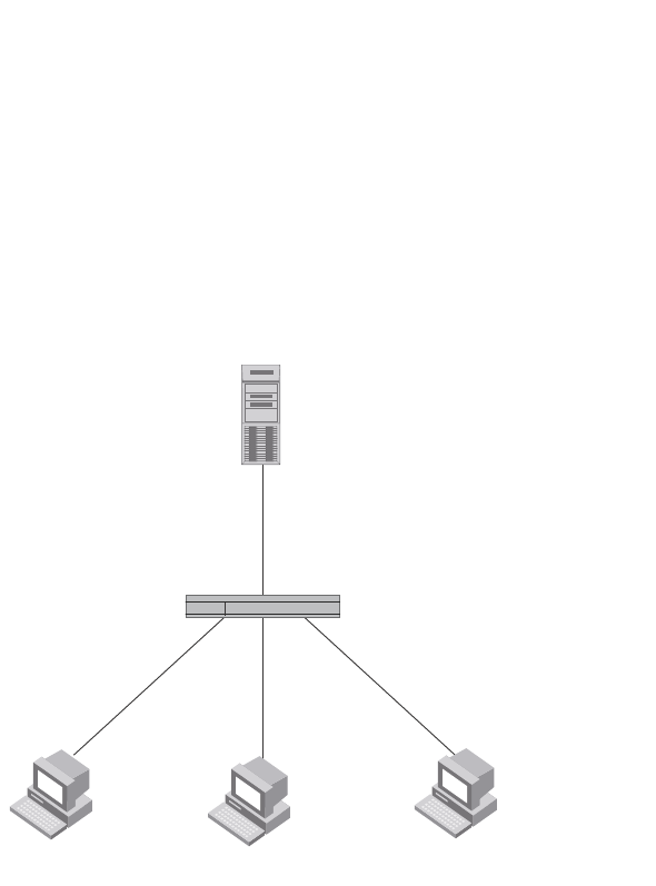
PowerConnect B-Series FCX Configuration Guide 1259
53-1002266-01
Sample 802.1X configurations 34
Point-to-point configuration
Figure 158 illustrates a sample 802.1X configuration with Clients connected to three ports on the
Dell PowerConnect device. In a point-to-point configuration, only one 802.1X Client can be
connected to each port.
FIGURE 158 Sample point-to-point 802.1X configuration
The following commands configure the Dell PowerConnect device in Figure 158
PowerConnect(config)#aaa authentication dot1x default radius
PowerConnect(config)#radius-server host 192.168.9.22 auth-port 1812 acct-port
1813 default key mirabeau dot1x
PowerConnect(config)#dot1x-enable e 1 to 3
PowerConnect(config-dot1x)#re-authentication
PowerConnect(config-dot1x)#timeout re-authperiod 2000
PowerConnect(config-dot1x)#timeout quiet-period 30
PowerConnect(config-dot1x)#timeout tx-period 60
PowerConnect(config-dot1x)#maxreq 6
PowerConnect(config-dot1x)#exit
PowerConnect(config)#interface e 1
PowerConnect(config-if-e1000-1)#dot1x port-control auto
PowerConnect(config-if-e1000-1)#exit
PowerConnect(config)#interface e 2
PowerConnectconfig-if-e1000-2)#dot1x port-control auto
PowerConnect(config-if-e1000-2)#exit
PowerConnect(config)#interface e 3
PowerConnect(config-if-e1000-3)#dot1x port-control auto
PowerConnect(config-if-e1000-3)#exit
RADIUS Server
(Authentication Server)
Clients/Supplicants running 802.1X-compliant client software
192.168.9.22
e2/1 e2/2 e2/3
Switch
(Authenticator)
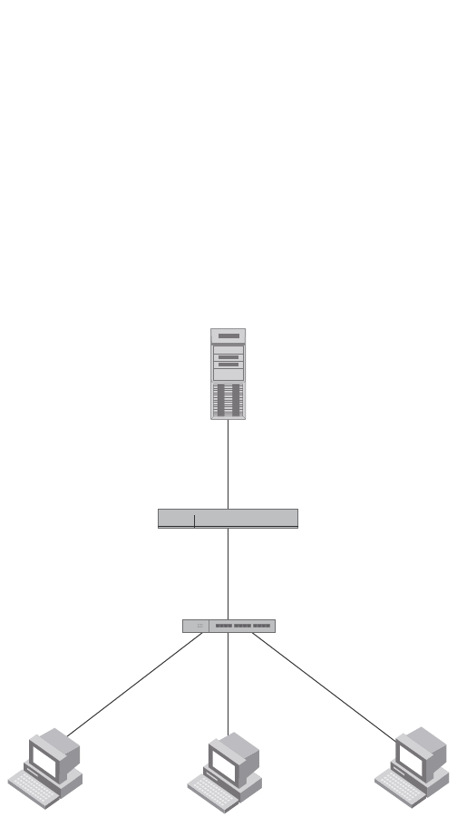
1260 PowerConnect B-Series FCX Configuration Guide
53-1002266-01
Sample 802.1X configurations
34
Hub configuration
Figure 159 illustrates a configuration where three 802.1X-enabled Clients are connected to a hub,
which is connected to a port on the Dell PowerConnect device. The configuration is similar to that
in Figure 158, except that 802.1X port security is enabled on only one port, and the multiple-hosts
command is used to allow multiple Clients on the port.
FIGURE 159 Sample 802.1X configuration using a hub
The following commands configure the Dell PowerConnect device in Figure 159
PowerConnect(config)#aaa authentication dot1x default radius
PowerConnect(config)#radius-server host 192.168.9.22 auth-port 1812 acct-port
1813 default key mirabeau dot1x
PowerConnect(config)#dot1x-enable e 1
PowerConnect(config-dot1x)#re-authentication
PowerConnect(config-dot1x)#timeout re-authperiod 2000
PowerConnect(config-dot1x)#timeout quiet-period 30
PowerConnect(config-dot1x)#timeout tx-period 60
PowerConnect(config-dot1x)#maxreq 6
PowerConnect(config-dot1x)#exit
PowerConnect(config)#interface e 1
PowerConnect(config-if-e1000-1)#dot1x port-control auto
PowerConnect(config-if-e1000-1)#dot1x multiple-hosts
PowerConnect(config-if-e1000-1)#exit
RADIUS Server
(Authentication Server)
Switch
(Authenticator)
e2/1
192.168.9.22
Hub
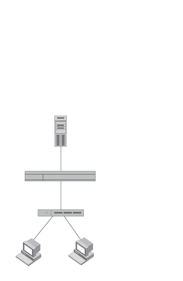
PowerConnect B-Series FCX Configuration Guide 1261
53-1002266-01
Sample 802.1X configurations 34
802.1X Authentication with dynamic VLAN assignment
Figure 160 illustrates 802.1X authentication with dynamic VLAN assignment. In this configuration,
two user PCs are connected to a hub, which is connected to port e2. Port e2 is configured as a
dual-mode port. Both PCs transmit untagged traffic. The profile for User 1 on the RADIUS server
specifies that User 1 PC should be dynamically assigned to VLAN 3. The RADIUS profile for User 2
on the RADIUS server specifies that User 2 PC should be dynamically assigned to VLAN 20.
FIGURE 160 Sample configuration using 802.1X authentication with dynamic VLAN assignment
In this example, the PVID for port e2 would be changed based on the first host to be successfully
authenticated. If User 1 is authenticated first, then the PVID for port e2 is changed to VLAN 3. If
User 2 is authenticated first, then the PVID for port e2 is changed to VLAN 20. Since a PVID cannot
be changed by RADIUS authentication after it has been dynamically assigned, if User 2 is
authenticated after the port PVID was changed to VLAN 3, then User 2 would not be able to gain
access to the network.
If there were only one device connected to the port, and authentication failed for that device, it
could be placed into the restricted VLAN, where it could gain access to the network.
The part of the running-config related to 802.1X authentication would be as follows.
dot1x-enable
re-authentication
servertimeout 10
timeout re-authperiod 10
auth-fail-action restricted-vlan
auth-fail-vlanid 1023
mac-session-aging no-aging permitted-mac-only
enable ethe 2 to 4
!
!
Hub
Untagged Untagged
User 1
MAC: 0002.3f7f.2e0a
User 2
MAC: 0050.048e.86ac
Port e2
Dual Mode
Switch
RADIUS Server
Tunnel-Private-Group-ID:
User 1 -> “U:3”
User 2 -> “U:20”

1262 PowerConnect B-Series FCX Configuration Guide
53-1002266-01
Using multi-device port authentication and 802.1X security on the same port
34
!
interface ethernet 2
dot1x port-control auto
dual-mode
If User 1 is successfully authenticated before User 2, the PVID for port e2 would be changed from
the default VLAN to VLAN 3.
Had User 2 been the first to be successfully authenticated, the PVID would be changed to 20, and
User 1 would not be able to gain access to the network. If there were only one device connected to
the port that was sending untagged traffic, and 802.1X authentication failed for that device, it
would be placed in the restricted VLAN 1023, and would be able to gain access to the network.
Using multi-device port authentication and 802.1X
security on the same port
You can configure the Dell PowerConnect device to use multi-device port authentication and
802.1X security on the same port:
•The multi-device port authentication feature allows you to configure a Dell PowerConnect
device to forward or block traffic from a MAC address based on information received from a
RADIUS server. Incoming traffic originating from a given MAC address is switched or forwarded
by the device only if the source MAC address is successfully authenticated by a RADIUS server.
The MAC address itself is used as the username and password for RADIUS authentication. A
connecting user does not need to provide a specific username and password to gain access to
the network.
•The IEEE 802.1X standard is a means for authenticating devices attached to LAN ports. Using
802.1X port security, you can configure a Dell PowerConnect device to grant access to a port
based on information supplied by a client to an authentication server.
When both of these features are enabled on the same port, multi-device port authentication is
performed prior to 802.1X authentication. If multi-device port authentication is successful, 802.1X
authentication may be performed, based on the configuration of a vendor-specific attribute (VSA) in
the profile for the MAC address on the RADIUS server.
For more information, including configuration examples, see “Using multi-device port
authentication and 802.1X security on the same port” on page 1276.

PowerConnect B-Series FCX Configuration Guide 1263
53-1002266-01
Chapter
35
Using the MAC Port Security Feature
Table 219 lists the individual Dell PowerConnect switches and the MAC port security features they
support.
This chapter describes how to configure Dell PowerConnect devices to learn “secure” MAC
addresses on an interface so that the interface will forward only packets that match the secure
addresses.
Overview
You can configure the Dell PowerConnect device to learn “secure” MAC addresses on an interface.
The interface will forward only packets with source MAC addresses that match these learned
secure addresses. The secure MAC addresses can be specified manually, or the Dell PowerConnect
device can learn them automatically. After the device reaches the limit for the number of secure
MAC addresses it can learn on the interface, if the interface then receives a packet with a source
MAC address that does not match the learned addresses, it is considered a security violation.
When a security violation occurs, a Syslog entry and an SNMP trap are generated. In addition, the
device takes one of two actions; it either drops packets from the violating address (and allows
packets from the secure addresses), or disables the port for a specified amount of time. You
specify which of these actions takes place.
The secure MAC addresses are not flushed when an interface is disabled and re-enabled. The
secure addresses can be kept secure permanently (the default), or can be configured to age out, at
which time they are no longer secure. You can configure the device to automatically save the
secure MAC address list to the startup-config file at specified intervals, allowing addresses to be
kept secure across system restarts.
TABLE 219 Supported MAC port security features
Feature PowerConnect B-Series FCX
MAC port security Yes
Setting the maximum number of secure
MAC addresses on an interface
Yes
Setting the port security age timer Yes
Specifying secure MAC addresses Yes
Autosaving secure MAC addresses to the
startup-config file
Yes
Specifying the action taken when a
security violation occurs
Yes
Clearing port security statistics Yes

1264 PowerConnect B-Series FCX Configuration Guide
53-1002266-01
Configuring the MAC port security feature
35
Local and global resources
The MAC port security feature uses a concept of local and global “resources” to determine how
many MAC addresses can be secured on each interface. In this context, a “resource” is the ability
to store one secure MAC address entry. Each interface is allocated 64 local resources. Additional
global resources are shared among all interfaces on the device.
When the MAC port security feature is enabled on an interface, the interface can store one secure
MAC address. You can increase the number of MAC addresses that can be secured using local
resources to a maximum of 64.
Besides the maximum of 64 local resources available to an interface, there are additional global
resources. Depending on flash memory size, a device can have 1024, 2048, or 4096 global
resources available. When an interface has secured enough MAC addresses to reach its limit for
local resources, it can secure additional MAC addresses by using global resources. Global
resources are shared among all the interfaces on a first-come, first-served basis.
The maximum number of MAC addresses any single interface can secure is 64 (the maximum
number of local resources available to the interface), plus the number of global resources not
allocated to other interfaces.
Configuration notes and feature limitations
The following limitations apply to this feature:
•MAC port security applies only to Ethernet interfaces.
•MAC port security is not supported on static trunk group members or ports that are configured
for link aggregation.
•MAC port security is not supported on 802.1X port security-enabled ports.
•Dell PowerConnect devices do not support the reserved-vlan-id <num> command, which
changes the default VLAN ID for the MAC port security feature.
•The SNMP trap generated for restricted MAC addresses indicates the VLAN ID associated with
the MAC address, as well as the port number and MAC address.
•MAC port security is not supported on ports that have multi-device port authentication
enabled.
Configuring the MAC port security feature
To configure the MAC port security feature, perform the following tasks:
•Enable the MAC port security feature
•Set the maximum number of secure MAC addresses for an interface
•Set the port security age timer
•Specify secure MAC addresses
•Configure the device to automatically save secure MAC addresses to the startup-config file
•Specify the action taken when a security violation occurs

PowerConnect B-Series FCX Configuration Guide 1265
53-1002266-01
Configuring the MAC port security feature 35
Enabling the MAC port security feature
By default, the MAC port security feature is disabled on all interfaces. You can enable or disable the
feature on all interfaces at once, or on individual interfaces.
To enable the feature on all interfaces at once, enter the following commands.
PowerConnect(config)#port security
PowerConnect(config-port-security)#enable
To disable the feature on all interfaces at once, enter the following commands.
PowerConnect(config)#port security
PowerConnect(config-port-security)#no enable
To enable the feature on a specific interface, enter the following commands.
PowerConnect(config)#interface ethernet 7/11
PowerConnect(config-if-e1000-7/11)#port security
PowerConnect(config-port-security-e1000-7/11)#enable
Syntax: port security
Syntax: [no] enable
Setting the maximum number of secure MAC addresses
for an interface
When MAC port security is enabled, an interface can store one secure MAC address. You can
increase the number of MAC addresses that can be stored to a maximum of 64, plus the total
number of global resources available.
For example, to configure interface 7/11 to have a maximum of 10 secure MAC addresses, enter
the following commands.
PowerConnect(config)#interface ethernet 7/11
PowerConnect(config-if-e1000-7/11)#port security
PowerConnect(config-port-security-e1000-7/11)#maximum 10
Syntax: maximum <number-of-addresses>
The <number-of-addresses> parameter can be set to a number from 0 through 64 plus (the total
number of global resources available). The total number of global resources is 2048 or 4096,
depending on flash memory size. Setting the parameter to 0 prevents any addresses from being
learned. The default is 1.
Setting the port security age timer
By default, learned MAC addresses stay secure indefinitely. You can optionally configure the device
to age out secure MAC addresses after a specified amount of time.
To set the port security age timer to 10 minutes on all interfaces, enter the following commands.
PowerConnect(config)#port security
PowerConnect(config-port-security)#age 10
To set the port security age timer to 10 minutes on a specific interface, enter the following
commands.

1266 PowerConnect B-Series FCX Configuration Guide
53-1002266-01
Configuring the MAC port security feature
35
PowerConnect(config)#interface ethernet 7/11
PowerConnect(config-if-e1000-7/11)#port security
PowerConnect(config-port-security-e1000-7/11)#age 10
Syntax: [no] age <minutes>
The <minutes> variable specifies a range from 0 through 1440 minutes.The default is 0 (never age
out secure MAC addresses).
Specifying secure MAC addresses
You can configure secure MAC addresses on tagged and untagged interfaces.
On an untagged interface
To specify a secure MAC address on an untagged interface, enter commands such as the following.
PowerConnect(config)#interface ethernet 7/11
PowerConnect(config-if-e1000-7/11)#port security
PowerConnect(config-port-security-e1000-7/11)#secure-mac-address 0050.DA18.747C
Syntax: [no] secure-mac-address <mac-address>
On a tagged interface
When specifying a secure MAC address on a tagged interface, you must also specify the VLAN ID.
To do so, enter commands such as the following.
PowerConnect(config)#interface ethernet 7/11
PowerConnect(config-if-e1000-7/11)#port security
PowerConnect(config-port-security-e1000-7/11)#secure-mac-address 0050.DA18.747C 2
Syntax: [no] secure-mac-address <mac-address> <vlan-ID>
NOTE
If MAC port security is enabled on a port and you change the VLAN membership of the port, make
sure that you also change the VLAN ID specified in the secure-mac-address configuration statement
for the port.
When a secure MAC address is applied to a tagged port, the VLAN ID is generated for both tagged
and untagged ports. When you display the configuration, you will see an entry for the secure MAC
addresses. For example, you might see an entry similar to the following line.
secure-mac-address 0000.1111.2222 10
This line means that MAC address 0000.1111.2222 on VLAN 10 is a secure MAC address.
Autosaving secure MAC addresses to the
startup-config file
Learned MAC addresses can automatically be saved to the startup-config file at specified intervals.
For example, to automatically save learned secure MAC addresses every 20 minutes, enter the
following commands.
PowerConnect(config)#port security
PowerConnect(config-port-security)#autosave 20

PowerConnect B-Series FCX Configuration Guide 1267
53-1002266-01
Configuring the MAC port security feature 35
Syntax: [no] autosave <minutes>
The <minutes> variable can be from 15 through 1440 minutes. By default, secure MAC addresses
are not autosaved to the startup-config file.
Specifying the action taken when a security
violation occurs
A security violation can occur when a user tries to connect to a port where a MAC address is
already locked, or the maximum number of secure MAC addresses has been exceeded. When a
security violation occurs, an SNMP trap and Syslog message are generated.
You can configure the device to take one of two actions when a security violation occurs; either
drop packets from the violating address (and allow packets from secure addresses), or disable the
port for a specified time.
Dropping packets from a violating address
To configure the device to drop packets from a violating address and allow packets from secure
addresses, enter the following commands.
PowerConnect(config)#interface ethernet 7/11
PowerConnect(config-if-e1000-7/11)#port security
PowerConnect(config-port-security-e1000-7/11)#violation restrict
Syntax: violation [restrict]
NOTE
When the restrict option is used, the maximum number of MAC addresses that can be restricted is
128. If the number of violating MAC addresses exceeds this number, the port is shut down. An
SNMP trap and the following Syslog message are generated: "Port Security violation restrict limit
128 exceeded on interface ethernet <port_id>". This is followed by a port shutdown Syslog message
and trap.
Specifying the period of time to drop packets from a violating address
To specify the number of minutes that the device drops packets from a violating address, use
commands similar to the following.
PowerConnect(config)#interface ethernet 7/11
PowerConnect(config-if-e1000-7/11)#port security
PowerConnect(config-port-security-e1000-7/11)#violation restrict 5
Syntax: violation restrict <age>
The <age> variable can be from 0 through 1440 minutes. The default is 5 minutes. Specifying 0
drops packets from the violating address permanently.
Aging for restricted MAC addresses is done in software. There can be a worst case inaccuracy of
one minute from the specified time.
The restricted MAC addresses are denied in hardware.

1268 PowerConnect B-Series FCX Configuration Guide
53-1002266-01
Clearing port security statistics
35
Disabling the port for a specified amount of time
You can configure the device to disable the port for a specified amount of time when a security
violation occurs.
To shut down the port for 5 minutes when a security violation occurs, enter the following
commands.
PowerConnect(config)#interface ethernet 7/11
PowerConnect(config-if-e1000-7/11)#port security
PowerConnect(config-port-security-e1000-7/11)#violation shutdown 5
Syntax: violation shutdown <minutes>
The mnutes can be from 0 through 1440 minutes. Specifying 0 shuts down the port permanently
when a security violation occurs.
Clearing port security statistics
You can clear restricted MAC addresses and violation statistics from ports on all ports or on
individual ports.
Clearing restricted MAC addresses
To clear all restricted MAC addresses globally, enter the following command.
PowerConnect#clear port security restricted-macs all
To clear restricted MAC addresses on a specific port, enter a command such as the following.
PowerConnect#clear port security restricted-macs ethernet 5
Syntax: clear port security restricted-macs all | ethernet <port>
Specify the <port> variable in the following formats:
•PowerConnect B-Series FCX stackable switches – <stack-unit/slotnum/portnum>
Clearing violation statistics
To clear violation statistics globally, enter the following command.
PowerConnect#clear port security statistics all
To clear violation statistics on a specific port, enter a command such as the following.
PowerConnect#clear port security statistics ethernet 1/5
Syntax: clear port security statistics all | ethernet <port>
Specify the <port> variable in the following formats:
•PowerConnect B-Series FCX stackable switches – <stack-unit/slotnum/portnum>
Displaying port security information
You can display the following information about the MAC port security feature:

PowerConnect B-Series FCX Configuration Guide 1269
53-1002266-01
Displaying port security information 35
•The port security settings for an individual port or for all the ports on a specified module
•The secure MAC addresses configured on the device
•Port security statistics for an interface or for a module
Displaying port security settings
You can display the port security settings for an individual port or for all the ports on a specified
module. For example, to display the port security settings for port 7/11, enter the following
command.
Syntax: show port security ethernet <port>
Specify the <port> variable in the following formats:
•PowerConnect B-Series FCX stackable switches – <stack-unit/slotnum/portnum>
Displaying the secure MAC addresses
To list the secure MAC addresses configured on the device, enter the following command.
Syntax: show port security mac
Table 221 describes the output from the show port security mac command.
TABLE 220 Output from the show port security ethernet command
This field... Displays...
Port The slot and port number of the interface.
Security Whether the port security feature has been enabled on the interface.
Violation The action to be undertaken when a security violation occurs, either “shutdown” or
“restrict”.
Shutdown-Time The number of seconds a port is shut down following a security violation, if the port is set to
“shutdown” when a violation occurs.
Age-Time The amount of time, in minutes, MAC addresses learned on the port will remain secure.
Max-MAC The maximum number of secure MAC addresses that can be learned on the interface.
TABLE 221 Output from the show port security mac command
This field... Displays...
Port The slot and port number of the interface.
Num-Addr The number of MAC addresses secured on this interface.
PowerConnect#show port security ethernet 7/11
Port Security Violation Shutdown-Time Age-Time Max-MAC
----- -------- --------- ------------- --------- -------
7/11 disabled shutdown 10 10 1
PowerConnect#show port security mac
Port Num-Addr Secure-Src-Addr Resource Age-Left Shutdown/Time-Left
----- -------- --------------- -------- --------- ------------------
7/11 1 0050.da18.747c Local 10 no

1270 PowerConnect B-Series FCX Configuration Guide
53-1002266-01
Displaying port security information
35
Displaying port security statistics
You can display port security statistics for an interface or for a module.
For example, to display port security statistics for interface 7/11, enter the following command.
Syntax: show port security statistics <port>
Specify the <port> variable in the following formats:
•PowerConnect B-Series FCX stackable switches – <stack-unit/slotnum/portnum>
For example, to display port security statistics for interface module 7, enter the following command.
PowerConnect#show port security statistics 7
Module 7:
Total ports: 0
Total MAC address(es): 0
Total violations: 0
Total shutdown ports 0
Syntax: show port security statistics <module>
Table 223 describes the output from the show port security statistics <module> command.
Secure-Src-Addr The secure MAC address.
Resource Whether the address was secured using a local or global resource.Refer to
“Local and global resources” on page 1264 for more information.
Age-Left The number of minutes the MAC address will remain secure.
Shutdown/Time-Left Whether the interface has been shut down due to a security violation and the
number of seconds before it is enabled again.
TABLE 222 Output from the show port security statistics <port> command
This field... Displays...
Port The slot and port number of the interface.
Total-Addrs The total number of secure MAC addresses on the interface.
Maximum-Addrs The maximum number of secure MAC addresses on the interface.
Violation The number of security violations on the port.
Shutdown/Time-Left Whether the port has been shut down due to a security violation and the
number of seconds before it is enabled again.
TABLE 221 Output from the show port security mac command (Continued)
This field... Displays...
PowerConnect#show port security statistics e 7/11
Port Total-Addrs Maximum-Addrs Violation Shutdown/Time-Left
----- ----------- ------------- --------- ------------------
7/11 1 1 0 no

PowerConnect B-Series FCX Configuration Guide 1271
53-1002266-01
Displaying port security information 35
Displaying restricted MAC addresses on a port
To display a list of restricted MAC addresses on a port, enter a command such as the following.
PowerConnect#show port security ethernet 1/5 restricted-macs
Syntax: show port security ethernet <port> restricted-macs
Specify the <port> variable in the following formats:
•PowerConnect B-Series FCX stackable switches – <stack-unit/slotnum/portnum>
TABLE 223 Output from the show port security statistics <module> command
This field... Displays...
Total ports The number of ports on the module.
Total MAC address(es) The total number of secure MAC addresses on the module.
Total violations The number of security violations encountered on the module.
Total shutdown ports The number of ports on the module shut down as a result of security violations.

1272 PowerConnect B-Series FCX Configuration Guide
53-1002266-01
Displaying port security information
35

PowerConnect B-Series FCX Configuration Guide 1273
53-1002266-01
Chapter
36
Configuring Multi-Device Port Authentication
Table 224 lists individual Dell PowerConnect switches and the Multi-device port authentication
features they support.
NOTE
PowerConnect B-Series FCX devices do not support:
- multi-device authentication on dynamic (LACP) and static trunk ports
- multi-device authentication and port security configured on the same port
- multi-device authentication and lock-address configured on the same port
Multi-device port authentication is a way to configure a Dell PowerConnect device to forward or
block traffic from a MAC address based on information received from a RADIUS server.
TABLE 224 Supported Multi-device port authentication (MDPA) features
Feature PowerConnect B-Series FCX
Multi-Device Port Authentication Yes
Support for Multi-Device Port
Authentication together with:
•Dynamic VLAN assignment Yes
•Dynamic ACLs Yes
•802.1X Yes
•Denial of Service (DoS) attack
protection
Yes
•Source guard protection Yes
•ACL-per-port-per-VLAN Yes
Authenticating multiple MAC addresses
on an interface
Yes
Specifying the format of the MAC
addresses sent to the RADIUS server
Yes
Specifying the authentication-failure
action
Yes
Password override Yes
Specifying the RADIUS timeout action Yes
SNMP Traps Yes
MAC Address Filters Yes
Aging time for blocked MAC Addresses Yes

1274 PowerConnect B-Series FCX Configuration Guide
53-1002266-01
How multi-device port authentication works
36
How multi-device port authentication works
Multi-device port authentication is a way to configure a Dell PowerConnect device to forward or
block traffic from a MAC address based on information received from a RADIUS server.
The multi-device port authentication feature is a mechanism by which incoming traffic originating
from a specific MAC address is switched or forwarded by the device only if the source MAC address
is successfully authenticated by a RADIUS server. The MAC address itself is used as the username
and password for RADIUS authentication; the user does not need to provide a specific username
and password to gain access to the network. If RADIUS authentication for the MAC address is
successful, traffic from the MAC address is forwarded in hardware.
If the RADIUS server cannot validate the user's MAC address, then it is considered an
authentication failure, and a specified authentication-failure action can be taken. The default
authentication-failure action is to drop traffic from the non-authenticated MAC address in
hardware. You can also configure the device to move the port on which the non-authenticated MAC
address was learned into a restricted or “guest” VLAN, which may have limited access to the
network.
RADIUS authentication
The multi-device port authentication feature communicates with the RADIUS server to authenticate
a newly found MAC address. The Dell PowerConnect device supports multiple RADIUS servers; if
communication with one of the RADIUS servers times out, the others are tried in sequential order.
If a response from a RADIUS server is not received within a specified time (by default, 3 seconds)
the RADIUS session times out, and the device retries the request up to three times. If no response
is received, the next RADIUS server is chosen, and the request is sent for authentication.
The RADIUS server is configured with the usernames and passwords of authenticated users. For
multi-device port authentication, the username and password is the MAC address itself; that is, the
device uses the MAC address for both the username and the password in the request sent to the
RADIUS server. For example, given a MAC address of 0007e90feaa1, the users file on the RADIUS
server would be configured with a username and password both set to 0007e90feaa1. When
traffic from this MAC address is encountered on a MAC-authentication-enabled interface, the
device sends the RADIUS server an Access-Request message with 0007e90feaa1 as both the
username and password. The format of the MAC address sent to the RADIUS server is configurable
through the CLI.
The request for authentication from the RADIUS server is successful only if the username and
password provided in the request matches an entry in the users database on the RADIUS server.
When this happens, the RADIUS server returns an Access-Accept message back to the Dell
PowerConnect device. When the RADIUS server returns an Access-Accept message for a MAC
address, that MAC address is considered authenticated, and traffic from the MAC address is
forwarded normally by the Dell PowerConnect device.
Authentication-failure actions
If the MAC address does not match the username and password of an entry in the users database
on the RADIUS server, then the RADIUS server returns an Access-Reject message. When this
happens, it is considered an authentication failure for the MAC address. When an authentication
failure occurs, the Dell PowerConnect device can either drop traffic from the MAC address in
hardware (the default), or move the port on which the traffic was received to a restricted VLAN.

PowerConnect B-Series FCX Configuration Guide 1275
53-1002266-01
How multi-device port authentication works 36
Supported RADIUS attributes
Dell PowerConnect devices support the following RADIUS attributes for multi-device port
authentication:
•Username (1) – RFC 2865
•NAS-IP-Address (4) – RFC 2865
•NAS-Port (5) – RFC 2865
•Service-Type (6) – RFC 2865
•FilterId (11) – RFC 2865
•Framed-MTU (12) – RFC 2865
•State (24) – RFC 2865
•Vendor-Specific (26) – RFC 2865
•Session-Timeout (27) – RFC 2865
•Termination-Action (29) – RFC 2865
•Calling-Station-ID (31) – RFC 2865
•NAS-Port-Type (61) š RFC 2865
•Tunnel-Type (64) – RFC 2868
•Tunnel-Medium-Type (65) – RFC 2868
•EAP Message (79) – RFC 2579
•Message-Authenticator (80) RFC 3579
•Tunnel-Private-Group-Id (81) – RFC 2868
•NAS-Port-id (87) – RFC 2869
Support for dynamic VLAN assignment
The Dell multi-device port authentication feature supports dynamic VLAN assignment, where a port
can be placed in one or more VLANs based on the MAC address learned on that interface. For
details about this feature, refer to “Configuring the RADIUS server to support dynamic VLAN
assignment” on page 1282.
Support for dynamic ACLs
The multi-device port authentication feature supports the assignment of a MAC address to a
specific ACL, based on the MAC address learned on the interface. For details about this feature,
refer to “Dynamically applying IP ACLs to authenticated MAC addresses” on page 1283.
Support for authenticating multiple MAC addresses
on an interface
The multi-device port authentication feature allows multiple MAC addresses to be authenticated or
denied authentication on each interface. The maximum number of MAC addresses that can be
authenticated on each interface is limited only by the amount of system resources available on the
Dell PowerConnect device.

1276 PowerConnect B-Series FCX Configuration Guide
53-1002266-01
Using multi-device port authentication and 802.1X security on the same port
36
Support for source guard protection
The Dell proprietary Source Guard Protection feature, a form of IP Source Guard, can be used in
conjunction with multi-device port authentication. For details, refer to “Enabling source guard
protection” on page 1286.
Using multi-device port authentication and 802.1X
security on the same port
On some Dell PowerConnect devices, multi-device port authentication and 802.1X security can be
configured on the same port, as long as the port is not a trunk port or an LACP port. When both of
these features are enabled on the same port, multi-device port authentication is performed prior to
802.1X authentication. If multi-device port authentication is successful, 802.1X authentication
may be performed, based on the configuration of a vendor-specific attribute (VSA) in the profile for
the MAC address on the RADIUS server.
NOTE
When multi-device port authentication and 802.1X security are configured together on the same
port, Dell recommends that dynamic VLANs and dynamic ACLs are done at the multi-device port
authentication level, and not at the 802.1X level.
When both features are configured on a port, a device connected to the port is authenticated as
follows.
1. Multi-device port authentication is performed on the device to authenticate the device MAC
address.
2. If multi-device port authentication is successful for the device, then the device checks whether
the RADIUS server included the Foundry-802_1x-enable VSA (described in Table 225) in the
Access-Accept message that authenticated the device.
3. If the Foundry-802_1x-enable VSA is not present in the Access-Accept message, or is present
and set to 1, then 802.1X authentication is performed for the device.
4. If the Foundry-802_1x-enable VSA is present in the Access-Accept message, and is set to 0,
then 802.1X authentication is skipped. The device is authenticated, and any dynamic VLANs
specified in the Access-Accept message returned during multi-device port authentication are
applied to the port.
5. If 802.1X authentication is performed on the device, and is successful, then dynamic VLANs or
ACLs specified in the Access-Accept message returned during 802.1X authentication are
applied to the port.
If multi-device port authentication fails for a device, then by default traffic from the device is either
blocked in hardware, or the device is placed in a restricted VLAN. You can optionally configure the
Dell PowerConnect device to perform 802.1X authentication on a device when it fails multi-device
port authentication. Refer to “Example 2” on page 1304 for a sample configuration where this is
used.

PowerConnect B-Series FCX Configuration Guide 1277
53-1002266-01
Using multi-device port authentication and 802.1X security on the same port 36
Configuring Dell-specific attributes on the
RADIUS server
If the RADIUS authentication process is successful, the RADIUS server sends an Access-Accept
message to the Dell PowerConnect device, authenticating the device. The Access-Accept message
can include Vendor-Specific Attributes (VSAs) that specify additional information about the device.
If you are configuring multi-device port authentication and 802.1X authentication on the same
port, then you can configure the Dell VSAs listed in Table 225 on the RADIUS server.
You add these Dell vendor-specific attributes to your RADIUS server configuration, and configure
the attributes in the individual or group profiles of the devices that will be authenticated. The Dell
Vendor-ID is 1991, with Vendor-Type 1.
If neither of these VSAs exist in a device profile on the RADIUS server, then by default the device is
subject to multi-device port authentication (if configured), then 802.1X authentication (if
configured). The RADIUS record can be used for both multi-device port authentication and 802.1X
authentication.
Configuration examples are shown in “Examples of multi-device port authentication and 802.1X
authentication configuration on the same port” on page 1302.
TABLE 225 Dell vendor-specific attributes for RADIUS
Attribute name Attribute ID Data type Description
Foundry-802_1x-enable 6 integer Specifies whether 802.1X authentication is
performed when multi-device port
authentication is successful for a device. This
attribute can be set to one of the following:
0 - Do not perform 802.1X authentication on
a device that passes multi-device port
authentication. Set the attribute to zero for
devices that do not support 802.1X
authentication.
1 - Perform 802.1X authentication when a
device passes multi-device port
authentication. Set the attribute to one for
devices that support 802.1X authentication.
Foundry-802_1x-valid 7 integer Specifies whether the RADIUS record is valid
only for multi-device port authentication, or
for both multi-device port authentication and
802.1X authentication.
This attribute can be set to one of the
following:
0 - The RADIUS record is valid only for
multi-device port authentication. Set this
attribute to zero to prevent a user from using
their MAC address as username and
password for 802.1X authentication
1 - The RADIUS record is valid for both
multi-device port authentication and 802.1X
authentication.

1278 PowerConnect B-Series FCX Configuration Guide
53-1002266-01
Configuring multi-device port authentication
36
Configuring multi-device port authentication
Configuring multi-device port authentication on the Dell PowerConnect device consists of the
following tasks:
•Enabling multi-device port authentication globally and on individual interfaces
•Specifying the format of the MAC addresses sent to the RADIUS server (optional)
•Specifying the authentication-failure action (optional)
•Enabling and disabling SNMP traps for multi-device port authentication
•Defining MAC address filters (optional)
•Configuring dynamic VLAN assignment (optional)
•Dynamically Applying IP ACLs to authenticated MAC addresses
•Enabling denial of service attack protection (optional)
•Clearing authenticated MAC addresses (optional)
•Disabling aging for authenticated MAC addresses (optional)
•Configuring the hardware aging period for blocked MAC addresses
•Specifying the aging time for blocked MAC addresses (optional)
Enabling multi-device port authentication
To enable multi-device port authentication, you first enable the feature globally on the device. On
some Dell PowerConnect devices, you can then enable the feature on individual interfaces.
Globally enabling multi-device port authentication
To globally enable multi-device port authentication on the device, enter the following command.
PowerConnect(config)#mac-authentication enable
Syntax: [no] mac-authentication enable
Enabling multi-device port authentication on an interface
To enable multi-device port authentication on an individual interface, enter a command such as the
following.
PowerConnect(config)#mac-authentication enable ethernet 3/1
Syntax: [no] mac-authentication enable <port> | all
Specify the <port> variable in the following formats:
•PowerConnect B-Series FCX stackable switches – <stack-unit/slotnum/portnum>
The all option enables the feature on all interfaces at once.
You can enable the feature on an interface at the interface CONFIG level.
Example
PowerConnect(config)#interface e 3/1
PowerConnect(config-if-e1000-3/1)#mac-authentication enable
Syntax: [no] mac-authentication enable

PowerConnect B-Series FCX Configuration Guide 1279
53-1002266-01
Configuring multi-device port authentication 36
You can also configure multi-device port authentication commands on a range of interfaces.
Example
PowerConnect(config)#int e 3/1 to 3/12
PowerConnect(config-mif-3/1-3/12)#mac-authentication enable
Specifying the format of the MAC addresses sent to the
RADIUS server
When multi-device port authentication is configured, the Dell PowerConnect device authenticates
MAC addresses by sending username and password information to a RADIUS server. The
username and password is the MAC address itself; that is, the device uses the MAC address for
both the username and the password in the request sent to the RADIUS server.
By default, the MAC address is sent to the RADIUS server in the format xxxxxxxxxxxx. You can
optionally configure the device to send the MAC address to the RADIUS server in the format
xx-xx-xx-xx-xx-xx, or the format xxxx.xxxx.xxxx. To do this, enter a command such as the following.
PowerConnect(config)#mac-authentication auth-passwd-format xxxx.xxxx.xxxx
Syntax: [no] mac-authentication auth-passwd-format xxxx.xxxx.xxxx | xx-xx-xx-xx-xx-xx |
xxxxxxxxxxxx
Specifying the authentication-failure action
When RADIUS authentication for a MAC address fails, you can configure the device to perform one
of two actions:
•Drop traffic from the MAC address in hardware (the default)
•Move the port on which the traffic was received to a restricted VLAN
To configure the device to move the port to a restricted VLAN when multi-device port authentication
fails, enter commands such as the following.
PowerConnect(config)#interface e 3/1
PowerConnect(config-if-e1000-3/1)#mac-authentication auth-fail-action
restrict-vlan 100
Syntax: [no] mac-authentication auth-fail-action restrict-vlan [<vlan-id>]
If the ID for the restricted VLAN is not specified at the interface level, the global restricted VLAN ID
applies for the interface.
To specify the VLAN ID of the restricted VLAN globally, enter the following command.
PowerConnect(config)#mac-authentication auth-fail-vlan-id 200
Syntax: [no] mac-authentication auth-fail-vlan-id <vlan-id>
The command above applies globally to all MAC-authentication-enabled interfaces.
Note that the restricted VLAN must already exist on the device. You cannot configure the restricted
VLAN to be a non-existent VLAN. If the port is a tagged or dual-mode port, you cannot use a
restricted VLAN as the authentication-failure action.
To configure the device to drop traffic from non-authenticated MAC addresses in hardware, enter
commands such as the following.

1280 PowerConnect B-Series FCX Configuration Guide
53-1002266-01
Configuring multi-device port authentication
36
PowerConnect(config)#interface e 3/1
PowerConnect(config-if-e1000-3/1)#mac-authentication auth-fail-action
block-traffic
Syntax: [no] mac-authentication auth-fail-action block-traffic
Dropping traffic from non-authenticated MAC addresses is the default behavior when multi-device
port authentication is enabled.
Generating traps for multi-device port authentication
You can enable and disable SNMP traps for multi-device port authentication. SNMP traps are
enabled by default.
To enable SNMP traps for multi-device port authentication after they have been disabled, enter the
following command.
PowerConnect(config)#snmp-server enable traps mac-authentication
Syntax: [no] snmp-server enable traps mac-authentication
Use the no form of the command to disable SNMP traps for multi-device port authentication.
Defining MAC address filters
You can specify MAC addresses that do not have to go through multi-device port authentication.
These MAC addresses are considered pre-authenticated, and are not subject to RADIUS
authentication. To do this, you can define MAC address filters that specify the MAC addresses to
exclude from multi-device port authentication.
You should use a MAC address filter when the RADIUS server itself is connected to an interface
where multi-device port authentication is enabled. If a MAC address filter is not defined for the
MAC address of the RADIUS server and applied on the interface, the RADIUS authentication
process would fail since the device would drop all packets from the RADIUS server itself.
For example, the following command defines a MAC address filter for address 0010.dc58.aca4.
PowerConnect(config)#mac-authentication mac-filter 1 0010.dc58.aca4
Syntax: [no] mac-authentication mac-filter <filter>
The following commands apply the MAC address filter on an interface so that address
0010.dc58.aca4 is excluded from multi-device port authentication.
PowerConnect(config)#interface e 3/1
PowerConnect(config-if-e1000-3/1)#mac-authentication apply-mac-auth-filter 1
Syntax: [no] mac-authentication apply-mac-auth-filter <filter-id>
Configuring dynamic VLAN assignment
An interface can be dynamically assigned to one or more VLANs based on the MAC address learned
on that interface. When a MAC address is successfully authenticated, the RADIUS server sends the
Dell PowerConnect device a RADIUS Access-Accept message that allows the Dell PowerConnect
device to forward traffic from that MAC address. The RADIUS Access-Accept message can also
contain attributes set for the MAC address in its access profile on the RADIUS server.

PowerConnect B-Series FCX Configuration Guide 1281
53-1002266-01
Configuring multi-device port authentication 36
If one of the attributes in the Access-Accept message specifies one or more VLAN identifiers, and
the VLAN is available on the Dell PowerConnect device, the port is moved from its default VLAN to
the specified VLAN.
To enable dynamic VLAN assignment for authenticated MAC addresses, you must add attributes to
the profile for the MAC address on the RADIUS server, then enable dynamic VLAN assignment on
multi-device port authentication-enabled interfaces. Refer to “Configuring the RADIUS server to
support dynamic VLAN assignment” on page 1282 for a list of the attributes that must be set on
the RADIUS server.
To enable dynamic VLAN assignment on a multi-device port authentication-enabled interface, enter
commands such as the following.
PowerConnect(config)#interface e 3/1
PowerConnect(config-if-e1000-3/1)#mac-authentication enable-dynamic-vlan
Syntax: [no] mac-authentication enable-dynamic-vlan
Configuring a port to remain in the restricted VLAN after a successful
authentication attempt
If a previous authentication attempt for a MAC address failed, and as a result the port was placed
in the restricted VLAN, but a subsequent authentication attempt was successful, the RADIUS
Access-Accept message may specify a VLAN for the port. By default, the Dell PowerConnect device
moves the port out of the restricted VLAN and into the RADIUS-specified VLAN. You can optionally
configure the device to leave the port in the restricted VLAN. To do this, enter the following
command.
PowerConnect(config-if-e1000-3/1)#mac-authentication no-override-restrict-vlan
When the above command is applied, if the RADIUS-specified VLAN configuration is tagged (e.g.,
T:1024) and the VLAN is valid, then the port is placed in the RADIUS-specified VLAN as a tagged
port and left in the restricted VLAN. If the RADIUS-specified VLAN configuration is untagged (e.g.,
U:1024), the configuration from the RADIUS server is ignored, and the port is left in the restricted
VLAN.
Syntax: [no] mac-authentication no-override-restrict-vlan
Configuration notes
•If you configure dynamic VLAN assignment on a multi-device port authentication enabled
interface, and the Access-Accept message returned by the RADIUS server contains a
Tunnel-Type and Tunnel-Medium-Type, but does not contain a Tunnel-Private-Group-ID attribute,
then it is considered an authentication failure, and the configured authentication failure action
is performed for the MAC address.
•If the <vlan-name> string does not match either the name or the ID of a VLAN configured on
the device, then it is considered an authentication failure, and the configured authentication
failure action is performed for the MAC address.
•For tagged or dual-mode ports, if the VLAN ID provided by the RADIUS server does not match
the VLAN ID in the tagged packet that contains the authenticated MAC address as its source
address, then it is considered an authentication failure, and the configured authentication
failure action is performed for the MAC address.

1282 PowerConnect B-Series FCX Configuration Guide
53-1002266-01
Configuring multi-device port authentication
36
•If an untagged port had previously been assigned to a VLAN through dynamic VLAN
assignment, and then another MAC address is authenticated on the same port, but the
RADIUS Access-Accept message for the second MAC address specifies a different VLAN, then it
is considered an authentication failure for the second MAC address, and the configured
authentication failure action is performed. Note that this applies only if the first MAC address
has not yet aged out. If the first MAC address has aged out, then dynamic VLAN assignment
would work as expected for the second MAC address.
•For dual mode ports, if the RADIUS server returns T:<vlan-name>, the traffic will still be
forwarded in the statically assigned PVID. If the RADIUS server returns U:<vlan-name>, the
traffic will not be forwarded in the statically assigned PVID.
Configuring the RADIUS server to support dynamic VLAN assignment
To specify VLAN identifiers on the RADIUS server, add the following attributes to the profile for the
MAC address on the RADIUS server, then enable dynamic VLAN assignment on multi-device port
authentication-enabled interfaces.
For information about the attributes, refer to “Dynamic multiple VLAN assignment for 802.1X ports”
on page 1231.
Also, refer to the example configuration of “Multi-device port authentication with dynamic VLAN
assignment” on page 1300.
Specifying to which VLAN a port is moved after its RADIUS-specified VLAN
assignment expires
When a port is dynamically assigned to a VLAN through the authentication of a MAC address, and
the MAC session for that address is deleted on the Dell PowerConnect device, then by default the
port is removed from its RADIUS-assigned VLAN and placed back in the VLAN where it was
originally assigned.
A port can be removed from its RADIUS-assigned VLAN when any of the following occur:
•The link goes down for the port
•The MAC session is manually deleted with the mac-authentication clear-mac-session
command
•The MAC address that caused the port to be dynamically assigned to a VLAN ages out
For example, say port 1/1 is currently in VLAN 100, to which it was assigned when MAC address
0007.eaa1.e90f was authenticated by a RADIUS server. The port was originally configured to be in
VLAN 111. If the MAC session for address 0007.eaa1.e90f is deleted, then port 1/1 is moved from
VLAN 100 back into VLAN 111.
Attribute name Type Value
Tunnel-Type 064 13 (decimal) – VLAN
Tunnel-Medium-Type 065 6 (decimal) – 802
Tunnel-Private-Group-ID 081 <vlan-name> (string)
The <vlan-name> value can specify either the name or the number of
one or more VLANs configured on the Dell PowerConnect device.

PowerConnect B-Series FCX Configuration Guide 1283
53-1002266-01
Configuring multi-device port authentication 36
You can optionally specify an alternate VLAN to which to move the port when the MAC session for
the address is deleted. For example, to place the port in the restricted VLAN, enter commands such
as the following.
PowerConnect(config)#interface e 3/1
PowerConnect(config-if-e1000-3/1)#mac-auth move-back-to-old-vlan
port-restrict-vlan
Syntax: [no] mac-authentication move-back-to-old-vlan disable | port-configured-vlan |
system-default-vlan
The disable keyword disables moving the port back to its original VLAN. The port would stay in its
RADIUS-assigned VLAN.
The port-configured-vlan keyword removes the port from its RADIUS-assigned VLAN and places it
back in the VLAN where it was originally assigned. This is the default.
The port-restrict-vlan keyword removes the port from its RADIUS-assigned VLAN and places it in the
restricted VLAN.
The system-default-vlan keyword removes the port from its RADIUS-assigned VLAN and places it in
the DEFAULT-VLAN.
NOTE
When a MAC session is deleted, if the port is moved back to a VLAN that is different than the running-
config file, the system will update the running-config file to reflect the changes. This will occur even
if mac-authentication save-dynamicvlan-to-config" is not configured.
Saving dynamic VLAN assignments to the running-config file
By default, dynamic VLAN assignments are not saved to the running-config file of the Dell
PowerConnect device. However, you can configure the device to do so by entering the following
command.
PowerConnect(config)#mac-authentication save-dynamicvlan-to-config
When the above command is applied, dynamic VLAN assignments are saved to the running-config
file and are displayed when the show run command is issued. Dynamic VLAN assignments can
also be displayed with the show vlan, show auth-mac-addresses detail, and show
auth-mac-addresses authorized-mac commands.
Syntax: [no] mac-authentication save-dynamicvlan-to-config
Dynamically applying IP ACLs to authenticated
MAC addresses
The Dell multi-device port authentication implementation supports the assignment of a MAC
address to a specific ACL, based on the MAC address learned on the interface.
When a MAC address is successfully authenticated, the RADIUS server sends the Dell
PowerConnect device a RADIUS Access-Accept message that allows the Dell PowerConnect device
to forward traffic from that MAC address. The RADIUS Access-Accept message can also contain,
among other attributes, the Filter-ID (type 11) attribute for the MAC address. When the
Access-Accept message containing the Filter-ID (type 11) attribute is received by the Dell
PowerConnect device, it will use the information in these attributes to apply an IP ACL on a per-MAC
(per user) basis.

1284 PowerConnect B-Series FCX Configuration Guide
53-1002266-01
Configuring multi-device port authentication
36
The dynamic IP ACL is active as long as the client is connected to the network. When the client
disconnects from the network, the IP ACL is no longer applied to the port. If an IP ACL had been
applied to the port prior to multi-device port authentication; it will be re-applied to the port.
NOTE
A dynamic IP ACL will take precedence over an IP ACL that is bound to a port (port ACL). When a client
authenticates with a dynamic IP ACL, the port ACL will not be applied. Also, future clients on the
same port will authenticate with a dynamic IP ACL or no IP ACL. If no clients on the port use dynamic
ACL, then the port ACL will be applied to all traffic.
The Dell PowerConnect device uses information in the Filter ID to apply an IP ACL on a per-user
basis. The Filter-ID attribute can specify the number of an existing IP ACL configured on the Dell
PowerConnect device. If the Filter-ID is an ACL number, the specified IP ACL is applied on a per-user
basis.
Multi-device port authentication with dynamic IP ACLs and
ACL-per-port-per-VLAN
The following features are supported:
•Multi-device port authentication and dynamic ACLs are supported on tagged, dual-mode, and
untagged ports, with or without virtual Interfaces.
Support is automatically enabled when all of the required conditions are met.
The following describes the conditions and feature limitations:
•On Layer 3 router code, dynamic IP ACLs are allowed on physical ports when
ACL-per-port-per-vlan is enabled.
•On Layer 3 router code, dynamic IP ACLs are allowed on tagged and dual-mode ports when
ACL-per-port-per-vlan is enabled. If ACL-per-port-per-vlan is not enabled, dynamic IP ACLs are
not allowed on tagged or dual-mode ports.
•Dynamic IP ACLs can be added to tagged/untagged ports in a VLAN with or without a VE, as
long as the tagged/untagged ports do not have configured ACLs assigned to them. The
following shows some example scenarios where dynamic IP ACLs would not apply:
•A port is a tagged/untagged member of VLAN 20, VLAN 20 includes VE 20, and an ACL is
bound to VE 20.
•A port is a tagged/untagged member of VLAN 20, VLAN 20 includes VE 20, and a
per-port-per-vlan ACL is bound to VE 20 and to a subset of ports in VE 20
In the above scenarios, dynamic IP ACL assignment would not apply in either instance,
because a configured ACL is bound to VE 20 on the port. Consequently, the MAC session
would fail.
Configuration considerations and guidelines
•Dynamic IP ACLs with multi-device port authentication are supported. Dynamic MAC address
filters with multi-device port authentication are not supported.
•In the Layer 2 switch code, dynamic IP ACLs are not supported when ACL-per-port-per-vlan is
enabled on a global-basis.
•The RADIUS Filter ID (type 11) attribute is supported. The Vendor-Specific (type 26) attribute is
not supported.

PowerConnect B-Series FCX Configuration Guide 1285
53-1002266-01
Configuring multi-device port authentication 36
•The dynamic ACL must be an extended ACL. Standard ACLs are not supported.
•Multi-device port authentication and 802.1x can be used together on the same port. However,
Dell does not recommend the use of multi-device port authentication and 802.1X with dynamic
ACLs together on the same port. If a single supplicant requires both 802.1x and multi-device
port authentication, and if both 802.1x and multi-device port authentication try to install
different dynamic ACLs for the same supplicant, the supplicant will fail authentication.
•Dynamically assigned IP ACLs are subject to the same configuration restrictions as
non-dynamically assigned IP ACLs. One caveat is that ports with VE interfaces cannot have
assigned user-defined ACLs. For example, a user-defined ACL bound to a VE or a port on a VE
is not allowed. There are no restrictions on ports that do not have VE interfaces.
•Dynamic ACL filters are supported only for the inbound direction. Dynamic outbound ACL filters
are not supported.
•Dynamic ACL assignment with multi-device port authentication is not supported in conjunction
with any of the following features:
•IP source guard
•Rate limiting
•Protection against ICMP or TCP Denial-of-Service (DoS) attacks
•Policy-based routing
•802.1X dynamic filter
Configuring the RADIUS server to support dynamic IP ACLs
When a port is authenticated using multi-device port authentication, an IP ACL filter that exists in
the running-config file on the Dell PowerConnect device can be dynamically applied to the port. To
do this, you configure the Filter-ID (type 11) attribute on the RADIUS server. The Filter-ID attribute
specifies the name or number of the Dell IP ACL.
The following is the syntax for configuring the Filter-ID attribute on the RADIUS server to refer to a
Dell IP ACL.
The following table lists examples of values you can assign to the Filter-ID attribute on the RADIUS
server to refer to IP ACLs configured on a Dell PowerConnect device.
Value Description
ip.<number>.in1
1. The ACL must be an extended ACL. Standard ACLs are not supported.
Applies the specified numbered ACL to the authenticated port in the inbound direction.
ip.<name>.in1,2
2. The <name> in the Filter ID attribute is case-sensitive
Applies the specified named ACL to the authenticated port in the inbound direction.
Possible values for the filter ID attribute on the
RADIUS server
ACLs configured on the Dell PowerConnect device
ip.102.in access-list 102 permit ip 36.0.0.0 0.255.255.255 any
ip.fdry_filter.in ip access-list standard fdry_filter
permit host 36.48.0.3

1286 PowerConnect B-Series FCX Configuration Guide
53-1002266-01
Configuring multi-device port authentication
36
Enabling source guard protection
Source Guard Protection is a form of IP Source Guard used in conjunction with multi-device port
authentication. When Source Guard Protection is enabled, IP traffic is blocked until the system
learns the IP address. Once the IP address is validated, traffic with that source address is
permitted.
NOTE
Source Guard Protection is supported together with multi-device port authentication as long as
ACL-per-port-per-vlan is enabled.
When a new MAC session begins on a port that has Source Guard Protection enabled, the session
will either apply a dynamically created Source Guard ACL entry, or it will use the dynamic IP ACL
assigned by the RADIUS server. If a dynamic IP ACL is not assigned, the session will use the
Source Guard ACL entry. The Source Guard ACL entry is permit ip <secure-ip> any, where
<secure-ip> is obtained from the ARP Inspection table or from the DHCP Secure table. The DHCP
Secure table is comprised of DHCP Snooping and Static ARP Inspection entries.
The Source Guard ACL permit entry is added to the hardware table after all of the following events
occur:
•The MAC address is authenticated
•The IP address is learned
•The MAC-to-IP mapping is checked against the Static ARP Inspection table or the DHCP Secure
table.
The Source Guard ACL entry is not written to the running configuration file. However, you can view
the configuration using the show auth-mac-addresses authorized-mac ip-addr. Refer to “Viewing
the assigned ACL for ports on which source guard protection is enabled” in the following section.
NOTE
The secure MAC-to-IP mapping is assigned at the time of authentication and remains in effect as
long as the MAC session is active. If the DHCP Secure table is updated after the session is
authenticated and while the session is still active, it does not affect the existing MAC session.
The Source Guard ACL permit entry is removed when the MAC session expires or is cleared.
To enable Source Guard Protection on a port on which multi-device port authentication is enabled,
enter the following command at the Interface level of the CLI.
PowerConnect (config)int e 1/4
PowerConnect (config-if-e1000-1/4)mac-authentication source-guard-protection
enable
Syntax: [no] mac-authentication source-guard-protection enable
Enter the no form of the command to disable SG protection.
Viewing the assigned ACL for ports on which source guard protection is enabled
Use the following command to view whether a Source Guard ACL or dynamic ACL is applied to ports
on which Source Guard Protection is enabled.

PowerConnect B-Series FCX Configuration Guide 1287
53-1002266-01
Configuring multi-device port authentication 36
In the above output, for port 6/12, Source Guard Protection is enabled and the Source Guard ACL
is applied to the MAC session, as indicated by SG in the ACL column. For port 6/13, Source Guard
Protection is also enabled, but in this instance, a dynamic ACL (103) is applied to the MAC session.
Clearing authenticated MAC addresses
The Dell PowerConnect device maintains an internal table of the authenticated MAC addresses
(viewable with the show authenticated-mac-address command). You can clear the contents of the
authenticated MAC address table either entirely, or just for the entries learned on a specified
interface. In addition, you can clear the MAC session for an address learned on a specific
interface.
To clear the entire contents of the authenticated MAC address table, enter the following command.
PowerConnect#clear auth-mac-table
Syntax: clear auth-mac-table
To clear the authenticated MAC address table of entries learned on a specified interface, enter a
command such as the following.
PowerConnect#clear auth-mac-table e 3/1
Syntax: clear auth-mac-table ethernet <port>
Specify the <port> variable in the following formats:
•PowerConnect B-Series FCX stackable switches – <stack-unit/slotnum/portnum>
To clear the MAC session for an address learned on a specific interface, enter commands such as
the following.
PowerConnect(config)#interface e 3/1
PowerConnect(config-if-e1000-3/1)#mac-authentication clear-mac-session
00e0.1234.abd4
Syntax: mac-authentication clear-mac-session <mac-address>
This command removes the Layer 2 CAM entry created for the specified MAC address. If the Dell
PowerConnect device receives traffic from the MAC address again, the MAC address is
authenticated again.
NOTE
In a configuration with multi-device port authentication and 802.1X authentication on the same
port, the mac-authentication clear-mac-session command will clear the MAC session, as well as its
respective 802.1X session, if it exists.
PowerConnect(config)#show auth-mac-addresses authorized-mac ip-addr
-------------------------------------------------------------------------------
MAC Address SourceIp Port Vlan Auth Age ACL dot1x
-------------------------------------------------------------------------------
00A1.0010.2000 200.1.17.5 6/12 171 Yes Dis SG Ena
00A1.0010.2001 200.1.17.6 6/13 171 Yes Dis 103 Ena

1288 PowerConnect B-Series FCX Configuration Guide
53-1002266-01
Configuring multi-device port authentication
36
Disabling aging for authenticated MAC addresses
MAC addresses that have been authenticated or denied by a RADIUS server are aged out if no
traffic is received from the MAC address for a certain period of time:
•Authenticated MAC addresses or non-authenticated MAC addresses that have been placed in
the restricted VLAN are aged out if no traffic is received from the MAC address over the device
normal MAC aging interval.
•Non-authenticated MAC addresses that are blocked by the device are aged out if no traffic is
received from the address over a fixed hardware aging period (70 seconds), plus a
configurable software aging period. (Refer to the next section for more information on
configuring the software aging period).
You can optionally disable aging for MAC addresses subject to authentication, either for all MAC
addresses or for those learned on a specified interface.
Globally disabling aging of MAC addresses
On most devices, you can disable aging for all MAC addresses on all interfaces where multi-device
port authentication has been enabled by entering the following command.
PowerConnect(config)#mac-authentication disable-aging
Syntax: mac-authentication disable-aging
Enter the command at the global or interface configuration level.
The denied-only parameter prevents denied sessions from being aged out, but ages out permitted
sessions.
The permitted-only parameter prevents permitted (authenticated and restricted) sessions from
being aged out and ages denied sessions.
Disabling the aging of MAC addresses on interfaces
To disable aging for all MAC addresses subject to authentication on a specific interface where
multi-device port authentication has been enabled, enter the command at the interface level.
Example
PowerConnect(config)#interface e 3/1
PowerConnect(config-if-e1000-3/1)#mac-authentication disable-aging
Syntax: [no] mac-authentication disable-aging
Changing the hardware aging period for blocked
MAC addresses
When the Dell PowerConnect device is configured to drop traffic from non-authenticated MAC
addresses, traffic from the blocked MAC addresses is dropped in hardware, without being sent to
the CPU. A Layer 2 hardware entry is created that drops traffic from the MAC address in hardware.
If no traffic is received from the MAC address for a certain amount of time, this Layer 2 hardware
entry is aged out. If traffic is subsequently received from the MAC address, then an attempt can be
made to authenticate the MAC address again.

PowerConnect B-Series FCX Configuration Guide 1289
53-1002266-01
Configuring multi-device port authentication 36
Aging of the Layer 2 hardware entry for a blocked MAC address occurs in two phases, known as
hardware aging and software aging.
On PowerConnect devices, the hardware aging period for blocked MAC addresses is fixed at 70
seconds and is non-configurable. (The hardware aging time for non-blocked MAC addresses is the
length of time specified with the mac-age command.) The software aging period for blocked MAC
addresses is configurable through the CLI, with the mac-authentication max-age command. Once
the hardware aging period ends, the software aging period begins. When the software aging period
ends, the blocked MAC address ages out, and can be authenticated again if the Dell PowerConnect
device receives traffic from the MAC address.
To change the hardware aging period for blocked MAC addresses, enter a command such as the
following.
PowerConnect(config)#mac-authentication hw-deny-age 10
Syntax: [no] mac-authentication hw-deny-age <num>
The <num> parameter is a value from 1 to 65535 seconds. The default is 70 seconds.
Specifying the aging time for blocked MAC addresses
When the Dell PowerConnect device is configured to drop traffic from non-authenticated MAC
addresses, traffic from the blocked MAC addresses is dropped in hardware, without being sent to
the CPU. A Layer 2 CAM entry is created that drops traffic from the blocked MAC address in
hardware. If no traffic is received from the blocked MAC address for a certain amount of time, this
Layer 2 CAM entry is aged out. If traffic is subsequently received from the MAC address, then an
attempt can be made to authenticate the MAC address again.
Aging of the Layer 2 CAM entry for a blocked MAC address occurs in two phases, known as
hardware aging and software aging. The hardware aging period is fixed at 70 seconds and is
non-configurable. The software aging time is configurable through the CLI.
Once the Dell PowerConnect device stops receiving traffic from a blocked MAC address, the
hardware aging begins and lasts for a fixed period of time. After the hardware aging period ends,
the software aging period begins. The software aging period lasts for a configurable amount of
time (by default 120 seconds). After the software aging period ends, the blocked MAC address
ages out, and can be authenticated again if the Dell PowerConnect device receives traffic from the
MAC address.
To change the length of the software aging period for blocked MAC addresses, enter a command
such as the following.
PowerConnect(config)#mac-authentication max-age 180
Syntax: [no] mac-authentication max-age <seconds>
You can specify from 1 – 65535 seconds. The default is 120 seconds.
Specifying the RADIUS timeout action
A RADIUS timeout occurs when the Dell PowerConnect device does not receive a response from a
RADIUS server within a specified time limit and after a certain number of retries. The time limit and
number of retries can be manually configured using the CLI commands radius-server timeout and
radius-server retransmit, respectively. If the parameters are not manually configured, the Dell
PowerConnect device applies the default value of three seconds with a maximum of three retries.

1290 PowerConnect B-Series FCX Configuration Guide
53-1002266-01
Configuring multi-device port authentication
36
You can better control port behavior when a RADIUS timeout occurs by configuring a port on the
Dell PowerConnect device to automatically pass or fail user authentication. A pass essentially
bypasses the authentication process and permits user access to the network. A fail bypasses the
authentication process and blocks user access to the network, unless restrict-vlan is configured, in
which case, the user is placed into a VLAN with restricted or limited access. By default, the Dell
PowerConnect device will reset the authentication process and retry to authenticate the user.
Specify the RADIUS timeout action at the Interface level of the CLI.
Permit User access to the network after a RADIUS timeout
To set the RADIUS timeout behavior to bypass multi-device port authentication and permit user
access to the network, enter commands such as the following.
PowerConnect(config)#interface ethernet 1/3
PowerConnect(config-if-e100-1/3)#mac-authentication auth-timeout-action success
Syntax: [no] mac-authentication auth-timeout-action success
Once the success timeout action is enabled, use the no form of the command to reset the RADIUS
timeout behavior to retry.
Deny User access to the network after a RADIUS timeout
To set the RADIUS timeout behavior to bypass multi-device port authentication and block user
access to the network, enter commands such as the following.
PowerConnect(config)#interface ethernet 1/3
PowerConnect(config-if-e100-1/3)#mac-authentication auth-timeout-action failure
Syntax: [no] mac-authentication auth-timeout-action failure
Once the failure timeout action is enabled, use the no form of the command to reset the RADIUS
timeout behavior to retry.
NOTE
If restrict-vlan is configured along with auth-timeout-action failure, the user will be placed into a
VLAN with restricted or limited access. Refer to “Allow user access to a restricted VLAN after a
RADIUS timeout” on page 1290.
Allow user access to a restricted VLAN after a RADIUS timeout
To set the RADIUS timeout behavior to bypass multi-device port authentication and place the user
in a VLAN with restricted or limited access, enter commands such as the following.
PowerConnect(config)#interface ethernet 1/3
PowerConnect(config-if-e100-1/3)#mac-authentication auth-fail-action
restrict-vlan 100
PowerConnect(config-if-e100-1/3)#mac-authentication auth-timeout-action failure
Syntax: [no] mac-authentication auth-fail-action restrict-vlan [<vlan-id>]
Syntax: [no] mac-authentication auth-timeout-action failure

PowerConnect B-Series FCX Configuration Guide 1291
53-1002266-01
Displaying multi-device port authentication information 36
Multi-device port authentication password override
The multi-device port authentication feature communicates with the RADIUS server to authenticate
a newly found MAC address. The RADIUS server is configured with the usernames and passwords
of authenticated users. For multi-device port authentication, the username and password is the
MAC address itself; that is, the device uses the MAC address for both the username and the
password in the request sent to the RADIUS server. For example, given a MAC address of
0007e90feaa1, the users file on the RADIUS server would be configured with a username and
password both set to 0007e90feaa1. When traffic from this MAC address is encountered on a
MAC-authentication-enabled interface, the device sends the RADIUS server an Access-Request
message with 0007e90feaa1 as both the username and password.
The MAC address is the default password for multi-device port authentication, and you can
optionally configure the device to use a different password. Note that the MAC address is still the
username and cannot be changed.
To change the password for multi-device port authentication, enter a command such as the
following at the GLOBAL Config Level of the CLI.
PowerConnect(config)#mac-authentication password-override
Syntax: [no] mac-authentication password-override <password>
where <password> can have up to 32 alphanumeric characters, but cannot include blank spaces.
Limiting the number of authenticated MAC addresses
You cannot enable MAC port security on the same port that has multi-device port authentication
enabled. To simulate the function of MAC port security, you can enter a command such as the
following.
PowerConnect(config-if-e1000-2)#mac-authentication max-accepted-session 5
Syntax: [no] mac-authentication max-accepted-session <session-number>
This command limits the number of successfully authenticated MAC addresses. Enter a value from
1 - 250 for session-number
Displaying multi-device port authentication information
You can display the following information about the multi-device port authentication configuration:
•Information about authenticated MAC addresses
•Information about the multi-device port authentication configuration
•Authentication Information for a specific MAC address or port
•Multi-device port authentication settings and authenticated MAC addresses for each port
where the multi-device port authentication feature is enabled
•The MAC addresses that have been successfully authenticated
•The MAC addresses for which authentication was not successful

1292 PowerConnect B-Series FCX Configuration Guide
53-1002266-01
Displaying multi-device port authentication information
36
Displaying authenticated MAC address information
To display information about authenticated MAC addresses on the ports where the multi-device
port authentication feature is enabled, enter the following command.
Syntax: show auth-mac-address
The following table describes the information displayed by the show auth-mac-address command.
Displaying multi-device port authentication
configuration information
To display information about the multi-device port authentication configuration, enter the following
command.
Syntax: show auth-mac-address configuration
The following table describes the output from the show auth-mac-address configuration command.
TABLE 226 Output from the show authenticated-mac-address command
This field... Displays...
Port The port number where the multi-device port authentication feature is enabled.
Vlan The VLAN to which the port has been assigned.
Accepted MACs The number of MAC addresses that have been successfully authenticated
Rejected MACs The number of MAC addresses for which authentication has failed.
Attempted-MACs The rate at which authentication attempts are made for MAC addresses.
PowerConnect#show auth-mac-address
----------------------------------------------------------------------
Port Vlan Accepted MACs Rejected MACs Attempted-MACs
----------------------------------------------------------------------
1/18 100 1 100 0
1/20 40 0 0 0
1/22 100 0 0 0
4/5 30 0 0 0
PowerConnect#show auth-mac-address configuration
Feature enabled : Yes
Number of Ports enabled : 4
--------------------------------------------------------------------------
Port Fail-Action Fail-vlan Dyn-vlan MAC-filter
--------------------------------------------------------------------------
1/18 Block Traffic 1 No No
1/20 Block Traffic 1 No No
1/22 Block Traffic 1 No Yes
4/5 Block Traffic 1 No No

PowerConnect B-Series FCX Configuration Guide 1293
53-1002266-01
Displaying multi-device port authentication information 36
Displaying multi-device port authentication information
for a specific MAC address or port
To display authentication information for a specific MAC address or port, enter a command such as
the following.
Syntax: show auth-mac-address <mac-address> | <ip-addr> | <port>
The <ip-addr> variable lists the MAC address associated with the specified IP address.
The <slotnum> variable is required on chassis devices.
The <port> variable is a valid port number. Specify the <port> variable in the following formats:
•PowerConnect B-Series FCX stackable switches – <stack-unit/slotnum/portnum>
The following table describes the information displayed by the show authenticated-mac-address
command for a specified MAC address or port.
TABLE 227 Output from the show authenticated-mac-address configuration command
This field... Displays...
Feature enabled Whether multi-device port authentication is enabled on the Dell PowerConnect
device.
Number of Ports enabled The number of ports on which the multi-device port authentication feature is
enabled.
Port Information for each multi-device port authentication-enabled port.
Fail-Action What happens to traffic from a MAC address for which RADIUS authentication has
failed either block the traffic or assign the MAC address to a restricted VLAN.
Fail-vlan The restricted VLAN to which non-authenticated MAC addresses are assigned, if the
Fail-Action is to assign the MAC address to a restricted VLAN.
Dyn-vlan Whether RADIUS dynamic VLAN assignment is enabled for the port.
MAC-filter Whether a MAC address filter has been applied to specify pre-authenticated MAC
addresses.
TABLE 228 Output from the show authenticated-mac-address <address> command
This field... Displays...
MAC/IP Address The MAC address for which information is displayed. If the packet for which
multi-device port authentication was performed also contained an IP address, then the
IP address is displayed as well.
Port The port on which the MAC address was learned.
Vlan The VLAN to which the MAC address was assigned.
Authenticated Whether the MAC address was authenticated.
PowerConnect#show auth-mac-address 0007.e90f.eaa1
-------------------------------------------------------------------------------
MAC/IP Address Port Vlan Authenticated Time Age CAM
Index
-------------------------------------------------------------------------------
0007.e90f.eaa1 : 25.25.25.25 1/18 100 Yes 00d01h10m06s 0 N/A

1294 PowerConnect B-Series FCX Configuration Guide
53-1002266-01
Displaying multi-device port authentication information
36
Displaying the authenticated MAC addresses
To display the MAC addresses that have been successfully authenticated, enter the show
auth-mac-addresses authorized-mac command.
Syntax: show auth-mac-addresses authorized-mac
Displaying the non-authenticated MAC addresses
To display the MAC addresses for which authentication was not successful, enter the following
command
Syntax: show auth-mac-addresses unauthorized-mac
Table 229 explains the information in the output.
Time The time at which the MAC address was authenticated. If the clock is set on the Dell
PowerConnect device, then the actual date and time are displayed. If the clock has not
been set, then the time is displayed relative to when the device was last restarted.
Age The age of the MAC address entry in the authenticated MAC address list.
CAM Index If the MAC address is blocked, this is the index entry for the Layer 2 CAM entry created
for this MAC address. If the MAC address is not blocked, either through successful
authentication or through being placed in the restricted VLAN, then “N/A” is displayed.
If the hardware aging period has expired, then “ffff” is displayed for the MAC address
during the software aging period.
TABLE 228 Output from the show authenticated-mac-address <address> command (Continued)
This field... Displays...
PowerConnect#show auth-mac-addresses authorized-mac
-------------------------------------------------------------------------------
MAC Address Port Vlan Authenticated Time Age dot1x
-------------------------------------------------------------------------------
0030.4874.3181 15/23 101 Yes 00d01h03m17s Ena Ena
000f.ed00.0001 18/1 87 Yes 00d01h03m17s Ena Ena
000f.ed00.012d 18/1 87 Yes 00d01h03m17s Ena Ena
000f.ed00.0065 18/1 87 Yes 00d01h03m17s Ena Ena
000f.ed00.0191 18/1 87 Yes 00d01h03m17s Ena Ena
000f.ed00.01f5 18/1 87 Yes 00d01h03m17s Ena Ena
PowerConnect#show auth-mac-addresses unauthorized-mac
-------------------------------------------------------------------------------
MAC Address Port Vlan Authenticated Time Age dot1x
-------------------------------------------------------------------------------
000f.ed00.0321 18/1 87 No 00d01h03m17s H44 Ena
000f.ed00.0259 18/1 87 No 00d01h03m17s H44 Ena
000f.ed00.0385 18/1 87 No 00d01h03m17s H44 Ena
000f.ed00.02bd 18/1 87 No 00d01h03m17s H44 Ena
000f.ed00.00c9 18/1 87 No 00d01h03m17s H44 Ena

PowerConnect B-Series FCX Configuration Guide 1295
53-1002266-01
Displaying multi-device port authentication information 36
Displaying multi-device port authentication information
for a port
To display a summary of Multi-Device Port Authentication for ports on a device, enter the following
command
Syntax: show auth-mac-address ethernet <port>
Table 229 explains the information in the output.
Displaying multi-device port authentication settings
and authenticated MAC addresses
To display the multi-device port authentication settings and authenticated MAC addresses for a
port where the feature is enabled, enter the following command.
Syntax: show auth-mac-address [detail] [ethernet <port>]
Specify the <port> variable in the following formats:
•PowerConnect B-Series FCX stackable switches – <stack-unit/slotnum/portnum>
TABLE 229 Output of show auth-mac-address
This field... Displays...
MAC Address The MAC addresses learned on the port. If the packet for which multi-device port
authentication was performed also contained an IP address, the IP address is also
displayed.
Port ID of the port on which the MAC address was learned.
VLAN VLAN of which the port is a member.
Authenticated Whether the MAC address has been authenticated by the RADIUS server.
Time The time the MAC address was authenticated. If the clock is set on the Dell PowerConnect
device, then the actual date and time are displayed. If the clock has not been set, the time is
displayed relative to when the device was last restarted.
Age The age of the MAC address entry in the authenticated MAC address list.
Dot1x Indicates if 802.1X authentication is enabled or disabled for the MAC address
PowerConnect#show auth-mac-addresses ethernet 18/1
-------------------------------------------------------------------------------
MAC Address Port Vlan Authenticated Time Age Dot1x
-------------------------------------------------------------------------------
000f.ed00.0001 18/1 87 Yes 00d01h03m17s Ena Ena
000f.ed00.012d 18/1 87 Yes 00d01h03m17s Ena Ena
000f.ed00.0321 18/1 87 No 00d01h03m17s H52 Ena
000f.ed00.0259 18/1 87 No 00d01h03m17s H52 Ena
000f.ed00.0065 18/1 87 Yes 00d01h03m17s Ena Ena
000f.ed00.0385 18/1 87 No 00d01h03m17s H52 Ena
000f.ed00.0191 18/1 87 Yes 00d01h03m17s Ena Ena
000f.ed00.02bd 18/1 87 No 00d01h03m17s H52 Ena
000f.ed00.00c9 18/1 87 No 00d01h03m17s H52 Ena
000f.ed00.01f5 18/1 87 Yes 00d01h03m17s Ena Ena

1296 PowerConnect B-Series FCX Configuration Guide
53-1002266-01
Displaying multi-device port authentication information
36
Omitting the ethernet <port> parameter displays information for all interfaces where the
multi-device port authentication feature is enabled.
The following table describes the information displayed by the show auth-mac-addresses detailed
command.
TABLE 230 Output from the show auth-mac-addresses detailed command
This field... Displays...
Port The port to which this information applies.
Dynamic-Vlan Assignment Whether RADIUS dynamic VLAN assignment has been enabled for the port.
RADIUS failure action What happens to traffic from a MAC address for which RADIUS authentication
has failed either block the traffic or assign the MAC address to a restricted
VLAN.
Failure restrict use dot1x Indicates if 802.1x traffic that failed multi-device port authentication, but
succeeded 802.1x authentication to gain access to the network.
Override-restrict-vlan Whether a port can be dynamically assigned to a VLAN specified by a RADIUS
server, if the port had been previously placed in the restricted VLAN because a
previous attempt at authenticating a MAC address on that port failed.
PowerConnect#show auth-mac-addresses detailed ethernet 15/23
Port : 15/23
Dynamic-Vlan Assignment : Enabled
RADIUS failure action : Block Traffic
Failure restrict use dot1x : No
Override-restrict-vlan : Yes
Port Default VLAN : 101 ( RADIUS assigned: No) (101)
Port Vlan State : DEFAULT
802.1x override Dynamic PVID : YES
override return to PVID : 101
Original PVID : 101
DOS attack protection : Disabled
Accepted Mac Addresses : 1
Rejected Mac Addresses : 0
Authentication in progress : 0
Authentication attempts : 0
RADIUS timeouts : 0
RADIUS timeouts action : Success
MAC Address on PVID : 1
MAC Address authorized on PVID : 1
Aging of MAC-sessions : Enabled
Port move-back vlan : Port-configured-vlan
Max-Age of sw mac session : 120 seconds
hw age for denied mac : 70 seconds
MAC Filter applied : No
Dynamic ACL applied : No
num Dynamic Tagged Vlan : 2
Dynamic Tagged Vlan list : 1025 (1/1) 4060 (1/0)
------------------------------------------------------------------------------
MAC Address RADIUS Server Authenticated Time Age Dot1x
------------------------------------------------------------------------------
0030.4874.3181 64.12.12.5 Yes 00d01h03m17s Ena Ena

PowerConnect B-Series FCX Configuration Guide 1297
53-1002266-01
Displaying multi-device port authentication information 36
Port Default Vlan The VLAN to which the port is assigned, and whether the port had been
dynamically assigned to the VLAN by a RADIUS server.
Port VLAN state Indicates the state of the port VLAN. The State can be one of the following
“Default”, “RADIUS Assigned” or “Restricted”.
802.1X override Dynamic PVID Indicates if 802.1X can dynamically assign a Port VLAN ID (PVID).
override return to PVID If a port PVID is assigned through the multi-device port authentication feature,
and 802.1X authentication subsequently specifies a different PVID, then the
PVID specified through 802.1X authentication overrides the PVID specified
through multi-device port authentication. This line indicates the PVID the port
will use if 802.1X dynamically assigns PVID.
Original PVID The originally configured (not dynamically assigned) PVID for the port.
DOS attack protection Whether denial of service attack protection has been enabled for multi-device
port authentication, limiting the rate of authentication attempts sent to the
RADIUS server.
Accepted Mac Addresses The number of MAC addresses that have been successfully authenticated.
Rejected Mac Addresses The number of MAC addresses for which authentication has failed.
Authentication in progress The number of MAC addresses for which authentication is pending.
This is the number of MAC addresses for which an Access-Request message has
been sent to the RADIUS server, and for which the RADIUS server has not yet
sent an Access-Accept message.
Authentication attempts The total number of authentication attempts made for MAC addresses on an
interface, including pending authentication attempts.
RADIUS timeouts The number of times the session between the Dell PowerConnect device and
the RADIUS server timed out.
RADIUS timeout action Action to be taken by the RADIUS server if it times out.
MAC address on the PVID Number of MAC addresses on the PVID.
MAC address authorized on
PVID
Number of authorized MAC addresses on the PVID.
Aging of MAC-sessions Whether software aging of MAC addresses is enabled.
Port move-back VLAN Indicates the destination VLAN when a RADIUS assigned VLAN is removed. By
default, it would return the configured VLAN.
Max-Age of sw MAC-sessions The configured software aging period for MAC addresses.
hw age for denied MAC The hardware aging period for blocked MAC addresses. The MAC addresses are
dropped in hardware ones the aging period expires.
MAC Filter applied Indicates whether a MAC address filter has been applied to this port to specify
pre-authenticated MAC addresses.
Dynamic ACL applied Indicates whether a dynamic ACL was applied to this port.
num Dynamic Tagged Vlan The number of dynamically tagged VLANs on this port.
Dynamic Tagged Vlan list The list of dynamically tagged VLANs on this port. In this example, 1025 (1/1)
indicates that there was one MAC session and one learned MAC address for
VLAN 1025. Likewise, 4060 (1/0) indicates that there was one MAC session
and no learned MAC addresses for VLAN 4060.
TABLE 230 Output from the show auth-mac-addresses detailed command (Continued)
This field... Displays...

1298 PowerConnect B-Series FCX Configuration Guide
53-1002266-01
Displaying multi-device port authentication information
36
Displaying the MAC authentication table for PowerConnect B-Series
FCX devices
For PowerConnect B-Series FCX devices, there are three commands you can use to display MAC
authentication information:
•show table <mac address>
•show table allowed-mac
•show table denied-mac
This section describes the output for these commands.
To display MAC authentication information for FCX devices, enter the show table <mac address>
command as shown.
PowerConnect#show table 0000.0010.1002
Syntax: show table <mac address>
The <mac address> variable is the specified MAC address.
Output from this command resembles the following:
PowerConnect#show table 0000.0010.1002
-------------------------------------------------------------------------------
MAC Address Port Vlan Authenticated Time Age dot1x
-------------------------------------------------------------------------------
0000.0010.1002 2/1/48 2 Yes 00d00h30m57s Ena Dis
PowerConnect#
To display the table of allowed (authenticated) mac addresses enter the show table allowed-mac
command as shown.
Syntax: show table allowed-mac
Output from this command resembles the following:
MAC Address The MAC addresses learned on the port. If the packet for which multi-device
port authentication was performed also contained an IP address, then the IP
address is displayed as well.
RADIUS Server The IP address of the RADIUS server used for authenticating the MAC
addresses.
Authenticated Whether the MAC address has been authenticated by the RADIUS server.
Time The time at which the MAC address was authenticated. If the clock is set on the
Dell PowerConnect device, then the actual date and time are displayed. If the
clock has not been set, then the time is displayed relative to when the device
was last restarted.
Age The age of the MAC address entry in the authenticated MAC address list.
Dot1x Indicated if 802.1X authentication is enabled or disabled for the MAC address
TABLE 230 Output from the show auth-mac-addresses detailed command (Continued)
This field... Displays...

PowerConnect B-Series FCX Configuration Guide 1299
53-1002266-01
Example configurations 36
PowerConnect#show table allowed-mac
-------------------------------------------------------------------------------
MAC Address PortVlanAuthenticatedTimeAgedot1x
-------------------------------------------------------------------------------
0000.0010.100a 1/1/1 2 Yes 00d00h30m57s Ena Dis
0000.0010.100b 1/1/1 2 Yes 00d00h31m00s Ena Dis
0000.0010.1002 2/1/48 2 Yes 00d00h30m57s Ena Dis
0000.0010.1003 2/1/48 2 Yes 00d00h30m57s Ena Dis
0000.0010.1004 2/1/48 2 Yes 00d00h30m57s Ena Dis
PowerConnect#
To display the table of allowed mac addresses enter the show table denied-mac command as
shown.
Syntax: show table <mac address>
The <mac address> variable is the specified MAC address.
Output from this command resembles the following:
PowerConnect#show table denied-mac
-------------------------------------------------------------------------------
MAC Address Port Vlan Authenticated Time Age dot1x
-------------------------------------------------------------------------------
0000.0010.1021 2/1/48 4092 No 00d00h32m48s H8 Dis
0000.0010.1022 2/1/48 4092 No 00d00h32m48s H8 Dis
PowerConnect #
To display MAC authentication for a specific port, enter the show table ethernet
<stack-unit/slot/port> command as shown.
PowerConnect#show table eth 2/1/48
---------------------------------------------------------------------------------
--------------
MAC AddressPortVlanAuthenticatedTimeAgeCAMMACDot1xTypePriIndex Index
---------------------------------------------------------------------------------
--------------
0000.0010.10022/1/482Yes00d00h30m57s Ena000070d4DisDyn0
0000.0010.10032/1/482Yes00d00h30m57sEna00023df0DisDyn0
0000.0010.10042/1/482Yes00d00h30m57sEna00011e74DisDyn0
0000.0010.10212/1/484092No00d00h36m22sH6000037a2cDisDyn0
0000.0010.10222/1/484092No00d00h36m22sH6000044d7cDisDyn0
PowerConnect#
Example configurations
This section includes configuration examples of multi-device port authentication with dynamic
VLAN assignment, and multi-device port authentication and 802.1X authentication.
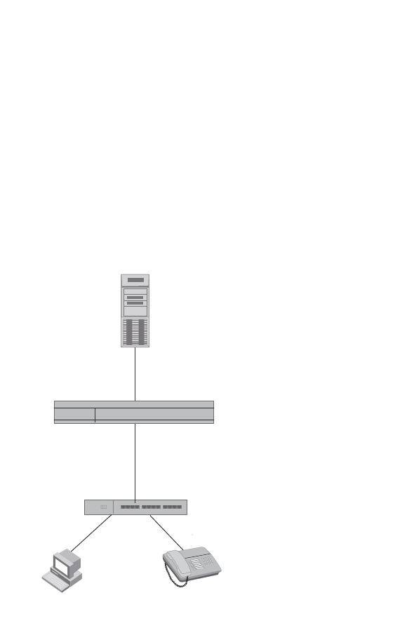
1300 PowerConnect B-Series FCX Configuration Guide
53-1002266-01
Example configurations
36
Multi-device port authentication with dynamic
VLAN assignment
Figure 162 illustrates multi-device port authentication with dynamic VLAN assignment on a Dell
PowerConnect device. In this configuration, a PC and an IP phone are connected to a hub, which is
connected to port e1 on a Dell PowerConnect device. The profile for the PC MAC address on the
RADIUS server specifies that the PC should be dynamically assigned to VLAN 102, and the RADIUS
profile for the IP phone specifies that it should be dynamically assigned to VLAN 3.
FIGURE 161 Using multi-device port authentication with dynamic VLAN assignment
In this example, multi-device port authentication is performed for both devices. If the PC is
successfully authenticated, port e1 PVID is changed from VLAN 1 (the DEFAULT-VLAN) to VLAN 102.
If authentication for the PC fails, then the PC can be placed in a specified “restricted” VLAN, or
traffic from the PC can be blocked in hardware. In this example, if authentication for the PC fails,
the PC would be placed in VLAN 1023, the restricted VLAN.
If authentication for the IP phone is successful, then port e1 is added to VLAN 3. If authentication
for the IP phone fails, then traffic from the IP phone would be blocked in hardware. (Devices
sending tagged traffic cannot be placed in the restricted VLAN.)
The part of the running-config related to multi-device port authentication would be as follows.
mac-authentication enable
mac-authentication auth-fail-vlan-id 1023
interface ethernet 1
dual-mode
mac-authentication enable
mac-authentication auth-fail-action restrict-vlan
mac-authentication enable-dynamic-vlan
mac-authentication disable-ingress-filtering
Hub
Switch
Port e1
Hub
Untagged Tagged
RADIUS Server
Tunnel-Private-Group-ID:
User 0002.3f7f.2e0a -> “U:102”
User 0050.048e.86ac -> “T:3”
PC
MAC: 0002.3f7f.2e0a
IP Phone
MAC: 0050.048e.86ac
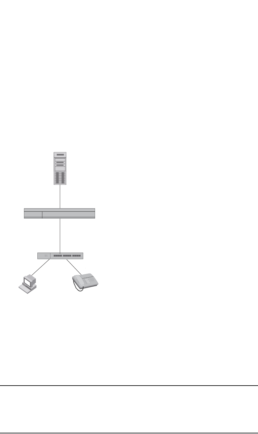
PowerConnect B-Series FCX Configuration Guide 1301
53-1002266-01
Example configurations 36
The mac-authentication disable-ingress-filtering command enables tagged packets on the port,
even if the port is not a member of the VLAN. If this feature is not enabled, authentication works as
in “Example 2”
Example 2
Figure 162 illustrates multi-device port authentication with dynamic VLAN assignment on a Dell
PowerConnect device. In this configuration, a PC and an IP phone are connected to a hub, which is
connected to port e1 on a Dell PowerConnect device. Port e1 is configured as a dual-mode port.
Also, mac-authentication disable-ingress-filtering is enabled on the port. The profile for the PC MAC
address on the RADIUS server specifies that the PC should be dynamically assigned to VLAN 102,
and the RADIUS profile for the IP phone specifies that it should be dynamically assigned to VLAN 3.
FIGURE 162 Using multi-device port authentication with dynamic VLAN assignment
In this example, multi-device port authentication is performed for both devices. If the PC is
successfully authenticated, dual-mode port e1 PVID is changed from the VLAN 1 (the
DEFAULT-VLAN) to VLAN 102. If authentication for the PC fails, then the PC can be placed in a
specified “restricted” VLAN, or traffic from the PC can be blocked in hardware. In this example, if
authentication for the PC fails, the PC would be placed in VLAN 1023, the restricted VLAN.
If authentication for the IP phone is successful, then dual-mode port e1 is added to VLAN 3. If
authentication for the IP phone fails, then traffic from the IP phone would be blocked in hardware.
(Devices sending tagged traffic cannot be placed in the restricted VLAN.)
NOTE
This example assumes that the IP phone initially transmits untagged packets (for example, CDP or
DHCP packets), which trigger the authentication process on the Dell PowerConnect device and client
lookup on the RADIUS server. If the phone sends only tagged packets and the port (e1) is not a
member of that VLAN, authentication would not occur. In this case, port e1 must be added to that
VLAN prior to authentication.
Hub
Switch
Port e1
Dual Mode
Hub
Untagged Tagged
RADIUS Server
Tunnel-Private-Group-ID:
User 0002.3f7f.2e0a -> “U:102”
User 0050.048e.86ac -> “T:3”
PC
MAC: 0002.3f7f.2e0a
IP Phone
MAC: 0050.048e.86ac

1302 PowerConnect B-Series FCX Configuration Guide
53-1002266-01
Example configurations
36
The part of the running-config related to multi-device port authentication would be as follows.
mac-authentication enable
mac-authentication auth-fail-vlan-id 1023
interface ethernet 1
mac-authentication enable
mac-authentication auth-fail-action restrict-vlan
mac-authentication enable-dynamic-vlan
dual-mode
Examples of multi-device port authentication and 802.1X
authentication configuration on the same port
The following examples show configurations that use multi-device port authentication and 802.1X
authentication on the same port.
Example 1
Figure 163 illustrates an example configuration that uses multi-device port authentication and
802.1X authentication n the same port. In this configuration, a PC and an IP phone are connected
to port e 1/3 on a Dell PowerConnect device. Port e 1/3 is configured as a dual-mode port.
The profile for the PC MAC address on the RADIUS server specifies that the PC should be
dynamically assigned to VLAN "Login-VLAN", and the RADIUS profile for the IP phone specifies that
it should be dynamically assigned to the VLAN named "IP-Phone-VLAN". When User 1 is
successfully authenticated using 802.1X authentication, the PC is then placed in the VLAN named
"User-VLAN".
NOTE
This example assumes that the IP phone initially transmits untagged packets (for example, CDP or
DHCP packets), which trigger the authentication process on the Dell PowerConnect device and client
lookup on the RADIUS server. If the phone sends only tagged packets and the port (e 1/3) is not a
member of that VLAN, authentication would not occur. In this case, port e 1/3 must be added to
that VLAN prior to authentication.
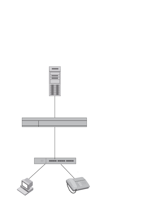
PowerConnect B-Series FCX Configuration Guide 1303
53-1002266-01
Example configurations 36
FIGURE 163 Using multi-device port authentication and 802.1X authentication on the same port
When the devices attempt to connect to the network, they are first subject to multi-device port
authentication.
When the MAC address of the IP phone is authenticated, the Access-Accept message from the
RADIUS server specifies that the IP phone port be placed into the VLAN named “IP-Phone-VLAN”.
which is VLAN 7. The Foundry-802_1x-enable attribute is set to 0, meaning that 802.1X
authentication is skipped for this MAC address. Port e 1/3 is placed in VLAN 7 as a tagged port.
No further authentication is performed.
When the PC MAC address is authenticated, the Access-Accept message from the RADIUS server
specifies that the PVID for the PC port be changed to the VLAN named “Login-VLAN”, which is VLAN
1024. The Foundry-802_1x-enable attribute is set to 1, meaning that 802.1X authentication is
required for this MAC address. The PVID of the port e 1/3 is temporarily changed to VLAN 1024,
pending 802.1X authentication.
When User 1 attempts to connect to the network from the PC, he is subject to 802.1X
authentication. If User 1 is successfully authenticated, the Access-Accept message from the
RADIUS server specifies that the PVID for User 1 port be changed to the VLAN named “User-VLAN”,
which is VLAN 3. If 802.1X authentication for User 1 is unsuccessful, the PVID for port e 1/3 is
changed to that of the restricted VLAN, which is 1023, or untagged traffic from port e 1/3 can be
blocked in hardware.
The part of the running-config related to port e 1/3 would be as follows.
interface ethernet 1/3
dot1x port-control auto
mac-authentication enable
dual-mode
Hub
User 0002.3f7f.2e0a (PC) Profile:
Foundry-y-802_1x-enable = 1
Tunnel-Private-Group-ID: = U:Login-VLAN
User 1 Profile:
Tunnel-Private-Group-ID: = U:IP-User-VLAN
Switch
Port e1/3
Dual Mode
Hub
Untagged Tagged
RADIUS Server
PC
MAC: 0002.3f7f.2e0a
User 1
IP Phone
MAC: 0050.048e.86ac
User 0050.048e.86ac (IP Phone) Profile:
Foundry-802_1x-enable = 0
Tunnel-Private-Group-ID = T:IP-Phone-VLAN
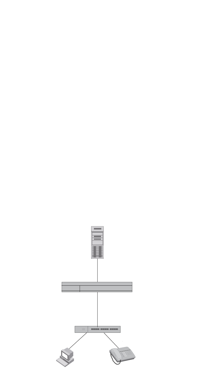
1304 PowerConnect B-Series FCX Configuration Guide
53-1002266-01
Example configurations
36
When the PC is authenticated using multi-device port authentication, the port PVID is changed to
“Login-VLAN”, which is VLAN 1024 in this example.
When User 1 is authenticated using 802.1X authentication, the port PVID is changed to
“User-VLAN”, which is VLAN 3 in this example.
Example 2
The configuration in Figure 164 requires that you create a profile on the RADIUS server for each
MAC address to which a device or user can connect to the network. In a large network, this can be
difficult to implement and maintain.
As an alternative, you can create MAC address profiles only for those devices that do not support
802.1X authentication, such as IP phones and printers, and configure the device to perform
802.1X authentication for the other devices that do not have MAC address profiles, such as user
PCs. To do this, you configure the device to perform 802.1X authentication when a device fails
multi-device port authentication.
Figure 164 shows a configuration where multi-device port authentication is performed for an IP
phone, and 802.1X authentication is performed for a user PC. There is a profile on the RADIUS
server for the IP phone MAC address, but not for the PC MAC address.
FIGURE 164 802.1X Authentication is performed when a device fails multi-device port
authentication
Multi-device port authentication is initially performed for both devices. The IP phone MAC address
has a profile on the RADIUS server. This profile indicates that 802.1X authentication should be
skipped for this device, and that the device port be placed into the VLAN named “IP-Phone-VLAN”.
Hub
No Profile for MAC 0002.3f7f.2e0a (PC)
User 1 Profile:
Tunnel-Private-Group-ID: = U:IP-User-VLAN
Switch
Port e1/4
Dual Mode
mac-authentication auth-fail-dot1x-override
CLI command configured
Hub
Untagged Tagged
RADIUS Server
PC
MAC: 0002.3f7f.2e0a
User 1
IP Phone
MAC: 0050.048e.86ac
User 0050.048e.86ac (IP Phone) Profile:
Foundry-802_1x-enable = 0
Tunnel-Private-Group-ID = T:IP-Phone-VLAN

PowerConnect B-Series FCX Configuration Guide 1305
53-1002266-01
Example configurations 36
Since there is no profile for the PC MAC address on the RADIUS server, multi-device port
authentication for this MAC address fails. Ordinarily, this would mean that the PVID for the port
would be changed to that of the restricted VLAN, or traffic from this MAC would be blocked in
hardware. However, the device is configured to perform 802.1X authentication when a device fails
multi-device port authentication, so when User 1 attempts to connect to the network from the PC,
he is subject to 802.1X authentication. If User 1 is successfully authenticated, the PVID for port e
1/4 is changed to the VLAN named “User-VLAN”.
NOTE
This example assumes that the IP phone initially transmits untagged packets (for example, CDP or
DHCP packets), which trigger the authentication process on the Dell PowerConnect device and client
lookup on the RADIUS server. If the phone sends only tagged packets and the port (e 1/4) is not a
member of that VLAN, authentication would not occur. In this case, port e 1/4 must be added to
that VLAN prior to authentication.
To configure the device to perform 802.1X authentication when a device fails multi-device port
authentication, enter the following command.
PowerConnect(config)#mac-authentication auth-fail-dot1x-override
Syntax: [no] mac-authentication auth-fail-dot1x-override

1306 PowerConnect B-Series FCX Configuration Guide
53-1002266-01
Example configurations
36

PowerConnect B-Series FCX Configuration Guide 1307
53-1002266-01
Chapter
37
Configuring Web Authentication
Table 231 lists individual Dell PowerConnect switches and the Web Authentication features they
support.
Overview
Authentication is important in enterprise networks because the network is considered a secure
area: it contains sensitive data and a finite amount of resources. Unauthorized users must be
prevented from accessing the network to protect the sensitive data and prevent the unnecessary
consumption of resources.
The ideal authentication method blocks unauthorized users at the earliest possible opportunity.
For internal enterprise networks, this can be controlled at the edge switch port. Two popular forms
of port-based security authentication used at the edge switch are multi-device port authentication
and 802.1x. Multi-device port authentication authenticates the MAC addresses of hosts or users
that are attempting to access the network. This type of authentication requires no intervention from
the host or user who is attempting to be authenticated. It is easy to use, but it can only authorize
hosts; it cannot be used to authorize users. 802.1x authentication can authorize users or hosts. It
is more flexible than the multi-device port authentication method; however, it requires more
support, configuration, maintenance and user intervention than multi-device port authentication.
The Dell Web authentication method provides an ideal port-based authentication alternative to
multi-device port authentication without the complexities and cost of 802.1x authentication. Hosts
gain access to the network by opening a Web browser and entering a valid URL address using HTTP
or HTTPS services. Instead of being routed to the URL, the host browser is directed to an
authentication Web page on the PowerConnect switch. The Web page prompts the host to enter a
user ID and password or a passcode. The credentials a host enters are used by a trusted source to
authenticate the host MAC address. (Multiple MAC addresses can be authenticated with the same
user name and password.)
If the authentication is unsuccessful, the appropriate page is displayed on the host browser. The
host is asked to try again or call for assistance, depending on what message is configured on the
Web page. If the host MAC address is authenticated by the trusted source, a Web page is displayed
with a hyperlink to the URL the host originally entered. If the user clicks on the link, a new window is
opened and the the user is directed to the requested URL.
TABLE 231 Supported Web Authentication features
Feature PowerConnect B-Series FCX
Enabling and disabling Web
Authentication
Yes
Configuring the Web Authentication
mode
Yes
Web Authentication options in this
chapter
Yes

1308 PowerConnect B-Series FCX Configuration Guide
53-1002266-01
Configuration considerations
37
While a MAC address is in the authenticated state, the host can forward data through the
PowerConnect switch. The MAC address remains authenticated until one of the following events
occurs:
•The host MAC address is removed from a list of MAC addresses that are automatically
authenticated. (Refer to “Specifying hosts that are permanently authenticated” on page 1321).
•The re-authentication timer expires and the host is required to re-authenticate (Refer to
“Configuring the re-authentication period” on page 1322).
•The host has remained inactive for a period of time and the inactive period timer has expired.
(Refer to “Forcing re-authentication after an inactive period” on page 1325.)
•All the ports on the VLAN on which Web Authentication has been configured are in a down
state. All MAC addresses that are currently authenticated are de-authenticated (Refer to
“Forcing re-authentication when ports are down” on page 1324.)
•The authenticated client is cleared from the Web Authentication table. (Refer to “Clearing
authenticated hosts from the web authentication table” on page 1323).
The PowerConnect switch can be configured to automatically authenticate a host MAC address.
The host will not be required to login or re-authenticate (depending on the re-authentication period)
once the MAC address passes authentication.
A host that is logged in and authenticated remains logged in indefinitely, unless a re-authentication
period is configured. When the re-authentication period ends, the host is logged out. A host can log
out at any time by pressing the Logout button in the Web Authentication Success page.
NOTE
The host can log out as long as the Logout window (Success page) is visible. If the window is
accidentally closed, the host cannot log out unless the re-authentication period ends or the host is
manually cleared from the Web Authentication table.
Configuration considerations
Web Authentication is modeled after other RADIUS-based authentication methods currently
available on Dell edge switches. However, Web Authentication requires a Layer 3 protocol (TCP/IP)
between the host and the authenticator. Therefore, to implement Web Authentication, you must
consider the following configuration and topology configuration requirements:
•Web Authentication works only on the default HTTP or HTTPS port.
•The host must have an IP address prior to Web Authentication. This IP address can be
configured statically on the host; however, DHCP addressing is also supported.
•If you are using DHCP addressing, a DHCP server must be in the same broadcast domain as
the host. This DHCP server does not have to be physically connected to the switch. Also, DHCP
assist from a router may be used.
•Web Authentication, 802.1X port security, and multi-device port authentication are not
supported concurrently on the same port.
The following applies to Web Authentication in the Layer 2 switch image:
•If the management VLAN and Web Authentication VLAN are in different IP networks, make sure
there is at least one routing element in the network topology that can route between these IP
networks.
The following are required for Web Authentication in the base Layer 3 and full Layer 3 images:
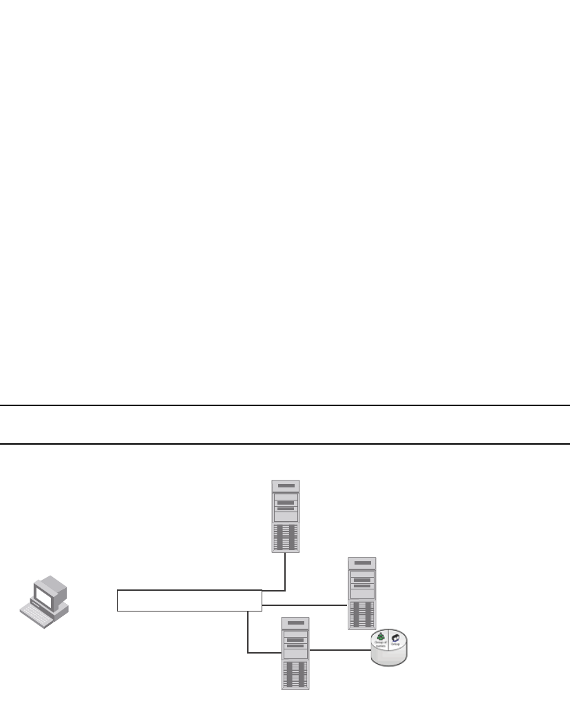
PowerConnect B-Series FCX Configuration Guide 1309
53-1002266-01
Configuration tasks 37
•Each Web Authentication VLAN must have a virtual interface (VE).
•The VE must have at least one assigned IPv4 address.
Web Authentication is enabled on a VLAN. That VLAN becomes a Web Authentication VLAN that
does the following:
•Forwards traffic from authenticated hosts, just like a regular VLAN.
•Blocks traffic from unauthenticated hosts except from ARP, DHCP, DNS, HTTP, and HTTPs that
are required to perform Web Authentication.
Figure 165 shows the basic components of a network topology where Web Authentication is used.
You will need:
•A Dell PowerConnect switch running a software release that supports Web Authentication
•DHCP server, if dynamic IP addressing is to be used
•Computer/host with a web browser
Your configuration may also require a RADIUS server with some Trusted Source such as LDAP or
Active Directory.
NOTE
The Web server, RADIUS server, and DHCP server can all be the same server.
FIGURE 165 Basic topology for web authentication
Configuration tasks
Follow the steps given below to configure Web Authentication on a device.
1. Set up any global configuration required for the PowerConnect switch, RADIUS server, Web
server and other servers.
•On a Layer 2 PowerConnect switch, make sure the PowerConnect switch has an IP
address.
PowerConnect# configure terminal
PowerConnect(config)#ip address 10.1.1.10/24
Computer/Client
10.1.1.101/24
IP-FES
10.1.1.101/24
DHCP Server
10.1.1.12/24
Web Server
10.1.1.9/24
RADIUS Server
10.1.1.8
Tr usted Source
(LDAP/Active Directory)

1310 PowerConnect B-Series FCX Configuration Guide
53-1002266-01
Configuration tasks
37
•On a Layer 3 PowerConnect switch, assign an IP address to a virtual interface (VE) for
each VLAN on which Web Authentication will be enabled.
PowerConnect#configure terminal
PowerConnect(config)#vlan 10
PowerConnect(config-vlan-10)#router-interface ve1
PowerConnect(config-vlan-10)#untagged e 1/1/1 to 1/1/10
PowerConnect(config-vlan-10)#interface ve1
PowerConnect(config-vif-1)#ip address 1.1.2.1/24
2. By default, Web Authentication will use a RADIUS server to authenticate host usernames and
passwords, unless it is configured to use a local user database. If Web Authentication will use
a RADIUS server, you must configure the RADIUS server and other servers. For example, if your
RADIUS server has an IP address of 192.168.1.253, then use the CLI to configure the following
global CLI commands on the PowerConnect switch.
PowerConnect(config)# radius-server host 10.1.1.8
PowerConnect(config)# radius-server key $GSig@U\
NOTE
Remember the RADIUS key you entered. You will need this key when you configure your RADIUS
server.
3. Web authentication can be configured to use secure (HTTPS) or non-secure (HTTP) login and
logout pages. By default, HTTPS is used.
To enable the non-secure Web server on the PowerConnect switch, enter the following
command.
PowerConnect(config)# web-management HTTP
PowerConnect(config)#vlan 10
PowerConnect(config-vlan-10)webauth
PowerConnect(config-vlan-10-webauth)#no secure-login
To enable the secure Web server on the PowerConnect switch, enter the following command.
PowerConnect(config)# web-management HTTPS
PowerConnect(config)#vlan 10
PowerConnect(config-vlan-10)webauth
PowerConnect(config-vlan-10-webauth)#secure-login
4. If the secure Web server is used, in order to access a secure Web page, the Web server needs
to provide a key. This key is exchanged using a certificate. A certificate is a digital document
that is issued by a trusted source that can validate the authenticity of the certificate and the
Web server that is presenting it. Therefore the switch must have a certificate for web
authentication to work. There are two choices for providing the switch with a certificate:
•Upload one using the following global CLI command.
PowerConnect(config)# ip ssl private-key-file tftp <ip-addr> <key-filename>
•Generate one using the following global CLI command.
PowerConnect(config)#crypto-ssl certificate generate default_cert
5. Create a Web Authentication VLAN and enable Web Authentication on that VLAN.
PowerConnect(config)#vlan 10
PowerConnect(config-vlan-10)#webauth
PowerConnect(config-vlan-10-webauth)#enable

PowerConnect B-Series FCX Configuration Guide 1311
53-1002266-01
Enabling and disabling web authentication 37
Once enabled, the CLI changes to the "webauth" configuration level. In the example above,
VLAN 10 will require hosts to be authenticated using Web Authentication before they can
forward traffic.
6. Configure the Web Authentication mode:
•Username and password – Blocks users from accessing the switch until they enter a valid
username and password on a web login page.
•Passcode – Blocks users from accessing the switch until they enter a valid passcode on a
web login page.
•None – Blocks users from accessing the switch until they press the ’Login’ button. A
username and password or passcode is not required.
Refer to “Configuring the web authentication mode” on page 1311.
7. Configure other Web Authentication options (refer to “Configuring web authentication options”
on page 1320).
Enabling and disabling web authentication
Web Authentication is disabled by default. To enable it, enter the following commands.
PowerConnect(config)#vlan 10
PowerConnect(config-vlan-10)webauth
PowerConnect(config(config-vlan-10-webauth)#enable
The first command changes the CLI level to the VLAN configuration level. The second command
changes the configuration level to the Web Authentication VLAN level. The last command enables
Web Authentication. In the example above, VLAN 10 will require hosts to be authenticated using
Web Authentication before they can forward traffic.
Syntax: webauth
PowerConnect devices support a maximum of two Web Authentication VLANs.
Syntax: [no] enable
Enter the no enable command to disable Web Authentication.
Configuring the web authentication mode
You can configure the PowerConnect switch to use one of three Web Authentication modes:
•Username and password – Block users from accessing the switch until they enter a valid
username and password on a web login page. Refer to “Using local user databases” on
page 1312.
•Passcode – Blocks users from accessing the switch until they enter a valid passcode on a web
login page. Refer to “Using passcodes” on page 1315.
•None – Blocks users from accessing the switch until they press the ’Login’ button. A username
and password or passcode is not required. Refer to “Using automatic authentication” on
page 1320.
This following sections describe how to configure these Web Authentication modes.

1312 PowerConnect B-Series FCX Configuration Guide
53-1002266-01
Configuring the web authentication mode
37
Using local user databases
Web Authentication supports the use of local user databases consisting of usernames and
passwords, to authenticate devices. Users are blocked from accessing the switch until they enter a
valid username and password on a web login page.
Once a user successfully authenticates through username and password, the user is subjected to
the same policies as for RADIUS-authenticated devices (for example, the re-authentication period,
maximum number of users allowed, etc.). Similarly, once a user fails username and password
authentication, the user is subjected to the same policies as for devices that fail RADIUS
authentication.
You can create up to ten local user databases on the PowerConnect switch either by entering a
series of CLI commands, or by uploading a list of usernames and passwords from a TFTP file to the
PowerConnect switch. The user databases are stored locally, on the PowerConnect switch.
Configuration steps
Follow the steps given below to configure a local user database.
1. Create the local user database.
2. Add records to the local user database either by entering a series of CLI commands, or by
importing a list of user records from an ASCII text file on the TFTP server to the PowerConnect
switch.
3. Set the local user database authentication mode.
4. If desired, set the authentication method (RADIUS/local) failover sequence.
5. Assign a local user databse to a Web Authentication VLAN.
Creating a local user database
The PowerConnect switch supports a maximum of ten local user databases, each containing up to
30 user records. Each user record consists of a username and password.
To create a local user database, enter a command such as the following.
PowerConnect#(config)#local-userdb userdb1
PowerConnect#(config-localuserdb-userdb1)#
This command creates a local user database named userdb1. To add user records to this
database, refer to “Adding a User record to a local user database” on page 1312.
Syntax: local-userdb <db-name>
You can create up to ten local user databases for Web Authentication.
For <db-name>, enter up to 31 alphanumeric characters.
Adding a User record to a local user database
To add a user record, enter commands such as the following.
PowerConnect#(config)#local-userdb userdb1
PowerConnect#(config-localuserdb-userdb1)#username marcia password bunch4

PowerConnect B-Series FCX Configuration Guide 1313
53-1002266-01
Configuring the web authentication mode 37
The first command changes the configuration level to the local user database level for userdb1. If
the database does not already exist, it is created. The second command adds the user record
marcia to the userdb1 database.
Syntax: username <username> password <password>
For <username>, enter up to 31 ASCII characters.
For <password>, enter up to 29 ASCII characters.
You can add up to 30 usernames and passwords to a local user database.
To view a list of users in a local user database, use the CLI command vlan-mod-port-userdb. Refer
to “Displaying a list of local user databases” on page 1337.
Deleting a user record from a local user database
To delete a user record from the local user database, enter commands such as the following.
PowerConnect#(config)#local-userdb userdb1
PowerConnect#(config-localuserdb-userdb1)#no username marcia
The first command changes the configuration level to the local user database level for userdb1.
The second command deletes the user record marcia from the userdb1 database.
Syntax: no username <username>
Deleting All user records from a local user database
To delete all user records from a local user database, enter the following command.
PowerConnect#(config-localuserdb-userdb1)#delete-all
Syntax: delete-all
Creating a text file of user records
If desired, you can use the TFTP protocol to import a list of usernames and passwords from a text
file on a TFTP server to the PowerConnect switch. The text file to be imported must be in the
following ASCII format.
[delete-all]
[no] username <username1> password <password1> <cr>
[no] username <username2> password <password2> <cr>
...
The [delete-all] keyword indicates that the user records in the text file will replace the user records
in the specified local user database on the PowerConnect switch. If the [delete-all] keyword is not
present, the new user records will be added to the specified local user database on the
PowerConnect switch. The [delete-all] keyword is optional. If present, it must appear on the first
line, before the first user record in the text file.
The optional [no] keyword indicates that the user entry will be deleted from the specified local user
database on the PowerConnect switch.
User records that already exist in the local user database will be updated with the information in
the text file when it is uploaded to the switch.
For <username1>, <username2>, etc., enter up to 31 ASCII characters.

1314 PowerConnect B-Series FCX Configuration Guide
53-1002266-01
Configuring the web authentication mode
37
For <password1>, <password2>, etc., enter up to 29 ASCII characters.
Be sure to Insert a cursor return (<cr>) after each user record.
You can enter up to 30 user records per text file.
Importing a text file of user records from a TFTP server
NOTE
Before importing the file, make sure it adheres to the ASCII text format described in the previous
section, “Creating a text file of user records” on page 1313.
To import a text file of user records from a TFTP server to the PowerConnect switch, enter a
command such as the following.
PowerConnect#(config-localuserdb-userdb1)#import-users tftp 192.168.1.1 filename
userdb1
Syntax: import-users tftp <ip-address> filename <filename>
The <ip-address> parameter specifies the IPv4 address of the TFTP server on which the desired
text file resides.
The <filename> parameter specifies the name of the image on the TFTP server.
Using a RADIUS server as the web authentication method
By default, Web Authentication will use a RADIUS server to authenticate hosts’ usernames and
passwords, unless the device is configured to use the local user database (see the previous
section). To configure the PowerConnect switch to use a RADIUS server, refer to “Configuring
RADIUS security” on page 1181. You must also do the following.
1. Configure the RADIUS server information on the PowerConnect switch. Enter a command
such as the following.
PowerConnect(config)#radius-server host 10.1.1.8 auth-port 1812 acct-port 1813
default key $GSig@U\
NOTE
Web Authentication will use the first reachable RADIUS server listed in the configuration. The
use-radius-server on individual ports is not supported for Web Authentication.
2. Enable the username and password authentication mode.
PowerConnect(config-vlan-10-webauth)#auth-mode username-password
3. Enable the RADIUS authentication method. Refer to “Setting the local user database
authentication method” on page 1314 or “Setting the web authentication failover sequence”
on page 1315
Setting the local user database authentication method
By default, the PowerConnect switch uses a RADIUS server to authenticate users in a VLAN. The
previous section describes how to configure a RADIUS server to authenticate users in a VLAN. To
configure the switch to instead use a local user database to authenticate users in a VLAN, enter a
command such as the following.

PowerConnect B-Series FCX Configuration Guide 1315
53-1002266-01
Configuring the web authentication mode 37
PowerConnect(config-vlan-10-webauth)#auth-mode username-password auth-methods
local
Syntax: auth-mode username-password auth-methods local
To revert back to using the RADIUS server, enter the following command.
PowerConnect(config-vlan-10-webauth)#auth-mode username-password auth-methods
radius
Syntax: auth-mode username-password auth-methods radius
Setting the web authentication failover sequence
You can optionally specify a failover sequence for RADIUS and local user database authentication
methods. For example, you can configure Web Authentication to first use a local user database to
authenticate users in a VLAN. If the local user database is not available, it will use a RADIUS
server. Enter the following command.
PowerConnect(config-vlan-10-webauth)#auth-mode username-password auth-methods
local radius
Syntax: auth-mode username-password auth-methods <method1> <method2>
For <method1> <method2>, enter radius local or local radius.
Assigning a local user database to a web authentication VLAN
After creating or importing a local user database on the PowerConnect switch and setting the local
user database authentication method to local, you can configure a Web Authentication VLAN to use
the database to authenticate users in a VLAN. To do so, enter a command such as the following.
PowerConnect(config-vlan-10-webauth)#auth-mode username-password
local-user-database userdb1
These commands configure Web Authentication to use the usernames and passwords in the
userdb1 database to authenticate users in VLAN 10.
Syntax: [no] auth-mode username-password local-user-database <db-name>
For <db-name>, enter a valid local user database.
Use the no form of the command to remove the database from the Web Authentication VLAN.
Using passcodes
Web Authentication supports the use of passcodes to authenticate users. Users are blocked from
accessing the switch until they enter a valid passcode on a web login page. Unlike username and
password authentication, passcode authentication uses a simple number to authenticate users.
The simplicity of a passcode reduces user errors and lowers the overhead of supporting and
managing simple tasks, such as Internet access for guests and visitors in the office.
When passcodes are enabled, the system will automatically generate them every 1440 minutes
(24 hours), and when the system boots up. You can optionally create up to four static passcodes
which will be used in conjunction with the dynamic passcodes generated by the system.

1316 PowerConnect B-Series FCX Configuration Guide
53-1002266-01
Configuring the web authentication mode
37
Configuration steps
Follow the steps given below to configure the device to use the passcode authentication mode.
1. Optionally create up to four static passcodes
2. Enable passcode authentication
3. Configure other options
Creating static passcodes
Static passcodes can be used for troubleshooting purposes, or for networks that want to use
passcode authentication, but do not have the ability to support automatically-generated passcodes
(for example, the network does not fully support the use of SNMP traps or Syslog messages with
passcodes).
Manually-created passcodes are used in conjunction with dynamic passcodes . You can configure
up to four static passcodes that never expire. Unlike dynamically-created passcodes, static
passcodes are saved to flash memory. By default, there are no static passcodes configured on the
switch.
To create static passcodes, enter commands such as the following.
PowerConnect(config-vlan-10-webauth)#auth-mode passcode static 3267345
PowerConnect(config-vlan-10-webauth)#auth-mode passcode static 56127
Syntax: auth-mode passcode static <passcode>
For <passcode>, enter a number from 4 to 16 digits in length. You can create up to four static
passcodes, each with a different length. Static passcodes do not have to be the same length as
passcodes that are automatically generated.
After creating static passcodes, you can enable passcode authentication as described in the next
section.
To view the passcodes configured on the switch, use the show webauth vlan <vlan-id> passcode
command. Refer to “Displaying passcodes” on page 1338.
Enabling passcode authentication
To enable passcode authentication, enter the following command.
PowerConnect(config-vlan-10-webauth)#auth-mode passcode
This command enables Web Authentication to use dynamically-created passcodes to authenticate
users in the VLAN. If the configuration includes static passcodes, they are used in conjunction with
dynamically-created passcodes.
Syntax: [no]auth-mode passcode
Enter no auth-mode passcode to disable passcode authentication.
Configuring the length of dynamically-generated passcodes
By default, dynamically-generated passcodes are 4 digits in length, for example, 0123. If desired,
you can increase the passcode length to up to 16 digits. To do so, enter a command such as the
following at the Web Authentication level of the CLI.
PowerConnect(config-vlan-10-webauth)#auth-mode passcode length 10

PowerConnect B-Series FCX Configuration Guide 1317
53-1002266-01
Configuring the web authentication mode 37
The next dynamically-created passcode will be 10 digits in length, for example, 0123456789.
Syntax: auth-mode passcode length <value>
For <value>, enter a number from 4 to 16.
Configuring the passcode refresh method
Passcode authentication supports two passcode refresh methods:
•Duration of time – By default, dynamically-created passcodes are refreshed every 1440
minutes (24 hours). When refreshed, a new passcode is generated and the old passcode
expires. You can increase or decrease the duration of time after which passcodes are
refreshed, or you can configure the device to refresh passcodes at a certain time of day
instead of after a duration of time.
•Time of day – When initially enabled, the time of day method will cause passcodes to be
refreshed at 0:00 (12:00 midnight). If desired, you can change this time of day, and you can
add up to 24 refresh periods in a 24-hour period.
When a passcode is refreshed, the old passcode will no longer work, unless a grace period is
configured (refer to “Configuring a Grace Period for an expired passcode” on page 1318).
If a user changes the passcode refresh value, the configuration is immediately applied to the
current passcode. For example, if the passcode duration is 100 minutes and the passcode was
last generated 60 minutes prior, a new passcode will be generated in 40 minutes. However, if the
passcode duration is changed from 100 to 75 minutes, and the passcode was last generated 60
minutes prior, a new passcode will be generated in 15 minutes. Similarly, if the passcode duration
is changed from 100 to 50 minutes, and the passcode was last generated 60 minutes prior, the
passcode will immediately expire and a new passcode will be generated. The same principles
apply to the time of day passcode refresh method.
If you configure both duration of time and time of day passcode refresh values, they are saved to
the configuration file. You can switch back and forth between the passcode refresh methods, but
only one method can be enabled at a time.
NOTE
Passcodes are not stateful, meaning a software reset or reload will cause the system to erase the
passcode. When the PowerConnect switch comes back up, a new passcode will be generated.
Changing the passcode refresh duration
To change the duration of time after which passcodes are refreshed, enter commands such as the
following.
PowerConnect(config-vlan-10-webauth)#auth-mode passcode refresh-type duration
4320
The passcode will be refreshed after 4320 minutes (72 hours).
Syntax: auth-mode passcode refresh-type duration <value>
For <value>, enter a number from 5 to 9999 minutes. The default is 1440 minutes (24 hours).
Refreshing passcodes at a certain time of the day
You can configure the PowerConnect switch to refresh passcodes at a certain time of day, up to 24
times each day, instead of after a duration of time. When this feature is enabled, by default
passcodes will be refreshed at 00:00 (12 midnight).

1318 PowerConnect B-Series FCX Configuration Guide
53-1002266-01
Configuring the web authentication mode
37
To configure the switch to refresh passcodes at a certain time of day, enter commands such as the
following.
PowerConnect(config-vlan-10-webauth)#auth-mode passcode refresh-type time 6:00
PowerConnect(config-vlan-10-webauth)#auth-mode passcode refresh-type time 14:30
The passcode will be refreshed at 6:00am, 2:30pm, and 0:00 (12 midnight).
Syntax: [no] auth-mode passcode refresh-type time <hh:mm>.
<hh:mm> is the hour and minutes. If you do not enter a value for <hh:mm>, by default, passcodes
will be refreshed at 00:00 (12:00 midnight). You can configure up to 24 refresh times. Each must
be at least five minutes apart.
Enter the no form of the command to remove the passcode refresh time of day.
Resetting the passcode refresh time of day configuration
If the PowerConnect switch is configured to refresh passcodes several times during the day (time of
day configuration), you can use the following comand to delete all of the configured times and
revert back to the default time of 00:00 (12 midnight).
PowerConnect(config-vlan-10-webauth)#auth-mode passcode refresh-type time
delete-all
Syntax: auth-mode passcode refresh-type time delete-all
Configuring a Grace Period for an expired passcode
You can optionally configure a grace period for an expired passcode. The grace period is the period
of time that a passcode will remain valid, even after a new passcode is generated. For example, if
a five minute grace period is set and the passcode 1234 is refreshed to 5678, both passcodes will
be valid for five minutes, after which the 1234 passcode will expire and the 5678 passcode will
remain in effect.
To configure the grace period for an expired passcode, enter a command such as the following.
PowerConnect(config-vlan-10-webauth)#auth-mode passcode grace-period 5
Syntax: auth-mode passcode grace-period <value>
<value> is a number between 0 and 5 minutes. 0 means there is no grace period.
NOTE
If the grace period is re-configured while a passcode is already in the grace period, the passcode is
not affected by the configuration change. The new grace period will apply only to passcodes that
expire after the new grace period is set.
Flushing all expired passcodes that are in the grace period
You can delete old passcodes that have expired but are still valid because they are in the grace
period. This feature is useful in situations where the old passcodes have been compromised but
are still valid because of the grace period. This feature does not affect current valid passcodes or
passcodes that newly expire.
To flush out all expired passcodes that are currently in the grace period, enter the following
command.
PowerConnect(config-vlan-10-webauth)#auth-mode passcode flush-expired

PowerConnect B-Series FCX Configuration Guide 1319
53-1002266-01
Configuring the web authentication mode 37
Syntax: auth-mode passcode flush-expired
Disabling and re-enabling passcode logging
The software generates a Syslog message and SNMP trap message every time a new passcode is
generated and passcode authentication is attempted,. This is the default behavior. If desired, you
can disable passcode-related Syslog messages or SNMP trap messages, or both.
The following shows an example Syslog message and SNMP trap message related to passcode
authentication.
New passcode: 01234567. Expires in 1440 minutes. Old passcode is valid for another
5 minutes.
To disable Syslog messages for passcodes, enter the following command.
PowerConnect(config-vlan-10-webauth)#no auth-mode passcode log syslog
Enter the following command to disable SNMP trap messages for passcodes.
PowerConnect(config-vlan-10-webauth)#no auth-mode passcode log snmp-trap
Enter the following command to re-enable Syslog messages for passcodes after they have been
disabled.
PowerConnect(config-vlan-10-webauth)#auth-mode passcode log syslog
Enter the following command to re-enable SNMP trap messages for passcodes after they have
been disabled.
PowerConnect(config-vlan-10-webauth)#auth-mode passcode log snmp-trap
Syntax: [no] auth-mode passcode log syslog | snmp-trap
Re-sending the passcode log message
If passcode logging is enabled, you can enter a CLI command to retransmit the current passcode to
a Syslog message or SNMP trap. To do so, enter the following command.
PowerConnect(config-vlan-10-webauth)#auth-mode passcode resend-log
Syntax: auth-mode passcode resend-log
NOTE
The switch retransmits the current passcode only. Passcodes that are in the grace period are not
sent.
Manually refreshing the passcode
You can manually refresh the passcode instead of waiting for the system to automatically generate
one. When manually refreshed, the old passcode will no longer work, even if a grace period is
configured. Also, if the passcode refresh method duration of time is used, the duration counter is
reset when the passcode is manually refreshed. The passcode refresh method time of day is not
affected when the passcode is manually refreshed.
To immediately refresh the passcode, enter the following CLI command.
PowerConnect(config-vlan-10-webauth)#auth-mode passcode generate
Syntax: auth-mode passcode generate

1320 PowerConnect B-Series FCX Configuration Guide
53-1002266-01
Configuring web authentication options
37
Using automatic authentication
By default, if Web Authentication is enabled, hosts need to login and enter authentication
credentials in order to gain access to the network. If a re-authentication period is configured, the
host will be asked to re-enter authentication credentials once the re-authentication period ends.
You can configure Web Authentication to authenticate a host when the user presses the ’Login’
button. When a host enters a valid URL address, Web Authentication checks the list of blocked
MAC addresses. If the hosts’ MAC address is not on the list and the number of allowable hosts has
not been reached, after pressing the ’Login’ button, the host is automatically authenticated for the
duration of the configured re-authentication period, if one is configured. Once the re-authentication
period ends, the host is logged out and needs to enter the URL address again.
NOTE
Automatic authentication is not the same as permanent authentication. (Refer to “Specifying hosts
that are permanently authenticated” on page 1321). You must still specify devices that are to be
permanently authenticated even if automatic authentication is enabled.
To enable automatic authentication, enter the following command.
PowerConnect(config)#vlan 10
PowerConnect(config-vlan-10)#webauth
PowerConnect(config-vlan-10-webauth)#auth-mode none
Syntax: [no] auth-mode none
If automatic authentication is enabled and a host address is not in the blocked MAC address list,
Web Authentication authenticates the host and displays the Login page without user credentials,
then provides a hyperlink to the requested URL site..
To determine if automatic authentication is enabled on your device, issue the show webauth vlan
<vlan-id> command at the VLAN configuration level.
Syslog messages are generated under the following conditions:
•The feature is enabled
•The feature is disabled
•A MAC address is successfully authenticated
•Automatic authentication cannot occur because the maximum number of hosts allowed has
been reached
Configuring web authentication options
The sections below explain other configuration options for Web Authentication.
Enabling RADIUS accounting for web authentication
When Web Authentication is enabled, you can enable RADIUS accounting to record login (start) and
logout (stop) events per host. The information is sent to a RADIUS server. Note that packet/byte
count is not supported.
To enable RADIUS accounting, enter the following command.
PowerConnect(config-vlan-10-webauth)#accounting

PowerConnect B-Series FCX Configuration Guide 1321
53-1002266-01
Configuring web authentication options 37
Syntax: [no] accounting
Enter the no accounting command to disable RADIUS accounting for Web Authentication.
Changing the login mode (HTTPS or HTTP)
Web Authentication can be configured to use secure (HTTPS) or non-secure (HTTP) login and logout
pages. By default, HTTPS is used. Figure 167 shows an example Login page.
To change the login mode to non-secure (HTTP), enter the following command.
PowerConnect(config-vlan-10-webauth)#no secure-login
To revert back to secure mode, enter the following command.
PowerConnect(config-vlan-10-webauth)#secure-login
Syntax: [no] secure-login
Specifying trusted ports
You can configure certain ports of a Web Authentication VLAN as trusted ports. All hosts connected
to the trusted ports need not authenticate and are automatically allowed access to the network.
To create a list of trusted ports, enter commands such as the following.
PowerConnect(config-vlan-10-webauth)#trust-port ethernet 3
PowerConnect(config-vlan-10-webauth)#trust port ethernet 6 to 10
The above commands configure ports 3 and 6 – 10 as trusted ports.
Syntax: trust-port ethernet <port> [to <port>]
Specify the <port> variable in the following formats:
•PowerConnect B-Series FCX stackable switches – <stack-unit/slotnum/portnum>
Specifying hosts that are permanently authenticated
Certain hosts, such as DHCP server, gateway, printers, may need to be permanently authenticated.
Typically, these hosts are managed by the network administrator and are considered to be
authorized hosts. Also, some of these hosts (such as printers) may not have a Web browser and will
not be able to perform the Web Authentication.
To permanently authenticate these types of hosts, enter a command such as the following at the
"webauth" configuration level.
PowerConnect(config-vlan-10-webauth)#add mac 0004.80eb.2d14 duration 0
PowerConnect(config-vlan-10-webauth)#add mac 0007.e90e.de3b duration 0
Syntax: [no] add mac <mac-address> duration <seconds> | ethernet <port> duration <seconds>
Syntax: no add mac <mac-address>
Specify the <port> variable in the following formats:
•PowerConnect B-Series FCX stackable switches – <stack-unit/slotnum/portnum>
<seconds> specifies how long the MAC address remains authenticated. Enter 0 – 128000
seconds. The default is the current value of reauth-time. A value of "0" means that Web
Authentication for the MAC address will not expire.

1322 PowerConnect B-Series FCX Configuration Guide
53-1002266-01
Configuring web authentication options
37
Instead of just entering a duration for how long the MAC address remains authenticated, you can
specify the MAC address to be added by the specified port that is a member of the VLAN. To do this,
enter values for the ethernet <port> duration <seconds> option. Enter the port number and the
number of seconds the MAC address remains authenticated.
Entering a no add mac <mac-address> duration <seconds> | ethernet <port> duration <seconds>
command sets duration and ethernet to their default values. If you want to remove a host, enter the
no add mac <mac-address> command.
NOTE
If a MAC address is statically configured, this MAC address will not be allowed to be dynamically
configured on any port.
Configuring the re-authentication period
After a successful authentication, a user remains authenticated for a duration of time. At the end of
this duration, the host is automatically logged off. The user must be re-authenticated again. To set
the number of seconds a host remains authenticated before being logged off, enter a command
such as the following.
PowerConnect(config-vlan-10-webauth)#reauth-time 10
Syntax: [no] reauth-time <seconds>
You can specify 0 – 128000 seconds. The default is 28800 seconds, and 0 means the user is
always authenticated and will never have to re-authenticate, except if an inactive period less than
the re-authentication period is configured on the Web Authentication VLAN. If this is the case, the
user becomes de-authenticated if there is no activity and the timer for the inactive period expires.
Defining the web authentication cycle
You can set a limit as to how many seconds users have to be Web Authenticated by defining a cycle
time. This time begins at a user first Login attempt on the Login page. If the user has not been
authenticated successfully when this time expires, the user must enter a valid URL again to display
the Web Authentication Welcome page.
To define a cycle time, enter a command such as the following.
PowerConnect(config-vlan-10-webauth)#cycle time 20
Syntax: [no] cycle time <seconds>
Enter 0 – 3600 seconds, where 0 means there is no time limit. The default is 600 seconds
Limiting the number of web authentication attempts
You can set a limit on the number of times a user enters an invalid user name and password during
the specified cycle time. If the user exceeds the limit, the user is blocked for a duration of time,
which is defined by the block duration command. Also, the Web browser will be redirected to the
Exceeded Allowable Attempts webpage.
To limit the number of Web Authentication attempts, enter a command such as the following.
PowerConnect(config-vlan-10-webauth)#attempt-max-num 4
Syntax: [no] attempt-max-num <number>

PowerConnect B-Series FCX Configuration Guide 1323
53-1002266-01
Configuring web authentication options 37
Enter a number from 0 to 64, where 0 means there is no limit to the number of Web Authentication
attempts. The default is 5.
Clearing authenticated hosts from the web
authentication table
Use the following commands to clear dynamically-authenticated hosts from the Web Authentication
table.
To clear all authenticated hosts in a Web authentication VLAN, enter a command such as the
following.
PowerConnect#clear webauth vlan 25 authenticated-mac
This command clears all the authenticated hosts in VLAN 25.
To clear a particular host in a Web authentication VLAN, enter a command such as the following.
PowerConnect#clear webauth vlan 25 authenticated-mac 1111.2222.3333
This command clears host 1111.2222.3333 from VLAN 25.
Syntax: clear webauth vlan <vlan-id> authenticated-mac [<mac-address>]
Setting and clearing the block duration for web
authentication attempts
After users exceed the limit for Web Authentication attempts, specify how many seconds users
must wait before the next cycle of Web Authenticated begins. Enter a command such as the
following.
PowerConnect(config-vlan-10-webauth)#block duration 4
Syntax: [no] block duration <seconds>
Users cannot attempt Web Authentication during this time.
Enter 0–128000 seconds. The default is 90 seconds, and entering 0 means that the MAC address
is infinitely blocked.
To unblock the MAC address, wait until the block duration timer expires or enter a command such
as the following.
PowerConnect(config-vlan-10-webauth)#clear webauth vlan 10 block-mac 000.000.1234
Syntax: clear webauth vlan <vlan-id> block-mac [<mac-address>]
If you do not enter a <mac-address>, then all the entries for the specified VLAN will be cleared.
Manually blocking and unblocking a specific host
A host can be temporarily or permanently blocked from attempting Web Authentication by entering
a command such as the following.
PowerConnect(config-vlan-10-webauth)#block mac 0123.17d1.0a3d duration 4
Syntax: [no] block mac <mac-address> duration <seconds>
Syntax: no block mac <mac-address>

1324 PowerConnect B-Series FCX Configuration Guide
53-1002266-01
Configuring web authentication options
37
Enter 0 – 128000 for <seconds>. The default is the current value of block duration command.
Entering a value of "0" means the MAC address is blocked permanently.
Entering no block mac <mac-address> duration <seconds> resets duration to its default value.
You can unblock a host by entering the no block mac <mac-address> command.
Limiting the number of authenticated hosts
You can limit the number of hosts that are authenticated at any one time by entering a command
such as the following.
PowerConnect(config-vlan-10-webauth)#host-max-num 300
Syntax: [no] host-max-num <number>
You can enter 0 – 8192, where 0 means there is no limit to the number of hosts that can be
authenticated. The default is 0. The maximum is 8192 or the maximum number of MAC addresses
the device supports.
When the maximum number of hosts has been reached, the PowerConnect switch redirects any
new host that has been authenticated successfully to the Maximum Host webpage.
Filtering DNS queries
Many of the Web Authentication solutions allow DNS queries to be forwarded from unauthenticated
hosts. To eliminate the threat of forwarding DNS queries from unauthenticated hosts to unknown or
untrusted servers (also known as domain-casting), you can restrict DNS queries from
unauthenticated hosts to be forwarded explicitly to defined servers by defining DNS filters. Any DNS
query from an unauthenticated host to a server that is not defined in a DNS filter are dropped. Only
DNS queries from unauthenticated hosts are affected by DNS filters; authenticated hosts are not. If
the DNS filters are not defined, then any DNS queries can be made to any server.
You can have up to four DNS filters. Create a filter by entering the following command.
PowerConnect(config-vlan-10-webauth)#dns-filter 1 191.166.2.44/24
Syntax: [no] dns-filter <number> <ip-address> <subnet-mask> | <wildcard>
For <number>, enter a number from 1 to 4 to identify the DNS filter.
Enter the IP address and subnet mask of unauthenticated hosts that will be forwarded to the
unknown/untrusted servers. Use the <ip-address> <subnet-mask> or
<ip-address>/<subnet-mask> format.
You can use a <wildcard> for the filter. The <wildcard> is in dotted-decimal notation (IP address
format). It is a four-part value, where each part is 8 bits (one byte) separated by dots, and each bit
is a one or a zero. Each part is a number ranging from 0 to 255, for example 0.0.0.255. Zeros in
the mask mean the packet source address must match the IP address. Ones mean any value
matches. For example, the <ip-address> and <subnet-mask> values 209.157.22.26 0.0.0.255
mean that all hosts in the Class C sub-net 209.157.22.x match the policy.
Forcing re-authentication when ports are down
If all ports on the device go down, you may want to force all authenticated hosts to be
re-authenticated. You can do this by entering the following command.

PowerConnect B-Series FCX Configuration Guide 1325
53-1002266-01
Configuring web authentication options 37
PowerConnect(config-vlan-10-webauth)#port-down-auth-mac-cleanup
Syntax: [no] port-down-auth-mac-cleanup
While this command is enabled, the device checks the link state of all ports that are members of
the Web Authentication VLAN. If the state of all the ports is down, then the device forces all
authenticated hosts to re-authenticate. However, hosts that were authenticated using the add mac
command will remain authenticated; they are not affected by the port-down-auth-mac-cleanup
command.
Forcing re-authentication after an inactive period
You can force Web Authenticated hosts to be re-authenticated if they have been inactive for a
period of time. The inactive duration is calculated by adding the mac-age-time that has been
configured for the device and the configured authenticated-mac-age-time. (The mac-age-time
command defines how long a port address remains active in the address table.) If the
authenticated host is inactive for the sum of these two values, the host is forced to be
re-authenticated.
To force authenticated hosts to re-authenticate after a period of inactivity, enter commands such as
the following.
PowerConnect(config)#mac-age-time 600
PowerConnect(config)#vlan 23
PowerConnect(config-vlan-23)webauth
PowerConnect(config-vlan-23-webauth)#reauth-time 303
PowerConnect(config-vlan-23-webauth)#authenticated-mac-age-time 300
Syntax: [no] authenticated-mac-age-time <seconds>
You can enter a value from 0 to the value entered for reauth-time. The default is 3600.
Refer to “Changing the MAC age time and disabling MAC address learning” on page 307 for details
on the mac-age-time command. The default mac-age-time is 300 seconds and can be configured
to be between 60 and 600 on the PowerConnect switch. If it is configured to be 0, then the MAC
address does not age out due to inactivity.
Defining the web authorization redirect address
When a user enters a valid URL address (one that exists), the user is redirected to a Web
Authentication address and the Welcome page for Web Authentication is displayed. By default, this
Web Authentication address is the IP address of the PowerConnect switch. You can change this
address so that the address matches the name on the security certificates.
To change the address on a Layer 2 switch, enter a command such as the following at the global
configuration level.
PowerConnect(config)#webauth-redirect-address my.domain.net
To change the address on a Layer 3 switch, enter a command such as the following at the Web
Authentication VLAN level.
PowerConnect(config-vlan-10-webauth)#webauth-redirect-address my.domain.net
Entering "my.domain.net" redirects the browser to https://my.domain.net/ when the user enters a
valid URL on the Web browser.
Syntax: [no] webauth-redirect-address <string>

1326 PowerConnect B-Series FCX Configuration Guide
53-1002266-01
Configuring web authentication options
37
For <string>, enter up to 64 alphanumeric characters. You can enter any value for <string>, but
entering the name on the security certificate prevents the display of error messages saying that the
security certificate does not match the name of the site.
Deleting a web authentication VLAN
To delete a Web Authentication VLAN, enter the following command:
PowerConnect(config)#vlan 10
PowerConnect(config-vlan-10)no webauth
Syntax: no webauth
Web authentication pages
There are several pages that can be displayed for Web Authentication.
When a user first enters a valid URL address on the Web browser, the browser is redirected to the
Web Authentication URL (refer to “Defining the web authorization redirect address” on page 1325).
If Automatic Authentication is enabled, the following Welcome page appears:
FIGURE 166 Example of a welcome page when automatic authentication is enabled
The browser will then be directed to the requested URL.
If username and password (Local User Database) authentication is enabled, the following Login
page appears.
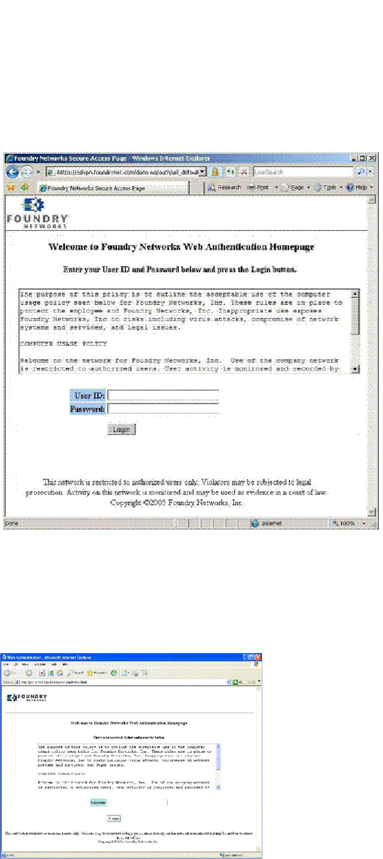
PowerConnect B-Series FCX Configuration Guide 1327
53-1002266-01
Configuring web authentication options 37
FIGURE 167 Example of a login page when automatic authentication is disabled and local user
database is enabled
The user enters a user name and password, which are then sent for authentication.
If passcode authentication is enabled, the following Login page appears.
FIGURE 168 Example of a login page when automatic authentication is disabled and passcode
Authentication is Enabled
The user enters a passcode, which is then sent for authentication.
If the Web Authentication fails, the page to try again is displayed (Figure 169).
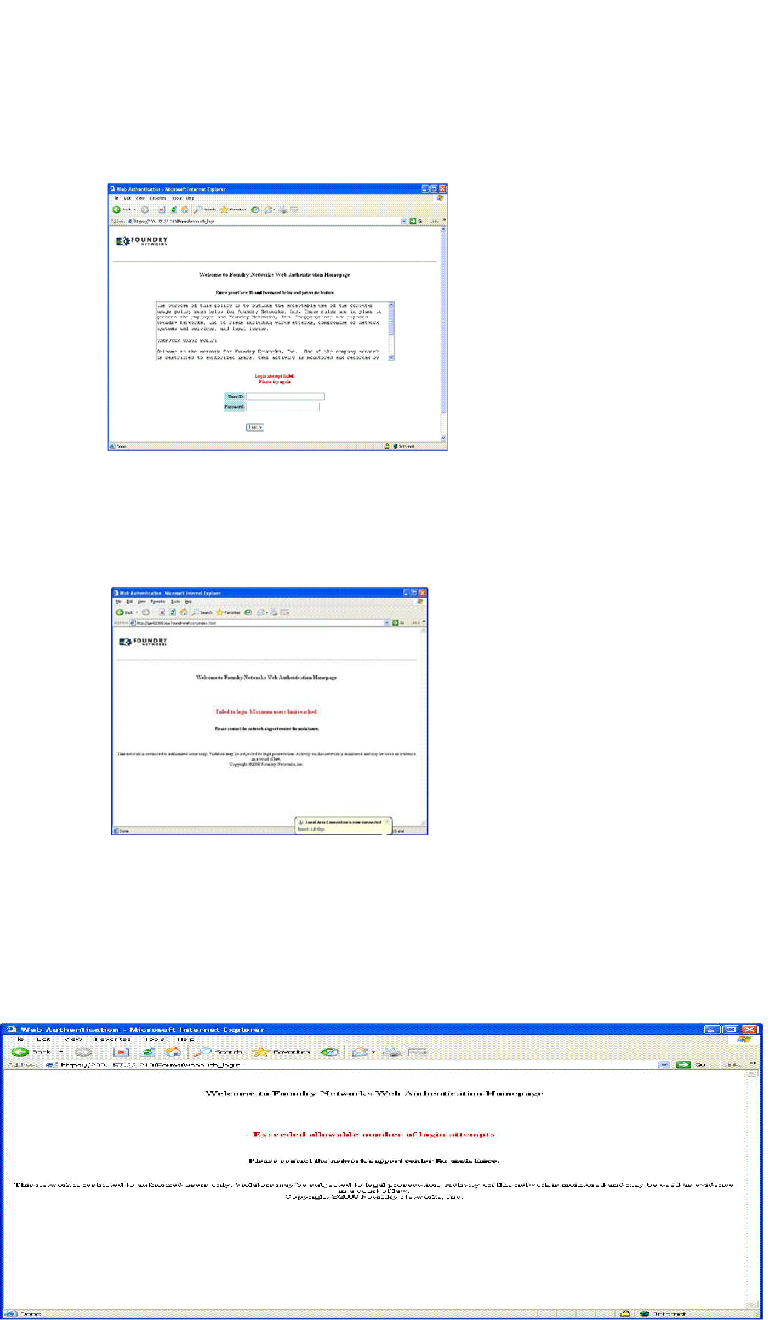
1328 PowerConnect B-Series FCX Configuration Guide
53-1002266-01
Configuring web authentication options
37
FIGURE 169 Example of a try again page
If the limit for the number of authenticated users on the network is exceeded, the Maximum Host
Limit page is displayed (Figure 170).
FIGURE 170 Example of a maximum Host limit page
If the number of Web Authentication attempts by a user has been exceeded, the Maximum
Attempts Limit page is displayed (Figure 171). The user is blocked from attempting any Web
Authentication unless either the user MAC address is removed from the blocked list (using the clear
webauth block-mac <mac-address> command) or when the block duration timer expires.
FIGURE 171 Example of a maximum attempts limit page
If the user Web Authentication attempt is successful, the Success page is displayed (Figure 172).
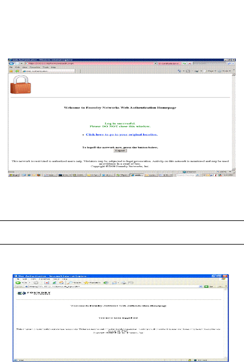
PowerConnect B-Series FCX Configuration Guide 1329
53-1002266-01
Configuring web authentication options 37
FIGURE 172 Example of a web authentication success page
Once a host is authenticated, that host can manually de-authenticate by clicking the ’Logout’
button in the Login Success page. The host remains logged in until the re-authentication period
expires. At that time, the host is automatically logged out. However, if a re-authentication period is
not configured, then the host remains logged in indefinitely.
NOTE
If you accidentally close the Success page, you will not be able to log out. if a re-authentication
period is configured, you will be logged out once the re-authentication period ends.
The host can log out of the Web session by simply clicking the Logout button. Once logged out, the
following window appears.
You can customize the top and bottom text for the all of the windows shown in Figure 166 through
Figure 172.
Displaying text for web authentication pages
Use the show webauth vlan <vlan-ID> webpage command to determine what text has been
configured for Web Authentication pages.

1330 PowerConnect B-Series FCX Configuration Guide
53-1002266-01
Configuring web authentication options
37
Syntax: show webauth vlan <vlan-id> webpage
Customizing web authentication pages
You can customize the following objects in the Web Authentication pages shown in Figure 166
through Figure 172:
•Title bar
•Banner image (the logo)
•Header
•Text box
•Login button
•Footer
You can use the CLI commands show webauth and show webauth vlan <vlan-id> webpage to
determine what text has been configured for Web Authentication pages.
NOTE
The banner image does not apply to the Web Authentication Maximum Attempts Limit page
(Figure 171). The text box and Login button apply to the Login page only.
Figure 173 shows the placement of these objects in the Login page.
PowerConnect#show webauth vlan 25 webpage
=================================
Web Page Customizations (VLAN 25):
Top (Header): Default Text
"<h3>Welcome to Brocade Communications, Inc. Web Authentication
Homepage</h3>"
Bottom (Footer): Custom Text
"Copyright 2009 SNL"
Title: Default Text
"Web Authentication"
Login Button: Custom Text
"Sign On"
Web Page Logo: blogo.gif
align: left (Default)
Web Page Terms and Conditions: policy1.txt
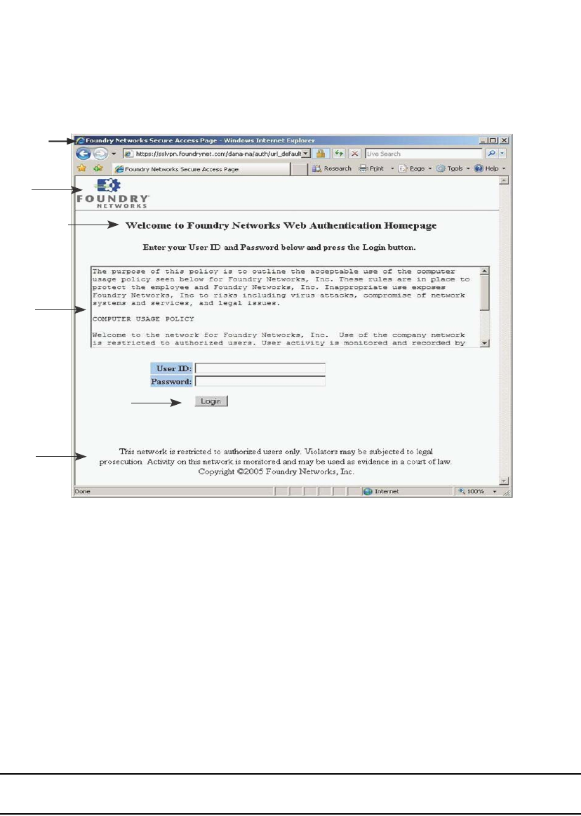
PowerConnect B-Series FCX Configuration Guide 1331
53-1002266-01
Configuring web authentication options 37
FIGURE 173 Objects in the web authentication pages that can be customized
Customizing the title bar
You can customize the title bar that appears on all Web Authentication pages (refer to Figure 173).
To do so, enter a command such as the following.
PowerConnect(config-vlan-10-webauth)#webpage custom-text title "Dell Secure
Access Page"
Syntax: [no] webpage custom-text title "<title>"
For <title>, enter up to 128 alphanumeric characters. The default title bar is "Web Authentication".
To reset the title bar back to the default value, enter the command no webpage custom-text title.
Customizing the banner image (Logo)
You can customize the logo that appears on all Web Authentication pages. Figure 173 shows
placement of the banner image in the Login page.
NOTE
The banner image does not display in the Maximum Attempts Limit page (Figure 171).
To customize the banner image, use the TFTP protocol to upload an image file from a TFTP server to
the PowerConnect switch. The image file can be in the format jpg, bmp, or gif, and its size must be
64K or less. When you upload a new image file, it willl overwrite the existing image file.
To replace the existing logo with a new one, enter a command such as the following.
PowerConnect(config-vlan-10-webauth)#webpage logo copy tftp 10.10.5.1
brocadelogo.gif
Syntax: [no] webpage logo copy tftp <ip-address> <filename>
Te x t
box
Header
Footer
Login button
Logo
Title bar

1332 PowerConnect B-Series FCX Configuration Guide
53-1002266-01
Configuring web authentication options
37
NOTE
This command downloads the image file and stores it in the device flash memory. Therefore, it is
not necessary to follow this command with a write memory.
The <ip-address> parameter specifies the address of the TFTP server on which the image file
resides.
The <filename> parameter specifies the name of the image file on the TFTP server.
Use the no webpage logo command to delete the logo from all Web Authentication pages and
remove it from flash memory.
Aligning the banner image (Logo)
You can optionally configure the placement of the logo that appears on all Web Authentication
pages (refer to Figure 173). By default, the logo is left-aligned at the top of the page. To center the
logo at the top of the page, enter the following command.
PowerConnect(config-vlan-10-webauth)#webpage logo align center
To right-justify the log at the top of the page, enter the following command.
PowerConnect(config-vlan-10-webauth)#webpage logo align right
Syntax: [no] webpage logo align center | left | right
Use the no webpage logo align command to reset the logo back to its default position (left).
Customizing the header
You can customize the header that appears on all Web Authentication pages. Figure 173 shows
placement of the header in the Login page.
To customize the header, enter a command such as the following.
PowerConnect(config-vlan-10-webauth)#webpage custom-text top "Welcome to Network
One"
Syntax: [no] webpage custom-text top <text>
For <text>, enter up to 255 alphanumeric characters.
To reset the header back to the default text, enter the command no webpage custom-text top.
Customizing the text box
You can customize the text box that appears on the Web Authentication Login page. Figure 173
shows placement of the text box in the Login page. By default, the text box is empty and is not
visible. To create a text box or to replace the existing one, upload an ASCII text file from a TFTP
server to the PowerConnect switch. The text file size must not exceed 2K.
To create or replace a text box, enter a command such as the following.
PowerConnect(config-vlan-10-webauth)#webpage terms copy tftp 10.10.5.1 policy.txt
Syntax: [no] webpage terms copy tftp <ip-address> <filename>
NOTE
This command downloads the text file and stores it in the device flash memory. Therefore, it is not
necessary to follow this command with a write memory.
The <ip-address> parameter is the address of the TFTP server on which the image resides.

PowerConnect B-Series FCX Configuration Guide 1333
53-1002266-01
Displaying web authentication information 37
The <filename> parameter is the name of the text file on the TFTP server.
To revert back to the default text box (none), enter the command no webpage terms.
Customizing the login button
You can customize the Login button that appears on the bottom of the Web Authentication Login
page (refer to Figure 173). To do so, enter a command such as the following.
PowerConnect(config-vlan-10-webauth)#webpage custom-text login-button "Press to
Log In"
Syntax: [no] webpage custom-text login-button "<text>"
For <text>, enter up to 32 alphanumeric characters.
To reset the Login button back to the default value ("Login"), enter the command no webpage
custom-text login-button.
Customizing the footer
You can customize the footer that appears on all Web Authentication pages. Figure 173 shows
placement of the footer in the Login page.
To customize the footer enter a command such as the following.
PowerConnect(config-vlan-10-webauth)#webpage custom-text bottom "Network One
Copyright 2010"
Syntax: [no] webpage custom-text bottom "<text>"
For <text>, enter up to 255 alphanumeric characters.
To reset the footer back to the default text, enter the command no webpage custom-text bottom.
The default text is "This network is restricted to authorized users only. Violators may be subjected to
legal prosecution. Activity on this network is monitored and may be used as evidence in a court of
law.
Displaying web authentication information
The following sections present the show commands you can use to display information about the
Web Authentication feature.
Displaying the web authentication configuration
Enter the following command to display the configuration for the Web Authentication feature.
PowerConnect#show webauth
=============================================================================
WEB AUTHENTICATION (VLAN 25): Enable
attempt-max-num: 5 (Default)
host-max-num: 0 (Default)
block duration: 90 (Default)
cycle-time: 600 (Default)
port-down-authenticated-mac-cleanup: Enable (Default)
reauth-time: 28800 (Default)
authenticated-mac-age-time: 3600 (Default)
dns-filter: Disable (Default)

1334 PowerConnect B-Series FCX Configuration Guide
53-1002266-01
Displaying web authentication information
37
authentication mode: username and password (Default)
authentication methods: radius
Local user database name: <none>
Radius accounting: Enable (Default)
Trusted port list: None
Secure Login (HTTPS): Enable (Default)
Web Page Customizations:
Top (Header): Default Text
Bottom (Footer): Custom Text
"SNL Copyright 2009"
Title: Default Text
Login Button: Custom Text
"Sign On"
Web Page Logo: blogo.gif
align: left (Default)
Web Page Terms and Conditions: policy1.txt
Host statistics:
Number of hosts dynamically authenticated: 0
Number of hosts statically authenticated: 2
Number of hosts dynamically blocked: 0
Number of hosts statically blocked: 0
Number of hosts authenticating: 1
The display shows the following information.
This field... Displays...
WEB AUTHENTICATION (VLAN 10) Identifies the VLAN on which Web Authentication is enabled.
attempt-max-num The maximum number of Web Authentication attempts during a
cycle.
host-max-num The maximum number of users that can be authenticated at one
time.
block duration How many seconds a user who failed Web Authentication must wait
before attempting to be authenticated.
cycle-time The number of seconds in one Web Authentication cycle.
port-down-authenticated-mac-cleanup Indicates if this option is enabled or disabled. If enabled, all
authenticated users are de-authenticated if all the ports in the
VLAN go down.
reauth-time The number of seconds an authenticated user remains
authenticated. Once this timer expires, the user must
re-authenticate.
authenticated-mac-age-time If a user is inactive, this time shows how many seconds a user has
before the user associated MAC address is aged out. The user will
be forced to re-authenticate.
dns-filter Shows the definition of any DNS filter that have been set. (Refer to
“Filtering DNS queries” on page 1324
authentication mode The authentication mode:
•username and password (default)
•passcode
•none
Also displays configuration details for the authentication mode.
RADIUS accounting Whether RADIUS accounting is enabled or disabled.
Trusted port list The statically-configured trusted ports of the Web Authentication
VLAN.

PowerConnect B-Series FCX Configuration Guide 1335
53-1002266-01
Displaying web authentication information 37
Syntax: show webauth [vlan <vlan-id>]
The show webauth command by itself displays information for all VLANs on which Web
Authentication is enabled. Use the vlan <vlan-id> parameter to display information for a specific
VLAN.
Displaying a list of authenticated hosts
Enter the following command to display a list of hosts that are currently authenticated.
The displays shows the following information.
Syntax: show webauth allowed-list
Secure login (HTTPS) Whether HTTPS is enabled or disabled.
Web Page Customizations The current configuration for the text that appears on the Web
Authentication pages. Either "Custom Text" or "Default Text"
displays for each page type:
•"Custom Text" means the message for the page has been
customized. The custom text is also displayed.
•"Default Text" means the default message that ships with the
PowerConnect switch is used.
The actual text on the Web Authentication pages can be displayed
using the show webauth vlan <vlan-id> webpage command. Refer
to “Displaying text for web authentication pages” on page 1329.
Host statistics The authentication status and the number of hosts in each state.
This field... Displays...
VLAN #: Web Authentication The ID of the VLAN on which Web Authentication is
enabled.
Web Authenticated List MAC Address The MAC addresses that have been authenticated.
User Name The authenticated username.
Configuration Static/Dynamic If the MAC address was dynamically (passed Web
Authentication) or statically (added to the authenticated
list using the add mac command) authenticated.
Authenticated Duration The remainder of time the MAC address will remain
authenticated
This field... Displays...
PowerConnect#show webauth allowed-list
=============================================================================
VLAN 1: Web Authentication
-----------------------------------------------------------------------------
Web Authenticated List Configuration Authenticated Duration Remaining
MAC Address User Name Static/Dynamic HH:MM:SS
-----------------------------------------------------------------------------
00a0.f86c.2807 N/A D 00:03:05
0009.5b69.79ea fdry1 D 04:58:01
000c.db82.8bca N/A S Infinite
0007.e90e.de3b N/A S Infinite
000a.e442.a50e fdry2 D 00:25:25

1336 PowerConnect B-Series FCX Configuration Guide
53-1002266-01
Displaying web authentication information
37
Displaying a list of hosts attempting to authenticate
Enter the following command to display a list of hosts that are trying to authenticate.
The report shows the following information.
Syntax: show webauth authenticating-list
Displaying a list of blocked hosts
Enter the following command to display a list of hosts that are currently blocked from any Web
Authentication Attempt.
The report shows the following information.
This field... Displays...
VLAN #: Web Authentication The ID of the VLAN on which Web Authentication is
enabled.
MAC Address The MAC addresses that are trying to be authenticated.
User Name The User Name associated with the MAC address.
# of Failed Attempts Number of authentication attempts that have failed.
Cycle Time Remaining The remaining time the user has to be authenticated
before the current authentication cycle expires. Once it
expires, the user must enter a valid URL again to display
the Web Authentication Welcome page.
PowerConnect#show webauth authenticating-list
===============================================================================
VLAN 25: Web Authentication
-------------------------------------------------------------------------------
Web Authenticating List # of Failed Cycle Time
Remaining
MAC Address User Name Attempts HH:MM:SS
-------------------------------------------------------------------------------
0012.3ff9.1fc6 N/A 0 00:09:46
PowerConnect#show webauth blocked-list
=============================================================================
VLAN 1: Web Authentication
-----------------------------------------------------------------------------
Web Block List Configuration Block Duration Remaining
MAC Address User Name Static/Dynamic HH:MM:SS
-----------------------------------------------------------------------------
0009.a213.ff09 bauser S 00:31:27
00a0.f86c.2807 causer D 00:01:24
00a0.f890.1ab3 dauser S infinite

PowerConnect B-Series FCX Configuration Guide 1337
53-1002266-01
Displaying web authentication information 37
Syntax: show webauth blocked-list
Displaying a list of local user databases
The following command displays a list of all local user databases configured on the PowerConnect
switch and the number of users in each database.
Syntax: show local-userdb
Displaying a list of users in a local user database
The following command displays a list of all users in a particular local user database.
As shown in the above example, passwords are encrypted in the command output.
This field... Displays...
VLAN #: Web Authentication The ID of the VLAN on which Web Authentication is
enabled.
Web Block List MAC Address The MAC addresses that have been blocked from Web
Authentication.
User Name The User Name associated with the MAC address.
Configuration Static/Dynamic If the MAC address was dynamically or statically
blocked. The block mac command statically blocks MAC
addresses.
Block Duration Remaining The remaining time the MAC address has before the
user with that MAC address can attempt Web
Authentication.
PowerConnect#show local-userdb
=============================================================================
Local User Database Name : My_Database
Number of users in the database : 4
=============================================================================
Local User Database Name : test
Number of users in the database : 3
=============================================================================
Local User Database Name : test123
Number of users in the database : 3
PowerConnect#show local-userdb test
=============================================================================
Local User Database : test
Username Password
-------- --------
user1 $e$&Z9'%*&+
user2 $e$,)A=)65N,%-3*%1?@U
user3 $e$5%&-5%YO&&A1%6%<@U

1338 PowerConnect B-Series FCX Configuration Guide
53-1002266-01
Displaying web authentication information
37
Syntax: show local-userdb <db-name>
Displaying passcodes
If the passcode Web authentication mode is enabled, you can use the following command to
display current passcodes.
Syntax: show webauth vlan <vlan-id> passcode
PowerConnect#show webauth vlan 25 passcode
Current Passcode : 1389
This passcode is valid for 35089 seconds
PowerConnect B-Series FCX Configuration Guide 1339
53-1002266-01
Chapter
38
Protecting Against Denial of Service Attacks
Table 232 lists individual Dell PowerConnect switches and the DoS protection features they
support.
This chapter explains how to protect your Dell PowerConnect devices from Denial of Service (DoS)
attacks.
In a Denial of Service (DoS) attack, a router is flooded with useless packets, hindering normal
operation. Dell PowerConnect devices include measures for defending against two types of DoS
attacks Smurf attacks and TCP SYN attacks.
Protecting against Smurf attacks
A Smurf attack is a kind of DoS attack in which an attacker causes a victim to be flooded with
Internet Control Message Protocol (ICMP) echo (Ping) replies sent from another network.
Figure 174 illustrates how a Smurf attack works.
FIGURE 174 How a Smurf attack floods a victim with ICMP replies
The attacker sends an ICMP echo request packet to the broadcast address of an intermediary
network. The ICMP echo request packet contains the spoofed address of a victim network as its
source. When the ICMP echo request reaches the intermediary network, it is converted to a Layer 2
broadcast and sent to the hosts on the intermediary network. The hosts on the intermediary
network then send ICMP replies to the victim network.
TABLE 232 Supported DoS protection features
Feature PowerConnect B-Series FCX
Smurf attack (ICMP attack) protection Yes
TCP SYN attack protection Yes
2
1
3
Attacker
Intermediary
Victim
Attacker sends ICMP echo requests to
broadcast address on Intermediary’s
network, spoofing Victim’s IP address
as the source
If Intermediary has directed broadcast
forwarding enabled, ICPM echo requests
are broadcast to hosts on Intermediary’s
network
The hosts on Intermediary’s network
send replies to Victim, inundating Victim
with ICPM packets

1340 PowerConnect B-Series FCX Configuration Guide
53-1002266-01
Protecting against Smurf attacks
38
For each ICMP echo request packet sent by the attacker, a number of ICMP replies equal to the
number of hosts on the intermediary network are sent to the victim. If the attacker generates a
large volume of ICMP echo request packets, and the intermediary network contains a large number
of hosts, the victim can be overwhelmed with ICMP replies.
Avoiding being an intermediary in a Smurf attack
A Smurf attack relies on the intermediary to broadcast ICMP echo request packets to hosts on a
target subnet. When the ICMP echo request packet arrives at the target subnet, it is converted to a
Layer 2 broadcast and sent to the connected hosts. This conversion takes place only when
directed broadcast forwarding is enabled on the device.
To avoid being an intermediary in a Smurf attack, make sure forwarding of directed broadcasts is
disabled on the Dell PowerConnect device. Directed broadcast forwarding is disabled by default. To
disable directed broadcast forwarding, do one of the following.
PowerConnect(config)#no ip directed-broadcast
Syntax: [no] ip directed-broadcast
Avoiding being a victim in a Smurf attack
You can configure the Dell PowerConnect device to drop ICMP packets when excessive numbers
are encountered, as is the case when the device is the victim of a Smurf attack. You can set
threshold values for ICMP packets that are targeted at the router itself or passing through an
interface, and drop them when the thresholds are exceeded.
For example, to set threshold values for ICMP packets targeted at the router, enter the following
command in global CONFIG mode.
PowerConnect(config)#ip icmp burst-normal 5000 burst-max 10000 lockup 300
To set threshold values for ICMP packets received on interface 3/11, enter the following
commands.
PowerConnect(config)#interface ethernet 3/11
PowerConnect(config-if-e1000-3/11)#ip icmp burst-normal 5000 burst-max 10000
lockup 300
For Layer 3 router code, if the interface is part of a VLAN that has a router VE, you must configure
ICMP attack protection at the VE level. Otherwise, you can configure this feature at the interface
level as shown in the previous example. When ICMP attack protection is configured at the VE level,
it will apply to routed traffic only. It will not affect switched traffic.
NOTE
You must configure VLAN information for the port before configuring ICMP attack protection. You
cannot change the VLAN configuration for a port on which ICMP attack protection is enabled.
To set threshold values for ICMP packets received on VE 31, enter commands such as the
following.
PowerConnect(config)#interface ve 31
PowerConnect(config-vif-31)#ip icmp burst-normal 5000 burst-max 10000 lockup 300
Syntax: ip icmp burst-normal <value> burst-max <value> lockup <seconds>
The burst-normal <value> parameter can be from 1 through 100,000 packets per second.

PowerConnect B-Series FCX Configuration Guide 1341
53-1002266-01
Protecting against TCP SYN attacks 38
The burst-max <value> paramter can be from 1 through 100,000 packets per second.
The lockup <value> parameter can be from 1 through 10,000 seconds.
This command is supported on Ethernet and Layer 3 interfaces.
The number of incoming ICMP packets per second is measured and compared to the threshold
values as follows:
•If the number of ICMP packets exceeds the burst-normal value, the excess ICMP packets are
dropped.
•If the number of ICMP packets exceeds the burst-max value, all ICMP packets are dropped for
the number of seconds specified by the lockup value. When the lockup period expires, the
packet counter is reset and measurement is restarted.
In the example, if the number of ICMP packets received per second exceeds 5,000, the excess
packets are dropped. If the number of ICMP packets received per second exceeds 10,000, the
device drops all ICMP packets for the next 300 seconds (5 minutes).
Protecting against TCP SYN attacks
TCP SYN attacks exploit the process of how TCP connections are established to disrupt normal
traffic flow. When a TCP connection starts, the connecting host first sends a TCP SYN packet to the
destination host. The destination host responds with a SYN ACK packet, and the connecting host
sends back an ACK packet. This process, known as a “TCP three-way handshake,” establishes the
TCP connection.
While waiting for the connecting host to send an ACK packet, the destination host keeps track of
the as-yet incomplete TCP connection in a connection queue. When the ACK packet is received,
information about the connection is removed from the connection queue. Usually there is not
much time between the destination host sending a SYN ACK packet and the source host sending
an ACK packet, so the connection queue clears quickly.
In a TCP SYN attack, an attacker floods a host with TCP SYN packets that have random source IP
addresses. For each of these TCP SYN packets, the destination host responds with a SYN ACK
packet and adds information to the connection queue. However, because the source host does not
exist, no ACK packet is sent back to the destination host, and an entry remains in the connection
queue until it ages out (after approximately a minute). If the attacker sends enough TCP SYN
packets, the connection queue can fill up, and service can be denied to legitimate TCP
connections.
To protect against TCP SYN attacks, you can configure the Dell PowerConnect device to drop TCP
SYN packets when excessive numbers are encountered. You can set threshold values for TCP SYN
packets that are targeted at the router itself or passing through an interface, and drop them when
the thresholds are exceeded.
For example, to set threshold values for TCP SYN packets targeted at the router, enter the following
command in global CONFIG mode.
PowerConnect(config)#ip tcp burst-normal 10 burst-max 100 lockup 300
To set threshold values for TCP SYN packets received on interface 3/11, enter the following
commands.
PowerConnect(config)#interface ethernet 3/11
PowerConnect(config-if-e1000-3/11)#ip tcp burst-normal 10 burst-max 100 lockup
300

1342 PowerConnect B-Series FCX Configuration Guide
53-1002266-01
Protecting against TCP SYN attacks
38
For Layer 3 router code, if the interface is part of a VLAN that has a router VE, you must configure
TCP/SYN attack protection at the VE level. Otherwise, you can configure this feature at the
interface level as shown in the previous example. WhenTCP/SYN attack protection is configured at
the VE level, it will apply to routed traffic only. It will not affect switched traffic.
NOTE
You must configure VLAN information for the port before configuring TCP/SYN attack protection. You
cannot change the VLAN configuration for a port on which TCP/SYN attack protection is enabled.
To set threshold values for TCP/SYN packets received on VE 31, enter commands such as the
following.
PowerConnect(config)#interface ve 31
PowerConnect(config-vif-31)#ip tcp burst-normal 5000 burst-max 10000 lockup 300
Syntax: ip tcp burst-normal <value> burst-max <value> lockup <seconds>
NOTE
This command is available at the global CONFIG level on both Chassis devices and Compact devices.
On Chassis devices, this command is available at the Interface level as well. This command is
supported on Ethernet and Layer 3 interfaces.
The burst-normal <value> parameter can be from 1 – 100,000 packets per second.
The burst-max <value> parameter can be from 1 – 100,000 packets per second.
The lockup <value> parameter can be from 1 – 10,000 seconds.
The number of incoming TCP SYN packets per second is measured and compared to the threshold
values as follows:
•If the number of TCP SYN packets exceeds the burst-normal value, the excess TCP SYN packets
are dropped.
•If the number of TCP SYN packets exceeds the burst-max value, all TCP SYN packets are
dropped for the number of seconds specified by the lockup value. When the lockup period
expires, the packet counter is reset and measurement is restarted.
In the example, if the number of TCP SYN packets received per second exceeds 10, the excess
packets are dropped. If the number of TCP SYN packets received per second exceeds 100, the
device drops all TCP SYN packets for the next 300 seconds (5 minutes).
TCP security enhancement
TCP security enhancement improves upon the handling of TCP inbound segments. This
enhancement eliminates or minimizes the possibility of a TCP reset attack, in which a perpetrator
attempts to prematurely terminate an active TCP session, and a data injection attack, wherein an
attacker injects or manipulates data in a TCP connection.
In both cases, the attack is blind, meaning the perpetrator does not have visibility into the content
of the data stream between two devices, but blindly injects traffic. Also, the attacker does not see
the direct effect, the continuing communications between the devices and the impact of the
injected packet, but may see the indirect impact of a terminated or corrupted session.
The TCP security enhancement prevents and protects against the following three types of attacks:
•Blind TCP reset attack using the reset (RST) bit

PowerConnect B-Series FCX Configuration Guide 1343
53-1002266-01
Protecting against TCP SYN attacks 38
•Blind TCP reset attack using the synchronization (SYN) bit
•Blind TCP packet injection attack
The TCP security enhancement is automatically enabled.
Protecting against a blind TCP reset attack using the RST bit
In a blind TCP reset attack using the RST bit, a perpetrator attempts to guess the RST bits to
prematurely terminate an active TCP session.
To prevent a user from using the RST bit to reset a TCP connection, the RST bit is subject to the
following rules when receiving TCP segments:
•If the RST bit is set and the sequence number is outside the expected window, the Dell
PowerConnect device silently drops the segment.
•If the RST bit is exactly the next expected sequence number, the Dell PowerConnect device
resets the connection.
•If the RST bit is set and the sequence number does not exactly match the next expected
sequence value, but is within the acceptable window, the Dell PowerConnect device sends an
acknowledgement.
Protecting against a blind TCP reset attack using the SYN bit
In a blind TCP reset attack using the SYN bit, a perpetrator attempts to guess the SYN bits to
prematurely terminate an active TCP session.
To prevent a user from using the SYN bit to tear down a TCP connection, in current software
releases, the SYN bit is subject to the following rules when receiving TCP segments:
•If the SYN bit is set and the sequence number is outside the expected window, the Dell
PowerConnect device sends an acknowledgement (ACK) back to the peer.
•If the SYN bit is set and the sequence number is an exact match to the next expected
sequence, the Dell PowerConnect device sends an ACK segment to the peer. Before sending
the ACK segment, the software subtracts one from the value being acknowledged.
•If the SYN bit is set and the sequence number is acceptable, the Dell PowerConnect device
sends an acknowledgement (ACK) segment to the peer.
Protecting against a blind injection attack
In a blind TCP injection attack, a perpetrator tries to inject or manipulate data in a TCP connection.
To reduce the chances of a blind injection attack, an additional check on all incoming TCP
segments is performed.
Displaying statistics about packets dropped
because of DoS attacks
To display information about ICMP and TCP SYN packets dropped because burst thresholds were
exceeded, enter the following command.

1344 PowerConnect B-Series FCX Configuration Guide
53-1002266-01
Protecting against TCP SYN attacks
38
Syntax: show statistics dos-attack
To clear statistics about ICMP and TCP SYN packets dropped because burst thresholds were
exceeded, enter the following command.
PowerConnect#clear statistics dos-attack
Syntax: clear statistics dos-attack
PowerConnect#show statistics dos-attack
---------------------------- Local Attack Statistics --------------------------
ICMP Drop Count ICMP Block Count SYN Drop Count SYN Block Count
--------------- ---------------- -------------- ---------------
0 0 0 0
--------------------------- Transit Attack Statistics -------------------------
Port ICMP Drop Count ICMP Block Count SYN Drop Count SYN Block Count
----- --------------- ---------------- -------------- ---------------
3/11 0 0 0 0

PowerConnect B-Series FCX Configuration Guide 1345
53-1002266-01
Chapter
39
Inspecting and Tracking DHCP Packets
Table 233 lists individual Dell PowerConnect switches and the DHCP packet inspection and
tracking features they support.
Dynamic ARP inspection
For enhanced network security, you can configure the Dell PowerConnect device to inspect and
keep track of Dynamic Host Configuration Protocol (DHCP) assignments.
Dynamic ARP Inspection (DAI) enables the Dell PowerConnect device to intercept and examine all
ARP request and response packets in a subnet and discard those packets with invalid IP to MAC
address bindings. DAI can prevent common man-in-the-middle (MiM) attacks such as ARP cache
poisoning, and disallow mis-configuration of client IP addresses.
ARP poisoning
ARP provides IP communication within a Layer 2 broadcast domain by mapping an IP address to a
MAC address. Before a host can talk to another host, it must map the IP address to a MAC address
first. If the host does not have the mapping in its ARP table, it creates an ARP request to resolve the
mapping. All computers on the subnet will receive and process the ARP requests, and the host
whose IP address matches the IP address in the request will send an ARP reply.
An ARP poisoning attack can target hosts, switches, and routers connected to the Layer 2 network
by poisoning the ARP caches of systems connected to the subnet and by intercepting traffic
intended for other hosts on the subnet. For instance, a malicious host can reply to an ARP request
with its own MAC address, thereby causing other hosts on the same subnet to store this
information in their ARP tables or replace the existing ARP entry. Furthermore, a host can send
gratuitous replies without having received any ARP requests. A malicious host can also send out
ARP packets claiming to have an IP address that actually belongs to another host (e.g. the default
router). After the attack, all traffic from the device under attack flows through the attacker
computer and then to the router, switch, or host.
TABLE 233 Supported DHCP packet inspection and tracking features
Feature PowerConnect B-Series FCX
Dynamic ARP inspection Yes
DHCP snooping Yes
DHCP relay agent information (DHCP
Option 82)
Yes
IP source guard Yes
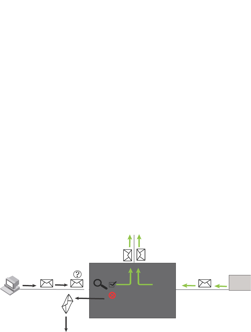
1346 PowerConnect B-Series FCX Configuration Guide
53-1002266-01
Dynamic ARP inspection
39
How DAI works
DAI allows only valid ARP requests and responses to be forwarded.
A Dell PowerConnect device on which DAI is configured does the following:
•Intercepts ARP packets received by the system CPU
•Inspects all ARP requests and responses received on untrusted ports
•Verifies that each of the intercepted packets has a valid IP-to-MAC address binding before
updating the local ARP table, or before forwarding the packet to the appropriate destination
•Drops invalid ARP packets
When you enable DAI on a VLAN, by default, all member ports are untrusted. You must manually
configure trusted ports. In a typical network configuration, ports connected to host ports are
untrusted. You configure ports connected to other switches or routers as trusted.
DAI inspects ARP packets received on untrusted ports, as shown in Figure 175. DAI carries out the
inspection based on IP-to-MAC address bindings stored in a trusted binding database. For the
Brocade device, the binding database is the ARP table, which supports DAI, DHCP snooping, and IP
Source Guard. To inspect an ARP request packet, DAI checks the source IP and source MAC
address against the ARP table. For an ARP reply packet, DAI checks the source IP, source MAC,
destination IP, and destination MAC addresses. DAI forwards the valid packets and discards those
with invalid IP-to-MAC address bindings.
When ARP packets reach a trusted port, DAI lets them through, as shown in Figure 175.
FIGURE 175 Dynamic ARP inspection at work
ARP entries
DAI uses the IP/MAC mappings in the ARP table to validate ARP packets received on untrusted
ports.
ARP entries in the ARP table derive from the following:
•Dynamic ARP – normal ARP learned from trusted ports.
•Static ARP – statically configured IP/MAC/port mapping.
•Inspection ARP – statically configured IP/MAC mapping, where the port is initially unspecified.
The actual physical port mapping will be resolved and updated from validated ARP
packets.Refer to “Configuring an inspection ARP entry” on page 1348.
ARP
packet
ARP
packet
Switch
Trusted
Untrusted
DAI

PowerConnect B-Series FCX Configuration Guide 1347
53-1002266-01
Dynamic ARP inspection 39
•DHCP-Snooping ARP – information collected from snooping DHCP packets when DHCP
snooping is enabled on VLANs.
The status of an ARP entry is either pending or valid:
•Valid – the mapping is valid, and the port is resolved. This is always the case for static ARP
entries.
•Pending – for normal dynamic and inspection ARP entries before they are resolved, and the
port mapped. Their status changes to valid when they are resolved, and the port mapped.
Refer to also “System reboot and the binding database” on page 1351.
Configuration notes and feature limitations
The following limits and restrictions apply when configuring DAI:
•To run Dynamic ARP Inspection, you must first enable support for ACL filtering based on VLAN
membership or VE port membership. To do so, enter the following commands at the Global
CONFIG Level of the CLI.
PowerConnect(config)#enable ACL-per-port-per-vlan
PowerConnect(config)#write memory
PowerConnect(config)#exit
PowerConnect#reload
NOTE
You must save the configuration and reload the software to place the change into effect.
•Dell recommends that you do not enable DAI on a trunk port.
•The maximum number of DHCP and static DAI entries depends on the maximum number of
ARP table entries allowed on the device. A Layer 2 switch can have up to 256 ARP entries and
a Layer 3 switch can have up to 64,000 ARP entries. In a Layer 3 switch, you can use the
system-max ip-arp command to change the maximum number of ARP entries for the device.
However, only up to 1024 DHCP entries can be saved to flash.
•ACLs are supported on member ports of a VLAN on which DHCP snooping and Dynamic ARP
Inspection (DAI) are enabled.
•DAI is supported on a VLAN without a VE, or on a VE with or without an assigned IP address.
Configuring DAI
Configuring DAI consists of the following steps.
1. Configure inspection ARP entries for hosts on untrusted ports.Refer to “Configuring an
inspection ARP entry” on page 1348.
2. Enable DAI on a VLAN to inspect ARP packets.Refer to “Enabling DAI on a VLAN” on page 1348.
3. Configure the trust settings of the VLAN members. ARP packets received on trusted ports
bypass the DAI validation process. ARP packets received on untrusted ports go through the
DAI validation process.Refer to “Enabling trust on a port” on page 1348.
4. Enable DHCP snooping to populate the DHCP snooping IP-to-MAC binding database.
The following shows the default settings of DAI.

1348 PowerConnect B-Series FCX Configuration Guide
53-1002266-01
Dynamic ARP inspection
39
Configuring an inspection ARP entry
Static ARP and static inspection ARP entries need to be configured for hosts on untrusted ports.
Otherwise, when DAI checks ARP packets from these hosts against entries in the ARP table, it will
not find any entries for them, and the Dell PowerConnect device will not allow and learn ARP from
an untrusted host.
When the inspection ARP entry is resolved with the correct IP/MAC mapping, its status changes
from pending to valid.
To configure an inspection ARP entry, enter a command such as the following.
PowerConnect(config)#arp 20.20.20.12 0001.0002.0003 inspection
This command defines an inspection ARP entry, mapping a device IP address 20.20.20.12 with its
MAC address 0001.0002.0003. The ARP entry will be in Pend (pending) status until traffic with the
matching IP-to-MAC is received on a port.
Syntax: [no] arp <ip-addr> <mac-addr> inspection
The <ip-addr> <mac-addr> parameter specifies a device IP address and MAC address pairing.
Enabling DAI on a VLAN
DAI is disabled by default. To enable DAI on an existing VLAN, enter the following command.
PowerConnect(config)#ip arp inspection vlan 2
The command enables DAI on VLAN 2. ARP packets from untrusted ports in VLAN 2 will undergo
DAI inspection.
Syntax: [no] ip arp inspection vlan <vlan-number>
The <vlan-number> variable specifies the ID of a configured VLAN.
Enabling trust on a port
The default trust setting for a port is untrusted. For ports that are connected to host ports, leave
their trust settings as untrusted.
To enable trust on a port, enter commands such as the following .
PowerConnect(config)#interface ethernet 1/4
PowerConnect(config-if-e10000-1/4)#arp inspection trust
The commands change the CLI to the interface configuration level of port 1/4 and set the trust
setting of port 1/4 to trusted.
Syntax: [no] arp inspection trust
Feature Default
Dynamic ARP Inspection Disabled
Trust setting for ports Untrusted

PowerConnect B-Series FCX Configuration Guide 1349
53-1002266-01
DHCP snooping 39
Displaying ARP inspection status and ports
To display the ARP inspection status for a VLAN and the trusted/untrusted port, enter the following
command.
Syntax: show ip arp inspection [vlan <vlan_id>]
The <vlan_id> variable specifies the ID of a configured VLAN.
Displaying the ARP table
To display the ARP table, enter the following command .
The command displays all ARP entries in the system. For field definitions, refer to Table 161 on
page 875.
Syntax: show arp
DHCP snooping
Dynamic Host Configuration Protocol (DHCP) snooping enables the Dell PowerConnect device to
filter untrusted DHCP packets in a subnet. DHCP snooping can ward off MiM attacks, such as a
malicious user posing as a DHCP server sending false DHCP server reply packets with the intention
of misdirecting other users. DHCP snooping can also stop unauthorized DHCP servers and prevent
errors due to user mis-configuration of DHCP servers.
Often DHCP snooping is used together with Dynamic ARP Inspection and IP Source Guard.
PowerConnect#show ip arp inspection vlan 2
IP ARP inspection VLAN 2: Disabled
Trusted Ports : ethe 1/4
Untrusted Ports : ethe 2/1 to 2/3 ethe 4/1 to 4/24 ethe 6/1 to 6/4 ethe 8/1 to
8/4
PowerConnect#show arp
Total number of ARP entries: 2, maximum capacity: 6000
No IP Address MAC Address Type Age Port Status
1 10.43.1.1 0004.80a0.4000 Dynamic 0 mgmt1 Valid
2 10.43.1.78 00e0.8160.6ab1 Dynamic 2 mgmt1 Valid
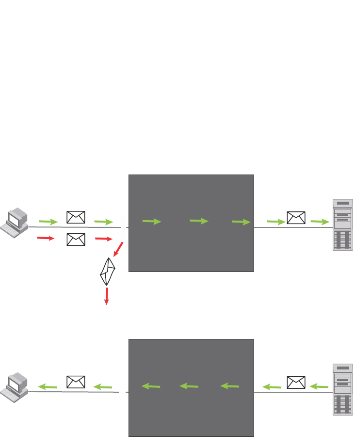
1350 PowerConnect B-Series FCX Configuration Guide
53-1002266-01
DHCP snooping
39
How DHCP snooping works
When enabled on a VLAN, DHCP snooping stands between untrusted ports (those connected to
host ports) and trusted ports (those connected to DHCP servers). A VLAN with DHCP snooping
enabled forwards DHCP request packets from clients and discards DHCP server reply packets on
untrusted ports, and it forwards DHCP server reply packets on trusted ports to DHCP clients, as
shown in the following figures
FIGURE 176 DHCP snooping at work - on an untrusted port
FIGURE 177 DHCP snooping at work - on a trusted port
DHCP binding database
When it forwards DHCP server reply packets on trusted ports, the Dell PowerConnect device saves
the client IP-to-MAC address binding information in the DHCP binding database. This is how the
DHCP snooping binding table is populated. The information saved includes MAC address, IP
address, lease time, VLAN number, and port number.
In the Brocade device, the DHCP binding database is integrated with the enhanced ARP table,
which is used by Dynamic ARP Inspection. For more information, refer to “ARP entries” on
page 1346.
The lease time will be refreshed when the client renews its IP address with the DHCP server;
otherwise the Dell PowerConnect device removes the entry when the lease time expires.
Switch
DHCP server
reply packet
Trusted
Untrusted
DHCP
Server
DHCP
Snooping
DHCP client
request packet
DHCP
Client
Switch
DHCP server
reply packet
Trusted
Untrusted
DHCP
Server
DHCP
Snooping

PowerConnect B-Series FCX Configuration Guide 1351
53-1002266-01
DHCP snooping 39
About client IP-to-MAC address mappings
Client IP addresses need not be on directly-connected networks, as long as the client MAC address
is learned on the client port and the client port is in the same VLAN as the DHCP server port. In this
case, the system will learn the client IP-to-MAC port mapping. Therefore, a VLAN with DHCP
snooping enabled does not require a VE interface.
In earlier releases, in the Layer 3 software image, DHCP snooping does not learn the secure
IP-to-MAC address mapping for a client, if the client port is not a virtual ethernet (VE) interface with
an IP subnet address. In other words, the client IP address had to match one of the subnets of the
client port in order for DHCP to learn the address mapping.
System reboot and the binding database
To allow DAI and DHCP snooping to work smoothly across a system reboot, the binding database is
saved to a file in the system flash memory after an update to the binding database, with a 30
second delay. The flash file is written and read only if DHCP snooping is enabled.
Configuration notes and feature limitations
The following limits and restrictions apply to DHCP snooping:
•To run DHCP snooping, you must first enable support for ACL filtering based on VLAN
membership or VE port membership. To do so, enter the following commands at the Global
CONFIG Level of the CLI.
PowerConnect(config)#enable ACL-per-port-per-vlan
PowerConnect(config)#write memory
PowerConnect(config)#exit
PowerConnect#reload
NOTE
You must save the configuration and reload the software to place the change into effect.
•DHCP snooping is not supported on trunk ports.
•DHCP snooping is not supported together with DHCP Auto-configuration.
•A switch can have up to 256 ARP entries, therefore, DHCP entries are limited to 256. A router,
however, can have 64,000 ARP entries, so a router can have up to 64,000 DHCP entries, of
which only 1024 entries can be saved to flash on reboot.
•ACLs are supported on member ports of a VLAN on which DHCP snooping and Dynamic ARP
Inspection (DAI) are enabled.
•See also “About client IP-to-MAC address mappings” on page 1351.
•DHCP snooping supports DHCP relay agent information (DHCP Option 82). For details, refer to
“DHCP relay agent information (DHCP Option 82)” on page 1354.
Configuring DHCP snooping
Configuring DHCP snooping consists of the following steps.

1352 PowerConnect B-Series FCX Configuration Guide
53-1002266-01
DHCP snooping
39
1. Enable DHCP snooping on a VLAN.Refer to “Enabling DHCP snooping on a VLAN” on
page 1352.
2. For ports that are connected to a DHCP server, change their trust setting to trusted.Refer to
“Enabling trust on a port” on page 1352.
The following shows the default settings of DHCP snooping.
Enabling DHCP snooping on a VLAN
When DHCP snooping is enabled on a VLAN, DHCP packets are inspected.
DHCP snooping is disabled by default. This feature must be enabled on the client and the DHCP
server VLANs. To enable DHCP snooping, enter the following global command for these VLANs.
PowerConnect(config)#ip dhcp snooping vlan 2
The command enables DHCP snooping on VLAN 2.
Syntax: [no] ip dhcp snooping vlan <vlan-number>
The <vlan-number> variable specifies the ID of a configured client or DHCP server VLAN.
Enabling trust on a port
The default trust setting for a port is untrusted. To enable trust on a port connected to a DHCP
server, enter commands such as the following.
PowerConnect(config)#interface ethernet 1/1
PowerConnect(config-if-e10000-1/1)#dhcp snooping trust
Port 1/1 is connected to a DHCP server. The commands change the CLI to the interface
configuration level of port 1/1 and set the trust setting of port 1/1 to trusted.
Syntax: [no] dhcp snooping trust
Disabling the learning of DHCP clients on a port
You can disable DHCP client learning on an individual port. To do so, enter commands such as the
following.
PowerConnect(config)#interface ethernet 1/1
PowerConnect(config-if-e10000-1/1)#dhcp snooping client-learning disable
Syntax: [no] dhcp snooping client-learning disable
Use the no form of the command to re-enable DHCP client learning on a port once it has been
disabled.
Clearing the DHCP binding database
You can clear the DHCP binding database using the CLI command clear DHCP. You can remove all
entries in the database, or remove entries for a specific IP address only.
Feature Default
DHCP snooping Disabled
Trust setting for ports Untrusted

PowerConnect B-Series FCX Configuration Guide 1353
53-1002266-01
DHCP snooping 39
To remove all entries from the DHCP binding database, enter the following command.
PowerConnect#clear dhcp
To clear entries for a specific IP address, enter a command such as the following.
PowerConnect#clear dhcp 10.10.102.4
Syntax: clear dhcp [<ip-addr>]
Displaying DHCP snooping status and ports
To display the DHCP snooping status for a VLAN and the trusted/untrusted port, use the show ip
dhcp snooping vlan command.
Syntax: show ip dhcp snooping [vlan <vlan-id>]
Displaying the DHCP snooping binding database
To display the DHCP snooping binding database, use the show ip dhcp snooping info command.
Syntax: show ip dhcp snooping info
Displaying DHCP binding entry and status
To display the DHCP binding entry and its current status, use the show arp command.
Syntax: show arp
For field definitions, refer to Table 161 on page 875.
DHCP snooping configuration example
The following example configures VLAN 2 and VLAN 20, and changes the CLI to the global
configuration level to enable DHCP snooping on the two VLANs. The commands are as follows.
PowerConnect#show ip dhcp snooping vlan 2
IP DHCP snooping VLAN 2: Enabled
PowerConnect#show ip dhcp snooping info
Dhcp snooping Info
Total learnt entries 1
SAVED DHCP ENTRIES IN FLASH
IP Address Mac Address Port vlan lease
0 10.10.10.20 0001.0002.0003 6/13 1112 361
PowerConnect#show arp
Total number of ARP entries: 2, maximum capacity: 6000
No. IP Address MAC Address Type Age Port Status
1 10.43.1.1 00e0.0001.c320 Dynamic 0 mgmt1 Valid
2 10.43.1.199 00e0.0002.b263 Dynamic 7 mgmt1 Valid

1354 PowerConnect B-Series FCX Configuration Guide
53-1002266-01
DHCP relay agent information (DHCP Option 82)
39
PowerConnect(config)#vlan 2
PowerConnect(config-vlan-2)#untagged ethe 1/3 to 1/4
PowerConnect(config-vlan-2)#router-interface ve 2
PowerConnect(config-vlan-2)#exit
PowerConnect(config)#ip dhcp snooping vlan 2
PowerConnect(config)#vlan 20
PowerConnect(config-vlan-20)#untagged ethe 1/1 to 1/2
PowerConnect(config-vlan-20)#router-interface ve 20
PowerConnect(config-vlan-20)#exit
PowerConnect(config)#ip dhcp snooping vlan 20
On VLAN 2, client ports 1/3 and 1/4 are untrusted by default all client ports are untrusted. Hence,
only DHCP client request packets received on ports 1/3 and 1/4 are forwarded.
On VLAN 20, ports 1/1 and 1/2 are connected to a DHCP server. DHCP server ports are set to
trusted .
PowerConnect(config)#interface ethernet 1/1
PowerConnect(config-if-e10000-1/1)#dhcp snooping trust
PowerConnect(config-if-e10000-1/1)#exit
PowerConnect(config)#interface ethernet 1/2
PowerConnect(config-if-e10000-1/2)#dhcp snooping trust
PowerConnect(config-if-e10000-1/2)#exit
Hence, DHCP server reply packets received on ports 1/1 and 1/2 are forwarded, and client IP/MAC
binding information is collected.
The example also sets the DHCP server address for the local relay agent.
PowerConnect(config)#interface ve 2
PowerConnect(config-vif-2)#ip address 20.20.20.1/24
PowerConnect(config-vif-2)#ip helper-address 1 30.30.30.4
PowerConnect(config-vif-2)#interface ve 20
PowerConnect(config-vif-20)#ip address 30.30.30.1/24
DHCP relay agent information (DHCP Option 82)
DHCP relay agent information, also known as DHCP option 82, enables a DHCP relay agent to
insert information about a clients’ identity into a DHCP client request being sent to a DHCP server.
When DHCP snooping is enabled on the PowerConnect switch, DHCP option 82 is automatically
enabled. DHCP packets are processed as follows:
•Before relaying a DHCP discovery packet or DHCP request packet from a client to a DHCP
server, the PowerConnect switch will add agent information to the packet.
•Before relaying a DHCP reply packet from a DHCP server to a client, the PowerConnect switch
will remove relay agent information from the packet.
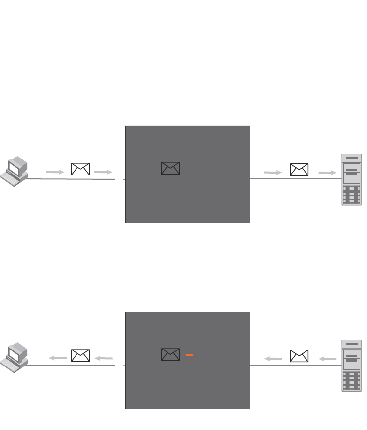
PowerConnect B-Series FCX Configuration Guide 1355
53-1002266-01
DHCP relay agent information (DHCP Option 82) 39
As illustrated in Figure 178, the DHCP relay agent (the PowerConnect switch), inserts DHCP option
82 attributes when relaying a DHCP request packet to a DHCP server.
FIGURE 178 DHCP Option 82 attributes added to the DHCP packet
As illustrated in Figure 179, the PowerConnect switch deletes DHCP option 82 attributes before
forwarding a server reply packet back to a DHCP client.
FIGURE 179 DHCP Option 82 attributes removed from the DHCP packet
The DHCP option 82 insertion/deletion feature is available only when DHCP snooping is enabled
for the client/server ports.
Configuration notes
•DHCP snooping and DHCP option 82 are supported on a per-VLAN basis.
•DHCP option 82 follows the same configuration rules and limitations as for DHCP snooping.
For more information, refer to “Configuration notes and feature limitations” on page 1351.
DHCP Option 82 sub-options
The Dell implementation of DHCP Option 82 supports the following sub-options:
•Sub-Option 1 – Circuit ID
•Sub-Option 2 - Remote ID
•Sub-Option 6 – Subscriber ID
These sub-options are described in the following sections.
DHCP
Client DHCP
Server
Trusted
Untrusted
DHCP
Snooping
DHCP Relay Agent
option
82
DHCP client
request packet
+ option 82
Switch
DHCP
Client DHCP
Server
DHCP Server
reply packet
Trusted
Untrusted
DHCP
Snooping
option 82
DHCP Relay Agent
option
82
Switch

1356 PowerConnect B-Series FCX Configuration Guide
53-1002266-01
DHCP relay agent information (DHCP Option 82)
39
Sub-option 1 – circuit id
The Circuit ID (CID) identifies the circuit or port from which a DHCP client request was sent. The
PowerConnect switch uses this information to relay DHCP responses back to the proper circuit, for
example, the port number on which the DHCP client request packet was received.
Dell PowerConnect devices support the General CID packet format. This simple format encodes
the CID type, actual information length, VLAN ID, slot number, and port number. This format is
compatible with the format used by other vendors’ devices. Figure 180 illustrates the general CID
packet format.
FIGURE 180 General CID packet format
Sub-option 2 – Remote ID
The Remote ID (RID) identifies the remote host end of the circuit (the relay agent). Dell
PowerConnect devices use the MAC address to identify itself as the relay agent. Figure 181
illustrates the RID packet format.
FIGURE 181 RID packet format
Sub-option 6 - subscriber id
The Subscriber ID (SID) is a unique identification number that enables an Internet Service Provider
to:
•Identify a subscriber
•Assign specific attributes to that subscriber (for example, host IP address, subnet mask, and
domain name server (DNS))
•Trigger accounting
Figure 182 illustrates the SID packet format.
FIGURE 182 SID packet format
The second byte (N in Figure 182) is the length of the ASCII string that follows. The PowerConnect
switch supports up to 50 ASCII characters.
1 Byte 2 Bytes
1 6 0 4 VLAN ID Slot ID Port
1 Byte
2806 MAC Address
1 Byte
6NASCII String 1.....N

PowerConnect B-Series FCX Configuration Guide 1357
53-1002266-01
DHCP relay agent information (DHCP Option 82) 39
Configuring DHCP option 82
When DHCP snooping is enabled on a VLAN, by default, DHCP option 82 also is enabled. You do
not need to perform any extra configuration steps to enable this feature. To enable DHCP
snooping, refer to“Enabling DHCP snooping on a VLAN” on page 1352.
When processing DHCP packets, the PowerConnect switch applies the following default behavior
when DHCP option 82 is enabled:
•Subjects all ports in the VLAN to DHCP option 82 processing
•Uses the general CID packet format
•Uses the standard RID packet format
•Replaces relay agent information received in DHCP packets with its own information
•Does not enable SID processing
When DHCP option 82 is enabled, you can optionally:
•Disable DHCP Option 82 processing on individual ports in the VLAN
•Configure the device to drop or keep the relay agent information in a DHCP packet instead of
replacing it with its own information
•Enable SID processing
Disabling and re-enabling DHCP option 82 processing on an individual interface
By default, when DHCP option 82 is enabled on a VLAN, DHCP packets received on all member
ports of the VLAN are subject to DHCP option 82 processing. You can optionally disable and later
re-enable DHCP option 82 processing on one or more member ports of the VLAN. To do so, use the
commands in this section.
To disable a particular port in a VLAN from adding relay agent information to DHCP packets, enter
commands such as the following.
PowerConnect(config)#ip dhcp snooping vlan 1
PowerConnect(config)#interface ethernet 1/4
PowerConnect(config-if-e1000-1/4)#no dhcp snooping relay information
The first CLI command enables DHCP snooping and DHCP option 82 on VLAN 1. The second
command changes the CLI configuration level to the Interface configuration level for port e 1/4.
The last command disables DHCP option 82 on interface e 1/4, which is a member of VLAN 1.
To re-enable DHCP option 82 on an interface after it has been disabled, enter the following
command at the Interface level of the CLI.
PowerConnect(config-if-e1000-1/4)#dhcp snooping relay information
Syntax: [no] dhcp snooping relay information
Use the show ip dhcp snooping vlan command to view the ports on which DHCP option 82
processing is disabled. For more information, refer to “Viewing the ports on which DHCP option 82
is disabled” on page 1359.

1358 PowerConnect B-Series FCX Configuration Guide
53-1002266-01
DHCP relay agent information (DHCP Option 82)
39
Changing the forwarding policy
When the Dell PowerConnect device receives a DHCP message that contains relay agent
information, by default, the device replaces the information with its own relay agent information. If
desired, you can configure the device to keep the information instead of replacing it, or to drop
(discard) messages that contain relay agent information. To do so, use the CLI commands in this
section.
For example, to configure the device to keep the relay agent information contained in a DHCP
message, enter the following command.
PowerConnect(config)#ip dhcp relay information policy keep
To configure the device to drop DHCP messages that contain relay agent information, enter the
following command.
PowerConnect(config)#ip dhcp relay information policy drop
Syntax: ip dhcp relay information policy <policy-type>
<policy-type> can be one of the following:
•drop – Configures the device to discard messages containing relay agent information
•keep – Configures the device to keep the existing relay agent information
•replace – Configures the device to overwrite the relay agent information with the information in
the Dell configuration. This is the default behavior.
Use the show ip dhcp relay information command to view the forwarding policy configured on the
switch.Refer to “Viewing the circuit Id, remote id, and forwarding policy” on page 1359.
Enabling and disabling subscriber ID processing
You can configure a unique subscriber ID (SID) per port. Unlike the CID and RID sub-options, the
SID sub-option is not automatically enabled when DHCP option 82 is enabled. To enable SID
processing, enter commands such as the following.
PowerConnect(config)#ip dhcp snooping vlan 1
PowerConnect(config)#interface ethernet 1/4
PowerConnect(config-if-e1000-1/4)#dhcp snooping relay information subscriber-id
Brcd01
The first CLI command enables DHCP snooping and DHCP option 82 on VLAN 1. The second
command changes the CLI configuration level to the Interface configuration level for port e 1/4.
The last command enables interface e 1/4 to insert the SID information in DHCP packets. In this
case, the SID is Brcd01. All other ports in VLAN 1 on which SID is not enabled will send the
standard relay agent information (CID and RID information) only.
Syntax: [no] dhcp snooping relay information option subscriber-id <ASCII string>
Enter up to 50 alphanumeric characters for <ASCII string>.
Use the no form of the command to disable SID processing once it is enabled.
Use the show interfaces ethernet command to view the subscriber ID configured on a port.Refer to
“Viewing the status of DHCP option 82 and the subscriber id” on page 1360.

PowerConnect B-Series FCX Configuration Guide 1359
53-1002266-01
DHCP relay agent information (DHCP Option 82) 39
Viewing information about DHCP option 82 processing
Use the commands in this section to view information about DHCP option 82 processing.
Viewing the circuit Id, remote id, and forwarding policy
Use the show ip dhcp relay information command to obtain information about the circuit ID, remote
ID, and forwarding policy for DHCP option 82. The following shows an example output.
Syntax: show ip dhcp relay information
Viewing the ports on which DHCP option 82 is disabled
Use the following command to refer which port in a DHCP snooping VLAN has DHCP Option 82
disabled.
Syntax: show ip dhcp snooping vlan <vlan-id>
TABLE 234 Output for the ip dhcp relay information command
This field... Displays
Circuit-ID The agent circuit ID format:
•vlan-mod-port – The default circuit ID format.
Remote-ID The remote ID format. This field displays mac, which is the default
remote ID format.
Policy How the Dell switch processes relay agent information it receives in
DHCP messages:
•drop – drops the relay agent information
•keep – keeps the relay agent information
•replace – replaces the relay agent information with its own
TABLE 235 Output for the show ip dhcp snooping vlan command
This field... Displays
IP DHCP snooping VLAN <vlan-id> The DHCP snooping and DHCP option 82 status for a VLAN:
•Enabled
•Disabled
Trusted Ports A list of trusted ports in the VLAN.
Untrusted Ports A list of untrusted ports in the VLAN.
Relay Info. disabled Ports Ports on which DHCP option 82 was disabled.
PowerConnect#show ip dhcp relay information
Relay Information: Format: Circuit-ID : vlan-mod-port
Remote-ID : mac
Policy : keep
PowerConnect#show ip dhcp snooping vlan 1
IP DHCP snooping VLAN 1: Enabled
Trusted Ports : ethe 3
Untrusted Ports : ethe 1 to 2 ethe 4 to 24
Relay Info. disabled Ports: ethe 10

1360 PowerConnect B-Series FCX Configuration Guide
53-1002266-01
IP source guard
39
Viewing the status of DHCP option 82 and the subscriber id
Use the show interfaces ethernet command to obtain information about the status of DHCP option
82 and the configured subscriber ID, if applicable. In the example below, the text in bold type
displays the information specific to DHCP option 82.
The above output shows that DHCP option 82 is Enabled on the device and the configured
subscriber ID is Brocade001.
Syntax: show interfaces ethernet <port>
Specify the <port> variable in the following formats:
•PowerConnect B-Series FCX stackable switches – <stack-unit/slotnum/portnum>
IP source guard
You can use IP Source Guard together with Dynamic ARP Inspection on untrusted ports. Refer to
“DHCP snooping” on page 1349 and “Dynamic ARP inspection” on page 1345.
The Dell implementation of the IP Source Guard feature supports configuration on a port, on
specific VLAN memberships on a port (Layer 2 devices only), and on specific ports on a virtual
interface (VE) (Layer 3 devices only).
When IP Source Guard is first enabled, only DHCP packets are allowed and all other IP traffic is
blocked. When the system learns a valid IP address, IP Source Guard then allows IP traffic. Only
the traffic with valid source IP addresses are permitted. The system learns of a valid IP address
from DHCP Snooping. When it learns a valid IP address, the system permits the learned source IP
address.
PowerConnect#show interfaces ethernet 3
GigabitEthernet3 is up, line protocol is up
Hardware is GigabitEthernet, address is 00e0.5200.0002 (bia 00e0.5200.0002)
Configured speed auto, actual 1Gbit, configured duplex fdx, actual fdx
Configured mdi mode AUTO, actual MDI
Member of L2 VLAN ID 1, port is untagged, port state is FORWARDING
BPDU guard is Disabled, ROOT protect is Disabled
Link Error Dampening is Disabled
STP configured to ON, priority is level0
Flow Control is config enabled, oper enabled, negotiation disabled
mirror disabled, monitor disabled
Not member of any active trunks
Not member of any configured trunks
No port name
IPG MII 96 bits-time, IPG GMII 96 bits-time
IP MTU 1500 bytes
300 second input rate: 0 bits/sec, 0 packets/sec, 0.00% utilization
300 second output rate: 264 bits/sec, 0 packets/sec, 0.00% utilization
0 packets input, 0 bytes, 0 no buffer
Received 0 broadcasts, 0 multicasts, 0 unicasts
0 input errors, 0 CRC, 0 frame, 0 ignored
0 runts, 0 giants
0 packets output, 0 bytes, 0 underruns
Transmitted 0 broadcasts, 0 multicasts, 0 unicasts
0 output errors, 0 collisions
Relay Agent Information option: Enabled, Subscriber-ID: Brocade001

PowerConnect B-Series FCX Configuration Guide 1361
53-1002266-01
IP source guard 39
When a new IP source entry binding on the port is created or deleted, the ACL will be recalculated
and reapplied in hardware to reflect the change in IP source binding. By default, if IP Source Guard
is enabled without any IP source binding on the port, an ACL that denies all IP traffic is loaded on
the port.
Configuration notes and feature limitations
•To run IP Source Guard, you must first enable support for ACL filtering based on VLAN
membership or VE port membership. To do so, enter the following commands at the Global
CONFIG Level of the CLI.
PowerConnect(config)#enable ACL-per-port-per-vlan
PowerConnect(config)#write memory
PowerConnect(config)#exit
PowerConnect#reload
NOTE
You must save the configuration and reload the software to place the change into effect.
•PowerConnect B-Series FCX devices do not support IP Source Guard and dynamic ACLs on the
same port.
•Dell PowerConnect devices support IP Source Guard together with IPv4 ACLs (similar to ACLs
for Dot1x), as long as both features are configured at the port-level or per-port-per-VLAN level.
Dell PowerConnect devices do not support IP Source Guard and IPv4 ACLs on the same port if
one is configured at the port-level and the other is configured at the per-port-per-VLAN level.
•IP source guard and IPv6 ACLs are supported together on the same device, as long as they are
not configured on the same port or virtual Interface.
•The following limitations apply when configuring IP Source Guard on Layer 3 devices:
•You cannot enable IP Source Guard on a tagged port on a Layer 3 device. To enable IP
Source Guard on a tagged port, enable it on a per-VE basis.
•You cannot enable IP Source Guard on an untagged port with VE on a Layer 3 device. To
enable IP Source Guard in this configuration, enable it on a per-VE basis.
•There are no restrictions for Layer 2, either on the port or per-VLAN.
•You cannot enable IP Source Guard on a port that has any of the following features enabled:
•MAC address filter
•Rate limiting
•Trunk port
•802.1x with ACLs
•Multi-device port authentication with ACLs
•A port on which IP Source Guard is enabled limits the support of IP addresses, VLANs, and ACL
rules per port. An IP Source Guard port supports a maximum of:
•64 IP addresses
•64 VLANs
•64 rules per ACL

1362 PowerConnect B-Series FCX Configuration Guide
53-1002266-01
IP source guard
39
•The number of configured ACL rules affect the rate at which hardware resources are used
when IP Source Guard is enabled. Use the show access-list hw-usage on command to enable
hardware usage for an ACL, followed by a show access-list <access-list-id> command to
determine the hardware usage for an ACL.
Example
PowerConnect#show access-list hw-usage on
PowerConnect#show access-list 100
Extended IP access list 100 (hw usage : 2)
deny ip any any (hw usage : 1)
To provide more hardware resource for IP Source Guard addresses, modify the ACL rules so
that it uses less hardware resource.
•If you enable IP Source Guard in a network topology that has DHCP clients, you must also
enable DHCP snooping. Otherwise, all IP traffic including DHCP packets will be blocked.
•When you enable IP Source Guard in a network topology that does not have DHCP clients, you
must create an IP source binding for each client that will be allowed access to the network.
Otherwise, data packets will be blocked. Refer to “Defining static IP source bindings” on
page 1362.
•Source Guard Protection enables concurrent support with multi-device port authentication.
For details, Refer to “Enabling source guard protection” on page 1286.
•IP Source Guard is supported on a VE with or without an assigned IP address.
Enabling IP source guard on a port
You can enable IP Source Guard on DHCP snooping untrusted ports. Refer to “DHCP snooping” on
page 1349 for how to configure DHCP and DHCP untrusted ports.
By default, IP Source Guard is disabled. To enable IP Source Guard on a DHCP untrusted port, enter
the following commands.
PowerConnect(config)#interface ethernet 1/4
PowerConnect(config-if-e10000-1/4)#source-guard enable
The commands change the CLI to the interface configuration level for port 1/4 and enable IP
Source Guard on the port.
Syntax: [no] source-guard enable
Defining static IP source bindings
You can manually enter valid IP addresses in the binding database. To do so, enter a command
such as the following.
PowerConnect(config)#ip source binding 10.10.10.1 e 2/4 vlan 4
Syntax: [no] ip source binding <ip-addr> ethernet [<slotnum>/]<portnum> [vlan <vlannum>]
For <ip-addr>, enter a valid IP address.
The <slotnum> parameter is required on chassis devices.
The <portnum> parameter is a valid port number.

PowerConnect B-Series FCX Configuration Guide 1363
53-1002266-01
IP source guard 39
The [vlan <vlannum>] parameter is optional. If you enter a VLAN number, the binding applies to
that VLAN only. If you do not enter a VLAN number, the static binding applies to all VLANs
associated with the port. Note that since static IP source bindings consume system resources, you
should avoid unnecessary bindings.
Enabling IP source guard per-port-per-VLAN
To enable IP Source Guard per-port-per VLAN, enter commands such as the following.
PowerConnect(config)#vlan 12 name vlan12
PowerConnect(config-vlan-12)#untag ethernet 5 to 8
PowerConnect(config-vlan-12)#tag ethernet 23 to 24
PowerConnect(config-vlan-12)#exit
PowerConnect(config)#int e 23
PowerConnect(config-if-e1000-23)#per-vlan vlan12
PowerConnect(config-if-e1000-23-vlan-12))#source-guard enable
The commands in this example configure port-based VLAN 12, and add ports e 5 – 8 as untagged
ports and ports e 23 – 24 as tagged ports to the VLAN. The last two commands enable IP Source
Guard on port e 23, a member of VLAN 12.
Syntax: [no] source-guard enable
Enabling IP source guard on a VE
To enable IP Source Guard on a virtual interface, enter commands such as the following.
PowerConnect(config)#vlan 2
PowerConnect(config-vlan-2)#tag e1
Added tagged port(s) ethe 1 to port-vlan 2
PowerConnect(config-vlan-2)#router-int ve 2
PowerConnect(config-vlan-2)#int ve 2
PowerConnect(config-vif-2)#source-guard enable e 1
Syntax: [no] source-guard enable
Displaying learned IP addresses
To display the learned IP addresses for IP Source Guard ports, use the CLI commands show ip
source-guard ethernet.

1364 PowerConnect B-Series FCX Configuration Guide
53-1002266-01
IP source guard
39

PowerConnect B-Series FCX Configuration Guide 1365
53-1002266-01
Chapter
40
Securing SNMP Access
Table 236 lists individual Dell PowerConnect switches and the SNMP access methods they
support. These features are supported in the Layer 2, base Layer 3, edge Layer 3, and full Layer 3
software images, except where explicitly noted.
SNMP overview
SNMP is a set of protocols for managing complex networks. SNMP sends messages, called protocol
data units (PDUs), to different parts of a network. SNMP-compliant devices, called agents, store
data about themselves in Management Information Bases (MIBs) and return this data to the SNMP
requesters.
Chapter 32, “Securing Access to Management Functions” introduced a few methods used to
secure SNMP access. They included the following:
•“Using ACLs to restrict SNMP access” on page 1140
•“Restricting SNMP access to a specific IP address” on page 1142
•“Restricting SNMP access to a specific VLAN” on page 1145
•“Disabling SNMP access” on page 1149
This chapter presents additional methods for securing SNMP access to Dell PowerConnect devices.
It contains the following sections:
•“Establishing SNMP community strings”
•“Using the user-based security model”
•“SNMP v3 Configuration examples”
•“SNMP version 3 traps”
•“Displaying SNMP Information”
•“SNMP v3 Configuration examples”
TABLE 236 Supported SNMP access features
Feature PowerConnect B-Series FCX
SNMP v1, v2, v3 Yes
Community strings Yes
User-based security model for SNMP v3 Yes
SNMP v3 traps Yes
Defining the UDP port for SNMP v3 traps Yes
SNMP v3 over IPv6 Yes
AES encryption for SNMP v3 Yes

1366 PowerConnect B-Series FCX Configuration Guide
53-1002266-01
Establishing SNMP community strings
40
Restricting SNMP access using ACL, VLAN, or a specific IP address constitute the first level of
defense when the packet arrives at a Dell PowerConnect device. The next level uses one of the
following methods:
•Community string match In SNMP versions 1 and 2
•User-based model in SNMP version 3
SNMP views are incorporated in community strings and the user-based model.
Establishing SNMP community strings
SNMP versions 1 and 2 use community strings to restrict SNMP access. The default passwords for
Web management access are the SNMP community strings configured on the device:
•The default read-only community string is “public”. To open a read-only Web management
session, enter “get” and “public” for the user name and password.
•There is no default read-write community string. Thus, by default, you cannot open a read-write
management session using the Web Management Interface. You first must configure a
read-write community string using the CLI. Then you can log on using “set” as the user name
and the read-write community string you configure as the password.
You can configure as many additional read-only and read-write community strings as you need. The
number of strings you can configure depends on the memory on the device. There is no practical
limit.
The Web Management Interface supports only one read-write session at a time. When a read-write
session is open on the Web Management Interface, subsequent sessions are read-only, even if the
session login is “set” with a valid read-write password.
NOTE
If you delete the startup-config file, the device automatically re-adds the default “public” read-only
community string the next time you load the software.
NOTE
As an alternative to the SNMP community strings, you can secure Web management access using
local user accounts or ACLs.Refer to “Setting up local user accounts” on page 1154 or “Using an ACL
to restrict Web management access” on page 1139.
Encryption of SNMP community strings
The software automatically encrypts SNMP community strings. Users with read-only access or who
do not have access to management functions in the CLI cannot display the strings. For users with
read-write access, the strings are encrypted in the CLI but are shown in the clear in the Web
Management Interface.
Encryption is enabled by default. You can disable encryption for individual strings or trap receivers
if desired. Refer to the next section for information about encryption.
Adding an SNMP community string
When you add a community string, you can specify whether the string is encrypted or clear. By
default, the string is encrypted.

PowerConnect B-Series FCX Configuration Guide 1367
53-1002266-01
Establishing SNMP community strings 40
To add an encrypted community string, enter commands such as the following.
PowerConnect(config)#snmp-server community private rw
PowerConnect(config)#write memory
Syntax: snmp-server community [0 | 1] <string>
ro | rw [view <viewname>] [<standard-ACL-name> | <standard-ACL-id>]
The <string> parameter specifies the community string name. The string can be up to 32
characters long.
The ro | rw parameter specifies whether the string is read-only (ro) or read-write (rw).
The 0 | 1 parameter affects encryption for display of the string in the running-config and the
startup-config file. Encryption is enabled by default. When encryption is enabled, the community
string is encrypted in the CLI regardless of the access level you are using. In the Web Management
Interface, the community string is encrypted at the read-only access level but is visible at the
read-write access level.
The encryption option can be omitted (the default) or can be one of the following:
•0 – Disables encryption for the community string you specify with the command. The
community string is shown as clear text in the running-config and the startup-config file. Use
this option if you do not want the display of the community string to be encrypted.
•1 – Assumes that the community string you enter is encrypted, and decrypts the value before
using it.
NOTE
If you want the software to assume that the value you enter is the clear-text form, and to encrypt
display of that form, do not enter 0 or 1. Instead, omit the encryption option and allow the software
to use the default behavior.
NOTE
If you specify encryption option 1, the software assumes that you are entering the encrypted form
of the community string. In this case, the software decrypts the community string you enter before
using the value for authentication. If you accidentally enter option 1 followed by the clear-text
version of the community string, authentication will fail because the value used by the software will
not match the value you intended to use.
The command in the example above adds the read-write SNMP community string “private”. When
you save the new community string to the startup-config file (using the write memory command),
the software adds the following command to the file.
snmp-server community 1 <encrypted-string> rw
To add a non-encrypted community string, you must explicitly specify that you do not want the
software to encrypt the string. Here is an example.
PowerConnect(config)#snmp-server community 0 private rw
PowerConnect(config)#write memory
The command in this example adds the string “private” in the clear, which means the string is
displayed in the clear. When you save the new community string to the startup-config file, the
software adds the following command to the file.
snmp-server community 0 private rw

1368 PowerConnect B-Series FCX Configuration Guide
53-1002266-01
Establishing SNMP community strings
40
The view <viewname> parameter is optional. It allows you to associate a view to the members of
this community string. Enter up to 32 alphanumeric characters. If no view is specified, access to
the full MIB is granted. The view that you want must exist before you can associate it to a
community string. Here is an example of how to use the view parameter in the community string
command.
PowerConnect(config)#snmp-s community myread ro view sysview
The command in this example associates the view “sysview” to the community string named
“myread”. The community string has read-only access to “sysview”. For information on how to
create views, refer to “SNMP v3 Configuration examples” on page 1379.
The <standard-ACL-name> | <standard-ACL-id> parameter is optional. It allows you to specify
which ACL group will be used to filter incoming SNMP packets. You can enter either the ACL name
or its ID. Here are some examples.
PowerConnect(config)#snmp-s community myread ro view sysview 2
PowerConnect(config)#snmp-s community myread ro view sysview myACL
The command in the first example indicates that ACL group 2 will filter incoming SNMP packets;
whereas, the command in the second example uses the ACL group called “myACL” to filter incoming
packets.Refer to “Using ACLs to restrict SNMP access” on page 1140 for more information.
NOTE
To make configuration changes, including changes involving SNMP community strings, you must
first configure a read-write community string using the CLI. Alternatively, you must configure another
authentication method and log on to the CLI using a valid password for that method.
Displaying the SNMP community strings
To display the configured community strings, enter the following command at any CLI level.
Syntax: show snmp server
PowerConnect#show snmp server
Contact: Marshall
Location: Copy Center
Community(ro): public
Community(rw): private
Traps
Cold start: Enable
Link up: Enable
Link down: Enable
Authentication: Enable
Locked address violation: Enable
Power supply failure: Enable
Fan failure: Enable
Temperature warning: Enable
STP new root: Enable
STP topology change: Enable
ospf: Enable
Total Trap-Receiver Entries: 4
Trap-Receiver IP Address Community
1 207.95.6.211
2 207.95.5.21

PowerConnect B-Series FCX Configuration Guide 1369
53-1002266-01
Using the user-based security model 40
NOTE
If display of the strings is encrypted, the strings are not displayed. Encryption is enabled by default.
Using the user-based security model
SNMP version 3 (RFC 2570 through 2575) introduces a User-Based Security model (RFC 2574) for
authentication and privacy services.
SNMP version 1 and version 2 use community strings to authenticate SNMP access to
management modules. This method can still be used for authentication. In SNMP version 3, the
User-Based Security model of SNMP can be used to secure against the following threats:
•Modification of information
•Masquerading the identity of an authorized entity
•Message stream modification
•Disclosure of information
SNMP version 3 also supports View-Based Access Control Mechanism (RFC 2575) to control
access at the PDU level. It defines mechanisms for determining whether or not access to a
managed object in a local MIB by a remote principal should be allowed. (refer to “SNMP v3
Configuration examples” on page 1379.)
Configuring your NMS
In order to use the SNMP version 3 features.
1. Make sure that your Network Manager System (NMS) supports SNMP version 3.
2. Configure your NMS agent with the necessary users.
3. Configure the SNMP version 3 features in Dell PowerConnect devices.
Configuring SNMP version 3 on Dell PowerConnect devices
Follow the steps given below to configure SNMP version 3 on Dell PowerConnect devices.
1. Enter an engine ID for the management module using the snmp-server engineid command if
you will not use the default engine ID.Refer to “Defining the engine id” on page 1370.
2. Create views that will be assigned to SNMP user groups using the snmp-server view command.
refer to “SNMP v3 Configuration examples” on page 1379 for details.
3. Create ACL groups that will be assigned to SNMP user groups using the access-list command.
4. Create user groups using the snmp-server group command.Refer to “Defining an SNMP group”
on page 1370.
5. Create user accounts and associate these accounts to user groups using the snmp-server user
command.Refer to “Defining an SNMP user account” on page 1371.
If SNMP version 3 is not configured, then community strings by default are used to authenticate
access.

1370 PowerConnect B-Series FCX Configuration Guide
53-1002266-01
Using the user-based security model
40
Defining the engine id
A default engine ID is generated during system start up. To determine what the default engine ID of
the device is, enter the show snmp engineid command and find the following line:
Local SNMP Engine ID: 800007c70300e05290ab60
See the section “Displaying the Engine ID” on page 1377 for details.
The default engine ID guarantees the uniqueness of the engine ID for SNMP version 3. If you want
to change the default engine ID, enter a command such as the following.
PowerConnect(config)#snmp-server engineid local 800007c70300e05290ab60
Syntax: [no] snmp-server engineid local <hex-string>
The local parameter indicates that engine ID to be entered is the ID of this device, representing an
SNMP management entity.
NOTE
Each user localized key depends on the SNMP server engine ID, so all users need to be reconfigured
whenever the SNMP server engine ID changes.
NOTE
Since the current implementation of SNMP version 3 does not support Notification, remote engine
IDs cannot be configured at this time.
The <hex-string> variable consists of 11 octets, entered as hexadecimal values. There are two
hexadecimal characters in each octet. There should be an even number of hexadecimal characters
in an engine ID.
The default engine ID has a maximum of 11 octets:
•Octets 1 through 4 represent the agent's SNMP management private enterprise number as
assigned by the Internet Assigned Numbers Authority (IANA). The most significant bit of Octet 1
is "1". With Octet 1 always equal to "1", the first four octets in the default engine ID is always
“800007c7” (which is 1991 in decimal).
•Octet 5 is always 03 in hexadecimal and indicates that the next set of values represent a MAC
address.
•Octets 6 through 11 form the MAC address of the lowest port in the management module.
NOTE
Engine ID must be a unique number among the various SNMP engines in the management domain.
Using the default engine ID ensures the uniqueness of the numbers.
Defining an SNMP group
SNMP groups map SNMP users to SNMP views. For each SNMP group, you can configure a read
view, a write view, or both. Users who are mapped to a group will use its views for access control.
To configure an SNMP user group, enter a command such as the following.
PowerConnect(config)#snmp-server group admin v3 auth read all write all
Syntax: [no] snmp-server group <groupname> v1 | v2 | v3 auth | noauth | priv [access
<standard-ACL-id>] [read <viewstring> | write <viewstring>]

PowerConnect B-Series FCX Configuration Guide 1371
53-1002266-01
Using the user-based security model 40
NOTE
This command is not used for SNMP version 1 and SNMP version 2. In these versions, groups and
group views are created internally using community strings. (refer to “Establishing SNMP
community strings” on page 1366.) When a community string is created, two groups are created,
based on the community string name. One group is for SNMP version 1 packets, while the other is
for SNMP version 2 packets.
The group <groupname> parameter defines the name of the SNMP group to be created.
The v1, v2, or v3 parameter indicates which version of SNMP is used. In most cases, you will be
using v3, since groups are automatically created in SNMP versions 1 and 2 from community
strings.
The auth | noauth parameter determines whether or not authentication will be required to access
the supported views. If auth is selected, then only authenticated packets are allowed to access the
view specified for the user group. Selecting noauth means that no authentication is required to
access the specified view. Selecting priv means that an authentication password will be required
from the users.
The access <standard-ACL-id> parameter is optional. It allows incoming SNMP packets to be
filtered based on the standard ACL attached to the group.
The read <viewstring> | write <viewstring> parameter is optional. It indicates that users who
belong to this group have either read or write access to the MIB.
The <viewstring> variable is the name of the view to which the SNMP group members have access.
If no view is specified, then the group has no access to the MIB.
The value of <viewstring> is defined using the snmp-server view command. The SNMP agent
comes with the "all" default view, which provides access to the entire MIB; however, it must be
specified when creating the group. The "all" view also allows SNMP version 3 to be backwards
compatibility with SNMP version 1 and version 2.
NOTE
If you will be using a view other than the "all" view, that view must be configured before creating the
user group.Refer to the section “SNMP v3 Configuration examples” on page 1379, especially for
details on the include | exclude parameters.
Defining an SNMP user account
The snmp-server user command does the following:
•Creates an SNMP user.
•Defines the group to which the user will be associated.
•Defines the type of authentication to be used for SNMP access by this user.
•Specifies one of the following encryption types used to encrypt the privacy password:
•Data Encryption Standard (DES) – A symmetric-key algorithm that uses a 56-bit key.
•Advanced Encryption Standard (AES) – The 128-bit encryption standard adopted by the
U.S. government. This standard is a symmetric cipher algorithm chosen by the National
Institute of Standards and Technology (NIST) as the replacement for DES.
Here is an example of how to create an SNMP User account.

1372 PowerConnect B-Series FCX Configuration Guide
53-1002266-01
Using the user-based security model
40
PowerConnect(config)#snmp-s user bob admin v3 access 2 auth md5 bobmd5 priv des
bobdes
The CLI for creating SNMP version 3 users has been updated as follows.
Syntax: [no] snmp-server user <name> <groupname> v3
[[access <standard-ACL-id>]
[[encrypted] [auth md5 <md5-password> | sha <sha-password>]
[priv [encrypted] des <des-password-key> | aes <aes-password-key>]]]
The <name> parameter defines the SNMP user name or security name used to access the
management module.
The <groupname> parameter identifies the SNMP group to which this user is associated or
mapped. All users must be mapped to an SNMP group. Groups are defined using the snmp-server
group command.
NOTE
The SNMP group to which the user account will be mapped should be configured before creating the
user accounts; otherwise, the group will be created without any views. Also, ACL groups must be
configured before configuring user accounts.
The v3 parameter is required.
The access <standard-ACL-id> parameter is optional. It indicates that incoming SNMP packets are
filtered based on the ACL attached to the user account.
NOTE
The ACL specified in a user account overrides the ACL assigned to the group to which the user is
mapped. If no ACL is entered for the user account, then the ACL configured for the group will be used
to filter packets.
The encrypted parameter means that the MD5 or SHA password will be a digest value. MD5 has
16 octets in the digest. SHA has 20. The digest string has to be entered as a hexadecimal string.
In this case, the agent need not generate any explicit digest. If the encrypted parameter is not
used, the user is expected to enter the authentication password string for MD5 or SHA. The agent
will convert the password string to a digest, as described in RFC 2574.
The auth md5 | sha parameter is optional. It defines the type of encryption that the user must
have to be authenticated. Choose between MD5 or SHA encryption. MD5 and SHA are two
authentication protocols used in SNMP version 3.
The <md5-password> and <sha-password> define the password the user must use to be
authenticated. These password must have a minimum of 8 characters. If the encrypted parameter
is used, then the digest has 16 octets for MD5 or 20 octets for SHA.
NOTE
Once a password string is entered, the generated configuration displays the digest (for security
reasons), not the actual password.
The priv [encrypted] parameter is optional after you enter the md5 or sha password. The priv
parameter specifies the encryption type (DES or AES) used to encrypt the privacy password. If the
encrypted keyword is used, do the following:
•If DES is the privacy protocol to be used, enter des followed by a 16-octet DES key in
hexadecimal format for the <des-password-key>. If you include the encrypted keyword, enter a
password string of at least 8 characters.

PowerConnect B-Series FCX Configuration Guide 1373
53-1002266-01
Defining SNMP views 40
•If AES is the privacy protocol to be used, enter aes followed by the AES password key. For a
small password key, enter 12 characters. For a big password key, enter 16 characters. If you
include the encrypted keyword, enter a password string containing 32 hexadecimal characters.
Defining SNMP views
SNMP views are named groups of MIB objects that can be associated with user accounts to allow
limited access for viewing and modification of SNMP statistics and system configuration. SNMP
views can also be used with other commands that take SNMP views as an argument. SNMP views
reference MIB objects using object names, numbers, wildcards, or a combination of the three. The
numbers represent the hierarchical location of the object in the MIB tree. You can reference
individual objects in the MIB tree or a subset of objects from the MIB tree.
To configure the number of SNMP views available on the Dell PowerConnect device, enter the
following command.
PowerConnect(config)#system-max view 15
Syntax: system-max view <number-of-views>
This command specifies the maximum number of SNMPv2 and v3 views that can be configured on
a device. The number of views can be from 10 – 65536. The default is 10 views.
To add an SNMP view, enter one of the following commands.
PowerConnect(config)#snmp-server view Maynes system included
PowerConnect(config)#snmp-server view Maynes system.2 excluded
PowerConnect(config)#snmp-server view Maynes 2.3.*.6 included
PowerConnect(config)#write mem
NOTE
The snmp-server view command supports the MIB objects as defined in RFC 1445.
Syntax: [no] snmp-server view <name> <mib_tree> included | excluded
The <name> parameter can be any alphanumeric name you choose to identify the view. The
names cannot contain spaces.
The <mib_tree> parameter is the name of the MIB object or family. MIB objects and MIB sub-trees
can be identified by a name or by the numbers called Object Identifiers (OIDs) that represent the
position of the object or sub-tree in the MIB hierarchy. You can use a wildcard (*) in the numbers to
specify a sub-tree family.
The included | excluded parameter specifies whether the MIB objects identified by the
<mib_family> parameter are included in the view or excluded from the view.
NOTE
All MIB objects are automatically excluded from any view unless they are explicitly included;
therefore, when creating views using the snmp-server view command, indicate which portion of the
MIB you want users to access.
For example, you may want to assign the view called “admin” a community string or user group. The
“admin” view will allow access to the Dell MIBs objects that begin with the 1.3.6.1.4.1.1991 object
identifier. Enter the following command.
PowerConnect(config)#snmp-server view admin 1.3.6.1.4.1.1991 included

1374 PowerConnect B-Series FCX Configuration Guide
53-1002266-01
SNMP version 3 traps
40
You can exclude portions of the MIB within an inclusion scope. For example, if you want to exclude
the snAgentSys objects, which begin with 1.3.6.1.4.1.1991.1.1.2 object identifier from the admin
view, enter a second command such as the following.
PowerConnect(config)#snmp-server view admin 1.3.6.1.4.1.1991.1.1.2 excluded
NOTE
Note that the exclusion is within the scope of the inclusion.
To delete a view, use the no parameter before the command.
SNMP version 3 traps
Dell PowerConnect devices support SNMP notifications in SMIv2 format. This allows notifications to
be encrypted and sent to the target hosts in a secure manner.
Defining an SNMP group and specifying which
view is notified of traps
The SNMP group command allows configuration of a viewname for notification purpose, similar to
the read and write view. The default viewname is "all", which allows access to the entire MIB.
To configure an SNMP user group, first configure SNMP v3 views using the snmp-server view
command.Refer to “SNMP v3 Configuration examples” on page 1379. Then enter a command such
as the following.
PowerConnect(config)#snmp-server group admin v3 auth read all write all
notify all
Syntax: [no] snmp-server group <groupname>
v1 | v2 | v3
auth | noauth | priv
[access <standard-ACL-id>] [read <viewstring> | write <viewstring> | notify <viewstring>]
The group <groupname> parameter defines the name of the SNMP group to be created.
The v1, v2, or v3 parameter indicates which version of SNMP to use. In most cases, you will use v3,
since groups are automatically created in SNMP versions 1 and 2 from community strings.
The auth | noauth parameter determines whether or not authentication will be required to access
the supported views. If auth is selected, then only authenticated packets are allowed to access the
view specified for the user group. Selecting noauth means that no authentication is required to
access the specified view. Selecting priv means that an authentication password will be required
from the users.
The access <standard-ACL-id> parameter is optional. It allows incoming SNMP packets to be
filtered based on the standard ACL attached to the group.
The read <viewstring> | write <viewstring> parameter is optional. It indicates that users who
belong to this group have either read or write access to the MIB.
The notify view allows administrators to restrict the scope of varbind objects that will be part of the
notification. All of the varbinds need to be in the included view for the notification to be created.
The <viewstring> variable is the name of the view to which the SNMP group members have access.
If no view is specified, then the group has no access to the MIB.

PowerConnect B-Series FCX Configuration Guide 1375
53-1002266-01
SNMP version 3 traps 40
Defining the UDP port for SNMP v3 traps
The SNMP host command enhancements allow configuration of notifications in SMIv2 format, with
or without encryption, in addition to the previously supported SMIv1 trap format.
You can define a port that receives the SNMP v3 traps by entering a command such as the
following.
PowerConnect(config)#snmp-server host 192.168.4.11 version v3 auth security-name
port 4/1
Syntax: [no] snmp-server host <ip-addr> | <ipv6-addr> version [ v1 | v2c <community-string> |
v3 auth | noauth | priv <security-name>] [port <trap-UDP-port-number>]
The <ip-addr> parameter specifies the IP address of the host that will receive the trap.
For version, indicate one of the following
For SNMP version 1, enter v1 and the name of the community string (<community-string>). This
string is encrypted within the system.
NOTE
If the configured version is v2c, then the notification is sent out in SMIv2 format, using the
community string, but in cleartext mode. To send the SMIv2 notification in SNMPv3 packet format,
configure v3 with auth or privacy parameters, or both, by specifying a security name. The actual
authorization and privacy values are obtained from the security name.
For SNMP version 2c, enter v2 and the name of the community string. This string is encrypted
within the system.
For SNMP version 3, enter one of the following depending on the authorization required for the
host:
•v3 auth <security-name>: Allow only authenticated packets.
•v3 no auth <security-name>: Allow all packets.
•v3 priv <security-name>: A password is required
For port <trap-UDP-port-number>, specify the UDP port number on the host that will receive the
trap.
Trap MIB changes
To support the SNMP V3 trap feature, the Dell Enterprise Trap MIB was rewritten in SMIv2 format,
as follows:
•The MIB name was changed from FOUNDRY-SN-TRAP-MIB to FOUNDRY-SN-NOTIFICATION-MIB
•Individual notifications were changed to NOTIFICATION-TYPE instead of TRAP-TYPE.
•As per the SMIv2 format, each notification has an OID associated with it. The root node of the
notification is snTraps (OID enterprise.foundry.0). For example, OID for
snTrapRunningConfigChanged is {snTraps.73}. Earlier, each trap had a trap ID associated with
it, as per the SMIv1 format.

1376 PowerConnect B-Series FCX Configuration Guide
53-1002266-01
SNMP version 3 traps
40
Backward compatibility with SMIv1 trap format
The Dell PowerConnect device will continue to support creation of traps in SMIv1 format, as before.
To allow the device to send notifications in SMIv2 format, configure the device as described above.
The default mode is still the original SMIv1 format.
Specifying an IPv6 host as an SNMP trap receiver
You can specify an IPv6 host as a trap receiver to ensure that all SNMP traps sent by the device will
go to the same SNMP trap receiver or set of receivers, typically one or more host devices on the
network. To do so, enter a command such as the following.
PowerConnect (config)#snmp-server host ipv6 2001:efff:89::13
Syntax: snmp-server host ipv6 <ipv6-address>
The <ipv6-address> must be in hexadecimal format using 16-bit values between colons as
documented in RFC 2373.
SNMP v3 over IPv6
Some PowerConnect devices support IPv6 for SNMP version 3.
Restricting SNMP Access to an IPv6 Node
You can restrict SNMP access so that the Dell PowerConnect device (including IronView Network
Manager) can only be accessed by the IPv6 host address that you specify. To do so, enter a
command such as the following .
PowerConnect (config)#snmp-client ipv6 2001:efff:89::23
Syntax: snmp-client ipv6 <ipv6-address>
The <ipv6-address> must be in hexadecimal format using 16-bit values between colons as
documented in RFC 2373.
Specifying an IPv6 host as an SNMP trap receiver
You can specify an IPv6 host as a trap receiver to ensure that all SNMP traps sent by the Dell
PowerConnect device will go to the same SNMP trap receiver or set of receivers, typically one or
more host devices on the network. To do so, enter a command such as the following .
PowerConnect(config)#snmp-server host ipv6 2001:efff:89::13
Syntax: snmp-server host ipv6 <ipv6-address>
The <ipv6-address> must be in hexadecimal format using 16-bit values between colons as
documented in RFC 2373.
Viewing IPv6 SNMP server addresses
Many of the existing show commands display IPv6 addresses for IPv6 SNMP servers. The following
example shows output for the show snmp server command.

PowerConnect B-Series FCX Configuration Guide 1377
53-1002266-01
Displaying SNMP Information 40
Displaying SNMP Information
This section lists the commands for viewing SNMP-related information.
Displaying the Engine ID
To display the engine ID of a management module, enter a command such as the following.
PowerConnect#show snmp engineid
Local SNMP Engine ID: 800007c70300e05290ab60
Engine Boots: 3
Engine time: 5
Syntax: show snmp engineid
The engine ID identifies the source or destination of the packet.
The engine boots represents the number of times that the SNMP engine reinitialized itself with the
same engine ID. If the engineID is modified, the boot count is reset to 0.
The engine time represents the current time with the SNMP agent.
Displaying SNMP groups
To display the definition of an SNMP group, enter a command such as the following.
PowerConnect#show snmp server
Contact:
Location:
Community(ro): .....
Traps
Warm/Cold start: Enable
Link up: Enable
Link down: Enable
Authentication: Enable
Locked address violation: Enable
Power supply failure: Enable
Fan failure: Enable
Temperature warning: Enable
STP new root: Enable
STP topology change: Enable
vsrp: Enable
Total Trap-Receiver Entries: 4
Trap-Receiver IP-Address Port-Number Community
1 192.147.201.100 162 .....
2 4000::200 162 .....
3 192.147.202.100 162 .....
4 3000::200 162 .....

1378 PowerConnect B-Series FCX Configuration Guide
53-1002266-01
Displaying SNMP Information
40
PowerConnect#show snmp group
groupname = exceptifgrp
security model = v3
security level = authNoPriv
ACL id = 2
readview = exceptif
writeview = <none>
Syntax: show snmp group
The value for security level can be one of the following.
Displaying user information
To display the definition of an SNMP user account, enter a command such as the following.
Syntax: show snmp user
Interpreting varbinds in report packets
If an SNMP version 3 request packet is to be rejected by an SNMP agent, the agent sends a report
packet that contains one or more varbinds. The varbinds contain additional information, showing
the cause of failures. An SNMP manager application decodes the description from the varbind. The
following table presents a list of varbinds supported by the SNMP agent.
Security level Authentication
<none> If the security model shows v1 or v2, then security level is blank. User names are not
used to authenticate users; community strings are used instead.
noauthNoPriv Displays if the security model shows v3 and user authentication is by user name only.
authNoPriv Displays if the security model shows v3 and user authentication is by user name and the
MD5 or SHA algorithm.
Varbind object Identifier Description
1. 3. 6. 1. 6. 3. 11. 2. 1. 3. 0 Unknown packet data unit.
1. 3. 6. 1. 6. 3. 12. 1. 5. 0 The value of the varbind shows the engine ID that needs to be used in
the snmp-server engineid command
1. 3. 6. 1. 6. 3. 15. 1. 1. 1. 0 Unsupported security level.
1. 3. 6. 1. 6. 3. 15. 1. 1. 2. 0 Not in time packet.
PowerConnect#show snmp user
username = bob
ACL id = 2
group = admin
security model = v3
group ACL id = 0
authtype = md5
authkey = 3aca18d90b8d172760e2dd2e8f59b7fe
privtype = des, privkey = 1088359afb3701730173a6332d406eec
engine ID= 800007c70300e052ab0000

PowerConnect B-Series FCX Configuration Guide 1379
53-1002266-01
SNMP v3 Configuration examples 40
SNMP v3 Configuration examples
The following sections present examples of how to configure SNMP v3.
Simple SNMP v3 configuration
PowerConnect(config)#snmp-s group admingrp v3 priv read all write all notify all
PowerConnect(config)#snmp-s user adminuser admingrp v3 auth md5 <auth password>
priv <privacy password>
PowerConnect(config)#snmp-s host <dest-ip> version v3 privacy adminuser
More detailed SNMP v3 configuration
PowerConnect(config)#snmp-server view internet internet included
PowerConnect(config)#snmp-server view system system included
PowerConnect(config)#snmp-server community ..... ro
PowerConnect(config)#snmp-server community ..... rw
PowerConnect(config)#snmp-server contact isc-operations
PowerConnect(config)#snmp-server location sdh-pillbox
PowerConnect(config)#snmp-server host 128.91.255.32 .....
PowerConnect(config)#snmp-server group ops v3 priv read internet write system
PowerConnect(config)#snmp-server group admin v3 priv read internet write internet
PowerConnect(config)#snmp-server group restricted v3 priv read internet
PowerConnect(config)#snmp-server user ops ops v3 encrypted auth md5
ab8e9cd6d46e7a270b8c9549d92a069 priv encrypted des
0e1b153303b6188089411447dbc32de
PowerConnect(config)#snmp-server user admin admin v3 encrypted auth md5
0d8a2123f91bfbd8695fef16a6f4207b priv encrypted des
18e0cf359fce4fcd60df19c2b6515448
PowerConnect(config)#snmp-server user restricted restricted v3 encrypted auth md5
261fd8f56a3ad51c8bcec1e4609f54dc priv encrypted des
d32e66152f89de9b2e0cb17a65595f43
1. 3. 6. 1. 6. 3. 15. 1. 1. 3. 0 Unknown user name. This varbind may also be generated:
•If the configured ACL for this user filters out this packet.
•If the group associated with the user is unknown.
1. 3. 6. 1. 6. 3. 15. 1. 1. 4. 0 Unknown engine ID. The value of this varbind would be the correct
authoritative engineID that should be used.
1. 3. 6. 1. 6. 3. 15. 1. 1. 5. 0 Wrong digest.
1. 3. 6. 1. 6. 3. 15. 1. 1. 6. 0 Decryption error.
Varbind object Identifier Description

1380 PowerConnect B-Series FCX Configuration Guide
53-1002266-01
SNMP v3 Configuration examples
40

PowerConnect B-Series FCX Configuration Guide 1381
53-1002266-01
Chapter
41
Using Syslog
Table 237 lists individual Dell PowerConnect switches and the Syslog features they support.
This chapter describes how to display Syslog messages and how to configure the Syslog facility,
and lists the Syslog messages that Dell PowerConnect devices can display during standard
operation.
NOTE
This chapter does not list Syslog messages that can be displayed when a debug option is enabled.
Overview
Dell software can write syslog messages to provide information at the following severity levels:
•Emergencies
•Alerts
•Critical
TABLE 237 Supported Syslog features
Feature PowerConnect B-Series FCX
Syslog messages Yes
Real-time display of Syslog messages Yes
Real-time display for Telnet or SSH
sessions
Yes
Show log on all terminals Yes
Time stamps Yes
Multiple Syslog server logging (up to 6
Syslog servers)
Yes
Disabling logging of a message level Yes
Changing the number of entries the local
buffer can hold
Yes
Changing the log facility Yes
Displaying Interface names in Syslog
messages
Yes
Displaying TCP and UDP port numbers in
Syslog messages
Yes
Retaining Syslog messages after a soft
reboot
Yes
Clearing Syslog messages from the local
buffer
Yes

1382 PowerConnect B-Series FCX Configuration Guide
53-1002266-01
Displaying Syslog messages
41
•Errors
•Warnings
•Notifications
•Informational
•Debugging
The device writes the messages to a local buffer.
You also can specify the IP address or host name of up to six Syslog servers. When you specify a
Syslog server, the Dell PowerConnect device writes the messages both to the system log and to the
Syslog server.
Using a Syslog server ensures that the messages remain available even after a system reload. The
Dell local Syslog buffer is cleared during a system reload or reboot, but the Syslog messages sent
to the Syslog server remain on the server.
NOTE
To enable the Dell PowerConnect device to retain Syslog messages after a soft reboot (reload
command). Refer to “Retaining Syslog messages after a soft reboot” on page 1391.
The Syslog service on a Syslog server receives logging messages from applications on the local
host or from devices such as a Layer 2 Switch or Layer 3 Switch. Syslog adds a time stamp to each
received message and directs messages to a log file. Most Unix workstations come with Syslog
configured. Some third party vendor products also provide Syslog running on NT.
Syslog uses UDP port 514 and each Syslog message thus is sent with destination port 514. Each
Syslog message is one line with Syslog message format. The message is embedded in the text
portion of the Syslog format. There are several subfields in the format. Keywords are used to
identify each subfield, and commas are delimiters. The subfield order is insensitive except that the
text subfield should be the last field in the message. All the subfields are optional.
Displaying Syslog messages
To display the Syslog messages in the device local buffer, enter the show logging command at any
level of the CLI. The following shows an example display output.
PowerConnect>#show logging
Syslog logging: enabled (0 messages dropped, 0 flushes, 0 overruns)
Buffer logging: level ACDMEINW, 3 messages logged
level code: A=alert C=critical D=debugging M=emergency E=error
I=informational N=notification W=warning
Static Log Buffer:
Dec 15 19:04:14:A:Fan 1, fan on right connector, failed
Dynamic Log Buffer (50 entries):
Dec 15 18:46:17:I:Interface ethernet 4, state up
Dec 15 18:45:21:I:Bridge topology change, vlan 4095, interface 4, changed
state to forwarding
Dec 15 18:45:15:I:Warm start
For information about the Syslog configuration information, time stamps, and dynamic and static
buffers, refer to “Displaying the Syslog configuration” on page 1384.

PowerConnect B-Series FCX Configuration Guide 1383
53-1002266-01
Configuring the Syslog service 41
Enabling real-time display of Syslog messages
By default, to view Syslog messages generated by a Dell PowerConnect device, you need to display
the Syslog buffer or the log on a Syslog server used by the Dell PowerConnect device.
You can enable real-time display of Syslog messages on the management console. When you
enable this feature, the software displays a Syslog message on the management console when the
message is generated. However, to enable display of real-time Syslog messages in Telnet or SSH
sessions, you also must enable display within the individual sessions.
To enable real-time display of Syslog messages, enter the following command at the global CONFIG
level of the CLI.
PowerConnect(config)#logging console
Syntax: [no] logging console
This command enables the real-time display of Syslog messages on the serial console. You can
enter this command from the serial console or a Telnet or SSH session.
Enabling real-time display for a Telnet or SSH session
To also enable the real-time display for a Telnet or SSH session, enter the following command from
the Privileged EXEC level of the session.
telnet@PowerConnect#terminal monitor
Syslog trace was turned ON
Syntax: terminal monitor
Notice that the CLI displays a message to indicate the status change for the feature. To disable the
feature in the management session, enter the terminal monitor command again. The command
toggles the feature on and off.
telnet@PowerConnect#terminal monitor
Syslog trace was turned OFF
Here is an example of how the Syslog messages are displayed.
telnet@PowerConnect#terminal monitor
Syslog trace was turned ON
SYSLOG: <9>PowerConnect, Power supply 2, power supply on left connector, failed
SYSLOG: <14>PowerConnect, Interface ethernet 6, state down
SYSLOG: <14>PowerConnect, Interface ethernet 2, state up
Show log on all terminals
Any terminal logged on to a Dell PowerConnect switch can receive real-time Syslog messages when
the terminal monitor command is issued.
Configuring the Syslog service
The procedures in this section describe how to perform the following Syslog configuration tasks:

1384 PowerConnect B-Series FCX Configuration Guide
53-1002266-01
Configuring the Syslog service
41
•Specify a Syslog server. You can configure the Dell PowerConnect device to use up to six
Syslog servers. (Use of a Syslog server is optional. The system can hold up to 1000 Syslog
messages in an internal buffer.)
•Change the level of messages the system logs.
•Change the number of messages the local Syslog buffer can hold.
•Display the Syslog configuration.
•Clear the local Syslog buffer.
Logging is enabled by default, with the following settings:
•Messages of all severity levels (Emergencies – Debugging) are logged.
•By default, up to 50 messages are retained in the local Syslog buffer. This can be changed.
•No Syslog server is specified.
Displaying the Syslog configuration
To display the Syslog parameters currently in effect on a Dell PowerConnect device, enter the
following command from any level of the CLI.
Syntax: show logging
The Syslog display shows the following configuration information, in the rows above the log entries
themselves.
TABLE 238 CLI display of Syslog buffer configuration
This field... Displays...
Syslog logging The state (enabled or disabled) of the Syslog buffer.
messages dropped The number of Syslog messages dropped due to user-configured filters. By
default, the software logs messages for all Syslog levels. You can disable
individual Syslog levels, in which case the software filters out messages at those
levels. Refer to “Disabling logging of a message level” on page 1388. Each time
the software filters out a Syslog message, this counter is incremented.
flushes The number of times the Syslog buffer has been cleared by the clear logging
command or equivalent Web Management Interface option. Refer to “Clearing
the Syslog messages from the local buffer” on page 1391.
PowerConnect>#show logging
Syslog logging: enabled (0 messages dropped, 0 flushes, 0 overruns)
Buffer logging: level ACDMEINW, 3 messages logged
level code: A=alert C=critical D=debugging M=emergency E=error
I=informational N=notification W=warning
Static Log Buffer:
Dec 15 19:04:14:A:Fan 1, fan on right connector, failed
Dynamic Log Buffer (50 entries):
Dec 15 18:46:17:I:Interface ethernet 1/4, state up
Dec 15 18:45:21:I:Bridge topology change, vlan 4095, interface 4, changed
state to forwarding
Dec 15 18:45:15:I:Warm start

PowerConnect B-Series FCX Configuration Guide 1385
53-1002266-01
Configuring the Syslog service 41
Static and dynamic buffers
The software provides two buffers:
•Static – logs power supply failures, fan failures, and temperature warning or shutdown
messages
•Dynamic – logs all other message types
In the static log, new messages replace older ones, so only the most recent message is displayed.
For example, only the most recent temperature warning message will be present in the log. If
multiple temperature warning messages are sent to the log, the latest one replaces the previous
one. The static buffer is not configurable.
The message types that appear in the static buffer do not appear in the dynamic buffer. The
dynamic buffer contains up to the maximum number of messages configured for the buffer (50 by
default), then begins removing the oldest messages (at the bottom of the log) to make room for
new ones.
The static and dynamic buffers are both displayed when you display the log.
Notice that the static buffer contains two separate messages for fan failures. Each message of
each type has its own buffer. Thus, if you replace fan 1 but for some reason that fan also fails, the
software replaces the first message about the failure of fan 1 with the newer message. The
software does not overwrite the message for fan 2, unless the software sends a newer message for
fan 2.
overruns The number of times the dynamic log buffer has filled up and been cleared to
hold new entries. For example, if the buffer is set for 100 entries, the 101st entry
causes an overrun. After that, the 201st entry causes a second overrun.
level The message levels that are enabled. Each letter represents a message type and
is identified by the key (level code) below the value. If you disable logging of a
message level, the code for that level is not listed.
messages logged The total number of messages that have been logged since the software was
loaded.
level code The message levels represented by the one-letter codes.
TABLE 238 CLI display of Syslog buffer configuration (Continued)
This field... Displays...
PowerConnect#show logging
Syslog logging: enabled (0 messages dropped, 0 flushes, 0 overruns)
Buffer logging: level ACDMEINW, 3 messages logged
level code: A=alert C=critical D=debugging M=emergency E=error
I=informational N=notification W=warning
Static Log Buffer:
Dec 15 19:04:14:A:Fan 1, fan on right connector, failed
Dec 15 19:00:14:A:Fan 2, fan on left connector, failed
Dynamic Log Buffer (50 entries):
Dec 15 18:46:17:I:Interface ethernet 4, state up
Dec 15 18:45:21:I:Bridge topology change, vlan 4095, interface 4, changed
state to forwarding
Dec 15 18:45:15:I:Warm start

1386 PowerConnect B-Series FCX Configuration Guide
53-1002266-01
Configuring the Syslog service
41
When you clear log entries, you can selectively clear the static or dynamic buffer, or you can clear
both. For example, to clear only the dynamic buffer, enter the following command at the Privileged
EXEC level.
PowerConnect#clear logging dynamic-buffer
Syntax: clear logging [dynamic-buffer | static-buffer]
You can specify dynamic-buffer to clear the dynamic buffer or static-buffer to clear the static buffer.
If you do not specify a buffer, both buffers are cleared.
Time stamps
The contents of the time stamp differ depending on whether you have set the time and date on the
onboard system clock:
•If you have set the time and date on the onboard system clock, the date and time are shown in
the following format.
mm dd hh:mm:ss
where
•mm – abbreviation for the name of the month
•dd – day
•hh – hours
•mm – minutes
•ss – seconds
For example, “Oct 15 17:38:03” means October 15 at 5:38 PM and 3 seconds.
•If you have not set the time and date on the onboard system clock, the time stamp shows the
amount of time that has passed since the device was booted, in the following format.
<num>d<num>h<num>m<num>s
where
•<num>d – day
•<num>h – hours
•<num>m – minutes
•<num>s – seconds
For example, “188d1h01m00s” means the device had been running for 188 days, 11 hours,
one minute, and zero seconds when the Syslog entry with this time stamp was generated.
Example of Syslog messages on a device with the onboard clock set
The example shows the format of messages on a device where the onboard system clock has been
set. Each time stamp shows the month, the day, and the time of the system clock when the
message was generated. For example, the system time when the most recent message (the one at
the top) was generated was October 15 at 5:38 PM and 3 seconds.

PowerConnect B-Series FCX Configuration Guide 1387
53-1002266-01
Configuring the Syslog service 41
Example of Syslog messages on a device wih the onboard clock not set
The example shows the format of messages on a device where the onboard system clock is not set.
Each time stamp shows the amount of time the device had been running when the message was
generated. For example, the most recent message, at the top of the list of messages, was
generated when the device had been running for 21 days, seven hours, two minutes, and 40
seconds.
Disabling or re-enabling Syslog
Syslog is enabled by default. To disable it, enter the following command at the global CONFIG level.
PowerConnect(config)#no logging on
Syntax: [no] logging on [<udp-port>]
The <udp-port> parameter specifies the application port used for the Syslog facility. The default is
514.
To re-enable logging, enter the following command.
PowerConnect(config)#logging on
PowerConnect#show logging
Syslog logging: enabled (0 messages dropped, 0 flushes, 0 overruns)
Buffer logging: level ACDMEINW, 38 messages logged
level code: A=alert C=critical D=debugging M=emergency E=error
I=informational N=notification W=warning
Static Log Buffer:
Dec 15 19:04:14:A:Fan 1, fan on right connector, failed
Dec 15 19:00:14:A:Fan 2, fan on left connector, failed
Dynamic Log Buffer (50 entries):
Oct 15 17:38:03:warning:list 101 denied tcp 209.157.22.191(0)(Ethernet 18
0010.5a1f.77ed) -> 198.99.4.69(http), 1 event(s)
Oct 15 07:03:30:warning:list 101 denied tcp 209.157.22.26(0)(Ethernet 18
0010.5a1f.77ed) -> 198.99.4.69(http), 1 event(s)
Oct 15 06:58:30:warning:list 101 denied tcp 209.157.22.198(0)(Ethernet 18
0010.5a1f.77ed) -> 198.99.4.69(http), 1 event(s)
PowerConnect#show logging
Syslog logging: enabled (0 messages dropped, 0 flushes, 0 overruns)
Buffer logging: level ACDMEINW, 38 messages logged
level code: A=alert C=critical D=debugging M=emergency E=error
I=informational N=notification W=warning
Static Log Buffer:
Dynamic Log Buffer (50 entries):
21d07h02m40s:warning:list 101 denied tcp 209.157.22.191(0)(Ethernet 4/18
0010.5a1f.77ed) -> 198.99.4.69(http), 1 event(s)
19d07h03m30s:warning:list 101 denied tcp 209.157.22.26(0)(Ethernet 4/18
0010.5a1f.77ed) -> 198.99.4.69(http), 1 event(s)
17d06h58m30s:warning:list 101 denied tcp 209.157.22.198(0)(Ethernet 4/18
0010.5a1f.77ed) -> 198.99.4.69(http), 1 event(s)

1388 PowerConnect B-Series FCX Configuration Guide
53-1002266-01
Configuring the Syslog service
41
This command enables local Syslog logging with the following defaults:
•Messages of all severity levels (Emergencies – Debugging) are logged.
•Up to 50 messages are retained in the local Syslog buffer.
•No Syslog server is specified.
Specifying a Syslog server
To specify a Syslog server, enter a command such as the following.
PowerConnect(config)#logging host 10.0.0.99
Syntax: logging host <ip-addr> | <server-name>
Specifying an additional Syslog server
To specify an additional Syslog server, enter the logging host <ip-addr> command again, as in the
following example. You can specify up to six Syslog servers.
PowerConnect(config)#logging host 10.0.0.99
Syntax: logging host <ip-addr> | <server-name>
Disabling logging of a message level
To change the message level, disable logging of specific message levels. You must disable the
message levels on an individual basis.
For example, to disable logging of debugging and informational messages, enter the following
commands.
PowerConnect(config)#no logging buffered debugging
PowerConnect(config)#no logging buffered informational
Syntax: [no] logging buffered <level> | <num-entries>
The <level> parameter can have one of the following values:
•alerts
•critical
•debugging
•emergencies
•errors
•informational
•notifications
•warnings
The commands in the example above change the log level to notification messages or higher. The
software will not log informational or debugging messages. The changed message level also
applies to the Syslog servers.

PowerConnect B-Series FCX Configuration Guide 1389
53-1002266-01
Configuring the Syslog service 41
Changing the number of entries the local buffer can hold
You also can use the logging buffered command to change the number of entries the local Syslog
buffer can store. For example.
PowerConnect(config)#logging buffered 100
PowerConnect(config)#write mem
PowerConnect(config)#exit
PowerConnect#reload
Syntax: logging buffered <num>
The default number of messages is 50. For PowerConnect Layer 2 switches, you can set the Syslog
buffer limit from 1 – 100 entries. For PowerConnect Layer 3 switches, you can set the Syslog buffer
limit from 1 – 1000 entries.
Configuration notes
•You must save the configuration and reload the software to place the change into effect.
•If you decrease the size of the buffer, the software clears the buffer before placing the change
into effect.
•If you increase the size of the Syslog buffer, the software will clear some of the older locally
buffered Syslog messages.
Changing the log facility
The Syslog daemon on the Syslog server uses a facility to determine where to log the messages
from the Dell PowerConnect device. The default facility for messages the Dell PowerConnect
device sends to the Syslog server is “user”. You can change the facility using the following
command.
NOTE
You can specify only one facility. If you configure the Dell PowerConnect device to use two Syslog
servers, the device uses the same facility on both servers.
PowerConnect(config)#logging facility local0
Syntax: logging facility <facility-name>
The <facility-name> can be one of the following:
•kern – kernel messages
•user – random user-level messages
•mail – mail system
•daemon – system daemons
•auth – security or authorization messages
•syslog – messages generated internally by Syslog
•lpr – line printer subsystem
•news – netnews subsystem
•uucp – uucp subsystem
•sys9 – cron/at subsystem

1390 PowerConnect B-Series FCX Configuration Guide
53-1002266-01
Configuring the Syslog service
41
•sys10 – reserved for system use
•sys11 – reserved for system use
•sys12 – reserved for system use
•sys13 – reserved for system use
•sys14 – reserved for system use
•cron – cron/at subsystem
•local0 – reserved for local use
•local1 – reserved for local use
•local2 – reserved for local use
•local3 – reserved for local use
•local4 – reserved for local use
•local5 – reserved for local use
•local6 – reserved for local use
•local7 – reserved for local use
Displaying Interface names in Syslog messages
By default, an interface slot number (if applicable) and port number are displayed when you display
Syslog messages. If you want to display the name of the interface instead of its number, enter the
following command:
PowerConnect(config)# ip show-portname
This command is applied globally to all interfaces on Layer 2 Switches and Layer 3 Switches.
Syntax: [no] Ip show-portname
When you display the messages in the Syslog, you see the interface name under the Dynamic Log
Buffer section. The actual interface number is appended to the interface name. For example, if the
interface name is "lab" and its port number is "2", you see "lab2" displayed as in the example
below:
PowerConnect# show logging
Syslog logging: enabled (0 messages dropped, 0 flushes, 0 overruns)
Buffer logging: level ACDMEINW, 3 messages logged
level code: A=alert C=critical D=debugging M=emergency E=error
I=informational N=notification W=warning
Static Log Buffer:
Dec 15 19:04:14:A:Fan 1, fan on right connector, failed
Dynamic Log Buffer (50 entries):
Dec 15 18:46:17:I:Interface ethernet Lab2, state up
Dec 15 18:45:15:I:Warm start
Displaying TCP or UDP port numbers in Syslog messages
The command ip show-service-number-in-log allows you to change the display of TCP or UDP
application information from the TCP or UDP well-known port name to the TCP or UDP port number.
For example, when this command is in effect, the Dell PowerConnect device will display http (the
well-known port name) instead of 80 (the port number) in the output of show commands, and other
commands that contain application port information. By default, Dell PowerConnect devices
display TCP or UDP application information in named notation.

PowerConnect B-Series FCX Configuration Guide 1391
53-1002266-01
Syslog messages 41
To display TCP or UDP port numbers instead of their names, enter the following command.
PowerConnect(config)#ip show-service-number-in-log
Syntax: [no] ip show-service-number-in-log
Retaining Syslog messages after a soft reboot
You can configure the device to save the System log (Syslog) after a soft reboot (reload command).
Configuration considerations
•If the Syslog buffer size was set to a different value using the CLI command logging buffered,
the System log will be cleared after a soft reboot, even when this feature (logging persistence)
is in effect. This will occur only with a soft reboot immediately following a Syslog buffer size
change. A soft reboot by itself will not clear the System log. To prevent the system from clearing
the System log, leave the number of entries allowed in the Syslog buffer unchanged.
•This feature does not save Syslog messages after a hard reboot. When the Dell PowerConnect
device is power-cycled, the Syslog messages are cleared.
To configure the device to save the System log messages after a soft reboot, enter the following
command.
PowerConnect(config)#logging persistence
Syntax: [no] logging persistence
Enter no logging persistence to disable this feature after it has been enabled.
Clearing the Syslog messages from the local buffer
To clear the Syslog messages stored in the local buffer of the Dell PowerConnect device, enter the
following command.
PowerConnect#clear logging
Syntax: clear logging
Syslog messages
Table 239 lists all of the Syslog messages. Note that some of the messages apply only to Layer 3
Switches. The messages are listed by message level, in the following order, then by message type:
•Emergencies (none)
•Alerts
•Critical
•Errors
•Warnings
•Notifications
•Informational
•Debugging

1392 PowerConnect B-Series FCX Configuration Guide
53-1002266-01
Syslog messages
41
TABLE 239 Syslog messages
Message level Message Explanation
Alert <num-modules> modules and 1 power
supply, need more power supply!!
Indicates that the chassis needs more
power supplies to run the modules in the
chassis.
The <num-modules> parameter indicates
the number of modules in the chassis.
Alert Fan <num>, <location>, failed A fan has failed.
The <num> is the fan number.
The <location> describes where the failed
fan is in the chassis.
Alert MAC Authentication failed for
<mac-address> on <portnum>
RADIUS authentication was successful for
the specified <mac-address> on the
specified <portnum>; however, the VLAN
returned in the RADIUS Access-Accept
message did not refer to a valid VLAN or
VLAN ID on the Dell PowerConnect device.
This is treated as an authentication failure.
Alert MAC Authentication failed for
<mac-address> on <portnum> (Invalid User)
RADIUS authentication failed for the
specified <mac-address> on the specified
<portnum> because the MAC address sent
to the RADIUS server was not found in the
RADIUS server users database.
Alert MAC Authentication failed for
<mac-address> on <portnum> (No VLAN
Info received from RADIUS server)
RADIUS authentication was successful for
the specified <mac-address> on the
specified <portnum>; however, dynamic
VLAN assignment was enabled for the port,
but the RADIUS Access-Accept message did
not include VLAN information. This is
treated as an authentication failure.
Alert MAC Authentication failed for
<mac-address> on <portnum> (Port is
already in another radius given vlan)
RADIUS authentication was successful for
the specified <mac-address> on the
specified <portnum>; however, the RADIUS
Access-Accept message specified a VLAN
ID, although the port had previously been
moved to a different RADIUS-assigned
VLAN. This is treated as an authentication
failure.
Alert MAC Authentication failed for
<mac-address> on <portnum> (RADIUS
given vlan does not exist)
RADIUS authentication was successful for
the specified <mac-address> on the
specified <portnum>; however, the RADIUS
Access-Accept message specified a VLAN
that does not exist in the Dell PowerConnect
configuration. This is treated as an
authentication failure.
Alert MAC Authentication failed for
<mac-address> on <portnum> (RADIUS
given VLAN does not match with TAGGED
vlan)
Multi-device port authentication failed for
the <mac-address> on a tagged port
because the packet with this MAC address
as the source was tagged with a VLAN ID
different from the RADIUS-supplied VLAN
ID.

PowerConnect B-Series FCX Configuration Guide 1393
53-1002266-01
Syslog messages 41
Alert Management module at slot <slot-num>
state changed from <module-state> to
<module-state>.
Indicates a state change in a management
module.
The <slot-num> indicates the chassis slot
containing the module.
The <module-state> can be one of the
following:
•active
•standby
•crashed
•coming-up
•unknown
Alert OSPF LSA Overflow, LSA Type =
<lsa-type>
Indicates an LSA database overflow.
The <lsa-type> parameter indicates the
type of LSA that experienced the overflow
condition. The LSA type is one of the
following:
•1 – Router
•2 – Network
•3 – Summary
•4 – Summary
•5 – External
Alert OSPF Memory Overflow OSPF has run out of memory.
Alert Power supply <num>, <location>, failed A power supply has failed.
The <num> is the power supply number.
The <location> describes where the failed
power supply is in the chassis.
Alert System: Module in slot <slot-num>
encountered PCI config read error: Bus
<PCI-bus-number>, Dev
<PCI-device-number>, Reg Offset
<PCI-config-register-offset>.
The module encountered a hardware
configuration read error.
Alert System: Module in slot <slot-num>
encountered PCI config write error: Bus
<PCI-bus-number>, Dev
<PCI-device-number>, Reg Offset
<PCI-config-register-offset>.
The module encountered a hardware
configuration write error.
Alert System: Module in slot <slot-num>
encountered PCI memory read error: Mem
Addr <memory-address>
The module encountered a hardware
memory read error.
The <memory-address> is in hexadecimal
format.
Alert System: Module in slot <slot-num>
encountered PCI memory write error: Mem
Addr <memory-address>.
The module encountered a hardware
memory write error.
The <memory-address> is in hexadecimal
format.
Alert System: Module in slot <slot-num>
encountered unrecoverable PCI bridge
validation failure. Module will be deleted.
The module encountered an unrecoverable
(hardware) bridge validation failure. The
module will be disabled or powered down.
TABLE 239 Syslog messages (Continued)
Message level Message Explanation

1394 PowerConnect B-Series FCX Configuration Guide
53-1002266-01
Syslog messages
41
Alert System: Module in slot <slot-num>
encountered unrecoverable PCI config read
failure. Module will be deleted.
The module encountered an unrecoverable
hardware configuration read failure. The
module will be disabled or powered down.
Alert System: Module in slot <slot-num>
encountered unrecoverable PCI config write
failure. Module will be deleted.
The module encountered an unrecoverable
hardware configuration write failure. The
module will be disabled or powered down.
Alert System: Module in slot <slot-num>
encountered unrecoverable PCI device
validation failure. Module will be deleted.
The module encountered an unrecoverable
(hardware) device validation failure. The
module will be disabled or powered down.
Alert System: Module in slot <slot-num>
encountered unrecoverable PCI memory
read failure. Module will be deleted.
The module encountered an unrecoverable
hardware memory read failure. The module
will be disabled or powered down.
Alert System: Module in slot <slot-num>
encountered unrecoverable PCI memory
write failure. Module will be deleted.
The module encountered an unrecoverable
hardware memory write failure. The module
will be disabled or powered down.
Alert System: Temperature is over shutdown level,
system is going to be reset in <num>
seconds
The chassis temperature has risen above
shutdown level. The system will be shut
down in the amount of time indicated.
Alert Temperature <degrees> C degrees, warning
level <warn-degrees> C degrees, shutdown
level <shutdown-degrees> C degrees
Indicates an over temperature condition on
the active module.
The <degrees> value indicates the
temperature of the module.
The <warn-degrees> value is the warning
threshold temperature configured for the
module.
The <shutdown-degrees> value is the
shutdown temperature configured for the
module.
Critical Authentication shut down <portnum> due to
DOS attack
Denial of Service (DoS) attack protection
was enabled for multi-device port
authentication on the specified <portnum>,
and the per-second rate of RADIUS
authentication attempts for the port
exceeded the configured limit. The Dell
PowerConnect device considers this to be a
DoS attack and disables the port.
Debug BGP4: Not enough memory available to run
BGP4
The device could not start the BGP4 routing
protocol because there is not enough
memory available.
Debug DOT1X: Not enough memory There is not enough system memory for
802.1X authentication to take place.
Contact Dell Technical Support.
Error No of prefixes received from BGP peer
<ip-addr> exceeds maximum
prefix-limit...shutdown
The Layer 3 Switch has received more than
the specified maximum number of prefixes
from the neighbor, and the Layer 3 Switch is
therefore shutting down its BGP4 session
with the neighbor.
Informational IPv6: IPv6 protocol disabled on the device
from <session-id>
IPv6 protocol was disabled on the device
during the specified session.
TABLE 239 Syslog messages (Continued)
Message level Message Explanation

PowerConnect B-Series FCX Configuration Guide 1395
53-1002266-01
Syslog messages 41
Informational IPv6: IPv6 protocol enabled on the device
from <session-id>
IPv6 protocol was enabled on the device
during the specified session.
Informational MAC Filter applied to port <port-id> by
<username> from <session-id> (filter
id=<filter-ids> )
Indicates a MAC address filter was applied
to the specified port by the specified user
during the specified session.
<session-id> can be console, telnet, ssh,
web, or snmp.
<filter-ids> is a list of the MAC address
filters that were applied.
Informational MAC Filter removed from port <port-id> by
<username> from <session-id> (filter
id=<filter-ids> )
Indicates a MAC address filter was removed
from the specified port by the specified user
during the specified session.
<session-id> can be console, telnet, ssh,
web, or snmp.
<filter-ids> is a list of the MAC address
filters that were removed.
Informational Security: Password has been changed for
user <username> from <session-id>
Password of the specified user has been
changed during the specified session ID or
type. <session-id> can be console, telnet,
ssh, web, or snmp.
Informational <device-name> : Logical link on interface
ethernet <slot#/port#> is down.
The specified ports were logically brought
down while singleton was configured on the
port.
Informational <device-name>: Logical link on interface
ethernet <slot#/port#> is up.
The specified ports were logically brought
up while singleton was configured on the
port.
Informational <user-name> login to PRIVILEGED mode A user has logged into the Privileged EXEC
mode of the CLI.
The <user-name> is the user name.
Informational <user-name> login to USER EXEC mode A user has logged into the USER EXEC mode
of the CLI.
The <user-name> is the user name.
Informational <user-name> logout from PRIVILEGED mode A user has logged out of Privileged EXEC
mode of the CLI.
The <user-name> is the user name.
Informational <user-name> logout from USER EXEC mode A user has logged out of the USER EXEC
mode of the CLI.
The <user-name> is the user name.
Informational ACL <ACL id> added | deleted | modified
from console | telnet | ssh | web | snmp
session
A user created, modified, deleted, or
applied an ACL through a Web, SNMP,
console, SSH, or Telnet session.
Informational Bridge is new root, vlan <vlan-id>,
root ID <root-id>
A Spanning Tree Protocol (STP) topology
change has occurred, resulting in the Dell
PowerConnect device becoming the root
bridge.
The <vlan-id> is the ID of the VLAN in which
the STP topology change occurred.
The <root-id> is the STP bridge root ID.
TABLE 239 Syslog messages (Continued)
Message level Message Explanation

1396 PowerConnect B-Series FCX Configuration Guide
53-1002266-01
Syslog messages
41
Informational Bridge root changed, vlan <vlan-id>, new
root ID <string>, root interface <portnum>
A Spanning Tree Protocol (STP) topology
change has occurred.
The <vlan-id> is the ID of the VLAN in which
the STP topology change occurred.
The <root-id> is the STP bridge root ID.
The <portnum> is the number of the port
connected to the new root bridge.
Informational Bridge topology change, vlan <vlan-id>,
interface <portnum>, changed state to
<stp-state>
A Spanning Tree Protocol (STP) topology
change has occurred on a port.
The <vlan-id> is the ID of the VLAN in which
the STP topology change occurred.
The <portnum> is the port number.
The <stp-state> is the new STP state and
can be one of the following:
•disabled
•blocking
•listening
•learning
•forwarding
•unknown
Informational Cold start The device has been powered on.
Informational DHCP : snooping on untrusted port
<portnum>, type <number>, drop
The device has indicated that the DHCP
client receives DHCP server reply packets
on untrusted ports, and packets are
dropped.
Informational DOT1X : port <portnum> - mac <mac
address> Cannot apply an ACL or MAC filter
on a port member of a VE (virtual interface)
The RADIUS server returned an IP ACL or
MAC address filter, but the port is a
member of a virtual interface (VE).
Informational DOT1X : port <portnum> - mac <mac
address> cannot remove inbound ACL
An error occurred while removing the
inbound ACL.
Informational DOT1X : port <portnum> - mac <mac
address> Downloading a MAC filter, but MAC
filter have no effect on router port
The RADIUS server returned an MAC
address filter, but the <portnum> is a router
port (it has one or more IP addresses).
Informational DOT1X : port <portnum> - mac <mac
address> Downloading an IP ACL, but IP ACL
have no effect on a switch port
The RADIUS server returned an IP ACL, but
the <portnum> is a switch port (no IP
address).
Informational DOT1X : port <portnum> - mac <mac
address> Error - could not add all MAC filters
The Dell PowerConnect device was unable
to implement the MAC address filters
returned by the RADIUS server.
Informational DOT1X : port <portnum> - mac <mac
address> Invalid MAC filter ID - this ID
doesn't exist
The MAC address filter ID returned by the
RADIUS server does not exist in the Dell
PowerConnect configuration.
Informational DOT1X : port <portnum> - mac <mac
address> Invalid MAC filter ID - this ID is user
defined and cannot be used
The port was assigned a MAC address filter
ID that had been dynamically created by
another user.
TABLE 239 Syslog messages (Continued)
Message level Message Explanation

PowerConnect B-Series FCX Configuration Guide 1397
53-1002266-01
Syslog messages 41
Informational DOT1X : port <portnum> - mac <mac
address> is unauthorized because system
resource is not enough or the invalid
information to set the dynamic assigned IP
ACLs or MAC address filters
802.1X authentication failed for the Client
with the specified <mac address> on the
specified <portnum> either due to
insufficient system resources on the device,
or due to invalid IP ACL or MAC address
filter information returned by the RADIUS
server.
Informational DOT1X : port <portnum> - mac <mac
address> Port is already bound with MAC
filter
The RADIUS server returned a MAC address
filter, but a MAC address filter had already
been applied to the port.
Informational DOT1X : port <portnum> - mac <mac
address> This device doesn't support ACL
with MAC Filtering on the same port
The RADIUS server returned a MAC address
filter while an IP ACL was applied to the
port, or returned an IP ACL while a MAC
address filter was applied to the port.
Informational DOT1X Port <portnum> is unauthorized
because system resource is not enough or
the invalid information to set the dynamic
assigned IP ACLs or MAC address filters
802.1X authentication could not take place
on the port. This happened because strict
security mode was enabled and one of the
following occurred:
•Insufficient system resources were
available on the device to apply an IP
ACL or MAC address filter to the port
•Invalid information was received from
the RADIUS server (for example, the
Filter-ID attribute did not refer to an
existing IP ACL or MAC address filter)
Informational DOT1X: Port <portnum> currently used
vlan-id changes to <vlan-id> due to
dot1x-RADIUS vlan assignment
A user has completed 802.1X
authentication. The profile received from
the RADIUS server specifies a VLAN ID for
the user. The port to which the user is
connected has been moved to the VLAN
indicated by <vlan-id>.
Informational DOT1X: Port <portnum> currently used
vlan-id is set back to port default vlan-id
<vlan-id>
The user connected to <portnum> has
disconnected, causing the port to be moved
back into its default VLAN, <vlan-id>.
Informational DOT1X: Port <portnum>,
AuthControlledPortStatus change:
authorized
The status of the interface controlled port
has changed from unauthorized to
authorized.
Informational DOT1X: Port <portnum>,
AuthControlledPortStatus change:
unauthorized
The status of the interface controlled port
has changed from authorized to
unauthorized.
Informational Enable super | port-config | read-only
password deleted | added | modified from
console | telnet | ssh | web | snmp
OR
Line password deleted | added | modified
from console | telnet | ssh | web | snmp
A user created, re-configured, or deleted an
Enable or Line password through the Web,
SNMP, console, SSH, or Telnet session.
Informational ERR_DISABLE: Interface ethernet
<port-number>, err-disable recovery timeout
Errdisable recovery timer expired and the
port has been reenabled.
TABLE 239 Syslog messages (Continued)
Message level Message Explanation

1398 PowerConnect B-Series FCX Configuration Guide
53-1002266-01
Syslog messages
41
Informational ERR_DISABLE: Interface ethernet 16,
err-disable recovery timeout
If the wait time (port is down and is waiting
to come up) expires and the port is brought
up the following message is displayed.
Informational ERR_DISABLE: Link flaps on port ethernet 16
exceeded threshold; port in err-disable state
The threshold for the number of times that
a port link toggles from “up” to “down” and
“down” to “up” has been exceeded.
Informational Interface <portnum>, line protocol down The line protocol on a port has gone down.
The <portnum> is the port number.
Informational Interface <portnum>, line protocol up The line protocol on a port has come up.
The <portnum> is the port number.
Informational Interface <portnum>, state down A port has gone down.
The <portnum> is the port number.
Informational Interface <portnum>, state up A port has come up.
The <portnum> is the port number.
Informational MAC Based Vlan Disabled on port <port id> A MAC Based VLAN has been disabled on a
port
Informational MAC Based Vlan Enabled on port <port id> A MAC Based VLAN has been enabled on a
port.
Informational MAC Filter added | deleted | modified from
console | telnet | ssh | web | snmp session
filter id = <MAC filter ID>, src mac = <Source
MAC address> | any, dst mac = <Destination
MAC address> | any
A user created, modified, deleted, or
applied this MAC address filter through the
Web, SNMP, console, SSH, or Telnet
session.
Informational MSTP: BPDU-guard interface ethernet
<port-number> detect (Received BPDU),
putting into err-disable state.
BPDU guard violation occurred in MSTP.
Informational OPTICAL MONITORING: port <port-number>
is not capable.
The optical transceiver is qualified by Dell
PowerConnect, but the transceiver does not
support digital optical performance
monitoring.
Informational Port <p> priority changed to <n> A port priority has changed.
Informational Port <portnum>, srcip-security
max-ipaddr-per-int reached.Last
IP=<ipaddr>
The address limit specified by the
srcip-security max-ipaddr-per-interface
command has been reached for the port.
Informational Port <portnum>, srcip-security
max-ipaddr-per-int reached.Last
IP=<ipaddr>
The address limit specified by the
srcip-security max-ipaddr-per-interface
command has been reached for the port.
Informational Security: console login by <username> to
USER | PRIVILEGE EXEC mode
The specified user logged into the device
console into the specified EXEC mode.
Informational Security: console logout by <username> The specified user logged out of the device
console.
Informational Security: telnet | SSH login by <username>
from src IP <ip-address>, src MAC
<mac-address> to USER | PRIVILEGE EXEC
mode
The specified user logged into the device
using Telnet or SSH from either or both the
specified IP address and MAC address. The
user logged into the specified EXEC mode.
TABLE 239 Syslog messages (Continued)
Message level Message Explanation

PowerConnect B-Series FCX Configuration Guide 1399
53-1002266-01
Syslog messages 41
Informational Security: telnet | SSH logout by <username>
from src IP <ip-address>, src MAC
<mac-address> to USER | PRIVILEGE EXEC
mode
The specified user logged out of the device.
The user was using Telnet or SSH to access
the device from either or both the specified
IP address and MAC address. The user
logged out of the specified EXEC mode.
Informational SNMP read-only community | read-write
community | contact | location | user |
group | view | engineld | trap [host] [<value
-str>] deleted | added | modified from
console | telnet | ssh | web | snmp session
A user made SNMP configuration changes
through the Web, SNMP, console, SSH, or
Telnet session.
[<value-str>] does not appear in the
message if SNMP community or engineld is
specified.
Informational SNMP Auth. failure, intruder IP: <ip-addr> A user has tried to open a management
session with the device using an invalid
SNMP community string.
The <ip-addr> is the IP address of the host
that sent the invalid community string.
Informational SSH | telnet server enabled | disabled from
console | telnet | ssh | web | snmp session
[by user <username>]
A user enabled or disabled an SSH or Telnet
session, or changed the SSH
enable/disable configuration through the
Web, SNMP, console, SSH, or Telnet
session.
Informational startup-config was changed
or
startup-config was changed by <user-name>
A configuration change was saved to the
startup-config file.
The <user-name> is the user ID, if they
entered a user ID to log in.
Informational STP: Root Guard Port <port-number>, VLAN
<vlan-ID> consistent (Timeout).
Root guard unblocks a port.
Informational STP: Root Guard Port <port-number>, VLAN
<vlan-ID> inconsistent (Received superior
BPDU).
Root guard blocked a port.
Informational STP: VLAN <vlan id> BPDU-Guard on Port
<port id> triggered (Received BPDU), putting
into err-disable state
The BPDU guard feature has detected an
incoming BPDU on {vlan-id, port-id}
Informational STP: VLAN <vlan id> Root-Protect Port <port
id>, Consistent (Timeout)
The root protect feature goes back to the
consistent state.
Informational STP: VLAN <vlan id> Root-Protect Port <port
id>, Inconsistent (Received superior BPDU)
The root protect feature has detected a
superior BPDU and goes into the
inconsistent state on {vlan-id, port-id}.
Informational STP: VLAN <vlan-id> BPDU-guard port
<port-number> detect (Received BPDU),
putting into err-disable state
STP placed a port into an errdisable state
for BPDU guard.
Informational STP: VLAN 1 BPDU-guard port
<port-number> detect (Received BPDU),
putting into err-disable state.
BPDU guard violation in occurred in STP or
RSTP.
TABLE 239 Syslog messages (Continued)
Message level Message Explanation

1400 PowerConnect B-Series FCX Configuration Guide
53-1002266-01
Syslog messages
41
Informational Syslog server <IP-address> deleted | added
| modified from console | telnet | ssh | web
| snmp
OR
Syslog operation enabled | disabled from
console | telnet | ssh | web | snmp
A user made Syslog configuration changes
to the specified Syslog server address, or
enabled or disabled a Syslog operation
through the Web, SNMP, console, SSH, or
Telnet session.
Informational SYSTEM: Optic is not Dell-qualified
(<port-number>)
Dell PowerConnect does not support the
optical transceiver.
Informational System: Fan <fan id> (from left when facing
right side), ok
The fan status has changed from fail to
normal.
Informational System: Fan speed changed automatically to
<fan speed>
The system automatically changed the fan
speed to the speed specified in this
message.
Informational System: No free TCAM entry. System will be
unstable
There are no TCAM entries available.
Informational System: Static Mac entry with Mac Address
<mac-address> is added from the
<unit>/<slot>/<port> to
<unit>/<slot>/<port> on VLANs <vlan-id> to
<vlan-id>
A MAC address is added to a range of
interfaces, which are members of the
specified VLAN range.
Informational System: Static Mac entry with Mac Address
<mac-address> is added to ethe
<unit>/<slot>/<port> to
<unit>/<slot>/<port> on <vlan-id>
A MAC address is added to a range of
interfaces, which are members of the
specified VLAN.
Informational System: Static Mac entry with Mac Address
<mac-address> is added to portnumber
<unit>/<slot>/<port> on VLAN <vlan-id>
A MAC address is added to an interface and
the interface is a member of the specified
VLAN.
Informational System: Static Mac entry with Mac Address
<mac-address> is deleted from ethe
<unit>/<slot>/<port> to
<unit>/<slot>/<port> on <vlan-id>
A MAC address is deleted from a range of
interfaces, which are members of the
specified VLAN.
Informational System: Static Mac entry with Mac Address
<mac-address> is deleted from ethe
<unit>/<slot>/<port> to
<unit>/<slot>/<port> on VLANs <vlan-id> to
<vlan-id>
A MAC address is deleted from a range of
interfaces, which are members of the
specified VLAN range.
Informational System: Static Mac entry with Mac Address
<mac-address> is deleted from portnumber
<unit>/<slot>/<port> on <vlan-id>
A MAC address is deleted from an interface
and the interface is a member of the
specified VLAN.
Informational System: Static Mac entry with Mac Address
<mac-address> is deleted from portnumber
<unit>/<slot>/<port> on VLANs <vlan-id> to
<vlan-id>
A MAC address is deleted from an interface
and the interface is a member of the
specified VLAN range.
TABLE 239 Syslog messages (Continued)
Message level Message Explanation

PowerConnect B-Series FCX Configuration Guide 1401
53-1002266-01
Syslog messages 41
Informational telnet | SSH | web access [by <username>]
from src IP <source ip address>, src MAC
<source MAC address> rejected, <n>
attempts
There were failed web, SSH, or Telnet login
access attempts from the specified source
IP and MAC address.
•[by <user> <username>] does not
appear if telnet or SSH clients are
specified.
•<n> is the number of times this SNMP
trap occurred in the last five minutes,
or other configured number of
minutes.
Informational Trunk group (<ports>) created by 802.3ad
link-aggregation module.
802.3ad link aggregation is configured on
the device, and the feature has dynamically
created a trunk group (aggregate link).
The <ports> is a list of the ports that were
aggregated to make the trunk group.
Informational user <username> added | deleted |
modified from console | telnet | ssh | web |
snmp
A user created, modified, or deleted a local
user account through the Web, SNMP,
console, SSH, or Telnet session.
Informational vlan <vlan id> added | deleted | modified
from console | telnet | ssh | web | snmp
session
A user created, modified, or deleted a VLAN
through the Web, SNMP, console, SSH, or
Telnet session.
Informational Warm start The system software (flash code) has been
reloaded.
Informational Stack: Stack unit <unit#> has been deleted
to the stack system
The specified unit has been deleted from
the stacking system.
Informational Stack unit <unitNumber> has been elected
as ACTIVE unit of the stack system
The specified unit in a stack has been
elected as the Master unit for the stacking
system.
Informational Stack: Stack unit <unit#> has been added to
the stack system
The specified unit has been added to the
stacking system.
Informational System: Management MAC address changed
to <mac_address>
The management MAC address of a
stacking system has been changed
Informational System: Stack unit <unit#> Fan <fan#>
(<description>), failed
The operational status of a fan in the
specified unit in a stack changed from
normal to failure.
Informational System: Stack unit <unit#> Power supply
<power-supply#> is down
The operational status of a power supply of
the specified unit in a stack changed from
normal to failure.
Informational System: Stack unit <unit#> Power supply
<power-supply#> is up
The operational status of a power supply of
the specified unit in a stack changed from
failure to normal.
Informational System: Stack unit <unit#r> Fan <fan#>
(<description>), ok
The operational status of a fan in the
specified unit in a stack changed from
failure to normal.
Informational System: Stack unit <unitNumber>
Temperature <actual-temp> C degrees,
warning level <warning-temp> C degrees,
shutdown level <shutdown-temp> C degrees
The actual temperature reading for a unit in
a stack is above the warning temperature
threshold.
TABLE 239 Syslog messages (Continued)
Message level Message Explanation

1402 PowerConnect B-Series FCX Configuration Guide
53-1002266-01
Syslog messages
41
Informational vlan <vlan-id> Bridge is RootBridge
<mac-address> (MgmtPriChg)
802.1W changed the current bridge to be
the root bridge of the given topology due to
administrative change in bridge priority.
Informational vlan <vlan-id> Bridge is RootBridge
<mac-address> (MsgAgeExpiry)
The message age expired on the Root port
so 802.1W changed the current bridge to
be the root bridge of the topology.
Informational vlan <vlan-id> interface <portnum> Bridge
TC Event (DOT1wTransition)
802.1W recognized a topology change
event in the bridge. The topology change
event is the forwarding action that started
on a non-edge Designated port or Root port.
Informational vlan <vlan-id> interface <portnum> STP
state -> <state> (DOT1wTransition)
802.1W changed the state of a port to a
new state: forwarding, learning, blocking. If
the port changes to blocking, the bridge
port is in discarding state.
Informational vlan <vlan-id> New RootBridge
<mac-address> RootPort <portnum>
(BpduRcvd)
802.1W selected a new root bridge as a
result of the BPDUs received on a bridge
port.
Informational vlan <vlan-id> New RootPort <portnum>
(RootSelection)
802.1W changed the port role to Root port,
using the root selection computation.
Notification ACL exceed max DMA L4 cam resource,
using flow based ACL instead
The port does not have enough Layer 4 CAM
entries for the ACL.
To correct this condition, allocate more
Layer 4 CAM entries. To allocate more Layer
4 CAM entries, enter the following
command at the CLI configuration level for
the interface:
ip access-group max-l4-cam <num>
Notification ACL insufficient L4 cam resource, using flow
based ACL instead
The port does not have a large enough CAM
partition for the ACLs
Notification ACL insufficient L4 session resource, using
flow based ACL instead
The device does not have enough Layer 4
session entries.
To correct this condition, allocate more
memory for sessions. To allocate more
memory, enter the following command at
the global CONFIG level of the CLI interface:
system-max session-limit <num>
Notification ACL port fragment packet inspect rate
<rate> exceeded on port <portnum>
The fragment rate allowed on an individual
interface has been exceeded.
The <rate> indicates the maximum rate
allowed.
The <portnum> indicates the port.
This message can occur if fragment
thottling is enabled.
Notification ACL system fragment packet inspect rate
<rate> exceeded
The fragment rate allowed on the device
has been exceeded.
The <rate> indicates the maximum rate
allowed.
This message can occur if fragment
thottling is enabled.
TABLE 239 Syslog messages (Continued)
Message level Message Explanation

PowerConnect B-Series FCX Configuration Guide 1403
53-1002266-01
Syslog messages 41
Notification Authentication Disabled on <portnum> The multi-device port authentication feature
was disabled on the on the specified
<portnum>.
Notification Authentication Enabled on <portnum> The multi-device port authentication feature
was enabled on the on the specified
<portnum>.
Notification BGP Peer <ip-addr> DOWN (IDLE) Indicates that a BGP4 neighbor has gone
down.
The <ip-addr> is the IP address of the
neighbor BGP4 interface with the Dell
PowerConnect device.
Notification BGP Peer <ip-addr> UP (ESTABLISHED) Indicates that a BGP4 neighbor has come
up.
The <ip-addr> is the IP address of the
neighbor BGP4 interface with the Dell
PowerConnect device.
Notification DHCP : snooping on untrusted port
<portnum>, type <number>, drop
Indicates that the DHCP client receives
DHCP server reply packets on untrusted
ports, and packets are dropped.
Notification DOT1X issues software but not physical port
down indication of Port <portnum> to other
software applications
The device has indicated that the specified
is no longer authorized, but the actual port
may still be active.
Notification DOT1X issues software but not physical port
up indication of Port <portnum> to other
software applications
The device has indicated that the specified
port has been authenticated, but the actual
port may not be active.
Notification DOT1X: Port <port_id> Mac <mac_address>
-user <user_id> - RADIUS timeout for
authentication
The RADIUS session has timed out for this
802.1x port.
Notification ISIS L1 ADJACENCY DOWN <system-id> on
circuit <circuit-id>
The Layer 3 Switch adjacency with this
Level-1 IS has gone down.
The <system-id> is the system ID of the IS.
The <circuit-id> is the ID of the circuit over
which the adjacency was established.
Notification ISIS L1 ADJACENCY UP <system-id> on
circuit <circuit-id>
The Layer 3 Switch adjacency with this
Level-1 IS has come up.
The <system-id> is the system ID of the IS.
The <circuit-id> is the ID of the circuit over
which the adjacency was established.
Notification ISIS L2 ADJACENCY DOWN <system-id> on
circuit <circuit-id>
The Layer 3 Switch adjacency with this
Level-2 IS has gone down.
The <system-id> is the system ID of the IS.
The <circuit-id> is the ID of the circuit over
which the adjacency was established.
Notification ISIS L2 ADJACENCY UP <system-id> on
circuit <circuit-id>
The Layer 3 Switch adjacency with this
Level-2 IS has come up.
The <system-id> is the system ID of the IS.
The <circuit-id> is the ID of the circuit over
which the adjacency was established.
TABLE 239 Syslog messages (Continued)
Message level Message Explanation

1404 PowerConnect B-Series FCX Configuration Guide
53-1002266-01
Syslog messages
41
Notification Local ICMP exceeds <burst-max> burst
packets, stopping for <lockup> seconds!!
The number of ICMP packets exceeds the
<burst-max> threshold set by the ip icmp
burst command. The Dell PowerConnect
device may be the victim of a Denial of
Service (DoS) attack.
All ICMP packets will be dropped for the
number of seconds specified by the
<lockup> value. When the lockup period
expires, the packet counter is reset and
measurement is restarted.
Notification Local TCP exceeds <burst-max> burst
packets, stopping for <lockup> seconds!!
The number of TCP SYN packets exceeds
the <burst-max> threshold set by the ip tcp
burst command. The Dell PowerConnect
device may be the victim of a TCP SYN DoS
attack.
All TCP SYN packets will be dropped for the
number of seconds specified by the
<lockup> value. When the lockup period
expires, the packet counter is reset and
measurement is restarted.
Notification Local TCP exceeds <num> burst packets,
stopping for <num> seconds!!
Threshold parameters for local TCP traffic
on the device have been configured, and
the maximum burst size for TCP packets
has been exceeded.
The first <num> is the maximum burst size
(maximum number of packets allowed).
The second <num> is the number of
seconds during which additional TCP
packets will be blocked on the device.
NOTE: This message can occur in response
to an attempted TCP SYN attack.
Notification MAC Authentication RADIUS timeout for
<mac_address> on port <port_id>
The RADIUS session has timed out for the
MAC address for this port.
Notification MAC Authentication succeeded for
<mac-address> on <portnum>
RADIUS authentication was successful for
the specified <mac-address> on the
specified <portnum>.
Notification Module was inserted to slot <slot-num> Indicates that a module was inserted into a
chassis slot.
The <slot-num> is the number of the
chassis slot into which the module was
inserted.
Notification Module was removed from slot <slot-num> Indicates that a module was removed from
a chassis slot.
The <slot-num> is the number of the
chassis slot from which the module was
removed.
TABLE 239 Syslog messages (Continued)
Message level Message Explanation

PowerConnect B-Series FCX Configuration Guide 1405
53-1002266-01
Syslog messages 41
Notification OSPF interface state changed,
rid <router-id>, intf addr <ip-addr>,
state <ospf-state>
Indicates that the state of an OSPF
interface has changed.
The <router-id> is the router ID of the Dell
PowerConnect device.
The <ip-addr> is the interface IP address.
The <ospf-state> indicates the state to
which the interface has changed and can
be one of the following:
•down
•loopback
•waiting
•point-to-point
•designated router
•backup designated router
•other designated router
•unknown
Notification OSPF intf authen failure, rid <router-id>,
intf addr <ip-addr>,
pkt src addr <src-ip-addr>,
error type <error-type>, pkt type <pkt-type>
Indicates that an OSPF interface
authentication failure has occurred.
The <router-id> is the router ID of the Dell
PowerConnect device.
The <ip-addr> is the IP address of the
interface on the Dell PowerConnect device.
The <src-ip-addr> is the IP address of the
interface from which the Dell PowerConnect
device received the authentication failure.
The <error-type> can be one of the
following:
•bad version
•area mismatch
•unknown NBMA neighbor
•unknown virtual neighbor
•authentication type mismatch
•authentication failure
•network mask mismatch
•hello interval mismatch
•dead interval mismatch
•option mismatch
•unknown
The <packet-type> can be one of the
following:
•hello
•database description
•link state request
•link state update
•link state ack
•unknown
TABLE 239 Syslog messages (Continued)
Message level Message Explanation

1406 PowerConnect B-Series FCX Configuration Guide
53-1002266-01
Syslog messages
41
Notification OSPF intf config error, rid <router-id>,
intf addr <ip-addr>,
pkt src addr <src-ip-addr>,
error type <error-type>, pkt type <pkt-type>
Indicates that an OSPF interface
configuration error has occurred.
The <router-id> is the router ID of the Dell
PowerConnect device.
The <ip-addr> is the IP address of the
interface on the Dell PowerConnect device.
The <src-ip-addr> is the IP address of the
interface from which the Dell PowerConnect
device received the error packet.
The <error-type> can be one of the
following:
•bad version
•area mismatch
•unknown NBMA neighbor
•unknown virtual neighbor
•authentication type mismatch
•authentication failure
•network mask mismatch
•hello interval mismatch
•dead interval mismatch
•option mismatch
•unknown
The <packet-type> can be one of the
following:
•hello
•database description
•link state request
•link state update
•link state ack
•unknown
Notification OSPF intf rcvd bad pkt, rid <router-id>,
intf addr <ip-addr>,
pkt src addr <src-ip-addr>,
pkt type <pkt-type>
Indicates that an OSPF interface received a
bad packet.
The <router-id> is the router ID of the Dell
PowerConnect device.
The <ip-addr> is the IP address of the
interface on the Dell PowerConnect device.
The <src-ip-addr> is the IP address of the
interface from which the Dell PowerConnect
device received the authentication failure.
The <packet-type> can be one of the
following:
•hello
•database description
•link state request
•link state update
•link state ack
•unknown
TABLE 239 Syslog messages (Continued)
Message level Message Explanation

PowerConnect B-Series FCX Configuration Guide 1407
53-1002266-01
Syslog messages 41
Notification OSPF intf rcvd bad pkt: Bad Checksum, rid
<ip-addr>, intf addr <ip-addr>, pkt size
<num>, checksum <num>, pkt src addr
<ip-addr>, pkt type <type>
The device received an OSPF packet that
had an invalid checksum.
The rid <ip-addr> is the Dell PowerConnect
router ID.
The intf addr <ip-addr> is the IP address of
the Dell PowerConnect interface that
received the packet.
The pkt size <num> is the number of bytes
in the packet.
The checksum <num> is the checksum
value for the packet.
The pkt src addr <ip-addr> is the IP address
of the neighbor that sent the packet.
The pkt type <type> is the OSPF packet type
and can be one of the following:
•hello
•database description
•link state request
•link state update
•link state acknowledgement
•unknown (indicates an invalid packet
type)
Notification OSPF intf rcvd bad pkt: Bad Packet type, rid
<ip-addr>, intf addr <ip-addr>, pkt size
<num>, checksum <num>, pkt src addr
<ip-addr>, pkt type <type>
The device received an OSPF packet with an
invalid type.
The parameters are the same as for the
Bad Checksum message. The pkt type
<type> value is “unknown”, indicating that
the packet type is invalid.
Notification OSPF intf rcvd bad pkt: Invalid packet size,
rid <ip-addr>, intf addr <ip-addr>, pkt size
<num>, checksum <num>, pkt src addr
<ip-addr>, pkt type <type>
The device received an OSPF packet with an
invalid packet size.
The parameters are the same as for the
Bad Checksum message.
Notification OSPF intf rcvd bad pkt: Unable to find
associated neighbor, rid <ip-addr>, intf addr
<ip-addr>, pkt size <num>, checksum
<num>, pkt src addr <ip-addr>, pkt type
<type>
The neighbor IP address in the packet is not
in the list of OSPF neighbors in the Dell
PowerConnect device.
The parameters are the same as for the
Bad Checksum message.
TABLE 239 Syslog messages (Continued)
Message level Message Explanation

1408 PowerConnect B-Series FCX Configuration Guide
53-1002266-01
Syslog messages
41
Notification OSPF intf retransmit, rid <router-id>,
intf addr <ip-addr>, nbr rid <nbr-router-id>,
pkt type is <pkt-type>, LSA type <lsa-type>,
LSA id <lsa-id>, LSA rid <lsa-router-id>
An OSPF interface on the Dell
PowerConnect device has retransmitted a
Link State Advertisement (LSA).
The <router-id> is the router ID of the Dell
PowerConnect device.
The <ip-addr> is the IP address of the
interface on the Dell PowerConnect device.
The <nbr-router-id> is the router ID of the
neighbor router.
The <packet-type> can be one of the
following:
•hello
•database description
•link state request
•link state update
•link state ack
•unknown
The <lsa-type> is the type of LSA.
The <lsa-id> is the LSA ID.
The <lsa-router-id> is the LSA router ID.
Notification OSPF LSDB approaching overflow,
rid <router-id>, limit <num>
The software is close to an LSDB condition.
The <router-id> is the router ID of the Dell
PowerConnect device.
The <num> is the number of LSAs.
Notification OSPF LSDB overflow, rid <router-id>,
limit <num>
A Link State Database Overflow (LSDB)
condition has occurred.
The <router-id> is the router ID of the Dell
PowerConnect device.
The <num> is the number of LSAs.
Notification OSPF max age LSA, rid <router-id>,
area <area-id>, LSA type <lsa-type>,
LSA id <lsa-id>, LSA rid <lsa-router-id>
An LSA has reached its maximum age.
The <router-id> is the router ID of the Dell
PowerConnect device.
The <area-id> is the OSPF area.
The <lsa-type> is the type of LSA.
The <lsa-id> is the LSA ID.
The <lsa-router-id> is the LSA router ID.
TABLE 239 Syslog messages (Continued)
Message level Message Explanation

PowerConnect B-Series FCX Configuration Guide 1409
53-1002266-01
Syslog messages 41
Notification OSPF nbr state changed, rid <router-id>, nbr
addr <ip-addr>, nbr rid <nbr-router-Id>, state
<ospf-state>
Indicates that the state of an OSPF
neighbor has changed.
The <router-id> is the router ID of the Dell
PowerConnect device.
The <ip-addr> is the IP address of the
neighbor.
The <nbr-router-id> is the router ID of the
neighbor.
The <ospf-state> indicates the state to
which the interface has changed and can
be one of the following:
•down
•attempt
•initializing
•2-way
•exchange start
•exchange
•loading
•full
•unknown
Notification OSPF originate LSA, rid <router-id>,
area <area-id>, LSA type <lsa-type>,
LSA id <lsa-id>,
LSA router id <lsa-router-id>
An OSPF interface has originated an LSA.
The <router-id> is the router ID of the Dell
PowerConnect device.
The <area-id> is the OSPF area.
The <lsa-type> is the type of LSA.
The <lsa-id> is the LSA ID.
The <lsa-router-id> is the LSA router ID.
TABLE 239 Syslog messages (Continued)
Message level Message Explanation

1410 PowerConnect B-Series FCX Configuration Guide
53-1002266-01
Syslog messages
41
Notification OSPF virtual intf authen failure,
rid <router-id>, intf addr <ip-addr>,
pkt src addr <src-ip-addr>,
error type <error-type>, pkt type <pkt-type>
Indicates that an OSPF virtual routing
interface authentication failure has
occurred.
The <router-id> is the router ID of the Dell
PowerConnect device.
The <ip-addr> is the IP address of the
interface on the Dell PowerConnect device.
The <src-ip-addr> is the IP address of the
interface from which the Dell PowerConnect
device received the authentication failure.
The <error-type> can be one of the
following:
•bad version
•area mismatch
•unknown NBMA neighbor
•unknown virtual neighbor
•authentication type mismatch
•authentication failure
•network mask mismatch
•hello interval mismatch
•dead interval mismatch
•option mismatch
•unknown
The <packet-type> can be one of the
following:
•hello
•database description
•link state request
•link state update
•link state ack
•unknown
TABLE 239 Syslog messages (Continued)
Message level Message Explanation

PowerConnect B-Series FCX Configuration Guide 1411
53-1002266-01
Syslog messages 41
Notification OSPF virtual intf config error,
rid <router-id>, intf addr <ip-addr>,
pkt src addr <src-ip-addr>,
error type <error-type>, pkt type <pkt-type>
Indicates that an OSPF virtual routing
interface configuration error has occurred.
The <router-id> is the router ID of the Dell
PowerConnect device.
The <ip-addr> is the IP address of the
interface on the Dell PowerConnect device.
The <src-ip-addr> is the IP address of the
interface from which the Dell PowerConnect
device received the error packet.
The <error-type> can be one of the
following:
•bad version
•area mismatch
•unknown NBMA neighbor
•unknown virtual neighbor
•authentication type mismatch
•authentication failure
•network mask mismatch
•hello interval mismatch
•dead interval mismatch
•option mismatch
•unknown
The <packet-type> can be one of the
following:
•hello
•database description
•link state request
•link state update
•link state ack
•unknown
Notification OSPF virtual intf rcvd bad pkt,
rid <router-id>, intf addr <ip-addr>,
pkt src addr <src-ip-addr>,
pkt type <pkt-type>
Indicates that an OSPF interface received a
bad packet.
The <router-id> is the router ID of the Dell
PowerConnect device.
The <ip-addr> is the IP address of the
interface on the Dell PowerConnect device.
The <src-ip-addr> is the IP address of the
interface from which the Dell PowerConnect
device received the authentication failure.
The <packet-type> can be one of the
following:
•hello
•database description
•link state request
•link state update
•link state ack
•unknown
TABLE 239 Syslog messages (Continued)
Message level Message Explanation

1412 PowerConnect B-Series FCX Configuration Guide
53-1002266-01
Syslog messages
41
Notification OSPF virtual intf retransmit, rid <router-id>,
intf addr <ip-addr>, nbr rid <nbr-router-id>,
pkt type is <pkt-type>, LSA type <lsa-type>,
LSA id <lsa-id>, LSA rid <lsa-router-id>
An OSPF interface on the Dell
PowerConnect device has retransmitted a
Link State Advertisement (LSA).
The <router-id> is the router ID of the Dell
PowerConnect device.
The <ip-addr> is the IP address of the
interface on the Dell PowerConnect device.
The <nbr-router-id> is the router ID of the
neighbor router.
The <packet-type> can be one of the
following:
•hello
•database description
•link state request
•link state update
•link state ack
•unknown
The <lsa-type> is the type of LSA.
The <lsa-id> is the LSA ID.
The <lsa-router-id> is the LSA router ID.
Notification OSPF virtual intf state changed,
rid <router-id>, area <area-id>,
nbr <ip-addr>, state <ospf-state>
Indicates that the state of an OSPF virtual
routing interface has changed.
The <router-id> is the router ID of the router
the interface is on.
The <area-id> is the area the interface is in.
The <ip-addr> is the IP address of the OSPF
neighbor.
The <ospf-state> indicates the state to
which the interface has changed and can
be one of the following:
•down
•loopback
•waiting
•point-to-point
•designated router
•backup designated router
•other designated router
•unknown
TABLE 239 Syslog messages (Continued)
Message level Message Explanation

PowerConnect B-Series FCX Configuration Guide 1413
53-1002266-01
Syslog messages 41
Notification OSPF virtual nbr state changed,
rid <router-id>, nbr addr <ip-addr>,
nbr rid <nbr-router-id>, state <ospf-state>
Indicates that the state of an OSPF virtual
neighbor has changed.
The <router-id> is the router ID of the Dell
PowerConnect device.
The <ip-addr> is the IP address of the
neighbor.
The <nbr-router-id> is the router ID of the
neighbor.
The <ospf-state> indicates the state to
which the interface has changed and can
be one of the following:
•down
•attempt
•initializing
•2-way
•exchange start
•exchange
•loading
•full
•unknown
Notification Transit ICMP in interface <portnum>
exceeds <num> burst packets, stopping for
<num> seconds!!
Threshold parameters for ICMP transit
(through) traffic have been configured on
an interface, and the maximum burst size
for ICMP packets on the interface has been
exceeded.
The <portnum> is the port number.
The first <num> is the maximum burst size
(maximum number of packets allowed).
The second <num> is the number of
seconds during which additional ICMP
packets will be blocked on the interface.
NOTE: This message can occur in response
to an attempted Smurf attack.
Notification Transit TCP in interface <portnum> exceeds
<num> burst packets, stopping for <num>
seconds!
Threshold parameters for TCP transit
(through) traffic have been configured on
an interface, and the maximum burst size
for TCP packets on the interface has been
exceeded.
The <portnum> is the port number.
The first <num> is the maximum burst size
(maximum number of packets allowed).
The second <num> is the number of
seconds during which additional TCP
packets will be blocked on the interface.
NOTE: This message can occur in response
to an attempted TCP SYN attack.
TABLE 239 Syslog messages (Continued)
Message level Message Explanation

1414 PowerConnect B-Series FCX Configuration Guide
53-1002266-01
Syslog messages
41
Notification VRRP intf state changed,
intf <portnum>, vrid <virtual-router-id>,
state <vrrp-state>
A state change has occurred in a Virtual
Router Redundancy Protocol (VRRP)
interface.
The <portnum> is the port.
The <virtual-router-id> is the virtual router
ID (VRID) configured on the interface.
The <vrrp-state> can be one of the
following:
•init
•master
•backup
•unknown
Warning DOT1X security violation at port <portnum>,
malicious mac address detected:
<mac-address>
A security violation was encountered at the
specified port number.
Warning Dup IP <ip-addr> detected, sent from MAC
<mac-addr> interface <portnum>
Indicates that the Dell PowerConnect device
received a packet from another device on
the network with an IP address that is also
configured on the Dell PowerConnect
device.
The <ip-addr> is the duplicate IP address.
The <mac-addr> is the MAC address of the
device with the duplicate IP address.
The <portnum> is the Dell PowerConnect
port that received the packet with the
duplicate IP address. The address is the
packet source IP address.
Warning IGMP/MLD no hardware vidx, broadcast to
the entire vlan. rated limited number
IGMP or MLD snooping has run out of
hardware application VLANs. There are
4096 application VLANs per device. Traffic
streams for snooping entries without an
application VLAN are switched to the entire
VLAN and to the CPU to be dropped. This
message is rate-limited to appear a
maximum of once every 10 minutes. The
rate-limited number shows the number on
non-printed warnings.
Warning IGMP/MLD: <vlanId>(<portId>) is V1 but
rcvd V2 from nbr <ipAddr>
Port has received a query with a MLD
version that does not match the port MLD
version. This message is rated-limited to
appear a maximum of once every 10 hours.
Warning Latched low RX Power | TX Power | TX Bias
Current | Supply Voltage | Temperature
warning
alarm | warning, port <port-number>
The optical transceiver on the given port
has risen above or fallen below the alarm or
warning threshold.
TABLE 239 Syslog messages (Continued)
Message level Message Explanation

PowerConnect B-Series FCX Configuration Guide 1415
53-1002266-01
Syslog messages 41
Warning list <ACL-num> denied <ip-proto>
<src-ip-addr> (<src-tcp/udp-port>)
(Ethernet <portnum> <mac-addr>) ->
<dst-ip-addr> (<dst-tcp/udp-port>),
1 event(s)
Indicates that an Access Control List (ACL)
denied (dropped) packets.
The <ACL-num> indicates the ACL number.
Numbers 1 – 99 indicate standard ACLs.
Numbers 100 – 199 indicate extended
ACLs.
The <ip-proto> indicates the IP protocol of
the denied packets.
The <src-ip-addr> is the source IP address
of the denied packets.
The <src-tcp/udp-port> is the source TCP or
UDP port, if applicable, of the denied
packets.
The <portnum> indicates the port number
on which the packet was denied.
The <mac-addr> indicates the source MAC
address of the denied packets.
The <dst-ip-addr> indicates the destination
IP address of the denied packets.
The <dst-tcp/udp-port> indicates the
destination TCP or UDP port number, if
applicable, of the denied packets.
Warning Locked address violation at interface
e<portnum>, address <mac-address>
Indicates that a port on which you have
configured a lock-address filter received a
packet that was dropped because the
packet source MAC address did not match
an address learned by the port before the
lock took effect.
The e<portnum> is the port number.
The <mac-address> is the MAC address
that was denied by the address lock.
Assuming that you configured the port to
learn only the addresses that have valid
access to the port, this message indicates a
security violation.
Warning mac filter group denied packets on port
<portnum> src macaddr <mac-addr>,
<num> packets
Indicates that a MAC address filtergroup
configured on a port has denied packets.
The <portnum> is the port on which the
packets were denied.
The <mac-addr> is the source MAC address
of the denied packets.
The <num> indicates how many packets
matching the values above were dropped
during the five-minute interval represented
by the log entry.
Warning multicast no software resource:
resource-name, rate limited number
IGMP or MLD snooping has run out of
software resources. This message is
rate-limited to appear a maximum of once
every 10 minutes. The rate-limited number
shows the number of non-printed warnings.
TABLE 239 Syslog messages (Continued)
Message level Message Explanation

1416 PowerConnect B-Series FCX Configuration Guide
53-1002266-01
Syslog messages
41
Warning No global IP! cannot send IGMP msg. The device is configured for ip multicast
active but there is no configured IP address
and the device cannot send out IGMP
queries.
Warning No of prefixes received from BGP peer
<ip-addr> exceeds warning limit <num>
The Layer 3 Switch has received more than
the allowed percentage of prefixes from the
neighbor.
The <ip-addr> is the IP address of the
neighbor.
The <num> is the number of prefixes that
matches the percentage you specified. For
example, if you specified a threshold of 100
prefixes and 75 percent as the warning
threshold, this message is generated if the
Layer 3 Switch receives a 76th prefix from
the neighbor.
Warning NTP server <ip-addr> failed to respond Indicates that a Simple Network Time
Protocol (SNTP) server did not respond to
the device query for the current time.
The <ip-addr> indicates the IP address of
the SNTP server.
Warning rip filter list <list-num> <direction> V1 | V2
denied <ip-addr>, <num> packets
Indicates that a RIP route filter denied
(dropped) packets.
The <list-num> is the ID of the filter list.
The <direction> indicates whether the filter
was applied to incoming packets or
outgoing packets. The value can be one of
the following:
•in
•out
The V1 or V2 value specifies the RIP version
(RIPv1 or RIPv2).
The <ip-addr> indicates the network
number in the denied updates.
The <num> indicates how many packets
matching the values above were dropped
during the five-minute interval represented
by the log entry.
Warning Temperature is over warning level. The chassis temperature has risen above
the warning level.
TABLE 239 Syslog messages (Continued)
Message level Message Explanation

PowerConnect B-Series FCX Configuration Guide 1417
53-1002266-01
Appendix
A
Network Monitoring
Table 240 lists the individual Dell PowerConnect switches and the network monitoring features
they support.
Basic management
The following sections contain procedures for basic system management tasks.
Viewing system information
You can access software and hardware specifics for a Layer 2 Switch or Layer 3 Switch. For
software specifics, refer to “Determining the software versions installed and running on a device”
on page 58.
To view the software and hardware details for the system, enter the show version command. The
following shows an example output.
TABLE 240 Supported network monitoring features
Feature PowerConnect B-Series FCX
Egress queue counters Yes
Remote monitoring (RMON) Yes
Specifying the maximum number of
entries allowed in the RMON Control
Table
Yes
sFlow version 2 Yes
sFlow version 5 (default) Yes
sFlow support for IPv6 packets Yes
Uplink utilization lists Yes

1418 PowerConnect B-Series FCX Configuration Guide
53-1002266-01
Basic management
A
The following hardware details are listed in the output of the show version command:
•Chassis type
•PROM type (if applicable)
•Chassis serial number
•Management and interface module serial numbers and ASIC types
For a description of the software details in the output of the show version command, refer to
“Determining the software versions installed and running on a device” on page 58.
Syntax: show version
Viewing configuration information
You can view a variety of configuration details and statistics with the show option. The show option
provides a convenient way to check configuration changes before saving them to flash.
The show options available will vary for Layer 2 Switches and Layer 3 Switches and by configuration
level.
PowerConnect#show version
==========================================================================
Active Management CPU [Slot-9]:
SW: Version 04.3.00b17T3e3 Copyright (c) 1996-2008 Brocade Communications,
Inc., Inc.
Compiled on Sep 25 2008 at 04:09:20 labeled as SXR04300b17
(4031365 bytes) from Secondary sxr04300b17.bin
BootROM: Version 04.0.00T3e5 (FEv2)
HW: ANR-Chassis SX 1600-PREM (PROM-TYPE SX-FIL3U)
Serial #: TE35069141
==========================================================================
SL 3: SX-FI424C 24-port Gig Copper
Serial #: CY13073008
P-ASIC 4: type 00D1, rev D2 subrev 00
P-ASIC 5: type 00D1, rev D2 subrev 00
==========================================================================
SL 9: SX-FI8GMR4 8-port Management
Serial #: CH37080003
P-ASIC 16: type 00D1, rev D2 subrev 00
==========================================================================
SL 14: SX-FI42XGW 2-port 10G LAN/WAN
Serial #: Invalid
P-ASIC 26: type 01D1, rev 00 subrev 00
P-ASIC 27: type 01D1, rev 00 subrev 00
==========================================================================
Active Management Module:
660 MHz Power PC processor 8541 (version 32/0020) 66 MHz bus
512 KB boot flash memory
16384 KB code flash memory
512 MB DRAM
The system uptime is 2 minutes 13 seconds
The system : started=warm start reloaded=by "reload"
*** NOT FOR PRODUCTION ***
*** AUTO SHUTDOWN IS OFF. PLEASE ACTIVATE WITH auto-shutdown ***

PowerConnect B-Series FCX Configuration Guide 1419
53-1002266-01
Basic management A
To determine the available show commands for the system or a specific level of the CLI, enter the
following command.
PowerConnect#show ?
Syntax: show <option>
You also can enter “show” at the command prompt, then press the TAB key.
Viewing port statistics
Port statistics are polled by default every 10 seconds.
You can view statistics for ports by entering the following show commands:
•show interfaces
•show configuration
•show statistics
To display the statistics, enter a command such as the following.
Syntax: show statistics [ethernet [<port>]
Specify the <port> variable in the following formats:
•PowerConnect B-Series FCX stackable switches – <stack-unit/slotnum/portnum>
Table 241 lists the statistics displayed in the output of the show statistics command.
TABLE 241 Port statistics
This line... Displays...
Port configuration
Port The port number.
PowerConnect#show statistics ethernet 1/3
Port Link State Dupl Speed Trunk Tag Priori MAC Name
1/3 Up Forward Half 100M None No level0 00e0.5200.0102
Port 1/3 Counters:
InOctets 3200 OutOctets 256
InPkts 50 OutPkts 4
InBroadcastPkts 0 OutBroadcastPkts 3
InMulticastPkts 48 OutMulticastPkts 0
InUnicastPkts 2 OutUnicastPkts 1
InBadPkts 0
InFragments 0
InDiscards 0 OutErrors 0
CRC 0 Collisions 0
InErrors 0 LateCollisions 0
InGiantPkts 0
InShortPkts 0
InJabber 0
InFlowCtrlPkts 0 OutFlowCtrlPkts 0
InBitsPerSec 264 OutBitsPerSec 16
InPktsPerSec 0 OutPktsPerSec 0
InUtilization 0.00% OutUtilization 0.00%

1420 PowerConnect B-Series FCX Configuration Guide
53-1002266-01
Basic management
A
Link The link state.
State The STP state.
Dupl The mode (full-duplex or half-duplex).
Speed The port speed (10M, 100M, or 1000M).
Trunk The trunk group number, if the port is a member of a trunk group.
Tag Whether the port is a tagged member of a VLAN.
Priori The QoS forwarding priority of the port (level0 – level7).
MAC The MAC address of the port.
Name The name of the port, if you assigned a name.
Statistics
InOctets The total number of good octets and bad octets received.
OutOctets The total number of good octets and bad octets sent.
InPkts The total number of packets received. The count includes rejected and local
packets that are not sent to the switching core for transmission.
OutPkts The total number of good packets sent. The count includes unicast, multicast,
and broadcast packets.
InBroadcastPkts The total number of good broadcast packets received.
OutBroadcastPkts The total number of good broadcast packets sent.
InMulticastPkts The total number of good multicast packets received.
OutMulticastPkts The total number of good multicast packets sent.
InUnicastPkts The total number of good unicast packets received.
OutUnicastPkts The total number of good unicast packets sent.
InBadPkts The total number of packets received for which one of the following is true:
•The CRC was invalid.
•The packet was oversized.
•Jabbers: The packets were longer than 1518 octets and had a bad FCS.
•Fragments: The packets were less than 64 octets long and had a bad FCS.
•The packet was undersized (short).
InFragments The total number of packets received for which both of the following was true:
•The length was less than 64 bytes.
•The CRC was invalid.
InDiscards The total number of packets that were received and then dropped due to a lack
of receive buffers.
OutErrors The total number of packets with internal transmit errors such as TX underruns.
CRC The total number of packets received for which all of the following was true:
•The data length was between 64 bytes and the maximum allowable frame
size.
•No Collision or Late Collision was detected.
•The CRC was invalid.
Collisions The total number of packets received in which a Collision event was detected.
TABLE 241 Port statistics (Continued)
This line... Displays...

PowerConnect B-Series FCX Configuration Guide 1421
53-1002266-01
Basic management A
Viewing STP statistics
You can view a summary of STP statistics for Layer 2 Switches and Layer 3 Switches. STP statistics
are by default polled every 10 seconds.
To view spanning tree statistics, enter the show span command. To view STP statistics for a VLAN,
enter the span vlan command.
Clearing statistics
You can clear statistics for many parameters using the clear command.
To determine the available clear commands for the system, enter the following command at the
Privileged EXEC level of the CLI.
PowerConnect#clear ?
Syntax: clear <option>
You also can enter “clear” at the command prompt, then press the TAB key.
InErrors The total number of packets received that had Alignment errors or phy errors.
LateCollisions The total number of packets received in which a Collision event was detected,
but for which a receive error (Rx Error) event was not detected.
InGiantPkts The total number of packets for which all of the following was true:
•The data length was longer than the maximum allowable frame size.
•No Rx Error was detected.
NOTE: Packets are counted for this statistic regardless of whether the CRC is
valid or invalid.
InShortPkts The total number of packets received for which all of the following was true:
•The data length was less than 64 bytes.
•No Rx Error was detected.
•No Collision or Late Collision was detected.
NOTE: Packets are counted for this statistic regardless of whether the CRC is
valid or invalid.
InJabber The total number of packets received for which all of the following was true:
•The data length was longer than the maximum allowable frame size.
•No Rx Error was detected.
•The CRC was invalid.
InFlowCtrlPkts The total number of flow control packets received.
OutFlowCtrlPkts The total number of flow control packets transmitted.
InBitsPerSec The number of bits received per second.
OutBitsPerSec The number of bits sent per second.
InPktsPerSec The number of packets received per second.
OutPktsPerSec The number of packets sent per second.
InUtilization The percentage of the port bandwidth used by received traffic.
OutUtilization The percentage of the port bandwidth used by sent traffic.
TABLE 241 Port statistics (Continued)
This line... Displays...

1422 PowerConnect B-Series FCX Configuration Guide
53-1002266-01
Basic management
A
Viewing egress queue counters on PowerConnect B-Series FCX devices
The show interface command displays the number of packets on a port that were queued for each
QoS priority (traffic class) and dropped because of congestion.
NOTE
These counters do not include traffic on management ports or for a stack member unit that is down.
The egress queue counters display at the end of the show interface command output as shown in
the following example.
Syntax: show interface [ethernet <port>]
Specify the <port> variable in the format stack-unit/slotnum/portnum.
Table 242 defines the egress queue statistics displayed in the output.
PowerConnect#show interface e 1/1/1
GigabitEthernet1/1/1 is up, line protocol is up
Hardware is GigabitEthernet, address is 0024.3877.8080 (bia 0024.3877.8080)
Configured speed auto, actual 1Gbit, configured duplex fdx, actual fdx
Configured mdi mode AUTO, actual none
Member of L2 VLAN ID 52, port is untagged, port state is FORWARDING
BPDU guard is Disabled, ROOT protect is Disabled
Link Error Dampening is Disabled
STP configured to ON, priority is level0, mac-learning is enabled
Flow Control is config enabled, oper enabled, negotiation disabled
mirror disabled, monitor disabled
Not member of any active trunks
Not member of any configured trunks
No port name
Inter-Packet Gap (IPG) is 96 bit times
IP MTU 1500 bytes
300 second input rate: 0 bits/sec, 0 packets/sec, 0.00% utilization
300 second output rate: 256 bits/sec, 0 packets/sec, 0.00% utilization
0 packets input, 0 bytes, 0 no buffer
Received 0 broadcasts, 0 multicasts, 0 unicasts
0 input errors, 0 CRC, 0 frame, 0 ignored
0 runts, 0 giants
215704 packets output, 13805066 bytes, 0 underruns
Transmitted 0 broadcasts, 215704 multicasts, 0 unicasts
0 output errors, 0 collisions
Relay Agent Information option: Disabled
Egress queues:
Queue counters Queued packets Dropped Packets
0 0 0
1 0 0
2 1 0
3 0 0
4 0 0
5 0 0
6 0 0
7 215703 0

PowerConnect B-Series FCX Configuration Guide 1423
53-1002266-01
RMON support A
Clearing the egress queue counters
You can clear egress queue statistics (reset them to zero), using the clear statistics and clear
statistics ethernet <port> command.
Syntax: clear statistics [ethernet <port>]
Specify the <port> variable in the format stack-unit/slotnum/portnum.
RMON support
The RMON agent supports the following groups. The group numbers come from the RMON
specification (RFC 1757):
•Statistics (RMON Group 1)
•History (RMON Group 2)
•Alarms (RMON Group 3)
•Events (RMON Group 9)
The CLI allows you to make configuration changes to the control data for these groups, but you
need a separate RMON application to view and display the data graphically.
Maximum number of entries allowed in the
RMON control table
You can specify the maximum number of entries allowed in the RMON control table, including
alarms, history, and events. The maximum number of RMON entries supported is 32768.
To set the maximum number of allowable entries to 3000 in the RMON history table, enter
commands such as the following.
PowerConnect(config)#system-max rmon-entries 3000
PowerConnect(config)#write mem
PowerConnect(config)#exit
PowerConnect#reload
NOTE
You must save the change to the startup-config file and reload or reboot. The change does not take
effect until you reload or reboot.
Syntax: system-max rmon-entries <value>
TABLE 242 Egress queue statistics
This line... Displays...
Queue counters The QoS traffic class.
Queued packets The number of packets queued on the port for the given traffic class.
Dropped packets The number of packets for the given traffic class that were dropped because
of congestion.

1424 PowerConnect B-Series FCX Configuration Guide
53-1002266-01
RMON support
A
Statistics (RMON group 1)
Count information on multicast and broadcast packets, total packets sent, undersized and
oversized packets, CRC alignment errors, jabbers, collision, fragments and dropped events is
collected for each port on a Layer 2 Switch or Layer 3 Switch.
No configuration is required to activate collection of statistics for the Layer 2 Switch or Layer 3
Switch. This activity is by default automatically activated at system start-up.
You can view a textual summary of the statistics for all ports by entering the following CLI
command.
Syntax: show rmon statistics [ethernet <port>]
The <port> parameter specifies the port number. You can use the physical port number or the
SNMP port number. The physical port number is based on the product. If you specify a physical
port, specify the <port> variable in one of the following formats:
•PowerConnect B-Series FCX stackable switches – <stack-unit/slotnum/portnum>
The SNMP numbers of the ports start at 1 and increase sequentially. For example, if you are using
a Chassis device and slot 1 contains an 8-port module, the SNMP number of the first port in slot 2
is 9. The physical port number of the same port is 2/1.
This command shows the following information.
TABLE 243 Export configuration and statistics
This line... Displays...
Octets The total number of octets of data received on the network.
This number includes octets in bad packets. This number does not include framing bits
but does include Frame Check Sequence (FCS) octets.
Drop events Indicates an overrun at the port. The port logic could not receive the traffic at full line
rate and had to drop some packets as a result.
The counter indicates the total number of events in which packets were dropped by the
RMON probe due to lack of resources. This number is not necessarily the number of
packets dropped, but is the number of times an overrun condition has been detected.
Packets The total number of packets received.
This number includes bad packets, broadcast packets, and multicast packets.
Broadcast pkts The total number of good packets received that were directed to the broadcast
address.
This number does not include multicast packets.
PowerConnect#show rmon statistics
Ethernet statistics 1 is active, owned by monitor
Interface 1/1 (ifIndex 1) counters
Octets 0
Drop events 0 Packets 0
Broadcast pkts 0 Multicast pkts 0
CRC alignment errors 0 Undersize pkts 0
Oversize pkts 0 Fragments 0
Jabbers 0 Collisions 0
64 octets pkts 0 65 to 127 octets pkts 0
128 to 255 octets pkts 0 256 to 511 octets pkts 0
512 to 1023 octets pkts 0 1024 to 1518 octets pkts 0

PowerConnect B-Series FCX Configuration Guide 1425
53-1002266-01
RMON support A
Multicast pkts The total number of good packets received that were directed to a multicast address.
This number does not include packets directed to the broadcast address.
CRC alignment errors The total number of packets received that were from 64 – 1518 octets long, but had
either a bad FCS with an integral number of octets (FCS Error) or a bad FCS with a
non-integral number of octets (Alignment Error).
The packet length does not include framing bits but does include FCS octets.
Undersize pkts The total number of packets received that were less than 64 octets long and were
otherwise well formed.
This number does not include framing bits but does include FCS octets.
Fragments The total number of packets received that were less than 64 octets long and had either
a bad FCS with an integral number of octets (FCS Error) or a bad FCS with a
non-integral number of octets (Alignment Error).
It is normal for this counter to increment, since it counts both runts (which are normal
occurrences due to collisions) and noise hits.
This number does not include framing bits but does include FCS octets.
Oversize packets The total number of packets received that were longer than 1518 octets and were
otherwise well formed.
This number does not include framing bits but does include FCS octets.
Jabbers The total number of packets received that were longer than 1518 octets and had either
a bad FCS with an integral number of octets (FCS Error) or a bad FCS with a
non-integral number of octets (Alignment Error).
NOTE: This definition of jabber is different from the definition in IEEE-802.3 section
8.2.1.5 (10BASE5) and section 10.3.1.4 (10BASE2). These documents define
jabber as the condition where any packet exceeds 20 ms. The allowed range to
detect jabber is between 20 ms and 150 ms.
This number does not include framing bits but does include FCS octets.
Collisions The best estimate of the total number of collisions on this Ethernet segment.
64 octets pkts The total number of packets received that were 64 octets long.
This number includes bad packets.
This number does not include framing bits but does include FCS octets.
65 to 127 octets pkts The total number of packets received that were 65 – 127 octets long.
This number includes bad packets.
This number does not include framing bits but does include FCS octets.
128 to 255 octets pkts The total number of packets received that were 128 – 255 octets long.
This number includes bad packets.
This number does not include framing bits but does include FCS octets.
256 to 511 octets pkts The total number of packets received that were 256 – 511 octets long.
This number includes bad packets.
This number does not include framing bits but does include FCS octets.
512 to 1023 octets pkts The total number of packets received that were 512 – 1023 octets long.
This number includes bad packets.
This number does not include framing bits but does include FCS octets.
1024 to 1518 octets
pkts
The total number of packets received that were 1024 – 1518 octets long.
This number includes bad packets.
This number does not include framing bits but does include FCS octets.
TABLE 243 Export configuration and statistics (Continued)
This line... Displays...

1426 PowerConnect B-Series FCX Configuration Guide
53-1002266-01
RMON support
A
History (RMON group 2)
All active ports by default will generate two history control data entries per active Layer 2 Switch
port or Layer 3 Switch interface. An active port is defined as one with a link up. If the link goes
down the two entries are automatically deleted.
Two history entries are generated for each device:
•A sampling of statistics every 30 seconds
•A sampling of statistics every 30 minutes
The history data can be accessed and displayed using any of the popular RMON applications
A sample RMON history command and its syntax is shown below.
PowerConnect(config)#rmon history 1 interface 1 buckets 10 interval 10 owner nyc02
Syntax: rmon history <entry-number> interface <port> buckets <number> interval
<sampling-interval> owner <text-string>
You can modify the sampling interval and the bucket (number of entries saved before overwrite)
using the CLI. In the above example, owner refers to the RMON station that will request the
information.
NOTE
To review the control data entry for each port or interface, enter the show rmon history command.
Alarm (RMON group 3)
Alarm is designed to monitor configured thresholds for any SNMP integer, time tick, gauge or
counter MIB object. Using the CLI, you can define what MIB objects are monitored, the type of
thresholds that are monitored (falling, rising or both), the value of those thresholds, and the
sample type (absolute or delta).
An alarm event is reported each time that a threshold is exceeded. The alarm entry also indicates
the action (event) to be taken if the threshold be exceeded.
A sample CLI alarm entry and its syntax is shown below.
PowerConnect(config)#rmon alarm 1 ifInOctets.6 10 delta rising-threshold 100 1
falling threshold 50 1 owner nyc02
Syntax: rmon alarm <entry-number> <MIB-object.interface-num> <sampling-time>
<sample-type>
<threshold-type> <threshold-value> <event-number> <threshold-type> <threshold-value>
<event-number>
owner <text-string>
Event (RMON group 9)
There are two elements to the Event Group—the event control table and the event log table.
The event control table defines the action to be taken when an alarm is reported. Defined events
can be found by entering the CLI command, show event. The Event Log Table collects and stores
reported events for retrieval by an RMON application.
A sample entry and syntax of the event control table is shown below.

PowerConnect B-Series FCX Configuration Guide 1427
53-1002266-01
sFlow A
PowerConnect(config)#rmon event 1 description ‘testing a longer string’
log-and-trap public owner nyc02
Syntax: rmon event <event-entry> description <text-string> log | trap | log-and-trap owner
<rmon-station>
sFlow
NOTE
PowerConnect devices support sFlow version 5 by default.
sFlow is a standards-based protocol that allows network traffic to be sampled at a user-defined rate
for the purpose of monitoring traffic flow patterns and identifying packet transfer rates on
user-specified interfaces.
When sFlow is enabled on a Layer 2 or Layer 3 switch, the system performs the following
sFlow-related tasks:
•Samples traffic flows by copying packet header information
•Identifies ingress and egress interfaces for the sampled flows
•Combines sFlow samples into UDP packets and forwards them to the sFlow collectors for
analysis
•Forwards byte and packet count data, or counter samples, to sFlow collectors
sFlow is described in RFC 3176, “InMon Corporation's sFlow: A Method for Monitoring Traffic in
Switched and Routed Networks”.
PowerConnect B-Series FCX devices, you can use QoS queue 1 for priority traffic, even when sFlow
is enabled on the port.
sFlow version 5
sFlow version 5 enhances and modifies the format of the data sent to the sFlow collector. sFlow
version 5 introduces several new sFlow features and also defines a new datagram syntax used by
the sFlow agent to report flow samples and interface counters to the sFlow collector.
sFlow version 5 adds support for the following:
•sFlow version 5 datagrams
•Sub-agent support
•Configurable sFlow export packet size
•Support for the new data field and sample type length in flow samples
•Configurable interval for exporting Dell-specific data structure
sFlow version 5 is backward-compatible with sFlow version 2. By default, the sFlow agent exports
sFlow version 5 flow samples by default, but you can configure the device to export the data in
sFlow version 2 format. You can switch between sFlow version 2 and sFlow version 5 formats. The
sFlow collector automatically parses each incoming sample and decodes it based on the version
number.

1428 PowerConnect B-Series FCX Configuration Guide
53-1002266-01
sFlow
A
The configuration procedures for sFlow version 5 are the same as for sFlow version 2, except where
explicitly noted. Configuration procedures for sFlow are in the section “Configuring and enabling
sFlow” on page 1430. The features and CLI commands that are specific to sFlow version 5 are
described in the section “Configuring sFlow version 5 features” on page 1436.
sFlow support for IPv6 packets
The implementation of sFlow features support IPv6 packets. This support includes extended router
information and extended gateway information in the sampled packet. Note that sFlow support for
IPv6 packets exists only on devices running software that supports IPv6.
The configuration procedures for this feature are the same as for IPv4, except where the collector is
a link-local address on a Layer 3 switch. For details refer to “Specifying the collector” on
page 1431.
Extended router information
IPv6 sFlow sampled packets include the following extended router information:
•IP address of the next hop router
•Outgoing VLAN ID
•Source IP address prefix length
•Destination IP address prefix length
Note that in IPv6 devices, the prefix lengths of the source and destination IP addresses are
collected if BGP is configured and the route lookup is completed. In IPv4 devices, this information is
collected only if BGP is configured on the devices.
Extended gateway information
If BGP is enabled, extended gateway information is included in IPv6 sFlow sampled packets,
including the following BGP information about a packet destination route:
•The autonomous system (AS) number for the router
•The source IP AS of the route
•The source peer AS for the route
•The AS patch to the destination
NOTE
AS communities and local preferences are not included in the sampled packets.
To obtain extended gateway information, use “struct extended_gateway” as described in RFC 3176.
IPv6 packet sampling
IPv6 sampling is performed by the packet processor. The system uses the sampling rate setting to
selectively mark the monitoring bit in the header of an incoming packet. Marked packets tell the
CPU that the packets are subject to sFlow sampling.

PowerConnect B-Series FCX Configuration Guide 1429
53-1002266-01
sFlow A
Configuration considerations
This section lists the sFlow configuration considerations on Dell PowerConnect devices.
PowerConnect B-Series FCX devices, you can use QoS queue 1 for priority traffic, even when sFlow
is enabled on the port.
•If an PowerConnect B-Series FCX stack is rebooted, sFlow is disabled on standby and member
units until the configuration is synchronized between the Active and Standby Controllers.
Hardware support
•Dell PowerConnect devices support sFlow packet sampling of inbound traffic only. These
devices do not sample outbound packets. However, Dell PowerConnect devices support byte
and packet count statistics for both traffic directions.
•sFlow is supported on all Ethernet ports (10/100, Gbps, and 10 Gbps)
CPU utilization
Enabling sFlow may cause a slight and noticeable increase of up to 20% in CPU utilization. In
typical scenarios, this is normal behavior for sFlow, and does not affect the functionality of other
features on the switch.
Source address
The sampled sFlow data sent to the collectors includes an agent_address field. This field identifies
the IP address of the device that sent the data:
•On a Layer 2 Switch, agent_address is the Layer 2 Switch management IP address. You must
configure the management IP address in order to export sFlow data from the device. If the
switch has both an IPv4 and IPv6 address, the agent_address is the IPv4 address. If the switch
has an IPv6 address only, the agent_address is the global IPv6 address.
•On a Layer 3 Switch with IPv6 interfaces only, sFlow looks for an IPv6 address in the following
order, and uses the first address found:
•The first IPv6 address on the lowest-numbered loopback interface
•The first IPv6 address on the lowest-numbered VE interface
•The first IPv6 address on any interface
•On a Layer 3 Switch with both IPv4 and IPv6 interfaces, or with IPv4 interfaces only, sFlow
looks for an IP address in the following order, and uses the first address found:
•The IPv4 router ID configured by the ip router-id command
•The first IPv4 address on the lowest-numbered loopback interface
•The first IPv4 address on the lowest-numbered virtual interface
•The first IPv4 address on any interface
NOTE
The device uses the router ID only if the device also has an IP interface with the same address.
Router ID is not supported on IPv6 devices.

1430 PowerConnect B-Series FCX Configuration Guide
53-1002266-01
sFlow
A
NOTE
If an IP address is not already configured when you enable sFlow, the feature uses the source
address 0.0.0.0. To display the agent_address, enable sFlow, then enter the show sflow command.
Refer to “Enabling sFlow forwarding” on page 1435 and “Displaying sFlow information” on
page 1439.
NOTE
In sFlow version 5, you can set an arbitrary IPv4 or IPv6 address as the sFlow agent IP address. Refer
to “Specifying the sFlow agent IP address” on page 1437.
Sampling rate
The sampling rate is the average ratio of the number of packets incoming on an sFlow enabled
port, to the number of flow samples taken from those packets. sFlow sampling can affect
performance in some configurations.
Note that on the PowerConnect devices, the configured sampling rate and the actual rate are the
same. The software does not adjust the configured sampling rate.
Port monitoring and sFlow
•PowerConnect B-Series FCX devices support sFlow and port monitoring together on the same
port.
Configuring and enabling sFlow
NOTE
The commands in this section apply to sFlow version 2 and sFlow version 5. CLI commands that are
specific to sFlow version 5 are documented in “Configuring sFlow version 5 features” on page 1436.
To configure sFlow,perform the following tasks:
•Optional – If your device supports sFlow version 5, change the version used for exporting sFlow
data
•Specify collector information. The collector is the external device to which you are exporting the
sFlow data. You can specify up to four collectors.
•Optional – Change the polling interval
•Optional – Change the sampling rate
•Enable sFlow globally
•Enable sFlow forwarding on individual interfaces
•Enable sFlow forwarding on individual trunk ports
•If your device supports sFlow version 5, configure sFlow version 5 features
NOTE
If you change the router ID or other IP address value that sFlow uses for its agent_address, you need
to disable and then re-enable sFlow to cause the feature to use the new source address.

PowerConnect B-Series FCX Configuration Guide 1431
53-1002266-01
sFlow A
Specifying the collector
sFlow exports traffic statistics to an external collector. You can specify up to four collectors. You can
specify more than one collector with the same IP address if the UDP port numbers are unique. You
can have up to four unique combinations of IP addresses and UDP port numbers.
IPv4 devices
To specify an sFlow collector on an IPv4 device, enter a command such as the following.
PowerConnect(config)#sflow destination 10.10.10.1
This command specifies a collector with IPv4 address 10.10.10.1, listening for sFlow data on UDP
port 6343.
Syntax: [no] sflow destination <ip-addr> [<dest-udp-port>]
The <ip-addr> parameter specifies the IP address of the collector.
The <dest-udp-port> parameter specifies the UDP port on which the sFlow collector will be listening
for exported sFlow data. The default port number is 6343.
The sampled sFlow data sent to the collectors includes an agent_address field. This field identifies
the device that sent the data. Refer to “Source address” on page 1429.
IPv6 devices
To specify an sFlow collector on an IPv6 device, enter a command such as the following.
PowerConnect(config)#sflow destination ipv6 2003:0:0::0b:02a
This command specifies a collector with IPv6 address 2003:0::0b:02a, listening for sFlow data on
UDP port 6343.
Syntax: [no] sflow destination ipv6 <ip-addr> [<dest-udp-port>]
The <ip-addr> parameter specifies the IP address of the collector.
The <dest-udp-port> parameter specifies the UDP port on which the sFlow collector will be listening
for exported sFlow data. The default port number is 6343.
If the IPv6 address you specify is a link-local address on a Layer 3 switch, you must also specify the
outgoing-interface ethernet <port-num> or the ve <port-num>. This identifies the outgoing
interface through which the sampled packets will be sent.
The sampled sFlow data sent to the collectors includes an agent_address field. This field identifies
the device that sent the data. Refer to “Source address” on page 1429.
Changing the polling interval
The polling interval defines how often sFlow byte and packet counter data for a port are sent to the
sFlow collectors. If multiple ports are enabled for sFlow, the Dell PowerConnect device staggers
transmission of the counter data to smooth performance. For example, if sFlow is enabled on two
ports and the polling interval is 20 seconds, the Dell PowerConnect device sends counter data
every ten seconds. The counter data for one of the ports are sent after ten seconds, and counter
data for the other port are sent after an additional ten seconds. Ten seconds later, new counter
data for the first port are sent. Similarly, if sFlow is enabled on five ports and the polling interval is
20 seconds, the Dell PowerConnect device sends counter data every four seconds.

1432 PowerConnect B-Series FCX Configuration Guide
53-1002266-01
sFlow
A
The default polling interval is 20 seconds. You can change the interval to a value from 1 to any
higher value. The interval value applies to all interfaces on which sFlow is enabled. If you set the
polling interval to 0, counter data sampling is disabled.
To change the polling interval, enter a command such as the following at the global CONFIG level of
the CLI.
PowerConnect(config)#sflow polling-interval 30
Syntax: [no] sflow polling-interval <secs>
The <secs> parameter specifies the interval and can be from 1 to any higher value. The default is
20 seconds. If you specify 0, counter data sampling is disabled.
Changing the sampling rate
The sampling rate is the average ratio of the number of packets incoming on an sFlow-enabled
port, to the number of flow samples taken from those packets.
You can change the default (global) sampling rate. You also can change the rate on an individual
port, overriding the default sampling rate of 512. With a sampling rate of 512, on average, one in
every 512 packets forwarded on an interface is sampled.
Configuration considerations
The sampling rate is a fraction in the form 1/N, meaning that, on average, one out of every N
packets will be sampled. The sflow sample command at the global level or port level specifies N,
the denominator of the fraction. Thus a higher number for the denominator means a lower
sampling rate since fewer packets are sampled. Likewise, a lower number for the denominator
means a higher sampling rate because more packets are sampled. For example, if you change the
denominator from 512 to 128, the sampling rate increases because four times as many packets
will be sampled.
NOTE
Dell recommends that you do not change the denominator to a value lower than the default.
Sampling requires CPU resources. Using a low denominator for the sampling rate can cause high
CPU utilization.
Configured rate and actual rate
When you enter a sampling rate value, this value is the configured rate as well as the actual
sampling rate.
Change to global rate
If you change the global sampling rate, the change is applied to all sFlow-enabled ports except
those ports on which you have already explicitly set the sampling rate. For example, suppose that
sFlow is enabled on ports 1/1, 1/2, and 5/1. If you configure the sampling rate on port 1/1 but
leave the other two ports using the default rate, then a change to the global sampling rate applies
to ports 1/2 and 5/1 but not port 1/1. sFlow assumes that you want to continue using the
sampling rate you explicitly configured on an individual port even if you globally change the
sampling rate for the other ports.
Module rate

PowerConnect B-Series FCX Configuration Guide 1433
53-1002266-01
sFlow A
While different ports on a module may be configured to have different sampling rates, the
hardware for the module will be programmed to take samples at a single rate (the module sampling
rate). The module sampling rate will be the highest sampling rate (i.e. lowest number) configured
for any of the ports on the module.
When ports on a given module are configured with different sampling rates, the CPU discards some
of the samples supplied by the hardware for ports with configured sampling rates which are lower
than the module sampling rate. This is referred to as subsampling, and the ratio between the port
sampling rate and the module sampling rate is known as the subsampling factor. For example, if
the module in slot 4 has sFlow enabled on ports 4/2 and 4/8, and port 4/2 is using the default
sampling rate of 512, and port 4/8 is configured explicitly for a rate of 2048, then the module
sampling rate will be 512 because this is this highest port sampling rate (lowest number). The
subsampling factor for port 4/2 will be 1, meaning that every sample taken by the hardware will be
exported, while the subsampling factor for port 4/8 will be 4, meaning that one out of every four
samples taken by the hardware will be exported. Whether a port's sampling rate is configured
explicitly, or whether it uses the global default setting, has no effect on the calculations.
You do not need to perform any of these calculations to change a sampling rate. For simplicity, the
syntax information in this section lists the valid sampling rates. You can display the rates you
entered for the default sampling rate, module rates, and all sFlow-enabled ports by entering the
show sflow command. Refer to “Displaying sFlow information” on page 1439.
Sampling rate for new ports
When you enable sFlow on a port, the port's sampling rate is set to the global default sampling rate.
This also applies to ports on which you disable and then re-enable sFlow. The port does not retain
the sampling rate it had when you disabled sFlow on the port, even if you had explicitly set the
sampling rate on the port.
Changing the default sampling rate
To change the default (global) sampling rate, enter a command such as the following at the global
CONFIG level of the CLI.
PowerConnect(config)#sflow sample 2048
Syntax: [no] sflow sample <num>
The <num> parameter specifies the average number of packets from which each sample will be
taken. The software rounds the value you enter to the next higher odd power of 2. This value
becomes the actual default sampling rate and is one of the following:
•2
•8
•32
•128
•512
•2048
•4096
•8192
•32768
•131072
•524288

1434 PowerConnect B-Series FCX Configuration Guide
53-1002266-01
sFlow
A
•2097152
•8388608
•33554432
•134217728
•536870912
•2147483648
For example, if the configured sampling rate is 1000, then the actual rate is 2048 and 1 in 2048
packets are sampled by the hardware.
Changing the sampling rate of a module
You cannot change a module sampling rate directly. You can change a module sampling rate only
by changing the sampling rate of a port on that module.
Changing the sampling rate on a port
You can configure an individual port to use a different sampling rate than the global default
sampling rate. This is useful in cases where ports have different bandwidths. For example, if you
are using sFlow on 10/100 ports and Gbps Ethernet ports, you might want to configure the Gbps
ports to use a higher sampling rate (and thus gather fewer samples per number of packets) than
the 10/100 ports.
To change the sampling rate on an individual port, enter a command such as the following at the
configuration level for the port.
PowerConnect(config-if-1/1)#sflow sample 8192
Syntax: [no] sflow sample <num>
The <num> parameter specifies the average number of packets from which each sample will be
taken. The software rounds the value you enter up to the next odd power of 2. The actual sampling
rate becomes one of the values listed in “Changing the default sampling rate”.
Changing the sampling rate for a trunk port
You can configure an individual static trunk port to use a different sampling rate than the global
default sampling rate. This feature is also supported on LACP trunk ports. This feature is useful in
cases where ports have different bandwidths. For example, if you are using sFlow on 10/100 ports
and Gbps Ethernet ports, you might want to configure the Gbps ports to use a higher sampling rate
(and thus gather fewer samples per number of packets) than the 10/100 ports.
To change the sampling rate on an individual trunk port, enter commands such as the following.
PowerConnect(config)#trunk e 4/1 to 4/8
PowerConnect(config-trunk-4/1-4/8)#config-trunk-ind
PowerConnect(config-trunk-4/1-4/8)#sflow-subsampling e 4/2 8192
Syntax: [no] sflow sample ethernet <port> <num>
Specify the <port> variable in the following formats:
•PowerConnect B-Series FCX stackable switches – <stack-unit/slotnum/portnum>
The <num> parameter specifies the average number of packets from which each sample will be
taken. The software rounds the value you enter up to the next odd power of 2. The actual sampling
rate becomes one of the values listed in “Changing the default sampling rate”.

PowerConnect B-Series FCX Configuration Guide 1435
53-1002266-01
sFlow A
Enabling sFlow forwarding
sFlow exports data only for the interfaces on which you enable sFlow forwarding. You can enable
sFlow forwarding on Ethernet interfaces.
To enable sFlow forwarding,perform the following:
•Globally enable the sFlow feature
•Enable sFlow forwarding on individual interfaces
•Enable sFlow forwarding on individual trunk ports
NOTE
Before you enable sFlow, make sure the device has an IP address that sFlow can use as its source
address. Refer to “Source address” on page 1429 for the source address requirements.
NOTE
When you enable sFlow forwarding on an 802.1X-enabled interface, the samples taken from the
interface include the username used to obtain access to either or both the inbound and outbound
ports, if that information is available. For information about 802.1X, refer to Chapter 34,
“Configuring 802.1X Port Security”.
Command syntax
This section shows how to enable sFlow forwarding.
Globally enabling sFlow forwarding
To enable sFlow forwarding, you must first enable it on a global basis, then on individual interfaces
or trunk ports, or both.
To globally enable sFlow forwarding, enter the following command.
PowerConnect(config)#sflow enable
You can now enable sFlow forwarding on individual ports as described in the next two sections.
Syntax: [no] sflow enable
Enabling sFlow forwarding on individual interfaces
To enable sFlow forwarding enter commands such as the following.
PowerConnect(config)#sflow enable
PowerConnect(config)#interface ethernet 1/1 to 1/8
PowerConnect(config-mif-1/1-1/8)#sflow forwarding
These commands globally enable sFlow, then enable sFlow forwarding on Ethernet ports 1/1 –
1/8. You must use both the sflow enable and sflow forwarding commands to enable the feature.
Syntax: [no] sflow enable
Syntax: [no] sflow forwarding
Enabling sFlow forwarding on individual trunk ports
This feature is supported on individual ports of a static trunk group. It is also supported on LACP
trunk ports.

1436 PowerConnect B-Series FCX Configuration Guide
53-1002266-01
sFlow
A
NOTE
When you enable sFlow forwarding on a trunk port, only the primary port of the trunk group forwards
sFlow samples.
To enable sFlow forwarding on a trunk port, enter commands such as the following.
PowerConnect(config)#sflow enable
PowerConnect(config)#trunk e 4/1 to 4/8
PowerConnect(config-trunk-4/1-4/8)#config-trunk-ind
PowerConnect(config-trunk-4/1-4/8)#sflow forwarding e 4/2
These commands globally enable sFlow, then enable sFlow forwarding on trunk port e 4/2. You
must use both the sflow enable and sflow forwarding commands to enable the feature.
Syntax: [no] sflow enable
Syntax: [no] sflow forwarding
Configuring sFlow version 5 features
NOTE
The commands in this section are supported when sFlow version 5 is enabled on the device. These
commands are not supported with sFlow version 2. sFlow version 5 also supports all of the sFlow
configuration commands in “Configuring and enabling sFlow” on page 1430.
When sFlow version 5 is enabled on the device, you can do the following:
•Specify the sFlow version (version 2 or version 5)
•Specify the sFlow agent IP address
•Specify the maximum flow sample size
•Export CPU and memory usage Information to the sFlow collector
•Specify the polling interval for exporting CPU and memory usage information to the sFlow
collector
•Export CPU-directed data (management traffic) to the sFlow collector
Egress interface ID for sampled broadcast and multicast packets
For broadcast and multicast traffic, the egress interface ID for sampled traffic is always
0x80000000. When broadcast and multicast packets are sampled, they are usually forwarded to
more than one port. However, the output port field in an sFlow datagram supports the display of
one egress interface ID only. Therefore, the sFlow version 5 agent always sets the output port ID to
0x80000000 for broadcast and multicast packets that are sampled.
Specifying the sFlow version format
If your device supports sFlow version 5, you can optionally specify the version used for exporting
sFlow data. Refer “Specifying the sFlow agent IP address”.

PowerConnect B-Series FCX Configuration Guide 1437
53-1002266-01
sFlow A
Specifying the sFlow agent IP address
The sampled sFlow data sent to the collectors includes an agent_address field. This field identifies
the device (the sFlow agent) that sent the data. By default, the device automatically selects the
sFlow agent IP address based on the configuration, as described in the section “Source address”
on page 1429. Alternatively, you can configure the device to instead use an arbitrary IPv4 or IPv6
address as the sFlow agent IP address.
To specify an IPv4 address as the sFlow agent IP address, enter a command such as the following
PowerConnect(config)#sflow agent-ip 10.10.10.1
Syntax: [no] sflow agent-ip <ipv4-addr>
The <ipv4-addr> specifies the address of the device that sent the data.
To specify an IPv6 address as the sFlow agent IP address, enter a command such as the following.
PowerConnect(config)#sflow agent-ip FE80::240:D0FF:FE48:4672
Syntax: [no] sflow agent-ip <ipv6-addr>
The <ipv6-addr> specifies the address of the device that sent the data.
Specifying the version used for exporting sFlow data
By default, when sFlow is enabled globally on the Dell PowerConnect device, the sFlow agent
exports sFlow data in version 5 format. You can change this setting so that the sFlow agent exports
data in version 2 format. You can switch between versions without rebooting the device or disabling
sFlow.
NOTE
When the sFlow version number is changed, the system will reset sFlow counters and flow sample
sequence numbers.
To specify the sFlow version used for exporting sFlow data, enter the following command.
PowerConnect(config)#sflow version 2
Syntax: [no] sflow version 2 | 5
The default is 5.
Specifying the maximum flow sample size
With sFlow version 5, you can specify the maximum size of the flow sample sent to the sFlow
collector. If a packet is larger than the specified maximum size, then only the contents of the
packet up to the specified maximum number of bytes is exported. If the size of the packet is
smaller than the specified maximum, then the entire packet is exported.
For example, to specify 1024 bytes as the maximum flow sample size, enter the following
command.
PowerConnect(config)# sflow max-packet-size 1024
Syntax: [no] sflow max-packet-size <size>
For both sFlow version 2 and version 5, the default maximum flow sample size is 256 bytes.
For sFlow version 5, the maximum flow sample size is 1300 bytes.

1438 PowerConnect B-Series FCX Configuration Guide
53-1002266-01
sFlow
A
Exporting CPU and memory usage information to the sFlow collector
With sFlow verion 5, you can optionally configure the sFlow agent on the Dell PowerConnect device
to export information about CPU and memory usage to the sFlow collector.
To export CPU usage and memory usage information, enter the following command.
PowerConnect(config)# sflow export system-info
Syntax: [no] sflow export system-info
By default, CPU usage information and memory usage information are not exported.
Specifying the polling interval for exporting CPU and memory usage information to
the sFlow collector
The polling interval defines how often sFlow data for a port is sent to the sFlow collector. With sFlow
version 5, you can optionally set the polling interval used for exporting CPU and memory usage
information.
For example, to set the polling interval for exporting CPU and memory usage information to 30
seconds, enter the following command.
PowerConnect(config)# sflow export system-info 30
Syntax: [no] sflow export system-info <seconds>
You can specify a polling interval from 5 seconds to 1,800 seconds (30 minutes). The default
polling interval for exporting CPU and memory usage information is 300 seconds (5 minutes).
Exporting CPU-directed data (management traffic) to the sFlow collector
You can select which and how often data destined to the CPU (for example, Telnet sessions) is sent
to the sFlow collector.
CLI commands allow you to do the following:
•Enable the sFlow agent to export CPU-directed data
•Specify the sampling rate for exported CPU-directed data
Enabling the sFlow agent to export CPU-directed data
To enable the sFlow agent on a Dell PowerConnect device to export data destined to the CPU to the
sFlow collector, enter the following command.
PowerConnect(config)# sflow export cpu-traffic
Syntax: [no] sflow export cpu-traffic
By default, this feature is disabled. The sFlow agent does not send data destined to the CPU to the
sFlow collector.
Specifying the sampling rate for exported CPU-directed data
The sampling rate is the average ratio of the number of packets incoming on an sFlow-enabled
port, to the number of flow samples taken from those packets. You can optionally set the sampling
rate for CPU-directed data exported to the sFlow collector. For example, to set this sampling rate to
2048, enter the following command.
PowerConnect(config)# sflow export cpu-traffic 2048

PowerConnect B-Series FCX Configuration Guide 1439
53-1002266-01
sFlow A
Syntax: [no] sflow export cpu-traffic <rate>
The default sampling rate depends on the Dell PowerConnect device being configured. Refer to
“Changing the sampling rate” on page 1432 for the default sampling rate for each kind of Dell
PowerConnect device.
Displaying sFlow information
To display sFlow configuration information and statistics, enter the following command at any level
of the CLI.

1440 PowerConnect B-Series FCX Configuration Guide
53-1002266-01
sFlow
A
PowerConnect#show sflow
sFlow version:5
sFlow services are enabled.
sFlow agent IP address: 123.123.123.1
4 collector destinations configured:
Collector IP 192.168.4.204, UDP 6343
Collector IP 192.168.4.200, UDP 6333
Collector IP 192.168.4.202, UDP 6355
Collector IP 192.168.4.203, UDP 6565
Polling interval is 0 seconds.
Configured default sampling rate: 1 per 512 packets
Actual default sampling rate: 1 per 512 packets
The maximum sFlow sample size:512
exporting cpu-traffic is enabled
exporting cpu-traffic sample rate:16
exporting system-info is enabled
exporting system-info polling interval:20 seconds
10552 UDP packets exported
24127 sFlow samples collected.
sFlow ports: ethe 1/2 to 1/12 ethe 1/15 ethe 1/25 to 1/26 ethe 4/1 ethe 5/10 to
5/20 ethe 8/1 ethe 8/4
Module Sampling Rates
---------------------
Slot 1 configured rate=512, actual rate=512
Slot 3 configured rate=0, actual rate=0
Slot 4 configured rate=10000, actual rate=32768
Slot 5 configured rate=512, actual rate=512
Slot 7 configured rate=0, actual rate=0
Slot 8 configured rate=512, actual rate=512
Port Sampling Rates
-------------------
Port 8/4, configured rate=512, actual rate=512, Subsampling factor=1
Port 8/1, configured rate=512, actual rate=512, Subsampling factor=1
Port 5/20, configured rate=3000, actual rate=8192, Subsampling factor=16
Port 5/19, configured rate=512, actual rate=512, Subsampling factor=1
Port 5/18, configured rate=512, actual rate=512, Subsampling factor=1
Port 5/17, configured rate=1500, actual rate=2048, Subsampling factor=4
Port 5/16, configured rate=1500, actual rate=2048, Subsampling factor=4
Port 5/15, configured rate=1500, actual rate=2048, Subsampling factor=4
Port 5/14, configured rate=1500, actual rate=2048, Subsampling factor=4
Port 5/13, configured rate=512, actual rate=512, Subsampling factor=1
Port 5/12, configured rate=512, actual rate=512, Subsampling factor=1
Port 5/11, configured rate=512, actual rate=512, Subsampling factor=1
Port 5/10, configured rate=512, actual rate=512, Subsampling factor=1
Port 4/1, configured rate=10000, actual rate=32768, Subsampling factor=1
Port 1/26, configured rate=512, actual rate=512, Subsampling factor=1
Port 1/25, configured rate=512, actual rate=512, Subsampling factor=1
Port 1/15, configured rate=512, actual rate=512, Subsampling factor=1
Port 1/12, configured rate=512, actual rate=512, Subsampling factor=1
...continued on next page...

PowerConnect B-Series FCX Configuration Guide 1441
53-1002266-01
sFlow A
Syntax: show sflow
This command shows the following information.
TABLE 244 sFlow information
This field... Displays...
sFlow version The version of sFlow enabled on the device, which can be one of the
following:
•2
•5
sFlow services The feature state, which can be one of the following:
•disabled
•enabled
sFlow agent IP address The IP address that sFlow is using in the agent_address field of packets
sent to the collectors. Refer to “Source address” on page 1429.
Collector The collector information. The following information is displayed for each
collector:
•IP address
•UDP port
If more than one collector is configured, the line above the collectors
indicates how many have been configured.
Polling interval The port counter polling interval.
Configured default sampling rate The configured global sampling rate. If you changed the global sampling
rate, the value you entered is shown here. The actual rate calculated by
the software based on the value you entered is listed on the next line,
”Actual default sampling rate”.
Actual default sampling rate The actual default sampling rate.
The maximum sFlow sample size The maximum size of a flow sample sent to the sFlow collector.
exporting cpu-traffic Indicates whether or not the sFlow agent is configured to export data
destined to the CPU (e.g., Telnet sessions) to the sFlow collector:
•enabled
•disabled
exporting cpu-traffic sample rate The sampling rate for CPU-directed data, which is the average ratio of
the number of incoming packets on an sFlow-enabled port, to the
number of flow samples taken from those packets.
exporting system-info Indicates whether or not the sFlow agent is configured to export
information about CPU and memory usage to the sFlow collector:
•enabled
•disabled
...continued from previous page...
Port 1/11, configured rate=512, actual rate=512, Subsampling factor=1
Port 1/10, configured rate=512, actual rate=512, Subsampling factor=1
Port 1/9, configured rate=512, actual rate=512, Subsampling factor=1
Port 1/8, configured rate=512, actual rate=512, Subsampling factor=1
Port 1/7, configured rate=1000, actual rate=2048, Subsampling factor=4
Port 1/6, configured rate=512, actual rate=512, Subsampling factor=1
Port 1/5, configured rate=512, actual rate=512, Subsampling factor=1
Port 1/4, configured rate=512, actual rate=512, Subsampling factor=1
Port 1/3, configured rate=512, actual rate=512, Subsampling factor=1
Port 1/2, configured rate=1000, actual rate=2048, Subsampling factor=4

1442 PowerConnect B-Series FCX Configuration Guide
53-1002266-01
Configuring a utilization list for an uplink port
A
Clearing sFlow statistics
To clear the UDP packet and sFlow sample counters in the show sflow display, enter the following
command.
PowerConnect#clear statistics
Syntax: clear statistics
This command clears the values in the following fields of the show sflow display:
•UDP packets exported
•sFlow samples collected
NOTE
This command also clears the statistics counters used by other features.
Configuring a utilization list for an uplink port
You can configure uplink utilization lists that display the percentage of a given uplink port
bandwidth that is used by a specific list of downlink ports. The percentages are based on
30-second intervals of RMON packet statistics for the ports. Both transmit and receive traffic is
counted in each percentage.
NOTE
This feature is intended for ISP or collocation environments in which downlink ports are dedicated
to various customers’ traffic and are isolated from one another. If traffic regularly passes between
the downlink ports, the information displayed by the utilization lists does not provide a clear
depiction of traffic exchanged by the downlink ports and the uplink port.
Each uplink utilization list consists of the following:
•Utilization list number (1, 2, 3, or 4)
exporting system-info polling interval Specifies the interval, in seconds, that sFlow data is sent to the sFlow
collector.
UDP packets exported The number of sFlow export packets the Dell PowerConnect device has
sent.
NOTE: Each UDP packet can contain multiple samples.
sFlow samples collected The number of sampled packets that have been sent to the collectors.
sFlow ports The ports on which you enabled sFlow.
Module Sampling Rates The configured and actual sampling rates for each module. If a module
does not have any sFlow-enabled ports, the rates are listed as 0.
Port Sampling Rates The configured and actual sampling rates for each sFlow-enabled port.
The Subsampling factor indicates how many times the sampling rate of
the port's module is multiplied to achieve the port's sampling rate.
Because of the way the actual sampling rates are computed, the
Subsampling factors are always whole numbers.
TABLE 244 sFlow information (Continued)
This field... Displays...

PowerConnect B-Series FCX Configuration Guide 1443
53-1002266-01
Configuring a utilization list for an uplink port A
•One or more uplink ports
•One or more downlink ports
Each list displays the uplink port and the percentage of that port bandwidth that was utilized by the
downlink ports over the most recent 30-second interval.
You can configure up to four bandwidth utilization lists.
Command syntax
To configure an uplink utilization list, enter commands such as the following. The commands in this
example configure a link utilization list with port 1/1 as the uplink port and ports 1/2 and 1/3 as
the downlink ports.
PowerConnect(config)#relative-utilization 1 uplink eth 1/1 downlink eth 1/2 to 1/3
PowerConnect(config)#write memory
Syntax: [no] relative-utilization <num> uplink ethernet <port> [to <port> | <port>…] downlink
ethernet <port> [to <port> | [<port>…]
The <num> parameter specifies the list number. You can configure up to four lists. Specify a
number from 1 – 4.
The uplink ethernet parameters and the port numbers you specify after the parameters indicate
the uplink ports.
The downlink ethernet parameters and the port numbers you specify after the parameters indicate
the downlink ports.
Specify the <port> variable in the following formats:
•PowerConnect B-Series FCX stackable switches – <stack-unit/slotnum/portnum>
Displaying utilization percentages for an uplink
After you configure an uplink utilization list, you can display the list to observe the percentage of
the uplink bandwidth that each of the downlink ports used during the most recent 30-second port
statistics interval. The number of packets sent and received between the two ports is listed, as well
as the ratio of each individual downlink port packets relative to the total number of packets on the
uplink.
To display an uplink utilization list, enter a command such as the following at any level of the CLI.
PowerConnect#show relative-utilization 1
uplink: ethe 1
30-sec total uplink packet count = 3011
packet count ratio (%)
1/ 2:60 1/ 3:40
In this example, ports 1/2 and 1/3 are sending traffic to port 1/1. Port 1/2 and port 1/3 are
isolated (not shared by multiple clients) and typically do not exchange traffic with other ports
except for the uplink port, 1/1.
Syntax: show relative-utilization <num>
The <num> parameter specifies the list number.

1444 PowerConnect B-Series FCX Configuration Guide
53-1002266-01
Configuring a utilization list for an uplink port
A
NOTE
The example above represents a pure configuration in which traffic is exchanged only by ports 1/2
and 1/1, and by ports 1/3 and 1/1. For this reason, the percentages for the two downlink ports
equal 100%. In some cases, the percentages do not always equal 100%. This is true in cases where
the ports exchange some traffic with other ports in the system or when the downlink ports are
configured together in a port-based VLAN.
In the following example, ports 1/2 and 1/3 are in the same port-based VLAN.
PowerConnect#show relative-utilization 1
uplink: ethe 1
30-sec total uplink packet count = 3011
packet count ratio (%)
1/ 2:100 1/ 3:100
Here is another example showing different data for the same link utilization list. In this example,
port 1/2 is connected to a hub and is sending traffic to port 1/1. Port 1/3 is unconnected.
PowerConnect#show relative-utilization 1
uplink: ethe 1
30-sec total uplink packet count = 2996
packet count ratio (%)
1 /2:100 1/ 3:---

PowerConnect B-Series FCX Configuration Guide 1445
53-1002266-01
Appendix
B
Software Specifications
IEEE compliance
Dell PowerConnect devices support the following standards.
RFC support
The following table lists the RFCs supported by Dell PowerConnect devices.
TABLE 245 IEEE compliance
Standard Description PowerConnect B-Series FCX
802.1AB Station and Media Access Control Connectivity Discovery
Also supports TIA-1057, Telecommunications – IP Telephony
Infrastructure -– Link Layer Discovery Protocol (LLDP) for Media
Endpoint Devices
Yes
802.1d Ethernet Bridging Yes
802.1D MAC Bridges Yes
802.1p Mapping to Priority Queue Yes
802.1p/q VLAN Tagging Yes
802.1Q Generic VLAN Registration Protocol (GVRP) Yes
802.1s Multiple Spanning Tree Yes
802.1w Rapid Spanning Tree Yes
802.1X Port-based Network Access Control Yes
802.3 10Base-T Yes
802.3 MAU MIB (RFC 2239) Yes
802.3ab 1000Base-T Yes
802.3ad Link Aggregation (Dynamic and Static) and Trunk Groups Yes
802.3ae 10-Gigabit Ethernet Yes
802.3af Power over Ethernet Yes
802.3u 100Base-TX, 100Base-FX, 100Base_LX Yes
802.3z 1000Base-SX, 1000Base-LX Yes
802.3x Flow Control Yes

1446 PowerConnect B-Series FCX Configuration Guide
53-1002266-01
RFC support
B
NOTE
Some devices support only a subset of the RFCs. For example, Layer 2 Switches do not support
router-specific RFCs. For a list of features supported on your device, refer to the data sheet or the
software release notes for the version of software running on your device.
TABLE 246 Dell PowerConnect RFC support
RFC number Protocol or Standard PowerConnect B-Series FCX
768 User Datagram Protocol (UDP) Yes
783 Trivial File Transfer Protocol (TFTP) Yes
791 Internet Protocol (IP) Yes
792 Internet Control Message Protocol (ICMP) Yes
793 Transmission Control Protocol (TCP) Yes
826 Ethernet Address Resolution Protocol
(ARP)
Yes
854, 855,
and 857
Telnet Yes
894 IP over Ethernet frames Yes
903 Reverse ARP (RARP) Yes
906 Bootstrap loading using TFTP Yes
919 Broadcast Internet datagrams Yes
920 Domain requirements Yes
922 Broadcast Internet datagrams in the
presence of subnets
Yes
950 Internet standard subnetting procedure Yes
951 Bootstrap Protocol (BootP) Yes
1027 Proxy ARP Yes
1042 IP datagrams over IEEE 802 networks (for
Ethernet)
Yes
1057
(ANSI-TIA)
LLDP-MED Yes
1058 Route Information Protocol (RIP) version 1 Yes
1112 Internet Gateway Management Protocol
(IGMP) version 1
Yes
1122 and
1123
Requirements for Internet hosts (routers) Yes
1141 Incremental updating of the Internet
checksum
Yes
1155 Structure and Identification of
Management Information (SMI)
Yes
1157 Simple Network Management Protocol
(SNMP) version 1
Yes
1191 Path MTU Discovery Yes

PowerConnect B-Series FCX Configuration Guide 1447
53-1002266-01
RFC support B
1212 Concise MIB Definitions Yes
1213 MIB II Definitions Yes
1215 SNMP generic traps Yes
1256 ICMP Router Discovery Protocol (IRDP) Yes
1267 Border Gateway Protocol version 3 Yes
1269 Definitions of Managed Objects for the
Border Gateway Protocol: Version 3
Yes
1321 The MD5 Message-Digest Algorithm Yes
1340 Assigned numbers (where applicable) Yes
1354 IP Forwarding Table MIB Yes
1398 Ethernet-Like MIB Yes
1492 An Access Control Protocol, Sometimes
Called TACACS
Yes
1493 Bridge MIB (excluding filtering of objects) Yes
1516 Repeater MIB Yes
1519 Classless Inter-Domain Routing (CIDR): an
Address Assignment and Aggregation
Strategy
Yes
1541 Dynamic Host Configuration Protocol
(DHCP)
Yes
1542 BootP Extensions Yes
1573 SNMP MIB II Yes
1583 Open Shortest Path First (OSPF) Yes
1587 OSPF Not-So-Stubby Areas (NSSAs) Yes
1591 Domain Name System (DNS) Structure
and Delegation
Yes
1643 Ethernet Interface MIB Yes
1657 Definitions of Managed Objects for the
Fourth Version of the Border Gateway
Protocol (BGP4) using SMIv2
Yes
1723 RIP version 2 Yes
1724 RIP version 2 MIB Yes
1745 OSPF Interactions Yes
1757 Remote Monitoring (RMON) groups 1, 2, 3,
9
Yes
1765 OSPF Database Overflow Yes
1771 Border Gateway Protocol version 4 (BGP4) Yes
1812 Requirements for IP version 4 routers Yes
TABLE 246 Dell PowerConnect RFC support (Continued)
RFC number Protocol or Standard PowerConnect B-Series FCX

1448 PowerConnect B-Series FCX Configuration Guide
53-1002266-01
RFC support
B
1850 OSPF Traps Yes
1850 OSPF version 2 MIB Yes
1905 Protocol Operations for version 2 of the
Simple Network Management Protocol
(SNMPv2)
Yes
1906 Transport Mappings for version 2 of the
Simple Network Management Protocol
(SNMPv2)
Yes
1965 Autonomous System Configurations for
BGP4
Yes
1966 BGP Route Reflection Yes
1997 BGP Communities Attributes Yes
2011 SNMPv2 Management Information Base
for the Internet Protocol using SMIv2
Yes
2012 SNMPv2 Management Information Base
for the Transmission Control Protocol using
SMIv2
Yes
2013 SNMPv2 Management Information Base
for the User Datagram Protocol using
SMIv2
Yes
2068 HTTP Yes
2096 IP Forwarding MIB Yes
2030 SNTP Yes
2131 BootP or DHCP Relay Yes
2138 Remote Authentication Dial In User Server
(RADIUS)
Yes
2139 RADIUS Accounting Yes
2154 OSPF with Digital Signatures (Password,
MD-5)
Yes
2178 Open Shortest Path First (OSPF) Yes
2205 Resource ReSerVation Protocol (RSVP) --
version 1 Functional Specification
Yes
2233 The Interfaces Group MIB using SMIv2 Yes
2236 Internet Gateway Management Protocol
(IGMP) version 2
Yes
2239 802.3 Medium Attachment Units (MAUs)
using SMIv2
Yes
2283 Multiprotocol Extensions for BGP4 Yes
2328 OSPF version 2
NOTE: AS External LSA reduction is
supported.
Yes
TABLE 246 Dell PowerConnect RFC support (Continued)
RFC number Protocol or Standard PowerConnect B-Series FCX

PowerConnect B-Series FCX Configuration Guide 1449
53-1002266-01
RFC support B
2336 IGMP version 2 Yes
2338 Virtual Router Redundancy Protocol
(VRRP)
Yes
2362 IP Multicast PIM Sparse Yes
2370 The OSPF Opaque LSA Option Yes
2385 TCP MD5 Signature Option (for BGP4) Yes
2439 BGP Route Flap Dampening Yes
2482 Language Tagging in Unicode Plain Text Yes
2544 Benchmarking Methodology for Network
Interconnect Devices
Yes
2570 Introduction to version 3 of the
Internet-standard Network Management
Framework
Yes
2571 An Architecture of Describing SNMP
Management Frameworks
Yes
2572 Message Processing and Dispatching for
the Simple Network Management Protocol
(SNMP)
Yes
2573 SNMP version 3 Applications Yes
2574 User-based Security (USM) for version 3 of
the Simple Network Management Protocol
(SNMPv3)
Yes
2575 View-based Access Control Model (VACM)
for the Simple Network Management
Protocol (SNMP)
Yes
2576 Coexistence between Version 1, Version 2,
and Version 3 of the Internet-standard
Network Management Framework
Yes
2578 Structure of Management Information
Version 2 (SMIv2)
Yes
2579 Textual Conventions for SMIv2 Yes
2580 Conformance Statements for SMIv2 Yes
2665 Ethernet Like MIB (incorporates RFC
1398)
Yes
2674 Definitions of Managed Objects for Bridges
with Traffic Classes, Multicast Filtering and
Virtual LAN Extensions
Yes
2796 BGP Route Reflection Yes
2818 HTTPS Yes
2842 BGP Capability Advertisement Yes
2865 Remote Authentication Dial In User Service
(RADIUS)
Yes
TABLE 246 Dell PowerConnect RFC support (Continued)
RFC number Protocol or Standard PowerConnect B-Series FCX

1450 PowerConnect B-Series FCX Configuration Guide
53-1002266-01
RFC support
B
2866 RADIUS Accounting Yes
2869 RADIUS Extensions Yes
2889 Benchmarking Methodology for LAN
Switching Devices
Yes
2918 Route Refresh Capability for BGP4 Yes
2932 IPv4 Multicast Routing MIB Yes
2933 Internet Group Management Protocol MIB Yes
2934 Protocol Independent Multicast MIB for
IPv4
Yes
3176 InMon Corporation's sFlow: A Method for
Monitoring Traffic in Switched and Routed
Networks
Yes
3376 Internet Gateway Management Protocol
(IGMP) version 3
Yes
3411 Simple Network Management Protocol
(SNMP) Management Frameworks
Yes
3412 Message Processing and Dispatching for
the Simple Network Management Protocol
(SNMP V3)
Yes
3413 Simple Network Management Protocol
(SNMP) Applications
Yes
3414 User-based Security Model (USM) for
version 3 of the Simple Network
Management Protocol (SNMP V3)
Yes
3415 View-based Access Control Model (VACM)
for the Simple Network Management
Protocol (SNMP)
Yes
3416 Version 2 of the Protocol Operations for
the SNMP
Yes
3418 Management Information Base (MIB) for
the Simple Network Management Protocol
(SNMP)
Yes
3584 Coexistence between Version 1, Version 2,
and Version 3 of the Internet-standard
Network Management Framework
Yes
3618 Multicast Source Discovery Protocol
(MSDP)
No
3918 Benchmarking Methodology for IP
Multicast
Yes
4188 Definitions of Managed Objects for Bridges Yes
4251 The Secure Shell (SSH) Protocol
Architecture
Yes
TABLE 246 Dell PowerConnect RFC support (Continued)
RFC number Protocol or Standard PowerConnect B-Series FCX

PowerConnect B-Series FCX Configuration Guide 1451
53-1002266-01
RFC support B
4252 The Secure Shell (SSH) Authentication
Protocol
Yes
4253 The Secure Shell (SSH) Transport Protocol Yes
4254 The Secure Shell (SSH) Connection
Protocol
Yes
4330 Simple Network Time Protocol (SNTP)
version 4
Yes
Authentication, Authorization, and
Accounting (AAA)
Yes
Authentication of BGP Session Yes
Bi-level access mode (standard and EXEC
level)
Yes
DNS Client Yes
DVMRP V3-07 No
Embedded Web Management Yes
HTTP and HTTPS Yes
IGMP Proxy Yes
IGMP Snooping (versions 1, 2, and 3) Yes
Integrated standard-based Command Line
Interface (CLI)
Yes
IronView Network Manager web-based
network management application
Yes
MRP Yes
PIM-DM V1 Yes
PIM-SSM Yes
Protection for Denial of Service attacks,
such as TCP SYN or Smurf Attacks
Yes
PVST/PVST+/PVRST Yes
RMON, Windows NT Yes
Secure Copy (SCP) Yes
SSH V 2 Yes
SNMP V1, V2c, and V3 Yes
TACACS/TACACS+ Yes
TELNET and SSH V1 Yes
UDLD Yes
Username or Password (challenge and
response)
Yes
TABLE 246 Dell PowerConnect RFC support (Continued)
RFC number Protocol or Standard PowerConnect B-Series FCX

1452 PowerConnect B-Series FCX Configuration Guide
53-1002266-01
Internet drafts
B
Internet drafts
In addition to the RFCs listed in “RFC support” on page 1445, Dell PowerConnect devices support
the following Internet drafts:
•ietf-idmr-dvmrp version 3.05, obsoletes RFC 1075
•draft-ietf-magma-igmp-proxy.txt
•draft-ietf-pim-dm-05 (V1)
•draft-ietf-pim-v2-dm-03 (V2)
•draft-katz-yeung-ospf-traffic-03.txt
•TACACS+ Protocol version 1.78
Virtual Cable Tester Yes
VRRPE (VRRP Enhanced) Yes
TABLE 246 Dell PowerConnect RFC support (Continued)
RFC number Protocol or Standard PowerConnect B-Series FCX
