Dell Force10 S60 44T Installation Manual Installing The System
2015-01-05
: Dell Dell-Force10-S60-44T-Installation-Manual-136543 dell-force10-s60-44t-installation-manual-136543 dell pdf
Open the PDF directly: View PDF ![]() .
.
Page Count: 45
- About this Guide
- The S60 System
- Install the S60 System
- Power Supplies
- Fans and Filters
- Access the Console Ports
- S60 Specifications
- Chassis Physical Design
- Agency Compliance
- Network Equipment Building Systems (NEBS) Compliance
- USA Federal Communications Commission (FCC) Statement
- Canadian Department of Communication Statement
- European Union EMC Directive Conformance Statement
- European Community Contact
- Japan: VCCI Compliance for Class A Equipment
- Korea Compliance
- China Compliance
- Safety Standards and Compliance Agency Certifications
- Electromagnetic Compatibility (EMC)
- Product Recycling and Disposal
- SD Card Removal
- Battery Replacement and Recycling
- Technical Support

Installing the S60 System
Publication Date: December 2013

Notes, Cautions, and Warnings
NOTE: A NOTE indicates important information that helps you make better use of your computer.
CAUTION: A CAUTION indicates either potential damage to hardware or loss of data and tells you how to
avoid the problem.
WARNING: A WARNING indicates a potential for property damage, personal injury, or death.
Information in this publication is subject to change without notice.
© 2013 Dell Force10. All rights reserved.
Reproduction of these materials in any manner whatsoever without the written permission of Dell Inc. is strictly forbidden.
Trademarks used in this text: Dell™, the Dell logo, Dell Boomi™, Dell Precision™ , OptiPlex™, Latitude™, PowerEdge™, PowerVault™,
PowerConnect™, OpenManage™, EqualLogic™, Compellent™, KACE™, FlexAddress™, Force10™ and Vostro™ are trademarks of Dell
Inc. Intel®, Pentium®, Xeon®, Core® and Celeron® are registered trademarks of Intel Corporation in the U.S. and other countries. AMD®is
a registered trademark and AMD Opteron™, AMD Phenom™ and AMD Sempron™ are trademarks of Advanced Micro Devices, Inc.
Microsoft®, Windows®, Windows Server®, Internet Explorer®, MS-DOS®, Windows Vista® and Active Directory® are either trademarks
or registered trademarks of Microsoft Corporation in the United States and/or other countries. Red Hat® and Red Hat®Enterprise Linux® are
registered trademarks of Red Hat, Inc. in the United States and/or other countries. Novell® and SUSE® are registered trademarks of Novell
Inc. in the United States and other countries. Oracle® is a registered trademark of Oracle Corporation and/or its affiliates. Citrix®, Xen®,
XenServer® and XenMotion® are either registered trademarks or trademarks of Citrix Systems, Inc. in the United States and/or other countries.
VMware®, Virtual SMP®, vMotion®, vCenter® and vSphere® are registered trademarks or trademarks of VMware, Inc. in the United States
or other countries. IBM® is a registered trademark of International Business Machines Corporation.
Other trademarks and trade names may be used in this publication to refer to either the entities claiming the marks and names or their products.
Dell Inc. disclaims any proprietary interest in trademarks and trade names other than its own.
December 2013
|3
1 About this Guide
Related Publications . . . . . . . . . . . . . . . . . . . . . . . . . . . . . . . . . . . . . . . . . . . . . . . . . . 5
2 The S60 System
Introduction . . . . . . . . . . . . . . . . . . . . . . . . . . . . . . . . . . . . . . . . . . . . . . . . . . . . . . . . . 6
Orderable S60 Systems. . . . . . . . . . . . . . . . . . . . . . . . . . . . . . . . . . . . . . . . . . . . 7
Features . . . . . . . . . . . . . . . . . . . . . . . . . . . . . . . . . . . . . . . . . . . . . . . . . . . . . . . . . . . 8
Ports . . . . . . . . . . . . . . . . . . . . . . . . . . . . . . . . . . . . . . . . . . . . . . . . . . . . . . . . . . . . . . 8
System Status. . . . . . . . . . . . . . . . . . . . . . . . . . . . . . . . . . . . . . . . . . . . . . . . . . . . . . . 8
LED Displays . . . . . . . . . . . . . . . . . . . . . . . . . . . . . . . . . . . . . . . . . . . . . . . . . . . . 8
3 Install the S60 System
Install the S60 System in a Rack or Cabinet. . . . . . . . . . . . . . . . . . . . . . . . . . . . . . . 11
Attach the Mounting Brackets . . . . . . . . . . . . . . . . . . . . . . . . . . . . . . . . . . . . . . 11
Install the Chassis into the Rack or Cabinet . . . . . . . . . . . . . . . . . . . . . . . . . . . 12
Attach the Ground Cable . . . . . . . . . . . . . . . . . . . . . . . . . . . . . . . . . . . . . . . . . . . . . 13
Insert Optional Modules . . . . . . . . . . . . . . . . . . . . . . . . . . . . . . . . . . . . . . . . . . . . . . 14
Install the SFP and SFP+ Optics . . . . . . . . . . . . . . . . . . . . . . . . . . . . . . . . . . . . . . . 15
Connect Stacking Ports (Optional) . . . . . . . . . . . . . . . . . . . . . . . . . . . . . . . . . . . . . . 15
Important Points to Know. . . . . . . . . . . . . . . . . . . . . . . . . . . . . . . . . . . . . . . . . . 15
Connect Two S60 Systems . . . . . . . . . . . . . . . . . . . . . . . . . . . . . . . . . . . . . . . . 17
Connect Three or More S60 Systems . . . . . . . . . . . . . . . . . . . . . . . . . . . . . . . . 18
Supply Power and Power Up the System. . . . . . . . . . . . . . . . . . . . . . . . . . . . . . . . . 19
Power Up Sequence . . . . . . . . . . . . . . . . . . . . . . . . . . . . . . . . . . . . . . . . . . . . . 19
AC Power. . . . . . . . . . . . . . . . . . . . . . . . . . . . . . . . . . . . . . . . . . . . . . . . . . . . . . 20
DC Power . . . . . . . . . . . . . . . . . . . . . . . . . . . . . . . . . . . . . . . . . . . . . . . . . . . . . 20
Hot-swap Units in a Stack. . . . . . . . . . . . . . . . . . . . . . . . . . . . . . . . . . . . . . . . . . . . . 21
4 Power Supplies
Components . . . . . . . . . . . . . . . . . . . . . . . . . . . . . . . . . . . . . . . . . . . . . . . . . . . . . . . 22
Install an AC or DC Power Supply . . . . . . . . . . . . . . . . . . . . . . . . . . . . . . . . . . . . . . 23
Replace an AC or DC Power Supply . . . . . . . . . . . . . . . . . . . . . . . . . . . . . . . . . . . . 24
5 Fans and Filters
Components . . . . . . . . . . . . . . . . . . . . . . . . . . . . . . . . . . . . . . . . . . . . . . . . . . . . . . . 26
Install a Fan Module . . . . . . . . . . . . . . . . . . . . . . . . . . . . . . . . . . . . . . . . . . . . . . . . . 26
Replace a Fan Module . . . . . . . . . . . . . . . . . . . . . . . . . . . . . . . . . . . . . . . . . . . . . . . 26
Install a Fan Filter . . . . . . . . . . . . . . . . . . . . . . . . . . . . . . . . . . . . . . . . . . . . . . . . . . . 27
6 Access the Console Ports
4|
www.dell.com | support.dell.com
Access the RJ-45 Console Port (RS-232). . . . . . . . . . . . . . . . . . . . . . . . . . . . . . . . . 28
Access the RJ-45 Console Port with a DB-9 Adapter . . . . . . . . . . . . . . . . . . . . 29
Access the USB-B Console Port. . . . . . . . . . . . . . . . . . . . . . . . . . . . . . . . . . . . . . . . 29
7 S60 Specifications
Chassis Physical Design. . . . . . . . . . . . . . . . . . . . . . . . . . . . . . . . . . . . . . . . . . . . . . 31
Environmental Parameters . . . . . . . . . . . . . . . . . . . . . . . . . . . . . . . . . . . . . . . . 31
AC Power Requirements . . . . . . . . . . . . . . . . . . . . . . . . . . . . . . . . . . . . . . . . . . 31
DC Power Requirements. . . . . . . . . . . . . . . . . . . . . . . . . . . . . . . . . . . . . . . . . . 32
IEEE Standards . . . . . . . . . . . . . . . . . . . . . . . . . . . . . . . . . . . . . . . . . . . . . . . . . 32
Agency Compliance . . . . . . . . . . . . . . . . . . . . . . . . . . . . . . . . . . . . . . . . . . . . . . . . . 32
Network Equipment Building Systems (NEBS) Compliance . . . . . . . . . . . . . . . 32
USA Federal Communications Commission (FCC) Statement . . . . . . . . . . . . . 33
Canadian Department of Communication Statement . . . . . . . . . . . . . . . . . . . . 33
European Union EMC Directive Conformance Statement. . . . . . . . . . . . . . . . . 34
European Community Contact. . . . . . . . . . . . . . . . . . . . . . . . . . . . . . . . . . . . . . 34
Japan: VCCI Compliance for Class A Equipment . . . . . . . . . . . . . . . . . . . . . . . 34
Korea Compliance . . . . . . . . . . . . . . . . . . . . . . . . . . . . . . . . . . . . . . . . . . . . . . . 35
China Compliance . . . . . . . . . . . . . . . . . . . . . . . . . . . . . . . . . . . . . . . . . . . . . . . 35
Safety Standards and Compliance Agency Certifications . . . . . . . . . . . . . . . . . 35
Electromagnetic Compatibility (EMC) . . . . . . . . . . . . . . . . . . . . . . . . . . . . . . . . 36
Product Recycling and Disposal . . . . . . . . . . . . . . . . . . . . . . . . . . . . . . . . . . . . 36
SD Card Removal . . . . . . . . . . . . . . . . . . . . . . . . . . . . . . . . . . . . . . . . . . . . . . . 37
Battery Replacement and Recycling . . . . . . . . . . . . . . . . . . . . . . . . . . . . . . . . . 38
8 Technical Support
The iSupport Website . . . . . . . . . . . . . . . . . . . . . . . . . . . . . . . . . . . . . . . . . . . . . . . . 41
Accessing iSupport Services . . . . . . . . . . . . . . . . . . . . . . . . . . . . . . . . . . . . . . . 41
Contacting the Technical Assistance Center . . . . . . . . . . . . . . . . . . . . . . . . . . . . . . 42
Requesting a Hardware Replacement . . . . . . . . . . . . . . . . . . . . . . . . . . . . . . . . . . . 43
About this Guide | 5
1
About this Guide
This guide provides site preparation recommendations, step-by-step procedures for rack mounting and
desk mounting, inserting optional modules, and connecting to a power source.
After you have completed the hardware installation and power-up of the S60 system, for software
configuration information, refer to the FTOS Configuration Guide for the S60 System and for Command
Line Interface (CLI) information, refer to the FTOS Command Line Reference Guide for the S60 System.
NOTE: For information about upgrading your system, refer to the S60 Release Notes. For questions regarding
FTOS versions and upgrades, contact Dell Networking Technical Support.
CAUTION: To avoid electrostatic discharge (ESD) damage, wear grounding wrist straps when handling the
S60 system.
WARNING: Only trained and qualified personnel can install the S60 system. Read this guide before installing
and powering up this equipment. The S60 system contains two power cords. Disconnect both power cords
before servicing.
WARNING: This equipment contains optical transceivers, which comply with the limits of Class 1 laser
radiation.
WARNING: When no cable is connected, visible and invisible laser radiation may be emitted from the
aperture of the optical transceiver ports. Avoid exposure to laser radiation and do not stare into open
apertures.
Related Publications
For more information about the S60 system, refer to the following documents:
• FTOS Configuration Guide for the S60 System
• FTOS Command Line Reference Guide for the S60 System
•
FTOS Release Not
es
for the S60 System
NOTE: For the most recent documentation and software, visit iSupport (registration for access to some
sections is required):
https://www.force10networks.com/CSPortal20/Main/SupportMain.aspx
.
The S60 System | 6
2
The S60 System
Introduction
The Dell Networking S60 system is a high-performance, high-capacity, low-cost, stackable, Layer 2
switch/Layer 3 router that supports 44 built-in 10/100/1000 Base-T ports, four Small Form-Factor
Pluggable (SFP) ports, an optional Small Form-Factor Pluggable Plus (SFP+) module, and optional 12G
or 24G stacking modules.
The front of the S60 (
Figure 2-1
) contains the Power Supply Units (PSUs), optional module slots, and the
grounding connectors. The rear of the S60 (
Figure 2-2
) contains the 44 ethernet ports, optional module
ports, management ports, and displays for alarms and stacking identification.
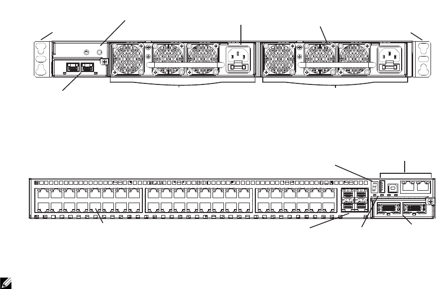
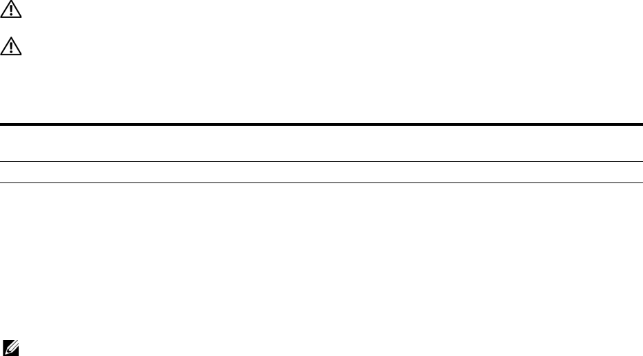
Figure 2-1. The Front of the S60 System
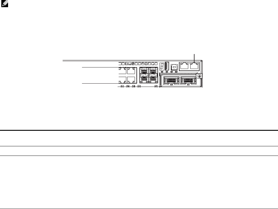
Figure 2-2. The Rear of the S60 System
NOTE: The ethernet ports are labeled 0-43. When cabling these ports, be sure not to interfere with the airflow
from the small vent holes above and below the ports.
Power Supply (PSU0) Power Supply (PSU1)
Mounting Bracket Mounting Bracket
Optional Module
(OPT1)
Ground Connectors Power Connector
(AC shown) Fans
Ethernet Ports SFP Ports Optional
Module
(OPT0)
Management
Ports
Stack ID
Alarm
LEDs

The S60 System | 7
Orderable S60 Systems
You can order the S60 in several different configurations. You can order optional modules separately.
To successfully install the S60 system, ensure that you have the following:
• S60 chassis (or multiple chassis, if stacking)
• At least one grounded AC or DC power source per chassis
• Cable to connect the AC or DC power source to the chassis (the US AC power cable is included)
• Mounting brackets for rack installation (included)
• Screws for rack installation and #1 #2 Phillips screwdrivers (not included)
• Ground cable (not included)
• Ground cable screws (included)
• Copper/fiber cables
Other optional components are:
• Additional PSU
• Additional fan module
• Optional modules, if needed
• Stacking cables, if stacking
Hardware
S60: 44 port 10/100/1000 Base-T with 4 SFP ports and 2 modular slots
S60: 44 port 10/100/1000 Base-T with 4 SFP ports, 2 modular slots,1 AC PSU and 1 fan subsystem
S60: 44 port 10/100/1000 Base-T with 4 SFP ports, 2 modular slots,1 DC PSU and 1 fan subsystem
S60 Fan Subsystem with airflow from the I/O panel to the PSU
S60 Fan Subsystem with airflow from the PSU to the I/O panel
S60 AC PSU with 1 fan module
S60 AC PSU with 1 reverse-flow fan module
S60 DC PSU with 1 fan module
S60 DC PSU with 1 reverse-flow fan module
S60 2-port, 12 Gigabit stacking module
S60 1-port, 24 Gigabit stacking module
S60 2-port, 10GE SFP+ module

The S60 System | 8
Features
The S60 offers the following:
• S60 CPU and switch processor
• Up to 12 stacked systems
• Stackable switch features
• 19-inch rack-mountable
• Standard 1U chassis height
• Hot-swappable optional modules, PSUs, and fan modules
• Integrated PSU/fan module (three fans per module)
• Up to 16K MAC address entries supported with hardware-assisted aging
• Supports 9K jumbo frames
Ports
• Optional ports supporting two 2-port, 10G SFP+ modules
• 44 fixed 10/100/1000 Mbps auto-sensing and auto-MDIX RJ45 ports
• Four fixed ports supporting 100/1000 Base-T or 1000 Base-X using auto-media detection
• Optional ports supporting one 2-port, 24G stacking module or two 1-port, 12G stacking modules
• Console port
• Universal Serial Bus (USB)-A port
• USB-B port
System Status
You can view S60 status information in several ways, including physical displays and boot menu options.
You can also view status information through the Command Line Interface (CLI) show commands and
with Simple Network Management Protocol (SNMP) traps. For more information about these options,
refer to the FTOS Command Line Reference Guide for the S60 System and the FTOS Configuration Guide
for the S60 System.
LED Displays
As shown in
Figure 2-3
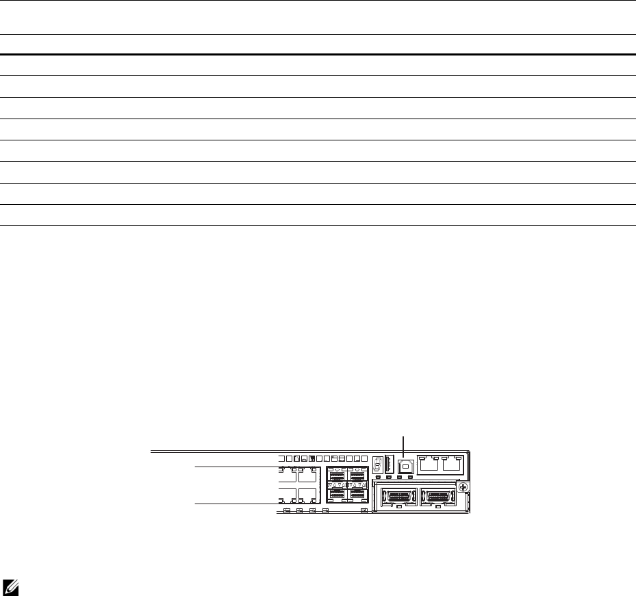
, the S60 rear panel contains several sets of Light Emitting Diodes (LEDs). The
Stacking ID is at the top right corner on the rear of the system and is shown in hexidecimal form. A small
decimal at the bottom right of the LED indicates the stack master.
NOTE: The stacking LED display is not applicable to the first release of the S60 system.
The S60 System | 9
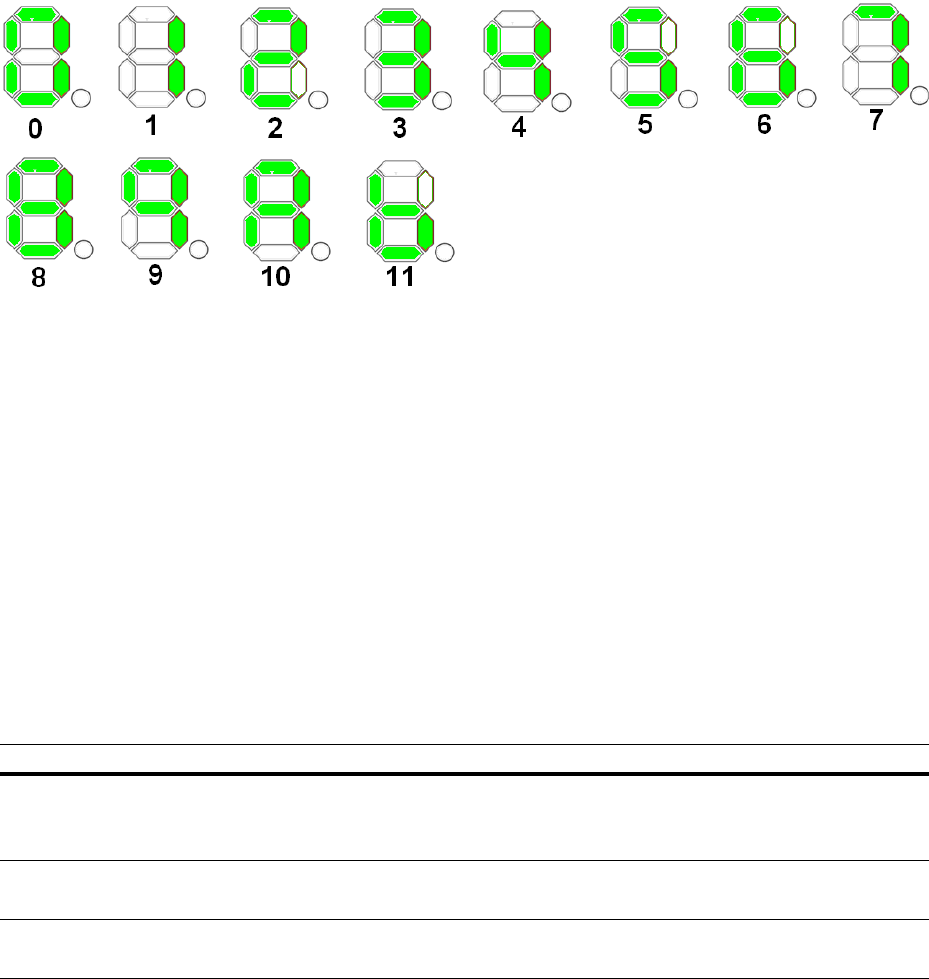
Figure 2-3. Stack ID Hexidecimal Display
• The stack master indicator displays:
• Stack Master—decimal LED ON
• Stack standby—decimal LED blinking
• Member—decimal LED Off
• Below the Stack ID LED and above the optional module ports are four LEDs that display the system
status (Table 2-1). From left to right they are:
• power
•alarm
•PSU0
•PSU1
Table 2-1. System LED Displays
Label LED Color/Display Description
Power (PWR) Green Blinking
Green
Yellow
System is booting up.
System power supply is OK.
System power supply is operating outside the expected parameters.
Power Supply
(PSU0) Green
Yellow
All fans are OK.
At least one fan is operating outside the expected parameters.
Power Supply
(PSU1) Green
Yellow
All fans are OK.
At least one fan is operating outside the expected parameters.

The S60 System | 10
In addition to the system LEDs, each port has status indicator LEDs.
Table 2-2
lists the port LED
displays.
Table 2-2. Port LED Displays
Feature Description
10/100/1000 Port LEDs • Link LED (on the left side of each port):
Green—1000M
Yellow—10/100M
Off—No link
• Activity LED (on the right side of each port):
Green—Link up on this port, full traffic
Blinking Green—Activity, transmitting or receiving packet at this port.
Off—No traffic
SFP+ Port LED • Link/Activity LED:
Green—Link up on this port, no activity taking place
Blinking Green—Activity, transmitting or receiving packet at this port.
Off—No link detected at this port
Stacking Module LEDs • Link/Activity LED:
Green—Link up on this port, no activity taking place
Blinking Green—Activity, transmitting or receiving packet in link up state
Off—No Link detected at this port

Install the S60 System | 11
3
Install the S60 System
To install the S60 system, Dell Force10 recommends completing the installation procedures in the order
presented in this chapter.
Always handle the S60 system and its components with care. Avoid dropping the system or its Field
Replaceable Units (FRUs).
This chapter describes the installation procedures as follows:
1
Install the S60 System in a Rack or Cabinet
a
Attach the Mounting Brackets
b
Install the Chassis into the Rack or Cabinet
2
Attach the Ground Cable
3
Insert Optional Modules
4
Connect Stacking Ports (Optional)
5
Supply Power and Power Up the System
WARNING: Electrostatic discharge (ESD) damage can occur if the components are mishandled. Always wear
an ESD-preventive wrist or heel ground strap when handling the S60 system and its components. As with all
electrical devices, take all the necessary safety precautions to prevent injury when installing this system.
Install the S60 System in a Rack or Cabinet
Attach the Mounting Brackets
The S60 system is shipped with mounting brackets (rack ears) and the required screws for rack or cabinet
installation. The brackets are enclosed in a package with the chassis.
NOTE: Dell Networking recommends attaching the brackets to the front of the chassis on the Power Supply
Unit (PSU) side. This provides the greatest weight support for the chassis in the rack or cabinet and is in
compliance with Bellcore Zone 4 earthquake requirements.
Install the S60 System | 12
To attach the brackets to the chassis, follow these steps:
Install the Chassis into the Rack or Cabinet
To permit access and airflow, ensure that there is adequate clearance surrounding the rack or within the
cabinet. When you install two S60 systems near each other, to permit proper airflow, position the two
chassis at least five inches (12.7 cm) apart.
To install a switch into a two-post 19-inch equipment rack, using the already attached mounting brackets,
follow these steps:
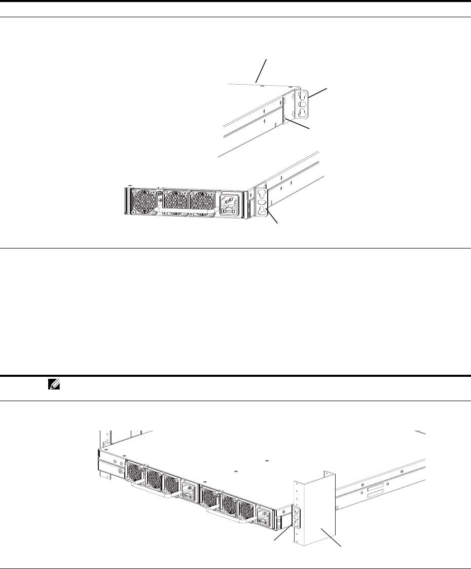
Step Task
1Take the brackets and screws out of their packaging.
2Attach the brackets to the rear sides of the chassis using four screws for each bracket. Attach the bracket so that
the “ear” faces to the rear and the outside of the chassis.
Step Task
NOTE: Dell Networking recommends one person holding the S60 chassis in place while another person
attaches the brackets to the posts.
1Attach the bracket “ears” to the rack or cabinet posts using two screws for each bracket. Ensure the screws are
tightened firmly.
Power Supply
Power Supply
Screws
Connect to
rack/cabinet
(ear)
Connect to
rack/cabinet
(ear)
View of chassis front
View from chassis rear
Rack/Cabinet
Post
Rack Mounting
"ears"
PSU0
PSU1
Install the S60 System | 13
Attach the Ground Cable
The S60 system is shipped with two 10-32 screws to attach a ground cable to the system. The cable is not
included. To properly ground the system, Dell Networking recommends using a 6AWG two-hole lug, #10
hole size, 63" spacing (not included). The two-hole lug must be a UL recognized, crimp-type lug.
NOTE: Coat the two-hole lug with an anti-oxidant compound prior to crimping. Bring any un-plated mating
surfaces to a shiny finish and coat with an anti-oxidant prior to mating. Plated mating surfaces must be clean
and free from contamination.
NOTE: The rack installation “ears” are not suitable for grounding.
CAUTION: Grounding conductors must be made of copper. Do not use aluminum conductors.
To connect the ground cable to the system, follow these steps:
Step Task
1Take the two 10-32 screws from the package.
2Cut the cable to the desired length. The cable length must facilitate the proper operation of the fault interrupt
circuits. Dell Networking recommends using the shortest cable route allowable.
3Attach the two-hole lug to the system using the supplied 10-32 screws with captive internal tooth lock washers.
Torque the screws to 20 in-lbs.
4Attach the other end of the ground cable to a suitable ground point. The rack installation “ears” are not a suitable
grounding point.
1
2
Install the S60 System | 14
Insert Optional Modules
The S60 system has expansion slots at the front left and rear right of the system that you can use for
stacking modules or for Small Form-Factor Pluggable Plus (SFP+) devices.
Table 3-1
lists the optional
modules that you can install into these expansion slots. The optional modules are hot-swappable.
NOTE: Pre-configuring the interfaces for the optical module preserves the configuration if and when you
remove an optical module. The optional 10G optical module is automatically recognized and the interfaces are
created when you insert the module into the slot. However, if the system is not already configured for the
interfaces, when you remove the optional module, the interfaces and their configurations are removed as well.
WARNING: ESD damage can occur if the components are mishandled. Always wear an ESD-preventive wrist
or heel ground strap when handling the S60 system and its components.
To install an optional module, follow these steps:
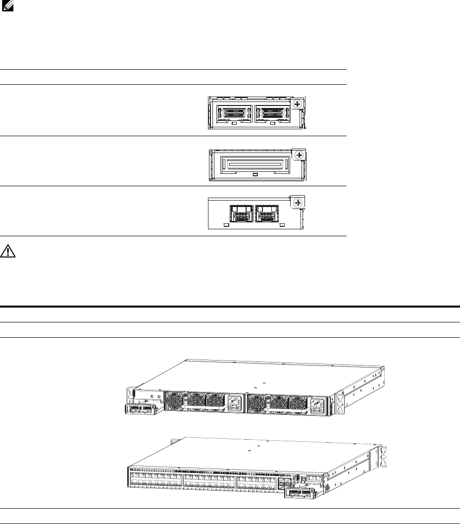
Table 3-1. Optional Modules
Module Description
2-port, 12G stacking module
1-port, 24G stacking module
2-port, 10G SFP+ optical module
Step Task
1Remove the faceplate covering the module slot located at the rear left or front right of the S60 system.
2Remove the optional module from its packaging.
3 Slide the optional module into the slot.
4Secure the captive screw on the side of the optional module.
Install the S60 System | 15
Install the SFP and SFP+ Optics
In addition to the optional SFP+ optical modules, the S60 system has four Small Form-Factor Pluggable
(SFP) optical ports in the front of the system.
WARNING: ESD damage can occur if the components are mishandled. Always wear an ESD-preventive wrist
or heel ground strap when handling the S60 system and its components.
WARNING: When working with optical fibers, follow all warning labels and always wear eye protection. Never
look directly into the end of a terminated or unterminated fiber or connector as it may cause eye damage.
To install SFP or SFP+ optics into an open port, follow these steps:
Connect Stacking Ports (Optional)
Before you make your stacking port connections, rack-mount the S60 system or insert it into a cabinet.
Insert one end of the stacking cable into a stacking port and insert the other end into a stacking port of the
adjacent system. To ensure the cable is secure in the connector, hand-tighten all the captive screws.
To configure as a unified system, Dell Networking supports stacking connections of up to 12 S60
systems.
NOTE: The S60 system does not stack with other S-Series systems.
You can connect the stacking systems while they are powered down or up. Both ring topology and
cascade topology connections are supported (
Figure 3-1
and
Figure 3-2
). The stacking ports are
bi-directional.
If you use the 2-port, 12G stacking module, the stacking ports are labeled 48-49 on the rear (ethernet
port) side and 50-51 on the front (PSU) side.
If you use the 2-port, 24G stacking module, the stacking ports are labeled 48 on the rear (ethernet port)
side and 50 on the front (PSU) side.
Important Points to Know
• Do not mix stacking modules. Use either the 1-port, 24G stacking module or the 2-port, 12G stacking
module within a single stack. You cannot cable from a 1-port module to a 2-port module.
• You can install the S60 optional modules on either the back or front side of the system. Dell Networking
supports cabling between the front and the back side stacking modules. If you need to reach from one
side of the system to the other side, be sure to use a cable of suitable length.
• To connect the systems, use only the supported stacking cables.
The S60 system supports stacking in either a ring or cascade topology (
Figure 3-1
and
Figure 3-2
). When
stacking S60 systems, to provide redundant connectivity, Dell Networking recommends using the ring
topology.
Step Task
1Position the SFP or SFP+ optic so it is in the correct position. The optic has a key that prevents it from being
inserted incorrectly.
2Insert the optic into the port until it gently snaps into place.
Install the S60 System | 16
Figure 3-1. S60 Stacking Topology with 2-port, 12G Stacking Modules
Figure 3-2. S60 Stacking Topology with 1-port, 24G Stacking Modules
While the diagram shows A-to-B connections, the ports are bi-directional so you can connect A-to-A or
B-to-B, as shown in the examples of two-switch ring topologies (
Figure 3-4
) and three-switch (
Figure 3-5
or
Figure 3-6
) ring topologies.
Before you make your stacking port connections, rack-mount the stacking systems or insert them into a
cabinet. Insert one end of the stacking cable into a stacking port and insert the other end into a stacking
port of the adjacent switch. To ensure the cable is secure in the connector, hand-tighten all the captive
screws.
Ring Topology
(with 2-port 12G modules)
Switch 1
Switch 2
Switch 3
Cascade Topology
(with 2-port 12G modules)
Switch 1
Switch 2
Switch 3
48
48
48
49
49
49
48 49
48 49
48 49
Ring Topology
(with 1-port 24G modules)
Switch 1
Switch 2
Switch 3
Cascade Topology
(with 1-port 24G modules)
Switch 1
Switch 2
Switch 3
50
48
48
48
48
48
48
50
50
50
50
50
Install the S60 System | 17
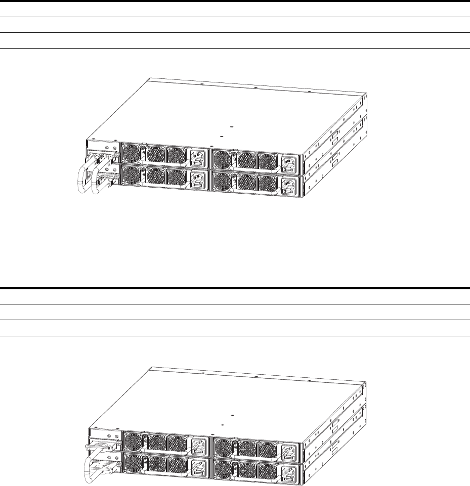
Connect Two S60 Systems
2-port, 12G Stacking Modules
As an option, when using the 2-port, 12G stacking modules, insert a second cable into the other open
stack ports (
Figure 3-4
). The second cable provides both backup connectivity and increased data transfer
between the systems.
To connect 2-port, 12G stacking modules, starting with the S60 at the bottom of the stack:
Figure 3-3. Two S60 Systems with 2-port, 12G Stacking Modules Connected in a Ring Topology
1-port, 24G stacking modules
The 1-port, 24G stacking module requires the S60 systems be cabled across the front-ports-to-rear-port,
or vice versa (
Figure 3-4
).
To connect 1-port, 24G stacking modules, starting with the S60 at the bottom of the stack:
Figure 3-4. Two S60 Systems with 1-port, 24G Stacking Modules Connected in a Ring Topology
Step Task
1Insert one end of the first cable into Stack Port 48 (or 50).
2Insert the other end of the cable into Stack Port 48 (or 50) of the top.
3Insert a second cable into Stack Port 49 (or 51) of the bottom and top S60 systems.
Step Task
1Insert one end of the first cable into Stack Port 48 (or 50).
2Insert the other end of the cable into Stack Port 50 (or 48) of the top S60 system.
3Insert the second cable into Stack Port 50 (or 48) of the middle and top S60 systems.

Install the S60 System | 18
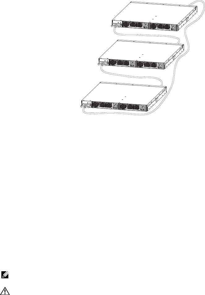
Connect Three or More S60 Systems
2-port, 12G Stacking Modules
As an option, when using the 2-port, 12G stacking modules, insert a second cable into the other open
stack ports (
Figure 3-5
). The second cable provides both backup connectivity and increased data transfer
between the systems.
To connect 2-port, 12G stacking modules, starting with the S60 system at the bottom of the stack:
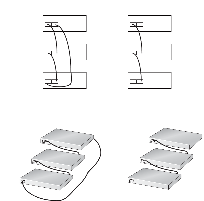
Figure 3-5. Three S60 Systems with 2-port, 12G Stacking Modules Connected in a Ring Topology
1-port, 24G Stacking Modules
The 1-port, 24G stacking module requires the S60 systems be cabled from the front-ports-to-rear-port, or
vice versa (
Figure 3-6
).
To connect 1-port, 24G stacking modules, starting with the S60 system at the bottom of the stack:
Step Task
1Insert one end of the first cable into Stack Port 48 (or 50).
2Insert the other end of the cable into Stack Port 48 (or 50) of the middle S60 system.
3Insert the second cable into Stack Port 49 (or 51) of the middle and top S60 systems.
4Use the remaining cable to connect the top and bottom S60 systems by inserting one end of the cable into the open
Stack Port 49 (or 51) of the bottom S60 system and the other end of the cable into Stack Port 48 (or 50) of the top
S60 system.
Step Task
1Insert one end of the first cable into Stack Port 48 (or 50).
2Insert the other end of the cable into Stack Port 48 (or 50) of the middle S60 system.
3Insert the second cable into Stack Port 50 (or 48) of the middle and top S60 systems.
4Use the remaining cable to connect the top and bottom S60 systems by inserting one end of the cable into the open
Stack Port 48 (or 50) of the bottom S60 system and the other end of the cable into Stack Port 50 (or 48) of the top
S60 system.
Install the S60 System | 19
Figure 3-6. Three S60 Systems with 1-port, 24G Stacking Modules Connected in a Ring Topology
Supply Power and Power Up the System
Supply power to the S60 system after you have mounted them in a rack (or on a table) and have installed
the optional modules.
Dell Networking recommends re-inspecting your system prior to powering up. Verify that:
• the equipment is properly secured to the rack and properly grounded.
• the equipment rack is properly mounted and grounded.
• the ambient temperature around the system (which may be higher than the room temperature) is within
the limits specified for the S60 system.
• there is sufficient airflow around the system.
• the input circuits are correctly sized for the loads and that you use sufficient over-current protection
devices.
• all the protective covers are in place.
• you have installed blank panels if you did not install optional modules.
NOTE: A US AC power cable is included in the shipping container for powering up an AC PSU. You must
order all other power cables separately.
WARNING: ESD damage can occur if the components are mishandled. Always wear an ESD-preventive wrist
or heel ground strap when handling the S60 system and its components.
Power Up Sequence
When the system powers up, the fans immediately come on at high speed. The fan speed slows as the
system boots up.
Install the S60 System | 20
The PWR Light Emitting Diode (LED) blinks until the boot-up sequence is complete. When the boot up
is complete, the PWD LED is steadily lit.
The Stack ID LED displays a digit to show the position of the unit in a stacking chain. For a single
chassis, a 0 displays.
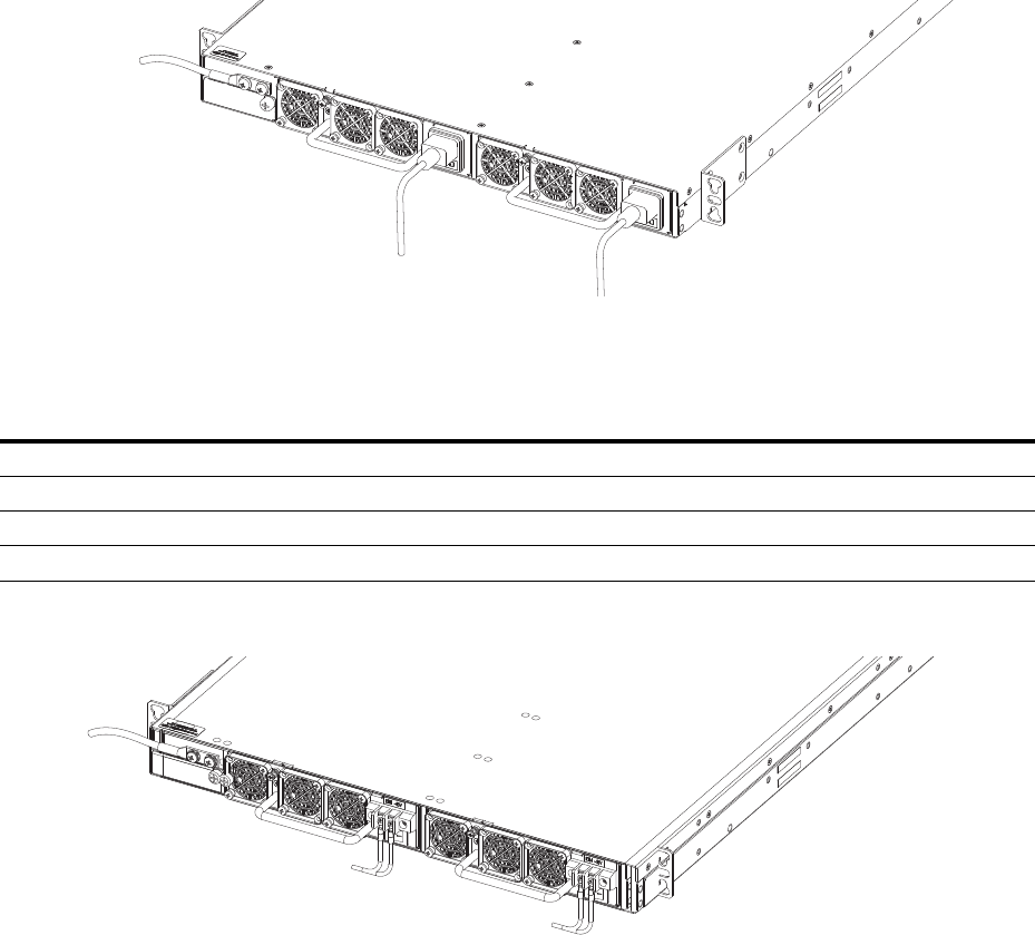
AC Power
Connect the plug to each AC receptacle (
Figure 3-7
). Ensure the power cord is secure.
As soon as the cable is connected between the S60 system and the power source, the system is
powered-up; there is no on/off switch.
Figure 3-7. AC Power Connection
DC Power
To connect DC power (
Figure 3-8
), follow these steps:
Figure 3-8. DC power connection
Step Task
1Remove the small plastic cover from the DC connectors.
2Attach the connectors to both the DC PSUs at the rear of the S60 system. Ensure the connection is secure.
3Replace the plastic cover over the DC connectors.
4Turn the power switch on.
Install the S60 System | 21
Hot-swap Units in a Stack
You can add, remove, or swap units in an existing stack. The units in the stack and the new units can be
already powered up or they can be powered down.
All units in a stack must run the same version of the operating system. If you attempt to attach a unit with
a different version of the operating system to an existing stack, the Command Line Interface (CLI)
displays an error and the unit is not added until you install compatible software.
The order in which the units come on-line or are added to or removed from the stack can affect how the
stack identifies them and how the units identify themselves. This influences the unit numbers,
management addresses, and other elements of the configuration file.
How units are identified within the stack is determined by the selected identification algorithm. The
default algorithm has the units self-identify as Unit 1 through Unit [last] based on the order in which they
come on-line. So, when setting up a new set of switches in a stack, you should have no trouble forcing the
identification of the management unit and unit IDs by methodically supplying power to the units in your
preferred sequence.
Similarly, when you add a brand new unit to the stack, the unit will be gracefully added as Unit [last] (the
lowest unused number) with the current configuration. Attaching the unit causes each unit in the stack to
reload and the subsequent configuration file in each unit includes the awareness of the new unit.
If you have a pre-configured unit that you want to add to the stack, but you want to make sure the
configuration does not override the configuration of the stack, in order to avoid stack management
conflicts, add the unit while it is powered down.
You can use the CLI to make stack identification changes on the fly, such as renumbering units (stack-
unit unit number renumber unit number), assigning a new management unit (redundancy force-
failover stack-unit number), or removing priority or provisioning of a stack unit member (no stack-unit
unit number provision provision type). You can also use commands such as stack-unit unit number
priority value and member that override the default unit identification algorithms.
To see the current assignment of the management unit, use the show system command. To see the serial
number of the designated unit, use the show system stack-unit unit number command.
For more information about removing a unit from a stack and other stacking commands, refer to the
Stacking chapter in the FTOS Configuration Guide for the S60 System and the Stacking Commands
chapter in the FTOS Command Line Reference Guide for the S60 System.
Power Supplies | 22
4
Power Supplies
The S60 system is designed to support two hot-swappable power supply units (PSUs) with integrated
fans that provide the cooling for the system. There are two types of power supplies (AC or DC) and there
are two airflow directions (normal and reverse). Two PSUs are required for full redundancy, but the
system will operate with a single PSU. You can equip one of the PSU bays with a fan-only module.
For the procedure to replace only a fan module or fan filter, refer to
Chapter 5, Fans and Filters
.
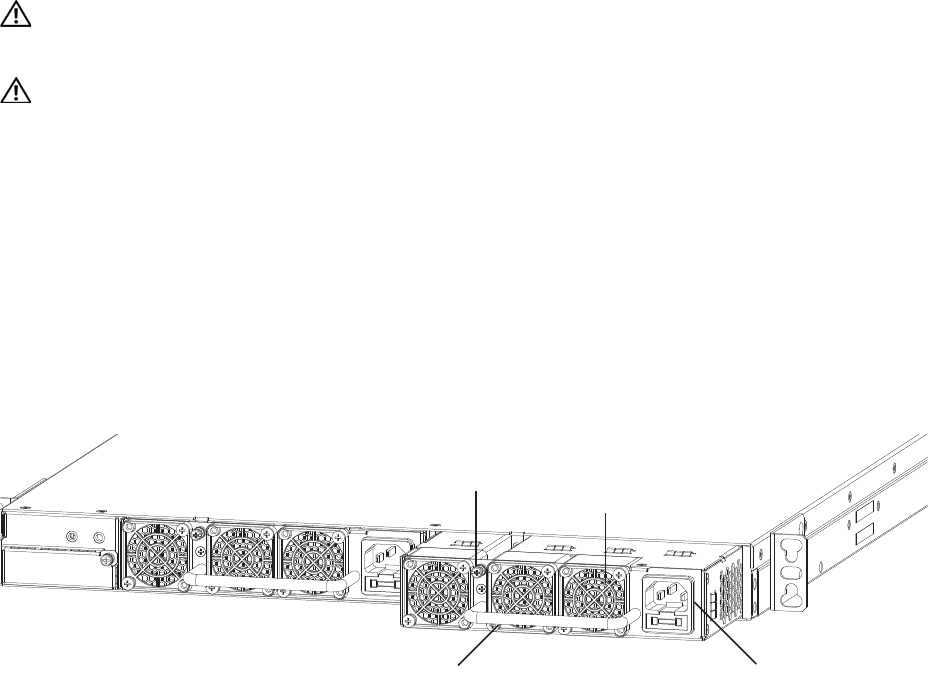
You can order the S60 system as an empty chassis or with either AC power (
Figure 4-1
) or DC power
(
Figure 4-2
). Both PSU types are field replaceable. When running with full redundancy (two PSUs
installed and running), you can remove and replace one PSU while the other PSU is running without
disrupting traffic.
WARNING: To prevent electrical shock, ensure the S60 system is grounded properly. If you do not ground
your system correctly, excessive emissions may result. Use a qualified electrician to ensure that the power
cables meet your local electrical requirements.
WARNING: Electrostatic discharge (ESD) damage can occur if the components are mishandled. Always
wear an ESD-preventive wrist or heel ground strap when handling the S60 system and its components.
Components
The following power supply options are available for the S60 system:
• AC power supply with integrated fans
• AC power supply with integrated reverse flow fans
• DC power supply with integrated fans
• DC power supply with integrated reverse flow fans
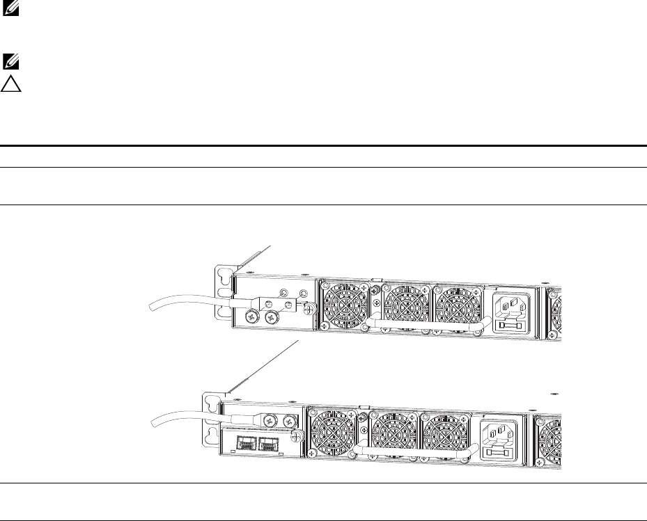
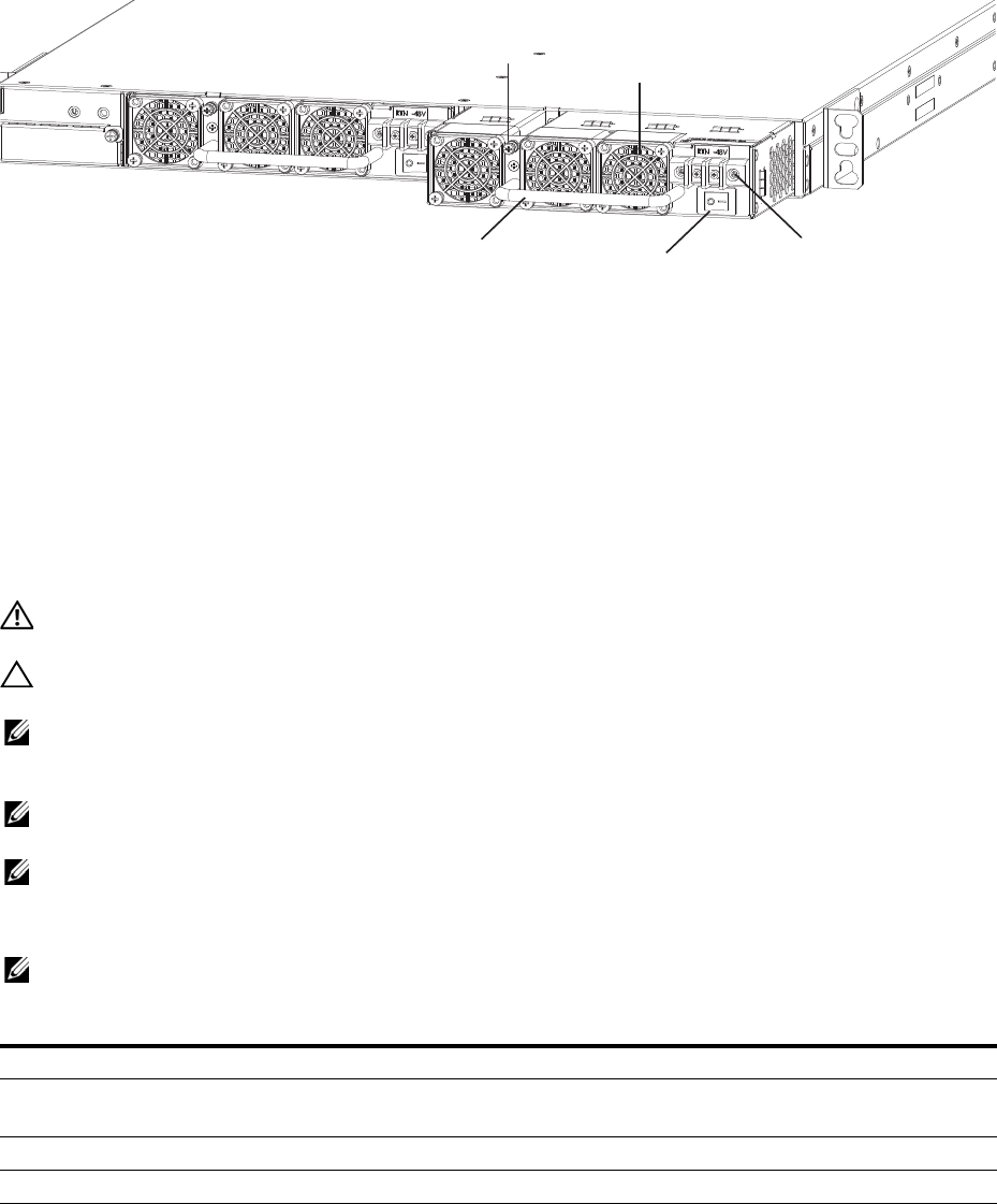
Figure 4-1. AC Power Supply
Grab Handle
Securing Screw
AC Power Connector
Fans and Filters
PSU0
PSU1
Power Supplies | 23
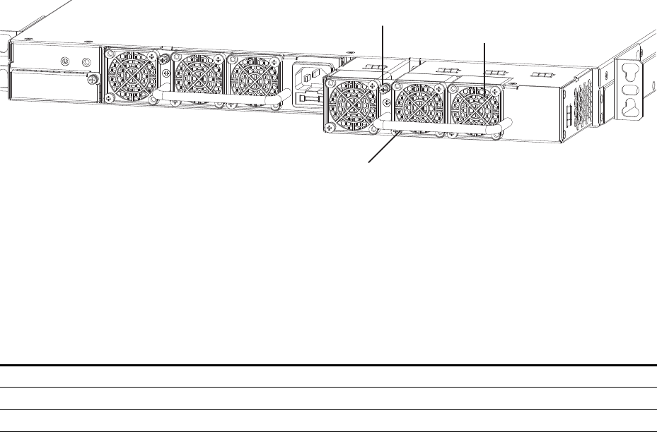
Figure 4-2. DC Power Supply
Power supply 0 (PSU0) is on the left side of the system; power supply 1 (PSU1) is on the right side of the
system.
Install an AC or DC Power Supply
The PSUs in the S60 system are field replaceable. When both PSUs are up and running, you can remove
one PSU without interrupting traffic.
The PSUs are in a single piece with the fans. You can replace the fan filters individually (in the reverse
[-R] systems), but replacing a PSU also replaces the fans attached to that PSU. For the procedure to
replace only the fan filters, refer to
Chapter 5, Fans and Filters
.
WARNING: Prevent exposure and contact with hazardous voltages. Do not attempt to operate this system
with the safety cover removed.
CAUTION: Remove the power cable from the PSU prior to removing the PSU. Also, do not connect power to
the PSU prior to inserting the PSU in the system.
NOTE: For a Network Equipment Building System (NEBS)-compliant installation, to protect the AC power
supplies from damage due to excessive power line surges, the AC power connections must use a Surge
Protection Device (SPD).
NOTE: To comply with the GR-1089 Lightning Criteria for Equipment Interfacing with AC Power Ports, use an
external SPD at the AC input of the router.
NOTE: You must isolate the DC power return conductor from the chassis or frame when you make
connections to the PSU.
To install a PSU, follow these steps:
NOTE: The PSU module slides into the slot smoothly. Do not force a module into a slot as this may damage
the PSU or the S60 system.
Step Task
1Take the PSU out of the shipping box.
2For DC PSUs, remove the small plastic cover over the DC connectors. Do not throw the cover away; you will
replace it when you complete the installation.
3Use the grab handle to slide the PSU into the power supply bay.
4Tighten the securing screw at the top of the PSU.
5Attach the power cables.
Grab Handle
Securing Screw
DC Power Connector
Fans and Filters
PSU0
PSU1
Power Switch
Power Supplies | 24
Replace an AC or DC Power Supply
NOTE: If a PSU fails, you must completely replace it. There are no field servicable components in the PSU.
To request a hardware replacement, refer to
Chapter 8, Technical Support
.
To replace a PSU, follow these steps:
6For DC PSUs, replace the small plastic cover over the DC connectors.
7• For an AC PSU, the system powers up as soon as the cables are connected between the PSU and the power
source.
• For a DC PSU, turn on the power.
Step Task
1• For an AC PSU: disconnect the power cable from the PSU.
• For a DC PSU: IMPORTANT: Turn OFF the power switch and disconnect the power cord from the PSU.
2For DC PSUs, remove the small plastic cover over the DC connectors. Do not throw the cover away; you will put
it back on when you complete the PSU replacement.
CAUTION: You must complete steps 3 and 4 within one minute or the system powers down.
3Use the grab handle to slide the PSU out of the power supply bay.
4Use the grab handle on the replacement PSU to slide it into the power supply bay.
5Tighten the securing screws on the replacement PSU. Ensure the PSU is secure.
6Attach the power cord to the replacement PSU.
7For DC PSUs, replace the small plastic cover over the DC connectors.
8• For an AC PSU, the system powers up as soon as the cables are connected between the PSU and the power
source.
• For a DC PSU, turn on the power.
Step Task (continued)

Fans and Filters | 25
5
Fans and Filters
The S60 system comes from the factory with one Power Supply Unit (PSU) and one fan module installed
in the system (
Figure 5-1
). If a second (redundant) PSU is installed and running, both the fan module and
the integrated fan/PSU are hot-swappable. With redundant PSUs, if you remove a fan module, traffic is
not interrupted.
WARNING: To run the system, both slots must have operating fan units. If a module is not installed in each
slot (either as part of the PSU or as an independent fan module), the system powers down when it exceeds an
internal temperature threshold.
WARNING: Dell Networking recommends replacing the fan tray within five minutes. If the fan tray is left out
for too long, the system may experience traffic disruption.
The S60 system supports two airflow direction options (normal and reverse). Do not mix fan airflow
types; you can only use a single airflow direction in a system. If the airflow directions are mismatched,
the system powers down in one minute.
• Normal—airflow is from the Input/Output (I/O) panel to the PSU
• Reverse—airflow is from the PSU to the I/O panel
Environmental factors can decrease the amount of time required between air filter replacements. Check
the environmental factors regularly. An increase in temperature and/or particulate matter in the air might
affect performance (for example, new equipment installation).
CAUTION: Check the fan air filters at six-month intervals and replace them as necessary. In order to
accurately determine air filter replacement intervals, regularly monitor the speeds of the cooling fans. An
increase in overall fan speed may indicate a clogged filter.
You must replace the S60 fan filters with new filters; you cannot clean and reuse the fan filters.
Replacement filters can be sourced online through third-party component suppliers. The fan filter is
manufactured by Qualtek Electronics Corporation and is stocked at several different online electronics
supply sites. The Qualtek part number is 09150-M/30 (on some sites the part number is referenced as
09150-M30), and provides conformance to the following standards as per the NEBS GR-63-CORE
specification:
• Minimum dust arrestance of 65%, per ASHRAE Standard 52.1-1992
OR
• Minimum Efficiency Rating Value (MERV) of 2, per ANSI/ASHRAE Standard 52.2-2007
Dell Networking does not recommend any one site to procure these filters, but you can find a link on the
filter manufacturer’s site (http://www.qualtekusa.com) that displays a list of distributors and their current
stock. Select Catalog > Fan_Accessories then scroll to part “09150-M/30*.” Click the check mark in the
Distributor Stock Check column. A list of distributors and their reported inventory displays.
CAUTION: For Network Equipment Building System (NEBS)-compliance, use the NEBS-approved filters.
These filters are colored green and are installed exactly the same as the non-NEBS filters.
Fans and Filters | 26
Components
• S60 Fan module
• S60 Fan module - Reverse flow
• S60 Fan filter
• The fan filters are used on the reverse flow (R) fan modules only.
Figure 5-1. The S60 Fan Module
Module slot 0 is on the left side of the system; module slot 1 is on the right side of the system.
Install a Fan Module
The fan modules in the S60 are field replaceable. The PSUs are in a single piece with the fans. For the
procedure to replace the entire PSU, refer to
Chapter 4, Power Supplies
.
To install a fan module, follow these steps:
Replace a Fan Module
Dell Networking recommends replacing the fan tray within five minutes. If the fan tray is left out for too
long, the system may experience traffic disruption.
Step Task
1Take the fan module out of the shipping box.
2Use the grab handle to slide the fan module into the bay.
3Tighten the securing screw at the top of the fan module.
Grab Handle
Securing Screw Fans and Filters
PSU0
Fan Module1
Fans and Filters | 27
Error messages appear when the fan tray is removed and when the temperature approaches the threshold.
• When a fan tray is removed, the system displays the following message:
00:00:37: %STKUNIT0-M:CP %CHMGR-2-FAN_TRAY_BAD: Major alarm: fan tray 0 in unit 0
is missing or down
• When the temperature reaches the maximum threshold (3), the system displays the following warning
message:
00:00:38: %STKUNIT0-M:CP %CHMGR-2-TEMP_SHUTDOWN_WARN: WARNING! Unit 0
temperature is current temp;
To replace a fan module, follow these steps:
Install a Fan Filter
Use the fan filters with the reverse (R) flow fan modules and PSU/fan modules only. You can replace
them individually on each fan within the module without powering down a PSU module or disrupting
traffic.
The fan filters and retainers pop into the fan guards on the module. There is no need to unscrew the filter
guard.
To install a fan filter, follow these steps:
Step Task
1Loosen the securing screw at the top of the fan module.
CAUTION: You must complete steps 2 and 3 within five minutes or the system powers down. If a fan
module is not installed in each slot (either as part of the PSU or as an independent fan module), the system powers
down when it exceeds an internal temperature threshold.
2Use the grab handle to slide the fan module out of the bay.
3Use the grab handle on the replacement fan module to slide it into the bay.
4Tighten the captive screws on the replacement fan module. Ensure the fan module is secure.
Step Task
1Using your fingernail, gently pry the filter retainer off the filter guard.
2Remove the filter.
3Replace the filter and ensure it is pressed firmly into place. Gently press the filter retainer into the filter guard
until it snaps in.
4Repeat for all the fan filters, if necessary.
Access the Console Ports | 28
6
Access the Console Ports
You can access the S60 system directly through the console port at rear of the system (
Figure 6-1
).
Access the RJ-45 Console Port (RS-232)
NOTE: Before starting this procedure, be sure you have a terminal emulation program already installed on
your PC.
The RS-232 console port is labeled on the upper right-hand side on the rear of the S60 system.
Figure 6-1. S60 Serial Console Port Connector
For the console port pin assignments, refer to
Table 6-1
.
To access the RJ-45 console port, follow these steps:.
Step Task
1Install an RJ-45 copper cable into the console port. Use a rollover cable to connect the S60 console port to a
terminal server.
2Connect the other end of the cable to the DTE terminal server.
3Set the default terminal settings as follows:
• 9600 baud rate
• No parity
• 8 data bits
•1 stop bit
• No flow control
Console
Port
Access the Console Ports | 29
Access the RJ-45 Console Port with a DB-9 Adapter
If the DTE has a DB-9 interface, you can connect to the console port using an RJ-45 to DB-9 adapter
along with the RJ-45 rollover cable.
Table 6-1
lists the pin assignments.
Access the USB-B Console Port
The S60 system has two management ports available for system access: a console port and a Universal
Serial Bus (USB)-B port (
Figure 6-2
). The USB-B ports act exactly as the console port. The terminal
settings are the same. When the USB-B drive is connected, the S60 system sends all messages to it.
The USB-B connector port is labeled on the left of the management ports on the rear of the S60 system.
Figure 6-2. S60 USB-B Port Connector
When you connect both the console port and the USB-B port, the S60 system defaults to the USB-B port.
If the USB-B port is connected, the console connection is considered inactive.
NOTE: Before starting this procedure, be sure you have a terminal emulation program already installed on
your PC. You will also require the appropriate drivers for the USB device in use. For assistance, contact Dell
Networking Technical Support.
Table 6-1. Pin Assignments Between the E-Series Console and a DTE Terminal Server
E-Series Console
Port RJ-45 to RJ-45 Rollover Cable RJ-45 to DB-9
Adapter Terminal Server Device
Signal RJ-45 Pinout RJ-45 Pinout DB-9 Pin Signal
RTS 1 8 8 CTS
NC 2 7 6 DSR
TxD 3 6 2 RxD
GND 4 5 5 GND
GND 5 4 5 GND
RxD 6 3 3 TxD
NC 7 2 4 DTR
CTS 8 1 7 RTS
USB-B
Port
Access the Console Ports | 30
To access the USB-B console port, follow these steps:
Step Task
1Power on the PC (Dell Force 10 recommends using an XP operating system).
2Connect the USB-A end of cable (included) into an available USB port on the PC.
3Connect the USB-B end of cable into the USB-B console port on the S60 system.
4Power on the S60 system.
5Install the necessary USB device drivers (an internet connection is required). For assistance, contact Dell
Networking Technical Support.
6Open your terminal software emulation program to access the S60 system.
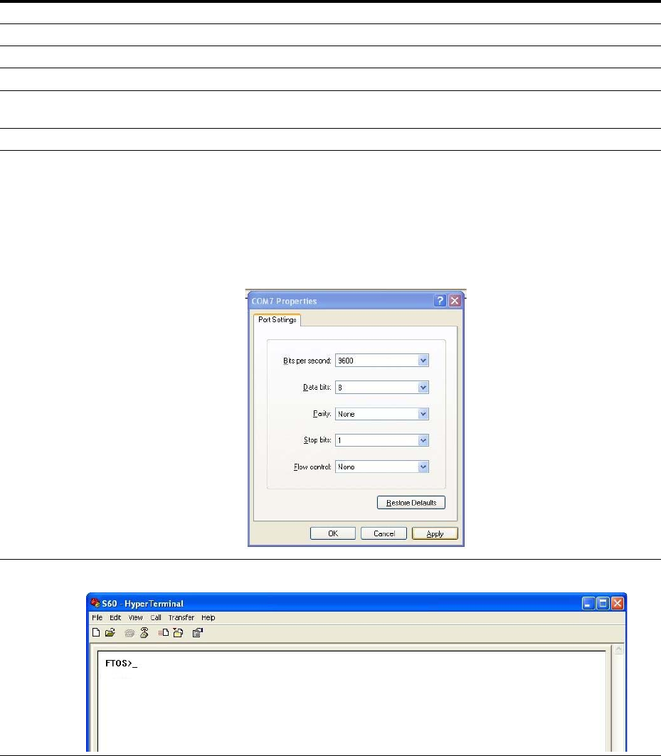
7Set the terminal connection settings as follows:
• 9600 baud rate
• No parity
• 8 data bits
•1 stop bit
• No flow control
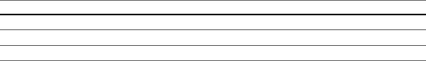
8The CLI command prompt appears when you are connected to the S60 system.

S60 Specifications | 31
7
S60 Specifications
This chapter the following sections:
• Chassis Physical Design
•Agency Compliance
Chassis Physical Design
Environmental Parameters
AC Power Requirements
Parameter Specifications
Height 1.7 inches (4.3 cm)
Width 17.32 inches (44.0 cm)
Depth 16.73 inches (42.5 cm)
Chassis weight with factory-installed components 14.39 pounds (approx.) (6.54 kg)
Rack clearance required Front: 5-inches (12.7 cm)
Rear: 5-inches (12.7 cm)
Thermal dissipation 597 BTU/hr
Power consumption 175 Watts (nominal)
225 Watts (maximum)
Parameter Specifications
Temperature 32° to 122°F (0° to 50°C)
-40° to 158°F (-40° to 70°C) non-operating
Maximum altitude No performance degradation to 10,000 feet (3,048 meters)
Relative humidity 10 to 85% non-condensing
5 to 95% non-condensing (non-operating)
Shock MIL-STD-810
Vibration Bellcore GR-63
Parameter Specifications
Nominal input voltage 100 to 240 VAC, 50/60 Hz
Maximum AC power supply input current 2 A at 100/120 VAC
Maximum system power input 225 W
S60 Specifications | 32
DC Power Requirements
IEEE Standards
The S60 complies with the following IEEE standards:
• 802.3ae 10 Gigabit Ethernet
• 802.3ab 1000Base-T
• 802.1p L2 Prioritization
• 802.1Q VLAN Tagging, Double VLAN Tagging (Q in Q), GVRP
• 802.1s Multiple Spanning Tree Protocol
• 802.1w Rapid Spanning Tree Protocol
• 802.3ad Link Aggregation with LACP
• 802.1D Bridging, GARP, GMRP
• 802.3x Flow Control
• 802.1ac Frame Extension for VLAN tagging
• 802.1x Port based Network Access Control
Agency Compliance
The S60 system is designed to comply with the following safety and agency requirements.
Network Equipment Building Systems (NEBS) Compliance
• Use shielded cables for ports 0 - 43. The shields must be grounded at both ends.
• You can only use reverse airflow configurations in a NEBS-compliant installation. Use only supported
Dell S60 AC power supply units, DC power supply units, and fans.
• You must fit the Power Supply Units (PSUs) and fan modules with the supported Dell S60 filter kits.
You must replace the fan filters on a regular basis.
• Use this equipment with an external second-level 6kV lightning Surge Protection Device (SPD) at the
AC input of the building.
• For the NEBS-compliant installation, in order to protect the AC PSUs from damage due to excessive
power line surges, AC power connections must use a SPD.
• In order to comply with the GR-1089 Lightning Criteria for Equipment Interfacing with AC Power
Ports, use an external SPD at the AC input of the router.
Parameter Specifications
Nominal input voltage –40 to – 60 VDC
Maximum power supply input current 3.6 A at -48 VDC
Maximum system power input 225 W

S60 Specifications | 33
WARNING: Electrostatic discharge (ESD) damage can occur if the components are mishandled. Always
wear an ESD-preventive wrist or heel ground strap when handling the S60 system and its components.
CAUTION: The intra-building port(s) of the equipment or sub-assembly is suitable for connection to
intra-building or unexposed wiring or cabling only. The intra-building port(s) of the equipment or sub-assembly
MUST NOT be metallically connected to interfaces that connect to the OSP or its wiring. These interfaces are
designed for use as intra-building interfaces only (Type 2 or Type 4 ports as described in GR-1089-CORE,
Issue 5) and require isolation from the exposed OSP cabling. The addition of Primary Protectors is not
sufficient protection in order to connect these interfaces metallically to OSP wiring.
USA Federal Communications Commission (FCC) Statement
This equipment has been tested and found to comply with the limits for a Class A digital device, pursuant
to Part 15 of the FCC rules. These limits are designated to provide reasonable protection against harmful
interference when the equipment is operated in a commercial environment. This equipment generates,
uses, and can radiate radio frequency energy. If it is not installed and used in accordance to the
instructions, it may cause harmful interference to radio communications. Operation of this equipment in a
residential area is likely to cause harmful interference, in which case users will be required to take
whatever measures necessary to correct the interference at their own expense.
Properly shielded and grounded cables and connectors must be used in order to meet FCC emission
limits. Dell Networking is not responsible for any radio or television interference caused by using other
than recommended cables and connectors or by unauthorized changes or modifications in the equipment.
Unauthorized changes or modification could void the user’s authority to operate the equipment.
This device complies with Part 15 of the FCC Rules. Operation is subject to the following two conditions:
(1) this device may not cause harmful interference, and (2) this device must accept any interference
received, including interference that may cause undesired operation.
Canadian Department of Communication Statement
S60 Specifications | 34
European Union EMC Directive Conformance Statement
This product is in conformity with the protection requirements of EU Council Directive 2004/108/EC on
the approximation of the laws of the Member States relating to electromagnetic compatibility. Dell
Networking cannot accept responsibility for any failure to satisfy the protection requirements resulting
from a non-recommended modification of this product, including the fitting of non-Dell Networking
option cards.
This product has been tested and found to comply with the limits for Class A Information Technology
Equipment according to CISPR 22/European Standard EN 55022. The limits for Class A equipment were
derived for commercial and industrial environments to provide reasonable protection against interference
with licensed communication equipment.
WARNING: This is a Class A product. In a domestic environment, this device may cause radio interference, in
which case, you may be required to take adequate measures.
European Community Contact
For regulatory compliance, refer to
www.dell.com/regulatory_compliance
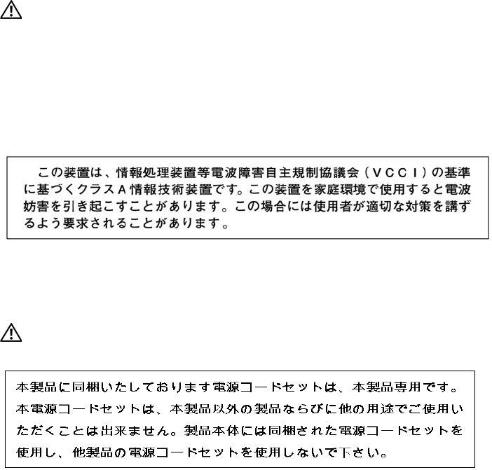
Japan: VCCI Compliance for Class A Equipment
This is Class A product based on the standard of the Voluntary Control Council For Interference by
Information Technology Equipment (VCCI). If this equipment is used in a domestic environment, radio
disturbance may arise. When such trouble occurs, the user may be required to take corrective actions.
WARNING: AC Power cords are for use with Dell Networking equipment only. Do not use Dell Networking AC
power cords with any unauthorized hardware.
S60 Specifications | 35
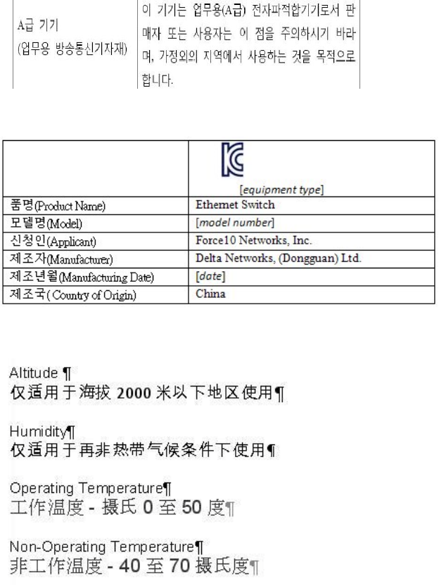
Korea Compliance
Korea Information
China Compliance
Safety Standards and Compliance Agency Certifications
• CUS UL 60950-1, 1st Edition
• CSA 60950-1-03, 2nd Edition
• EN 60950-1, 2nd Edition
• EN 60825-1, 1st Edition
• EN 60825-1 Safety of Laser Products—Part 1: Equipment Classification Requirements and User’s
Guide
S60 Specifications | 36
• EN 60825-2 Safety of Laser Products—Part 2: Safety of Optical Fibre Communication Systems
• FDA Regulation 21CFR 1040.10 and 1040.11
• IEC 60950-1, 2nd Ed, including all National Deviations and Group Differences
Electromagnetic Compatibility (EMC)
Emissions
• International: CISPR 22: 2006, Class A
• Australia/New Zealand: AS/NZS CISPR 22: 2006, Class A
• Canada: ICES-003, Issue-4, Class A
• Europe: EN55022 2006 (CISPR 22: 2006), Class A
• Japan: VCCI V3/ 2007.04 Class A
• USA: FCC CFR47 Part 15, Subpart B, Class A
Immunity
• EN 300 386 v1.3.3: 2005 EMC for Network Equipment
• EN55022 2006, Class A
• EN 55024 1998 + A1: 2001 + A2: 2003
• EN 61000-3-2 Harmonic Current Emissions
• EN 61000-3-3 Voltage Fluctuations and Flicker
• EN 61000-4-2 ESD
• EN 61000-4-3 Radiated Immunity
• EN 61000-4-4 EFT
• EN 61000-4-5 Surge
• EN 61000-4-6 Low Frequency Conducted Immunity
Product Recycling and Disposal
You must recycle or discard this system according to the applicable local and national regulations. Dell
Networking encourages owners of information technology (IT) equipment to responsibly recycle their
equipment when it is no longer needed. Dell Networking offers a variety of product return programs and
services in several countries to assist equipment owners in recycling their IT products.
Waste Electrical and Electronic Equipment (WEEE) Directive for Recovery, Recycle and Reuse of IT and
Telecommunications Products
Dell Networking equipment is labeled in accordance with European Directive 2002/96/EC concerning
waste electrical and electronic equipment (WEEE). The Directive determines the framework for the
return and recycling of used appliances as applicable throughout the European Union. This label is
applied to various products to indicate that the product is not to be thrown away, but rather reclaimed
upon end of life per this Directive.
S60 Specifications | 37
Figure 7-1. The European WEEE symbo
l
In accordance with the European WEEE Directive, electrical and electronic equipment (EEE) is to be
collected separately and to be reused, recycled, or recovered at end of life. Users of EEE with the WEEE
marking per Annex IV of the WEEE Directive, as shown above, must not dispose of end of life EEE as
unsorted municipal waste, but use the collection framework available to customers for the return,
recycling and recovery of WEEE. Customer participation is important to minimize any potential effects
of EEE on the environment and human health due to the potential presence of hazardous substances in
EEE.
Dell Networking products, which fall within the scope of the WEEE, are labeled with the crossed-out
wheelie-bin symbol, as shown above, as required by WEEE.
For information on Dell Networking product recycling offerings, see the WEEE Recycling instructions
at:
http://www.euro.dell.com/recycling
.
For more information, contact the Dell Networking Technical Assistance Center (TAC) (see
Contacting
the Technical Assistance Center
).
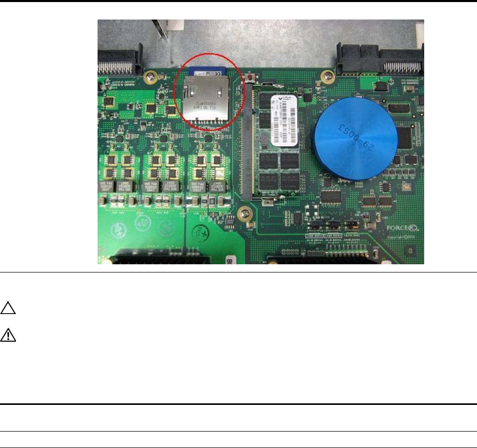
SD Card Removal
To support high-security environments, you can remove and re-install the SD card. Dell Networking
recommends only removing the card when necessary. Only authorized personnel should remove and
replace the card.
CAUTION: Only remove the SD card to support high-security operations and after discussions with Dell
Networking Technical Support or your Dell Networking representative.
To remove the SD card, follow these steps:
Step Task
1Remove the small Phillips screws that connect the top to the body. There are three screws evenly spaced across
the rear and three screws evenly spaced along each side of the case.
2Slide the top backwards until its front flange slides free of the faceplate. Lift it off.
3Gently push the SD card to release it from the slot.
S60 Specifications | 38
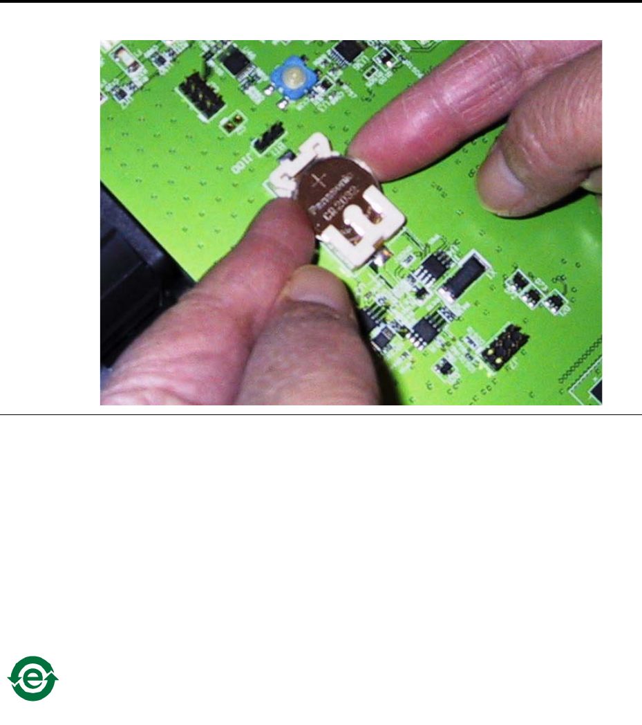
Battery Replacement and Recycling
CAUTION: The lithium battery is not field replaceable. Only authorized personnel should remove and replace
the lithium battery. If the battery requires replacement, contact Dell Networking Technical Support.
WARNING: ESD damage can occur if the components are mishandled. Always wear an ESD-preventive
wrist or heel ground strap when handling the S60 system and its components. As with all electrical devices,
take all the necessary safety precautions to prevent injury when installing this system.
To remove the battery, follow these steps:
4Remove the card.
Step Task
1Remove the small Phillips screws that connect the top to the body. There are three evenly spaced screws across
the rear and three evenly spaced screws along each side.
2Slide the top backwards until its front flange slides free of the faceplate. Lift it off.
3Insert a small, flat screw driver blade under the battery and in one of the slots of the plastic retainer underneath the
battery.
Step Task (continued)
S60 Specifications | 39
Batteries or packaging for batteries are labeled in accordance with European Directive 2006/66/EC
concerning batteries and accumulators and waste batteries and accumulators. The Directive determines
the framework for the return and recycling of used batteries and accumulators as applicable throughout
the European Union. This label is applied to various batteries to indicate that the battery is not to be
thrown away, but rather reclaimed upon end of life per this Directive.
In accordance with the European Directive 2006/66/EC, batteries and accumulators are labeled to
indicate that they are to be collected separately and recycled at end of life. The label on the battery may
also include a chemical symbol for the metal concerned in the battery (Pb for lead, Hg for mercury and
Cd for cadmium). Users of batteries and accumulators must not dispose of batteries and accumulators as
unsorted municipal waste, but use the collection framework available to customers for the return,
recycling and treatment of batteries and accumulators.
Customer participation is important to minimize any potential effects of batteries and accumulators on the
environment and human health due to the potential presence of hazardous substances. For proper
collection and treatment, contact your local Dell Networking representative.
4Lever the battery up against the coin cell clip (the hold-down lead on top of the battery) far enough to provide
room for the battery to be lifted above the edge of its retainer, as shown.
The lithium battery in this system contains less than the maximum concentrations of hazardous
materials, as specified in the China RoHS Disclosure Table (included with the chassis).
Step Task (continued)
S60 Specifications | 40
For California:
Perchlorate Material — Special handling may apply.
See:
http://www.dtsc.ca.gov/hazardouswaste/perchlorate
The foregoing notice is provided in accordance with California Code of Regulations Title 22, Division
4.5 Chapter 33. Best Management Practices for Perchlorate Materials.

Technical Support | 41
8
Technical Support
This appendix contains the following sections:
•The iSupport Website
•Contacting the Technical Assistance Center
•Requesting a Hardware Replacement
The iSupport Website
iSupport provides a range of documents and tools to assist you with effectively using Dell Networking
equipment and mitigating the impact of network outages. Through iSupport you can obtain technical
information regarding Dell Networking products, access to software upgrades and patches, and open and
manage your Technical Assistance Center (TAC) cases. Dell Networking iSupport provides integrated,
secure access to these services.
Accessing iSupport Services
The URL for iSupport is
https://www.force10networks.com/CSPortal20/Main/SupportMain.aspx
.
To access
iSupport services, you must have a userid and password. If you do not have one, you can request one at
the website.
To request a userid and password, follow these steps:
Step Task
1On the Dell Networking Support page, click the Account Request link.
2Fill out the User Account Request form, and click Send. You will receive your userid and password by E-mail.
3To access iSupport services, click the LOGIN link and enter your userid and password.

Technical Support | 42
Contacting the Technical Assistance Center
How to Contact Dell
Networking TAC Log in to iSupport at http://support.dell.com/force10 and select the Service Request tab.
Information to Submit When
Opening a Support Case • Your name, company name, phone number, and E-mail address
• Preferred method of contact
• Model number
• Software version number
• Serial number (required)
• Dell Service Tag (required)
• Chassis color (required)
• Symptom description
• Screen shots show the symptom, including any error messages. These can include:
• Output from the show tech-support [non-paged] command (This report is very long
so set the storage buffer in your terminal program to high.)
• Output from the show logging eventlog [unit] command, where unit is the stack ID of
the member unit that experienced the failure (This report is included as a section in the
output of show tech-support [non-paged] command.)
• Console captures showing the error messages
• Console captures showing the troubleshooting steps taken
• Saved messages to a syslog server, if you use one
Managing Your Case Log in to iSupport and select the Service Request tab to view all open cases and Return
Materials Authorizations (RMAs).
Downloading Software
Updates Log in to iSupport and select the Software Center tab.
Technical Documentation Log in to iSupport and select the Documents tab. You can access this page without logging
in using the Documentation link on the iSupport page.
Contact Information E-mail: Dell-Force10_Technical_Support@Dell.com
Web: http://support.dell.com/force10.
Telephone:
• US and Canada: 866.965.5800
• International: 408.965.5800

Technical Support | 43
Requesting a Hardware Replacement
To request replacement hardware, follow these steps:
Step Task
1Determine the part number and serial number of the component. To list the numbers for all components installed in
the chassis, use the show hardware command.
2Request a Return Materials Authorization (RMA) number from the Technical Assistance Center (TAC) by opening a
support case. Open a support case by:
• Using the Create Service Request form on the iSupport page (refer to
Contacting the Technical Assistance Center
).
• Contacting Dell Networking directly by E-mail or by phone (refer to
Contacting the Technical Assistance Center
).
Provide the following information when using E-mail or phone:
• Part number, description, and serial number of the component.
• Your name, organization name, telephone number, fax number, and E-mail address.
• Shipping address for the replacement component, including a contact name, phone number, and E-mail address.
• A description of the failure, including log messages. This generally include:
– Output from the show tech-support [non-paged] command (This report is very long so set the storage buffer in
your terminal program to high.)
– Output from the show logging eventlog [unit] command, where the unit is the stack ID of the member unit that
experienced the failure (This report is included as a section in the output of show tech-support [non-paged]
command.)
– Console captures showing the error messages
– Console captures showing the troubleshooting steps taken
– Saved messages to a syslog server, if you use one

www.dell.com | support.dell.com
Printed in the U.S.A.
