Dell Kvm 2161Ds Owners Manual User’s Guide
1508078158poweredge-2161ds_user's guide2_en-us DELL 2161DS-2 pdf | FreeUserManuals.com
2014-11-13
: Dell Dell-Kvm-2161Ds-Owners-Manual-116354 dell-kvm-2161ds-owners-manual-116354 dell pdf
Open the PDF directly: View PDF ![]() .
.
Page Count: 86
- Hardware and OSCAR® User’s Guide
- Product Overview
- Installation
- Analog Port Operation
- Terminal Operations
- Appendices
- Appendix A: Flash Upgrades
- Appendix B: Technical Specifications
- Appendix C: Notifications
- USA Notification
- Canadian Notification
- Japanese Approvals
- Taiwanese Approvals
- Agency Approvals
- Limited Warranty for Dell-Branded Hardware Products (U.S. Only)
- Total Satisfaction Return Policy (U.S. Only)
- Limited Warranty Terms for Dell-Branded Hardware Products (Canada Only)
- Total Satisfaction Return Policy (Canada Only)
- Dell Software and Peripherals (Canada Only)
- 1-Year End-User Manufacturer Guarantee (Latin America and the Caribbean Only)
- Intel® Warranty Statement for Pentium® and Celeron® Processors Only (U.S. and Canada Only)

www.dell.com | support.dell.com
Dell™ 2161DS Console Switch
Hardware and OSCAR® User’s
Guide
Model: 2161DS Console Switch

Notes, Notices, and Cautions
NOTE: A NOTE indicates important information that helps you make better use of your computer.
NOTICE: A NOTICE indicates either potential damage to hardware or loss of data and tells you how to avoid the
problem.
CAUTION: A CAUTION indicates a potential for property damage, personal injury, or death.
___________________
Information in this document is subject to change without notice.
© 2004 Dell Inc. All rights reserved.
Reproduction in any manner whatsoever without the written permission of Dell Inc. is strictly forbidden.
Trademarks used in this text: Avocent is a registered trademarks of Avocent Corporation. OSCAR is a registered trademark of Avocent
Corporation or its affiliates. Dell, PowerEdge, Powervault, PowerApp, and the DELL logo are trademarks of Dell Inc. Microsoft, Windows,
and Windows NT are registered trademarks of Microsoft Corporation.
Other trademarks and trade names may be used in this document to refer to either the entities claiming the marks and names or their products.
Dell Inc. disclaims any proprietary interest in trademarks and trade names other than its own.
Model: 2161DS Console Switch
July 2004

Contents 3
Contents
1 Product Overview
Features and Benefits . . . . . . . . . . . . . . . . . . . . . . . . . . . 9
SIP Intelligent Cabling . . . . . . . . . . . . . . . . . . . . . . . . . 9
Interoperability with Avocent® AVRIQ Intelligent Cabling . . . . . . . . 9
Access Via Network Connection . . . . . . . . . . . . . . . . . . . . 10
Point and Click Control With the Remote Console Switch Software . . . 10
Interoperability with Avocent A1000R/A2000R Switches . . . . . . . . . 11
Safety Precautions. . . . . . . . . . . . . . . . . . . . . . . . . . . . . 11
General. . . . . . . . . . . . . . . . . . . . . . . . . . . . . . . . 12
Rack Mounting of Systems. . . . . . . . . . . . . . . . . . . . . . . 13
LAN Options . . . . . . . . . . . . . . . . . . . . . . . . . . . . . 13
2 Installation
Getting Started . . . . . . . . . . . . . . . . . . . . . . . . . . . . . . 15
Verification of Ethernet/Computer Connections . . . . . . . . . . . . . 16
Setting Up Your Network . . . . . . . . . . . . . . . . . . . . . . . 16
Rack Mounting Your 2161DS Console Switch . . . . . . . . . . . . . . . . 16
Installing the 2161DS Console Switch Unit . . . . . . . . . . . . . . . 18
Video Optimization . . . . . . . . . . . . . . . . . . . . . . . . . . 21
Mouse Acceleration. . . . . . . . . . . . . . . . . . . . . . . . . . 21
Connecting a SIP . . . . . . . . . . . . . . . . . . . . . . . . . . . 22
Adding a PEM (Optional). . . . . . . . . . . . . . . . . . . . . . . . 22
Adding a Cascade Switch (Optional) . . . . . . . . . . . . . . . . . . 24
Connecting to the Network . . . . . . . . . . . . . . . . . . . . . . 25
Installing Remote Console Switch Software . . . . . . . . . . . . . . 27
Adding Servers . . . . . . . . . . . . . . . . . . . . . . . . . . . . . . 27
3 Analog Port Operation
Controlling Your System at the Analog Port . . . . . . . . . . . . . . . . . 29
Viewing and Selecting Ports and Servers . . . . . . . . . . . . . . . . . . 29

4Contents
Selecting Servers . . . . . . . . . . . . . . . . . . . . . . . . . . . 31
OSCAR Navigation Basics . . . . . . . . . . . . . . . . . . . . . . . . . 32
Configuring OSCAR . . . . . . . . . . . . . . . . . . . . . . . . . . . . 33
Assigning Server Names . . . . . . . . . . . . . . . . . . . . . . . 34
Assigning Device Types . . . . . . . . . . . . . . . . . . . . . . . . 36
Changing the Display Behavior. . . . . . . . . . . . . . . . . . . . . 37
Controlling the Status Flag . . . . . . . . . . . . . . . . . . . . . . . 39
Setting Console Security . . . . . . . . . . . . . . . . . . . . . . . 41
Viewing and Disconnecting Users . . . . . . . . . . . . . . . . . . . . . 43
Preemption . . . . . . . . . . . . . . . . . . . . . . . . . . . . . . 45
Running System Diagnostics . . . . . . . . . . . . . . . . . . . . . . . . 46
Displaying Version Information. . . . . . . . . . . . . . . . . . . . . . . 49
Resetting a SIP . . . . . . . . . . . . . . . . . . . . . . . . . . . . 51
Resetting Your Keyboard and Mouse . . . . . . . . . . . . . . . . . . . . 52
Scanning Your System . . . . . . . . . . . . . . . . . . . . . . . . . . . 53
Broadcasting to Servers . . . . . . . . . . . . . . . . . . . . . . . . . . 55
4 Terminal Operations
Configuring the Terminal Menu. . . . . . . . . . . . . . . . . . . . . . . 59
Network Configuration . . . . . . . . . . . . . . . . . . . . . . . . 60
Firmware Management . . . . . . . . . . . . . . . . . . . . . . . . 60
Enable Debug Messages . . . . . . . . . . . . . . . . . . . . . . . 60
Set/Change Passwords . . . . . . . . . . . . . . . . . . . . . . . . 60
Restore Factory Defaults . . . . . . . . . . . . . . . . . . . . . . . 61
Reset Appliance . . . . . . . . . . . . . . . . . . . . . . . . . . . 61
Display Diagnostic Report . . . . . . . . . . . . . . . . . . . . . . . 61
Exit . . . . . . . . . . . . . . . . . . . . . . . . . . . . . . . . . . 61
5 Appendices
Appendix A: Flash Upgrades . . . . . . . . . . . . . . . . . . . . . . . . 63
Upgrading the Dell™ 2161DS Console Switch . . . . . . . . . . . . . . 63
Upgrading the SIP. . . . . . . . . . . . . . . . . . . . . . . . . . . 64
Upgrading Cascaded Dell 8-port and 16-port Console Switch . . . . . . 67

Contents 5
Appendix B: Technical Specifications . . . . . . . . . . . . . . . . . . . 69
Appendix C: Notifications . . . . . . . . . . . . . . . . . . . . . . . . . 70
USA Notification . . . . . . . . . . . . . . . . . . . . . . . . . . . 70
Canadian Notification . . . . . . . . . . . . . . . . . . . . . . . . . 70
Japanese Approvals . . . . . . . . . . . . . . . . . . . . . . . . . 70
Taiwanese Approvals . . . . . . . . . . . . . . . . . . . . . . . . . 70
Agency Approvals. . . . . . . . . . . . . . . . . . . . . . . . . . . 71
Limited Warranty for Dell-Branded Hardware Products (U.S. Only). . . . 73
Total Satisfaction Return Policy (U.S. Only) . . . . . . . . . . . . . . . 76
Limited Warranty Terms for Dell-Branded Hardware Products (Canada Only) 76
Total Satisfaction Return Policy (Canada Only) . . . . . . . . . . . . . 79
Dell Software and Peripherals (Canada Only) . . . . . . . . . . . . . . 80
1-Year End-User Manufacturer Guarantee (Latin America and the Caribbean Only)
81
Intel® Warranty Statement for Pentium® and Celeron® Processors Only
(U.S. and Canada Only) . . . . . . . . . . . . . . . . . . . . . . . . 82
Index . . . . . . . . . . . . . . . . . . . . . . . . . . . . . . . . . . . . 85
Figures
Figure 1-1. Example 2161DS Console Switch Configuration . . . 12
Figure 1-2. 2161DS Console Switch . . . . . . . . . . . . . . 13
Figure 2-3. OU Mounting Bracket Installation . . . . . . . . . 19
Figure 2-4. IU Installation . . . . . . . . . . . . . . . . . . 20
Figure 2-5. Basic 2161DS Console Switch Configuration . . . . 21
Figure 2-6. Network Configuration Menu . . . . . . . . . . . 22
Figure 2-7. 2161DS Console Switch Configuration With a PEM . 25
Figure 2-8. PEM Rack Installation . . . . . . . . . . . . . . . 26
Figure 2-9. 2161DS Console Switch With a Cascade Switch . . 27
Figure 2-10. 1U Cable Arm - Side View . . . . . . . . . . . . . 28
Figure 2-11. 2U Cable Arm - Side View . . . . . . . . . . . . . 28
Figure 2-12. 1U or 2U Cable Arm - Top View . . . . . . . . . . . 28

6Contents
Figure 2-13. Cable Management Arm - Side View . . . . . . . . 28
Figure 2-14. Cable Management Arm - Top View . . . . . . . . 29
Figure 3-15. Example of Configured Main Dialog Box . . . . . . 32
Figure 3-16. Setup Dialog Box . . . . . . . . . . . . . . . . . 35
Figure 3-17. Names Dialog Box . . . . . . . . . . . . . . . . 36
Figure 3-18. Name Modify Dialog Box . . . . . . . . . . . . . 37
Figure 3-19. Devices Dialog Box . . . . . . . . . . . . . . . . 38
Figure 3-20. Device Modify Dialog Box . . . . . . . . . . . . . 39
Figure 3-21. Menu Dialog Box . . . . . . . . . . . . . . . . . 40
Figure 3-22. Flag Dialog Box . . . . . . . . . . . . . . . . . . 42
Figure 3-23. Position Flag . . . . . . . . . . . . . . . . . . . 42
Figure 3-24. Security Dialog Box . . . . . . . . . . . . . . . . 43
Figure 3-25. User Status Dialog Box . . . . . . . . . . . . . . 46
Figure 3-26. Disconnect Dialog Box . . . . . . . . . . . . . . 46
Figure 3-27. Preempt Dialog box . . . . . . . . . . . . . . . . 48
Figure 3-28. Diagnostics Dialog Box . . . . . . . . . . . . . . 49
Figure 3-29. Suspect SIPs Dialog Box . . . . . . . . . . . . . 51
Figure 3-30. Version Dialog Box . . . . . . . . . . . . . . . . 52
Figure 3-31. Digital Version Dialog Box . . . . . . . . . . . . . 52
Figure 3-32. SIP Selection Dialog Box . . . . . . . . . . . . . 53
Figure 3-33. SIP Version Dialog Box . . . . . . . . . . . . . . 54
Figure 3-34. Main Dialog Box . . . . . . . . . . . . . . . . . 55
Figure 3-35. Scan Dialog Box . . . . . . . . . . . . . . . . . 56
Figure 3-36. Command Dialog Box . . . . . . . . . . . . . . . 57
Figure 3-37. Broadcast Dialog Box . . . . . . . . . . . . . . . 58
Figure 3-38. Command Dialog Box . . . . . . . . . . . . . . . 59
Figure 4-39. Terminal Menu . . . . . . . . . . . . . . . . . . 61
Figure 5-40. SIP Status Dialog Box.. . . . . . . . . . . . . . . 66

Contents 7
Figure 5-41. SIP Load Dialog Box . . . . . . . . . . . . . . . 67
Figure 5-42. Version Dialog Box . . . . . . . . . . . . . . . . 67
Figure 5-43. SIP Selection Dialog Box . . . . . . . . . . . . . 68
Figure 5-44. SIP Version Dialog Box . . . . . . . . . . . . . . 68
Figure 5-45. SIP Load Dialog Box . . . . . . . . . . . . . . . . 69
Tables
Table 3-1. OSCAR Status Symbols . . . . . . . . . . . . . . 34
Table 3-2. Keyboard and Mouse Navigation . . . . . . . . . . 36
Table 3-3. OSCAR Status Flags . . . . . . . . . . . . . . . 43
Table 3-4. LAN Connection Test Icons . . . . . . . . . . . . 51
Table 3-5. Diagnostic Test Details . . . . . . . . . . . . . . 51
Table 5-6. Technical Specifications . . . . . . . . . . . . . . 73

8Contents

Product Overview 9
1
Product Overview
Features and Benefits
The Dell™ 2161DS Digital Console Switch combines analog and digital technology to provide
flexible, centralized, control of data center servers. This solution delivers a significant reduction in
cable volume, as well as secure digital access, and flexible server management from anywhere at any
time.
The 2161DS Console Switch consists of a rack mountable keyboard, video, and mouse (KVM)
switch, configurable for analog or digital connectivity. Each 2161DS Console Switch has 16 ARI
(Analog Rack Interface) ports, used to connect devices, and operates over standard LAN
connections.
For KVM connectivity and administration, users can remotely access servers across a 10/100BaseT
Ethernet connection, or locally through an analog port on the 2161DS Console Switch. Users
connecting with a SIP can achieve server video resolution of up to 1280x1024 with a cable length
of up to 32 feet (10 meters).
For digital connections between the 2161DS Console Switch and the server, users can achieve
video resolution of up 1280 x 1024 with a cable length of up to 32 feet (10 meters).
SIP Intelligent Cabling
Server Interface Pod (SIP), designed to utilize 10/100 BaseT CAT 5 cabling, dramatically reduces
cable clutter, while providing optimal digital display resolution and video settings. The built-in
memory of the SIP simplifies configuration by assigning and retaining unique server identification
codes for each attached server. This integrated intelligence enhances security and prevents
unauthorized access to a server through cable manipulation. The SIP is powered directly from the
server and provides Keep Alive functionality even if the 2161DS Console Switch unit is not
powered. PS/2 and USB options are available.
Interoperability with Avocent
®
AVRIQ Intelligent Cabling
Avocent AVRIQ intelligent cable may also be used to connect servers to the 2161DS Console
Switch. PS/2, USB, Sun, and serial cabling options are available. Please refer to the Avocent
AutoView 1000R/2000R Installer/User Guide
for more information.
10 Product Overview
www.dell.com | support.dell.com
Access Via Network Connection
No special software or drivers are required on the attached computers. Users access the 2161DS
Console Switch unit and all attached systems via Ethernet from a PC running the Remote Console
Switch Software application. This software resides on the user PC only. User PCs can be located
anywhere a valid network connection exists. The 2161DS Console Switch unit can be configured
on a separate network from your data network, allowing access to your servers even if your
applications network is down.
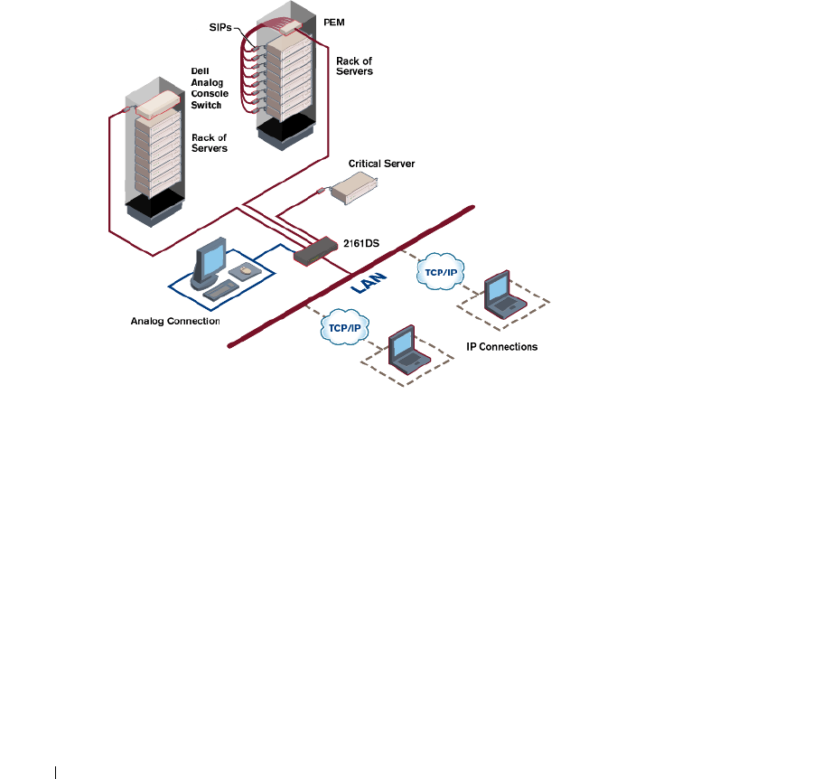
Figure 1-1. Example 2161DS Console Switch Configuration
Point and Click Control With the Remote Console Switch Software
The Remote Console Switch Software is a cross-platform management application that allows you
to view and control the 2161DS Console Switch and all attached servers. The Remote Console
Switch Software provides secure appliance-based authentication, data transfers, and
username/password storage. By utilizing an Explorer-like interface for navigation with an intuitive
split-screen interface, this software provides you with a single point of access for your entire system.
From here, you can manage the 2161DS Console Switch, install a new 2161DS Console Switch
unit or launch a video session to a system server. Multiple servers can be accessed by one user. Each
additional computer's video will appear in a separate program window.
Product Overview 11
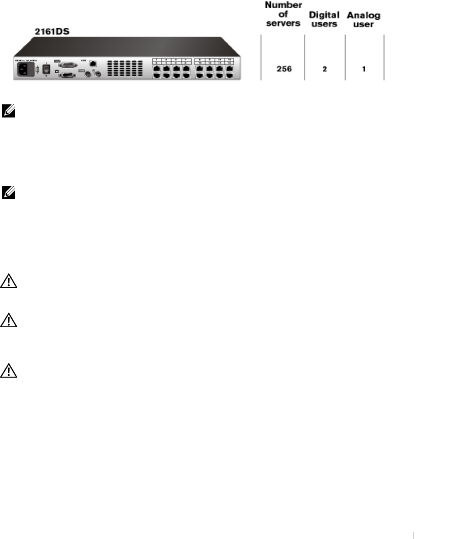
Figure 1-2. 2161DS Console Switch
NOTE: You can access up to 256 servers in a fully configured system by connecting a 16-port analog
switch to each ARI port.
Interoperability with Avocent A1000R/A2000R Switches
The Remote Console Switch Software can also be used to view and control Avocent
A1000R/A2000R switches and all attached servers.
NOTE: Dell SIPs may not be used to connect servers to Avocent A1000R/A2000R switches. Use Avocent
AVRIQs for this configuration.
Safety Precautions
Use the following safety guidelines to help ensure your own personal safety and to help protect your
system and working environment from potential damage.
CAUTION: There is a danger of a new battery exploding if it is incorrectly installed. Replace the battery
only with the same or equivalent type recommended by the manufacturer. Discard used batteries
according to the manufacturer’s instructions.
CAUTION: The power supplies in your system may produce high voltages and energy hazards, which
can cause bodily harm. Only trained service technicians are authorized to remove the covers and
access any of the components inside the system. This warning applies to Dell™ PowerEdge™ servers,
Dell PowerVault™ storage systems.
CAUTION: This system may have more than one power supply cable. To reduce the risk of electrical
shock, a trained service technician must disconnect all power supply cables before servicing the
system.
This document pertains only to the Dell 2161DS Console Switch. You should also read and follow
the additional safety instructions contained elsewhere:
•
The
2161 DS Console Switch Installation Guide
included with your rack solution that
describes how to install your system into a rack.
•
The User's Guide which provides information about setting up and operating your rack
mounted server system.
•
The
Avocent AutoView 1000R/2000R Installer/User’s Guide
if applicable.
12 Product Overview
www.dell.com | support.dell.com
CAUTION: To reduce the risk of electrical shock, a trained service technician must disconnect all
power supply cables before servicing the system.
VAROVANI
:
Ke snízení rizika úrazu elektrickým proudem je nutné, aby školený servisní technik pred
provádením servisu systému odpojil všechny napájecí kabely.
FORSIGTIG: For at reducere risikoen for elektrisk stød, bør en professionel servicetekniker frakoble alle
strømforsyningskabler, før systemet serviceres.
TÄRKEÄÄ: Sähköiskuvaaran pienentämiseksi ammattitaitoisen huoltohenkilön on irrotettava kaikki
virtajohdot ennen järjestelmän huoltamista.
UWAGA:
Aby zmniejszyc ryzyko porazenia pradem, przed naprawa lub konserwacja systemu
wszystkie kable zasilania powinny byc odlaczone przez przeszkolonego technika obslugi.
ADVARSEL! Unngå fare for støt: En erfaren servicetekniker må koble fra alle strømledninger før det
utføres service på systemet.
VARNING: En behörig servicetekniker måste koppla loss alla nätkablar innan service utförs för att minska
risken för elektriska stötar.
ОСТОРОЖНО!
Чтобы избежать поражения электрическим током, перед обслуживанием
системы все кабели электрического питания должны быть отключены квалифицированным
техническим специалистом.
General
•
Observe and follow service markings:
•
Do not service any product except as explained in your system documentation.
•
Opening or removing covers that are marked with the triangular symbol with a lightning bolt
may expose you to electrical shock.
•
Components inside these compartments should be serviced only by a trained service
technician.
–
This product contains no serviceable components. Do not attempt to open.
•
If any of the following conditions occur, unplug the product from the electrical outlet and
replace the part or contact your trained service provider:
–
The power cable, extension cable, or plug is damaged.
–
An object has fallen into the product.
–
The product has been exposed to water.
–
The product has been dropped or damaged.
–
The product does not operate correctly when you follow the operating instructions.
•
Keep your system away from radiators and heat sources. Also, do not block cooling vents.
•
Do not spill food or liquids on your system components, and never operate the product in a
wet environment. If the system gets wet, see the appropriate section in your troubleshooting
guide or contact your trained service provider.

Product Overview 13
•
Use the product only with approved equipment.
•
Allow the product to cool before removing covers or touching internal components.
•
Operate the product only from the type of external power source indicated on the electrical
ratings label. If you are not sure of the type of power source required, consult your service
provider or local power company.
NOTICE: To help avoid damaging your system, be sure the voltage selection switch (if provided) on the
power supply is set for the voltage that most closely matches the AC power available in your location.
Also be sure that your monitor and attached devices are electrically rated to operate
•
Be sure that your monitor and attached devices are electrically rated to operate with the
power available in your location.
•
Use only power cables provided with this product.
•
To help prevent electric shock, plug the system and peripheral power cables into properly
grounded electrical outlets. These cables are equipped with three-prong plugs to help ensure
proper grounding. Do not use adapter plugs or remove the grounding prong from a cable.
•
Observe extension cable and power strip ratings. Make sure that the total ampere rating of all
products plugged into the power strip does not exceed 80 percent of the ampere ratings limit
for the power strip.
•
To help protect your system from sudden, transient increases and decreases in electrical
power, use a surge suppressor, line conditioner, or uninterruptible power supply (UPS).
•
Position system cables and power cables carefully. Route cables so that they cannot be stepped
on or tripped over. Be sure that nothing rests on any cables.
•
Do not modify power cables or plugs. Consult a licensed electrician or your power company
for site modifications. Always follow your local/national wiring rules.
Rack Mounting of Systems
•
Refer to the rack installation documentation accompanying the rack for specific caution
statements and procedures.
•
System rack kits are intended to be installed in a rack by trained service technicians. If a non-
Dell rack is utilized, be sure that the rack meets the specifications of a Dell rack.
LAN Options
•
Do not connect or use during a lightning storm. There may be a risk of electrical shock from
lightning.
•
Never connect or use in a wet environment.

14 Product Overview
www.dell.com | support.dell.com

Installation 15
2
Installation
The Dell™ 2161DS Console Switch requires that the Remote Console Switch Software be installed
prior to use. Remote Console Switch Software allows a user to view and control a server attached to
the 2161DS Console Switch system, configure and maintain the system, and prevent unauthorized
access to the 2161DS Console Switch via IP connection.
NOTE: The analog port does not require the Remote Console Switch Software for operation. The analog
port uses the On-Screen Configuration and Activity Reporting interface (OSCAR®). For more information,
see "Analog Port Operation".
The 2161DS Console Switch system uses Ethernet networking infrastructure and TCP/IP protocol
to transmit keyboard, video, and mouse information between operators and connected computers.
Although 10BaseT Ethernet may be used, Dell recommends a dedicated, switched 100BaseT
network.
CAUTION: Before performing any of the procedures listed in this section, read and follow the Safety
Precautions outlined in the Overview section of this guide.
Getting Started
Before installing your 2161DS Console Switch, refer to the list below to ensure you have all items
that shipped with the 2161DS Console Switch, as well as other items necessary for proper
installation.
Supplied with the 2161DS Console Switch:
• 2161DS Console Switch unit
• Local country power cord
• Rack mounting brackets
•Serial cable
• 2161DS Console Switch Hardware and OSCAR User's Guide on CD
• 2161DS Console Switch Remote Console Switch Software User's Guide on CD
• 2161DS Console Switch Installation Instructions
Additional items needed:
• One Server Interface Pod (SIP) or Avocent® AVRIQ module per attached server
• One CAT 5 patch cable per attached server (up to 10 meters)
Optional items:

16 Installation
www.dell.com | support.dell.com
• Port Expansion Module (PEM)
• PS/2 Keyboard and Mouse Extension cable
Verification of Ethernet/Computer Connections
The front panel of the 2161DS Console Switch features two LEDs describing the Ethernet
connection. The top LED is the
Link
indicator. It will illuminate when a valid connection to the
network is established and blink when there is activity on the port. The lower LED, labeled
100Mbps, will indicate that you are communicating at the 100Mb rate.
Additionally, there are two LEDs above each port number on the front of your unit: one green and
one amber. The green LED will illuminate when the SIP on that port is powered. The amber LED
will illuminate when that port is selected.
Setting Up Your Network
The 2161DS Console Switch system uses IP addresses to uniquely identify the 2161DS Console
Switch units, Avocent A1000R/A2000R units and the computers running Remote Console Switch
Software. The 2161DS Console Switch supports BootP (Bootstrap Protocol) and static IP
addressing. Dell recommends that IP addresses be reserved for each unit and that they remain
static while the 2161DS Console Switch units are connected to the network.
NOTE: Dell 2161DS Console Switch does not support dynamic IP address assignment or BootP
emulation through DHCP.
Rack Mounting Your 2161DS Console Switch
Obtain a Switch Mounting Bracket Kit (0U or 1U) to rack mount your 2161DS Console Switch
unit. Before installing the 2161DS Console Switch and other components in the rack, stabilize the
rack in a permanent location. Start rack mounting your equipment at the bottom of the rack, then
work to the top. Avoid uneven loading or overloading of racks.
CAUTION: Connect only to the power source specified on the unit. When multiple electrical
components are installed in a rack, ensure the total component power ratings do not exceed circuit
capabilities. Overloaded power sources and extension cords present fire and shock hazards.
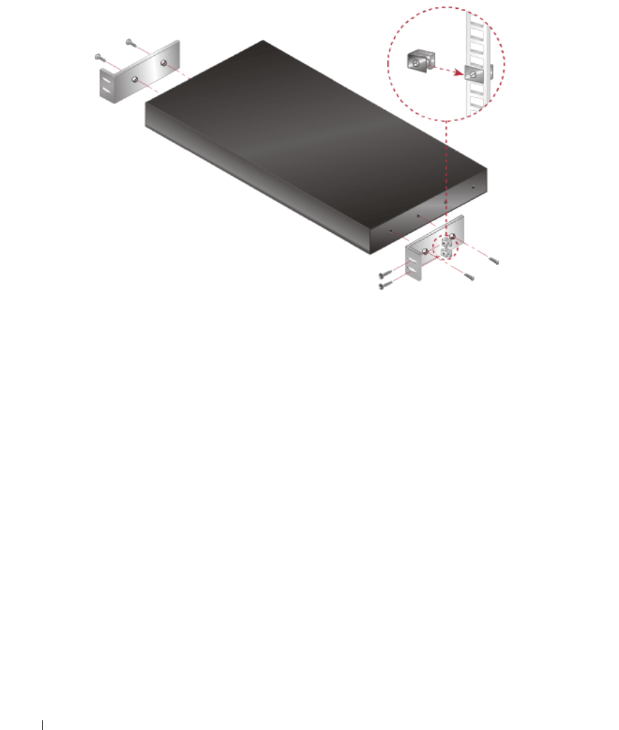
To install the 0U switch mounting bracket (shipped as default):
1
Line up the holes of the mounting brackets with the screw holes in the switch.
2
Fasten the mounting bracket to the switch using the button head socket cap screws on each
side.
3
Mount the switch assembly to the rack by inserting the three mounting hooks on one side of
the bracket into square holes in the vertical rack.
4
Press down until the blue push button pops out and clicks.
Installation 17
Figure 2-3. OU Mounting Bracket Installation
To install the 1U switch mounting bracket:
1
Line up the holes in the long side of the kit's side brackets with the screw holes in the switch.
2
Fasten the mounting brackets to the switch using two button head socket cap screws on each
side.
3
Attach the six rack nut/holders to the mounting rail of the rack so that the nut is positioned
on the inside of the rack.
4
Mount the switch assembly to the rack by matching the holes in the “short side” of each
bracket to an appropriate set of matching holes on your equipment rack.
5
Insert the #10-32 Phillips screws through the slots in the bracket and the holes in the
mounting rail, then into the rack/nut holders.
18 Installation
www.dell.com | support.dell.com
Figure 2-4. IU Installation
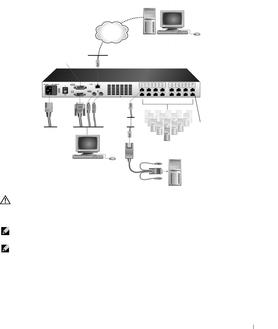
Installing the 2161DS Console Switch Unit
The diagram below illustrates one possible configuration for your 2161DS Console Switch
appliance. Follow the detailed set of procedures following Figure 2-5 to successfully install your
2161DS Console Switch unit.
Installation 19
Figure 2-5. Basic 2161DS Console Switch Configuration
CAUTION: To reduce the risk of electric shock or damage to your equipment do not disable the power
cord grounding plug. The grounding plug is an important safety feature. Plug the power cord into a
grounded (earthed) outlet that is easily accessible at all times. Disconnect the power from the unit by
unplugging the power cord from either the electrical outlet or the unit.
NOTE: If the building has 3-phase AV power, ensure that the computer and monitor are on the same
phase to avoid potential phase-related video and/or keyboard problems.
NOTE: The maximum supported cable length from switch to server is 10 meters.
To install the 2161DS Console Switch hardware:
1
Remove the 2161DS Console Switch unit from the packing material.
2
Connect a terminal or PC running terminal emulation software (such as HyperTerminal) to
the configuration port on the back panel of the 2161DS Console Switch using the supplied
serial cable. The terminal should be set to 9600 baud, 8 bits, 1 stop bit, no parity, and no flow
control.
Network
Digital User
Configuration
Port for updating
firmware
Analog User
Servers 2-16
Server 1
ARI
Port
20 Installation
www.dell.com | support.dell.com
3
Plug the supplied power cord into the back of the 2161DS Console Switch unit and then into
an appropriate power source.
4
When the power is switched on, the Power indicator on the front of the unit will blink for 30
seconds while performing a self-test. Approximately 10 seconds after it stops blinking, press
the <Enter> key to access the main menu.
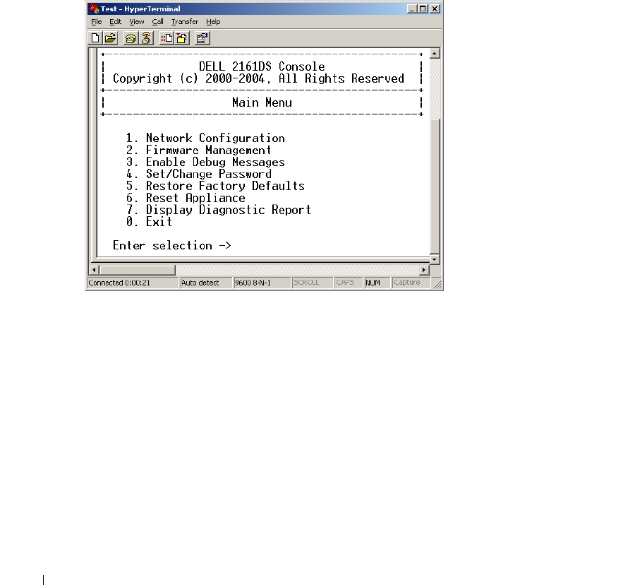
To configure the 2161DS Console Switch hardware:
1
You will see the
Terminal Applications
menu with seven options. Select option 1,
Network
Configuration
.
Figure 2-6. Network Configuration Menu
2
Select option 1 to set your network speed. When possible, you should set your connection
manually without relying on the auto negotiate feature. Once you enter your selection, you
will be returned to the
Network Configuration
menu.
3
Select option 2 and specify if you are using a static or BootP IP address. Dell recommends
using a static IP address for ease of configuration. If you are using a BootP address, please
configure your BootP server to provide an IP address to the 2161DS Console Switch, skip step
4 and continue to the next procedure.
4
Select options 3-5 from the
Terminal Applications
menu, in turn, to finish configuring your
2161DS Console Switch for IP address, Netmask, and Default Gateway.
5
Once this is completed, type Ø to return to the main menu.

Installation 21
Video Optimization
To ensure optimal video quality you will want to configure the 2161DS Console Switch with the
same settings as the network switch. For example, if the 2161DS Console Switch is set to
Auto-
Negotiate
, then the network switch must be set to
Auto-Negotiate
both speed and duplex. If the
2161DS Console Switch is set to 100MB - full duplex, then the network switch must be set to
100MB - full duplex.
Once you have made these changes, you may need to refresh/flush the Address Resolution Protocol
(ARP) tables in the network before you establish a new connection with the 2161DS Console
Switch, especially if the 2161DS Console Switch has been in use within the hour proceeding these
changes.
To refresh the ARP table, do one of the following:
Wait approximately 10 minutes for the ARP tables to rebuild automatically.
-or-
Clear the ARP table entry in a video session viewer workstation and ping the appliance at its IP
address. This can be done from a DOS window.
a
Ty p e
ARP -d 1.2.3.4
(where 1.2.3.4 is the IP address of the 2161DS Console Switch).
b
Ty p e
PING 1.2.3.4
If the PING is successful, the 2161DS Console Switch is ready for operation.
NOTE: For further information on refreshing the ARP table refer to the Remote Console Switch Software
User’s Guide.
Mouse Acceleration
To adjust the mouse acceleration:
NOTE: Dell highly recommends that all Microsoft® Windows® systems attached to the 2161DS Console
Switch use the default Windows PS/2 mouse driver.
Before a server can be connected to the 2161DS Console Switch, an adjustment to mouse
acceleration must be made. Follow the steps listed for each type of system.
For systems running the Windows NT® operating system (using default drivers):
1
From the desktop, select
Start - Settings - Control Panel - Mouse
.
2
Click the
Motion
tab.
3
Set the pointer speed to
Slow
. You will need to set this for any Windows NT user account that
will be accessing the NT system through the 2161DS Console Switch.

22 Installation
www.dell.com | support.dell.com
For systems running the Windows® 2000 operating system:
1
From the desktop, select
Start - Settings - Control Panel - Mouse
.
2
Click the
Motion
tab.
3
Set the Acceleration setting to
None
and the speed setting to the default of
50%
.
Connecting a SIP
To connect a SIP to each server:
1
Locate the SIPs for your 2161DS Console Switch unit.
2
Attach the SIP or AVRIQ ends to the appropriate keyboard, monitor, and mouse ports on the
first server you will be connecting to this 2161DS Console Switch unit.
3
Attach one end of the CAT 5 cabling that will run from your SIP to the 2161DS Console
Switch unit to the RJ45 connector on the SIP.
4
Connect the other end of the CAT 5 cable to the desired Analog Rack Interface (ARI) port on
the back of your 2161DS Console Switch unit.
5
Repeat steps 2-4 for all servers you wish to attach.
NOTE: Power down the 2161DS Console Switch unit before servicing. Always disconnect the power
cord from the wall outlet.Power down the 2161DS Console Switch unit before servicing. Always
disconnect the power cord from the wall outlet.
NOTE: In addition to Dell SIPs, the 2161DS Console Switch may also be connected to servers using
Avocent AVRIQ, including Sun and Serial AVRIQs.
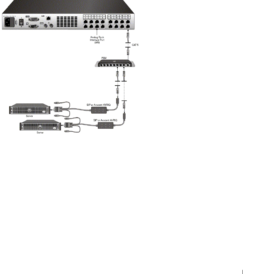
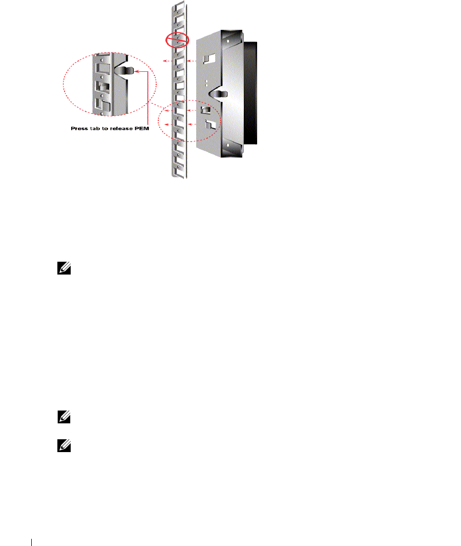
Adding a PEM (Optional)
A Port Expansion Module (PEM) allows you to expand each ARI port to accommodate up to eight
servers instead of one.
NOTE: The PEM operates passively. Therefore, once a user accesses a server attached to a PEM, any
subsequent users attempting to access any of the servers attached to that PEM will be blocked.
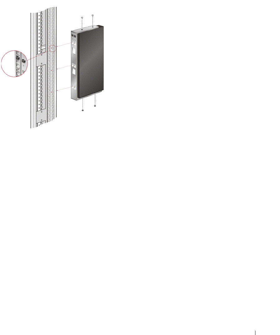
To add a PEM (optional):
1
Mount the PEM into your rack. Using up to nine CAT 5 cables, one connects your 2161DS
Console Switch unit to the PEM, and the other eight connect the PEM to the SIP attached to
each server.
2
Attach one end of the CAT 5 cabling that will run between your PEM and the 2161DS
Console Switch unit to the RJ45 connector slightly separate from the other connectors on the
PEM. Connect the remaining end of the CAT 5 cable to the desired ARI port on the back of
your 2161DS Console Switch unit.
Installation 23
3
Attach the CAT 5 cabling that will run between your PEM and each server’s SIP to one of the
eight RJ45 connectors grouped on the back of the PEM.
4
Connect the other end of the CAT 5 cable to the first of the SIPs.
5
Repeat steps 3-4 for all servers you wish to attach.
Figure 2-7. 2161DS Console Switch Configuration With a PEM
24 Installation
www.dell.com | support.dell.com
Figure 2-8. PEM Rack Installation
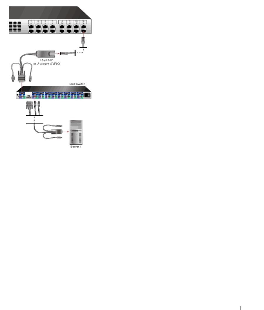
Adding a Cascade Switch (Optional)
You can add your cascade switches in the 2161DS Console Switch system. Each ARI port will then
accommodate up to 16 servers, increasing the total number of servers you can add to 256.
To add a cascade switch (optional):
NOTE: The 2161DS Console Switch does not support the EL80-DT.
1
Mount the switch into your rack. Locate a CAT 5 cable to connect your 2161DS Console
Switch unit to the SIP for your switch.
2
Attach one end of the CAT 5 cabling to the RJ45 connector on the SIP. Connect the other
end of the CAT 5 cable to the desired port on the back of your 2161DS Console Switch unit.
3
Attach the keyboard, monitor, and mouse connectors of the SIP to a user port on your switch.
4
Connect the servers to your cascaded switch according to the switch manufacturer's
recommendations.
5
Repeat steps 1-4 for all the cascade switches you wish to attach to your 2161DS Console
Switch system.
NOTE: The 2161DS Console Switch supports only 1 switch per ARI port. You cannot tier another switch
under this first switch.
NOTE: When cascading with a 2161DS Console Switch, an 8-port or 16-port analog console switch is not
supported as the primary unit in a cascaded configuration. The 2161DS Console Switch must be the
primary unit.
Installation 25
Figure 2-9. 2161DS Console Switch Configuration With a Cascade Switch
Connecting to the Network
To connect the network and power up your 2161DS Console Switch:
1
Connect your network cable to the LAN port on the rear of the 2161DS Console Switch to
your network.
2
Power up all attached systems.
To connect the analog port monitor and PS/2 keyboard and mouse:
Attach your monitor and PS/2 keyboard and mouse cable connectors to the appropriate ports on
the back of your 2161DS Console Switch unit.
26 Installation
www.dell.com | support.dell.com
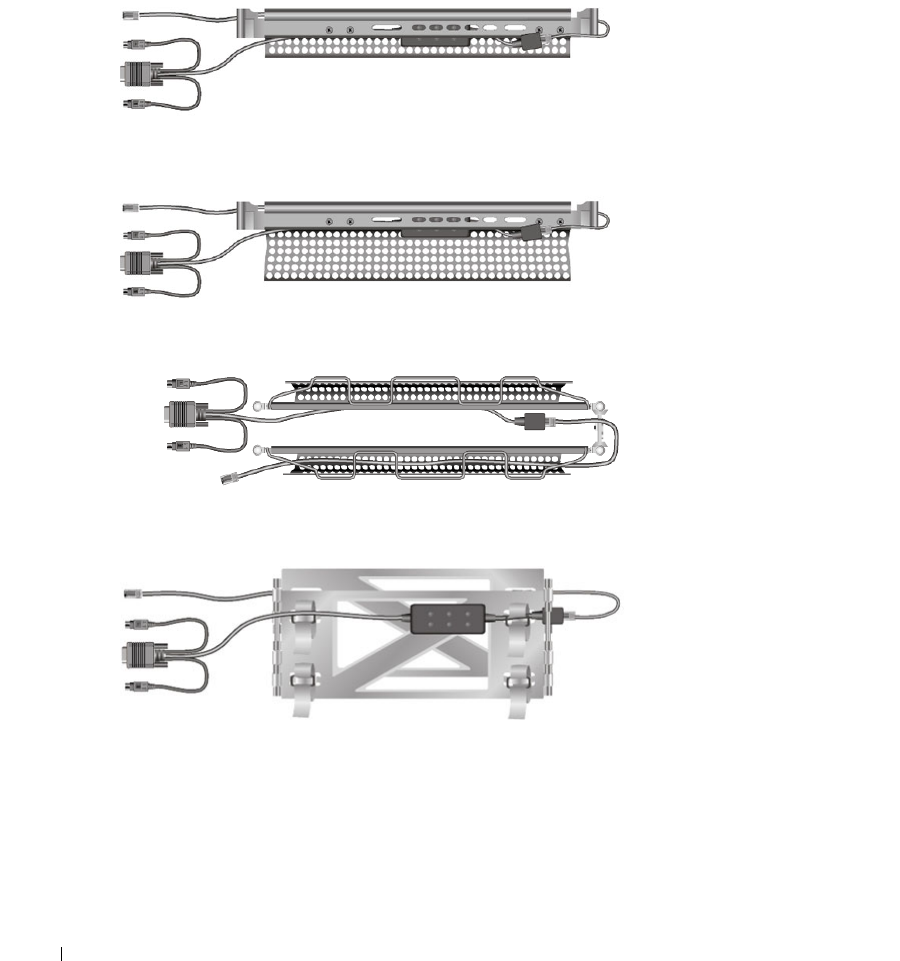
To install a SIP in a 1U or 2U cable management arm:
Route the SIP through the cable management arm. The following series of figures demonstrate the
correct configuration for your cable management arm.
Figure 2-10. 1U Cable Arm - Side View
Figure 2-11. 2U Cable Arm - Side View
Figure 2-12. 1U or 2U Cable Arm - Top View
Figure 2-13. Cable Management Arm - Side View

Installation 27
Figure 2-14. Cable Management Arm - Top View
Installing Remote Console Switch Software
To install your Remote Console Switch Software:
See the
Dell™ 2161DS Console Switch Remote Console Switch Software User's Guide
that ships
with your 2161DS Console Switch system.
Adding Servers
While you can configure the entire 2161DS Console Switch system through either OSCAR or the
Remote Console Switch Software, Dell recommends first adding server names to OSCAR at the
local analog station prior to adding or discovering the appliance in Remote Console Switch
Software at the digital station.
The 2161DS Console Switch system has an analog port that allows you to attach a monitor and a
PS/2 keyboard and mouse to the back of the unit. Dell recommends that you first set up your
servers at the analog port via OSCAR before proceeding to the Remote Console Switch Software to
finish configuring your system. Proceed to "Analog Port Operation" in this user's guide for detailed
instructions on OSCAR setup and configuration. Once your servers are named, you will want to go
to a digital station and configure the Remote Console Switch Software. For more information, see
"Installation" for an overview of the installation procedure.
NOTE: Connected servers may be up to 10 meters away from the 2161DS Console Switch.

28 Installation
www.dell.com | support.dell.com

Analog Port Operation 29
3
Analog Port Operation
Controlling Your System at the Analog Port
The Dell™ 2161DS Console Switch includes an analog port on the back of the unit that allows you
to connect a monitor, a PS/2 keyboard, and a mouse for direct analog access. The 2161DS Console
Switch uses the On-Screen Configuration and Activity Reporting interface (OSCAR®), which has
intuitive menus, to configure your system, and select computers.
Viewing and Selecting Ports and Servers
Use the
Main
dialog box to view, configure, and control servers in the 2161DS Console Switch
system. You can view your servers by name, port or by the unique Electronic ID number (EID)
embedded in each Server Interface Pod (SIP). You will see an OSCAR-generated
Name
list by
default when you first launch OSCAR.
To access the
Main
dialog box:
Press <Print Screen> to launch OSCAR. The
Main
dialog box appears.
-or-
If a password has been assigned, the
Password
dialog box appears. Type your password and click
OK
. The
Main
dialog box appears. For more information, see "Setting Console Security".
30 Analog Port Operation
www.dell.com | support.dell.com
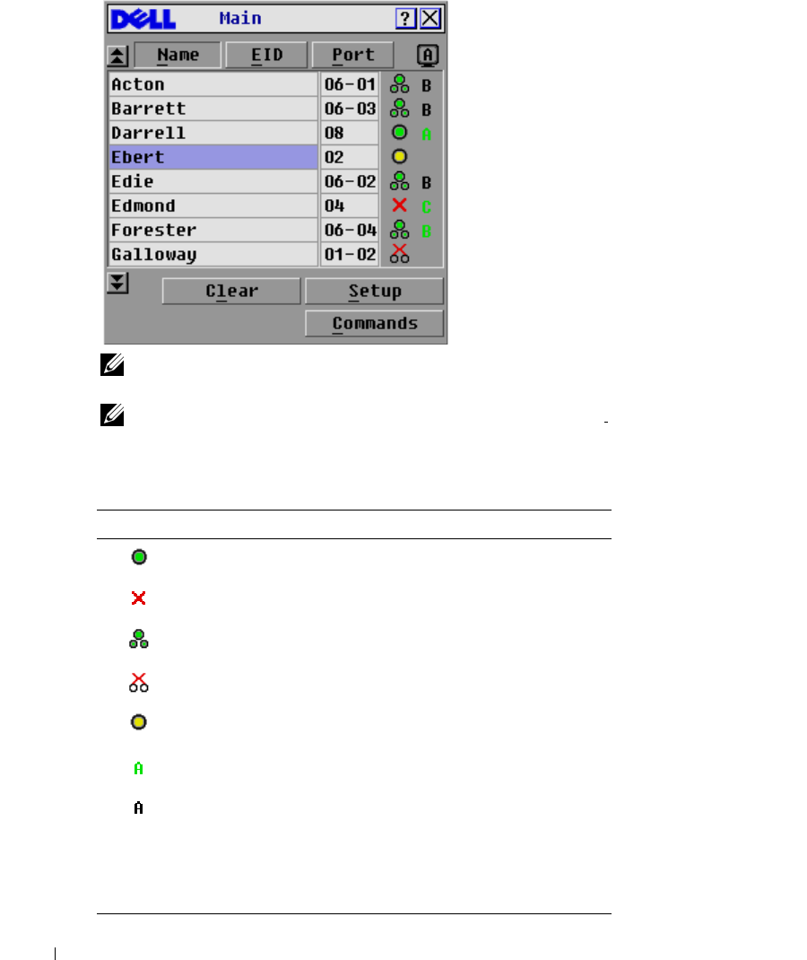
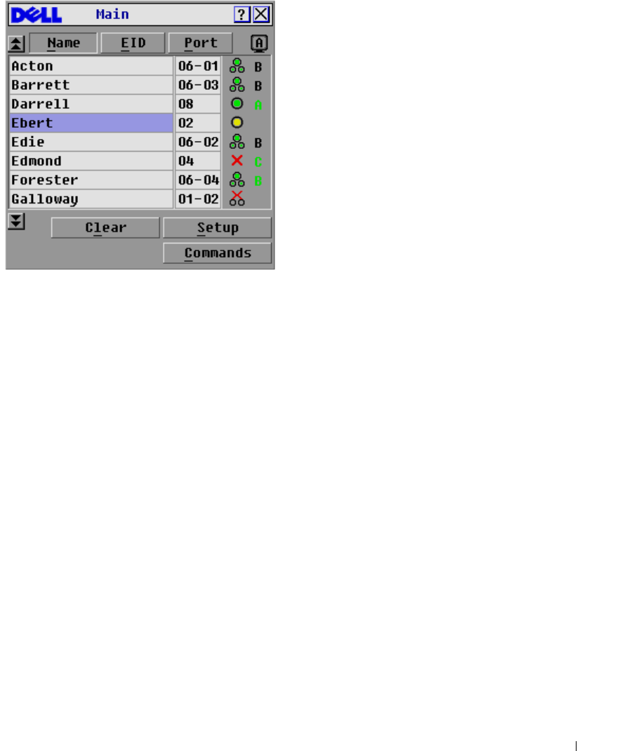
Figure 3-15. Example of Configured Main Dialog Box
NOTE: You can also press the <Ctrl> key twice within one second to launch OSCAR. You can use this key
sequence in any place you see <Print Screen> throughout this User's Guide.
NOTE: To clear an offline Server Interface Pod (SIP) from the list, click Clear.
The status of servers in your system is indicated in the far right column of the
Main
dialog box.
Table 3-1 describes the status symbols.
Table 3-1. OSCAR Status Symbols
Symbol Description
SIP is online.
SIP is offline or is not operating properly.
Connected switch is online.
Connected switch is offline or is not operating properly.
SIP is being upgraded.
Indicates which user channel is currently connected to a SIP.
Indicates channels that are blocked by a user connected
through a Port Expansion Module (PEM) or switch. Figure 3-15
shows user B viewing Forester (green B) through a PEM, but
blocking access to Acton, Barrett, and Edie (Black B) which are
connected to the same PEM. A green user is viewing, and a
black user shows which user is blocking server access..

Analog Port Operation 31
Selecting Servers
Use the
Main
dialog box to select servers. When you select a server, the 2161DS Console Switch
reconfigures the keyboard and mouse to the proper settings for that server.
To select servers:
Double-click the server name, EID or port number.
-or-
If the display order of your server list is by port (
Port
button is depressed), type the port number
and press <Enter>.
-or-
If the display order of your server list is by name or EID number (
Name
or
EID
button is
depressed), type the first few letters of the name of the server or the EID number to establish it as
unique and press <Enter> twice.
To select the previous server:
Press <Print Screen> and then <Backspace>. This key combination toggles you between the
previous and current connections.
To disconnect the analog user from a server:
Press <Print Screen> and then <Alt><Ø>. This leaves you in a free state, with no server
selected. The status flag on your desktop, if active, displays Free.
Soft Switching
Soft switching is the ability to switch servers using a hot key sequence. You can soft switch to a
server by pressing <Print Screen> and then typing the first few characters of its name or number.
If you have a Delay Time set and you press the key sequences before that time has elapsed, OSCAR
will not display.
NOTE: If you have a PEM in your configuration and you are viewing servers in port order, you will only be
able to soft switch to the first server attached to the PEM.
To configure OSCAR for soft switching:
1
Press <Print Screen> to launch OSCAR. The
Main
dialog box appears.
2
Click
Setup - Menu
. The
Menu
dialog box appears.
3
For
Delay Time
, type the number of seconds of delay desired before the
Main
dialog box is
displayed after <Print Screen> is pressed.
4
Click
OK
.

32 Analog Port Operation
www.dell.com | support.dell.com
To soft switch to a server:
1
To select a server, press <Print Screen>. If the display order of your server list is by port (
Port
button is depressed), type the port number and press <Enter>.
-or-
2
If the display order of your server list is by name or EID number (
Name
or
EID
button is
depressed), type the first few characters of the name of the server or the EID number to
establish it as unique and press <Enter>.
3
To switch back to the previous server, press <Print Screen> then <Backspace>.
OSCAR Navigation Basics
Table 3-2 describes how to use the keyboard and mouse to navigate OSCAR.
Table 3-2. Keyboard and Mouse Navigation
This Keystroke Does this
Print Screen Opens OSCAR. Press <Print Screen> twice to send the <Print Screen> keystroke
to the currently selected device.
F1 Opens the Help screen for the current dialog box.
Escape Closes the current dialog box without saving changes and returns to the previous
one. In the Main dialog box, it closes OSCAR and returns to the selected server. In
a message box, it closes the pop-up box and returns to the current dialog box.
Alt Opens dialog boxes, selects or checks options and executes actions when used in
combination with underlined letters or other designated characters.
Alt+X Closes current dialog box and returns to the previous one.
Alt+O Selects the OK button, then returns to the previous dialog box.
Enter Completes the switch operation in the Main dialog box and exits OSCAR.
Single-click Enter In a text box, it selects the text for editing and enables the left-arrow key and right-
arrow key keys to move the cursor. Press <Enter> again to quit the edit mode.
Print Screen,
Backspace
Toggles back to previous selection if no other keystrokes have been typed.
Print Screen, Alt+Ø Immediately disconnects user from a server; no server is selected. Status flag
displays Free. (This only applies to the <Ø> on the keyboard and not the keypad.)
Print Screen, Pause Immediately turns on screen saver mode and prevents access to that particular
console, if it is password protected.
Up/Down Arrows Moves the cursor from line to line in lists.
Right/Left Arrows Moves the cursor between columns. When editing a text box, these keys move the
cursor within the column
Page Up/Page Down Pages up and down through Name and Port lists.
Analog Port Operation 33
Configuring OSCAR
You can configure your 2161DS Console Switch system from the
Setup
menu within OSCAR.
Select the
Names
button when initially setting up your 2161DS Console Switch system to identify
servers by unique names. Select the other setup features to manage routine tasks for your servers
from the OSCAR menu.
To access the
Setup
menu:
1
Press <Print Screen> to launch OSCAR. The
Main
dialog box appears.
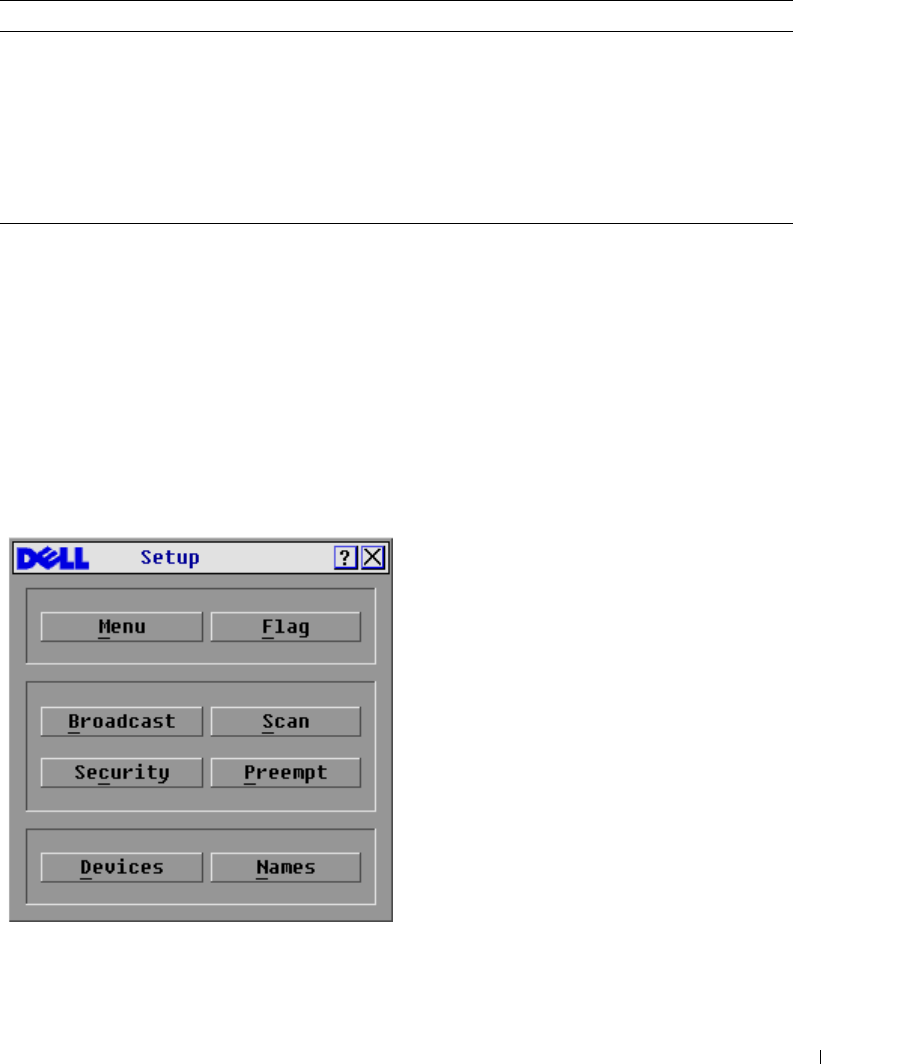
2
Click
Setup
. The
Setup
dialog box appears
.
Figure 3-16. Setup Dialog Box
Home/End Moves the cursor to the top or bottom of a list.
Backspace Erases characters in a text box.
Delete Deletes current selection in the Scan list or characters in a text box.
Shift-Del Deletes from current selection to all lines below it when editing a Scan list.
Numbers Type from the keyboard or keypad.
Caps Lock Disabled. Use the <Shift> key to change case.
Table 3-2. Keyboard and Mouse Navigation (continued)
This Keystroke Does this
34 Analog Port Operation
www.dell.com | support.dell.com
Assigning Server Names
Use the
Names
dialog box to identify individual servers or servers connected to cascade switch
channels by name rather than by port number. The
Names
list is always sorted by port order. You
can toggle between displaying the name or the EID number of each SIP. Names are stored in the
SIP, so even if you move the cable/server to another Analog Rack Interface (ARI) port, the name,
and configuration will be recognized by the 2161DS Console Switch.
NOTE: If a server is powered down, its respective SIP will not appear in the Names list.
NOTE: If you move a SIP from one server to another, you must assign the new server name to the SIP.
For information, see Figure 3-18.
To access the
Names
dialog box:
1
Press <Print Screen>. The
Main
dialog box will appear.
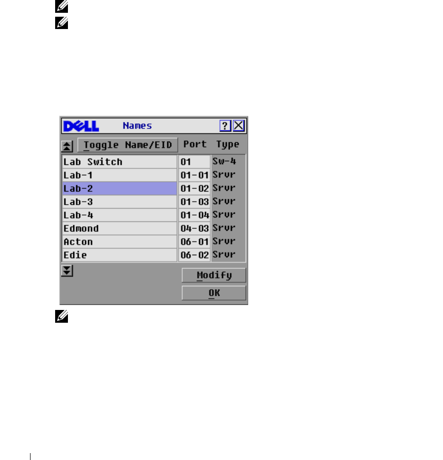
2
Click
Setup - Names.
The
Names
dialog box appears.
Figure 3-17. Names Dialog Box
NOTE: If new SIPs are discovered by the 2161DS Console Switch, the on-screen list will be
automatically updated. The mouse cursor will change into an hourglass during the update. No mouse or
keyboard input will be accepted until the list update is complete.
Analog Port Operation 35
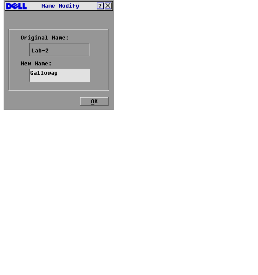
To assign names to servers:
1
In the
Names
dialog box, select the name or port number you wish to change and click
Modify. The
Name Modify
dialog box appears.
Figure 3-18. Name Modify Dialog Box
2
Ty pe a n a me in t h e
New Name
box. Names of servers may be up to 15 characters long. Legal
characters include: A-Z, a-z, Ø-9, space, and hyphen.
3
Click
OK
to transfer the new name to the
Names
dialog box. Your selection is not saved until
you click
OK
in the
Names
dialog box.
4
Repeat steps 1-3 for each server in the system.
5
Click
OK
in the
Names
dialog box to save your changes.
-or-
Click
X
or press <Escape> to exit the dialog box without saving changes.
36 Analog Port Operation
www.dell.com | support.dell.com
Assigning Device Types
While the 2161DS Console Switch unit automatically discovers cascade switches attached to your
unit, you will need to specify the number of ports on the cascade switch though the
Devices
dialog
box. The 2161DS Console Switch intially recognizes cascade switches as being either an 8 port
maximum or 24 port maximum switch. You will see an Sw-8 or Sw-24 designation appear in the
Ty p e
category. When you select that switch from the list, the
Modify
button appears, allowing you
to assign the appropriate number of ports to it.
To access the
Devices
dialog box:
1
Press <Print Screen>. The
Main
dialog box will appear.
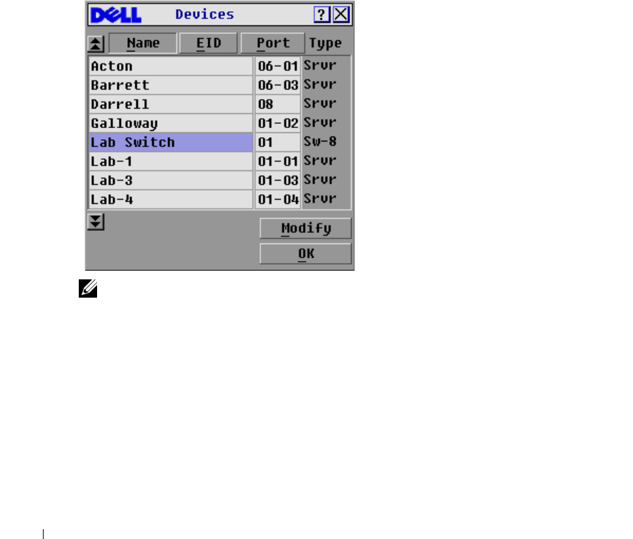
2
Click
Setup - Devices
. The
Devices
dialog box appears.
Figure 3-19. Devices Dialog Box
NOTE: The Modify button will only be available if a configurable switch is selected.
When the 2161DS Console Switch discovers a cascade switch, you will notice the port numbering
change to accommodate each server under that switch. For example, if the switch is connected to
port 2, the switch port would be listed as 02 and each server under it would be numbered
sequentially 02-01, 02-02 and so on.
To assign a device type:
1
In the
Devices
dialog box, select the desired port number.
2
Click
Modify
. The
Device Modify
dialog box appears.
Analog Port Operation 37
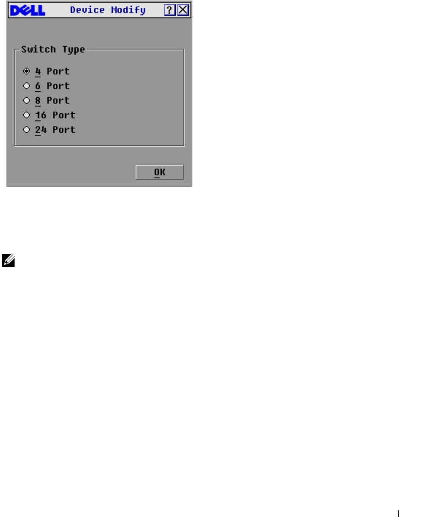
Figure 3-20. Device Modify Dialog Box
3
Choose the number of ports supported by your switch.
4
Click
OK
.
5
Repeat steps 2–4 for each port to which you want to assign a device type.
6
Click
OK
in the
Devices
dialog box to save settings.
NOTE: Changes made in the Device Modify dialog box are not saved until you click OK in the Devices
dialog box.
Changing the Display Behavior
Use the
Menu
dialog box to change the display order of servers and set a screen delay time for
OSCAR.
To access the
Menu
dialog box:
1
Press <Print Screen> to launch OSCAR. The
Main
dialog box appears.
2
Click
Setup - Menu
. The
Menu
dialog box appears.
38 Analog Port Operation
www.dell.com | support.dell.com
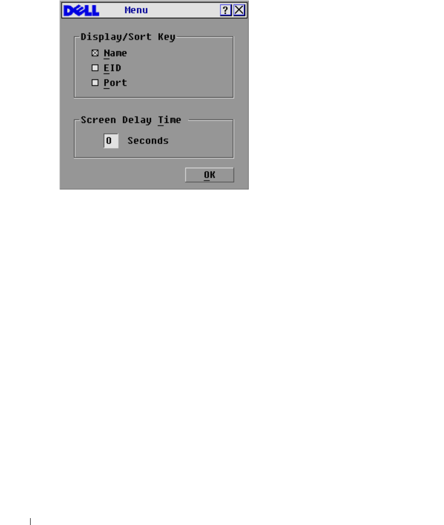
Figure 3-21. Menu Dialog Box
To choose the display order of servers in the
Main
dialog box:
1
Select
Name
to display servers alphabetically by name.
-or-
Select
EID
to display servers numerically by EID number.
-or-
Select
Port
to display servers numerically by port number.
2
Click
OK
.
To set a screen delay time for OSCAR:
1
Type in the number of seconds (Ø-9) you want to delay display of OSCAR after you press
<Print Screen>. Entering <Ø> will instantly launch OSCAR with no delay.
2
Click
OK
.
Setting a time to delay display of OSCAR allows you to complete a soft switch without OSCAR
displaying. To perform a soft switch, see "Soft Switching".
Analog Port Operation 39
Controlling the Status Flag
The status flag displays on your desktop and shows the name or EID number of the selected server
or the status of a port. Use the
Flag
dialog box to configure the flag to display by server name or
EID number, or to change the flag color, opacity, display time, and location on the desktop.
To access the
Flag
dialog box:
1
Press <Print Screen>. The
Main
dialog box will appear.
2
Click
Setup - Flag
. The
Flag
dialog box appears.
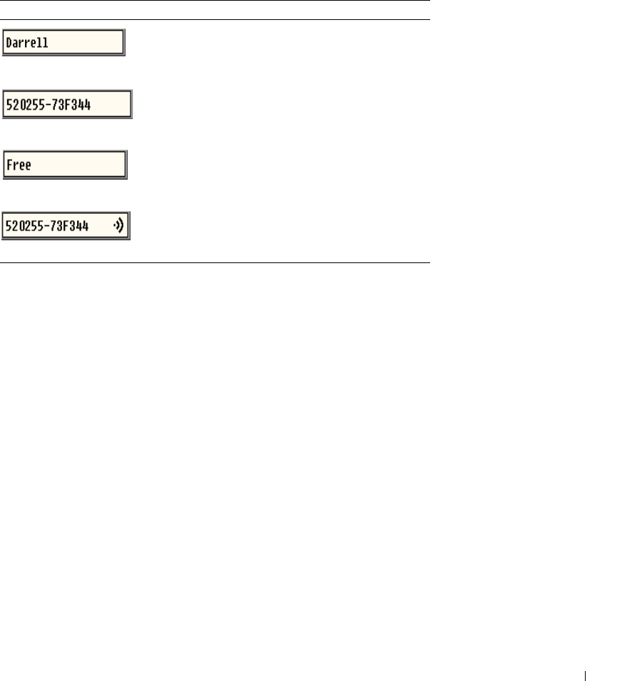
Table 3-3. OSCAR Status Flags
Flag Description
Flag type by name
Flag type by EID number
Flag indicating that the user has been
disconnected from all systems
Flag indicating that Broadcast mode is
enabled
40 Analog Port Operation
www.dell.com | support.dell.com
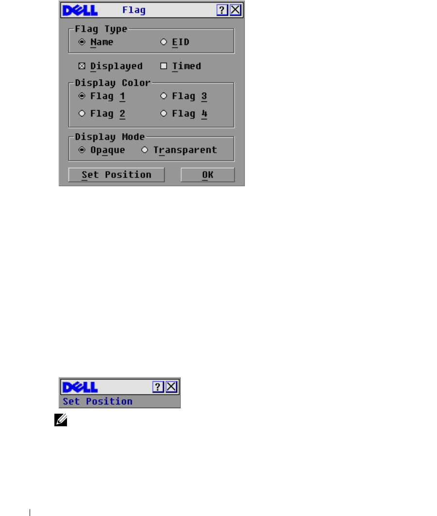
Figure 3-22. Flag Dialog Box
To determine how the status flag is displayed:
1
Select
Name
or
EID
to determine what information will be displayed.
2
Select
Displayed
to show the flag all the time or select
Timed
to display the flag for only five
seconds after switching.
3
Select a flag color in
Display Color
.
4
In Display mode, select
Opaque
for a solid color flag or select
Transparent
to see the desktop
through the flag.
5
To position the status flag on the desktop:
a
Click
Set Position
to gain access to the
Position Flag
screen.
b
Left-click on the title bar and drag to the desired location.
c
Right-click to return to the
Flag
dialog box.
Figure 3-23. Position Flag
NOTE: Changes made to the flag position are not saved until you click OK in the Flag dialog box.
6
Click
OK
to save settings.
-or-
Click
X
to exit without saving changes.
Analog Port Operation 41
Setting Console Security
OSCAR enables you to set security on your analog port console. You can establish a screen saver
mode that engages after your console remains unused for a specified delay time. Once engaged,
your console will remain locked until you press any key or move the mouse. You will then need to
type in your password to continue.
Use the
Security
dialog box to lock your console with password protection, set or change your
password and enable the screen saver.
To access the
Security
dialog box:
1
Press <Print Screen>. The
Main
dialog box will appear.
2
Click
Setup - Security
. The
Security
dialog box appears.
NOTE: If a password has been previously set, the user will have to enter the password before being able
to access the Security dialog box.
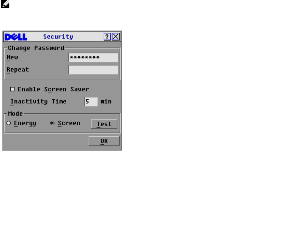
Figure 3-24. Security Dialog Box
To set or change the password:
1
Single-click and press <Enter> or double-click in the
New
text box.
2
Type the new password in the
New
text box and press <Enter>. Passwords require 5 to 12
characters and must include at least one letter and one number. Passwords are also case
sensitive. Legal characters are: A-Z, a-z, 0-9, space, and hyphen. Entering a new password
deactivates the old one.
3
In the
Repeat
box, type the password again and press <Enter>.
4
Click
OK
if you only want to change your password, and then close the dialog box.

42 Analog Port Operation
www.dell.com | support.dell.com
To password protect your console:
1
Set your password as described in the previous procedure.
2
Select
Enable Screen Saver.
3
Type the number of minutes for Inactivity Time (from 1 to 99) to delay activation of password
protection and the screen saver feature.
4
For Mode, select
Energy
if your monitor is ENERGY STAR™ compliant; otherwise select
Screen
.
CAUTION: Monitor damage can result from the use of Energy mode with monitors not compliant with
ENERGY STAR™.
5
(Optional) Click
Test
to activate the screen saver test which lasts 10 seconds then returns you
to the
Security
dialog box.
6
Click
OK
.
To log in to your console:
1
Press <Print Screen> to launch OSCAR. The
Password
dialog box appears.
2
Type your password and then click
OK
.
3
The
Main
dialog box appears if the password was entered properly.
To automatically log out of a server when inactive:
1
In the
Main
dialog box, click
Setup - Security.
If you have password protection, the
Password
dialog box appears.
2
Type your password, and then click
OK
. The
Security
dialog box appears.
3
In the
Inactivity Time
text box, enter the length of time you want to stay connected to a
server before it automatically disengages you.
4
Click
OK
.
To remove password protection from your console:
1
In the
Main
dialog box, click
Setup - Security
. the
Password
dialog box appears.
2
Type your password, and then click
OK
.
3
In the
Security
dialog box, single-click and press <Enter> or double-click in the
New
box.
Leave the box blank. Press <Enter>.
4
Single-click and press <Enter> or double-click in the
Repeat
box. Leave the box blank. Press
<Enter>.
5
Click
OK
if you only want to eliminate your password.
To enable the screen saver mode with no password protection:

Analog Port Operation 43
1
If your console does not require a password to gain access to the
Security
dialog box, go to
step 2.
- or -
If your console is password protected, see the previous procedure, then go to step 2.
2
Select
Enable Screen Saver
.
3
Type the number of minutes for delay time (from 1 to 99) that you want to delay activation of
the screen saver.
4
Choose
Energy
if your monitor is ENERGY STAR™ compliant; otherwise select
Screen
.
CAUTION: Monitor damage can result from the use of Energy mode with monitors not compliant with
ENERGY STAR™.
5
(Optional) Click
Test
to activate the screen saver test which lasts 10 seconds then returns you
to the
Security
dialog box.
6
Click
OK
.
NOTE: Activation of the screen saver mode disconnects the user from a server; no server is selected.
The status flag displays Free.
To exit the screen saver mode:
Press any key or move your mouse. The
Main
dialog box appears.
To turn off the screen saver:
1
In the
Security
dialog box, clear
Enable Screen Saver
.
2
Click
OK
.
To immediately turn on the screen saver:
Press <Print Screen>, then press <Pause>.
Viewing and Disconnecting Users
You can view and disconnect users through the
User Status
dialog box. The user name (U) will
always be displayed; however, you can display either the server name or EID number to which a
user is connected. If there is no user currently connected to a channel, the user field will be blank
and the server field will display Free.
You can also automatically disconnect users after a specified period of inactivity by setting up an
inactivity timeout in the
Security
dialog box. For more information, see "Setting Console Security".
To view current user connections:
1
Press <Print Screen>. The
Main
dialog box will appear.
2
Click
Commands - User Status
. The
User Status
dialog box appears.
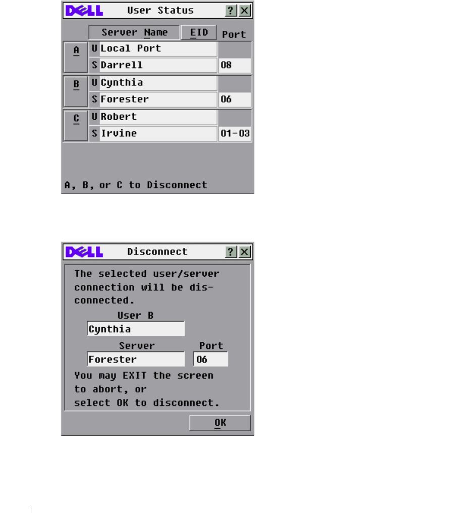
To disconnect a user:
1
Press <Print Screen>. The
Main
dialog box will appear.
44 Analog Port Operation
www.dell.com | support.dell.com
2
Click
Commands - User Status
. The
User Status
dialog box appears.
Figure 3-25. User Status Dialog Box
3
Click the letter of the user you wish to disconnect. The
Disconnect
dialog box will appear.
Figure 3-26. Disconnect Dialog Box
4
Click
OK
to disconnect the user and return to the
User Status
dialog box.
-or-
Click
X
or press <Escape> to exit the dialog box without disconnecting the user.

Analog Port Operation 45
NOTE: If the User Status list has changed since it was last displayed, the mouse cursor will turn into an
hourglass as the list is automatically updated. No mouse or keyboard input will be accepted until the list
update is complete.
Preemption
Preemption of a Local User by a Remote Administrator
This occurs when a remote administrator attempts to take control of a server that is being accessed
by a local user.
If a preemption timeout value has been set, a message appears warning the local user that a remote
user has requested the preemption. The local user can then decide whether to accept or reject the
preemption request. If the local user does not respond within the time specified, they are
disconnected.
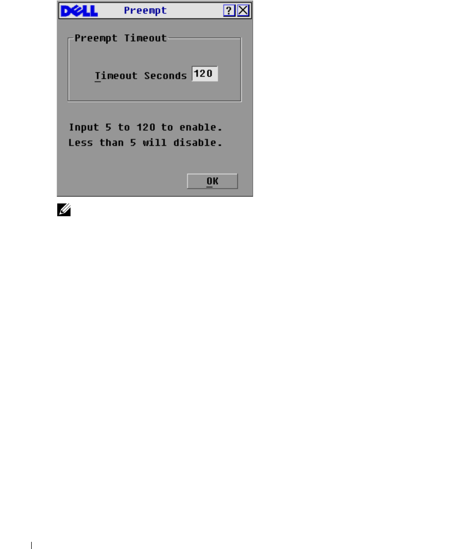
To set the preemption timeout value:
1
Press <Print Screen> to launch OSCAR. The
Main
dialog box appears.
2
Click
Setup - Preempt
. The
Preempt
dialog box appears.
3
In the
Timeout Seconds
box, type a value between 5 and 120.
46 Analog Port Operation
www.dell.com | support.dell.com
Figure 3-27. Preempt Dialog box
NOTE: Typing a value of less than five will disable preemption timeout and will result in preemption
without warning if the administrator preempts the local user.
4
Click OK.
Preemption of a Remote Administrator by a Local User
This occurs when a local user attempts to take control of a server that is being accessed by a remote
administrator. In this instance, when the local user tries to connect to the server a message appears
asking the local user to wait while the preemption request is answered by the remote administrator.
If the remote administrator rejects the preemption request, a message appears informing the local
user that they cannot connect to the server. If the request is granted by the remote administrator,
the local user can access the server.
Preemption of a Remote User by a Local User
This occurs when a local user attempts to take control of a server that is being accessed by a remote
user who is not an administrator. In this instance, the local user is given access to the server after a
defined time.
Running System Diagnostics
You can validate the integrity of your system through the
Run Diagnostics
command. This
command checks the main board functional sub-systems (memory, intra-board communications,
switch control, and the video channels) for each system controller. When you select the
Run
Diagnostics
command, you will receive a warning indicating that all users (remote and local) will
be disconnected. Click
OK
to confirm and begin the test.
Analog Port Operation 47
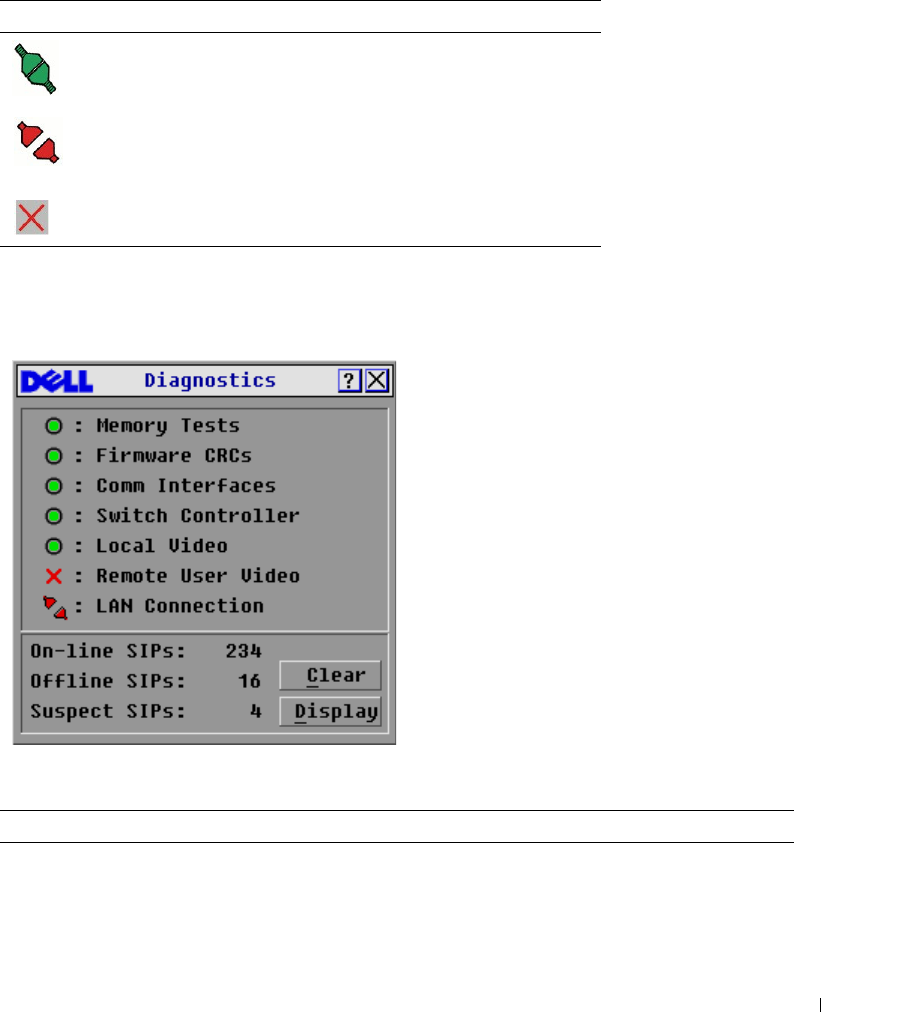
The
Diagnostic
dialog box appears. The top section of the dialog box displays the hardware tests.
The bottom portion divides the SIPs tested into three categories: online, offline or suspect.
Next to each item to be tested, you will see a pass (green circle) or fail (red x) symbol appear to the
left of each item as that test finishes.Table 3-5 details each of the tests.
Figure 3-28. Diagnostics Dialog Box
Table 3-4. LAN Connection Test Icons
Icon Description
The appliance is connected to an active LAN,
and has received at least one packet since the
connection was established.
The appliance is connected to an active LAN,
and has not received at least one packet since the
connection was established.
The appliance is not connected to an active LAN.
Table 3-5. Diagnostic Test Details
Test Description
Memory Test Reports on the condition of the main board RAM
Firmware Cyclical Redundancy
Checks (CRC)
Validates the current firmware images stored in the system's FLASH

48 Analog Port Operation
www.dell.com | support.dell.com
To run diagnostic tests:
1
If OSCAR is not open, press <Print Screen>. The
Main
dialog box will appear.
2
Click
Commands - Run Diagnostics
. A warning message appears indicating that all users will
be disconnected.
3
Click
OK
to begin diagnostics.
-or-
Click
X
or press <Escape> to exit the dialog box without running a diagnostic test.
4
All users are disconnected and the diagnostics screen displays.
5
As each test is finished, a pass or fail symbol appears. The test is complete when the last test's
symbol displays.
6
(Optional) If you have any Offline SIP, you can click the
Clear
button to remove them from
the list.
7
(Optional) If you have any Suspect SIP, you can click the
Display
button. The
Suspect SIPs
dialog box appears.
Comm Interfaces Verifies that inter-board communication sub-systems are accessible and
functional
Switch Controller Verifies the switch matrix controller is accessible and functional
Local and Remote Video Verifies that all the video channel sub-systems are accessible and
functional
LAN Connection Verifies the LAN connection is accessible and functional.
On-line SIPs Indicates the total number of currently connected and powered SIP
Offline SIPs Indicates the number of SIP that have been connected successfully in
the past and are apparently powered down
Suspect SIPs Indicates the number of SIP that have been detected, but are either
unavailable for connection or have dropped packets during the ping
tests
Table 3-5. Diagnostic Test Details
Test Description
Analog Port Operation 49
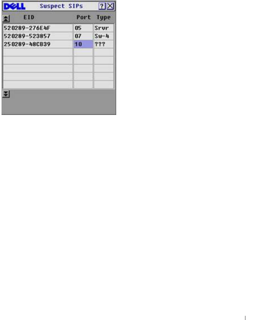
Figure 3-29. Suspect SIPs Dialog Box
a
In Figure 3-29, the first SIP is connected to a server. The second SIP is connected to
port 4 on a cascaded switch, where 'sw' is the switch and the number 4 indicates the
fourth port.The third SIP is inactive. Make a note of each SIP in the suspect SIP list. You
may want to troubleshoot each of these SIPs.
Displaying Version Information
Use the
Version
dialog box to display the 2161DS Console Switch and SIP firmware versions, as
well as keyboard and mouse information for the currently selected server. For optimum
performance, keep your firmware current. For more information on updates, see "Appendix A:
Flash Upgrades".
To display version information:
1
Press <Print Screen>. The
Main
dialog box will appear.
2
Click
Commands - Display Versions
. The
Version
dialog box appears. The top half of the box
lists the subsystem versions in the 2161DS Console Switch unit.
50 Analog Port Operation
www.dell.com | support.dell.com
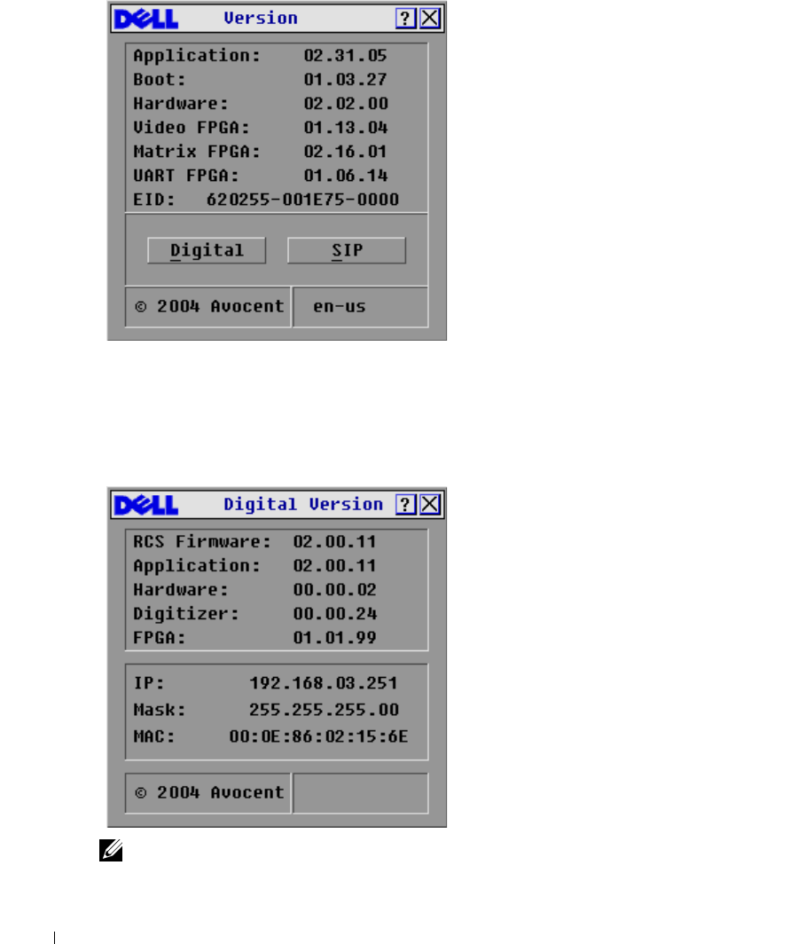
Figure 3-30. Version Dialog Box
3
Click
Digital
to view the Digitizer unit firmware versions. The
Digital Version
dialog box
appears. The top section identifies the digitizer subsystem versions. The center section
identifies the current network settings. Click
X
or press <Escape> to return to the
Version
dialog box.
Figure 3-31. Digital Version Dialog Box
NOTE: The application version that appears on the Digital Version screen is the preferred version to use
for Dell Support calls.
Analog Port Operation 51
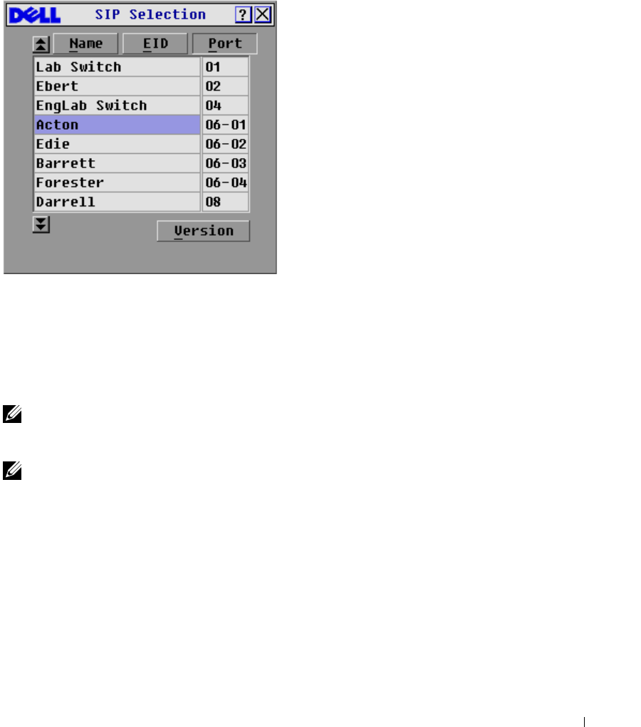
4
Click
SIP
to view individual SIP version information.
Figure 3-32. SIP Selection Dialog Box
5
Select the SIP that you wish to view and click
Version
. The
SIP Version
dialog box appears.
For more information on loading firmware, see "Appendix A: Flash Upgrades".
6
Click
X
or press <Escape> to close the various
Version
dialog boxes.
Resetting a SIP
SIPs can be reset using the
Reset
button in the
SIP Version
dialog box.
NOTE: This procedure is only relevant where your 2161DS Console Switch system involves a PS/2 SIP
attached to a tiered switch. On these occasions, it may be necessary to reset the SIP when the tiered
switch is not recognized.
NOTE: If a reset is performed, when a 2161DS Console Switch is connected directly to a server, and not
a Cascade Switch, the mouse/keyboard may fail to respond. When this occurs, the target server requires
a reboot.
To reset a SIP:
1
Press <Print Screen>. The
Main
dialog box will appear.
2
Click
Commands - Display Versions
. The
Version
dialog box appears.
3
Click
SIP.
The
SIP Selection
dialog box appears.
4
Select the PS/2 SIP that you wish to view and click
Version
. The
SIP Version
dialog box
appears.
52 Analog Port Operation
www.dell.com | support.dell.com
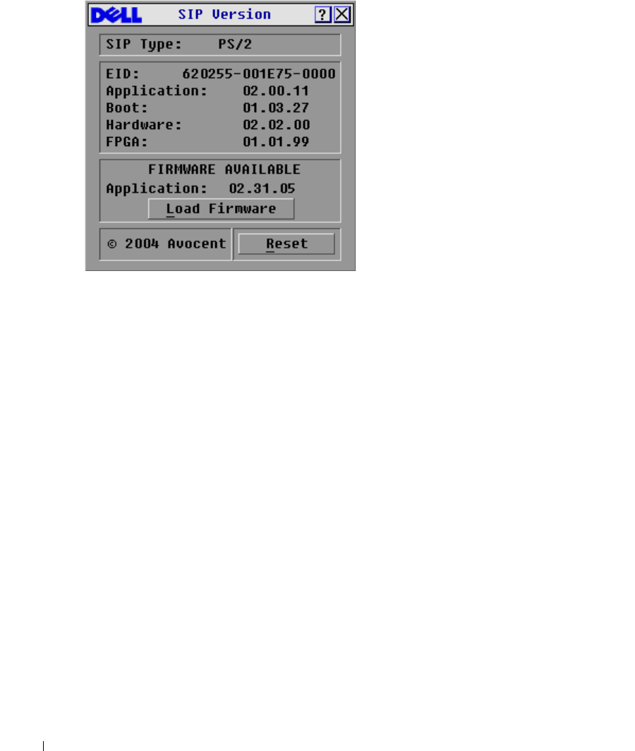
Figure 3-33. SIP Version Dialog Box
5
Click
Reset
. A warning message appears, warning that the function is for tiered switches only
and that resetting the SIP could result in the need to reboot the target server.
6
Click
OK
to proceed with the reset.
or
7
Press <ESC> to exit.
Resetting Your Keyboard and Mouse
If a keyboard or mouse locks up, you may be able to re-establish operation of these peripherals by
issuing a reset command. The reset command sends a hot-plug sequence to the server which causes
the mouse and keyboard settings to be sent to the 2161DS Console Switch. With communication
re-established between the server and the 2161DS Console Switch, functionality is restored to the
user.
To reset the mouse and keyboard values:
1
Press <Print Screen>. The
Main
dialog box will appear.
2
Click
Commands - Device Reset
. A message box displays requesting that you confirm the
reset.
3
Click
OK
. A message appears indicating that the mouse and keyboard have been reset.
4
Click
X
to close the message box.
-or-
Click
X
or press <Escape> to exit without sending a reset command to the PS/2 mouse and
keyboard.
Analog Port Operation 53
Figure 3-34. Main Dialog Box
Scanning Your System
In scan mode, the 2161DS Console Switch automatically scans from port to port (server to server).
You can scan up to 16 servers by specifying which servers you want to scan and the number of
seconds that each server will display. You can choose to display the server's name or EID number by
pressing the appropriate button.
To add servers to the
Scan
list:
1
If OSCAR is not open, press <Print Screen>. The
Main
dialog box will appear.
2
Click
Setup - Scan
. The
Scan
dialog box appears.
54 Analog Port Operation
www.dell.com | support.dell.com
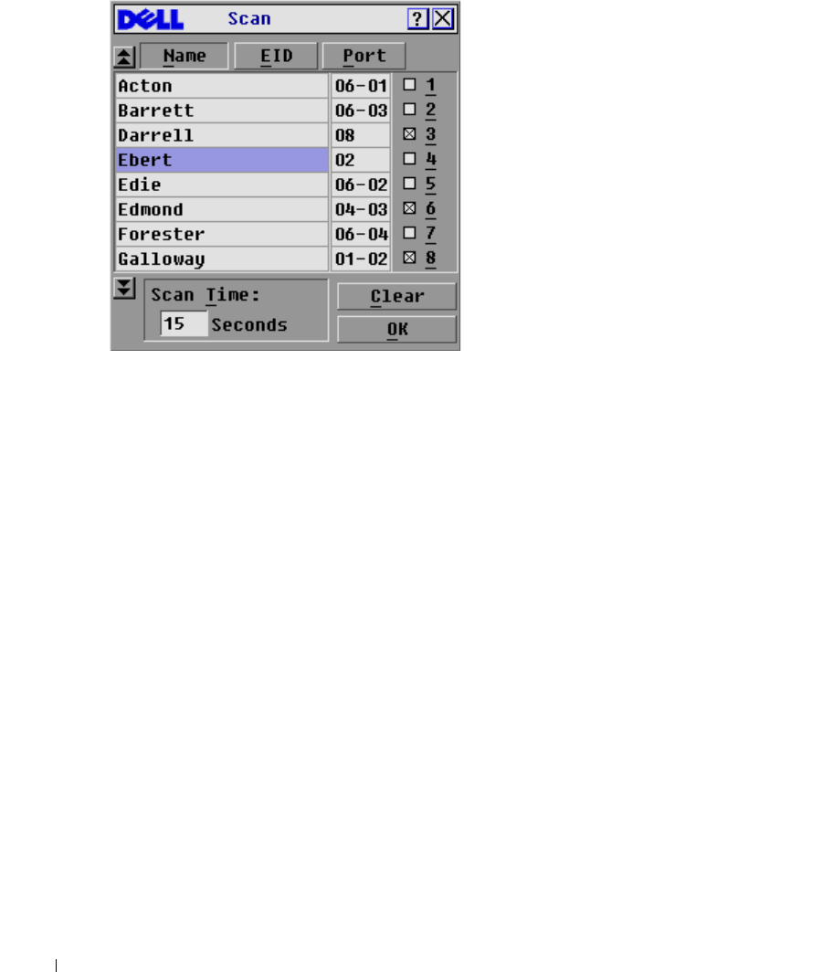
Figure 3-35. Scan Dialog Box
3
The dialog box contains a listing of all the servers attached to your unit. Click to enable the
check box next to the servers you wish to scan.
-or-
Double-click on a server's name or port.
-or-
Press <Alt>+ the number of the server you wish to scan. You can select up to 16 servers.
4
In the
Scan Time
box, type the number of seconds (from 3 to 99) of desired time before the
scan moves to the next server in the sequence.
5
Click
OK
.
To remove a server from the
Scan
list:
1
In the
Scan
dialog box, click to disable the check box next to a server to be removed.
-or-
Double-click on a server's name or port.
-or-
Click the
Clear
button to remove all servers from the
Scan
list
2
Click
OK
.
To start the scan mode:
1
Press <Print Screen>. The
Main
dialog box will appear.
2
Click
Commands
. The
Command
dialog box appears.
Analog Port Operation 55
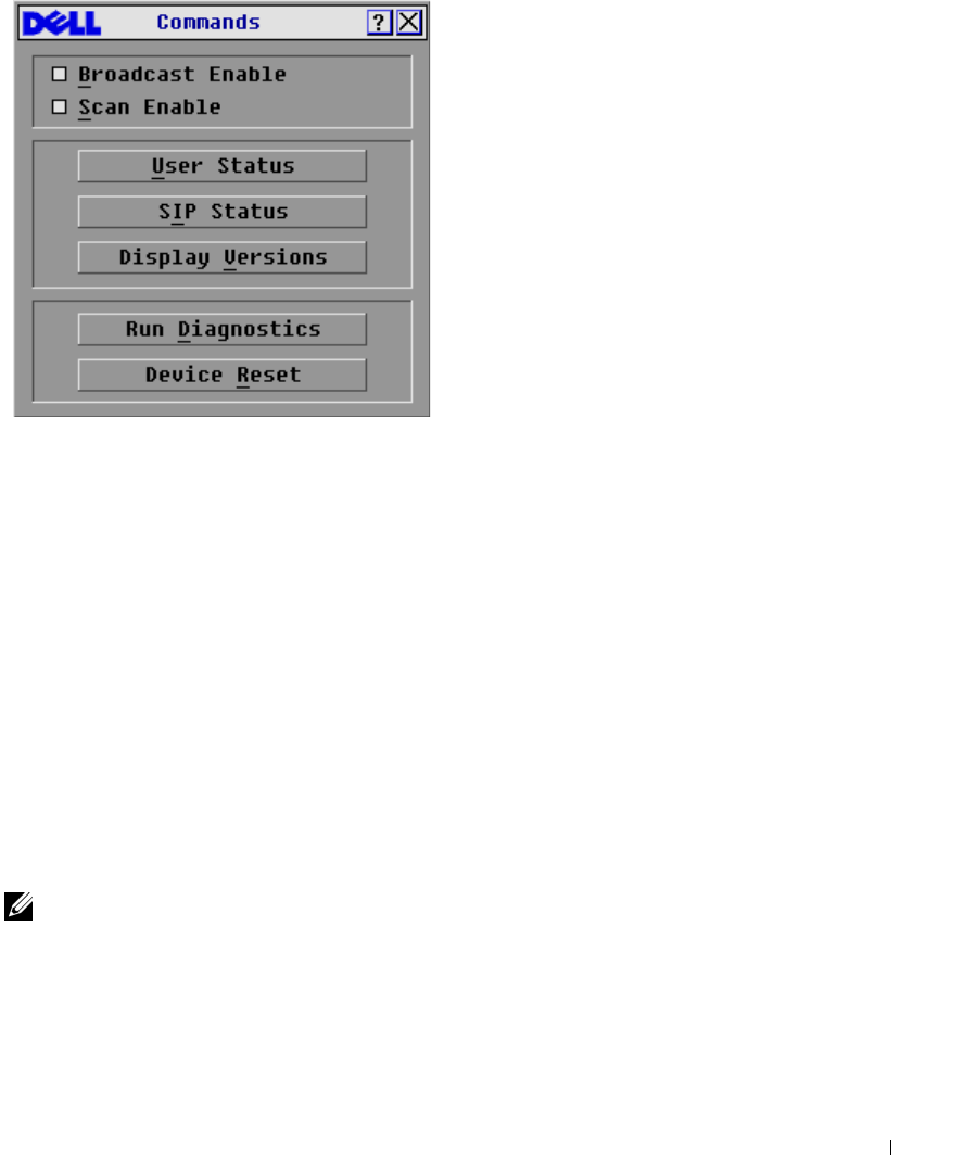
Figure 3-36. Command Dialog Box
3
Select
Scan Enable
in the
Command
dialog box.
To cancel scan mode:
1
Select a server if OSCAR is open.
-or-
Move the mouse or press any key on the keyboard if OSCAR is not open. Scanning will stop at
the currently selected server.
-or-
Press <Print Screen>. The
Main
dialog box will appear.
2
Click
Commands
.
The
Command
dialog box appears.
3
Clear
Scan Enable
.
Broadcasting to Servers
The analog user can simultaneously control more than one server in a system, ensuring that all
selected servers receive identical input. You can choose to broadcast keystrokes and/or mouse
movements independently.
NOTE: You can broadcast to only one server per ARI connection.
To access the
Broadcast
dialog box:
1
Press <Print Screen>. The
Main
dialog box will appear.
2
Click
Setup - Broadcast
. The
Broadcast
dialog box appears.
56 Analog Port Operation
www.dell.com | support.dell.com
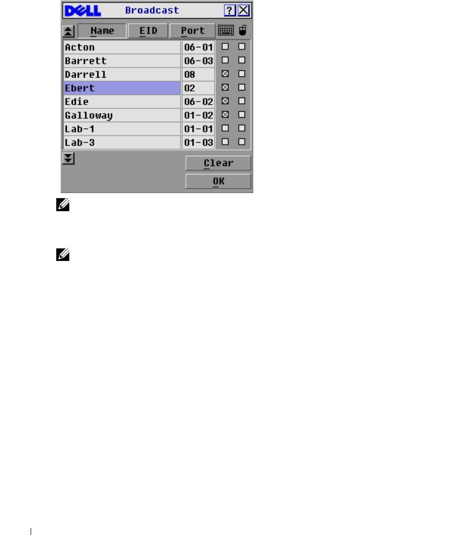
Figure 3-37. Broadcast Dialog Box
NOTE: Broadcasting Keystrokes - The keyboard state must be identical for all servers receiving a
broadcast to interpret keystrokes identically. Specifically, the Caps Lock and Num Lock modes must be
the same on all keyboards. While the 2161DS Console Switch attempts to send keystrokes to the selected
servers simultaneously, some servers may inhibit and thereby delay the transmission.
NOTE: Broadcasting Mouse Movements - For the mouse to work accurately, all systems must have
identical mouse drivers, desktops (such as identically placed icons), and video resolutions. In addition,
the mouse must be in exactly the same place on all screens. Because these conditions are extremely
difficult to achieve, broadcasting mouse movements to multiple systems may have unpredictable results.
To broadcast to selected servers:
1
In the
Broadcast
dialog box, click to enable the mouse and keyboard check boxes for the
servers that are to receive the broadcast commands.
-or-
Press the
down-arrow key
or
up-arrow key
to move the cursor to the target server. Then press
<Alt><k> to select the keyboard check box and/or <Alt><m> to select the mouse check
box. Repeat for additional servers.
2
Click
OK
to save the settings and return to the
Setup
dialog box.
3
Click
X
or press <Escape> to return to the
Main
dialog box.
4
Click
Commands
. The
Command
dialog box appears.
5
Click the
Broadcast Enable
check box to activate broadcasting.
6
From the user station, type the information and/or perform the mouse movements you want
to broadcast.
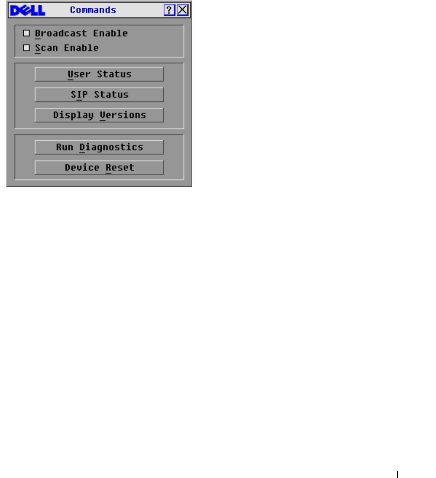
Analog Port Operation 57
To turn broadcasting off:
In the
Command
dialog box, click to disable the
Broadcast Enable
check box.
Figure 3-38. Command Dialog Box

58 Analog Port Operation
www.dell.com | support.dell.com
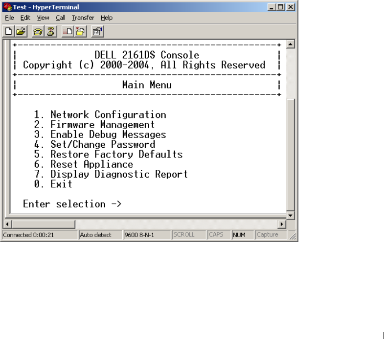
Terminal Operations 59
4
Terminal Operations
Each individual Dell™ 2161DS Console Switch may be configured at the unit level through the
configuration port on the back of the switch. All Terminal commands are accessed through a
terminal or PC running terminal emulation software.
Configuring the Terminal Menu
The 2161DS Console Switch
Terminal Applications
menu features seven selections:
Network
Configuration, Firmware Management, Enable Debug Messages, Set/Change Password,
Restore
Factory Defaults
,
Reset Appliance
,
Display Diagnostic Report
, and
Exit
.
Figure 4-39. Terminal Menu

60 Terminal Operations
www.dell.com | support.dell.com
To access the
Terminal
menu:
1
Connect a terminal or system running terminal emulation software (such as HyperTerminal)
to the configuration port on the back panel of the 2161DS Console Switch using the supplied
serial cable. The terminal should be set to 9600 baud, 8 bits, 1 stop bit, no parity, and no flow
control. The terminal may be connected at any time, even when the unit is powered.
2
Press any key to access the main menu.
Network Configuration
The 2161DS Console Switch is configured for network access through this option. When it is
selected, you will have access to the addressing that allows the 2161DS Console Switch to be
positioned in your network. For more information, see "Rack Mounting Your 2161DS Console
Switch".
Firmware Management
This menu option contains the
Flash Download
command. The
Flash Download
command allows
you to keep your 2161DS Console Switch firmware current with upgrades available from Dell. For
more information, see "Appendix A: Flash Upgrades".
Enable Debug Messages
This menu option allows you to configure the 2161DS Console Switch to display messages
regarding the status of the 2161DS Console Switch unit. Once you select the level of detail you
wish to receive, the 2161DS Console Switch will begin to display information on your terminal
screen. When you are finished viewing, press any key to exit this mode.
Set/Change Passwords
The 2161DS Console Switch can be set to a secure mode where the
Terminal
menu cannot be
accessed without first entering a password.
To activate security:
1
Select the
Set/Change Password
menu option. You will be prompted to decide if you wish to
continue. Press <y>.
2
Type a password for this 2161DS Console Switch unit and press <Enter>. Passwords require
5 to 12 characters and must include at least one letter and one number. Passwords are also
case sensitive. Entering a new password deactivates the old one.
3
You will be prompted to re-type the password. Once you complete this step, security will be
active and you will not be able to access 2161DS Console Switch terminal operations without
the password.

Terminal Operations 61
To change the password:
1
Select the
Set/Change Password
menu option.
2
You will be prompted to type the old password and a new one.
3
Re-enter the new password to verify.
NOTICE: This password places your 2161DS Console Switch terminal in a secure mode. This password
should be guarded like any network password and care should be taken to avoid forgetting or misplacing
it. There are no means for recovering a lost password.
Restore Factory Defaults
This menu option allows you to restore the network and security configurations to their default
settings.
Reset Appliance
This menu option allows you to execute a soft reset of the 2161DS Console Switch.
Display Diagnostic Report
This menu option allows you to display the report generated by the Run Diagnostics feature of the
On-Screen Configuration and Activity Reporting interface (OSCAR®).
NOTE: A diagnostic report can only be displayed if one has been generated using OSCAR. If no report
exists a message appears indicating that no report exists to display. For more information, see "Running
System Diagnostics"
.
Exit
This menu selection will return you to the ready prompt.

62 Terminal Operations
www.dell.com | support.dell.com

Appendices 63
5
Appendices
Appendix A: Flash Upgrades
Upgrading the Dell™ 2161DS Console Switch
The Dell™ 2161DS Console Switch FLASH upgrade feature allows you to update your unit with
the latest firmware available. To perform this update, you will first need a Trivial FTP (TFTP)
server. If you do not have a TFTP server, there are several shareware programs that provide TFTP
emulation that you can download.
NOTICE: The 2161DS with firmware 3.0.2 or higher is not downgradeable. Please do no attempt to
downgrade your 2161DS to any version lower than 3.0.2.
Next, you will need to download the latest FLASH firmware from Dell at support.dell.com. Save
the FLASH upgrade file to the appropriate directory on the TFTP server. Once this is complete,
the following steps will upload the new FLASH file.
To upload a new FLASH file to the 2161DS Console Switch:
1
Connect a terminal or PC running terminal emulation software (such as HyperTerminal) to
the configuration port on the back panel of the 2161DS Console Switch using the supplied
serial cable. The terminal should be set to 9600 baud, 8 bits, 1 stop bit, no parity, and no flow
control.
2
If the 2161DS Console Switch is not powered up, turn it on now. The Power indicator on the
front of the unit will blink for 30 seconds while performing a self-test. Approximately
10 seconds after it stops blinking, press <Enter> to access the main menu.
3
You will see the Terminal Applications menu with seven options. Select option 2,
Firmware
Management
.
NOTE: The current version of your firmware will be displayed on the Firmware Management screen.
4
Select option 1,
FLASH Download
.
5
Type the IP address of your TFTP server and press <Enter>.
6
Type the name of the file that you downloaded from the Dell site.
7
Confirm the TFTP download by typing a y or yes and pressing <Enter>.
8
The 2161DS Console Switch will verify that the file you downloaded is valid.
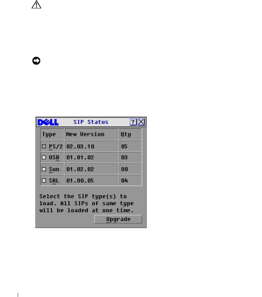
64 Appendices
www.dell.com | support.dell.com
9
The 2161DS Console Switch will begin the FLASH upgrade process. On-screen indicators
will display the upgrade progress. When the upload is complete, the 2161DS Console Switch
will reset and upgrade the internal subsystems.
CAUTION: Do not cycle power to the 2161DS Console Switch during this process. A loss of power will
render the 2161DS Console Switch inoperable and require the unit be returned to the factory for repair.
10
Once the upgrade is complete, a verification message will appear on screen.
Upgrading the SIP
The Server Interface Pods (SIPs) or Avocent® AVRIQs can be upgraded individually or
simultaneously. As long as an upgrade is in progress, you cannot initiate another.
NOTICE: Do not cycle power to the server or disconnect the SIP during this process. A loss of power
will render the SIP inoperable and require the unit be returned to the factory for repair.
To simultaneously upgrade multiple SIPs:
1
Press <Print Screen>. The
Main
dialog box will appear.
2
Click
Commands-SIP Status
. The
SIP Status
dialog box appears.
Figure 5-40. SIP Status Dialog Box.
3
Click one or more types of SIPs you wish to upgrade. Click
Upgrade
. The
SIP Load
dialog box
appears.
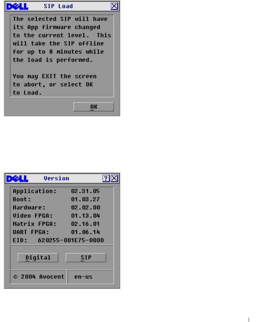
Appendices 65
Figure 5-41. SIP Load Dialog Box
4
Click
OK
to initiate the upgrade and return to the
SIP Status
dialog box.
To upgrade SIP firmware individually:
1
Press <Print Screen>. The
Main
dialog box will appear.
2
Click
Commands-Display Versions
. The
Version
dialog box appears.
Figure 5-42. Version Dialog Box
3
Click
SIP
to view individual SIP version information.
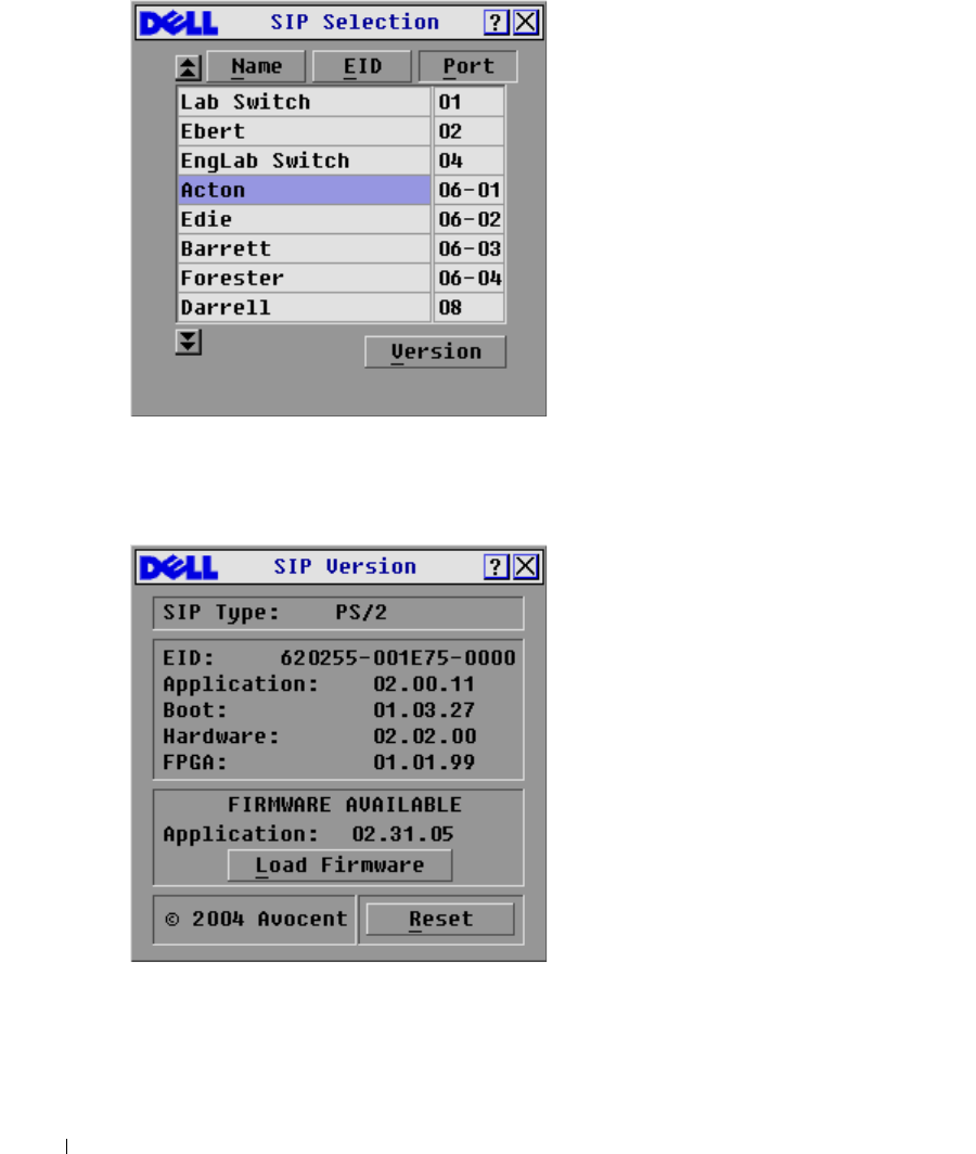
66 Appendices
www.dell.com | support.dell.com
Figure 5-43. SIP Selection Dialog Box
4
Select the SIP that you wish to upgrade and click the
Version
button. The
SIP Version
dialog
box appears.
Figure 5-44. SIP Version Dialog Box
5
Click the
Load Firmware
button. The
SIP Load
dialog box appears.
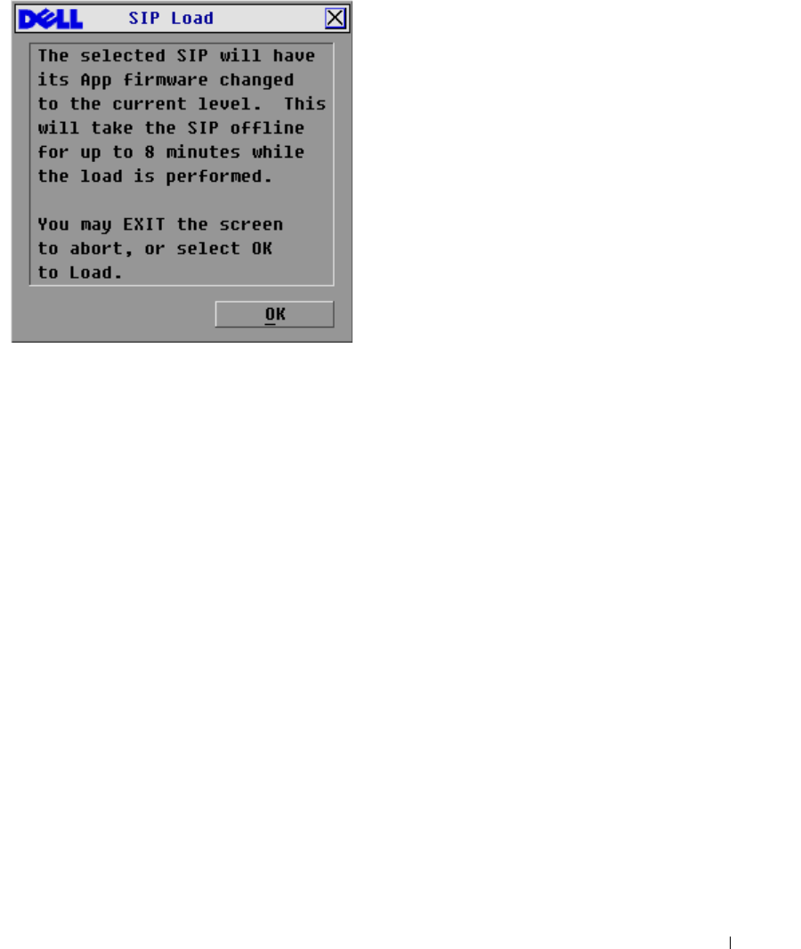
Appendices 67
Figure 5-45. SIP Load Dialog Box
6
Click
OK
to initiate the upgrade and return to the
SIP Status
dialog box.
Upgrading Cascaded Dell 8-port and 16-port Console Switch
Visit the support.dell.com web site for the latest firmware versions. If your firmware is out of date,
you can upgrade your cascaded Dell console switch from the analog port on the switch.
To upgrade an 8-port/16-port console switch from the analog port of the switch:
1
Check the firmware version of the cascaded unit.
a
At the local port of the 8-port/16-port unit, press <Print Screen>> to access the
OSCAR® GUI. The
Main
dialog box appears.
b
Click
Commands - Versions
.
c
The firmware version of the 8-port and 16-port switches is shown in the
F:
field. The
minimum version required for the 8-port is version 2.1.3 and version 1.3.3 for the 16-port
switch.
2
Go to support.dell.com.
3
Search using the keywords Console Switch.
4
Follow instructions to download the latest upgrade for your cascaded unit.

68 Appendices
www.dell.com | support.dell.com
To upgrade an 8-port/16-port console switch cascaded from a Dell 2161DS Console Switch:
1
Check the firmware version of the cascaded unit.
a
Connect a keyboard, mouse, and monitor to the local port of your cascaded switch.
b
At the local port of the cascaded unit, pull up the cascaded unit OSCAR.
c
In the
Commands
menu, select Versions.
d
System requirements for cascading 8-port and 16-port switches from a 2161DS Console
Switch are version shown in the
S:
field. The minimum version required for the 8-port is
version 2.1.2.1, and version 1.3.2.0 for the 16-port.
e
Go to support.dell.com.
2
Search using the keywords Console Switch.
3
Follow instructions to download the latest upgrade for your cascaded unit.

Appendices 69
Appendix B: Technical Specifications
Table 5-6. Technical Specifications
Server Ports
Number 16
SIP Types PS/2 and USB, Dell branded or Avocent. Sun and Serial,
Avocent AVRIQs only.
Connectors Separate horizontal and vertical
Video Port
Sync Types Separate horizontal and vertical
Plug and Play DDC2B
Video Resolution Analog Port Maximum 1600x1280@ 75 Hz.
Digital Port Maximum 1280 x 1024 @ 75 Hz
Analog Port Maximum 1600 x 1200 @ 75 Hz
Digital Port Maximum 1280 x 1024 @ 75 Hz
15 meters from ARI port to server
Configuration Port
Number 1
Typ e Se r i al R S 2 32
Connectors DB9 Male
Network Connection
Number 1
Type Ethernet: IEEE 8023, 10BaseT, Fast Ethernet: IEEE
802.3U, 100BaseT
Connectors RJ45
Analog Port
Number 1
Typ e PS / 2 and V G A
Connectors PS/2 MiniDIN, 15 Pin D
Agency Approvals
EN55022 Class A, EN55024, EN6100-3-3, FCC15 Class A,
VCCI Class A, IEC950, EN60950, UL 1950 third edition,
CSA C22.2 No. 950
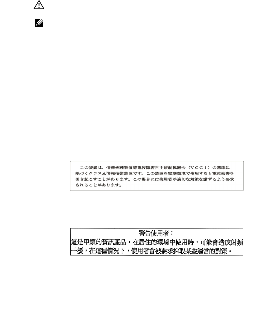
70 Appendices
www.dell.com | support.dell.com
Appendix C: Notifications
USA Notification
CAUTION: Changes or modifications to this unit not expressly approved by the party responsible for
compliance could void the user's authority to operate the equipment.
NOTE: This equipment has been tested and found to comply with the limits for a Class A digital device,
pursuant to Part 15 of the FCC Rules. These limits are designed to provide reasonable protection against
harmful interference when the equipment is operated in a commercial environment. This equipment
generates, uses and can radiate radio frequency energy and, if not installed and used in accordance
with the instruction manual, may cause harmful interference to radio communications. Operation of this
equipment in a residential area is likely to cause harmful interference in which case the user will be
required to correct the interference at his own expense.
Canadian Notification
This digital apparatus does not exceed the Class A limits for radio noise emissions from digital
apparatus set out in the Radio Interference Regulations of the Canadian Department of
Communications.
Le présent appareil numérique n'émet pas de bruits radioélectriques dépassant les limites
applicables aux appareils numériques de la classe A prescrites dans le Règlement sur le brouillage
radioélectrique édicté par le Ministère des Communications du Canada.
Japanese Approvals
Taiwanese Approvals

Appendices 71
Agency Approvals
UL 1950, CSA C22. 2 No. 950, EN60950, IEC 950
FCC part 15A, EN55022, EN50082
Republic of Korea EMI Standard Certificate Number: E-F900-01-2012 (A)

72 Appendices
www.dell.com | support.dell.com

73
Limited Warranties and Return Policy
Dell-branded hardware products purchased in the U.S. or Canada come with either a 90-day, 1-year,
2-year, 3-year, or 4-year limited warranty. To determine which warranty came with your hardware
product(s), see your packing slip or invoice. The following sections describe the limited warranties
and return policy for the U.S., the limited warranties and return policy for Canada, the
manufacturer guarantee for Latin America and the Caribbean, and the Intel
®
Pentium
®
and
Celeron
®
warranty for the U.S. and Canada.
Limited Warranty for Dell-Branded Hardware Products (U.S. Only)
What is covered by this limited warranty?
This limited warranty covers defects in materials and workmanship in your—our end-user customer's—Dell-branded
hardware products, including Dell-branded peripheral products.
What is not covered by this limited warranty?
This limited warranty does not cover:
• Software, including the operating system and software added to the Dell-branded hardware products through our
factory-integration system, third-party software, or the reloading of software
• Non-Dell-branded and Solution Provider Direct products and accessories
• Problems that result from:
– External causes such as accident, abuse, misuse, or problems with electrical power
– Servicing not authorized by Dell
– Usage that is not in accordance with product instructions
– Failure to follow the product instructions or failure to perform preventive maintenance
– Problems caused by using accessories, parts, or components not supplied by Dell
• Products with missing or altered Service Tags or serial numbers
• Products for which Dell has not received payment
THIS WARRANTY GIVES YOU SPECIFIC LEGAL RIGHTS, AND YOU MAY ALSO HAVE OTHER RIGHTS
WHICH VARY FROM STATE TO STATE (OR JURISDICTION TO JURISDICTION). DELL'S
RESPONSIBILITY FOR MALFUNCTIONS AND DEFECTS IN HARDWARE IS LIMITED TO REPAIR AND
REPLACEMENT AS SET FORTH IN THIS WARRANTY STATEMENT. ALL EXPRESS AND IMPLIED
WARRANTIES FOR THE PRODUCT, INCLUDING BUT NOT LIMITED TO ANY IMPLIED WARRANTIES
AND CONDITIONS OF MERCHANTABILITY AND FITNESS FOR A PARTICULAR PURPOSE, ARE
LIMITED IN TIME TO THE TERM OF THE LIMITED WARRANTY PERIOD REFLECTED ON YOUR
PACKING SLIP OR INVOICE. NO WARRANTIES, WHETHER EXPRESS OR IMPLIED, WILL APPLY AFTER
THE LIMITED WARRANTY PERIOD HAS EXPIRED. SOME STATES DO NOT ALLOW LIMITATIONS ON
HOW LONG AN IMPLIED WARRANTY LASTS, SO THIS LIMITATION MAY NOT APPLY TO YOU.
WE DO NOT ACCEPT LIABILITY BEYOND THE REMEDIES PROVIDED FOR IN THIS LIMITED
WARRANTY OR FOR CONSEQUENTIAL OR INCIDENTAL DAMAGES, INCLUDING, WITHOUT
LIMITATION, ANY LIABILITY FOR THIRD-PARTY CLAIMS AGAINST YOU FOR DAMAGES, FOR
PRODUCTS NOT BEING AVAILABLE FOR USE, OR FOR LOST DATA OR LOST SOFTWARE. OUR
LIABILITY WILL BE NO MORE THAN THE AMOUNT YOU PAID FOR THE PRODUCT THAT IS THE
SUBJECT OF A CLAIM. THIS IS THE MAXIMUM AMOUNT FOR WHICH WE ARE RESPONSIBLE.

74
www.dell.com | support.dell.com
SOME STATES DO NOT ALLOW THE EXCLUSION OR LIMITATION OF INCIDENTAL OR
CONSEQUENTIAL DAMAGES, SO THE ABOVE LIMITATION OR EXCLUSION MAY NOT APPLY TO YOU.
How long does this limited warranty last?
This limited warranty lasts for the time period indicated on your packing slip or invoice, except for the following Dell-
branded hardware:
• Portable computer batteries carry a 1-year limited warranty.
• Projector lamps carry a 90-day limited warranty.
• Memory carries a lifetime limited warranty.
• Monitors carry the longer of either a 3-year limited warranty or the remainder of the warranty for the Dell
computer to which the monitor will be connected.
• Other add-on hardware carries the longer of either a 1-year limited warranty for new parts and a 90-day limited
warranty for reconditioned parts or, for both new and reconditioned parts, the reminder of the warranty for the
Dell computer on which such parts are installed.
The limited warranty on all Dell-branded products begins on the date of the packing slip or invoice. The warranty
period is not extended if we repair or replace a warranted product or any parts. Dell may change the availability of
limited warranties, at its discretion, but any changes will not be retroactive.
What do I do if I need warranty service?
Before the warranty expires, please call us at the relevant number listed in the following table. Please also have your Dell
Service Tag or order number available.
What will Dell do?
During the 90 days of the 90-day limited warranty and the first year of all other limited warranties: During the 90 days
of the 90-day limited warranty and the first year of all other limited warranties, we will repair any Dell-branded hardware
products returned to us that prove to be defective in materials or workmanship. If we are not able to repair the product,
we will replace it with a comparable product that is new or refurbished.
Individual Home Consumers: U.S. Only
Technical Support 1-800-624-9896
Customer Service 1-800-624-9897
Individual Home Consumers who purchased through an
Employee Purchase Program:
Technical Support and Customer Service 1-800-822-8965
Home and Small Business Commercial Customers:
Technical Support and Customer Service 1-800-456-3355
Medium, Large, or Global Commercial Customers, Healthcare
Customers, and Value-Added Resellers (VARs):
Technical Support and Customer Service 1-800-822-8965
Government and Education Customers:
Technical Support and Customer Service 1-800-234-1490
Dell-Branded Memory 1-888-363-5150

75
When you contact us, we will issue a Return Material Authorization Number for you to include with your return. You
must return the products to us in their original or equivalent packaging, prepay shipping charges, and insure the
shipment or accept the risk if the product is lost or damaged in shipment. We will return the repaired or replacement
products to you. We will pay to ship the repaired or replaced products to you if you use an address in the United States
(excluding Puerto Rico and U.S. possessions and territories). Otherwise, we will ship the product to you freight collect.
If we determine that the product is not covered under this warranty, we will notify you and inform you of service
alternatives that are available to you on a fee basis.
During the remaining years: For the remaining period of the limited warranty, we will replace any defective part with
new or refurbished parts, if we agree that it needs to be replaced. When you contact us, we will require a valid credit card
number at the time you request a replacement part, but we will not charge you for the replacement part as long as you
return the original part to us within 30 days after we ship the replacement part to you. If we do not receive the original
part within 30 days, we will charge to your credit card the then-current standard price for that part.
We will pay to ship the part to you if you use an address in the United States (excluding Puerto Rico and U.S.
possessions and territories). Otherwise, we will ship the part freight collect. We will also include a prepaid shipping
container with each replacement part for your use in returning the replaced part to us.
NOTE: Before you ship the product(s) to us, make sure to back up the data on the hard drive(s) and any other storage
device(s) in the product(s). Remove any confidential, proprietary or personal information, removable media, such as
diskettes, CDs, or PC Cards. We are not responsible for any of your confidential, proprietary or personal information; lost or
corrupted data; or damaged or lost removable media.
What if I purchased a service contract?
If your service contract is with Dell, service will be provided to you under the terms of the service agreement. Please refer
to that contract for details on how to obtain service.
If you purchased through us a service contract with one of our third-party service providers, please refer to that contract
for details on how to obtain service.
How will you fix my product?
We use new and refurbished parts made by various manufacturers in performing warranty repairs and in building
replacement parts and systems. Refurbished parts and systems are parts or systems that have been returned to Dell,
some of which were never used by a customer. All parts and systems are inspected and tested for quality. Replacement
parts and systems are covered for the remaining period of the limited warranty for the product you bought. Dell owns all
parts removed from repaired products.
May I transfer the limited warranty?
Limited warranties on systems may be transferred if the current owner transfers ownership of the system and records the
transfer with us. The limited warranty on Dell-branded memory may not be transferred. You may record your transfer by
going to Dell's website:
• If you are an Individual Home Consumer, go to www.dell.com/us/en/dhs/topics/sbtopic_015_ccare.htm
• If you are a Home Office, Small, Medium, Large, or Global Commercial Customer, go to
www.dell.com/us/en/biz/topics/sbtopic_ccare_nav_015_ccare.htm
• If you are a Government, Education, or Healthcare Customer, or an Individual Home Consumer who purchased
through an Employee Purchase Program, go to www.dell.com/us/en/pub/topics/sbtopic_015_ccare.htm
If you do not have Internet access, call your customer care representative or call 1-800-624-9897.

76
www.dell.com | support.dell.com
All requests to transfer ownership are at Dell's sole discretion. All such transfers will be subject to the terms and
conditions of the original service or limited warranty agreement and Dell's terms and conditions of sale located at
www.dell.com. Dell cannot guarantee the authenticity of the products, limited warranties, service or support or the
accuracy of the listings of products you purchase from a third party.
Total Satisfaction Return Policy (U.S. Only)
We value our relationship with you and want to make sure that you're satisfied with your purchases. That's why we offer
a "Total Satisfaction" return policy for most products that you—the end-user customer—purchase directly from Dell.
Under this policy, you may return to Dell products that you purchased directly from Dell for a credit or a refund of the
purchase price paid, less shipping and handling and applicable return fees as follows:
•New Hardware Products and Accessories — Unless you have a separate agreement with Dell, all new hardware,
accessories, peripherals, parts, and unopened software still in its sealed package, excluding the products listed
below, may be returned within 21 days from the date on the packing slip or invoice. New PowerEdge™,
PowerConnect™, and PowerVault™ products may be returned within 30 days from the date on the packing slip or
invoice except that new PowerEdge™SC servers and n-Series products purchased from the Small and Medium
Business Sales Division may only be returned within 14 days from the date on the packing slip or invoice. To
return applications software or an operating system that has been installed by Dell, you must return the entire
computer. A different return policy applies to nondefective products purchased through Dell's Software and
Peripherals division by customers of our Small and Medium Business divisions. Those products may be returned
within 21 days from the date on the packing slip or invoice, but a fifteen percent (15%) return fee will be
deducted from any refund or credit. The "Total Satisfaction" Return Policy and Software and Peripherals division
return policy are not available for Dell | EMC storage products, EMC-branded products, Unisys-branded
products, PowerVault™ 160T tape libraries, enterprise software, non-Dell branded enterprise products, software
and/or software licenses purchased under any type of volume purchase agreement or any non-Dell customized
hardware and/or hardware product(s).
•Reconditioned or Refurbished Dell-Branded Hardware Products and Parts — All reconditioned or refurbished
PowerEdge™, PowerConnect™, and PowerVault™ products may be returned within 30 days from the date on the
packing slip or invoice. All other reconditioned or refurbished Dell-branded hardware products and parts may be
returned within 14 days of the date on the packing slip or invoice.
•How to Return — To return products, e-mail or call Dell customer service to receive a Credit Return
Authorization Number within the return policy period applicable to the product you want to return. You must
obtain a Credit Return Authorization Number in order to return the product. See "Contacting Dell" or "Getting
Help" in your customer documentation (or www.dell.com/us/en/gen/contact.htm) to find the appropriate contact
information for obtaining customer assistance.
You must ship the products to Dell within 5 days of the date that Dell issues the Credit Return Authorization Number.
You must also return the products to Dell in their original packaging, in as-new condition along with any media,
documentation, and all other items that were included in the original shipment, prepay shipping charges, and insure the
shipment or accept the risk of loss or damage during shipment.
Limited Warranty Terms for Dell-Branded Hardware Products (Canada Only)
What is covered by this limited warranty?
This limited warranty covers defects in materials and workmanship in your—our end-user customer's—Dell-branded
hardware products, including Dell-branded peripheral products.
What is not covered by this limited warranty?
This limited warranty does not cover:

77
• Software, including the operating system and software added to the Dell-branded hardware products through our
factory-integration system, or the reloading of the software
• Non-Dell branded and Solution Provider Direct products and accessories
• Problems that result from:
– External causes such as accident, abuse, misuse, or problems with electrical power
– Servicing not authorized by Dell
– Usage that is not in accordance with product instructions
– Failure to follow the product instructions or failure to perform preventive maintenance
– Problems caused by using accessories, parts, or components not supplied by Dell
• Products with missing or altered Service Tags or serial numbers
• Products for which Dell has not received payment
THIS WARRANTY GIVES YOU SPECIFIC LEGAL RIGHTS, AND YOU MAY ALSO HAVE OTHER RIGHTS
WHICH VARY FROM PROVINCE TO PROVINCE. DELL'S RESPONSIBILITY FOR MALFUNCTIONS AND
DEFECTS IN PRODUCT IS LIMITED TO REPAIR AND REPLACEMENT AS SET FORTH IN THIS WARRANTY
STATEMENT, FOR THE TERM OF THE WARRANTY PERIOD REFLECTED ON YOUR PACKING SLIP OR
INVOICE. EXCEPT FOR THE EXPRESS WARRANTIES CONTAINED IN THIS WARRANTY STATEMENT,
DELL DISCLAIMS ALL OTHER WARRANTIES AND CONDITIONS, EXPRESS OR IMPLIED, INCLUDING
WITHOUT LIMITATION IMPLIED WARRANTIES AND CONDITIONS OF MERCHANTABILITY AND
FITNESS FOR A PARTICULAR PURPOSE, STATUTORY OR OTHERWISE. SOME PROVINCES DO NOT
ALLOW THE EXCLUSION OF CERTAIN IMPLIED WARRANTIES OR CONDITIONS, OR LIMITATIONS ON
HOW LONG AN IMPLIED WARRANTY OR CONDITION LASTS. THEREFORE, THE FOREGOING
EXCLUSIONS AND LIMITATIONS MAY NOT APPLY TO YOU.
WE DO NOT ACCEPT LIABILITY BEYOND THE REMEDIES PROVIDED FOR IN THIS WARRANTY
STATEMENT OR FOR SPECIAL, INDIRECT, CONSEQUENTIAL, OR INCIDENTAL DAMAGES, INCLUDING,
WITHOUT LIMITATION, ANY LIABILITY FOR THIRD-PARTY CLAIMS AGAINST YOU FOR DAMAGES, FOR
PRODUCTS NOT BEING AVAILABLE FOR USE, OR FOR LOST DATA OR LOST SOFTWARE. OUR LIABILITY
WILL BE NO MORE THAN THE AMOUNT YOU PAID FOR THE PRODUCT THAT IS THE SUBJECT OF A
CLAIM. THIS IS THE MAXIMUM AMOUNT FOR WHICH WE ARE RESPONSIBLE.
SOME PROVINCES DO NOT ALLOW THE EXCLUSION OR LIMITATION OF SPECIAL, INDIRECT,
INCIDENTAL, OR CONSEQUENTIAL DAMAGES, SO THE ABOVE LIMITATION OR EXCLUSION MAY NOT
APPLY TO YOU.
How long does this limited warranty last?
This limited warranty lasts for the time period indicated on your packing slip or invoice, except that the limited warranty
on Dell-branded batteries lasts only 1 year and the limited warranty on the lamps for Dell-branded projectors lasts only
90 days. The limited warranty begins on the date of the packing slip or invoice. The warranty period is not extended if
we repair or replace a warranted product or any parts. Dell may change the terms and availability of limited warranties,
at its discretion, but any changes will not be retroactive (that is, the warranty terms in place at the time of purchase will
apply to your purchase).

78
www.dell.com | support.dell.com
What do I do if I need warranty service?
Before the warranty expires, please call us at the relevant number listed in the following table. Please also have your Dell
Service Tag or order number available.
What will Dell do?
During the 90 days of the 90-day limited warranty and the first year of all other limited warranties: During the 90 days
of the 90-day limited warranty and the first year of all other limited warranties, we will repair any Dell-branded hardware
products returned to us that prove to be defective in materials or workmanship. If we are not able to repair the product,
we will replace it with a comparable product that is new or refurbished.
When you contact us, we will issue a Return Material Authorization Number for you to include with your return. You
must return the products to us in their original or equivalent packaging, prepay shipping charges, and insure the
shipment or accept the risk if the product is lost or damaged in shipment. We will return the repaired or replacement
products to you. We will pay to ship the repaired or replaced products to you if you use an address in Canada. Otherwise,
we will ship the product to you freight collect.
If we determine that the problem is not covered under this warranty, we will notify you and inform you of service
alternatives that are available to you on a fee basis.
NOTE: Before you ship the product(s) to us, make sure to back up the data on the hard drive(s) and any other storage
device(s) in the product(s). Remove any confidential, proprietary or personal information, removable media, such as
diskettes, CDs, or PC Cards. We are not responsible for any of your confidential, proprietary or personal information; lost or
corrupted data; or damaged or lost removable media.
During the remaining years following the first year of all limited warranties: We will replace any defective part with
new or refurbished parts, if we agree that it needs to be replaced. When you contact us, we will require a valid credit card
number at the time you request a replacement part, but we will not charge you for the replacement part as long as you
return the original part to us within 30 days after we ship the replacement part to you. If we do not receive the original
part within 30 days, we will charge to your credit card the then-current standard price for that part.
Individual Home Consumers; Home Office and Small Business
Customers:
Canada Only
Technical Support and Customer Service 1-800-847-4096
Medium, Large, and Global Commercial Customers; Government,
Education, and Healthcare Customers; and Value-Added
Resellers (VARs):
Technical Support 1-800-387-5757
Customer Service 1-800-326-9463
Government or Education Customers, or Individual Home
Consumers who purchased through an Employee Purchase
Program:
Technical Support 1-800-387-5757
Customer Service 1-800-326-9463 (Extension 8221 for Individual
Consumers)
Dell-Branded Memory 1-888-363-5150

79
We will pay to ship the part to you if you use an address in Canada. Otherwise, we will ship the part freight collect. We
will also include a prepaid shipping container with each replacement part for your use in returning the replaced part to
us.
NOTE: Before you replace parts, make sure to back up the data on the hard drive(s) and any other storage device(s) in the
product(s). We are not responsible for lost or corrupted data.
What if I purchased a service contract?
If your service contract is with Dell, service will be provided to you under the terms of the service contract. Please refer
to that contract for details on how to obtain service. Dell's service contracts can be found online at www.dell.ca or by
calling Customer Care at 1-800-847-4096. If you purchased through us a service contract with one of our third-party
service providers, please refer to that contract (mailed to you with your packing slip or invoice) for details on how to
obtain service.
How will you fix my product?
We use new and refurbished parts made by various manufacturers in performing warranty repairs and in building
replacement parts and systems. Refurbished parts and systems are parts or systems that have been returned to Dell,
some of which were never used by a customer. All parts and systems are inspected and tested for quality. Replacement
parts and systems are covered for the remaining period of the limited warranty for the product you bought. Dell owns all
parts removed from repaired products.
May I transfer the limited warranty?
Limited warranties on systems may be transferred if the current owner transfers ownership of the system and records the
transfer with us. The limited warranty on Dell-branded memory may not be transferred. You may record your transfer by
going to Dell’s website:
• For Canada-purchased computers (in-country transfers) and to transfer from one customer to another, go to
www.dell.ca/ca/en/gen/topics/segtopic_ccare_nav_013_ccare.htm
• For out-of-country transfers (outside of the original country of purchase), go to
www.dell.com/us/en/biz/topics/sbtopic_ccare_nav_016_ccare.htm
If you do not have Internet access, call Dell at 1-800-847-4096 (Home Consumer customers) or 1-800-326-9463
(Corporate Commercial or Government customers).
Total Satisfaction Return Policy (Canada Only)
If you are an end-user customer who bought new products directly from Dell, you may return them to Dell up to 30 days
after you receive them for a refund or credit of the product purchase price. If you are an end-user customer who bought
reconditioned or refurbished products from Dell, you may return them to Dell within 14 days after the date on the
packing slip or invoice for a refund or credit of the product purchase price. In either case, the refund or credit will not
include any shipping and handling charges shown on your packing slip or invoice and will be subject to a fifteen percent
(15%) restocking fee, unless otherwise prohibited by law. If you are an organization that bought the products under a
written agreement with Dell, the agreement may contain different terms for the return of products than specified by this
policy.

80
www.dell.com | support.dell.com
To return products, you must call Dell Customer Service at 1-800-847-4096 to receive a Credit Return Authorization
Number. To expedite the process of your refund or credit, Dell expects you to return the products to Dell in their
original packaging within 5 days of the date that Dell issues the Credit Return Authorization Number. You must also
prepay shipping charges and insure the shipment or accept the risk of loss or damage during shipment. You may return
software for a refund or credit only if the sealed package containing the diskette(s) or CD(s) is unopened. Returned
products must be in as-new condition, and all of the manuals, diskette(s), CD(s), power cables, and other items
included with a product must be returned with it. For customers who want to return, for refund or credit only, either
application or operating system software that has been installed by Dell, the whole system must be returned, along with
any media and documentation that may have been included in the original shipment.
The "Total Satisfaction" Return Policy does not apply to Dell | EMC storage products. It also does not apply to products
purchased through Dell's Software and Peripherals division. For those products, please instead refer to Dell's Software
and Peripheral's then-current return policy (see the following section, "Dell Software and Peripherals [Canada Only]").
Dell Software and Peripherals (Canada Only)
Third-Party Software and Peripherals Products
Similar to other resellers of software and peripherals, Dell does not warrant third-party products. Third-party software
and peripheral products are covered by the warranties provided by the original manufacturer or publisher only. Third-
party manufacturer warranties vary from product to product. Consult your product documentation for specific warranty
information. More information may also be available from the manufacturer or publisher.
While Dell offers a wide selection of software and peripheral products, we do not specifically test or guarantee that all of
the products we offer work with any or all of the various models of Dell computers, nor do we test or guarantee all of the
products we sell on the hundreds of different brands of computers available today. If you have questions about
compatibility, we recommend and encourage you to contact the third-party software and peripheral product
manufacturer or publisher directly.
Dell-Branded Peripheral Products
Dell does provide a limited warranty for new Dell-branded peripheral products (products for which Dell is listed as the
manufacturer) such as monitors, batteries, memory, docking stations, and projectors. To determine which limited
warranty applies to the product you purchased, see the Dell packing slip or invoice and/or the product documentation
that accompanied your product. Descriptions of Dell's limited warranties are described in preceding sections.
Return Policy
If you are an end-user customer who bought Dell Software and Peripherals products directly from a Dell company, you
may return Dell Software and Peripherals products that are in as-new condition to Dell up to 30 days from the date on
the packing slip or invoice for a refund of the product purchase price if already paid. This refund will not include any
shipping and handling charges shown on your packing slip or invoice; you are responsible for those.
To return products, you must call Dell Customer Service at 1-800-387-5759 to receive a Credit Return Authorization
Number. You must ship the Dell Software and Peripherals products back to Dell in their original manufacturer's
packaging (which must be in as-new condition), prepay shipping charges, and insure the shipment or accept the risk of
loss or damage during shipment.
To qualify for refund or replacement, returned products must be in as-new condition, software products must be
unopened, and all of the manuals, diskette(s), CD(s), power cables, and other items included with a product must be
returned with it.

81
1-Year End-User Manufacturer Guarantee (Latin America and the Caribbean Only)
Guarantee
Dell Inc. ("Dell") warrants to the end user in accordance with the following provisions that its branded hardware
products, purchased by the end user from a Dell company or an authorized Dell distributor in Latin America or the
Caribbean, will be free from defects in materials, workmanship, and design affecting normal use, for a period of 1 year
from the original purchase date. Products for which proper claims are made will, at Dell’s option, be repaired or replaced
at Dell’s expense. Dell owns all parts removed from repaired products. Dell uses new and reconditioned parts made by
various manufacturers in performing repairs and building replacement products.
Exclusions
This Guarantee does not apply to defects resulting from: improper or inadequate installation, use, or maintenance;
actions or modifications by unauthorized third parties or the end user; accidental or willful damage; or normal wear and
tear.
Making a Claim
Claims must be made in Latin America or the Caribbean by contacting the Dell point of sale within the guarantee
period. The end user must always supply proof of purchase, indicating name and address of the seller, date of purchase,
model and serial number, name and address of the customer, and details of symptoms and configuration at the time of
malfunction, including peripherals and software used. Otherwise, Dell may refuse the guarantee claim. Upon diagnosis
of a warranted defect, Dell will make arrangements and pay for ground freight and insurance to and from Dell’s
repair/replacement center. The end user must ensure that the defective product is available for collection properly
packed in original or equally protective packaging together with the details listed above and the return number provided
to the end user by Dell.
Limitation and Statutory Rights
Dell makes no other warranty, guarantee or like statement other than as explicitly stated above, and this Guarantee is
given in place of all other guarantees whatsoever, to the fullest extent permitted by law. In the absence of applicable
legislation, this Guarantee will be the end user’s sole and exclusive remedy against Dell or any of its affiliates, and
neither Dell nor any of its affiliates shall be liable for loss of profit or contracts, or any other indirect or consequential
loss arising from negligence, breach of contract, or howsoever.
This Guarantee does not impair or affect mandatory statutory rights of the end user against and/or any rights resulting
from other contracts concluded by the end user with Dell and/or any other seller.
Dell World Trade LP
One Dell Way, Round Rock, TX 78682, USA
Dell Computadores do Brasil Ltda (CNPJ No. 72.381.189/0001-10)
Avenida Industrial Belgraf, 400
92990-000 - Eldorado do Sul – RS - Brasil
Dell Computer de Chile Ltda
Coyancura 2283, Piso 3- Of.302,
Providencia, Santiago - Chile
Dell Computer de Colombia Corporation
Carrera 7 #115-33 Oficina 603
Bogota, Colombia

82
www.dell.com | support.dell.com
Dell Computer de Mexico SA de CV
Paseo de la Reforma 2620 - 11° Piso
Col. Lomas Altas
11950 México, D.F.
Intel® Warranty Statement for Pentium® and Celeron® Processors Only
(U.S. and Canada Only)
Intel’s Three Year Limited Warranty
Limited Warranty
Intel warrants that its family of Pentium® and Celeron® processors, if properly used and installed, will be free from defects in materials and workmanship and will substantially
conform to Intel’s publicly available specifications for a period of three (3) years after the date the Pentium or Celeron processor was purchased (whether purchased separately
or as part of a computer system).
If the Pentium or Celeron processor, which is the subject of this Limited Warranty, fails during the warranty period for reasons covered by this Limited Warranty, Intel, at its option, will:
• REPAIR the Pentium or Celeron processor by means of hardware and/or software; OR
• REPLACE the Pentium or Celeron processor with another Pentium or Celeron processor; OR
if Intel is unable to repair or replace the particular Pentium or Celeron processor,
• REFUND the then-current value of the Pentium or Celeron processor.
THIS LIMITED WARRANTY, AND ANY IMPLIED WARRANTIES THAT MAY EXIST UNDER STATE LAW, APPLY ONLY TO THE ORIGINAL PURCHASER OF THE
PENTIUM OR CELERON PROCESSOR, OR PENTIUM OR CELERON PROCESSOR-BASED COMPUTER AND LAST ONLY FOR AS LONG AS SUCH PURCHASER
CONTINUES TO OWN THE PROCESSOR.
Extent of Limited Warranty
Intel does not warrant that your Pentium or Celeron processor will be free from design defects or errors known as "errata." Current characterized errata are available upon request.
This limited warranty is for purchasers in the United States and Canada only. The limited warranty does not cover any costs relating to removal or replacement of any Pentium or
Celeron processors that are soldered or otherwise permanently affixed to your system’s motherboard.
This limited warranty does not cover damages due to external causes, including accident, problems with electrical power, usage not in accordance with product instructions,
misuse, neglect, alteration, repair, improper installation, or improper testing.
How to Obtain Warranty Service
To obtain warranty service for your Pentium or Celeron processor, you may contact your computer system manufacturer in accordance with its instructions, or you may contact Intel.
To request warranty service from Intel, you should call Intel at 1-800-628-8686 during the warranty period during normal business hours (Pacific Time), excluding holidays. Please
be prepared to provide:
(1) your name, address, and telephone numbers;
(2) proof of purchase;
(3) this Intel warranty card;
(4) a description of the computer system including the brand and model; and
(5) an explanation of the problem.
[Note: The Customer Service Representative may need additional information from you depending on the nature of the problem.]
The replacement processor is warranted under this written warranty and is subject to the same limitations and exclusions for the remainder of the original warranty period or one
(1) year, whichever is longer.
WARRANTY LIMITATIONS AND EXCLUSIONS
THESE WARRANTIES REPLACE ALL OTHER WARRANTIES, EXPRESS OR IMPLIED INCLUDING, BUT NOT LIMITED TO, THE IMPLIED WARRANTIES OF
MERCHANTABILITY AND FITNESS FOR A PARTICULAR PURPOSE. INTEL MAKES NO EXPRESS WARRANTIES BEYOND THOSE STATED HERE. INTEL
DISCLAIMS ALL OTHER WARRANTIES, EXPRESS OR IMPLIED, INCLUDING, WITHOUT LIMITATION, IMPLIED WARRANTIES OF MERCHANTABILITY
AND FITNESS FOR A PARTICULAR PURPOSE.
SOME LAWS DO NOT ALLOW THE EXCLUSION OF IMPLIED WARRANTIES SO THIS LIMITATION MAY NOT APPLY TO YOU. IF THESE LAWS APPLY, THEN ALL
EXPRESS AND IMPLIED WARRANTIES ARE LIMITED IN DURATION TO THE LIMITED WARRANTY PERIOD. NO WARRANTIES APPLY AFTER THAT PERIOD.
SOME LAWS DO NOT ALLOW LIMITATIONS ON HOW LONG AN IMPLIED WARRANTY LASTS, SO THIS LIMITATION MAY NOT APPLY TO YOU.
LIMITATIONS OF LIABILITY
INTEL’S RESPONSIBILITY UNDER THIS, OR ANY OTHER WARRANTY, IMPLIED OR EXPRESS, IS LIMITED TO REPAIR, REPLACEMENT OR REFUND, AS SET
FORTH ABOVE. THESE REMEDIES ARE THE SOLE AND EXCLUSIVE REMEDIES FOR ANY BREACH OF WARRANTY. INTEL IS NOT RESPONSIBLE FOR INDIRECT,
SPECIAL, INCIDENTAL, OR CONSEQUENTIAL DAMAGES RESULTING FROM ANY BREACH OF WARRANTY OR UNDER ANY OTHER LEGAL THEORY
INCLUDING, BUT NOT LIMITED TO, LOST PROFITS, DOWNTIME, GOODWILL, DAMAGE TO OR REPLACEMENT OF EQUIPMENT AND PROPERTY, AND ANY
COSTS OF RECOVERING, REPROGRAMMING, OR REPRODUCING ANY PROGRAM OR DATA STORED IN OR USED WITH A SYSTEM CONTAINING YOUR
PENTIUM PROCESSOR. SOME JURISDICTIONS DO NOT ALLOW THE EXCLUSION OR LIMITATION OF INCIDENTAL OR CONSEQUENTIAL DAMAGES, SO THE
ABOVE LIMITATIONS OR EXCLUSIONS MAY NOT APPLY TO YOU.
THE LIMITED WARRANTY GIVES YOU SPECIFIC LEGAL RIGHTS, AND YOU MAY ALSO HAVE OTHER RIGHTS THAT VARY FROM JURISDICTION TO JURISDICTION.

83
Intel Pentium
®
and Celeron
®
Processors are backed by a three-year limited warranty.
Please refer to the reverse side of this card for complete warranty details.
Intel’s Commitment to Quality
Intel is committed to producing the highest quality processors available. That’s why we have hundreds of people dedicated to continuously improve our design, manufacturing,
and testing technology.
We put every one of our Pentium
®
and Celeron
®
processors through a rigorous battery of tests during the design and manufacturing processes.
To verify that the new chip will correctly run the software written for Intel Architecture processors, a team of Intel engineers is dedicated to compatibility testing. In a state-of-art lab,
this group runs an extensive set of operating systems, applications, network tests and stress tests repeatedly to ensure that the processor is compatible with representative software.
Just as importantly, we work with hardware and software companies in the computer industry to ensure that our processors are compatible with their products.
Additionally, a sampling of Intel processors are subjected to a rigorous "burn-in" test whereby the chip is operated at higher-than-normal temperatures and voltages. During this
burn-in period, the processor experiences the equivalent of weeks of normal usage. These units are monitored for failures as part of our ongoing quality assurance process.
As a result, today’s microprocessors from Intel are among the most reliable components in computers.
What are "Errata"?
Exhaustive product testing can highlight differences between the actual behavior of the microprocessor and its specifications. Sometimes the discrepancies are caused by a design
defect or error, which we call errata. Rigorous validation identifies most errata during the development of the processor, but we do detect additional errata during the life cycle of
a microprocessor.
When an erratum is identified, our engineers work to characterize it and find a solution. We work with system designers and software developers to ensure that the discrepancy does
not affect their products. If necessary, special software or hardware solutions (sometimes known as "work arounds") are implemented in the system design to prevent computer
users from encountering the problem. Errata may then be corrected in future revisions of the microprocessor.
No microprocessor is perfect, and Intel recognizes that some consumers want to know about any errata, whether or not the errata affect them. Intel makes documentation of all
characterized Pentium and Celeron processor errata publicly available through our Technical Documentation Service.
At Intel, our goal is to make every computer user satisfied with his or her Pentium or Celeron processor. Should you have any questions, comments or concerns about your Intel
microprocessor, please call us at 1-800-628-8686.
©1997, 1998 Intel Corporation. All rights reserved.

84
www.dell.com | support.dell.com

Index 85
Index
Numerics
2161DS Console Switch
Configuring, 20
Installing, 19
2161DS Console Switch Unit
Installing, 18
A
Address Resolution Protocol.
See ARP.
analog port, 29
ARI, 22, 34, 55
ARP, 21
Auto-Negotiate, 21
AVRIQ, 15
B
BootP, 20
Broadcast dialog box, 55
Broadcasting, 55
C
Cascade Switch
Adding, 24
Comm Interfaces, 48
Command dialog box, 54
Configuration port, 19, 60
CRC, 47
Cyclical Redundancy Checks.
See CRC.
D
Device Types
Assigning, 36
Devices dialog box
Accessing, 36
Diagnostics
Tests, 48
Diagnostics dialog Box, 47
Disconnect dialog box, 44
E
EID, 29, 31, 34, 38-39, 43
Electronic ID number. See
EID.
F
Firmware, 63
Management, 59
Flag dialog box
Accessing, 39
Flash Upgrades, 63
H
HyperTerminal, 19, 60
L
LAN Connection, 48
Load Firmware button, 66
Local and Remote Video, 48
M
Main dialog box, 29, 36, 42,
55, 65
Memory Test, 47
Menu dialog box
Accessing, 37
Modify button, 36
Mouse Acceleration, 21
Adjusting, 21
N
Name Modify dialog box, 35
Names, 33
Assigning, 34
dialog box, 34
Network Configuration, 20,
60

86 Index
O
On-Screen Configuration and
Activity Reporting
interface. See OSCAR.
OSCAR, 15, 29, 61
Configuring, 33
Navigation, 32
Setting screen delay time, 38
Status Symbols, 30
P
Password
Changing, 41
Removing, 42
Set/Change, 60
PEM, 16, 31
Adding, 22
Port Expansion Module. See
PEM.
power indicator, 20
Preemption, 43
Timeout, 45
R
Rack Mounting, 16
Remote Console Switch
Software, 10, 15-16
S
Scan dialog box, 53
Scan mode, 54
Cancelling, 55
Security, 41
Security dialog box, 41
Servers
Adding, 27
Selecting, 31
Setup menu, 33
SIP, 9, 15-16, 29, 65
Connecting, 22
Offline, 30
Resetting, 51
Upgrading, 64
SIP Selection dialog box, 51
SIPs
Offline, 48
Online, 48
Suspect, 48
Soft Switching, 31
Status Flag
Controlling, 39
Status flag
Positioning, 40
Suspect SIPs dialog box, 48
Switch Controller, 48
System Diagnostics
Running, 46
T
Terminal Applications, 20, 59
Terminal Menu, 59
Terminal menu
Accessing, 60
TFTP, 63
Trivial FTP, See TFTP.
U
User Status dialog box, 43
Users
Viewing and
Disconnecting, 43
V
Version dialog box, 50
Version Information
Displaying, 49
Video Optimization, 21
W
warranty, 73
