Dell Latitude E6400 Atg Mid 2008 Service Manual
2014-11-13
: Dell Dell-Latitude-E6400-Atg-Mid-2008-Service-Manual-112389 dell-latitude-e6400-atg-mid-2008-service-manual-112389 dell pdf
Open the PDF directly: View PDF  .
.
Page Count: 99
Dell™Latitude™E6400andE6400ATGand
MobileWorkstationPrecision™M2400ServiceManual
Notes, Notices, and Cautions
IfyoupurchasedaDELL™nSeriescomputer,anyreferencesinthisdocumenttoMicrosoft® Windows® operating systems are not applicable.
Information in this document is subject to change without notice.
©2008DellInc.Allrightsreserved.
Reproduction of these materials in any manner whatsoever without the written permission of Dell Inc. is strictly forbidden.
Trademarks used in this text: Dell, Latitude, and the DELL logo are trademarks of Dell Inc.; Bluetooth is a registered trademark owned by Bluetooth SIG, Inc., and is used by Dell
under license; Intel is a registered trademark of Intel Corporation in the U.S. and other countries; Microsoft, Windows, Windows Vista, and the Windows Vista start button logo are
either trademarks or registered trademarks of Microsoft Corporation in the United States and/or other countries.
Other trademarks and trade names may be used in this document to refer to either the entities claiming the marks and names or their products. Dell Inc. disclaims any
proprietary interest in trademarks and trade names other than its own.
Model PP36S
July2008Rev.A00
Troubleshooting
Working on Your Computer
Base Assembly
Hinge Covers
Hard Drive
WLAN/WiMax Card
WWAN Card
WPAN (UWB/BT) Card
FCM
Fan
Processor Heatsink Assembly
Processor Module
Memory
Coin-Cell Battery
Modular Drive
LED Cover
Keyboard
Modem
Right Speaker Grill/Fingerprint Reader Assembly
Palm Rest Assembly
Card Cage
1394 Card
RJ-11 Modem Connector
System Board Assembly
I/O Card
DC Power Cable
Battery Latch Assembly
Display Assembly
Flashing the BIOS
NOTE: A NOTE indicates important information that helps you make better use of your computer.
NOTICE: A NOTICE indicates either potential damage to hardware or loss of data and tells you how to avoid the problem.
CAUTION: A CAUTION indicates potential for property damage, personal injury, or death.
Back to Contents Page
1394 Card
Dell™Latitude™E6400andE6400ATGand
MobileWorkstationPrecision™M2400ServiceManual
Removing the 1394 Card
Replacing the 1394 Card
Removing the 1394 Card
1. Follow the instructions in Before Working on Your Computer.
2. Remove the bottom of the base assembly (see Removing the Bottom of the Base Assembly).
3. Remove the modular drive (see Removing the Modular Drive).
4. Remove the hinge covers (see Removing the Hinge Covers).
5. Remove the heatsink assembly (see Removing the Processor Heatsink Assembly).
6. Remove the display assembly (see Removing the Display Assembly (E6400 and M2400) or Removing the Display Assembly (E6400 ATG)).
7. Remove the LED cover (see Removing the LED Cover).
8. Remove the keyboard (see Removing the Keyboard).
9. Remove the right speaker grill (see Removing the Right Speaker Grill/Fingerprint Reader Assembly).
10. Remove the palm rest assembly (Removing the Palm Rest Assembly).
11. Remove the card cage (see Removing the Card Cage).
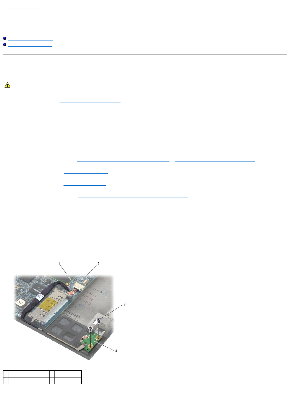
12. Disconnect the 1394 cable from the system board, and unroute the cable.
13. Remove the two M2 x 3 screws.
14. Lift the 1394 card up at an angle and remove it.
CAUTION: Before you begin the following procedure, follow the safety instructions that shipped with your computer.
1
1394 cable connector
2
system board
3
M2 x 3 screws (2)
4
1394 card

Replacing the 1394 Card
1. Insert the 1394 card at a 45-degree angle to fit the connector into the base assembly. Use the alignment pins to seat into position.
2. Replace the two M2 x 3 screws.
3. Route and connect the 1394 cable to the system board.
4. Replace the card cage (see Replacing the Card Cage).
5. Replace the palm rest assembly (Replacing the Palm Rest Assembly).
6. Replace the right speaker grill (see Replacing the Right Speaker Grill/Fingerprint Reader Assembly).
7. Replace the keyboard (see Replacing the Keyboard).
8. Replace the LED cover (see Replacing the LED Cover).
9. Replace the display assembly (see Replacing the Display Assembly (E6400 and M2400) or Replacing the Display Assembly (E6400 ATG)).
10. Replace the heatsink assembly (see Replacing the Processor Heatsink Assembly).
11. Replace the hinge covers (see Replacing the Hinge Covers).
12. Replace the modular drive (see Replacing the Modular Drive).
13. Replace the bottom of the base assembly (see Replacing the Bottom of the Base Assembly).
14. Follow the procedures in After Working on Your Computer.
Back to Contents Page
CAUTION: Before you begin the following procedure, follow the safety instructions that shipped with your computer.
Back to Contents Page
Base Assembly
Dell™Latitude™E6400andE6400ATGand
MobileWorkstationPrecision™M2400ServiceManual
Removing the Bottom of the Base Assembly
Replacing the Bottom of the Base Assembly
Removing the Base Assembly
Replacing the Base Assembly
Removing the Bottom of the Base Assembly
1. Follow the procedures in Before Working on Your Computer.
2. Close the display and turn the computer upside down.
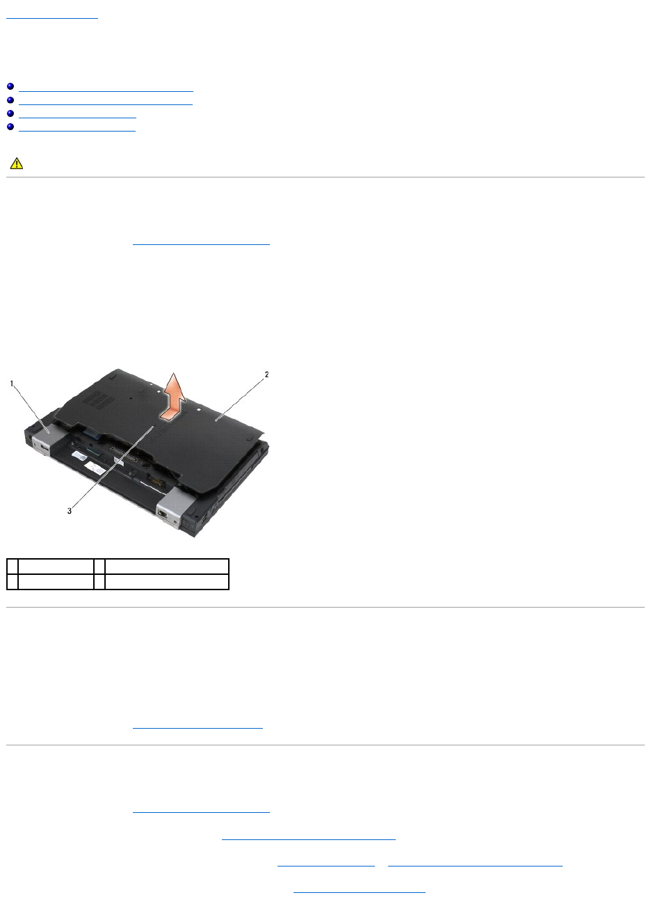
3. Loosen the captive screw.
4. Slide the bottom of the base assembly away from the hinge covers, and lift to remove the bottom of the base assembly.
Replacing the Bottom of the Base Assembly
1. Slide the bottom of the base assembly into place.
2. Tighten the captive screw.
3. Follow the procedures in After Working on Your Computer.
Removing the Base Assembly
1. Follow the procedures in Before Working on Your Computer.
2. Remove the bottom of the base assembly (see Removing the Bottom of the Base Assembly).
3. Remove the card in the WWAN/FCM card slot, if present (see Removing a WWAN Card or Removing an FCM from the WWAN/FCM Slot).
4. Remove the card from the WLAN/WiMax card slot, if present (see Removing the WLAN/WiMax Card).
CAUTION: Before you begin any of the procedures in this section, follow the safety instructions that shipped with your computer.
1
hinges covers (2)
2
bottom of the base assembly
3
captive screw

5. Remove the hinge covers (see Removing the Hinge Covers).
6. Remove the card from the WPAN/UWB/FCM card slot, if present (see Removing a WPAN (UWB/BT) Card or Removing an FCM from the WPAN/UWB/FCM
Slot).
7. Remove the heatsink assembly (see Removing the Processor Heatsink Assembly).
8. Remove the hard drive (see Removing the Hard Drive).
9. Remove the modular drive (see Removing the Modular Drive).
10. Remove the display assembly (see Removing the Display Assembly (E6400 and M2400) or Removing the Display Assembly (E6400 ATG)).
11. Remove the LED cover (see Removing the LED Cover).
12. Remove the keyboard (see Removing the Keyboard).
13. Remove the right speaker grill (see Removing the Right Speaker Grill/Fingerprint Reader Assembly).
14. Remove the palm rest assembly (see Removing the Palm Rest Assembly).
15. Remove the card cage (see Removing the Card Cage).
16. Remove the coin-cell battery (see Removing the Coin-Cell Battery).
17. Remove the system board (see Removing the System Board Assembly).
18. Remove the modem (see Removing the Modem).
19. Remove the RJ-11 modem connector (see Removing the RJ-11 Modem Connector).
20. Remove the I/O card (see Removing the I/O Card).
Replacing the Base Assembly
1. Replace the I/O card (see Replacing the I/O Card).
2. Replace the RJ-11 modem connector (see Replacing the RJ-11 Modem Connector).
3. Replace the modem (see Replacing the Modem).
4. Replace the system board (see Replacing the System Board Assembly).
5. Replace the coin-cell battery (see Replacing the Coin-Cell Battery).
6. Replace the card cage (see Replacing the Card Cage).
7. Replace the palm rest assembly (see Replacing the Palm Rest Assembly).
8. Replace the right speaker grill (see Replacing the Right Speaker Grill/Fingerprint Reader Assembly).
9. Replace the keyboard (see Replacing the Keyboard).
10. Replace the LED cover (see Replacing the LED Cover).
11. Replace the display assembly (see Replacing the Display Assembly (E6400 and M2400) or Replacing the Display Assembly (E6400 ATG)).
12. Replace the modular drive (see Replacing the Modular Drive).
13. Replace the hard drive (see Replacing the Hard Drive).
14. Replace the heatsink assembly (see Replacing the Processor Heatsink Assembly).
15. Replace the card in the WPAN/UWB/FCM card slot, if applicable (see Replacing a WPAN (UWB/BT) Card or Replacing an FCM).

16. Replace the hinge covers (see Replacing the Hinge Covers).
17. Replace the card from the WLAN/WiMax card slot, if applicable (see Replacing the WLAN/WiMax Card).
18. Replace the card from the WWAN/FCM card slot, if applicable (see Replacing a WWAN Card or Replacing an FCM).
19. Replace the bottom of the base assembly (see Replacing the Bottom of the Base Assembly).
20. Follow the procedures in After Working on Your Computer.
21. Flash update the BIOS (see Flashing the BIOS for more information).
22. Enter the system setup program to update the BIOS on the new system board with the computer Service Tag. For information on the system setup
program, see the Dell™TechnologyGuide on your computer or at support.dell.com.
Back to Contents Page
NOTE: If you use a BIOS update program disc to flash the BIOS, press <F12> before inserting the disc in order to set the computer to boot from the disc
for one time only. Otherwise, you must enter the system setup program to change the default boot order.

Back to Contents Page
Battery Latch Assembly
Dell™Latitude™E6400andE6400ATGand
MobileWorkstationPrecision™M2400ServiceManual
Removing a Battery Latch Assembly
Replacing the Battery Latch Assembly
There are two battery latches, a left and a right, and each latch uses a unique latch assembly. The spring, screw, and release buttons are the same for the left
and right battery latches.
The removing and replacing procedures are primarily the same for the right and the left battery latch. The differences are noted for the instructions that are
different for the right and left battery latches.
Removing a Battery Latch Assembly
1. Follow the instructions in Before Working on Your Computer.
2. Remove the bottom of the base assembly (see Removing the Bottom of the Base Assembly).
3. Remove the hard drive (see Removing the Hard Drive).
4. Remove the modular drive (see Removing the Modular Drive).
5. Remove the hinge covers (see Removing the Hinge Covers).
6. Remove the heatsink assembly (see Removing the Processor Heatsink Assembly).
7. Remove the display assembly (see Removing the Display Assembly (E6400 and M2400) or Removing the Display Assembly (E6400 ATG)).
8. Remove the LED cover (see Removing the LED Cover).
9. Remove the keyboard (see Removing the Keyboard).
10. Remove the right speaker grill (see Removing the Right Speaker Grill/Fingerprint Reader Assembly).
11. Remove the palm rest assembly (see Removing the Palm Rest Assembly).
12. Remove the card cage (see Removing the Card Cage).
13. Remove the system board (see Removing the System Board Assembly). Do not remove the wireless mini-cards, memory modules, or processor from the
system board.
14. Remove the modem (see Removing the Modem).
15. Remove the RJ-11 modem connector (see Removing the RJ-11 Modem Connector).
16. Remove the I/O card (see Removing the I/O Card).
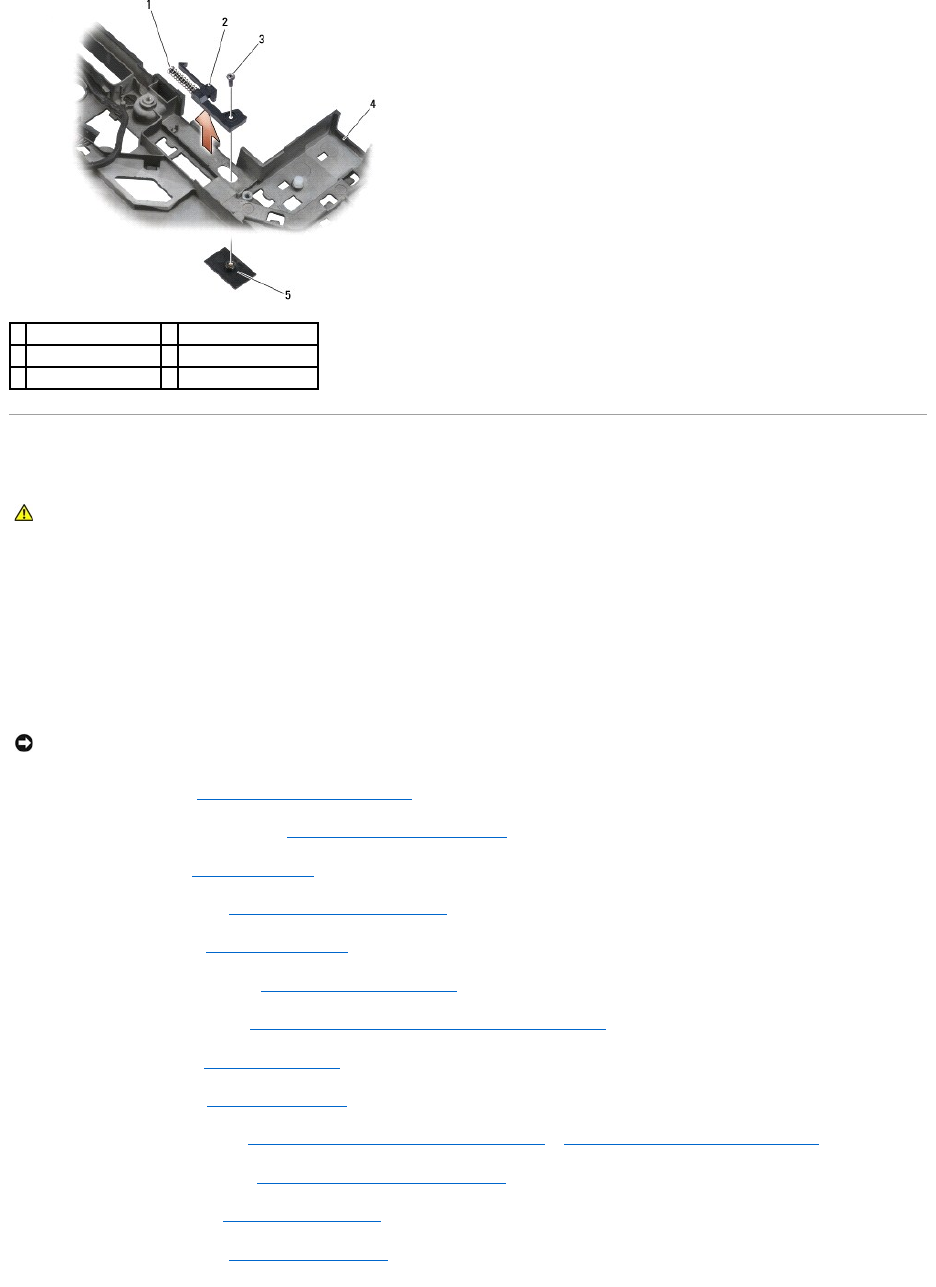
17. Remove the M2 x 3-mm screw from the alignment bracket, and remove the battery latch assembly.
18. Remove the spring from the alignment bracket and set it aside until the assembly is ready to be reinstalled.
CAUTION: Before you begin the following procedure, follow the safety instructions that shipped with your computer.
NOTICE: The spring is not secured to the alignment bracket and can be easily misplaced. When removing the battery latch assembly, place the spring in
a secure location until the assembly is ready to be reinstalled.
Replacing the Battery Latch Assembly
1. Place the spring on the alignment bracket.
2. Place the battery release button underneath the base assembly.
For the right battery latch assembly, slide the alignment bracket to the left to align the button with the hole in the alignment bracket.
For the left battery latch assembly, slide the alignment bracket to the right to align the button with the hole in the alignment bracket.
3. Replace the M2 x 3-mm screw.
4. Replace the I/O card (see Replacing the Battery Latch Assembly).
5. Replace the RJ-11 modem connector (see Replacing the RJ-11 Modem Connector).
6. Replace the modem (see Replacing the Modem).
7. Replace the system board (see Replacing the System Board Assembly).
8. Replace the card cage (see Replacing the Card Cage).
9. Replace the palm rest assembly (see Replacing the Palm Rest Assembly).
10. Replace the right speaker grill (see Replacing the Right Speaker Grill/Fingerprint Reader Assembly).
11. Replace the keyboard (see Replacing the Keyboard).
12. Replace the LED cover (see Replacing the LED Cover).
13. Replace the display assembly (see Replacing the Display Assembly (E6400 and M2400) or Replacing the Display Assembly (E6400 ATG)).
14. Replace the heatsink assembly (see Replacing the Processor Heatsink Assembly).
15. Replace the hinge covers (see Replacing the Hinge Covers).
16. Replace the modular drive (see Replacing the Modular Drive).
1
spring
2
alignment bracket
3
M2 x 3-mm screws (2)
4
battery release button
5
base assembly
CAUTION: Before you begin the following procedure, follow the safety instructions that shipped with your computer.
NOTICE: The battery release button is keyed to ensure proper alignment. If you feel resistance, check the alignment of the release button.

Back to Contents Page
Working on Your Computer
Dell™Latitude™E6400andE6400ATGand
MobileWorkstationPrecision™M2400ServiceManual
Recommended Tools
Before Working on Your Computer
After Working on Your Computer
This document provides procedures for removing and installing the components in your computer. Unless otherwise noted, each procedure assumes that:
lYou have performed the steps in Before Working on Your Computer.
lYou have read the safety information that shipped with your computer.
Recommended Tools
The procedures in this document may require the following tools:
lSmall flat-blade screwdriver
lPhillips screwdriver
lSmall plastic scribe
lFlash BIOS update (see the Dell Support website at support.dell.com)
Before Working on Your Computer
Use the following safety guidelines to help protect your computer from potential damage and to help ensure your own personal safety.
1. Ensure that the work surface is flat and clean to prevent the computer cover from being scratched.
2. Shut down your computer.
lIn Windows XP, click Start® Shutdown® Shutdown.
lIn Windows Vista, click Start , click the arrow icon, and then click Shut Down to turn off your computer.
3. Disconnect your computer and all attached devices from their electrical outlets.
4. Disconnect any telephone or network cables from the computer.
5. Turn the computer upside down.
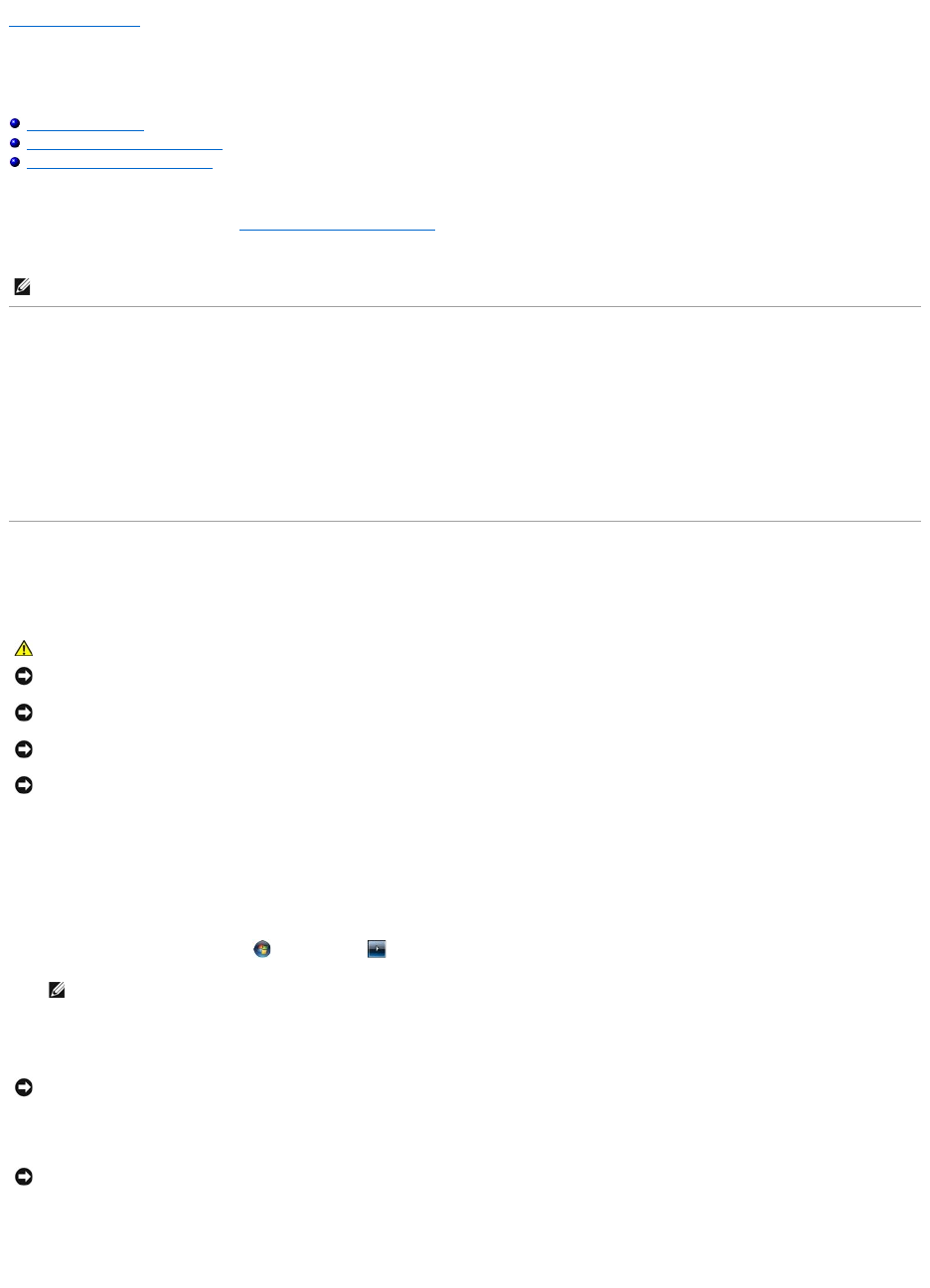
6. Slide the battery release latches toward each other to lock them in an open position.
NOTE: The color of your system and certain system components may appear differently than shown in this document.
CAUTION: Before you begin any of the procedures in this section, follow the safety instructions that shipped with your computer.
NOTICE: Only a certified service technician should perform repairs on your computer. Damage due to servicing that is not authorized by Dell is not
covered by your warranty.
NOTICE: To avoid electrostatic discharge, ground yourself by using a wrist grounding strap or by periodically touching an unpainted metal surface, such
as a connector on the back of the computer.
NOTICE: Handle components and cards with care. Do not touch the components or contacts on a card. Hold a card by its edges or by its metal
mounting bracket. Hold a component such as a processor by its edges, not by its pins.
NOTICE: When disconnecting a cable, pull on the cable's connector or on its strain-relief loop, not on the cable itself. For cable connectors with locking
tabs, press inward on the locking tabs to release the connector. When connecting a cable, ensure that the connectors are correctly oriented and
aligned to avoid damage to the connector and/or the connector's pins.
NOTE: Ensure that the computer is off and not in a power management mode. If you cannot shut down the computer using the operating system,
press and hold the power button for 4 seconds.
NOTICE: To disconnect a network cable, first unplug the cable from your computer, and then unplug it from the network wall jack.
NOTICE: To help prevent damage to the system board, you must remove the battery from the battery bay before you service the computer.
7. Slide the battery out of the battery bay.
8. Disconnect any external devices and remove any installed cards before working on your computer:
lTo remove any installed cards, such as an ExpressCard, see the Dell™TechnologyGuide on your computer or at support.dell.com.
lTo undock from a docking station, see the E-Port User's Guide or the E-Port Plus User's Guide on support.dell.com.
lTo remove a battery slice, see the documentation that shipped with your battery slice or on support.dell.com.
lTo remove a cool slice, see the documentation that shipped with your cool slice or on support.dell.com.
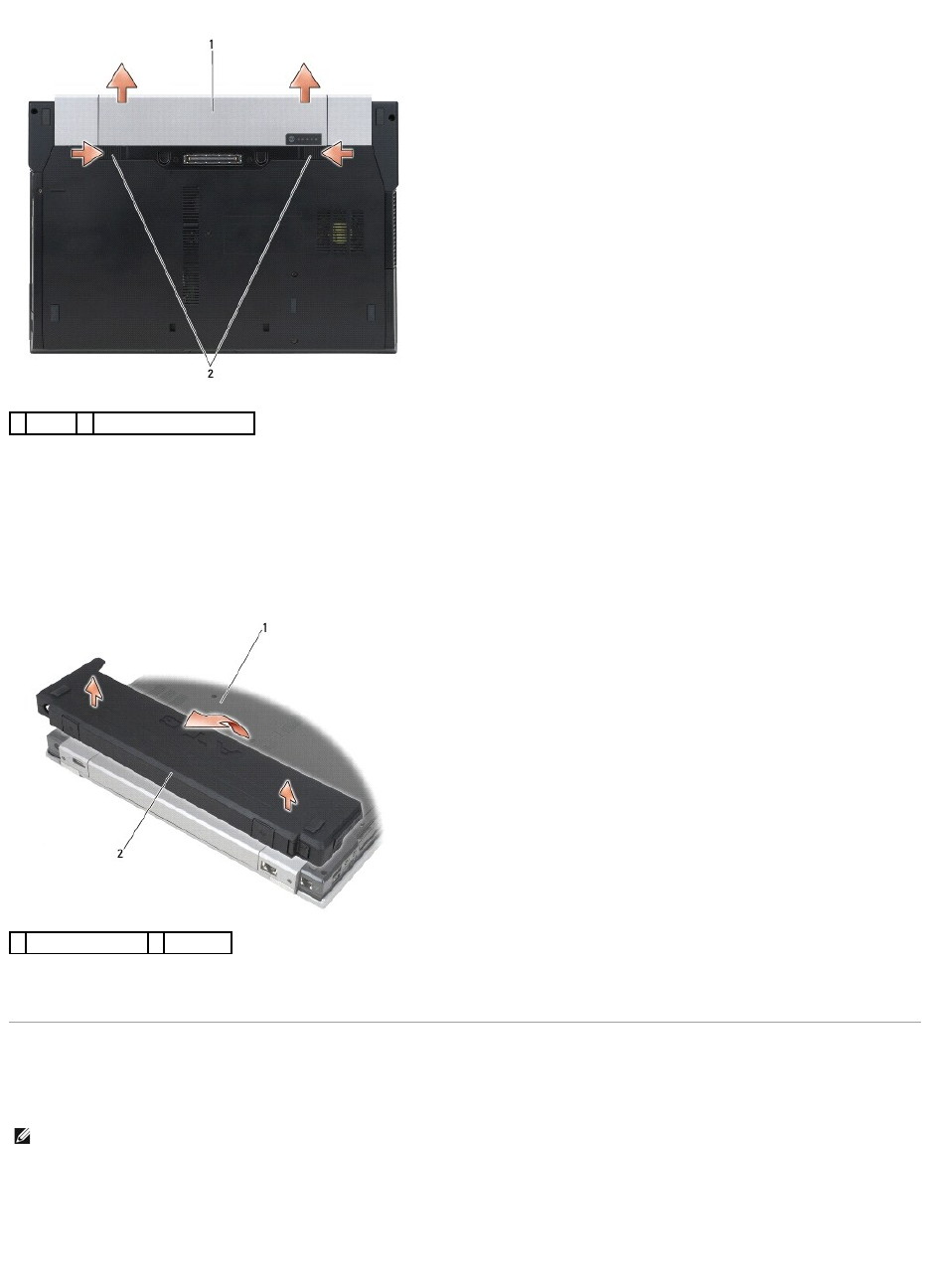
lTo remove a port cover from the E6400 ATG, lift up and ease the port cover away from the connectors along the back of the computer.
9. Turn the computer topside up, open the display, and press the power button to ground the system board.
After Working on Your Computer
After you have completed the replacement procedures, ensure you connect the external devices, cards, cables, etc. before turning on your computer.
1. Connect any external devices, such as a port replicator, battery slice, or cool slice, and replace any cards, such as an ExpressCard.
2. To replace a port cover from the E6400 ATG, fit the port cover into the connectors on the back of the computer.
3. Connect any telephone or network cables to your computer.
1
battery
2
battery release latches (2)
1
bottom of computer
2
port cover
NOTE: To avoid damage to the computer, use only the battery designed for this particular Dell computer. Do not use batteries designed for other Dell
computers.


Back to Contents Page
Flashing the BIOS
Dell™Latitude™E6400andE6400ATGand
MobileWorkstationPrecision™M2400ServiceManual
Flashing the BIOS From a CD
Flashing the BIOS From the Hard Drive
If a BIOS-update program CD is provided with a new system board, flash the BIOS from the CD. If you do not have a BIOS-update program CD, flash the BIOS
from the hard drive.
Flashing the BIOS From a CD
1. Ensure that the AC adapter is plugged in and that the main battery is installed properly.
2. Press <F12> before inserting the BIOS-update program CD so that you can set up the computer to boot from a CD for one time only. Otherwise, you
must enter the system setup program to change the default boot order.
3. Insert the BIOS-update program CD, and turn on the computer.
Follow the instructions that appear on the screen. The computer continues to boot and updates the new BIOS. When the flash update is complete, the
computer will automatically reboot.
4. Remove the flash BIOS update program CD from the drive.
Flashing the BIOS From the Hard Drive
1. Ensure that the AC adapter is plugged in, the main battery is properly installed, and a network cable is attached.
2. Turn on the computer.
3. Locate the latest BIOS update file for your computer at support.dell.com.
4. Click Download Now to download the file.
5. If the Export Compliance Disclaimer window appears, click Yes, I Accept this Agreement.
The File Download window appears.
6. Click Save this program to disk, and then click OK.
The Save In window appears.
7. Click the down arrow to view the Save In menu, select Desktop, and then click Save.
The file downloads to your desktop.
8. Click Close if the Download Complete window appears.
The file icon appears on your desktop and is titled the same as the downloaded BIOS update file.
9. Double-click the file icon on the desktop and follow the instructions on the screen.
Back to Contents Page
NOTICE: Plug the AC adapter into a known good power source to prevent a loss of power. Failure to do so may cause system damage.
NOTICE: Do not interrupt this process once it begins. Doing so may cause system damage.
NOTICE: Plug the AC adapter into a known good power source to prevent a loss of power. Failure to do so may cause system damage.

Back to Contents Page
Card Cage
Dell™Latitude™E6400andE6400ATGand
MobileWorkstationPrecision™M2400ServiceManual
Removing the Card Cage
Replacing the Card Cage
Removing the Card Cage
1. Follow the procedures in Before Working on Your Computer.
2. Remove the bottom of the base assembly (see Removing the Bottom of the Base Assembly).
3. Remove the modular drive (see Removing the Modular Drive).
4. Remove the hinge covers (see Removing the Hinge Covers).
5. Remove the heatsink assembly (see Removing the Processor Heatsink Assembly).
6. Remove the display assembly (see Removing the Display Assembly (E6400 and M2400) or Removing the Display Assembly (E6400 ATG)).
7. Remove the LED cover (see Removing the LED Cover).
8. Remove the keyboard (see Removing the Keyboard).
9. Remove the right speaker grill (see Removing the Right Speaker Grill/Fingerprint Reader Assembly).
10. Remove the palm rest assembly (Removing the Palm Rest Assembly).
11. If a card is in the card cage, remove the card.
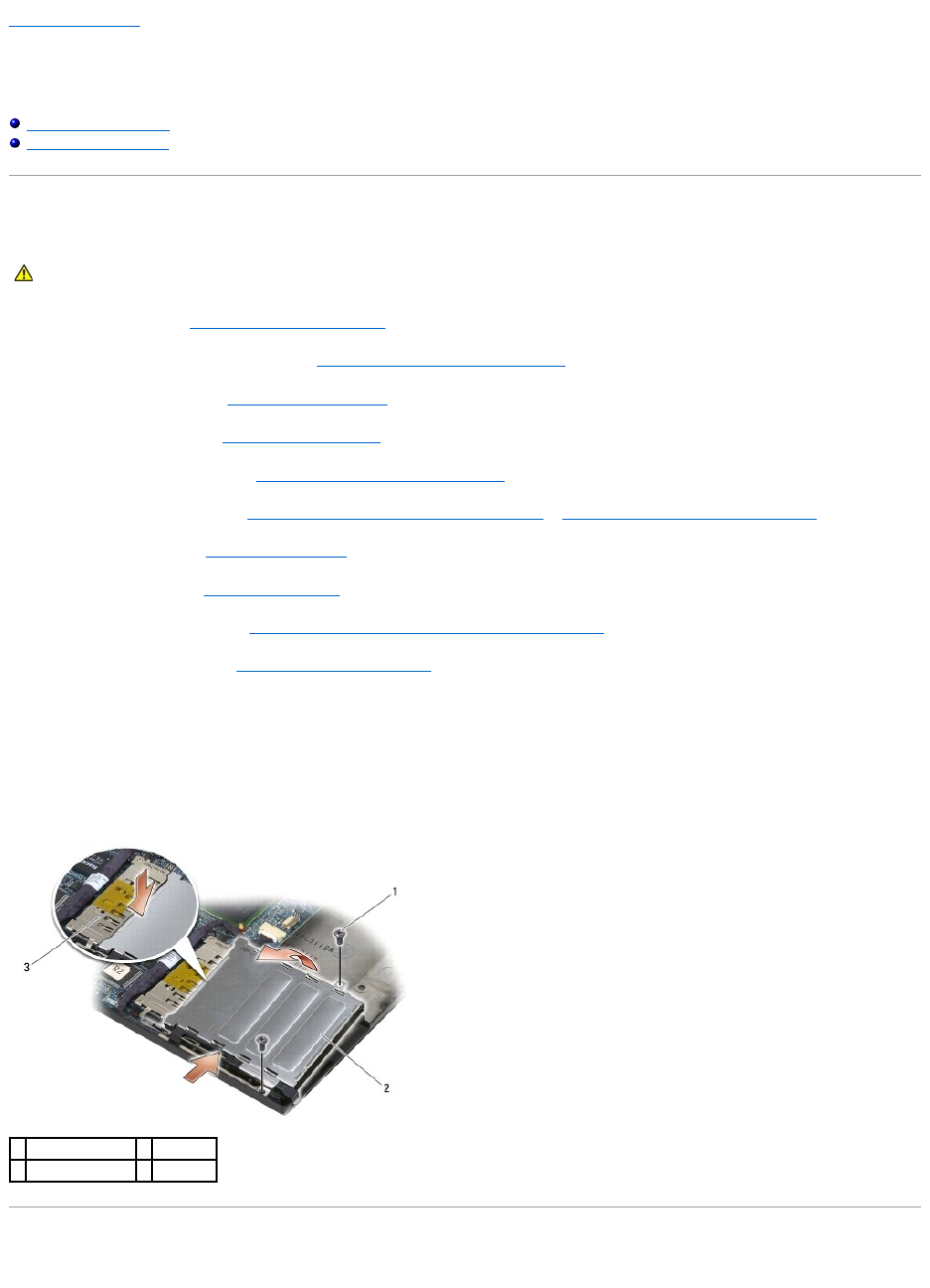
12. Remove the two M2 x 3 screws.
13. Press down on the connector-end of the card cage, then grasp each side of the card cage and push it towards the back of the laptop.
14. Pivot the card cage up to a 45-degree angle, then lift it up from the connector and laptop.
Replacing the Card Cage
CAUTION: Before you begin any of the procedures in this section, follow the safety instructions that shipped with your computer.
1
M2 x 3 screws (2)
2
card cage
3
connector
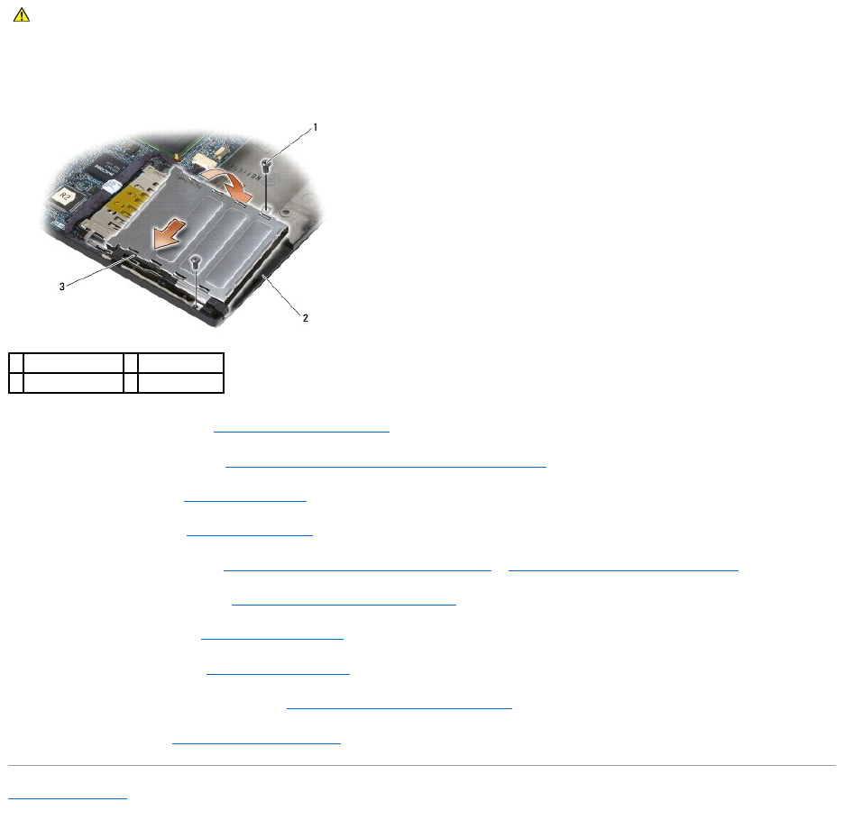
1. Holding the card cage at a 45-degree angle, attach the front of the card cage to the base assembly, then lower the card cage into place.
2. Replace the two M2 x 3 screws.
3. Replace the palm rest assembly (Replacing the Palm Rest Assembly).
4. Replace the right speaker grill (see Replacing the Right Speaker Grill/Fingerprint Reader Assembly).
5. Replace the keyboard (see Replacing the Keyboard).
6. Replace the LED cover (see Replacing the LED Cover).
7. Replace the display assembly (see Replacing the Display Assembly (E6400 and M2400) or Replacing the Display Assembly (E6400 ATG)).
8. Replace the heatsink assembly (see Replacing the Processor Heatsink Assembly).
9. Replace the hinge covers (see Replacing the Hinge Covers).
10. Replace the modular drive (see Replacing the Modular Drive).
11. Replace the bottom of the base assembly (see Replacing the Bottom of the Base Assembly).
12. Follow the procedures in After Working on Your Computer.
Back to Contents Page
CAUTION: Before you begin any of the procedures in this section, follow the safety instructions that shipped with your computer.
1
M2 x 3 screws (2)
2
base assembly
3
front of card cage
Back to Contents Page
Coin-Cell Battery
Dell™Latitude™E6400andE6400ATGand
MobileWorkstationPrecision™M2400ServiceManual
Removing the Coin-Cell Battery
Replacing the Coin-Cell Battery
Removing the Coin-Cell Battery
1. Follow the procedures in Before Working on Your Computer.
2. Remove the bottom of the base assembly (see Removing the Bottom of the Base Assembly).
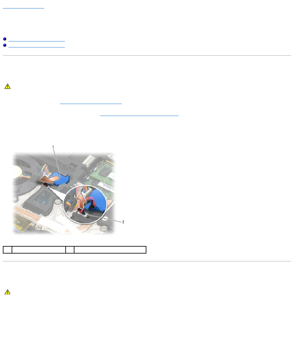
3. Pry up the coin-cell battery to release the double-stick adhesive tape on the bottom of the coin-cell battery, then lift it out of the computer.
4. Disconnect the coin-cell battery cable from the system board.
Replacing the Coin-Cell Battery
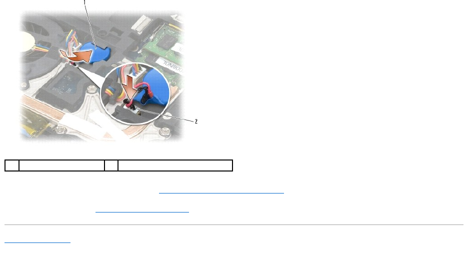
1. Connect the coin-cell battery cable to the system board.
2. Insert the coin-cell battery into the computer:
If you are installing the same coin-cell battery you removed, slide the battery under the tab, then press down to seal the tape on bottom.
If you are installing a new coin-cell battery, first remove the adhesive backing paper from the coin-cell battery. Slide the battery under the tab, then
press down to seal the tape on bottom.
CAUTION: Before you begin any of the procedures in this section, follow the safety instructions that shipped with your computer.
1
coin-cell battery
2
coin-cell battery cable
CAUTION: Before you begin any of the procedures in this section, follow the safety instructions that shipped with your computer.
Back to Contents Page
Processor Module
Dell™Latitude™E6400andE6400ATGand
MobileWorkstationPrecision™M2400ServiceManual
Removing the Processor Module
Replacing the Processor Module
Removing the Processor Module
1. Follow the instructions in Before Working on Your Computer.
2. Remove the bottom of the computer (see Removing the Bottom of the Base Assembly).
3. Remove the processor heatsink assembly (see Removing the Processor Heatsink Assembly).
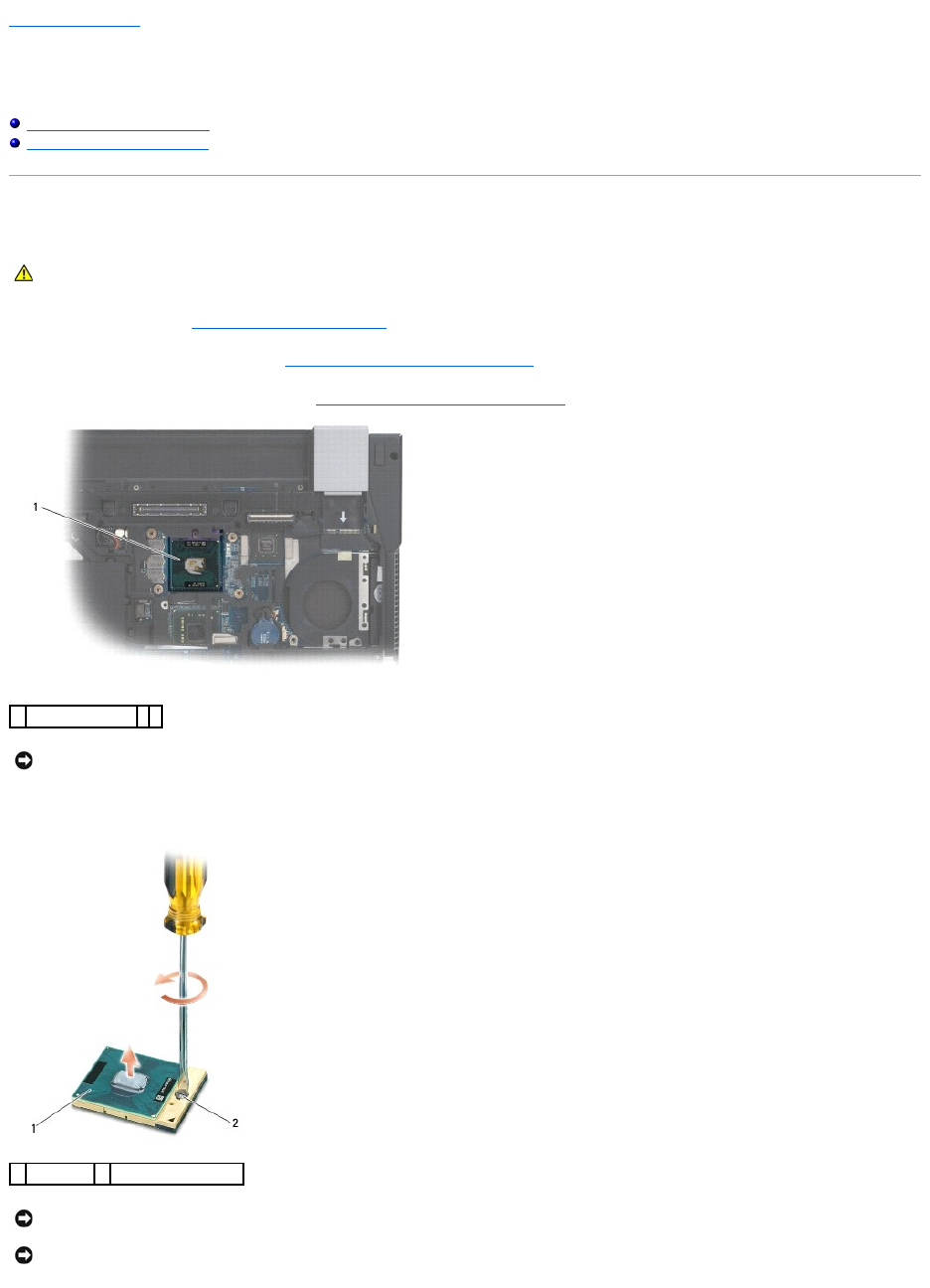
4. To loosen the ZIF socket, use a small, flat-blade screwdriver and rotate the ZIF-socket cam screw counterclockwise until it comes to the cam stop.
CAUTION: Before you begin the following procedure, follow the safety instructions that shipped with your computer.
1
processor module
NOTICE: To avoid damage to the processor, hold the screwdriver so that it is perpendicular to the processor when turning the cam screw.
1
ZIF socket
2
ZIF-socket cam screw
NOTICE: To ensure maximum cooling for the processor, do not touch the heat transfer areas on the processor heatsink assembly. The oils in your skin
can reduce the heat transfer capability of the thermal pads.
NOTICE: When removing the processor module, pull the module straight up. Be careful not to bend the pins on the processor module.
5. Lift the processor module from the ZIF socket.
Replacing the Processor Module
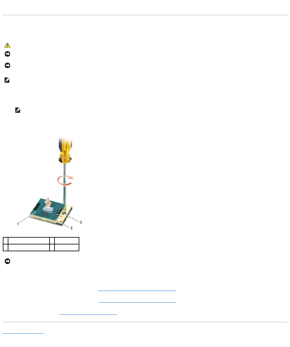
1. Align the pin-1 corner of the processor module with the pin-1 corner of the ZIF socket, then insert the processor module.
When the processor module is properly seated, all four corners are aligned at the same height. If one or more corners of the module are higher than the
others, the module is not seated properly.
2. Tighten the ZIF socket by turning the cam screw clockwise to secure the processor module to the system board.
3. Replace the processor heatsink assembly (see Replacing the Processor Heatsink Assembly).
4. Replace the bottom of the base assembly (see Replacing the Bottom of the Base Assembly).
5. Follow the procedures in After Working on Your Computer.
Back to Contents Page
CAUTION: Before you begin the following procedure, follow the safety instructions that shipped with your computer.
NOTICE: Do not touch the processor die. Press and hold the processor down on the substrate on which the die is mounted while turning the cam screw
to prevent intermittent contact between the cam screw and processor.
NOTICE: Ensure that the cam lock is in the fully open position before seating the processor module. Seating the processor module properly in the ZIF
socket does not require force. A processor module that is not properly seated can result in an intermittent connection or permanent damage to the
microprocessor and ZIF socket.
NOTE: If a new processor is installed, you will receive a new heatsink assembly, which will include an affixed thermal pad, or you will receive a new
thermal pad along with a tech sheet to illustrate proper installation.
NOTE: The pin-1 corner of the processor module has a triangle that aligns with the triangle on the pin-1 corner of the ZIF socket.
1
ZIF socket
2
pin-1 corner
3
ZIF-socket cam screw
NOTICE: To avoid damage to the processor, hold the screwdriver so that it is perpendicular to the processor when turning the cam screw.
Back to Contents Page
Processor Heatsink Assembly
Dell™Latitude™E6400andE6400ATGand
MobileWorkstationPrecision™M2400ServiceManual
Removing the Processor Heatsink Assembly
Replacing the Processor Heatsink Assembly
Removing the Processor Heatsink Assembly
1. Follow the instructions in Before Working on Your Computer.
2. Remove the bottom of the base assembly (see Removing the Bottom of the Base Assembly).
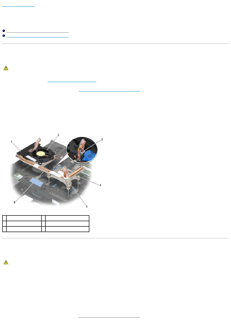
3. Disconnect the fan cable from the system board.
4. In sequential order, loosen the four captive screws that secure the processor heatsink assembly to the system board.
5. Carefully lift the screw-end of the assembly up at an angle.
6. Remove the vent-end of the assembly out of the computer.
Replacing the Processor Heatsink Assembly
1. Place the vent-end of the assembly into the computer at an angle, then connect the fan cable to the system board, and set the screw-end of the
assembly in place.
2. Align the four captive screws on the processor heatsink assembly with the screw holes on the system board.
3. In sequential order, tighten the four captive screws to secure the processor heatsink assembly to the system board.
4. Connect the fan cable to the system board.
5. Replace the bottom of the base assembly (see Replacing the Bottom of the Base Assembly).
CAUTION: Before you begin the following procedure, follow the safety instructions that shipped with your computer.
1
vent-end of assembly
2
fan
3
fan cable
4
captive screws (4)
5
screw-end of assembly
6
processor heatsink assembly
CAUTION: Before you begin the following procedure, follow the safety instructions that shipped with your computer.


Back to Contents Page
I/O Card
Dell™Latitude™E6400andE6400ATGand
MobileWorkstationPrecision™M2400ServiceManual
Removing the I/O Card
Replacing the I/O Card
Removing the I/O Card
1. Follow the procedures in Before Working on Your Computer.
2. Remove the bottom of the base assembly (see Removing the Bottom of the Base Assembly).
3. Remove the hard drive (see Removing the Hard Drive).
4. Remove the modular drive (see Removing the Modular Drive).
5. Remove the hinge covers (see Removing the Hinge Covers).
6. Remove the heatsink assembly (see Removing the Processor Heatsink Assembly).
7. Remove the display assembly (see Removing the Display Assembly (E6400 and M2400) or Removing the Display Assembly (E6400 ATG)).
8. Remove the LED cover (see Removing the LED Cover).
9. Remove the keyboard (see Removing the Keyboard).
10. Remove the right speaker grill (see Removing the Right Speaker Grill/Fingerprint Reader Assembly).
11. Remove the palm rest assembly (see Removing the Palm Rest Assembly).
12. Remove the card cage (see Removing the Card Cage).
13. Remove the system board (see Removing the System Board Assembly). Do not remove the wireless mini-cards, memory modules, or processor from the
system board.
14. Remove the modem (see Removing the Modem).
15. Remove the RJ-11 modem connector (see Removing the RJ-11 Modem Connector).
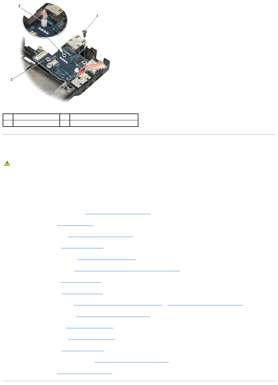
16. Remove the M2 x 3-mm screw from the I/O card.
17. Pull out the large plastic plug from the I/O card.
18. Remove the I/O card.
CAUTION: Before you begin the following procedure, follow the safety instructions that shipped with your computer.
Replacing the I/O Card
1. Place the I/O card in the base assembly.
2. Replace the M2 x 3-mm screw to secure the I/O card to the base assembly.
3. Replace the plastic plug.
4. Replace the RJ-11 modem connector (see Replacing the RJ-11 Modem Connector).
5. Replace the modem (see Replacing the Modem).
6. Replace the system board (see Replacing the System Board Assembly).
7. Replace the card cage (see Replacing the Card Cage).
8. Replace the palm rest assembly (see Replacing the Palm Rest Assembly).
9. Replace the right speaker grill (see Replacing the Right Speaker Grill/Fingerprint Reader Assembly).
10. Replace the keyboard (see Replacing the Keyboard).
11. Replace the LED cover (see Replacing the LED Cover).
12. Replace the display assembly (see Replacing the Display Assembly (E6400 and M2400) or Replacing the Display Assembly (E6400 ATG)).
13. Replace the heatsink assembly (see Replacing the Processor Heatsink Assembly).
14. Replace the hinge covers (see Replacing the Hinge Covers).
15. Replace the modular drive (see Replacing the Modular Drive).
16. Replace the hard drive (see Replacing the Hard Drive).
17. Replace the bottom of the base assembly (see Replacing the Bottom of the Base Assembly).
18. Follow the procedures in After Working on Your Computer.
1
plastic plug
2
M2 x 3-mm screw
3
I/O card
CAUTION: Before you begin the following procedure, follow the safety instructions that shipped with your computer.

Back to Contents Page
Display Assembly
Dell™Latitude™E6400andE6400ATGand
MobileWorkstationPrecision™M2400ServiceManual
Removing the Display Assembly (E6400 and M2400)
1. Follow the instructions in Before Working on Your Computer.
2. Remove the bottom of the base assembly (see Removing the Bottom of the Base Assembly).
3. Remove the hinge covers (see Removing the Hinge Covers).
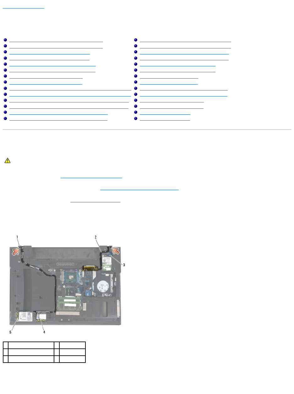
4. Disconnect and unroute the display cable and the wireless cables (WLAN, WWAN, and WPAN). Position all cables to the rear of the laptop after
unrouting.
5. Remove the M2.5 x 5-mm screw from each hinge.
6. Turn the computer topside up.
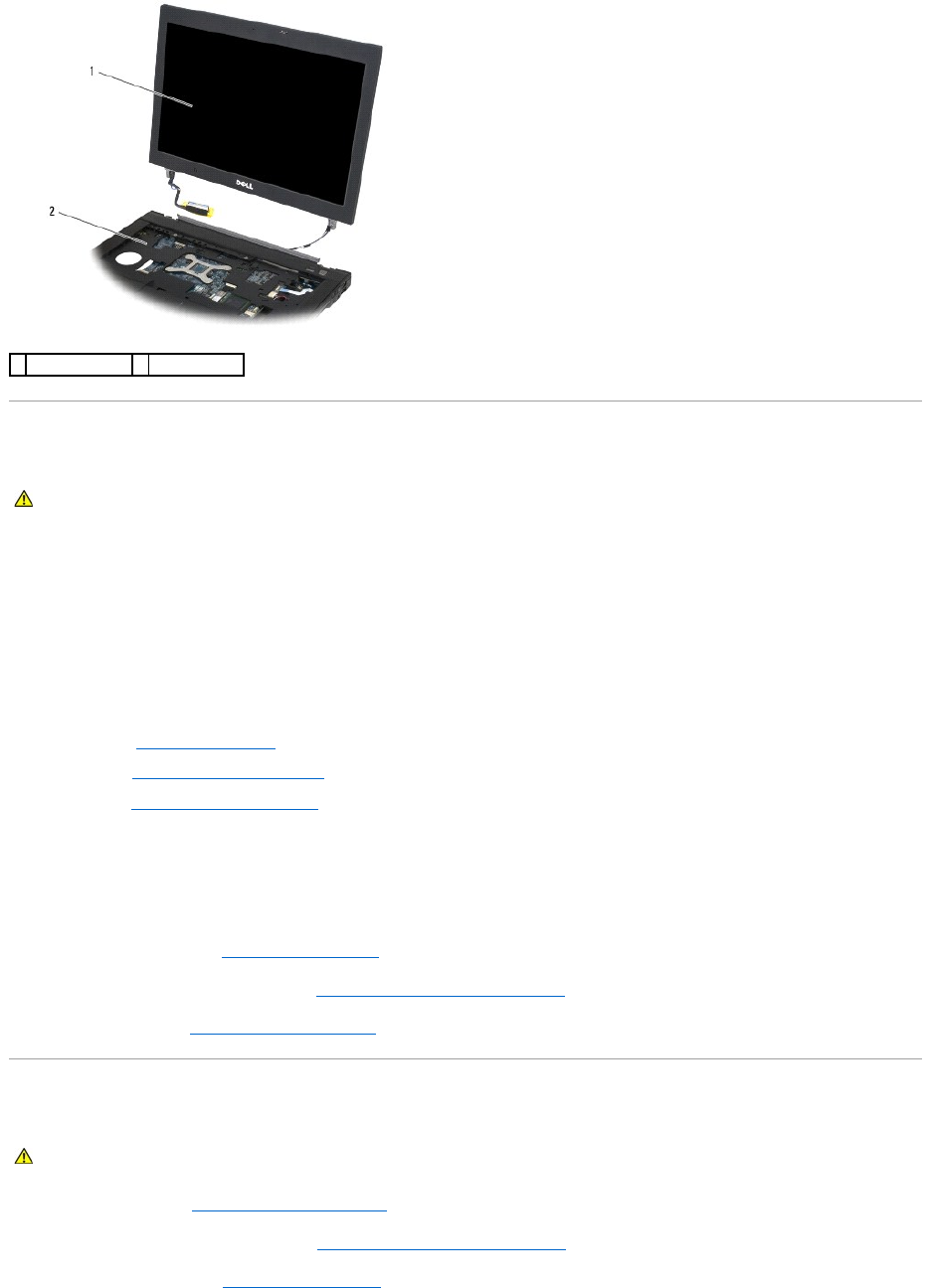
7. Open the display to 90 degrees and lift the display assembly off the base assembly.
Removing the Display Assembly (E6400 and M2400)
Replacing the Display Assembly (E6400 and M2400)
Removing the Display Assembly (E6400 ATG)
Replacing the Display Assembly (E6400 ATG)
Removing the Display Bezel (E6400 and M2400)
Replacing the Display Bezel (E6400 and M2400)
Removing the Display Bezel (E6400 ATG)
Replacing the Display Bezel (E6400 ATG)
Removing the CCFL Display Panel and Brackets (E6400 and M2400)
Replacing the CCFL Display Panel and Brackets (E6400 and M2400)
Removing the LED Display Panel and Brackets (E6400 and M2400)
Replacing the LED Display Panel and Brackets (E6400 and M2400)
Removing the Display Panel and Brackets (E6400 ATG)
Replacing the Display Panel and Brackets (E6400 ATG)
Removing the Display Inverter (E6400 and M2400)
Replacing the Display Inverter (E6400 and M2400)
Removing the Display Hinges (E6400 and M2400)
Replacing the Display Hinges (E6400 and M2400)
Removing the Display Hinges (E6400 ATG)
Replacing the Display Hinges (E6400 ATG)
Removing the Microphone Board
Replacing the Microphone Board
Removing the Camera and Microphone Assembly
Replacing the Camera and Microphone Assembly
Removing the Latch Hook Assembly
Replacing the Latch Hook Assembly
Removing the Display Cover
Replacing the Display Cover
CAUTION: Before you begin the following procedure, follow the safety instructions that shipped with your computer.
1
M2.5 x 5-mm screws (2)
2
display cable
3
WPAN cable
4
WLAN cable
5
WWAN cable
Replacing the Display Assembly (E6400 and M2400)
1. Position the cables on the display assembly away from the base assembly.
2. Align the display hinges with the holes in the base of the computer, and lower the display into place.
3. Close the display and turn the computer upside down.
4. Route the display cable and wireless (WLAN, WWAN, and WPAN) cables. Fit the cables under each tab in their respective routing channel, including the
tabs on the back of the base assembly.
5. Depending on the cards in your computer configuration, connect the antenna cables to their respective card:
For WWAN, see Replacing a WWAN Card.
For WPAN, see Replacing a WPAN (UWB/BT) Card.
For WLAN, see Replacing the WLAN/WiMax Card.
Place any unused antenna cables in the base assembly cable holders next to the card slot.
6. Connect the display cable to the display cable connector on the system board.
7. Replace the two M2.5 x 5-mm screws on the hinges.
8. Replace the hinge covers (see Replacing the Hinge Covers).
9. Replace the bottom of the base assembly (see Replacing the Bottom of the Base Assembly).
10. Follow the procedures in After Working on Your Computer.
Removing the Display Assembly (E6400 ATG)
1. Follow the instructions in Before Working on Your Computer.
2. Remove the bottom of the base assembly (see Removing the Bottom of the Base Assembly).
3. Remove the hinge covers (see Removing the Hinge Covers).
1
display assembly
2
base assembly
CAUTION: Before you begin the following procedure, follow the safety instructions that shipped with your computer.
CAUTION: Before you begin the following procedure, follow the safety instructions that shipped with your computer.
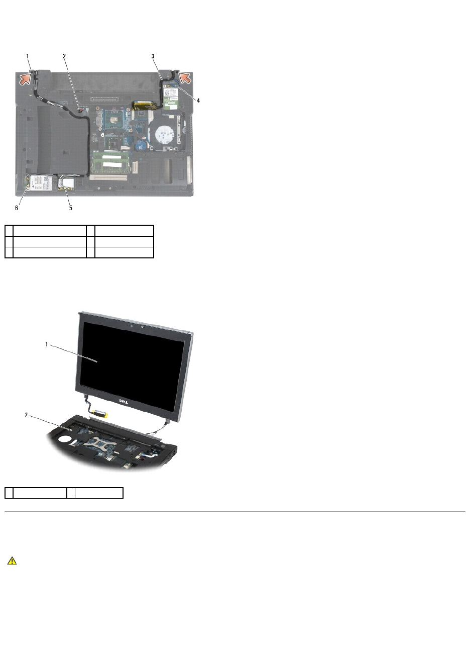
4. Disconnect and unroute the display cable, touch screen cable, and the wireless cables (WLAN, WWAN, and WPAN). Position all cables to the rear of the
laptop after unrouting.
5. Remove the two M2.5 x 5-mm screws from the hinges.
6. Turn the computer topside up.
7. Open the display to 90 degrees and lift the display assembly off the base assembly.
Replacing the Display Assembly (E6400 ATG)
1. Position the cables on the display assembly away from the base assembly.
2. Align the display hinges with the holes in the base of the computer, and lower the display into place.
3. Close the display and turn the computer upside down.
4. Route the display cable, touch screen cable, and wireless (WLAN, WWAN, and WPAN) cables. Fit the cables under each tab in their respective routing
1
M2.5 x 5-mm screws (2)
2
touch screen cable
3
display cable
4
WPAN cable
5
WLAN cable
5
WWAN cable
1
display assembly
2
base assembly
CAUTION: Before you begin the following procedure, follow the safety instructions that shipped with your computer.

channel, including the tabs on the back of the base assembly.
5. Depending on the cards in your computer configuration, connect the antenna cables to their respective card:
For WWAN, see Replacing a WWAN Card.
For WPAN, see Replacing a WPAN (UWB/BT) Card.
For WLAN, see Replacing the WLAN/WiMax Card.
Place any unused antenna cables in the base assembly cable holders next to the card slot.
6. Connect the display cable to the display cable connector on the system board.
7. Connect the touch screen cable to the touch screen connector on the system board.
8. Replace the two M2.5 x 5-mm screws on the hinges.
9. Replace the hinge covers (see Replacing the Hinge Covers).
10. Replace the bottom of the base assembly (see Replacing the Bottom of the Base Assembly).
11. Follow the procedures in After Working on Your Computer.
Removing the Display Bezel (E6400 and M2400)
1. Follow the instructions in Before Working on Your Computer.
2. Remove the bottom of the base assembly (see Removing the Bottom of the Base Assembly).
3. Remove the hinge covers (see Removing the Hinge Covers).
4. Remove the display assembly (see Removing the Display Assembly (E6400 and M2400)).
5. Starting with the middle of the right side of the bezel, push the bezel out or away from the display panel, and then pull up on the bezel to release the
side bezel snaps. See the arrows labeled "1" in the following illustration.
6. For the top right corner of the bezel, push out to release the corner bezel snap. See the arrow labeled "2" in the following illustration.
7. For the lower right corner, push out with force, then gently pull up to release the corner bezel snap. See the arrows labeled "3" in the following
illustration.
8. For the bottom of the bezel, push in toward the display panel starting with the lower right corner snap, then the middle bottom snaps, and then the
lower left corner snap. See the arrows labeled "4" through "6" in the following illustration.
9. For the left side of the bezel, push the bezel out or away from the middle of the display panel, then pull up on the bezel to release the side and corner
bezel snaps. See the arrows labeled "7" in the following illustration.
10. For the top of the bezel, push in toward the display panel to release the snaps along the top of the bezel. See the arrows labeled "8" in the following
illustration.
CAUTION: Before you begin the following procedure, follow the safety instructions that shipped with your computer.
NOTICE: Removal of the bezel from the display requires extreme care to avoid damage to the bezel. Special attention is required for the corners,
especially for the bezels used with the LED display panels. Follow the numbered arrows in the following illustration for the correct sequence for
releasing the bezel snaps.
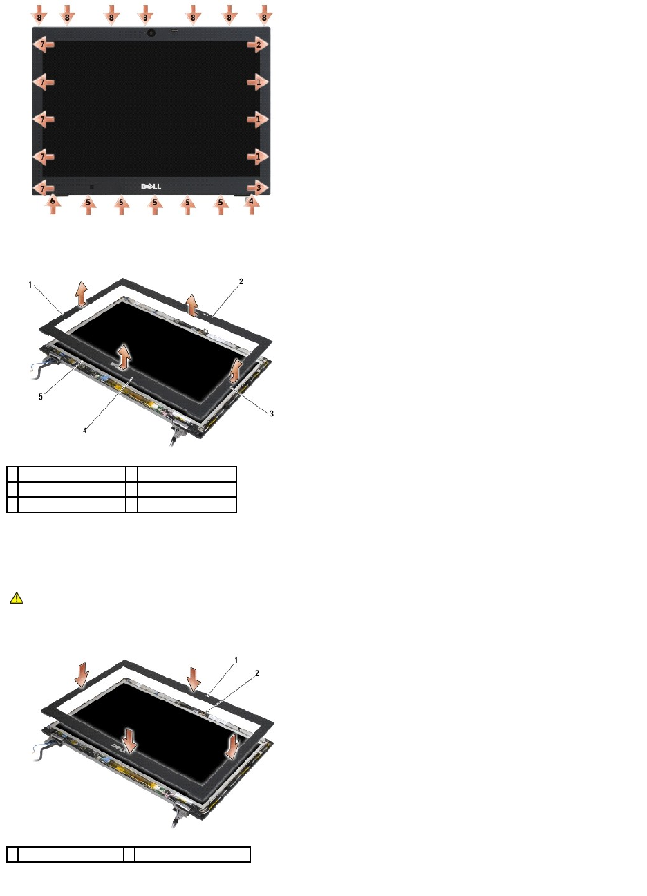
11. Once all snaps are released, lift the bezel from the display assembly.
Replacing the Display Bezel (E6400 and M2400)
1. Align the latch hook on the display panel with the small rectangular opening on the display bezel.
2. Simultaneously push in on the right and left sides of the bezel to engage the side bezel snaps.
1
right side of display bezel
2
top of display bezel
3
left side of display bezel
4
bottom of display bezel
5
display panel
CAUTION: Before you begin the following procedure, follow the safety instructions that shipped with your computer.
1
opening on display bezel
2
latch hook on display panel
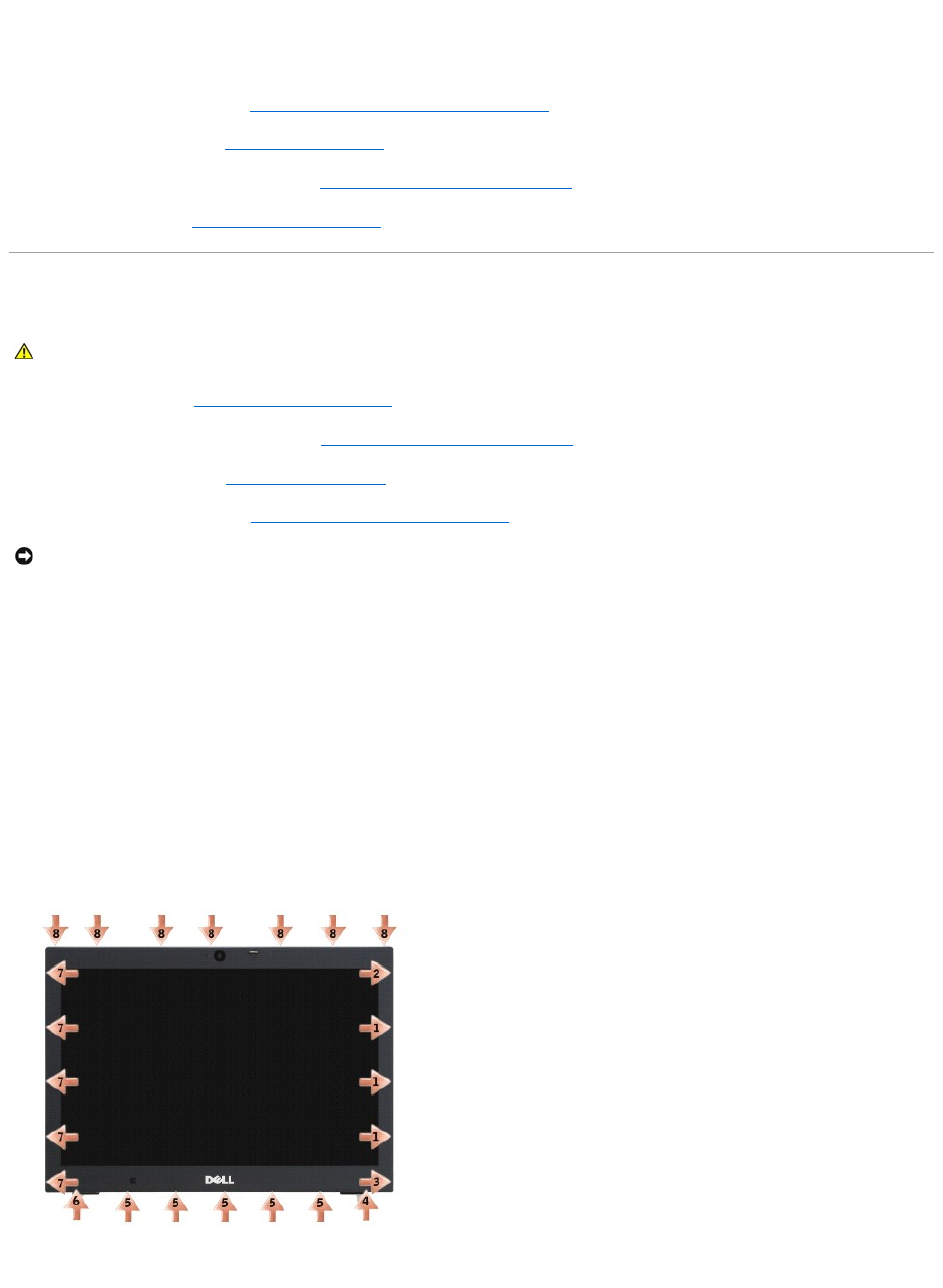
3. Simultaneously pull out on the top and bottom of the bezel to engage the top and bottom bezel snaps.
4. Gently snap the bezel into place to secure it to the display assembly.
5. Replace the display assembly (see Replacing the Display Assembly (E6400 and M2400)).
6. Replace the hinge covers (see Replacing the Hinge Covers).
7. Replace the bottom of the base assembly (see Replacing the Bottom of the Base Assembly).
8. Follow the procedures in After Working on Your Computer.
Removing the Display Bezel (E6400 ATG)
1. Follow the instructions in Before Working on Your Computer.
2. Remove the bottom of the base assembly (see Removing the Bottom of the Base Assembly).
3. Remove the hinge covers (see Removing the Hinge Covers).
4. Remove the display assembly (see Removing the Display Assembly (E6400 ATG)).
5. Starting with the middle of the right side of the bezel, push the bezel out or away from the display panel, and then pull up on the bezel to release the
side bezel snaps. See the arrows labeled "1" in the following illustration.
6. For the top right corner of the bezel, push out to release the corner bezel snap. See the arrow labeled "2" in the following illustration.
7. For the lower right corner, push out with force, then gently pull up to release the corner bezel snap. See the arrows labeled "3" in the following
illustration.
8. For the bottom of the bezel, push in toward the display panel starting with the lower right corner snap, then the middle bottom snaps, and then the
lower left corner snap. See the arrows labeled "4" through "6" in the following illustration.
9. For the left side of the bezel, push the bezel out or away from the middle of the display panel, then pull up on the bezel to release the side and corner
bezel snaps. See the arrows labeled "7" in the following illustration.
10. For the top of the bezel, push in toward the display panel to release the snaps along the top of the bezel. See the arrows labeled "8" in the following
illustration.
11. Once all snaps are released, lift the bezel from the display assembly.
CAUTION: Before you begin the following procedure, follow the safety instructions that shipped with your computer.
NOTICE: Removal of the bezel from the display requires extreme care to avoid damage to the bezel. Special attention is required for the corners,
especially for the bezels used with the LED display panels. Follow the numbered arrows in the following illustration for the correct sequence for
releasing the bezel snaps.
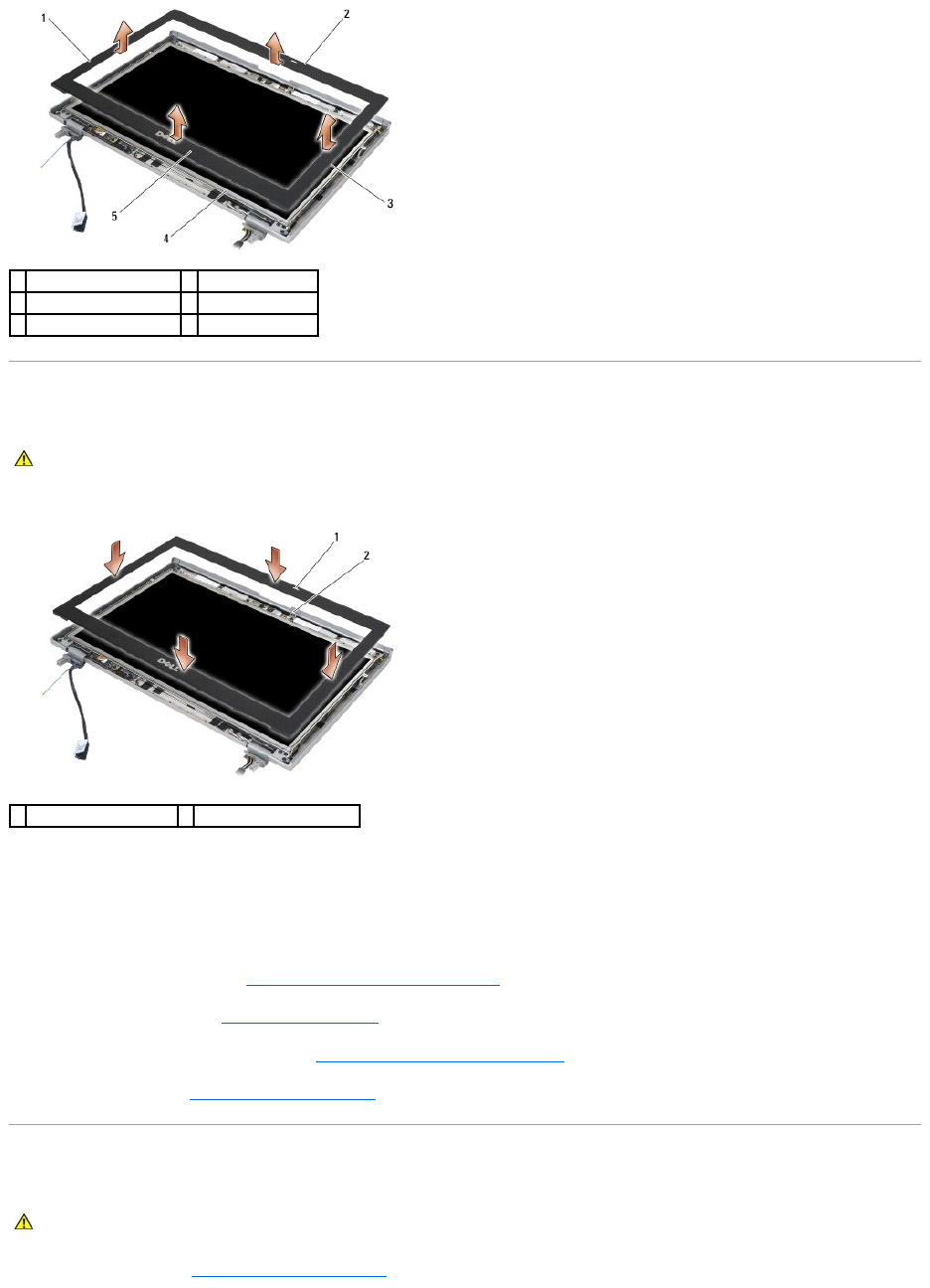
Replacing the Display Bezel (E6400 ATG)
1. Align the latch hook on the display panel with the small rectangular opening on the display bezel.
2. Simultaneously push in on the right and left sides of the bezel to engage the side bezel snaps.
3. Simultaneously pull out on the top and bottom of the bezel to engage the top and bottom bezel snaps.
4. Gently snap the bezel into place to secure it to the display assembly.
5. Replace the display assembly (see Replacing the Display Assembly (E6400 ATG)).
6. Replace the hinge covers (see Replacing the Hinge Covers).
7. Replace the bottom of the base assembly (see Replacing the Bottom of the Base Assembly).
8. Follow the procedures in After Working on Your Computer.
Removing the CCFL Display Panel and Brackets (E6400 and M2400)
1. Follow the instructions in Before Working on Your Computer.
1
right side of display bezel
2
top of display bezel
3
left side of display bezel
4
display panel
5
bottom of display bezel
CAUTION: Before you begin the following procedure, follow the safety instructions that shipped with your computer.
1
opening on display bezel
2
latch hook on display panel
CAUTION: Before you begin the following procedure, follow the safety instructions that shipped with your computer.
2. Remove the bottom of the base assembly (see Removing the Bottom of the Base Assembly).
3. Remove the hinge covers (see Removing the Hinge Covers).
4. Remove the display assembly (see Removing the Display Assembly (E6400 and M2400)).
5. Remove the display bezel (see Removing the Display Bezel (E6400 and M2400)).
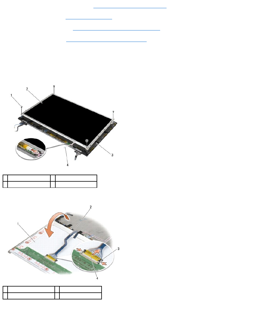
6. Remove the four M2.5 x 5-mm screws from the display panel.
7. Lift the display panel out of the display cover and carefully lay the display panel flat on your workspace. Be careful to avoid damaging the display panel
with the hinges and cables on the display cover.
8. Disconnect the inverter backlight cable from the inverter.
9. Disconnect the display cable. Squeeze the release tabs together, then pull the cable out of the connector.
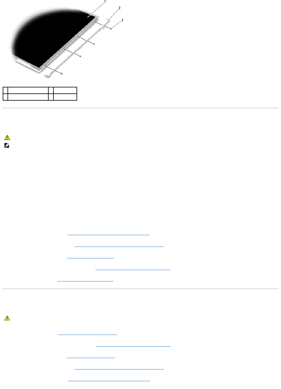
10. Remove four M2 x 3-mm screws from the right bracket and four M2 x 3- mm screws from the left bracket.
1
M2.5 x 5-mm screws (4)
2
display panel
3
display cover
4
inverter backlight cable
1
underside of display panel
2
display cable
3
connector release tabs
4
display cable connector
Replacing the CCFL Display Panel and Brackets (E6400 and M2400)
1. Replace the four M2 x 3-mm screws on the right bracket and the four
M2 x 3-mm screws on the left bracket.
2. Place the display panel upside down on your workspace in front of the display cover.
3. Connect the backlight cable to the inverter.
4. Connect the display cable to the connector on the back of the display panel.
5. Place the display panel in display cover. Use the alignment posts in the display cover to align each bracket.
6. Replace the four M2.5 x 5-mm screws that secure the display panel to the display cover.
7. Replace the display bezel (see Replacing the Display Bezel (E6400 and M2400)).
8. Replace the display assembly (see Replacing the Display Assembly (E6400 and M2400)).
9. Replace the hinge covers (see Replacing the Hinge Covers).
10. Replace the bottom of the base assembly (see Replacing the Bottom of the Base Assembly).
11. Follow the procedures in After Working on Your Computer.
Removing the LED Display Panel and Brackets (E6400 and M2400)
1. Follow the instructions in Before Working on Your Computer.
2. Remove the bottom of the base assembly (see Removing the Bottom of the Base Assembly).
3. Remove the hinge covers (see Removing the Hinge Covers).
4. Remove the display assembly (see Removing the Display Assembly (E6400 and M2400)).
5. Remove the display bezel (see Removing the Display Bezel (E6400 and M2400)).
1
display panel
2
brackets (2)
3
M2 x 3-mm screws (8)
CAUTION: Before you begin the following procedure, follow the safety instructions that shipped with your computer.
NOTE: The brackets are labeled "L" (left) and "R" (right).
CAUTION: Before you begin the following procedure, follow the safety instructions that shipped with your computer.
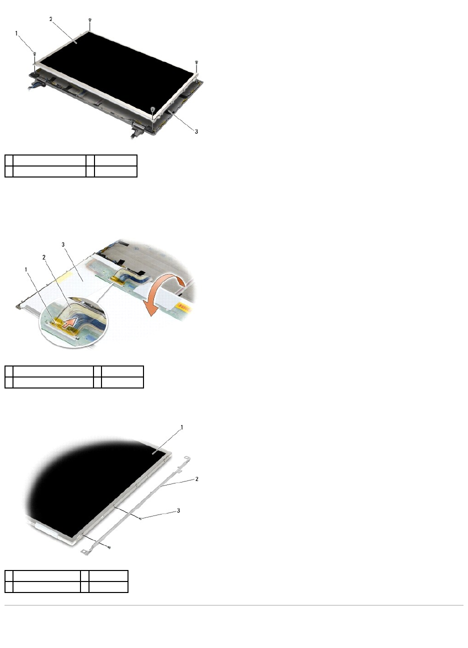
6. Remove the four M2.5 x 5-mm screws from the display panel.
7. Lift the display panel out of the display cover and carefully lay the display panel flat on your workspace. Be careful to avoid damaging the display panel
with the hinges and cables on the display cover.
8. Use the pull tab to disconnect the display cable.
9. Remove two M2 x 3-mm screws from the right bracket and two
M2 x 3-mm screws from the left bracket.
Replacing the LED Display Panel and Brackets (E6400 and M2400)
1
M2.5 x 5-mm screws (4)
2
display panel
3
display cover
1
display cable connector
2
display cable
3
underside of display panel
1
display panel
2
brackets (2)
3
M2 x 3-mm screws (4)
1. Replace the two M2 x 3-mm screws on the right bracket and the two
M2 x 3-mm screws on the left bracket.
2. Connect the display cable to the connector on the back of the display panel.
3. Route the display cable around the notch on the display cover and set the display panel in place.
4. Replace the four M2.5 x 5-mm screws that secure the display panel to the display cover.
5. Replace the display bezel (see Replacing the Display Bezel (E6400 and M2400)).
6. Replace the display assembly (see Replacing the Display Assembly (E6400 and M2400)).
7. Replace the hinge covers (see Replacing the Hinge Covers).
8. Replace the bottom of the base assembly (see Replacing the Bottom of the Base Assembly).
9. Follow the procedures in After Working on Your Computer.
Removing the Display Panel and Brackets (E6400 ATG)
1. Follow the instructions in Before Working on Your Computer.
2. Remove the bottom of the base assembly (see Removing the Bottom of the Base Assembly).
3. Remove the hinge covers (see Removing the Hinge Covers).
4. Remove the display assembly (see Removing the Display Assembly (E6400 ATG)).
5. Remove the display bezel (see Removing the Display Bezel (E6400 ATG)).
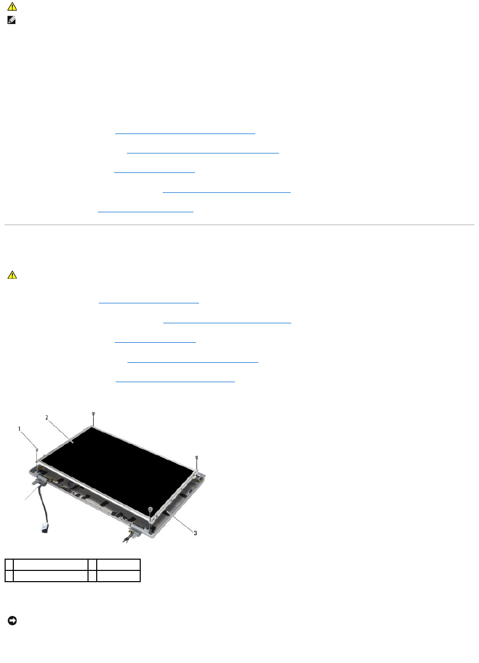
6. Remove the four M2.5 x 5-mm screws from the display panel.
7. Lift the display panel out of the display cover and lay the display panel flat on your workspace.
8. Disconnect the display cable. Squeeze the release tabs together, then pull the cable out of the connector.
CAUTION: Before you begin the following procedure, follow the safety instructions that shipped with your computer.
NOTE: The brackets are labeled "L" (left) and "R" (right).
CAUTION: Before you begin the following procedure, follow the safety instructions that shipped with your computer.
1
M2.5 x 5-mm screws (4)
2
display panel
3
display cover
NOTICE: Touch screen display panels include a second cable (touch screen cable) to attach to a touch screen display panel. For non-touch screen
display panels, leave the touch screen cable taped to the display cover.
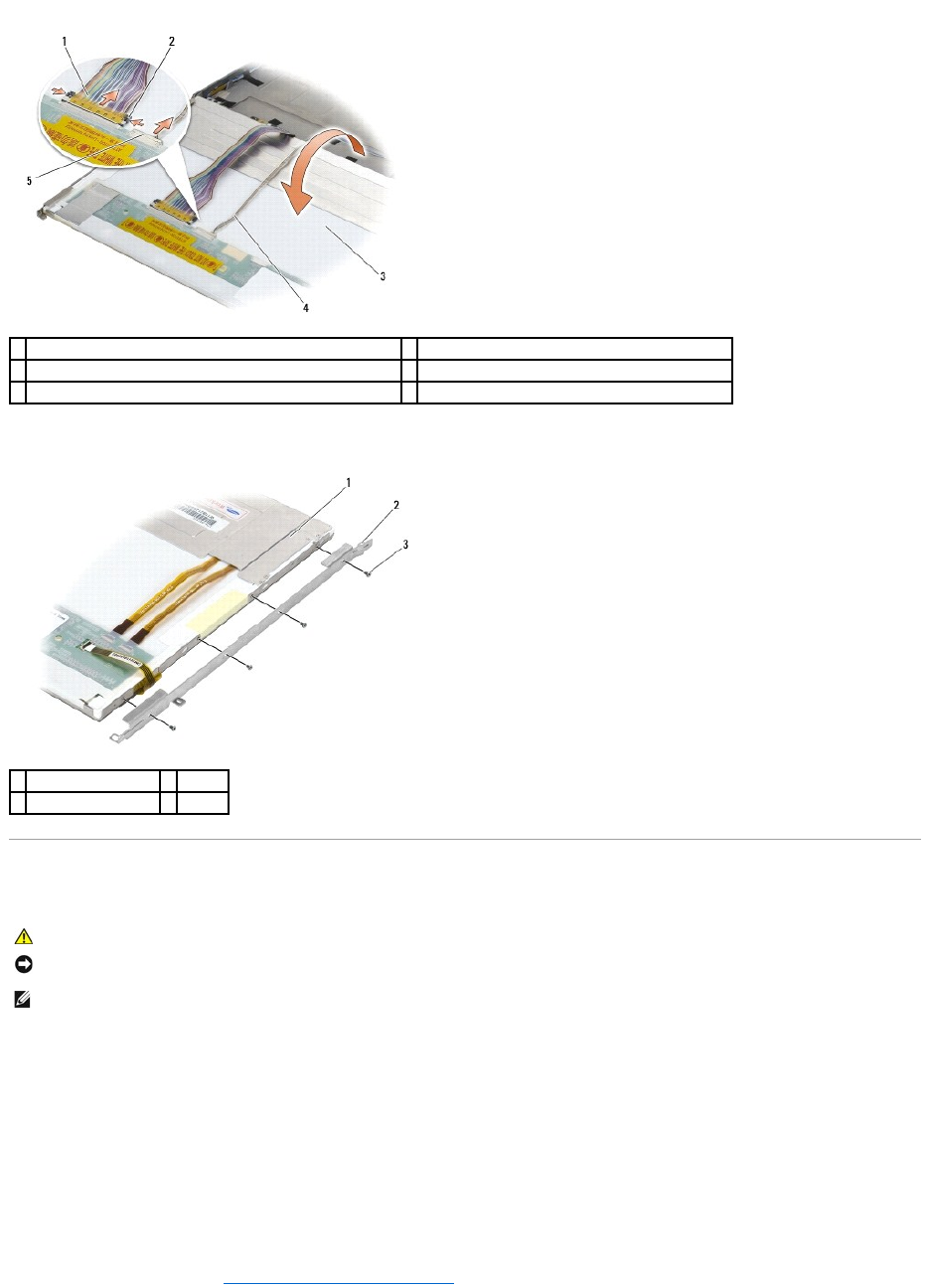
9. For touch screen display panels, disconnect the touch screen cable.
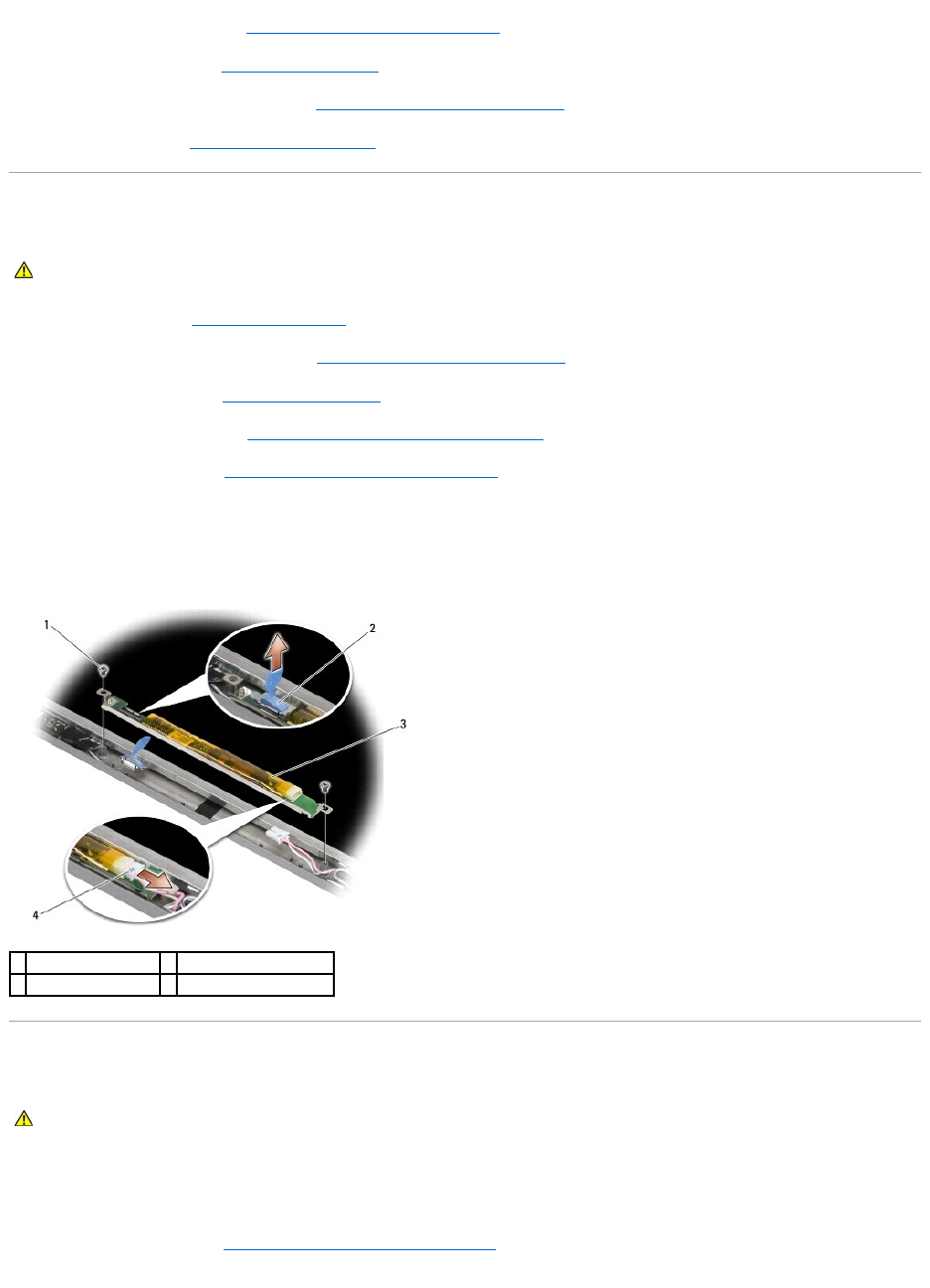
10. Remove four M2 x 3-mm screws from the right bracket and four
M2 x 3-mm screws from the left bracket.
Replacing the Display Panel and Brackets (E6400 ATG)
1. Replace the four M2 x 3-mm screws on the right display panel bracket and the four M2 x 3-mm screws on the left display panel bracket.
2. Place the display panel upside down on your workspace in front of the display cover.
3. Connect the display cable to the connector on the back of the display panel.
4. For touch screen panels, connect the touch screen cable to the connector on the back of the display panel.
5. Place the display panel in display cover. Use the alignment posts in the display cover to align each bracket.
6. Replace the four M2.5 x 5-mm screws that secure the display panel to the display cover.
7. Replace the display bezel (see Replacing the Display Bezel (E6400 ATG)).
1
display cable
2
display connector release tabs
3
underside of display panel
4
touch screen cable (touch screen display panels only)
5
touch screen cable connector (touch screen display panels only)
1
display panel
2
bracket
3
M2 x 3-mm screws (8)
CAUTION: Before you begin the following procedure, follow the safety instructions that shipped with your computer.
NOTICE: On touch screen display panels, use care when installing the brackets. There is a cable that wraps around the side of the touch screen display
panel, and the bracket is installed on top of the cable.
NOTE: The brackets are labeled "L" (left) and "R" (right).
8. Replace the display assembly (see Replacing the Display Assembly (E6400 ATG)).
9. Replace the hinge covers (see Replacing the Hinge Covers).
10. Replace the bottom of the base assembly (see Replacing the Bottom of the Base Assembly).
11. Follow the procedures in After Working on Your Computer.
Removing the Display Inverter (E6400 and M2400)
1. Follow the instructions in Working on Your Computer.
2. Remove the bottom of the base assembly (see Removing the Bottom of the Base Assembly).
3. Remove the hinge covers (see Removing the Hinge Covers).
4. Remove the display assembly (see Removing the Display Assembly (E6400 and M2400)).
5. Remove the display bezel (see Removing the Display Bezel (E6400 and M2400)).
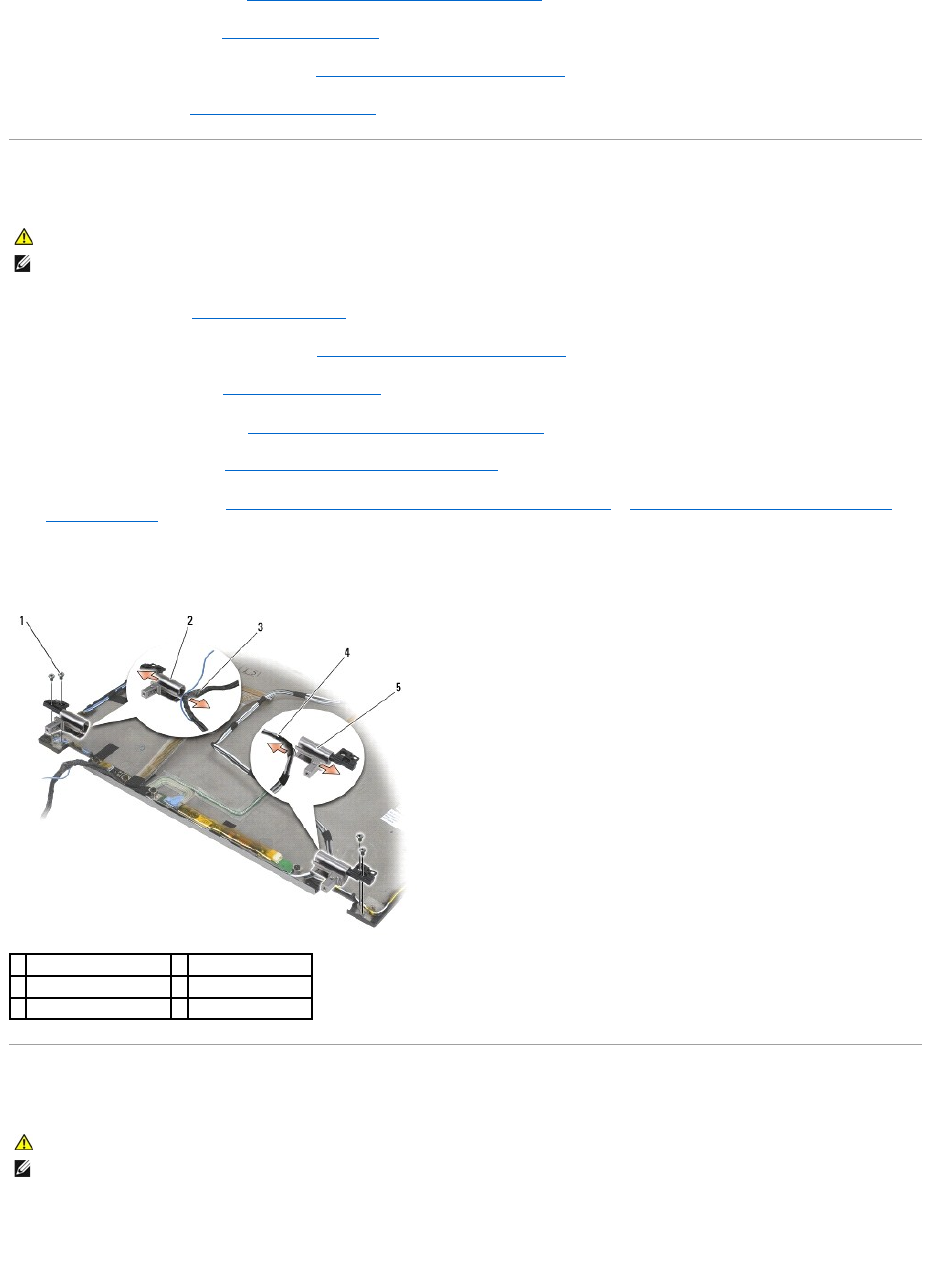
6. Remove the two M2 x 3-mm screws from the display inverter.
7. Disconnect the two display inverter connectors.
8. Lift the display inverter out of the display cover.
Replacing the Display Inverter (E6400 and M2400)
1. Connect the two display inverter connectors to the display inverter.
2. Replace the two M2 x 3-mm screws securing the display inverter.
3. Replace the display bezel (see Replacing the Display Bezel (E6400 and M2400)).
4. Replace the display assembly (see Replacing the Display Assembly (E6400 and M2400)).
CAUTION: Before you begin the following procedure, follow the safety instructions that shipped with your computer.
1
M2 x 3-mm screws (2)
2
display inverter connector
3
display inverter
4
display inverter connector
CAUTION: Before you begin the following procedure, follow the safety instructions that shipped with your computer.
5. Replace the hinge covers (see Replacing the Hinge Covers).
6. Replace the bottom of the base assembly (see Replacing the Bottom of the Base Assembly).
7. Follow the procedures in After Working on Your Computer.
Removing the Display Hinges (E6400 and M2400)
1. Follow the instructions in Working on Your Computer.
2. Remove the bottom of the base assembly (see Removing the Bottom of the Base Assembly).
3. Remove the hinge covers (see Removing the Hinge Covers).
4. Remove the display assembly (see Removing the Display Assembly (E6400 and M2400)).
5. Remove the display bezel (see Removing the Display Bezel (E6400 and M2400)).
6. Remove the display panel (see Removing the CCFL Display Panel and Brackets (E6400 and M2400) or Removing the LED Display Panel and Brackets
(E6400 and M2400)).
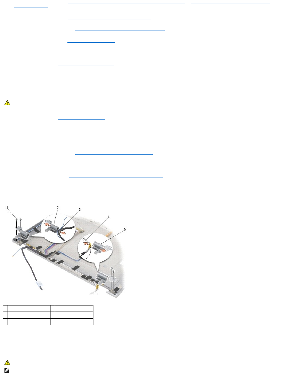
7. Remove the two M2.5 x 5-mmscrewsfromtherighthingeandthetwoM2.5x5-mm screws from the left hinge.
8. Unthread the cables from each hinge and remove the hinge.
Replacing the Display Hinges (E6400 and M2400)
1. Thread the cables into each hinge, then slide the hinge onto the display cover. Use the alignment pins on the display cover to place each hinge.
2. Replace the two M2.5 x 5-mmscrewsontherighthingeandthetwoM2.5x5-mm screws on the left hinge.
CAUTION: Before you begin the following procedure, follow the safety instructions that shipped with your computer.
NOTE: The display hinge panels are labeled "L" (left) and "R" (right).
1
M2.5 x 5-mm screws (4)
2
left hinge
3
cables in left hinge
4
cables in right hinge
5
right hinge
CAUTION: Before you begin the following procedure, follow the safety instructions that shipped with your computer.
NOTE: The display hinge panels are labeled "L" (left) and "R" (right).
3. Replace the display panel (see Replacing the CCFL Display Panel and Brackets (E6400 and M2400) or Replacing the LED Display Panel and Brackets
(E6400 and M2400)).
4. Replace the display bezel (see Replacing the Display Bezel (E6400 and M2400)).
5. Replace the display assembly (see Replacing the Display Assembly (E6400 and M2400)).
6. Replace the hinge covers (see Replacing the Hinge Covers).
7. Replace the bottom of the base assembly (see Replacing the Bottom of the Base Assembly).
8. Follow the procedures in After Working on Your Computer.
Removing the Display Hinges (E6400 ATG)
1. Follow the instructions in Working on Your Computer.
2. Remove the bottom of the base assembly (see Removing the Bottom of the Base Assembly).
3. Remove the hinge covers (see Removing the Hinge Covers).
4. Remove the display assembly (see Removing the Display Assembly (E6400 ATG)).
5. Remove the display bezel (see Removing the Display Bezel (E6400 ATG)).
6. Remove the display panel (see Removing the Display Panel and Brackets (E6400 ATG)).
7. Remove the two M2.5 x 5-mmscrewsfromtherighthingeandthetwoM2.5x5-mm screws from the left hinge.
8. Unthread the cables from each hinge and remove the hinge.
Replacing the Display Hinges (E6400 ATG)
1. Thread the cables into each hinge, then slide the hinge onto the display cover. Use the alignment pins on the display cover to place each hinge.
CAUTION: Before you begin the following procedure, follow the safety instructions that shipped with your computer.
1
M2.5 x 5-mm screw (4)
2
left hinge
3
cables in left hinge
4
cables in right hinge
5
right hinge
CAUTION: Before you begin the following procedure, follow the safety instructions that shipped with your computer.
NOTE: The display hinge panels are labeled "L" (left) and "R" (right).
2. Replace the two M2.5 x 5-mmscrewsontherighthingeandthetwoM2.5x5-mm screws on the left hinge.
3. Replace the display panel (see Replacing the Display Panel and Brackets (E6400 ATG)).
4. Replace the display bezel (see Replacing the Display Bezel (E6400 ATG)).
5. Replace the display assembly (see Replacing the Display Assembly (E6400 ATG)).
6. Replace the hinge covers (see Replacing the Hinge Covers).
7. Replace the bottom of the base assembly (see Replacing the Bottom of the Base Assembly).
8. Follow the procedures in After Working on Your Computer.
Removing the Microphone Board
1. Follow the instructions in Before Working on Your Computer.
2. Remove the bottom of the base assembly (see Removing the Bottom of the Base Assembly).
3. Remove the hinge covers (see Removing the Hinge Covers).
4. Remove the display assembly (see Removing the Display Assembly (E6400 and M2400) or Removing the Display Assembly (E6400 ATG)).
5. Remove the display bezel (see Removing the Display Bezel (E6400 and M2400) or Removing the Display Bezel (E6400 ATG)).
6. Lift the small connector lever on the microphone cable.
7. Loosen the captive screw, and carefully lift the microphone board up at an angle and disconnect the microphone cable.
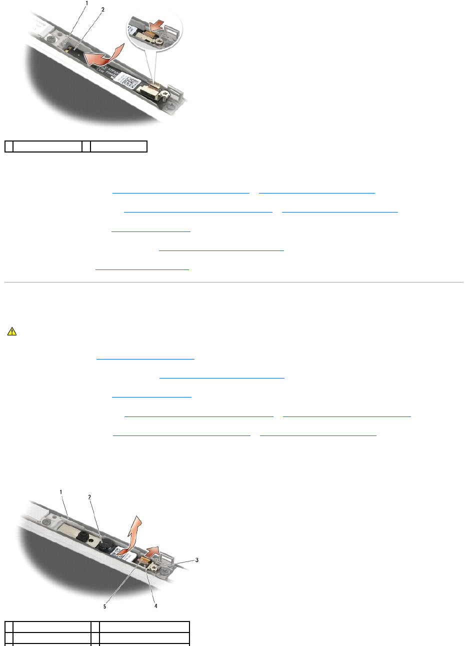
Replacing the Microphone Board
1. Slide the cable connector of the microphone cable into the connector on the microphone board.
2. Close the lever on the connector on the microphone board.
3. Angle in and align the microphone board with the notch on the display cover.
CAUTION: Before you begin the following procedure, follow the safety instructions that shipped with your computer.
1
display cover
2
microphone board
3
captive screw
4
connector lever
5
microphone cable
CAUTION: Before you begin the following procedure, follow the safety instructions that shipped with your computer.
4. Tighten the M2 x 3-mm screw that secures the microphone board to the display cover.
5. Replace the display bezel (see Replacing the Display Bezel (E6400 and M2400) or Replacing the Display Bezel (E6400 ATG)).
6. Replace the display assembly (see Replacing the Display Assembly (E6400 and M2400) or Replacing the Display Bezel (E6400 ATG)).
7. Replace the hinge covers (see Replacing the Hinge Covers).
8. Replace the bottom of the base assembly (see Replacing the Bottom of the Base Assembly).
9. Follow the procedures in After Working on Your Computer.
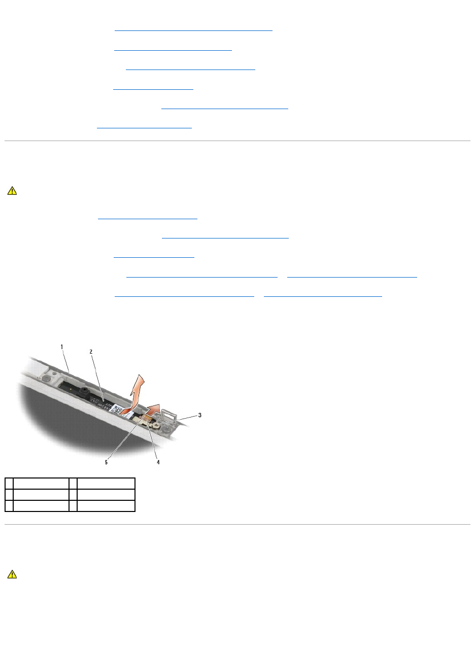
Removing the Camera and Microphone Assembly
1. Follow the instructions in Before Working on Your Computer.
2. Remove the bottom of the base assembly (see Removing the Bottom of the Base Assembly).
3. Remove the hinge covers (see Removing the Hinge Covers).
4. Remove the display assembly (see Removing the Display Assembly (E6400 and M2400) or Removing the Display Assembly (E6400 ATG)).
5. Remove the display bezel (see Removing the Display Bezel (E6400 and M2400) or Removing the Display Bezel (E6400 ATG)).
6. Lift the small connector lever on the camera/microphone cable.
7. Loosen the captive screw, and carefully lift the camera/microphone assembly up at an angle and disconnect the camera/microphone cable.
1
notch on display cover
2
microphone board
CAUTION: Before you begin the following procedure, follow the safety instructions that shipped with your computer.
1
display cover
2
camera/microphone assembly
3
captive screw
4
connector lever

Replacing the Camera and Microphone Assembly
1. Slide the cable connector of the camera/microphone cable into the connector on the camera/microphone assembly.
2. Close the lever on the connector on the camera/microphone assembly.
3. Angle in and align the camera/microphone assembly with the notch on the display cover.
4. Tighten the M2 x 3-mm screw that secures the camera/microphone assembly to the display cover.
5. Replace the display bezel (see Replacing the Display Bezel (E6400 and M2400) or Replacing the Display Bezel (E6400 ATG)).
6. Replace the display assembly (see Replacing the Display Assembly (E6400 and M2400) or Replacing the Display Bezel (E6400 ATG)).
7. Replace the hinge covers (see Replacing the Hinge Covers).
8. Replace the bottom of the base assembly (see Replacing the Bottom of the Base Assembly).
9. Follow the procedures in After Working on Your Computer.
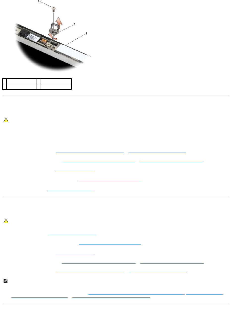
Removing the Latch Hook Assembly
1. Follow the instructions in Before Working on Your Computer.
2. Remove the bottom of the base assembly (see Removing the Bottom of the Base Assembly).
3. Remove the hinge covers (see Removing the Hinge Covers).
4. Remove the display assembly (see Removing the Display Assembly (E6400 and M2400) or Removing the Display Assembly (E6400 ATG)).
5. Remove the display bezel (see Removing the Display Bezel (E6400 and M2400) or Removing the Display Bezel (E6400 ATG)).
6. Remove the M2.5 x 5-mm screw, and angle the latch hook assembly out of the display cover.
5
camera/microphone cable
CAUTION: Before you begin the following procedure, follow the safety instructions that shipped with your computer.
1
camera/microphone assembly
2
notch on display cover
CAUTION: Before you begin the following procedure, follow the safety instructions that shipped with your computer.
Replacing the Latch Hook Assembly
1. Angle the latch hook into the display cover.
2. Replace the M2.5 x 5-mm screw that secures the latch hook assembly to the display cover.
3. Replace the display bezel (see Replacing the Display Bezel (E6400 and M2400) or Replacing the Display Bezel (E6400 ATG)).
4. Replace the display assembly (see Replacing the Display Assembly (E6400 and M2400) or Replacing the Display Assembly (E6400 ATG)).
5. Replace the hinge covers (see Replacing the Hinge Covers).
6. Replace the bottom of the base assembly (see Replacing the Bottom of the Base Assembly).
7. Follow the procedures in After Working on Your Computer.
Removing the Display Cover
1. Follow the instructions in Before Working on Your Computer.
2. Remove the bottom of the base assembly (see Removing the Bottom of the Base Assembly).
3. Remove the hinge covers (see Removing the Hinge Covers).
4. Remove the display assembly (see Removing the Display Assembly (E6400 and M2400) or Removing the Display Assembly (E6400 ATG)).
5. Remove the display bezel (see Removing the Display Bezel (E6400 and M2400) or Removing the Display Bezel (E6400 ATG)).
6. Remove the display panel from the display cover (see Removing the CCFL Display Panel and Brackets (E6400 and M2400), Removing the LED Display
Panel and Brackets (E6400 and M2400) or Removing the Display Panel and Brackets (E6400 ATG)).
Replacing the Display Cover
1
M2.5 x 5-mm screw
2
latch hook assembly
3
display cover
CAUTION: Before you begin the following procedure, follow the safety instructions that shipped with your computer.
CAUTION: Before you begin the following procedure, follow the safety instructions that shipped with your computer.
NOTE: It is not necessary to remove the brackets from the display panels in the next step.

1. Remove the tape from the cables that are taped to the display cover.
2. Replace the display panel (see Replacing the CCFL Display Panel and Brackets (E6400 and M2400), Replacing the LED Display Panel and Brackets (E6400
and M2400) or Replacing the Display Panel and Brackets (E6400 ATG)).
3. Replace the display bezel (see Replacing the Display Bezel (E6400 and M2400) or Replacing the Display Bezel (E6400 ATG)).
4. Replace the display assembly (see Replacing the Display Assembly (E6400 and M2400) or Replacing the Display Assembly (E6400 ATG)).
5. Replace the hinge covers (see Replacing the Hinge Covers).
6. Replace the bottom of the base assembly (see Replacing the Bottom of the Base Assembly).
7. Follow the procedures in After Working on Your Computer.
Back to Contents Page
CAUTION: Before you begin the following procedure, follow the safety instructions that shipped with your computer.
Back to Contents Page
Fan
Dell™Latitude™E6400andE6400ATGand
MobileWorkstationPrecision™M2400ServiceManual
Removing the Fan
Replacing the Fan
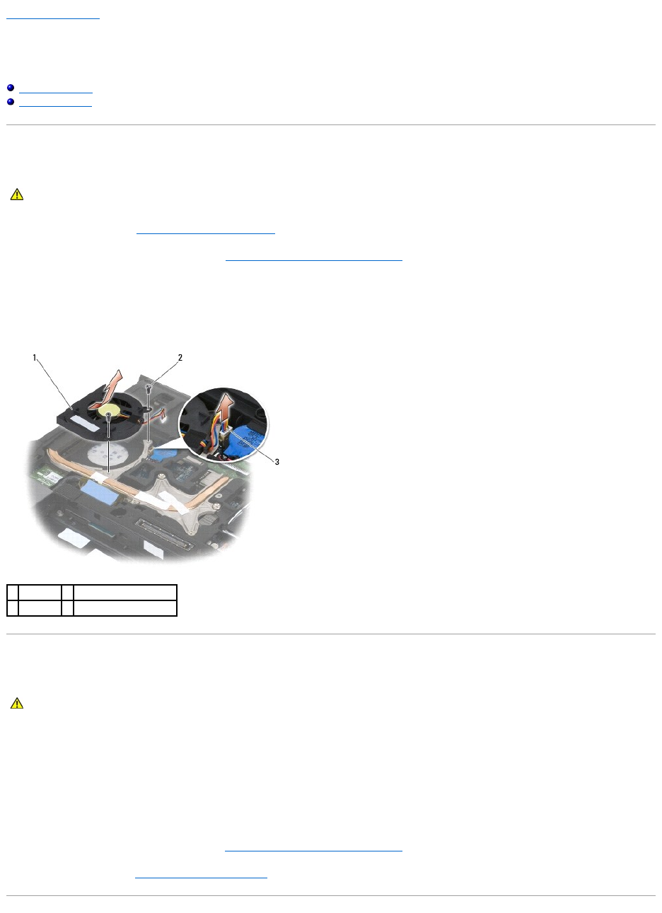
Removing the Fan
1. Follow the instructions in Before Working on Your Computer.
2. Remove the bottom of the base assembly (see Removing the Bottom of the Base Assembly).
3. Remove the two M2.5 x 5-mm screws that secure the fan to the processor heatsink assembly.
4. Disconnect the fan cable from the system board.
5. Lift the fan up at a 45-degree angle, and pull it away from the flap on the processor heatsink assembly to remove it.
Replacing the Fan
1. Lift the flap on the heatsink assembly and insert the fan at an angle.
2. Align the screws holes in the fan with the screw holes in the processor heatsink assembly.
3. Replace the two M2.5 x 5-mm screws to secure the fan to the processor heatsink assembly.
4. Connect the fan cable to the system board.
5. Replace the bottom of the base assembly (see Removing the Bottom of the Base Assembly).
6. Follow the procedures in After Working on Your Computer.
CAUTION: Before you begin the following procedure, follow the safety instructions that shipped with your computer.
1
fan
2
M2.5 x 5-mm screws (2)
3
fan cable
CAUTION: Before you begin the following procedure, follow the safety instructions that shipped with your computer.

Back to Contents Page
FCM
Dell™Latitude™E6400andE6400ATGand
MobileWorkstationPrecision™M2400ServiceManual
Removing an FCM from the WWAN/FCM Slot
Removing an FCM from the WPAN/UWB/FCM Slot
Replacing an FCM
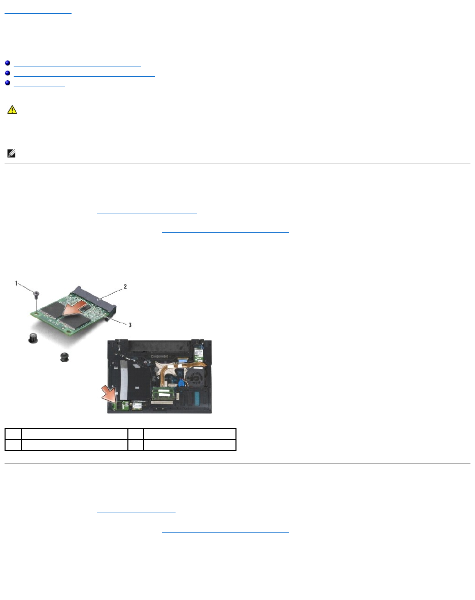
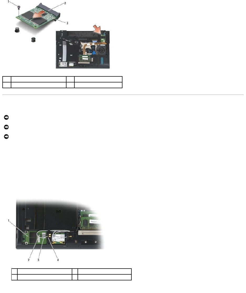
The FCM is also known as Intel®Turbo Memory and the Intel Flash Cache Logic Chip Mini-card. You can install an FCM in either the WWAN/FCM card connector
or the WPAN/UWB/FCM card connector.
Removing an FCM from the WWAN/FCM Slot
1. Follow the procedures in Before Working on Your Computer.
2. Remove the bottom of the base assembly (see Removing the Bottom of the Base Assembly).
3. Remove the M2 x 3-mm screw. The FCM pops up at a 45-degree angle.
4. Slide the FCM out of the card connector on the system board.
Removing an FCM from the WPAN/UWB/FCM Slot
1. Follow the procedures in Working on Your Computer.
2. Remove the bottom of the base assembly (see Removing the Bottom of the Base Assembly).
3. Remove the M2.5 x 5-mm screw from the left hinge cover, and slide it forward then lift to remove it.
4. Remove the M2 x 3-mm screw. The FCM pops up at a 45-degree angle.
5. Slide the FCM out of the card connector on the system.
CAUTION: Before you begin any of the procedures in this section, follow the safety instructions that shipped with your computer.
NOTE: This module is only compatible with the Microsoft®Windows Vista®operating system.
1
M2 x 3-mm screw
2
card connector
3
FCM
Replacing an FCM
1. Slide the FCM into the card connector on the system board.
2. Press the FCM down and hold it in place.
3. Replace the M2 x 3-mm screw.
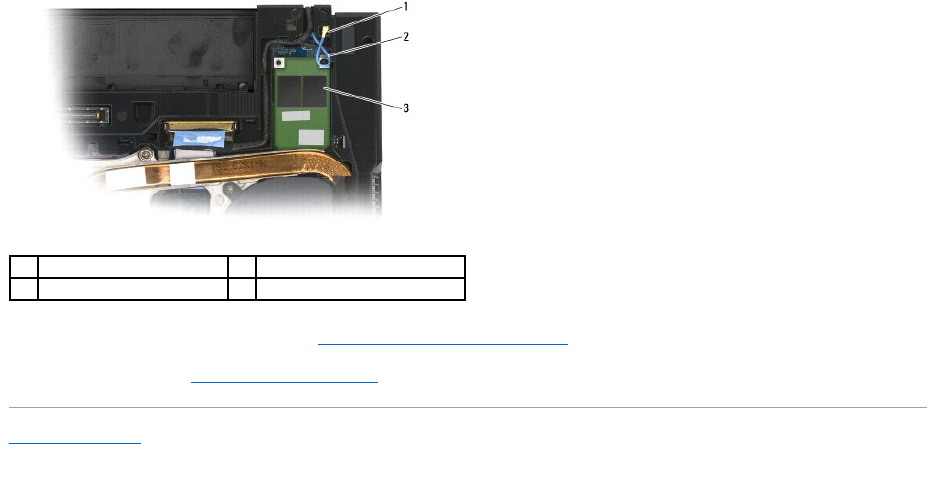
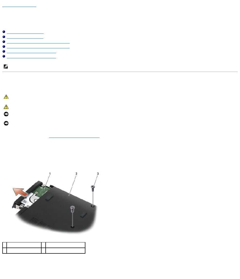
4. Secure the wireless cables:
If you are installing the FCM in the WWAN/FCM slot, place the gray/black and gray/white antenna cables in the holder next to the module.
If you are installing the FCM in the WPAN/UWB/FCM slot, place the blue antenna cable in the holder next to the module.
1
M2 x 3-mm screw
2
card connector
3
FCM
NOTICE: When installing this module, ensure that the antenna cables are not under the card. Place the antenna cables in the holder next to the
module. Installing the module on top of these antenna cables may cause damage to your computer.
NOTICE: The connectors are keyed to ensure correct insertion. If you feel resistance, check the connectors on the module and on the system board,
and realign the module.
NOTICE: An FCM can be installed in the WWAN/FCM card connector or the WPAN/UWB/FCM card connector. Use whichever card connector is available. If
both are available, use the WWAN/FCM card connector, which is easier to access.
1
FCM
2
gray/black antenna cable
3
gray/white antenna cable
4
holder by module
Back to Contents Page
Hard Drive
Dell™Latitude™E6400andE6400ATGand
MobileWorkstationPrecision™M2400ServiceManual
Removing the Hard Drive
Replacing the Hard Drive
Removing the 1.8" Hard Drive (E6400 ATG)
Replacing the 1.8" Hard Drive (E6400 ATG)
Removing the Modular Hard Drive
Replacing the Modular Hard Drive
Removing the Hard Drive
1. Follow the procedures in Before Working on Your Computer.
2. Close the display and turn the computer upside down.
3. Remove the two M3 x 3-mm screws.
4. Slide the hard drive out of the base assembly.
5. Remove the M3 x 3-mm screw on the hard drive bezel.
6. Remove the hard drive bezel.
NOTE: Dell does not guarantee compatibility or provide support for hard drives obtained from sources other than Dell.
CAUTION: Before you begin any of the procedures in this section, follow the safety instructions that shipped with your computer.
CAUTION: Do not touch the metal housing of the hard drive if you remove the hard drive from the computer while the drive is hot.
NOTICE: To prevent data loss, turn off your computer before removing the hard drive. Do not remove the hard drive while the computer is on or in
Sleep state.
NOTICE: Hard drives are extremely fragile. Exercise care when handling the hard drive.
1
hard drive
2
bottom of base assembly
3
M3 x 3-mm screws (2)
Replacing the Hard Drive
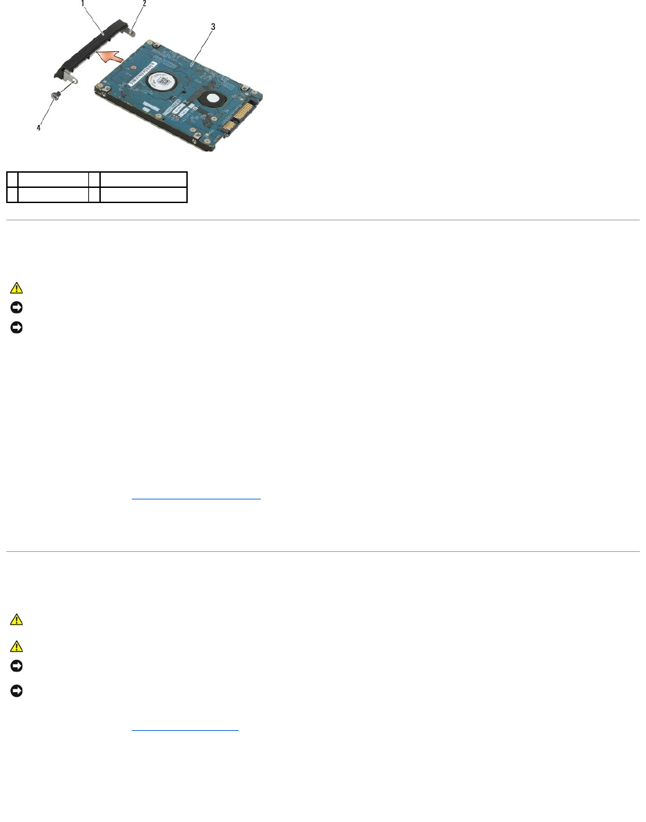
1. Hold the hard drive with the label facing down.
2. Place the pin on one end of the bezel into the hole on the hard drive.
3. On the other end of the bezel, replace the M3 x 3-mm screw that secures the hard drive bezel to the hard drive.
4. Slide the hard drive into the hard drive bay.
5. Replace the two M3 x 3-mm screws that secure the hard drive to the base assembly.
6. Follow the procedures in After Working on Your Computer.
7. Install the operating system, drivers, and utilities for your computer, as needed. For more information, see the Setup and Quick Reference Guide that
shipped with your computer or at support.dell.com.
Removing the 1.8" Hard Drive (E6400 ATG)
1. Follow the procedures in Working on Your Computer.
2. Close the display and turn the computer upside down.
3. Remove the two M3 x 3-mm screws.
4. Slide the hard drive out of the base assembly.
1
hard drive bezel
2
pin on bezel bracket
3
hard drive
4
M3 x 3-mm screw
CAUTION: Before you begin any of the procedures in this section, follow the safety instructions that shipped with your computer.
NOTICE: Hard drives are extremely fragile. Exercise care when handling the hard drive.
NOTICE: Use firm and even pressure to slide the hard drive into place. Excessive force may result in damage to the connector.
CAUTION: Before you begin any of the procedures in this section, follow the safety instructions that shipped with your computer.
CAUTION: Do not touch the metal housing of the hard drive if you remove the hard drive from the computer while the drive is hot.
NOTICE: To prevent data loss, turn off your computer before removing the hard drive. Do not remove the hard drive while the computer is on or in
Sleep state.
NOTICE: Hard drives are extremely fragile. Exercise care when handling the hard drive.
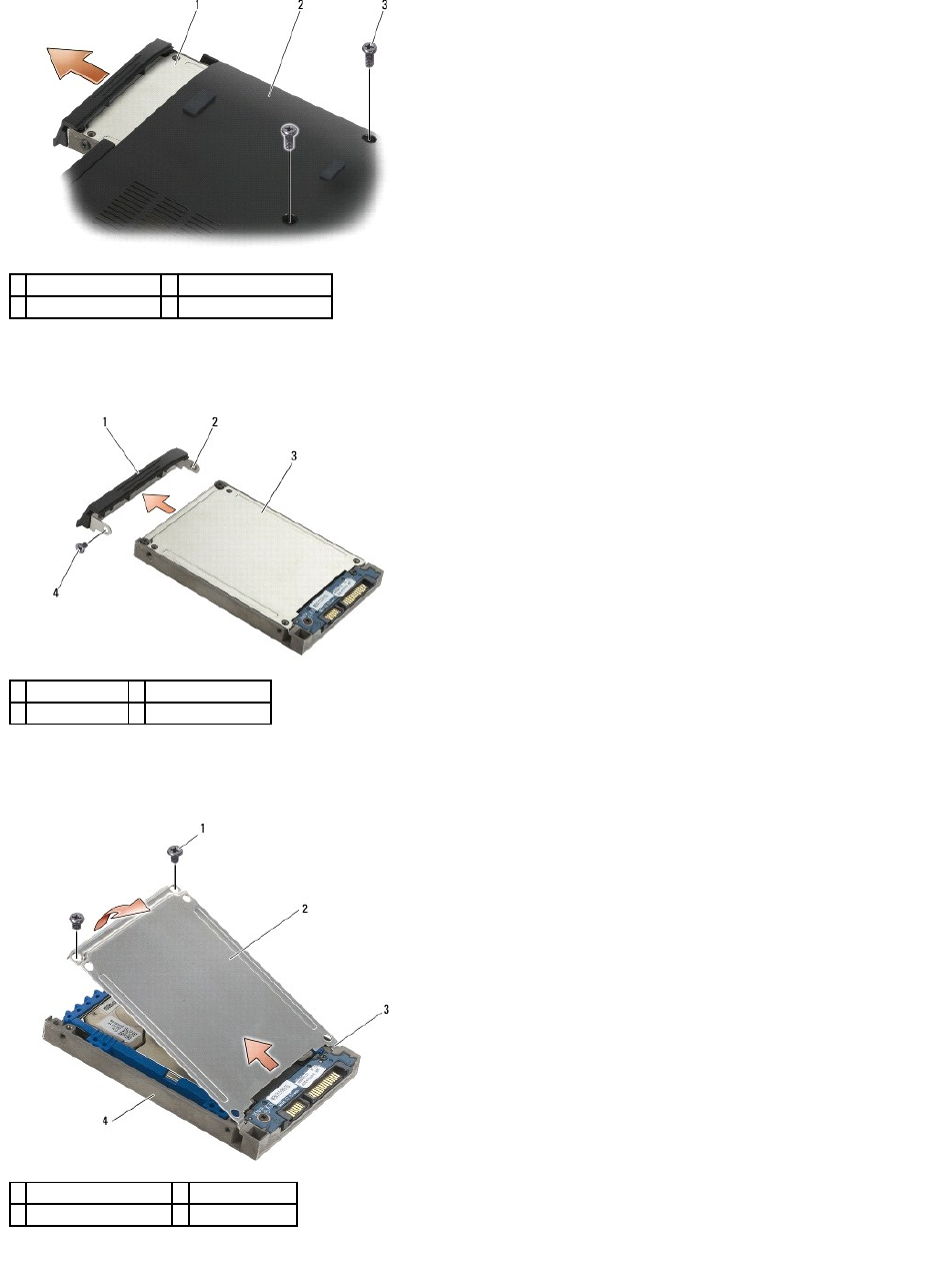
5. Remove the M3 x 3-mm screw on the hard drive bezel.
6. Remove the hard drive bezel.
7. Remove the two M2.5 x 5-mm screws from the cover of the hard drive carrier.
8. Lift the cover up at an angle and slide the tabs on the cover out from the carrier.
9. Lift the hard drive up an angle and slide it out from the connector on the hard drive carrier.
1
hard drive
2
bottom of base assembly
3
M3 x 3-mm screws (2)
1
hard drive bezel
2
pin on bezel bracket
3
hard drive
4
M3 x 3-mm screw
1
M2.5 x 5-mm screws (2)
2
cover
3
tabs (2)
4
hard drive carrier
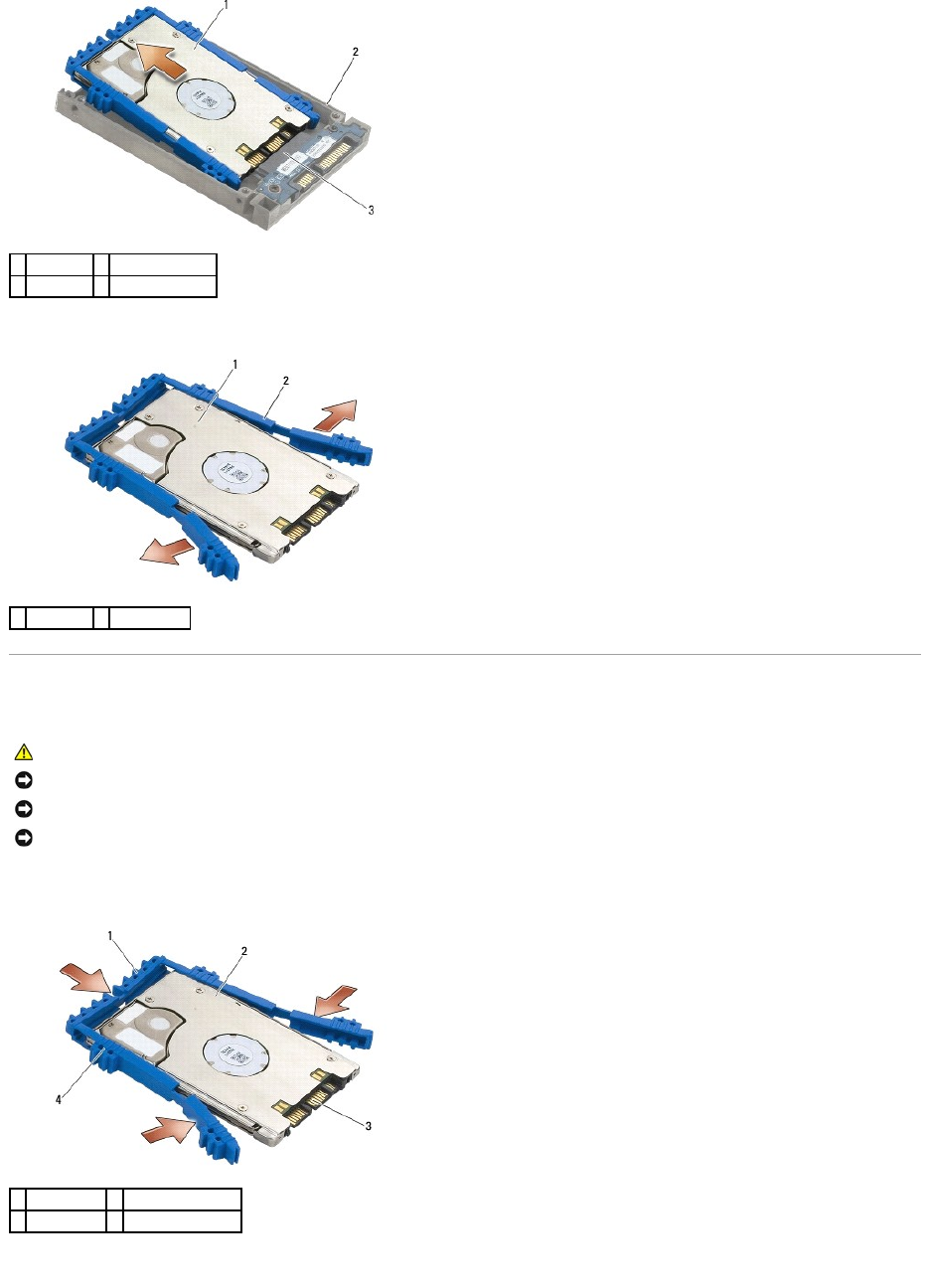
10. Pull out on the sides of the blue bumper to remove it from the hard drive.
Replacing the 1.8" Hard Drive (E6400 ATG)
1. With the top of the bumper facing up, place the end of the blue bumper on the end of the hard drive opposite from the connector, then enclose the two
sides of the hard drive with the blue bumper.
2. Place the hard drive into the carrier at an angle.
1
hard drive
2
hard drive carrier
3
connector
1
hard drive
2
blue bumper
CAUTION: Before you begin any of the procedures in this section, follow the safety instructions that shipped with your computer.
NOTICE: Hard drives are extremely fragile. Exercise care when handling the hard drive.
NOTICE: Use firm and even pressure to slide the hard drive into place. Excessive force may result in damage to the connector.
NOTICE: The top and bottom of the blue bumper are different. The top is flat with slight ridges, and the bottom has protruding ridges. When replacing
the blue bumper around the hard drive, ensure that the top is installed facing up, otherwise the cover will not completely close on the hard drive carrier.
1
blue bumper
2
hard drive
3
connector
4
top of blue bumper
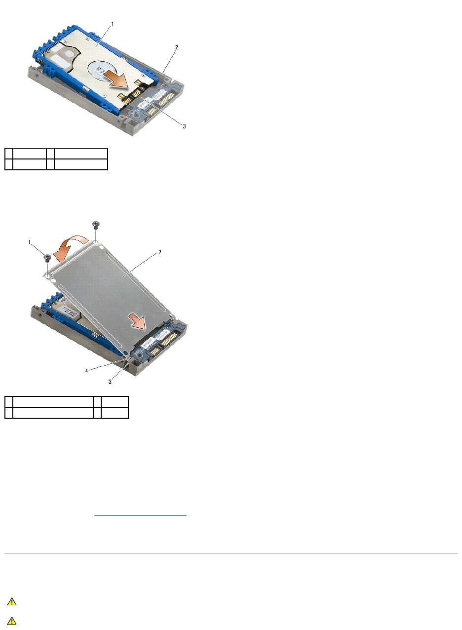
3. Connect the hard drive to the connector in the carrier.
4. Slide the tabs on the cover under the lip on the hard drive carrier.
5. Replace the two M2.5 x 5-mm screws.
6. Place the pin on one end of the bezel into the hole on the hard drive.
7. On the other end of the bezel, replace the M3 x 3-mm screw that secures the hard drive bezel to the hard drive.
8. Slide the hard drive into the hard drive bay.
9. Replace the two M3 x 3-mm screws that secure the hard drive to the base assembly.
10. Follow the procedures in After Working on Your Computer.
11. Install the operating system, drivers, and utilities for your computer, as needed. For more information, see the Setup and Quick Reference Guide that
shipped with your computer at support.dell.com.
Removing the Modular Hard Drive
1
hard drive
2
hard drive carrier
3
connector
1
M2.5 x 5-mm screws
2
cover
3
lip on hard drive carrier (2)
4
tabs (2)
CAUTION: Before you begin any of the procedures in this section, follow the safety instructions that shipped with your computer.
CAUTION: Do not touch the metal housing of the hard drive if you remove the hard drive from the computer while the drive is hot.
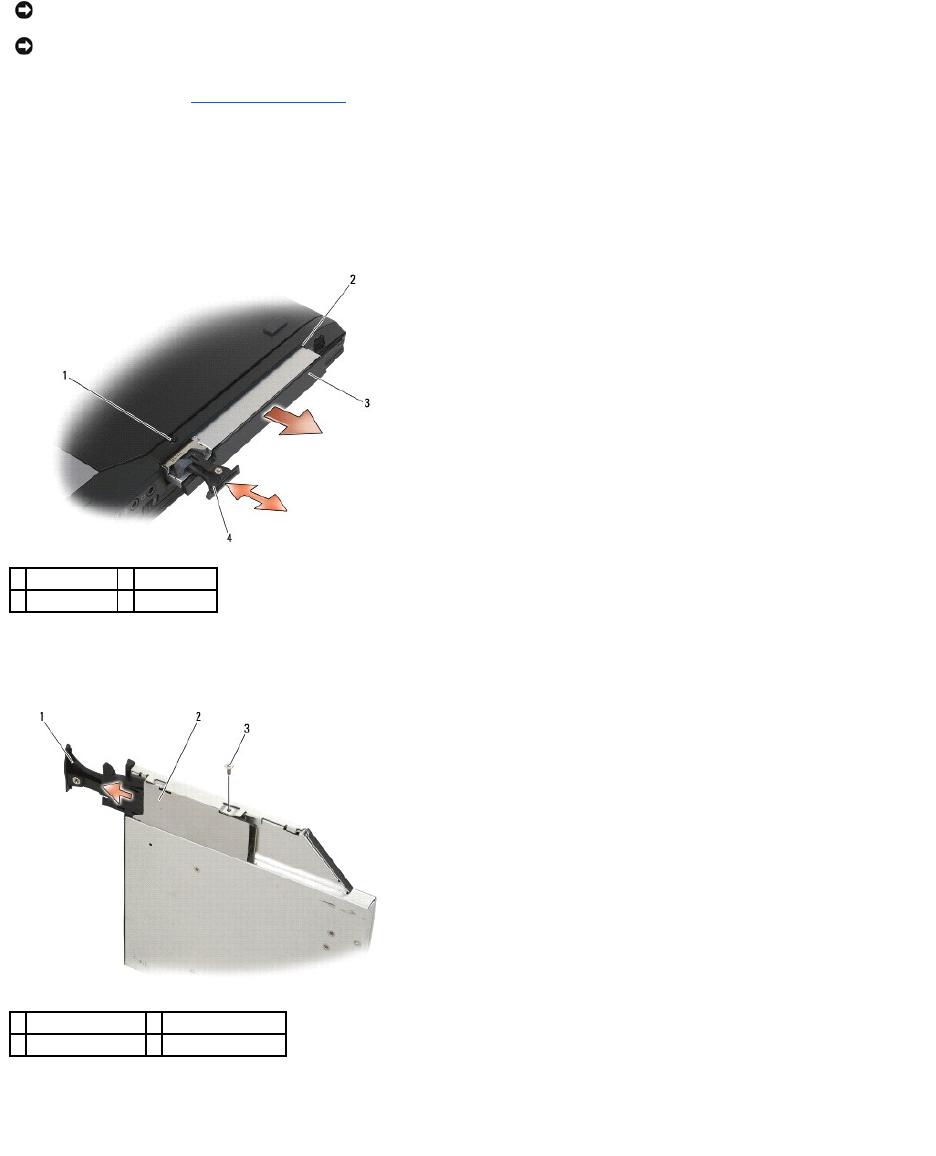
1. Follow the procedures in Working on Your Computer.
2. Turn your computer upside down.
3. If your computer has a security screw for the modular drive, remove the security screw.
4. Push the release latch in to release it.
5. Use the release latch to slide the drive out of the modular bay.
6. Remove the M2.5 x 5-mm screw that holds the release latch in place.
7. Slide the release latch out from the release latch carrier.
8. Remove the M2.5 x 5-mm screw that holds the carrier for the release latch in place.
9. Slide the release latch carrier out of the hard drive carrier.
NOTICE: To prevent data loss, turn off your computer before removing the hard drive. Do not remove the hard drive while the computer is on or in
Sleep state.
NOTICE: Hard drives are extremely fragile. Exercise care when handling the hard drive.
1
security screw
2
modular bay
3
modular drive
4
release latch
1
release latch
2
release latch carrier
3
M2.5 x 5-mm screw
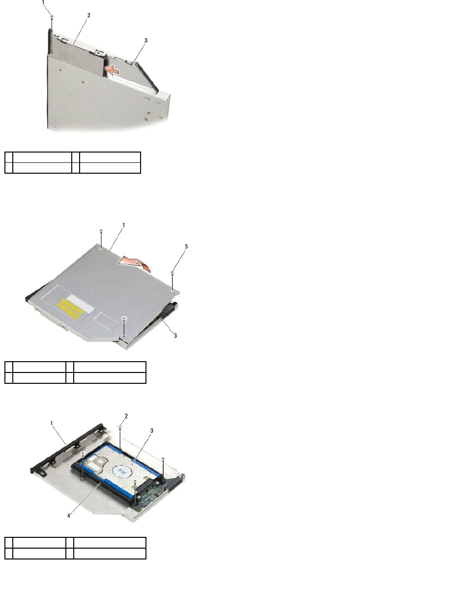
10. Remove the three M2.5 x 5-mm screws on the cover of the hard drive carrier.
11. Lift the cover up at an angle and remove.
12. Remove the four M2.5 x 5 screws from the hard drive bracket.
13. Lift the hard drive up at an angle and disconnect it from the hard drive carrier.
1
M2.5 x 5-mm screw
2
release latch carrier
3
hard drive carrier
1
cover
2
M2.5 x 5-mm screws (3)
3
hard drive carrier
1
hard drive carrier
2
M2.5 x 5-mm screws (4)
3
hard drive
4
hard drive bracket
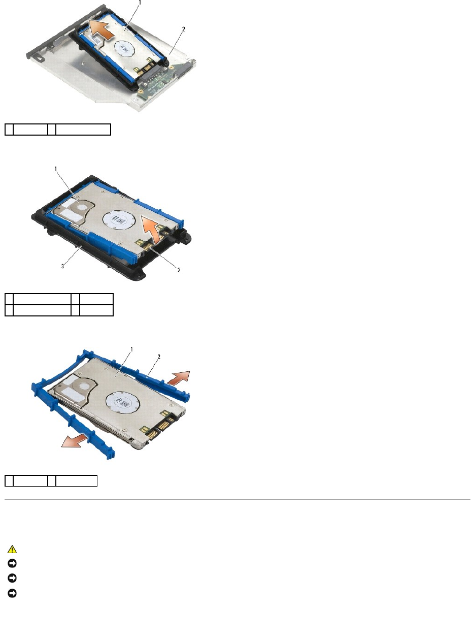
14. Lift the connector-end of the hard drive and remove the hard drive from the hard drive bracket.
15. Pull out on the sides of the blue bumper to remove it from the hard drive.
Replacing the Modular Hard Drive
1. With the top of the bumper facing up, place the end of the blue bumper on the end of the hard drive opposite from the connector, then enclose the two
sides of the hard drive with the blue bumper.
1
hard drive
2
hard drive carrier
1
hard drive
2
connector
3
hard drive bracket
1
hard drive
2
blue bumper
CAUTION: Before you begin any of the procedures in this section, follow the safety instructions that shipped with your computer.
NOTICE: Hard drives are extremely fragile. Exercise care when handling the hard drive.
NOTICE: Use firm and even pressure to slide the hard drive into place. Excessive force may result in damage to the connector.
NOTICE: The top and bottom of the blue bumper are different. The top has protruding ridges, and the bottom is flatter with slight ridges. When
replacing the blue bumper around the hard drive, ensure that the top is installed facing up.
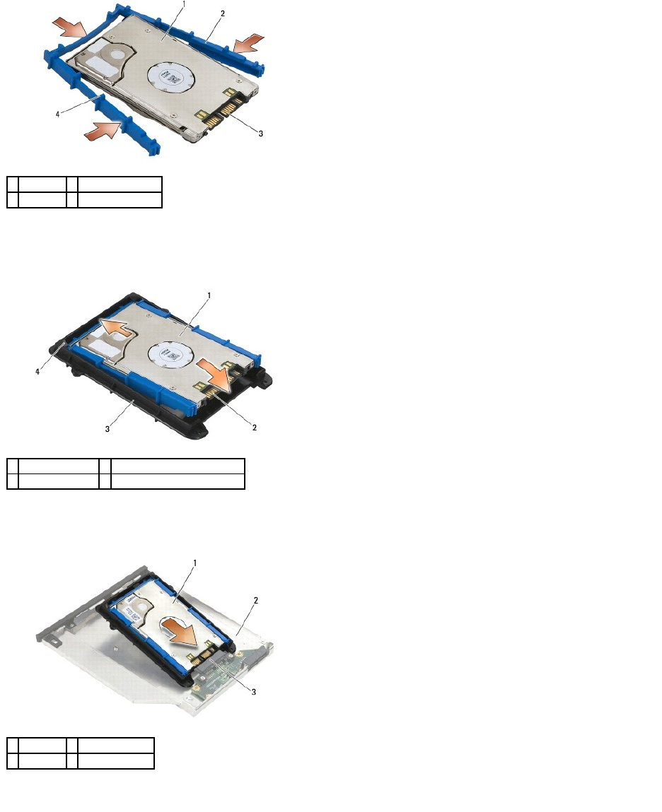
2. Place the end that is opposite from the connector on the hard drive into the hard drive bracket, ensuring that the hard drive fits into each corner of the
hard drive bracket.
3. Lower the hard drive into the hard drive bracket.
4. Place the hard drive into the carrier at an angle.
5. Connect the hard drive to the connector in the carrier and lower the hard drive into the carrier.
6. Replace the four M2.5 x 5-mm screws in the hard drive bracket.
1
hard drive
2
blue bumper
3
connector
4
top of blue bumper
1
hard drive
2
connector
3
hard drive bracket
4
corner of hard drive bracket (2)
1
hard drive
2
hard drive carrier
3
connector
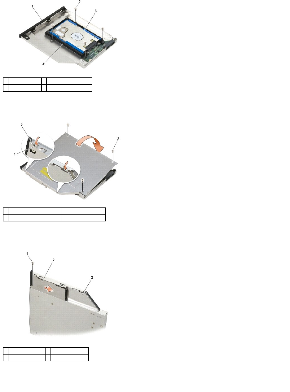
7. Attach the side of the cover where it is angled, ensuring the tabs on the cover fit properly into the notches on the carrier.
8. Set the cover in place and replace the three M2.5 x 5-mm screws.
9. Slide the release latch carrier into the hard drive carrier.
10. Replace the M2.5 x 5-mm screw that holds the carrier for the release latch in place.
11. Slide the release latch into the hard drive carrier.
12. Replace the M2.5 x 5-mm screw that holds the release latch in place.
1
hard drive carrier
2
M2.5 x 5-mm screws (4)
3
hard drive
4
hard drive bracket
1
notches in hard drive carrier
2
tabs on carrier cover
3
M2.5 x 5-mm screws (3)
1
M2.5 x 5-mm screw
2
release latch carrier
3
hard drive carrier
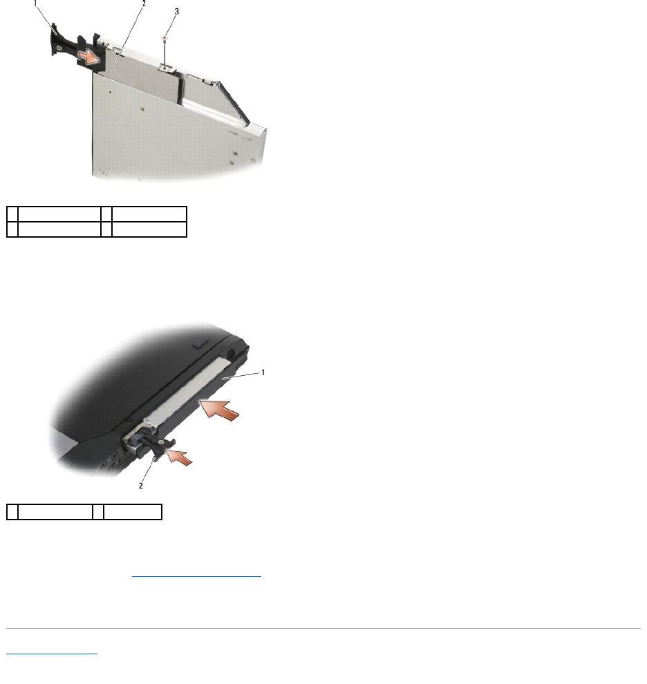
13. Slide the hard drive carrier into the modular bay.
14. Push the release latch in to hold the carrier in place.
15. If your computer has a security screw for the modular drive, replace the security screw.
16. Follow the procedures in After Working on Your Computer.
17. Install the operating system, drivers, and utilities for your computer, as needed. For more information, see the Setup and Quick Reference Guide that
shipped with your computer at support.dell.com.
Back to Contents Page
1
release latch
2
hard drive carrier
3
M2.5 x 5-mm screw
1
hard drive carrier
2
release latch
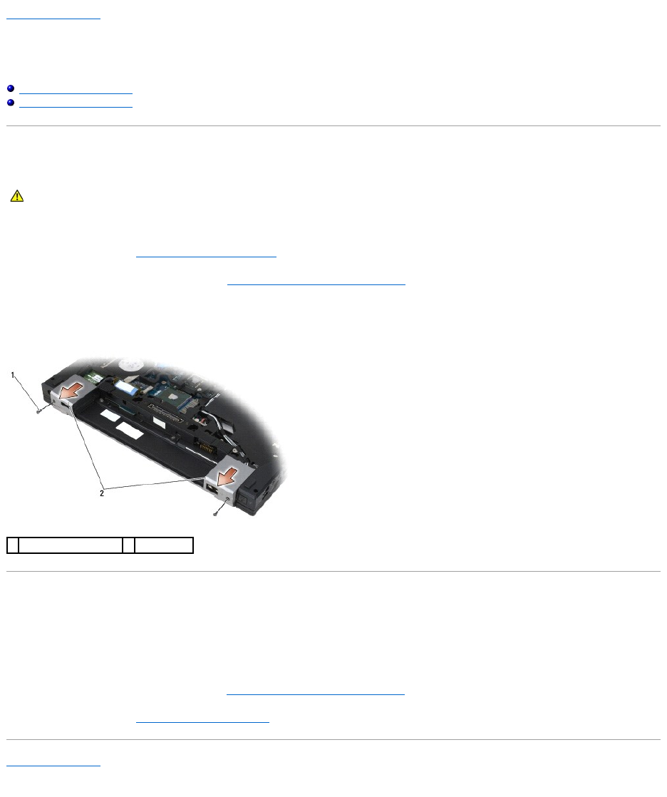
Back to Contents Page
Hinge Covers
Dell™Latitude™E6400andE6400ATGand
MobileWorkstationPrecision™M2400ServiceManual
Removing the Hinge Covers
Replacing the Hinge Covers
Removing the Hinge Covers
The hinge covers are not interchangeable; the left one covers the DisplayPort connector and the right one covers the RJ-45 network connector.
1. Follow the procedures in Before Working on Your Computer.
2. Remove the bottom of the base assembly (see Removing the Bottom of the Base Assembly).
3. Remove the M2.5 x 5-mm screw from each hinge cover.
4. Slide each hinge cover forward and lift to remove it.
Replacing the Hinge Covers
1. Slide the left hinge cover over the DisplayPort connector and slide the right hinge cover over the RJ-45 network connector.
2. Replace the M2.5x5-mm screw in each hinge cover.
3. Replace the bottom of the base assembly (see Replacing the Bottom of the Base Assembly).
4. Follow the procedures in After Working on Your Computer.
Back to Contents Page
CAUTION: Before you begin any of the procedures in this section, follow the safety instructions that shipped with your computer.
1
M2.5 x 5-mm screws (2)
2
hinge covers
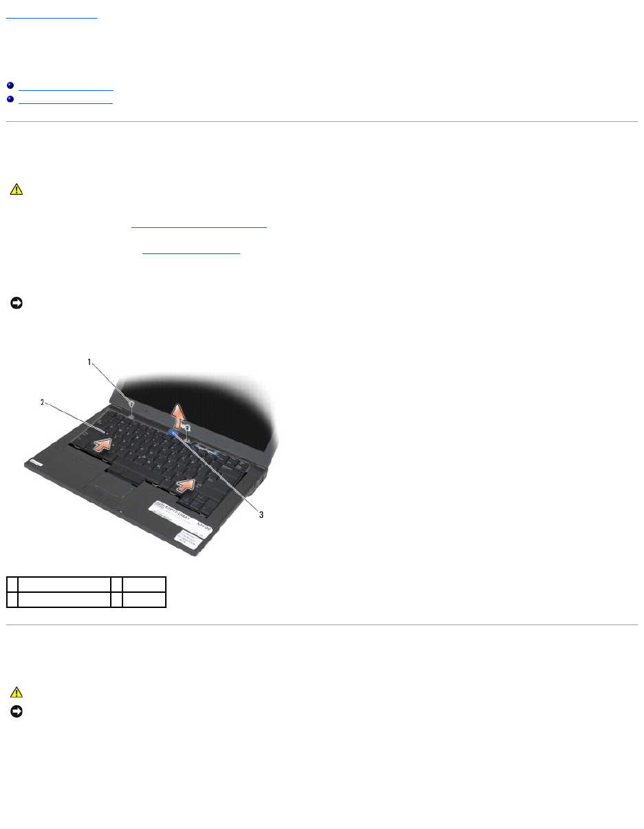
Back to Contents Page
Keyboard
Dell™Latitude™E6400andE6400ATGand
MobileWorkstationPrecision™M2400ServiceManual
Removing the Keyboard
Replacing the Keyboard
Removing the Keyboard
1. Follow the procedures in Before Working on Your Computer.
2. Remove the LED cover (see Removing the LED Cover).
3. Remove the two M2 x 3-mm screws along the top of the keyboard.
4. Using the pull tab, gently lift the top of the keyboard, then pull back to disconnect the keyboard.
Replacing the Keyboard
1. Holding the top of the keyboard slightly above the computer, slide the bottom of the keyboard in at an angle, and fit the tabs and keyboard connector
along the bottom of the keyboard beneath the front-inside edge of the palm rest.
2. Carefully press each side to snap the keyboard into place.
3. Replace the two M2 x 3-mm screws at the top of the keyboard.
CAUTION: Before you begin any of the procedures in this section, follow the safety instructions that shipped with your computer.
NOTICE: The key caps on the keyboard are fragile, easily dislodged, and time-consuming to replace. Exercise care when removing and handling the
keyboard.
1
M2 x 3-mm screws (2)
2
keyboard
3
pull tab
CAUTION: Before you begin any of the procedures in this section, follow the safety instructions that shipped with your computer.
NOTICE: The key caps on the keyboard are fragile, easily dislodged, and time-consuming to replace. Exercise care when removing and handling the
keyboard.
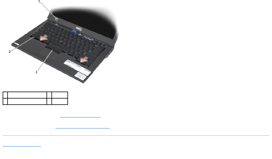
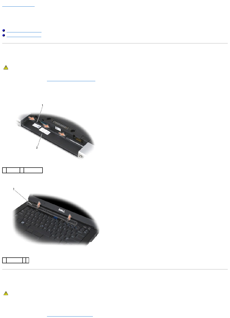
Back to Contents Page
LED Cover
Dell™Latitude™E6400andE6400ATGand
MobileWorkstationPrecision™M2400ServiceManual
Removing the LED Cover
Replacing the LED Cover
Removing the LED Cover
1. Follow the procedures in Before Working on Your Computer.
2. Locate the tabs in the battery bay that secure the LED cover to the top of the computer.
3. Using a plastic scribe, gently push on the tabs to release the LED cover.
4. Turn the computer topside up, then open the display and remove the LED cover.
Replacing the LED Cover
1. Working at an angle, snap the LED cover into place one tab at a time.
2. Follow the procedures in After Working on Your Computer.
CAUTION: Before you begin any of the procedures in this section, follow the safety instructions that shipped with your computer.
1
tabs (3)
2
battery bay
1
LED cover
CAUTION: Before you begin any of the procedures in this section, follow the safety instructions that shipped with your computer.

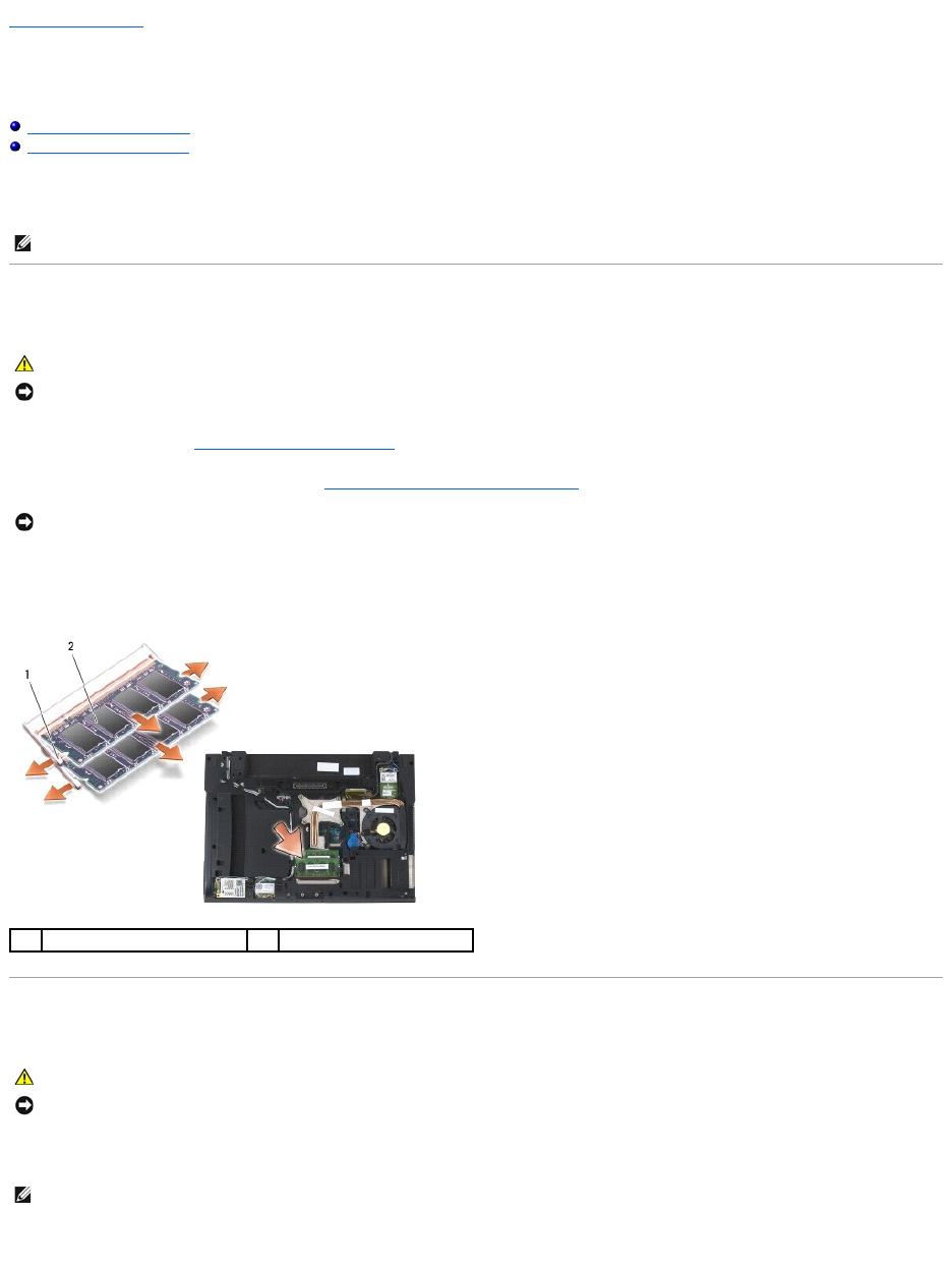
Back to Contents Page
Memory
Dell™Latitude™E6400andE6400ATGand
MobileWorkstationPrecision™M2400ServiceManual
Removing a Memory Module
Replacing a Memory Module
Your computer has two user-accessible SODIMM sockets. You can increase your computer memory by installing memory modules on the system board. See
"Specifications" in your Setup and Quick Reference Guide for information on the memory supported by your computer. Install only memory modules that are
intended for your computer.
Removing a Memory Module
1. Follow the procedures in Before Working on Your Computer.
2. Remove the bottom of the base assembly (see Removing the Bottom of the Base Assembly).
3. Use your fingertips to carefully spread apart the securing clips on each end of the memory module connector until the memory module pops up.
4. Remove the memory module from the connector.
Replacing a Memory Module
1. Place the module at a 45-degree angle, and align the notch in the module with the tab on the connector.
2. Press down on the module until it clicks into place. If the module does not click into place, remove the module and reinstall it.
NOTE: Memory modules purchased from Dell are covered under your computer warranty.
CAUTION: Before you begin any of the procedures in this section, follow the safety instructions that shipped with your computer.
NOTICE: If two memory modules are installed, you must remove the top memory module first to access the bottom memory module.
NOTICE: To prevent damage to the memory module connector, do not use tools to spread the memory module securing clips.
1
securing clips (2)
2
memory module
CAUTION: Before you begin any of the procedures in this section, follow the safety instructions that shipped with your computer.
NOTICE: If you are installing two memory modules, you must install the bottom memory module first.
NOTE: If the memory module is not installed properly, the computer may not boot. No error message indicates this failure.
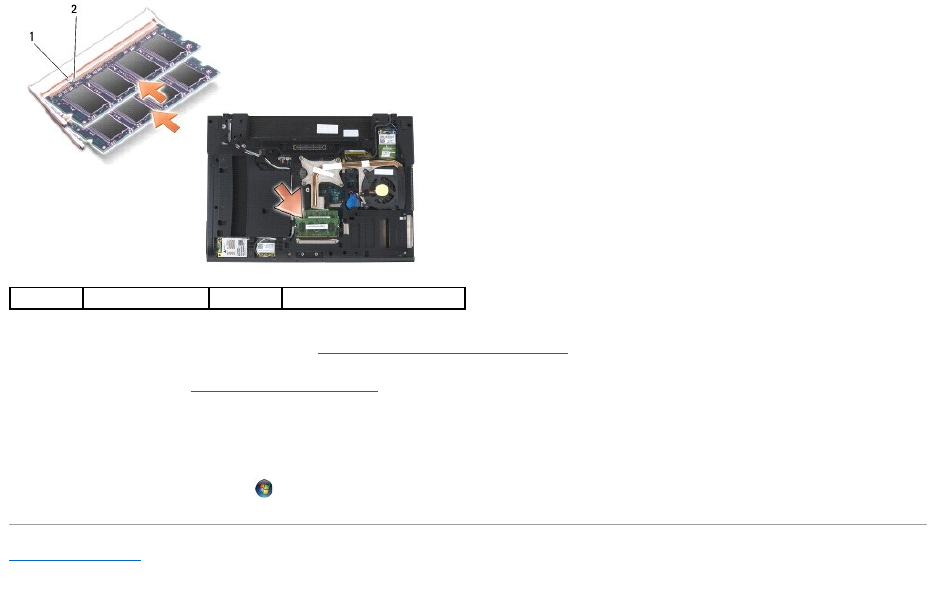
3. Replace the bottom of the base assembly (see Replacing the Bottom of the Base Assembly).
4. Follow the procedures in After Working on Your Computer.
As the computer boots, it detects the additional memory and automatically updates the system configuration information. To confirm the amount of
memory installed in the computer:
lIn Windows XP, right-click the My Computer icon on your desktop. Click Properties® General.
lIn Windows Vista, click Start ® Help and Support® Dell System Information.
Back to Contents Page
1
tab
2
notch
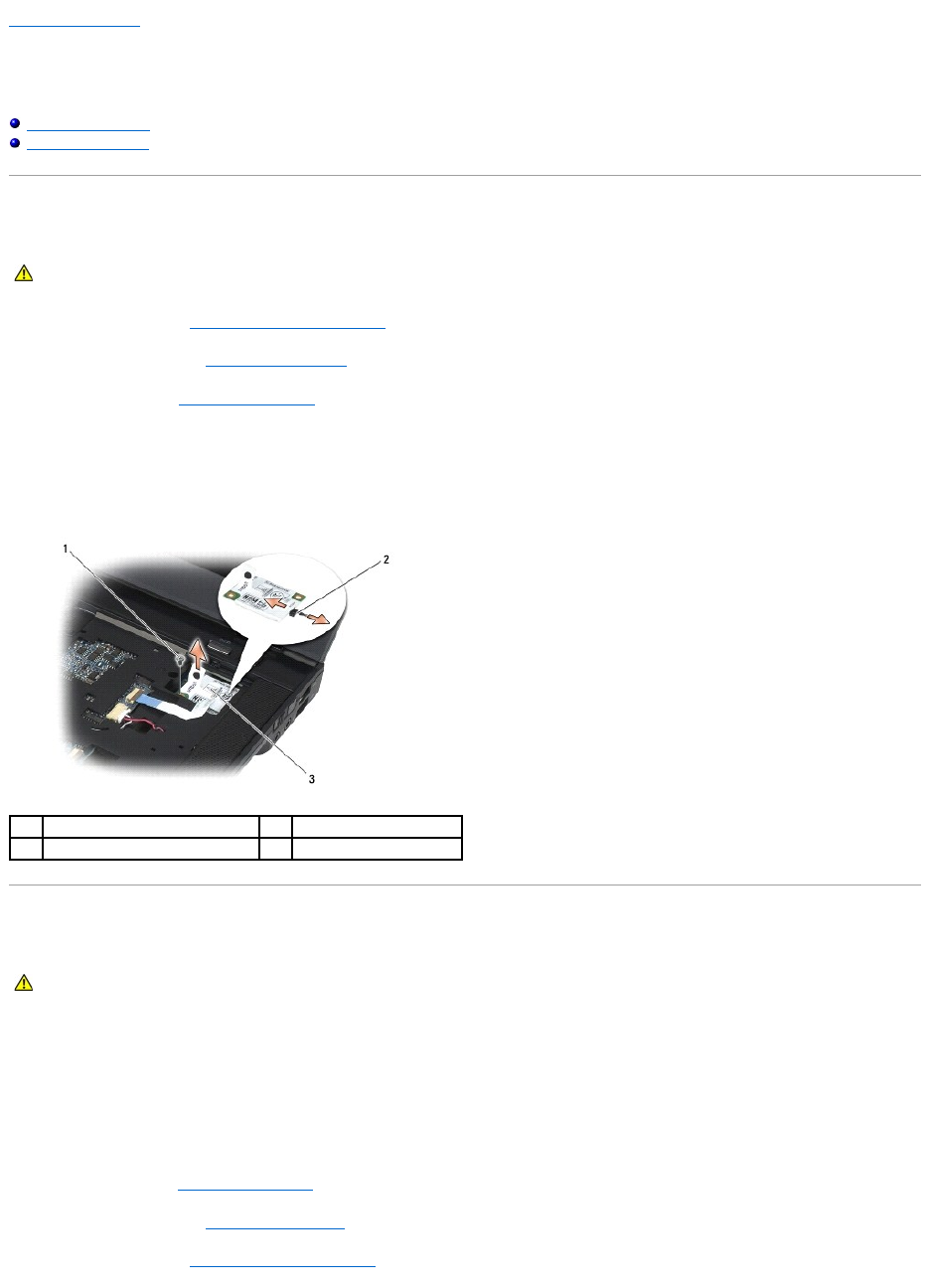
Back to Contents Page
Modem
Dell™Latitude™E6400andE6400ATGand
MobileWorkstationPrecision™M2400ServiceManual
Removing the Modem
Replacing the Modem
Removing the Modem
1. Follow the procedures in Before Working on Your Computer.
2. Remove the LED cover (see Removing the LED Cover).
3. Remove the keyboard (Removing the Keyboard).
4. Remove the M2 x 3-mm screw from the modem.
5. Use the pull tab to remove the modem from the I/O card.
6. Disconnect the modem cable from the modem.
Replacing the Modem
1. Connect the modem cable to the modem.
2. Use the screw hole on the modem to align it with the connector on the I/O card.
3. Press the area on the modem marked "Press Here" to connect the modem to the I/O card.
4. Replace the M2 x 3-mm screw to secure the modem to the I/O card.
5. Replace the keyboard (Replacing the Keyboard).
6. Replace the LED cover (see Replacing the LED Cover).
7. Follow the procedures in After Working on Your Computer.
CAUTION: Before you begin the following procedure, follow the safety instructions that shipped with your computer.
1
M2 x 3-mm screw
2
modem cable
3
modem
CAUTION: Before you begin the following procedure, follow the safety instructions that shipped with your computer.

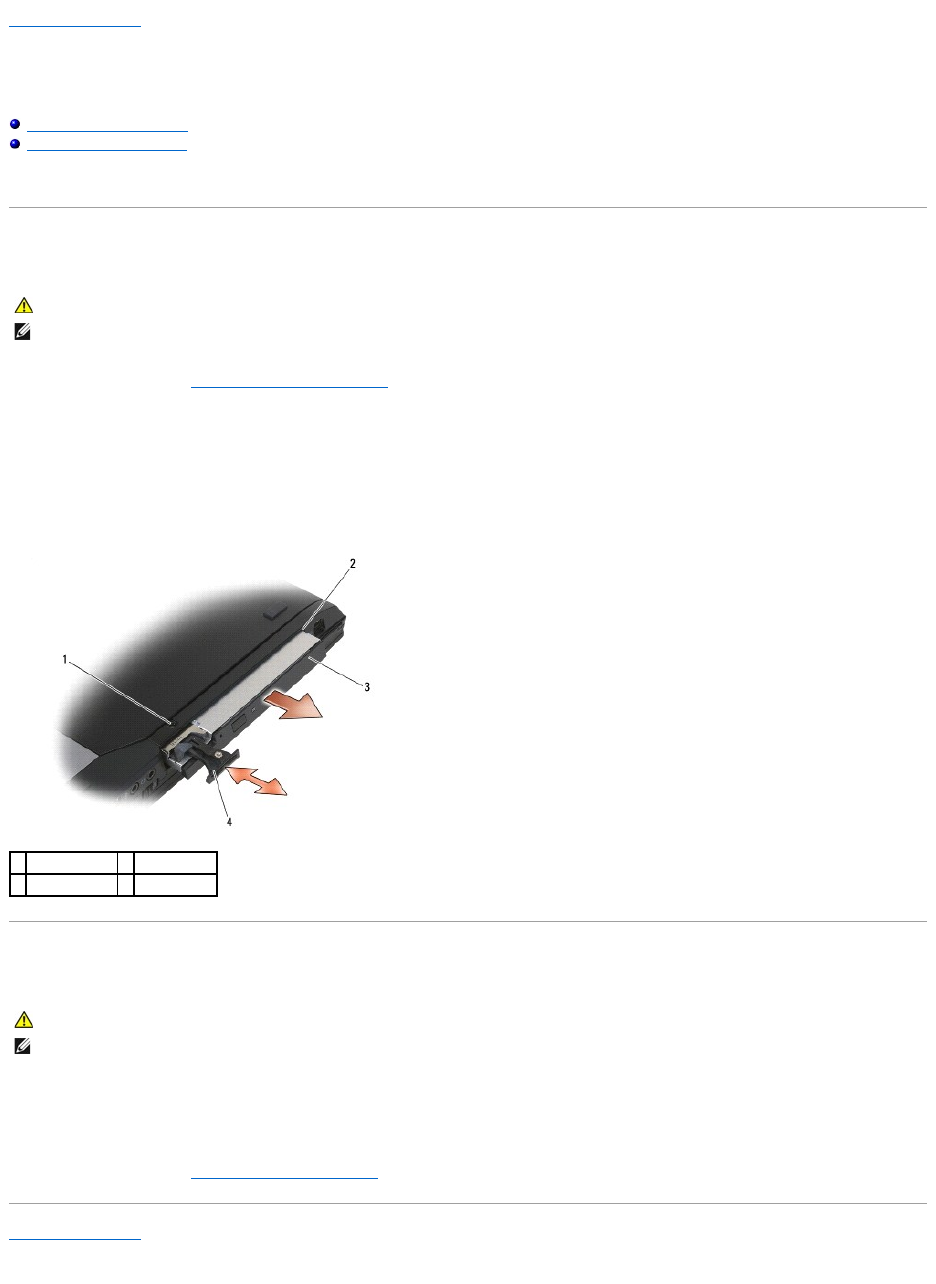
Back to Contents Page
Modular Drive
Dell™Latitude™E6400andE6400ATGand
MobileWorkstationPrecision™M2400ServiceManual
Removing the Modular Drive
Replacing the Modular Drive
The modular drive supports either a second hard drive, an optical drive, or a an air bay for travel.
Removing the Modular Drive
1. Follow the procedures in Before Working on Your Computer.
2. Turn your computer upside down.
3. If your computer has a security screw for the modular drive, remove the security screw.
4. Push the release latch in to release it.
5. Use the release latch to slide the drive out of the modular bay.
Replacing the Modular Drive
1. Slide the drive in the modular bay.
2. If your computer has a security screw for the modular drive, replace the security screw.
3. Follow the procedures in After Working on Your Computer.
Back to Contents Page
CAUTION: Before you begin any of the procedures in this section, follow the safety instructions that shipped with your computer.
NOTE: The security screw on the modular drive is optional and may not be installed on your computer.
1
security screw
2
modular bay
3
modular drive
4
release latch
CAUTION: Before you begin any of the procedures in this section, follow the safety instructions that shipped with your computer.
NOTE: The security screw on the modular drive is optional and may not be installed on your computer.
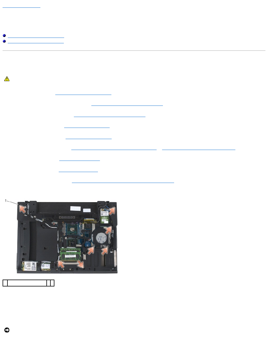
Back to Contents Page
Palm Rest Assembly
Dell™Latitude™E6400andE6400ATGand
MobileWorkstationPrecision™M2400ServiceManual
Removing the Palm Rest Assembly
Replacing the Palm Rest Assembly
Removing the Palm Rest Assembly
1. Follow the instructions in Before Working on Your Computer.
2. Remove the bottom of the base assembly (see Removing the Bottom of the Base Assembly).
3. Remove the heatsink assembly (see Removing the Processor Heatsink Assembly).
4. Remove the hinge covers (see Removing the Hinge Covers).
5. Remove the modular drive (see Removing the Modular Drive).
6. Remove the display assembly (see Removing the Display Assembly (E6400 and M2400) or Removing the Display Assembly (E6400 ATG)).
7. Remove the LED cover (see Removing the LED Cover).
8. Remove the keyboard (see Removing the Keyboard).
9. Remove the right speaker grill (see Removing the Right Speaker Grill/Fingerprint Reader Assembly).
10. Turn the computer over and remove seven M2.5 x 5-mm screws.
11. Turn the computer topside up and remove four M2.5 x 5-mm screws labeled "P".
12. Disconnect the wireless switch cable, the speaker cable, and the touch pad cable from the system board.
13. Lift the touch pad cable to reveal the contactless smart card cable underneath. Disconnect the contactless smart card cable from the system board.
14. Lift the left side of the palm rest, then push in on the right side to release the palm rest tabs from the base assembly. Pull the palm rest forward, then
carefully lift it up from the computer.
CAUTION: Before you begin the following procedure, follow the safety instructions that shipped with your computer.
1
2.5 x 5-mm screws (7)
NOTICE: Do not use force to separate the palm rest from the computer. If you encounter resistance, gently flex or apply pressure to the palm rest, or
move along the edge, working away from the area of resistance, until the palm rest is free.
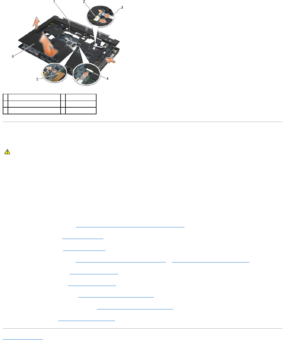
Replacing the Palm Rest Assembly
1. Holding the palm rest at an angle, connect the front of the palm rest to the computer, securing all snaps.
2. Lower and snap the left side into place.
3. Connect the contactless smart card cable, the touchpad cable, the speaker cable, and the wireless switch cable to the system board.
4. Replace the four M2.5 x 5-mm screws in the holes labeled "P".
5. Turn the computer upside down, and replace the seven M2.5 x 5.5-mm screws on the bottom of the computer.
6. Replace the right speaker grill (see Replacing the Right Speaker Grill/Fingerprint Reader Assembly).
7. Replace the keyboard (see Replacing the Keyboard).
8. Replace the LED cover (see Replacing the LED Cover).
9. Replace the display assembly (see Replacing the Display Assembly (E6400 and M2400) or Replacing the Display Assembly (E6400 ATG)).
10. Replace the modular drive (see Replacing the Modular Drive).
11. Replace the hinge covers (see Replacing the Hinge Covers).
12. Replace the heatsink assembly (see Replacing the Processor Heatsink Assembly).
13. Replace the bottom of the base assembly (see Replacing the Bottom of the Base Assembly).
14. Follow the procedures in After Working on Your Computer.
Back to Contents Page
1
2.5 x 5-mm screws (4)
2
speaker cable
3
wireless switch cable
4
touch pad cable
5
contactless smart card cable
6
palm rest
CAUTION: Before you begin the following procedure, follow the safety instructions that shipped with your computer.
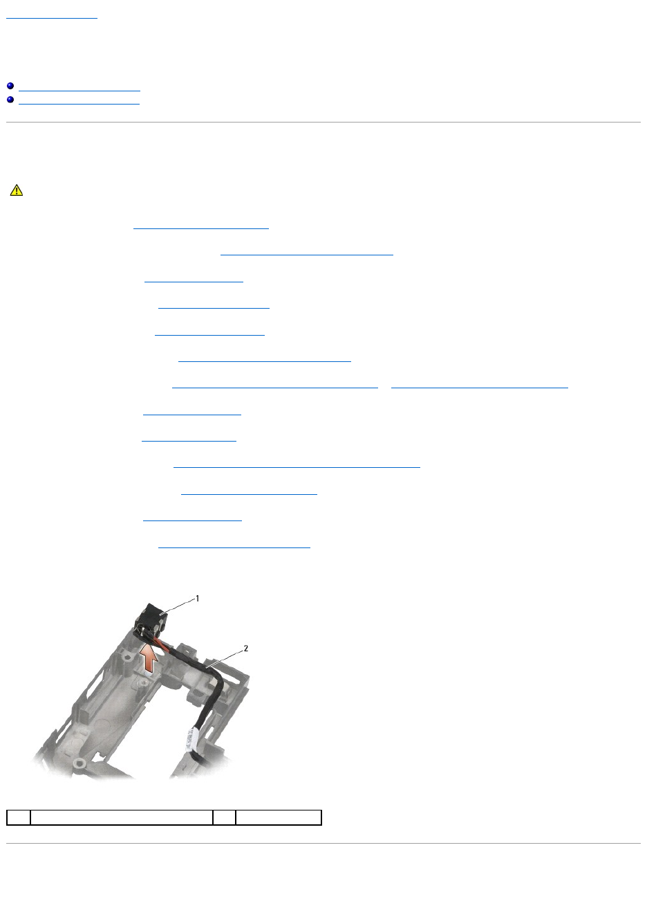
Back to Contents Page
DC Power Cable
Dell™Latitude™E6400andE6400ATGand
MobileWorkstationPrecision™M2400ServiceManual
Removing the DC Power Cable
Replacing the DC Power Cable
Removing the DC Power Cable
1. Follow the instructions in Before Working on Your Computer.
2. Remove the bottom of the base assembly (see Removing the Bottom of the Base Assembly).
3. Remove the hard drive (see Removing the Hard Drive).
4. Remove the modular drive (see Removing the Modular Drive).
5. Remove the hinge covers (see Removing the Hinge Covers).
6. Remove the heatsink assembly (see Removing the Processor Heatsink Assembly).
7. Remove the display assembly (see Removing the Display Assembly (E6400 and M2400) or Removing the Display Assembly (E6400 ATG)).
8. Remove the LED cover (see Removing the LED Cover).
9. Remove the keyboard (see Removing the Keyboard).
10. Remove the right speaker grill (see Removing the Right Speaker Grill/Fingerprint Reader Assembly).
11. Remove the palm rest assembly (see Removing the Palm Rest Assembly).
12. Remove the card cage (see Removing the Card Cage).
13. Remove the system board (see Removing the System Board Assembly). Do not remove the wireless mini-cards, memory modules, or processor from the
system board.
14. Unroute the DC power cable from the base assembly and remove it.
Replacing the DC Power Cable
CAUTION: Before you begin the following procedure, follow the safety instructions that shipped with your computer.
1
DC power connector
2
DC cable
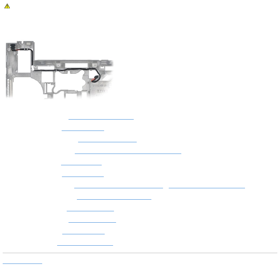
1. Place the DC power cable in the base assembly, aligning the guides on the connector sides with the base.
2. Route the DC power cable in the base assembly.
3. Replace the system board (see Replacing the System Board Assembly).
4. Replace the card cage (see Replacing the Card Cage).
5. Replace the palm rest assembly (see Replacing the Palm Rest Assembly).
6. Replace the right speaker grill (see Replacing the Right Speaker Grill/Fingerprint Reader Assembly).
7. Replace the keyboard (see Replacing the Keyboard).
8. Replace the LED cover (see Replacing the LED Cover).
9. Replace the display assembly (see Replacing the Display Assembly (E6400 and M2400) or Replacing the Display Assembly (E6400 ATG)).
10. Replace the heatsink assembly (see Replacing the Processor Heatsink Assembly).
11. Replace the hinge covers (see Replacing the Hinge Covers).
12. Replace the modular drive (see Replacing the Modular Drive).
13. Replace the hard drive (see Replacing the Hard Drive).
14. Follow the procedures in After Working on Your Computer.
Back to Contents Page
CAUTION: Before you begin the following procedure, follow the safety instructions that shipped with your computer.
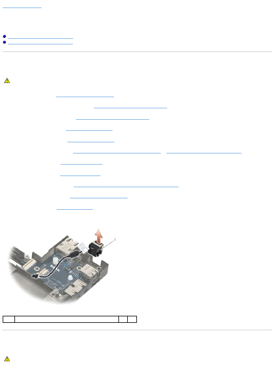
Back to Contents Page
RJ-11 Modem Connector
Dell™Latitude™E6400andE6400ATGand
MobileWorkstationPrecision™M2400ServiceManual
Removing the RJ-11 Modem Connector
Replacing the RJ-11 Modem Connector
Removing the RJ-11 Modem Connector
1. Follow the procedures in Before Working on Your Computer.
2. Remove the bottom of the base assembly (see Removing the Bottom of the Base Assembly).
3. Remove the heatsink assembly (see Removing the Processor Heatsink Assembly).
4. Remove the hinge covers (see Removing the Hinge Covers).
5. Remove the modular drive (see Removing the Modular Drive).
6. Remove the display assembly (see Removing the Display Assembly (E6400 and M2400) or Removing the Display Assembly (E6400 ATG)).
7. Remove the LED cover (see Removing the LED Cover).
8. Remove the keyboard (see Removing the Keyboard).
9. Remove the right speaker grill (see Removing the Right Speaker Grill/Fingerprint Reader Assembly).
10. Remove the palm rest assembly (Removing the Palm Rest Assembly).
11. Remove the modem (see Removing the Modem).
12. Lift the RJ-11 modem connector out of the base assembly.
Replacing the RJ-11 Modem Connector
1. Place the RJ-11 modem connector into the base assembly, aligning the guides on the connector sides with the base.
CAUTION: Before you begin the following procedure, follow the safety instructions that shipped with your computer.
1
RJ-11 modem connector
CAUTION: Before you begin the following procedure, follow the safety instructions that shipped with your computer.

2. Replace the modem (see Replacing the Modem).
3. Replace the palm rest assembly (Replacing the Palm Rest Assembly).
4. Replace the right speaker grill (see Replacing the Right Speaker Grill/Fingerprint Reader Assembly).
5. Replace the keyboard (see Replacing the Keyboard).
6. Replace the LED cover (see Replacing the LED Cover).
7. Replace the display assembly (see Replacing the Display Assembly (E6400 and M2400) or Replacing the Display Assembly (E6400 ATG)).
8. Replace the modular drive (see Replacing the Modular Drive).
9. Replace the hinge covers (see Replacing the Hinge Covers).
10. Replace the heatsink assembly (see Replacing the Processor Heatsink Assembly).
11. Replace the bottom of the base assembly (see Replacing the Bottom of the Base Assembly).
12. Follow the procedures in After Working on Your Computer.
Back to Contents Page
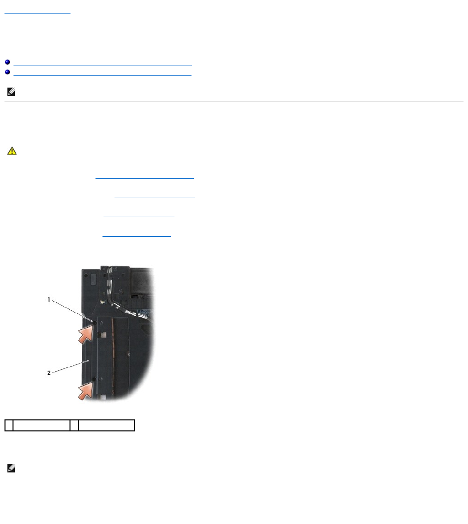
Back to Contents Page
Right Speaker Grill/Fingerprint Reader Assembly
Dell™Latitude™E6400andE6400ATGand
MobileWorkstationPrecision™M2400ServiceManual
Removing the Right Speaker Grill/Fingerprint Reader Assembly
Replacing the Right Speaker Grill/Fingerprint Reader Assembly
Removing the Right Speaker Grill/Fingerprint Reader Assembly
1. Follow the procedures in Before Working on Your Computer.
2. Remove the modular drive (see Removing the Modular Drive).
3. Remove the LED cover (see Removing the LED Cover).
4. Remove the keyboard (see Removing the Keyboard).
5. Turn the computer upside down, and loosen the two captive screws in the modular drive bay.
6. Turn the computer topside up and open the display.
7. If your computer has a fingerprint reader, disconnect the fingerprint reader cable, and peel it away from the palm rest.
8. Unsnap the right speaker grill, then lift it up from the palm rest.
NOTE: The fingerprint reader is optional and may not be installed on your computer.
CAUTION: Before you begin the following procedure, follow the safety instructions that shipped with your computer.
1
captive screws (2)
2
modular drive bay
NOTE: The fingerprint reader is optional and may not be installed on your computer.
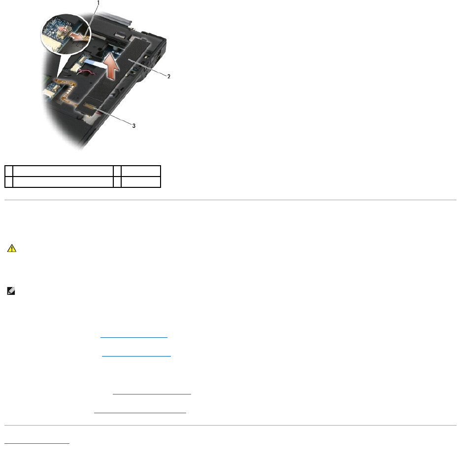
Replacing the Right Speaker Grill/Fingerprint Reader Assembly
1. Snap the right speaker grill into place on the palm rest.
2. If your computer has a fingerprint reader, connect the fingerprint reader cable. Press the length of the cable to secure it to the palm rest.
3. Replace the keyboard (see Replacing the Keyboard).
4. Replace the LED cover (see Replacing the LED Cover).
5. Turn the computer upside down, and tighten the two M2.5 x 5-mm screws in the modular bay.
6. Replace the modular drive (see Replacing the Modular Drive).
7. Follow the procedures in After Working on Your Computer.
Back to Contents Page
1
fingerprint reader cable (optional)
2
speaker grill
3
fingerprint reader (optional)
CAUTION: Before you begin the following procedure, follow the safety instructions that shipped with your computer.
NOTE: If you are installing a new right speaker grill with a fingerprint reader, remove the backing from the fingerprint reader cable.

Back to Contents Page
System Board Assembly
Dell™Latitude™E6400andE6400ATGand
MobileWorkstationPrecision™M2400ServiceManual
Removing the System Board Assembly
Replacing the System Board Assembly
The system board's BIOS chip contains the Service Tag, which is also visible on a barcode label on the bottom of the computer. The replacement kit for the
system board includes media that provides a utility for transferring the Service Tag to the replacement system board.
Removing the System Board Assembly
1. Follow the instructions in Before Working on Your Computer.
2. Remove the bottom of the base assembly (see Removing the Bottom of the Base Assembly).
3. Remove the card in the WWAN/FCM card slot, if present (see Removing a WWAN Card or Removing an FCM from the WWAN/FCM Slot).
4. Remove the card from the WLAN/WiMax card slot, if present (see Removing the WLAN/WiMax Card).
5. Remove the hinge covers (see Removing the Hinge Covers).
6. Remove the card from the WPAN/UWB/FCM card slot, if present (see Removing a WPAN (UWB/BT) Card or Removing an FCM from the WPAN/UWB/FCM
Slot).
7. Remove the memory modules (see Removing a Memory Module).
8. Remove the heatsink assembly (see Removing the Processor Heatsink Assembly).
9. Remove the processor (see Removing the Processor Module).
10. Disconnect the coin-cell battery cable from the system board.
11. Remove the hard drive (see Removing the Hard Drive).
12. Remove the modular drive (see Removing the Modular Drive).
13. Remove the display assembly (see Removing the Display Assembly (E6400 and M2400) or Removing the Display Assembly (E6400 ATG)).
14. Remove the LED cover (see Removing the LED Cover).
15. Remove the keyboard (see Removing the Keyboard).
16. Remove the right speaker grill (see Removing the Right Speaker Grill/Fingerprint Reader Assembly).
17. Remove the palm rest assembly (see Removing the Palm Rest Assembly).
18. Remove the card cage (see Removing the Card Cage).
19. Disconnect the smart card cable from the system board.
20. Disconnect the 1394 daughtercard cable from the system board, and unroute the cable from the system board.
21. Remove three M2.5 x 5-mm screws labeled with white arrows from the system board.
22. Pull out on the top-left corner of the base assembly to release the connectors, while lifting the top-left corner of the system board.
23. Lift the top-right corner of the system board to disconnect the system board from the I/O card.
24. Disconnect the DC cable, which is connected to the bottom of the system board.
CAUTION: Before you begin the following procedure, follow the safety instructions that shipped with your computer.
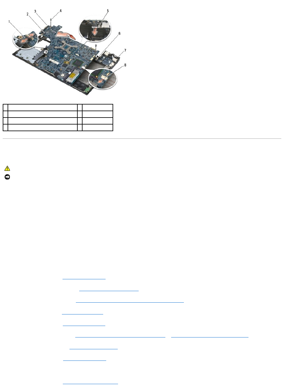
25. Lift the system board out of the base assembly.
Replacing the System Board Assembly
1. Place the front-edge of the system board into the base of the computer, ensuring the system board fits under the metal LCD latch mechanism in the
front center of the base assembly.
2. Connect the DC power cable to the bottom of the system board.
3. Place the top-left corner of the system board in the base assembly.
4. Push down on the top-right corner of the system board to connect it to the I/O card.
5. Replace the three M2.5 x 5-mm screws on the system board in the holes labeled with white arrows.
6. Route and connect the 1394 card cable to the connector on the system board. Press down on the cable to adhere it to the system board.
7. Connect the smart card cable to the connector on the system board.
8. Replace the card cage (see Replacing the Card Cage).
9. Replace the palm rest assembly (see Replacing the Palm Rest Assembly).
10. Replace the right speaker grill (see Replacing the Right Speaker Grill/Fingerprint Reader Assembly).
11. Replace the keyboard (see Replacing the Keyboard).
12. Replace the LED cover (see Replacing the LED Cover).
13. Replace the display assembly (see Replacing the Display Assembly (E6400 and M2400) or Replacing the Display Assembly (E6400 ATG)).
14. Replace the modular drive (see Replacing the Modular Drive).
15. Replace the hard drive (see Replacing the Hard Drive).
16. Connect the coin-cell battery cable to the system board.
17. Replace the processor (see Replacing the Processor Module).
1
smart card cable
2
system board
3
M2.5 x 5-mm system board screws (3)
4
DC cable
5
top-left corner of base assembly
6
I/O card
7
top-right corner of base assembly
8
1394 card cable
CAUTION: Before you begin the following procedure, follow the safety instructions that shipped with your computer.
NOTICE: Ensure that any loose cables do not get caught beneath the system board.

18. Replace the heatsink assembly (see Replacing the Processor Heatsink Assembly).
19. Replace the memory modules (see Replacing a Memory Module).
20. Replace the card in the WPAN/UWB/FCM card slot, if applicable (see Replacing a WPAN (UWB/BT) Card or Replacing an FCM).
21. Replace the card from the WLAN/WiMax card slot, if applicable (see Replacing the WLAN/WiMax Card).
22. Replace the card from the WWAN/FCM card slot, if applicable (see Replacing a WWAN Card or Replacing an FCM).
23. Replace the hinge covers (see Replacing the Hinge Covers).
24. Replace the bottom of the base assembly (see Replacing the Bottom of the Base Assembly).
25. Follow the procedures in After Working on Your Computer.
26. Flash update the BIOS (see Flashing the BIOS for more information).
27. Enter the system setup program to update the BIOS on the new system board with the computer Service Tag. For information on the system setup
program, see the Dell™TechnologyGuide on your computer or at support.dell.com.
Back to Contents Page
NOTE: If you use a BIOS update program disc to flash the BIOS, press <F12> before inserting the disc in order to set the computer to boot from the disc
for one time only. Otherwise, you must enter the system setup program to change the default boot order.
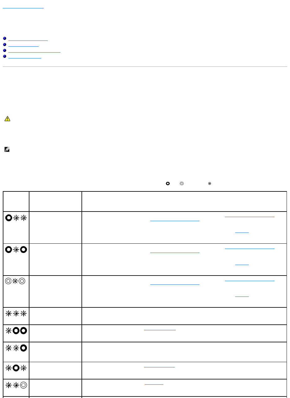
Back to Contents Page
Troubleshooting
Dell™Latitude™E6400andE6400ATGand
MobileWorkstationPrecision™M2400ServiceManual
Troubleshooting Tools
Solving Problems
Dell Technical Update Service
Dell Support Utility
Troubleshooting Tools
Diagnostic Lights
Your computer has three keyboard status lights located above the keyboard. During normal operation, the keyboard status lights display the current status
(on or off) of the Num Lock, Caps Lock, and Scroll Lock features. If the computer starts without error, the lights flash, and then turn off. If the computer
malfunctions, however, you can use the status of the lights to help identify the problem.
Diagnostic Light Codes During POST
To troubleshoot a problem with your computer, read the sequence of the keyboard status lights in order from left to right (Num Lock, Caps Lock, and then
Scroll Lock). If the computer malfunctions, the individual lights display a status of either On , Off , or Flashing .
CAUTION: Before you begin any of the procedures in this section, follow the safety instructions that shipped with your computer.
NOTE: After the computer completes POST, the Num Lock light may remain on, depending on your BIOS settings. For more information on using the
system setup program, see the Dell™TechnologyGuide on your computer or at support.dell.com.
Light
Pattern
Problem Description
Suggested Resolution
No memory modules are
detected.
lIf two or more memory modules are installed, remove the modules (see Removing a Memory Module),
then reinstall one module (see Replacing a Memory Module) and restart the computer. If the computer
starts normally, continue to install additional memory modules (one at a time) until you have identified a
faulty module or reinstalled all modules without error.
lIf available, install working memory of the same type into your computer (see Memory).
lIf the problem persists, contact Dell Support.
Memory modules are
detected, but a memory
failure has occurred.
lIf two or more memory modules are installed, remove the modules (see Removing a Memory Module),
then reinstall one module (see Replacing a Memory Module) and restart the computer. If the computer
starts normally, continue to install additional memory modules (one at a time) until you have identified a
faulty module or reinstalled all modules without error.
lIf available, install working memory of the same type into your computer (see Memory).
lIf the problem persists, contact Dell Support.
Memory failed to initialize or
memory is unsupported.
lIf two or more memory modules are installed, remove the modules (see Removing a Memory Module),
then reinstall one module (see Replacing a Memory Module) and restart the computer. If the computer
starts normally, continue to install additional memory modules (one at a time) until you have identified a
faulty module or reinstalled all modules without error.
lIf available, install working memory of the same type into your computer (see Memory).
lIf the problem persists, contact Dell Support.
System board failure has
occurred.
lContact Dell Support.
A possible processor failure
has occurred.
lReseat the processor (see Processor Module).
lIf the problem persists, contact Dell Support.
A possible graphics
card/video failure has
occurred.
lReseat any installed graphics cards.
lIf available, install a working graphics card into your computer.
lIf the problem persists, contact Dell Support.
A possible LCD failure has
occurred.
lReseat the LCD cable (see Display Assembly).
lIf the problem persists, contact Dell Support.
System failed on hard drive
initialization.
lReseat the hard drive (see Hard Drive).
lIf the problem persists, contact Dell Support.
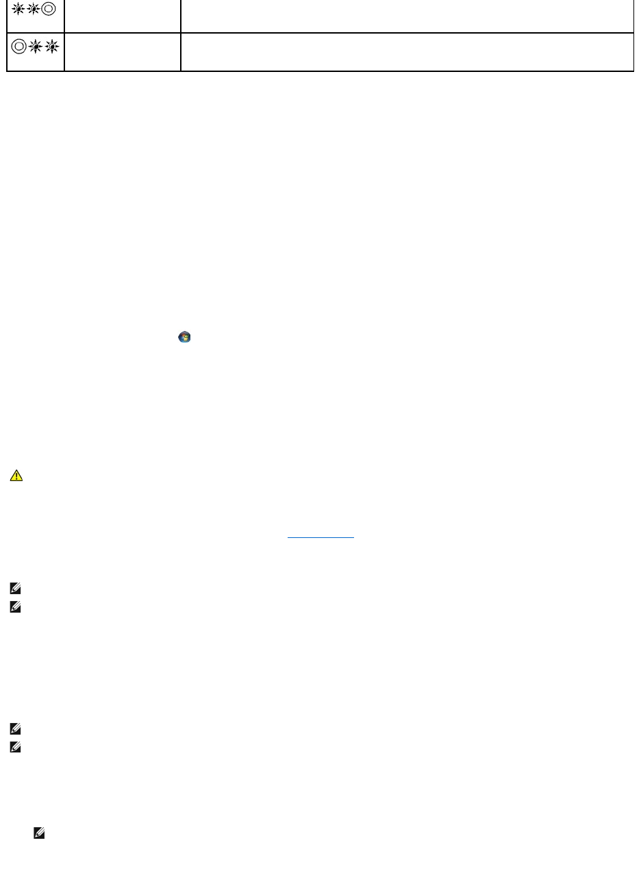
Hardware Troubleshooter
If a device is either not detected during the operating system setup or is detected, but incorrectly configured, you can use the Hardware Troubleshooter to
resolve the incompatibility.
Microsoft® Windows® XP:
1. Click Start® Help and Support.
2. Type hardware troubleshooter in the search field and press <Enter> to start the search.
3. In the Fix a Problem section, click Hardware Troubleshooter.
4. In the Hardware Troubleshooter list, select the option that best describes the problem and click Next to follow the remaining troubleshooting steps.
Microsoft Windows Vista®:
1. Click the Windows Vista start button , and click Help and Support.
2. Type hardware troubleshooter in the search field and press <Enter> to start the search.
3. In the search results, select the option that best describes the problem and follow the remaining troubleshooting steps.
Dell Diagnostics
When to Use the Dell Diagnostics
If you experience a problem with your computer, perform the checks in Solving Problems, and then run the Dell Diagnostics before contacting Dell for
assistance.
Start the Dell Diagnostics from your hard drive or from the Drivers and Utilities media provided with your computer.
Starting the Dell Diagnostics From Your Hard Drive
Before running the Dell Diagnostics, enter system setup to review your computer's configuration information, and ensure that the device you want to test is
displayed in system setup and is active. For more information on using the system setup program, see the Dell™TechnologyGuide on your computer or at
support.dell.com.
The Dell Diagnostics is located on a separate diagnostic utility partition on your hard drive.
1. Ensure that the computer is connected to an electrical outlet that is known to be working properly.
2. Press and hold the <Fn> key or the mute button then turn on your computer.
The computer runs the Pre-boot System Assessment (PSA), a series of initial tests of your system board, keyboard, display, memory, hard drive, etc.
System failed in Option
ROM initialization.
lIf you have added any plug-in hardware with an option ROM, try removing or reseating it.
lIf the problem persists, contact Dell Support.
A possible modem failure
has occurred.
lIf available, install a working modem into your computer.
lIf the problem persists, contact contact Dell Support.
CAUTION: Before you begin any of the procedures in this section, follow the safety instructions that shipped with your computer
NOTE: The Drivers and Utilities media is optional and may not ship with your computer.
NOTE: The Dell Diagnostics only operate on Dell computers.
NOTE: If the computer is connected to a docking device (docked), undock it. See the documentation that came with your docking device for instructions.
NOTE: If your computer does not display a screen image, contact Dell Support.
NOTE: Alternatively, you can select Diagnostics from the one-time boot menu at startup to boot to the diagnostic utility partition and run the Dell
Diagnostics.

¡During the assessment, answer any questions that appear.
¡If failures are detected during the Pre-boot System Assessment, write down the error code(s) and contact Dell Support.
¡If the Pre-boot System Assessment completes successfully, the following message appears: "Booting Dell Diagnostic Utility
Partition. Press any key to continue."
3. Press any key to start the Dell Diagnostics from the diagnostics utility partition on your hard drive.
4. Press <Tab> to select Test System and then press <Enter>.
5. At the Dell Diagnostics Main Menu, left-click with the touch pad/mouse, or press <Tab> and then <Enter>, to select the test you want to run (see Dell
Diagnostics Main Menu).
6. After all tests have completed, close the test window to return to the Dell Diagnostics Main Menu.
7. Close the Main Menu window to exit the Dell Diagnostics and restart the computer.
Starting the Dell Diagnostics From the Drivers and Utilities Media
Before running the Dell Diagnostics, enter system setup to review your computer's configuration information, and ensure that the device you want to test is
displayed in system setup and is active. For more information on using the system setup program, see the Dell™TechnologyGuide on your computer or at
support.dell.com.
1. Insert the Drivers and Utilities media into the optical drive.
2. Restart your computer.
3. When the DELL logo appears, press <F12> immediately.
If you wait too long and the operating system logo appears, continue to wait until you see the Microsoft Windows desktop, then shut down your
computer and try again.
4. When the boot device list appears, use the up- or down- arrow keys to highlight CD/DVD/CD-RW Drive then press <Enter>.
5. Press any key to confirm that you want to start from the CD/DVD.
If you wait too long and the operating system logo appears, continue to wait until you see the Microsoft Windows desktop, then shut down your
computer and try again.
6. Type 1 to Run the 32 Bit Dell Diagnostics.
7. At the Dell Diagnostics Menu, type 1 to select Dell 32-bit Diagnostics for Resource CD (graphical user interface).
8. Press <Tab> to select Test System and then press <Enter>.
9. At the Dell Diagnostics Main Menu, left-click with the mouse, or press <Tab> and then <Enter>, to select the test you want to run (see Dell Diagnostics
Main Menu).
NOTE: If you see a message stating that no diagnostics utility partition has been found, run the Dell Diagnostics from your Drivers and Utilities
media (see Starting the Dell Diagnostics From the Drivers and Utilities Media).
NOTE: It is recommended that you select Test System to run a complete test on your computer. Selecting Test Memory initiates the extended
memory test, which can take up to thirty minutes or more to complete. When the test completes, record the test results and then press any key to
return to the previous menu.
NOTE: Write down any error codes and problem descriptions exactly as they appear and follow the instructions on the screen.
NOTE: If you see a message stating that no diagnostics utility partition has been found, run the Dell Diagnostics from your Drivers and Utilities
media (see Starting the Dell Diagnostics From the Drivers and Utilities Media).
NOTE: Keyboard failure may result when a key is held down for extended periods of time. To avoid possible keyboard failure, press and release
<F12> in even intervals to open the Boot Device Menu.
NOTE: Using the one-time boot menu changes the boot sequence for the current boot only. Upon restart, the computer boots according to the
boot sequence specified in system setup.
NOTE: It is recommended that you select Test System to run a complete test on your computer. Selecting Test Memory initiates the extended
memory test, which can take up to thirty minutes or more to complete. When the test completes, record the test results and then press any key to
return to the previous menu.
10. After all tests have completed, close the test window to return to the Dell Diagnostics Main Menu.
11. Close the Main Menu window to exit the Dell Diagnostics and restart the computer.
12. Remove the Drivers and Utilities media from the optical drive.
Dell Diagnostics Main Menu
After the Dell Diagnostics loads, the following menu appears:
Press <Tab> to select the test you want to run and then press <Enter>.
After Test System is selected, the following menu appears:
For any problem encountered during a test, a message appears with an error code and a description of the problem. Write down the error code and problem
description exactly as it appears and follow the instructions on the screen. If you cannot resolve the problem, contact Dell Support.
The following tabs provide additional information for tests run from the Custom Test or Symptom Tree option:
NOTE: Write down any error codes and problem descriptions exactly as they appear and follow the instructions on the screen.
Option
Function
Test Memory
Run the stand-alone memory test
Test System
Run system diagnostics
Exit
Exit the diagnostics
NOTE: It is recommended that you select Test System to run a complete test on your computer. Selecting Test Memory initiates the extended memory
test, which can take up to thirty minutes or more to complete. When the test completes, record the test results and then press any key to return to this
menu.
Option
Function
Express Test
Performs a quick test of devices in the system. This typically can take 10 to 20 minutes.
NOTE: The Express Test requires no interaction on your part. Run Express Test first to increase the possibility of tracing a problem quickly.
Extended Test
Performs a thorough check of devices in the system. This typically can take an hour or more.
NOTE: The Extended Test periodically requires your input to answer specific questions.
Custom Test
Use to test a specific device or customize the tests to be run.
Symptom Tree
This option allows you to select tests based on a symptom of the problem you are having. This option lists the most common symptoms.
NOTE: It is recommended that you select Extended Test to perform a more thorough check of devices in the computer.
NOTE: When contacting Dell Support, have your Service Tag ready. The Service Tag for your computer is located at the top of each test screen.
Tab
Function
Results
Displays the results of the test and any error conditions encountered.
Errors
Displays error conditions encountered, error codes, and the problem description.
Help
Describes the test and any requirements for running the test.
Configuration
Displays the hardware configuration for the selected device.
The Dell Diagnostics obtains configuration information for all devices from System Setup, memory, and various internal tests, and displays the
information in the device list in the left pane of the screen.
NOTE: The device list may not display the names of all components installed on your computer or all devices attached to your computer.
Parameters
Allows you to customize the test, if applicable, by changing the test settings.

Error Messages
If the error message is not listed, see the documentation for the operating system or the program that was running when the message appeared.
A filename cannot contain any of the following characters: \ / : * ? " < > | — Do not use these characters in filenames.
A required .DLL file was not found — The program that you are trying to open is missing an essential file. To remove and then reinstall the program:
Windows XP:
1. Click Start® Control Panel® Add or Remove Programs® Programs and Features.
2. Select the program you want to remove.
3. Click Uninstall.
4. See the program documentation for installation instructions.
Windows Vista:
1. Click Start ® Control Panel® Programs® Programs and Features.
2. Select the program you want to remove.
3. Click Uninstall.
4. See the program documentation for installation instructions.
drive letter :\ is not accessible. The device is not ready — The drive cannot read the disk. Insert a disk into the drive and try again.
Insert bootable media — Insert a bootable floppy disk, CD, or DVD.
Non-system disk error — Remove the floppy disk from the floppy drive and restart your computer.
Not enough memory or resources. Close some programs and try again — Close all windows and open the program that you want to use. In some cases,
you may have to restart your computer to restore computer resources. If so, run the program that you want to use first.
Operating system not found — Contact Dell Support.
Solving Problems
Follow these tips when troubleshooting your computer:
lIf you added or removed a part before the problem started, review the installation procedures and ensure that the part is correctly installed.
lIf a peripheral device does not work, ensure that the device is properly connected.
lIf an error message appears on the screen, write down the exact message. This message may help support personnel diagnose and fix the problem(s).
lIf an error message occurs in a program, see the program's documentation.
Battery Problems
Drive Problems
CAUTION: Before you begin any of the procedures in this section, follow the safety instructions that shipped with your computer.
NOTE: The procedures in this document were written for the Windows default view, so they may not apply if you set your Dell computer to the Windows
Classic view.
CAUTION: There is a danger of a new battery exploding if it is incorrectly installed. Replace the battery only with the same or equivalent type
recommended by the manufacturer. Discard used batteries according to the manufacturer's instructions.
CAUTION: Before you begin any of the procedures in this section, follow the safety instructions that shipped with your computer.
CAUTION: Before you begin any of the procedures in this section, follow the safety instructions that shipped with your computer.

Ensure that Microsoft Windows Recognizes the drive —
Windows XP:
lClick Start and click My Computer.
Windows Vista:
lClick the Windows Vista Start button and click Computer.
If the drive is not listed, perform a full scan with your antivirus software to check for and remove viruses. Viruses can sometimes prevent Windows from
recognizing the drive.
Test the drive
lInsert another disc to eliminate the possibility that the original drive is defective.
lInsert a bootable floppy disk and restart the computer.
Clean the drive or disk —
For information on cleaning your computer, see the Dell™TechnologyGuide on your computer or at support.dell.com.
Check the cable connections
Run the Hardware Troubleshooter —
See Hardware Troubleshooter.
Run the Dell Diagnostics —
See Dell Diagnostics.
Optical drive problems
Adjust the Windows volume control —
lClick the speaker icon in the lower-right corner of your screen.
lEnsure that the volume is turned up by clicking the slidebar and dragging it up.
lEnsure that the sound is not muted by clicking any boxes that are checked.
Check the speakers and subwoofer —
See Sound and Speaker Problems.
Problems writing to an optical drive
Close other programs —
Theopticaldrivemustreceiveasteadystreamofdataduringthewritingprocess.Ifthestreamisinterrupted,anerroroccurs.Tryclosingallprogramsbefore
you write to the optical.
Turn off standby mode in Windows before writing to a disc —
For information about setting power options, see the Dell™TechnologyGuide on your computer or at support.dell.com. You can also search for the keyword
standby in Windows Help and Support for information on power management modes.
Hard drive problems
NOTE: High-speed optical drive vibration is normal and may cause noise, which does not indicate a defect in the drive or the media.
NOTE: Because of different regions worldwide and different disc formats, not all DVD titles work in all DVD drives.

Run Check Disk —
Windows XP:
1. Click Start and click My Computer.
2. Right-click Local Disk C:.
3. Click Properties® Tools® Check Now.
4. Click Scan for and attempt recovery of bad sectors and click Start.
Windows Vista:
1. Click Start and click Computer.
2. Right-click Local Disk C:.
3. Click Properties® Tools® Check Now.
The User Account Control window may appear. If you are an administrator on the computer, click Continue; otherwise, contact your administrator to
continue the desired action.
4. Follow the instructions on the screen.
IEEE 1394 Device Problems
Ensure that the cable for the IEEE 1394 device is properly inserted into the device and into the connector on the computer
Ensure that the IEEE 1394 device is enabled in system setup — For more information on using the system setup program, see the Dell™TechnologyGuide
on your computer or at support.dell.com.
Ensure that the IEEE 1394 device is recognized by Windows —
Windows XP:
1. Click Start and click Control Panel.
2. Under Pick a Category, click Performance and Maintenance® System® System Properties ® Hardware® Device Manager.
Windows Vista:
1. Click Start ® Control Panel® Hardware and Sound.
2. Click Device Manager.
If your IEEE 1394 device is listed, Windows recognizes the device.
If you have problems with a Dell IEEE 1394 device —
ContactDellSupport.
If you have problems with an IEEE 1394 device not provided by Dell — ContacttheIEEE1394devicemanufacturer.
Lockups and Software Problems
The computer does not start up
Check the diagnostic lights —
See Power Problems.
Ensure that the power cable is firmly connected to the computer and to the electrical outlet
CAUTION: Before you begin any of the procedures in this section, follow the safety instructions that shipped with your computer.
NOTE: Your computer supports only IEEE 1394a standard.
CAUTION: Before you begin any of the procedures in this section, follow the safety instructions that shipped with your computer.

The computer stops responding
Turn the computer off — If you are unable to get a response by pressing a key on your keyboard or moving your mouse, press and hold the power button for
at least 8 to 10 seconds (until the computer turns off), and then restart your computer.
A program stops responding
End the program
1. Press <Ctrl><Shift><Esc> simultaneously to access the Task Manager.
2. Click the Applications tab.
3. Click to select the program that is no longer responding.
4. Click End Task.
A program crashes repeatedly
Check the software documentation —
If necessary, uninstall and then reinstall the program.
A program is designed for an earlier Windows operating system
Run the Program Compatibility Wizard —
Windows XP:
The Program Compatibility Wizard configures a program so that it runs in an environment similar to non-XP operating system environments.
1. Click Start® All Programs® Accessories® Program Compatibility Wizard® Next.
2. Follow the instructions on the screen.
Windows Vista:
The Program Compatibility Wizard configures a program so that it runs in an environment similar to non-Windows Vista operating system environments.
1. Click Start ® Control Panel® Programs® Use an older program with this version of Windows.
2. In the welcome screen, click Next.
3. Follow the instructions on the screen.
A solid blue screen appears
Turn the computer off —
If you are unable to get a response by pressing a key on your keyboard or moving your mouse, press and hold the power button for at least 8 to 10 seconds
(until the computer turns off), and then restart your computer.
Other software problems
Check the software documentation or contact the software manufacturer for troubleshooting information —
lEnsure that the program is compatible with the operating system installed on your computer.
lEnsure that your computer meets the minimum hardware requirements needed to run the software. See the software documentation for information.
lEnsure that the program is installed and configured properly.
lVerify that the device drivers do not conflict with the program.
lIf necessary, uninstall and then reinstall the program.
Back up your files immediately
NOTICE: You may lose data if you are unable to perform an operating system shutdown.
NOTE: Most software includes installation instructions in its documentation or on a floppy disk, CD, or DVD.

Use a virus-scanning program to check the hard drive, floppy disks, CDs, or DVDs
Save and close any open files or programs and shut down your computer through the Start menu
Memory Problems
If you receive an insufficient memory message —
lSave and close any open files and exit any open programs you are not using to see if that resolves the problem.
lSee the software documentation for minimum memory requirements. If necessary, install additional memory (see Replacing a Memory Module).
lReseat the memory modules (see Memory) to ensure that your computer is successfully communicating with the memory.
lRun the Dell Diagnostics (see Dell Diagnostics).
If you experience other memory problems —
lReseat the memory modules (see Memory) to ensure that your computer is successfully communicating with the memory.
lEnsure that you are following the memory installation guidelines (see Replacing a Memory Module).
lEnsure that the memory you are using is supported by your computer. For more information about the type of memory supported by your computer,
see the Setup and Quick Reference Guide for your computer at support.dell.com.
lRun the Dell Diagnostics (see Dell Diagnostics).
Power Problems
If the power light is blue and the computer is not responding — See Diagnostic Lights.
If the power light is off — The computer is either turned off or is not receiving power.
lReseat the power cable in the power connector on the back of the computer and the electrical outlet.
lBypass power strips, power extension cables, and other power protection devices to verify that the computer turns on properly.
lEnsure that any power strips being used are plugged into an electrical outlet and are turned on.
lEnsure that the electrical outlet is working by testing it with another device, such as a lamp.
Eliminate interference — Some possible causes of interference are:
lPower, keyboard, and mouse extension cables
lToo many devices connected to the same power strip
lMultiple power strips connected to the same electrical outlet
Sound and Speaker Problems
No sound from speakers
Adjust the Windows volume control — Click or double-click the speaker icon in the lower-right corner of your screen. Ensure that the volume is turned up and
that the sound is not muted.
Disconnect headphones from the headphone connector — Sound from the speakers is automatically disabled when headphones are connected to the
computer's front-panel headphone connector.
Eliminate possible interference — Turn off nearby fans, fluorescent lights, or halogen lamps to check for interference.
Run the Hardware Troubleshooter — See Hardware Troubleshooter.
CAUTION: Before you begin any of the procedures in this section, follow the safety instructions that shipped with your computer.
CAUTION: Before you begin any of the procedures in this section, follow the safety instructions that shipped with your computer.
CAUTION: Before you begin any of the procedures in this section, follow the safety instructions that shipped with your computer.
NOTE: The volume control in MP3 and other media players may override the Windows volume setting. Always check to ensure that the volume on the
media player(s) has not been turned down or off.

No sound from headphones
Check the headphone cable connection — Ensure that the headphone cable is securely inserted into the headphone connector. See the Setup and Quick
Reference Guide for your computer at support.dell.com.
Adjust the Windows volume control — Click or double-click the speaker icon in the lower-right corner of your screen. Ensure that the volume is turned up and
that the sound is not muted.
Video and Display Problems
Check the diagnostic lights —
See Diagnostic Lights.
Check the display settings —
See the Dell™TechnologyGuideon your computer or at support.dell.com.
Adjust the Windows display settings —
Windows XP:
1. Click Start® Control Panel® Appearance and Themes.
2. Click the area you want to change or click the Display icon.
3. Try different settings for Color quality and Screen resolution.
Windows Vista:
1. Click Start ® Control Panel® Hardware and Sound® Personalization® Display Settings.
2. Adjust Resolution and Colors settings, as needed.
Only part of the display is readable
Connect an external monitor —
1. Shut down your computer and connect an external monitor to the computer.
2. Turn on the computer and the monitor and adjust the monitor brightness and contrast controls.
If the external monitor works, the computer display or video controller may be defective. Contact Dell Support.
Dell Technical Update Service
The Dell Technical Update service provides proactive e-mail notification of software and hardware updates for your computer. The service is free and can be
customized for content, format, and how frequently you receive notifications.
To enroll for the Dell Technical Update service, go to support.dell.com.
Dell Support Utility
The Dell Support Utility is installed on your computer and available from the Dell Support, , icon on the taskbar or from the Start button. Use this support
CAUTION: Before you begin any of the procedures in this section, follow the safety instructions that shipped with your computer.
NOTICE: If your computer came with a PCI graphics card installed, removal of the card is not necessary when installing additional graphics cards;
however, the card is required for troubleshooting purposes. If you remove the card, store it in a safe and secure location. For information about your
graphics card, go to support.dell.com.
utility for self-support information, software updates, and health scans of your computing environment.
Accessing the Dell Support Utility
Access the Dell Support Utility from the icon on the taskbar or from the Start menu.
If the Dell Support icon does not appear in your taskbar:
1. Click Start® All Programs® Dell Support® Dell Support Settings.
2. Ensure that the Show icon on the taskbar option is checked.
The Dell Support Utility is customized for your computing environment.
The icon in the taskbar functions differently when you click, double-click, or right-click the icon.
Clicking the Dell Support Icon
Click or right-click the icon to perform the following tasks:
lCheck your computing environment.
lView the Dell Support Utility settings.
lAccess the help file for the Dell Support Utility.
lView frequently asked questions.
lLearn more about the Dell Support Utility.
lTurn the Dell Support Utility off.
Double-Clicking the Dell Support Icon
Double-click the icon to manually check your computing environment, view frequently asked questions, access the help file for the Dell Support Utility, and
view Dell Support settings.
For more information about the Dell Support Utility, click the question mark (?) at the top of the Dell™ Support screen.
Back to Contents Page
NOTE: If the Dell Support Utility is not available from the Start menu, go to support.dell.com and download the software.
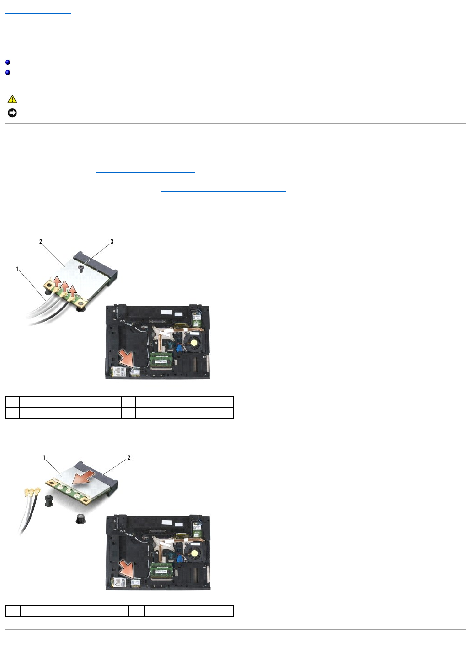
Back to Contents Page
WLAN/WiMax Card
Dell™Latitude™E6400andE6400ATGand
MobileWorkstationPrecision™M2400ServiceManual
Removing the WLAN/WiMax Card
Replacing the WLAN/WiMax Card
Removing the WLAN/WiMax Card
1. Follow the procedures in Before Working on Your Computer.
2. Remove the bottom of the base assembly (see Removing the Bottom of the Base Assembly).
3. Disconnect the antenna cables from the card.
4. Remove the M2 x 3-mm screw. The card will pop up at a 45-degree angle.
5. Slide the card out of the card connector on the system board.
CAUTION: Before you begin any of the procedures in this section, follow the safety instructions that shipped with your computer.
NOTICE: Insert a WLAN or WiMax card only into the slot labeled WLAN/WiMax.
1
antenna cables (3)
2
WLAN/WiMax card
3
M2 x 3-mm screw
1
WLAN/WiMax card
2
card connector
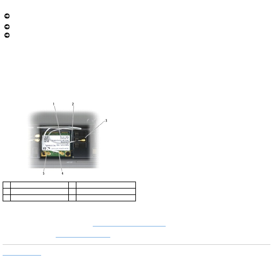
Replacing the WLAN/WiMax Card
1. Slide the card into the connector labeled WLAN/WiMax.
2. Press the card down and hold it in place.
3. Replace the M2 x 3-mm screw.
4. Connect the appropriate antenna cables to the card you are installing:
If the card has two triangles on the label (white and black), connect the white antenna cable to the connector labeled "main" (white triangle), and
connect the black antenna cable to the connector labeled "aux" (black triangle). Secure the gray antenna cable in the plastic holder next to the card.
If the card has three triangles on the label (white, black, and gray), connect the white antenna cable to the white triangle, connect the black antenna
cable to the black triangle, and connect the gray antenna cable to the gray triangle.
5. Replace the bottom of the base assembly (see Replacing the Bottom of the Base Assembly).
6. Follow the procedures in After Working on Your Computer.
Back to Contents Page
NOTICE: The connectors are keyed to ensure correct insertion. If you feel resistance, check the connectors on the card and on the system board, and
realign the card.
NOTICE: To avoid damage to the WLAN or WiMax card, ensure the cables are not under the card when you replace it.
NOTICE: Insert a WLAN or WiMax card only into the slot labeled WLAN/WiMax.
1
WLAN card
2
gray antenna cable
3
holder by card
4
white antenna cable
5
black antenna cable
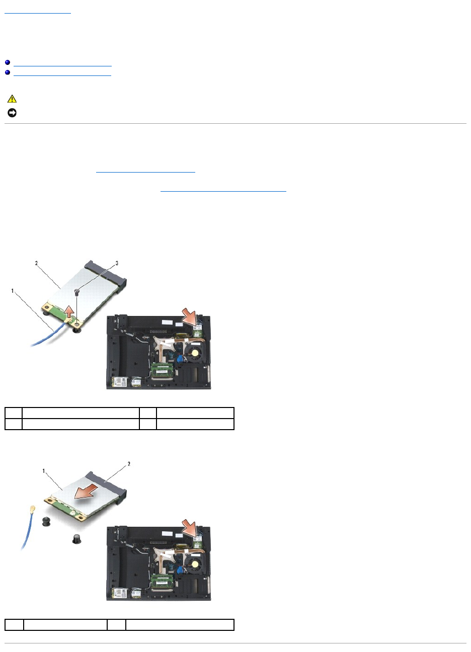
Back to Contents Page
WPAN (UWB/BT) Card
Dell™Latitude™E6400andE6400ATGand
MobileWorkstationPrecision™M2400ServiceManual
Removing a WPAN (UWB/BT) Card
Replacing a WPAN (UWB/BT) Card
Removing a WPAN (UWB/BT) Card
1. Follow the procedures in Before Working on Your Computer.
2. Remove the bottom of the base assembly (see Removing the Bottom of the Base Assembly).
3. Remove the M2.5 x 5-mm screw from the left hinge cover, then slide it forward and lift to remove it.
4. Disconnect the blue antenna cable from the card.
5. Remove the M2 x 3-mm screw. The card pops up at a 45-degree angle.
6. Slide the card out of the card connector on the system board.
CAUTION: Before you begin any of the procedures in this section, follow the safety instructions that shipped with your computer.
NOTICE: WPAN is a generic name for Ultra Wide Band (UWB) and Bluetooth®(BT). Insert a WPAN card only into the slot labeled WPAN/UWB/FCM.
1
antenna cable
2
WPAN card
3
M2 x 3-mm screw
1
WPAN card
2
card connector

Replacing a WPAN (UWB/BT) Card
1. Slide the card into the connector labeled WPAN/UWB/FCM.
2. Press the card down and hold it in place.
3. Replace the M2 x 3-mm screw.
4. Connect the blue antenna cable to the WPAN card.
5. Slide the left hinge cover back in place and replace the M2.5 x 5-mm screw on the hinge cover.
6. Replace the bottom of the base assembly (see Replacing the Bottom of the Base Assembly).
7. Follow the procedures in After Working on Your Computer.
Back to Contents Page
NOTICE: The connectors are keyed to ensure correct insertion. If you feel resistance, check the connectors on the card and on the system board, and
realign the card.
NOTICE: To avoid damage to the WPAN card, ensure the cables are not under the card when you replace it.
NOTICE: Insert a WPAN card only into the slot labeled WPAN/UWB/FCM.
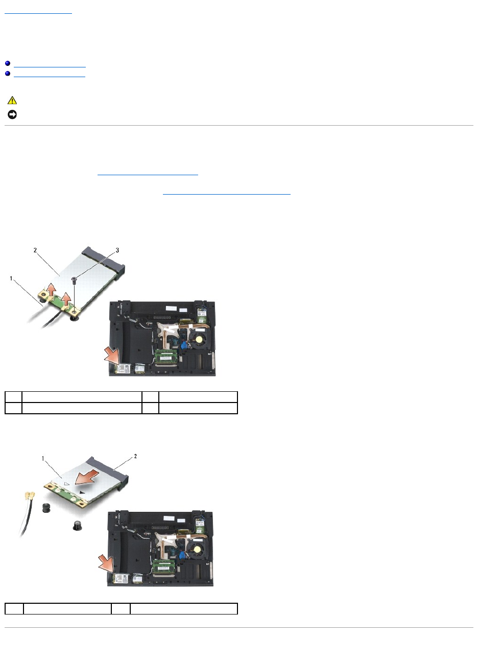
Back to Contents Page
WWAN Card
Dell™Latitude™E6400andE6400ATGand
MobileWorkstationPrecision™M2400ServiceManual
Removing a WWAN Card
Replacing a WWAN Card
Removing a WWAN Card
1. Follow the procedures in Before Working on Your Computer.
2. Remove the bottom of the base assembly (see Removing the Bottom of the Base Assembly).
3. Disconnect the antenna cables from the card.
4. Remove the M2 x 3-mm screw. The card pops up at a 45-degree angle.
5. Slide the card out of the card connector on the system board.
Replacing a WWAN Card
CAUTION: Before you begin any of the procedures in this section, follow the safety instructions that shipped with your computer.
NOTICE: Insert a WWAN card or FCM only into the slot labeled WWAN/FCM.
1
antenna cables (2)
2
WWAN card
3
M2 x 3-mm screw
1
WWAN card
2
card connector

1. Slide the card into the connector labeled WWAN/FCM.
2. Press the card down and hold it in place.
3. Replace the M2 x 3-mm screw.
4. Connect the white antenna cable to the connector labeled "main" (white triangle), and connect the black antenna cable to the connector labeled
"aux" (black triangle).
5. Replace the bottom of the base assembly (see Replacing the Bottom of the Base Assembly).
6. Follow the procedures in After Working on Your Computer.
Back to Contents Page
NOTICE: The connectors are keyed to ensure correct insertion. If you feel resistance, check the connectors on the card and on the system board, and
realign the card.
NOTICE: To avoid damage to the WWAN card, ensure the cables are not under the card when you replace it.
NOTICE: Insert a WWAN card or FCM only into the slot labeled WWAN/FCM.
