Dell Latitude Xpi Cd Service Manual
2014-11-13
: Dell Dell-Latitude-Xpi-Cd-Service-Manual-112491 dell-latitude-xpi-cd-service-manual-112491 dell pdf
Open the PDF directly: View PDF ![]() .
.
Page Count: 122 [warning: Documents this large are best viewed by clicking the View PDF Link!]
- Title Page
- Contents
- System Overview
- Initial Procedures
- Beep Codes and Error Messages
- Removing and Replacing Parts
- Factory Repair Parts
- System Setup Options
- Index

Dell Latitude XPi CD
SERVICE MANUAL
®

Information in this manual is subject to change without notice.
1994–1996 Dell Computer Corporation. All rights reserved.
Reproduction in any manner whatsoever without the written permission of Dell Computer Corporation is strictly forbidden.
Trademarks used in this text: Dell, the DELL logo, and Latitude are registered trademarks of Dell Computer Corporation; Microsoft, Windows, and MS-DOS are
registered trademarks of Microsoft Corporation; Intel and Pentium are registered trademarks of Intel Corporation; IBM is a registered trademark of International
Business Machines Corporation.
Other trademarks and trade names may be used in this document to refer to either the entities claiming the marks and names or their products. Dell Computer
Corporation disclaims any proprietary interest in trademarks and trade names other than its own.
October 1996 P/N 30269

v
Contents
Chapter 1
System Overview. . . . . . . . . . . . . . . . . . . . . . . . . . . . . . . 1-1
System Features . . . . . . . . . . . . . . . . . . . . . . . . . . . . . . . . . . . . . . . . . . . . . . . 1-1
Physical Description . . . . . . . . . . . . . . . . . . . . . . . . . . . . . . . . . . . . . . . . . . . . 1-2
Indicator Panel . . . . . . . . . . . . . . . . . . . . . . . . . . . . . . . . . . . . . . . . . . . . . 1-3
Power/Suspend Indicator . . . . . . . . . . . . . . . . . . . . . . . . . . . . . . . . . . 1-4
Diskette-Drive Access Indicator. . . . . . . . . . . . . . . . . . . . . . . . . . . . . 1-4
Hard-Disk/CD-ROM Drive Access Indicator. . . . . . . . . . . . . . . . . . . 1-4
PC Card Access Indicator . . . . . . . . . . . . . . . . . . . . . . . . . . . . . . . . . . 1-4
Low-Battery Indicator. . . . . . . . . . . . . . . . . . . . . . . . . . . . . . . . . . . . . 1-4
Charging Indicator . . . . . . . . . . . . . . . . . . . . . . . . . . . . . . . . . . . . . . . 1-4
Keyboard Indicators . . . . . . . . . . . . . . . . . . . . . . . . . . . . . . . . . . . . . . 1-5
Controlling Computer Power . . . . . . . . . . . . . . . . . . . . . . . . . . . . . . . . . . . . . 1-5
Power States . . . . . . . . . . . . . . . . . . . . . . . . . . . . . . . . . . . . . . . . . . . . . . . 1-5
Interrupt Assignments. . . . . . . . . . . . . . . . . . . . . . . . . . . . . . . . . . . . . . . . . . . 1-6
Technical Specifications. . . . . . . . . . . . . . . . . . . . . . . . . . . . . . . . . . . . . . . . . 1-7
Chapter 2
Initial Procedures . . . . . . . . . . . . . . . . . . . . . . . . . . . . . . 2-1
Initial User Contact. . . . . . . . . . . . . . . . . . . . . . . . . . . . . . . . . . . . . . . . . . . . . 2-1
Visual Inspection . . . . . . . . . . . . . . . . . . . . . . . . . . . . . . . . . . . . . . . . . . . . . . 2-1
Observing the Boot Routine . . . . . . . . . . . . . . . . . . . . . . . . . . . . . . . . . . . . . . 2-4
Eliminating Resource Conflicts . . . . . . . . . . . . . . . . . . . . . . . . . . . . . . . . . . . 2-5
Getting Help . . . . . . . . . . . . . . . . . . . . . . . . . . . . . . . . . . . . . . . . . . . . . . . . . . 2-5

vi
Chapter 3
Beep Codes and Error Messages . . . . . . . . . . . . . . . . . . 3-1
POST Beep Codes . . . . . . . . . . . . . . . . . . . . . . . . . . . . . . . . . . . . . . . . . . . . . 3-1
System Error Messages . . . . . . . . . . . . . . . . . . . . . . . . . . . . . . . . . . . . . . . . . 3-3
Running the Dell Diagnostics. . . . . . . . . . . . . . . . . . . . . . . . . . . . . . . . . . . . . 3-8
Chapter 4
Removing and Replacing Parts . . . . . . . . . . . . . . . . . . . 4-1
Recommended Tools . . . . . . . . . . . . . . . . . . . . . . . . . . . . . . . . . . . . . . . . . . . 4-2
Precautionary Measures . . . . . . . . . . . . . . . . . . . . . . . . . . . . . . . . . . . . . . . . . 4-2
Screw Identification and Tightening . . . . . . . . . . . . . . . . . . . . . . . . . . . . . . . 4-4
ZIF Connectors. . . . . . . . . . . . . . . . . . . . . . . . . . . . . . . . . . . . . . . . . . . . . . . . 4-5
Field-Replaceable Parts and Assemblies . . . . . . . . . . . . . . . . . . . . . . . . . . . . 4-6
Hard-Disk Drive Assembly . . . . . . . . . . . . . . . . . . . . . . . . . . . . . . . . . . . 4-7
Memory Compartment Cover . . . . . . . . . . . . . . . . . . . . . . . . . . . . . . . . . 4-8
Memory Modules . . . . . . . . . . . . . . . . . . . . . . . . . . . . . . . . . . . . . . . . . . . 4-9
Palmrest Assembly . . . . . . . . . . . . . . . . . . . . . . . . . . . . . . . . . . . . . . . . . . . . 4-10
Trackball Assembly . . . . . . . . . . . . . . . . . . . . . . . . . . . . . . . . . . . . . . . . 4-13
Keyboard Assembly . . . . . . . . . . . . . . . . . . . . . . . . . . . . . . . . . . . . . . . . 4-14
Display Assembly. . . . . . . . . . . . . . . . . . . . . . . . . . . . . . . . . . . . . . . . . . . . . 4-16
Tilt-Support Foot . . . . . . . . . . . . . . . . . . . . . . . . . . . . . . . . . . . . . . . . . . 4-16
Display Assembly. . . . . . . . . . . . . . . . . . . . . . . . . . . . . . . . . . . . . . . . . . 4-18
Display Assembly Bezel . . . . . . . . . . . . . . . . . . . . . . . . . . . . . . . . . . . . 4-20
Display Assembly Latch and Latch Spring . . . . . . . . . . . . . . . . . . . . . . 4-21
LCD Panel . . . . . . . . . . . . . . . . . . . . . . . . . . . . . . . . . . . . . . . . . . . . . . . 4-22
LCD Inverter Board . . . . . . . . . . . . . . . . . . . . . . . . . . . . . . . . . . . . . . . . 4-24
Hinge Covers . . . . . . . . . . . . . . . . . . . . . . . . . . . . . . . . . . . . . . . . . . . . . 4-25
Display-Assembly Interface Cable. . . . . . . . . . . . . . . . . . . . . . . . . . . . . 4-26
Microphone/Switch Assembly . . . . . . . . . . . . . . . . . . . . . . . . . . . . . . . . 4-28
Bottom Case Assembly . . . . . . . . . . . . . . . . . . . . . . . . . . . . . . . . . . . . . . . . 4-29
Diskette/CD-ROM Drive Assembly . . . . . . . . . . . . . . . . . . . . . . . . . . . 4-31
Deck Buoy . . . . . . . . . . . . . . . . . . . . . . . . . . . . . . . . . . . . . . . . . . . . . . . 4-33
Superpart Assembly . . . . . . . . . . . . . . . . . . . . . . . . . . . . . . . . . . . . . . . . 4-34
Reserve Battery . . . . . . . . . . . . . . . . . . . . . . . . . . . . . . . . . . . . . . . . . . . 4-36
System Board Assembly . . . . . . . . . . . . . . . . . . . . . . . . . . . . . . . . . . . . 4-38
Removing the System Board Assembly. . . . . . . . . . . . . . . . . . . . . . 4-39
Replacing the System Board Assembly . . . . . . . . . . . . . . . . . . . . . . 4-40
3.1-V Power Supply Board . . . . . . . . . . . . . . . . . . . . . . . . . . . . . . . . . . 4-41

vii
I/O-Panel Dust Cover . . . . . . . . . . . . . . . . . . . . . . . . . . . . . . . . . . . . . . . 4-42
Advanced Port Replicator Connector Dust Cover . . . . . . . . . . . . . . . . . 4-43
Audio Board . . . . . . . . . . . . . . . . . . . . . . . . . . . . . . . . . . . . . . . . . . . . . . 4-44
Appendix A
Factory Repair Parts . . . . . . . . . . . . . . . . . . . . . . . . . . . . A-1
Recommended Tools . . . . . . . . . . . . . . . . . . . . . . . . . . . . . . . . . . . . . . . . . . .A-1
Precautionary Measures . . . . . . . . . . . . . . . . . . . . . . . . . . . . . . . . . . . . . . . . .A-1
Factory Repair Parts and Assemblies . . . . . . . . . . . . . . . . . . . . . . . . . . . . . . .A-1
Exploded Views of Components and Assemblies . . . . . . . . . . . . . . . . . . . .A-12
Hard-Disk Drive . . . . . . . . . . . . . . . . . . . . . . . . . . . . . . . . . . . . . . . . . . .A-15
CD-ROM Drive . . . . . . . . . . . . . . . . . . . . . . . . . . . . . . . . . . . . . . . . . . .A-16
Diskette Drive. . . . . . . . . . . . . . . . . . . . . . . . . . . . . . . . . . . . . . . . . . . . .A-16
Palmrest Assembly Components . . . . . . . . . . . . . . . . . . . . . . . . . . . . . . . . .A-16
Trackball . . . . . . . . . . . . . . . . . . . . . . . . . . . . . . . . . . . . . . . . . . . . . . . . .A-16
Trackball Interface Cable . . . . . . . . . . . . . . . . . . . . . . . . . . . . . . . . . . . .A-16
Trackball Button Board . . . . . . . . . . . . . . . . . . . . . . . . . . . . . . . . . . . . .A-16
Palmrest Brace . . . . . . . . . . . . . . . . . . . . . . . . . . . . . . . . . . . . . . . . . . . .A-16
Display Assembly Components . . . . . . . . . . . . . . . . . . . . . . . . . . . . . . . . . .A-17
Display-Assembly EMI Shield . . . . . . . . . . . . . . . . . . . . . . . . . . . . . . . .A-17
Display Assembly Base . . . . . . . . . . . . . . . . . . . . . . . . . . . . . . . . . . . . .A-18
Display Assembly Hinges. . . . . . . . . . . . . . . . . . . . . . . . . . . . . . . . . . . .A-19
System-Board Assembly Components . . . . . . . . . . . . . . . . . . . . . . . . . . . . .A-20
System Board . . . . . . . . . . . . . . . . . . . . . . . . . . . . . . . . . . . . . . . . . . . . .A-20
Keyboard/Keypad/Mouse Connector Shield . . . . . . . . . . . . . . . . . . . . .A-21
I/O Interface Cable . . . . . . . . . . . . . . . . . . . . . . . . . . . . . . . . . . . . . . . . .A-22
I/O Board . . . . . . . . . . . . . . . . . . . . . . . . . . . . . . . . . . . . . . . . . . . . . . . .A-23
I/O Panel . . . . . . . . . . . . . . . . . . . . . . . . . . . . . . . . . . . . . . . . . . . . . . . . .A-24
Bottom-Case Assembly Components . . . . . . . . . . . . . . . . . . . . . . . . . . . . . .A-25
Main Battery Insulator . . . . . . . . . . . . . . . . . . . . . . . . . . . . . . . . . . . . . .A-25
Power Button and Power-Button Mounting Bracket . . . . . . . . . . . . . . .A-26
Spreader and Keel Plates . . . . . . . . . . . . . . . . . . . . . . . . . . . . . . . . . . . .A-27
Appendix B
System Setup Options . . . . . . . . . . . . . . . . . . . . . . . . . . B-1
Accessing the Dell Control Center . . . . . . . . . . . . . . . . . . . . . . . . . . . . . . . . .B-1
Accessing the System Setup Program . . . . . . . . . . . . . . . . . . . . . . . . . . . . . .B-2
System Setup Screens . . . . . . . . . . . . . . . . . . . . . . . . . . . . . . . . . . . . . .B-3

viii
Index
Figures
Figure 1-1. Front View of the Notebook Computer. . . . . . . . . . . . . . . . . . 1-2
Figure 1-2. Back View of the Notebook Computer . . . . . . . . . . . . . . . . . . 1-3
Figure 1-3. Indicator Panel. . . . . . . . . . . . . . . . . . . . . . . . . . . . . . . . . . . . . 1-3
Figure 4-1. Computer Orientation . . . . . . . . . . . . . . . . . . . . . . . . . . . . . . . 4-1
Figure 4-2. Main Battery Assembly Removal . . . . . . . . . . . . . . . . . . . . . . 4-3
Figure 4-3. Screw Identification. . . . . . . . . . . . . . . . . . . . . . . . . . . . . . . . . 4-4
Figure 4-4. Disconnecting an Interface Cable . . . . . . . . . . . . . . . . . . . . . . 4-5
Figure 4-5. Exploded View—Computer . . . . . . . . . . . . . . . . . . . . . . . . . . 4-6
Figure 4-6. Hard-Disk Drive Assembly Removal . . . . . . . . . . . . . . . . . . . 4-7
Figure 4-7. Memory Compartment Cover Removal . . . . . . . . . . . . . . . . . 4-8
Figure 4-8. Memory Module Removal . . . . . . . . . . . . . . . . . . . . . . . . . . . 4-9
Figure 4-9. Palmrest Assembly Removal. . . . . . . . . . . . . . . . . . . . . . . . . 4-10
Figure 4-10. Palmrest-Assembly Retaining Screws. . . . . . . . . . . . . . . . . . 4-11
Figure 4-11. Trackball Assembly Removal . . . . . . . . . . . . . . . . . . . . . . . . 4-13
Figure 4-12. Keyboard Assembly Removal. . . . . . . . . . . . . . . . . . . . . . . . 4-14
Figure 4-13. Tilt-Support Foot Removal . . . . . . . . . . . . . . . . . . . . . . . . . . 4-16
Figure 4-14. Display Assembly Removal . . . . . . . . . . . . . . . . . . . . . . . . . 4-18
Figure 4-15. Display Assembly Bezel Removal . . . . . . . . . . . . . . . . . . . . 4-20
Figure 4-16. Display Assembly Latch and Latch Spring Removal . . . . . . 4-21
Figure 4-17. LCD Panel Removal . . . . . . . . . . . . . . . . . . . . . . . . . . . . . . . 4-22
Figure 4-18. LCD Inverter Board Removal . . . . . . . . . . . . . . . . . . . . . . . . 4-24
Figure 4-19. Hinge Covers Removal . . . . . . . . . . . . . . . . . . . . . . . . . . . . . 4-25
Figure 4-20. Display-Assembly Interface Cable Removal . . . . . . . . . . . . 4-26
Figure 4-21. Microphone/Switch Assembly Removal. . . . . . . . . . . . . . . . 4-28
Figure 4-22. Bottom Case Assembly Removal . . . . . . . . . . . . . . . . . . . . . 4-30
Figure 4-23. Diskette/CD-ROM Drive Assembly Removal . . . . . . . . . . . 4-31
Figure 4-24. Deck Buoy Removal . . . . . . . . . . . . . . . . . . . . . . . . . . . . . . . 4-33
Figure 4-25. Superpart Assembly Removal . . . . . . . . . . . . . . . . . . . . . . . . 4-34
Figure 4-26. Reserve Battery Removal . . . . . . . . . . . . . . . . . . . . . . . . . . . 4-36
Figure 4-27. System Board Assembly Removal . . . . . . . . . . . . . . . . . . . . 4-38
Figure 4-28. I/O Bracket Clips. . . . . . . . . . . . . . . . . . . . . . . . . . . . . . . . . . 4-40
Figure 4-29. 3.1-V Power Supply Board Removal . . . . . . . . . . . . . . . . . . 4-41
Figure 4-30. I/O-Panel Dust Cover Removal. . . . . . . . . . . . . . . . . . . . . . . 4-42
Figure 4-31. Advanced Port Replicator Connector Dust Cover. . . . . . . . . 4-43
Figure 4-32. Audio Board Removal. . . . . . . . . . . . . . . . . . . . . . . . . . . . . . 4-44

ix
Figure A-1. Exploded View—Display Assembly . . . . . . . . . . . . . . . . . . .A-12
Figure A-2. Exploded View—Palmrest Assembly . . . . . . . . . . . . . . . . . .A-13
Figure A-3. Exploded View—Bottom Case Assembly. . . . . . . . . . . . . . .A-14
Figure A-4. Display-Assembly EMI Shield Removal. . . . . . . . . . . . . . . .A-17
Figure A-5. System Board Assembly in the Bottom Case Assembly . . . .A-20
Figure A-6. Keyboard/Keypad/Mouse Connector Shield Removal . . . . .A-21
Figure A-7. I/O Interface Cable Removal . . . . . . . . . . . . . . . . . . . . . . . . .A-22
Figure A-8. I/O Board Removal . . . . . . . . . . . . . . . . . . . . . . . . . . . . . . . .A-23
Figure A-9. I/O Panel Removal. . . . . . . . . . . . . . . . . . . . . . . . . . . . . . . . .A-24
Figure A-10. Bottom-Case Assembly Components . . . . . . . . . . . . . . . . . .A-25
Figure A-11. Power Button and Power-Button Mounting Bracket
Removal . . . . . . . . . . . . . . . . . . . . . . . . . . . . . . . . . . . . . . . . .A-26
Figure A-12. Spreader and Keel Plate Removal . . . . . . . . . . . . . . . . . . . . .A-27
Figure B-1. Dell Control Center Icon . . . . . . . . . . . . . . . . . . . . . . . . . . . . .B-1
Figure B-2. Dell Control Center Window . . . . . . . . . . . . . . . . . . . . . . . . . .B-1
Figure B-3. System Setup Screens . . . . . . . . . . . . . . . . . . . . . . . . . . . . . . .B-3
Tables
Table 1-1. Interrupt Assignments . . . . . . . . . . . . . . . . . . . . . . . . . . . . . . . 1-6
Table 1-2. Technical Specifications . . . . . . . . . . . . . . . . . . . . . . . . . . . . . 1-7
Table 3-1. POST Beep Codes . . . . . . . . . . . . . . . . . . . . . . . . . . . . . . . . . . 3-1
Table 3-2. System Error Messages . . . . . . . . . . . . . . . . . . . . . . . . . . . . . . 3-3
Table A-1. Factory Repair Parts and Assemblies. . . . . . . . . . . . . . . . . . . .A-2
Table B-1. System Setup Program Categories. . . . . . . . . . . . . . . . . . . . . .B-4

R
ead This First
W
arnings, Cautions, and Notes
Throughout this manual, there may be blocks of text printed in bold type or in
italic type. These blocks are warnings, cautions, and notes, and they are used as
follows:
NOTE: A NOTE provides helpful information about using the computer system.
A prerequisite for using this manual to service Dell portable computers is a
basic knowledge of IBM®-compatible PCs and prior training in IBM-
compatible PC troubleshooting techniques. In addition to information
provided in this manual, Dell provides the Reference and Troubleshooting
Guide for troubleshooting procedures and instructions on using the Dell
diagnostics to test portable computers, and the online System User’s Guide
for information about system setup and operations.
WARNING: A WARNING indicates the potential for bodily harm and
provides instructions for how to avoid the problem.
CAUTION: A CAUTION indicates either potential damage to hardware
or loss of data and provides instructions for how to avoid the problem.
x

System Overview 1-1
Chapter 1
System Overview
T
he Dell® Latitude® XPi CD is a lightweight, expandable portable computer
that use the Intel® Pentium® microprocessor. This chapter provides an overview
of the features and technical specifications of this computer.
S
ystem Features
In addition to the standard features found in a Dell portable computer, the Dell
Latitude XPi CD models include the following new features:
•64-bit-wide data bus.
•60-MHz local bus and a 30-MHz PCI bus.
•256-KB pipelined-burst SRAM secondary cache.
•16 MB of nonremovable, EDO-type memory built in to the system board.
Memory can be increased up to 48 MB by installing combinations of 8- and
16-MB fast-page memory modules in the two memory sockets on the sys-
tem board.
•128-bit accelerated graphics adapter with 1.1 MB of integrated video mem-
ory. The integrated video adapter is attached to the PCI bus.
•Full multimedia capability through the following standard features:
— A built-in CD-ROM drive
— MPEG software
— Hardware wavetable support
— SoundBlasterPro-compatible voice and music functions
— Jacks for connecting external speakers, headphones, or a microphone
•Two infrared ports that compatible with the Infrared Data Association
(IrDA) Standard 1.1 (Fast IR) for use with external devices.
•Keyboard with sound and Microsoft® Windows® operating system support.
•Support for two 3.3-V or 5-V PC Cards that adhere to the standards of the
Personal Computer Memory Card International Association (PCMCIA).
The computer supports type I, type II, or type III cards (in any
combination).
For a complete list of system features, see “Technical Specifications” found
later in this chapter.
1-2 Dell Latitude XPi CD Service Manual
P
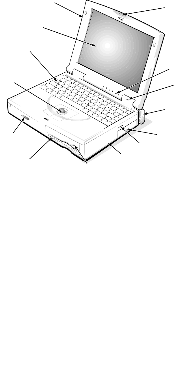
hysical Description
Figure 1-1. Front View of the Notebook Computer
trackball
assembly
diskette drive
main battery assembly
LCD panel
display assembly
latch
indicator panel
tilt-support foot (2)
keyboard
display assembly
speaker
microphone
infrared port
CD-ROM drive
bottom case assembly
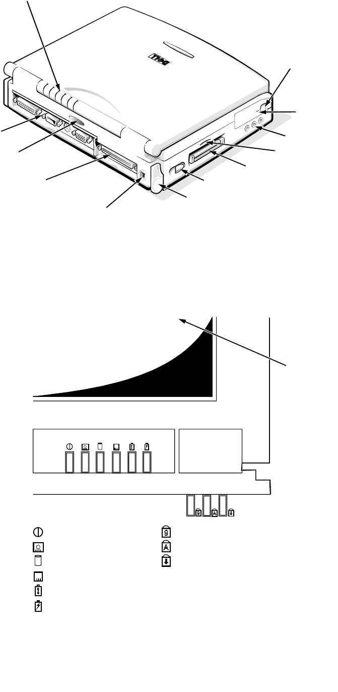
System Overview 1-3
Figure 1-2. Back View of the Notebook Computer
Indicator Panel
Figure 1-3. Indicator Panel
PC Card slot
power switch
hard-disk drive
security
cable slot
DC power input connector
tilt-support foot
Advanced Port
Replicator connector
indicator panel
I/O panel
infrared port
audio jacks (3)
speaker
LCD panel
power/suspend indicator
diskette-drive access indicator
PC Card access indicator
low-battery indicator
charging indicator
Num Lock indicator
Caps Lock indicator
Scroll Lock indicator
Legend
hard-disk/CD-ROM drive
access indicator

1-4 Dell Latitude XPi CD Service Manual
The portable computer has nine indicators: six on the display assembly’s indica-
tor panel and three on the keyboard assembly. Each of the six indicators on the
display assembly has an identical pair of LEDs: one is visible on the indicator
panel when the display is open, and the other is visible through an aperture on
the outside of the display assembly when the display is fully closed. The sub-
sections that follow describe the functions of the indicators.
Power/Suspend Indicator
The power/suspend indicator is a green LED. After the computer is turned on,
the power/suspend indicator lights up constantly to indicate that the computer is
receiving stable power. When the computer enters suspend mode, the indicator
blinks once approximately every 8 seconds.
Diskette-Drive Access Indicator
The diskette-drive access indicator is a green LED. The indicator lights when
data is being transferred to or from the diskette drive.
Hard-Disk/CD-ROM Drive Access Indicator
The hard-disk/CD-ROM drive access indicator is a green LED. The indicator
lights when data is being transferred to or from the hard-disk drive or the
CD-ROM.
PC Card Access Indicator
The PC Card access indicator is a green LED. The indicator lights when data is
being transferred to or from an installed PC Card (also known as a PCMCIA
card).
Low-Battery Indicator
The low-battery indicator is an amber LED. This indicator is used in conjunc-
tion with the speaker to indicate either of the following low-battery conditions:
•The first low-battery warning occurs when the main battery’s charge has
been depleted to 8 percent of its fully charged condition. The low-battery
indicator turns on and the speaker emits five beeps.
•The second and final low-battery warning occurs when the main battery’s
charge has been depleted to 3 percent of its fully charged condition. The
speaker beeps twice every 1 to 2 seconds for 15 seconds; then the system
does a suspend-to-disk operation automatically before shutting down.
Charging Indicator
The charging indicator is an amber LED. The indicator turns on when the main
battery begins charging and blinks to show the battery is fully charged.

System Overview 1-5
Keyboard Indicators
The keyboard controls the operation of the numeric lock (Num Lock) indicator,
the capitals lock (Caps Lock) indicator, and the Scroll Lock indicator, all of
which are visible through apertures at the top of the keyboard. These indicators
are associated with the <NUM LOCK> key, the <CAPS LOCK> key, and the
<SCROLL LOCK> key; when lit, the LEDs indicate the active state of these
keys.
C
ontrolling Computer Power
The power button does not directly control power to the computer. Instead,
when you slide the power button toward the front of the computer and then
release it, the button momentarily closes the power switch on the system board.
The power switch sends a signal to the power management controller, signaling
the controller to initiate a change of state of the computer’s power. The resulting
power state depends on the present power state. The following subsection gives
a description of the power states.
Power States
Sliding the power button toward the front of the computer initiates a change
from the current power state to a different state. The protocols for the power
state changes are as follows:
•If the computer is off (no indicators on) and the display is open and/or an
external monitor is attached to the computer, sliding the power button ini-
tiates a boot operation.
•If the computer is off, if the display is closed, and if no external monitor is
attached, sliding the power button causes the computer to run the POST and
then turn off.
•If the computer is on and the SYSTEM SWITCH option in System Setup is set
to ON/OFF, sliding the power button turns off the computer.
•If the computer is on and the SYSTEM SWITCH option in System Setup is set
to S2D/RFD, sliding the power button causes the computer to enter suspend-
to-disk mode.
•If the computer is in suspend mode (the power/suspend indicator flashes
every 8 seconds), if the SYSTEM SWITCH option in System Setup is set to
ON/OFF, and if the display is open or an external monitor is attached, sliding
the power button turns off the computer.
•If the computer is in suspend mode (the power/suspend indicator flashes
every 8 seconds), if the SYSTEM SWITCH option in System Setup is set to
S2D/RFD, and if the display is open or an external monitor is attached, sliding
the power button causes the computer to enter suspend-to-disk mode.

1-6 Dell Latitude XPi CD Service Manual
•If the computer is in suspend mode (the power/suspend indicator flashes
every 8 seconds), if the display is closed, and if no external monitor is
attached, sliding the power button has no effect on the power state. The
computer remains in suspend mode.
•If the computer is in suspend-to-disk mode, sliding the power button causes
the computer to initiate the resume-from-disk operation.
I
nterrupt Assignments
Table 1-1. Interrupt Assignments
IRQ Line Used/Available
IRQ0 Generated by the system timer
IRQ1 Generated by the keyboard controller to signal that the keyboard
output buffer is full
IRQ2 Generated internally by the interrupt controller to enable IRQ8
through IRQ15
IRQ3 Available for use by a PC Card unless the built-in serial port or
infrared port is configured for COM2 (the default)
IRQ4 Available for use by a PC Card unless the built-in serial port is
configured for COM1 (the default)
IRQ5 Available for use by the audio controller
IRQ6 Generated by the diskette drive controller to indicate that the
diskette drive requires the attention of the microprocessor
IRQ7 Available for use by a PC Card or audio controller if the built-in
parallel port is disabled
IRQ8 Generated by the system I/O controller’s RTC
IRQ9 Available for use by the PC Card interrupt controller or the
audio controller
IRQ10 Available for use by a PC Card or audio controller unless the
Advanced Port Replicator is attached
IRQ11 Available for use by a PC Card unless the Advanced Port Repli-
cator is attached
IRQ12 Generated by the keyboard controller to indicate that the output
buffer of the integrated trackball or external PS/2 mouse is full
IRQ13 Reserved for use by the internal coprocessor
IRQ14 Generated by the hard-disk drive to indicate that the drive
requires the attention of the microprocessor
IRQ15 Reserved for the CD-ROM drive

System Overview 1-7
T
echnical Specifications
Table 1-2. Technical Specifications
Microprocessor
Microprocessor type . . . . . . . . . . . Intel Pentium microprocessor
Microprocessor speed . . . . . . . . . . 150 MHz
Bus architecture . . . . . . . . . . . . . . PCI
Internal cache memory . . . . . . . . . 16 KB
External cache memory. . . . . . . . . 256 KB pipelined-burst SRAM
Math coprocessor . . . . . . . . . . . . . internal to the microprocessor
Chip Set and Bus
System chip set . . . . . . . . . . . . . . . Pico Power Vesuvius-LS Core Logic
Microprocessor data bus width. . . 64 bits
DRAM bus width . . . . . . . . . . . . . 64 bits
Address bus width. . . . . . . . . . . . . 32 bits
Security EEPROM . . . . . . . . . . . . 256 bytes
Flash EPROM. . . . . . . . . . . . . . . . 256 KB
Local bus. . . . . . . . . . . . . . . . . . . . 60 MHz
PCI bus . . . . . . . . . . . . . . . . . . . . . 30 MHz
PC Card
PC Card controller . . . . . . . . . . . . Texas Instruments PCI1130 CardBus
controller
PC Card connectors . . . . . . . . . . . two (supports type I and type II cards in
any combination; type III cards can be
used only with type I or type II cards)
Cards supported . . . . . . . . . . . . . . 3.3-V and 5-V
PC Card connector size. . . . . . . . . 68 pins
Data width (maximum). . . . . . . . . 32 bits
Memory
Architecture . . . . . . . . . . . . . . . . . EDO memory1
Memory module sockets. . . . . . . . two
1The system supports fast-page-mode memory modules for memory upgrades.

1-8 Dell Latitude XPi CD Service Manual
Memory
(Continued)
Memory module type and
capacities . . . . . . . . . . . . . . . . . . . 8- and 16-MB fast-page mode
Standard RAM . . . . . . . . . . . . . . . 16 MB (EDO) on system board
Maximum RAM . . . . . . . . . . . . . . 48 MB
Memory access time:
tRAC . . . . . . . . . . . . . . . . . . . 70 ns
tCAC . . . . . . . . . . . . . . . . . . . 20 ns
BIOS address . . . . . . . . . . . . . . . . F000:0000
Connectors
Serial (DTE) . . . . . . . . . . . . . . . . . one 9-pin connector; 16550-compatible,
16-byte buffer
Parallel . . . . . . . . . . . . . . . . . . . . . one 25-hole connector; unidirectional,
bidirectional, EPP 1.9, or ECP
Monitor. . . . . . . . . . . . . . . . . . . . . one 15-hole connector
PS/2 . . . . . . . . . . . . . . . . . . . . . . . one 6-pin mini-DIN (this connector does
not support more than one device at a time)
Infrared . . . . . . . . . . . . . . . . . . . . . two ports compatible with IrDA
Standard 1.1 (Fast IR)
Audio . . . . . . . . . . . . . . . . . . . . . . microphone-in
line-in/audio-in
headphones/speakers
Advanced Port Replicator . . . . . . 200-pin connector
Audio
Audio type . . . . . . . . . . . . . . . . . . SoundBlasterPro-compatible 3.01
voice and music functions
Audio controller . . . . . . . . . . . . . . ES1888
ES690 wavetable music synthesizer,
ES938 3D audio spatializer
Stereo conversion . . . . . . . . . . . . . 16 bit (analog-to-digital and digital-
to-analog)
FM music synthesizer. . . . . . . . . . 20-voice, 72-operator
Table 1-2. Technical Specifications
(Continued)

System Overview 1-9
Audio
(Continued)
Interfaces:
Internal . . . . . . . . . . . . . . . . . . ISA bus
External. . . . . . . . . . . . . . . . . . stereo line-in minijack
microphone-in minijack
headphones/speakers-out minijack
Speakers . . . . . . . . . . . . . . . . . . . . four 8-ohm speakers
Internal speaker amplifier . . . . . . . 1 W into 8 ohms stereo
Headphones amplifier. . . . . . . . . . 150 mW into 32 ohms stereo
Controls. . . . . . . . . . . . . . . . . . . . . volume can be controlled through key
combinations, software application
menus, or the Speaker window in the Dell
Control Center
Video
Video type . . . . . . . . . . . . . . . . . . . hardware-accelerated, 128-bit PCI
Video controller . . . . . . . . . . . . . . NeoMagic 2090
Integrated video memory . . . . . . . 1.1 MB
Display
Type. . . . . . . . . . . . . . . . . . . . . . . . active-matrix color (TFT)
Dimensions:
Height . . . . . . . . . . . . . . . . . . . 195.0 mm (7.68 inches)
Width. . . . . . . . . . . . . . . . . . . . 272.0 mm (10.7 inches)
Diagonal . . . . . . . . . . . . . . . . . 307.5 mm (12.1 inches)
Maximum resolution. . . . . . . . . . . 800 x 600 pixels; 65,536 colors
Response time (typical) . . . . . . . . 80 ms
Operating angle. . . . . . . . . . . . . . . 0° (closed) to 180°
Dot pitch . . . . . . . . . . . . . . . . . . . . 0.31 mm
Power consumption:
Panel (typical). . . . . . . . . . . . . 0.69 W
Backlight. . . . . . . . . . . . . . . . . 2.10 W
Controls. . . . . . . . . . . . . . . . . . . . . brightness can be controlled through a key
combination, the Display window in the
Dell Control Center, or the System Setup
program
Table 1-2. Technical Specifications
(Continued)

1-10 Dell Latitude XPi CD Service Manual
Keyboard
Number of keys . . . . . . . . . . . . . . 85 (U.S., Canada, Korea, Thailand, and
locations that use traditional Chinese);
86 (Europe);
87 (Japan)
Key travel . . . . . . . . . . . . . . . . . . . 3.0 ± 0.5 mm (0.12 ± 0.02 inch)
Key spacing . . . . . . . . . . . . . . . . . 18.25 mm (0.72 inch)
Layout. . . . . . . . . . . . . . . . . . . . . . QWERTY, AZERTY, Kanji
Battery
Type . . . . . . . . . . . . . . . . . . . . . . . lithium ion
Dimensions:
Height. . . . . . . . . . . . . . . . . . . 20.5 mm (0.81 inch)
Depth . . . . . . . . . . . . . . . . . . . 152.75 mm (6.01 inches)
Width . . . . . . . . . . . . . . . . . . . 78.5 mm (3.09 inches)
Weight. . . . . . . . . . . . . . . . . . . . . . 0.41 kg (0.9 lb)
Voltage . . . . . . . . . . . . . . . . . . . . . 14.4 VDC
Capacity . . . . . . . . . . . . . . . . . . . . 36 WH
Charge time (approximate):2
Computer on. . . . . . . . . . . . . . 2.5 hours
Computer off . . . . . . . . . . . . . 1.5 hours
Operating time (approximate, with no
power management features
enabled)2. . . . . . . . . . . . . . . . . . . . 2 to 3.5 hours (without a CD-ROM drive
in use)
Life span (approximate)2 . . . . . . . 400 discharge/charge cycles
Temperature range:
Charge . . . . . . . . . . . . . . . . . . 10° to 40°C (50° to 104°F)
Discharge . . . . . . . . . . . . . . . . 10° to 40°C (50° to 104°F)
Storage . . . . . . . . . . . . . . . . . . –40° to 65°C (–40° to 149°F)
2Battery performance features such as charge time, operating time, and life span can vary according
to the conditions under which the computer and battery are used.
Table 1-2. Technical Specifications
(Continued)

System Overview 1-11
Battery
(Continued)
NiCad reserve battery:
Voltage . . . . . . . . . . . . . . . . . . 7.2 V
Operating time
(approximate) . . . . . . . . . . . . . 2 minutes (if computer is in battery swap
mode); 40 days (if power is
turned off)
AC Adapter
Input voltage . . . . . . . . . . . . . . . . . 90 to 135 VAC and 164 to 264 VAC
Input current (maximum) . . . . . . . 1.2 A and 0.6 A
Input frequency . . . . . . . . . . . . . . . 47 to 63 Hz
Output current. . . . . . . . . . . . . . . . 4.5 A (maximum);
3.5 A (continuous)
Rated output voltage . . . . . . . . . . . 18.5 VDC
Height . . . . . . . . . . . . . . . . . . . . . . 27.94 mm (1.1 inches)
Width. . . . . . . . . . . . . . . . . . . . . . . 58.42 mm (2.3 inches)
Depth. . . . . . . . . . . . . . . . . . . . . . . 133.35 mm (5.25 inches)
Weight (with cables) . . . . . . . . . . 0.4 kg (0.89 lb)
Temperature range:
Operating . . . . . . . . . . . . . . . . 0° to 40°C (32° to 104°F)
Storage . . . . . . . . . . . . . . . . . . -40° to 70°C (-40° to 158°F)
CD-ROM Drive3
Disc size . . . . . . . . . . . . . . . . . . . . 8 cm and 12 cm (no adapter required)
Data transfer rate:
Sustained. . . . . . . . . . . . . . . . . 900 KB/sec (mode 2 disc)
Burst . . . . . . . . . . . . . . . . . . . . 14.4 MB/sec (PIO mode 3)
Seek time:
Random. . . . . . . . . . . . . . . . . . 200 m/sec
Full-stroke. . . . . . . . . . . . . . . . 500 m/sec
3The CD-ROM drive in your computer may have different specifications.
Table 1-2. Technical Specifications
(Continued)

1-12 Dell Latitude XPi CD Service Manual
CD-ROM Drive3
(Continued)
Access time:
Random . . . . . . . . . . . . . . . . . 250 m/sec
Full-stroke . . . . . . . . . . . . . . . 550 m/sec
Memory buffer . . . . . . . . . . . . . . . 128 KB
Physical (Computer)
Height . . . . . . . . . . . . . . . . . . . . . . 63.0 mm (2.48 inches)
Width . . . . . . . . . . . . . . . . . . . . . . 280.9 mm (11.06 inches)
Depth . . . . . . . . . . . . . . . . . . . . . . 233.5 mm (9.19 inches)
Weight (with battery and
hard-disk drive) . . . . . . . . . . . . . . 3.29 kg (7.26 lb)
Environmental
Temperature:
Operating . . . . . . . . . . . . . . . . 10° to 40°C (50° to 104°F)
Storage . . . . . . . . . . . . . . . . . . -40° to 65°C (-40° to 149°F)
Relative humidity (maximum):
Operating . . . . . . . . . . . . . . . . 90% (noncondensing)
Storage . . . . . . . . . . . . . . . . . . 95% (noncondensing)
Maximum vibration:
Operating . . . . . . . . . . . . . . . . 0.51 GRMS, using a random-vibration
spectrum that simulates truck shipment
Storage . . . . . . . . . . . . . . . . . . 1.1 GRMS, using a random-vibration
spectrum that simulates air/truck
shipment
3The CD-ROM drive in your computer may have different specifications.
Table 1-2. Technical Specifications
(Continued)

System Overview 1-13
Environmental
(Continued)
Maximum shock:4
Operating . . . . . . . . . . . . . . . . 152.4 cm/sec (60 inches/sec) (less than or
equal to a pulse width of 2 ms)
Storage . . . . . . . . . . . . . . . . . . 203.2 cm/sec (80 inches/sec)
(less than or equal to a pulse width of 2 ms)
Altitude (maximum):
Operating . . . . . . . . . . . . . . . . 3048 m (10,000 ft)
Storage . . . . . . . . . . . . . . . . . . 10,600 m (35,000 ft)
4Measured with the hard-disk drive in head-parked position.
Table 1-2. Technical Specifications
(Continued)

1-14 Dell Latitude XPi CD Service Manual

Initial Procedures 2-1
Chapter 2
Initial Procedures
T
his chapter describes initial procedures that can help you diagnose a com-
puter problem. These procedures can often reveal the source of a problem or
indicate the correct starting point for troubleshooting the computer. Dell recom-
mends that you perform these procedures in the order they are presented in this
manual.
I
nitial User Contact
When you first contact a user who has a computer problem, ask the user to
describe the problem and the conditions under which it occurs. A verbal
description can often indicate the cause of a problem or indicate the appropriate
troubleshooting procedure to use. After the user describes the problem, follow
these steps:
1. Ask the user to back up any data on the hard-disk drive if the system’s
condition permits.
See “Maintaining Your Computer” in the online System User’s Guide.
2. Ask the user to try to duplicate the problem by repeating the operations
he or she was performing at the time the problem occurred.
Can the user duplicate the problem?
Yes. Proceed to step 3.
No. Proceed to the next section, “Visual Inspection.”
3. Observe the user to determine whether he or she is making an error,
such as typing an incorrect key combination or entering a command
incorrectly.
Is the problem a result of user error?
Yes. Instruct the user in the proper procedure, or direct him or her to the
appropriate user documentation for a description of the correct procedure.
No. Proceed to the next section, “Visual Inspection.”
V
isual Inspection
The visual inspection consists of a quick inspection of the exterior of the
computer and any attached peripherals, including making any necessary correc-
tions. For information about the proper removal and installation of computer

2-2 Dell Latitude XPi CD Service Manual
components, as instructed in the following procedures, see Chapter 4, “Remov-
ing and Replacing Parts.”
To perform a visual inspection, follow these steps:
1. Turn off any attached peripherals.
2. Determine the present power state of the computer.
Look at the indicators to determine which of the following conditions apply,
and then turn off the computer, taking the actions listed for that condition:
•Power/suspend indicator is blinking approximately every 8 seconds —
The computer is in suspend mode. Open the display and press any key to
return the computer to the power-on state. If the computer does not turn
on, press <FN><B> to return from battery-swap mode. Then slide the
power button to turn off the computer.
•Low-battery indicator is on or blinking — A low-battery warning
occurred; open the display and slide the power button to turn off the
computer.
•Low-battery and charging indicators are both blinking — A defective
battery is detected or the computer is too warm; slide the power button
to turn off the computer.
•All indicators remain off — The computer is already turned off or is in
suspend-to-disk mode.
3. Verify that the exterior of the computer is free of any obvious physical
damage.
4. If the computer is operating from an AC adapter, verify the following:
•The AC adapter’s AC power cable is connected to the AC adapter and
the power source.
•The AC adapter’s DC power cable is properly connected to the com-
puter’s DC power input connector.
•The AC adapter and cables are free of any obvious physical damage.
NOTE: If the charging indicator and low-battery indicator flash continu-
ously while the computer is connected to AC power, disconnect the computer
from AC power and move it to a cooler location. When the computer has
cooled to room temperature, reconnect it to AC power and continue charging
the battery. If the computer is not allowed to cool, the battery stops charging
before it reaches full capacity.
CAUTION: Before you proceed with the visual inspection, ensure that
the user has saved all open files and exited all open application programs
if possible.

Initial Procedures 2-3
5. If the computer is operating from battery power, remove the main bat-
tery assembly, verify that it is free of any obvious physical damage, and
then reinsert the battery assembly into its compartment.
6. Turn off the computer. Remove the hard-disk drive, verify that it is free
of any obvious physical damage, and then reinsert the drive into its
compartment.
7. Remove any installed PC Cards from the PC Card slot, verify that they
are free of any obvious physical damage, and then reinsert the card(s)
into the PC Card slot.
8. Remove any memory modules from the memory compartment, verify
that they are free of any obvious damage, and then reinstall the mem-
ory modules.
9. Open the display assembly, and verify that it is free of any obvious
physical damage.
10. Verify that the internal keyboard is free of any obvious physical dam-
age and that its keys operate freely.
11. Verify that the trackball and its associated switches operate freely.
12. If an external monitor is connected, verify the following:
•The monitor’s interface cable is properly attached to the VGA connector
on the I/O panel.
•The monitor’s power cable is attached to a power source and is free of
any obvious physical damage.
•The monitor’s controls are set according to the instructions in the docu-
mentation for the monitor.
•The monitor and its interface cable are free of any obvious physical
damage.
13. If an external mouse is connected, verify the following:
•The mouse is properly connected to the keyboard/keypad/mouse con-
nector on the computer’s I/O panel.
•The mouse and its cable are free of any obvious physical damage.
•The mouse’s ball and push buttons operate freely.
14. For any attached serial or parallel devices, verify the following:
•The device’s interface cable connector is correctly attached to the appro-
priate port connector on the computer’s I/O panel.
•The captive screws that secure the connectors at each end of the inter-
face cable are secure enough to ensure a firm connection.
•The attached device and its interface cable are free of any obvious phys-
ical damage.

2-4 Dell Latitude XPi CD Service Manual
15. Turn on any attached peripherals and then the computer.
Does the problem reoccur?
Yes. Proceed to the next procedure, “Observing the Boot Routine.”
No. No further steps are necessary.
O
bserving the Boot Routine
After you perform a visual inspection as described in the previous section, boot
the computer from a diagnostics diskette and, while the boot routine is running,
observe the computer for any indications of problems.
NOTE: To prevent possible damage to the original diagnostics diskette, always
use a backup copy of the diagnostics diskette when servicing a user’s computer.
Dell recommends that users make copies of the Dell diagnostics diskette. For
instructions, see “Before You Start Testing” in Chapter 4 of the Reference and
Troubleshooting Guide.
To observe the boot routine, follow these steps:
1. Turn off the computer and any attached peripherals.
2. Insert a diagnostics diskette into the diskette drive. Turn on all periph-
erals and then the computer.
3. Watch the indicators on the top of the keyboard. After all three indica-
tors flash momentarily, the Num Lock indicator should light up and
remain on.
Do these indicators light up within approximately 10 seconds after the boot
routine starts?
Yes. Proceed to step 4.
No. Troubleshoot the power subsystem.
4. While the boot routine is running, observe the computer for any of the
following:
•Diskette-drive and hard-disk drive access indicators — These indicators
light in response to data being transferred to or from the drives. If either
of these indicators fail to light during the boot routine, troubleshoot the
diskette-drive or hard-disk drive subsystem, as appropriate.
•Beep codes — A beep code is a series of beeps that indicates an error
condition. If the computer emits a beep code, go to Table 3-1.
NOTE: The computer beeps once during the boot routine. This single
beep is normal and is not a beep code.
•System error messages — These messages can indicate problems or
provide status information. If a system error message displays, go to
Table 3-2.

Initial Procedures 2-5
5. Observe the display for the Diagnostics Menu.
Does the Diagnostics Menu display?
Yes. See “Running the Dell Diagnostics” in Chapter 3.
No. Proceed to step 6.
6. Insert another copy of the diagnostics diskette into the diskette drive,
and reboot the computer.
Does the Diagnostics Menu display?
Yes. See “Running the Dell Diagnostics” in Chapter 3.
No. Proceed to the next section, “Eliminating Resource Conflicts.”
E
liminating Resource Conflicts
Devices within the computer may require dedicated memory spaces, interrupt
levels, or DMA channels, all of which must be allocated during installation of
the devices. Because a device may be installed at a different time, it is possible
that the same resource is assigned to two or more devices.
Resource conflicts can result in disorderly or erratic computer operation or fail-
ure of the computer to operate at all. If you suspect that resource conflicts might
exist, check the computer and reassign the resources as necessary.
For more information about resolving conflicts, see Chapter 3, “Troubleshoot-
ing Your Computer,” in the Reference and Troubleshooting Guide.
G
etting Help
If none of the procedures in this chapter reveal the source of the problem or lead
to the proper troubleshooting steps for determining the source of the problem,
call Dell for technical assistance. For instructions, see Chapter 5, “Getting
Help,” in the Reference and Troubleshooting Guide.

2-6 Dell Latitude XPi CD Service Manual

Beep Codes and Error Messages 3-1
Chapter 3
Beep Codes and Error Messages
T
his chapter describes beep codes and system error messages that can occur
during computer start-up or, in the case of some failures, during normal com-
puter operation. The tables in this chapter list faults that can cause a beep code
or system error message to occur and the probable causes of the fault in each
case.
If a faulty computer does not emit beep codes or display system error messages
to indicate a failure, use the Dell diagnostics to help isolate the source of the
problem. See “Running the Dell Diagnostics” found later in this chapter.
P
OST Beep Codes
If the display cannot display error messages during the POST, the computer
may emit a series of beeps that identifies the problem or that can help you iden-
tify a faulty component or assembly. The following table lists the beep codes
that may be generated during POST. Most beep codes indicate a fatal error that
requires replacement of the system board or other corrective actions before the
computer can operate.
Table 3-1. POST Beep Codes
Beep Code Error Probable Causes
1-1-3 NVRAM write/read
failure BIOS corrupted; system board
faulty
1-1-4 ROM BIOS checksum
failure BIOS corrupted; system board
faulty
1-2-1 Programmable interval
timer failure System board faulty
1-2-2 DMA initialization
failure System board faulty
1-2-3 DMA page register
write/read failure System board faulty
1-3-1
through
2-4-4
Installed memory
module(s) not being
properly identified or
used
Memory module improperly seated
or system memory controller faulty
(system board faulty)

3-2 Dell Latitude XPi CD Service Manual
3-1-1
3-1-2
Slave DMA register
failure
Master DMA register
failure
System board faulty
3-1-3
3-1-4
Master interrupt mask
register failure
Slave interrupt mask
register failure
System board faulty
3-2-4 Keyboard controller test
failure Keyboard assembly faulty or system
board faulty
3-3-4
3-4-1
3-4-2
Display memory test
failure
Display initialization
failure
Display retrace test
failure
System board faulty
4-2-1
4-2-2
4-2-3
4-2-4
No timer tick
Shutdown failure
Gate A20 failure
Unexpected interrupt in
protected mode
System board faulty
4-3-1 Memory failure above
address 0FFFFh Memory module improperly seated
or system memory controller faulty
(system board faulty)
4-3-3 Timer chip counter 2
failure System board faulty
4-3-4 Time-of-day clock
stopped Reserve battery faulty or system
board faulty
4-4-1 Serial port failure System board faulty
4-4-2 Parallel port test failure System board faulty
4-4-3 Math coprocessor
failure System board faulty
Table 3-1. POST Beep Codes
(Continued)
Beep Code Error Probable Causes

Beep Codes and Error Messages 3-3
S
ystem Error Messages
The following table lists (in alphabetical order) system error messages that may
appear on the display during the boot routine or during normal computer
operation.
5-1-1
5-1-2
5-1-3
5-2-1
5-2-2
5-2-3
5-2-4
System power-
management interrupt
initialization failure
BIOS shadowing
failure
Video BIOS shadowing
failure
Keyboard controller
download failure
CPU stepping failure
System board failure
Setup decompression
and shadowing failure
System board faulty
Table 3-2. System Error Messages
Message Definition Probable Causes
Auxiliary
device failure Integrated trackball or
external PS/2 mouse failed. Integrated trackball
or external PS/2
mouse faulty.
Bad command or
File Name Command entered
does not exist or is not
in pathname specified.
Bad command or
filename entered.
Cache disabled
due to failure Microprocessor’s internal
cache memory failed. System board faulty.
Data error Diskette or hard-disk
drive cannot read the
data.
Faulty diskette/tape
drive subsystem or
hard-disk drive sub-
system.
Table 3-1. POST Beep Codes
(Continued)
Beep Code Error Probable Causes

3-4 Dell Latitude XPi CD Service Manual
Decreasing
available
memory
Informational message
indicating memory is fail-
ing (usually preceded by
memory error message).
One or more DIMMs
faulty or improperly
seated.
Disk C: failed
initialization Hard-disk drive failed to
initialize. Hard-disk drive data
in System Setup
does not match
installed hard-disk
drive, or hard-disk
drive faulty.
System files missing
or corrupted.
Diskette drive 0
seek failure
Diskette read
failure
System cannot read dis-
kette in diskette drive. Diskette faulty or
incorrectly inserted
in drive.
System Setup con-
tains incorrect
settings.
Diskette drive inter-
face loose or faulty.
Diskette drive faulty.
Diskette sub-
system reset
failed
Diskette subsystem failed
to respond to reset com-
mand from computer.
System board faulty.
Diskette write-
protected Diskette is write-
protected, operation
cannot be completed.
Diskette write-
protected.
Drive not ready The diskette may be
missing from or
improperly installed in
the diskette drive.
Defective or unfor-
matted diskette.
Error reading
PCMCIA card Computer cannot identify
PC Card. PC Card faulty,
improperly seated,
or improperly con-
figured. System
board faulty.
PC Card software
faulty or incorrectly
installed.
Table 3-2. System Error Messages
(Continued)
Message Definition Probable Causes

Beep Codes and Error Messages 3-5
Extended memory
size has changed Amount of memory
recorded in NVRAM not
matching memory
installed in computer.
One or more mem-
ory module(s) faulty
or improperly
seated.
Gate A20 failure Computer cannot enable
protective mode. One or more mem-
ory module(s) faulty
or improperly
seated.
System board faulty.
General failure Message indicates sys-
tem failure. Operating system
unable to carry out
the command.
Hard-disk drive
configuration
error
Computer cannot identify
hard-disk drive type. Installed hard-disk
drive not compatible
with computer.
Hard-disk drive
controller
failure 0
Hard-disk drive or control-
ler not responding to
commands from computer.
System board faulty.
Hard-disk drive
controller
failure 0
The CD-ROM drive does
not respond to commands
from the computer.
System board faulty.
Hard-disk drive
failure
Hard-disk drive
read failure
Hard-disk drive not
responding to commands
from computer.
Computer needs
rebooting.
Hard-disk drive
faulty.
Invalid
configuration
information —
please run
System Setup
program
System Setup contains
invalid settings. Incorrect settings in
System Setup.
Reserve battery
weak or depleted.
Keyboard con-
troller failure Keyboard controller not
responding. Cable or connector
loose, or keyboard
faulty.
Keyboard clock
line failure
Keyboard data
line failure
Keyboard not responding. Cable or connector
loose, or keyboard
faulty.
Table 3-2. System Error Messages
(Continued)
Message Definition Probable Causes

3-6 Dell Latitude XPi CD Service Manual
Keyboard stuck
key failure Keyboard key(s) jammed. For external key-
board or keypad,
cable or connector
loose or keyboard
faulty.
For built-in key-
board, keyboard
faulty.
For either keyboard,
key may have been
pressed while com-
puter was booting.
Memory address
line failure at
address
, read
value
expecting
value
Memory control logic not
operating properly. Installed memory
module faulty or
improperly seated.
Memory alloca-
tion error The software in use
conflicts with the
operating system, an
application program,
or a utility
Faulty application
program
Table 3-2. System Error Messages
(Continued)
Message Definition Probable Causes

Beep Codes and Error Messages 3-7
Memory data line
failure at
address
, read
value
expecting
value
Memory double
word logic fail-
ure at a
ddress
,
read
value
expecting
value
Memory odd/even
logic failure
at
address
,
read
value
expecting
value
Memory write/
read failure at
address
, read
value
expecting
value
Memory not operating
properly. Installed memory
module faulty or
improperly seated.
No boot device
available Computer not recognizing
diskette drive or hard-disk
drive from which it is try-
ing to boot.
No boot device
available.
No boot sector
on hard-disk
drive
No boot sector on hard-
disk drive. Operating system
boot files missing or
corrupted.
No timer tick
interrupt Timer on system board
malfunctioning. System board faulty.
Non-system disk
or disk error
Not a boot dis-
kette
Unable to boot from hard-
disk drive or diskette drive. No operating
system files on hard-
disk drive or
diskette.
Optional ROM
bad checksum ROM in external device
failed. Optional ROM in
external device
faulty.
Sector not found MS-DOS® unable to
locate a sector on dis-
kette or hard-disk
drive.
Bad sector or cor-
rupted FAT on
diskette or hard-disk
drive.
Table 3-2. System Error Messages
(Continued)
Message Definition Probable Causes

3-8 Dell Latitude XPi CD Service Manual
R
unning the Dell Diagnostics
The diagnostics contains tests that aid in troubleshooting the computer. If
needed, see Chapter 4, “Running the Dell Diagnostics,” in the Reference and
Troubleshooting Guide. The diagnostics diskette contains the following test groups:
•RAM — Tests the main memory
•System Set — Tests the system board’s primary functions
•Video — Tests the video subsystem
•Keyboard — Tests the keyboard subsystem
•Mouse — Tests the mouse/trackball subsystem
•Diskette Drives — Tests the diskette drive subsystem
•Hard-Disk Drives (Non-SCSI) — Tests the IDE hard-disk drive subsystem
•IDE CD-ROM Drives — Tests the CD-ROM drive subsystem
Seek error MS-DOS unable to
find specific track on
diskette or hard-disk
drive.
Defective diskette
or hard-disk drive.
Shutdown fail-
ure Microprocessor unable to
reset. System board faulty.
Time-of-day
clock lost power
Time-of-day
clock stopped
System clock stopped. Reserve battery lost
its charge.
Time-of-day not
set—please run
the System Setup
program.
Time or date stored in RTC
does not match system
clock.
Reserve battery lost
its charge.
System board faulty.
Timer chip
counter 2 failed Timer circuit on system
board malfunctioning. System board faulty.
Unexpected
interrupt in
protected mode
Keyboard/mouse control-
ler malfunctioning, or
memory module(s) not
responding.
One or more mem-
ory module(s) faulty
or improperly
seated.
Warning! Bat-
tery is criti-
cally low.
Main battery has lost its
charge. Main battery needs
recharging.
Table 3-2. System Error Messages
(Continued)
Message Definition Probable Causes

Beep Codes and Error Messages 3-9
•Serial Ports — Tests the serial communication port
•Parallel Ports — Tests the parallel communication port
•SCSI Devices — Tests the SCSI controller in the Advanced Port
Replicator
•Network Interface — Tests the network controller in the Advanced Port
Replicator
•Serial Infrared — Tests the IrDA communications port
•Audio — Tests the built-in sound subsystem
To start the diagnostics, turn off the computer, insert a diagnostics diskette into
the diskette drive, and then turn on the computer.
Starting the diagnostics causes the Dell logo screen to appear, followed by a
message indicating that the diagnostics is loading. Before the diagnostics loads,
a program tests the portion of main memory (RAM) required for loading the
diagnostics. If a main memory error is detected, a message appears on the
screen telling you which memory address failed.
If no errors are found in main memory, the diagnostics loads and the Diagnos-
tics Menu appears. This menu lets you choose the following options or exit to
the MS-DOS prompt:
•RUN QUICK TESTS — Runs selected tests from all test groups to quickly
locate the failure or to indicate where further testing may be needed to iso-
late a failure
•RUN ALL TESTS — Runs all tests for a thorough test of the computer
•RUN SPECIFIC TESTS — Tests a particular area or subsystem
CAUTION: To prevent possible damage to the original diagnostics dis-
kette, always use a backup copy of the diagnostics diskette when servicing a
user’s system. If the user has not already made a backup copy of the diagnostics
diskette, do so before you run the diagnostics.

3-10 Dell Latitude XPi CD Service Manual
Removing and Replacing Parts 4-1
Chapter 4
Removing and Replacing Parts
T
his chapter provides instructions for removing and replacing field-
replaceable components, assemblies, and subassemblies. For removal and
replacement procedures for factory-replaceable parts, see Appendix A,
“Factory Repair Parts.”
Unless otherwise noted, each procedure in this chapter assumes the following:
•The computer and any attached peripherals are turned off, and the peripher-
als are disconnected from the I/O panel on the back of the computer.
•A part can be replaced by performing the removal procedure in reverse
order.
When the display assembly is open nearly 180 degrees, use a book or something
similar to support the display assembly. The angle of the display assembly with
respect to the bottom case should never be allowed to exceed 180 degrees. Also,
when performing the procedures in this chapter, the locations or directions rela-
tive to the computer are as shown in Figure 4-1 unless otherwise specified.
Figure 4-1. Computer Orientation
right side
left side
back of computer
front of computer

4-2 Dell Latitude XPi CD Service Manual
R
ecommended Tools
Most of the procedures in this guide require the use of one or more of the fol-
lowing tools:
•Small flat-blade screwdriver
•Jeweler’s screwdriver set
•Number 1 magnetized Phillips-head screwdriver
•Number 2 magnetized Phillips-head screwdriver
•Chip-removal tool
•Wrist grounding strap
•Small plastic scribe
•Nut drivers
P
recautionary Measures
Before you start to work on the computer, perform the following steps:
1. Turn off the computer and any attached peripherals.
NOTE: Make sure the computer is turned off and not in suspend-to-disk
mode. See “Controlling Computer Power” in Chapter 1.
2. Disconnect the computer and any attached peripherals from AC power
sources to reduce the potential for personal injury or shock. Also dis-
connect any telephone or telecommunications lines from the computer.
3. Remove the main battery assembly from the battery compartment.
Slide the battery compartment door downward until it stops (about
3/16 of an inch). Slide the main battery assembly out.
WARNING: FOR YOUR PERSONAL SAFETY AND PROTECTION
OF THE EQUIPMENT, PERFORM THE FOLLOWING STEPS IN
THE SEQUENCE LISTED.
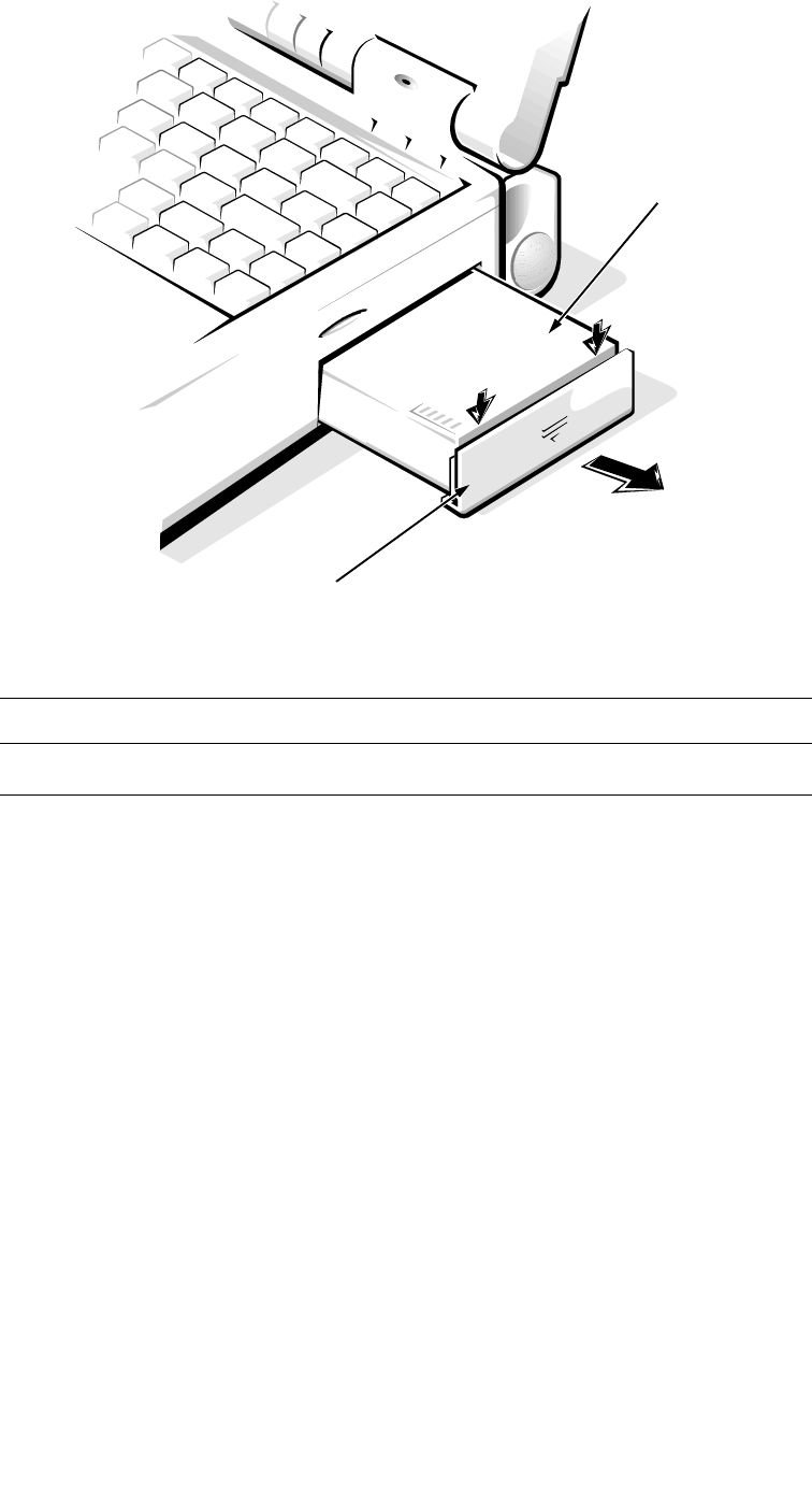
Removing and Replacing Parts 4-3
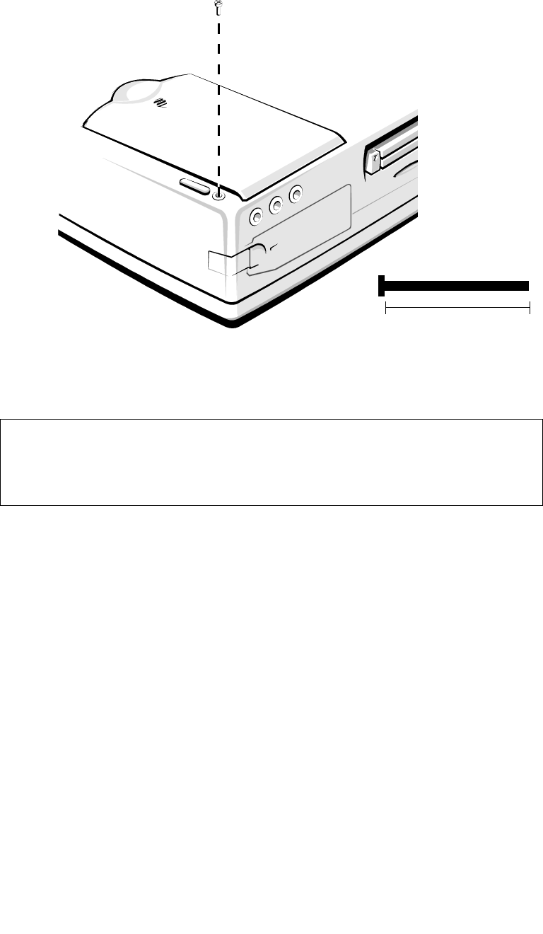
Figure 4-2. Main Battery Assembly Removal
4. To avoid possible damage to the computer from ESD, ground yourself
by attaching a wrist grounding strap to yourself and an unpainted
metal surface on the I/O panel.
If a wrist grounding strap is not available, you can discharge static electric-
ity from your body by periodically touching the unpainted metal surface of
the I/O panel.
Part or Assembly Name Order Name
Main battery assembly CUS,BTRY,SAR,36WHR,LXP
battery door
battery
4-4 Dell Latitude XPi CD Service Manual
S
crew Identification and Tightening
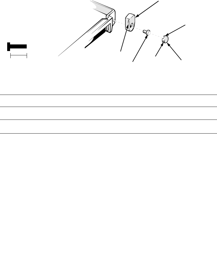
Figure 4-3. Screw Identification
The removal procedure illustrations provide the correct screw length in
parentheses next to the screw’s label. Also, a graphic for that length screw is
included in the illustration. Match the actual screw to the graphic in the illustra-
tion to check for correct length.
CAUTION: It is essential that the correct length screw be used when
reinstalling a screw. Otherwise, hardware damage could result. Make
sure that the screw is properly aligned with its corresponding hole, and
avoid overtightening.
A6 (35 mm)
(screw A6 is 35 mm)
match length here
35 mm
Removing and Replacing Parts 4-5
Z
IF Connectors
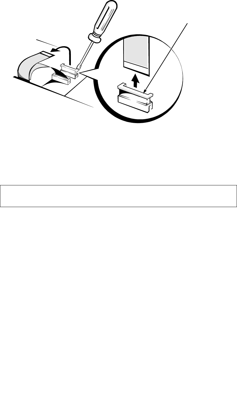
Figure 4-4. Disconnecting an Interface Cable
Some of the computer’s interface connectors are zero insertion force (ZIF) con-
nectors. These connectors are not removable, but they must be released to
disconnect a cable from them.
To disconnect an interface cable from a ZIF connector, follow these steps:
1. Insert a small flat-blade screwdriver or a chip-removal tool under the
movable part of the connector.
If a small flat-blade screwdriver is unavailable, use a chip-removal tool to
carefully pry up on first one end of the movable part of the connector and
then the other end.
2. Pull gently upward on the movable part of the connector until it
releases the interface cable.
3. Grasp the interface cable and pull it out of the connector.
To reconnect an interface cable to a ZIF connector, follow these steps:
1. Use a flat-blade screwdriver or chip-removal tool to open the movable
part of the ZIF connector.
2. Orient the end of the interface cable with the ZIF connector, and insert
the end of the cable into the connector.
3. While holding the cable in place, close the ZIF connector.
To ensure a firm connection, make sure the ZIF connector is completely
closed.
CAUTION: The ZIF connectors are fragile. To avoid damage, do not
apply too much pressure to the movable part of the connector.
movable part of
connector;
do not remove

4-6 Dell Latitude XPi CD Service Manual
F
ield-Replaceable Parts and Assemblies
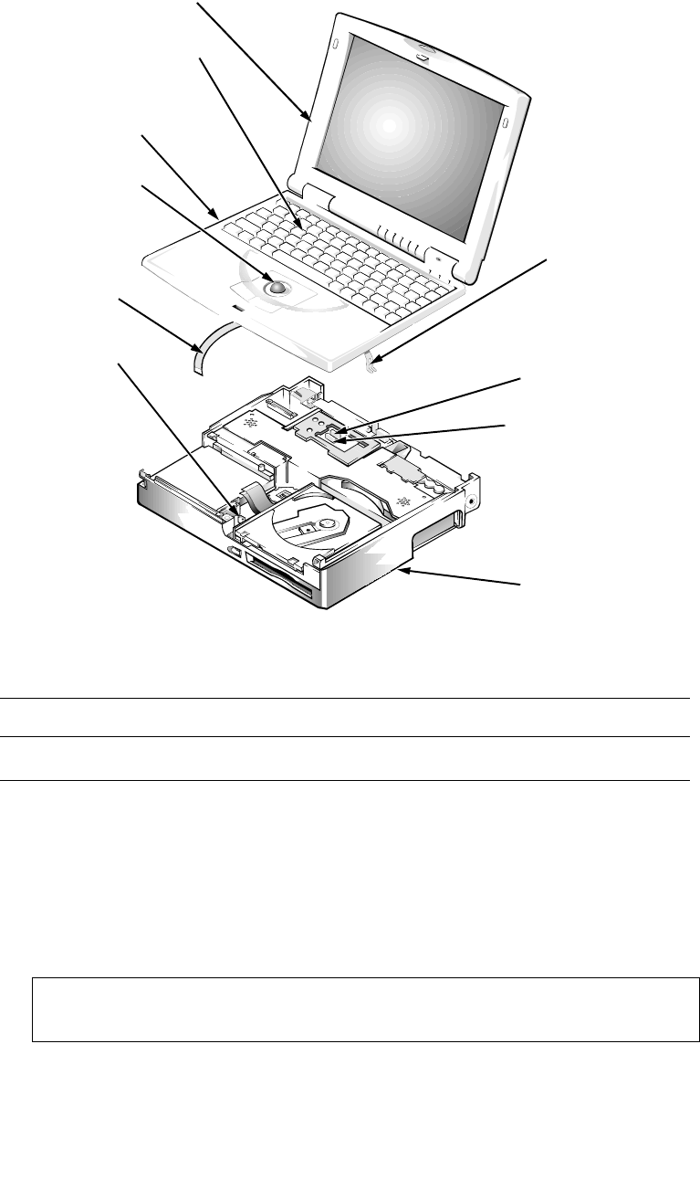
Figure 4-5. Exploded View—Computer
The computer is divided into three major assemblies: the palmrest assembly
(which contains the keyboard and the trackball), the display assembly (which
contains the LCD), and the bottom case assembly (which contains many of the
removable parts).
display assembly
keyboard
I/O panel dust cover
dust cover for the Advanced
Port Replicator connector
right tilt-support foot
main battery
left tilt-support foot
PC Card
memory compartment cover CD-ROM/diskette
drive assembly
palmrest assembly
bottom case assembly
superpart assembly
trackball assembly
CD-ROM
EMI clip
keyboard EMI clip
hard-disk
drive assembly
Removing and Replacing Parts 4-7
The following subsections provide instructions for removing and replacing
these parts and assemblies. Some of the instructions are preceded by a table list-
ing the Dell order name for the part or assembly being replaced. A more
detailed breakdown of parts and assemblies can be found in Appendix A, “Fac-
tory Repair Parts.”
Hard-Disk Drive Assembly
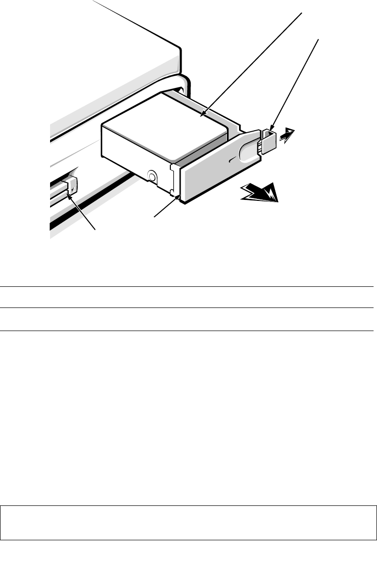
Figure 4-6. Hard-Disk Drive Assembly Removal
To remove the hard-disk drive assembly, follow these steps:
1. Slide the drive latch toward the front of the computer to release the
hard-disk drive assembly from the hard-disk drive bay.
The latch is on the left-front corner of the computer.
2. Grasp the drive door and pull the drive out of the computer.
When reinserting the drive into the drive bay, ensure that the drive latch is open.
Then slide the drive completely into the hard-disk drive bay.
Part or Assembly Name Order Name
Hard-disk drive assembly CUS,HD,xxxxx,yyMM,zzz,LXP*
* Substitute the drive capacity for xxxxx, the drive height for yy, and the
manufacturer for zzz.
CAUTION: The hard-disk drive is very sensitive to shock. Handle the
assembly with care and avoid dropping it even from a height of 1 inch.
drive latch
front of computer
drive door
PC Card slot
hard-disk drive
4-8 Dell Latitude XPi CD Service Manual
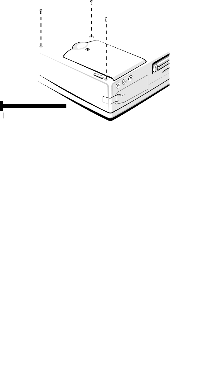
Memory Compartment Cover
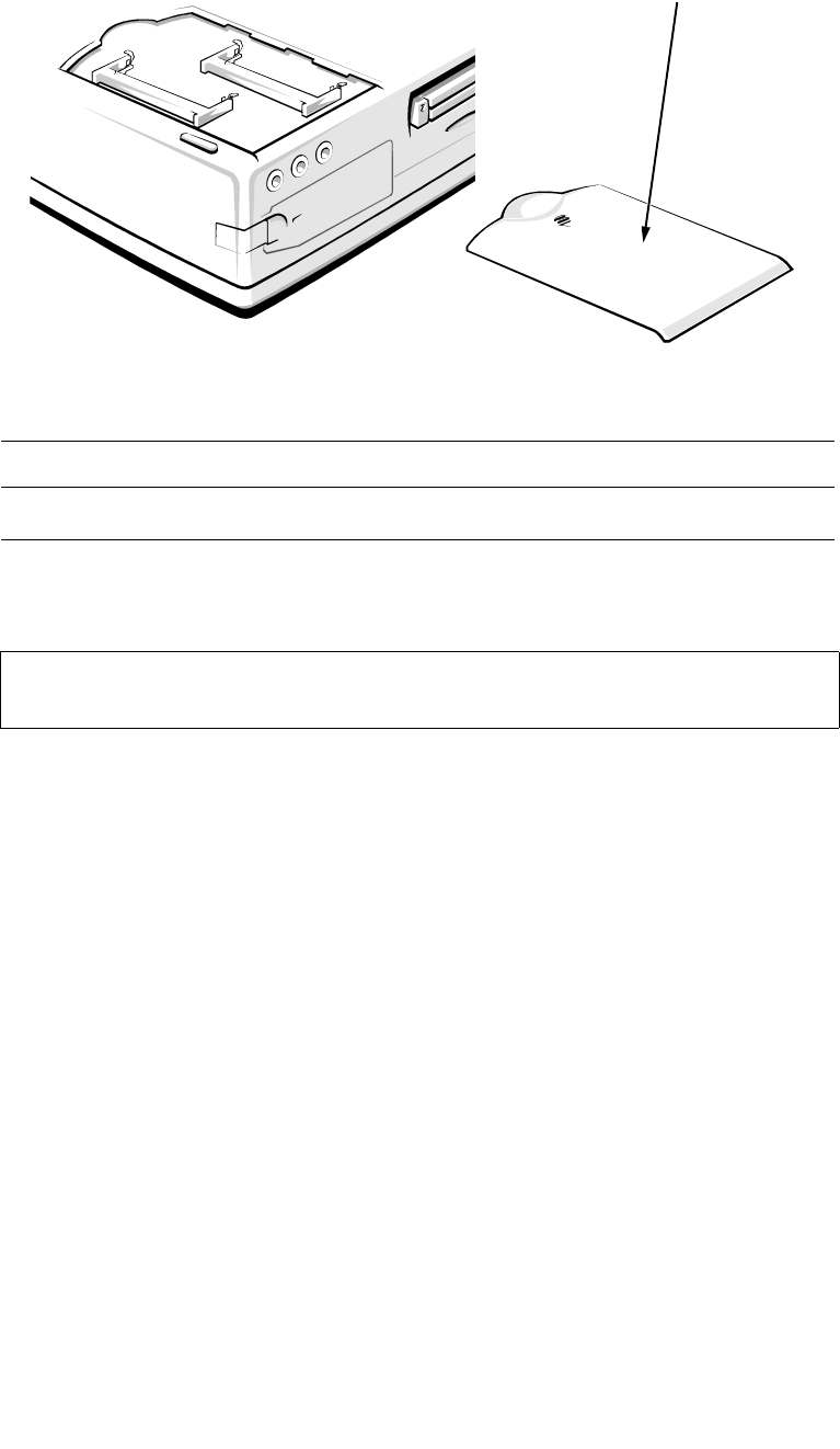
Figure 4-7. Memory Compartment Cover Removal
To remove the memory compartment cover, follow these steps:
1. Turn the computer upside down on the work surface.
2. To release the memory compartment cover, press down on the identa-
tion in the edge of the cover, and then slide the cover towards the edge
of the computer.
Part or Assembly Name Order Name
Memory compartment cover CVR,MEM,LXPiCD
CAUTION: Make sure the work surface is clean to prevent scratching
the computer cover.
memory compartment
cover
Removing and Replacing Parts 4-9
Memory Modules
Figure 4-8. Memory Module Removal
To remove a memory module, follow these steps:
1. Remove the memory compartment cover.
2. To release a memory module from its socket, gently push outward on
each of the memory module’s two metal retaining clips.
The memory module should rotate upward out of its retaining clips.
3. Lift the memory module out of its socket.
Memory modules can be installed only one way. Do not attempt to force the
memory module into the socket. Align the notch in one corner of the memory
module with the corresponding indent in the memory module socket.
Part or Assembly Name Order Name
Memory module, 4-MB CUS,MEM,4M,LXP4D/T,LXPi
Memory module, 8-MB CUS,MEM,8M,LXP4D/T,LXPi
Memory module, 16-MB CUS,MEM,16M,LXP4D/T,LXPi
memory module
sockets
4-10 Dell Latitude XPi CD Service Manual
P
almrest Assembly
The palmrest assembly consists of the trackball and the keyboard.
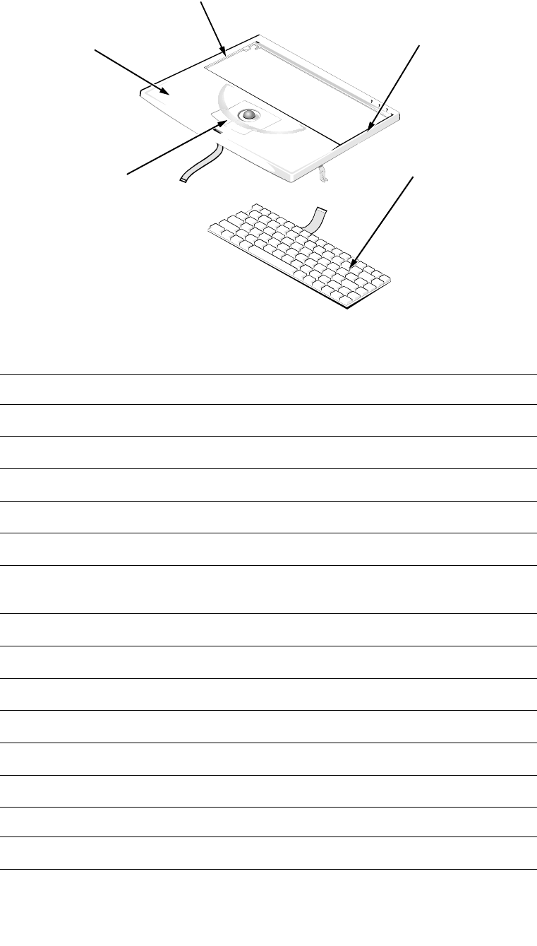
Figure 4-9. Palmrest Assembly Removal
To remove the palmrest assembly, follow these steps:
1. Remove any installed PC Card(s).
2. Disconnect any cables attached to the audio ports.
3. Remove the hard-disk drive assembly.
Part or Assembly Name Order Name
Palmrest assembly with sound SVC,ASSY,PLMRST,LXPiCD
CAUTION: Make sure the work surface is clean to prevent scratch-
ing the computer cover.
connector JTB
connector JKB1
connector JKB2
palmrest assembly
display assembly
trackball cable
trackball assembly
keyboard
bottom case assembly
CD-ROM EMI
clip
Removing and Replacing Parts 4-11
4. Close the display assembly, and turn the computer upside down on a
flat work surface.
5. Remove the three palmrest-assembly retaining screws A1, A2, and A3
(see Figure 4-10).
Figure 4-10. Palmrest-Assembly Retaining Screws
6. Turn the computer right-side up on the work surface, and open the dis-
play assembly.
NOTE: Remember to support the display assembly with a book or similar
object so that the display assembly does not open beyond 180 degrees.
7. Release the palmrest assembly from the bottom case assembly (see Fig-
ure 4-9).
To release the palmrest assembly, lift the front of the assembly upward with
one hand approximately 1 inch. Then, with the fingers of the other hand,
disconnect the trackball cable from LIF connector JTB.
8. Rotate the front of the palmrest assembly towards the display assembly.
9. Disconnect the two keyboard cables from ZIF connectors JKB1 and
JKB2.
10. Carefully lift the palmrest assembly from the bottom case assembly.
The keyboard is captured in the palmrest by snaps and tabs.
A1 (35 mm)
A2 (35 mm)
A3 (35 mm)
35 mm

4-12 Dell Latitude XPi CD Service Manual
To reseat the palmrest assembly on the bottom case assembly, set the palmrest
assembly down, slightly forward of its original position, on top of the bottom
case assembly. Then push down on all sides of the palmrest assembly while
sliding the assembly toward the back of the computer.
Ensure that the palmrest assembly is properly aligned and fully seated on the
bottom case assembly and that all of the mounting tabs are fully engaged. Then
close the display assembly, turn the computer upside down on the work surface,
and reinstall retaining screws A1, A2, and A3 (see Figure 4-10).
CAUTION: Be careful not to bend the CD-ROM EMI clip. Set the palm-
rest assembly top side down, when the palmrest assembly is free from
the bottom case assembly.
Removing and Replacing Parts 4-13
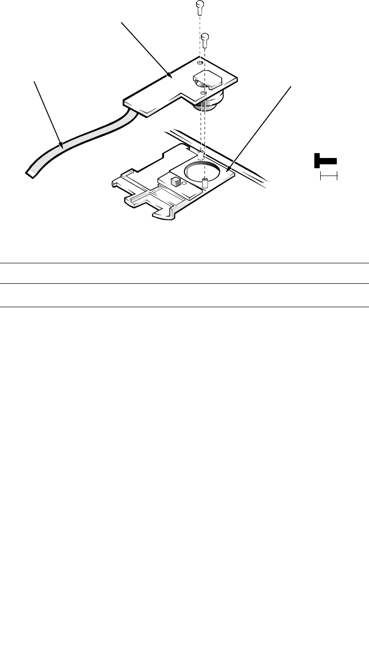
Trackball Assembly
Figure 4-11. Trackball Assembly Removal
To remove the trackball assembly, follow these steps:
1. Remove the palmrest assembly.
2. Turn the palmrest assembly upside down on a flat work surface.
3. Remove screws A4 and A5.
4. Lift the trackball assembly out of the palmrest assembly.
NOTE: It is not necessary to remove the trackball button board when
removing the trackball assembly.
Part or Assembly Name Order Name
Optical trackball assembly SVC,ASSY,TBALL/SWT,LXPi+
palmrest assembly
A4 (6 mm)
trackball assembly
A5 (6 mm)
6 mm
trackball cable
4-14 Dell Latitude XPi CD Service Manual
Keyboard Assembly
Figure 4-12. Keyboard Assembly Removal
Part or Assembly Name Order Name
Keyboard assembly, Belgium KYBD,86,BEL,ALPS,LXPi+
Keyboard assembly, China KYBD,85,CHI,ALPS,LXPi+
Keyboard assembly, domestic SVC,KYBD,85,DOM,LXPi+
Keyboard assembly, Danish KYBD,86,DEN,ALPS,LXPi+
Keyboard assembly, French KYBD,86,FR,ALPS,LXPi+
Keyboard assembly, French/
Canadian KYBD,85,FR,CAN,ALPS,LXPi+
Keyboard assembly, German KYBD,86,GER,ALPS,LXPi+
Keyboard assembly, Japan KYBD,87,JPN,LXPi+
Keyboard assembly, Korean KYBD,85,KOREA,ALPS,LXPi+
Keyboard assembly, Latin American KYBD,86,LTN,ALPS,LXPi+
Keyboard assembly, Norwegian KYBD,86,NOR,ALPS,LXPi+
Keyboard assembly, Russian KYBD,86,RUS,ALPS,LXPi+
Keyboard assembly, Spanish KYBD,86,SPN,ALPS,LXPi+
Keyboard assembly, Swedish KYBD,86,SWE,ALPS,LXPi+
trackball assembly
press
press
keyboard
palmrest
assembly

Removing and Replacing Parts 4-15
To remove the keyboard assembly, follow these steps:
1. Remove the palmrest assembly.
2. Press along the sides of the keyboard to release the keyboard from the
palmrest assembly.
Part or Assembly Name Order Name
Keyboard assembly, Swiss KYBD,86,SWI,ALPS,LXPi+
Keyboard assembly, Thailand KYBD,85,THAI,ALPS,LXPi+
Keyboard assembly, United
Kingdom KYBD,84,UK,LXPi+
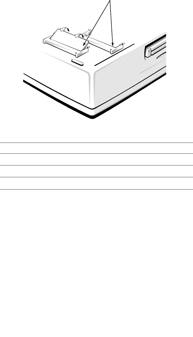
4-16 Dell Latitude XPi CD Service Manual
D
isplay Assembly
For removal procedures, the display assembly consists of the following:
•Tilt-support foot
•Display assembly bezel
•Display assembly latch and latch spring
•LCD panel
•LCD inverter board
•Hinge covers
•Display-assembly interface cable
•Microphone/switch assembly
Tilt-Support Foot
Figure 4-13. Tilt-Support Foot Removal
Part or Assembly Name Order Name
Tilt-support foot, left FOOT,PLSTC,REAR,LF,LXPiCD
Tilt-support foot, right FOOT,PLSTC,REAR,RT,LXPiCD
right tilt-support foot
10 mm
finger-access recess
foot retaining screw (10 mm)
cover
tab
notch

Removing and Replacing Parts 4-17
To remove a tilt-support foot, follow these steps:
1. Close the display assembly.
2. With the foot set to its fully retracted position, insert a small device
(such as a scribe) into the bottom notch on the foot-retaining screw
cover and gently lift out the cover partway. Lift on the sides of the
cover, working around to the top, and then lift out the cover.
3. Remove the foot retaining screw.
The foot retaining screw also functions as a mounting screw for one of the
display assembly hinges, which has a threaded hole for the screw.
Therefore, the foot retaining screws cannot be reinstalled with the display
assembly removed.
The foot-retaining screw cover can fit only one way in the foot. To reinstall
the cover, make sure the tilt-support foot is in its fully retracted position.
Then orient the cover with the notch toward the bottom of the computer and
its mounting tab toward the top of the computer. Press in on the cover until
it snaps into place.
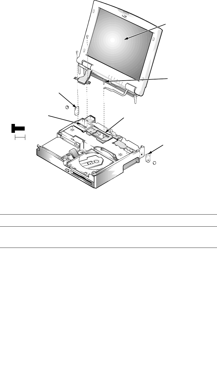
4-18 Dell Latitude XPi CD Service Manual
Display Assembly
Figure 4-14. Display Assembly Removal
To remove the display assembly, follow these steps:
1. Remove the palmrest assembly.
2. Remove the computer’s tilt-support feet.
3. Remove interface-cable grounding screws C1 and C2 from the
display assembly.
Part or Assembly Name Order Name
Display assembly ASSY,LCD,TFT,SVGA,12.1”,
LXPiCD
C1 (6 mm)
connector JLCD connector JMIC
6 mm
left tilt-support foot
right tilt-support foot
detent post
display assembly
C2 (6 mm)

Removing and Replacing Parts 4-19
4. Disconnect the display-assembly interface cable from connector JLCD
on the system board.
To disconnect the cable, grasp the pull tab and pull it straight up from the
system board.
5. Disconnect the microphone cable from ZIF connector JMIC.
6. Lift the display assembly from the bottom case assembly.
A plastic detent post located approximately at the center of the display
assembly may hang on the bottom case assembly. If so, carefully push the
center of the display assembly away from the bottom case assembly.
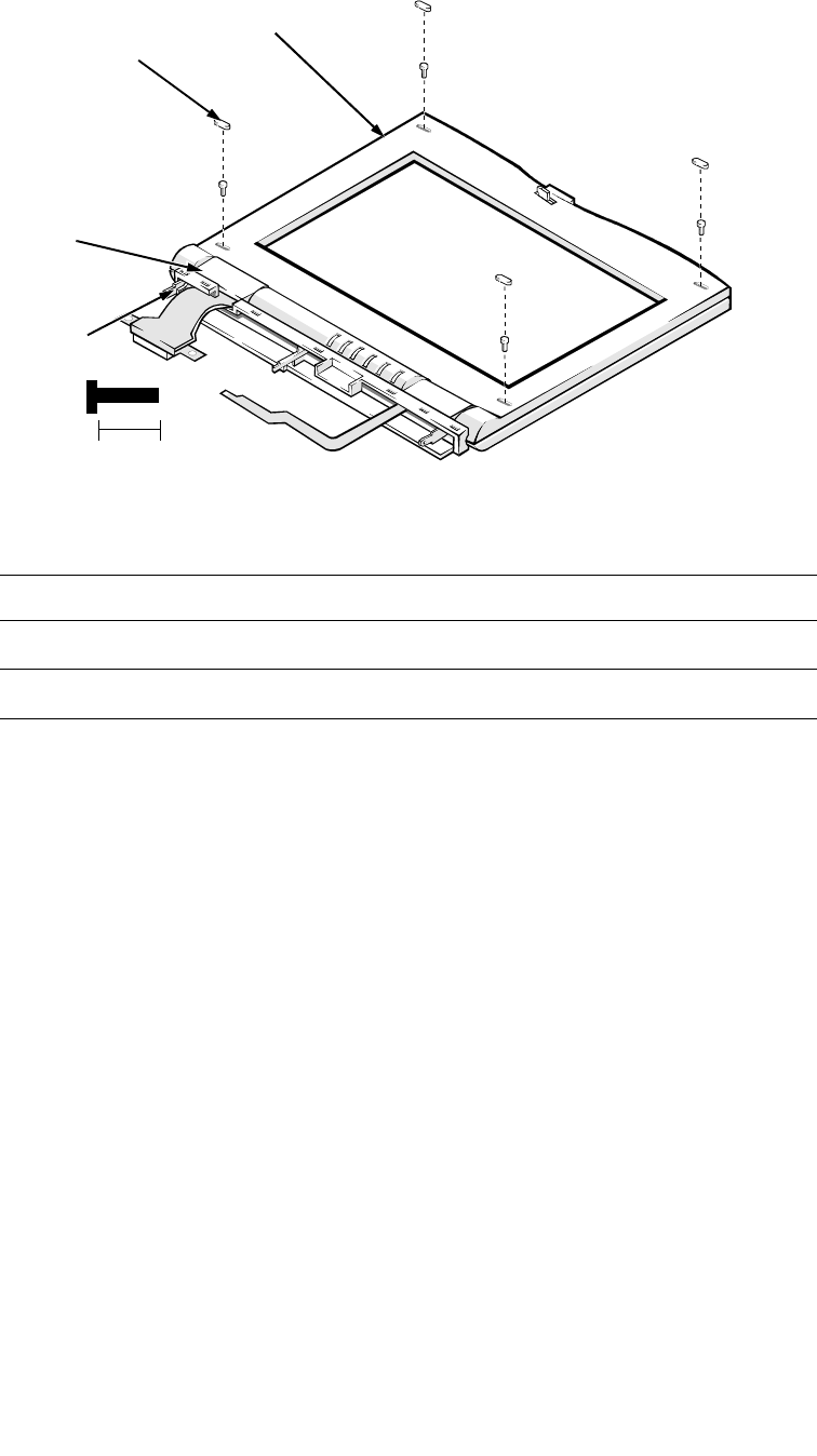
4-20 Dell Latitude XPi CD Service Manual
Display Assembly Bezel
l
Figure 4-15. Display Assembly Bezel Removal
To remove the display assembly bezel, follow these steps:
1. Use a scribe to pry the retaining screw covers out of the screw holes in
the bezel.
2. Remove retaining screws H1, H2, H3, and H4.
3. Separate the bezel from the display assembly.
Insert your fingertips between the bezel and the LCD, and lift upward on the
bezel to release the hidden tabs just above the indicator panel, as well as the
hidden tabs beneath each side of the bezel. Then slide the bezel toward the
front of the computer, and lift it up and away from the display assembly.
When replacing the bezel, orient the bezel in its original position on the display
assembly and press firmly near each tab until it snaps into position. Be careful
to have the display latch and spring properly assembled.
Part or Assembly Name Order Name
Bezel service kit, 12.1-inch SVC,BZL,LCD,TFT,LXPiCD
Display case service kit, 12.1-inch SVC,CVR,BK,TFT,LXPi+
screw covers (4)
H1 (10 mm)
H2 (10 mm)
H3 (10 mm)
H4 (10 mm)
10 mm
display assembly bezel
display
assembly
base
hinge
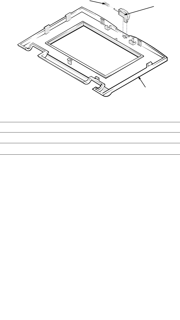
Removing and Replacing Parts 4-21
Display Assembly Latch and Latch Spring
Figure 4-16. Display Assembly Latch and Latch Spring Removal
To remove the display assembly latch and latch spring, follow these steps:
1. Remove the display assembly bezel.
2. Turn the display assembly bezel upside down on the work surface.
3. While holding down the display-assembly latch spring, slide the latch
against the spring, rotate the latch upward, and lift the latch and spring
out of the bezel.
Part or Assembly Name Order Name
Display assembly latch LTCH,LXPiCD
Display assembly latch spring SPR,LTCH,LXPiCD
latch
latch spring
display assembly
bezel
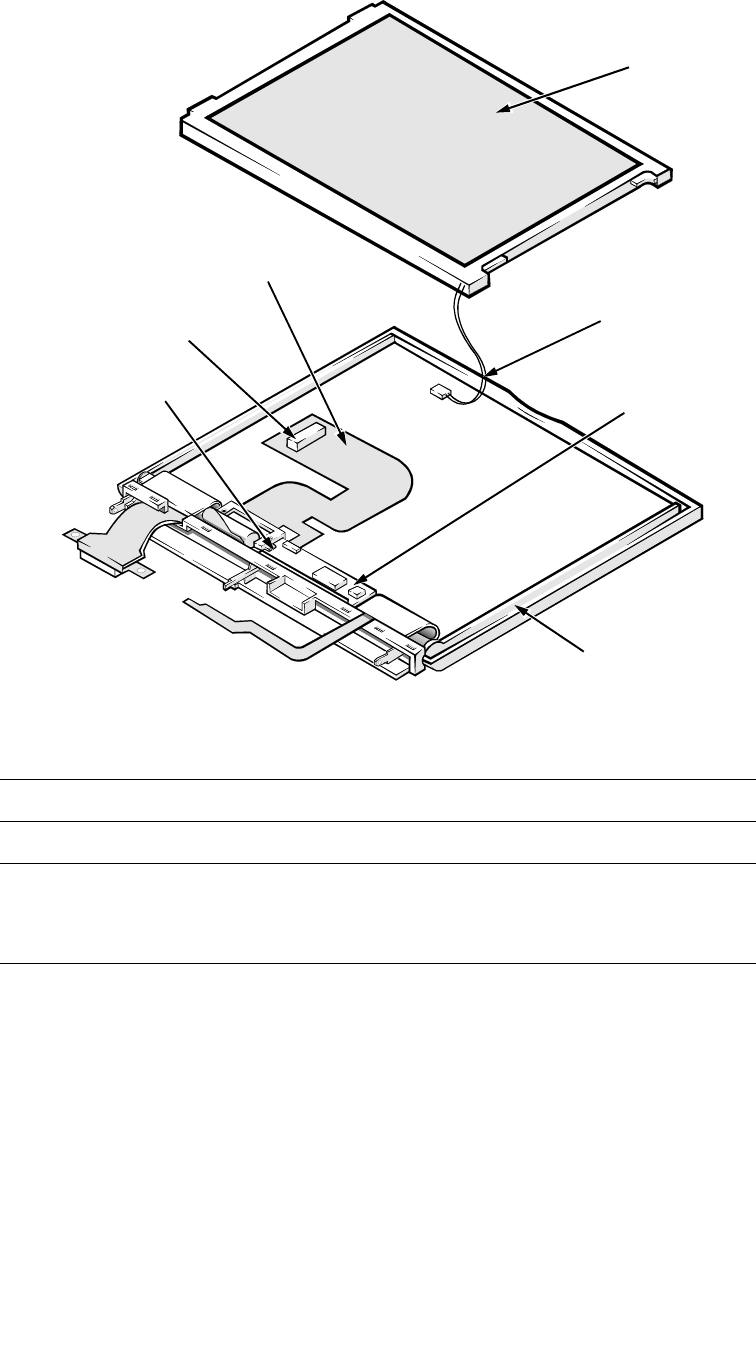
4-22 Dell Latitude XPi CD Service Manual
LCD Panel
Figure 4-17. LCD Panel Removal
Part or Assembly Name Order Name
LCD panel LCD,TFT,SVGA,12.1”,SAMSUNG
LCD assembly, LCD inverter board,
active-matrix color, TFT SVGA
display
SVC,LCD/INVTR,TFT,LXPiCD
LCD panel
LCD power cable
connector CN2
LCD inverter board
display assembly case
interface connector
interface cable

Removing and Replacing Parts 4-23
To remove the LCD panel, follow these steps:
1. Remove the display assembly bezel.
2. Lift the lower edge of the LCD panel about 1 inch.
3. Disconnect the LCD-assembly power cable from connector CN2 on the
LCD inverter board.
4. Lift the lower edge of the LCD panel approximately 3 inches.
5. Disconnect the display-assembly interface cable from the LCD interface
connector on the underside of the LCD panel.
6. Lift the LCD panel out of the display assembly case.
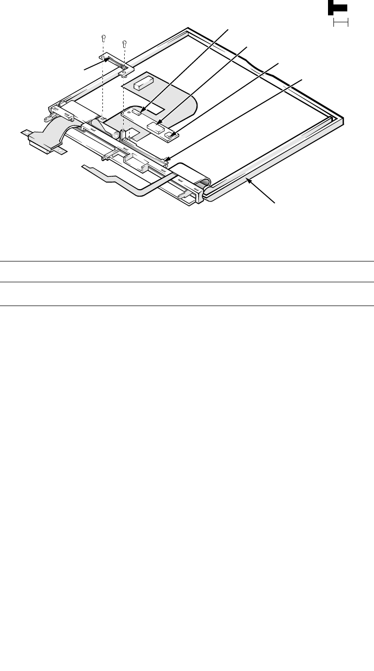
4-24 Dell Latitude XPi CD Service Manual
LCD Inverter Board
Figure 4-18. LCD Inverter Board Removal
To remove the LCD inverter board, follow these steps:
1. Remove the display assembly bezel.
2. Remove screws I1 and I2 securing the display-interface cable retaining
bracket, and then remove the bracket.
3. Move the LED board out of the display assembly case far enough to
gain access to the LCD inverter board.
4. Disconnect the LCD-inverter board interface cable from ZIF connector
CN1 on the LCD inverter board.
5. Lift the LCD inverter board about 1/4 of an inch.
6. Disconnect the LCD power cable from connector CN2 on the LCD
inverter board.
7. Lift the LCD inverter board out of the display assembly case.
Part or Assembly Name Order Name
LCD inverter board ASSY,BD,INVRTR,TFT,SVGA12.1”
retaining bracket
I1 (5 mm)
I2 (5 mm) 5 mm
LED board
inverter board
display assembly case
connector CN1
connector CN2
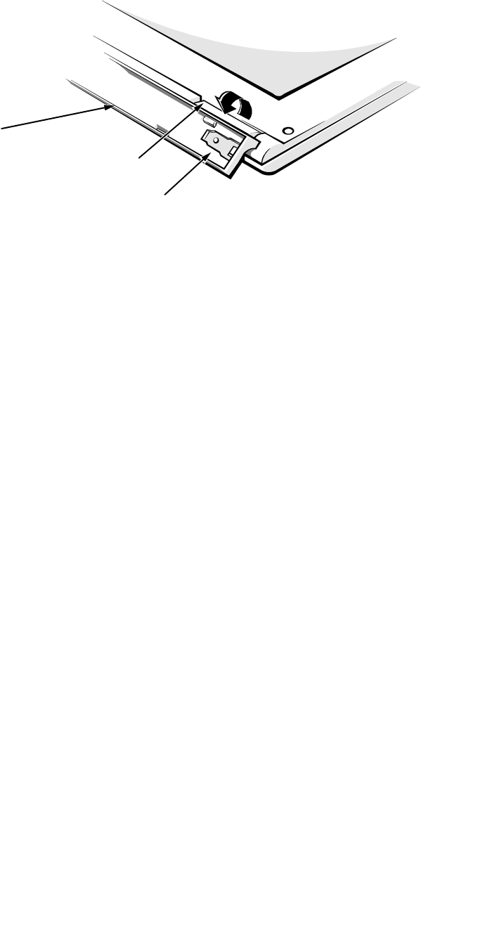
Removing and Replacing Parts 4-25
Hinge Covers
Figure 4-19. Hinge Covers Removal
Each of the hinge covers is held in place by three tabs that fit into slots on the
display assembly base. The microphone is inside the right hinge cover. To
remove the hinge covers, follow these steps:
1. Remove the display assembly from the computer.
2. Place the display assembly faceup on the work surface.
3. Rotate the display assembly base until the display assembly hinges are
pointing upward at approximately a 45-degree angle.
4. To remove a hinge cover, press in on the front of the cover to release the
hinge cover’s front tab. Then rotate the cover in the direction of the
arrow, and lift the cover away from the display assembly base.
To replace the hinge covers, set the display assembly base in the position
shown, and reinsert the hinge cover into its original position, making sure that
its two tab slots engage the tabs on the display assembly base. Then rotate the
hinge cover opposite to the direction shown in Figure 4-18 until its front tab
engages the tab slot in the display assembly base.
display
assembly
base
hinge
hinge cover
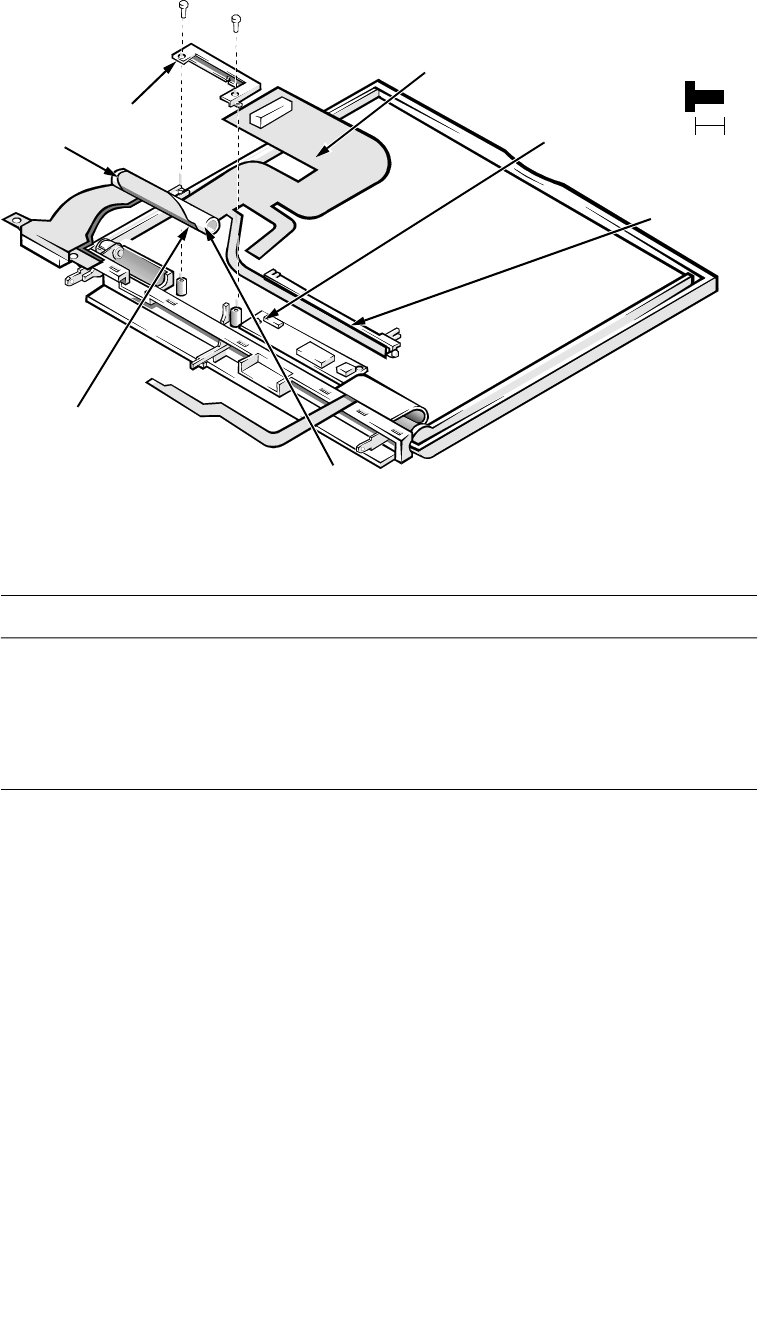
4-26 Dell Latitude XPi CD Service Manual
Display-Assembly Interface Cable
Figure 4-20. Display-Assembly Interface Cable Removal
The display-assembly interface cable connects the system board, LCD panel,
LCD inverter board, and LED board. The cable wraps around a bobbin. To
remove the display-assembly interface cable, follow these steps:
1. Remove the display assembly.
2. Remove the display assembly bezel.
3. Remove the LCD panel.
4. Remove the left hinge cover.
5. Remove screws I1 and I2 securing the display-interface cable retaining
bracket, then remove the bracket.
6. Disconnect the display-assembly interface cable from ZIF connector
CN1 on the LCD inverter board.
Part or Assembly Name Order Name
LCD cables, active-matrix, TFT
SVGA display (includes display-
assembly interface, LED board, and
LCD-inverter-board interface
cables)
SVC,CBL,LCD,TFT,SAMSUNG,
LXPiCD
I1 (5 mm)
I2 (5 mm)
connector CN1
bobbin 5 mm
alignment marks
on cable
retaining bracket
alignment notch
in shoulder
LED board
display-assembly interface cable

Removing and Replacing Parts 4-27
7. Lift the display-assembly interface cable and bobbin out of the display
assembly.
NOTE: Some computers have a display-assembly interface cable that detaches
from the bobbin. If you have a cable with a permanently attached bobbin, stop
here; otherwise, proceed to Step 8.
8. Look at the alignment marks on the display-assembly interface cable,
and note the alignment of the cable to the bobbin. Then carefully detach
the cable from the bobbin.
A double-sided adhesive strip attaches the cable to the bobbin (see
Figure 4-20).
9. To reattach the display-assembly interface cable to the bobbin, align the
marks on the cable with the notch in the shoulder of the bobbin, and
then wrap the cable around the bobbin.
If you are installing a new cable, remove the protective cover from the adhesive
strip on the new cable. Align the alignment marks on the cable with the notch in
the shoulder of the bobbin, and then wrap the cable around the bobbin, making
sure it stays between the shoulders of the bobbin. Place the cable and bobbin
into the display assembly before attaching the EMI shield.
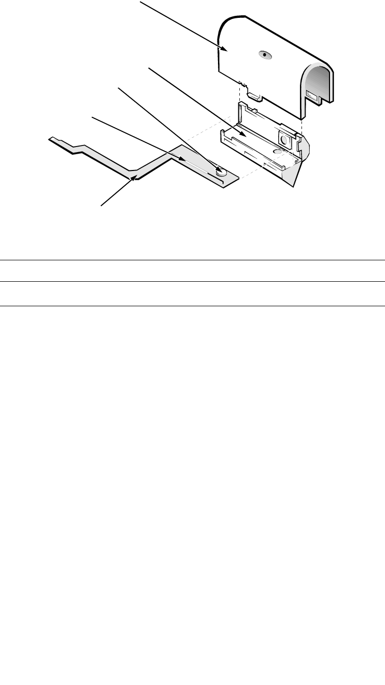
4-28 Dell Latitude XPi CD Service Manual
Microphone/Switch Assembly
Figure 4-21. Microphone/Switch Assembly Removal
The microphone/switch assembly is inside the right hinge cover. There is a
microphone and a magnetic reed switch on the microphone/switch assembly. To
remove the microphone/switch assembly, follow these steps:
1. Remove the display assembly.
2. Remove the right hinge cover. (Before doing so, note the correct routing
of the microphone cable around the display assembly base.)
3. Remove the microphone cover from the right hinge cover.
4. Open the microphone cover, and remove the microphone/switch
assembly.
Part or Assembly Name Order Name
Microphone service kit SVC,MIPHN/SWT,LXPiCD
microphone/switch assembly
right hinge cover
microphone cover
microphone/switch cable
magnet switch

Removing and Replacing Parts 4-29
B
ottom Case Assembly
The bottom case assembly consists of the following:
•Diskette/CD-ROM assembly
•Deck-buoy
•Superpart assembly
•System board
•3.1-V power supply board
•I/O-panel dust cover
•Dust cover for the Advanced Port Replicator
•Audio board
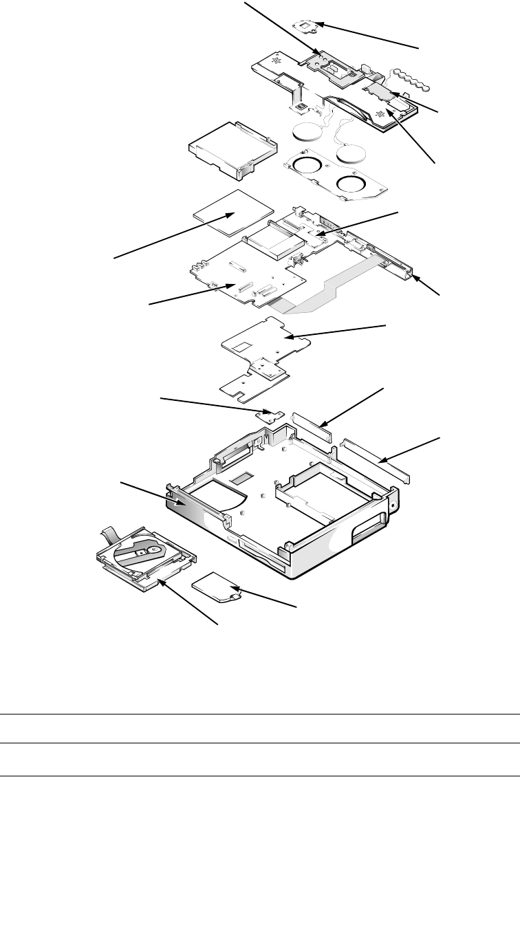
4-30 Dell Latitude XPi CD Service Manual
Figure 4-22. Bottom Case Assembly Removal
Part or Assembly Name Order Name
Bottom case assembly ASSY,CVR,BTM,LXPiCD
bottom case assembly
system board assembly
memory compartment cover
I/O bracket clip
I/O bracket clip
superpart
assembly
3.1-V power supply
spreader plate
diskette/CD-ROM assembly
audio board
keel plate
I/O panel
dust cover
dust cover for the
Advanced Port
Replicator
superpart
serial EMI clip
superpart docking EMI clip
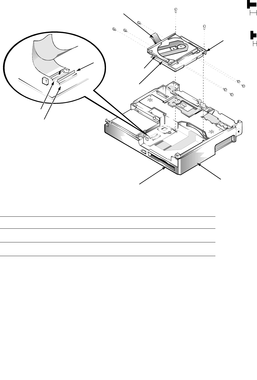
Removing and Replacing Parts 4-31
Diskette/CD-ROM Drive Assembly
Figure 4-23. Diskette/CD-ROM Drive Assembly Removal
To remove the diskette/CD-ROM drive assembly, follow these steps:
1. Remove the palmrest assembly.
2. Remove screws D1 and D2 securing the diskette/CD-ROM drive assem-
bly to the bottom case assembly.
3. Lift the back of the drive assembly slightly, and then slide the drive
assembly toward the back of the computer about 1/4 of an inch
Part or Assembly Name Order Name
Diskette drive assembly SVC,ASSY,FD,LXPiCD
CD-ROM drive assembly SVC,ASSY,CDROM,LXPiCD
diskette drive
CD-ROM drive
connector JCDROM
connector JFLOP
D1 (4 mm)
D2 (4 mm) 4 mm
D3 (2 mm) D4 (2 mm)
D5 (2 mm)
D6 (2 mm)
2 mm
CD-ROM flex cable
bracket
bottom case assembly
tab
D7 (2 mm)
D8 (2 mm)
D9 (2 mm)
plastic flip lock

4-32 Dell Latitude XPi CD Service Manual
4. Lift the drive assembly straight up about 1 inch.
The front edge of the drive assembly engages tabs on the bottom case
assembly. Make sure the diskette drive assembly is clear of the tab before
attempting to lift it out of the bottom case assembly.
5. Disconnect the diskette drive and CD-ROM drive interface cables from
connectors JFLOP and JCDROM on the system board.
6. Lift the drive assembly out of the bottom case assembly.
When replacing the drive assembly, first connect the two drive interface cables
to the system board. Then lower the drive assembly into the bottom case assem-
bly, beginning with its forward edge, so that the diskette drive board fits
between the tabs in the corner of the bottom case assembly.
To separate the diskette/CD-ROM assembly into a diskette drive and a
CD-ROM drive, remove screws D3 through D9. Lift up the CD-ROM, and
remove it from the assembly. Slide the CD-ROM flex cable out of the slot in the
bracket that holds the CD-ROM to the diskette drive.
CAUTION: Before removing the diskette drive and CD-ROM drive
interface cables from connectors JFLOP and JCDROM, release each
connector’s plastic flip lock (see Figure 4-23). Do not pull the interface
cable from the connector; doing so can ruin the cable’s electrical
conductivity.
CAUTION: Use care when handling the diskette/CD-ROM drive; it is
fragile and will bend if handled improperly. Place the assembly on a flat
work surface, and carefully remove the small 2-mm screws. Do not bend
either the drives or the bracket. If bending occurs, the diskette or
CD-ROM will not function correctly when inserted in the drive.
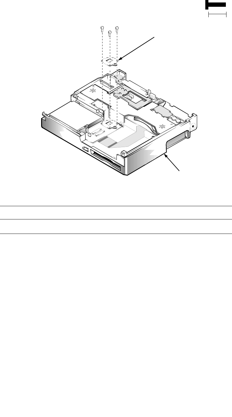
Removing and Replacing Parts 4-33
Deck Buoy
Figure 4-24. Deck Buoy Removal
To remove the deck buoy, follow these steps:
1. Remove the palmrest assembly.
2. Remove the display assembly.
3. Remove the diskette/CD-ROM assembly.
4. Remove screws B1, B2, and B3.
Lift the deck buoy out of the bottom case assembly.
Part or Assembly Name Order Name
Deck buoy ASSY,CLMP,THRM,LXPiCD
B1 (10 mm)
B2 (10 mm)
B3 (10 mm)
bottom case assembly
10 mm
deck buoy
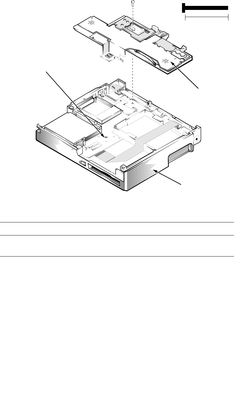
4-34 Dell Latitude XPi CD Service Manual
Superpart Assembly
Figure 4-25. Superpart Assembly Removal
The superpart assembly includes two speakers, two fans, the reserve battery, a
printed circuit board for those parts, and an infrared printed circuit board. To
remove the superpart assembly, follow these steps:
1. Remove the palmrest assembly.
2. Remove the display assembly.
3. Remove the diskette-drive/CD-ROM assembly.
4. Remove the deck-buoy.
Part or Assembly Name Order Name
Superpart assembly SVC,ASSY,FAN/SPKR,
BRKT,LXPiCD
bottom case assembly
B4 (25 mm)
25 mm
superpart
assembly
thermal tape

Removing and Replacing Parts 4-35
5. Remove screw B4.
Lift the superpart assembly out of the bottom case assembly.
CAUTION: To prevent tearing the thermal tape, slowly pull the super-
part assembly away from the system board.
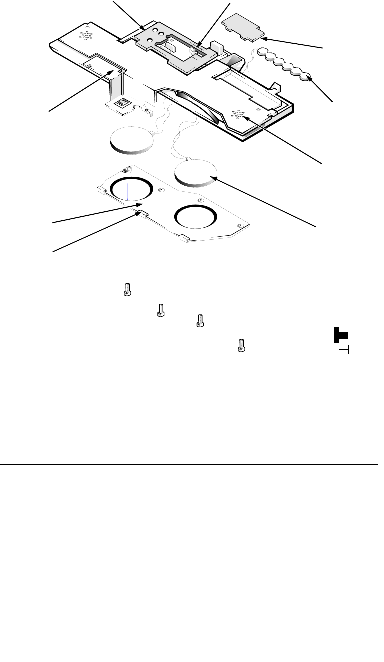
4-36 Dell Latitude XPi CD Service Manual
Reserve Battery
Figure 4-26. Reserve Battery Removal
Part or Assembly Name Order Name
Reserve battery SVC,BTRY,RSRV,LXP
CAUTION: The reserve battery provides power to the computer’s RTC
and NVRAM when the computer is turned off. Removing the battery
causes the computer to lose its date and time information as well as user-
settable parameters in the NVRAM. If possible, make a copy of this
information before you remove the reserve battery.
reserve
battery
connector JRBAT
F1 (3 mm)
F2 (3 mm)
F3 (3 mm)
F4 (3 mm)
speaker/
fan bracket
superpart
middle tab
3 mm
speaker (2)
speaker (2)
superpart
serial EMI
clip
superpart docking EMI clip

Removing and Replacing Parts 4-37
To remove the reserve battery, follow these steps:
1. Remove the palmrest assembly.
2. Remove the superpart assembly.
3. Remove the superpart docking EMI clip and the superpart serial EMI
clip.
4. Unplug the battery from connector JRBAT.
5. Place the superpart assembly upside down on a flat work surface.
6. Remove screws F1 through F4.
Remove the speaker/fan bracket protecting the speakers and fan.
7. Lift the battery out of its recess in the superpart assembly.
To free the reserve battery, thread the battery cable and connector through
the opening in the plastic superpart assembly.
CAUTION: When replacing the speaker/fan bracket, be sure to rein-
stall the middle tab correctly.
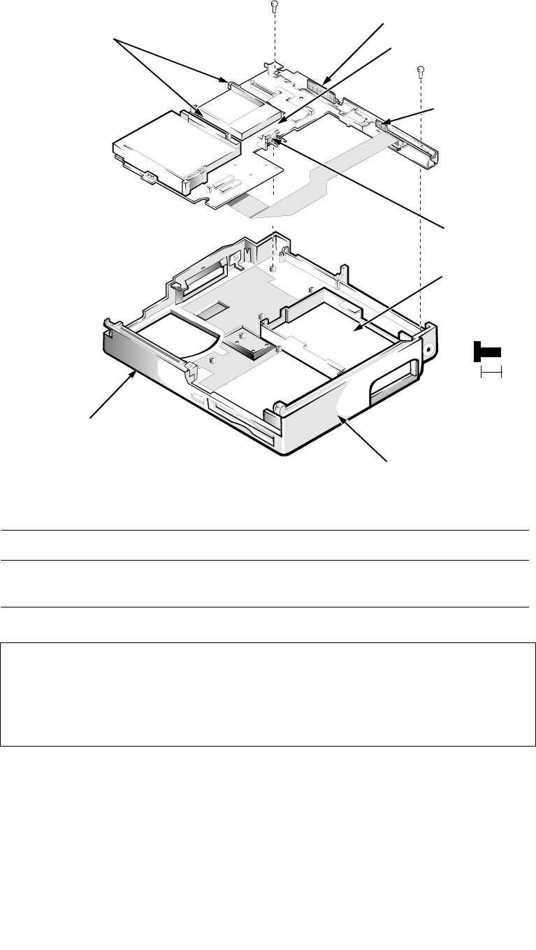
4-38 Dell Latitude XPi CD Service Manual
System Board Assembly
Figure 4-27. System Board Assembly Removal
The system board’s BIOS chip contains the system service tag number, which is
also visible on a bar-code label on the bottom of the computer. The replacement
kit for the system board assembly includes a diskette that provides a utility for
transferring the service tag number to the replacement system board assembly.
Part or Assembly Name Order Name
System board assembly SVC,SYS,PLN,LXPiCD-150ST,
WB,0M
CAUTION: Dell uses the system’s service tag number to maintain a his-
tory of the computer and its maintenance services. Do not neglect to
transfer the service tag number to the replacement system board assem-
bly (see step 3 of “Replacing the System Board Assembly” found later in
this section).
system board assembly
bottom case assembly
SB1 (5 mm)
SB2 (5 mm)
5 mm
main battery
connector
battery
compartment
PC Card
ejectors
molded tabs (3)
I/O docking EMI clip
I/O serial EMI clip

Removing and Replacing Parts 4-39
Removing the System Board Assembly
To remove the system board assembly, follow these steps:
1. Remove the palmrest assembly.
2. Remove the display assembly.
3. Remove the diskette/CD-ROM assembly.
4. Verify that the PC Card ejectors are fully depressed.
5. Remove the deck buoy plate. (Reinstall this part on the new system
board.)
6. Remove the superpart assembly.
Carefully disengage the superpart docking EMI and serial EMI clips from
the I/O docking EMI and serial EMI clips.
7. Remove screws SB1 and SB2, which retain the system board (see
Figure 4-27).
8. Lift the system board approximately 2 inches from the back of the
computer.
9. Disengage the front of the system board from the three molded tabs in
the bottom case assembly.
The tabs’ approximate location is shown in Figure 4-27. The tabs are
located alongside the hard-disk drive compartment, inside the bottom case
assembly.
10. Lift the system board assembly out of the bottom case assembly.
NOTE: If the main battery insulator comes out with the system board assem-
bly, detach the insulator and set it aside.
CAUTION: To ensure maximum cooling for the microprocessor, do
not touch the heat transfer area on the system board above the micro-
processor or on the deck buoy plate. The oils in your skin reduce the
heat transfer of the thermal pads.
CAUTION: When removing the system board assembly, be careful
not to damage the main battery connector and EMI shield on the bot-
tom of the assembly.
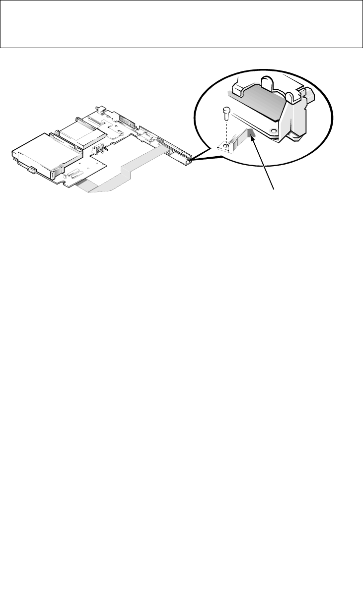
4-40 Dell Latitude XPi CD Service Manual
Replacing the System Board Assembly
Observe the following precautions when you reinstall a system board:
1. Before reinstalling the system board assembly, make sure the upper I/O
bracket clip and the side I/O bracket clip are in place. If the side I/O
bracket clip has been dislodged, reinstall it as shown in Figure 4-27.
Figure 4-28. I/O Bracket Clips
2. While reinstalling the system board assembly, make sure the power
button is positioned as far as it will go toward the back of the computer.
This will ensure that the power button engages the power switch properly.
3. Enter the system’s service tag number into the BIOS of the replacement
system board assembly.
Insert the diskette that accompanied the replacement system board assembly
into the diskette drive, and turn on the computer. Follow the instructions on
the display screen.
CAUTION: To avoid possible damage to the computer, make sure the
system board assembly is inserted under the three molded tabs at the
front of the bottom case assembly.
I/O bracket clip
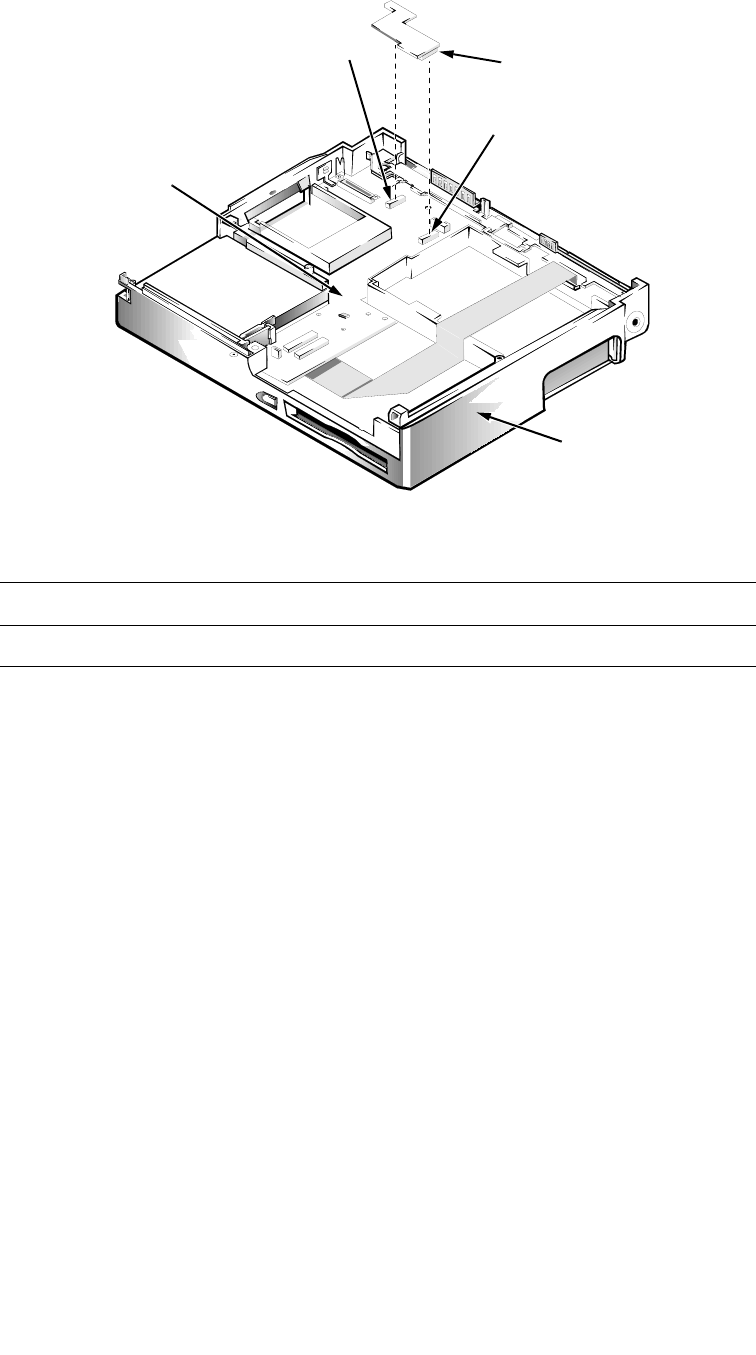
Removing and Replacing Parts 4-41
3.1-V Power Supply Board
Figure 4-29. 3.1-V Power Supply Board Removal
To remove the 3.1-V power supply board, follow these steps:
1. Remove the palmrest assembly
2. Remove the superpart assembly.
3. Remove the 3.1-V power supply board from the system board.
The power supply board is held in place on the system board by connectors
JPS1 and JPS2.
Part or Assembly Name Order Name
3.1-V power supply board CRD,PWR SPLY,LXPiCD,V3.1,NBK
connector JPS1
connector JPS2
bottom case assembly
system board
power supply board
with insulator
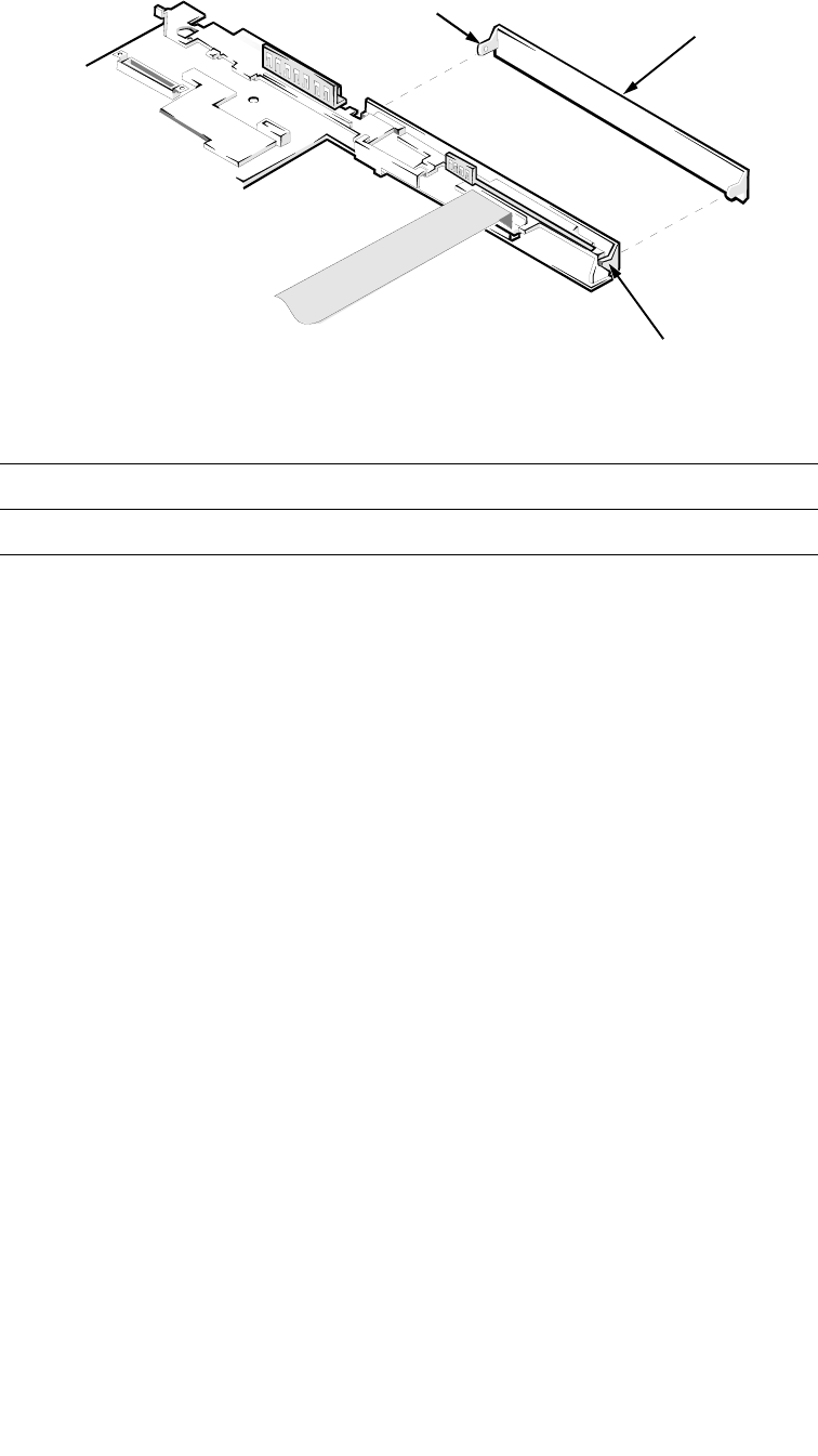
4-42 Dell Latitude XPi CD Service Manual
I/O-Panel Dust Cover
Figure 4-30. I/O-Panel Dust Cover Removal
To remove the I/O-panel dust cover, follow these steps:
1. Remove the palmrest assembly.
2. Remove the display assembly.
3. Remove the superpart assembly.
4. Remove the system board.
5. Remove the I/O-panel dust cover.
Push outward on one end of the dust cover to release the pivot pin from its
associated pivot hole. Then repeat the operation for the other end of the
cover. After both ends have been disengaged, lift the dust cover away from
the system board assembly.
To replace the I/O-panel dust cover, orient the cover in its original position and
snap the pivot pins into place in their associated pivot holes. Make sure the dust
cover opens and closes freely before you reinstall the display assembly.
Part or Assembly Name Order Name
I/O-panel dust cover DOOR,PLSTC,I/O,LXP/NBK
I/O-panel
dust cover
pivot pin (2)
pivot hole (2)
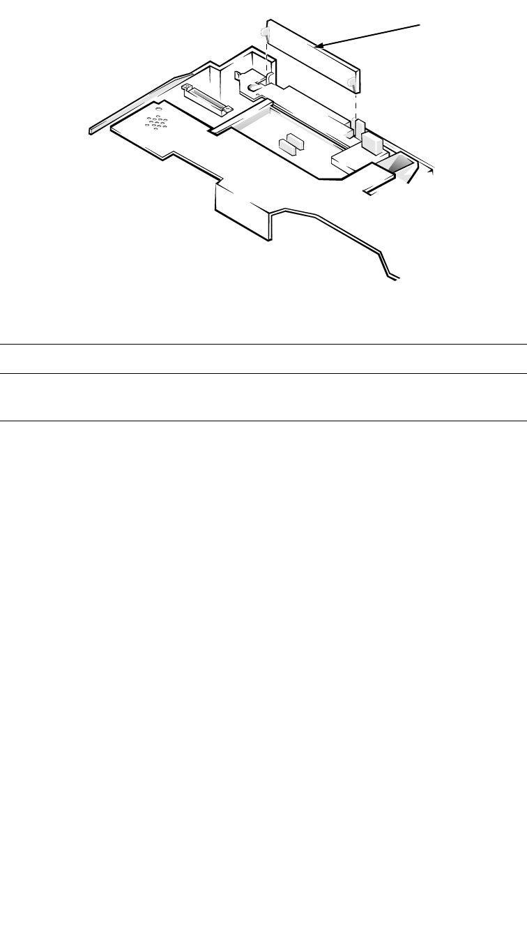
Removing and Replacing Parts 4-43
Advanced Port Replicator Connector Dust Cover
Figure 4-31. Advanced Port Replicator Connector
Dust Cover
To remove the dust cover for the Advanced Port Replicator connector, follow
these steps:
1. Remove the palmrest assembly.
2. Remove the display assembly.
3. Remove the dust cover.
Part or Assembly Name Order Name
Advanced Port Replicator
connector dust cover CVR,DOOR,DOCKING,LXP
Advanced Port
Replicator connec-
tor dust cover
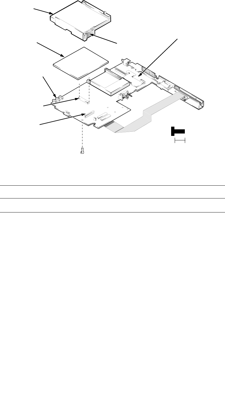
4-44 Dell Latitude XPi CD Service Manual
Audio Board
Figure 4-32. Audio Board Removal
To remove the audio board, follow these steps:
1. Remove the palmrest assembly.
2. Remove the display assembly.
3. Remove the superpart assembly.
4. Remove the system board.
5. Remove the hard-disk drive bracket.
Turn the system board over and place it on a flat work surface. Remove
screw HD1, which secures the bracket to the system board. Turn the system
board over so that the bracket is on the top. Use a plastic scribe or a small
flat-blade screwdriver to pry the bracket from connector JTB. Gently push
the bracket outward from the system board until the bracket is disengaged
from the audio connectors, and lift the bracket away from the system board.
6. Lift the audio board straight up from the system board.
The audio board is held in place on the system board by connector JAUDIO.
Part or Assembly Name Order Name
Audio board PWA,AUDIO,LXPiCD,NBK
6 mm
connector JTB
audio
board
audio
connectors
system board
hard-disk
drive bracket
HD1 (6 mm)
connector JAUDIO
connector board

Factory Repair Parts A-1
Appendix A
Factory Repair Parts
T
his appendix provides procedures for removing and replacing factory com-
ponents and subassemblies at a service facility. (Dell does not recommend
removal and replacement of factory components and subassemblies in the field.
For removal and replacement procedures for field-replaceable parts, see Chap-
ter 4, “Removing and Replacing Parts.”)
R
ecommended Tools
Most of the procedures in this appendix require the use of one or more of the
following tools:
•Small flat-blade screwdriver
•Jeweler’s screwdriver set
•Number 1 magnetized Phillips-head screwdriver
•Number 2 magnetized Phillips-head screwdriver
•Chip-removal tool
•Wrist grounding strap
•Small plastic scribe
•Nut drivers
P
recautionary Measures
Before you begin working on the computer, read about the precautionary mea-
sures, screw identification, and computer orientation outlined at the beginning
of Chapter 4, “Removing and Replacing Parts.”
F
actory Repair Parts and Assemblies
Table A-1 lists the factory repair parts and assemblies available for the com-
puter. The subsections that follow Table A-1 provide instructions for removing
and replacing these parts and assemblies.

A-2 Dell Latitude XPi CD Service Manual
Table A-1. Factory Repair Parts and Assemblies
Part or Assembly Name Order Name Figure
AC Adapter and Power Cords
AC adapter ADPT,AC,EXT,18V,65W,LXP
Power cable, U.S. CORD,PWR,110V,6F,AC
ADPT,US
Power cable, Europe CORD,PWR,220V,6F,AC
ADPT,EUR
Power cable, Australia CORD,PWR,220V,6F,AC
ADPT,AUS
Power cable, U.K. CORD,PWR,220V,6F,AC
ADPT,UK
Audio
Audio board service kit SVC,ASSY,AUD BD/SPKR,
LXPi+ 4-32
Microphone service kit SVC,ASSY,MIPHN,LXPi+CD 4-21
Microphone/switch
assembly ASSY,MIPHN/SWT,LXPi+CD 4-21
Magnet switch SWT,MGNT,ENCL,SPST,
LXPiCD 4-21
Microphone/switch
cable CBL,FPC,MIC/SW,LCD,12.1" 4-21
Technical booklet DOC,SERV,GDE,XPi+
Batteries
Reserve battery SVC,BTRY,RSRV,LXP 4-26
Battery, reserve BTRY,RSV,LXP
Technical booklet TSH,SERV,LXP

Factory Repair Parts A-3
Batteries
(Continued)
Main battery assembly CUS,BTRY,SAR,36WHR,LXP 4-2
Main battery BTRY,MAIN,36WH,LXP/XPi
Technical booklet TSH,BTRY,LXP
CD-ROM Drive Assembly
CD-ROM drive assembly SVC,ASSY,CD,LXPiCD 4-23
CD-ROM bezel BZL,CD,PLSTC,LXPiCD
CD-ROM bezel
assembly SUBASSY,BZLPLSTC,CD,
LXPiCD
CD-ROM bezel
spring SPR,FL,CLP,CD BZL,
LXPiCD
CD-ROM drive CD,627M,I,INT,CC,LXPiCD
CD-ROM drive
cable CBL,FPC,CD,LXPiCD
Eject button BTN,EJCT,CD,LXPiCD
Screws, diskette/
CD-ROM drive
bracket
SCR,M2X2MM,PHH,MS,ZPS,N
BK
Diskette Drive Assembly
Diskette drive assembly SVC,ASSY,FD,LXPiCD 4-23
Diskette drive FD,1.44M,F3,LXPiCD
Diskette drive cable CBL,FPC,FD,LXPiCD
Eject button BTN,EJCT,FD,LXPiCD
Technical booklet DOC,SERV,GDE,XPi+
Screws, diskette/
CD-ROM drive
bracket
SCR,M2X2MM,PHH,MS,ZPS,
NBK
Table A-1. Factory Repair Parts and Assemblies
(Continued)
Part or Assembly Name Order Name Figure

A-4 Dell Latitude XPi CD Service Manual
Diskette Drive Assembly
(Continued)
Diskette/CD-ROM drive
assembly SUBASSY,FD/CD,LXPiCD 4-23
Diskette/CD-ROM bracket BRKT,FD,AL,RT,LXPiCD 4-23
Hard-Disk Drive Assemblies
Hard-disk drive assembly CUS,HD, xxxxx,yy,MM,zzz,
LXP*4-6
Hard-disk drive,
subassembly SUBASSY,HD,xxxxx,yy,MM,
zzz,LXP*
Hard-disk
drive HD,xxxxx,yy,MM,zzz,REV2*
Hard-disk
drive bracket BRKT,HD,LXP
Hard-disk
drive mount-
ing screws
SCR,M3X4,BIND/PHH,BL
OXIDE
Hard-disk
drive
insulator
INSUL,yyMM,LXP*
Technical booklet TSH,HD,LXP
Keyboards
Keyboard assembly,
Belgium KYBD,86,BEL,ALPS,LXPi+ 4-5
Keyboard assembly, China KYBD,85,CHINA,ALPS,
LXPi+ 4-5
Keyboard assembly,
domestic SVC,KYBD,85,DOM,LXPi+ 4-5
Keyboard assembly, Danish KYBD,86,DEN,ALPS,LXPi+ 4-5
Keyboard assembly, French KYBD,86,FR,ALPS,LXPi+ 4-5
* Substitute your drive capacity for xxxxx, your drive height for yy, and the
manufacturer for zzz.
Table A-1. Factory Repair Parts and Assemblies
(Continued)
Part or Assembly Name Order Name Figure

Factory Repair Parts A-5
Keyboards
(Continued)
Keyboard assembly,
French/Canadian KYBD,85,FR,CAN,ALPS,LXPi+ 4-5
Keyboard assembly,
German KYBD,86,GER,ALPS,LXPi+ 4-5
Keyboard assembly, Japan KYBD,87,JPN,LXPi+ 4-5
Keyboard assembly, Korean KYBD,85,KOREA,ALPS,LXPi+ 4-5
Keyboard assembly, Latin KYBD,86,LTN,ALPS,LXPi+ 4-5
Keyboard assembly,
Norwegian KYBD,86,NOR,ALPS,LXPi+ 4-5
Keyboard assembly,
Russian KYBD,86,RUS,ALPS,LXPi+ 4-5
Keyboard assembly,
Spanish KYBD,86,SPN,ALPS,LXPi+ 4-5
Keyboard assembly,
Swedish KYBD,86,SWE,ALPS,LXPi+ 4-5
Keyboard assembly, Swiss KYBD,86,SWI,ALPS,LXPi+ 4-5
Keyboard assembly,
Thailand KYBD,85,THAI,ALPS,LXPi+ 4-5
Keyboard assembly, U.K. KYBD,84,UK,LXPi+ 4-5
LCD Assemblies
LCD panel, LCD inverter
board, active-matrix color,
TFT SVGA display
SVC,LCD/INVTR,TFT,
LXPi+CD
LCD panel LCD,TFT,SVGA,12.1”,
SAMSUNG 4-17
LCD inverter board ASSY,BD,INVTR,TFT,SVGA,
12.1” 4-17
Technical booklet DOC,SERV,GDE,XPi+
Table A-1. Factory Repair Parts and Assemblies
(Continued)
Part or Assembly Name Order Name Figure

A-6 Dell Latitude XPi CD Service Manual
LCD Assemblies
(Continued)
LCD/LED/inverter board
cable, service kit, active-
matrix color, TFT SVGA
display
SVC,CBLS,LCD,TFT,SAM-
SUNG,LXPi+CD
Display-assembly
interface cable CBL,FPC,LED/INVRTR,TFT,
12.1” 4-20
Display-assembly
interface cable bob-
bin, 12.1-inch
BBN,LCD,TFT,12.1” 4-20
Technical booklet DOC,SERV,GDE,XPi
Bezel service kit, 12.1-inch SVC,BZL,LCD,TFT,LXPiCD 4-15
Display assembly bezel
12.1-inch ASSY,LCD,BZL,12.1” 4-15
Display-assembly latch
spring SPR,LTCH 4-16
Technical booklet DOC,SERV,GUIDE,LXPi
Display case service kit,
12.1-inch SVC,CVR,BK,TFT,LXPi+
Display assembly case,
12.1-inch ASSY,LCD,CVR,BK,TFT,12.1” 4-17
Technical booklet DOC,SERV,GUIDE,LXPi
Display assembly latch ser-
vice kit, 12.1-inch SVC,LTCH,DIS,TFT,LXPi+
Display assembly latch,
12.1-inch LTCH,LCD,STN/TFT,LXP 4-16
Display-assembly latch
spring, 12.1-inch SPR,LTCH 4-16
Technical booklet DOC,SERV,GUIDE,LXPi
Table A-1. Factory Repair Parts and Assemblies
(Continued)
Part or Assembly Name Order Name Figure

Factory Repair Parts A-7
LCD Parts
Hinge cover, right CVR,HNG,RT,MIPHN,LXPi+ 4-21
Hinge cover, left CVR,HNG,LXP
Display assembly base ASSY,CVR,BTM,DIS,LXPiCD 4-19
Left hinge HNG,LCD,LFT,TFT,12.1" 4-15
Right hinge HNG,LCD,RT,TFT,12.1" 4-19
Display-assembly-bezel re-
taining screw covers, lower CVR,LCD,LWR,LXPiCD 4-15
Display-assembly-bezel re-
taining screw covers, upper BMPR,UPR,LCD,LXPiCD 4-15
Display-assembly EMI
shield 12.1-inch SHLD,LCD,MET,TFT,12.1” A-4
Memory
Memory module, 4-MB,
customer kit CUS,MEM,4M,LXP4D/T,
LXPi 4-9
Memory module,
4-MB SIMM,4MB,LXP
Technical booklet TSH,DIMM INSTL,LXP
Memory module, 8-MB,
customer kit CUS,MEM,8M,LXP4D/T,
LXPi 4-9
Memory module,
8-MB DIMM,8M,2X32,TL,LXP
Technical booklet TSH,DIMM INSTL,LXP
Memory module, 16-MB,
customer kit CUS,MEM,16M,LXP4D/T,
LXPi 4-9
Memory module,
16-MB SIMM,16MB,LXP
Technical booklet TSH,DIMM INSTL,LXP
Table A-1. Factory Repair Parts and Assemblies
(Continued)
Part or Assembly Name Order Name Figure

A-8 Dell Latitude XPi CD Service Manual
Miscellaneous Parts
CD-ROM EMI clip CLP,EMI,CD,LXPiCD 4-5
Keyboard EMI clip CLP,EMI,KYBD,LXPiCD 4-5
Superpart serial EMI clip CLP,EMI,SER,SUPERPRT,
I/O,LXPiCD 4-5
Superpart docking EMI clip CLP,EMI,DOCK,SUPERPRT,
I/O,LXPiCD 4-5
Memory compartment
cover CVR,MEM,LXPiCD 4-7
PCMCIA blank INSR,BLNK,PCMCIA,LXP 4-5
PCMCIA blank, type III INSR,BLNK,PCMCIA,
TYP 3,LXPiCD 4-5
Tilt-support-foot retaining
screw cover CVR,REAR,FOOT,LXP 4-12
Advanced Port Replicator
connector dust cover CVR,DOOR,DOCKING,LXP 4-31
Tilt-support foot, left FOOT,PLSTC,REAR,LF,
LXPiCD 4-5
Tilt-support foot, right FOOT,REAR,RT,LXP 4-5
I/O panel dust cover DOOR,PLSTC,I/O,LXP/NBK 4-30
Main battery insulator CVR,MYLAR,BTRY,CVTY,
LXPiCD A-10
I/O bracket, hinge GSKT,I/O BRKT,BTM,EMI,
LXPi
Superpart assembly SVC,ASSY,FAN/SPKR,
BRKT,LXPiCD 4-33
Spreader plate PLT,SPRDR,BTM,LXPiCD A-12
Spreader plate spacer SPCR,TOP SPRDR,PORON,
LXPiCD A-12
Table A-1. Factory Repair Parts and Assemblies
(Continued)
Part or Assembly Name Order Name Figure

Factory Repair Parts A-9
Miscellaneous Parts
(Continued)
Keel plate ASSY,PLT,KEEL,LXPiCD A-12
Deck buoy ASSY,CLMP,THRM,LXPiCD 4-24
Microphone insulator
bracket INSUL,PLSTC,MIPHN/
SWT,LXPiCD
Bottom case assembly CVR,BTM,BLK,LXPi 4-22
Power button BTN,PWR SWT,LXP A-11
Power-button mounting
bracket GDE,PWR SWT,PLSTC,LXPi A-11
Memory compartment
cover CVR,MEM,LXPi+CD 4-5
Palmrest Assembly
Palmrest service kit SVC,ASSY,PLMRST,
LXPi+CD
Palmrest assembly SUBASSY,PLMRST,LXPi+CD 4-9
Technical booklet DOC,SERV,GUIDE,LXPiCD
Screws
Screws service kit SVC,SCR,LXP
3 mm, black SCR,2mmX3mm,PHH,MS,
BLO,LXP B2
3 mm, gold SCR,2mmX3mm,PHH,MS,
NON,LXP B8
4 mm, black SCR,2.6mmX4mm,PHH,MS,
BLO,LXPB7
5 mm, black SCR,2.6mmX5mm,PHH,MS,
BLO,LXPB3
5 mm, gold SCR,2.6mmX5mm,PHH,MS,
NON,LXP B8
Table A-1. Factory Repair Parts and Assemblies
(Continued)
Part or Assembly Name Order Name Figure

A-10 Dell Latitude XPi CD Service Manual
Screws
(Continued)
6 mm, black SCR,2mmX6mm,PHH,MS,
BLO,LXP B6
8 mm, gold SCR,2.6mmX8mm,PHH,MS,
ZPS
10 mm, gold SCR,2.5mmX10mm,PHH,MS,
NON,LXP5
10 mm, black SCR,2mmX10mm,PHH,MS,
BLO,LXP B9
10 mm, black SCR,M2X.4x10mm,PHH,
MS,BLO
25 mm, black SCR,2.6mmX25mm,PHH,MS,
BLO,LXP1
System Board Assemblies
System board assembly,
LXPi CD, 150-MHz,
service kit
SVC,SYS,PLN,
LXPiCD- P150ST,WB,0M 4-27
System board sub-
assembly, LXPi CD,
150-MHz
ASSY,PLN,LXPiCD-150ST,
WB,0M
BIOS access door CVR,PLSTC,BIOS,LXPiCD
BIOS chip IC,EEPROM,256X8,150NS,
PLCC
Audio board PWA,AUDIO,LXPiCD,NBK 4-32
Hard-disk
drive bracket BRKT,GDE,HD,LXP 4-32
Connector
board, hard-
disk drive
PWA,HD CON,LXPiCD,NBK 4-32
Power supply
board CRD,PWR SPLY,LXPiCD,
V3.1,NBK 4-29
Table A-1. Factory Repair Parts and Assemblies
(Continued)
Part or Assembly Name Order Name Figure

Factory Repair Parts A-11
System Board Assemblies
(Continued)
System
board,
150-MHz
PWA,PLN,LXPiCD-150ST,
NBK
I/O interface
cable CBL,I/O TO M/B,LXPiCD A-7
Bracket, I/O BRKT,I/O,LXPi
Serial EMI
clip, I/O CLP,EMI,SER,I/O,XPiCD
Docking
EMI clip, I/O CLP,EMI,DOCK,I/O,XPiCD
Diskette, field
service DSK,FLD SERV,F3,US, LXP
Technical booklet,
service DOC,SERV,GUIDE,LXPi
Trackball
Optical trackball assembly SVC,ASSY,TBALL/SWT,
LXPi+CD 4-11
Trackball interface
cable CBL,TBALL,LXPi+CD 4-11
Trackball
subassembly SUBASSY,TBALL,OPTICAL,
LXPiCD
Trackball
board PWA,TBALL,OPTICAL,
LXPiCD A-2
Trackball TBALL,OPTICAL,LXPiCD A-2
Trackball
button board SUBASSY,TBALL,SWT BD,
LXPiCD A-2
Technical booklet DOC,SERV,GUIDE,LXPi
Table A-1. Factory Repair Parts and Assemblies
(Continued)
Part or Assembly Name Order Name Figure
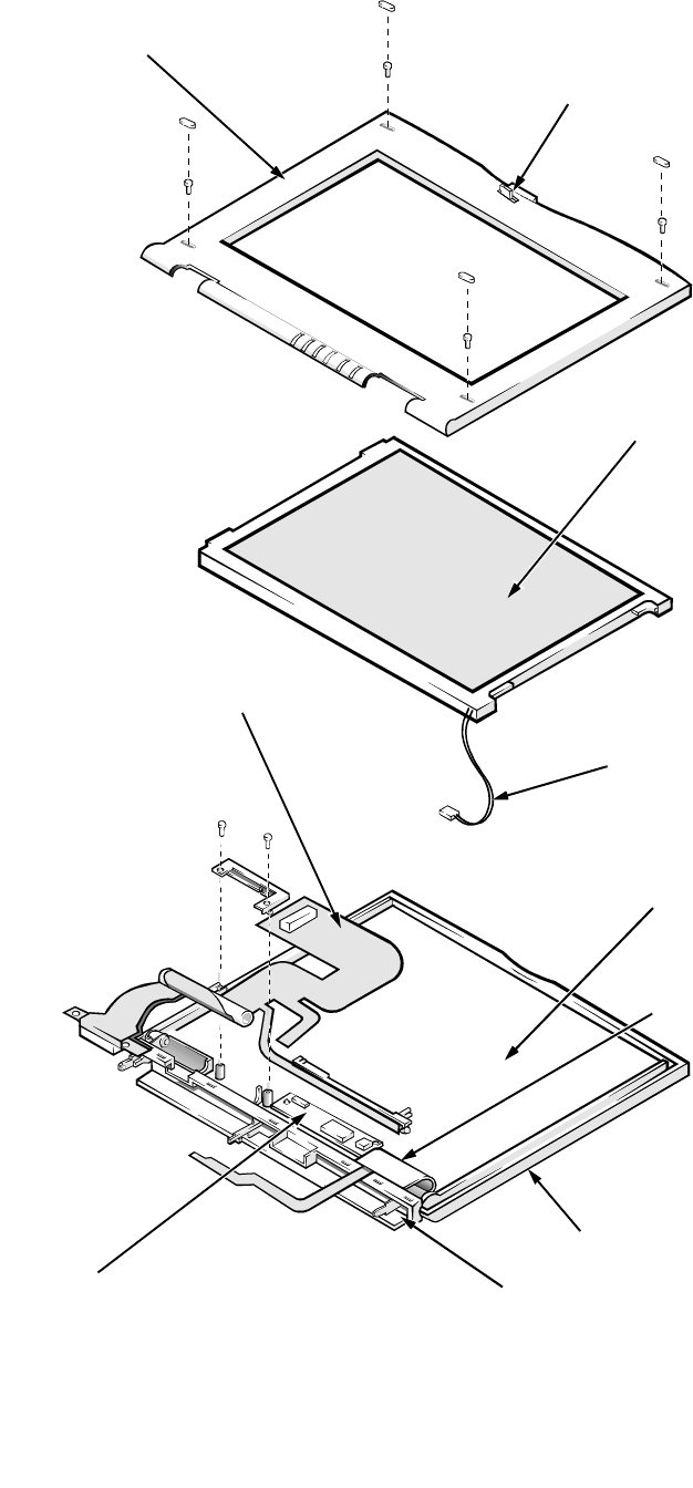
A-12 Dell Latitude XPi CD Service Manual
E
xploded Views of Components and Assemblies
Figure A-1. Exploded View—Display Assembly
display assembly bezel
latch
LCD panel
LCD power cable
interface cable
LCD inverter board
display assembly case
EMI shield
display assembly hinges (2)
hinge covers (2)
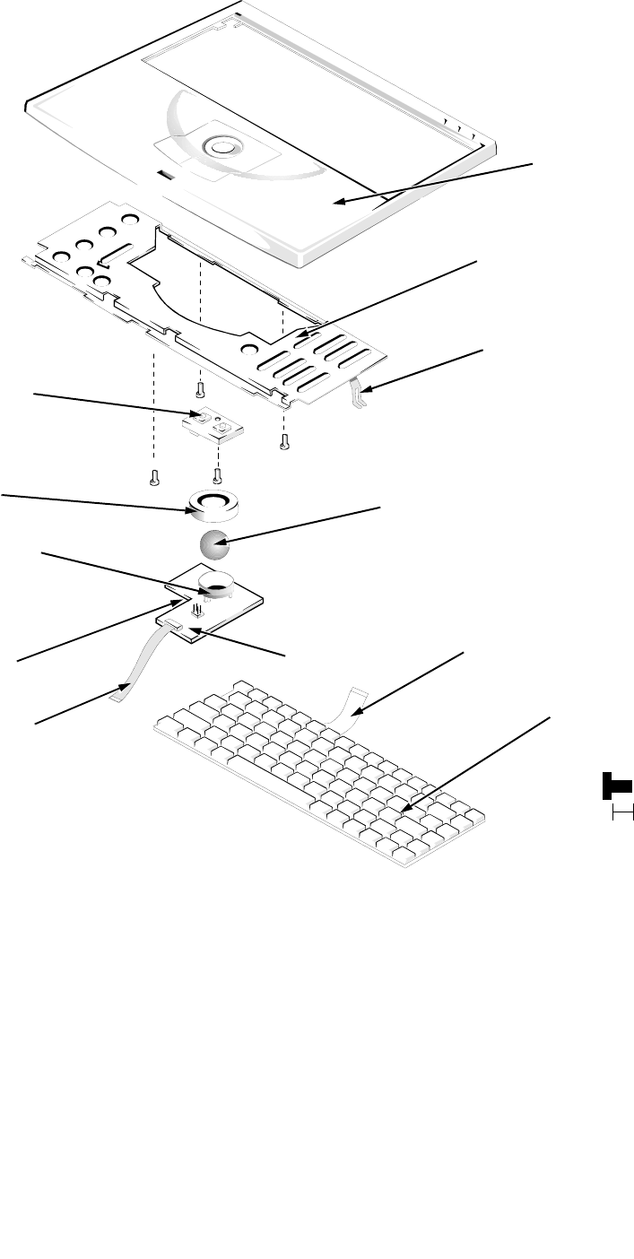
Factory Repair Parts A-13
.
Figure A-2. Exploded View—Palmrest Assembly
keyboard
keyboard
cables (2)
trackball interface cable
trackball
palmrest
plastic housing
trackball button board
palmrest
brace
trackball ring
trackball board connector J1
CD-ROM
EMI clip
A6 (4 mm)
A7 (4 mm) A8 (4 mm)
A9 (4 mm)
4 mm
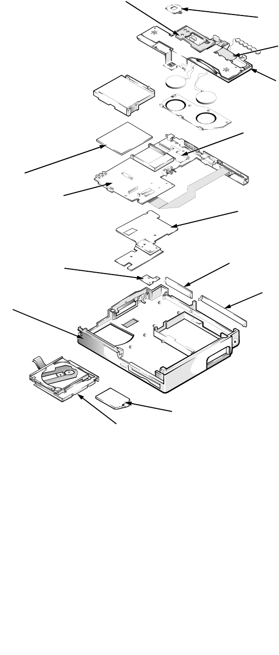
A-14 Dell Latitude XPi CD Service Manual
.
Figure A-3. Exploded View—Bottom Case Assembly
bottom case
assembly
system board assembly
memory compartment cover
I/O bracket clip
superpart
assembly
3.1-V power supply
spreader plate
diskette/CD-ROM assembly
audio board
key buoy plate
I/O panel dust cover
dust cover for the Advanced
Port Replicator
superpart
serial EMI clip
superpart
docking EMI clip

Factory Repair Parts A-15
H
ard-Disk Drive
The hard-disk drive resides in a carrier that mounts inside the computer’s
hard-disk drive bay. Four screws secure the drive inside the carrier. A mylar
insulator provides electrical insulation between the hard-disk drive and the bot-
tom of its carrier. To remove the hard-disk drive and hard-disk drive insulator,
follow these steps:
1. Remove the hard-disk drive assembly.
See “Hard-Disk Drive Assembly” in Chapter 4.
2. Place the hard-disk drive assembly right side up on the work surface,
and remove the four screws that secure the drive in its carrier.
3. Rotate the front of the drive toward the back of the carrier far enough
to expose the connector on the back of the drive.
4. Carefully pry the flex cable connector away from the hard-disk drive
interface connector on the back of the drive.
5. Lift the hard-disk drive out of its carrier.
6. Remove the hard-disk drive insulator, if necessary.
With the hard-disk drive removed, lift the insulator straight up out of the
carrier. The 17-mm hard-disk drives also have a foam spacer on top of the
insulator (not shown).
To avoid possible damage to components on the hard-disk drive’s integrated
controller board, hold the drive at approximately a 45-degree angle while reat-
taching the interface cable. Then rotate the drive toward the front of its carrier
until it is seated in its original position.
CAUTION: Rotating the hard-disk drive too far can damage the
short flex cable that connects the hard-disk drive to the system
board’s hard-disk drive interface connector. Do not rotate the drive
farther than necessary to disconnect the cable from the back of the
drive.

A-16 Dell Latitude XPi CD Service Manual
C
D-ROM Drive
The CD-ROM drive is attached to the CD-ROM/diskette drive bracket. See
“Diskette/CD-ROM Drive Assembly” in Chapter 4 for instructions about
removing the diskette/CD-ROM assembly from the bottom case assembly. The
CD-ROM flex cable is threaded through a slot in the drive bracket. Remove the
four screws that hold the CD-ROM to the drive bracket. Slide the CD-ROM
flex cable out of the slot in the bracket holding the CD-ROM. The CD-ROM is
replaced as a unit and is not disassembled.
D
iskette Drive
The diskette drive is attached to the CD-ROM/diskette drive bracket. See
“Diskette/CD-ROM Drive Assembly” in Chapter 4 for instructions about
removing the diskette/CD-ROM assembly from the bottom case assembly.
Remove three screws to separate the diskette drive from the drive bracket. The
diskette drive is replaced as a unit and is not disassembled.
P
almrest Assembly Components
To remove and replace a component of the palmrest assembly, you must first
remove the assembly as described in “Palmrest Assembly” in Chapter 4. The
subsections that follow provide removal procedures for the components of the
trackball assembly. See Figure A-2.
Trackball
Turn the trackball board over. Rotate the retaining ring counter-clockwise. Lift
the trackball out of the recess in the trackball holder.
Trackball Interface Cable
Gently disconnect the end of the cable from connector J1 on the trackball button
board.
Trackball Button Board
Remove retaining screw A6 (see Figure A-2), and lift the board out of the palm-
rest assembly. When replacing the board, fit the two small switches on the
underside of the board into the recesses in the palmrest.
Palmrest Brace
Remove screws A-7 through A-9 (see Figure A-2). Gently pull the brace toward
the front, and lift the brace away from the palmrest.
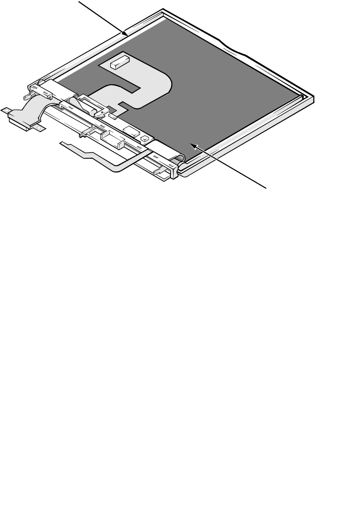
Factory Repair Parts A-17
D
isplay Assembly Components
The display assembly consists of the LCD assembly and its related components.
It also contains the LED board, which provides visual indications of many of
the computer’s basic functions. The microphone assembly is mounted inside the
right hinge cover of the display.
Some parts of the display assembly can be removed and replaced without
removing the assembly from the computer. Others require that the display
assembly be removed. The following subsections describe the removal of dis-
play assembly parts.
Display-Assembly EMI Shield
Figure A-4. Display-Assembly EMI Shield Removal
To remove the display-assembly EMI shield, follow these steps:
1. Remove the display assembly from the computer.
See “Display Assembly” in Chapter 4.
2. Remove the display assembly bezel.
See “Display Assembly Bezel” in Chapter 4.
3. Remove the LCD assembly.
See “LCD Assembly” in Chapter 4.
4. Remove the display-assembly interface cable.
See “Display-Assembly Interface Cable” in Chapter 4.
display assembly case
EMI shield

A-18 Dell Latitude XPi CD Service Manual
5. Remove the LCD-inverter-board.
See “LCD-Inverter-Board Interface Cable” in Chapter 4.
6. Remove the display assembly base.
See “Display Assembly Base” later in this chapter.
7. Remove the display-assembly EMI shield.
The EMI shield is held in place by tabs along the upper and lower edges. Pull-
ing the center of the shield slightly away from the display assembly will release
the tabs.
To replace an EMI shield, carefully orient the replacement EMI shield in the
same position as the original shield. Make sure that all screw holes in the shield
are aligned with their corresponding screw holes in the display assembly case.
Display Assembly Base
To remove the display assembly base (see Figure 4-14), follow these steps:
1. Remove the display assembly from the computer.
See “Display Assembly” in Chapter 4.
2. Remove both hinge covers.
See “Hinge Covers” in Chapter 4.
3. Rotate the display assembly hinges so that they point away from the
display assembly at approximately 180 degrees.
4. Remove the display assembly bezel.
See “Display Assembly Bezel” in Chapter 4.
5. Remove the left hinge.
See the next subsection, “Display Assembly Hinges.”
6. Rotate the right end of the display assembly base away from the display
assembly until the base clears the right hinge.
7. Lift the display assembly base away from the left hinge.
8. Disengage the display-assembly interface cable from the slot in the
base.

Factory Repair Parts A-19
Display Assembly Hinges
To remove a hinge (see Figure 4-14), follow these steps:
1. Remove the display assembly from the computer.
See “Display Assembly” in Chapter 4.
2. Remove the display assembly bezel.
See “Display Assembly Bezel” in Chapter 4.
3. Remove the LCD assembly.
See “LCD Panel” in Chapter 4.
4. Remove the display-assembly interface cable.
See “Display-Assembly Interface Cable” in Chapter 4.
5. Remove the hinge covers.
See “Hinge Covers” in Chapter 4.
6. Remove the display assembly base.
See the previous subsection, “Display Assembly Base.”
7. Rotate the display assembly hinges so that they point away from the
display assembly case at approximately 180 degrees.
8. To remove the hinge, remove the screw securing the hinge to the display
assembly case and disengage the hinge from the display assembly case.
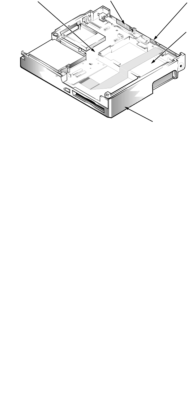
A-20 Dell Latitude XPi CD Service Manual
S
ystem-Board Assembly Components
Figure A-5. System Board Assembly in the Bottom Case Assembly
To remove a part of the system board assembly, Dell recommends that you first
remove the assembly as described in “System Board Assembly” in Chapter 4.
Then follow the instructions described in the following subsections to remove
parts of the system board assembly.
System Board
To remove and replace the system board, transfer the following items from the
system board assembly to the replacement system board assembly:
•Any installed memory modules — See “Memory Modules” in Chapter 4.
•Keyboard/keypad/mouse connector shield — See the next subsection,
“Keyboard/Keypad/Mouse Connector Shield.”
•I/O interface cable — See “I/O Interface Cable” found later in this
appendix.
•I/O board — See “I/O Board” found later in this section.
bottom case assembly
system board assembly
I/O interface
cable
I/O docking EMI clip I/O serial
EMI clip
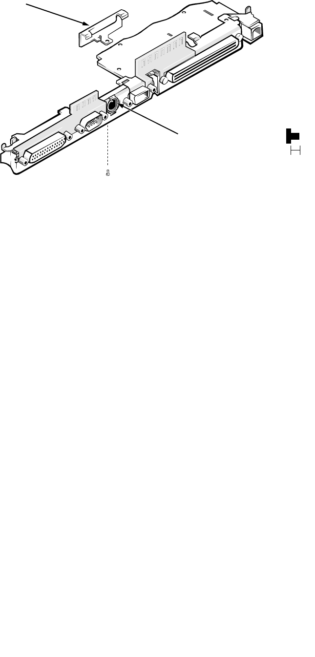
Factory Repair Parts A-21
Keyboard/Keypad/Mouse Connector Shield
Figure A-6. Keyboard/Keypad/Mouse Connector Shield Removal
Two tabs on the keyboard/keypad/mouse connector shield engage two associ-
ated slots on the I/O panel near the keyboard/keypad/mouse connector.
Retaining screw D4 attaches the bottom of the shield to the bottom of the I/O
panel. To remove the shield, remove retaining screw D4, rotate the bottom of
the shield toward the back of the system board assembly, and lift the shield off
the I/O panel.
D4 (3 mm)
keyboard/keypad/
mouse connector
connector shield
3 mm
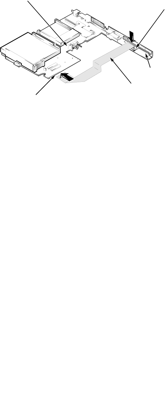
A-22 Dell Latitude XPi CD Service Manual
I/O Interface Cable
Figure A-7. I/O Interface Cable Removal
To remove the cable, follow these steps:
1. Disconnect one end of the I/O interface cable from connector JSTDIO
on the system board.
Connector JSTDIO is located on the underside of the system board.
2. Disconnect the other end of the I/O interface cable from connector
JFLEX on the I/O board.
I/O interface cable
connector JFLEX
connector JSTDIO
I/O board
system board
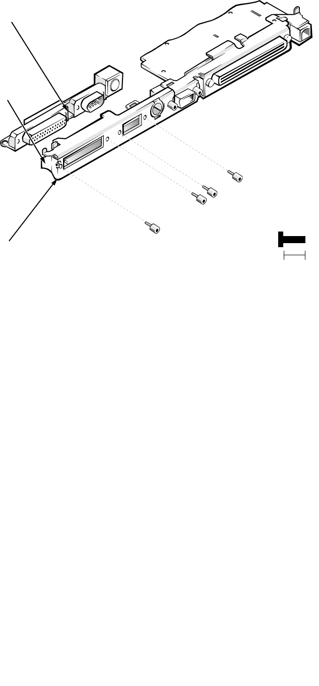
Factory Repair Parts A-23
I/O Board
Figure A-8. I/O Board Removal
To remove and replace the I/O board, follow these steps:
1. Remove the I/O interface cable from connector JSTDIO.
See the previous subsection in this appendix.
2. Remove the keyboard/keypad/mouse connector shield.
See “Keyboard/Keypad/Mouse Connector Shield” found earlier in this
appendix.
3. Remove the four hexagonal standoff screws ST1 through ST4 that
secure the serial and parallel port connectors to the I/O panel.
Use a 3/16 nut holder to remove the standoff screws.
4. Remove the side I/O bracket clip.
See “System Board Assembly” in Chapter 4.
5. Lift the I/O board away from the I/O panel.
When replacing the I/O board, make sure that the side I/O bracket clip is
positioned so that it rests directly on the I/O board, rather than between the
I/O board and I/O bracket (see Figure A-8).
I/O board
I/O bracket
8 mm
I/O bracket clip
ST1 (8 mm)
ST2 (8 mm)
ST3 (8 mm)
ST4 (8 mm)
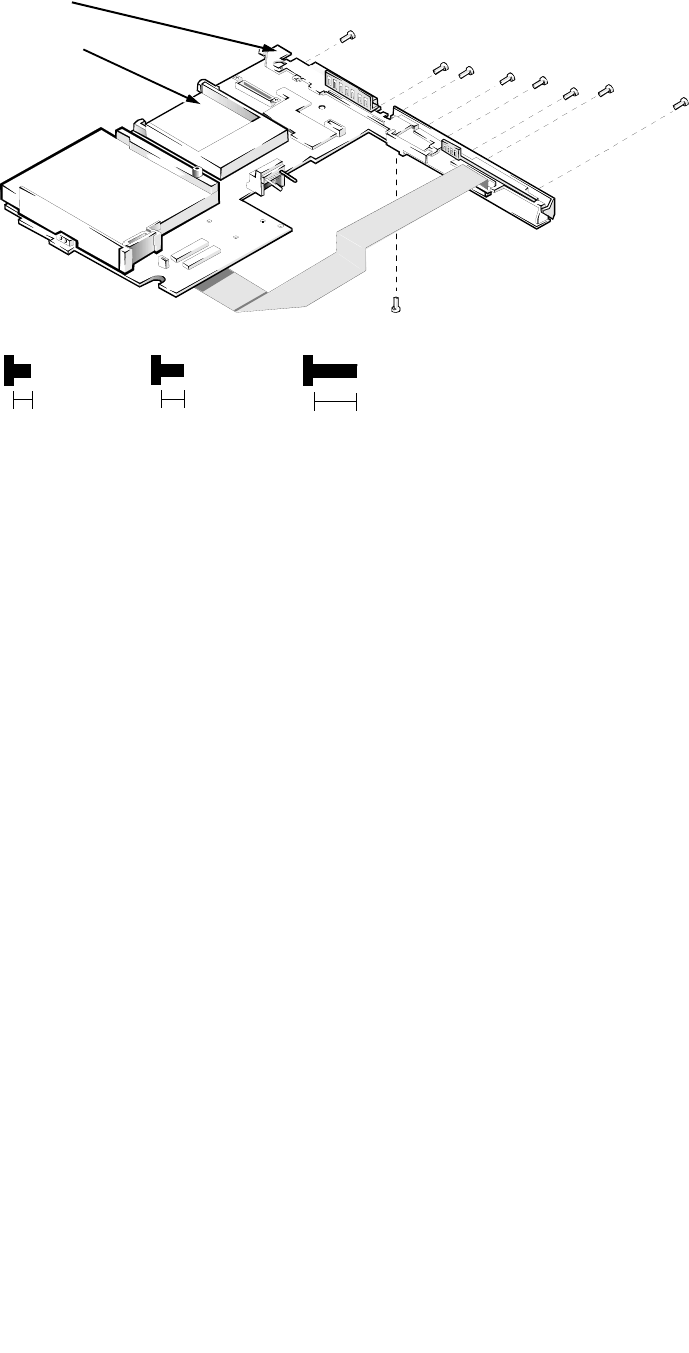
A-24 Dell Latitude XPi CD Service Manual
I/O Panel
Figure A-9. I/O Panel Removal
To remove and replace the I/O panel, follow these steps:
1. Remove the I/O board.
See the previous subsection in this appendix.
2. Remove the standoff nuts ST1 through ST8
Use a 3/16 nut driver to remove standoff nuts ST1 through ST6 and a 7/32 nut
driver for ST7 and ST8.
3. Remove screw D5.
4. Remove the I/O bracket from the system board.
system board
I/O bracket
8 mm
ST5
ST6
ST7 (4 mm)
4 mm
3 mm
D5 (3 mm)
ST4 ST3 ST2 ST1
ST8 (4 mm)
NOTE: ST1–ST8 are
8-mm standoff nuts
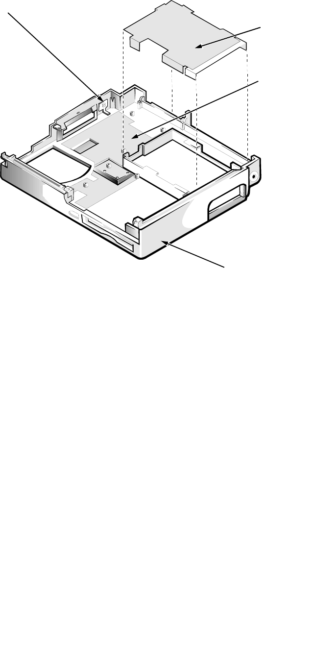
Factory Repair Parts A-25
B
ottom-Case Assembly Components
Figure A-10. Bottom-Case Assembly Components
To remove parts of the bottom case assembly, you must first remove the system
board assembly as described in “System Board Assembly” in Chapter 4. The
subsections that follow describe the removal and replacement of bottom-case
assembly components.
Main Battery Insulator
The main battery insulator insulates the main battery from the system board
assembly. To remove the main battery insulator, lift it off the main battery
compartment.
NOTE: The main battery insulator sometimes comes out as part of the system
board assembly. If this happens, follow the instructions in “System Board
Assembly” in Chapter 4.
bottom case assembly
spreader plate
power button
main battery
insulator
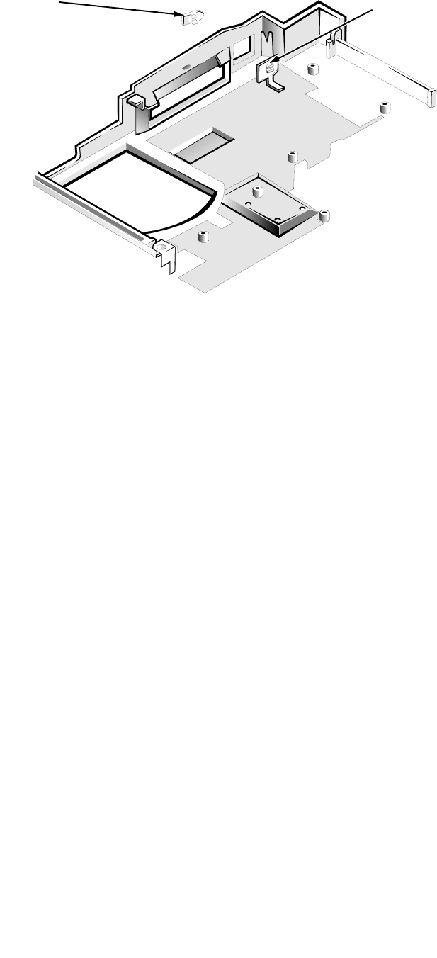
A-26 Dell Latitude XPi CD Service Manual
Power Button and Power-Button Mounting Bracket
Figure A-11. Power Button and Power-Button Mounting Bracket
Removal
Two tabs attach the power button to the power-button mounting bracket. To
remove the power button and its mounting bracket, slide the power button as far
as it will go toward the back of the bottom case assembly. Use a small flat-blade
screwdriver or similar device to press the two tabs out of the mounting bracket.
Lift the mounting bracket out of the bottom case assembly; then press the power
button out of the hole in the side of the bottom case assembly.
power button
mounting bracket
power button
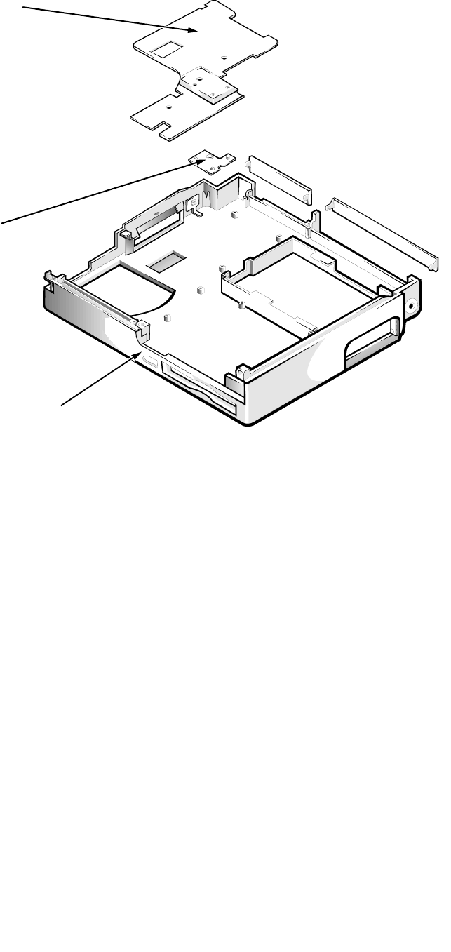
Factory Repair Parts A-27
Spreader and Keel Plates
Figure A-12. Spreader and Keel Plate Removal
Remove the spreader plate by lifting it from the bottom case assembly. The
spreader plate fits easily over plastic projections and screw holes. The keel plate
is in the center of the bottom case, below the spreader plate. The keel plate fits
over a small peg and a semicircular plastic projection. Remove the keel plate by
lifting it out of the bottom case assembly.
spreader plate
bottom case assembly
keel plate

A-28 Dell Latitude XPi CD Service Manual
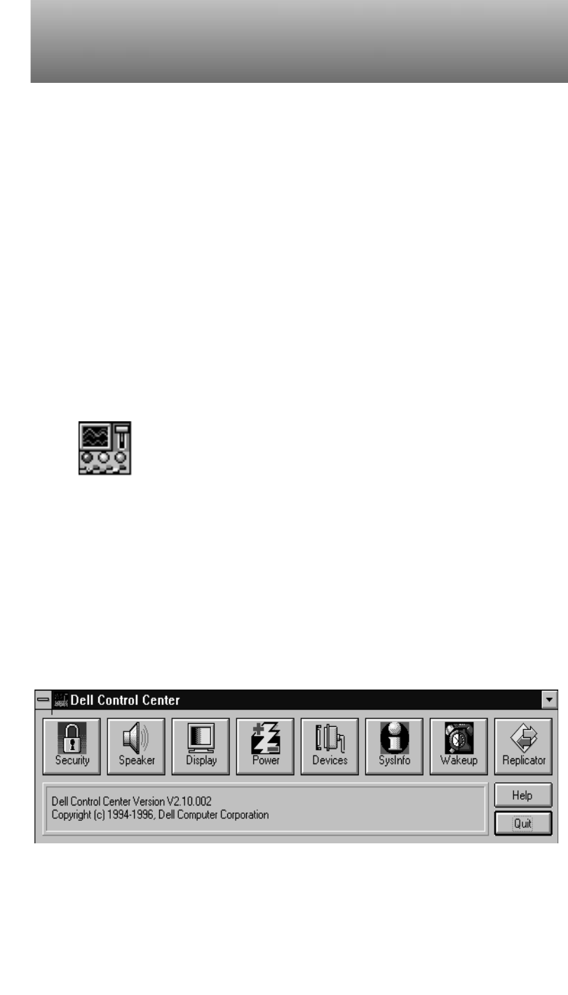
System Setup Options B-1
Appendix B
System Setup Options
Y
ou may want to customize the configuration of your computer. This appen-
dix describes how to change the system setup options stored in NVRAM on the
system board.
You can access these options in two ways:
•Using the Dell Control Center
•Using the MS-DOS–based version of the system setup options, called the
System Setup program
A
ccessing the Dell Control Center
Figure B-1. Dell Control Center Icon
To access system setup options, double-click the Dell Control Center icon in the
Dell Accessories program group in Windows.
Each button in the Dell Control Center window corresponds to a particular
group of system setup options. The Dell Control Center has a detailed help file
that explains each setup option.
Figure B-2. Dell Control Center Window

B-2 Dell Latitude XPi CD Service Manual
A
ccessing the System Setup Program
NOTE: If the System Setup program is running when the computer enters sus-
pend mode, the computer exits the System Setup program and then activates
suspend mode.
To enter the System Setup program, hold down the <CTRL> and <ALT> keys and
press the <ENTER> key, or press the <FN> and <F1> keys.
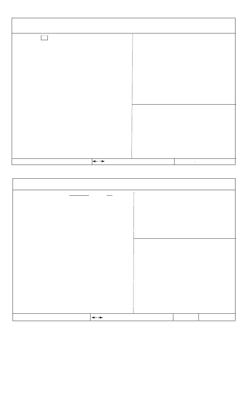
System Setup Options B-3
System Setup Screens
Figure B-3. System Setup Screens
Time: 13:17:02Date: Mon Feb 12, 1997 This category sets the time in
24-hour format (hours:min-
utes:seconds) for the internal
clock/calendar.
To change the value in a field,
enter digits or use the left- or
right-arrow key to decrease or
increase the value.
Changes take effect immediately.
Esc exit
change values Alt-B reboot
Dell Computer Corporation
Page 1 of 2 Dell Latitude XPi CD System Setup
Tab,Shift-Tab change fields change values Esc exit
BIOS Version: A
XX
XXX
Dell Computer Corporation
Page 2 of 2 Dell Latitude XPi CD System Setup
Alt-P nextTab,Shift-Tab change fields
BIOS Version: A
XX
Alt-P next Alt-B reboot
Internal Hard Drive:
Diskette Drive A:
Boot Speed:
Boot Sequence:
Speaker Volume:
Keyboard Click:
Serial Port:
Infrared Data Port:
Parallel Mode:
Integrated Trackball:
Upper PC Card Socket:
Lower PC Card Socket:
Monitor Toggle:
Replicator SCSI:
Replicator Network:
Ring Speed:
1216 MB
3.5 inch, 1.44 MB
150 MHz
Diskette First
High
Disabled
COM1
Disabled
Bidirectional
Enabled
Not Installed
Not installed
Enabled
Enabled
Enabled
16 mbps
Power Management:
Display Time-Out:
Disk Time-Out:
Suspend Time-Out:
S2D Time-Out:
Smart CPU Mode:
Brightness:
Ring/Event Resume:
Alarm Resume:
Display Close:
System Switch:
Battery Status:
IntelliSpin:
Primary Password:
Admin Password:
AC
Disabled
Disabled
Disabled
Disabled
Disabled
Disabled
High
BATTERY
Enabled
4 minutes
1 minute
10 minutes
8 hours
Enabled
Low
When set to DISABLED, this cate-
gory disables all power
management features.
The default setting is ENABLED.
A change in this category takes
Microprocessor:
System Memory:
Video Memory:
External Cache:
Expansion Device:
Service Tag:
Asset Tag:
Pentium-150
16 MB
1.1 MB
256 KB
Not installed
XXXXX
XXXXX
Pentium-150
16 MB
1.1 MB
256 KB
Not installed
XXXXX
XXXXX
Microprocessor:
System Memory:
Video Memory:
External Cache:
Expansion Device:
Service Tag:
Asset Tag:
Enabled
Enabled
SUSPEND
ON/OFF
Display
High Performance
Disabled
Disabled

B-4 Dell Latitude XPi CD Service Manual
Table B-1. System Setup Program Categories
Category Function
BIOS VERSION Displays the version number and release date
of the BIOS in the computer.
TIME Resets time on computer’s internal clock.
DATE Resets date on computer’s internal calendar.
INTERNAL HARD DRIVE Displays capacity of computer’s hard-disk
drive.
DISKETTE DRIVE A Identifies type of diskette drive installed.
BOOT SPEED Indicates operating frequency at which com-
puter boots—processor’s rated speed or a
slower speed for power conservation or speed-
sensitive software.
BOOT SEQUENCE Determines whether computer boots from dis-
kette (if present) or hard-disk drive.
SPEAKER VOLUME Adjusts volume of computer’s speaker or dis-
ables speaker. (System beep codes are not
affected by this category’s setting.)
KEYBOARD CLICK Determines whether built-in keyboard makes
audible clicking sounds. (SPEAKER VOLUME
must also be enabled.)
SERIAL PORT Configures computer’s built-in serial port.
INFRARED DATA PORT Configures computer’s built-in IrDA 1.0-
compatible communications port.
PARALLEL MODE Controls whether computer’s built-in parallel
port is configured as an Enhanced Capability
Port, Enhanced Parallel Port, AT-compatible
(unidirectional) port, or PS/2-compatible
(bidirectional) port.
INTEGRATED TRACKBALL Enables computer’s integrated trackball. Set to
DISABLED to connect a serial mouse.
UPPER PC CARD
SOCKET
or
LOWER PC CARD
SOCKET
Displays status of PC Card connectors. To
conserve power, category may be set to
DISABLED if a PC Card is installed but not
being used.
MONITOR TOGGLE Enables <CTRL><ALT><F8> key combina-
tion that directs where computer’s video image
is sent (the built-in display, an external VGA
display, or both).

System Setup Options B-5
REPLICATOR SCSI Configures computer for use with Advanced
Port Replicator. SCSI drivers will load auto-
matically if a SCSI device is connected.
REPLICATOR NETWORK Enabling this category and installing
is_net.exe utility allow user to configure net-
work drivers for use with Advanced Port
Replicator.
RING SPEED Configures the ring speed for the Advanced
Port Replicator.
MICROPROCESSOR Displays type of microprocessor installed.
SYSTEM MEMORY Displays amount of system memory.
VIDEO MEMORY Displays amount of video memory.
EXTERNAL CACHE Displays amount of external cache memory.
EXPANSION DEVICE Shows the type of Dell Latitude Advanced
Port Replicator that is attached to the com-
puter. There are no user-selectable settings for
this option.
SERVICE TAG Displays computer’s five-character service
tag number.
ASSET TAG Displays computer’s customer-programmable
asset tag. This category only appears if user
has entered an asset tag number.
POWER MANAGEMENT Enables computer’s power conservation fea-
tures.
BATTERY One of the categories of POWER MANAGE-
MENT. Set different time-outs for the following
options when the computer operates from bat-
tery power: DISPLAY TIME-OUT, DISK TIME-
OUT, SUSPEND TIME-OUT, S2D TIME-OUT,
SMART CPU MODE, and BRIGHTNESS.
Changing the BATTERY option takes effect
immediately (rebooting is not required)
AC One of the categories of POWER MANAGE-
MENT. Set different time-outs for the following
options when operating the computer from
alternating current (AC) power: DISPLAY
TIME-OUT, DISK TIME-OUT, SUSPEND TIME-
OUT, S2D TIME-OUT, SMART CPU MODE, and
BRIGHTNESS.
Table B-1. System Setup Program Categories
(Continued)
Category Function

B-6 Dell Latitude XPi CD Service Manual
DISPLAY TIME-OUT Determines how long computer operates with-
out detecting I/O activity before display is
switched off to conserve battery power. This
option should be disabled if software compati-
bility problems occur.
DISK TIME-OUT Determines how long hard-disk drive is idle
before drive motor turns off to conserve bat-
tery power.
SUSPEND TIME-OUT Determines how long computer is idle before
suspend mode is activated.
S2D TIME-OUT Determines how long computer is idle before
suspend-to-disk mode is activated.
SMART CPU MODE Allows microprocessor to slow down when
inactive. If software runs particular slowly,
this category should be set to DISABLE.
BRIGHTNESS Determines the brightness used when running
from the battery.
RING/EVENT RESUME Determines if computer exits suspend mode if
an installed modem receives an incoming call.
ALARM RESUME Determines if computer resumes normal oper-
ation from suspend or standby mode if an
alarm from RTC is detected.
DISPLAY CLOSE Indicates whether the computer enters suspend
mode when the display is closed or whether
only the display is turned off when the display
is closed. SUSPEND (the default) indicates the
computer is in suspend mode when the display
is closed. ACTIVE turns off the display, but
does not put the computer into suspend mode.
SYSTEM SWITCH Determines if power switch serves as a con-
ventional on/off switch, or toggles computer
between suspend-to-disk operation and normal
operation.
BATTERY STATUS Displays percentage of charge remaining in
battery.
Table B-1. System Setup Program Categories
(Continued)
Category Function

System Setup Options B-7
INTELLISPIN Compensates for unbalanced CDs that cause the
computer to vibrate when the CD-ROM drive is
in use. Allows use of discs that might otherwise
be unreadable. Available for CD-ROM drives
with speeds of 6X or higher. HIGH PERFOR-
MANCE (the default), lets the CD-ROM drive
run at the highest speed. VARIABLE automati-
cally lowers the CD-ROM’s speed to reduce or
stop the vibration.
PRIMARY PASSWORD Displays the current status of the primary pass-
word and allows you to assign or change this
password.
ADMIN PASSWORD Displays current status of computer’s adminis-
trator password security feature. Also used to
assign and verify a new administrator pass-
word.
Table B-1. System Setup Program Categories
(Continued)
Category Function

B-8 Dell Latitude XPi CD Service Manual

Index 1
Index
Numerics
3.1-V power supply board, 4-41
A
Advanced Port Replicator connector dust
cover
removal, 4-43
audio board
removal, 4-44
audio ports
location, 1-3
B
beep codes
POST, 3-1
boot routine
observing when troubleshooting, 2-4
bottom case assembly
components, A-25
removal, 4-29
C
cables
display assembly interface, removal, 4-26
I/O interface, removal, A-22
CD-ROM drive
about, 1-1
removal, 4-31, A-16
computer
features, 1-1
illustrated, 1-2
power, controlling, 1-5
connectors
ZIF, 4-5
D
deck buoy, 4-33
Dell Control Center
entering, B-1
Dell diagnostics, 3-9
diskette drive, A-16
diskette drive assembly
removal, 4-31, A-16
display assembly
base, removal, A-18
bezel, removal, 4-20
EMI shield, removal, A-17
hinges, removal, A-19
interface cable, removal, 4-26
latch spring, removal, 4-21
latch, removal, 4-21
removal, 4-18

2 Dell Latitude XPi CD Service Manual
E
error messages, system, 3-3
ESD, 4-2
exploded view
bottom assembly, A-14
LCD assembly, A-12
top assembly, A-13
external visual inspection, 2-1
G
grounding strap, 4-3
H
hard-disk drive, A-15
hard-disk drive assembly
removal, 4-7
hinge covers
removal, 4-25
I
I/O board, A-23
I/O interface cable
removal, 4-41, A-22
I/O panel, A-24
I/O panel dust cover
removal, 4-42
indicator panel, 1-3
initial procedures
system error messages, 3-3
troubleshooting, 2-1
initialization
error messages, 3-9
IrDA communications port
location, 1-2
IRQ line assignments
list of, 1-6
K
keel plate, A-27
key combinations
to enter System Setup program, B-2
keyboard assembly
removal, 4-14
keyboard/keypad/mouse connector shield
removal, A-21
L
LCD inverter board, 4-24
LCD panel
removal, 4-22
LEDs, 1-3
low-battery warnings, 1-4
M
main battery
removal, 4-3
memory compartment cover
removal, 4-8
memory module
capacities, 1-1
removal, 4-9
messages, system error
list of, 3-3
messages See system error messages
microphone/switch assembly
removal, 4-28

Index 3
P
palmrest assembly
components, A-16
removal, 4-10
palmrest brace, A-16
PC Card
types supported, 1-1
POST beep codes
about, 3-1
list of, 3-1
power button
removal, A-26
power-button mounting bracket, A-26
precautions, 4-2
R
reserve battery
removal, 4-36
S
screw identification and tightening, 4-4
sockets
memory module, 4-9
specifications
technical, 1-7
spreader plate, A-27
subsystems
testing, 3-8
superpart assembly
components, 4-36
removal, 4-34
system
configuring, B-4
features, 1-1
locations, 1-2
system board assembly
removal, 4-34, 4-38
system board components, A-20
system configuration information, B-3
system error messages
about, 3-3
list of, 3-3
system setup options, B-1
System Setup program
entering, B-2
screens, B-3
settings, B-4
T
technical specifications, 1-7
tilt-support feet
removal, 4-16
tools required, 4-2, A-1
trackball
assembly removal, 4-13, A-16
button board removal, A-16
interface cable, A-16
troubleshooting
boot routine interpretation, 2-4
external visual inspection, 2-1
initial user contact, 2-1
U
user contact
initial, 2-1

