Dell Mellanox Family Of Adapters Owners Manual User For ConnectX 3 10/40 Gigabit Ethernet PowerEdge Servers
2014-11-13
: Dell Dell-Mellanox-Family-Of-Adapters-Owners-Manual-116816 dell-mellanox-family-of-adapters-owners-manual-116816 dell pdf
Open the PDF directly: View PDF ![]() .
.
Page Count: 115 [warning: Documents this large are best viewed by clicking the View PDF Link!]
- User Manual for Mellanox ConnectX®-3 10/40 Gigabit Ethernet Adapters for Dell PowerEdge Servers
- Restrictions and Disclaimers
- Export Regulations
- Revision History
- About this Manual
- 1 Introduction
- 2 Adapter Card Interfaces
- 3 Installing the Hardware
- 4 Driver Installation and Configuration
- 4.1 Linux Driver
- 4.2 Linux Driver Features
- 4.2.1 iSCSI Extensions for RDMA (iSER)
- 4.2.2 iSER Initiator
- 4.2.3 Quality of Service (QoS) Ethernet
- 4.2.4 Ethernet Time-Stamping
- 4.2.5 RoCE Time Stamping
- 4.2.6 Flow Steering
- 4.2.7 Single Root IO Virtualization (SR-IOV)
- 4.2.7.1 System Requirements
- 4.2.7.2 Setting Up SR-IOV
- 4.2.7.3 Enabling SR-IOV and Para Virtualization on the Same Setup
- 4.2.7.4 Assigning a Virtual Function to a Virtual Machine
- 4.2.7.5 Uninstalling SR-IOV Driver
- 4.2.7.6 Configuring Pkeys and GUIDs under SR-IOV
- 4.2.7.7 Ethernet Virtual Function Configuration when Running SR-IOV
- 4.2.8 Ethtool
- 4.2.9 Ethernet Performance Counters
- 4.3 VMware Driver
- 4.4 Windows
- 4.5 WinOF Features
- 5 Remote Boot
- 6 Firmware
- 7 Dell Lifecycle ControllerTroubleshooting
- 8 Specifications
- 9 Regulatory
- Appendix A: Configuration for Mellanox Adapters through System Setup
- Appendix B: Safety Warnings
- Appendix C: Avertissements de sécurité d’installation (Warnings in French)
- Appendix D: Sicherheitshinweise (Warnings in German)
- Appendix E: Advertencias de seguridad para la instalación (Warnings in Spanish)

www.mellanox.com
User Manual for Mellanox ConnectX®-3 10/40
Gigabit Ethernet Adapters for Dell PowerEdge
Servers
Rev 1.1

Mellanox Technologies
350 Oakmead Parkway Suite 100
Sunnyvale, CA 94085
U.S.A.
www.mellanox.com
Tel: (408) 970-3400
Fax: (408) 970-3403
Mellanox Technologies, Ltd.
Beit Mellanox
PO Box 586 Yokneam 20692
Israel
www.mellanox.com
Tel: +972 (0)74 723 7200
Fax: +972 (0)4 959 3245
© Copyright 2014. Mellanox Technologies. All Rights Reserved.
Mellanox®, Mellanox logo, BridgeX®, ConnectX®, Connect-IB®, CORE-Direct®, InfiniBridge®, InfiniHost®,
InfiniScale®, MetroX®, MLNX-OS®, PhyX®, ScalableHPC®, SwitchX®, UFM®, Virtual Protocol Interconnect® and
Voltaire® are registered trademarks of Mellanox Technologies, Ltd.
ExtendX™, FabricIT™, Mellanox Open Ethernet™, Mellanox Virtual Modular Switch™, MetroDX™, TestX™,
Unbreakable-Link™ are trademarks of Mellanox Technologies, Ltd.
All other trademarks are property of their respective owners.
Dell and the DELL logo are trademarks of Dell Inc. Microsoft and Windows are trademarks of Microsoft Corporation. Linux
is a trademark of Linus Torvalds. Intel is a trademark of Intel Corporation. Magic Packet is a trademark of Advanced Micro
Devices, Inc. Red Hat is a trademark of Red Hat, Inc. PCI Express is a trademark of PCI-SIG. Any other trademarks or trade
names mentioned are the property of their respective owners.
NOTE:
THIS HARDWARE, SOFTWARE OR TEST SUITE PRODUCT (“PRODUCT(S)”) AND ITS RELATED
DOCUMENTATION ARE PROVIDED BY MELLANOX TECHNOLOGIES “AS-IS” WITH ALL FAULTS OF ANY
KIND AND SOLELY FOR THE PURPOSE OF AIDING THE CUSTOMER IN TESTING APPLICATIONS THAT USE
THE PRODUCTS IN DESIGNATED SOLUTIONS. THE CUSTOMER'S MANUFACTURING TEST ENVIRONMENT
HAS NOT MET THE STANDARDS SET BY MELLANOX TECHNOLOGIES TO FULLY QUALIFY THE
PRODUCTO(S) AND/OR THE SYSTEM USING IT. THEREFORE, MELLANOX TECHNOLOGIES CANNOT AND
DOES NOT GUARANTEE OR WARRANT THAT THE PRODUCTS WILL OPERATE WITH THE HIGHEST
QUALITY. ANY EXPRESS OR IMPLIED WARRANTIES, INCLUDING, BUT NOT LIMITED TO, THE IMPLIED
WARRANTIES OF MERCHANTABILITY, FITNESS FOR A PARTICULAR PURPOSE AND NONINFRINGEMENT
ARE DISCLAIMED. IN NO EVENT SHALL MELLANOX BE LIABLE TO CUSTOMER OR ANY THIRD PARTIES
FOR ANY DIRECT, INDIRECT, SPECIAL, EXEMPLARY, OR CONSEQUENTIAL DAMAGES OF ANY KIND
(INCLUDING, BUT NOT LIMITED TO, PAYMENT FOR PROCUREMENT OF SUBSTITUTE GOODS OR SERVICES;
LOSS OF USE, DATA, OR PROFITS; OR BUSINESS INTERRUPTION) HOWEVER CAUSED AND ON ANY
THEORY OF LIABILITY, WHETHER IN CONTRACT, STRICT LIABILITY, OR TORT (INCLUDING NEGLIGENCE
OR OTHERWISE) ARISING IN ANY WAY FROM THE USE OF THE PRODUCT(S) AND RELATED
DOCUMENTATION EVEN IF ADVISED OF THE POSSIBILITY OF SUCH DAMAGE.
Document Number: 4078
Rev 1.1
Mellanox Technologies
2

User Manual for Mellanox ConnectX®-3 10/40 Gigabit Ethernet Adapters for Dell PowerEdge Servers Rev 1.1
Mellanox Technologies 3
Restrictions and Disclaimers
The information contained in this document, including all instructions, cautions, and regulatory
approvals and certifications, is provided by the supplier and has not been independently verified
or tested by Dell, except where specifically noted. Dell cannot be responsible for damage caused
as a result of either following or failing to follow these instructions. All statements or claims
regarding the properties, capabilities, speeds or qualifications of the part referenced in this docu-
ment are made by the supplier and not by Dell. Dell specifically disclaims knowledge of the
accuracy, completeness or substantiation for any such statements. All questions or comments
relating to such statements or claims should be directed to the supplier.
Export Regulations
Customer acknowledges that these Products, which may include technology and software, are
subject to the customs and export control laws and regulations of the United States ("U.S.") and
may also be subject to the customs and export laws and regulations of the country in which the
Products are manufactured and/or received. Customer agrees to abide by those laws and regula-
tions. Further, under U.S. law, the Products may not be sold, leased or otherwise transferred to
restricted end-users or to restricted countries. In addition, the Products may not be sold, leased or
otherwise transferred to, or utilized by an end-user engaged in activities related to weapons of
mass destruction, including without limitation, activities related to the design, development, pro-
duction or use of nuclear weapons, materials, or facilities, missiles or the support of missile proj-
ects, and chemical or biological weapons.

Rev 1.1
Mellanox Technologies
4
Table of Contents
Restrictions and Disclaimers . . . . . . . . . . . . . . . . . . . . . . . . . . . . . . . . . . . . . . . . .3
Export Regulations . . . . . . . . . . . . . . . . . . . . . . . . . . . . . . . . . . . . . . . . . . . . . . . . .3
Table of Contents . . . . . . . . . . . . . . . . . . . . . . . . . . . . . . . . . . . . . . . . . . . . . . . . . . .4
List of Tables . . . . . . . . . . . . . . . . . . . . . . . . . . . . . . . . . . . . . . . . . . . . . . . . . . . . . .8
List of Figures . . . . . . . . . . . . . . . . . . . . . . . . . . . . . . . . . . . . . . . . . . . . . . . . . . . . . .9
Revision History . . . . . . . . . . . . . . . . . . . . . . . . . . . . . . . . . . . . . . . . . . . . . . . . . . .10
About this Manual . . . . . . . . . . . . . . . . . . . . . . . . . . . . . . . . . . . . . . . . . . . . . . . . .11
Intended Audience. . . . . . . . . . . . . . . . . . . . . . . . . . . . . . . . . . . . . . . . . . . . . . 11
Related Documentation . . . . . . . . . . . . . . . . . . . . . . . . . . . . . . . . . . . . . . . . . . 11
Document Conventions . . . . . . . . . . . . . . . . . . . . . . . . . . . . . . . . . . . . . . . . . . 11
Technical Support . . . . . . . . . . . . . . . . . . . . . . . . . . . . . . . . . . . . . . . . . . . . . . 11
Chapter 1 Introduction . . . . . . . . . . . . . . . . . . . . . . . . . . . . . . . . . . . . . . . . . . . . 12
1.1 Functional Description . . . . . . . . . . . . . . . . . . . . . . . . . . . . . . . . . . . . . . .12
1.2 Features . . . . . . . . . . . . . . . . . . . . . . . . . . . . . . . . . . . . . . . . . . . . . . . . . .12
1.2.1 Single Root IO Virtualization (SR-IOV). . . . . . . . . . . . . . . . . . . . . . . . . . . 14
1.2.2 Remote Direct Memory Access (RDMA) . . . . . . . . . . . . . . . . . . . . . . . . . 14
1.3 Supported Operating Systems/Distributions . . . . . . . . . . . . . . . . . . . . . . .14
Chapter 2 Adapter Card Interfaces. . . . . . . . . . . . . . . . . . . . . . . . . . . . . . . . . . . 15
2.1 I/O Interfaces . . . . . . . . . . . . . . . . . . . . . . . . . . . . . . . . . . . . . . . . . . . . . .15
2.1.1 Ethernet QSFP+/ SFP+ Interface. . . . . . . . . . . . . . . . . . . . . . . . . . . . . . . 15
2.1.2 LED Assignment. . . . . . . . . . . . . . . . . . . . . . . . . . . . . . . . . . . . . . . . . . . . 15
Chapter 3 Installing the Hardware . . . . . . . . . . . . . . . . . . . . . . . . . . . . . . . . . . . 18
3.1 System Requirements . . . . . . . . . . . . . . . . . . . . . . . . . . . . . . . . . . . . . . .18
3.1.1 Hardware . . . . . . . . . . . . . . . . . . . . . . . . . . . . . . . . . . . . . . . . . . . . . . . . . 18
3.1.2 Operating Systems/Distributions . . . . . . . . . . . . . . . . . . . . . . . . . . . . . . . 18
3.1.3 Software Stacks . . . . . . . . . . . . . . . . . . . . . . . . . . . . . . . . . . . . . . . . . . . . 18
3.1.4 Co-requisites . . . . . . . . . . . . . . . . . . . . . . . . . . . . . . . . . . . . . . . . . . . . . . 18
3.2 Safety Precautions . . . . . . . . . . . . . . . . . . . . . . . . . . . . . . . . . . . . . . . . . .18
3.3 Pre-installation Checklist . . . . . . . . . . . . . . . . . . . . . . . . . . . . . . . . . . . . .19
3.4 Installation Instructions . . . . . . . . . . . . . . . . . . . . . . . . . . . . . . . . . . . . . . .19
3.4.1 For Adapters. . . . . . . . . . . . . . . . . . . . . . . . . . . . . . . . . . . . . . . . . . . . . . . 19
3.4.2 For Mezzanine Cards . . . . . . . . . . . . . . . . . . . . . . . . . . . . . . . . . . . . . . . . 19
3.5 Connecting the Network Cables . . . . . . . . . . . . . . . . . . . . . . . . . . . . . . . .20
3.5.1 Inserting a Cable into the Adapter Card . . . . . . . . . . . . . . . . . . . . . . . . . . 20
3.5.2 Removing a Cable from the Adapter Card . . . . . . . . . . . . . . . . . . . . . . . . 20
3.6 Identifying the Card in A System . . . . . . . . . . . . . . . . . . . . . . . . . . . . . . .20
3.6.1 On Linux . . . . . . . . . . . . . . . . . . . . . . . . . . . . . . . . . . . . . . . . . . . . . . . . . . 20
Chapter 4 Driver Installation and Configuration. . . . . . . . . . . . . . . . . . . . . . . . 21
4.1 Linux Driver . . . . . . . . . . . . . . . . . . . . . . . . . . . . . . . . . . . . . . . . . . . . . . .21

User Manual for Mellanox ConnectX®-3 10/40 Gigabit Ethernet Adapters for Dell PowerEdge Servers Rev 1.1
Mellanox Technologies 5
4.1.1 Installation Requirements. . . . . . . . . . . . . . . . . . . . . . . . . . . . . . . . . . . . . 21
4.1.2 Downloading Mellanox OFED . . . . . . . . . . . . . . . . . . . . . . . . . . . . . . . . . 21
4.1.3 Installing Mellanox OFED. . . . . . . . . . . . . . . . . . . . . . . . . . . . . . . . . . . . . 21
4.1.3.1 Pre-installation Notes . . . . . . . . . . . . . . . . . . . . . . . . . . . . . . . . . . . . . . . 22
4.1.4 Installation Script . . . . . . . . . . . . . . . . . . . . . . . . . . . . . . . . . . . . . . . . . . . 22
4.1.4.1 mlnxofedinstall Return Codes . . . . . . . . . . . . . . . . . . . . . . . . . . . . . . . . . 22
4.1.5 Installation Procedure. . . . . . . . . . . . . . . . . . . . . . . . . . . . . . . . . . . . . . . . 23
4.1.6 Installation Results . . . . . . . . . . . . . . . . . . . . . . . . . . . . . . . . . . . . . . . . . . 24
4.1.7 Post-installation Notes . . . . . . . . . . . . . . . . . . . . . . . . . . . . . . . . . . . . . . . 25
4.1.8 Uninstalling Mellanox OFED. . . . . . . . . . . . . . . . . . . . . . . . . . . . . . . . . . . 25
4.2 Linux Driver Features . . . . . . . . . . . . . . . . . . . . . . . . . . . . . . . . . . . . . . . .25
4.2.1 iSCSI Extensions for RDMA (iSER) . . . . . . . . . . . . . . . . . . . . . . . . . . . . . 25
4.2.2 iSER Initiator. . . . . . . . . . . . . . . . . . . . . . . . . . . . . . . . . . . . . . . . . . . . . . . 25
4.2.3 Quality of Service (QoS) Ethernet . . . . . . . . . . . . . . . . . . . . . . . . . . . . . . 25
4.2.3.1 Mapping Traffic to Traffic Classes. . . . . . . . . . . . . . . . . . . . . . . . . . . . . . 25
4.2.3.2 Plain Ethernet Quality of Service Mapping . . . . . . . . . . . . . . . . . . . . . . . 26
4.2.3.3 RoCE Quality of Service Mapping. . . . . . . . . . . . . . . . . . . . . . . . . . . . . . 27
4.2.3.4 Raw Ethernet QP Quality of Service Mapping . . . . . . . . . . . . . . . . . . . . 27
4.2.3.5 Map Priorities with tc_wrap.py/mlnx_qos . . . . . . . . . . . . . . . . . . . . . . . . 27
4.2.3.6 Quality of Service Properties. . . . . . . . . . . . . . . . . . . . . . . . . . . . . . . . . . 28
4.2.3.7 Quality of Service Tools . . . . . . . . . . . . . . . . . . . . . . . . . . . . . . . . . . . . . 29
4.2.4 Ethernet Time-Stamping. . . . . . . . . . . . . . . . . . . . . . . . . . . . . . . . . . . . . . 32
4.2.4.1 Enabling Time Stamping . . . . . . . . . . . . . . . . . . . . . . . . . . . . . . . . . . . . . 32
4.2.4.2 Getting Time Stamping . . . . . . . . . . . . . . . . . . . . . . . . . . . . . . . . . . . . . . 35
4.2.4.3 Querying Time Stamping Capabilities via ethtool . . . . . . . . . . . . . . . . . . 36
4.2.5 RoCE Time Stamping. . . . . . . . . . . . . . . . . . . . . . . . . . . . . . . . . . . . . . . . 36
4.2.5.1 Query Capabilities. . . . . . . . . . . . . . . . . . . . . . . . . . . . . . . . . . . . . . . . . . 36
4.2.5.2 Creating Time Stamping Completion Queue. . . . . . . . . . . . . . . . . . . . . . 37
4.2.5.3 Polling a Completion Queue . . . . . . . . . . . . . . . . . . . . . . . . . . . . . . . . . . 37
4.2.5.4 Querying the Hardware Time . . . . . . . . . . . . . . . . . . . . . . . . . . . . . . . . . 38
4.2.6 Flow Steering . . . . . . . . . . . . . . . . . . . . . . . . . . . . . . . . . . . . . . . . . . . . . . 38
4.2.6.1 Enable/Disable Flow Steering . . . . . . . . . . . . . . . . . . . . . . . . . . . . . . . . . 38
4.2.6.2 Flow Domains and Priorities . . . . . . . . . . . . . . . . . . . . . . . . . . . . . . . . . . 39
4.2.7 Single Root IO Virtualization (SR-IOV). . . . . . . . . . . . . . . . . . . . . . . . . . . 41
4.2.7.1 System Requirements. . . . . . . . . . . . . . . . . . . . . . . . . . . . . . . . . . . . . . . 41
4.2.7.2 Setting Up SR-IOV . . . . . . . . . . . . . . . . . . . . . . . . . . . . . . . . . . . . . . . . . 41
4.2.7.3 Enabling SR-IOV and Para Virtualization on the Same Setup . . . . . . . . 44
4.2.7.4 Assigning a Virtual Function to a Virtual Machine. . . . . . . . . . . . . . . . . . 44
4.2.7.5 Uninstalling SR-IOV Driver . . . . . . . . . . . . . . . . . . . . . . . . . . . . . . . . . . . 45
4.2.7.6 Configuring Pkeys and GUIDs under SR-IOV. . . . . . . . . . . . . . . . . . . . . 46
4.2.7.7 Ethernet Virtual Function Configuration when Running SR-IOV. . . . . . . 47
4.2.8 Ethtool . . . . . . . . . . . . . . . . . . . . . . . . . . . . . . . . . . . . . . . . . . . . . . . . . . . 48
4.2.9 Ethernet Performance Counters. . . . . . . . . . . . . . . . . . . . . . . . . . . . . . . . 50
4.3 VMware Driver . . . . . . . . . . . . . . . . . . . . . . . . . . . . . . . . . . . . . . . . . . . . .55
4.3.1 Installing and Running the Driver . . . . . . . . . . . . . . . . . . . . . . . . . . . . . . . 55
4.3.1.1 Installing and Running the VIB Driver on ESXi-5.x . . . . . . . . . . . . . . . . . 55
4.3.2 Installing and Running the offline_bundle Driver on ESXi-5.x . . . . . . . . . 57
4.3.3 Removing the VIB/offline_bundle Driver. . . . . . . . . . . . . . . . . . . . . . . . . . 57

Rev 1.1
Mellanox Technologies
6
4.4 Windows . . . . . . . . . . . . . . . . . . . . . . . . . . . . . . . . . . . . . . . . . . . . . . . . . .57
4.4.1 Installation Requirements. . . . . . . . . . . . . . . . . . . . . . . . . . . . . . . . . . . . . 58
4.4.1.1 Required Disk Space for Installation . . . . . . . . . . . . . . . . . . . . . . . . . . . . 58
4.4.2 Software Requirements . . . . . . . . . . . . . . . . . . . . . . . . . . . . . . . . . . . . . . 58
4.4.2.1 Installer Privileges . . . . . . . . . . . . . . . . . . . . . . . . . . . . . . . . . . . . . . . . . . 58
4.4.3 Downloading Mellanox WinOF . . . . . . . . . . . . . . . . . . . . . . . . . . . . . . . . . 58
4.4.4 Installing Mellanox WinOF . . . . . . . . . . . . . . . . . . . . . . . . . . . . . . . . . . . . 58
4.4.4.1 Attended Installation . . . . . . . . . . . . . . . . . . . . . . . . . . . . . . . . . . . . . . . . 58
4.4.4.2 Unattended Installation . . . . . . . . . . . . . . . . . . . . . . . . . . . . . . . . . . . . . . 59
4.4.5 Uninstalling Mellanox WinOF . . . . . . . . . . . . . . . . . . . . . . . . . . . . . . . . . . 59
4.4.6 Windows Performance Tuning . . . . . . . . . . . . . . . . . . . . . . . . . . . . . . . . . 59
4.5 WinOF Features . . . . . . . . . . . . . . . . . . . . . . . . . . . . . . . . . . . . . . . . . . . .59
4.5.1 Configuring Quality of Service (QoS) . . . . . . . . . . . . . . . . . . . . . . . . . . . . 59
4.5.2 RDMA over Converged Ethernet . . . . . . . . . . . . . . . . . . . . . . . . . . . . . . . 61
4.5.2.1 RoCE Configuration . . . . . . . . . . . . . . . . . . . . . . . . . . . . . . . . . . . . . . . . 61
4.5.2.2 Configuring Router (PFC only) . . . . . . . . . . . . . . . . . . . . . . . . . . . . . . . . 63
4.5.3 Deploying Windows Server 2012 and 2012 R2 with SMB Direct . . . . . . . 63
4.5.3.1 Hardware and Software Prerequisites. . . . . . . . . . . . . . . . . . . . . . . . . . . 63
4.5.3.2 SMB Configuration Verification . . . . . . . . . . . . . . . . . . . . . . . . . . . . . . . . 63
4.5.3.3 Verifying SMB Connection . . . . . . . . . . . . . . . . . . . . . . . . . . . . . . . . . . . 64
4.5.3.4 Verifying SMB Events that Confirm RDMA Connection . . . . . . . . . . . . . 64
Chapter 5 Remote Boot. . . . . . . . . . . . . . . . . . . . . . . . . . . . . . . . . . . . . . . . . . . . 65
5.1 iSCSI Boot . . . . . . . . . . . . . . . . . . . . . . . . . . . . . . . . . . . . . . . . . . . . . . . .65
5.1.1 RHEL6.4/RHEL6.5 . . . . . . . . . . . . . . . . . . . . . . . . . . . . . . . . . . . . . . . . . . 65
5.1.1.1 Configuring the iSCSI Target Machine . . . . . . . . . . . . . . . . . . . . . . . . . . 65
5.1.1.2 Installing RHEL6.4/RHEL6.5 on a Remote Storage over iSCSI . . . . . . . 66
5.1.1.3 SAN-Booting the Diskless Client with FlexBoot . . . . . . . . . . . . . . . . . . . 70
5.1.2 Booting Windows from an iSCSI Target . . . . . . . . . . . . . . . . . . . . . . . . . . 70
5.1.2.1 Configuring the WDS, DHCP and iSCSI Servers . . . . . . . . . . . . . . . . . . 70
5.1.2.2 Configuring the Client Machine . . . . . . . . . . . . . . . . . . . . . . . . . . . . . . . . 71
5.1.2.3 Installing iSCSI . . . . . . . . . . . . . . . . . . . . . . . . . . . . . . . . . . . . . . . . . . . . 72
5.1.3 SLES11 SP3. . . . . . . . . . . . . . . . . . . . . . . . . . . . . . . . . . . . . . . . . . . . . . . 73
5.1.3.1 Configuring the iSCSI Target Machine . . . . . . . . . . . . . . . . . . . . . . . . . . 73
5.1.3.2 Configuring the DHCP Server . . . . . . . . . . . . . . . . . . . . . . . . . . . . . . . . . 75
5.1.3.3 Installing SLES11 SP3 on a Remote Storage over iSCSI. . . . . . . . . . . . 75
5.1.3.4 Using PXE Boot Services for Booting the SLES11 SP3 from the iSCSI Target 82
5.2 PXE Boot . . . . . . . . . . . . . . . . . . . . . . . . . . . . . . . . . . . . . . . . . . . . . . . . .82
5.2.1 SLES11 SP3. . . . . . . . . . . . . . . . . . . . . . . . . . . . . . . . . . . . . . . . . . . . . . . 82
5.2.1.1 Configuring the PXE Server . . . . . . . . . . . . . . . . . . . . . . . . . . . . . . . . . . 82
Chapter 6 Firmware . . . . . . . . . . . . . . . . . . . . . . . . . . . . . . . . . . . . . . . . . . . . . . . 84
Chapter 7 Troubleshooting. . . . . . . . . . . . . . . . . . . . . . . . . . . . . . . . . . . . . . . . . 85
7.1 General . . . . . . . . . . . . . . . . . . . . . . . . . . . . . . . . . . . . . . . . . . . . . . . . . . .85
7.2 Linux . . . . . . . . . . . . . . . . . . . . . . . . . . . . . . . . . . . . . . . . . . . . . . . . . . . . .86
7.3 Windows . . . . . . . . . . . . . . . . . . . . . . . . . . . . . . . . . . . . . . . . . . . . . . . . . .86
Chapter 8 Specifications. . . . . . . . . . . . . . . . . . . . . . . . . . . . . . . . . . . . . . . . . . . 88
Chapter 9 Regulatory. . . . . . . . . . . . . . . . . . . . . . . . . . . . . . . . . . . . . . . . . . . . . . 91

User Manual for Mellanox ConnectX®-3 10/40 Gigabit Ethernet Adapters for Dell PowerEdge Servers Rev 1.1
Mellanox Technologies 7
9.1 Regulatory Statements . . . . . . . . . . . . . . . . . . . . . . . . . . . . . . . . . . . . . . .91
9.1.1 FCC Statements (USA) . . . . . . . . . . . . . . . . . . . . . . . . . . . . . . . . . . . . . . 91
9.1.2 EN Statements (Europe) . . . . . . . . . . . . . . . . . . . . . . . . . . . . . . . . . . . . . 92
9.1.3 ICES Statements (Canada) . . . . . . . . . . . . . . . . . . . . . . . . . . . . . . . . . . . 92
9.1.4 VCCI Statements (Japan). . . . . . . . . . . . . . . . . . . . . . . . . . . . . . . . . . . . . 92
9.1.5 KCC Certification (Korea) . . . . . . . . . . . . . . . . . . . . . . . . . . . . . . . . . . . . . 93
Appendix A Configuration for Mellanox Adapters through System Setup . . .94
Appendix B Safety Warnings . . . . . . . . . . . . . . . . . . . . . . . . . . . . . . . . . . . . . . .108
Appendix C Avertissements de sécurité d’installation (Warnings in French) 110
Appendix D Sicherheitshinweise (Warnings in German) . . . . . . . . . . . . . . . .112
Appendix E Advertencias de seguridad para la instalación (Warnings in Spanish) 114

Rev 1.1
Mellanox Technologies
8
List of Tables
Table 1: Revision History Table . . . . . . . . . . . . . . . . . . . . . . . . . . . . . . . . . . . . . . . . . . . . . . . . . . .10
Table 2: Documents List . . . . . . . . . . . . . . . . . . . . . . . . . . . . . . . . . . . . . . . . . . . . . . . . . . . . . . . . .11
Table 3: LED Assignment for 10GbE SFP+ Network Adapters . . . . . . . . . . . . . . . . . . . . . . . . . .15
Table 4: LED Assignment for 40GbE QSFP+ Network Adapters . . . . . . . . . . . . . . . . . . . . . . . . .16
Table 5: install.sh Return Codes . . . . . . . . . . . . . . . . . . . . . . . . . . . . . . . . . . . . . . . . . . . . . . . . . . .22
Table 6: Flow Specific Parameters . . . . . . . . . . . . . . . . . . . . . . . . . . . . . . . . . . . . . . . . . . . . . . . . .40
Table 7: ethtool Supported Options . . . . . . . . . . . . . . . . . . . . . . . . . . . . . . . . . . . . . . . . . . . . . . . .49
Table 8: Port IN Counters . . . . . . . . . . . . . . . . . . . . . . . . . . . . . . . . . . . . . . . . . . . . . . . . . . . . . . . .51
Table 9: Port OUT Counters . . . . . . . . . . . . . . . . . . . . . . . . . . . . . . . . . . . . . . . . . . . . . . . . . . . . . .52
Table 10: Port VLAN Priority Tagging (where <i> is in the range 0…7) . . . . . . . . . . . . . . . . . . . .52
Table 11: Port Pause (where <i> is in the range 0…7) . . . . . . . . . . . . . . . . . . . . . . . . . . . . . . . . . . .53
Table 12: VPort Statistics (where <i>=<empty_string> is the PF, and ranges 1…NumOfVf per VF) 53
Table 13: SW Statistics . . . . . . . . . . . . . . . . . . . . . . . . . . . . . . . . . . . . . . . . . . . . . . . . . . . . . . . . . . .54
Table 14: Per Ring (SW) Statistics (where <i> is the ring I – per configuration) . . . . . . . . . . . . . .55
Table 15: Reserved IP Address Options . . . . . . . . . . . . . . . . . . . . . . . . . . . . . . . . . . . . . . . . . . . . . .71
Table 16: Mellanox ConnectX-3 Dual 40GbE QSFP+ Network Adapter Specifications . . . . . . . .88
Table 17: Mellanox ConnectX-3 Dual 10GbE SFP+ Network Adapter Specifications . . . . . . . . . .89
Table 18: Mellanox ConnectX-3 Dual 10GbE KR Blade Mezzanine Card Specifications . . . . . . .90
Table 19: Ethernet Network Adapter Certifications . . . . . . . . . . . . . . . . . . . . . . . . . . . . . . . . . . . . .91

User Manual for Mellanox ConnectX®-3 10/40 Gigabit Ethernet Adapters for Dell PowerEdge Servers Rev 1.1
Mellanox Technologies 9
List of Figures
Figure 1: Mellanox ConnectX-3 Dual Port 40GbE QSFP+ Network Adapter Full Height Bracket 16
Figure 2: Mellanox ConnectX-3 Dual Port 10GbE SFP+ Network Adapter Full Height Bracket .17
Figure 3: Life Cycle Controller Main Configuration System Setup Menu . . . . . . . . . . . . . . . . . . .94
Figure 4: Main Configuration Page Options . . . . . . . . . . . . . . . . . . . . . . . . . . . . . . . . . . . . . . . . . .95
Figure 5: Main ConfiguratioP page - iSCSI Configuration - iSCSI General Parameters . . . . . . .101
Figure 6: Main Configuration Page - iSCSI Configuration - iSCSI Initiator Parameters . . . . . . .102
Figure 7: Main Configuration Page - iSCSI Configuration - iSCSI Target Parameters . . . . . . . .103

Rev 1.1
Mellanox Technologies
10
Revision History
This document was printed on August 12, 2014.
Table 1 - Revision History Table
Date Rev Comments/Changes
August 2014 1.1 • Added Section 4.2, “Linux Driver Features,” on page 25
• Added Section 4.5, “WinOF Features,” on page 59
• Added Section 5, “Remote Boot,” on page 65
• Added Appendix A, “Configuration for Mellanox Adapters
through System Setup,” on page 94
November 2013 1.0 Initial Release

User Manual for Mellanox ConnectX®-3 10/40 Gigabit Ethernet Adapters for Dell PowerEdge Servers Rev 1.1
Mellanox Technologies 11
About this Manual
This User Manual describes Mellanox Technologies ConnectX®-3 10/40 Gigabit Ethernet
Adapter and Cards for Dell PowerEdge Servers. It provides details as to the interfaces of the
board, specifications, required software and firmware for operating the board, and relevant docu-
mentation.
Intended Audience
This manual is intended for the installer and user of these cards.
The manual assumes the user has basic familiarity with Ethernet networks and architecture spec-
ifications.
Related Documentation
Table 2 - Documents List
Document Conventions
This document uses the following conventions:
• MB and MBytes are used to mean size in mega Bytes. The use of Mb or Mbits (small b)
indicates size in mega bits.
• PCIe is used to mean PCI Express
Technical Support
Dell Support site: http://www.dell.com/support
IEEE Std 802.3 Specification This is the IEEE Ethernet specification
http://standards.ieee.org/getieee802
PCI Express 3.0 Specifications Industry Standard PCI Express 3.0 Base and
PCI_Express_CEM_r3.0

IntroductionRev 1.1
Mellanox Technologies
12
1 Introduction
1.1 Functional Description
Mellanox Ethernet adapters utilizing IBTA RoCE technology provide efficient RDMA services,
delivering high performance to bandwidth and latency sensitive applications. Applications utiliz-
ing TCP/UDP/IP transport can achieve industry-leading throughput over 10 or 40GbE. The hard-
ware-based stateless offload and flow steering engines in Mellanox adapters reduce the CPU
overhead of IP packet transport, freeing more processor cycles to work on the application. Sock-
ets acceleration software further increases performance for latency sensitive applications. This
User Manual relates to the following products:
• Mellanox ConnectX®-3 Dual Port 40GbE QSFP Network Adapter for Dell PowerEdge
Servers with full height bracket
• Mellanox ConnectX®-3 Dual Port 40GbE QSFP Network Adapter for Dell PowerEdge
Servers with low profile bracket
• Mellanox ConnectX®-3 Dual Port 10GbE DA/SFP+ Network Adapter for Dell Power-
Edge Servers with full height bracket
• Mellanox ConnectX®-3 Dual Port 10GbE DA/SFP+ Network Adapter for Dell Power-
Edge Servers with low profile bracket
• Mellanox ConnectX®-3 Dual Port 10GbE KR Blade Mezzanine Card for Dell Power-
Edge Servers
1.2 Features
The adapters and cards described in this manual support the following features:
• Low latency RDMA over Ethernet
• Traffic steering across multiple cores
• Intelligent interrupt coalescence
• Advanced Quality of Service
• Dual Ethernet ports
• CPU off-load of transport operations
• Application Offload
• End-to-end QoS and congestion control
•Ethernet
• IEEE 802.3ae 10 Gigabit Ethernet
• IEEE 802.3ba 40 Gigabit Ethernet supported on Mellanox ConnectX-3 Dual Port 40GbE QSFP+
Network Adapter only
• IEEE 802.3ad Link Aggregation and Failover
• IEEE 802.1Q, 802.1p VLAN tags and priority
• IEEE 802.1Qau Congestion Notification
• IEEE P802.1Qbb D1.0 Priority-based Flow Control
• Jumbo frame support (10KB)

User Manual for Mellanox ConnectX®-3 10/40 Gigabit Ethernet Adapters for Dell PowerEdge Servers Rev 1.1
Mellanox Technologies 13
• 128 MAC/VLAN addresses per port
• Wake on LAN (WoL) supported on Mellanox ConnectX-3 Dual Port 10GbE KR Blade Mezzanine
Card only
• PCI Express Interface
• PCIe Base 3.0 compliant, 1.1 and 2.0 compatible
• 2.5, 5.0, or 8.0GT/s link rate x8
• Auto-negotiates to x8, x4, or x1
• Support for MSI/MSI-X mechanisms
• Hardware-based I/O Virtualization
• Single Root IOV (SR-IOV) - see Section 1.2.1, “Single Root IO Virtualization (SR-IOV),”
on page 14
• Address translation and protection
• Dedicated adapter resources
• Multiple queues per virtual machine
• Enhanced QoS for vNICs
• VMware NetQueue support
• Additional CPU Offloads
• RDMA over Converged Ethernet - see Section 1.2.2, “Remote Direct Memory Access
(RDMA),” on page 14
• TCP/UDP/IP stateless offload
• Intelligent interrupt coalescence
• FlexBoot™ Technology
• Remote boot over Ethernet
• iSCSI boot
• PXE boot
• Connectivity
• Interoperable with 1/10/40GbE switches
• QSFP+ connectors supported on Mellanox ConnectX-3 Dual Port 40GbE QSFP+ Network Adapter
only
• SFP+ connectors supported on Mellanox ConnectX-3 Dual Port 10GbE SFP+ Network Adapter
only
• Passive copper cable
• Powered connectors for optical and active cable support
• Management and Tools
• MIB, MIB-II, MIB-II Extensions, RMON, RMON 2
• Configuration and diagnostic tools
• RoHS-R6 compliant
1.2.1 Single Root IO Virtualization (SR-IOV)
Single Root IO Virtualization (SR-IOV) is a technology that allows a physical PCIe device to
present itself multiple times through the PCIe bus. This technology enables multiple virtual

IntroductionRev 1.1
Mellanox Technologies
14
instances of the device with separate resources. Mellanox adapters are capable of exposing up to
126 virtual instances called Virtual Functions (VFs). These virtual functions can then be provi-
sioned separately. Each VF can be seen as an addition device connected to the Physical Function.
It shares the same resources with the Physical Function, and its number of ports equals those of
the Physical Function. SR-IOV is commonly used in conjunction with an SR-IOV enabled hyper-
visor to provide virtual machines direct hardware access to network resources hence increasing
its performance.
1.2.2 Remote Direct Memory Access (RDMA)
Remote Direct Memory Access (RDMA) is the remote memory management capability that
allows server to server data movement directly between application memory without any CPU
involvement. RDMA over Converged Ethernet (RoCE) is a mechanism to provide this efficient
data transfer with very low latencies on loss-less Ethernet networks. With advances in data center
convergence over reliable Ethernet, ConnectX®-3 EN with RoCE uses the proven and efficient
RDMA transport to provide the platform for deploying RDMA technology in mainstream data
center application at 10GigE and 40GigE link-speed. ConnectX®-3 EN with its hardware offload
support takes advantage of this efficient RDMA transport (InfiniBand) services over Ethernet to
deliver ultra low latency for performance-critical and transaction intensive applications such as
financial, database, storage, and content delivery networks. RoCE encapsulates IB transport and
GRH headers in Ethernet packets bearing a dedicated ether type. While the use of GRH is
optional within InfiniBand subnets, it is mandatory when using RoCE. Applications written over
IB verbs should work seamlessly, but they require provisioning of GRH information when creat-
ing address vectors. The library and driver are modified to provide mapping from GID to MAC
addresses required by the hardware.
1.3 Supported Operating Systems/Distributions
• RedHat Enterprise Linux (RHEL)
• SuSe Linux Enterprise Server (SLES)
• OpenFabrics Enterprise Distribution (OFED)
• Microsoft Windows Server Family of Operating Systems
• VMware ESX
For the list of the specific supported operating systems and distributions, please refer to
the release notes for the applicable software downloads on the Dell support site: http://
www.dell.com/support.

User Manual for Mellanox ConnectX®-3 10/40 Gigabit Ethernet Adapters for Dell PowerEdge Servers Rev 1.1
Mellanox Technologies 15
2Adapter Card Interfaces
2.1 I/O Interfaces
Each adapter card includes the following interfaces:
• High speed port:
• QSFP+ for the 40GbE Network Adapters
• SFP+ for the 10GbE Network Adapters
• Backplane connection to the M1000e chassis for the 10GbE KR Blade Mezzanine Card
• PCI Express (PCIe) x8 edge connector
• I/O panel LEDs (does not apply with Mellanox ConnectX-3 Dual Port 10GbE KR Blade
Mezzanine Card)
2.1.1 Ethernet QSFP+/ SFP+ Interface
Note: This section does not apply to Mellanox ConnectX-3 Dual Port 10GbE KR Blade Mezza-
nine Card.
The network ports of the ConnectX-3 adapter cards are compliant with the IEEE 802.3 Ethernet
standards. The QSFP+ port has four Tx/Rx pairs of SerDes. The SFP+ port has one Tx/Rx pair of
SerDes. Ethernet traffic is transmitted through the cards' QSFP+ or SFP+ connectors.
2.1.2 LED Assignment
There is a one bicolor link LED, green and yellow, and a green color activity LED located on the
I/O panel. Link LED color is determined by link speed. See Table 3 and Table 4 for different
LED functions.
Note: This section does not apply to Mellanox ConnectX-3 Dual Port 10GbE KR Blade Mezza-
nine Card.
Table 3 - LED Assignment for 10GbE SFP+ Network Adapters
Link LED (Bicolor -
Green and Yellow) Activity LED (Green) Function
Off Off No link present
Yellow Off 1 Gb/s link is presenta
a. 1 Gb/s Link Speed is only supported with 1 Gb/s optics. No 1 Gb/s optics are currently supported.
Green Off 10 Gb/s link is present
Yellow Blinking Green Speed lower than the maximum is active
Green Blinking Green Maximum supported speed is active
Adapter Card InterfacesRev 1.1
Mellanox Technologies
16
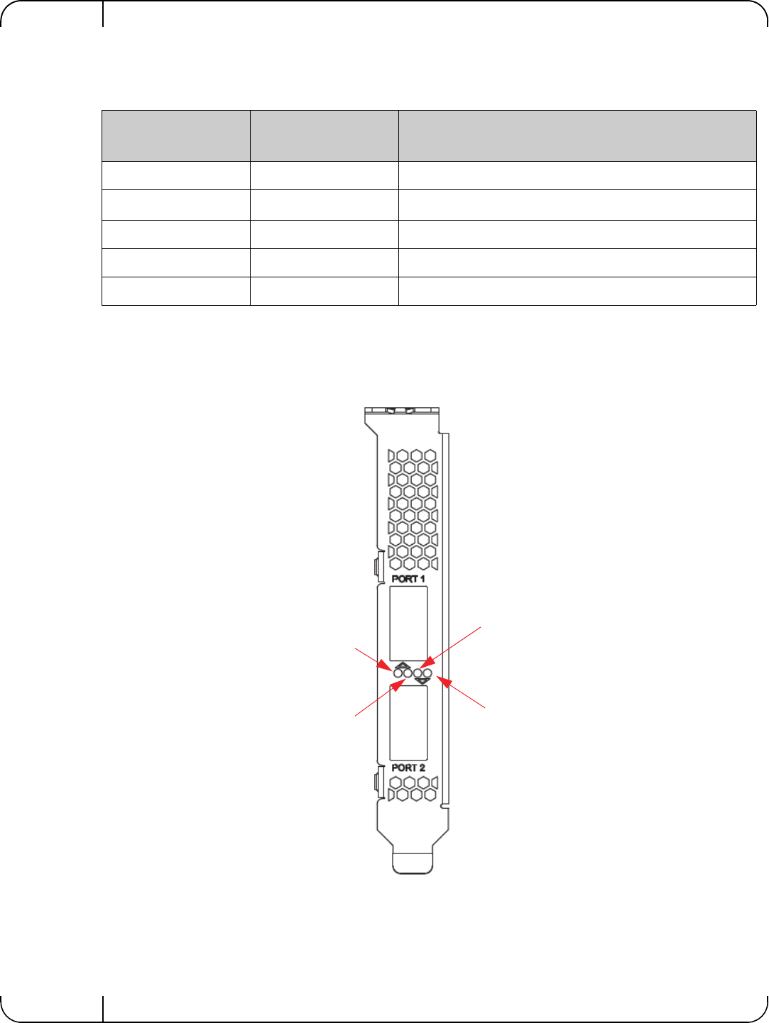
Figure 1: Mellanox ConnectX-3 Dual Port 40GbE QSFP+ Network Adapter Full Height Bracket
Table 4 - LED Assignment for 40GbE QSFP+ Network Adapters
Link LED (Bicolor -
Green and Yellow) Activity LED (Green) Function
Off Off No link present
Yellow Off 10 Gb/s link is presenta
a. 10 Gb/s Link Speed is only supported with the Mellanox Quad to Serial Small Form Factor Pluggable Adapter
(QSFP+ to SFP+ adapter or QSA). The QSA is not currently supported.
Green Off 40 Gb/s link is present
Yellow Blinking Green Speed lower than the maximum is active
Green Blinking Green Maximum supported speed is active
Port 1 Activity
Port 2 Link
Port 2 Activity
Port 1 Link
User Manual for Mellanox ConnectX®-3 10/40 Gigabit Ethernet Adapters for Dell PowerEdge Servers Rev 1.1
Mellanox Technologies 17
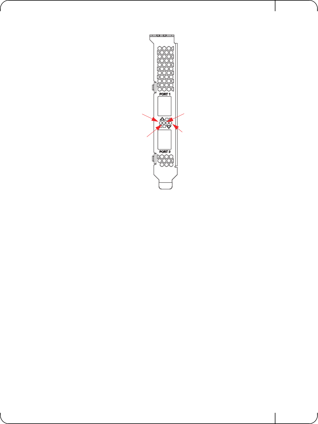
Figure 2: Mellanox ConnectX-3 Dual Port 10GbE SFP+ Network Adapter Full Height Bracket
Port 2 Link
Port 2 Activity
Port 1 Link
Port 1 Activity
Installing the HardwareRev 1.1
Mellanox Technologies
18
3Installing the Hardware
3.1 System Requirements
3.1.1 Hardware
Dell PowerEdge Server with an available PCI Express x8 slot for installing the card is required.
3.1.2 Operating Systems/Distributions
Please refer to Section 1.3, “Supported Operating Systems/Distributions,” on page 14.
3.1.3 Software Stacks
Mellanox OpenFabric software package - MLNX_OFED for Linux.
3.1.4 Co-requisites
For full functionality including manageability support, minimum versions of Server BIOS, Inte-
grated Dell Remote Access Controller (iDRAC), and Dell Lifecycle Controller are required.
3.2 Safety Precautions
1. Remove any metallic objects from your hands and wrists.
2. Make sure to use only insulated tools.
3. Verify that the system is powered off and is unplugged.
4. It is required to use an ESD strap or other antistatic devices.
For the list of supported Dell PowerEdge Servers please refer to the release notes for the
applicable software and firmware downloads on the Dell support site: http://
www.dell.com/support.
For the list of the specific supported operating systems and distributions, please refer to
the release notes for the applicable software downloads on the Dell support site: http://
www.dell.com/support.
For the list of co-requisites, please refer to the release notes for the applicable software
and firmware downloads on the Dell support site: http://www.dell.com/support.
The adapter is being installed in a system that operates with voltages that can be lethal.
Before opening the case of the system, observe the following precautions to avoid
injury and prevent damage to system components.
User Manual for Mellanox ConnectX®-3 10/40 Gigabit Ethernet Adapters for Dell PowerEdge Servers Rev 1.1
Mellanox Technologies 19
3.3 Pre-installation Checklist
1. Verify that your system meets the hardware and software requirements stated above.
2. Shut down your system if active.
3. After shutting down the system, turn off power and unplug the cord.
4. Remove the card from its package. Please note that the card must be placed on an antistatic
surface.
5. Check the card for visible signs of damage. Do not attempt to install the card if damaged.
3.4 Installation Instructions
3.4.1 For Adapters
Refer to the manuals that were supplied with your system for instructions on installing add-in
cards.
1. Before installing the card, make sure that the system is off and the power cord is not con-
nected to the server. Please follow proper electrical grounding procedures.
2. Open the system case.
3. The adapter can be placed in an available slot.
4. A lesser width adapter can be seated into a greater width slot (x4 in a x8), but a greater width
adapter cannot be seated into a lesser width slot (x8 in a x4). Align the adapter connector edge
with the PCI Express connector slot.
5. Applying even pressure at both corners of the adapter, insert the adapter into the slot until it is
firmly seated. When the adapter is properly seated, the adapter port connectors are aligned
with the slot opening, and the adapter faceplate is visible against the system chassis.
6. Secure the adapter with the adapter clip or screw per the instructions provided with the server
model.
7. Close the system case.
3.4.2 For Mezzanine Cards
Refer to the owner's manuals that were supplied with your Dell PowerEdge Blade Server for
instructions on installing blade mezzanine cards.
1. Before installing the card, take the blade server out of the chassis
2. Open the system case.
3. The card can be placed in an available slot.
Do not use excessive force when seating the adapter, as this may damage the system or
the adapter.
Ensure that the adapters are seated correctly such that the QSFP+ or SFP+ ports of the
adapter are unobstructed.

Installing the HardwareRev 1.1
Mellanox Technologies
20
4. Expose the socket to be used for the new card. When replacing an existing card, remove the
card from the socket. Grab the card on the edge on the side with UPC number and pull up
while gently rocking the card back and forth. For a new installation remove the protective
cover enclosing the socket for the card.
5. Line up the blade mezzanine card so that the pins of the card are over the sockets in the blade
server. Plug the card into the socket by placing your thumb over the Dell part number label
and pressing down until the card is fully seated.
6. Secure the blade mezzanine card with the mezzanine card latch.
7. Close the system case.
3.5 Connecting the Network Cables
3.5.1 Inserting a Cable into the Adapter Card
1. Support the weight of the cable before connecting it to the adapter card. Do this by using a
cable holder or tying the cable to the rack.
2. Determine the correct orientation of the connector to the card before inserting the connector.
Do not try and insert the connector upside down. This may damage the adapter card.
3. Insert the connector into the adapter card. Be careful to insert the connector straight into the
cage. Do not apply any torque, up or down, to the connector cage in the adapter card.
4. Make sure that the connector locks in place.
3.5.2 Removing a Cable from the Adapter Card
1. Pull on the latch release mechanism thereby unlatching the connector and pull the connector
out of the cage.
2. Do not apply torque to the connector when removing it from the adapter card.
3. Remove any cable supports that were used to support the cable’s weight.
3.6 Identifying the Card in A System
3.6.1 On Linux
Get the device location on the PCI bus by running lspci and locating lines with the string “Mella-
nox Technologies”:
Do not use excessive force when seating the card, as this may damage the system or
the adapter.
> lspci |grep -i Mellanox
27:00.0 Network controller: Mellanox Technologies MT27500 Family [ConnectX-3]

User Manual for Mellanox ConnectX®-3 10/40 Gigabit Ethernet Adapters for Dell PowerEdge Servers Rev 1.1
Mellanox Technologies 21
4Driver Installation and Configuration
4.1 Linux Driver
For Linux, download and install the latest Linux Drivers for Mellanox ConnectX-3 Ethernet
adapters software package available on the Dell support site http://www.dell.com/support For
driver installation instructions, please refer to Dell documentation via http://www.dell.com/sup-
port.
4.1.1 Installation Requirements
Required Disk Space for Installation
•100 MB
Software Requirements
• Linux operating system
Installer Privileges
• The installation requires administrator privileges on the target machine
4.1.2 Downloading Mellanox OFED
Step 1. Verify that the system has a Mellanox network adapter (NIC) installed by ensuring that you can
see ConnectX-3 in the display.
The following example shows a system with an installed Mellanox NIC:
Step 2. Download the software release to your host.
The software release name has the format MLNX_OFED_LINUX-<ver>.tar.gz
Step 3. Use the md5sum utility to confirm the file integrity of your software release. Run the following
command and compare the result to the value provided on the download page.
4.1.3 Installing Mellanox OFED
The installation script, install.sh, performs the following:
• Discovers the currently installed kernel
• Uninstalls any software stacks that are part of the standard operating system distribution
or another vendor's commercial stack
• Installs the MLNX_OFED_LINUX binary RPMs (if they are available for the current
kernel)
For the list of supported operating system distributions and kernels, release notes for the
applicable software download on the Dell support site: http://www.dell.com/support.
host1# lspci -v | grep Mellanox
27:00.0 Network controller: Mellanox Technologies MT27500 Family [ConnectX-3]
host1$ md5sum MLNX_OFED_LINUX-<ver>.tar.gz

Driver Installation and ConfigurationRev 1.1
Mellanox Technologies
22
4.1.3.1 Pre-installation Notes
• The installation script removes all previously installed Mellanox OFED packages and
installs the software release.
4.1.4 Installation Script
Within each distribution specific subdirectory there is an installation script called install.sh.
Its usage is described below. You will use it during the installation procedure described in
Section 4.1.5, “Installation Procedure,” on page 23.
4.1.4.1 mlnxofedinstall Return Codes
Table 5 lists the install.sh script return codes and their meanings.
Table 5 - install.sh Return Codes
Return Code Meaning
0 The Installation ended successfully
1 The installation failed
2 No firmware was found for the adapter device
22 Invalid parameter
28 Not enough free space
171 Not applicable to this system configuration. This can occur when the
required hardware is not present on the system.
172 Prerequisites are not met. For example, missing the required software
installed or the hardware is not configured correctly.
173 Failed to start the mst driver

User Manual for Mellanox ConnectX®-3 10/40 Gigabit Ethernet Adapters for Dell PowerEdge Servers Rev 1.1
Mellanox Technologies 23
4.1.5 Installation Procedure
Step 1. Login to the installation machine as root.
Step 2. Copy the software release on your machine
Step 3. Un-tar the software release.
Step 4. Change directory to the distribution specific subdirectory.
Step 5. Run the installation script (example).
For specific installation instructions, please refer to the applicable software download
on the Dell support site http://www.dell.com/support.
host1# tar -xvf MLNX_OFED_LINUX-<ver>.tar.gz
host1# cd /MLNX_OFED_LINUX-<ver>/rhel6/rhel6.4
../install.sh
This program will install the MLNX_OFED_LINUX package on your machine.
Note that all other Mellanox, OEM, OFED, or Distribution IB packages will be removed.
Do you want to continue?[y/N]:y
Installing mlnx-ofa_kernel RPM
Preparing... ##################################################
mlnx-ofa_kernel ##################################################
Installing kmod-mlnx-ofa_kernel RPM
Preparing... ##################################################
kmod-mlnx-ofa_kernel ##################################################
Installing mlnx-ofa_kernel-devel RPM
Preparing... ##################################################
mlnx-ofa_kernel-devel ##################################################
Installing user level RPMs:
Preparing... ##################################################
ofed-scripts ##################################################
Preparing... ##################################################
libibverbs ##################################################
Preparing... ##################################################
libibverbs-devel ##################################################
Preparing... ##################################################
libibverbs-devel-static ##################################################
Preparing... ##################################################
libibverbs-utils ##################################################
Preparing... ##################################################
libmlx4 ##################################################
Preparing... ##################################################
libmlx4-devel ##################################################
Preparing... ##################################################
libibumad ##################################################
Preparing... ##################################################
libibumad-devel ##################################################
Preparing... ##################################################

Driver Installation and ConfigurationRev 1.1
Mellanox Technologies
24
Step 6. The script adds the following lines to /etc/security/limits.conf for the userspace
components such as MPI:
These settings unlimit the amount of memory that can be pinned by a user space application. If
desired, tune the value unlimited to a specific amount of RAM.
4.1.6 Installation Results
Software
• The OFED package is installed under the /usr directory.
• The kernel modules are installed under:
• mlx4 driver:
•RDS:
• The script openibd is installed under /etc/init.d/. This script can be used to load and
unload the software stack.
libibumad-static ##################################################
Preparing... ##################################################
libibmad ##################################################
Preparing... ##################################################
libibmad-devel ##################################################
Preparing... ##################################################
libibmad-static ##################################################
Preparing... ##################################################
librdmacm ##################################################
Preparing... ##################################################
librdmacm-utils ##################################################
Preparing... ##################################################
librdmacm-devel ##################################################
Preparing... ##################################################
perftest ##################################################
Device (02:00.0):
02:00.0 Ethernet controller: Mellanox Technologies MT27500 Family [ConnectX-
3]
Link Width: 8x
PCI Link Speed: Unknown
Installation finished successfully.
* soft memlock unlimited
* hard memlock unlimited
/lib/modules/<kernel_version>/extra/mlnx-ofa_kernel/drivers/net/ethernet/mellanox/mlx4/
/lib/modules/`uname -r`/updates/kernel/net/rds/rds.ko
/lib/modules/`uname -r`/updates/kernel/net/rds/rds_rdma.ko
/lib/modules/`uname -r`/updates/kernel/net/rds/rds_tcp.ko
Kernel’s modules location may vary depending on the kernel’s configuration.
For example: /lib/modules/`uname -r`/extra/kernel/drivers/net/ethernet/mellanox/mlx4/
mlx4_core

User Manual for Mellanox ConnectX®-3 10/40 Gigabit Ethernet Adapters for Dell PowerEdge Servers Rev 1.1
Mellanox Technologies 25
• The installation process unlimits the amount of memory that can be pinned by a user
space application. See Step 6.
• Man pages will be installed under /usr/share/man/
4.1.7 Post-installation Notes
• Most of the Mellanox OFED components can be configured or reconfigured after the
installation by modifying the relevant configuration files.
4.1.8 Uninstalling Mellanox OFED
Either use the distribution specific uninstall.sh script or use the script /usr/sbin/
ofed_uninstall.sh to uninstall the Mellanox OFED package. The ofed_uninstall.sh is part
of the ofed-scripts RPM.
4.2 Linux Driver Features
4.2.1 iSCSI Extensions for RDMA (iSER)
iSCSI Extensions for RDMA (iSER) extends the iSCSI protocol to RDMA. It permits data to be
transferred directly into and out of SCSI buffers without intermediate data copies.
4.2.2 iSER Initiator
The iSER initiator is controlled through the iSCSI interface available from the iscsi-initiator-utils
package.
Make sure iSCSI is enabled and properly configured on your system before proceeding with
iSER.
Targets settings such as timeouts and retries are set the same as any other iSCSI targets.
Example for discovering and connecting targets over iSER:
iSER also supports RoCE without any additional configuration required. To bond the RoCE
interfaces, set the fail_over_mac option in the bonding driver.
4.2.3 Quality of Service (QoS) Ethernet
4.2.3.1 Mapping Traffic to Traffic Classes
Mapping traffic to TCs consists of several actions which are user controllable, some controlled
by the application itself and others by the system/network administrators.
If targets are set to auto connect on boot, and targets are unreachable, it may take a long
time to continue the boot process if timeouts and max retries are set too high.
iscsiadm -m discovery -o new -o old -t st -I iser -p <ip:port> -l

Driver Installation and ConfigurationRev 1.1
Mellanox Technologies
26
The following is the general mapping traffic to Traffic Classes flow:
1. The application sets the required Type of Service (ToS).
2. The ToS is translated into a Socket Priority (sk_prio).
3. The sk_prio is mapped to a User Priority (UP) by the system administrator (some applica-
tions set sk_prio directly).
4. The UP is mapped to TC by the network/system administrator.
5. TCs hold the actual QoS parameters
QoS can be applied on the following types of traffic. However, the general QoS flow may vary
among them:
•Plain Ethernet - Applications use regular inet sockets and the traffic passes via the ker-
nel Ethernet driver
•RoCE - Applications use the RDMA API to transmit using QPs
•Raw Ethernet QP - Application use VERBs API to transmit using a Raw Ethernet QP
4.2.3.2 Plain Ethernet Quality of Service Mapping
Applications use regular inet sockets and the traffic passes via the kernel Ethernet driver.
The following is the Plain Ethernet QoS mapping flow:
1. The application sets the ToS of the socket using setsockopt (IP_TOS, value).
2. ToS is translated into the sk_prio using a fixed translation:
3. The Socket Priority is mapped to the UP:
• If the underlying device is a VLAN device, egress_map is used controlled by the vconfig
command. This is per VLAN mapping.
• If the underlying device is not a VLAN device, the tc command is used. In this case, even
though tc manual states that the mapping is from the sk_prio to the TC number, the
mlx4_en driver interprets this as a sk_prio to UP mapping.
Mapping the sk_prio to the UP is done by using tc_wrap.py -i <dev name> -u
0,1,2,3,4,5,6,7
4. The the UP is mapped to the TC as configured by the mlnx_qos tool or by the lldpad daemon
if DCBX is used.
TOS 0 <=> sk_prio 0
TOS 8 <=> sk_prio 2
TOS 24 <=> sk_prio 4
TOS 16 <=> sk_prio 6
Socket applications can use setsockopt (SK_PRIO, value) to directly set the sk_prio
of the socket. In this case the ToS to sk_prio fixed mapping is not needed. This allows
the application and the administrator to utilize more than the 4 values possible via ToS.
In case of VLAN interface, the UP obtained according to the above mapping is also used
in the VLAN tag of the traffic

User Manual for Mellanox ConnectX®-3 10/40 Gigabit Ethernet Adapters for Dell PowerEdge Servers Rev 1.1
Mellanox Technologies 27
4.2.3.3 RoCE Quality of Service Mapping
Applications use RDMA-CM API to create and use QPs.
The following is the RoCE QoS mapping flow:
1. The application sets the ToS of the QP using the rdma_set_option option
(RDMA_OPTION_ID_TOS, value).
2. ToS is translated into the Socket Priority (sk_prio) using a fixed translation:
3. The Socket Priority is mapped to the User Priority (UP) using the tc command.
In case of a VLAN device, the parent real device is used for the purpose of this mapping.
4. The the UP is mapped to the TC as configured by the mlnx_qos tool or by the lldpad daemon
if DCBX is used.
4.2.3.4 Raw Ethernet QP Quality of Service Mapping
Applications open a Raw Ethernet QP using VERBs directly.
The following is the RoCE QoS mapping flow:
1. The application sets the UP of the Raw Ethernet QP during the INIT to RTR state transition of
the QP:
• Sets qp_attrs.ah_attrs.sl = up
• Calls modify_qp with IB_QP_AV set in the mask
2. The UP is mapped to the TC as configured by the mlnx_qos tool or by the lldpad daemon if
DCBX is used
4.2.3.5 Map Priorities with tc_wrap.py/mlnx_qos
Network flow that can be managed by QoS attributes is described by a User Priority (UP). A
user's sk_prio is mapped to UP which in turn is mapped into TC.
• Indicating the UP
TOS 0 <=> sk_prio 0
TOS 8 <=> sk_prio 2
TOS 24 <=> sk_prio 4
TOS 16 <=> sk_prio 6
With RoCE, there can only be 4 predefined ToS values for the purpose of QoS mapping.
When using Raw Ethernet QP mapping, the TOS/sk_prio to UP mapping is lost.
Performing the Raw Ethernet QP mapping forces the QP to transmit using the given UP.
If packets with VLAN tag are transmitted, UP in the VLAN tag will be overwritten with
the given UP.

Driver Installation and ConfigurationRev 1.1
Mellanox Technologies
28
• When the user uses sk_prio, it is mapped into a UP by the ‘tc’ tool. This is done by the
tc_wrap.py tool which gets a list of <= 16 comma separated UP and maps the sk_prio to
the specified UP.
For example, tc_wrap.py -ieth0 -u 1,5 maps sk_prio 0 of eth0 device to UP 1 and
sk_prio 1 to UP 5.
• Setting set_egress_map in VLAN, maps the skb_priority of the VLAN to a vlan_qos.
The vlan_qos is represents a UP for the VLAN device.
• In RoCE, rdma_set_option with RDMA_OPTION_ID_TOS could be used to set the UP
• When creating QPs, the sl field in ibv_modify_qp command represents the UP
• Indicating the TC
• After mapping the skb_priority to UP, one should map the UP into a TC. This assigns
the user priority to a specific hardware traffic class. In order to do that, mlnx_qos should
be used. mlnx_qos gets a list of a mapping between UPs to TCs. For example, mlnx_qos -
ieth0 -p 0,0,0,0,1,1,1,1 maps UPs 0-3 to TC0, and Ups 4-7 to TC1.
4.2.3.6 Quality of Service Properties
The different QoS properties that can be assigned to a TC are:
•Strict Priority (see “Strict Priority”)
• Minimal Bandwidth Guarantee (ETS) (see “Minimal Bandwidth Guarantee (ETS)”)
• Rate Limit (see “Rate Limit”)
Strict Priority
When setting a TC's transmission algorithm to be 'strict', then this TC has absolute (strict) prior-
ity over other TC strict priorities coming before it (as determined by the TC number: TC 7 is
highest priority, TC 0 is lowest). It also has an absolute priority over non strict TCs (ETS).
This property needs to be used with care, as it may easily cause starvation of other TCs.
A higher strict priority TC is always given the first chance to transmit. Only if the highest strict
priority TC has nothing more to transmit, will the next highest TC be considered.
Non strict priority TCs will be considered last to transmit.
This property is extremely useful for low latency low bandwidth traffic. Traffic that needs to get
immediate service when it exists, but is not of high volume to starve other transmitters in the sys-
tem.
Minimal Bandwidth Guarantee (ETS)
After servicing the strict priority TCs, the amount of bandwidth (BW) left on the wire may be
split among other TCs according to a minimal guarantee policy.
If, for instance, TC0 is set to 80% guarantee and TC1 to 20% (the TCs sum must be 100), then
the BW left after servicing all strict priority TCs will be split according to this ratio.
Since this is a minimal guarantee, there is no maximum enforcement. This means, in the same
example, that if TC1 did not use its share of 20%, the reminder will be used by TC0.
Rate Limit
Rate limit defines a maximum bandwidth allowed for a TC. Please note that 10% deviation from
the requested values is considered acceptable.

User Manual for Mellanox ConnectX®-3 10/40 Gigabit Ethernet Adapters for Dell PowerEdge Servers Rev 1.1
Mellanox Technologies 29
4.2.3.7 Quality of Service Tools
mlnx_qos
mlnx_qos is a centralized tool used to configure QoS features of the local host. It communicates
directly with the driver thus does not require setting up a DCBX daemon on the system.
The mlnx_qos tool enables the administrator of the system to:
• Inspect the current QoS mappings and configuration
The tool will also display maps configured by TC and vconfig set_egress_map tools, in order to
give a centralized view of all QoS mappings.
• Set UP to TC mapping
• Assign a transmission algorithm to each TC (strict or ETS)
• Set minimal BW guarantee to ETS TCs
• Set rate limit to TCs
Usage:
Options:
For unlimited ratelimit set the ratelimit to 0.
mlnx_qos -i <interface> [options]
--version show program's version number and exit
-h, --help show this help message and exit
-p LIST, --prio_tc=LIST
maps UPs to TCs. LIST is 8 comma seperated TC numbers.
Example: 0,0,0,0,1,1,1,1 maps UPs 0-3 to TC0, and UPs
4-7 to TC1
-s LIST, --tsa=LIST Transmission algorithm for each TC. LIST is comma
seperated algorithm names for each TC. Possible
algorithms: strict, etc. Example: ets,strict,ets sets
TC0,TC2 to ETS and TC1 to strict. The rest are
unchanged.
-t LIST, --tcbw=LIST Set minimal guaranteed %BW for ETS TCs. LIST is comma
seperated percents for each TC. Values set to TCs that
are not configured to ETS algorithm are ignored, but
must be present. Example: if TC0,TC2 are set to ETS,
then 10,0,90 will set TC0 to 10% and TC2 to 90%.
Percents must sum to 100.
-r LIST, --ratelimit=LIST
Rate limit for TCs (in Gbps). LIST is a comma
seperated Gbps limit for each TC. Example: 1,8,8 will
limit TC0 to 1Gbps, and TC1,TC2 to 8 Gbps each.
-i INTF, --interface=INTF
Interface name
-a Show all interface's TCs

Driver Installation and ConfigurationRev 1.1
Mellanox Technologies
30
Get Current Configuration:
Set ratelimit. 3Gbps for tc0 4Gbps for tc1 and 2Gbps for tc2:
tc: 0 ratelimit: unlimited, tsa: strict
up: 0
skprio: 0
skprio: 1
skprio: 2 (tos: 8)
skprio: 3
skprio: 4 (tos: 24)
skprio: 5
skprio: 6 (tos: 16)
skprio: 7
skprio: 8
skprio: 9
skprio: 10
skprio: 11
skprio: 12
skprio: 13
skprio: 14
skprio: 15
up: 1
up: 2
up: 3
up: 4
up: 5
up: 6
up: 7
tc: 0 ratelimit: 3 Gbps, tsa: strict
up: 0
skprio: 0
skprio: 1
skprio: 2 (tos: 8)
skprio: 3
skprio: 4 (tos: 24)
skprio: 5
skprio: 6 (tos: 16)
skprio: 7
skprio: 8
skprio: 9
skprio: 10
skprio: 11
skprio: 12
skprio: 13
skprio: 14
skprio: 15
up: 1
up: 2
up: 3
up: 4
up: 5
up: 6
up: 7

User Manual for Mellanox ConnectX®-3 10/40 Gigabit Ethernet Adapters for Dell PowerEdge Servers Rev 1.1
Mellanox Technologies 31
Configure QoS. map UP 0,7 to tc0, 1,2,3 to tc1 and 4,5,6 to tc 2. set tc0,tc1 as ets and tc2 as strict.
divide ets 30% for tc0 and 70% for tc1:
tc and tc_wrap.py
The 'tc' tool is used to setup sk_prio to UP mapping, using the mqprio queue discipline.
In kernels that do not support mqprio (such as 2.6.34), an alternate mapping is created in sysfs.
The 'tc_wrap.py' tool will use either the sysfs or the 'tc' tool to configure the sk_prio to UP
mapping.
Usage:
Options:
Example: set skprio 0-2 to UP0, and skprio 3-7 to UP1 on eth4
mlnx_qos -i eth3 -s ets,ets,strict -p 0,1,1,1,2,2,2 -t 30,70
tc: 0 ratelimit: 3 Gbps, tsa: ets, bw: 30%
up: 0
skprio: 0
skprio: 1
skprio: 2 (tos: 8)
skprio: 3
skprio: 4 (tos: 24)
skprio: 5
skprio: 6 (tos: 16)
skprio: 7
skprio: 8
skprio: 9
skprio: 10
skprio: 11
skprio: 12
skprio: 13
skprio: 14
skprio: 15
up: 7
tc: 1 ratelimit: 4 Gbps, tsa: ets, bw: 70%
up: 1
up: 2
up: 3
tc: 2 ratelimit: 2 Gbps, tsa: strict
up: 4
up: 5
up: 6
tc_wrap.py -i <interface> [options]
--version show program's version number and exit
-h, --help show this help message and exit
-u SKPRIO_UP, --skprio_up=SKPRIO_UP maps sk_prio to UP. LIST is <=16 comma separated
UP. index of element is sk_prio.
-i INTF, --interface=INTF Interface name

Driver Installation and ConfigurationRev 1.1
Mellanox Technologies
32
Additional Tools
tc tool compiled with the sch_mqprio module is required to support kernel v2.6.32 or higher.
This is a part of iproute2 package v2.6.32-19 or higher. Otherwise, an alternative custom sysfs
interface is available.
•mlnx_qos tool (package: ofed-scripts) requires python >= 2.5
•tc_wrap.py (package: ofed-scripts) requires python >= 2.5
4.2.4 Ethernet Time-Stamping
Time stamping is the process of keeping track of the creation of a packet. A time-stamping ser-
vice supports assertions of proof that a datum existed before a particular time. Incoming packets
are time-stamped before they are distributed on the PCI depending on the congestion in the PCI
buffers. Outgoing packets are time-stamped very close to placing them on the wire.
4.2.4.1 Enabling Time Stamping
Time-stamping is off by default and should be enabled before use.
To enable time stamping for a socket:
UP 0
skprio: 0
skprio: 1
skprio: 2 (tos: 8)
skprio: 7
skprio: 8
skprio: 9
skprio: 10
skprio: 11
skprio: 12
skprio: 13
skprio: 14
skprio: 15
UP 1
skprio: 3
skprio: 4 (tos: 24)
skprio: 5
skprio: 6 (tos: 16)
UP 2
UP 3
UP 4
UP 5
UP 6
UP 7

User Manual for Mellanox ConnectX®-3 10/40 Gigabit Ethernet Adapters for Dell PowerEdge Servers Rev 1.1
Mellanox Technologies 33
• Call setsockopt() with SO_TIMESTAMPING and with the following flags:
SOF_TIMESTAMPING_TX_HARDWARE: try to obtain send time stamp in hardware
SOF_TIMESTAMPING_TX_SOFTWARE: if SOF_TIMESTAMPING_TX_HARDWARE is off or
fails, then do it in software
SOF_TIMESTAMPING_RX_HARDWARE: return the original, unmodified time stamp
as generated by the hardware
SOF_TIMESTAMPING_RX_SOFTWARE: if SOF_TIMESTAMPING_RX_HARDWARE is off or
fails, then do it in software
SOF_TIMESTAMPING_RAW_HARDWARE: return original raw hardware time stamp
SOF_TIMESTAMPING_SYS_HARDWARE: return hardware time stamp transformed to
the system time base
SOF_TIMESTAMPING_SOFTWARE: return system time stamp generated in
software
SOF_TIMESTAMPING_TX/RX determine how time stamps are generated.
SOF_TIMESTAMPING_RAW/SYS determine how they are reported

Driver Installation and ConfigurationRev 1.1
Mellanox Technologies
34
To enable time stamping for a net device:
Admin privileged user can enable/disable time stamping through calling ioctl(sock, SIOCSHWT-
STAMP, &ifreq) with following values:
Send side time sampling:
• Enabled by ifreq.hwtstamp_config.tx_type when
/* possible values for hwtstamp_config->tx_type */
enum hwtstamp_tx_types {
/*
* No outgoing packet will need hardware time stamping;
* should a packet arrive which asks for it, no hardware
* time stamping will be done.
*/
HWTSTAMP_TX_OFF,
/*
* Enables hardware time stamping for outgoing packets;
* the sender of the packet decides which are to be
* time stamped by setting %SOF_TIMESTAMPING_TX_SOFTWARE
* before sending the packet.
*/
HWTSTAMP_TX_ON,
/*
* Enables time stamping for outgoing packets just as
* HWTSTAMP_TX_ON does, but also enables time stamp insertion
* directly into Sync packets. In this case, transmitted Sync
* packets will not received a time stamp via the socket error
* queue.
*/
HWTSTAMP_TX_ONESTEP_SYNC,
};
Note: for send side time stamping currently only HWTSTAMP_TX_OFF and
HWTSTAMP_TX_ON are supported.

User Manual for Mellanox ConnectX®-3 10/40 Gigabit Ethernet Adapters for Dell PowerEdge Servers Rev 1.1
Mellanox Technologies 35
Receive side time sampling:
• Enabled by ifreq.hwtstamp_config.rx_filter when
4.2.4.2 Getting Time Stamping
Once time stamping is enabled time stamp is placed in the socket Ancillary data. recvmsg() can
be used to get this control message for regular incoming packets. For send time stamps the outgo-
ing packet is looped back to the socket's error queue with the send time stamp(s) attached. It can
be received with recvmsg(flags=MSG_ERRQUEUE). The call returns the original outgoing
packet data including all headers preprended down to and including the link layer, the
scm_timestamping control message and a sock_extended_err control message with
ee_errno==ENOMSG and ee_origin==SO_EE_ORIGIN_TIMESTAMPING. A socket with such
/* possible values for hwtstamp_config->rx_filter */
enum hwtstamp_rx_filters {
/* time stamp no incoming packet at all */
HWTSTAMP_FILTER_NONE,
/* time stamp any incoming packet */
HWTSTAMP_FILTER_ALL,
/* return value: time stamp all packets requested plus some others */
HWTSTAMP_FILTER_SOME,
/* PTP v1, UDP, any kind of event packet */
HWTSTAMP_FILTER_PTP_V1_L4_EVENT,
/* PTP v1, UDP, Sync packet */
HWTSTAMP_FILTER_PTP_V1_L4_SYNC,
/* PTP v1, UDP, Delay_req packet */
HWTSTAMP_FILTER_PTP_V1_L4_DELAY_REQ,
/* PTP v2, UDP, any kind of event packet */
HWTSTAMP_FILTER_PTP_V2_L4_EVENT,
/* PTP v2, UDP, Sync packet */
HWTSTAMP_FILTER_PTP_V2_L4_SYNC,
/* PTP v2, UDP, Delay_req packet */
HWTSTAMP_FILTER_PTP_V2_L4_DELAY_REQ,
/* 802.AS1, Ethernet, any kind of event packet */
HWTSTAMP_FILTER_PTP_V2_L2_EVENT,
/* 802.AS1, Ethernet, Sync packet */
HWTSTAMP_FILTER_PTP_V2_L2_SYNC,
/* 802.AS1, Ethernet, Delay_req packet */
HWTSTAMP_FILTER_PTP_V2_L2_DELAY_REQ,
/* PTP v2/802.AS1, any layer, any kind of event packet */
HWTSTAMP_FILTER_PTP_V2_EVENT,
/* PTP v2/802.AS1, any layer, Sync packet */
HWTSTAMP_FILTER_PTP_V2_SYNC,
/* PTP v2/802.AS1, any layer, Delay_req packet */
HWTSTAMP_FILTER_PTP_V2_DELAY_REQ,
};
Note: for receive side time stamping currently only HWTSTAMP_FILTER_NONE and
HWTSTAMP_FILTER_ALL are supported.

Driver Installation and ConfigurationRev 1.1
Mellanox Technologies
36
a pending bounced packet is ready for reading as far as select() is concerned. If the outgoing
packet has to be fragmented, then only the first fragment is time stamped and returned to the
sending socket.
4.2.4.3 Querying Time Stamping Capabilities via ethtool
To display Time Stamping capabilities via ethtool:
• Show Time Stamping capabilities
Example:
4.2.5 RoCE Time Stamping
RoCE Time Stamping allows you to stamp packets when they are sent to the wire / received from
the wire. The time stamp is given in a raw hardware cycles, but could be easily converted into
hardware referenced nanoseconds based time. Additionally, it enables you to query the hardware
for the hardware time, thus stamp other application's event and compare time.
4.2.5.1 Query Capabilities
Time stamping is available if and only the hardware reports it is capable of reporting it. To verify
whether RoCE Time Stamping is available, run ibv_ex_query_device.
When time-stamping is enabled, VLAN stripping is disabled. For more info please
refer to Documentation/networking/timestamping.txt in kernel.org
ethtool -T eth<x>
ethtool -T eth0
Time stamping parameters for p2p1:
Capabilities:
hardware-transmit (SOF_TIMESTAMPING_TX_HARDWARE)
software-transmit (SOF_TIMESTAMPING_TX_SOFTWARE)
hardware-receive (SOF_TIMESTAMPING_RX_HARDWARE)
software-receive (SOF_TIMESTAMPING_RX_SOFTWARE)
software-system-clock (SOF_TIMESTAMPING_SOFTWARE)
hardware-raw-clock (SOF_TIMESTAMPING_RAW_HARDWARE)
PTP Hardware Clock: none
Hardware Transmit Timestamp Modes:
off (HWTSTAMP_TX_OFF)
on (HWTSTAMP_TX_ON)
Hardware Receive Filter Modes:
none (HWTSTAMP_FILTER_NONE)
all (HWTSTAMP_FILTER_ALL)
RoCE Time Stamping is currently at beta level.
Please be aware that everything listed here is subject to change.

User Manual for Mellanox ConnectX®-3 10/40 Gigabit Ethernet Adapters for Dell PowerEdge Servers Rev 1.1
Mellanox Technologies 37
For example:
4.2.5.2 Creating Time Stamping Completion Queue
To get time stamps, a suitable extended Completion Queue (CQ) must be created via a special
call to ibv_create_cq_ex verb.
4.2.5.3 Polling a Completion Queue
Polling a CQ for time stamp is done via the ibv_poll_cq_ex verb.
struct ibv_exp_device_attr attr;
ibv_exp_query_device(context, &attr);
if (attr.comp_mask & IBV_EXP_DEVICE_ATTR_WITH_TIMESTAMP_MASK) {
if (attr.timestamp_mask) {
/* Time stamping is supported with mask attr.timestamp_mask */
}
}
if (attr.comp_mask & IBV_EXP_DEVICE_ATTR_WITH_HCA_CORE_CLOCK) {
if (attr.hca_core_clock) {
/* reporting the device's clock is supported. */
/* attr.hca_core_clock is the frequency in MHZ */
}
}
cq_init_attr.flags = IBV_CQ_TIMESTAMP;
cq_init_attr.comp_mask = IBV_CQ_INIT_ATTR_FLAGS;
cq = ibv_create_cq_ex(context, cqe, node, NULL, 0, &cq_init_attr);
This CQ cannot report SL or SLID information. The value of sl and sl_id fields in
struct ibv_wc_ex are invalid. Only the fields indicated by the wc_flags field in
struct ibv_wc_ex contains a valid and usable value.
When using Time Stamping, several fields of struct ibv_wc_ex are not available
resulting in RoCE UD / RoCE traffic with VLANs failure.
ret = ibv_poll_cq_ex(cq, 1, &wc_ex, sizeof(wc_ex));
if (ret > 0) {
/* CQ returned a wc */
if (wc_ex.wc_flags & IBV_WC_WITH_TIMESTAMP) {
/* This wc contains a timestamp */
timestamp = wc_ex.timestamp;
/* Timestamp is given in raw hardware time */
}
}
CQs that are opened with the ibv_create_cq_ex versb should be always be polled with
the ibv_poll_cq_ex verb.

Driver Installation and ConfigurationRev 1.1
Mellanox Technologies
38
4.2.5.4 Querying the Hardware Time
Querying the hardware for time is done via the ibv_query_values_ex verb.
For example:
To change the queried time in nanoseconds resolution, use the IBV_VALUES_HW_CLOCK_NS flag
along with the hwclock_ns field.
4.2.6 Flow Steering
Flow steering is a new model which steers network flows based on flow specifications to specific
QPs. Those flows can be either unicast or multicast network flows. In order to maintain flexibil-
ity, domains and priorities are used. Flow steering uses a methodology of flow attribute, which is
a combination of L2-L4 flow specifications, a destination QP and a priority. Flow steering rules
may be inserted either by using ethtool or by using InfiniBand verbs. The verbs abstraction uses a
different terminology from the flow attribute (ibv_flow_attr), defined by a combination of speci-
fications (struct ibv_flow_spec_*).
4.2.6.1 Enable/Disable Flow Steering
Flow Steering is disabled by default and regular L2 steering is performed instead (B0 Steering).
When using SR-IOV, flow steering is enabled if there is an adequate amount of space to store the
flow steering table for the guest/master.
To enable Flow Steering:
Step 1. Open the /etc/modprobe.d/mlnx.conf file.
Step 2. Set the parameter log_num_mgm_entry_size to -1 by writing the option mlx4_core
log_num_mgm_entry_size=-1.
Step 3. Restart the driver
To disable Flow Steering:
Step 1. Open the /etc/modprobe.d/mlnx.conf file.
Step 2. Remove the options mlx4_core log_num_mgm_entry_size= -1.
Step 3. Restart the driver
ret = ibv_query_values_ex(context, IBV_VALUES_HW_CLOCK, &queried_values);
if (!ret && queried_values.comp_mask & IBV_VALUES_HW_CLOCK)
queried_time = queried_values.hwclock;
ret = ibv_query_values_ex(context, IBV_VALUES_HW_CLOCK_NS, &queried_values);
if (!ret && queried_values.comp_mask & IBV_VALUES_HW_CLOCK_NS)
queried_time_ns = queried_values.hwclock_ns;
Querying the Hardware Time is available only on physical functions / native machines.
Flow Steering is applicable to the mlx4 driver only.

User Manual for Mellanox ConnectX®-3 10/40 Gigabit Ethernet Adapters for Dell PowerEdge Servers Rev 1.1
Mellanox Technologies 39
4.2.6.2 Flow Domains and Priorities
Flow steering defines the concept of domain and priority. Each domain represents a user agent
that can attach a flow. The domains are prioritized. A higher priority domain will always super-
sede a lower priority domain when their flow specifications overlap. Setting a lower priority
value will result in higher priority.
In addition to the domain, there is priority within each of the domains. Each domain can have at
most 2^12 priorities in accordance with its needs.
The following are the domains at a descending order of priority:
•User Verbs allows a user application QP to be attached into a specified flow when
using ibv_create_flow and ibv_destroy_flow verbs
•ibv_create_flow
Input parameters:
•struct ibv_qp - the attached QP.
•struct ibv_flow_attr - attaches the QP to the flow specified. The flow contains mandatory control
parameters and optional L2, L3 and L4 headers. The optional headers are detected by setting the size and
num_of_specs fields:
struct ibv_flow_attr can be followed by the optional flow headers structs:
For further information, please refer to the ibv_create_flow man page.
Each header struct holds the relevant network layer parameters for matching. To enforce the match, the
user sets a mask for each parameter. The supported masks are:
• All one mask - include the parameter value in the attached rule
Note: Since the VLAN ID in the Ethernet header is 12bit long, the following parameter should be
used: flow_spec_eth.mask.vlan_tag = htons(0x0fff).
• All zero mask - ignore the parameter value in the attached rule
When setting the flow type to NORMAL, the incoming traffic will be steered according to the rule spec-
ifications. ALL_DEFAULT and MC_DEFAULT rules options are valid only for Ethernet link type since
InfiniBand link type packets always include QP number.
For further information, please refer to the relevant man pages.
•ibv_destroy_flow
Input parameters:
ibv_destroy_flow requires struct ibv_flow which is the return value of ibv_create_flow in
case of success.
struct ibv_flow *ibv_create_flow(struct ibv_qp *qp, struct ibv_flow_attr *flow)
struct ibv_flow_spec_ib
struct ibv_flow_spec_eth
struct ibv_flow_spec_ipv4
struct ibv_flow_spec_tcp_udp
Be advised that from MLNX_OFED v2.0-3.0.0 and higher, the parameters (both the
value and the mask) should be set in big-endian format.
int ibv_destroy_flow(struct ibv_flow *flow_id)

Driver Installation and ConfigurationRev 1.1
Mellanox Technologies
40
Output parameters:
Returns 0 on success, or the value of errno on failure.
For further information, please refer to the ibv_destroy_flow man page.
• Ethtool
Ethtool domain is used to attach an RX ring, specifically its QP to a specified flow.
Please refer to the most recent ethtool manpage for all the ways to specify a flow.
Examples:
• ethtool –U eth5 flow-type ether dst 00:11:22:33:44:55 loc 5 action 2
All packets that contain the above destination MAC address are to be steered into rx-ring 2 (its
underlying QP), with priority 5 (within the ethtool domain)
• ethtool –U eth5 flow-type tcp4 src-ip 1.2.3.4 dst-port 8888 loc 5 action 2
All packets that contain the above destination IP address and source port are to be steered into rx-
ring 2. When destination MAC is not given, the user's destination MAC is filled automatically.
• ethtool –u eth5
Shows all of ethtool’s steering rule
When configuring two rules with the same priority, the second rule will overwrite the first one, so this
ethtool interface is effectively a table. Inserting Flow Steering rules in the kernel requires support
from both the ethtool in the user space and in kernel (v2.6.28).
MLX4 Driver Support
The mlx4 driver supports only a subset of the flow specification the ethtool API defines. Asking for
an unsupported flow specification will result with an “invalid value” failure.
The following are the flow specific parameters:
•RFS
RFS is an in-kernel-logic responsible for load balancing between CPUs by attaching flows to CPUs
that are used by flow’s owner applications. This domain allows the RFS mechanism to use the flow
steering infrastructure to support the RFS logic by implementing the ndo_rx_flow_steer, which, in
turn, calls the underlying flow steering mechanism with the RFS domain.
Enabling the RFS requires enabling the ‘ntuple’ flag via the ethtool,
For example, to enable ntuple for eth0, run:
Table 6 - Flow Specific Parameters
ether tcp4/udp4 ip4
Mandatory dst src-ip/dst-ip
Optional vlan src-ip, dst-ip, src-
port, dst-port, vlan src-ip, dst-ip, vlan
ethtool -K eth0 ntuple on

User Manual for Mellanox ConnectX®-3 10/40 Gigabit Ethernet Adapters for Dell PowerEdge Servers Rev 1.1
Mellanox Technologies 41
RFS requires the kernel to be compiled with the CONFIG_RFS_ACCEL option. This options is available
in kernels 2.6.39 and above. Furthermore, RFS requires Device Managed Flow Steering support.
• All of the rest
The lowest priority domain serves the following users:
•The mlx4 Ethernet driver attaches its unicast and multicast MACs addresses to its QP
using L2 flow specifications
•The mlx4 ipoib driver when it attaches its QP to his configured GIDS
4.2.7 Single Root IO Virtualization (SR-IOV)
4.2.7.1 System Requirements
To set up an SR-IOV environment, the following is required:
•MLNX_OFED Driver
• A server/blade with an SR-IOV-capable motherboard BIOS
• Hypervisor that supports SR-IOV such as: Red Hat Enterprise Linux Server Version 6.*
• Mellanox ConnectX® Adapter Card family with SR-IOV capability
4.2.7.2 Setting Up SR-IOV
Depending on your system, perform the steps below to set up your BIOS.For further information,
please refer to the appropriate BIOS User Manual:
Step 4. Enable “Virtualization Technology” in System BIOS => Processor setting. See
Appendix A.5, “SR-IOV Configuration,” on page 104. Enable “SR-IOV Global Enable” in
system BIOS - integrated Devices section
Step 5. Install a hypervisor that supports SR-IOV.
Step 6. Depending on your system, update the /boot/grub/grub.conf file to include a similar com-
mand line load parameter for the Linux kernel.
RFS cannot function if LRO is enabled. LRO can be disabled via ethtool.
Fragmented UDP traffic cannot be steered. It is treated as 'other' protocol by hardware
(from the first packet) and not considered as UDP traffic.
Use of libibverbs v2.0-3.0.0 and libmlx4 v2.0-3.0.0 and higher as of
MLNX_OFED v2.0-3.0.0 is recommended due to API changes.

Driver Installation and ConfigurationRev 1.1
Mellanox Technologies
42
For example, to Intel systems, add:
Step 7. Enable SRIOV number of functions in PCI. Note: by default 8 virtual functions are enabled
in PCI level.
Step 8. Create the text file /etc/modprobe.d/mlx4_core.conf if it does not exist, otherwise delete its
contents.
Step 9. Insert an "option" line in the /etc/modprobe.d/mlx4_core.conf file to set the number of VFs.
the protocol type per port, and the allowed number of virtual functions to be used by the
physical function driver (probe_vf).
For example:
default=0
timeout=5
splashimage=(hd0,0)/grub/splash.xpm.gz
hiddenmenu
title Red Hat Enterprise Linux Server (2.6.32-36.x86-645)
root (hd0,0)
kernel /vmlinuz-2.6.32-36.x86-64 ro root=/dev/VolGroup00/LogVol00 rhgb quiet
intel_iommu=on
a
initrd /initrd-2.6.32-36.x86-64.img
a. Please make sure the parameter "intel_iommu=on" exists when updating the /boot/grub/grub.conf
file, otherwise SR-IOV cannot be loaded.
options mlx4_core num_vfs=5 port_type_array=1,2 probe_vf=1
Parameter Recommended Value
num_vfs •If absent, or zero: no VFs will be available
• If its value is a single number in the range of 0-63: The driver
will enable the num_vfs VFs on the HCA and this will be
applied to all ConnectX® HCAs on the host.
• If its format is a string: The string specifies the num_vfs
parameter separately per installed HCA.
• The string format is: "bb:dd.f-v,bb:dd.f-v,…"
• bb:dd.f = bus:device.function of the PF of the HCA
• v = number of VFs to enable for that HCA
For example:
•num_vfs=5 - The driver will enable 5 VFs on the HCA and
this will be applied to all ConnectX® HCAs on the host
•num_vfs=00:04.0-5,00:07.0-8 - The driver will enable 5
VFs on the HCA positioned in BDF 00:04.0 and 8 on the one in
00:07.0)
Note: PFs not included in the above list will not have SR-
IOV enabled.

User Manual for Mellanox ConnectX®-3 10/40 Gigabit Ethernet Adapters for Dell PowerEdge Servers Rev 1.1
Mellanox Technologies 43
The example above loads the driver with 5 VFs (num_vfs). The standard use of a VF is a single VF
per a single VM. However, the number of VFs varies upon the working mode requirements.
The protocol types are:
Step 10. Reboot the server.
Step 11. Load the driver and verify the SR-IOV is supported. Run:
Where:
• “03:00" represents the Physical Function
• “03:00.X" represents the Virtual Function connected to the Physical Function
port_type_array Specifies the protocol type of the ports. It is either one array
of 2 port types 't1,t2' for all devices or list of BDF to
port_type_array 'bb:dd.f-t1;t2,...'. (string)
Valid port types: 1-ib, 2-eth, 3-auto, 4-N/A
If only a single port is available, use the N/A port type for
port2 (e.g '1,4').
Note: For dual port Ethernet only devices set
port_type_array=2,2.
probe_vf • If absent or zero: no VF interfaces will be loaded in the Hyper-
visor/host
• If num0_vfs is a number in the range of 1-63, the driver run-
ning on the Hypervisor will itself activate that number of VFs.
All these VFs will run on the Hypervisor. This number will
apply to all ConnectX® HCAs on that host.
• If its format is a string: the string specifies the probe_vf
parameter separately per installed HCA.
• The string format is: "bb:dd.f-v,bb:dd.f-v,…
• bb:dd.f = bus:device.function of the PF of the HCA
• v = number of VFs to use in the PF driver for that HCA
For example:
•probe_vfs=5 - The PF driver will activate 5 VFs on the HCA
and this will be applied to all ConnectX® HCAs on the host
•probe_vfs=00:04.0-5,00:07.0-8 - The PF driver will
activate 5 VFs on the HCA positioned in BDF 00:04.0 and 8
for the one in 00:07.0)
Note: PFs not included in the above list will not activate any
of their VFs in the PF driver.
If the Mellanox card is not available after rebooting when SR-IOV is enabled (and
many virtual functions were configured), the following steps can be taken:
1. Disable SR-IOV in the System BIOS
2. Reboot the server
3. Verify the adapter becomes available
4. Configure less SR-IOV virtual functions for the Mellanox adapters. Recommenda-
tion is less than 126 total functions (virtual and physical) for Mellanox devices.
5. Enable SR-IOV in the System BIOS
lspci | grep Mellanox
Parameter Recommended Value

Driver Installation and ConfigurationRev 1.1
Mellanox Technologies
44
4.2.7.3 Enabling SR-IOV and Para Virtualization on the Same Setup
To enable SR-IOV and Para Virtualization on the same setup:
Step 1. Create a bridge.
Step 2. Change the related interface (in the example below bridge0 is created over eth5).
Step 3. Restart the service network.
Step 4. Attach a virtual NIC to VM.
4.2.7.4 Assigning a Virtual Function to a Virtual Machine
This section will describe a mechanism for adding a SR-IOV VF to a Virtual Machine.
Assigning the SR-IOV Virtual Function to the Red Hat KVM VM Server
Step 1. Run the virt-manager.
Step 2. Double click on the virtual machine and open its Properties.
vim /etc/sysconfig/network-scripts/ifcfg-bridge0
DEVICE=bridge0
TYPE=Bridge
IPADDR=12.195.15.1
NETMASK=255.255.0.0
BOOTPROTO=static
ONBOOT=yes
NM_CONTROLLED=no
DELAY=0
DEVICE=eth5
BOOTPROTO=none
STARTMODE=on
HWADDR=00:02:c9:2e:66:52
TYPE=Ethernet
NM_CONTROLLED=no
ONBOOT=yes
BRIDGE=bridge0
ifconfig -a
…
eth6 Link encap:Ethernet HWaddr 52:54:00:E7:77:99
inet addr:13.195.15.5 Bcast:13.195.255.255 Mask:255.255.0.0
inet6 addr: fe80::5054:ff:fee7:7799/64 Scope:Link
UP BROADCAST RUNNING MULTICAST MTU:1500 Metric:1
RX packets:481 errors:0 dropped:0 overruns:0 frame:0
TX packets:450 errors:0 dropped:0 overruns:0 carrier:0
collisions:0 txqueuelen:1000
RX bytes:22440 (21.9 KiB) TX bytes:19232 (18.7 KiB)
Interrupt:10 Base address:0xa000
…
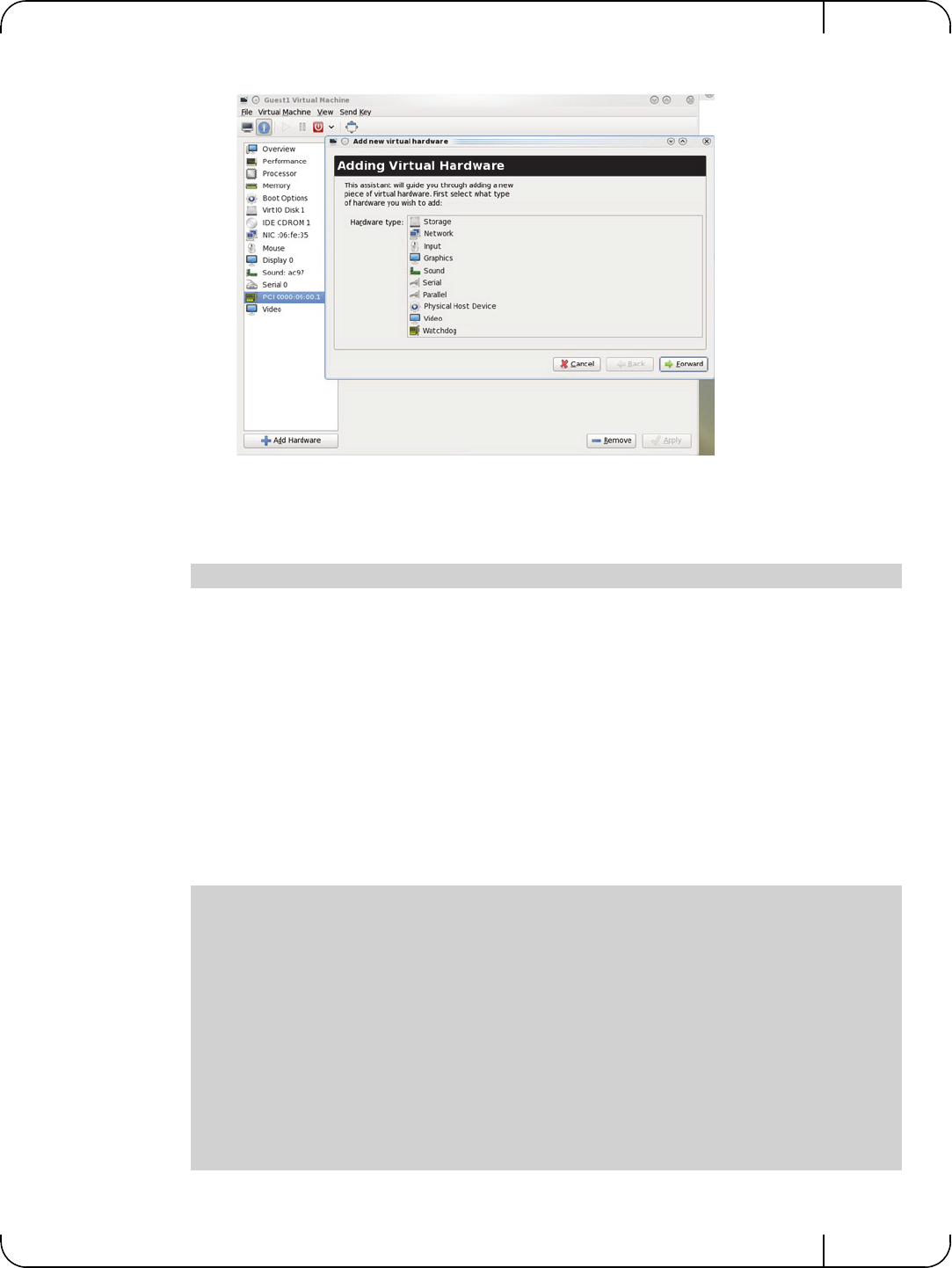
User Manual for Mellanox ConnectX®-3 10/40 Gigabit Ethernet Adapters for Dell PowerEdge Servers Rev 1.1
Mellanox Technologies 45
Step 3. Go to Details->Add hardware ->PCI host device.
Step 4. Choose a Mellanox virtual function according to its PCI device (e.g., 00:03.1)
Step 5. If the Virtual Machine is up reboot it, otherwise start it.
Step 6. Log into the virtual machine and verify that it recognizes the Mellanox card. Run:
Step 7. Add the device to the /etc/sysconfig/network-scripts/ifcfg-ethX configuration file.
The MAC address for every virtual function is configured randomly, therefore it is not nec-
essary to add it.
4.2.7.5 Uninstalling SR-IOV Driver
To uninstall SR-IOV driver, perform the following:
Step 1. For Hypervisors, detach all the Virtual Functions (VF) from all the Virtual Machines (VM)
or stop the Virtual Machines that use the Virtual Functions.
Please be aware, stopping the driver when there are VMs that use the VFs, will cause machine to hang.
Step 2. Run the script below. Please be aware, uninstalling the driver deletes the entire driver's file,
but does not unload the driver.
Step 3. Restart the server.
lspci | grep Mellanox
[root@swl022 ~]# /usr/sbin/ofed_uninstall.sh
This program will uninstall all OFED packages on your machine.
Do you want to continue?[y/N]:y
Running /usr/sbin/vendor_pre_uninstall.sh
Removing OFED Software installations
Running /bin/rpm -e --allmatches kernel-ib kernel-ib-devel libibverbs libibverbs-devel
libibverbs-devel-static libibverbs-utils libmlx4 libmlx4-devel libibcm libibcm-devel
libibumad libibumad-devel libibumad-static libibmad libibmad-devel libibmad-static
librdmacm librdmacm-utils librdmacm-devel ibacm opensm-libs opensm-devel perftest com-
pat-dapl compat-dapl-devel dapl dapl-devel dapl-devel-static dapl-utils srptools infini-
band-diags-guest ofed-scripts opensm-devel
warning: /etc/infiniband/openib.conf saved as /etc/infiniband/openib.conf.rpmsave
Running /tmp/2818-ofed_vendor_post_uninstall.sh

Driver Installation and ConfigurationRev 1.1
Mellanox Technologies
46
4.2.7.6 Configuring Pkeys and GUIDs under SR-IOV
4.2.7.6.1 SRIOV sysfs Administration Interfaces on the Hypervisor
Administration of GUIDs and PKeys is done via the sysfs interface in the Hypervisor (Dom0).
This interface is under:
Under this directory, the following subdirectories can be found:
•ports - The actual (physical) port resource tables
Port GID tables:
•ports/<n>/gids/<n> where 0 <= n <= 127 (the physical port gids)
•ports/<n>/admin_guids/<n> where 0 <= n <= 127 (allows examining or changing the
administrative state of a given GUID>
•ports/<n>/pkeys/<n> where 0 <= n <= 126 (displays the contents of the physical pkey
table)
•<pci id> directories - one for Dom0 and one per guest. Here, you may see the map-
ping between virtual and physical pkey indices, and the virtual to physical gid 0.
Currently, the GID mapping cannot be modified, but the pkey virtual to physical mapping can .
These directories have the structure:
•<pci_id>/port/<m>/gid_idx/0 where m = 1..2 (this is read-only)
and
•<pci_id>/port/<m>/pkey_idx/<n>, where m = 1..2 and n = 0..126
For instructions on configuring pkey_idx, please see below.
4.2.7.6.2 Configuring an Alias GUID (under ports/<n>/admin_guids)
Step 1. Determine the GUID index of the PCI Virtual Function that you want to pass through to a
guest.
For example, if you want to pass through PCI function 02:00.3 to a certain guest, you ini-
tially need to see which GUID index is used for this function.
To do so:
The value returned will present which guid index to modify on Dom0.
Step 2. Modify the physical GUID table via the admin_guids sysfs interface.
To configure the GUID at index <n> on port <port_num>:
Only the PFs are set via this mechanism. The VFs inherit their port types from their asso-
ciated PF.
/sys/class/infiniband/<infiniband device>/iov
cat /sys/class/infiniband/iov/0000:02:00.3/port/<port_num>/gid_idx/0
cd /sys/class/infiniband/mlx4_0/iov/ports/<port_num>/admin_guids
echo <your desired guid> > n

User Manual for Mellanox ConnectX®-3 10/40 Gigabit Ethernet Adapters for Dell PowerEdge Servers Rev 1.1
Mellanox Technologies 47
Example:
Step 3. Read the administrative status of the GUID index.
To read the administrative status of GUID index m on port n:
Step 4. Check the operational state of a GUID.
The values indicate what gids are actually configured on the firmware/hardware, and all the
entries are R/O.
Step 5. Compare the value you read under the "admin_guids" directory at that index with the value
under the "gids" directory, to verify the change requested in Step 3 has been accepted by
the SM, and programmed into the hardware port GID table.
If the value under admin_guids/<m> is different that the value under gids/<m>, the request
is still in progress.
4.2.7.7 Ethernet Virtual Function Configuration when Running SR-IOV
4.2.7.7.1 VLAN Guest Tagging (VGT) and VLAN Switch Tagging (VST)
When running ETH ports on VGT, the ports may be configured to simply pass through packets as
is from VFs (Vlan Guest Tagging), or the administrator may configure the Hypervisor to silently
force packets to be associated with a VLan/Qos (Vlan Switch Tagging).
In the latter case, untagged or priority-tagged outgoing packets from the guest will have the
VLAN tag inserted, and incoming packets will have the VLAN tag removed. Any vlan-tagged
packets sent by the VF are silently dropped. The default behavior is VGT.
The feature may be controlled on the Hypervisor from userspace via iprout2 / netlink:
use:
•where NUM = 0..max-vf-num
• vlan_id = 0..4095 (4095 means "set VGT")
•qos = 0..7
For example:
cd /sys/class/infiniband/mlx4_0/iov/ports/1/admin_guids
echo
a
"0x002fffff8118" > 3
a. echo "0x0" means let the SM assign a value to that GUID
echo "0xffffffffffffffff" means delete that GUID
echo <any other value> means request the SM to assign this GUID to this index
cat /sys/class/infiniband/mlx4_0/iov/ports/<n>/admin_guids/<m>
/sys/class/infiniband/mlx4_0/iov/ports/<n>/gids (where n = 1 or 2)
ip link set { dev DEVICE | group DEVGROUP } [ { up | down } ]
...
[ vf NUM [ mac LLADDR ]
[ vlan VLANID [ qos VLAN-QOS ] ]
...
[ spoofchk { on | off} ] ]
...
ip link set dev <PF device> vf <NUM> vlan <vlan_id> [qos <qos>]

Driver Installation and ConfigurationRev 1.1
Mellanox Technologies
48
•ip link set dev eth2 vf 2 qos 3 - sets VST mode for VF #2 belonging to PF eth2,
with qos = 3
•ip link set dev eth2 vf 2 4095 - sets mode for VF 2 back to VGT
4.2.7.7.2 Additional Ethernet VF Configuration Options
• Guest MAC configuration
By default, guest MAC addresses are configured to be all zeroes. In the mlnx_ofed guest driver,
if a guest sees a zero MAC, it generates a random MAC address for itself. If the administrator wishes
the guest to always start up with the same MAC, he/she should configure guest MACs before the
guest driver comes up.
The guest MAC may be configured by using:
For legacy guests, which do not generate random MACs, the adminstrator should always configure
their MAC addresses via ip link, as above.
• Spoof checking
Spoof checking is currently available only on upstream kernels newer than 3.1.
4.2.7.7.3 RoCE Support
RoCE is supported on Virtual Functions and VLANs may be used with it. For RoCE, the hyper-
visor GID table size is of 16 entries while the VFs share the remaining 112 entries. When the
number of VFs is larger than 56 entries, some of them will have GID table with only a single
entry which is inadequate if VF's Ethernet device is assigned with an IP address.
When setting num_vfs in mlx4_core module parameter it is important to check that the number
of the assigned IP addresses per VF does not exceed the limit for GID table size.
4.2.8 Ethtool
ethtool is a standard Linux utility for controlling network drivers and hardware, particularly for
wired Ethernet devices. It can be used to:
• Get identification and diagnostic information
• Get extended device statistics
• Control speed, duplex, autonegotiation and flow control for Ethernet devices
• Control checksum offload and other hardware offload features
• Control DMA ring sizes and interrupt moderation
ip link set dev <PF device> vf <NUM> mac <LLADDR>
ip link set dev <PF device> vf <NUM> spoofchk [on | off]

User Manual for Mellanox ConnectX®-3 10/40 Gigabit Ethernet Adapters for Dell PowerEdge Servers Rev 1.1
Mellanox Technologies 49
The following are the ethtool supported options:
Table 7 - ethtool Supported Options
Options Description
ethtool -i eth<x> Checks driver and device information.
For example:
#> ethtool -i eth2
driver: mlx4_en (MT_0DD0120009_CX3)
version: 2.1.6 (Aug 2013)
firmware-version: 2.30.3000
bus-info: 0000:1a:00.0
ethtool -k eth<x> Queries the stateless offload status.
ethtool -K eth<x> [rx on|off] [tx
on|off] [sg on|off] [tso on|off] [lro
on|off] [gro on|off] [gso on|off]
Sets the stateless offload status.
TCP Segmentation Offload (TSO), Generic Segmentation
Offload (GSO): increase outbound throughput by reducing
CPU overhead. It works by queuing up large buffers and
letting the network interface card split them into separate
packets.
Large Receive Offload (LRO): increases inbound through-
put of high-bandwidth network connections by reducing
CPU overhead. It works by aggregating multiple incoming
packets from a single stream into a larger buffer before
they are passed higher up the networking stack, thus
reducing the number of packets that have to be processed.
LRO is available in kernel versions < 3.1 for untagged
traffic.
Note: LRO will be done whenever possible. Otherwise
GRO will be done. Generic Receive Offload (GRO) is
available throughout all kernels.
ethtool -c eth<x> Queries interrupt coalescing settings.
ethtool -C eth<x> adaptive-rx
on|off Enables/disables adaptive interrupt moderation.
By default, the driver uses adaptive interrupt moderation
for the receive path, which adjusts the moderation time to
the traffic pattern.
ethtool -C eth<x> [pkt-rate-low N]
[pkt-rate-high N] [rx-usecs-low N]
[rx-usecs-high N]
Sets the values for packet rate limits and for moderation
time high and low values.
• Above an upper limit of packet rate, adaptive moderation
will set the moderation time to its highest value.
• Below a lower limit of packet rate, the moderation time will
be set to its lowest value.

Driver Installation and ConfigurationRev 1.1
Mellanox Technologies
50
4.2.9 Ethernet Performance Counters
Counters are used to provide information about how well an operating system, an application, a
service, or a driver is performing. The counter data helps determine system bottlenecks and fine-
tune the system and application performance. The operating system, network, and devices pro-
vide counter data that an application can consume to provide users with a graphical view of how
well the system is performing.
The counter index is a QP attribute given in the QP context. Multiple QPs may be associated with
the same counter set, If multiple QPs share the same counter its value represents the cumulative
total.
• ConnectX®-3 support 127 different counters which allocated:
• 4 counters reserved for PF - 2 counters for each port
• 2 counters reserved for VF - 1 counter for each port
• All other counters if exist are allocated by demand
• RoCE counters are available only through sysfs located under:
• # /sys/class/infiniband/mlx4_*/ports/*/counters/
• # /sys/class/infiniband/mlx4_*/ports/*/counters_ext/
ethtool -C eth<x> [rx-usecs N] [rx-
frames N] Sets the interrupt coalescing settings when the adaptive
moderation is disabled.
Note: usec settings correspond to the time to wait after the
*last* packet is sent/received before triggering an inter-
rupt.
ethtool -a eth<x> Queries the pause frame settings.
ethtool -A eth<x> [rx on|off] [tx
on|off] Sets the pause frame settings.
ethtool -g eth<x> Queries the ring size values.
ethtool -G eth<x> [rx <N>] [tx
<N>] Modifies the rings size.
ethtool -S eth<x> Obtains additional device statistics.
ethtool -t eth<x> Performs a self diagnostics test.
ethtool -s eth<x> msglvl [N] Changes the current driver message level.
ethtool -T eth<x> Shows time stamping capabilities
ethtool -l eth<x> Shows the number of channels
ethtool -L eth<x> [rx <N>] [tx
<N>] Sets the number of channels
Table 7 - ethtool Supported Options
Options Description

User Manual for Mellanox ConnectX®-3 10/40 Gigabit Ethernet Adapters for Dell PowerEdge Servers Rev 1.1
Mellanox Technologies 51
• Physical Function can also read Virtual Functions' port counters through sysfs located
under:
• # /sys/class/net/eth*/vf*_statistics/
To display the network device Ethernet statistics, you can run:
Ethtool -S <devname>
Table 8 - Port IN Counters
Counter Description
rx_packets Total packets successfully received.
rx_bytes Total bytes in successfully received packets.
rx_multicast_packets Total multicast packets successfully received.
rx_broadcast_packets Total broadcast packets successfully received.
rx_errors Number of receive packets that contained errors preventing them
from being deliverable to a higher-layer protocol.
rx_dropped Number of receive packets which were chosen to be discarded
even though no errors had been detected to prevent their being
deliverable to a higher-layer protocol.
rx_length_errors Number of received frames that were dropped due to an error in
frame length
rx_over_errors Number of received frames that were dropped due to overflow
rx_crc_errors Number of received frames with a bad CRC that are not runts,
jabbers, or alignment errors
rx_jabbers Number of received frames with a length greater than MTU octets
and a bad CRC
rx_in_range_length_error Number of received frames with a length/type field value in the
(decimal) range [1500:46] (42 is also counted for VLANtagged
frames)
rx_out_range_length_error Number of received frames with a length/type field value in the
(decimal) range [1535:1501]
rx_lt_64_bytes_packets Number of received 64-or-less-octet frames
rx_127_bytes_packets Number of received 65-to-127-octet frames
rx_255_bytes_packets Number of received 128-to-255-octet frames
rx_511_bytes_packets Number of received 256-to-511-octet frames
rx_1023_bytes_packets Number of received 512-to-1023-octet frames
rx_1518_bytes_packets Number of received 1024-to-1518-octet frames

Driver Installation and ConfigurationRev 1.1
Mellanox Technologies
52
rx_1522_bytes_packets Number of received 1519-to-1522-octet frames
rx_1548_bytes_packets Number of received 1523-to-1548-octet frames
rx_gt_1548_bytes_packets Number of received 1549-or-greater-octet frames
Table 9 - Port OUT Counters
Counter Description
tx_packets Total packets successfully transmitted.
tx_bytes Total bytes in successfully transmitted packets.
tx_multicast_packets Total multicast packets successfully transmitted.
tx_broadcast_packets Total broadcast packets successfully transmitted.
tx_errors Number of frames that failed to transmit
tx_dropped Number of transmitted frames that were dropped
tx_lt_64_bytes_packets Number of transmitted 64-or-less-octet frames
tx_127_bytes_packets Number of transmitted 65-to-127-octet frames
tx_255_bytes_packets Number of transmitted 128-to-255-octet frames
tx_511_bytes_packets Number of transmitted 256-to-511-octet frames
tx_1023_bytes_packets Number of transmitted 512-to-1023-octet frames
tx_1518_bytes_packets Number of transmitted 1024-to-1518-octet frames
tx_1522_bytes_packets Number of transmitted 1519-to-1522-octet frames
tx_1548_bytes_packets Number of transmitted 1523-to-1548-octet frames
tx_gt_1548_bytes_packets Number of transmitted 1549-or-greater-octet frames
Table 10 - Port VLAN Priority Tagging (where <i> is in the range 0…7)
Counter Description
rx_prio_<i>_packets Total packets successfully received with priority i.
rx_prio_<i>_bytes Total bytes in successfully received packets with priority i.
rx_novlan_packets Total packets successfully received with no VLAN priority.
Table 8 - Port IN Counters
Counter Description

User Manual for Mellanox ConnectX®-3 10/40 Gigabit Ethernet Adapters for Dell PowerEdge Servers Rev 1.1
Mellanox Technologies 53
rx_novlan_bytes Total bytes in successfully received packets with no VLAN pri-
ority.
tx_prio_<i>_packets Total packets successfully transmitted with priority i.
tx_prio_<i>_bytes Total bytes in successfully transmitted packets with priority i.
tx_novlan_packets Total packets successfully transmitted with no VLAN priority.
tx_novlan_bytes Total bytes in successfully transmitted packets with no VLAN
priority.
Table 11 - Port Pause (where <i> is in the range 0…7)
Counter Description
rx_pause_prio_<i> The total number of PAUSE frames received from the far-end
port
rx_pause_duration_prio_<i
>The total time in microseconds that far-end port was requested to
pause transmission of packets.
rx_pause_transition_prio_<i
>The number of receiver transitions from XON state (paused) to
XOFF state (non-paused)
tx_pause_prio_<i> The total number of PAUSE frames sent to the far-end port
tx_pause_duration_prio_<i> The total time in microseconds that transmission of packets has
been paused
tx_pause_transition_prio_<i
>The number of transmitter transitions from XON state (paused)
to XOFF state (non-paused)
Table 12 - VPort Statistics (where <i>=<empty_string> is the PF, and ranges 1…NumOfVf per VF)
Counter Description
vport<i>_rx_unicast_packet
sUnicast packets received successfully
vport<i>_rx_unicast_bytes Unicast packet bytes received successfully
vport<i>_rx_multicast_pack
ets Multicast packets received successfully
vport<i>_rx_multicast_byte
sMulticast packet bytes received successfully
Table 10 - Port VLAN Priority Tagging (where <i> is in the range 0…7)
Counter Description

Driver Installation and ConfigurationRev 1.1
Mellanox Technologies
54
vport<i>_rx_broadcast_pac
kets Broadcast packets received successfully
vport<i>_rx_broadcast_byte
sBroadcast packet bytes received successfully
vport<i>_rx_dropped Received packets discarded due to out-of-buffer condition
vport<i>_rx_errors Received packets discarded due to receive error condition
vport<i>_tx_unicast_packet
sUnicast packets sent successfully
vport<i>_tx_unicast_bytes Unicast packet bytes sent successfully
vport<i>_tx_multicast_pack
ets Multicast packets sent successfully
vport<i>_tx_multicast_byte
sMulticast packet bytes sent successfully
vport<i>_tx_broadcast_pac
kets Broadcast packets sent successfully
vport<i>_tx_broadcast_byte
sBroadcast packet bytes sent successfully
vport<i>_tx_errors Packets dropped due to transmit errors
Table 13 - SW Statistics
Counter Description
rx_lro_aggregated Number of packets aggregated
rx_lro_flushed Number of LRO flush to the stack
rx_lro_no_desc Number of times LRO description was not found
rx_alloc_failed Number of times failed preparing receive descriptor
rx_csum_good Number of packets received with good checksum
rx_csum_none Number of packets received with no checksum indication
tx_chksum_offload Number of packets transmitted with checksum offload
tx_queue_stopped Number of times transmit queue suspended
tx_wake_queue Number of times transmit queue resumed
tx_timeout Number of times transmitter timeout
Table 12 - VPort Statistics (where <i>=<empty_string> is the PF, and ranges 1…NumOfVf per VF)
Counter Description

User Manual for Mellanox ConnectX®-3 10/40 Gigabit Ethernet Adapters for Dell PowerEdge Servers Rev 1.1
Mellanox Technologies 55
4.3 VMware Driver
For VMware, download and install the latest Mellanox Ethernet Driver for VMware vSphere 5.X
from the VMware support site: http://www.vmware.com/support.
4.3.1 Installing and Running the Driver
4.3.1.1 Installing and Running the VIB Driver on ESXi-5.x
1. Log into the VMware ESXi server machine as root.
2. You can either:
a. Remove any earlier version of the driver from your VMware ESXi server machine prior to installing the new
version. Run:
b. Install the mlx4_en driver VIB package. Run:
c. Reboot ESXi server (The driver will be loaded automatically).
OR
a. Update the driver. Run:
b. Reboot ESXi server (The driver will be loaded automatically).
» To verify that the driver is loaded, run:
tx_tso_packets Number of packet that were aggregated
Table 14 - Per Ring (SW) Statistics (where <i> is the ring I – per configuration)
Counter Description
rx<i>_packets Total packets successfully received on ring i
rx<i>_bytes Total bytes in successfully received packets on ring i.
tx<i>_packets Total packets successfully transmitted on ring i.
tx<i>_bytes Total bytes in successfully transmitted packets on ring i.
#> esxcli software vib list
#> esxcli software vib remove –n net-mlx4-en
#> esxcli software vib install –v <vib_url>
#> esxcli software vib update –v <vib_url>
#> vmkload_mod -l | grep mlx4_en
Table 13 - SW Statistics
Counter Description

Driver Installation and ConfigurationRev 1.1
Mellanox Technologies
56
» To query network uplinks installed on your machine, run:
The number of uplinks claimed by MLX4_EN driver should be displayed.
#> esxcli network nic list
In Non Multifunction Mode, port 2 is identified as a pseudo device. Therefore devices
are not seen by vSphere when added as uplink.

User Manual for Mellanox ConnectX®-3 10/40 Gigabit Ethernet Adapters for Dell PowerEdge Servers Rev 1.1
Mellanox Technologies 57
4.3.2 Installing and Running the offline_bundle Driver on ESXi-5.x
1. Copy the offline_bundle zip file to ESXi 5.0 machine and extract its contents.
2. You can install the driver in one of the following ways:
a. Remove any earlier version of the driver from your VMware ESXi server machine prior to installing the new
version. Run:
b. Install the mlx4_en driver offline_bundle package. Run:
c. Reboot ESXi server. (The driver will be loaded automatically).
OR
a. Update the driver. Run:
b. Reboot ESXi server. (The driver will be loaded automatically).
» To verify that the driver is loaded, run:
» To query network uplinks installed on your machine, run:
The number of uplinks claimed by MLX4_EN driver should be displayed.
4.3.3 Removing the VIB/offline_bundle Driver
» To remove the VIB/offline_bundle driver package from the ESXi server machine, run:
4.4 Windows
For Windows, download and install the latest Mellanox OFED for Windows (WinOF) software
package available at the Dell support site http://www.dell.com/support.
#> esxcli software vib list
#> esxcli software vib remove –n net-mlx4-en
#> esxcli software vib install –d
<path>/mlx4_en-mlnx-1.6.1.2-offline_bundle-471530.zip
#> esxcli software vib update –n net-mlx4-en –d
<path>/mlx4_en-mlnx-1.6.1.2-offline_bundle-471530.zip
#> vmkload_mod -l | grep mlx4_en
#> esxcli network nic list
In Non Multifunction Mode, port 2 is identified as a pseudo device. Therefore devices
are not seen by vSphere when added as uplink.
#> esxcli software vib remove –n net-mlx4-en

Driver Installation and ConfigurationRev 1.1
Mellanox Technologies
58
4.4.1 Installation Requirements
4.4.1.1 Required Disk Space for Installation
•200 MB
4.4.2 Software Requirements
• Microsoft Windows Server operating system
4.4.2.1 Installer Privileges
• The installation requires administrator privileges on the target machine
4.4.3 Downloading Mellanox WinOF
Step 1. Verify that the machine architecture.
Open a CMD console (Click Start ' Run and enter CMD). Enter the following command.
• On an x64 (64-bit) machine, the output will be "AMD64".
• On an x86 (32-bit) machine, the output will be "x86
Step 2. Download the Windows Driver Dell Update Package to your host.
The software release name has the format Network_Driver_NNNNN_WN64_XX.XX.XX.EXE.
Step 3. Use an md5 checksum utility such as Microsoft File Checksum Integrity Verifier to confirm the
file integrity of the downloaded file. Checksum information is on the Dell support site http://
www.dell.com/support.
4.4.4 Installing Mellanox WinOF
This section provides instructions for two types of installation:
1. Attended Installation - An installation procedure that requires frequent user intervention.
2. Unattended Installation - An automated installation procedure that requires no user interven-
tion.
4.4.4.1 Attended Installation
Double click the Dell Update Package and follow the GUI instructions to install
Mellanox_WinOF.
For the list of supported operating systems, please refer to the release notes file accom-
panying the Windows Driver Dell Update Package on the Dell support site.
> echo %PROCESSOR_ARCHITECTURE%
For specific installation instructions, please refer to the applicable software download
on the Dell support site: http://www.dell.com/support.

User Manual for Mellanox ConnectX®-3 10/40 Gigabit Ethernet Adapters for Dell PowerEdge Servers Rev 1.1
Mellanox Technologies 59
4.4.4.2 Unattended Installation
From a CMD console, execute the Dell Update Package silently.
Network_Driver_NNNNN_WN_XX.XX.XX.EXE /s
4.4.5 Uninstalling Mellanox WinOF
To uninstall Mellanox_WinOF on a single node, perform one of the following options:
Option 1. Click Start-> Control Panel-> Programs and Features. (NOTE: This requires elevated
administrator privileges)
Option 2. Double click the Dell Update Package and follow the instructions of the install wizard.
Option 3. Click Start-> All Programs-> Mellanox Technologies-> MLNX_WinOF-> Uninstall
MLNX_WinOF.
4.4.6 Windows Performance Tuning
The user can configure the Ethernet adapter by setting some registry keys. The registry keys may
affect Ethernet performance.
To improve performance, activate the performance tuning tool as follows:
Step 1. Start the "Device Manager" (open a command line window and enter: devmgmt.msc).
Step 2. Open "Network Adapters".
Step 3. Right click the relevant Ethernet adapter and select Properties.
Step 4. Select the "Advanced" tab
Step 5. Modify performance parameters (properties) as desired
4.5 WinOF Features
4.5.1 Configuring Quality of Service (QoS)
Prior to configuring Quality of Service, you must install Data Center Bridging using one of the
following methods:
To install the Data Center Bridging using the Server Manager:
Step 1. Open the 'Server Manager'.
Step 2. Select 'Add Roles and Features'.
Step 3. Click Next.
Step 4. Select 'Features' on the left panel
Step 5. Check the 'Data Center Bridging' checkbox.
Step 6. Click 'Install'.
To install the Data Center Bridging using PowerShell:
For a list of Dell Update Package command line options, execute the Dell Update Pack-
age with the option "/?" or "/h"
Network_Driver_NNNNN_WN_XX.XX.XX.EXE /?

Driver Installation and ConfigurationRev 1.1
Mellanox Technologies
60
Step 1. Enable Data Center Bridging (DCB).
To configure QoS on the host:
Step 1. Change the Windows PowerShell execution policy.
Step 2. Remove the entire previous QoS configuration.
Step 3. Set the DCBX Willing parameter to false as Mellanox drivers do not support this feature.
Step 4. Create a Quality of Service (QoS) policy and tag each type of traffic with the relevant priority.
In this example, TCP/UDP priority 1, ND/NDK priority 3 is used.
Step 5. [Optional] If VLANs are used, mark the egress traffic with the relevant VlanID.
The NIC is referred as "Ethernet 4” in the examples below.
Step 6. [Optional] Configure the IP address for the NIC.
If DHCP is used, the IP address will be assigned automatically.
Step 7. [Optional] Set the DNS server (assuming its IP address is 192.168.1.2).
Step 8. Disable Priority Flow Control (PFC) for all other priorities except for 3.
PS $ Install-WindowsFeature Data-Center-Bridging
The procedure below is not saved after the system is rebooted. Creating a script using the
steps below and running it on the local machine is recommended. Please see the procedure
below on how to add the script to the local machine startup scripts.
PS $ Set-ExecutionPolicy AllSigned
PS $ Remove-NetQosTrafficClass
PS $ Remove-NetQosPolicy -Confirm:$False
PS $ set-NetQosDcbxSetting -Willing 0
PS $ New-NetQosPolicy "SMB" -store Activestore -NetDirectPortMatchCondition 445 -
PriorityValue8021Action 3
PS $ New-NetQosPolicy "DEFAULT" -store Activestore -Default -PriorityValue8021Action 3
PS $ New-NetQosPolicy "TCP" -store Activestore -IPProtocolMatchCondition TCP -
PriorityValue8021Action 1
PS $ New-NetQosPolicy "UDP" -store Activestore -IPProtocolMatchCondition UDP -
PriorityValue8021Action 1
PS $ Set-NetAdapterAdvancedProperty -Name "Ethernet 4" -RegistryKeyword "VlanID" -RegistryValue
"55"
PS $ Set-NetIPInterface -InterfaceAlias “Ethernet 4” -DHCP Disabled
PS $ Remove-NetIPAddress -InterfaceAlias “Ethernet 4” -AddressFamily IPv4 -Confirm:$false
PS $ New-NetIPAddress -InterfaceAlias “Ethernet 4” -IPAddress 192.168.1.10 -PrefixLength 24 -Type
Unicast
PS $ Set-DnsClientServerAddress -InterfaceAlias “Ethernet 4” -ServerAddresses 192.168.1.2
After establishing the priorities of ND/NDK traffic, the priorities must have PFC
enabled on them.
PS $ Disable-NetQosFlowControl 0,1,2,4,5,6,7

User Manual for Mellanox ConnectX®-3 10/40 Gigabit Ethernet Adapters for Dell PowerEdge Servers Rev 1.1
Mellanox Technologies 61
Step 9. Enable QoS on the relevant interface.
Step 10. Enable PFC on priority 3.
To add the script to the local machine startup scripts:
Step 1. From the PowerShell invoke.
Step 2. In the pop-up window, under the 'Computer Configuration' section, perform the following:
1. Select Windows Settings
2. Select Scripts (Startup/Shutdown)
3. Double click Startup to open the Startup Properties
4. Click Add
5. Browse for the script's location.
6. Click OK
4.5.2 RDMA over Converged Ethernet
4.5.2.1 RoCE Configuration
In order to function reliably, RoCE requires a form of flow control. While it is possible to use
global flow control, this is normally undesirable, for performance reasons.
The normal and optimal way to use RoCE is to use Priority Flow Control (PFC). To use PFC, it
must be enabled on all endpoints and switches in the flow path.
In the following section instructions are presented to configure PFC on Mellanox ConnectX™
cards. There are multiple configuration steps required, all of which may be performed via Power-
Shell. Therefore, although each step is presented individually, you may ultimately choose to
write a PowerShell script to do them all in one step. Note that administrator privileges are
required for these steps.
Prerequisites
The following are the driver’s prerequisites in order to set or configure RoCE:
• All InfiniBand verbs applications which run over InfiniBand verbs should work on
RoCE links if they use GRH headers.
Configuring Windows Host
To configure Priority flow control (PFC) on the host, perform the steps below:
Step 1. Remove all the previous QoS configuration.
Step 2. Enable PowerShell to configure DCB.
Step 3. Enable the Data Center Bridging (DCB) feature which is mandatory for PFC.
PS $ Enable-NetAdapterQos -InterfaceAlias "Ethernet 4"
PS $ Enable-NetQosFlowControl -Priority 3
gpedit.msc
PS $ Remove-NetQosTrafficClass
PS $ Remove-NetQosPolicy -Confirm:$False
PS $ Set-ExecutionPolicy Unrestricted
PS $ Install-WindowsFeature Data-Center-Bridging

Driver Installation and ConfigurationRev 1.1
Mellanox Technologies
62
Step 4. The DCBX Willing parameter should be set to false as Mellanox drivers do not support this
feature.
Step 5. Create a Quality of Service (QoS) policy and tag each type of traffic with the relevant priority
NOTE: In this example,TCP/UDP priority 1, ND/NDK priority 3 is used.
Step 6. If VLANs are used, Mark the egress traffic with the relevant VlanID.
NOTE: The NIC is assumed as "Ethernet 4” as shown in the examples below.
Step 7. Configure the IP address for the NIC.
NOTE: If DHCP is used, the IP address will be assigned automatically.
Step 8. Set the DNS server (assuming its IP address is 192.168.1.2).
Step 9. Enable Priority Flow Control (PFC) on priority 3, run.
Step 10. Disable PFC for all other priorities except for 3.
PS $ set-NetQosDcbxSetting -Willing 0
Since PFC is all about controlling flow control at the granularity of traffic priority, it is
necessary to assign different priorities to different kinds of network traffic.
The idea, as far as RoCE configuration goes, is to assign all ND/NDK traffic (since this
is the only kind of traffic that can take advantage of RoCE) to one or more chosen prior-
ities, and then enable PFC on those priorities.
In addition, one may wish to assign non-ND/NDK traffic to other priorities, so that only
the RoCE traffic gets PFC.
PS $ New-NetQosPolicy "SMB" -NetDirectPortMatchCondition 445 -
PriorityValue8021Action 3
PS $ New-NetQosPolicy "DEFAULT" -Default -PriorityValue8021Action 3
PS $ New-NetQosPolicy "TCP" -IPProtocolMatchCondition TCP -
PriorityValue8021Action 1
PS $ New-NetQosPolicy "UDP" -IPProtocolMatchCondition UDP -
PriorityValue8021Action 1
PS $ Set-NetAdapterAdvancedProperty -Name "Ethernet 4" -RegistryKeyword "VlanID"
-RegistryValue "55"
PS $ Set-NetIPInterface -InterfaceAlias “Ethernet 4” -DHCP Disabled
PS $ Remove-NetIPAddress -InterfaceAlias “Ethernet 4” -AddressFamily IPv4 -Con-
firm:$false
PS $ New-NetIPAddress -InterfaceAlias “Ethernet 4” -IPAddress 192.168.1.10 -Pre-
fixLength 24 -Type Unicast
PS $ Set-DnsClientServerAddress -InterfaceAlias “Ethernet 4”
-ServerAddresses 192.168.1.2
After establishing the priorities of ND/NDK traffic, the priorities must have PFC
enabled on them.
PS $ Enable-NetQosFlowControl -Priority 3
PS $ Disable-NetQosFlowControl 0,1,2,4,5,6,7

User Manual for Mellanox ConnectX®-3 10/40 Gigabit Ethernet Adapters for Dell PowerEdge Servers Rev 1.1
Mellanox Technologies 63
Step 11. Enable QoS on the relevant interface.
Using Global Pause Flow Control (GFC)
To use Global Pause Flow Control (GFC) mode, disable QoS and Priority:
4.5.2.2 Configuring Router (PFC only)
The router uses L3's DSCP value to mark the egress traffic of L2 PCP. The required mapping,
maps the three most significant bits of the DSCP into the PCP. This is the default behavior, and
no additional configuration is required.
Copying Port Control Protocol (PCP) between Subnets
The captured PCP option from the Ethernet header of the incoming packet can be used to set the
PCP bits on the outgoing Ethernet header.
4.5.3 Deploying Windows Server 2012 and 2012 R2 with SMB Direct
The Server Message Block (SMB) protocol is a network file sharing protocol implemented in
Microsoft Windows. The set of message packets that defines a particular version of the protocol
is called a dialect.
The Microsoft SMB protocol is a client-server implementation and consists of a set of data pack-
ets, each containing a request sent by the client or a response sent by the server.
SMB protocol is used on top of the TCP/IP protocol or other network protocols. Using the SMB
protocol allows applications to access files or other resources on a remote server, to read, create,
and update them. In addition, it enables communication with any server program that is set up to
receive an SMB client request.
4.5.3.1 Hardware and Software Prerequisites
The following are hardware and software prerequisites:
• Two or more machines running Windows Server 2012 and above
• One or more Mellanox ConnectX®-3 network adapter for each server
4.5.3.2 SMB Configuration Verification
Verifying SMB Configuration
Use the following PowerShell cmdlets to verify SMB Multichannel is enabled, confirm the
adapters are recognized by SMB and that their RDMA capability is properly identified.
• On the SMB client, run the following PowerShell cmdlets:
• On the SMB server, run the following PowerShell cmdlets:
PS $ Enable-NetAdapterQos -InterfaceAlias "Ethernet 4"
PS $ Disable-NetQosFlowControl
PS $ Disable-NetAdapterQos
Get-SmbClientConfiguration | Select EnableMultichannel
Get-SmbClientNetworkInterface
Get-SmbServerConfiguration | Select EnableMultichannel

Driver Installation and ConfigurationRev 1.1
Mellanox Technologies
64
The NETSTAT command confirms if the File Server is listening on the RDMA interfaces.
4.5.3.3 Verifying SMB Connection
To verify the SMB connection on the SMB client:
Step 1. Copy the large file to create a new session with the SMB Server.
Step 2. Open a PowerShell window while the copy is ongoing.
Step 3. Verify the SMB Direct is working properly and that the correct SMB dialect is used.
4.5.3.4 Verifying SMB Events that Confirm RDMA Connection
To confirm RDMA connection, verify the SMB events:
Step 1. Open a PowerShell window on the SMB client.
Step 2. Run the following cmdlets.
NOTE: Any RDMA-related connection errors will be displayed as well.
Get-SmbServerNetworkInterface
netstat.exe -xan | ? {$_ -match "445"}
Get-SmbConnection
Get-SmbMultichannelConnection
netstat.exe -xan | ? {$_ -match "445"}
If there is no activity while running the commands above, you might get an empty list
due to session expiration and no current connections.
Get-WinEvent -LogName Microsoft-Windows-SMBClient/Operational | ? Message -match "RDMA"

User Manual for Mellanox ConnectX®-3 10/40 Gigabit Ethernet Adapters for Dell PowerEdge Servers Rev 1.1
Mellanox Technologies 65
5Remote Boot
5.1 iSCSI Boot
5.1.1 RHEL6.4/RHEL6.5
5.1.1.1 Configuring the iSCSI Target Machine
To configure the iSCSI target:
Step 1. Download the IET target software from.
http://sourceforge.net/projects/iscsitarget/files/iscsitarget/1.4.20.2/
Step 2. Install iSCSI target and additional required software on target server.
Step 3. Create the IQN in the ietd configuration file.
[root@sqa030 ~]# yum install kernel-devel openssl-devel gcc rpm-build
[root@sqa030 tmp]# tar xzvf iscsitarget-1.4.20.2.tar.gz
[root@sqa030 tmp]# cd iscsitarget-1.4.20.2/
[root@sqa030 iscsitarget-1.4.20.2]# make && make install
Target iqn.2013-10.qalab.com:sqa030.prt9
Lun 0 Path=/dev/cciss/c0d0p9,Type=fileio,IOMode=wb
MaxConnections 1 # Number of connections/session. We only support 1
InitialR2T Yes # Wait first for R2T
ImmediateData Yes # Data can accompany command
MaxRecvDataSegmentLength 8192 # Max data per PDU to receive
MaxXmitDataSegmentLength 8192 # Max data per PDU to transmit
MaxBurstLength 262144 # Max data per sequence (R2T)
FirstBurstLength 65536 # Max unsolicited data sequence
DefaultTime2Wait 2 # Secs wait for ini to log out Not used
DefaultTime2Retain 20 # Secs keep cmnds after log out Not used
MaxOutstandingR2T 1 # Max outstanding R2Ts per cmnd
DataPDUInOrder Yes # Data in PDUs is ordered. We only support ordered
DataSequenceInOrder Yes # PDUs in sequence are ordered. We only support
ordered
ErrorRecoveryLevel 0 # We only support level 0
HeaderDigest NONE # PDU header checksum algo list. None or CRC32C
# If only one is set then the initiator must agree
# to it or the connection will fail
DataDigest NONE # PDU data checksum algo list Same as above
MaxSessions 0 # Maximum number of sessions to this target 0 =
unlimited
NOPInterval 0 # Send a NOP-In ping each after that many seconds
if the
# conn is otherwise idle 0 = off
NOPTimeout 0 # Wait that many seconds for a response on a
NOP-In ping
# If 0 or > NOPInterval, NOPInterval is used!
# Various target parameters
Wthreads 8 # Number of IO threads
QueuedCommands 32 # Number of queued commands
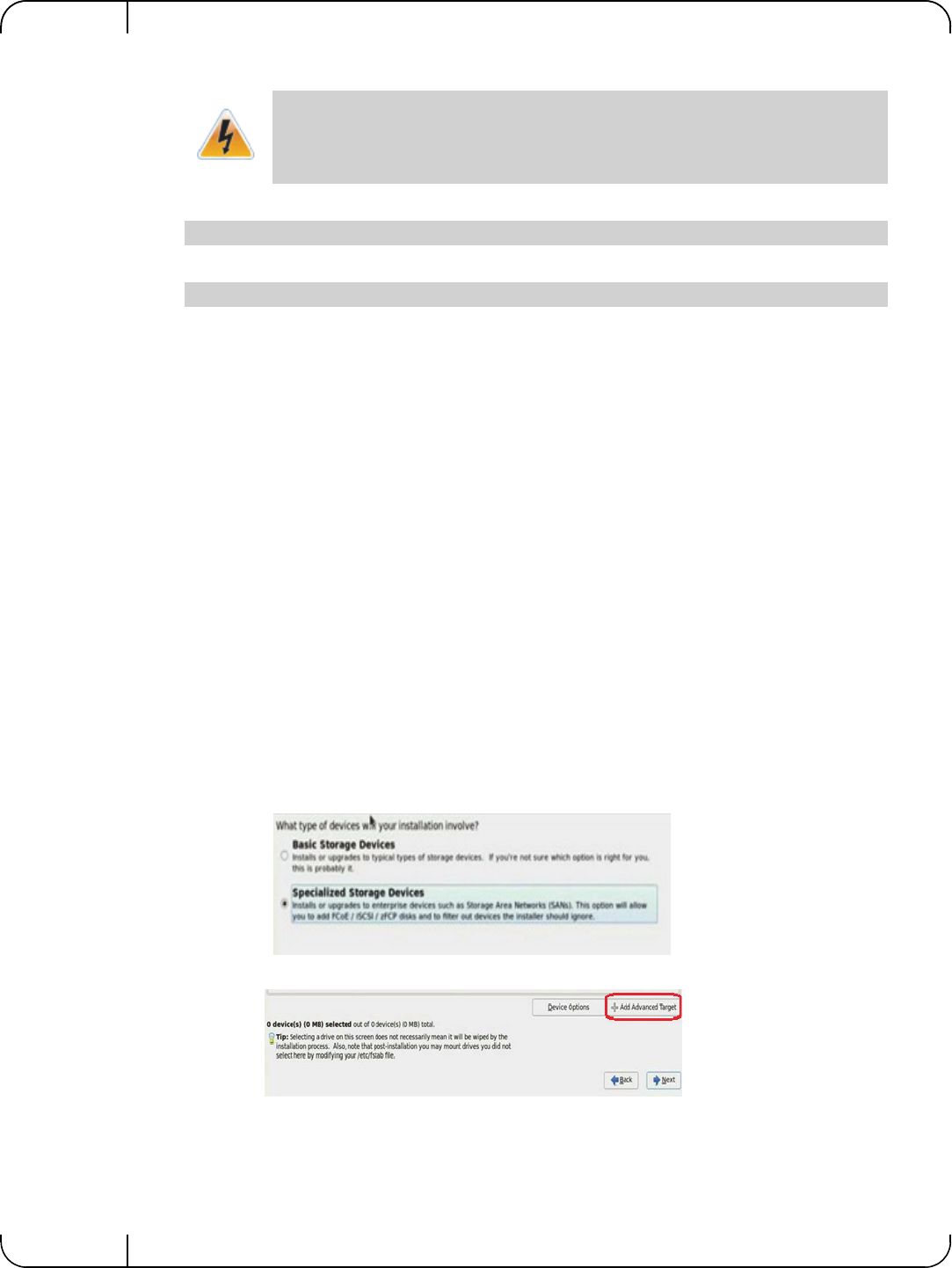
Remote BootRev 1.1
Mellanox Technologies
66
Step 4. Edit the /etc/sysconfig/iscsi-target file as follow.
Step 5. Start the iSCSI target service.
Step 6. Perform a sanity check by connecting to the iSCSI target from a remote PC on the 10GE
network link.
5.1.1.2 Installing RHEL6.4/RHEL6.5 on a Remote Storage over iSCSI
Step 1. Reboot the diskless client and perform a PXE boot with FlexBoot.
This is not an iSCSI boot, rather a regular PXE initiated network deployment of RHEL6.4/
RHEL6.5. In the DHCP server configuration, the PXELINUX (pxelinux.0) and a RHEL
6.4 distribution media will be provided for network installation.
The clients’ HDD was removed beforehand; therefore the RHEL installer (also know as
Anaconda) will ask to locate a HDD. The Anacaonda’s built-in iSCSI discovery will be
used to connect to the iSCSI target LUN partition. For further information, please refer to:
https://access.redhat.com/site/documentation/en-US/Red_Hat_Enterprise_Linux/6/html-
single/Installation_Guide/index.html#ISCSI_disks
Step 2. Select the Network Interface (the same interface which was used by FlexBoot during PXE
boot stage) for the installation process once prompted.
Step 3. Select the type of Installation Media access.
In this example, NFS is used, which also requires us to enter the NFS server name be
entered, and the directory path to the installation media on the NFS.
Step 4. Select Specialized Storage Devices.
Step 5. Click on the + Add Advanced Target button.
The local Hard Disk partition assigned to the LUN (/dev/cciss/c0d0p9 in the example
above) must not contain any valuable data, as this data will be destroyed by the instal-
lation process taking place later in this procedure
OPTIONS="-c /etc/iet/ietd.conf --address=12.7.6.30"
[root@sqa030 ~]# /etc/init.d/iscsi-target start
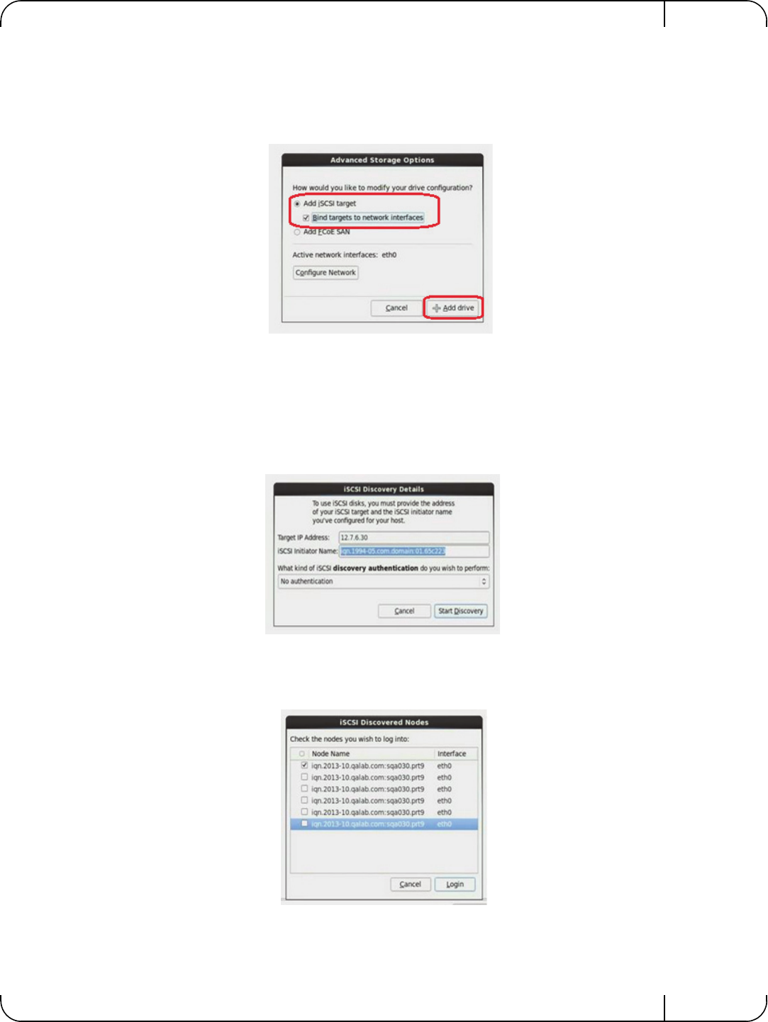
User Manual for Mellanox ConnectX®-3 10/40 Gigabit Ethernet Adapters for Dell PowerEdge Servers Rev 1.1
Mellanox Technologies 67
Step 6. In the Advanced Storage Options window perform the following:
Step a. Select the Add Iscsi Target option.
Step b. Check the Bind targets to network interfaces checkbox.
Step c. Click +Add drive button.
Step 7. Enter the IP address of iSCSI target.
Optionally, you may choose to enter a customized Initiator Name and select the necessary
CHAP authentication of choice. Please refer to Section 5.1.1.3, “SAN-Booting the Disk-
less Client with FlexBoot,” on page 70 for further information.
In the example below, iSCSI Initiator Name is left with the default value given by the
installer and iSCSI discovery authentication is left with No authentication.
Step 8. Check the relevant Node Name to log in.
If as a result of the discovery, multiple Node Names are found, select the one that is rele-
vant.
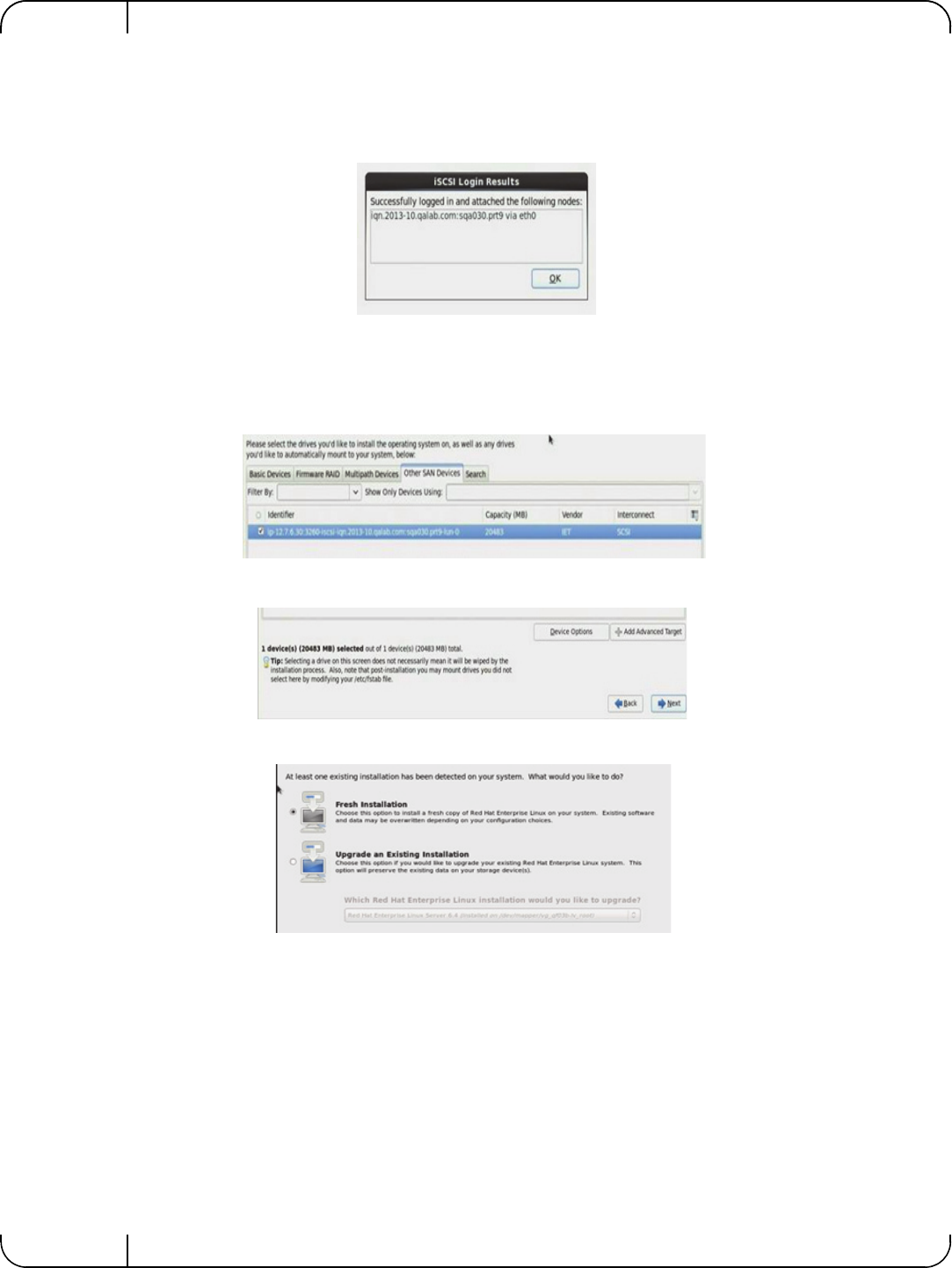
Remote BootRev 1.1
Mellanox Technologies
68
Step 9. Click Login.
A successful login is mandatory to proceed. A failure at this stage is probably a result of a
target or network configuration error and recovery/troubleshooting that is out of the scope
of this document.
Step 10. Make sure a new storage LUN appears in the Other AN Devices tab.
A successful LUN discovery is mandatory to proceed. A failure at this stage is probably a
result of a target or network configuration error and recovery/troubleshooting that is out of
the scope of this document.
Step 11. Click Next.
Step 12. Select Fresh Installation and proceed with the Installation
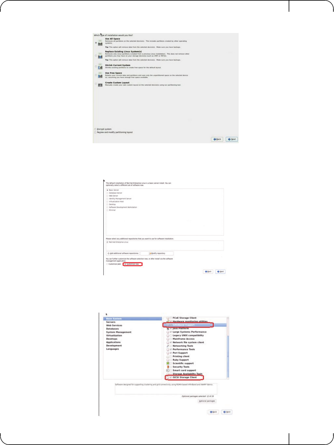
User Manual for Mellanox ConnectX®-3 10/40 Gigabit Ethernet Adapters for Dell PowerEdge Servers Rev 1.1
Mellanox Technologies 69
Step 13. Select the Use All Space option.
Step 14. Click Next and proceed with the Installation.
Step 15. Select the Basic Server option.
This is only one of the options that can be chosen, not the mandatory one.
Step 16. Check the Customize Now checkbox.
Step 17. Click Next.
Step 18. Select Infiniband Support and iSCSI Storage Client.
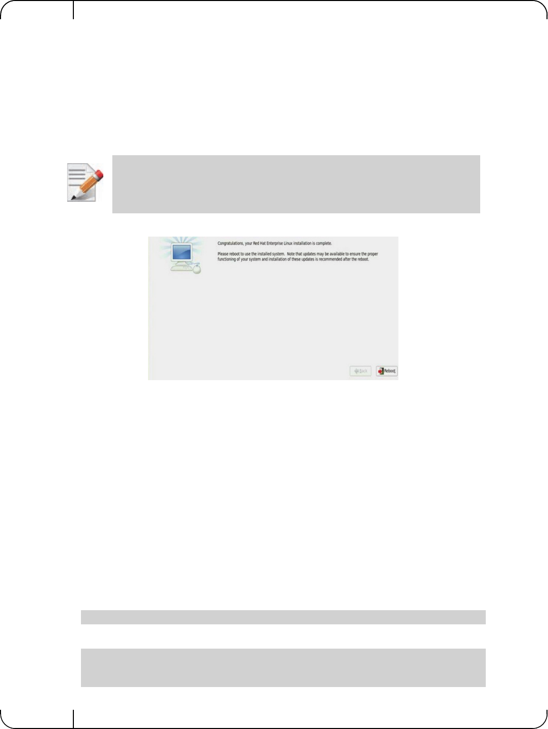
Remote BootRev 1.1
Mellanox Technologies
70
Step 19. Click Next. Allow the installation to reach completion.
5.1.1.3 SAN-Booting the Diskless Client with FlexBoot
When the installation process is completed, the client will ask to reboot. At that point, the DHCP
server configuration for that client needs to be changed so that when it PXE boots again, it will
get the root-path IQN and LUN information from the DHCP server.
For further information, please refer to section DHCP Configuration for iSCSI Boot with Flex-
Boot (PXE SAN Boot).
• Reboot the system
The expected result is that for the diskless PXE client to boot the newly installed RHEL6.4/
RHEL6.5 from the iSCSI storage, and become an operational environment, accessible from any
remote PC via ssh over 10GbE IP network
5.1.2 Booting Windows from an iSCSI Target
5.1.2.1 Configuring the WDS, DHCP and iSCSI Servers
Configuring the WDS Server
To configure the WDS server:
1. Install the WDS server.
2. Extract the Mellanox drivers to a local directory using the '-a' parameter.
For boot over Ethernet, when using adapter cards with older firmware version than 2.30.8000, onewill
need to extract the PXE package, otherwise use Mellanox WinOF VPI package.
Example:
3. Add the Mellanox driver to boot.wim1.
Restart your DHCP service after changing the dhcp configuration file.
Mellanox.msi.exe -a
dism /Mount-Wim /WimFile:boot.wim /index:2 /MountDir:mnt
dism /Image:mnt /Add-Driver /Driver:drivers /recurse
dism /Unmount-Wim /MountDir:mnt /commit

User Manual for Mellanox ConnectX®-3 10/40 Gigabit Ethernet Adapters for Dell PowerEdge Servers Rev 1.1
Mellanox Technologies 71
4. Add the Mellanox driver to install.wim1.
5. Add the new boot and install images to WDS.
For additional details on WDS, please refer to:
http://technet.microsoft.com/en-us/library/jj648426.aspx
Configuring iSCSI Target
To configure iSCSI Target:
1. Install iSCSI Target (e.g StartWind).
2. Add to the iSCSI target initiators the IP addresses of the iSCSI clients.
Configuring the DHCP Server
To configure the DHCP server:
1. Install a DHCP server.
2. Add to IPv4 a new scope.
3. Add iSCSI boot client identifier (MAC/GUID) to the DHCP reservation.
4. Add to the reserved IP address the following options:
5.1.2.2 Configuring the Client Machine
To configuring your client:
5. Verify the Mellanox adapter card is updated with a firmware version that supports iSCSI boot.
6. Set the “Mellanox Adapter Card” as the first boot device in the BIOS settings boot order.
1. Use ‘index:2’ for Windows setup and ‘index:1’for WinPE.
dism /Mount-Wim /WimFile:install.wim /index:4 /MountDir:mnt
dism /Image:mnt /Add-Driver /Driver:drivers /recurse
dism /Unmount-Wim /MountDir:mnt /commit
1. When adding the Mellanox driver to install.wim, verify the appropriate index for the OS distribution is used. To check the OS run
‘imagex /info install.win’.
Table 15 - Reserved IP Address Options
Option Name Value
017 Root Path iscsi:11.4.12.65::::iqn:2011-01:iscsiboot
Assuming the iSCSI target IP is: 11.4.12.65 and the Target Name: iqn:2011-
01:iscsiboot
060 PXEClient PXEClient
066 Boot Server
Host Name WDS server IP address
067 Boot File
Name boot\x86\wdsnbp.com
Please refer to the firmware release notes to see if a particular firmware supports iSCSI
boot or PXE capability.
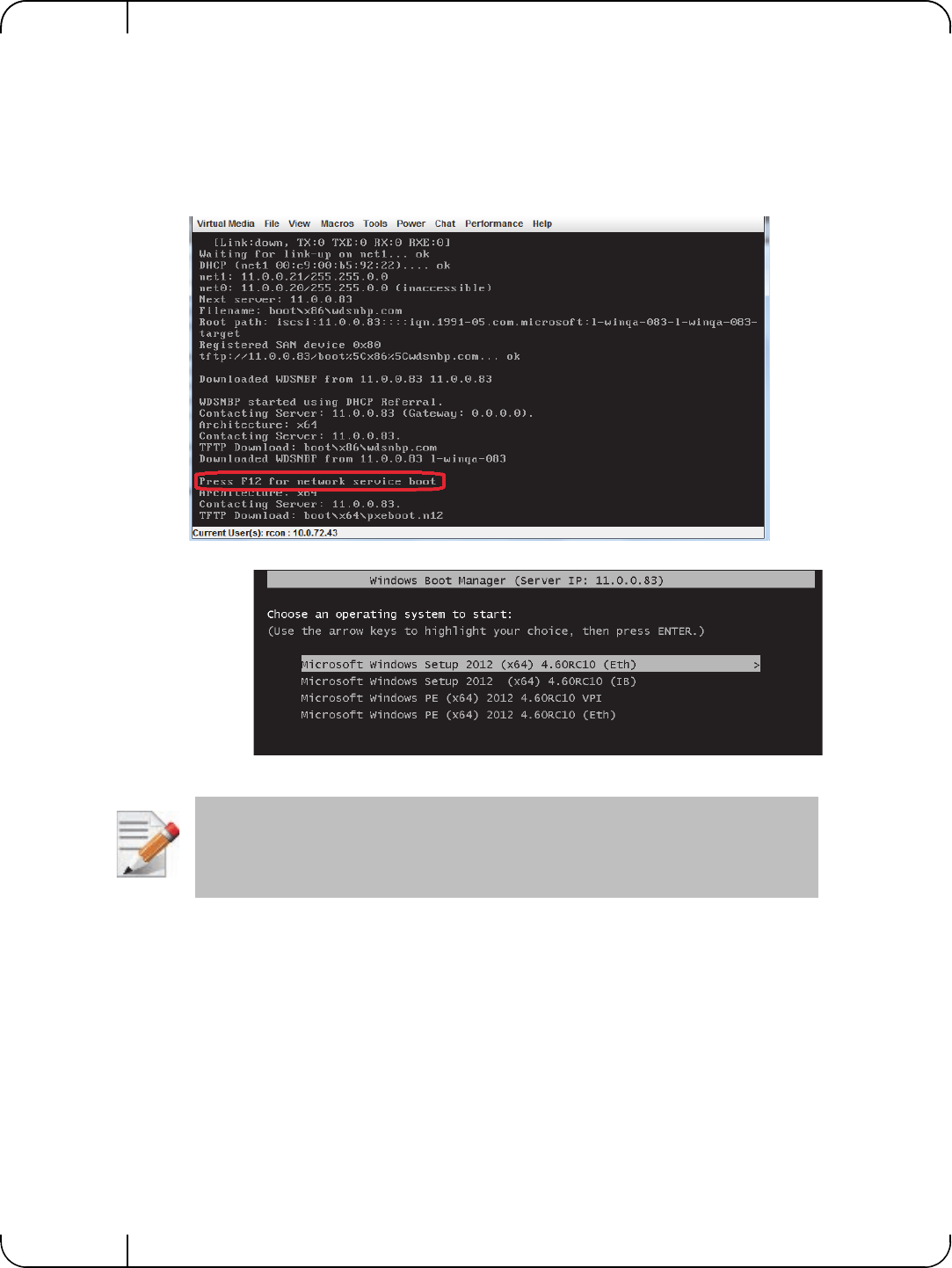
Remote BootRev 1.1
Mellanox Technologies
72
7. In Device Settings for the adapter, confirm that Legacy Boot Protocol is set to iSCSI and con-
firm that the Option ROM setting is set to Enabled.
5.1.2.3 Installing iSCSI
1. Reboot your iSCSI client.
2. Press F12 when asked to proceed to iSCSI boot.
3. Choose the relevant boot image from the list of all available boot images presented.
The above figure is an example only. Microsoft Windows 4.60 is the supported operat-
ing system.
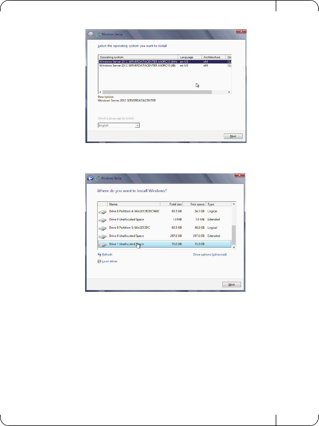
User Manual for Mellanox ConnectX®-3 10/40 Gigabit Ethernet Adapters for Dell PowerEdge Servers Rev 1.1
Mellanox Technologies 73
4. Choose the Operating System to install.
5. Run the Windows Setup Wizard.
6. Choose iSCSI target drive to install Windows and follow the instructions presented by the
installation Wizard.
Installation process will start once completing all the required steps in the Wizard, the Client will
reboot and will boot from the iSCSI target.
5.1.3 SLES11 SP3
5.1.3.1 Configuring the iSCSI Target Machine
To configure the iSCSI target:
Step 1. Download the IET target software from.
http://sourceforge.net/projects/iscsitarget/files/iscsitarget/1.4.20.2/

Remote BootRev 1.1
Mellanox Technologies
74
Step 2. Install iSCSI target and additional required software on target server.
Step 3. Create the IQN in the ietd configuration file.
Step 4. Edit the /etc/sysconfig/iscsi-target file as follow.
Step 5. Start the iSCSI target service.
Step 6. Perform a sanity check by connecting to the iSCSI target from a remote PC on the 10GE
network link.
[root@sqa030 ~]# yum install kernel-devel openssl-devel gcc rpm-build
[root@sqa030 tmp]# tar xzvf iscsitarget-1.4.20.2.tar.gz
[root@sqa030 tmp]# cd iscsitarget-1.4.20.2/
[root@sqa030 iscsitarget-1.4.20.2]# make && make install
Target iqn.2013-10.qalab.com:sqa030.prt9
Lun 0 Path=/dev/cciss/c0d0p9,Type=fileio,IOMode=wb
MaxConnections 1 # Number of connections/session. We only support 1
InitialR2T Yes # Wait first for R2T
ImmediateData Yes # Data can accompany command
MaxRecvDataSegmentLength 8192 # Max data per PDU to receive
MaxXmitDataSegmentLength 8192 # Max data per PDU to transmit
MaxBurstLength 262144 # Max data per sequence (R2T)
FirstBurstLength 65536 # Max unsolicited data sequence
DefaultTime2Wait 2 # Secs wait for ini to log out Not used
DefaultTime2Retain 20 # Secs keep cmnds after log out Not used
MaxOutstandingR2T 1 # Max outstanding R2Ts per cmnd
DataPDUInOrder Yes # Data in PDUs is ordered. We only support ordered
DataSequenceInOrder Yes # PDUs in sequence are ordered. We only support
ordered
ErrorRecoveryLevel 0 # We only support level 0
HeaderDigest NONE # PDU header checksum algo list. None or CRC32C
# If only one is set then the initiator must agree
# to it or the connection will fail
DataDigest NONE # PDU data checksum algo list Same as above
MaxSessions 0 # Maximum number of sessions to this target 0 =
unlimited
NOPInterval 0 # Send a NOP-In ping each after that many seconds
if the
# conn is otherwise idle 0 = off
NOPTimeout 0 # Wait that many seconds for a response on a
NOP-In ping
# If 0 or > NOPInterval, NOPInterval is used!
# Various target parameters
Wthreads 8 # Number of IO threads
QueuedCommands 32 # Number of queued commands
The local Hard Disk partition assigned to the LUN (/dev/cciss/c0d0p9 in the example
above) must not contain any valuable data, as this data will be destroyed by the instal-
lation process taking place later in this procedure
OPTIONS="-c /etc/iet/ietd.conf --address=12.7.6.30"
[root@sqa030 ~]# /etc/init.d/iscsi-target start

User Manual for Mellanox ConnectX®-3 10/40 Gigabit Ethernet Adapters for Dell PowerEdge Servers Rev 1.1
Mellanox Technologies 75
5.1.3.2 Configuring the DHCP Server
Edit a host-declaration for your PXE client in the DHCP configuration file, serving it with pxe-
linux.0, and restart your DHCP.
Here is an example of such host declaration inside DHCP config file:
5.1.3.3 Installing SLES11 SP3 on a Remote Storage over iSCSI
Step 1. In the DHCP server configuration, the PXELINUX (pxelinux.0) and a SLES11 SP3 distri-
bution media will be provided for network installation.
The clients’ HDD was removed beforehand; therefore the installer will ask to locate a
HDD. The built-in iSCSI discovery will be used to connect to the iSCSI target LUN parti-
tion.
host qadell011 {
filename "pxelinux.0" ;
next-server 12.7.6.30;
option host-name "qadell011";
fixed-address 12.7.6.11 ;
hardware ethernet 00:02:C9:E5:D8:E0 ;
}
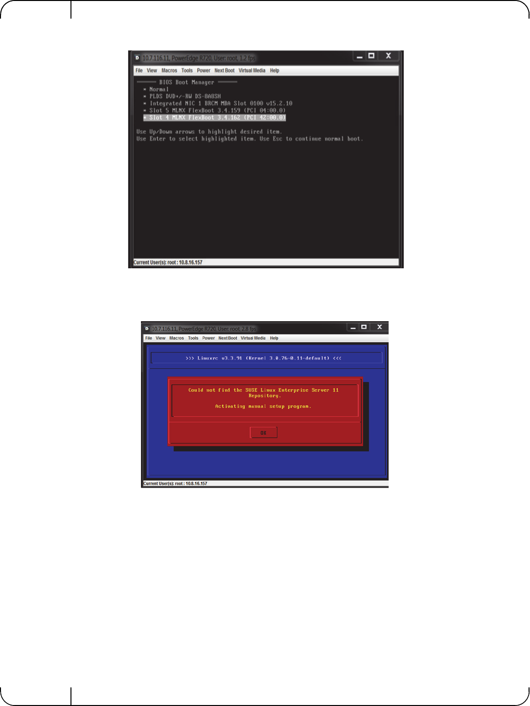
Remote BootRev 1.1
Mellanox Technologies
76
Step 2. Reboot the client and invoke PXE boot with the Mellanox boot agent.
Step 3. Select the "Install SLES11.3" boot option from the menu (see pxelinux.cfg example above).
After about 30 seconds, the SLES installer will issue the notification below due to the
PXELINUX boot label we used above.
Step 4. Click OK.
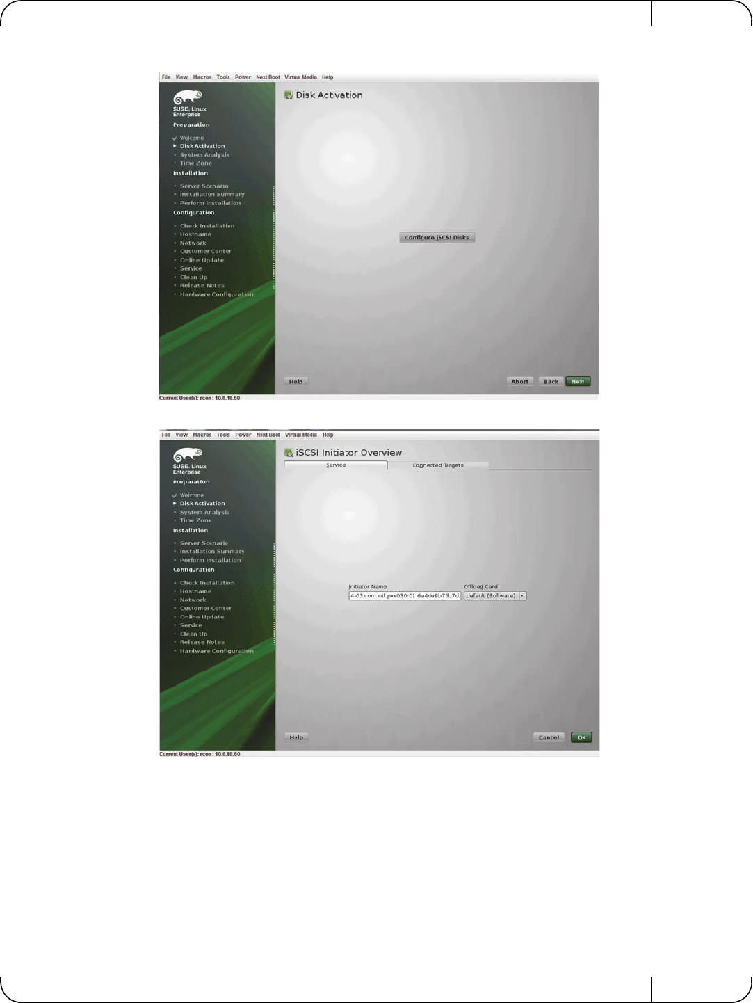
User Manual for Mellanox ConnectX®-3 10/40 Gigabit Ethernet Adapters for Dell PowerEdge Servers Rev 1.1
Mellanox Technologies 77
Step 5. Click on the Configure iSCSI Disks button.
Step 6. Choose Connected Targets tab.
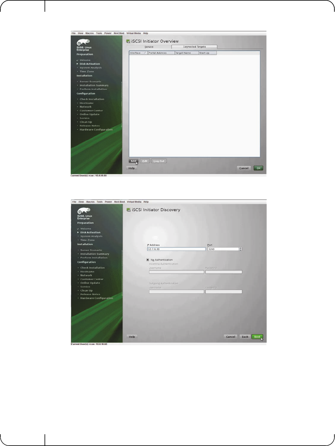
Remote BootRev 1.1
Mellanox Technologies
78
Step 7. Click Add.
Step 8. Enter the IP address of the iSCSI storage target.
Step 9. Click Next.
Step 10. Select the relevant target from the table (In our example, only one target exist so only one
was discovered).
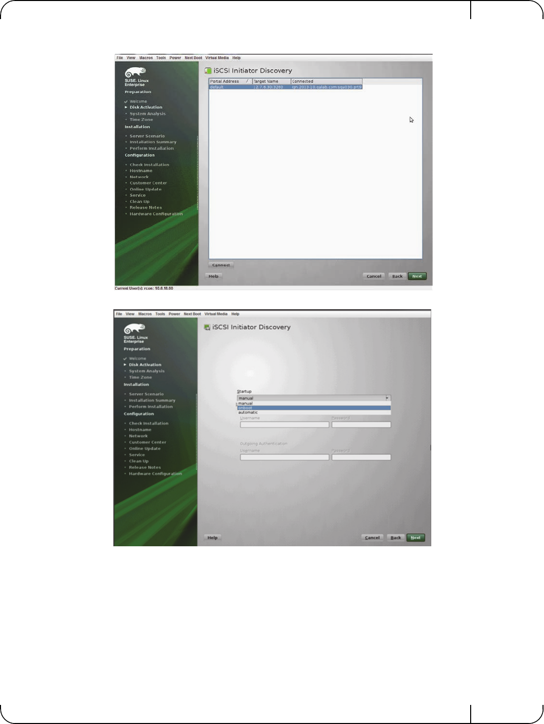
User Manual for Mellanox ConnectX®-3 10/40 Gigabit Ethernet Adapters for Dell PowerEdge Servers Rev 1.1
Mellanox Technologies 79
Step 11. Click Connect.
Step 12. Select onboot from drop-list.
Step 13. Click Next to exit the discovery screen.
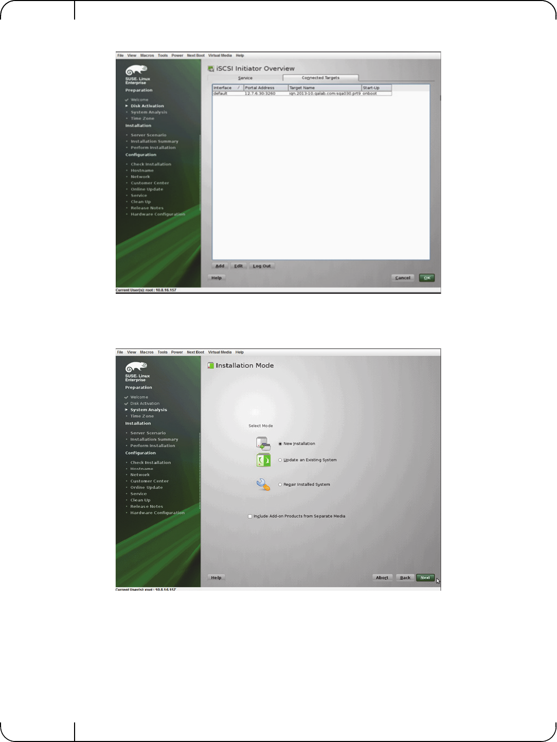
Remote BootRev 1.1
Mellanox Technologies
80
Step 14. Go to the Connected Targets tab again to confirm iSCSI connection with target.
Step 15. Click OK.
Step 16. Click Next back at the Disk Activation screen.
Step 17. Select New Installation.
Step 18. Click Next.
Step 19. Complete Clock and Time Zone configuration.
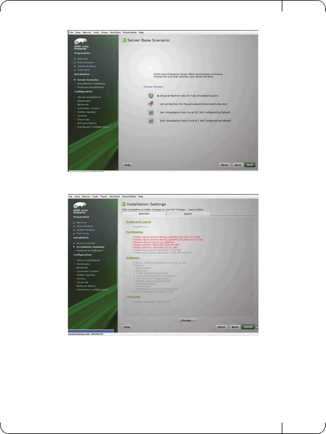
User Manual for Mellanox ConnectX®-3 10/40 Gigabit Ethernet Adapters for Dell PowerEdge Servers Rev 1.1
Mellanox Technologies 81
Step 20. Select Physical Machine.
Step 21. Click Next.
Step 22. Click Install.
Make sure "open-iscsi" RPM is selected for the installation under "Software".
After the installation is completed, the system will reboot.
Choose "SLES11.3x64_iscsi_boot" label from the boot menu (See Section 5.1.3.3,
“Installing SLES11 SP3 on a Remote Storage over iSCSI,” on page 75).

Remote BootRev 1.1
Mellanox Technologies
82
Step 23. Complete post installation configuration steps.
5.1.3.4 Using PXE Boot Services for Booting the SLES11 SP3 from the iSCSI Target
Once the installation is completed, the system will reboot. At this stage, it is expected from the
client to perform another PXE network boot with FlexBoot®.
Choose the "SLES11.3x64 iSCSI boot" label from the boot menu (See Section 5.1.3.3, “Install-
ing SLES11 SP3 on a Remote Storage over iSCSI,” on page 75).
5.2 PXE Boot
5.2.1 SLES11 SP3
5.2.1.1 Configuring the PXE Server
Step 1. Download SLES11SP3-kISO-VPI.tgz from
http://www.mellanox.com/page/products_dyn?&product_family=34&mtag=flexboot
Step 2. Extract the .tgz file on the PXE server, under the TFTP root directory.
For example:
The following are examples of PXE server configuration:
• PXE server configuration:
• Kernel and initrd for the installation:
• Kernel and initrd for the boot after the installation:
• kISO installation medium that can be used to boot from instead of booting the installer program
over the network.
If choosing this method:
• Boot the client into the below SLES11 SP3 iso and proceed with the installation until
the client fully boots up the installer program.
• Discover and connect to a remote iSCSI storage.
During the installation process you will be asked to insert the original installation medium to
continue with the installation.
It is recommended to download and install the latest version of MLNX_OFED_LINUX
available from
http://www.mellanox.com/page/
products_dyn?product_family=26&mtag=linux_sw_drivers
[root@sqa030 ~]# cd /var/lib/tftpboot; tar xzvf SLES11SP3-kISO-VPI.tgz
SLES11SP3-kISO-VPI/pxelinux.cfg/default
SLES11SP3-kISO-VPI/pxeboot-install/initrd
SLES11SP3-kISO-VPI/pxeboot-install/linux
SLES11SP3-kISO-VPI/pxeboot/initrd
SLES11SP3-kISO-VPI/pxeboot/linux
SLES11SP3-kISO-VPI/sles11-sp3-x86_64-mlnx_ofed-2.1-1.0.6.iso

User Manual for Mellanox ConnectX®-3 10/40 Gigabit Ethernet Adapters for Dell PowerEdge Servers Rev 1.1
Mellanox Technologies 83
If the iso method above is not used, two different PXE server configurations are required
(PXELINUX booting labels) for each phase discussed herein (booting the installer and
post-installation boot)
• For booting the installer program off the TFTP server, please provide the client a path to the initrd
and linux kernel as provided inside SLES11SP3-kISO-VPI/pxeboot-install/ in the tgz above.
The below is an example of such label.
• For post-installation boot (booting the SLES 11 SP3 off the iSCSI storage using PXE services)
please provide the booting client a path to the initrd and linux kernel as provided inside SLES11SP3-
kISO-VPI/pxeboot/ in the tgz above.
The below is an example of such label.
The steps described in this document do not refer to an unattended installation with autoyast. For
official information on SLES unattented installation with autoyast, please refer to:
https://www.suse.com/documentation/sles11/book_autoyast/?page=/documentation/sles11/
book_autoyast/data/book_autoyast.html
The following is known to work with Mellanox NIC:
LABEL SLES11.3x64_manual_installl
MENU LABEL ^1) Install SLES11.3
kernel SLES11SP3-kISO-VPI/pxeboot-install/linux
append initrd=SLES11SP3-kISO-VPI/pxeboot-install/initrd install=nfs://12.7.6.30/pxerepo/
SLES/11.3/x86_64/DVD1/?device=p4p2
IPAPPEND 2
To install SLES11 SP3 over iSCSI over IPoIB, the following parameters need to be
added to the “append” statement above:
insmod=ib_ipoib insmod=libiscsi insmod=rdma_cm insmod=ib_iser
LABEL SLES11.3x64_iscsi_boot
MENU LABEL ^2) SLES11.3 iSCSI boot
kernel SLES11SP3-kISO-VPI/pxeboot/linux
append initrd= SLES11SP3-kISO-VPI/pxeboot/initrd net-root=iscsi:12.7.6.30::::iqn.2013-
10.qalab.com:sqa030.prt9 TargetAd-dress=12.7.6.30 TargetName=iqn.2013-
10.qalab.com:sqa030.prt9 TargetPort=3260 net_delay=10 rootfstype=ext3 rootdev=/dev/sda2
append initrd=SLES-11-SP3-DVD-x86_64-GM-DVD1/boot/x86_64/loader/initrd install=nfs://
<NFS IP Address>/<path the the repository directory>/ autoyast=nfs://<NFS IP Address>/
<path to autoyast xml directory>/autoyast-unattended.xml biosdevname=0
IPAPPEND 2

FirmwareRev 1.1
Mellanox Technologies
84
6 Firmware
Firmware and update instructions for these cards can be obtained from the Dell support web
page: http://www.dell.com/support.
Note: The firmware version on the adapter can be checked using the following methods:
1. System Setup > Device Settings
2. Dell iDRAC

User Manual for Mellanox ConnectX®-3 10/40 Gigabit Ethernet Adapters for Dell PowerEdge Servers Rev 1.1
Mellanox Technologies 85
7Dell Lifecycle ControllerTroubleshooting
7.1 General
Server unable to find
the adapter
• Ensure that the adapter is placed correctly
• Make sure the adapter slot and the adapter are compatible
• Install the adapter in a different PCI Express slot
• Use the drivers that came with the adapter or download the latest
• Make sure your motherboard has the latest BIOS
• Try to reboot the server
The adapter no longer
works
• Reseat the adapter in its slot or a different slot, if necessary
• Try using another cable
• Reinstall the drivers for the network driver files may be damaged
or deleted
• Reboot the server
Adapters stopped
working after
installing another
adapter
• Try removing and re-installing all adapters
• Check that cables are connected properly
• Make sure your motherboard has the latest BIOS
Link indicator light is
off
• Ensure that adapter driver/s is loaded
• Try another port on the switch
• Make sure the cable is securely attached
• Check your are using the proper cables that do not exceed the rec-
ommended lengths
• Verify that your switch and adapter port are compatible
Link light is on, but
with no
communication
established
• Check that the latest driver is loaded
• Check that both the adapter and its link are set to the same speed
and duplex settings
Low Performance
with RDMA over
Converged Ethernet
(RoCE)
• Check to make sure flow-control is enabled on the switch ports.

Dell Lifecycle ControllerTroubleshootingRev 1.1
Mellanox Technologies
86
7.2 Linux
7.3 Windows
Firmware Version
Upgrade
To download the latest firmware version refer to the Dell support site
http://www.dell.com/support
Environment
Information
cat/etc/issue
uname –a
cat/proc/cupinfo | grep ‘model name’ | uniq
ofed_info | head -1
ifconfig –a
ethtool <interface>
ethtool –i <interface_of_Mellanox_port_num>
ibdev2netdev
Card Detection lspci | grep –i Mellanox
Ports Information ibstat
lbv_devinfo
Collect Log File /var/log/messages
dmesg > system.logF
Firmware Version
Upgrade
To download the latest firmware version refer to the Dell support site
http://www.dell.com/support
Performance is Low This can be due to non-optimal system configuration. See the section
“Performance Tuning” to take advantage of Mellanox 10 GBit NIC
performance
Driver Does Not Start
This can happen due to an RSS configuration mismatch between the
TCP stack and the Mellanox adapter. To confirm this scenario, open
the event log and look under “System” for the “mlx4eth5” or
“mlx4eth6” source. If found, enable RSS as follows:
Run the following command: “netsh int tcp set global rss = enabled”.
This is a less recommended suggestion, and will cause low perfor-
mance. Disable RSS on the adapter. To do this set RSS mode to “No
Dynamic Rebalancing”.
The Ethernet Driver
Fails to Start
If in the Event log, under the mlx4_bus source, the following
error message appears: RUN_FW command failed with error -22,
this error message indicates that the wrong firmware image has been
programmed on the adapter card.
If a yellow sign appears near the Mellanox ConnectX Ethernet
Adapter instance in the Device Manager display, this can happen due
to a hardware error. Try to disable and re-enable “Mellanox Con-
nectX Adapter” from the Device Manager display.

User Manual for Mellanox ConnectX®-3 10/40 Gigabit Ethernet Adapters for Dell PowerEdge Servers Rev 1.1
Mellanox Technologies 87
No connectivity to a
Fault Tolerance
bundle while using
network capture tools
(e.g., Wireshark)
This can happen if the network capture tool captures the network
traffic of the non-active adapter in the bundle. This is not allowed
since the tool sets the packet filter to “promiscuous”, thus causing
traffic to be transferred on multiple interfaces. Close the network
capture tool on the physical adapter card, and set it on the LBFO
interface instead.
No Ethernet
connectivity on 1Gb/
100Mb adapters after
activating
Performance Tuning
(part of the
installation)
This can happen due to adding a TcpWindowSize registry value. To
resolve this issue, remove the value key under
HKEY_LOCAL_MACHINE\SYSTEM\CurrentControl- Set\Ser-
vices\Tcpip\Parameters\TcpWindowSize or set its value to 0xFFFF
System reboots on an
I/OAT capable system
on Windows Server 20
This may occur if you have an Intel I/OAT capable system with
Direct Cache Access enabled, and 9K jumbo frames enabled. To
resolve this issue, disable 9K jumbo frames.
Packets are being lost This may occur if the port MTU has been set to a value higher than
the maximum MTU supported by the switch.
Windows System
Event Viewer Events
Failed to reset the Mellanox ConnectX EN 10Gbit Ethernet NIC. Try
disabling then re-enabling the “Mellanox Ethernet Bus Driver”
device via the Windows device manager.
Failed to initialize the Mellanox ConnectX EN 10Gbit Ethernet
Adapter <X> because it uses old firmware version (<old firmware
version>). You need to update the adapter to firmware version <new
firmware version> or higher, and to restart your computer.
Mellanox ConnectX EN 10Gbit Ethernet Adapter <X> device
detected that the link connected to port <Y> is down. This can occur
if the physical link is disconnected or damaged, or if the other end-
port is down.
Mismatch in the configurations between the two ports may affect the
performance. When Using MSI-X, both ports should use the same
RSS mode. To fix the problem, configure the RSS mode of both
ports to be the same in the driver GUI.
Mellanox ConnectX EN 10Gbit Ethernet Adapter <X> device failed
to create enough MSI-X vectors. The Network interface will not use
MSI-X interrupts. This may affects the performance. To fix the prob-
lem, configure the number of MSI-X vectors in the registry to be at
least <Y>.

SpecificationsRev 1.1
Mellanox Technologies
88
8 Specifications
Table 16 - Mellanox ConnectX-3 Dual 40GbE QSFP+ Network Adapter Specifications
Physical
Board Size: 2.71in. x 5.6in. (68.90 mm x 142.25 mm)
Full height Bracket Size: 4.5 in. (116 mm)
Low profile Bracket Size: 3.16 in. (80.3 mm)
Connector: QSFP+ 40Gb/s
Protocol Support
Ethernet: 10GBASE-CR, 40GBASE-CR4 /-SR4
Data Rate:
10/40Gb/s – Ethernet
PCI Express Gen3: SERDES @ 8.0GT/s, 8lanes (2.0 and 1.1 compatible)
Power and
Environmentala
a. Thermal and power characteristics with optical modules only supported with Mellanox QSFP+ optical
module, MC2210411-SR4 (Dell Part Number 2MJ5F)
Voltage: 12V, 3.3V, 3.3V_AUX
Typ Power: Passive Cables: 8.14W
Optical Cables: 10.96W
Max Power: Passive Cables: 9.98W
Optical Cables: 13.51W
Temperature: 0°C to 55°C
Non-operational 0°C to 70°C
Note: Thermal spec covers Power Level 1 QSFP modules
Humidity: 90% relative humidity b
b. For both operational and non-operational states
Air Flow: 120LFMc
c. Air flow is measured ~1” from the heat sink between the heat sink and the cooling air inlet.
Regulatory
EMC: Refer to Chapter 9, “Regulatory,” on page 91
Safety: IEC/EN 60950-1:2006
ETSI EN 300 019-2-2
IEC 60068-2- 64, 29, 32
RoHS: RoHS-R6
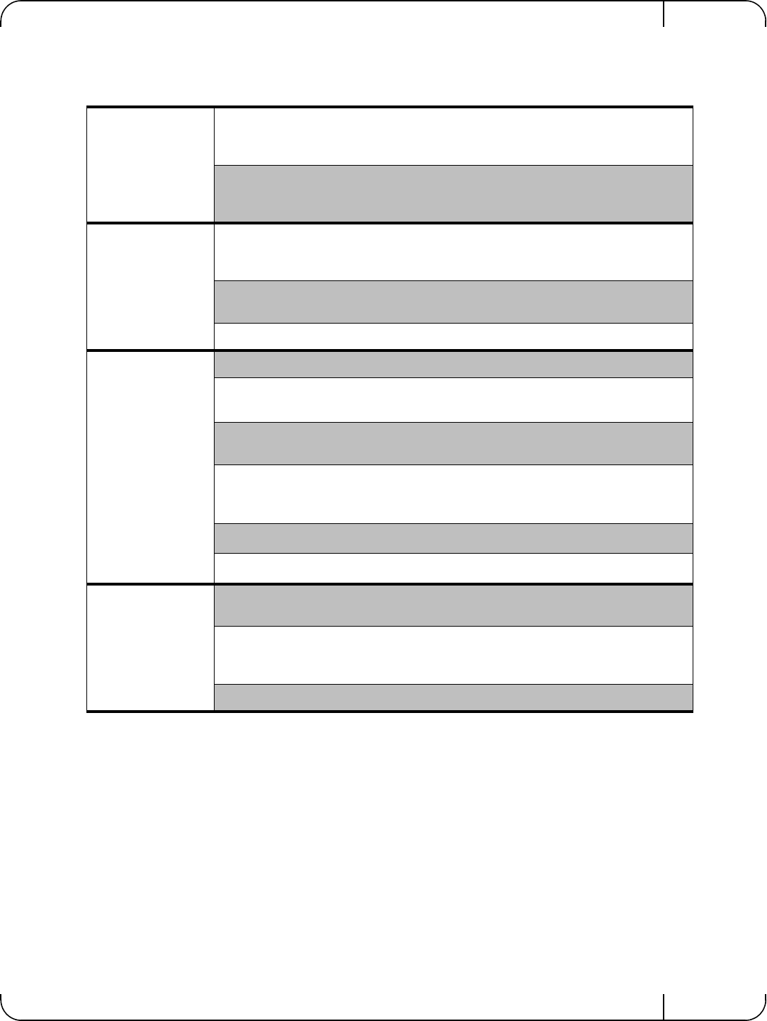
User Manual for Mellanox ConnectX®-3 10/40 Gigabit Ethernet Adapters for Dell PowerEdge Servers Rev 1.1
Mellanox Technologies 89
Table 17 - Mellanox ConnectX-3 Dual 10GbE SFP+ Network Adapter Specifications
Physical
Size: 2.71in. x 5.6in. (68.90 mm x 142.25 mm)
Full height Bracket Size: 3.8in (96.52 mm)
Low profile Bracket Size: 3.16in (80.3 mm)
Connector: SFP+ 10Gb/s
Protocol Support
Ethernet: 10GBASE-CR, 10GBASE-R, and 1000BASE-R
Data Rate:
10Gb/s – Ethernet
PCI Express Gen3: SERDES @ 8.0GT/s, 8lanes (2.0 and 1.1 compatible)
Power and
Environmentala
a. Thermal and power characteristics with optical modules only supported with Mellanox SFP+ optical mod-
ule, MFM1T02A-SR (Dell Part Number T16JY).
Voltage: 12V, 3.3V. 3.3V_AUX
Typ Power: Passive Cables: 4.84W
Optical Cables: 6.24W
Max Power: Passive Cables: 5.87W
Optical Cables: 7.87W
Temperature: Operational 0°C to 55°C
Non-operational 0°C to 70°C
Note: Thermal spec covers Power Level 1 SFP+ modules
Humidity: 90% relative humidityb
b. For both operational and non-operational states
Air Flow: 100LFMc
c. Air flow is measured ~1” from the heat sink between the heat sink and the cooling air inlet.
Regulatory
EMC: Refer to Chapter 9, “Regulatory,” on page 91
Safety: IEC/EN 60950-1:2006
ETSI EN 300 019-2-2
IEC 60068-2- 64, 29, 32
RoHS: RoHS-R6
SpecificationsRev 1.1
Mellanox Technologies
90
Table 18 - Mellanox ConnectX-3 Dual 10GbE KR Blade Mezzanine Card Specifications
Physical Size: 3.4in. x 3.3in. (88 mm x 84mm)
Protocol Support
Ethernet: 10GBASE-KR, 10GBASE-KX4, 1000BASE-KX
Data Rate:
1/10Gb/s – Ethernet
PCI Express Gen3: SERDES @ 8.0GT/s, 8 lanes (2.0 and 1.1 compatible)
Power and
Environmental
Voltage: 12V, 3.3Vaux
Typ Power: 4.84
Max Power: 5.87
Temperature: Operational 0°C to 65°C
Non-operational 0°C to 70°C
Humidity: 90% relative humiditya
a. For both operational and non-operational states
Air Flow: 200LFMb
b. Air flow is measured ~1” from the heat sink between the heat sink and the cooling air inlet.
Regulatory
Safety: IEC/EN 60950-1:2006
ETSI EN 300 019-2-2
IEC 60068-2- 64, 29, 32
RoHS: RoHS-R6

User Manual for Mellanox ConnectX®-3 10/40 Gigabit Ethernet Adapters for Dell PowerEdge Servers Rev 1.1
Mellanox Technologies 91
9 Regulatory
9.1 Regulatory Statements
9.1.1 FCC Statements (USA)
Class A Statements:
§ 15.19(a)(4)
This device complies with Part 15 of the FCC Rules.
Operation is subject to the following two conditions:
1. This device may not cause harmful interference, and
2. This device must accept any interference received, including interference that may cause
undesired operation.
§ 15.21
Statement
Warning!
Changes or modifications to this equipment not expressly approved by the party responsible
for compliance (Mellanox Technologies) could void the user's authority to operate the equip-
ment.
§15.105(a)
Statement
NOTE: This equipment has been tested and found to comply with the limits for a Class A digi-
tal device, pursuant to Part 15 of the FCC Rules. These limits are designed to provide reason-
able protection against harmful interference when the equipment is operated in a commercial
environment. This equipment generates, uses, and can radiate radio frequency energy and, if
not installed and used in accordance with the instruction manual, may cause harmful interfer-
ence to radio communications. Operation of this equipment in a residential area is likely to
cause harmful interference in which case the user will be required to correct the interference
at his own expense.
Table 19 - Ethernet Network Adapter Certifications
OPN FCC VCCI EN ICES CE CB cTUV
us KCC C-
TICK CCC GOST
-R
S-
MAR
K
Mellanox Con-
nectX-3 Dual
40GbE QSFP+ Net-
work Adapter
YES YES YES YES YES YES YES YES YES Exemp-
tion letter N/A N/A
Mellanox Con-
nectX-3 Dual
10GbE SFP+ Net-
work Adapter
YES YES YES YES YES YES YES YES YES Exemp-
tion letter N/A N/A

RegulatoryRev 1.1
Mellanox Technologies
92
9.1.2 EN Statements (Europe)
EN55022 Class A Statement:
Warning
This is a class A product. In a domestic environment this product may cause radio interference
in which case the user may be required to take adequate measures.
9.1.3 ICES Statements (Canada)
Class A Statement:
“This Class A digital apparatus complies with Canadian ICES-003.
Cet appareil numérique de la classe A est conforme à la norme NMB-003 du Canada.”
9.1.4 VCCI Statements (Japan)
Class A Statement:
(Translation - “This is a Class A product based on the standard of the Voluntary Control Coun-
cil for Interference by Information Technology Equipment (VCCI). If this equipment is used in
a domestic environment, radio interference may occur, in which case the user may be required
to take corrective actions.”)

User Manual for Mellanox ConnectX®-3 10/40 Gigabit Ethernet Adapters for Dell PowerEdge Servers Rev 1.1
Mellanox Technologies 93
9.1.5 KCC Certification (Korea)
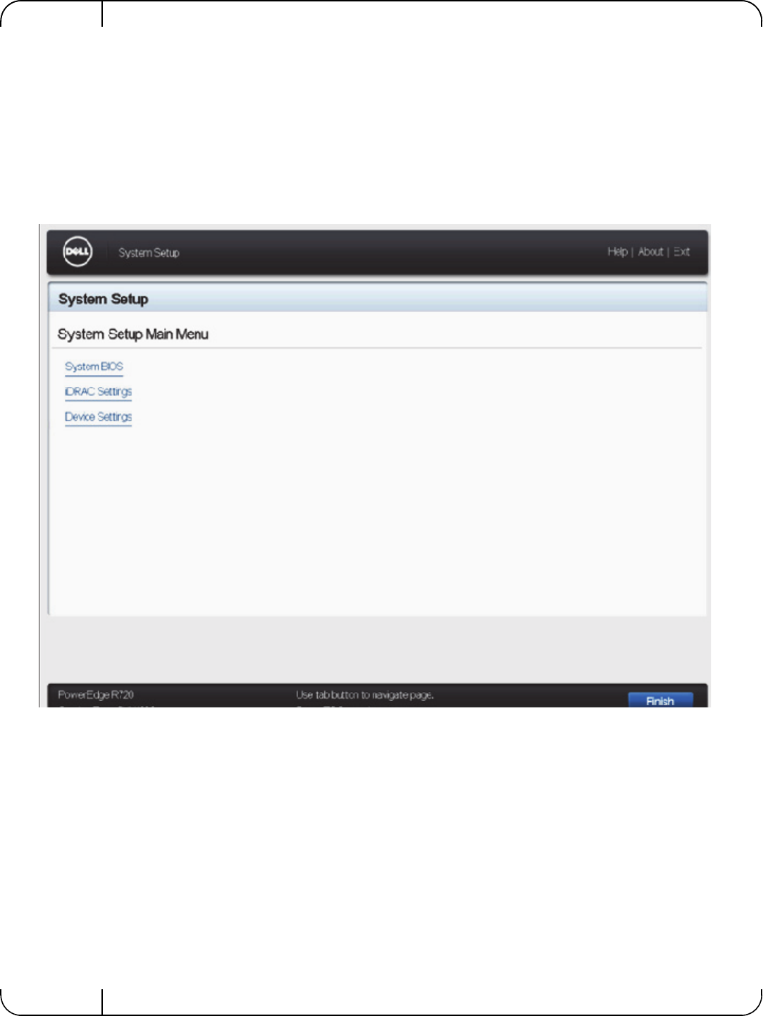
Rev 1.1
Mellanox Technologies
94
Appendix A: Configuration for Mellanox Adapters through
System Setup
This section covers the main configuration options in Dell PowerEdge System Setup which can
be accessed through BIOS or through Lifecycle Controller.
Figure 3: System Setup Menu
Setup menu options:
1. System BIOS
2. iDRAC Settings
3. Device Settings
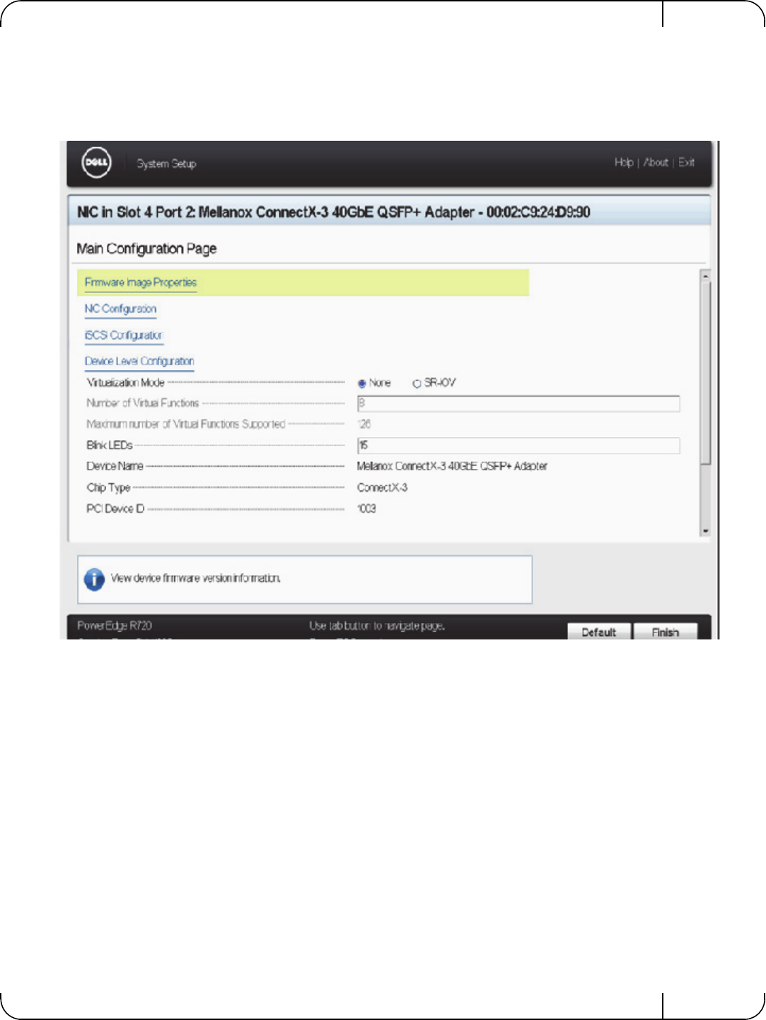
User Manual for Mellanox ConnectX®-3 10/40 Gigabit Ethernet Adapters for Dell PowerEdge Servers Rev 1.1
Mellanox Technologies 95
To configure the Mellanox Adapter, choose 'Device settings' and the relevant Mellanox adapter:
Figure 4: Main Configuration Page Options
1. Shows general info regarding the adapter.
2. Allows configuration of SR-IOV on the adapter - see Appendix A.5, “SR-IOV Configura-
tion,” on page 104.
3. Allows setting the Blink LEDs to allow physical identification of the card
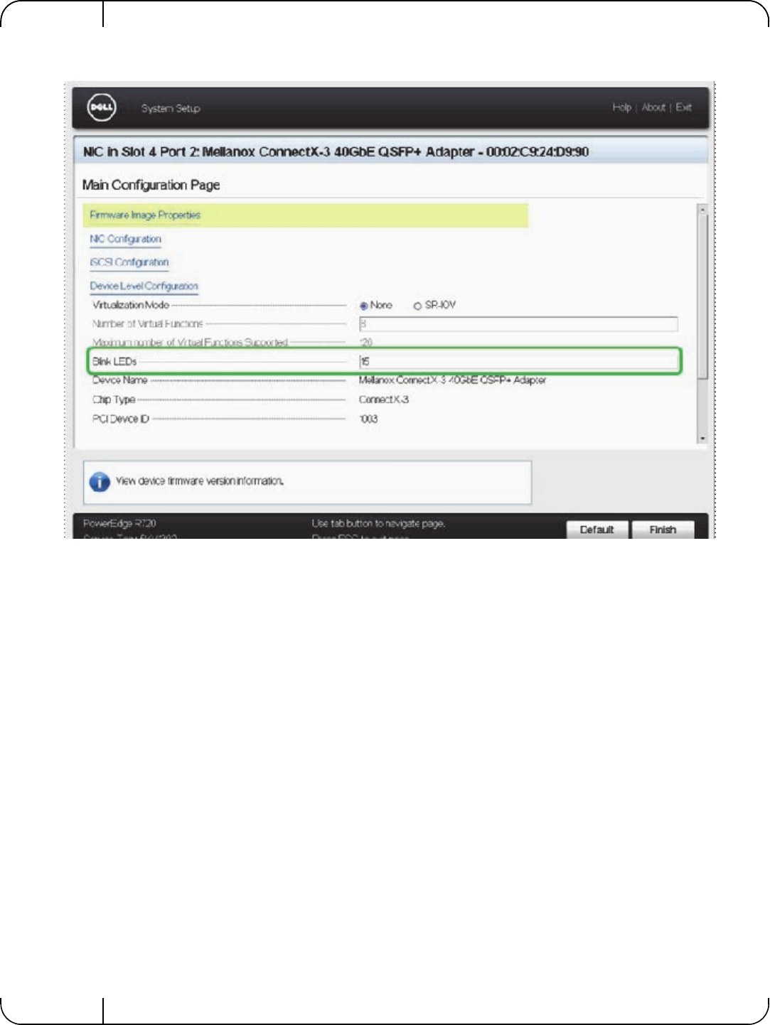
Rev 1.1
Mellanox Technologies
96
a. To trigger Blink LEDs configure the number of seconds for it to blink (Max is 15 seconds).
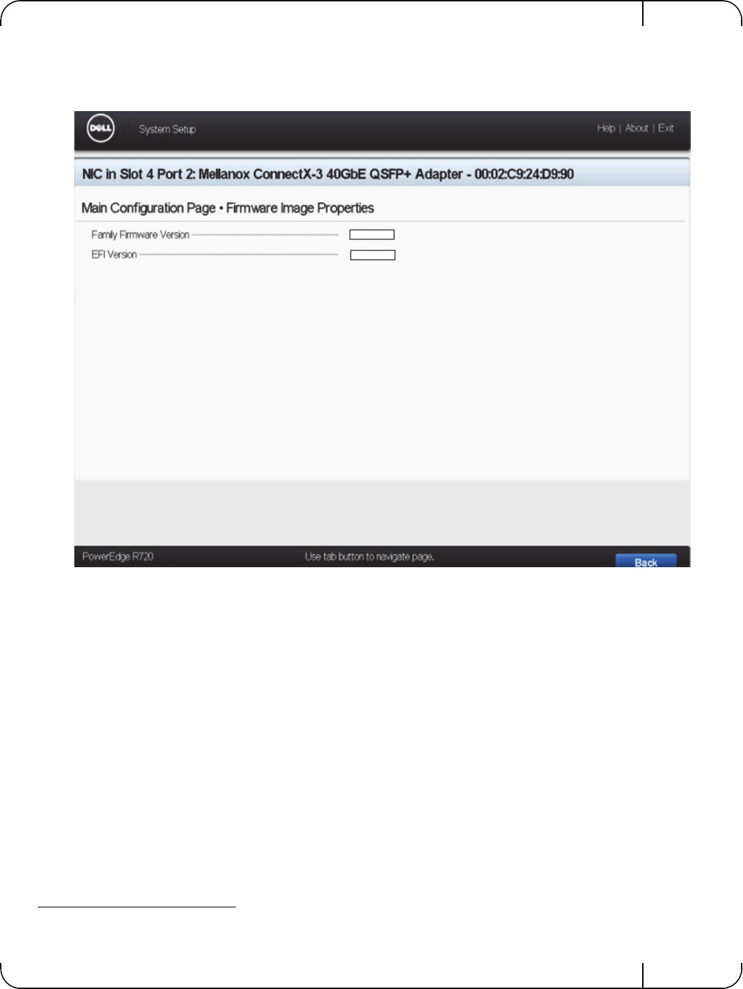
User Manual for Mellanox ConnectX®-3 10/40 Gigabit Ethernet Adapters for Dell PowerEdge Servers Rev 1.1
Mellanox Technologies 97
A.1 Main Configuration Page - Firmware Image Properties
The below provides Firmware the uEFI versions numbers.1
A.2 Main Configuration Page - NIC Configuration
1. Allows configuration of Legacy Boot Protocol: None, PXE, iSCSI.
2. Allows configuration of Virtual LAN Mode and Virtual LAN ID.
3. Allows to Enable or Disable the Option ROM.
1. These version numbers are just an example.
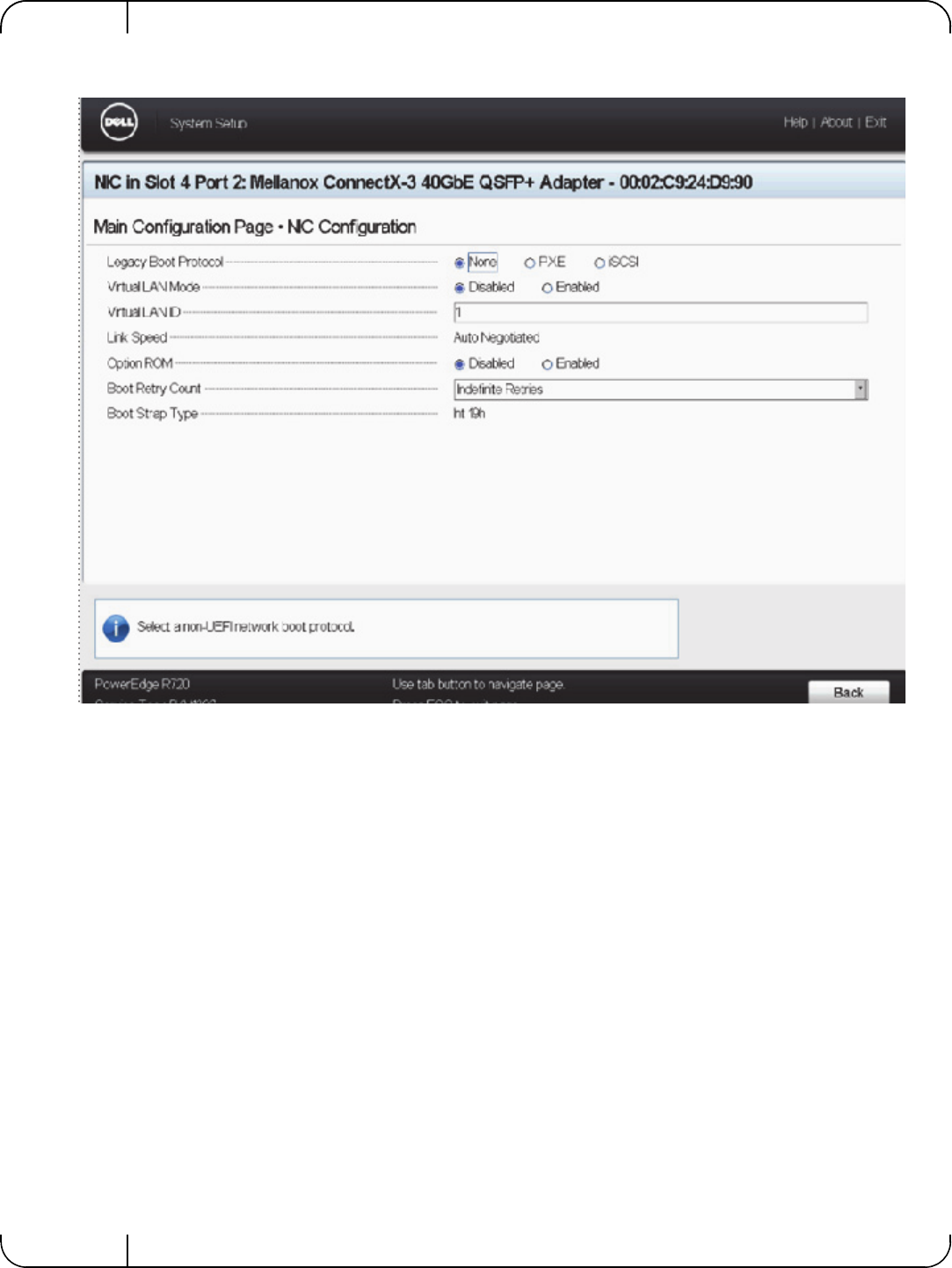
Rev 1.1
Mellanox Technologies
98
4. Allows setting Boot Retry Count.

User Manual for Mellanox ConnectX®-3 10/40 Gigabit Ethernet Adapters for Dell PowerEdge Servers Rev 1.1
Mellanox Technologies 99
5. Allows setting Boot Retry Count.
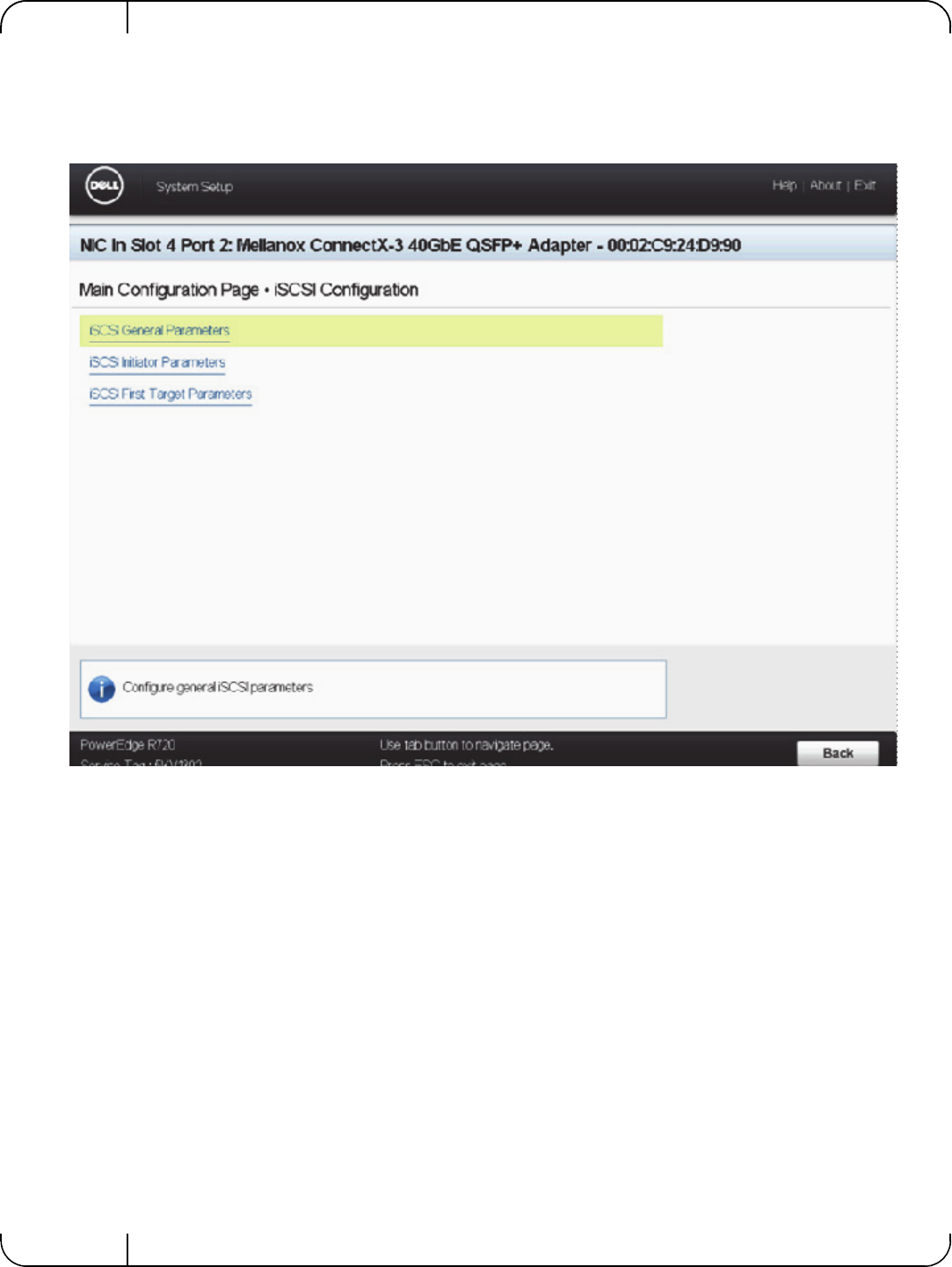
Rev 1.1
Mellanox Technologies
100
A.3 Main Configuration Page - iSCSI Configuration
This section allows to override the default configurations of iSCSI and replaces DHCP configu-
ration of iSCSI.
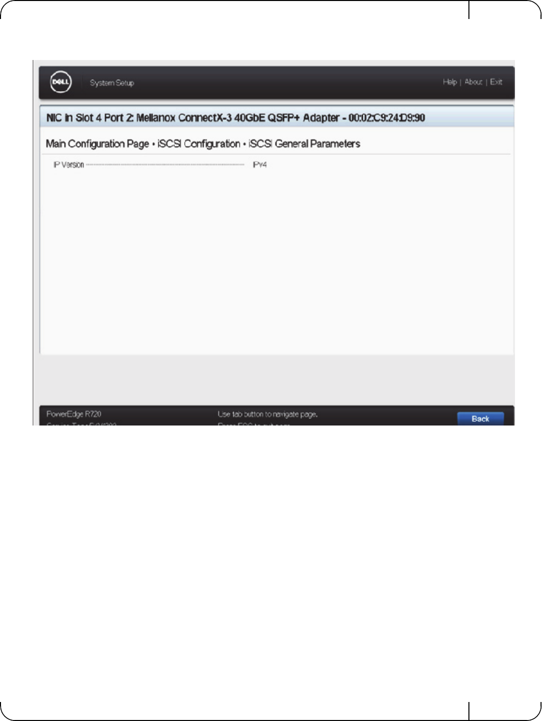
User Manual for Mellanox ConnectX®-3 10/40 Gigabit Ethernet Adapters for Dell PowerEdge Servers Rev 1.1
Mellanox Technologies 101
Figure 5: Main ConfiguratioP page - iSCSI Configuration - iSCSI General Parameters
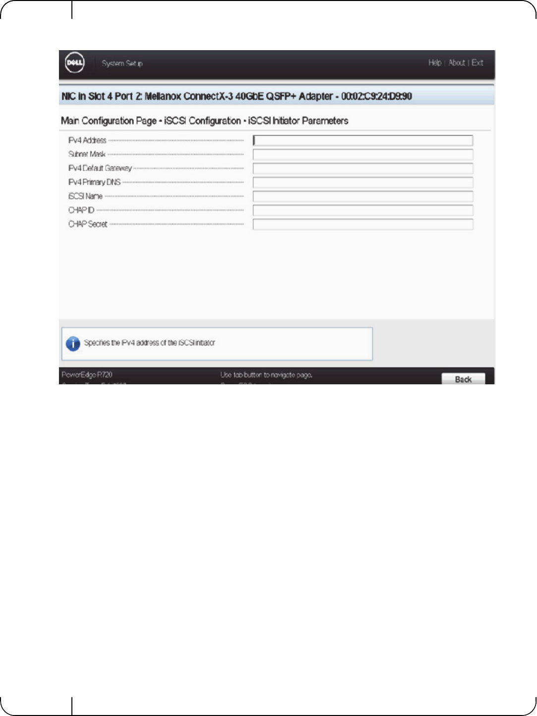
Rev 1.1
Mellanox Technologies
102
Figure 6: Main Configuration Page - iSCSI Configuration - iSCSI Initiator Parameters
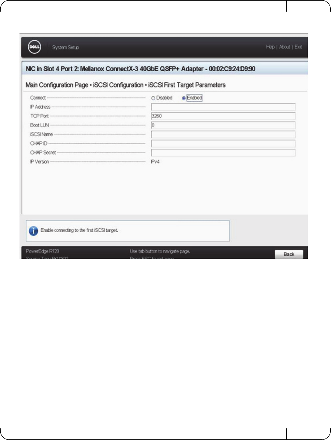
User Manual for Mellanox ConnectX®-3 10/40 Gigabit Ethernet Adapters for Dell PowerEdge Servers Rev 1.1
Mellanox Technologies 103
Figure 7: Main Configuration Page - iSCSI Configuration - iSCSI Target Parameters
A.4 Main Configuration Page - Device Level Configuration
Allows setting Global Flow control settings for the adapter's port.
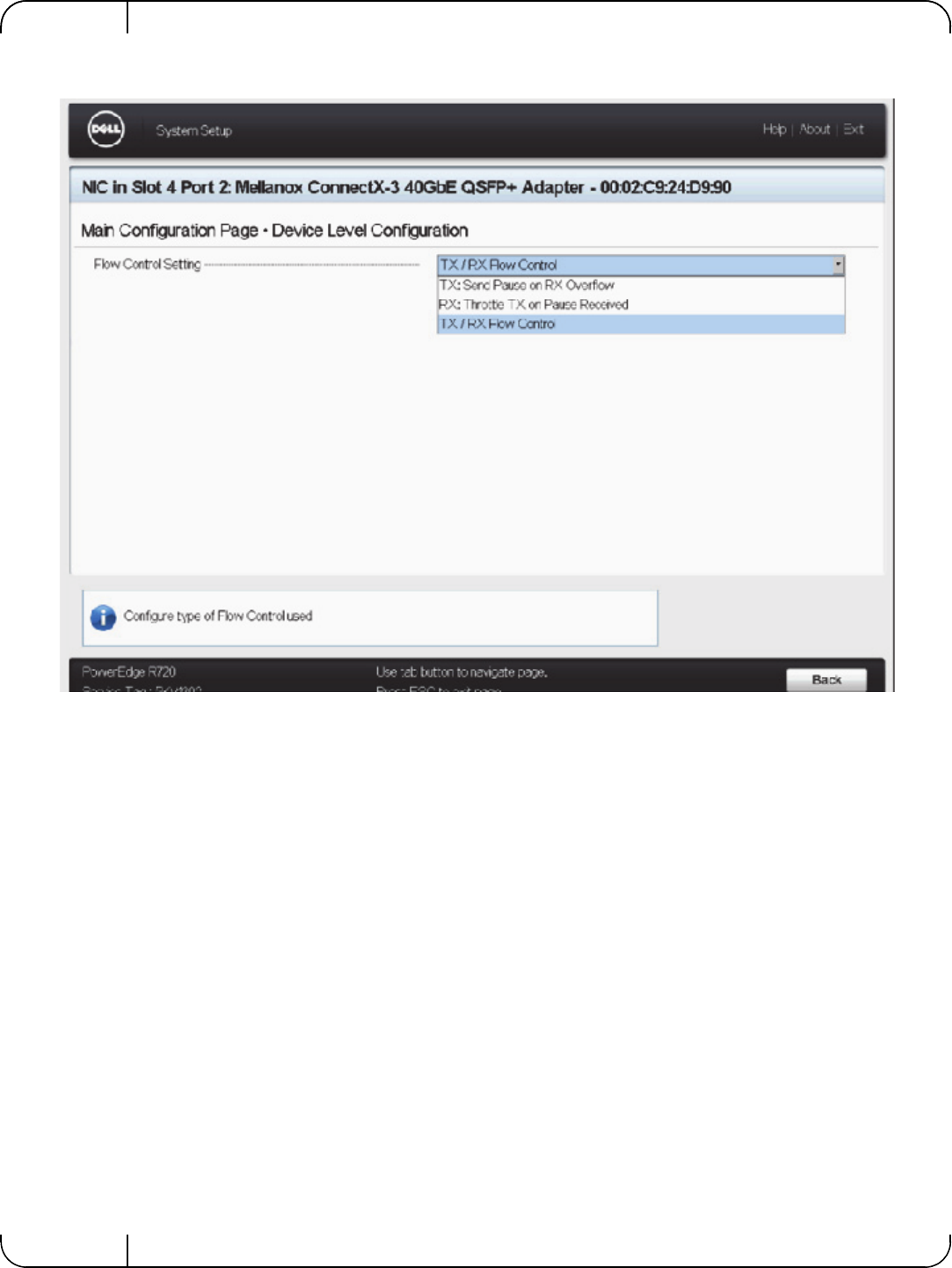
Rev 1.1
Mellanox Technologies
104
A.5 SR-IOV Configuration
Enabling SRIOV requires configuration both for the system and the specific Mellanox adapter.
To enable SR-IOV - follow the below steps 1-4.
To disable SR-IOV - set the configuration in steps 1-3 to disabled.
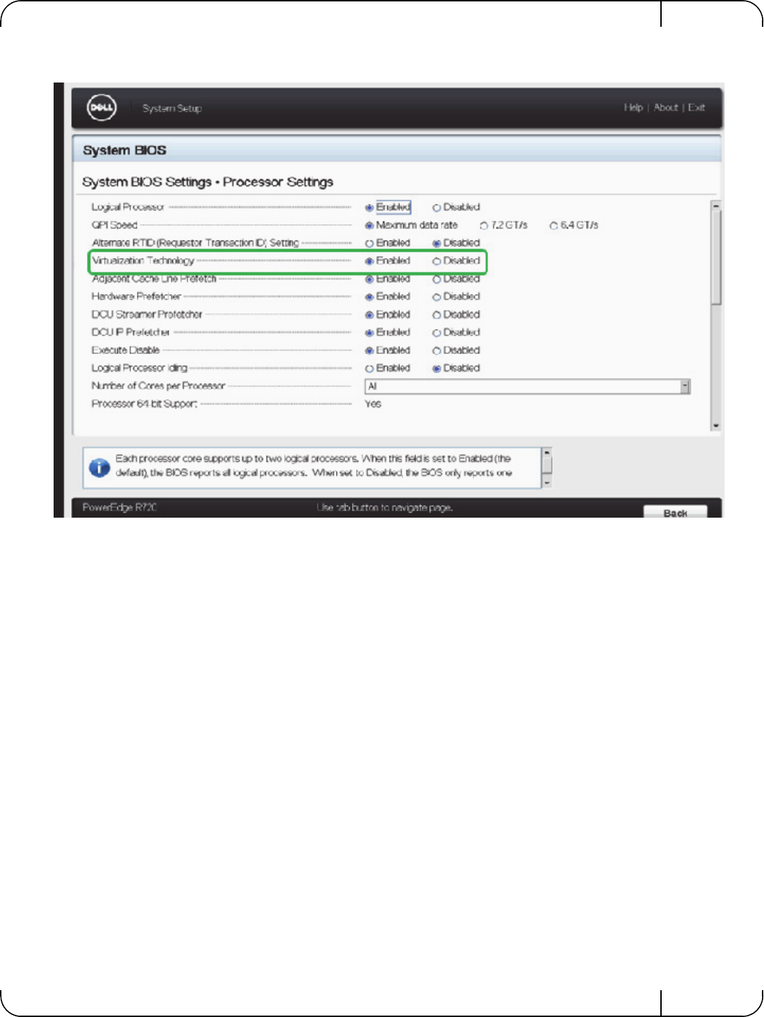
User Manual for Mellanox ConnectX®-3 10/40 Gigabit Ethernet Adapters for Dell PowerEdge Servers Rev 1.1
Mellanox Technologies 105
Step 1. Enable “Virtualization Technology” in System BIOS => Processor setting :
Step 2. Enable “SR-IOV Global Enable”
Go to: System BIOS => integrated Devices section
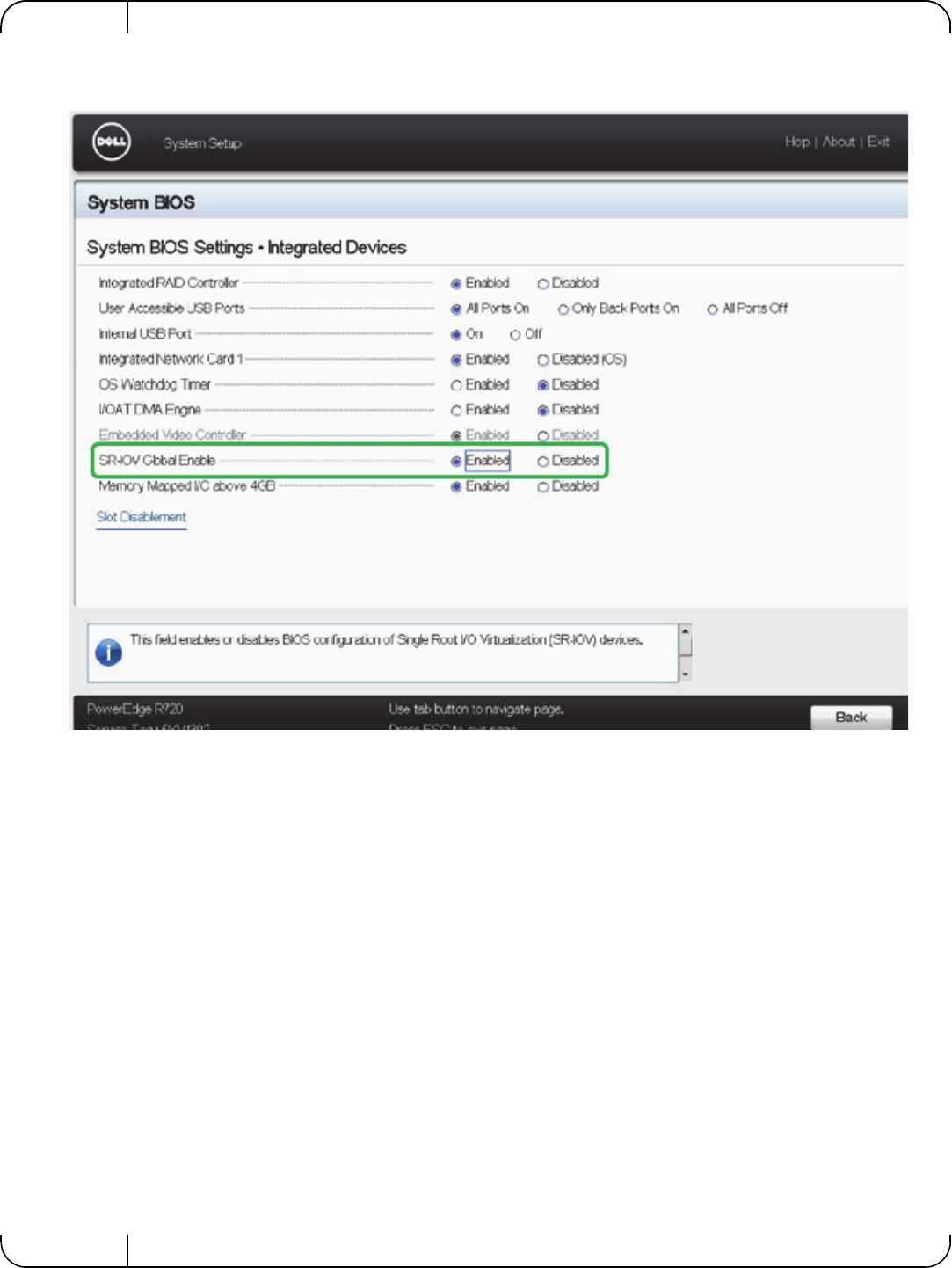
Rev 1.1
Mellanox Technologies
106
Step 3. Enable SR-IOV on the relevant adapter and set the number of required virtual functions:
Go to: Device settings => Select the relevant Mellanox adapter.
By default, Mellanox adapter is set to SRI-OV enabled with 8 virtual functions.
Note the maximum number of virtual functions supported by the adapter PCIe.
Refer to the relevant driver user manual for support for SR-IOV and number of supported func-
tions.
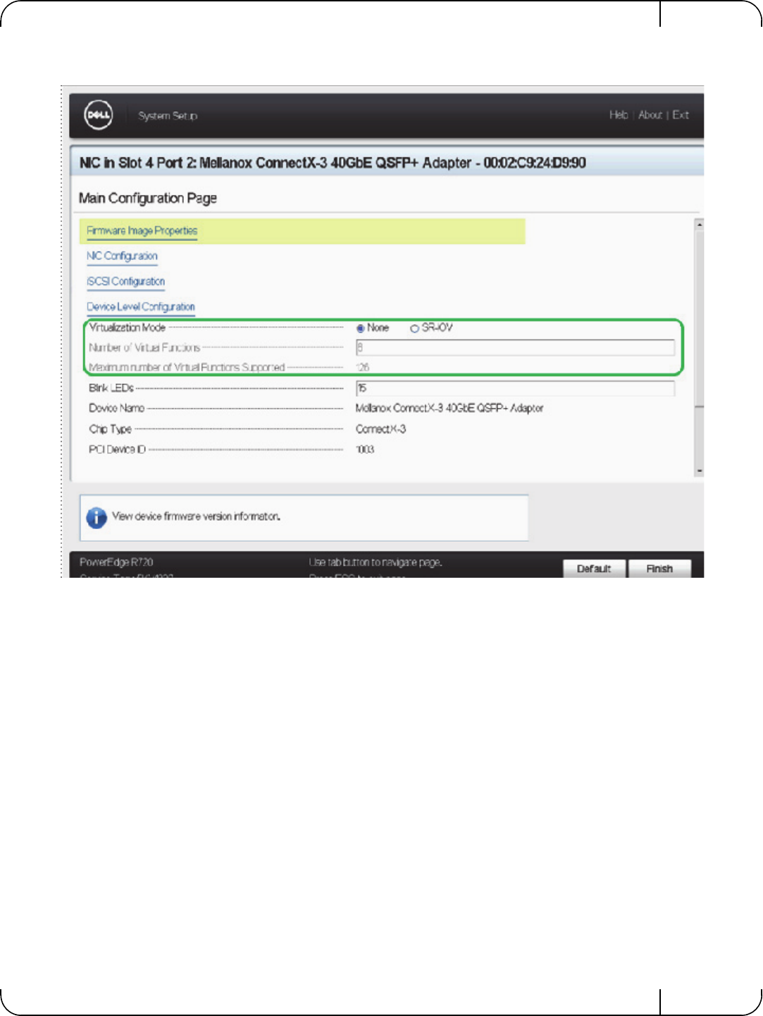
User Manual for Mellanox ConnectX®-3 10/40 Gigabit Ethernet Adapters for Dell PowerEdge Servers Rev 1.1
Mellanox Technologies 107
Step 4. Reboot the server for the SR-IOV configuration to take effect.
Rev 1.1
Mellanox Technologies
108
Appendix B: Safety Warnings
Below is a list of safety warnings in English. For safety warnings in other languages, please refer
to the appendices in this manual.
1. Installation Instructions
2. Over-temperature
3. During Lightning - Electrical Hazard
4. Copper Cable Connecting/Disconnecting
5. Equipment Installation
6. Equipment Disposal
7. Local and National Electrical Codes
8. Hazardous Radiation Exposure
Read all installation instructions before connecting the equipment to the power source.
This equipment should not be operated in an area with an ambient temperature exceed-
ing the maximum recommended according to the Dell server.
During periods of lightning activity, do not work on the equipment or connect or dis-
connect cables.
Some copper cables are heavy and not flexible, as such they should be carefully
attached to or detached from the connectors. Refer to the cable manufacturer for spe-
cial warnings and instructions.
This equipment should be installed, replaced, or serviced only by qualified personnel.
Disposal of this equipment should be in accordance to all national laws and regula-
tions.
This equipment should be installed in compliance with local and national electrical
codes.
Caution – Use of controls or adjustment or performance of procedures other than
those specified herein may result in hazardous radiation exposure.

User Manual for Mellanox ConnectX®-3 10/40 Gigabit Ethernet Adapters for Dell PowerEdge Servers Rev 1.1
Mellanox Technologies 109
CLASS 1 LASER PRODUCT and reference to the most recent laser standards:
IEC 60 825-1:1993 + A1:1997 + A2:2001 and EN 60825-1:1994+A1:1996+
A2:2001
Rev 1.1
Mellanox Technologies
110
Appendix C: Avertissements de sécurité d’installation
(Warnings in French)
1. Instructions d’installation
2. Température excessive
3. Orages – dangers électriques
4. Branchement/débranchement des câbles en cuivre
5. Installation du matériel
6. Elimination du matériel
7. Codes électriques locaux et nationaux
8. Exposition au rayonnement grave
Lisez toutes les instructions d’installation avant de brancher le matériel à la source
d’alimentation électrique.
Cet équipement ne doit pas être en service dans un local dont la température dépasse le
maximum recommandé pour le serveur Dell.
Pendant un orage, il ne faut pas utiliser le matériel et il ne faut pas brancher ou
débrancher les câbles.
Les câbles en cuivre sont lourds et ne sont pas flexibles, il faut donc faire très attention
en les branchant et en les débranchant des connecteurs. Consultez le fabricant des
câbles pour connaître les mises en garde et les instructions spéciales.
Ce matériel ne doit être installé, remplacé ou entretenu que par du personnel formé et
qualifié.
L’élimination de ce matériel doit s’effectuer dans le respect de toutes les législations et
réglementations nationales en vigueur.
Ce matériel doit être installé dans le respect des codes électriques locaux et nationaux.
Mise en garde – l'utilisation de commandes ou de réglages ou l'exécution de
procédures autres que ce qui est spécifié dans les présentes peut engendrer une
exposition au rayonnement grave.

User Manual for Mellanox ConnectX®-3 10/40 Gigabit Ethernet Adapters for Dell PowerEdge Servers Rev 1.1
Mellanox Technologies 111
PRODUIT LASER DE CLASSE 1 » et références aux normes laser les plus
récentes CEI 60 825-1:1993 + A1:1997 + A2:2001 et NE 60825-
1:1994+A1:1996+ A2:2001
Rev 1.1
Mellanox Technologies
112
Appendix D: Sicherheitshinweise (Warnings in German)
1. Installationsanleitungen
2. Übertemperatur
3. Bei Gewitter - Elektrische Gefahr
4. Anschließen/Trennen von -Kupferkabel
5. Geräteinstallation
6. Geräteentsorgung
7. Regionale und nationale elektrische Bestimmungent
Lesen Sie alle Installationsanleitungen, bevor Sie das Gerät an die Stromversorgung
anschließen.
Dieses Gerät sollte nicht in einer Umgebung mit einer Umgebungstemperatur von
mehr als der maximal für den Dell-Server empfohlenen betrieben werden.
Arbeiten Sie während eines Gewitters und Blitzschlag nicht am Gerät, schließen Sie
keine Kabel an oder ab.
Kupferkabel sind schwer und nicht flexible. Deshalb müssen sie vorsichtig an die
Anschlüsse angebracht bzw. davon getrennt werden. Lesen Sie die speziellen Warnun-
gen und Anleitungen des Kabelherstellers.
Diese Gerät sollte nur von geschultem und qualifiziertem Personal installiert, ausge-
tauscht oder gewartet werden.
Die Entsorgung dieses Geräts sollte unter Beachtung aller nationalen Gesetze Bestim-
mungen erfolgen.
Dieses Gerät sollte unter Beachtung der regionalen und nationalen elektrischen
Bestimmungen installiert werden.
This equipment should be installed in compliance with local and national elec-
trical codes.

User Manual for Mellanox ConnectX®-3 10/40 Gigabit Ethernet Adapters for Dell PowerEdge Servers Rev 1.1
Mellanox Technologies 113
8. Strahlenkontak
Achtung – Nutzung von Steuerungen oder Einstellungen oder Ausführung von
Prozeduren, die hier nicht spezifiziert sind, kann zu gefährlichem Strahlenkon-
takt führen..
Klasse 1 Laserprodukt und Referenzen zu den aktuellsten Lasterstandards :
ICE 60 825-1:1993 + A1:1997 + A2:2001 und EN 60825-1:1994+A1:1996+
A2:2001
Rev 1.1
Mellanox Technologies
114
Appendix E: Advertencias de seguridad para la insta-
lación (Warnings in Spanish)
1. Instrucciones de instalación
2. Sobrecalentamiento
3. Cuando hay rayos: peligro de descarga eléctrica
4. Conexión y desconexión del cable Copper
5. Instalación de equipos
6. Eliminación de equipos
7. Códigos eléctricos locales y nacionales
8. Exposición a niveles de radiación peligrosos
Antes de conectar el equipo a la fuente de alimentación, leer todas las instrucciones de
instalación.
Este equipo no se debe utilizar en una zona con una temperatura ambiente superior a la
máxima recomendada para el servidor Dell.
No utilizar el equipo ni conectar o desconectar cables durante períodos de actividad de
rayos.
Dado que los cables de cobre son pesados y no son flexibles, su conexión a los conec-
tores y su desconexión se deben efectuar con mucho cuidado. Para ver advertencias o
instrucciones especiales, consultar al fabricante del cable.
La instalación, el reemplazo y el mantenimiento de este equipo estarán a cargo única-
mente de personal capacitado y competente.
La eliminación definitiva de este equipo se debe efectuar conforme a todas las leyes y
reglamentaciones nacionales.
Este equipo se debe instalar conforme a los códigos eléctricos locales y nacionales.
Precaución: el uso de controles o ajustes o la realización de procedimientos distintos de
los que aquí se especifican podrían causar exposición a niveles de radiación peligrosos.

User Manual for Mellanox ConnectX®-3 10/40 Gigabit Ethernet Adapters for Dell PowerEdge Servers Rev 1.1
Mellanox Technologies 115
PRODUCTO LÁSER DE CLASE 1 y referencia a las normas de láser más recientes:
IEC 60825-1:2007/03 y EN 60825-1:2007
