Dell Network Hardware 124T Lto 3 Users Manual PowerVault Autoloader User's Guide
124T LTO-3 to the manual 125fce73-cd97-4f2d-82af-f34032b441c8
2015-02-09
: Dell Dell-Network-Hardware-124T-Lto-3-Users-Manual-544400 dell-network-hardware-124t-lto-3-users-manual-544400 dell pdf
Open the PDF directly: View PDF ![]() .
.
Page Count: 56

Dell™PowerVault™124TLTO-3 Autoloader User's Guide
Introduction
Installing the Autoloader
Operating the Autoloader
Remote Management Unit
Front Panel Administration
Diagnostics
Troubleshooting
Technical Specifications
Getting Help
Notes, Notices, and Cautions
Information in this document is subject to change without notice.
©2005-2007 Dell Inc. All rights reserved.
Reproduction in any manner whatsoever without the written permission of Dell Inc. is strictly forbidden.
Trademarks used in this text: Dell, the DELL logo, PowerVault, Dimension, Inspiron, OptiPlex, Latitude, Dell Precision, PowerApp, PowerEdge, PowerConnect, and
DellNet are trademarks of Dell Inc.; Microsoft, Windows, Windows NT, and Windows Server are registered trademarks of Microsoft Corporation. DLTtape is a
registered trademark of Quantum Corporation. Adobe is either a registered trademark or trademark of Adobe Systems Incorporated in the United States
and/or other countries. RedHat is a registered trademark of Red Hat, Inc. Mozilla and Firefox are trademarks of Mozilla.
Other trademarks and trade names may be used in this document to refer to either the entities claiming the marks and names or their products. Dell Inc.
disclaims any proprietary interest in trademarks and trade names other than its own.
NOTE: A NOTE indicates important information that helps you make better use of your system.
NOTICE: A NOTICE indicates either potential damage to hardware or loss of data and tells you how to avoid the problem.
CAUTION: A CAUTION indicates a potential for property damage, personal injury, or death.
Initial release: 15 Jun 2005
Revised: September 2007

Back to Contents Page
FrontPanelAdministration:Dell™PowerVault™124TLTO-3 Autoloader User's Guide
When you first power on the Dell PowerVault 124T LTO-3 autoloader, it automatically runs a Power-On Self-Test (POST). During the POST, the left (green) LED
flashes. After the POST, the left (green) and right (amber) LED flash alternately back and forth. Do one of the following:
lIf the autoloader powers on successfully, continue configuring the autoloader (see "Configuring the Autoloader").
lIf the autoloader does not power on successfully, check the following:
¡Power switch is on.
¡Power cable is inserted correctly.
¡SCSI bus is terminated.
¡SCSI cable is connected to the autoloader and host computer.
¡No error code appears on the autoloader LCD.
If you cannot resolve the problem yourself, contact your service representative or go to support.dell.com.
When you first power on the autoloader, the setting for the Internet Protocol (IP) address is static with the address 192.168.20.128. If you want to use
Dynamic Host Configuration Protocol (DHCP) to change the IP address, see "Setting the IP Address." To determine the IP address when using DHCP, view the
Ethernet status information (see "Viewing Ethernet Information").
Configuring the Autoloader
To configure the autoloader, start with the main menu on the front panel. If the main menu is not already visible on the LCD, press Enter.
When you first power on the autoloader, the default is set with no password protection. However, after you set the security option, all the configuration
functionality is password-protected. You need an administrator-level password to configure the autoloader.
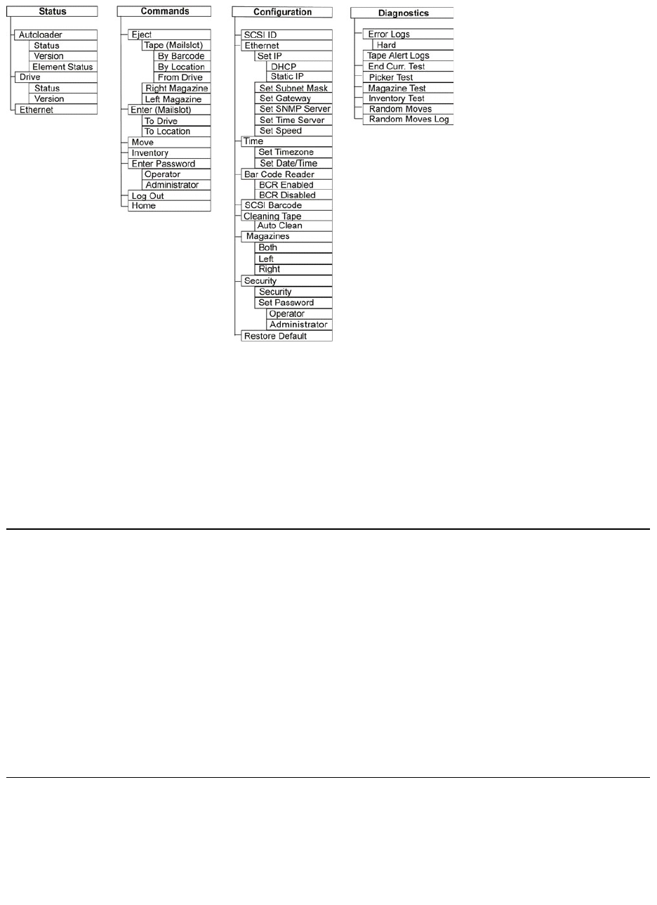
The front panel menu has the following options:
Configuring the Autoloader
SCSI Barcode Length
Setting the SCSI ID
Setting Security
Setting Ethernet
Setting Magazines
Setting the Time
Setting Passwords
Barcode Reader
NOTE: The front panel requires a six-digit password to change the configuration (see "Setting Passwords"). The LCD front panel default
password for the Administrator is 000000. The default password for the Operator is 111111.
To configure the Dell PowerVault 124T LTO-3 autoloader, you must verify the setup of the following:
lSCSI ID(s). For the autoloader, there is a single SCSI ID.
lMagazine(s).
lEthernet IP address (if you are not using DHCP).
lSNMP server IP address—only if SNMP is being used.
lTime server IP address (or the time zone, date, and time, if configuring manually)—only if a time server is being used.
lControl mode.
lSecurity option.
Setting the SCSI ID
Each SCSI device attached to a server or workstation must have a unique SCSI ID. For the PowerVault 124T autoloader, you need one SCSI ID.
To set the SCSI ID:
1. If the main menu is not already visible, press Enter.
2. On the main menu, scroll to Configuration and press Enter.
3. On the Configuration submenu, scroll to SCSI ID and press Enter.
4. Scroll to the number you want to set as the autoloader's SCSI ID, then press Enter. Cycle Power new SCSI ID appears on the LCD.
5. Press and hold the power button on the front panel until System Shutdown wait 60 sec appears on the LCD. Power Off appears on the LCD, then the
autoloader shuts off.
6. Press the power button again to power on the autoloader. The new SCSI ID is now in effect.
Setting Ethernet
Ethernet is the method used by the autoloader to access a network. With an Ethernet connection, you can remotely access the autoloader over the network.
To use the Ethernet connection, you must define the following:
lA dynamic or static IP address for the autoloader (required)
lA subnet mask (required for static IP)

lAn IP gateway (optional)
lA Simple Network Management Protocol (SNMP) server (optional)
lA time server, or set the time and time zone manually (optional)
Setting the IP Address
An IP address is the address of any device attached to a network. Each device must have a unique IP address. IP addresses are written as four sets of
numbers separated by periods ranging from 0.0.0.0 up to and including 255.255.255.255.
IP addresses are either permanent or dynamically assigned. A permanent, or static, address remains the same each time the device connects to the network.
A dynamic address may change each time the device connects to the network server using Dynamic Host Configuration Protocol (DHCP).
To set a dynamic IP address:
1. From the main menu, scroll to Configuration, and then press Enter.
2. From the Configuration menu, scroll to Ethernet, and then press Enter.
3. From the Ethernet submenu, scroll to Set IP, and then press Enter.
4. Scroll to DHCP, and then press Enter.
To set a static IP address:
1. From the main menu, scroll to Configuration, and then press Enter.
2. From the Configuration menu, scroll to Ethernet, and then press Enter.
3. From the Ethernet submenu, scroll to Set IP, and then press Enter.
4. Scroll to Static IP, and then press Enter. The cursor automatically appears at the first digit.
5. At each position of the IP address, use the up and down arrows to change the value of each digit. Press Enter to advance the cursor to the next digit.
When you have advanced through all of the digits of the IP address, the autoloader displays Enter to save.
6. Press Enter. The Configuration submenu appears and the static IP is now in effect. You do not need to reboot the autoloader.
7. Press Escape or Enter to return to the Ethernet submenu.
Setting the Subnet Mask
Creating a subnet mask is a method of splitting IP networks into a series of subgroups, or subnets, to improve performance or security.
To set a subnet mask:
1. From the main menu, scroll to Configuration, and then press Enter.
2. From the Configuration menu, scroll to Ethernet, and then press Enter.
3. From the Ethernet submenu, scroll to Set Subnet Mask, and then press Enter.
4. At each position of the Subnet Mask address, use the up and down arrows to change the value of each digit. Press Enter to advance the cursor to the
next digit.
When you have advanced through all of the digits of the subnet mask address, the autoloader displays Enter to save.
5. Press Enter. New Subnet Mask xxx.xxx.xxx.xxx appears on the LCD. You do not need to reboot the autoloader.
6. Press Escape or Enter to return to the Ethernet submenu.
Setting an IP Gateway
1. From the main menu, scroll to Configuration, and then press Enter.
2. From the Configuration menu, scroll to Ethernet, and then press Enter.
3. From the Ethernet submenu, scroll to Set Gateway, and then press Enter. The cursor automatically appears at the first digit.
4. At each position of the gateway address, use the up and down arrows to change the value of each digit. Press Enter to advance the cursor to the next
digit.
When you have advanced through all of the digits of the gateway address, the autoloader displays Enter to save.
NOTE: If you make a mistake, press Escape to backspace to the digit you want to change.
NOTE: If you make a mistake, press Escape to backspace to the digit you want to change.

5. Press Enter. New Gateway is xxx.xxx.xxx.xxx appears on the LCD. You do not need to reboot the autoloader.
6. Press Escape or Enter to return to the Ethernet submenu.
Setting the SNMP Server
An SNMP server monitors a network by processing reporting activity in each network device (hub, router, bridge, and so on). The server uses this information
to define what is obtainable from each device and what can be controlled (turned off, on, and so on).
To set an SNMP server:
1. From the main menu, scroll to Configuration, and then press Enter.
2. From the Configuration menu, scroll to Ethernet, and then press Enter.
3. From the Ethernet submenu, scroll to Set SNMP Server, and then press Enter. The cursor automatically appears at the first digit.
4. At each position of the SNMP server address, use the up and down arrows to change the value of each digit. Press Enter to advance the cursor to the
next digit.
When you have advanced through all of the digits of the SNMP server address, the autoloader displays Enter to save.
5. Press Enter. New SNMP Server xxx.xxx.xxx.xxx appears on the LCD. You do not need to reboot the autoloader.
6. Press Escape or Enter to return to the Ethernet submenu.
Setting the Time
The system time is displayed by the Remote Management Unit and it is used internally when logging events and errors. The system time is either regular time
or power-on time. Regular time is Month/Date/Year Time, such as Nov/21/2004 19:28. Power-on time is Power On Cycles (POC)/Power On Hours (POH). For
example, POC: 00121, POH: 00002:07:45 where POC is the number of times the system has booted since it was manufactured, and POH is the number of
hours, minutes, and seconds since the last system boot. If regular time is known, it will be used, otherwise power-on time is used.
The PowerVault 124T autoloader must be reset after each power up. The time can be reset automatically if a time server is configured (see "Setting the Time
Server").
Setting the Time Server
If you locate a time server that is compatible with Simple Network Time Protocol (SNTP), you can connect the autoloader to a server that will supply the correct
date and time. The autoloader uses this information to time stamp information in its memory.
To set a time server:
1. From the main menu, scroll to Configuration, and then press Enter.
2. From the Configuration menu, scroll to Ethernet, and then press Enter.
3. From the Ethernet submenu, scroll to Set Time Server, and then press Enter. The cursor automatically appears at the first digit.
4. At each position of the time server address, use the up and down arrows to change the value of each digit. Press Enter to advance the cursor to the
next digit.
When you have advanced through all of the digits of the time server address, the autoloader displays Enter to save.
5. Press Enter. New Time Server xxx.xxx.xxx.xxx appears on the LCD. You do not need to reboot the autoloader.
6. Press Escape or Enter to return to the Ethernet submenu.
To set the time zone:
1. From the main menu, scroll to Configuration, and then press Enter.
2. From the Configuration menu, scroll to Time, and then press Enter.
3. From the Time submenu, scroll to Set Timezone, and then press Enter. The Time Zone screen appears, allowing you to set the hours. The cursor
automatically appears at the first digit.
NOTE: If you make a mistake, press Escape to backspace to the digit you want to change.
NOTE: The PV124T SNMP agent supports only the MIB-II variable group. The MIB provides power-on notification commonly referred to as
the "cold start trap" which is sent to the SNMP host (if configured). Embedded webserver user interface is supported for configuring the
SNMP server. However, extended SNMP functions such as availability of tape information through SNMP, SNMP traps for tape events,
availability of global tape status information through SNMP, availability of information through SNMP to classify the loader as a tape
device, etc. are not supported.
NOTE: If you make a mistake, press Escape to backspace to the digit you want to change.
NOTE: If you make a mistake, press Escape to backspace to the digit you want to change.

4. Scroll to set the number of hours difference between your local time and Greenwich Mean Time (GMT).
5. Scroll to set the number of minutes difference between your local time and GMT, then press Enter. The new time zone is set.
6. Press Escape or Enter as necessary to return to the main menu.
To set the date and time:
1. From the main menu, scroll to Configuration, and then press Enter.
2. From the Configuration menu, scroll to Time, and then press Enter.
3. From the Time submenu, scroll to Set Date/Time, and then press Enter. The Date/Time screen appears, allowing you to set the date and time. The
cursor automatically appears at the first digit.
4. The first four digits represent the current year. At each position of the year, use the up and down arrows to change the value of each digit. Press Enter
to advance the cursor to the next digit.
5. The next two digits represent the current month. At each position of the month, use the up and down arrows to change the value of each digit. Press
Enter to advance the cursor to the next digit.
6. The next two digits represent the current day. At each position of the day, use the up and down arrows to change the value of each digit. Press Enter
to advance the cursor to the next digit.
7. The next two digits represent the current hour. At each position of the hour, use the up and down arrows to change the value of each digit. Press
Enter.
8. The last two digits represent the current minute. At each position of the minute, use the up and down arrows to change the value of each digit. Press
Enter to advance the cursor to the next digit.
9. Press Enter to save.
10. Press Escape as necessary to return to the main menu.
Barcode Reader
You can enable or disable the Barcode Reader from the Operator Control Panel (OCP). Disabling the barcode reader prevents the barcode reader from
attempting to read label information. If barcode labels are not being used, disabling the barcode reader will reduce initialization time.
Either a power cycle (through the front panel button) or an Autoloader Reset (through the Autoloader Reset command found on the Error Logs and Diagnostics
page of the Web interface) is required for the change to take effect.
To change the Barcode Reader setting:
1. From the main menu, scroll to Configuration, and then press Enter.
2. From the Configuration menu, scroll to Barcode Reader and press Enter.
3. A checkmark will be present before either Barcode Enabled or Barcode Disabledtoindicatethecurrentsetting.Scrolltothedesiredsettingandpress
Enter.
4. Press Esc as necessary to return to the main menu.
5. Power cycle the autoloader as requested.
SCSI Barcode Length
SCSI Barcode Length sets the maximum number of barcode characters that will be returned in the SCSI Read Element Data. The display of barcode information
on the Web interface and Operator Control Panel (OCP) are unaffected by this setting.
Setting the SCSI Barcode Length to 0 disables truncation of the barcode and the full barcode will be returned in the SCSI Read Element Data.
This setting is particularly useful if you have a pool of media previously catalogued by another device that has a limitation on the number of barcode characters
thatcanberead(typically6or9).AdjustingthePV124Tsettingtomatchtheprevioushardwarepreventstheuserfromhavingtore-catalog all barcode
labeled media previously used in the other device.
To change the SCSI Barcode setting:
1. From the main menu, scroll to Configuration, and then press Enter.
2. From the Configuration menu, scroll to SCSI Barcode and press Enter.
3. Scroll to the desired setting (from 0 to 15) and press Enter.
4. Press Escasnecessarytoreturntothemainmenu.Theautoloaderdoesnotneedtoberesetwhenmakingthischange.

Setting Magazines
In some cases, autoloader owners were being charged Independent Software Vendor (ISV) licensing fees for two-magazine autoloaders although only one
magazine was configured. This occurred because the ISV software was registering the autoloader as a two-magazine device, regardless of the number of
magazines configured. You have the ability to set the number of magazines in the autoloader. The default setting is Left.
To set the number of magazines:
1. From the main menu, scroll to Configuration, and then press Enter.
2. From the Configuration menu, scroll to Magazines, and then press Enter.
3. From the Magazines menu, select either Right, Left, or Both to indicate the magazines installed in the autoloader.
Setting Security
You can add security to the front panel by password-protecting the autoloader's functionality. The security setting only protects the front panel functionality.
The default setting is Off, meaning that no password is required. However, you can enable the security option so that users must enter a password to access
functionality.
Security Option
When you first power on the autoloader, the security option is set to Off. Use the following procedure to enable the security option. You must have an
administrator-level password to set passwords.
To set the security option:
1. From the main menu, scroll to Configuration, and then press Enter.
2. From the Configuration menu, scroll to Security. If a check mark appears before the word, the security option is On. If no check mark appears, the
security option is Off.
3. Press Enter. If you are not logged in as Administrator, press Enter again to log in.
4. To change the option, press Enter. For example, if the security option was set to On, it is now set to Off, and no check mark appears.
Setting Passwords
Many operations on the autoloader are password-protected to ensure data integrity. You can set passwords to administrator level and to operator level.
Operator-level users have access to the Commands and Status menus. Administrator-level users have access to all functionality.
To set a password:
1. From the main menu, scroll to Configuration, and then press Enter.
2. From the Configuration menu, scroll to Set Password, and then press Enter.
3. To set a password to the operator level, scroll to Operator. To set a password to the administrator level, scroll to Administrator.
4. Press Enter. If you are not logged in as Administrator, press Enter again to log in.
5. In the text box, scroll to the first character of the password. The cursor automatically appears at the first number of the password.
6. At each position of the password, use the up and down arrows to change the value of each number. Press Enter to advance the cursor to the next
number.
7. When you have entered six numbers, the autoloader displays Submit Password.
8. Press Enter to submit the password. Password Successfully changed appears on the LCD.
9. Press Enter. The Operator and Administrator options reappear. You can either enter another password, or press Escape or Enter as necessary to return
to the main menu.
Getting Lost Passwords
If you forget the administrator-level password, you cannot access the autoloader's functionality to enter a new password. In this case, you must call
support.dell.com. When you call, have the autoloader connected to the Ethernet and open the Remote Management Unit.
NOTE: The default setting must be reconfigured if the optional right magazine is installed. Host backup software may also require a
configuration change to support the additional media locations.
NOTE: If you make a mistake, press Escape to backspace to the digit you want to change.
NOTE: You can reset front panel passwords to the factory defaults from the Remote Management Unit. However, if the Remote
Management Unit passwords are lost, you must contact support.dell.com. If you must contact support.dell.com, be at the host computer
with the Remote Management Unit on line. From the main screen, click Configuration. The Enter Network Password or User name
screen displays. The customer support representatives will need the number surrounded by asterisks to locate and reset your password.
This is your "realm number."


Back to Contents Page
Diagnostics:Dell™PowerVault™124TLTO-3 Autoloader User's Guide
Diagnostic Tests from the Front Panel
Remote Management Unit Diagnostic Tests
Diagnostic Tests from the Front Panel
Diagnostic tests allow you to calibrate parts of the autoloader, check the condition of parts, or test the autoloader's functionality. From the front panel, you
can perform all of the diagnostic tests. Because certain tests require you to manually insert a minimum of two cartridges, you can perform only some of the
diagnostic tests using the Remote Management Unit (see "Remote Management Unit Diagnostic Tests").
Setting the Security
When you enable the security function, the diagnostic tests are password protected to ensure data integrity. To access any of the diagnostic tests, you must
first enter an Administrator password. If you do not enter the password, you will be prompted to enter the password when you attempt to perform a
diagnostic test.
You can also enter passwords from the Commands menu as follows::
1. From any menu, click the Commands heading. The Commands screen displays.
2. On the Commands submenu, scroll to Enter Password, and then press Enter.
3. On the Enter Password submenu, scroll to Administrator, and then press Enter.
4. In the text box, scroll to the first number of the password, and then press Enter.
5. Repeat step 4 to enter the remaining numbers of your password.
When you have finished entering your password, Submit Password appears on the LCD below the asterisks.
6. Press Enter to submit your password. The display returns to the Enter Password submenu.
Stopping a Diagnostic Test
At times, you may need to stop a diagnostic test while it is in progress. To stop a diagnostic test while it is running, use the End Curr. Test function.
When you
select End Curr. Test, any picker or magazine functions complete, and then the diagnostic test stops.
To end a test from the front panel:
1. While the diagnostic test you wish to stop is running, press Escape. The Diagnostics submenu displays.
2. On the submenu, scroll to End Curr. Test, and then press Enter. User Abort displays.
3. Press Enter to return to the Diagnostics submenu. Refer to the Remote Management Unit for any test results.
To stop a test from the Remote Management Unit:
1. Select the Stop Test button in the Diagnostics test section of the Error Logs and Diagnostics page.
2. Select View Status to see the results of the command. Test Stopped displays along with any test results.
Front Panel Diagnostic Tests
You can perform the following diagnostic tests using the front panel:
lPicker Test
lMagazine Test
lInventory Test
lRandom Moves
To perform any of the front panel diagnostic tests:
1. From any menu, click the Diagnostics heading. The Diagnostics screen displays.
NOTE: The Remote Management Unit allows you to request all diagnostic tests, but any tests that require a cartridge to be inserted will
time-out unless someone manually inserts the cartridge at the appropriate time.
NOTE: Press Escape to backspace to a previous text box, if necessary.

2. Scroll to the test you want to run and press Enter.
If you are already logged in as Administrator, the test begins executing immediately. The message Running Test appears while the test is running.
3. If you are not logged in, you will be asked to enter the Administrator password. Do the following:
¡From the front panel, enter the administrator password by using the Up and Down scroll arrows to select each digit, and then press Enter to
move to the next digit. To move to the previous digit, press Escape. When you have entered the entire six digit password, you will be asked to
press Enter one more time to submit the password. If the password is incorrect, you will be asked to re-enter it using the same procedure.
Otherwise, you will be returned to the Diagnostics menu. Press Enter to run the desired test.
Running Test appears while the test is in progress. To stop the test prematurely, see "Stopping a Diagnostic Test."
4. If the test is successful, press Enter to return to the Diagnostic test menu. For detailed results of a test, use the Remote Management Unit to retrieve
the diagnostic test status (see "Running Diagnostic Tests").
Remote Management Unit Diagnostic Tests
Because some of the diagnostic tests require you to insert a cartridge into the autoloader, you cannot perform these tests from a remote location. You can
perform the following diagnostic tests from the Remote Management Unit:
lLoader - Picker Test
lLoader - Magazine Test
lLoader - Inventory Test
lRandom Moves
Diagnostics Using the Remote Management Unit
Many tests can be run using the Remote Management Unit. To perform the Remote Management Unit diagnostic tests:
1. Open a Web browser and connect to the autoloader. The Remote Management Unit main menu appears.
2. Click the Error Logs and Diagnostics heading. A login window appears.
3. Type an Administrator user name and a password, and then click Enter. The Diagnostics submenu appears.
4. Select the test you wish to perform from the Diagnostics drop-down menu, and then click submit.
The selected diagnostic test runs. While the test is running, you can view the status of the test. To view the status, from the View Diagnostic Test
Progress section, click View Status.
Back to Contents Page
NOTE: Each test takes from 30 seconds to several minutes to complete. To stop the test prematurely, see "Stopping a Diagnostic Test."
NOTE: The Remote Management Unit allows you to request all diagnostic tests, but any tests that require a cartridge to be inserted will
time-out unless someone manually inserts the cartridge at the appropriate time.

Back to Contents Page
GettingHelp:Dell™PowerVault™124TLTO-3 Autoloader User's Guide
Technical Assistance
Dell Enterprise Training and Certification
Problems With Your Order
Product Information
Returning Items for Warranty Repair or Credit
Before You Call
Technical Assistance
If you need assistance with a technical problem, perform the following steps:
1. Complete the procedures in "Before Contacting Customer Support".
2. Run the system diagnostics and record any information provided.
3. Use Dell's extensive suite of online services available at Dell Support at support.dell.com for help with installation and troubleshooting procedures.
For more information, see "Online Services."
4. If the preceding steps have not resolved the problem, call Dell for technical assistance.
When prompted by Dell's automated telephone system, enter your Express Service Code to route the call directly to the proper support personnel. If
you do not have an Express Service Code, open the Dell Accessories folder, double-click the "Express Service Code" icon, and follow the directions.
For instructions on using the technical support service, see "Technical Support Service" and "Before You Call."
Online Services
You can access Dell Support at support.dell.com. Select your region on the WELCOME TO DELL SUPPORT page, and fill in the requested details to access
help tools and information.
You can contact Dell electronically using the following addresses:
lWorld Wide Web
www.dell.com/
www.dell.com/ap (Asian/Pacific countries only)
NOTE: Call technical support from a phone near or at the system so that technical support can assist you with any necessary procedures.
NOTE: Dell's Express Service Code system may not be available in all countries.
NOTE: Some of the following services are not always available in all locations outside the continental U.S. Call your local Dell
representative for information on availability.

www.dell.com/jp (Japan only)
www.euro.dell.com (Europe only)
www.dell.com/la (Latin American countries)
www.dell.ca (Canada only)
lAnonymous file transfer protocol (FTP)
ftp.dell.com/
Log in as user:anonymous, and use your e-mail address as your password.
lElectronic Support Service
support@us.dell.com
apsupport@dell.com (Asian/Pacific countries only)
support.jp.dell.com (Japan only)
support.euro.dell.com (Europe only)
lElectronic Quote Service
sales@dell.com
apmarketing@dell.com (Asian/Pacific countries only)
sales_canada@dell.com (Canada only)
lElectronic Information Service
info@dell.com
AutoTech Service
Dell's automated technical support service — AutoTech — provides recorded answers to the questions most frequently asked by Dell customers about their
portable and desktop computer systems.
When you call AutoTech, use your touch-tone telephone to select the subjects that correspond to your questions.
The AutoTech service is available 24 hours a day, 7 days a week. You can also access this service through the technical support service. See the contact
information for your region.

Automated Order-Status Service
TocheckonthestatusofanyDell™productsthatyouhaveordered,youcangotosupport.dell.com, or you can call the automated order-status service. A
recording prompts you for the information needed to locate and report on your order. See the contact information for your region.
Technical Support Service
Dell'stechnicalsupportserviceisavailable24hoursaday,7daysaweek,toansweryourquestionsaboutDellhardware.Ourtechnicalsupportstaffuse
computer-based diagnostics to provide fast, accurate answers.
To contact Dell's technical support service, see "Before You Call" and then see the contact information for your region.
Dell Enterprise Training and Certification
Dell Enterprise Training and Certification is available; see www.dell.com/training for more information. This service may not be offered in all locations.
Problems With Your Order
If you have a problem with your order, such as missing parts, wrong parts, or incorrect billing, contact Dell for customer assistance. Have your invoice or
packing slip available when you call. See the contact information for your region.
Product Information
If you need information about additional products available from Dell, or if you would like to place an order, visit the Dell website at www.dell.com. For the
telephone number to call to speak to a sales specialist, see the contact information for your region.
Returning Items for Warranty Repair or Credit
Prepare all items being returned, whether for repair or credit, as follows:
1. Call Dell to obtain a Return Material Authorization Number, and write it clearly and prominently on the outside of the box.
For the telephone number to call, see the contact information for your region.
2. Include a copy of the invoice and a letter describing the reason for the return.
3. Include a copy of any diagnostic information indicating the tests you have run and any error messages reported by the system diagnostics.
4. Include any accessories that belong with the item(s) being returned (such as power cables, media such as CDs and diskettes, and guides) if the return
is for credit.
5. Pack the equipment to be returned in the original (or equivalent) packing materials.
You are responsible for paying shipping expenses. You are also responsible for insuring any product returned, and you assume the risk of loss during
shipment to Dell. Collect-on-delivery (C.O.D.) packages are not accepted.
Returns that are missing any of the preceding requirements will be refused at our receiving dock and returned to you.

Before You Call
If possible, turn on your system before you call Dell for technical assistance and call from a telephone at or near the computer. You may be asked to type some
commands at the keyboard, relay detailed information during operations, or try other troubleshooting steps possible only at the computer system itself.
Ensure that the system documentation is available.
Back to Contents Page
NOTE: Have your Express Service Code ready when you call. The code helps Dell's automated-support telephone system direct your call
more efficiently.
CAUTION: Before servicing any components inside your computer, see your Product Information Guide for important safety information.

Back to Contents Page
InstallingtheAutoloader:Dell™PowerVault™124TLTO-3 Autoloader User's Guide
Installation Overview
Installing the autoloader consists of the following steps, which are explained in more detail later in this section:
1. Prepare to install your new Dell PowerVault 124T LTO-3 autoloader (see "Installation Preparation").
2. Identify the proper SCSI bus types (see "SCSI Bus Requirements").
3. Identify the accessories that come with the autoloader (see "Accessories").
4. Install the autoloader in a computer rack near the host server. If installing a rack mount unit, refer to your rack Installation Guide.
5. Shut down or turn off the server and all devices attached to the server (see "Connecting the SCSI and Power Cables").
6. Attach the SCSI cable to the autoloader and server's SCSI host adapter (see "Connecting the SCSI and Power Cables").
7. Attach the power cable to the autoloader and plug in the power cable to the nearest power outlet (see "Connecting the SCSI and Power Cables").
Power the autoloader on to ensure it passes the Power-on Self-Test (POST).
8. Set the SCSI ID for the autoloader (see "Setting the SCSI ID").
9. Set up the host and verify the connection (see "Preparing the Host and Verifying the Connection").
Installation Preparation
Before you install your new Dell PowerVault 124T LTO-
3 autoloader, unpack it carefully and inspect it for any damage that might have occurred during shipping.
Installation Overview
Unpacking the Autoloader
Installation Preparation
Identifying Product Components
SCSI Bus Requirements
Connecting the SCSI and Power Cables
Accessories
Preparing the Host and Verifying the Connection
Choosing a Location
Installing the Device Drivers
UL Requirements
Enabling LUN Support in Linux
Bar Code Reader
Enabling LUN Support in Netware
Product Overview
The Getting Started Guide included in the packaging describes all the necessary information to unpack and inspect your autoloader correctly. Locate the Getting
Started Guide and follow the directions.
Ensure that the work area is free from conditions that could cause electrostatic discharge (ESD). Discharge static electricity from your body by touching a
known grounded surface, such as your computer's metal chassis.
SCSI Bus Requirements
You must connect the Dell PowerVault 124T LTO-3 autoloader to one of the following SCSI bus types:
lUltra 160 SCSI, Low-voltage Differential (LVD)
lUltra 320 SCSI, Low-voltage Differential (LVD)
lSingle-ended (SE) SCSI bus
Your SCSI host adapter card must also support the SCSI bus type used to connect the autoloader. If you use a LVD SCSI bus, use a host adapter card with a
connection for a high-density (HD) 68-pin cable.
Accessories
The following accessories are shipped with the Dell PowerVault 124T LTO-3 autoloader:
lGetting Started Guide
lSCSI host cable
lSCSI terminator
lHardware to rack mount the autoloader (autoloader rails are included, rack rails are optional)
lOne magazine blank
lPower cable
lDocumentation CD containing all of the documentation in Adobe®Portable Document Format (PDF) and supplied device drivers
NOTE: The Dell PowerVault 124T LTO-3 autoloader is not compatible with a High-voltage Differential (HVD) SCSI bus.
NOTE: If you use an SE SCSI bus, the tape drive's performance is limited to the maximum data transfer speed of the bus.
NOTE: The maximum number of autoloaders supported per SCSI bus is two.
NOTE: The autoloader may not work with multiple SCSI LUNS when attached to a redundant array of independent disks (RAID) controller.
The autoloader is not recommended for use with a RAID controller. If this problem occurs, it is recommended that the autoloader be
attached to a separate SCSI bus controller on the server.

lBar code labels
lTORX L-key drivers (T8 and T10)
lEmergency Magazine Removal Tool
Choosing a Location
Choose a location that meets the following criteria (see "Technical Specifications"):
UL Requirements
Bar Code Reader
Your autoloader is equipped with a bar code reader. The bar code reader is enclosed within the body of the autoloader and automatically scans each cartridge
in the magazine upon power up, after a reset, after an import or export, or when a re-inventory command is issued (see "Running an Inventory"). The
information from each label is stored in memory and available through SCSI and the Remote Management Unit to the computer's operating system or backup
application upon request. The bar code reader can be disabled through the operator control panel or the web user interface. This feature allows faster
initialization of the unit if non-bar code labels or no labels are used on the cartridges.
If utilizing the bar code reader, you must apply the bar code labels into the slot on the front of each cartridge. The labels must conform to ANSI/AIM BC1 -1995
Uniform Symbology Specification Code 39. A set of bar code labels is initially included with the autoloader. Refer to www.dell.com for information on obtaining
additional bar code labels.
Product Overview
Front Panel Controls
NOTICE: Do not place the autoloader on its side or upside down. Do not stack anything on top of the autoloader.
Rack
Requirements
Standard 19-inch rack with 2U (3.5 in.) of clearance.
Room
Temperature
10-35°C(50-95°F)
Power Source
AC power voltage: 100-127 VAC; 200-240 VAC
Line frequency: 50-60 Hz
NOTE: Locate the AC outlet near the autoloader. The AC power cable is the product's main AC disconnect device and must be easily
accessible at all times.
Weight
14.1 kg (31 lb) unloaded
17.2 kg (38 lb) loaded (2 magazines, 16 cartridges)
Air Quality
Minimize sources of particulate contamination. Avoid areas near frequently used doors and walkways, cooling or exhaust vents, stacks of
supplies that collect dust, printers, and smoke-filled rooms. Avoid placing on or near the floor, or in carpeted rooms.
NOTICE: Excessive dust and debris can damage tapes and tape drives.
Humidity
20-80% RH (noncondensing)
Clearance
Back: Minimum of 43.2 cm (17 in)
Front: Minimum of 68.6 cm (27 in)
Sides: Minimum of 5.08 cm (2 in)
Elevated Operating
Ambient Temperature
When installed in a closed or multi-unit rack assembly, the operating ambient temperature of the rack environment may be
greater than the room ambient. You must install the equipment in an environment compatible with the manufacturer's
maximum recommended ambient temperature.
Reduced Air Flow
Installation of the equipment in a rack should be such that the amount of air flow required for safe operation of the
equipment is not compromised.
Mechanical Loading
Mounting of the equipment in a rack should be such that a hazardous condition is not achieved due to uneven mechanical
loading.
Overloading the Circuit
Consideration should be given to the connection of the equipment to the supply circuit and the effect that overloading of
circuits might have on overcurrent protection and supply wiring. Appropriate consideration of equipment nameplate ratings
should be used when addressing the concern.
Reliable Grounding
Reliable grounding of rack-mounted equipment should be maintained. Particular attention should be given to supply
connections other than direct connections to the branch circuit, such as use of power strips.
Back Panel Overview
Unpacking the Autoloader
Before you begin, clear a desk or table so that you can unpack the autoloader. You also need to select an open 2U computer rack location near the server that
will host the autoloader.
Unpack and inspect the autoloader for shipping damage by doing the following:
1. Clear a table or desk so that you have room to unpack the autoloader.
2. Inspect the shipping box for damage. If you notice any damage, report it to the shipping company immediately.
3. Open the shipping box and remove the accessories package. Set the accessories package aside for now.
4. Lift the autoloader and padding out of the box and place it on the work surface, top facing up. Do not set the autoloader on either end or sides.
5. Carefully remove the shipping padding from the front and back of the autoloader. Then remove the bag from the autoloader. Save the packing materials
in case you need to move or ship the autoloader in the future. Illustrations on the box flaps indicate proper placement of the packaging materials.
Identifying Product Components
Accessories
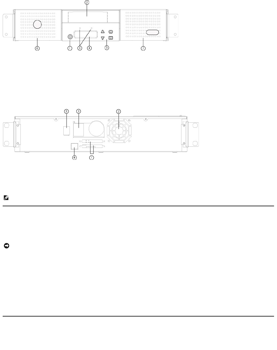
1
Power switch
2
Media door (mailslot)
3
Front panel LEDs
4
Front panel LCD screen
5
Function keys
6
Left magazine
7
Right magazine (or blank)
1
68-pin HD SCSI connectors
2
Fan vent
3
Power connector
4
Ethernet connector
5
Power switch
NOTE: If the cover must be taken off, there are 26 screws and 6 rail bolts that need to be removed. The cover should be removed only
by a qualified Dell Service Provider.
NOTICE:Iftheroominwhichyouareworkingdiffersfromthetemperatureinwhichtheautoloaderwasshippedorstoredby15°C(30°
F) or more, let the autoloader acclimate to the surrounding environment for at least 12 hours before opening the shipping carton.
Connecting the SCSI and Power Cables
To connect the SCSI and power cables to the autoloader, follow these steps:
1. Shut down and turn off the selected server. Turn off all attached accessory devices, such as printers and other SCSI devices.
2. Attach one end of the SCSI cable (included in the accessory kit) to one of the connectors on the back panel of the autoloader.
3. Attach the other end of the SCSI cable to the connector on the SCSI host adapter or to the connector on the previous device on the SCSI bus.
If the supplied SCSI cable does not fit the connector on your SCSI host adapter, you either have an incompatible SCSI host adapter or you need to
purchase a cable adapter. Contact your service representative or your SCSI host adapter manufacturer for information.
4. Attach the terminator to the remaining SCSI connector on the back panel of the autoloader (if the autoloader is the last or only device on the SCSI bus).
Otherwise, attach the cable to the next device on the SCSI bus. Make sure that the last device on the SCSI bus is properly terminated.
5. Attach the female connector of the power cable to the power connector on the back panel of the autoloader.
6. Plug in the power cable to the nearest properly grounded power outlet.
7. Plug in the host server or workstation and all attached devices.
8. Turn on the autoloader by setting the power switch on the back panel to the ON position. Turn on any other devices you turned off earlier. Check the
LCD screen to make sure the autoloader is receiving power. If it is not, check the power connections and your power source.
During the Power-On Self-Test (POST), both LEDs are illuminated briefly, followed by only the Ready/Activity LED flashing. When the initialization
sequence is complete, the LCD screen displays the Home screen.
9. Turn on the server.
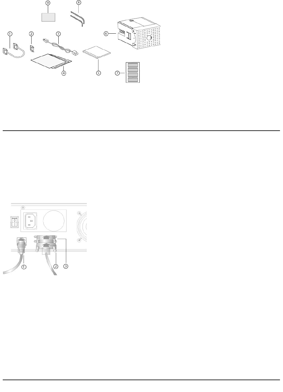
1
SCSI cable
2
SCSI terminator
3
Power cable
4
Getting Started Guide
5
CD (drivers and documentation)
6
Magazine blank
7
Bar code labels
8
TORX L-key drivers (T8 and T10)
9
Emergency Magazine Removal Tool
1
Ethernet cable
2
SCSI cable
3
SCSI terminator

Preparing the Host and Verifying the Connection
If necessary, install a SCSI host adapter, software, and compatible drivers. Refer to the manuals for the host computer and SCSI host adapter for detailed
instructions. In addition, follow these general guidelines:
lWhen the host server is powered on, install software, and/or drivers that are compatible with the autoloader (see "Installing the Device Drivers").
Software compatibility information is available at support.dell.com. Most backup software packages require an additional module to communicate with
the autoloader robotics.
lIf the host server is connected to a network, check with the system administrator before turning off power.
lUse proper procedures to prevent electrostatic discharge (ESD). Use wrist-grounding straps and anti-static mats when handling internal components.
lMake sure that the host server has an open expansion slot.
lMake sure that your backup application supports the SCSI host adapter.
lDepending on the server configuration, you may need to change the SCSI ID of the autoloader (see "Setting the SCSI ID").
lEnsure the autoloader is properly terminated. If the autoloader is the only SCSI device—other than the SCSI host adapter—on the selected SCSI bus, it
must be terminated. Likewise, if the autoloader is physically the last SCSI device on the SCSI bus, it must be terminated. Only the devices physically at
the beginning and end of the SCSI bus should be terminated. If the host is located at the beginning of the SCSI bus, the host should already have a
terminator installed.
lVerify the connection between the autoloader and host by going to Settings>Control Panel>System>Hardware>Device Manager>Tape Drive
and/or
Media Changer in Microsoft®Windows®2000, Microsoft Windows XP and Windows Server®2003. For more information on verifying the connection of
SCSI devices, consult the operating system documentation.
Installing the Device Drivers
There are two device drivers associated with the Dell PowerVault 124T LTO-3 autoloader. One for the autoloader itself, and a second for the LTO-3 tape drive
within the autoloader.
Tape Drive Device Driver
Microsoft Windows 2000:
1. Make sure that you are logged on to the host server with administrator privileges.
2. Insert the Dell PowerVault 124T Autoloader User's Manual and Drivers CD into the CD drive on the host computer.
3. Open the device manager (refer to your specific OS documentation for instructions). For example, right-click the My Computer icon on the Windows
desktop, click Manage, and then click Device Manager.
The LTO-3 drive should be listed under the ? Other Devices item as IBM ULTRIUM-TD3 SCSI Sequential Device.
4. Right-click the IBM ULTRIUM 3 SCSI Sequential Device listing and click Properties.
5. Select the Driver tab.
6. Click Update Driver.
7. When the Upgrade Device Driver Wizard appears, click Next.
8. Click Display a list... and then click Next.
9. Scroll down and click Tape Drive, and then click Next.
10. Click Have Disk, type D:\Drivers\Drive\, replacing d: with the drive letter for the CD drive into which you inserted the Dell PowerVault 124T Autoloader
User's Manual and Drivers CD, and then click OK.
11. Click the IBM ULTRIUM III TAPE DRIVE entry, and then click Next.
12. Click Next to install the driver.
13. Click Finish.
14. Click the Device Properties dialog box.
The drive now appears in Device Manager under Tape Drives as a IBM ULTRIUM III TAPE DRIVE and is ready to use.
Microsoft Windows Server 2003:
1. Make sure that you are logged on to the host server with administrator privileges.
2. Insert the Dell PowerVault 124T Autoloader User's Manual and Drivers CD into the CD drive on the host computer.
3. Open the device manager (refer to your specific OS documentation for instructions). For example, right-click the My Computer icon on the Windows
desktop, click Properties, and then click Device Manager or by going to the Control Panel and opening System. Select Hardware, then click Device
NOTE: The device drivers supplied on the Dell PowerVault 124T LTO-3 Autoloader User's Manual and Drivers CD are required if you intend to
use the Microsoft Windows native backup application. Commercial backup applications provide all necessary device driver support. Refer
to support.dell.com for a list of compatible backup applications.

Manager.
The LTO-3 drive should be listed under the ? Other Devices item as IBM ULTRIUM-TD3 SCSI Sequential Device.
4. Right-click the IBM ULTRIUM-TD3 SCSI Sequential Device listing and click Properties.
5. Select the Driver tab.
6. Click Update Driver.
7. When the Upgrade Device Driver Wizard appears, click Next.
8. Click Display a list... and then click Next.
9. Scroll down and click Tape Drive, and then click Next.
10. Click Have Disk, type D:\Drivers\Drive\ replacing d: with the drive letter for the CD drive into which you inserted the Dell PowerVault 124T Autoloader
User's Manual and Drivers CD, and then click OK.
11. Click the IBM ULTRIUM III TAPE DRIVE entry, and then click Next.
12. Click Next to install the driver.
13. Click Finish.
14. Click the Device Properties dialog box.
The drive now appears in Device Manager under Tape Drives as a IBM ULTRIUM III TAPE DRIVE and is ready to use.
Autoloader Device Driver
Microsoft Windows 2000:
1. Make sure that you are logged on to the host server with administrator privileges.
2. Insert the Dell PowerVault 124T Autoloader User's Manual and Drivers CD into the CD drive on the host server.
3. Right-click the My Computer icon on the Windows desktop, click Manage, and then click Device Manager.
The autoloader should be listed under Medium Changers as Unknown Medium Changer Device.
4. Right-click the Unknown Medium Changer Device listing and click Properties.
5. Select the Driver tab.
6. When the Upgrade Device Driver Wizard appears, click Next.
7. Click Display a list... and then click Next.
8. Click Have Disk, type d:\Drivers\Autoloader, replacing d: with the drive letter for the CD drive into which you inserted the Dell PowerVault 124T
Autoloader User's Manual and Drivers CD, and then click OK.
9. Click the Dell (tm) PowerVault (tm) 124T Autoloader entry and click Next.
10. Click Next again to install the driver.
11. Click Finish.
12. Close the Device Properties dialog box.
The autoloader now appears in Device Manager under Medium Changers as a Dell (tm) PowerVault (tm) 124T Autoloader, and is ready to use.
Microsoft Windows Server 2003:
1. Make sure that you are logged on to the host server with administrator privileges.
2. Insert the Dell PowerVault 124T Autoloader User's Manual and Drivers CD into the CD drive on the host server.
3. Right-click the My Computer icon on the Windows desktop, click Manage, and then click Device Manager.
The autoloader should be listed under Medium Changers as Unknown Medium Changer Device.
4. Right-click the Unknown Medium Changer Device listing and click Properties.
5. Select the Driver tab.
6. When the Upgrade Device Driver Wizard appears, click Next.
7. Click Display a list... and then click Next.
8. Click Have Disk, type d:\Drivers\Autoloader, replacing d: with the drive letter for the CD drive into which you inserted the Dell PowerVault 124T
Autoloader User's Manual and Drivers CD, and then click OK.
9. Click the Dell (tm) PowerVault (tm) 124T Autoloader entry and click Next.

10. Click Next again to install the driver.
11. Click Finish.
12. Close the Device Properties dialog box.
The autoloader now appears in Device Manager under Medium Changers as a Dell (tm) PowerVault (tm) 124T Autoloader, and is ready to use.
Enabling LUN Support in Linux
To verify the detection of a tape drive, administrators should check for its entry in /proc/scsi/scsi. Current versions of Linux may not scan the logical storage
unit (LUN) ID of every device. This can result in some PowerVault devices not being identified or listed in the /proc/scsi/scsi
output. Administrators can follow
these steps to enable support for such devices.
1. Type cat/proc/scsi/scsi. The output will look similar to the following:
Attached devices:
Host: scsi3 Channel: 00 Id: 00 Lun: 00
Vendor:IBMModel:ULTRIUM-TD3Rev: 5BG2
Type:Sequential-AccessANSI SCSI revision: 03
2. Identify the host adapter, channel number, target ID number, and LUN number for the first LUN of the device to be configured. In this example, the
Certance Ultrium 2 (a drive in the PowerVault 124T) is shown at the address, or nexus, 3 0 0 0 — which means host adapter 3, channel number 0, ID 0,
and LUN 0. The PowerVault 124T always has the tape drive at LUN 0 and the robot at LUN 1.
3. For each LUN that needs to be discovered by Linux, issue the following command:
echo "scsi-add-single-device H C I L">/proc/scsi/scsi
H C I L refers to the nexus described in step 2. So, with the PowerVault 124T robot configured at LUN 1, type:
echo "scsi-add-single-device 3 0 0 1">/proc/scsi/scsi
The echo command will force a scan of each device at the given nexus.
4. Type cat /proc/scsi/scsi again to verify that all devices are now listed. The output will look similar to the following:
Attached devices:
Host: scsi3 Channel: 00 Id: 00 Lun: 00
Vendor:IBMModel:ULTRIUM-TD3Rev: 5BG2
Type:Sequential-AccessANSI SCSI revision: 03
Attached devices:
Host: scsi3 Channel: 00 Id: 00 Lun: 01
Vendor:DELLModel:PV-124TRev: V31
Type:Sequential-AccessANSI SCSI revision: 03
Administrators should add the echo command to the Linux boot scripts because the device information is not persistent and must be created each time
the system boots up. One example file that can be used for storing the commands is /etc/rc.local. Note that configuring additional devices on a server or
a storage area network (SAN) can cause the devices to be reordered, which requires administrators to modify the commands. If the Fibre Channel
adapter supports Persistent Bindings or an equivalent function, it can be enabled to reduce the chance of devices being reordered upon discovery.
The other way to enable LUN support is to recompile the kernel and enable LUN scanning in the Adaptec driver, but it requires advanced knowledge of Linux
and will not be covered here. However, it will allow the server to always boot and see the device without any manual procedures.
Enabling LUN Support in Netware
1. From the System Console, verify the LUN device is not being detected by using the list storage adapters command.
Typical output where only the tape drive is being recognized:
0x08 [V321-A3] Adaptec SCSI Card 39160/3960D - Ultra160 SCSI [slot 201]
0x15[V321-A3-D5:0] IBM ULTRIUM-TD3 5BG2
0x09 [V321-A4] Adaptec SCSI Card 39160/3960D - Ultra160 SCSI [slot 202]
2. From the System Console, type nwconfig.
3. Select NCF files Options from the Configuration Options screen.
4. Select Edit STARTUP.NCF from the Available NCF Files Options screen.
5. Add the /LUNS switch to the load line of the appropriate SCSI driver. If a dual channel card is installed and the user is unsure which channel the LUN
device is attached to, simply edit both lines.
NOTE: This procedure must be run each time the server is booted. Also, if backup application services are running (for example, they
automatically start when the OS loads), they must be disabled and re-enabled after the above procedure.

LOAD ADPT160M.HAM SLOT=201 /LUNS
LOAD ADPT160M.HAM SLOT=202 /LUNS
6. After the STARTUP.NCF file has been edited, save the file and reboot the server to activate the new STARTUP.NCF.
7. Upon reboot navigate to the System Console and type scan all. This will start a scan of all the LUNS on each adapter.
8. When the scan is complete, verify the LUN device has been detected using the list storage adapters command.
Typical output with both the tape drive and loader being recognized:
0x08 [V321-A3] Adaptec SCSI Card 39160/3960D - Ultra160 SCSI [slot 201]
0x16[V321-A3-D5:1]DELLPV-124T0031
0x15[V321-A3-D5:0] IBM ULTRIUM-TD3 5BG2
0x09 [V321-A4] Adaptec SCSI Card 39160/3960D - Ultra160 SCSI [slot 202]
Netware may display unbound device, meaning a driver is not bound to the loader unless a driver from a backup software is loaded. This does not
prevent the backup application from detecting the LUN and binding the appropriate driver.
Back to Contents Page
NOTE: The user must type the command scan all upon OS boot every time. If backup software services automatically start on OS boot,
the user must disable them, run the scan all command, and re-enable the services.
NOTE: Netware may display unbound device meaning a driver is not bound to the loader unless a driver from a backup software is
loaded. This does not prevent the backup application from detecting the LUN and binding the appropriate driver.

Back to Contents Page
Introduction:Dell™PowerVault™124TLTO-3 Autoloader User's Guide
Overview
Data backup is essential to protect irreplaceable information. Backing up data to magnetic tape is an easy, cost-efficient method used by many small and
medium businesses. However, most enterprises have so much data that a single backup tape is not enough; the information has to be spread across
numerous tapes. To avoid constantly changing tapes manually, many tape backup solutions include a PowerVault 124T LTO-3 autoloader.
Each autoloader is a device that includes a robot, a tape drive and one or two magazines for tape cartridges. The user's application can automatically load and
unload tape cartridges as required for data backup or data retrieval. Dell PowerVault 124T LTO-3 autoloaders provide a compact, high capacity, but low cost
method for easy, unattended data backup.
The PowerVault 124T LTO-3 contains an IBM LTO-3 tape drive, and one or two magazines that can hold up to eight cartridges each. The user can insert a
single cartridge directly through a media door (mailslot) that can be password protected. From the media door (mailslot), the user can insert the cartridge into
the tape drive provided there is no cartridge already in the drive, or into a magazine slot provided there is no cartridge already in the slot.
The front panel on the autoloader includes a liquid crystal display (LCD) screen and four function keys. A scrolling menu on the LCD screen allows the user to
obtain information from the autoloader and enter commands. The front panel also includes two light emitting diodes (LEDs) indicating the autoloader's ready
status and error status.
The PowerVault 124T LTO-3 connects to the user's host server through a Small Computer System Interface (SCSI) connection allowing the host to send data
and commands automatically. The unit also can connect to an Ethernet which allows the user to perform administrative functions and download system
updates.
The autoloader is SCSI-3 compatible and operates as a single SCSI ID/two LUN data storage device and provides a compressed capacity of 1.24 Terabytes
and a sustained data transfer rate of 245 GB per hour (native) or as high as 490 GB per hour compressed (assuming 2:1 compression)
The autoloader is compatible with the most popular operating systems and environments supporting an Ultra 160 SCSI or an Ultra 320 SCSI LVD interface but
requires direct support from the operating system or a compatible backup application to take full advantage of its many features.
Back to Contents Page
Back to Contents Page
OperatingtheAutoloader:Dell™PowerVault™124TLTO-3 Autoloader User's Guide
Operator's Panel Functionality
Using Cartridges
Using Magazines and Magazine Blanks
Viewing Status Information
Running an Inventory
Data Compression
Operator's Panel Functionality
The Operator's Panel consists of two LEDs, five buttons, and a 2-line by 16-character LCD screen. The Operator's Panel provides everything you need to
monitor autoloader status and to control all of its functions.
All the functionality accessed from the scrolling menu can be password-protected. Two levels of security are built into the menu. The lower-level security is the
operator level and the higher-level security is the administrator level. There is one password for each level.
The administrator password allows access to all the functionality available. The operator password allows access to all the functionality in the Command and
Status submenus.
Enter Passwords
Many functions on the autoloader may be password-protected to ensure data integrity. To access the menu items necessary to execute these functions, you
must first enter your password (see "Setting Passwords"). All passwords are six numeric digits long. These passwords are specific to the front panel and are
different from Remove Management Unit (RMU) passwords.
When you enter a password, all password-protected functionality is available until you log out (see "Logout"). If you do not use the front panel for a period of
time, the main screen reappears on the LCD. When the main screen reappears, the autoloader has automatically logged you out. You will have to re-enter
your password again to access the menu functionality.
Logout
To logout of the autoloader, use the following procedure.
1. From the main menu, scroll to Commands, and then press Enter.
2. From the Commands submenu, scroll to Log Out, and then press Enter. Session Complete appears on the LCD.
NOTE: If security is enabled and you try to execute a command without entering a password, the autoloader displays the Enter
Password screen until you enter a password. Once you enter a password, the autoloader takes you back to the command screen that
you were at prior to entering the password.
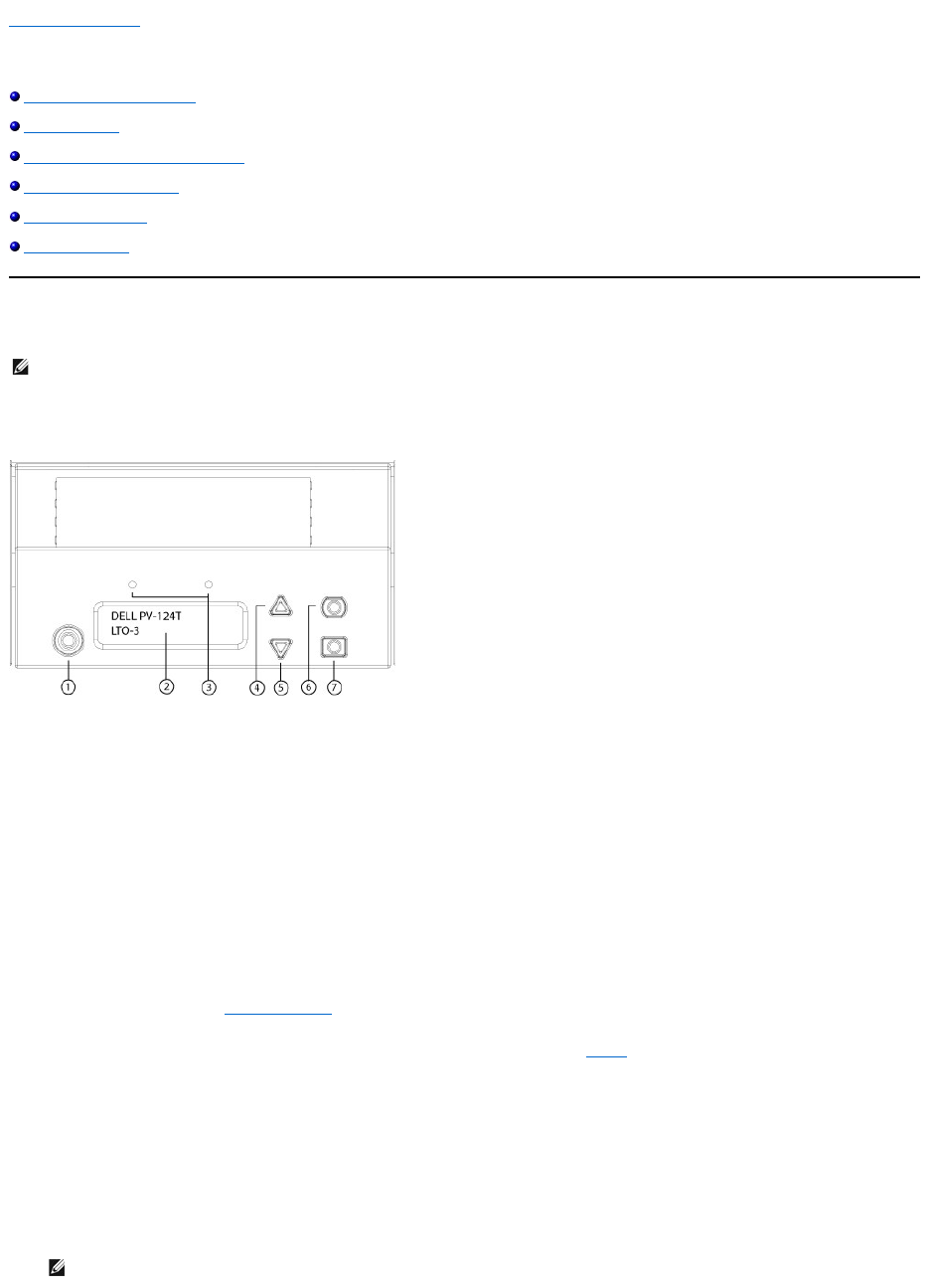
1
Power switch
2
Front panel LCD screen
3
Front panel LEDs
4
Scroll up button
5
Scroll down button
6
Escape
7
Enter
NOTE: You can also press Escape to log out. Continue pressing Escape as required until the main screen appears.

Using Cartridges
Typically, when you first install the autoloader, you load your cartridges into the magazines and then load the magazines into the autoloader. However, you
can insert and eject cartridges individually using the media door (mailslot), or you can eject a magazine, manually load and unload cartridges, then load the
magazine back into the autoloader. The autoloader automatically detects the presence of a cartridge in the magazine slot.
If you try to perform an illegal operation, the autoloader refuses to perform the operation. For example, if you try to load a cartridge through the media door
(mailslot) to the drive but the drive already contains a cartridge, the media door (mailslot) does not unlock and will display an error message. If you try to
unload a cartridge from the drive while the autoloader is writing to the tape, the command will not be initiated until the write command is completed.
Insert a Single Cartridge
When you want to load a single cartridge into the autoloader, you can use the media door (mailslot). However, if the Security option is turned on, you have to
enter a valid password to unlock the media door (mailslot) before you can load a cartridge. When you insert a cartridge through the media door (mailslot), you
can load it into the tape drive or store it in a magazine.
To insert a cartridge in the tape drive:
1. From the main menu, scroll to Commands, and then press Enter.
2. From the Commands submenu, scroll to Enter-Mailslot, and then press Enter.
3. From the Enter-Mailslot submenu, scroll to To Drive, and then press Enter.
4. Once you have inserted the cartridge, the prompt Enter to Continue appears. You have 5 seconds to press Enter in response or the autoloader will
automatically load the cartridge.
To insert a cartridge in a magazine slot:
1. From the main menu, scroll to Commands, and then press Enter.
2. From the Commands submenu, scroll to Enter-Mailslot, and then press Enter.
3. From the Enter-Mailslot submenu, scroll to To Location, and then press Enter.
Scroll through the magazine slots and view their status until you find the appropriate slot. Slots that are occupied by a data cartridge are indicated by
an asterisk (*). A slot assigned for and occupied by a cleaning cartridge will be indicated by an at sign (@). An empty slot assigned to a cleaning
cartridge will be indicated by an exclamation point (!).
4. Scroll to the slot where you want to store the cartridge, and then press Enter.
After Load cartridge appears on the LCD, you have 40 seconds to load a cartridge through the media door (mailslot) before it relocks. The autoloader
automatically loads the cartridge into the selected slot.
5. Once you have inserted the cartridge, the prompt Enter to Continue appears. You have 20 seconds to press Enter in response or the autoloader will
automatically load the cartridge.
Moving a Single Cartridge
You can easily move a single cartridge from one location to another inside the autoloader.
1. From the main menu, scroll to Commands, and then press Enter.
2. From the Commands submenu, scroll to Move, and then press Enter.
The Move screen appears under From:. Scroll to the current location of the cartridge you want to move. Slots that are occupied by a data cartridge are
indicated by an asterisk (*).
3. From To:, scroll to the location to which you want to move the cartridge. Slots that are occupied by a data cartridge are indicated by an asterisk (*).
Press Enter.
4. Press Enter.
¡If you select an empty location, No Source Tape appears on the LCD. Choose a different location.
¡If you select a location that is already occupied, Destination Full appears on the LCD. Choose a different location.
NOTE: On the front panel menu, whenever you see Enter or Eject, it means the tape enters and leaves the autoloader through the
media door (mailslot). Whenever you see Load or Unload, it means the tape is loaded into or unloaded from the tape drive.
NOTE: After Insert Tape, Push Until Prompted appears on the LCD, you have 40 seconds to load a cartridge through the media door
(mailslot) before it relocks and "User Aborted" appears on the operator control panel.
NOTE: For the PowerVault 124T, push in the cartridge until you meet resistance. The cartridge will be about 2 inches (5.0 cm) inside the
media door (mailslot), and only the end of the cartridge will be visible through the media door (mailslot).
NOTE: If the insert cartridge function fails, the cartridge ejects and you will have to perform steps 3 and 4 again. A "Missed Tape" error
message will be displayed on the operator control panel.
NOTE: If the load cartridge function fails, the cartridge ejects and you will have to perform steps 3 and 4 again.

Ejecting a Single Cartridge
When you want to remove a single cartridge from the autoloader, you can specify the cartridge you want by bar code or location, or choose the cartridge
currently in the tape drive.
To eject a cartridge by bar code:
1. From the main menu, scroll to Commands, and then press Enter.
2. From the Commands submenu, scroll to Eject, and then press Enter.
3. From the Eject submenu, scroll to Tape → Mailslot, and then press Enter.
4. Scroll to By Barcode.
A bar code label appears.
5. Scroll to the label that corresponds to the cartridge you want to eject. Press Enter.
To eject a cartridge by location:
1. From the main menu, scroll to Commands, and then press Enter.
2. From the Commands submenu, scroll to Eject, and then press Enter.
3. From the Eject submenu, scroll to Tape → Mailslot, and then press Enter.
4. Scroll to By Location.
Slots that are occupied by a data cartridge are indicated by an asterisk (*). A slot assigned for and occupied by a cleaning cartridge will be indicated by
an at sign (@). An empty slot assigned to a cleaning cartridge will be indicated by an exclamation point (!). Scroll to the slot containing the cartridge you
want to eject.
5. Press Enter.
The cartridge you want is ejected from the media door (mailslot).
To eject a cartridge from the tape drive:
1. From the main menu, scroll to Commands, and then press Enter.
2. From the Commands submenu, scroll to Eject, and then press Enter.
3. From the Eject submenu, scroll to Tape → Mailslot, and then press Enter.
4. Scroll to From Drive, and then press Enter.
The cartridge you want is ejected from the media door (mailslot).
Using Magazines and Magazine Blanks
Inward Side of a Magazine
Outward Side of a Magazine
NOTE: This function is only allowed if the bar code reader is enabled.

The autoloader will not run unless both magazine bays are properly occupied with either a magazine or a magazine blank. One way that you can close the
openings is to use two magazines. If you use only one magazine, then you must fill the other magazine opening with a magazine blank for the unit to become
operational.
Ejecting a Magazine
When you want to remove several cartridges at once, eject the magazine(s) first.
To eject a magazine:
1. From the main menu, scroll to Commands, and then press Enter.
2. From the Commands submenu, scroll to Eject, and then press Enter.
3. On the Eject submenu, scroll to Right Magazine or Left Magazine, and then press Enter.
You will hear a distinctive popping sound as the appropriate magazine is ejected from the autoloader. Left magazine has been ejected or Right
magazine has been ejected appears on the LCD.
4. Grasp the magazine by the handle with one hand and slide it out, supporting it underneath with the other hand.
When issuing a Load/Unload command from software, the system automatically ejects the right magazine. To remove the left magazine using the
Load/Unload command, you must:
1. Remove the right magazine.
2. Replace the right magazine with a magazine blank.
3. Issue the Load/Unload command again. The system will then eject the left magazine.
4. If you want to have a magazine in the right bay, replace the magazine blank in the right bay with a cartridge magazine.
Installing a Magazine
To install a magazine into the autoloader, use the following procedure.
1. Grasp the magazine by the handle with one hand and support it underneath with the other hand.
2. Slide the magazine into the magazine bay until it clicks.
Make sure that you position the magazine correctly. It should slide into the magazine bay smoothly. If you meet resistance, verify the orientation of the
magazine.
The magazine is correctly installed when you feel it click into place and the front of the magazine is flush with the front panel. Left Mag Inserted or
Right Mag Inserted appears on the LCD. The autoloader automatically proceeds to run an inventory.
Manually Operating the Magazine
NOTE: Magazines are not interchangeable between drive types. Order the appropriate part numbers when replacing these items.
NOTICE: To prevent damage to the autoloader or the magazine, use both hands when removing the magazine from the autoloader,
supporting the entire length of the magazine.
NOTE: Once you eject a magazine, you must fully remove it or fully reinstall it before powering off the autoloader. Before returning a
magazine to the autoloader, manually turn one of the white thumb wheels located on each end of the magazine. If they move freely, the
cartridges are properly seated. If the wheels do not turn freely, check the cartridges and remove and replace as needed.
NOTICE: Be careful not to turn the knob on the side of the magazine while the magazine is partially inserted into the autoloader. Doing
so may cause damage to the magazine or the autoloader.

There are two white thumbwheels, located on each end of the magazine. You can move the slots within the magazine by turning these two white
thumbwheels and aligning a slot with one of the two openings. Do not rotate the magazine by inserting your hand and pushing the cartridge carriers. You can
use the openings in the magazine to load and unload cartridges from the eight slots within each magazine.
To load cartridges into a fully ejected magazine:
1. To load cartridges into the magazine, center a slot within one of the openings located on the side of the magazine.
2. Properly orient the cartridge; tape upright and bar code label facing outward.
3. Fully insert the cartridge into the slot.
When pushing the cartridge into the slot, you will feel a small resistance (detent) until the cartridge is properly latched into the slot. All forward progress
stops when the cartridge is fully inserted.
You can remove a cartridge in the same manner as you insert it. Use the white thumbwheels to center the desired slot(s) in the openings on the side of the
magazine. Do not rotate the magazine by inserting your hand and pushing the cartridge carriers. Using your thumb and index finger, pull out the cartridge. You
will feel a small resistance, but continue to pull the cartridge until it comes free.
To identify a slot:
Each slot has an identification number that is exposed when the slots are in the upper section of the magazine. With the magazine removed from the
autoloader, you can see the identification mark on the top side of the magazine through one of two windows on the upper surface of the magazine. Each
magazine carrier is labeled 1/9, 2/10, 3/11, and so fourth. Lower numbers 1 - 8 reference slots in the left magazine. Higher numbers 9 - 16 reference slots on
the right magazine if the optional right magazine is installed.
Running an Inventory
The autoloader automatically runs an inventory whenever you power it back on or insert a magazine. An inventory checks each magazine slot, the drive, the
picker, and the media door (mailslot) to determine if a cartridge is present. If so, it also reads the bar code label, if available. If you need to run an inventory in
addition to this, you can do so manually.
To perform an inventory manually:
1. From the main menu, scroll to Commands, and then press Enter.
2. From the Commands submenu, scroll to Inventory, and then press Enter. The autoloader scans the bar codes of all the cartridges present.
Viewing Status Information
From the scrolling menu on the LCD, you can view the autoloader status, firmware version, element status, tape drive status, tape drive version, and Ethernet
information.
Viewing PowerVault 124T Autoloader Status
The autoloader status provides information about: whether a magazine is installed or not, SCSI connection status, Ethernet connection status, and whether
the bar code reader is enabled or not.
To view the autoloader status:
1. From the main menu, scroll to Status, and then press Enter.
2. From the Status submenu, scroll to Autoloader, and then press Enter.
3. From the Autoloader submenu, scroll to Status, and then press Enter. A list of messages similar to the following appears:
NOTICE: It is recommended that you fully remove the magazine to load and unload cartridges. If the magazine is not fully removed, do
not rotate the magazine.
NOTE: There is a keying feature in each slot that only allows you to fully insert the cartridge one way. Make sure there are no labels
adhering to the cartridge at any point other than the designated label area.
NOTE: No bar code labels can be read if there is a tape in the picker.
SCSI ID
A digit 0 through 7 (default 6).
The assigned SCSI ID for the autoloader.
Magazines
L=*
Asterisk indicates the left magazine is present.
R=*
Asterisk indicates the right magazine is present.
BC Reader
Yes
Bar code reader enabled
No
Bar code reader disabled

Viewing Firmware Version
To view the current firmware version, use the following procedure:
1. From the main menu, scroll to Status, and then press Enter.
2. From the Status submenu, scroll to Autoloader, and then press Enter.
3. From the Autoloader submenu, scroll to Version, and then press Enter.
A list of messages appears on the LCD. The firmware version is listed as Firmware: VX.XX where X.XX is the current installed version of the firmware.
Viewing Element Status
The element status reports the status of the magazine slots. The status indicates whether a slot contains a cartridge or not, and which slot is allocated as the
cleaning cartridge's slot. To view an element's status:
1. From the main menu, scroll to Status, and then press Enter.
2. From the Status submenu, scroll to Autoloader, and then press Enter.
3. From the Autoloader submenu, scroll to Element Status, and then press Enter.
4. Scroll to view Drive, Mailslot, and Picker status. Scroll and press Enter when prompted to view Magazine status.
You can scroll through each of the slots. Slots that are occupied by a data cartridge are indicated by an asterisk (*). If a slot assigned to a cleaning
cartridge is occupied, it is indicated by an at sign (@). If a slot assigned to a cleaning cartridge is empty, it is indicated with an exclamation point (!).
5. Scroll to the slot containing the cartridge for which you want to see the label, or the cartridge you want to move, and then press Enter.
The Element Status screen appears, displaying the bar code label for that cartridge.
Viewing Tape Drive Status
To view the tape drive status, use the following procedure.
1. From the main menu, scroll to Status, and then press Enter.
2. From the Status submenu, scroll to Drive, and then press Enter.
3. From the Drive submenu, scroll to Status, and then press Enter.
A list of messages appears. These messages may include:
Viewing Tape Drive Version
To view the tape drive version, use the following procedure.
1. From the main menu, scroll to Status, and then press Enter.
2. From the Status submenu, scroll to Drive, and then press Enter.
3. From the Drive submenu, scroll to Version, and then press Enter.
A list of messages appears. These messages may include:
Firmware
The number indicates the firmware version.
EDC
The number indicates the Error Correction Code that was generated when the firmware was installed. The autoloader uses this number to
verify that the firmware and the memory holding the firmware are good.
HW Rev
The number indicates the hardware version.
ME Rev
The number indicates the mechanical version.
SCSI ID
Indicates the drive's SCSI ID number.
Compression
Indicates whether the tape drive compression is enabled or disabled.
Drive Tape
Indicates whether a tape is present in the drive or not.
NOTE:The LTO-3 tape drive can compress data which may allow it to write more data to the same amount of tape. Compression also
increases the performance of the data transfers from or to the SCSI bus. The data compression is drive dependent and cannot be set
from the front panel or the Remote Management Unit. Your backup application package may also have information on compression.
The front panel display will indicate whether data compression is Enabled or Disabled. Not all data is compressible and performance is
heavily dependent on the type of data being backed up.
ProductType
Indicates the type of drive installed.
Version
Indicates the firmware version of the drive.

Viewing Ethernet Information
To view the Ethernet information, use the following procedure.
1. From the main menu, scroll to Status, and then press Enter.
2. From the Status submenu, scroll to Ethernet, and then press Enter.
A list of messages appears. These messages may include:
Back to Contents Page
MACaddress
Indicates the unique network identifier associated with the autoloader.
IP address
Indicates the static IP address or currently assigned dynamic IP address. The text DHCP displays in this case.
Network
Indicates whether the autoloader is connected to the network or not and at what speed.

Back to Contents Page
RemoteManagementUnit:Dell™PowerVault™124TLTO-3 Autoloader User's Guide
Remote Management Unit Overview
Configuration Page
Firmware Page
Error Log and Diagnostics Page
Library Operations Page
Remote Management Unit Overview
Your Dell PowerVault 124T LTO-3 autoloader includes an Ethernet interface that allows remote administration. The interface, called the Remote Management
Unit (RMU), includes a Web server that provides a Hypertext Markup Language (HTML)-based graphic user interface (GUI) for ease of use.
The RMU performs many of the same functions as the front panel interface. These functions include moving tapes, system operations options, networking
options, security options, running diagnostic tests, and performing system updates.
Default Username and Password
The default username for the Remote Management Unit is admin. The default password is password.
The username and password are case sensitive and should be entered in all lower case letters. The default username and password are valid if no usernames
have been configured.
Opening the Remote Management Unit
The Remote Management Unit has an HTML interface, which means you use a browser to open it. The following Web browsers are supported:
lFor Microsoft®Windows®— Microsoft Internet Explorer 5.5 or later
lFor Microsoft Windows Server®2003 — Microsoft Internet Explorer 6.0 or later (with latest security patches)
lFor Redhat®2.1 — Mozilla™1.4.2
lFirefox™1.0
If security is enabled, you need an operator password to access the Library Operations page, and you need an administrator password to access the
Configuration, Error Logs and Diagnostics, and Firmware pages.
When using the RMU with Microsoft Internet Explorer, be sure to enable the Allow META REFRESH option. On version 6.0 of Internet Explorer, this feature is
controlled through the Tools>Internet Options menu selection, under the Security tab.
Use of all Remote Management Unit web pages features requires Java Script to be enabled in the user's web browser.
To open the Remote Management Unit:
1. From your computer, open your Web browser.
2. In the browser's address field, enter the IP address for your autoloader (see "Viewing Ethernet Information").
The Home page appears in your browser window.
Viewing Status Information
NOTE: Only use the Diagnostics commands when the autoloader is known to be idle and unavailable to host backup/restore
applications. If a Diagnostic command is issued during a drive or autoloader operation, the unit will respond that it is busy. However, if a
Diagnostic command is issued and then a backup or restore job runs, that job may fail.
NOTE: To log out of the system, you must close your browser.
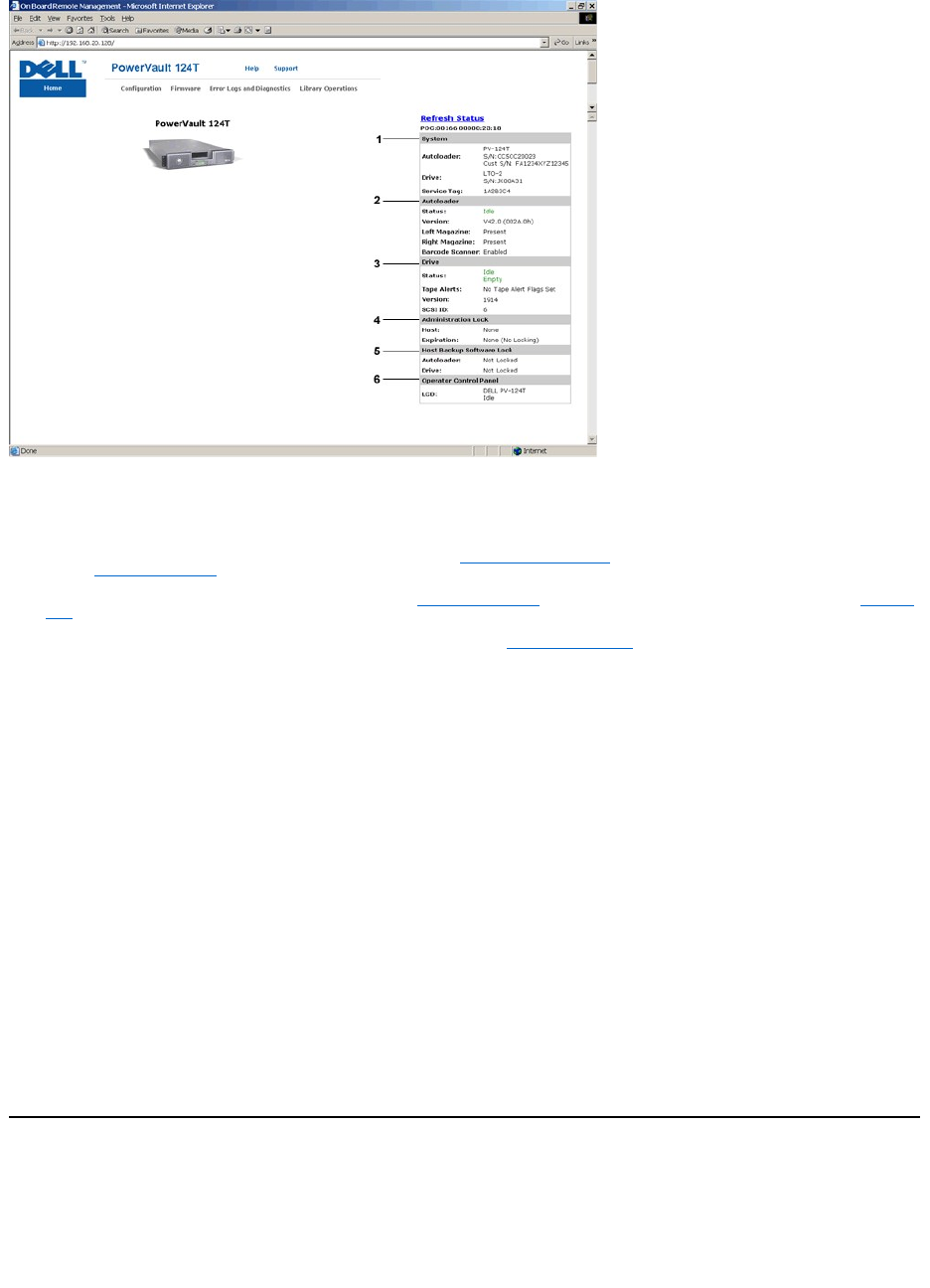
Remote Management Unit (RMU) Web Interface Status Pane
1. System Status - provides model and serial number (S/N) of both the autoloader and the drive. This section also contains the Dell Service Tag number.
You will need this number if you call for technical support.
2. Autoloader - provides status specific to the automation device. Refer to Front Panel Administration for information regarding magazine configuration.
Refer to Installation Overview for information regarding enabling or disabling the Barcode Scanner.
3. Drive - provides status information specific to the drive. Refer to Installation Overview for information on how to change the SCSI ID. Refer to TapeAlert
Logs for information regarding drive Tape Alert flags.
4. Administration Lock - provides status regarding RMU security settings. Refer to Client Overlap Control for information on how to configure the
Administration Lock.
5. Host Backup Software Lock - provides status regarding Independent Software Vendor (ISV) autoloader and drive lock settings. These settings must
typically be changed from within the host backup software application. Refer to your Backup Software Help or User Guide for steps on how to change
autoloader and drive lock settings.
6. Operator Control Panel - provides an "OCP mirror," showing text currently displayed on the operator control panel.
Status information appears on the right-hand side of the Home page and every page of the Remote Management Unit except for the Firmware page. The
status information is updated automatically every 10 seconds. Changes to the status appear in the status window update, but may take approximately 10
seconds to refresh. You can also click Refresh Status to get an immediate update of the system.
The menu headings also appear at the top of every page. To access the functionality under the menu heading, click the specific menu heading. The first time
that you connect, the Remote Management Unit prompts you for your username and password, then displays the opening page for that menu.
Depending on your screen resolution settings, you may have to scroll to see all status info.
Time Display
The time displayed is either regular time or power-on time. Regular time is Month/Date/Year time, such as Nov/21/2004 19:28. Power-on time is Power On
Cycles (POC)/Power On Hours (POH), such as POC:00121, POH:00002:07:45.
lPOC (5-digit number) is the number of times the system has booted since it was manufactured.
lPOH is the number of hours, minutes, and seconds that the system has been on since the current boot occurred.
Feedback on Pages
If there is feedback from the system when you submit a request, the feedback appears beneath the submit button. In some cases, you may have to scroll to
see the feedback information.
Configuration Page
The Configuration page includes a submenu on the left-hand side of the page. You can set the System Operations, Networking, and Security options from
this page.
System Operations Options
The options listed under System Operations include SCSI ID, Compression, Barcode Reader, Cleaning Tape, Magazines, and System Time.

SCSI ID
You can change the drive's SCSI ID from the Remote Management Unit. To change the SCSI ID:
1. From any page, click the Configuration heading. The Configuration screen displays.
2. Under System Operations, select SCSI ID.
3. Click the drop-down box to select a number to assign for the new SCSI ID.
4. Click submit.
Compression
For the Dell PowerVault 124T LTO-3 autoloader, data compression is drive-dependent. The front panel and the Remote Management Unit will display whether
or not compression is enabled.
Compressing the data means that the drive can write more data to the same amount of tape. Compression also increases the performance of the data
transfers from or to the SCSI bus.
To view the compression setting:
From any page, click the Configuration heading. The Configuration screen displays. Under the Compression heading, the current compression setting is
displayed as Compression Enabled or Compression Disabled.
Bar Code Reader
The bar code reader can be enabled or disabled. Disabling the bar code reader prevents the reader from attempting to read label information. If non-bar code
labels or no labels are being used, disabling the bar code reader will reduce initialization time at startup or system reset.
Either a power cycle (through the front panel button) or an autoloader reset (through the
Autoloader Reset command found on the Error Logs and Diagnostics
page) is required for the setting change to take effect.
SCSI Barcode Length sets the maximum number of barcode characters that will be
returned in the SCSI Read Element Data. The display of barcode information
on the Web interface and Operator Control Panel (OCP) are unaffected by this setting.
Setting the SCSI Barcode Length to 0 disables truncation of the barcode and the full barcode will be returned in the SCSI Read Element Data.
This setting is particularly useful if you have a pool of media previously catalogued by another device that has a limitation on the number of barcode
characters
that can be read (typically 6 or 9). Adjusting the PV124T setting to match the previous hardware prevents the user from having to re-catalog all barcode
labeled media previously used in the other device.
The autoloader does not need to be reset when changing the Barcode Length.
To change the Barcode Reader settings:
1. From any page, click the Configuration heading. The Configuration Screen displays.
2. Under the Barcode Reader section, select the desired Enable/Disable option and Barcode Length setting and click Submit.
3. If the Enable/Disable option is changed, the message This will require a power cycle and host backup software configuration change will be displayed.
4. Select OK.Thefrontpaneland Web interface will display Please Power Cycle.
5. Either a power cycle (through the front panel button) or an autoloader reset (through the Autoloader Reset command found on the Error Logs and
Diagnostics page of the Web interface) is required for the change to take effect.
Cleaning Tape
To enable or disable the Auto Clean function, you must also designate a full slot for the cleaning tape cartridge. If a slot has not been designated, the box
displays None. To designate the cleaning tape slot:
1. Load a cleaning tape into an empty slot using the Library Operations page.
2. Enable or disable Auto Clean by selecting the check box. If autoclean is enabled, the cleaning cartridge will automatically be moved from the assigned
cleaning slot to the drive if the drive indicates cleaning is required.
To set Auto Clean:
1. From any page, click the Configuration heading. The Configuration screen displays.
2. Scroll to Cleaning Tape.
If a check mark appears in the box next to Auto Clean, the option is enabled. To disable Auto Clean, click the box to remove the check mark. If no check
mark appears in the box next to Auto Clean, the option is disabled. To enable Auto Clean, click the box to enter a check mark.
3. In the Cleaning Tape Location field, select the appropriate slot location where you installed the cleaning tape. If Auto Clean is disabled, cleaning is
NOTE: You must perform an Autoloader reset or use the front panel to power cycle your machine before the new SCSI ID takes effect.
NOTE: Compression cannot be changed from the front panel or the Remote Management Unit of the autoloader.
NOTE: If Auto Clean is disabled, the cleaning tape will automatically be ejected through the media door (mailslot). Cleaning is handled by
the backup package you have installed instead.

handled by the backup package you have installed instead.
4. Click submit.
Setting the Magazines
This setting is used to report the number of storage elements and the element address to the SCSI host. This setting must match the physical configuration in
order for correct information to be reported. This setting only affects the information reported to the SCSI host. This setting does not affect the access to
magazine slots from the front panel or the Remote Management Unit. Those interfaces are based on the physical configuration.
When configured for Both magazines, the autoloader always reports 16 storage elements to the SCSI host. This allows the removal and reinstallation of
magazines without affecting what is reported to the host. When configured for Left or Right
, the autoloader will always report 8 storage elements to the SCSI
host.
The element addresses vary depending on which magazine is configured. If Left or Right is selected, and both magazines are physically installed, the front
panel and the Remote Management Unit allow the user access to the other magazine, but the SCSI host will not have access.
To set the Magazines option:
1. From any page, click the Configuration heading. The Configuration screen displays.
2. Scroll to Magazines. The Magazines options display.
A radio button appears after the currently enabled mode.
3. Do one of the following:
¡To leave the Magazines mode unchanged, press Esc.
¡To change the Magazines configuration, scroll to the setting you want for the autoloader, selecting the appropriate check box, and then click
submit. These settings include Both, Right, and Left.
The message This will require a power cycle and host backup software configuration change. Enter To Continue is displayed.
¡To continue with the change, press submit. The message Please power cycle the tape autoloader and reconfigure the host backup software
app. displays.
Setting the System Time
The system time is displayed by the Remote Management Unit and it is used internally for logging events and errors (see "Setting the Time").
The autoloader must be reset after each power up. The time can be reset automatically if a time server is configured (see "Setting Network Options").
Otherwise, the time must be set manually from the front panel or through the Remote Management Unit. The time zone setting is not lost when powered off.
To set the system time:
1. Using the first drop-down list next to Time Zone, select the number of hours difference between your local time and Greenwich Mean Time (GMT).
2. Below the Time Zone field, select the current Month from the drop-down list.
3. In the Day field, type the current day of the month.
4. In the Year field, type the current year.
5. In the Hour text box, type the current hour in 24-hour format.
6. In the Minute text box, type the current minute.
7. Click submit to save the information.
Setting Network Options
When you originally installed the autoloader, you set the Ethernet configurations through the front LCD panel. However, you can modify them through the
Remote Management Unit. The options include Current Network Parameters, Set IP, and Set Network Configuration. To change the Ethernet
configurations:
To view the Current Network Parameters:
1. From any page, click the Configuration heading. The Configuration screen displays.
2. From the Configuration menu, click Networking.
The Current Network Parameters area displays the current IP address, MAC address, and the speed setting for the Ethernet connection.
In the Set IP section, if a check mark appears in the box next to DHCP, the dynamic IP address option is enabled. This means that with every reset of the
NOTE: The default setting of Left must be reconfigured if the optional right magazine is installed. Host backup software may also require
reconfiguration if the loader was originally installed with only the default left magazine
NOTE: Whether the autoloader is connected to a time server or not, if you want to include time changes for daylight savings time, you
must change the time zone manually.
NOTE: For example, if you live in Colorado, the time difference is –6 hours in the summer and –7 hours in the winter.

system, the IP address may change depending on the network administrator's settings.
To Set IP address:
1. Clear the check box to remove the check mark from the DHCP field, if applicable.
2. In the IP address fields, type the static IP address using the <Tab> key to move from box to box.
3. If no check mark appears in the box next to DHCP, the static IP address option is enabled. To change a static IP address, type in the new address in
the IP address fields using the <Tab> key to move from box to box.
4. To change the IP address from a static address to a dynamic address, click the box next to DHCP.
To Set Network Configuration:
1. To change the values of the subnet mask, gateway, Simple Network Management Protocol (SNMP) server, or the time server, type in the new address,
using the <Tab> key to move from box to box.
2. Click submit.
Setting Front Panel Security Options
When you enable the security option, users must enter a password to access the autoloader's front panel functionality. A password allows either
administrator-level access or operator-level access (see "Setting Security"). Up to two Admin and two Operator passwords may be set. To set security:
1. From any page, click the Configuration heading. The Configuration screen displays.
2. On the left-hand side of the screen, click Security. The System Security section of the screen displays.
3. To enable front panel security, select the check box next to Front Panel Security Enabled.
If the check box is blank, the security option for the front LCD panel is not enabled.
4. Click submit.
To reset the front panel password:
1. From any page, click the Configuration heading. The Configuration screen displays.
2. On the left-hand side of the screen, click Security.
3. Select the check box next to Reset Front Panel Password. A check mark appears.
4. Click submit.
To set User Administration:
1. From any page, click the Configuration heading. The Configuration screen displays.
2. On the left-hand side of the screen, click Security.
3. From the drop-down list next to Select User Type, select Operator 1, Operator 2, Administrator 1 or Administrator 2.
4. In the Username field, enter a user name.
5. In the Password field, enter the new password.
6. In the Verify Password field, re-enter the same new password.
7. Click submit.
To set the Client Authorization Control:
1. From any page, click the Configuration heading. The Configuration screen displays.
2. On the left-hand side of the screen, click Security.
Scroll to Client Authorization Control. In this section is a list of the IP addresses that are authorized to perform with the Remote Management Unit for
this specific unit. There are two sets of IP address boxes. You can individually enable/disable and configure each set.
¡If enabled, each set can be used to specify either a range of IP addresses or a pair of specific IP addresses that are allowed to administer this
unit. A set can also be used to specify a single IP address if the desired IP address is entered into both the "a" and "b" portions of the set. When
a set is used to specify a range of IP addresses, the "b" portion of each address set must be greater than or equal to the "a" portion of that
address set.
¡If neither set is enabled, any IP client can administer the unit. If a single set is enabled, only clients that pass the test specified by that set are
allowed administrator access. If both sets are enabled, any client that passes either of the two filter tests can administer the unit.
The Web server always allows any client to view the status information of the unit, regardless of the authorized client list or the overlap control policy.
3. Use the drop-down box to select Enable or Disabled.
NOTE: To view the list of currently defined users, click submit with Select User Type chosen.

4. Type the IP addresses in the appropriate boxes.
5. Click submit to save.
Client Overlap Control is a management policy on controlling how the Web server handles overlapping control requests from multiple clients on the
authorized client list. The options include No Locking, Full Locking, and Time-Based Locking.
lNo Locking allows multiple clients to have unrestricted access to control the system as long as they are on the authorized client list.
lFull Locking permits only one authorized client to issue control requests at a time. This client must release the lock by clicking the Home/Logout option
in the upper frame of the page to permit other authorized clients to have control access.
lTime-Based Locking is similar to Full Locking in that only one authorized client can have control access at once, but the lock is automatically released
after the specified number of seconds of inactivity have elapsed.
After selecting the appropriate policy by clicking the check box, click submit to save the changes.
1. From any page, click the Configurations heading. The Configurations screen displays.
2. On the left-hand side of the screen, click Security.
3. Select a security option from the Client Overlap Control options:
¡No locking allows multiple users to access the system and issue requests.
¡Full Locking allows only one user to access the system and issue requests.
¡Time-based Locking allows only one user to access the system and issue requests with the lock expiring after a designated amount of inactivity
(in seconds).
¡Home/Logout is used to release a full or time-based lock and permit another user to access the system.
4. Click submit.
Firmware Page
You can browse to find system updates and then upload the updates. To get system updates:
1. From any page, click the Firmware heading. The Firmware Update screen displays.
2. Click Browse to navigate to the host system for the update file. The file should end in an .img extension.
3. Click Upload.
4. Click OK in response to the confirmation box. The autoloader automatically uploads the new code and processes it to the system.
5. Power cycle the loader, then the server firmware update is complete.
Error Logs and Diagnostics Page
From the Error Log and Diagnostics page, you can run various tests on the autoloader. You can also view error and history logs, test progress, identify the
physical unit in a rack, or reset the system.
Viewing Error or History Logs:
NOTE: By entering an improper range of IP addresses, a user can possibly lock out all IP clients from administering the autoloader. If this
occurs, the user can restore the default values by running Restore Default from the front panel Configuration menu.
NOTE: Locking is only available to users on the authorized client list.
NOTE: The preferred method of autoloader update is through the RMU (Remote Management Unit web interface). The preferred method
for drive update is across the host SCSI interface using the Dell Firmware Update utility (DFU) supplied with the firmware update
package. Refer to the README file provided with the firmware update package.
NOTE: It is recommended that all firmware updated be performed with image files located on the local system hard drive as opposed to a
removable media device or network share.
NOTE: A Microsoft issue may keep a user from updating drive or loader firmware over the RMU interface. This can occur under Windows
Server®2003 with Service Pack 1 (SP1), or if a user has installed Microsoft Security Update MS05-019. This problem displays as a 6F
Communication Error message on the front panel with the warning light set. The RMU will continue to report the autoloader status as
Initialization.
For information and a workaround to this problem, go to Microsoft Technical Support Article 898060. If this problem occurs, the autoloader
should be restarted to avoid further communication errors.
NOTE: After firmware update is complete, the unit will report new revision levels to the host on startup. You may have to reconfigure you
host backup software to recognize the updated unit.

1. From any page, click the Diagnostics heading. The Diagnostics screen will be displayed.
2. Under View Error and History Logs, click View Logs. You can also save the logs to a file by clicking Save Logs. If you save the logs to a file, you must
select a destination folder within 60 seconds.
Running Diagnostics Tests
A minimum of two cartridges are required to run the diagnostic tests. The diagnostic tests available on the autoloader include:
lLoader - Picker Test
lLoader - Magazine Test
lLoader - Inventory Test
lRandom Moves
1. From any page, click the Error Log and Diagnostics heading. The Error Log and Diagnostics screen will be displayed.
2. In the Diagnostics section, select the diagnostic test that you want to run from the Test drop-down menu.
3. Specify a loop count, if desired. Valid numbers are 1 to 99.
4. Click submit.
5. While the test is running, you can view the status of the test. From View Diagnostic Test Progress, click View Status.
A separate screen indicates which test is running and the current status of the diagnostic test.
6. To view diagnostic progress click View Status again.
Identification
You can use the Identification feature of the autoloader by requesting the LCD backlight to flash for a specified number of seconds.This can be helpful in
identifying the location of the autoloader in an equipment room.
1. From any page, click the Error Log and Diagnostics heading. The Error Log and Diagnostics screen displays.
2. Under Identification, enter the number of seconds in the Time (secs) field.
3. Click Identify. The LCD backlight flashes on the autoloader for the specified number of seconds.
Performing an Autoloader Reset
You will use autoloader reset when making SCSI ID changes and magazine changes. An autoloader reset will take at least three minutes if there is a tape in
the drive, or approximately 30 seconds otherwise. To perform an autoloader reset:
1. From any page, click the Error Log and Diagnostics heading. The Error Log and Diagnostics screen displays.
2. Under the Autoloader Reset section, click Autoloader Reset.
Library Operations Page
You can move tapes, run a system inventory, reset the picker to its home position, or perform sequential operations from the Library Operations page. When
you click Library Operations, the page displays.
Moving Tapes
From a remote location, you can request that a tape be moved from one position to another. To move a tape:
1. From any page, click the Library Operations heading. The Library Operations screen displays.
2. From the Moving Tapes section of the page, click the drop-down menu under From: and select the current location of the tape that you want to move.
3. From the drop-down menu under To:, select the location to which you want to move the tape, and then click submit.
Inventory
The autoloader automatically runs an inventory whenever you power it on or insert a magazine. If you need to run an inventory in addition to this, you can
use the Remote Management Unit to do it remotely. To run an inventory:
NOTE: Saved logs taken at point of failure are valuable for assessing problems. Service personnel may request these logs.
NOTE: You can also click the slot on the graphic of the autoloader magazine to select and move a cartridge.

1. From any page, click the Library Operations heading. The Library Operations screen displays.
2. From the Library Operations page, click Inventory. The autoloader starts an inventory immediately.
Set to Home
If the autoloader is not able to successfully execute a Moving Tapes or an Inventory command, try executing a Set to Home command, and then retry the
move or inventory command again.
The Set to Home command resets the autoloader as a means to help the autoloader recover from an unexpected internal condition. To Set to Home:
1. From any page, click the Library Operations heading. The Library Operations screen displays.
2. From the Library Operations page, click Set to Home. This executes a reset command to the autoloader.
Back to Contents Page

Back to Contents Page
TechnicalSpecifications:Dell™PowerVault™124TLTO-3 Autoloader User's Guide
Physical Specifications
Autoloader Performance Specifications
Autoloader Environmental Specifications
Autoloader Power Specifications
Autoloader Vibration Specifications
Autoloader Shock Specifications
Tape Drive Specifications
Physical Specifications
Autoloader Performance Specifications
Autoloader Environmental Specifications
Characteristic
ProductAlone
Height
8.9 cm (3.5 in)
Width
45 cm (17.7 in)
Length
75.46 cm (29.71 in)
Package Weight (without media)
22.7 kg (50 lb)
Footprint
0.32squaremeters(3.4squarefeet)
Characteristic
Specification
Maximum data transfer rate
Native: 245 GB/hr
Compressed: 490 GB/hr (assuming 2:1 compression ratio)
Drive type
1 IBM LTO-3 drive
Number of slots
16 (8 per magazine)
MCBF
100,000 cartridge load/unload cycles
Interface
Ultra 160 SCSI LVD
Initialize element status
90 seconds (typical)
Typical cycle time
< 40 seconds. One cycle consists of moving a cartridge from the tape drive to a magazine slot, selecting another magazine
slot, and then moving the cartridge back to the tape drive. It does not include the time that the tape drive takes to unload or
load/calibrate.
Average load time (after placing
cartridge in drive)
LTO Ultrium 3 = 15 seconds (to BOT for previously written tape)
LTO Ultrium 3 = 15 seconds (to BOT with initialized tape)
Average unload time (from BOT)
LTO Ultrium 3 = 15 seconds (from BOT)
Characteristic
Specification
Temperature Range (Dry Bulb)
Operating
+10°to+35°C
Nonoperating
–40°to+65°C
Temperature Variation
Operating
10°Cperhour
Nonoperating
20°Cperhour
Humidity
Operating
20% to 80% noncondensing
Nonoperating
10% to 90% noncondensing
Gradient
10% per hour without condensation
Wet Bulb
Operating
26°Cmaximum
Nonoperating
29°Cmaximum
Altitude
Operating
–153 to 3048 m
Nonoperating
–153 to 12192 m
Vibration (5-500 Hz)
Maximumaccelerationtooperating
0.25g RMS (random)
Frequency range
500 Hz

Autoloader Power Specifications
Autoloader Vibration Specifications
Autoloader Shock Specifications
Tape Drive Specifications
LTO-3 Drive Specifications
Media Capacity
Media Specifications
Back to Contents Page
Characteristic
Specification
Line voltage
60 Hz system: 90 – 265 VAC
50 Hz system: 90 – 265 VAC
Line frequency
47 – 63 Hz
AC Input current
60 Hz system: 4.0 A (RMS) for 115 VAC
50 Hz system: 2.0 A (RMS) for 230 VAC
Power consumption
60 Hz = 75 W; 50 Hz = 80 W
Characteristic
Specification
Operating
SweptSineVibration
5 – 500 Hz, 0.25 G, 0.254 mm (0.01 inch) to smooth crossover, 1 8ve/min, (X, Y, Z) axes
Random Vibration
0.25 Grms, 5 – 500 Hz (X, Y, Z) axes
Nonoperating
Swept Sine Vibration
5 – 500 Hz, 0.75 G, 0.51 mm (0.02 inch) to smooth crossover, 1 8ve/min, (X, Y, Z) axes
Random Vibration
1.06 Grms, 5 – 500 Hz (X, Y, Z) axes
Characteristic
Specification
Operating
3 G, 5 ms half-sine, 3 pulses (+/–) per axis, X, Y, Z
Nonoperating
20 G, 8 ms half-sine, 3 shocks (+/–) per axis, X, Y, Z
Description
IBM LTO-3
Read/write transfer rate: maximum sustained
(LTO Ultrium 3 media)
Noncompressed mode: 245 GB/hr
Compressed (2:1 typical): 490 GB/hr
Burst transfer rate
160 MB/s
Average access time
54 seconds (from BOT)
Loading time to BOT
(for previously written tape)
15 seconds (maximum)
Unloading time from BOT
15 seconds (maximum)
MCBF
> 100,000 cartridge load/unload cycles
Interface type
Ultra 160 SCSI LVD
Mediatype
Capacity
LTO Ultrium 3 storage capacity
12800 GB (compressed) with 16 cartridges
Characteristic
LTO Ultrium 3
LTO Ultrium 3 formatted capacity
400 GB (noncompressed)
800 GB (2:1 typical compression)
Basic description
Dual coat metal particle
Tape length
680 m (2230.9 ft)
Cartridge dimensions
10.2 x 10.54 x 2.15 cm
(4 x 4.15 x .85 in)
Read compatibility
LTO Ultrium 1, LTO Ultrium 2, LTO Ultrium 3
Write compatibility
LTO Ultrium 2 and LTO Ultrium 3
Shelf life
>30yearswith<10%lossindemagnetization@20°C
40% RH (noncondensing)
Cartridge life
1,000,000 passes (any point on the tape passing the recording head in either direction)
LTO Universal Cleaning cartridge life
50 uses

Back to Contents Page
Troubleshooting:Dell™PowerVault™124TLTO-3 Autoloader User's Guide
Before Contacting Customer Support
Operator Control Panel Error Display
Checking For Errors
Autoloader Logs
TapeAlert Logs
Returning the Autoloader for Service
Before Contacting Customer Support
Errors that you may experience with your autoloader can range from simple connection problems to more complex hardware failure. Before you return your
autoloader, you may be able to fix the problem yourself by following some basic troubleshooting procedures.
Other than drive cleaning, there is no recommended routine maintenance of the Dell PowerVault 124T autoloader.
The operator control panel located at the front of the autoloader provides some troubleshooting capabilities, but is limited. The Remote Management Unit
provides more detailed information about the present state of the autoloader and past performance, and is more helpful for troubleshooting errors.
The following table describes the probable cause and suggested action for problems that you may encounter.
Table 1: Basic Troubleshooting
NOTICE: If you find that you must power cycle the autoloader, do not turn the power back on for at least 10 seconds after powering
down. This allows time for the power supply to completely discharge and ensure a complete system reset. If time is not allowed for the
discharge, the system may fail to boot properly and will display a blank LCD screen. Power cycle again, waiting at least 10 seconds, to
clear the problem.
Problem
Probable Cause
Suggested Action
The front panel does not display
information.
The connection to the LCD has failed.
lUse the Remote Management Unit to troubleshoot error.
Error messages appear on the
front panel LCD display.
An error has occurred.
lRefer to Front Panel Error Display.
The autoloader is operating
slowly.
The autoloader, system hardware, or
host backup software is incorrectly
configured.
lGo to support.dell.com for configuration requirements.
The autoloader does not turn on.
The power cable is defective or the
power source is malfunctioning. The
power switch at the back of the
autoloader is not turned on.
lCheck all outlets and power cables for proper connection.
lCheck the power switch at the back of the autoloader.
lContact support.dell.com.
The front panel does not display
information, but light indicators
above the front panel are turned
on.
A momentary power interruption
allowed the autoloader to power off,
then back on prior to the power supply
being fully discharged.
lOn the front panel, press and hold the power switch for 15 seconds, then
turn the rear power switch off. Wait 60 seconds and turn the rear power
switch back on.
lContact support.dell.com.
The autoloader does not
communicate with the host
system through the SCSI bus.
A problem within the SCSI cabling path
is preventing communication.
lVerify that the SCSI cables are connected to the rear of the autoloader
and that the correct LVD host controller card is installed.
lVerify that the SCSI cables are not damaged or crimped and the total SCSI
cable length is not exceeding the maximum required length.
lVerify that a LVD SCSI terminator is attached to both the first and last
SCSI device on the SCSI bus.
lVerify that the autoloader SCSI ID is set to a unique SCSI ID that is not
used by any other SCSI device on the same SCSI bus.
lVerify that the host bus adapter is supported for use with the Dell
PowerVault 124T on support.dell.com.
lIssue an Autoloader Reset either by using the Remote Management Unit
Diagnostic page or by turning off power from the front panel.
lContact support.dell.com.
The tape drive responds on the
A system configuration problem is
lIf the SCSI ID is unique, check SCSI cable and terminator connections.

Operator Control Panel Error Display
The Operator Control Panel (OCP) is used for operator input, and to display status and error information output. Errors
generated by the autoloader hardware
result in error codes unique to the Dell PowerVault 124T. These errors codes are displayed on the OCP along with a brief description of the error. Further
information and recommended actions for Dell PowerVault 124T error codes can found in Table 2.
Errors generated by the internal tape drive are presented in terms of industry standard TapeAlerts. TapeAlerts are also displayed on the OCP along with a
brief description of the error. Further information and recommended actions for tape drive TapeAlerts can be found in Table 3.
Checking for Errors
Errors are problems that occur while operating the autoloader. They prevent the autoloader from completing a specific action. When an error occurs, two
things can happen:
lAn error message appears on the Operator Control Panel (OCP) or in the Remote Management Unit (RMU) screen.
SCSI bus to the host, but the
autoloader does not respond.
preventing communication.
lVerify that the host application and the device drivers are installed with
the most current patches to support the autoloader.
lVerify that LUN scanning is enabled on the host bus adapter.
lContact support.dell.com.
The autoloader does not
communicate with the host
system through the Ethernet.
A problem with either the Ethernet
cabling or network configuration is
preventing communication.
lVerify that the Ethernet cable is connected to the correct hub.
lVerify the Ethernet configuration settings through the front panel LCD. If
the DHCP server is available, Ethernet status should indicate DHCP,
otherwise, you must set a unique static IP address and a sub-net mask.
The static IP address of the autoloader must be on the same sub-net as
the host.
lIf connected directly to the host system, a cross-over cable must be used.
lPower off the autoloader by turning off the system from the front panel
LCD, wait at least 10 seconds, and turn it back on.
lContact support.dell.com.
The application software reports
a failure locating a piece of media
or fails to move a piece of media
as requested.
The current host backup software or
autoloader inventory has been lost.
lUse the Remote Management Unit tool and verify that the media is in the
expected location internal to the autoloader.
lUsing the Remote Management Unit diagnostic tool, execute the Loader
Inventory Test test.
lUsing the Remote Management Unit diagnostic tool, execute the Random
Moves test. Note: a minimum of two pieces of media are required for this
test.
lIssue an Autoloader Reset either by using the Remote Management Unit
Diagnostic page Autoloader Reset or by turning the power off from the
front panel.
lRetry inventory within the software application.
lContact support.dell.com.
The application software reports
an error while reading or writing
a piece of media.
The current media is defective, or the
internal tape drive needs to be
cleaned.
lTry a different piece of media.
lUse a cleaning cartridge to clean the internal tape drive.
lIssue an Autoloader Reset either by using the Remote Management Unit
Diagnostic page Autoloader Reset, or cycle the power from the front
panel.
lRetry the job within the software application.
lContact support.dell.com.
Other failures occur.
lRefer to Front Panel Error Display for error-specific instruction.
lIssue an Autoloader Reset either by using the Remote Management Unit
Diagnostic page Autoloader Reset, or by turning the power off from the
front panel LCD.
lContact support.dell.com.

lNo error message appears, but the autoloader fails to complete the action.
When either of these things occur, the system generates a log of the error. You can use these error logs to determine the type of error, when it occurred, and
what parts of the autoloader it affects. Different types of error logs are generated for the autoloader and for the internal tape drive.
lThe Autoloader Logs provide information for errors related to the autoloader, or data cartridge movement within the autoloader.
lThe TapeAlert Logs provide information for errors reported by the tape drive inside the autoloader.
Autoloader Logs
You can retrieve autoloader error log information through one of three methods:
lOperator Control Panel (OCP)
lRemote Management Unit (RMU) display to screen
lDetailed logs saved to text file through the RMU for call center diagnosis
Further information and recommended actions for Dell PowerVault 124T error codes can found in Table 2.
Autoloader Logs through OCP
To view Hard Error log information from the front panel:
1. From the front panel LCD, scroll to Diagnostics, and then press Enter. The Diagnostics submenu appears.
2. From the Diagnostics submenu, scroll to Error Logs, and then press Enter. The Error Log submenu appears.
3. From the Error Logs submenu, scroll to Hard, and then press Enter. The log information is displayed.
4. You may scroll up and down through the hard log entries. The most recent entry will be associated with the highest event number shown.
Autoloader Logs through RMU
To view hard error log information, or save all logs from the Remote Management Unit:
1. From within the RMU, click the Diagnostics heading. The Diagnostics screen displays.
2. Click View Logs to display the hard error log. The most recent entry will be associated with the highest event number shown.
3. Detailed log information files are particularly useful when calling for support. If you want to save logs to a local text file, click Save Logs.
Table 2: Autoloader Error Detail
Error Type
Description
Recommended Action
Autoloader Operating System Failure Types
01
Resource Deleted
Errors 01-25 indicate that an unexpected event has occurred within the autoloader internal operating
system. The autoloader internal operating system is called ThreadX, and some error messages may be
preceded by a 'TX' notation.
For any of these events:
lPower cycle the autoloader.
lRun the Random Moves test from either the Remote Management Unit (RMU) or the Operator Control
Panel (OCP).
Note: The Random Moves test requires a minimum of two cartridges present within the autoloader.
lCheck support.dell.com for PowerVault 124T firmware updates.
lIf all previous steps fail, contact support.dell.com.
02
Pool Error
03
Pointer Error
04
Wait Error
05
Size Error
06
Group Error
07
No Event Timeout
08
Option Error
09
Queue Error
0A
Queue Empty
0B
Queue Full
0C
Semaphore Error
0D
Semaphore Timeout
0E
Thread Error
0F
Priority Error
10
Start Error
11
Delete Error
12
Resume Error
13
Caller Error
14
Suspend Error

15
Timer Error
16
Tick Error
17
Activate Error
18
Threshold Error
19
Suspend Lifted
1A
Block Pool Error
1B
Queue Function Failed
1C
Semaphore Function Failed
1D
Timer Function Failed
1F
Thread Function Failed
20
Command Started
21
System Failure
22
System Busy
23
System Timeout
24
Software Error
25
Hardware Error
Message Error Types
26
Message Sender (Task ) ID
Error
lVerify the host backup application and device driver are at the latest supported revision at
support.dell.com.
lCheck host adapter and SCSI cables and terminator.
lPower cycle the autoloader and retry the operation.
lIf all previous steps fail, contact support.dell.com.
27
Message Type Bad
28
Message Parameter Bad
Stack/Global Data Corruption Error Types
29
Invalid Element
lVerify the host backup application and device driver are at the latest supported revision at
support.dell.com.
lPower cycle the autoloader.
lRun the Random Moves test from either the Remote Management Unit (RMU) or the Operator Control
Panel (OCP).
Note: The Random Moves test requires a minimum of two cartridges present within the autoloader.
lIf all previous steps fail, contact support.dell.com.
2A
InvalidElementStatus
2B
Element Table Bad
2C
Global Data Bad
2D
Stack Data Bad
2E
Task Stack Low
2F
Task Stack Overflow
System Shutdown/Disruption Error Types
30
POST Failure
lVerify that the magazines/magazine blank are fully seated.
lPower cycle the autoloader.
lIf all previous steps fail, contact support.dell.com.
31
Watchdog Timer
lPower cycle the autoloader.
lRun the Random Moves test from either the Remote Management Unit (RMU) or the Operator Control
Panel (OCP).
Note: The Random Moves test requires a minimum of two cartridges present within the autoloader.
lCheck support.dell.com for PowerVault 124T firmware updates.
lIf all previous steps fail, contact support.dell.com.
32
Power Event
33
Power Down Failure
34
System Overload
35
System Performance
36
Asynchronous Stop
System Miscellaneous Error Types
37
System Cleaning Error
Cleaning slot in use.
lVerify that a valid cleaning cartridge is located in the dedicated cleaning slot indicated within the
Remote Management Unit Configuration page settings.
lCheck support.dell.com for PowerVault 124T firmware updates.
lIf all previous steps fail, contact support.dell.com.
38
System Internal I2C HW Error
Contact support.dell.com.
39
ALD (Autoloader Diagnostic)
Limits Error
This error may occur as a result of a failed diagnostic test.
lIf the Magazine Test or Inventory Test failed, remove and inspect the magazines
one at a time. Turn the white thumbwheels on each magazine and insure that the carriers move
freely at
least one full rotation in each direction. Re-insert each magazine after inspection.

lIf the Picker Test failed, verify there is no obstruction within the picker assembly and repeat the test.
lIf the Random Moves test failed, see steps above for necessary actions.
lPower cycle the autoloader and re-run the failed test. Contact support.dell.com if failure recurs.
Tape Drive Error Types
3A
Drive Reset Error
Check the TapeAlert log for more specific drive error information. Refer to Table 3 for recommended actions.
3B
Drive HW Error
3C
Drive Cleaning Required
lPerform cleaning by loading a valid cleaning cartridge into the drive. If a slot is available to be
dedicated for a cleaning cartridge, this operation can be enabled to run automatically within the
Remote Management Unit Configuration page.
lCheck the TapeAlert log for more specific drive error information. Refer to Table 3 for recommended
actions.
lIf the drive continues to request cleaning, contact support.dell.com.
3D
General Drive Error
lCheck the TapeAlert log for more specific drive error information. Refer to Table 3 for recommended
actions.
lIf the drive is logging Read/Write errors, repeat the operation with new media.
lIf the drive fails with two different pieces of media, contact support.dell.com.
3E
Drive Load Error
lPerform cleaning by loading a valid cleaning cartridge into the drive. If a slot is available to be
dedicated for a cleaning cartridge, this operation can be enabled to run automatically within the
Remote Management Unit Configuration page.
lTry to load a different piece of media.
lIf the operation fails with two different pieces of media, contact support.dell.com.
3F
Drive Unload Error
Drive/Media Error Types
40
Media Threading Error
lCheck the TapeAlert log for more specific drive error information. Refer to Table 3 for recommended
actions.
lVerify that a valid cartridge type is in use.
lRepeat operation with a new piece of media.
lIf the operation fails with two different pieces of media, contact support.dell.com.
41
Media Unthreading Error
42
Media (MAM) Info Error
43
Invalid Media Type
44
Expired Cleaning Media
45
Unknown Media Error
46
Drive/Media Error
Miscellaneous Error Types
47
EEROM Chksum Error
Contact support.dell.com.
48
Fan Sense Motion Error
lVerify that the main fan is moving freely when the unit is on.
lIf the previous step fails, contact support.dell.com
49
Offline
Diagnostics controlling system. No action required.
4A
Host Lock Prevents Eject
Host backup software has issued PREVENT/ALLOW MEDIUM REMOVAL command, often called a "lock" by the
host backup software.
lIssue an Unlock command through the host backup software, or power cycle the autoloader using the
Operator Control Panel power button to clear the lock setting.
4B
Open Front
All motor movement, including picker and magazine rotation, has been disabled for safety reasons.
lVerify the magazine or magazine blank is completely inserted on both the left and right sides of the
autoloader.
lReplace magazine or magazine blank (try a second one if possible).
lIf the Random Moves test failed, see steps above for necessary actions.
lIf all previous steps fail, contact support.dell.com.
4C
Over Temp
lVerify the temperature of the autoloader inlet air is within specification.
lClear debris from all openings of the autoloader, both in front and back.
lVerify that the fan is working.
lIf all previous steps fail, contact support.dell.com.
TCP/IP Stack and Task Error Types
50
IP Stack Panic
lVerify that the autoloader is connected to the correct network.

lVerify that the network is properly configured (i.e. no loop-back condition exists).
lVerify that the autoloader operates correctly when properly configured and attached directly to a host
system using a cross-over cable.
lIf all previous steps fail, contact support.dell.com.
51
IP Stack Memory Allocation
Error
52
IP Stack Can't Free Memory
53
Stack DTrap Occurred
Loader Task Error Types
60
Drive Init Failed
lCheck support.dell.com for PowerVault 124T firmware updates.
lCheck the TapeAlert log for more specific drive error information. Refer to Table 3 for recommended
actions.
lPower cycle the autoloader using the front panel power button and retry the operation.
lIf all previous steps fail, contact support.dell.com.
61
Drive Login Error
62
Drive Logout/Unexpected Error
63
Drive Command Failed
64
Drive Response Timeout
65
Command Flushed From Queue
66
Drive Manager Not In Correct
State
67
Drive Reporting Not Ready
68
Autoclean Move Failed
lCheck the Remote Management Unit autoclean Configuration settings. Insure that a valid cleaning
cartridge is located at the configured location.
lVerify that the cleaning cartridge does not have labels or other matter placed anywhere on the
cartridge except where labels are expected to be placed.
lTry a different cleaning cartridge.
lIf the operation fails with two different cleaning cartridges, contact support.dell.com.
69
Drive Unload Retry
lCheck the TapeAlert log for more specific drive error information. Refer to Table 3 for recommended
actions..
lVerify that the cleaning cartridge does not have labels or other matter placed anywhere on the
cartridge except where labels are expected to be placed.
lTry to load a different piece of media.
lPower cycle the autoloader using the front panel power button and retry the operation.
lIf all previous steps fail, contact support.dell.com.
6D
Drive Communications Error
lCheck support.dell.com for PowerVault 124T firmware updates.
lCheck the TapeAlert log for more specific drive error information. Refer to Table 3 for recommended
actions.
lPower cycle the autoloader using the front panel power button and retry the operation.
lIf all previous steps fail, contact support.dell.com.
6E
Drive Communications Error
6F
Loader Communication Error
Code Update Error Types
70
Failed to Send CUP Cmd to
Drive / No Response From Drive
lVerify the firmware images for both the autoloader and drive are the most recent images located at
support.dell.com.
lReview the firmware update readme file provided with the firmware images.
Note: The recommended method for drive firmware update is through the host SCSI interface using
the DFU utility provided with the firmware images. The recommended method for loader firmware
update is through the Remote Management Unit.
lVerify all SCSI cable and terminator connections between the host and autoloader.
lVerify no media in drive during update.
lPower cycle the autoloader using the front panel power button and retry the operation.
lIf all previous steps fail, contact support.dell.com.
71
CUP Send Failed
72
Drive Update Failed, Media
Present
73
Image Size in Header Too Big
74
Block Erase Failed
75
Flash Program Failed
76
Header Corrupt
77
Checksum Error
78
Timeout During CUP
79
Reset During Drive Update
7A
Unexpected Reset From Drive
7B
Unexpected Message From PSP
7C
Personality or Version Check
Failed
7D
SCSI Error During Write Buffer
Command
7E
Uncompressed EDC Failure
7F
Image Processing Ended Early
SCSI Server Task Error Types
80
Unexpected Response or Data
Received
lVerify the host backup application and device driver are at the latest supported revision at
support.dell.com.

lCheck host adapter and SCSI cables and terminator.
lPower cycle the autoloader and retry the operation.
lIf all previous steps fail, contact support.dell.com.
81
Drive Send Failed
Servo Elevator Hardware Error Types
92
Elevator Flag Bad
lPower cycle the autoloader
lRun the Random Moves test from either the Remote Management Unit (RMU) or the Operator Control
Panel (OCP).
Note: The Random Moves test requires a minimum of two cartridges present within the autoloader.
lCheck support.dell.com for PowerVault 124T firmware updates.
lIf all previous steps fail, contact support.dell.com.
93
Elevator Sensor Bad
97
Elevator Calibration Lost
98
Elevator Calibration Jammed
99
Elevator Lost
9B
Elevator Position Error
Picker/Magazine Servo Error Types
A0
Servo Error
lPower cycle the autoloader.
lRun the Random Moves test from either the Remote Management Unit (RMU) or the Operator Control
Panel (OCP).
lAlso execute the Recommended Actions for "Open Front" (4B) error type.
Note: The Random Moves test requires a minimum of two cartridges present within the autoloader.
lCheck support.dell.com for PowerVault 124T firmware updates.
lIf all previous steps fail, contact support.dell.com.
A1
Reserved Error Code
A2
Servo Timeout Error
A3
Position Error
A4
Servo Not Calibrated
A5
Source Element Empty
lVerify that the expected source really does not have a cartridge.
lPower cycle the autoloader.
lRun the Random Moves test from either the Remote Management Unit (RMU) or the Operator Control
Panel (OCP).
Note: The Random Moves test requires a minimum of two cartridges present within the autoloader.
lIf the source is a slot within a magazine, check if the spring loaded cartridge present flag moves freely
when the cartridge is manually inserted into the magazine.
lIf the error continues, contact support.dell.com.
A6
Magazine Missing
lVerify the magazine or magazine blank is fully inserted into the autoloader.
lRemove and re-insert the magazine.
lTry a second magazine if possible.
lPower cycle the autoloader.
lIf the error continues, contact support.dell.com.
A7
Mail Slot Full
lRemove any previously ejected media from the mail slot.
lVerify that there is no debris or foreign object in the mail slot opening.
lVerify the mail slot door is fully closed.
lIf the error continues, contact support.dell.com.
A8
Destination Element Full
lVerify that the expected destination element already has a cartridge.
lPower cycle the autoloader.
lRun the Random Moves test from either the Remote Management Unit (RMU) or the Operator Control
Panel (OCP).
Note: The Random Moves test requires a minimum of two cartridges present within the autoloader.
lIf the destination is a slot within a magazine, check if the spring loaded cartridge present flag moves
freely when the cartridge is manually inserted into the magazine
lIf the error continues, contact support.dell.com.
A9
Picker Full
lLook in the front of the autoloader and confirm the picker is full.
lExecute a Move command from the Operator Control Panel to move the cartridge from the picker to a

location.
lPower cycle the autoloader through the front panel.
lRun the Random Moves test from either the Remote Management Unit (RMU) or the Operator Control
Panel (OCP).
Note: The Random Moves test requires a minimum of two cartridges present within the autoloader.
lIf the source is a slot within a magazine, check if the spring loaded cartridge present flag moves freely
when the cartridge is manually inserted into the magazine.
lIf all previous steps fail, contact support.dell.com.
AA
Picker Cartridge Sensor Error
AB
Drive Path Sensor Error
lPower cycle the autoloader through the front panel.
lRun the Random Moves test from either the Remote Management Unit (RMU) or the Operator Control
Panel (OCP).
Note: The Random Moves test requires a minimum of two cartridges present within the autoloader.
lIf all previous steps fail, contact support.dell.com.
AC
Mail Slot Door Sensor Error
lPower cycle the autoloader.
lInsert a cartridge into the autoloader through the mail slot. Verify the cartridge is sensed and the
door closes fully.
lIf all previous steps fail, contact support.dell.com.
AD
Mail Slot Solenoid Error
AE
Servo Initialization Error
lRemove and inspect the magazines one at a time. Turn the white thumbwheels on each magazine
and insure that the carriers move freely at least one full rotation in each direction. Re-insert each
magazine after inspection.
lCheck the barcode reader setting through either the Remote Management Unit or the Operator
Control Panel.
lIf the barcode reader is enabled, verify that all cartridges have valid barcode labels. If cartridges do
not have valid barcode labels, disable the barcode reader.
lCheck support.dell.com for PowerVault 124T firmware updates.
lPower cycle the autoloader.
lRun the Random Moves test from either the Remote Management Unit (RMU) or the Operator Control
Panel (OCP).
Note: The Random Moves test requires a minimum of two cartridges present within the autoloader.
lIf all previous steps fail, contact support.dell.com.
AF
Error Log Information Event
Used to analyze start of servo/motor error sequence in the Soft Error Log. Error entries immediately
following indicate nature of specific motor/position error.
lNo action required.
Servo Picker Hardware Error Types
B0
Rotation Sensor Bad
lPower cycle the autoloader.
lRun the Random Moves test from either the Remote Management Unit (RMU) or the Operator Control
Panel (OCP).
Note: The Random Moves test requires a minimum of two cartridges present within the autoloader.
lIf all previous steps fail, contact support.dell.com.
B1
Rotation Flag Not Found
B2
Rotation Flag Bad
B3
Translation Sensor Bad
B4
Translation Sensor 1 Bad
B5
Translation Sensor 2 Bad
B6
Translation Flag Bad
B7
Rotational Calibration Lost
B8
Translation Calibration Lost
B9
Rotation Lost
BA
Translation Lost
BB
Rotation Position Lost
BC
Translation Position Lost
BD
Picker Dropped Cartridge Error
lCheck for a jammed cartridge in the picker. Remove the cartridge if present.
lRemove and inspect the magazines one at a time. Turn the white thumbwheels on each magazine
and insure that the carriers move freely at least one full rotation in each direction.
lFully insert a cartridge into each magazine slot, then remove. Look for difficulty in extracting the
cartridge from each slot.
lRe-insert the magazine after inspection.
BE
Picker Missed Cartridge Error

lPower cycle the autoloader.
lRun the Random Moves test from either the Remote Management Unit (RMU) or the Operator Control
Panel (OCP).
Note: The Random Moves test requires a minimum of two cartridges present within the autoloader.
lIf all previous steps fail, contact support.dell.com.
BF
Picker Jammed Cartridge Error
Servo Motor Error Types
C0
Motor Error
lInsure that the autoloader is resting on a solid flat surface, or mounted level in a rack unit.
lPower cycle the autoloader.
lRun the Random Moves test from either the Remote Management Unit (RMU) or the Operator Control
Panel (OCP).
Note: The Random Moves test requires a minimum of two cartridges present within the autoloader.
lCheck support.dell.com for PowerVault 124T firmware updates.
lIf all previous steps fail, contact support.dell.com.
C1
Motor SW Error
C2
Motor HW Error
C3
Motor Seg Error
C4
Motor Position Error
C5
Motor Direction Error
C6
Motor Runaway Error
C7
Motor Corrupt
C8
Motor Acceleration Error
C9
Motor Sense Noise
CA
Motor Seek Error
CB
Motor Skipped Step
CC
Motor Stalled
CD
Motor Jammed
CE
Motor Translation Pin Jammed
Error
CF
Motor Asynchronous Stop
Magazine Hardware Error Types
D0
Magazine Eject Failed
lInsure that the autoloader is resting on a solid flat surface, or mounted level in a rack unit.
lRemove and re-insert the magazine. Verify that the magazine slides freely in and out of the magazine
bay.
lVerify that the magazine clicks and locks in place when fully inserted.
lPower cycle the autoloader and retry the operation.
lIf all previous steps fail, contact support.dell.com.
D1
Magazine Present Sensor Bad
D2
Magazine Cam Position Sensor
Bad
lInsure that the autoloader is resting on a solid flat surface, or mounted level in a rack unit.
lRemove and re-insert the magazine. Verify that the magazine slides freely in and out of the magazine
bay.
lVerify that the magazine clicks and locks in place when fully inserted.
lPower cycle the autoloader and run the Magazine Test from the Operator Control Panel.
lIf all previous steps fail, contact support.dell.com.
D3
Magazine Sensor 1 Bad
D4
Magazine Sensor 2 Bad
D5
Magazine Flag Missing
Magazine errors may occur if the magazine sensor cannot detect cartridge carrier flags during magazine
rotation. This may be caused by an issue with a cartridge carrier flag, a sensor problem, a physically jammed
magazine, or a sensor alignment issue caused by a mis-inserted magazine.
lInsure that the autoloader is resting on a solid flat surface, or mounted level in a rack unit.
lRemove and inspect the magazines one at a time. Turn the white thumbwheels on each magazine
and insure that the carriers move freely at least one full rotation in each direction.
lVerify that carrier flags are present on all slots and slot 1 has the unique (longer) carrier flag.
lInsure that the sensors protruding from the picker into the magazine bays are free of debris, and
'float' in and out freely when pushed by hand.
lCarefully re-insert the magazine straight into the magazine bay. Be careful to avoid twisting or
biasing the magazine up or down.
lPower cycle the autoloader.
lRun the Magazine Test from the operator control panel.
lIf all previous steps fail, contact support.dell.com.
D6
Magazine Flag Bad
D7
Slot Zero Not Found
D8
Multiple Slot Zero Detected
D9
Magazine Step Tolerance Error
DA
Magazine Calibration Lost
DB
Magazine Lost
DC
Magazine Position Error
DD
Magazine Slot Type Invalid
DE
Magazine Slot (Gross) Position
Error
DF
Magazine Jammed Error
System Event Types
E8
Time Zone Update Event
User updated the time zone setting. No action required.

E9
Time Update Event
The system time was changed. No action required.
Front Panel Error Types
EA
LCD Busy Error
Possible LCD controller problem, software error, or communication error.
lPower cycle the autoloader.
lRun the Random Moves test.
lIf all previous steps fail, contact support.dell.com.
EB
LCD Goto Error
EC
Login/Password Error
Incorrect login from front panel.
lUse correct login/password.
ED
Socket Error During SNTP
Barcode Error Types
F0
Bar Code Init Error
lRemove magazines and inspect cartridges. Verify that valid barcode labels are being used on all
cartridges, and re-insert the magazines.
lIf barcode labels are not being used, disable the barcode reader through the Operator Control Panel
or Remote Management Unit.
lRun the Random Moves test from either the Remote Management Unit (RMU) or the Operator Control
Panel (OCP).
Note: The Random Moves test requires a minimum of two cartridges present within the autoloader.
lIf all previous steps fail, contact support.dell.com.
F1
Bar Code Hardware Error
F2
Bar Code Baud Rate Error
F3
Bar Code Handshake Error
F4
Bad/Noisy Response From Bar
Code Reader
F5
Checksum Failed
Incomplete barcode label or barcode checksum failed.
lRepeat test with new cartridge or label.
lIf problems recur with the original cartridge or label, replace.
lIf all previous steps fail, contact support.dell.com.
F6
Barcode No Read
Barcode label not present.
lApply valid barcode label to cartridge, or disable the barcode reader through the Operator Control
Panel or Remote Management Unit.
F7
Barcode Mismatch Error
lPower cycle the autoloader.
lRun the Random Moves test from either the Remote Management Unit (RMU) or the Operator Control
Panel (OCP).
Note: The Random Moves test requires a minimum of two cartridges present within the autoloader.
lIf all previous steps fail, contact support.dell.com.
F8
Barcode Duplicate Label Error
Duplicate barcode.
Diagnostic Error Types
F9
Diagnostic Test Failure
lPower cycle the autoloader.
lRe-run the failing diagnostic test.
lIf all previous steps fail, contact support.dell.com.
FA
Diagnostic Error, Drive
Reporting Write Protect
lVerify that valid, not data protected media is present for test.
lRun the Random Moves test from either the Remote Management Unit (RMU) or the Operator Control
Panel (OCP).
Note: The Random Moves test requires a minimum of two cartridges present within the autoloader.
lIf all previous steps fail, contact support.dell.com.
FB
Diagnostic Error, Cleaning Tape
Inserted
FC
Diagnostic Load Tape Prompt
This is a prompt to manually load a cartridge as required for test.
FD
Diagnostic Unknown Tape
Format
lVerify that valid, not data protected media is present for test.
lRun the Random Moves test from either the Remote Management Unit (RMU) or the Operator Control
Panel (OCP).
Note: The Random Moves test requires a minimum of two cartridges present within the autoloader.
lIf all previous steps fail, contact support.dell.com.
FE
Diagnostic Invalid Configuration
This is an indication that a minimum of two pieces of media are required for test.
lInsure at least two cartridges are present in the autoloader and re-run the failed test.
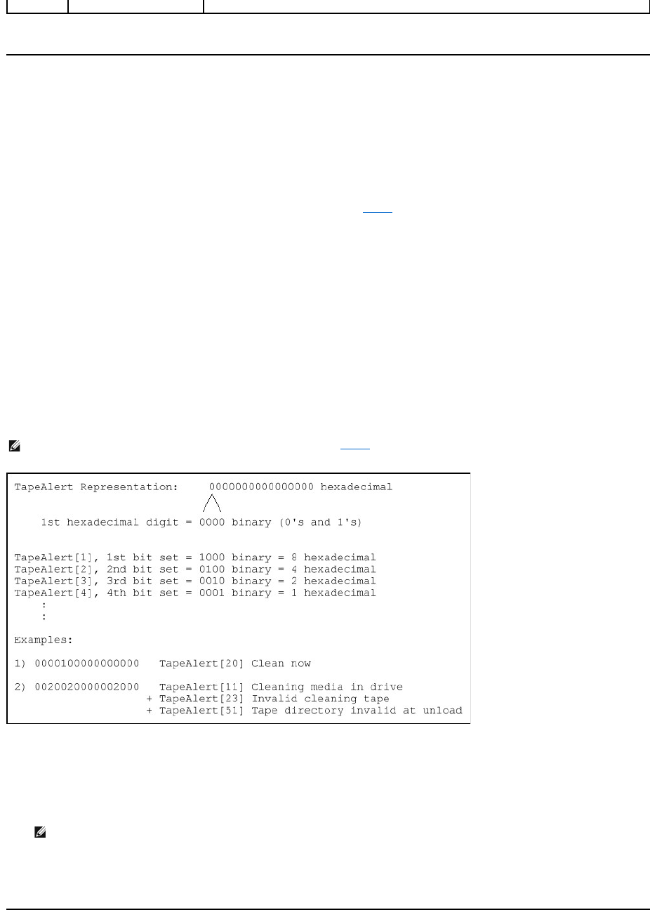
TapeAlert Logs
You can retrieve TapeAlert log information through one of three methods:
lOperator Control Panel (OCP)
lRemote Management Unit (RMU) display to screen
lDetailed logs saved to text file through the RMU for call center diagnosis
Further information and recommended actions for tape drive TapeAlerts can be found in Table 3.
TapeAlert Logs through OCP
To view TapeAlert log information from the front panel:
1. From the front panel LCD, scroll to Diagnostics, and then press Enter. The Diagnostics submenu appears.
2. From the Diagnostics submenu, scroll to TapeAlert Logs, and then press Enter. The TapeAlert log information is displayed.
3. You may scroll up and down through the TapeAlert log entries. The most recent entry will be associated with the highest event number shown.
Within each TapeAlert log entry, you may scroll up and down to display the date and time that an error occurred, the barcode label associated with the tape
being used at the time of error (if barcode labels are being used and the barcode reader is enabled), and any TapeAlert flags set during that event.
TapeAlert Interpretation
In order to display any combination of TapeAlerts that may be set for any one event, a binary representation is used. The 16 character hexadecimal TapeAlert
representation is broken down into a total of 64 bits (16 x 4 = 64), one for each possible TapeAlert that may be reported. The illustration below demonstrates
TapeAlert bit assignment, as well as practical examples. In the first example, the tape drive requested cleaning. In the second example, cleaning was
attempted with an invalid cleaning cartridge.
TapeAlert Logs through RMU
To view TapeAlert log information from the Remote Management Unit, or save all logs:
1. From within the RMU, click the Diagnostics heading. The Diagnostics screen displays.
2. Click TapeAlert Logs to display the TapeAlert log. The most recent entry will be associated with the highest event number shown.
3. Detailed log information files are particularly useful when calling for support. If you want to save logs to a local text file, click Save Logs.
Table 3: TapeAlert Detail
NOTE: The binary representation for every possible TapeAlert is presented in Table 3. Multiple TapeAlerts may be set as shown in the
following example:
NOTE: This option is particularly useful for locating suspect media. The screen output will display a history of unit TapeAlerts, current
TapeAlerts reported by the drive, and a history of TapeAlerts recorded on each cartridge since being inserted in the autoloader.

Tape Alert Message
Typical Application Client Message
Probable Cause Of Error
Message
Recommended Action
Drive TAflag[01] Read
Warning
TapeAlert Log Entry:
8000000000000000
The tape drive is having problems reading
data. No data has been lost, but there has
been a reduction in the performance of the
tape.
The drive is having severe
trouble reading.
This can be caused by bad media
or the drive.
lClean the drive
lTry another piece of media.
lIf no errors are encountered with the
alternate piece of media, retry the
original media.
Drive TAflag[02] Write
Warning
TapeAlert Log Entry:
4000000000000000
The tape drive is having problems writing
data. No data has been lost, but there has
been a reduction in the capacity of the tape.
The drive is having severe
trouble writing.
This can be caused by bad media
or the drive.
lClean the drive
lTry another piece of media.
lIf no errors are encountered with the
alternate piece of media, retry the
original media.
Drive TAflag[03] Hard Error
TapeAlert Log Entry:
2000000000000000
The operation has stopped because an
error has occurred while reading or writing
data that the drive cannot correct.
The drive had a hard read or
write error.
This can be caused by bad media
or the drive.
lClean the drive
lTry another piece of media.
lIf no errors are encountered with the
alternate piece of media, retry the
original media.
DriveTAflag[04]Media
TapeAlert Log Entry:
1000000000000000
Your data is at risk. Copy any data you
require from this tape. Do not use this tape
again.
Media can no longer be
written/read, or performance is
severely degraded.
lClean the drive
lTry another piece of media.
lIf no errors are encountered with the
alternate piece of media, retry the
original media.
Drive TAflag[05] Read
Failure
TapeAlert Log Entry:
0800000000000000
The tape is damaged or the drive is faulty.
The drive can no longer read
data from the tape.
lClean the drive
lTry another piece of media.
lIf no errors are encountered with the
alternate piece of media, retry the
original media.
Drive TAflag[06] Write
Failure
TapeAlert Log Entry:
0400000000000000
The tape is from a faulty batch or the tape
drive is faulty.
The drive can no longer write
data to the tape.
lClean the drive
lTry another piece of media.
lIf no errors are encountered with the
alternate piece of media, retry the
original media.
Drive TAflag[07] Media Life
TapeAlert Log Entry:
0200000000000000
The tape cartridge has reached the end of
its calculated useful life.
The media has exceeded its
specified life.
Copy any data you need to another tape.
Discard the old tape.
Drive TAflag[08] Not Data
Grade
TapeAlert Log Entry:
0100000000000000
The cartridge is not data-grade. Any data
you write to the tape is at risk.
The drive has not been able to
read the MRS stripes
Replace the cartridge with a data-grade tape.
Drive TAflag[09] Write
Protect
TapeAlert Log Entry:
0080000000000000
You are trying to write to a write protected
cartridge.
Write command is attempted to
a write protected tape.
Remove the write protection or use another
tape.
Drive TAflag[10] No
Removal
TapeAlert Log Entry:
0040000000000000
You cannot eject the cartridge because the
tape drive is in use. Wait until the operation
is complete before ejecting the cartridge.
Manual or software unload
attempted when prevent media
removal is on.
lCheck in the RMU if the Software Lock
is set.
lPerform an unlock using the Backup
Application.
Drive TAflag[11] Cleaning
Media
TapeAlert Log Entry:
0020000000000000
The tape in the drive is a cleaning cartridge.
Cleaning tape loaded into drive.
Drive TAflag[12]
UnsupportedFormat
TapeAlert Log Entry:
0010000000000000
You have attempted to load a cartridge of a
type that is not supported by this drive.
Attempted load of unsupported
tape format. (e.g., Unformatted
Type IV media in a VS160 drive.)
Use tape format correct for the drive type.
Drive TAflag[13] Recoverable
Mechanical Cartridge Failure
TapeAlert Log Entry:
0008000000000000
The operation has failed because the tape
in the drive has experienced a mechanical
failure.
Tape snapped/cut or other
cartridge mechanical failure in
the drive where medium can be
de-mounted.
Discard the old tape. Restart the operation
with a different tape.
Drive TAflag[14]
The operation has failed because the tape
Tape snapped/cut or other
Discard the old tape. Restart the operation

Unrecoverable Mechanical
Cartridge Failure
TapeAlert Log Entry:
0004000000000000
in the drive has experienced a mechanical
failure.
cartridge mechanical failure in
the drive where medium cannot
be de-mounted.
with a different tape.
Drive TAflag[15] Memory
Chip In Cartridge Failure
TapeAlert Log Entry:
0002000000000000
The memory in the tape cartridge has failed,
which reduces performance. Do not use the
cartridge for further write operations.
Memory chip failed in cartridge.
Replace cartridge.
Drive TAflag[16] Forced Eject
TapeAlert Log Entry:
0001000000000000
The operation has failed because the tape
cartridge was manually de-mounted while
the tape drive was actively writing or
reading.
Manual forced eject while drive
actively writing or reading.
Retry operation using the same media.
Drive TAflag[17] Read Only
Format
TapeAlert Log Entry:
0000800000000000
You have loaded a cartridge of a type that is
read-only in this drive. The cartridge will
appear as write protected.
Media loaded that is read-only
format.
Check write protect tab on cartridge.
Drive TAflag[18] Tape
Directory Corrupted On Load
TapeAlert Log Entry:
0000400000000000
The tape directory on the tape cartridge has
been corrupted. File search performance will
be degraded. The tape directory can be
rebuilt by reading all the data on the
cartridge.
The tape drive powered down
with tape loaded, or permanent
error prevented the tape
directory from being updated.
lRetry operation with same tape.
lIf error persists, discard tape.
Drive TAflag[19] Nearing
Media Life
TapeAlert Log Entry:
0000200000000000
The tape cartridge is nearing the end of its
calculated Media may have life.
Media may have exceeded its
specified number of passes.
lUse another tape cartridge for your
next backup.
lStore this tape cartridge in a safe place
in case you need to restore data from
it.
Drive TAflag[20] Clean Now
TapeAlert Log Entry:
0000100000000000
The tape drive needs cleaning.
The drive has responded as if it
has a head clog or needs
cleaning.
lIf the operation has stopped, eject the
tape and clean the drive.
lIf the operation has not stopped, wait
for it to finish and then clean the drive.
Check the tape drive user's manual for
device specific cleaning instructions.
Drive TAflag[21] Clean
Periodic
TapeAlert Log Entry:
0000080000000000
The tape drive is due for routine cleaning.
The drive is ready for a periodic
cleaning.
lWait for the current operation to finish.
lThen use a cleaning cartridge. Check
the tape drive user's manual for device
specific cleaning instructions.
Drive TAflag[22] Expired
CleaningMedia
TapeAlert Log Entry:
0000040000000000
The last cleaning cartridge used in the tape
drive has worn out.
The cleaning tape has expired.
lDiscard the worn out cleaning
cartridge.
lWait for the current operation to finish.
lThen use a new cleaning cartridge.
Drive TAflag[23] Invalid
Cleaning Tape
TapeAlert Log Entry:
0000020000000000
The last cleaning cartridge used in the tape
drive was an invalid type.
Invalid cleaning tape type used.
lDo not use this cleaning cartridge in
this drive.
lWait for the current operation to finish.
lThen use a valid cleaning cartridge.
Drive TAflag[24] Retension
Requested
TapeAlert Log Entry:
0000010000000000
The tape drive has requested a retension
operation.
The drive is having severe
trouble reading or writing that
will be resolved by a retension
cycle.
lPerform a retension operation.
lRetry operation.
Drive TAflag[25] Dual port
Interface Error
TapeAlert Log Entry:
0000008000000000
A redundant interface port on the tape drive
has failed.
Failure of one interface port in a
dual-port configuration (i.e.,
Fibre Channel).
Drive TAflag[26] Cooling Fan
Failure
TapeAlert Log Entry:
0000004000000000
A tape drive cooling fan has failed.
Fan failure inside tape drive
mechanism or tape drive
enclosure.
Drive TAflag[27] Power
Supply Failure
TapeAlert Log Entry:
0000002000000000
A redundant power supply has failed inside
the tape drive enclosure.
Redundant PSU failure inside the
tape drive enclosure or rack
subsystem.
Check the enclosure user's manual for
instructions on replacing the failed power
supply.

Drive TAflag[28] Power
Consumption
TapeAlert Log Entry:
0000001000000000
The tape drive power consumption is
outside the specified range.
Power consumption of the tape
drive is outside specified range.
Drive TAflag[29] Drive
Maintenance
TapeAlert Log Entry:
0000000800000000
Preventive maintenance of the tape drive is
required.
The drive requires preventative
maintenance (not cleaning).
Check the tape drive user's manual for device
specific preventive maintenance tasks.
Drive TAflag[30] Hardware
A
TapeAlert Log Entry:
0000000400000000
The tape drive has a hardware fault.
The drive has a hardware fault
that requires reset to recover.
lEject the tape.
lReset the drive.
lRestart the operation.
Drive TAflag[31] Hardware B
TapeAlert Log Entry:
0000000200000000
The tape drive has a hardware fault.
The drive has a hardware fault
that is not read/write related or
requires a power cycle to
recover.
lPower cycle the tape drive.
lRestart the operation.
Drive TAflag[32] Interface
TapeAlert Log Entry:
0000000100000000
The tape drive has a problem with the
application client interface.
The drive has identified an
interface fault.
lCheck the SCSI interface cables,
terminator, and all connections.
lRestart the operation.
Drive TAflag[33] Eject Media
TapeAlert Log Entry:
0000000080000000
The operation has failed.
Error recovery action
lEject the tape or magazine.
lInsert the tape or magazine again.
lRestart the operation.
Drive TAflag[34] Download
Fail
TapeAlert Log Entry:
0000000040000000
The firmware download has failed because
you have tried to use the incorrect firmware
for this tape drive.
Firmware download failed.
Obtain the correct firmware and try again.
Drive TAflag[35] Drive
Humidity
TapeAlert Log Entry:
0000000020000000
Environmental conditions inside the tape
drive are outside the specified humidity
range.
Drive humidity limits exceeded.
Drive TAflag[36] Drive
Temperature
TapeAlert Log Entry:
0000000010000000
Environmental conditions inside the tape
drive are outside the specified temperature
range.
Cooling problem.
Drive TAflag[37] Drive
Voltage
TapeAlert Log Entry:
0000000008000000
The voltage supply to the tape drive is
outside the specified range.
Drive voltage limits exceeded.
Drive TAflag[38] Predictive
Failure
TapeAlert Log Entry:
0000000004000000
A hardware failure of the tape drive is
predicted.
Predictive failure of drive
hardware.
Drive TAflag[39] Diagnostics
Required
TapeAlert Log Entry:
0000000002000000
The tape drive may have a hardware fault
The drive may have a hardware
fault that may be identified by
extended diagnostics (i.e., SEND
DIAGNOSTIC command).
lRun extended diagnostics to verify and
diagnose the problem.
lCheck the tape drive user's manual for
device specific instructions on running
extended diagnostic tests.
Drive TAflag[50] Lost
Statistics
TapeAlert Log Entry:
0000000000004000
Media statistics have been lost at some time
in the past.
Drive or library powered on with
tape loaded
lClean drive.
lRetry operation.
Drive TAflag[51] Tape
Directory Invalid at Unload
TapeAlert Log Entry:
0000000000002000
The tape directory on the tape cartridge just
unloaded has been corrupted. File search
performance will be degraded.
Error preventing the tape
directory being updated on
unload.
The tape directory can be rebuilt by reading
all the data.
Drive TAflag[52] Tape
System Area Write Failure
TapeAlert Log Entry:
0000000000001000
The tape just unloaded could not write its
system area successfully.
Write errors while writing the
system area on unload.
lCopy data to another tape cartridge.
lDiscard the old cartridge.
Drive TAflag[53] Tape
System Area Read Failure
The tape system area could not be read
successfully at load time.
Read errors while reading the
system area on load
Copy data to another tape cartridge.

Returning the Autoloader for Service
If you need to return the autoloader or a component of the autoloader for service, contact support.dell.com. The following steps will help you to prepare the
autoloader for shipment, remove the autoloader from a rack, and package the autoloader.
To prepare the autoloader for shipment
1. Remove all cartridges from the unit.
2. Power off the autoloader through the front panel.
3. Remove the power, Ethernet, and SCSI cables, and any terminators from the autoloader.
To Remove the Autoloader from a Rack
1. Loosen the two thumb screws that secure the loader to the front of the rack.
2.
Using two people, or an appropriately rated mechanical lift, remove the autoloader from the rack by sliding the autoloader out and supporting it from the
bottom.
3. Place the autoloader into the original packaging box, or the packaging from the replacement unit.
TapeAlert Log Entry:
0000000000000800
Drive TAflag[54] No Start Of
Data
TapeAlert Log Entry:
0000000000000400
The start of data could not be found on the
tape.
Tape damaged, bulk erased, or
incorrect format.
lCheck that you are using the correct
format tape.
lDiscard the tape or return the tape to
your supplier.
Drive TAflag[55] Loading
Failure
TapeAlert Log Entry:
0000000000000200
The operation has failed because the media
cannot be loaded and threaded.
The drive is unable to load the
media and thread the tape.
Remove the cartridge, inspect it as specified
in the product manual, and retry the
operation.
Drive TAflag[56]
Unrecoverable Unload
Failure
TapeAlert Log Entry:
0000000000000100
The operation has failed because the
medium cannot be unloaded.
The drive is unable to unload the
medium.
Remove the cartridge if possible, inspect it as
specified in the product manual, and retry the
operation.
Drive TAflag[57] Automation
Interface Failure
TapeAlert Log Entry:
0000000000000080
The tape drive has a problem with the
automation interface.
The drive has identified an
interface fault.
lCheck the power to the automation
system.
lCheck the cables and cable
connections.
Drive TAflag[58] Firmware
Failure
TapeAlert Log Entry:
0000000000000040
The tape drive has reset itself due to a
detected firmware fault.
Firmware issue encountered.
Drive TAflag[59] WORM
Medium - Integrity Check
Failed
TapeAlert Log Entry:
0000000000000020
The tape drive has detected an
inconsistency during the WORM medium
integrity checks.
WORM cartridge may have been
tampered with.
Replace WORM medium.
Drive TAflag[60] WORM
Medium - Overwrite
Attempted
TapeAlert Log Entry:
0000000000000010
An attempt had been made to overwrite
user data on WORM medium.
The application software does
not recognize the medium as
WORM.
lIf a WORM medium was used
inadvertently, replace it with a normal
data medium.
lIf a WORM medium was used
intentionally:
- check that the software application is
compatible with the WORM medium
format you are using.
- check that the medium is bar-coded
correctly for WORM.
NOTE: Do not ship these items if you are returning the autoloader.

Packing the Autoloader
Gather the original packaging material to pack the autoloader: the shipping box, two foam end caps, accessory package insert (placed at the back of the unit),
and the antistatic bag. You will also need packing tape.
1. Place the antistatic bag over the autoloader.
2. Place one of the foam end caps onto each end of the autoloader. Place the second foam insert onto the other side of the autoloader and make sure the
pieces fit snugly onto the autoloader.
3. Place the autoloader into the shipping box and push the front of the autoloader towards the front end of the box.
4. Insert the accessory package insert at the back of the unit.
5. Place any necessary paperwork on top of the autoloader inside the box.
6. Close and seal the box.
7. Place the shipping label on the box.
Back to Contents Page
NOTE: The foam end caps are not identical. Refer to the diagram on the box flaps for proper orientation.
NOTE: The accessory package insert is to be placed at the back of the unit, not the front. Refer to the diagram on the box flaps for
proper orientation.
