Dell Optiplex 980 Early 2010 Service Manual Desktop
2014-11-13
: Dell Dell-Optiplex-980-Early-2010-Service-Manual-110943 dell-optiplex-980-early-2010-service-manual-110943 dell pdf
Open the PDF directly: View PDF ![]() .
.
Page Count: 77
- Local Disk
- Dell OptiPlex 980 Desktop Service Manual--Desktop
- Dell OptiPlex 980 Service Manual-Working on Your Computer
- Dell OptiPlex 980 Service Manual-Technical Specifications
- Dell OptiPlex 980 Desktop Service Manual--Removing and Replacing Parts
- Dell OptiPlex 980 Desktop Service Manual--System Board Layout
- Dell OptiPlex 980 Desktop Service Manual--System Setup
- Dell OptiPlex 980 Desktop Service Manual--Diagnostics
- Dell OptiPlex 980 Desktop Service Manual--Computer Cover
- Dell OptiPlex 980 Desktop Service Manual--Computer Cover
- Dell OptiPlex 980 Desktop Service Manual--Front Panel
- Dell OptiPlex 980 Desktop Service Manual--Optical Drive
- Dell OptiPlex 980 Desktop Service Manual--Hard Drive
- Dell OptiPlex 980 Desktop Service Manual--Expansion Cards
- Dell OptiPlex 980 Desktop Service Manual--Wireless Module
- Dell OptiPlex 980 Desktop Service Manual--Fan
- Dell OptiPlex 980 Desktop Service Manual--Heat Sink and Processor
- Dell OptiPlex 980 Desktop Service Manual--Memory
- Dell OptiPlex 980 Desktop Service Manual--Internal Speaker
- Dell OptiPlex 980 Desktop Service Manual--Front Thermal Sensor
- Dell OptiPlex 980 Desktop Service Manual--Power Supply
- Dell OptiPlex 980 Desktop Service Manual--I/O Panel
- Dell OptiPlex 980 Desktop Service Manual--Control Panel
- Dell OptiPlex 980 Desktop Service Manual--Intrusion Switch
- Dell OptiPlex 980 Desktop Service Manual--Coin-Cell Battery
- Dell OptiPlex 980 Desktop Service Manual--System Board

Dell™ OptiPlex™ 980 Service Manual—Desktop
Working on Your Computer
Specifications
Removing and Replacing Parts
System Board Layout
System Setup
Diagnostics
Notes, Cautions, and Warnings
NOTE: A NOTE indicates important information that helps you make better use of your computer.
CAUTION: A CAUTION indicates potential damage to hardware or loss of data if instructions are not followed.
WARNING: A WARNING indicates a potential for property damage, personal injury, or death.
If you purchased a Dell™ n Series computer, any references in this document to Microsoft® Windows® operating systems are not
applicable.
Information in this document is subject to change without notice.
© 2010 Dell Inc. All rights reserved.
Reproduction of this material in any manner whatsoever without the written permission of Dell Inc. is strictly forbidden.
Trademarks used in this text: Dell, the DELL logo, and OptiPlex are trademarks of Dell Inc.; Intel, Pentium, and Core are either trademarks or registered
trademarks of Intel Corporation; Microsoft, Windows, Windows Vista, and the Windows Vista start button are either trademarks or registered trademarks of
Microsoft Corporation in the United States and/or other countries.
Other trademarks and trade names may be used in this document to refer to either the entities claiming the marks and names or their products. Dell Inc.
disclaims any proprietary interest in trademarks and trade names other than its own.
May 2010 Rev. A00

Back to Contents Page
Working on Your Computer
Dell™ OptiPlex™ 980 Service Manual—Desktop
Before Working Inside Your Computer
Recommended Tools
Turning Off Your Computer
After Working Inside Your Computer
Before Working Inside Your Computer
Use the following safety guidelines to help protect your computer from potential damage and to help to ensure your personal
safety. Unless otherwise noted, each procedure included in this document assumes that the following conditions exist:
You have read the safety information that shipped with your computer.
A component can be replaced or—purchased separately—installed by performing the removal procedure in reverse
order.
WARNING: Before working inside your computer, read the safety information that shipped with your
computer. For additional safety best practices information, see the Regulatory Compliance Homepage at
www.dell.com/regulatory_compliance.
CAUTION: Many repairs may only be done by a certified service technician. You should only perform
troubleshooting and simple repairs as authorized in your product documentation, or as directed by the
online or telephone service and support team. Damage due to servicing that is not authorized by Dell is
not covered by your warranty. Read and follow the safety instructions that came with the product.
CAUTION: To avoid electrostatic discharge, ground yourself by using a wrist grounding strap or by
periodically touching an unpainted metal surface, such as a connector on the back of the computer.
CAUTION: Handle components and cards with care. Do not touch the components or contacts on a card.
Hold a card by its edges or by its metal mounting bracket. Hold a component such as a processor by its
edges, not by its pins.
CAUTION: When you disconnect a cable, pull on its connector or on its pull-tab, not on the cable itself.
Some cables have connectors with locking tabs; if you are disconnecting this type of cable, press in on the
locking tabs before you disconnect the cable. As you pull connectors apart, keep them evenly aligned to
avoid bending any connector pins. Also, before you connect a cable, ensure that both connectors are
correctly oriented and aligned.
NOTE: The color of your computer and certain components may appear differently than shown in this document.
To avoid damaging your computer, perform the following steps before you begin working inside the computer.
1. Ensure that your work surface is flat and clean to prevent the cover from being scratched.
2. Turn off your computer (see Turning Off Your Computer).
CAUTION: To disconnect a network cable, first unplug the cable from your computer and then unplug the
cable from the network device.
3. Disconnect all network cables from the computer.
4. Disconnect your computer and all attached devices from their electrical outlets.
5. Press and hold the power button while the computer is unplugged to ground the system board.
6. Remove the cover.
CAUTION: Before touching anything inside your computer, ground yourself by touching an unpainted metal
surface, such as the metal at the back of the computer. While you work, periodically touch an unpainted
metal surface to dissipate static electricity, which could harm internal components.

Recommended Tools
The procedures in this document may require the following tools:
Small flat-blade screwdriver
Phillips screwdriver
Small plastic scribe
Flash BIOS update program media
Turning Off Your Computer
CAUTION: To avoid losing data, save and close all open files and exit all open programs before you turn off
your computer.
1. Shut down the operating system:
In Windows® 7:
Click Start , then click Shut Down.
In Windows Vista®:
Click Start , then click the arrow in the lower-right corner of the Start menu as shown below, and then click
Shut Down.
In Windows® XP:
Click Start® Turn Off Computer® Turn Off.
The computer turns off after the operating system shutdown process is complete.
2. Ensure that the computer and all attached devices are turned off. If your computer and attached devices did not
automatically turn off when you shut down your operating system, press and hold the power button for about 6
seconds to turn them off.
After Working Inside Your Computer
After you complete any replacement procedure, ensure you connect any external devices, cards, and cables before turning on
your computer.
1. Replace the cover.
CAUTION: To connect a network cable, first plug the cable into the network device and then plug it into the
computer.
2. Connect any telephone or network cables to your computer.
3. Connect your computer and all attached devices to their electrical outlets.
4. Turn on your computer.
5. Verify that the computer works correctly by running the Dell Diagnostics.
Back to Contents Page
Back to Contents Page
Technical Specifications
Processor
Memory
Expansion Bus
Video
System Information
Cards
Drives
External Connectors
Controls and Lights
Network
Audio
Power
System Board Connectors
Physical
Environmental
NOTE: Offerings may vary by region. For more information regarding the configuration of your computer, click Start®
Help and Support and select the option to view information about your computer.
NOTE: Unless otherwise stated, the specifications are identical for mini-tower, desktop, and small form factor
computers.
Processor
Type
Quad-Core Intel® Core™ i7 series
Intel Core i5 series
Dual-Core Intel Core i5 series
Intel Core i3 series
Intel Pentium®
Level 2 (L2) cache
Intel Core i7 series
Intel Core i5 series 8 MB
Intel Core i5 series
Intel Core i3 series 4 MB
Intel Pentium 3 MB
Memory
Type DDR3 SDRAM (non-ECC memory only)
Speed 1066 MHz or 1333 MHz
Connectors four
Capacity 1 GB, 2 GB, or 4 GB
Minimum memory 1 GB
Maximum memory 16 GB
Video
Integrated Intel graphics media accelerator HD
NOTE: Not supported by computers
shipped with
Intel i7 and Intel i5 quad-core processors.
Discrete PCI Express x16 slot supports a PCI
Express card
Memory - Integrated Up to 1759 MB shared video memory
(total system memory greater than 512
MB)
Audio
Integrated Intel high definition audio
Network
Integrated Integrated Intel 82578DM Gigabit
Ethernet capable of 10/100/1000 Mb/s
communication
System Information
Chipset Intel Q57 Express chipset
DMA channels eight
Interrupt levels 24
BIOS chips (NVRAM) 64 Mb and 16 Mb
Expansion Bus
Bus type PCI 2.3
PCI Express 2.0
SATA 1.0A and 2.0
eSATA
USB 2.0
Bus speed
PCI 133 MB/s
PCI Express x1-slot (wireless only) bidirectional speed
- 500 MB/s
x16-slot (wired as x4) bidirectional speed
- 2 GB/s
x16-slot bidirectional speed - 8 GB/s
SATA 1.5 GB/s and 3.0 GB/s
eSATA 3.0 GB/s
USB 480 MB/s
Cards
PCI
Mini-tower up to two full-height cards
Desktop without riser card — up to two low-profile
cards
with riser card — up to two full-height
cards
Small form factor one low-profile card
PCI Express x16 (wired as x4)
Mini-tower one full-height card
Desktop one low-profile card
Small form factor none
PCI Express x16

Mini-tower one full-height card
Desktop without riser card— one low-profile card
with riser card— one full-height card
Small form factor one low-profile card
PCI Express x1
Mini-tower one wireless card
Desktop one wireless card
Small form factor one wireless card
Drives
Externally accessible - 5.25-inch drive bay(s)
Mini-tower two bays
Desktop one bay
Small form factor one slimline bay
Externally accessible - 3.5-inch drive bay (s)
Mini-tower one bay
Desktop one bay
Small form factor one bay
Internally accessible - 3.5 inch drive bay(s) for hard drives
Mini-tower two bays
Desktop one bay
Small form factor one bay
NOTE: Your computer can support up to two 2.5 inch hard drives with brackets.
External Connectors
Audio
Back panel two connectors for line-in/ microphone
and line-out
Front panel two front-panel connectors for
headphones and microphone
eSATA one 7-pin connector
Network one RJ45 connector
Parallel one 25-pin connector (bidirectional)
Serial one 9-pin connector; 16550C-compatible
USB - Front panel
Mini-tower four connectors
Desktop two connectors
Small form factor two connectors
USB - Back panel
Mini-tower six connectors
Desktop six connectors
Small form factor six connectors

Video one 15-hole VGA connector
one 20-pin DisplayPort connector
System Board Connectors
PCI 2.3 data width (maximum) — 32 bits
Mini-tower two 120-pin connectors
Desktop two 120-pin connectors
Small form factor one 120-pin connector
PCI Express x16 (wired as x4) data width (maximum) — four PCI Express lanes
Mini-tower one 164-pin connector
Desktop one 164-pin connector
Small form factor not applicable
PCI Express x16 data width (maximum) — 16 PCI Express lanes
Mini-tower one 164-pin connector
Desktop one 164-pin connector
Small form factor one 164-pin connector
Serial ATA
Mini-tower four 7-pin connectors
Desktop three 7-pin connectors
Small form factor three 7-pin connectors
Memory four 240-pin connectors
Internal USB one 10-pin connector (supports two USB
ports)
Processor fan one 5-pin connector
Front I/O one 26-pin connector
Front panel control one 14-pin connector
Processor one 1156-pin connector
Power 12V one 4-pin connector
Power one 24-pin connector
Internal serial card one 14-pin connector
Internal speaker one 5-pin connector
PCI Express x1 (wireless card) one 36-pin connector
Thermal sensor one 2-pin connector
Intruder connector one 3-pin connector
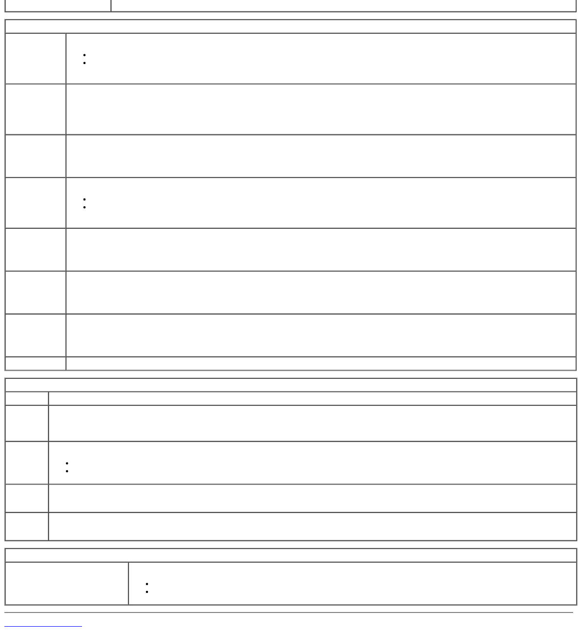
Controls and Lights
Front of the computer
Power button push button
Power light blinking blue — indicates that the
computer is in sleep state.
solid blue — indicates that the computer
is in power-on state.
blinking amber — indicates a problem
with the system board.
solid amber (when the computer does not
start) — indicates a problem with the
system board or power supply.
Drive activity light blinking blue — indicates that the
computer is reading data from or writing
data to the hard drive.
Network connectivity light blue — indicates that a good connection
exists between the network and the
computer.
off (no light) — indicates that the
computer is not detecting a physical
connection to the network.
Diagnostic lights four amber lights on the front panel. For
more information, see Diagnostics.
Back of the computer
Link integrity light on integrated
network adapter green — a good 10 Mbps connection
exists between the network and the
computer.
orange — a good 100 Mbps connection
exists between the network and the
computer.
yellow — a good 1000 Mbps connection
exists between the network and the
computer.
off (no light) — the computer is not
detecting a physical connection to the
network.
Network activity light on integrated
network adapter yellow light — a blinking yellow light
indicates that network activity is present.
Power supply light green light — the power supply is turned
on and is functional. The power cable
must be connected to the power
connector (at the back of the computer)
and the electrical outlet.
NOTE: You can test the health of the
power system by pressing the test button.
When the system's power supply voltage
is within specification, the self-test LED
lights up. If the LED does not light up, the
power supply may be defective. AC power
must be connected during this test.
Power
Wattage
Mini-tower 255 W
(EPA) 305 W (non-
EPA)
Desktop 255 W
(EPA) 255 W (non-
EPA)
Small form factor 235 W
(EPA) 235 W (non-
EPA)
Maximum heat dissipation
Mini-tower 1000
BTU/hr
(EPA)
1603 BTU/hr
(non-EPA)
Desktop 1000
BTU/hr
(EPA)
1341 BTU/hr
(non-EPA)

Small form factor 921
BTU/hr
(EPA)
1235 BTU/hr
(non-EPA)
Voltage 100–240 VAC
Coin-cell battery 3 V CR2032 lithium coin cell
NOTE: Heat dissipation is calculated by using the power supply wattage rating.
Physical
Height
Mini-tower 40.80 cm (16.06 inches)
Desktop 39.70 cm (15.62 inches)
Small form factor 29.0 cm (11.41 inches)
Width
Mini-tower 18.70 cm (7.36 inches)
Desktop 10.90 cm (4.29 inches)
Small form factor 8.50 cm (3.34 inches)
Depth
Mini-tower 43.10 cm (16.96 inches)
Desktop 34.80 cm (13.70 inches)
Small form factor 32.40 cm (12.75 inches)
Weight
Mini-tower 11.40 kg (25.13 lb)
Desktop 8.30 kg (18.29 lb)
Small form factor 5.90 kg (13.00 lb)
Environmental
Temperature
Operating 10 °C to 35 °C (50 °F to 95 °F)
Storage –40 °C to 65 °C (–40 °F to 149 °F)
Relative humidity (noncondensing) 20% to 80%
Maximum vibration
Operating 5 Hz to 350 Hz at 0.0002 G2/Hz
Storage 5 Hz to 500 Hz at 0.001 to 0.01 G2/Hz
Maximum shock
Operating 40 G +/- 5% with pulse duration of 2
msec +/- 10% (equivalent to 20 in/sec
[51 cm/sec])
Storage 105 G +/- 5% with pulse duration of 2
msec +/- 10% (equivalent to 50 in/sec
[127 cm/sec])
Altitude
Operating –15.2 m to 3048 m (–50 ft to 10,000 ft)
Storage –15.2 m to 10,668 m (–50 ft to 35,000

Back to Contents Page
Removing and Replacing Parts
Dell™ OptiPlex™ 980 Service Manual—Desktop
Cover
Front Panel
Optical Drive
Hard Drive
Expansion Cards
Wireless Module
Processor Fan
Heat Sink and Processor
Memory
Internal Speaker
Front Thermal Sensor
Power Supply
I/O Panel
Control Panel
Intrusion Switch
Coin-Cell Battery
System Board
Back to Contents Page
Back to Contents Page
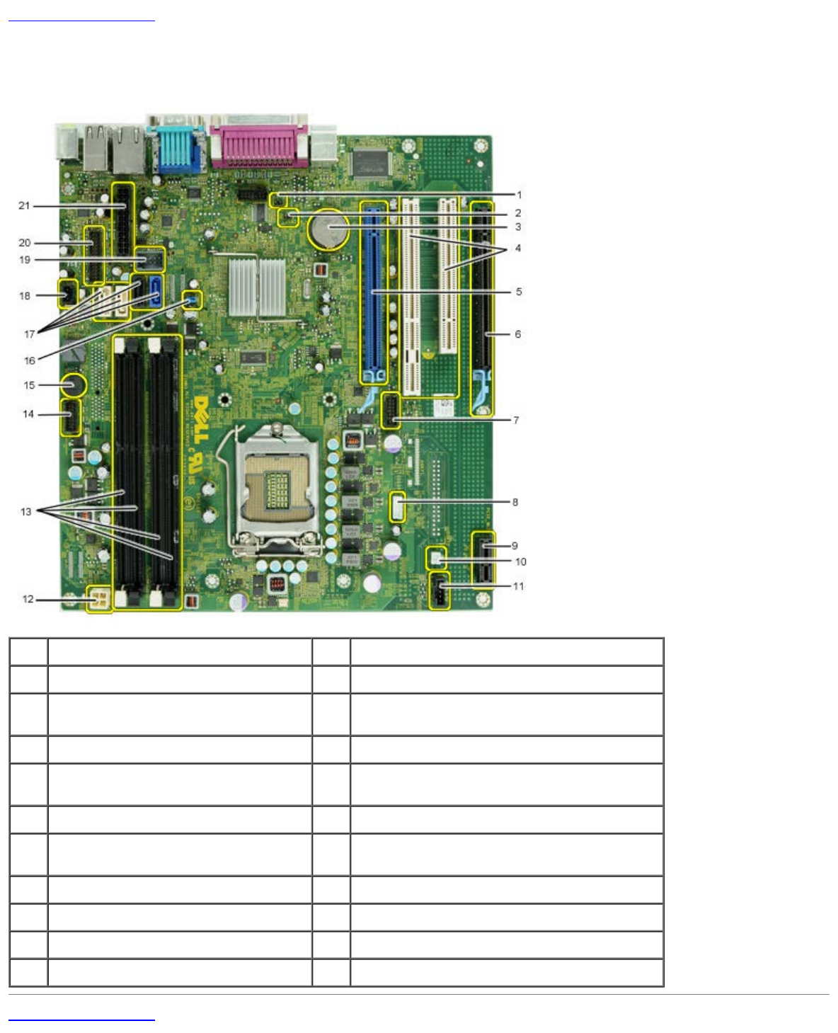
System Board Layout
Dell™ OptiPlex™ 980 Service Manual—Desktop
1service mode jumper (Service_Mode) 2RTC reset jumper (RTCRST)
3battery socket (BATTERY) 4PCI card connectors ( SLOT 2 & 3)
5PCI Express x16 card
connector(SLOT1) 6PCI Express x16 (wired as x4) connector (Slot
4)
7internal serial card connector (Serial2) 8speaker connector (INT_SPKR)
9PCI Express x1 wireless card
connector (PCIE_WLS1) 10 thermal sensor connector THRM3)
11 fan connector (FAN_CPU) 12 power connector (12V POWER)
13 memory module connectors (DIMM_1-
4) 14 front panel connector (FRONTPANEL)
15 Internal buzzer (BEEP) 16 password jumper (PSWD)
17 SATA drive connectors (SATA0-3) 18 intruder connector (INTRUDER)
19 internal USB connector (INT_USB) 20 front I/O connector(FIO)
21 power connector (MICRO_PWR)
Back to Contents Page

Back to Contents Page
System Setup
Dell™ OptiPlex™ 980 Service Manual—Desktop
Boot Menu
Navigation Keystrokes
Entering System Setup
System Setup Menu Options
Boot Menu
Press <F12> or <Ctrl><Alt><F8> when the Dell™ logo appears to initiate a one-time boot menu with a list of the valid boot devices for the system.
The options listed are:
Onboard SATA Hard Drive
Onboard or USB CD-ROM Drive
System Setup
Diagnostics
This menu is useful when you are attempting to boot to a particular device or to bring up the diagnostics for the system. Using the boot menu does not make any
changes to the boot order stored in the BIOS.
Navigation Keystrokes
Use the following keystrokes to navigate the System Setup screens.
Navigation Keystrokes
Action Keystroke
Expand and collapse field <Enter>, left- or right-arrow key, or +/–
Expand or collapse all fields < >
Exit BIOS <Esc>—Remain in Setup, Save/Exit, Discard/Exit
Change a setting Left or right-arrow key
Select field to change <Enter>
Cancel modification <Esc>
Reset defaults <Alt><F> or Load Defaults menu option
Entering System Setup
Your computer offers the following BIOS and System Setup options:
Bring up a one-time boot menu by pressing <F12>
Access System Setup by pressing <F2>
<F12> Menu
Press <F12> when the Dell™ logo appears to initiate a one-time boot menu with a list of the valid boot devices for the computer. Diagnostics and Enter Setup
options are also included in this menu. The devices listed on the boot menu depend on the bootable devices installed in the computer. This menu is useful when you
are attempting to boot to a particular device or to bring up the diagnostics for the computer. Making changes in the boot menu does not make any changes to the
boot order stored in the BIOS.
<F2>
Press <F2> to enter System Setup and make changes to user-definable settings. If you have trouble entering System Setup using this key, press <F2> when the
keyboard lights first flash.
System Setup Menu Options
NOTE: System Setup options may vary depending on your computer and may not appear in the exact same order.
General
System
Board Displays the following information:
System information: Displays BIOS Version, Service Tag, Express Service Code, Asset Tag, Manufacture Date, and the Ownership
Date.
Memory information: Displays Installed Memory, Memory Speed, Number of Active Channels, Memory Technology, DIMM_1 Size,
DIMM_2 Size.
Processor information: Displays the Processor Type, Processor Speed, Processor Bus Speed, Processor L2 cache, Processor ID,
Microcode Version, Multi Core Capable and HT Capable 64-bit Technology.
PCI information: Displays available slots on the system board.
Date/Time Displays the system date and time. Changes to the system date and time take effect immediately.
Boot
Sequence Specifies the order in which the computer attempts to find an operating system from the devices specified in this list.
Onboard or USB Floppy
Onboard SATA Hard Drive
Onboard or USB CD-Rom Drive
Drives
Diskette drive This field determines how the BIOS configures floppy drives, operating systems with USB support will recognize USB Floppy drives regardless of this
setting:
Disable - All Floppy drive are disable
Enable - All floppy drive are enable.
The "USB Controller" Setup option will affect floppy operation.
SATA
Operation
configures the operating mode of the integrated hard drive controller.
RAID Autodetect / AHCI = RAID if signed drives, otherwise AHCI
RAID Autodetect / ATA= RAID if signed drives, otherwise ATA
RAID On / ATA= SATA is configured for RAID on every boot
Legacy = The hard drive controller is configured for legacy mode
Legacy mode provides for compatibility with some older operating systems that do not support native resources assigned to the drive controller.
RAID Mode is incompatible with ImageServer. Please disable RAID mode if enabling Image Server.
S.M.A.R.T.
Reporting This field controls whether hard drive errors for integrated drives are reported during system startup. This technology is part of the SMART(Self
Monitoring Analysis and Reporting Technology) specification.
This option is disabled by default.
Drives Enables or disables the SATA or ATA drives connected to the system board.
System Configuration
Integrated NIC
Enables or disables the integrated network card. You can set the integrated NIC to:
Disable
Enable (default)
Enable with PXE
Enable with ImageSever
ImageServe is incompatible with RAID mode. Please disable RAID if enabling ImageServer.
PXE is needed only if intending to boost to an operating system located on a server, not if you are booting on an OS located on a hard drive in
this system.
USB Controller Enables or disables the integrated USB controller. You can set the USB controller to:
Enable (default)
Disable
No boot
Operating systems with USB support will recognize USB Storage
Parallel Port Identifies and defines the parallel port settings. You can set the parallel port to:
Disable
AT
PS/2 (default)
EPP
ECP No DMA
ECP DMA 1
ECP DMA 3
Parallel Port
Address Sets the base I/O address of the integrated parallel port.
Serial Port #1
Identifies and defines the serial port settings. You can set the serial port to:
Disable
Auto (default)
COM1
COM3
The Operating System may allocate resources even though the setting is disabled.
Miscellaneous
Devices Enables or disables the following onboard devices:
Front USB
PCI slots
Audio
OptiPlex ON Reader
Rear Quad USB
WiFi NIC Slot
Video
Primary
Video This field determines which video controller will become the primary video controller when 2 controllers are available in the system. This selection
matters only if there are 2 video controller present.
Auto(default) - Use the add-in video controller.
Onboard/Card - Use the integrated video controller unless a Graphic care is installed. A PCI Express Graphic(PEG) card will overide and disable
the integrated video controller.
Performance
Multi Core
Support This field specifies whether the processor will have one or all cores enable. The performance of some application will improve with the additional
cores.
Hyper-
Threading
Technology
This option enables or disables the Hyper-Threading Technology. When disabled, only one thread per enabled core is enabled
This option is enabled by default.
Intel®
Turbo Boost
Technology
This option enables or disables the Intel® Turbo Boost Technology. When disabled, Intel® Turbo Boost Technology allows processor(s) to run at
frequencies higher than the advertised frequency
This option is enabled by default.
Intel®
SpeedStep™ This Option enables or disables the Intel® SpeedStep™ mode of the processor. When disabled, the system is placed into the highest performance
state and the Intel® SpeedStep™ applet or native operating system driver are prevented from adjusting the processor's performance. When enable.
the Intel® SpeedStep™, enabled CPU is allowed to operate in multiple performance states.
This option is disabled by default.
C States
Control
This option enables or disables additional processor sleep states. The operating system may optionally use these for additional power saving when
idle.
This option is disabled by default.
Limit CPUID
Value This field limits the maximum value the processor Standard CPUID Function will support. Some operating systems will not complete installation when
the maximum CPUID Function supported is greater than 3.
This option is disabled by default.
Virtualization Support
Virtualization This Option specifies whether a Virtual Machine Monitor (VMM) can utilize the additional hardware capabilities provided by Intel® Virtualization
Technology.
Enable Intel® Virtualization Technology - This option is disabled by default.
VT for Direct
I/O Enables or disables the Virtual Machine Monitor (VMM) from utilizing the additional hardware capabilities provided by Intel® Virtualization technology
for direct I/O.
Enable Intel® Virtualization Technology for Direct I/O - This option is disabled by default.
Trusted
Execution
Field specifies whether a Measured Virtual Machine(MVMM) can utilize the additional hardware capabilities provided by Intel® Trusted Execution
Technology. The TPM Virtualization Technology and Virtualization Technology for Direct I/O must be enable to use this feature.
Enable Intel® Trusted Execution Technology - This option is disabled by default.
Security
Administrative
Password Provides restricted access to the computer's system setup program in the same way that access to the system can be restricted with the System
Password option.
This option is not set by default.
System
Password Displays the current status of the system's password security feature and allows a new system password to be assigned and verified.
This option is not set by default.
Password
Changes Enables or disables the user from changing the system password without the administrative password.
This option is enabled by default.
Admin Setup
Lockout Enables or disables the user from entering Setup when an Admin password is set.
This option is disabled by default.
Password
Configuration These fields control the minimum and maximum number of characters allowed for Admin and System passwords. Changes to these fields are not
active until they are committed via the apply button or saving changes before exiting setup.
Admin Password Min
Admin Password Max
System Password Min
System Password Max
Strong
Password This field enforces strong passwords. If enabled, all passwords must contain at least one uppercase character, one lowercase character, and be at
least 8 characters long. Enabling this feature automatically changes the default minimum password length to 8 characters.
Enforce strong password - This option is disabled by default.
TPM Security Enables or disables the trusted platform module (TPM) security.
You can set the TPM security to:

Deactivate (default)
Activate
Clear
When TPM Security is set to Clear, the system setup program clears the owner information stored in the TPM. Use this setting to restore the TPM
to its default state if you lose or forget the owner authentication data.
CPU XD
Support Enables or disables the execute disable mode of the processor.
This option is enabled by default.
Computrace(R) Enables or disables the optional Computrace® service designed for asset management.
You can set this option to:
Deactivate (default)
Disable
Activate
Chassis
Intrusion This field controls the chassis intrusion feature.
You can set this option to:
Clear Intrusion Warning (Enabled by default if detected the chassis intrusion)
Disable
Enabled
On-Silent (Enabled by default if detected the chassis intrusion)
SATA-0
Password Displays the current status of the password set for the hard drive connected to the SATA-0 connector on the system board.
You can also set a new password. This option is not set by default.
The system setup program displays a password for each of the hard drives connected to your system board.
SATA-1
Password Displays the current status of the password set for the hard drive connected to the SATA-1 connector on the system board.
You can also set a new password. This option is not set by default.
The system setup program displays a password for each of the hard drives connected to your system board.
Power Management
AC Recovery Determines how the system responds when AC power is re-applied after a power loss. You can set the AC Recovery to:
Power Off (default)
Power On
Last State
Auto On Time
Sets time to automatically turn on the computer.
Time is kept in the standard 12-hour format (hours:minutes:seconds).
Change the startup time by typing the values in the time and AM/PM fields.
NOTE: This feature does not work if you turn off your computer using the switch on a power strip or surge protector or if Auto Power On is set
to disabled.
Low Power
Mode
Enables or disables low power mode.
This option is disabled by default.
When low power mode is enabled, the integrated network card is disabled when the system is shutdown or in Hibernate mode. Only Add-in NIC
cards will be able to remotely wake the system.
Remote
Wakeup Allows the system to power up when a network interface controller receives a wake up signal. You can set Remote Wakeup to:
Disable (default)
Enable
Enable with Boot NIC
Suspend Mode Sets the power management suspend mode to:
S1
S3 (default)
Fan Control
Override Controls the speed of the system fan. This option is disabled by default.
NOTE: When enabled, the fan runs at full speed.
Maintenance
Service Tag Displays the Service Tag of your computer.
Asset Tag Allows you to create a system asset tag if an asset tag is not already set.
This option is not set by default.
SERR Messages Controls the SERR Message mechanism.
This option is enabled by default.
Some graphics cards require the SERR Message mechanism be disabled.
Image Server
Lookup Method Specifies how the ImageServer looks up the server address.
Static IP
DNS
NOTE: You must set the Integrated NIC to Enable with ImageServer to set the Lookup Method.
ImageServer IP Specifies the primary static IP address of the ImageServer with which the client software communicates.
The default IP address is 255.255.255.255
NOTE: You must set the “Integrated NIC” control in the “System Configuration” group to “Enabled with ImageServer” and when “Lookup Method”
is set to “Static IP”.
ImageServer
Port Specifies the primary IP port of the image server with which the client software communicates.
The default IP port is 06910
NOTE: You must set the “Integrated NIC” control in the “System Configuration” group to “Enabled with ImageServer”.
Client DHCP Specifies how the client obtains the IP address.
Static IP
DHCP (default)
NOTE: You must set the “Integrated NIC” control in the “System Configuration” group to “Enabled with ImageServer”.
Client IP Specifies the static IP address of the client.
The default IP address is 255.255.255.255
NOTE: To set Client IP you must set Client DHCP to Static IP
Client
SubnetMask Specifies the subnet mask for the client.
The default setting is 255.255.255.255
NOTE: To set Client SubnetMask you must set Client DHCP to Static IP
Client Gateway Specifies the gateway IP address for the client.
The default setting is 255.255.255.255
NOTE: To set Client SubnetMask you must set Client DHCP to Static IP
License Status Displays the current license status.
Post Behavior
Fast Boot When enabled (default), your computer starts more quickly because it skips certain configurations and tests.
NumLock
LED Enables or disables the NumLock feature when your computer starts.
When enabled (default), this option activates the numeric and mathematical features shown at the top of each key. When disabled, this option activates
the cursor-control functions labeled on the bottom of each key
POST
Hotkeys Allows you to specify the function keys to display on the screen when the computer starts.
Enable F2 = Setup (enabled by default)
Enable F12 = Boot menu (enabled by default)
Keyboard
Errors Enables or disables keyboard error reporting when the computer starts.
This option is enabled by default.
MEBx
Hotkey sign-on displays a message stating the keystroke sequence required to enter the Manageability Engine BIOS Extensions(MEBx) Setup program.
This option is enabled by default.
System Logs
BIOS Events Displays the system event log and allows you to:
Clear Log
Mark all Entries
Back to Contents Page

Back to Contents Page
Diagnostics
Dell™ OptiPlex™ 980 Service Manual—Desktop
Dell Diagnostics
Power Button Light Codes
Beep Codes
Diagnostic Lights
Dell Diagnostics
When to Use the Dell Diagnostics
It is recommended that you print these procedures before you begin.
NOTE: The Dell Diagnostics software works only on Dell computers.
NOTE: The Drivers and Utilities media is optional and may not ship with your computer.
Enter system setup (see Entering System Setup), review your computer's configuration information, and ensure that the
device you want to test displays in System Setup and is active.
Start the Dell Diagnostics from either your hard drive or from the Drivers and Utilities media.
Starting the Dell Diagnostics From Your Hard Drive
1. Turn on (or restart) your computer.
2. When the DELL logo appears, press <F12> immediately.
NOTE: If you see a message stating that no diagnostics utility partition has been found, run the Dell Diagnostics from
your Drivers and Utilities media.
If you wait too long and the operating system logo appears, continue to wait until you see the Microsoft®
Windows® desktop. Then shut down your computer and try again.
3. When the boot device list appears, highlight Boot to Utility Partition and press <Enter>.
4. When the Dell Diagnostics Main Menu appears, select the test that you want to run.
Starting the Dell Diagnostics From the Drivers and Utilities Disc
1. Insert the Drivers and Utilities disc.
2. Shut down and restart the computer.
When the DELL logo appears, press <F12> immediately.
If you wait too long and the Windows logo appears, continue to wait until you see the Windows desktop. Then shut
down your computer and try again.
NOTE: The next steps change the boot sequence for one time only. On the next startup, the computer boots according
to the devices specified in the system setup program.
3. When the boot device list appears, highlight Onboard or USB CD-ROM Drive and press <Enter>.

4. Select the Boot from CD-ROM option from the menu that appears and press <Enter>.
5. Type 1 to start the menu and press <Enter> to proceed.
6. Select Run the 32 Bit Dell Diagnostics from the numbered list. If multiple versions are listed, select the version
appropriate for your computer.
7. When the Dell Diagnostics Main Menu appears, select the test you want to run.
Dell Diagnostics Main Menu
1. After the Dell Diagnostics loads and the Main Menu screen appears, click the button for the option you want.
Option Function
Express
Test Performs a quick test of devices. This test typically takes 10 to 20 minutes and requires no interaction on your
part. Run Express Test first to increase the possibility of tracing the problem quickly.
Extended
Test Performs a thorough check of devices. This test typically takes 1 hour or more and requires you to answer
questions periodically.
Custom
Test Tests a specific device. You can customize the tests you want to run.
Symptom
Tree Lists the most common symptoms encountered and allows you to select a test based on the symptom of the
problem you are having.
2. If a problem is encountered during a test, a message appears with an error code and a description of the problem.
Write down the error code and problem description and follow the instructions on the screen.
3. If you run a test from the Custom Test or Symptom Tree option, click the applicable tab described in the following
table for more information.
Tab Function
Results Displays the results of the test and any error conditions encountered.
Errors Displays error conditions encountered, error codes, and the problem description.
Help Describes the test and may indicate requirements for running the test.
Configuration Displays your hardware configuration for the selected device.
The Dell Diagnostics obtains configuration information for all devices from system setup, memory, and
various internal tests, and it displays the information in the device list in the left pane of the screen. The
device list may not display the names of all the components installed on your computer or all devices
attached to your computer.
Parameters Allows you to customize the test by changing the test settings.
4. When the tests are completed, if you are running the Dell Diagnostics from the Drivers and Utilities disc, remove the
disc.
5. Close the test screen to return to the Main Menu screen. To exit the Dell Diagnostics and restart the computer, close
the Main Menu screen.
Power Button Light Codes
The diagnostic lights give much more information about the system state, but legacy power light states are also supported in
your computer. The power light states are shown in following table.
Power
Light
State Description
Off
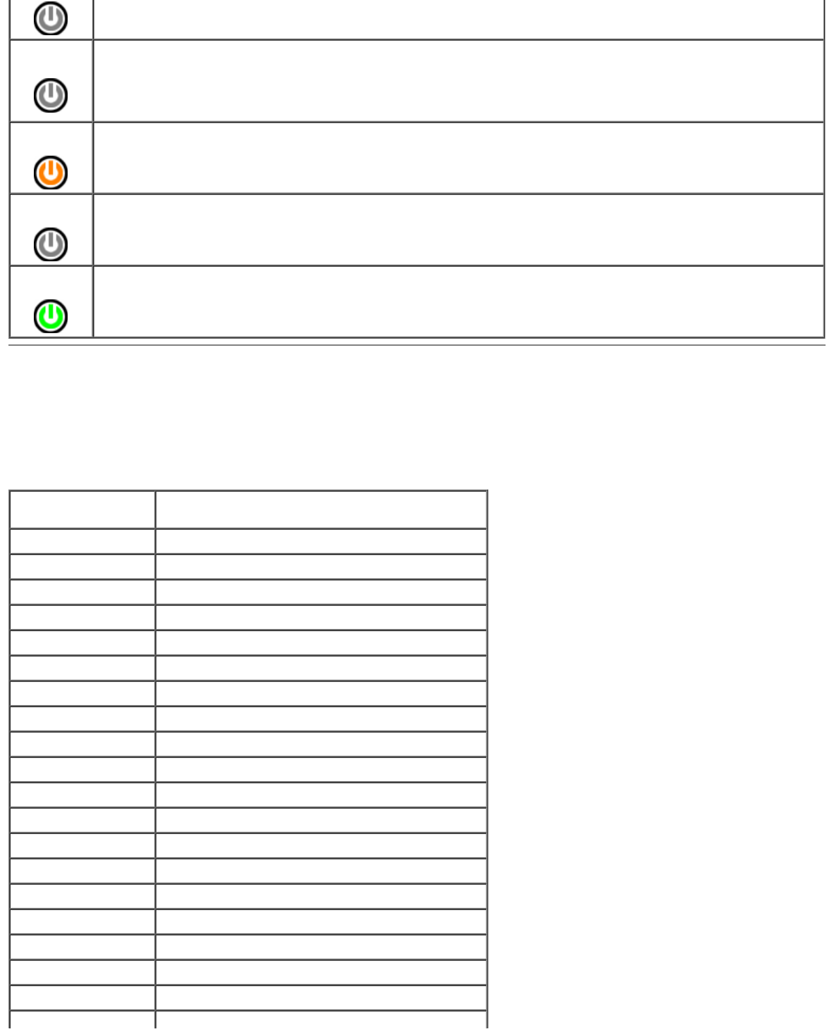
Power is off, light is blank.
Blinking
Amber Initial state of light at power up.
Indicates system has power, but the POWER_GOOD signal is not yet active.
If the Hard Drive light is off, it is probable that the power supply needs to be replaced.
If the Hard Drive light on, it is probable that an onboard regulator or VRM has failed. Look at the diagnostic
lights for further information.
Solid
Amber Second state of the light at power up. Indicates the POWER_GOOD signal is active and it is probable that the
power supply is fine. Look at the diagnostic lights for further information.
Blinking
Green System is in a low power state, either S1 or S3. Look at the diagnostic lights to determine which state the
system is in.
Solid
Green System is in S0 state, the normal power state of a functioning machine.
The BIOS will turn the light to this state to indicate it has started fetching op-codes.
Beep Codes
If the monitor cannot display error messages during the POST, the computer may emit a series of beeps that identifies the
problem or that can help you identify a faulty component or assembly. The following table lists the beep codes that may be
generated during the POST. Most beep codes indicate a fatal error that prevents the computer from completing the boot
routine until the indicated condition is corrected.
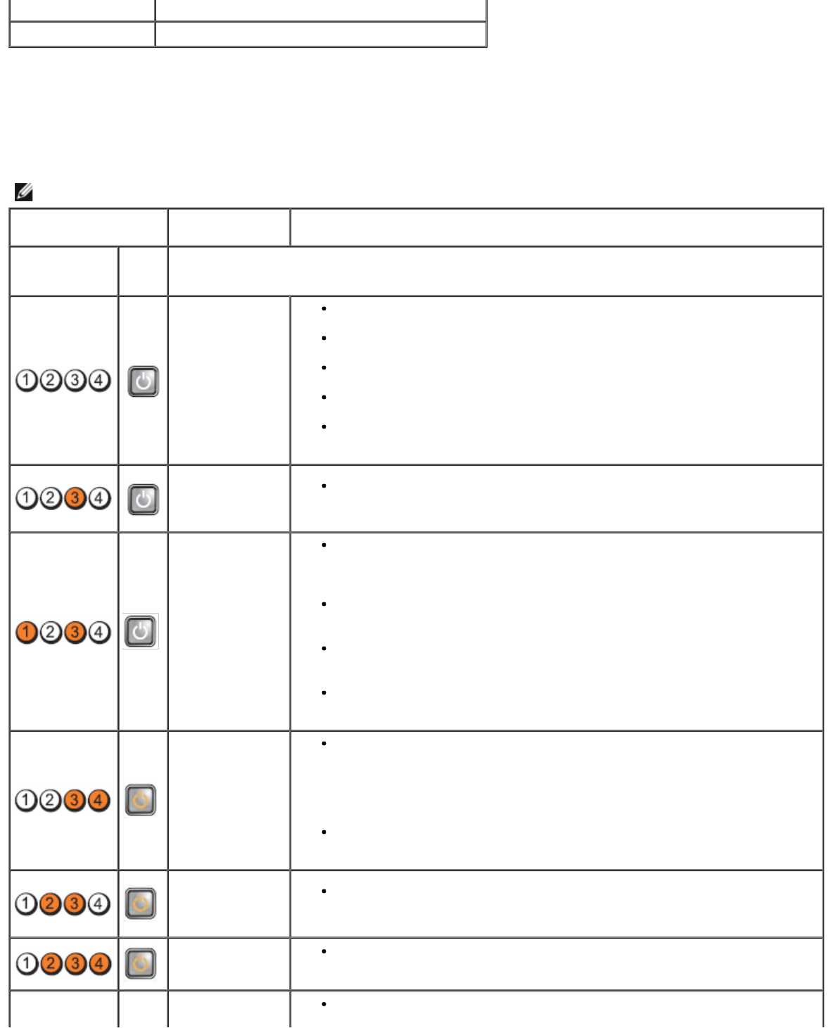
Code Cause
1-1-2 Microprocessor register failure
1-1-3 NVRAM
1-1-4 ROM BIOS checksum failure
1-2-1 Programmable interval timer
1-2-2 DMA initialization failure
1-2-3 DMA page register read/write failure
1-3-1 through 2-4-4 DIMMs not being properly identified or used
3-1-1 Slave DMA register failure
3-1-2 Master DMA register failure
3-1-3 Master interrupt mask register failure
3-1-4 Slave interrupt mask register failure
3-2-2 Interrupt vector loading failure
3-2-4 Keyboard Controller Test failure
3-3-1 NVRAM power loss
3-3-2 NVRAM configuration
3-3-4 Video Memory Test failure
3-4-1 Screen initialization failure
3-4-2 Screen retrace failure
3-4-3 Search for video ROM failure

4-2-1 No time tick
4-2-2 Shutdown failure
4-2-3 Gate A20 failure
4-2-4 Unexpected interrupt in protected mode
4-3-1 Memory failure above address 0FFFFh
4-3-3 Timer-chip counter 2 failure
4-3-4 Time-of-day clock stopped
4-4-1 Serial or parallel port test failure
4-4-2 Failure to decompress code to shadowed memory
4-4-3 Math coprocessor test failure
4-4-4 Cache test failure
1-1-2 Microprocessor register failure
1-1-3 NVRAM read/write failure
1-1-4 ROM BIOS checksum failure
1-2-1 Programmable interval timer failure
1-2-2 DMA initialization failure
1-2-3 DMA page register read/write failure
1-3 Video Memory Test failure
1-3-1 through 2-4-4 Memory not being properly identified or used
3-1-1 Slave DMA register failure
3-1-2 Master DMA register failure
3-1-3 Master interrupt mask register failure
3-1-4 Slave interrupt mask register failure
3-2-2 Interrupt vector loading failure
3-2-4 Keyboard Controller Test failure
3-3-1 NVRAM power loss
3-3-2 Invalid NVRAM configuration
3-3-4 Video Memory Test failure
3-4-1 Screen initialization failure
3-4-2 Screen retrace failure
3-4-3 Search for video ROM failure
4-2-1 No timer tick
4-2-2 Shutdown failure
4-2-3 Gate A20 failure
4-2-4 Unexpected interrupt in protected mode
4-3-1 Memory failure above address 0FFFFh
4-3-3 Timer-chip counter 2 failure
4-3-4 Time-of-day clock stopped
4-4-1 Serial or parallel port test failure
4-4-2 Failure to decompress code to shadowed memory
4-4-3 Math-coprocessor test failure
4-4-4 Cache test failure
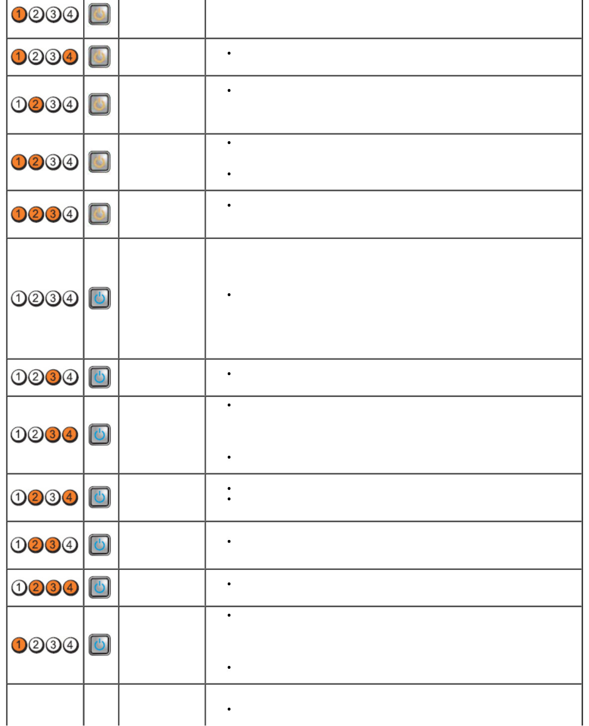
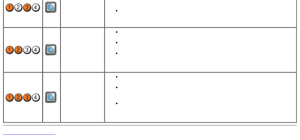
Diagnostic Lights
To help troubleshoot a problem, your computer has four lights labeled 1, 2, 3, and 4 on the bank panel. When the computer
starts normally, the lights flash before turning off. If the computer malfunctions, the sequence of the lights help to identify
the problem.
NOTE: After the computer completes POST, all four lights turn off before booting to the operating system.
Light Pattern Problem
Description Suggested Resolution
Diagnostic LEDs Power
Button
LED
The computer is
either turned off
or not receiving
power.
Reseat the power cable in the power connector on the back of the
computer and the electrical outlet.
Bypass power strips, power extension cables, and other power protection
devices to verify that the computer turns on properly.
Ensure that any power strips being used are plugged into an electrical
outlet and are turned on.
Ensure that the electrical outlet is working by testing it with another
device, such as a lamp.
Ensure that the main power cable and front panel cable are securely
connected to the system board.
A possible
system board
failure has
occurred.
Unplug the computer. Allow one minute for the power to drain. Plug the
computer into a working electrical outlet and press the power button.
A possible
system board,
power supply, or
peripheral failure
has occurred.
Power off computer, leaving the computer plugged in. Press and hold the
power supply test button on the rear of the power supply unit. If the LED
next to the switch illuminates, the problem may be with your system
board.
If the LED next to the switch does not illuminate, disconnect all internal
and external peripherals, and press and hold the power supply test
button. If it illuminates, there could be a problem with a peripheral.
If the LED still does not illuminate, remove the PSU connections from the
system board, then press and hold the power supply button. If it
illuminates, there could be a problem with the system board.
If the LED still does not illuminate, the problem is probably with the power
supply.
Memory modules
are detected, but
a memory power
failure has
occurred.
If two or more memory modules are installed, remove the modules, then
reinstall one module and restart the computer. If the computer starts
normally, continue to install additional memory modules (one at a time)
until you have identified a faulty module or reinstalled all modules without
error. If only one memory module is installed, try moving it to a different
DIMM connector and restart the computer.
If available, install verified working memory of the same type into your
computer.
A possible CPU or
system board
failure has
occurred.
Replace the CPU with a known good CPU. If the computer still fails to
boot, inspect the CPU socket for damage.
BIOS may be
corrupt or
missing.
The computer hardware is operating normally but the BIOS may be
corrupt or missing.
A possible
system board Remove all peripheral cards from the PCI and PCI-E slots and restart the
computer. If the computer boots, add the peripheral cards back one by
failure has
occurred. one until you find the bad one.
Power connector
not installed
properly. Reseat the 2x2 power connector from the power supply unit.
Possible
peripheral card
or system board
failure has
occurred.
Remove all peripheral cards from the PCI and PCI-E slots and restart the
computer. If the computer boots, add the peripheral cards back one by
one until you find the bad one.
A possible
system board
failure has
occurred.
Disconnect all internal and external peripherals, and restart the computer.
If the computer boots, add the peripheral cards back one by one until you
find the bad one.
If the problem persists, the system board is probably bad.
A possible coin
cell battery
failure has
occurred.
Remove the coin cell battery for one minute, reinstall the battery, and
restart.
The computer is
in a normal on
condition.
The diagnostic
lights are not lit
after the
computer
successfully
boots to the
operating
system.
Ensure that the display is connected and powered on.
A possible
processor failure
has occurred. Reseat the processor.
Memory modules
are detected, but
a memory failure
has occurred.
If two or more memory modules are installed, remove the modules (see
your service manual), then reinstall one module (see your service manual
and restart the computer. If the computer starts normally, continue to
install additional memory modules (one at a time) until you have identified
a faulty module or reinstalled all modules without error.
If available, install working memory of the same type into your computer.
A possible
graphics card
failure has
occurred.
Reseat any installed graphics cards.
If available, install a working graphics card into your computer.
A possible floppy
drive or hard
drive failure has
occurred.
Reseat all power and data cables.
A possible USB
failure has
occurred. Reinstall all USB devices and check all cable connections.
No memory
modules are
detected.
If two or more memory modules are installed, remove the modules (see
your service manual), then reinstall one module (see your service
manual) and restart the computer. If the computer starts normally,
continue to install additional memory modules (one at a time) until you
have identified a faulty module or reinstalled all modules without error.
If available, install working memory of the same type into your computer.
Memory modules
are detected, but
a memory Ensure that no special requirements for memory module/connector
placement exist.
configuration or
compatibility
error has
occurred.
Ensure that the memory you are using is supported by your computer.
A possible
expansion card
failure has
occurred.
Determine if a conflict exists by removing an expansion card (not a
graphics card) and restarting the computer.
If the problem persists, reinstall the card you removed, then remove a
different card and restart the computer.
Repeat this process for each expansion card installed. If the computer
starts normally, troubleshoot the last card removed from the computer for
resource conflicts.
Another failure
has occurred.
Ensure that all hard drive and optical drive cables are properly connected
to the system board.
If there is an error message on the screen identifying a problem with a
device (such as the floppy drive or hard drive), check the device to make
sure it is functioning properly.
If the operating system is attempting to boot from a device (such as the
floppy drive or optical drive), check system setup to ensure the boot
sequence is correct for the devices installed on your computer.
Back to Contents Page
Back to Contents Page
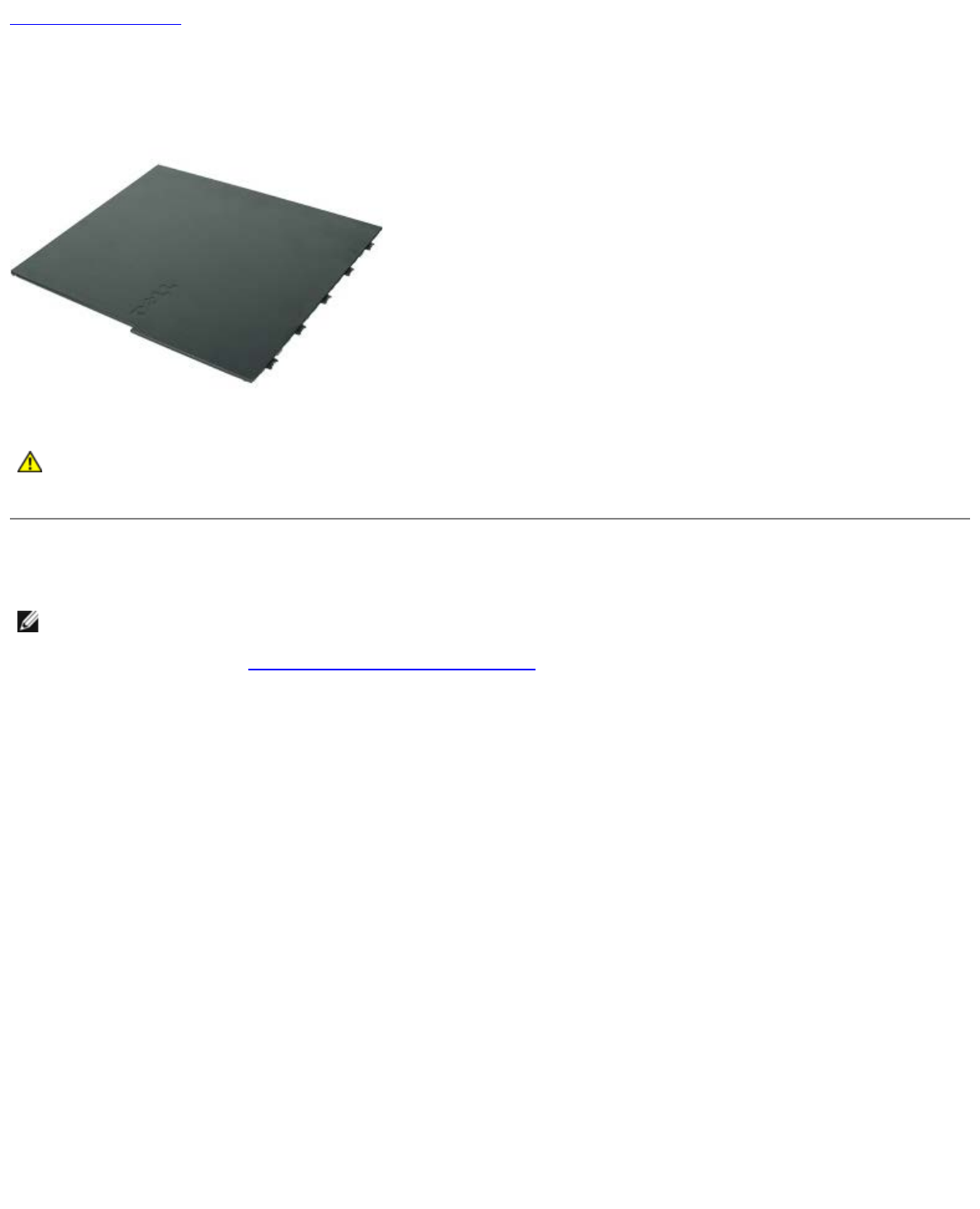
Cover
Dell™ OptiPlex™ 980 Service Manual—Desktop
WARNING: Before working inside your computer, read the safety information that shipped with your
computer. For additional safety best practices information, see the Regulatory Compliance Homepage at
www.dell.com/regulatory_compliance.
Removing the Cover
NOTE: You may need to install Adobe Flash Player from Adobe.com to view the following illustrations.
1. Follow the procedures in Before Working Inside Your Computer.
2. Pull back the cover-release latch.


Back to Contents Page
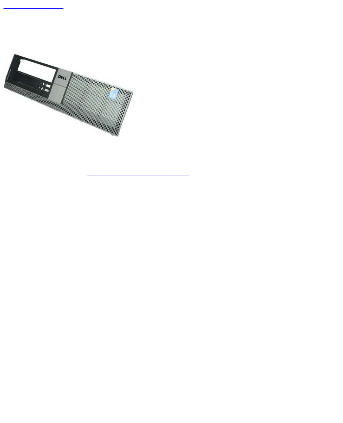
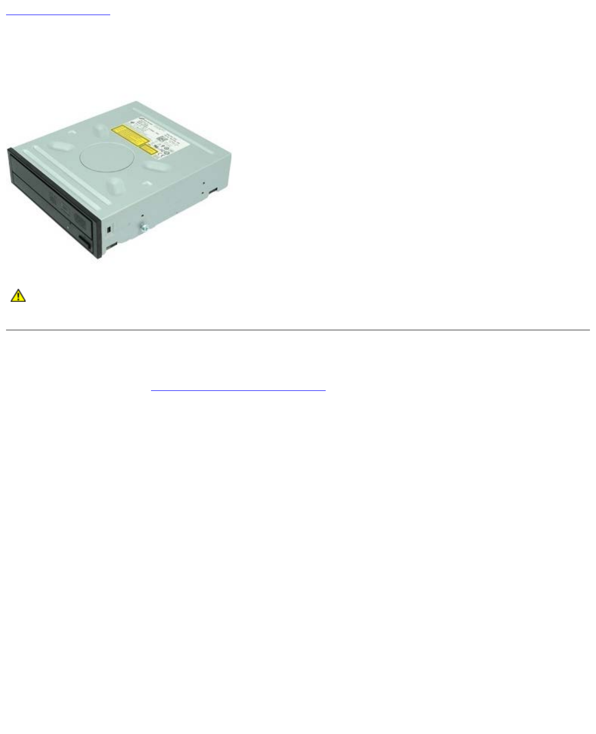
Optical Drive
Dell™ OptiPlex™ 980 Service Manual—Desktop
WARNING: Before working inside your computer, read the safety information that shipped with your
computer. For additional safety best practices information, see the Regulatory Compliance Homepage at
www.dell.com/regulatory_compliance.
Removing the Optical Drive
1. Follow the procedures in Before Working Inside Your Computer.
2. Disconnect the data and power cables from the back of the optical drive.

3. Pull up the drive-release latch and then slide the optical drive towards the back of the computer.
4. Lift up to remove the optical drive from the computer.

Back to Contents Page
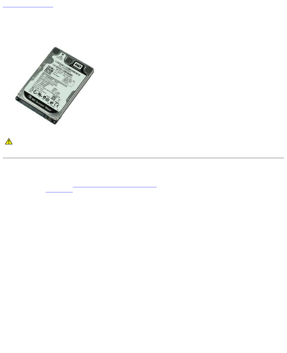
Hard Drive
Dell™ OptiPlex™ 980 Service Manual—Desktop
WARNING: Before working inside your computer, read the safety information that shipped with your
computer. For additional safety best practices information, see the Regulatory Compliance Homepage at
www.dell.com/regulatory_compliance.
Removing the Hard Drive
1. Follow the procedures in Before Working Inside Your Computer.
2. Remove the optical drive from the computer.
3. Lift the hard-drive cage and remove it from the computer.

4. Disconnect the data and power cables.
5. Press in on the blue securing tabs on each side of the drive, and then remove the hard drive.

6. Release the screws from the first hard drive.
7. Remove the primary hard drive from the bay.

8. Release the screws from the second hard drive (if available).
9. Remove the secondary hard drive from the bay.

Back to Contents Page
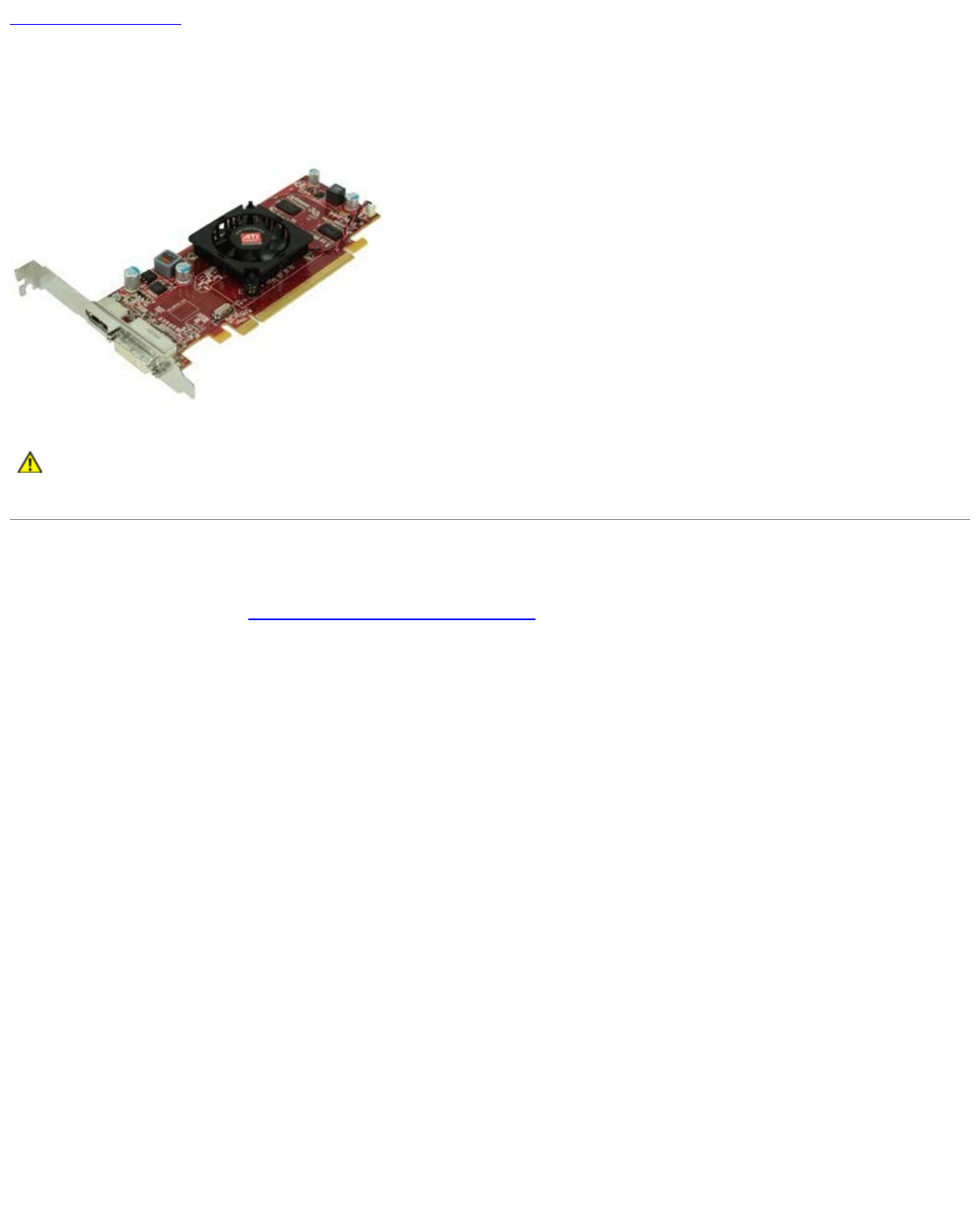
Expansion Cards
Dell™ OptiPlex™ 980 Service Manual—Desktop
WARNING: Before working inside your computer, read the safety information that shipped with your
computer. For additional safety best practices information, see the Regulatory Compliance Homepage at
www.dell.com/regulatory_compliance.
Removing Expansion Cards
1. Follow the procedures in Before Working Inside Your Computer.
2. Lift up the expansion card riser handle.

3. Pull up the expansion card riser.
4. Unlock the expansion card retention.

Back to Contents Page
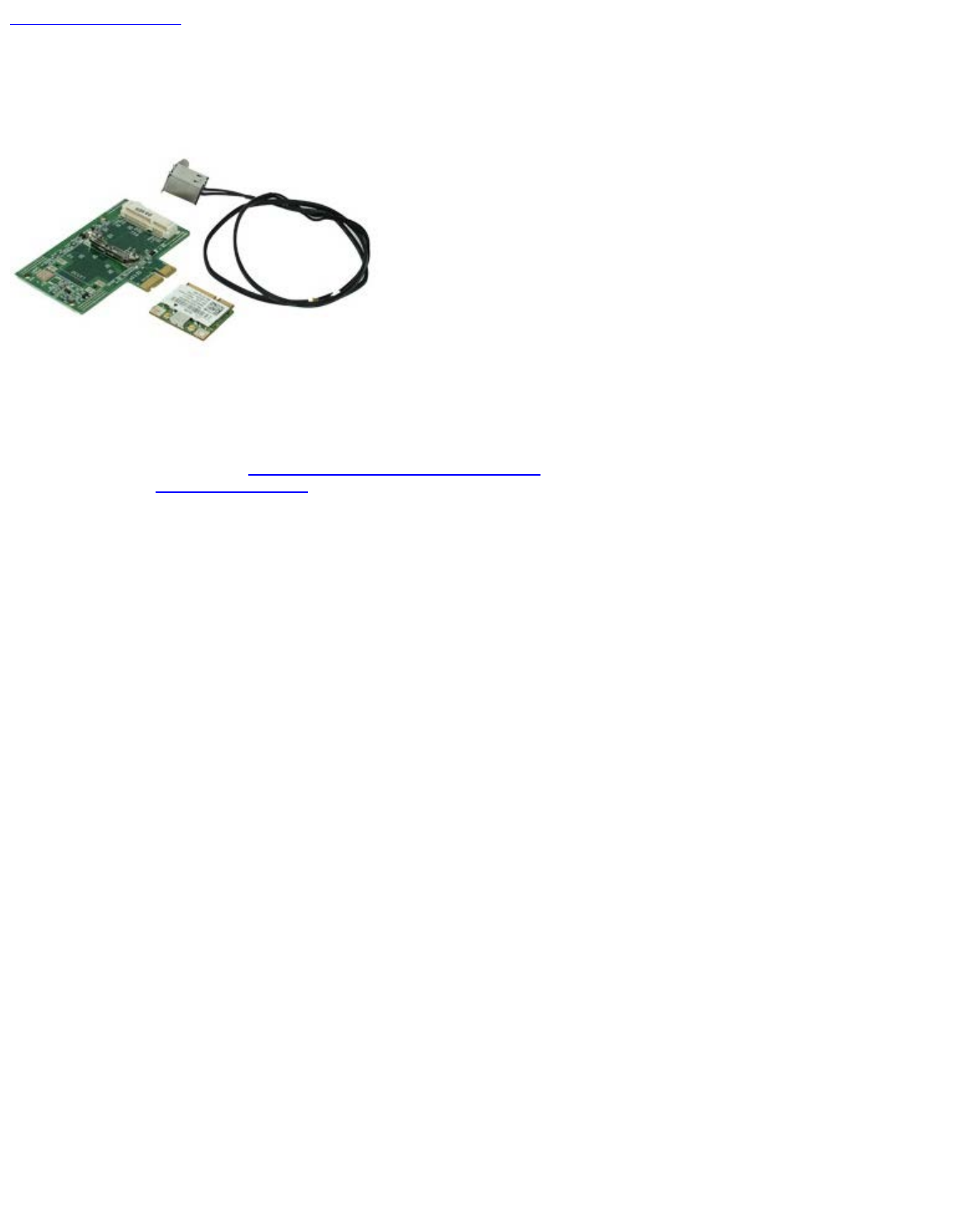
Wireless Module
Dell™ OptiPlex™ 980 Service Manual—Desktop
Removing the Wireless Module
1. Follow the procedures in Before Working Inside Your Computer.
2. Remove the expansion card riser.
3. Lift and release the wireless antenna port from the computer.
4. Release the wireless antenna.

5. Press in on the blue tab that secures the wireless card assembly to the computer and lift the wireless card assembly up
and away from the computer.

6. Remove the metal cover from the wireless card assembly.
7. Disconnect the two antennae.

8. Remove the Wireless Local Area Network (WLAN) card from the socket.
9. Remove the antennae from the bracket.

Back to Contents Page
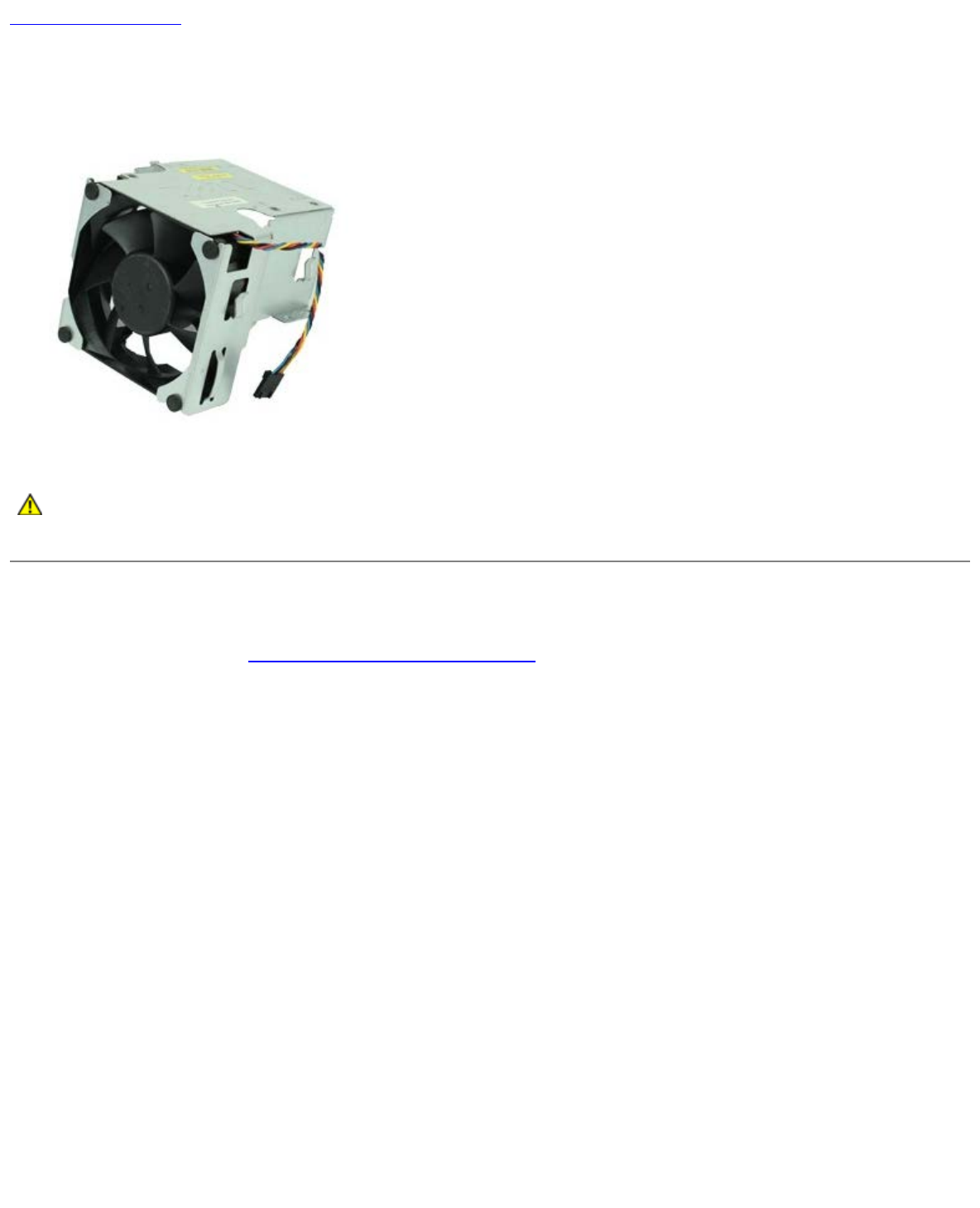
Fan
Dell™ OptiPlex™ 980 Service Manual—Desktop
WARNING: Before working inside your computer, read the safety information that shipped with your
computer. For additional safety best practices information, see the Regulatory Compliance Homepage at
www.dell.com/regulatory_compliance.
Removing the Fan
1. Follow the procedures in Before Working Inside Your Computer.
2. Disconnect the fan power cable from the system board.

3. Remove the screws that secure the fan-shroud to the computer.
4. Lift the fan and remove it from the computer.

Back to Contents Page
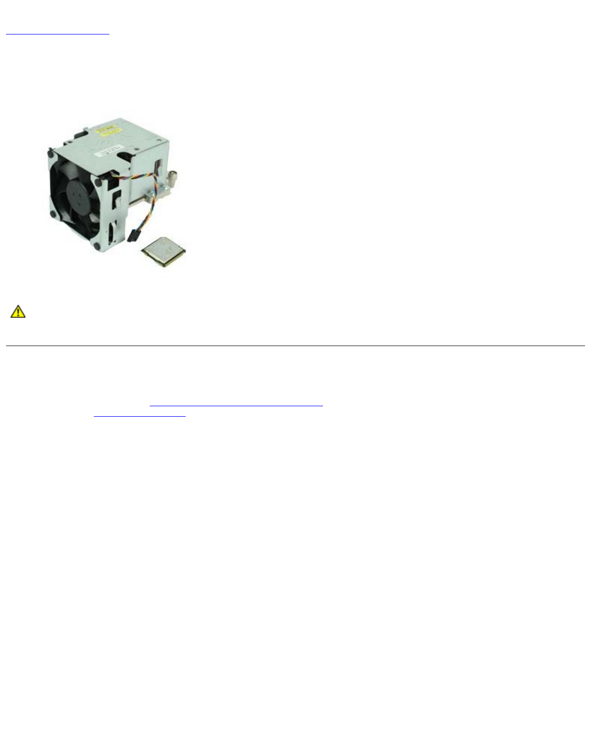
Heat Sink and Processor
Dell™ OptiPlex™ 980 Service Manual—Desktop
WARNING: Before working inside your computer, read the safety information that shipped with your
computer. For additional safety best practices information, see the Regulatory Compliance Homepage at
www.dell.com/regulatory_compliance.
Removing the Heat Sink and Processor
1. Follow the procedures in Before Working Inside Your Computer.
2. Remove the expansion card riser.
3. Disconnect the fan connector from the system board.

4. Loosen the captive screws that secure the heat sink to the system board.
5. Lift the heat sink and remove it from the computer.

6. Slide the release lever from under the center-cover latch and rotate the release lever upward.
7. Lift the processor cover.

8. Remove the processor from the computer.
CAUTION: When replacing the processor, do not touch any of the pins inside the socket or allow any objects
to fall on the pins in the socket.
Replacing the Heat Sink and Processor
To replace the heat sink and processor, perform the above steps in reverse order.
Back to Contents Page
Back to Contents Page
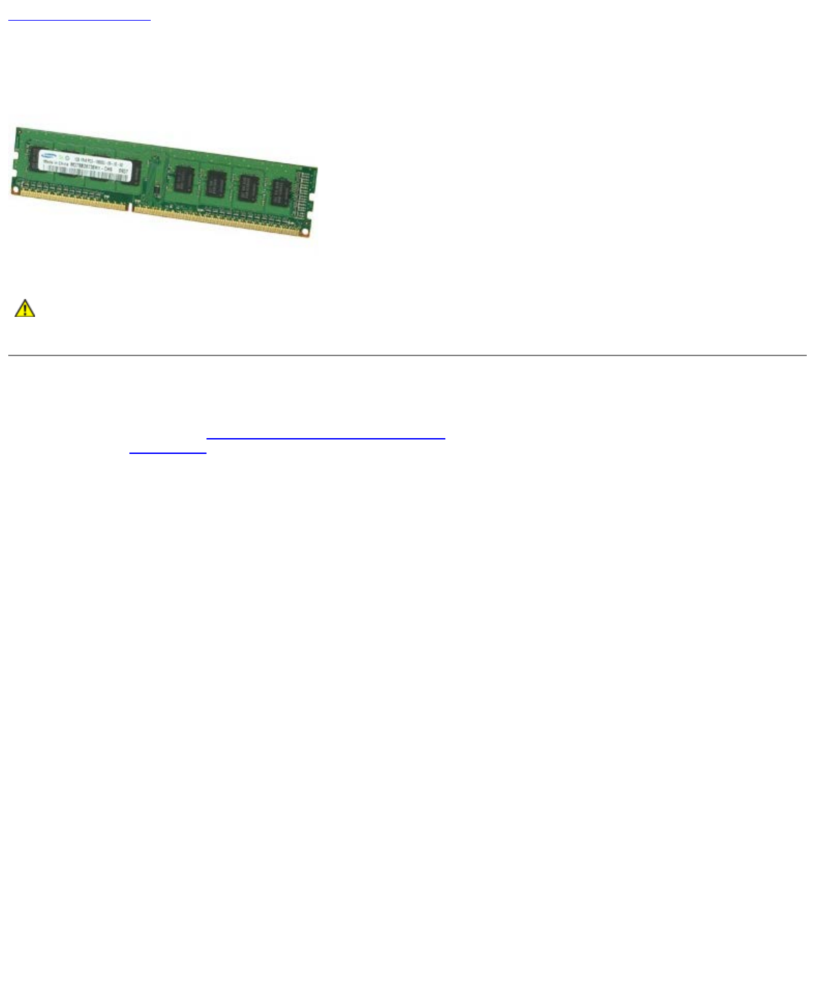
Memory
Dell™ OptiPlex™ 980 Service Manual—Desktop
WARNING: Before working inside your computer, read the safety information that shipped with your
computer. For additional safety best practices information, see the Regulatory Compliance Homepage at
www.dell.com/regulatory_compliance.
Removing the Memory Module(s)
1. Follow the procedures in Before Working Inside Your Computer.
2. Remove the optical drive.
3. Press down on the memory retention clips to release the memory module.
4. Lift the memory module out of the connector and remove it from the computer.

Back to Contents Page
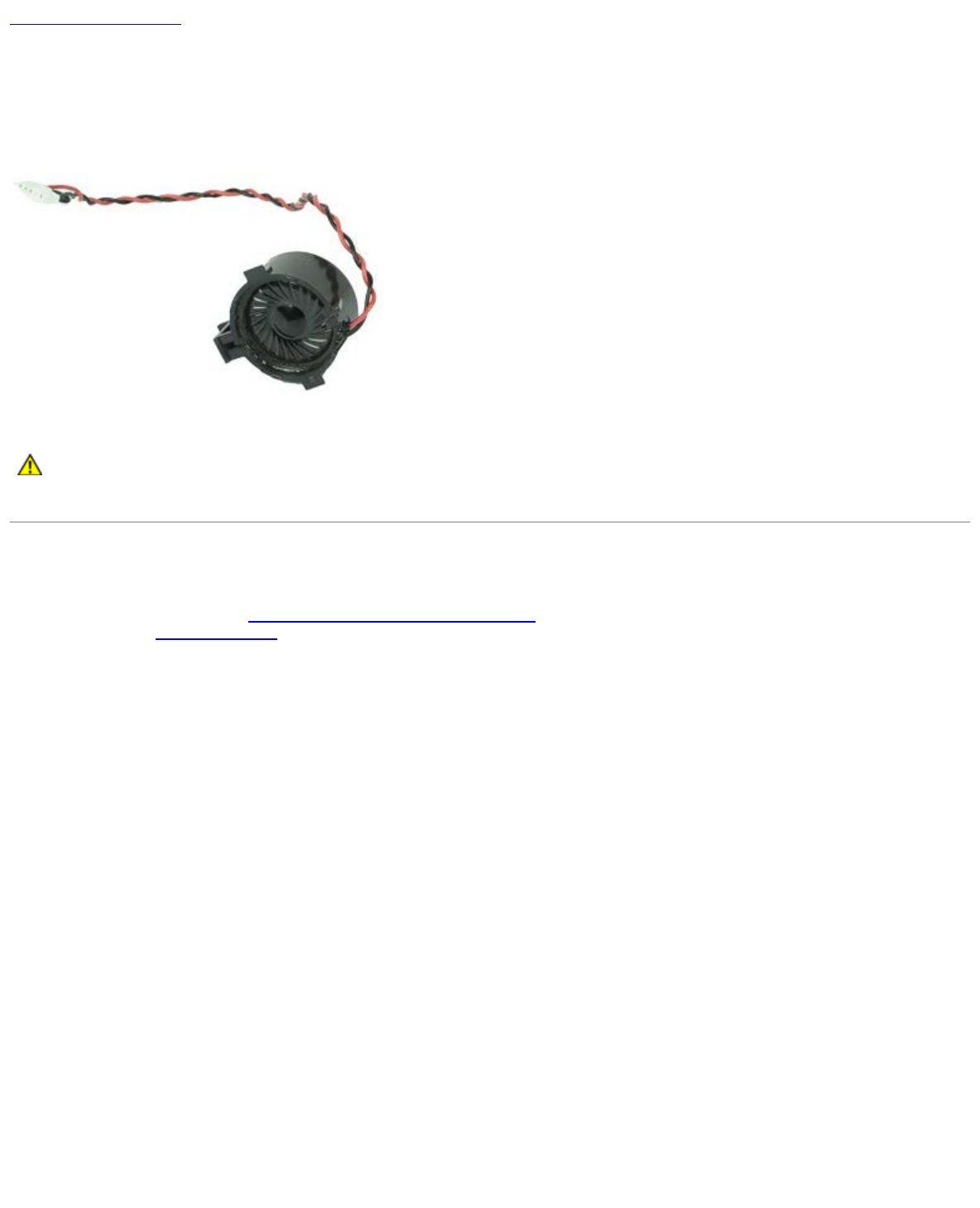
Internal Speaker
Dell™ OptiPlex™ 980 Service Manual—Desktop
WARNING: Before working inside your computer, read the safety information that shipped with your
computer. For additional safety best practices information, see the Regulatory Compliance Homepage at
www.dell.com/regulatory_compliance.
Removing the Internal Speaker
1. Follow the procedures in Before Working Inside Your Computer.
2. Remove the wireless module.
3. Disconnect the internal speaker cable.

Back to Contents Page
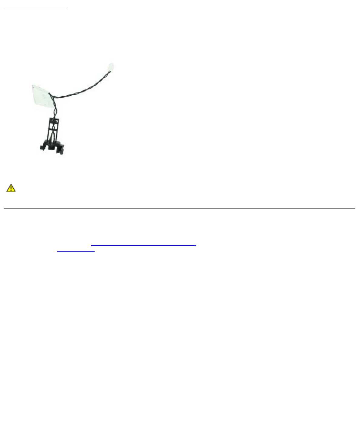
Front Thermal Sensor
Dell™ OptiPlex™ 980 Service Manual—Desktop
WARNING: Before working inside your computer, read the safety information that shipped with your
computer. For additional safety best practices information, see the Regulatory Compliance Homepage at
www.dell.com/regulatory_compliance.
Removing the Front Thermal Sensor
1. Follow the procedures in Before Working Inside Your Computer.
2. Remove the processor fan.
3. Disconnect the front thermal sensor cable from the system board.

Back to Contents Page
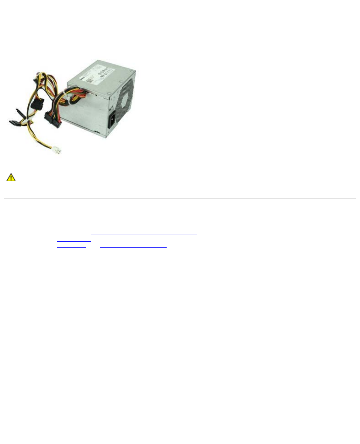
Power Supply
Dell™ OptiPlex™ 980 Service Manual—Desktop
WARNING: Before working inside your computer, read the safety information that shipped with your
computer. For additional safety best practices information, see the Regulatory Compliance Homepage at
www.dell.com/regulatory_compliance.
Removing the Power Supply
1. Follow the procedures in Before Working Inside Your Computer.
2. Remove the optical drive.
3. Remove the hard drive and heat sink and processor.
4. Disconnect the main power connector from the system board.

5. Disconnect the processor power connector from the system board.
6. Release the processor power connector cable from their routing guides under the system board.

7. Remove the screws that secure the power supply to the back of the chassis.
8. Press the power-supply release latch at the bottom of the chassis and then slide the power supply towards the front of
the computer.

Back to Contents Page
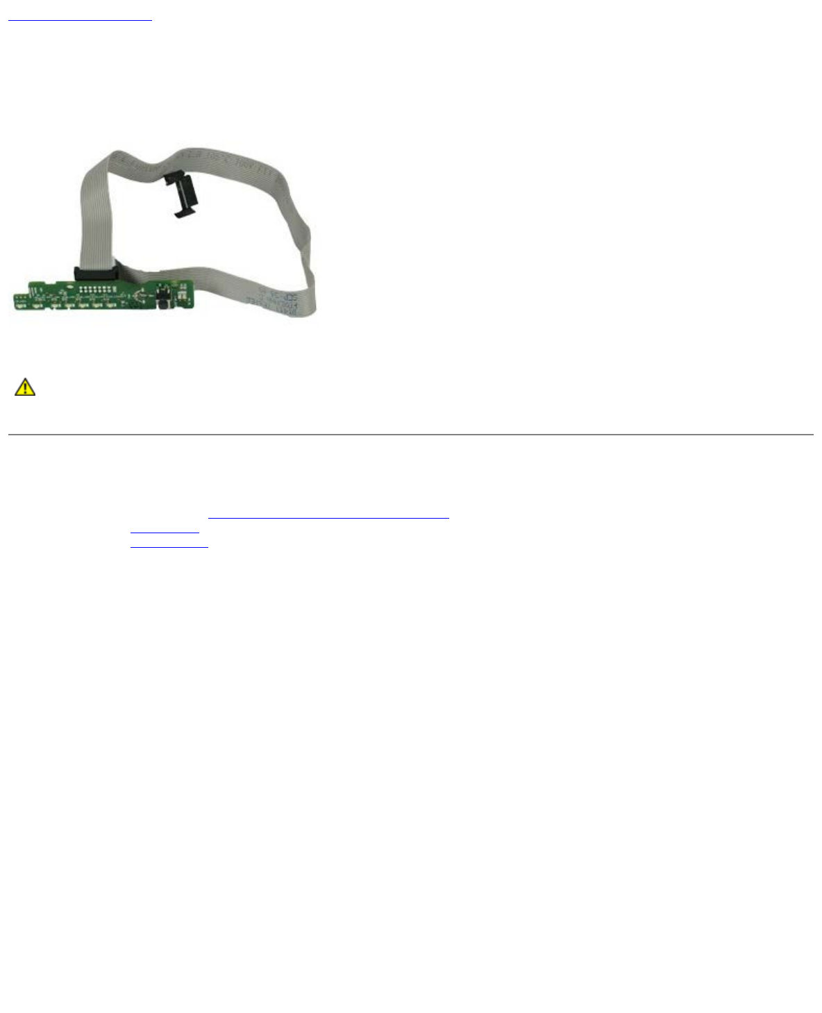
I/O Panel
Dell™ OptiPlex™ 980 Service Manual—Desktop
WARNING: Before working inside your computer, read the safety information that shipped with your
computer. For additional safety best practices information, see the Regulatory Compliance Homepage at
www.dell.com/regulatory_compliance.
Removing the I/O Panel
1. Follow the procedures in Before Working Inside Your Computer.
2. Remove the front panel.
3. Disconnect the I/O-panel cable.

Back to Contents Page
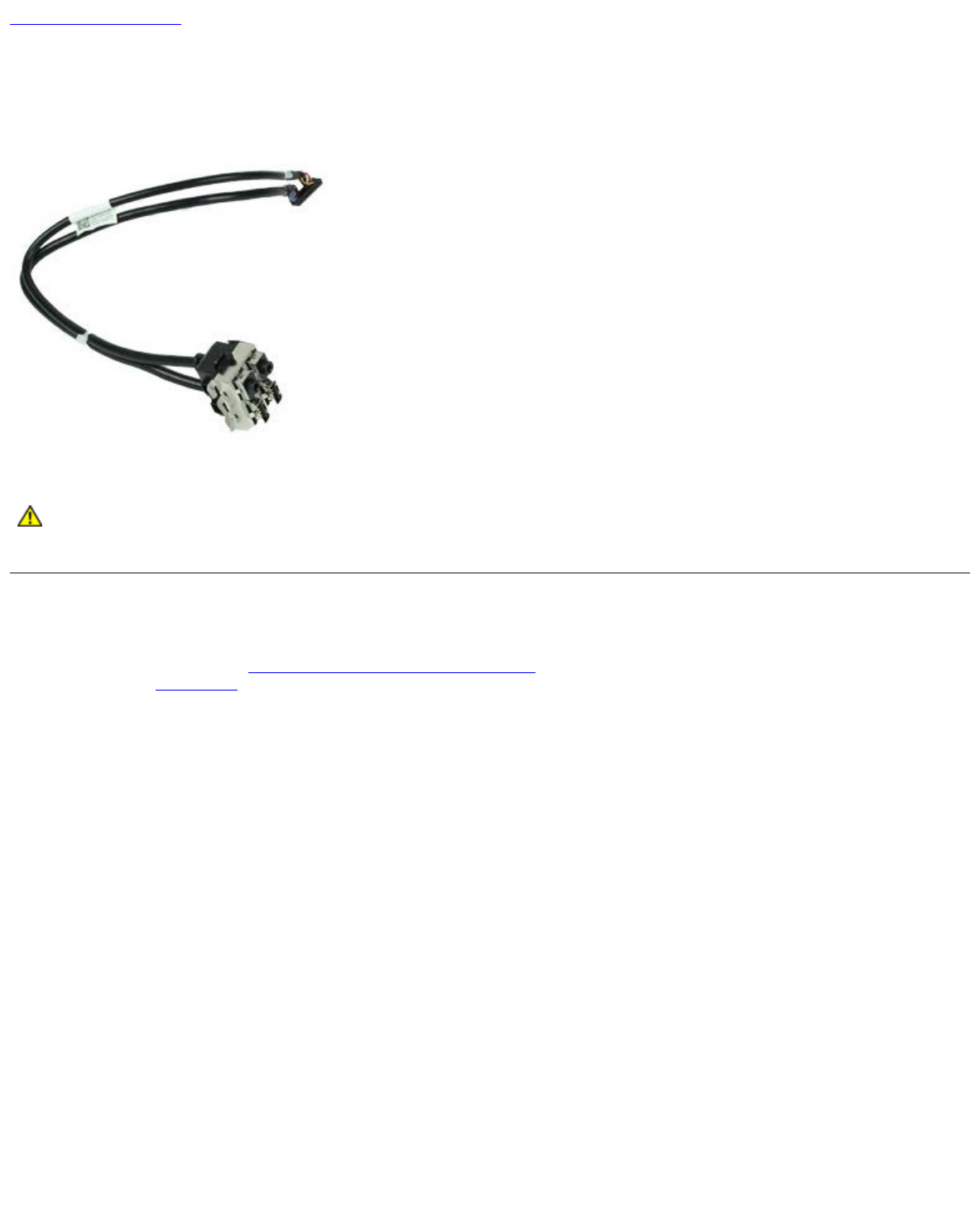
Control Panel
Dell™ OptiPlex™ 980 Service Manual—Desktop
WARNING: Before working inside your computer, read the safety information that shipped with your
computer. For additional safety best practices information, see the Regulatory Compliance Homepage at
www.dell.com/regulatory_compliance.
Removing the I/O Panel
1. Follow the procedures in Before Working Inside Your Computer.
2. Remove the front panel.
3. Remove the optical drive.
4. Disconnect the control panel cable.

5. Release the cable.

6. Remove the screw.
7. Remove the control panel from the chassis.

Back to Contents Page
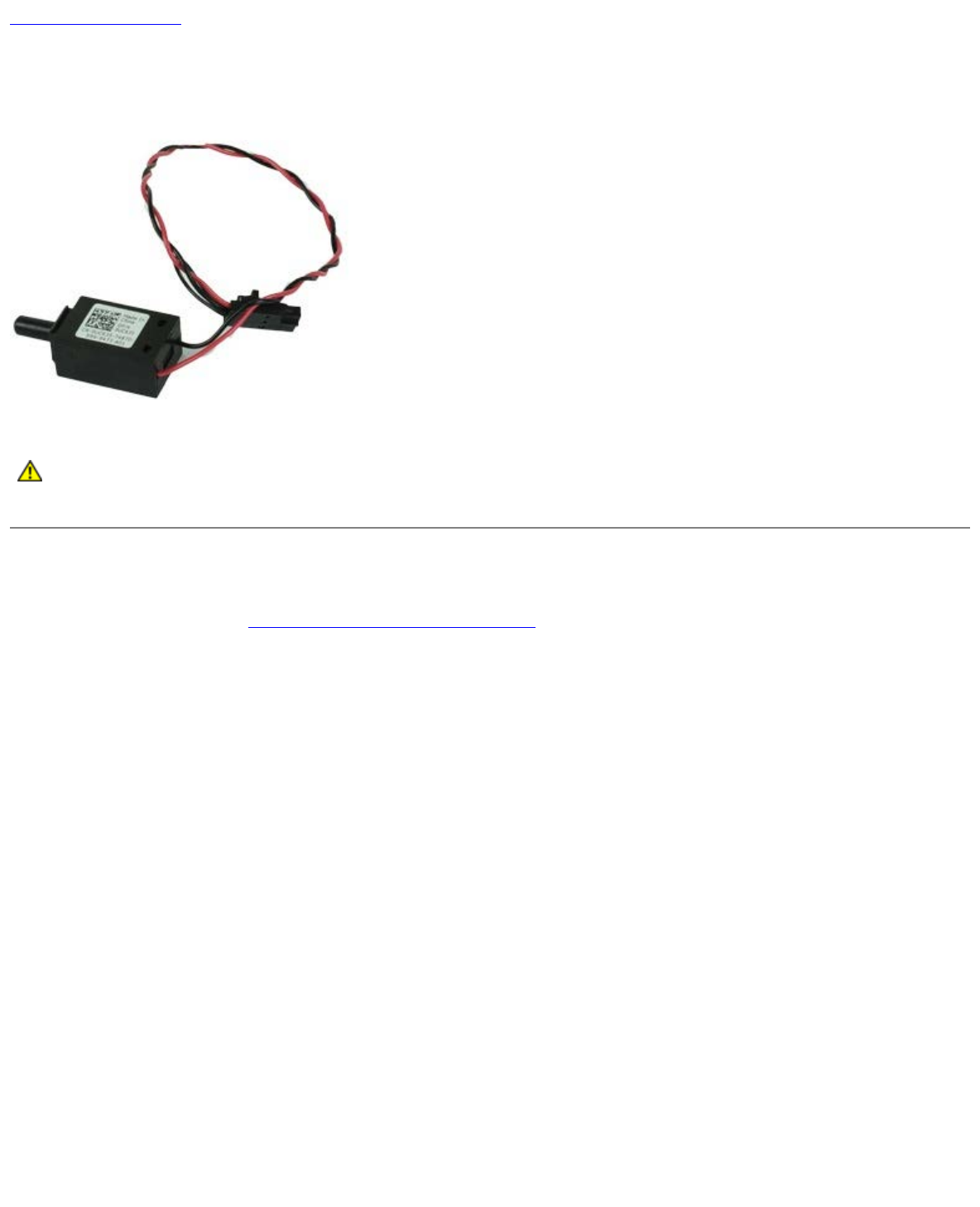
Intrusion Switch
Dell™ OptiPlex™ 980 Service Manual—Desktop
WARNING: Before working inside your computer, read the safety information that shipped with your
computer. For additional safety best practices information, see the Regulatory Compliance Homepage at
www.dell.com/regulatory_compliance.
Removing the Intrusion Switch
1. Follow the procedures in Before Working Inside Your Computer.
2. Disconnect the intrusion-switch cable from the system board.

Back to Contents Page
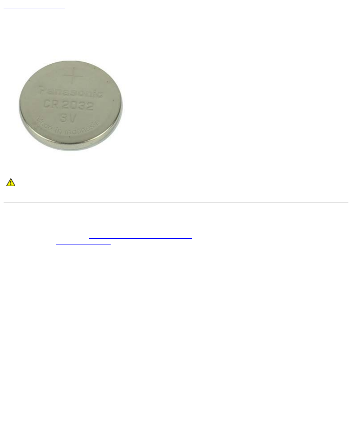
Coin-Cell Battery
Dell™ OptiPlex™ 980 Service Manual—Desktop
WARNING: Before working inside your computer, read the safety information that shipped with your
computer. For additional safety best practices information, see the Regulatory Compliance Homepage at
www.dell.com/regulatory_compliance.
Removing the Coin-Cell Battery
1. Follow the procedures in Before Working Inside Your Computer.
2. Remove the expansion card riser.
3. Pull the retention clip away from the coin-cell battery
.

Back to Contents Page
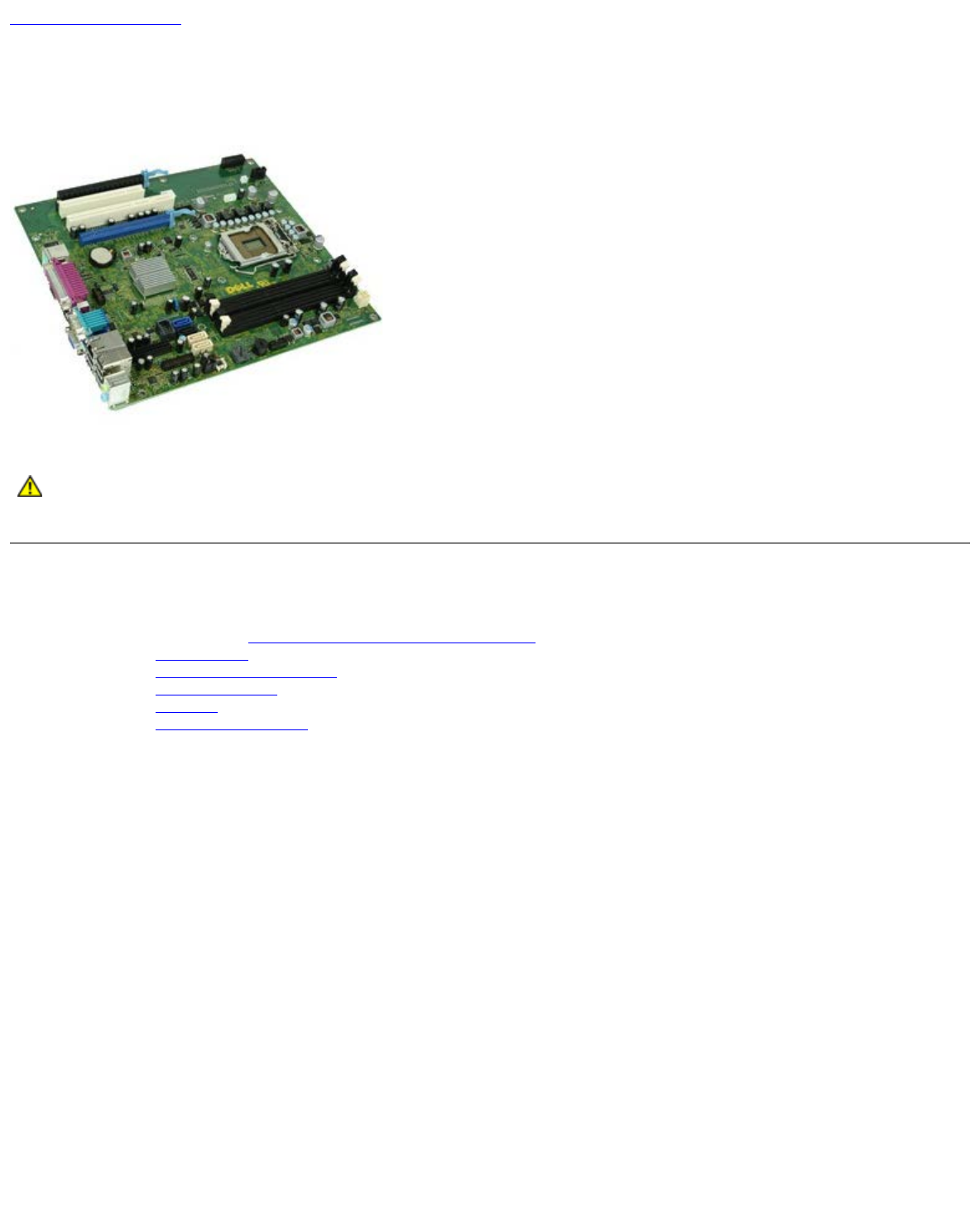
System Board
Dell™ OptiPlex™ 980 Service Manual—Desktop
WARNING: Before working inside your computer, read the safety information that shipped with your
computer. For additional safety best practices information, see the Regulatory Compliance Homepage at
www.dell.com/regulatory_compliance.
Removing the System Board
1. Follow the procedures in Before Working Inside Your Computer.
2. Remove the optical drive.
3. Remove the heat sink and processor.
4. Remove the wireless module
5. Remove the memory
6. Remove the expansion card riser.
7. Disconnect all the cables on the system board.

8. Remove the screws that secure the system board to the computer chassis.
9. Lift the system board up and away from the computer.