Dell Optiplex E1 Users Manual User's Guide
2014-11-13
: Dell Dell-Optiplex-E1-Users-Manual-110961 dell-optiplex-e1-users-manual-110961 dell pdf
Open the PDF directly: View PDF ![]() .
.
Page Count: 75

333-MHz SEPP Cartridge/Heat Sink/Fan Assembly Removal (Low-ProfileChassis):Dell™
OptiPlex™E1Systems
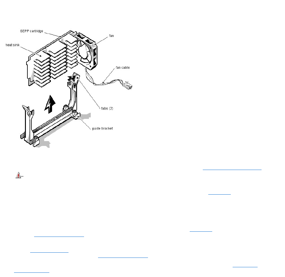
To remove the SEPP cartridge/heat sink/fan assembly, follow these steps:
1. Remove the computer cover according to the instructions in "Removing the Computer Cover" in Chapter 5 in the Reference and Installation Guide.
2. Locate the SEPP cartridge/heat sink assembly.
3. If a fan is connected to the heat sink, disconnect the fan connector from the 3-pin connector (labeled "FAN") on the system board, located between the
SERIAL2 connector and the MONITOR connector.
4. Locate and press outward on the guide bracket tabs to release them from the SEPP cartridge/heat sink assembly.
5. Lift the SEPP cartridge/heat sink/fan assembly out of its guide bracket assembly/connector on the system board.
6. Insert the new microprocessor assembly into the connector.
Carefully orient the replacement microprocessor assembly with the guide bracket and press firmly with up to 25 pounds of force to mate the SEPP with its connector.
7. Press inward on the guide bracket tabs to secure them to the SEPP cartridge/heat sink assembly.
8. Connect the power cable on the cooling fan to the microprocessor fan connector (labeled "FAN") on the system board.
9. Change the microprocessor speed jumper to the "333MHZ" setting.
10. Replace the computer cover, reconnect your computer and peripherals to their power sources, and turn them on.
As the system boots, it detects the presence of the new microprocessor and automatically changes the system configuration information in the System Setup program.
11. Enter the System Setup program, and confirm that the installed microprocessor is correctly identified.
See Chapter 2,"Using the System Setup Program," in the Reference and Installation Guide.
12. Run the Dell Diagnostics to verify that the new microprocessor is operating correctly.
For information on using the diagnostics and troubleshooting any problems that occur, see the chapter titled "Running the Dell Diagnostics" in the Diagnostics and
Troubleshooting Guide.
WARNING: The SEPP cartridge/heat sink assembly can get extremely hot during system operations. Be sure that the assembly has had
sufficient time to cool before touching it.

Microsoft® UpdatedATAPIDriver:Dell™OptiPlex™E1Systems
Reinstalling the Microsoft Windows NT®4.0 Updated ATAPI Driver | Removing the Windows NT 4.0 Microsoft Updated ATAPI Driver
Reinstalling the Microsoft Windows NT® 4.0 Updated ATAPI Driver
The driver for Windows NT 4.0 is provided on your hard-disk drive in diskette-image form. To reinstall the Microsoft updated ATAPI driver for Windows NT 4.0,
perform the following steps:
1. If you have not already done so, use the Program Diskette Maker to make a diskette copy of the Microsoft updated ATAPI driver diskette image on your hard-
disk drive.
The Program Diskette Maker is available through the Dell Accessories program folder. For more information, refer to the online help provided in the Program Diskette Maker.
2. Start the Windows NT operating system. If you are already running Windows NT, close any open documents or application programs.
3. Insert the Microsoft updated ATAPI driver diskette into drive A.
4. Click the Start button.
5. Click Run, type a:\setup.bat in the Run window, and then click OK.
A black screen will quickly appear and disappear, which indicates that the driver file has been loaded. Setup automatically saves the existing atapi.sys driver as atapi.000 and loads
the new driver into the system32\drivers subdirectory in the Windows NT directory.
6. Remove the diskette from drive A and restart the computer.
Removing the Windows NT 4.0 Microsoft Updated ATAPI Driver
To remove the Microsoft updated ATAPI driver, perform the following steps:
1. Start the Windows NT operating system. If you are already running Windows NT, close any open documents or application programs.
2. Use Explorer to open the system32\drivers subdirectory in the Windows NT directory.
3. Rename the existing atapi.sys file to atapi.bak.
4. Rename the atapi.000 file to atapi.sys.
5. Restart the computer.
NOTES: If Windows NT 4.0 is reinstalled, the Microsoft updated ATAPI drivers must also be reinstalled.
To install the Microsoft updated ATAPI driver for Windows NT 4.0, you must have a mouse connected to the system and Windows NT 4.0 must
already be installed on the hard-disk drive connected to the primary EIDE channel.
NOTE: To enable or disable direct memory access (DMA) while using the Microsoft updated ATAPI driver, run dmacheck.exe from
\support\utils\i386 on the Microsoft Windows NT Service Pack 3 CD.
POSTBeepCodes:Dell™OptiPlex™E1Systems
If the monitor cannot display error messages during the POST, the system may emit a series of beeps that identifies the problem or that can help you identify a faulty
component or assembly. The following table lists the beep codes that may be generated during the POST. Most beep codes indicate a fatal error that prevents the
system from completing the boot routine until the indicated condition is corrected.
Beep Code
Error
Probable Causes
1-1-3
NVRAM write/read failure
Defective system board
1-1-4
BIOS checksum failure
Faulty BIOS or defective system board
1-2-1
Programmable interval-timer failure
Defective system board
1-2-2
DMA initialization failure
Defective system board
1-2-3
DMA page register write/read failure
Defective system board
1-3-1
Main-memory refresh verification failure
Faulty or improperly seated DIMM or defective system
board
1-3-2
No memory installed
No memory installed, or faulty or improperly seated DIMM
1-3-3
Chip or data line failure in the first 64 KB of
main memory
Faulty or improperly seated DIMM
1-3-4
Odd/even logic failure in the first 64 KB of main
memory
Faulty or improperly seated DIMM
1-4-1
Address line failure in the first 64 KB of main
memory
Faulty or improperly seated DIMM
1-4-2
Parity failure in the first 64 KB of main memory
Faulty or improperly seated DIMM
Address line failure in the first 64 KB of RAM
(System riser cards may cause this error. Remove the riser
card and retest)
2-1-1 through
2-4-4
Bit failure in the first 64 KB of main memory
Faulty or improperly seated DIMM
3-1-1
Slave DMA-register failure
Defective system board
3-1-2
Master DMA-register failure
Defective system board
3-1-3
Master interrupt-mask register failure
Defective system board
3-1-4
Slave interrupt-mask register failure
Defective system board
3-2-4
Keyboard-controller test failure
Faulty keyboard controller (defective system board)
3-3-4
Screen initialization failure
Faulty video subsystem (defective system board)
3-4-1
Screen-retrace test failure
Faulty video subsystem (defective system board)
3-4-2
Search for video ROM failed
Faulty video subsystem (defective system board)
4-2-1
No timer tick
Defective system board
4-2-2
Shutdown failure
Defective system board
4-2-3
Gate A20 failure
Defective system board
4-2-4
Unexpected interrupt in protected mode
Defective system board
4-3-1
Memory failure above address 0FFFFh
Faulty or improperly seated DIMM
4-3-3
Timer-chip counter 2 failure
Defective system board
4-3-4
Time-of-day clock stopped
Bad battery or defective system board
4-4-1
Serial-port test failure
Faulty I/O chip (defective system board)
4-4-2
Parallel-port test failure
Faulty I/O chip (defective system board)
4-4-3
Math coprocessor failure
Faulty microprocessor chip or system board
4-4-4
Cache test failure
Defective microprocessor or system board
ControlsandIndicators:Dell™OptiPlex™E1Systems
Low-Profile Chassis | Mini Tower Chassis | NIC
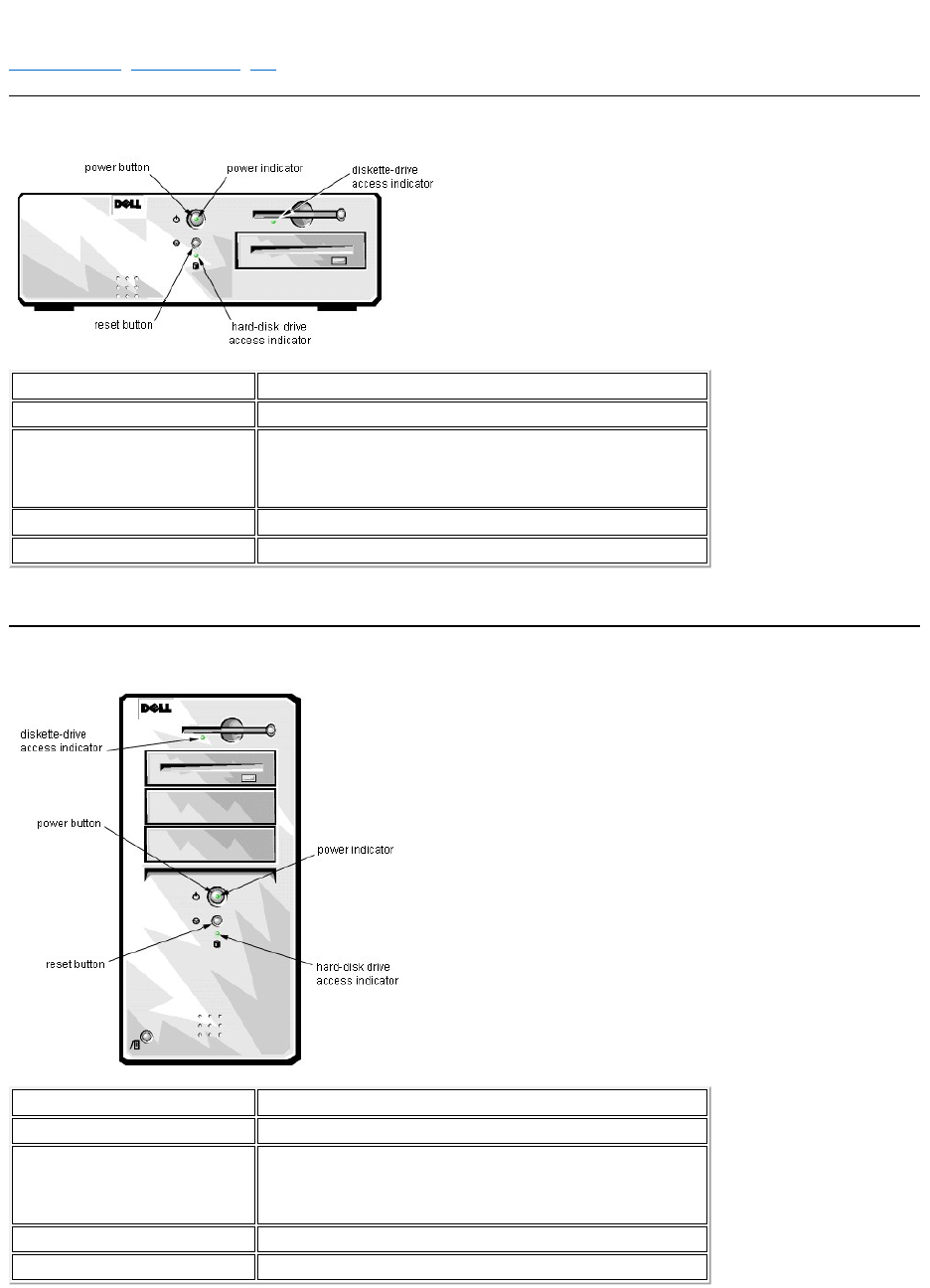
Low-Profile Chassis
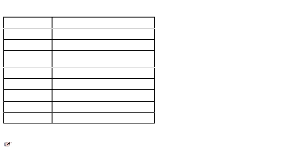
Mini Tower Chassis
Power button
Turns computer on and off.
Power indicator
Lights up when the computer is on.
Reset button
Initiates a hardware reset. To avoid possible data or file structure corruption, use
the reset button only when the system cannot be rebooted with the
<Ctrl><Alt><Del> key combination, and close any open application programs
or files if possible.
Hard-disk drive access indicator
Lights up when the hard-disk drive is being accessed.
Diskette-drive access indicator
Lights up when the diskette drive is being accessed.

DMA Channel Assignments: Dell™OptiPlex™E1Systems
DREQ Line
Used By/Available
DREQ0
Available
DREQ1
Available
DREQ2
Super I/O controller (to initiate DMA cycle for attached
diskette drive)
DREQ3
Available
DREQ4
Bus controller chip (to activate second DMA controller)
DREQ5
Available
DREQ6
Available
DREQ7
Available
NOTE: The integrated sound controller, NIC, and video controllers are assigned available DMA channels automatically during system start-up.
Documentation: Dell™ OptiPlex™ E1 Systems
HTML Documents | PDF Documents
HTML Documents
PDF Documents
To save PDF files (files with an extension of .pdf) to your hard-disk drive, right-click the document title, click Save Target As in Microsoft® Internet Explorer or
Save Link As in Netscape Navigator, and specify a location on your hard-disk drive.
Right-click only the following links:
Low-Profile Reference and Installation Guide (.pdf)
Mini Tower Reference and Installation Guide (.pdf)
Service Manual (.pdf)
Diagnostics and Troubleshooting Guide (.pdf)
Dell OptiPlex E1 Managed PC Systems Documentation Update (.pdf)
ToviewaPDFfile,launchAdobe™AcrobatReader.ClickFile–> Open and select the PDF file.
To view a Help file (a file with an extension of .hlp),clickthelinkforthefile.
System User's Guide (.hlp)
(link to Spanish documentation page)
(link to French documentation page)
You must right-click the link for a portable document format (PDF) file and save the file to your hard-disk drive. Attempting to link directly to
large PDF files causes your system to freeze.
NOTES: PDF files require Acrobat Reader, which can be downloaded from the Adobe World Wide Web site.
Help files require winhelp.exe, which is part of the Microsoft Windows® operating system (located in the windows directory). To view Help files
online, you may need to configure winhelp.exe to work with your browser as a helper application program. See the Help information associated with
your browser for additional information.


Documentation:Dell™OptiPlex™E1Systems
Guided'utillisationdeDellOptiPlexE1avecgestionamélioréeSommaire (.hlp)
Guidederéférenceetd'installation,taillebasse (.pdf)
Guidederéférenceetd'installation,mini-tour (.pdf)
Guidedesdiagnosticsetdedépannage (.pdf)
Sivousneparvenezpasàtrouverlesinformationsdontvousavezbesoinenligne, consultez notre Centre de communicationsenligneoucontactezunreprésentant
Dell.Ayezàportéedemainvotrecodedeserviceexpresspourunserviceplusrapide.
REMARQUES: Pour utiliser les fichiers .pdf,vousavezbesoind'AcrobatReader,quevouspouvezdéchargerdusite web d'Adobe™. Pour afficher
les fichiers .pdfenligneaprèslechargementetl'installationd'AcrobatReader,voudevrezpeut-êtreconfigurerAcrobatReaderpourqu'ilfonctionne
avec votre navigateur comme application d'aide ou module enfichable. Reportez-vous aux informations d'aide de votre navigateur pour plus de
précisions.
Les fichiers .hlp ont besoin de winhelp.exe,quifaitpartiedusystèmed'exploitationMicrosoft® Windows® (situédanslerépetoirewindows). Pour
afficher les fichiers .hlp en ligne, vous devrez peut-êtreconfigurerwinhelp.exe pour qu'il fonctionne avec votre navigateur comme application
d'aide. Reportez-vousauxinformationsd'aidedevotrenavigateurpourplusdeprécisions.

Graphics:Dell™OptiPlex™E1Systems
System Board
Jumpers
Controls and Indicators
Internal View of the Low-Profile Computer
Internal View of the Mini Tower Computer
Low-Profile Chassis Riser Board
Mini Tower Chassis Riser Board
I/O Ports and Connectors
System Setup
Additional graphics can be found in Removing and Replacing Parts.
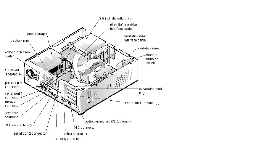
Internal View of the Low-ProfileComputer:Dell™OptiPlex™E1Systems
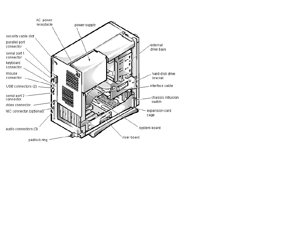
InternalViewoftheMiniTowerComputer:Dell™OptiPlex™E1Systems
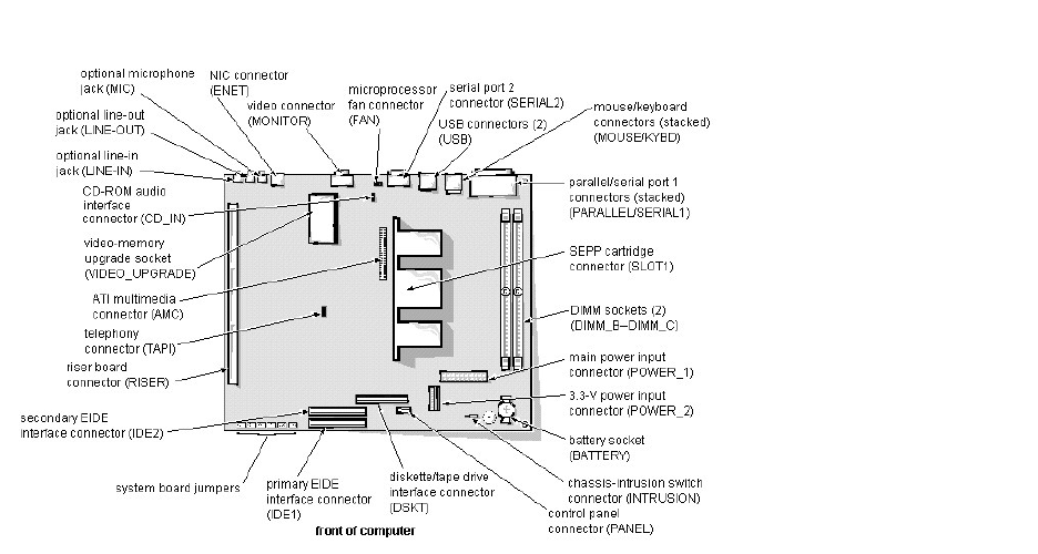
SystemBoard:Dell™OptiPlex™E1Systems

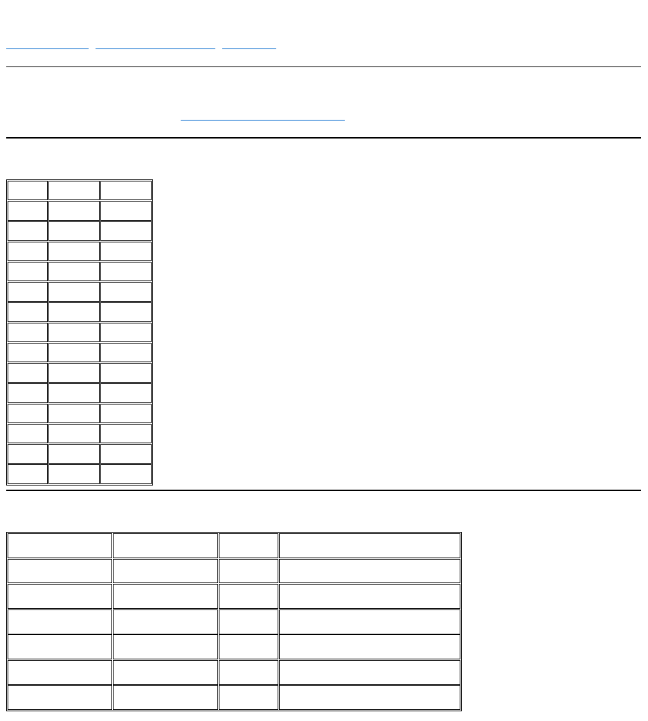
I/OMap:Dell™OptiPlex™E1Systems
Address
Device
0000-000F
DMA controller #1
0020-003F
Interrupt controller #1
0040-0043
System timers
0044-005F
Reserved
0060-006F
Keyboard controller
0070-0071
RTC and NMI enable
0080-008F
DMA page registers
00A0-00BF
Interrupt controller #2
00C0-00DF
DMA controller #2
00F0
Coprocessor busy clear
00F1
Coprocessor busy reset
00F2-00FF
Available
278-27F
LPT2
2E8-2EF
COM4
2F8-2FF
COM2
378-37F
LPT1
3E8-3EF
COM3
3F8-3FF
COM1
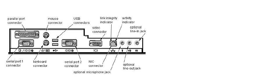
I/OPortsandConnectors:Dell™OptiPlex™E1Systems

IRQAssignments:Dell™OptiPlex™E1Systems
1IRQ3isavailableprovidedthatnootherdeviceinthecomputer(suchasamodem)isusingCOM2orCOM4.
2 If an ISA expansion card is configured for IRQ11, the NIC or PCI IRQ is assigned to another available IRQ line.
IRQ Line
System Resource
IRQ0
System timer
IRQ1
Keyboard port
IRQ2
Enables IRQ8 through IRQ15
IRQ31
Available
IRQ4
Serial port
IRQ5
Audio controller
IRQ6
Diskette/tape drive controller
IRQ7
Parallel port
IRQ8
RTC
IRQ9
ACPI
IRQ10
Available
IRQ112
NIC/default PCI IRQ
IRQ12
Mouse port
IRQ13
Math coprocessor
IRQ14
Primary EIDE channel
IRQ15
Secondary EIDE channel
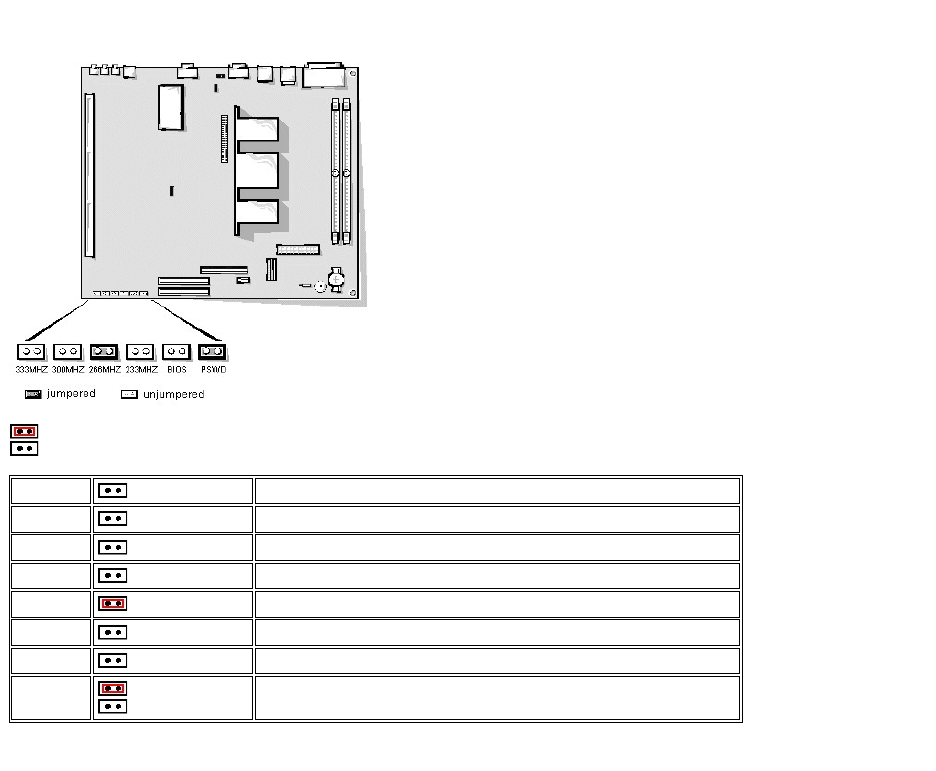
Jumpers:Dell™OptiPlex™E1Systems
= jumpered
=unjumpered
* One set of the speed jumper pins must have a jumper plug installed; otherwise, the system will operate at an undetermined speed.
400MHZ
Internally set. Speed jumper settings no longer apply.
366MHZ
Internally set. Speed jumper settings no longer apply.
333MHZ*
Jumpered when the microprocessor's internal speed is 333 MHz.
300MHZ*
Jumpered when the microprocessor's internal speed is 300 MHz.
266MHZ*
(default)
Jumpered when the microprocessor's internal speed is 266 MHz.
233MHZ*
Jumpered when the microprocessor's internal speed is 233 MHz.
BIOS
(default)
Reserved. Do not change.
PSWD
(default)
The password features are enabled.
The password features are disabled.
Memory:Dell™OptiPlex™E1Systems
Installation Guidelines | Memory Configuration Options | Memory Map
Installation Guidelines
For information on installing DIMMs, refer to DIMM removal and installation instructions.
Memory Configuration Options
Memory Map
Total
DIMM_B
DIMM_C
16 MB
16 MB
32 MB
16 MB
16 MB
32 MB
32 MB
48 MB
32 MB
16 MB
64 MB
32 MB
32 MB
64 MB
64 MB
80 MB
64 MB
16 MB
96 MB
64 MB
32 MB
128 MB
64 MB
64 MB
128 MB
128 MB
144 MB
128 MB
16 MB
160 MB
128 MB
32 MB
192 MB
128 MB
64 MB
256 MB
128 MB
128 MB
Memory Range
Address Range
Size
Description
1024–262,144 KB
100000–10000000h
256 MB
Extended memory
960–1023 KB
F0000–FFFFFh
64 KB
System BIOS
800–959 KB
C8000–EFFFFh
160 KB
Available high memory
640–799 KB
A0000–C7FFFh
160 KB
Video memory and BIOS
639 KB
9FC00–9FFFFh
1 KB
Extended-BIOS data
0–638 KB
00000–9FBFFh
639 KB
Conventional memory
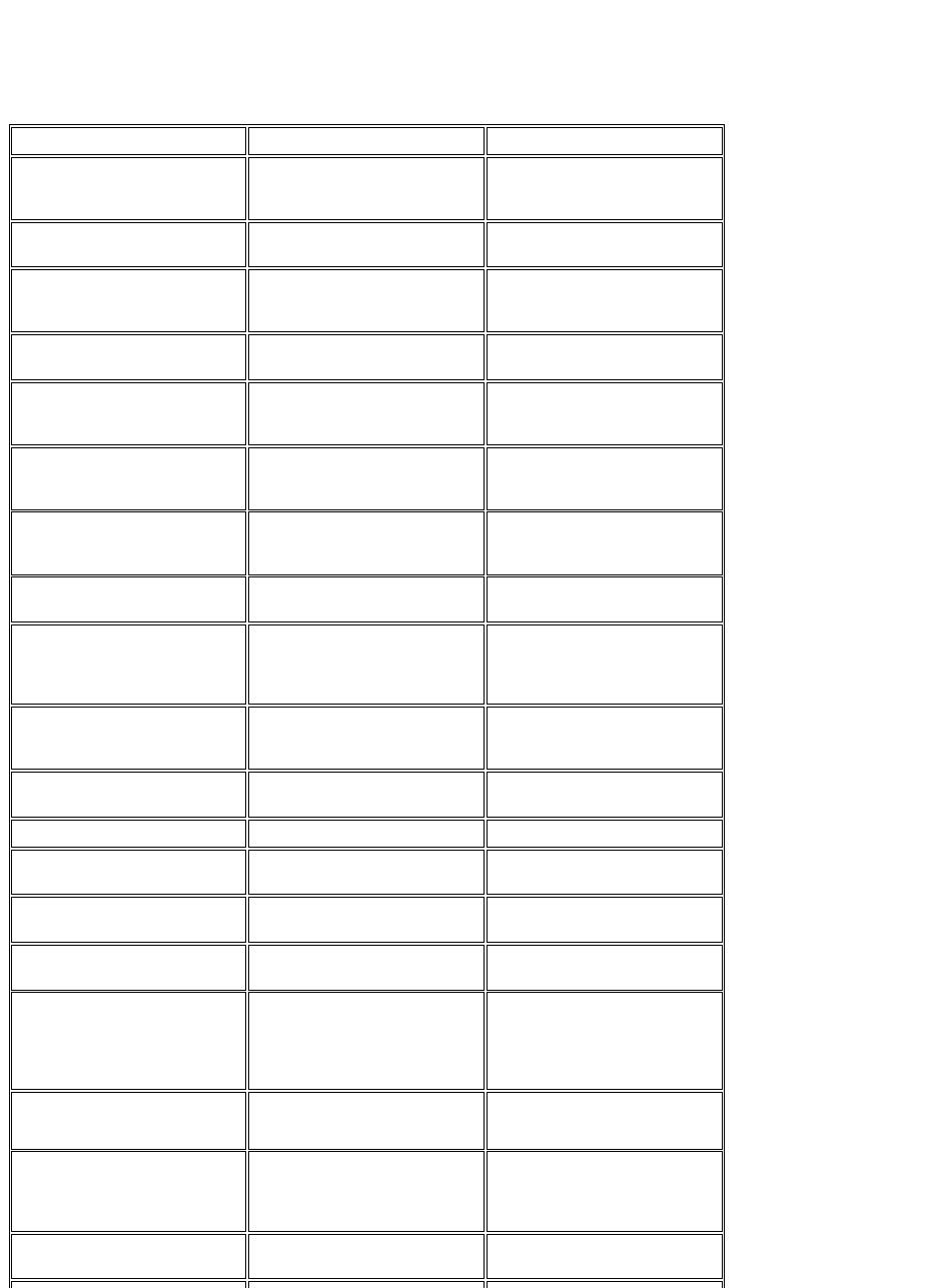
SystemErrorMessages:Dell™OptiPlex™E1Systems
This section lists (in alphabetical order) system error messages that can appear on the monitor screen. These messages can help you find the source of a problem.
Some of these error messages indicate fatal errors. When a fatal error occurs, the system cannot usually be rebooted until an appropriate hardware change has been
made.
Message
Definition
Probable Causes
Address mark not found
BIOS found faulty disk sector or could
not find particular disk sector.
Faulty diskette/tape drive subsystem or
hard-disk drive subsystem (defective
system board).
Alert! Cover was previously
removed
Chassis intrusion alert.
The cover was removed. Message is
informational.
Attachment failed to respond
Diskette drive or hard-disk drive
controller cannot send data to associated
drive.
Faulty interface cable or connector.
Bad command or file name
Command entered does not exist or is
not in pathname specified.
Bad command.
Bad error-correction code(ECC)
on disk read
Diskette drive or hard-disk drive
controller detected uncorrectable read
error. Indicates a fatal error.
Faulty diskette/tape drive subsystem or
hard-disk drive subsystem (defective
system board).
Controller has failed
Hard-disk drive or associated controller
defective. Indicates a fatal error.
Faulty diskette/tape drive subsystem or
hard-disk drive subsystem (defective
system board).
Data error
System received unrecoverable data-
read error from diskette or hard-disk
drive. Indicates a fatal error.
Faulty diskette, diskette drive, or hard-
disk drive.
Decreasing available memory
Read/write failure during POST prevents
system from using available memory.
Faulty or improperly seated DIMM(s).
Diskette drive 0 seek failure
Diskette drive 1 seek failure
Diskette/tape drive controller could not
locate specific sector or track.
Faulty or improperly inserted diskette,
incorrect configuration settings in System
Setup program, loose diskette/tape drive
interface cable, or loose power cable.
Diskette read failure
Failure occurred while system attempted
to read diskette.
Faulty diskette, faulty or improperly
connected diskette/tape drive interface
cable, or loose power cable.
Diskette subsystem reset
failed
System could not successfully issue reset
command to diskette controller.
Faulty diskette/tape drive controller
(defective system board).
Diskette write protected
Diskette write-protect feature activated.
Diskette write-protected.
Drive not ready
Diskette missing from or improperly
inserted in diskette drive.
Defective, unformatted, or improperly
inserted diskette.
Gate A20 failure
Gate A20 of the keyboard controller
malfunctioned. Indicates a fatal error.
Faulty keyboard controller (defective
system board).
General failure
Operating system cannot execute
command.
Operating system corrupted or not
installed properly.
Hard disk controller failure
Hard disk drive read failure
Hard disk failure
Hard-disk drive failed to initialize.
Indicates a fatal error.
Incorrect configuration settings in System
Setup program, improperly connected
hard-disk drive cable, faulty hard-disk
drive controller subsystem (defective
system board), or loose power cable.
Invalid configuration
information - please run SETUP
program
System Setup program contains
incorrect system configuration settings.
Incorrect configuration settings in System
Setup program or faulty battery.
Keyboard clock line failure
Keyboard failure
System cannot communicate with
keyboard. Indicates a fatal error.
Loose or improperly connected
keyboard cable connector, defective
keyboard, or defective keyboard/mouse
controller (defective system board).
Keyboard controller failure
Keyboard/mouse controller failed.
Indicates a fatal error.
Defective keyboard/mouse controller
(defective system board).

Keyboard data line failure
Keyboard stuck key failure
System cannot communicate with
keyboard. Indicates a fatal error.
Loose or improperly connected
keyboard cable connector, defective
keyboard, or defective keyboard/mouse
controller (defective system board).
Memory address line failure at
address, read value expecting
value
Memory data line failure at
address, read value expecting
value
Memory double word logic
failure at address, read value
expecting value
Memory odd/even logic failure
at address, read value
expecting value
Memory write/read failure at
address, read value expecting
value
During memory test, value read at
address was incorrect.
Faulty or improperly seated DIMMs or
defective system board.
Memory allocation error
Software in use conflicts with operating
system, application, or utility.
Faulty application or utility.
No boot device available
System does not recognize diskette drive
or hard-disk drive from which it is trying
to boot.
Faulty diskette, diskette/tape drive
subsystem, hard-disk drive, hard-disk
drive subsystem; or no boot disk in drive
A.
No boot sector on hard-disk
drive
Configuration settings in System Setup
program incorrect, or operating system
corrupted.
Incorrect configuration settings in System
Setup program, or no operating system
on hard-disk drive.
No timer tick interrupt
Timer on system board malfunctioning.
Indicates a fatal error.
Defective system board.
Non-system disk or disk error
Diskette in drive A or hard-disk drive
does not have bootable operating system
installed on it.
Faulty diskette, diskette/tape drive
subsystem, or hard-disk drive
subsystem.
Not a boot diskette
No operating system on diskette.
No operating system on diskette.
Plug and Play Configuration
Error
System encountered problem in trying to
configure one or more expansion cards.
System resource conflict.
Read fault
Requested sector not found
MS-DOS®cannot read from diskette
or hard-disk drive.
System could not find particular sector
on disk, or requested sector defective.
Faulty diskette, diskette/tape drive
subsystem, or hard-disk drive subsystem
(defective system board).
Reset failed
Disk reset operation failed.
Improperly connected diskette/tape
drive, hard-disk drive interface cable, or
power cable.
Sector not found
MS-DOS unable to locate sector on
diskette or hard-disk drive.
Defective sectors on diskette or hard-
disk drive.
Seek error
MS-DOS unable to locate specific track
on diskette or hard-disk drive.
Defective diskette or hard-disk drive.
Seek operation failed
System could not find particular address
mark on disk.
Faulty diskette or hard-disk drive.
Shutdown failure
System board chip faulty. Indicates a
fatal error.
Defective system board.
Time-of-day clock stopped
System battery low.
Defective battery or faulty chip
(defective system board).
Time-of-day not set
Time or Date setting in System Setup
program incorrect, or system battery
bad.
Incorrect Time or Date settings, or
defective system battery.
Timer chip counter 2 failed
Timer circuit on system board
Defective system board.

malfunctioning. Indicates a fatal error.
Unexpected interrupt in
protected mode
Keyboard/mouse controller
malfunctioning, or one or more DIMMs
improperly seated. Indicates a fatal
error.
Improperly seated DIMMs or faulty
keyboard/mouse controller chip
(defective system board).
Write fault
Write fault on selected drive
MS-DOS cannot write to diskette or
hard-disk drive.
Faulty diskette or hard-disk drive.
NIC:Dell™OptiPlex™E1Systems
The OptiPlex E1 system has an onboard Ethernet NIC subsystem.
The integrated 10/100-Mbps 3Com®PCI 3C905B-TX Ethernet NIC subsystem supports the Wakeup On LAN feature and the 10BASE-T and 100BASE-TX
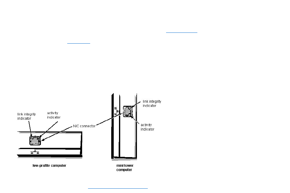
standards. The NIC subsystem connects to the Ethernet network through a single RJ45 connector on the back of the computer. The RJ45 connector and the NIC
interface circuitry are mounted on the system board.
The NIC connector on the computer’s back panel has the following indicators:
lA yellow activity indicator that flashes when the system is transmitting or receiving network data. (A high volume of network traffic may make this indicator
appear to be in a steady “on” state.)
lA green link integrity indicator that lights up when there is a good connection between the network and the NIC. When the green indicator is off, the system is
not detecting a physical connection to the network.
See Chapter 4, "Using Integrated Devices," in the Reference and Installation Guide for information on configuring the NIC.

TechNotes:Dell™OptiPlex™E1Systems
Video
Memory
Expansion Subsystem
Power
Hard-Disk Drive Options
I/O Map
POST Beep Codes
NIC
System Error Messages
IRQ Assignments
DMA Channel Assignments
System Setup
Updated System Setup Categories
Drivers and Utilities
Microsoft Updated ATAPI Driver
Removing and Replacing Parts
Wakeup On LAN

System and Setup Passwords
Assigning a System Password | Assigning a Setup Password | Operating With a Setup Password Enabled | Disabling a Forgotten Password
Assigning a System Password
Before you can assign a system password, you must enter the System Setup program and check the System Password category.
When a system password is assigned, the System Password setting shown is Enabled. When the system password feature is disabled by a jumper setting on the system
board, the setting shown is Disabled by Jumper. You cannot change or enter a new system password if the Disabled by Jumper setting is displayed. When a system
password is not assigned, the System Password setting shown is Not Enabled.
To assign a system password, follow these steps:
1. Enter the System Setup program and verify that the Password Status setting is Unlocked.
For instructions on changing this setting, see "Password Status" in Chapter 2 of your system's Reference and Installation Guide.
2. Highlight System Security and press <Enter>.
3. Highlight System Password and press <Enter>.
4. Type the desired system password in the Enter Password field and press <Enter>.
You can use up to 7 characters in your password.
As you press each character key (or the spacebar for a blank space), a placeholder appears in the field.
The password assignment operation recognizes keys by their location on the keyboard, without distinguishing between lowercase and uppercase characters. For
example, if you have an M in your password, the system recognizes either M or m as correct.
Certain key combinations are not valid. If you enter one of these combinations, the speaker emits a beep.
To erase a character when entering your password, press <Backspace> or the left-arrow key.
5. Type the desired system password in the Confirm Password field and press <Enter>.
The system password is now assigned and is Enabled. You can exit the System Setup program and begin using your system. Password protection takes effect after the
system reboots.
Assigning a Setup Password
A setup password can be assigned (or changed) only when Setup Password is set to Not Enabled. To assign a setup password, follow these steps:
1. Enter the System Setup program.
2. Highlight System Security and press <Enter>.
3. Highlight Setup Password and press <Enter>.
4. Type the desired setup password in the Enter Password field and press <Enter>.
If a character is illegal for password use, the system emits a beep.
5. Type the desired setup password in the Confirm Password field and press <Enter>.
The setup password is now assigned. The Setup Password setting changes from Not Enabled to Enabled.
After you verify the password, the Setup Password setting changes to Enabled. The next time you enter the System Setup program, the system prompts you for the
setup password.
A change to the Setup Password setting becomes effective immediately (rebooting the system is not required).
Operating with a Setup Password Enabled
If Setup Password is set to Enabled, you must enter the correct setup password before you can modify the majority of the System Setup categories.
When you start the System Setup program, the System Setup screen appears with Setup Password highlighted, prompting you to type the password.
If you do not enter the correct password, the system lets you view, but not modify, the System Setup screen, with one exception: If Password Status is set to
Unlocked, you may modify the system password.
NOTE: To escape from the field without assigning a system password, press <Esc>.
NOTE: The setup password can be the same as the system password. If the two passwords are different, the setup password can be used as an
alternate system password. However, the system password cannot be used in place of the setup password.

Disabling a Forgotten Password
If you forget your system or setup password, you cannot operate your system or change settings in the System Setup program, respectively, until you remove the
computer cover, change the password jumper setting to disable the password(s), and erase the existing password(s).
To disable a forgotten password, follow these steps.
1. Remove the computer cover according to the instructions in "Removing the Computer Cover" in Chapter 5 in your Reference and Installation Guide.
2. Remove the jumper plug from the PSWD jumper to disable the password features.
Refer to Figure 1 for the location of the password jumper (labeled "PSWD") on the system board.
3. Replace the computer cover.
4. Reconnect your computer and peripherals to their electrical outlets, and then turn them on.
Booting your system with the PSWD jumper plug removed erases the existing password(s).
5. To reset the chassis intrusion detector, enter the System Setup program and reset Chassis Intrusion.
See "Chassis Intrusion" in Chapter 2 of your Reference and Installation Guide for instructions.
6. In the System Setup program, verify that the password is disabled. Continue with this procedure if you want to assign a new password.
7. Remove the computer cover according to the instructions in "Removing the Computer Cover" in Chapter 5 in your Reference and Installation Guide.
8. Replace the PSWD jumper plug.
9. Replace the computer cover, and then reconnect the computer and peripherals to their electrical outlets and turn them on.
Booting with the PSWD jumper installed reenables the password features. When you enter the System Setup program, both password settings appear as Not Enabled, meaning that
the password features are enabled but that no passwords have been assigned.
10. To reset the chassis intrusion detector, enter the System Setup program and reset Chassis Intrusion.
See "Chassis Intrusion" in Chapter 2 of your Reference and Installation Guide for instructions.
11. Assign a new system and/or setup password.
CAUTION: Before you remove the computer cover, turn off the computer and unplug it from the electrical outlet. See "Protecting Against
Electrostatic Discharge" in the safety instructions at the front of your Reference and Installation Guide.
NOTE: After you remove and replace the cover, the chassis intrusion detector will cause the following message to be displayed at the next
system start-up:
ALERT! Cover was previously removed.
NOTE: If a setup password has been assigned by someone else, contact your network administrator for information on resetting the chassis
intrusion detector.
NOTE: Before you assign a new system and/or setup password, you must replace the PSWD jumper plug.
CAUTION: Before you remove the computer cover, turn off the computer and unplug it from the electrical outlet. See "Protecting
Against Electrostatic Discharge" in the safety instructions at the front of your Reference and Installation Guide.
NOTE: After you remove and replace the cover, the chassis intrusion detector will cause the following message to be displayed at the next
system start-up:
ALERT! Cover was previously removed.
NOTE: If a setup password has been assigned by someone else, contact your network administrator for information on resetting the chassis
intrusion detector.
Power:Dell™OptiPlex™E1Systems
DC Voltage Ranges | DC Power Cables (Low-Profile Chassis) | DC Power Cables (Mini Tower Chassis) | DC Power Distribution (Low-Profile Chassis) | DC Power
Distribution (Mini Tower Chassis)
DC Voltage Ranges
OptiPlex E1 systems are equipped with a switch-selectable (115/230 VAC) universal power supply that can operate from standard AC power outlets in all countries.
The system power supplies provide the DC operating voltages and currents listed in the following table.
1 The combined load on the +5-VDC and +3.3-VDC outputs should not exceed 105 W on the low-profile system.
2 Withstands surges of up to 11.0 A to support disk start-up operations.
3 VFP (volts flea power) — sometimes called "standby power."
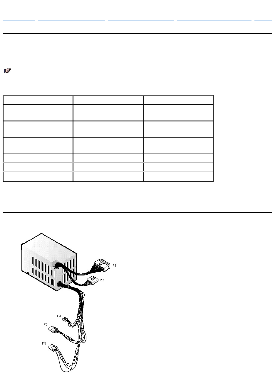
DC Power Cables (Low-Profile Chassis)
NOTE: Each power supply produces DC voltages only under its loaded condition. Therefore, when you measure these voltages, the DC power
connectors must be connected to their corresponding power input connectors on the system board or drives.
Voltage
Range
Maximum Output Current
+3.3 VDC
+3.15 to +3.45 VDC
12.0 A1 (low-profile chassis)
14.0 A1 (mini tower chassis)
+5 VDC
+4.75 to +5.25 VDC
18.0 A1 (low-profile chassis)
22.0 A1 (mini tower chassis)
+12 VDC
+11.40 to +12.60 VDC
3.0 A2 (low-profile chassis)
6.0 A2 (mini tower chassis)
–12 VDC
–10.80 to –13.20 VDC
0.3 A
–5 VDC
–4.50 to –5.50 VDC
0.3 A
+5 VFP3
+4.75 to +5.25 VDC
1.2 A
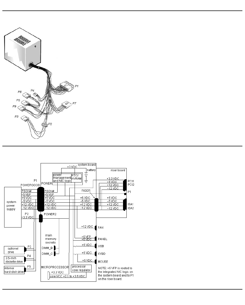
DC Power Cables (Mini Tower Chassis)
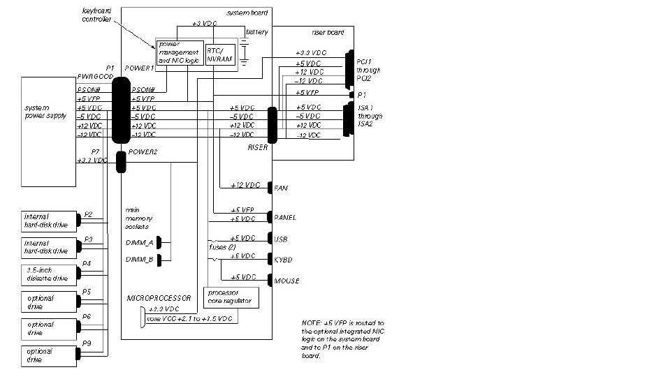
DC Power Distribution (Low-Profile Chassis)
DC Power Distribution (Mini Tower Chassis)
RemovingandReplacingParts:Dell™OptiPlex™E1Systems
Precautionary Measures | Procedures | Recommended Tools
Precautionary Measures
Before you remove or replace parts in the system, read the following warning for your personal safety and to prevent damage to the system from ESD.
Procedures
Unless otherwise noted, each procedure is based on the following assumptions:
lYou have the recommended tools.
lYou have performed the steps in Precautionary Measures.
lYou have removed the computer cover.
lYou can replace or reinstall a part by performing the removal procedure in reverse order unless additional information is provided.
Recommended Tools
lSmall flat-blade screwdriver
lWide flat-blade screwdriver
lNumber 1 and number 2 Phillips-head screwdrivers
l1/4-inch nut driver
lTweezers or long-nose pliers
lChip removal tool
lWrist grounding strap
WARNING: For your personal safety and protection of the equipment, perform the following steps in the sequence listed before you start to
work on the computer:
1. Turn off the computer and any attached peripherals.
2. Disconnect the computer and any attached peripherals from their power sources to reduce the potential for personal injury.
3. Disconnect any telephone or telecommunication lines from the computer.
4. Wear a wrist grounding strap, and clip it to an unpainted metal surface, such as the padlock ring on the back of the chassis. If a wrist
grounding strap is not available, touch an unpainted metal surface on the back of the computer to discharge any static charge from your
body.
CAUTION! The computer's power supply continues to supply "flea power" to the system board whenever the computer is turned off and
plugged into an electrical outlet. Do not replace or install components on the system board without first unplugging the computer from the
electrical outlet. Otherwise, damage may occur to the system board and to the components.
Low-Profile Chassis
Mini Tower Chassis
Computer Cover Removal
Eject-, Power-, and Reset-Button Removal
Front-Panel Insert Removal
Control Panel Removal
Drive Hardware Removal
System Power-Supply Removal
Expansion-Card Cage Removal
Expansion Card Removal
Riser Board Removal
DIMM Removal and Installation
Video Memory Removal
SEPP Cartridge/Heat Sink Assembly Removal
333-MHz SEPP Cartridge/Heat Sink/Fan Assembly Removal
System Battery Removal
System Board Removal
Computer Cover Removal
Front Bezel Removal
Eject-, Power-, and Reset-Button Removal
Front-Panel Insert Removal
Control Panel Removal
Drive Hardware Removal
System Power-Supply Removal
Expansion-Card Cage Removal
Expansion Card Removal
Riser Board Removal
DIMM Removal and Installation
Video Memory Removal
SEPP Cartridge/Heat Sink Assembly Removal
System Battery Removal
System Board Removal
ExpansionSubsystem:Dell™OptiPlex™E1Systems
ISA Configuration Utility | Low-Profile Chassis Riser Board | Mini Tower Chassis Riser Board
ISA Configuration Utility
The OptiPlex E1 systems contain an advanced expansion subsystem that can support a mixture of traditional ISA expansion cards (called legacy cards), Plug and Play
ISA expansion cards, and PCI expansion cards. The ISA Configuration Utility (ICU) included with the computer provides a means of avoiding resource conflicts that
might arise from such an arrangement.
After all legacy cards have been configured with the ICU, the computer automatically assigns any required memory space, IRQ lines, and DMA channels to any
installed Plug and Play ISA expansion cards and PCI expansion cards the next time the computer is rebooted. "Configuring Expansion Cards" in the online System
User's Guide describes the ICU and provides instructions for using it to configure the computer.
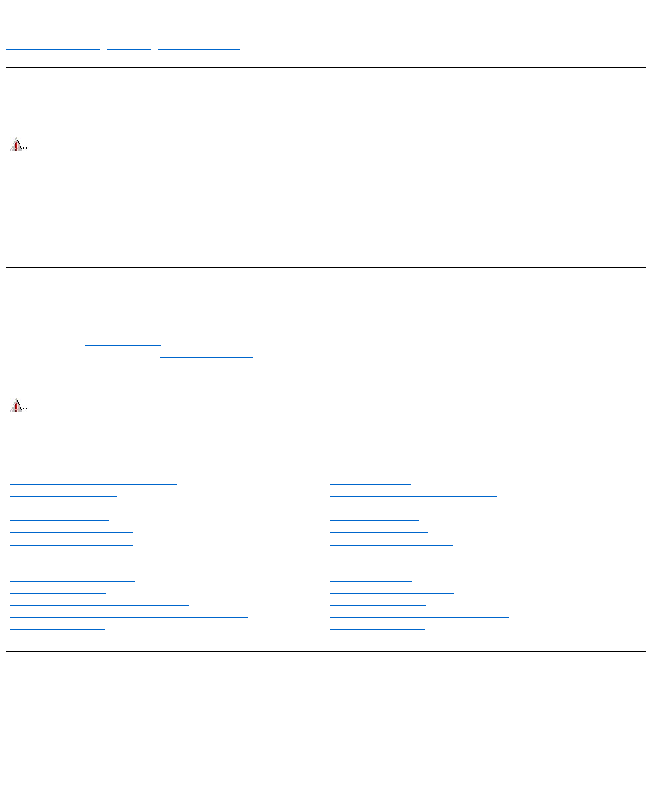
Low-Profile Chassis Riser Board
ISA1 and PCI2 share the same card-slot opening. The OptiPlex E1 computer has a passive riser board, with no PCI-to-PCI bridge. The riser board includes the P1
connector (for connecting the NIC to the riser board cable) and an LED. If the LED is on, the riser board is receiving power; if off, the riser board is not receiving
power.
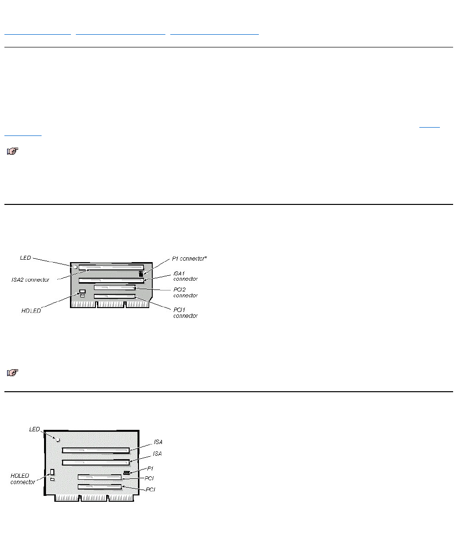
Mini Tower Chassis Riser Board
The mini tower computer has four expansion-card slots. The riser board has two ISA expansion-card connectors and two PCI expansion-card connectors.
The riser board is active, incorporating PCI-to-PCI bridging. The riser board includes the P1 connector (for connecting the NIC to the riser board cable) and an LED.
If the LED is on, the riser board is receiving power; if off, the riser board is not receiving power.
NOTES: If the Microsoft® Windows NT®operating system is being used, set any Plug and Play expansion cards to legacy mode, using the card
manufacturer’s configuration utility, and enter the card’s resources with this utility. Then run the ICU and add the card to the system’s
configuration.
The ICU is not required for the Microsoft Windows®95 or Windows 98 operating system because the same functions are provided by the Device
Manager.
NOTE: On some versions of this riser board, the P1 connector may be in a different location. This does not change or in any way affect the
functionality of this board.
Computer Cover Removal (Low-ProfileChassis):Dell™OptiPlex™E1Systems
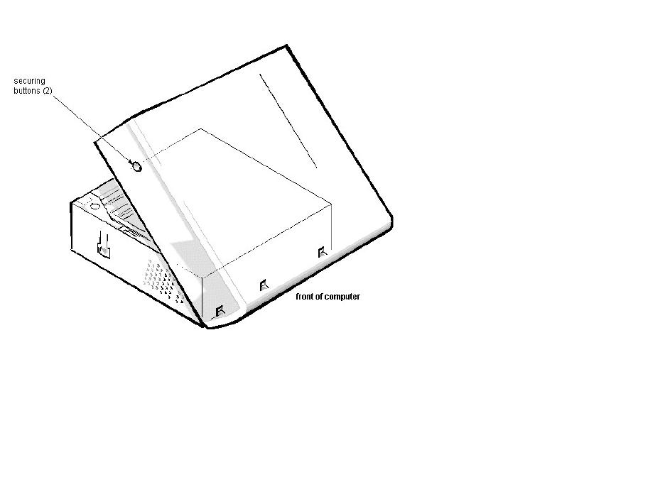
To remove the computer cover, follow these steps:
1. Turn off power to the computer and all peripherals, and disconnect the AC power cables from their electrical outlets.
2. Remove the padlock if one is installed.
3. Press in on the 2 securing buttons until the cover is free to swing up.
4. Raise the back of the cover, and pivot it toward the front of the computer.
5. Lift the cover off of the hooks at the front of the chassis.
Three plastic hooks on the inside-front part of the cover secure it to the chassis.
Before you reinstall the cover, fold all cables out of the way so that they do not interfere with the cover or with proper airflow inside the computer.
System Board Removal (Low-ProfileChassis):Dell™OptiPlex™E1Systems
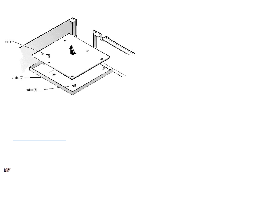
To remove the system board, follow these steps:
1. Disconnect all cables from their connectors at the back of the computer.
2. Remove the expansion-card cage.
3. Disconnect all cables from the system board.
4. Remove the screw that secures the system board to the bottom of the chassis.
5. Slide the system board toward the front of the chassis until it stops.
6. Carefully lift the system board out of the chassis (be sure to lift evenly and not twist the system board).
When you reinstall the system board (before you slide the system board back to lock it in position), push down near each slot to engage the grounding clip onto its
corresponding tab. Push evenly on both sides of the system board as you slide it into position (do not twist the system board).
NOTES: If you are replacing the system board, remove all DIMMs, the video-memory upgrade module (if present), the SEPP/heat sink assembly, and
the guide bracket assembly from the old system board and install them on the replacement board. Also, set the jumpers on the new system board so
thattheyareidenticaltothoseontheoldboard,unlessamicroprocessorupgradeisbeinginstalled.
DIMM Removal and Installation (Low-ProfileChassis):Dell™OptiPlex™E1Systems
DIMM Removal | DIMM Installation
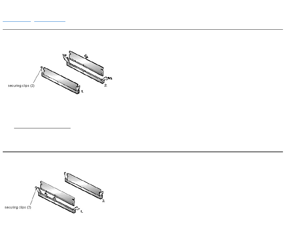
DIMM Removal
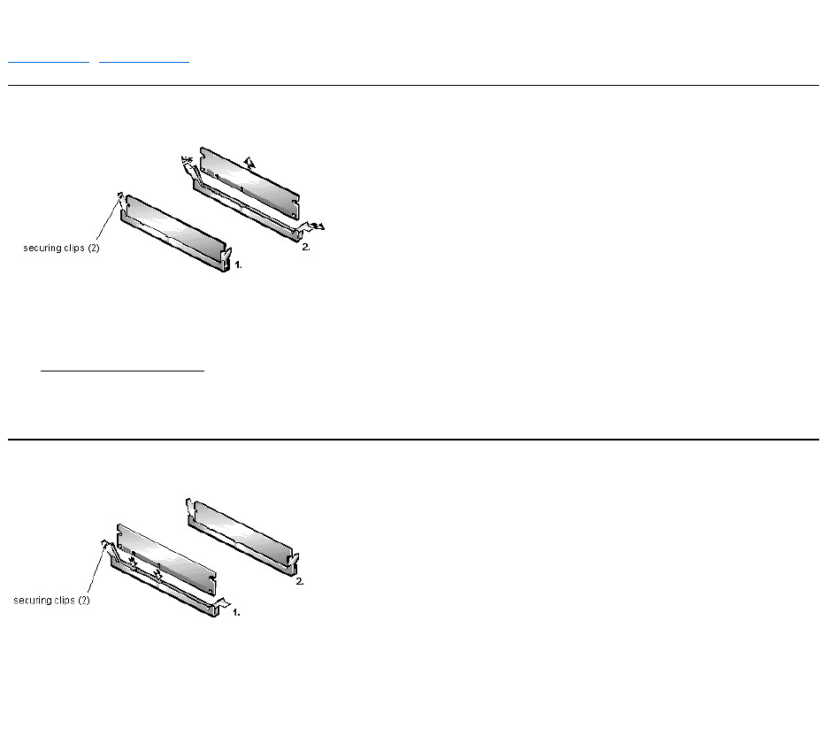
To remove a DIMM from 1 of the 2 DIMM sockets, follow these steps:
1. Remove the system power supply.
2. Locate the DIMM that you wish to remove.
3. Push outward on the DIMM socket's securing clips until the DIMM is released from its socket.
4. Lift the DIMM away from the socket.
DIMM Installation
1. Install the replacement DIMM by pressing the DIMM fully into the socket while closing the securing clips to lock the DIMM into the socket.
2. Replace all assemblies and cables previously removed.
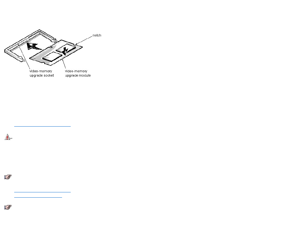
Video Memory Removal (Low-ProfileChassis):Dell™OptiPlex™E1Systems
You can upgrade video memory from 2 MB to 4 MB by installing a video-memory upgrade module in the video-memory upgrade socket on the system board. Adding
video memory increases the system’s video performance and provides additional modes for high-resolution/expanded color applications.
To install the video memory upgrade, follow these steps:
1. Remove the expansion-card cage.
2. Orient the video-memory upgrade module as shown in the illustration. Then carefully align the module’s edge connector pins with the socket, ensuring that the
slot in the module mates with the socket key.
3. Press the video-memory upgrade module firmly into the socket, and pivot the module downward until the module clicks into place.
4. Replace the expansion-card cage.
5. Replace the computer cover, and reconnect the AC power cable to the electrical outlet. Press the power button on the computer to reboot the system.
6. Enter the System Setup program, and confirm that 4 MB is shown for Video Memory. If the total memory is listed incorrectly, repeat steps 1 through 6 to reseat
the video-memory upgrade module and verify that the computer acknowledges the module.
7. Run the system diagnostics (Video Test Group) to test the new video-memory upgrade module.
CAUTION: To avoid possible damage to the video-memory upgrade socket and/or video-memory upgrade module, the module is keyed and
must be correctly positioned before inserting it into the socket.
NOTE: If you do not hear a sharp click when installing the video-memory upgrade module, remove the module and repeat steps 2 and 3.
NOTE: As the system boots, it automatically detects the presence of the new video-memory upgrade module and changes the system configuration
information in the System Setup program.
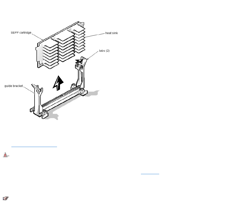
SEPP Cartridge/Heat Sink Assembly Removal (Low-ProfileChassis):Dell™OptiPlex™E1
Systems
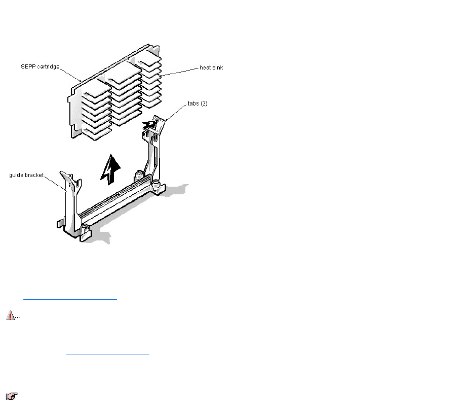
To remove the SEPP cartridge/heat sink assembly, follow these steps:
1. Remove the system power supply.
2. Locate the SEPP cartridge/heat sink assembly.
3. Disconnect the microprocessor fan connector from the 3-pin connector (labeled "FAN") on the system board, located between the SERIAL2 connector and the
MONITOR connector.
The connector is located between the SERIAL 2 connector and the MONITOR connector.
4. Locate and press outward on the SEPP cartridge release latches (located directly on top of the SEPP cartridge adjacent to the heat sink assembly).
5. Lift the SEPP cartridge/heat sink assembly out of its guide bracket assembly/connector on the system board.
WARNING: The SEPP cartridge/heat sink assembly can get extremely hot during system operations. Be sure that the assembly has had
sufficient time to cool before touching it.
NOTE: When installing the SEPP cartridge/heat sink assembly, carefully orient the assembly and press firmly with up to 25 pounds of force to connect
the SEPP cartridge with its connector.
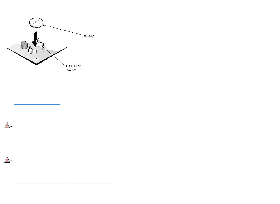
System Battery Removal (Low-ProfileChassis):Dell™OptiPlex™E1Systems
To remove the system battery, follow these steps:
1. If possible, boot the system and enter the System Setup program. Then record important system configuration information.
2. Turn off power to the computer and all peripherals, and disconnect the AC power cables from their electrical outlets.
3. Remove the computer cover.
4. Remove the expansion-card cage, and locate the battery in the front-right corner of the system board adjacent to the DIMM connectors.
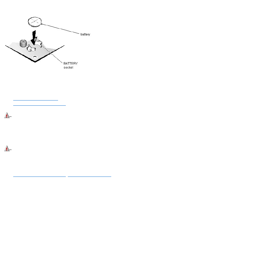
5. Remove the battery by carefully prying it out of its socket with your fingers or with a blunt, nonconducting object, such as a plastic screwdriver.
6. Insert the battery into the socket (with the positive side labeled “+” facing upwards), and snap it into place.
6. Replace the expansion-card cage; replace the computer cover, reconnect all cabling, and reboot the system.
7. Enter the System Setup program, and configure the system using the information you recorded in step 1.
8. Turn off the computer; wait 10 or more minutes, and then reenter the System Setup program to ensure that the date and time are still correct, indicating that the
system battery is functioning correctly.
CAUTION: If you pry out the battery with a blunt object, be careful not to touch the system board with the object. Ensure that the object is
inserted between the battery and the socket before attempting to pry out the battery. Otherwise, you may damage the system board by prying
off the socket or by breaking traces on the system board.
WARNING: There is a danger of the new battery exploding if it is incorrectly installed. When you replace the system battery, orient the new
battery with the "+" facing up. Replace the battery only with the same or equivalent type recommended by the manufacturer. Discard used
batteries according to the manufacturer's instructions.
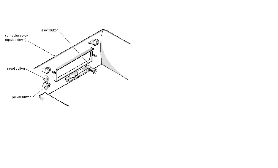
Eject-, Power-, and Reset-Button Removal (Low-ProfileChassis):Dell™OptiPlex™E1Systems
To remove the eject, power, and reset buttons, follow these steps:
1. Lay the computer cover upside down on a flat work surface with the back of the cover facing you.
2. To remove the 3.5-inch diskette-drive eject button, pull gently on the plastic part of the button until it comes free.
3. To remove the power button or the reset button, use a small screwdriver and push in on the 2 or 3 plastic clips that hold the button to the computer cover.
When these clips are released, the button comes free from the front panel of the cover.
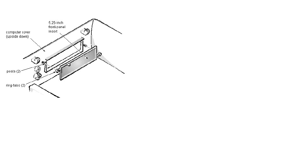
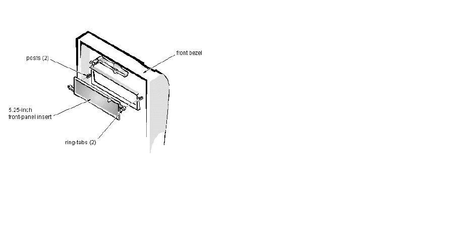
Front-Panel Insert Removal (Low-ProfileChassis):Dell™OptiPlex™E1Systems
To remove a front-panel insert, follow these steps:
1. Lay the computer cover upside down on a flat work surface with the front of the cover facing you.
2. From the front of the cover, use your thumbs to push inward on the insert until it slides off the 2 posts.
To replace a 5.25-inch front-panel insert, position the 2 ring-tabs over the posts on the inside of the bay opening, and then press the ring-tabs over the posts. If
necessary, use a 1/4-inch nut driver to help push on the ring-tabs.
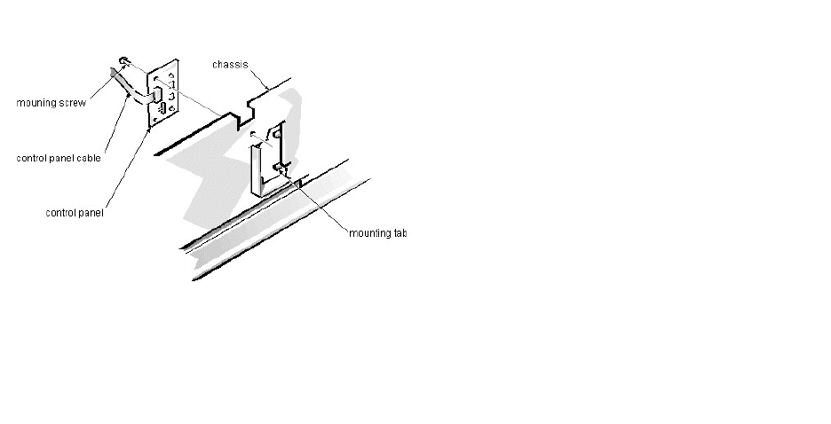
Control Panel Removal (Low-ProfileChassis):Dell™OptiPlex™E1Systems
To remove the control panel, follow these steps:
1. Disconnect the control panel cable from the PANEL connector on the system board.
2. From the inside of the chassis, remove the mounting screw holding the control panel to the chassis.
3. Remove the control panel from the chassis.
When you reinstall the control panel, be sure to put the right side of the control panel behind the mounting tab.
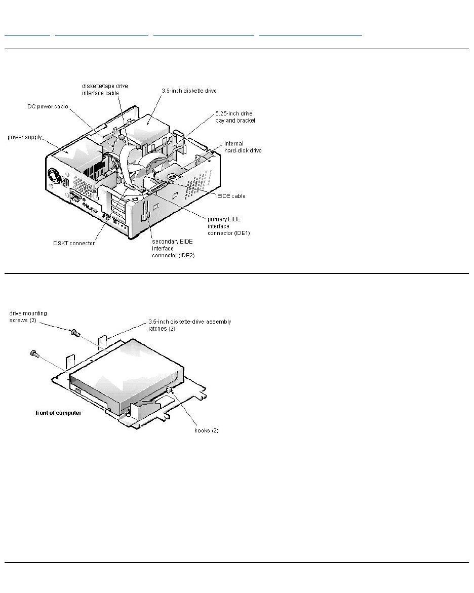
Drive Hardware Removal (Low-ProfileChassis):Dell™OptiPlex™E1Systems
Drive Hardware | 3.5-Inch Diskette-Drive Removal | 5.25-Inch Drive Assembly Removal | Hard-Disk Drive Assembly Removal
Drive Hardware
3.5-Inch Diskette-Drive Removal
To remove the 3.5-inch diskette drive assembly, follow these steps:
1. Disconnect the DC power cable and the interface cable from the back of the diskette drive.
2. Press the (2) 3.5-inch diskette-drive assembly latches to the left to release the assembly.
3. Rotate the left side of the assembly up, and lift the assembly out of the chassis.
4. Remove the 2 drive mounting screws from the left side of the drive, and remove the drive from the bracket.
When you replace the 3.5-inch diskette drive, be sure that the mounting holes on the right side of the drive engage the 2 hooks on the bracket.
5.25-Inch Drive Assembly Removal
To remove a 5.25-inch drive assembly, follow these steps:
1. Remove the 3.5-inch diskette drive assembly.
2. Disconnect the DC power cable and the interface cable from the back of the 5.25-inch drive.
3. Lift the 5.25-inch drive assembly straight up and out of the chassis.
4. Lay the 5.25-inch drive assembly upside down; then remove the 4 screws attaching the drive to the bracket.
When you replace the 5.25-inch drive, place the front of the drive toward the front of the bracket; then install the 4 screws, but do not tighten them. Align the screws
with the score marks on the bracket, and tighten the screws in the order stamped on the bottom of the bracket.
Check the alignment of the computer cover around the 5.25-inch drive bezel. Adjust the drive forward or backward on the bracket to align it.
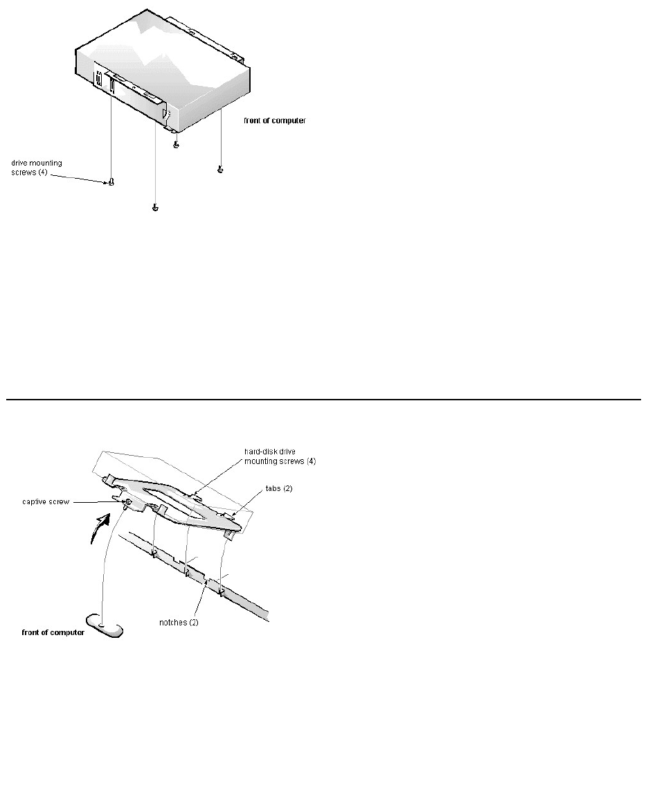
Hard-Disk Drive Assembly Removal
To remove the hard-disk drive, follow these steps:
1. Disconnect the DC power cable and the interface cable from the back of the drive.
2. Loosen the captive screw that secures the hard-disk drive bracket to the chassis.
3. Pivot the hard-disk drive assembly up and lift it out of the chassis.
4. Remove the 4 hard-disk drive mounting screws that attach the hard-disk drive to the hard-disk drive bracket.
When you reinstall the hard-disk drive assembly, be sure that the tabs on the back of the mounting plate fully engage the notches on the chassis before you rotate the
assembly into place.
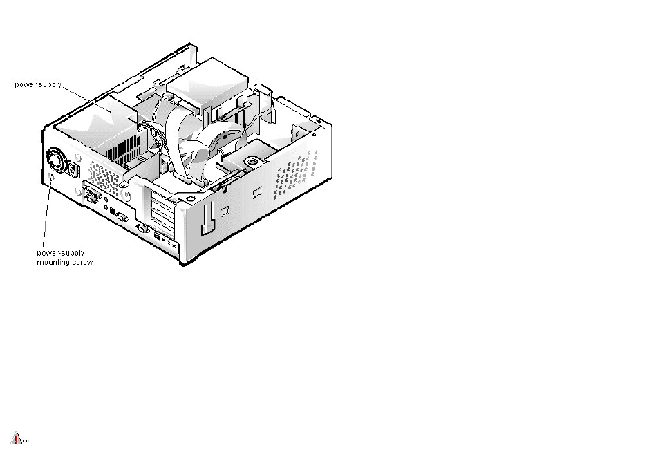
System Power-Supply Removal (Low-ProfileChassis):Dell™OptiPlex™E1Systems
To remove the system power supply, follow these steps:
1. Disconnect the AC power cable from the back of the power supply.
2. Disconnect the DC power cables from the system board and the drives.
3. Remove the power-supply mounting screw at the back of the chassis.
4. Slide the system power supply forward until it stops; then lift it from the chassis.
When you replace the system power supply, place it down inside the chassis and against the right side of the chassis. Then slide it toward the back of the chassis, and
hook the tabs into the right side of the power supply.
WARNING: The voltage selection switch, located on the back of the power supply assembly, must be set to the correct operating voltage (115
or 230 V) before the power cable is plugged into an electrical outlet.
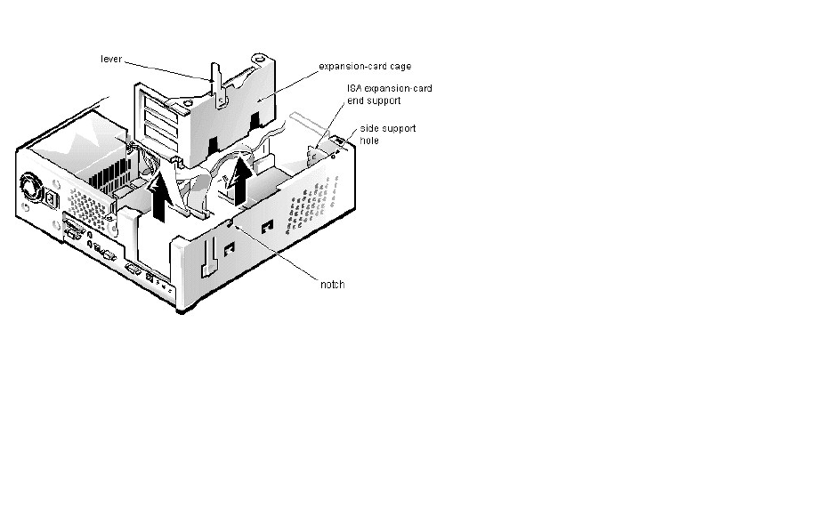
Expansion-Card Cage Removal (Low-ProfileChassis):Dell™OptiPlex™E1Systems
To remove an expansion-card cage, follow these steps:
1. Rotate the lever toward the back of the computer until it stops in the upright position.
2. Lift the expansion-card cage up and away from the computer.
To replace an expansion-card cage, keep it flush against the chassis to ensure that the lever engages the notch in the chassis when the lever is depressed.
If reinstalling an ISA expansion card into the expansion-card cage, be sure to slip the end of the ISA expansion card into the plastic ISA expansion-card end support.
The ISA expansion-card end support should not be removed; however, if it is accidentally removed, reinstall it by first inserting its top tab into the side support hole and
then sliding the bottom 2 tabs into the 2 support holes on the chassis floor.
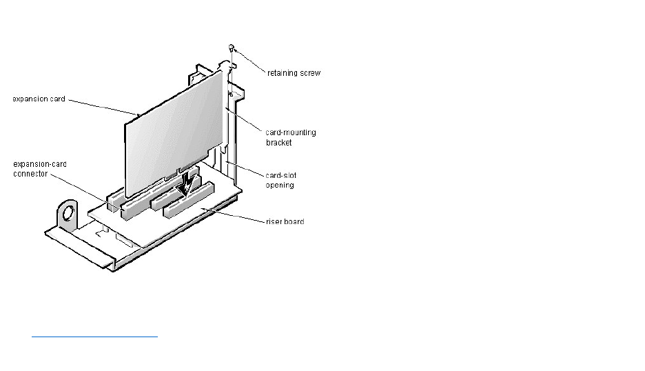
Expansion Card Removal (Low-ProfileChassis):Dell™OptiPlex™E1Systems
To remove an expansion card, follow these steps:
1. Disconnect any external cables from the expansion card being removed.
2. Remove the expansion-card cage.
3. Remove the retaining screw from the card-mounting bracket.
4. Grasp the expansion card by its corners, and carefully remove it from the expansion-card connector.
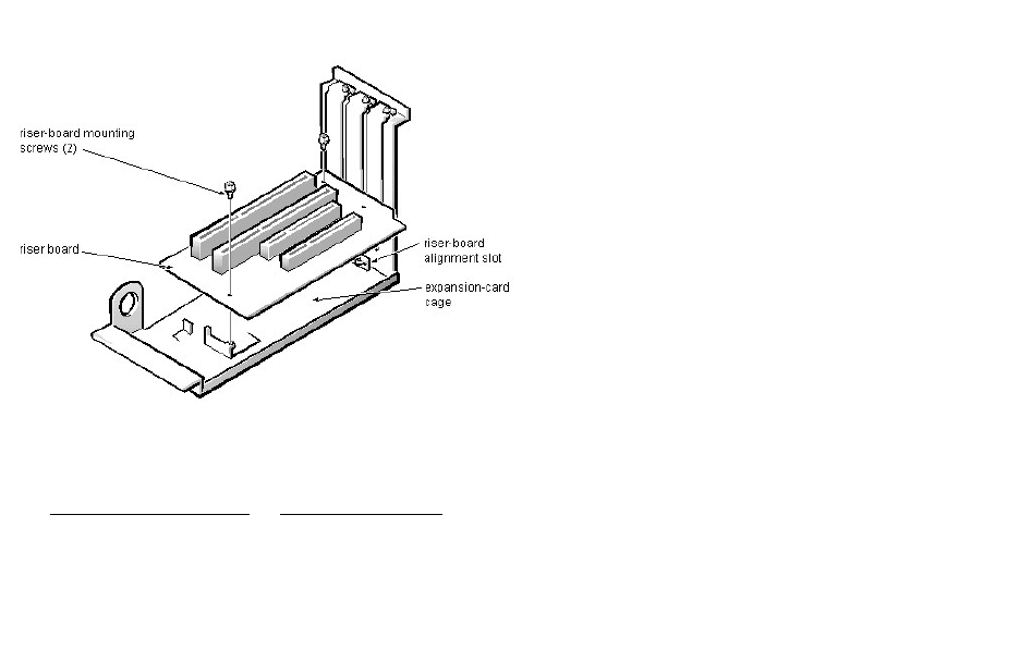
Riser Board Removal (Low-ProfileChassis):Dell™OptiPlex™E1Systems
To remove the riser board, follow these steps:
1. Remove the expansion-card cage and remove all expansion cards.
2. Lay the expansion-card cage on a flat work surface with the riser board facing up.
3. Remove the 2 riser-board mounting screws.
4. Lift the riser board away from the expansion-card cage.
When you replace the riser board, be sure that the alignment feature on the expansion-card cage engages with the alignment slot.
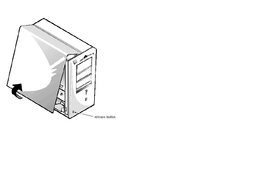
ComputerCoverRemoval(MiniTowerChassis):Dell™OptiPlex™E1Systems
To remove the computer cover, follow these steps:
1. Turn off power to the computer and all peripherals, and disconnect the AC power cables from their AC outlets.
2. Remove the padlock if one is installed.
3. Facing the left side of the computer, press the release button at the bottom-left corner of the front bezel.
4. Lift the bottom of the cover, allowing it to pivot up toward you.
5. Disengage the tabs that secure the cover to the top of the chassis, and lift the cover away.
Before you reinstall the cover, fold all cables out of the way so that they do not interfere with the cover or with proper airflow inside the computer.
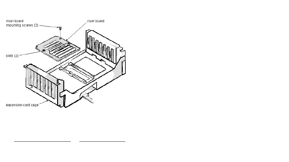
RiserBoardRemoval(MiniTowerChassis):Dell™OptiPlex™E1Systems
To remove the riser board, follow these steps:
1. Remove the expansion-card cage and remove all expansion cards.
2. Place the expansion-card cage on a flat work surface with the riser board facing up.
3. Remove the riser-board mounting screws.
4. Slide the riser board away from the release handle until it stops; then lift the riser board away from the expansion-card cage.
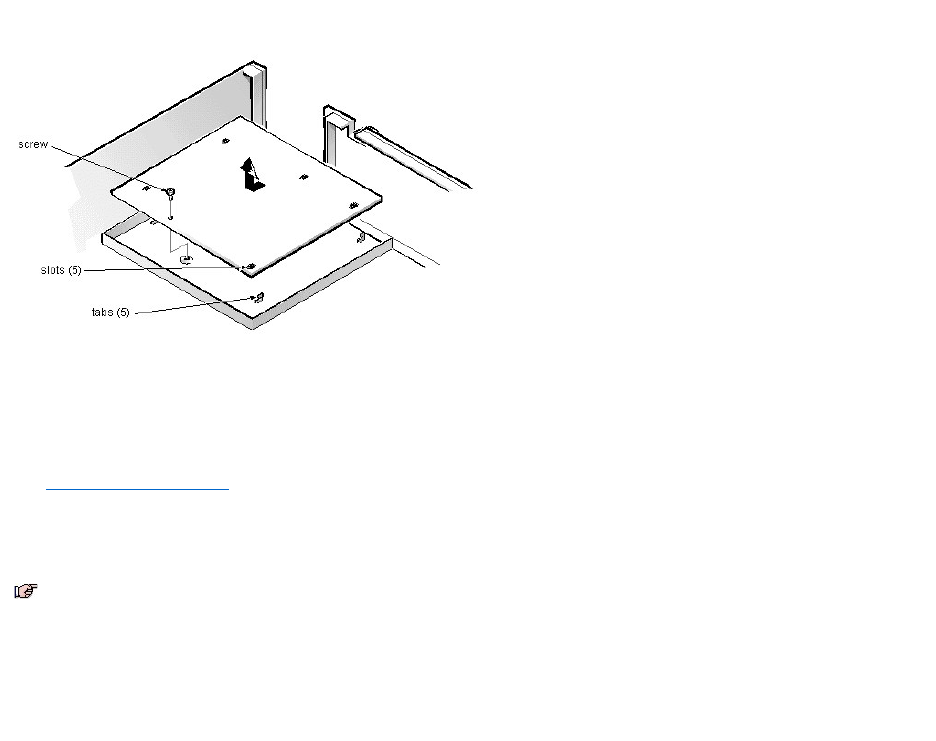
SystemBoardRemoval(MiniTowerChassis):Dell™OptiPlex™E1Systems
To remove the system board, follow these steps:
1. Disconnect all cables from their connectors at the back of the computer.
2. Remove the expansion-card cage.
3. Disconnect all cables from the system board.
4. Remove the screw that secures the system board to the bottom of the chassis.
5. Slide the system board toward the front of the chassis until it stops.
6. Carefully lift the system board out of the chassis (be sure to lift evenly and not twist the system board).
When you reinstall the system board (before you slide the system board back to lock it in position), push down near each slot to engage the grounding clip onto its
corresponding tab. Push evenly on both sides of the system board as you slide it into position (do not twist the system board).
NOTES: If you are replacing the system board, remove all DIMMs, the video-memory upgrade module (if present), the SEPP/heat sink assembly, and
the guide bracket assembly from the old system board and install them on the replacement board. Also, set the jumpers on the new system board so
thattheyareidenticaltothoseontheoldboard,unlessamicroprocessorupgradeisbeinginstalled.
If the original system board has a NIC connector, ensure that the replacement board has a NIC connector.
DIMMRemovalandInstallation(MiniTowerChassis):Dell™OptiPlex™E1Systems
DIMM Removal | DIMM Installation
DIMM Removal
To remove a DIMM from 1 of the 2 DIMM sockets, follow these steps:
1. Remove the system power supply.
2. Locate the DIMM you wish to remove.
3. Push outward on the DIMM socket's securing clips until the DIMM is released from its socket.
4. Lift the DIMM away from the socket.
DIMM Installation
1. Reinstall the replacement DIMM by pressing the DIMM fully into the socket while closing the securing clips to lock the DIMM into the socket.
2. Replace all assemblies and cables previously removed.

VideoMemoryRemoval(MiniTowerChassis):Dell™OptiPlex™E1Systems
You can upgrade video memory from 2 MB to 4 MB by installing a video-memory upgrade module in the video-memory upgrade socket on the system board. Adding
video memory increases the system’s video performance and provides additional modes for high-resolution/expanded-color applications.
To install the video-memory upgrade module, follow these steps:
1. Remove the expansion-card cage.
2. Orient the video-memory upgrade module as shown in the illustration. Then carefully align the module’s edge connector pins with the socket, ensuring that the
slot in the module connects with the socket key.
3. Press the video-memory upgrade module firmly into the socket, and pivot the module downward until the module clicks into place.
4. Replace the expansion-card cage.
5. Replace the computer cover, and reconnect the AC power cable to the electrical outlet. Press the power button on the computer to reboot the system.
6. Enter the System Setup program, and confirm that 4 MB is shown for Video Memory.
If the total memory is listed incorrectly, repeat steps 1 through 6 to reseat the video-memory upgrade module and verify that the computer acknowledges the module.
7. Run the Video Test Group in system diagnostics to test the new video-memory upgrade module.
CAUTION: To avoid possible damage to the video-memory upgrade socket and module, the module is keyed and must be correctly positioned
before inserting it into the socket.
NOTE: If you do not hear a sharp click when installing the video-memory upgrade module, remove the module and repeat steps 2 and 3.
NOTE: As the system boots, it automatically detects the presence of the new video-memory upgrade module and changes the system configuration
information in the System Setup program.
SEPPCartridge/HeatSinkAssemblyRemoval(MiniTowerChassis):Dell™OptiPlex™E1
Systems
To remove the SEPP cartridge/heat sink assembly, follow these steps:
1. Remove the system power supply.
2. Locate the SEPP cartridge/heat sink assembly.
3. Disconnect the microprocessor fan connector from the 3-pin FAN connector on the system board.
The connector is located between the SERIAL 2 connector and the MONITOR connector.
4. Locate and press outward on the SEPP cartridge release latches (located directly on top of the SEPP cartridge adjacent to the heat sink assembly).
5. Lift the SEPP cartridge/heat sink assembly out of its guide bracket assembly/connector on the system board.
WARNING: The SEPP cartridge/heat sink assembly can get extremely hot during system operations. Be sure that the assembly has had
sufficient time to cool before touching it.
NOTE: When installing the SEPP cartridge/heat sink assembly, carefully orient the assembly and press firmly with up to 25 pounds of force to connect
the SEPP cartridge with its connector.
SystemBatteryRemoval(MiniTowerChassis):Dell™OptiPlex™E1Systems
To remove the system battery, follow these steps:
1. If possible, boot the system and enter the System Setup program. Then record important system configuration information.
2. Turn off power to the computer and all peripherals, and disconnect the AC power cables from their electrical outlets.
3. Remove the computer cover.
4. Remove the expansion-card cage, and locate the battery in the front-right corner of the system board adjacent to the DIMM connectors.
5. Remove the battery by carefully prying it out of its socket with your fingers or with a blunt, nonconducting object, such as a plastic screwdriver.
6. Insert the battery into the socket (with the positive side labeled “+” facing upwards), and snap it into place.
7. Replace the expansion-card cage; replace the computer cover, reconnect all cabling, and reboot the system.
8. Enter the System Setup program, and configure the system using the information you recorded in step 1.
9. Turn off the computer for 10 or more minutes; then reboot the computer and reenter the System Setup program to ensure that the date and time are still correct,
indicating that the system battery is functioning correctly.
CAUTION: If you pry out the battery with a blunt object, be careful not to touch the system board with the object. Ensure that the object is
inserted between the battery and the socket before attempting to pry out the battery. Otherwise, you may damage the system board by prying
off the socket or by breaking traces on the system board.
WARNING: There is a danger of the new battery exploding if it is incorrectly installed. When you replace the system battery, orient the new
battery with the "+" facing up. Replace the battery only with the same or equivalent type recommended by the manufacturer. Discard used
batteries according to the manufacturer's instructions.

FrontBezelRemoval(MiniTowerChassis):Dell™OptiPlex™E1Systems
To remove the front bezel, follow these steps:
1. Press the tab release marked with the icon.
2. Tilt the bezel away from the chassis.
3. Disengage the 2 retaining hooks at the bottom of the bezel, and pull the bezel away from the chassis.
Eject-, Power-, and Reset-ButtonRemoval(MiniTowerChassis):Dell™OptiPlex™E1Systems
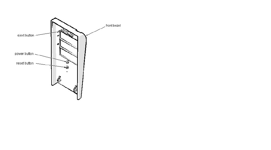
To remove the eject, power, and reset buttons, follow these steps:
1. Lay the front bezel on a flat work surface with the back of the bezel facing up.
2. To remove the 3.5-inch diskette-drive eject button, pull gently on the plastic part of the button until it comes free.
3. To remove the power button or the reset button, use a small screwdriver and push in on the 2 or 3 plastic clips that hold the button to the bezel.
When these clips are released, the button comes free from the bezel.
Front-PanelInsertRemoval(MiniTowerChassis):Dell™OptiPlex™E1Systems
To remove a 5.25-inch front-panel insert, follow these steps:
1. Hold the bezel with the front facing you.
2. From the front of the bezel, use your thumbs to press inward on the insert until it slides off the 2 posts.
To replace a 5.25-inch front-panel insert, position the 2 ring-tabs over the posts on the inside of the bay opening, and then press the ring-tabs over the posts. If
necessary, use a 1/4-inch nut driver to help push on the ring-tabs.
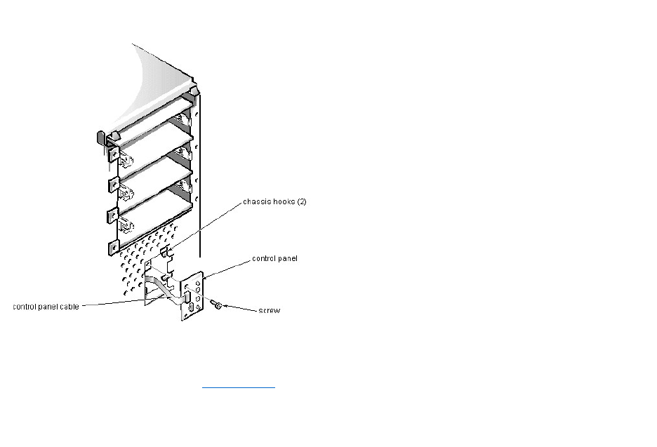
ControlPanelRemoval(MiniTowerChassis):Dell™OptiPlex™E1Systems
To remove the control panel, follow these steps:
1. Remove the hard-disk drive bracket.
2. Disconnect the control panel cable from the PANEL connector on the system board.
3. Remove the mounting screw holding the control panel to the chassis.
4. Slide the control panel out of the hooks holding it to the chassis.
Note the routing of the control panel cable as you remove it from the chassis.
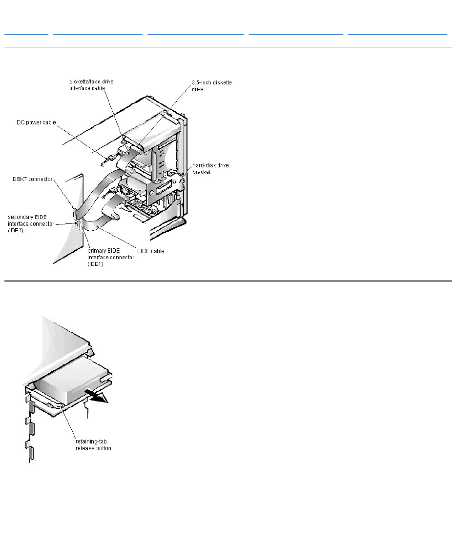
DriveHardwareRemoval(MiniTowerChassis):Dell™OptiPlex™E1Systems
Drive Hardware | 3.5-Inch Diskette Drive Removal | 5.25-Inch Drive Assembly Removal | Hard-Disk Drive Bracket Removal | Hard-Disk Drive Assembly Removal
Drive Hardware
3.5-Inch Diskette Drive Removal
To remove a 3.5-inch diskette drive assembly, follow these steps:
1. Disconnect the DC power cable and the interface cable from the back of the 3.5-inch diskette drive.
2. Press the retaining-tab release button, and pull the drive assembly forward to remove it.
3. Remove the drive-mounting screw from the left side of the drive, and remove the drive from the bracket.
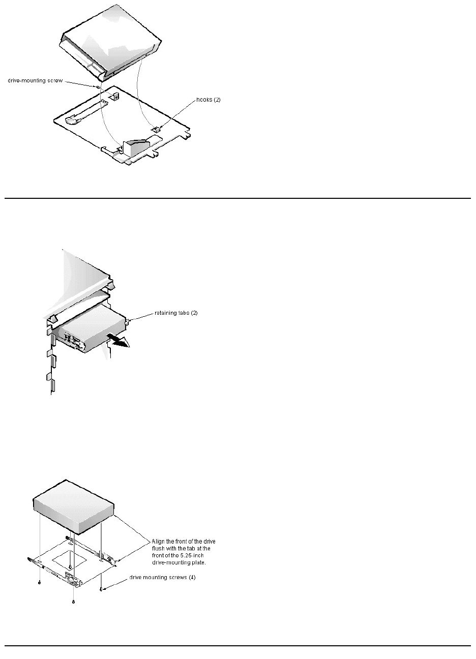
When you replace the 3.5-inch diskette drive, be sure that the 2 hooks on the right side of the bracket engage the mounting holes in the side of the drive.
5.25-Inch Drive Assembly Removal
To remove a 5.25-inch drive assembly from the middle or lower drive bay, follow these steps:
1. Disconnect the DC power cable and the interface cable from the back of the drive.
2. Press in on the 2 retaining tabs (1 on each side of the drive), and slide the drive assembly forward to remove it.
3. Remove the 4 screws attaching the 5.25-inch drive to the mounting plate, and lift the drive out of the mounting plate.
When you replace the 5.25-inch drive, align the front of the drive flush with the tab at the front of the mounting plate. Insert the 4 mounting screws, and tighten them in
the order stamped on the bottom of the mounting plate.
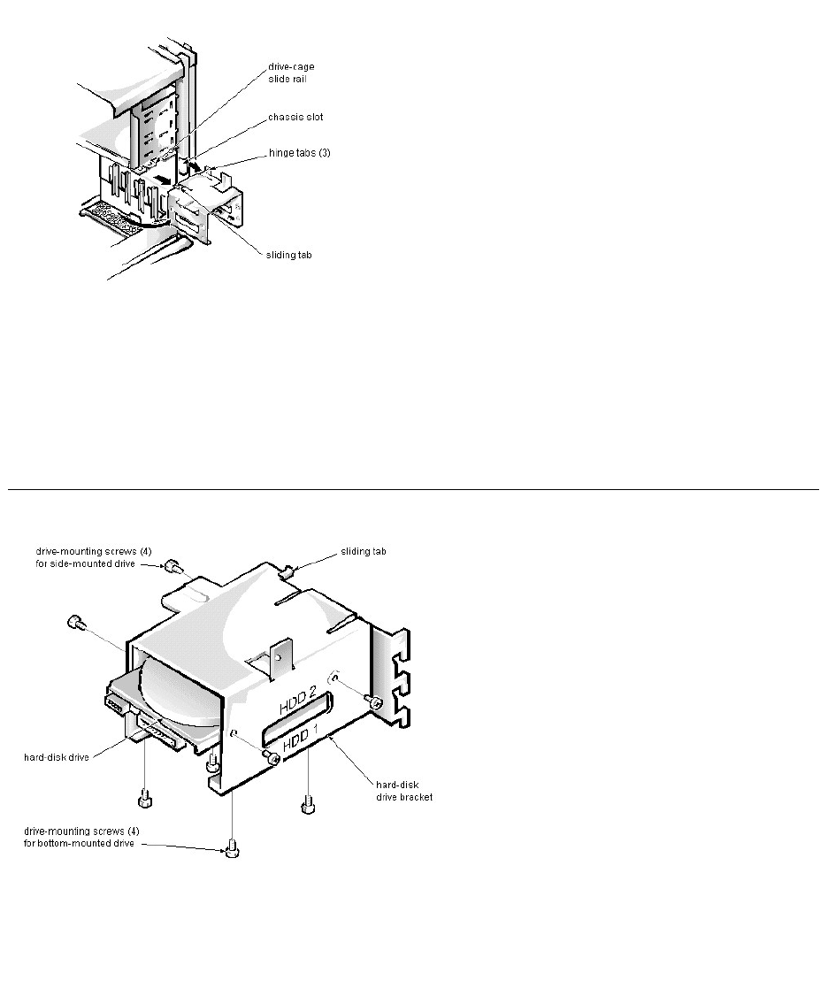
Hard-Disk Drive Bracket Removal
To remove the hard-disk drive bracket, follow these steps:
1. Disconnect the DC power cable and the interface cable from the back of each hard-disk drive installed in the hard-disk drive bracket.
2. Remove the screw that secures the hard-disk drive bracket to the drive cage in the chassis.
3. Grasp the bracket, and rotate it outward from the chassis until the sliding tab clears the slide rail on the drive cage.
4. Lift the hard-disk drive bracket up slightly to free the hinge tabs and remove the bracket from the computer.
When you reinstall the hard-disk drive bracket, insert the bracket's hinge tabs into the chassis slot so that the tabs hook over the slot. Then rotate the bracket toward
the drive cage, and fit the bracket's sliding tab on the drive-cage slide rail.
Hard-Disk Drive Assembly Removal
To remove the hard-disk drive assembly, follow these steps:
1. Remove the hard-disk drive bracket.
2. Remove the 4 screws that attach the hard-disk drive to the hard-disk drive bracket.
One hard-disk drive attaches to the hard-disk drive bracket at the sides of the drive. The other hard-disk drive attaches to the hard-disk drive bracket at the bottom of the hard-disk
drive.
3. Slide the drive out of the hard-disk drive bracket.
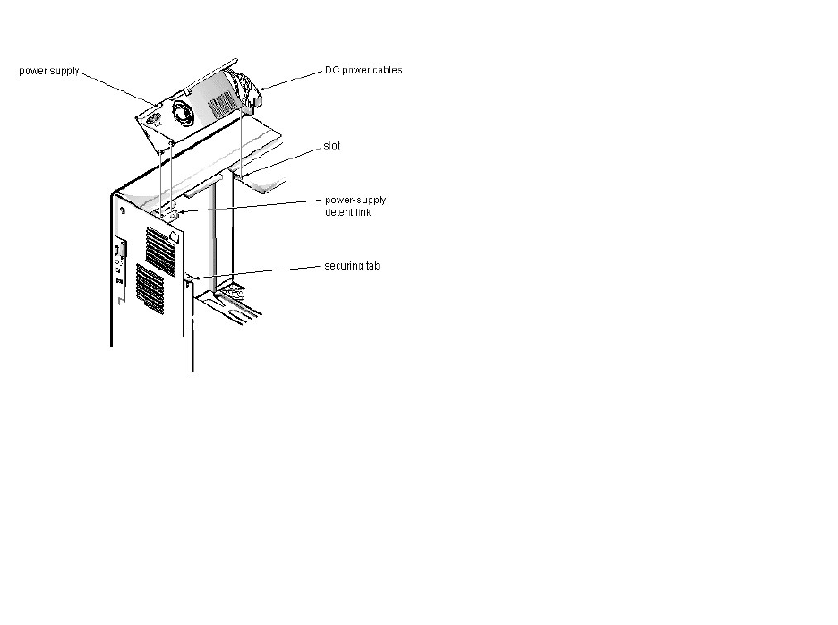
System Power-SupplyRemoval(MiniTowerChassis):Dell™OptiPlex™E1Systems
To remove the system power supply, follow these steps:
1. Disconnect the AC power cable from the back of the system power supply.
2. Free the system power supply from the securing tab labeled “RELEASE —>,” and rotate it upward until it locks.
Press the securing tab to release the power supply.
3. Disconnect the DC power cables from the system board and the drives.
4. Facing the left side of the computer, move the front end of the system power supply toward you, and lift it up to disengage the power supply from the slot in the
chassis.
5. Lift the system power supply from the computer.
When you reinstall the system power supply, place the power-supply detent link over the pin on the power supply as you position the power supply in the chassis
opening.
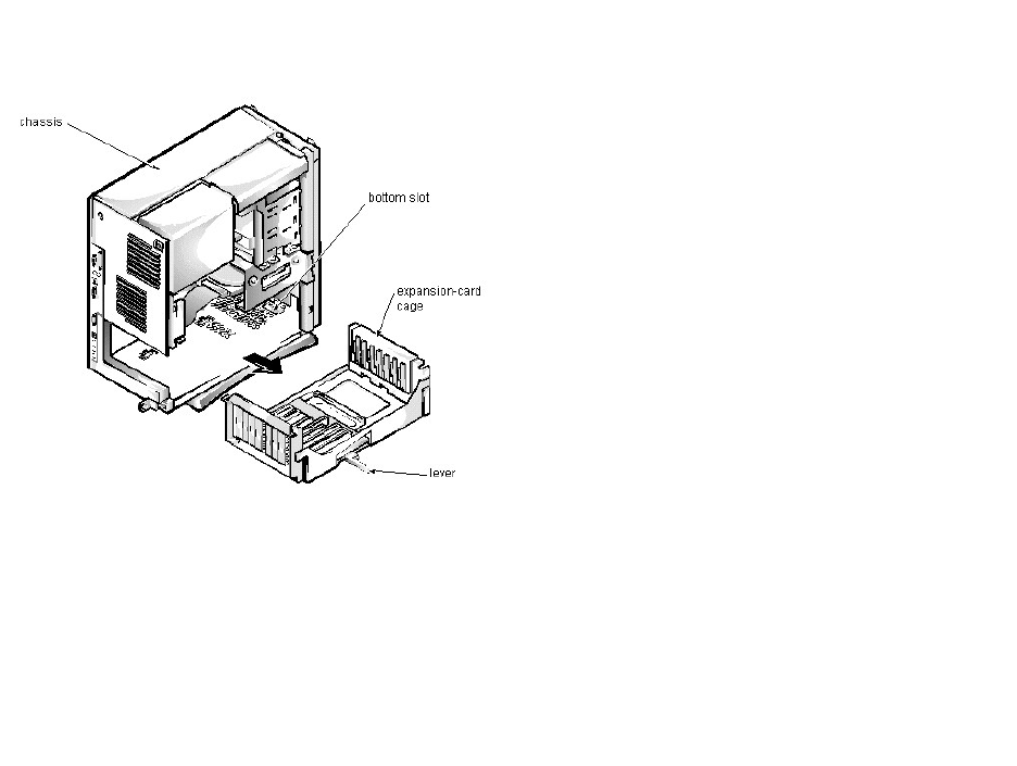
Expansion-CardCageRemoval(MiniTowerChassis):Dell™OptiPlex™E1Systems
To remove the expansion-card cage, follow these steps:
1. Rotate the lever toward the back of the computer until it stops in the upright position.
2. Slide the expansion-card cage out of the computer.
To replace the expansion-card cage, align the tabs on the left and right sides of the expansion-card cage with the slots on the back and bottom of the chassis. With the
securing lever in its extended position, slide the expansion-card cage into place.
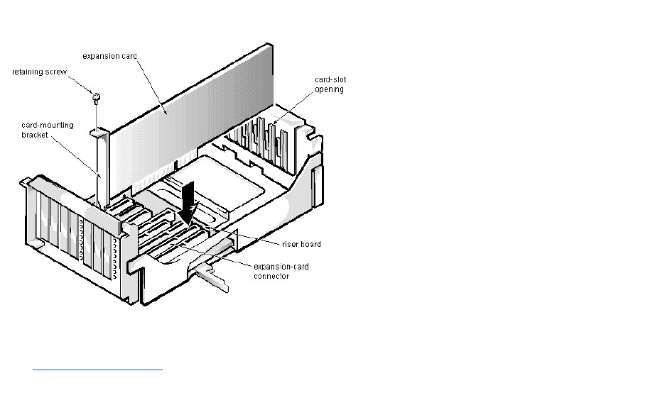
ExpansionCardRemoval(MiniTowerChassis):Dell™OptiPlex™E1Systems
To remove an expansion card, follow these steps:
1. Disconnect any cables from the expansion card being removed.
2. Remove the expansion-card cage.
3. Remove the retaining screw from the card-mounting bracket.
4. Grasp the expansion card by its corners, and carefully remove it from the expansion-card connector.
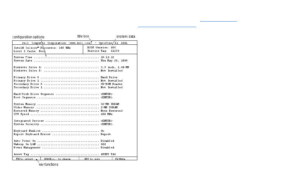
SystemSetup:Dell™OptiPlex™E1Systems
For detailed information on System Setup categories and options, see "Using the System Setup Program" in the online System User's Guide. For updated information
about System Setup categories since the System User's Guide was released, see Updated System Setup Categories.

Documentation:Dell™OptiPlex™E1Systems
SistemaDellOptiPlexE1conCapacidaddemanipulaciónmejorada,GuíadelusuarioIndice (.hlp)
Guíadereferenciaeinstalación,bajoaltura (.pdf)
Guíadereferenciaeinstalación,minigabinetevertical (.pdf)
Guíadediagnósticosysolucióndeproblemas (.pdf)
Sinopuedeencontrarlainformaciónquenecesitaenlíneaytodavíanecesitaayuda, visite nuestro Centro de comunicacionesenlíneaocomuníqueseconun
representantedeserviciodeDell.TengaalamanosuCódigodeservicioexpresopararecibirunserviciomasrápido.
NOTAS: Los archivos .pdf requieren Acrobat Reader, el que puede ser descargado de lapáginawebdeAdobe™. Para leer archivos .pdfenlínea
despuésdedescargareinstalarAcrobatReader,ustednecesitaconfigurarAcrobatReaderparaquetrabajeconsubrowsercomounaaplicaciónde
ayuda o de tipo plug-in.ConsultelainformaciónenAyudaasociadaconsubrowserparaobtenerinformaciónadicional.
Los archivos .hlp requieren winhelp.exe, que es parte del sistema operativo Microsoft® Windows® (localizado en la carpeta windows). Para leer
archivos .hlpenlínea,usteddebeconfigurarwinhelp.exeparaquetrabajeconsubrowsercomoaplicacióndeayudas.Consultelainformaciónen
Ayudaasociadaconsubrowserparaobtenerinformaciónadicional.

Specifications: Dell™OptiPlex™E1Systems
General | System Information | Expansion Bus | System Clocks | Memory | Drives | Ports | Audio (optional) | Video | Supported
Resolutions | Power | Physical | Environmental | Regulatory Notices
General
Microprocessor type
Intel®Celeron™microprocessor
Microprocessor speeds
266, 300, 333, 366, or 400 MHz
Internal cache
32 KB (L1) (16-KB data cache, 16-KB instruction cache)
L2 cache memory
128 KB for processors 300 MHz and above
Math coprocessor
internal to the microprocessor
Microprocessor slot
slot 1
System Information
System chip set
Intel 440EX AGPset
PIIX4e controller
82371EB
PCI, AGP controller
82443EX PAC
Data bus width
64 bits
Address bus width
32 bits
DMA channels
8
Timers
3
Interrupt levels
15
Flash EPROM (BIOS)
2 Mb
BIOS source
Dell
NIC chip
integrated 3Com®PCI 3C905B-TX Wakeup On LAN NIC, operating
at 10 or 100 Mbps
I/O controller chip
National PC87309
Expansion Bus
Bus type
PCI (2.1-compliant) and ISA
PCI expansion-card connectors
Low-profile chassis
2 (1 PCI connector and 1 ISA connector share an expansion-card slot)
Mini tower chassis
2
ISA expansion-card connectors
Low-profile chassis
2 (1 ISA connector and 1 PCI connector share an expansion-card slot)
Mini tower chassis
2
Bus speeds
PCI: 33 MHz
ISA: 8.33 MHz
PCI data transfer rate
130 MB/sec (132-MB/sec burst)
Plug and Play BIOS and ISA bus revision
1.0A
PCI bus specification
complies with PCI specification 2.1
PCI-to-PCI bridging
supported
ISA connector data width
16 bits

PCI connector data width
32 bits (maximum)
System Clocks
Diskette/communications ports
48 MHz from system clock
System clock
66 MHz
Keyboard controller
48 MHz
Memory
Architecture
64-bit (non-ECC), noninterleaved
Wait states
near 0
DIMM sockets
2 (gold contacts)
DIMM capacities
16-, 32-, 64-, and 128-MB SDRAM ("PC100" 100 MHz, 10 ns)
Minimum RAM
16 MB
Maximum RAM
256 MB
Memory access time
synchronized with system clock
BIOS address
F0000h
Drives
Externally accessible bays
Low-profile chassis
(1) 5.25-inch bay for removable media device; (1) 3.5-inch bay for a
diskette drive
Mini tower chassis
(3) 5.25-inch bay for removable media device; (1) 3.5-inch bay for a
diskette drive
Internally accessible bays
Low-profile chassis
(1) 3.5-inch bay for a 1-inch-high hard-disk drive
Mini tower chassis
(2) 3.5-inch bays for either one or two 1-inch-high hard-disk drives, or
one 1-inch-high hard-disk drive and one 1.6-inch-high hard-disk drive
Ports
Externally accessible:
Serial (DTE)
(2) 9-pin connectors (16550-compatible)
Parallel
25-hole connector (bidirectional)
Video
15-hole connector
NIC
RJ45 connector
PS/2-style keyboard
6-pin mini-DIN
PS/2-compatible mouse
6-pin mini-DIN
USB
2 USB-compliant connectors
Line-in (optional)
miniature audio jack
Line-out
(amplified source) (optional)
miniature audio jack
Microphone (optional)
miniature audio jack
Internally accessible:
Primary EIDE hard-disk drive
40-pin connector
Secondary EIDE hard-disk drive
40-pin connector
Diskette drive
34-pin connector
CD-ROM drive audio interface (optional)
4-pin connector
ATI Multimedia Channel (optional)
40-pin connector
TAPI (optional)
4-pin connector
Audio (optional)
Model
Crystal Semiconductor
Chipset
CS4236B
Jacks:
Line-in
miniature audio jack
Line-out
miniature audio jack (amplified)
Microphone
miniature audio jack
Video
Video type
on-board ATI Rage II C
(baseline AGP) graphics
Video memory
2-MB standard (upgradable to 4-MB) SGRAM
Supported Resolutions
Video Resolution
Maximum Color Depth
Maximum Refresh Rate
Minimum SGRAM
Required
640 x 480
True-color (32 bpp)
85 Hz
2 MB
800 x 600
True-color (32 bpp)
85 Hz
2 MB
1024 x 768
65,536 colors (16 bpp)
85 Hz
2 MB
1280 x 1024
256 (8 bpp)
85 Hz
2 MB
1024 x 768
True-color (32 bpp)
85 Hz
4 MB
1280 x 1024
65,536 colors (16 bpp)
85 Hz
4 MB
1600 x 1200
65,536 colors (16 bpp)
76 Hz
4 MB
Power
DC power supply:
Wattage
low-profile chassis: 145 W
mini tower chassis: 200 W
Voltage
90 to 135 V at 60 Hz;
180 to 265 V at 50 Hz

Heat dissipation
low-profile chassis: 808 BTU/hr (nominal)
mini tower chassis: 913 BTU/hr (nominal)
Backup battery
3-V CR2032 coin cell
Physical
Low-profile chassis:
Weight (minimum)
10.89 kg (24 lb)
Height
10.9 cm (4.3 inches)
Width
40.89 cm (16.1 inches)
Depth
43.69 cm (17.2 inches)
Mini tower chassis:
Weight (minimum)
14.9 kg (33.0 lb) or more, depending on options installed
Height
44.4 cm (17.5 inches)
Width
20.6 cm (8.1 inches)
Depth
43.7 cm (17.2 inches)
Environmental
Temperature:
Operating
10o to 35oC (50o to 95oF)
Storage
–40o to 65oC (–40o to 149oF)
Relative humidity
20% to 80% (noncondensing)
Maximum vibration:
Operating
0.25 G at 3 to 200 Hz at 1 octave/min
Storage
0.5 G at 3 to 200 Hz at 1 octave/min
Maximum shock:
Operating
left side (for computers operating in a vertical orientation) and bottom
half-sine pulse with a change in velocity of 50.8 cm/sec (20 inches/sec)
Storage
27-G faired square wave with a velocity change of 508 cm/sec (200
inches/sec)
Altitude:
Operating
–16 to 3048 m* (–50 to 10,000 ft)
Storage
–16 to 10,600 m (–50 to 35,000 ft)
*Themaximumoperatingtemperatureof35°C(95°F)isforaltitudesbelow914.6m(3000ft).Above914.6m(3000ft)
the maximum operating temperature is reduced.
Regulatory Notices
FCC (U.S. only)
Class B (low-profile chassis)
Class A1, Class B2 (mini tower chassis)

IC Notice (Canada only)
Class B
CE Notice
Class B
DMI 3.0-compliant
APM 1.1-compliant
FCC ID
Class B
EN 55022 (Czech Republic only)
Category B
VCCI Notice (Japan only)
Class 1, Class 2
Korean Regulatory Notice
Class A, Class B
NOM 024 Information (Mexico only)
Polish Center for Testing and Certification
1 For the mini tower chassis when networked
2 For the mini tower chassis when in stand-alone mode

UpdatedSystemSetupCategories:Dell™OptiPlex™E1Systems
Hard-Disk Drive Sequence | Boot Sequence | ACPI | System Security | Chassis Intrusion
Hard-Disk Drive Sequence
Hard-Disk Drive Sequence lists installed adapter cards and devices in the order they will be initialized. The first hard-disk drive in the list becomes the bootable drive
C.
Boot Sequence
Boot Sequence enables you to set the order of the devices from which the system attempts to boot.
The term boot refers to the system's start-up procedure. When turned on, the system "bootstraps" itself into an operational state by loading into memory a small
program, which in turn loads the necessary operating system. Boot Sequence tells the system where to look for the files that it needs to load.
To set the boot device order, press <Enter> to access the field's pop-up options menu. Use the up- and down-arrow keys to move through the list of devices. Press
<Enter> to enable or disable a device (enabled devices appear with a check mark). Press plus (+) or minus (-) to move a selected device up or down the list. The
following sections detail typical devices:
lDiskette Drive A: — Selecting Diskette Drive A: as the first device causes the system to try booting from drive A first. If the system finds a diskette that is
not bootable in the drive or finds a problem with the drive itself, it displays an error message. If it does not find a diskette in the drive, the system tries to boot
from the next device in the boot sequence list.
lHard-Disk Drive — Selecting Hard-Disk Drive causes the system to attempt to boot first from the hard-disk drive and then from the next device in the boot
sequence list.
lIDE CD-ROM Reader — Selecting IDE CD-ROM Reader causes the system to try booting from the CD-ROM drive first. If the system finds a CD that is
not bootable in the drive or finds a problem with the drive itself, it displays an error message. If it does not find a CD in the drive, the system tries to boot from
the next device in the boot sequence list.
lPXE — Selecting PXE (Preboot eXecution Environment) causes the system to boot from the integrated network interface controller (NIC) first. If a boot
routine is not available from the network server, the system tries to boot from the next device in the boot sequence list.
lIntegrated Devices — Integrated Devices configures the devices integrated with the system board. Press <Enter> to configure these options.
lNetwork Interface Controller — Network Interface Controller determines whether the integrated NIC is On, Off, or On w/ PXE. The default is On w/
PXE, which means that the NIC is enabled and set to boot the system remotely from a network server.
ACPI
ACPI controls the operation of the system's Advanced Configuration and Power Interface (ACPI) feature. The default is Off.
When ACPI is set to On, momentarily pressing the power button places the system in a power-saving mode. To turn the system off completely, press the power
button for more than 4 seconds. When ACPI is set to On, interrupt request (IRQ) line 9 is not available for use by an expansion card.
When ACPI is set to Off, momentarily pressing the power button turns off the system completely. With this setting, IRQ9 is available for use by an expansion card.
System Security
System Security configures the password and chassis intrusion categories. Press <Enter> to configure these categories.
Chassis Intrusion
Chassis Intrusion displays the status of the system chassis intrusion monitor and can be set to Enabled, Enabled-Silent, or Disabled. The default is Enabled.
If the computer cover is removed while the intrusion monitor is set to Enabled, the setting changes to Detected and the following message is displayed during the boot
routine at the next system start-up:
Alert! Cover was previously removed.
If the computer cover is removed while the intrusion monitor is set to Enabled-Silent, the setting changes to Detected, but the alert message is not displayed during
the boot sequence at the next system start-up.
If the intrusion monitor is set to Disabled, no intrusion monitoring occurs and no messages are displayed.
To reset the Detected setting, enter the System Setup program during the system's power-on self-test (POST). At Chassis Intrusion, press any edit key to reset the
setting, and then choose Enabled, Enabled-Silent, or Disabled.

NOTE: When the setup password is enabled, the setup password is required to reset the Chassis Intrusion category.

Hard-DiskDriveOptions:Dell™OptiPlex™E1Systems
Low-Profile Chassis | Mini Tower Chassis
Low-Profile Chassis
The hard-disk drive assembly (consisting of the hard-disk drive and the hard-disk drive bracket) is located inside the left-front area of the chassis and is attached to the
bottom of the chassis. A single 1-inch-high EIDE hard-disk drive can be mounted on the hard-disk drive bracket.
Mini Tower Chassis
The hard-disk drive assembly (consisting of the hard-disk drive and the hard-disk drive bracket) is located under the externally accessible drive bays at the front of the
computer. The hard-disk drive assembly can contain either 1 or (2) 1-inch-high EIDE hard-disk drives, or (1) 1-inch-high EIDE hard-disk drive and (1) 1.6-inch-high
EIDE hard-disk drive.

Video:Dell™OptiPlex™E1Systems
All systems include an integrated, high-performance, 64-bit accelerated graphics port (baseline AGP) subsystem that drives an external SVGA monitor. The AGP is a
dedicated bus that bypasses the PCI bus and allows for interconnection of the video subsystem directly to the microprocessor's chip set for high performance required
for 3D video subsystems. This architecture also off-loads video data from the PCI bus, providing greater performance for devices attached to the PCI bus.
The maximum supported resolution is 1600 x 1200 pixels with 65,535 colors (16 bpp) at 76 Hz. Other supported resolutions are listed in Specifications. The SVGA
subsystem has the following major components:
lATI 3D Rage II C (baseline AGP) SVGA video controller
l2-MB SGRAM video memory (expandable to 4 MB)
lATI Multimedia Channel (AMC) connector
l15-pin monitor connector

WakeupOnLAN:Dell™OptiPlex™E1Systems
The Dell OptiPlex E1 has an integrated Wakeup On LAN-capable NIC. When the system is connected to a server with network management software, the Wakeup
On LAN feature allows remote computer setup, software downloading and installation, file updates, and asset tracking after hours and on weekends when LAN traffic
is at a minimum.
