Dell Optiplex Gx110 Users Manual System User's Guide
2014-11-13
: Dell Dell-Optiplex-Gx110-Users-Manual-110985 dell-optiplex-gx110-users-manual-110985 dell pdf
Open the PDF directly: View PDF ![]() .
.
Page Count: 137 [warning: Documents this large are best viewed by clicking the View PDF Link!]
Dell™OptiPlex™GX110SystemUser'sGuide
Models DCP, DCS, DCM, and MMP
Notes, Notices, and Cautions
Throughout this guide, there may be blocks of text printed in bold type or in italic type. These blocks are notes, notices, and cautions, and they are
used as follows:
NOTICE: A NOTICE indicates either potential damage to hardware or loss of data and tells you how to avoid the problem.
Information in this document is subject to change without notice.
©1999 Dell Computer Corporation. All rights reserved.
Reproduction in any manner whatsoever without the written permission of Dell Computer Corporation is strictly forbidden.
Trademarks used in this text: Dell, OptiPlex, OptiFrame, Dell OpenManage, Dimension, Latitude, Inspiron, DellWare, and the DELL logo are trademarks of Dell Computer
Corporation; Microsoft, Windows, MS-DOS, and WindowsNT are registered trademarks of Microsoft Corporation; Intel and Pentium are registered trademarks of Intel
Corporation; 3Com is a registered trademark of 3Com Corporation; IBM and OS/2 are registered trademarks of International Business Machines Corporation; Novell and
NetWare are registered trademarks of Novell, Inc. As an ENERGY STAR Partner, Dell Computer Corporation has determined that this product meets the ENERGY STAR
guidelines for energy efficiency.
Other trademarks and trade names may be used in this document to refer to either the entities claiming the marks and names or their products. Dell Computer Corporation
disclaims any proprietary interest in trademarks and trade names other than its own.
Initial release: 19 Aug 1999
Last revised: 3 Dec 1999
Introduction
Setup and Operation
Drivers and Utilities
System Setup
Installing Upgrades
Troubleshooting
Technical Specifications
NOTE: You can obtain the latest version of this document from the Support section of the Dell Web site at http://www.dell.com.
NOTE: A NOTE indicates important information that helps you make better use of your system.
CAUTION: A CAUTION indicates a potentially hazardous situation which, if not avoided, may result in minor or moderate
injury.
Back to Contents Page
BasicChecks:Dell™OptiPlex™GX110SystemUser'sGuide
Overview
If your Dell computer system is not working as expected, and if you are not sure what to do, start your troubleshooting with the procedures in this
section. This section guides you through basic steps to solve basic computer problems. It also directs you to further detailed troubleshooting
information and procedures to solve more complex problems.
Backing Up Your Files
If your system is behaving erratically, back up your files immediately. If your system has a tape drive installed, see the documentation that came
with the tape backup software for instructions on performing a backup operation. Otherwise, see your operating system documentation for
information on backing up data files.
Basic Checks
See the following sections in the order indicated until the problem is resolved:
lIf your computer is wet or damaged, see "Troubleshooting a Wet Computer" or "Troubleshooting a Damaged Computer."
lPerform the steps in "Checking Connections and Switches."
lPerform the steps in "Look and Listen."
lIf your system did not complete the boot (start-up) routine, see "Getting Help."
lIf your system displayed a message or emitted a beep code, see "Messages and Codes."
lVerify the settings in System Setup.
lRun the Dell Diagnostics.
Checking Connections and Switches
Improperly set switches and controls and loose or improperly connected cables are the most likely source of problems for your computer, monitor,
or other peripheral (such as a printer, keyboard, mouse, or other external equipment).
Complete the following steps in the order indicated to check all the connections and switches:
1. Turn off the system, including any attached peripherals (such as the monitor, keyboard, printer, external drives, scanners, or plotters).
Disconnect all the AC power cables from their electrical outlets.
2. If your computer is connected to a power strip, turn the power strip off and then on again. If the problem is not resolved, try another power
strip or connect the system directly to an electrical outlet to see if the original power strip is faulty.
3. Connect the system to a different electrical outlet.
If doing so corrects the problem, the original outlet is faulty.
Overview
Checking Connections and Switches
Backing Up Your Files
Look and Listen
Basic Checks
System Setup
NOTE: The boot routine is the operating system's attempt to load its files into memory from the boot-up sector on the hard-disk
drive or another bootable device.
NOTE: See "Controls and Indicators" and "Connecting Peripheral Devices" for the location of your computer's external connections
and switches.
4. Reconnect the system to an electrical outlet. Make sure that all connections fit tightly together, and turn on the system.
5. If the problem is resolved, you have corrected a faulty connection.
6. If your monitor is not operating properly, see "Troubleshooting the Monitor."
7. If your keyboard is not operating properly, see "Troubleshooting the Keyboard."
8. If your mouse or printer is not operating properly, see "Troubleshooting I/O Ports." Otherwise, see "Look and Listen."
Look and Listen
Looking at and listening to your system is important in determining the source of a problem. Look and listen for the indications described in Table
1.
If after looking and listening to your computer you have not resolved the problem, continue with the recommendations in "System Setup."
Table 1. Boot Routine Indications
Look/Listen for:
Action
An error message
See "Messages and Codes."
The monitor's power indicator
Most monitors have a power indicator (usually on the front bezel). If the monitor's power indicator does not light
up, see "Troubleshooting the Monitor."
The power and hard-disk
drive indicators
Use the power and hard-disk drive indicators to help you identify a system problem when you press the power
button to turn on the computer but the system does not boot.
The power indicator
Use the power indicator to help you identify a system problem when you press the power button to turn on the
computer but the system does not boot:
lA blinking yellow power indicator before power-on self-test (POST) indicates that the power supply may be
faulty. In rare cases, the system board may be faulty. See "Getting Help" for instructions on getting
technical assistance from Dell.
lA solid yellow power indicator before POST indicates that a device on the system board may be faulty or
isincorrectlyinstalled.Besurethatthemicroprocessorisproperlyseated,remove all expansion cards,
and then reboot. If the system does not boot, see "Getting Help" for instructions on getting technical
assistance from Dell.
lA solid green power indicator and a beep code during POST indicate that a dual in-line memory module
(DIMM) may be faulty or is not properly seated. Remove all DIMMs, install only one DIMM, and then reboot.
Repeat this procedure until you identify the faulty or improperly seated DIMM.
lA solid green power indicator and no beep code and no video during POST indicate that the monitor or
the integrated video controller may be faulty. See "Troubleshooting the Monitor." If the monitor is operating
properly and is correctly connected, see "Getting Help" for instructions on getting technical assistance
from Dell.
lA solid green power indicator and no beep code with video during POST indicate that an integrated
system board device may be faulty. See "Getting Help" for instructions on getting technical assistance
from Dell.
The keyboard indicators
Most keyboards have one or more indicators (usually in the upper-right corner). Press the <Num Lock> key, the
<Caps Lock> key, and the <Scroll Lock> key to toggle the keyboard indicators on and off. If the keyboard
indicators do not light up, see "Troubleshooting the Keyboard."
The diskette-drive access
indicator
The diskette-drive access indicator should quickly flash on and off when you access data on the diskette drive.
On a system running a Microsoft®Windows®operating system, you can test the drive by opening Windows
Explorer and clicking the icon for drive A. If the diskette-drive access indicator does not light up, see
"Troubleshooting Drives."
The hard-disk drive access
indicator
The hard-disk drive access indicator should quickly flash on and off when you access data on the hard-disk
drive. On a system running a Windows operating system, you can test the drive by opening Windows Explorer
and clicking the icon for drive C. If the hard-disk drive access indicator does not light up, see "Troubleshooting
Drives."
A series of beeps
See "Messages and Codes."
An unfamiliar constant
scraping or grinding sound
when you access a drive
Make sure the sound is not caused by the application program you are running. The sound could be caused by a
hardware malfunction. See "Getting Help" for instructions on getting technical assistance from Dell.
The absence of a familiar
sound
When you turn on your system, you can hear the hard-disk drive spin up, and the system tries to access the boot
files from the hard-disk drive or the diskette drive. If your system boots, see "Dell Diagnostics." If your system
does not boot, see "Getting Help."

System Setup
You can easily correct certain system problems by verifying the correct settings in System Setup. When you boot your system, your system checks
the system configuration information and compares it with the current hardware configuration. If your system hardware configuration does not
match the information recorded by System Setup, an error message may appear on your screen.
This problem can happen if you changed your system's hardware configuration and forgot to run System Setup. To correct this problem, enter
System Setup, correct the setting for the corresponding System Setup program option, and reboot your system.
If after checking the settings in System Setup you have not resolved the problem, see "Dell Diagnostics."
Back to Contents Page

Back to Contents Page
Battery:Dell™OptiPlex™GX110SystemUser'sGuide
Overview
A 3.0-volt (V) CR2032 coin-cell battery installed on the system board maintains system configuration, date, and time information in a special
section of memory.
The operating life of the battery can extend up to ten years. The battery may need replacing if an incorrect time or date is displayed during the boot
routine along with a message such as:
Time-of-day not set - please run SETUP program
or
Invalid configuration information -
please run SETUP program
or
Strike the F1 key to continue,
F2 to run the setup utility
To determine whether you need to replace the battery, reenter the time and date through System Setup and exit the program properly to save the
information. Turn off your system and disconnect it from the electrical outlet for a few hours; then reconnect and turn on your system. Enter System
Setup. If the date and time are not correct in System Setup, replace your battery.
You can operate your system without a battery; however, without a battery, the system configuration information is erased if the system is turned off
or unplugged from the electrical outlet. In this case, you must enter System Setup and reset the configuration options.
Replacing the Battery
Toreplacethesystembattery,performthefollowingsteps:
1. If you have not already done so, make a copy of your system configuration information in System Setup.
If the settings are lost while you are replacing the battery, refer to your written or printed copy of the system configuration information to
restore the correct settings.
2. Remove the computer cover according to the instructions in "Removing and Replacing the Computer Cover."
3. Remove the battery.
See Figure 9 in "Inside Your Computer" for the location of the battery.
NOTICE: If you pry the battery out of its socket with a blunt object, be careful not to touch the system board with the object.
Make certain that the object is inserted between the battery and the socket before you attempt to pry out the battery. Otherwise,
you may damage the system board by prying off the socket or by breaking circuit traces on the system board.
Pry the battery out of its socket with your fingers or with a blunt, nonconductive object, such as a plastic screwdriver.
4. Install the new battery.
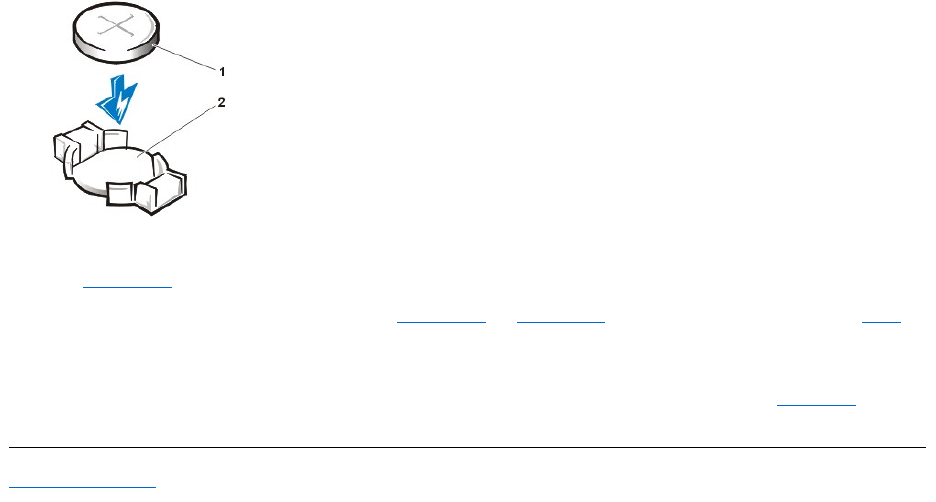
Orient the battery with the side labeled "+" facing up (see Figure 1). Then insert the battery into the socket, and snap it into place.
Figure 1. Replacing the System Battery
Overview
Replacing the Battery
CAUTION: There is a danger of the new battery exploding if it is incorrectly installed. Replace the battery only with the same or
equivalent type recommended by the manufacturer. Discard used batteries according to the manufacturer's instructions.
CAUTION: Before you remove the computer cover, see "Safety First — For You and Your Computer."
5. Replace the computer cover, reconnect your computer and peripherals to their electrical outlets, and turn them on.
6. Enter System Setup, and confirm that the battery is operating properly.
Enter the correct time and date through System Setup's System Time and System Date options. Also, use the copy you made in step 1 of
the system configuration information to restore the correct settings for other System Setup options. Then exit System Setup.
7. Turn off and unplug your computer. Leave the computer turned off for at least 10 minutes.
8. After 10 minutes, plug in the computer, turn it on, and enter System Setup. If the time and date are still incorrect, see "Getting Help" for
instructions on obtaining technical assistance.
Back to Contents Page
1
Battery
2
Battery socket
Back to Contents Page
ContactingDell:Dell™OptiPlex™GX110SystemUser'sGuide
Overview
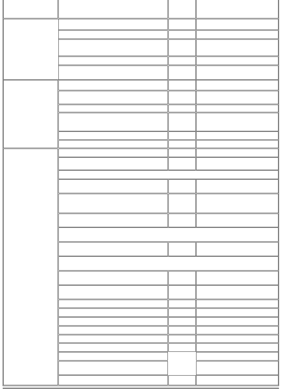
When you need to contact Dell, use the telephone numbers, codes, and electronic addresses provided in the following sections. "International
Dialing Codes" provides the various codes required to make long-distance and international calls. "Americas Contact Numbers," "Europe Contact
Numbers," and "Asia and Other Regions Contact Numbers" provide local telephone numbers, area codes, toll-free numbers, and e-mail
addresses, if applicable, for each department or service available in various countries around the world.
If you are making a direct-dialed call to a location outside of your local telephone service area, determine which codes to use (if any) in
"International Dialing Codes," in addition to the local numbers provided in the other sections.
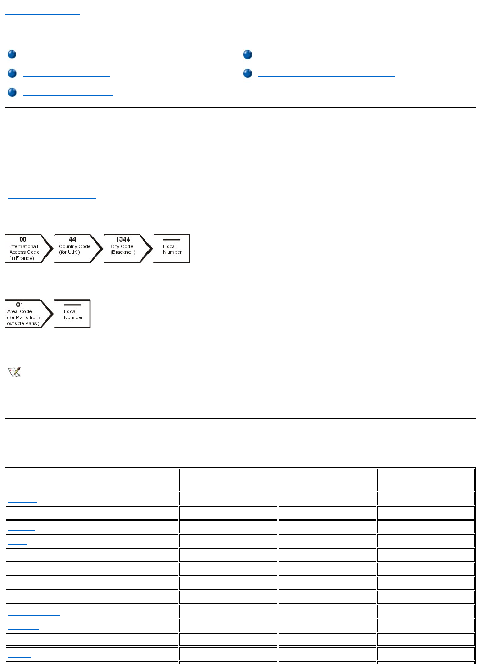
For example, to place an international call from Paris, France to Bracknell, England, dial the international access code for France followed by the
country code for the U.K., the city code for Bracknell, and then the local number as shown in the following illustration:
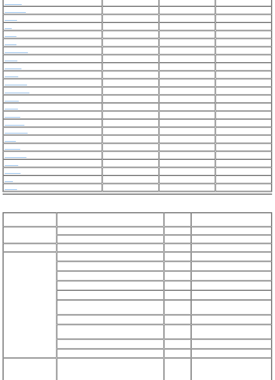
To place a long-distance call within your own country, use area codes instead of international access codes, country codes, and city codes. For
example, to call Paris, France from Montpellier, France, dial the area code plus the local number as shown in the following illustration:
The codes required depend on where you are calling from as well as the destination of your call; in addition, each country has a different dialing
protocol. If you need assistance in determining which codes to use, contact a local or an international operator.
International Dialing Codes
Click a listed country to obtain the appropriate contact numbers.
Overview
Europe Contact Numbers
International Dialing Codes
Asia and Other Regions Contact Numbers
Americas Contact Numbers
NOTES: Toll-free numbers are for use only within the country for which they are listed. Area codes are most often used to call long
distance within your own country (not internationally)—in other words, when your call originates in the same country you are calling.
Have your Express Service Code ready when you call. The code helps Dell's automated-support telephone system direct your call
more efficiently.
Country (City)
International Access
Code
Country Code
City Code
Australia (Sydney)
0011
61
2
Austria (Vienna)
900
43
1
Belgium (Brussels)
00
32
2
Brazil
0021
55
51
Brunei
—
673
—
Canada (North York, Ontario)
011
—
Not required
Chile (Santiago)
—
56
2
China (Xiamen)
—
86
592
Czech Republic (Prague)
00
420
2
Denmark (Horsholm)
00
45
Not required
Finland (Helsinki)
990
358
9
France (Paris) (Montpellier)
00
33
(1) (4)
Americas Contact Numbers
Germany (Langen)
00
49
6103
Hong Kong
001
852
Not required
Ireland (Cherrywood)
16
353
1
Italy (Milan)
00
39
02
Japan (Kawasaki)
001
81
44
Korea (Seoul)
001
82
2
Luxembourg
00
352
—
Macau
—
853
Not required
Malaysia (Penang)
00
60
4
Mexico (Colonia Granada)
95
52
5
Netherlands (Amsterdam)
00
31
20
New Zealand
00
64
—
Norway (Lysaker)
00
47
Not required
Poland (Warsaw)
011
48
22
Portugal
00
35
—
Singapore (Singapore)
005
65
Not required
South Africa (Johannesburg)
09/091
27
11
Spain (Madrid)
00
34
91
Sweden (Upplands Vasby)
00
46
8
Switzerland (Geneva)
00
41
22
Taiwan
002
886
—
Thailand
001
66
—
U.K. (Bracknell)
010
44
1344
U.S.A. (Austin, Texas)
011
1
Not required
Country (City)
Department Name or Service
Area Code
Local Number or
Toll-Free Number
Brazil
Customer Support, Technical Support
toll free: 0800 90 3355
Sales
toll free: 0800 90 3366
Web site: http://www.dell.com/br
Canada
(North York, Ontario)
Automated Order-Status System
toll free: 1-800-433-9014
AutoTech (Automated technical support)
toll free: 1-800-247-9362
Customer Care (From outside Toronto)
toll free: 1-800-387-5759
Customer Care (From within Toronto)
416
758-2400
Customer Technical Support
toll free: 1-800-847-4096
Sales (Direct Sales—from outside Toronto)
toll free: 1-800-387-5752
Sales (Direct Sales—from within Toronto)
416
758-2200
Sales (Federal government, education, and medical)
toll free: 1-800-567-7542
Sales (Major Accounts)
toll free: 1-800-387-5755
TechFax
toll free: 1-800-950-1329
Chile
(Santiago)
NOTE: Customers in
Sales, Customer Support, and Technical Support
toll free: 1230-020-4823
Chile call the U.S.A. for
sales, customer, and
technical assistance
Latin America
NOTE: Customers in Latin
America call the U.S.A. for
sales, customer, and
technical assistance.
Customer Technical Support (Austin, Texas, U.S.A.)
512
728-4093
Customer Service (Austin, Texas, U.S.A.)
512
728-3619
Fax (Technical Support and Customer Service)
(Austin, Texas, U.S.A.)
512
728-3883
Sales (Austin, Texas, U.S.A.)
512
728-4397
SalesFax (Austin, Texas, U.S.A.)
512
728-4600
728-3772
Mexico
NOTE: Customers in
Mexico call the U.S.A. for
access to the Automated
Order-Status System and
AutoTech.
Automated Order-Status System (Austin, Texas, U.S.A.)
512
728-0685
AutoTech (Automated technical support) (Austin, Texas,
U.S.A.)
512
728-0686
Customer Technical Support
525
228-7870
Sales
525
228-7811
toll free: 91-800-900-37
toll free: 91-800-904-49
Customer Service
525
228-7878
Main
525
228-7800
U.S.A.
(Austin, Texas)
Automated Order-Status System
toll free: 1-800-433-9014
AutoTech (for portable and desktop computers)
toll free: 1-800-247-9362
Dell Home and Small Business Group (for portable and desktop computers):
Customer Technical Support (Return Material
Authorization Numbers)
toll free: 1-800-624-9896
Customer Technical Support
(Home sales purchased via http://www.dell.com)
toll free: 1-877-576-3355
Customer Service
(Credit Return Authorization Numbers)
toll free: 1-800-624-9897
National Accounts (systems purchased by established Dell national accounts [have your account number handy],
medical institutions, or value-added resellers [VARs]):
Customer Service and Technical Support (Return
Material Authorization Numbers)
toll free: 1-800-822-8965
Public Americas International (systems purchased by governmental agencies [local, state, or federal] or
educational institutions):
Customer Service and Technical Support (Return
Material Authorization Numbers)
toll free: 1-800-234-1490
Dell Sales
toll free: 1-800-289-3355
toll free: 1-800-879-3355
Spare Parts Sales
toll free: 1-800-357-3355
DellWare™
toll free: 1-800-753-7201
Desktop and Portable Fee-Based Technical Support
toll free: 1-800-433-9005
Server Fee-Based Technical Support
toll free: 1-800-967-0765
Sales (Catalogs)
toll free: 1-800-426-5150
Fax
toll free: 1-800-727-8320
TechFax
toll free: 1-800-950-1329
Dell Services for the Deaf, Hard-of-Hearing, or Speech-
Impaired
toll free: 1-877-DELLTTY
(1-877-335-5889)
Switchboard
512
338-4400
Europe Contact Numbers
Country (City)
Department Name or Service
Area Code
Local Number or
Toll-Free Number
Austria
(Vienna)
NOTE: Customers in
Austria call Langen,
Germany for Technical
Support and Customer
Care.
Switchboard
01
491 040
Home/Small Business Sales
01
795676-02
Home/Small Business Sales Fax
01
795676-05
Home/Small Business Customer Care
01
795676-03
Preferred Accounts/Corporate Customer Care
0660-8056
Home/Small Business Technical Support
01
795676-04
Preferred Accounts/Corporate Technical Support
0660-8779
Web site: http://support.euro.dell.com
E-mail:
tech_support_central_europe@dell.com
Belgium (Brussels)
Technical Support
02
481 92 88
Customer Care
02
481 91 19
Home/Small Business Sales
toll free: 0800 16884
Corporate Sales
02
481 91 00
Fax
02
481 92 99
Switchboard
02
481 91 00
Web site: http://support.euro.dell.com
E-mail: tech_be@dell.com
Czech Republic
(Prague)
Technical Support
02
22 83 27 27
Customer Care
02
22 83 27 11
Fax
02
22 83 27 14
TechFax
02
22 83 27 28
Switchboard
02
22 83 27 11
Web site: http://support.euro.dell.com
E-mail: czech_dell@dell.com
Denmark
(Horsholm)
NOTE: Customers in
Denmark call Sweden for
fax technical support.
Technical Support
45170182
Relational Customer Care
45170184
Home/Small Business Customer Care
32875505
Switchboard
45170100
Fax Technical Support (Upplands Vasby, Sweden)
46
859005594
Fax Switchboard
45170117
Web site: http://support.euro.dell.com
E-mail: den_support@dell.com
E-mail Support for Servers:
Nordic_server_support@dell.com
Finland
(Helsinki)
Technical Support
09
253 313 60
Technical Support Fax
09
253 313 81
Relational Customer Care
09
253 313 38
Home/Small Business Customer Care
09
693 791 94
Fax
09
253 313 99
Switchboard
09
253 313 00
Web site: http://support.euro.dell.com
E-mail: fin_support@dell.com

France
(Paris/Montpellier)
Home and Small Business
Technical Support
0825
387 270
CustomerCare
0825
823 833
Fax
0825
004701
Switchboard
0825
004 700
Switchboard (Alternative)
04
99 75 40 00
Sales
0825
004 700
Web site: http://support.euro.dell.com
E-mail: web_fr_tech@dell.com
Corporate
Technical Support
0825
004 719
CustomerCare
0825
338 339
Fax
01
55 94 71 01
Switchboard
01
55 94 71 00
Sales
01
55 94 71 00
Web site: http://support.euro.dell.com
E-mail: web_fr_tech@dell.com
Germany
(Langen)
Technical Support
06103
766-7200
Home/Small Business Customer Care
0180-5-224400
Global Segment Customer Care
06103
766-9570
Preferred Accounts Customer Care
06103
766-9420
Large Accounts Customer Care
06103
766-9560
Public Accounts Customer Care
06103
766-9555
Switchboard
06103
766-7000
Web site: http://support.euro.dell.com
E-mail:
tech_support_central_europe@dell.com
Ireland
(Cherrywood)
Technical Support
0870 908 0800
HomeUserCustomerCare
01
204 4095
Small Business Customer Care
01
204 4026
Corporate Customer Care
01
204 4003
Sales
01
286 0500
SalesFax
01
204 0144
Fax
0870 907 5590
Switchboard
01
286 0500
Web site: http://support.euro.dell.com
E-mail: dell_direct_support@dell.com
Italy
(Milan)
Home and Small Business
Technical Support
02
577 826 90
Customer Care
02
696 821 14
Fax
02
696 821 13
Switchboard
02
696 821 11
Web site: http://support.euro.dell.com
E-mail: web_it_tech@dell.com
Corporate
Technical Support
02
577 826 90
Customer Care
02
577 825 55

Fax
02
575 035 30
Switchboard
02
577 821
Web site: http://support.euro.dell.com
E-mail: web_it_tech@dell.com
Luxembourg
NOTE: Customers in
Luxembourg call Belgium
for sales, customer, and
technical assistance.
Technical Support (Brussels, Belgium)
02
481 92 88
Home/Small Business Sales (Brussels, Belgium)
toll free: 080016884
Corporate Sales (Brussels, Belgium)
02
481 91 00
Customer Care (Brussels, Belgium)
02
481 91 19
Switchboard (Brussels, Belgium)
02
481 91 00
Fax (Brussels, Belgium)
02
481 92 99
Web site: http://support.euro.dell.com
E-mail: tech_be@dell.com
Netherlands
(Amsterdam)
Technical Support
020
581 8838
Customer Care
020
581 8740
Home/Small Business Sales
toll free: 0800-0663
Home/Small Business Sales Fax
020
682 7171
Corporate Sales
020
581 8818
Corporate Sales Fax
020
686 8003
Fax
020
686 8003
Switchboard
020
581 8818
Web site: http://support.euro.dell.com
E-mail: tech_nl@dell.com
Norway
(Lysaker)
NOTE: Customers in
Norway call Sweden for fax
technical support.
Technical Support
671 16882
Relational Customer Care
671 17514
Home/Small Business Customer Care
231 62298
Switchboard
671 16800
Fax Technical Support (Upplands Vasby, Sweden)
00
08 590 05 594
Fax Switchboard
671 16865
Web site: http://support.euro.dell.com
E-mail: nor_support@dell.com
E-mail Support for Servers:
Nordic_server_support@dell.com
Poland
(Warsaw)
Technical Support
22
57 95 700
Customer Care
22
57 95 999
Sales
22
57 95 999
Switchboard
22
57 95 999
Fax
22
57 95 998
Web site: http://support.euro.dell.com
E-mail: pl_support@dell.com
Portugal
Technical Support
35
800 834 077
Customer Care
800 300 415
or 800 834 075
Sales
800 300 410
or 800 300 411
or 800 300 412
or 351 214 220 710
Switchboard
34
917 229 200
Fax
35
121 424 01 12
E-mail es_support@dell.com
Spain
(Madrid)
Home and Small Business
Technical Support
902 100 130
Customer Care
902 118 540
Switchboard
902 118 541
Fax
902 118 539
Web site: http://support.euro.dell.com
E-mail: web_esp_tech@dell.com
Corporate
Technical Support
902 100 130
Customer Care
902 118 546
Switchboard
91
722 92 00
Fax
91
722 95 83
Web site: http://support.euro.dell.com
E-mail: web_esp_tech@dell.com
Sweden
(Upplands Vasby)
Technical Support
08
590 05 199
Relational Customer Care
08
590 05 642
Home/Small Business Customer Care
08
587 70 527
Fax Technical Support
08
590 05 594
Sales
08
590 05 185
Web site: http://support.euro.dell.com
E-mail: swe_support@dell.com
E-mailSupportforLatitude™andInspiron™:Swe-
nbk_kats@dell.com
E-mailSupportforOptiPlex™:
Swe_kats@dell.com
E-mail Support for Servers:
Nordic_server_support@dell.com
Switzerland
(Geneva)
Technical Support (Home and Small Business)
0844 811 411
Technical Support (Corporate)
0844 822 844
Customer Care (Home and Small Business)
0848 802 202
Customer Service (Corporate)
0848 821 721
Switchboard
022
799 01 01
Fax
022
799 01 90
Web site: http://support.euro.dell.com
E-mail: swisstech@dell.com
U.K.
(Bracknell)
Technical Support (Corporate/Preferred
Accounts/PAD [1000+ employees])
0870
9080500
Technical Support (Direct/PAD and General)
0870
9080800
Global Accounts Customer Care
01344
723186
Corporate Customer Care
0870
908 0500
Preferred Accounts (500-5000 employees)
Customer Care
01344
723 196
Central Government Customer Care
01344
723 193
Local Government Customer Care
01344
723 194
Home/Small Business Sales
0870
9074000
Home/Small Business Customer Care
0870
906 0010
Corporate/Public Sector Sales
01344
860 456
Web site: http://support.euro.dell.com
Asia and Other Regions Contact Numbers
E-mail: dell_direct_support@dell.com
Country (City)
Department Name or Service
Area Code
Local Number or
Toll-Free Number
Australia
(Sydney)
Home and Small Business
1-300-65-55-33
Government and Business
toll free: 1-800-633-559
Preferred Accounts Division (PAD)
toll free: 1-800-060-889
Customer Care
toll free: 1-800-819-339
Corporate Sales
toll free: 1-800-808-385
Transaction Sales
toll free: 1-800-808-312
Fax
toll free: 1-800-818-341
Brunei
NOTE: Customers in
Brunei call Malaysia for
customer assistance.
Customer Technical Support
(Penang, Malaysia)
633 4966
Customer Service
(Penang, Malaysia)
633 4949
Transaction Sales
(Penang, Malaysia)
633 4955
China
(Xiamen)
Technical Support
toll free: 800 858 2437
Customer Experience
toll free: 800 858 2060
Home and Small Business
toll free: 800 858 2222
Preferred Accounts Division
toll free: 800 858 2062
Large Corporate Accounts
toll free: 800 858 2999
Hong Kong
NOTE: Customers in
Hong Kong call Malaysia
for customer assistance.
Technical Support
toll free: 800 96 4107
Customer Service (Penang, Malaysia)
633 4949
Transaction Sales
toll free: 800 96 4109
Corporate Sales
toll free: 800 96 4108
Japan
(Kawasaki)
Technical Support (Server)
toll free: 0120-1984-35
TechnicalSupport(Dimension™andInspiron)
Technical Support Outside of Japan (Dimension
and Inspiron)
81-44
toll free: 0120-1982-26
520-1435
TechnicalSupport(DellPrecision™,OptiPlex,and
Latitude)
Technical Support Outside of Japan (Dell Precision,
OptiPlex, and Latitude)
81-44
toll free: 0120-1984-33
556-3894
Customer Care
044
556-4240
24-Hour Automated Order Status Service
044
556-3801
Home and Small Business Group Sales
044
556-3344
IndividualUserSales
044
556-3344
Business Sales Division (up to 400 employees)
044
556-3344
Government, Educational, and Medical Sales
044
556-1469
Preferred Accounts Division Sales (over 400
employees)
044
556-3433
Dell Global Japan
044
556-3469
Large Corporate Accounts Sales (over 3500
employees)
044
556-3430
Faxbox Service
044
556-3490
Switchboard
044
556-4300
Web site: http://support.jp.dell.com
Back to Contents Page
Korea
(Seoul)
Technical Support
toll free: 080-200-3800
Sales
toll free: 080-200-3777
Customer Service (Penang, Malaysia)
604-633-4949
Customer Service (Seoul, Korea)
2194-6220
Fax
2194-6202
Switchboard
2194-6000
Macau
NOTE: Customers in
Macau call Malaysia for
customer assistance.
Technical Support
toll free: 0800 582
Customer Service (Penang, Malaysia)
633 4949
Transaction Sales
toll free: 0800 581
Malaysia
(Penang)
Technical Support
toll free: 1 800 888 298
Customer Service
04
633 4949
Transaction Sales
toll free: 1 800 888 202
Corporate Sales
toll free: 1 800 888 213
New Zealand
Home and Small Business
0800 446 255
Government and Business
0800 444 617
Sales
0800 441 567
Fax
0800 441 566
Singapore
(Singapore)
NOTE: Customers in
Singapore call Malaysia
for customer assistance.
Technical Support
toll free: 800 6011 051
Customer Service (Penang, Malaysia)
04
633 4949
Transaction Sales
toll free: 800 6011 054
Corporate Sales
toll free: 800 6011 053
South Africa
(Johannesburg)
Technical Support
011
709 7710
Customer Care
011
709 7707
Sales
011
709 7700
Fax
011
706 0495
Switchboard
011
709 7700
Web site: http://support.euro.dell.com
E-mail: dell_za_support@dell.com
Southeast Asian/Pacific
Countries
(excluding Australia,
Brunei, China, Hong Kong,
Japan, Korea, Macau,
Malaysia, New Zealand,
Singapore, Taiwan, and
Thailand—refer to
individual listings for these
countries)
Customer Technical Support, Customer Service,
and Sales (Penang, Malaysia)
60 4 633-4810
Taiwan
Technical Support
toll free: 0080 60 1225
Technical Support (Servers)
toll free: 0080 60 1256
Customer Service (Penang, Malaysia)
633 4949
Transaction Sales
toll free:
0080 651 228/0800 33 556
Corporate Sales
toll free:
0080 651 227/0800 33 555
Thailand
NOTE: Customers in
Thailand call Malaysia for
customer assistance.
Technical Support
toll free: 088 006 007
Customer Service (Penang, Malaysia)
633 4949
Sales
toll free: 088 006 009

Back to Contents Page
Dell™Diagnostics:DellOptiPlex™GX110SystemUser'sGuide
Overview
Unlike many diagnostic programs, the Dell Diagnostics helps you check your computer's hardware without any additional equipment and without
destroying any data. By using the diagnostics, you can have confidence in your computer system's operation. If you find a problem you cannot
solve by yourself, the diagnostic tests can provide you with important information you will need when talking to Dell's service and support
personnel.
NOTICE: Use the Dell Diagnostics only to test your Dell computer system. Using this program with other computers may cause
incorrect computer responses or result in error messages.
Features of the Dell Diagnostics
The Dell Diagnostics provides a series of menus and options from which you choose particular test groups or subtests. You control the sequence
in which the tests are run. The diagnostic test groups or subtests have the following helpful features:
lOptions that let you run tests individually or collectively
lAn option that allows you to choose the number of times a test group or subtest is repeated
lThe ability to display or print test results or to save them in a file
lOptions to temporarily suspend testing if an error is detected or to terminate testing when an adjustable error limit is reached
lA menu category called Devices that briefly describes each test and its parameters
lA menu category called Config that describes the configuration of the devices in the selected device group
lStatus messages that inform you whether test groups or subtests were completed successfully
lError messages that appear if any problems are detected
When to Use the Dell Diagnostics
Whenever a major component or device in your computer system does not function properly, you may have a component failure. As long as the
microprocessor and the input and output components of your computer system (the monitor, keyboard, and diskette drive) are working, you can
use the Dell Diagnostics. If you are experienced with computers and know what component(s) you need to test, simply select the appropriate
diagnostic test group(s) or subtest(s). If you are unsure about how to begin diagnosing a problem, read the rest of this section.
Before You Start Testing
Turn on your printer if one is attached, and make sure it is online. Enter System Setup, confirm your computer's system configuration information,
and enable all its components and devices, such as ports.
See "Using System Setup" for instructions on entering and using the program.
Starting the Dell Diagnostics
After you complete the preliminary instructions outlined in the previous section, perform the following steps to start the diagnostics:
1. Turn off your system.
Overview
Starting the Dell Diagnostics
Features of the Dell Diagnostics
Dell Diagnostics Main Screen Overview
When to Use the Dell Diagnostics
Confirming the System Configuration Information
Before You Start Testing
How to Use Dell Diagnostics
2. InserttheDellDiagnosticsmedia(forexample,adisketteorCD)intotheappropriatedrive.
3. Turn on your system.
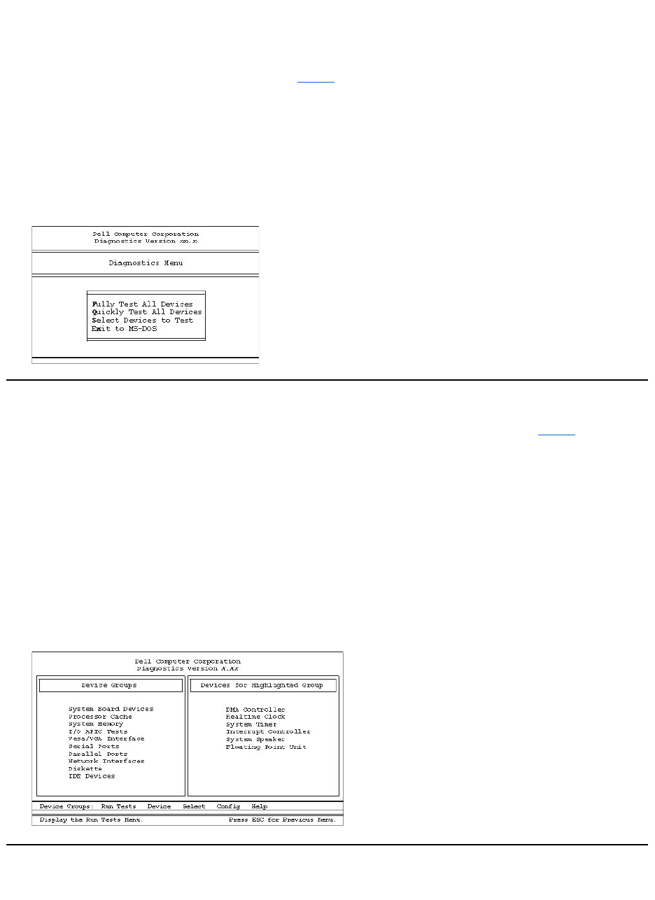
When you start the diagnostics, the Dell logo screen appears, followed by a message telling you that the diagnostics is loading.
After the diagnostics loads, the Diagnostics Menu appears (see Figure 1). The menu allows you to run all or specific diagnostic tests or to exit to
the MS-DOS® prompt.
For a quick check of your system, select the Quickly Test All Devices option. This option runs only the subtests that do not require user
interaction and that do not take a long time to run. Dell recommends that you choose this option first to identify the source of the problem quickly.
Forathoroughcheckofyoursystem,selecttheFully Test All Devices option. To check a particular area of your system, select the Select
Devices to Test option.
To select an option from this menu, highlight the option and press <Enter>, or press the key that corresponds to the highlighted letter in the option
you choose.
Figure 1. Diagnostics Menu
Dell Diagnostics Main Screen Overview
When you select Select Devices to TestfromtheDiagnostics Menu, the main screen of the diagnostics appears (see Figure 2). The main
screen lists the diagnostic test device groups, lists the devices of the selected device group, and allows you to select categories from a menu.
From this screen, you can access the main screens.
Information on the main screen of the diagnostics is presented in the following areas:
lTwo lines at the top of the screen identify the version number of the Dell Diagnostics.
lOn the left side of the screen, the Device Groups area lists the diagnostic test groups in the order they will run if you select All from the Run
Tests menu category. Press the up- or down-arrow key to highlight a test device group.
lOn the right side of the screen, the Devices for Highlighted Group area lists the computer's currently detected hardware and some of the
relevant settings.
lTwo lines at the bottom of the screen make up the menu area. The first line lists the categories you can select; press the left- or right-arrow
key to highlight a menu category. The second line gives information about the category currently highlighted.
Figure 2. Dell Diagnostics Main Screen
Confirming the System Configuration Information
When you boot your system from your diagnostics diskette, the diagnostics checks your system configuration information and displays it in the

Device Groups area on the main screen.
The following sources supply this configuration information for the diagnostics:
lThe system configuration information settings (stored in nonvolatile random-access memory [NVRAM]) that you selected while using System
Setup
lIdentification tests of the microprocessor, the video controller, the keyboard controller, and other key components
lBasic input/output system (BIOS) configuration information temporarily saved in RAM
Do not be concerned if the Device Groups area does not list the names of all the components or devices you know are part of your computer
system. For example, you may not see a printer listed, although you know one is attached to your computer. Instead, the printer is listed as a
parallel port. The computer recognizes the parallel port as LPT1, which is an address that tells the computer where to send outgoing information
and where to look for incoming information. Because your printer is a parallel communications device, the computer recognizes the printer by its
LPT1 address and identifies it as a parallel port. You can test your printer connection in the Parallel Portstests.
How to Use Dell Diagnostics
Six comprehensive, menu-driven, online help categories provide instructions on how to use the program and explain each menu item, test group,
subtest, and test result. To enter the Help menu, perform the following steps:
1. Highlight Select Devices to Test in the Diagnostics Menu.
2. Press <Enter>.
3. Press <h>.
The six Help menu categories are Menu, Keys, Device Group, Device, Test, and Versions. The online help also provides detailed
descriptions of the devices that you are testing. The Help menu categories are explained in the following subsections.
Menu Category
The Menu help category describes the main menu screen area, the device groups, and the different diagnostic menus and commands and
instructs you on how to use them.
Keys Category
The Keys help category explains the functions of all keystrokes that you can use in the Dell Diagnostics.
Device Group Category
The Device Group help category describes the test group that is currently highlighted in the Device Groups list on the main menu screen. It also
provides reasoning for using some tests.
Device Category
The Device help category is the educational section of online help. It describes the function and purpose of the highlighted device in the Device
Groups. For example, the following information appears when you select the DevicehelpcategoryforDiskette in the Device Groups list:
Diskette drive A:
The diskette disk drive device reads and writes data to and from diskettes. Diskettes are flexible
recording media, sometimes contained in hard shells. Diskette recording capacities are small and
access times are slow relative to hard disk drives, but they provide a convenient means of storing
and transferring data.
Test Category
The Test help category thoroughly explains the test procedure of each currently highlighted subtest. For example, the subtest Diskette Drive Seek
Test of the Diskettedevicegroupliststhefollowinginformation:
Diskette drive A: - Diskette Drive Seek Test
This test verifies the drive's ability to position its read/write heads. The test operates in two
passes: first, seeking from the beginning to ending cylinders inclusively, and second, seeking
alternately from the beginning to ending cylinders with convergence towards the middle.
Versions Category
The Versions help category lists the version numbers of the subtests that are used by your Dell Diagnostics program.

Back to Contents Page
Diskette, Tape, and CD-ROMDrives:Dell™OptiPlex™GX110SystemUser'sGuide
Installing a CD-ROM Drive in a Small-Form-Factor Chassis
To install a CD-ROM drive in the 5.25-inch drive bay in the small-form-factor chassis, perform the following steps.
1. Unpack the drive and prepare it for installation.
NOTICE: To avoid possibly damaging the drive by electromagnetic static (EMS), ground yourself by touching an unpainted
metal surface on the back of the computer.
Check the documentation that accompanied the drive to verify that the drive is configured for your computer system. Change any settings
necessary for your configuration.
2. Remove the computer cover as instructed in "Removing and Replacing the Computer Cover."
3. If a drive is already installed in the drive bay, remove it.
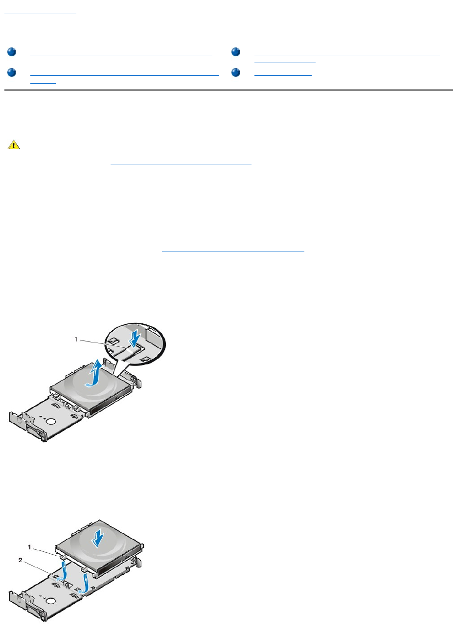
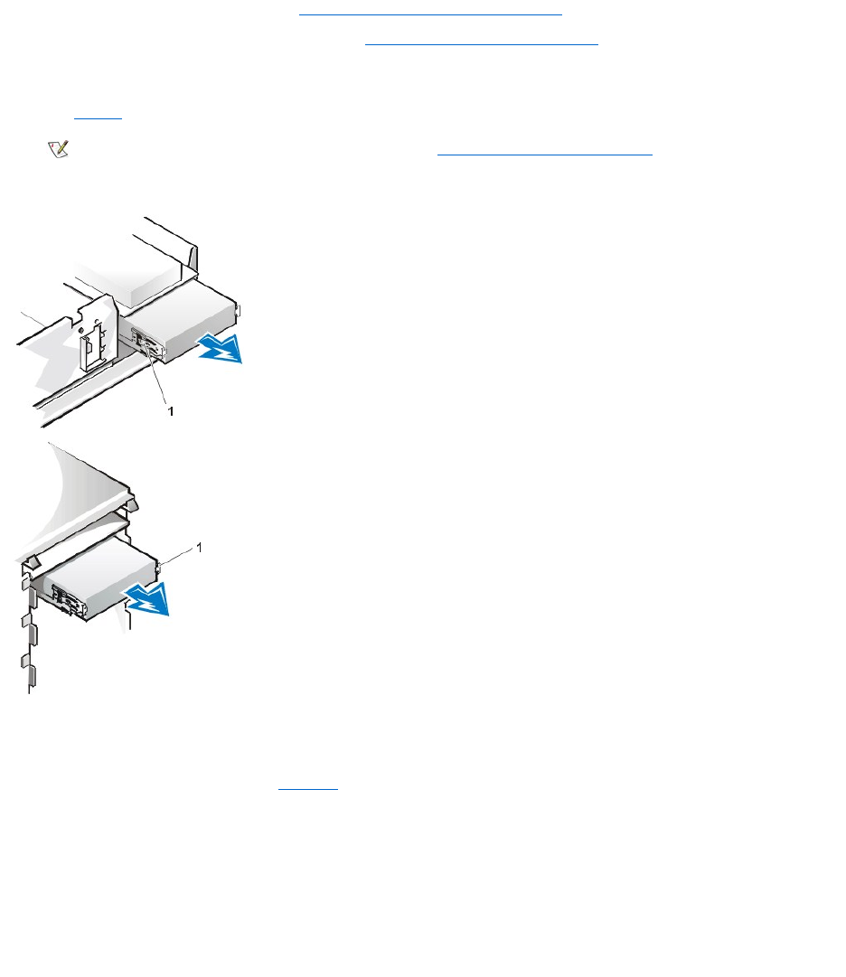
Disconnect the power cable and interface cable from the back of the drive. Push down on the drive release tab on the right side of the
drive (see Figure 1), and slide the drive forward out of the chassis.
Figure 1. Removing a CD-ROM Drive From the Small-Form-Factor Chassis
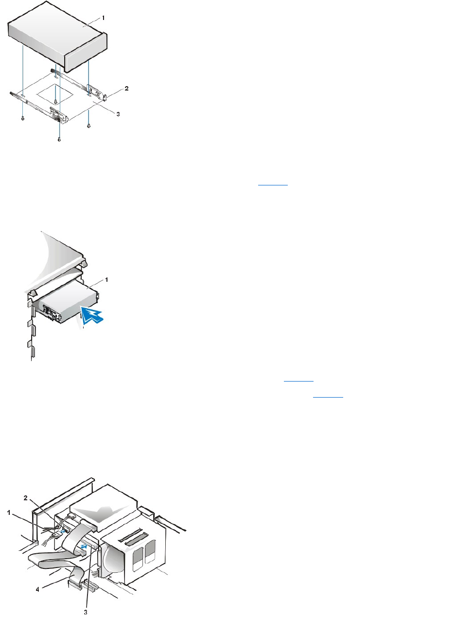
4. Install the new drive in the chassis.
Align the tabs along the bottom of the drive with the notches on the chassis, and slide the drive toward the back of the chassis until it
snaps into place (see Figure 2).
Figure 2. Inserting a CD-ROM Drive in the Small-Form-Factor Chassis
Installing a CD-ROM Drive in a Small-Form-Factor Chassis
Installing a Diskette, Tape, or CD-ROM Drive in a Midsize or
Mini Tower Chassis
Installing a Diskette, Tape, or CD-ROM Drive in a Low-Profile
Chassis
Connecting Drives
CAUTION: To avoid the possibility of electric shock, turn off the computer and any peripherals, disconnect them from their
electrical outlets, and then wait at least 5 seconds before you remove the computer cover. Also, before you install a drive, see
the other precautions in "Safety First—For You and Your Computer."
1
Drive release tab
1
Tabs (2)
2
Notches (2)
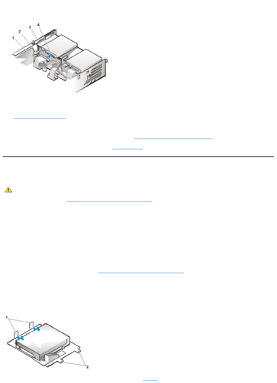
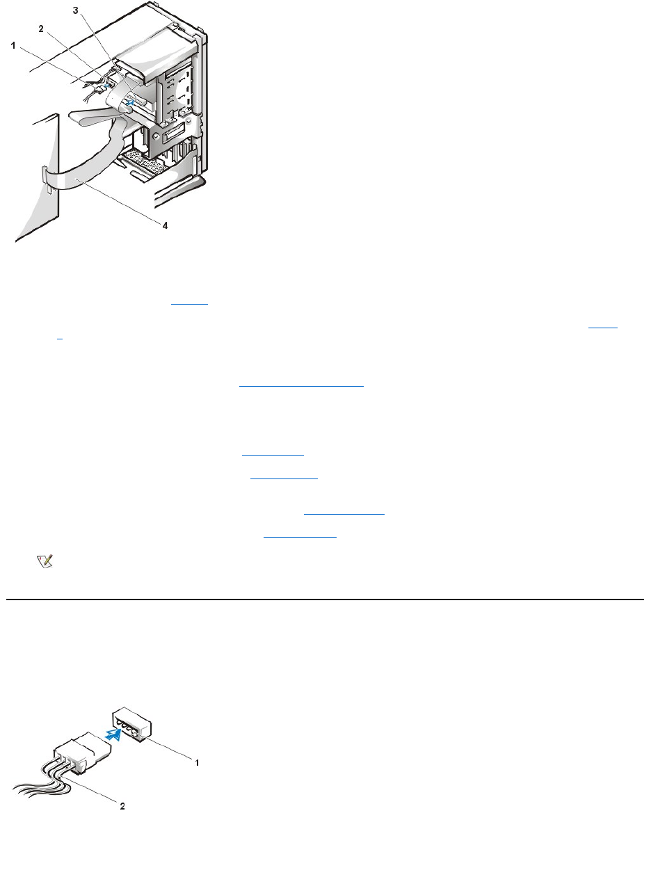
5. Connect a power cable and an interface cable to the appropriate connectors on the back of the drive (see Figure 3).
Figure 3. Attaching Cables to a CD-ROM Drive in the Small-Form-Factor Chassis
Check all cable connections. Fold cables out of the way to provide airflow for the fan and cooling vents.
6. Replace the computer cover; reconnect your computer and peripherals to their electrical outlets, and turn them on.
7. Update your system configuration information.
Set the Drive 0 option under Drives: Secondary to Auto. See "Primary Drive n and Secondary Drive n" for more information.
8. Verify that your system works correctly by running the Dell Diagnostics.
Installing a Diskette, Tape, or CD-ROM Drive in a Low-Profile Chassis
To install a diskette, tape, or CD-ROM drive in a 5.25-inch drive bay in a low-profile chassis, perform the following steps.
1. Unpack the drive and prepare it for installation.
NOTICE: To avoid possibly damaging the drive by electromagnetic static (EMS), ground yourself by touching an unpainted
metal surface on the back of the computer.
Check the documentation that accompanied the drive to verify that the drive is configured for your computer system. Change any settings
necessary for your configuration.
If you are installing an enhanced integrated drive electronics (EIDE) drive, configure the drive for the cable select setting. You usually
configure a drive for cable select by setting a jumper or switch, depending on the drive. For instructions on configuring the cable select
setting, see the documentation that accompanied the drive.
2. Remove the computer cover as instructed in "Removing and Replacing the Computer Cover."
3. Remove the 3.5-inch diskette drive/bracket assembly.
Facing the front of the computer, press outward on the two tabs on the left side of the drive bay to disengage the bracket from the
chassis (see Figure 4). Then rotate the bracket upward, and remove it from the chassis.
Figure 4. Removing the 3.5-Inch Diskette Drive/Bracket Assembly
4. Lift the 5.25-inch drive bracket straight up and out of the chassis (see Figure 5).
1
Interface cable
2
Power cable
3
Power input connector
4
Interface connector
CAUTION:Toavoidthepossibilityofelectricshock,turnoffthecomputerandanyperipherals,disconnectthemfromtheir
electrical outlets, and then wait at least 5 seconds before you remove the computer cover. Also, before you install a drive, see
the other precautions in "Safety First—For You and Your Computer."
1
Tabs (2)
2
Notches (2)
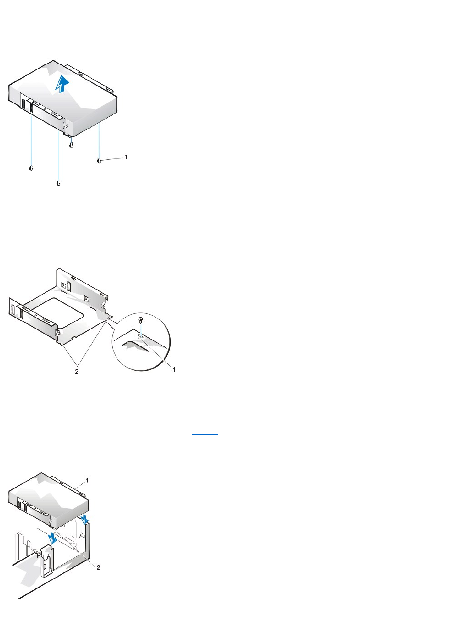
If a drive is already installed in the bay and you are replacing it, be sure to disconnect the DC power cable and interface cable from the
back of the drive before you remove the drive/bracket assembly. To remove the old drive from the bracket, turn the drive/bracket
assembly upside down and unscrew the four screws that secure the drive to the bracket (see Figure 5).
Figure 5. Removing the 5.25-Inch Drive Bracket
5. Attach the bracket to the new drive.
a. Turn the drive upside down, and locate the four screw holes around its perimeter. Fit the bracket over the drive so that the
notched end aligns with the front of the drive. Use the score marks on the drive bracket to help align the screw holes on the drive
with the screw holes on the bracket (see Figure 6).
Figure 6. Installing a Drive in the 5.25-Inch Drive Bracket
b. To further ensure proper positioning of the drive in the bracket, insert and tighten all four screws in the order in which the holes
are numbered (the holes are marked "1" through "4").
6. Reinstall the 5.25-inch diskette drive/bracket assembly in the chassis.
Align the notches on the front of the drive bracket (see Figure 6) with the front of the computer. Hold the bracket level, and lower the
assembly straight down into place (see Figure 7).
Figure 7. Inserting the Drive/Bracket Assembly Into the Drive Bay
7. If you are installing a drive that has its own controller card, install the controller card in an expansion slot.
8. Connect a DC power cable to the power input connector on the back of the drive (see Figure 8).
1
Screws (4)
1
Score mark
2
Notches (2)
1
Bracket
2
Notches (2)
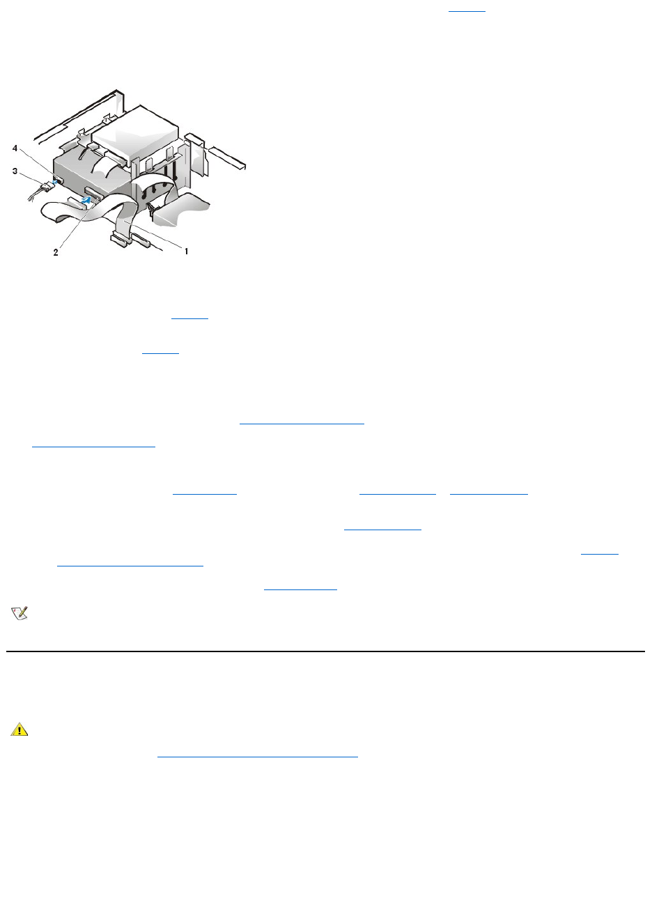
9. Connect the appropriate interface cable to the interface connector on the back of the drive (see Figure 8).
If your system came with an enhanced integrated drive electronics (EIDE) CD-ROM or tape drive, use the spare connector on the
existing interface cable. Otherwise, use the EIDE interface cable provided in the drive kit.
Figure 8. Attaching Cables to a Drive in the 5.25-Inch Drive Bay
10. Connect the interface cable to the system board or a controller card, depending on the type of drive.
lFor an EIDE tape drive or CD-ROM drive, connect the other end of the interface cable to the interface connector labeled "IDE2"
on the system board (see Figure 7 in "Inside Your Computer").
lFor a diskette drive or non-EIDE tape drive, connect the cable from the drive to the interface connector labeled "DSKT" on the
system board (see Figure 7 in "Inside Your Computer").
lFor a drive that comes with its own controller card, connect the other end of the interface cable to the controller card.
Check all cable connections. Fold cables out of the way to provide airflow for the fan and cooling vents.
11. If the 5.25-inch drive bay was previously empty, remove the front-panel insert from the front bezel.
12. Replace the computer cover; reconnect your computer and peripherals to their electrical outlets, and turn them on.
13. Update your system configuration information.
lFor a diskette drive, enter System Setup and update the appropriate Diskette Drive A or Diskette Drive B option to reflect the
size and capacity of your new diskette drive.
lIf you installed a non-EIDE tape drive as the second drive, set the Diskette Drive B option to Not Installed.
lFor EIDE CD-ROM and tape drives, set the appropriate Drive option (0 or 1) under Drives: Secondary to Auto. See "Primary
Drive n and Secondary Drive n" for more information.
14. Verify that your system works correctly by running the Dell Diagnostics.
Installing a Diskette, Tape, or CD-ROM Drive in a Midsize or Mini Tower Chassis
To install a diskette, tape, or CD-ROM drive in a 5.25-inch drive bay, perform the following steps.
1. Unpack the drive and prepare it for installation.
NOTICE: To avoid possibly damaging the drive by electromagnetic static (EMS), ground yourself by touching an unpainted
metal surface on the back of the computer.
Check the documentation that accompanied the drive to verify that the drive is configured for your computer system. Change any settings
necessary for your configuration.
If you are installing an enhanced integrated drive electronics (EIDE) drive, configure the drive for the cable select setting. The cable select
setting is located on the drive. To configure the cable select setting, see the documentation that accompanied the drive.
1
Diskette/tape drive interface cable
2
Interface connector
3
DC power cable
4
Power input connector
NOTE: Tape drives sold by Dell come with their own operating software and documentation. After you install a tape drive, refer to the
documentation that came with the drive for instructions on installing and using the tape drive software.
CAUTION:Toavoidthepossibilityofelectricshock,turnoffthecomputerandanyperipherals,disconnectthemfromtheir
electrical outlets, and then wait at least 5 seconds before you remove the computer cover. Also, before you install a drive, see
the other precautions in "Safety First—For You and Your Computer."
2. Remove the computer cover as instructed in "Removing and Replacing the Computer Cover."
3. Remove the front bezel (mini tower only) as instructed in "Removing and Replacing the Front Bezel."
4. Remove the drive bracket from the bay you want to use.
a. Squeeze the metal tabs that extend from each side of the drive bracket toward each other, and pull the bracket out of the bay (see
Figure 9).
Figure 9. Removing a Drive
If a drive is already installed in the bay and you are replacing it, disconnect the DC power cable and interface cable from the back of
the drive before you slide the bracket out of the bay.
b. To remove the installed drive from the bracket, turn the drive/bracket assembly upside down and unscrew the four screws that
secure the drive to the bracket (see Figure 10).
5. Attach the bracket to the replacement drive.
a. Turn the drive upside down, and locate the four screw holes around its perimeter.
b. Fit the bracket over the drive, and then tilt the front of the drive up so that the bracket drops down into place.
c. To ensure proper installation, align all screw holes and ensure that the tabs on the front of the bracket are flush with the front of the drive
(see Figure 10).
Figure 10. Attaching the Drive Bracket to the New Drive
NOTE: For easier access inside the chassis, you may want to rotate the power supply out of the way temporarily.
1
Bracket tabs (2)
d. To further ensure proper positioning of the drive in the bracket, insert and tighten all four screws in the order in which the holes
are numbered (the holes are labeled "1" through "4").
6. Slide the drive into the drive bay until the drive snaps securely into place (see Figure 11).
Make sure that both bracket tabs snap into place in the drive bay.
Figure 11. Inserting the New Drive Into the Drive Bay
7. Connect a DC power cable to the power input connector on the back of the drive (see Figure 12).
8. Connect the appropriate interface cable to the interface connector on the back of the drive (see Figure 12).
If your system came with an EIDE CD-ROM or tape drive, use the spare connector on the existing interface cable. Otherwise, use the EIDE
interface cable provided in the drive kit.
NOTICE: You must match the colored strip on the cable with pin 1 on the drive's interface connector to avoid possible damage
to your system.
Figure 12. Attaching Diskette Drive or Tape Drive Cables
1
5.25-inch drive
2
Bracket tabs (2)
3
Bracket
1
5.25-inch drive
1
DC power cable
2
Power input connector
3
Interface connector
4
Diskette/tape drive interface cable
Connect the interface cable to the system board.
lFor an EIDE tape drive or CD-ROM drive, connect the other end of the interface cable to the interface connector labeled "IDE2"
on the system board (see Figure 9 in "Inside Your Computer").
lFor a diskette drive, connect the cable from the drive to the interface connector labeled "DSKT" on the system board (see Figure
9 in "Inside Your Computer").
Check all cable connections. Fold cables out of the way to provide airflow for the fan and cooling vents.
10. If the 5.25-inch drive bay was previously empty, remove the front-panel insert from the front bezel.
11. Replace the front bezel (mini tower only).
12. Replace the computer cover, reconnect your computer and peripherals to their electrical outlets, and turn them on.
13. Update your system configuration information in System Setup.
lFor a diskette drive, update the appropriate Diskette Drive option (A or B) to reflect the size and capacity of your new diskette
drive.
lFor EIDE CD-ROM and tape drives, set the appropriate Secondary Drive option (0 or 1) to Auto.
14. Verify that your system works correctly by running the Dell Diagnostics.
Connecting Drives
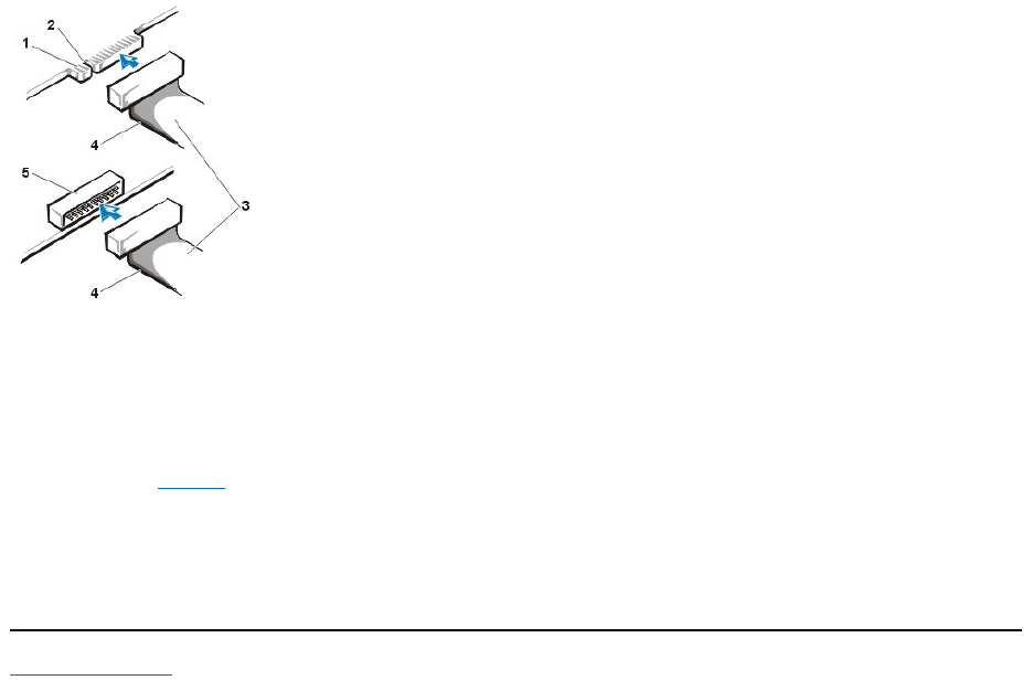
When you install a drive, you connect two cables—a DC power cable and an interface cable—to the back of the drive. Your drive’s power input
connector(towhichyouconnecttheDCpowercable)resemblestheconnectorshowninFigure13.
Figure 13. Power Cable Connector
The drive’s interface connector is a card-edge connector or a header connector, as shown in Figure 14.
Figure 14. Drive Interface Connectors
NOTE: Tape drives sold by Dell come with their own operating software and documentation. After you install a tape drive,
refer to the documentation that came with the drive for instructions on installing and using the tape drive software.
1
Power input connector
2
Power cable
When you attach the interface cable to a drive, be sure to match the colored strip on the cable to pin 1 of the drive’s interface connector. For the
location of pin 1 on the drive’s interface connector, see the documentation that came with the drive.
When you disconnect an interface cable from the system board, be sure to press in on the locking tabs on the cable connector before you
disconnect the cable. When you attach an interface cable to the system board, be sure that the locking tabs snap into place so that the cable is
firmly attached to the connector on the system board.
Most interface connectors are keyed for correct insertion; that is, a notch or a missing pin on one connector matches a tab or a filled-in hole on the
other connector (see Figure 14). Keyed connectors ensure that the pin-1 wire in the cable (indicated by the colored strip along one edge of the
cable) goes to the pin-1 end of the connector.
The pin-1 end of a connector on a board or a card is usually indicated by a silk-screened "1" printed directly on the board or card.
NOTICE: When you connect an interface cable, do not reverse the interface cable (do not place the colored strip away from pin 1 of
the connector). Reversing the cable prevents the drive from operating and could damage the controller, the drive, or both.
Back to Contents Page
1
Card-edge connector on drive
2
Notch
3
Interface cables
4
Colored strip
5
Header connector on drive

Back to Contents Page
DriversandUtilities:Dell™OptiPlex™GX110SystemUser'sGuide
Program Diskette Maker
Dell installed all the drivers for any integrated devices as well as the system utilities on your system's hard-disk drive. These drivers and utilities are
provided in diskette image form, from which you can make backup diskettes using the Program Diskette Maker. Dell strongly urges that you make
these backup diskettes as soon as you complete initial system setup in case you need to reinstall one of these drivers or utilities.
The Program Diskette Maker is located in the Dell Accessories program folder and contains complete online documentation on its use. To
access the Program Diskette Maker, perform the following steps:
1. Start your operating system.
2. Click Start, and then click Programs.
3. Click Dell Accessories.
4. Click Program Disk Maker.
Video Drivers
To reinstall the video drivers, perform the following steps:
1. Use the Program Diskette Maker (located in the Dell Accessories program folder) to make a diskette copy of the video drivers installed
on your hard-disk drive.
2. Insert the video driver diskette 1 into the diskette drive.
3. Click the Start button, click Run, type a:\setup in the Run window, and then click OK.
4. Follow the instructions that appear on your screen to complete the installation.
NIC Drivers
This section describes how to reinstall the network interface controller (NIC) driver for the following operating systems:
lMicrosoft®Windows NT®4.0
lMicrosoft Windows®98
lMicrosoft Windows 95
Windows NT 4.0 NIC Driver
The Windows NT 4.0 operating system installed by Dell automatically detects and installs the NIC driver. To reinstall the driver, perform the
following steps:
1. Use the Program Diskette Maker (located in the Dell Accessories program folder) to make a diskette copy of the NIC drivers installed on
your hard-disk drive.
2. Connect the network cable to the back of your computer.
See "Network Cable Requirements" for detailed instructions.
3. Verify that the NIC is enabled in System Setup.
See "Network Interface Controller" for more information.
Program Diskette Maker
Intel INF Chipset Update Utility for Windows 95 or Windows 98
Video Drivers
Mouse Drivers
NIC Drivers
System Utilities
Bus-Mastering EIDE Driver for Windows NT 4.0 or Windows 98

4. Start the Windows NT operating system, and log on as an administrator or as a user with administrator privileges.
For information on administrator privileges, see your Windows NT documentation.
5. Double-click the My Computer icon, double-click Control Panel, and then double-click the Network icon.
6. Click the Adapters tab in the Network Control Panel, and then click Update.
7. Insert the NIC driver diskette 1 into drive A, type a:\, and then click Continue.
8. When prompted, remove the NIC driver diskette 1 from the diskette drive and insert the NIC driver diskette 2.
9. Remove the diskette from drive A, and click Yes in the Network Settings Change window to restart your system.
Windows 98 NIC Driver
To install the NIC driver for Windows 98, perform the following steps:
1. Use the Program Diskette Maker (located in the Dell Accessories program folder) to make a diskette copy of the NIC drivers installed on
your hard-disk drive.
2. Connect the network cable to the back of your computer.
See "Network Cable Requirements" for detailed instructions.
3. Verify that the integrated NIC is enabled and connected to its network.
See "Network Interface Controller" for more information.
4. Start the Windows 98 operating system.
5. Click the Start button, point to Settings, and click Control Panel. Then double-click the System icon.
6. In the System Properties window, click the Device Manager tab.
7. If you are updating or reinstalling the driver for a Dell-installed Windows 98 operating system, click Network Adapters, and then click 3Com
3C920 Integrated Fast Ethernet Controller (3C905C-TX Compatible).
If you are installing the driver for a new Windows 98 installation, click Other Devices, and then click PCI Ethernet Controller.
8. Click Properties.
9. Click the Driver tab.
10. Click the Update Driver button.
The Update Device Driver Wizard window appears.
11. Click Next.
12. Select Display a list of drivers in a specific location, so you can select the driver you want, and click Next.
If you are installing the driver for a new Windows 98 installation, select Network Adapters from the list of device types. Then click OK.
13. Click the Have Disk button.
14. Insert the NIC driver diskette 1 into drive A, verify that a:\ is specified as the target location, and click OK.
15. Verify that 3Com 3C920 Integrated Fast Ethernet Controller (3C905C-TX Compatible) is selected, and then click OK.
16. When the Update Device Driver Wizard asks where to install the driver, click Next.
17. When prompted, remove the NIC driver diskette 1 and insert the NIC driver diskette 2. Then click OK.
18. Click Finish.
19. When prompted to restart your system, remove the diskette from drive A, and click Yes.
Windows 95 NIC Driver
The Windows 95 operating system installed by Dell automatically detects and installs the NIC driver. This subsection provides instructions for
NOTE: If you are installing networking on your system for the first time, the Windows NT operating system displays a
message asking if you want to install networking. Click Yes, and refer to your Windows NT documentation for instructions.

reinstalling the NIC driver on systems running a Dell-installed Windows 95 Service Release 2.1 operating system.
To reinstall the NIC driver in a system running Dell-installed Windows 95 Service Release 2.1, perform the following steps:
1. Use the Program Diskette Maker (located in the Dell Accessories program folder) to make a diskette copy of the NIC drivers installed on
your hard-disk drive.
2. Connect the network cable to the back of your computer.
See "Network Cable Requirements" for detailed instructions.
3. Verify that the integrated NIC is enabled and connected to its network.
See "Network Interface Controller" for more information.
4. Start the Windows 95 operating system.
5. Click the Start button, point to Settings, and click Control Panel. Then double-click the System icon.
6. In the System Properties window, click the Device Manager tab.
7. In the list of system devices, double-click Other Devices. Then click PCI Ethernet Controller.
8. Click Properties to access the PCI Ethernet Controller window.
9. Click the Driver tab, and then click Update Driver.
The Update Device Driver Wizard starts.
10. Insert the NIC driver diskette 1 into drive A, and click No, select driver from list.
11. Click Next, click Network Adapter, and then click Have Disk.
12. Type a:\, and then click OK.
The Windows 95 operating system begins to copy files to the system's hard-disk drive.
13. Click 3Com 3C920 Integrated Fast Ethernet Controller (3C905C-TX Compatible) and click OK.
14. When prompted to insert the Windows 95 CD-ROM, click OK.
15. Specify the location of the Windows 95 cab files and click OK.
16. When prompted, insert the NIC driver diskette 2 and click OK.
17. Type a:\ and click OK.
18. When prompted to restart the computer, click Yes.
If you receive a notification about Dynamic Host Configuration Protocol (DHCP), see your network administrator.
Bus-Mastering EIDE Driver for Windows NT 4.0 or Windows 98
This section describes how to reinstall the following bus-mastering drivers:
lBus-mastering enhanced integrated drive electronics (EIDE) Driver for Windows NT 4.0
lIntel®INF Chip Set Update Utility for Windows 98 or Windows 95
Bus-Mastering EIDE Driver for Windows NT 4.0
Dell has installed the Microsoft-updated Advanced Technology Attachment Packet Interface (ATAPI) driver for your operating system, and it is
operativewhenyoureceiveyourcomputer.Nofurtherinstallationorconfigurationisneeded.
To reinstall the Microsoft-updated ATAPI driver for Windows NT 4.0, perform the following steps:
NOTE: If you reinstall Windows 95, you must use either the Windows 95 operating system release version provided by Dell or its
equivalent. Because of the advanced architecture of your Dell OptiPlex GX110 system, some components will not function correctly with
Windows 95 versions earlier than Service Release 2.1.
NOTE: If you reinstall Windows NT 4.0, you must also reinstall the Microsoft-updated ATAPI driver. To do so, you must have a mouse
connected to the system, and Windows NT 4.0 must already be installed on the hard-disk drive connected to the primary EIDE channel.

1. If you have not already done so, use the Program Diskette Maker to make a diskette copy of the Microsoft-updated ATAPI driver diskette
image on your hard-disk drive.
The Program Diskette Maker is available through the Dell Accessories program folder. For more information, refer to the online help
provided in the Program Diskette Maker.
2. Start the Windows NT operating system. If your system is already running Windows NT, close any open documents or application programs.
3. Insert the Microsoft-updated ATAPI driver diskette into drive A.
4. Click the Start button, click Run, type a:\setup.bat in the Run window, and then click OK.
A black screen quickly appears and disappears, which indicates that the driver file has been loaded. The ATAPI driver setup program
automatically saves the existing atapi.sys driver as atapi.000 and loads the new driver into the system32\drivers subdirectory in the
Windows NT directory.
5. Remove the diskette from drive A, and then restart the computer.
Intel®INF Chip Set Update Utility for Windows 95 or Windows 98
The Intel INF Chip Set Update Utility installs Windows device installation files (.inf) that tell the operating system how certain chip set components
should be configured for proper operation. Dell installed the INF Chip Set Update Utility for Windows 98 or Windows 95 on your hard-disk drive.
No further installation or configuration is needed. Use the Program Diskette Maker to make a backup copy of this driver in case you need to
reinstall it.
To reinstall the INF Chip Set Update Utility on systems running Windows 98 or Windows 95, perform the following steps.
NOTICE: Only Dell-installed hard-disk drives support bus-mastering. Enabling bus-mastering on a system with a hard-disk drive not
supplied by Dell may result in a loss of data.
1. Verify that the Windows 98 or Windows 95 operating system is installed on the system.
2. If you have not done so already, use the Program Diskette Maker to make a diskette copy of the INF Chip Set Update Utility for Windows
98 or Windows 95 diskette image on your hard-disk drive.
3. Close any open application programs.
4. Insert the INF Chip Set Update Utility diskette into diskette drive A. Click Start and then click Run.
5. Type a:\setup and click OK.
6. Follow the instructions on the screen, and accept all defaults.
7. Remove the diskette from drive A. Then click Finish to restart the system.
After the system restarts, you are prompted to find the drivers installed from the diskette.
8. Click Next at the next two prompts, and restart the system again.
Mouse Drivers
To reinstall your mouse driver software, perform the following steps:
1. If you have not done so already, use the Program Diskette Maker to make a diskette copy of the mouse drivers diskette image on your
hard-disk drive.
2. Insert the mouse drivers diskette into your diskette drive.
3. Click the Start button, and then click Run.
4. Type a:\setup and press <Enter>.
5. Follow the instructions on your screen to complete the installation.
To configure the operation of your mouse in Windows NT or Windows 95, perform the following steps:
1. Click the Start button, point to Settings, and click Control Panel.
NOTE: To enable or disable direct memory access (DMA) while using the Microsoft-updated ATAPI driver, run dmacheck.exe from
\support\utils\i386 on the Microsoft Windows NT Service Pack 3 CD.

2. Double-click the Mouse icon.
3. Configure your mouse as desired, and then click OK.
To access context-sensitive help, hold the mouse cursor over an item in the Mouse Properties dialog box, click the right-mouse button, and click
What’s This in the pop-up menu. You can also click the question mark button in the upper-right corner of the dialog box, drag the question mark
icon over an item, and then click the item.
System Utilities
This section describes how to reinstall the following system utilities:
lWindows NT 4.0
lWindows 98 or Windows 95
lAutoShutdown service
Reinstalling System Utilities for Windows NT 4.0
The system utilities and services are already installed and operative on your hard-disk drive. If you need to reinstall the utilities and services,
perform the following steps:
1. If you have not already done so, use the Program Diskette Maker to make a diskette copy of the Dell system utilities diskette image on your
hard-disk drive.
2. Start Windows NT and log in as an administrator or as a user with administrator privileges. If you are already running Windows NT, close any
open documents or application programs.
3. With the utilities diskette in drive A, run the setup.exe program from the diskette.
4. Follow the instructions on the screen to install the Dell utilities and/or services. When the installation is complete, restart your system to
activate the services.
5. Verify that the utilities and/or service(s) are installed and running.
6. Double-click the Services icon in the Control Panel. AutoShutdown and ThermalShutdown should be listed with the status of Started.
The Asset Tag utility and Auto Power On utility (if installed) are located in the c:\dellutil folder on the drive containing the Windows NT 4.0 system
files.
Reinstalling System Utilities for Windows 98 or Windows 95
The system utilities and services are already installed and operative on your hard-disk drive. If you need to reinstall the utilities and services,
perform the following steps:
1. If you have not already done so, use the Program Diskette Maker to make a diskette copy of the Dell system utilities diskette image on your
hard-disk drive.
2. Start Windows 98 or Windows 95. If you are already running Windows 98 or Windows 95, close any open documents or application
programs.
3. With the utilities diskette in your diskette drive, run the setup.exe program from the diskette.
4. Follow the instructions on the screen to reinstall the utilities and services.
The Asset Tag utility and Auto Power On utility (if installed) are located in the c:\dellutil directory on the drive containing your Windows 98 or
Windows 95 system files.
AutoShutdown Service
The Dell AutoShutdown service provides the Windows NT 4.0, Windows 98, and Windows 95 operating systems the ability to perform an orderly
system shutdown when you press the power button.
How the AutoShutdown Service Works
The power button operates in two modes: immediate and AutoShutdown. When the system is off, the power button always acts in immediate
mode—that is, when you press the button, the system turns on immediately.
When the system is on and the AutoShutdown service is installed, the power button operates in AutoShutdown mode. Pressing the power button
signals the operating system to perform an orderly shutdown (reducing the possibility of data loss and file corruption) before removing power from
the system. During the shutdown sequence, the power indicator on the computer blinks.
If Your Operating System Locks Up

If the power indicator blinks when you press the power button, but the system does not turn off, your operating system may have locked up. To turn
off the system in this situation, either press the power button a second time or press the reset button.
Reinstalling or Removing the AutoShutdown Service
If you need to reinstall the AutoShutdown service, see "System Utilities." To remove the AutoShutdown service, perform the following steps:
1. Insert the utilities diskette into drive A.
2. Run the remove.exe utility from the diskette.
3. Make sure that AutoShutdown Service is selected, and click Next.
Back to Contents Page
NOTE: This scenario (a locked-up system with the AutoShutdown service active) is the only situation in which pressing the reset button
turns off the system without rebooting it.
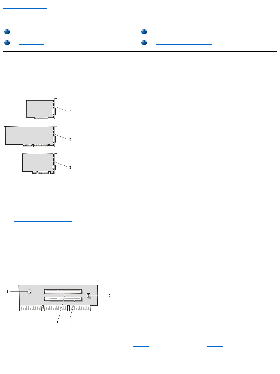
Back to Contents Page
ExpansionCards:Dell™OptiPlex™GX110SystemUser'sGuide
Overview
Each OptiPlex GX110 chassis can accommodate 32-bit Peripheral Component Interconnect (PCI) expansion cards and 16-bit and 8-bit Industry-
StandardArchitecture(ISA)expansioncards,dependingontheinstalledriserboard.SeeFigure1forexamplesoftheexpansioncards.
Figure 1. Expansion Cards
Riser Boards
The PCI expansion-card connectors are located on a riser board that differs for each chassis:
lSmall-form-factor chassis riser board
lLow-profile chassis riser board
lMidsize chassis riser board
lMini tower chassis riser board
Small-Form-Factor Chassis Riser Board
The small-form-factor chassis riser board has two PCI expansion-card connectors (see Figure 2).
Figure 2. Small-Form-Factor Chassis Riser Board
Low-Profile Chassis Riser Boards
The low-profile chassis is available with either a PCI riser board (see Figure 3) or a PCI/ISA riser board (see Figure 4). The PCI riser board
provides three PCI expansion card slots. The PCI/ISA riser board provides one PCI expansion slot, one ISA expansion slot, and one shared
PCI/ISA expansion slot.
Figure 3. Low-Profile Chassis PCI Riser Board
Overview
Installing an Expansion Card
Riser Boards
Removing an Expansion Card
1
8-bit ISA expansion card
2
16-bit ISA expansion card
3
32-bit PCI expansion card
1
Auxiliary power indicator (AUX_LED)
2
Remote Wakeup header (WOL)
3
PCI expansion-card connector 1 (PCI1)
4
PCI expansion-card connector 2 (PCI2)
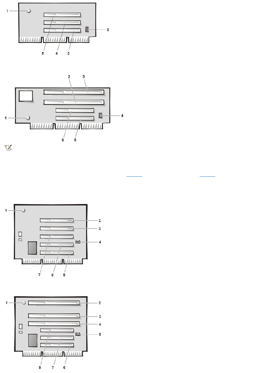
Figure 4. Low-Profile Chassis PCI/ISA Riser Board
Midsize Chassis Riser Boards
The midsize chassis is available with either a PCI riser board (see Figure 5) or a PCI/ISA riser board (see Figure 6). The PCI riser board provides
five PCI expansion card slots. The PCI/ISA riser board provides two PCI expansion slots, two ISA expansion slots, and one shared PCI/ISA
expansion slot.
Figure 5. Midsize Chassis PCI Riser Board
Figure 6. Midsize Chassis PCI/ISA Riser Board
1
Auxiliary power indicator (AUX_LED)
2
Remote Wakeup header (WOL)
3
PCI expansion-card connector 1 (PCI1)
4
PCI expansion-card connector 2 (PCI2)
5
PCI expansion-card connector 3 (PCI3)
1
Standby power indicator (AUX_LED)
2
ISA expansion-card connector 1 (ISA1)
3
ISA expansion-card connector 2 (ISA2)
4
Remote Wakeup header (WOL)
5
PCI expansion-card connector 1 (PCI1)
6
PCI expansion-card connector 2 (PCI2)
NOTE: ISA expansion-card connector 1 and PCI expansion-card connector 2 share an expansion slot; only one of these two connectors
can be used.
1
Standby power indicator (AUX_LED)
2
PCI expansion-cardconnector5(PCI5)
3
PCI expansion-card connector 4 (PCI4)
4
Remote Wakeup header (WOL)
5
PCI expansion-card connector 1 (PCI1)
6
PCI expansion-card connector 2 (PCI2)
7
PCI expansion-card connector 3 (PCI3)
1
Standby power indicator LED (AUX_LED)
2
ISA expansion-card connector 3 (ISA3)
3
ISA expansion-card connector 2 (ISA2)
4
ISA expansion-card connector 1 (ISA1)
5
Remote Wakeup header (WOL)
6
PCI expansion-card connector 1 (PCI1)
7
PCI expansion-card connector 2 (PCI2)
8
PCI expansion-card connector 3 (PCI3)
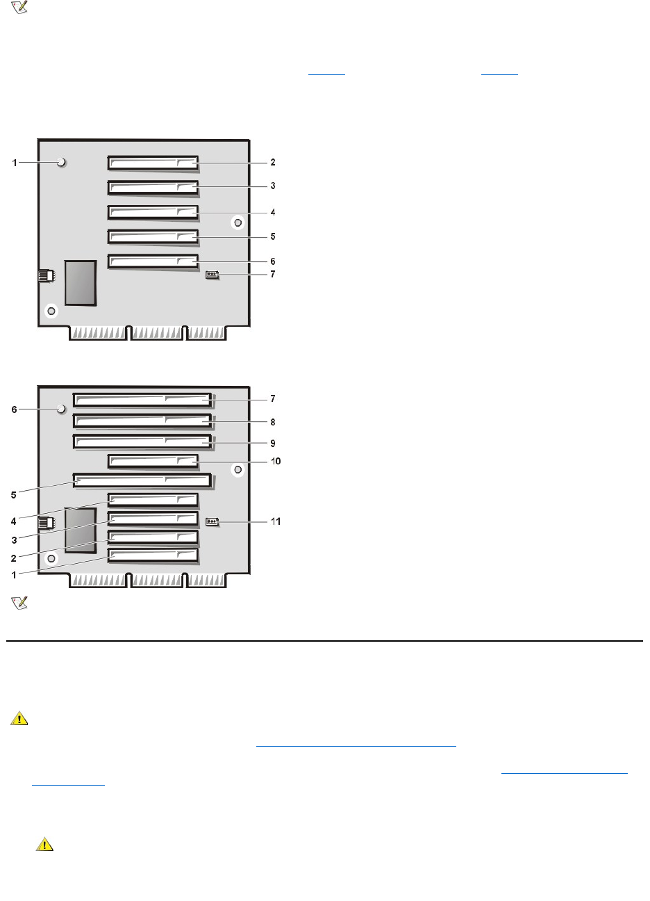
Mini Tower Chassis Riser Boards
The mini tower chassis is available with either a PCI riser board (see Figure 7) or a PCI/ISA riser board (see Figure 8). The PCI riser board
provides five PCI expansion card slots. The PCI/ISA riser board provides three PCI expansion slots, two ISA expansion slots, and two shared
PCI/ISA expansion slots.
Figure 7. Mini Tower Chassis PCI Riser Board
Figure 8. Mini Tower Chassis PCI/ISA Riser Board
Installing an Expansion Card
To install an expansion card, perform the following steps.
1. Prepare the expansion card for installation, and remove the computer cover according to the instructions in "Removing and Replacing the
Computer Cover."
See the documentation that came with the expansion card for information on configuring the card, making internal connections, or otherwise
customizing it for your system.
2. Unscrew and remove the metal filler bracket that covers the card-slot opening for the expansion-card connector you intend to use (see Figure
9).
NOTE: ISA expansion-card connector 1 and PCI expansion-card connector 3 share an expansion slot; only one of these two connectors
can be used.
1
Standby power indicator LED (AUX_LED)
2
PCI expansion-card connector 5 (PCI5)
3
PCI expansion-card connector 4 (PCI4)
4
PCI expansion-card connector 3 (PCI3)
5
PCI expansion-card connector 2 (PCI2)
6
PCI expansion-card connector 1 (PCI1)
7
Remote Wakeup header (WOL)
1
PCI expansion-card connector 1 (PCI1)
2
PCI expansion-card connector 2 (PCI2)
3
PCI expansion-card connector 3 (PCI3)
4
PCI expansion-card connector 4 (PCI4)
5
ISA expansion-card connector 1 (ISA1)
6
Standby power indicator LED (AUX_LED)
7
ISA expansion-card connector 4 (ISA4)
8
ISA expansion-card connector 3 (ISA3)
9
ISA expansion-card connector 2 (ISA2)
10
PCI expansion-card connector 5 (PCI5)
11
Remote Wakeup header (WOL)
NOTE: ISA expansion-card connector 2 and PCI expansion-card connector 5 share an expansion slot; only one of these two connectors
can be used. ISA expansion-card connector 1 and PCI expansion-card connector 4 share an expansion slot; only one of these two
connectors can be used.
CAUTION: To avoid the possibility of electric shock, turn off the computer and any peripherals, disconnect them from their
electrical outlets, and then wait at least 5 seconds before you remove the computer cover. Also, before you install an
expansion card, see the other precautions in "Safety First—For You and Your Computer."
CAUTION: Some network cards automatically start up the system when they are connected. To guard against electrical
shock, be sure to unplug your computer from its electrical outlet before you install any expansion cards.
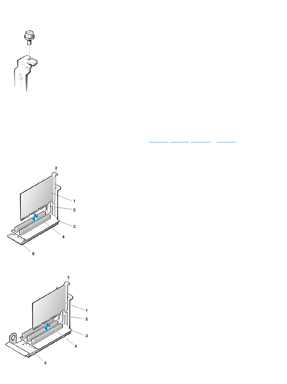
Save the screw for use when you install the expansion card later in this procedure.
Figure 9. Removing the Filler Bracket
3. Insert the expansion card into the expansion-card connector.
a. If the expansion card is full-length, insert the front end of the card into the corresponding card guide on the inside front of the
chassis as you insert the card into its connector.
b. Insert the card's edge connector firmly into the expansion-card connector.
c. Gently rock the card into the connector until it is fully seated (see Figure 10, Figure 11, Figure 12, or Figure 13 for instructions for
the small-form-factor, low-profile, midsize, and mini tower chassis, respectively).
Figure 10. Installing an Expansion Card in a Small-Form-Factor Chassis
Figure 11. Installing an Expansion Card in a Low-Profile Chassis
Figure 12. Installing an Expansion Card in a Midsize Chassis
1
Expansion card
2
Card-edge connector
3
Riser board
4
Expansion-card connector
5
Expansion-card cage
1
Expansion card
2
Card-edge connector
3
Riser board
4
Expansion-card connector
5
Expansion-card cage
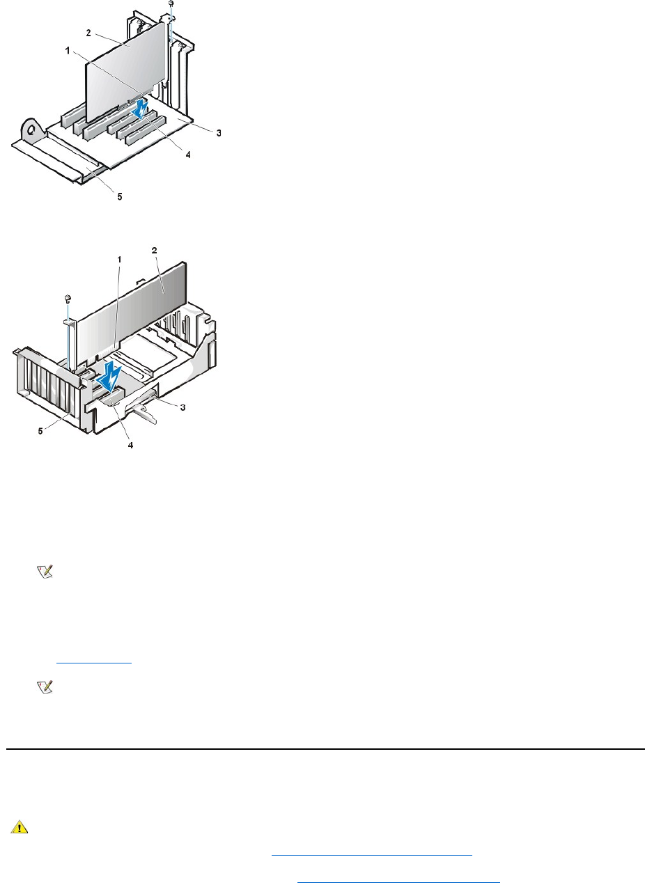
Figure 13. Installing an Expansion Card in a Mini Tower Chassis
4. When the card is firmly seated in the connector, secure the card's mounting bracket to the chassis with the screw you removed in step 2.
5. Connect any cables that should be attached to the card.
See the documentation for the card for information about the card's cable connections.
6. Replace the computer cover, and reconnect your computer and peripherals to their electrical outlets and turn them on.
ALERT! Cover was previously removed.
7. To reset the chassis intrusion detector, enter System Setup and reset Chassis Intrusion to Enabled or Enabled-Silent.
See "Chassis Intrusion" for instructions.
While in System Setup, if you installed an entry-level OptiPlex sound card, change the setting for Sound to Off.
Removing an Expansion Card
To remove an expansion card, perform the following steps.
1. Remove the computer cover according to the instructions in "Removing and Replacing the Computer Cover."
1
Card-edge connector
2
Expansion card
3
Riser board
4
Expansion-card connector
5
Expansion-card cage
1
Card-edge connector
2
Expansion card
3
Riser board
4
Expansion-card connector
5
Expansion-card cage
NOTE: After you remove and replace the cover, the chassis intrusion detector causes the following message to appear on the
screen at the next system start-up:
NOTE: If a setup password has been assigned by someone else, contact your network administrator for information on resetting
the chassis intrusion detector.
CAUTION: To avoid the possibility of electric shock, turn off the computer and any peripherals, disconnect them from their
electrical outlets, and then wait at least 5 seconds before you remove the computer cover. Also, before you remove or replace
an expansion card, see the other precautions in "Safety First—For You and Your Computer."

2. If necessary, disconnect any cables connected to the card.
3. Unscrew the mounting bracket of the card you want to remove.
4. Grasp the card by its outside corners, and ease it out of its connector.
5. If you are removing the card permanently, install a metal filler bracket over the empty card-slot opening.
6. Replace the computer cover, and reconnect your computer and peripherals to their electrical outlets and turn them on.
ALERT! Cover was previously removed.
7. To reset the chassis intrusion detector, enter System Setup and reset Chassis Intrusion to Enabled or Enabled-Silent.
Back to Contents Page
NOTE: You must install filler brackets over empty card-slot openings to maintain Federal Communications Commission (FCC)
certification of the system. The brackets also keep dust and dirt out of your computer.
NOTE: After you remove and replace the cover, the chassis intrusion detector causes the following message to appear on the
screen at the next system start-up:
NOTE: If a setup password has been assigned by someone else, contact your network administrator for information on resetting
the chassis intrusion detector.

Back to Contents Page
ExternalComponents:Dell™OptiPlex™GX110SystemUser'sGuide
Overview
This section provides troubleshooting procedures for equipment that connects directly to the input/output (I/O) panel of your computer, such as your
monitor, keyboard, mouse, or printer. Before performing any of the procedures in this section, see "Checking Connections and Switches." Then
perform the troubleshooting procedures for the equipment that is malfunctioning.
If your system does not have a CD-ROM drive, you need a copy of the Dell Diagnostics media to perform the procedures in this section. Use the
Program Diskette Maker, if necessary, to make a copy from the diskette image on the hard-disk drive.
Troubleshooting the Monitor
Troubleshooting video problems involves determining which of the following is the source of the problem:
lMonitor or monitor interface cable
lVideo controller
The procedures in this section troubleshoot problems with the monitor and the monitor interface cable only.
If information on the monitor screen is displayed incorrectly or not at all, perform each of the following steps in the order indicated until the problem
is resolved:
1. Turn on the system, including any attached peripherals.
2. Adjust the switches and controls as specified in the monitor's documentation to correct the video image, including the horizontal and vertical
position and size.
3. Insert the Dell Diagnostics media into drive A, reboot the system, and run the Video test group in the Dell Diagnostics.
4. Turn off the system and disconnect it from the electrical outlet. Swap the monitor with one of the same type that is working, and reconnect the
system to an electrical outlet.
5. Reboot the system, and run the Video test group again.
If the tests complete successfully, the original monitor was faulty. If the tests still fail, the video controller on the system board may be faulty.
See "Getting Help" for instructions on obtaining technical assistance.
Troubleshooting the Keyboard
This procedure determines what kind of keyboard problem you have. If a system error message indicates a keyboard problem when you start the
computer system or if the keyboard does not operate as expected, perform the following steps in the order indicated until the problem is resolved:
1. If the keyboard or its cable shows signs of physical damage or if the keys do not work, replace the keyboard with a working keyboard.
2. Insert the Dell Diagnostics media into the appropriate drive, reboot the system, and run the Keyboard test group in the Dell Diagnostics.
3. If the Keyboard Interactive Test fails, replace the keyboard.
4. If the Keyboard Controller Test fails, the system board may be faulty. See "Getting Help" for instructions on obtaining technical assistance.
Troubleshooting the Mouse
This procedure determines what kind of mouse problem you have. If a system error message indicates a mouse problem when you start the
computer system or if the mouse does not operate as expected, perform the following steps in the order indicated until the problem is resolved:
Overview
Troubleshooting I/O Ports
Troubleshooting the Monitor
Troubleshooting Basic I/O Functions
Troubleshooting the Keyboard
Troubleshooting a Parallel Printer
Troubleshooting the Mouse
Troubleshooting a Serial I/O Device

1. Clean the mouse as instructed in your mouse documentation.
Most mice have a ball that can be removed and cleaned of debris by turning the mouse upside down and removing a cover on the bottom of
the mouse. Also remove any lint or other debris that has accumulated on the bottom of the mouse.
2. If the mouse or its cable shows signs of physical damage or if the buttons do not work, replace the mouse with a working mouse.
3. Insert the Dell Diagnostics media into the appropriate drive, reboot the system, and run the Mouse Test in the Dell Diagnostics.
4. If the Mouse Test fails, the system board may be faulty. See "Getting Help" for instructions on obtaining technical assistance.
Troubleshooting I/O Ports
This section provides a procedure for troubleshooting the ports on your computer's I/O panel and the equipment connected to them, such as a
printer, scanner, or other peripheral device.
You can also use this procedure to test I/O ports on expansion cards. However, you should first complete the procedures in "Troubleshooting
Expansion Cards" to verify that the card is configured and installed correctly.
If a system error message indicates a port problem or if equipment connected to a port seems to perform incorrectly or not at all, the source of the
problem may be any of the following:
lA faulty connection between the I/O port and the peripheral device
lA faulty cable between the I/O port and the peripheral device
lA faulty peripheral device
lIncorrect settings in System Setup
lIncorrect settings in the system's configuration files
lFaulty I/O port logic on the system board
Troubleshooting Basic I/O Functions
If a system error message indicates an I/O port problem or the device connected to the port does not function properly, follow these steps in the
order indicated until the problem is resolved:
1. Enter System Setup and verify that the settings for the Serial Port 1, Serial Port 2, and Parallel Port options are set to Auto.
2. Insert the Dell Diagnostics media into the appropriate drive, reboot the system, and run the Serial/ Infrared Ports test group and/or the
Parallel Ports test group in the Dell Diagnostics.
If any of the tests fail, the system board may be faulty. See "Getting Help" for instructions on obtaining technical assistance.
If the problem persists, go to "Troubleshooting a Parallel Printer" or "Troubleshooting a Serial I/O Device," depending on which device appears to
be malfunctioning.
Troubleshooting a Parallel Printer
If the information in "Troubleshooting Basic I/O Functions" indicates that the problem is with a parallel printer, perform the following steps in the
order indicated until the problem is resolved:
1. Reinstall the printer device driver.
See the documentation for the printer and for your operating system for instructions on reinstalling the printer driver.
2. Turn off the parallel printer and computer, replace the parallel printer interface cable with a known working cable, and turn on the parallel
printer and computer.
If the problem is resolved, the original printer cable was faulty.
3. Run the parallel printer's self-test.
If the test fails, the printer is faulty.
NOTE: With certain modems installed, the Serial Port test group subtests may fail because the modem appears to the diagnostics as a
serial port, but it cannot be tested as a serial port. If you have a modem installed and you experience a serial port test failure, remove
the modem and run the diagnostic tests again.

If the problem still is not resolved, the system board may be faulty. See "Getting Help" for instructions on obtaining technical assistance.
Troubleshooting a Serial I/O Device
If the information in "Troubleshooting Basic I/O Functions" indicates that the problem is with a device connected to one of the serial ports, perform
the following steps in the order indicated until the problem is resolved:
1. Attach the serial device to the other serial port (for example, if it is currently connected to serial port 1, attach the device to serial port 2).
If the problem is resolved, the serial port on the system board is faulty. See "Getting Help" for instructions on obtaining technical assistance.
2. If the faulty device has a detachable serial cable, replace the serial cable.
If the problem is resolved, the serial cable was faulty.
3. Replace the faulty serial device.
If the problem is still not resolved, the system board may be faulty. See "Getting Help" for instructions on obtaining technical assistance.>
Back to Contents Page

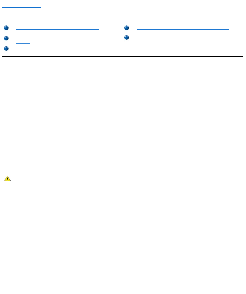
Back to Contents Page
Hard-DiskDrives:Dell™OptiPlex™GX110SystemUser'sGuide
General Information About EIDE Hard-Disk Drives
The small-form-factor and low-profile chassis support a single enhanced integrated drive electronics (EIDE) hard-disk drive in the hard-disk drive
bay. In the mini tower chassis, you can install up to two EIDE drives (one of which must be 1 inch high or less) in the hard-disk drive bracket below
the drive cage. The first EIDE drive is installed in the 1-inch (lower) drive bay labeled "HD1"; a second drive is installed in the 1.6-inch bay labeled
"HD2."
EIDE Drive Addressing
All EIDE devices require that you configure the cable select setting, which assigns master and slave status to devices according to their position
on the interface cable. You usually configure a drive for cable select by setting a jumper or switch, depending on the drive. Refer to the drive
documentation in your upgrade kit for information on configuring devices for the cable select setting. When you connect two EIDE devices to a
single EIDE interface cable and configure them for the cable select setting, the device attached to the last connector on the interface cable is the
master or boot device (drive 0) and the device attached to the middle connector on the interface cable is the slave device (drive 1).
With the two EIDE interface connectors on the system board, your system supports up to four EIDE devices in the mini tower chassis; the small-
form-factor and low-profile chassis support up to two EIDE devices. EIDE hard-disk drives should be connected to the EIDE interface connector
labeled "IDE1." (Always connect EIDE tape drives and CD-ROM drives to the EIDE interface connector labeled "IDE2.")
Installing an EIDE Hard-Disk Drive in a Small-Form-Factor Chassis
To install an EIDE hard-disk drive in a small-form-factor chassis, perform the following steps:
1. If you are replacing a hard-disk drive that contains data you want to keep, be sure to make a backup of your files before you continue this
procedure.
2. Prepare the drive for installation.
NOTICE: Ground yourself by touching an unpainted metal surface on the back of the computer.
NOTICE: When you unpack the drive, do not set it on a hard surface, which may damage the drive. Instead, set the drive on a
surface, such as a foam pad, that will sufficiently cushion it.
Check the documentation for the drive to verify that it is configured for your computer system.
3. Remove the computer cover as instructed in "Removing and Replacing the Computer Cover."
4. Remove the drive shelf from the chassis.
a. Disconnect the power and interface cables from the diskette drive and CD-ROM drive (if any).
b. Press inward on the two drive shelf release tabs, and pull the shelf forward and out of the chassis (see Figure 1).
Figure 1. Removing the Drive Shelf From the Small-Form-Factor Chassis
General Information About EIDE Hard-Disk Drives
Installing an EIDE Hard-Disk Drive in a Midsize Chassis
Installing an EIDE Hard-Disk Drive in a Small-Form-Factor
Chassis
Installing an EIDE Hard-Disk Drive in a Mini Tower Chassis
Installing an EIDE Hard-Disk Drive in a Low-Profile Chassis
CAUTION: To avoid the possibility of electric shock, turn off the computer and any peripherals, disconnect them from
electrical outlets, and then wait at least 5 seconds before you remove the computer cover. Also, before you install a drive, see
the other precautions in "Safety First — For You and Your Computer."
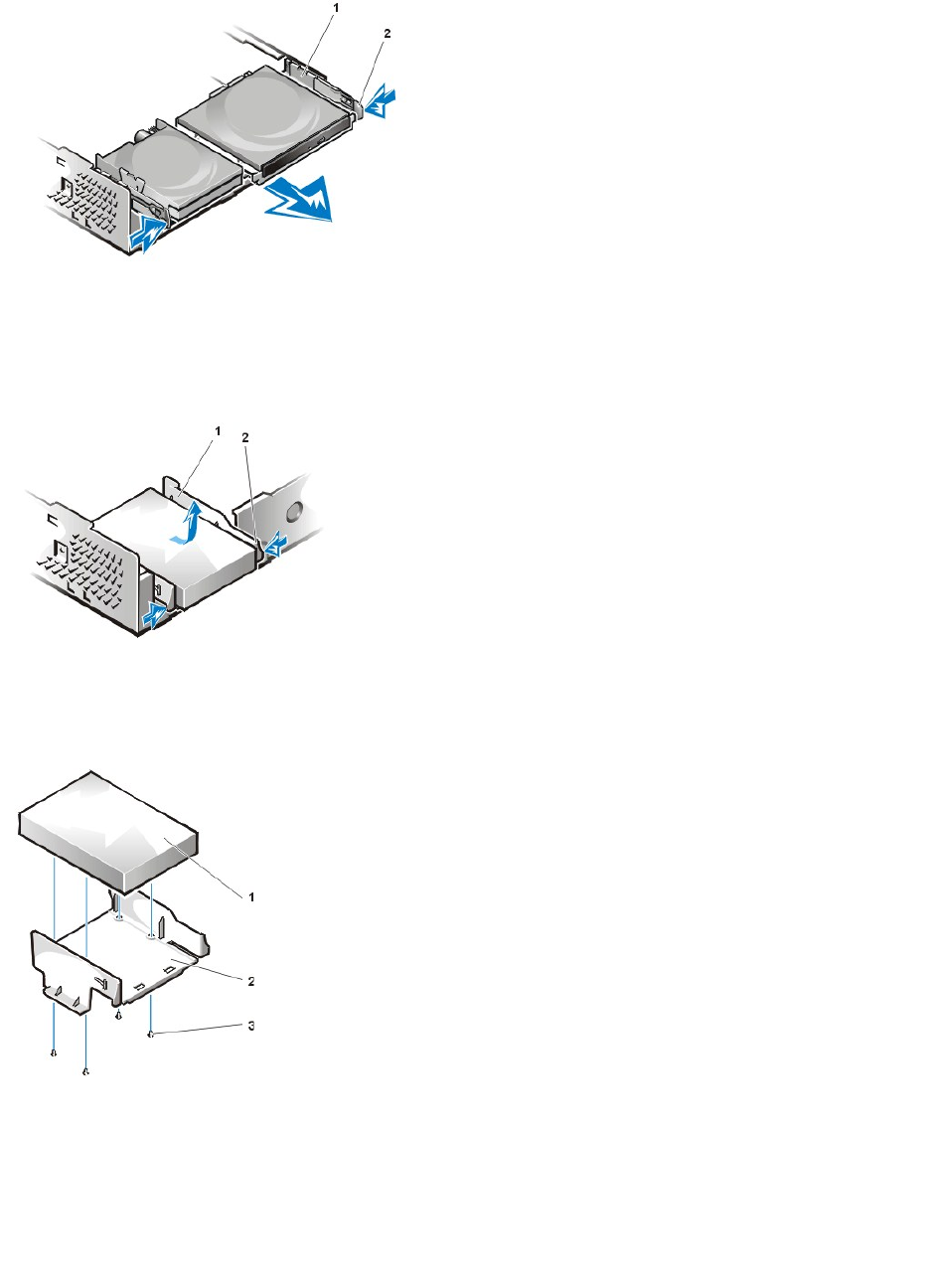
5. Remove the drive bracket from the chassis.
a. If a drive is already installed in the bracket, disconnect the power and interface cables from the back of the drive.
b. Squeeze the tabs on each side of the drive bracket, and slide it forward about one inch (see Figure 2).
Figure 2. Removing the Hard-Disk Drive Bracket From the Small-Form-Factor Chassis
c. Lift the drive bracket away from the chassis.
d. If a drive is already installed in the bracket, remove the four screws securing the drive to the bottom of the bracket (see Figure 3).
Figure 3. Removing a Hard-Disk Drive From the Hard-Disk Drive Bracket
6. Secure the new drive to the drive bracket with four screws (see Figure 3).
7. Reinstall the hard-disk drive bracket in the chassis.
a. Place the bracket so that the release tabs extend about one inch past the front of the chassis, and align the tabs on the bottom of the
bracket with the hooks on the chassis floor.
b. Then slide the bracket toward the back of the chassis until the tabs snap under the hooks (see Figure 4). The bracket release tabs
should also snap into the front of the chassis.
Figure 4. Reinstalling the Hard-Disk Drive Bracket in the Small-Form-Factor Chassis
1
Drive shelf
2
Release tabs (2)
1
Drive bracket
2
Release tabs (2)
1
Drive
2
Drive bracket
3
Screws (4)
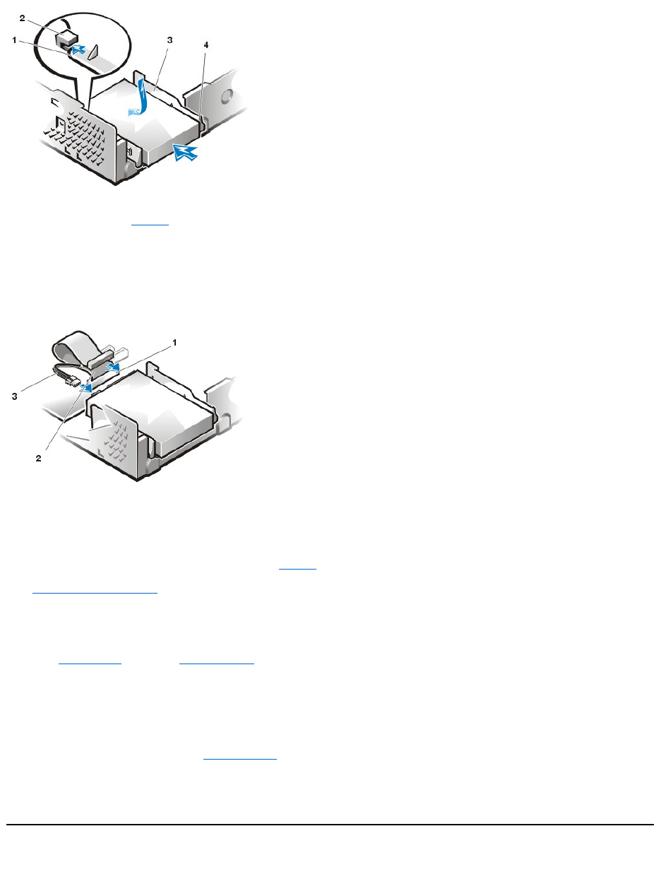
8. Connect a power cable to the power input connector on the back of the drive, and connect an EIDE cable to the interface connector on the
back of the drive (see Figure 5).
Check all connectors to be certain that they are properly cabled and firmly seated.
NOTICE: You must match the colored strip on the EIDE cable with pin 1 on the drive's interface connector to avoid
possible damage to your system.
Figure 5. Attaching Hard-Disk Drive Cables in the Small-Form-Factor Chassis
9. If it is not already connected, connect the blue end of the EIDE cable to the IDE1 connector on the system board.
NOTICE: You must match the colored strip on the EIDE cable with pin 1 on the IDE1 connector to avoid possible damage to
your system.
To locate the IDE1 connector on the system board, see Figure 9 in "Inside Your Computer."
10. Replace the computer cover. Then reconnect your computer and peripherals to their electrical outlets, and turn them on.
11. Insert a bootable diskette into drive A.
12. Turn on the computer system.
13. Enter System Setup, and update Primary Drive 0.
After you update the System Setup settings, reboot the system.
14. Partition and logically format your drive before proceeding to the next step.
See the documentation for your operating system for instructions.
15. Test the hard-disk drive by running the Dell Diagnostics.
16. If the drive you just installed is the primary drive, install your operating system on the hard-disk drive.
For instructions, refer to the documentation that came with your operating system.
Installing an EIDE Hard-Disk Drive in a Low-Profile Chassis
To install an EIDE hard-disk drive in a low-profile chassis, perform the following steps:
1
Tabs on bottom of drive bracket
2
Hooks on chassis floor
3
Drive bracket
4
Release tabs (2)
1
IDE1 connector
2
EIDE cable
3
Power cable
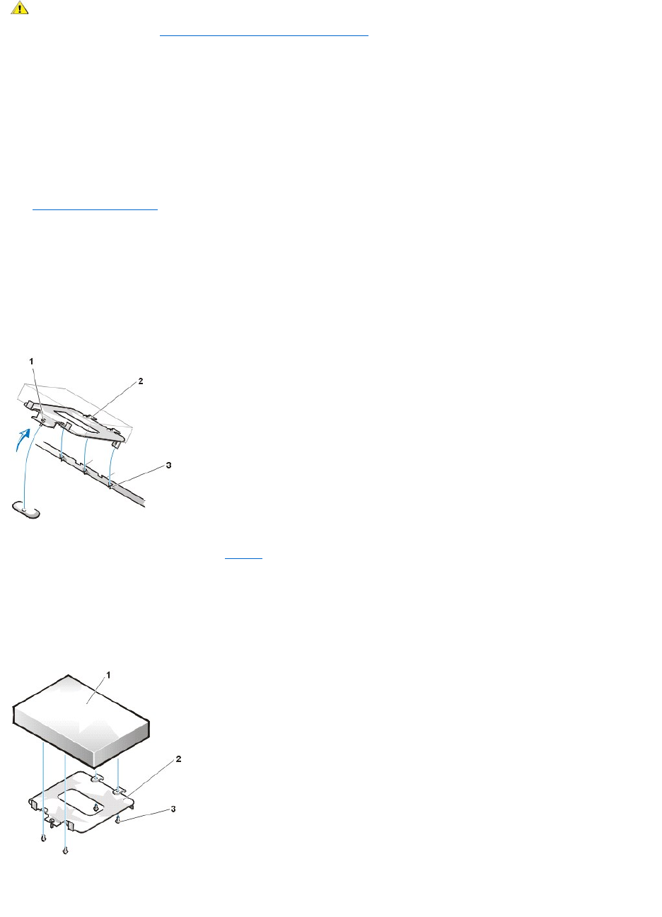
1. If you are replacing a hard-disk drive that contains data you want to keep, be sure to make a backup of your files before you begin this
procedure.
2. Prepare the drive for installation.
NOTICE: Ground yourself by touching an unpainted metal surface on the back of the computer.
NOTICE: When you unpack the drive, do not set it on a hard surface, which may damage the drive. Instead, set the drive on a
surface, such as a foam pad, that will sufficiently cushion it.
Check the documentation for the drive to verify that it is configured for your computer system.
3. Remove the computer cover.
4. Remove the drive bracket from the chassis.
a. If a hard-disk drive is already installed in the drive bracket, disconnect the DC power cable and EIDE cable from the drive.
b. Remove the screw securing the hard-disk drive bracket to the drive cage in the chassis.
c. Grasp the bracket, and rotate it outward from the chassis until the sliding tab clears the slide rail on the drive cage (see Figure 6). Lift
the bracket up slightly to free its hinge tabs from the chassis slots.
Figure 6. Removing the Hard-Disk Drive Bracket
5. Slide the drive into the chosen bay of the bracket, orienting the drive so that the connectors on the back of the drive will face the back of the
chassiswhenyoureinstallthebracket(seeFigure 7).
6. Align the four screw holes of the drive and bracket. Insert and tighten the screws that came with your upgrade kit.
a. If you are installing a drive in the 1.6-inch bay, use the four screw holes in the side of the bracket (see Figure 7).
b. If you are installing a drive in the 1-inch bay, use the four screw holes in the bottom of the bracket.
Figure 7. Inserting a 1.6-Inch Hard-Disk Drive in the Bracket
7. Reinstall the hard-disk drive bracket in the chassis.
a. Insert the bracket's hinge tabs into the chassis slots so that the tabs hook over the slots.
CAUTION: To avoid the possibility of electric shock, turn off the computer and any peripherals, disconnect them from
electrical outlets, and then wait at least 5 seconds before you remove the computer cover. Also, before you install a drive, see
the other precautions in "Safety First — For You and Your Computer."
1
Captive screw
2
Tabs on back of drive bracket (2)
3
Slots in chassis floor divider (3)
1
Hard-disk drive
2
Bracket
3
Screws (4)
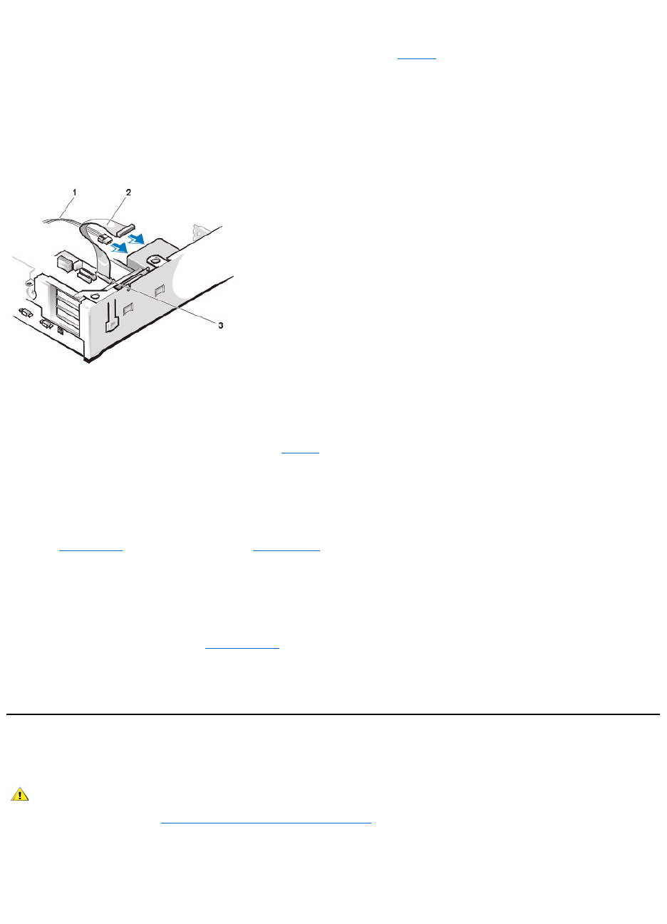
b. Then rotate the bracket toward the drive cage, and fit the bracket's sliding tab on the drive-cage slide rail.
c. Slide the bracket into place, and reinstall the screw you removed in step 4.
8. Connect a power cable to the power input connector on the back of the drive (see Figure 8).
Check all connectors to be certain that they are properly cabled and firmly seated.
9. Connect one of the device connectors on the EIDE cable to the 40-pin interface connector on the back of the hard-disk drive.
NOTICE: You must match the colored strip on the EIDE cable with pin 1 on the drive's interface connector to avoid possible
damage to your system.
Figure 8. Attaching Hard-Disk Drive Cables in the Low-Profile Chassis
10. If it is not already connected, connect the other end of the EIDE cable to the IDE1 connector on the system board.
NOTICE: You must match the colored strip on the EIDE cable with pin 1 on the IDE1 connector to avoid possible damage to
your system.
To locate the IDE1 connector on the system board, see Figure 9 in "Inside Your Computer."
11. Replace the computer cover. Then reconnect your computer and peripherals to their electrical outlets, and turn them on.
12. If the drive you just installed is the primary drive, insert a bootable diskette into drive A.
13. Turn on the computer system.
14. Enter System Setup, and update the appropriate Primary Drive option (0 or 1).
15. After you update the System Setup settings, reboot the system.
16. Partition and logically format your drive before you proceed to the next step.
See the documentation for your operating system for instructions.
17. Test the hard-disk drive by running the Dell Diagnostics.
18. If the drive you just installed is the primary drive, install your operating system on the hard-disk drive.
For instructions, refer to the documentation that came with your operating system.
Installing an EIDE Hard-Disk Drive in a Midsize Chassis
To install an EIDE hard-disk drive in a midsize chassis, perform the following steps.
1. If you are replacing a hard-disk drive that contains data you want to keep, be sure to make a backup of your files before you begin this
procedure.
2. Prepare the drive for installation.
NOTICE: Ground yourself by touching an unpainted metal surface on the back of the computer.
1
Power cable
2
EIDE cable
3
IDE1 connector
CAUTION: To avoid the possibility of electric shock, turn off the computer and any peripherals, disconnect them from
electrical outlets, and then wait at least 5 seconds before you remove the computer cover. Also, before you install a drive, see
the other precautions in "Safety First — For You and Your Computer."
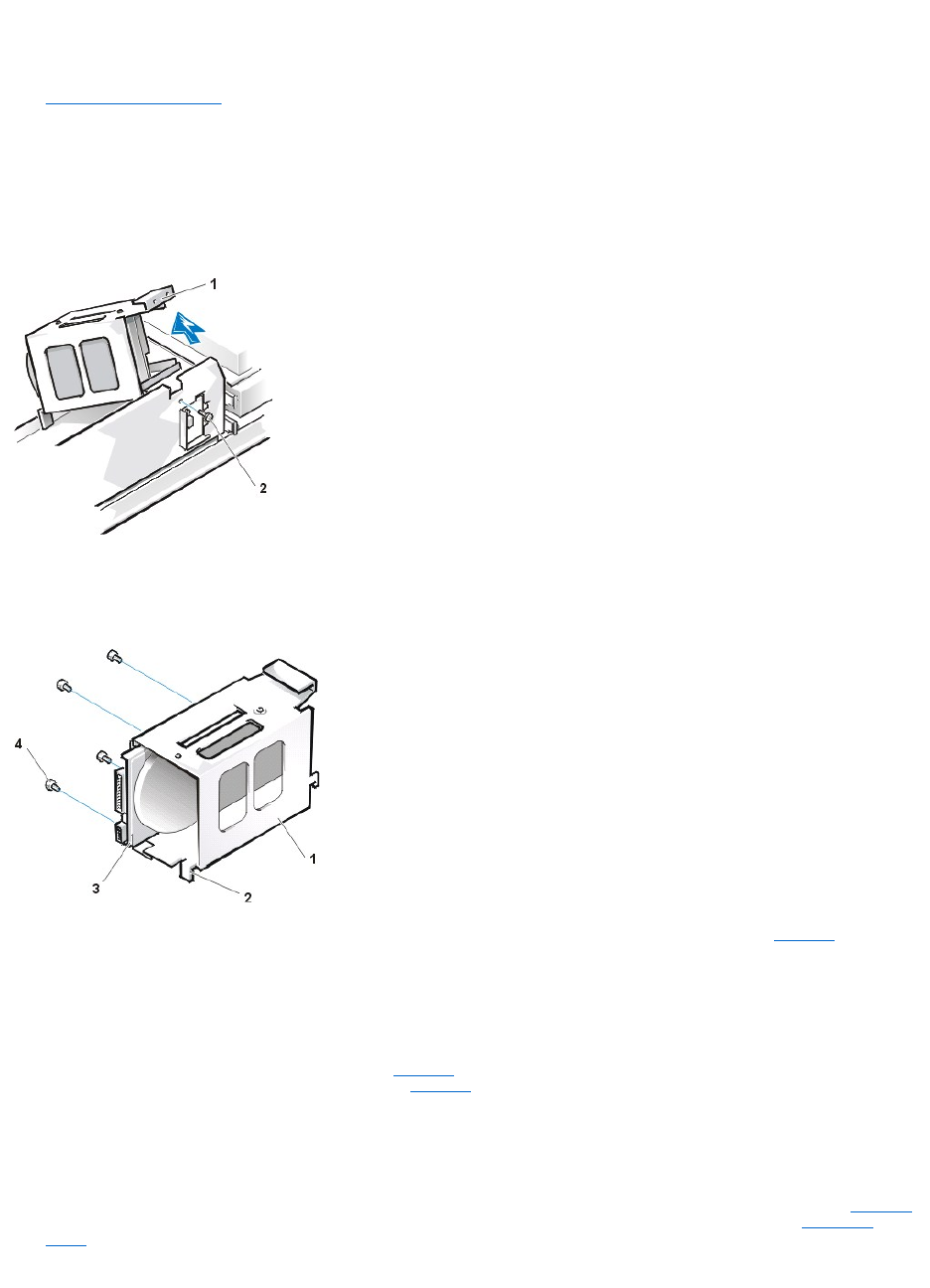
NOTICE: When you unpack the drive, do not set it on a hard surface, which may damage the drive. Instead, set the drive
on a surface, such as a foam pad, that will sufficiently cushion it.
Check the documentation for the drive to verify that it is configured for your computer system.
3. Remove the computer cover.
4. Remove the drive bracket from the chassis.
If a hard-disk drive is already installed on the drive bracket, disconnect the DC power cable and EIDE cable from the drive.
Remove the screw securing the hard-disk drive bracket to the front wall of the chassis. Grasp the front part of the bracket that serves as
a handle, and rotate the bracket up toward the back of the computer until it disengages from the floor of the chassis (see Figure 9).
Figure 9. Removing the Hard-Disk Drive Bracket
5. Slide the drive into the chosen bay of the bracket, orienting it so that the connectors on the back of the drive face the back of the chassis—
and the power input connector is closest to the floor of the chassis—when the bracket is reinstalled (see Figure 10).
Figure 10. Inserting the Hard-Disk Drive in the Bracket
6. Align the four screw holes of the drive and bracket. Insert and tighten the screws that came with your upgrade kit (see Figure 10).
If you are replacing a drive in the 1.6-inch slot, use the four screw holes in the side of the bracket. If you are replacing a drive in the 1-
inch slot, use the four screw holes in the bottom of the bracket.
7. Reinstall the hard-disk drive bracket in the chassis.
Hold the bracket by its handle, so that it stays at the proper tilt. Let it brush the side of the drive cage as you lower it into the chassis
until the two tabs at the bottom back of the bracket (see Figure 10) fit flush against the front of the rail that extends across the chassis
floor and the horizontal lip at the back fits over the rail (see Figure 11).
Rotate the bracket down into position, and reinstall the screw you removed in step 4.
NOTICE: You must match the colored strip on the EIDE cable with pin 1 on the IDE1 connector to avoid possible damage to your
system.
8. Connect one of the device connectors on the EIDE cable to the 40-pin interface connector on the back of the hard-disk drive (see Figure 11).
The cable is keyed so that the colored edge of the EIDE cable lines up with the pin-1 end of the interface connector. See "Connecting
Drives" for more information about drive cable connections.
Figure 11. Attaching Hard-Disk Drives Cables in the Midsize Chassis
1
"Handle" on bracket
2
Screw securing drive to chassis
1
Drive bracket
2
Tabs (2)
3
1.6-inch drive
4
Screws (4)
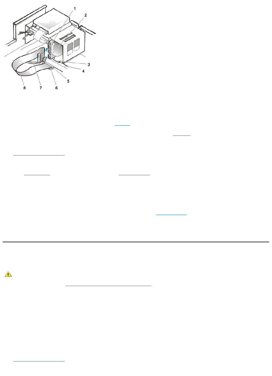
NOTICE: You must match the colored strip on the EIDE cable with pin 1 on the IDE1 connector to avoid possible damage to your
system. Pin 1 is indicated by a silk-screened "1" printed on the system board.
9. If it is not already connected, connect the other end of the EIDE cable to the appropriate EIDE interface connector on the system board.
To locate the IDE1 connector on the system board, see Figure 9 in "Inside Your Computer."
10. Connect a DC power cable into the power input connector on the back of the drive (see Figure 11).
Check all connectors to be certain that they are properly cabled and firmly seated.
11. Replace the computer cover. Then reconnect your computer and peripherals to their electrical outlets, and turn on the peripherals.
12. If the drive you just installed is the primary drive, insert a bootable diskette into drive A, and turn on the computer system.
13. Enter System Setup and update the Drive 0 option under Primary Drive n.
After you update the drive setting, reboot the system.
14. Partition and logically format your drive before proceeding to the next step.
See the documentation for your operating system for instructions.
15. Test the hard-disk drive by running the Hard-Disk Drive(s) Test Group in the Dell Diagnostics.
16. Install your operating system on your hard-disk drive.
Refer to the documentation that came with your operating system.
Installing an EIDE Hard-Disk Drive in a Mini Tower Chassis
To install an EIDE hard-diskdriveinaminitowerchassis,performthefollowingsteps:
1. If you are replacing a hard-disk drive that contains data you want to keep, be sure to make a backup of your files before you continue this
procedure.
2. Prepare the drive for installation.
NOTICE: To avoid possibly damaging the drive by electromagnetic static (EMS), ground yourself by touching an unpainted
metal surface on the back of the computer.
NOTICE: When you unpack the drive, do not set it on a hard surface, which may damage the drive. Instead, set the drive on a
surface, such as a foam pad, that will sufficiently cushion it.
Check the documentation for the drive to verify that it is configured for your computer system.
3. Remove the computer cover.
4. Remove the drive bracket from the chassis.
1
Interface connector
2
Power input connector on drive
3
Lip
4
Rail
5
IDE1 connector
6
IDE2 connector
7
DC power cable
8
EIDE cable
CAUTION: To avoid the possibility of electric shock, turn off the computer and any peripherals, disconnect them from
electrical outlets, and then wait at least 5 seconds before you remove the computer cover. Also, before you install a drive, see
the other precautions in "Safety First — For You and Your Computer."
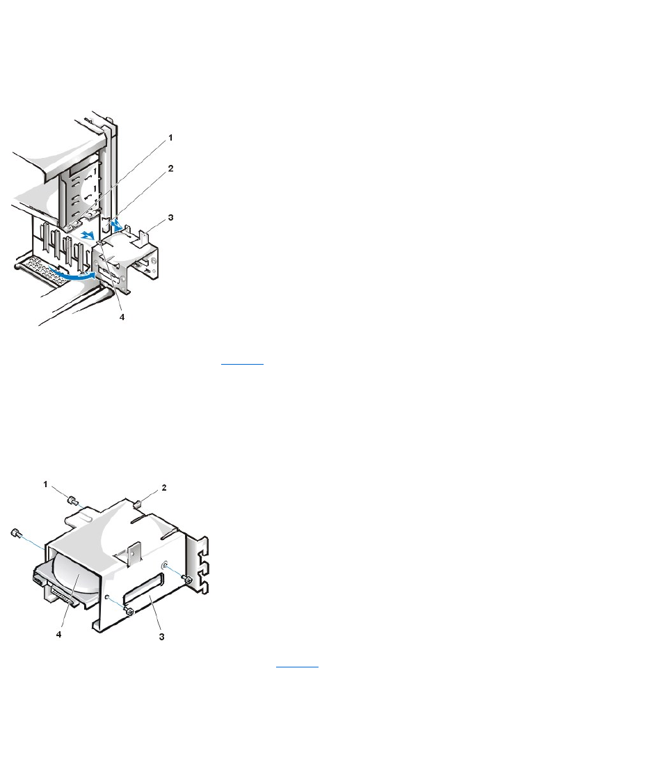
a. If a hard-disk drive is already installed in the drive bracket, disconnect the DC power cable and EIDE cable from the drive.
b. Remove the screw securing the hard-disk drive bracket to the drive cage in the chassis.
c. Grasp the bracket, and rotate it outward from the chassis until the sliding tab clears the slide rail on the drive cage (see Figure 12). Lift
the bracket up slightly to free its hinge tabs from the chassis slots.
Figure 12. Removing the Hard-Disk Drive Bracket
5. Slide the drive into the chosen bay of the bracket, orienting the drive so that the connectors on the back of the drive will face the back of the
chassis when you reinstall the bracket (see Figure 13).
6. Align the four screw holes of the drive and bracket. Insert and tighten the screws that came with your upgrade kit.
¡If you are installing a drive in the 1.6-inch bay, use the four screw holes in the side of the bracket (see Figure 13).
¡If you are installing a drive in the 1-inch bay, use the four screw holes in the bottom of the bracket.
Figure 13. Inserting a 1.6-Inch Hard-Disk Drive in the Bracket
7. Reinstall the hard-disk drive bracket in the chassis (see Figure 14).
a. Insert the bracket's hinge tabs into the chassis slots so that the tabs hook over the slots.
b. Then rotate the bracket toward the drive cage, and fit the bracket's sliding tab on the drive-cage slide rail.
c. Slide the bracket into place, and reinstall the screw you removed in step 4.
Figure 14. Inserting the Drive Bracket in the Chassis
1
Drive-cage slide rail
2
Chassis slots
3
Hinge tabs
4
Sliding tab
1
Screws (4)
2
Sliding tab
3
Drive bracket
4
1.6-inch drive
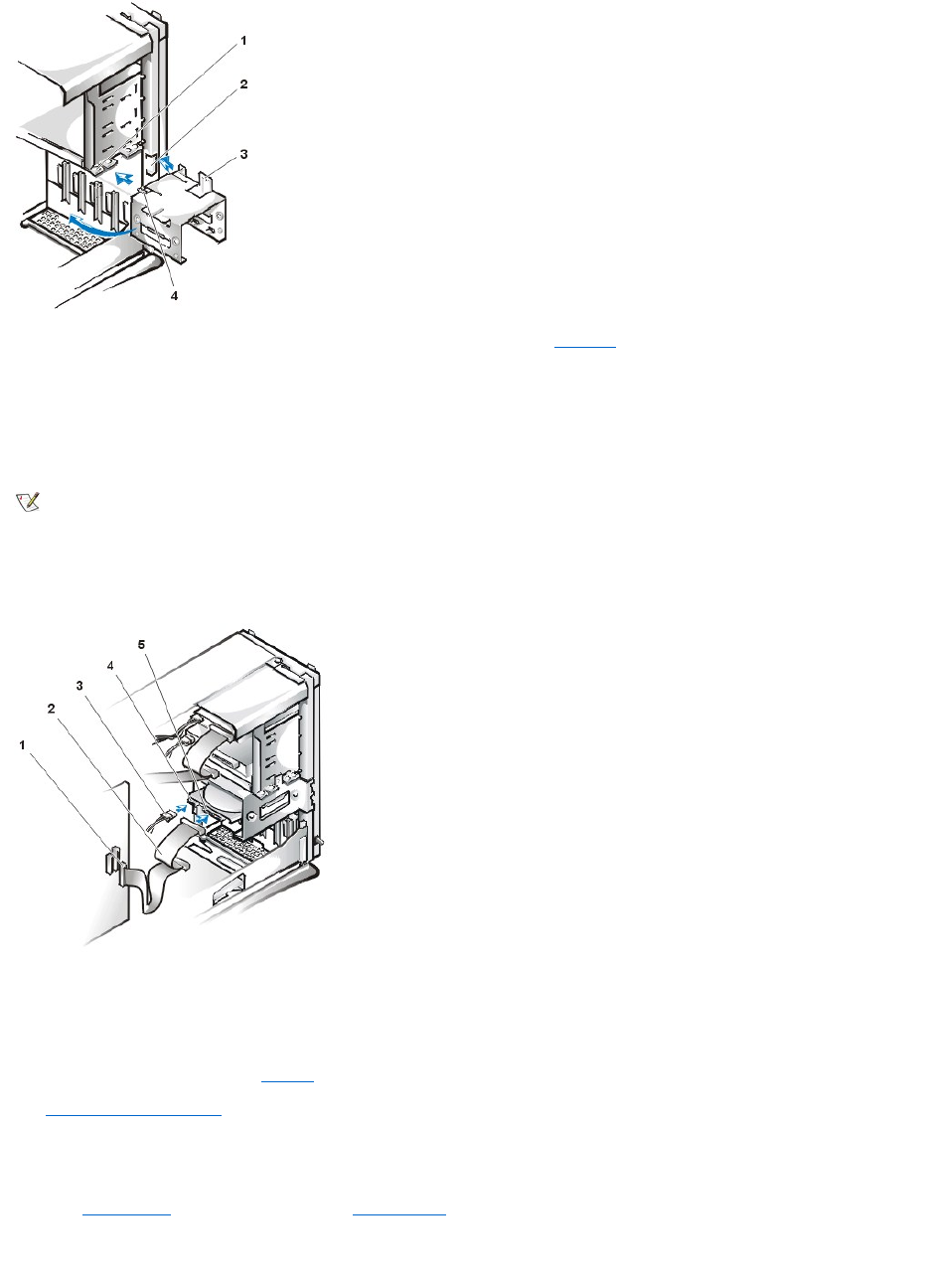
8. Connect a power cable to the power input connector on the back of the drive (see Figure 15).
Check all connectors to be certain that they are properly cabled and firmly seated.
9. Connect one of the device connectors on the EIDE cable to the 40-pin interface connector on the back of the hard-disk drive.
NOTICE: You must match the colored strip on the EIDE cable with pin 1 on the drive's interface connector to avoid possible
damage to your system.
Figure 15. Attaching Hard-Disk Drive Cable in the Mini Tower Chassis
10. If it is not already connected, connect the other end of the EIDE cable to the IDE1 connector on the system board.
NOTICE: You must match the colored strip on the EIDE cable with pin 1 on the IDE1 connector to avoid possible damage to
your system.
To locate the IDE1 connector, see Figure 9 in "Inside Your Computer."
11. Replace the computer cover. Then reconnect your computer and peripherals to their electrical outlets, and turn them on.
12. Ifthedriveyoujustinstalledistheprimarydrive,insertabootablediskette(suchastheDell Diagnostics Diskette) into drive A.
13. Turn on the computer system.
14. Enter System Setup, and update the appropriate Primary Drive option (0 or 1).
15. After you update the System Setup settings, reboot the system.
16. Partition and logically format your drive before you proceed to the next step.
1
Drive-cage slide rail
2
Chassis slots
3
Hinge tabs
4
Sliding tabs
NOTE: On systems with hard-disk drives larger than 2 GB, create a primary partition of 2 GB and divide the remaining capacity into
partitions of 2 GB or less. For example, a system with a 2.5-GB hard-disk drive would have a primary partition of 2 GB (drive C) and a
second partition of 500 MB (drive D). Hard-disk drives must be partitioned this way because MS-DOS-based operating systems
(including Windows NT, when using a file allocation table [FAT] 16 file system) do not support drive partitions larger than 2 GB.
1
Interface connector
2
Interface cable
3
Power cable
4
Power input connector on drive
5
Interface connector on drive

See the documentation for your operating system for instructions.
17. Test the hard-disk drive by running the Dell Diagnostics.
18. If the drive you just installed is the primary drive, install your operating system on the hard-disk drive.
For instructions, refer to the documentation that came with your operating system.
Back to Contents Page
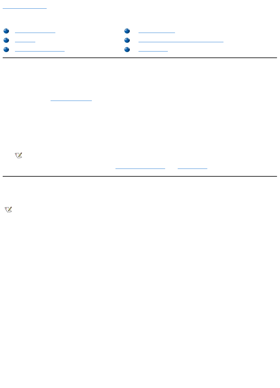
Back to Contents Page
HelpOverview:Dell™OptiPlex™GX110SystemUser'sGuide
Technical Assistance
If you need assistance with a technical problem, perform the following steps:
1. Run the Dell Diagnostics.
2. Make a copy of the Diagnostics Checklist and fill it out.
3. Use Dell's extensive suite of online services available at Dell's World Wide Web site (http://www.dell.com) for help with installation and
troubleshooting procedures.
4. If the preceding steps have not resolved the problem, call Dell for technical assistance.
When prompted by Dell's automated telephone system, enter your Express Service Code to route the call directly to the proper support
personnel. If you do not have an Express Service Code, open the Dell Accessories folder, double-click the Express Service Code
icon, and follow the directions.
For instructions on using the technical support service, see "Technical Support Service" and "Before You Call."
Help Tools
Dell provides a number of tools to assist you. These tools are described in the following sections.
World Wide Web
The Internet is your most powerful tool for obtaining information about your computer and other Dell products. Through the Internet, you can access
most of the services described in this section, including AutoTech, TechFax, order status, technical support, and product information.
You can access Dell’s support Web site at http://support.dell.com. To select your country, click the map that appears. The Welcome to
support.dell.com page opens. Enter your system information to access help tools and information.
You can contact Dell electronically by using the following addresses:
lWorld Wide Web
http://www.dell.com/
http://www.dell.com/ap/ (for Asian/Pacific countries only)
http://www.euro.dell.com (for Europe only)
http://www.dell.com/la/ (for Latin American countries)
lAnonymous file transfer protocol (FTP)
ftp.dell.com/
Log in as user: anonymous, and use your e-mail address as your password.
lElectronic Support Service
support@us.dell.com
apsupport@dell.com (for Asian/Pacific countries only)
Technical Assistance
Product Information
Help Tools
Returning Items for Warranty Repair or Credit
Problems With Your Order
Before You Call
NOTE: Dell's Express Service Code system may not be available in all countries.
NOTE: Some of the following tools are not always available in all locations outside the continental U.S. Please call your local Dell
representative for information on availability.

support.euro.dell.com (for Europe only)
lElectronic Quote Service
sales@dell.com
apmarketing@dell.com (for Asian/Pacific countries only)
lElectronic Information Service
info@dell.com
AutoTech Service
Dell's automated technical support service—AutoTech—provides recorded answers to the questions most frequently asked by Dell customers.
When you call AutoTech, you use your touch-tone telephone to select the subjects that correspond to your questions. You can even interrupt an
AutoTech session and continue the session later. The code number that the AutoTech service gives you allows you to continue your session where
you ended it.
The AutoTech service is available 24 hours a day, seven days a week. You can also access this service through the technical support service. For
the telephone number to call, see the contact numbers for your region.
TechFax Service
Dell takes full advantage of fax technology to serve you better. Twenty-four hours a day, seven days a week, you can call the Dell TechFax line toll-
free for all kinds of technical information.
Using a touch-tone phone, you can select from a full directory of topics. The technical information you request is sent within minutes to the fax
number you designate. For the TechFax telephone number to call, see the contact numbers for your region.
TechConnect BBS
Use your modem to access Dell's TechConnect bulletin board service (BBS) 24 hours a day, seven days a week. The service is menu-driven and
fully interactive. The protocol parameters for the BBS are 1200 to 19.2K baud, 8 data bits, no parity, 1 stop bit.
Automated Order-Status System
You can call this automated service to check on the status of any Dell products that you have ordered. A recording prompts you for the information
needed to locate and report on your order. For the telephone number to call, see the contact numbers for your region.
Technical Support Service
Dell's industry-leading hardware technical support service is available 24 hours a day, seven days a week, to answer your questions about Dell
hardware.
Our technical support staff pride themselves on their track record: more than 90 percent of all problems and questions are taken care of in just one
toll-free call, usually in less than 10 minutes. When you call, our experts can refer to records kept on your Dell system to better understand your
particular question. Our technical support staff uses computer-based diagnostics to provide fast, accurate answers to questions.
To contact Dell's technical support service, see "Before You Call" and then call the number for your country as listed in "Contacting Dell."
Problems With Your Order
If you have a problem with your order, such as missing parts, wrong parts, or incorrect billing, contact Dell for customer assistance. Have your
invoice or packing slip handy when you call. For the telephone number to call, see the contact numbers for your region.
Product Information
If you need information about additional products available from Dell, or if you would like to place an order, visit Dell's World Wide Web site at
http://www.dell.com. For the telephone number to call to speak to a sales specialist, see "Contacting Dell."
Returning Items for Warranty Repair or Credit
Prepare all items being returned, whether for repair or credit, as follows:
1. Call Dell to obtain an authorization number, and write it clearly and prominently on the outside of the box.
For the telephone number to call, see the contact numbers for your region.
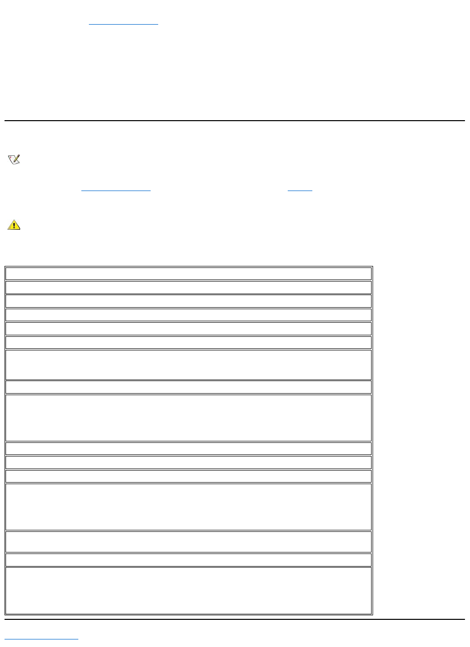
2. Include a copy of the invoice and a letter describing the reason for the return.
3. Include a copy of the Diagnostics Checklist indicating the tests you have run and any error messages reported by the Dell Diagnostics.
4. Include any accessories that belong with the item(s) being returned (power cables, software diskettes, guides, and so on) if the return is for
credit.
5. Pack the equipment to be returned in the original (or equivalent) packing materials.
You are responsible for paying shipping expenses. You are also responsible for insuring any product returned, and you assume the risk of loss
during shipment to Dell. Collect On Delivery (C.O.D.) packages are not accepted.
Returns that are missing any of the preceding requirements will be refused at our receiving dock and returned to you.
Before You Call
Remember to fill out the Diagnostics Checklist. If possible, turn on your system before you call Dell for technical assistance and call from a
telephone at or near the computer. You may be asked to type some commands at the keyboard, relay detailed information during operations, or try
other troubleshooting steps possible only at the computer system itself. Make sure the system documentation is available.
Diagnostics Checklist
Back to Contents Page
NOTE: Have your Express Service Code ready when you call. The code helps Dell's automated-support telephone system direct your
call more efficiently.
CAUTION: If you need to remove the computer cover, be sure to first disconnect the computer system's power and modem
cables from all electrical outlets.
Date:
Name:
Address:
Phone number:
Service tag (bar code on the back of the computer):
Express Service Code:
Return Material Authorization Number (if provided by Dell support technician):
Operating system and version:
Peripherals:
Expansion cards:
Areyouconnectedtoanetwork?YesNo
Network, version, and network card:
Programs and versions:
Refer to your operating system documentation to determine the contents of the system’s start-up files. If the
computer is connected to a printer, print each file. Otherwise, record the contents of each file before calling Dell.
Error message, beep code, or diagnostic code:
Description of problem and troubleshooting procedures you performed:
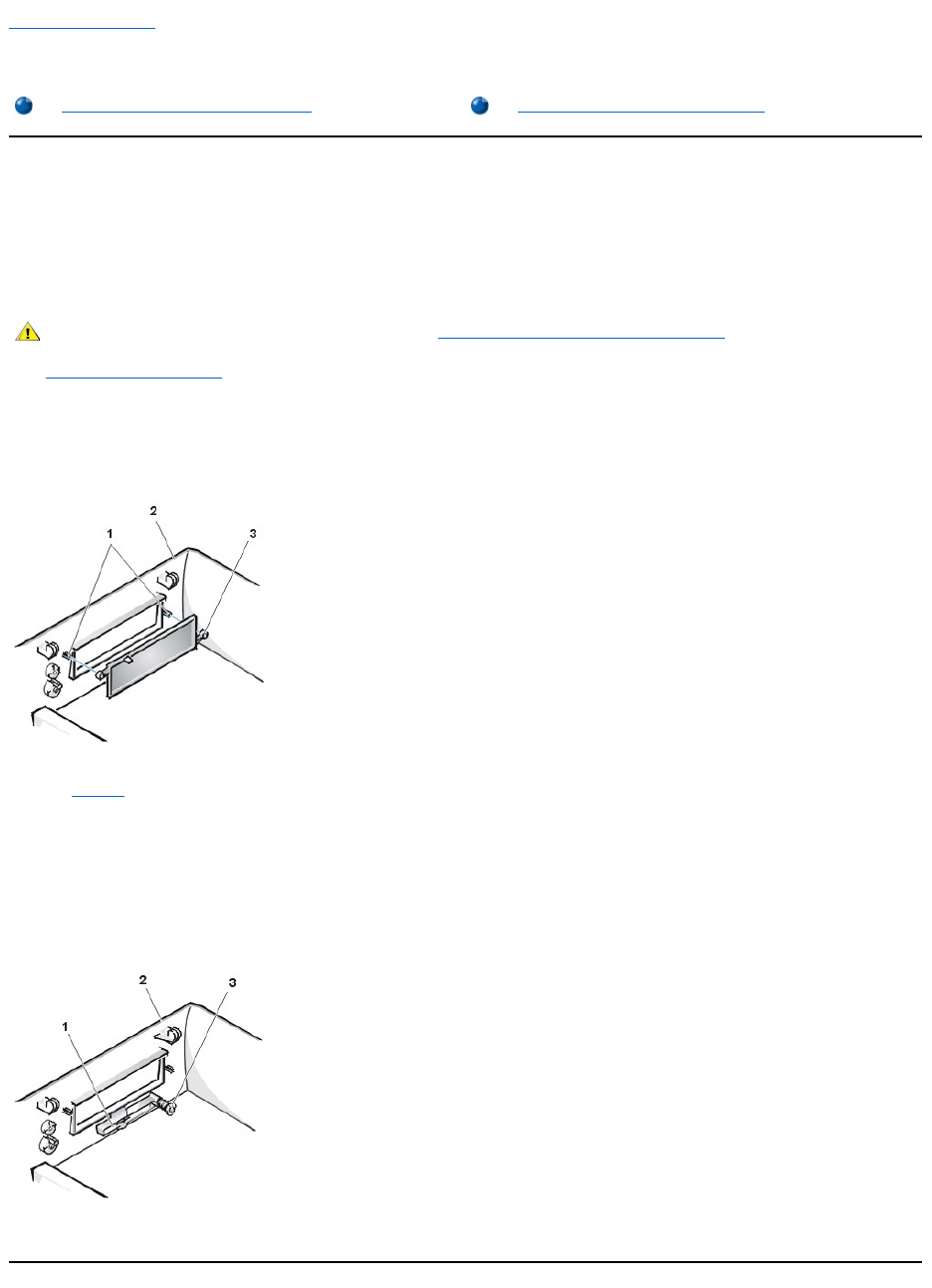
Back to Contents Page
Front-PanelInserts:Dell™OptiPlex™GX110SystemUser'sGuide
Low-Profile Chassis Front-Panel Inserts
Empty drive bays contain a front-panel insert to protect the inside of the computer from dust particles and also to ensure proper airflow within the
computer. Before you install a drive in an empty drive bay, you must remove the front-panel insert.
To remove the insert covering the 5.25-inch bay, perform the following steps:
1. Turn off the system, including any attached peripherals, and disconnect all the AC power cables from their electrical outlets.
2. Remove the computer cover.
3. Lay the computer cover upside down on a flat work surface, with the front of the cover facing toward you.
4. With your thumbs, press in each end of the insert until it snaps free of the cover (see Figure 1).
Figure 1. Removing the Front-Panel Insert for the 5.25-Inch Bay (Low-Profile Chassis)
To replace the front-panel insert for the 5.25-inch bay, work from inside the cover. Position the insert behind the bay opening, insert the two ring-
tabs (see Figure 1) over the posts on the inside of the opening, and firmly press both ends of the insert into place.
To remove the insert covering the 3.5-inch bay, perform the following steps:
1. Complete steps 1 through 3 of the procedure for removing the 5.25-inch insert.
2. Inside the cover, locate the eject button mechanism for the 3.5-inch bay (see Figure 2). Press the mechanism toward the front panel to snap
the plastic insert out of its opening.
Figure 2. Removing the Front-Panel Insert for the 3.5-Inch Bay (Low-Profile Chassis)
To replace the front-panel insert for the 3.5-inch bay, work from outside the cover. Place the insert in position and press it into the opening.
Low-Profile Chassis Front-Panel Inserts
Mini Tower Chassis Front-Panel Inserts
CAUTION: Before you remove the computer cover, see "Safety First—For You and Your Computer."
1
Posts (2)
2
Computer cover (upside down)
3
Ring tabs (2)
1
3.5-inch front-panel insert
2
Computer cover (upside down)
3
Eject button mechanism
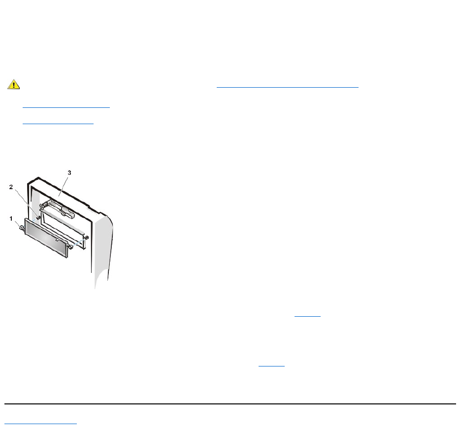
Mini Tower Chassis Front-Panel Inserts
Empty drive bays contain a front-panel insert to protect the inside of the computer from dust particles and also to ensure proper airflow within the
computer. Before you install a drive in an empty drive bay, you must first remove the front-panel insert.
To remove the insert covering a 5.25-inch bay, perform the following steps:
1. Turn off the system, including any attached peripherals, and disconnect all the AC power cables from their electrical outlets.
2. Remove the computer cover.
3. Remove the front bezel.
4. With your thumbs, press in each end of the insert until it snaps free of the bezel (see Figure 3).
Figure 3. Removing the Front-Panel Insert (Mini Tower Chassis)
To replace a front-panel insert for a 5.25-inch bay, work from inside the bezel. Insert the two ring-tabs (one on each end of the insert) over the
posts on the inside of the bay opening, and firmly press both ends of the insert into place (see Figure 3).
To remove the insert covering the 3.5-inch bay, perform the following steps:
1. Complete steps 1 through 3 of the procedure for removing a 5.25-inch insert.
2. Inside the cover, locate the eject button mechanism for the 3.5-inch bay (see Figure 3). Press the mechanism toward the front panel to snap
the plastic insert out of its opening.
To replace the front-panel insert for the 3.5-inch bay, work from outside the cover. Place the insert in position, and press it into the opening.
Back to Contents Page
CAUTION: Before you remove the computer cover, see "Safety First—For You and Your Computer."
1
Ring tabs (2)
2
Posts (2)
3
Computer cover
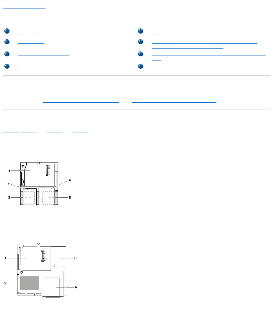
Back to Contents Page
InsideYourComputer:Dell™OptiPlex™GX110SystemUser'sGuide
Overview
This section describes the inside of your computer as a reference for you to use before you perform an upgrade procedure. Before you remove the
computer cover, see "Safety First—For You and Your Computer" and "Removing and Replacing the Computer Cover."
Internal Views
Figure 1,Figure 2, and Figure 3, and Figure 4showasideviewofthesmall-form-factor, low-profile, midsize, and mini tower chassis,
respectively, to help you orient yourself when you work inside the computer.
Figure 1. Small-Form-Factor Chassis Orientation View
Figure 2. Low-Profile Chassis Orientation View
Figure 3. Midsize Chassis Orientation View
Overview
System Board Labels
Internal Views
Rotating the Power Supply Away From the System Board
(Midsize and Mini Tower Chassis Only)
System Board Components
Removing and Replacing the Front Bezel (Mini Tower Chassis
Only)
System Board Jumpers
Removing and Replacing the Expansion-Card Cage
1
System board
2
Diskette drive
3
Hard-disk drive
4
CD-ROM drive
5
Power supply
1
System board
2
Hard-disk drive
3
Power supply
4
Externally accessible drive bays
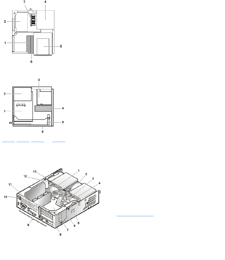
Figure 4. Mini Tower Chassis Orientation View
Figure 5, Figure 6, Figure 7, and Figure 8 show the small-form-factor, low-profile, midsize, and mini tower chassis, respectively, with the cover
removed.
Figure 5. Inside the Small-Form-Factor Chassis
Figure 6. Inside the Low-Profile Chassis
1
Internal drive cage
2
Expansion-card cage
3
System board
4
Power supply
5
Drive cage
6
Front of computer
1
System board
2
Power supply
3
Drive cage
4
Internal hard-disk drive bracket
5
Expansion-card cage
6
Bottom of computer
1
CD-ROM drive interface cable
2
Externally accessible upper bay
3
Hard-disk drive
4
Diskette-drive interface cable
5
Hard-disk drive interface cable
6
Expansion-card cage
7
System board
8
Expansion-card slots
9
I/O ports and connectors
10
AC power receptacle
11
Security cable slot
12
Power supply
13
Chassis intrusion switch
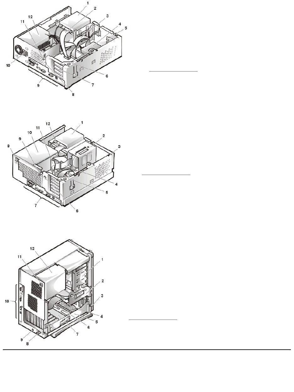
Figure 7. Inside the Midsize Chassis
Figure 8. Inside the Mini Tower Chassis
System Board Components
Figure 9 shows the system board and the location of all its sockets and connectors.
Figure 9. System Board Components
1
Diskette drive in upper bay
2
Diskette drive interface cable
3
Hard-disk drive interface cable
4
Hard-disk drive
5
Chassis intrusion switch
6
Expansion-card cage
7
Expansion-card slots
8
Security cable slot
9
I/O ports and connectors
10
AC power receptacle
11
Padlock ring
12
Power supply
1
Drive in upper bay
2
Internal drive cage
3
Chassis intrusion switch
4
Drive interface cable
5
Expansion-card cage
6
Security cable slot
7
I/O ports and connectors
8
AC power receptacle
9
Padlock ring
10
Power supply
11
System board
12
Drive interface cable
1
External drive bay
2
Internal drive cage
3
Chassis intrusion switch
4
Hard-disk drive interface cable
5
Expansion-card cage
6
System board
7
Riserboard
8
Padlock ring
9
Security cable slot
10
I/O ports and connectors
11
AC power receptacle
12
Power supply
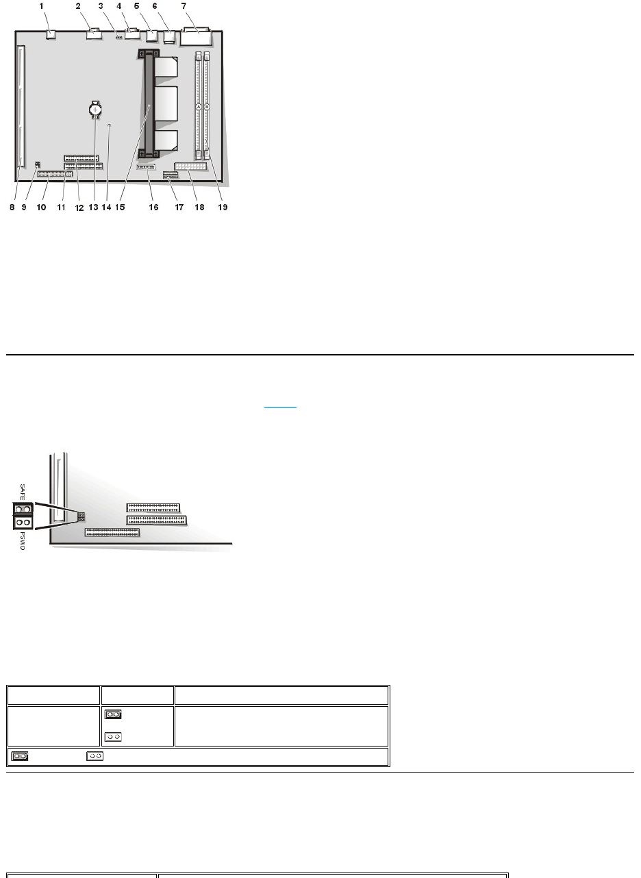
System Board Jumpers
Figure 10 shows the layout of jumpers on the system board. Table 1 lists the system board jumpers and their settings.
Figure 10. System Board Jumpers
Jumpers are small blocks on a circuit board with two or more pins emerging from them. Plastic plugs containing a wire fit down over the pins. The
wire connects the pins and creates a circuit.
To change a jumper setting, pull the plug off its pin(s) and carefully fit it down onto the pin(s) indicated.
NOTICE: Make sure your system is turned off and unplugged before you change a jumper setting. Otherwise, damage to your
system or unpredictable results may occur.
Table 1. System-Board Jumper Settings
System Board Labels
Table 2 lists the labels for light-emitting diode (LED) indicators, connectors, and sockets on the system board, and it gives a brief description of
their functions.
Table 2. System Board Indicators, Connectors, and Sockets
1
NIC connector
2
Video connector
3
Fan connector
4
Serial port 2 connector
5
USB connectors (2)
6
Keyboard (lower) and mouse (upper) connectors
7
Parallel port (upper) and serial port 1 (lower) connectors
8
Riser board connector
9
System board jumpers
10
EIDE1 connector
11
EIDE2 connector
12
Diskette/tape-drive connector
13
Battery
14
Auxiliary power indicator
15
Microprocessor
16
Control panel connector
17
3.3-V power connector
18
DC power connector
19
DIMM connectors (2)
Jumper
Setting
Description
PSWD
(default)
System password features are enabled.
System password features are disabled.
jumpered unjumpered
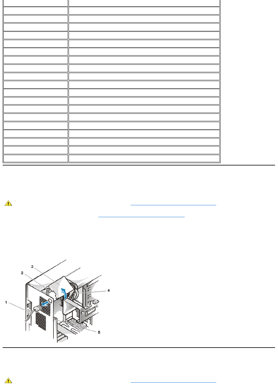
Rotating the Power Supply Away From the System Board (Midsize and Mini Tower Chassis Only)
To access some components on the system board, you may have to rotate the midsize or mini tower chassis system power supply out of the way.
Torotatethepowersupply,performthefollowingsteps.
1. Remove the computer cover as instructed in "Removing and Replacing the Computer Cover."
2. Disconnect the AC power cable from the AC power receptacle on the back of the power supply (Figure 11 illustrates rotating the power
supplyontheminitowerchassis;thepowersupplyisontherightsideofthemidsizechassis).
3. Free the power supply from the securing tab labeled "RELEASE —>," and rotate it upward until it locks in its extended position.
Figure 11. Rotating the Power Supply
Removing and Replacing the Front Bezel (Mini Tower Chassis Only)
To access some drive bays in the mini tower chassis, you must first remove the front bezel. To remove the front bezel, perform the following steps.
Connector or Socket
Description
AUX_LED
Auxiliary power indicator
B1
Battery socket
DIMM_x
Dual in-line memory module (DIMM) socket
DSKT
Diskette/tape drive interface connector
ENET
Integrated network interface controller(NIC) connector
FAN
Microprocessor fan connector
IDEn
EIDE interface connector
INTRUSION
Chassis intrusion switch connector
KYBD
Keyboard connector
MICROPROCESSOR
Microprocessor connector
MONITOR
Video connector
MOUSE
Mouse connector
PANEL
Control panel connector
PARALLEL
Parallel port connector; sometimes referred to as LPT1
POWER_1
Main power input connector
POWER_2
3.3-volt (V) power input connector
RISER
Riser board connector
SERIALn
Serial port connectors
USB
Universal Serial Bus (USB) connectors
CAUTION: Before you remove the computer cover, see "Safety First—For You and Your Computer."
1
AC power cable
2
AC power receptacle
3
Power supply
4
DC power cables
5
Securing tab
CAUTION: Before you remove the computer cover, see "Safety First—For You and Your Computer."
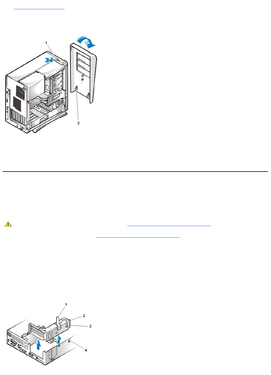
1. Remove the computer cover.
2. With the cover removed, release the bezel by pressing the tab release (see Figure 12).
Figure 12. Removing the Mini Tower Chassis Front Bezel
3. While you press the tab release, tilt the bezel away from the chassis, disengage the two retaining hooks at the bottom of the bezel, and
carefully pull the bezel away from the chassis.
To replace the bezel, fit the two retaining hooks on the bezel into their corresponding slots at the bottom of the mini tower chassis. Then rotate the
bezel toward the chassis until the tabs snap into their corresponding slots on the bezel.
Removing and Replacing the Expansion-Card Cage
This section describes how to remove and replace the expansion-card cage.
Removing and Replacing the Small-Form-Factor Chassis Expansion-Card Cage
To remove the expansion-card cage from the small-form-factor chassis, perform the following steps.
1. Remove the computer cover as instructed in "Removing and Replacing the Computer Cover."
Checkany cables connected to expansion cards through the back-panel openings. Disconnect any cables that will not reach to where the
cage must be placed upon removal from the chassis.
2. Locatethesecuringlever(seeFigure13).
3. Rotate the lever upward until it stops in an upright position.
Figure 13. Removing the Expansion-Card Cage From the Small-Form-Factor Chassis
1
Tab release
2
Retaining hooks (2)
CAUTION: Before you remove the computer cover, see "Safety First—For You and Your Computer."
1
Securing lever
2
Expansion card cage
3
Tab
4
Hook
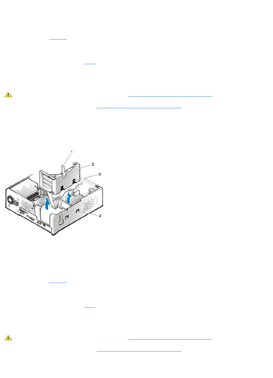
4. Slide the expansion-card cage out of the chassis.
5. Lift the expansion-card cage up and away from the chassis.
To replace the expansion-card cage in the small-form-factor chassis, perform the following steps:
1. With the securing lever in the upright position, align the slots in the left side of the expansion-card cage with the tabs on the back and bottom
of the chassis (see Figure 13). Slide the expansion-card cage into place.
2. Rotate the securing lever downward until it is flush with the top side of the chassis. Make sure that the riser board is fully seated in the RISER
connector on the system board.
3. Reconnect any cables you removed in step 2 of the previous procedure.
Removing and Replacing the Low-Profile or Midsize Chassis Expansion-Card Cage
To remove the expansion-card cage from the low-profile chassis or midsize chassis, perform the following steps.
1. Remove the computer cover as instructed in "Removing and Replacing the Computer Cover."
2. Check any cables connected to expansion cards through the back-panel openings. Disconnect any cables that will not reach to where the
cage must be placed upon removal from the chassis.
3. Locatethesecuringlever(seeFigure14).Rotatetheleverupwarduntilitstopsinanuprightposition.
Figure 14. Removing the Expansion-Card Cage From the Low-Profile or Midsize Chassis
4. Slide the expansion-card cage out of the chassis.
5. Lift the expansion-card cage up and away from the chassis.
To replace the expansion-card cage in the low-profile chassis or midsize chassis, perform the following steps:
1. With the securing lever in the upright position, align the slots in the left side of the expansion-card cage with the tabs on the back and bottom
of the chassis (see Figure 14). Slide the expansion-card cage into place.
2. Rotate the securing lever downward until it is flush with the top side of the chassis. Make sure that the riser board is fully seated in the RISER
connector on the system board.
3. Reconnect any cables you removed in step 2 of the previous procedure.
Removing and Replacing the Mini Tower Chassis Expansion-Card Cage
To remove the expansion-card cage from the mini tower chassis, perform the following steps.
1. Remove the computer cover as instructed in "Removing and Replacing the Computer Cover."
2. Check any cables connected to expansion cards through the back-panel openings. Disconnect any cables that will not reach to where the
cage must be placed upon removal from the chassis.
3. Locatethesecuringlever(seeFigure15).Rotatetheleverupwarduntilitstopsinanuprightposition.
CAUTION: Before you remove the computer cover, see "Safety First—For You and Your Computer."
1
Securing lever
2
Expansion-card cage
3
Slots (2)
4
Tab
CAUTION: Before you remove the computer cover, see "Safety First—For You and Your Computer."
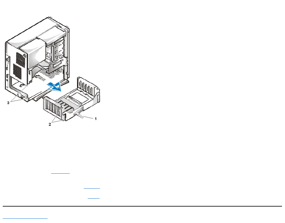
Figure 15. Removing the Expansion-Card Cage From the Mini Tower Chassis
4. Slide the expansion-card cage out of the chassis.
5. Lift the expansion-card cage up and away from the chassis.
To replace the expansion-card cage in the mini tower chassis, perform the following steps:
1. With the securing lever in the upright position, align the slots in the left side of the expansion-card cage with the tabs on the back and bottom
of the chassis (see Figure 15). Slide the expansion-card cage into place.
2. Rotate the securing lever inward until it is flush with the top side of the chassis. Make sure that the riser board is fully seated in the riser board
connector on the system board (see Figure 9).
3. Reconnect any cables you removed in step 2 of the previous procedure.
Back to Contents Page
1
Securing lever
2
Tabs (2)
3
Slots (2)


Back to Contents Page
InternalComponents:Dell™OptiPlex™GX110SystemUser'sGuide
Overview
This section provides troubleshooting procedures for components inside your computer. Before you start any of the procedures in this section, do
the following:
lPerform the procedures described in "Checking Connections and Switches" and "System Setup."
lRead the safety instructions in "Safety First—For You and Your Computer."
You need the following items to perform the procedures in this section:
lA copy of the Dell Diagnostics media
lA small flat-blade screwdriver and a #1 Phillips-head screwdriver (or quarter-inch hex-nut driver)
Safety First—For You and Your Computer
The procedures in this section require that you remove the cover and work inside your computer. While working inside your computer, do not
attempt to service the computer except as explained in this guide and elsewhere in Dell documentation. Always follow the instructions closely.
Working inside your computer is safe—if you observe the following precautions.
Before you start to work on the computer, perform the following steps in the sequence indicated:
1. Turn off the computer and all peripherals.
2. Touch an unpainted metal surface on the computer chassis, such as the metal around the card-slot openings at the back of your computer,
before touching anything inside your computer.
3. Disconnect the computer and peripherals from their electrical outlets. Doing so reduces the potential for personal injury or shock. Also
disconnect any telephone or telecommunication lines from the computer.
While you work, periodically touch an unpainted metal surface on the computer chassis to dissipate any static electricity that might harm
internal components.
In addition, Dell recommends that you periodically review the safety instructions in your System Information Guide.
Removing and Replacing the Computer Cover
To remove the computer cover, perform the following steps:
1. Turn off your computer and peripherals, and observe the Caution for Your Personal Safety and Protection of Your Equipment described
in"Safety First—For You and Your Computer."
2. If you have installed a padlock through the padlock ring on the back panel, remove the padlock.
Overview
Troubleshooting Expansion Cards
Safety First—For You and Your Computer
Troubleshooting System Memory
Removing and Replacing the Computer Cover
Troubleshooting the Video Subsystem
Troubleshooting a Wet Computer
Troubleshooting the System Board
Troubleshooting a Damaged Computer
Troubleshooting Drives
Troubleshooting the Battery
CAUTION FOR YOUR PERSONAL SAFETY AND PROTECTION OF THE EQUIPMENT
NOTE: If your small-form-factor, low-profile, or midsize chassis has an optional stand attached to it, remove the optional stand before
youremovethecomputercover.
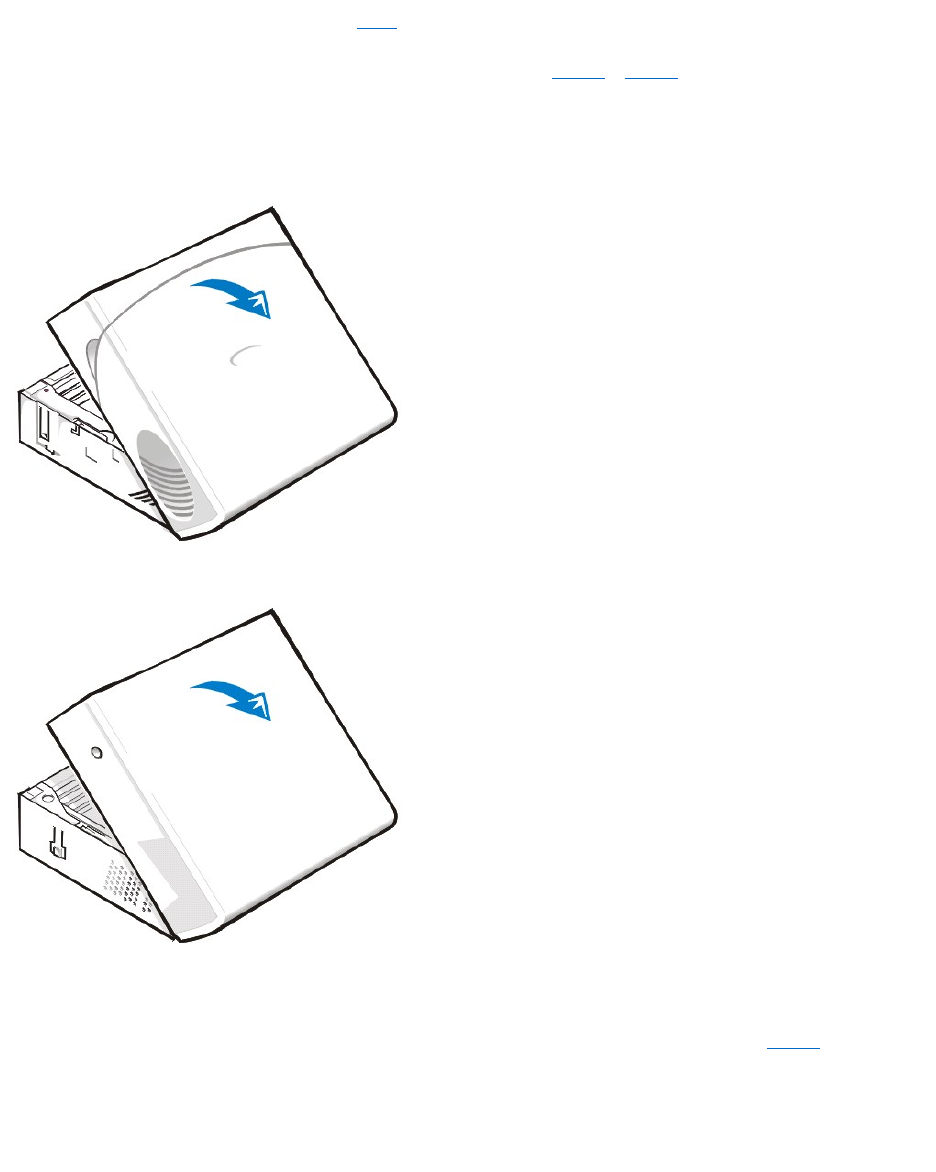
3. If your computer has a mini tower chassis, skip to step 4. If your computer has a small-form-factor, low-profile, or midsize chassis, remove the
computer cover as follows:
a. Press in on the two securing buttons until the cover is free to swing up (see Figure 1 or Figure 2).
b. Raise the back of the cover, and pivot it toward the front of the computer.
c. Lift the cover off the hooks at the front of the chassis.
Figure 1. Removing the Small-Form-Factor Computer Cover
Figure 2. Removing the Low-Profile or Midsize Computer Cover
4. If your computer has a mini tower chassis, remove the computer cover as follows:
a. Face the back of the computer and slide the upper half of the padlock ring to the left to unlock the cover release mechanism.
b. Face the left side cover and press the release button (located at the bottom-left corner of the front bezel) (see Figure 3).
c. Lift the bottom of the cover, allowing it to pivot up toward you.
d. Disengage the tabs that secure the cover to the top of the chassis, and lift the cover away.
Figure 3. Removing the Mini Tower Computer Cover
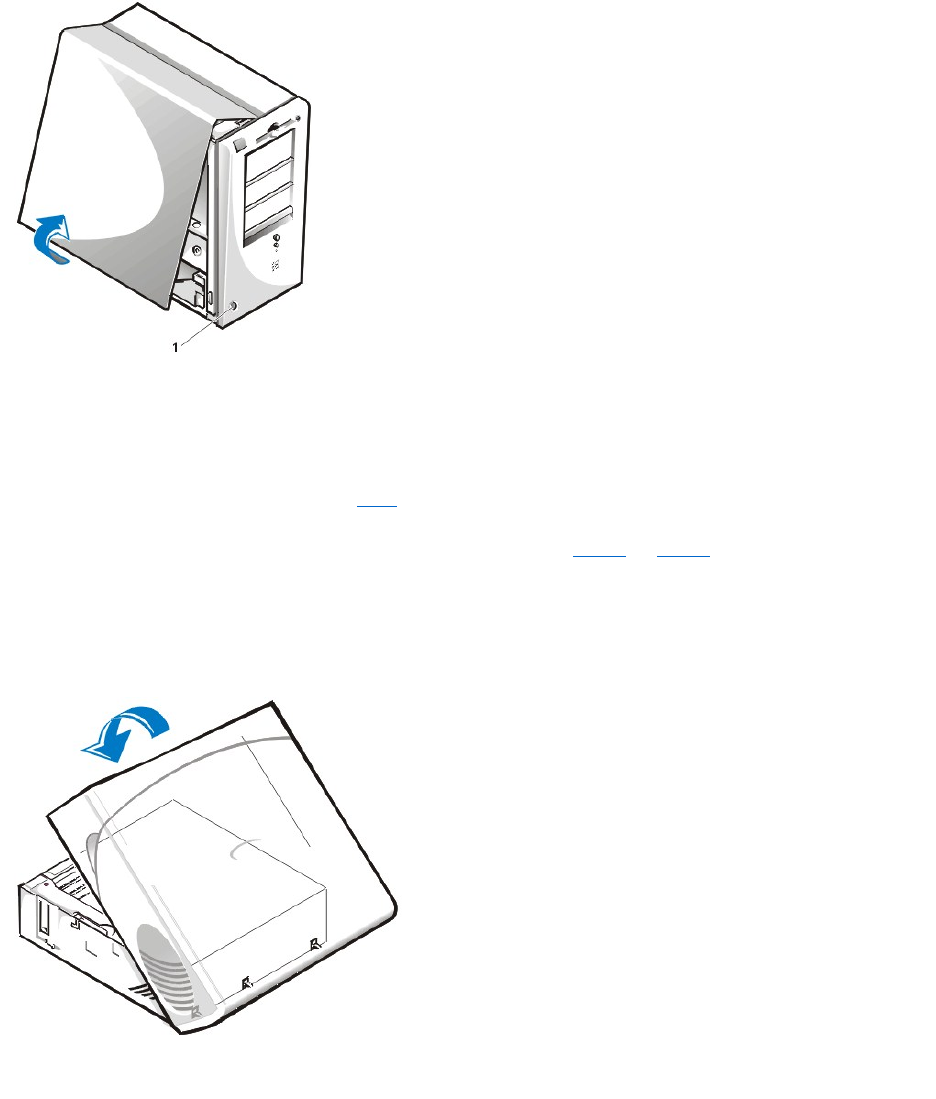
To replace the computer cover, perform the following steps:
1. Check all cable connections, especially those that might have come loose during your work. Fold cables out of the way so that they do not
catch on the computer cover. Make sure cables are not routed over the drive cage—they will prevent the cover from closing properly.
2. Check to see that no tools or extra parts (including screws) are left inside the computer's chassis.
3. If your computer has a mini tower chassis, skip to step 4. If your computer has a small-form-factor, low-profile, or midsize chassis, replace the
computer cover as follows:
a. Face the front of the computer and hold the cover at a slight angle as shown in Figure 4 and Figure 5.
b. Align the bottom of the cover with the bottom of the chassis, and insert the hooks on the cover into the recessed slots on the computer
chassis so that the tabs catch the hooks inside the slots.
c. Pivot the cover down toward the back of the chassis and into position. Make sure that the securing buttons click into place.
Figure 4. Replacing the Small-Form-Factor Computer Cover
Figure 5. Replacing the Low-Profile or Midsize Computer Cover
1
Release button
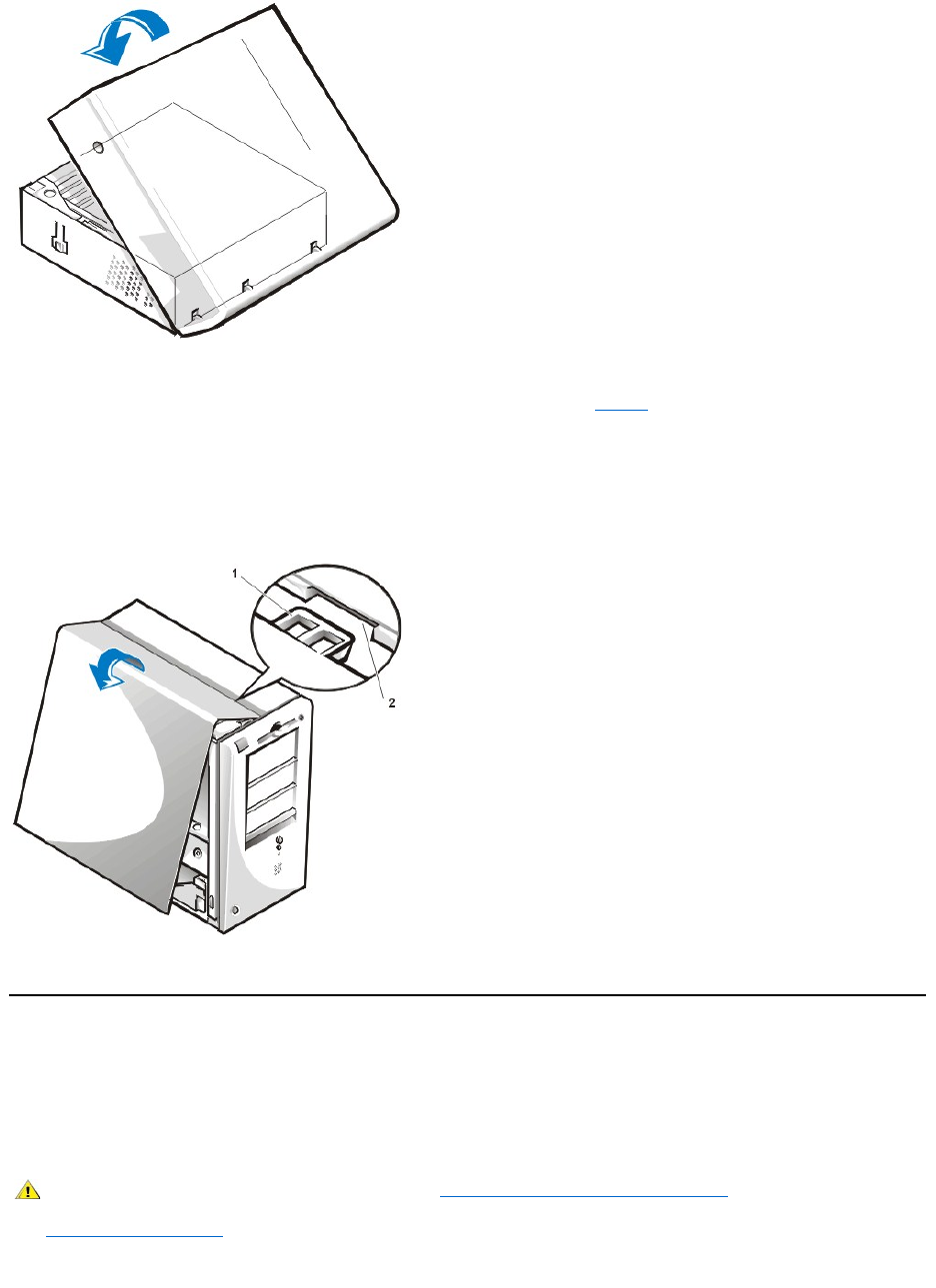
4. If your computer has a mini tower chassis, replace the computer cover as follows:
a. Face the left side of the computer and hold the cover at a slight angle as shown in Figure 6.
b. Align the top of the cover with the top of the chassis and insert the hooks on the cover into the recessed slots on the computer chassis
so that the tabs catch the hooks inside the slots.
c. Pivot the cover down toward the bottom of the chassis and into position. Make sure that the securing hooks at the bottom of the cover
click into place.
Figure 6. Replacing the Mini Tower Computer Cover
5. If you are using a padlock to secure your system, reinstall the padlock.
Troubleshooting a Wet Computer
Liquids can damage your computer. While you are not likely to submerge your computer, spills, splashes, and excessive humidity can also cause
damage. If an external device (such as a printer or an external drive) gets wet, contact the manufacturer for instructions. If your computer gets wet,
perform the following steps:
1. Turn off the system, including any attached peripherals, and disconnect all the AC power cables from their electrical outlets. Also, disconnect
any telephone or telecommunication lines from the computer.
2. Remove the computer cover.
3. Let the computer dry for at least 24 hours. Make sure that it is thoroughly dry before you proceed.
1
Hook
2
Recessed slot
CAUTION: Before you remove the computer cover, see "Safety First—For You and Your Computer."

4. Remove all expansion cards installed in the computer except a drive controller card and video expansion card.
5. Replace the computer cover, reconnect the system to an electrical outlet, and turn it on.
If the system has power, proceed to step 6. If the system does not have power, see "Getting Help" for instructions on obtaining technical
assistance.
6. Turn off the system, disconnect it from the electrical outlet, remove the computer cover, and reinstall all expansion cards that you removed in
step 4.
7. Replace the computer cover, and reconnect the system to an electrical outlet. Also, reconnect any telephone or telecommunication lines to
the computer.
8. Insert the Dell Diagnostics media into the appropriate drive, reboot the system, and run the System Board Devices test group in the Dell
Diagnostics.
If the tests complete successfully, your system is operating properly. If any of the tests fail, see "Getting Help" for instructions on obtaining
technical assistance.
Troubleshooting a Damaged Computer
If your computer was dropped or damaged, you should check your computer to see if it functions properly. If an external device attached to your
computer is dropped or damaged, contact the manufacturer of the device for instructions or see "Getting Help" for information on obtaining
technical assistance from Dell. To troubleshoot a damaged computer, perform the following steps:
1. Turn off the system, including any attached peripherals, and disconnect all the AC power cables from their electrical outlets. Also, disconnect
any telephone or telecommunication lines from the computer.
2. Remove the computer cover.
3. Check all the expansion-card connections in the computer.
4. Verify the diskette/tape drive, hard-disk drive, and all other internal connections.
Make sure that all cables are properly connected and that all components are properly seated in their connectors and sockets.
5. Replace the computer cover, reconnect the system to an electrical outlet, and reconnect any telephone or telecommunication lines.
6. Insert the Dell Diagnostics media into the appropriate drive, and reboot the system.
7. Run the System Board Devices test group in the Dell Diagnostics.
If the tests complete successfully, your system is operating properly. If any of the tests fail, see "Getting Help" for instructions on obtaining
technical assistance.
Troubleshooting the Battery
If an error message indicates a problem with the battery or if System Setup loses the system configuration information when the computer is turned
off, the battery may be defective.
To troubleshoot the battery, perform the following steps:
1. Turn off the system, including any attached peripherals, and disconnect all the AC power cables from their electrical outlets. Also, disconnect
any telephone or telecommunication lines from the computer.
2. Remove the computer cover.
3. Reseat the battery in its socket.
The battery is a coin cell that snaps into a socket on the system board.
4. If the problem is not resolved, replace the battery.
If the problem is still not resolved, you may have a faulty system board. See "Getting Help" for instructions on obtaining technical assistance.
CAUTION: Before you remove the computer cover, see "Safety First—For Your and Your Computer."
CAUTION: There is a danger of a new battery exploding if it is incorrectly installed. Replace the battery only with the same or
equivalent type recommended by the manufacturer. Discard used batteries according to the manufacturer's instructions.
CAUTION: Before you remove the computer cover, see "Safety First—For You and Your Computer."

Troubleshooting Expansion Cards
If an error message indicates an expansion-card problem or if an expansion card seems to perform incorrectly or not at all, the problem could be a
faulty connection, a conflict with software or other hardware, or a faulty expansion card. To troubleshoot expansion cards, perform the following
steps:
1. Turn off the system, including any attached peripherals, and disconnect all the AC power cables from their electrical outlets. Also, disconnect
any telephone or telecommunication lines from the computer.
2. Remove the computer cover.
3. Verify that each expansion card is firmly seated in its connector. If any expansion cards are loose, reseat them.
4. Verify that any cables are firmly connected to their corresponding connectors on the expansion cards. If any cables appear loose, reconnect
them.
For instructions on which cables should be attached to specific connectors on an expansion card, see the expansion card's documentation.
5. Remove all expansion cards except the video card.
6. Replace the computer cover, reconnect the system to an electrical outlet, and turn it on.
7. Insert the Dell Diagnostics media into the appropriate drive, reboot the system, and run the RAM test group in the Dell Diagnostics.
If the tests complete successfully, proceed to step 8. If any of the tests fail, see "Getting Help" for information on obtaining technical
assistance.
8. Turn off the system, disconnect it from the electrical outlet, and remove the computer cover.
9. Reinstall one of the expansion cards that you removed previously, and repeat steps 6 and 7.
If any of the tests fail, the expansion card you just reinstalled is faulty and needs to be replaced. If the tests complete successfully, repeat
steps 8 and 9 with another expansion card.
10. If you have replaced all the expansion cards removed previously and the expansion card problem is not resolved, see "Getting Help" for
information on obtaining technical assistance.
Troubleshooting System Memory
A computer memory problem can be a faulty dual in-line memory module (DIMM) or a faulty system board. If a random-access memory (RAM)
error message appears, the computer probably has a memory problem.
When you turn on or reboot the system, the Caps Lock and Scroll Lock indicators on the keyboard should flash momentarily and then turn off. If the
Num Lock option in System Setup is set to On, the Num Lock indicator should flash momentarily and then remain on; otherwise, it should turn off.
Abnormal operation of these indicators can result from a defective DIMM in socket A. To troubleshoot system memory, perform the following steps:
1. Turn on the system, including any attached peripherals.
2. If an error message indicates invalid system configuration information, enter System Setup and check the System Memory option. If the
amount of memory displayed does not match the amount of memory installed, turn off the computer, disconnect it from the electrical outlet,
remove the computer cover, and reseat the DIMMs in their sockets.
3. Replace the computer cover, reconnect the system to an electrical outlet, and turn it on.
4. If the problem is not resolved, insert the Dell Diagnostics media into the appropriate drive, reboot the system, and run the RAM test group in
the Dell Diagnostics.
If the Dell Diagnostics identifies a faulty DIMM, replace that DIMM. If the Dell Diagnostics determines that the system board is faulty, or if the
Dell Diagnostics does not identify the cause of the problem and the problem is still not resolved, see "Getting Help" for instructions on
obtaining technical assistance.
Troubleshooting the Video Subsystem
Troubleshooting video problems involves determining which of the following is the source of the problem: the monitor, the monitor interface cable,
CAUTION: Before you remove the computer cover, see "Safety First—For You and Your Computer."
CAUTION: Before you remove the computer cover, see "Safety First—For You and Your Computer."

or the integrated video subsystem.
Before attempting to troubleshoot the video subsystem, perform the procedure found in "Troubleshooting the Monitor" to determine whether or not
the monitor is the source of the problem.
If the monitor is not at fault, perform the following steps:
1. Check the monitor cable connections as indicated in "Checking Connections and Switches."
2. If problem is not resolved, insert the Dell Diagnostics media into the appropriate drive, and reboot the system. Run the Videotestgroupin
the Dell Diagnostics.
If any of the tests fail, see "Getting Help" for instructions on obtaining technical assistance.
Troubleshooting the System Board
A system board problem can result from a defective system board component, a faulty power supply, or a defective component connected to the
system board. If an error message indicates a system board problem, perform the following steps:
1. Insert the Dell Diagnostics media into the appropriate drive, and reboot the system. Run the System Board Devices test group in the Dell
Diagnostics.
If any of the tests fail, see "Getting Help" for instructions on obtaining technical assistance.
2. Turn off the system, including any attached peripherals, and disconnect all the AC power cables from their electrical outlets. Also, disconnect
any telephone or telecommunication lines from the computer.
3. Remove the computer cover.
4. Verify that the power cables from the power supply are firmly connected to the connectors on the system board.
5. Replace the computer cover, reconnect the system to an electrical outlet, and turn it on. If the problem is not resolved, proceed to step 6.
6. Perform the procedure in "Troubleshooting Expansion Cards." If the problem is not resolved, proceed to step 7.
7. Perform the procedure in "Troubleshooting the Keyboard."
8. If the problem is still not resolved, see "Getting Help" for instructions on obtaining technical assistance.
Troubleshooting Drives
If the monitor displays a system error message to indicate a drive problem during execution of either the boot routine or the Dell Diagnostics, or if
a drive is not operating correctly, perform the following steps:
1. Enter System Setup, and verify that the problem drive is configured correctly. Make any necessary changes, and reboot the system.
2. If the problem is not resolved, turn off the system, including any attached peripherals, and disconnect all the AC power cables from their
electrical outlets. Also, disconnect any telephone or telecommunication lines from the computer.
3. Remove the computer cover.
4. Verify that the DC power cables from the power supply are firmly connected to the connectors on each drive. Also verify that the interface
cable for each drive is firmly connected to the drive and to the system board.
5. Replace the computer cover, reconnect the system to an electrical outlet, and turn it on. If the problem is not resolved, proceed to step 6.
6. Insert the Dell Diagnostics media into the appropriate drive, reboot the system, and run the appropriate test group in the Dell Diagnostics.
If the Dell Diagnostics identifies a faulty drive, replace the drive. If the Dell Diagnostics identifies a faulty controller, the system board may be
faulty. See "Getting Help" for instructions on obtaining technical assistance.
Back to Contents Page
CAUTION: Before you remove the computer cover, see "Safety First—For You and Your Computer."
CAUTION: Before you remove the computer cover, see "Safety First—For You and Your Computer."

Back to Contents Page
Introduction:Dell™OptiPlex™GX110SystemUser'sGuide
Overview
Dell OptiPlex GX110 Managed PC systems are high-speed, expandable personal computers designed around the Intel®Pentium®
IIImicroprocessor.Eachcomputersystemusesahigh-performance Peripheral Component Interconnect (PCI) design that allows you to configure
the computer system to your initial requirements and then add Dell-supported upgrades as necessary. These systems also support the Industry-
Standard Architecture (ISA) bus for older expansion devices, depending upon the installed riser board.
Hardware Features
Your system offers the following features:
lAn Intel Pentium III microprocessor.
lSystem memory of up to 512 megabytes (MB) of synchronous dynamic random-access memory (SDRAM) dual in-line memory modules
(DIMMs) in the two DIMM sockets on the system board (DIMMs must be non-error checking and correction [ECC]).
lIntegrated Intel Direct AGP Graphics Accelerator with Dynamic Video Memory (DVM) technology architecture.
lSelf-Monitoring and Analysis Reporting Technology II (SMART II) support, which warns you at system start-up if your hard-disk drive has
become unreliable.
Hard-disk drives shipped with OptiPlex GX110 systems are SMART II-compliant.
lUltra Advanced Technology Attachment (ATA)/66 support, which allows storage devices to transfer data at speeds up to 66 MB per second
(MB/sec).
lFull compliance with PCI specification 2.2.
lFull compliance with Advanced Configuration and Power Interface (ACPI) specification 1.0A.
lRemote Wake Up capability for both integrated network interface controllers (NICs) and NIC cards. When the Remote Wake Up option is
enabled in embedded System Setup, the system can be turned on from a server management console.
Remote Wake Up capability also allows remote computer setup, software downloading and installation, file updates, and asset
tracking after business hours and on weekends when network traffic is at a minimum.
lManaged boot agent (MBA), which allows the system to boot from one of four network preboot environment protocols: Preboot eXecution
Environment (PXE), Remote Program Load (RPL), BootP, or Novell®NetWare®Remote Boot.
lRemote system alerts, which allow the system to transmit special predetermined network messages regarding its operating condition.
lUniversal Serial Bus (USB) capability, which can simplify connecting peripheral devices such as mice, printers, and computer speakers. The
system basic input/output system (BIOS) provides support for USB keyboards and mice in MS-DOS®and other non-Windows®
environments. To use this capability, enabled the USB support in the BIOS setup.
lDellOptiFrame™chassisforeasydisassemblyandimprovedserviceability.
For additional hardware features, see "Technical Specifications."
Software Features
The following software is included with your Dell computer system:
lA BIOS, which resides in flash memory and can be upgraded by diskette, or remotely over a network, if required.
lBus-mastering enhanced integrated device electronics (EIDE) drivers to improve performance by off-loading certain functions from the
microprocessor during multithreaded operation (when several applications are running simultaneously).
Overview
Manageability Features
Hardware Features
ENERGY STAR®Compliance
Software Features

lEmbedded System Setup for quickly viewing and changing the system configuration. System Setup also provides several enhanced security
features (a setup password, a system password, a system-password lock option, a write-protectoptionfordiskettedrives,anddisplayofthe
system's service tag number).
lDell Diagnostics for evaluating the computer's components and devices.
lVideo drivers designed to support the integrated Intel Direct AGP Graphics Accelerator.
lNetwork device drivers for several operating systems.
lDesktop Management Interface (DMI) support, which enables the remote management of your computer system's software and hardware.
lSupport for DellOpenManage™ITAssistant.
Manageability Features
Your Dell OptiPlex GX110 Managed PC system incorporates the following hardware and software features to improve the manageability of the
system:
lDell OpenManage IT Assistant
lManaged boot agent (MBA)
lRemote Wake Up
lRemote System Alert
lAuto Power On
lChassis intrusion alerts
lCommon Information Model (CIM) support
lConfiguration change alerts
lAsset Info with support for the cost of ownership (COO) Management Information Format (MIF) standard
lRemote flash BIOS
lRemote system configuration
lPrefailure alerts
Dell OpenManage IT Assistant
The Dell OpenManage IT Assistant program is the Dell software-management application interface for DMI. It allows you to manage system-level
information, such as system configuration information and MIF database values.
Fault management features of the Dell OpenManage IT Assistant include the following:
lAlerts to warn you about events generated by SMART drives on a local or remote system
lAn event log that stores events in a text file and reports the following information about events: System Name, Component Name, Date
and Time, Event Type, Event Severity, Event Class, and Event System
Configuration management features of the Dell OpenManage IT Assistant program include the following:
lRemote Wake Up support, which allows network administrators to remotely turn on Managed PC systems with Remote Wake Up capability
in a Dell DMI network
lA System Properties window that enables network administrators to view, set, or disable certain hardware configuration settings for the
local and remote systems in a Dell DMI network
lSupport for the Microsoft®System Management Server (SMS), which allows the exporting of one or more groups to an SMS directory that
the SMS administrator can access
lA monitor component for systems running Windows 98 or Windows 95 and having a display data channel (DDC)-compliant video subsystem
and monitor
lAutomated inventory control of one or more groups for the remote systems in a Dell DMI network
Network administrators can automate inventory to occur every day, week, or month at a certain hour, on the hour; or you can enable
inventory as needed. The Dell OpenManage IT Assistant program creates a text file for the group(s) and saves it to a user-defined

directory.
lSupport for the application program used to create user-definable attributes (UDAs)
Asset management features of the Dell OpenManage IT Assistant include the following:
lSupport that enables network administrators to remotely view, enter, and modify an asset tag for a remote system in a Dell DMI network
lAutomated and manual mapping of one or more groups to a user-defined directory
Security management features of the Dell OpenManage IT Assistant include password security that enables network administrators to maintain
standard attribute values for the local and remote systems in a Dell DMI network.
For more information about the Dell OpenManage IT Assistant, see the online Dell OpenManage IT Assistant documentation that accompanied the
software.
MBA
The 3Com®MBA supports multiple preboot environments and allows network administrators to boot the system from a network server.
See "Network Interface Controller" for more information about MBA.
Remote Wake Up
Remote Wake Up allows you to remotely turn on a Managed PC system that is either in a sleep state or soft-off state. The ability to turn on
Managed PC systems remotely allows you to perform remote computer setup, software downloading and installation, file updates, and asset
tracking at any time.
To use the Remote Wake Up feature, each Managed PC system must contain a NIC that supports Remote Wake Up. You must also enable the
Remote Wake Up option in System Setup.
Remote Wake Up by a System User
With the advent of ACPI technology, Microsoft implemented a new wake-up method called pattern byte matching (PBM). When PBM is enabled,
there is the potential for a local area network (LAN) user to wake up another system that is in suspend mode. The following information explains
wake-up technology and its functionality on your Dell system under various operating systems (OS).
Remote Wake Up, also known as Wakeup On LAN, allows a network administrator to start a system remotely using a LAN signal from a server
management console. This capability provides for remote computer access after hours and on weekends when LAN traffic is typically at a
minimum.
Magic Packet Technology
Wakeup On LAN originally used a technology known as Magic Packet, which sends a data packet directly to a system. This packet consists of
data that has 16 repetitions of the system's media access control (MAC) layer address. The MAC address is unique to the network adapter in the
system so the Magic Packet wakes only the system targeted for start-up. When the network adapter receives and decodes this packet, it sends a
power management event (PME) signal to the system that brings it back to full power and boots the system.
Pattern Byte Matching Technology
PBM provides the wake-up packet for systems that support ACPI. The system downloads a series of patterns to the network adapter, and the
network adapter monitors for the arrival of these patterns in a packet. If it finds these patterns, the network adapter generates a PME signal to
wake up the system.
PBM and Magic Packet Technology Differences
PBM wake-up technology is much different from Magic Packet wake-up technology. A Magic Packet is not a regular network data packet. Magic
Packet technology starts a system when a network administrator sends the data packet from a management station.
Wake from Address Resolution Protocol (ARP) and Wake from NetBIOS name lookup patterns are available in the PBM method currently
provided in Windows 98 Second Edition (SE). ARP or NetBIOS lookup packets are standard features of network activity and can wake up
suspended systems without action from an administrator. For example, several systems may share hard-disk drives in a standard work group
scenario. If a system is in a suspend mode when someone on the network searches for that system using Network Neighborhood or clicks the
system icon, it can generate an ARP or a NetBIOS name lookup packet that wakes up the target system.
Current Wake-Up Patterns
Current wake-up patterns allowed by the Network Device Class Power Management Specification are the following:
lWake from ARP
lWake from NetBIOS name lookup
NOTE:This feature does not work if the system is shut off using a power strip or surge protector.
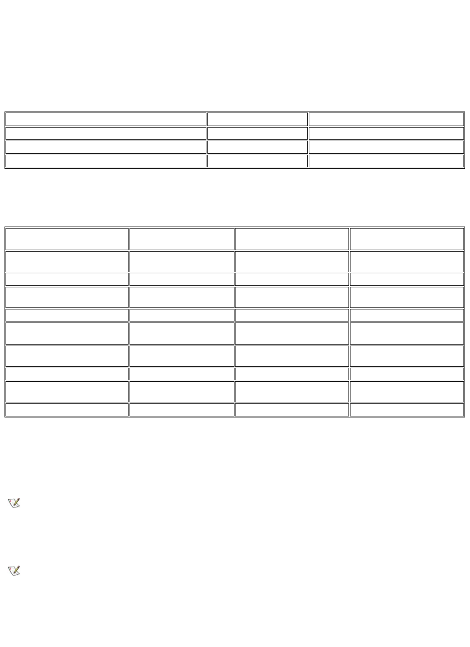
lDirected wake packet
The specification also defines Magic Packet as a wake-up method. Wake-up technology that uses PBM is controlled by the Microsoft Windows
OS because the OS programs the patterns. Therefore, PBM only works in systems that use the Windows OS with ACPI enabled. For more
information on PBM, please refer to the Network Device Class Power Management Specification.
Changing Remote Wake Up Options
To change Remote Wake Up options, enter System Setup by pressing <F2> during the start-up boot sequence. Tables 1 and 2 define remote
wake-up functions for each Windows operating system and system power state combination.
Table 1. Network Driver Interface Specification (NDIS) 4.0 Driver
Table 2. NDIS 5.0 Driver with ACPI Enabled
Remote System Alert
Remote System Alert allows you to receive certain predetermined messages from the system about its operating condition. For example, the
system can transmit an alert if the computer cover is removed.
To use the Remote System Alert feature, each Managed PC system must contain an integrated NIC that supports Remote System Alert.
Auto Power On
Auto Power On enables you to turn on the computer system automatically on certain days of the week at a preset time. You can set Auto Power
On to turn on the system either every day or every Monday through Friday.
Chassis Intrusion Alerts
Chassis intrusion alerts notify you if a local or remote system's chassis has been opened.
CIM Support
CIM allows you to access system management information if your system is running Microsoft®Windows 98 or any other Windows operating
System Setup—Remote Wake Up On
Windows 95 OS
Windows NT®4.0 OS
Wake from Off—Magic Packet
Yes
Yes
Wake from Off—PBM
No
No
Wake from Suspend
No
No
NOTES: When Remote Wake Up is set to Off, all wake-up events are disabled.
Wake from NetBIOS name lookup is not available in the Windows 95 or Windows NT 4.0 operating systems.
System Setup—
Remote Wake Up Off
Windows 98 OS
Windows 98 SE OS
Windows 2000 OS
Wake from standby (S1)—Magic
Packet
No
Yes
Yes
Wake from standby (S1)—PBM
No
Yes
Yes
Wake from shutdown (S5)—Magic
Packet
No
No
No
Wake from shutdown (S5)—PBM
No
No
No
System Setup—
Remote Wake Up On
Windows 98 OS
Windows 98 SE OS
Windows 2000 OS
Wake from standby (S1)—Magic
Packet
No
Yes
Yes
Wake from standby (S1)—PBM
No
Yes
Yes
Wake from shutdown (S5)—Magic
Packet
Yes
Yes
Yes
Wake from shutdown (S5)—PBM
No
No
No
NOTE: This feature does not work if the system is shut off using a power strip or surge protector.
NOTE:This feature does not work if the system is shut off using a power strip or surge protector.

system that includes the Web-Based Enterprise Management (WBEM) core components. For information about the WBEM core components and
how to install them, see the Microsoft World Wide Web site at http:\\www.microsoft.com.
For more information about CIM support, see the Dell OpenManage Client Instrumentation Version 5.0 User's Guide installed in the Dell
Documents folder on your hard-disk drive.
Configuration Change Alerts
Configuration change alerts generate warning messages if a local or remote system has a change in hardware configuration.
Asset Info With Support for the COO MIF Standard
Asset Info uses the nonproprietary DMI standard to allow you to record and track costs related to your system. The cost-related information is
stored in the cost of ownership Management Information Format (coo.mif) file on your system's hard-disk drive. For more information about Asset
Info and the COO MIF standard, see the online "Dell OpenManage Client Instrumentation Version 5.0 User's Guide."
Remote Flash BIOS
Remote flash BIOS allows a network administrator to perform remote BIOS upgrades to systems on a network.
Remote System Configuration
Remote system configuration features allow a network administrator to change the system asset tag, boot sequence, property ownership tag, and
System Setup settings and to update the system BIOS.
Prefailure Alerts
Prefailure alerts generate warning messages about potential failures by the system DIMMs and SMART II hard-disk drives.
ENERGY STAR®Compliance
Certain configurations of Dell computer systems comply with the requirements set forth by the Environmental Protection Agency (EPA) for energy-
efficient computers. If the front panel of your computer bears the ENERGY STAR®Emblem (see Figure 1), your original configuration complies
with these requirements and all ENERGY STAR® power management features of the computer are enabled.
Figure 1. ENERGY STAR®Emblem
The EPA's ENERGY STAR®Computers program is a joint effort between the EPA and computer manufacturers to reduce air pollution by
promoting energy-efficient computer products. The EPA estimates that use of ENERGY STAR®computer products can save computer users up
to two billion dollars annually in electricity costs. In turn, this reduction in electricity usage can reduce emissions of carbon dioxide, the gas primarily
responsible for the greenhouse effect, and sulfur dioxide and nitrogen oxides, which are the two primary causes of acid rain.
Computer users can also help to reduce electricity usage and its side effects by turning off their computer systems when they are not in use for
extended periods of time—particularly at night and on weekends.
Back to Contents Page
NOTES: As an ENERGY STAR®Partner, Dell Computer Corporation has determined that this product meets the ENERGY STAR®
guidelines for energy efficiency.
Any Dell computer bearing the ENERGY STAR®Emblem is certified to comply with EPA ENERGY STAR®requirements as
configured when shipped by Dell. Any changes you make to this configuration (such as installing additional expansion cards or
drives) may increase the system's power consumption beyond the limits set by the EPA's ENERGY STAR® Computers program.
Back to Contents Page
SystemMemory:Dell™OptiPlex™GX110SystemUser'sGuide
Overview
You can increase system memory up to 512 megabytes (MB) by using synchronous dynamic random-access memory (SDRAM) dual in-line
memory modules (DIMMs). Figure 9 in "Inside Your Computer" shows the location of the DIMM sockets on the system board (DIMMs must be non-
error checking and correction [ECC]).
When you add system memory, you may install DIMMs in either socket. For optimum operation, Dell recommends that you install a DIMM in socket
A first (closest to the processor) before installing a DIMM in socket B.
Installing DIMMs
To upgrade memory, perform the following steps.
1. Remove the computer cover according to the instructions in "Removing and Replacing the Computer Cover."
2. If necessary, remove any DIMMs that occupy sockets in which you plan to install the upgrade DIMMs.
3. Install the upgrade DIMMs.
a. Locate the plastic securing clips at each end of the socket (see Figure 1).
b. Press the clips outward until they snap open.
c. Press the DIMM straight into the slot running down the center of the socket until the securing tabs snap into place around the ends
of the DIMM.
Figure 1. Installing a DIMM
4. Replace the computer cover, and reconnect your computer and peripherals to their electrical outlets and turn them on.
The system detects that the new memory does not match the existing system configuration information and generates the following
message:
The amount of system memory has changed.
Overview
Removing DIMMs
Installing DIMMs
NOTICE: Before you install new memory modules, download the most recent BIOS for your computer from the Dell Support website at
support.dell.com.
CAUTION: To avoid the possibility of electric shock, turn off the computer and any peripherals, disconnect them from their
electrical outlets, and then wait at least 5 seconds before you remove the computer cover. Also, before you upgrade memory,
see the other precautions in "Safety First—For You and Your Computer. "
1
Securing clips (2)
2
Slot
NOTE: After you remove and replace the cover, the chassis intrusion detector causes the following message to appear on the
screen at the next system start-up:
ALERT! Cover was previously removed.
Strike the F1 key to continue, F2 to run the setup utility
5. Press <F2> to enter System Setup, and check the value for System Memory.
The system should have already changed the value of System Memory to reflect the newly installed memory. Verify the new total. If it is
correct, skip to step 7.
6. If the memory total is incorrect, turn off and disconnect your computer and peripherals from their electrical outlets. Remove the computer
cover, rotate the power supply, and check the installed DIMMs to make sure that they are seated properly in their sockets. Then repeat steps
3, 4, and 5.
7. Reset the chassis intrusion detector by changing Chassis Intrusion to Enabled or Enabled-Silent.
8. When the System Memory total is correct, press <Esc> to exit System Setup.
9. Run the Dell Diagnostics to verify that the DIMMs are operating properly.
Removing DIMMs
To remove a DIMM, press the securing clips outward simultaneously until the DIMM disengages and pops out slightly from the socket (see Figure
2).
Figure 2. Removing a DIMM
Back to Contents Page
NOTE: If a setup password has been assigned by someone else, contact your network administrator for information on resetting
the chassis intrusion detector.
1
Securing clips (2)
Back to Contents Page
MessagesandCodes:Dell™OptiPlex™GX110SystemUser'sGuide
Overview
Your application programs, operating system, and the computer itself are capable of identifying problems and alerting you to them. When a
problem occurs, a message may appear on your monitor screen or a beep code may sound. See "System Messages" or "System Beep Codes"
for information about each message or beep code.
System Messages
If you receive a system message, see Table 1 for suggestions on resolving any problems indicated by the message. The system messages are
listed alphabetically.
Table 1. System Messages
Overview
Warning Messages
System Messages
Diagnostics Messages
System Beep Codes
Diagnostic LEDs
NOTE: If the system message you received is not listed in the table, check the documentation for the application program that you were
running at the time the message appeared and/or the operating system documentation for an explanation of the message and a
recommended action.
Message
Cause
Action
Address mark not found
The basic input/output system
(BIOS) found a faulty disk sector or
could not find a particular disk
sector.
See "Troubleshooting Drives."
Alert! Previous attempts at booting this
system have failed at checkpoint [nnnn].
For help in resolving this problem, please
note this checkpoint and contact Dell
Technical Support.
The system has failed to complete
the boot routine three consecutive
times for the same error.
See "Getting Help" for instructions on
obtaining technical assistance, and
report the checkpoint code (nnnn) to the
support technician.
Attachment failed to respond
The diskette drive or hard-disk drive
controller cannot send data to the
associated drive.
See "Troubleshooting Drives."
Bad command or file name
The command you entered does not
exist or is not in the pathname you
specified.
Make sure you have spelled the
command correctly, placed spaces in the
proper location, and used the correct
pathname.
Bad error-
correction code(ECC) on disk read
The diskette drive or hard-disk drive
controller detected an uncorrectable
read error.
See "Troubleshooting Drives."
Controller has failed
The hard-disk drive or the
associated controller is defective.
See "Troubleshooting Drives."
Data error
The diskette or hard-disk drive
cannot read the data.
Run the ScanDisk utility in the Microsoft®
Windows®operating system to check the
file structure of the diskette or hard-disk
drive. See your operating system
documentation for more information.
If you are using another operating system,
run the appropriate utility to check the file
structure of the diskette or hard-disk
drive. See your operating system
documentation.
Decreasing available memory
One or more dual in-line memory
modules (DIMMs) may be faulty or
improperly seated.
See "Troubleshooting System Memory."
Diskette drive 0 seek failure
A cable may be loose, or the
See "Troubleshooting Drives."
Diskette drive 1 seek failure
system configuration information
may not match the hardware
configuration.
Diskette read failure
A cable may be loose, or the
diskette may be faulty.
See "Troubleshooting Drives."
Diskette subsystem reset failed
The diskette drive controller may be
faulty.
Run the Diskette tests in the Dell
Diagnostics.
Drive not ready
No diskette is in the drive. The
operation requires a diskette in the
drive before it can continue.
Put a diskette in the drive or close the
drive latch.
Diskette write protected
The diskette write-protect feature is
activated.
Remove the diskette from drive A and
move the write-protect tab to the
unlocked position.
Gate A20 failure
One or more DIMMs may be loose.
See "Troubleshooting System Memory."
General failure
The operating system is unable to
carry out the command.
This message is usually followed by
specific information—for example,
PRINTER OUT OF PAPER. Respond
by taking the appropriate action.
Hard disk configuration error
The hard-disk drive failed
initialization.
See "Troubleshooting Drives."
Hard disk controller failure
Hard disk failure
Hard-disk drive read failure
The hard-disk drive failed
initialization.
See "Troubleshooting Drives."
Invalid configuration information - please
run SETUP program
The system configuration
information does not match the
hardware configuration.
Enter System Setup and correct the
system configuration information.
Keyboard clock line failure
Keyboard controller failure
Keyboard data line failure
Keyboard failure
Keyboard stuck key failure
A cable or connector may be loose,
or the keyboard or keyboard/mouse
controller may be faulty.
See "Troubleshooting the Keyboard."
Memory address line failure at address,
read value expecting value
One or more DIMMs may be faulty
or improperly seated.
See "Troubleshooting System Memory."
Memory allocation error
The software you are attempting to
run is conflicting with the operating
system or another application
program or utility.
Turn off the computer, wait 30 seconds,
and then turn it on. Try to run the program
again. If the problem persists, contact the
software company.
Memory data line failure at address, read
value expecting value
Memory double word logic failure at
address, read value expecting value
Memory odd/even logic failure at address,
read value expecting value
Memory write/read failure at address, read
value expecting value
One or more DIMMs may be faulty
or improperly seated.
See "Troubleshooting System Memory."
Memory size in CMOS invalid
The amount of memory recorded in
the system configuration information
does not match the memory
installed in the computer.
Reboot the computer. If the error appears
again, see "Getting Help" for instructions
on obtaining technical assistance.
Memory tests terminated by keystroke
The memory test did not complete.
Rerun the memory test.
No boot device available
The computer cannot find the
diskette or hard-disk drive.
Enter System Setup, check the system
configuration information for the diskette
and hard-disk drive, and if necessary,
correct the information.
No boot sector on hard-disk drive
The system configuration
information in System Setup may be
incorrect, or the operating system
may be corrupted.
Enter System Setup, check the system
configuration information for the hard-disk
drive, and if necessary, correct the
information.
System Beep Codes
If the message persists, reinstall your
operating system. See the
documentation that came with your
operating system.
No timer tick interrupt
A chip on the system board might
be malfunctioning.
Run the System Board Devices tests in
the Dell Diagnostics.
Non-system disk or disk error
The diskette in drive A or your hard-
disk drive does not have a bootable
operating system installed on it.
A nonbootable diskette is in drive A.
Either replace the diskette with one that
has a bootable operating system, or
remove the diskette from drive A and
restart the computer.
Not a boot diskette
There is no operating system on the
diskette.
Boot the computer with a diskette that
contains an operating system.
Plug and Play Configuration Error
The system has encountered a
problem in trying to configure one or
more expansion cards.
Turn your system off and unplug it.
Remove all but one of the cards. Plug in
your system and reboot it. If the message
persists, the expansion card may be
malfunctioning. If the message does not
appear, turn off the power and reinsert
one of the other cards. Repeat this
process until you identify the
malfunctioning card.
Read fault
Requested sector not found
The operating system cannot read
from the diskette or hard-disk drive.
The system could not find a
particular sector on the disk, or the
requested sector is defective.
See "Troubleshooting Drives."
Reset failed
The disk reset operation failed.
See "Troubleshooting Drives."
Sector not found
The operating system is unable to
locate a sector on the diskette or
hard-disk drive.
See "Troubleshooting Drives."
Seek error
The operating system is unable to
find a specific track on the diskette
or hard-disk drive.
If the error is on the diskette drive, try
another diskette in the drive.
Shutdown failure
A chip on the system board might
be malfunctioning.
Run the System Board Devices tests in
the Dell Diagnostics.
Time-of-day clock stopped
The battery may be dead.
Enter System Setup and correct the date
or time.
If the problem persists, see
"Troubleshooting the Battery."
Time-of-day not set
The time or date displayed in the
system configuration information
does not match the system clock.
Enter System Setup and correct the date
or time.
Timer chip counter 2 failed
A chip on the system board might
be malfunctioning.
Run the System Board Devices tests in
the Dell Diagnostics.
Unexpected interrupt in protected mode
The keyboard controller may be
malfunctioning, or one or more
DIMMs may be loose.
Run the System Memory and the
Keyboard tests in the Dell Diagnostics.
WARNING: Dell's Disk Monitoring System has
detected that drive [0/1] on the
[primary/secondary] EIDE controller is
operating outside of normal
specifications. It is advisable to
immediately back up your data and replace
your hard-disk drive by calling your
support desk or Dell Computer Corporation.
Power-on self-test (POST) has
queried the enhanced integrated
drive electronics (EIDE) drive for
status information. The drive has
returned a parameter from the call
that indicates it has detected
possible error conditions for its
operating specifications.
Once your computer finishes booting,
immediately back up your data and
replace your hard-disk drive. Restore the
data to the replaced drive.
If a replacement drive is not immediately
available and the drive is not the only
bootable drive, enter System Setup and
change the appropriate drive setting to
None. Remove the drive from the system.
This should be done only after you have
backed up the data.
Write fault
Write fault on selected drive
The operating system cannot write
to the diskette or hard-disk drive.
See "Troubleshooting Drives."
When errors occur during a boot routine that cannot be reported on the monitor, your computer may emit a series of beeps that identify the
problem. The beep code is a pattern of sounds: for example, one beep, followed by a second beep, and then a burst of three beeps (code 1-1-3)
means that the computer was unable to read the data in nonvolatile random-access memory (NVRAM). This information is invaluable to the Dell
support staff if you need to call for technical assistance.
When a beep code is emitted, write it down on a copy of the Diagnostics Checklist found in "Getting Help," and then look it up in Table 2. If you are
unable to resolve the problem by looking up the meaning of the beep code, use the Dell Diagnostics to identify a more serious cause. If you are still
unable to resolve the problem, see "Getting Help" for instructions on obtaining technical assistance.
Table 2. System Beep Codes
Warning Messages
A warning message alerts you to a possible problem and asks you to do something before execution continues. For example, before you format a
diskette, a message may warn you that you may lose all data on the diskette as a way to protect against inadvertently erasing or writing over the
Code
Cause
Action
1-1-2
Microprocessor register failure
See "Getting Help" for instructions on obtaining technical assistance.
1-1-3
NVRAM
Run the System Board Devices tests in the Dell Diagnostics.
1-1-4
ROM BIOS checksum failure
Run the System Board Devices tests in the Dell Diagnostics, if possible.
1-2-1
Programmable interval timer
Run the System Board Devices tests in the Dell Diagnostics, if possible.
1-2-2
Direct memory access (DMA)
initialization failure
Run the System Board Devices tests in the Dell Diagnostics, if possible.
1-2-3
DMA page register read/write failure
Run the System Board Devices tests in the Dell Diagnostics, if possible.
1-3
Video Memory Test failure
Run the VESA/VGA Interface tests in the Dell Diagnostics.
1-3-1 through
2-4-4
DIMMs not being properly identified
or used
See "Troubleshooting System Memory."
3-1-1
Slave DMA register failure
Run the System Board Devices tests in the Dell Diagnostics, if possible.
3-1-2
Master DMA register failure
Run the System Board Devices tests in the Dell Diagnostics, if possible.
3-1-3
Master interrupt mask register failure
See "Getting Help" for instructions on obtaining technical assistance.
3-1-4
Slave interrupt mask register failure
See "Getting Help" for instructions on obtaining technical assistance.
3-2-2
Interrupt vector loading failure
See "Getting Help" for instructions on obtaining technical assistance.
3-2-4
Keyboard Controller Test failure
Run the Keyboard tests in the Dell Diagnostics. Otherwise, see "Getting Help" for
instructions on obtaining technical assistance.
3-3-1
NVRAM power loss
Run the System Board Devices tests in the Dell Diagnostics, if possible.
3-3-2
NVRAM configuration
Run the System Board Devices tests in the Dell Diagnostics, if possible.
3-3-4
Video Memory Test failure
Run the VESA/VGA Interface tests in the Dell Diagnostics.
3-4-1
Screen initialization failure
Run the VESA/VGA Interface tests in the Dell Diagnostics.
3-4-2
Screen retrace failure
Run the VESA/VGA Interface tests in the Dell Diagnostics.
3-4-3
Search for video ROM failure
Run the VESA/VGA Interface tests in the Dell Diagnostics.
4-2-1
No time tick
See "Getting Help" for instructions on obtaining technical assistance.
4-2-2
Shutdown failure
See "Getting Help" for instructions on obtaining technical assistance.
4-2-3
Gate A20 failure
See "Getting Help" for instructions on obtaining technical assistance.
4-2-4
Unexpected interrupt in protected
mode
See "Getting Help" for instructions on obtaining technical assistance.
4-3-1
Memory failure above address
0FFFFh
Run the System Memory tests in the Dell Diagnostics.
4-3-3
Timer-chip counter 2 failure
See "Getting Help" for instructions on obtaining technical assistance.
4-3-4
Time-of-day clock stopped
See "Getting Help" for instructions on obtaining technical assistance.
4-4-1
Serial or parallel port test failure
Run the Serial Ports and the Parallel Ports tests in the Dell Diagnostics.
4-4-2
Failure to decompress code to
shadowed memory.
Run the System Board Devices tests in the Dell Diagnostics.
4-4-3
Math-coprocessor test failure
Run the System Board Devices tests in the Dell Diagnostics.
4-4-4
Cache test failure
Run the System Board Devices tests in the Dell Diagnostics.
data. These warning messages usually interrupt the procedure and require you to respond by typing a y (yes) or n (no).
Diagnostics Messages
When you run a test group or subtest in the Dell Diagnostics, an error message may result. These particular error messages are not covered in this
section. Record the message on a copy of your Diagnostics Checklist found in "Getting Help." Also see "Getting Help" for instructions on obtaining
technical assistance.
Diagnostic LEDs
The power indicator light-emitting diode (LED) and the hard-disk drive LED on the front of the computer emit diagnostic codes that can help you
troubleshoot a system problem. Table 3 lists the codes for the diagnostic LEDs, probable causes, and suggested corrective actions.
Table 3. Diagnostic LED Codes
Back to Contents Page
NOTE: Warning messages are generated by either your application programs or your operating system. See "Software Checks" and
the documentation that accompanied your operating system and application programs.
CAUTION: Before servicing any components inside your computer, see "Safety First—For You and Your Computer."
Power LED Code
Cause
Action
Blinking yellow
The system power
supply may have failed.
See "Getting Help" for instructions on
obtaining technical assistance.
Solid yellow
A device on the system
board may be faulty or
is incorrectly installed.
Be sure that each microprocessor is
properly seated, remove all expansion
cards, and then reboot. If the system does
not boot, see "Getting Help" for
instructions on obtaining technical
assistance.
Solid green and a
beep code during
POST
A problem was
detected while the BIOS
was executing.
See Table 2 for instructions on diagnosing
the beep code.
Solid green power
indicator and no
beep code and no
video during POST
The monitor or the
graphics card may be
faulty.
See "Troubleshooting the Monitor." If the
monitor is operating properly and is
correctly connected, see "Getting Help" for
instructions on obtaining technical
assistance.
Solid green power
indicator and no
beep code but the
system locks up
during POST
An integrated system
board device may be
faulty.
See "Getting Help" for instructions on
obtaining technical assistance.

Temporary file. Delete before release.
Basic Checks: Dell OptiPlex GX100 System User's Guide
Battery: Dell OptiPlex GX100 System User's Guide
Contacting Dell: Dell Precision WorkStation 420 System User's Guide
Dell Diagnostics: Dell OptiPlex GX100 System User's Guide
Diskette, Tape, and CD-ROM Drives: Dell OptiPlex GX100 System User's Guide
Drivers and Utilities: Dell OptiPlex GX100 System User's Guide
Expansion Cards: Dell OptiPlex GX100 System User's Guide
External Components: Dell GX100 System User's Guide
Getting Help: Dell OptiPlex GX100 System User's Guide
Hard-Disk Drives: Dell OptiPlex GX100 System User's Guide
Help Overview: Dell Precision WorkStation 420 System User's Guide
Contents: Dell OptiPlex GX100 System User's Guide
Front-Panel Inserts: Dell OptiPlex GX100 System User's Guide
Inside Your Computer: Dell OptiPlex GX100 System User's Guide
Installing Upgrades: Dell OptiPlex GX100 System User's Guide
Internal Components: Dell OptiPlex GX100 System User's Guide
Introduction: Dell OptiPlex GX100 System User' Guide
System Memory: Dell OptiPlex GX100 System User's Guide
Messages and Codes: Dell OptiPlex GX100 System User's Guide
Microprocessor: Dell OptiPlex GX100 System User's Guide
Setup and Operation: Dell OptiPlex GX100 System User's Guide
System Setup Options: Dell OptiPlex GX100 System User's Guide
Software Checks: Dell OptiPlex GX100 System User's Guide
Technical Specifications: Dell OptiPlex GX100 System User's Guide
System Setup: Dell OptiPlex GX100 System User's Guide
Optional Stand: Dell OptiPlex GX100 System User's Guide
Using the System Setup Program: Dell OptiPlex GX100 System User's Guide
Troubleshooting:DellOptiPlexGX100SystemUser'sGuide
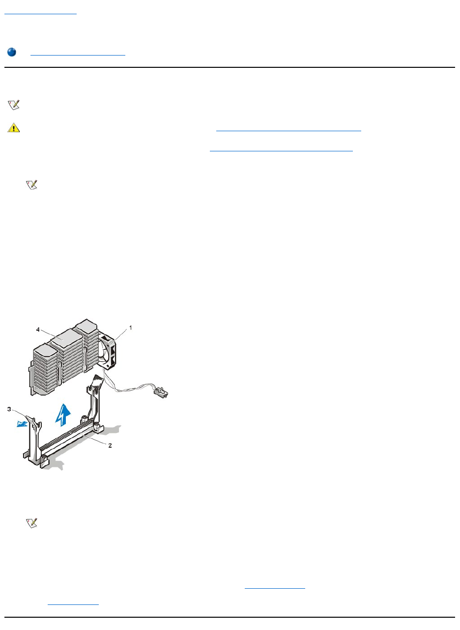
Back to Contents Page
Microprocessor:Dell™OptiPlex™GX110SystemUser'sGuide
Upgrading the Microprocessor
1. Remove the computer cover according to the instructions in "Removing and Replacing the Computer Cover."
2. Disconnect the fan cable from the system board (if fan is mounted to the heat sink).
3. Gently pull out the guide-bracket assembly latch, grasp the existing microprocessor/heat sink assembly firmly, and pull straight up to remove
it from the guide bracket assembly.
You must use up to 15 pounds of force to disengage the microprocessor package from the connector. Do not rock the package while
removing it.
4. Slide the new microprocessor package into the guide bracket assembly, with the heat sink toward the front of the computer, and firmly seat
the microprocessor/heat sink assembly.
You must use up to 25 pounds of force to seat the new microprocessor package. Do not rock the package while inserting it into the
connector.
Figure 1. Microprocessor Heat Sink (Small-Form-Factor and Low-Profile Chassis)
5. Reconnect the fan cable (if necessary).
6. Replace the computer cover, and reconnect your computer and peripherals to their power sources and turn them on.
ALERT! Cover was previously removed.
7. EnterSystemSetup,andconfirmthatthetoplineinthesystemdataareacorrectlyidentifiestheinstalledmicroprocessor.
8. While in System Setup, reset the chassis intrusion detector by changing Chassis Intrusion to Enabled or Enabled-Silent.
9. Run the Dell Diagnostics to verify that the new microprocessor is operating correctly.
Upgrading the Microprocessor
NOTE: Dell recommends that only a technically knowledgeable person perform the following procedure.
CAUTION: Before you remove the computer cover, see "Safety First — For You and Your Computer."
NOTE: The fan is mounted on the chassis in the mini-tower system.
1
Fan
2
Guide bracket assembly
3
Guide bracket assembly latch
4
Heat sink
NOTE: After you remove and replace the cover, the chassis intrusion detector will cause the following message to be displayed at
the next system start-up:

Back to Contents Page
Small-Form-Factor Chassis — RemovingandReplacingParts:Dell™OptiPlex™GX110
Systems Service Manual
Overview
This section provides procedures for removing and replacing the components, assemblies, and subassemblies in the Dell OptiPlex small-form-
factor chassis GX110 system.
Unless otherwise noted, each procedure assumes that the following conditions exist:
lYou have performed the steps in "Precautionary Measures."
lYou have removed the computer cover.
lYou can replace or reinstall a part by performing the removal procedure in reverse order unless additional information is provided.
Recommended Tools
Most of the procedures in this manual require the use of one or more of the following tools:
lSmall flat-blade screwdriver
lWide flat-blade screwdriver
l#1 and #2 Phillips-head screwdrivers
l1/4-inch nut driver
Also, use a wrist grounding strap as explained in "Precautionary Measures."
Precautionary Measures
Before you perform any procedures in this manual, take a few moments to read the following caution for your personal safety and to prevent
damage to the system from ESD.
Overview
System Power Supply
Recommended Tools
Expansion-Card Cage
Precautionary Measures
Riser Board
Internal Views
System Board Components
Computer Cover
Expansion Cards
Eject and Power Buttons
DIMMs
Control Panel
Microprocessor/Heat Sink Assembly
Chassis Intrusion Switch
System Battery
Drives
System Board
CAUTION: FOR YOUR PERSONAL SAFETY AND PROTECTION OF THE EQUIPMENT
Before you start to work on the system, perform the following steps in the sequence listed:
1. Turn off the computer and all peripherals.
2. Disconnect the computer and peripherals from their AC power sources. Also, disconnect any telephone or telecommunication lines
from the computer. Doing so reduces the potential for personal injury or shock.
3. If you are disconnecting a peripheral from the computer or are removing a component from the system board, wait 10 to 20 seconds
after disconnecting the computer from AC power before disconnecting the peripheral or removing the component to avoid possible
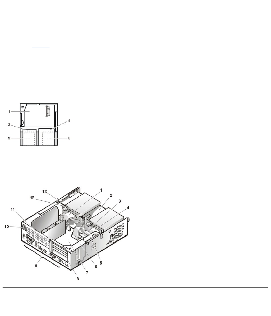
Internal Views
Figure 1 shows a top view of the chassis to help you orient yourself when you work inside the computer.
Figure 1. Orientation View
Figure 2 shows the chassis with the cover removed.
Figure 2. Inside the Chassis
Computer Cover
Figure 3. Computer Cover Removal
damage to the system board.
4. Wear a wrist grounding strap, and clip it to an unpainted metal surface, such as the padlock loop on the back of the chassis. If a wrist
grounding strap is not available, touch any unpainted metal surface on the back of the computer or on the computer chassis, such as
thepowersupply,todischargeanystaticchargefromyourbodybeforetouchinganythinginsidethecomputer.Whileyouwork,
periodically touch an unpainted metal surface on the computer chassis to dissipate any static electricity that might harm internal
components. Also avoid touching components or contacts on a card and avoid touching pins on a chip.
5. Verify that the auxiliary power indicator on the system board is not on. If it is on, you may need to wait 10 to 30 seconds for it to go out
(see Figure 20).
1
System board
2
Diskette drive
3
Hard-disk drive
4
CD-ROM drive
5
Power supply
1
CD-ROM drive interface cable
2
Externally accessible upper drive bay
3
Hard-disk drive
4
Diskette-drive interface cable
5
Hard-disk drive interface cable
6
Expansion-card cage
7
System board
8
Expansion-card slots
9
I/O ports and connectors
10
AC power receptacle
11
Security cable slot
12
Power supply
13
Chassis intrusion switch
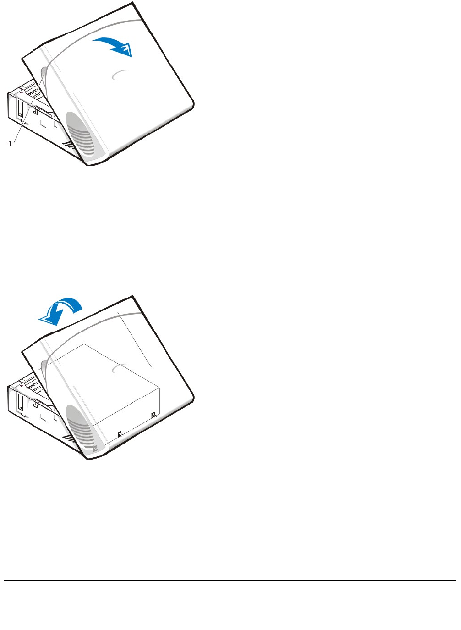
To remove the computer cover, perform the following steps:
1. Press in to retract the padlock ring into the cover (this permits opening of the cover).
2. Pressinonthetwosecuringbuttonsuntilthecoverisfreetoswingup(seeFigure3).
3. Raisethebackofthecover,andpivotittowardthefrontofthecomputer.
4. Lift the cover off the hooks at the front of the chassis.
5. Disengage the tabs that secure the cover to the top of the chassis, and lift the cover away.
Figure 4. Computer Cover Replacement
To replace the computer cover, perform the following steps:
1. Face the front of the computer and hold the cover at a slight angle (see Figure 4).
2. Align the bottom of the cover with the bottom of the chassis and insert the hooks on the cover into the recessed slots on the computer
chassis so that the tabs catch the hooks inside the slots.
3. Pivot the cover down toward the back of the chassis and into position.
Make sure that the securing buttons click into place.
4. If you wish to install a padlock, slide the padlock ring out of the cover.
Eject and Power Buttons
Figure 5. Eject and Power Button Removal
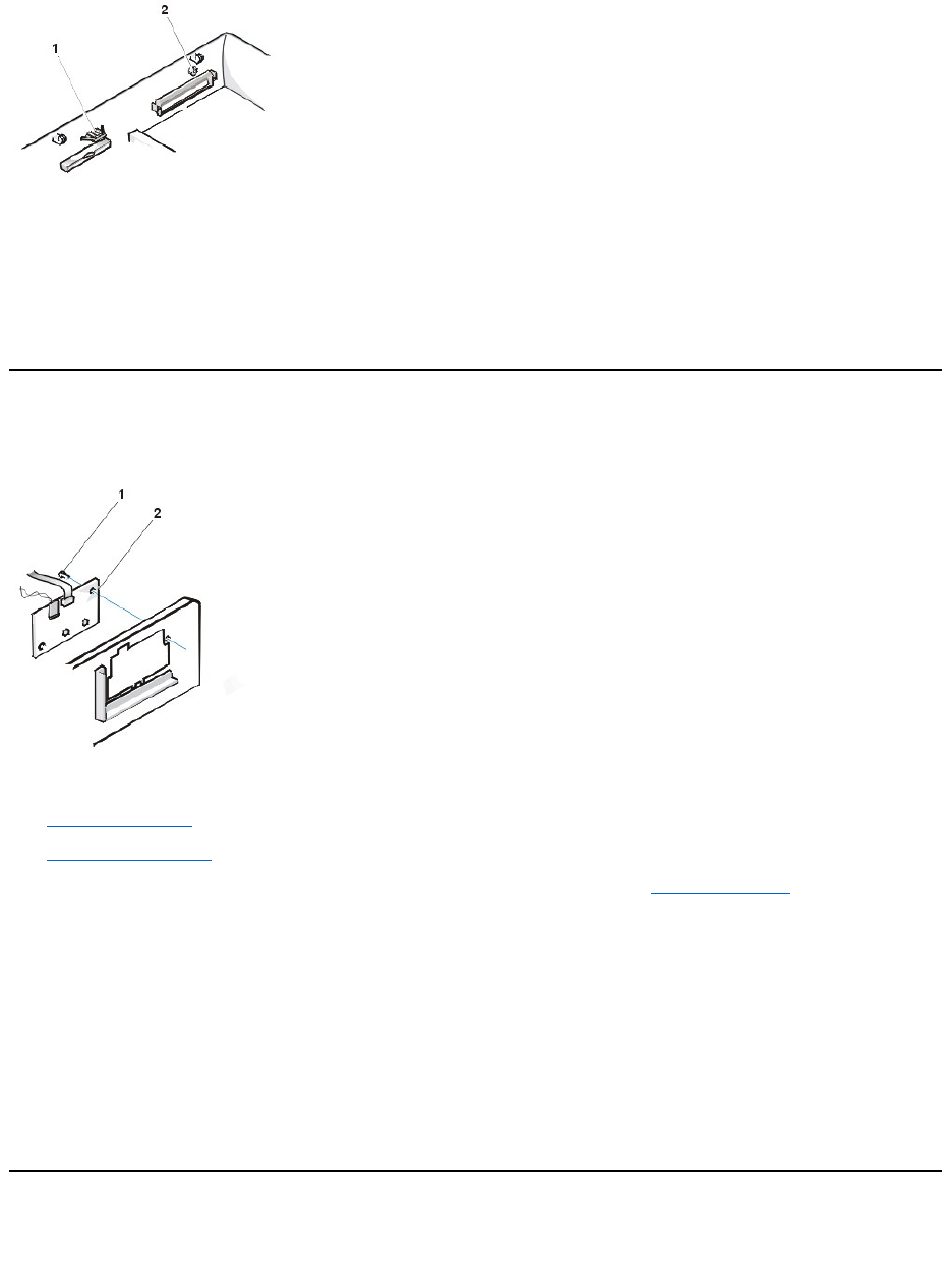
To remove the eject and power buttons, perform the following steps:
1. Lay the computer cover on a flat work surface, with the inside of the top cover facing up.
2. To remove the 3.5-inch diskette-drive eject button, pull gently on the plastic part of the button until it comes free.
3. Toremovethepowerbutton,useasmallscrewdriverandpushinthetwoplasticclipsthatholdthebuttontothebezel.Whentheseclipsare
released, the button and the spring come free from the bezel.
Control Panel
Figure 6. Control Panel Removal
To remove the control panel, perform the following steps:
1. Remove the drive shelf.
2. Remove the power supply.
3. Disconnect the control panel cable from the control panel connector on the system board (see "System Board Labels" for the location of the
PANEL connector).
Note the routing of the control panel cable as you remove it from the chassis.
4. Remove the mounting screw that secures the control panel to the chassis.
5. Disconnect the chassis intrusion switch cable connector from the control panel.
6. Remove the control panel cable.
7. Remove the control panel from the chassis.
Note the routing of the control panel cable as you remove it from the chassis.
When you install the replacement control panel, be sure to put the right side of the control panel behind the mounting tab.
Chassis Intrusion Switch
Figure 7. Chassis Intrusion Switch Removal
1
Diskette eject button
2
Power button
1
Screw
2
Control panel
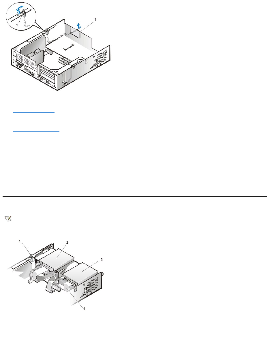
To remove the chassis intrusion switch, perform the following steps:
1. Remove the drive shelf.
2. Remove the power supply.
3. Remove the control panel.
4. Disconnect the chassis intrusion switch cable connector from the control panel.
Note the routing of the chassis intrusion cable as you remove the cable from the chassis. Chassis hooks may hold the cable in place inside
the chassis.
5. Slide the chassis intrusion switch out of its slot and remove the switch and its attached cable from the chassis.
6. Install the replacement chassis intrusion switch and cable.
7. To reset the chassis intrusion detector, enter the System Setup program and reset Chassis Intrusion to Not Detected (see your online
System User's Guide for instructions).
Drives
Figure 8. Drive Locations
Preliminary Steps
You must remove the drive shelf before removing the 3.5-inch diskette drive, the CD-ROM drive, the hard-disk drive, the control panel, the chassis
intrusion switch, or the power supply.
Figure 9. Drive Shelf Removal
1
Control panel
2
Chassis intrusion switch
NOTE: In all of the following procedures, left and right refer to your left and right as you face the front of the computer.
1
Chassis intrusion switch
2
CD-ROM drive
3
3.5-inch diskette drive
4
Hard-disk drive
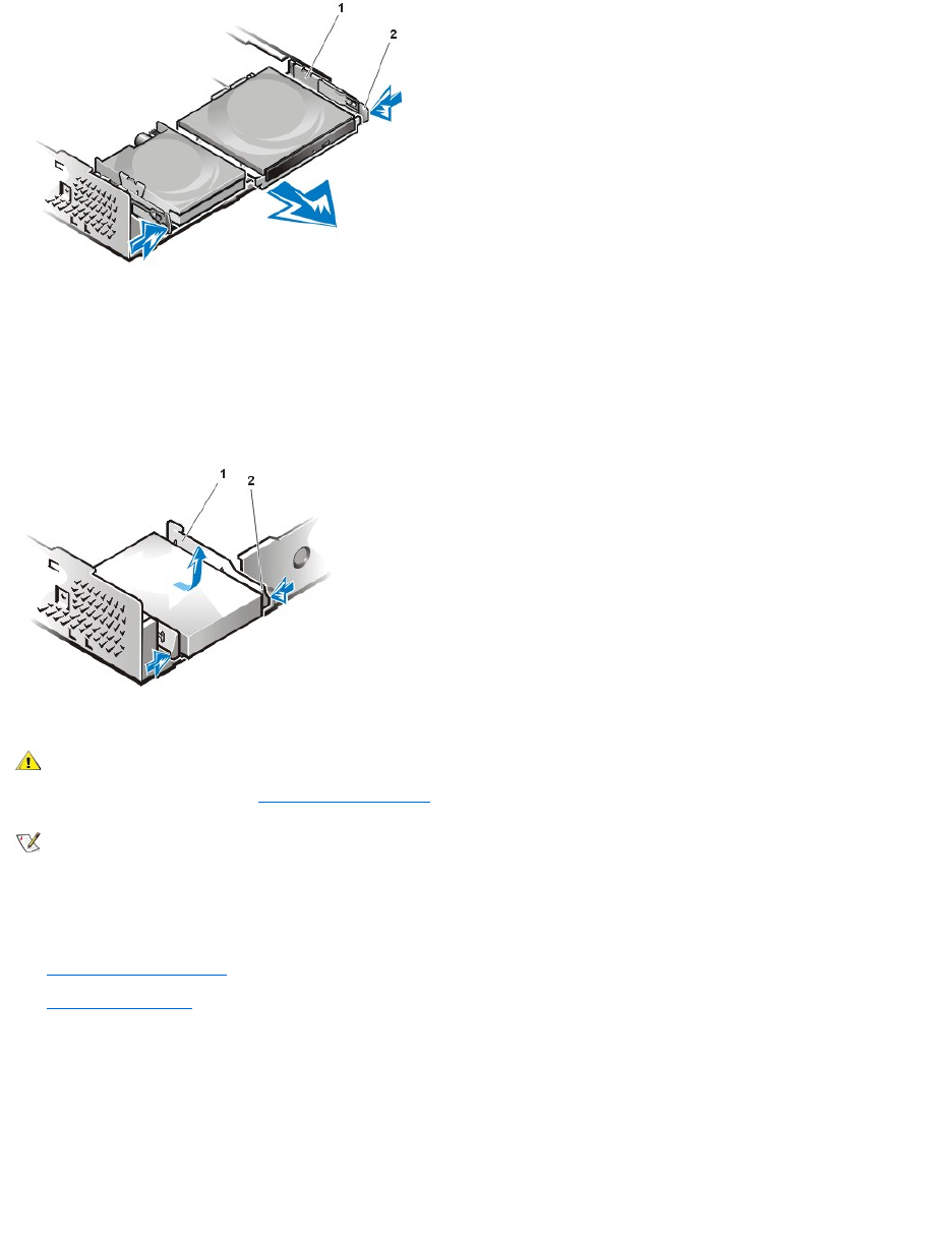
To remove the drive shelf from the chassis, perform the following steps:
1. Disconnect the power and interface cables from the diskette drive and CD-ROM drive.
2. Press inward on the two drive shelf release tabs, and pull the shelf forward and out of the chassis (see Figure 9).
Hard-Disk Drive
Figure 10. Hard-Disk Drive/Bracket Removal
To remove the hard-disk drive and its bracket from the chassis, perform the following steps:
1. If you are replacing a hard-disk drive that contains data you want to keep, make a backup copy of your files before you continue this
procedure.
2. Remove the computer cover if not already removed.
3. Remove the drive shelf.
4. Squeeze the tabs on each side of the hard-disk drive/bracket, and pull the hard-disk drive/bracket forward about one inch (see Figure 10).
5. Disconnect the power and interface cables from the back of the drive.
6. Lift the hard-disk drive/bracket away from the chassis.
7. Lay the hard-disk drive/bracket on an antistatic surface with its bracket facing up.
8. Remove the four screws securing the hard-diskdrivetothebottomofthebracket(seeFigure11).
Figure 11. Drive Bracket Removal
1
Drive shelf
2
Release tabs (2)
1
Drive bracket
2
Release tabs (2)
CAUTION: To avoid the possibility of electric shock, turn off the computer and any peripherals, disconnect them from
electrical outlets, and then wait at least 5 seconds before you remove the computer cover. Also, before you remove a drive,
see the other precautions in "Precautionary Measures."
NOTE: This procedure assumes that you have removed the drive shelf from the chassis.
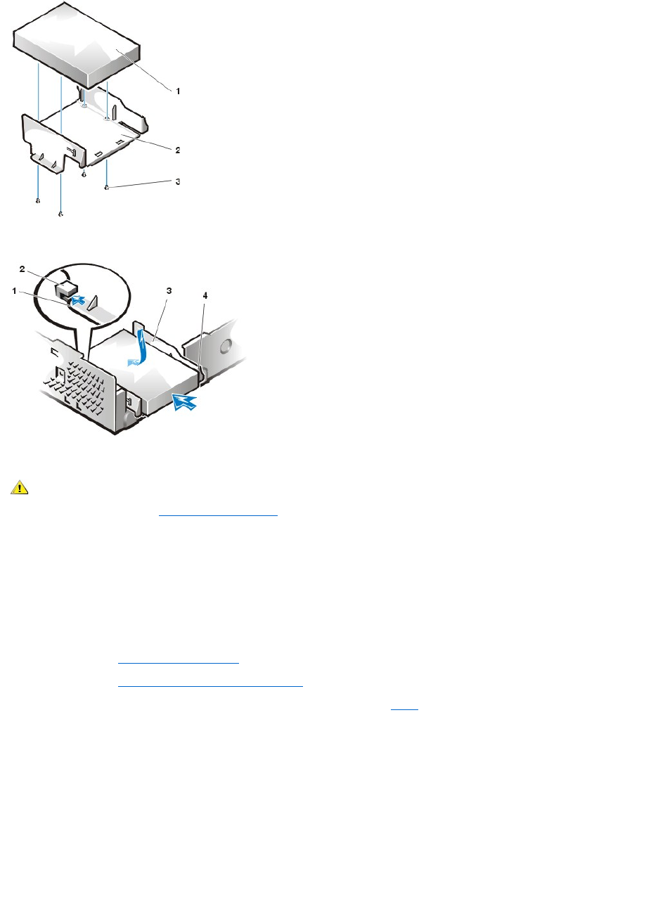
Figure 12. Hard-Disk Drive/Bracket Replacement
To install a replacement hard-disk drive in the chassis, perform the following steps.
NOTICE: To avoid possibly damaging the drive by electrostatic discharge (ESD), ground yourself by touching an unpainted metal
surface on the back of the computer.
NOTICE: When you unpack the drive, do not set it on a hard surface, which may damage the drive. Instead, set the drive on a
surface, such as a foam pad, that will sufficiently cushion it.
1. Prepare the drive for installation.
Check the documentation for the drive to verify that it is configured for your computer system.
2. If not already done, remove the computer cover.
3. If not already done, remove the drive bracket from the chassis.
4. Attach the new hard-disk drive to the bracket with the four screws you removed in step 8 of the previous procedure.
5. Reinstall the hard-disk drive/bracket in the chassis (see Figure 12).
6. Place the bracket so that the release tabs extend about one inch past the front of the chassis, and align the tabs on the bottom of the bracket
with the hooks on the chassis floor.
7. Slide the bracket toward the back of the chassis until the tabs snap under the hooks (see Figure 12). The bracket release tabs should also
snap into the front of the chassis.
8. Connect a power cable to the power input connector on the back of the drive, and connect an EIDE cable to the interface connector on the
back of the drive (see Figure 13).
Check all connectors to be certain that they are properly cabled and firmly seated.
Figure 13. Hard-Disk Drive Cable Attachment
1
Drive
2
Drive bracket
3
Screws (4)
1
Tabs on bottom of drive bracket
2
Hooks on chassis floor
3
Drive bracket
4
Release tabs (2)
CAUTION: To avoid the possibility of electric shock, turn off the computer and any peripherals, disconnect them from
electrical outlets, and then wait at least 5 seconds before you remove the computer cover. Also, before you install a drive, see
the other precautions in "Precautionary Measures."
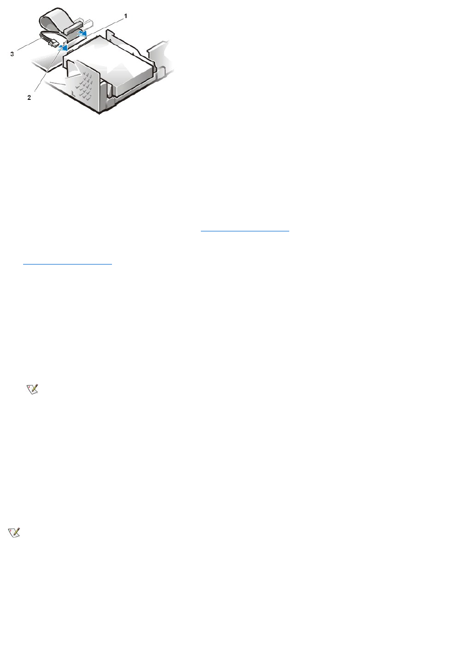
NOTICE: You must connect the blue connector on the EIDE interface cable to the IDE1 connector on the system board to avoid
possible damage to your system.
NOTICE: You must match the red-colored stripe on the EIDE cable with pin 1 on the drive's interface connector to avoid possible
damage to your system.
NOTICE: You must match the red-colored stripe on the EIDE interface cable with pin 1 on the IDE1 connector to avoid possible
damage to your system.
9. If it is not already connected, connect the blue connector on the EIDE interface cable to the IDE1 connector on the system board.
To locate the IDE1 connector on the system board, see "System Board Components."
10. Replace the drive shelf and connect the diskette and CD-ROM drive power and interface cables.
11. Replace the computer cover. Then reconnect your computer and peripherals to their electrical outlets, and turn them on.
12. Insert a bootable diskette into drive A.
13. Turn on the computer system.
14. Enter the System Setup program and update Primary Drive 0 (see the online System User's Guide for complete information on the System
Setup program).
After you update the system setup settings, reboot the system.
15. Partition and logically format your computer's hard-disk drive before proceeding to the next step.
See the documentation for your operating system for instructions.
16. Test the hard-disk drive by running the Dell Diagnostics (see the online System User's Guide for complete information).
17. If the drive you just installed is the primary drive, install your operating system on the hard-disk drive.
For instructions, refer to the documentation that came with your operating system.
3.5-Inch Diskette Drive
To remove the 3.5-inch diskette drive from the drive shelf, perform the following steps:
1. Press down on the release latch on the top left side of the 3.5-inch diskette drive.
The 3.5-inch diskette drive will pop up slightly when the latch disengages.
2. Pivot the 3.5-inch diskette drive up and out of the drive shelf.
To replace the 3.5-inch diskettedrive,performthefollowingsteps:
1. Rotate the replacement drive into position under the right diskette drive bracket on the drive shelf.
2. Lower the left side of the diskette drive while gently pressing downward, so that the slots on the bottom of the 3.5-inch diskette drive engage
1
IDE1 connector
2
EIDE cable
3
Power cable
NOTE: On systems with hard-disk drives larger than 2 GB, create a primary partition of 2 GB and divide the remaining
capacity into partitions of 2 GB or less. For example, a system with a 2.5-GB hard-disk drive would have a primary partition of
2 GB (drive C) and a second partition of 500 MB (drive D). Hard-disk drives must be partitioned this way because MS-
DOS®–based operating systems (including Microsoft®Windows NT®, when using a FAT16 file system) do not support
drive partitions larger than 2 GB.
NOTE: This procedure assumes that you have removed the drive shelf from the chassis.
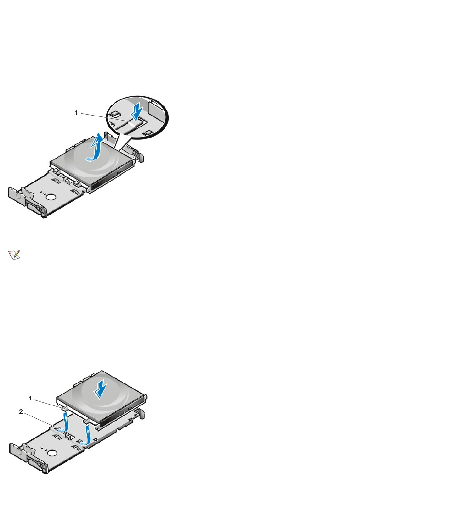
in hooks on the drive shelf.
3. Ensure that the latch on the left side of the 3.5-inch diskette drive engages the top of the diskette drive.
If necessary, press pn the latch from the bottom of the drive shelf.
4. Replace the drive shelf and connect the interface and power cable connectors.
CD-ROM Drive
Figure 14. CD-ROM Drive Removal
To remove a CD-ROM drive, perform the following steps.
1. Pushdownonthedrivereleasetabontherightsideofthedrive(seeFigure14).
2. Slide the CD-ROM drive assembly forward and up and out of the chassis.
To replace a CD-ROM drive, perform the following steps:
1. Align the tabs on the bottom of the CD-ROM drive with the notches on the drive shelf, and slide the drive toward the back of the shelf until it
snaps into place (see Figure 15).
Figure 15. CD-ROM Drive Replacement
2. Connect a power cable and an interface cable to the appropriate connectors on the back of the drive (see Figure 16).
Figure 16. CD-ROM Drive Cable Attachment
1
Drive release tab
NOTE: This procedure assumes that you have removed the drive shelf from the chassis.
1
Tabs (2)
2
Notches (2)
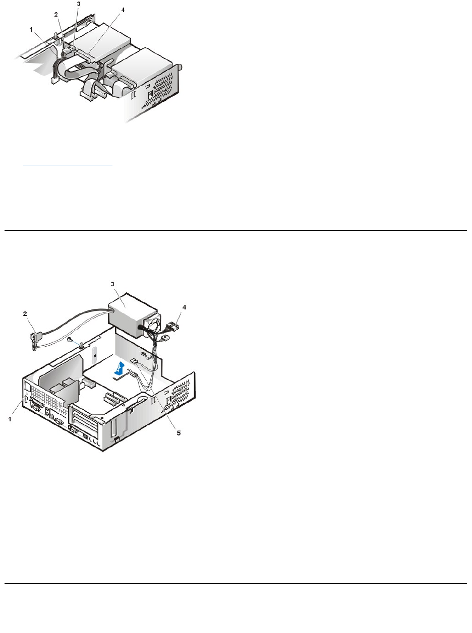
Check all cable connections. Fold cables out of the way to provide airflow for the fan and cooling vents.
3. Replace the computer cover; reconnect your computer and peripherals to their electrical outlets, and turn them on.
4. Update your system configuration information.
Set the Drive 1 option under Drives: Primary to Auto. See the online System User's Guide for more information.
5. Verify that your system works correctly by running the Dell Diagnostics (see the online System User's Guide for complete information).
System Power Supply
Figure 17. Power Supply Removal
To remove the system power supply, perform the following steps:
1. Disconnect the AC power cable from the back of the power supply.
2. DisconnecttheDCpowercablesfromthesystemboardandthedrives.
3. Remove the screw on the side of the chassis that secures the power supply.
4. RemovethescrewbelowtheACpowerreceptacleatthebackofthechassis.
5. Slide the power supply toward the center of the computer approximately 1 inch.
6. Liftthepowersupplyupandoutthecomputerchassis.
Expansion-Card Cage
Figure 18. Expansion-Card Cage Removal
1
Interface cable
2
Power cable
3
Power input connector
4
Interface connector
1
Securing screw hole
2
AC power receptacle
3
Power supply
4
System board DC
power connectors (2)
5
Drive DC power
connectors (3)
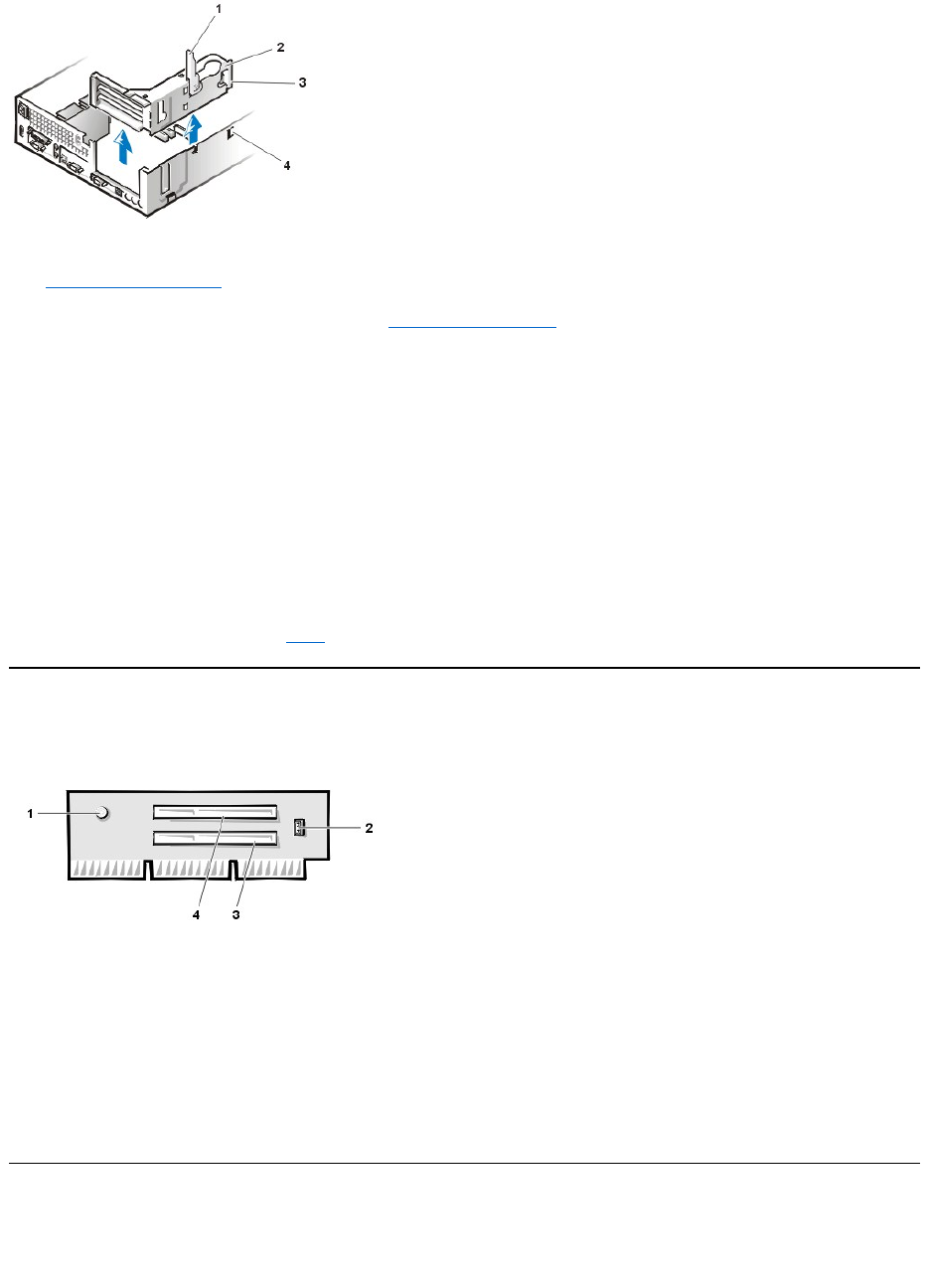
To remove the expansion-card cage from the chassis, perform the following steps:
1. Remove the computer cover.
2. Examine the cables connected to expansion cards through the back-panel openings, and disconnect any cables that will not reach to where
the cage must be placed when it is removed from the chassis.
3. Locate the securing lever and rotate the lever upward until it stops in an upright position.
4. Lift the expansion-card cage up and out of the chassis.
To replace the expansion-card cage into the chassis, perform the following steps:
1. With the securing lever in the upright position, align the tabs in the side of the expansion-card cage with the mating hooks on the left side of
the chassis wall (see Figure 18). Slide the expansion-card cage into place.
2. Rotate the securing lever downward until it is flush with the top side of the chassis. Make sure that the riser board is fully seated in the RISER
connector on the system board.
3. Reconnect any cables you removed in step 2 of the previous procedure.
Riser Board
Figure 19. PCI Riser Board
The chassis has a PCI riser board that has two PCI expansion-card connectors (see Figure 19).
To remove the PCI riser board, perform the following steps:
1. Remove the expansion-card cage.
2. Remove the expansion cards installed in the slots.
3. Remove the screws securing the riser board to the expansion-card cage.
4. Lift the riser board off the expansion card cage.
System Board Components
The subsections that follow contain procedures for removing system board components, which are shown in Figure 20.
Figure 20. System Board Components
1
Securing lever
2
Expansion-card cage
3
Tabs (2)
4
Hooks (2)
NOTICE: Use a wrist grounding strap as explained in "Precautionary Measures."
1
Auxiliary power indicator LED (AUX_LED)
2
Wakeup On LAN jumper (WOL)
3
PCI expansion slot 1 (PCI1)
4
PCI expansion slot 2 (PCI2)
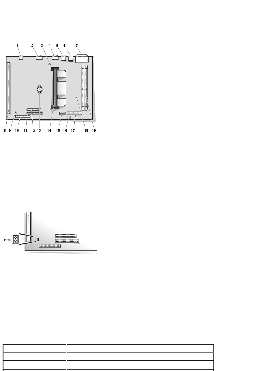
System Board Jumpers
Figure 21 shows the layout of jumpers on the system board.
Figure 21. System Board Jumpers
Jumper pins are small groups of two or more pins on a circuit board. Plastic jumpers containing a wire fit down over the pins. The wire connects
the pins and creates a circuit.
NOTICE: Make sure that your system is turned off before you change a jumper setting. Otherwise, damage to your system or
unpredictable results may occur.
To change a jumper setting, pull the jumper off its pin(s) and carefully fit it down onto the pin(s) indicated.
Dell shipped your computer with a PSWD jumper installed, meaning that the password features for this computer are enabled. When you remove
the jumper, or when you install the jumper on only one of the two pins, the password features are disabled.
System Board Labels
Table 1 lists the labels for connectors and sockets on your system board, and it gives a brief description of their functions.
Table 1. System Board Connectors and Sockets
1
NIC connector
2
Video connector
3
Fan power connector
4
Serial port 2 connector
5
USB connectors (2)
6
Mouse (upper) and keyboard (lower) connectors
7
Parallel port (upper) and serial port 1 (lower)
connectors
8
System board jumpers
9
Riser board connector
10
EIDE1 connector
11
EIDE2 connector
12
Diskette/tape-drive connector
13
Auxiliary power indicator
14
DIMM connectors (2)
15
3.3 VDC power connector
16
Control panel connector
17
DC power connector
Connector or Socket
Description
AUX_LED
Auxiliary power indicator
B1
Battery socket
Expansion Cards
The small-form-factor GX110 chassis can accommodate up to two half-length 32-bitPCIexpansioncards.Figure22 shows an example of a 32-
bit PCI expansion card.
Figure 22. 32-Bit PCI Expansion Card Example
Removing an Expansion Card
To remove an expansion card, perform the following steps.
1. Remove the computer cover.
2. If necessary, disconnect any cables connected to the card.
3. Remove the expansion-card cage.
4. Remove the screw on the mounting bracket of the card you want to remove.
5. Grasp the card by its outside corners, and ease it out of its connector.
6. If you are removing the card permanently, install a metal filler bracket over the empty card-slot opening.
7. Replace the computer cover, and reconnect your computer and peripherals to their power sources and turn them on.
DIMM_x
DIMM socket
DSKT
Diskette/tape drive interface connector
ENET
Integrated NIC connector
FAN
Microprocessor fan connector
IDEn
EIDE interface connector
KYBD
Keyboard connector
MICROPROCESSOR
Microprocessor connector
MONITOR
Video connector
MOUSE
Mouse connector
PANEL
Control panel connector
PARALLEL
Parallel port connector; sometimes referred to as LPT1
POWER_1
Main power input connector
POWER_2
3.3-volt (V) power input connector
RISER
Riser board connector
SERIALn
Serial port connectors
USB
USB connectors
CAUTION: Use a wrist grounding strap as explained in "Precautionary Measures."
NOTE: Installing filler brackets over empty card-slot openings is necessary to maintain Federal Communications Commission (FCC)
certification of the system. The brackets also keep dust and dirt out of your computer.
NOTE: After you remove and replace the cover, the chassis intrusion detector will cause the following message to be displayed at the
next system start-up:
ALERT! Cover was previously removed.
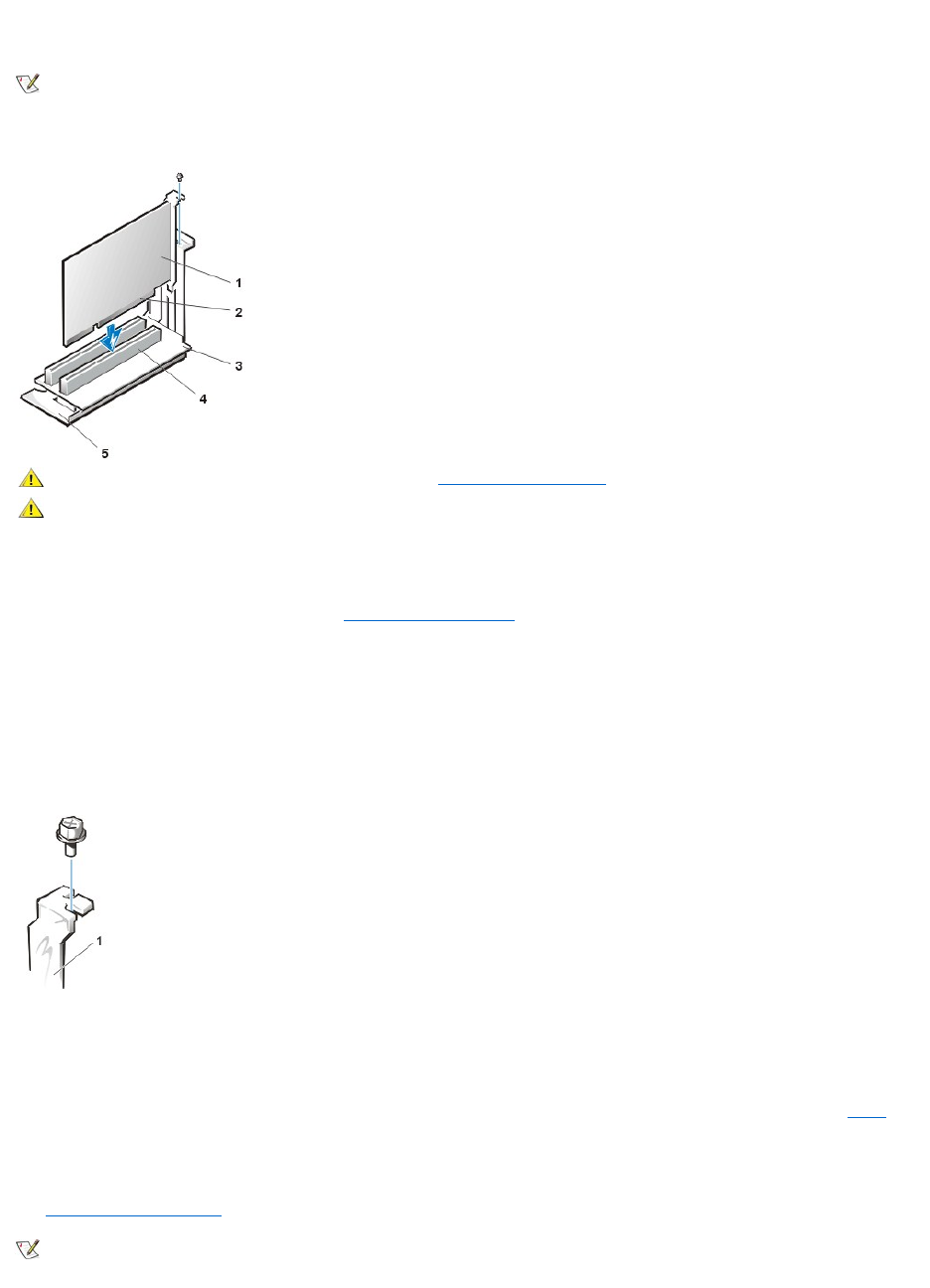
8. To reset the chassis intrusion detector, enter the System Setup program and reset Chassis Intrusion to Not Detected.
See the online System User's Guide for detailed information on the chassis intrusion detector.
Figure 23. Expansion Card Installation
To install an expansion card, perform the following steps:
1. Prepare the expansion card for installation, and remove the computer cover.
See the documentation that came with the expansion card for information on configuring the card, making internal connections, or otherwise
customizing it for your system.
2. Remove the screw and remove the metal filler bracket that covers the card-slot opening for the expansion slot you intend to use (see Figure
24).
Save the screw to use when installing the expansion card later in this procedure.
Figure 24. Filler Bracket Removal
3. Insert the expansion card into the expansion-card connector.
If the expansion card is full-length, insert the front end of the card into the corresponding card guide on the inside front of the chassis as you
insert the card into its connector. Insert the card's edge connector firmly into the expansion-card slot.
4. When the card is firmly seated in the connector, secure the card's mounting bracket to the chassis with the screw you removed in step 2.
5. Connect any cables that should be attached to the card.
See the documentation for the card for information about the card's cable connections.
6. Replace the computer cover, and reconnect your computer and peripherals to their power sources and turn them on.
NOTE: If a setup password has been assigned by someone else, contact your network administrator for information on resetting the
chassis intrusion detector.
1
Expansion card
2
Card-edge connector
3
Riser board
4
Expansion-card connector
5
Expansion-card cage
CAUTION: Use a wrist grounding strap as explained in "Precautionary Measures."
CAUTION: Some network cards automatically start up the system when they are connected. To
guard against electrical shock, be sure to unplug your computer from its electrical outlet before
installing any expansion cards
1
Filler bracket
NOTE: After you remove and replace the cover, the chassis intrusion detector will cause the following message to be displayed at the
next system start-up:
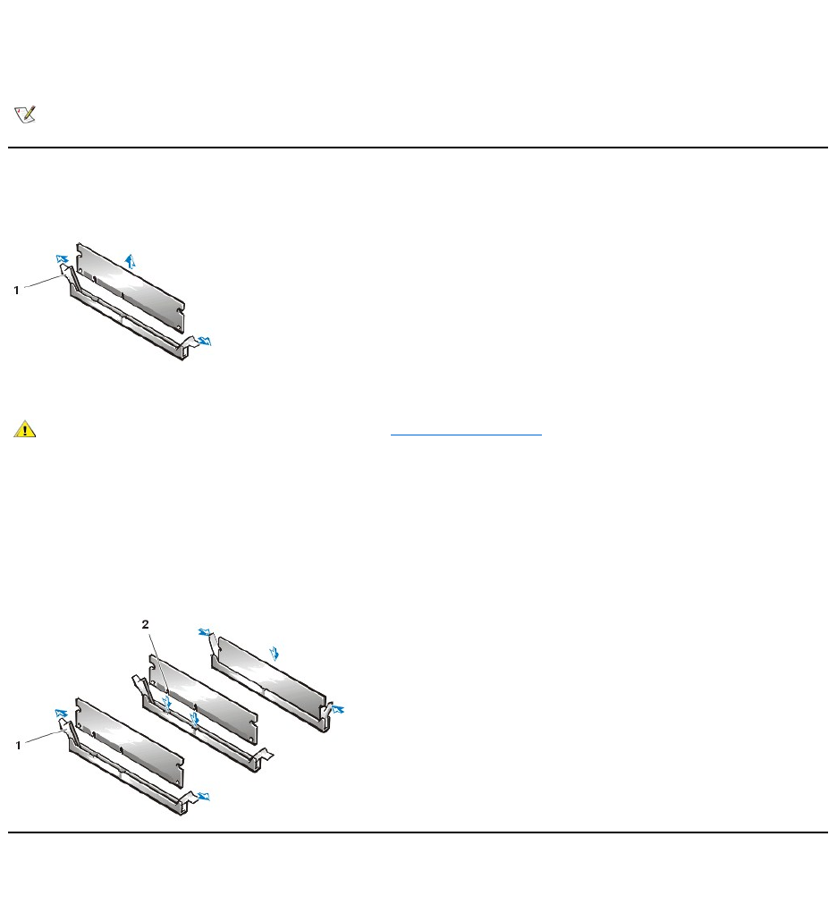
7. To reset the chassis intrusion detector, enter the System Setup program and reset Chassis Intrusion to Not Detected.
See the User's Guide for detailed information on the chassis intrusion detector.
DIMMs
Figure 25. DIMM Removal
To remove a DIMM, perform the following steps:
1. Push outward on the two DIMM socket ejectors simultaneously until the DIMM is released from its socket.
2. Lift the DIMM away from the socket.
To install a DIMM, press the DIMM fully into the socket while closing the ejectors to lock the DIMM into the socket (see Figure 26).
Figure 26. DIMM Installation
Microprocessor/Heat Sink Assembly
Figure 27. Microprocessor/Heat Sink Assembly Removal
ALERT! Cover was previously removed.
NOTE: If a setup password has been assigned by someone else, contact your network administrator for information on resetting the
chassis intrusion detector.
1
Ejectors (2)
CAUTION: Use a wrist grounding strap as explained in "Precautionary Measures."
1
Ejectors (2)
2
Notches (2)
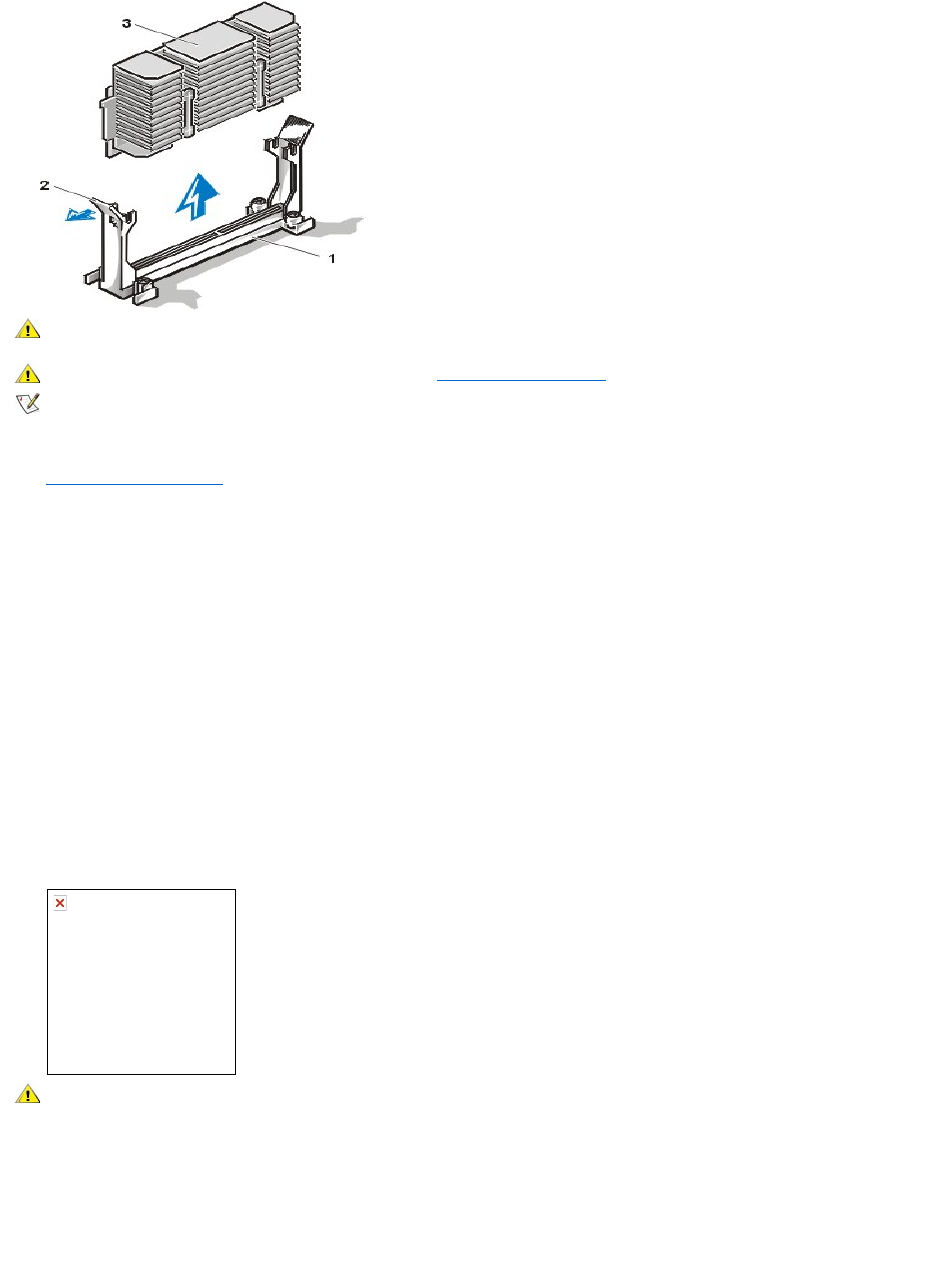
To replace a microprocessor, perform the following steps:
1. Remove the computer cover.
2. Locate the microprocessor socket on the system board.
3. Unplug the fan power connector on the system board
4. Remove the screws securing the fan to the end of the heat sink assembly. Then remove the fan.
5. Gently pull out the guide-bracket assembly latch, grasp the existing microprocessor/heat sink assembly firmly, and pull straight up to remove
it from the guide bracket assembly.
You must use up to 15 pounds of force to disengage the microprocessor package from the connector. Do not rock the package while
removing it.
6.
7. Remove the microprocessor chip from the socket.
Your microprocessor socket is a zero insertion force (ZIF) socket with a lever-type handle that secures the chip in, or releases it from, the
socket.
To remove the chip, pull the microprocessor-socket release lever straight out until the chip is released (see Figure 28). Then remove the chip
from the socket. Leave the release lever extended so that the socket is ready for the new microprocessor.
Figure 28. Microprocessor Removal
8. Unpack the new microprocessor.
If any of the pins on the chip appear to be bent, see your Installation and Troubleshooting Guide for instructions on obtaining technical
1
Securing clip
2
Press here to release securing clip
CAUTION: The microprocessor SEC cartridge/heat sink assembly can get extremely hot. Be sure that the assembly has had
sufficient time to cool before you touch it.
CAUTION: Use a wrist grounding strap as explained in "Precautionary Measures."
NOTE: Dell recommends that only a technically knowledgeable person perform this procedure.
remove17.gif (10325 bytes)
1
Microprocessorchip
2
Releaselever
3
Microprocessorsocket
CAUTION: Ground yourself by touching an unpainted metal surface on the back of the computer.
NOTICE: Positioning the microprocessor chip incorrectly in the socket can permanently damage the chip and the computer when
you turn on the system.
NOTICE: Be careful not to bend any of the pins when unpacking the microprocessor. Bending the pins can permanently damage
the microprocessor.
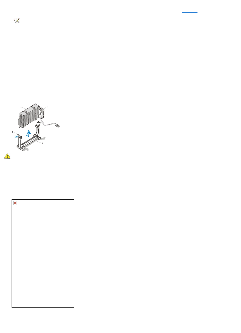
assistance.
9. Align the pin-1 corner of the microprocessor chip with the pin-1 corner of the microprocessor socket (see Figure28).
The pin-1 corner of the microprocessor is the squared off corner (see Figure 28).
10. Install the microprocessor chip in the socket (see Figure28).
If the release lever on the microprocessor socket is not all the way out, move it to that position now.
With the pin-1 corners of the chip and socket aligned, align the pins on the chip with the holes in the socket. Set the chip lightly in the socket
and make sure all pins are headed into the correct holes. Because your system uses a ZIF microprocessor socket, there is no need to use
force (which could bend the pins if the chip is misaligned). When the chip is positioned correctly, it should seat itself in the socket with
minimal pressure.
When the chip is fully seated in the socket, pivot the microprocessor-socket release lever back toward the socket until it snaps into place,
securing the chip.
Figure 29. Microprocessor Chip Installation
11. Unpack the heat sink included in your upgrade kit.
Peel the release liner from the adhesive tape that is attached to the bottom of the heat sink.
12. Place the heat sink on top of the microprocessor chip (see Figure 30).
Figure 30. Heat Sink Installation
13. Replace the heat sink securing clip.
Orient the clip as shown in Figure 30, and hook the unfolded end of the clip over the tab on the top edge of the socket. Then press down on
the folded end of the clip to snap the clip over the tab on the bottom edge of the socket.
NOTE: Identifying the pin-1 corners is critical to positioning the chip correctly.
1
Pin-1 corners of chip and socket aligned
CAUTION: Ground yourself by touching an unpainted metal surface on the back of the computer.
process04.gif (22697 bytes)
1
Fan screws (2)
2
Fan
3
Securing clip
4
Heat sink
5
Celeron™microprocessor
6
Microprocessor ZIF socket
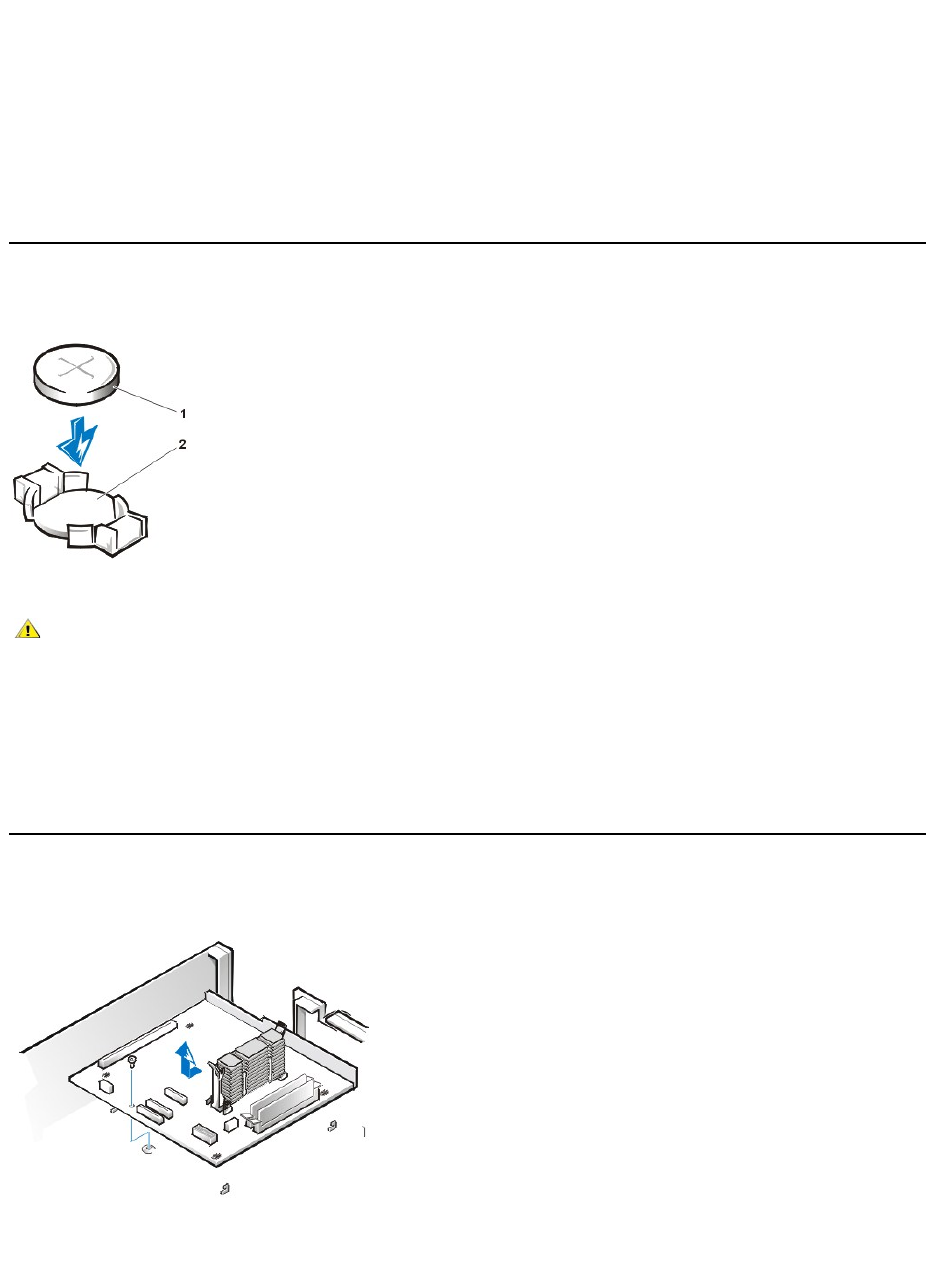
14. Replace the fan assembly and secure it with two thumbscrews. Then connect the fan power cable to the FAN connector on the system
board .
15. Install the microprocessor fan cable connector to the FAN connector on the system board.
16. Replace the computer cover, and then reconnect your computer and peripherals to their power sources and turn them on.
As the system boots, it detects the presence of the new microprocessor and automatically changes the system configuration information in
the System Setup program.
17. Enter the System Setup program, and confirm that the Microprocessor option correctly identifies the installed microprocessor.
18. Run the Dell Diagnostics to verify that the new microprocessor operates correctly.
System Battery
Figure 31. System Battery Removal
To remove the system battery, perform the following steps:
1. If possible, enter the System Setup program and print the System Setup screens.
2. Remove the system battery by carefully prying it out of its socket with your fingers or with a blunt, nonconducting object such as a plastic
screwdriver.
When you replace the system battery, orient the new battery with the "+" facing up. Insert the battery into its socket and snap it into place.
System Board
Figure 32. System Board Removal
To remove the system board, perform the following steps:
1. Disconnect all cables from their connectors at the back of the computer.
1
Battery
2
Battery socket
CAUTION: There is a danger of the new battery exploding if it is incorrectly installed. Replace the battery only with the same or
equivalent type recommended by the manufacturer. Discard used batteries according to the manufacturer’s instructions.

2. Remove the drive shelf assembly.
3. Remove the expansion-card cage.
4. Remove the hard-disk drive/bracket.
5. Disconnect all cables from the system board.
6. Remove the screw that secures the system board to the bottom of the chassis (see Figure32).
7. Slide the system board toward the front of the chassis until it stops.
8. Carefully lift the system board out of the chassis (be sure to lift evenly and not twist the system board).
To replace a system board, perform the following steps:
1. Remove the DIMMs and the microprocessor/heat sink assembly and install them on the replacement board.
2. Set the jumpers on the new system board so that they are identical to those on the old board, unless a microprocessor upgrade is being
installed.
3. Push down near each slot to engage the grounding clip onto its corresponding tab.
4. Push evenly on both sides of the system board as you slide it into position (do not twist the system board).
Back to Contents Page
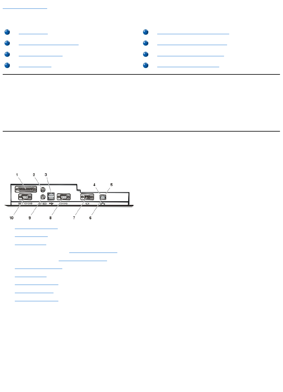
Back to Contents Page
SetupandOperation:Dell™OptiPlex™GX110SystemUser'sGuide
Getting Started
If you need to set up your computer system yourself (rather than having it set up by a network administrator), see "Getting Started" in the System
Information Guide that accompanied your system for instructions on connecting cables and turning on your system for the first time.
After you correctly connect all the cables to your system and turn it on, see the setup guide for your operating system to complete its installation.
When the operating system is installed, you can connect peripheral devices, such as a printer, or install application programs not already installed
by Dell.
Connecting Peripheral Devices
Figure 1 shows the connectors on the back of your computer for attaching external devices.
Figure 1. I/O Ports, Connectors, and Indicators
When you connect external devices to your computer's back panel, follow these guidelines:
lCheck the documentation that accompanied the device for specific installation and configuration instructions.
For example, you must connect most devices to a particular input/output (I/O) port or connector to operate properly. Also, external
devices like a mouse or printer usually require you to load device drivers into system memory before they will work.
lAlways attach external devices while your computer is turned off. Then turn on the computer before turning on any external devices, unless
the documentation for the device specifies otherwise. (If the computer does not seem to recognize the device, try turning on the device
before turning on the computer.)
NOTICE: When you disconnect external devices from the back of the computer, wait 5 seconds after turning off the
computer before you disconnect any devices to avoid possible damage to the system board.
Parallel Port Connector
Getting Started
Security Cable Slot and Padlock Ring
Connecting Peripheral Devices
Using the System Password Feature
Controls and Indicators
Using the Setup Password Feature
Chassis Intrusion
Disabling a Forgotten Password
1
Parallel port connector
2
Mouse connector
3
USB connectors
4
Link integrity indicator (see "Integrated NIC Connector")
5
Activity indicator (see "Integrated NIC Connector")
6
Integrated NIC connector
7
Video connector
8
Serial port 2 connector
9
Keyboard connector
10
Serial port 1 connector

The integrated parallel port uses a 25-pin D-subminiature connector on the computer's back panel.
This I/O port sends data in parallel format (where eight data bits, or one byte, are sent simultaneously over eight separate lines in a single cable).
The parallel port is used primarily for printers.
The default designation of your computer's integrated parallel port is LPT1. Port designations are used, for example, in software installation
procedures to identify the port to which your printer is attached, thus telling your software where to send its output. (An incorrect designation
prevents the printer from printing or causes scrambled print.)
Mouse Connector
Your system uses a Personal System/2 (PS/2)-compatible mouse. The mouse cable attaches to a 6-pin miniature Deutsche Industrie Norm (DIN)
connector on the back panel of your computer. Turn off the computer and any attached peripherals before connecting a mouse to the computer.
A PS/2-compatible mouse works as does an industry-standard serial mouse or bus mouse except that it has its own dedicated connector, which
frees up the serial ports and does not require an expansion card.
Mouse driver software gives the mouse priority with the microprocessor by issuing interrupt request (IRQ) 12 whenever you move the mouse. The
drivers also pass along the mouse data to the application that is in control. If you have the Microsoft®Windows®98, Windows 95, or Windows
NT®4.0 operating system, Dell already installed the necessary mouse drivers on your hard-disk drive. If you need to reinstall the mouse drivers,
see "Mouse Drivers" for instructions.
USB Connectors
Your system contains two Universal Serial Bus (USB) connectors for attaching USB-compliant devices. USB-compliant devices are typically
peripherals such as keyboards, mice, printers, and computer speakers.
If you reconfigure your hardware, you may need pin number and signal information for the USB connectors.
Integrated NIC Connector
Your system has an integrated 10/100-megabit-per-second (Mbps) 3Com®Peripheral Component Interconnect (PCI) 3C905C-TX Ethernet
network interface controller (NIC). The NIC provides all the functions of a separate network expansion card and supports both the 10BASE-T and
100BASE-TX Ethernet standards.
The NIC includes a Remote Wake Up feature that enables the computer to be started by a special local area network (LAN) signal from a server
management console. Remote Wake Up provides remote computer setup, software downloading and installation, file updates, and asset tracking
after hours and on weekends when LAN traffic is typically at a minimum.
The NIC connector on the computer's back panel has the following indicators (see Figure 1):
lA yellow activity indicator flashes when the system is transmitting or receiving network data. (A high volume of network traffic may make this
indicator appear to be in a steady "on" state.)
lA dual-colored link integrity indicator, which lights up green when there is a good connection between a 10-Mbps network and the NIC, or it
lights up orange when there is a good connection between a 100-Mbps network and the NIC. When the green indicator is off, the computer is
not detecting a physical connection to the network.
Video Connector
The system uses a 15-pin high-density D-subminiature connector on the back panel for attaching a video graphics array (VGA)-compatible
monitor to your system.
Serial Port Connectors
The serial ports use 9-pin D-subminiature connectors on the back panel. These ports support devices such as external modems or plotters that
require serial transmission (sending one bit of data at a time over one line).
The default designations for these integrated serial ports are COM1 for serial port 1 and COM2 for serial port 2. Port designations are used in
software installation procedures to identify the port used by a device—for example, to specify the port used by a modem when you install
communications software.
The system contains a reconfiguration feature to reassign the serial port's designation if you add an expansion card containing a serial port using
this designation.
If you set the system’s integrated serial ports to Auto in System Setup and add an expansion card containing a serial port configured to a specific
designation, the computer automatically maps (assigns) the integrated ports to the appropriate COM setting as necessary.
Before you add a card with a serial port, check the documentation that accompanied your software to make sure that the software can be mapped
to the new COM port designation.
Keyboard Connector
NOTE: The integrated parallel port is automatically disabled if the system detects an installed expansion card containing a parallel port
configured to the same address as specified in Parallel Port in System Setup.
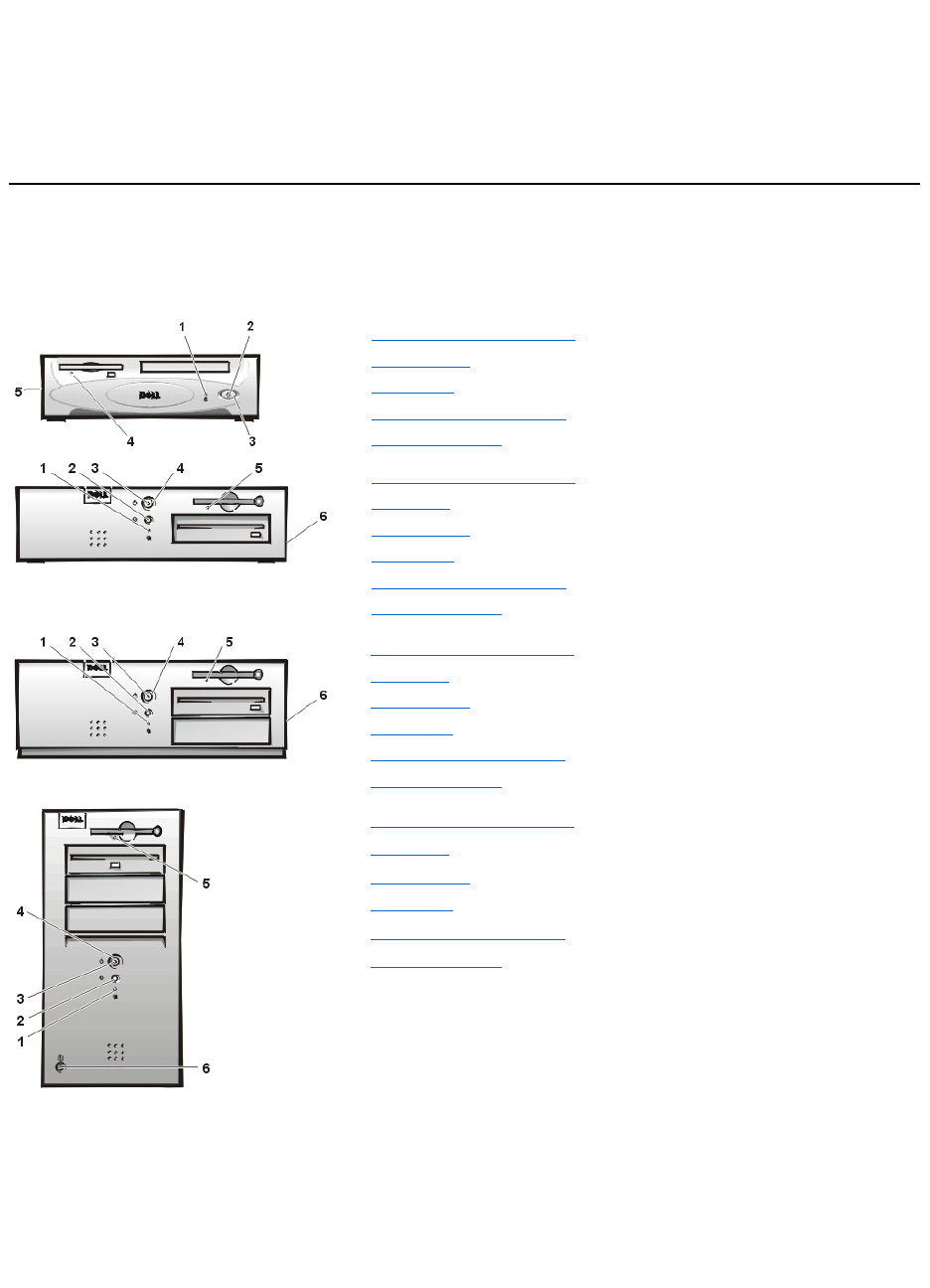
Your system uses a PS/2-style keyboard. The keyboard cable attaches to a 6-pin miniature DIN connector on the back panel of your computer.
Network Cable Requirements
Your computer's NIC connector (an RJ45 connector located on the back panel) is designed for attaching an unshielded twisted pair (UTP) Ethernet
cable. Press one end of the UTP cable into the NIC connector until the cable snaps securely into place.
Connect the other end of the cable to an RJ45 jack wall plate or to an RJ45 port on a UTP concentrator or hub, depending on your network
configuration.
Controls and Indicators
Figure 2 shows the controls and indicators on the front panel of your computer.
Figure 2. Controls and Indicators
Hard-Disk Drive Access Indicator
The hard-disk drive access indicator lights up when a hard-disk drive is reading data from or writing data to the drive.
Reset Button
The reset button allows you to reboot (restart) your system without having to turn the power off and then on again. Rebooting the system in this
manner reduces stress on system components. However, be sure that you have saved and closed all open files and application programs (if
possible) to avoid losing any data. Then perform an orderly shutdown of the operating system (see your operating system documentation for
instructions).
1
Hard-disk drive access indicator
2
Power indicator
3
Power button
4
Diskette-drive access indicator
5
Cover release button
1
Hard-disk drive access indicator
2
Reset button
3
Power indicator
4
Power button
5
Diskette-drive access indicator
6
Cover release button
1
Hard-disk drive access indicator
2
Reset button
3
Power indicator
4
Power button
5
Diskette-drive access indicator
6
Cover release button
1
Hard-disk drive access indicator
2
Reset button
3
Power indicator
4
Power button
5
Diskette-drive access indicator
6
Cover release button
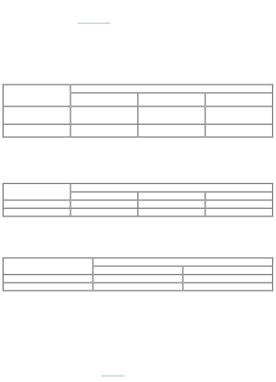
Power Indicator
The power indicator on the front of the computer has a light-emitting diode (LED) that illuminates in two different colors and blinks or remains solid
to indicate several different states. See "Diagnostic LEDs" for a description of each of these states.
Power Button
The power button controls the system's AC input power.
The Microsoft Windows 98 and Windows 98 Second Edition (SE) operating systems let you configure the function of the power button through the
Advanced Configuration and Power Interface (ACPI) feature (see Table 1).
NOTICE: To turn off your computer system, perform an orderly system shutdown using the operating system menu when possible.
Table 1. Power Button Behavior Under Microsoft Windows 98 and Windows 98 SE Operating Systems With ACPI
*Pressing or holding the power button to shut down the system may result in data loss. Use the power button to shut down the system only if the
operating system is not responding.
Microsoft Windows 95 does not support ACPI. Table 2 shows power button functions for Windows 95 operating systems and for Windows 98
operating systems that have the ACPI feature disabled.
Table 2. Power Button Behavior Under Microsoft Windows 95 and Windows 98 (With Dell AutoShutdown Loaded)
*Pressing or holding the power button to shut down the system may result in data loss. Use the power button to shut down the system only if the
operating system is not responding.
Table 3 shows power button functions for Microsoft Windows NT operating systems.
Table 3. Power Button Behavior Under Microsoft Windows NT (With Dell AutoShutdown Loaded)
*Pressing or holding the power button to shut down the system may result in data loss. Use the power button to shut down the system only if the
operating system is not responding.
If the system does not turn off when you press the power button, the system may be hung. Press and hold the power button until the system turns off
completely (this process may take several seconds). Alternatively, press the reset button to reset the system and reboot. If the system is hung and
both buttons fail to function properly, unplug the AC power cable from the computer, wait for it to completely stop running, plug in the AC power
cable, and if it the system does not restart, press the power button to restart the system.
Diskette-Drive Access Indicator
The diskette-drive access indicator lights up when the drive is reading data from or writing data to a diskette. Wait until the access indicator turns
off before removing a diskette from the drive.
Cover Release Button
On the back of the chassis, slide the upper half of the padlock ring to the left. Then press the cover release button to remove the computer cover.
Action
Results
System Turned On
and ACPI Enabled
System in Standby Mode
System Turned Off
Press power button
System goes into standby mode
or turns off (depending on the
operating system setup)
System turns on
Boots and system turns on
Hold power button
for 6 seconds*
System turns off immediately
System turns off immediately
Boots and system turns on
Action
Results
System Turned On
System in Suspend Mode
System Turned Off
Press power button
System turns off
System turns off
Boots and system turns on
Hold power button for 6 seconds*
System turns off immediately
System turns off immediately
Boots and system turns on
Action
Results
System Turned On
System Turned Off
Press power button
System shuts down
Bootsandsystemturnson
Hold power button for 6 seconds*
System turns off immediately
Boots and system turns on

Chassis Intrusion
An integrated chassis intrusion alarm displays the status of the system chassis intrusion monitor. If the chassis has been opened, the setting
changes to Detected and the following message appears during the boot sequence at system start-up:
Alert! Cover was previously removed.
Use System Setup to reset the alarm so that future intrusions are detected.
Security Cable Slot and Padlock Ring
On the back of the computer are a security cable slot and padlock ring (see Figure 5, Figure 6, Figure 7, or Figure 8 in "Inside Your Computer") for
attaching commercially available antitheft devices. Security cables for personal computers usually include a segment of galvanized cable with an
attached locking device and key. To prevent unauthorized removal of your computer, loop the cable around an immovable object, insert the locking
device into the security cable slot on the back of your computer, and lock the device with the key provided. Complete instructions for installing this
kind of antitheft device are usually included with the device.
Using the System Password Feature
NOTICE: The password features provide a basic level of security for the data on your system. However, they are not foolproof. If
your data requires more security, it is your responsibility to obtain and use additional forms of protection, such as data encryption
programs.
Your Dell system is shipped to you without the system password feature enabled. If system security is a concern, operate your system only with
system password protection.
You can assign a system password, as described in "Assigning a System Password," whenever you use System Setup. After a system password
is assigned, only those who know the password have full use of the system.
When System Password is set to Enabled, the computer system prompts you for the system password just after the system boots. See "Using
Your System Password to Secure Your System" for more information.
To change an existing system password, you must know the password (see "Deleting or Changing an Existing System Password"). If you assign
and later forget a system password, you must remove the computer cover to change a jumper setting that disables the system password feature
(see "Disabling a Forgotten Password"). Note that you erase the setup password at the same time.
NOTICE: If you leave your system running and unattended without having a system password assigned, or if you leave your
computer unlocked so that someone can disable the password by changing a jumper setting, anyone can access the data stored on
your hard-disk drive.
Assigning a System Password
Before you can assign a system password, you must enter System Setup and check the System Password option.
When a system password is assigned, the setting shown in System Password is Enabled. When the system password feature is disabled by a
jumper setting on the system board, the setting shown is Disabled. You cannot change or enter a new system password if either of these options
is displayed.
When no system password is assigned and the password jumper on the system board is in the enabled position (its default setting), the option
shown for the System Password option is Not Enabled. Only when System Password is set to Not Enabled can you assign a system
password, using the following procedure:
1. Verify that Password Status is set to Unlocked.
For instructions on changing the setting for Password Status, see "Password Status."
2. Highlight System Password, and then press the left- or right-arrow key.
The option heading changes to Enter Password, followed by an empty 32-character field in square brackets.
3. Type your new system password.
You can use up to 32 characters in your password.
NOTES: Antitheft devices are of differing designs. Before purchasing such a device, make sure it works with the cable slot on your
computer.
The small-form-factor chassis has a padlock ring that slides in and out of the back cover. To use the ring, pull it into the extended
position.

As you press each character key (or the spacebar for a blank space), a placeholder appears in the field. The password assignment
operation recognizes keys by their location on the keyboard, without distinguishing between lowercase and uppercase characters. For
example, if you have an M in your password, the system recognizes either M or m as correct.
Certain key combinations are not valid. If you enter one of these combinations, the speaker emits a beep.
To erase a character when entering your password, press the <Backspace> key or the left-arrow key.
4. Press <Enter>.
If the new system password is less than 32 characters, the whole field fills with placeholders. Then the option heading changes to
Verify Password, followed by another empty 32-character field in square brackets.
5. To confirm your password, type it a second time and press <Enter>.
The password setting changes to Enabled. Your system password is now set; you can exit System Setup and begin using your
system. Note, however, that password protection does not take effect until you reboot the system by pressing the reset button or by
turning the system off and then on again.
Using Your System Password to Secure Your System
Whenever you either turn on your system or press the reset button, or when you reboot the system by pressing the <Ctrl><Alt><Del> key
combination, the following prompt appears on the screen when Password Status is set to Unlocked:
Type in the password and
- press <ENTER> to leave password security enabled.
- press <CTRL><ENTER> to disable password security.
Enter password:
If Password Status is set to Locked, the following prompt appears:
Type the password and press <Enter>.
After you type the correct system password and press <Enter>, your system boots and you can use the keyboard and/or mouse to operate your
system as usual.
If you enter a wrong or incomplete system password, the following message appears on the screen:
** Incorrect password. **
Enter password:
If you again enter an incorrect or incomplete system password, the same message appears on the screen.
The third and subsequent times you enter an incorrect or incomplete system password, the system displays the following message:
** Incorrect password. **
Number of unsuccessful password attempts: 3
System halted! Must power down.
The number of unsuccessful attempts made to enter the correct system password can alert you to an unauthorized person attempting to use your
system.
Even after your system is turned off and on, the previous message is displayed each time an incorrect or incomplete system password is entered.
Deleting or Changing an Existing System Password
To delete or change an existing system password, perform the following steps:
1. Enter System Setup by pressing <F2>, and verify that Password Status is set to Unlocked.
2. Reboot your system to force it to prompt you for a system password.
3. When prompted, type the system password.
NOTE: To escape from the field without assigning a system password, press the <Tab> key or the <Shift><Tab> key
combination to move to another field, or press the <Esc> key at any time prior to completing step 5.
NOTE: If you have assigned a setup password (see "Using the Setup Password Feature"), the system accepts your setup password as
an alternate system password.
NOTE: You can use Password Status in conjunction with System Password and Setup Password to further protect your system from
unauthorized changes.

4. Press <Ctrl><Enter> to disable the existing system password, instead of pressing <Enter> to continue with the normal operation of your
system.
5. Confirm that Not Enabled is displayed for the System Password option of System Setup.
If Not Enabled appears in the System Password option, the system password has been deleted. If you want to assign a new
password, continue to step 6. If Not Enabled is not displayed for the System Password option, press <Alt><B> to reboot the system,
and then repeat steps 3 through 5.
6. To assign a new password, follow the procedure in "Assigning a System Password."
Using the Setup Password Feature
Your Dell system is shipped to you without the setup password feature enabled. If system security is a concern, you should operate your system
with setup password protection.
You can assign a setup password, as described in "Assigning a Setup Password," whenever you use System Setup. After you assign a setup
password, only those who know the password have full use of System Setup. See "Operating Your System With A Setup Password Enabled" for
more information.
To change an existing setup password, you must know the setup password. If you assign and later forget a setup password, you need to remove
the computer cover to change a jumper setting that disables the setup password feature (see "Disabling a Forgotten Password"). Note that you
erase the system password at the same time.
Assigning a Setup Password
You can assign a setup password only if Setup Password is set to Not Enabled. To assign a setup password, highlight Setup Password and
press the left- or right-arrow key. The system prompts you to enter and verify the password. If a character is illegal for password use, the system
emits a beep.
After you verify the password, the Setup Password setting changes to Enabled. The next time you enter System Setup, the system prompts you
for the setup password.
A change to Setup Password becomes effective immediately (rebooting the system is not required).
Operating Your System With a Setup Password Enabled
If Setup Password is set to Enabled, you must enter the correct setup password before you can modify the majority of the System Setup options.
When you start System Setup, the System Setup screen appears with Setup Password highlighted, prompting you to type the password.
If you do not enter the correct password, the system lets you view, but not modify, the System Setup screen.
Deleting or Changing an Existing Setup Password
To delete or change an existing setup password, perform the following steps:
1. Enter System Setup.
2. Highlight Setup Password and press the left- or right-arrow key to delete the existing setup password.
The setting changes to Not Enabled.
3. If you want to assign a new setup password, perform the steps in "Assigning a Setup Password."
Disabling a Forgotten Password
If you forget your system or setup password, you cannot operate your system or change settings in System Setup until you remove the computer
cover, change the password jumper setting to disable the passwords, and erase the existing passwords.
Todisableaforgottenpassword,performthefollowingsteps.
NOTES: The setup password can be the same as the system password.
If the two passwords are different, the setup password can be used as an alternate system password. However, the system password
cannot be used in place of the setup password.
NOTE: You can use Password Status in conjunction with Setup Password to protect the system password from unauthorized
changes.

1. Remove the computer cover according to the instructions in "Removing and Replacing the Computer Cover."
2. Remove the jumper plug from the PSWD jumper to disable the password feature.
Refer to "System Board Jumpers" for jumper information and to Figure 10 in "Inside Your Computer" for the location of the password
jumper (labeled "PSWD") on the system board.
3. Replace the computer cover.
4. Reconnect your computer and peripherals to an electrical outlet, and then turn them on.
Booting your system with the PSWD jumper plug removed erases the existing password(s).
5. Enter System Setup, and verify that the password is disabled. Proceed to step 6 if you want to assign a new password.
6. Remove the computer cover according to the instructions in "Removing and Replacing the Computer Cover."
7. Replace the PSWD jumper plug.
8. Replace the computer cover, and then reconnect the computer and peripherals to an electrical outlet and turn them on.
Booting your system with the PSWD jumper installed reenables the password feature. When you enter System Setup, both password
options appear as Not Enabled, meaning that the password feature is enabled but that no password has been assigned.
9. Assign a new system and/or setup password.
To assign a new system password, see "Assigning a System Password."Toassignanewsetuppassword,see"Assigning a Setup
Password."
Back to Contents Page
CAUTION: Before you remove the computer cover, see "Safety First—For You and Your Computer."
NOTE: Before you assign a new system and/or setup password, you must replace the PSWD jumper plug.
CAUTION: Before you remove the computer cover, see "Safety First—For You and Your Computer."
Back to Contents Page
SystemSetupOptions:Dell™OptiPlex™GX110SystemUser'sGuide
AC Power Recovery
AC Power Recovery determines what happens when AC power is restored to the system.
When Off is selected, the system remains off when AC power is restored. When On is selected, the system starts up when AC power is restored.
When Last is selected, the system returns to the AC power state existing at the time that AC power was lost. If the system is on when AC power is
lost, the system starts up when AC power is restored. If the system is off when AC power is lost, the system remains off when AC power is
restored.
Asset Tag
Asset Tag displays the customer-programmable asset tag number for the system if an asset tag number is assigned. You can use the Asset Tag
utility, which is included with your software support utilities, to enter an asset tag number up to ten characters long into nonvolatile random-access
memory (NVRAM).
Auto Power On
Auto Power On allows you to set the time and days of the week to turn on the computer system automatically. You can set Auto Power On to turn
on the system either every day or every Monday through Friday.
Time is kept in a 24-hour format (hours:minutes). To change the start-up time, press the right-arrow key to increase the number in the highlighted
field or press the left-arrow key to decrease the number. If you prefer, you can type numbers in both fields.
The default for Auto Power On is Disabled.
Boot Sequence
Boot Sequence enables you to set the order of the devices from which the system attempts to boot.
The term boot refers to the system's start-up procedure. When turned on, the system "bootstraps" itself into an operational state by loading into
memory a small program, which in turn loads the necessary operating system. Boot Sequence tells the system where to look for the files that it
needs to load.
To set the boot device order, press <Enter> to access the field's pop-up options menu. Press the up- and down-arrow keys to move through the list
of devices. Press the spacebar to enable or disable a device (enabled devices appear with a check mark). Press plus (+) or minus (–) to move a
selected device up or down the list. The following subsections describe typical boot devices.
Diskette Drive A:
Selecting Diskette Drive A: as the first device causes the system to try booting from drive A first. If the system finds a diskette that is not bootable
AC Power Recovery
Primary Drive n and Secondary Drive n
Asset Tag
Remote Wake Up
Auto Power On
Report Keyboard Errors
Boot Sequence
System Data
CPU ID
System Date
CPU Speed
System Memory
Diskette Drive A and Diskette Drive B
System Security
Integrated Devices
System Time
Keyboard NumLock
ZIP Floppy Support
PCI IRQ Assignment
NOTE: This feature does not work if you turn off your system using a power strip or surge protector.

in the drive or finds a problem with the drive itself, it displays an error message. If it does not find a diskette in the drive, the system tries to boot
from the next device in the boot sequence list.
Hard-Disk Drive
Selecting Hard-Disk Drive causes the system to attempt to boot first from the hard-disk drive and then from the next device in the boot sequence
list.
IDE CD-ROM Device
Selecting IDE CD-ROM Device causes the system to try booting from the CD-ROM drive first. If the system finds a CD that is not bootable in the
drive or finds a problem with the drive itself, it displays an error message. If it does not find a CD in the drive, the system tries to boot from the next
device in the boot sequence list.
MBA UNDI
Selecting MBA UNDI allows the system to boot from the network server. The MBA UNDI option appears under Boot Sequence only if the
Network Interface Controller option is set to On w/MBA. If the Network Interface Controller option is set to On or Off, set it to On w/MBA and then
press <Alt><b> to save the change and reboot the system. MBA UNDI then appears under Boot Sequence.
When you select this option, the system prompts you to press <Ctrl><Alt><b> at the Dell logo screen during system boot. A menu then appears
that allows you to select PXE, RPL, BootP, or NetWare as the active boot mode. If a boot routine is not available from the network server, the
system tries to boot from the next device in the boot sequence list.
CPU ID
CPU ID provides the manufacturer's identification code for the installed microprocessor.
CPU Speed
CPU Speed indicates the processor speed at which your system boots.
Press the left- or right-arrow key to toggle the CPU Speed option between the resident microprocessor's rated speed (the default) and a lower
compatibility speed, which lets you accommodate speed-sensitive application programs. A change to this option takes effect immediately
(rebooting the system is not required).
To toggle between the rated processor speed and the compatibility speed while the system is running in real mode, press <Ctrl><Alt><\>. (For
keyboards that do not use American English, press <Ctrl><Alt><#>.)
Diskette Drive A and Diskette Drive B
Diskette Drive A and Diskette Drive B identify the type of diskette drives installed in your computer. With the standard cabling configuration,
Diskette Drive A (the boot diskette drive) is the 3.5-inch diskette drive installed in the top externally accessible drive bay; Diskette Drive B is a
second diskette drive installed in any of the lower externally accessible drive bays.
The Diskette Drive A and Diskette Drive B options have the following possible settings:
l5.25 Inch, 360 KB
l5.25 Inch, 1.2 MB
l3.5 Inch, 720 KB
l3.5 Inch, 1.44 MB
lNot Installed
Integrated Devices
Integrated Devices configures the following devices integrated with the system board:
lNetwork Interface Controller
NOTE: Tape drives are not reflected in the Diskette Drive A and Diskette Drive B options. For example, if you have a single diskette
drive and a tape drive attached to the diskette/tape drive interface cable, set Diskette Drive A to match the characteristics of the
diskette drive and set Diskette Drive B to Not Installed.

lMouse Port
lSerial Port 1 and Serial Port 2
lParallel Port
lIDE Drive Interface
lDiskette Interface
lUSB Emulation
lPC Speaker
lPrimary Video Controller
lVideo DAC Snoop
Press <Enter> to configure these options as explained in the following subsections.
Network Interface Controller
Network Interface Controller determines whether the integrated NIC is On, Off, or On w/ MBA. The default is On. If you select On w/ MBA, you
are prompted to press <Ctrl><Alt><b> at the Dell logo screen during system boot. A menu then appears that allows you to select PXE, RPL,
BootP, or NetWare as the active boot mode.
Mouse Port
Mouse Port enables or disables the system's integrated Personal System/2 (PS/2)-compatible mouse port. Disabling the mouse allows an
expansion card to use interrupt request (IRQ)12.
Serial Port 1 and Serial Port 2
Serial Port 1 and Serial Port 2 configure the system's integrated serial ports. You can set these options to Auto (the default) to automatically
configure a port, to a particular designation (COM1 or COM3 for Serial Port 1; COM2 or COM4 for Serial Port 2), or to Off to disable the port.
If you set a serial port to Auto and add an expansion card containing a port configured to the same designation, the system automatically remaps
the integrated port to the next available port designation that shares the same IRQ setting as follows:
lCOM1 (input/output [I/O] address 3F8h), which shares IRQ4 with COM3, is remapped to COM3 (I/O address 3E8h).
lCOM2 (I/O address 2F8h), which shares IRQ3 with COM4, is remapped to COM4 (I/O address 2E8h).
Parallel Port
Parallel Port configures the system's integrated parallel port. Press <Enter> to configure the Parallel Port options explained in the following
subsections.
Mode
You can set this option to PS/2, EPP, ECP, AT, or Off to disable the port.
Set this option according to the type of peripheral device connected to the parallel port. To determine the correct mode to use, see the
documentation that came with the device.
I/O Address
This option determines the I/O address used by the parallel port and appears except when Mode is set to Off. You can set I/O Address to 378h
(the default), 278h, or 3BCh.
DMA Channel
This option determines the direct memory access (DMA) channel used by the parallel port and appears only when Mode is set to ECP. The
available options are DMA 1, DMA 3, and Off.
IDE Drive Interface
IDE Drive Interface enables or disables the system's integrated enhanced integrated drive electronics (EIDE) hard-disk drive interface.
NOTE: When two COM ports share an IRQ setting, you can use either port as necessary, but you may not be able to use them both at
the same time. If you are using the Microsoft®Windows®95 or IBM®OS/2®operating system, you cannot use both serial ports at the
same time. If the second port (COM3 or COM4) is also in use, the integrated port is turned off.
NOTE: You cannot set the parallel port to 3BCh if you are in extended parallel port (EPP) mode.

With Auto (the default) selected, the system turns off the integrated EIDE interface when necessary to accommodate a controller card installed in
an expansion slot.
As part of the boot routine, the system first checks for a primary hard-disk drive controller card installed in an expansion slot. If no card is found, the
system enables the integrated EIDE interface to use IRQ14 and IRQ15.
If a primary controller is detected on the expansion bus, the integrated EIDE interface is disabled.
Selecting Off disables the integrated EIDE interface.
Diskette Interface
Diskette Interface controls the operation of the system's integrated diskette drive controller.
With Auto (the default) selected, the system turns off the integrated diskette drive controller when necessary to accommodate a controller card
installed in an expansion slot.
With Read Only selected, nothing can be written to any diskette drives and tape drives using the system's integrated diskette/tape drive controller.
(The system can still read from the drives.) When Read Only is selected, Auto (whereby the system turns off the integrated diskette drive
controller as necessary) is also in effect.
Selecting Off turns off the integrated diskette/tape drive controller; this setting is used primarily for troubleshooting purposes.
USB Emulation
USB Emulation determines whether the system basic input/output system (BIOS) controls Universal Serial Bus (USB) keyboards and mice.
When On is selected, the system BIOS controls USB keyboards and mice until a USB driver is loaded by the operating system. When Off is
selected (the default), the system BIOS does not control USB keyboards and mice, though they function during the boot routine. Set USB
Emulation to Off if you are using a PS/2-compatible keyboard and mouse.
PC Speaker
PC Speaker determines whether the integrated speaker is On (the default) or Off. A change to this option takes effect immediately (rebooting the
system is not required).
Primary Video Controller
Primary Video Controller determines which video controller to use when the system boots. When Auto is selected, the system uses a video
expansion card, if one is installed, or the onboard video controller if a video expansion card is not installed. When Onboard is selected, the
system uses the onboard video controller even if a video expansion card is installed.
Video DAC Snoop
Video DAC Snoop lets you correct video problems that may occur when you use certain video expansion cards. The default is Off. If you are
using a video expansion card and problems such as incorrect colors or blank windows occur, set Video DAC Snoop to On.
Keyboard NumLock
Keyboard NumLock determines whether your system boots with the Num Lock mode activated on 101- or 102-key keyboards (it does not apply
to 84-key keyboards).
When Num Lock mode is activated, the rightmost bank of keys on your keyboard provides the mathematical and numeric functions shown at the
tops of the keys. When Num Lock mode is turned off, these keys provide cursor-control functions according to the label on the bottom of each key.
PCI IRQ Assignment
PCI IRQ Assignment specifies which IRQ lines are assigned to the Peripheral Component Interconnect (PCI) devices installed in the computer.
Press <Enter> to configure these devices. Then select the device whose IRQ line you want to change, and press the plus (+) or minus (–) key to
scroll through the available IRQ lines. Normally you do not need to change the IRQ lines assigned to PCI devices unless a particular device, device
driver, or operating system requires a specific IRQ line already in use by a PCI device.
Primary Drive n and Secondary Drive n
Primary Drive n identifies drives attached to the primary EIDE interface connector (labeled "IDE1") on the system board; Secondary Drive n
identifies drives connected to the secondary EIDE interface connector (labeled "IDE2"). Use the secondary EIDE interface connector for EIDE
CD-ROM and EIDE tape drives.
NOTES: For all devices obtained from Dell that use the integrated EIDE controller, set the appropriate Drive option to Auto.

The following settings identify the type of EIDE devices installed in the computer:
lAuto (use this setting for all EIDE devices from Dell)
lOff
lUser 1 or User 2
lA specific drive-type number
To choose a setting for each option, press <Enter> to access the field's pop-up settings menu. Then type characters from the keyboard or press
the left- or right-arrow key to cycle through the settings.
A drive-type number specifies the parameters of a hard-disk drive, based on a table recorded in the system's basic input/output system (BIOS).
If You Have a Problem
If the system generates a drive error message the first time you boot your system after you install an EIDE drive, it may mean that your particular
drive does not work with the automatic drive-type detect feature. If you suspect that your problem is related to drive type, try entering your drive-type
information in one of the following ways:
lIf you know the drive-type number
Use the drive-type number you found in the documentation that came with the drive, or if the drive was installed by Dell when you
purchased your system, access the Manufacturing Test Report from the Dell Accessories folder.
To set the drive-type number in System Setup, highlight the appropriate drive option (Primary Drive 0 or Primary Drive 1) and type
the correct drive-type number. If you prefer, you can press the right- or left-arrow key to increase or decrease, respectively, the drive-
type number until the correct one is displayed.
lIf you do not know the drive-type number
The Drive 0 and Drive 1 options display the following parameters for each drive:
¡Drive Type is the drive-type number for the selected hard-disk drive.
¡Capacity (automatically calculated by the system) indicates the number of millions of bytes of storage provided by the drive.
¡Cylinders is the number of logical cylinders.
¡Heads indicates the number of logical heads in the drive.
¡Sectors is the number of logical sectors per track.
If none of the supported drive types match the parameters of your new drive, you can enter your own parameters. To do so, highlight the Drive 0
option and type u to display User 1. You can then press the right- or left-arrow key to switch between the User 1 and User 2 settings (only two
user-defined drive types are allowed). Then press the <Tab> key to highlight each of the parameter fields in succession, and enter the appropriate
number for each field.
Remote Wake Up
Remote Wake Up allows you to set the Remote Wake Up feature to On or Off. You must reboot your system before a change takes effect.
Report Keyboard Errors
Report Keyboard Errors enables or disables reporting of keyboard errors during the power-on self-test (POST), which is a series of tests that
the system performs on the hardware each time you turn on the system or press the reset button.
This option is useful when applied to self-starting servers or host systems that have no permanently attached keyboard. In these situations,
selecting Do Not Report suppresses all error messages relating to the keyboard or to the keyboard controller during POST. This setting does not
affect the operation of the keyboard itself if a keyboard is attached to the computer.
System Data
You must have an EIDE device connected to the primary EIDE interface if you have an EIDE device connected to the secondary EIDE
interface.
NOTE: Operating systems that bypass the system BIOS may not obtain optimum hard-disk drive performance.
NOTE: You can use the User 1 and User 2 drive types for both the Primary and Secondary Drive 0 and Drive 1 options. However, if
you select the User 1 or User 2 drive type, you may not obtain optimum hard-disk drive performance. Also, you cannot use the User 1
and User 2 drive types for hard-disk drives with a storage capacity that is greater than 528 megabytes (MB).

The following information about the system is displayed in the system data area of the System Setup screen:
lThe microprocessor type and BIOS level.
lThe size of the integrated level 2 (L2) cache.
lThe system's five-character service tag number, which was programmed into NVRAM by Dell during the manufacturing process. Refer to this
number during technical assistance or service calls. The service tag number is also accessed by certain Dell support software, including the
diagnostics software.
System Date
System Date resets the date on the computer's internal calendar.
Your system automatically displays the day of the week corresponding to the settings in the month, day-of-month, and year fields.
To change the date, press the left- or right-arrow key to select a field, and then press plus (+) or minus (–) to increase or decrease the number. If
you prefer, you can type numbers in the month, day-of-month, and year fields.
System Memory
System Memory indicates the entire amount of installed memory detected in your system. After you add memory, check this option to confirm that
the new memory is installed correctly and is recognized by the system.
System Security
System Security configures the following password and chassis intrusion options:
lSystem Password
lPassword Status
lSetup Password
lChassis Intrusion
lCPU Serial Number
Press <Enter> to configure these options as explained in the following subsections.
System Password
System Password displays the current status of your system's password security feature and allows you to assign and verify a new password. No
one can assign a new password unless the current status is Not Enabled, which is displayed in bright characters.
The System Password option has the following settings:
lNot Enabled (the default)
lEnabled
lDisabled by Jumper
Password Status
When Setup Password is set to Enabled, Password Status allows you to prevent the system password from being changed or disabled at
system start-up.
To lock the system password, you must first assign a setup password in Setup Password and then change the Password Status option to
Locked. When Setup Password has a password assigned and Password Status is set to Locked, the system password cannot be changed
through the System Password option and cannot be disabled at system start-up by pressing <Ctrl><Enter>.
To unlock the system password, you must enter the setup password in Setup Password and then change the Password Status option to
Unlocked. When the option is set to Unlocked, you can disable the system password at system start-up by pressing <Ctrl><Enter>. Then change
NOTE: See "Using the System Password Feature" for instructions on assigning a system password and using or changing an existing
system password. See "Disabling a Forgotten Password" for instructions on disabling a forgotten system password.

the password through the System Password option.
Setup Password
Setup Password lets you restrict access to System Setup in the same way that you restrict access to your system with the system password
feature. The settings are:
lNot Enabled (the default)
lEnabled
lDisabled by Jumper
Chassis Intrusion
Chassis Intrusion displays the status of the system chassis intrusion monitor and can be set to Enabled, Enabled-Silent, or Disabled. The
default is Enabled.
If the computer cover is removed while the intrusion monitor is set to Enabled, a Desktop Management Interface (DMI) event is generated, the
setting changes to Detected, and the following message appears during the boot routine at the next system start-up:
Alert! Cover was previously removed.
If the computer cover is removed while the intrusion monitor is set to Enabled-Silent, a DMI event is generated and the setting changes to
Detected, but the alert message does not appear during the boot sequence at the next system start-up.
If the intrusion monitor is set to Disabled, no intrusion monitoring occurs and no messages appear.
To reset the Detected setting, enter System Setup during the system's POST. In the Chassis Intrusion option, press the left- or right-arrow key to
select Reset, and then choose Enabled, Enabled-Silent, or Disabled.
CPU Serial Number
CPU Serial Number determines whether the microprocessor serial number (if any) is provided to programs that request it. When Enabled is
selected, the system provides the microprocessor serial number to programs that request it. When Disabled is selected, the system never
provides the microprocessor serial number.
System Time
System Time resets the time on the computer's internal clock.
Time is kept in a 24-hour format (hours:minutes:seconds). To change the time, press the left- or right-arrow key to select a field, and then press
plus (+) or minus (–) to increase or decrease the number. If you prefer, you can type numbers in each of the fields.
ZIP Floppy Support
ZIP Floppy Support enables or disables the support of Advanced Technology Attachment Packet Interface (ATAPI) Zip devices by the system
BIOS. When Enabled is selected, ATAPI Zip devices are supported as diskette drives, and the first Zip device is listed as a bootable device
under Boot Sequence. When Disabled is selected, the system BIOS ignores ATAPI Zip devices, though the operating system may still support
them.
Back to Contents Page
NOTE: See "Using the Setup Password Feature" for instructions on assigning a setup password and using or changing an existing
setup password. See "Disabling a Forgotten Password" for instructions on disabling a forgotten setup password.
NOTE: When the setup password is enabled, you must know the setup password before you can reset the Chassis Intrusion option.

Back to Contents Page
SoftwareChecks:Dell™OptiPlex™GX110SystemUser'sGuide
Overview
Because most computers have several application programs installed in addition to the operating system, isolating a software problem can be
confusing. Software errors can also appear to be hardware malfunctions at first. Software problems can result from the following circumstances:
lImproper installation or configuration of a program
lInput errors
lDevice drivers that conflict with certain application programs
lMemory conflicts resulting from the use of terminate-and-stay-resident (TSR) programs
lInterrupt conflicts between devices
You can confirm that a computer problem is caused by software by running the System Board Devices test group as described in "Dell
Diagnostics." If all tests in the test group complete successfully, the error condition is most likely caused by software.
This section provides some general guidelines for analyzing software problems. For detailed troubleshooting information on a particular program,
see the documentation that accompanied the software or consult the support service for the software.
Installing and Configuring Software
When you obtain software, check it for viruses with virus-scanning software before installing it on your computer's hard-disk drive. Viruses, which
are pieces of code that can replicate themselves, can quickly use all available system memory, damage or destroy data stored on the hard-disk
drive, and permanently affect the performance of the programs they infect. Several commercial virus-scanning programs are available for
purchase, and most bulletin board services (BBSs) archive freely distributed virus-scanning programs that you can download with a modem.
Before you install a program, read its documentation to learn how the program works, what hardware it requires, and what its defaults are. A
program usually includes installation instructions in its accompanying documentation and a software installation routine on its program diskette(s)
or CD(s).
The software installation routine assists you in transferring the appropriate program files to your computer's hard-disk drive. Installation instructions
may provide details about how to configure your operating system to successfully run the program. Always read the installation instructions before
running a program's installation routine. You may be instructed to modify some operating system start-up files, such as config.sys and
autoexec.bat, or the installation routine may modify start-up files automatically.
When you run the installation routine, be prepared to respond to prompts for information about how your computer's operating system is
configured, what type of computer you have, and what peripherals are connected to your computer.
Error Messages
Error messages can be produced by an application program, the operating system, or the computer. "Messages and Codes" discusses the error
messages that are generated by the system. If you receive an error message that is not listed in "Messages and Codes," check your operating
system or application program documentation.
Input Errors
If a specific key or set of keys is pressed at the wrong time, a program may give you unexpected results. See the documentation that came with
your application program to make sure the values or characters you are entering are valid.
Make sure the operating environment is set up to accommodate the programs you use. Keep in mind that whenever you change the parameters of
the computer's operating environment, you may affect the successful operation of your programs. Sometimes, after modifying the operating
environment, you may need to reinstall a program that no longer runs properly.
Overview
Memory-Resident Programs
Installing and Configuring Software
Program Conflicts
Error Messages
Memory Address Conflicts
Input Errors
Interrupt Assignment Conflicts
Memory-Resident Programs
There are a variety of utilities and supplementary programs that can be loaded either when the computer boots or from an operating system
prompt. These programs are designed to stay resident in system memory and thus always be available for use. Because they remain in the
computer's memory, memory conflicts and errors can result when other programs require use of all or part of the memory already occupied by
these TSR programs.
Typically, your operating system's start-up files (such as config.sys and autoexec.bat) contain commands to start TSR programs when you boot
your system. If you suspect that one of these TSR programs is causing a memory conflict, remove the commands that start them from the start-up
file. If the problem you were experiencing does not recur, one of the TSR programs probably created the conflict. Add the TSR commands back
into the start-up files one at a time until you identify which TSR program is creating the conflict.
Program Conflicts
Some programs may leave portions of their setup information behind, even though you have exited from them. As a result, other programs cannot
run. Rebooting your system can confirm whether or not these programs are the cause of the problem.
Programs that use specialized subroutines called device drivers can also cause problems with your computer system. For example, a variation in
the way the data is sent to the monitor may require a special screen driver program that expects a certain kind of video mode or monitor. In such
cases, you may have to develop an alternative method of running that particular program—the creation of a boot file made especially for that
program, for example. Call the support service for the software you are using to help you with this problem.
Memory Address Conflicts
Memory address conflicts occur when two or more devices try to access the same address in the upper memory blocks (UMB). For example, if a
network expansion card and an expanded-memory page frame are assigned an overlapping block of addresses, a memory address conflict
arises. As a result, when you try to log in to the network, the operation fails.
To resolve this type of conflict, you can change the address of one of the devices. For example, in the case of the network expansion card and
expanded-memory page-frame address conflict, you can move the network card to an address block in the range of CC000h through D0000h. To
reassign the expansion card's address block, refer to the documentation for the card.
Interrupt Assignment Conflicts
Problems can arise if two devices attempt to use the same interrupt request (IRQ) line. To avoid this type of conflict, check the documentation for
the default IRQ-line setting for each installed expansion card. Then consult Table 1 to configure the card for one of the available IRQ lines.
Table 1. Default IRQ Line Assignments
NOTE: Table 1 lists default IRQ settings. In systems with Plug and Play capabilities, you can modify the default settings. If you install a
Plug and Play card in a Plug and Play system, the system automatically selects an open IRQ line if any are available. If you install a
non-Plug and Play or legacy card, you may need to run the ISA Configuration Utility to determine the current IRQ settings and to find an
available IRQ line.
IRQ Line
Used/Available
IRQ0
Used by the system timer
IRQ1
Used by the keyboard to signal that the output buffer is full
IRQ2
Used by interrupt controller 1 to enable IRQ8 through IRQ15
IRQ3
Used by serial port 2
IRQ4
Used by serial port 1
IRQ5
Available
IRQ6
Used by the diskette/tape drive controller
IRQ7
Used by the parallel port
IRQ8
Used by the real-time clock (RTC)
IRQ9
Used by the video graphics array (VGA) interface (optional)
IRQ10
Available
IRQ11
Available
IRQ12
Used by the mouse port


Back to Contents Page
Technical Specifications:Dell™OptiPlex™GX110SystemUser'sGuide
Processor
Ports
Memory
Key Combinations
System Information
Controls and Indicators
Graphics and Video
Power
Expansion Bus
Physical
Drives
Environmental
Processor
Microprocessor type
Intel®Pentium®III microprocessor
Internal cache
32-kilobyte (KB) first-level (16-KB data cache; 16-KB instruction cache)
Level 2 (L2) cache memory
integrated 256-KB at full microprocessor speed
Math coprocessor
internal to Pentium III microprocessor
Memory
Architecture
100-megahertz (MHz) synchronous dynamic random-access memory (SDRAM)
Dual in-line memory module (DIMM)
sockets
two (non-error checking and correction [ECC])
DIMM capacities
32-, 64-, 128-, and 256-megabyte (MB) SDRAM
System random-access memory (RAM)
32 to 512 MB
Basic input/output system (BIOS) address
F0000h
System Information
System chip set
Intel 810e
Data bus width
64 bits
Address bus width
32 bits
DMA channels
eight
Interrupts
15
System BIOS
year 2000 (Y2K)-, Desktop Management Interface (DMI) 2.0s-, and system management BIOS 2.3-
compliant BIOS in 4-megabit (Mb) flash chip
System clock
100 or 133 MHz (matches external bus speed)
Network Interface Controller
3Com 3c905c
Graphics and Video
Graphics architecture
Intel Dynamic Video Memory (DVM) technology
Graphics accelerator
Intel Direct Accelerated Graphics Port (AGP) 2D and 3D graphics accelerator
Display cache
4 MB, 133-MHz synchronous dynamic random-access memory (SDRAM)
Graphics memory
Dynamically assigned from system memory
Video resolutions
800 x 600 pixels; 85 hertz (Hz) refresh rate with 16.7 million colors
1024 x 786 pixels; 85 Hz refresh rate with 64,000 colors
1280 x 1024 pixels; 85 Hz refresh rate with 256 colors
1600 x 1200 pixels; 75 Hz refresh rate with 256 colors

Expansion Bus
Bus types
Peripheral Component Interconnect (PCI), Industry-Standard Architecture (ISA)
Bus speed
PCI: 33 MHz
ISA: 8.33 MHz
Small-form-factor chassis
expansion-card connectors:
PCI riser board
two PCI expansion slots
Low-profile chassis
expansion-card connectors:
PCI riser board
three PCI expansion slots
PCI/ISA riser board
one PCI expansion slot; one ISA expansion slot; one shared PCI/ISA expansion slot
Midsize chassis
expansion-card connectors:
PCI riser board
five PCI expansion slots
PCI/ISA riser board
two PCI expansion slots; two ISA expansion slots; one shared PCI/ISA expansion slot
Mini tower chassis
expansion-card connectors:
PCI riser board
five PCI expansion slots
PCI/ISA riser board
three PCI expansion slots; two ISA expansion slots; two shared PCI/ISA expansion slots
PCI expansion-card connector size
120 pins
PCI expansion-card connector data width
(maximum)
32 bits
ISA expansion-card connector size
98 pins
ISA expansion-card connector data width
(maximum)
16 bits
Drives
Externally accessible bays:
Small-form-factor chassis
one 3.5-inch bay for a 3.5-inch diskette drive; one 5.25-inch bay for a removable media device
(slim-height devices only)
Low-profilechassis/p>
one 3.5-inch bay for a 3.5-inch diskette drive; one 5.25-inch bay for a removable media device
Mini tower chassis
one 3.5-inch bay for a 3.5-inch diskette drive; three 5.25-inch bays for removable media devices
Internally accessible bays:
Small-form-factor chassis
one bay for a 1-inch-high enhanced integrated drive electronics (EIDE) hard-disk drive
Low-profilechassis
one bay for a 1-inch-high EIDE hard-disk drive
Mini tower chassis
two 3.5-inch bays for either one or two 1-inch-high hard-disk drives, or one 1-inch-high hard-disk
drive and one 1.6-inch-high hard-disk drive
Ports
Externally accessible:
Serial (data terminal equipment
[DTE]
two 9-pin connectors; 16550-compatible

Parallel
25-hole connector (bidirectional)
Video
15-hole connector (on video card)
Integrated network interface
controller (NIC)
RJ45 connector
Personal System/2 (PS/2>)-
style keyboard
6-pin mini-Deutsche Industrie Norm (DIN)
PS/2-compatible mouse
6-pin mini-DIN
Universal Serial Bus (USB)
two USB-compliant connectors
Internally accessible:
Primary EIDE hard-disk drive
40-pin connector on PCI local bus
Secondary EIDE hard-disk
drive
40-pin connector on PCI local bus
Diskette drive
34-pin connector
Remote Wake Up
3-pin connector
Fan
3-pin connector
Key Combinations
<Ctrl><Alt><Del>
restarts (reboots) the system
<Ctrl><Alt><\>
toggles microprocessor speeds on 101-key keyboard (in MS-DOS® real mode only)
<Ctrl><Alt><#>
toggles microprocessor speeds on 102-key keyboard (in MS-DOS real mode only)
<F2> or <Ctrl><Alt><Enter>
starts embedded System Setup (during power-on system test [POST] only)
<F3> or <F12>
automatically starts (boots) the system from the network environment specified by the managed
boot agent (MBA) rather than from one of the devices in the System Setup Boot Sequence option
<Ctrl><Alt><F10>
launches the utility partition (if installed) during system start-up
Controls and Indicators
Reset control
push button (no reset button on small-form-factor systems)
Power control
push button
Power indicators
green light-emitting diode (LED) on riser board; blinking green in sleep state; dual-color LED on
front panel—green for power, yellow for diagnostics
Hard-disk drive access indicator
green LED
Link integrity indicator (on optional
integrated NIC connector)
green LED for 10-Mb operation; orange LED for 100-Mb operation
Activity indicator (on optional integrated
NIC connector)
yellow LED
Power
DC power supply:
Wattage
small form-factor chassis: 110 W;
low-profile chassis: 145 W;
midsize chassis: 200 W;
mini tower chassis: 200 W
Heat dissipation
small form-factor chassis: 808 BTU/hr (nominal);
low-profile chassis: 808 BTU/hr (nominal);

midsize chassis: 913 BTU/hr (nominal);
mini tower chassis: 913 BTU/hr (nominal)
Voltage
90 to 135 volts (V) at 60 hertz (Hz); 180 to 265 V at 50 Hz
Backup battery
3-V CR2032 coin cell
Physical
Small-form-factor chassis:
Height
9.1 cm (3.6 inches)
Width
31.8 cm (12.5 inches)
Depth
37.8 cm (14.9 inches)
Weight
6.6 kilograms (kg) (14.5 pounds [lb])
Low-profile chassis:
Height
10.9 centimeters (cm) (4.3 inches)
Width
40.9 cm (16.1 inches)
Depth
43.7 cm (17.2 inches)
Weight
10.9 kg (24 lb)
Midsize chassis:
Height
16.5 cm (6.5 inches)
Width
41.9 cm (16.5 inches)
Depth
44.5 cm (17.5 inches)
Weight
12.7 kg (28 lb)
Mini tower chassis:
Height
44.4 cm (17.5 inches)
Width
20.6 cm (8.1 inches)
Depth
43.7 cm (17.2 inches)
Weight
14.9 kg (33.0 lb) or more, depending on options installed
Environmental
Temperature:
Operating
10°to35°Celsius(C)[50°to95°Fahrenheit[F])
Storage
–40°to65°C(–40°to149°F)
Relative humidity
20% to 80% (noncondensing)
Maximum vibration:
Operating
0.25 gravities (G) at 3 to 200 Hz at 1 octave/min
Storage
0.5 G at 3 to 200 Hz at 1 octave/min

Back to Contents Page
Maximum shock:
Operating
bottom half-sine pulse with a change in velocity of 20 inches/sec (50.8 cm/sec)
Storage
27-G faired square wave with a velocity change of 200 inches/sec (508 cm/sec)
Altitude:
Operating
–16 to 3048 meters (m) (–50 to 10,000 feet [ft])
Storage
–16 to 10,600 m (–50 to 35,000 ft)

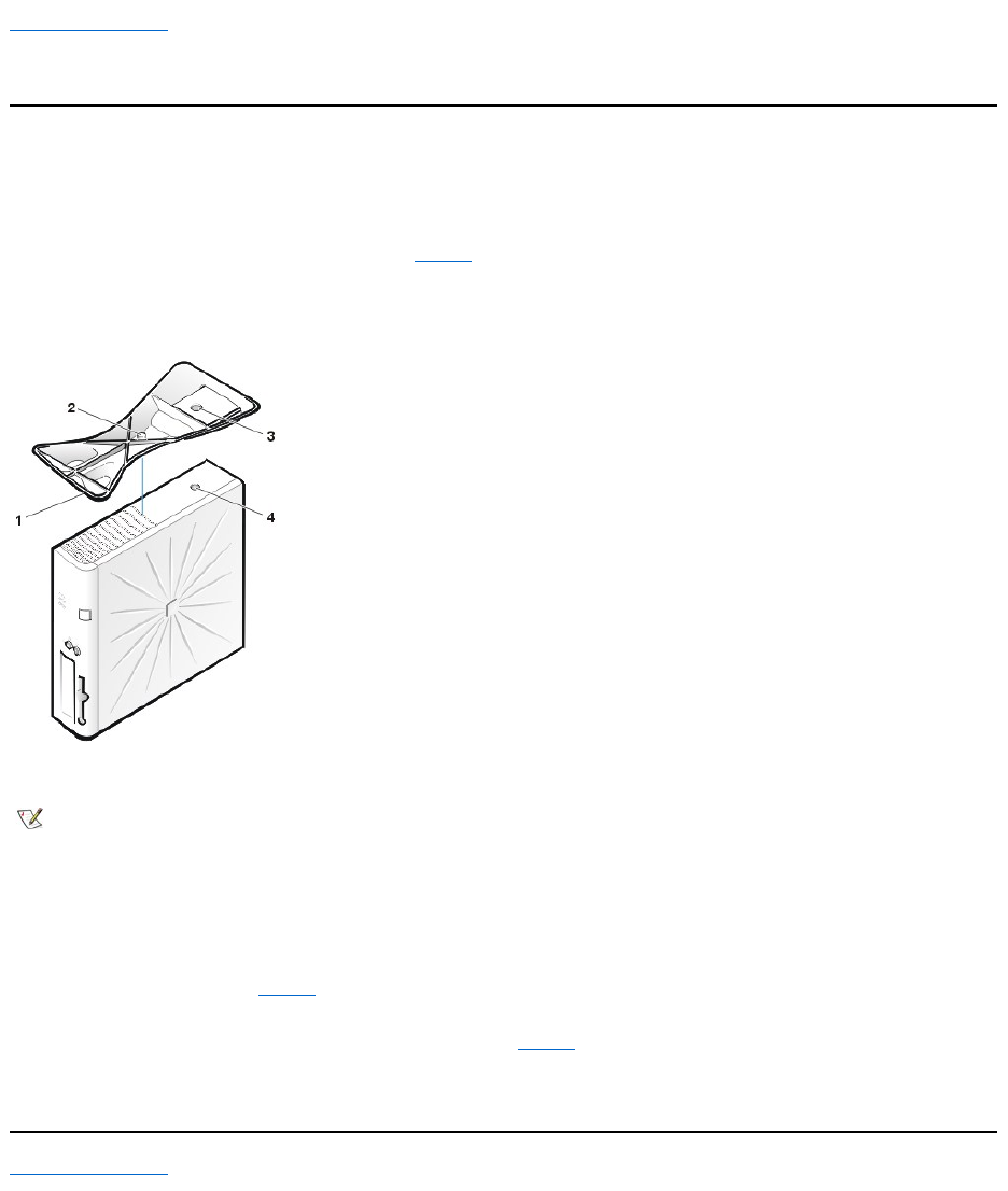
Back to Contents Page
OptionalStand:Dell™OptiPlex™GX110SystemUser'sGuide
Removing and Attaching the Small-Form-Factor or Low-Profile Chassis Optional Stand
To remove the optional stand from the small-form-factor or low-profile chassis, perform the following steps:
1. Turn the computer over so that the stand is at the top.
2. Loosen the captive screw and lift the stand away (see Figure 1).
3. Place the computer in a horizontal position.
Figure 1. Low-Profile Chassis Optional Stand
To attach the optional stand to the small-form-factor or low-profile chassis, perform the following steps:
1. Turn the computer onto its right side so that the drive bays are at the bottom.
2. Fit the stand onto what was the left side of the computer.
Position the stand as shown in Figure 1. Align the large round hole in the stand with the securing button on the side of the cover, and
align the captive thumbscrew in the stand with the screw hole in the cover.
As you lower the stand into place, make sure that the locator pin (see Figure 1) fits into the corner hole of the hole pattern as shown.
When the stand is in place, tighten the thumbscrew.
3. Rotate the computer so that the stand is at the bottom and the drives are at the top.
Back to Contents Page
1
Locator pin (on underside of stand)
2
Captive screw
3
Locator hole
4
Securing button
NOTE: The low-profile chassis and its optional stand are shown in Figure 1. The optional stand for the small-form-factor chassis differs
slightly in shape, but the process for removing or replacing the stand is the same as for the low-profilechassis.
Back to Contents Page
UsingSystemSetup:Dell™OptiPlex™GX110SystemUser'sGuide
Overview
Each time you turn on your computer system or press the reset button, the system compares the hardware installed in the system to the hardware
listed in the system configuration information stored in nonvolatile random-access memory (NVRAM) on the system board. If the system detects a
discrepancy, it generates error messages that identify the incorrect configuration settings. The system then prompts you to enter System Setup to
correct the setting.
You can use System Setup as follows:
lTo change the system configuration information after you add, change, or remove any hardware in your system
lTo set or change user-selectable options—for example, the time or date on your system
You can view the current settings at any time. When you change a setting, in many cases you must reboot the system before the change takes
effect.
After you set up your system, run System Setup to familiarize yourself with your system configuration information and optional settings. Dell
recommends that you print the System Setup screens (by pressing the <Print Screen> key) or record the information for future reference.
Before you use System Setup, you need to know the kind of diskette drive(s) and hard-disk drive(s) installed in your computer. If you are unsure of
this information, see the Manufacturing Test Report that was shipped with your system and is located in the Dell Accessories folder.
Entering System Setup
ToenterSystemSetup,performthefollowingsteps:
1. Turn on your system.
If your system is already on, shut it down and then turn it on again.
2. When the Press <F2> to Enter Setup window appears in the upper-right corner of the screen, press <F2>.
If you wait too long and your operating system begins to load into memory, let the system complete the load operation; then shut down the system
and try again.
System Setup Screen
The System Setup screen displays the current setup and configuration information and optional settings for your system. Information on the
System Setup screen is organized in four areas (see Figure 1 for typical examples):
lTitle — The box at the top of all screens lists the system name.
lSystem data — The two boxes below the title box display your system processor, level 2 (L2) cache, service tag, and the version number of
the basic input/output system (BIOS).
lOptions — The main area of the screen is a scrollable window containing options that define the installed hardware in your computer and the
power conservation and security features for your computer.
Fields next to the options contain settings or values. You can change those values that appear bright on the screen. Options or values that
you cannot change (because they are determined or calculated by the computer) appear less bright.
lKey functions — The line of boxes across the bottom of all screens lists keys and their functions within System Setup.
Figure 1. System Setup Screen
Overview
System Setup Screen
Entering System Setup
System Setup Navigation Keys
NOTE: To ensure an orderly system shutdown, consult the documentation that accompanied your operating system.
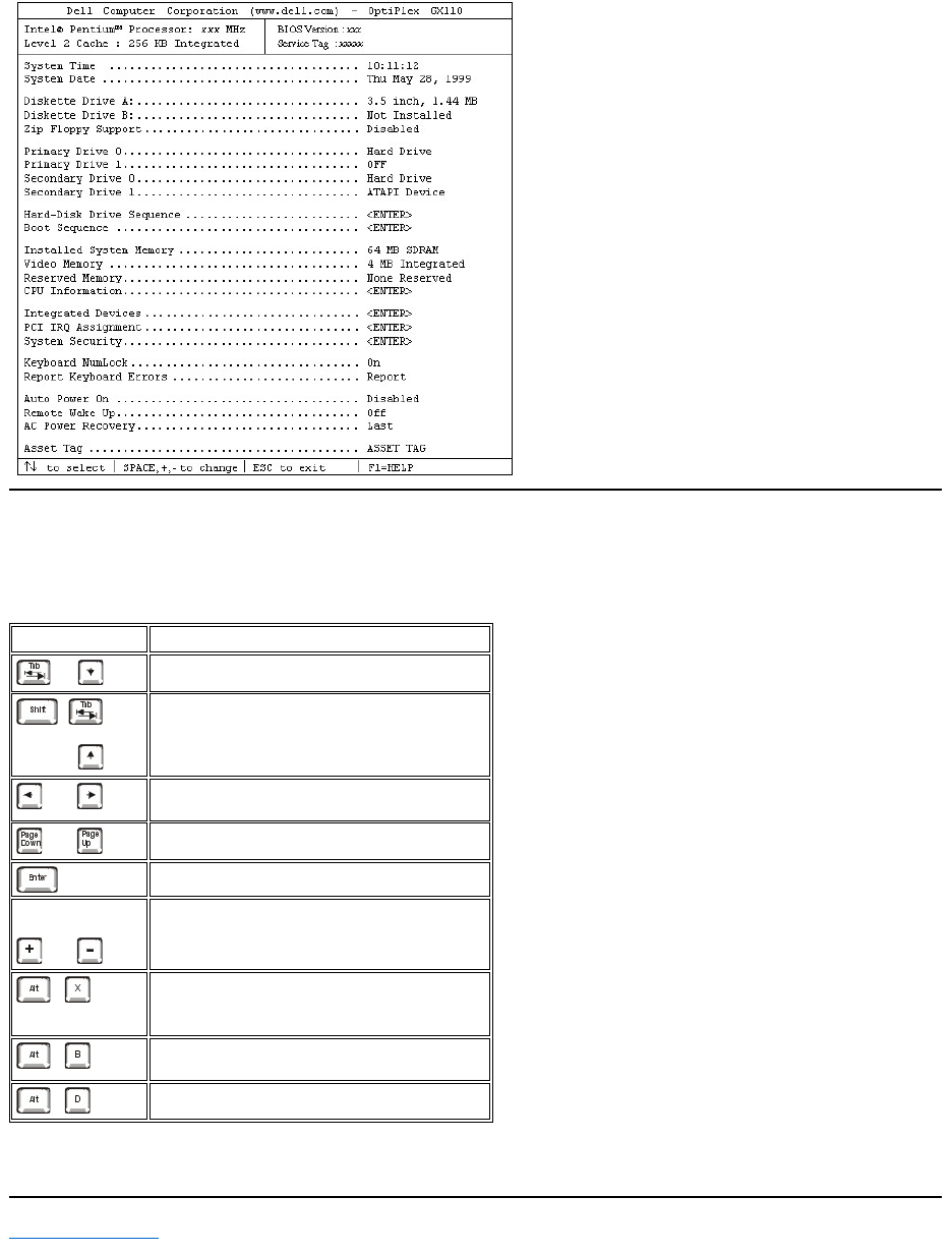
System Setup Navigation Keys
Table 1 lists the keys you use to view or change information on the System Setup screen and to exit the program.
Table 1. System Setup Navigation Keys
Back to Contents Page
Keys
Action
or
Moves to the next field.
or
Moves to the previous field.
or
Cycles through the options in a field. In many fields,
you can also type the appropriate value.
or
Scrolls through help information.
Enters the selected field's pop-up options menu.
spacebar or
or
In the selected field's pop-up options menu, cycles
through the options in a field.
Exits System Setup without rebooting the system
and returns the system to its previous state—the
boot routine.1
Exits System Setup and reboots the system,
implementing any changes you have made.
Resets the selected option to its default setting.
1For most of the options, any changes you make are recorded but do not take effect until the next time you boot the system. For a few options
(as noted in the help area), the changes take effect immediately.