Dell Perc 4E Dc Users Manual PowerEdge Expandable RAID Controller 4/SC, 4/DC, And 4e/DC User's Guide
Dell-Perc-4-Sc-Users-Manual-116831 dell-perc-4-sc-users-manual-116831
Dell-Perc-4-Dc-Users-Manual-116827 dell-perc-4-dc-users-manual-116827
2014-11-13
: Dell Dell-Perc-4E-Dc-Users-Manual-116834 dell-perc-4e-dc-users-manual-116834 dell pdf
Open the PDF directly: View PDF ![]() .
.
Page Count: 92

Dell™PowerEdge™ExpandableRAIDController4/SC,4/DC,and4e/DC
User's Guide
Overview
RAID Controller Features
Hardware Installation
Configuring the RAID Controller
BIOS Configuration Utility and Dell Manager
Troubleshooting
Appendix A: Regulatory Notice
Glossary
Information in this document is subject to change without notice.
©2004DellInc.Allrightsreserved.
Reproduction in any manner whatsoever without the written permission of Dell Inc. is strictly forbidden.
Trademarks used in this text: Dell, the DELL logo, PowerEdge, and Dell OpenManage are trademarks of Dell Inc. Microsoft and Windows are registered trademarks of Microsoft
Corporation. Intel is a registered trademark of Intel Corporation. Novell and NetWare are registered trademarks of Novell Corporation. Red Hat is a registered trademark of Red Hat,
Inc.
Other trademarks and trade names may be used in this document to refer to either the entities claiming the marks and names or their products. Dell Inc. disclaims any
proprietary interest in trademarks and trade names other than its own.
Model PERC 4
Release: July 2004
PartNumber:D8096Rev.A00

Back to Contents Page
Overview
Dell™PowerEdge™ExpandableRAIDController4/SC,4/DC,and4e/DCUser'sGuide
Overview of PERC 4/SC, 4/DC, and 4e/DC
Documentation
Overview of PERC 4/SC, 4/DC, and 4e/DC
The PERC 4 RAID controller is a high-performance, intelligent peripheral component interconnect (PCI) and PCI-Express to Small Computer System Interface
(SCSI) host adapter with RAID control capabilities. It provides reliable fault-tolerant disk subsystem management and is an ideal RAID solution for internal
storageinDell's™PowerEdge™enterprisesystems.TheRAIDcontrolleroffersacost-effective way to implement RAID in a server.
PERC 4 controllers are available with one or two SCSI channels using PCI or PCI-Express input/output (I/O) architecture:
lPERC 4/SC (single channel) provides one SCSI channel and PCI architecture
lPERC 4/DC (dual channel) provides two SCSI channels and PCI architecture
lPERC 4e/DC (dual channel) provides two SCSI channels and PCI-Express architecture
PCI and PCI-Express are I/O architectures designed to increase data transfers without slowing down the central processing unit (CPU). PCI-Express goes
beyond the PCI specification in that it is intended as a unifying I/O architecture for various systems: desktops, workstations, mobile, server, communications,
and embedded devices.
Your RAID controller supports a low-voltage differential (LVD) SCSI bus. Using LVD, you can use cables up to 12 meters long. Throughput on each SCSI channel
can be as high as 320 MB/sec.
Documentation
The technical documentation set includes
lDell PowerEdge RAID Controller 4/SC, 4/DC, and 4e/DC User's Guide, which contains information about installation of the RAID controller, general
introductory information about RAID, RAID system planning, configuration information, and software utility programs.
lCERC and PERC RAID Controllers Operating System Driver Installation Guide, which contains the information you need to install the appropriate operating
system software drivers.
Back to Contents Page
Back to Contents Page
RAID Controller Features
Dell™PowerEdge™ExpandableRAIDController4/SC,4/DC,and4e/DCUser'sGuide
Hardware Requirements
RAID Controller Specifications
Configuration Features
Hardware Architecture Features
Array Performance Features
Fault Tolerance Features
Operating System Software Drivers
RAID Management Utilities
Hardware Requirements
The RAID controller can be installed in a system with a motherboard that has 5-V or 3.3-V, 32- or 64-bit PCI or PCI-Express slots.
RAID Controller Specifications
Table2-1 provides a summary of the specifications for the RAID controllers.
Table 2-1.RAIDControllerSpecifications
NOTE: PERC 4/DC and 4e/DC support clustering, but PERC 4/SC does not.
Parameters
PERC 4/SC Specifications
PERC 4/DC Specifications
PERC 4e/DC Specifications
Card size
Low-profile PCI adapter card size (6.875"
X 4.2")
Half-length PCI adapter card size (6.875" X
4.2")
Half-length PCI adapter card size (6.875" X
4.2")
Processor
Intel® GC80302 (Zion Lite)
Intel GC80303 (Zion)
80332
Bus type
PCI 2.2
PCI 2.2
PCI Express 1.0a
PCI bus data
transfer rate
2 - 4 GB/sec, depending on the system
2 - 4 GB/sec, depending on the system
2 - 4 GB/sec, depending on the system
Cache
configuration
64 MB SDRAM
128 MB SDRAM
128 MB SDRAM
Firmware
Flash size is 1MB
Flash size is 1MB
Flash size is 1MB
Nonvolatile
random access
memory (RAM)
32 KB for storing RAID configuration
32 KB for storing RAID configuration
32 KB for storing RAID configuration
Operating voltage
and tolerances
3.3V +/- 0.3V, 5V +/- 5%, +12V +/- 5%, -
12V +/- 10%
3.3V +/- 0.3V, 5V +/- 5%, +12V +/- 5%, -
12V +/- 10%
3.3V +/- 0.3V, 5V +/- 5%, +12V +/- 5%, -
12V +/- 10%
SCSI controller
One SCSI LSI53C1020 controller for
Ultra320 support
One SCSI LSI53C1030 controller for
Ultra320 support
One SCSI LSI53C1030 controller for
Ultra320 support
SCSI data transfer
rate
Up to 320 MB/sec per channel
Up to 320 MB/sec per channel
Up to 320 MB/sec per channel
SCSI bus
LVD, Single-ended (SE)
LVD, Single-ended (SE)
LVD, Single-ended (SE)
SCSI termination
Active
Active
Active
Termination
disable
Automatic through cable and device
detection
Automatic through cable and device
detection This is automatic capable, but
jumpers by default do not allow auto
termination on PERC 4/DC.
Automatic through cable and device
detection
Devices per SCSI
channel
Up to 15 Wide SCSI devices
Up to 15 Wide SCSI devices
Up to 15 Wide SCSI devices
SCSI device types
Synchronous or asynchronous
Synchronous or asynchronous
Synchronous or asynchronous
RAID levels
supported
0, 1, 5, 10, 50
0, 1, 5, 10, 50
0, 1, 5, 10, 50
SCSI connectors
One 68-pin internal high-density connector
for SCSI devices. One very high density 68-
pin external connector for Ultra320 and
Two 68-pin internal high-density connectors
for SCSI devices. Two very high density 68-
pin external connectors for Ultra320 and
Two 68-pin internal high-density
connectors for SCSI devices. Two very high
density 68-pin external connectors for
Cache Memory
64 MB of cache memory resides in a memory bank for PERC 4/SC and 128 MB for PERC 4/DC and PERC 4e/DC. The RAID controller supports write-through or
write-back caching, selectable for each logical drive. To improve performance in sequential disk accesses, the RAID controller uses read-ahead caching by
default. You can disable read-ahead caching.
Onboard Speaker
The RAID controller has a speaker that generates audible warnings when system errors occur. No management software needs to be loaded for the speaker
to work.
Alarm Beep Codes
The purpose of the alarm is to indicate changes that require attention. The following conditions trigger the alarm to sound:
lA logical drive is offline
lA logical drive is running in degraded mode
lAn automatic rebuild has been completed
lThe temperature is above or below the acceptable range
lThe firmware gets a command to test the speaker from an application
Each of the conditions has a different beep code, as shown in Table2-2. Every second the beep switches on or off per the pattern in the code. For example, if
the logical drive goes offline, the beep code is a three second beep followed by one second of silence.
Table 2-2.AlarmBeepCodes
BIOS
For easy upgrade, the BIOS resides on 1 MB flash memory. It provides an extensive setup utility that you can access by pressing <Ctrl><M> at BIOS
initialization to run the BIOS Configuration Utility.
Background Initialization
Background initialization is the automatic check for media errors on physical drives It ensures that striped data segments are the same on all physical drives in
an array.
The background initialization rate is controlled by the rebuild rate set using the BIOS Configuration Utility, <Ctrl><M>. The default and recommended rate is
30%. Before you change the rebuild rate, you must stop the background initialization or the rate change will not affect the background initialization rate. After
you stop background initialization and change the rebuild rate, the rate change takes effect when you restart background initialization.
Wide SCSI.
Wide SCSI.
Ultra320 and Wide SCSI.
Serial port
3-pin RS232C-compatible connector (for
manufacturing use only)
3-pin RS232C-compatible connector (for
manufacturing use only)
3-pin RS232C-compatible connector (for
manufacturing use only)
NOTE: PERC 4 controller cards are not PCI Hot Pluggable. The system must be powered down in order to change or add cards.
Alarm Description
Code
A logical drive is offline.
Three seconds on, one second off
A logical drive is running in degraded mode.
One second on, one second off
An automatic rebuild has been completed.
One second on, three seconds off
The temperature is above or below the acceptable range.
Two seconds on, two seconds off
The firmware gets a command to test the speaker from an application.
Four seconds on

Configuration Features
Table2-3 lists the configuration features for the RAID controller.
Table 2-3.ConfigurationFeatures
1Hotswapofdrivesmustbesupportedbyenclosureorbackplane.
Firmware Upgrade
You can download the latest firmware from the Dell website and flash it to the firmware on the board. Perform the following steps to upgrade the firmware:
1. Go to the support.dell.com website.
2. Download the latest firmware and driver to a diskette.
The firmware is an executable file that downloads the files to the diskette in your system.
3. Restart the system and boot from the diskette.
4. Run pflash to flash the firmware.
SMART Hard Drive Technology
The Self-Monitoring Analysis and Reporting Technology (SMART) detects predictable hard drive failures. SMART monitors the internal performance of all motors,
heads, and hard drive electronics.
Drive Roaming
NOTE: Unlike initialization of logical drives, background initialization does not clear data from the drives.
Specifications
PERC 4/SC
PERC 4/DC
PERC 4e/DC
RAID levels
0, 1, 5, 10, and 50
0, 1, 5, 10, and 50
0, 1, 5, 10, and 50
SCSI channels
1
2
2
Maximum number of drives
per channel
14
14 (for a maximum of 28 on two
channels)
14 (for a maximum of 28 on two
channels)
Array interface to host
PCI Rev 2.2
PCI Rev 2.2
PCI Express Rev. 1.0a
Cache memory size
64 MB SDRAM
Up to 128 MB SDRAM
Up to 128 MB SDRAM
Cache Function
Write-back, write-through, adaptive
read-ahead, non read-ahead, read-
ahead
Write-back, write-through, adaptive
read-ahead, non read-ahead, read-
ahead
Write-back, write-through, adaptive
read-ahead, non read-ahead, read-
ahead
Number of logical drives and
arrays supported
Up to 40 logical drives and 32 arrays
per controller
Up to 40 logical drives and 32 arrays
per controller
Up to 40 logical drives and 32 arrays
per controller
Hot spares
Yes
Yes
Yes
Flashable firmware
Yes
Yes
Yes
Hot swap devices supported
1
Yes
Yes
Yes
Non-disk devices supported
Only SCSI accessed fault-tolerant
enclosure (SAF-TE) and SES
Only SAF-TE and SES
Only SAF-TE and SES
Mixed capacity hard drives
Yes
Yes
Yes
Number of 16-bit internal
connectors
1
2
2
Cluster support
No
Yes
Yes
NOTICE: Do not flash the firmware while performing a background initialization or data consistency check, as it can cause the procedures to fail.
Drive roaming occurs when the hard drives are changed to different channels on the same controller. When the drives are placed on different channels, the
controller detects the RAID configuration from the configuration information on the drives.
Configuration data is saved in both non-volatile random access memory (NVRAM) on the RAID controller and on the hard drives attached to the controller. This
maintains the integrity of the data on each drive, even if the drives have changed their target ID. Drive roaming is supported across channels on the same
controller, except when cluster mode is enabled.
Table2-4 lists the drive roaming features for the RAID controller.
Table 2-4. Features for Drive Roaming
Drive Migration
Drive migration is the transfer of a set of hard drives in an existing configuration from one controller to another. The drives must remain on the same channel
and be reinstalled in the same order as in the original configuration.
Hardware Architecture Features
Table2-5 displays the hardware architecture features for the RAID controller.
Table 2-5.HardwareArchitectureFeatures
LED Operation
After you remove a physical drive and place it back in the slot for a rebuild, the LED blinks for the drive as it is being rebuilt.
NOTE: Drive roaming does not work if you move the drives to a new controller and put them on different channels. If you put drives on a new controller,
the controller must have a clear configuration. In addition, the drives must be on the same channel/target as they were on the previous controller to
keep the same configuration.
NOTE: Before performing drive roaming, make sure that you have first powered off both your platform and your drive enclosure.
Specification
PERC 4/SC
PERC 4/DC
PERC 4e/DC
Online RAID level migration
Yes
Yes
Yes
RAID remapping
Yes
Yes
Yes
No reboot necessary after capacity extension
Yes
Yes
Yes
NOTE: Drive roaming and drive migration cannot be supported at the same time. PERC can support either drive roaming or drive migration at any one
time, but not both at the same time.
Specification
PERC 4/SC
PERC 4/DC
PERC 4e/DC
Processor
Intel GC80302 (Zion Lite)
Intel GC80303 (Zion)
80332
SCSI controller(s)
One LSI53C1020 Single SCSI
controller
One LSI53C1030 Dual SCSI
controller
One LSI53C1030 Dual SCSI
controller
Size of flash memory
1 MB
1 MB
1 MB
Amount of NVRAM
32 KB
32 KB
32 KB
Hardware exclusive OR (XOR) assistance
Yes
Yes
Yes
Direct I/O
Yes
Yes
Yes
SCSI bus termination
Active or LVD
Active or LVD
Active or LVD
Double-sided dual inline memory modules (DIMMs)
Yes
Yes
Yes
Support for hard drives with capacities of more than
eight gigabytes (GB)
Yes
Yes
Yes
Hardware clustering support on the controller
No
Yes
Yes
Array Performance Features
Table2-6 displays the array performance features for the RAID controller.
Table 2-6.ArrayPerformanceFeatures
Fault Tolerance Features
Table2-7 describes the fault tolerance capabilities of the RAID controller.
Table 2-7.FaultToleranceFeatures
1Thelengthofdataretentiondependsonthecachememoryconfiguration.
Operating System Software Drivers
Operating System Drivers
Drivers are provided to support the controller on the following operating systems:
lWindows®2000
lWindows 2003
lNovell®NetWare®
lRed Hat®Linux, Advanced Server, Enterprise
See the CERC and PERC RAID Controllers Operating System Driver Installation Guide for more information about the drivers.
SCSI Firmware
Specification
PERC 4/SC, PERC 4/DC, and PERC 4e/DC
PCI host data transfer rate
2 - 4 GB/sec, depending on the system
Drive data transfer rate
Up to 320 MB/sec
Maximum size of I/O requests
6.4 MB in 64 KB stripes
Maximum queue tags per drive
As many as the drive can accept
Stripe sizes
8 KB, 16 KB, 32 KB, 64 KB, or 128 KB
Maximum number of concurrent commands
255
Support for multiple initiators
Only on PERC 4/DC and PERC 4e/DC
Specification
PERC 4/SC
PERC 4/DC
PERC 4e/DC
Support for SMART
Yes
Yes
Yes
Optional battery backup for cache memory
N/A
Yes. Up to 72 hours data retention.1
Yes. Up to 72 hours data retention.
Drive failure detection
Automatic
Automatic
Automatic
Drive rebuild using hot spares
Automatic
Automatic
Automatic
Parity generation and checking
Yes
Yes
Yes
User-specified rebuild rate
Yes
Yes
Yes
NOTE: We support both 32-bit (x86) and 64-bit (IA64) processors for Windows 2003 and Red Hat Linux.

The RAID controller firmware handles all RAID and SCSI command processing and supports the features described in Table2-8.
Table 2-8.SCSIFirmwareSupport
RAID Management Utilities
Software utilities enable you to manage and configure the RAID system, create and manage multiple disk arrays, control and monitor multiple RAID servers,
provide error statistics logging, and provide online maintenance. The utilities include:
lBIOS Configuration Utility
lDell Manager for Linux
lDellOpenManage™ArrayManagerforWindowsandNetware
BIOS Configuration Utility
The BIOS Configuration Utility configures and maintains RAID arrays, clears hard drives, and manages the RAID system. It is independent of any operating
system. See BIOS Configuration Utility and Dell Manager for additional information.
Dell Manager
Dell Manager is a utility that works in Red Hat Linux. See BIOS Configuration Utility and Dell Manager for additional information.
Dell OpenManage Array Manager
Dell OpenManage Array Manager is used to configure and manage a storage system that is connected to a server, while the server is active and continues to
handle requests. Array Manager runs under Novell NetWare, Windows 2000, and Windows Server 2003. Refer to the online documentation that accompanies
Array Manager or the documentation section at support.dell.com for more information.
Server Administrator Storage Management Service
Storage Management provides enhanced features for configuring a system's locally attached RAID and non-RAID disk storage. Storage Management runs
under Red Hat Linux, Windows 2000, and Windows Server 2003. Refer to the online documentation that accompanies Storage Management or the
documentation section at support.dell.com for more information.
Back to Contents Page
Feature
PERC 4/SC, PERC 4/DC, and PERC 4e/DC Description
Disconnect/reconnect
Optimizes SCSI bus utilization
Tagged command queuing
Multiple tags to improve random access
Multi-threading
Up to 255 simultaneous commands with elevator sorting and concatenation of requests per SCSI channel
Stripe size
Variable for all logical drives: 8 KB, 16 KB, 32 KB, 64 KB, or 128 KB.
Rebuild
Multiple rebuilds and consistency checks with user-definable priority.
NOTE: You can run the OpenManage Array Manager remotely to access NetWare, but not locally.

Back to Contents Page
Hardware Installation
Dell™PowerEdge™ExpandableRAIDController4/SC,4/DC,and4e/DCUser'sGuide
Requirements
Quick Installation Procedure
Installation Steps
Requirements
This section describes the procedures for installing the RAID controller. You must have the following items to install the controller:
lA PERC 4/SC, 4/DC, or 4e/DC controller
lA host system with an available 32- or 64-bit, PCI extension slot for PERC 4/SC or 4/DC, and a PCI-Express slot for PERC 4e/DC
lThe DellOpenManage™SystemsManagementCD or driver diskette
lThe necessary internal and/or external SCSI cables
lUltra, Ultra2, Ultra3, Ultra160, or Ultra320 SCSI hard drives
(SCSI is backward compatible, but it slows to the speed of the slowest device).
Quick Installation Procedure
Perform the following steps for quick installation of the controller if you are an experienced system user/installer. All others should follow the steps in the next
section, Installation Steps.
1. Turn off all power to the server and all hard drives, enclosures, and system components, then disconnect power cords from the system.
2. Open host system by following the instructions in the host system technical documentation.
3. Determine the SCSI ID and SCSI termination requirements.
4. Install the PERC 4/SC or 4/DC RAID controller in a PCI slot or the PERC 4e/DC in the PCI- Express slot in the server and attach the SCSI cables and
terminators.
See the section Cable Suggestions for cable information and suggestions.
lMake sure pin 1 on the cable matches pin 1 on the connector.
lMake sure that the SCSI cables conform to all SCSI specifications.
5. Perform a safety check.
lMake sure all cables are properly attached.
lMake sure the RAID controller is properly installed.
lClose the cabinet of the host system.
lTurn power on after completing the safety check.
6. Format the hard drives as needed.
7. Configure logical drives using the BIOS Configuration Utility or Dell Manager.
8. Initialize the logical drives.
9. Install the network operating system drivers as needed.
CAUTION: See your Product Information Guide for complete information about safety precautions, working inside the computer, and protecting
against electrostatic discharge.
NOTE: The default for SCSI termination is onboard SCSI termination enabled. See the section Step 7 Set SCSI Termination for a description of SCSI
termination.

Installation Steps
This section provides instructions for installing the RAID controllers.
Step 1 Unpack the Controller
Unpack and remove the controller and inspect it for damage. If the controller appears damaged, or if any items listed below are missing, contact your Dell
support representative. The RAID controller is shipped with:
lThe PERC 4 RAID Controller User's Guide (on CD)
lThe CERC and PERC RAID Controllers Operating System Driver Installation Guide (on CD)
lA license agreement
Step 2 Power Down the System
Perform the following steps to power down the system:
1. Turn off the system.
2. Remove the AC power cord.
3. Disconnect the system from any networks before installing the controller.
4. Remove the system's cover.
Please consult the system documentation for instructions.
Step 3 Set Jumpers
Make sure the jumper settings on the RAID controller are correct. The default jumper settings are recommended. Following are diagrams of the controllers
showing their jumpers and connectors, and tables describing them. Select your controller from the ones shown on the following pages.
Figure 3-1. PERC 4/SC Controller Layout
CAUTION: See your Product Information Guide for complete information about safety precautions, working inside the computer, and protecting
against electrostatic discharge.
NOTE: You can order a hard copy of the documentation for the controller.
CAUTION: See your Product Information Guide for complete information about safety precautions, working inside the computer, and protecting
against electrostatic discharge.
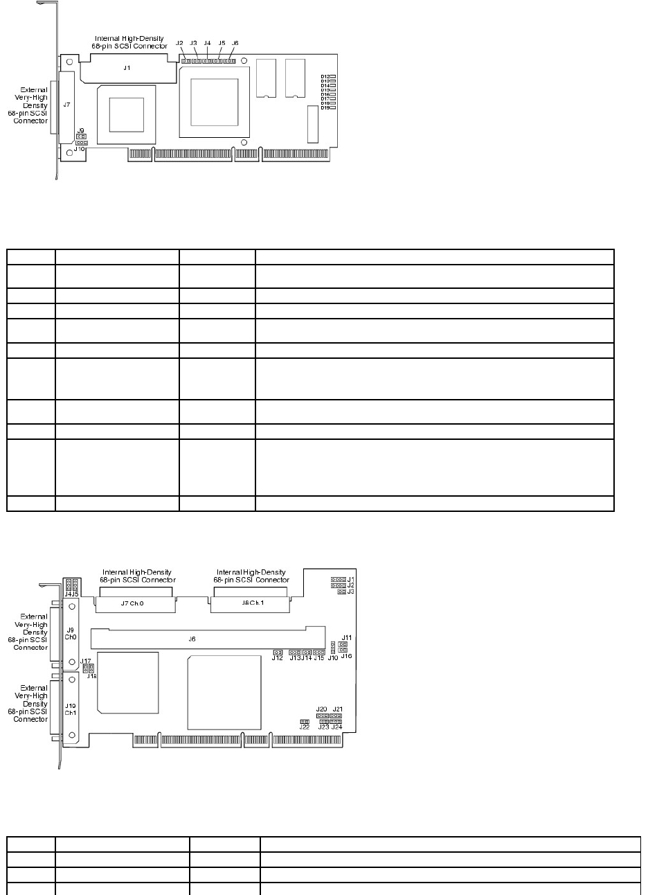
Table 3-1.PERC4/SCJumperandConnectorDescriptions
Figure 3-2. PERC 4/DC Controller Layout
Table 3-2.PERC4/DCJumperandConnectorDescriptions
Connector
Description
Type
Setting
J1
Internal SCSI connector
68-pin connector
Internal high-density SCSI bus connector.
Connection is optional.
J2
NVRAM Clear
2-pin header
To CLEAR configuration data, install a jumper.
J3
Serial EPROM
2-pin header
To CLEAR configuration data, install a jumper.
J4
Onboard BIOS Enable
2-pin header
No jumper = Enabled (Default is Enabled)
With jumper in = Disabled
J5
SCSI Activity
2-pin header
Connector for enclosure LED to indicate data transfers. Connection is optional.
J6
Serial Port
3-pin header
Connector is for diagnostic purposes.
Pin-1 RXD (Receive Data)
Pin-2 TXD (Transmit Data)
Pin-3 GND (Ground)
J7
External SCSI connector
68-pin connector
External very-high density SCSI bus connector.
Connection is optional.
J9
SCSI bus TERMPWR Enable
2-pin header
Install jumper to enable onboard termination power. Default is installed.
J10
SCSI bus Termination Enable
3-pin header
Jumper pins 1-2 to enable software control of SCSI termination through drive detection.
Jumper pins 2-3 to disable onboard SCSI termination.
No jumper installed enables onboard SCSI termination. This is the default.
D12 - D19
LEDs
Indicate problems with the card.
Connector
Description
Type
Settings
J1
I2C Header
4-pin header
Reserved.
J2
SCSI Activity LED
4-pin header
Connector for LED on enclosure to indicate data transfers. Optional.
J3
Write Pending Indicator
2-pin header
Connector for enclosure LED to indicate when data in the cache has yet to be written to the
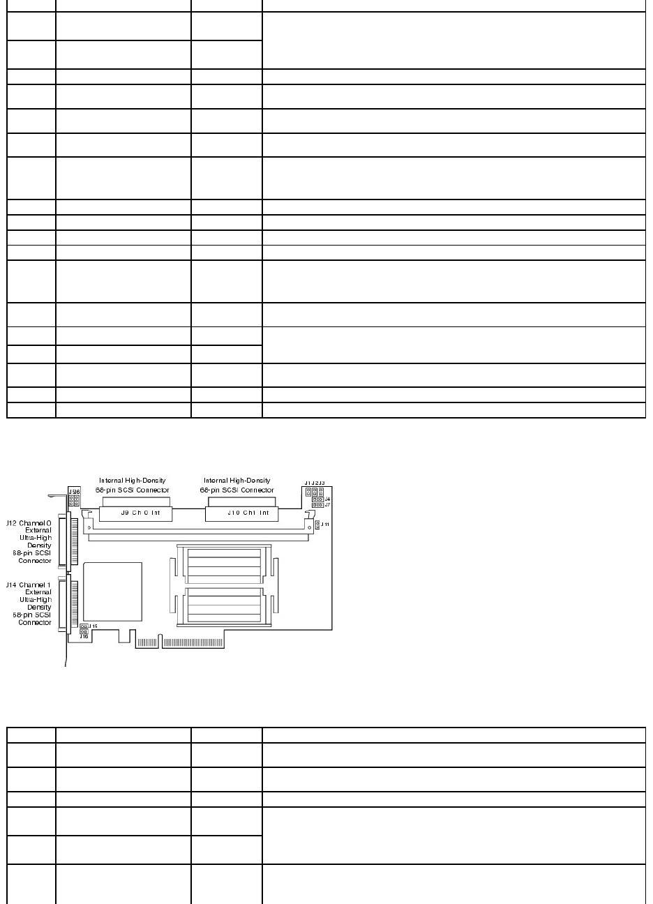
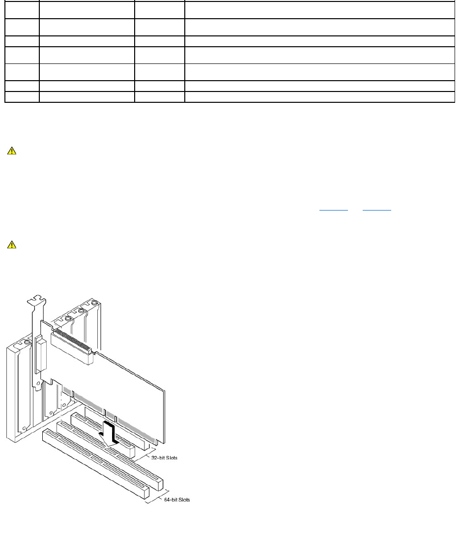
Figure 3-3. PERC 4e/DC Controller Layout
Table 3-3.PERC4e/DCJumperandConnectorDescriptions
(Dirty Cache LED)
device. Optional.
J4
SCSI Termination Enable
Channel 1
3-pin header
Jumper pins 1-2 to enable software control of SCSI termination via drive detection.
Jumper pins 2-3 to disable onboard SCSI termination.
No jumper installed enables onboard SCSI termination. (See J17 and J18). This is the default.
J5
SCSI Termination Enable
Channel 0
3-pin header
J6
DIMM socket
DIMM socket
Socket that hold the memory module
J7
Internal SCSI Channel 0
connector
68-pin
connector
Internal high-density SCSI bus connector. Connection is optional.
J8
Internal SCSI Channel 1
connector
68-pin
connector
Internal high-density SCSI bus connector. Connection is optional.
J9
External SCSI Channel 0
connector
68-pin
connector
External very-high density SCSI bus connector. Connection is optional.
J10
Battery connector
3-pin header
Connector for an optional battery pack.
Pin-1 -BATT Terminal (black wire)
Pin-2Thermistor(whitewire)
Pin-3 +BATT Terminal (red wire)
J11
NVRAM clear
2-pin header
To CLEAR the configuration data, install a jumper.
J12
NMI jumper
2-pin header
Reserved for factory.
J13
32-bit SPCI Enable
3-pin header
Reserved for factory.
J14
Mode Select jumper
2-pin header
J15
Serial Port
3-pin header
Connector is for diagnostic purposes.
Pin-1 RXD (Receive Data)
Pin-2 TXD (Transmit Data)
Pin-3 GND (Ground)
J16
Onboard BIOS Enable
2-pin header
No jumper = Enabled (Default setting)
Jumpered = Disabled
J17
TERMPWR Enable Channel 0
2-pin header
Jumper installed enables TERMPWR from the PCI bus. Default setting.
No jumper installed enables TERMPWR from the SCSI bus. (See J4 and J5)
J18
TERMPWR Enable Channel 1
2-pin header
J19
External SCSI Channel 1
connector
68-pin
connector
External very-high density SCSI bus connector. Connection is optional.
J23
Serial EEPROM
2-pin header
To CLEAR configuration data, install a jumper.
D17 - D24
LEDs (located on back of card)
Indicate problems with the card.
Connector
Description
Type
Settings
J1
Write Pending Indicator
(Dirty Cache LED)
2-pin header
Connector for enclosure LED to indicate when data in the cache has yet to be written to the
device. Optional.
J2
Onboard BIOS Enable
2-pin header
No jumper = Enabled (Default setting)
Jumpered = Disabled
J4
I2C Header
3-pin header
Reserved
J5
SCSI Termination Enable
Channel 0
3-pin header
Jumper pins 1-2 to enable software control of SCSI termination via drive detection.
Jumper pins 2-3 to disable onboard SCSI termination.
No jumper installed enables onboard SCSI termination. (See J17 and J18). This is the default.
J6
SCSI Termination Enable
Channel 1
3-pin header
J7
Serial Port (RS232)
3-pin header
Connector is for diagnostic purposes.
Pin-1 RXD (Receive Data)
Pin-2 TXD (Transmit Data)
Pin-3 GND (Ground)
Step 4 Install the RAID Controller
Perform the following steps to install the controller:
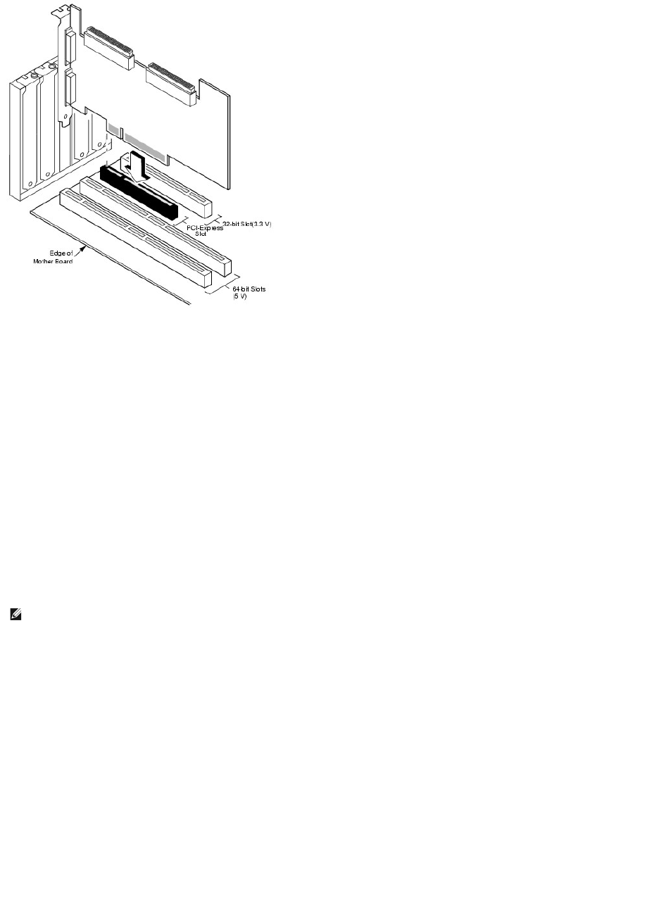
1. Select a PCI slot for PERC 4/SC or PERC 4/DC, or a PCI-Express slot for PERC 4e/DC and align the controller PCI bus connector to the slot.
2. Press down gently but firmly to make sure that the controller is properly seated in the slot, as shown in Figure3-4 and Figure3-5.
3. Screw the bracket to the system chassis.
Figure 3-4. Inserting a PERC 4 RAID Controller into a PCI Slot
Figure 3-5. Inserting a PERC 4e/DC RAID Controller in a PCI-Express Slot
J9
Internal SCSI Channel 0
connector
68-pin
connector
Internal high-density SCSI bus connector. Connection is optional.
J10
Internal SCSI Channel 1
connector
68-pin
connector
Internal high-density SCSI bus connector. Connection is optional.
J11
Mode Select
2-pin header
Reserved for internal use.
J12
External SCSI Channel 0
connector
68-pin
connector
External very-high density SCSI bus connector. Connection is optional.
J14
External SCSI Channel 1
connector
68-pin
connector
External very-high density SCSI bus connector. Connection is optional.
J15
Termination Power
2-pin connector
J16
Termination Power
2-pin connector
CAUTION: See your Product Information Guide for complete information about safety precautions, working inside the computer, and protecting
against electrostatic discharge.
CAUTION: You cannot install a PCI board in a PCI-Express slot or a PCI-Express board in a PCI slot.
Step 5 Connect SCSI Cables and SCSI Devices
Connect the SCSI cables to the SCSI connectors and SCSI devices.
Connect SCSI Devices
Perform the following steps to connect SCSI devices.
1. Disable termination on any SCSI device that does not sit at the end of the SCSI bus.
2. Configure all SCSI devices to supply TermPWR.
3. Set proper target IDs (TIDs) for all SCSI devices.
4. The host controller has a SCSI ID of 7.
5. Connect the cable to the devices.
Cable Suggestions
System throughput problems can occur if the SCSI cables are not the correct type. To avoid problems, you should follow the following cable suggestions:
lUse cables no longer than 12 meters for Ultra3, Ultra160, and Ultra320 devices. (It's better to use shorter cables, if possible.)
lMake sure the cables meet the specifications.
lUse active termination.
lNotethatcablestublengthshouldbenomorethan0.1meter(4inches).
lRoute SCSI cables carefully and do not bend cables.
lUse high impedance cables.
lDo not mix cable types (choose either flat or rounded and shielded or non-shielded).
lNote that ribbon cables have fairly good cross-talk rejection characteristics, meaning the signals on the different wires are less likely to interfere with
each other.
NOTE: The maximum cable length for Fast SCSI (10 MB/sec) devices is 3 meters and for Ultra SCSI devices is 1.5 meters. The cable length can be up to
12 meters for LVD devices. Use shorter cables if possible.
Step 6 Set Target IDs
Set target identifiers (TIDs) on the SCSI devices. Each device in a channel must have a unique TID. Non-disk devices should have unique SCSI IDs regardless of
the channel where they are connected. See the documentation for each SCSI device to set the TIDs. The RAID controller automatically occupies TID 7, which is
the highest priority. The arbitration priority for a SCSI device depends on its TID. Table3-4 lists the target IDs.
Table 3-4. Target IDs
Step 7 Set SCSI Termination
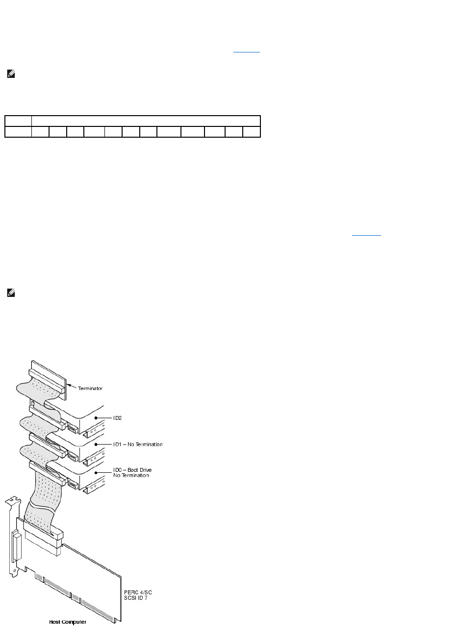
The SCSI bus is an electrical transmission line and must be terminated properly to minimize reflections and losses. Termination should be set at each end of
the SCSI cable(s).
For a disk array, set SCSI bus termination so that removing or adding a SCSI device does not disturb termination. An easy way to do this is to connect the
RAID controller to one end of the SCSI cable and an external terminator module at the other end of the cable, as shown in Figure3-6.
The connectors between the two ends can connect SCSI drives which have their termination disabled, as shown in the drives (ID0, ID1, ID2) attached in the
figure. See the documentation for each SCSI drive to disable termination.
Set the termination so that SCSI termination and TermPWR are intact when any hard drive is removed from a SCSI channel.
Figure 3-6. Terminating Internal SCSI Disk Array
NOTE: The RAID controller can occupy TID 6 in cluster mode. When in cluster mode, one controller is TID 6 and the other TID 7. IDs 0 - 7 are valid target
IDs; 7 has the highest priority.
Priority
HighestLowest
TID
7
6
5
...
2
1
0
15
14
...
9
8
NOTE: Dell does not recommend mixing U160 and U320 drives on the same bus or logical drive.

Step 8 Start the System
Replace the system cover and reconnect the AC power cords. Turn power on to the host system. Set up the power supplies so that the SCSI devices are
powered up at the same time as or before the host system. If the system is powered up before a SCSI device, the device might not be recognized.
During bootup, the BIOS message appears:
PowerEdge Expandable RAID Controller BIOS Version x.xx date
Copyright (c) LSI Logic Corp.
Firmware Initializing... [ Scanning SCSI Device ...(etc.)... ]
The firmware takes several seconds to initialize. During this time, the adapter scans the SCSI channel. When ready, the following appears:
HA –0 (Bus 1 Dev 6) Type: PERC 4/xx Standard FW x.xx SDRAM=xxxMB
Battery Module is Present on Adapter
0 Logical Drives found on the Host Adapter
0 Logical Drive(s) handled by BIOS
Press <Ctrl><M> to run PERC 4 BIOS Configuration Utility
The BIOS Configuration Utility prompt times out after several seconds.
The host controller number, firmware version, and cache SDRAM size display in the second portion of the BIOS message. The numbering of the controllers
follows the PCI slot scanning order used by the host motherboard.
Light-emitting Diode (LED) Description
When you start the system, the boot block and firmware perform a number of steps that load the operating system and allow the system to function properly.
The boot block contains the operating system loader and other basic information needed during startup.
As the system boots, the LEDs indicate the status of the boot block and firmware initialization and whether the system performed the steps correctly. If there
is an error during startup, you can use the LED display to identify it.
Table3-5 displays the LEDs and execution states for the boot block. Table3-6 displays the LEDs and execution states during firmware initialization. The LEDs
display in hexadecimal format so that you can determine the number and the corresponding execution state from the LEDs that display.
Table 3-5.BootBlockStates
LED
Execution State
0x01
Setup 8-bit Bus for access to Flash and 8-bit devices successful
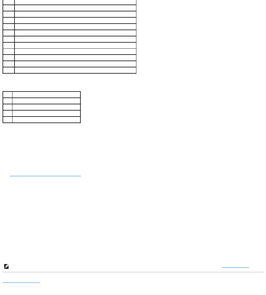
Table 3-6.FirmwareInitializationStates
Step 9 Run the BIOS Configuration Utility or Dell Manager
Press <Ctrl><M> when prompted during the boot process to run the BIOS Configuration Utility. You can run Dell Manager in Red Hat Linux to perform the same
functions, such as configuring arrays and logical drives.
See BIOS Configuration Utility and Dell Manager for additional information about running the BIOS Configuration Utility and Dell Manager.
Step 10 Install an Operating System
Install one of the following operating systems: Microsoft®Windows®2000, Windows 2003, Novell®NetWare®, and Red Hat Linux.
Step 11 Install the Operating System Driver
Operating system drivers are provided on the Dell OpenManage Server Assistant CD that accompanies your PERC controller. See the CERC and PERC RAID
Controllers Operating System Driver Installation Guide for additional information about installing the drivers for the operating systems.
Back to Contents Page
0x03
Serial port initialization successful
0x04
Spd (cache memory) read successful
0x05
SDRAM refresh initialization sequence successful
0x07
Start ECC initialization and memory scrub
0x08
End ECC initialization and memory scrub
0x10
SDRAM is present and properly configured. About to program ATU.
0x11
CRC check on the firmware image successful. Continue to load firmware.
0x12
Initialization of SCSI chips successful.
0x13
BIOS protocols ports initialized. About to load firmware.
0x17
Firmware is either corrupt or BIOS disabled. Firmware was not loaded.
0x19
Error ATU ID programmed.
0x55
System Halt: Battery Backup Failure
LED
Execution State
0x1
Begin Hardware Initialization
0x3
Begin Initialize ATU
0x7
Begin Initialize Debug Console
0xF
Set if Serial Loopback Test is successful
NOTE: To make sure you have the latest version of the drivers, download the updated drivers from the Dell Support website at support.dell.com.
Back to Contents Page
Configuring the RAID Controller
Dell™PowerEdge™ExpandableRAIDController4/SC,4/DC,and4e/DCUser'sGuide
Configuring SCSI Physical Drives
Physical Device Layout
Device Configuration
Setting Hardware Termination
Configuring Arrays
Assigning RAID Levels
Optimizing Storage
Planning the Array Configuration
This section describes how to configure for physical drives, arrays, and logical drives. It contains tables you can complete to list the configuration for the
physical drives and logical drives.
Configuring SCSI Physical Drives
Your SCSI hard drives must be organized into logical drives in an array and must be able to support the RAID level that you select.
Observe the following guidelines when connecting and configuring SCSI devices in a RAID array:
lYou can place up to 28 physical drives in an array.
lUse drives of the same size and speed to maximize the effectiveness of the controller.
lWhen replacing a failed drive in a redundant array, make sure that the replacement drive has the same or larger capacity than the smallest drive in the
array (RAID 1, 5, 10, and 50).
When implementing RAID 1 or RAID 5, disk space is spanned to create the stripes and mirrors. The span size can vary to accommodate the different disk sizes.
There is, however, the possibility that a portion of the largest disk in the array will be unusable, resulting in wasted disk space. For example, consider a RAID 1
array that has the following disks, as shown in Table4-1.
Table 4-1. Storage Space in a RAID 1 Array
In this example, data is mirrored across the two disks until 20 GB on Disk A and B are completely full. This leaves 10 GB of disk space on Disk B. Data cannot be
written to this remaining disk space, as there is no corresponding disk space available in the array to create redundant data.
Table4-2 provides an example of a RAID 5 array.
Table 4-2. Storage Space in a RAID 5 Array
NOTE: For RAID levels 10 and 50, the additional space in larger arrays can store data, so you can use arrays of different sizes.
Disk
Disk Size
Storage Space Used in Logical Drive for RAID 1 Array
Storage Space Left Unused
A
20 GB
20 GB
0
B
30 GB
20 GB
10 GB
Disk
Disk Size
Storage Space Used in Logical Drive for RAID 5 Array
Storage Space Left Unused
A
40 GB
40 GB
0 GB
B
40 GB
40 GB
0 GB
C
60 GB
40 GB
20 GB

In this example, data is striped across the disks until 40 GB on Disks A, B, and C are completely full. This leaves 20 GB of disk space on Disk C. Data cannot be
written to this remaining disk space, as there is no corresponding disk space available in the array to create redundant data.
Physical Device Layout
Use Table4-3 to list the details for each physical device on the channels.
Table 4-3.PhysicalDeviceLayout
Channel 0
Channel 1
Target ID
Device type
Logical drive number/ drive number
Manufacturer/model number
Firmware level
Target ID
Device type
Logical drive number/ drive number
Manufacturer/model number
Firmware level
Target ID
Device type
Logical drive number/ drive number
Manufacturer/model number
Firmware level
Target ID
Device type
Logical drive number/drive number
Manufacturer/model number
Firmware level
Target ID
Device type
Logical drive number/drive number
Manufacturer/model number
Firmware level
Target ID
Device type
Logical drive number/drive number
Manufacturer/model number
Firmware level
Target ID
Device type
Logical drive number/drive number
Manufacturer/model number
Firmware level
Target ID
Device type
Logical drive number/drive number
Manufacturer/model number
Firmware level
Target ID
Device type
Logical drive number/drive number
Manufacturer/model number
Firmware level
Target ID
Device Configuration
The following contain tables you can fill out to list the devices assigned to each channel. The PERC 4/SC controller has one channel; the PERC 4/DC and 4e/DC
have two.
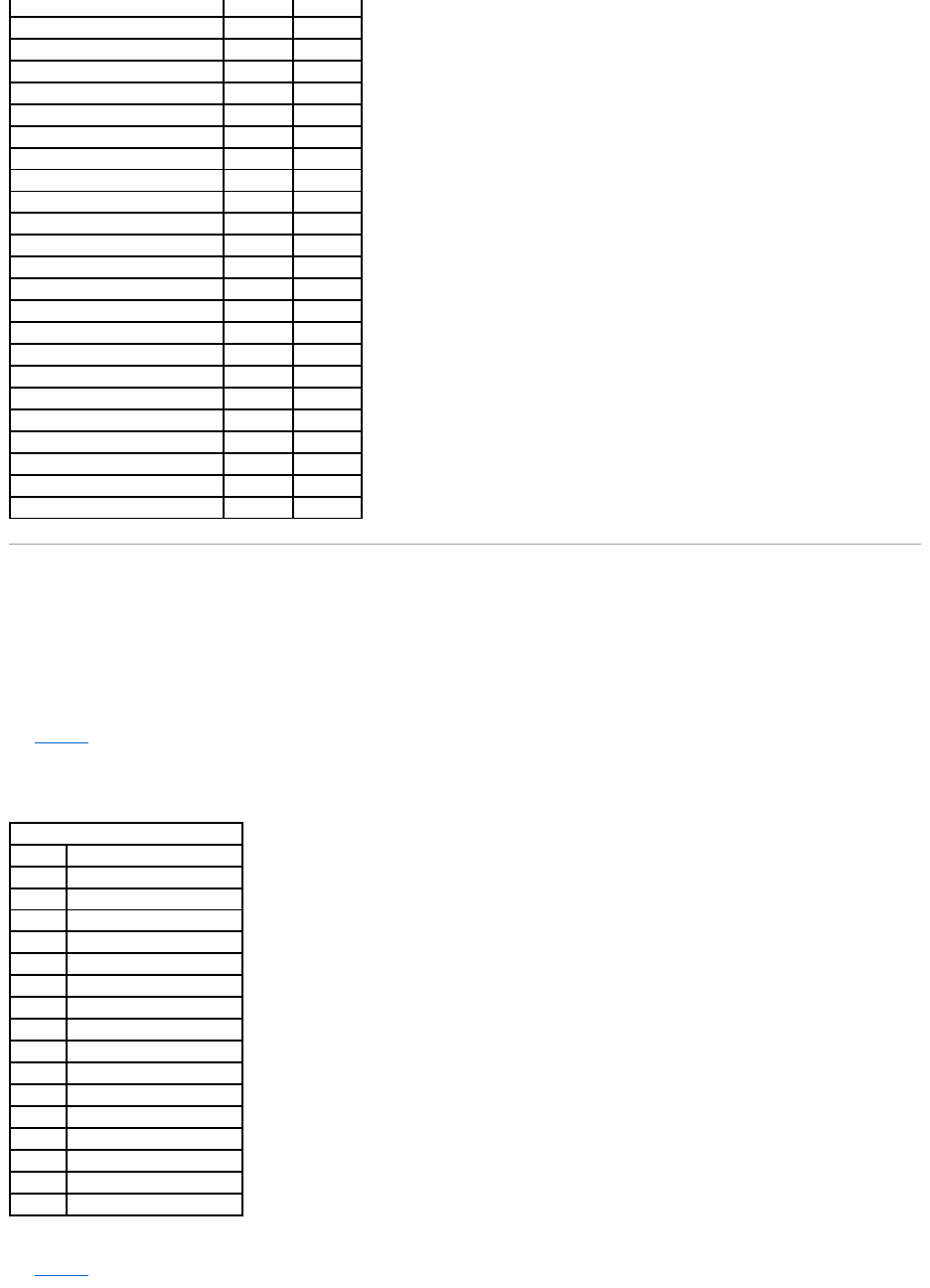
Use Table4-4 to list the devices that you assign to each SCSI ID for SCSI Channel 0.
Table 4-4.ConfigurationforSCSIChannel0
Use Table4-5 to list the devices that you assign to each SCSI ID for SCSI Channel 1.
Device type
Logical drive number/drive number
Manufacturer/model number
Firmware level
Target ID
Device type
Logical drive number/drive number
Manufacturer/model number
Firmware level
Target ID
Device type
Logical drive number/drive number
Manufacturer/model number
Firmware level
Target ID
Device type
Logical drive number/drive number
Manufacturer/model number
Firmware level
Target ID
Device type
Logical drive number/drive number
Manufacturer/model number
Firmware level
SCSI Channel 0
SCSI ID
Device Description
0
1
2
3
4
5
6
7
Reserved for host controller.
8
9
10
11
12
13
14
15
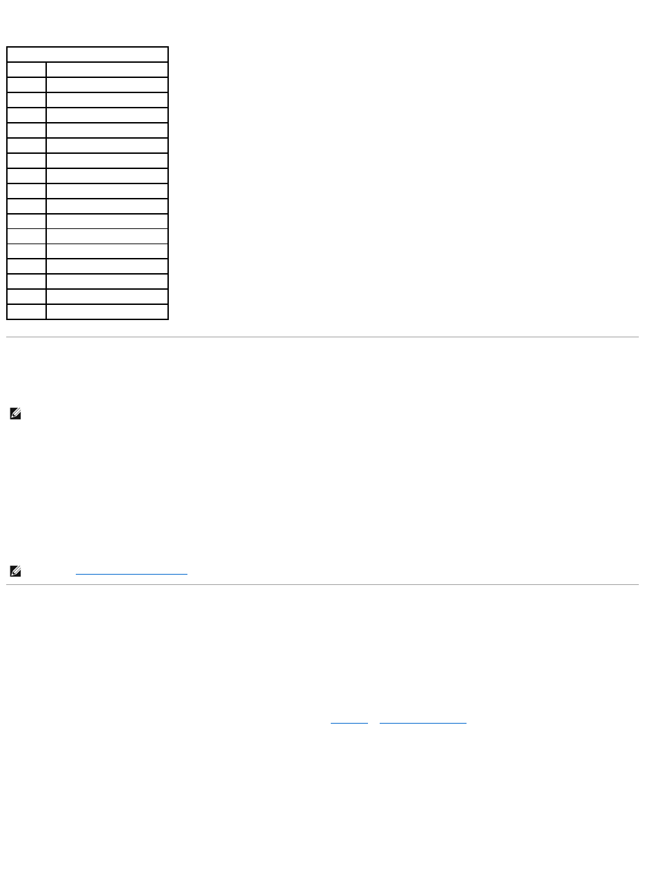
Table 4-5.ConfigurationforSCSIChannel1
Setting Hardware Termination
The SCSI bus is an electrical transmission line and must be terminated properly to minimize reflections and losses. Termination should be set at each end of
the SCSI cable(s). For PERC 4e/DC, the following headers specify control of the SCSI termination:
lJ5 Termination Enable is a three-pin header that specifies control of the SCSI termination for channel 0.
lJ6 Termination Enable is a three-pin header that specifies control of the SCSI termination for channel 1.
To enable hardware termination, leave the pins open. The default is hardware termination.
Configuring Arrays
After you configure and initialize the hard drives, you are ready to configure arrays. The number of drives in an array determines the RAID levels that can be
supported.
For information about the number of drives required for different RAID levels, see Table4-7 in Assigning RAID Levels.
Spanned Drives
You can arrange arrays sequentially with an identical number of drives so that the drives in the different arrays are spanned. Spanned drives can be treated
as one large drive. Data can be striped across multiple arrays as one logical drive.
You can create spanned drives using your array management software.
SCSI Channel 1
SCSI ID
Device Description
0
1
2
3
4
5
6
7
Reserved for host controller.
8
9
10
11
12
13
14
15
NOTE: If you are using the PERC 4/DC RAID controller for clustering, then you must use hardware termination. Otherwise, software termination is OK.
NOTE: See Step 7 Set SCSI Termination for additional information about setting SCSI termination.

Hot Spares
Any hard drive that is present, formatted, and initialized, but is not included in an array or logical drive, can be designated as a hot spare. A hot spare should
have the same or greater capacity than the smallest physical disk in the array it protects. You can designate hard drives as hot spares using your array
management software.
Logical Drives
Logical drives, also known as virtual disks, are arrays or spanned arrays that are available to the operating system. The storage space in a logical drive is
spread across all the physical drives in the array or spanned arrays.
You must create one or more logical drives for each array, and the logical drive capacity must include all of the drive space in an array. You can make the logical
drive capacity larger by spanning arrays. In an array of drives with mixed sizes, the smallest common drive size is used and the space in larger drives is not
used. The RAID controller supports up to 40 logical drives.
Configuration Strategies
The most important factors in RAID array configuration are:
lDrive capacity
lDrive availability (fault tolerance)
lDrive performance
You cannot configure a logical drive that optimizes all three factors, but it is easy to choose a logical drive configuration that maximizes one factor at the
expense of the other two factors. For example, RAID 1(mirroring) provides excellent fault tolerance, but requires a redundant drive.
Configuring Logical Drives
After you have attached all physical drives, perform the following steps to prepare a logical drive. If the operating system is not yet installed, use the BIOS
Configuration Utility to perform this procedure. If the operating system is installed, you can use the Dell Manager for Linux or OpenManage Array Manager (for
Windows and Netware), depending on the operating system.
1. Start the system.
2. Run your array management software.
3. Select the option to customize the RAID array.
In the BIOS Configuration Utility and Dell Manager for Linux, use either Easy Configuration or New Configuration to customize the RAID array.
4. Create and configure one or more system drives (logical drives).
5. Select the RAID level, cache policy, read policy, and write policy.
6. Save the configuration.
7. Initialize the system drives.
After initialization, you can install the operating system.
See BIOS Configuration Utility and Dell Manager for detailed configuration instructions.
CAUTION: If you select New Configuration, all previous configuration information will be deleted.
NOTE: Refer to the section Summary of RAID Levels for RAID level explanations.

Logical Drive Configuration
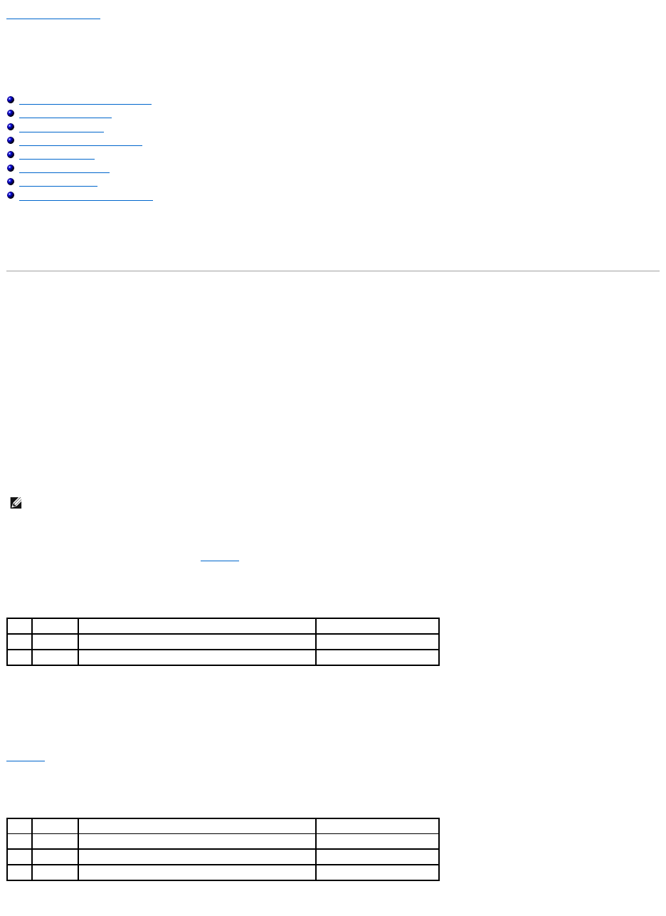
Use Table4-6 to list the details for each logical drive that you configure.
Table 4-6.LogicalDriveConfiguration
Assigning RAID Levels
Only one RAID level can be assigned to each logical drive. Table4-7 shows the minimum and maximum number of drives required.
Logical Drive
RAID Level
Stripe Size
Logical Drive Size
Cache Policy
Read Policy
Write Policy
Number of Physical Drives
LD0
LD1
LD2
LD3
LD4
LD5
LD6
LD7
LD8
LD9
LD10
LD11
LD12
LD13
LD14
LD15
LD16
LD17
LD18
LD19
LD20
LD21
LD22
LD23
LD24
LD25
LD26
LD27
LD28
LD29
LD30
LD31
LD32
LD33
LD34
LD35
LD36
LD37
LD38
LD39
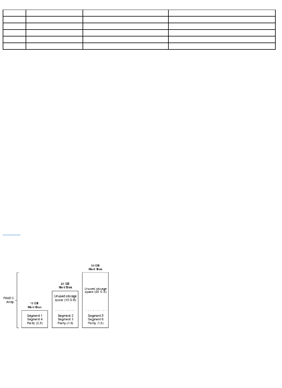
Table 4-7.PhysicalDrivesRequiredforEachRAIDLevel
Summary of RAID Levels
RAID 0 uses striping to provide high data throughput, especially for large files in an environment that does not require fault tolerance.
RAID 1 uses mirroring and is good for small databases or other applications that require small capacity, but complete data redundancy.
RAID 5 provides high data throughput, especially for small random access. Use this level for any application that requires high read request rates, but low
write request rates, such as transaction processing applications. Write performance is significantly lower for RAID 5 than for RAID 0 and RAID 1.
RAID 10 consists of striped data across mirrored spans. It provides high data throughput and complete data redundancy, but uses a larger number of spans.
RAID 50 uses parity and disk striping and works best with data that requires high reliability, high request rates, high data transfers, and medium-to-large
capacity. Write performance is limited to the same as RAID 5.
Storage in an Array with Drives of Different Sizes
For RAID levels 0 and 5, data is striped across the disks. If the hard drives in an array are not the same size, data is striped across all the drives until one or
more of the drives is full. After one or more drives are full, disk space left on the other disks cannot be used. Data cannot be written to that disk space
because other drives do not have corresponding disk space available.
Figure4-1 shows an example of storage allocation in a RAID 5 array. The data is striped, with parity, across the three drives until the smallest drive is full. The
remaining storage space in the other hard drives cannot be used because not all of the drives have disk space for redundant data.
Figure 4-1. Storage in a RAID 5 Array
Storage in RAID 10 and RAID 50 Arrays
You can span RAID 1 and 5 arrays to create RAID 10 and RAID 50 arrays, respectively. For RAID levels 10 and 50, you can have some arrays with more storage
space than others. After the storage space in the smaller arrays is full, you can use the additional space in larger arrays can store data.
RAID Level
Minimum # of Physical Drives
Maximum # of Physical Drives for PERC 4/SC
Maximum # of Physical Drives for PERC 4/DC and 4e/DC
0
1
14
28
1
2
2
2
5
3
14
28
10
4
14
28
50
6
14
28
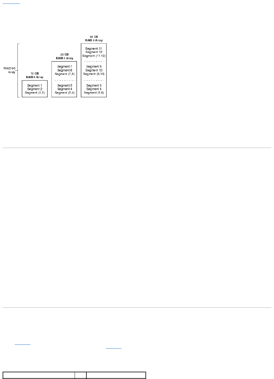
Figure4-2 shows the example of a RAID 50 span with three RAID 5 arrays of different sizes. (Each array can have from three to 14 hard disks.) Data is striped
across the three RAID 5 arrays until the smallest array is full. The data is striped across the remaining two RAID 5 arrays until the smaller of the two arrays is
full. Finally, data is stored in the additional space in the largest array.
Figure 4-2. Storage in a RAID 50 Array
Performance Considerations
The system performance improves as the number of spans increases. As the storage space in the spans is filled, the system stripes data over fewer and fewer
spans and RAID performance degrades to that of a RAID 1 or RAID 5 array.
Optimizing Storage
Data Access Requirements
Each type of data stored in the disk subsystem has a different frequency of read and write activity. If you know the data access requirements, you can more
successfully determine a strategy for optimizing the disk subsystem capacity, availability, and performance.
Servers that support video on demand typically read the data often, but write data infrequently. Both the read and write operations tend to be long. Data
stored on a general-purpose file server involves relatively short read and write operations with relatively small files.
Array Functions
Define the major purpose of the disk array by answering questions such as the following, which are followed by suggested RAID levels for each situation:
lWill this disk array increase the system storage capacity for general-purpose file and print servers? Use RAID 5, 10, or 50.
lDoes this disk array support any software system that must be available 24 hours per day? Use RAID 1, 5, 10, or 50.
lWill the information stored in this disk array contain large audio or video files that must be available on demand? Use RAID 0.
lWill this disk array contain data from an imaging system? Use RAID 0 or 10.
Planning the Array Configuration
Fill out Table4-8 to help you plan the array configuration. Rank the requirements for your array, such as storage space and data redundancy, in order of
importance, then review the suggested RAID levels. Refer to Table4-7 for the minimum and maximum number of drives allowed per RAID level.
Table 4-8.FactorstoConsiderforArrayConfiguration
Requirement
Rank
Suggested RAID Level(s)


Back to Contents Page
BIOS Configuration Utility and Dell Manager
Dell™PowerEdge™ExpandableRAIDController4/SC,4/DC,and4e/DCUser'sGuide
Starting the BIOS Configuration Utility
Starting Dell Manager
Using Dell Manager in Red Hat Linux GUI Mode
Configuring Arrays and Logical Drives
Designating Drives as Hot Spares
Creating Arrays and Logical Drives
Drive Roaming
Initializing Logical Drives
Deleting Logical Drives
Clearing Physical Drives
Rebuilding Failed Hard Drives
Using a Pre-loaded SCSI Drive "As-is"
FlexRAID Virtual Sizing
Checking Data Consistency
Reconstructing Logical Drives
Exiting the Configuration Utility
The BIOS Configuration Utility configures disk arrays and logical drives. Because the utility resides in the RAID controller BIOS, its operation is independent of
the operating systems on your system.
Dell™Managerisacharacter-based, non-GUI utility that changes policies, and parameters, and monitors RAID systems. Dell Manager runs under Red Hat®
Enterprise Linux, Advanced Server edition and Enterprise edition.
Use these utilities to do the following:
lCreate hot spare drives.
lConfigure physical arrays and logical drives.
lInitialize one or more logical drives.
lAccess controllers, logical drives, and, physical drives individually.
lRebuild failed hard drives.
lVerify that the redundancy data in logical drives using RAID level 1, 5, 10, or 50 is correct.
lReconstruct logical drives after changing RAID levels or adding a hard drive to an array.
lSelect a host controller to work on.
The BIOS Configuration Utility and the Dell Manager for Linux use the same command structure to configure controllers and disks. The following sections
describe the steps to start either utility and detailed instructions to perform configuration steps using either utility.
Starting the BIOS Configuration Utility
When the host computer boots, hold the <Ctrl> key and press the <M> key when a BIOS banner such as the following appears:
HA -0 (Bus X Dev X) Type: PERC 4 Standard FWx.xx SDRAM=128MB
Battery Module is Present on Adapter
NOTE: TheOpenManage™ArrayManagercanperformmanyofthesametasksastheBIOSConfigurationUtilityandDellManager.
NOTE: Dell Manager screens differ slightly from the BIOS Configuration Utility screens, but the utilities have similar functions.

1 Logical Drive found on the Host Adapter
Adapter BIOS Disabled, No Logical Drives handled by BIOS
0 Logical Drive(s) handled by BIOS
Press <Ctrl><M> to Enable BIOS
For each controller in the host system, the firmware version, dynamic random access memory (DRAM) size, and the status of logical drives on that controller
display. After you press a key to continue, the Management Menu screen displays.
Starting Dell Manager
Make sure the program file is in the correct directory before you enter the command to start Dell Manager. For Linux, use the Dell Manager RPM to install files in
the usr/sbin directory. The RPM installs them automatically in that directory.
Type dellmgr to start the program.
Using Dell Manager in Red Hat Linux GUI Mode
On a system running Red Hat Linux, for Dell Manager to work correctly in a terminal in GUI Mode, you must set the terminal type to linux and keyboard
mappings.
Perform the procedure below if you use konsole, gnome terminal, or xterm.
The Linux console mode, which you select from the terminal with the File —> Linux Console command, works correctly by default. The text mode console (non-
GUI) also works correctly by default.
To prepare the system to use Dell Manager, perform the following steps:
1. Start the Terminal.
2. Before you enter dellmgr to start Dell Manager, type the following commands:
TERM=linux
Export TERM
3. Select Settings—> Keyboard—> Linux Console from the Terminal menu.
l<Shift><1> for <F1>
NOTE: In the BIOS Configuration Utility, pressing <Ctrl><M> has the same effect as pressing <Enter>.
NOTE: You can access multiple controllers through the BIOS Configuration Utility. Be sure to verify which controller you are currently set to edit.
NOTE: On a Red Hat Enterprise Linux system, when you run Dell Manager (v. x.xx) from a Gnome- terminal in XWindows, the <F10> key cannot be
used to create a logical drive. Instead, use the alternate keys <Shift><0>. (This is not an issue if Xterm is used to call dellmgr). The following is a
list of alternate keys you can use in case of problems with keys <F1> through <F7>, and <F10>:

l<Shift><2> for <F2>
l<Shift><3> for <F3>
l<Shift><4> for <F4>
l<Shift><5> for <F5>
l<Shift><6> for <F6>
l<Shift><7> for <F7>
l<Shift><0> for <F10>
Configuring Arrays and Logical Drives
The following procedures apply to both the BIOS Configuration Utility and the Dell Manager for Linux.
1. Designate hot spares (optional).
See Designating Drives as Hot Spares in this section for more information.
2. Select a configuration method.
See Creating Arrays and Logical Drives in this section for more information.
3. Create arrays using the available physical drives.
4. Define logical drives using the arrays.
5. Save the configuration information.
6. Initialize the logical drives.
See Initializing Logical Drives in this section for more information.
Designating Drives as Hot Spares
Hot spares are physical drives that are powered up along with the RAID drives and usually stay in a standby state. If a hard drive used in a RAID logical drive
fails, a hot spare will automatically take its place and the data on the failed drive is reconstructed on the hot spare. Hot spares can be used for RAID levels 1,
5, 10, and 50. Each controller supports up to eight hot spares.
The methods for designating physical drives as hot spares are:
lPressing <F4> while creating arrays in Easy, New or View/Add Configuration mode.
lUsing the Objects—> Physical Drive menu.
<F4> Key
When you select any configuration option, a list of all physical devices connected to the current controller appears. Perform the following steps to designate a
drive as a hot spare:
1. On the Management Menu select Configure, then a configuration option.
2. Press the arrow keys to highlight a hard drive that displays as READY.
3. Press <F4> to designate the drive as a hot spare.
4. Click YES to make the hot spare.
NOTE: In the BIOS Configuration Utility and Dell Manager, only global hot spares can be assigned. Dedicated hot spares cannot be assigned.
The drive displays as HOTSP.
5. Save the configuration.
Objects Menu
1. On the Management Menu select Objects—> Physical Drive.
A physical drive selection screen appears.
2. Select a hard drive in the READY state and press <Enter> to display the action menu for the drive.
3. Press the arrow keys to select Make HotSpare and press <Enter>.
The selected drive displays as HOTSP.
Creating Arrays and Logical Drives
Configure arrays and logical drives using Easy Configuration, New Configuration, or View/Add Configuration. See Using Easy Configuration, Using New
Configuration, or Using View/Add Configuration for the configuration procedures.
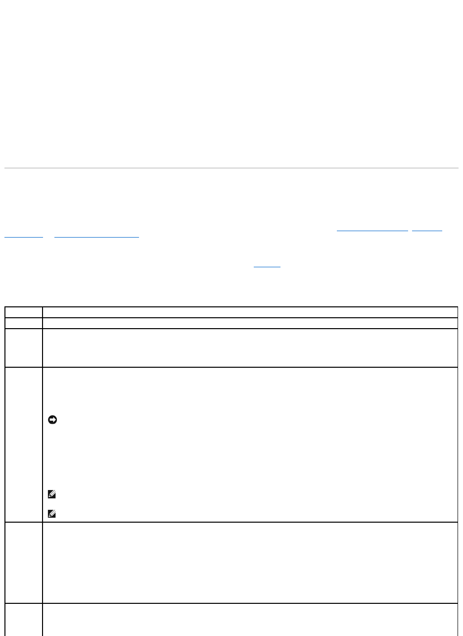
After you create an array or arrays, you can select the parameters for the logical drive. Table5-1 contains descriptions of the parameters.
Table 5-1.LogicalDriveParametersandDescriptions
Parameter
Description
RAID Level
The number of physical drives in a specific array determines the RAID levels that can be implemented with the array.
Stripe Size
Stripe Size specifies the size of the segments written to each drive in a RAID 1, 5, or 10 logical drive. You can set the stripe size to 8 KB, 16
KB, 32 KB, 64 KB, or 128 KB. The default is 64 KB.
A larger stripe size provides better read performance, especially if your computer does mostly sequential reads. However, if you are sure that
your computer does random read requests more often, select a small stripe size.
Write
Policy
Write Policy specifies the cache write policy. You can set the write policy to Write-back or Write-through.
In Write-back caching, the controller sends a data transfer completion signal to the host when the controller cache has received all the data in
a transaction. This setting is recommended in standard mode.
In Write-through caching, the controller sends a data transfer completion signal to the host when the disk subsystem has received all the
data in a transaction.
Write-through caching has a data security advantage over write-back caching. Write-back caching has a performance advantage over write-
through caching.
NOTICE: If WriteBack is enabled and the system is quickly turned off and on, the RAID controller may hang when flushing cache memory.
Controllers that contain a battery backup will default to WriteBack caching.
NOTE: You should not use write-back for any logical drive that is to be used as a Novell NetWare volume.
NOTE: Enabling clustering turns off write cache. PERC 4/DC and PERC 4e/DC support clustering.
Read
Policy
Read-ahead enables the read-ahead feature for the logical drive. You can set this parameter to Read-Ahead, No-Read-ahead, or Adaptive.
The default is Adaptive.
Read-ahead specifies that the controller uses read-ahead for the current logical drive. Read-ahead capability allows the adapter to read
sequentially ahead of requested data and store the additional data in cache memory, anticipating that the data will be needed soon. Read-
ahead supplies sequential data faster, but is not as effective when accessing random data.
No-Read-Ahead specifies that the controller does not use read-ahead for the current logical drive.
Adaptive specifies that the controller begins using read-ahead if the two most recent disk accesses occurred in sequential sectors. If all read
requests are random, the algorithm reverts to No-Read-Ahead; however, all requests are still evaluated for possible sequential operation.
Cache
Policy
Cache Policy applies to reads on a specific logical drive. It does not affect the Read-ahead cache. The default is Direct I/O.
Cached I/O specifies that all reads are buffered in cache memory.

Using Easy Configuration
In Easy Configuration, each physical array you create is associated with exactly one logical drive. You can modify the following parameters:
lRAID level
lStripe size
lWrite policy
lRead policy
lCache policy
If logical drives have already been configured when you select Easy Configuration, the configuration information is not disturbed. Perform the following steps
to create arrays and logical drives using Easy Configuration.
1. Select Configure—> Easy Configuration from the Management Menu.
Hot key information displays at the bottom of the screen.
2. Press the arrow keys to highlight specific physical drives.
3. Press the spacebar to associate the selected physical drive with the current array.
The selected drive changes from READY to ONLIN A[array number]-[drive number]. For example, ONLIN A02-03 means array 2 with hard drive 3.
4. Add physical drives to the current array as desired.
Try to use drives of the same capacity in a specific array. If you use drives with different capacities in an array, all drives in the array are treated as if
they have the capacity of the smallest drive in the array.
5. Press <Enter> after you finish creating the current array.
The Select Configurable Array(s) window appears. It displays the array and array number, such as A-00.
6. Press the spacebar to select the array.
7. Press <F10> to configure logical drives.
The window at the top of the screen shows the logical drive that is currently being configured.
8. Highlight RAID and press <Enter> to set the RAID level for the logical drive.
The available RAID levels for the current logical drive display.
9. Select a RAID level and press <Enter> to confirm.
10. Click Advanced Menu to open the menu for logical drive settings.
11. Set the Stripe Size.
12. Set the Write Policy.
Direct I/O specifies that reads are not buffered in cache memory. Direct I/O does not override the cache policy settings. Data is transferred
to cache and the host concurrently. If the same data block is read again, it comes from cache memory.
Span
The choices are:
Yes—Array spanning is enabled for the current logical drive. The logical drive can occupy space in more than one array.
No—Array spanning is disabled for the current logical drive. The logical drive can occupy space in only one array.
The RAID controller supports spanning of RAID 1 and 5 arrays. You can span two or more RAID 1 arrays into a RAID 10 array and two or more
RAID 5 arrays into a RAID 50 array.
For two arrays to be spanned, they must have the same stripe width (they must contain the same number of physical drives).
NOTE: You can press <F2> to display the number of drives in the array, their channel and ID, and press <F3> to display array information, such as
the stripes, slots, and free space.

13. Set the Read Policy.
14. Set the Cache Policy.
15. Press <Esc> to exit the Advanced Menu.
16. After you define the current logical drive, select Accept and press <Enter>.
The array selection screen appears if any unconfigured hard drives remain.
17. Repeat step 2 through step 16 to configure another array and logical drive.
The RAID controller supports up to 40 logical drives per controller.
18. When finished configuring logical drives, press <Esc> to exit Easy Configuration.
A list of the currently configured logical drives appears.
19. Respond to the Save prompt.
After you respond to the prompt, the Configure menu appears.
20. Initialize the logical drives you have just configured.
See Initializing Logical Drives in this section for more information.
Using New Configuration
If you select New Configuration, the existing configuration information on the selected controller is destroyed when the new configuration is saved. In New
Configuration, you can modify the following logical drive parameters:
lRAID level
lStripe size
lWrite policy
lRead policy
lCache policy
lLogical drive size
lSpanning of arrays
1. Select Configure—> New Configuration from the Management Menu.
Hot key information appears at the bottom of the screen.
2. Press the arrow keys to highlight specific physical drives.
3. Press the spacebar to associate the selected physical drive with the current array.
The selected drive changes from READY to ONLINE A[array number]-[drive number]. For example, ONLINE A02-03 means array 2 with hard drive 3.
4. Add physical drives to the current array as desired.
5. Press <Enter> twice after you finish creating the current array.
NOTICE: Selecting New Configuration erases the existing configuration information on the selected controller. To use the existing configuration, use
View/Add Configuration.
NOTE: Try to use drives of the same capacity in a specific array. If you use drives with different capacities in an array, all drives in the array are
treated as if they have the capacity of the smallest drive in the array.

The Select Configurable Array(s) window appears. It displays the array and array number, such as A-00.
6. Press the spacebar to select the array.
Span information displays in the array box. You can create multiple arrays, then select them to span them.
7. Repeat step2 through step6 to create another array or go to step8 to configure a logical drive.
8. Press <F10> to configure a logical drive.
The logical drive configuration screen appears. Span=Yes displays on this screen if you select two or more arrays to span.
The window at the top of the screen shows the logical drive that is currently being configured as well as any existing logical drives.
9. Highlight RAID and press <Enter> to set the RAID level for the logical drive.
A list of the available RAID levels for the current logical drive appears.
10. Select a RAID level and press <Enter> to confirm.
11. Highlight Span and press <Enter>.
12. Highlight a spanning option and press <Enter>.
13. Move the cursor to Size and press <Enter> to set the logical drive size.
By default, the logical drive size is set to all available space in the array(s) being associated with the current logical drive, accounting for the Span
setting.
14. Click Advanced Menu to open the menu for logical drive settings.
15. Set the Stripe Size.
16. Set the Write Policy.
17. Set the Read Policy.
18. Set the Cache Policy.
19. Press <Esc> to exit the Advanced Menu.
20. After you define the current logical drive, select Accept and press <Enter>.
If space remains in the arrays, the next logical drive to be configured appears. If the array space has been used, a list of the existing logical drives
appears.
21. Press any key to continue, then respond to the Save prompt.
22. Initialize the logical drives you have just configured.
See Initializing Logical Drives in this section for more information.
Using View/Add Configuration
View/Add Configuration allows you to control the same logical drive parameters as New Configuration without disturbing the existing configuration
information. In addition, you can enable the Configuration on Disk feature.
1. Select Configure—> View/Add Configuration from the Management Menu.
NOTE: You can press <F2> to display the number of drives in the array, their channel and ID, and <F3> to display array information, such as the
stripes, slots, and free space.
NOTE: The PERC 4 family supports spanning for RAID 1 and RAID 5 only. You can configure RAID 10 by spanning two or more RAID 1 logical drives.
You can configure RAID 50 by spanning two or more RAID 5 logical drives. The logical drives must have the same stripe size.
NOTE: The full drive size is used when you span logical drives; you cannot specify a smaller drive size.

Hot key information appears at the bottom of the screen.
2. Press the arrow keys to highlight specific physical drives.
3. Press the spacebar to associate the selected physical drive with the current array.
The selected drive changes from READY to ONLIN A[array number]-[drive number]. For example, ONLIN A02-03 means array 2 with hard drive 3.
4. Add physical drives to the current array as desired.
5. Press <Enter> twice after you finish creating the current array.
The Select Configurable Array(s) window appears. It displays the array and array number, such as A-00.
6. Press the spacebar to select the array.
Span information, such as Span-1, displays in the array box. You can create multiple arrays, then select them to span them.
7. Press <F10> to configure a logical drive.
The logical drive configuration screen appears. Span=Yes displays on this screen if you select two or more arrays to span.
8. Highlight RAID and press <Enter> to set the RAID level for the logical drive.
The available RAID levels for the current logical drive appear.
9. Select a RAID level and press <Enter> to confirm.
10. Highlight Span and press <Enter>.
11. Highlight a spanning option and press <Enter>.
12. Move the cursor to Size and press <Enter> to set the logical drive size.
By default, the logical drive size is set to all available space in the array(s) associated with the current logical drive, accounting for the Span setting.
13. Highlight Span and press <Enter>.
14. Highlight a spanning option and press <Enter>.
15. Open the Advanced Menu to open the menu for logical drive settings.
16. Set the Stripe Size.
17. Set the Write Policy.
18. Set the Read Policy.
19. Set the Cache Policy.
20. Press <Esc> to exit the Advanced Menu.
21. After you define the current logical drive, select Accept and press <Enter>.
If space remains in the arrays, the next logical drive to be configured appears.
22. Repeat step 2 to step 21 to create an array and configure another logical drive.
If all array space is used, a list of the existing logical drives appears.
NOTE: Try to use drives of the same capacity in a specific array. If you use drives with different capacities in an array, all drives in the array are
treated as if they have the capacity of the smallest drive in the array.
NOTE: You can press <F2> to display the number of drives in the array, their channel and ID, and <F3> to display array information, such as the
stripes, slots, and free space.
NOTE: The full drive size is used when you span logical drives; you cannot specify a smaller drive size.

23. Press any key to continue, then respond to the Save prompt.
24. Initialize the logical drives you have just configured.
See Initializing Logical Drives in this section for more information.
Drive Roaming
Drive roaming occurs when the hard drives are changed to different channels on the same controller or to different target IDs. When the drives are placed on
different channels, the controller detects the RAID configuration from the configuration data on the drives. See Drive Roaming in the RAID Controller Features
section for more information.
Initializing Logical Drives
Initialize each new logical drive you configure. You can initialize the logical drives individually or in batches (up to 40 simultaneously).
Batch Initialization
1. Select Initialize from the Management Menu.
A list of the current logical drives appears.
2. Press the spacebar to select the desired logical drive for initialization.
3. Press <F2> to select/deselect all logical drives.
4. After you finish selecting logical drives, press <F10> and select Yes from the confirmation prompt.
The progress of the initialization for each drive is shown in bar graph format.
5. When initialization is complete, press any key to continue or press <Esc> to display the Management Menu.
Individual Initialization
1. Select the Objects—> Logical Drive from the Management Menu.
2. Select the logical drive to be initialized.
3. Select Initialize from the action menu.
Initialization progress appears as a bar graph on the screen.
4. When initialization completes, press any key to display the previous menu.
Deleting Logical Drives
This RAID controller supports the ability to delete any unwanted logical drives and use that space for a new logical drive. You can have an array with multiple
logical drives and delete a logical drive without deleting the whole array.
After you delete a logical drive, you can create a new one. You can use the configuration utilities to create the next logical drive from a free space (`hole'), and
from the newly created arrays. The configuration utility provides a list of configurable arrays where there is a space to configure. In the BIOS Configuration
Utility, you must create a logical drive in the hole before you create a logical drive using the rest of the disk.

To delete logical drives, perform the following steps:
1. Select Objects—> Logical Drive from the Management Menu.
The logical drives display.
2. Use the arrow key to highlight the logical drive you want to delete.
3. Press <F5> to delete the logical drive.
This deletes the logical drive and makes the space it occupied available for you to make another logical drive.
Clearing Physical Drives
You can clear the data from SCSI drives using the configuration utilities. To clear a drive, perform the following steps:
1. Select Management Menu—> Objects—> Physical Drives in the BIOS Configuration Utility.
A device selection window displays the devices connected to the current controller.
2. Press the arrow keys to select the physical drive to be cleared and press <Enter>.
3. Select Clear.
4. When clearing completes, press any key to display the previous menu.
Displaying Media Errors
Check the View Drive Information screen for the drive to be formatted. Perform the following steps to display this screen which contains the media errors:
1. Select Objects—> Physical Drives from the Management Menu.
2. Select a device.
3. Press <F2>.
The error count displays at the bottom of the properties screen as they occur. If you feel that the number of errors is excessive, you should probably clear the
hard drive. You do not have to select Clear to erase existing information on your SCSI disks, such as a DOS partition. That information is erased when you
initialize logical drives.
Rebuilding Failed Hard Drives
If a hard drive fails in an array that is configured as a RAID 1, 5, 10, or 50 logical drive, you can recover the lost data by rebuilding the drive.
Rebuild Types
Table5-2 describes automatic and manual rebuilds.
Table 5-2. Rebuild Types
NOTICE: The deletion of the logical drive can fail under certain conditions: During a rebuild, initialization or check consistency of a logical drive.
NOTICE: Do not terminate the clearing process, as it makes the drive unusable. You would have to clear the drive again before you could use it.
Manual Rebuild – Rebuilding an Individual Drive
1. Select Objects—> Physical Drive from the Management Menu.
A device selection window displays the devices connected to the current controller.
2. Designate an available drive as a hot spare before the rebuild starts.
See the section Designating Drives as Hot Spares for instructions on designating a hot spare.
3. Press the arrow keys to select the failed physical drive you want to rebuild, then press <Enter>.
4. Select Rebuild from the action menu and respond to the confirmation prompt.
Rebuilding can take some time, depending on the drive capacity.
5. When the rebuild is complete, press any key to display the previous menu.
Manual Rebuild – Batch Mode
1. Select Rebuild from the Management Menu.
A device selection window displays the devices connected to the current controller. The failed drives display as FAIL.
2. Press the arrow keys to highlight any failed drives to be rebuilt.
3. Press the spacebar to select the desired physical drive for rebuild.
4. After you select the physical drives, press <F10> and select Yes at the prompt.
The selected drives change to REBLD. Rebuilding can take some time, depending on the number of drives selected and the drive capacities.
5. When the rebuild is complete, press any key to continue.
6. Press <Esc> to display the Management Menu.
Using a Pre-loaded SCSI Drive "As-is"
If you have a SCSI hard drive that is already loaded with software and the drive is a boot disk containing an operating system, add the PERC device driver to
this system drive before you switch to the RAID controller and attempt to boot from it. Perform the following steps:
1. Connect the SCSI drive to the channel on the RAID controller, with proper termination and target ID settings.
2. Boot the computer.
3. Start the configuration utility by pressing <Ctrl><M>.
4. Select Configure—> Easy Configuration.
5. Press the cursor keys to select the pre-loaded drive.
6. Press the spacebar.
Type
Description
Automatic
Rebuild
If you have configured hot spares, the RAID controller automatically tries to use them to rebuild failed disks. Select Objects—> Physical
Drive to display the list of physical drives while a rebuild is in progress. The hot spare drive changes to REBLD A[array number]-[drive
number], indicating the hard drive is being replaced by the hot spare. For example, REBLD A01-02 indicates that the data is being rebuilt on
hard drive 2 in array 1.
Manual
Rebuild
Manual rebuild is necessary if no hot spares with enough capacity to rebuild the failed drives are available.You must insert a drive with
enough storage into the subsystem before rebuilding the failed drive. Use the following procedures to rebuild a failed drive manually in
individual or batch mode.
NOTE: To use a pre-loaded system drive in the manner described here, you must make it the first logical drive defined (for example: LD1) on the
controller it is connected to. This will make the drive ID 0 LUN 0. If the drive is not a boot device, the logical drive number is not critical.

The pre-loaded drive should now become an array element.
7. Press <Enter>.
You have now declared the pre-loaded drive as a one-disk array.
8. Set the Read Policy and Cache Policy on the Advanced Menu.
9. Exit the Advanced Menu.
10. Highlight Accept and press <Enter>.
Do not initialize.
11. Press <Esc> and select Yes at the Save prompt.
12. Exit the configuration utility and reboot.
13. Set the host system to boot from SCSI, if such a setting is available.
FlexRAID Virtual Sizing
The FlexRAID Virtual Sizing option can no longer be enabled on PERC 4/SC or PERC 4/DC. This option allowed Windows® NT and Novell® NetWare® 5.1 to
use the new space of a RAID array immediately after you added capacity online or performed a reconstruction.
FlexRAID Virtual Sizing is in the BIOS Configuration Utility. If you have this option enabled on older cards, you need to disable it, then upgrade the firmware.
Perform the following steps to do this:
1. Go to the support.dell.com website.
2. Download the latest firmware and driver to a diskette or directly to your system.
The download is an executable file that generates the firmware files on bootable diskette.
3. Restart the system and boot from the diskette.
4. Run pflash to flash the firmware.
Checking Data Consistency
Select this option to verify the redundancy data in logical drives that use RAID levels 1, 5, 10, and 50. (RAID 0 does not provide data redundancy.)
The parameters of the existing logical drives appear. Discrepancies are automatically corrected when the data is correct. However, if the failure is a read error
on a data drive, the bad data block is reassigned and the data is re-generated.
Perform the following steps to run Check Consistency:
1. Select Check Consistency from the Management Menu.
2. Press the arrow keys to highlight the desired logical drives.
3. Press the spacebar to select or deselect a drive for consistency checking.
4. Press <F2> to select or deselect all the logical drives.
5. Press <F10> to begin the consistency check.
NOTE: FlexRAID virtual sizing is not supported on PERC 4e/DC.
NOTE: Dell recommends that you run periodic data consistency checks on a redundant array. This allows detection and automatic replacement of bad
blocks. Finding a bad block during a rebuild of a failed drive is a serious problem, as the system does not have the redundancy to recover the data.

A progress graph for each selected logical drive displays.
6. When the check is finished, press any key to clear the progress display.
7. Press <Esc> to display the Management Menu.
(To check an individual drive, select Objects—> Logical Drives from the Management Menu, the desired logical drive(s), then Check Consistency on the
action menu.)
Reconstructing Logical Drives
A reconstruction occurs when you change the RAID level of an array or add a physical drive to an existing array. Perform the following steps to reconstruct a
drive:
1. Move the arrow key to highlight Reconstruct on the Management Menu.
2. Press <Enter>.
The window entitled "Reconstructables" displays. This contains the logical drives that can be reconstructed. You can press <F2> to view logical drive
information or <Enter> to select the reconstruct option.
3. Press <Enter>.
The next reconstruction window displays. The options on this window are <spacebar> to select a drive, <Enter> to open the reconstruct menu, and
<F3> to display logical drive information.
4. Press <Enter> to open the reconstruct menu.
The menu items are RAID level, stripe size, and reconstruct.
5. To change the RAID level, select RAID with the arrow key, and press <Enter>.
6. Select Reconstruct and press <Enter> to reconstruct the logical drive.
Exiting the Configuration Utility
1. Press <Esc> when the Management Menu displays.
2. Select Yes at the prompt.
3. Reboot the system.
Back to Contents Page
NOTE: Stay at the Check Consistency menu until the check is complete.
NOTE: After you start the reconstruct process, you must wait until it is complete. You cannot reboot, cancel, or exit until the reconstruction is complete.

Back to Contents Page
Troubleshooting
Dell™PowerEdge™ExpandableRAIDController4/SC,4/DC,and4e/DCUser'sGuide
General Problems
BIOS Boot Error Messages
Other Potential Problems
Cache Migration
SCSI Cable and Connector Problems
Audible Warnings
General Problems
Table6-1 describes general problems you might encounter, along with suggested solutions.
Table 6-1.GeneralProblems
Problem
Suggested Solution
The system does not boot from the RAID controller.
lCheck the system basic input/output system (BIOS) configuration for PCI interrupt
assignments. Make sure a unique interrupt is assigned for the RAID controller.
Initialize the logical drive before installing the operating system.
One of the hard drives in the array fails often.
This could result from one or two problems.
lIf the same drive fails:
¡Format the drive.
¡Check the enclosure or backplane for damage.
¡Check the SCSI cables.
¡Replace the hard drive.
lDrives in the same slot keep failing:
Replace the cable or backplane, as applicable.
After pressing <Ctrl><M> during bootup and trying to make a
new configuration, the system hangs when scanning devices.
l Check the drives IDs on each channel to make sure each device has a different ID.
lCheck to make sure an internal connection and external connection are not occupying
the same channel.
lCheck the termination. The device at the end of the channel must be terminated.
lCheck to make sure that the RAID controller is seated properly in the slot.
lReplace the drive cable.
There is a problem spinning the drives all at once, when
multiple drives are connected to the RAID controller using the
same power supply.
lSet the drives to spin on command. This allows the RAID controller to spin two devices
simultaneously.
Pressing <Ctrl><M> does not display a menu.
lThese utilities require a color monitor.
At system power-up with the RAID controller installed, the
BIOS banner display is garbled or does not appear at all.
lThe RAID controller cache memory may be defective or missing.
Cannot flash or update the EEPROM.
lContactDell™supportforassistance.
NOTICE: Do not flash the firmware during a background initialization or data
consistency check. Otherwise, the procedures will fail.
Firmware Initializing...
appears and remains on the screen.
l Make sure that TERMPWR is being properly provided to each peripheral device
populated channel.
lMake sure that each end of the SCSI channel chain is properly terminated using the
recommended terminator type for the peripheral device. The channel is automatically
terminated at the RAID controller if only one cable is connected to a channel.
lMake sure that the RAID controller is properly seated in the PCI slot.
The BIOS Configuration Utility does not detect a replaced
physical drive in a RAID 1 array and offer the option to start a
rebuild.
Perform the following steps to solve this problem:
lAccess the BIOS Configuration Utility and select Objects—> Physical Drive to display
the list of physical drives.

BIOS Boot Error Messages
Table6-2 describes error messages about the BIOS that can display at bootup, the problems, and suggested solutions.
Table 6-2.BIOSBootErrorMessages
After the drive is replaced, the utility shows all drives online
and all logical drives reporting optimal state. It does not allow
rebuild because no failed drives are found.
This occurs if you replace the drive with a drive that contains
data. If the new drive is blank, this problem does not occur.
If you exit from this screen and restart the server, the
system will not find the operating system.
lUse the arrow key to select the newly inserted drive, then press <Enter>.
The menu for that drive displays.
lSelect Force Offline and press <Enter>.
This changes the physical drive from Online to Failed.
lSelect Rebuild and press <Enter>.
After rebuilding is complete, the problem is resolved and the operating system will
boot.
Message
Problem
Suggested Solution
Adapter BIOS Disabled. No Logical
Drives Handled by BIOS
The BIOS is disabled. Sometimes the BIOS is disabled to
prevent booting from the BIOS. This is the default when
cluster mode is enabled.
lEnable the BIOS by pressing <Ctrl><M> at the
boot prompt to run the BIOS Configuration Utility.
Host Adapter at Baseport xxxx Not
Responding
The BIOS cannot communicate with the adapter firmware.
lMake sure the RAID controller is properly installed.
lCheck SCSI termination and cables.
No PERC 4 Adapter
The BIOS cannot communicate with the adapter firmware.
lMake sure the RAID controller is properly installed.
Run View/Add Configuration option
of Configuration Utility.
Press A Key to Run Configuration
Utility Or <Alt><F10> to
Continue.
The configuration data stored on the RAID controller does
not match the configuration data stored on the drives.
lPress <Ctrl><M> to run the BIOS Configuration
Utility.
lSelect Configure—> View/Add Configuration to
examine both the configuration data in non-volatile
random access memory (NVRAM) and the
configuration data stored on the hard drives.
lResolve the problem by selecting one of the
configurations.
lIf you press <Alt><F10> to continue, the
configuration data on the NVRAM will be used to
resolve the mismatch.
Unresolved configuration mismatch
between disks and NVRAM on the
adapter after creating a new
configuration
Some legacy configurations in the drives cannot be
cleared.
lClear the configuration.
lClear the related drives and re-create the
configuration.
1 Logical Drive Failed
A logical drive failed to sign on.
lMake sure all physical drives are properly
connected and are powered on.
lRun the BIOS Configuration Utility to find out
whether any physical drives are not responding.
lReconnect, replace, or rebuild any drive that is not
responding.
X Logical Drives Degraded
X number of logical drives signed on in a degraded state.
lMake sure all physical drives are properly
connected and are powered on.
lRun the BIOS Configuration Utility to find whether
any physical drives are not responding.
lReconnect, replace, or rebuild a drive that is not
responding.
Insufficient memory to run BIOS
Press any key to continue...
Not enough memory to run the BIOS
lMake sure the cache memory has been properly
installed.
Insufficient Memory
Not enough memory on the adapter to support the
current configuration.
lMake sure the cache memory has been properly
installed.
Other Potential Problems
Table6-3 describes other problems that can occur.
Table 6-3.OtherPotentialProblems
Cache Migration
To move cache memory from one controller to another, first determine whether the cache memory contains data, then transfer it to the other controller. The
cache memory with a transportable battery backup unit (TBBU) contains an LED that lights up if data exists on the cache memory.
If the cache memory contains data, perform the following steps before you move the cache from one controller to another:
1. Make sure the NVRAM configuration on the new controller is cleared.
a. Before connecting any disks to the new controller, start the system and press <Ctrl><M> at the prompt to enter the BIOS Configuration Utility.
b. If there is an existing configuration on the new controller, make sure that no drives are connected to the new controller before clearing the
NVRAM configuration.
c. Access the Management Menu, then select Configure—> Clear Configuration.
This clears the configuration on the NVRAM.
2. Make sure that the configuration data on the disks is intact.
The following SCSI IDs are not
responding:
Channel x:a.b.c
The physical drives with SCSI IDs a, b, and c are not
responding on SCSI channel x.
lMake sure the physical drives are properly
connected and are powered on.
Following SCSI disk not found and
no empty slot available for
mapping it
The physical disk roaming feature did not find the physical
disk with the displayed SCSI ID. No slot is available to map
the physical drive and the RAID controller cannot resolve
the physical drives into the current configuration.
lReconfigure the array.
Following SCSI IDs have the same
data y, z
Channel x: a, b, c
The physical drive roaming feature found the same data
on two or more physical drives on channel x with SCSI IDs
a, b, and c. The RAID controller cannot determine the drive
that has the duplicate information.
lRemove the drive or drives that should not be
used.
Unresolved configuration mismatch
between disks and NVRAM on the
adapter
The RAID controller is unable to determine the proper
configuration after reading both NVRAM and Configuration
on Disk
lPress <Ctrl><M> to run the BIOS Configuration
Utility.
lSelect Configure—> New Configuration to create
a new configuration.
Note that this will delete any configuration that
existed.
Topic
Information
Physical drive errors
To display the BIOS Configuration Utility Media Error and Other Error options, press <F2> after selecting
a physical drive under the Objects—> Physical Drive menu.
A Media Error is an error that occurs while transferring data.
An Other Error is an error that occurs at the hardware level, such as a device failure, poor cabling, bad
termination, or signal loss.
RAID controller power requirements
The maximum power requirements are 15 watts at 5-V and 3 Amps.
Changes in the BIOS Configuration Utility do
not appear to take affect.
When there are multiple controllers in a system, make sure the correct controller is selected in the BIOS
Configuration Utility.
3. Transfer the cache to the new controller and connect the drives in the same order as they were connected on the previous adapter.
This ensures that the configuration data on the cache matches the configuration data on they physical disks. This is important for successful cache
migration.
4. Power on the system.
SCSI Cable and Connector Problems
If you are having problems with your SCSI cables or connectors, first check the cable connections. If still having a problem, visit the Dell's website at
www.dell.com for information about qualified small computer system interface (SCSI) cables and connectors or contact your Dell representative for information.
Audible Warnings
The RAID controller has a speaker that generates warnings to indicate events and errors. Table6-4 describes the warnings.
Table 6-4.AudibleWarnings
Back to Contents Page
Tone Pattern
Meaning
Examples
Three seconds on and one
second off
A logical drive is offline.
One or more drives in a RAID 0 configuration failed.
Two or more drives in a RAID 1 or 5 configuration failed.
One second on and one
second off
A logical drive is running in degraded
mode.
One drive in a RAID 5 configuration failed.
One second on and three
seconds off
An automatically initiated rebuild has been
completed.
While you were away from the system, a hard drive in a RAID 1 or 5
configuration failed and was rebuilt.

Back to Contents Page
Appendix A: Regulatory Notice
Dell™PowerEdge™ExpandableRAIDController4/SC,4/DC,and4e/DCUser'sGuide
FCC Notices (U.S. Only)
A Notice About Shielded Cables
Class B
Canadian Compliance (Industry Canada)
MIC Notice (Republic of Korea Only)
VCCI Class B Statement
FCC Notices (U.S. Only)
Most Dell systems are classified by the Federal Communications Commission (FCC) as Class B digital devices. However, the inclusion of certain options changes
the rating of some configurations to Class A. To determine which classification applies to your system, examine all FCC registration labels located on the back
panel of your system, on card-mounting brackets, and on the controllers -themselves. If any one of the labels carries a Class A rating, your entire system is
considered to be a Class A digital device. If all labels carry either the Class B rating or the FCC logo (FCC), your system is considered to be a Class B digital
device.
Once you have determined your system's FCC classification, read the appropriate FCC notice. Note that FCC regulations provide that changes or modifications
not expressly approved by Dell Inc. could void your authority to operate this equipment.
A Notice About Shielded Cables
Use only shielded cables for connecting peripherals to any Dell device to reduce the possibility of interference with radio and television reception. Using
shielded cables ensures that you maintain the appropriate FCC radio frequency emissions compliance (for a Class A device) or FCC certification (for a Class B
device) of this product. For parallel printers, a cable is available from Dell Inc.
Class B
This equipment generates, uses, and can radiate radio frequency energy and, if not installed and used in accordance with the manufacturer's instruction
manual, may cause interference with radio and television reception. This equipment has been tested and found to comply with the limits for a Class B digital
device pursuant to Part 15 of the FCC Rules. These limits are designed to provide reasonable protection against harmful interference in a residential
installation.
However, there is no guarantee that interference will not occur in a particular installation. If this equipment does cause harmful interference with radio or
television reception, which can be determined by turning the equipment off and on, you are encouraged to try to correct the interference by one or more of the
following measures:
lReorient the receiving antenna.
lRelocate the system with respect to the receiver.
lMove the system away from the receiver.
lPlug the system into a different outlet so that the system and the receiver are on different branch circuits.
If necessary, consult a representative of Dell Inc. or an experienced radio/television technician for additional suggestions. You may find the following booklet
helpful: FCC Interference Handbook, 1986, available from the U.S. Government Printing Office, Washington, DC 20402, Stock No. 004-000-00450-7. This device
complies with Part 15 of the FCC Rules. Operation is subject to the following two conditions:
lThis device may not cause harmful interference.
lThis device must accept any interference received, including interference that may cause undesired operation.
The following information is provided on the device or devices covered in this document in compliance with FCC regulations:
lProduct name: Dell PowerEdge Expandable RAID Controller 4 Controller
lCompany name:
Dell Inc.
Regulatory Department
One Dell Way
Round Rock, Texas 78682 USA
512-338-4400
Canadian Compliance (Industry Canada)
Canadian Regulatory Information (Canada Only)
This digital apparatus does not exceed the Class B limits for radio noise emissions from digital apparatus set out in the Radio Interference Regulations of the
Canadian Department of Communications. Note that the Canadian Department of Communications (DOC) regulations provide, that changes or modifications
not expressly approved by Intel could void your authority to operate the equipment. This Class B digital apparatus meets all the requirements of the Canadian
Interference -Causing Equipment Regulations.
Cet appareil numerique de la classe B respecte toutes les exigences du Reglement sur la material brouilleur du Canada.
MIC Notice (Republic of Korea Only)
B Class Device
Please note that this device has been approved for non-business purposes and may be used in any environment, including residential areas.
VCCI Class B Statement


Back to Contents Page
Overview
Dell™PowerEdge™ExpandableRAIDController4/SCand4/DCUser'sGuide
Overview of PERC 4/SC and 4/DC
Documentation
Overview of PERC 4/SC and 4/DC
The PERC 4 RAID controller is a high-performance, intelligent peripheral component interconnect (PCI)-to-small computer system interface (SCSI) host adapter
with RAID control capabilities. It provides reliability, high performance, fault-tolerant disk subsystem management, and is an ideal RAID solution for internal
storage in Dell's workgroup, departmental, and enterprise systems. The RAID controller offers a cost-effective way to implement RAID in a server.
PERC 4 controllers are available with one or two SCSI channels:
lPERC 4/SC (single channel) provides one SCSI channel.
lPERC 4/DC (dual channel) provides two SCSI channels.
Your RAID controller supports a low-voltage differential (LVD) SCSI bus.Using LVD, you can use cables up to 12 meters long. Throughput on each SCSI channel
can be as high as 320 MB/sec.
Documentation
The technical documentation set includes:
lPERC 4 RAID Controller User's Guide
lCERC and PERC RAID Controllers Operating System Driver Installation Guide
PERC 4 RAID Controller User's Guide
The PERC 4 RAID Controller User's Guide contains information about installation of the RAID controller, general introductory information about RAID, RAID system
planning, configuration information, and software utility programs.
CERC and PERC RAID Controllers Operating System Driver Installation Guide
This manual provides all the information you need to install the appropriate operating system software drivers.
Back to Contents Page
Back to Contents Page
RAID Controller Features
Dell™PowerEdge™ExpandableRAIDController4/SCand4/DCUser'sGuide
Hardware Requirements
RAID Controller Specifications
Configuration Features
Hardware Architecture Features
Array Performance Features
Fault Tolerance Features
Software Utilities
Operating System Software Drivers
RAID Management Utilities
Hardware Requirements
TheRAIDcontrollercanbeinstalledinaDell™PowerEdge™systemwithamotherboardthathas5-V or 3.3-V, 32- or 64-bit PCI slots.
RAID Controller Specifications
Table2-1 provides a summary of the specifications for the RAID controller.
Table 2-1.RAIDControllerSpecifications
NOTE: PERC 4/DC supports clustering, but PERC 4/SC does not.
Parameters
PERC 4/SC Specifications
PERC 4/DC Specifications
Card size
Low-profile PCI adapter card size (6.875" X 4.2")
Half-length PCI adapter card size (6.875" X 4.2")
Processor
Intel® GC80302 (Zion Lite)
Intel GC80303 (Zion)
Bus type
PCI 2.2
PCI 2.2
PCI bus data transfer
rate
Up to 532 MB/sec
Up to 532 MB/sec
Cache configuration
64 MB SDRAM
128 MB SDRAM
Firmware
Flash size is 1MB.
Flash size is 1MB.
Nonvolatile random
access memory (RAM)
32 KB for storing RAID configuration
32 KB for storing RAID configuration
Operating voltage and
tolerances
3.3V +/- 0.3V, 5V +/- 5%, +12V +/- 5%, -12V +/- 10%
3.3V +/- 0.3V, 5V +/- 5%, +12V +/- 5%, -12V +/- 10%
SCSI controller
One SCSI LSI53C1020 controller for Ultra320 support
One SCSI LSI53C1030 controller for Ultra320 support
SCSI data transfer rate
Up to 320 MB/sec per channel
Up to 320 MB/sec per channel
SCSI bus
LVD, Single-ended (SE)
LVD, Single-ended (SE)
SCSI termination
Active
Active
Termination disable
Automatic through cable and device detection
Automatic through cable and device detection This is automatic
capable, but jumpers by default do not allow auto termination on
PERC 4/DC.
Devices per SCSI
channel
Up to 15 Wide SCSI devices
Up to 15 Wide SCSI devices
SCSI device types
Synchronous or asynchronous
Synchronous or asynchronous
RAID levels supported
0, 1, 5, 10, 50
0, 1, 5, 10, 50
SCSI connectors
One 68-pin internal high-density connector for SCSI devices.
One very high density 68-pin external connector for Ultra320
and Wide SCSI.
Two 68-pin internal high-density connectors for SCSI devices.
Two very high density 68-pin external connectors for Ultra320
and Wide SCSI.
Serial port
3-pin RS232C-compatible connector (for manufacturing use
only)
3-pin RS232C-compatible connector (for manufacturing use only)
Cache Memory
64 MB of cache memory resides in a memory bank for PERC 4/SC and 128 MB for PERC 4/DC. The RAID controller supports write-through or write-back caching,
selectable for each logical drive. To improve performance in sequential disk accesses, the RAID controller uses read-ahead caching by default. You can disable
read-ahead caching.
Onboard Speaker
The RAID controller has a speaker that generates audible warnings when system errors occur. No management software needs to be loaded for the speaker
to work.
Alarm Beep Codes
The purpose of the alarm is to indicate changes which require attention. The following conditions trigger the alarm to sound:
lA logical drive is offline.
lA logical drive is running in degraded mode.
lAn automatic rebuild has been completed.
lThe temperature is above or below the acceptable range.
lThe firmware gets a command to test the speaker from an application.
Each of the conditions has a different beep code, as shown in Table2-2. Every second the beep switches on or off per the pattern in the code. For example, if
the logical drive goes offline, the beep code is three one-second beeps followed by one second of silence.
Table 2-2.AlarmBeepCodes
BIOS
For easy upgrade, the BIOS resides on 1 MB flash memory. It provides an extensive setup utility that you can access by pressing <Ctrl><M> at BIOS
initialization to run the BIOS Configuration Utility.
Background Initialization
Background initialization is the automatic check for media errors on physical drives It makes sure that striped data segments are the same on all physical
drives in an array.
Configuration Features
Alarm Description
Code
A logical drive is offline.
Three seconds on, one second off
A logical drive is running in degraded mode.
One second on, one second off
An automatic rebuild has been completed.
One second on, three seconds off
The temperature is above or below the acceptable range.
Two seconds on, two seconds off
The firmware gets a command to test the speaker from an application.
Four seconds on
NOTE: Unlike initialization of logical drives, background initialization does not clear data from the drives.
The background initialization rate is controlled by the rebuild rate set using the BIOS Configuration Utility, <Ctrl><M>. The default and recommended
rate is 30%. You must stop the background initialization before you change the rebuild rate or the rate change will not affect the background
initialization rate. After you stop background initialization and change the rebuild rate, the rate change takes affect when you restart background
initialization.
Table2-3 lists the configuration features for the RAID controller.
Table 2-3.ConfigurationFeatures
Firmware Upgrade
You can download the latest firmware from the Dell web site and flash it to the firmware on the board. Perform the following steps to upgrade the firmware:
1. Go to the support.dell.com web site.
2. Download the latest firmware and driver to a diskette.
The firmware is an executable file that downloads the files to the diskette in your system.
3. Restart the system and boot from the diskette.
4. Run pflash to flash the firmware.
SMART Hard Drive Technology
The Self-Monitoring Analysis and Reporting Technology (SMART) detects predictable hard drive failures. SMART monitors the internal performance of all motors,
heads, and hard drive electronics.
Drive Roaming
Drive roaming (also known as configuration on disk) occurs when the hard drives are changed to different channels on the same controller. When the drives
are placed on different channels, the controller detects the RAID configuration from the configuration information on the drives.
Configuration data is saved in both non-volatile random access memory (NVRAM) on the RAID controller and on the hard drives attached to the controller. This
maintains the integrity of the data on each drive, even if the drives have changed their target ID. Drive roaming is supported across channels on the same
controller, except when cluster mode is enabled.
Specifications
PERC 4/SC
PERC 4/DC
RAID levels
0, 1, 5, 10, and 50
0, 1, 5, 10, and 50
SCSI channels
1
2
Maximum number of drives per
channel
14
14 (for a maximum of 28 on two channels)
Array interface to host
PCI Rev 2.2
PCI Rev 2.2
Cache memory size
64 MB SDRAM
Up to 128 MB SDRAM
Cache Function
Write-back, write-through, adaptive read-ahead, non
read-ahead, read-ahead
Write-back, write-through, adaptive read-ahead, non
read-ahead, read-ahead
Number of logical drives and arrays
supported
Up to 40 logical drives and 32 arrays per controller
Up to 40 logical drives and 32 arrays per controller
Hot spares
Yes
Yes
Flashable firmware
Yes
Yes
Hot swap devices supported
Yes
Yes
Non-disk devices supported
Only SAF-TE and SES
Only SAF-TE and SES
Mixed capacity hard drives
Yes
Yes
Number of 16-bit internal
connectors
1
2
Cluster support
No
Yes
CAUTION: Do not flash the firmware while performing a background initialization or data consistency check, as it can cause the procedures to
fail.
NOTE: Drive roaming does not work if you move the drives to a new controller and put them on different channels on the new adapter. If you put drives
on a new controller, they must be on the same channel/target as they were on the previous controller to keep the same configuration.
NOTE: Before performing drive roaming, make sure that you have first powered off both your platform and your drive enclosure.
Table2-4 lists the drive roaming features for the RAID controller.
Table 2-4. Features for Drive Roaming
Drive Migration
Drive migration is the transfer of a set of hard drives in an existing configuration from one controller to another. The drives must remain on the same channel
and be reinstalled in the same order as in the original configuration.
Hardware Architecture Features
Table2-5 displays the hardware architecture features for the RAID controller.
Table 2-5.HardwareArchitectureFeatures
LED Operation
The LED on the system displays the data for a PV Dell enclosure connected a PERC 4/DC RAID controller. Table2-6 displays the normal operation mode after
you remove a physical drive and place it back in the slot.
Table 2-6. LED Operation
Array Performance Features
Table2-7 displays the array performance features for the RAID controller.
Specification
PERC 4/SC
PERC 4/DC
Online RAID level migration
Yes
Yes
RAID remapping
Yes
Yes
No reboot necessary after capacity extension
Yes
Yes
NOTE: Drive roaming and drive migration cannot be supported at the same time. PERC can support either drive roaming or drive migration at any one
time, but not both at the same time.
Specification
PERC 4/SC
PERC 4/DC
Processor
Intel GC80302 (Zion Lite)
Intel GC80303 (Zion)
SCSI controller(s)
One LSI53C1020 Single SCSI controller
One LSI53C1030 Dual SCSI controller
Size of flash memory
1 MB
1 MB
Amount of NVRAM
32 KB
32 KB
Hardware exclusive OR (XOR) assistance
Yes
Yes
Direct I/O
Yes
Yes
SCSI bus termination
Active or LVD
Active or LVD
Double-sided dual inline memory modules (DIMMs)
Yes
Yes
Support for hard drives with capacities of more than eight gigabytes (GB)
Yes
Yes
Hardware clustering support on the controller
No
Yes
Controller/ System
Physical Drive
State
Virtual Disk
State
Physical Drive
State
Virtual Disk
State
Status LED Blink Pattern
PV Dell enclosure attached to PERC 4/DC
online
Online
Ready
Rebuilding
Degraded
Only reinserted disk blinks during
rebuild
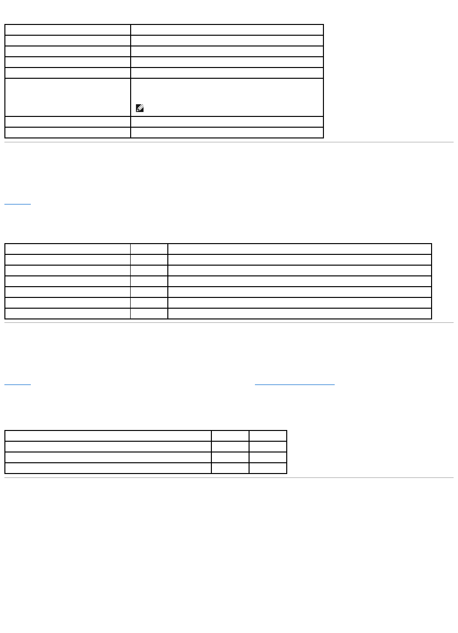
Table 2-7.ArrayPerformanceFeatures
Fault Tolerance Features
Table2-8 describes the fault tolerance capabilities of the RAID controller.
Table 2-8.FaultToleranceFeatures
Software Utilities
Table2-9 describes the features offered by the utilities used for RAID management. See "RAID Management Utilities" in this section for descriptions of the
utilities.
Table 2-9.SoftwareUtilitiesFeatures
Operating System Software Drivers
Operating System Drivers
Drivers are provided to support the controller on the following operating systems:
lMicrosoft®Windows NT®
lWindows®2000
lWindows 2003
lNovell®NetWare®
Specification
PERC 4/SC and PERC 4/DC
PCI host data transfer rate
532 MB/sec
Drive data transfer rate
Up to 320 MB/sec
Maximum size of I/O requests
6.4 MB in 64 KB stripes
Maximum queue tags per drive
As many as the drive can accept
Stripe sizes
2 KB, 4 KB, 8 KB, 16 KB, 32 KB, 64 KB, or 128 KB
NOTE: Using a 2 KB or 4 KB stripe size is not recommended.
Maximum number of concurrent commands
255
Support for multiple initiators
Only on PERC 4/DC
Specification
PERC 4/SC
PERC 4/DC
Support for SMART
Yes
Yes
Optional battery backup for cache memory
N/A
Yes. Up to 72 hours data retention for 64 MB cache memory (less for larger cache memory).
Drive failure detection
Automatic
Automatic
Drive rebuild using hot spares
Automatic
Automatic
Parity generation and checking
Yes
Yes
User-specified rebuild rate
Yes
Yes
Specification
PERC 4/SC
PERC 4/DC
Management utility
Yes
Yes
Bootup configuration using the PERC BIOS Configuration Utility (Ctrl–M)
Yes
Yes
Online read, write, and cache policy switching
Yes
Yes
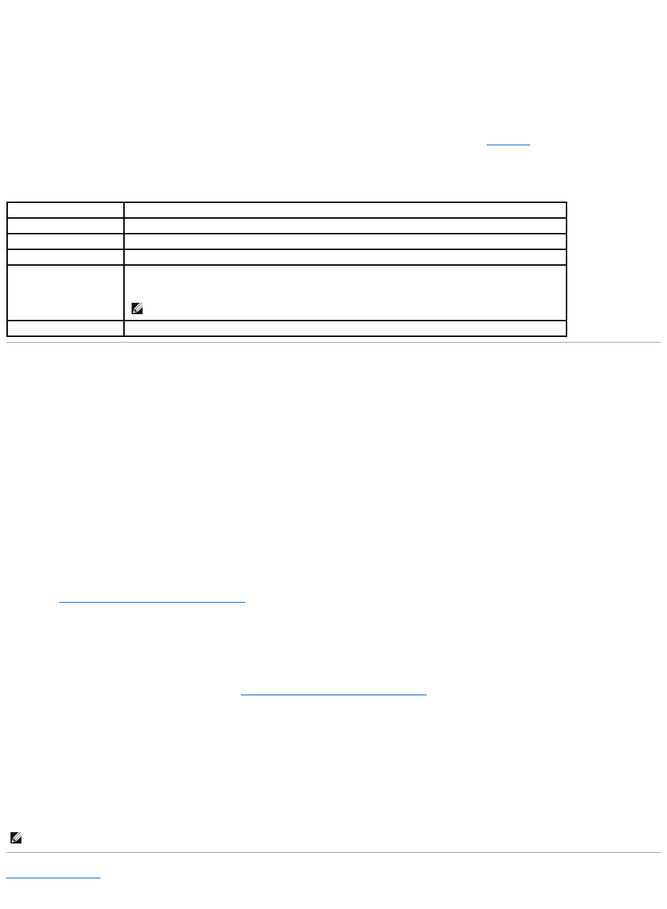
lRed Hat Linux
See the CERC and PERC RAID Controllers Operating System Driver Installation Guide for more information about the drivers.
SCSI Firmware
The RAID controller firmware handles all RAID and SCSI command processing and supports the features described in Table2-10.
Table 2-10.SCSIFirmwareSupport
RAID Management Utilities
Software utilities enable you to manage and configure the RAID system, create and manage multiple disk arrays, control and monitor multiple RAID servers,
provide error statistics logging, and provide online maintenance. The utilities include:
lBIOS Configuration Utility
lDell Manager for Linux
lDellOpenManage™ArrayManagerforWindowsandNetware
BIOS Configuration Utility
The BIOS Configuration Utility configures and maintains RAID arrays, clears hard drives, and manages the RAID system. It is independent of any operating
system. See "BIOS Configuration Utility and Dell Manager" for additional information.
Dell Manager
Dell Manager is a utility that works in Red Hat Linux. See "BIOS Configuration Utility and Dell Manager" for additional information.
Dell OpenManage Array Manager
Dell OpenManage Array Manager is used to configure and manage a storage system that is connected to a server, while the server is active and continues to
handle requests. Array Manager runs under Novell NetWare, Windows NT, and Windows 2000. Refer to Dell documentation and CDs at the Dell Support web
site at support.dell.com for more information.
Back to Contents Page
Feature
PERC 4/SC and PERC 4/DC Description
Disconnect/reconnect
Optimizes SCSI bus utilization
Tagged command queuing
Multiple tags to improve random access
Multi-threading
Up to 255 simultaneous commands with elevator sorting and concatenation of requests per SCSI channel
Stripe size
Variable for all logical drives: 2 KB, 4 KB, 8 KB, 16 KB, 32 KB, 64 KB, or 128 KB.
NOTE: Using a 2 KB or 4 KB stripe size is not recommended.
Rebuild
Multiple rebuilds and consistency checks with user-definable priority.
NOTE: You can run the OpenManage Array Manager remotely to access NetWare, but not locally.

Back to Contents Page
Hardware Installation
Dell™PowerEdge™ExpandableRAIDController4/SCand4/DCUser'sGuide
Requirements
Quick Installation Procedure
Installation Steps
Requirements
This section describes the procedures for installing the RAID controller. You must have the following items to install the controller:
lA PERC 4/SC or 4/DC controller
lA host system with an available 32- or 64-bit, 3.3-V PCI extension slot
lThe DellOpenManage™SystemsManagementCD or driver diskette
lThe necessary internal and/or external SCSI cables
lUltra, Ultra2, Ultra3, Ultra160, or Ultra320 SCSI hard drives
(SCSI is backward compatible, but it slows to the speed of the slowest device).
Quick Installation Procedure
Perform the following steps for quick installation of the controller if you are an experienced system user/installer. All others should follow the steps in the next
section, Installation Steps.
1. Turn off all power to the server and all hard drives, enclosures, and system components.
2. Open host system by following the instructions in the host system technical documentation.
3. Determine the SCSI ID and SCSI termination requirements.
4. Install the RAID controller in the server and attach the SCSI cables and terminators.
lMake sure pin 1 on the cable matches pin 1 on the connector.
lMake sure that the SCSI cables conform to all SCSI specifications.
5. Perform a safety check.
lMake sure all cables are properly attached.
lMake sure the RAID controller is properly installed.
lClose the cabinet of the host system.
lTurn power on after completing the safety check.
6. Format the hard drives as needed.
7. Configure logical drives using the BIOS Configuration Utility or Dell Manager.
8. Initialize the logical drives.
9. Install the network operating system drivers as needed.
Installation Steps
This section provides instructions for installing the RAID controllers.
Step 1 Unpack the Controller
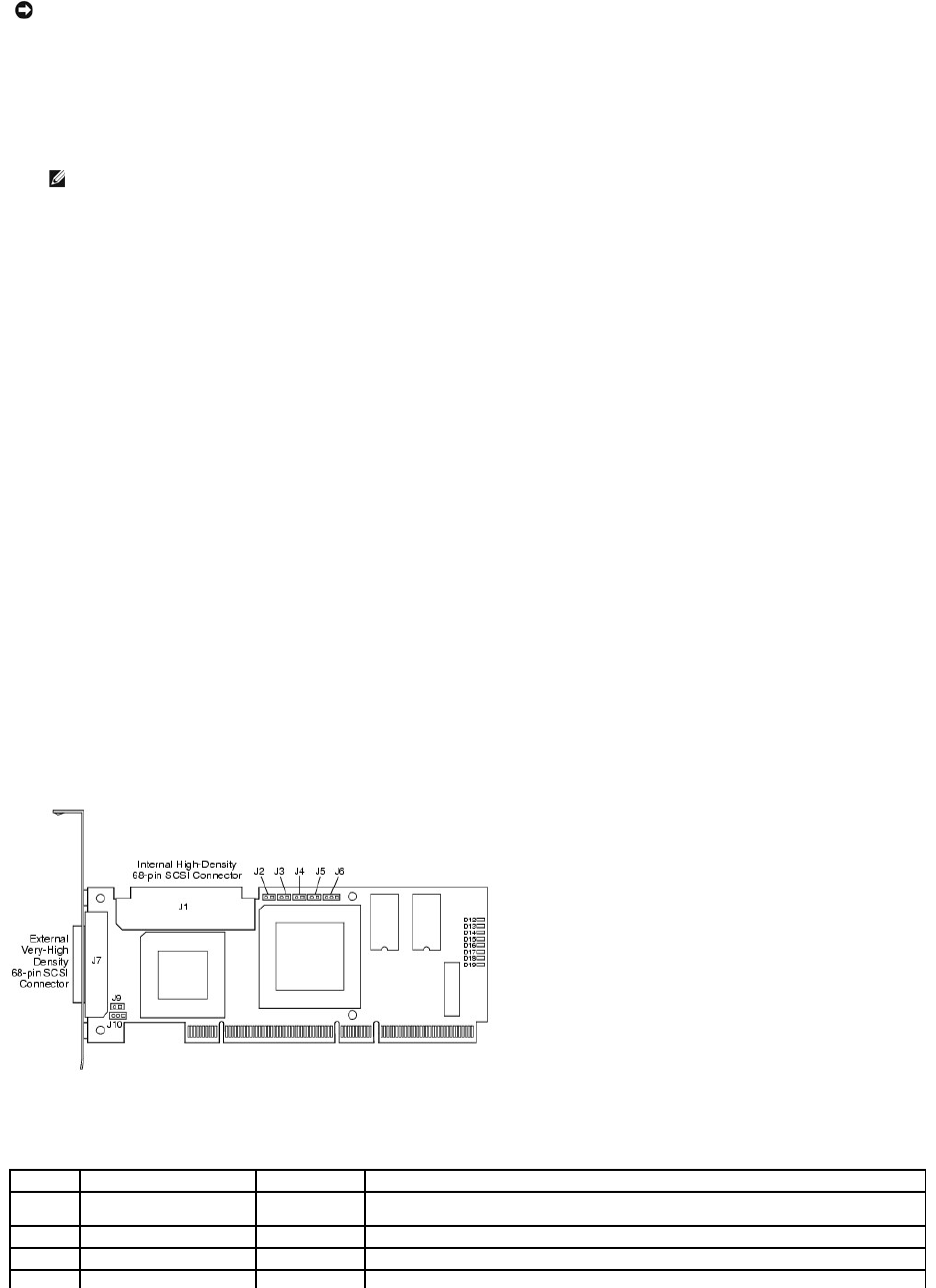
Unpack and remove the controller and inspect it for damage. If the controller appears damaged, or if any items listed below are missing, contact your Dell
support representative. The RAID controller is shipped with:
lThe PERC 4 RAID Controller User's Guide (on CD)
lThe CERC and PERC RAID Controllers Operating System Driver Installation Guide (on CD)
lA license agreement
Step 2 Power Down the System
Perform the following steps to power down the system:
1. Turn off the system.
2. Remove the AC power cord.
3. Disconnect the system from any networks before installing the controller.
4. Remove the system's cover.
Please consult the system documentation for instructions.
Step 3 Set Jumpers
Make sure the jumper settings on the RAID controller are correct. Following are diagrams of the controllers showing their jumpers and connectors, and tables
describing them. Select your controller from the ones shown on the following pages.
PERC 4/SC Jumpers and Connectors
Figure 3-1. PERC 4/SC Controller Layout
Table 3-1.PERC4/SCJumperandConnectorDescriptions
NOTICE: See the safety instructions in your system documentation for information about protecting against electrostatic discharge.
NOTE: You can order a hard copy of the documentation for the controller.
Connector
Description
Type
Setting
J1
Internal SCSI connector
68-pin
connector
Internal high-density SCSI bus connector.
Connection is optional.
J2
NVRAM Clear
2-pin header
To CLEAR configuration data, install a jumper.
J3
Serial EPROM
2-pin header
To CLEAR configuration data, install a jumper.
J4
Onboard BIOS Enable
2-pin header
No jumper = Enabled (Default is Enabled)
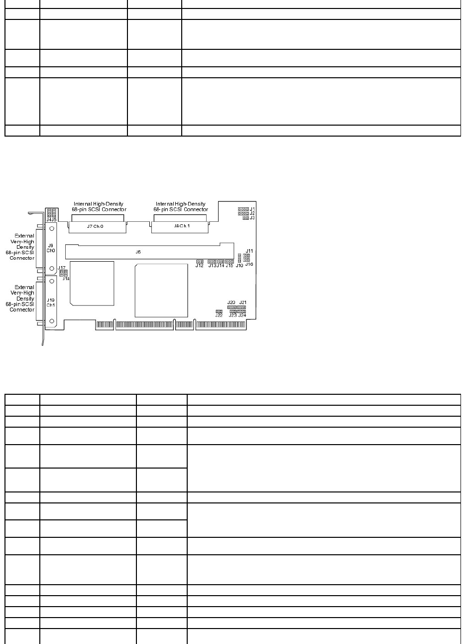
PERC 4/DC Jumpers and Connectors
Figure 3-2. PERC 4/DC Controller Layout
Table 3-2.PERC4/DCJumperandConnectorDescriptions
With jumper in = Disabled
J5
SCSI Activity
2-pin header
Connector for enclosure LED to indicate data transfers. Connection is optional.
J6
Serial Port
3-pin header
Connector is for diagnostic purposes.
Pin-1 RXD (Receive Data)
Pin-2 TXD (Transmit Data)
Pin-3 GND (Ground)
J7
External SCSI connector
68-pin
connector
External very-high density SCSI bus connector.
Connection is optional.
J9
SCSI bus TERMPWR Enable
2-pin header
Install jumper to enable onboard termination power. Default is installed.
J10
SCSI bus Termination
Enable
3-pin header
Jumper pins 1-2 to enable software control of SCSI termination through drive detection.
Jumper pins 2-3 to disable onboard SCSI termination.
Having no jumper installed enables onboard SCSI termination. The default is no jumper
installed.
D12 - D19
LEDs
Indicate problems with the card.
Connector
Description
Type
Settings
J1
I2C Header
4-pin header
Reserved.
J2
SCSI Activity LED
4-pin header
Connector for LED on enclosure to indicate data transfers. Optional.
J3
Write Pending Indicator
(Dirty Cache LED)
2-pin header
Connector for enclosure LED to indicate when data in the cache has yet to be written to the
device. Optional.
J4
SCSI Termination Enable
Channel 1
3-pin header
Jumper pins 1-2 to enable software control of SCSI termination via drive detection.
Jumper pins 2-3 to disable onboard SCSI termination.
No Jumper installed enables onboard SCSI termination. (See J17 and J18). The default is no
jumper installed.
J5
SCSI Termination Enable
Channel 0
3-pin header
J6
DIMM socket
DIMM socket
Socket that hold the memory module
J7
Internal SCSI Channel 0
connector
68-pin
connector
Internal high-density SCSI bus connector. Connection is optional.
J8
Internal SCSI Channel 1
connector
68-pin
connector
J9
External SCSI Channel 0
connector
68-pin
connector
External very-high density SCSI bus connector. Connection is optional.
J10
Battery connector
3-pin header
Connector for an optional battery pack.
Pin-1 -BATT Terminal (black wire)
Pin-2Thermistor(whitewire)
Pin-3 +BATT Terminal (red wire)
J11
NVRAM clear
2-pin header
To CLEAR the configuration data, install a jumper.
J12
NMI jumper
2-pin header
Reserved for factory.
J13
32-bit SPCI Enable
3-pin header
Reserved for factory.
J14
Mode Select jumper
2-pin header
J15
Serial Port
3-pin header
Connector is for diagnostic purposes.
Pin-1 RXD (Receive Data)
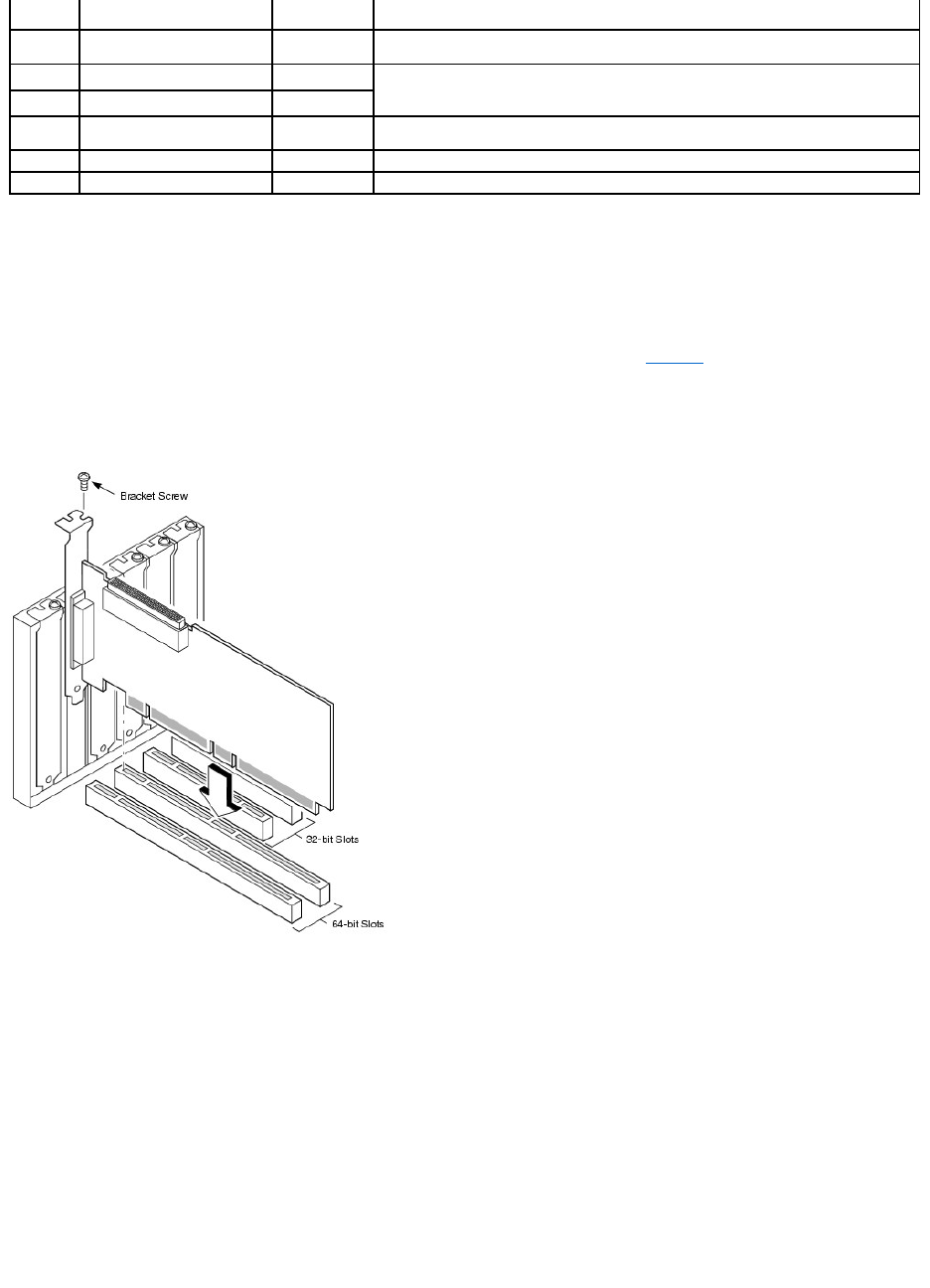
Step 4 Install the RAID Controller
Perform the following steps to install the controller:
1. Select a 3.3-V PCI slot and align the controller PCI bus connector to the slot.
2. Press down gently but firmly to make sure that the controller is properly seated in the slot, as shown in Figure3-3.
3. Screw the bracket to the system chassis.
Figure 3-3. Inserting the RAID Controller into a PCI Slot
Step 5 Connect SCSI Cables and SCSI Devices
Connect the SCSI cables to the SCSI connectors and SCSI devices.
Connect SCSI Devices
Perform the following steps to connect SCSI devices.
1. Disable termination on any SCSI device that does not sit at the end of the SCSI bus.
2. Configure all SCSI devices to supply TermPWR..
3. Set proper target IDs (TIDs) for all SCSI devices.
Pin-2 TXD (Transmit Data)
Pin-3 GND (Ground)
J16
Onboard BIOS Enable
2-pin header
No jumper = Enabled (Default setting)
Jumpered = Disabled
J17
TERMPWR Enable Channel 0
2-pin header
Jumper installed enables TERMPWR from the PCI bus. Default setting.
No jumper installed enables TERMPWR from the SCSI bus. (See J4 and J5)
J18
TERMPWR Enable Channel 1
2-pin header
J19
External SCSI Channel 1
connector
68-pin
connector
External very-high density SCSI bus connector. Connection is optional.
J23
Serial EEPROM
2-pin header
To CLEAR configuration data, install a jumper.
D17 - D24
LED (located on back of card)
Indicate problems with the card.

4. The host controller has a SCSI ID of 7.
5. Connect the cable to the devices.
Cable Suggestions
System throughput problems can occur if the SCSI cables are not the correct type. To avoid problems, you should follow the following cable suggestions:
lUse cables no longer than 12 meters for Ultra3, Ultra160, and Ultra320 devices. (It's better to use shorter cables if possible.)
lMake sure the cables meet the specifications.
lUse active termination.
lNotethatcablestublengthshouldbenomorethan0.1meter(4inches).
lRoute SCSI cables carefully and do not bend cables.
lUse high impedance cables.
lDo not mix cable types (choose either flat or rounded and shielded or non-shielded).
lNote that ribbon cables have fairly good cross-talk rejection characteristics, meaning the signals on the different wires are less likely to interfere with
each other.
Step 6 Set Target IDs
Set target identifiers (TIDs) on the SCSI devices. Each device in a channel must have a unique TID. Non-disk devices should have unique SCSI IDs regardless of
the channel where they are connected. See the documentation for each SCSI device to set the TIDs. The RAID controller automatically occupies TID 7, which is
the highest priority. The arbitration priority for a SCSI device depends on its TID. Table3-3 lists the target IDs.
Table 3-3.TargetIDs
Step 7 Set SCSI Termination
The SCSI bus is an electrical transmission line and must be terminated properly to minimize reflections and losses. Termination should be set at each end of
the SCSI cable(s).
For a disk array, set SCSI bus termination so that removing or adding a SCSI device does not disturb termination. An easy way to do this is to connect the
RAID controller to one end of the SCSI cable and an external terminator module at the other end of the cable, as shown in Figure3-4.
The connectors between the two ends can connect SCSI drives which have their termination disabled, as shown in the drives (ID0, ID1, ID2) attached in the
figure. See the manual for each SCSI drive to disable termination.
Set the termination so that SCSI termination and TermPWR are intact when any hard drive is removed from a SCSI channel.
Figure 3-4. Terminating Internal SCSI Disk Array
NOTE: The maximum cable length for Fast SCSI (10 MB/sec) devices is 3 meters and for Ultra SCSI devices is 1.5 meters. The cable length can be up to
12 meters for LVD devices. Use shorter cables if possible.
Priority
HighestLowest
TID
7
6
5
...
2
1
0
15
14
...
9
8
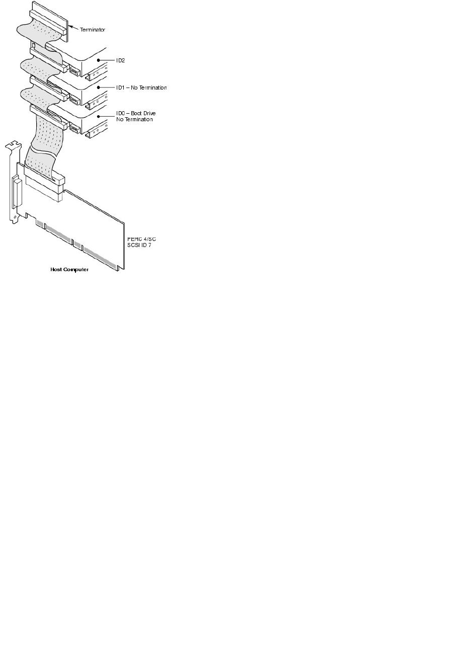
Step 8 Start the System
Replace the system cover and reconnect the AC power cords. Turn power on to the host system. Set up the power supplies so that the SCSI devices are
powered up at the same time as or before the host system. If the system is powered up before a SCSI device, the device might not be recognized.
During bootup, the BIOS message appears:
PowerEdge Expandable RAID Controller BIOS Version x.xx date
Copyright (c) Dell Inc
Firmware Initializing... [ Scanning SCSI Device ...(etc.)... ]
The firmware takes several seconds to initialize. During this time the adapter scans the SCSI channel. When ready, the following appears:
HA –0 (Bus 1 Dev 6) Type: PERC 4/xx Standard FW x.xx SDRAM=xxxMB
0 Logical Drives found on the Host Adapter
0 Logical Drive(s) handled by BIOS
Press <Ctrl><M> to run PERC 4 BIOS Configuration Utility
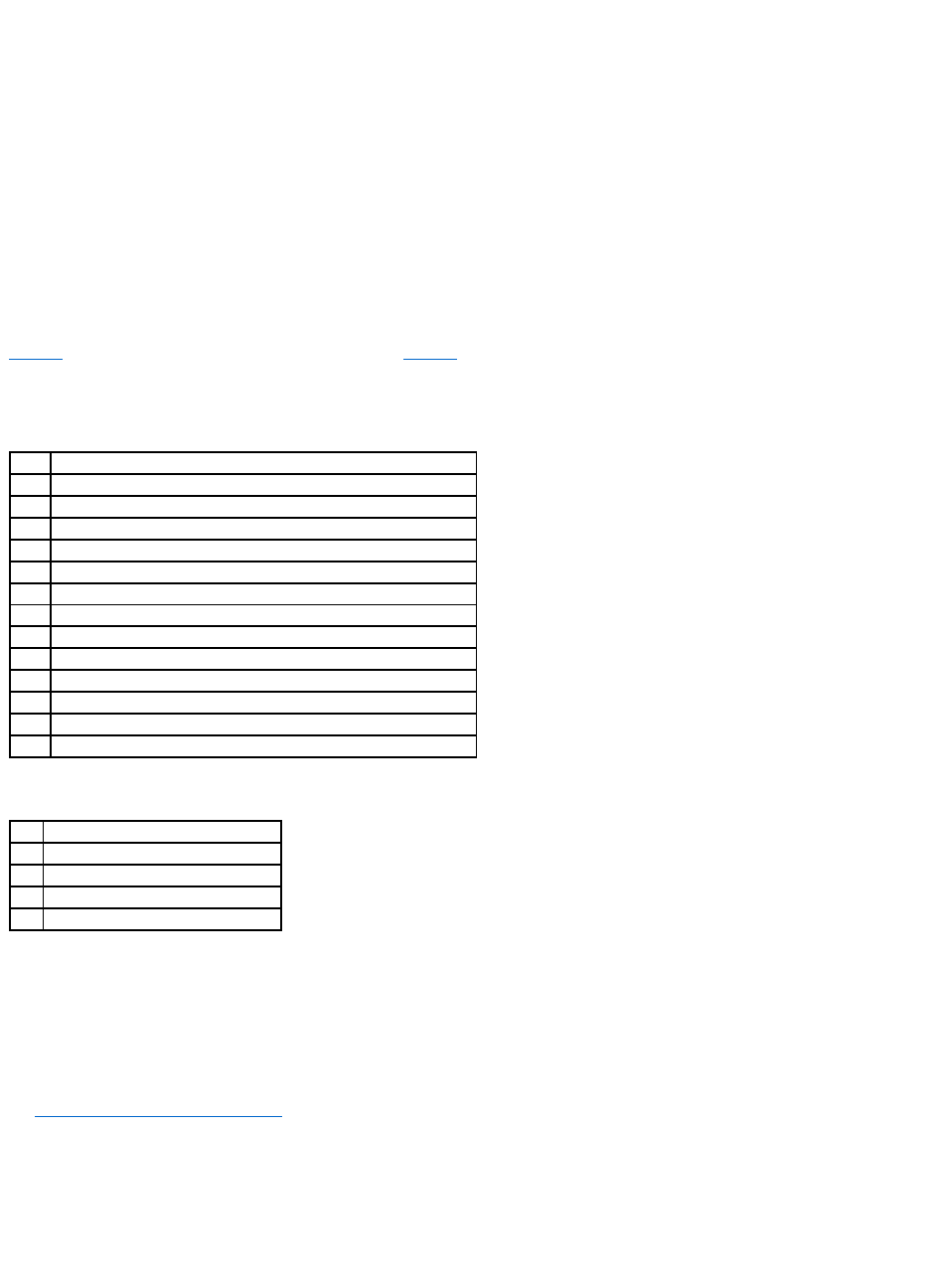
The BIOS Configuration Utility prompt times out after several seconds.
The host controller number, firmware version, and cache SDRAM size display in the second portion of the BIOS message. The numbering of the controllers
follows the PCI slot scanning order used by the host motherboard.
Light-emitting Diode (LED) Description
When you start the system, the boot block and firmware perform a number of steps that load the operating system and allow the system to function properly.
The boot block contains the operating system loader and other basic information needed during startup.
As the system boots, the LEDs indicate the status of the boot block and firmware initialization and whether the system performed the steps correctly. If there
is an error during startup, you can use the LED display to identify it.
Table3-4 displays the LEDs and execution states for the boot block. Table3-5 displays the LEDs and execution states during firmware initialization. The LEDs
display in hexadecimal format so that you can determine the number and the corresponding execution state from the LEDs that display.
Table 3-4.BootBlockStates
Table 3-5.FirmwareInitializationStates
Step 9 Run the BIOS Configuration Utility or Dell Manager
Press <Ctrl><M> when prompted during the boot process to run the BIOS Configuration Utility. You can run Dell Manager in Red Hat Linux to perform the same
functions, such as configuring arrays and logical drives.
See BIOS Configuration Utility and Dell Manager for additional information about running the BIOS Configuration Utility and Dell Manager.
Step 10 Install an Operating System
Install one of the following operating systems: Microsoft®Windows NT®, Windows®2000, Windows 2003, Novell®NetWare®, and Red Hat Linux.
LED
Execution State
0x01
Setup 8-bit Bus for access to Flash and 8 Bit devices successful
0x03
Serial port initialization successful
0x04
Spd (cache memory) read successful
0x05
SDRAM refresh initialization sequence successful
0x07
Start ECC initialization and memory scrub
0x08
End ECC initialization and memory scrub
0x10
SDRAM is present and properly configured. About to program ATU.
0x11
CRC check on the firmware image successful. Continue to load firmware.
0x12
Initialization of SCSI chips successful.
0x13
BIOS protocols ports initialized. About to load firmware.
0x17
Firmware is either corrupt or BIOS disabled. Firmware was not loaded.
0x19
Error ATU ID programmed.
0x55
System Halt: Battery Backup Failure
LED
Execution State
0x1
Begin Hardware Initialization
0x3
Begin Initialize ATU
0x7
Begin Initialize Debug Console
0xF
Set if Serial Loopback Test is successful

Step 11 Install the Operating System Driver
Operating system drivers are provided on the Dell OpenManage Systems Management CD that accompanies your PERC controller. See the CERC and PERC RAID
Controllers Operating System Driver Installation Guide for additional information about installing the drivers for the operating systems.
Back to Contents Page
NOTE: To make sure you have the latest version of the drivers, download the updated drivers from the Dell Support web site at support.dell.com.

Back to Contents Page
Configuring the RAID Controller
Dell™PowerEdge™ExpandableRAIDController4/SCand4/DCUser'sGuide
Configuring SCSI Physical Drives
Physical Device Layout
Device Configuration
Setting Hardware Termination
Configuring Arrays
Assigning RAID Levels
Optimizing Data Storage
This section describes how to configure for physical drives, arrays, and logical drives. It contains tables you can complete to list the configuration for the
physical drives and logical drives.
Configuring SCSI Physical Drives
Your SCSI hard drives must be organized into logical drives in an array and must be able to support the RAID level that you select.
Observe the following guidelines when connecting and configuring SCSI devices in a RAID array:
lYou can place up to 32 physical drives in an array.
lWhen implementing RAID 1 or RAID 5, disk space is spanned to create the stripes and mirrors. The span size can vary to accommodate the different
disk sizes. There is, however, the possibility that a portion of the largest disk in the array will be unusable, resulting in wasted disk space. For example,
consider an array that has the following disks:
¡Disk A = 40 GB
¡Disk B = 40 GB
¡Disk C = 60 GB
¡Disk D = 80 GB
In this example, data is spanned across all four disks until Disk A and Disk B and 40 GB on each of Disk C and D are completely full. Data is then spanned
across Disks C and D until Disk C is full. This leaves 20 GB of disk space remaining on Disk D. Data cannot be written to this disk space, as there is no
corresponding disk space available in the array to create redundant data.
lFor RAID levels 10 and 50, the additional space in larger arrays can store data, so you can use arrays of different sizes.
lWhen replacing a failed hard drive, make sure that the replacement drive has a capacity that is the same size or larger than the smallest drive in a
logical drive that supports redundancy (RAID 1, 5, 10, and 50).
Physical Device Layout
Use Table4-1 to list the details for each physical device on the channels.
Table 4-1.PhysicalDeviceLayout
Channel 0
Channel 1
Target ID
Device type
Logical drive number/ drive number
Manufacturer/model number
Firmware level
Target ID
Device type

Logical drive number/ drive number
Manufacturer/model number
Firmware level
Target ID
Device type
Logical drive number/ drive number
Manufacturer/model number
Firmware level
Target ID
Device type
Logical drive number/drive number
Manufacturer/model number
Firmware level
Target ID
Device type
Logical drive number/drive number
Manufacturer/model number
Firmware level
Target ID
Device type
Logical drive number/drive number
Manufacturer/model number
Firmware level
Target ID
Device type
Logical drive number/drive number
Manufacturer/model number
Firmware level
Target ID
Device type
Logical drive number/drive number
Manufacturer/model number
Firmware level
Target ID
Device type
Logical drive number/drive number
Manufacturer/model number
Firmware level
Target ID
Device type
Logical drive number/drive number
Manufacturer/model number
Firmware level
Target ID
Device type
Logical drive number/drive number
Manufacturer/model number
Firmware level
Target ID
Device type
Logical drive number/drive number
Manufacturer/model number
Firmware level
Target ID
Device type
Logical drive number/drive number
Manufacturer/model number
Firmware level
Target ID
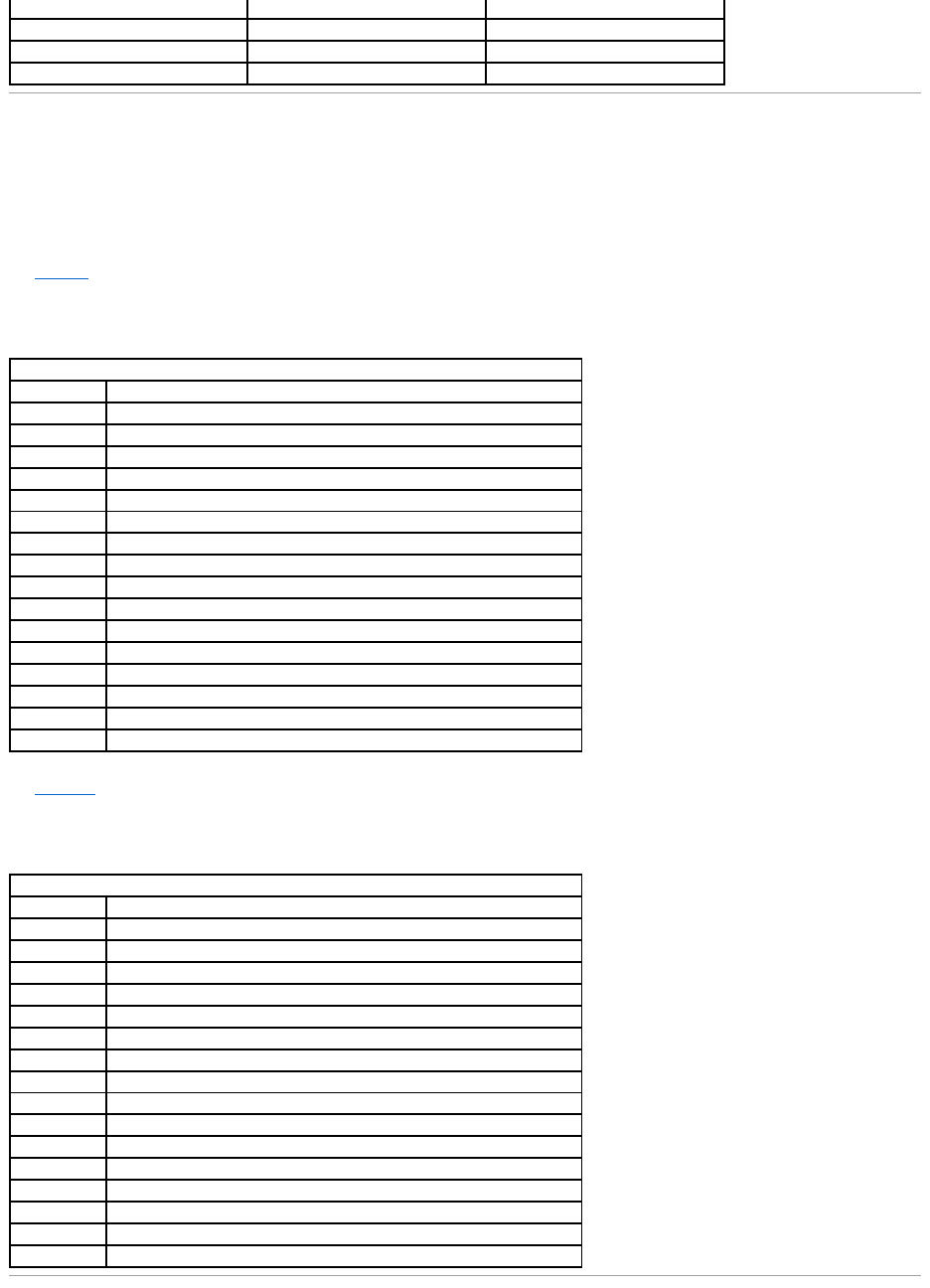
Device Configuration
The following contain tables you can fill out to list the devices assigned to each channel. The PERC 4/SC controller has one channel; the PERC 4/DC has two.
Use Table4-2 to list the devices that you assign to each SCSI ID for SCSI Channel 0.
Table 4-2.ConfigurationforSCSIChannel0
Use Table 4-3. to list the devices that you assign to each SCSI ID for SCSI Channel 1.
Table 4-3.ConfigurationforSCSIChannel1
Device type
Logical drive number/drive number
Manufacturer/model number
Firmware level
SCSI Channel 0
SCSI ID
Device Description
0
1
2
3
4
5
6
7
Reserved for host controller.
8
9
10
11
12
13
14
15
SCSI Channel 1
SCSI ID
Device Description
0
1
2
3
4
5
6
7
Reserved for host controller.
8
9
10
11
12
13
14
15

Setting Hardware Termination
The SCSI bus is an electrical transmission line and must be terminated properly to minimize reflections and losses. Termination should be set at each end of
the SCSI cable(s).
lJ5 Termination Enable is a three-pin header that specifies control of the SCSI termination for channel 0.
lJ6 Termination Enable is a three-pin header that specifies control of the SCSI termination for channel 1.
To enable hardware termination, leave the pins open. The default is hardware termination.
Configuring Arrays
Organize the physical drives into arrays after the drives are connected to the RAID controller, formatted, and initialized. An array can consist of up to 28
physical drives (24 drives when used with the span feature in a RAID 50 configuration).
The number of drives in an array determines the RAID levels that can be supported. The RAID controller supports up to 40 logical drives per controller.
Creating Hot Spares
Any drive that is present, formatted, and initialized, but not included in an array or logical drive can be designated as a hot spare. You can use the RAID
management utilities to designate drives as hot spares. The utilities are described in the RAID Management Utilities section.
Creating Logical Drives
Logical drives are arrays or spanned arrays that are presented to the operating system. The logical drive capacity can also be larger than an array by using
spanning. The RAID controller supports up to 40 logical drives.
Configuration Strategies
The most important factors in RAID array configuration are drive capacity, drive availability (fault tolerance), and drive performance.
You cannot configure a logical drive that optimizes all three factors, but it is easy to select a logical drive configuration that maximizes one or two factors at the
expense of the other factor(s).
Configuring Logical Drives
After you have installed the RAID controller in the server and have attached all physical drives, perform the following steps to prepare a RAID disk array:
1. Start the system.
2. Press <Ctrl><M> during bootup to run the BIOS Configuration Utility.
3. Select Easy Configuration, New Configuration, or View/Add Configuration in BIOS Configuration Utility and Dell Manager to customize the RAID array.
4. Create and configure one or more system drives (logical drives).
NOTE: If you are using the PERC 4/DC RAID controller for clustering, then you must use hardware termination. Otherwise, software termination is OK.
NOTE: See "Step 7 Set SCSI Termination" for additional information about setting SCSI termination.

5. Select the RAID level, cache policy, read policy, and write policy.
6. Save the configuration.
7. Initialize the system drives.
8. Install the operating system.
See BIOS Configuration Utility and Dell Manager for detailed instructions.
Logical Drive Configuration
Use Table4-4 to list the details for each logical drive that you configure.
Table 4-4.LogicalDriveConfiguration
Logical Drive
RAID Level
Stripe Size
Logical Drive
Size
Cache Policy
Read Policy
Write Policy
Number of
Physical Drives
LD0
LD1
LD2
LD3
LD4
LD5
LD6
LD7
LD8
LD9
LD10
LD11
LD12
LD13
LD14
LD15
LD16
LD17
LD18
LD19
LD20
LD21
LD22
LD23
LD24
LD25
LD26
LD27
LD28
LD29
LD30
LD31
LD32
LD33
LD34
LD35
LD36
LD37
LD38
LD39
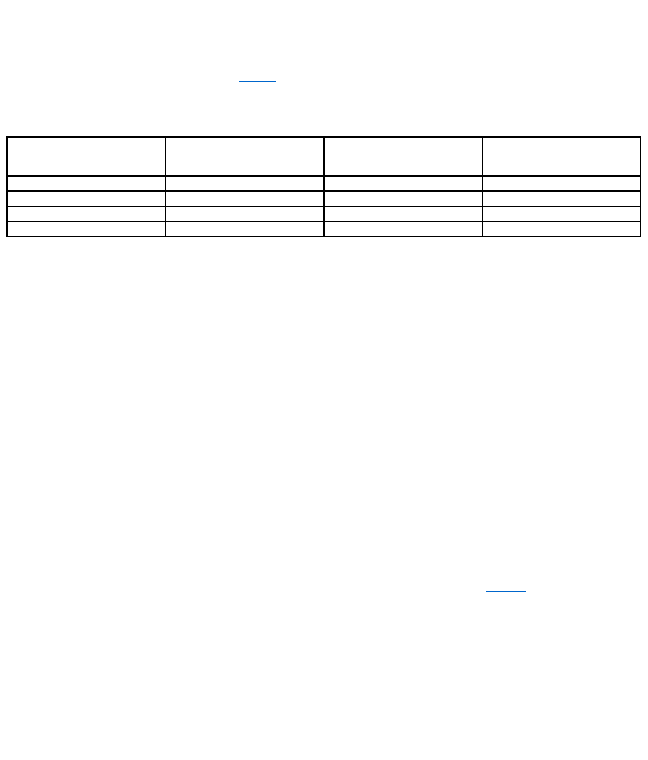
Assigning RAID Levels
Only one RAID level can be assigned to each logical drive. Table4-5 shows the minimum and maximum number of drives required.
Table 4-5.PhysicalDrivesRequiredforEachRAIDLevel
Summary of RAID Levels
RAID 0 uses striping to provide high data throughput, especially for large files in an environment that does not require fault tolerance.
RAID 1 uses mirroring and is good for small databases or other applications that require small capacity, but complete data redundancy.
RAID 5 provides high data throughput, especially for small random access. Use this level for any application that requires high read request rates, but low
write request rates, such as transaction processing applications. Write performance is significantly lower for RAID 5 than for RAID 0 and RAID 1.
RAID 10 consists of striped data across mirrored spans. It provides high data throughput and complete data redundancy, but uses a larger number of spans.
RAID 50 uses parity and disk striping and works best with data that requires high reliability, high request rates, high data transfers, and medium-to-large
capacity. Write performance is limited to the same as RAID 5.
Storage in RAID 10 and RAID 50 Arrays of Different Sizes
For RAID levels 10 and 50, the additional space in larger arrays can store data, so you can use arrays of different sizes. Figure4-1 shows the example of a
RAID 50 array with three RAID 5 arrays of different sizes. Data is striped across the three arrays until the smallest drive is full. The data is then striped across
the larger two arrays until the smaller of those two arrays is full. Finally, data is stored in the additional space in the largest of the three arrays.
Performance Considerations
Performance is better the more spans there are. As the storage space in the spans is filled, the system stripes data over fewer and fewer spans and RAID
performance degrades to that of a RAID 1 or RAID 5 array.
Figure 4-1. Storage in a RAID 50 Array
RAID Level
Minimum # of Physical Drives
Maximum # of Physical Drives for
PERC 4/SC
Maximum # of Physical Drives for
PERC 4/DC
0
1
14
28
1
2
2
2
5
3
14
28
10
4
14
28
50
6
14
28
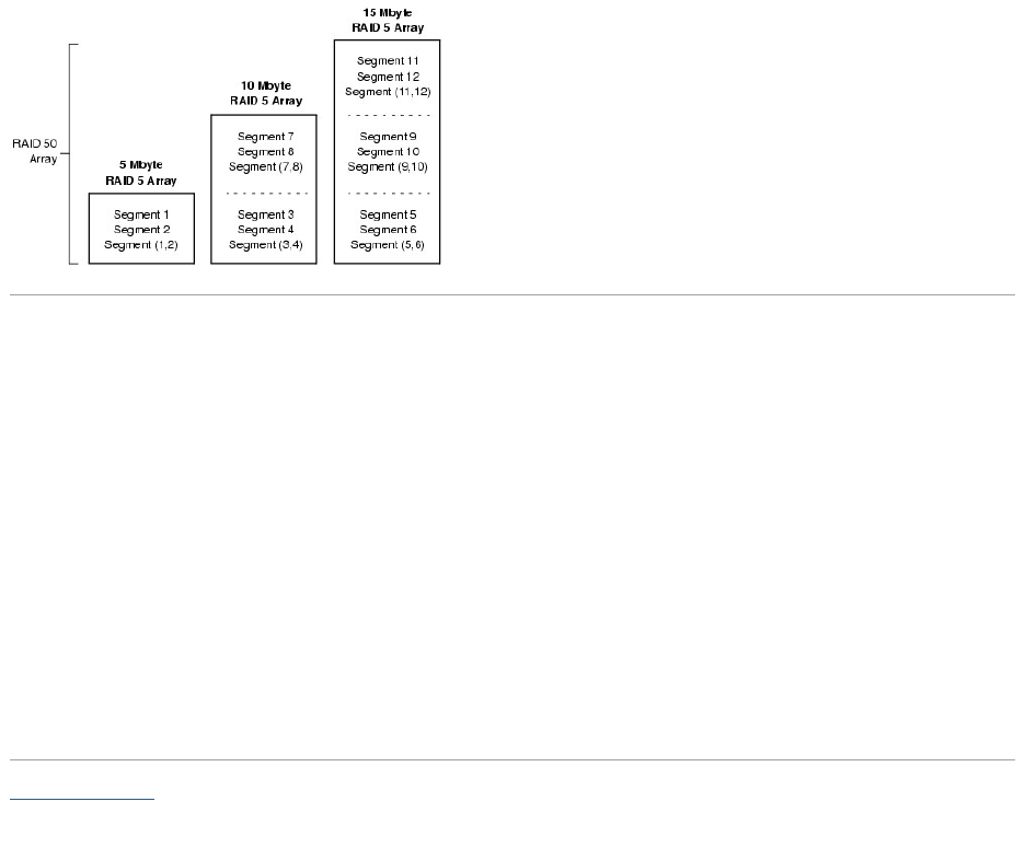
Optimizing Data Storage
Data Access Requirements
Each type of data stored in the disk subsystem has a different frequency of read and write activity. If you know the data access requirements, you can more
successfully determine a strategy for optimizing the disk subsystem capacity, availability, and performance. For example, servers that support Video on
Demand typically read the data often, but write data infrequently. Both the read and write operations tend to be long. Data stored on a general-purpose file
server involves relatively short read and write operations with relatively small files.
Array Considerations
You must identify the purpose of the data to be stored in the disk subsystem before you can confidently select a RAID level and a RAID configuration. Will this
array increase the system storage capacity for general-purpose file and print servers? Does this array support any software system that must be available 24
hours per day? Will the information stored in this array contains large audio or video files that must be available on demand? Will this array contain data from
an imaging system?
Back to Contents Page

Back to Contents Page
BIOS Configuration Utility and Dell Manager
Dell™PowerEdge™ExpandableRAIDController4/SCand4/DCUser'sGuide
Starting the BIOS Configuration Utility
Starting Dell Manager
Using Dell Manager in Red Hat Linux GUI Mode
Configuring Arrays and Logical Drives
Designating Drives as Hot Spares
Creating Arrays and Logical Drives
Drive Roaming
Initializing Logical Drives
Deleting Logical Drives
Clearing Physical Drives
Rebuilding Failed Hard Drives
Using a Pre-loaded SCSI Drive "As-is"
FlexRAID Virtual Sizing
Checking Data Consistency
Reconstructing Logical Drives
Exiting the Configuration Utility
The BIOS Configuration Utility configures disk arrays and logical drives. Because the utility resides in the RAID controller BIOS, its operation is independent of
the operating systems on your system.
Dell™Managerisacharacter-based, non-GUI utility that changes policies, and parameters, and monitors RAID systems. Dell Manager runs under Red Hat
Linux, Advanced Server, Enterprise.
Use these utilities to do the following:
lCreate hot spare drives.
lConfigure physical arrays and logical drives.
lInitialize one or more logical drives.
lAccess controllers, logical drives, and, physical drives individually.
lRebuild failed hard drives.
lVerify that the redundancy data in logical drives using RAID level 1, 5, 10, or 50 is correct.
lReconstruct logical drives after changing RAID levels or adding a hard drive to an array
lSelect a host controller to work on.
Starting the BIOS Configuration Utility
When the host computer boots, hold the <Ctrl> key and press the <M> key when a BIOS banner such as the following appears:
HA -0 (Bus X Dev X) Type: PERC 4 Standard FWx.xx SDRAM=128MB
Battery Module is Present on Adapter
1 Logical Drive found on the Host Adapter
Adapter BIOS Disabled, No Logical Drives handled by BIOS

0 Logical Drive(s) handled by BIOS
Press <Ctrl><M> to Enable BIOS
For each controller in the host system, the firmware version, dynamic random access memory (DRAM) size, and the status of logical drives on that controller
display. After you press a key to continue, the Management Menu screen displays.
Starting Dell Manager
Make sure the program file is in the correct directory before you enter the command to start Dell Manager. For Linux, use the Dell Manager RPM to install files in
the usr/sbin directory. The RPM installs them automatically in that directory.
Type dellmgr to start the program.
Using Dell Manager in Red Hat Linux GUI Mode
On a Red Hat Linux system, for Dell Manager to work correctly in a terminal in GUI Mode, you must set the terminal type to linux and keyboard mappings.
Perform the procedure below if you use konsole, gnome terminal, or xterm.
The linux console mode, which you select from the terminal with the File —> Linux Console command, works correctly by default. The text mode console (non-
GUI) also works correctly by default.
To prepare the system to use Dell Manager, perform the following steps:
1. Start the Terminal.
2. Before you enter dellmgr to start Dell Manager, type the following commands:
TERM=linux
Export TERM
3. Select Settings—> Keyboard—> Linux Console from the Terminal menu.
l<Shift><1> for <F1>
l<Shift><2> for <F2>
l<Shift><3> for <F3>
l<Shift><4> for <F4>
l<Shift><5> for <F5>
l<Shift><6> for <F6>
l<Shift><7> for <F7>
l<Shift><0> for <F10>
NOTE: In the BIOS Configuration Utility, pressing <Ctrl><M> has the same effect as pressing <Enter>.
NOTE: On a Red Hat Linux 8.x system, when you run Dell Manager (v. x.xx) from a Gnome-terminal in XWindows, the <F10> key cannot be used to
create a logical drive. Instead, use the alternate keys <Shift><0>. (This is not an issue if Xterm is used to call dellmgr). The following is a list of
alternate keys you can use in case of problems with keys <F1> through <F7>, and <F10>:

Configuring Arrays and Logical Drives
1. Designate hot spares (optional).
See Designating Drives as Hot Spares in this section for more information.
2. Select a configuration method.
See Creating Arrays and Logical Drives in this section for more information.
3. Create arrays using the available physical drives.
4. Define logical drives using the arrays.
5. Save the configuration information.
6. Initialize the logical drives.
See Initializing Logical Drives in this section for more information.
Designating Drives as Hot Spares
Hot spares are physical drives that are powered up along with the RAID drives and usually stay in a standby state. If a hard drive used in a RAID logical drive
fails, a hot spare will automatically take its place and the data on the failed drive is reconstructed on the hot spare. Hot spares can be used for RAID levels 1,
5, 10, and 50. Each controller supports up to eight hot spares.
The methods for designating physical drives as hot spares are:
lPressing <F4> while creating arrays in Easy, New or View/Add Configuration mode.
lUsing the Objects—> Physical Drive menu.
<F4> Key
When you select any configuration option, a list of all physical devices connected to the current controller appears. Perform the following steps to designate a
drive as a hot spare:
1. On the Management Menu select Configure, then a configuration option.
2. Press the arrow keys to highlight a hard drive that displays as READY.
3. Press <F4> to designate the drive as a hot spare.
4. Click YES to make the hot spare.
The drive displays as HOTSP.
5. Save the configuration.
Objects Menu
1. On the Management Menu select Objects—> Physical Drive.
A physical drive selection screen appears.
2. Select a hard drive in the READY state and press <Enter> to display the action menu for the drive.
3. Press the arrow keys to select Make HotSpare and press <Enter>.
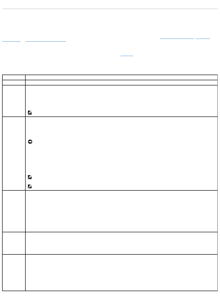
The selected drive displays as HOTSP.
Creating Arrays and Logical Drives
Configure arrays and logical drives using Easy Configuration, New Configuration, or View/Add Configuration. See Using Easy Configuration, Using New
Configuration, or Using View/Add Configuration for the configuration procedures.
After you create an array or arrays, you can select the parameters for the logical drive. Table5-1 contains descriptions of the parameters.
Table 5-1.LogicalDriveParametersandDescriptions
Using Easy Configuration
Parameter
Description
RAID Level
The number of physical drives in a specific array determines the RAID levels that can be implemented with the array.
Stripe Size
Stripe Size specifies the size of the segments written to each drive in a RAID 1, 5, or 10 logical drive. You can set the stripe size to 2 KB, 4
KB, 8 KB, 16 KB, 32 KB, 64 KB, or 128 KB. The default is 64 KB.
A larger stripe size provides better read performance, especially if your computer does mostly sequential reads. However, if you are sure
that your computer does random read requests more often, select a small stripe size.
NOTE: Using a 2 KB or 4 KB stripe size is not recommended.
Write Policy
Write Policy specifies the cache write policy. You can set the write policy to Write-back or Write-through.
In Write-back caching, the controller sends a data transfer completion signal to the host when the controller cache has received all the
data in a transaction. This setting is recommended in standard mode.
In Write-through caching, the controller sends a data transfer completion signal to the host when the disk subsystem has received all the
data in a transaction.
Write-through caching has a data security advantage over write-back caching. Write-back caching has a performance advantage over
write-through caching.
NOTICE: If WriteBack is enabled and the system is quickly turned off and on, the RAID controller may hang when flushing cache
memory. Controllers that contain a battery backup will default to WriteBack caching.
NOTE: You should not use write-back for any logical drive that is to be used as a Novell NetWare volume.
NOTE: Enabling clustering turns off write cache. PERC 4/DC supports clustering.
Read Policy
Read-ahead enables the read-ahead feature for the logical drive. You can set this parameter to Read-Ahead, No-Read-ahead, or
Adaptive. The default is Adaptive.
Read-ahead specifies that the controller uses read-ahead for the current logical drive. Read-ahead capability allows the adapter to read
sequentially ahead of requested data and store the additional data in cache memory, anticipating that the data will be needed soon. Read-
ahead supplies sequential data faster, but is not as effective when accessing random data.
No-Read-Ahead specifies that the controller does not use read-ahead for the current logical drive.
Adaptive specifies that the controller begins using read-ahead if the two most recent disk accesses occurred in sequential sectors. If all
read requests are random, the algorithm reverts to No-Read-Ahead; however, all requests are still evaluated for possible sequential
operation.
Cache Policy
Cache Policy applies to reads and writes on a specific logical drive. It does not affect the Read-ahead cache. The default is Direct I/O.
Cached I/O specifies that all reads and writes are buffered in cache memory.
Direct I/O specifies that reads and writes are not buffered in cache memory. Direct I/O does not override the cache policy settings. Data
is transferred to cache and the host concurrently. If the same data block is read again, it comes from cache memory.
Span
The choices are:
Yes—Array spanning is enabled for the current logical drive. The logical drive can occupy space in more than one array.
No—Array spanning is disabled for the current logical drive. The logical drive can occupy space in only one array.
The RAID controller supports spanning of RAID 1 and 5 arrays. You can span two or more RAID 1 arrays into a RAID 10 array and two or
more RAID 5 arrays into a RAID 50 array.
For two arrays to be spanned, they must have the same stripe width (they must contain the same number of physical drives).

In Easy Configuration, each physical array you create is associated with exactly one logical drive. You can modify the following parameters:
lRAID level
lStripe size
lWrite policy
lRead policy
lCache policy
If logical drives have already been configured when you select Easy Configuration, the configuration information is not disturbed. Perform the following steps
to create arrays and logical drives using Easy Configuration.
1. Select Configure—> Easy Configuration from the Management Menu.
Hot key information displays at the bottom of the screen.
2. Press the arrow keys to highlight specific physical drives.
3. Press the spacebar to associate the selected physical drive with the current array.
The selected drive changes from READY to ONLIN A[array number]-[drive number]. For example, ONLIN A2-3 means array 2 with hard drive 3.
4. Add physical drives to the current array as desired.
Try to use drives of the same capacity in a specific array. If you use drives with different capacities in an array, all drives in the array are treated as if
they have the capacity of the smallest drive in the array.
5. Press <Enter> after you finish creating the current array.
The Select Configurable Array(s) window appears. It displays the array and array number, such as A-00.
6. Press the spacebar to select the array.
Span information displays in the array box. You can create multiple arrays, then select them to span them.
7. Press <F10> to configure logical drives.
The window at the top of the screen shows the logical drive that is currently being configured.
8. Highlight RAID and press <Enter> to set the RAID level for the logical drive.
The available RAID levels for the current logical drive display.
9. Select a RAID level and press <Enter> to confirm.
10. Click Advanced Menu to open the menu for logical drive settings.
11. Set the Stripe Size.
12. Set the Write Policy.
13. Set the Read Policy.
14. Set the Cache Policy.
15. Press <Esc> to exit the Advanced Menu.
16. After you define the current logical drive, select Accept and press <Enter>.
The array selection screen appears if any unconfigured hard drives remain.
NOTE: You can press <F2> to display the number of drives in the array, their channel and ID, and <F3> to display array information, such as the
stripes, slots, and free space.

17. Repeat step 2 through step 16 to configure another array and logical drive.
The RAID controller supports up to 40 logical drives per controller.
18. When finished configuring logical drives, press <Esc> to exit Easy Configuration.
A list of the currently configured logical drives appears.
19. Respond to the Save prompt.
After you respond to the Save prompt, the Configure menu appears.
20. Initialize the logical drives you have just configured.
See "Initializing Logical Drives"in this section for more information.
Using New Configuration
If you select New Configuration, the existing configuration information on the selected controller is destroyed when the new configuration is saved. In New
Configuration, you can modify the following logical drive parameters:
lRAID level
lStripe size
lWrite policy
lRead policy
lCache policy
lLogical drive size
lSpanning of arrays
1. Select Configure—> New Configuration from the Management Menu.
Hot key information appears at the bottom of the screen.
2. Press the arrow keys to highlight specific physical drives.
3. Press the spacebar to associate the selected physical drive with the current array.
The selected drive changes from READY to ONLINE A[array number]-[drive number]. For example, ONLINE A2-3 means array 2 with hard drive 3.
4. Add physical drives to the current array as desired.
5. Press <Enter> after you finish creating the current array.
The Select Configurable Array(s) window appears. It displays the array and array number, such as A-00.
6. Press the spacebar to select the array.
Span information displays in the array box. You can create multiple arrays, then select them to span them.
NOTE: The PERC 4 family supports spanning across RAID 1 and 5 arrays only.
NOTICE: Selecting New Configuration erases the existing configuration information on the selected controller. To use the spanning feature and keep
the existing configuration, use View/Add Configuration.
NOTE: Try to use drives of the same capacity in a specific array. If you use drives with different capacities in an array, all drives in the array are
treated as if they have the capacity of the smallest drive in the array.

7. Repeat step2 through step6 to create another array or go to step8 to configure a logical drive.
8. Press <F10> to configure a logical drive.
The logical drive configuration screen appears. Span=Yes displays on this screen if you select two or more arrays to span.
The window at the top of the screen shows the logical drive that is currently being configured as well as any existing logical drives.
9. Highlight RAID and press <Enter> to set the RAID level for the logical drive.
A list of the available RAID levels for the current logical drive appears.
10. Select a RAID level and press <Enter> to confirm.
11. Highlight Span and press <Enter>.
12. Highlight a spanning option and press <Enter>.
13. Move the cursor to Size and press <Enter> to set the logical drive size.
By default, the logical drive size is set to all available space in the array(s) being associated with the current logical drive, accounting for the Span
setting.
14. Click Advanced Menu to open the menu for logical drive settings.
15. Set the Stripe Size.
16. Set the Write Policy.
17. Set the Read Policy.
18. Set the Cache Policy.
19. Press <Esc> to exit the Advanced Menu.
20. After you define the current logical drive, select Accept and press <Enter>.
If space remains in the arrays, the next logical drive to be configured appears. If the array space has been used, a list of the existing logical drives
appears.
21. Press any key to continue, then respond to the Save prompt.
22. Initialize the logical drives you have just configured.
See Initializing Logical Drives in this section for more information.
Using View/Add Configuration
View/Add Configuration allows you to control the same logical drive parameters as New Configuration without disturbing the existing configuration
information. In addition, you can enable the Configuration on Disk feature.
1. Select Configure—> View/Add Configuration from the Management Menu.
Hot key information appears at the bottom of the screen.
2. Press the arrow keys to highlight specific physical drives.
3. Press the spacebar to associate the selected physical drive with the current array.
NOTE: You can press <F2> to display the number of drives in the array, their channel and ID, and <F3> to display array information, such as the
stripes, slots, and free space.
NOTE: The PERC 4 family supports spanning for RAID 1 and RAID 5 only. You can configure RAID 10 by spanning two or more RAID 1 logical drives.
You can configure RAID 50 by spanning two or more RAID 5 logical drives. The logical drives must have the same stripe size.
NOTE: The full drive size is used when you span logical drives; you cannot specify a smaller drive size.

The selected drive changes from READY to ONLIN A[array number]-[drive number]. For example, ONLIN A2-3 means array 2 with hard drive 3.
4. Add physical drives to the current array as desired.
5. Press <Enter> after you finish creating the current array.
The Select Configurable Array(s) window appears. It displays the array and array number, such as A-00.
6. Press the spacebar to select the array.
Span information, such as Span-1, displays in the array box. You can create multiple arrays, then select them to span them.
7. Press <F10> to configure a logical drive.
The logical drive configuration screen appears. Span=Yes displays on this screen if you select two or more arrays to span.
8. Highlight RAID and press <Enter> to set the RAID level for the logical drive.
The available RAID levels for the current logical drive appear.
9. Select a RAID level and press <Enter> to confirm.
10. Highlight Span and press <Enter>.
11. Highlight a spanning option and press <Enter>.
12. Move the cursor to Size and press <Enter> to set the logical drive size.
By default, the logical drive size is set to all available space in the array(s) associated with the current logical drive, accounting for the Span setting.
13. Highlight Span and press <Enter>.
14. Highlight a spanning option and press <Enter>.
15. Open the Advanced Menu to open the menu for logical drive settings.
16. Set the Stripe Size.
17. Set the Write Policy.
18. Set the Read Policy.
19. Set the Cache Policy.
20. Press <Esc> to exit the Advanced Menu.
21. After you define the current logical drive, select Accept and press <Enter>.
If space remains in the arrays, the next logical drive to be configured appears.
22. Repeat step 2 to step 21 to create an array and configure another logical drive.
If all array space is used, a list of the existing logical drives appears.
23. Press any key to continue, then respond to the Save prompt.
24. Initialize the logical drives you have just configured.
See "Initializing Logical Drives"in this section for more information.
NOTE: Try to use drives of the same capacity in a specific array. If you use drives with different capacities in an array, all drives in the array are
treated as if they have the capacity of the smallest drive in the array.
NOTE: You can press <F2> to display the number of drives in the array, their channel and ID, and <F3> to display array information, such as the
stripes, slots, and free space.
NOTE: The full drive size is used when you span logical drives; you cannot specify a smaller drive size.

Drive Roaming
Drive roaming (also known as configuration on disk) occurs when the hard drives are changed to different channels on the same controller. When the drives
are placed on different channels, the controller detects the RAID configuration from the configuration data on the drives. See Drive Roaming in the RAID
Controller Features section for more information. Perform the following steps to add support for drive roaming:
1. Press <Ctrl><M> during system boot to run the BIOS Configuration Utility.
2. Select Configure—> View/Add Configuration.
3. Select Disk when asked to use Disk or NVRAM.
4. Select Save.
5. Press <Esc> to exit the BIOS Configuration Utility.
6. Reboot the computer.
Initializing Logical Drives
Initialize each new logical drive you configure. You can initialize the logical drives individually or in batches (up to 40 simultaneously).
Batch Initialization
1. Select Initialize from the Management Menu.
A list of the current logical drives appears.
2. Press the spacebar to select the desired logical drive for initialization.
3. Press <F2> to select/deselect all logical drives.
4. After you finish selecting logical drives, press <F10> and select Yes from the confirmation prompt.
The progress of the initialization for each drive is shown in bar graph format.
5. When initialization is complete, press any key to continue or press <Esc> to display the Management Menu.
Individual Initialization
1. Select the Objects—> Logical Drive from the Management Menu.
2. Select the logical drive to be initialized.
3. Select Initialize from the action menu.
Initialization progress appears as a bar graph on the screen.
4. When initialization completes, press any key to display the previous menu.
Deleting Logical Drives
This RAID controller supports the ability to delete any unwanted logical drives and use that space for a new logical drive. You can have an array with multiple
logical drives and delete a logical drive without the whole array.
After you delete a logical drive, you can create a new one. You can use the configuration utilities to create the next logical drive from the non-contiguous free
space (`holes'), and from the newly created arrays. The configuration utility provides a list of configurable arrays where there is a space to configure.

To delete logical drives, perform the following steps:
1. Select Objects—> Logical Drive from the Management Menu.
The logical drives display.
2. Use the arrow key to highlight the logical drive you want to delete.
3. Press <F5> to delete the logical drive.
This deletes the logical drive and makes the space it occupied available for you to make another logical drive.
Clearing Physical Drives
You can clear the data from SCSI drives using the configuration utilities. To clear a drive, perform the following steps:
1. Select Management Menu—> Objects—> Physical Drives in the BIOS Configuration Utility.
A device selection window displays the devices connected to the current controller.
2. Press the arrow keys to select the physical drive to be cleared and press <Enter>.
3. Select Clear.
4. When clearing completes, press any key to display the previous menu.
Displaying Media Errors
Check the View Drive Information screen for the drive to be formatted. Perform the following steps to display this screen which contains the media errors:
1. Select Objects—> Physical Drives from the Management Menu.
2. Select a device.
3. Press <F2>.
The error count displays at the bottom of the properties screen as they occur. If you feel that the number of errors is excessive, you should probably clear the
hard drive. You do not have to select Clear to erase existing information on your SCSI disks, such as a DOS partition. That information is erased when you
initialize logical drives.
Rebuilding Failed Hard Drives
If a hard drive fails in an array that is configured as a RAID 1, 5, 10, or 50 logical drive, you can recover the lost data by rebuilding the drive.
Rebuild Types
Table5-2 describes automatic and manual rebuilds.
NOTICE: The deletion of the logical drive can fail under certain conditions: During a rebuild, initialization or check consistency of a logical drive, if that
drive has a higher logical drive number than the drive you want to delete.
CAUTION: Do not terminate the clearing process, as it makes the drive unusable. The drive would have to be cleared again.

Table 5-2. Rebuild Types
Manual Rebuild – Rebuilding an Individual Drive
1. Select Objects—> Physical Drive from the Management Menu.
A device selection window displays the devices connected to the current controller.
2. Press the arrow keys to select the physical drive to rebuild, then press <Enter>.
3. Select Rebuild from the action menu and respond to the confirmation prompt.
Rebuilding can take some time, depending on the drive capacity.
4. When the rebuild is complete, press any key to display the previous menu.
Manual Rebuild – Batch Mode
1. Select Rebuild from the Management Menu.
A device selection window displays the devices connected to the current controller. The failed drives display as FAIL.
2. Press the arrow keys to highlight any failed drives to be rebuilt.
3. Press the spacebar to select the desired physical drive for rebuild.
4. After you select the physical drives, press <F10> and select Yes at the prompt.
The selected drives change to REBLD. Rebuilding can take some time, depending on the number of drives selected and the drive capacities.
5. When the rebuild is complete, press any key to continue.
6. Press <Esc> to display the Management Menu.
Using a Pre-loaded SCSI Drive "As-is"
If you have a SCSI hard drive that is already loaded with software and the drive is a boot disk containing an operating system, add the PERC device driver to
this system drive before you switch to the RAID controller and attempt to boot from it. Perform the following steps:
1. Connect the SCSI drive to the channel on the RAID controller, with proper termination and target ID settings.
2. Boot the computer.
3. Start the configuration utility by pressing <Ctrl><M>.
4. Select Configure—> Easy Configuration.
5. Press the cursor keys to select the pre-loaded drive.
6. Press the spacebar.
The pre-loaded drive should now become an array element.
7. Press <Enter>.
Type
Description
Automatic
Rebuild
If you have configured hot spares, the RAID controller automatically tries to use them to rebuild failed disks. Select Objects—> Physical
Drive to display the physical drives screen while a rebuild is in progress. The drive for the hot spare drive changes to REBLD A[array number]-
[drive number], indicating the hard drive being replaced by the hot spare.
Manual
Rebuild
Manual rebuild is necessary if no hot spares with enough capacity to rebuild the failed drives are available. Use the following procedures to
rebuild a failed drive manually.
NOTE: To use a pre-loaded system drive in the manner described here, you must make it the first logical drive defined (for example: LD1) on the
controller it is connected to. This will make the drive ID 0 LUN 0. If the drive is not a boot device, the logical drive number is not critical.

You have now declared the pre-loaded drive as a one-disk array.
8. Set the Read Policy and Cache Policy on the Advanced Menu.
9. Exit the Advanced Menu.
10. Highlight Accept and press <Enter>.
Do not initialize.
11. Press <Esc> and select Yes at the Save prompt.
12. Exit the configuration utility and reboot.
13. Set the host system to boot from SCSI, if such a setting is available.
FlexRAID Virtual Sizing
The FlexRAID Virtual Sizing option can no longer be enabled. It was used to allow Windows NT® and Novell® NetWare® 5.1 to use the new space of a RAID
array immediately after you added capacity online or performed a reconstruction.
FlexRAID Virtual Sizing is in the BIOS Configuration Utility. If you have this option enabled on older cards, you need to disable it, then upgrade the firmware.
Perform the following steps to do this:
1. Go to the support.dell.com web site.
2. Download the latest firmware and driver to a diskette.
The firmware is an executable file that downloads the files to the diskette in your system.
3. Restart the system and boot from the diskette.
4. Run pflash to flash the firmware.
Checking Data Consistency
Select this option to verify the redundancy data in logical drives that use RAID levels 1, 5, 10, and 50. (RAID 0 does not provide data redundancy.)
The parameters of the existing logical drives appear. Discrepancies are automatically corrected, assuming always that the data is correct. However, if the failure
is a read error on a data drive, the bad data block is reassigned with the generated data.
Perform the following steps to run Check Consistency:
1. Select Check Consistency from the Management Menu.
2. Press the arrow keys to highlight the desired logical drives.
3. Press the spacebar to select or deselect a drive for consistency checking.
4. Press <F2> to select or deselect all the logical drives.
5. Press <F10> to begin the consistency check.
A progress graph for each selected logical drive displays.
6. When the check is finished, press any key to clear the progress display.
7. Press <Esc> to display the Management Menu.
(To check an individual drive, select Objects—> Logical Drives from the Management Menu, the desired logical drive(s), then Check Consistency on the
action menu.)

Reconstructing Logical Drives
A reconstruction occurs when you change the RAID level of an array or add a physical drive to an existing array. Perform the following steps to reconstruct a
drive:
1. Move the arrow key to highlight Reconstruct on the Management Menu.
2. Press <Enter>.
The window entitled "Reconstructables" displays. This contains the logical drives that can be reconstructed. You can press <F2> to view logical drive
information or <Enter> to select the reconstruct option.
3. Press <Enter>.
The next reconstruction window displays. The options on this window are <spacebar> to select a drive, <Enter> to open the reconstruct menu, and
<F3> to display logical drive information.
4. Press <Enter> to open the reconstruct menu.
The menu items are RAID level, stripe size, and reconstruct.
5. To change the RAID level, select RAID with the arrow key, and press <Enter>.
6. Select Reconstruct and press <Enter> to reconstruct the logical drive.
Exiting the Configuration Utility
1. Press <Esc> when the Management Menu displays.
2. Select Yes at the prompt.
3. Reboot the system.
Back to Contents Page
NOTE: Stay at the Check Consistency menu until the check is complete.
NOTE: Once you start the reconstruct process, you must wait until it is complete.

Back to Contents Page
Troubleshooting
Dell™PowerEdge™ExpandableRAIDController4/SCand4/DCUser'sGuide
General Problems
BIOS Boot Error Messages
Other Potential Problems
Cache Migration
SCSI Cable and Connector Problems
Audible Warnings
General Problems
Table6-1 describes general problems you might encounter, along with suggested solutions.
Table 6-1.GeneralProblems
Problem
Suggested Solution
Some operating systems do not load in a system with a RAID
controller.
lCheck the system basic input/output system (BIOS) configuration for PCI interrupt
assignments. Make sure a unique interrupt is assigned for the RAID controller.
Initialize the logical drive before installing the operating system.
One of the hard drives in the array fails often.
lCheck the SCSI cables.
lCheck the drive error counts.
lClear the data on the drive.
lRebuild the drive.
lIf the drive continues to fail, replace the drive with another drive of the same
capacity.
If the drives are not the same size, the array uses the size of the smallest drive and the
same amount of space on the other drives to construct the arrays. The larger hard drives
are truncated.
After pressing <Ctrl><M> during bootup and trying to make a
new configuration, the system hangs when scanning devices.
lCheck the drives IDs on each channel to make sure each device has a different ID.
lCheck to make sure an internal connection and external connection are not occupying
the same channel.
lCheck the termination. The device at the end of the channel must be terminated.
lCheck to make sure that the RAID controller is seated properly in the slot.
lReplace the drive cable.
Multiple drives connected to the RAID controller using the
same power supply. There is a problem spinning the drives all
at once.
lSet the drives to spin on command. This allows the RAID controller to spin two
devices simultaneously.
Pressing <Ctrl><M> does not display a menu.
lThese utilities require a color monitor.
At system power-up with the RAID controller installed, the
BIOS banner display is garbled or does not appear at all.
lThe RAID controller cache memory may be defective or missing.
Cannot flash or update the EEPROM.
lContactDell™supportforassistance.
CAUTION: Do not perform a firmware flash update while a check consistency or
background initialization process is ongoing or failure could result.
Firmware Initializing...
appears and remains on the screen.
lMake sure that TERMPWR is being properly provided to each peripheral device
populated channel.
lMake sure that each end of the SCSI channel chain is properly terminated using the
recommended terminator type for the peripheral device. The channel is automatically
terminated at the RAID controller if only one cable is connected to a channel.
lMake sure that the RAID controller is properly seated in the PCI slot.
The BIOS Configuration Utility does not detect a replaced
physical drive in a RAID 1 array and offer the option to start a
Perform the following steps to solve this problem:

BIOS Boot Error Messages
Table6-2 describes error messages about the BIOS that can display at bootup, the problems, and suggested solutions.
Table 6-2.BIOSBootErrorMessages
rebuild.
After the drive is replaced, the utility shows all drives online
and all logical drives reporting optimal state. It does not allow
rebuild because no failed drives are found.
This occurs if you replace the drive with a drive that contains
data. If the new drive is blank, this problem does not occur.
If you exit from this screen and restart the server, the system
will not find the operating system.
lAccess the BIOS Configuration Utility and select Objects—> Physical Drive to display
the list of physical drives.
lUse the arrow key to select the newly inserted drive, then press <Enter>.
The menu for that drive displays.
lSelect Force Offline and press <Enter>.
This changes the physical drive from Online to Failed.
lSelect Rebuild and press <Enter>.
After rebuilding is complete, the problem is resolved and the operating system will
boot.
Message
Problem
Suggested Solution
Adapter BIOS Disabled. No Logical
Drives Handled by BIOS
The BIOS is disabled. Sometimes the BIOS is disabled to
prevent booting from the BIOS. This is the default when
cluster mode is enabled.
lEnable the BIOS by pressing <Ctrl><M> at the
boot prompt to run the BIOS Configuration Utility.
Host Adapter at Baseport xxxx Not
Responding
The BIOS cannot communicate with the adapter firmware.
lMake sure the RAID controller is properly installed.
lCheck SCSI termination and cables.
No PERC 4 Adapter
The BIOS cannot communicate with the adapter firmware.
lMake sure the RAID controller is properly installed.
Run View/Add Configuration option
of Configuration Utility.
Press A Key to Run Configuration
Utility Or <Alt><F10> to
Continue.
The configuration data stored on the RAID controller does
not match the configuration data stored on the drives.
lPress <Ctrl><M> to run the BIOS Configuration
Utility.
lSelect Configure—> View/Add Configuration to
examine both the configuration data in non-volatile
random access memory (NVRAM) and the
configuration data stored on the hard drives.
lResolve the problem by selecting one of the
configurations.
lIf you press <Alt><F10> to continue, the
configuration data on the NVRAM will be used to
resolve the mismatch.
Unresolved configuration mismatch
between disks and NVRAM on the
adapter after creating a new
configuration
Some legacy configurations in the drives cannot be
cleared.
lClear the configuration.
lClear the related drives and re-create the
configuration.
1 Logical Drive Failed
A logical drive failed to sign on.
lMake sure all physical drives are properly
connected and are powered on.
lRun the BIOS Configuration Utility to find out
whether any physical drives are not responding.
lReconnect, replace, or rebuild any drive that is not
responding.
X Logical Drives Degraded
X number of logical drives signed on in a degraded state.
lMake sure all physical drives are properly
connected and are powered on.
lRun the BIOS Configuration Utility to find whether
any physical drives are not responding.
lReconnect, replace, or rebuild a drive that is not
responding.
1 Logical Drive Degraded
A logical drive signed on in a degraded state.
lMake sure all physical drives are properly
connected and are powered on.
lRun a RAID utility to find out if any physical drives
are not responding.

Other Potential Problems
Table6-3 describes other problems that can occur.
Table 6-3.OtherPotentialProblems
Cache Migration
To move cache memory from one controller to another, first determine whether the cache memory contains data, then transfer it to the other controller. The
cache memory with a transportable battery backup unit (TBBU) contains an LED that lights up if data exists on the cache memory.
If the cache memory contains data, perform the following steps before you move the cache from one controller to another:
lMake sure the NVRAM configuration on the new controller is cleared.
lReconnect, replace, or rebuild any drive that is not
responding.
Insufficient memory to run BIOS
Press any key to continue...
Not enough memory to run the BIOS
lMake sure the cache memory has been properly
installed.
Insufficient Memory
Not enough memory on the adapter to support the
current configuration.
lMake sure the cache memory has been properly
installed.
The following SCSI IDs are not
responding:
Channel x:a.b.c
The physical drives with SCSI IDs a, b, and c are not
responding on SCSI channel x.
lMake sure the physical drives are properly
connected and are powered on.
Following SCSI disk not found and
no empty slot available for
mapping it
The physical disk roaming feature did not find the physical
disk with the displayed SCSI ID. No slot is available to map
the physical drive and the RAID controller cannot resolve
the physical drives into the current configuration.
lReconfigure the array.
Following SCSI IDs have the same
data y, z
Channel x: a, b, c
The physical drive roaming feature found the same data
on two or more physical drives on channel x with SCSI IDs
a, b, and c. The RAID controller cannot determine the drive
that has the duplicate information.
lRemove the drive or drives that should not be
used.
Unresolved configuration mismatch
between disks and NVRAM on the
adapter
The RAID controller is unable to determine the proper
configuration after reading both NVRAM and Configuration
on Disk
lPress <Ctrl><M> to run the BIOS Configuration
Utility.
lSelect Configure—> New Configuration to create
a new configuration.
Note that this will delete any configuration that
existed.
Topic
Information
Physical drive errors
To display the BIOS Configuration Utility Media Error and Other Error options, press <F2> after selecting a physical
drive under the Objects—> Physical Drive menu.
A Media Error is an error that occurs while transferring data.
An Other Error is an error that occurs at the hardware level, such as a device failure, poor cabling, bad termination,
or signal loss.
RAID controller power requirements
The maximum power requirements are 15 watts at 5-V and 3 Amps.
Windows NT does not detect the
RAID controller.
Refer to the CERC and PERC RAID Controllers Operating System Driver Installation Guide for the section about Windows
NT driver installation.

See RAID Controller Features for information about the jumper to set to clear NVRAM.
lMake sure that the configuration data on the disks is intact.
lTransfer the cache to the new controller and connect the drives in the same order as they were connected on the previous adapter.
This ensures that the configuration data on the cache matches the configuration data on they physical disks. This is important for successful cache
migration.
lPower on the system.
SCSI Cable and Connector Problems
If you are having problems with your SCSI cables or connectors, first check the cable connections. If still having a problem, visit the Dell's web site at
www.dell.com for information about qualified small computer system interface (SCSI) cables and connectors or contact your Dell representative for information.
Audible Warnings
The RAID controller has a speaker that generates warnings to indicate events and errors. Table6-4 describes the warnings.
Table 6-4.AudibleWarnings
Back to Contents Page
Tone Pattern
Meaning
Examples
Three seconds on and one
second off
A logical drive is offline.
One or more drives in a RAID 0 configuration failed.
Two or more drives in a RAID 1 or 5 configuration failed.
One second on and one
second off
A logical drive is running in degraded
mode.
One drive in a RAID 5 configuration failed.
One second on and three
seconds off
An automatically initiated rebuild has been
completed.
While you were away from the system, a hard drive in a RAID 1 or 5
configuration failed and was rebuilt.

Back to Contents Page
Appendix A: Regulatory Notice
Dell™PowerEdge™ExpandableRAIDController4/SCand4/DCUser'sGuide
FCC Notices (U.S. Only)
A Notice About Shielded Cables:
Class B
Canadian Compliance (Industry Canada)
MIC
VCCI Class B Statement
FCC Notices (U.S. Only)
Most Dell systems are classified by the Federal Communications Commission (FCC) as Class B digital devices. However, the inclusion of certain options changes
the rating of some configurations to Class A. To determine which classification applies to your system, examine all FCC registration labels located on the back
panel of your system, on card-mounting brackets, and on the controllers -themselves. If any one of the labels carries a Class A rating, your entire system is
considered to be a Class A digital device. If all labels carry either the Class B rating or the FCC logo (FCC), your system is considered to be a Class B digital
device.
Once you have determined your system's FCC classification, read the appropriate FCC notice. Note that FCC regulations provide that changes or modifications
not expressly approved by Dell Inc. could void your authority to operate this equipment.
A Notice About Shielded Cables:
Use only shielded cables for connecting peripherals to any Dell device to reduce the possibility of interference with radio and television reception. Using
shielded cables ensures that you maintain the appropriate FCC radio frequency emissions compliance (for a Class A device) or FCC certification (for a Class B
device) of this product. For parallel printers, a cable is available from Dell Inc.
Class B
This equipment generates, uses, and can radiate radio frequency energy and, if not installed and used in accordance with the manufacturer's instruction
manual, may cause interference with radio and television reception. This equipment has been tested and found to comply with the limits for a Class B digital
device pursuant to Part 15 of the FCC Rules. These limits are designed to provide reasonable protection against harmful interference in a residential
installation.
However, there is no guarantee that interference will not occur in a particular installation. If this equipment does cause harmful interference with radio or
television reception, which can be determined by turning the equipment off and on, you are encouraged to try to correct the interference by one or more of the
following measures:
lReorient the receiving antenna.
lRelocate the system with respect to the receiver.
lMove the system away from the receiver.
lPlug the system into a different outlet so that the system and the receiver are on different branch circuits.
If necessary, consult a representative of Dell Inc. or an experienced radio/television technician for additional suggestions. You may find the following booklet
helpful: FCC Interference Handbook, 1986, available from the U.S. Government Printing Office, Washington, DC 20402, Stock No. 004-000-00450-7. This device
complies with Part 15 of the FCC Rules. Operation is subject to the following two conditions:
lThis device may not cause harmful interference.
lThis device must accept any interference received, including interference that may cause undesired operation.
The following information is provided on the device or devices covered in this document in compliance with FCC regulations:
lProduct name: Dell PowerEdge Expandable RAID Controller 4 Controller
lCompany name:
Dell Inc.
Regulatory Department
One Dell Way
Round Rock, Texas 78682 USA
512-338-4400
Canadian Compliance (Industry Canada)
Canadian Regulatory Information (Canada Only)
This digital apparatus does not exceed the Class B limits for radio noise emissions from digital apparatus set out in the Radio Interference Regulations of the
Canadian Department of Communications. Note that the Canadian Department of Communications (DOC) regulations provide, that changes or modifications
not expressly approved by Intel could void your authority to operate the equipment. This Class B digital apparatus meets all the requirements of the Canadian
Interference -Causing Equipment Regulations.
Cet appareil numerique de la classe B respecte toutes les exigences du Reglement sur la material brouilleur du Canada.
MIC
B Class Device
Please note that this device has been approved for non-business purposes and may be used in any environment, including residential areas.
VCCI Class B Statement


Back to Contents Page
Glossary
Dell™PowerEdge™ExpandableRAIDController4/SC,4/DC,and4e/DCUser'sGuide
A •C •D •F •G •H •I •L •M •O •P •R •S
Array
A grouping of hard drives that combines the storage space on the hard drives into a single segment of contiguous storage space. The RAID controller can
group hard drives on one or more channels into an array. A hot spare drive does not participate in an array.
Array Spanning
Array spanning by a logical drive combines storage space in two arrays of hard drives into a single, contiguous storage space in a logical drive. The logical
drive can span consecutively numbered arrays, each having the same number of hard drives. Array spanning promotes RAID level 1 to RAID level 10. See also
Disk Spanning, and Spanning.
Asynchronous Operations
Operations that are not related to each other in time and can overlap. The concept of asynchronous I/O operations is central to independent access arrays in
throughput-intensive applications.
Cache I/O
A small amount of fast memory that holds recently accessed data. Caching speeds subsequent access to the same data. It is most often applied to processor-
memory access, but can also be used to store a copy of data accessible over a network. When data is read from or written to main memory, a copy is also
saved in cache memory with the associated main memory address. The cache memory software monitors the addresses of subsequent reads to see if the
required data is already stored in cache memory. If it is already in cache memory (a cache hit), it is read from cache memory immediately and the main memory
read is aborted (or not started.) If the data is not cached (a cache miss), it is fetched from main memory and saved in cache memory.
Channel
An electrical path for the transfer of data and control information between a disk and a disk controller.
Clearing
In the BIOS Configuration Utility, the option used to delete information from physical drives.
Consistency Check
An examination of the data in the hard drives in a logical drive to ensure that the data is redundant.
Cold Swap
A cold swap requires that you power down the system before replacing a defective hard drive in a disk subsystem.
Data Transfer Capacity
The amount of data per unit time moved through a channel. For disk I/O, bandwidth is expressed in megabytes per second (MB/sec).
Degraded Drive
A logical drive that has become non-functional or has a hard drive that is non-functional.
Disk
A non-volatile, randomly addressable, rewritable mass storage device, including both rotating magnetic and optical disks and solid-state disks, or non-volatile
electronic storage elements. It does not include specialized devices such as write-once-read-many (WORM) optical disks, nor does it include so-called RAM
disks implemented using software to control a dedicated portion of a host system's volatile random access memory.
Disk Array
A collection of disks from one or more disk subsystems combined using a configuration utility. The utility controls the disks and presents them to the array
operating environment as one or more logical drives.
Disk Mirroring
Disk mirroring is the process of duplicating the data onto another drive (RAID 1) or set of drives (in RAID 10), so that if a drive fails, the other drive has the
same data and no data is lost.
Disk Spanning
Disk spanning allows multiple logical drives to function as one big logical drive. Spanning overcomes lack of disk space and simplifies storage management by
combining existing resources or adding relatively inexpensive resources. See also Array Spanning and Spanning.
Disk Striping
A type of disk array mapping. Consecutive stripes of data are mapped round-robin to consecutive array members. A striped array (RAID level 0) provides high
I/O performance at low cost, but provides no data redundancy.

Disk Subsystem
A collection of disks and the hardware that connects them to one or more host systems. The hardware can include an intelligent controller, or the disks can
attach directly to a host system.
Double Buffering
A technique that achieves maximum data transfer bandwidth by constantly keeping two I/O requests for adjacent data outstanding. A software component
begins a double-buffered I/O stream by issuing two requests in rapid sequence. Thereafter, each time an I/O request completes, another is immediately
issued. If the disk subsystem is capable of processing requests fast enough, double buffering allows data to be transferred at the full-volume transfer rate.
Failed Drive
A drive that has ceased to function or consistently functions improperly.
Firmware
Software stored in read-only memory (ROM) or Programmable ROM (PROM). Firmware is often responsible for the startup routines and low-level I/O processes
of a system when it is first turned on.
FlexRAID Power Fail Option
The FlexRAID Power Fail option allows drive reconstruction, rebuild, and check consistency to continue when the system restarts because of a power failure,
reset, or hard boot. This is the advantage of the FlexRAID option. The disadvantage is, once the reconstruction is active, the performance is slower because an
additional activity is running.
Formatting
The process of writing zeros to all data fields in a physical drive (hard drive) to map out unreadable or bad sectors. Because most hard drives are factory
formatted, formatting is usually only done if a hard disk generates many media errors.
GB
(gigabyte) 1,073,741,824 bytes. It is the same as 1,024 MB (megabytes).
Host System
Any system to which disks are directly attached. Mainframes, servers, workstations, and personal systems can all be considered host systems.
Hot Spare
A stand-by drive ready for use if another drive fails. It does not contain any user data. Up to eight hard drives can be assigned as hot spares for an adapter.
Hot Swap
The substitution of a replacement unit in a disk subsystem for a defective one, where the substitution can be performed while the subsystem is running
(performing its normal functions). Hot swaps are manual. The backplane and enclosure must support hot swap in order for the functionality to work.
IDE
(Integrated Device Electronics) Also known at ATA (Advanced Technology Attachment), this is a type of interface for the hard drive, in which the controller
electronics are integrated onto the drive itself. With IDE, a separate adapter card is no longer needed; this reduces interface costs and makes it easier to
implement firmware.
I/O Driver
A host system software component (usually part of the operating system) that controls the operation of peripheral controllers or adapters attached to the
host system. I/O drivers communicate between applications and I/O devices, and in some cases participates in data transfer.
Initialization
The process of writing zeros to the data fields of a logical drive and generating the corresponding parity to bring the logical drive to a Ready state. Initializing
erases previous data and generates parity so that the logical drive will pass a consistency check. Arrays can work without initializing, but they can fail a
consistency check because the parity fields have not been generated.
Logical Disk
A set of contiguous chunks on a physical disk. Logical disks are used in array implementations as constituents of logical volumes or partitions. Logical disks are
normally transparent to the host environment, except when the array containing them is being configured.
Logical Drive
A virtual drive within an array that can consist of more than one physical drive. Logical drives divide the storage space of an array of hard drives or a spanned
group of arrays of drives. The storage space in a logical drive is spread across all the physical drives in the array or spanned arrays.
Mapping
The conversion between multiple data addressing schemes, especially conversions between member disk block addresses and block addresses of the virtual
disks presented to the operating environment.
MB
(Megabyte) An abbreviation for 1,048,576 (102) bytes. It is the same as 1,000 KB (kilobytes).

Multi-threaded
Having multiple concurrent or pseudo-concurrent execution sequences. Used to describe processes in systems. Multi-threaded processes allow throughput-
intensive applications to efficiently use a disk array to increase I/O performance.
Operating Environment
The operating environment includes the host system where the group of hard drives is attached, any I/O buses and controllers, the host operating system,
and any additional software required to operate the array. For host-based arrays, the operating environment includes I/O driver software for the member
disks.
Parity
Parity is an extra bit added to a byte or word to reveal errors in storage (in RAM or disk) or transmission. Parity is used to generate a set of redundancy data
from two or more parent data sets. The redundancy data can be used to reconstruct one of the parent data sets; however, parity data does not fully duplicate
the parent data sets. In RAID, this method is applied to entire drives or stripes across all hard drives in an array. Parity consists of dedicated parity, in which
the parity of the data on two or more drives is stored on an additional drive, and distributed parity, in which the parity data are distributed among all the
drives in the system. If a single drive fails, it can be rebuilt from the parity of the respective data on the remaining drives.
Partition
A separate logical area of memory or a storage device that acts as though it were a physically separate area.
Physical Disk
A hard drive that stores data. A hard drive consists of one or more rigid magnetic discs rotating about a central axle with associated read/write heads and
electronics.
Physical Disk Roaming
The ability of some adapters to detect when hard drives have been moved to a different slots in the system, for example, after a hot swap.
RAID
(Redundant Array of Independent Disks) An array of multiple independent hard disk drives that yields better performance than a Single Large Expensive Disk
(SLED). A RAID disk subsystem improves I/O performance on a server using only a single drive. The RAID array appears to the host server as a single storage
unit. I/O is expedited because several disks can be accessed simultaneously.
RAID Levels
A style of redundancy applied to a logical drive. It can increase the performance of the logical drive and can decrease usable capacity. Each logical drive must
have a RAID level assigned to it. The RAID level drive requirements are: RAID 0 requires at least one physical drive, RAID 1 requires two physical drives, RAID 5
requires at least three physical drives and RAID 10 requires at least four physical drives. RAID 10 results when a RAID 1 logical drive spans arrays.
RAID Migration
RAID migration is used to move between optimal RAID levels or to change from a degraded redundant logical drive to an optimal RAID 0. In Novell, the utility
used for RAID migration is MEGAMGR.
Read-Ahead
A memory caching capability in some adapters that allows them to read sequentially ahead of requested data and store the additional data in cache memory,
anticipating that the additional data will be needed soon. Read-Ahead supplies sequential data faster, but is not as effective when accessing random data.
Ready State
A condition in which a workable hard drive is neither online nor a hot spare and is available to add to an array or to designate as a hot spare.
Rebuild
The regeneration of all data from a failed disk in a RAID level 1, 5, 10, or 5 array to a replacement disk. A disk rebuild normally occurs without interruption of
application access to data stored on the array virtual disk.
Rebuild Rate
The percentage of CPU resources devoted to rebuilding.
Reconstruct
The act of remaking a logical drive after changing RAID levels or adding a physical drive to an existing array.
Redundancy
The provision of multiple interchangeable components to perform a single function to cope with failures or errors. Redundancy normally applies to hardware; a
common form of hardware redundancy is disk mirroring.
Replacement Disk
A disk available to replace a failed member disk in a RAID array.
Replacement Unit
A component or collection of components in a disk subsystem that are always replaced as a unit when any part of the collection fails. Typical replacement units
in a disk subsystem includes disks, controller logic boards, power supplies, and cables. Also called a hot spare.

SCSI
(small computer system interface) A processor-independent standard for system-level interfacing between a system and intelligent devices, including hard
disks, diskettes, CD drives, printers, scanners, etc. SCSI can connect up to seven devices to a single adapter (or host adapter) on the system's bus. SCSI
transfers eight or 16 bits in parallel and can operate in either asynchronous or synchronous modes. The synchronous transfer rate is up to 320 MB/sec. SCSI
connections normally use single-ended drivers, as opposed to differential drivers.
The original standard is now called SCSI-1 to distinguish it from SCSI-2 and SCSI-3, which include specifications of Wide SCSI (a 16-bit bus) and Fast SCSI (10
MB/sec transfer.) Ultra 160M SCSI is a subset of Ultra3 SCSI and allows a maximum throughput of 160 MB/sec, which is more than twice as fast as Wide Ultra2
SCSI. Ultra320 SCSI allows a maximum throughput of 320 MB/sec.
Spanning
Array spanning by a logical drive combines storage space in two arrays of hard drives into a single, contiguous storage space in a logical drive. Logical drives
can span consecutively numbered arrays that each consist of the same number of hard drives. Array spanning promotes RAID level 1 to RAID levels 10. See
also Array Spanning, and Disk Spanning.
Spare
A hard drive available to back up the data of other drives.
Stripe Size
The amount of data contiguously written to each disk. You can specify stripe sizes of 4 KB, 8 KB, 16 KB, 32 KB, 64 KB, and 128 KB for each logical drive. For
best performance, choose a stripe size equal to or smaller than the block size used by the host system.
Stripe Width
The number of hard drives across which the data are striped.
Striping
Segmentation of logically sequential data, such as a single file, so that segments can be written to multiple physical devices in a round-robin fashion. This
technique is useful if the processor can read or write data faster than a single disk can supply or accept it. While data is being transferred from the first disk,
the second disk can locate the next segment. Data striping is used in some modern databases and in certain RAID devices.
Back to Contents Page
