Dell Powerconnect 3548P Users Manual User's Guide
2014-11-13
: Dell Dell-Powerconnect-3548P-Users-Manual-114408 dell-powerconnect-3548p-users-manual-114408 dell pdf
Open the PDF directly: View PDF ![]() .
.
Page Count: 474 [warning: Documents this large are best viewed by clicking the View PDF Link!]
- User’s Guide
- Introduction
- System Description
- Stacking Overview
- Features Overview
- IP Version 6 (IPv6) Support
- Power over Ethernet
- Head of Line Blocking Prevention
- Flow Control Support (IEEE 802.3X)
- Back Pressure Support
- Virtual Cable Testing (VCT)
- MDI/MDIX Support
- Auto Negotiation
- MAC Address Supported Features
- Layer 2 Features
- VLAN Supported Features
- Spanning Tree Protocol Features
- Link Aggregation
- Quality of Service Features
- Device Management Features
- Security Features
- Additional CLI Documentation
- Hardware Description
- Installing the PowerConnect 3524/P and PowerConnect 3548/P
- Configuring PowerConnect 3524/P and 3548/P
- Using Dell OpenManage Switch Administrator
- Configuring System Information
- Defining General Switch Information
- Configuring SNTP Settings
- Managing Logs
- Defining IP Addressing
- Configuring the Internet Protocol Version 6 (IPv6)
- Defining IPv4 Default Gateways
- Defining IPv4 Interfaces
- Defining DHCP IPv4 Interface Parameters
- Defining IPv6 Interfaces
- Defining IPv6 Default Gateway
- Defining IPv6 ISATAP Tunnels
- Defining IPv6 Neighbors
- Viewing the IPv6 Routes Table
- Configuring Domain Name Systems
- Defining Default Domains
- Mapping Domain Host
- Defining ARP Settings
- Running Cable Diagnostics
- Managing Management Security
- Configuring LLDP and MED
- Defining SNMP Parameters
- Managing Files
- Configuring Advanced Settings
- Configuring Switch Information
- Viewing Statistics
- Configuring Quality of Service
- Glossary
- Device Feature Interaction Information
- Index
www.dell.com | support.dell.com
Dell™ PowerConnect™ 35xx Systems
User’s Guide

Notes, Cautions, and Warnings
NOTE: A NOTE indicates important information that helps you make better use of your computer.
CAUTION: A CAUTION indicates potential damage to hardware or loss of data if instructions are not followed.
WARNING: A WARNING indicates a potential for property damage, personal injury, or death.
____________________
Information in this document is subject to change without notice.
© 2007–2008 Dell Inc. All rights reserved.
Reproduction of these materials in any manner whatsoever without the written permission of Dell Inc. is strictly forbidden.
Trademarks used in this text: Dell, the DELL logo, Dell OpenManage, and PowerConnect are trademarks of Dell Inc. Microsoft and Windows
are either trademarks or registered trademarks of Microsoft Corporation in the United States and/or other countries.
Other trademarks and trade names may be used in this document to refer to either the entities claiming the marks and names or their products.
Dell Inc. disclaims any proprietary interest in trademarks and trade names other than its own.
December 2008 Rev. A01

Contents 3
Contents
1 Introduction . . . . . . . . . . . . . . . . . . . . . . . . . . . . . . . . . 11
System Description. . . . . . . . . . . . . . . . . . . . . . . . . . . . . . . . 11
PowerConnect 3524. . . . . . . . . . . . . . . . . . . . . . . . . . . . . 11
PowerConnect 3524P . . . . . . . . . . . . . . . . . . . . . . . . . . . . 11
PowerConnect 3548. . . . . . . . . . . . . . . . . . . . . . . . . . . . . 12
PowerConnect 3548P . . . . . . . . . . . . . . . . . . . . . . . . . . . . 12
Stacking Overview. . . . . . . . . . . . . . . . . . . . . . . . . . . . . . . . 12
Understanding the Stack Topology . . . . . . . . . . . . . . . . . . . . . 13
Stacking Failover Topology . . . . . . . . . . . . . . . . . . . . . . . . . 13
Stacking Members and Unit ID . . . . . . . . . . . . . . . . . . . . . . . 13
Removing and Replacing Stacking Members . . . . . . . . . . . . . . . 14
Exchanging Stacking Members . . . . . . . . . . . . . . . . . . . . . . 15
Switching from the Stack Master to the Backup Stack Master . . . . . . 17
Features Overview . . . . . . . . . . . . . . . . . . . . . . . . . . . . . . . . 17
IP Version 6 (IPv6) Support . . . . . . . . . . . . . . . . . . . . . . . . . 17
Power over Ethernet . . . . . . . . . . . . . . . . . . . . . . . . . . . . 17
Head of Line Blocking Prevention . . . . . . . . . . . . . . . . . . . . . 18
Flow Control Support (IEEE 802.3X) . . . . . . . . . . . . . . . . . . . . . 18
Back Pressure Support . . . . . . . . . . . . . . . . . . . . . . . . . . . 18
Virtual Cable Testing (VCT) . . . . . . . . . . . . . . . . . . . . . . . . . 18
MDI/MDIX Support . . . . . . . . . . . . . . . . . . . . . . . . . . . . . 18
Auto Negotiation . . . . . . . . . . . . . . . . . . . . . . . . . . . . . . 18
MAC Address Supported Features . . . . . . . . . . . . . . . . . . . . . 19
Layer 2 Features . . . . . . . . . . . . . . . . . . . . . . . . . . . . . . 20
VLAN Supported Features . . . . . . . . . . . . . . . . . . . . . . . . . 21
Spanning Tree Protocol Features. . . . . . . . . . . . . . . . . . . . . . 21
Link Aggregation . . . . . . . . . . . . . . . . . . . . . . . . . . . . . . 22
Quality of Service Features . . . . . . . . . . . . . . . . . . . . . . . . . 23
Device Management Features . . . . . . . . . . . . . . . . . . . . . . . 23
Security Features . . . . . . . . . . . . . . . . . . . . . . . . . . . . . . 25
Additional CLI Documentation. . . . . . . . . . . . . . . . . . . . . . . . . . 26

4Contents
2 Hardware Description . . . . . . . . . . . . . . . . . . . . . . . . . . 27
Port Description . . . . . . . . . . . . . . . . . . . . . . . . . . . . . . . . . 27
PowerConnect 3524 Port Description . . . . . . . . . . . . . . . . . . . 27
The back panel contains an RPS connector, console port,
and power connector.. . . . . . . . . . . . . . . . . . . . . . . . . . . . 28
PowerConnect 3548 Port Description . . . . . . . . . . . . . . . . . . . 28
SFP Ports . . . . . . . . . . . . . . . . . . . . . . . . . . . . . . . . . . 29
RS-232 Console Port . . . . . . . . . . . . . . . . . . . . . . . . . . . . 29
Physical Dimensions . . . . . . . . . . . . . . . . . . . . . . . . . . . . . . . 30
LED Definitions . . . . . . . . . . . . . . . . . . . . . . . . . . . . . . . . . . 30
Gigabit Port LEDs . . . . . . . . . . . . . . . . . . . . . . . . . . . . . . 32
System LEDs . . . . . . . . . . . . . . . . . . . . . . . . . . . . . . . . 33
Power Supplies . . . . . . . . . . . . . . . . . . . . . . . . . . . . . . . 35
Stack ID Button . . . . . . . . . . . . . . . . . . . . . . . . . . . . . . . 36
Reset Button . . . . . . . . . . . . . . . . . . . . . . . . . . . . . . . . 37
Ventilation System . . . . . . . . . . . . . . . . . . . . . . . . . . . . . 37
3 Installing the PowerConnect 3524/P and
PowerConnect 3548/P . . . . . . . . . . . . . . . . . . . . . . . . . . 39
Site Preparation . . . . . . . . . . . . . . . . . . . . . . . . . . . . . . . . . 39
Unpacking . . . . . . . . . . . . . . . . . . . . . . . . . . . . . . . . . . . . 39
Package Contents. . . . . . . . . . . . . . . . . . . . . . . . . . . . . . 39
Unpacking the Device . . . . . . . . . . . . . . . . . . . . . . . . . . . 40
Mounting the Device. . . . . . . . . . . . . . . . . . . . . . . . . . . . . . . 40
Installing in a Rack . . . . . . . . . . . . . . . . . . . . . . . . . . . . . 40
Installing on a Flat Surface . . . . . . . . . . . . . . . . . . . . . . . . . 41
Installing the Device on a Wall . . . . . . . . . . . . . . . . . . . . . . . 42
Connecting to a Terminal . . . . . . . . . . . . . . . . . . . . . . . . . . 43
Connecting a Device to a Power Supply . . . . . . . . . . . . . . . . . . . . 43
Installing a Stack . . . . . . . . . . . . . . . . . . . . . . . . . . . . . . . . 44
Overview . . . . . . . . . . . . . . . . . . . . . . . . . . . . . . . . . . 44
Stacking PowerConnect 35xx Series Systems Switches. . . . . . . . . . 44
Unit ID Selection Process. . . . . . . . . . . . . . . . . . . . . . . . . . 46
Starting and Configuring the Device . . . . . . . . . . . . . . . . . . . . . . 47
Connecting to the Device . . . . . . . . . . . . . . . . . . . . . . . . . . 47

Contents 5
4 Configuring PowerConnect 3524/P and 3548/P . . . . . . . . . 49
Configuration Procedures . . . . . . . . . . . . . . . . . . . . . . . . . . . . 49
Booting the Switch . . . . . . . . . . . . . . . . . . . . . . . . . . . . . 50
Initial Configuration . . . . . . . . . . . . . . . . . . . . . . . . . . . . . 50
Advanced Configuration . . . . . . . . . . . . . . . . . . . . . . . . . . . . . 54
Retrieving an IP Address From a DHCP Server. . . . . . . . . . . . . . . 54
Receiving an IP Address From a BOOTP Server . . . . . . . . . . . . . . 56
Security Management and Password Configuration. . . . . . . . . . . . 56
Configuring Login Banners . . . . . . . . . . . . . . . . . . . . . . . . . . . 59
Startup Procedures . . . . . . . . . . . . . . . . . . . . . . . . . . . . . . . 59
Startup Menu Procedures . . . . . . . . . . . . . . . . . . . . . . . . . 59
Software Download Through TFTP Server . . . . . . . . . . . . . . . . . 63
Port Default Settings . . . . . . . . . . . . . . . . . . . . . . . . . . . . . . . 65
Auto-Negotiation . . . . . . . . . . . . . . . . . . . . . . . . . . . . . . 66
MDI/MDIX. . . . . . . . . . . . . . . . . . . . . . . . . . . . . . . . . . 66
Flow Control. . . . . . . . . . . . . . . . . . . . . . . . . . . . . . . . . 66
Back Pressure . . . . . . . . . . . . . . . . . . . . . . . . . . . . . . . 66
Switching Port Default Settings . . . . . . . . . . . . . . . . . . . . . . 67
5 Using Dell OpenManage Switch Administrator . . . . . . . . . 69
Starting the Application . . . . . . . . . . . . . . . . . . . . . . . . . . . . . 69
Understanding the Interface . . . . . . . . . . . . . . . . . . . . . . . . . . . 69
Device Representation . . . . . . . . . . . . . . . . . . . . . . . . . . . 71
Using the Switch Administrator Buttons . . . . . . . . . . . . . . . . . . . . 72
Information Buttons. . . . . . . . . . . . . . . . . . . . . . . . . . . . . 72
Device Management Buttons. . . . . . . . . . . . . . . . . . . . . . . . 72
Field Definitions . . . . . . . . . . . . . . . . . . . . . . . . . . . . . . . . . 73
Accessing the Device Through the CLI . . . . . . . . . . . . . . . . . . . . . 73
Terminal Connection . . . . . . . . . . . . . . . . . . . . . . . . . . . . 73
Telnet Connection. . . . . . . . . . . . . . . . . . . . . . . . . . . . . . 74

6Contents
Using the CLI . . . . . . . . . . . . . . . . . . . . . . . . . . . . . . . . . . . 74
Command Mode Overview . . . . . . . . . . . . . . . . . . . . . . . . . 74
User EXEC Mode . . . . . . . . . . . . . . . . . . . . . . . . . . . . . . 75
Privileged EXEC Mode . . . . . . . . . . . . . . . . . . . . . . . . . . . 75
Global Configuration Mode . . . . . . . . . . . . . . . . . . . . . . . . . 76
6 Configuring System Information . . . . . . . . . . . . . . . . . . . 77
Defining General Switch Information . . . . . . . . . . . . . . . . . . . . . . 78
Viewing Switch Asset Information . . . . . . . . . . . . . . . . . . . . . 78
Asset . . . . . . . . . . . . . . . . . . . . . . . . . . . . . . . . . . . . 78
Defining System Time Settings . . . . . . . . . . . . . . . . . . . . . . . 84
Viewing System Health Information . . . . . . . . . . . . . . . . . . . . 90
Managing Power over Ethernet . . . . . . . . . . . . . . . . . . . . . . 92
Viewing Version Information . . . . . . . . . . . . . . . . . . . . . . . . 98
Managing Stack Members . . . . . . . . . . . . . . . . . . . . . . . . . 99
Resetting the Device . . . . . . . . . . . . . . . . . . . . . . . . . . . 100
Configuring SNTP Settings . . . . . . . . . . . . . . . . . . . . . . . . . . 101
Defining SNTP Global Settings . . . . . . . . . . . . . . . . . . . . . . 103
Defining SNTP Authentication Methods . . . . . . . . . . . . . . . . . 105
Defining SNTP Servers . . . . . . . . . . . . . . . . . . . . . . . . . . 107
Defining SNTP Interfaces. . . . . . . . . . . . . . . . . . . . . . . . . 111
Managing Logs . . . . . . . . . . . . . . . . . . . . . . . . . . . . . . . . . 113
Defining Global Log Parameters . . . . . . . . . . . . . . . . . . . . . 114
Viewing the RAM Log Table. . . . . . . . . . . . . . . . . . . . . . . . 118
Viewing the Log File Table . . . . . . . . . . . . . . . . . . . . . . . . 120
Viewing the Device Login History. . . . . . . . . . . . . . . . . . . . . 121
Modifying Remote Log Server Definitions . . . . . . . . . . . . . . . . 123
Defining IP Addressing . . . . . . . . . . . . . . . . . . . . . . . . . . . . 128
Configuring the Internet Protocol Version 6 (IPv6) . . . . . . . . . . . . 129
Defining IPv4 Default Gateways . . . . . . . . . . . . . . . . . . . . . 129
Defining IPv4 Interfaces . . . . . . . . . . . . . . . . . . . . . . . . . 131
Defining DHCP IPv4 Interface Parameters . . . . . . . . . . . . . . . . 134
Defining IPv6 Interfaces . . . . . . . . . . . . . . . . . . . . . . . . . 137
Defining IPv6 Default Gateway . . . . . . . . . . . . . . . . . . . . . . 142
Defining IPv6 ISATAP Tunnels . . . . . . . . . . . . . . . . . . . . . . 145
Defining IPv6 Neighbors . . . . . . . . . . . . . . . . . . . . . . . . . 148
Viewing the IPv6 Routes Table . . . . . . . . . . . . . . . . . . . . . . 152

Contents 7
Configuring Domain Name Systems . . . . . . . . . . . . . . . . . . . 154
Defining Default Domains. . . . . . . . . . . . . . . . . . . . . . . . . 157
Mapping Domain Host . . . . . . . . . . . . . . . . . . . . . . . . . . 159
Defining ARP Settings . . . . . . . . . . . . . . . . . . . . . . . . . . 162
Running Cable Diagnostics . . . . . . . . . . . . . . . . . . . . . . . . . . 165
Viewing Copper Cable Diagnostics . . . . . . . . . . . . . . . . . . . . 165
Viewing Optical Transceiver Diagnostics . . . . . . . . . . . . . . . . 167
Managing Management Security . . . . . . . . . . . . . . . . . . . . . . . 170
Defining Access Profiles . . . . . . . . . . . . . . . . . . . . . . . . . 170
Defining Authentication Profiles . . . . . . . . . . . . . . . . . . . . . 177
Selecting Authentication Profiles . . . . . . . . . . . . . . . . . . . . 181
Managing Passwords. . . . . . . . . . . . . . . . . . . . . . . . . . . 184
Displaying Active Users . . . . . . . . . . . . . . . . . . . . . . . . . 187
Defining the Local User Databases. . . . . . . . . . . . . . . . . . . . 189
Defining Line Passwords . . . . . . . . . . . . . . . . . . . . . . . . . 192
Defining Enable Passwords. . . . . . . . . . . . . . . . . . . . . . . . 194
Defining TACACS+ Settings. . . . . . . . . . . . . . . . . . . . . . . . 196
Configuring RADIUS Settings . . . . . . . . . . . . . . . . . . . . . . . 200
Configuring LLDP and MED . . . . . . . . . . . . . . . . . . . . . . . . . . 205
Defining LLDP Properties . . . . . . . . . . . . . . . . . . . . . . . . . 207
Configuring LLDP Using CLI Commands . . . . . . . . . . . . . . . . . 208
Defining LLDP Port Settings . . . . . . . . . . . . . . . . . . . . . . . 208
Defining LLDP MED Network Policy . . . . . . . . . . . . . . . . . . . 211
Defining LLDP MED Port Settings . . . . . . . . . . . . . . . . . . . . 213
Viewing the LLDP Neighbors Information . . . . . . . . . . . . . . . . 217
Defining SNMP Parameters . . . . . . . . . . . . . . . . . . . . . . . . . . 219
Defining SNMP Global Parameters. . . . . . . . . . . . . . . . . . . . 220
Defining SNMP View Settings . . . . . . . . . . . . . . . . . . . . . . 223
Defining SNMP Access Control . . . . . . . . . . . . . . . . . . . . . 227
Assigning SNMP User Security . . . . . . . . . . . . . . . . . . . . . 230
Defining SNMP Communities . . . . . . . . . . . . . . . . . . . . . . . 234
Defining SNMP Notification Filters . . . . . . . . . . . . . . . . . . . . 238
Defining SNMP Notification Recipients . . . . . . . . . . . . . . . . . 240
Managing Files. . . . . . . . . . . . . . . . . . . . . . . . . . . . . . . . . 246
Downloading Files . . . . . . . . . . . . . . . . . . . . . . . . . . . . 247
Uploading Files . . . . . . . . . . . . . . . . . . . . . . . . . . . . . . 250
Activating Image Files . . . . . . . . . . . . . . . . . . . . . . . . . . 253

8Contents
Copying Files . . . . . . . . . . . . . . . . . . . . . . . . . . . . . . . 255
Managing Device Files . . . . . . . . . . . . . . . . . . . . . . . . . . 257
Configuring Advanced Settings . . . . . . . . . . . . . . . . . . . . . . . . 259
Configuring General Settings . . . . . . . . . . . . . . . . . . . . . . . 259
7 Configuring Switch Information. . . . . . . . . . . . . . . . . . . 261
Configuring Network Security. . . . . . . . . . . . . . . . . . . . . . . . . 261
Port Based Authentication . . . . . . . . . . . . . . . . . . . . . . . . 262
Configuring Advanced Port Based Authentication. . . . . . . . . . . . 268
Authenticating Users . . . . . . . . . . . . . . . . . . . . . . . . . . . 271
Configuring Port Security . . . . . . . . . . . . . . . . . . . . . . . . . 273
ACL Overview . . . . . . . . . . . . . . . . . . . . . . . . . . . . . . . . . 276
Defining IP based ACLs . . . . . . . . . . . . . . . . . . . . . . . . . . 277
Defining MAC Based Access Control Lists. . . . . . . . . . . . . . . . 283
Defining ACL Binding . . . . . . . . . . . . . . . . . . . . . . . . . . . 286
Configuring DHCP Snooping . . . . . . . . . . . . . . . . . . . . . . . . . . 288
Defining DHCP Snooping Global Parameters. . . . . . . . . . . . . . . 289
Defining DHCP Snooping on VLANs . . . . . . . . . . . . . . . . . . . 291
Defining Trusted Interfaces. . . . . . . . . . . . . . . . . . . . . . . . 292
Adding Interfaces to the DHCP Snooping Database . . . . . . . . . . . 294
Configuring Ports. . . . . . . . . . . . . . . . . . . . . . . . . . . . . . . . 297
Defining Port Configuration . . . . . . . . . . . . . . . . . . . . . . . . 297
Defining LAG Parameters. . . . . . . . . . . . . . . . . . . . . . . . . 304
Enabling Storm Control . . . . . . . . . . . . . . . . . . . . . . . . . . 308
Defining Port Mirroring Sessions. . . . . . . . . . . . . . . . . . . . . 312
Configuring Address Tables . . . . . . . . . . . . . . . . . . . . . . . . . . 315
Defining Static Addresses . . . . . . . . . . . . . . . . . . . . . . . . 315
Viewing Dynamic Addresses . . . . . . . . . . . . . . . . . . . . . . . 318
Configuring GARP . . . . . . . . . . . . . . . . . . . . . . . . . . . . . . . 321
Defining GARP Timers . . . . . . . . . . . . . . . . . . . . . . . . . . 322
Configuring the Spanning Tree Protocol . . . . . . . . . . . . . . . . . . . 325
Defining STP Global Settings . . . . . . . . . . . . . . . . . . . . . . . 325
Defining STP Port Settings . . . . . . . . . . . . . . . . . . . . . . . . 331
Defining STP LAG Settings . . . . . . . . . . . . . . . . . . . . . . . . 336
Defining Rapid Spanning Tree . . . . . . . . . . . . . . . . . . . . . . 339

Contents 9
Configuring Multiple Spanning Tree . . . . . . . . . . . . . . . . . . . 343
Defining MSTP Interface Settings . . . . . . . . . . . . . . . . . . . . 347
Configuring VLANs . . . . . . . . . . . . . . . . . . . . . . . . . . . . . . . 351
Defining VLAN Membership . . . . . . . . . . . . . . . . . . . . . . . 352
Defining VLAN Ports Settings. . . . . . . . . . . . . . . . . . . . . . . 357
Defining VLAN LAGs Settings. . . . . . . . . . . . . . . . . . . . . . . 359
Binding MAC Address to VLANs . . . . . . . . . . . . . . . . . . . . . 362
Defining VLAN Protocol Groups . . . . . . . . . . . . . . . . . . . . . 364
Adding Interfaces to Protocol Groups . . . . . . . . . . . . . . . . . . 367
Configuring GVRP Parameters . . . . . . . . . . . . . . . . . . . . . . 369
Configuring Voice VLAN . . . . . . . . . . . . . . . . . . . . . . . . . . . . 374
Defining Voice VLAN Global Parameters . . . . . . . . . . . . . . . . . 374
Defining Voice VLAN Port Settings . . . . . . . . . . . . . . . . . . . . 377
Defining OUIs . . . . . . . . . . . . . . . . . . . . . . . . . . . . . . . 379
Aggregating Ports . . . . . . . . . . . . . . . . . . . . . . . . . . . . . . . 382
Defining LACP Parameters . . . . . . . . . . . . . . . . . . . . . . . . 383
Defining LAG Membership . . . . . . . . . . . . . . . . . . . . . . . . 385
Multicast Forwarding Support. . . . . . . . . . . . . . . . . . . . . . . . . 387
Defining Multicast Global Parameters . . . . . . . . . . . . . . . . . . 387
Adding Bridge Multicast Address Members . . . . . . . . . . . . . . . 389
Assigning Multicast Forward All Parameters . . . . . . . . . . . . . . 394
IGMP Snooping . . . . . . . . . . . . . . . . . . . . . . . . . . . . . . 396
Unregistered Multicast . . . . . . . . . . . . . . . . . . . . . . . . . . 401
8 Viewing Statistics . . . . . . . . . . . . . . . . . . . . . . . . . . . . 405
Viewing Tables. . . . . . . . . . . . . . . . . . . . . . . . . . . . . . . . . 405
Viewing Utilization Summary . . . . . . . . . . . . . . . . . . . . . . . 405
Viewing Counter Summary . . . . . . . . . . . . . . . . . . . . . . . . 407
Viewing Interface Statistics . . . . . . . . . . . . . . . . . . . . . . . 408
Viewing Etherlike Statistics. . . . . . . . . . . . . . . . . . . . . . . . 411
Viewing GVRP Statistics . . . . . . . . . . . . . . . . . . . . . . . . . 414
Viewing EAP Statistics . . . . . . . . . . . . . . . . . . . . . . . . . . 418
Viewing EAP Statistics Using the CLI Commands . . . . . . . . . . . . 419
Viewing RMON Statistics . . . . . . . . . . . . . . . . . . . . . . . . . . . 420
Viewing RMON Statistics Group . . . . . . . . . . . . . . . . . . . . . 420
Viewing RMON History Control Statistics . . . . . . . . . . . . . . . . 423

10 Contents
Viewing the RMON History Table . . . . . . . . . . . . . . . . . . . . . 425
Defining Device RMON Events . . . . . . . . . . . . . . . . . . . . . . 428
Viewing the RMON Events Log . . . . . . . . . . . . . . . . . . . . . . 430
Defining RMON Device Alarms . . . . . . . . . . . . . . . . . . . . . . 431
Viewing Charts . . . . . . . . . . . . . . . . . . . . . . . . . . . . . . . . . 435
Viewing Port Statistics . . . . . . . . . . . . . . . . . . . . . . . . . . 436
Viewing LAG Statistics . . . . . . . . . . . . . . . . . . . . . . . . . . 437
Viewing the CPU Utilization . . . . . . . . . . . . . . . . . . . . . . . . 438
Viewing CPU Utilization Using CLI Commands . . . . . . . . . . . . . . 440
9 Configuring Quality of Service. . . . . . . . . . . . . . . . . . . . 441
Quality of Service (QoS) Overview . . . . . . . . . . . . . . . . . . . . . . 441
CoS Services . . . . . . . . . . . . . . . . . . . . . . . . . . . . . . . 442
Configuring QoS Global Settings . . . . . . . . . . . . . . . . . . . . . . . 443
Defining QoS Interface Settings . . . . . . . . . . . . . . . . . . . . . 445
Defining Bandwidth Settings . . . . . . . . . . . . . . . . . . . . . . . 446
Mapping CoS Values to Queues . . . . . . . . . . . . . . . . . . . . . 448
Mapping DSCP Values to Queues . . . . . . . . . . . . . . . . . . . . 450
10 Glossary . . . . . . . . . . . . . . . . . . . . . . . . . . . . . . . . . . . 453
A Device Feature Interaction Information . . . . . . . . . . . . . 467
Index . . . . . . . . . . . . . . . . . . . . . . . . . . . . . . . . . . . . . . . . 471
Introduction 11
Introduction
Dell™ PowerConnect™ 3524/3548 and PowerConnect 3524P/3548P are stackable, advanced
multi-layer devices. PowerConnect units can function either as stand-alone, multi-layer, switching
devices or stackable devices with up to eight stacking members.
This
User Guide
contains the information needed for installing, configuring, and maintaining
the device.
System Description
PowerConnect 3524/3548 and PowerConnect 3524P/3548P combine versatility with minimal
management. The PowerConnect 3524 and 3548 series include the following device types:
• PowerConnect 3524
• PowerConnect 3524P
• PowerConnect 3548
• PowerConnect 3548P
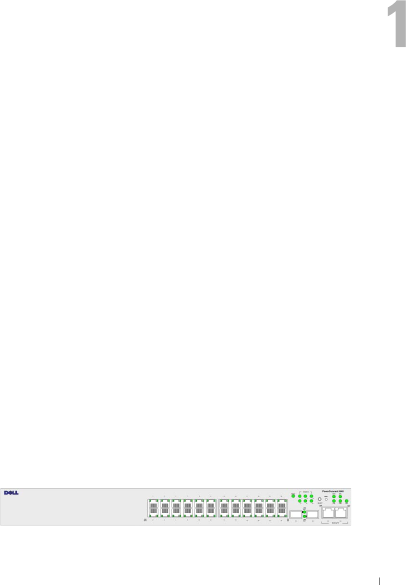
PowerConnect 3524
The PowerConnect 3524 provides 24 10/100Mbps ports plus two SFP ports, and two Copper ports
which can be used to forward traffic in a stand-alone device, or as stacking ports when the device is
stacked. The device also provides one RS-232 console port. The PowerConnect 3524 is a stackable
device, but also operates as a stand-alone device.
PowerConnect 3524P
The PowerConnect 3524P provides 24 10/100Mbps ports plus two SFP ports, and two Copper ports
which can be used to forward traffic in a stand-alone device, or as stacking ports when the device is
stacked. The device also provides one RS-232 console port. The PowerConnect 3524P is a stackable
device, but also operates as a stand-alone device. The PowerConnect 3524P also provides Power over
Ethernet (PoE).
Figure 1-1. PowerConnect 3524 and PowerConnect 3524P
12 Introduction
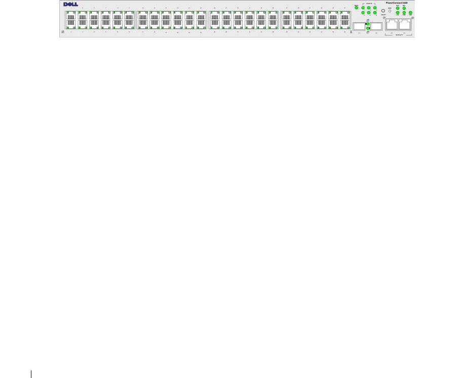
PowerConnect 3548
The PowerConnect 3548 provides 48 10/100Mbps ports plus two SFP ports, and two Copper ports which
can be used to forward traffic in a stand-alone device, or as stacking ports when the device is stacked.
The device also provides one RS-232 console port. The PowerConnect 3548 is a stackable device, but also
functions as a stand-alone device.
PowerConnect 3548P
The PowerConnect 3548P provides 48 10/100Mbps ports, two SFP ports, and two copper ports that can
be used to forward traffic when the device is in stand-alone mode, or as stacking ports when the device is
part of a stack. The device also provides one RS-232 console port. In addition, PowerConnect 3548P
provides PoE.
Figure 1-2. PowerConnect 3548 and PowerConnect 3548P
Stacking Overview
PowerConnect 3524/P and PowerConnect 3548/P stacking provides multiple switch management
through a single point as if all stack members are a single unit. All stack members are accessed through
a single IP address through which the stack is managed. The stack is managed from a:
• Web-based interface
• SNMP Management Station
• Command Line Interface (CLI)
PowerConnect 3524/P and PowerConnect 3548/P devices support stacking up to eight units per stack,
or can operate as stand-alone units.
During the Stacking setup, one switch is selected as the Stack Master and another stacking member can be
selected as the Backup Master. All other devices are selected as stack members, and assigned a unique
Unit ID.
Switch software is downloaded separately for each stack members. However, all units in the stack must be
running the same software version.
Switch stacking and configuration is maintained by the Stack Master. The Stack Master detects and
reconfigures the ports with minimal operational impact in the event of:
• Unit Failure
• Inter-unit Stacking Link Failure
• Unit Insertion
• Removal of a Stacking Unit
Introduction 13
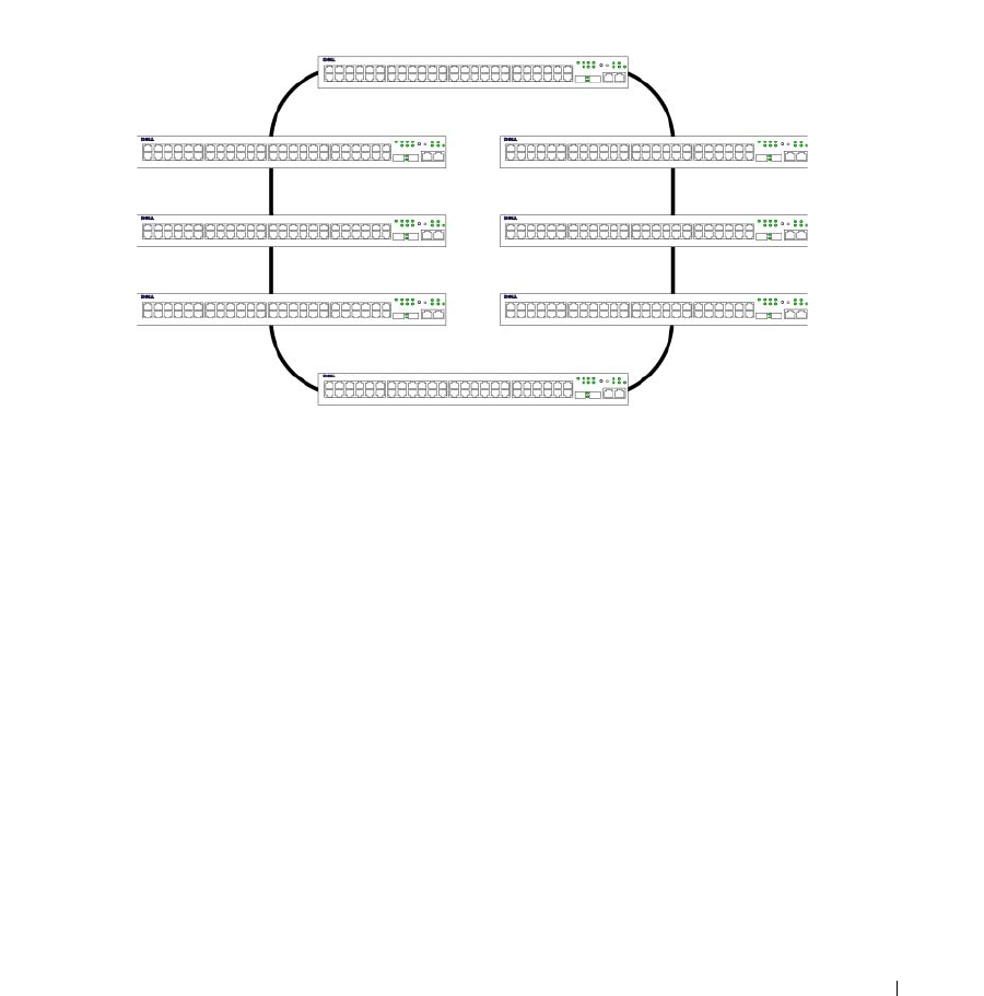
Understanding the Stack Topology
The PowerConnect 35xx series systems operates in a Ring topology. A stacked Ring topology is where all
devices in the stack are connected to each other forming a circle. Each device in the stack accepts data and
sends it to the device to which it is attached. The packet continues through the stack until it reaches its
destination. The system discovers the optimal path on which to send traffic.
Figure 1-3. Stacking Ring Topology
Most difficulties incurred in Ring topologies occur when a device in the ring becomes non-functional,
or a link is severed. With the PowerConnect 3524/P and PowerConnect 3548/P stack, the system
automatically switches to a Stacking Failover topology without any system downtime. An SNMP message
is automatically generated, but no stack management action is required. However, the stacking link or
stacking member must be repaired to ensure the stacking integrity.
After the stacking issues are resolved, the device can be reconnected to the stack without interruption,
and the Ring topology is restored.
Stacking Failover Topology
If a failure occurs in the stacking topology, the stack reverts to Stacking Failover Topology. In the
Stacking Failover topology, devices operate in a chain formation. The Stack Master determines where the
packets are sent. Each unit is connected to two neighboring devices, except for the top and bottom units.
Stacking Members and Unit ID
Stacking Unit IDs are essential to the stacking configuration. The stacking operation is determined
during the boot process. The operation mode is determined by the Unit ID selected during the
initialization process. For example, if the user selected the stand-alone mode, the device boots in the
boot-up process as a stand-alone device.
Ring Topology

14 Introduction
The device units are shipped with a default Unit ID of the stand-alone unit. If the device is operating as
a stand-alone unit, all stacking LEDs are off.
Once the user selects a different Unit ID, it is not erased, and remains valid, even if the unit is reset.
Unit ID 1 and Unit ID 2 are reserved for Master enabled units. Unit IDs 3 to 8 can be defined for stack
members.
When the Master unit boots or when inserting or removing a stack member, the Master unit initiates
a stacking discovering process.
NOTE: If two members are discovered with the same Unit ID the stack continues to function, however only the unit
with the older join time joins the stack. A message is sent to the user, notifying that a unit failed to join the stack.
Removing and Replacing Stacking Members
Unit 1 and Unit 2 are Master enabled units. Unit 1 and Unit 2 are either designated as Master Unit or
Backup Master Unit. The stack Master assignment is performed during the configuration process.
One Master enabled stack member is elected as Master, and the other Master enabled stack member is
elected as Backup Master, according to the following decision process:
• If only one Stack Master enabled unit is present, it is elected as the Master.
• If two Master enabled stacking members are present, and one has been manually configured as the
Stack Master, the manually configured member is elected as Stack Master.
• If two Master enabled units are present and neither has been manually configured as the Master, the
one with the longer up-time is elected as the Stack Master.
• If two Master enabled units are present and both have been manually configured as the Master, the one
with the longer up-time is elected as the Stack Master.
• If the two Master enabled stacking members are the same age, Unit 1 is elected as the Stack Master.
NOTE: Two stacking member are considered the same age if they were inserted within a ten minute interval.
For example, Unit 2 is inserted in the first minute of a ten-minute cycle, and Unit 1 is inserted in fifth
minute of the same cycle, the units are considered to be the same age. If there are two Master enabled
stack members that are the same age, then Unit 1 is elected master.
The Stack Master and the Backup Master maintain a Warm Standby. The Warm Standby ensures that
the Backup Master takes over for the Stack Master if a failover occurs. This guarantees that the stack
continues to operate normally.
During the Warm Standby, the Master and the Backup Master are synchronized with the static
configuration only. When the Stacking Master is configured, the Stack Master must synchronize the
Stacking Backup Master. The Dynamic configuration is not saved, for example, dynamically learned
MAC addresses are not saved.

Introduction 15
Each port in the stack has a specific Unit ID, port type, and port number, which are part of both the
configuration commands and the configuration files. Configuration files are managed only from the
device Stack Master, including:
• Saving to the FLASH
• Uploading Configuration files to an external TFTP Server/HTTP Client
• Downloading Configuration files from an external TFTP Server/HTTP Client
NOTE: Stack configuration for all configured ports is saved, even if the stack is reset and/or the ports are no
longer present.
Whenever a reboot occurs, topology discovery is performed, and the Master learns all units in the stack.
Unit IDs are saved in the unit and are learned through topology discovery. If a unit attempts to boot
without a selected Master, and the unit is not operating in stand-alone mode, the unit does not boot.
Configuration files are changed only through explicit user configuration. Configuration files are not
automatically modified when:
• Units are Added
• Units are Removed
• Units are reassigned Unit IDs
• Units toggle between Stacking Mode and Stand-alone Mode
Each time the system reboots, the Startup Configuration file in the Master unit is used to configure
the stack.
If a stack member is removed from the stack, and then replaced with a unit with the same Unit ID,
the stack member is configured with the original device configuration. Only ports which are physically
present are displayed in the PowerConnect OpenManage Switch Administrator home page, and can be
configured through the web management system. Non-present ports are configured through the CLI or
SNMP interfaces.
Exchanging Stacking Members
If a stack member with the same Unit ID replaces an existing Unit ID with the same Unit ID, the
previous device configuration is applied to the inserted stack member. If the new inserted device has
either more or fewer ports than the previous device, the relevant port configuration is applied to the new
stack member. For example,
• If a PowerConnect 3524/P replaces PowerConnect 3524/P, all port configurations remain the same.
• If a PowerConnect 3548/P replaces the PowerConnect 3548/P, all port configurations remain the same.
16 Introduction
Figure 1-4. PowerConnect 3548/P replaces PowerConnect 3548/P
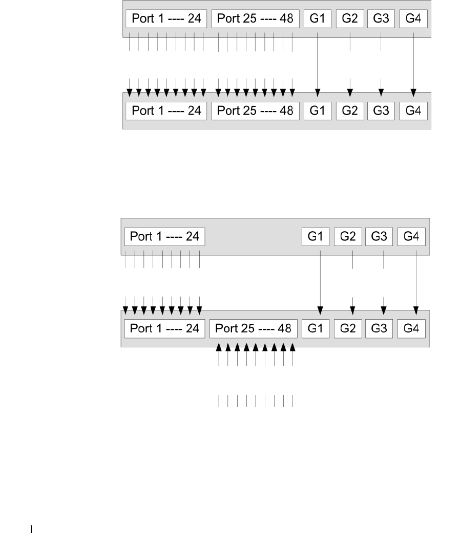
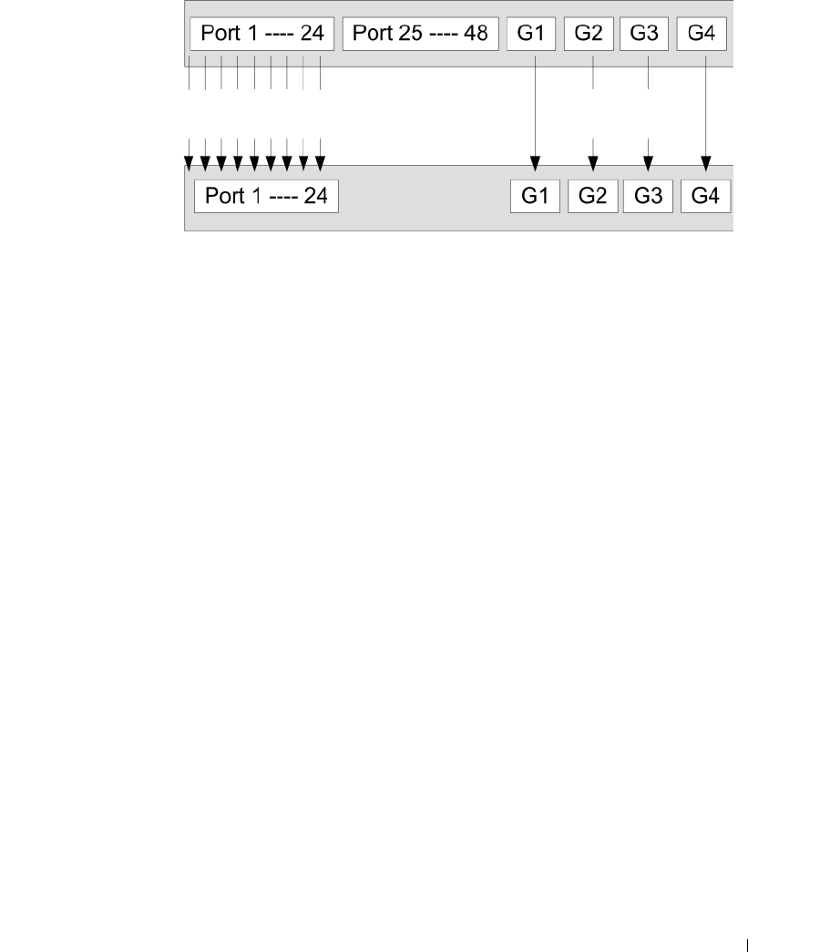
• If a PowerConnect 3548/P replaces PowerConnect 3524/P, the first 3548/P 24 FE ports receive the
3524/P 24 FE port configuration. The GE port configurations remain the same. The remaining ports
receive the default port configuration.
Figure 1-5. PowerConnect 3524/P port replaces PowerConnect 3548/P port
• If a PowerConnect 3524/P replaces PowerConnect 3548/P, the PowerConnect 3524/P 24 FE ports
receives the first 24 FE PowerConnect 3548/P port configuration. The GE port configurations remain
the same.
Same Configuration Same Configuration Same
Configuration
Same Configuration Same Configuration
Default
Configuration
Introduction 17
Figure 1-6. PowerConnect 3548/P port replaces PowerConect 3524/P Port
Switching from the Stack Master to the Backup Stack Master
The Backup Master replaces the Stack Master if the following events occur:
• The Stack Master fails or is removed from the stack.
• Links from the Stack Master to the stacking members fails.
• A soft switchover is performed with either via web interface or the CLI.
Switching between the Stack Master and the Backup Master results in a limited service loss.
Any dynamic tables are relearned if a failure occurs. The running configuration file is synchronized
between Stack Master and the Backup Master, and continues running on the Backup Master.
Features Overview
This section describes the device features. For a complete list of all updated device features, see the latest
software version Release Notes.
IP Version 6 (IPv6) Support
The device functions as an IPv6 compliant Host, as well as an IPv4 Host (also known as dual stack).
This allows device operation in a pure IPv6 network as well as in a combined IPv4/IPv6 network.
Power over Ethernet
Power over Ethernet (PoE) provides power to devices over existing LAN cabling, without updating or
modifying the network infrastructure. PoE removes the need for placing network devices next to power
sources. PoE can be used in the following applications:
• IP Phones
• Wireless Access Points
•IP Gateways
Same Configuration Same
Configuration

18 Introduction
•PDAs
• Audio and video remote monitoring
For more information about Power over Ethernet, see "Managing Power over Ethernet".
Head of Line Blocking Prevention
Head of Line (HOL) blocking results in traffic delays and frame loss caused by traffic competing for the
same egress port resources. To prevent HOL blocking the device queues packets, and the packets at the
head of the queue are forwarded before packets at the end of the queue.
Flow Control Support (IEEE 802.3X)
Flow control enables lower speed devices to communicate with higher speed devices, by requesting that
the higher speed device refrains from sending packets. Transmissions are temporarily halted to prevent
buffer overflows.
For information on configuring Flow Control for ports or LAGs, see "Defining Port Configuration" or
"Defining LAG Parameters."
Back Pressure Support
On half-duplex links, the receiving port prevents buffer overflows by occupying the link so that it is
unavailable for additional traffic.
For information on configuring Flow Control for ports or LAGs, see "Defining Port Configuration" or
"Defining LAG Parameters."
Virtual Cable Testing (VCT)
VCT detects and reports copper link cabling occurrences such as open cables and cable shorts. For more
information on testing cables, see "Running Cable Diagnostics".
MDI/MDIX Support
The device automatically detects whether the cable connected to an RJ-45 port is crossed or straight
through, when auto-negotiation is enabled.
Standard wiring for end stations is Media-Dependent Interface (MDI) and the standard wiring for hubs
and switches is known as Media-Dependent Interface with Crossover (MDIX).
For information on configuring MDI/MDIX for ports or LAGs, see "Defining Port Configuration" or
"Defining LAG Parameters."
Auto Negotiation
Auto negotiation allows the device to advertise modes of operation. The auto negotiation function
provides the means to exchange information between two devices that share a point-to-point link
segment, and to automatically configure both devices to take maximum advantage of their
transmission capabilities.

Introduction 19
The PowerConnect 35xx series systems enhances auto negotiation by providing port advertisement.
Port advertisement allows the system administrator to configure the port speeds that are advertised.
For more information on auto-negotiation, see "Defining Port Configuration" or "Defining LAG Parameters."
Voice VLAN
Voice VLAN allows network administrators to enhance VoIP service by configuring ports to carry IP voice
traffic from IP phones on a specific VLAN. VoIP traffic has a preconfigured OUI prefix in the source
MAC address. Network Administrators can configure VLANs from which voice IP traffic is forwarded.
Non-VoIP traffic is dropped from the Voice VLAN in auto Voice VLAN secure mode. Voice VLAN also
provides QoS to VoIP, ensuring that the quality of voice does not deteriorate if the IP traffic is received
unevenly.
For more information, see "Configuring Voice VLAN" on page 374.
Guest VLAN
Guest VLAN provides limited network access to unauthorized ports. If a port is denied network access
via port-based authorization, but the Guest VLAN is enabled, the port receives limited network access.
MAC Address Supported Features
MAC Address Capacity Support
The device supports up to 8K MAC addresses. The device reserves specific MAC addresses for system
use.
Static MAC Entries
MAC entries can be manually entered in the Bridging Table, as an alternative to learning them from
incoming frames. These user-defined entries are not subject to aging, and are preserved across resets
and reboots.
For more information, see "Defining Static Addresses."
Self-Learning MAC Addresses
The device enables controlled MAC address learning from incoming packets. The MAC addresses are
stored in the Bridging Table.
Automatic Aging for MAC Addresses
MAC addresses, from which no traffic is received for a given period, are aged out. This prevents the
Bridging Table from overflowing.
For more information on configuring the MAC Address Age Out Time, see "Viewing Dynamic Addresses."

20 Introduction
VLAN-aware MAC-based Switching
The device always performs VLAN-aware bridging. Classic bridging(IEEE802.1D) is not performed,
where frames are forwarded based only on their destination MAC address. However, a similar
functionality can be configured for untagged frames. Frames addressed to a destination MAC address
that is not associated with any port are flooded to all ports of the relevant VLAN.
MAC Multicast Support
Multicast service is a limited broadcast service, which allows one-to-many and many-to-many
connections for information distribution. Layer 2 Multicast service is where a single frame is addressed
to a specific Multicast address, from where copies of the frame are transmitted to the relevant ports.
When Multicast groups are statically enabled, you can set the destination port of registered groups,
as well as define the behavior of unregistered multicast frames.
For more information, see "Assigning Multicast Forward All Parameters."
Layer 2 Features
IGMP Snooping
Internet Group Membership Protocol (IGMP) Snooping examines IGMP frame contents, when they are
forwarded by the device from work stations to an upstream Multicast router. From the frame, the device
identifies work stations configured for Multicast sessions, and which Multicast routers are sending
Multicast frames. IGMP Querier simulates the behavior of a multicast router; this allows snooping of the
layer 2 multicast domain even if there is no multicast router.
For more information, see "IGMP Snooping."
Port Mirroring
Port mirroring monitors and mirrors network traffic by forwarding copies of incoming and outgoing
packets from a monitored port to a monitoring port. Users specify which target port receives copies of all
traffic passing through a specified source port.
For more information, see "Defining Port Mirroring Sessions."
Broadcast Storm Control
Storm Control enables limiting the amount of Multicast and Broadcast frames accepted and forwarded
by the device.
When Layer 2 frames are forwarded, Broadcast and Multicast frames are flooded to all ports on the
relevant VLAN. This occupies bandwidth, and loads all nodes connected on all ports.
For more information, see "Enabling Storm Control."

Introduction 21
VLAN Supported Features
VLAN Support
VLANs are collections of switching ports that comprise a single broadcast domain. Packets are classified
as belonging to a VLAN based on either the VLAN tag or based on a combination of the ingress port and
packet contents. Packets sharing common attributes can be grouped in the same VLAN.
For more information, see "Configuring VLANs."
Port Based Virtual LANs (VLANs)
Port-based VLANs classify incoming packets to VLANs based on their ingress port.
For more information, see "Defining VLAN Ports Settings."
Full 802.1Q VLAN Tagging Compliance
IEEE 802.1Q defines an architecture for virtual bridged LANs, the services provided in VLANs, and the
protocols and algorithms involved in the provision of these services.
GVRP Support
GARP VLAN Registration Protocol (GVRP) provides IEEE 802.1Q-compliant VLAN pruning and
dynamic VLAN creation on 802.1Q trunk ports. When GVRP is enabled, the device registers and
propagates VLAN membership on all ports that are part of the active underlying "Spanning Tree
Protocol Features" on page 21 topology.
For more information, see "Configuring GVRP Parameters."
Private VLAN Edge
Ports can be assigned to Private VLAN Edge (PVE) groups. A port defined as PVE is protected by an
uplink, so that it is isolated from other ports within the same VLAN. The uplink must be a GE port.
For more information on Private VLANs, see "Configuring Ports" on page 297.
Spanning Tree Protocol Features
Spanning Tree Protocol (STP)
802.1d Spanning tree is a standard Layer 2 switch requirement that allows bridges to automatically
prevent and resolve L2 forwarding loops. Switches exchange configuration messages using specifically
formatted frames and selectively enable and disable forwarding on ports.
For more information, see "Configuring the Spanning Tree Protocol."

22 Introduction
Fast Link
STP can take up to 30-60 seconds to converge. During this time, STP detects possible loops, allowing
time for status changes to propagate and for relevant devices to respond. 30-60 seconds is considered too
long of a response time for many applications. The Fast Link option bypasses this delay, and can be used
in network topologies where forwarding loops do not occur.
For more information enabling Fast Link for ports and LAGs, see "Defining STP Port Settings" or
"Defining Static Addresses."
IEEE 802.1w Rapid Spanning Tree
Spanning Tree can take 30-60 seconds for each host to decide whether its ports are actively forwarding
traffic. Rapid Spanning Tree (RSTP) detects uses of network topologies to enable faster convergence,
without creating forwarding loops.
For more information, see "Defining Rapid Spanning Tree."
IEEE 802.1s Multiple Spanning Tree
Multiple Spanning Tree (MSTP) operation maps VLANs into STP instances. MSTP provides differing
load balancing scenario. Packets assigned to various VLANs are transmitted along different paths within
MSTP Regions (MST Regions). Regions are one or more MSTP bridges by which frames can be
transmitted. The standard lets administrators assign VLAN traffic to unique paths.
For more information, see "Configuring the Spanning Tree Protocol."
Link Aggregation
Link Aggregation
Up to eight Aggregated Links may be defined, each with up to eight member ports, to form a single Link
Aggregated Group (LAG). This enables:
• Fault tolerance protection from physical link disruption
• Higher bandwidth connections
• Improved bandwidth granularity
• High bandwidth server connectivity
LAG is composed of ports with the same speed, set to full-duplex operation.
For more information, see "Defining LAG Parameters."
Link Aggregation and LACP
LACP uses peer exchanges across links to determine, on an ongoing basis, the aggregation capability of
various links, and continuously provides the maximum level of aggregation capability achievable between
a given pair of devices. LACP automatically determines, configures, binds, and monitors the port binding
within the system.
For more information, see "Aggregating Ports."

Introduction 23
BootP and DHCP Clients
DHCP enables additional setup parameters to be received from a network server upon system startup.
DHCP service is an on-going process. DHCP is an extension to BootP.
For more information on DHCP, see "Defining DHCP IPv4 Interface Parameters."
Quality of Service Features
Class Of Service 802.1p Support
The IEEE 802.1p signaling technique is an OSI Layer 2 standard for marking and prioritizing network
traffic at the data link/MAC sub-layer. 802.1p traffic is classified and sent to the destination.
No bandwidth reservations or limits are established or enforced. 802.1p is a spin-off of the
802.1Q (VLANs) standard. 802.1p establishes eight levels of priority, similar to the IP Precedence
IP Header bit-field.
For more information, see "Configuring Quality of Service."
Device Management Features
SNMP Alarms and Trap Logs
The system logs events with severity codes and timestamps. Events are sent as SNMP traps to a Trap
Recipient List.
For more information on SNMP Alarms and Traps, see "Defining SNMP Parameters."
SNMP Versions 1, 2 and 3
Simple Network Management Protocol (SNMP) over the UDP/IP protocol controls access to the system,
a list of community entries is defined, each of which consists of a community string and its access
privileges. There are 3 levels of SNMP security read-only, read-write, and super. Only a super user can
access the community table.
For more information, see "Defining SNMP Parameters".
Web Based Management
With the web based management, the system can be managed from any web browser. The system
contains an Embedded Web Server (EWS), which serves HTML pages, through which the system can be
monitored and configured. The system internally converts web-based input into configuration
commands, MIB variable settings and other management-related settings.
Configuration File Download and Upload
The device configuration is stored in a configuration file. The Configuration file includes both system
wide and port specific device configuration. The system can display configuration files in the form of a
collection of CLI commands, which are stored and manipulated as text files.
For more information, see "Managing Files."

24 Introduction
TFTP Trivial File Transfer Protocol
The device supports boot image, software, and configuration upload/download via TFTP.
Remote Monitoring
Remote Monitoring (RMON) is an extension to SNMP, which provides comprehensive network traffic
monitoring capabilities (as opposed to SNMP which allows network device management and
monitoring). RMON is a standard MIB that defines current and historical MAC-layer statistics and
control objects, allowing real-time information to be captured across the entire network.
For more information, see "Viewing Statistics."
Command Line Interface
Command Line Interface (CLI) syntax and semantics conform as much as possible to common industry
practice. CLI is composed of mandatory and optional elements. The CLI interpreter provides command
and keyword completion to assist user and shorten typing.
Syslog
Syslog is a protocol that enables event notifications to be sent to a set of remote servers, where they can
be stored, examined and acted upon. The system sends notifications of significant events in real time,
and keeps a record of these events for after-the-fact usage.
For more information on Syslog, see "Managing Logs."
SNTP
The Simple Network Time Protocol (SNTP) assures accurate network Ethernet Switch clock time
synchronization up to the millisecond. Time synchronization is performed by a network SNTP server.
Time sources are established by Stratums. Stratums define the distance from the reference clock.
The higher the stratum (where zero is the highest), the more accurate the clock.
For more information, see "Configuring SNTP Settings."
Domain Name System
Domain Name System (DNS) converts user-defined domain names into IP addresses. Each time a
domain name is assigned the DNS service translates the name into a numeric IP address. For example,
www.ipexample.com is translated to 192.87.56.2. DNS servers maintain domain name databases and
their corresponding IP addresses.
For more information, see "Configuring Domain Name Systems" on page 154.
Traceroute
Traceroute discovers IP routes that packets were forwarded along during the forwarding process. The CLI
Traceroute utility can be executed from either the user-exec or privileged modes.

Introduction 25
802.1ab (LLDP-MED)
The Link Layer Discovery Protocol (LLDP) allows network managers to troubleshoot and enhance
network management by discovering and maintaining network topologies over multi-vendor
environments. LLDP discovers network neighbors by standardizing methods for network devices to
advertise themselves to other systems, and to store discovered information. The multiple advertisement
sets are sent in the packet Type Length Value (TLV) field. LLDP devices must support chassis and port
ID advertisement, as well as system name, system ID, system description, and system capability
advertisements.
LLDP Media Endpoint Discovery (LLDP-MED) increases network flexibility by allowing different
IP systems to co-exist on a single network LLDP. It provides detailed network topology information,
emergency call service via IP Phone location information, and troubleshooting information.
Security Features
SSL
Secure Socket Layer (SSL) is an application-level protocol that enables secure transactions of data
through privacy, authentication, and data integrity. It relies upon certificates and public and private keys.
Port Based Authentication (802.1x)
Port based authentication enables authenticating system users on a per-port basis via an external server.
Only authenticated and approved system users can transmit and receive data. Ports are authenticated via
the Remote Authentication Dial In User Service (RADIUS) server using the Extensible Authentication
Protocol (EAP). Dynamic VLAN Assignment (DVA) allows network administrators to automatically
assign users to VLANs during the RADIUS server authentication.
For more information, see "Port Based Authentication."
Locked Port Support
Locked Port increases network security by limiting access on a specific port only to users with specific
MAC addresses. These addresses are either manually defined or learned on that port. When a frame is
seen on a locked port, and the frame source MAC address is not tied to that port, the protection
mechanism is invoked.
For more information, see "Configuring Port Security."
RADIUS Client
RADIUS is a client/server-based protocol. A RADIUS server maintains a user database, which contains
per-user authentication information, such as user name, password and accounting information.
For more information, see "Configuring RADIUS Settings."

26 Introduction
SSH
Secure Shell (SSH) is a protocol that provides a secure, remote connection to a device. SSH version 2 is
currently supported. The SSH server feature enables an SSH client to establish a secure, encrypted
connection with a device. This connection provides functionality that is similar to an inbound telnet
connection. SSH uses RSA and DSA Public Key cryptography for device connections and authentication.
TACACS+
TACACS+ provides centralized security for validation of users accessing the device. TACACS+ provides
a centralized user management system, while still retaining consistency with RADIUS and other
authentication processes.
For more information, see "Defining TACACS+ Settings."
Password Management
Password management provides increased network security and improved password control. Passwords
for SSH, Telnet, HTTP, HTTPS, and SNMP access are assigned security features. For more information
on Password Management, see "Managing Passwords".
Access Control Lists (ACL)
Access Control Lists (ACL) allow network managers to define classification actions and rules for specific
ingress ports. Packets entering an ingress port, with an active ACL, are either admitted or denied entry
and the ingress port is disabled. If they are denied entry, the user can disable the port.
For more information, see "ACL Overview" on page 276.
DHCP Snooping
DHCP Snooping expands network security by providing firewall security between untrusted interfaces
and DHCP servers. By enabling DHCP Snooping network administrators can differentiate between
trusted interfaces connected to end-users or DHCP Servers and untrusted interfaces located beyond the
network firewall.
For more information, see "Configuring DHCP Snooping" on page 288.
Additional CLI Documentation
The CLI Reference Guide, which is available on the Documentation CD, provides information about the
CLI commands used to configure the device. The document provides information about the command
description, syntax, default values, guidelines, and examples.
Hardware Description 27
Hardware Description
Port Description
PowerConnect 3524 Port Description
The Dell™ PowerConnect™ 3524 device is configured with the following ports:
•
24 Fast Ethernet ports
— RJ-45 ports designated as 10/100Base-T ports
•
2 Fiber ports
— Designated as 1000Base-X SFP ports
•
2 Gigabit ports
— Designated as 1000Base-T ports
•
Console port
— RS-232 based port
The following figure illustrates the PowerConnect 3524 front panel.
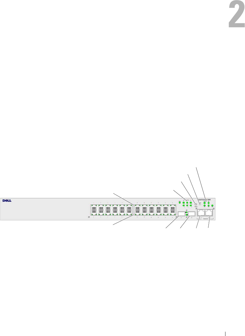
Figure 2-1. PowerConnect 3524 Front Panel
The front panel contains 24 RJ-45 ports number 1-24. The upper row of ports is marked with
odd numbers 1-23, and the lower row of ports is marked with even numbers 2-24. In addition,
the front panel also contains ports G1 - G2 which are fiber ports and ports G3- G4 which are
copper ports. Ports G3 - G4 can either be used as stacking ports, or used to forward network traffic
in a stand-alone device.
Stacking LEDs
Stacking Button
Reset Button
System LEDs
10/100 Base-T Ports 1, 3, 5, 7, ...23
10/100 Base-T Ports 2, 4, 6, 8, ...24 G1 G2 G3 G4
1000Base-X
SFP Ports
Stacking
Ports
28 Hardware Description
There are two buttons on the front panel. The Stack ID button is used to select the unit number.
The second button is the Reset Button which is used to manually reset the device. The Reset button
does not extend beyond the unit’s front panel surface, so reset by pressing it accidentally is prevented.
On the front panel are all the device LEDs.
The following figure illustrates the PowerConnect 3524 back:
Figure 2-2. PowerConnect 3524 Back Panel
The back panel contains an RPS connector, console port, and power connector.
PowerConnect 3548 Port Description
The PowerConnect 3548 device is configured with the following ports:
•
48 FE ports
— RJ-45 ports designated as 10/100Base-T ports
•
2 Fiber ports
— Designated as 1000Base-X SFP ports
•
2 Gigabit ports
— Designated as 1000Base-T ports
•
Console port
— RS-232 Console based port
The following figure illustrates the PowerConnect 3548 front panel.
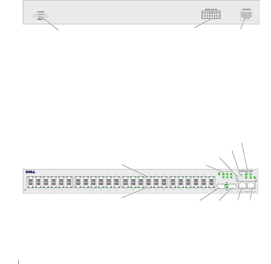
Figure 2-3. PowerConnect 3548 Front Panel
Console Port RPS Connector Power Connector
10/100 Base-T Ports 1, 3, 5, 7, ...47
10/100 Base-T Ports 2, 4, 6, 8, ...48
Stacking LEDs
Stacking Button
Reset Button
System LEDs
G1 G2 G3 G4
1000Base-X
SFP Ports
Stacking
Ports
Hardware Description 29
The front panel contains 48 RJ-45 ports number 1-48. The upper row of ports is marked by odd numbers
1-47, and the lower row of ports is marked with even numbers 2-48. In addition, the front panel also
contains ports G1 - G2 which are fiber ports and ports G3- G4 which are copper ports. Ports G3- G4 can
either be used as stacking ports, or used to forward network traffic in a stand-alone device.
There are two buttons on the front panel. The Stack ID button is used to select the unit number.
The second button is the Reset Button which is used to manually reset the device. The Reset button
does not extend beyond the unit’s front panel surface, so reset by pressing it accidentally is prevented.
On the front panel are all the device LEDs.
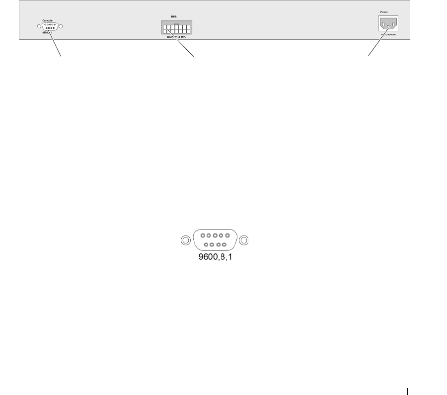
The following figure illustrates the PowerConnect 3548 back panel:
Figure 2-4. PowerConnect 3548 Back Panel
The back panel contains an RPS connector, console port and power connector.
SFP Ports
The Small Form Factor Plugable (SFP) ports are fiber transceivers designated as 10000 Base-SX or LX.
They include TWSI (Two-Wire Serial Interface) and internal EPROM.
RS-232 Console Port
One DB-9 connector for a terminal connection is used for debugging, software download etc.
The default baud rate is 9,600 bps. The baud rate can be configured from 2400 bps up to 115,200 bps.
Figure 2-5. Console Port
Console Port RPS Connector Power Connector

30 Hardware Description
Physical Dimensions
The PowerConnect 3524/P and PowerConnect 3548/P devices have the following physical dimensions:
PoE Model:
•
Width
— 440 mm (17.32 inch)
•
Depth
— 387 mm (15.236 inch)
•
Height
— 43.2 mm (1.7 inch)
Non-PoE Device:
•
Width
— 440 mm (17.32 inch)
•
Depth
— 257 mm (10.118 inch)
•
Height
— 43.2 mm (1.7 inch)
LED Definitions
The front panel contains light emitting diodes (LED) that indicate the status of links, power supplies,
fans, and system diagnostics.
Port LEDs
Each 10/100/1000 Base-T port and 10/100 Base-T port has two LEDs. The speed LED is located on the
left side of the port, while the link/duplex/activity LED is located on the right side.
The following figure illustrates the 10/100 Base-T port LEDs on The PowerConnect 3524 /P and
PowerConnect 3548/P switches:
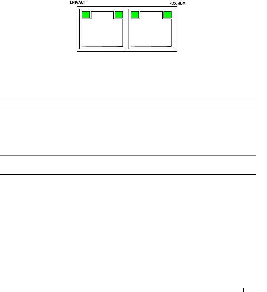
Figure 2-6. RJ-45 Copper Based 10/100 BaseT LEDs
The RJ-45 100 Base-T port on the PowerConnect 3524 /P and PowerConnect 3548/P has two LEDs
marked as LNK/ACT.
Speed/LNK/ACT FDX
Speed/LNK/ACT FDX
Hardware Description 31
The following figure illustrates the 100 Base-T LEDs.
Figure 2-7. RJ-45 1000 BaseT LED
The RJ-45 LED indications for PowerConnect 3524 and PowerConnect 3548 are described in the
following table:
Table 2-1. PowerConnect 3524 and PowerConnect 3548 RJ-45 100BaseT LED Indications
LED Color Description
Link/Activity/Speed Green Static The port is running at 100 Mbs.
Green Flashing The port is either transmitting or receiving data at 100 Mbps.
Amber Static The port is running at 10 Mbs.
Yellow Flashing The port is either transmitting or receiving data at 10 Mbps.
OFF The port is currently not operating.
FDX Green Static The port is currently operating in Full Duplex mode.
OFF The port is currently operating in Half Duplex mode,

32 Hardware Description
The RJ-45 LED indications for PowerConnect 3524P and PowerConnect 3548P are described in the
following table:
Gigabit Port LEDs
The following table describes the Gigabit (stacking port) LEDs:
Table 2-2. PowerConnect 3524P and PowerConnect 3548P RJ-45 Copper based 100BaseT LED Indications
LED Color Description
Speed/Link/Act Green Static The port is currently linked at 100 Mbps.
Green Flashing The ports is currently operating at 100 Mbps.
OFF The port is currently operating at 10 Mbps or is not linked.
FDX Green Static The Powered Device (PD) is detected and is operating at normal load. For more
information about Powered Devices, see "Managing Power over Ethernet".
Green Flashing The port is operating at transitional mode. The PD is being detected, or is faulty.
For more information about Power over Ethernet, see "Managing Power over
Ethernet".
Amber Static An overload or short has occurred on the Powered Device. For more information
about Power over Ethernet faults, see "Managing Power over Ethernet".
Amber
Flashing
The powered device power conception exceeds the predefined power allotment.
For more information about Power over Ethernet power allotments, see
"Managing Power over Ethernet".
OFF No powered device is detected.
Table 2-3. PowerConnect 3524 and PowerConnect 3548 RJ-45 Copper based 100BaseT LED Indications
LED Color Description
Link/Activity/Speed Green Static The port is running at 1000 Mbs.
Green Flashing The port is either transmitting or receiving data at 1000 Mbps.
Yellow Static The port is running at 10 or 100Mbs.
Yellow Flashing The port is either transmitting or receiving data at 10 or 100 Mbps.
OFF The port is currently not operating.
FDX Green Static The port is currently operating in Full Duplex mode.
OFF The port is currently operating in Half Duplex mode.
Hardware Description 33
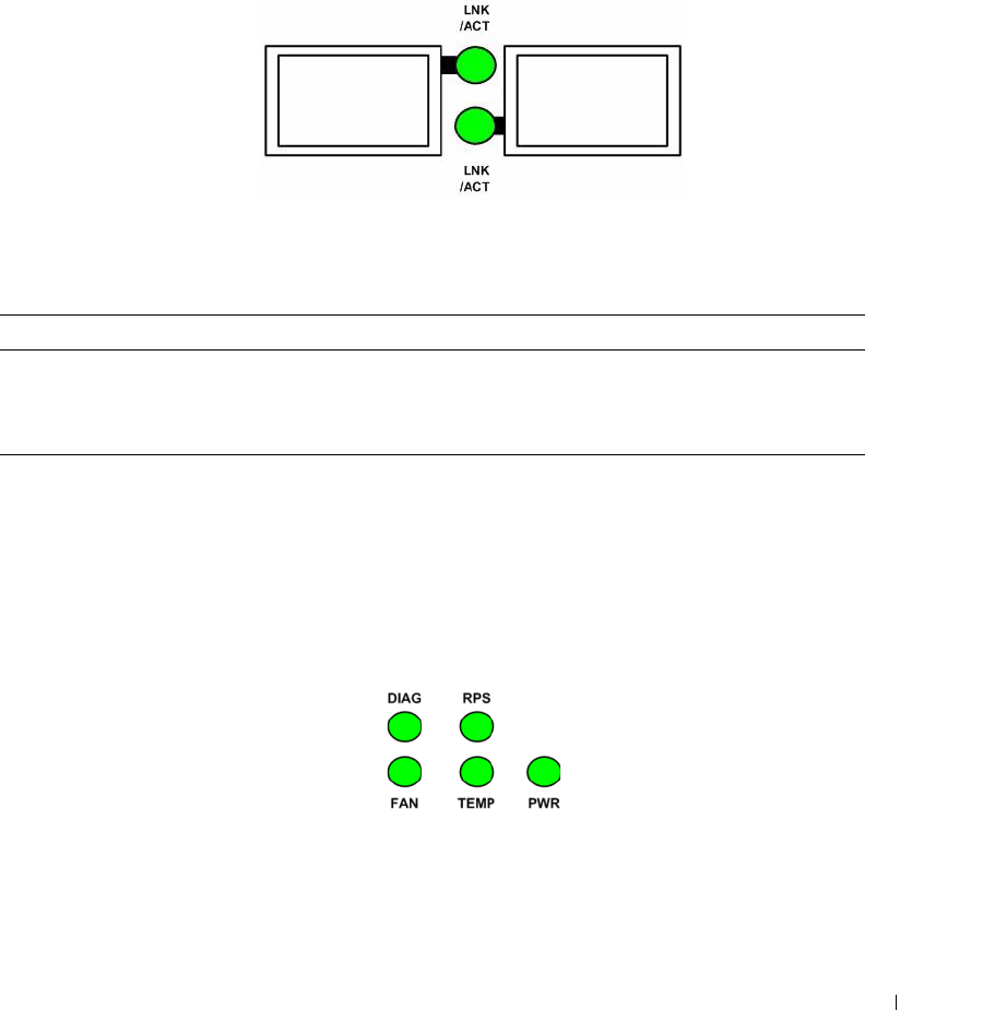
SFP LEDs
The SFP ports each have one LED marked as LNK/ACT. On the PowerConnect 3524/P and
PowerConnect 3548/P devices, the LEDs are located between ports and are round in shape.
The following figures illustrate the LEDs on each device.
Figure 2-8. SFP Port LEDs
The SFP port LED indications are described in the following table:
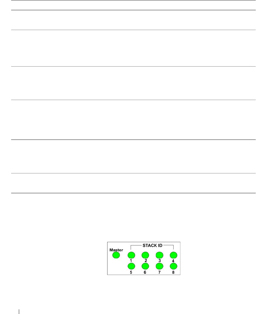
System LEDs
The system LEDs of The PowerConnect 3524 /P and PowerConnect 3548/P devices provide information
about the power supplies, fans, thermal conditions, and diagnostics. The following figure illustrates the
system LEDS.
Figure 2-9. System LEDs
Table 2-4. SFP Port LED Indications
LED Color Description
Link/Activity Green Static A link is established.
Green Flashing The port is currently transmitting or receiving data.
OFF The port is currently not linked.
34 Hardware Description
The following table describes the system LED indications.
The Stacking LEDs indicate the unit position in the stack. The following figure illustrates the LEDs on
the front panel.
Figure 2-10. Stacking LEDs
Table 2-5. System LED Indicators
LED Color Description
Power Supply (PWR) Green Static The switch is turned on.
OFF The switch is turned off.
Redundant Power Supply (RPS)
(models: 3524 and 3548 )
Green Static The RPS is currently operating.
Red Static The RPS failed.
OFF The redundant power supply is not plugged in.
Redundant Power Supply (RPS)
(models: 3524P and 3548P )
Green Static The RPS is currently operating.
OFF The redundant power supply has failed or is not
plugged in.
Diagnostics (DIAG) Green Flashing The system diagnostic test is currently in progress.
Green Static The system diagnostic test passed successfully.
Red Static The system diagnostic test failed.
OFF The system is operating normally.
Temperature (TEMP) Red Static The device has crossed the permitted temperature
range.
OFF The device is operating within the permitted
temperature range.
Fan (FAN) Green Static All device fans are operating normally.
Red Static One or more of the device fans is not operating.

Hardware Description 35
The Stacking LEDs are numbered 1- 8. Each stacking unit has one stacking LED lit, indicating its Unit
ID number. If either Stacking LED 1 or 2 is lit, it indicates that the device is either the Stack Master or
Backup Master.
Table 2-6. Stacking LED Indications
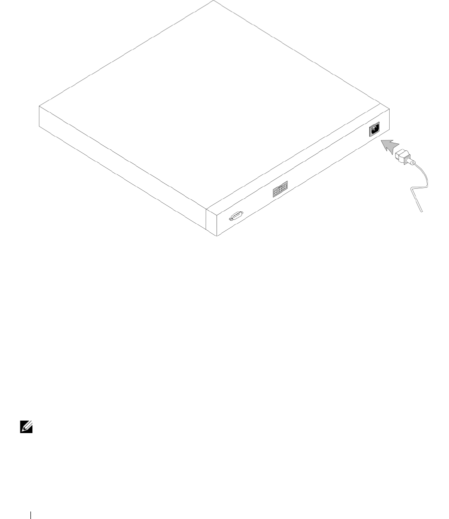
Power Supplies
The device has an internal power supply unit (AC unit) and a connector to connect PowerConnect
3524/P and PowerConnect 3548/P devices to a PowerConnect EPS-470 unit, or to connect
PowerConnect 3524 and PowerConnect 3548 devices to a PowerConnect RPS-600 unit.
The PowerConnect 3524/P and PowerConnect 3548/P devices have an internal power supply (12 Volt).
Operation with both power supply units is regulated through load sharing. Power supply LEDs indicate
the status of the power supply.
The PowerConnect 3524/P and PowerConnect 3548/P devices have an internal power supply of 470W
(12V/-48V), with a total of 370W for 24 ports PoE device.
AC Power Supply Unit
The AC power supply unit operates from 90 to 264 VAC, 47 to 63 Hz. The AC power supply unit uses a
standard connector. LED indicator is on the front panel and indicates whether the AC unit is connected.
DC Power Supply Unit
The PowerConnect 3524 and PowerConnect 3548 switches connect to an external RPS-600 unit to
provide a redundant power option. No configuration is required. The front panel "RPS" LED indicates
whether the external RPS-600 is connected. See Table 2-5 for RPS LED definition.
The PowerConnect 3524/P and PowerConnect 3548/P switches connect to an external EPS-470 unit to
provide a redundant power option. No configuration is required. The front panel "RPS" LED indicates
whether the external EPS-470 is connected. See Table 2-5 for RPS LED definition.
LED Color Description
All Stacking LEDs OFF The switch is currently a stand-alone device.
Stacking LED 1-8 (S1-S8) Green Static The device is designated as Stacking Unit N.
OFF The device is not designated as Stacking Unit N.
Stacking Master LED Green Static The device is the Stack Master
OFF The device is not the Stack Master.
36 Hardware Description
Figure 2-11. Power Connection
When the device is connected to a different power source, the probability of failure in the event of a
power outage decreases.
Stack ID Button
The device front panel contains a Stack ID button used to manually select the Unit ID for the Stack
Master and members.
The Stack Master and members must be selected within 15 seconds of booting the device. If the Stack
Master is not selected within 15 seconds, the device is booted in stand-alone mode. To select a Unit ID
for the device, reboot the device.
The Stack Master receives the Unit ID of 1 or 2. If both Unit 1 and Unit 2 are present, the unit that is not
elected functions as the Backup Master. Stack members receive a separate Unit ID (3-8). For example,
if there are four units in a stack, the Master unit is either 1 or 2, the backup Master is either 1 or 2
depending on the Unit ID of the Master unit, the third member is 3, and the fourth Stack member is 4.
NOTE: The device does not automatically detect a stand-alone unit. If a Unit ID has already been selected, press
the Stack ID button several times until no stacking LED is lit.

Hardware Description 37
Reset Button
The PowerConnect 3524/P and PowerConnect 3548/P switches have a reset button, located on the front
panel, for manual reset of the device. If the Master device is reset, the entire stack is reset. If only a
member unit is reset, the remain stacking members are not reset.
The single reset circuit of the switch is activated by power-up or low-voltage conditions.
Ventilation System
The PowerConnect 3524/P and PowerConnect 3548/P switches with the PoE feature have five built-in
fans. The non-PoE PowerConnect 3524 and PowerConnect 3548 devices have two built-in fans.
Operation can be verified by observing the LED that indicates if one or more fans is faulty.

38 Hardware Description

Installing the PowerConnect 3524/P and PowerConnect 3548/P 39
Installing the PowerConnect 3524/P and
PowerConnect 3548/P
Site Preparation
The Dell™ PowerConnect™ 3524 /P and PowerConnect 3548/P devices can be mounted in a standard
48.26-am (19-inch) equipment rack, placed on a tabletop or mounted on a wall. Before installing the
unit, verify that the chosen location for installation meets the following site requirements:
•
Power
— The unit is installed near an easily accessible 100-240 VAC, 50-60 Hz outlet.
•
General
— The Redundant Power Supply (RPS) is correctly installed by checking that the LEDs
on the front panel are illuminated.
• PoE Models
— The RPS is currently installed by checking that the PoE LEDs on the front panel
are illuminated.
•
Clearance
— There is adequate frontal clearance for operator access. Allow clearance for cabling,
power connections, and ventilation.
•
Cabling
— The cabling is routed to avoid sources of electrical noise such as radio transmitters,
broadcast amplifiers, power lines, and fluorescent lighting fixtures.
•
Ambient Requirements
— The ambient unit operating temperature range is 0 to 45ºC (32 to
113ºF) at a relative humidity of 10% to 90%, non-condensing.
Unpacking
Package Contents
While unpacking the device, ensure that the following items are included:
• Device/Switch
• AC power cable
• RS-232 crossover cable
• Self-adhesive rubber pads

40 Installing the PowerConnect 3524/P and PowerConnect 3548/P
• Rack-mount kit for rack installation or wall mounting kit
• Documentation CD
• Product Information Guide
Unpacking the Device
NOTE: Before unpacking the device, inspect the package and immediately report any evidence of damage.
1
Place the box on a clean flat surface.
2
Open the box or remove the box top.
3
Carefully remove the device from the box and place it on a secure and clean surface.
4
Remove all packing material.
5
Inspect the device and accessories for damage. Report any damage immediately.
Mounting the Device
The following mounting instructions apply to The PowerConnect 3524/P and PowerConnect 3548/P
devices. The Console port is on the back panel. The power connectors are positioned on the back panel.
Connecting a Redundant Power Supply (RPS) is optional, but is recommended. The RPS connector is
on the back panel of the devices.
Installing in a Rack
WARNING: Read the Safety Information included in the Product Information Guide for safety information on
devices connected to or that support the SWI.
WARNING: Disconnect all cables from the unit before mounting the device in a rack or cabinet.
WARNING: When mounting multiple devices into a rack, mount the devices from the bottom up.
Installing the PowerConnect 3524/P and PowerConnect 3548/P 41
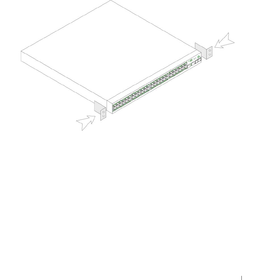
1
Place the supplied rack-mounting bracket on one side of the device, ensuring that the mounting holes
on the device line up to the mounting holes on the rack-mounting bracket.
The following figure illustrates where to mount the brackets.
Figure 3-1. Bracket Installation for Rack Mounting
2
Insert the supplied screws into the rack-mounting holes and tighten with a screwdriver.
3
Repeat the process for the rack-mounting bracket on the other side of the device.
4
Insert the unit into the 48.26 cm (19 inch) rack, ensuring that the rack-mounting holes on the device
line up to the mounting holes on the rack.
5
Secure the unit to the rack with the rack screws (not provided). Fasten the lower pair of screws before
the upper pair of screws. Ensure that the ventilation holes are not obstructed.
Installing on a Flat Surface
The device must be installed on a flat surface if it is not installed on a rack. The surface must be able to
support the weight of the device and the device cables.
1
Attach the self-adhesive rubber pads on each marked location on the bottom of the chassis.
2
Set the device on a flat surface, leaving 5.08 cm (2 inch) on each side and 12.7 cm (5 inch) at the back.
3
Ensure that the device has proper ventilation.
42 Installing the PowerConnect 3524/P and PowerConnect 3548/P
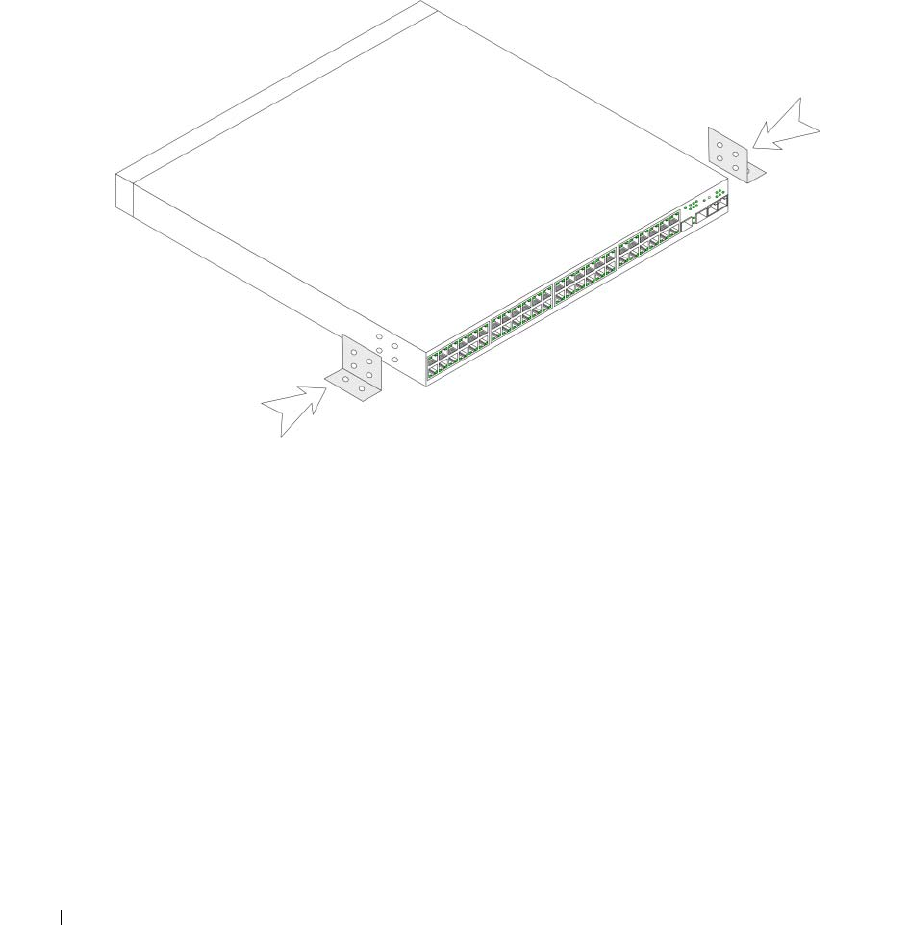
Installing the Device on a Wall
1
Place the supplied wall-mounting bracket on one side of the device, ensuring that the mounting holes
on the device line up to the mounting holes on the rack-mounting bracket. The following figure
illustrates where to mount the brackets.
Figure 3-2. Bracket Installation for Mounting on a Wall
2
Insert the supplied screws into the rack-mounting holes and tighten with a screwdriver.
3
Repeat the process for the wall-mounting bracket on the other side of the device.
4
Place the device on the wall in the location where the device is being installed.
5
On the wall mark the locations where the screws to hold the device must be prepared.
6
Drill holes and place all plugs (not provided) in the holes, in the marked location.
7
Secure the unit to the wall with screws (not provided). Ensure that the ventilation holes are not
obstructed.

Installing the PowerConnect 3524/P and PowerConnect 3548/P 43
Figure 3-3. Mounting a Device on a Wall
Connecting to a Terminal
1
Connect an RS-232 crossover cable to the ASCII terminal or the serial connector of a desktop system
running terminal emulation software.
2
Connect the female DB-9 connector at the other end of the cable to the device serial port connector.
Fro n t Pan el
Drilled
Holes
Wall
Drilled
Holes
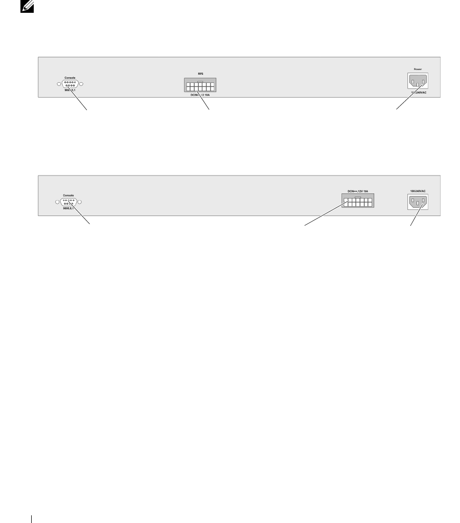
44 Installing the PowerConnect 3524/P and PowerConnect 3548/P
Connecting a Device to a Power Supply
Connect the supplied AC power cable to the AC power connector on the back panel.
NOTE: Do not connect the power cable to a grounded AC outlet at this time. Connect the device to a power source
in the steps detailed in "Starting and Configuring the Device" on page 47.
Figure 3-4. Back-Panel Power Connector
After connecting the device to a power source, confirm that the device is connected and operating
correctly by examining the LEDs on the front panel.
Installing a Stack
Overview
Each device can operate as a stand-alone device or can be a member in a stack. Up to eight devices or up
to 384 ports are supported per stack.
All stacks must have a Master unit, and may have a Master Backup unit, with any other devices
connected to the stack as Members.
Console Port RPS Connector
Console Port
PowerConnect 3524/3548 Rear View
EPS Connector Power Connector
Power Connector
PowerConnect 3524P/3548P Rear View
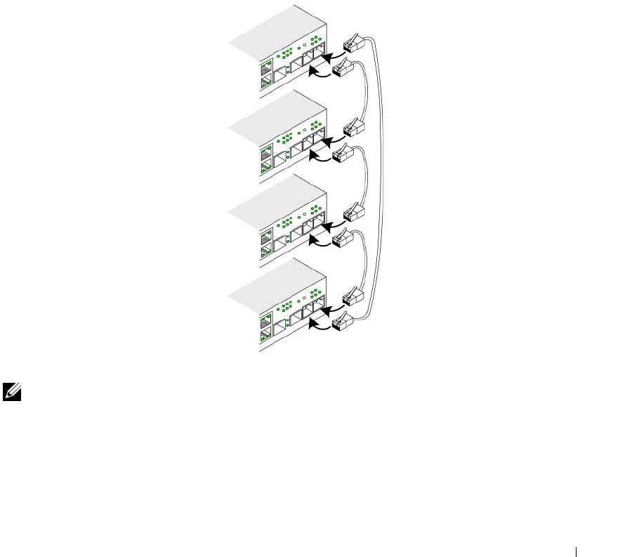
Installing the PowerConnect 3524/P and PowerConnect 3548/P 45
Stacking PowerConnect 35xx Series Systems Switches
Each PowerConnect 35xx series systems stack contains a single Master unit, and may have a Master
Backup unit, while the remaining units are considered stacking Members.
PowerConnect 35xx series systems switches use the RJ-45 Gigabit Ethernet ports (G3 and G4) for
stacking. This enables added stacking capabilities to the devices without adding additional device
accessories. To stack the devices together, insert a standard Category 5 cable into port G3 in the
uppermost device in the stack, and into port G4 of the device immediately below it in the stack. Repeat
this process until all devices are connected. Connect the bottommost device’s port G3 in the stack to
port G4 of the uppermost device in the stack.
Figure 3-5. Stacking Cable Diagram
NOTE: In stacking mode ports designated as G3 and G4 are not displayed in the EWS. The effect is of not being
present on the device. This is because the ports receive a different index for stacking.
Stack unit identification is performed on the device front panel using the Stack ID button.
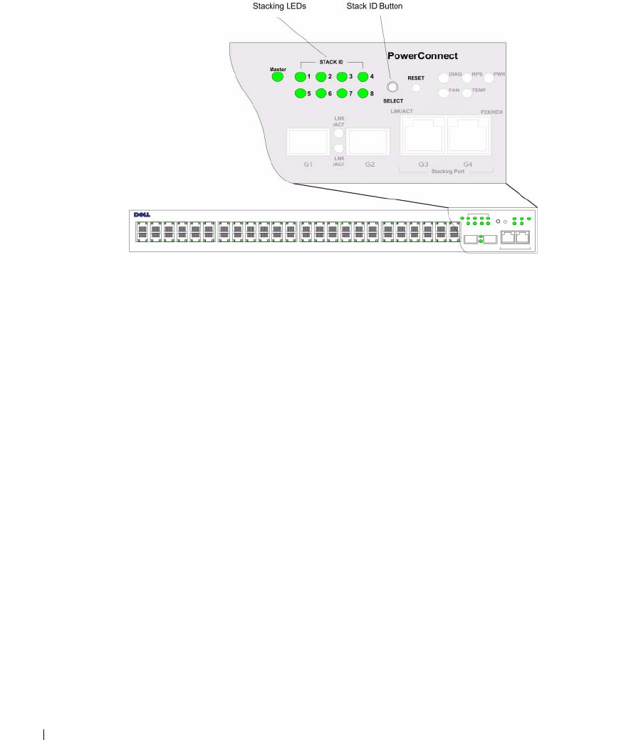
46 Installing the PowerConnect 3524/P and PowerConnect 3548/P
Figure 3-6. Stacking Configuration and Identification Panel
Each stack device has a unique identifying unit ID that defines the unit’s position and function in
the stack. If the device is a stand-alone unit, the Stack LED is not illuminated. The default setting
is stand-alone.
The unit ID is manually configured by using the Stack ID button. The unit ID is indicated by the Stack
ID LEDs. Unit ID 1 and 2 are reserved for the Master and Backup Master unit, and unit ID 3 to 8 are for
Member units.
Unit ID Selection Process
The unit ID selection process is as follows:
1
Ensure that the stand-alone/Master device Console port is connected to a VT100 terminal device or
VT100 terminal emulator via the RS-232 crossover cable.
2
Locate an AC power receptacle.
3
Deactivate the AC power receptacle.
4
Connect the device to the AC receptacle.
5
Activate the AC power receptacle.
When powering up, the configured LED number (corresponding to the previously saved unit ID) begins
to flash. The LED flashes for 15 seconds. During this period, select a specific Stack ID by pressing the
Stack ID button until the appropriate Stack ID LED is illuminated.

Installing the PowerConnect 3524/P and PowerConnect 3548/P 47
6
Selection Process
— To advance the stacking ID LED number, continue pressing the Stack ID button.
When LED 8 is flashing, pressing the Stack ID button results in the device being configured as a stand-alone.
Pressing the Stack ID button again advances the Stack ID to 1. Unit 1 and Unit 2 are master-enabled units.
See "Stacking Overview" on page 12 master-election process.
7
End selection process
— The unit ID selection process is completed when the 15-second flashing
period has transpired. The Stack ID button becomes unresponsive and the unit ID is set to the
LED ID flashing at the end of the period.
NOTE: These steps should be performed one unit at a time until all stack members are powered up and their
Stack IDs are selected. Performing the steps one unit at a time will allow for sufficient time to select the Stack ID
for each unit. However, the entire stack should be cabled as per the "Stacking Cable Diagram" on page 45 before
powering up the devices.
Starting and Configuring the Device
After completing all external connections, connect a terminal to the device to configure the device.
Performing the additional advanced functions is described in the section "Advanced Configuration" on
page 54.
NOTE: Before proceeding, read the release notes for this product. Download the release notes from the Dell
Support website at support.dell.com.
NOTE: It is recommended that you obtain the most recent revision of the user documentation from the Dell Support
website at support.dell.com.
Connecting to the Device
To configure the device, the device must be connected to a console. However, if the device is part of
a stack, only one device called the Master unit in the stack needs to be connected to a terminal.
Because the stack operates as a single device, only the Master unit is configured.
Connecting the Terminal to the Device
The device provides a Console port that enables a connection to a terminal desktop system running
terminal emulation software for monitoring and configuring the device. The Console port connector is a
male DB-9 connector, implemented as a data terminal equipment (DTE) connector.
To use the Console port, the following is required:
• VT100-compatible terminal or a desktop or portable system with a serial port and running
VT100 terminal emulation software
• An RS-232 crossover cable with a female DB-9 connector for the Console port and the appropriate
connector for the terminal
To connect a terminal to the device Console port:
1
Connect the supplied RS-232 crossover cable to the terminal running VT100 terminal emulation
software.
2
Select the appropriate serial port (serial port 1 or serial port 2) to connect to the console.
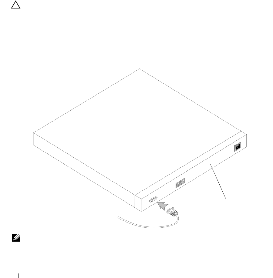
48 Installing the PowerConnect 3524/P and PowerConnect 3548/P
3
Set the data rate to 9600 baud.
4
Set the data format to 8 data bits, 1 stop bit, and no parity.
5
Set flow control to
non
e.
6
Under Properties, select VT100 for Emulation mode.
7
Select Terminal keys for Function, Arrow, and Ctrl keys. Ensure that the setting is for Terminal keys
(
not
Windows keys).
CAUTION: When using HyperTerminal with Microsoft® Windows® 2000,ensure that you have Windows 2000 Service
Pack 2 or later installed. With Windows 2000 Service Pack 2, the arrow keys function properly in HyperTerminal’s
VT100 emulation. Go to www.microsoft.com for information on Windows 2000 service packs.
8
Connect the female connector of the RS-232 crossover cable directly to the device Console port on the
Master unit/stand-alone device, and tighten the captive retaining screws. The PowerConnect 35xx
Series Systems Console port is on the rear panel.
Figure 3-7. Connecting to PowerConnect 35xx Series Systems Console Port
NOTE: A console can be connected to the Console port on any unit in the stack, but stack management is
performed only from the stack master (unit ID 1 or 2).
Back Panel
To VT100
Terminal
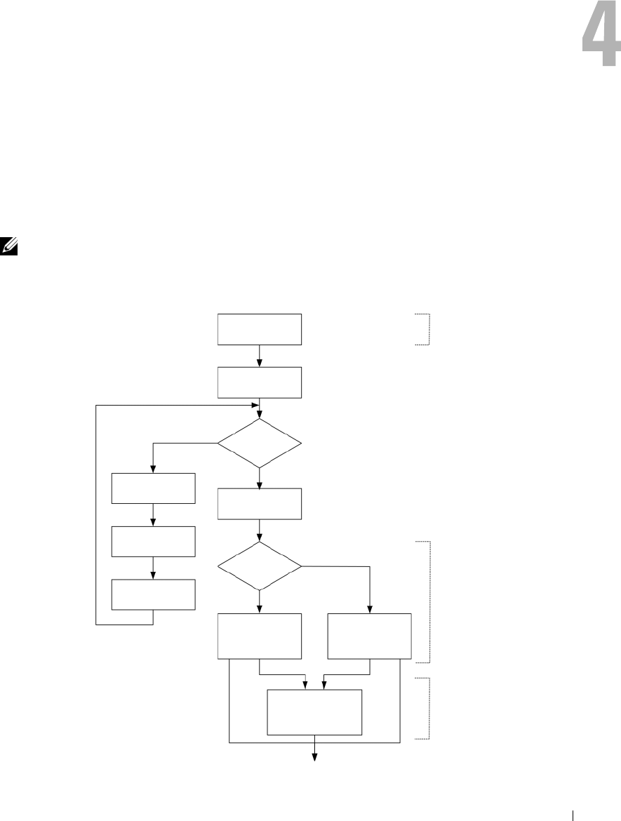
Configuring PowerConnect 3524/P and 3548/P 49
Configuring PowerConnect 3524/P and 3548/P
Configuration Procedures
After all the device external connections are completed, a terminal is connected to the device to
monitor the boot and other procedures. The order of installation and configuration procedures is
illustrated in the following figure:
NOTE: Before proceeding, read the release notes for this product. Download the release notes from
support.dell.com.
Figure 4-1. Installation and Configuration Flow
Connect Device and
Console
Power On
Suspend
Bootup
Yes
Press Esc
Startup Menu (Special
Functions)
Reboot
No
Loading Program from
flash to RAM
Enter Wizard
Yes
No
Initial Configuration:
IP Address, Subnet
mask, Users Basic
Security Configuration
Wizard Configuration
Process
Advanced Configuration:
IP Address from DHCP,
IP address from bootp,
Security Management
Standard
Device
Installation
Advanced
Device
Installation
Hardware
Setup

50 Configuring PowerConnect 3524/P and 3548/P
Booting the Switch
When the power is turned on with the local terminal already connected, the switch goes through
power-on self-test (POST). POST runs every time the device is initialized and checks hardware
components to determine if the device is fully operational before completely booting. If a critical
problem is detected, the program flow stops. If POST passes successfully, a valid executable image is
loaded into RAM. POST messages are displayed on the terminal and indicate test success or failure.
The boot process runs approximately 30 seconds.
Initial Configuration
NOTE: Before proceeding, read the release notes for this product. Download the release notes from the
Dell Support website at support.dell.com.
NOTE: The initial configuration assumes the following:
•The Dell™ PowerConnect™ device was never configured before and is in the same state as when you
received it.
•The PowerConnect device booted successfully.
•The console connection is established and the console prompt is displayed on the screen of a VT100
terminal device.
The initial device configuration is through the Console port. After the initial configuration, the device
can be managed either from the already connected Console port or remotely through an interface
defined during the initial configuration.
If this is the first time the device has booted up, or if the configuration file is empty because the device has
not been configured, the user is prompted to use the Setup Wizard. The Setup Wizard provides guidance
through the initial device configuration, and gets the device up and running as quickly as possible.
NOTE: Obtain the following information from the network administrator before configuring the device:
•The IP address to be assigned to the VLAN 1 interface through which the device is to be managed (by default,
every port is a member of the VLAN 1)
•The IP subnet mask for the network
•The default gateway (next hop router) IP address for configuring the default route.
•SNMP community string and SNMP management system IP address (optional)
•Username and password
The Setup Wizard guides you through the initial switch configuration, and gets the system up and
running as quickly as possible. You can skip the Setup Wizard, and manually configure the device
through the device CLI mode.
The Setup Wizard configures the following fields.
• SNMP Community String and SNMP Management System IP address (optional)
• Username and Password

Configuring PowerConnect 3524/P and 3548/P 51
• Device IP address
• Default Gateway IP address
The following is displayed:
Welcome to Dell Easy Setup Wizard
The Setup Wizard guides you through the initial switch configuration,
and gets you up and running as quickly as possible. You can skip the
setup wizard, and enter CLI mode to manually configure the switch.
The system will prompt you with a default answer; by pressing enter,
you accept the default.
You must respond to the next question to run the setup wizard within
60 seconds, otherwise the system will continue with normal operation
using the default system configuration.
Would you like to enter the Setup Wizard (you must answer this
question within 60 seconds? (Y/N)[Y]Y
You can exit the Setup Wizard at any time by entering [ctrl+Z].
If you enter [N], the Setup Wizard exits. If there is no response within 60 seconds, the Setup Wizard
automatically exits and the CLI console prompt appears.
If you enter [Y], the Setup Wizard provides interactive guidance through the initial device configuration.
NOTE: If there is no response within 60 seconds, and there is a BootP server on the network, an address is
retrieved from the BootP server.
NOTE: You can exit the Setup Wizard at any time by entering [ctrl+z].
Wizard Step 1
The following is displayed:
The system is not setup for SNMP management by default.
To manage the switch using SNMP (required for Dell Network Manager)
you can
•
Setup the initial SNMP version 2 account now.
•
Return later and setup additional SNMP v1/v3 accounts.
For more information on setting up SNMP accounts, please see the user
documentation.
Would you like to setup the SNMP management interface now? (Y/N)[Y]Y
Enter [N] to skip to Step 2.

52 Configuring PowerConnect 3524/P and 3548/P
Enter [Y] to continue the Setup Wizard. The following is displayed:
To setup the SNMP management account you must specify the management
system IP address and the "community string" or password that the
particular management system uses to access the switch. The wizard
automatically assigns the highest access level [Privilege Level 15]
to this account.
You can use Dell Network Manager or CLI to change this setting, and
to add additional management systems. For more information on adding
management systems, see the user documentation.
To add a management station:
Please enter the SNMP community string to be used:
[Dell_Network_Manager]
Please enter the IP address of the Management System (A.B.C.D) or
wildcard (0.0.0.0) to manage from any Management Station: [0.0.0.0]
Enter the following:
• SNMP community string, for example, Dell_Network_Manager.
• IP address of the Management System (A.B.C.D), or wildcard (0.0.0.0) to manage from any
Management Station.
NOTE: IP addresses and masks beginning with zero cannot be used.
Press Enter.
Wizard Step 2
The following is displayed:
Now we need to setup your initial privilege (Level 15) user account.
This account is used to login to the CLI and Web interface.
You may setup other accounts and change privilege levels later.
For more information on setting up user accounts and changing
privilege levels, see the user documentation.
To setup a user account:
Enter the user name<1-20>:[admin]
Please enter the user password:*
Please reenter the user password:*
Enter the following:
• User name, for example "admin"
• Password and password confirmation.
NOTE: If the first and second password entries are not identical, the user is prompted until they are identical.
Press Enter.

Configuring PowerConnect 3524/P and 3548/P 53
Wizard Step 3
The following is displayed:
Next, an IP address is setup.
The IP address is defined on the default VLAN (VLAN #1), of which all
ports are members. This is the IP address you use to access the CLI,
Web interface, or SNMP interface for the switch.To setup an IP
address:
Please enter the IP address of the device (A.B.C.D):[1.1.1.1]
Please enter the IP subnet mask (A.B.C.D or nn): [255.255.255.0]
Enter the IP address and IP subnet mask, for example 1.1.1.1 as the IP address and 255.255.255.0 as the
IP subnet mask.
Press Enter.
Wizard Step 4
The following is displayed:
Finally, setup the default gateway.
Please enter the IP address of the gateway from which this network is
reachable (e.g. 192.168.1.1).Default gateway (A.B.C.D):[0.0.0.0]
Enter the default gateway.
Press Enter. The following is displayed (as per the example parameters described):
This is the configuration information that has been collected:
==============================================================
SNMP Interface = Dell_Network_Manager@0.0.0.0
User Account setup = admin
Password = *
Management IP address = 1.1.1.1 255.255.255.0
Default Gateway = 1.1.1.2
==============================================================
Wizard Step 5
The following is displayed:
If the information is correct, please select (Y) to save the
configuration, and copy to the start-up configuration file. If the
information is incorrect, select (N) to discard configuration and
restart the wizard: (Y/N)[Y]Y
Enter [N] to skip to restart the Setup Wizard.

54 Configuring PowerConnect 3524/P and 3548/P
Enter [Y] to complete the Setup Wizard. The following is displayed:
Configuring SNMP management interface
Configuring user account......
Configuring IP and subnet......
Thank you for using Dell Easy Setup Wizard. You will now enter CLI
mode.
Wizard Step 6
The CLI prompt is displayed.
Advanced Configuration
This section provides information about dynamic allocation of IP addresses and security management
based on the Authentication, Authorization, and Accounting (AAA) mechanism, and includes the
following topics:
• Configuring IP Addresses through DHCP
• Configuring IP Addresses through BOOTP
• Security Management and Password Configuration
When configuring/receiving IP addresses through DHCP and BOOTP, the configuration received from
these servers includes the IP address and may include subnet mask and default gateway.
Retrieving an IP Address From a DHCP Server
When using the DHCP protocol to retrieve an IP address, the device acts as a DHCP client. When the
device is reset, the DHCP command is saved in the configuration file, but the IP address is not.
To retrieve an IP address from a DHCP server, perform the following steps:
1
Select and connect any port to a DHCP server or to a subnet that has a DHCP server on it, in order to
retrieve the IP address.
2
Enter the following commands to use the selected port for receiving the IP address. In the following
example, the commands are based on the port type used for configuration.
• Assigning Dynamic IP Addresses:
console# configure
console(config)# interface ethernet 1/e1
console(config-if)# ip address dhcp hostname powerconnect
console(config-if)# exit
console(config)#

Configuring PowerConnect 3524/P and 3548/P 55
• Assigning Dynamic IP Addresses (on a VLAN):
console# configure
console(config)# interface ethernet vlan 1
console(config-if)# ip address dhcp hostname device
console(config-if)# exit
console(config)#
The interface receives the IP address automatically.
3
To verify the IP address, enter the
show ip interface
command at the system prompt as shown in the
following example.
console# show ip interface
IP Address I/F Type
------------- ------ -------
100.1.1.1/24 vlan 1 dynamic
NOTE: It is not necessary to delete the device configuration to retrieve an IP address for the DHCP server.
NOTE: When copying configuration files, avoid using a configuration file that contains an instruction to enable
DHCP on an interface that connects to the same DHCP server, or to one with an identical configuration. In this
instance, the device retrieves the new configuration file and boots from it. The device then enables DHCP as
instructed in the new configuration file, and the DHCP instructs it to reload the same file again.
NOTE: If you configure a DHCP IP address, this address is dynamically retrieved, and the ip address dhcp
command is saved in the configuration file. In the event of master failure, the backup will again attempt to retrieve
a DHCP address. This could result in one of the following:
•The same IP address may be assigned.
•A different IP address may be assigned, which could result in loss of connectivity to the management station.
•The DHCP server may be down, which would result in IP address retrieval failure, and possible loss of
connectivity to the management station.

56 Configuring PowerConnect 3524/P and 3548/P
Receiving an IP Address From a BOOTP Server
The standard BOOTP protocol is supported and enables the device to automatically download its IP host
configuration from any standard BOOTP server in the network. In this case, the device acts as a BOOTP
client.
To retrieve an IP address from a BOOTP server:
1
Select and connect any port to a BOOTP server or subnet containing such a server, to retrieve the
IP address.
2
At the system prompt, enter the
delete startup configuration
command to delete the Startup
Configuration from flash.
The device reboots with no configuration and in 60 seconds starts sending BOOTP requests.
The device receives the IP address automatically.
NOTE: When the device reboot begins, any input at the ASCII terminal or keyboard automatically cancels the
BOOTP process before completion and the device does not recieve an IP address from the BOOTP server.
The following example illustrates the process:
console> enable
console# delete startup-config
Startup file was deleted
console# reload
You haven’t saved your changes. Are you sure you want to continue
(y/n) [n]?
This command will reset the whole system and disconnect your current
session. Do you want to continue (y/n) [n]?
******************************************************
/* the device reboots */
To verify the IP address, enter the show ip interface command.
The device is now configured with an IP address.
Security Management and Password Configuration
System security is handled through the Authentication, Authorization, and Accounting (AAA)
mechanism that manages user access rights, privileges, and management methods. AAA uses both local
and remote user databases. Data encryption is handled through the SSH mechanism.
The system is delivered with no default password configured; all passwords are user-defined. If a
user-defined password is lost, a password recovery procedure can be invoked from the Startup menu.
The procedure is applicable for the local terminal only and allows a one-time access to the device from
the local terminal with no password entered.

Configuring PowerConnect 3524/P and 3548/P 57
Configuring Security Passwords
The security passwords can be configured for the following services:
• Terminal
• Telnet
• SSH
•HTTP
•HTTPS
NOTE: Passwords are user-defined.
NOTE: When creating a user name, the default priority is 1, which allows access but not configuration rights.
A priority of 15 must be set to enable access and configuration rights to the device. Although user names can
be assigned privilege level 15 without a password, it is recommended to always assign a password. If there is no
specified password, privileged users can access the Web interface with any password.
NOTE: Passwords can be secured by using password management commands to force aging-out of passwords,
or expiration of passwords. For more information, see "Security Management and Password Configuration" on
page 56.
Configuring an Initial Terminal Password
To configure an initial terminal password, enter the following commands:
console(config)# aaa authentication login default line
console(config)# aaa authentication enable default line
console(config)# line console
console(config-line)# login authentication default
console(config-line)# enable authentication default
console(config-line)# password george
• When initially logging on to a device through a terminal session, enter
george
at the password
prompt.
• When changing a device’s mode to enable, enter
george
at the password prompt.
Configuring an Initial Telnet Password
To configure an initial Telnet password, enter the following commands:
console(config)# aaa authentication login default line
console(config)# aaa authentication enable default line
console(config)# line telnet
console(config-line)# login authentication default

58 Configuring PowerConnect 3524/P and 3548/P
console(config-line)# enable authentication default
console(config-line)# password bob
• When initially logging onto a device through a Telnet session, enter
bob
at the password prompt.
• When changing a device mode to enable, enter
bob
.
Configuring an Initial SSH password
To configure an initial SSH password, enter the following commands:
console(config)# aaa authentication login default line
console(config)# aaa authentication enable default line
console(config)# line ssh
console(config-line)# login authentication default
console(config-line)# enable authentication default
console(config-line)# password jones.
• When initially logging onto a device through a SSH session, enter
jones
at the password prompt.
• When changing a device’s mode to enable, enter
jones
.
Configuring an Initial HTTP Password
To configure an initial HTTP password, enter the following commands:
console(config)# ip http authentication local
console(config)# username admin password user1 level 15
Configuring an initial HTTPS password
To configure an initial HTTPS password, enter the following commands:
console(config)# ip https authentication local
console(config)# username admin password user1 level 15
Enter the following commands once when configuring to use a terminal, a Telnet, or an SSH session in
order to use an HTTPS session.
NOTE: In the Web browser enable SSL 2.0 or greater for the page content to be displayed.
console(config)# crypto certificate generate key_generate
console(config)# ip https server
When initially enabling an http or https session, enter admin for user name and user1 for password.
NOTE: Http and Https services require level 15 access and connect directly to the configuration level access.

Configuring PowerConnect 3524/P and 3548/P 59
Configuring Login Banners
You can define 3 types of login banners:
•
Message-of-the-Day Banner:
Displayed when the user is connected to the device, before the user has
logged in.
•
Login Banner:
Displayed after the Message-of-the-Day Banner, and before the user has logged in.
•
Exec Banner:
Displayed after successful login (in all privileged levels and in all authentication
methods).
To view and configure login banners:
console# banner motd Welcome
console# show banner motd
console# banner login Please log in
console# show banner login
console# banner exec Successfully logged in
console# show banner exec
Startup Procedures
Startup Menu Procedures
The procedures called from the Startup menu cover software download, flash handling and password
recovery. The diagnostics procedures are for use by technical support personnel only and are not disclosed
in the document.
You can enter the Startup menu when booting the device. The user input is to be entered immediately
after the POST test.
To enter the Startup menu:
1
Turn the power on and watch for the auto-boot message.
**************************************************
***************** SYSTEM RESET *****************
**************************************************
Boot1 Checksum Test...............................PASS
Boot2 Checksum Test...............................PASS
Flash Image Validation Test.......................PASS
BOOT Software Version 1.0.0.05 Built 06-Jan-xxxx 14:46:49

60 Configuring PowerConnect 3524/P and 3548/P
Ryan board, based on PPC8247
128 MByte SDRAM. I-Cache 16 KB. D-Cache 16 KB. Cache Enabled.
Autoboot in 2 seconds - press RETURN or Esc. to abort and enter prom.
2
When the auto-boot message appears, press
<Enter>
to get the Startup menu. The Startup menu
procedures can be done using the ASCII terminal or Windows HyperTerminal.
[1] Download Software
[2] Erase Flash File
[3] Password Recovery Procedure
[4] Enter Diagnostic Mode
[5] Set Terminal Baud-Rate
[6] Back
The following sections describe the available Startup menu options.
NOTE: When selecting an option from the Startup menu, take time-out into account: if no selection is made within
35 seconds (default), the device times out. This default value can be changed through CLI.
NOTE: Technical support personnel only can operate the Diagnostics Mode (option[4]). For this reason,
Enter Diagnostics Mode is not described in this guide.
Download Software - option[1]
The software download procedure is performed when a new version must be downloaded to replace the
corrupted files, update or upgrade the system software. To download software from the Startup menu:
1
From the Startup menu,
press [1]
. The following prompt appears:
Downloading code using XMODEM
******************************************************************
*** Running SW Ver. 21_08 Date 21-Aug-xxxx Time 17:22:25 ***
******************************************************************
HW version is 00.00.00
Base Mac address is: 00:14:47:78:89:96
Dram size is : 128M bytes
Dram first block size is : 102400K bytes
Dram first PTR is : 0x1800000
Dram second block size is : 4096K bytes
Dram second PTR is : 0x7C00000

Configuring PowerConnect 3524/P and 3548/P 61
Flash size is: 16M
01-Jan-xxxx 01:01:07 %CDB-I-LOADCONFIG: Loading running
configuration.
01-Jan-xxxx 01:01:07 %CDB-I-LOADCONFIG: Loading startup
configuration.
Device configuration:
CPLD revision: 1.01
Slot 1 - PowerConnect 35xx HW Rev. 1.1
------------------------------------
-- Unit Standalone --
------------------------------------
Tapi Version: v1.3.3.1
Core Version: v1.3.3.1
01-Jan-xxxx 01:01:19 %INIT-I-InitCompleted: Initialization task is
completed
01-Jan-xxxx 01:01:19 %SNMP-I-CDBITEMSNUM: Number of running
configuration items loaded: 0
01-Jan-xxxx 01:01:19 %SNMP-I-CDBITEMSNUM: Number of startup
configuration items loaded: 0
01-Jan-xxxx 01:01:20 %Box-I-SFP-PRESENT-CHNG: unit_id 1 SFP 0 status
is not present.
01-Jan-xxxx 01:01:20 %Box-I-SFP-PRESENT-CHNG: unit_id 1 SFP 1 status
is not present.
2
When using the HyperTerminal, click
Transfer
on the HyperTerminal Menu Bar.
3
In the
Filename
field, enter the file path for the file to be downloaded.
4
Ensure that the Xmodem protocol is selected in the
Protocol
field.
5
Press
Send
. The software is downloaded.
NOTE: After software download, the device reboots automatically.

62 Configuring PowerConnect 3524/P and 3548/P
Erase FLASH File - option[2]
In some cases, the device configuration must be erased. If the configuration is erased, all parameters
configured via CLI, EWS or SNMP must be reconfigured.
To erase the device configuration:
1
From the Startup menu,
press [2]
within two seconds to erase flash file. The following message is
displayed:
Warning! About to erase a Flash file.
Are you sure (Y/N)? y
2
Press
Y
. The following message is displayed.
Write Flash file name (Up to 8 characters, Enter for none.):config
File config (if present) will be erased after system initialization
======== Press Enter To Continue ========
3
Enter
config
as the name of the flash file. The configuration is erased and the device reboots.
4
Repeat the device initial configuration.
Password Recovery - option[3]
If a password is lost, the Password Recovery procedure can be called from the Startup menu.
The procedure enables entry to the device once without password.
To recover a lost password when entering the local terminal only:
1
From the Startup menu, type
[3]
and press
<Enter>
. The password is deleted.
Enter your choice or press
ESC
to exit
Current password will be ignored!
NOTE: To ensure device security, reconfigure passwords for applicable management methods.
Enter Diagnostic Mode - option[4]
For Technical Support only.
Set Terminal Baud-Rate - option[5]
To set the terminal baud-rate, type [5] and press <Enter>.
Enter your choice or press 'ESC' to exit:
Set new device baud-rate: 38,400

Configuring PowerConnect 3524/P and 3548/P 63
Software Download Through TFTP Server
This section contains instructions for downloading device software (system and boot images) through a
TFTP server. The TFTP server must be configured before downloading the software.
System Image Download
The device boots and runs when decompressing the system image from the flash memory area where a
copy of the system image is stored. When a new image is downloaded, it is saved in the other area
allocated for the other system image copy.
On the next boot, the device will decompress and run from the currently active system image unless
chosen otherwise.
To download a system image through the TFTP server:
1
Ensure that an IP address is configured on one of the device ports and pings can be sent to a TFTP
server.
2
Make sure that the file to be downloaded is saved on the TFTP server (the
arc
file).
3
Enter the
show version
command to verify which software version is currently running on the device.
The following is an example of the information that appears:
console# show version
SW version 1.0.0.30 (date 27-Jan-xxxx time 13:42:41)
Boot version 1.0.0.05 (date 27-Jan-xxxx time 15:12:20)
HW version
4
Enter the
show bootvar
command to verify which system image is currently active. The following is an
example of the information that appears:
console# show bootvar
Images currently available on the Flash
Image-1 active (selected for next boot)
Image-2 not active
console#

64 Configuring PowerConnect 3524/P and 3548/P
5
Enter the
copy tftp://{tftp address}/{file name} image command
to copy a new
system image to the device. When the new image is downloaded, it is saved in the area allocated for
the other copy of system image (image-2, as given in the example). The following is an example of the
information that appears:
console# copy tftp://176.215.31.3/file1.ros image
Accessing file ‘file1’ on 176.215.31.3Ö
Loading file1 from 176.215.31.3:
!!!!!!!!!!!!!!!!!!!!!!!!!!!!!!!!!!!!!!!!!!!!!!!!!!!!!!!!!!!!!!!!!!!!
!!!!!!!!!!!!!!!!!!!!!!!!!!!!!!!!!!!!!!!!!!!!!!!!!!!!!!!!!!!!!!!!
Copy took 00:01:11 [hh:mm:ss]
Exclamation symbols indicate that a copying process is in progress. Each symbol (!) corresponds to
512 bytes transferred successfully. A period indicates that the copying process is timed out. Many
periods in a row indicate that the copying process failed.
6
Select the image for the next boot by entering the
boot system
command. After this command,
enter the
show bootvar
command to verify that the copy indicated as a parameter in the
boot system
command is selected for the next boot.
The following is an example of the information that appears:
console# boot system image-2
console# show bootvar
Images currently available on the Flash
Image-1 active
Image-2 not active (selected for next boot)
If the image for the next boot is not selected by entering the boot system command, the system boots
from the currently active image.
7
Enter the
reload
command. The following message is displayed:
console# reload
This command will reset the whole system and disconnect your current
session. Do you want to continue (y/n) [n]?
8
Enter
y
. The device reboots.

Configuring PowerConnect 3524/P and 3548/P 65
Boot Image Download
Loading a new boot image from the TFTP server and programming it into the flash updates the boot
image. The boot image is loaded when the device is powered on. A user has no control over the boot
image copies. To download a boot image through the TFTP server:
1
Ensure that an IP address is configured on one of the device ports and pings can be sent to
a TFTP server.
2
Ensure that the file to be downloaded is saved on the TFTP server (the
rfb
file).
3
Enter the show version command to verify which software version is currently running on the device.
The following is an example of the information that appears:
console# show version
SW version 1.0.0.30 (date 27-Jan-xxxx time 13:42:41)
Boot version 1.0.0.05 (date 27-Jan-xxxx time 15:12:20)
HW version
4
Enter the
copy tftp://{tftp address}/{file name} boot
command to copy the boot
image to the device. The following is an example of the information that appears:
console# copy tftp://176.215.31.3/332448-10018.rfb boot
Erasing file..done.
!!!!!!!!!!!!!!!!!!!!!!!!!!!!!!!!!!!!!!!!!!!!!!!!!!!!!!!!!!!!!!!!!!!!
!!!!!!!!!!!!!!!!!!!!!!!!!!!!!!!!!!!!!!!!!!!!!!!!!!!!!!!!!!!!!!!!
Copy: 2739187 bytes copied in 00:01:13 [hh:mm:ss]
5
Enter the
reload
command. The following message is displayed:
console# reload
This command will reset the whole system and disconnect your current
session. Do you want to continue (y/n) [n]?
6
Enter
y
. The device reboots.

66 Configuring PowerConnect 3524/P and 3548/P
Port Default Settings
The general information for configuring the device ports includes the short description of the
auto-negotiation mechanism and the default settings for switching ports.
Auto-Negotiation
Auto-negotiation enables automatic detection of speed, duplex mode and flow control on all switching
10/100/1000BaseT ports. Auto-negotiation is enabled per port by default.
Auto-negotiation is a mechanism established between two link partners to enable a port to advertise its
transmission rate, duplex mode and flow control (the flow control default is disabled) abilities to its
partner. The ports then both operate at the highest common denominator between them.
If connecting a NIC that does not support auto-negotiation or is not set to auto-negotiation, both the
device switching port and the NIC must be manually set to the same speed and duplex mode.
If the station on the other side of the link attempts to auto-negotiate with a device 100BaseT port that is
configured to full duplex, the auto-negotiation results in the station attempting to operate in half duplex.
MDI/MDIX
The device supports auto-detection of straight through and crossed cables on all switching
10/100/1000BaseT ports. The feature is part of the Auto-negotiation and is enabled when
Auto-negotiation is enabled.
When the MDI/MDIX (Media Dependent Interface with Crossover) is enabled, the automatic
correction of errors in cable selection is possible, thus making the distinction between a straight
through cable and a crossover cable irrelevant. (The standard wiring for end stations is known as MDI
(Media Dependent Interface), and the standard wiring for hubs and switches is known as MDIX.
Flow Control
The device supports 802.3x Flow Control for ports configured with the Full Duplex mode. By default,
this feature is disabled. It can be enabled per port. The flow control mechanism allows the receiving side
to signal to the transmitting side that transmission must temporarily be halted to prevent buffer
overflow.
Back Pressure
The device supports back pressure for ports configured with the half duplex mode. By default, this
feature is disabled. It can be enabled per port. The back-pressure mechanism prevents the sender from
transmitting additional traffic temporarily. The receiver may occupy a link so it becomes unavailable for
additional traffic.

Configuring PowerConnect 3524/P and 3548/P 67
Switching Port Default Settings
The following table gives the port default settings.
Table 4-1. Port Default Settings
Function Default Setting
Port speed and mode 10/100BaseT copper: auto-negotiation 100 Mbps full duplex
10/100/1000BaseT copper / SFP: auto-negotiation1000 Mbps full duplex
Port forwarding state Enabled
Port tagging No tagging
Flow Control Off (disabled on ingress)
Back Pressure Off (disabled on ingress)

68 Configuring PowerConnect 3524/P and 3548/P

Using Dell OpenManage Switch Administrator 69
Using Dell OpenManage Switch Administrator
This section provides an introduction to the Dell™ OpenManage™ Switch Administrator
user interface.
Starting the Application
NOTE: Before starting the application the IP address must be defined. For more information, see Initial
Configuration.
1
Open a web browser.
2
Enter the device’s IP address in the address bar and press <Enter>.
3
When the
Log In
window displays, enter a user name and password.
NOTE: Passwords are both case sensitive and alpha-numeric.
4
Click
OK
.
The
Dell OpenManage
Switch Administrator
home page displays.
Understanding the Interface
The home page contains the following views:
•
Tree view
— Located on the left side of the home page, the tree view provides an expandable view
of the features and their components.
•
Device view
— Located on the right side of the home page, the device view provides a view of the
device, an information or table area, and configuration instructions.
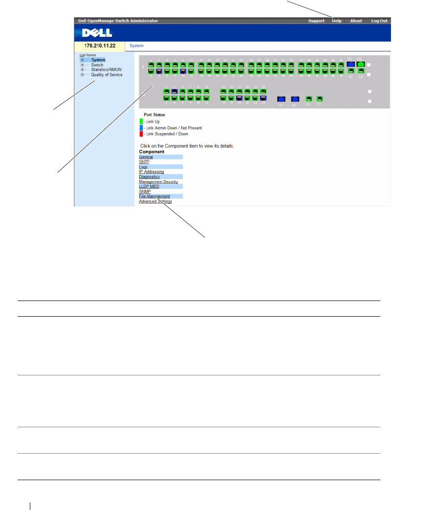
70 Using Dell OpenManage Switch Administrator
Figure 5-1. Switch Administrator Components
Table 5-1 lists the interface components with their corresponding numbers.
Table 5-1. Interface Components
Component Description
1 The tree view contains a list of the different device features. The branches in
the tree view can be expanded to view all the components under a specific
feature, or retracted to hide the feature's components. By dragging the
vertical bar to the right, the tree area can be expanded to display the full
name of a component.
2 The device view provides information about device ports, current
configuration and status, table information, and feature components.
Depending on the option selected, the area at the bottom of the device view
displays other device information and/or dialogs for configuring parameters.
3 The components list contains a list of the feature components. Components
can also be viewed by expanding a feature in the tree view.
4 The information buttons provide access to information about the device and
access to Dell Support. For more information, see "Information Buttons."
1
2
3
4
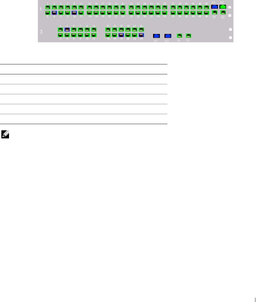
Using Dell OpenManage Switch Administrator 71
Device Representation
The home page contains a graphical representation of the device front panel.
Figure 5-2. Dell PowerConnect™ Device Port Indicators
The port coloring indicates if a specific port is currently active. Ports can be the following colors:
Table 5-2. PowerConnect Port and Stacking Indicators
NOTE: The Port LEDs are not reflected in PowerConnect™ front panel in the OpenManage Switch Administrator.
LED status can only be determined by viewing the actual device. However, the Stacking LEDs reflect the Stacking
port status. For more information about LEDs, see LED Definitions.
Component Description
Port Indicators
Green The port is currently enabled.
Red An error has occurred on the port.
Blue The port is currently disabled.
Red The device is not currently linked in a stack.

72 Using Dell OpenManage Switch Administrator
Using the Switch Administrator Buttons
This section describes the buttons found on the OpenManage Switch Administrator interface. Interface
buttons are divided into the following categories:
Information Buttons
Information buttons provide access to online support and online help, as well as information about the
OpenManage Switch Administrator interfaces.
Device Management Buttons
Device Management buttons provide an easy method of configuring device information, and include
the following:
Table 5-3. Information Buttons
Button Description
Support Opens the Dell Support page at support.dell.com
Help Online help that contains information to assist in configuring and managing the
device. The online help pages are context-sensitive. For example, if the IP Addressing
page is open, the help topic for that page displays when Help is clicked.
About Contains the version and build number and Dell copyright information.
Log Out Opens the Log Out window.
Table 5-4. Device Management Buttons
Button Description
Apply Changes Applies set changes to the device.
Add Adds information to tables or dialogs.
Telnet Starts a Telnet session.
Query Queries tables.
Show All Displays the device tables.
Left arrow/Right Arrows Moves information between lists.
Refresh Refreshes device information.
Reset All Counters Clears statistic counters.
Print Prints the Network Management System page and/or table information.
Draw Creates statistics charts on-the-fly.
Details Shows further details relevant to the current page.
Back Returns to the previous page.

Using Dell OpenManage Switch Administrator 73
Field Definitions
Fields which are user-defined can contain between 1 -159 characters, unless otherwise noted on the
OpenManage Switch Administrator web page. All letters or characters can be used, except the following:
•\
•/
•:
•*
•?
•<
•>
•|
Accessing the Device Through the CLI
You can manage the device over a direct connection to the Terminal port or via a Telnet connection.
If access is via a Telnet connection, ensure that the device has an IP address defined and that
the workstation used to access the device is connected to the device prior to beginning using
CLI commands.
For information about configuring an initial IP Address, see "Initial Configuration" on page 50.
NOTE: Ensure that the software has been downloaded to the device before using the CLI to remotely access
the device.
Terminal Connection
1
Power on the device and wait until the startup is complete.
2
When the
Console>
prompt displays, type
enable
and press <Enter>.
3
Configure the device and enter the necessary commands to complete the required tasks.
4
When finished, enter the exit Privileged EXEC mode command.
The session quits.
NOTE: If a different user logs into the system in the Privileged EXEC command mode, the current user is logged off
and the new user is logged in.

74 Using Dell OpenManage Switch Administrator
Telnet Connection
Telnet is a terminal emulation TCP/IP protocol. RS-232 terminals can be virtually connected to the local
device through a TCP/IP protocol network. Telnet is an alternative to a local login terminal where a
remote login is required.
The device supports up to four simultaneous Telnet sessions to manage the device. All CLI commands
can be used over a telnet session.
To start a Telnet session:
1
Select
Start
→
Run
.
The
Run
window opens.
2
In the
Run
window, type
Telnet <IP address>
in the
Open
field.
3
Click
OK.
The Telnet session begins.
Using the CLI
This section provides information for using the CLI.
Command Mode Overview
The CLI is divided into command modes. Each command mode has a specific command set. Entering a
question mark at the terminal prompt displays a list of commands available for that particular
command mode.
In each mode, a specific command is used to navigate from one command mode to another.
During the CLI session initialization, the CLI mode is the User EXEC mode. Only a limited subset of
commands are available in the User EXEC mode. This level is reserved for tasks that do not change the
terminal configuration and is used to access configuration sub-systems such as the CLI. To enter the
next level, the Privileged EXEC mode, a password is required (if configured).
The Privileged EXEC mode provides access to the device global configuration. For specific global
configurations within the device, enter the next level, Global Configuration mode. A password is
not required.
The Global Configuration mode manages the device configuration on a global level.
The Interface Configuration mode configures the device at the physical interface level. Interface
commands which require subcommands have another level called the Subinterface Configuration mode.
A password is not required.

Using Dell OpenManage Switch Administrator 75
User EXEC Mode
After logging into the device, the EXEC command mode is enabled. The user-level prompt consists of
the host name followed by the angle bracket (>). For example:
console>
NOTE: The default host name is console unless it has been modified during initial configuration.
The User EXEC commands permit connecting to remote devices, changing terminal settings on a
temporary basis, performing basic tests, and listing system information.
To list the User EXEC commands, enter a question mark at the command prompt.
Privileged EXEC Mode
Privileged access can be protected to prevent unauthorized access and ensure operating parameters.
Passwords are displayed on the screen, and are case sensitive.
To access and list the Privileged EXEC mode commands:
1
At the prompt type
enable
and press <Enter>.
2
When a password prompt displays, enter the password and press <Enter>.
The Privileged EXEC mode prompt displays as the device host name followed by #. For example:
console#
To list the Privileged EXEC commands, type a question mark at the command prompt.
To return from Privileged EXEC mode to User EXEC mode, type
disable
and press <Enter>.
The following example illustrates accessing privileged EXEC mode and then returning to the
User EXEC mode:
console> enable
Enter Password: ******
console#
console# disable
console>
Use the exit command to move back to a previous mode. For example, from Interface Configuration
mode to Global Configuration mode, and from Global Configuration mode to Privileged EXEC mode.

76 Using Dell OpenManage Switch Administrator
Global Configuration Mode
Global Configuration commands apply to system features, rather than a specific protocol or interface.
To access Global Configuration mode, at the Privileged EXEC Mode prompt, type the configure
command and press <Enter>. The Global Configuration mode displays as the device host name
followed by (config) and the pound sign #.
console(config)#
To list the Global Configuration commands, enter a question mark at the command prompt.
To return from Global Configuration mode to Privileged EXEC mode, type the exit command or use the
<Ctrl>+<Z> key combination.
The following example illustrates how to access Global Configuration mode and return back to the
Privileged EXEC mode:
console#
console# configure
console(config)# exit
console#
For a complete list of the CLI modes, see the Dell™ PowerConnect™3524/P and PowerConnect 3548/P
CLI Guide.
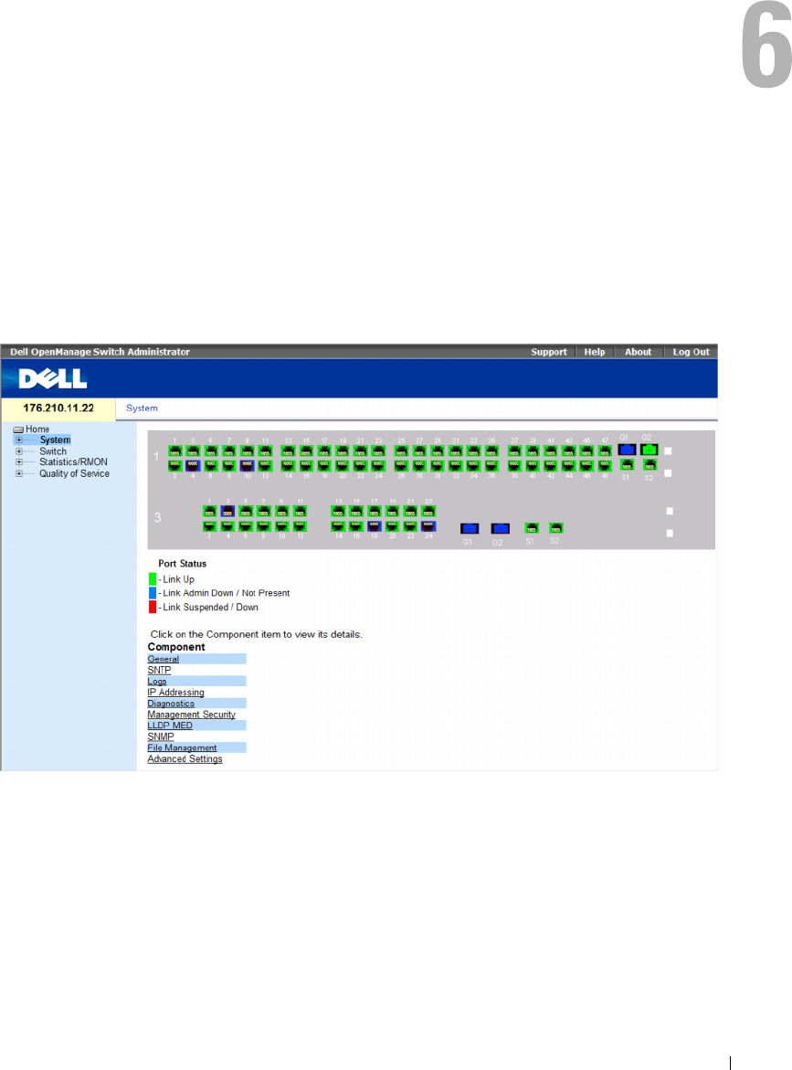
Configuring System Information 77
Configuring System Information
This section provides information This page provides links for defining system parameters including
security features, downloading switch software, and resetting the switch. To open the System page,
Click a link below to access on-line help for the indicated screen.
Click System in the tree view.
Figure 6-1. System
This section contians the following topics:
• "Defining General Switch Information" on page 78
• "Configuring SNTP Settings" on page 101
• "Managing Logs" on page 113
• "Defining IP Addressing" on page 128
• "Running Cable Diagnostics" on page 165

78 Configuring System Information
• "Managing Management Security" on page 170
• "Configuring LLDP and MED" on page 205
• "Defining SNMP Parameters" on page 219
• "Managing Files" on page 246
• "Configuring Advanced Settings" on page 259
Defining General Switch Information
The General page contains links to pages that allow network managers to configure switch parameters.
This section contians the following topics:
• "Viewing Switch Asset Information" on page 78
• "Asset" on page 78
• "Defining System Time Settings" on page 84
• "Viewing System Health Information" on page 90
• "Managing Power over Ethernet" on page 92
• "Viewing Version Information" on page 98
• "Managing Stack Members" on page 99
• "Resetting the Device" on page 100
Viewing Switch Asset Information
Asset
The Asset page contains parameters for configuring and viewing general device information, including
the system name, location, and contact, the system MAC Address, System Object ID, date, time,
and System Up Time. To open the Asset page, click System → General → Asset in the tree view.
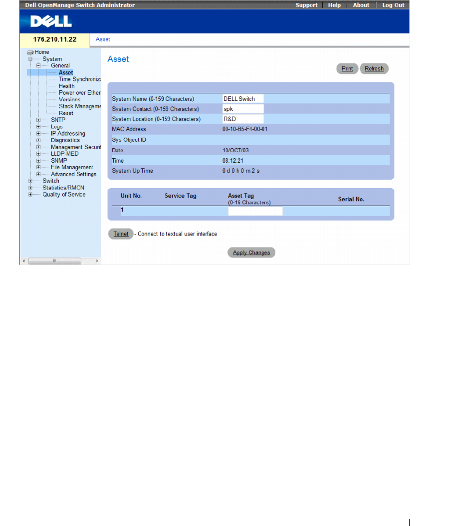
Configuring System Information 79
Figure 6-2. Asset
The Asset page contains the following fields:
•
System Name (0-159 Characters)
— Defines the user-defined device name.
•
System Contact (0-159 Characters)
— Indicates the name of the contact person.
•
System Location (0-159 Characters)
— The location where the system is currently running.
•
MAC Address
— Indicates the device MAC address.
•
Sys Object ID
— The vendor's authoritative identification of the network management subsystem
contained in the entity.
•
Date
— The current date. The format is day, month, year, for example, 15/FEB/07 is February 15, 2007.
•
Time
— Indicates the time. The format is hour, minute, second, for example, 20:12:21 is eight twelve
and twenty-one seconds in the evening.
•
System Up Time
— Specifies the amount of time since the last device reset. The system time is
displayed in the following format: Days, Hours, Minutes and Seconds. For example, 41 days, 2 hours,
22 minutes and 15 seconds.

80 Configuring System Information
•
Unit No.
— Indicates the unit number for which the device asset information is displayed.
•
Service Tag
— The service reference number used when servicing the device.
•
Asset Tag (0-16 Characters)
— Indicates the user-defined device reference.
•
Serial No.
— The device serial number.
Defining System Information
1
Open the
Asset page
.
2
Define the relevant fields.
3
Click
Apply Changes
.
The system parameters are defined, and the device is updated.
Initiating a Telnet Session
1
Open the
Asset page
.
2
Click
Telnet
.
A Telnet session is initiated.
Configuring device Information Using the CLI Commands
The following table summarizes the equivalent CLI commands for viewing and setting fields displayed
in the Asset page.
Table 6-1. Asset CLI Commands
CLI Command Description
hostname name Indicates or modifies the device host name.
snmp-server contact text Sets up a system contact.
snmp-server location text Enters information on where the device is located.
clock set hh:mm:ss day month year Manually sets the system clock and date.
show clock [detail] Displays the time and date from the system clock.
show system id Displays the service tag information.
show system Displays system information.
asset-tag text Sets the device asset tag.
show stack <1-8> Displays the system stack information.
show system [unit unit]Displays system information.
show system id [unit unit]Displays system identity information.

Configuring System Information 81
The following is an example of defining the device host name, system contact and device location as well
as setting the time and date of the system clock using the CLI commands:
The following is an example of displaying system information for a stand-alone device using the CLI
commands:
console(config)# hostname dell
dell (config)# snmp-server contact Dell_Tech_Supp
dell (config)# snmp-server location New_York
dell (config)# exit
Console(config)# snmp-server host 10.1.1.1 management 2
Console# clock set 13:32:00 7 Mar 2002
Console# show clock
15:29:03 Jun 17 2002
console# show system id
Service tag :
Serial number : 51
Asset tag :
console# show system
System Description: Ethernet Switch
System Up Time
(days,hour:min:sec):
0,00:00:57
System Contact:
System Name: PowerConnect-1
System Location:
System MAC Address: 00:00:00:08:12:51
System Object ID: 1.3.6.1.4.1.674.10895.3006
Type: PowerConnect 3524

82 Configuring System Information
The following is an example of displaying system information for a stacked devices using the CLI commands:
Main Power Supply Status: OK
Fan 1 Status: NOT OPERATIONAL
Fan 2 Status: NOT OPERATIONAL
Temperature (Celsius): 30
Temperature Sensor Status: OK
console# show system id
Unit Serial number Asset tag Service tag
---- ------------- --------- -----------
1 893658972 mkt-1 89788978
2 893658973 mkt-2 89788979
3 893658974 mkt-3 89788980
4 893658975 mkt-4 89788981
5 893658976 mkt-5 89788982
6 893658977 mkt-6 89788983
7 893658978 mkt-7 89788984
8 893658979 mkt-8 89788985
console# show system
Unit Type
---- -----------------
1 PowerConnect 3524
2 PowerConnect 3524
3 PowerConnect 3524
4 PowerConnect 3524P
5 PowerConnect 3524P
6 PowerConnect 3524P
7 PowerConnect 3524P
8 PowerConnect 3524P

Configuring System Information 83
Unit Main Power Supply Redundant Power Supply
---- ----------------- ----------------------
1OK
2OK
3OK
4OK
5OK OK
6OK OK
7OK OK
8OK OK
Unit Fan1 Fan2 Fan3 Fan4 Fan5
---- ---- ---- ---- ---- ----
1OK OK
2OK OK
3OK OK
4OK OK
5OK OK OK OK OK
6OK OK OK OK OK
7OK OK OK OK OK
8OK OK OK OK OK
Unit
Temperature (Celsius)
Temperature Sensor Status
---- -------------------- -------------------------
130 OK
230 OK
330 OK
430 OK
530 OK
630 OK
730 OK
830 OK

84 Configuring System Information
Defining System Time Settings
The Time Synchronization page contains fields for defining system time parameters for both the local
hardware clock, and the external SNTP clock. If the system time is kept using an external SNTP clock,
and the external SNTP clock fails, and the system time reverts to the local hardware clock. Daylight
Savings Time can be enabled on the device. The following is a list of Daylight Time start and end times
in specific countries:
•
Albania
— Last weekend of March until the last weekend of October.
•
Australia
— From the end of October until the end of March.
•
Australia
- T
asmania
— From beginning of October until the end of March.
•
Armenia
— Last weekend of March until the last weekend of October.
•
Austria
— Last weekend of March until the last weekend of October.
•
Bahamas
— From April to October, in conjunction with U.S. summer hours.
•
Belarus
— Last weekend of March until the last weekend of October.
•
Belgium
— Last weekend of March until the last weekend of October.
•
Brazil
— From the 3rd Sunday in October until the 3rd Saturday in March. During the period of
Daylight Saving Time, Brazilian clocks go forward one hour in most of the Brazilian southeast.
•
Chile
— Easter Island 9th March 12th October. The first Sunday in March or after 9th March.
•
China
— China does not operate Daylight Saving Time.
•
Canada
— From the first Sunday in April until the last Sunday of October. Daylight Saving Time is
usually regulated by provincial and territorial governments. Exceptions may exist in certain
municipalities.
•
Cuba
— From the last Sunday of March to the last Sunday of October.
•
Cyprus
— Last weekend of March until the last weekend of October.
•
Denmark
— Last weekend of March until the last weekend of October.
•
Egypt
— Last Friday in April until the last Thursday in September.
•
Estonia
— Last weekend of March until the last weekend of October.
•
Finland
— Last weekend of March until the last weekend of October.
•
France
— Last weekend of March until the last weekend of October.
•
Germany
— Last weekend of March until the last weekend of October.
•
Greece
— Last weekend of March until the last weekend of October.
•
Hungary
— Last weekend of March until the last weekend of October.
•
India
— India does not operate Daylight Saving Time.
•
Iran
— From 1st Farvardin until the 1st Mehr.
•
Iraq
— From 1st April until 1st October.

Configuring System Information 85
•
Ireland
— Last weekend of March until the last weekend of October.
•
Israel
— Varies year-to-year.
•
Italy
— Last weekend of March until the last weekend of October.
•
Japan
— Japan does not operate Daylight Saving Time.
•
Jordan
— Last weekend of March until the last weekend of October.
•
Latvia
— Last weekend of March until the last weekend of October.
•
Lebanon
— Last weekend of March until the last weekend of October.
•
Lithuania
— Last weekend of March until the last weekend of October.
•
Luxembourg
— Last weekend of March until the last weekend of October.
•
Macedonia
— Last weekend of March until the last weekend of October.
•
Mexico
— From the first Sunday in April at 02:00 to the last Sunday in October at 02:00.
•
Moldova
— Last weekend of March until the last weekend of October.
•
Montenegro
— Last weekend of March until the last weekend of October.
•
Netherlands
— Last weekend of March until the last weekend of October.
•
New Zealand
— From the first Sunday in October until the first Sunday on or after 15th March.
•
Norway
— Last weekend of March until the last weekend of October.
•
Paraguay
— From 6th April until 7th September.
•
Poland
— Last weekend of March until the last weekend of October.
•
Portugal
— Last weekend of March until the last weekend of October.
•
Romania
— Last weekend of March until the last weekend of October.
•
Russia
— From the 29th March until the 25th October.
•
Serbia
— Last weekend of March until the last weekend of October.
•
Slovak
R
epublic
— Last weekend of March until the last weekend of October.
•
South Africa
— South Africa does not operate Daylight Saving Time.
•
Spain
— Last weekend of March until the last weekend of October.
•
Sweden
— Last weekend of March until the last weekend of October.
•
Switzerland
— Last weekend of March until the last weekend of October.
•
Syria
— From 31st March until 30th October.
•
Tai wan
— Taiwan does not operate Daylight Saving Time.
•
Tur k ey
— Last weekend of March until the last weekend of October.
•
United Kingdom
— Last weekend of March until the last weekend of October.
•
United States of America
— From the second Sunday of March at 02:00 to the first Sunday of
November at 02:00.
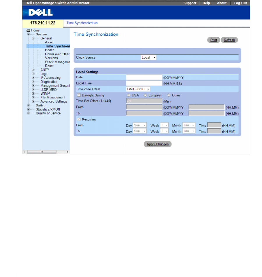
86 Configuring System Information
For more information on SNTP, see "Configuring SNTP Settings" on page 104.
To open the Time Synchronization page, click System → General → Time Synchronization in the
tree view.
Figure 6-3. Time Synchronization
The Time Synchronization page contains the following fields:
•
Clock Source
— The source used to set the system clock. The possible field values:
–
Local
— Specifies that the system time is not set by an external source.
–
SNTP
— Specifies that the system time is set via an SNTP server. For more information,
see "Configuring SNTP Settings" on page 104.
Local Settings
•
Date
— Defines the system date. The field format is DD/MMM/YY, for example, 04/May/07.
•
Local Time
— Defines the system time. The field format is HH:MM:SS, for example, 21:15:03.
•
Time Zone Offset
— The difference between Greenwich Mean Time (GMT) and local time.
For example, the Time Zone Offset for Paris is GMT +1:00, while the local time in New York is
GMT –5:00.

Configuring System Information 87
There are two types of daylight settings, either by a specific date in a particular year or a recurring setting
irrespective of the year. For a specific setting in a particular year complete the Daylight Savings area, and
for a recurring setting, complete the Recurring area.
•
Daylight Savings
— Enables the Daylight Savings Time (DST) on the device based on the device’s
location. The possible field values are:
–
USA
— The device switches to DST at 2 a.m. on the second Sunday of March, and reverts to
standard time at 2 a.m. on the first Sunday of November.
–
European
— The device switches to DST at 1:00 am on the last Sunday in March, and reverts to
standard time at 1:00 am on the last Sunday in October. The
European
option applies to
EU members, and other European countries using the EU standard.
–
Other
— The DST definitions are user-defined based on the device locality. If Other is selected,
the
From
and
To
fields must be defined.
•
Time Set Offset (1-1440)
— Indicates the difference in minutes between DST and the local
standard time. The default time is 60 minutes.
•
From
— Defines the time that DST begins in countries other than USA or Europe, in the format
DayMonthYear in one field and time in another. For example, DST begins on the 25th October 2007
5:00 am, the two fields will be 25Oct07 and 5:00. The possible field values are:
–
DD/MMM/YY
— The date , month, and year at which DST begins.
–
HH/MM
— The time (hour and minutes) at which DST begins. The field format is HH/MM,
for example, 05:30.
•
To
— Defines the time that DST ends in countries other than USA or Europe in the format
DayMonthYear in one field and time in another. For example, DST ends on the 23rd March 2008
12:00 am, the two fields will be 23Mar08 and 12:00. The possible field values are:
–
DD/MMM/YY
— The date , month, and year at which DST ends.
–
HH/MM
— The time (hour and minutes) at which DST ends. The field format is HH/MM,
for example, 05:30.
•
Recurring
— Defines the time that DST starts in countries other than USA or European where the
DST is constant year to year. The possible field values are:

88 Configuring System Information
•
From
— Defines the time that DST begins each year. For example, DST begins locally every second
Sunday in April at 5:00 am. The possible field values are:
–
Day
— The day of the week from which DST begins every year. The possible field range is
Sunday-Saturday.
–
Week
— The week within the month from which DST begins every year. The possible field
range is 1-5.
–
Month
— The month of the year in which DST begins every year. The possible field range is
Jan.-Dec.
–
Time
— The time at which DST begins every year. The field format is Hour:Minute,
for example, 02:10.
•
To
— Defines the recurring time that DST ends each year. For example, DST ends locally every fourth
Friday in October at 5:00 am. The possible field values are:
–
Day
— The day of the week at which DST ends every year. The possible field range is
Sunday-Saturday.
–
Week
— The week within the month at which DST ends every year. The possible field range is 1-5.
–
Month
— The month of the year in which DST ends every year. The possible field range is
Jan.-Dec.
–
Time
— The time at which DST ends every year. The field format is Hour:Minute,
for example, 05:30.
Selecting a Clock Source
1
Open the
Time Synchronization
page.
2
Define the
Clock Source
field.
3
Click
Apply Changes
.
The Clock source is selected, and the device is updated.
Defining Local Clock Settings
1
Open the
Time Synchronization
page.
2
Define the fields.
3
Click
Apply Changes
.
The local clock settings are applied.
Defining Clock Settings Using CLI Commands
The following table summarizes the equivalent CLI commands for setting fields displayed in the Time
Synchronization page.

Configuring System Information 89
The following steps must be completed before setting the summer clock:
1
Configure the summer time.
2
Define the time zone.
3
Set the clock.
For example:
Table 6-2. Clock Setting CLI Commands
The following is an example of the CLI commands:
console(config)# clock summer-time recurring usa
console(config)# clock time zone 2 zone TMZ2
console(config)# clock set 10:00:00 apr 15 2004
CLI Description
clock source sntp Configures an external time source for the system clock.
clock time zone hours-offset
[minutes minutes-
offset][zone acronym]
Sets the time zone for display purposes.
clock summer-time Configures the system to automatically switch to
summer time (Daylight Savings Time).
clock summer-time recurring
{usa
|
eu
|
week day
month hh:mm week day month
hh:mm
}
[offset
offset]
[zone
acronym]
Configures the system to automatically switch to
summer time (according to the USA and European
standards).
clock summer-time date date
month year hh:mm date
month year hh:mm [offset
offset] [zone acronym]
Configures the system to automatically switch to
summer time (Daylight Savings Time) for a specific
period - date/month/year format.
console(config)# clock timezone -6 zone CST
console(config)# clock summer-time recurring first sun apr 2:00
last sun oct 2:00
console(config)# clock source sntp
console(config)# interface ethernet e14
console(config-if)# sntp client enable
console(config-if)# exit
console(config)# sntp broadcast client enable
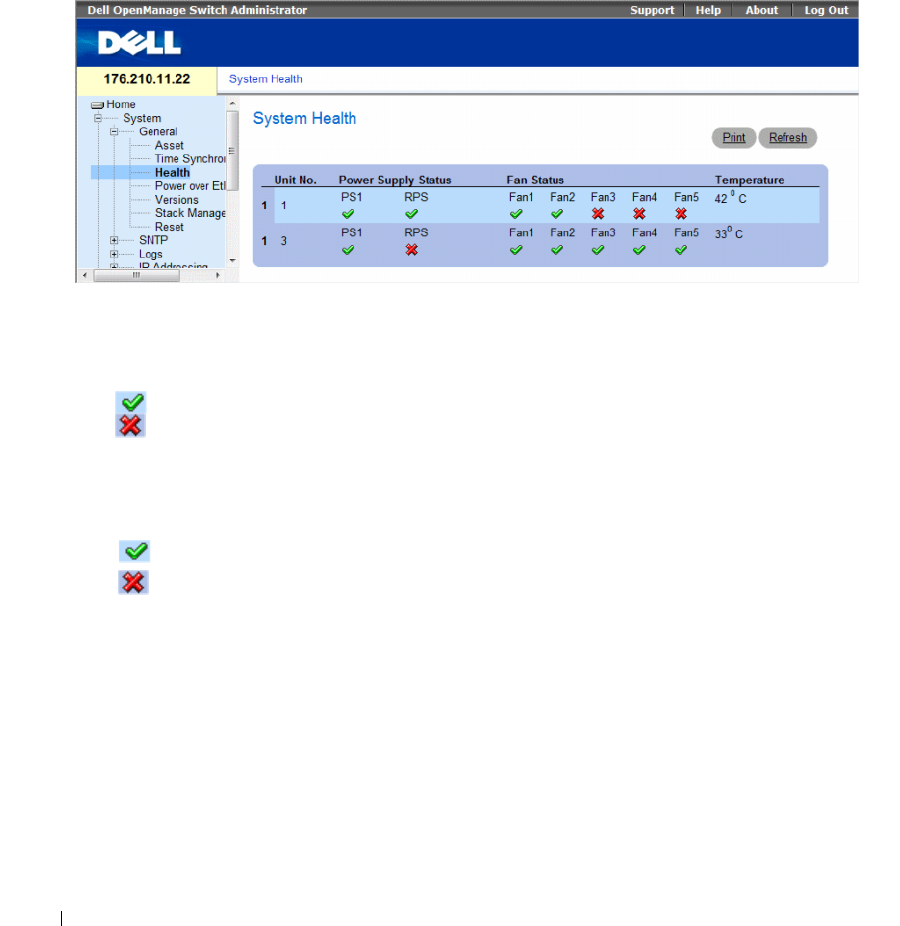
90 Configuring System Information
Viewing System Health Information
The System Health page displays physical device information, including information about the device’s
power and ventilation sources. To open the System Health page, click System→ General→ Health in the
tree view.
Figure 6-4. System Health
The System Health page contains the following fields:
•
Unit No.
— Indicates the unit number for which the device health information is displayed.
•
Power Supply Status
— The device has two power supplies. The possible field values are:
– Checked — The power supply is operating normally.
– Unchecked — The power supply is not operating normally.
–
Not Present
— The power supply is currently not present.
•
Fan Status
— The non-PoE devices have two fans, while the PoE devices have five fans. Each fan is
denoted as fan plus the fan number in the interface. The possible field values are:
– Checked — The fan is operating normally.
– Unchecked — The fan is not operating normally.
–
Not Present
— A fan is currently not present.
•
Temperature
— The temperature at which the device is currently running. The device temperature is
displayed in Celsius. The device temperature threshold is 0-40 C (32-104 F). The following table
displays the temperature in Fahrenheit in increments of 5.

Configuring System Information 91
Table 6-3. Celsius to Fahrenheit Conversion Table
Viewing System Health Information Using the CLI Commands
The following table summarizes the equivalent CLI commands for viewing fields displayed on the
System Health page.
The following is an example of the system health CLI command.
Celsius Fahrenheit
032
541
10 50
15 59
20 68
25 77
30 86
35 95
40 104
Table 6-4. System Health CLI Command
CLI Command Description
show system [unit
unit
]Displays system information.
console# show system
Unit Type
1 PowerConnect
3524
Unit Main Power
Supply
Redundant
Power
Supply
1OK

92 Configuring System Information
Managing Power over Ethernet
Power over Ethernet (PoE) provides power to devices over existing LAN cabling, without updating or
modifying the network infrastructure. Power over Ethernet removes the necessity of placing network
devices next to power sources.
Powered Devices are devices which receive power from the PowerConnect power supplies, for example
IP phones. Powered Devices are connected to the PowerConnect device via Ethernet ports. Powered
devices are connected via either all PowerConnect 3524P’s 24 FE ports or all PowerConnect 3548P’s
48 FE ports.
To open the Power Over Ethernet page. click System→ General→ Power over Ethernet in the tree view.
Fan1 Fan2 Fan3 Fan4 Fan5
1OK OK OK OK
Unit Temperature
(Celsius)
Temperature
Sensor
Status
127 OK
Unit Up time
1 00,09:30:36
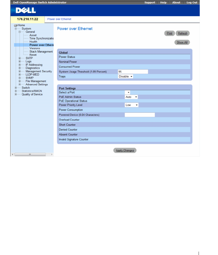
Configuring System Information 93
Figure 6-5. Power Over Ethernet
The Power Over Ethernet page contains the following sections:
• Global
• Port Settings

94 Configuring System Information
Global
The Power over Ethernet Global Settings section contains the following fields:
•
Power Status
— Indicates the inline power source status.
–
On
— Indicates that the power supply unit is functioning.
–
Off
— Indicates that the power supply unit is not functioning.
–
Faulty
— Indicates that the power supply unit is functioning, but an error has occurred.
For example, a power overload or a short circuit.
•
Nominal Power
— Indicates the actual amount of power the device can supply. The field value is
displayed in Watts.
•
Consumed Power
— Indicates the amount of the power used by the device. The field value is
displayed in Watts.
•
System Usage Threshold (1-99 Percent)
— Indicates the percentage of power consumed before an
alarm is generated. The field value is 1-99 percent. The default is 95 percent.
•
Traps
— Enables or disables receiving PoE device traps.
–
Enable
— Enables PoE traps on the device.
–
Disable
— Disables PoE traps on the device. This is the default value.
Port Settings
•
Select a Port
— Indicates the specific interface for which PoE parameters are defined and assigned to
the powered interface connected to the selected port.
•
PoE Admin Status
— Indicates the device PoE mode. The possible field values are:
–
Auto
— Enables the Device Discovery protocol, and provides power to the device using the PoE
module. The Device Discovery Protocol enables the device to discover Powered Devices attached
to the device interfaces, and to learn their classification. This is the default setting.
–
Never
— Disables the Device Discovery protocol, and stops the power supply to the device using
the PoE module.
•
PoE Operational Status
— Indicates if the port is enabled to work on PoE. The possible field values are:
– Disabled
—
–
Searching
— Indicates that the PowerConnect device is currently searching for a powered device.
Searching is the default PoE operational status.
–
Delevering Power
— Indicates that the PowerConnect device is delevering power.
–
Fault
— Indicates that the PowerConnect device has detected a fault on the powered device.
For example, the powered device memory could not be read.

Configuring System Information 95
– Test — Indicates the powered device is being tested. For example, a powered device is tested to
confirm it is receiving power from the power supply.
–Other Fault —
– Unknown —
•
Power Priority Level
— Determines the port priority if the power supply is low. The port power
priority is used if the power supply is low. The field default is low. For example, if the power supply
is running at 99% usage, and port 1 is prioritized as high, but port 3 is prioritized as low, port 1 is
prioritized to receive power, and port 3 may be denied power.
–
Critical
— Assigns the highest power priority level.
–
High
— Assigns the second highest power priority level.
–
Low
— Assigns the lowest power priority level.
•
Power Classification
— Indicates the powered device is classed according to the following
classification:
–
Class 0: 0.44 – 12.95
— Indicates that the port is assigned a power consumption level of .44 to
12.95 Watts.
–
Class 1: 0.44 – 3.8
— Indicates that the port is assigned a power consumption level of .44 to
3.8 Watts.
–
Class 2: 3.84 – 6.49
— Indicates that the port is assigned a power consumption level of 3.84 to
6.49 Watts.
–
Class 3: 6.49 – 12.95
— Indicates that the port is assigned a power consumption level of 6.49 to
12.95 Watts.
•
Powered Device (0-24 characters)
— Provides a user-defined powered device description. The field
can contain up to 24 characters.
•
Overload Counter
— Indicates the total power overload occurrences.
•
Short Counter
— Indicates the total power shortage occurrences.
•
Denied Counter
— Indicates times the powered device was denied power.
•
Absent Counter
— Indicates the times the power supply was stopped to the powered device because
the powered device was no longer detected.
•
Invalid Signature Counter
— Indicate the times an invalid signature was received. Signatures are
the means by which the powered device identifies itself to the PSE. Signatures are generated during
powered device detection, classification, or maintenance.
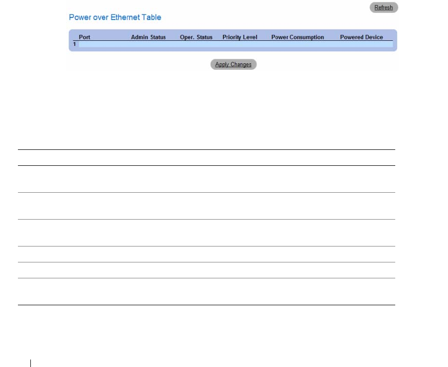
96 Configuring System Information
Defining PoE Settings
1
Open the
Power Over Ethernet
page.
2
Define the fields.
3
Click
Apply Changes
.
PoE settings are defined, and the device is updated.
Displaying PoE Settings for All Ports
1
Open the
Power Over Ethernet
page.
2
Click
Show All
.
The
Power Over Ethernet Table
opens.
Figure 6-6. Power Over Ethernet Table
Managing PoE Using the CLI Commands
The following table summarizes the equivalent CLI commands for viewing fields displayed on the Power
Over Ethernet page.
Table 6-5. System Health CLI Commands
CLI Command Description
power inline {auto | never} Configures the administrative mode of the inline power on
an interface.
power inline powered-device
pd-type
Adds a description of the powered device type.
power inline priority
{critical | high | low}
Configures the priority of the interface from the point of
view of inline power management.
power inline usage-threshold Configures the threshold for triggering alarms
power inline traps enable Enables PoE device traps
show power inline [
ethernet
interface
]
Displays PoE configuration information

Configuring System Information 97
The following is an example of the PoE CLI commands.
Console> enable
Console# show power inline
Unit Power Nominal Power Consumed Power Usage Threshold
1 On 370 Watts 0 Watts (0%) 95 Disable
2 Off 1 Watts 0 Watts (0%) 95 Disable
3 Off 1 Watts 0 Watts (0%) 95 Disable
4 Off 1 Watts 0 Watts (0%) 95 Disable
5 Off 1 Watts 0 Watts (0%) 95 Disable
6 Off 1 Watts 0 Watts (0%) 95 Disable
7 Off 1 Watts 0 Watts (0%) 95 Disable
8 Off 1 Watts 0 Watts (0%) 95 Disable
Port Powered Device State Status Prior
ity
Class
1/e1 Auto Searching low class0
1/e2 Auto Searching low class0
1/e3 Auto Searching low class0
1/e4 Auto Searching low class0
1/e5 Auto Searching low class0
1/e6 Auto Searching low class0
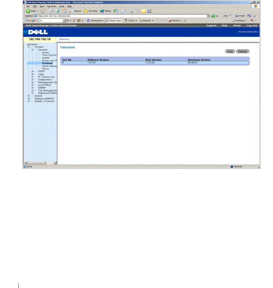
98 Configuring System Information
Viewing Version Information
The Versions page contains information about the hardware and software versions currently running.
To open the Versions page, click System → General → Versions in the tree view.
Figure 6-7. Versions
The Versions page contains the following fields:
•
Unit No.
— Indicates the unit number for which the device versions are displayed.
•
Software Version
— The current software version running on the device.
•
Boot Version
— The current Boot version running on the device.
•
Hardware Version
— The current device hardware version.
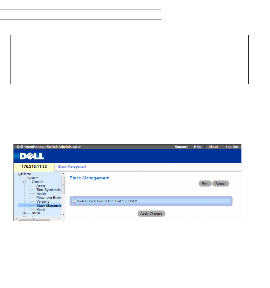
Configuring System Information 99
Displaying Device Versions Using the CLI
The following table summarizes the equivalent CLI commands for viewing fields displayed in the
Versions page.
The following is an example of the CLI commands:
Managing Stack Members
The Stack Management page allows network managers to switch stack control between unit 1 and unit 2
in the stack. To open the Stack Management page, click System → General → Stack Management in the
tree view.
Figure 6-8. Stack Management
•
Switch Stack Control from Unit 1 to Unit 2
— Enables switching from the current stack Master to the
backup Master unit.
Table 6-6. Versions CLI Commands
CLI Command Description
show version Displays system version information.
console> show version
Unit SW version Boot version HW version
------------------- ------------------- ------------------- -----
1 1.0.0.8 1.0.0.02 00.00.01
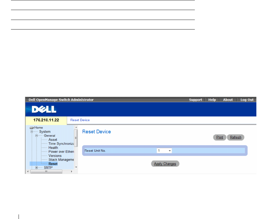
100 Configuring System Information
Switching Between Stack Masters
1
Open the
Stack Management
page.
2
Check the
Switch Stack Control from Unit 1 to Unit 2
check box.
3
Click
Apply Changes
.
A confirmation message displays.
4
Click
OK
.
The device is reset. After the device is reset, a prompt for a user name and password displays.
Managing Stacks Using the CLI Commands
The following table summarizes the equivalent CLI commands for viewing fields displayed in the Stack
Management page.
Resetting the Device
The Reset page enables the device to be reset from a remote location. Save all changes to the Startup
Configuration file before resetting the device. This prevents the current device configuration from being
lost. For more information about saving Configuration files, see "Copy Files" on page 239. To open the
Reset page, click System → General → Reset in the tree view.
Figure 6-9. Reset
The Reset page contains the following field:
Reset Unit No. — Resets the selected stacking member.
Table 6-7. Stack Management CLI Commands
CLI Command Description
stack reload Reloads stack members.
stack master Forces the stack master selection

Configuring System Information 101
Resetting the Device
1
Open the
Reset
page.
2
Select a unit in the
Reset Unit Number
field.
3
Click
Apply Changes.
A confirmation message displays.
4
Click
OK
.
The device is reset. After the device is reset, a prompt for a user name and password is displayed.
5
Enter a user name and password to reconnect to the Web Interface.
Resetting the Device Using the CLI
The following table summarizes the equivalent CLI commands for performing a reset of the device via
the CLI:
The following is an example of the CLI command:
Configuring SNTP Settings
The switch supports the Simple Network Time Protocol (SNTP). SNTP assures accurate network switch
clock time synchronization up to the millisecond. Time synchronization is performed by a network
SNTP server. SNTP operates only as a client, and cannot provide time services to other systems.
The switch can poll the following server types for the server time:
•Unicast
•Anycast
• Broadcast
Table 6-8. Reset CLI Command
CLI Command Description
reload Reloads the device.
console# reload
You haven't saved your changes. Are you sure you want to
continue? (Y/N)[N] Y
This command will reset the whole system and disconnect your
current session. Do you want to continue ? (Y/N)[N] Y

102 Configuring System Information
Time sources are established by Stratums. Stratums define the accuracy of the reference clock.
The higher the stratum (where zero is the highest), the more accurate the clock. The switch receives
time from stratum 1 and above. The following is an example of stratums:
•
Stratum 0
— Indicates a real time clock is used as the time source, for example, a GPS system.
•
Stratum 1
— Indicates that a server that is directly linked to a Stratum 0 time source is used.
Stratum 1 time servers provide primary network time standards.
•
Stratum 2
— Indicates that the time source is distanced from the Stratum 1 server over a
network path. For example, a Stratum 2 server receives the time over a network link, via NTP,
from a Stratum 1 server.
Information received from SNTP servers is evaluated based on the Time level and server type.
SNTP time definitions are assessed and determined by the following time levels:
•
T1
— The time at which the original request was sent by the client.
•
T2
— The time at which the original request was received by the server.
•
T3
— The time at which the server sent the client a reply.
•
T4
— The time at which the client received the server's reply.
The device can poll the following server types for the server time: Unicast, Anycast and Broadcast.
Polling for Unicast information is used for polling a server for which the IP address is known.
SNTP servers that are configured on the device are the only ones that are polled for synchronization
information. T1-T4 are used to determine server time. This is the preferred method for synchronizing
device time as it is most secure. If this method is selected, SNTP information is accepted only from
SNTP servers defined on the device using the SNTP Servers page.
Polling for Anycast information is used when the server IP address is unknown. If this method is selected,
all SNTP servers on the network can send synchronization information . The device is synchronized
when it proactively requests synchronization information. The best response (lowest stratum) from the
first 3 SNTP servers to respond to a request for synchronization information is used to set the time value.
Time levels T3 and T4 are used to determine the server time.
Using Anycast polling to get time information for synchronizing device time is preferred to using
Broadcast polling to get time information. However, this method is less secure than unicast polling,
because SNTP packets are accepted from SNTP servers that are not configured on the device.
Broadcast information is used when the server IP address is unknown. When a Broadcast message is
sent from an SNTP server, the SNTP client listens to the message. If Broadcast polling is enabled,
any synchronization information is accepted, even if it has not been requested by the device. This is the
least secure method.
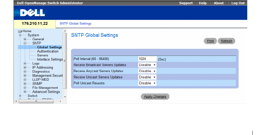
Configuring System Information 103
The device retrieves synchronization information, either by actively requesting information or at every poll
interval. If Unicast, Anycast and Broadcast polling are enabled, the information is retrieved in this order:
• Information from servers defined on the device is preferred. If Unicast polling is not enabled or if no servers
are defined on the device, the device accepts time information from any SNTP server that responds.
• If more than one Unicast device responds, synchronization information is preferred from the device
with the lowest stratum.
• If the servers have the same stratum, synchronization information is accepted from the SNTP server
that responded first.
MD5 (Message Digest 5) Authentication safeguards device synchronization paths to SNTP servers. MD5
is an algorithm that produces a 128-bit hash. MD5 is a variation of MD4, and increases MD4 security.
MD5 verifies the integrity of the communication, authenticates the origin of the communication.
To open the SNTP page, click System → SNTP in the tree view to open the SNTP page.
This section contians the following topics:
• "Defining SNTP Global Settings" on page 103
• "Defining SNTP Authentication Methods" on page 105
• "Defining SNTP Servers" on page 107
• "Defining SNTP Interfaces" on page 111
Defining SNTP Global Settings
The SNTP Global Settings page provides information for defining SNTP parameters globally. To open
the SNTP Global Settings page, click System → SNTP → Global Settings in the tree view.
Figure 6-10. SNTP Global Settings

104 Configuring System Information
The SNTP Global Settings page contains the following fields:
•
Poll Interval (60-86400)
— Defines the interval (in seconds) at which the SNTP server is polled for
Unicast information. By default, the poll interval is 1024 seconds.
•
Receive Broadcast Servers Updates
— Listens to the SNTP servers for Broadcast server time
information on the selected interfaces, when enabled.
•
Receive Anycast Servers Updates
— Polls the SNTP server for Anycast server time information,
when enabled. If both the
Receive Anycast Servers Update
, and the
Receive Broadcast Servers Update
fields are enabled, the system time is set according the Anycast server time information.
•
Receive Unicast Servers Updates
— Polls the SNTP server for Unicast server time information,
when enabled. If the
Receive Broadcast Servers Updates
,
Receive Anycast Servers Updates
, and the
Receive Unicast Servers Updates
fields are all enabled, the system time is set according the Unicast
server time information.
•
Poll Unicast Requests
— Sends SNTP Unicast server time information requests to the SNTP server,
when enabled.
Defining SNTP Global Settings
1
Open the
SNTP Global Settings
page.
2
Define the fields.
3
Click
Apply Changes
.
The SNTP configuration changes are applied.
Defining SNTP Global Settings Using CLI Commands
The following table summarizes the equivalent CLI commands for setting fields displayed in the SNTP
Global Settings page.
The following is an example of the CLI commands:
Table 6-9. SNTP Global Parameters CLI Commands
CLI Command Description
sntp broadcast client enable Enables SNTP broadcast clients
sntp anycast client enable Enables SNTP anycast clients
sntp unicast client enable Enables SNTP predefined unicast clients
console(config)# sntp anycast client enable
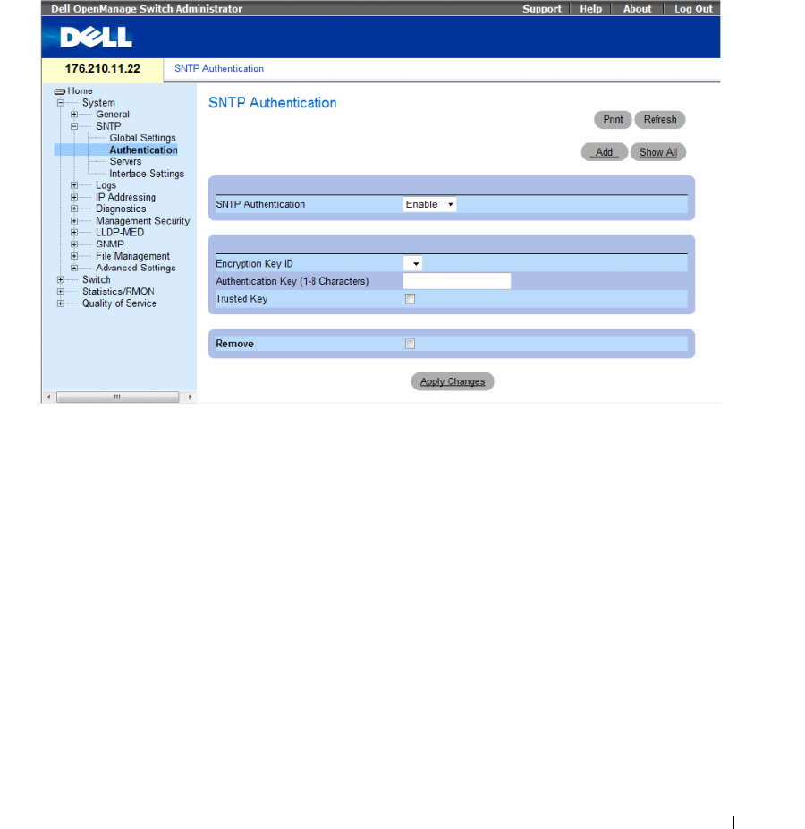
Configuring System Information 105
Defining SNTP Authentication Methods
The SNTP Authentication page enables SNTP authentication between the device and an SNTP server.
The means by which the SNTP server is authenticated is also selected in the SNTP Authentication page.
Click System → SNTP → Authentication in the tree view to open the SNTP Authentication page.
Figure 6-11. SNTP Authentication
The SNTP Authentication page contains the following:
•
SNTP Authentication
— Enables or disables authenticating an SNTP session between the device and
an SNTP server.
–
Enable
— Authenticates SNTP sessions between the device and SNTP server.
–
Disable
— Disables authenticating SNTP sessions between the device and SNTP server.
•
Encryption Key ID
— Defines the Key Identification used to authenticate the SNTP server and
device. The field value is up to 4294967295.
•
Authentication Key (up to 8 Characters)
— The key used for authentication.
•
Trusted Key
—
Indicates if the encryption key is used (Unicast) to authenticate the SNTP server.
–
Checked —
Encryption key is used.
–
Unchecked
—
Encryption key is not used.
•
Remove
— Removes selected authentication keys.
–
Checked —
Removes the selected Encryption Key ID.
–
Unchecked
—
Maintains the Encryption Key IDs. This is the default value.
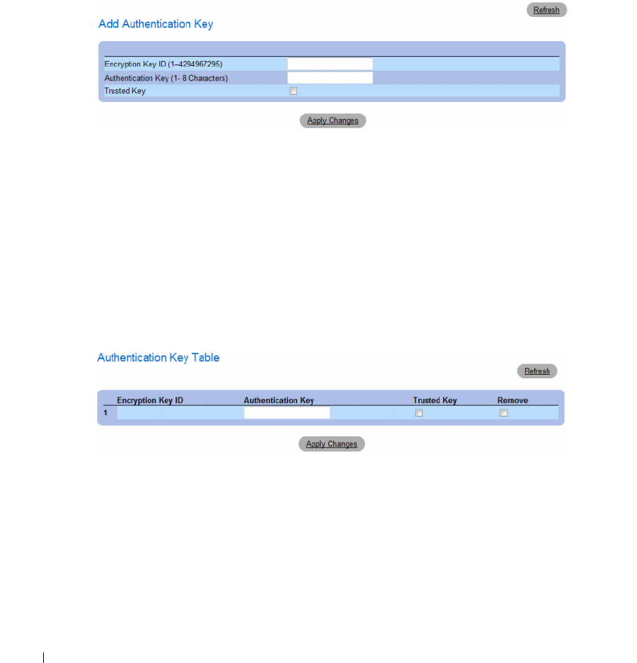
106 Configuring System Information
Adding an SNTP Authentication Key
1
Open the
SNTP Authentication
page.
2
Click
Add
.
The
Add Authentication Key
page opens.
Figure 6-12. Add Authentication Key
3
Define the
fields.
4
Click
Apply Changes
.
The SNMP authentication key is added, and the device is updated.
Displaying the Authentication Key Table
1
Open the
SNTP Authentication
page.
2
Click
Show
All
.
The
Authentication Key Table
opens.
Figure 6-13. Authentication Key Table

Configuring System Information 107
Deleting the Authentication Key
1
Open the
SNTP Authentication
page.
2
Click
Show
All
.
The
Authentication Key Table
opens.
3
Select an
Authentication Key Table
entry.
4
Select the
Remove
check box.
5
Click
Apply Changes
.
The entry is removed, and the device is updated.
Defining SNTP Authentication Settings Using CLI Commands
The following table summarizes the equivalent CLI commands for setting fields displayed in the SNTP
Authentication page.
The following is an example of the CLI commands:
Defining SNTP Servers
You can enable SNTP servers, as well as add new SNTP servers, from the SNTP Servers page. To open
the SNTP Servers page, click System → SNTP → Servers in the tree view.
Table 6-10. SNTP Authentication CLI Commands
CLI Command Description
sntp authenticate Defines authentication for received Simple Network
Time Protocol (SNTP) traffic from servers.
sntp trusted key Authenticates the identity of a system to which
SNTP will synchronize.
sntp authentication-key number
md5 value
Defines an authentication key for SNTP.
console(config)# sntp authentication-key 8 md5 Calked
console(config)# sntp trusted-key 8
Console(config)# sntp authenticate
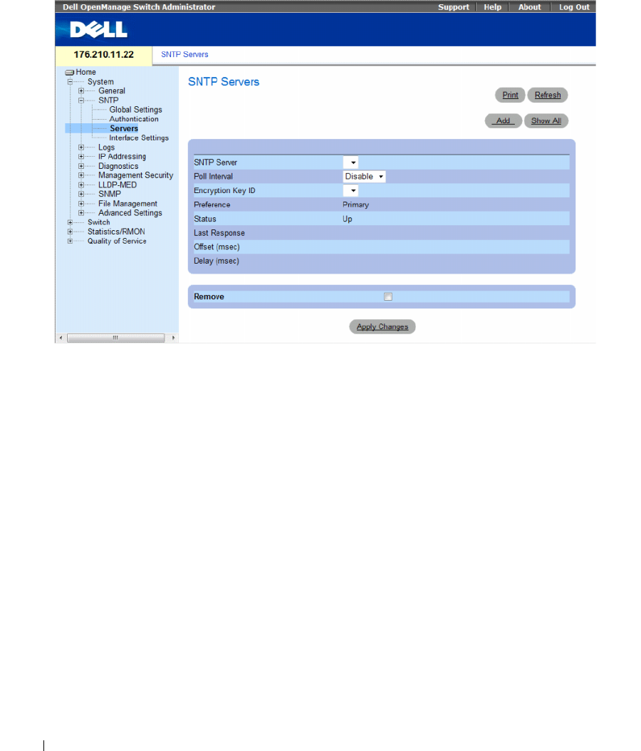
108 Configuring System Information
Figure 6-14. SNTP Servers
The SNTP Servers page contains the following fields:
•
SNTP Server
— Select a user-defined SNTP server IP address. Up to eight SNTP servers can
be defined.
•
Poll Interval
— Polls the selected SNTP Server for system time information, when enabled.
•
Encryption Key ID
— Indicates the Key Identification used to communicate between the SNTP
server and device. The range is 1 - 4294967295.
•
Preference
— The SNTP server providing SNTP system time information. The possible field values are:
–
Primary
— The primary server provides SNTP information.
–
Secondary
— The backup server provides SNTP information.
•
Status
— The operating SNTP server status. The possible field values are:
–
Up
— The SNTP server is currently operating normally.
–
Down
— Indicates that a SNTP server is currently not available. For example, the SNTP server is
currently not connected or is currently down.
–
In progress
— The SNTP server is currently sending or receiving SNTP information.
–
Unknown
— The progress of the SNTP information currently being sent is unknown.
For example, the device is currently looking for an interface.
•
Last Response
— The last time a response was received from the SNTP server.
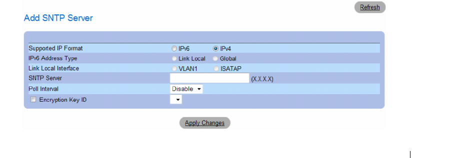
Configuring System Information 109
•
Offset (msec)
—
Timestamp difference between the device local clock and the acquired time from
the SNTP server.
•
Delay (msec)
— The amount of time it takes to reach the SNTP server.
•
Remove
— Removes a specific SNTP server from the
SNTP Servers
list.
–
Checked —
Removes the selected SNTP server.
–
Unchecked
—
Maintains the SNTP server in the configuration. This is the default value.
When adding an SNTP Server, the following additional parameters are available:
•
Supported IP Format
— Specifies the IP format supported by the SNTP server. The possible values are:
–
IPv6
— IP version 6 is supported.
–
IPv4
— IP version 4 is supported.
•
IPv6 Address Type
— When the server supports IPv6 (see previous parameter), this specifies the type
of static address supported. The possible values are:
–
Link Local
— A Link Local address that is non-routable and used for communication on the same
network only.
–
Global
— A globally unique IPv6 address; visible and reachable from different subnets.
•
Link Local Interface
— When the server supports an IPv6 Link Local address (see previous
parameter), this specifies the the Link Local interface. The possible values are:
–
VLAN1
— The IPv6 interface is configured on VLAN1.
–
ISATAP
— The IPv6 interface is configured on ISATAP tunnel.
Adding an SNTP Server
1
Open the
SNTP Servers
page.
2
Click
Add.
The
Add SNTP Server
page opens.
Figure 6-15. Add SNTP Server
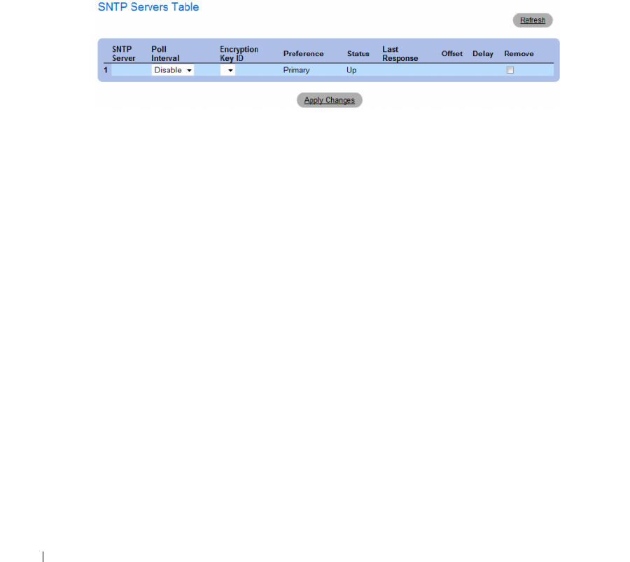
110 Configuring System Information
3
Define the
fields.
4
Click
Apply Changes
.
The SNTP Server is added, and the device is updated.
Displaying the SNTP Server Table
1
Open the
SNTP Servers
page.
2
Click
Show All.
The
SNTP Servers Table
opens.
Figure 6-16. SNTP Servers Table
Modifying an SNTP Server
1
Open the
SNTP Servers
page.
2
Click
Show All.
The
SNTP Servers Table
opens.
3
Select an SNTP Server entry.
4
Modify the
relevant fields.
5
Click
Apply Changes
.
The SNTP Server information is updated.
Deleting the SNTP Server
1
Open the
SNTP Servers
page.
2
Click
Show
All.
The
SNTP Servers Table
opens.
3
Select an
SNTP Server
entry.
4
Select the
Remove
check box.
5
Click
Apply Changes
.
The entry is removed, and the device is updated.
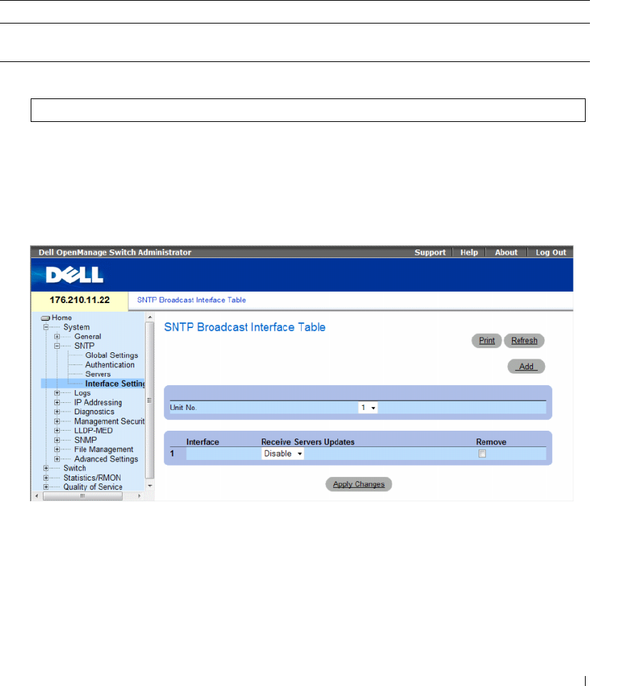
Configuring System Information 111
Defining SNTP Servers Settings Using CLI Commands
The following table summarizes the equivalent CLI commands for setting fields displayed in the SNTP
Server page.
The following is an example of the CLI commands:
Defining SNTP Interfaces
The SNTP Broadcast Interface Table page contains SNTP interface information. To open the SNTP
Broadcast Interface Table page, click System → SNTP → Interface Settings.
Figure 6-17. SNTP Broadcast Interface Table
Table 6-11. SNTP Server CLI Commands
CLI Command Description
sntp server ipv4-address|ipv6-
address|hostname [poll] [key keyid]
Configures the device to use SNTP to request and accept SNTP
traffic from a server.
Console(config)# sntp server 100.1.1.1 poll key 10
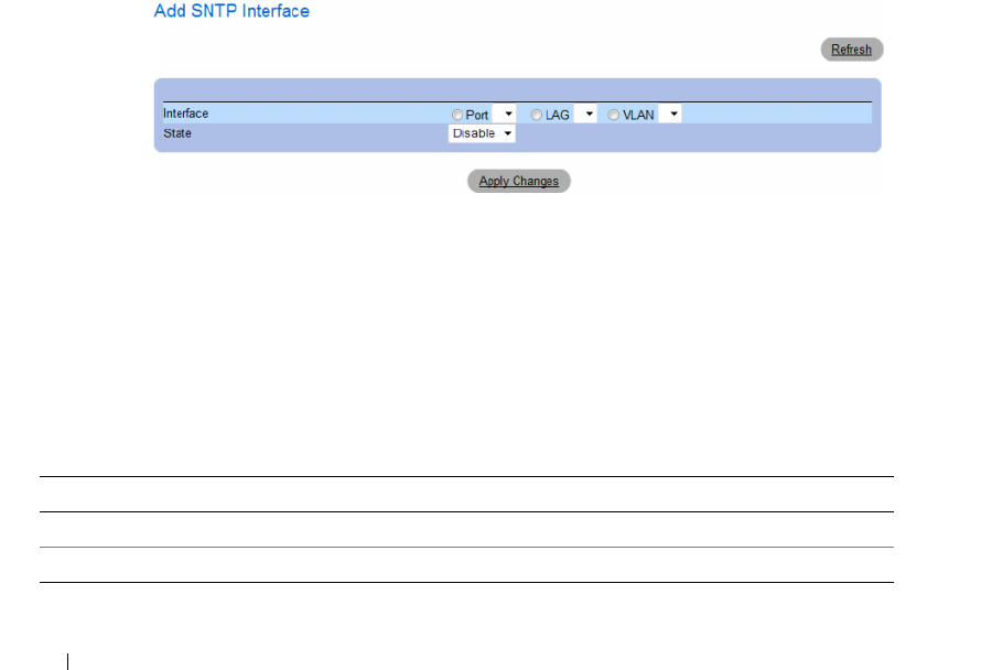
112 Configuring System Information
The SNTP Broadcast Interface Table page contains the following fields:
•
Unit No.
— Indicates the stacking member on which the SNTP interface is enabled.
Interface — Contains an interface list on which SNTP can be enabled:
•
Receive Servers Updates
— Enables or disables SNTP on the specific interface.
–
Enable
— Enables the interface to receive updates from the SNTP server.
–
Disable
— Interface does not receive updates from the SNTP server.
•
Remove
— Removes SNTP from a specific interface, when selected.
–
Checked
— Removes the SNTP interface entry.
–
Unchecked
— Maintains the SNTP interface entry.
Adding an SNTP Interface
1
Open the
SNTP Broadcast Interface Table
page.
2
Click
Add.
The
Add SNTP Interface
page opens.
Figure 6-18. Add SNTP Interface
3
Define the relevant fields.
4
Click
Apply Changes
.
The SNTP interface is added, and the device is updated.
Defining SNTP Interface Settings Using CLI Commands
The following table summarizes the equivalent CLI commands for setting fields displayed in the SNTP
Broadcast Interface Table page.
Table 6-12. SNTP Interface Settings CLI Commands
CLI Command Description
sntp client enable Enables the Simple Network Time Protocol (SNTP) client on an interface.
show sntp configuration Shows the configuration of the Simple Network Time Protocol (SNTP).

Configuring System Information 113
The following is an example of the CLI commands for displaying SNTP interfaces:
Managing Logs
The Logs page contains links to various log pages. To open the Logs page, click System → Logs in the tree
view.
This section contians the following topics:
• "Defining Global Log Parameters" on page 114
• "Viewing the RAM Log Table" on page 118
• "Viewing the Log File Table" on page 120
• "Viewing the Device Login History" on page 121
• "Modifying Remote Log Server Definitions" on page 123
console# show sntp configuration
Polling interval: 7200 seconds.
MD5 Authentication keys: 8, 9
Authentication is required for synchronization.
Trusted Keys: 8,9
Unicast Clients Polling: Enabled.
Server Polling Encryption Key
----------- -------- ---------------
176.1.1.8 Enabled 9
176.1.8.179 Disabled Disabled
Broadcast Clients: Enabled
Broadcast Clients Poll: Enabled
Broadcast Interfaces:1/e1, 1/e3

114 Configuring System Information
Defining Global Log Parameters
The System Logs enable viewing device events in real time, and recording the events for later usage.
System Logs record and manage events and report errors or informational messages.
Event messages have a unique format, as per the System Logs protocol recommended message format
for all error reporting. For example, Syslog and local device reporting messages are assigned a severity
code, and include a message mnemonic, which identifies the source application generating the message.
It allows messages to be filtered based on their urgency or relevancy. The distribution of logging messages
to the various destinations, such as the logging buffer, logging file or Syslog server, is controlled by the
Syslog configuration parameters. Users can define up-to eight Syslog servers.
The following are the Log Severity Levels:
•
Emergency
— The highest warning level. If the device is down or not functioning properly,
an emergency log message is saved to the specified logging location.
•
Alert
— The second highest warning level. An alert log is saved if there is a serious device malfunction,
for example, all device features are down.
•
Critical
— The third highest warning level. A critical log is saved if a critical device malfunction
occurs, for example, two device ports are not functioning, while the rest of the device ports
remain functional.
•
Error
— A device error has occurred, for example, if a single port is offline.
•
Warning
— The lowest level of a device warning. The device is functioning, but an operational
problem has occurred.
•
Notice
— Provides device information.
•
Informational
— Provides device information.
•
Debug
— Provides debugging messages.
Table 6-13. Log Severity Levels
Severity Type Severity Level Description
Emergency 0 The system is not functioning.
Alert 1 The system needs immediate attention.
Critical 2 The system is in a critical state.
Error 3 A system error has occurred.
Warning 4 A system warning has occurred.
Notice 5 The system is functioning properly, but system notice has occurred.
Informational 6 Provides device information.
Debug 7 Provides detailed information about the log. If a Debug error occurs,
contact Dell Online Technical Support.
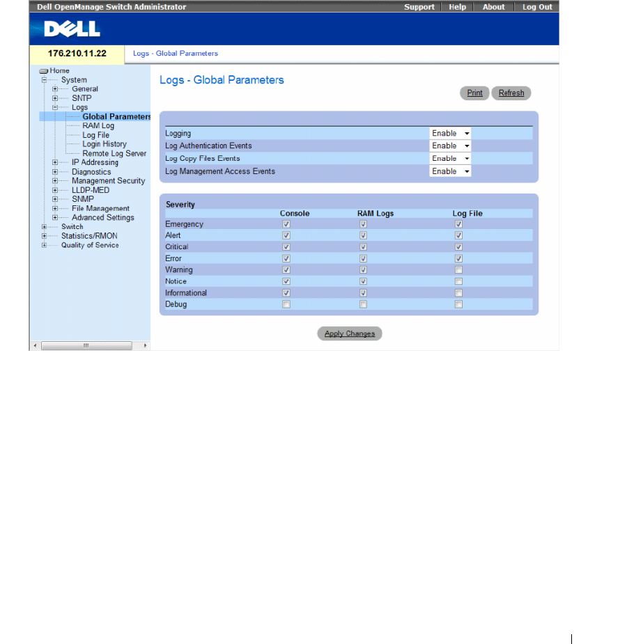
Configuring System Information 115
The Logs - Global Parameters page contains fields for defining which events are recorded to which logs.
It contains fields for enabling logs globally, and fields for defining log parameters. The Severity log
messages are listed from the highest severity to the lowest.
To open the Logs - Global Parameters page, click System → Logs → Global Parameters in the tree view.
Figure 6-19. Logs - Global Parameters
The Logs - Global Parameters page contains the following parameters:
•
Logging
— Enables or disables device global logs for Cache, File, and Server Logs. Console logs are
enabled by default.
•
Log Authentication Events
— Enables or disables generating logs when users are authenticated.
•
Log Copy Files Events
— Enables or disables generating logs when files are copied.

116 Configuring System Information
•
Log Management Access Events
— Enables or disables generating logs when the device is accessed
using a management method. For example, each time the device is accessed using SSH, a device log is
generated.
•
Severity
— Displays the severity logs. The following are the severity log levels. When a severity level is
selected, all severity level choices above the selection are selected automatically.
–
Emergency
— The highest warning level. If the device is down or not functioning properly,
an emergency log message is saved to the specified logging location.
–
Alert
— The second highest warning level. An alert log is saved if there is a serious device
malfunction, for example, an attempt was made to download a non-existing configuration file.
–
Critical
— The third highest warning level. A critical log is saved if a critical device malfunction
occurs, for example, two device ports are not functioning, while the rest of the device ports remain
functional.
–
Error
— A device error has occurred, for example, a copy operation has failed.
–
Warning
— The lowest level of a device warning. For example, the device is functioning, but a port
link is currently down.
–
Notice
— Provides important device information.
–
Informational
— Provides device information. For example, a port is currently up.
–
Debug
— Provides debugging messages.
The Global Log Parameters page also contains check boxes which correspond to a distinct
logging system:
•
Console
— The minimum severity level from which logs are sent to the console.
•
RAM Logs
— The minimum severity level from which logs are sent to the Log File kept in
RAM (Cache).
•
Log File
— The minimum severity level from which logs are sent to the Log File kept in
FLASH memory.
Enabling Logs
1
Open the
Global Log Parameters page
.
2
Select
Enable
in the
Logging
drop-down list.
3
Select the log type and log severity in the
Global Log Parameters
check boxes.
4
Click
Apply Changes.
The log settings are saved, and the device is updated.
Enabling Logs Using CLI Commands
The following table summarizes the equivalent CLI commands for setting fields displayed in the Global
Log Parameters page.

Configuring System Information 117
The following is an example of the CLI commands:
Table 6-14. Global Log Parameters CLI Commands
CLI Command Description
logging on Enables error message logging.
logging {ipv4-address | ipv6-address | hostname}
[port port] [severity level] [facility facility]
[description text]
Logs messages to a syslog server. For a list of the Severity levels,
see "Log Severity Levels" on page 117.
logging console level Limits messages logged to the console based on severity.
logging buffered level Limits syslog messages displayed from an internal buffer
(RAM) based on severity.
logging file level Limits syslog messages sent to the logging file based on
severity.
clear logging Clears logs.
clear logging file Clears messages from the logging file.
show syslog servers Displays the syslog servers settings.
console(config)# logging on
console(config)# logging console errors
console(config)# logging buffered debugging
console(config)# logging file alerts
console(config)# end
console# clear logging file
Clear Logging File [y/n]y
Console# show syslog-servers
Device Configuration
-----------------------------
IP address Port facility Severity Description
---------- ---- -------- -------- -----------
1.1.1.1 514 local7 info
fe80::11%vlan1 514 local7 info
3211::22 514 local7 info
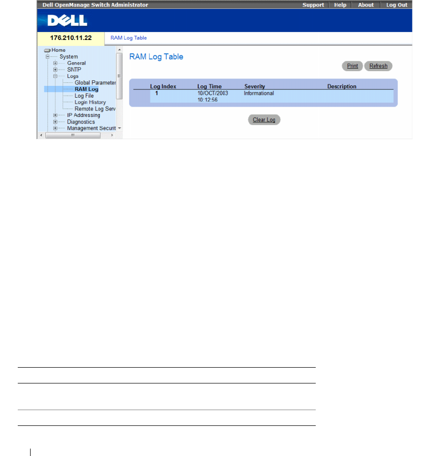
118 Configuring System Information
Viewing the RAM Log Table
The RAM Log Table contains information about log entries kept in RAM, including the time the log was
entered, the log severity, and a description of the log. To open the RAM Log Table, click System → Logs
→ RAM Log in the tree view.
Figure 6-20. RAM Log Table
The RAM Log Table contains the following fields:
•
Log Index
— The log number in the
RAM Log Table
.
•
Log Time
— Indicates the time at which the log was entered into the
RAM Log Table
.
•
Severity
— Indicates the log severity.
•
Description
— Description of the log entry.
Removing Log Information:
1
Open the
RAM Log Table
.
2
Click
Clear Log
.
The log information is removed from the
RAM Log Table
, and the device is updated.
Viewing and Clearing the RAM Log Table Using the CLI Commands
The following table summarizes the equivalent CLI commands for viewing and clearing fields displayed
in the RAM Log Table.
Table 6-15. RAM Log Table CLI Commands
CLI Command Description
show logging Displays the state of logging and the syslog
messages stored in the internal buffer.
clear logging Clears logs.

Configuring System Information 119
The following is an example of the CLI commands:
console# show logging
Logging is enabled.
Console Logging: Level info. Console Messages: 0 Dropped.
Buffer Logging: Level info. Buffer Messages: 124 Logged, 124
Displayed, 200 Max.
File Logging: Level error. File Messages: 164 Logged, 126
Dropped.
3 messages were not logged
Application filtering control
Application Event Status
AAA Login Enabled
File system Copy Enabled
File system Delete-Rename Enabled
Management ACL Deny Enabled
01-Jan-2000 09:23:34 :%Box-I-PS-STAT-CHNG: PS# 1 status is -
operational.
01-Jan-2000 09:23:29 :%Box-W-PS-STAT-CHNG: PS# 1 status is - not
operational.
01-Jan-2000 09:22:44 :%Box-I-PS-STAT-CHNG: PS# 1 status is -
operational.
01-Jan-2000 09:22:39 :%Box-W-PS-STAT-CHNG: PS# 1 status is - not
operational.
01-Jan-2000 09:10:34 :%Box-I-PS-STAT-CHNG: PS# 1 status is -
operational.
01-Jan-2000 09:10:29 :%Box-W-PS-STAT-CHNG: PS# 1 status is - not
operational.
01-Jan-2000 09:09:16 :%AAA-I-CONNECT: New http connection for
user admin, source 192.168.102.5 destination 192.168.102.15
ACCEPTED
01-Jan-2000 08:39:49 :%Box-I-PS-STAT-CHNG: PS# 1 status is -
operational.
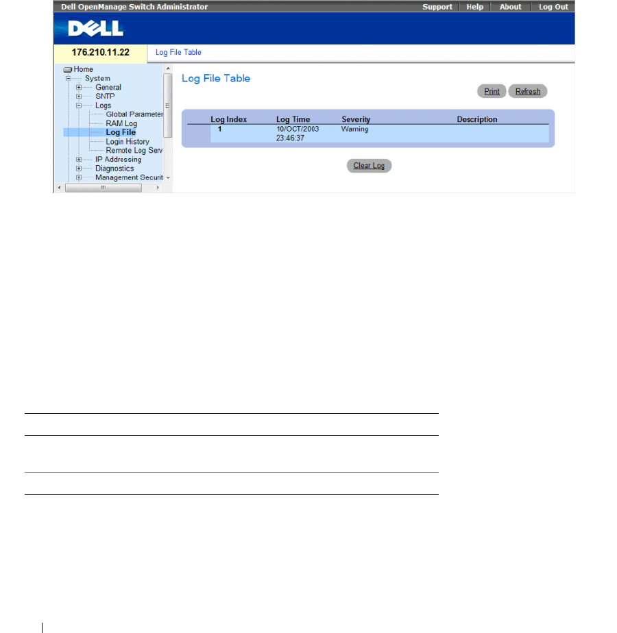
120 Configuring System Information
Viewing the Log File Table
The Log File Table contains information about log entries saved to the Log File in FLASH, including
the time the log was entered, the log severity, and a description of the log message. To open the Log File
Table, click System → Logs → Log File in the tree view.
Figure 6-21. Log File Table
The Log File Table contains the following fields:
•
Log Index
— The log number in the
Log File Table
.
•
Log Time
— Indicates the time at which the log was entered in the
Log File Table
.
•
Severity
— Indicates the log severity.
•
Description
— The log message text.
Displaying the Log File Table Using the CLI Commands
The following table summarizes the equivalent CLI commands for viewing and setting fields displayed
in the Log File Table.
Table 6-16. Log File Table CLI Commands
CLI Command Description
show logging file Displays the logging state and the syslog
messages stored in the logging file.
clear logging file Clears messages from the logging file.

Configuring System Information 121
The following is an example of the CLI commands:
Viewing the Device Login History
The Login History page contains information for viewing and monitoring device utilization, including
the time the user logged in and the protocol used to log on to the device.
To open the Login History page, click System→ Logs→ Login History in the tree view.
console# show logging file
Logging is enabled.
Console Logging: Level info. Console Messages: 0 Dropped.
Buffer Logging: Level info. Buffer Messages: 62 Logged, 62
Displayed, 200 Max.
File Logging: Level debug. File Messages: 11 Logged, 51
Dropped.
SysLog server 12.1.1.2 Logging: warning. Messages: 14
Dropped.
SysLog server 1.1.1.1 Logging: info. Messages: 0 Dropped.
01-Jan-2000 01:12:01 :%COPY-W-TRAP: The copy operation was
completed successfully
01-Jan-2000 01:11:49 :%LINK-I-Up: 1/e11
01-Jan-2000 01:11:46 :%LINK-I-Up: 1/e12
01-Jan-2000 01:11:42 :%LINK-W-Down: 1/e13
01-Jan-2000 01:11:35 :%LINK-I-Up: 1/e14
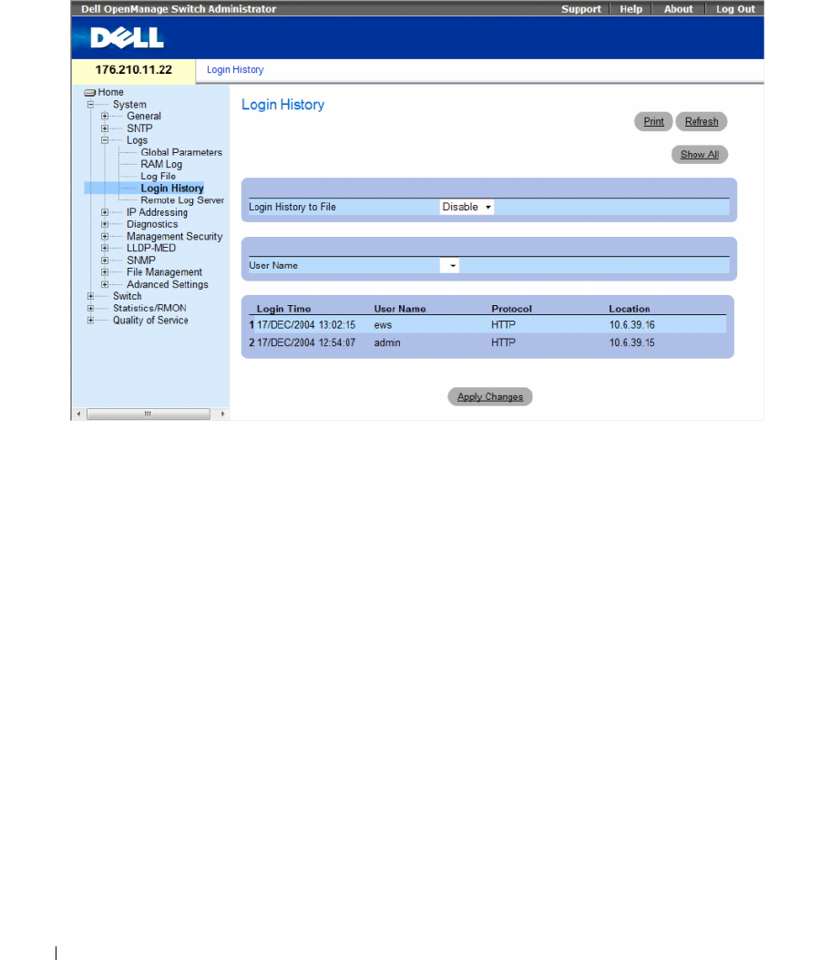
122 Configuring System Information
Figure 6-22. Login History
The Login History page contains the following fields:
•
User Name
— Contains a user-defined device user name list.
•
Login History
— Indicates if the Login History logs are enabled.
•
Login Time
— Indicates the time the selected user logged on to the device.
•
User Name
— Indicates the user that logged on to the device.
•
Protocol
— Indicates the means by which the user logged on to the device.
•
Location
— Indicates the IP address of the station from which the device was accessed.
Viewing Login History
1
Open the
Login History
page.
2
Select a user in the
User Name
field.
3
Click
Apply Changes
.
The login information for the selected user is displayed.

Configuring System Information 123
Displaying the Device Login History Using CLI Commands
The following table summarizes the equivalent CLI commands for viewing and setting fields displayed
in the Login History page.
The following is an example of the CLI commands:
Modifying Remote Log Server Definitions
The Remote Log Server Settings page contains fields for viewing and configuring the available Log
Servers. In addition, new log servers can be defined, and the log severity sent to each server.
The event severity levels are listed on this page in descending order from the highest severity to the lowest.
When a severity level is selected to appear in a log, all higher severity events are automatically selected to
appear in the log. When a security level is not selected, no lower severity events appear in the log.
For example, if Warning is selected, all severity levels higher and including Warning will appear in the
log. Additionally, no events with a lower security level than Warning will be listed.
To open the Remote Log Server Settings page, click System → Logs → Remote Server Settings in the
tree view.
Table 6-17. Log File Table CLI Commands
CLI Command Description
show users login-history Displays password management history
information.
console# show users login-history
Login Time Username Protocol Location
----------- -------- -------- ----------
01-Jan-2005
23:58:17
Anna HTTP 172.16.1.8
01-Jan-2005
07:59:23
Errol HTTP 172.16.0.8
01-Jan-2005
08:23:48
Amy Serial
01-Jan-2005
08:29:29
Alan SSH 172.16.0.8
01-Jan-2005
08:42:31
Bob HTTP 172.16.0.1
01-Jan-2005
08:49:52
Cindy Telnet 172.16.1.7
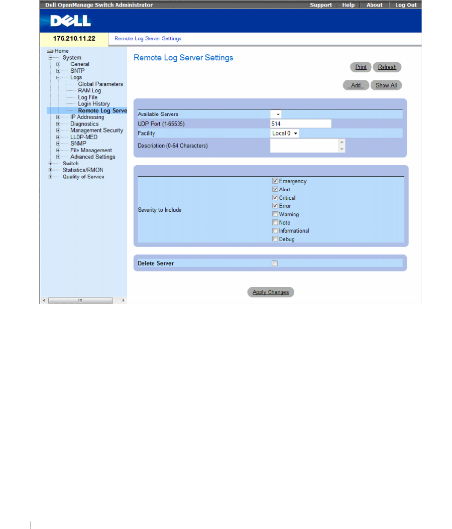
124 Configuring System Information
Figure 6-23. Remote Log Server Settings
The Remote Log Server Settings page contains the following fields:
•
Available Servers
— Contains a list of servers to which logs can be sent.
•
UDP Port (1-65535)
— The UDP port to which the logs are sent for the selected server. The possible
range is 1 - 65535. The default value is 514.
•
Facility
— Defines a user-defined application from which system logs are sent to the remote server.
Only one facility can be assigned to a single server. If a second facility level is assigned, the first facility
level is overridden. All applications defined for a device utilize the same facility on a server. The field
default is Local 7. The possible field values are:
–
Local 0
to
Local 7.
•
Description (0-64 Characters)
— The user-defined server description.

Configuring System Information 125
•
Severity to Include
— The following are the available severity levels:
–
Emergency
—The system is not functioning.
–
Alert
— The system needs immediate attention.
–
Critical
— The system is in a critical state.
–
Error
— A system error has occurred.
–
Warning
— A system warning has occurred.
–
Notice
— The system is functioning properly, but system notice has occurred.
–
Informational
— Provides device information.
–
Debug
— Provides detailed information about the log. If a Debug error occurs, contact Customer
Tech Support.
•
Delete Server
— Deletes the currently selected server from the Available Servers
list, when selected.
When adding a Log Server, the following additional parameters are available:
•
Supported IP Format
— Specifies the IP format supported by the server. The possible values are:
–
IPv6
— IP version 6 is supported.
–
IPv4
— IP version 4 is supported.
•
IPv6 Address Type
— When the server supports IPv6 (see previous parameter), this specifies the type
of static address supported. The possible values are:
–
Link Local
— A Link Local address that is non-routable and used for communication on the same
network only.
–
Global
— A globally unique IPv6 address; visible and reachable from different subnets.
•
Link Local Interface
— When the server supports an IPv6 Link Local address (see previous
parameter), this specifies the the Link Local interface. The possible values are:
–
VLAN1
— The IPv6 interface is configured on VLAN1.
•
ISATAP
— The IPv6 interface is configured on ISATAP tunnel.
Sending Logs to a Server:
1
Open the
Remote Log Server Settings
page.
2
Select a server from the
Available Servers
drop-down list.
3
Define the fields.
4
Select the log severity in the
Severity
to Include
check boxes.
5
Click
Apply Changes
.
The log settings are saved, and the device is updated.
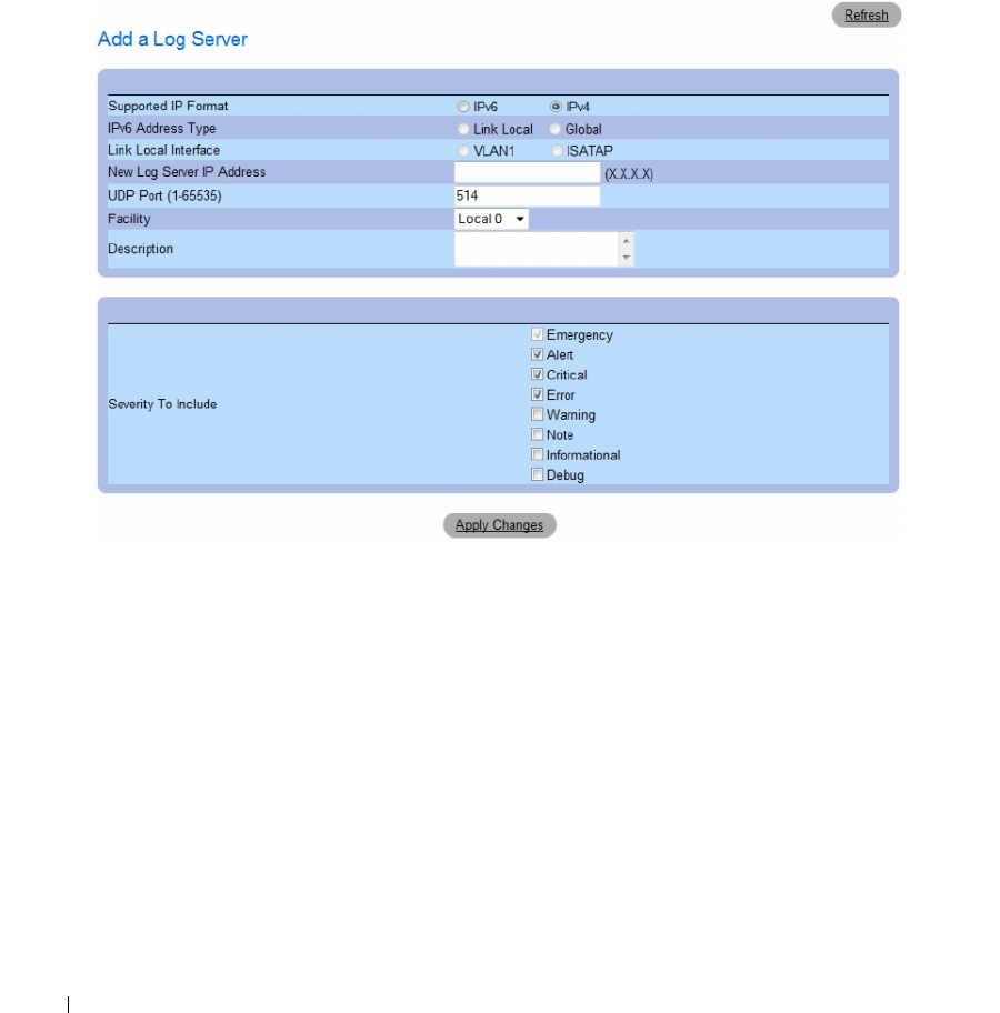
126 Configuring System Information
Defining a New Server:
1
Open the
Remote Log Server Settings
page.
2
Click
Add.
The
Add a Log Server
page opens.
Figure 6-24. Add a Log Server
The
Add a Log Server
page contains the additional field:
–
New Log Server IP Address
— Defines the IP address of the new Log Server.
3
Define the fields.
4
Click
Apply Changes
.
The server is defined and added to the
Available Servers
list.
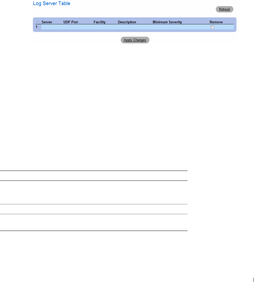
Configuring System Information 127
Displaying the Remote Log Servers Table:
1
Open the
Remote Log Server Settings
page.
2
Click
Show All
.
The
Log Servers Table
page opens.
Figure 6-25. Log Servers Table
Removing a Log Server from the Log Servers Table Page:
1
Open the
Remote Log Server Settings
page.
2
Click
Show All
.
The
Log Servers Table
page opens.
3
Select a
Log Servers Table
entry.
4
Select the
Remove
check box to remove the server(s).
5
Click
Apply Changes
.
The
Log Servers Table
entry is removed, and the device is updated.
Working with Remote Server Logs Using the CLI Commands
The following table summarizes the equivalent CLI command for working with remote log servers.
Table 6-18. Remote Log Server CLI Commands
CLI Command Description
logging (ipv4-address|ipv6-addres |
hostname} [port port] [severity level]
[facility facility] [description text]
Logs messages to a remote server.
no logging Deletes a syslog server.
show logging Displays the state of logging and the syslog
messages.

128 Configuring System Information
The following is an example of the CLI commands:
Defining IP Addressing
The IP Addressing page contains links for assigning interface and default gateway IP addresses, and
defining ARP and DHCP parameters for the interfaces. To open the IP Addressing page, click System →
IP Addressing in the tree view.
This section contians the following topics:
• "Defining IPv4 Default Gateways" on page 129
• "Defining IPv4 Interfaces" on page 131
• "Defining DHCP IPv4 Interface Parameters" on page 134
• "Configuring Domain Name Systems" on page 154
console> enable
console# configure
console(config)# logging 10.1.1.1 severity critical
console(config)# end
console# show logging
Logging is enabled.
Console Logging: Level debug. Console Messages: 5 Dropped.
Buffer Logging: Level debug. Buffer Messages: 16 Logged, 16
Displayed, 200 Max.
File Logging: Level error. File Messages: 0 Logged, 209 Dropped.
SysLog server 31.1.1.2 Logging: error. Messages: 22 Dropped.
SysLog server 5.2.2.2 Logging: info. Messages: 0 Dropped.
SysLog server 10.2.2.2 Logging: critical. Messages: 21 Dropped.
SysLog server 10.1.1.1 Logging: critical. Messages: 0 Dropped.
1 messages were not logged
03-Mar-2004 12:02:03 :%LINK-I-Up: 1/e11
03-Mar-2004 12:02:01 :%LINK-W-Down: 1/e12
03-Mar-2004 12:02:01 :%LINK-I-Up: 1/e13

Configuring System Information 129
• "Defining Default Domains" on page 157
• "Mapping Domain Host" on page 159
• "Defining ARP Settings" on page 162
Configuring the Internet Protocol Version 6 (IPv6)
The device functions as an IPv6 compliant Host, as well as an IPv4 Host (also known as dual stack).
This allows device operation in a pure IPv6 network as well as in a combined IPv4/IPv6 network.
The primary change from IPv4 to IPv6 is the length of network addresses. IPv6 addresses are 128 bits
long, whereas IPv4 addresses are 32 bits; allowing a much larger address space.
IPv6 Syntax
The 128-bit IPv6 address format is divided into eight groups of four hexadecimal digits. Abbreviation of
this format by replacing a group of zeros with "double colons" (::) is acceptable. IPv6 address
representation can be further simplified by suppressing the leading zeros.
All different IPv6 address formats are acceptable for insertion, yet for display purposes, the system will
display the most abbreviated form, which replaces groups of zeros with "double colons" and removes the
"leading zeros".
IPv6 Prefixes
While unicast IPv6 addresses written with their prefix lengths are permitted, in practice their prefix
lengths are always 64 bits and therefore are not required to be expressed. Any prefix that is less than
64 bits is a route or address range that is summarizing a portion of the IPv6 address space.
For every assignment of an IP address to an interface, the system runs the Duplicate Address Detection
(DAD) algorithm to ensure uniqueness.
An intermediary transition mechanism is required for IPv6-only nodes to communicate with IPv6 nodes
over an IPv4 infrastructure. The tunneling mechanism implemented is the Intra-Site Automatic Tunnel
Addressing Protocol (ISATAP). This protocol treats the IPv4 network as a virtual IPv6 local-link,
with each IPv4 address mapped to a Link Local IPv6 address.
Defining IPv4 Default Gateways
The IPv4 Default Gateway page contains fields for assigning Gateway to devices. Packets are forwarded
to the default IP when packets are sent to a remote network. The configured IP address must belong to
the same IP address subnet of one of the IP interfaces.
To open the IPv4 Default Gateway page, click System→ IP Addressing → IPv4 Default Gateway in the
tree view.
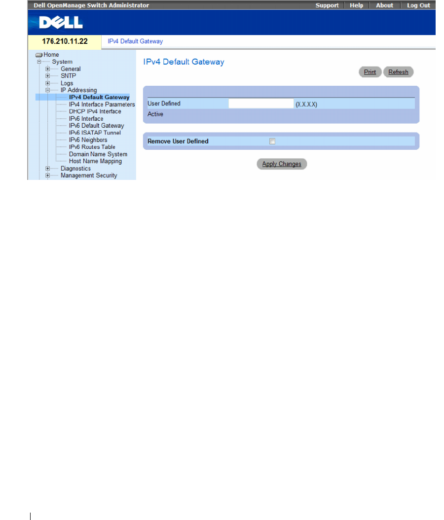
130 Configuring System Information
Figure 6-26. IPv4 Default Gateway
The IPv4 Default Gateway page contains the following fields:
•
User Defined
— The device’s Gateway IP address.
•
Active
— Indicates if the Gateway is active.
•
Remove User Defined
— Removes the default gateway. The possible field values are:
–
Checked
— Removes the selected default gateway.
–
Unchecked
— Maintains the default gateway.
Selecting a Device’s IPv4 Gateway
1
Open the
IPv4
Default Gateway
page
.
2
Type an IP address in the
User Defined
field.
3
Select the
Active
check box.
4
Click
Apply Changes
.
The device’s Default Gateway is selected and the device is updated.
Removing a Device’s IPv4 Default Gateway Device
1
Open the
IPv4
Default Gateway
page
.
2
Select the
Remove User Defined
check box to remove default gateways.
3
Click
Apply Changes
.
The default gateway entry is removed, and the device is updated.
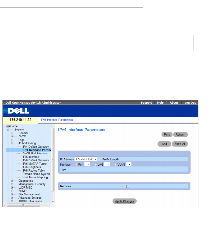
Configuring System Information 131
Defining a Device’s IPv4 Gateway Using the CLI Commands
The following table summarizes the equivalent CLI commands for setting fields displayed in the Default
Gateway page
.
The following is an example of the CLI commands:
Defining IPv4 Interfaces
The IPv4 Interface Parameters page contains fields for assigning IP parameter to interfaces.
To open the IP Interface Parameters page, click System→ IP Addressing→ IPv4 Interface Parameters in
the tree view.
Figure 6-27. IPv4 Interface Parameters
Table 6-19. Default Gateway CLI Commands
CLI Command Description
ip default-gateway ip-address Defines a default gateway.
no ip default-gateway Removes a default gateway.
console(config)# ip default-gateway 196.210.10.1
console(config)# no ip default-gateway
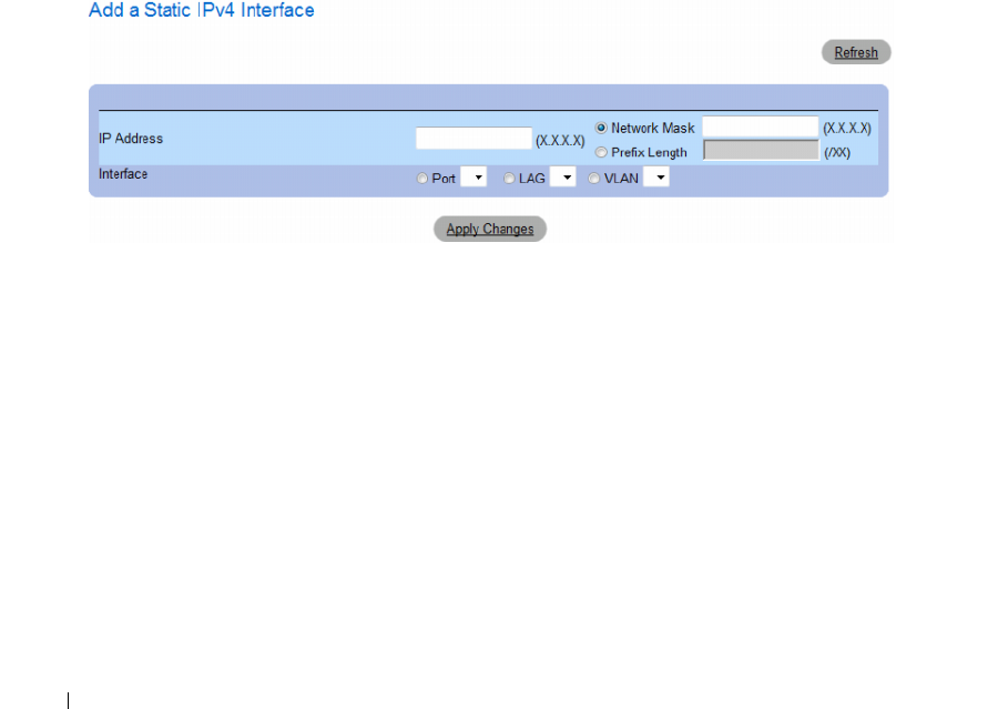
132 Configuring System Information
The IP Interface Parameters page contains the following parameters:
•
IP Address
— The interface IP address.
•
Prefix Length
— The number of bits that comprise the IP address prefix.
•
Interface
— The interface type for which the IP address is defined. Select
Port
,
LAG
, or
VLAN
.
•
Ty p e
— Indicates whether or not the IP address was configured statically.
•
Remove
— Removes the interface from the
IP Address
drop-down menu.
–
Checked
— Removes the selected interface.
–
Unchecked
— Maintains the selected interface.
Adding an IPv4 IP Interface
1
Open the
IPv4
Interface Parameters
page.
2
Click
Add
.
The
Add a Static
IPv4
Interface
page opens.
Figure 6-28. Add a Static IPv4 Interface
In addition to the parameters on the
IP Interface Parameters
page, the
Add a Static IP Interface
page
contains the following parameter:
•
Network Mask
— Indicates the subnetwork mask of the IP address.
3
Complete the fields on the page.
4
Click
Apply Changes
.
The new IP address is added to the interface, and the device is updated.
Modifying IPv4 Address Parameters
1
Open the
IPv4
Interface Parameters
page.
2
Select an IP address in the
IP Address
drop-down menu.
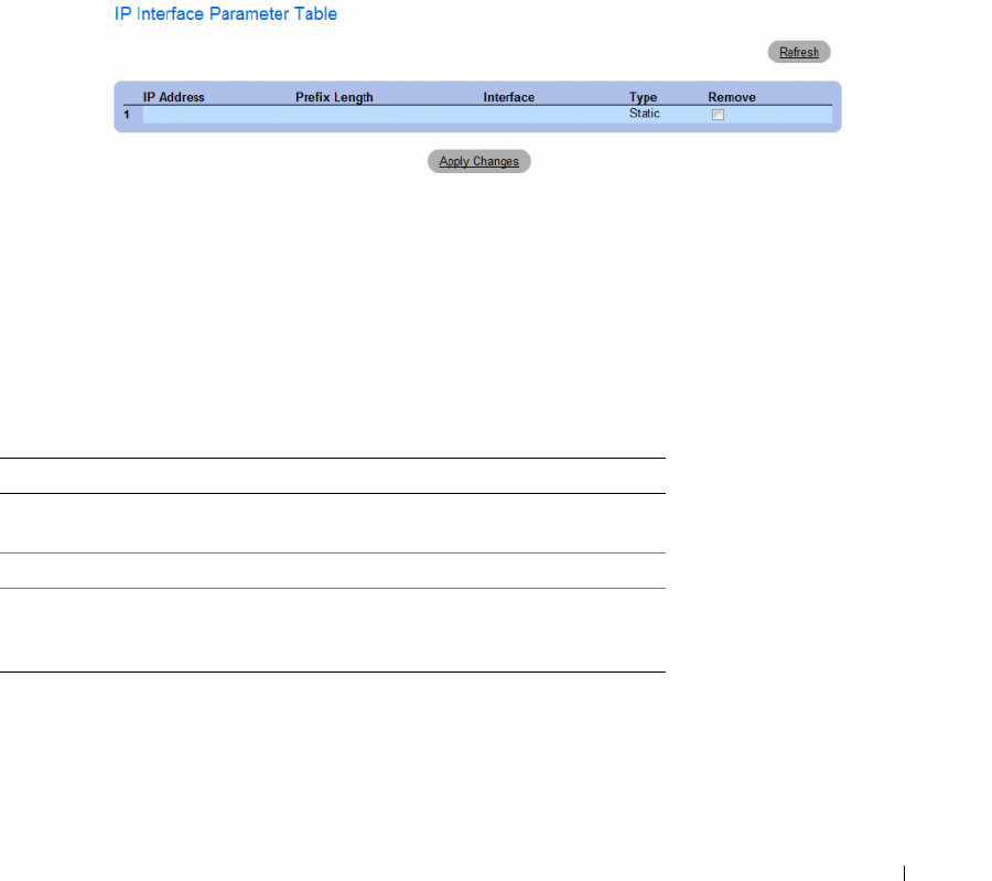
Configuring System Information 133
3
Modify the interface type.
4
Click
Apply Changes
.
The parameters are modified, and the device is updated.
Deleting IPv4 Addresses
1
Open the
IPv4
Interface Parameters
page.
2
Click
Show All.
The
Interface Parameters Table
page opens.
Figure 6-29. IPv4 Interface Parameter Table
3
Select an IP address and select the
Remove
check box.
4
Click
Apply Changes
.
The selected IP address is deleted, and the device is updated.
Defining IPv4 Interfaces Using CLI Commands
The following table summarizes the equivalent CLI commands for setting fields displayed in the IPv4
Interfaces Parameters page.
Table 6-20. IPv4 Interface Parameters CLI Commands
CLI Command Description
ip address ip-address {mask |
prefix-length}
Sets an IP address.
no ip address [ip-address] Removes an IP address
show ip interface [ethernet
interface-number | vlan vlan-
id | port-channel number]
Displays the usability status of interfaces
configured for IP.
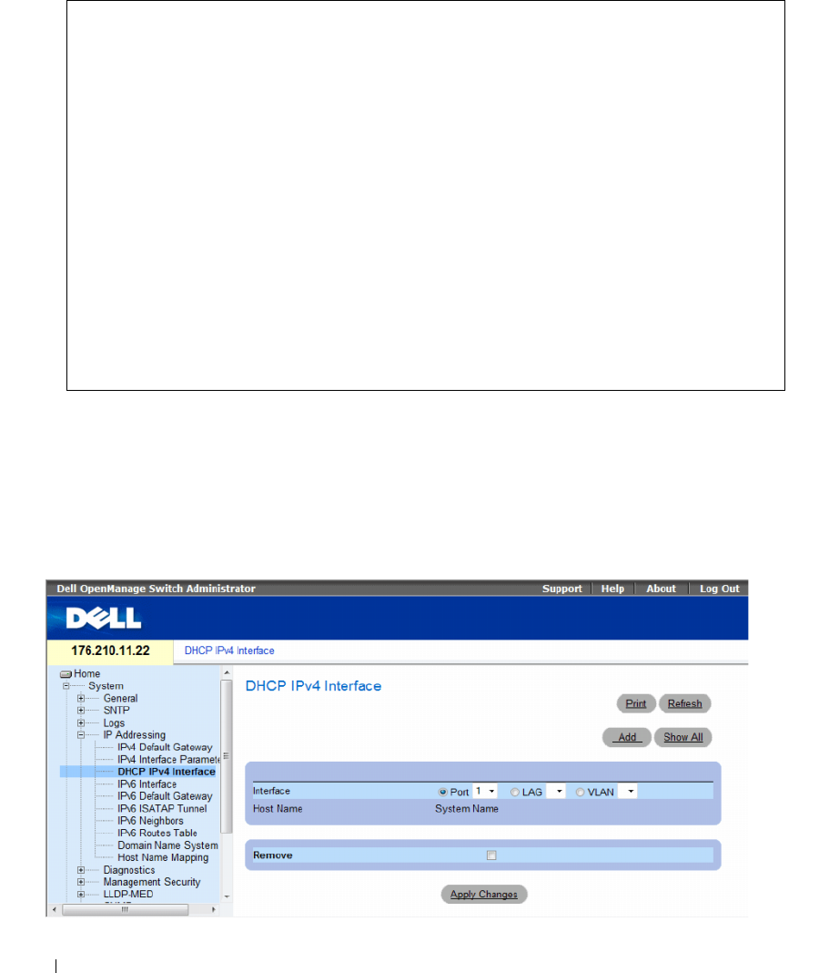
134 Configuring System Information
The following is an example of the CLI commands:
Defining DHCP IPv4 Interface Parameters
The DHCP IPv4 Interface page contains parameters for defining DHCP clients on device interfaces.
To open the DHCP IPv4 Interface page, click System → IP Addressing → DHCP IPv4 Interface in the
tree view.
Figure 6-30. DHCP IPv4 Interface
console(config)# interface vlan 1
console(config-if)# ip address 92.168.1.123 255.255.255.0
console(config-if)# no ip address 92.168.1.123
console(config-if)# end
console# show ip interface vlan 1
Gateway IP Address Activity status
---------------------------------------
192.168.1.1 Active
IP address Interface Type
-------------------------------------------------
192.168.1.123/24 VLAN 1 Static
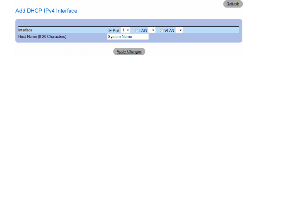
Configuring System Information 135
The DHCP IP Interface page contains the following fields:
•
Interface
— The DHCP client interface. Click the option button next to
Port
,
LAG
, or
VLAN
and
select the DHCP client interface.
•
Host Name
— The system name as written in a DHCP Server log. This field can contain up to
20 characters.
•
Remove
— When selected, removes DHCP clients.
–
Checked
— Removes the selected DHCP client.
–
Unchecked
— Maintains the selected DHCP client.
Adding DHCP Clients
1
Open the
DHCP IPv4 Interface
page.
2
Click
Add
.
The
Add DHCP IPv4 Interface
page opens.
Figure 6-31. Add DHCP IPv4 Interface
3
Complete the information on the page.
4
Click
Apply Changes
.
The DHCP Interface is added, and the device is updated.
Modifying a DHCP IPv4 Interface
1
Open the
DHCP IPv4 IP Interface
page.
2
Modify the fields.
3
Click
Apply Changes
.
The entry is modified, and the device is updated.
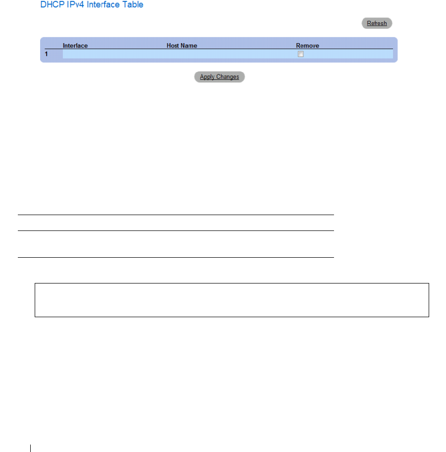
136 Configuring System Information
Deleting a DHCP IPv4 Interface
1
Open the
DHCP IPv4 Interface
page.
2
Click
Show All
.
The
DHCP IPv4 Interface Table
opens.
Figure 6-32. DHCP IPv4 Interface Table
3
Select a DHCP client entry.
4
Select the
Remove
check box.
5
Click
Apply Changes
.
The selected entry is deleted, and the device is updated.
Defining DHCP IPv4 Interfaces Using CLI Commands
The following table summarizes the equivalent CLI commands for defining DHCP clients.
The following is an example of the CLI command:
Table 6-21. DHCP IPv4 Interface CLI Commands
CLI Command Description
ip address dhcp
[hostname host-name]
To acquire an IP address on an Ethernet interface from the
Dynamic Host Configuration Protocol (DHCP).
console(config)# interface ethernet 1/e11
console(config-if)# ip address dhcp
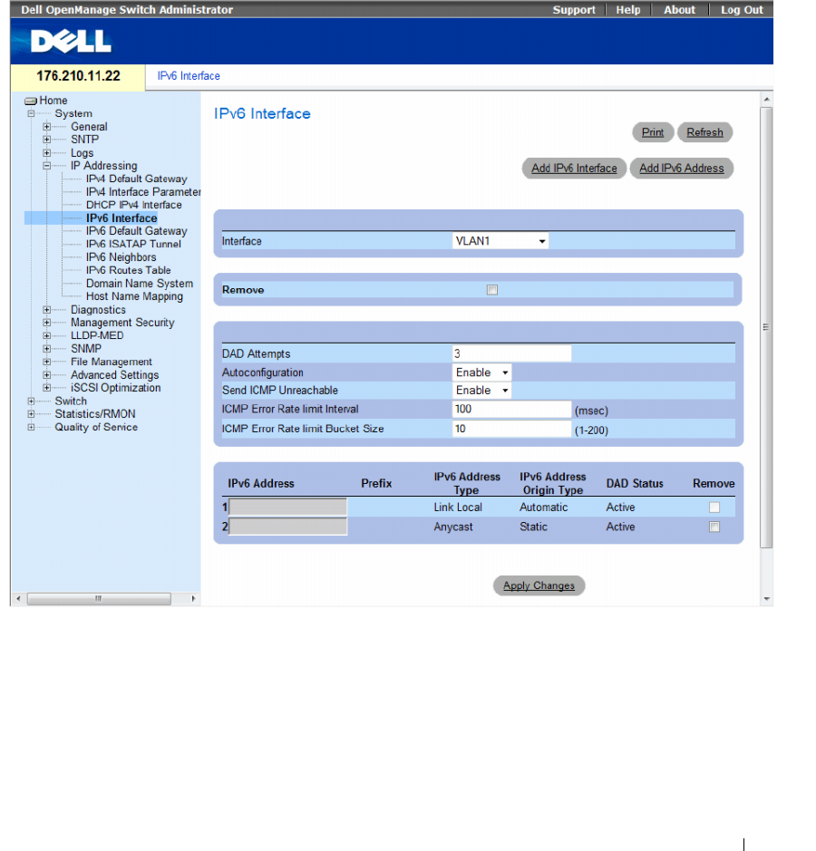
Configuring System Information 137
Defining IPv6 Interfaces
The system supports IPv6 hosts. The IPv6 Interface page contains fields for defining IPv6 interfaces.
To open the IPv6 Interface page, click System→ IP Addressing→ IPv6 Interface in the tree view.
Figure 6-33. IPv6 Interface
•
Interface
— The IPv6 interface that has been selected for configuration.
•
Remove
— When selected, removes the IPv6 attributes of the interface.
•
DAD Attempts
— Defines the number of consecutive neighbor solicitation messages that are sent on
an interface while Duplicate Address Detection (DAD) is performed on unicast IPv6 addresses on this
interface. New addresses remain in a tentative state while duplicate address detection is performed.
A field value of 0, disables duplicate address detection processing on the specified interface. A field
value of 1, indicates a single transmission without follow up transmissions. Range is 0-600, default is 1.

138 Configuring System Information
• Autoconfiguration
— Specifies whether IPv6 address assignment on an interface is done by stateless
autoconfiguration. When enabled, the router solicitation ND procedure is initiated (to discover a
router in order to assign an IP address to the interface based on prefixes received with RA messages).
When autoconfiguration is disabled, no automatic assignment of IPv6 Global Unicast addresses is
performed, and existing automatically assigned IPv6 Global Unicast addresses are removed from the
interface. Default is
Enabled
.
•
Send ICMP Unreachable
— Specifies whether transmision of ICMPv6 Address Unreachable messages
is enabled. When enabled, unreachable messages are generated for any packet arriving on the interface
with unassigned TCP/UDP port. Default is
Enabled
.
•
ICMP Error Rate Limit Interval
— The rate-limit interval for ICMPv6 error messages in milliseconds.
The value of this parameter together with the Bucket Size parameter (below) determines how many
ICMP error messages may be sent per time interval. For example, a rate-limit interval of 100 ms and a
bucket size of 10 messages translates to 100 ICMP error messages per second.
•
ICMP Error Rate Limit Bucket Size
— The bucket size for ICMPv6 error messages. The value of this
parameter together with the Interval parameter (above) determines how many ICMP error messages
may be sent per time interval. For example, a rate-limit interval of 100 ms and a bucket size of
10 messages translates to 100 ICMP error messages per second. Default is 100 ICMP error messages
per second; this corresponds to the default interval of 100 ms multiplied by the default bucket size of 10.
•
IPv6 Address
— Indicates the IPv6 address assigned to the interface. The address must be a valid
IPv6 address, specified in hexadecimal using 16-bit values between colons. An example of an
IPv6 address is 2031:0:130F:0:0:9C0:876A:130D and the compressed version is represented as
2031::0:9C0:876A:130D. Up to five IPv6 addresses (not including Link Local addresses) can be set per
interface, with the limitation of up to 128 addresses per system.
•
Prefix
— Specifies the length of the IPv6 prefix. The length is a decimal value that indicates how many
of the high-order contiguous bits of the address comprise the prefix (the network portion of the
address). The Prefix field is applicable only on a static IPv6 address defined as a Global IPv6 address.
•
IPv6 Address Type
— Specifies the means by which the IP address was added to the interface.
The possible field values are:
– Link Local
— Indicates the IP address is link local; non-routable and can be used for
communication on the same network only. A Link Local address has a prefix of 'FE80'.
– Global Unicast
— Indicates the IP address is a globally unique IPv6 unicast address; visible and
reachable from different subnets
.
– Global Anycast
— Indicates the IP address is a globally unique IPv6 anycast address; visible and
reachable from different subnets
.
– Multicast
— Indicates the IP address is multicast.
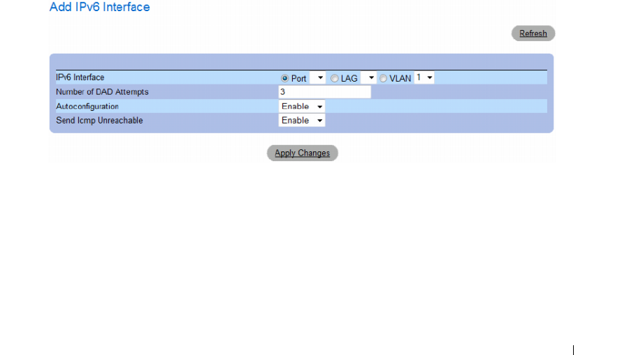
Configuring System Information 139
•
IPv6 Address Origin Type
— Defines the type of configurable static IPv6 address for an interface.
The possible values are:
– Dyanmic
— Indicates the IP address was received from RA.
–
Static
— Indicates the IP address was configured by the user.
–
System
— Indicates the IP address was generated by the system.
•
DAD Status
— Displays the Duplicate Address Detection (DAD) Status which is the process of
verifying and assuring an inserted IPv6 address is unique. This is a read-only parameter with the
following field values:
–
Tentative
— Indicates the system is in process of IPv6 address duplication verification.
–
Duplicate
— Indicates the IPv6 address is being used by an another host on the network.
The duplicated IPv6 address is suspended and is not used for sending or receiving any traffic.
–
Active
— Indicates the IPv6 address is set to active.
•
Remove
— When selected, removes the address from the table.
Adding an IPv6 Interface
1
Open the
IPv6 Interface
page.
2
Click
Add IPv6 Interface
.
The
Add a Static IPv4 Interface
page opens.
Figure 6-34. Add IPv6 Interface
3
Complete the fields on the page.
IPv6 Interface
specifies whether the interface is a specific port, LAG or VLAN.
4
Click
Apply Changes
.
The new interface is added, and the device is updated.
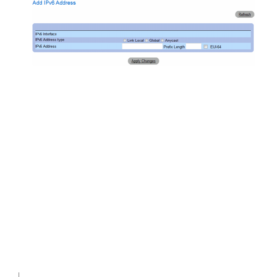
140 Configuring System Information
Adding an IPv6 Address to the Current Interface
1
Open the
IPv6 Interface
page.
2
Click
Add IPv6 Address
.
The
Add IPv6 Address
page opens.
Figure 6-35. Add IPv6 Address
3
Complete the fields on the page.
4
Click
Apply Changes
.
The new address is added, and the device is updated.
Modifying IPv6 Interface Parameters
1
Open the
IPv6 Interface
page.
2
Select an interface in the
Interface
drop-down menu.
3
Modify the required fields.
4
Click
Apply Changes
.
The parameters are modified, and the device is updated.

Configuring System Information 141
Defining IPv6 Interfaces Using CLI Commands
The following table summarizes the equivalent CLI commands for setting fields displayed in the IPv6
Interface page.
Table 6-22. IPv6 Interface CLI Commands
CLI Command Description
ipv6 enable [no-autoconfig] Enables IPv6 processing on an interface.
ipv6 address autoconfig Enables automatic configuration of IPv6 addresses using
stateless auto-configuration on an interface.
ipv6 icmp error-interval milliseconds [bucket-
size]
Configures the rate limit interval and bucket size parameters
for IPv6 Internet Control Message Protocol (ICMP) error
messages.
show ipv6 icmp error-interval Displays the ipv6 icmp error interval.
ipv6 address ipv6-address/prefix-length [eui-64]
[anycast]
Configures an IPv6 address for an interface.
ipv6 address ipv6-address link-local Configures an IPv6 link-local address for an interface.
ipv6 unreachables Enables the generation of Internet Control Message Protocol
for IPv6 (ICMPv6) unreachable messages for any packets
arriving on a specified interface.
show ipv6 interface [ethernet interface-number
| vlan vlan-id | port-channel number]
Displays the usability status of interfaces configured for IPv6.
ipv6 nd dad attempts attempts-number Configures the number of consecutive neighbor solicitation
messages that are sent on an interface while duplicate address
detection is performed on the unicast IPv6 addresses of the
interface.
ipv6 host name ipv6-address1 [ipv6-
address2...ipv6-address4]
Defines a static host name-to-address mapping in the host
name cache.
ipv6 set mtu {ethernet interface | port-channel
port-channel-number} { bytes | default}
Sets the maximum transmission unit (MTU) size of IPv6
packets sent on an interface.
ping {ipv4-address | hostname} [size
packet_size] [count packet_count] [timeout
time_out]
Sends IPv4 ICMP echo request packets to another node on
the network.
ping ipv6 {ipv6-address | hostname} [size
packet_size] [count packet_count] [timeout
time_out]
Sends IPv6 ICMP echo request packets to another node on
the network.

142 Configuring System Information
The following is an example of the CLI commands:
Defining IPv6 Default Gateway
The IPv6 Default Gateway Page provides the ability to manually configure the router of all off-link
traffic. The default gateway address is an interface that serves as an access point to another network.
For IPv6, the configuration of the default gateway is not mandatory, as hosts can automatically learn of
the existence of a router on the local network via the router advertisement procedure.
Unlike IPv4, the IPv6 default gateway can have multiple IPv6 addresses which may include up to one
user-defined static address and multiple dynamic addresses learned via router solicitation message.
The user-defined default gateway has a higher precedence over an automatically advertised router.
• When removing an IP interface, all of its default gateway IP addresses are removed.
• Dynamic IP addresses cannot be removed.
• An Alert message appears once a user attempts to insert more than one user-defined address.
• An Alert message appears when attempting to insert a none Link Local type address.
console# show ipv6 interface vlan 1
Number of ND DAD attempts: 1
MTU size: 1500
Stateless Address Autoconfiguration state: enabled
ICMP unreachable message state: enabled
MLD version: 2
IP addresses Type DAD State
------------------------ ------ -----------
fe80::232:87ff:fe08:1700 linklayer Active
ff02::1 linklayer N/A
ff02::1:ff08:1700 linklayer N/A
console(config)# ipv6 icmp
error-interval ICMP errors rate limiting
console(config)# ipv6 icmp error-interval
<0-2147483647> The time interval between tokens being placed
in the bucket in milliseconds
console(config)# ipv6 icmp error-interval 100
<1-200> The maximum number of tokens stored in the bucket
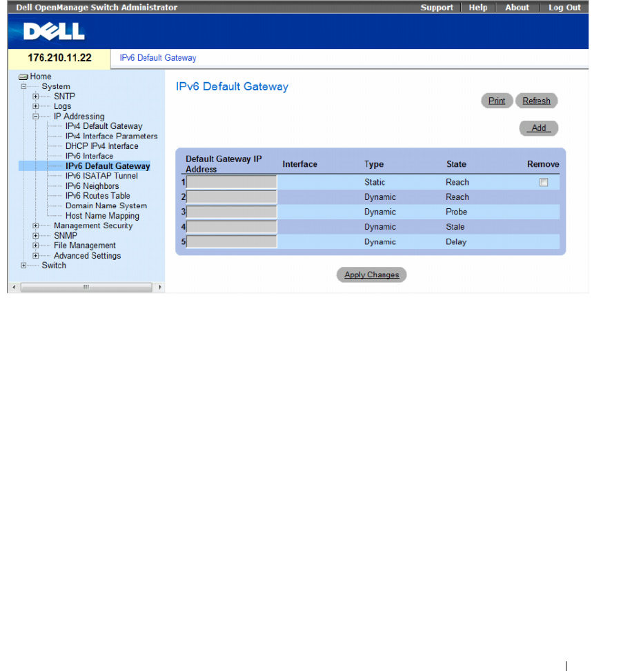
Configuring System Information 143
To open the IPv6 Default Gateway page, click System→ IP Addressing→ IPv6 Default Gateway in the
tree view.
Figure 6-36. IPv6 Default Gateway
•
Default Gateway IP Address
— Displays the Link Local IPv6 address of the default gateway.
•
Interface
— Specifies the outgoing interface through which the default gateway can be reached.
Interface refers to any Port/LAG/VLAN and/or Tunnel.
•
Ty p e
— Specifies the means by which the default gateway was configured. The possible field
values are:
–
Static
— Indicates the default gateway is user-defined.
–
Dynamic
— Indicates the default gateway is dynamically configured.
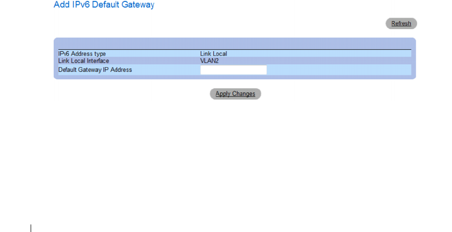
144 Configuring System Information
•
State
— Displays the default gateway status. The possible field values are:
–
Incomplete
— Indicates that address resolution is in progress and the link-layer address of the
default gateway has not yet been determined.
–
Reachable
— Indicates that the default gateway is known to have been reachable recently (within
tens of seconds ago).
–
Stale
— Indicates that the default gateway is no longer known to be reachable but until traffic is
sent to the default gateway, no attempt is made to verify its reachability.
–
Delay
— Indicates that the default gateway is no longer known to be reachable, and traffic has
recently been sent to the default gateway. Rather than probe the default gateway immediately,
however, there is a delay sending probes for a short while in order to give upper-layer protocols a
chance to provide reachability confirmation.
–
Probe
— Indicates that the default gateway is no longer known to be reachable, and unicast
Neighbor Solicitation probes are being sent to verify reachability.
–
Unreachable
— Indicates that no reachability confirmation was received.
•
Remove
— When selected, removes the address from the list.
Adding an IPv6 Default Gateway
1
Open the
IPv6 Default Gateway
page.
2
Click
Add
.
The
Add IPv6 Default Gateway
page opens.
Figure 6-37. Add IPv6 Default Gateway
3
Complete the fields on the page.
4
Click
Apply Changes
.
The new gateway is added, and the device is updated.

Configuring System Information 145
Defining IPv6 Default Gateway Parameters Using CLI Commands
The following table summarizes the equivalent CLI commands for setting fields displayed in the IPv6
Default Gateway page.
Defining IPv6 ISATAP Tunnels
The IPv6 ISATAP Tunnel Page defines the tunneling process on the device, which encapsulates
IPv6 packets in IPv4 packets for delivery across an IPv4 network.
The Intra-Site Automatic Tunnel Addressing Protocol (ISATAP) is an IPv6 transition mechanism which is
defined as a tunneling IPv6 interface and is meant to transmit IPv6 packets between dual-stack nodes on
top of an IPv4 network.
When enabling ISATAP on a tunnel interface, an explicit IP address is configured as the tunnel source or
an automatic mode exists where the lowest IPv4 address is assigned to an IP interface. This source IPv4 is
used for setting the tunnel interface identifier according to ISATAP addressing convention. When a
tunnel interface is enabled for ISATAP, the tunnel source must be set for the interface in order for the
interface to become active.
An ISATAP address is represented using the [64-bit prefix]:0:5EFE:w.x.y.z, where 5EFE is the ISATAP
identifier and w.x.y.z is a public or private IPv4 address. Thus, a Link Local address will be represented as
FE80::5EFE:w.x.y.z
Once the last IPv4 address is removed from the interface, the ISATAP IP interface state becomes inactive
and is represented as “Down”, however the Admin state remains enabled.
When defining tunneling, note the following:
• An IPv6 Link Local address is assigned to the ISATAP interface. The initial IP address is assigned to the
interface, and the interface state becomes Active.
• If an ISATAP interface is active, the ISATAP router IPv4 address is resolved via DNS by using
ISATAP-to-IPv4 mapping. If the ISATAP DNS record is not resolved, the ISATAP host name-to-address
mapping is searched in the host name cache.
• When an ISATAP router IPv4 address is not resolved via DNS process, the status of the
ISATAP IP interface remains
Active
. The system does not have a default gateway for ISATAP traffic
until the DNS procedure is resolved.
• In order for an ISATAP Tunnel to work properly over an IPv4 network, an ISATAP Router is required to
be set up.
Table 6-23. IPv6 Default Gateway CLI Commands
CLI Command Description
ipv6 default-gateway ipv6-
address
Defines an IPv6 default gateway.
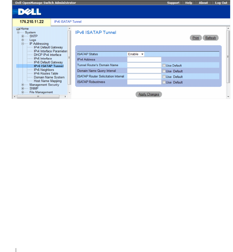
146 Configuring System Information
To open the IPv6 ISATAP Tunnel page, click System→ IP Addressing→ IPv6 ISATAP Tunnel in the
tree view.
Figure 6-38. IPv6 ISATAP Tunnel
•
ISATAP Status
— Specifies the status of ISATAP on the device. The possible field values are:
–
Enable
— ISATAP is enabled on the device.
–
Disable
— ISATAP is disabled on the device. This is the default value.
•
IPv4 Address
— Specifies the local (source) IPv4 address of a tunnel interface.
•
Tunnel Router's Domain Name
— Specifies a global string that represents a specific automatic tunnel
router domain name. The default value is ISATAP.
–
Use Default
— Selecting the check box returns settings to default.
•
Domain Name Query Interval
— Specifies the interval between DNS Queries (before the IP address
of the ISATAP router is known) for the automatic tunnel router domain name. The range is
10 - 3600 seconds. The default is 10 seconds.
–
Use Default
— Selecting the check box returns settings to default.
•
ISATAP Router Solicitation Interval
— Specifies the interval between router solicitations messages
when there is no active router. The range is 10 - 3600 seconds. The default is 10.
–
Use Default
— Selecting the check box returns settings to default.
•
ISATAP Robustness
— Specifies the number of DNS Query/ Router Solicitation refresh messages that
the device sends. The range is 1 - 20 seconds. The default is 3.
–
Use Default
— Selecting the check box returns settings to default.

Configuring System Information 147
Defining IPv6 ISATAP Tunnel Parameters Using CLI Commands
The following table summarizes the equivalent CLI commands for setting fields displayed in the IPv6
ISATAP Tunnel page.
The following is an example of the CLI commands:
Table 6-24. IPv6 Default Gateway CLI Commands
CLI Command Description
interface tunnel number Enters tunnel interface configuration mode.
tunnel mode ipv6ip {isatap} Configures an IPv6 transition mechanism global
support mode.
tunnel isatap router
router_name
Configures a global string that represents a
specific automatic tunnel router domain name.
tunnel source { auto | ip-
address ipv4-address |
interface }
Sets the local (source) IPv4 address of a tunnel
interface.
tunnel isatap query-interval
seconds
Configures the interval between DNS Queries
(before the IP address of the ISATAP router is
known) for the automatic tunnel router domain
name.
tunnel isatap solicitation-
interval seconds
Configures the interval between ISATAP router
solicitations messages (when there is no active
ISATAP router).
tunnel isatap robustness
number
Configure the number of DNS Query / Router
Solicitation refresh messages that the device
sends.
show ipv6 tunnel Displays information on the ISATAP tunnel.
Console> show ipv6 tunnel
Router DNS name: ISATAP
Router IPv4 address: 172.16.1.1
DNS Query interval: 10 seconds
Min DNS Query interval: 0 seconds
Router Solicitation interval: 10 seconds
Min Router Solicitation interval: 0 seconds
Robustness: 3
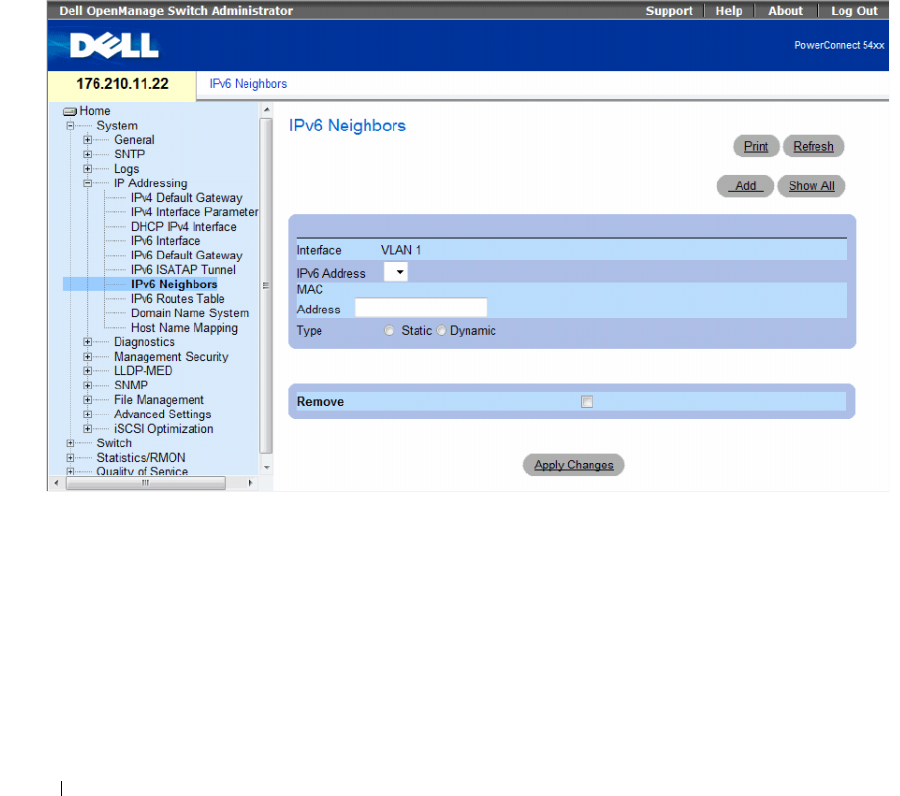
148 Configuring System Information
Defining IPv6 Neighbors
The IPv6 Neighbors Page contains information for defining IPv6 Neighbors which is similar to the
functionality of the IPv4 Address Resolution Protocol (ARP). IPv6 Neighbors enables detecting Link Local
addresses within the same subnet, and includes a database for maintaining reachability information
about the active neighbors paths.
The device supports a total of up to 256 neighbors obtained either statically or dynamically.
When removing an IPv6 interface, all neighbors learned statically and dynamically are removed.
To open the IPv6 Neighbors page, click System→ IP Addressing→ IPv6 Neighbors in the tree view.
Figure 6-39. IPv6 Neighbors
•
Interface
— Displays the interface on which IPv6 Interface is defined. Interfaces include Ports, LAGs,
or VLANs.
•
IPv6 Address
— Defines the currently configured neighbor IPv6 address.
•
MAC Address
— Displays the MAC address assigned to the interface.
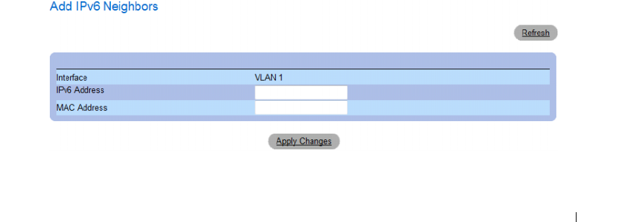
Configuring System Information 149
•
Ty p e
— Displays the type of the neighbor discovery cache information entry. The possible field values are:
–
Static
— Shows static neighbor discovery cache entries. If an entry for the specified IPv6 address
already exists in the neighbor discovery cache—as learned through the IPv6 neighbor discovery
process—you can convert the entry to a static entry.
–
Dynamic
— Shows dynamic neighbor discovery cache entries.
•
Remove
— When selected, removes the neighbor from the list.
In the IPv6 Neighbors Table, the following additional parameter appears:
•
State
— Displays the IPv6 Neighbor status. The field possible values are:
•
Incomplete
— Indicates that an address resolution is in progress and the link-layer address of the
neighbor has not yet been determined.
•
Reachable
— Indicates that the neighbor is known to have been reachable recently (within tens of
seconds ago).
•
Stale
— Indicates that the neighbor is no longer known to be reachable but until traffic is sent to
the neighbor, no attempt is made to verify its reachability.
–
Delay
— Indicates that the neighbor is no longer known to be reachable, and traffic has recently
been sent to the neighbor. Rather than probe the neighbor immediately, however, there is a delay
sending probes for a short while in order to give upper-layer protocols a chance to provide
reachability confirmation.
–
Probe
— Indicates that the neighbor is no longer known to be reachable, and unicast Neighbor
Solicitation probes are being sent to verify reachability.
Adding an IPv6 Neighbor
1
Open the
IPv6 Neighbors
page.
2
Click
Add
.
The
Add IPv6 Neighbors
page opens.
Figure 6-40. Add IPv6 Neighbors
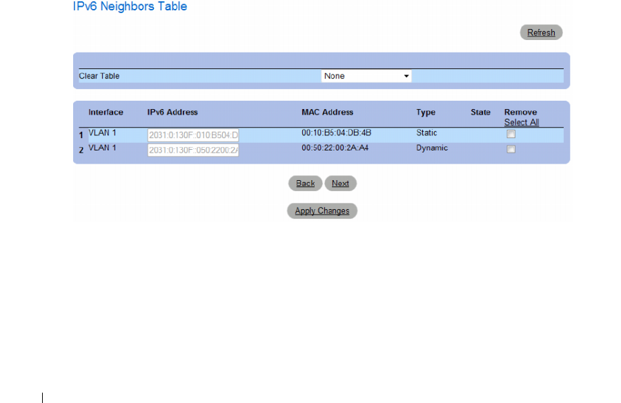
150 Configuring System Information
3
Complete the fields on the page.
4
Click
Apply Changes
.
The new neighbor is added, and the device is updated.
Modifying Neighbor Parameters
1
Open the
IPv6 Neighbors
page.
2
Select an IP address in the
IPv6 Address
drop-down menu.
3
Modify the required fields.
4
Click
Apply Changes
.
The parameters are modified, and the device is updated.
Deleting Neighbors
1
Open the
IPv6 Neighbors
page.
2
Click
Show All.
The
IPv6 Neighbors Table
opens.
Figure 6-41. IPv6 Neighbors Table
Configuring System Information 151
3
Select the
Remove
check box in the desired entry. Alternatively, select the desired value in the
Clear
Tab le
field. The possible filed values are:
– Static Only — Clears the the IPv6 Neighbor Table static entries.
– Dynamic Only — Clears the IPv6 Neighbor Table dynamic entries.
– All Dynamic and Static — Clears the IPv6 Neighbor Table static and dynamic address entries.
– None — Does not clear any entries.
4
Click
Apply Changes
.
The selected neighbors are deleted, and the device is updated.
Defining IPv6 Neighbors Using CLI Commands
The following table summarizes the equivalent CLI commands for setting fields displayed in the IPv6
Neighbors page.
The following is an example of the CLI commands:
Table 6-25. IPv6 Neighbors Parameters CLI Commands
CLI Command Description
ipv6 neighbor ipv6_addr hw_addr {ethernet
interface-number | vlan vlan-id | port-channel
number }
Configures a static entry in the IPv6 neighbor
discovery cache.
show ipv6 neighbors {static | dynamic}[ipv6-
address ipv6-address] [mac-address mac-address]
[ethernet interface-number | vlan vlan-id | port-
channel number ]
Displays IPv6 neighbor discovery cache
information.
clear ipv6 neighbors Deletes all entries in the IPv6 neighbor discovery
cache.
Console# show ipv6 neighbors dynamic
Interface IPv6 address HW address State
--------- ------------ ---------- -----
VLAN 1 2031:0:130F::010:B504:DBB4 00:10:B5:04:DB:4B REACH
VLAN 1 2031:0:130F::050:2200:2AA4 00:50:22:00:2A:A4 REACH
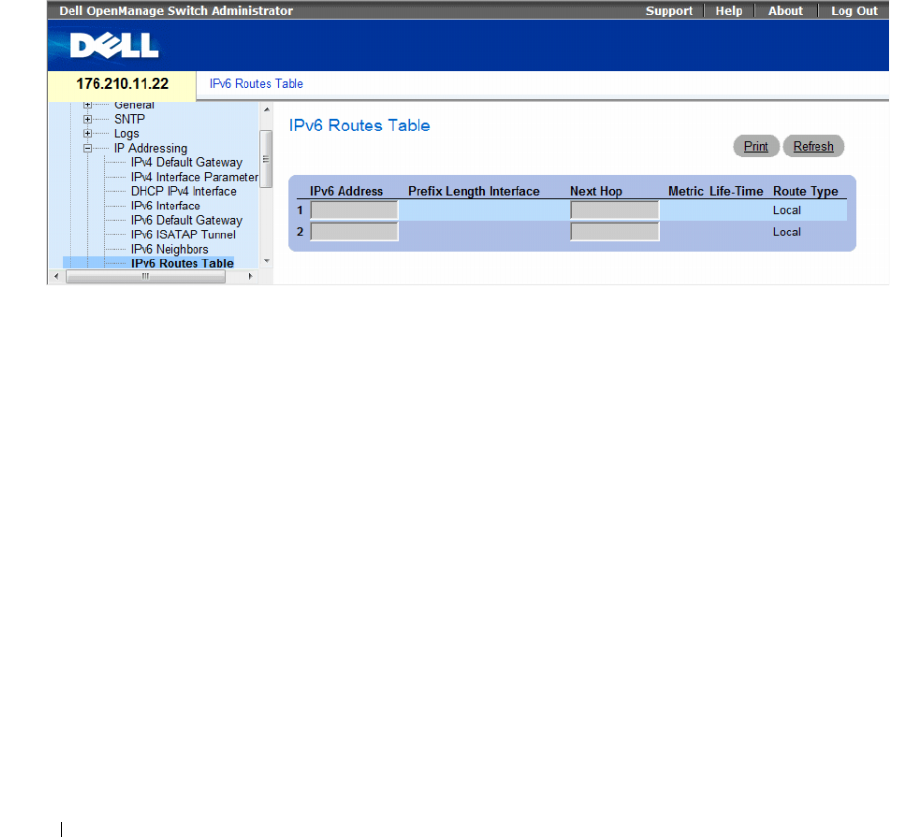
152 Configuring System Information
Viewing the IPv6 Routes Table
The IPv6 Routes Table stores information about IPv6 destination prefixes and how they are reached,
either directly or indirectly. The routing table is used to determine the next-hop address and the interface
used for forwarding.
Each dynamic entry also has an associated invalidation timer value (extracted from Router
Advertisements) used to delete entries that are no longer advertised.
To open the IPv6 Routes Table page, click System→ IP Addressing→ IPv6 Routes Table in the tree view.
Figure 6-42. IPv6 Routes Table
•
IPv6 Address
— Defines the destination IPv6 address.
•
Prefix Length
— Specifies the length of the IPv6 prefix. The Prefix field is applicable only when the
IPv6 Static IP address is defined as a Global IPv6 address. The range is 5 - 128.
•
Interface
— Displays the interface that is used to forward the packet. Interface refers to any Port,
LAG or VLAN.
•
Next
Hop — Defines the address to which the packet is forwarded on the route to the Destination address
(typically the address of a neighboring router). This can be either a Link Local or Global IPv6 address.
•
Metric
— Indicates the value used for comparing this route to other routes with the same destination in
the IPv6 route table. This is an administrative distance with the range of 0-255. The default value is 1.
•Life-Time
— Indicates the life-time of the route.
•
Route
Ty p e
— Displays whether the destination is directly attached and the means by which the entry
was learned. The following values are:
–
Local
— Indicates a directly connected route entry.
–
Static
— Indicates the route is learned through the ND process. The entry is automatically
converted to a static entry.
–
ICMP
— Indicates the route is learned through ICMP messages.
–
ND
— Indicates the route is learned through RA messages.

Configuring System Information 153
Viewing IPv6 Routes Table Parameters Using CLI Commands
The following table summarizes the equivalent CLI commands for setting fields displayed in the IPv6
Routes Table page.
The following is an example of the CLI commands:
Table 6-26. IPv6 Default Gateway CLI Commands
CLI Command Description
traceroute {ipv4-address | hostname} [size packet_size] [ttl
max-ttl] [count packet_count] [timeout time_out] [source
ip-address] [tos tos]
Discovers the routes that IPv4 packets will
actually take when traveling to their destination.
traceroute ipv6 {ipv6-address | hostname} [size packet_size]
[ttl max-ttl] [count packet_count] [timeout time_out]
[source ip-address] [tos tos]
Discovers the routes that IPv6 packets will
actually take when traveling to their destination.
show ipv6 route Displays the current state of the ipv6 routing
table.
Console> show ipv6 route
Codes: L - Local, S - Static, I - ICMP, ND - Router Advertisment
The number in the brackets is the metric.
S ::/0 via fe80::77 [0] VLAN 1 Lifetime Infinite
ND ::/0 via fe80::200:cff:fe4a:dfa8 [0] VLAN 1 Lifetime 1784 sec
L 2001::/64 is directly connected, g2 Lifetime Infinite
L 2002:1:1:1::/64 is directly connected, VLAN 1 Lifetime 2147467 sec
L 3001::/64 is directly connected, VLAN 1 Lifetime Infinite
L 4004::/64 is directly connected, VLAN 1 Lifetime Infinite
L 6001::/64 is directly connected, g2 Lifetime Infinite
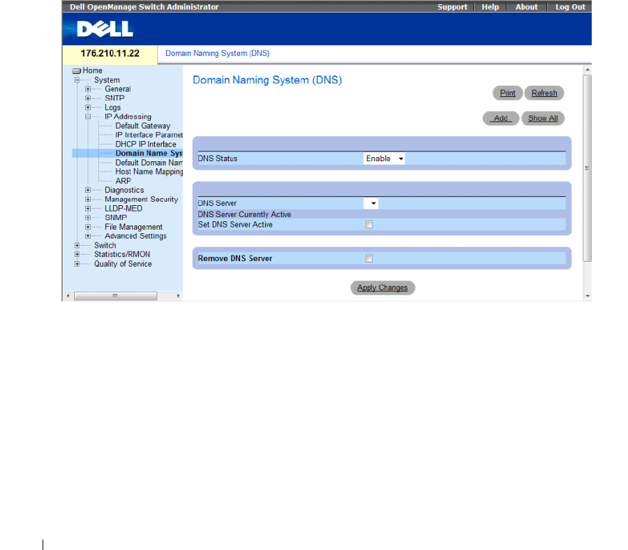
154 Configuring System Information
Configuring Domain Name Systems
Domain Name System (DNS) converts user-defined domain names into IP addresses. Each time a
domain name is assigned the DNS service translates the name into a numeric IP address. For example,
www.ipexample.com is translated into 192.87.56.2. DNS servers maintain domain name databases and
their corresponding IP addresses.
The Domain Naming System (DNS) page contains fields for enabling and activating specific
DNS servers.
To open the Domain Naming System (DNS) page, click System → IP Addressing → Domain Naming
System (DNS) in the tree view.
Figure 6-43. Domain Naming System (DNS)
The Domain Naming System (DNS) page contains the following fields:
•
DNS Status
— Enables or disables translating DNS names into IP addresses.
•
DNS Server
— Contains a list of DNS servers. DNS servers are added from the
Add DNS Server
page.
•
DNS Server Currently Active
— The DNS server that is currently active.
•
Set DNS Server Active
— Activates the selected DNS server.
•
Remove DNS Server
— Removes the selected DNS server.
–
Checked
— Removes the selected DNS server.
–
Unchecked
— Maintains the selected DNS server.
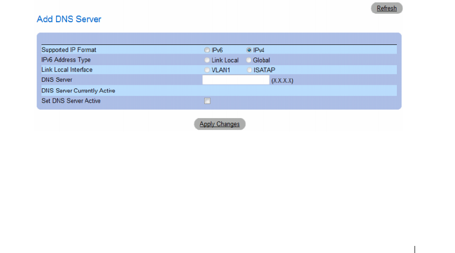
Configuring System Information 155
When defining a new DNS server, the following additional parameters are available:
•
Supported IP Format
— Specifies the IP format supported by the server. The possible values are:
–
IPv6
— IP version 6 is supported.
–
IPv4
— IP version 4 is supported.
•
IPv6 Address Type
— When the server supports IPv6 (see previous parameter), this specifies the type
of static address supported. The possible values are:
–
Link Local
— A Link Local address that is non-routable and used for communication on the same
network only.
–
Global
— A globally unique IPv6 address; visible and reachable from different subnets.
•
Link Local Interface
— When the server supports an IPv6 Link Local address (see previous
parameter), this specifies the the Link Local interface. The possible values are:
–
VLAN1
— The IPv6 interface is configured on VLAN1.
–
ISATAP
— The IPv6 interface is configured on ISATAP tunnel.
Adding a DNS Server
1
Open the
Domain Naming System (DNS)
page
.
2
Click
Add
.
The
Add DNS Server
page opens.
Figure 6-44. Add DNS Server
In addition to the fields in the
Domain Naming System (DNS)
page
,
the
Add DNS Server
page
contains the following field:
•
DNS Server
— DNS Server IP address.
3
Define the relevant fields.
4
Click
Apply Changes
.
The new DNS server is defined, and the device is updated.

156 Configuring System Information
Displaying the DNS Servers Table
1
Open the
Domain Naming System (DNS)
page
.
2
Click
Show All.
The
DNS Server Table
opens.
Figure 6-45. DNS Server Table
Removing DNS Servers
1
Open the
Domain Naming System (DNS)
page
.
2
Click
Show All.
The
DNS Server Table
page opens.
3
Select a
DNS Server Table
entry
.
4
Select the
Remove
checkbox.
5
Click
Apply Changes.
The selected DNS server is deleted, and the device is updated.
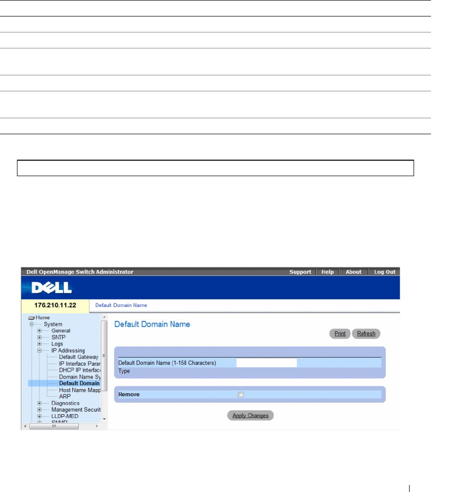
Configuring System Information 157
Configuring DNS Servers Using the CLI Commands
The following table summarizes the CLI commands for configuring device system information.
The following is an example of the CLI commands:
Defining Default Domains
The Default Domain Name page provides information for defining default DNS domain names.
To open the Default Domain Name page, click System → IP Addressing → Default Domain Name.
Figure 6-46. Default Domain Name
Table 6-27. DNS Server CLI Commands
CLI Command Description
ip name-server server-address Sets the available name servers. Up to eight name servers can be set.
no ip name-server server-address Removes a name server.
ip domain-name name Defines a default domain name that the software uses to complete
unqualified host names.
clear host {name | *} Deletes entries from the host name-to-address cache.
show hosts [name]Displays the default domain name, list of name server hosts, the
static and the cached list of host names and addresses.
ip domain-lookup Enables DNS system for translating host names to IP addresses.
console(config)# ip name-server 176.16.1.18

158 Configuring System Information
The Default Domain Name page contains the following fields:
•
Default Domain Name (1-158 characters)
— Contains a user-defined default domain name.
When defined, the default domain name is applied to all unqualified host names.
•
Ty p e
— The IP address type. The possible field values are:
–
Dynamic
— The IP address is created dynamically.
–
Static
— The IP address is a static IP address.
–
Remove
— Removes the default domain name.
–
Checked
— Removes the selected domain name.
–
Unchecked
— Maintains the selected domain name.
Defining DNS Domain Names Using the CLI Commands
The following table summarizes the CLI commands for configuring DNS domain names:
The following is an example of the CLI commands:
Table 6-28. DNS Domain Name CLI Commands
CLI Command Description
ip domain-name name Defines a default domain name that the software uses to
complete unqualified host names.
no ip domain-name Disable the use of the Domain Name System (DNS).
show hosts [name]Displays the default domain name, list of name server hosts,
the static and the cached list of host names and addresses.
console(config)# ip domain-name dell.com
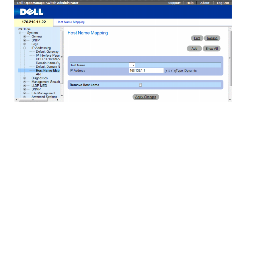
Configuring System Information 159
Mapping Domain Host
The Host Name Mapping page provides parameters for assigning IP addresses to static host names.
On this page, one IP address per host can be assigned.
To open the Host Name Mapping page, click System → IP Addressing → Host Name Mapping in the
tree view.
Figure 6-47. Host Name Mapping
The Host Name Mapping page contains the following fields:
•
Host Name
— Contains a Host Name list. Host Names are defined in the
Add Host Name Mapping
page. Each host provides one IP address.
•
IP Address (X.X.X.X)
— Provides an IP address that is assigned to the specified host name.
•
Ty p e
— The IP address type. The possible field values are:
–
Dynamic
— The IP address is created dynamically.
–
Static
— The IP address is a static IP address.
•
Remove Host Name
— Removes the DNS Host Mapping.
–
Checked
— Removes the DNS host mapping
–
Unchecked
— Maintains the DNS host mapping.
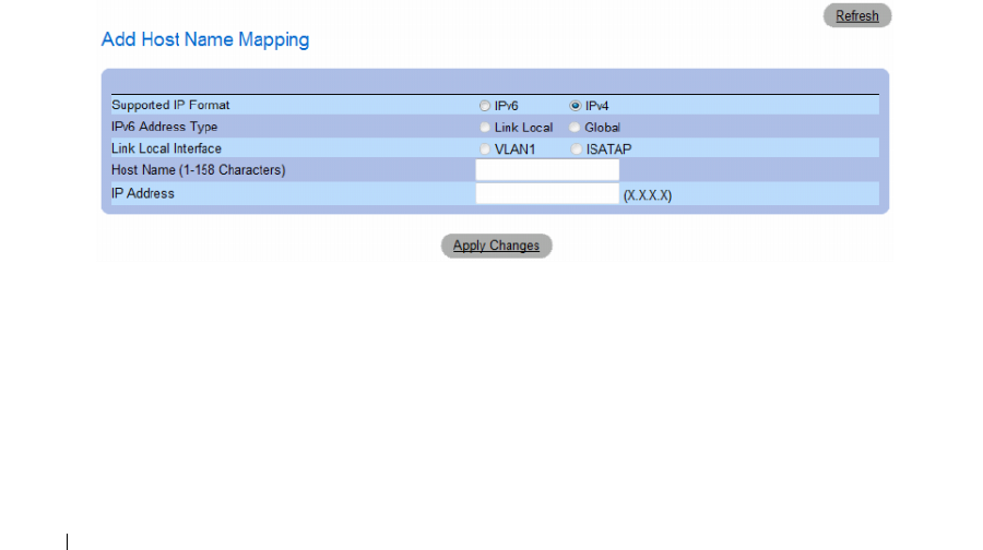
160 Configuring System Information
When defining a new host name mapping, the following additional parameters are available:
•
Supported IP Format
— Specifies the IP format supported by the host. The possible values are:
–
IPv6
— IP version 6 is supported.
–
IPv4
— IP version 4 is supported.
•
IPv6 Address Type
— When the host supports IPv6 (see previous parameter), this specifies the type of
static address supported. The possible values are:
–
Link Local
— A Link Local address that is non-routable and used for communication on the same
network only.
–
Global
— A globally unique IPv6 address; visible and reachable from different subnets.
•
Link Local Interface
— When the server supports an IPv6 Link Local address (see previous
parameter), this specifies the the Link Local interface. The possible values are:
–
VLAN1
— The IPv6 interface is configured on VLAN1.
–
ISATAP
— The IPv6 interface is configured on ISATAP tunnel.
Adding Host Domain Names
1
Open the
Host Name Mapping
page
.
2
Click
Add
.
The
Add Host Name Mapping
page opens.
Figure 6-48. Add Host Name Mapping
3
Define the relevant fields.
4
Click
Apply Changes
.
The IP address is mapped to the Host Name, and the device is updated.
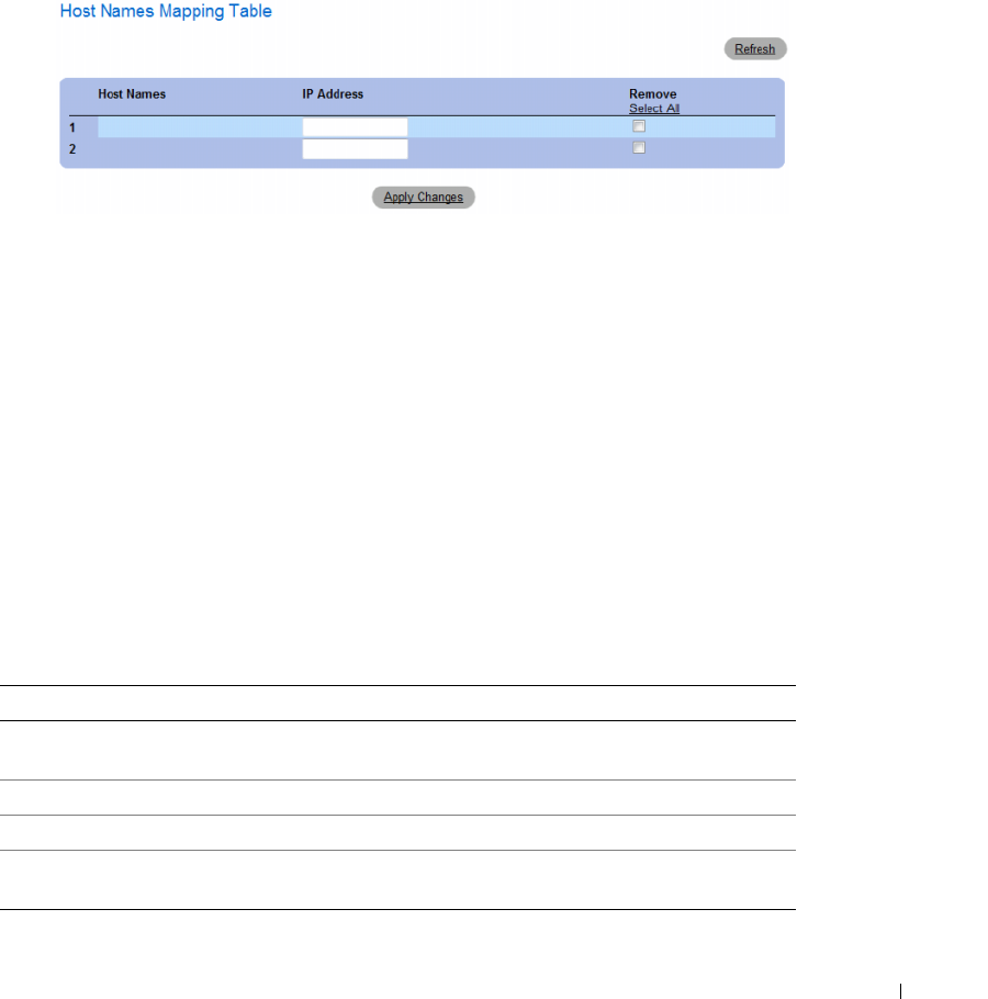
Configuring System Information 161
Displaying the Hosts Name Mapping Table
1
Open the
Host Name Mapping
page
.
2
Click
Show
All
.
The
Hosts Name Mapping Table
page opens.
Figure 6-49. Hosts Name Mapping Table
Removing Host Name from IP Address Mapping
1
Open the
Host Name Mapping
page
.
2
Click
Show
All.
3
The
Host Mapping Table
page opens.
4
Select a
Host Name Mapping Table
entry
.
5
Check the
Remove
checkbox.
6
Click
Apply Changes
.
The
Host Mapping Table
entry is deleted, and the device is updated.
Mapping IP addresses to Domain Host Names Using the CLI Commands
The following table summarizes the equivalent CLI commands for mapping Domain Host names to
IP addresses.
Table 6-29. Domain Host Name CLI Commands
CLI Command Description
ip host name address Defines the static host name-to-address mapping in the host
cache
no ip host name Removes the name-to-address mapping.
clear host {name | *} Deletes entries from the host name-to-address cache.
show hosts [name] Displays the default domain name, list of name server hosts, the
static and the cached list of host names and addresses.
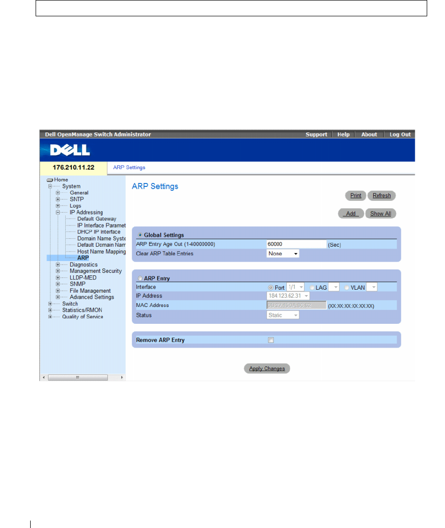
162 Configuring System Information
The following is an example of the CLI commands:
Defining ARP Settings
The Address Resolution Protocol (ARP) converts IP addresses into physical addresses, and maps the
IP address to a MAC address. ARP allows a host to communicate with other hosts only when the
IP address of its neighbors is known.
To open the ARP Settings page, click System → IP Addressing → ARP in the tree view.
Figure 6-50. ARP Settings
console(config)# ip host accounting.abc.com 176.10.23.1

Configuring System Information 163
The ARP Settings page contains the following fields:
•
Global Settings
— Select this option to activate the fields for ARP global settings.
•
ARP Entry Age Out (1-40000000)
— For all devices, the amount of time (seconds) that passes
between ARP requests about an ARP table
entry. After this period, the entry is deleted from the
table. The range is
1 - 40000000
seconds. The default value is 60000 seconds.
•
Clear ARP Table Entries
— The type of ARP entries that are cleared on all devices. The possible
values are:
•
None
— ARP entries are not cleared.
•
All
— All ARP entries are cleared.
•
Dynamic
— Only dynamic ARP entries are cleared.
•
Static
— Only static ARP entries are cleared.
•
ARP Entry
— Select this option to activate the fields for ARP settings on a single Ethernet devices.
•
Interface
— The interface number of the port, LAG, or VLAN that is connected to the device.
•
IP Address
— The station IP address, which is associated with the MAC address filled in below.
•
MAC Address
— The station MAC address, which is associated in the ARP table with the IP address.
•
Status
— The ARP Table
entry status. Possible field values are:
•
Dynamic
— The ARP entry is learned dynamically.
•
Static
— The ARP entry is a static entry.
•
Remove ARP Entry
— Removes an ARP entry.
–
Checked
— Removes the ARP entry.
–
Unchecked
— Maintains the ARP entry.
Adding a Static ARP Table Entry:
1
Open the
ARP Settings page
.
2
Click
Add
.
The
Add ARP Entry
page opens.
3
Select an interface.
4
Define the fields.
5
Click
Apply Changes
.
The
ARP Table
entry is added, and the device is updated.
Displaying the ARP Table
1
Open the
ARP Settings page
.
2
Click
Show All
.
The
ARP Table
page opens.

164 Configuring System Information
Deleting ARP Table Entry
1
Open the
ARP Settings page
2
Click
Show All.
The
ARP Table
page opens.
3
Select a table entry.
4
Select the
Remove
check box.
5
Click
Apply Changes
.
The selected
ARP Table
entry is deleted, and the device is updated.
Configuring ARP Using the CLI Commands
The following table summarizes the equivalent CLI commands for setting fields displayed in the ARP
Settings page.
The following is an example of the CLI commands:
Table 6-30. ARP Settings CLI Commands
CLI Command Description
arp ip_addr hw_addr {ethernet interface-number | vlan
vlan-id | port-channel number}
Adds a permanent entry in the ARP cache.
arp timeout seconds Configures how long an entry remains in the ARP cache.
clear arp-cache Deletes all dynamic entries from the ARP cache
show arp Displays entries in the ARP Table.
no arp Removes an ARP entry from the ARP Table.
console(config)# arp 198.133.219.232 00-00-0c-40-0f-bc
console(config)# arp timeout 12000
console(config)# exit
console# show arp
ARP timeout: 12000 Seconds
Interface IP address HW address Status
--------- ---------- ---------- ------
1/e11 10.7.1.102 00:10:B5:04:DB:4B Dynamic
1/e12 10.7.1.135 00:50:22:00:2A:A4 Static
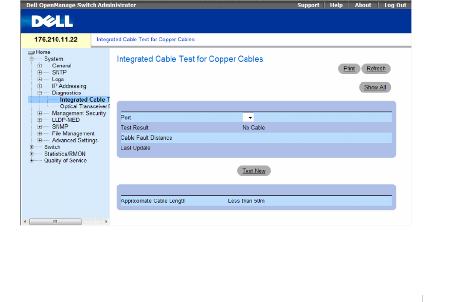
Configuring System Information 165
Running Cable Diagnostics
The Diagnostics page contains links to pages for performing virtual cable tests on copper and fiber
optic cables. To open the Diagnostics page, click System→ Diagnostics in the tree view.
This section contians the following topics:
• "Viewing Copper Cable Diagnostics" on page 165
• "Viewing Optical Transceiver Diagnostics" on page 167
Viewing Copper Cable Diagnostics
The Integrated Cable Test for Copper Cables page contains fields for performing tests on copper cables.
Cable testing provides information about where errors occurred in the cable, the last time a cable test
was performed, and the type of cable error which occurred. The tests use Time Domain Reflectometry
(TDR) technology to test the quality and characteristics of a copper cable attached to a port. Cables up
to 120 meters long can be tested. Cables are tested when the ports are in the down state, with the
exception of the Approximated Cable Length test.
To open the Integrated Cable Test for Copper Cables page, click System → Diagnostics → Integrated
Cable Test in the tree view.
Figure 6-51. Integrated Cable Test for Copper Cables
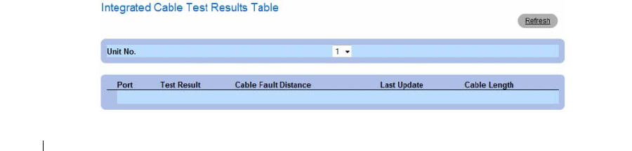
166 Configuring System Information
The Integrated Cable Test for Copper Cables page contains the following fields:
•
Port
— The port to which the cable is connected.
•
Test Result
— The cable test results. The possible field values are:
–
No Cable
— There is no cable connected to the port.
–
Open Cable
— The cable is connected on only one side.
–
Short Cable
— A short has occurred in the cable.
–
OK
— The cable passed the test.
•
Cable Fault Distance
— The distance from the port where the cable error occurred.
•
Last Update
— The last time the port was tested.
•
Approximate Cable Length
— The approximate cable length. This test can only be performed when
the port is up and operating at 1 Gbps.
Performing a Cable Test
1
Ensure that both ends of the copper cable are connected to a device.
2
Open the
Integrated Cable Test for Copper Cables
page.
3
Select an interface to test.
4
Click
Test Now
.
The copper cable test is performed, and the results are displayed on the
Integrated Cable Test for
Copper Cables
page.
Displaying Virtual Cable Test Results Table
This screen displays the results of tests that have been previously run, but does not actually perform the
test on all ports now. The cable length returned by the Integrated Cable Test (VCT) is an approximation
in the ranges of up to 50 meters, 50m-80m, 80m-110m, 110m-120m, or more than 120m. The deviation
may be up to 20 meters, and cable length measurement does not operate for 10 Mbps links.
1
Open the
Integrated Cable Test for Copper Cables
page.
2
Click
Show All
.
The
Integrated Cable Test Results Table
page opens.
Figure 6-52. Integrated Cable Test Results Table

Configuring System Information 167
In addition to the fields in the Integrated Cable Test for Copper Cables page, the Integrated Cable Test
Results Table contains the following field:
•
Unit No
. — The stacking member unit for which the cable is displayed.
Performing Copper Cable Tests Using CLI Commands
The following table contains the CLI commands for performing copper cable tests.
The following is an example of the CLI commands:
Viewing Optical Transceiver Diagnostics
Use the Optical Transceiver Diagnostics page to perform tests on Fiber Optic cables. Optical transceiver
diagnostics can be performed only when the link is present. Finisar transceivers do not support
transmitter fault diagnostic testing. Fiber Optic analysis feature works only on SFPs that support the
digital diagnostic standard SFF-872.
To open the Optical Transceiver Diagnostics page, click System → Diagnostics → Optical Transceiver
Diagnostics in the tree view.
Table 6-31. Copper Cable Test CLI Commands
CLI Command Description
test copper-port
tdr
interface
Performs VCT tests.
show copper-port
tdr
interface
Shows results of last VCT tests on ports.
show copper-port
cable-length
interface
Displays the estimated copper cable length attached to a
port.
console> enable
Console# test copper-port tdr 1/e3
Cable is open at 100 meters.
Console# show copper-port cable-length
Port Length (meters)
---- ---------------
1/e3 110-140
1/e4 Fiber
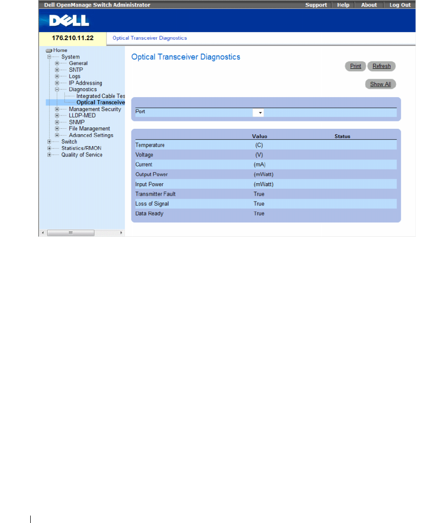
168 Configuring System Information
Figure 6-53. Optical Transceiver Diagnostics
The Optical Transceiver Diagnostics page contains the following fields:
•
Port
— The port number on which the cable is tested.
•
Temperature
— The temperature (C) at which the cable is operating.
•
Voltage
— The voltage at which the cable is operating.
•
Current
— The current at which the cable is operating.
•
Output Power
— The rate at which the output power is transmitted.
•
Input Power
— The rate at which the input power is transmitted.
•
Transmitter Fault
— Indicates if a fault occurred during transmission.
•
Loss of Signal
— Indicates if a signal loss occurred in the cable.
•
Data Ready
— The transceiver has achieved power up and data is ready.
Displaying the Optical Transceiver Diagnostics Test Results Table
1
Open the
Optical Transceiver Diagnostics
page.
2
Click
Show All
.
The test runs and the
Optical Transceiver Diagnostics Table
page opens.
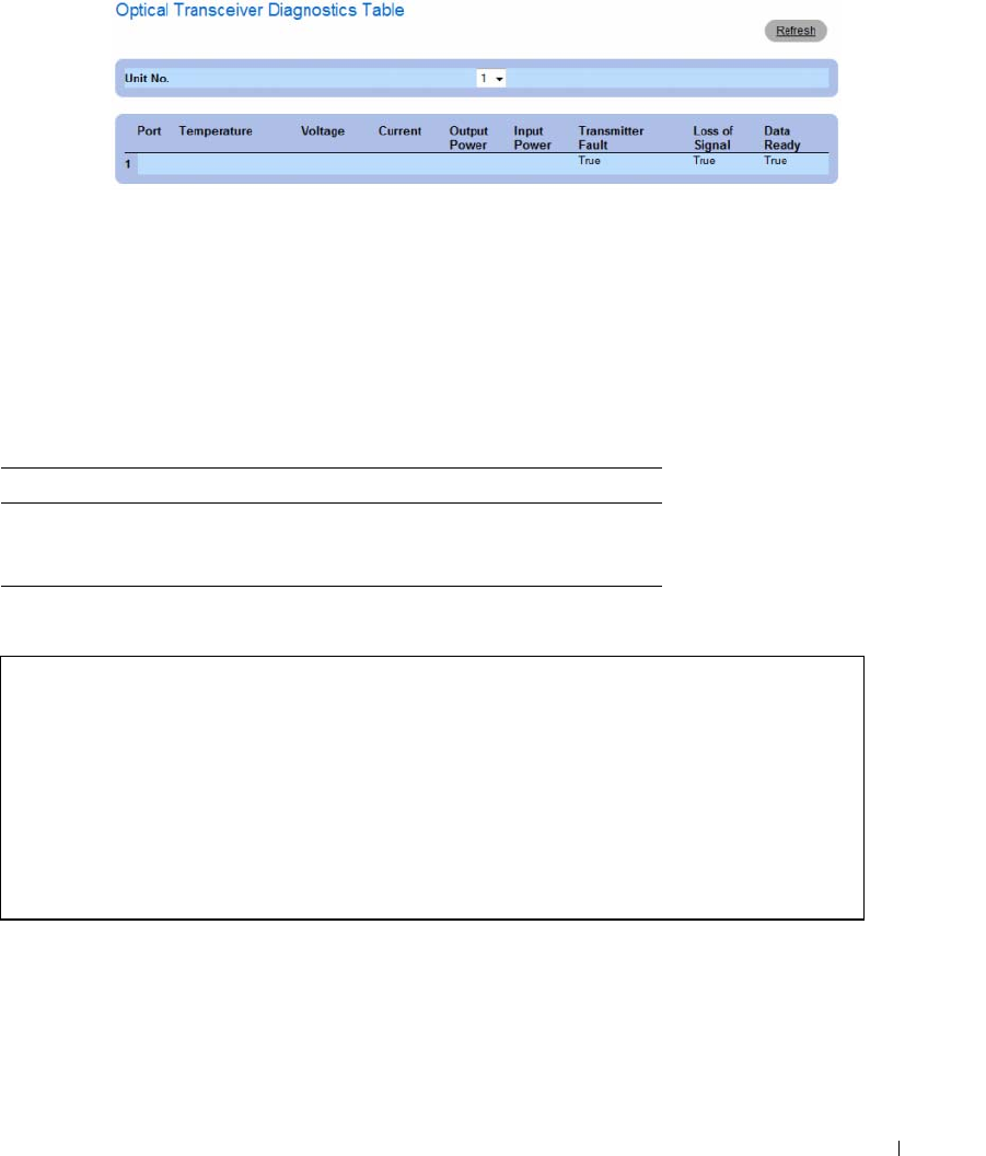
Configuring System Information 169
Figure 6-54. Optical Transceiver Diagnostics Table
In addition to the fields in the Optical Transceiver Diagnostics page, the Optical Transceiver Diagnostics
Ta bl e contains the following field:
•
Unit No
. — The unit number for which the cable is displayed.
•
N/A
— Not Available, N/S - Not Supported, W - Warning, E - Error
Performing Fiber Optic Cable Tests Using CLI Commands
The following table contains the CLI command for performing fiber optic cable tests.
The following is an example of the CLI command:
Table 6-32. Fiber Optic Cable Test CLI Commands
CLI Command Description
show fiber-ports optical-
transceiver [
interface
]
[
detailed
]
Displays the optical transceiver
diagnostics.
Console# show fiber-ports optical-transceiver detailed
Port Temp
[C]
Voltage Current
[Volt]
Output
[mA]
Input
[mWatt]
POWER
TX
[mWatt]
LOS
Fault
---- ---- ------ ----- ------ ------ ------ -----
1/g1 48 5.15 50 1.789 1.789 No No
1/g2 43 5.15 10 1.789 1.789 No No

170 Configuring System Information
Managing Management Security
The Management Security page provides access to security pages that contain fields for setting security
parameters for device management methods, user authentication databases and servers. To open the
Management Security page, click System→ Management Security in the tree view.
This section contians the following topics:
• "Defining Access Profiles" on page 170
• "Defining Authentication Profiles" on page 177
• "Selecting Authentication Profiles" on page 181
• "Managing Passwords" on page 184
• "Displaying Active Users" on page 187
• "Defining the Local User Databases" on page 189
• "Defining Line Passwords" on page 192
• "Defining Enable Passwords" on page 194
• "Defining TACACS+ Settings" on page 196
• "Configuring RADIUS Settings" on page 200
Defining Access Profiles
The Access Profiles page contains fields for defining profiles and rules for accessing the device. Access to
management functions can be limited to user groups, which are defined by ingress interfaces and source
IP address or source IP subnets.
Management access can be separately defined for each type of management access method, including
Web (HTTP), Secure Web (HTTPS), Telnet, and Secure Telnet.
Access to different management methods may differ between user groups. For example, User Group 1
can access the device only via an HTTPS session, while User Group 2 can access the device via both
HTTPS and Telnet sessions.
Management Access Lists contain up to 256 rules that determine which users can manage the device,
and by which methods. Users can also be blocked from accessing the device.
The Access Profiles page contains fields for configuring Management Lists and applying them to
specific interfaces.
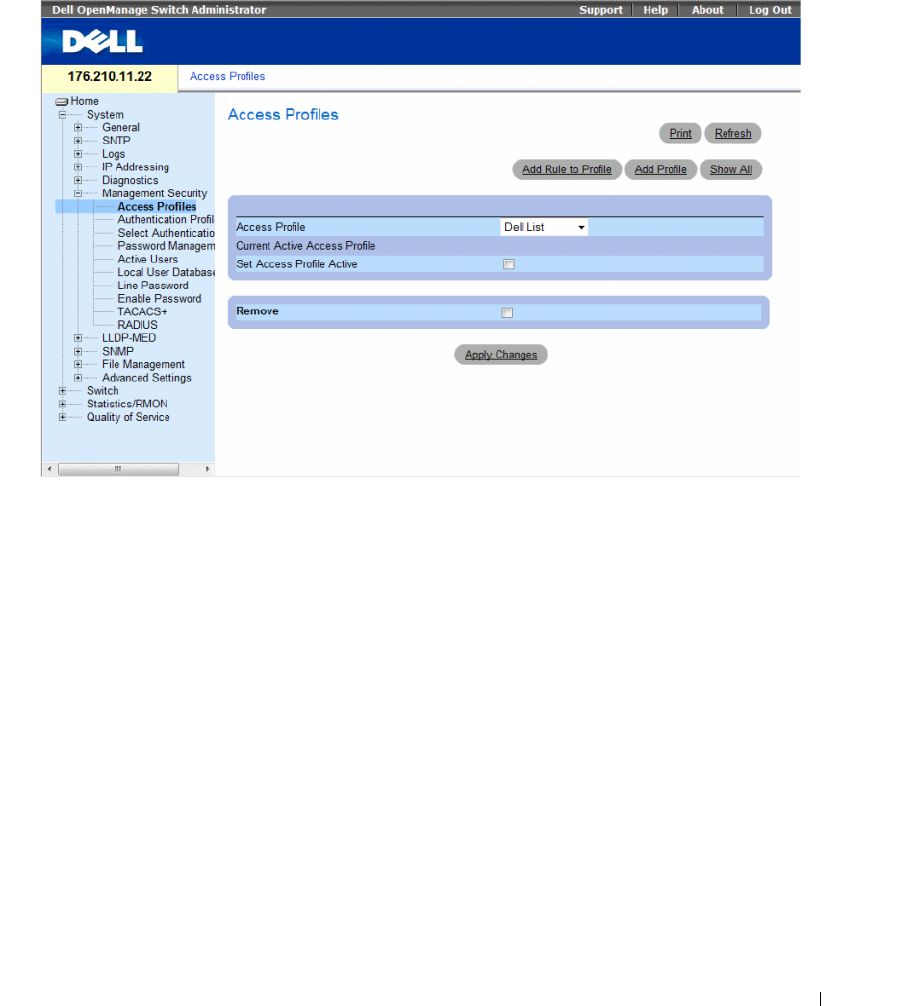
Configuring System Information 171
To open the Access Profiles page, click System → Management Security → Access Profiles in the tree view.
Figure 6-55. Access Profiles
The Access Profiles page contains following fields:
•
Access Profile
— User-defined Access Profile lists. The Access Profile list contains a default value of
Console Only
. When this access profile is selected, active management of the device is performed
using the console connection only.
•
Current Active Access Profile
— The access profile that is currently active.
•
Set Access Profile Active
— Activates an access profile.
•
Remove
— Removes an access profile from the
Access Profile Name
list.
–
Checked
— Removes the access profile.
–
Unchecked
— Maintains the access profile.
Activating a Profile
1
Open the
Access Profiles
page.
2
Select an Access Profile in the
Access Profile
field.
3
Select the
Set Access Profile Active
check box.
4
Click
Apply Changes
.
The Access Profile is activated.
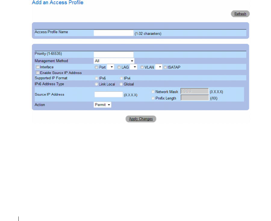
172 Configuring System Information
Adding an Access Profile
Rules act as filters for determining rule priority, the device management method, interface type,
source IP address and network mask, and the device management access action. Users can be blocked or
permitted management access. Rule priority sets the order in which the rules are implemented.
Assigning an access profile to an interface denies access via other interfaces. If an access profile is not
assigned to any interface, the device can be accessed by all interfaces.
Defining Rules for an Access Profile:
1
Open the
Access Profiles
page
.
2
Click
Add Profile.
The
Add an Access Profile
page opens.
Figure 6-56. Add an Access Profile
The Add an Access Profile page contains the following additional fields:
•
Access Profile Name (1-32 Characters)
— User-defined name for the access profile. The Access Profile
name can contain up to 32 characters.
•
Rule Priority
(1-65535)
— The rule priority. When the packet is matched to a rule, user groups are
either granted access or denied access to device management. The rule order is set by defining a rule
priority using this field. The rule number is essential to matching packets to rules, as packets are
matched on a first-fit basis. The rule priorities can be viewed in the
Profile Rules Table
.

Configuring System Information 173
•
Management Method
— The management method for which the access profile is defined. Users with
this access profile are denied or permitted access to the device from the selected management method
(line). The possible field values are:
–
All
— Assigns all management methods to the rule.
–
Telnet
— Assigns Telnet access to the rule. If selected, users accessing the device using Telnet
meeting access profile criteria are permitted or denied access to the device.
–
Secure Telnet (SSH)
— Assigns SSH access to the rule. If selected, users accessing the device
using Telnet meeting access profile criteria are permitted or denied access to the device.
–
HTTP
— Assigns HTTP access to the rule. If selected, users accessing the device using HTTP
meeting access profile criteria are permitted or denied access to the device.
–
Secure HTTP (HTTPS)
— Assigns HTTPS access to the rule. If selected, users accessing the
device using HTTPS meeting access profile criteria are permitted or denied access to the device.
–
SNMP
— Assigns SNMP access to the rule. If selected, users accessing the device using SNMP
meeting access profile criteria are permitted or denied access to the device.
•
Interface
— The interface type to which the rule applies. This is an optional field. This rule can be
applied to a selected port, LAG, or VLAN by selecting the check box, then selecting the appropriate
option button and interface.
• Enable Source IP Address
— Check this parameter to restrict conditions based on the source
IP address. When unchecked, the source IP address cannot be entered into a configured rule.
•
Supported IP Format
— Specifies the IP format. The possible values are:
–
IPv6
— IP version 6 is supported.
–
IPv4
— IP version 4 is supported.
•
IPv6 Address Type
— For IPv6 (see previous parameter), this specifies the type of static address
supported. The possible values are:
–
Link Local
— A Link Local address that is non-routable and used for communication on the same
network only.
•
Global
— A globally unique IPv6 address; visible and reachable from different subnets.
•
Source IP Address
(X.X.X.X) — The interface source IP address for which the rule applies. This is an
optional field and indicates that the rule is valid for a subnetwork.
•
Network Mask
(X.X.X.X) — The IP subnetwork mask.
•
Prefix Length (/XX)
— The number of bits that comprise the source IP address prefix, or the network
mask of the source IP address.
•
Action
— Defines whether to permit or deny management access to the defined interface.
–
Permit
— Permits access to the device.
–
Deny
— Denies access to the device. This is the default.
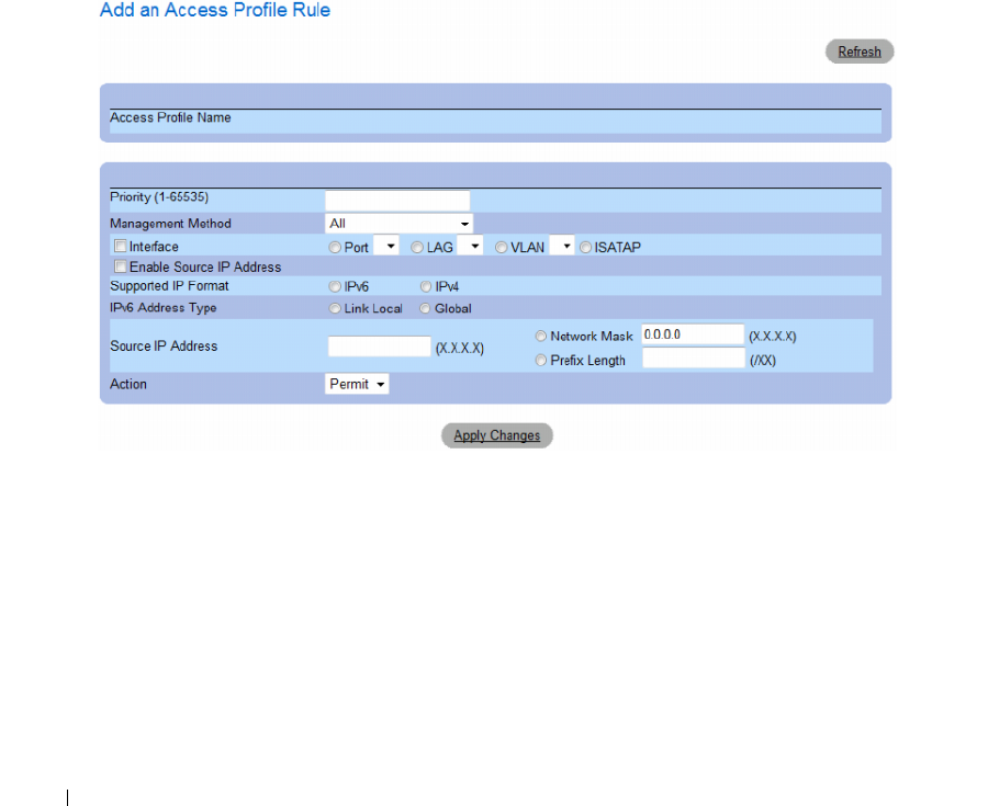
174 Configuring System Information
3
Define the
Access Profile Name
field.
4
Define the relevant
fields.
5
Click
Apply Changes
.
The new Access Profile is added, and the device is updated.
Adding Rules to Access Profile
The first rule must be defined to beginning matching traffic to access profiles.
1
Open the
Access Profile
page
.
2
Click
Add Rule to Profile
.
The
Add an Access Profile Rule
page opens.
Figure 6-57. Add an Access Profile Rule
3
Complete the fields.
4
Click
Apply Changes
.
The rule is added to the access profile, and the device is updated.
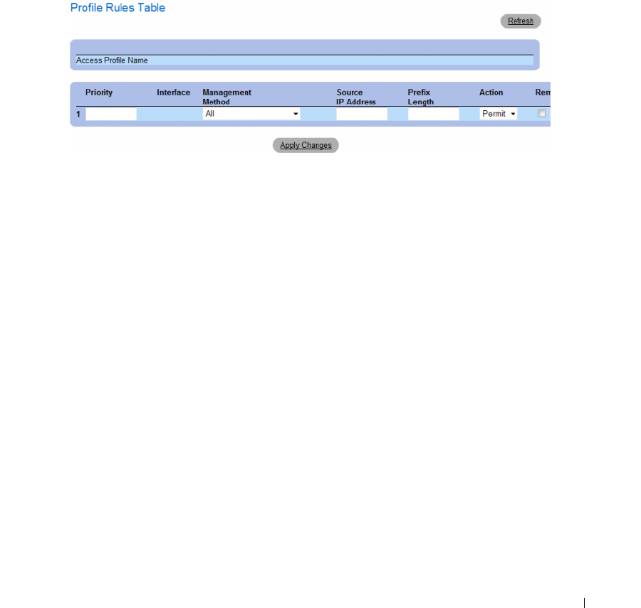
Configuring System Information 175
Viewing the Profile Rules Table
The order in which rules appear in the Profile Rules Table is important. Packets are matched to the first
rule which meets the rule criteria.
1
Open the
Access Profiles
page
.
2
Click
Show All.
The
Profile Rules Table
page
opens.
Figure 6-58. Profile Rules Table
Removing a Rule
1
Open the
Access Profiles
page.
2
Click
Show All
.
The
Profile Rules Table
page opens.
3
Select a rule.
4
Select the
Remove
check box.
5
Click
Apply Changes
.
The selected rule is deleted, and the device is updated.

176 Configuring System Information
Defining Access Profiles Using CLI Commands
The following table summarizes the equivalent CLI commands for setting fields displayed in the Access
Profiles page.
Table 6-33. Access Profiles CLI Commands
CLI Command Description
management access-list name Defines an access-list for management, and enters
the access-list context for configuration.
permit [ethernet interface-number |
vlan vlan-id | port-channel number]
[service service]
Sets port permitting conditions for the management
access list.
permit ip-source {ipv4-address | ipv6-
address / prefix-length} [mask mask |
prefix-length] [ethernet interface-
number | vlan vlan-id | port-channel
number] [service service]
Sets port permitting conditions for the management
access list, and the selected management method.
deny [ethernet interface-number | vlan
vlan-id | port-channel number] [service
service]
Sets port denying conditions for the management
access list, and the selected management method.
deny ip-source {ipv4-address | ipv6-
address / prefix-length} [mask mask |
prefix-length] [ethernet interface-
number | vlan vlan-id | port-channel
number] [service service]
Sets port denying conditions for the management
access list, and the selected management method.
management access-class {console-only
| name}
Defines which access-list is used as the active
management connections.
show management access-list [name] Displays the active management access-lists.
show management access-class Displays information about management access-
class.

Configuring System Information 177
The following is an example of the CLI commands:
Defining Authentication Profiles
The Authentication Profiles page contains fields for selecting the user authentication method on the
device. User authentication occurs:
•Locally
• Via an external server
User authentication can also be set to None.
User authentication occurs in the order the methods are selected. For example, if both the Local and
RADIUS options are selected, the user is authenticated first locally. If the local user database is empty,
the user is then authenticated via the RADIUS server. If the authentication fails using the first method,
the authentication process ends.
console(config)# management access-list mlist
console(config-macl)# permit ethernet 1/e1
console(config-macl)# permit ethernet 1/e2
console(config-macl)# deny ethernet 1/e3
console(config-macl)# deny ethernet 1/e4
console(config-macl)# exit
console(config)# management access-class mlist
console(config)# exit
console# show management access-list
mlist
-----
permit ethernet 1/e1
permit ethernet 1/e2
deny ethernet 1/e3
deny ethernet 1/e4
! (Note: all other access implicitly denied)
Console# show management access-class
Management access-class is enabled, using access list mlist
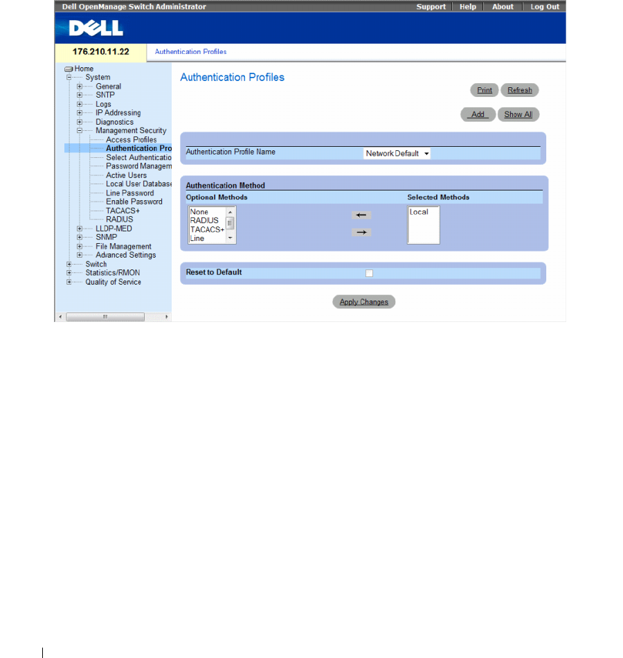
178 Configuring System Information
If an error occurs during the authentication, the next selected method is used.
To open the Authentication Profiles page, click System → Management Security → Authentication
Profiles in the tree view.
Figure 6-59. Authentication Profiles
The Authentication Profiles page contains the following fields:
•
Authentication Profile Name
— User-defined authentication profile lists to which user-defined
authentication profiles are added. The options are
Network Default
and
Console Default
.
Profile names cannot include blank spaces.
•
Optional Methods
— User authentication methods. The possible options are:
–
None
— No user authentication occurs.
–
Local
— User authentication occurs at the device level. The device checks the user name and
password for authentication.
–
RADIUS
— User authentication occurs at the RADIUS server. For more information,
see
Configuring RADIUS Settings
.
–
TACACS+
— The user authentication occurs at the TACACS+ server.
–
Line
— The line password is used for user authentication.
–
Enable
— The enable password is used for authentication.
•
Reset to Default
— Restores the default user authentication method on the device. Available for
default profile only.
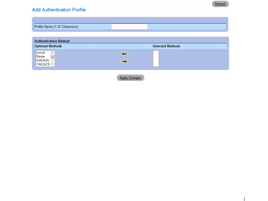
Configuring System Information 179
Selecting an Authentication Profile:
1
Open the
Authentication Profiles
page.
2
Select a profile in the
Authentication Profile Name
field.
3
Select the authentication method using the navigation arrows. The authentication occurs in the order
the authentication methods are listed.
4
Click
Apply Changes
.
The user authentication profile is updated to the device.
Adding an Authentication Profile:
1
Open the
Authentication Profiles
page.
2
Click
Add
.
The
Add Authentication Profile
page opens.
Figure 6-60. Add Authentication Profile
3
Configure the profile.
4
Click
Apply Changes
.
The authentication profile is updated to the device.

180 Configuring System Information
Displaying the Authentication Profiles Table:
1
Open the
Authentication Profiles
page.
2
Click
Show All
.
The
Authentication Profiles Table
page opens.
Figure 6-61. Authentication Profiles Table
Deleting an Authentication Profile:
1
Open the
Authentication Profiles
page.
2
Click
Show All
.
The
Authentication Profiles Table
page opens.
3
Select an authentication profile.
4
Select the
Remove
check box.
5
Click
Apply Changes
.
The selected authenticating profile is deleted.
Configuring an Authentication Profile Using CLI Commands
The following table summarizes the equivalent CLI commands for setting fields displayed in the
Authentication Profiles page.
Table 6-34. Authentication Profile CLI Commands
CLI Command Description
aaa authentication login
{default | list-name}
method1 [method2.]
Configures login authentication.
no aaa authentication login
{default | list-name}
Removes a login authentication profile.
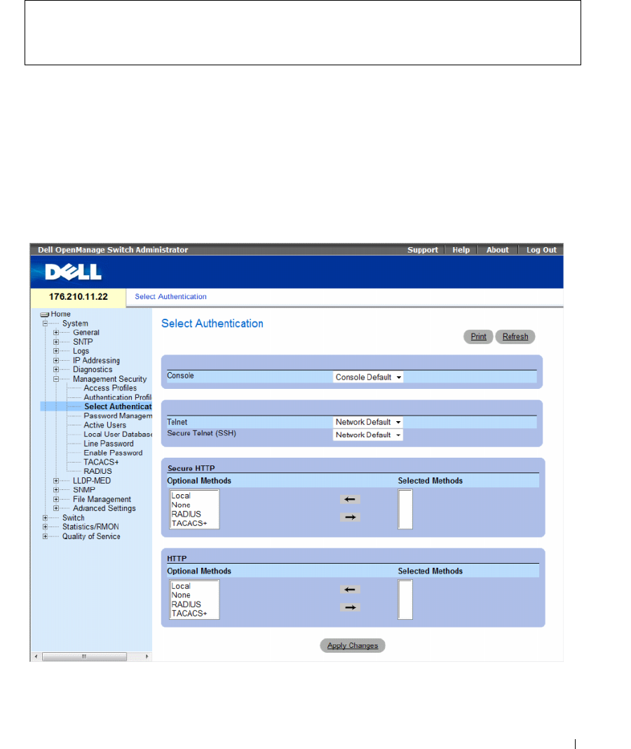
Configuring System Information 181
The following is an example of the CLI commands:
Selecting Authentication Profiles
After Authentication Profiles are defined, the Authentication Profiles can be applied to Management
Access methods. For example, console users can be authenticated by Authentication Method List 1,
while Telnet users are authenticated by Authentication Method List 2.
To open the Select Authentication page, click System → Management Security → Select Authentication
in the tree view.
Figure 6-62. Select Authentication
console(config)# aaa authentication login default radius local
enable none
console(config)# no aaa authentication login default

182 Configuring System Information
The Select Authentication page contains the following fields:
•
Console
— Authentication profiles used to authenticate console users.
•
Telnet
— Authentication profiles used to authenticate Telnet users.
•
Secure Telnet (SSH
) — Authentication profiles used to authenticate Secure Shell (SSH) users.
SSH
provides clients with secure and encrypted remote connections to a device.
•
Secure HTTP
and
HTTP
— Authentication method used for Secure HTTP access and HTTP access,
respectively. Possible field values are:
–
Local
— Authentication occurs locally.
–
None
— No authentication method is used for access.
–
RADIUS
— Authentication occurs at the RADIUS server.
–
TACACS+
— Authentication occurs at the TACACS+ server.
Applying an Authentication List to Console Sessions
1
Open the
Select Authentication
page.
2
Select an Authentication Profile in the
Console
field.
3
Click
Apply Changes
.
Console sessions are assigned an Authentication List.
Applying an Authentication Profile to Telnet Sessions
1
Open the
Select Authentication
page.
2
Select an Authentication Profile in the
Telnet
field.
3
Click
Apply Changes
.
Telnet sessions are assigned an Authentication List.
Applying an Authentication Profile to Secure Telnet (SSH) Sessions
1
Open the
Select Authentication
page.
2
Select an Authentication Profile in the
Secure Telnet (SSH)
field.
3
Click
Apply Changes
.
Secure Telnet (SSH) sessions are assigned an Authentication Profile.
Assigning HTTP Sessions an Authentication Sequence
1
Open the
Select Authentication
page.
2
Select an authentication sequence in the
HTTP
field.
3
Click
Apply Changes
.
HTTP sessions are assigned an authentication sequence.

Configuring System Information 183
Assigning Secure HTTP Sessions an Authentication Sequence
1
Open the
Select Authentication
page.
2
Select an authentication sequence in the
Secure HTTP
field.
3
Click
Apply Changes
.
Secure HTTP sessions are assigned an authentication sequence.
Assigning Access Authentication Profiles or Sequences Using CLI Commands
The following table summarizes the equivalent CLI commands for setting fields displayed in the Select
Authentication page.
The following is an example of the CLI commands:
Table 6-35. Select Authentication CLI Commands
CLI Command Description
enable authentication
[default | list-name]
Indicates the authentication method list when
accessing a higher privilege level from a remote Telnet,
Console or SSH.
login authentication
[default | list-name]
Indicates the login authentication method list for a
remote Telnet, Console or SSH.
ip http authentication
method1 [method2.]
Indicates authentication methods for HTTP servers.
ip https authentication
method1 [method2.]
Indicates authentication methods for HTTPS servers.
show authentication
methods
Displays information about the authentication
methods.
console(config-line)# enable authentication default
console(config-line)# login authentication default
console(config-line)# exit
console(config)# ip http authentication radius local
console(config)# ip https authentication radius local
console(config)# exit
console# show authentication methods
Login Authentication Method Lists
---------------------------------
Console_Default : None

184 Configuring System Information
Managing Passwords
Password management provides increased network security and improved password control.
Passwords for SSH, Telnet, HTTP, HTTPS, and SNMP access are assigned security features,
which include:
• Defining minimum password lengths
• Password expiration
• Prevents frequent password reuse
• Locks users out after failed login attempts
Password aging starts immediately, when password management is enabled. Passwords expire based on
the user-defined time/day definition expiration. Ten days prior to password expiration, the device
displays a password expiration warning message.
After the password has expired, users can login several additional times (number of times is
configurable). During the remaining logins an additional warning message displays informing the user
that the password must be changed immediately. If the password is not changed, users are locked out of
the system, and can only log in using the console. Password warnings are logged in the Syslog file.
If a privilege level is redefined, the user must also be re-defined. However, the password age time expires
from the initial user definition.
Users are notified before the password expires and that it must be changed. However, this notification is
not displayed to the Web user.
Network_Default : Local
Enable Authentication Method Lists
----------------------------------
Console_Default : Enable None
Network_Default : Enable
Line Login Method List Enable Method List
---- ----------------- ------------------
Console Default Default
Telnet Default Default
SSH Default Default
http : Local
https : Local
dot1x :
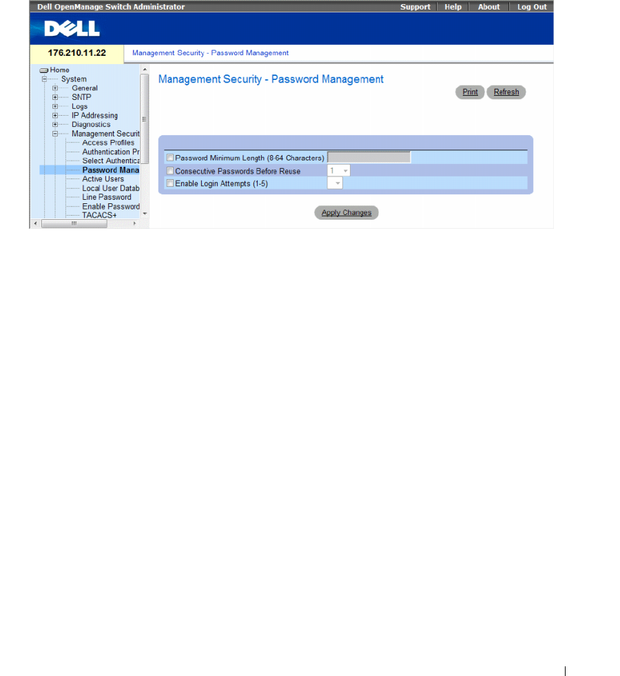
Configuring System Information 185
To open the Password Management page, click System → Management Security → Password
Management in the tree view.
Figure 6-63. Password Management
The Password Management page contains the following fields:
•
Password Minimum Length (8-64)
— Indicates the minimum password length, when checked.
For example, the administrator can define that all passwords must have a minimum of 10 characters.
•
Consecutive Passwords Before Re-use
— Indicates the amount of times a password is changed,
before the password can be reused. Possible field values are 1-10
.
•
Enable Login Attempts (1-5)
— When checked, enables locking a user out of the device when a faulty
password is used more than a user-defined number of times. For example, if this field is checked,
configured to 5 and a user attempts to log on five times with an incorrect password, the device locks
the user out on the sixth attempt. Possible field values are 1-5.
Defining Password Management
1
Open the
Password Management
page.
2
Define the fields.
3
Click
Apply Changes
.
Password management is defined, and the device is updated.

186 Configuring System Information
Password Management Using CLI Commands
The following table summarizes the equivalent CLI commands for setting fields displayed in the
Password Management page.
The following is an example of the CLI commands:
Table 6-36. Password Management Using CLI Commands
CLI Command Description
password min-length length Defines the minimum password length.
password history number Defines the amount of times a password is changed,
before the password can be reused.
password lock-out number Defines the number of times a faulty password is entered
before the user is locked out of the device.
show password configuration Displays password management information.
show users accounts Displays the userd account.
console # show passwords configuration
Minimal length: 0
History: Disabled
History hold time: no limit
Lockout control: disabled
Enable Passwords
Level Password
Aging
Password
Expiry date
Lockout
----- -------- ----------- -------
1---
15 - - -
Line Passwords
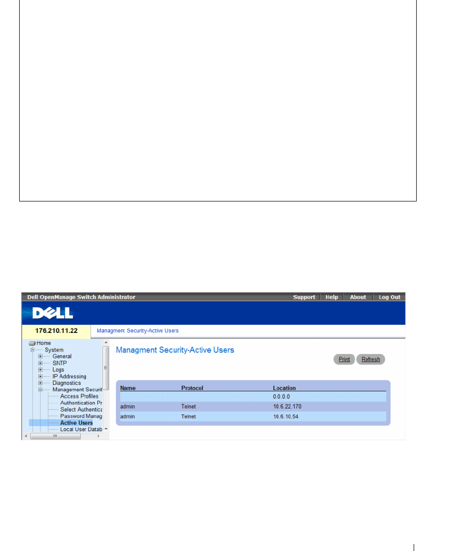
Configuring System Information 187
Displaying Active Users
The Active Users page displays information about active users on the device.
To open the Active Users page, click System → Management Security → Active Users in the tree view.
Figure 6-64. Active Users
The Active Users page contains the following fields:
•
Name
— List of user names logged into the device.
•
Protocol
— The management method by which the user is connected to the device.
•
Location
— The user’s IP address.
Line Password
Aging
Password
Expiry date
Lockout
------- -------- ----------- -------
Telnet - - -
SSH - - -
Console - - -
console # show users accounts
Username Privilege Password
Aging
Password
Expiry Date
Lockout
-------- --------- -------- ----------- -------
nim 15 39 18-Feb-2005

188 Configuring System Information
Displaying Active Users Using CLI Commands
The following table summarizes the equivalent CLI commands for viewing active users connected to
the device.
Table 6-37. Active Users CLI Commands
The following example shows an example of the CLI command:
CLI Command Description
show users Displays information about active users.
console> show users
Username Protocol Location
---------- ---------- ---------
Bob Serial
John SSH 172.16.0.1
Robert HTTP 172.16.0.8
Betty Telnet 172.16.1.7
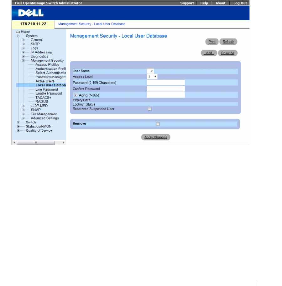
Configuring System Information 189
Defining the Local User Databases
The Local User Database page contains fields for defining users, passwords and access levels.
To open the Local User Database page, click System → Management Security → Local User Database in
the tree view.
Figure 6-65. Local User Database
The Local User Database page contains the following fields:
•
User Name
— List of users.
•
Access Level
— User access level. The lowest user access level is
1
and
15
is the highest user access
level. Users with access level 15 are Privileged Users, and only they can access and use the
OpenManage Switch Administrator.
•
Password (0-159 Characters)
— User-defined password.
•
Confirm Password
— Confirms the user-defined password.
•
Aging (1-365)
— Indicates the amount of time in days that elapses before a password is aged out.
–
Checked
— Password ages out after the specified number of days.
–
Unchecked
— Password does not expire.
•
Expiry Date
— Indicates the expiration date of the user-defined password.
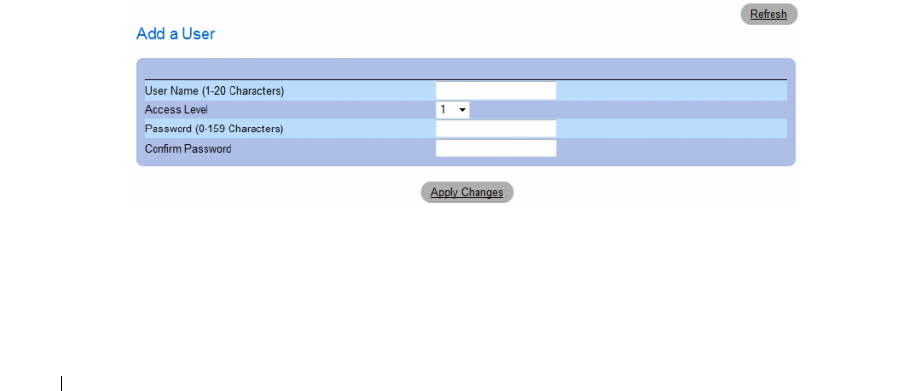
190 Configuring System Information
•
Lockout Status
— Indicates whether the user currently has access (status
Usable
), or whether the user
is locked out due to too many failed authentication attempts since the user last logged in successfully
(status
Locked
).
•
Reactivate Suspended User
— Reactivate the specified user’s access rights. Access rights can be
suspended after unsuccessfully attempting to login.
–
Checked
— Reactivate the specified user’s access rights.
–
Unchecked
— Maintain the specified user’s access suspension.
•
Remove
— Removes users from the
User Name
list.
–
Checked
— Removes the selected user.
–
Unchecked
— Maintains the selected user.
Assigning Access Rights to a User:
1
Open the
Local User Database
page.
2
Select a user in the
User Name
field.
3
Define the fields.
4
Click
Apply Changes
.
The user access rights and passwords are defined, and the device is updated.
Defining a New User:
1
Open the
Local User Database
page.
2
Click
Add
.
The
Add User
page opens.
Figure 6-66. Add a User
3
Define the fields.
4
Click
Apply Changes
.
The new user is defined, and the device is updated.
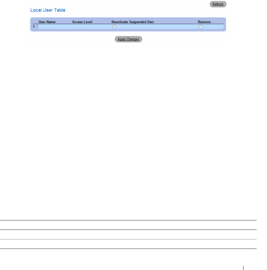
Configuring System Information 191
Displaying the Local User Table:
1
Open the
Local User Database
page.
2
Click
Show All.
The
Local User Table
opens.
Figure 6-67. Local User Table
Reactivating a Suspended User:
1
Open the
Local User Database
page.
2
Select a
User Name
entry.
3
Select the
Reactivate Suspended User
check box.
4
Click
Apply Changes
.
The user access rights are reactivated, and the device is updated. You can also reactivate suspended
users from the Local User Table.
Deleting Users:
1
Open the
Local User Database
page.
2
Select a
User Name.
3
Select the
Remove
check box.
4
Click
Apply Changes
.
The selected user is deleted, and the device is updated.
Assigning Users Using CLI Commands
The following table summarizes the equivalent CLI commands for setting fields displayed in the Local
User Database page.
Table 6-38. Local User Database CLI Commands
CLI Command Description
username name [password password] [level level] [encrypted] Establishes a username-based authentication system.
set username name active Reactivates a suspended user’s access rights.
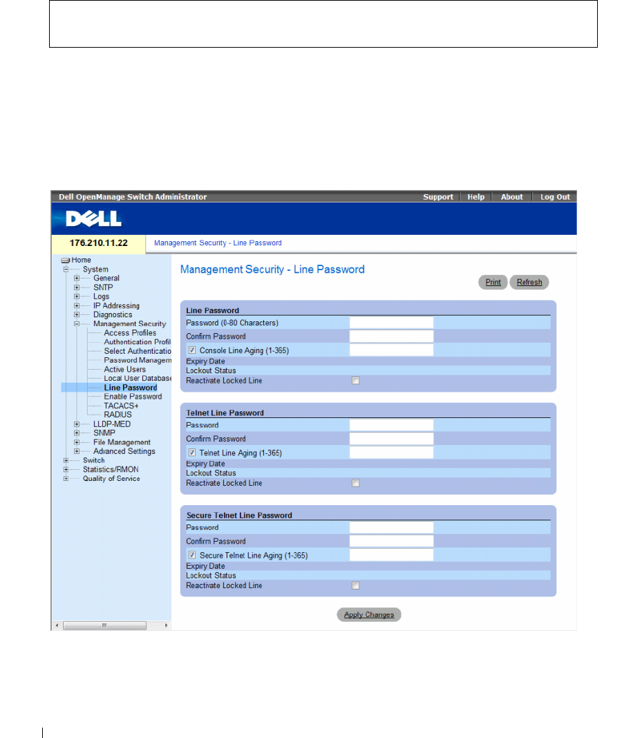
192 Configuring System Information
The following is an example of the CLI commands:
Defining Line Passwords
The Line Password page contains fields for defining line passwords for management methods.
To open the Line Password page, click System → Management Security → Line Passwords in the
tree view.
Figure 6-68. Line Password
console(config)# username bob password lee level 15
console# set username bob active

Configuring System Information 193
The Line Password page contains the following fields:
•
Line Password/Telnet Line Password/Secure Telnet Line Password
— Password settings for Console,
Telnet, or Secure Telnet session, respectively.
•
Password
— The line password for accessing the device.
•
Confirm Password
— Confirms the new line password. The password appears in the ***** format,
for security reasons.
•
Console/Telnet/Secure Telnet Line Aging (1-365)
— Indicates the amount of time in days that
elapses before a line password is aged out.
–
Checked
— Password ages out after the specified number of days.
–
Unchecked
— Password does not expire.
•
Expiry Date
— Indicates the expiration date of the line password.
•
Lockout Status
— Indicates whether the user currently has access (status
Usable
), or whether the user
is locked out due to too many failed authentication attempts since the user last logged in successfully
(status
Locked
).
•
Reactivate Locked Line
— Reactivates the line password for a Console/Telnet/Secure Telnet session.
Access rights can be suspended after unsuccessfully attempting to log in.
–
Checked
— Reactivates the line password.
–
Unchecked
— Maintains locked password.
Defining Line Passwords for Console Sessions
1
Open the
Line Password
page
2
Define the
Console Line Password
fields.
3
Click
Apply Changes
.
The line password for console sessions is defined, and the device is updated.
Defining Line Passwords for Telnet Sessions
1
Open the
Line Password
page.
2
Define the
Telnet Line Password
fields.
3
Click
Apply Changes
.
The line password for the Telnet sessions is defined, and the device is updated.
Defining Line Passwords for Secure Telnet Sessions
1
Open the
Line Password
page.
2
Define the
Secure Telnet Line Password
fields.
3
Click
Apply Changes
.
The line password for Secure Telnet sessions is defined, and the device is updated.
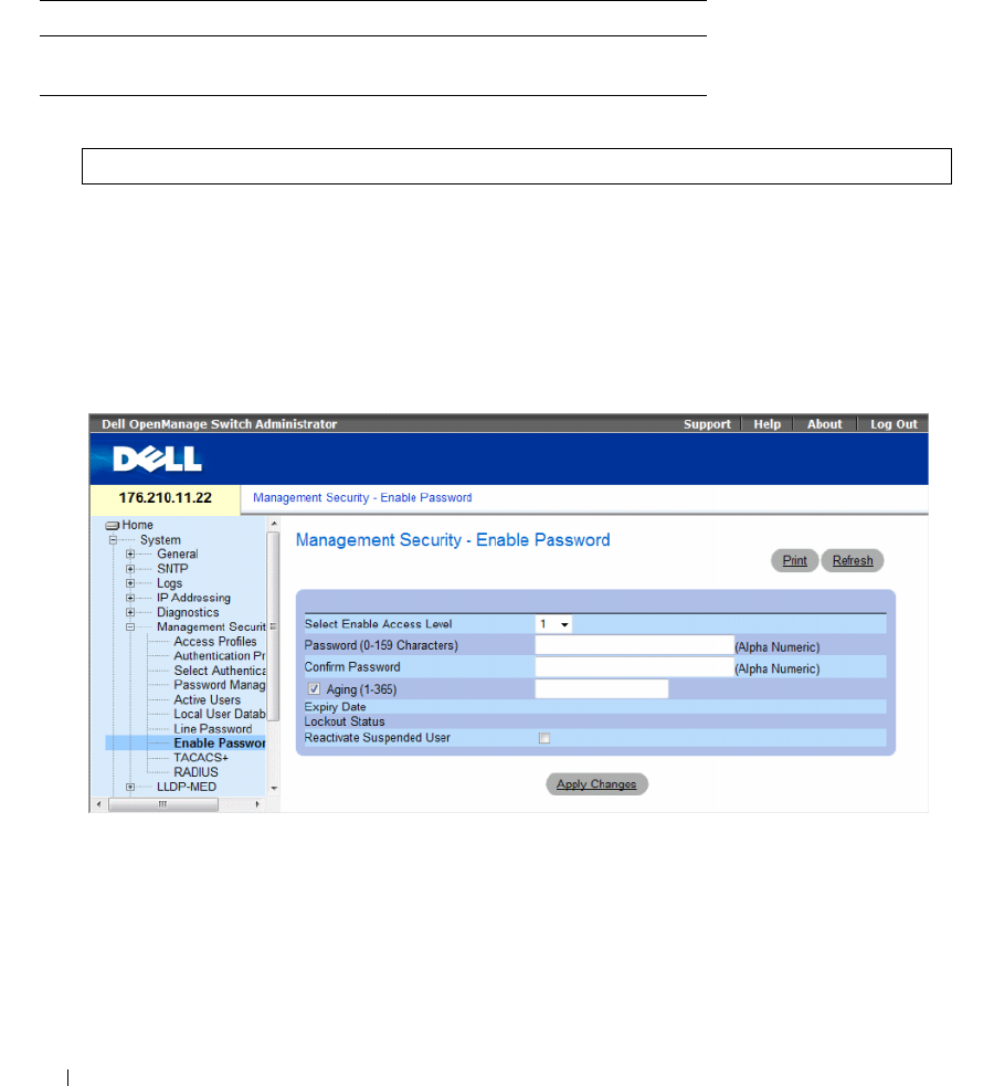
194 Configuring System Information
Assigning Line Passwords Using CLI Commands
The following table summarizes the equivalent CLI commands for setting fields displayed in the Line
Password page.
The following is an example of the CLI commands:
Defining Enable Passwords
The Enable Password page sets a local password to control access to Normal and Privilege levels.
To open the Enable Password page, click System → Management Security → Enable Passwords in the
tree view.
Figure 6-69. Enable Password
The Enable Password page contains the following fields:
•
Select Enable Access Level
— Access level associated with the enable password. The lowest user access
level is
1
and
15
is the highest user access level. Users with access level 15 are Privileged Users, and only
they can access and use the OpenManage Switch Administrator.
•
Password (0-159 characters)
— The password to enable.
Table 6-39. Line Password CLI Commands
CLI Command Description
password password
[encrypted]
Indicates a password on a line.
console(config-line)# password dell

Configuring System Information 195
•
Confirm Password
— Confirms the password. The password appears in the ***** format, for security
reasons.
•
Aging (1-365)
— Indicates the amount of time in days that elapses before a password is aged out.
–
Checked
— Password ages out after the specified number of days.
–
Unchecked
— Password does not expire.
•
Expiry Date
— Indicates the expiration date of the enable password.
•
Lockout Status
— Specifies the number of failed authentication attempts since the user last logged in
successfully, when the
Enable Login Attempts
checkbox is selected in the
Password Management
page. Specifies
LOCKOUT
, when the user account is locked.
•
Reactivate Suspended User
— Reactivates the specified user’s access rights. Access rights can be
suspended after unsuccessfully attempting to login.
–
Checked
— Reactivate the specified user’s access rights.
–
Unchecked
— Maintain the specified user’s access suspension.
Defining a New Enable Password:
1
Open the
Enable Password
page
.
2
Define the fields.
3
Click
Apply Changes
.
The new Enable password is defined, and the device is updated.
Assigning Enable Passwords Using CLI Commands
The following table summarizes the equivalent CLI commands for setting fields displayed in the Enable
Password page.
The following is an example of the CLI commands:
Table 6-40. Modify Enable Password CLI Commands
CLI Command Description
enable password [level level]
password [encrypted]
Sets a local password to control access to user and
privilege levels.
console(config)# enable password level 15 secret
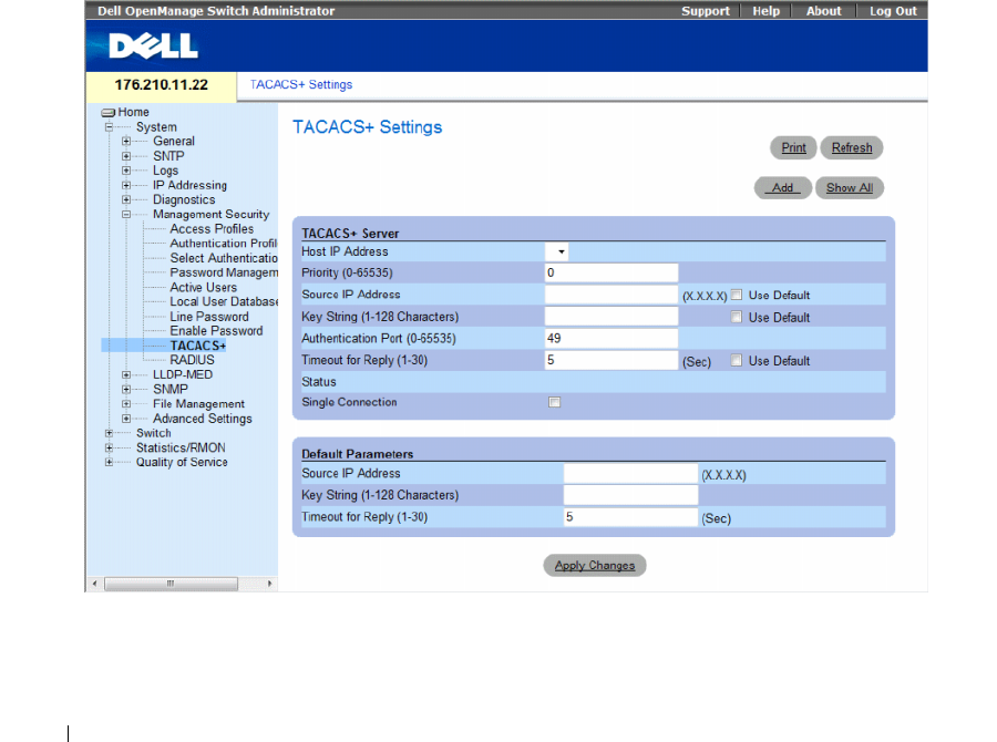
196 Configuring System Information
Defining TACACS+ Settings
The devices provide Terminal Access Controller Access Control System (TACACS+) client support.
TACACS+ provides centralized security for validation of users accessing the device.
TACACS+ provides a centralized user-management system, while still retaining consistency with
RADIUS and other authentication processes. TACACS+ provides the following services:
•
Authentication
— Provides authentication during login and via user names and user-defined
passwords.
•
Authorization
— Performed at login. Once the authentication session is completed, an authorization
session starts using the authenticated user name. The TACACS+ server checks the user privileges.
The TACACS+ protocol ensures network integrity through encrypted protocol exchanges between the
device and TACACS+ server.
To open the TACACS+ Settings page, click System → Management Security → TACACS+ in the
tree view.
Figure 6-70. TACACS+ Settings

Configuring System Information 197
The TACACS+ Settings page contains the following fields:
•
Host IP Address
— Indicates the TACACS+ Server IP address.
•
Priority (0-65535)
— Indicates the order in which the TACACS+ servers are used. The default is 0.
•
Source IP Address
— The device source IP address used for the TACACS+ session between the device
and the TACACS+ server.
•
Key String (1-128 Characters)
— Defines the authentication and encryption key for TACACS+
communications between the device and the TACACS+ server. This key must match the encryption
key used on the TACACS+ server. This key is encrypted.
•
Authentication Port (0-65535)
— The port number through which the TACACS+ session occurs.
The default is port 49.
•
Timeout for Reply (1-30)
— The amount of time that passes before the connection between the
device and the TACACS+ server times out. The field range is 1-30 seconds.
•
Status
— The connection status between the device and the TACACS+ server. The possible field
values are:
–
Connected
— There is currently a connection between the device and the TACACS+ server.
–
Not Connected
— There is not currently a connection between the device and the TACACS+
server.
•
Single Connection
— Maintains a single open connection between the device and the TACACS+
server when selected
•
Use Default
— Uses the default value for the parameter.
The TACACS+ default parameters are user-defined defaults. The default settings are applied to newly
defined TACACS+ servers. If default values are not defined, the system defaults are applied to the
new TACACS+ servers.
The following are the TACACS+ defaults:
–
Source IP Address
— The default device source IP address used for the TACACS+ session
between the device and the TACACS+ server. The default source IP address is 0.0.0.0.
–
Key String (1-128 Characters)
— The default key string used for authenticating and encrypting all
communications between the device and the TACACS+ server. This key is encrypted.
–
Timeout for Reply (1-30)
— The default time that passes before the device and the TACACS+
server connection times out. The default is 5 seconds.
Adding a TACACS+ Server
1
Open the
TACACS+ Settings
page.
2
Click
Add.
The
Add TACACS+ Host
page opens.
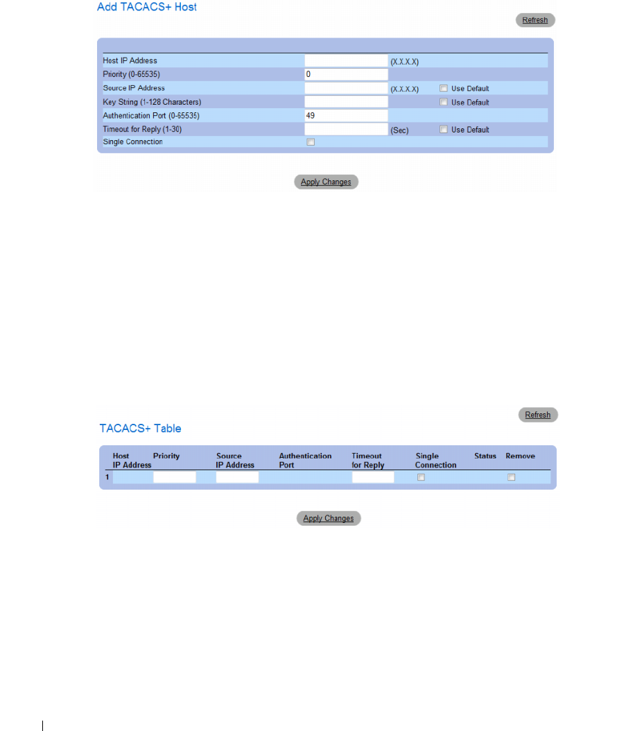
198 Configuring System Information
Figure 6-71. Add TACACS+ Host
3
Define the fields.
4
Click
Apply Changes
.
The TACACS+ server is added, and the device is updated.
Displaying the TACACS+ Table
1
Open the
TACACS+ Settings
page.
2
Click
Show All
.
The
TACACS+ Table
opens.
Figure 6-72. TACACS+ Table
Removing a TACACS+ Server
1
Open the
TACACS+ Table
page.
2
Click
Show All
.
The
TACACS+ Table
opens.
3
Select a
TACACS+ Table
entry.

Configuring System Information 199
4
Select the
Remove
check box.
5
Click
Apply Changes
.
The TACACS+ server is removed, and the device is updated.
Defining TACACS+ Settings Using CLI Commands
The following table summarizes the equivalent CLI commands for setting fields displayed in
theTACACS+ Settings page.
Table 6-41. TACACS+ CLI Commands
CLI Command Description
tacacs-server host {ip-address | host-
name} [single-connection] [port port-
number] [timeout timeout] [key key-
string] [source source] [priority priority]
Indicates a TACACS+ host.
tacacs-server key key-string Indicates the authentication and encryption key
for all TACACS+ communications between the
device and the TACACS+ server. This key must
match the encryption used on the TACACS+
daemon. (Range: 0 - 128 characters.)
tacacs-server timeout timeout Indicates the timeout value in seconds. (Range: 1
- 30.)
tacacs-server source-ip source Indicates the source IP address. (Range: Valid
IP Address.)
show tacacs [ip-address] Displays configuration and statistics for a
TACACS+ server.

200 Configuring System Information
The following is an example of the CLI commands:
Configuring RADIUS Settings
Remote Authorization Dial-In User Service (RADIUS) servers provide additional security for networks.
Up to four RADIUS servers can be defined. RADIUS servers provide a centralized authentication
method for:
• Telnet Access
• Secure Shell Access
• Web Access
• Console Access
To open the RADIUS Settings page, click System → Management Security → RADIUS in the tree view.
console# show tacacs
Device Configuration
IP address Status Port Single
Connection
TimeOut Source IP Priority
----------- --------- ---- ---------- -------- --------- ---------
12.1.1.2 Not
Connected
49 Yes 1 12.1.1.1 1
Global values
-----------------
TimeOut : 5
Device Configuration
--------------------
Source IP : 0.0.0.0
console#
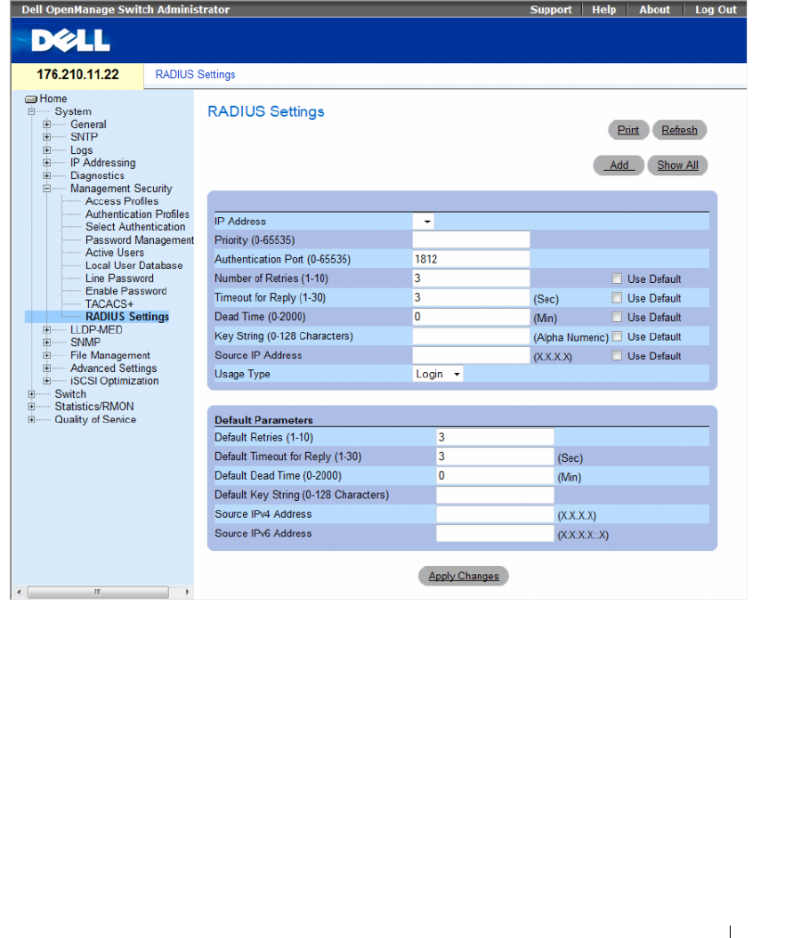
Configuring System Information 201
Figure 6-73. RADIUS Settings
The RADIUS Settings page contains the following pages:
•
IP Address
— The list of Authentication Server IP addresses.
•
Priority (0-65535)
— The server priority. The possible values are 0-65535, where 0 is the highest value.
This is used to configure the order in which servers are queried.
•
Authentication Port (0-65535)
— Identifies the authentication port. The authentication port is used
to verify the RADIUS server authentication.
•
Number of Retries (1-10)
— Indicates the number of transmitted requests sent to RADIUS server
before a failure occurs. The possible field values are 1-10.
•
Timeout for Reply (1-30
) — Indicates the amount of the time in seconds the device waits for an
answer from the RADIUS server before retrying the query, or switching to the next server. The possible
field values are 1- 30.

202 Configuring System Information
•
Dead Time (0-2000)
— Indicates the amount of time (in minutes) that a RADIUS server is bypassed
for service requests. The range is 0-2000.
•
Key String (0-128 Characters)
— The Key string used for authenticating and encrypting all RADIUS
communications between the device and the RADIUS server. This key is encrypted.
•
Source IP Address
— Indicates the source IP address that is used for communication with RADIUS
servers.
•
Usage Type
—
Indicates the server usage type. Can be one of the following values: login, 802.1x or
all. If unspecified, defaults to all.
•
Use Default
— Uses the default value for the parameter.
If host-specific Timeouts, Retries, or Dead time values are not specified, the Global values (Defaults) are
applied to each host. The following fields set the RADIUS default values:
•
Default Retries (1-10)
— Indicates the default number of transmitted requests sent to RADIUS server
before a failure occurs.
•
Default Timeout for Reply (1-30)
— Indicates the default amount of the time (in seconds) the device
waits for an answer from the RADIUS server before timing out. The default is 5 seconds.
•
Default Dead time (0-2000)
— Indicates the default amount of time (in minutes) that a RADIUS
server is bypassed for service requests. The range is 0-2000.
•
Default Key String (0-128 Characters)
— The Default Key string used for authenticating and
encrypting all RADIUS communications between the device and the RADIUS server. This key
is encrypted.
•
Source IPv4 Address
— Specifies the source IP version 4 address that is used for communication with
RADIUS servers.
•
Source IPv6 Address
— Specifies the source IP version 6 address that is used for communication with
RADIUS servers.
When adding a new RADIUS server, the following additional parameter is available:
•
Supported IP Format
— Specifies the IP format supported by the server. The possible values are:
–
IPv6
Global — IP version 6 is supported.
–
IPv4
— IP version 4 is supported.
Defining RADIUS Parameters:
1
Open the
RADIUS Settings
page.
2
Define the fields.
3
Click
Apply Changes
.
The RADIUS setting are updated to the device.
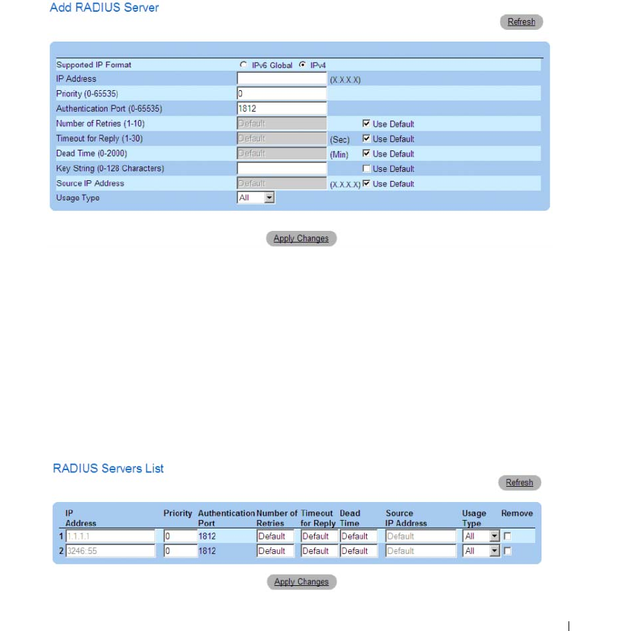
Configuring System Information 203
Adding a RADIUS Server:
1
Open the
RADIUS Settings
page.
2
Click
Add
.
The
Add RADIUS Server
page opens.
Figure 6-74. Add RADIUS Server
3
Define the
fields.
4
Click
Apply Changes
.
The new RADIUS server is added, and the device is updated.
Displaying the RADIUS Server List:
1
Open the
RADIUS Settings
page.
2
Click
Show All
.
The
RADIUS Servers List
opens.
Figure 6-75. RADIUS Servers List

204 Configuring System Information
Removing a RADIUS Server
1
Open the
RADIUS Settings
page.
2
Click
Show All
.
The
RADIUS Servers List
opens.
3
Select a
RADIUS Servers List
entry.
4
Select the
Remove
check box.
5
Click
Apply Changes
.
The RADIUS server is removed, and the device is updated.
Defining RADIUS Servers Using CLI Commands
The following table summarizes the equivalent CLI commands for defining fields displayed on the
RADIUS Settings page.
Table 6-42. RADIUS Server CLI Commands
CLI Command Description
radius-server timeout
timeout
Sets the interval for which a device waits for a server host to
reply.
radius-server source-ip source Specifies the source IPv4 address that will be used for the IPv4
communication with RADIUS servers.
radius-server source-ipv6 source Specifies the source IPv6 address that will be used for the IPv6
communication with RADIUS servers.
radius-server retransmit
retries
Specifies the number of times the software searches the list of
RADIUS server hosts.
radius-server deadtime
deadtime
Configures unavailable servers to be skipped.
radius-server key
key-string
Sets the authentication and encryption key for all RADIUS
communications between the router and the RADIUS server.
radius-server host
ip-address
[auth-port
auth-port-number
] [timeout timeout]
[retransmit
retries
] [deadtime
deadtime
]
[key
key-string
] [source
source
] [priority
priority
]
Specifies a RADIUS server host.
show radius-servers Displays the RADIUS server settings.

Configuring System Information 205
The following is an example of CLI commands:
Configuring LLDP and MED
The Link Layer Discovery Protocol (LLDP) allows network managers to troubleshoot and enhance network
management by discovering and maintaining network topologies over multi-vendor environments.
LLDP discovers network neighbors by standardizing methods for network devices to advertise themselves
to other system, and to store discovered information. Device discovery information includes:
• Device Identification
• Device Capabilities
• Device Configuration
The advertising device transmits multiple advertisement message sets in a single LAN packet. The
multiple advertisement sets are sent in the packet Type Length Value (TLV) field. LLDP devices must
support chassis and port ID advertisement, as well as system name, system ID, system description, and
system capability advertisements.
This section includes the following topics:
• Defining Global LLDP Properties
• Defining LLDP Port Settings
• Defining Media Endpoint Discovery Network Policy
• Defining LLDP MED Port Settings
• Viewing the LLDP Neighbors Information
Console(config)# radius-server timeout 5
Console(config)# radius-server retransmit 5
Console(config)# radius-server deadtime 10
Console(config)# radius-server key dell-server
Console(config)# radius-server host 196.210.100.1 auth-port 127
timeout 20
Console# show radius-servers
IP address Auth Acct TimeOut Retransmit Deadtime Source IP Priority
-------- ---- ---- ------ --------- ------- ------- ------
172.16.1.1 164 51646 3 3 0 01
172.16.1.2 164 51646 3 3 0 02

206 Configuring System Information
LLDP Media Endpoint Discovery (LLDP-MED) increases network flexibility by allowing different
IP systems to co-exist on a single network LLDP.
Provides detailed network topology information, including what device are located on the network, and
where the devices are located. For example, what IP phone is connect to what port, what software is
running on what switch, and with port is connected to what PC. Automatically deploys policies over
networks for:
• QoS Policies
• Voice VLANs
Provides Emergency Call Service (E-911) via IP Phone location information.
Provides troubleshooting information LLDP MED send network managers alerts for:
• Port speed and duplex mode conflicts
• QoS policy misconfigurations
This section contians the following topics:
• "Defining LLDP Properties" on page 207
• "Configuring LLDP Using CLI Commands" on page 208
• "Defining LLDP Port Settings" on page 208
• "Defining LLDP MED Network Policy" on page 211
• "Defining LLDP MED Port Settings" on page 213
• "Viewing the LLDP Neighbors Information" on page 217
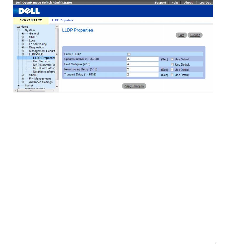
Configuring System Information 207
Defining LLDP Properties
The LLDP Properties page contains fields for configuring LLDP.
To open the LLDP Properties page, click System → LLDP-MED → LLDP Properties in the tree view.
Figure 6-76. LLDP Properties
•
Enable LLDP
—
Indicates if LLDP is enabled on the device. The possible field values are:
–
Checked
— Indicates that LLDP is enabled on the device.
–
Unchecked
— Indicates that LLDP is disabled on the device. This is the default value.
•
Updates Interval (5-32768) —
Indicates that rate at which LLDP advertisement updates are sent.
The possible field range is 5 - 32768 seconds. The default value is 30 seconds.
•
Hold Multiplier (2-10) —
Specifies the hold time to be sent in the LLDP update packets as a multiple
of the timer value. The possible field range is 2 - 10. The field default is 4.
•
Reinitializing Delay (1-10)
— Specifies the minimum time in seconds an LLDP port will wait before
reinitializing LLDP transmission. The possible field range is 1 - 10 seconds. The field default is
2 seconds.
•
Transmit Delay (1-8192)
— Indicates the amount of time that passes between successive LLDP frame
transmissions due to changes in the LLDP local systems MIB. The possible field value is 1 – 8192
seconds. The field default is 2 seconds.

208 Configuring System Information
Configuring LLDP Using CLI Commands
The following is an example of the CLI commands:
Defining LLDP Port Settings
The LLDP Port Settings page allows network administrators to define LLDP port settings, including the
port number, the LLDP port number, and the type of port information advertised.
The Port Settings page contains fields for configuring LLDP. To open the Port Settings page,
click System → LLDP-MED → Port Settings in the tree view.
Table 6-43. LLDP Properties CLI Commands
CLI Command Description
lldp enable (global) Enables enable Link Layer Discovery Protocol.
lldp hold-multiplier
number
Specifies the time that the receiving device should
hold a Link Layer Discovery Protocol (LLDP) packet
before discarding it.
lldp reinit-delay
Seconds
Specifies the minimum time an LLDP port will wait
before reinitializing.
lldp tx-delay
Seconds
Specifies the delay between successive LLDP frame
tr.ansmissions.
Console(config)# interface ethernet g1
Console(config-if)# lldp enable
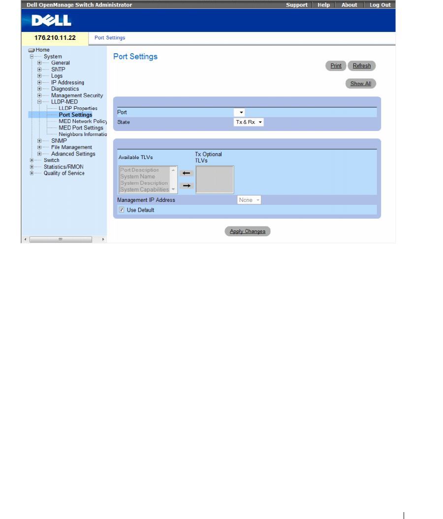
Configuring System Information 209
Figure 6-77. Port Settings
•
Port
— Contains a list of ports on which LLDP is enabled.
•
State
— Indicates the port type on which LLDP is enabled. The possible field values are:
–
Tx Only
— Enables transmitting LLDP packets only.
–
Rx Only
— Enables receiving LLDP packets only.
–
Tx & Rx
— Enables transmitting and receiving LLDP packets. This is the default value.
–
Disable
— Indicates that LLDP is disabled on the port.
•
Available TLVs
— Contains a list of available TLVs that can be advertised by the port. The possible
field values are:
–
Port Description
— Advertises the port description.
–
System Name
— Advertises the system name.
–
System Description
— Advertises the system description.
–
System Capabilities
— Advertises the system capabilities.
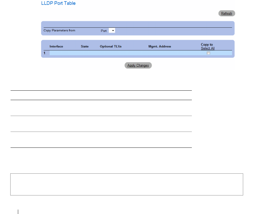
210 Configuring System Information
•
Tx Optional TLVs
— Contains a list of optional TLVs advertised by the port. For the complete list,
see the
Available TLVs
field.
•
Management IP Address
— Indicates the management IP address that is advertised from the
interface.
–
Use Default
— Specifies the way TLVs are included:
–
Checked
— Only mandatory TLVs are used by default; they are Chassis subtype (MAC address),
Port subtype (port number), and TTL (time-to-leave equal to 120s).
–
Unchecked
— User-defined TLVs consisting of the 3 above mentioned mandatory TLVs plus
optional TLVs that are moved by user from the Avalable set of TLVs.
The LLDP Port Table page displays the LLDP Port Configuration. To open the LLDP Port Table,
click Security → LLDP → Port Settings → Show All in the tree view.
Figure 6-78. LLDP Port Table
Table 6-44. LLDP Port settings CLI Commands
The following is an example of the CLI commands:
CLI Command Description
clear lldp rx interface Restarts the LLDP RX state machine
and clearing the neighbors table
lldp optional-tlv tlv1 [tlv2 … tlv5] Specifies which optional TLVs from the
basic set should be transmitted
lldp enable [rx | tx | both] To enable Link Layer Discovery
Protocol (LLDP) on an interface.
Console(config)# interface ethernet g1
Console(config-if)# lldp enable
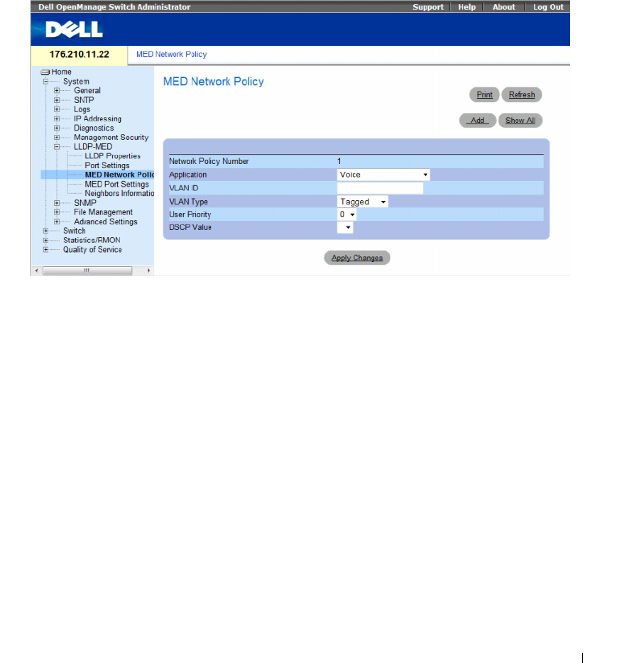
Configuring System Information 211
Defining LLDP MED Network Policy
The MED Network Policy page contains fields for configuring LLDP.
To open the MED Network Policy page, click System → LLDP-MED → MED Network Policy in the
tree view.
Figure 6-79. MED Network Policy
The MED Network Policy page contains the following fields:
•
Network Policy Number
— Displays the network policy number.
•
Application
— Displays the application for which the network policy is defined. The possible field
values are:
–
Voice
— Indicates that the network policy is defined for a Voice application.
–
Voice Signaling
— Indicates that the network policy is defined for a Voice Signaling application.
–
Guest Voice
— Indicates that the network policy is defined for a Guest Voice application.
–
Guest Voice Signaling
— Indicates that the network policy is defined for a Guest Voice Signaling
application.
–
Softphone Voice
— Indicates that the network policy is defined for a Softphone Voice application.
–
Video Conferencing
— Indicates that the network policy is defined for a Video Conferencing
application.
–
Streaming Video
— Indicates that the network policy is defined for a Streaming Video application.
–
Video Signaling
— Indicates that the network policy is defined for a Video Signalling application.
•
VLAN ID
— Displays the VLAN ID for which the network policy is defined.
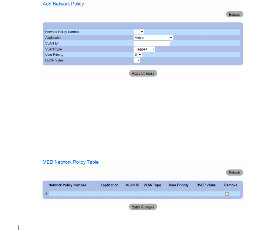
212 Configuring System Information
•
VLAN Type
— Indicates the VLAN type for which the network policy is defined. The possible field
values are:
–
Tagged
— Indicates the network policy is defined for tagged VLANs.
–
Untagged
— Indicates the network policy is defined for untagged VLANs.
•
User Priority
— Defines the priority assigned to the network application. The range is 0-7.
•
DSCP Value
— Defines the DSCP value assigned to the network policy. The range is 0-63.
Adding an MED Network Policy
1
Open the
MED Network Policy
page.
2
Click
Add
.
The
Add Network Policy
page opens.
Figure 6-80. Add Network Policy
3
Define the
fields.
4
Click
Apply Changes
.
The new network policy is added, and the device is updated.
Displaying the MED Network Policy Table:
1
Open the
MED Network Policy
page.
2
Click
Show All
.
The
MED Network Policy Table
opens.
Figure 6-81. MED Network Policy Table
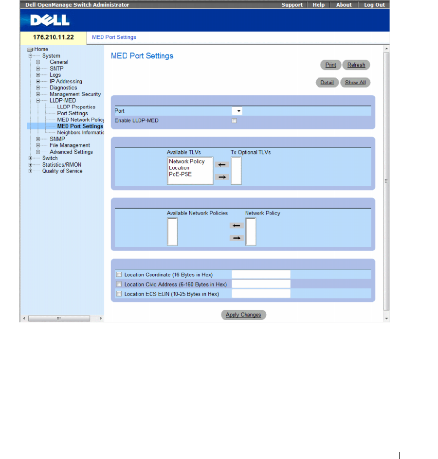
Configuring System Information 213
Defining LLDP MED Port Settings
The MED Port Settings contains parameters for assigning LLDP network policies to specific ports.
To open the MED Port Settings page, click System → LLDP-MED → Port Settings in the tree view.
The MED Port Settings opens.
Figure 6-82. MED Port Settings
The MED Port Settings page contains the following fields:
•
Port
— Displays the port on which LLDP-MED is enabled or disabled.
•
Enable LLDP-MED
— Indicates if LLDP-MED is enabled on the selected port. The possible field
values are:
–
Checked
— Enables LLDP-MED on the port.
–
Unchecked
— Disables LLDP-MED on the port. This is the default value.

214 Configuring System Information
•
Tx Optional TLVs/Available TLVs
— Contains a list of available TLVs that can be advertised by the
port. The possible field values are:
–
Network Policy
— Advertises the network policy attached to the port.
–
Location
— Advertises the port’s location.
–
PoE-PSE
— Indicates if the connected media is a PoE or PSE (Power Sourcing Equipment)
device.
•
Network Policy/Available Network Policy
— Contains a list of network policies that can be assigned to
a port.
•
Location Coordinate (16 Bytes in Hex)
— Displays the device’s location map coordinates (16 bytes in
hex).
•
Location Civic Address (6-160 Bytes in Hex)
— Displays the device’s civic or street address location,
for example 414 23rd Ave E. The possible field value are 6 - 160 bytes in hex.
•
Location ECS ELIN (10-25 Bytes in Hex)
— Displays the device’s ECS ELIN location. The field
range is 10-25 bytes in hex.
Modifying MED Port Settings
1
Open the
MED Port Settings
page.
2
Modify the fields.
3
Click
Apply Changes
.
The parameters are saved to the device.
Displaying Advertise Information Details
1
Open the
MED Port Settings
page.
2
Click
Details
.
The
Details Advertise Information
page opens.
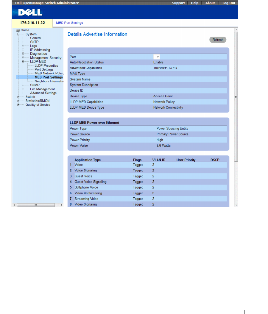
Configuring System Information 215
Figure 6-83. Details Advertise Information Page
The Details Advertise Information page contains the following fields:
•
Port
— The port for which detailed information is displayed.
•
Auto-Negotiation Status
— The auto-negotiation status of the port. The possible field values are:
–
Enabled
— Auto-negotiation is enabled on the port.
–
Disabled
— Auto-negotiation is disabled on the port.
•
Advertised Capabilities
— The port capabilities advertised for the port.
•
MAU Type
— Indicates the media attachment unit type.
•
System Name
— The system name advertised.
•
System Description
— The system description advertised.

216 Configuring System Information
•
Device ID
— The device ID advertised, for example, the device MAC address.
•
Device Type
— The type of device.
•
LLDP MED Capabilities
— The TLV that is advertised by the port.
•
LLDP MED Device Type
— Indicates whether a sender is a network connectivity device or an
endpoint device.
•
Power Type
— The port’s power type.
•
Power Source
— The port’s power source.
•
Power Priority
— The port’s power priority.
•
Power Value
— The port’s power value, in Watts.
•
LLDP MED Network Policy
— The port’s LLDP Network Policy for each of the following application
types:
–Voice
– Voice Signaling
– Guest Voice
– Guest Voice Signaling
– Softphone Voice
– Video Conferencing
– Streaming Video
– Video Signaling
•
Flags
— Displays the VLAN tagging status for the application type. The possible field values are:
–
Tagged
— The packets are tagged.
–
Untagged
— The packets are not tagged.
•
VLAN ID
— Displays the VLAN number for the application type.
•
User Priority
— Displays the VLAN number for the application type.
•
DSCP Value
— Defines the DSCP value assigned to the network policy. The possible field value is
1-64.
•
LLDP MED Location
— The port’s advertised LLDP location:
–
Coordinates
— Displays the device’s location map coordinates.
–
Civic Address
— Displays the device’s civic or street address location, for example 414 23rd Ave E.
The possible field value are 6 - 160 characters.
–
ECS ELIN
— Displays the device’s ECS ELIN location. The field range is 10 - 25.
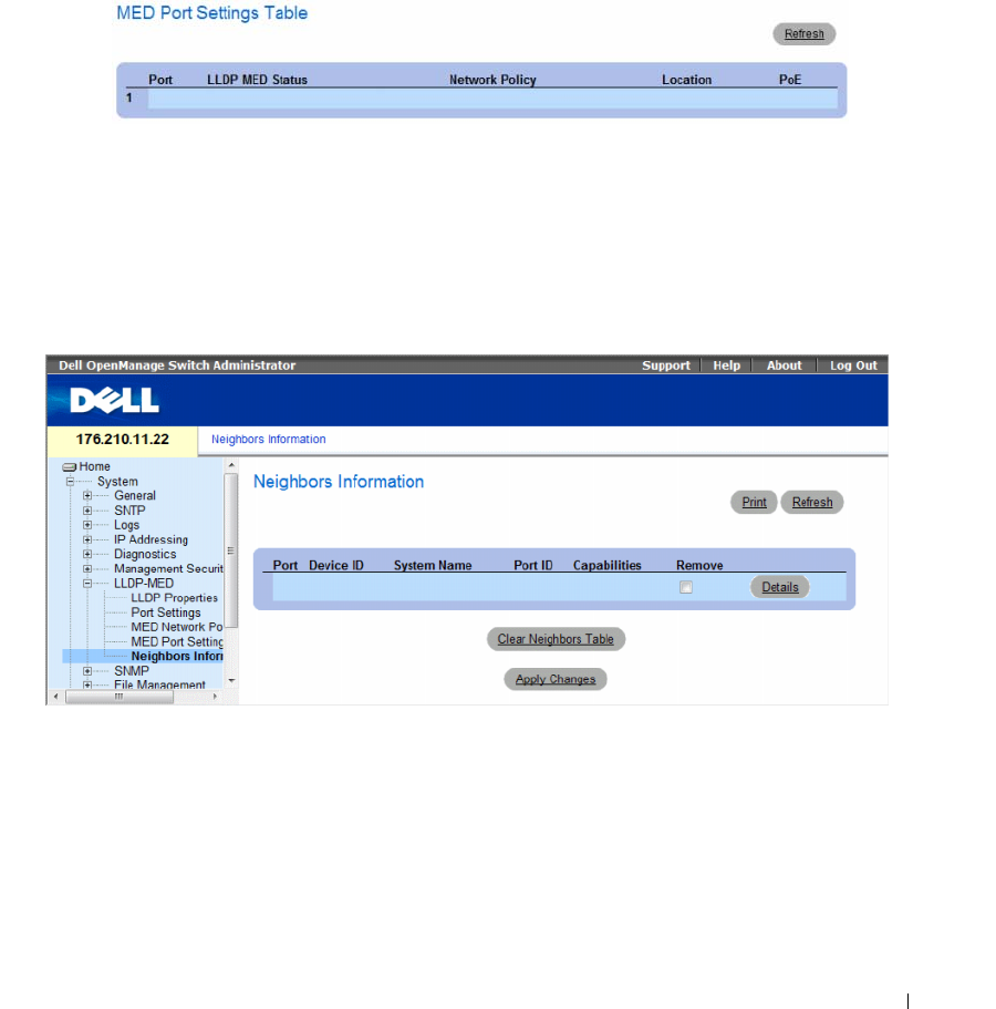
Configuring System Information 217
Displaying the MED Port Settings Table
1
Open the
MED Port Settings
page.
2
Click
Show All
.
The
MED Port Settings Table
opens.
Figure 6-84. MED Port Settings Table
Viewing the LLDP Neighbors Information
The Neighbors Information page contains information received from neighboring device LLDP
advertisements. To open the Neighbors Information page, click System → LLDP-MED → Neighbors
Information in the tree view.
Figure 6-85. Neighbors Information
•
Port
— Displays the port number for which neighbouring information is displayed.
•
Device ID
— Displays the neighboring device ID.
•
System Name
— Displays the name of the neighboring system .
•
Port ID
— Displays the neighboring port ID
•
Capabilities
— Displays the neighboring device capabilities.
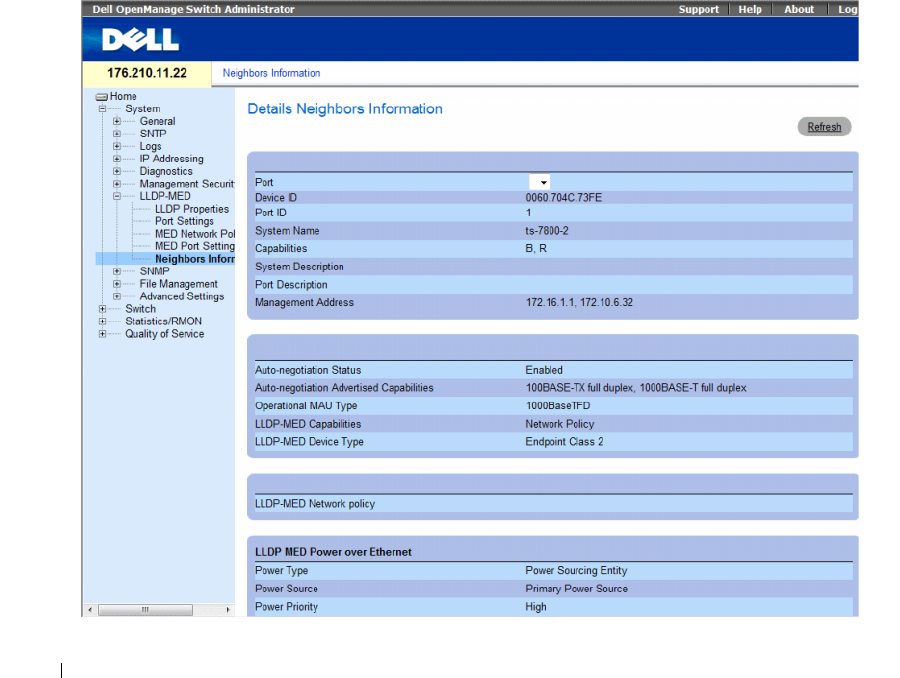
218 Configuring System Information
Removing a Port From the Table
1
Open the
Neighbors Information
page.
2
Check the
Remove
checkbox of each port to be removed.
3
Click
Apply Changes
. The ports are removed.
Clearing the Table
1
Open the
Neighbors Information
page.
2
Click
Clear Neighbors Table
. The table is cleared.
Viewing the Details of the LLDP MED Information Advertised by a Neighbor Device
1
Open the
Neighbors Information
page.
2
Click the
Details
button next to the desired entry. The Details Neighbors Information page appears:
Figure 6-86. Details Neighbors Information

Configuring System Information 219
For information on the fields, refer to the Details Advertise Information page above.
Table 6-45. LLDP Neighbors Information CLI Commands
The following is an example of the CLI commands:
Switch# show lldp neighbors
Defining SNMP Parameters
Simple Network Management Protocol (SNMP) provides a method for managing network devices.
The switch supports the following SNMP versions:
• SNMPv1 (version 1)
• SNMPv2 (version 2)
• SNMPv3 (version 3)
SNMP v1 and v2
The SNMP agents maintains a list of variables, which are used to manage the switch. The variables are
defined in the Management Information Base (MIB). The MIB presents the variables controlled by the
agent. The SNMP agent defines the MIB specification format, as well as the format used to access the
information over the network. Access rights to the SNMP agents are controlled by access strings.
SNMPv1 and v2 are enabled by default.
SNMP v3
SNMP v3 also applies access control and a new traps mechanism to SNMPv1 and SNMPv2 PDUs.
In addition, a User Security Model (USM) is defined for SNMPv3, which includes:
•
Authentication
— Provides data integrity and data origin authentication.
•
Privacy
— Protects against disclosure message content. Cipher Block-Chaining
(CBC) is used for
encryption. Either authentication is enabled on an SNMP message, or both authentication and privacy
are enabled on an SNMP message. However privacy cannot be enabled without authentication.
•
Timeliness
— Protects against message delay or message redundancy. The SNMP agent compares
incoming message to the message time information.
•
Key Management
— Defines key generation, key updates, and key use.
CLI Command Description
show lldp neighbors
interface
Displays information about
neighboring devices discovered using
Link Layer Discovery Protocol (LLDP)
Port Device ID Port ID System Name Capabilities
3/e31 00:00:77:77:00:00 1/g3 0
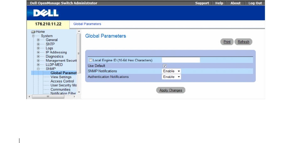
220 Configuring System Information
The switch supports SNMP notification filters based on Object IDs (OID). OIDs are used by the system
to manage switch features. SNMP v3 supports the following features:
• Security
• Feature Access Control
•Traps
Authentication or Privacy Keys are modified in the User Security Model (USM).
SNMPv3 can be enabled on if the Local Engine ID is enabled.
This section contians the following topics:
• "Defining SNMP Global Parameters" on page 220
• "Defining SNMP View Settings" on page 223
• "Defining SNMP Access Control" on page 227
• "Assigning SNMP User Security" on page 230
• "Defining SNMP Communities" on page 234
• "Defining SNMP Notification Filters" on page 238
• "Defining SNMP Notification Recipients" on page 240
Defining SNMP Global Parameters
The SNMP Global Parameters page permits enabling both SNMP and Authentication notifications.
To open the SNMP Global Parameters page, click System → SNMP → Global Parameters in the tree view.
Figure 6-87. SNMP Global Parameters

Configuring System Information 221
The SNMP Global Parameters page contains the following fields:
•
Local Engine ID
(10-64 Hex Characters)
— Indicates the local device engine ID. The field value is a
hexadecimal string. Each byte in hexadecimal character strings is two hexadecimal digits. Each byte
can be separated by a period or a colon. The Engine ID must be defined before SNMPv3 is enabled.
– For stand-alone devices select a default Engine ID that is comprised of Enterprise number and the
default MAC address.
– For a stackable system configure the Engine ID, and verify that the Engine ID is unique for the
administrative domain. This prevents two devices in a network from having the same Engine ID.
•
Use Default
— Select to use the device generated Engine ID. The default Engine ID is based on the
device MAC address and is defined per standard as:
–
First 4 octets
— first bit = 1, the rest is IANA Enterprise number = 674.
–
Fifth octet
— Set to 3 to indicate the MAC address that follows.
–
Last 6 octets
— MAC address of the device.
•
SNMP Notifications
— Enables or disables the router sending SNMP notifications.
•
Authentication Notifications
— Enables or disables the router sending SNMP traps when
authentication fails.
Enabling SNMP Notifications
1
Open the
SNMP Global Parameters
page
.
2
Select
Enable
in the
SNMP Notifications
field.
3
Click
Apply Changes
.
SNMP notifications are enabled, and the device is updated.
Enabling Authentication Notifications
1
Open the
SNMP Global Parameters
page.
2
Select
Enable
in the
Authentication Notifications
field.
3
Click
Apply Changes
.

222 Configuring System Information
Enabling SNMP Notifications Using CLI Commands
The following table summarizes the equivalent CLI commands for viewing fields displayed in the SNMP
Global Parameters page.
The following is an example of the CLI commands:
Table 6-46. SNMP Notification Commands
CLI Command Description
snmp-server enable
traps
Enables the router to send Simple Network Management Protocol traps
snmp-server trap
authentication
Enables the router to send Simple Network Management Protocol traps
when authentication fails
show snmp Checks the status of SNMP communications.
snmp-server engine ID
local {engineid-string |
default}
Indicates the local device engine ID. The field values is a hexadecimal
string. Each byte in hexadecimal character strings is two hexadecimal
digits. Each byte can be separated by a period or colon. The Engine ID
must be defined before SNMPv3 is enabled.
Console(config)# snmp-server enable traps
Console(config)# snmp-server trap authentication
Console# show snmp
Community-String Community-Access View name IP address
---------------- ----------------- --------- ----------
public read only view-1 All
Community-String Group name IP address Type
----
---------------- ---------- ----------
Traps are enabled.
Authentication-failure trap is enabled.

Configuring System Information 223
Defining SNMP View Settings
SNMP Views provide access or block access to device features or feature aspects. For example, a view can
be defined which states that SNMP group A has read only (R/O) access to Multicast groups, while SNMP
group B has read-write (R/W) access to Multicast groups. Feature access is granted via the MIB name,
or MIB Object ID.
The Up and Down arrows allow navigating through the MIB tree, and MIB branches.
To open the SNMPv3 View Settings page, click System → SNMP → View Settings in the tree view.
Version 1,2 notifications
Target
Address
Type Community Version Udp
Port
Filter
name
To
Sec
Retries
------- ---- --------- ------- ---- ------ --- -------
Version 3 notifications
Target
Address
Type Username Security
Level
Udp
Port
Filter
name
To
Sec
Retries
-------- ---- --------- -------- ----
-
------
-
--- -------
System Contact: Robert
System Location: Marketing
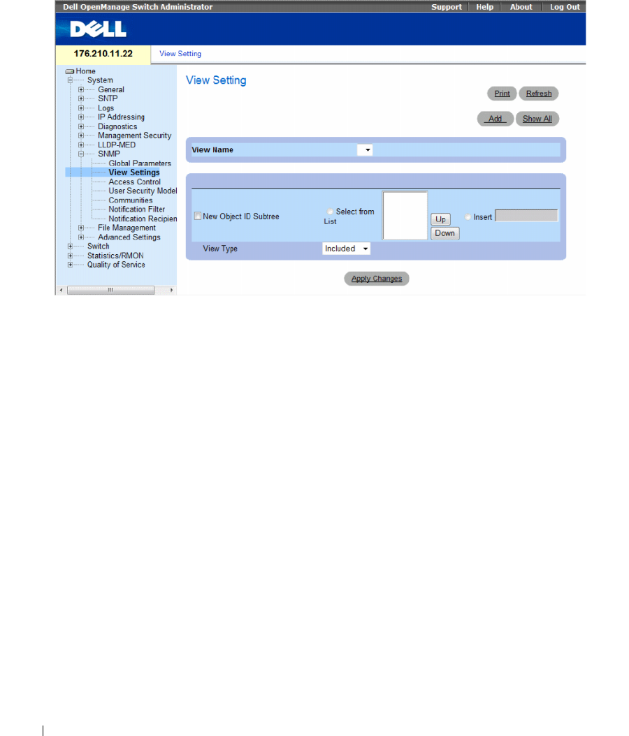
224 Configuring System Information
Figure 6-88. SNMPv3 View Settings
The SNMPv3 View Settings page contains the following fields:
•
View Name
— Contains a list of user-defined views. The view name can contain a maximum of
30 alphanumeric characters.
•
New Object ID Subtree
— Indicates the device feature OID included or excluded in the selected
SNMP view.
–
Selected from List
— Select the device feature OID by using the
Up
and
Down
buttons to scroll
through a list of all device OIDs.
–
Insert
— Specify the device feature OID.
•
View Type
— Indicates if the defined OID branch will be included or excluded in the selected SNMP view.
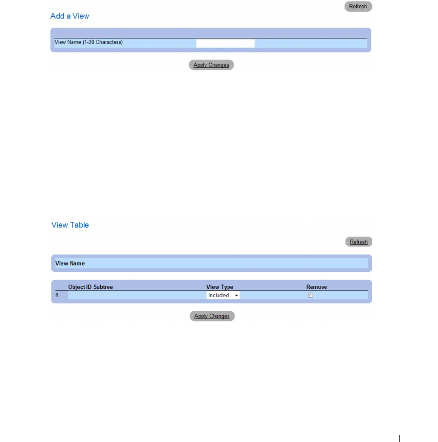
Configuring System Information 225
Adding a View
1
Open the
SNMPv3 View Settings
page
.
2
Click
Add
.
The
Add A View
page opens.
Figure 6-89. Add A View
3
Define the
field.
4
Click
Apply Changes
.
The SNMP View is added, and the device is updated.
Displaying the View Table
1
Open the
SNMPv3 View Settings
page
.
2
Click
Show All
.
The
View Table
page opens.
Figure 6-90. View Table

226 Configuring System Information
Defining SNMPv3 Views Using CLI Commands
The following table summarizes the equivalent CLI commands for defining fields displayed in the
SNMPv3 View Settings page.
The following is an example of CLI commands:
Table 6-47. SNMP View CLI Commands
CLI Command Description
snmp-server view view-name
oid-tree {included |
excluded}
Creates or updates a view entry.
show snmp views [viewname] Displays the configuration of views.
Console(config)# snmp-server view user1 1 included
Console(config)# end
Console# show snmp views
Name OID Tree Type
------------- ----------------- --------
user1 iso included
Default iso included
Default snmpVacmMIB excluded
Default usmUser excluded
Default rndCommunityTable excluded
DefaultSuper iso included
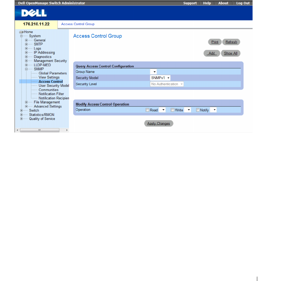
Configuring System Information 227
Defining SNMP Access Control
The Access Control page provides information for creating SNMP groups, and assigning SNMP access
control privileges to SNMP groups. Groups allow network managers to assign access rights to specific
device features, or features aspects.
To open the
Access Control Group
page, click System
→
SNMP
→
Access Control in the tree view.
Figure 6-91. Access Control Group
The Access Control Group contains the following fields:
•
Group Name
— The user-defined group to whom access control rules are applied. The field range is up
to 30 characters.
•
Security Model
— Defines the SNMP version attached to the group. The possible field values are:
–
SNMPv1
— SNMPv1 is defined for the group.
–
SNMPv2
— SNMPv2 is defined for the group.
–
SNMPv3
— SNMPv3 is defined for the group.
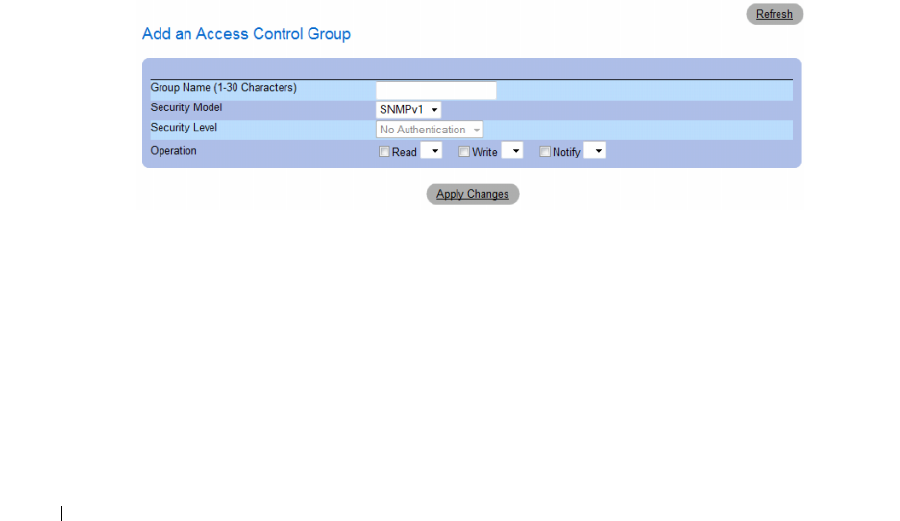
228 Configuring System Information
•
Security Level
— The security level attached to the group. Security levels apply to SNMPv3 only.
The possible field values are:
–
No Authentication
— Neither the Authentication nor the Privacy security levels are assigned to
the group.
–
Authentication
— Authenticates SNMP messages, and ensures the SNMP messages origin is
authenticated.
–
Privacy
— Encrypts SNMP message.
•
Operation
— Defines the group access rights. The possible field values are:
–
Read
— The management access is restricted to read-only, and changes cannot be made to the
assigned SNMP view.
–
Write
— The management access is read-write and changes can be made to the assigned SNMP
view.
–
Notify
— Sends traps for the assigned SNMP view.
Defining SNMP Groups
1
Open the
Access Control Group
page.
2
Click
Add
.
The
Add an Access Control Group
page opens.
Figure 6-92. Add an Access Control Group
3
Define the fields in the
Add an Access Control Group
page.
4
Click
Apply Changes
.
The group is added, and the device is updated.
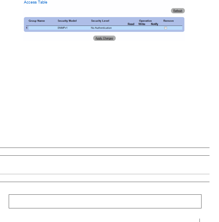
Configuring System Information 229
Displaying the Access Table
1
Open the
Access Control Group
page.
2
Click
Show All
.
The
Access Table
opens.
Figure 6-93. Access Table
Removing SNMP Groups
1
Open the
Access Control Group
page
.
2
Click
Show All
.
The
Access Table
opens.
3
Select a SNMP group.
4
Check the
Remove
checkbox.
5
Click
Apply Changes
.
The SNMP group is deleted, and the device is updated.
Defining SNMP Access Control Using CLI Commands
The following table summarizes the equivalent CLI commands for defining fields displayed in the
Access Control Group page.
The following is an example of the CLI commands:
Table 6-48. SNMP Access Control CLI Commands
CLI Command Description
snmp-server group groupname {v1 | v2 | v3
{noauth | auth | priv}} [read readview]
[write writeview] [notify notifyview ]
Configure a new Simple Network Management Protocol (SNMP)
group, or a table that maps SNMP users to SNMP views.
show snmp groups [groupname] Displays the configuration of groups
console (config)# snmp-server group user-group v3 priv read user-
view
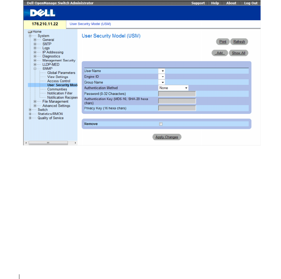
230 Configuring System Information
Assigning SNMP User Security
The SNMPv3 User Security Model (USM) page enables assigning system users to SNMP groups, as well
as defining the user authentication method.
To open the SNMPv3 User Security Model (USM) page, click System → SNMP → User Security Model
in the tree view.
Figure 6-94. SNMPv3 User Security Model (USM)
The SNMPv3 User Security Model (USM) page contains the following fields:
•
User Name
— Contains a list of user-defined user names. The field range is up to 30 alphanumeric
characters.
•
Engine ID
— Indicates either the local or remote SNMP entity, to which the user is connected.
Changing or removing the local SNMP Engine ID deletes the SNMPv3 User Database.
•
Group Name
— Contains a list of user-defined SNMP groups. SNMP groups are defined in the
Access
Control Group
page.

Configuring System Information 231
•
Authentication Method
— The authentication method used to authenticate users. The possible field
values are:
–
None
— No user authentication is used.
–
MD5
Password
— Indicates that HMAC-MD5-96 password is used for authentication. The user
should enter a password.
–
SHA Password
— Users are authenticated using the HMAC-SHA-96 authentication level.
The user should enter a password.
–
MD5
Key— Users are authenticated using the HMAC-MD5 algorithm.
–
SHA
Key — Users are authenticated using the HMAC-SHA-96 authentication level.
•
Password
(0-32 Characters)
— Modifies the user-defined password for a group. Passwords can contain
a maximum of 32 alphanumeric characters.
•
Authentication Key (MD5-16; SHA-20 hexa chars)
— Defines the HMAC-MD5-96 or
HMAC-SHA-96 authentication level. The authentication and privacy keys are entered to define the
authentication key. If only authentication is required, 16 bytes are defined for MD5. If both privacy
and authentication are required, 32 bytes are defined for MD5. Each byte in hexadecimal character
strings is two hexadecimal digits. Each byte can be separated by a period or a colon.
•
Privacy Key (16 hexa characters)
— If only authentication is required, 20 bytes are defined. If both
privacy and authentication are required, 16 bytes are defined. Each byte in hexadecimal character
strings is two hexadecimal digits. Each byte can be separated by a period or colon.
•
Remove
— When checked, removes users from a specified group.
–
Checked
— Removes the user from the specified group.
–
Unchecked
— Maintains the user in the specified group.
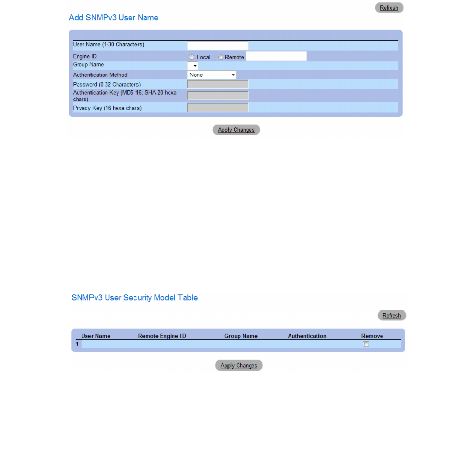
232 Configuring System Information
Adding Users to a Group
1
Open the
SNMPv3 User Security Model (USM)
page.
2
Click
Add
.
The
Add SNMPv3 User Name
page opens.
Figure 6-95. Add SNMPv3 User Name
3
Define the
relevant
fields.
4
Click
Apply Changes
.
The user is added to the group, and the device is updated.
Displaying the User Security Model Table
1
Open the
SNMPv3 User Security Model (USM)
page.
2
Click
Show All
.
The
User Security Model Table
opens.
Figure 6-96. User Security Model Table
Configuring System Information 233
Deleting an User Security Model Table Entry
1
Open the
SNMPv3 User Security Model (USM)
page.
2
Click
Show All
.
The
User Security Model Table
opens.
3
Select a
User Security Model Table
entry.
4
Check the
Remove
checkbox.
5
Click
Apply Changes
.
The
User Security Model Table
entry is deleted, and the device is updated.
Defining SNMPv3 Users Using CLI Commands
The following table summarizes the equivalent CLI commands for defining fields displayed in the
SNMPv3 User Security Model (USM) page.
The following is an example of the CLI commands:
Table 6-49. SNMPv3 User CLI Commands
CLI Command Description
snmp-server user username groupname
[remote engineid-string][auth-md5
password | auth-sha password | auth-
md5-key md5-des-key | auth-sha-key
sha-des-key]
Configures a new SNMP V3 user.
show snmp users [username] Displays the configuration of users.
console (config)
# snmp-server user John user-group auth-md5 1234
console (config)
# end
console# show snmp users
Name Group Name Auth Method Remote
------- ---------- ----------- ------
John user-group md5
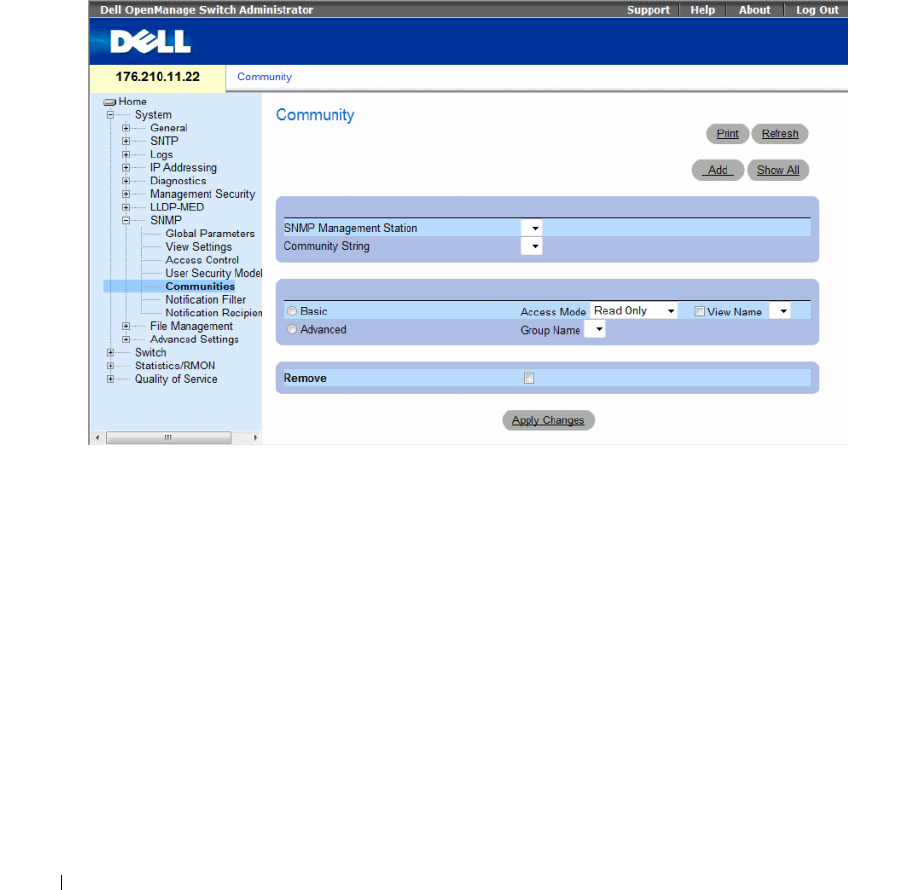
234 Configuring System Information
Defining SNMP Communities
Access rights are managed by defining communities on the SNMP Community page. When the
community names are changed, access rights are also changed. SNMP Communities are defined only for
SNMP v1 and SNMP v2.
To open the SNMP Community page, click System → SNMP → Communities in the tree view.
Figure 6-97. SNMP Community
The SNMP Community page contains the following fields:
•
SNMP Management Station
— The management station IP address for which the SNMP community
is defined.
•
Community String
— Functions as a password and used to authenticate the management station to
the device.

Configuring System Information 235
•
Basic
— Enables
SNMP Basic mode for a selected community. The possible field values are:
–
Access Mode
— Defines the access rights of the community. The possible field values are:
Read-Only
— Management access is restricted to read-only, and changes cannot be made to the
community.
Read-Write
— Management access is read-write and changes can be made to the device
configuration, but not to the community.
SNMP-Admin
— User has access to all device configuration options, as well as permissions to
modify the community.
–
View Name
— Contains a list of user-defined SNMP views
•
Advanced
— Contains a list of user-defined groups. When SNMP Advanced mode is selected,
the SNMP access control rules comprising the group are enabled for the selected community.
The Advanced mode also enables SNMP groups for specific SNMP communities. The SNMP
Advanced mode is defined only with SNMPv3. The possible field value is:
–
Group Name
— Specifies the name of the group when working in SNMP Advanced mode.
Remove — Removes a community from the specified device.
–
Checked
— Removes the community.
–
Unchecked
— Maintains the community in the specified device.
When defining a new SNMP community, the following additional parameters are available:
•
Supported IP Format
— Specifies the IP format supported by the community. The possible values are:
–
IPv6
— IP version 6 is supported.
–
IPv4
— IP version 4 is supported.
•
IPv6 Address Type
— When the community supports IPv6 (see previous parameter), this specifies the
type of static address supported. The possible values are:
–
Link Local
— A Link Local address that is non-routable and used for communication on the same
network only.
–
Global
— A globally unique IPv6 address; visible and reachable from different subnets.
•
Link Local Interface
— When the server supports an IPv6 Link Local address (see previous
parameter), this specifies the the Link Local interface. The possible values are:
–
VLAN1
— The IPv6 interface is configured on VLAN1.
–
ISATAP
— The IPv6 interface is configured on ISATAP tunnel.
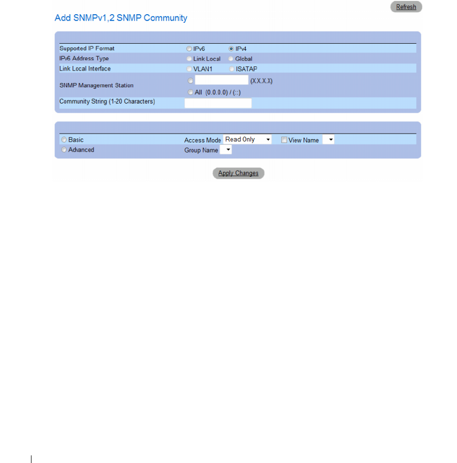
236 Configuring System Information
Defining a New Community
1
Open the
SNMP Community
page.
2
Click
Add
.
The Add SNMP Community page opens.
Figure 6-98. Add SNMP Community
3
Complete the
relevant
fields.
4
Click
Apply Changes
.
The new community is saved, and the device is updated.
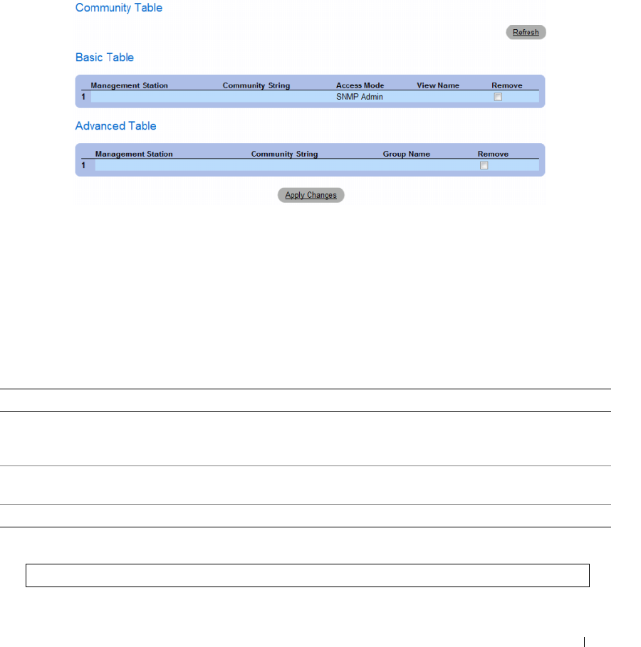
Configuring System Information 237
Deleting Communities
1
Open the
SNMP Community
page.
2
Click
Show All
.
The
Community Table
page opens.
Figure 6-99. Community Table
3
Select a community and check the
Remove
check box.
4
Click
Apply Changes
.
The community entry is deleted, and the device is updated.
Configuring Communities Using CLI Commands
The following table summarizes the equivalent CLI commands for viewing fields displayed in the SNMP
Community.
The following is an example of the CLI commands:
Table 6-50. SNMP Community CLI Commands
CLI Command Description
snmp-server community community [ro | rw |
su] [ipv4-address | ipv6-address][view view-
name]
Sets up the community access string to permit access to the
SNMP protocol.
snmp-server community-group community
group-name [ipv4-address | ipv6-address]
Sets up community access string to permit limited access to the
SNMP protocol based on group access rights.
show snmp Displays the current SNMP device configuration.
Console (config)# snmp-server community dell ro 10.1.1.1
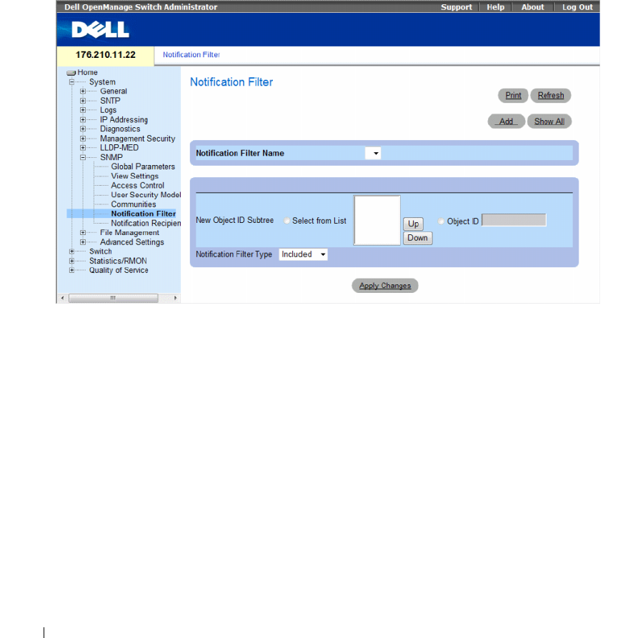
238 Configuring System Information
Defining SNMP Notification Filters
The Notification Filter page permits filtering traps based on OIDs. Each OID is linked to a device
feature or a feature aspect. The Notification Filter page also allows network managers to filter
notifications.
To open the
Notification Filter
page
,
click
System
→
SNMP
→
Notification Filters
in the tree view.
Figure 6-100. Notification Filter
The Notification Filter page contains the following fields:
•
Notification Filter Name
— The user-defined notification filter.
•
New Object ID Tree
— The OID for which notifications are sent or blocked. If a filter is attached to an
OID, traps or informs are generated and sent to the trap recipients. Object IDs are selected from either
the
Select from
List or the
Object ID
List.
•
Notification Filter Typ
e — Indicates whether informs or traps are sent regarding the OID to the trap
recipients.
–
Excluded
— Restricts sending OID traps or informs.
–
Included
— Sends OID traps or informs.
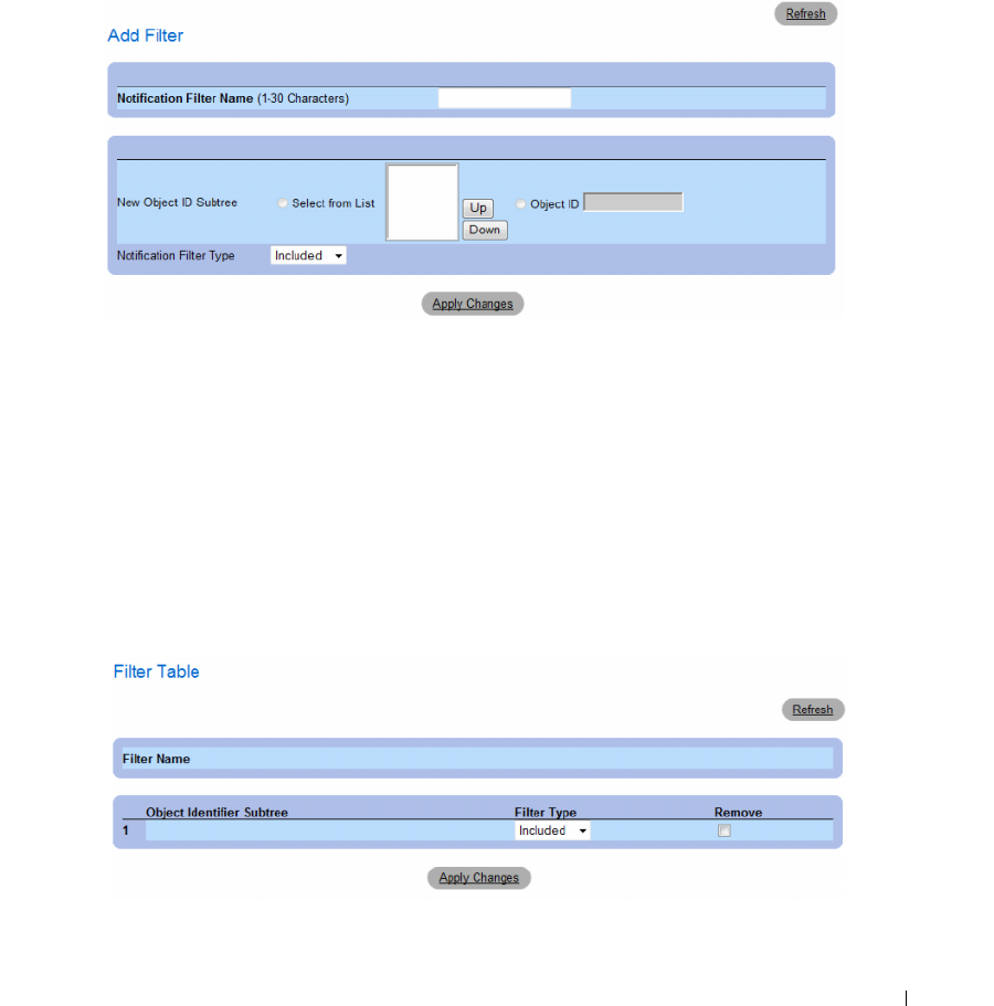
Configuring System Information 239
Adding SNMP Filters
1
Open the
Notification Filter
page.
2
Click
Add
.
The
Add Filter
page opens.
Figure 6-101. Add Filter
3
Define the relevant
fields.
4
Click
Apply Changes
.
The new filter is added, and the device is updated.
Displaying the Filter Table
1
Open the
Notification Filter
page.
2
Click
Show All
.
The
Filter Table
opens.
Figure 6-102. Filter Table

240 Configuring System Information
Removing a Filter
1
Open the
Notification Filter
page.
2
Click
Show All
.
The
Filter Table
opens.
3
Select a
Filter Table
entry.
4
Check the
Remove
checkbox.
The filter entry is deleted, and the device is updated.
Configuring Notification Filters Using CLI Commands
The following table summarizes equivalent CLI commands for defining fields displayed in the
Notification Filter page.
The following is an example of CLI commands:
Defining SNMP Notification Recipients
The Notification Recipients page contains information for defining filters that determine whether traps
are sent to specific users, and the trap type sent. SNMP notification filters provide the following services:
• Identifying Management Trap Targets
• Trap Filtering
• Selecting Trap Generation Parameters
• Providing Access Control Checks
Table 6-51. SNMP Notification Filter CLI Commands
CLI Command Description
snmp-server filter
filter-name
oid-tree
{included | excluded}
Creates or updates an SNMP notification filter.
show snmp filters [filtername] Displays the configuration of SNMP
notification filters
Console (config)# snmp-server filter user1 iso included
Console(config)# end
Console # show snmp filters
Name OID Tree Type
----------- ------------- --------
user1 iso Included
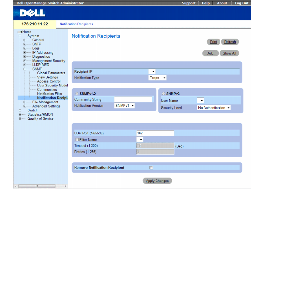
Configuring System Information 241
To open the Notification Recipients page, click System → SNMP → Notification Recipient in the tree
view.
Figure 6-103. Notification Recipients
The Notification Recipients page contains the following fields:
•
Recipient IP
— Indicates the IP address to whom the traps are sent.
•
Notification Type
— The notification sent. The possible field values are:
–
Trap
— Traps are sent.
–
Inform
— Informs are sent.

242 Configuring System Information
SNMPv1,2
SNMP versions 1 and 2 are enabled for the selected recipient. Define the following fields for SNMPv1
and SNMPv2:
•
Community String (1-20 Characters)
— Identifies the community string of the trap manager.
•
Notification Version
— Determines the trap type. The possible field values are:
–
SNMP V1
— SNMP Version 1 traps are sent.
–
SNMP V2
— SNMP Version 2 traps are sent.
SNMPv3
SNMPv3 is used to send and receive traps. Define the following fields for SNMPv3:
•
User Name
— The user to whom SNMP notifications are sent.
•
Security Level
— Defines the means by which the packet is authenticated. The possible field values
are:
–
No Authentication
—
The packet is neither authenticated nor encrypted.
–
Authentication
—
The packet is authenticated.
–
Privacy
—
The packet is both authenticated and encrypted.
•
UDP Port (1-65535)
— The UDP port used to send notifications. The default is 162.
•
Filter Name
— Includes or excludes SNMP filters.
–
Checked
— Includes SNMP filters.
–
Unchecked
— Excludes SNMP filters.
•
Timeout (1-300)
— The amount of time (seconds) the device waits before resending informs.
The default is 15 seconds.
•
Retries (1-255)
— The amount of times the device resends an inform request.
The default is 3.
•
Remove Notification Recipient
— Removes selected notification recipients.
–
Checked
— Removes the specific notification recipient.
–
Unchecked
— Maintains the notification recipient.
When adding a Notification Recipient, the following additional parameters are available:
•
Supported IP Format
— Specifies the IP format supported by the recipient. The possible values are:
–
IPv6
— IP version 6 is supported.
–
IPv4
— IP version 4 is supported.
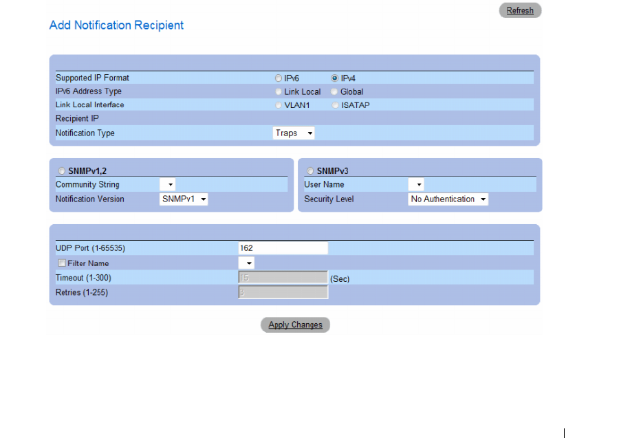
Configuring System Information 243
•
IPv6 Address Type
— When the recipient supports IPv6 (see previous parameter), this specifies the
type of static address supported. The possible values are:
–
Link Local
— A Link Local address that is non-routable and used for communication on the same
network only.
–
Global
— A globally unique IPv6 address; visible and reachable from different subnets.
•
Link Local Interface
— When the server supports an IPv6 Link Local address (see previous
parameter), this specifies the the Link Local interface. The possible values are:
–
VLAN1
— The IPv6 interface is configured on VLAN1.
–
ISATAP
— The IPv6 interface is configured on ISATAP tunnel.
Adding a new Trap Recipients
1
Open
Notification Recipients
page.
2
Click
Add.
The
Add Notification Recipients
page opens.
Figure 6-104. Add Notification Recipients
3
Define the relevant
fields.
4
Click
Apply Changes
.
The notification recipient is added, and the device is updated.
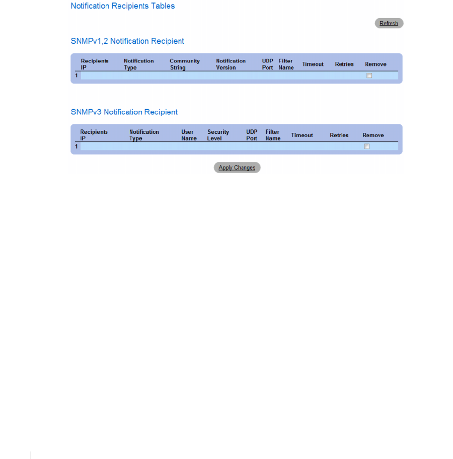
244 Configuring System Information
Displaying Notification Recipients Tables
1
Open
Notification Recipients
page.
2
Click
Show All
.
The
Notification Recipients Tables
page opens.
Figure 6-105. Notification Recipients Tables
Deleting Notification Recipients
1
Open
Notification Recipients
page.
2
Click
Show All
.
The
Notification Recipients Tables
page opens.
3
Select a notification recipient in either the
SNMPV1,2 Notification Recipient
or
SNMPv3
Notification Recipient Tables
.
4
Check the
Remove
checkbox.
5
Click
Apply Changes
.
The recipient is deleted, and the device is updated.

Configuring System Information 245
Configuring SNMP Notification Recipients Using CLI Commands
The following table summarizes the equivalent CLI commands for viewing fields displayed in the
Notification Recipients page.
The following is an example of the CLI commands:
Table 6-52. SNMP Community CLI Commands
CLI Command Description
snmp-server host {ipaddress | hostname}
community-string [traps | informs] [1 | 2]
[udp-port port] [filter filtername]
[timeout seconds] [retries retries]
Creates or updates a notification
recipient receiving notifications in
SNMP version 1 or 2.
snmp-server v3-host {ip-address |
hostname} username [traps | informs]
{noauth | auth | priv} [udp-port port]
[filter filtername] [timeout seconds]
[retries retries]
Creates or updates a notification
recipient receiving notifications in
SNMP version 3.
show snmp Shows the current SNMP
configuration.
console(config)# snmp-server host 172.16.1.1 private
console(config)# end
console# show snmp
Community-String Community-Access View name IP address
---------------- ---------------- --------- ----------
public read only user-view All
private read write default 172.16.1.1
private su DefaultSuper 172.17.1.1

246 Configuring System Information
Managing Files
Use the File Management page to manage device software, the image file, and the configuration files.
Files can be downloaded or uploaded via a TFTP server. The management file structure consists of the
following files:
•
Startup Configuration File
— Contains the commands required to configure device at startup or after
reboot. The startup configuration file is created by copying the configuration commands from the
Running Configuration file or an Image file.
•
Running Configuration File
— Contains all Startup Configuration file commands, as well as all
commands entered during the current session. After the device is powered down or rebooted,
all commands stored in the Running Configuration file are lost. During the startup process,
all commands in the Startup Configuration file are copied to the Running Configuration file and
applied to the device. During the session, all new commands are added to the commands existing in
the Running Configuration file. To update the Startup Configuration file, before powering down the
device, the Running Configuration file must be copied to the Startup Configuration file.
•
Image Files
— System file images are saved in two Flash Files called Image 1 and Image 2. The active
image
stores the active copy, while the other image stores a second copy. The device boots and runs
from the active
image. If the active image is corrupted, the system automatically boots from the
non-active image. This is a safety feature for faults occurring during the Software Upgrade process.
To open the File Management page, click System → File Management in the tree view.
This section contians the following topics:
• "Downloading Files" on page 247
• "Uploading Files" on page 250
• "Activating Image Files" on page 253
• "Copying Files" on page 255
• "Managing Device Files" on page 257
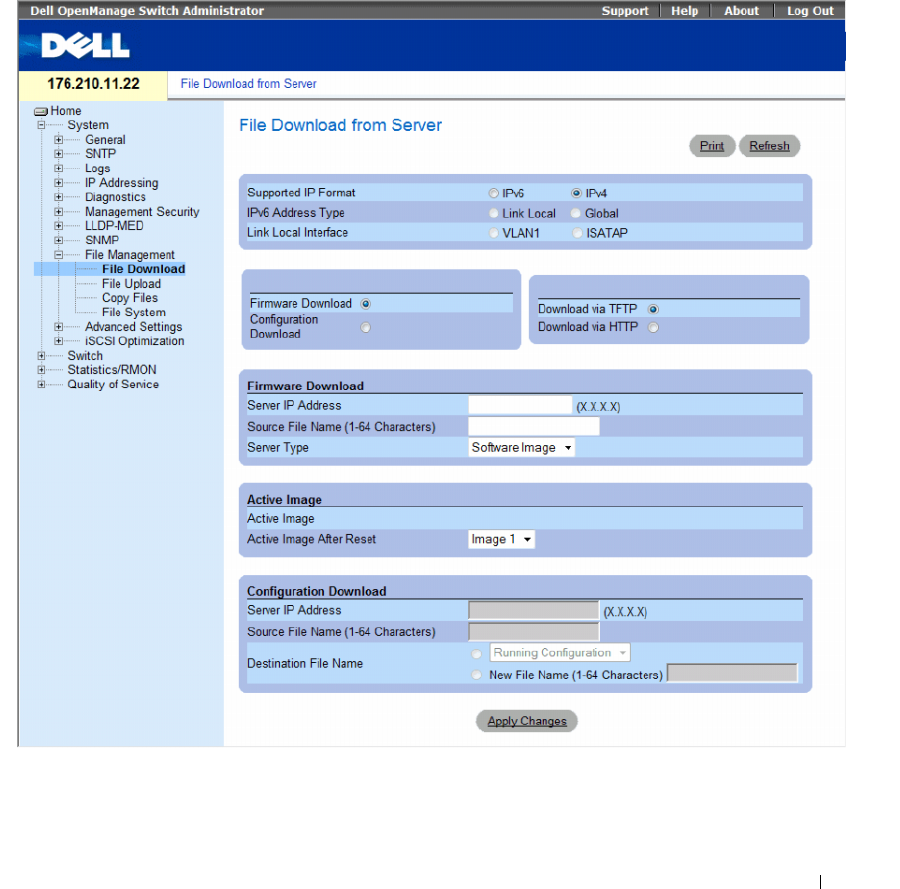
Configuring System Information 247
Downloading Files
The File Download from Server page contains fields for downloading system image and Configuration
files from the TFTP server or HTTP client to the device.
To open the File Download from Server page, click System → File Management → File Download in the
tree view.
Figure 6-106. File Download from Server

248 Configuring System Information
The File Download from Server page contains the following fields:
•
Supported IP Format
— Specifies the IP format supported by the server. The possible values are:
–
IPv6
— IP version 6 is supported.
–
IPv4
— IP version 4 is supported.
•
IPv6 Address Type
— When the server supports IPv6 (see previous parameter), this specifies the type
of static address supported. The possible values are:
–
Link Local
— A Link Local address that is non-routable and used for communication on the same
network only.
–
Global
— A globally unique IPv6 address; visible and reachable from different subnets.
•
Link Local Interface
— When the server supports an IPv6 Link Local address (see previous
parameter), this specifies the the Link Local interface. The possible values are:
–
VLAN1
— The IPv6 interface is configured on VLAN1.
–
ISATAP
— The IPv6 interface is configured on ISATAP tunnel.
•
Firmware Download
— The Firmware file is downloaded. If
Firmware Download
is selected,
the
Configuration Download
fields are grayed out.
•
Configuration Download
— The Configuration file is downloaded. If
Configuration Download
is
selected, the
Firmware Download
fields are grayed out.
•
Download via TFTP
—
Enables initiating an image upload via the TFTP server.
•
Download via HTTP
—
Enables initiating an image upload via the HTTP server.
Firmware Download
•
Server IP Address
— The Server IP Address from which the firmware files are downloaded.
•
Source File Name (1-64 characters)
— Indicates the file to be downloaded.
•
Destination File Name
— The destination file type to which the file is downloaded. The possible field
values are:
–
Software Image
— Downloads the Image file. The image file overwrites the non-active image. It is
recommended to designate that the non-active image becomes the active image after reset, and
then to reset the device following the download. During the Image file download a dialog box
opens which displays the download progress. The window closes automatically when the download
is complete.
–
Boot Code
— Downloads the Boot file.

Configuring System Information 249
Configuration Download
•
Server IP Address
— The TFTP Server IP Address from which the configuration files are downloaded.
•
Source File Name (1-64 characters)
— Indicates the configuration files to be downloaded.
•
Destination File
— The destination file to which the configuration file is downloaded. The possible
field values are:
–
Running Configuration
— Downloads commands into the Running Configuration file.
–
Startup Configuration —
Downloads the Startup Configuration file, and overwrites it.
–
<filename>
— Downloads commands into a configuration backup file. The filename is
determined by the user at download.
Downloading Files
1
Open the
File Download from Server
page.
2
Define the file type to download.
3
Define the fields.
4
Click
Apply Changes
.
The software is downloaded to the device. To activate the selected Image file, reset the device.
For information on resetting the device, see Switching Between Stack Masters.
Downloading Files Using CLI Commands
The following table summarizes the equivalent CLI commands for setting fields displayed in the File
Download from Server page.
The following is an example of the CLI commands:
NOTE: Each exclamation mark (!) indicates that ten packets were successfully transferred.
Table 6-53. File Download CLI Commands
CLI Command Description
copy source-url destination-url Copies any file from a source to a destination.
console# copy tftp://10.6.6.64/pp.txt startup-config
....!
Copy: 575 bytes copied in 00:00:06 [hh:mm:ss]
01-Jan-2000 06:41:55 %COPY-W-TRAP: The copy operation was
completed successfully
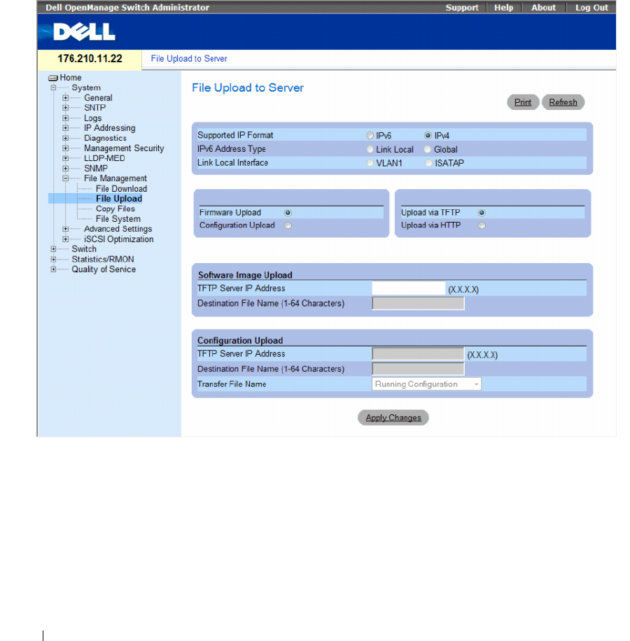
250 Configuring System Information
Uploading Files
The File Upload to Server page contains fields for uploading the software to the TFTP server from the
device. The Image file can also be uploaded from the File Upload to Server page.
To open the File Upload to Server page, click System → File Management → File Upload in the tree view.
Figure 6-107. File Upload to Server

Configuring System Information 251
The File Upload to Server page contains the following fields:
•
Supported IP Format
— Specifies the IP format supported by the server. The possible values are:
–
IPv6
— IP version 6 is supported.
–
IPv4
— IP version 4 is supported.
•
IPv6 Address Type
— When the server supports IPv6 (see previous parameter), this specifies the type
of static address supported. The possible values are:
–
Link Local
— A Link Local address that is non-routable and used for communication on the same
network only.
–
Global
— A globally unique IPv6 address; visible and reachable from different subnets.
•
Link Local Interface
— When the server supports an IPv6 Link Local address (see previous
parameter), this specifies the the Link Local interface. The possible values are:
–
VLAN1
— The IPv6 interface is configured on VLAN1.
–
ISATAP
— The IPv6 interface is configured on ISATAP tunnel.
•
Firmware Upload
— The Firmware file is uploaded. If
Firmware Upload
is selected, the
Configuration Upload
fields become unavailable.
•
Configuration Upload
— The Configuration file is uploaded. If
Configuration Upload
is selected,
the
Software Image Upload
fields become unavailable.
•
Upload via TFTP
—
Enables initiating an image upload via the TFTP server.
•
Upload via HTTP
—
Enables initiating an image upload via the FTP server.
Software Image Upload
•
TFTP Server IP Address
— The TFTP Server IP Address to which the Software Image is uploaded.
•
Destination File Name (1-64 Characters)
— Indicates the Software Image file path to which the file is
uploaded.

252 Configuring System Information
Configuration Upload
•
TFTP Server IP Address
— The TFTP Server IP Address to which the Configuration file is uploaded.
•
Destination File Name (1-64 Characters)
— Indicates the Configuration file path to which the file is
uploaded.
•
Transfer File Name
— The software file to which the configuration is uploaded. The possible field
values are:
–
Running Configuration
— Uploads the Running Configuration file.
–
Startup Configuration
— Uploads the Startup Configuration file.
–
My Backup Configuration —
Uploads the Backup Configuration file. This list of user-defined
configuration files only appears if the user had created backup configuration files. For example,
if the user copied the running configuration file to a user-defined configuration file called
BACKUP-SITE-1, this list appears on the File Upload to Server page and the BACKUP-SITE-1
configuration file appears in the list.
Uploading Files
1
Open the
File Upload to Server
page.
2
Define the file type to upload.
3
Define the fields.
4
Click
Apply Changes
.
The software is uploaded to the TFTP server.
Uploading Files Using CLI Commands
The following table summarizes the equivalent CLI commands for setting fields displayed in the File
Upload to Server page.
Table 6-54. File Upload CLI Commands
CLI Command Description
copy source-url destination-url Copies any file from a source to a destination.
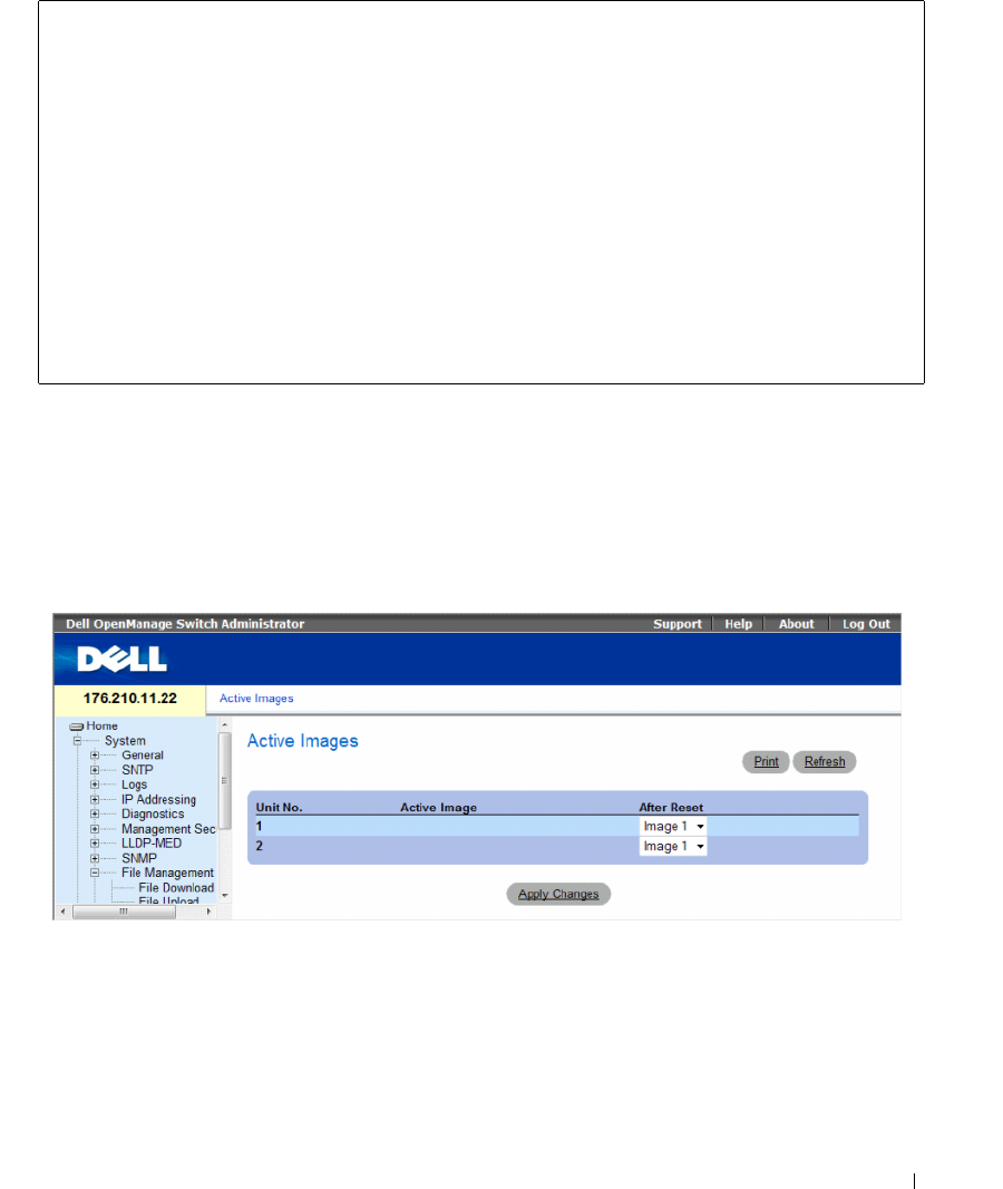
Configuring System Information 253
The following is an example of the CLI commands:
Activating Image Files
The Active Images page allows network managers to select and reset the Image files. The Active Image
file for each unit in a stacking configuration can be individually selected.
To open the Active Images page, click System → File Management → Active Images in the tree view.
Figure 6-108. Active Images
console# copy image tftp://10.6.6.64/uploaded.ros
!!!!!!!!!!!!!!!!!!!!!!!!!!!!!!!!!!!!!!!!!!!!!!!!!!!!!!!!!!!!!!!
!!!!!!!!!!!!!!!!!!!!!!!!!!!!!!!!!!!!!!!!!!!!!!!!!!!!!!!!!!!!!!
!!!!!!!!!!!!!!!!!!!!!!!!!!!!!!!!!!!!!!!!!!!!!!!!!!!!!!!!!!!!!!!
!!!!!!!!!!!!!!!!!!!!!!!!!!!!!!!!!!!!!!!!!!!!!!!!!!!!!!!!!!!!!!!
!!!!!!!!!!!!!!!!!!!!!!!!!!!!!!!!!!!!!!!!!!!!!!!!!!!!!!!!!!!!!!!
!!!!!!!!!!!!!!!!!!!!!!!!!!!!!!!!!!!!!!!!!!!!!!!!!!!!!!!!!!!!!!!
Copy: 4234656 bytes copied in 00:00:33 [hh:mm:ss]
01-Jan-2000 07:30:42 %COPY-W-TRAP: The copy operation was
completed successfully

254 Configuring System Information
The Active Images page contains the following fields:
•
Unit No.
— The unit number for which the Image file is selected.
•
Active Image
— The Image file which is currently active on the unit.
•
After Reset
— The Image file which is active on the unit after the device is reset. The possible field
values are:
–
Image 1
— Activates Image file 1 after the device is reset.
–
Image 2
— Activates Image file 2 after the device is reset.
Selecting an Image File
1Open the
Active Images
page
.
2Select an Image file for a specific unit in the After Reset field.
3Click Apply Changes.
The Image file is selected. The Image file reloads only after the next reset. The currently selected
Image file continue to run until the next device reset.
Working with the Active Image File Using CLI Commands
The following table summarizes the equivalent CLI commands for viewing fields displayed in the Active
Images.
The following is an example of the CLI commands:
Table 6-55. File Upload CLI Commands
CLI Command Description
boot system [unit | unit ]
{image-1 | image-2}
Indicates the system image that the device loads
at startup.
show version [unit unit] Displays version information for the system
Console# boot system image-1
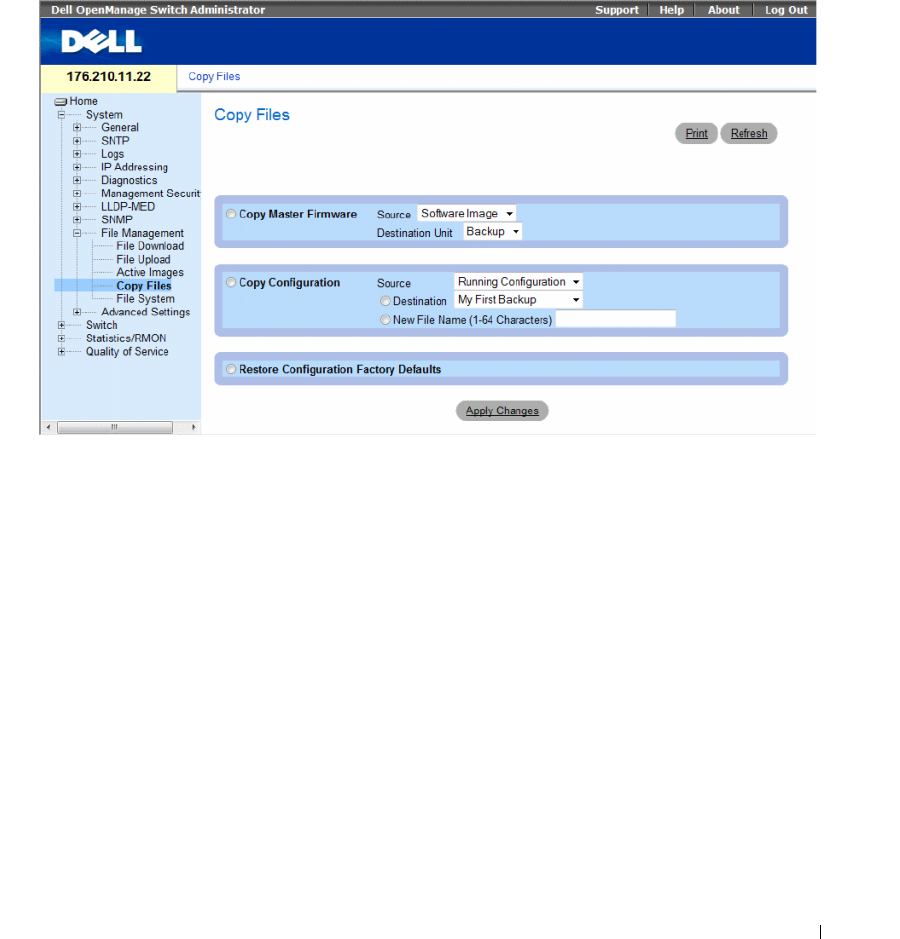
Configuring System Information 255
Copying Files
Files can be copied and deleted from the Copy Files page.
To open the Copy Files page, click System → File Management → Copy Files in the tree view.
Figure 6-109. Copy Files
The Copy Files page contains the following fields:
•
Copy Master Firmware
— Indicates the firmware file to copy. The possible field values are:
–
Source
— Copies the current Stacking Master’s Software Image file or Boot Code file.
–
Destination Unit
— Specifies the stacking member to upload the file.
•
Copy Configuration
— When selected, copies either the running, startup or backup configuration file
of the Master file to the destination file.
–
Source
— Indicates the type of file to be copied to the destination file. Select either the Running
Configuration or Startup Configuration.
–
Destination
— Indicates the destination configuration file to which the source file is copied.
Select My First Backup or Startup Configuration.
–
New File Name (1-64 characters)
— Indicates the name of the newly created backup
configuration file.
•
Restore Configuration Factory Defaults
— When selected, indicates that the current configuration
settings should be replaced by the factory configuration default settings. When clear, indicates that the
current configuration settings should be maintained.

256 Configuring System Information
Copying Files
1
Open the
Copy Files
page.
2
Define the
Source
and
Destination
fields.
3
Click
Apply Changes
.
The file is copied, and the device is updated.
Restoring Company Factory Default Settings
1
Open the
Copy Files
page.
2
Click
Restore Configuration Factory Defaults
.
3
Click
Apply Changes
.
The company factory default settings are restored, and the device is updated.
Copying and Deleting Files Using CLI Commands
The following table summarizes the equivalent CLI commands for setting fields displayed in the Copy
Files page.
The following is an example of the CLI commands:
Table 6-56. Copy Files CLI Commands
CLI Command Description
copy source-url destination-url Copies any file from a source to a destination.
delete startup-config Deletes the startup-config file.
delete url Deletes a file from the FLASH memory device.
console# delete startup-config
Startup file was deleted
console#
console# copy running-config startup-config
01-Jan-2000 06:55:32 %COPY-W-TRAP: The copy operation was
completed successfully
Copy succeeded
console#
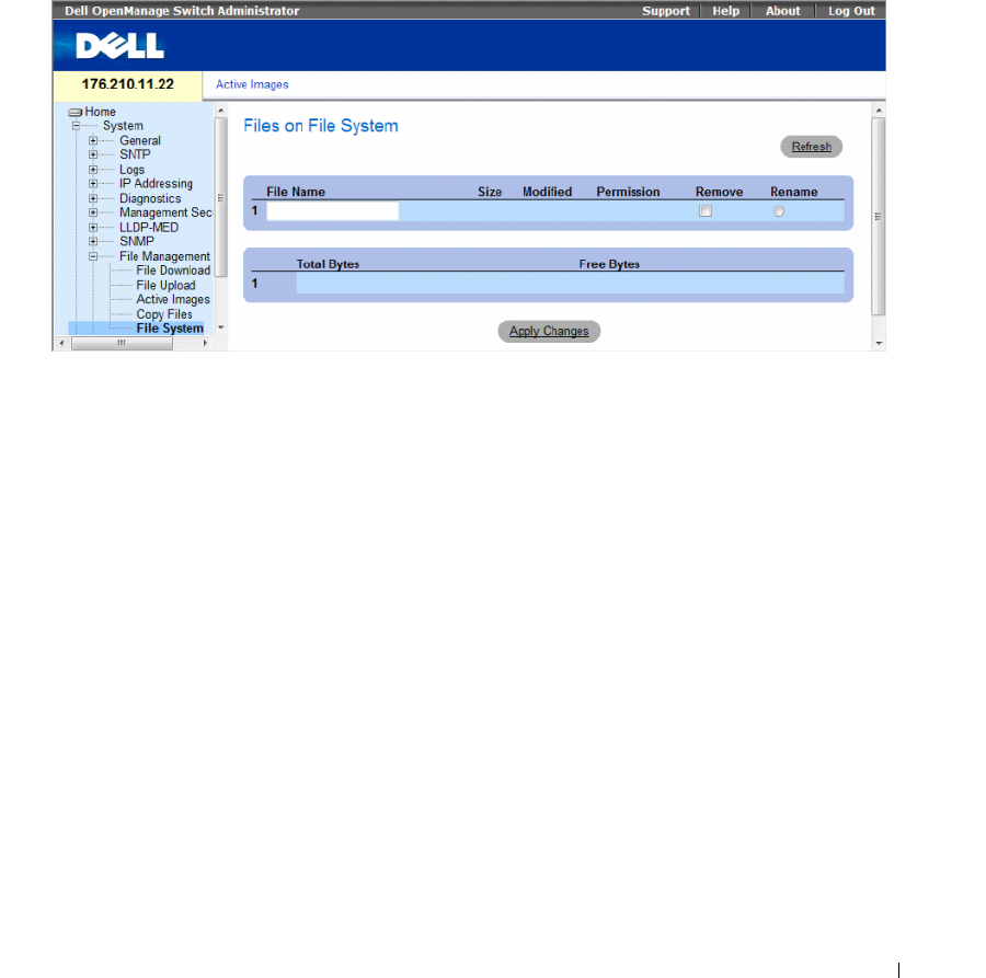
Configuring System Information 257
Managing Device Files
The Files on File System page provides information about files currently stored on the system, including
file names, file sizes, files modifications, and file permissions. The files system permits managing up to
five files, with a maximum size of 0.5 MB per file.
To open the Files on File System page, click System→ File Management→ File System in the tree view.
Figure 6-110. Files on File System
The Files on File System page contains the following fields:
•
File Name
— Indicates the file currently stored in the file management system.
•
Size
— Indicates the file size.
•
Modified
— Indicates the date the file was last modified.
•
Permission
— Indicates the permission type assigned to the file. The possible field values are:
–
Read Only
— Indicates a read-only file.
–
Read Write
— Indicates a read-write file.
•
Remove
— Deletes the file.
–
Checked
— Removes the specified file from the file management system.
–
Unchecked
— Maintains the specified file in the file management system.
•
Rename
— Permits renaming the file. The file name is renamed in the
File Name
field.
•
Total Bytes
— Indicates the total amount of the space currently used.
•
Free Bytes
— Indicates the remaining amount of the space currently free.

258 Configuring System Information
Managing Files Using CLI Commands
The following table summarizes the equivalent CLI commands for managing system files.
The following is an example of the CLI commands:
Table 6-57. Copy Files CLI Commands
CLI Command Description
dir Display list of files on a flash file system
console# dir
Directory of flash:
File Name Permis-
sion
Flash
Size
Data
Size
Modified
-------------- ------ ------ ------ --------------------
3.txt rw 524288 523776 22-Feb-2005 18:49:27
setup rw 524288 95 22-Feb-2005 15:58:19
setup2 rw 524288 95 22-Feb-2005 15:58:35
image-1 rw 4325376 4325376 06-Feb-2005 17:55:32
image-2 rw 4325376 4325376 06-Feb-2005 17:55:31
test.txt rw 524288 95 22-Feb-2005 12:16:44
aaafile.prv -- 131072 -- 06-Feb-2005 19:09:02
syslog1.sys r- 262144 -- 22-Feb-2005 18:49:27
syslog2.sys r- 262144 -- 22-Feb-2005 18:49:27
directory.prv -- 262144 -- 06-Feb-2005 17:55:31
startup-config rw 524288 347 22-Feb-2005 11:56:03
Total size of flash: 16646144 bytes
Free size of flash: 4456448 bytes
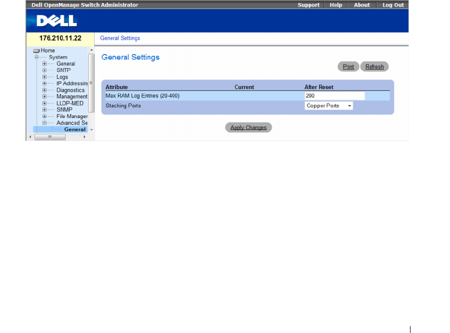
Configuring System Information 259
Configuring Advanced Settings
Use Advanced Settings to set miscellaneous global attributes of the switch. The changes to these
attributes are applied only after the switch is reset.
Click a link below to access on-line help for the indicated screen.
Click System → Advanced Settings in the tree view to open the Advanced Settings page.
The the Advanced Settings page contains a link for configuring general settings.
This section contians the following topics:
• "Configuring General Settings" on page 259
Configuring General Settings
The General Settings page provides information for defining general device parameters.
To open the General Settings page, click System → Advanced Settings → General Settings in the tree view.
Figure 6-111. General Settings
The General Settings page contains the following information:
•
Attribute
— The general setting attribute.
•
Current
— The currently configured value.
•
After Reset
— The future (after reset) value. By entering a value in the After Reset column, memory is
allocated to the field table.
•
Max RAM Log Entries (20-400)
— The maximum number of RAM Log entries. When the Log
entries are full, the log is cleared and the Log file is restarted.
•
Stacking Ports
— The type of stacking ports: copper or fiber ports.

260 Configuring System Information
Viewing RAM Log Entries Counter Using the CLI Commands
The following table summarizes the equivalent CLI commands for setting fields displayed in the
General Settings page.
The following is an example of the CLI commands:
Table 6-58. General Settings CLI Commands
CLI Command Description
logging buffered size number Sets the number of syslog messages stored in the
internal buffer (RAM).
console(config)# logging buffered size 300

Configuring Switch Information 261
Configuring Switch Information
This section provides all system operation and general information for configuring network security,
ports, Address tables, GARP, VLANs, Spanning Tree, Port Aggregation, and Multicast Support.
This section contians the following topics:
• "Configuring Network Security" on page 261
• "ACL Overview" on page 276
• "Configuring DHCP Snooping" on page 288
• "Configuring Ports" on page 297
• "Configuring Address Tables" on page 315
• "Configuring GARP" on page 321
• "Configuring the Spanning Tree Protocol" on page 325
• "Configuring VLANs" on page 351
• "Configuring Voice VLAN" on page 374
• "Aggregating Ports" on page 382
• "Multicast Forwarding Support" on page 387
Configuring Network Security
Use the Network Security page to set network security through both access control lists and locked
ports. To open the Network Security page, select Switch → Network Security.
This section contians the following topics:
• "Port Based Authentication" on page 262
• "Configuring Advanced Port Based Authentication" on page 268
• "Authenticating Users" on page 271
• "Configuring Port Security" on page 273

262 Configuring Switch Information
Port Based Authentication
Port based authentication enables authenticating system users on a per-port basis via an external server.
Only authenticated and approved system users can transmit and receive data. Ports are authenticated via
the RADIUS server using the Extensible Authentication Protocol (EAP). Port Authentication includes:
•
Authenticators
— Specifies the device port which is authenticated before permitting system access.
•
Supplicants
— Specifies host connected to the authenticated port requesting to access the system
services.
•
Authentication Server
— Specifies the external server, for example, the RADIUS server that performs
the authentication on behalf of the authenticator, and indicates whether the supplicant is authorized
to access system services.
Port based authentication creates two access states:
•
Controlled Access
— Permits communication between the supplicant and the system, if the
supplicant is authorized.
•
Uncontrolled Access
— Permits uncontrolled communication regardless of the port state.
The device currently supports Port Based Authentication via RADIUS servers.
MAC Based Authentication
MAC based authentication is an alternative to 802.1x that allows allows network access to devices
(such as printers and IP phones) that do not have the 802.1X supplicant capability. MAC authentication
uses the MAC address of the connecting device to grant or deny network access.
Advanced Port Based Authentication
Advanced Port Based Authentication:
• Enables multiple hosts to be attached to a single port.
• Requires only one host to be authorized for all hosts to have system access. If the port is unauthorized,
all attached hosts are denied access to the network.
• Enables user based authentication. Specific VLANs in the device are always available, even if specific
ports attached to the VLAN are unauthorized.
– For example, Voice over IP does not require authentication, while data traffic requires
authentication. VLANs for which authorization is not required can be defined. Unauthenticated
VLANs are available to users, even if the ports attached to the VLAN are defined as authorized.
Advanced Port Based Authentication is implemented in the following modes:
•
Single Host Mode
— Enables only the authorized host for single-session access to the port.
•
Multiple Host Mode
— Enables multiple hosts to be attached to a single port, for single-session
access. Only one host must be authorized for all hosts to access the network. If the host authentication
fails or an EAPOL-logoff message is received, all attached clients are denied network access.
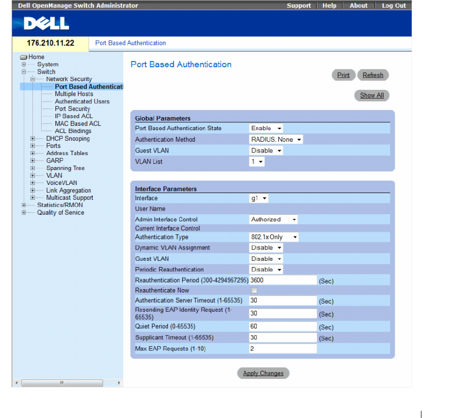
Configuring Switch Information 263
•
Multiple Session Mode
— Enables only the authorized host for multiple-session access to the port.
•
Guest VLANs
— Provides limited network access authorized to ports. If a port is denied network
access via port based authorization, but the Guest VLAN is enabled, the port receives limited network
access. For example, a network administrator can use Guest VLANs to deny network access via port
based authentication, but grant Internet access to unauthorized users.
The Port Based Authentication page allows network managers to configure port based authentication.
To open the Port Based Authentication page, click Switch → Network Security → Port Based
Authentication.
Figure 7-1. Port Based Authentication

264 Configuring Switch Information
The Port Based Authentication page contains the following fields:
•
Port Based Authentication State
— Permits port based authentication on the device. The possible
field values are:
–
Enable
— Enables port based authentication on the device.
–
Disable
— Disables port based authentication on the device.
•
Authentication Method
— Indicates the Authentication method used. The possible field values are:
–
None
— Indicates that no authentication method is used to authenticate the port.
–
RADIUS
— Indicates that port authentication is performed via RADIUS server.
–
RADIUS, None
— Indicates that port authentication is performed first via the RADIUS server.
If the port is not authenticated, then no authentication method is used, and the session is
permitted.
•
Guest VLAN
— Specifies whether the Guest VLAN is enabled on the device. The possible field values
are:
–
Enable
— Enables use of a Guest VLAN for unauthorized ports. If a Guest VLAN is enabled, the
unauthorized port automatically joins the VLAN selected in the
VLAN List
field.
–
Disable
— Disables use of a Guest VLAN for unauthorized ports. This is the default.
•
VLAN List
— Contains a list of VLANs. The Guest VLAN is selected from the VLAN list.
Interface Parameters
•
Interface
— Contains an interface list for which port based authentication is enabled.
•
User Name
— Indicates the supplicant user-name.
•
Admin Interface Control
— Defines the port authorization state. The possible field values are:
–
Auto
— Enables port based authentication on the device. The interface moves between an
authorized or unauthorized state based on the authentication exchange between the device and
the client.
–
Authorized
— Places the interface into an authorized state without being authenticated.
The interface resends and receives normal traffic without client port based authentication.
–
Unauthorized
— Denies the selected interface system access by moving the interface into
unauthorized state. The device cannot provide authentication services to the client through the
interface.
•
Current Interface Control
— The current port authorization state.
• Authentication Type
— Specifies the type of authentication on the port. The possible field values are:
–
802.1x Only
— Sets the authentication type to 802.1x based authentication only.
–
MAC Only
— Sets the authentication type to MAC based authentication only.
–
802.1x & MAC
— Sets the authentication type to 802.1x based authentication and MAC based
authentication.

Configuring Switch Information 265
•
Dynamic VLAN Assignment
— Indicates whether dynamic VLAN assignment is enabled for this port.
This feature allows network administrators to automatically assign users to VLANs during the RADIUS
server authentication. When a user is authenticated by the RADIUS server, the user is automatically
joined to the VLAN configured on a RADIUS server.
– Port Lock and Port Monitor should be disabled when DVA is enabled.
– Dynamic VLAN Assignment (DVA) can occur only if a RADIUS server is configured, and port
authentication is enabled and set to 802.1x multi-session mode.
– If the Radius Accept Message doesn’t contain the supplicant’s VLAN, the supplicant is rejected.
– Authenticated ports are added to the supplicant VLAN as untagged.
– Authenticated ports remain unauthenticated VLAN and Guest VLAN members. Static VLAN
configuration is not applied to the port.
– The following list of VLANs cannot participate in DVA: an Unauthenticated VLAN, a Dynamic
VLAN that was created by GVRP, a Voice VLAN, a Default VLAN and a Guest VLAN.
– Network administrators can delete the supplicant VLAN while the supplicant is logged in.
The supplicant is authorized during the next re-authentication if this supplicant VLAN is
re-created or a new VLAN is configured on the RADIUS server.
•
Guest VLAN
— If enabled, indicates that unauthorized users connected to this interface can access
the Guest VLAN.
–
Enable
— Enables unauthorized users to access the guest VLAN.
–
Disable
— Prevents unauthorized users from accessing the guest VLAN.
•
Periodic Reauthentication
— Reauthenticates the selected port periodically. The reauthentication
period is defined in the
Reauthentication Period (300-4294967295)
field.
–
Enable
— Enables periodic port reauthentication.
–
Disable
— Disables periodic port reauthentication.
•
Reauthentication Period (300-4294967295)
— Indicate the time span in which the selected port is
reauthenticated. The field value is seconds. The field default is 3600 seconds.
•
Reauthenticate Now
— Permits immediate port reauthentication.
–
Checked
— Enables immediate port reauthentication.
–
Disable
— Disables immediate port reauthentication.
•
Authentication Server Timeout (1-65535)
— Defines the amount of time that lapses before the
device resends a request to the authentication server. The field value is specified in seconds. The field
default is 30 seconds.
•
Resending EAP Identity Request (1-65535)
— Defines the amount of time that lapses before
EAP request are resent. The field default is 30 seconds.
•
Quiet Period (0-65535)
— Indicates the number of seconds that the device remains in the quiet state
following a failed authentication exchange. The possible field range is 0-65535. The field default is
60 seconds.
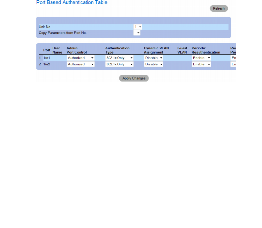
266 Configuring Switch Information
•
Supplicant Timeout (1-65535)
— Indicates the amount of time that lapses before EAP requests are
resent to the supplicant. The field value is in seconds. The field default is 30 seconds.
•
Max EAP Requests (1-10)
— Indicates that total amount of EAP requests sent. If a response is not
received after the defined period, the authentication process is restarted. The field default is 2 retries.
Displaying the Port Based Authentication Table
1
Open the
Port Based Authentication
page.
2
Click
Show All
.
The
Port Based Authentication Table
opens.
Figure 7-2. Port Based Authentication Table
In addition to the fields in the Port Based Authentication Table also displays the following fields:
•
Unit No.
— Selects a stacking member.
•
Copy Parameters from Port No.
— Copies parameters a the selected port.
Copying parameters in the Port Based Authentication Table
1
Open the page.
2
Click
Show All
.
The
Port Based Authentication Table
opens.
3
Select the interface in the
Copy Parameters from Port No.
field.
4
Select an interface in the
Port Based Authentication Table
.
5
Check the
Copy to
check box to define the interfaces to which the Port based authentication
parameters are copied.
6
Click
Apply Changes
.

Configuring Switch Information 267
Enabling Port Based Authentication Using the CLI Commands
The following table summarizes the equivalent CLI commands for enabling the port based
authentication as displayed in the Port Based Authentication table.
Table 7-1. Port Authentication CLI Commands
CLI Command Description
aaa authentication dot1x default
method1 [method2.]
Specifies one or more authentication, authorization, and accounting
(AAA) methods for use on interfaces running IEEE 802.1X.
dot1x auth-not-req Enables authorized devices access to the VLAN.
dot1x guest-vlan Defines a Guest VLAN.
dot1x guest vlan enable Enables authorized users on the inteface to access the Guest VLAN.
dot1x mac-authentication Enables authentication based on the station’s MAC address (MAC
based authentication).
dot1x max-req count Sets the maximum number of times that the device sends an EAP to
the client, before restarting the authentication process.
dot1x re-authenticate [ethernet
interface]
Manually initiates a re-authentication of all 802.1X-enabled ports or the
specified 802.1X-enabled port.
dot1x re-authentication Enables periodic re-authentication of the client.
dot1x timeout quiet-period seconds Sets the number of seconds that the device remains in the quiet state
following a failed authentication exchange.
dot1x timeout re-authperiod seconds Sets the number of seconds between re-authentication attempts.
dot1x timeout server-timeout seconds Sets the time for the retransmission of packets to the authentication server.
dot1x timeout supp-timeout seconds Sets the time for the retransmission of an EAP request frame to the client.
dot1x timeout tx-period seconds Sets the number of seconds that the device waits for a response to an EAP -
request/identity frame, from the client, before resending the request.
dot1x traps mac-authentication failure Enables sending traps when the MAC address failed authenticaiton
(MAC based authentication).
dot1x radius-attribues vlan Enables user-based VLAN assignment.
show dot1x [ethernet interface]Displays 802.1X status for the device or for the specified interface.
show dot1x advanced Displays 802.1X advanced features for the switch or specified interface.
show dot1x users [username username] Displays 802.1X users for the device.
dot1x guest-vlan enable Enables using a guest VLAN for unauthorized ports. If a Guest
VLAN is enabled, the unauthorized port automatically joins the
VLAN selected in VLAN List field. The field default is disabled.
dot1x guest-vlan Contains a list of VLANs. The guest VLAN is selected from the
VLAN List
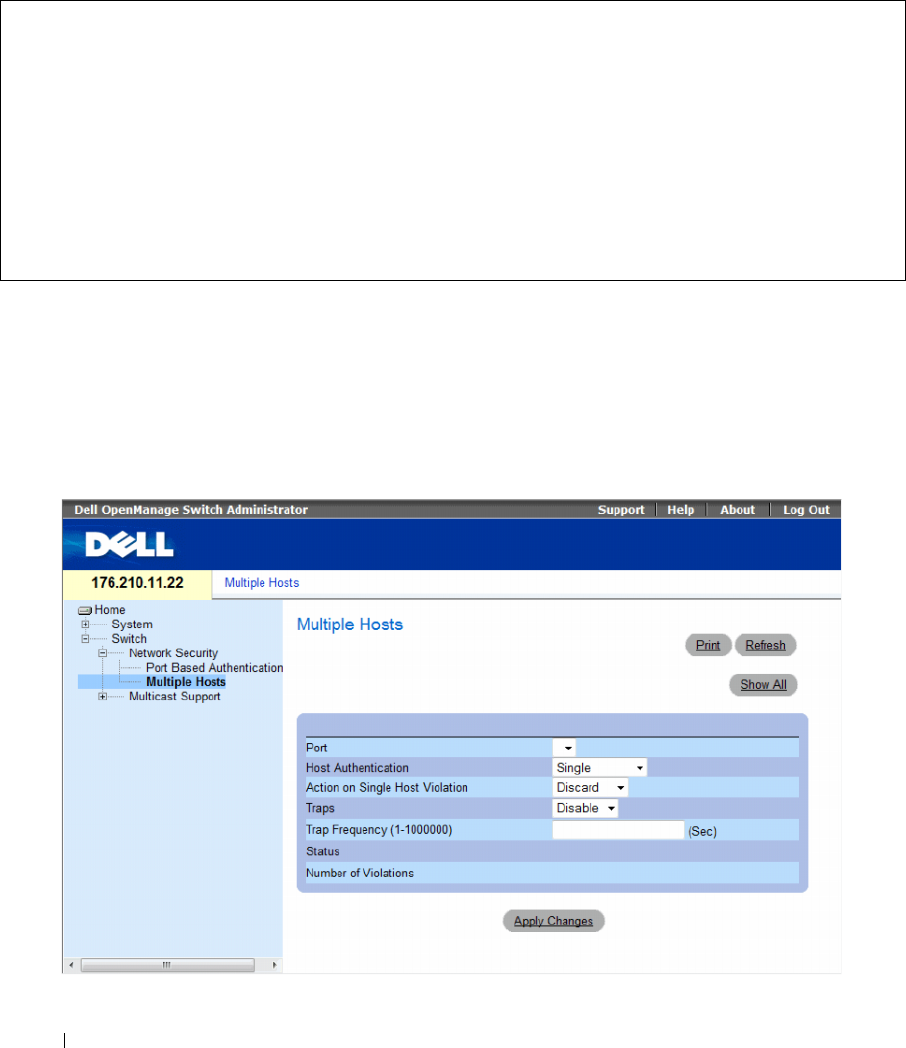
268 Configuring Switch Information
The following is an example of the CLI commands:
Configuring Advanced Port Based Authentication
The Multiple Hosts page provides information for defining advanced port based authentication settings
for specific ports and VLANs. For more information on Advanced Port Based Authentication, see
Advanced Port Based Authentication.
To open the Multiple Hosts, click Switch → Network Security → Multiple Hosts.
Figure 7-3. Multiple Hosts
Console# show dot1x
Interface Admin Mode Oper Mode Reauth
Control
Reauth
Period
Username
--------- ---------- ---------- -------- ------ --------
1/e1 Auto Authorized Ena 3600 Bob
1/e2 Auto Authorized Ena 3600 John
1/e3 Auto Unauthorized Ena 3600 Clark
1/e4 Force-auth Authorized Dis 3600 n/a

Configuring Switch Information 269
The Multiple Hosts page contains the following fields:
•
Port
— The port number for which Advanced Port Based Authentication is enabled.
• Host Authentication
— Defines the host authentication type. The possible fields are:
–Single
— Enables a single authorized host for single-session access to the system.
–
Multiple Host
— Enables a single host to authorize multiple hosts for single-session access to the
system. This setting must be enabled in order to either disable the ingress-filter, or to use port-lock
security on the selected port.
–
Multiple Session
— Enables a single authorzied host for multiple-session access to the system.
This is the default value.
•
Action on Single Host Violation
— Defines the action to be applied to packets arriving in single-host
mode, from a host whose MAC address is not the client (supplicant) MAC address. The possible field
values are:
–
Forward
— Forwards the packets from an unknown source, however, the MAC address is
not learned.
–
Discard
— Discards the packets from any unlearned source. This is the default value.
–
Shutdown
— Discards the packet from any unlearned source and shuts down the port.
Ports remain shut down until they are activated, or the switch is reset.
•
Traps
— Enables or disables sending traps to the host if a violation occurs.
–
Enable
— Enables sending traps.
–
Disable
— Disables sending traps.
•
Trap Frequency (1-1000000)
— Defines the time period in seconds by which traps are sent to the host.
The
Trap Frequency (1-1000000)
field can be defined only if the
Multiple Hosts
field is defined as
Disable
. The default is 10 seconds.
•
Status
— The host status. The possible field values are:
–
Unauthorized
— Indicates that the port control is
Force Unauthorized,
the port link is down or the
port control is Auto, but a client has not been authenticated via the port.
–
Not in Auto Mode
— Indicates that the port control is
Forced Authorized
, and clients have full
port access.
–
Single-host Lock
— Indicates that the port control is
Auto
and a single client has been
authenticated via the port.
–
No Single Host
— Indicates that Multiple Host is enabled.
•
Number of Violations
— The number of packets that arrived on the interface in single-host mode,
from a host whose MAC address is not the client (supplicant) MAC address.
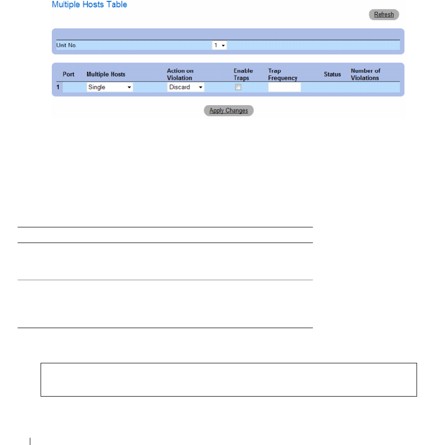
270 Configuring Switch Information
Displaying the Multiple Hosts Table
1
Open the
Multiple Hosts
page.
2
Click
Show All
.
The
Multiple Hosts Table
opens.
Figure 7-4. Multiple Hosts Table
The Multiple Hosts Table displays the following additional field:
•
Unit No.
— Selects a stacking member.
Enabling Multiple Hosts Using the CLI Commands
The following table summarizes the equivalent CLI commands for enabling the advanced port based
authentication as displayed in the Multiple Hosts page.
The following is an example of the CLI Command.
Table 7-2. Multiple Hosts CLI Commands
CLI Command Description
dot1x multiple-hosts Allows multiple hosts (clients) on an 802.1X-
authorized port that has the dot1x port-control
interface configuration command set to auto.
dot1x single-host-
violation {forward
|discard |discard-
shutdown}[trap seconds]
Configures the action to be taken when a station,
whose MAC address is not the client (supplicant)
MAC address, attempts to access the interface.
Console(config)# interface ethernet 1/e1
Console(config-if)# dot1x multiple-hosts
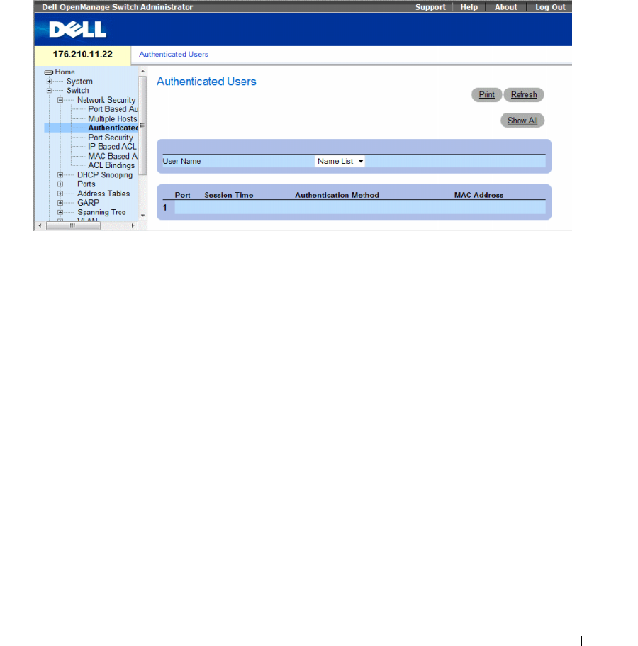
Configuring Switch Information 271
Authenticating Users
The Authenticated Users page displays user port access lists. The User Access Lists are defined in the
Add User Name page.
To open the Authenticated Users page, click Switch → Network Security → Authenticated Users.
Figure 7-5. Authenticated Users
The Authenticated Users page contains the following fields:
•
User Name
— List of users authorized via the RADIUS Server.
•
Port
— The port number(s) used for authentication, per user name.
•
Session Time
— The amount of time the user was logged on to the device. The field format is
Day:Hour:Minute:Seconds
, for example, 3 days: 2 hours: 4 minutes: 39 seconds.
•
Authentication Method
— The method by which the last session was authenticated. The possible
field values are:
–
Remote
— The user was authenticated from a remote server.
–
None
— The user was not authenticated.
•
MAC Address
— The supplicant MAC address.
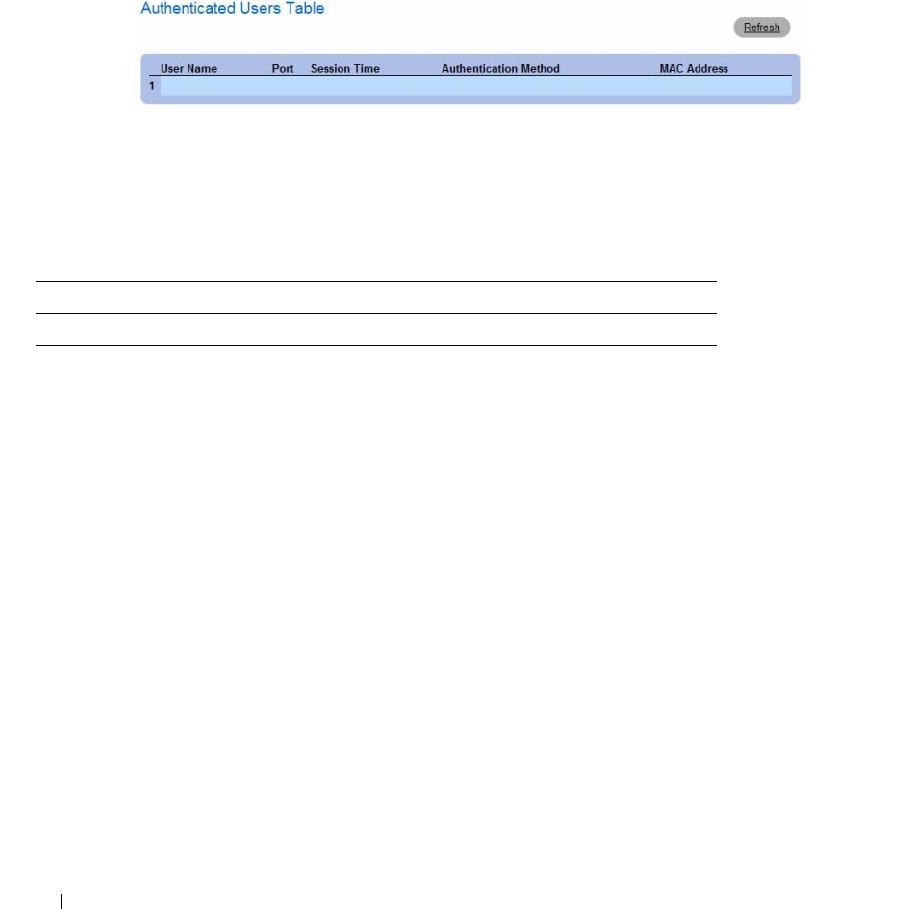
272 Configuring Switch Information
Displaying the Authenticated Users Table
1
Open the
Authenticated Users
page.
2
Click
Show All
.
The
Authenticated Users Table
opens.
Figure 7-6. Authenticated Users Table
Authenticating Users Using the CLI Commands
The following table summarizes the equivalent CLI commands for authenticating users as displayed in
the Authenticated Users page.
The following is an example of the CLI commands:
console# show dot1x users
Port Username Session Time Auth Method MAC Address
-----------------------------------------------------------------
1/e11 gili 00:09:27 Remote 00:80:c8:b9:dc:1d
Table 7-3. Add User Name CLI Commands
CLI Command Description
show dot1x users [username username] Displays 802.1X users for the device.
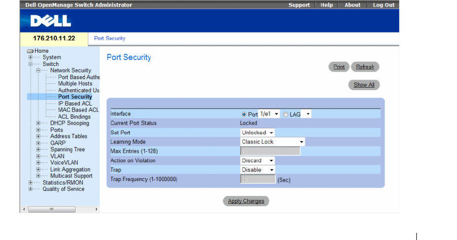
Configuring Switch Information 273
Configuring Port Security
Network security can be enhanced by limiting access on a specific port only to users with specific
MAC addresses. The MAC addresses can be dynamically learned, up to that point, or they can be
statically configured. Locked port security monitors both received and learned packets that are received
on specific ports. Access to the locked port is limited to users with specific MAC addresses.
These addresses are either manually defined on the port, or learned on that port up to the point when it
is locked. When a packet is received on a locked port, and the packet’s source MAC address is not tied to
that port (either it was learned on a different port, or it is unknown to the system), the protection
mechanism is invoked, and can provide various options. Unauthorized packets arriving to a locked port
are either:
• Forwarded
• Discarded with no trap
• Discarded with a trap
• The port is shut down
Locked port security also enables storing a list of MAC addresses in the configuration file.
The MAC address list can be restored after the device has been reset.
In order to enable port security, enable the Multiple Hosts feature on the required ports.
Disabled ports are activated from the Port Security page. The Ports page provides links for configuring
port functionality including advanced features such as storm control and port mirroring, and for
performing virtual port tests.
To open the Port Security page, click Switch → Network Security → Port Security.
Figure 7-7. Port Security

274 Configuring Switch Information
The Port Security page contains the following fields:
•
Interface
— The selected interface type on which Locked Port is enabled.
–
Port
— The selected interface type is a port.
–
LAG
— The selected interface type is a LAG.
•
Current Port Status
— The currently configured Port status.
•
Set Port
— The port is either locked or unlocked. The possible field values are:
–
Unlocked
— Unlocks Port. This is the default value.
–
Locked
— Locks Port.
•
Learning Mode
— Defines the locked port type. The
Learning Mode
field is enabled only if
Locked
is
selected in the
Set Port
field.The possible field values are:
–
Classic Lock
— Locks the port using the classic lock mechanism. The port is immediately locked,
regardless of the number of addresses that have already been learned.
–
Limited Dynamic Lock
— Locks the port by deleting the current dynamic MAC addresses
associated with the port. The port learns up to the maximum addresses allowed on the port.
Both relearning and aging MAC addresses are enabled.
•
Max Entries (1-128)
— Specifies the number of MAC address that can be learned on the port.
The
Max Entries field
is enabled only if
Locked
is selected in the
Set Port
field. In addition,
the Limited Dynamic Lock mode is selected. The default is 1.
•
Action on Violation
— The action to be applied to packets arriving on a locked port. The possible field
values are:
–
Forward
— Forwards the packets from an unknown source, however, the MAC address is not
learned.
–
Discard
— Discards the packets from any unlearned source. This is the default value.
–
Shutdown
— Discards the packet from any unlearned source and shuts down the port. Ports
remained shut down until they are reactivated, or the device is reset.
•
Trap
— Enables traps being sent when a packet is received on a locked port.
•
Trap Frequency (1-1000000)
— The amount of time (in seconds) between traps. The default value is
10 seconds.
Defining a Locked Port
1
Open the
Port Security
page.
2
Select an interface type and number.
3
Define the fields.
4
Click
Apply Changes
.
The locked port is added to the
Port Security Table
, and the device is updated.
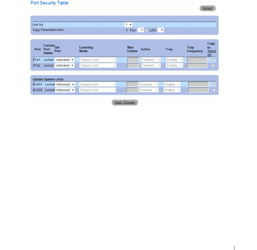
Configuring Switch Information 275
Displaying the Port Security Table
1
Open the
Port Security
page.
2
Click
Show All.
The
Port Security Table
opens.
Locked Ports are defined in the Port Security Table.
Figure 7-8. Port Security Table
The Port Security Table contains the additional following fields:
•
Unit No.
— Specifies the stacking unit for which locked port information is displayed.
•
Copy Parameters from
— The port from which parameters will be copied and assigned to the selected
unit number.

276 Configuring Switch Information
Configuring Locked Port Security with CLI Commands
The following table summarizes the equivalent CLI commands for configuring Locked Port security as
displayed in the Port Security page.
The following is an example of the CLI commands:
ACL Overview
Access Control Lists (ACL) allow network managers to define classification actions and rules for specific
ingress ports. Packets entering an ingress port, with an active ACL, are either admitted or denied entry
and the ingress port is disabled. If they are denied entry, the user can disable the port.
This section contians the following topics:
• "Defining IP based ACLs" on page 277
• "Defining MAC Based Access Control Lists" on page 283
• "Defining ACL Binding" on page 286
Table 7-4. Port Security CLI Commands
CLI Command Description
shutdown Disables interfaces.
set interface active {ethernet interface | port-
channel port-channel-number}
Reactivates an interface that is shutdown due to
port security reasons.
port security learning {disabled | dynamic} Defines the locked port type.
port security max max-addr Specifies the number of MAC address that
can be learned on the port.
port security [forward | discard | discard-
shutdown] [trap seconds]
Locks learning of new addresses on an interface.
show ports security {ethernet interface | port-
channel port-channel-number}
Displays port lock status.
console # show ports security
Port Status Action Trap Frequency Counter
----- ------- ------- ------- --------- --------
1/e1 locked Discard Enable 100 88
1/e2 locked Discard,
Shutdown
Disable
1/e3 Unlocked - - - -
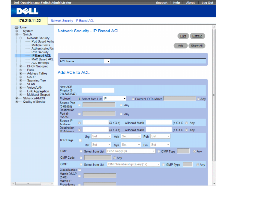
Configuring Switch Information 277
Defining IP based ACLs
Access Control Lists (ACL), which are comprised of Access Control Entries (ACE), allow network
managers to define classification actions and rules for specific ingress ports. Packets entering an ingress
port, with an active ACL, are either admitted or denied entry and the ingress port is disabled. If they are
denied entry, the user can disable the port.
For example, a network administrator defines an ACL rule that states, port number 20 can receive
TCP packets, however, if a UDP packet is received, the packet is dropped.
ACLs are composed of access control entries (ACEs) that are made of the filters that determine traffic
classifications. Each ACE is a rule, and there are 256 rules available. But rules are not only used for user
configuration purposes, they are also used for features like DHCP Snooping, Protocol Group VLAN and
PVE, so not all 256 will be available for ACEs. It is expected that you will have at least 124 rules available.
If you find that there are less rules available, this may be due to DHCP Snooping. You can redue the
number of entries in DHCP Snooping configuration in order to free rules for ACE’s.
To define IP based ACLs, click Switch→ Network Security→ IP Based ACL. I
Figure 7-9. Network Security - IP Based ACL

278 Configuring Switch Information
•
ACL Name
— User-defined ACLs.
•
New ACE Priority
— ACE priority that determines which ACE is matched to a packet based on a
first-match basis.
•
Protocol
— Enables creating an ACE based on a specific protocol. The possible field values are:
–
IP —
Internet Protocol (IP). Specifies the format of packets and their addressing method.
IP addresses packets and forwards the packets to the correct port.
–
ICMP —
I
nternet Control Message Protocol (ICMP). The ICMP allows the gateway or
destination host to communicate with the source host. For example, to report a processing error.
–
IGMP —
Internet Group Management Protocol (IGMP). Allows hosts to notify their local switch
or router that they want to receive transmissions assigned to a specific multicast group.
–
TCP —
Transmission Control Protocol (TCP). Enables two hosts to communicate and exchange
data streams. TCP guarantees packet delivery, and guarantees packets are transmitted and received
in the order the are sent.
–
EGP —
Exterior Gateway Protocol (EGP). Permits exchanging routing information between two
neighboring gateway hosts in an autonomous systems network.
–
IGP —
Interior Gateway Protocol (IGP). Allows for routing information exchange between
gateways in an autonomous network.
–
UDP —
User Datagram Protocol (UDP). Communication protocol that transmits packets but
does not guarantee their delivery.
–
HMP
— Host Mapping Protocol (HMP). Collects network information from various networks
hosts. HMP monitors hosts spread over the internet as well as hosts in a single network.
–
RDP —
Remote Desktop Protocol (RDP). Allows a clients to communicate with the Terminal
Server over the network.
–
IDPR
— Matches the packet to the IDPR protocol.
–
IPV6
— Matches the packet to the IPV6 protocol.
–
IPV6 ROUTE
— Matches the packet to the IPV6 Route protocol.
–
IPV6 FRAG
— Matches the packet to the IPV6 FRAG protocol.
–
IDRP
— Matches the packet to the Inter-Domain Routing Protocol (IDRP).
–
RVSP
— Matches the packet to the ReSerVation Protocol (RSVP).
–
AH
— Authentication Header (AH). Provides source host authentication and data integrity.
–
EIGRP
— Enhanced Interior Gateway Routing Protocol (EIGRP). Provides fast convergence,
support for variable-length subnet mask, and supports multiple network layer protocols.
–
OSPF
— The Open Shortest Path First (OSPF) protocol is a link-state, hierarchical interior
gateway protocol (IGP) for network routing Layer Two (2) Tunneling Protocol, an extension to the
PPP protocol that enables ISPs to operate Virtual Private Networks (VPNs).

Configuring Switch Information 279
–
IPIP
— IP over IP (IPIP). Encapsulates IP packets to create tunnels between two routers.
This ensure that IPIP tunnel appears as a single interface, rather than several separate interfaces.
IPIP enables tunnel intranets occur the internet, and provides an alternative to source routing.
–
PIM
— Matches the packet to Protocol Independent Multicast (PIM).
–
L2TP
— Matches the packet to Internet Protocol (L2IP).
–
ISIS
— Intermediate System - Intermediate System (ISIS). Distributes IP routing information
throughout a single Autonomous System in IP networks
–
Protocol ID To Match
— Adds user-defined protocols by which packets are matched to the ACE.
Each protocol has a specific protocol number which is unique. The possible field range is 0-255.
–
Any
— Matches the protocol to any protocol.
•
Source Port
— The TCP/UDP source port. Select
Any
to include all ports.
•
Destination Port
— The TCP/UDP destination port. Select
Any
to include all ports.
•
Source IP Address
— Matches the source port IP address to which packets are addressed to the ACE.
Wildcard masks specify which bits are used and which bits are ignored. A wildcard of 0.0.0.0 indicates
that all the bits are important.
•
Destination IP Address
— Matches the destination port IP address to which packets are addressed to
the ACE. Wildcard masks specify which bits are used and which bits are ignored. A wildcard of 0.0.0.0
indicates that all the bits are important.
•
TCP Flags
— Sets the indicated TCP flag that can be triggered. To use TCP flags, check the
TCP Flag
checkbox and then set the desired flag(s).
•
ICMP
— Specifies an ICMP message type for filtering ICMP packets. You can choose from the list,
type it in, or select
Any
for all ICMP message types. This field is available only when ICMP is selected
in the
Protocol
field.
•
ICMP Code
— Specifies an ICMP message code for filtering ICMP packets that are filtered by ICMP
message type or ICMP message code. This field is available only when ICMP is selected in the
Protocol
field.
•
IGMP
— IGMP packets can be filtered by IGMP message type. You can choose from the list, type it
in, or select
Any
for all IGMP message types. This field is available only when IGMP is selected in the
Protocol
field.
•
Classification Mach DSCP
— Matches the packet DSCP value to the ACL. Either the DSCP value or
the IP Precedence value is used to match packets to ACLs. The possible field range is 0-63.
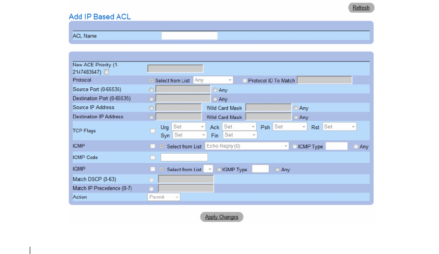
280 Configuring Switch Information
•
Match IP Precedence
— Indicates matching ip-precedence with the packet ip-precedence value.
IP Precendence enables marking frames that exceed CIR threshold. In a congested network, frames
containing a higher are discarded before frames with a lower DP.
•
Action
— Indicates the ACL forwarding action. The possible field values are:
–
Permit
— Forwards packets which meet the ACL criteria.
–
Deny
— Drops packets which meet the ACL criteria.
–
Shutdown
— Drops packet that meet the ACL criteria, and disables the port to which the packet
was addressed.
Adding ACEs to IP based ACLs
1
Open the
Network Security - IP Based ACL
page.
2
Select an ACL.
3
Edit the relevant fields.
4
Click
Apply Changes
.
Adding IP based ACLs
1
Open the
IP Based ACL
page.:
2
Click
Add
.
The
Network Security - IP Based ACL
page opens.
Figure 7-10. Add IP Based ACL
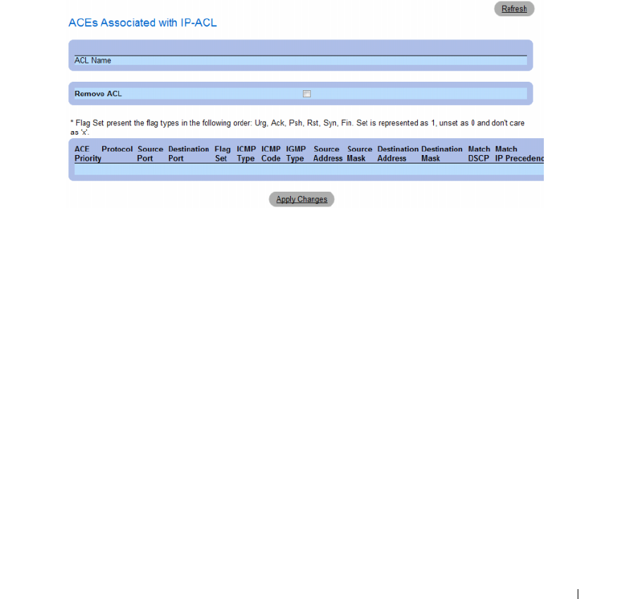
Configuring Switch Information 281
3
Define the relevant fields.
4
Click
Apply Changes
. The IP based protocol is defined, and the device is updated.
Displaying the ACEs Associated with IP based ACLs
1
Open the
Network Security - IP Based ACL
page.
2
Click
Show All.
The
ACEs Associated with IP-ACL
opens.
Figure 7-11. ACEs Associated with IP-ACL
Removing an IP based ACL
1
Open the
Network Security - IP Based ACL
page.
2
Click
Show All.
The
ACEs Associated with IP-ACL Table
opens.
3
Check the
Remove ACL
checkbox.
4
Click
Apply Changes
.
Removing an IP based ACE
1
Open the
Network Security - IP Based ACL
page.
2
Click
Show All.
The
ACEs Associated with IP-ACL Table
opens.
3
Check the
Remove
checkbox next to an ACE.
4
Click
Apply Changes
.

282 Configuring Switch Information
Configuring IP Based ACLs with CLI Commands
The following table summarizes the equivalent CLI commands for configuring IP Based ACLs.
Table 7-5. IP Based ACL CLI Commands
CLI Command Description
ip access-list access-list-name
no ip access-list access-list-name
To define an IPv4 access list and to
place the device in IPv4 access list
configuration mode, use the ipv4
access-list command in global
configuration mode. To remove the
access list, use the no form of this
command.
permit {any| protocol} {any|{source source-wildcard}}
{any|{destination destination-wildcard}} [dscp number | ip-precedence
number] [fragments]
permit-icmp {any|{source source-wildcard}} {any|{destination
destination-wildcard}} {any|icmp-type} {any|icmp-code} [dscp number |
ip-precedence number]
permit-igmp {any|{source source-wildcard}} {any|{destination
destination-wildcard}} {any|igmp-type} [dscp number | ip-precedence
number]
permit-tcp {any|{ source source-wildcard}} {any|source-port} {any|{
destination destination-wildcard}} {any|destination-port} [dscp number |
ip-precedence number] [flags list-of-flags]
permit-udp {any|{ source source-wildcard}} {any| source-port}
{any|{destination destination-wildcard}} {any|destination-port} [dscp
number | ip-precedence number]
To set conditions to allow a packet to
pass a named IP access list, use the
permit command in access list
configuration mode.
deny [disable-port] {any| protocol} {any|{source source-wildcard}}
{any|{destination destination-wildcard}} [dscp number | ip-precedence
number] [fragments]
deny-icmp [disable-port] {any|{source source-wildcard}}
{any|{destination destination-wildcard}} {any|icmp-type} {any|icmp-
code} [dscp number | ip-precedence number]
deny-igmp [disable-port] {any|{source source-wildcard}}
{any|{destination destination-wildcard}} {any|igmp-type} [dscp number
| ip-precedence number]
deny-tcp [disable-port] {any|{ source source-wildcard}} {any|source-
port} {any|{ destination destination-wildcard}} {any|destination-port}
[dscp number | ip-precedence number] [flags list-of-flags]
deny-udp [disable-port] {any|{ source source-wildcard}} {any| source-
port} {any|{destination destination-wildcard}} {any|destination-port}
[dscp number | ip-precedence number]
To set conditions to allow a packet to
pass a named IP access list, use the
deny command in access list
configuration mode.
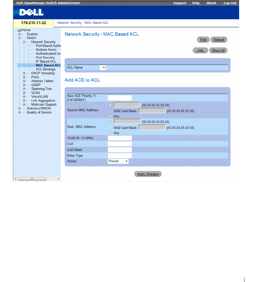
Configuring Switch Information 283
Defining MAC Based Access Control Lists
The Network Security - MAC Based ACL page allows a MAC- based ACL to be defined. ACEs can be
added only if the ACL is not bound to an interface.
To define MAC Based ACLs, click Switch → Network Security → MAC Based ACL.
• Network Security - MAC Based ACL
•
ACL Name
— Displays the user-defined MAC based ACLs.
•
New ACE Priority
— Indicates the ACE priority, which determines which ACE is matched to a packet
on a first-match basis. The possible field values are 1-2147483647.
•
Source Address
— Matches the source MAC address to which packets are addressed to the ACE.
Wildcard masks specify which bits are used and which bits are ignored. A wildcard of 0.0.0.0 indicates
that all the bits are important.
•
Destination Address
— Matches the destination MAC address to which packets are addressed to the
ACE. Wildcard masks specify which bits are used and which bits are ignored. A wildcard of 0.0.0.0
indicates that all the bits are important.
•
VLAN ID
— Matches the packet’s VLAN ID to the ACE. The possible field values are 1 to 4095.
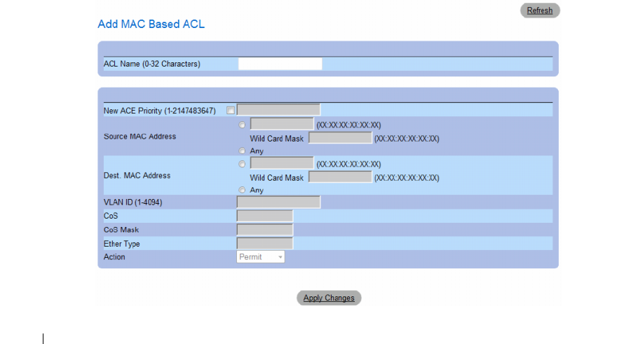
284 Configuring Switch Information
•
CoS
— Indicates the CoS values by which the packets are filtered.
•
Cos Mask
— Indicates the CoS Mask by which the packets are filtered.
•
Ethertype
— Indicates the Ethertype packet by which the packets are filtered.
•
Action
— Indicates the ACL forwarding action. Possible field values are:
–
Permit
— Forwards packets which meet the ACL criteria.
–
Deny
— Drops packets which meet the ACL criteria.
–
Shutdown
— Drops packet that meet the ACL criteria, and disables the port to which the packet
was addressed.
Adding ACEs to IP based ACLs
1
Open the
Network Security - MAC Based ACL
page.
2
Select an ACL.
3
Edit the relevant fields.
4
Click
Apply Changes
.
Adding MAC based ACLs
1
Open the
MAC Based ACL
page.:
2
Click
Add
.
The
Network Security - MAC Based ACL
page opens.
Figure 7-12. Add Mac Based ACL
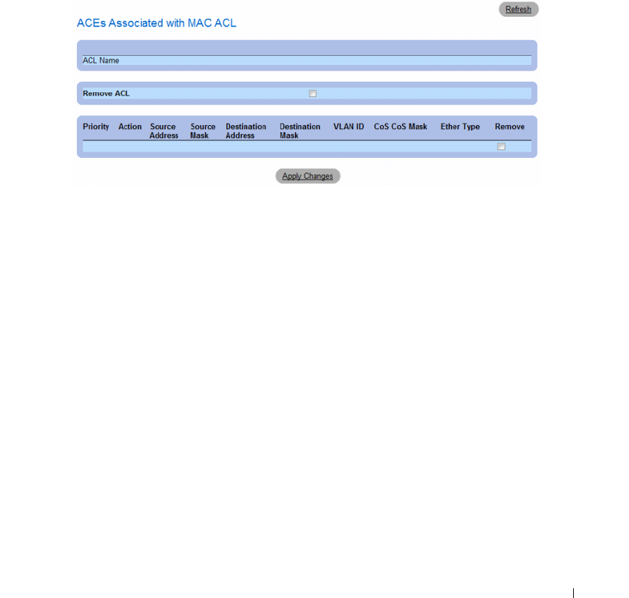
Configuring Switch Information 285
3
Define the relevant fields.
4
Click
Apply Changes
. The MAC based protocol is defined, and the device is updated.
Displaying the ACEs Associated with MAC based ACLs
1
Open the
Network Security - MAC Based ACL
page.
2
Click
Show All.
The
ACEs Associated with MAC Based ACL
opens.
Removing a MAC based ACL
1
Open the
Network Security - MAC Based ACL
page.
2
Click
Show All.
The
ACEs Associated with MAC-ACL Table
opens.
3
Check the
Remove ACL
checkbox.
4
Click
Apply Changes
.
Removing a MAC based ACE
1
Open the
Network Security - MAC Based ACL
page.
2
Click
Show All.
The
ACEs Associated with MAC-ACL Table
opens.
3
Check the
Remove
checkbox next to an ACE.
4
Click
Apply Changes
.
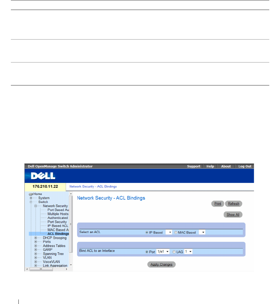
286 Configuring Switch Information
Configuring MAC Based ACLs with CLI Commands
The following table summarizes the equivalent CLI commands for configuring MAC Based ACLs.
Defining ACL Binding
When an ACL is bound to an interface, all the ACE rules that have been defined are applied to the
selected interface.Whenever an ACL is assigned on a port, LAG or, VLAN, flows from that ingress
interface that do not match the ACL are matched to the default rule, which is Drop unmatched packets.
To bind ACLs to interfaces:
1
Open the
Network Security - ACL Bindings
page, click
Switch
→
Network Security
→
ACL Binding
s.
Figure 7-13. Network Security - ACL Binding
2
In the
Select an ACL
field, select an IP Based or MAC Based ACL.
Table 7-6. MAC Based ACL CLI Commands
CLI Command Description
mac access-list access-list-name
no mac access-list access-list-name
To define a Layer 2 access list and to place the device in
MAC access list configuration mode, use the mac
access-list command in global configuration mode. To
remove the access list, use the no form of this command.
permit {any|{source source- wildcard} {any|{
destination destination- wildcard}} [vlan vlan-id] [cos
cos cos-wildcard] [ethtype eth-type] [inner-vlan vlan-id]
To set permit conditions for an MAC access list,
use the permit command in MAC access list
configuration mode.
deny [disable-port] {any|{source source- wildcard} {any|{
destination destination- wildcard}} [vlan vlan-id] [cos cos
cos-wildcard] [ethtype eth-type] [inner-vlan vlan-id]
To set deny conditions for an MAC access list, use the
deny command in MAC access list configuration mode.
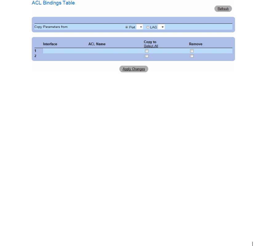
Configuring Switch Information 287
3
In the
Bind ACL to an Interface
field, select a port or LAG.
4
Click
Apply Changes
.
The ACL is bound to the interface.
Displaying the ACL Bindings Table:
1
Open the
Network Security - ACL Binding
page.
2
Click
Show All.
The
ACL Bindings Table
opens.
Figure 7-14. ACL Bindings Table
Copying ACL Parameters Between Interfaces
1
Open the
Network Security - ACL Binding
page.
2
Click
Show All.
The
ACL Bindings Table
opens.
3
In the
Copy Parameters from
field, select a Port or LAG from which you want to copy ACL settings.
4
In the table, check the
Copy to
checkbox for each entry to which you want to copy the settings.
5
Click
Apply Changes
.
Removing ACL Bindings
1
Open the
Network Security - ACL Binding
page.
2
Click
Show All.
The
ACL Bindings Table
opens.
3
In the table, check the
Remove
checkbox for each binding you want to remove.
4
Click
Apply Changes
.
288 Configuring Switch Information
Configuring ACL Bindings with CLI Commands
The following table summarizes the equivalent CLI commands for configuring ACL Bindings.
The following is an example of some of the CLI commands:
Configuring DHCP Snooping
DHCP Snooping expands network security by providing firewall security between untrusted interfaces
and DHCP servers. By enabling DHCP Snooping network administrators can differentiate between
trusted interfaces connected to end-users or DHCP Servers and untrusted interfaces located beyond the
network firewall.
DHCP Snooping filters untrusted messages. DHCP Snooping creates and maintains a DHCP Snooping
Table which contains information received from untrusted packets. Interfaces are untrusted if the packet
is received from an interface outside the network or from an interface beyond the network firewall.
Trusted interfaces receive packets only from within the network or the network firewall.
The DHCP Snooping Table contains the untrusted interfaces’ MAC address, IP address, Lease Time,
VLAN ID, and interface information.
The DHCP section contains the following topics:
• Defining DHCP Snooping Properties
• Defining DHCP Snooping on VLANs
• Defining Trusted Interfaces
• Adding Interfaces to the DHCP Snooping Database
Table 7-7. ACL Bindings CLI Commands
CLI Command Description
service-acl input acl-name
no service-acl input
To control access to an interface, use the service-acl command in interface
configuration mode. To remove the access control, use the no form of this command.
show access-lists [name]Use the show access-lists privileged EXEC command to display access control lists
(ACLs) configured on the switch.
Switch# show access-lists
IP access list ACL1
permit 234 172.30.40.1 0.0.0.0 any
permit 234 172.30.8.8 0.0.0.0 any
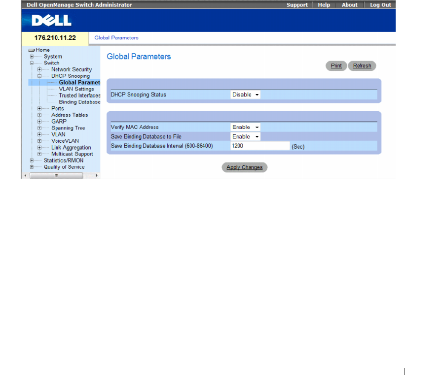
Configuring Switch Information 289
This section contians the following topics:
• "Defining DHCP Snooping Global Parameters" on page 289
• "Defining DHCP Snooping on VLANs" on page 291
• "Defining Trusted Interfaces" on page 292
• "Adding Interfaces to the DHCP Snooping Database" on page 294
Defining DHCP Snooping Global Parameters
The DHCP Snooping Global Parameters page contains parameters for enabling and configuring DHCP
Snooping on the device.
To define DHCP global parameters, click Switch→ DHCP Snooping → Global Parameters
Figure 7-15. Global Parameters
•
DHCP Snooping Status
— Indicates if DHCP Snooping is enabled on the device. The possible field
values are:
–
Enable
— Enables DHCP Snooping on the device.
–
Disable
— Disables DHCP Snooping on the device. This is the default value.
•
Verify MAC Address
— Indicates if MAC addresses are verified. The possible field values are:
–
Enable
— Verifies that an untrusted port source MAC address matches the client’s MAC address.
–
Disable
— Disables verifying that an untrusted port source MAC address matches the client’s
MAC address. This is the default value.

290 Configuring Switch Information
•
Save Binding Database to File
— Indicates if the DHCP Snooping Database is saved to file.
The possible field values are:
–
Enable
— Enables saving the database to file. This is the default value.
–
Disable
— Disables saving the database to file.
•
Save Binding Database Internal
— Indicates how often the DHCP Snooping Database is updated.
The possible field range is 600 – 86400 seconds. The field default is 1200 seconds.
Configuring DHCP Snooping Global Parameters with CLI Commands
The following table summarizes the equivalent CLI commands for configuring DHCP Snooping global
parameters.
Table 7-8. DHCP Snooping Global Parameters CLI Commands
CLI Command Description
ip dhcp snooping
no ip dhcp snooping
Use the ip dhcp snooping global configuration command to
globally enable DHCP snooping. Use the no form of this
command to return to the default setting.
ip dhcp snooping verify
no ip dhcp snooping verify
Use the ip dhcp snooping verify global configuration command to
configure the switch to verify on an untrusted port that the source
MAC address in a DHCP packet matches the client hardware
address. Use the no form of this command to configure the switch
to not verify the MAC addresses.
ip dhcp snooping database
no ip dhcp snooping database
Use the ip dhcp snooping database global configuration
command to configure the DHCP snooping binding file. Use the
no form of this command to delete the binding file.
ip dhcp snooping database update-freq seconds
no ip dhcp snooping database update-freq
Use the ip dhcp snooping database update-freq global
configuration command to configure the update frequency ofthe
DHCP snooping binding file. Use the no form of this command
to return to default.
show ip dhcp snooping [ethernet interface |
port-channel port-channel-number]
Use the show ip dhcp snooping EXEC command to display the
DHCP snooping configuration.
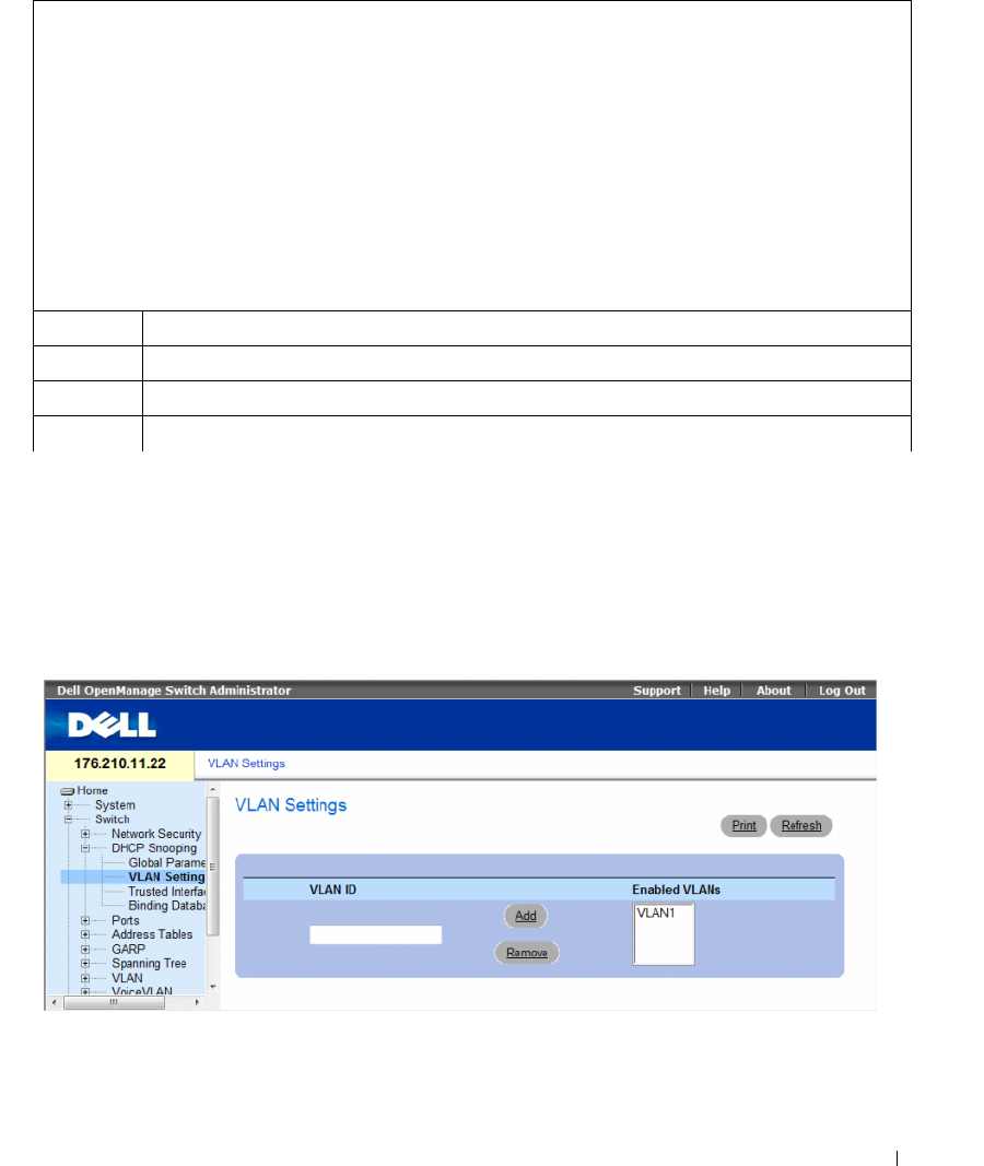
Configuring Switch Information 291
The following is an example of some of the CLI commands:
Defining DHCP Snooping on VLANs
The DHCP Snooping VLAN Settings Page allows network managers to enable DHCP Snooping on
VLANs. DHCP snooping separates ports in the VLAN. To enable DHCP Snooping on VLAN,
ensure that DHCP Snooping is enabled on the device. To enable DHCP Snooping on VLANs:
To define DHCP snooping on VLANS, click Switch→ DHCP Snooping → VLAN Settings
Figure 7-16. VLAN Settings
•
VLAN ID
— The VLAN on which DHCP snooping can be enabled.
•
Enabled VLANs
— Contains a list of VLANs on which DHCP snooping is enabled.
Console# show ip dhcp snooping
DHCP snooping is enabled
DHCP snooping is configured on following VLANs: 2, 7-18
DHCP snooping database: enabled
Option 82 on untrusted port is allowed
Verification of hwaddr field is enabled
Interface Trusted
----------- -----------
1/1 yes
1/2 yes
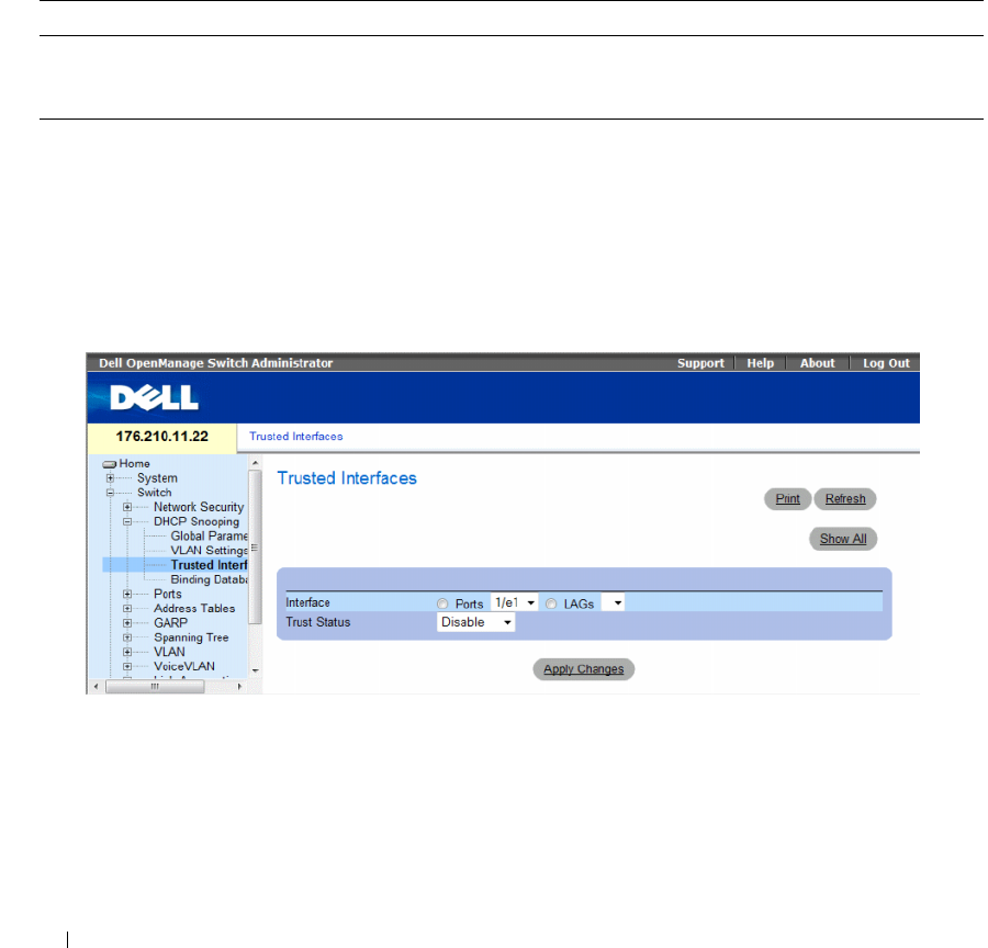
292 Configuring Switch Information
Defining DHCP Snooping on VLANS
1
Open the DHCP Snooping VLAN Settings page.
2
Click
Add
and
Remove
to add/remove VLAN IDs to or from the Enabled VLAN list.
3
Click
Apply Changes
.
Configuring DHCP Snooping on VLANs with CLI Commands
The following table summarizes the equivalent CLI commands for configuring DHCP Snooping on VLANs .
Defining Trusted Interfaces
The Trusted Interfaces page allows network managers to define Trusted interfaces. Interfaces are
untrusted if the packet is received from an interface outside the network or from an interface beyond the
network firewall. Trusted interfaces receive packets only from within the network or the network firewall.
To define Trusted interfaces, click Switch→ DHCP Snooping → Trusted Interface
Figure 7-17. Trusted Interfaces
•
Interface
— Indicates the port or LAG on which DHCP Snooping Trust mode is enabled.
•
Trust Status
— Indicates if the DHCP Snooping Trust mode is enabled on the port or LAG.
The possible field values are:
–
Enable
— Indicates that DHCP Snooping Trust mode is enabled on the port or LAG.
–
Disable
— Indicates that DHCP Snooping Trust mode is disabled on the port or LAG.
Table 7-9. DHCP Snooping on VLANs CLI Commands
CLI Command Description
ip dhcp snooping vlan vlan-id
no ip dhcp snooping vlan-id
Use the ip dhcp snooping vlan global configuration command to enable DHCP
snooping on a VLAN. Use the no form of this command to disable DHCP
snooping on a VLAN.
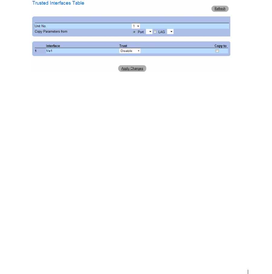
Configuring Switch Information 293
Displaying the Trusted Interfaces Table:
1
Open the
Trusted Interfaces
page.
2
Click
Show All.
The
Trusted Interfaces Table
opens.
Figure 7-18. Trusted Interfaces Table
Copying Trusted Interfaces Settings Between Interfaces
1
Open the
Trusted Interfaces
page.
2
Click
Show All.
The
Trusted Interfaces Table
opens.
3
In the
Unit
and
Copy from
fields, select a Port or LAG from which you want to copy settings.
4
In the table, check the
Copy to
checkbox for each entry to which you want to copy the settings.
5
Click
Apply Changes
.
Designating Interfaces as Trusted/Untrusted
1
Open the
Trusted Interfaces
page.
2
Click
Show All.
The
Trusted Interfaces Table
opens.
3
In the
Trust
column of the table, enable or disable the interface as trusted.
4
Click
Apply Changes
.
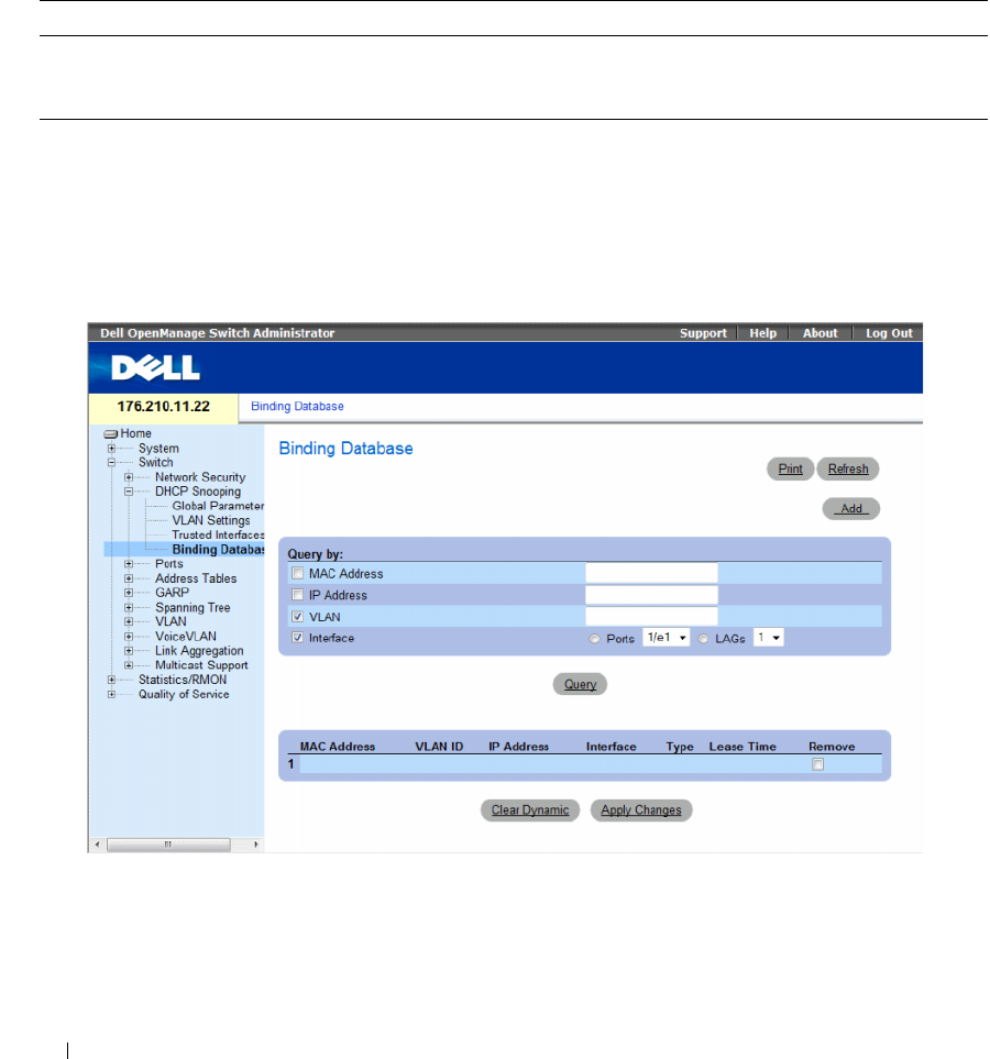
294 Configuring Switch Information
Configuring DHCP Snooping Trusted Interfaces with CLI Commands
The following table summarizes the equivalent CLI commands for configuring DHCP Snooping
Trusted Interfaces.
Adding Interfaces to the DHCP Snooping Database
The DHCP Snooping Binding Database page contains parameters for querying and adding IP addresses
to the DHCP Snooping Database.
To open the Binding Database page, click Switch→ DHCP Snooping → Binding Database
Figure 7-19. Binding Database
Table 7-10. DHCP Snooping Trusted Interfaces CLI Commands
CLI Command Description
ip dhcp snooping trust
no ip dhcp snooping trust
Use the ip dhcp snooping trust interface configuration command to configure a
port as trusted for DHCP snooping purposes. Use the no form of this command to
return to the default setting.

Configuring Switch Information 295
Querying the Database
1
Open the
Binding Database
page.
2
Select the following categories:
–
MAC Address
— Indicates the MAC addresses recorded in the DHCP Snooping Database.
–
IP Address
— Indicates the IP addresses recorded in the DHCP Snooping Database.
–
VLAN
— Indicates the VLANs recorded in the DHCP Snooping Database.
–
Interface
— Contains a list of interfaces recorded in the DHCP Snooping Database. The possible
field values are: Port and LAG.
In addition to the fields above, the following fields appear in the Query result Table:
–
VLAN ID
— Displays the VLAN ID to which the IP address is attached in the DHCP Snooping
Database.
–
Ty p e
— Displays the IP address binding type. The possible field values are
Static
which indicates
that the IP address was statically configured, and
Dynamic
which indicates that the IP address was
dynamically configured.
–
Lease Time
— Displays the lease time. The Lease Time defines the amount of time the entry is
active in the DHCP Database. Entries whose lease times are expired are ignored by the switch.
3
Click
Query
.
Removing a Database Entry
1
Open the
Binding Database
page.
2
In the table, click the checkbox in the
Remove
column next to the desired entry.
3
Click
Apply Changes
.
Clearing the Dynamic Database
1
Open the
Binding Database
page.
2
Click
Clear Dynamic
.
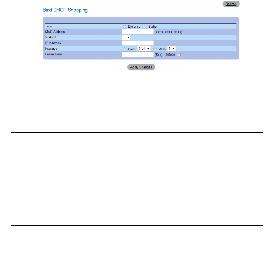
296 Configuring Switch Information
Binding a DHCP Snooping Database
1
Open the
Binding Database
page.
2
Click
Add
.
The
Bind DHCP Snooping
page opens.
Figure 7-20. Bind DHCP Snooping Page
3
Define the fields.
4
Click
Apply Changes
.
Configuring DHCP Snooping Binding Database with CLI Commands
The following table summarizes the equivalent CLI commands for configuring DHCP Snooping
Binding Database .
Table 7-11. DHCP Snooping Binding Database CLI Commands
CLI Command Description
ip dhcp snooping binding mac-address vlan-id
ip-address {ethernet interface | port-channel
port-channel-number} expiry seconds
no ip dhcp snooping binding mac-address
vlan-id
Use the ip dhcp snooping binding privileged EXEC command
to configure the DHCP snooping binding database and to add
binding entries to the database. Use the no form of this
command to delete entries from the binding database.
clear ip dhcp snooping database Use the clear ip dhcp snooping database privileged EXEC
command to clear the DHCP binding database.
show ip dhcp snooping binding [mac-address
mac-address] [ip-address ip-address] [vlan
vlan] [ethernet interface | port-channel port-
channel-number]
Use the show ip dhcp snooping binding user EXEC command
to display the DHCP snooping binding database and
configuration information for all interfaces on a switch.

Configuring Switch Information 297
The following is an example of some of the CLI commands:
Configuring Ports
The Ports page provides links for configuring port functionality including advanced features such as
storm control and port mirroring, and for performing virtual port tests.
To open the Ports page Select Switch → Ports.
This section contians the following topics:
• "Defining Port Configuration" on page 297
• "Defining LAG Parameters" on page 304
• "Enabling Storm Control" on page 308
• "Defining Port Mirroring Sessions" on page 312
Defining Port Configuration
Use the Port Configuration page to define port parameters. If port configuration is modified while the
port is a LAG member, the configuration change is only effective after the port is removed from the
LAG.
To open the Port Configuration page, click Switch → Ports → Port Configuration in the tree view.
Console# show ip dhcp snooping binding
Update frequency: 1200
Total number of binding: 2
Mac Address IP Address Lease (sec) Type VLAN Interface
----------- ----------- ----------- -------- -------- -------
0060.704C.73FF 10.1.8.1 7983 snooping 3 1/21
0060.704C.7BC1 10.1.8.2 92332 snooping (s)3 1/22
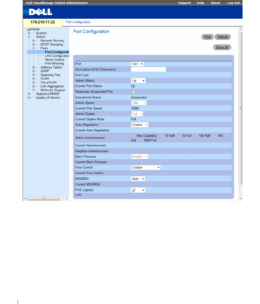
298 Configuring Switch Information
Figure 7-21. Port Configuration
The Port Configuration page contains the following fields:
•
Port
— The port number for which port parameters are defined.
•
Description (0 - 64 Characters)
— A brief interface description, such as Ethernet.
•
Port Type
— The type of port.
•
Admin Status
— Enables or disables traffic forwarding through the port.
–
Up
— Traffic is enabled through the port.
–
Down
— Traffic is disabled through the port.
•
Current Port Status
— Specifies whether the port is currently operational or non-operational.

Configuring Switch Information 299
•
Reactivate Suspended Port
— Reactivates a port if the port has been disabled through the locked port
security option.
–
Checked
— Reactivates the port.
–
Unchecked
— Maintains the port’s operational status.
•
Operational Status
— Indicates the port operational status. Possible field values are:
Suspended
— The port is currently active, and is not receiving or transmitting traffic.
Active
— The port is currently active and is receiving and transmitting traffic.
Disable
— The port is currently disabled, and is not receiving or transmitting traffic.
•
Admin Speed
— The configured rate for the port. The port type determines what speed setting
options are available. Admin speed can only be designated when the port is disabled. The possible field
values are:
–
10M
— Indicates the port is currently operating at 10 Mbps.
–
100M
— Indicates the port is currently operating at 100 Mbps.
–
1000M
— Indicates the port is currently operating at 1000 Mbps.
•
Current Port Speed
— The actual synchronized port speed (bps).
•
Admin Duplex
— The port duplex mode in bps.
–
Full
— Indicates that the interface supports transmission between the device and the client in
both directions simultaneously.
–
Half
— Indicates that the interface supports transmission between the device and the client in
only one direction at a time.
•
Current Duplex Mode
— The synchronized port duplex mode.
•
Auto Negotiation
— Auto Negotiation is a protocol between two link partners that enables a port to
advertise its transmission rate, duplex mode and flow control abilities to its partner.
–
Enable
— Enables Auto Negotiation on the port.
–
Disable
— Disables Auto Negotiation on the port.
•
Current Auto Negotiation
— The current Auto Negotiation setting.
•
Admin Advertisement
— Defines the auto-negotiation setting the port advertises. The possible field
values are:
–
Max Capability
— Indicates that all port speeds and Duplex mode settings are accepted.
–
10 Half
— Indicates that the port advertises for a 10 mbps speed port and half duplex mode setting.
–
10 Full
— Indicates that the port advertises for a 10 mbps speed port and full duplex mode setting.
–
100 Half
— Indicates that the port advertises for a 100 mbps speed port and half duplex mode setting.
–
100 Full
— Indicates that the port advertises for a 100 mbps speed port and full duplex mode setting.
–
1000 Full
— Indicates that the port advertises for a 1000 mbps speed port and full duplex mode setting.

300 Configuring Switch Information
•
Current Advertisement
— The port advertises its speed to its neighbor port to start the negotiation
process. The possible field values are those specified in the
Admin Advertisement
field.
•
Neighbor Advertisement
— Indicates the neighboring port’s advertisement settings. The field values
are identical to the
Admin Advertisement
field values.
•
Back Pressure
— Back Pressure mode is used with Half Duplex mode to disable ports from receiving
messages. Back Pressure is not supported in OOB ports.
–
Enable
— Enables Back Pressure mode on the port.
–
Disable
— Disables Back Pressure mode on the port.
•
Current Back Pressure
— The current Back Pressure setting.
•
Flow Control
— Indicates the flow control status on the port.
–
Enable
— Enables flow control on the port.
–
Disable
— Disables flow control on the port.
–
Auto-negotiation
— Enables the auto negotiation of flow control on the port.
•
Current Flow Control
— The current Flow Control setting.
•
MDI/MDIX
— Allows the device to decipher between crossed and uncrossed cables. Hubs and
switches are deliberately wired opposite the way end stations are wired, so that when a hub or switch is
connected to an end station, a straight through Ethernet cable can be used, and the pairs are match up
properly. When two hubs/switches are connected to each other, or two end stations are connected to
each other, a crossover cable is used ensure that the correct pairs are connected. Auto MDIX does not
operate on FE ports if auto negotiation is disabled. The possible field values are:
–
Auto
— Use to automatically detect the cable type.
–
MDIX
— Use for hubs and switches.
–
MDI
— Use for end stations.
•
Current MDI/MDIX
— Indicates the current device MDIX settings. The possible field values are:
–
MDI
— The current MDI setting is MDI.
–
MDIX
— The current MDI setting is MDIX.
•
Private VLAN Edge (PVE)
— Indicates the Private VLAN Edge (PVE) group to which the LAG is
configured. A port defined as PVE is protected by an uplink, so that it is isolated from other ports
within the same VLAN. The uplink must be a GE port.
•
LAG
— Specifies if the port is part of a LAG.
If port configuration is modified while the port is a LAG member, the configuration change is only
effective after the port is removed from the LAG.
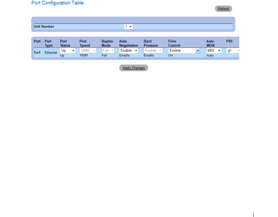
Configuring Switch Information 301
Defining Port Parameters
1
Open the
Port Configuration
page.
2
Select a port in the
Port
Field.
3
Define the available fields in the dialog.
4
Click
Apply Changes
.
The port parameters are saved to the device.
Displaying and Modifying Multiple Port Configurations
1
Open the
Port Configuration
page.
2
Click
Show All
.
The
Port Configuration Table
opens.
Figure 7-22. Port Configuration Table
3
Define the available fields for the relevant port.
4
Click
Apply Changes
.
The port parameters are saved to the device.

302 Configuring Switch Information
Configuring Ports with CLI Commands
The following table summarizes the equivalent CLI commands for configuring ports as displayed in the
Port Configuration page.
Table 7-12. Port Configuration CLI Commands
CLI Command Description
interface ethernet interface Enters the interface configuration mode to configure an
ethernet type interface.
description string Adds a description to an interface configuration.
shutdown Disables interfaces that are part of the currently set context.
set interface active {ethernet
interface | port-channel port-channel-
number}
Reactivates an interface that is shutdown due to security
reasons.
speed Mbps Configures the speed of a given ethernet interface when not
using auto negotiation.
duplex {half | full} Configures the full/half duplex operation of a given ethernet
interface when not using auto negotiation.
negotiation [capability1
[capability2…capability5]
Enables auto negotiation operation for the speed and
duplex parameters of a given interface.
back-pressure Enables Back Pressure on a given interface.
flowcontrol {auto | on | off} Configures the Flow Control on a given interface.
mdix {on | auto} Enables automatic crossover on a given interface or Port-
channel.
show interfaces configuration
[ethernet interface |port-channel
port-channel-number]
Displays the configuration for all configured interfaces.
show interface advertise Displays the interface’s negotiation advertisement settings.
show interfaces status [ethernet
interface | port-channel port-
channel-number]
Displays the status for all configured interfaces.
show interfaces description
[ethernet interface | port-channel
port-channel-number]
Displays the description for all configured interfaces.

Configuring Switch Information 303
The following is an example of the CLI commands:
console(config)# interface ethernet 1/e3
console(config-if)# description "RD SW#3"
console(config-if)# shutdown
console(config-if)# no shutdown
console(config-if)# speed 100
console(config-if)# duplex full
console(config-if)# negotiation
console(config-if)# back-pressure
console(config-if)# flowcontrol on
console(config-if)# mdix auto
console(config-if)# end
console# show interfaces configuration ethernet 1/e3
Port Type Duplex Speed Neg Flow
Control
Admin
State
Back
Pressure
Mdix
Mode
---- ----- ------ ------ ---- ------ ----- ------ ----
1/e3 100 Full 100 Enabled On Up Enable Auto
Console# show interfaces status
Port Type Duplex Speed Neg Flow
Control
Link
State
Back
Pressure
Mdix
Mode
---- ----- ------ ------ ---- ------ ----- ------ ----
1/e3 100 Full 100 Auto On Up Enable On
1/e4 100 Full 1000 Off Off Up Disable On
Ch Type Duplex Speed Neg Flow
Control
Back
Pressure
Link
State
--- ---- ------ ----- ----- ------- -------- ------
Ch1 1000 Full 1000 Off Off Disable Up
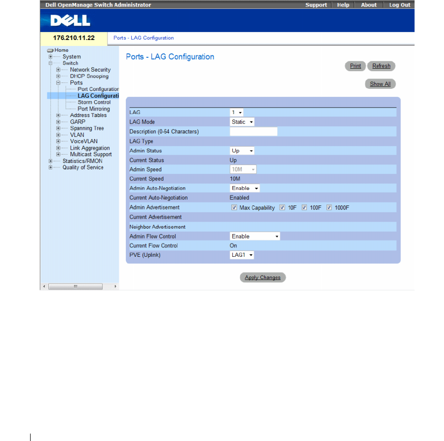
304 Configuring Switch Information
Defining LAG Parameters
The Ports - LAG Configuration page contains fields for configuring parameters for configured LAGs.
The device supports up to fifteen LAGs per system. For information about Link Aggregated Groups
(LAG) and assigning ports to LAGs, see Aggregating Ports.
To open the Ports - LAG Configuration page, click Switch → Ports → LAG Configuration in the tree view.
Figure 7-23. Ports - LAG Configuration
The Ports - LAG Configuration page contains the following fields:
•
LAG
— The LAG number.
•
LAG Mode
— Type of LAG. The possible field values are:
–
Static
— The ports comprise a single logical port for high-speed connections between networking
devices.
–
LACP
— Link Aggregate Control Protocol. LACP-enabled LAGs can exchange information with
other links in order to update and maintain LAG configurations automatically.
•
Description (0 - 64 Characters)
— Provides a user-defined description of the configured LAG.

Configuring Switch Information 305
•
LAG Type
— The port types that comprise the LAG.
•
Admin Status
— Enables or disables the selected LAG.
–
Up
— Traffic is enabled through the LAG.
–
Down
— Traffic is disabled through the LAG.
•
Current Status
— Indicates if the LAG is currently operating.
•
Admin Speed
— The configured speed at which the LAG is operating. The possible field values are:
–
10M
— Indicates the LAG is currently operating at 10 Mbps.
–
100M
— Indicates the LAG is currently operating at 100 Mbps.
–
1000M
— Indicates the LAG is currently operating at 1000 Mbps.
•
Current Speed
— The speed at which the LAG is currently operating.
•
Admin Auto Negotiation
— Auto Negotiation is a protocol between two link partners that enables a
LAG to advertise its transmission rate, duplex mode and flow control abilities to its partner.
–
Enable
— Enables Auto Negotiation on the LAG.
–
Disable
— Disables Auto Negotiation on the LAG.
•
Current Auto Negotiation
— The current Auto Negotiation setting.
•
Admin Advertisement
— Defines the auto-negotiation setting the LAG advertises. The possible field
values are:
–
Max Capability
— Indicates that all LAG speeds and Duplex mode settings are accepted.
–
10 Full
— Indicates that the LAG advertises for a 10 mbps speed LAG and full duplex mode
setting.
–
100 Full
— Indicates that the LAG advertises for a 100 mbps speed LAG and full duplex mode
setting.
–
1000 Full
— Indicates that the LAG advertises for a 1000 mbps speed LAG and full duplex mode
setting.
•
Current Advertisement
— The LAG advertises its speed to its neighbor LAG to start the negotiation
process. The possible field values are those specified in the
Admin Advertisement
field.
•
Neighbor Advertisement
— Indicates the neighboring LAG advertisement settings. The field values
are identical to the
Admin Advertisement
field values.
•
Admin Flow Control
— Indicates the flow control status on the LAG. Flow Control mode is effective
on the ports operating in Full Duplex in the LAG.
–
Enable
— Enables flow control on the LAG.
–
Disable
— Disables flow control on the LAG.
–
Auto-negotiation
— Enables the auto negotiation of flow control on the LAG.
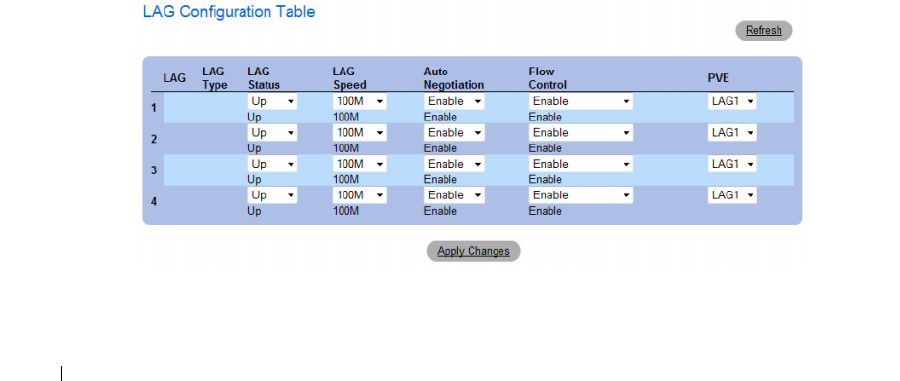
306 Configuring Switch Information
•
Current Flow Control
— The current Flow Control setting.
•
Private VLAN Edge (PVE)
— Indicates the Private VLAN Edge (PVE) group to which the LAG is
configured. A port defined as PVE is protected by an uplink, so that it is isolated from other ports
within the same VLAN. The uplink must be a GE port or LAG.
Defining LAG Parameters
1
Open the
Ports - LAG Configuration
page.
2
Select a LAG in the
LAG
field.
3
Define the fields.
4
Click
Apply Changes
.
The LAG parameters are saved to the device.
Modifying LAG Parameters
1
Open the
Ports - LAG Configuration
page.
2
Select a LAG in the
LAG
field.
3
Modify the fields.
4
Click
Apply Changes
.
The LAG parameters are saved to the device.
Displaying and Modifying Multiple LAG Configurations
1
Open the
Ports - LAG Configuration
page.
2
Click
Show All.
The
LAG Configuration Table
opens.
Figure 7-24. LAG Configuration Table

Configuring Switch Information 307
3
Define the available fields for the relevant LAGs.
4
Click
Apply Changes
.
The LAG parameters are saved to the device.
Configuring LAGs with CLI Commands
The following table summarizes the equivalent CLI commands for configuring LAGs as displayed in the
Ports - LAG Configuration page.
Table 7-13. LAG Configuration CLI Commands
CLI Command Description
interface port-channel port-channel-
number
Enters the interface configuration mode of a specific
port-channel.
description string Adds a description to an interface configuration.
shutdown Disables interfaces that are part of the currently set
context.
speed bps Configures the speed of a given ethernet interface when
not using auto negotiation.
negotiation [capability1
[capability2…capability5]
Enables interface speed auto negotiation operation.
back-pressure Enables Back Pressure on a given interface.
flowcontrol {auto | on | off } Configures the Flow Control on a given interface.
show interfaces configuration
[ethernet interface| port-channel
port-channel-number]
Displays the configuration for all configured interfaces.
show interfaces status [ethernet
interface |port-channel port-channel-
number]
Displays the status for all configured interfaces.
show interfaces description
[ethernet interface |port-channel
port-channel-number]
Displays the description for all configured interfaces.
show interfaces port-channel [port-
channel-number]
Displays Port-channel information (which ports are
members of that port-channel, and whether they are
currently active or not).

308 Configuring Switch Information
The following is an example of the CLI commands:
Enabling Storm Control
A Broadcast Storm is a result of an excessive amount of Broadcast messages simultaneously transmitted
across a network by a single port. Forwarded message responses are heaped onto the network, straining
network resources or causing the network to time out.
Storm Control is enabled per port by defining the packet type and the rate the packets are transmitted.
The system measures the incoming Broadcast, Unicast, and Multicast frame rate separately on each port,
and discard frames when the rate exceeds a user-defined rate.
console(config)# interface port-channel 2
console(config-if)# no negotiation
console(config-if)# speed 100
console(config-if)# flowcontrol on
console(config-if)# exit
console(config)# interface port-channel 3
console(config-if)# shutdown
console(config-if)# exit
console(config)# interface port-channel 4
console(config-if)# back-pressure
console(config-if)# description p4
console(config-if)# end
console# show interfaces port-channel
Channel Ports
--------- ---------
ch1 Inactive: 1/e(11-13)
ch2 Active: 1/e14
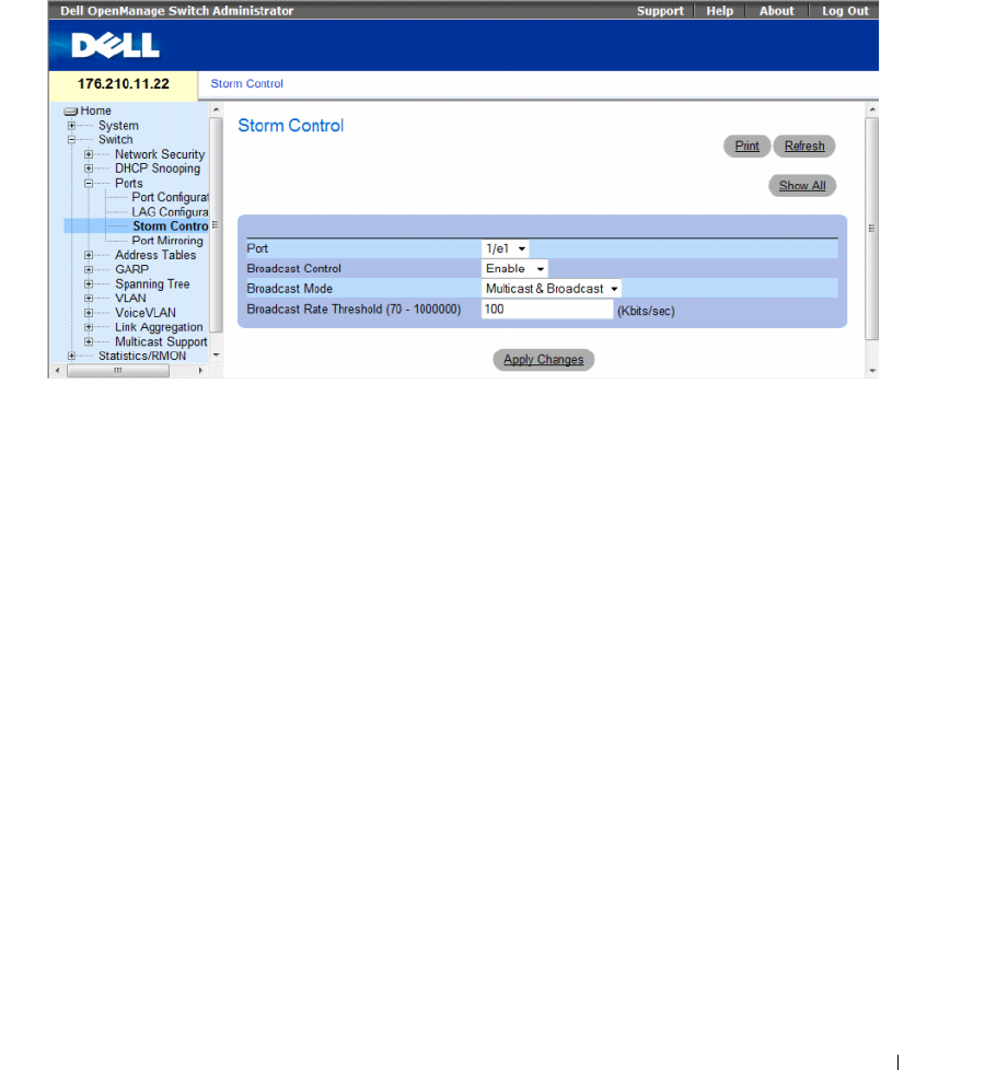
Configuring Switch Information 309
The Storm Control page provides fields for enabling and configuring Storm Control.
To open the Storm Control page, click Switch → Ports → Storm Control in the tree view.
Figure 7-25. Storm Control
The Storm Control page contains the following fields:
•
Port
— The port from which storm control is enabled.
•
Broadcast Control
— Enables or disables forwarding Broadcast packet types on the specific interface.
–
Enable
— Enables Broadcast packet types to be forwarded.
–
Disable
— Disables Broadcast packet types to be forwarded.
•
Broadcast Mode
— Specifies the Broadcast mode currently enabled on the device or stack.
The possible field values are:
–
Multicast & Broadcast
— Counts Broadcast and Multicast traffic together.
–
Broadcast Only
— Counts only Broadcast traffic.
•
Broadcast Rate Threshold (70-1000000)
— The maximum rate (Kbits/sec) at which unknown packets
are forwarded. The field range is 70-1,000,000 Kbps.
Enabling Storm Control
1
Open the
Storm Control
page.
2
Select an interface on which to implement storm control.
3
Define the fields.
4
Click
Apply Changes
.
Storm Control is enabled.
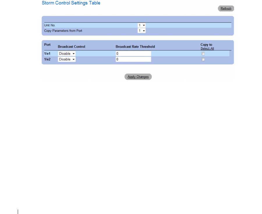
310 Configuring Switch Information
Modifying Storm Control Port Parameters
1
Open the
Storm Control
page.
2
Modify the fields.
3
Click
Apply Changes
The Storm Control port parameters are saved to the device.
Displaying the Port Parameters Table
1
Open the
Storm Control
page.
2
Click
Show All.
The
Storm Control Settings Table
opens.
Figure 7-26. Storm Control Settings Table
In addition to the fields in the Storm Control page, the Storm Control Settings Table contains the
following additional fields:
•
Unit No.
— Indicates the stacking member for which the Storm Control information is displayed.
•
Copy Parameters from Port
— Indicates the specific port from which Storm Control parameters
are copied.
•
Copy To
— Copies the Storm Control parameters to the selected ports.
Copying Parameters in the Storm Control Settings Table
1
Open the
Storm Control
page.
2
Click
Show All
.
The
Storm Control Settings Table
opens.
3
Select the port from which settings are copied from the
Copy Parameters from Port
field.

Configuring Switch Information 311
4
Check the
Copy to
check box to define the interfaces to which the storm control definitions are
copied, or click
Select All
to copy the definitions to all ports.
5
Click
Apply Changes
.
The parameters are copied to the selected ports in the
Storm Control Settings Table
, and the device is
updated.
Configuring Storm Control with CLI Commands
The following table summarizes the equivalent CLI commands for configuring Storm Control as
displayed on the Storm Control page.
The following is an example of the CLI commands:
Table 7-14. Storm Control CLI Commands
CLI Command Description
port storm-control include-multicast Enables the device to count Multicast,
Unicast, and Broadcast packets together.
port storm-control broadcast enable Enables broadcast storm control.
port storm-control broadcast rate Configures the maximum broadcast rate.
show ports storm-control
port
Displays the storm control configuration.
console(config)# port storm-control include-multicast
console(config)# interface ethernet 1/e1
console(config-if)# port storm-control broadcast enable
console(config-if)# port storm-control broadcast rate 100000
console(config-if)# end
console# show ports storm-control
Port Broadcast Storm control [kbyes/sec]
----- -------------------------------------
1/e1 8000
2/e1 Disabled
3/e2 Disabled

312 Configuring Switch Information
Defining Port Mirroring Sessions
Port mirroring does the following:
• Monitors and mirrors network traffic by forwarding copies of incoming and outgoing packets from one
port to a monitoring port.
• Can be used as a diagnostic tool and/or a debugging feature.
• Enables device performance and monitoring.
Port mirroring is configured by selecting a specific port to copy all packets, and different ports from
which the packets are copied.
Before configuring Port Mirroring, note the following:
• Port mirroring monitors and mirrors network traffic by forwarding copies of incoming and outgoing
packets, from a monitored port to a monitoring port.
• Monitored port cannot operate faster than the monitoring port.
• All the RX/TX packets should be monitored to the same port.
The following restrictions apply to ports configured to be destination ports:
• Ports cannot be configured as a source port.
• Ports cannot be a LAG member.
• IP interfaces are not configured on the port.
• GVRP is not enabled on the port.
• The port is not a VLAN member.
• Only one destination port can be defined.
The following restrictions apply to ports configured to be source ports:
• Source Ports cannot be a LAG member.
• Ports cannot be configured as a destination port.
•
Mirroring supports 4 ports in this device
.
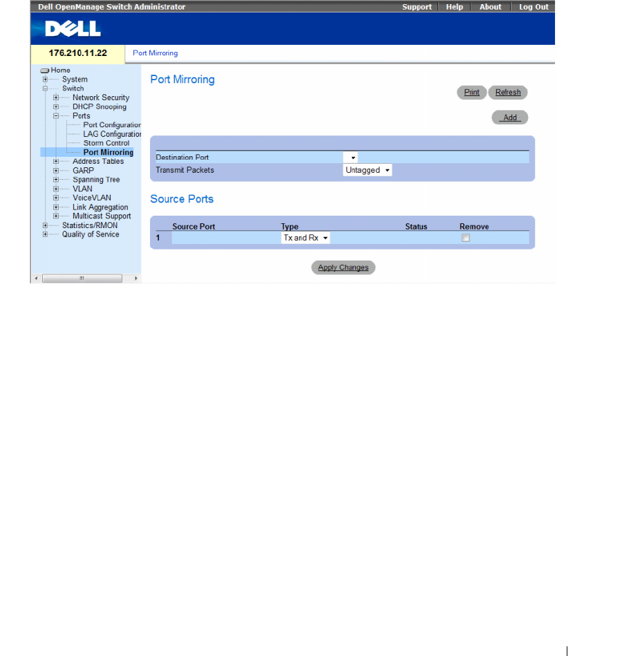
Configuring Switch Information 313
To open the Port Mirroring page, click Switch → Ports → Port Mirroring in the tree view.
When a port is set to be a target port for a port-mirroring session, all normal operations on it are
suspended. This includes Spanning Tree and LACP.
Figure 7-27. Port Mirroring
The Port Mirroring page contains the following fields:
•
Destination Port
— The port number to which port traffic is copied.
•
Transmit Packets
— Defines the how the packets are mirrored. The possible field values are:
–
Untagged
— Mirrors packets as untagged vlan packets. This is the default value.
–
Tagged
— Mirrors packets as tagged vlan packets.
Source Ports
•
Source Port
— Defines the port number from which port traffic is mirrored.
•
Ty p e
— Indicates if the mirrored packets are RX, TX, or both RX and TX. The possible field values are:
–
RxOnly
— Defines the port mirroring on receiving ports. This is the default value.
–
TxOnly
— Defines the port mirroring on transmitting ports.
–
Tx and Rx
— Defines the port mirroring on both receiving and transmitting ports.
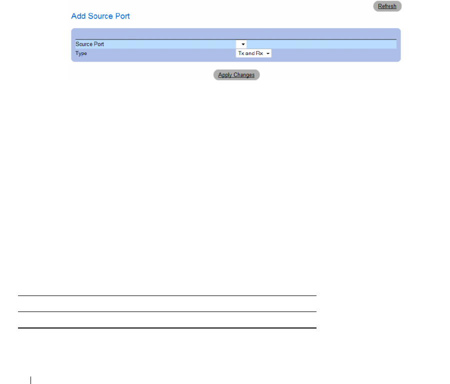
314 Configuring Switch Information
•
Status
— Indicates if the port is currently monitored (
Active
) or not monitored (
Ready
).
•
Remove
— Removes the port mirroring session. The possible field values are:
–
Checked
— Removes the selected port mirroring sessions.
–
Unchecked
— Maintains the port mirroring session.
Adding a Port Mirroring Session
1
Open the
Port Mirroring
page.
2
Click
Add
.
The
Add Source Port
page opens.
Figure 7-28. Add Source Port
3
Define the
Source Port
and the
Ty p e
fields.
4
Click
Apply Changes
.
The new source port is defined, and the device is updated.
Deleting a Copied Port from a Port Mirroring Session
1
Open the
Port Mirroring
page.
2
In the Source Ports table, select the port’s
Remove
check box.
3
Click
Apply Changes
.
The selected port mirroring session is deleted, and the device is updated.
Configuring a Port Mirroring Session Using CLI Commands
The following table summarizes the equivalent CLI commands for configuring a Port Mirroring session
as displayed in the Port Mirroring page.
Table 7-15. Port Mirroring CLI Commands
CLI Command Description
port monitor src-interface [rx | tx] Starts a port monitoring session.

Configuring Switch Information 315
The following is an example of the CLI commands:
Configuring Address Tables
MAC addresses are stored in either the Static Address or the Dynamic Address databases. A packet
addressed to a destination stored in one of the databases is forwarded immediately to the port.
The Dynamic Address Table can be sorted by interface, VLAN, and MAC Address. MAC addresses are
dynamically learned as packets from sources arrive at the device. Addresses are associated with ports by
learning the ports from the frames source address. Frames addressed to a destination MAC address that
is not associated with any port, are flooded to all ports of the relevant VLAN. Static addresses are
manually configured. In order to prevent the bridging table from overflowing, dynamic MAC addresses,
from which no traffic is seen for a certain period, are erased.
To open the Address Tables page, click Switch → Address Tables in the tree view.
This section contians the following topics:
• "Defining Static Addresses" on page 315
• "Viewing Dynamic Addresses" on page 318
Defining Static Addresses
The Static MAC Address page contains a list of static MAC addresses. Static Address can be added and
removed from the Static MAC Address page. In addition, several MAC Addresses can be defined for a
single port.
To open the Static MAC Address page, click Switch →Address Tables →Static Address Table in the
tree view.
console(config)# interface ethernet 1/e1
console(config-if)# port monitor 1/e2
console (config-if)# end
console# show ports monitor
Source Port Destination Port Type Status VLAN Tagging
----------- ---------------- ------------ ------- ------------
1/e2 1/e1 RX, TX Active No
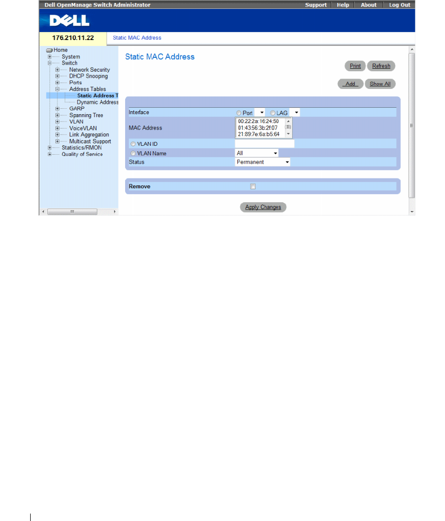
316 Configuring Switch Information
Figure 7-29. Static MAC Address
The Static MAC Address page contains the following fields:
•
Interface
— The specific port or LAG to which the static MAC address is applied.
•
MAC Address
— The MAC addresses listed in the current static addresses list.
•
VLAN ID
— The VLAN ID attached to the MAC.
•
VLAN Name
— User-defined VLAN name.
•
Status
— MAC address status. Possible values are:
–
Secure
— Used for defining static MAC Addresses for Locked ports.
–
Permanent
— The MAC address is permanent.
–
Delete on Reset
— The MAC address is deleted when the device is reset.
–
Delete on Timeout
— The MAC address is deleted when a timeout occurs.
To prevent Static MAC addresses from being deleted when the Ethernet device reset, ensure the port
attached to the MAC address is locked.
•
Remove
— Removes the selected MAC address from the
Static MAC Address Table
. The possible
field values are:
–
Checked
— Removes the selected MAC address.
–
Unchecked
— Maintains the selected MAC address.
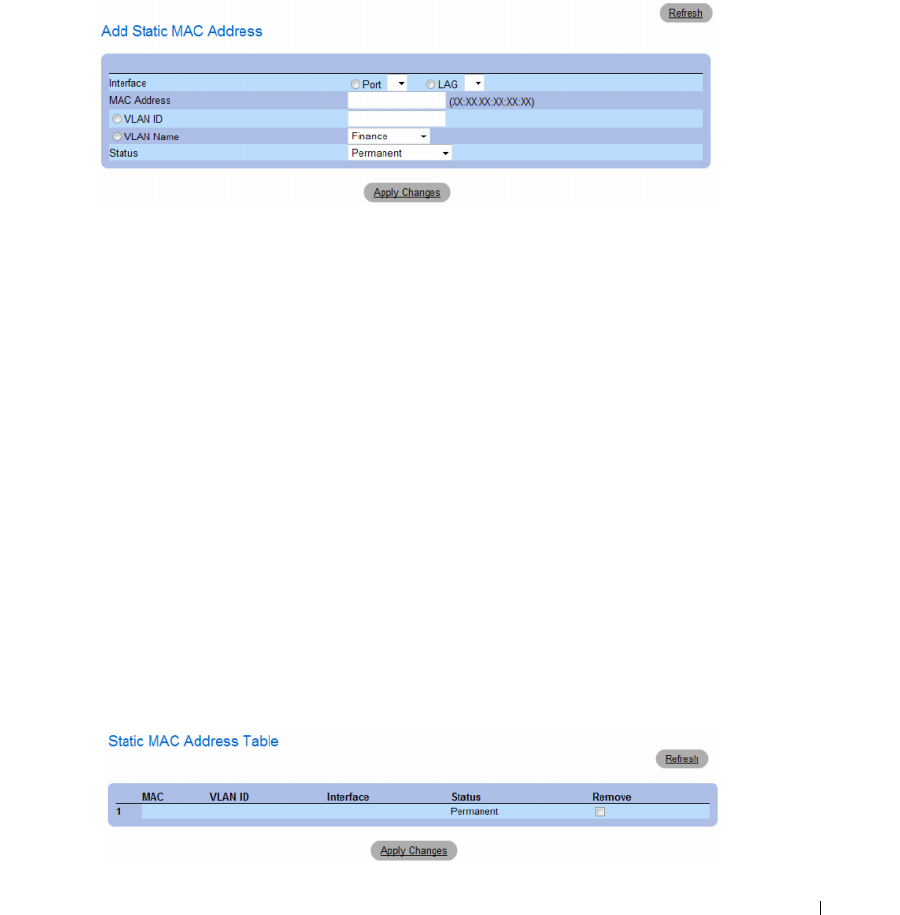
Configuring Switch Information 317
Adding a Static MAC Address
1
Open the
Static MAC Address
page
.
2
Click
Add
.
The
Add Static MAC Address
page opens.
Figure 7-30. Add Static MAC Address
3
Complete the fields.
4
Click
Apply Changes
.
The new static address is added to the
Static MAC Address Table
, and the device is updated.
Modifying a Static Address Setting in the Static MAC Address Table
1
Open the
Static MAC Address
page
.
2
Select an interface.
3
Modify the fields.
4
Click
Apply Changes
.
The static MAC address is modified, and the device is updated.
Removing a Static Address from the Static Address Table
1
Open the
Static MAC Address
page
.
2
Choose an interface.
3
Click
Show All
.
The
Static MAC Address Table
opens.
Figure 7-31. Static MAC Address Table
318 Configuring Switch Information
4
Select a table entry.
5
Select the
Remove
check box.
6
Click
Apply Changes
.
The selected static address is deleted, and the device is updated.
Configuring Static Address Parameters Using CLI Commands
The following table summarizes the equivalent CLI commands for configuring static address parameters
as displayed in the Static MAC Address page.
The following is an example of the CLI commands.
Viewing Dynamic Addresses
The Dynamic Address Table contains information for querying information in the dynamic address
table, including the interface type, MAC addresses, VLAN, and table sorting. Packets forwarded to an
address stored in the address table are forwarded directly to those ports. The Dynamic Address Table
page also contains information about the aging time before a dynamic MAC address is erased, and
includes parameters for querying and viewing the Dynamic Address list. The Current Address Table
contains dynamic address parameters by which packets are directly forwarded to the ports.
Table 7-16. Static Address CLI Commands
CLI Command Description
bridge address mac-address [permanent | delete-on-
reset | delete-on-timeout | secure] {ethernet interface
| port-channel port-channel-number}
Adds a static MAC-layer station source address to the
bridge table.
show bridge address-table [vlan vlan] [ethernet
interface | port-channel port-channel-number]
Displays entries in the bridge-forwarding database.
console(config-if)#bridge address 00:60:70:4C:73:FF permanent
ethernet g8
console# show bridge address-table
Aging time is 300 sec
vlan mac address port type
---- ------------ ---- --------
100:60:70:4C:73:FF 1/e8 dynamic
100:60:70:8C:73:FF 1/e8 dynamic
200 00:10:0D:48:37:FF 1/e9 static
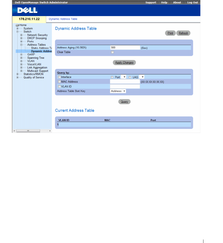
Configuring Switch Information 319
To open the Dynamic Address Table page, click Switch → Address Tables → Dynamic MAC Address in
the tree view.
Figure 7-32. Dynamic Address Table
The Dynamic Address Table page contain the following fields:
•
Address Aging (10-3825)
— Specifies the amount of time (in seconds) the MAC Address remains in
the
Dynamic Address Table
before it is timed out if no traffic from the source is detected. The default
value is 300 seconds.
•
Clear Table
— Clears the Dynamic Address table.
–
Checked
— Clears the Dynamic Address table.
–
Unchecked
— Maintains the Dynamic Address table.
Query By
In the Query By section, select the preferred option for sorting the Dynamic Addresses Table:
•
Port
— Specifies the interface for which the table is queried. There are two interface types from which
to select.
•
MAC Address
— Specifies the MAC address for which the table is queried.

320 Configuring Switch Information
•
VLAN ID
— The VLAN ID for which the table is queried.
•
Address Table Sort Key
— Specifies the means by which the Dynamic Address Table is sorted.
The address table can be sorted by Address, VLAN or Interface.
Redefining the Aging Time
1
Open the
Dynamic Address Table
.
2
Define the
Address Aging
field.
3
Click
Apply Changes
.
The aging time is modified, and the device is updated.
Querying the Dynamic Address Table
1
Open the
Dynamic Address Table
.
2
Define the parameter by which to query the
Dynamic Address Table
.
Entries can be queried by
Port
,
MAC Address
, or
VLAN ID
.
3
Click
Query
.
The
Dynamic Address Table
is queried, and the results are displayed.
Sorting the Dynamic Address Table
1
Open the
Dynamic Address Table
.
2
From the
Address Table Sort Key
drop-down menu, select whether to sort addresses by address, VLAN
ID, or interface.
3
Click
Query
.
The
Dynamic Address Table
is sorted.
Querying and Sorting Dynamic Addresses Using CLI Commands
The following table summarizes the equivalent CLI commands for aging, querying, and sorting dynamic
addresses as displayed in the Dynamic Address Table.
Table 7-17. Query and Sort CLI Commands
CLI Command Description
bridge aging-time
seconds
Sets the address table aging time.
show bridge address-table [vlan vlan]
[ethernet interface | port-channel
port-
channel-number
]
Displays classes of dynamically created entries in the bridge-
forwarding database.

Configuring Switch Information 321
The following is an example of the CLI commands:
Configuring GARP
Generic Attribute Registration Protocol (GARP) is a general-purpose protocol that registers any network
connectivity or membership-style information. GARP defines a set of devices interested in a given
network attribute, such as VLAN or multicast address.
When configuring GARP, ensure the following:
• The leave time must be greater than or equal to three times the join time.
• The leave-all time must be greater than the leave time.
• Set the same GARP timer values on all Layer 2-connected devices. If the GARP timers are set
differently on the Layer 2-connected devices, GARP application does not operate successfully.
To open the GARP page, click Switch → GARP in the tree view.
This section contians the following topics:
• "Defining GARP Timers" on page 322
console (config)# bridge aging-time 250
console (config)# end
console# show bridge address-table
Aging time is 250 sec
vlan mac address port type
---- ----------- ---- ----
1 00:60:70:4C:73:FF 1/e8 dynamic
1 00:60:70:8C:73:FF 1/e8 dynamic
200 00:10:0D:48:37:FF 1/e8 static
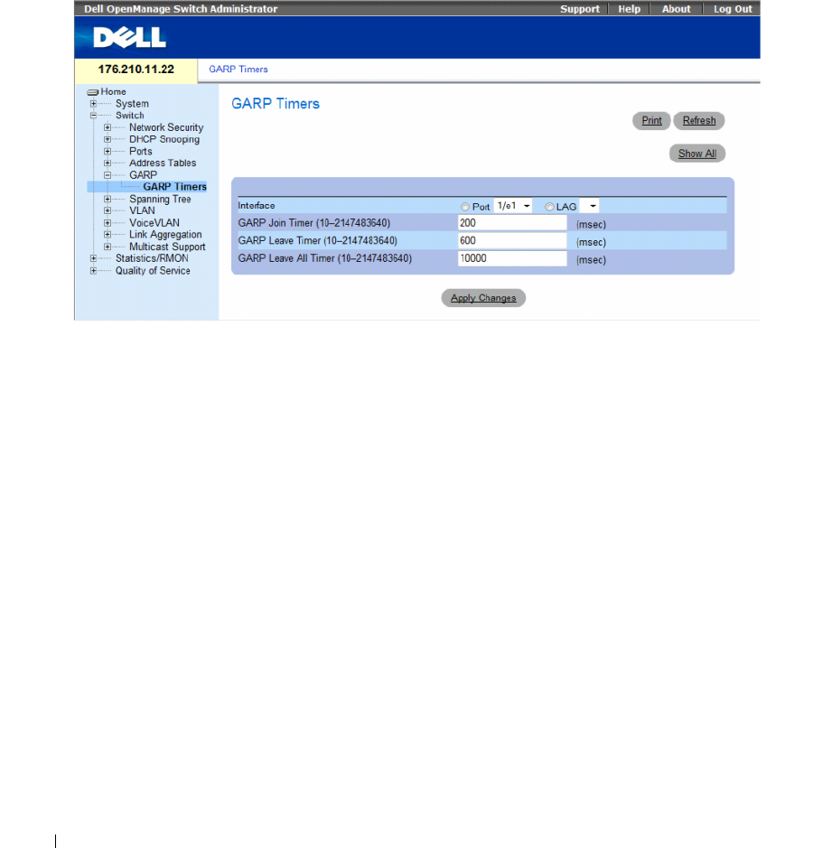
322 Configuring Switch Information
Defining GARP Timers
The GARP Timers page contains fields for enabling GARP on the device.
To open the GARP Timers page, click Switch → GARP → GARP Timers in the tree view.
Figure 7-33. GARP Timers
The GARP Timers page contains the following fields:
•
Interface
— Determines if enabled on a port or on a LAG..
•
GARP Join Timer (10 - 2147483640)
— Time, in milliseconds, that Protocol Data Units (PDU) are
transmitted. The default value is 200 msec.
•
GARP Leave Timer (10 - 2147483640
) — Time lapse, in milliseconds, that the device waits before
leaving its GARP state. Leave time is activated by a Leave All Time message sent/received, and
cancelled by the Join message received. Leave time must be greater than or equal to three times the
join time. The default value is 600 msec.
•
GARP Leave All Timer (10 - 2147483640)
— Time lapse, in milliseconds, that all devices wait before
leaving the GARP state. The leave all time must be greater than the leave time
.
The default value is
10000 msec.
Defining GARP Timers
1
Open the
GARP Timers
page.
2
Select an interface.
3
Complete the fields.
4
Click
Apply Changes
.
The GARP parameters are saved to the device.
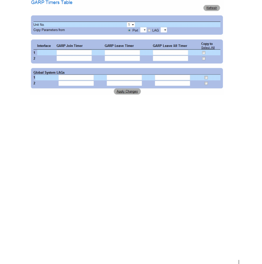
Configuring Switch Information 323
Copying Parameters in the GARP Timers Table
1
Open the
GARP Timers
page.
2
Click
Show All
.
The
GARP Timers Table
opens.
Figure 7-34. GARP Timers Table
3
Select the interface in the
Copy Parameters from
field from either the
Port
or
LAG
drop-down menu.
The definitions for this interface are copied to the selected interfaces. See step 4.
4
Select the
Copy to
check box to define the interfaces to which the GARP timer definitions
(copied from
Copy Parameters from
field) are copied, or click
Select All
to copy the definitions to
all ports or LAGs.
5
Click
Apply Changes
.
The parameters are copied to the selected ports or LAGs in the
GARP Timers Table
, and the device
is updated.

324 Configuring Switch Information
Defining GARP Timers Using CLI Commands
This table summarizes the equivalent CLI commands for defining GARP timers as displayed in the
GARP Timers page.
The following is an example of the CLI commands:
Table 7-18. GARP Timer CLI Commands
CLI Command Description
garp timer {join | leave | leaveall}
timer_value
Adjusts the GARP application join,
leave, and leaveall GARP timer values.
console(config)# interface ethernet 1/e1
console(config-if)# garp timer leave 900
console(config-if)# end
console# show gvrp configuration ethernet 1/e11
GVRP Feature is currently Disabled on the device.
Maximum VLANs: 223
Port(s) GVRP- Registration Dynamic VLAN Timers (milliseconds)
Status Creation Join Leave Leave All
---------
------- -------- ------------ ------------ ------- ------
1/e11 Disabled Normal Enabled 200 900 10000

Configuring Switch Information 325
Configuring the Spanning Tree Protocol
Spanning Tree Protocol (STP) provides tree topography for any bridge arrangement. STP eliminates
loops by providing one path between end stations on a network.
Loops occur when alternate routes exist between hosts. Loops in an extended network can cause bridges
to forward traffic indefinitely, resulting in increased traffic and reducing network efficiency.
The device supports the following Spanning Tree versions:
•
Classic STP
— Provides a single path between end stations, avoiding and eliminating loops. For more
information on configuring Classic STP, see
Defining STP Global Settings
.
•
Rapid STP
— Detects and uses of network topologies that provide faster convergence of the spanning
tree, without creating forwarding loops. If RSTP is enabled on the device, but the neighboring device is
STP enabled, the local device uses STP.
For more information on configuring Rapid STP, see
Defining Rapid Spanning Tree
.
•
Multiple STP
— Provides full connectivity for packets allocated to any VLAN. Multiple STP is based
on the RSTP. In addition, Multiple STP transmits packets assigned to different VLANs through
different MST regions. MST regions act as a single bridge if MSTP is enabled on the device. However,
if RSTP is enabled on the neighboring device and the local device uses STP, RSTP, and MSTP, then
both the devices are interoperable.
For more information on configuring Multiple STP, see
Configuring Multiple Spanning Tree
.
To open the Spanning Tree page, click Switch → Spanning Tree in the tree view.
This section contians the following topics:
• "Defining STP Global Settings" on page 325
• "Defining STP Port Settings" on page 331
• "Defining STP LAG Settings" on page 336
• "Defining Rapid Spanning Tree" on page 339
• "Configuring Multiple Spanning Tree" on page 343
• "Defining MSTP Interface Settings" on page 347
Defining STP Global Settings
The Spanning Tree Global Settings page contains parameters for enabling STP on the device.
To open the Spanning Tree Global Settings page, click Switch → Spanning Tree → Global Settings in the
tree view.
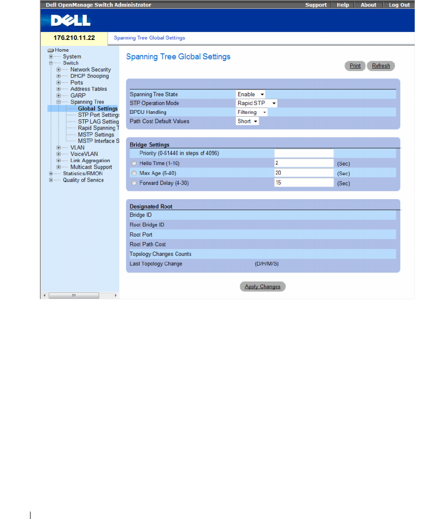
326 Configuring Switch Information
Figure 7-35. Spanning Tree Global Settings
The Spanning Tree Global Settings page contains the following fields:
•
Spanning Tree State
— Enables or disables Spanning Tree on the device. The possible field values are:
–
Enable
— Enables Spanning Tree.
–
Disable
— Disables Spanning Tree.
•
STP Operation Mode
— Indicates the STP mode by which STP is enabled on the device. The possible
field values are:
–
Classic STP
— Enables Classic STP on the device. This is the default value.
–
Rapid STP
— Enables Rapid STP on the device.
–
Multiple STP
— Enables Multiple STP on the device.

Configuring Switch Information 327
•
BPDU Handling
— Determines how
Bridge Protocol Data Unit
(BPDU) packets are managed when
STP is disabled on the port/ device. BPDUs are used to transmit spanning tree information.
The possible field values are:
–
Filtering
— Filters BPDU packets when spanning tree is disabled on an interface. This is the
default value.
–
Flooding
— Floods BPDU packets when spanning tree is disabled on an interface.
•
Path Cost Default Values
— Specifies the method used to assign default path costs to STP ports.
The possible field values are:
–
Short
— Specifies 1 through 65,535 range for port path costs. This is the default value.
–
Long
— Specifies 1 through 200,000,000 range for port path costs.
The default path costs assigned to an interface vary according to the selected method:
Bridge Settings
•
Priority (0-61440 in steps of 4096)
— Specifies the bridge priority value. When switches or bridges are
running STP, each is assigned a priority. After exchanging BPDUs, the device with the lowest priority
value becomes the Root Bridge. The default value is 32768. The port priority value is provided in
increments of 4096. For example, 4096, 8192, 12288, etc.
•
Hello Time (1-10)
— Specifies the device Hello Time. The Hello Time indicates the amount of time
in seconds a root bridge waits between configuration messages. The default is 2 seconds.
•
Max Age (6-40
) — Specifies the device Maximum Age Time. The Maximum Age Time indicates the
amount of time in seconds a bridge waits before sending configuration messages. The default max age
is 20 seconds.
•
Forward Delay (4-30)
— Specifies the device forward delay time. The Forward Delay Time indicates
the amount of time in seconds a bridge remains in a listening and learning state before forwarding
packets. The default is 15 seconds.
Designated Root
•
Bridge ID
— Identifies the Bridge priority and MAC address.
•
Root Bridge ID
— Identifies the Root Bridge priority and MAC address.
•
Root Port
— Indicates the port number that offers the lowest cost path from this bridge to the Root
Bridge. It is significant when the Bridge is not the Root.
Interface
Long Short
LAG
20,000 4
1000 Mbps
20,000 4
100 Mbps
200,000 19
10 Mbps
2,000,000 100

328 Configuring Switch Information
•
Root Path Cost
— The cost of the path from this bridge to the root.
•
Topology Changes Counts
— Specifies the total amount of STP state changes that have occurred.
•
Last Topology Change
— Indicates the amount of time that has elapsed since the bridge was
initialized or reset, and the last topographic change occurred. The time is displayed in a D/H/M/S
format, for example, 2D/5H/10M/4S.
Defining STP Global Parameters
1
Open the page.
2
Select
Enable
in the
Spanning Tree State
field.
3
Select the
STP
mode in the
STP Operation Mode
field, and define the bridge settings.
4
Click
Apply Changes
.
STP is enabled on the device.
Modifying STP Global Parameters
1
Open the page.
2
Define the fields in the dialog.
3
Click
Apply Changes
.
The STP parameters are modified, and the device is updated.
Defining STP Global Parameters Using CLI Commands
The following table summarizes the equivalent CLI commands for defining STP global parameters as
displayed in the Spanning Tree Global Settings page.
Table 7-19. STP Global Parameter CLI Commands
CLI Command Description
spanning-tree Enables spanning tree functionality.
spanning-tree mode {stp | rstp | mstp} Configures the mode of the spanning tree protocol.
spanning-tree priority priority Configures the spanning tree priority.
spanning-tree hello-time seconds Configures the spanning tree bridge Hello Time, which is how
often the device broadcasts Hello messages to other devices.
spanning-tree max-age seconds Configures the spanning tree bridge maximum age.
spanning-tree forward-time seconds Configures the spanning tree bridge forward time, which is the
amount of time a port remains in the listening and learning
states before entering the forwarding state.

Configuring Switch Information 329
The following is an example of the CLI commands:
show spanning-tree [ethernet interface | port-
channel port-channel-number] [instance instance-id]
Displays spanning tree configuration.
show spanning-tree [detail] [active |
blockedports] [instance instance-id]
Displays detailed spanning tree information on active or
blocked ports.
show spanning-tree mst-configuration Displays spanning tree MST configuration identifier.
console(config)# spanning-tree
console(config)# spanning-tree mode rstp
console(config)# spanning-tree priority 12288
console(config)# spanning-tree hello-time 5
console(config)# spanning-tree max-age 12
console(config)# spanning-tree forward-time 25
console(config)# exit
console# show spanning-tree
Spanning tree enabled mode MSTP
Default port cost method: short
Gathering information ..........
###### MST 0 Vlans Mapped: 16-4094
CST Root ID Priority 20480
Address 00:30:ab:00:00:08
Path Cost 4
Root Port ch2
This switch is the IST master
Hello Time 2 sec Max Age 20 sec Forward Delay 15 sec
Bridge ID Priority 32768
Address 00:00:00:16:00:64
Max hops 20
Table 7-19. STP Global Parameter CLI Commands (continued)
CLI Command Description

330 Configuring Switch Information
Name State Prio.Nbr Cost Sts Role PortFast Type
---- ----- ------- ---- --- ---- ------- ----
1/e2 enabled 128.2 100 DSBL Dsbl No P2p Intr
1/e3 enabled 128.3 100 DSBL Dsbl No P2p Intr
1/e4 enabled 128.4 100 DSBL Dsbl No P2p Intr
1/e5 enabled 128.5 19 FRW Desg Yes P2p Intr
1/e6 enabled 128.6 100 DSBL Dsbl No P2p Intr
1/e7 enabled 128.7 100 DSBL Dsbl No P2p Intr
1/e8 enabled 128.8 100 DSBL Dsbl No P2p Intr
1/e9 enabled 128.9 100 DSBL Dsbl No P2p Intr
1/e10 enabled 128.10 100 DSBL Dsbl No P2p Intr
1/e11 enabled 128.11 19 DSBL Desg Yes P2p Intr
console# show spanning-tree active
Spanning tree enabled mode MSTP
Default port cost method: short
Gathering information ..........
###### MST 0 Vlans Mapped: 16-4094
CST Root ID Priority 20480
Address 00:30:ab:00:00:08
Path Cost 4
Root Port ch2
This switch is the IST master
Hello Time 2 sec Max Age 20 sec Forward Delay 15 sec
Bridge ID Priority 32768
Address 00:00:00:16:00:64
Max hops 20
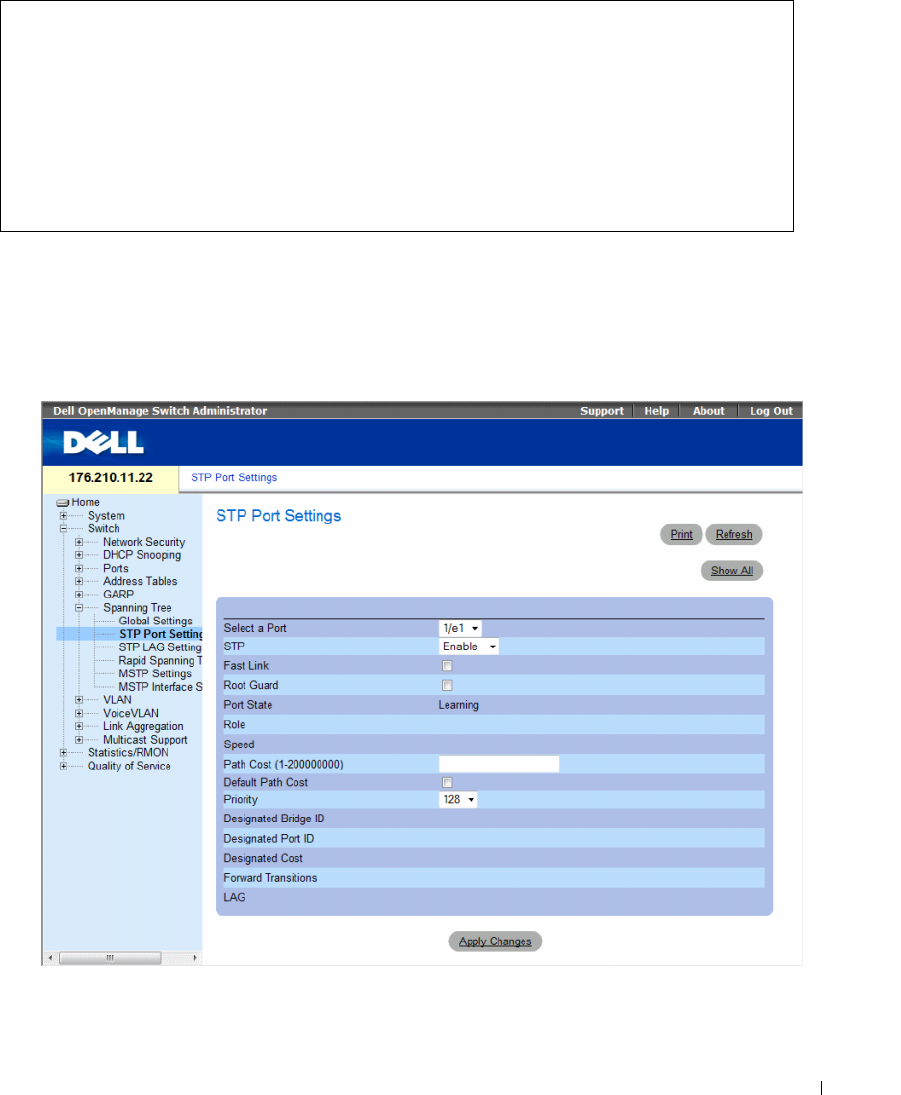
Configuring Switch Information 331
Defining STP Port Settings
Use the STP Port Settings page to assign STP properties to individual ports.
To open the STP Port Settings page, click Switch → Spanning Tree → Port Settings in the tree view.
Figure 7-36. STP Port Settings
Name State Prio.Nbr Cost Sts Role PortFast Type
---- ----- ------- ---- --- ---- ------- ----
1/e5 enabled 128.2 19 FRW Desg Yes P2p Intr
1/e7 enabled 128.7 19 DSCR Altn No P2p Bound (STP)
1/e11 enabled 128.11 19 FRW Desg Yes P2p Intr
1/e15 enabled 128.15 19 FRW Desg No P2p Intr
1/e22 enabled 128.22 19 FRW Desg Yes P2p Intr

332 Configuring Switch Information
The STP Port Settings page contains the following fields:
•
Select a Port
— Specifies the port number on which STP settings are to be to modified.
•
STP
— Enables or disables STP on the port. The possible field values are:
–
Enable
— Indicates that STP is enabled on the port.
–
Disable
— Indicates that STP is disabled on the port.
•
Fast Link
— Enables Fast Link mode for the port. If Fast Link mode is enabled for a port, the
Port
State
is automatically placed in the
Forwarding
state
when the port link is up. Fast Link mode
optimizes the time it takes for the STP protocol to converge. STP convergence can take 30-60 seconds
in large networks. The possible values are:
–
Checked
— Fast Link is enabled.
–
Unchecked
— Fast Link is disabled.
•
Root Guard
—
Prevents devices outside the network core from being assigned the spanning tree root.
–
Checked
— Root guard is enabled on the port.
–
Unchecked
— Root guard is disabled on the port.
•
Port State
— Indicates the current STP state of a port. If enabled, the port state determines what
forwarding action is taken on traffic. Possible port states are:
–
Disabled
— STP is currently disabled on the port. The port forwards traffic while learning
MAC addresses.
–
Blocking
— The port is currently blocked and cannot be used to forward traffic or learn
MAC addresses. Blocking is displayed when Classic STP is enabled.
–
Listening
— The port is currently in the listening mode. The port cannot forward traffic nor can it
learn MAC addresses.
–
Learning
— The port is currently in the learning mode. The port cannot forward traffic however it
can learn new MAC addresses.
–
Forwarding
— The port is currently in the forwarding mode. The port can forward traffic and learn
new MAC addresses.
•
Role
— Indicates the port role assigned by the STP algorithm that provides STP paths. The possible
field values are:
–
Root
— Provides the lowest cost path to forward packets to root switch.
–
Designated
— Indicates that the port via which the designated switch is attached to the LAN.
–
Alternate
— Provides an alternate path to the root switch from the root interface.
–
Backup
— Provides a backup path to the designated port path toward the Spanning Tree leaves.
Backup ports occur only when two ports are connected in a loop by a point-to-point link. Backup
ports also occur when a LAN has two or more connections connected to a shared segment.
–
Disabled
— Indicates the port is not participating in the Spanning Tree.
•
Speed
— Speed at which the port is operating.

Configuring Switch Information 333
•
Path Cost (1-200000000)
— The port contribution to the root path cost. The path cost is adjusted to
a higher or lower value, and is used to forward traffic when a path being rerouted.
•
Default Path Cost
— Indicates if the device uses the default path cost. The possible field values are:
–
Checked
— Device uses the default path cost.
–
Unchecked
— Device uses path cost defined in the Path Cost field above.
•
Priority
— Priority value of the port. The priority value influences the port choice when a bridge has
two ports connected in a loop. The priority value is between 0 -240. The priority value is provided in
increments of 16.
•
Designated Bridge ID
— The bridge priority and the MAC Address of the designated bridge.
•
Designated Port ID
— The designated port’s priority and interface.
•
Designated Cost
— Cost of the port participating in the STP topology. Ports with a lower cost are less
likely to be blocked if STP detects loops.
•
Forward Transitions
— Number of times the port has changed from the
Forwarding
state to
Blocking
.
•
LAG
— The LAG to which the port is attached.
Enabling STP on a Port
1
Open the Spanning Tree
Port Settings
page.
2
Select the port.
3
Select
Enabled
in the
STP
field.
4
Define the
Fast Link,
Root Guard
,
Path Cost
,
Default Path Cost
, and the
Priority
fields.
5
Click
Apply Changes
.
STP is enabled on the port.
Modifying STP Port Properties
1
Open the Spanning Tree Port Settings page.
2
Select the port.
3
Modify the relevant fields.
4
Click
Apply Changes
.
The STP port parameters are modified, and the device is updated.
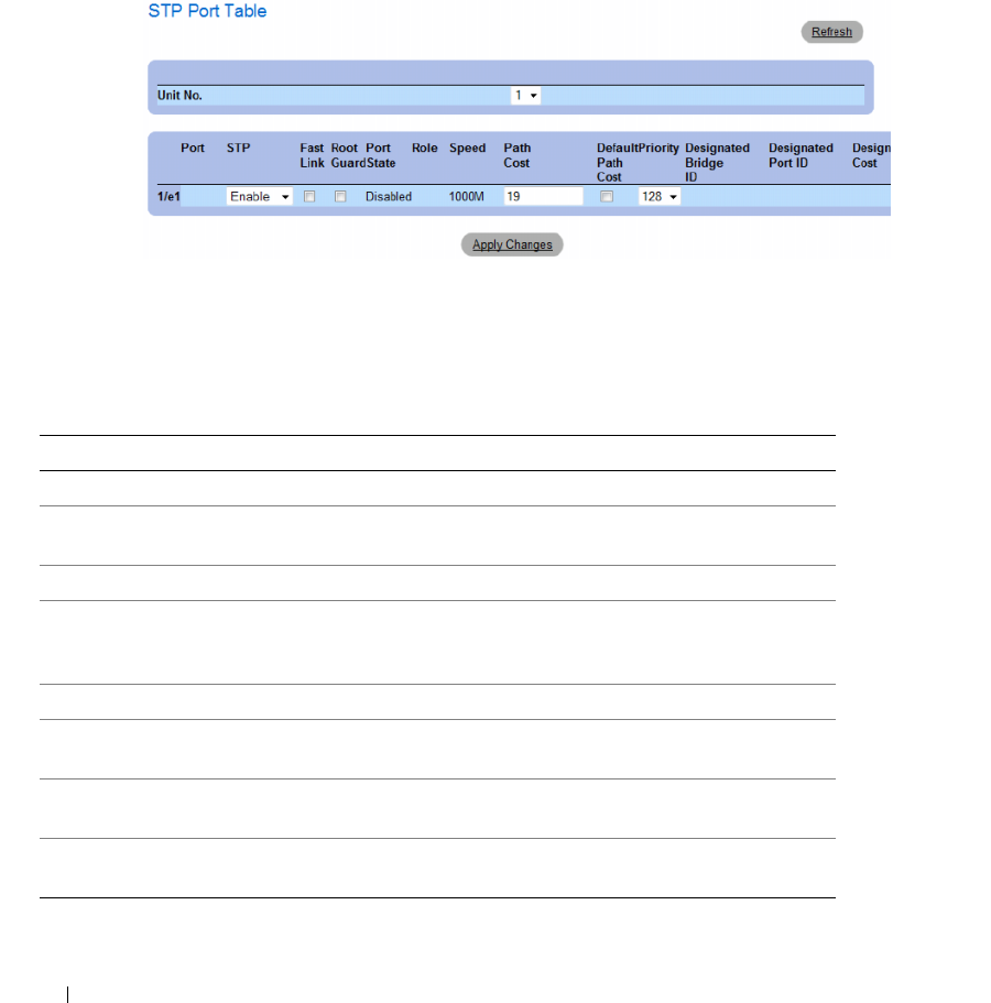
334 Configuring Switch Information
Displaying the STP Port Table
1
Open the Spanning Tree Port Settings page.
2
Click
Show All
.
The
STP Port Table
opens.
Figure 7-37. STP Port Table
Defining STP Port Settings Using CLI Commands
The following table summarizes the equivalent CLI commands for defining STP port parameters as
displayed in the STP Port Settings page.
Table 7-20. STP Port Settings CLI Commands
CLI Command Description
spanning-tree disable Disables spanning tree on a specific port.
spanning-tree cost cost Configures the spanning tree cost
contribution of a port.
spanning-tree port-priority priority Configures port priority.
show spanning-tree [ethernet
interface | port-channel port-
channel-number][instance instance-id]
Displays spanning tree configuration.
spanning-tree portfast Enables Fast Link mode.
spanning-tree guard root Enables root guard on all spanning tree
instances on the interface.
show spanning-tree [detail] [active |
blockedports] [instance instance-id]
Displays detailed spanning tree information
on active or blocked ports.
show spanning-tree mst-configuration Displays spanning tree MST configuration
identifier.

Configuring Switch Information 335
The following is an example of the CLI commands:
console> enable
console# configure
Console(config)# interface ethernet 1/e1
Console(config-if)# spanning-tree disable
Console(config-if)# spanning-tree cost 35000
Console(config-if)# spanning-tree port-priority 96
Console(config-if)# spanning-tree portfast
Console(config-if)# exit
Console(config)# exit
Console# show spanning-tree ethernet 1/e15
Port 1/e15 enabled
State: forwarding Role: designated
Port id: 128.15 Port cost: 19
Type: P2p (configured: Auto) Internal Port Fast: No (configured: No)
Designated bridge Priority : 32768 Address: 00:00:00:16:00:64
Designated port id: 128.15 Designated path cost: 4
Guard root: Disabled
Number of transitions to forwarding state: 2
BPDU: sent 483, received 1037
console# show spanning-tree ethernet 1/e15 instance 12
Port 1/e15 enabled
State: discarding Role: alternate
Port id: 128.15 Port cost: 19
Type: P2p (configured: Auto) Internal Port Fast: No (configured:
No)
Designated bridge Priority : 32768 Address: 00:00:b0:07:07:49
Designated port id: 128.11 Designated path cost: 0
Guard root: Disabled
Number of transitions to forwarding state: 3
BPDU: sent 482, received 1035
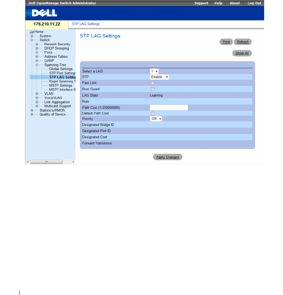
336 Configuring Switch Information
Defining STP LAG Settings
Use the STP LAG Settings page to assign STP aggregating ports parameters.
To open the STP LAG Settings page, click Switch → Spanning Tree → LAG Settings in the tree view.
Figure 7-38. STP LAG Settings
The Spanning Tree LAG Settings page contains the following fields:
•
Select a LAG
— The LAG number for which you want to modify STP settings.
•
STP
— Enables or disables STP on the LAG. The possible field values are:
–
Enable
— Indicates that STP is enabled on the LAG.
–
Disable
— Indicates that STP is disabled on the LAG.
•
Fast Link
— Enables Fast Link mode for the LAG. If Fast Link mode is enabled for a LAG, the
LAG
State
is automatically placed in the
Forwarding
state
when the LAG is up. Fast Link mode optimizes
the time it takes for the STP protocol to converge. STP convergence can take 30-60 seconds in large
networks. The possible values are:
–
Checked
— Fast Link is enabled.
–
Unchecked
— Fast Link is disabled.

Configuring Switch Information 337
•
Root Guard
—
Prevents devices outside the network core from being assigned the spanning tree root.
–
Checked
— Root guard is enabled on the port.
–
Unchecked
— Root guard is disabled on the port.
•
LAG State
— Current STP state of a LAG. If enabled, the LAG state determines what forwarding
action is taken on traffic. If the bridge discovers a malfunctioning LAG, the LAG is placed in the
Broken
state. Possible LAG states are:
–
Disabled
— STP is currently disabled on the LAG. The LAG forwards traffic while learning
MAC addresses.
–
Blocking
— The LAG is blocked and cannot be used to forward traffic or learn MAC addresses.
–
RSTP Discarding State
— In this state the port does not learn MAC addresses and do not forward
frames.
– This state is union of Blocking, and Listening state introduced in STP (802.1.D).
–
Listening
— The LAG is in the listening mode and cannot forward traffic or learn MAC addresses.
–
Learning
— The LAG is in the learning mode and cannot forward traffic, but it can learn new
MAC addresses.
–
Forwarding
— The LAG is currently in the forwarding mode, and it can forward traffic and learn
new MAC addresses.
–
Broken
— The LAG is currently malfunctioning and cannot be used for forwarding traffic.
•
Role
— Indicates the LAG role assigned by the STP algorithm that provides STP paths. The possible
field values are:
–
Root
— Provides the lowest cost path to forward packets to root switch.
–
Designated
— Indicates that the via which the designated switch is attached to the LAN.
–
Alternate
— Provides an alternate LAG to the root switch from the root interface.
–
Backup
— Provides a backup path to the designated port path toward the Spanning Tree leaves.
Backup ports occur only when two ports are connected in a loop by a point-to-point link. Backup
ports also occur when a LAN has two or more connections connected to a shared segment.
–
Disabled
— Indicates the LAG is not participating in the Spanning Tree.
•
Path Cost (1-200000000)
— Amount the LAG contributes to the root path cost. The path cost is
adjusted to a higher or lower value, and is used to forward traffic when a path is being rerouted.
The path cost has a value of 1 to 200000000.
•
Default Path Cost
— Indicates if the device uses the default path cost. The possible field values are:
–
Checked
— Device uses the default path cost.
–
Unchecked
— Device uses path cost defined in the Path Cost field above.
•
Priority
— Priority value of the LAG. The priority value influences the LAG choice when a bridge has
looped ports. The priority value is between 0-240, in steps of 16.
•
Designated Bridge ID
— The priority and the MAC Address of the designated bridge.
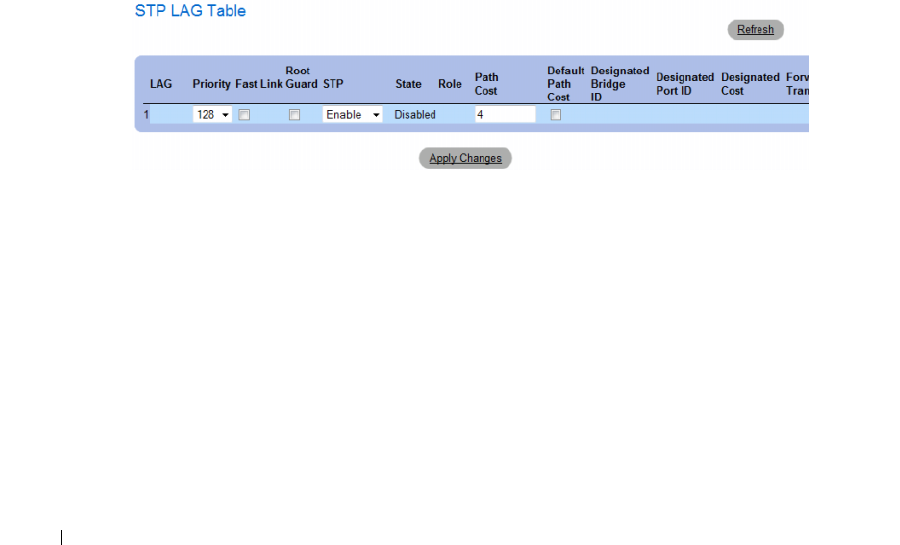
338 Configuring Switch Information
•
Designated Port ID
— The ID of the selected interface.
•
Designated Cost
— Cost of the port participating in the STP topology. Ports with a lower cost are less
likely to be blocked if STP detects loops.
•
Forward Transitions
— Number of times the
LAG State
has changed from the
Forwarding
state to a
Blocking state
.
Modifying the LAG STP Parameters
1
Open the
Spanning Tree LAG Settings
page.
2
Select a LAG from the
Select a LAG
drop-down menu.
3
Modify the fields as desired.
4
Click
Apply Changes
.
The STP LAG parameters are modified, and the device is updated.
Displaying the STP LAG Table
1
Open the
STP LAG Settings
page.
2
Click
Show All
.
The
STP LAG Table
opens.
Figure 7-39. STP LAG Table

Configuring Switch Information 339
Defining STP LAG Settings Using CLI Commands
The following table contains the CLI commands for defining STP LAG settings.
The following is an example of the CLI commands:
Defining Rapid Spanning Tree
While the classic spanning tree prevents Layer 2 forwarding loops on a general network topology,
convergence can take 30-60 seconds. The delay allows time to detect possible loops, and propagate
status changes.
Rapid Spanning Tree Protocol (RSTP) detects and uses network topologies that allow a faster
convergence of the spanning tree, without creating forwarding loops.
To open the Rapid Spanning Tree (RSTP) settings page, click Switch → Spanning Tree → Rapid
Spanning Tree in the tree view.
Table 7-21. STP LAG Settings CLI Commands
CLI Command Description
spanning-tree Enables spanning tree.
spanning-tree disable Disables spanning tree on a specific LAG.
spanning-tree cost
cost
Configures the spanning tree cost contribution of a
LAG.
spanning-tree guard root Enables root guard on all spanning tree instances on the
interface.
spanning-tree port-priority
priority
Configures port priority.
show spanning-tree [ethernet interface
|
port-channel
port-channel-number
][instance
instance-id]
Displays spanning tree configuration.
show spanning-tree [detail] [active | blockedports]
[instance instance-id]
Displays detailed spanning tree information on active or
blocked ports.
console(config)# interface port-channel 1
console(config-if)# spanning-tree disable
console(config-if)# spanning-tree cost 35000
console(config-if)# spanning-tree port-priority 96
console(config-if)# spanning-tree portfast
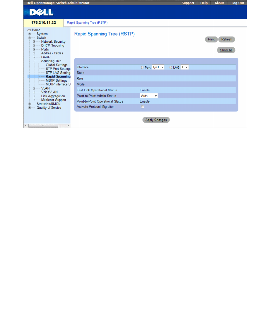
340 Configuring Switch Information
Figure 7-40. Rapid Spanning Tree (RSTP)
The Spanning Tree RSTP page contains the following fields:
•
Interface
— Port or LAG for which you can view and edit RSTP settings.
•
State
— Disables RSTP state of the selected interface.
•
Role
—Indicates the port role assigned by the STP algorithm in order to provide STP paths.
The possible field values are:
–
Root
—Provides the lowest cost path to forward packets to root switch.
–
Designated
—Indicates that the port or LAG via which the designated switch is attached to the LAN.
–
Alternate
—Provides an alternate path to the root switch from the root interface.
–
Backup
—Provides a backup path to the designated port path toward the Spanning Tree leaves.
Backup ports occur only when two ports are connected in a loop by a point-to-point link. Backup ports
also occur when a LAN has two or more connections connected to a shared segment.
–
Disabled
—Indicates the port is not participating in the Spanning Tree.
•
Mode
—Indicates the current Spanning Tree mode. The Spanning Tree mode is selected in the
Spanning Tree Global Settings
page. The possible field values are:
–
Classic STP
—Indicates that Classic STP is enabled on the device.
–
Rapid STP
—Indicates that Rapid STP is enabled on the device.
–
Multiple STP
—Indicates that Multiple STP is enabled on the device.

Configuring Switch Information 341
•
Fast Link Operational Status
— Indicates if Fast Link is enabled or disabled for the port or LAG.
If Fast Link is enabled for an interface, the interface is automatically placed in the forwarding state.
The possible field values are:
–
Enable
— Fast Link is enabled.
–
Disable
— Fast Link is disabled.
–
Auto
— Fast Link mode is enabled a few seconds after the interface becomes active.
•
Point-to-Point Admin Status
— Indicates if a point-to-point links is established, or permits the device
to establish a point-to-point link. The possible field values are:
–
Enable
— Enables the device to establish a point-to-point link, or specifies for the device to
automatically establish a point-to-point link. To establish communications over a point-to-point
link, the originating PPP first sends Link Control Protocol (LCP) packets to configure and test the
data link. After a link is established and optional facilities are negotiated as needed by the LCP,
the originating PPP sends
Network Control Protocols (NCP) packets to select and configure one
or more network layer protocols. When each of the chosen network layer protocols has been
configured, packets from each network layer protocol can be sent over the link. The link remains
configured for communications until explicit LCP or NCP packets close the link, or until some
external event occurs. This is the actual switch port link type. It may differ from the administrative
state.
–
Disable
— Disables point-to-point link.
–
Auto
— The device automatically establishes a point-to-point link.
•
Point-to-Point Operational Status
— The Point-to-Point operating state.
•
Activate Protocol Migrational
— Enables PPP sending Link Control Protocol (LCP) packets to
configure and test the data link. The possible field values are:
–
Checked
— Protocol Migration is enabled.
–
Unchecked
— Protocol Migration is disabled.
Defining RSTP parameters
1
Open the Spanning Tree RSTP Settings page.
2
Select an interface.
3
Define the fields.
4
Click
Apply Changes
.
RSTP parameters are defined, and the device is updated.
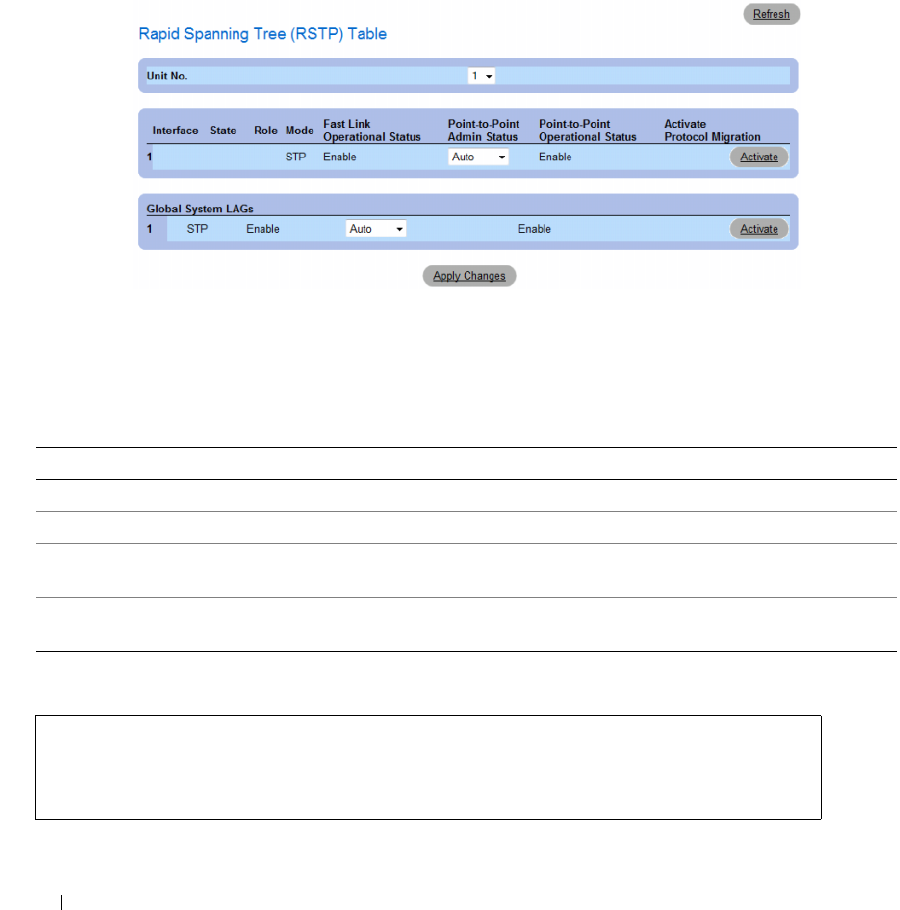
342 Configuring Switch Information
Displaying the Rapid Spanning Tree (RSTP) Table
1
Open the Rapid Spanning Tree (RSTP) page.
2
Click
Show All
.
The
Rapid Spanning Tree (RSTP) Table
opens.
Figure 7-41. Rapid Spanning Tree (RSTP) Table
Defining Rapid STP Parameters Using CLI Commands
The following table summarizes the equivalent CLI commands for defining Rapid STP parameters as
displayed in the Rapid Spanning Tree (RSTP).
The following is an example of the CLI commands:
Table 7-22. RSTP Settings CLI Command
CLI Command Description
spanning-tree link-type {point-to-point | shared} Overrides the default link-type setting.
spanning tree mode {stp | rstp | mstp} Configure the spanning tree protocol currently running.
clear spanning-tree detected-protocols [ethernet
interface | port-channel port-channel-number]
Restarts the protocol migration process.
show spanning-tree [ethernet interface | port-channel
port-channel-number]
Displays spanning tree configuration.
console(config)# interface ethernet 1/e5
console(config-if)# spanning-tree link-type shared
console(config-if)#
spanning tree mode rstp
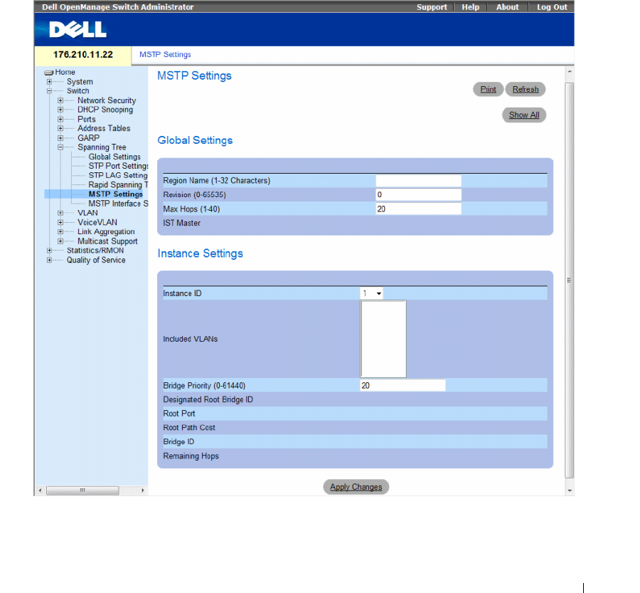
Configuring Switch Information 343
Configuring Multiple Spanning Tree
MSTP operation maps VLANs into STP instances. Multiple Spanning Tree provides differing load
balancing scenario. For example, while port A is blocked in one STP instance, the same port is placed in
the Forwarding State in another STP instance.
In addition, packets assigned to various VLANs are transmitted along different paths within Multiple
Spanning Trees Regions (MST Regions). Regions are one or more Multiple Spanning Tree bridges by
which frames can be transmitted.
To open the MSTP Settings page, click Switch → Spanning Tree → MSTP Settings in the tree view.
Figure 7-42. MSTP Settings

344 Configuring Switch Information
The MSTP Settings page contains the following fields:
•
Region Name (1-32 Characters)
— Indicates user-defined MSTP region name.
•
Revision (0-65535)
— Defines unsigned 16-bit number that identifies the current MST configuration
revision. The revision number is required as part of the MST configuration. The possible field range is
0-65535.
•
Max Hops (1-40)
— Defines the total number of hops that occur in a specific region before the BPDU
is discarded. Once the BPDU is discarded, the port information is aged out. The possible field range is
1-40. The field default is 20 hops.
•
IST Master
— Indicates the Internal Spanning Tree Master ID. The IST Master is the instance 0 root.
•
Instance ID
— Defines the MSTP instance. the field range is 1-15.
•
Included VLANs
— Displays VLANs mapped to the selected instance. Each VLAN belongs to one
instance.
•
Bridge Priority (0-61440)
— Specifies the selected spanning tree instance device priority. The field
range is 0-61440 in steps of 4096.
•
Designated Root Bridge ID
— Indicates the ID of the bridge which is the root of the selected
instance.
•
Root Port
— Indicates the selected instance’s root port.
•
Root Path Cost
— Indicates the selected instance’s path cost.
•
Bridge ID
— Indicates the bridge ID of the selected instance.
•
Remaining Hops
— Indicates the number of hops remaining to the next destination.
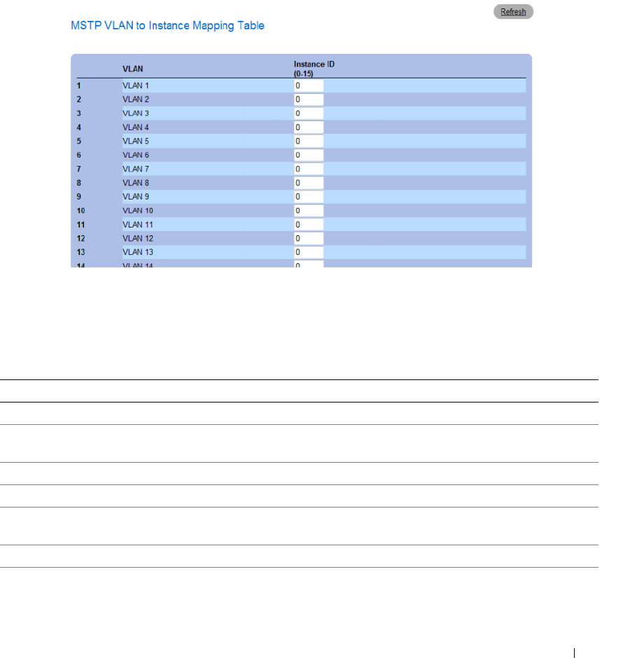
Configuring Switch Information 345
Displaying the MSTP VLAN to Instance Mapping Table
1
Open the
Spanning Tree MSTP Settings
page.
2
Click
Show All
to open the
MSTP VLAN to Instance Mapping Table
.
Figure 7-43. MSTP VLAN to Instance Mapping Table
Defining MST Instances Using CLI Commands
The following table summarizes the equivalent CLI commands for defining MST instance groups as
displayed in the Spanning Tree MSTP Settings page.
Table 7-23. MSTP Instances CLI Commands
CLI Command Description
spanning-tree mst configuration Enters MST Configuration mode.
instance instance-id {add | remove} vlan vlan-
range
Maps VLANs to the MST instance.
name string Sets the configuration name.
revision value Sets the configuration revision number
spanning-tree mst instance-id port-priority
priority
Sets the priority of a port.
spanning-tree mst instance-id priority priority Sets the device priority for the specified spanning tree instance.
spanning-tree mst max-hops hop-count Sets the number of hops in an MST region before the BPDU is
discarded and the information held for a port is aged.

346 Configuring Switch Information
The following is an example of the CLI commands:
spanning-tree mst instance-id cost cost Sets the path cost of the port for MST calculations
exit Exits the MST region configuration mode and applies
configuration changes.
abort Exits the MST region configuration mode without applying
configuration changes.
show {current | pending} Displays the current or pending MST region configuration.
console(config)# spanning-tree mst configuration
console(config-mst)# instance 1 add vlan 10-20
console(config-mst)# name region1
console(config-mst)# revision 1
console(config)# spanning-tree mst configuration
console(config-mst)# instance 2 add vlan 21-30
console(config-mst)# name region1
console(config-mst)# revision 1
console(config-mst)# show pending
Pending MST configuration
Name: Region1
Revision: 1
Instance Vlans Mapped
-------- ------------
0 1-9,31-4094
1 10-20
2 21-30
Table 7-23. MSTP Instances CLI Commands (continued)
CLI Command Description
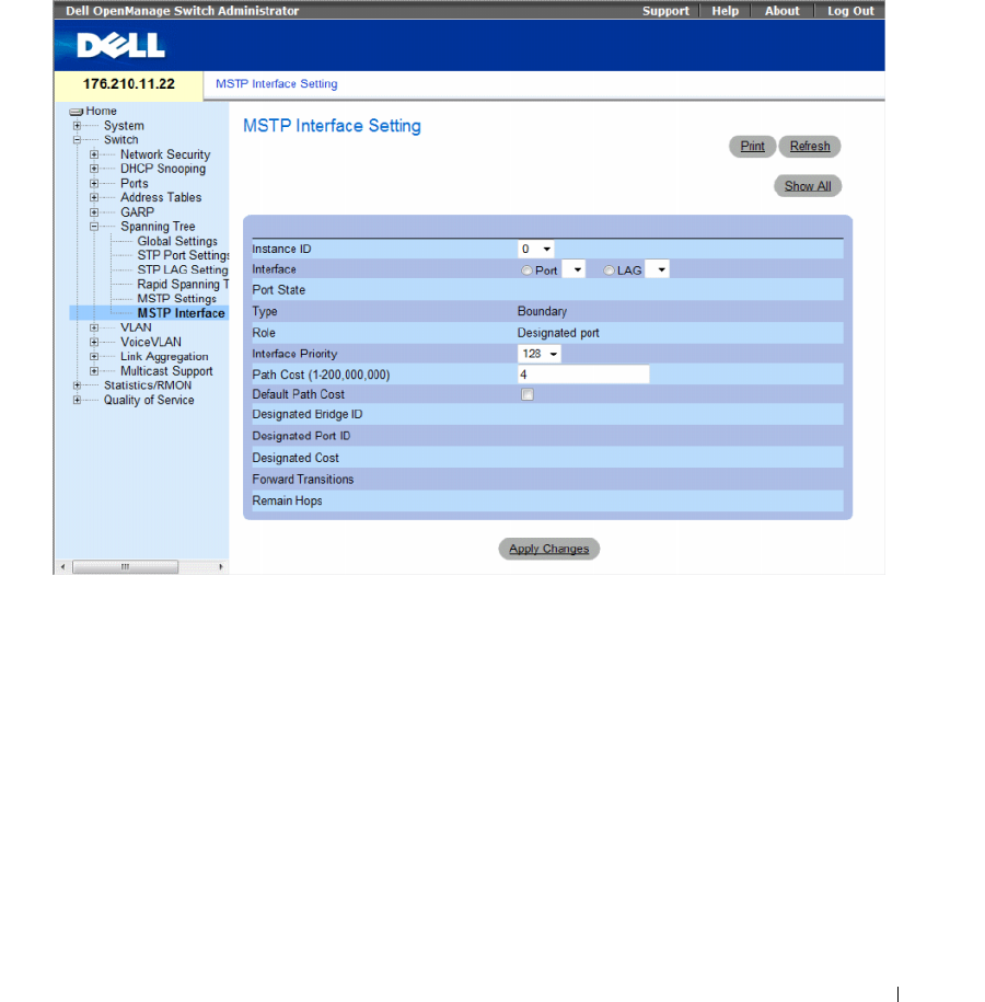
Configuring Switch Information 347
Defining MSTP Interface Settings
The MSTP Interface Settings page contains parameters assigning MSTP settings to specific interfaces.
To open the MSTP Interface Settings page, click Switch → Spanning Tree → MSTP Interface Settings in
the tree view.
Figure 7-44. MSTP Interface Settings
The MSTP Interface Settings page contains the following fields:
•
Instance ID —
Lists the MSTP instances configured on the device. Possible field range is 0-15.
•
Interface —
Assigns either ports or LAGs to the selected MSTP instance.
•
Port State —
Indicates whether the port is enabled or disabled in the specific instance.
•
Ty p e —
Indicates whether MSTP treats the port as a point-to-point port, or a port connected to a hub,
and whether the port is internal to the MST region or a boundary port. A Master port provides
connectivity from a MSTP region to the outlying CIST root. A Boundary port attaches MST bridges to
LAN in an outlying region. If the port is a boundary port, it also indicates whether the device on the
other side of the link is working in RSTP or STP mode.

348 Configuring Switch Information
•
Role —
Indicates the port role assigned by the STP algorithm in order to provide to STP paths.
The possible field values are:
–
Root
— Provides the lowest cost path to forward packets to root device.
–
Designated
— Indicates the port or LAG via which the designated device is attached to the LAN.
–
Alternate
— Provides an alternate path to the root device from the root interface.
–
Backup
— Provides a backup path to the designated port path toward the Spanning Tree leaves.
Backup ports occur only when two ports are connected in a loop by a point-to-point link. Backup
ports also occur when a LAN has two or more connections connected to a shared segment.
–
Disabled
— Indicates the port is not participating in the Spanning Tree.
•
Interface Priority
—
Defines the interface priority for specified instance. The default value is 128.
•
Path Cost
— Indicates the port contribution to the Spanning Tree instance. The possible range
is 1-200,000,000.
•
Default Path Cost
— Indicates if the default path cost is used. The possible values are:
–
Checked
— Default path cost is used.
–
Unchecked
— Path cost is user-defined.
•
Designated Bridge ID —
The bridge ID number that connects the link or shared LAN to the root.
•
Designated Port ID —
The Port ID number on the designated bridge that connects the link or the
shared LAN to the root.
•
Designated Cost —
Cost of the path from the link or the shared LAN to the root.
•
Forward Transitions —
Number of times the port changed to the forwarding state.
•
Remain Hops —
Indicates the number of hops remaining to the next destination.
Defining MSTP Interface Settings
1
Open the
MSTP Interface Settings
page.
2
Select an interface.
3
Define the fields.
4
Click
Apply Changes
.
MSTP parameters are defined, and the device is updated.
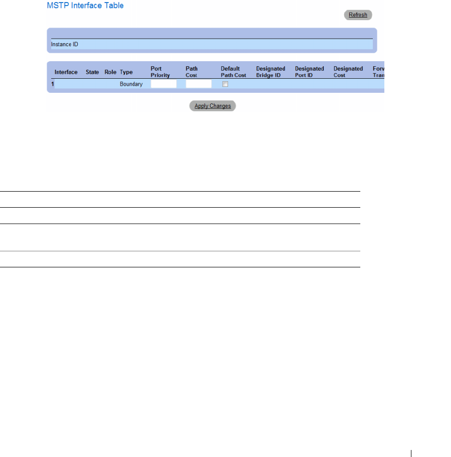
Configuring Switch Information 349
Viewing the MSTP Interface Table
1
Open the
MSTP Interface Settings
page.
2
Click
Show All
.
The
MSTP Interface Table
page opens.
Figure 7-45. MSTP Interface Table
Defining MSTP Interfaces Using CLI Commands
The following table summarizes the equivalent CLI commands for defining MSTP interfaces as
displayed in the Spanning Tree MSTP Interface Settings page.
Table 7-24. MSTP Interface CLI Commands
CLI Command Description
spanning-tree mst instance-id cost cost Sets the path cost of the port for MST calculations
spanning-tree mst instance-id priority
priority
Sets the device priority for the specified ST instance.
show spanning-tree mst-configuration Displays the MST configuration.

350 Configuring Switch Information
The following is an example of the CLI commands:
console# show spanning-tree mst-configuration
Gathering information ..........
Current MST configuration
Name: Gili
Revision: 65000
Instance Vlans Mapped State
--------- -------------------------- -----------
016-4094 enabled
11 enabled
22 enabled
33 enabled
44 enabled
55 enabled
66 enabled
77 enabled
88 enabled
99 enabled
10 10 enabled
11 11 enabled
12 12 enabled
13 13 enabled
14 14 enabled
15 15 enabled

Configuring Switch Information 351
Configuring VLANs
VLANs are logical subgroups with a LAN created via software, rather than defining a hardware solution.
VLANs combine user stations and network devices into a single unit, regardless of the physical LAN
segment to which they are attached. VLANs allow network traffic to flow more efficiently within
subgroups. VLANs managed through software reduce the amount of time network changes, additions,
and moves are implemented.
Click a link below to access on-line help for the indicated screen.
VLANs have no minimum number of ports, and can be created per unit, per device, per stack, or any
other logical connection combination, as VLANs are software-based and not defined by physical
attributes.
VLANs function at Layer 2 level. Since VLANs isolate traffic within the VLAN, a router working at the
Layer 3 protocol level is needed to allow traffic flow between VLANs. Layer 3 routers identify segments
and coordinate with VLANs. VLANs are Broadcast and Multicast domain. Broadcast and Multicast
traffic is transmitted only in the VLAN in which the traffic is generated.
VLAN tagging provides a method of transferring VLAN information between VLAN groups.
VLAN tagging attaches a 4-byte tag to packet headers. The VLAN tag indicates to which VLAN the
packet belongs. VLAN tags are attached to the VLAN by either the end station or by the network device.
VLAN tags also contains VLAN network priority information.
QinQ tagging allows network managers to add an additional tag to previously tagged packets. Customer
VLANs are configured using QinQ. Adding additional tags to the packets helps create more VLAN space.
The added tag provides VLAN ID to each customer, this ensures private and segregated network traffic.
The VLAN ID tag is assigned to a customer port in the service providers network. The designated port
then provides additional services to the packets with the double-tags. This allows administrators to
expand service to VLAN users.
Combining VLANs and GVRP allows network managers to define network nodes into Broadcast
domains. Broadcast and Multicast traffic is confined to the originating group.
To open the VLAN page, click Switch → VLAN in the tree view.
This section contians the following topics:
• "Defining VLAN Membership" on page 352
• "Defining VLAN Ports Settings" on page 357
• "Defining VLAN LAGs Settings" on page 359
• "Binding MAC Address to VLANs" on page 362
• "Defining VLAN Protocol Groups" on page 364
• "Adding Interfaces to Protocol Groups" on page 367
• "Configuring GVRP Parameters" on page 369
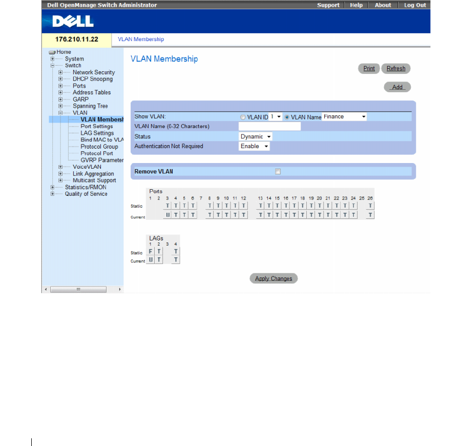
352 Configuring Switch Information
Defining VLAN Membership
The VLAN Membership page contains fields for defining VLAN groups. The device supports the
mapping of 4094 VLAN IDs to 256 VLANs. All ports must have a defined PVID. If no other value is
configured the default VLAN PVID is used. VLAN ID #1 is the default VLAN, and cannot be deleted
from the system.
To open the VLAN Membership page, click Switch→ VLAN→ VLAN Membership in the tree view.
Figure 7-46. VLAN Membership
The VLAN Membership page contains the following fields:
•
Show VLAN
— Lists and displays specific VLAN information according to VLAN ID or VLAN name.
•
VLAN Name (0-32 Characters)
— The user-defined VLAN name.
•
Status
— The VLAN type. Possible values are:
–
Dynamic
— The VLAN was dynamically created through GVRP.
–
Static
— The VLAN is user-defined.
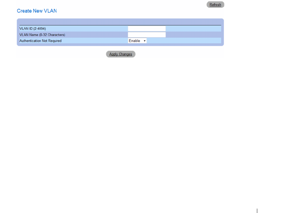
Configuring Switch Information 353
•
Authentication Not Required
— Indicates whether unauthorized users can access a VLAN.
The possible field values are:
–
Enable
— Enables unauthorized users to use a VLAN.
–
Disable
— Prevents unauthorized users from using a VLAN.
•
Remove VLAN
— Indicates whether to removes the VLAN from the VLAN Membership Table.
–
Checked
— Removes the VLAN.
–
Unchecked
— Maintains the VLAN in the VLAN Membership Table.
Adding New VLANs
1
Open the
VLAN Membership
page.
2
Click
Add
.
The
Create New VLAN
page opens.
Figure 7-47. Create New VLAN
3
Enter the VLAN ID and name.
4
Click
Apply Changes
.
The new VLAN is added, and the device is updated.
Modifying VLAN Membership Groups
1
Open the
VLAN Membership
page.
2
Select a VLAN from the
Show VLAN
drop-down menu.
3
Modify the fields as desired.
4
Click
Apply Changes
.
The VLAN membership information is modified, and the device is updated.

354 Configuring Switch Information
VLAN Port Membership Table
The VLAN Port Membership Table contains a Port Table for assigning ports to VLANs. Ports are
assigned to a VLAN by toggling through the Port Control settings. Ports can have the following values:
The VLAN Port Membership Table displays the ports and the ports states, as well as LAGs.
Assigning Ports to a VLAN Group
1
Open the
VLAN Membership
page.
2
Click the
VLAN ID
or
VLAN Name
option button and select a VLAN from the drop-down menu.
3
Select a port in the
Port Membership Table
, and assign the port a value.
4
Click
Apply Changes
.
The port is assigned to the VLAN group, and the device is updated.
Deleting a VLAN
1
Open the
VLAN Membership
page.
2
Click the
VLAN ID
or
VLAN Name
option button and select a VLAN from the drop-down menu.
3
Select the
Remove VLAN
check box.
4
Click
Apply Changes
.
The selected VLAN is deleted, and the device is updated.
Table 7-25. VLAN Port Membership Table
Port Control Definition
T The interface is a member of a VLAN. All packets forwarded by the interface are tagged.
The packets contain VLAN information.
U The interface is a VLAN member. Packets forwarded by the interface are untagged.
F The interface is denied membership to a VLAN.
Blank The interface is not a VLAN member. Packets associated with the interface are not forwarded.

Configuring Switch Information 355
Defining VLAN Membership Groups Using CLI Commands
The following table summarizes the equivalent CLI commands for defining VLAN membership groups
as displayed in the VLAN Membership page.
The following is an example of the CLI commands:
Assigning Ports to VLAN Groups Using CLI Commands
The following table summarizes the equivalent CLI commands for assigning ports to VLAN groups.
Table 7-26. VLAN Membership Group CLI Commands
CLI Command Description
vlan database Enters the VLAN configuration mode.
vlan {vlan-range} Creates a VLAN.
name string Adds a name to a VLAN.
console(config)# vlan database
console(config-vlan)# vlan 1972
console(config-vlan)# end
console(config)# interface vlan 1972
console(config-if)# name Marketing
console(config-if)# end
Table 7-27. Port-to-VLAN Group Assignments CLI Commands
CLI Command Description
switchport general acceptable-frame-types tagged-
only
Discards untagged frames at ingress.
switchport forbidden vlan {add vlan-list | remove
vlan-list}
Forbids adding specific VLANs to the port.
switchport mode {access | trunk | general} Configures the VLAN membership mode of a port.
switchport access vlan vlan-id Configures the VLAN ID when the interface is in access
mode.
switchport trunk allowed vlan {add vlan-list |
remove vlan-list}
Adds or removes VLANs from a trunk port.

356 Configuring Switch Information
The following is an example of the CLI commands:
switchport trunk native vlan vlan-id Defines the port as a member of the specified VLAN, and the
VLAN ID as the port default VLAN ID (PVID).
switchport general allowed vlan add vlan-list
[tagged | untagged]
Adds or removes VLANs for a port in general mode.
switchport general pvid vlan-id Configures the PVID when the interface is in general mode.
console(config)# vlan database
console(config-vlan)# vlan 23-25
console(config-vlan)# end
console(config)# interface vlan 23
console(config-if)# name Marketing
console(config-if)# end
console(config)# interface ethernet 1/e8
console(config-if)# switchport mode access
console(config-if)# switchport access vlan 23
console(config-if)# end
console(config)# interface ethernet 1/e9
console(config-if)# switchport mode trunk
console(config-if)# switchport mode trunk allowed vlan
add 23-25
console(config-if)# end
console(config)# interface ethernet 1/e11
console(config-if)# switchport mode general
console(config-if)# switchport general allowed vlan add
23,25 tagged
console(config-if)# switchport general pvid 25
Table 7-27. Port-to-VLAN Group Assignments CLI Commands (continued)
CLI Command Description
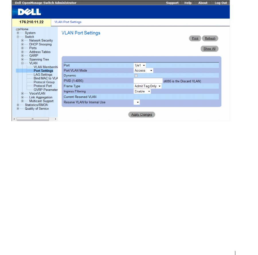
Configuring Switch Information 357
Defining VLAN Ports Settings
The VLAN Port Settings page contains fields for managing ports that are part of a VLAN. The port
default VLAN ID (PVID) is configured on the VLAN Port Settings page. All untagged packets arriving to
the device are tagged by the ports PVID.
To open the VLAN Port Settings page, click Switch → VLAN → Port Settings in the tree view.
Figure 7-48. VLAN Port Settings
The VLAN Port Settings page contains the following fields:
•
Port
— The port number included in the VLAN.
•
Port VLAN Mode
— The port mode. Possible values are:
–
Customer
— The port belongs to VLANs. When a port is in Customer mode, the added tag
provides a VLAN ID to each customer, ensuring private and segregated network traffic.
–
General
— The port belongs to VLANs, and each VLAN is user-defined as tagged or untagged
(full 802.1Q mode).
–
Access
— The port belongs to a single untagged VLAN. When a port is in Access mode, the packet
types which are accepted on the port cannot be designated. Ingress filtering cannot be
enabled/disabled on an access port.
–
Trunk
— The port belongs to VLANs in which all ports are tagged (except for one port that can
be untagged).

358 Configuring Switch Information
•
Dynamic
— Assigns a port to a VLAN based on the host source MAC address connected to the port.
–
Checked
— The port may be registered in a dynamic VLAN.
–
Unchecked
— The port is not allowed to register in a dynamic VLAN.
•
PVID (1-4095)
— Assigns a VLAN ID to untagged packets. The possible values are 1-4095.
VLAN 4095 is defined as per standard and industry practice as the Discard VLAN. Packets classified to
the Discard VLAN are dropped.
•
Frame Type
— Packet type accepted on the port. Possible values are:
–
Admit Tag Only
— Only tagged packets are accepted on the port.
–
Admit All
— Both tagged and untagged packets are accepted on the port.
•
Ingress Filtering
— Ingress filtering discards packets that are destined to VLANs of which the specific
port is not a member.
–
Enable
— Ingress filtering is activated on the port.
–
Disable
— Ingress filtering is not activated on the port.
•
Current Reserved VLAN
— The VLAN currently designated by the system as the reserved VLAN.
•
Reserve VLAN for Internal Use
— The VLAN selected by the user to be the reserved VLAN if not in
use by the system.
Assigning Port Settings
1
Open the
VLAN Port Settings
page.
2
Select the port to which settings need to be assigned from the
Port
drop-down menu.
3
Complete the remaining fields on the page
4
Click
Apply Changes
.
The VLAN port settings are defined, and the device is updated.
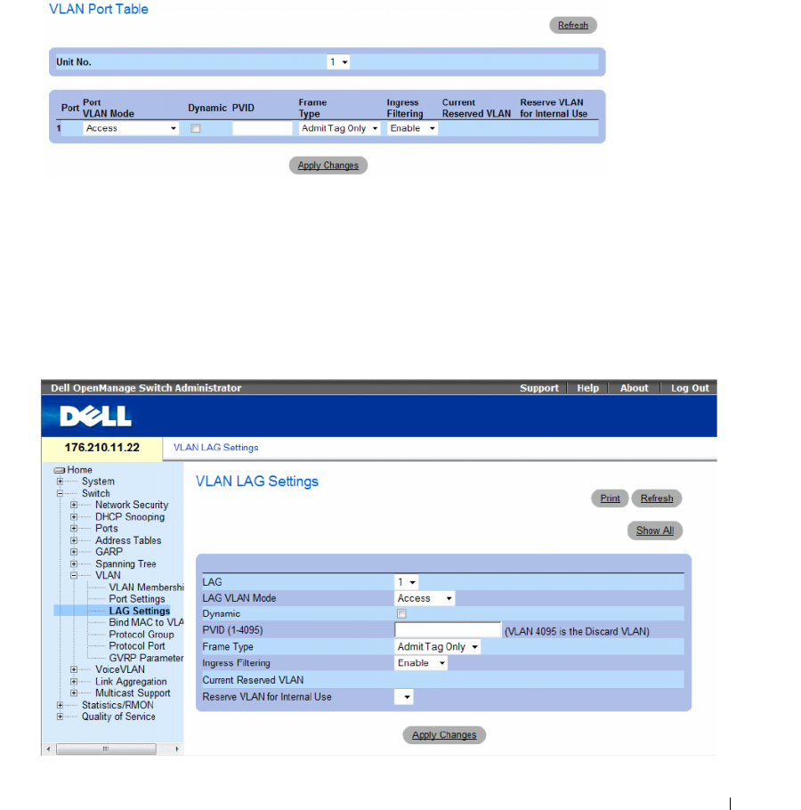
Configuring Switch Information 359
Displaying the VLAN Port Table
1
Open the
VLAN Port Settings
page.
2
Click
Show All.
The
VLAN Port Table
opens.
Figure 7-49. VLAN Port Table
Defining VLAN LAGs Settings
The VLAN LAG Settings page provides parameters for managing LAGs that are part of a VLAN.
VLANs can either be composed of individual ports or of LAGs. Untagged packets entering the device are
tagged with the LAGs ID specified by the PVID.
To open the VLAN LAG Settings page, click Switch → VLAN → LAG Settings in the tree view.
Figure 7-50. VLAN LAG Settings

360 Configuring Switch Information
The VLAN LAG Settings page contains the following fields:
•
LAG
— The LAG number included in the VLAN.
•
LAG VLAN Mode
— The LAG VLAN mode. Possible values are:
–
Customer
— The LAG belongs to VLANs. When LAGs are in Customer mode, the added tag
provides a VLAN ID to each customer, ensuring private and segregated network traffic.
–
General
— The LAG belongs to VLANs, and each VLAN is user-defined as tagged or untagged
(full 802.1Q mode).
–
Access
— The LAG belongs to a single, untagged VLAN.
–
Trunk
— The LAG belongs to VLANs in which all ports are tagged (except for one port that can be
untagged).
•
Dynamic
— Assigns a LAG to a VLAN based on the host source MAC address connected to the LAG.
The possible values are:
–
Checked
— The LAG may be registered in a dynamic VLAN.
–
Unchecked
— The LAG is not allowed to register in a dynamic VLAN.
•
PVID (1-4095)
— Assigns a VLAN ID to untagged packets. The possible field values are 1-4095.
VLAN 4095 is defined as per standard and industry practice, as the Discard VLAN. Packets classified to
this VLAN are dropped.
•
Frame Type
— Packet type accepted by the LAG. The possible values are:
–
Admit Tag Only
— Only tagged packets are accepted by the LAG.
–
Admit All
— Tagged and untagged packets are both accepted by the LAG.
•
Ingress Filtering
— Enables or disables Ingress filtering by the LAG. Ingress filtering discards packets
that are destined to VLANs of which the specific LAG is not a member. The possible values are:
–
Enable
— Ingress filtering is activated on the LAG.
–
Disable
— Ingress filtering is not activated on the LAG.
•
Current Reserve VLAN
— The VLAN currently designated as the reserved VLAN.
•
Reserve VLAN for Internal Use
— The VLAN that is designated as the reserved VLAN after the device
is reset.
Assigning VLAN LAG Settings:
1
Open the
VLAN LAG Settings
page.
2
Select a LAG from the
LAG
drop-down menu and complete the fields on the page.
3
Click
Apply Changes
.
The VLAN LAG parameters are defined, and the device is updated.
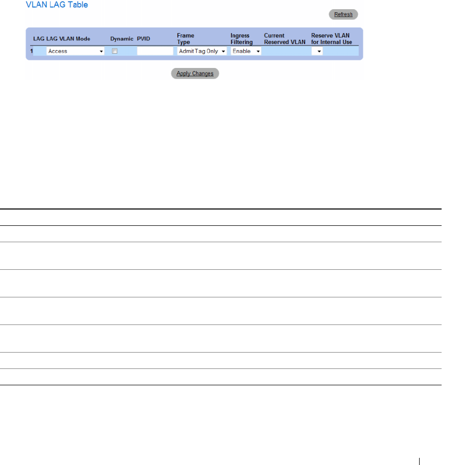
Configuring Switch Information 361
Displaying the VLAN LAG Table
1
Open the
VLAN LAG Settings
page.
2
Click
Show All
.
The
VLAN LAG Table
opens.
Figure 7-51. VLAN LAG Table
3
To change LAG settings, modify the fields for any LAGs in the table.
4
Click
Apply Changes
.
The VLAN LAG parameters are defined, and the device is updated.
Assigning LAGs to VLAN Groups Using CLI Commands
The following table summarizes the equivalent CLI commands for assigning LAGs to VLAN groups as
displayed in the VLAN LAG Settings page.
Table 7-28. LAG VLAN Assignments CLI Commands
CLI Command Description
switchport mode {access | trunk | general}Configures a LAG VLAN membership mode.
switchport trunk native vlan vlan-id Defines the port as a member of the specified VLAN, and the
VLAN ID as the LAG default VLAN ID (PVID).
switchport general pvid vlan-id Configure the LAG VLAN ID (PVID) when the interface is in
general mode.
switchport general allowed vlan add vlan-list
[tagged | untagged]
Adds or removes VLANs from a general LAG.
switchport general acceptable-frame-type
tagged-only
Discards untagged packets at ingress.
switchport access vlan dynamic Binds the MAC address to the VLAN.
switchport general ingress-filtering disable Disables LAG ingress filtering.

362 Configuring Switch Information
The following is an example of the CLI commands:
Binding MAC Address to VLANs
Binding MAC addresses to VLANs provides port to VLAN assignment based on MAC addresses. Once a
VLAN is assigned a MAC address, and the MAC address is learned on a port, the port joins the bound
VLAN. When the MAC address is aged out, the port leaves the VLAN. Only dynamic VLANs can be
bound to MAC addresses.
NOTE: The Bind MAC to VLAN feature (MAC to VLAN Assignment) is deprecated in versions that include the
Dynamic VLAN Assignment feature (DVA). DVA provides the same functionality as MAC to VLAN Assignment, but
does so in a standard way.
console(config)# interface port-channel 1
console(config-if)# switchport mode access
console(config-if)# switchport access vlan 2
console(config-if)# exit
console(config)# interface port-channel 2
console(config-if)# switchport mode general
console(config-if)# switchport general allowed vlan add 2-3
tagged
console(config-if)# switchport general pvid 2
console(config-if)# switchport general acceptable-frame-type
tagged-only
console(config-if)# switchport general ingress-filtering
disable
console(config-if)# exit
console(config)# interface port-channel 3
console(config-if)# switchport mode trunk
console(config-if)# switchport trunk native vlan 3
console(config-if)# switchport trunk allowed vlan add 2
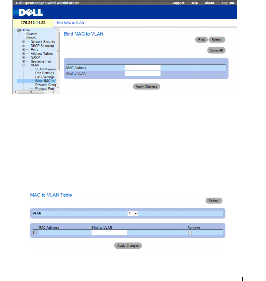
Configuring Switch Information 363
To bind MAC addresses to a VLAN, ensure the VLAN ports were dynamically added, and are not static
VLAN ports.
To open the Bind MAC to VLAN page, click Switch→ VLAN→ Bind MAC to VLAN.
Figure 7-52. Bind MAC to VLAN
The Bind MAC to VLAN page contains the following fields:
•
MAC Address
— Indicates the MAC Address which is bound to the VLAN.
•
Bind to VLAN
— Indicates the VLAN to which the MAC address is bound. The possible values
are 1-4094.
Displaying the MAC to VLAN Table:
1
Open the
Bind MAC to VLAN
page.
2
Click
Show All
.
The
MAC to VLAN Table
opens.
Figure 7-53. MAC to VLAN Table

364 Configuring Switch Information
Removing a MAC to VLAN Binding:
1
Open the
Bind MAC to VLAN
page.
2
Click
Show All
. The
MAC to VLAN Table
opens.
3
Select the desired VLAN, or select
All
to see bindings for all VLANs.
4
Select the
Remove
checkbox next to the desired bindings.
5
Click
Apply Changes
.
Binding MAC address to VLAN using CLI commands:
The following table summarizes the equivalent CLI commands for binding MAC addresses to VLAN.
The following is an example of the CLI commands:
console(config-vlan)# mac-to-vlan 0060.704c.73ff 123
console(config-vlan)# exit
console(config)# exit
console# show vlan mac-to-vlan
MAC Address VLAN
------------ ------
0060.704c.73ff 123
Defining VLAN Protocol Groups
The Protocol Group page provides parameters for configuring frame types to specific protocol groups.
To open the Protocol Group page, click Switch → VLAN → Protocol Group in the tree view.
Table 7-29. Binding MAC address to VLANs CLI Commands
CLI Command Description
mac-to-vlan mac-address vlan-id Binds the MAC address to the VLAN.
switchport access vlan dynamic Configures private VLANs.
show mac-to-vlan Displays the MAC to VLAN database
no mac-to-vlan mac-address Unbinds the MAC address from the VLAN.
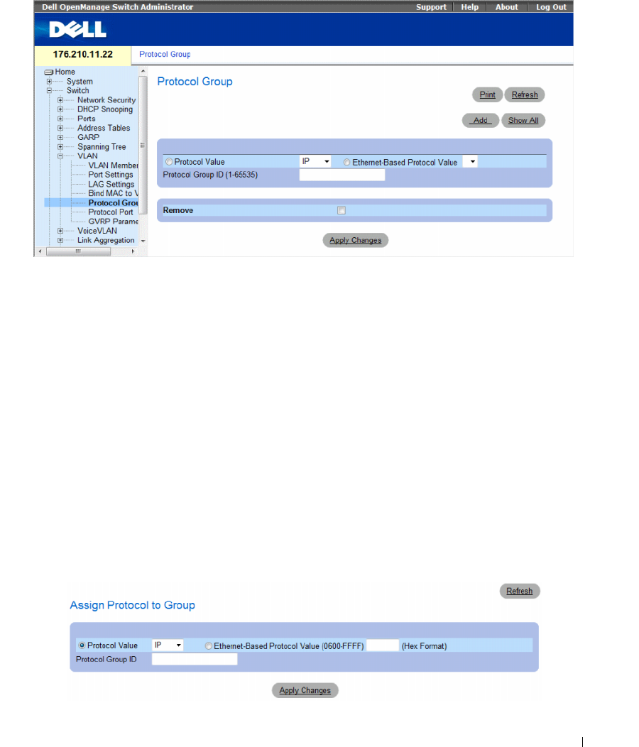
Configuring Switch Information 365
Figure 7-54. Protocol Group
•
Protocol Value —
Displays the User-defined protocol value. The options are as follows:
–
Protocol Value
— User-defined protocol name. The possible field values are
IP
,
IPX
and
ARP
.
–
Ethernet-Based Protocol Value
— The Ethernet protocol group type.
•
Protocol Group ID (1-65535)
— The VLAN Group ID number.
•
Remove
— Indicates whether to remove frame-to-protocol group mapping, if the protocol group to be
removed is not configured on this protocol port.
–
Checked
— Removes the protocol group mapping.
–
Unchecked
— Maintains the protocol group mapping.
Assigning a Protocol to a Group
1
Open the
Protocol Group
page.
2
Click
Add.
The
Assign Protocol To Group
page opens.
Figure 7-55. Assign Protocol To Group
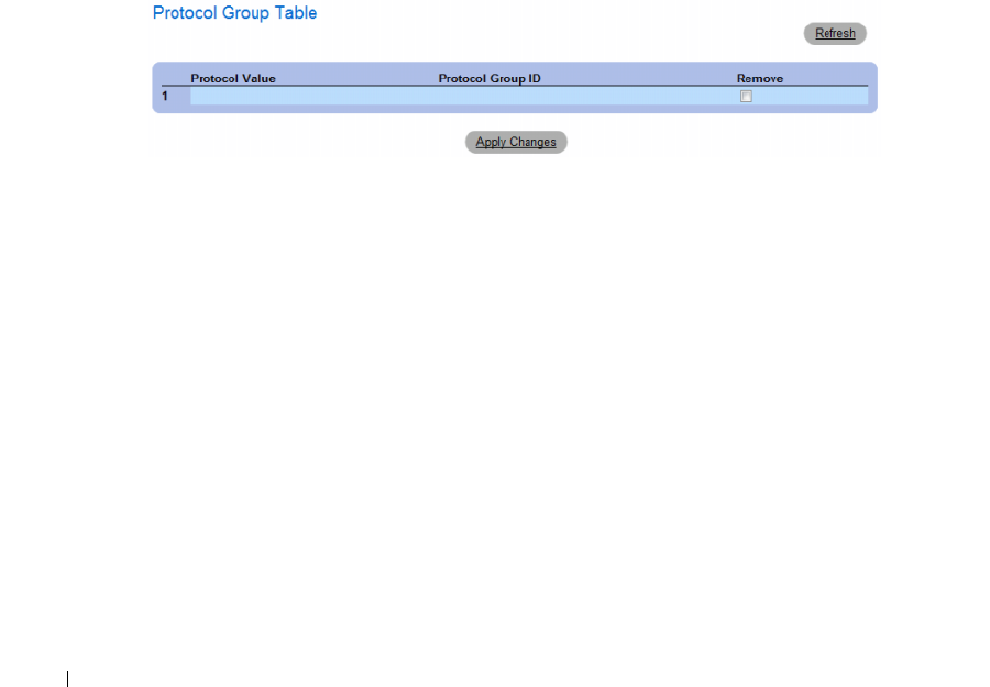
366 Configuring Switch Information
3
Complete the fields on the page.
4
Click
Apply Changes
.
The protocol group is assigned, and the device is updated.
Assigning VLAN Protocol Group Settings
1
Open the
Protocol Group
page.
2
Complete the fields on the page.
3
Click
Apply Changes
.
The VLAN protocol group parameters are defined, and the device is updated.
Removing Protocols From the Protocol Group Table
1
Open the
Protocol Group
page.
2
Click
Show All
.
The
Protocol Group Table
opens.
Figure 7-56. Protocol Group Table
3
Select
Remove
for the protocol groups that need to be removed.
4
Click
Apply Changes
.
The protocol is removed, and the device is updated.
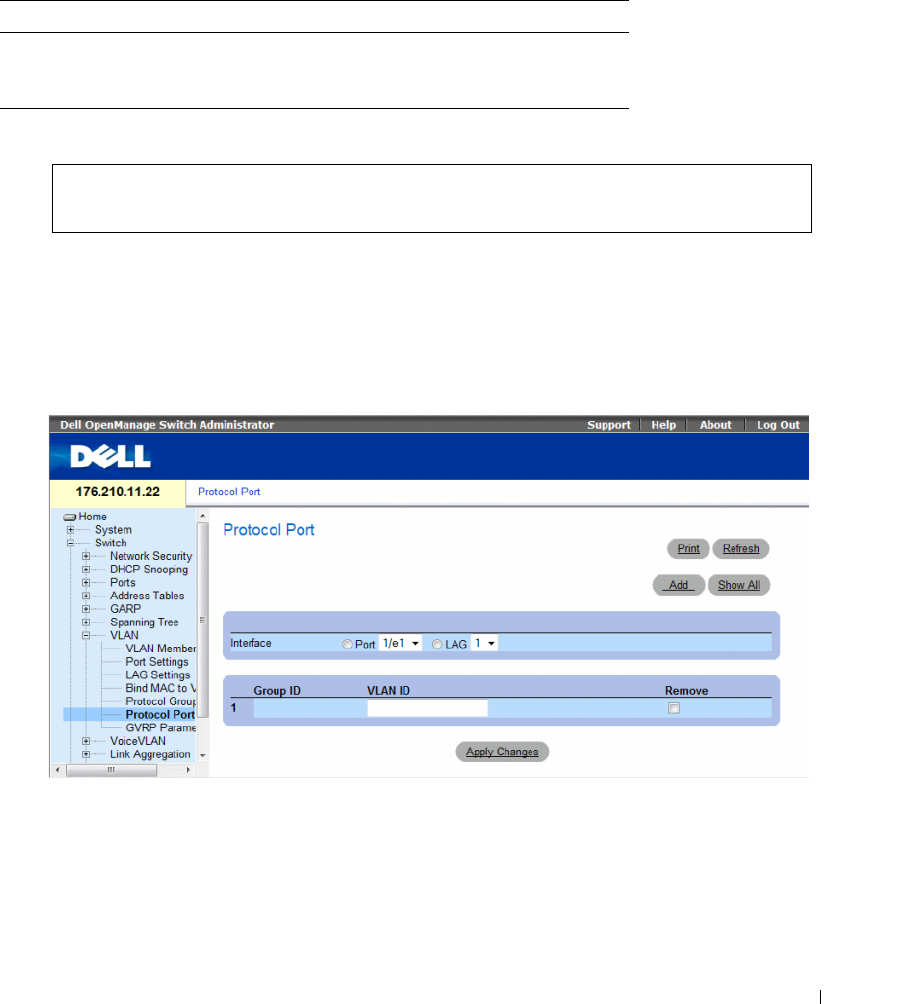
Configuring Switch Information 367
Defining VLAN Protocol Groups Using CLI Commands
The following table summarizes the equivalent CLI commands for configuring Protocol Groups.
Table 7-30. VLAN Protocol Groups CLI Commands
The following example maps ip-arp protocol to group "213":
Adding Interfaces to Protocol Groups
The Protocol Port page adds interfaces to Protocol groups.
To open the Protocol Port page, click Switch → VLAN → Protocol Port in the tree view.
Figure 7-57. Protocol Port
•
Interface
— Port or LAG number added to a protocol group.
•
Group ID
— Protocol group ID to which the interface is added. Protocol group IDs are defined in the
Protocol Group Table.
CLI Command Description
map protocol protocol [encapsulation]
protocols-group group
Maps a protocol to a protocol group.
Protocol groups are used for protocol-
based VLAN assignment.
Console (config)# vlan database
Console (config-vlan)# map protocol ip-arp protocols-group 213
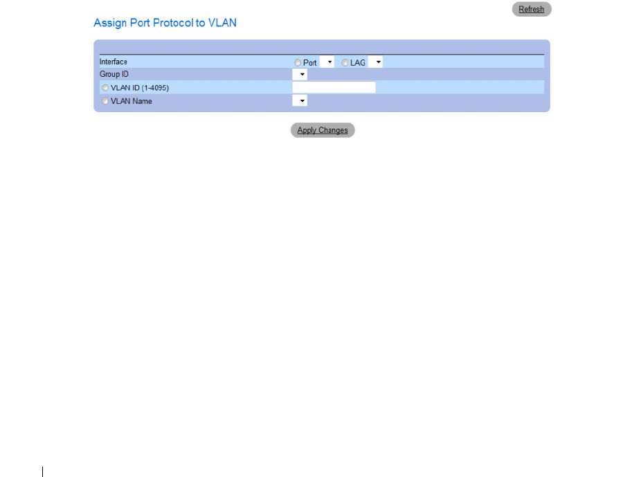
368 Configuring Switch Information
•
VLAN ID
— Attaches the interface to a user-defined VLAN ID. The VLAN ID is defined on the
Create a New VLAN
page. Protocol ports can either be attached to a
VLAN ID or a VLAN name.
The possible values are 1-4095. VLAN 4095 is the discard VLAN.
•
Remove
— Indicates whether to remove the selected interface from its protocol group.
–
Checked
— Removes the selected interface.
–
Unchecked
— Maintains the selected interface.
Adding a New Protocol Port to a VLAN
Protocol ports can be defined only on ports that are defined as General in the VLAN Port Settings page.
1
Open the
Protocol Port
page.
2
Click
Add
.
The
Assign Protocol Port To VLAN
page opens.
Figure 7-58. Assign Protocol Port To VLAN
3
Complete the fields in the dialog.
4
Click
Apply Changes
.
The new VLAN protocol group is added to the
Protocol Port Table
, and the device is updated.
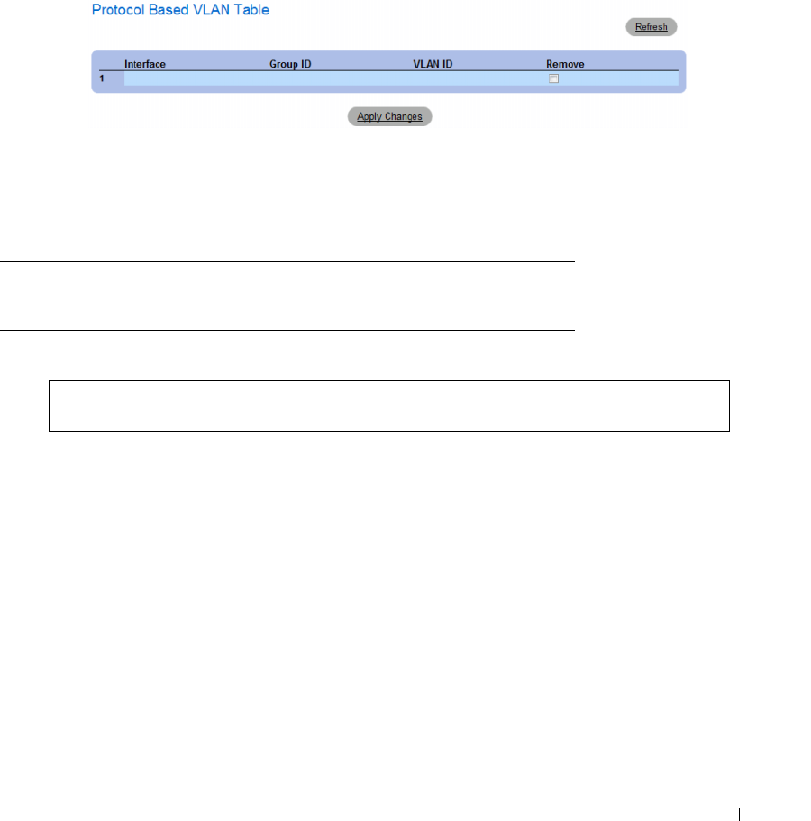
Configuring Switch Information 369
Displaying Protocols Assigned to Ports
1
Open the
Protocol Port
page.
2
Click
Show All
.
The
Protocol Based VLAN Table
opens.
Figure 7-59. Protocol Based VLAN Table
Defining Protocol Ports Using CLI Commands
The following table summarizes the equivalent CLI command for defining Protocol Ports.
Table 7-31. Protocol Port CLI Commands
The following example sets a protocol-based classification rule of protocol group 1 to VLAN 8:
Configuring GVRP Parameters
GARP VLAN Registration Protocol (GVRP) is specifically provided for automatic distribution of VLAN
membership information among VLAN-aware bridges. GVRP allows VLAN-aware bridges to
automatically learn VLANs to bridge ports mapping, without having to individually configure each
bridge and register VLAN membership.
To ensure the correct operation of the GVRP protocol, it is advised to set the maximum number of
GVRP VLANs equal to a value which significantly exceeds the sum of:
• The number of all static VLANs both currently configured and expected to be configured.
• The number of all dynamic VLANs participating in GVRP, both currently configured (initial number of
dynamic GVRP VLANs is 128) and expected to be configured.
CLI Command Description
switchport general map
protocols-group group
vlan vlan-id
Sets a protocol-based classification rule.
Console (config-if)# switchport general map protocols-group 1
vlan 8
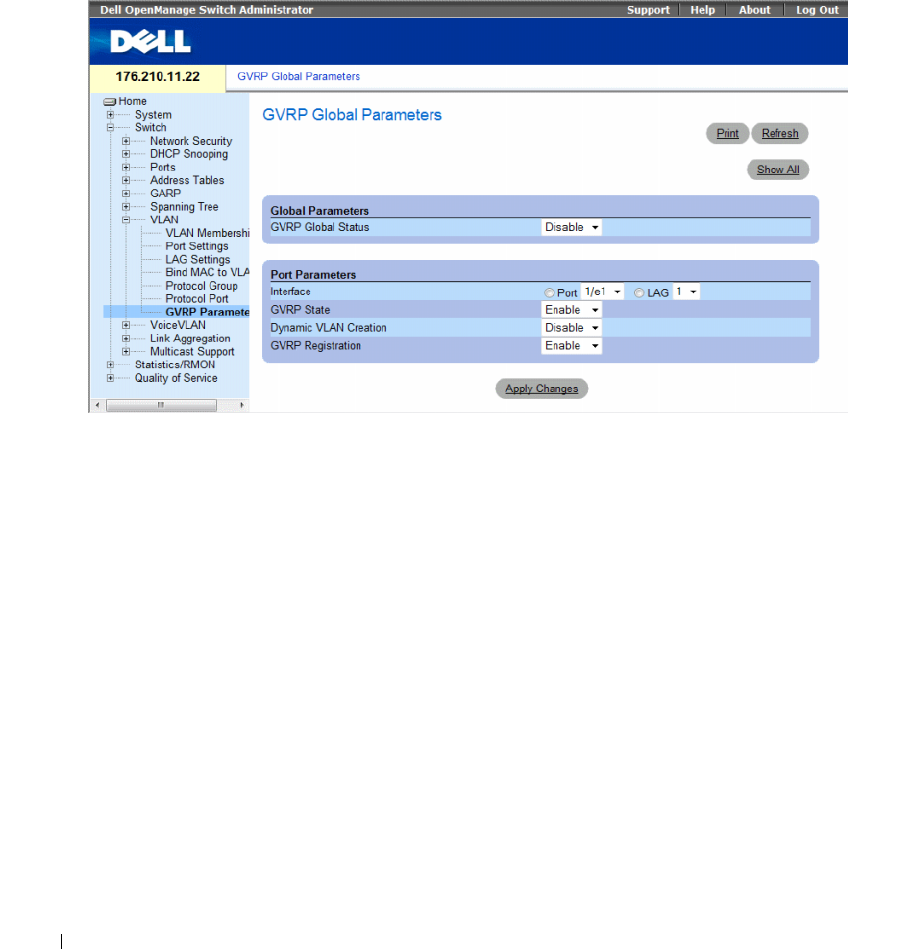
370 Configuring Switch Information
The GVRP Global Parameters page enables GVRP globally. GVRP can also be enabled on a per-interface
basis.
To open the GVRP Global Parameters page, click Switch → VLAN → GVRP Parameters in the tree view.
Figure 7-60. GVRP Global Parameters
The GVRP Global Parameters page contains the following fields:
Global Parameters
•
GVRP Global Status
— Indicates if GVRP is enabled on the device. The possible field values are:
–
Enable
— Enables GVRP on the selected device.
–
Disable
— Disables GVRP on the selected device. GVRP is disabled by default.
Port Parameters
•
Interface
— Specifies port or LAG for editing GVRP settings.
•
GVRP State
— Indicates if GVRP is enabled on the interface. The possible field values are:
–
Enabled
— Enables GVRP on the selected interface.
–
Disabled
— Disables GVRP on the selected interface.

Configuring Switch Information 371
•
Dynamic VLAN Creation
— Indicates if Dynamic VLAN creation is enabled on the interface.
The possible field values are:
–
Enabled
— Enables Dynamic VLAN creation on the interface.
–
Disabled
— Disables Dynamic VLAN creation on the interface.
•
GVRP Registration
— Indicates if VLAN registration through GVRP is enabled on the interface.
The possible field values are:
–
Enabled
— Enables GVRP registration on the interface.
–
Disabled
— Disables GVRP registration on the interface.
Enabling GVRP on the Device
1
Open the
GVRP Global Parameters
page.
2
Select
Enable
in the
GVRP Global Status
field.
3
Click
Apply Changes
.
GVRP is enabled on the device.
Enabling VLAN Registration Through GVRP
1
Open the
GVRP Global Parameters
page.
2
Select
Enable
in the
GVRP Global Status
.
3
Select
Enable
in the GVRP State field for the desired interface.
4
Select
Enable
in the
GVRP Registration
field.
5
Click
Apply Changes
.
GVRP VLAN Registration is enabled on the port, and the device is updated.
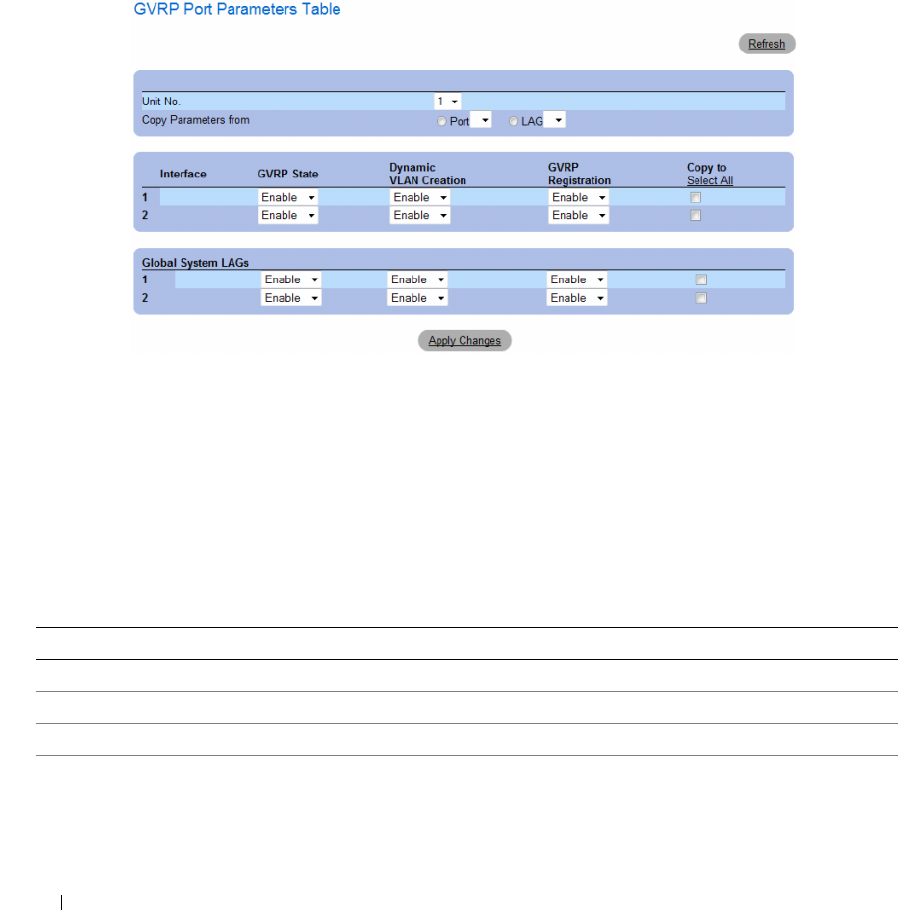
372 Configuring Switch Information
Displaying the GVRP Port Parameters Table
1
Open the
GVRP Global Parameters
page.
2
Click
Show All
.
The
GVRP Port Parameters Table
opens.
Figure 7-61. GVRP Port Parameters Table
In addition to the GVRP Global Parameters screen, the GVRP Port Parameters Table contains the
following field:
Copy Parameters from — The port or LAG from which parameters will be copied and assigned to other
interfaces.
Configuring GVRP Using CLI Commands
The following table summarizes the equivalent CLI commands for configuring GVRP as displayed in the
GVRP Global Parameters page.
Table 7-32. GVRP Global Parameters CLI Commands
CLI Command Description
gvrp enable (global)Enables GVRP globally.
gvrp enable (interface) Enables GVRP on an interface.
gvrp vlan-creation-forbid Enables or disables dynamic VLAN creation.
gvrp registration-forbid De-registers all dynamic VLANs, and prevents dynamic
VLAN registration on the port.

Configuring Switch Information 373
The following is an example of the CLI commands:
show gvrp configuration [ethernet interface| port-
channel port-channel-number]
Displays GVRP configuration information, including
timer values, whether GVRP and dynamic VLAN
creation is enabled, and which ports are running GVRP.
show gvrp error-statistics [ethernet interface| port-
channel port-channel-number]
Displays GVRP error statistics.
show gvrp statistics [ ethernet interface| port-channel
port-channel-number]
Displays GVRP statistics.
clear gvrp statistics [ ethernet interface| port-channel
port-channel-number]
Clears all the GVRP statistics information.
Table 7-32. GVRP Global Parameters CLI Commands (continued)
CLI Command Description
console(config)# gvrp enable
console(config)# interface ethernet 1/e1
console(config-if)# gvrp enable
console(config-if)# gvrp vlan-creation-forbid
console(config-if)# gvrp registration-forbid
console(config-if)# end
console# show gvrp configuration
GVRP Feature is currently Enabled on the device
Maximum VLANs: 223
Port(s) GVRP-
Status
Registration Dynamic
VLAN
Creation
Timers
(milliseconds)
Join
Leave Leave
All
------- ------ ------------ -------- -------------- ----- -----
1/e11 Enabled Forbidden Disabled 200 900 10000
1/e12 Disabled Normal Enabled 200 600 10000

374 Configuring Switch Information
Configuring Voice VLAN
Voice VLAN allows network administrators enhance VoIP service by configuring ports to carry IP voice
traffic from IP phones on a specific VLAN. VoIP traffic has a preconfigured OUI prefix in the source
MAC address. Network Administrators can configure VLANs on which voice IP traffic is forwarded.
Non-VoIP traffic is dropped from the Voice VLAN in auto Voice VLAN secure mode. Voice VLAN also
provides QoS to VoIP, ensuring that the quality of voice does not deteriorate if the IP traffic is received
unevenly. The system supports one Voice VLAN.
There are two operational modes for IP Phones:
• IP phones are configured with VLAN-mode as enabled, ensuring that tagged packets are used for all
communications.
• If the IP phone’s VLAN-mode is disabled, the phone uses untagged packets. The phone uses untagged
packets while retrieving the initial IP address through DHCP. The phone eventually use the Voice
VLAN and start sending tagged packets.
This section contains the following topics:
• Defining Voice VLAN Properties Page
• Defining Voice VLAN Port Settings
• Defining OUIs
This section contians the following topics:
• "Defining Voice VLAN Global Parameters" on page 374
• "Defining Voice VLAN Port Settings" on page 377
• "Defining OUIs" on page 379
Defining Voice VLAN Global Parameters
The Voice VLAN Global Parameters page contains parameters that apply to all Voice VLANs on the
device.
To open the Voice VLAN Global Parameters page, click Switch→ Voice VLAN → Global Parameters
in the tree view.
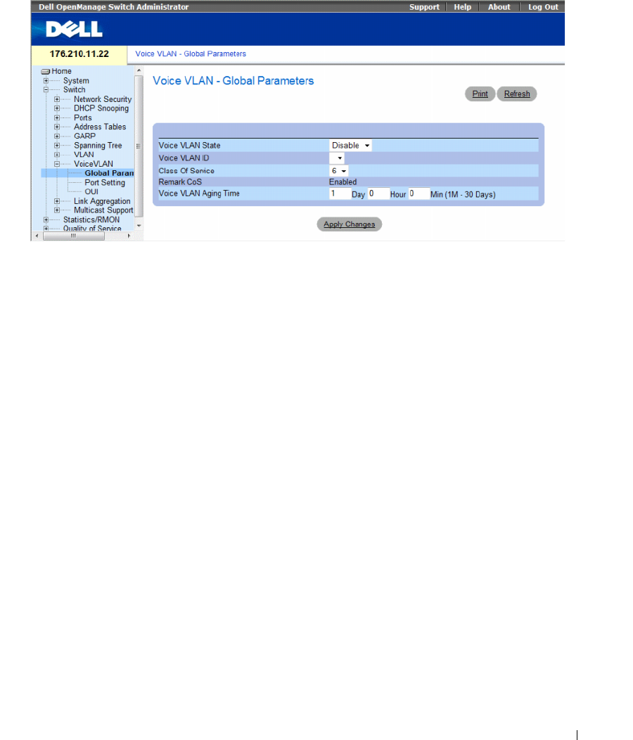
Configuring Switch Information 375
Figure 7-62. Voice VLAN Global Parameters
•
Voice VLAN Status
— Indicates if Voice VLAN is enabled on the device. The possible field values are:
–
Enable
— Enables Voice VLAN on the device.
–
Disable
— Disables Voice VLAN on the device. This is the default value.
•
Voice VLAN ID
— Defines the Voice VLAN ID number.
•
Class of Service
— Enables adding a CoS tag to untagged packets received on the voice VLAN.
The possible field values are 0-7, where zero is the lowest priority, and seven is the highest priority.
•
Remark CoS
— Indicates that the Remark CoS is always enabled.
•
Voice VLAN Aging Time
— Indicates the amount of time after the last IP phone's OUI is aged out for
a specific port. The port will age out after the bridge and voice aging time. The default time is one day.
The field format is Day, Hour, Minute. The aging time starts after the MAC Address is aged out from
the Dynamic MAC Address table. The default time is 300 sec. For more information on defining
MAC address age out time, see Defining Aging Time.
Configuring Voice VLAN global parameters:
1
Open the
Voice VLAN Global Parameters
page.
2
Complete the fields on the page.
3
Click
Apply Changes
.
The Voice VLAN global parameters are defined, and the device is updated.

376 Configuring Switch Information
Defining Voice VLAN Global Parameters Using CLI Commands
The following table summarizes the equivalent CLI command for defining Voice VLAN global parameters.
The following is an example of some of the CLI commands:
Table 7-33. Voice VLAN Global Parameters CLI Commands
CLI Command Description
voice vlan id vlan-id
no voice vlan id
To enable the voice VLAN and to configure the voice VLAN ID, use the
voice vlan id command in global configuration mode. To disable the
voice VLAN, enter the no form of this command.
voice vlan cos cos
no voice vlan cos
To set the voice VLAN Class Of Service, use the voice vlan cos
command in global configuration mode. To return to default, use the
no form of this command.
voice vlan aging-timeout minutes
no voice aging-timeout
To set the voice VLAN aging timeout, use the voice vlan aging-timeout
command in global configuration mode. To return to default, use the
no form of this command.
voice vlan enable Use the voice vlan enable interface configuration command to enable
automatic voice VLAN configuration for a port. Use the no form of this
command to disable automatic voice VLAN configuration.
show voice vlan [ ethernet interface |
port-channel port-channel-number ]
Use the show voice vlan EXEC command to display the voice VLAN
status.
Switch# show voice
vlan
Aging timeout: 1440
minutes
OUI table
MAC Address - Prefix Description
00:E0:BB 3COM
00:03:6B Cisco
00:E0:75 Veritel
00:D0:1E Pingtel
00:01:E3 Siemens
00:60:B9 NEC/Philips
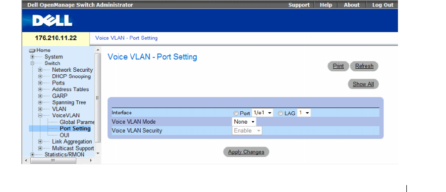
Configuring Switch Information 377
Defining Voice VLAN Port Settings
The Voice VLAN Port Settings Page contains fields for adding ports or LAGs to voice VLAN.
To open the Voice VLAN Port Setting page, click Switch→ Voice VLAN → Port Setting in the tree view.
Figure 7-63. Voice VLAN Port Setting
00:0F:E2 Huawei-3COM
Voice VLAN VLAN ID: 8
CoS: 6
Remark: Yes
Interface Enabled Secure Activated
------ ------ ------ ------
1/e1 Yes Yes Yes
1/e2 Yes Yes Yes
1/e3 Yes Yes Yes
1/e4 Yes Yes Yes
1/e5 No No -
1/e6 No No -
1/e7 No No -
1/e8 No No -
1/e9 No No -
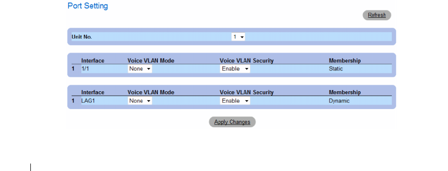
378 Configuring Switch Information
•
Interface
— Indicates the specific port or and LAG to which the Voice VLAN settings are applied.
•
Voice VLAN Mode
— Defines the Voice VLAN mode. The possible field values are:
–
None
— Disables the selected port/LAG on the Voice VLAN.
–
Static
— Maintains the current Voice VLAN port/LAG settings. This is the default value.
–
Auto
— Indicates that if traffic with an IP Phone MAC Address is transmitted on the port/LAG,
the port/LAG joins the Voice VLAN. The port/LAG is aged out of the voice VLAN if the IP
phone’s MAC address (with an OUI prefix) is aged out and exceeds the defined. If the MAC
Address of the IP phones OUI was added manually to a port/LAG in the Voice VLAN, the user
cannot add it to the Voice VLAN in Auto mode, only in Manual mode.
•
Voice VLAN Port/LAG Security
— Indicates if port/LAG security is enabled on the Voice VLAN.
Port Security ensures that packets arriving with an unrecognized OUI are dropped.
–
Enable
— Enables port security on the Voice VLAN.
–
Disable
— Disables port security on the Voice VLAN. This is the default value.
Configuring Port Settings
1
Open the
Voice VLAN Port Settings
page.
2
Select a port or LAG.
3
Modify the fields as desired.
4
Click
Apply Changes
.
The settings are modified and the device is updated.
Displaying the Port Setting Table
1
Open the
Voice VLAN Port Settings
page.
2
Click
Show All
. The Port Setting Table opens.
Figure 7-64. Voice VLAN Port Setting Table

Configuring Switch Information 379
The
Voice VLAN Port Setting Table
includes the
Membership
field which indicates if the Voice VLAN
member is a static or dynamic member. The field value
Dynamic
indicates the VLAN membership was
dynamically created through GARP. The field value
Static
indicates the VLAN membership is user-defined.
3
Select the unit number.
4
Modify the fields as desired.
5
Click
Apply Changes
.
Defining Voice VLAN Port Settings Using CLI Commands
The following table summarizes the equivalent CLI command for defining Voice VLAN port settings.
Defining OUIs
The Voice VLAN OUI page lists the Organizationally Unique Identifiers (OUIs) associated with the
Voice VLAN. The first three bytes of the MAC Address contain a manufacturer identifier. While the last
three bytes contain a unique station ID. Using the OUI, network managers can add specific
manufacturer’s MAC addresses to the OUI table. Once the OUIs are added, all traffic received on the
Voice VLAN ports from the specific IP phone with a listed OUI, is forwarded on the voice VLAN.
To open the Voice VLAN OUI page, click Switch→ Voice VLAN → OUI in the tree view.
Table 7-34. Voice VLAN Port Settings CLI Commands
CLI Command Description
voice vlan secure
no voice vlan secure
Use the voice vlan secure interface configuration command to configure the secure mode
for the voice VLAN. Use the no form of this command to disable the secure mode.
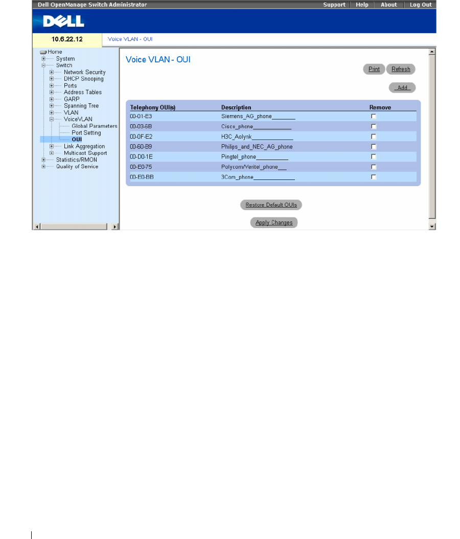
380 Configuring Switch Information
Figure 7-65. Voice VLAN OUI
•
Telephony OUI(s)
— Lists the OUIs currently enabled on the Voice VLAN. The following OUIs are
enabled by default.
– 00-01-E3 — Siemens AG phone
– 00-03-6B — Cisco phone
– 00-0F-E2 — H3C Aolynk
– 00-60-B9 — Philips and NEC AG phone
– 00-D0-1E — Pingtel phone
– 00-E0-75 — Polycom/Veritel phone
– 00-E0-BB — 3COM phone
•
Description
— Provides an OUI description up to 32 characters.
•
Remove
— Removes OUI from the Telephony OUI List. The possible field values are:
–
Checked
— Removes the selected OUI.
–
Unchecked
— Maintains the current OUIs in the Telephony OUI List. This is the default value.
•
Restore Default OUIs
— Restores OUIs to the factory defaults.
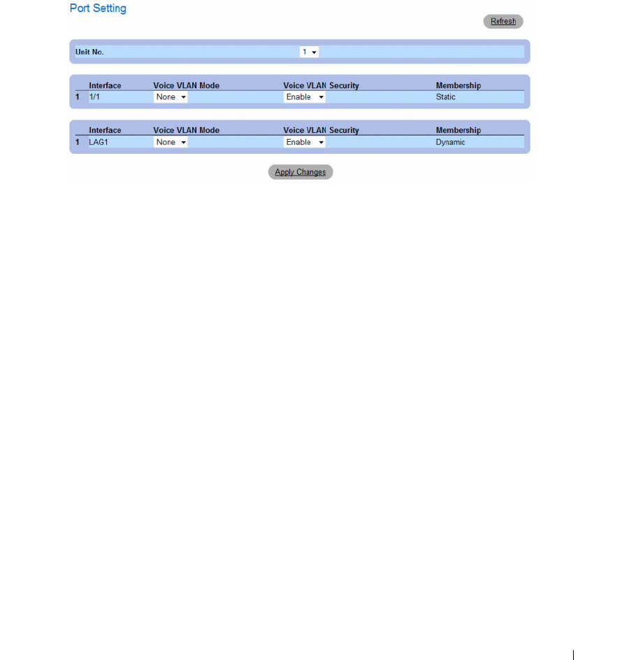
Configuring Switch Information 381
Adding OUIs
1
Open the
Voice VLAN OUI
page.
2
Click
Add
. The Add OUI page opens.
Figure 7-66. Voice VLAN Add OUI Page
3
Fill in the fields.
4
Click
Apply Changes
.
The OUIs is added.
Removing OUIs
1
Open the
Voice VLAN OUI
page.
2
Check the
Remove
checkbox next to teach OUI to be removed.
3
Click
Apply Changes
.
The selected OUIs are removed.
Restoring Default OUIs
1
Open the
Voice VLAN OUI
page.
2
Click
Restore Default OUIs
.
The default OUIs are restored.

382 Configuring Switch Information
Defining Voice VLAN OUIs Using CLI Commands
The following table summarizes the equivalent CLI command for defining Voice VLAN OUIs.
Aggregating Ports
Link Aggregation optimizes port usage by linking a group of ports together to form a single LAG
(aggregated group). Aggregating ports multiplies the bandwidth between the devices, increases port
flexibility, and provides link redundancy.
The device supports both static LAGs and Link Aggregation Control Protocol (LACP) LAGs. LACP
LAGs negotiate aggregating port’s links with other LACP ports located on a different device. If the other
device ports are also LACP ports, the devices establish a LAG between them.
Consider the following when aggregating ports:
• All ports within a LAG must be the same media type.
• A VLAN is not configured on the port.
• The port is not assigned to a different LAG.
• Auto-negotiation mode is not configured on the port.
• The port is in full-duplex mode.
• All ports in the LAG have the same ingress filtering and tagged modes.
• All ports in the LAG have the same back pressure and flow control modes.
• All ports in the LAG have the same priority.
• All ports in the LAG have the same transceiver type.
• The device supports up to eight LAGs, and eight ports in each LAG.
• Ports can be configured as LACP ports only if the ports are not part of a previously configured LAG.
Ports added to a LAG lose their individual port configuration. When ports are removed from the LAG,
the original port configuration is applied to the ports.
The device uses a hash function to determine which packets are carried on which aggregated-link
member. The hash function statistically load-balances the aggregated link members. The device
considers an Aggregated Link a single logical port.
Aggregate ports can be linked into link-aggregation port-groups. Each group comprises ports with the
same speed, set to full-duplex operations.
Table 7-35. Voice VLAN OUIs CLI Commands
CLI Command Description
voice vlan oui-table {add mac-address-prefix
[description text] | remove mac-address-
prefix}
no voice vlan oui-table
To configure the voice OUI table, use the voice vlan oui-table
command in global configuration mode. To return to default,
use the no form of this command.
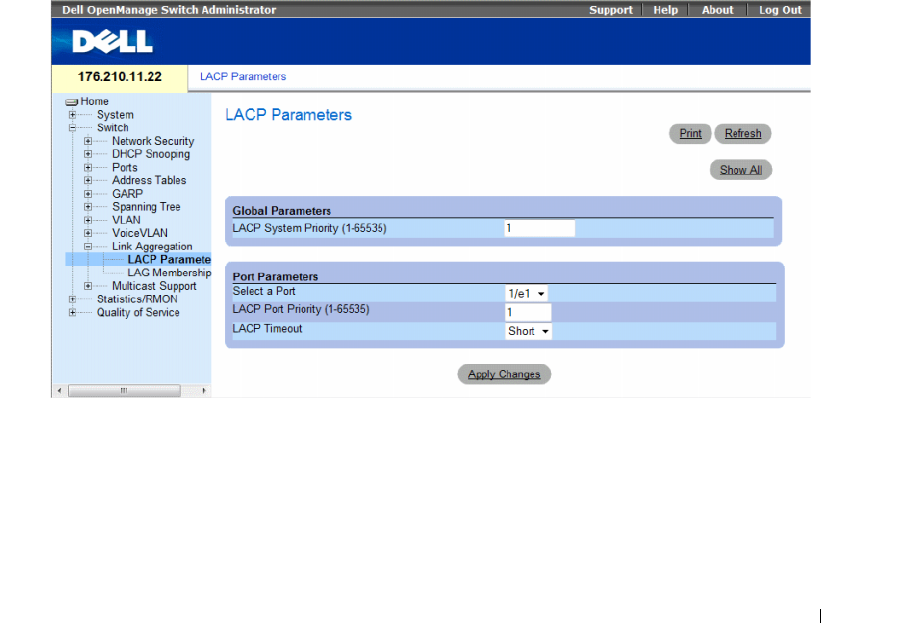
Configuring Switch Information 383
Ports in a Link Aggregated group (LAG) can contain different media types if the ports are operating at
the same speed. Aggregated links can be manually or automatically configured by enabling Link
Aggregation Control Protocol (LACP) on the relevant links.
This section contians the following topics:
• "Defining LACP Parameters" on page 383
• "Defining LAG Membership" on page 385
Defining LACP Parameters
The LACP Parameters page contains fields for configuring LACP LAGs. Aggregate ports can be linked
into link-aggregation port-groups. Each group is comprised of ports with the same speed. Aggregated
Links can be manually setup or automatically established by enabling Link Aggregation Control
Protocol (LACP) on the relevant links.
To open the LACP Parameters page, click Switch → Link Aggregation → LACP Parameters in the tree
view.
Figure 7-67. LACP Parameters
The LACP Parameters page contains the following fields:
•
LACP System Priority
(1-65535)
— The LACP priority value for global settings. The possible range is
1- 65535. The default value is 1.
•
Select a Port
— The port number to which timeout and priority values are assigned.
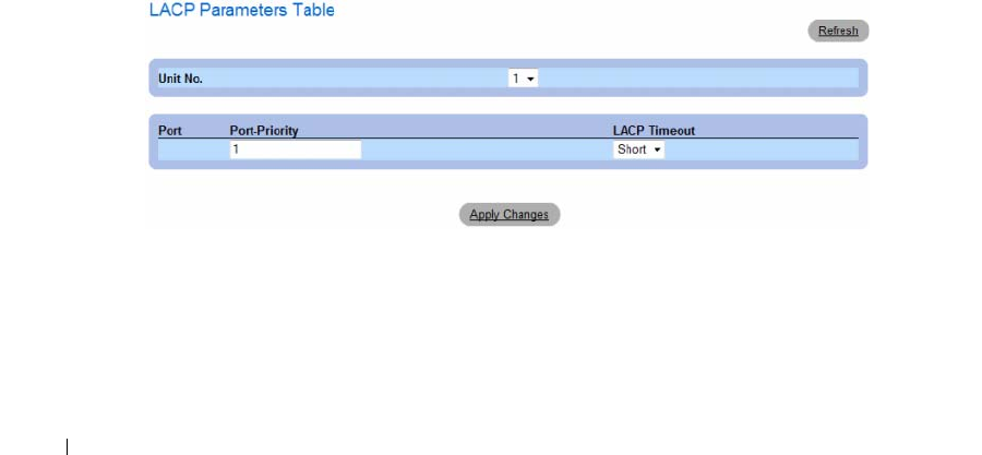
384 Configuring Switch Information
•
LACP Port Priority (1-65535)
— LACP priority value for the port.
•
LACP Timeout
— Administrative LACP timeout. The possible field values are:
–
Short
— Specifies a short timeout value.
–
Long
— Specifies a long timeout value.
Defining Link Aggregation Global Parameters
1
Open the
LACP Parameters
page.
2
Complete the
LACP System Priority
field.
3
Click
Apply Changes
.
The parameters are defined, and the device is updated.
Defining Link Aggregation Port Parameters
1
Open the
LACP Parameters
page.
2
Complete the fields in the
Port Parameters
area.
3
Click
Apply Changes
.
The parameters are defined, and the device is updated.
Displaying the LACP Parameters Table
1
Open the
LACP Parameters
page.
2
Click
Show All
.
The
LACP Parameters Table
opens.
Figure 7-68. LACP Parameters Table

Configuring Switch Information 385
Configuring LACP Parameters Using CLI Commands
The following table summarizes the equivalent CLI commands for configuring LACP parameters as
displayed in the LACP Parameters page.
The following is an example of the CLI commands:
Defining LAG Membership
The device supports fifteen LAGs per system, and eight ports per LAG, whether the device is a
stand-alone device or in a stack.
When a port is added to a LAG, the port acquires the LAG’s properties. If the port cannot be configured
with the LAG’s properties, it is not added to the LAG. An error message is generated. However, if the first
port joining the LAG cannot be configured with the LAG settings, the port is added to the LAG, using
the port default settings. An error message is generated. However, as this is the only port in the LAG, the
entire LAG operates with the port’s settings, instead of the LAG’s defined settings.
Use the LAG Membership page to assign ports to LAGs.
To open the LAG Membership page, click Switch → Link Aggregation → LAG Membership in the
tree view.
Table 7-36. LACP Parameters CLI Commands
CLI Command Description
lacp system-priority value Configures the system priority.
lacp port-priority value Configures the priority value for physical ports.
lacp timeout {long | short}Assigns an administrative LACP timeout.
show lacp ethernet interface [parameters |
statistics | protocol-state]
Displays LACP information for ethernet ports.
Console (config)# lacp system-priority 120
Console (config)# interface ethernet 1/e11
Console (config-if)# lacp port-priority 247
Console (config-if)# lacp timeout long
Console (config-if)# end
Console# show lacp ethernet 1/e11 statistics
Port 1/e11 LACP Statistics:
LACP PDUs sent:2
LACP PDUs received:2
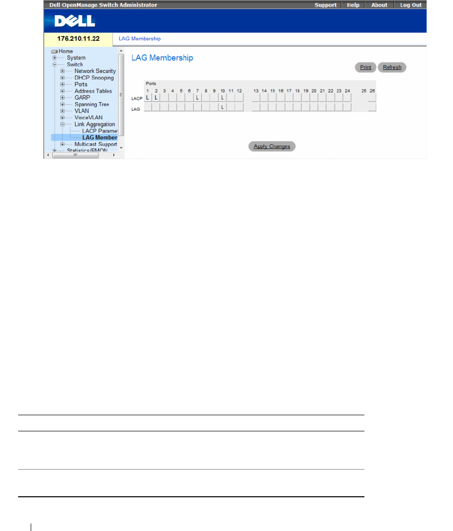
386 Configuring Switch Information
Figure 7-69. LAG Membership
The LAG Membership page contains the following fields:
•
LACP
— Aggregates the port to a LAG, using LACP.
•
LAG
— Adds a port to a LAG, and indicates the specific LAG to which the port belongs.
Adding Ports to a LAG or LACP
1
Open the
LAG Membership
page.
2
In the LAG row (the second row), toggle the button to a specific number to aggregate or remove the
port to that LAG number.
3
In the LACP row (the first row), toggle the button under the port number to assign either the LACP or
the static LAG.
4
Click
Apply Changes
.
The port is added to the LAG or LACP, and the device is updated.
Adding Ports to LAGs Using CLI Commands
The following table summarizes the equivalent CLI commands for assigning ports to LAGs as displayed
in the LAG Membership page.
Table 7-37. LAG Membership CLI Commands
CLI Command Description
channel-group
port-
channel-number
mode
{on | auto}
Associates a port with a port-channel. Use the no form of
this command to remove the channel-group configuration
from the interface.
show interfaces port-channel
[port-channel-number]
Displays port-channel information.

Configuring Switch Information 387
The following is an example of the CLI commands:
Multicast Forwarding Support
Multicast forwarding allows a single packet to be forwarded to multiple destinations. Layer 2 Multicast
service is based on Layer 2 device receiving a single packet addressed to a specific Multicast address.
Multicast forwarding creates copies of the packet, and transmits the packets to the relevant ports.
•
Registered Multicast traffic
— If traffic addressed to a registered multicast group is seen it is handled
by an entry in the Multicast Filtering Database and forwarded only to the registered ports.
•
Unregistered Multicast traffic
— If traffic addressed to an unregistered Multicast group is seen, it is
handled by a special entry in the Multicast Filtering Database. The default setting of this is to flood all
such traffic (traffic in unregistered Multicast groups).
The device supports:
•
Forwarding L2 Multicast Packets
— Forwards Layer 2 Multicast packets. Layer 2 Multicast filtering is
enabled by default, and not user-configurable.
The system supports Multicast filtering for 256 Multicast groups.
•
Filtering L2 Multicast Packets
— Forwards Layer 2 packets to interfaces. If Multicast filtering is
disabled, Multicast packets are flooded to all relevant ports.
To open the Multicast Support page, click Switch → Multicast Support in the tree view.
This section contians the following topics:
• "Defining Multicast Global Parameters" on page 387
• "Adding Bridge Multicast Address Members" on page 389
• "Assigning Multicast Forward All Parameters" on page 394
• "IGMP Snooping" on page 396
Defining Multicast Global Parameters
Layer 2 switching forwards Multicast packets to all relevant VLAN ports by default, managing the packet
as a single Multicast transmission. While Multicast traffic forwarding is effective, it is not optimal, as
irrelevant ports also receive the Multicast packets. The excess packets cause increased network traffic.
Multicast forwarding filters enable forwarding of Layer 2 packets to port subsets.
When IGMP Snooping is enabled globally, all IGMP packets are forwarded to the CPU. The CPU
analyzes the incoming packets and determines:
• Which ports want to join which Multicast groups.
• Which ports have Multicast routers generating IGMP queries.
• What routing protocols are forwarding packets and Multicast traffic.
console(config)# interface ethernet 1/e11
console(config-if)# channel-group 1 mode on
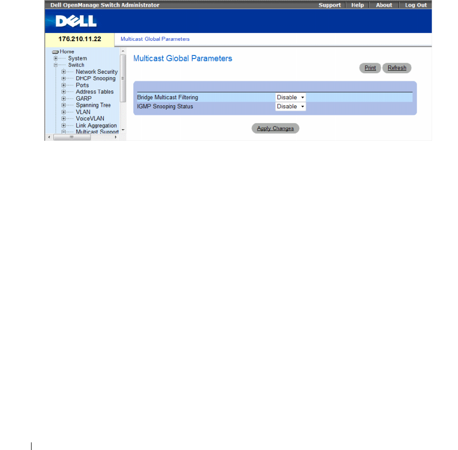
388 Configuring Switch Information
Ports requesting to join a specific Multicast group issue an IGMP report, specifying that Multicast group
is accepting members. This results in the creation of the Multicast filtering database.
The Global Parameters page contains fields for enabling IGMP Snooping on the device.
To open the Global Parameters page, click Switch → Multicast Support → Global Parameters in the tree
view.
Figure 7-70. Global Parameters
The
Global Parameters
page contains the following fields:
•
Bridge Multicast Filtering
— Enables or disables bridge Multicast filtering. Disabled is the default
value.
–
Enable
— Enables bridge multicast filtering on the device.
–
Disable
— Disables bridge multicast filtering on the device.
•
IGMP Snooping Status
— Enables or disables IGMP Snooping on the device. Disabled is the default
value. IGMP Snooping can be enabled only if
Global Parameters
is enabled.
– Enable — Enables IGMP Snooping on the device.
– Disable — Disables IGMP Snooping on the device.
Enabling Bridge Multicast Filtering on the device
1
Open the
Global Parameters
page.
2
Select
Enable
in the
Bridge Multicast Filtering
field.
3
Click
Apply Changes
.
Bridge Multicast
Filtering is enabled on the device.

Configuring Switch Information 389
Enabling IGMP Snooping on the device
1
Open the
Global Parameters
page.
2
Select
Enable
in the
IGMP Snooping Status
field.
3
Click
Apply Changes
.
IGMP Snooping is enabled on the device.
Enabling Multicast Filtering and IGMP Snooping Using CLI Commands
The following table summarizes the equivalent CLI commands for enabling Multicast Filtering and IGMP
Snooping as displayed on the
Global Parameters
page.
The following is an example of the CLI commands:
Adding Bridge Multicast Address Members
The Bridge Multicast Group page displays the ports and LAGs attached to the Multicast service group
in the Ports and LAGs tables. The Port and LAG tables also reflect the manner in which the port or
LAGs joined the Multicast group. Ports can be added either to existing groups or to new Multicast
service groups. The Bridge Multicast Group page permits new Multicast service groups to be created.
The Bridge Multicast Group page also assigns ports to a specific Multicast service address group.
To open the Bridge Multicast Group page, click Switch → Multicast Support → Bridge Multicast Group
in the tree view.
Table 7-38. Multicast Filtering and Snooping CLI Commands
CLI Command Description
bridge multicast filtering Enables filtering of Multicast addresses.
ip igmp snooping Enables Internet Group Membership
Protocol (IGMP) snooping.
console(config)# bridge multicast filtering
console(config)# ip igmp snooping
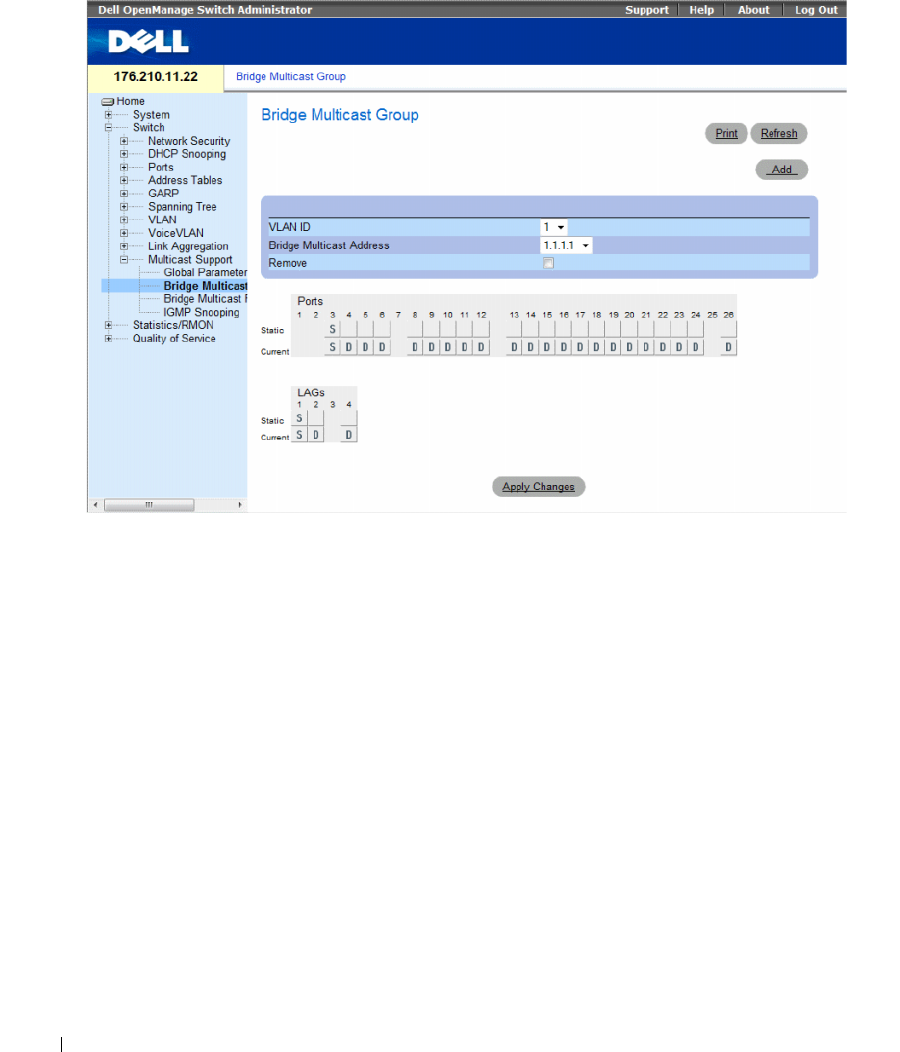
390 Configuring Switch Information
Figure 7-71. Bridge Multicast Group
The Bridge Multicast Group page contains the following fields:
•
VLAN ID
— Identifies a VLAN and contains information about the Multicast group address.
•
Bridge Multicast Address
— Identifies the Multicast group MAC address/IP address.
•
Remove
— Indicates whether to remove a Bridge Multicast address.
–
Checked
— Removes the selected Bridge Multicast address.
–
Unchecked
— Maintains the selected Bridge Multicast address.
•
Ports
— Port that can be added to a Multicast service.
•
LAGs
— LAGs that can be added to a Multicast service.
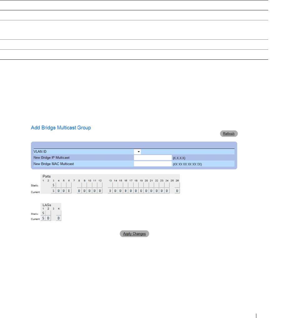
Configuring Switch Information 391
The following table contains the IGMP port and LAG members management settings:
Adding Bridge Multicast Addresses
1
Open the
Bridge Multicast Group
page.
2
Click
Add
.
The
Add Bridge Multicast Group
page opens.
Figure 7-72. Add Bridge Multicast Group
3
Define the
VLAN ID
and
New Bridge Multicast Address
fields.
4
Toggle a port to
S
to join the port to the selected Multicast group.
5
Toggle a port to
F
to forbid adding specific Multicast addresses to a specific port.
6
Click
Apply Changes
.
The bridge Multicast address is assigned to the Multicast group, and the device is updated.
Table 7-39. IGMP Port/LAG Members Table Control Settings
Port Control Definition
D The port/LAG has joined the Multicast group dynamically in the Current Row.
S Attaches the port to the Multicast group as static member in the Static Row.
The port/LAG has joined the Multicast group statically in the Current Row.
F Forbidden.
Blank The port is not attached to a Multicast group.

392 Configuring Switch Information
Defining Ports to Receive Multicast Service
1
Open the
Bridge Multicast Group
page.
2
Define the
VLAN ID
and the
Bridge Multicast Address
fields.
3
Toggle a port to
S
to join the port to the selected Multicast group.
4
Toggle a port to
F
to forbid adding specific Multicast addresses to a specific port.
5
Click
Apply Changes
.
The port is assigned to the Multicast group, and the device is updated.
Assigning LAGs to Receive Multicast Service
1
Open the
Bridge Multicast Group
page.
2
Define the
VLAN ID
and the
Bridge Multicast Address
fields.
3
Toggle the LAG to
S
to join the LAG to the selected Multicast group.
4
Toggle the LAG to
F
to forbid adding specific Multicast addresses to a specific LAG.
5
Click
Apply Changes
.
The LAG is assigned to the Multicast group, and the device is updated.
Managing Multicast Service Members Using CLI Commands
The following table summarizes the equivalent CLI commands for managing Multicast service members
as displayed in the Bridge Multicast Group page.
Table 7-40. Multicast Service Member CLI Commands
CLI Command Description
bridge multicast address {mac-
multicast-address | ip-multicast-
address}
Registers MAC-layer Multicast
addresses to the bridge table, and
adds static ports to the group.
bridge multicast forbidden address
{mac-multicast-address | ip-multicast-
address}[add | remove] {ethernet
interface-list | port-channel port-
channel-number-list}
Forbids adding a specific Multicast
address to specific ports. Use the no
form of this command to return to
default
show bridge multicast address-table
[vlan vlan-id] [address {mac-
multicast-address | ip-multicast-
address}] [format ip | mac]
Displays Multicast MAC address
table information.

Configuring Switch Information 393
The following is an example of the CLI commands:
Console(config-if)# bridge multicast address 0100.5e02.0203
add ethernet 1/e11,1/e12
console(config-if)# end
console # show bridge multicast address-table
Vlan MAC Address Type Ports
---- ----------- ----- ----------
1 0100.5e02.0203 static 1/e11, 1/e12
19 0100.5e02.0208 static 1/e11-16
19 0100.5e02.0208 dynamic 1/e11-12
Forbidden ports for multicast addresses:
Vlan MAC Address Ports
---- ----------- ----------
1 0100.5e02.0203 1/e8
19 0100.5e02.0208 1/e8
console # show bridge multicast address-table format ip
Vlan IP Address Type Ports
---- ----------- ----- ----------
1 224-239.130|2.2.3 static 1/e11, 1/e12
19 224-239.130|2.2.8 static 1/e11-16
19 224-239.130|2.2.8 dynamic 1/e11-12
Forbidden ports for multicast addresses:
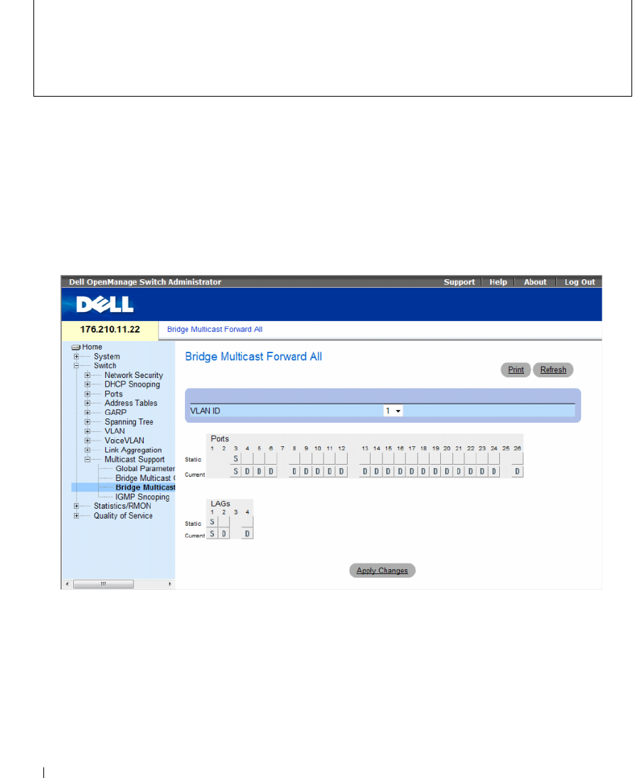
394 Configuring Switch Information
Assigning Multicast Forward All Parameters
The Bridge Multicast Forward All page contains fields for attaching ports or LAGs to a device that is
attached to a neighboring Multicast router/switch. Once IGMP Snooping is enabled, Multicast packets
are forwarded to the appropriate port or VLAN.
To open the Bridge Multicast Forward All page, click Switch → Multicast Support → Bridge Multicast
Forward All page in the tree view.
Figure 7-73. Bridge Multicast Forward All
The Bridge Multicast Forward All page contains the following fields:
•
VLAN ID
— Identifies a VLAN.
•
Ports
— Ports that can be added to a Multicast service.
•
LAGs
— LAGs that can be added to a Multicast service.
The Bridge Multicast Forward All Switch/Port Control Settings Table contains the settings for
managing router and port settings.
Vlan IP Address Ports
---- ----------- ----------
1 224-239.130|2.2.3 1/e8
19 224-239.130|2.2.8 1/e8

Configuring Switch Information 395
Managing Bridge Multicast Forward All Switch/Port Control Settings Table
The following table describes the controls used to set the port controls.
Attaching a Port to a Multicast Router or Switch
1
Open
Bridge Multicast Forward All
page.
2
Define the
VLAN ID
field.
3
Select a port in the
Ports
table, and assign the port a value.
4
Click
Apply Changes
.
The port is attached to the Multicast router or switch.
Attaching a LAG to a Multicast Router or Switch
1
Open
Bridge Multicast Forward All
page.
2
Define the
VLAN ID
field.
3
Select a port in the
LAGs
table, and assign the LAG a value.
4
Click
Apply Changes
.
The LAG is attached to the Multicast router or switch.
Managing LAGs and Ports Attached to Multicast Routers Using CLI Commands
The following table summarizes the equivalent CLI commands for managing LAGs and ports attached
to Multicast routers as displayed on the Bridge Multicast Forward All page.
Table 7-41. Bridge Multicast Forward All Switch/Port Control Settings Table
Port Control Definition
D Attaches the port to the Multicast router or switch as a
dynamic port.
S Attaches the port to the Multicast router or switch as a
static port.
F Forbidden.
Blank The port is not attached to a Multicast router or switch.
Table 7-42. CLI Commands for Managing LAGs and Ports Attached to Multicast Routers
CLI Command Description
show bridge multicast filtering vlan-id Displays the Multicast filtering configuration.
bridge multicast forward-all {add | remove}
{ethernet interface-list | port-channel port-
channel-number-list}
Enables forwarding of all Multicast packets on a port. Use the
no form of this command to return to default.
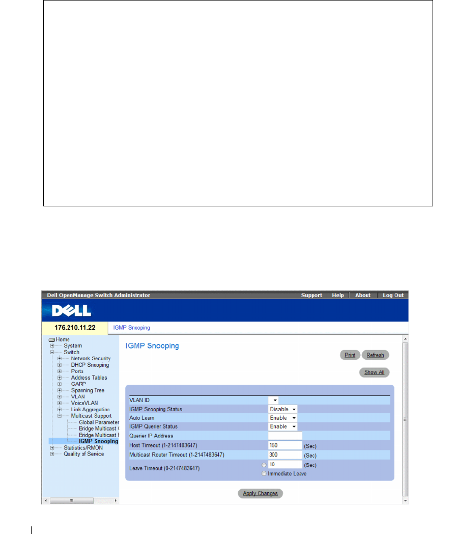
396 Configuring Switch Information
The following is an example of the CLI commands:
IGMP Snooping
The IGMP Snooping page contains fields for adding IGMP members. To open the IGMP Snooping
page, click Switch→ Multicast Support→ IGMP Snooping in the tree view.
Figure 7-74. IGMP Snooping
Console(config)# interface vlan 1
Console(config-if)# bridge multicast forward-all add ethernet
1/e3
Console(config-if)# end
Console# show bridge multicast filtering 1
Filtering: Enabled
VLAN: Forward-All
Port Static Status
------- ----------------- -----------
1/e11 Forbidden Filter
1/e12 Forward Forward(s)
1/e13 - Forward(d)
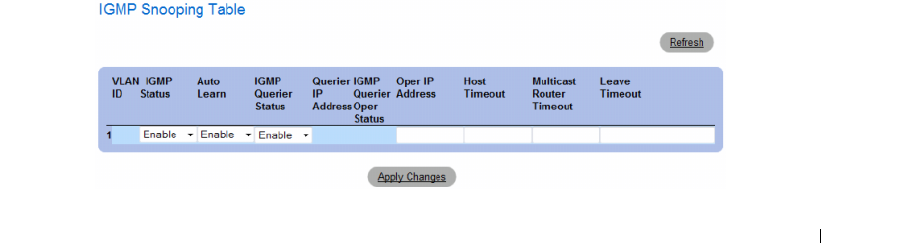
Configuring Switch Information 397
•
VLAN ID
— Specifies the VLAN ID.
•
IGMP Snooping Status
— Enables or disables IGMP snooping on the VLAN.
•
Auto Learn
— Enables or disables Auto Learn on the device.
•
IGMP Querier Status
— Enables or disables the IGMP Querier. The IGMP Querier simulates the
behavior of a multicast router, allowing snooping of the layer 2 multicast domain even though there is
no multicast router.
•
Querier IP Address
— IP address of the IGMP Querier. Use either use the VLAN’s IP Interface address
or define a unique IP address which will be used as a source address of Querier.
•
Host Timeout (1-2147483647)
— Time before an IGMP snooping entry is aged out. The default time
is 260 seconds.
•
Multicast Router Timeout (1-2147483647)
— Time before aging out a Multicast router entry.
The default value is 300 seconds.
•
Leave Timeout (0-2147483647)
— Time, in seconds, after a port leave message is received before the
entry is aged out.
User-defined
enables a user-definable timeout period, and
Immediate Leave
specifies an immediate timeout period. The default timeout is 10 seconds.
Enabling IGMP Snooping on the Device
1
Open the
IGMP Snooping
page.
2
Select the VLAN ID for the device on which IGMP snooping needs to be enabled.
3
Select
Enable
in the
IGMP Snooping Status
field.
4
Complete the fields on the page.
5
Click
Apply Changes
.
IGMP snooping is enabled on the device.
Displaying the IGMP Snooping Table
1
Open the
IGMP Snooping
.
2
Click
Show All
.
The
IGMP Snooping Table
opens.
Figure 7-75. IGMP Snooping Table

398 Configuring Switch Information
Configuring IGMP Snooping with CLI Commands
The following table summarizes the equivalent CLI commands for configuring IGMP Snooping on the
device:
Table 7-43. IGMP Snooping CLI Commands
CLI Command Description
ip igmp snooping Enables Internet Group Membership
Protocol (IGMP) snooping.
ip igmp snooping mrouter learn-pim-
dvmrp
Enables automatic learning of
Multicast router ports in the context of
a specific VLAN.
ip igmp snooping host-time-out
time-
out
Configures the host-time-out.
ip igmp snooping mrouter-time-out
time-out
Configures the mrouter-time-out.
ip igmp snooping leave-time-out {
time-
out
| immediate-leave}
Configures the leave-time-out.
ip igmp snooping querier enable
no ip igmp snooping querier enable
Enables Internet Group Management
Protocol (IGMP) querier on a specific
VLAN. Use the no form of this
command to disable.
ip igmp snooping querier address
ip-address
no ip igmp snooping querier address
Defines the source IP address that the
IGMP Snooping querier would use. Use
the no form of this command to return
to default.
show ip igmp snooping groups [vlan
vlan-id] [address ip-multicast-address]Displays the Multicast groups learned
by IGMP snooping.
show ip igmp snooping interface vlan-id Displays IGMP snooping configuration.
show ip igmp snooping mrouter
[interface vlan-id]
Displays information about
dynamically learned Multicast router
interfaces.

Configuring Switch Information 399
The following is an example of the CLI commands:
Console> enable
Console# config
Console (config)# ip igmp snooping
Console (config)# interface vlan 1
Console (config-if)# ip igmp snooping mrouter learn-pim-dvmrp
Console (config-if)# ip igmp snooping host-time-out 300
Console (config-if)# ip igmp snooping mrouter-time-out 200
Console (config-if)# exit
Console (config)# interface vlan 1
Console (config-if)# ip igmp snooping leave-time-out 60
Console (config-if)# exit
Console (config)# exit
Console # show ip igmp snooping groups
Vlan IP Address Querier Ports
----- ------------------ -------- -----
1 224-239.130|2.2.3 Yes g1, g2
Console # show ip igmp snooping interface 1000
IGMP Snooping is globally enabled

400 Configuring Switch Information
IGMP Snooping admin: Enabled
Hosts and routers IGMP version: 2
IGMP snooping oper mode: Enabled
IGMP snooping querier admin: Enabled
IGMP snooping querier oper: Enabled
IGMP snooping querier address admin:
IGMP snooping querier address oper: 172.16.1.1
IGMP snooping querier version admin: 3
IGMP snooping querier version oper: 2
IGMP host timeout is 300 sec
IGMP Immediate leave is disabled. IGMP leave timeout is 10 sec
IGMP mrouter timeout is 300 sec
Automatic learning of multicast router ports is enabled
Console # show ip igmp snooping mrouter
VLAN Ports
---- ------
1g1
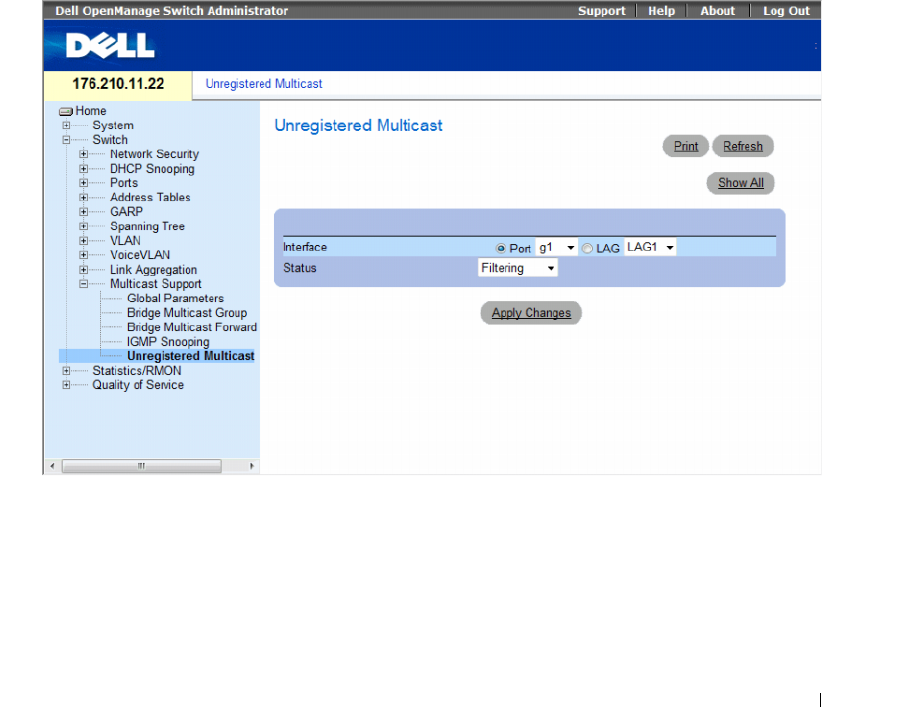
Configuring Switch Information 401
Unregistered Multicast
Multicast frames are generally forwarded to all ports in the VLAN. If IGMP Snooping is enabled, the device
learns about the existence of Multicast groups and monitors which ports have joined what Multicast group.
Multicast groups can also be statically enabled. This enables the device to forward the Multicast frames
(from a registered Multicast group) only to ports that are registered to that Multicast group.
The Unregistered Multicast Page contains fields to handle Multicast frames that belong to unregistered
Multicast groups. Unregistered Multicast groups are the groups that are not known to the device. All
unregistered Multicast frames are still forwarded to all ports on the VLAN. After a port has been set to
Forwarding/Filtering, then this port's configuration is valid for any VLAN it is a member of (or will be a
member of).
To open the Unregistered Multicast page, click Switch→ Multicast Support→ Unregistered Multicast in
the tree view.
Figure 7-76. Unregistered Multicast
•
Interface
— Selects a port or LAG.
•
Status
— Indicates the forwarding status of the selected interface. The possible values are:
–
Forwarding
— Enables forwarding of unregistered Multicast frames on the selected port or
port-channel. This is the default value.
–
Filtering
— Enables filtering of unregistered Multicast frames on the selected VLAN interface.
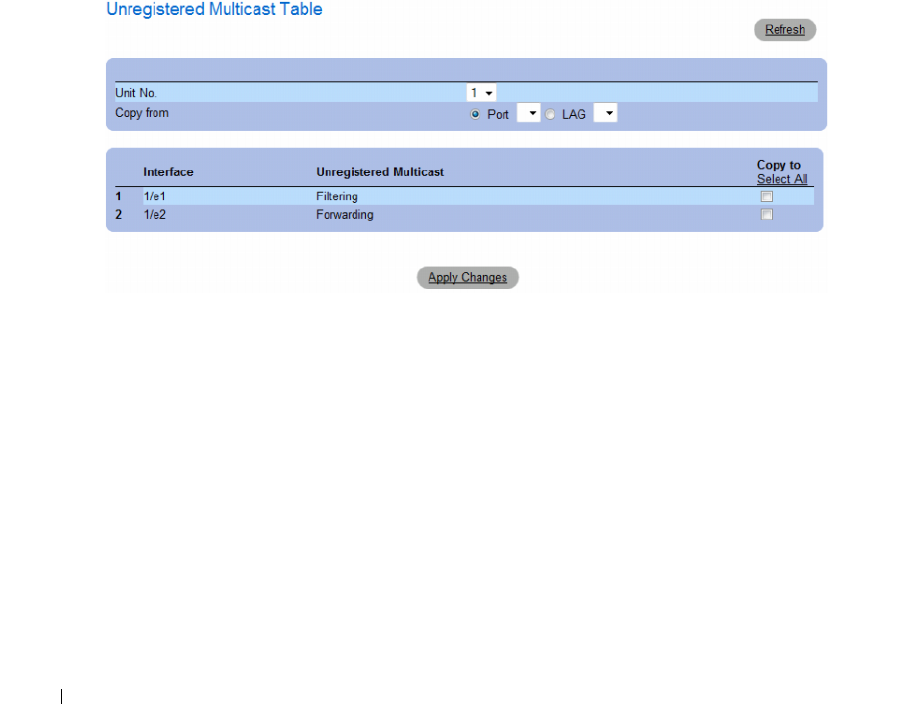
402 Configuring Switch Information
Setting the Unregistered Multicast Status of an Interface
1
Open the
Unregistered Multicast
page.
2
Select the interface for which Unregistered Multicast needs to be set.
3
Select a status in the
Status
field.
4
Click
Apply Changes
.
Unregistered Multicast status is set.
Displaying the Unregistered Multicast Table
1
Open the
Unregistered Multicast
page.
2
Click
Show All
.
The
Unregistered Multicast Table
opens.
Figure 7-77. Unregistered Multicast Table
The Unregistered Multicast Table displays the following additional fields:
•
Unit No.
— Selects a stacking member.
•
Copy from
— Copies parameters from the selected item.
Copying Unregistered Multicast Settings Between Interfaces
1
Open the
Unregistered Multicast
page.
2
Click
Show All
. The
Unregistered Multicast Table
opens.
3
In the
Copy Parameters from
field, select the interface from which to copy.
4
For each interface to which you want to copy parameters, select the checkbox in the
Copy to
field.
Alternativey, click
Select All
to automatically select all interfaces.
5
Click
Apply Changes
.
The Unregistered Multicast parameters are copied between the interfaces.

Configuring Switch Information 403
Configuring Unregistered Multicast with CLI Commands
The following table summarizes the equivalent CLI commands for configuring Unregistered Multicast
on the device:
The following is an example of the CLI commands:
Table 7-44. Unregistered Multicast CLI Commands
CLI Command Description
bridge multicast unregistered Configures the forwarding state of unregistered multicast
addresses.
show bridge multicast unregistered Displays the unregistered multicast filtering configuration.
Console # show bridge multicast unregistered
Port Unregistered
---- -------------
1/1 Forward
1/2 Filter
1/3 Filter

404 Configuring Switch Information

Viewing Statistics 405
Viewing Statistics
The Statistic pages contains links to device information for interface, GVRP, etherlike, RMON,
and device utilization. To open the Statistics page, click Statistics in the tree view.
CLI commands are not available for all the Statistics pages.
This section contians the following topics:
• "Viewing Tables" on page 405
• "Viewing RMON Statistics" on page 420
• "Viewing Charts" on page 435
Viewing Tables
The Table Views page contains links for displaying statistics in a table form. To open the page,
click Statistics → Table in the tree view.
This section contians the following topics:
• "Viewing Utilization Summary" on page 405
• "Viewing Counter Summary" on page 407
• "Viewing Interface Statistics" on page 408
• "Viewing Etherlike Statistics" on page 411
• "Viewing GVRP Statistics" on page 414
• "Viewing EAP Statistics" on page 418
• "Viewing EAP Statistics Using the CLI Commands" on page 419
Viewing Utilization Summary
The Utilization Summary page contains statistics for interface utilization. This screen is refreshed
periodically to minimize the impact on computers with lower memory. Display may be disrupted
during this period.
To open the page, click Statistics → Table Views → Utilization Summary in the tree view.
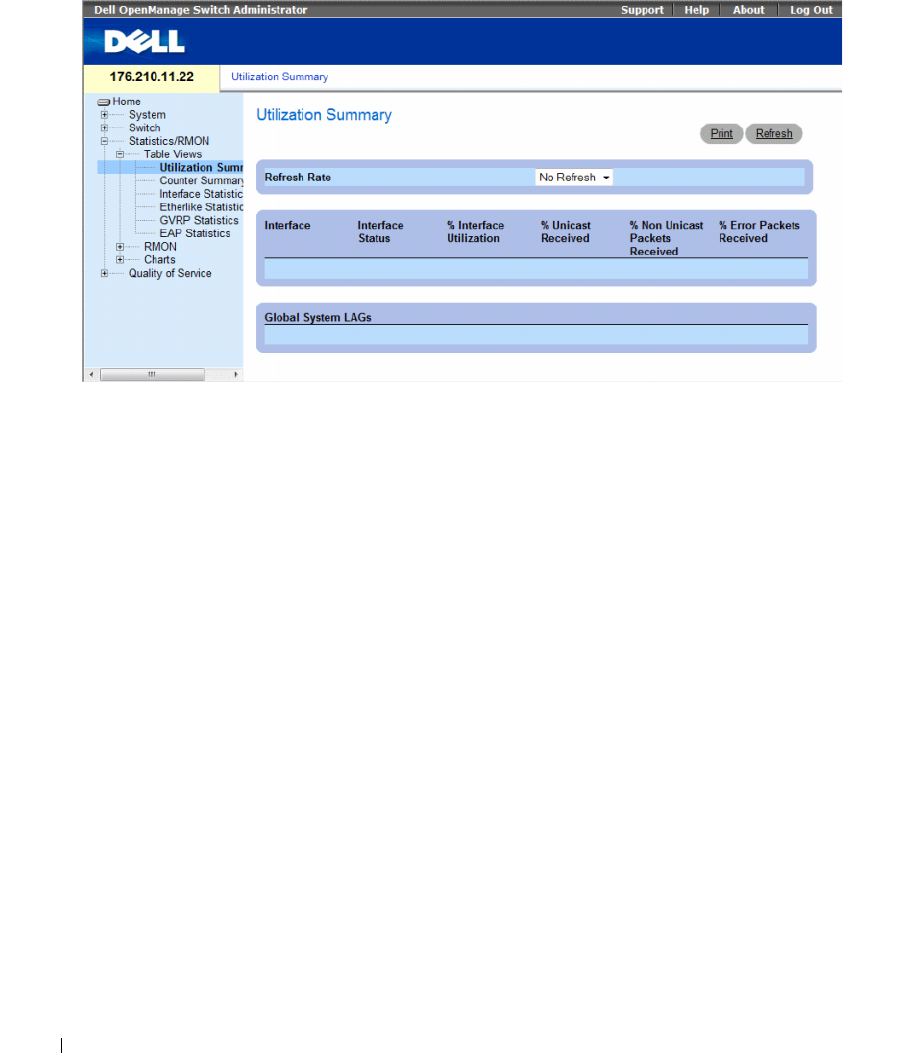
406 Viewing Statistics
Figure 8-1. Utilization Summary
The Utilization Summary page contains the following fields:
•
Refresh Rate
—Indicates the amount of time that passes before the interface statistics are refreshed.
The possible field values are:
•
15 Sec
— Indicates that the interface statistics are refreshed every 15 seconds.
•
30 Sec
— Indicates that the interface statistics are refreshed every 30 seconds.
•
60 Sec
— Indicates that the interface statistics are refreshed every 60 seconds.
•
No Refresh
— Indicates that the interface statistics are not refreshed automatically.
•
Interface
— The interface number.
•
Interface Status
— Status of the interface.
•
% Interface Utilization
— Network interface utilization percentage based on the duplex mode of the
interface. The range of this reading is from 0 to 200%. The maximum reading of 200% for a full duplex
connection indicates that 100% of bandwidth of incoming and outgoing connections is used by the
traffic travelling through the interface. The maximum reading for a half duplex connection is 100%.
•
% Unicast Received
— Percentage of Unicast packets received on the interface.
•
% Non Unicast Packets Received
— Percentage of non-Unicast packets received on the interface.
•
% Error Packets Received
— Percentage of packets with errors received on the interface.
•
Global System LAGs
— Indicates the current global LAG utilization.
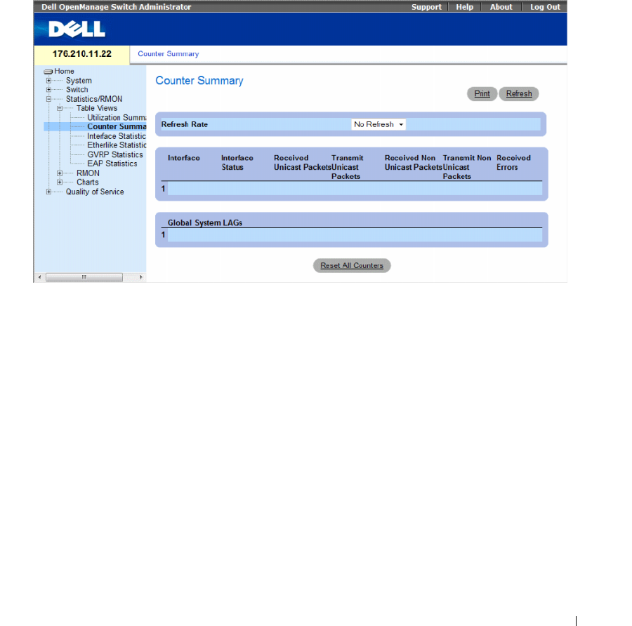
Viewing Statistics 407
Viewing Counter Summary
The Counter Summary page contains statistics for port utilization in numeric sums as opposed to
percentages.
To open the Counter Summary page, click Statistics/RMON → Ta bl e Vi ews → Counter Summary in the
tree view.
Figure 8-2. Counter Summary
The Counter Summary page contains the following fields:
•
Refresh Rate
— Indicates the amount of time that passes before the interface statistics are refreshed.
The possible field values are:
•
15 Sec
— Indicates that the interface statistics are refreshed every 15 seconds.
•
30 Sec
— Indicates that the interface statistics are refreshed every 30 seconds.
•
60 Sec
— Indicates that the interface statistics are refreshed every 60 seconds.
•
No Refresh
— Indicates that the interface statistics are not refreshed automatically.
•
Interface
— The interface number.
•
Interface Status
— Status of the interface.
•
Received Unicast Packets
— Number of received Unicast packets on the interface.
•
Transmit Unicast Packets
— Number of transmitted Unicast packets from the interface.
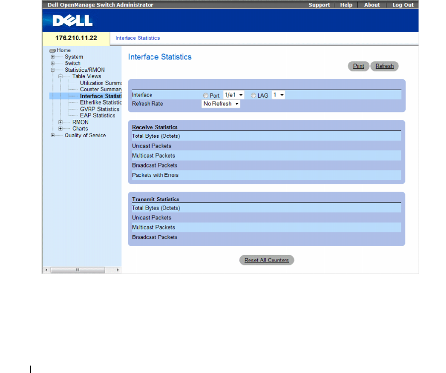
408 Viewing Statistics
•
Received Non Unicast Packets
— Number of received non-Unicast packets on the interface.
•
Transmit Non Unicast Packets
— Number of transmitted non-Unicast packets from the interface.
•
Received Errors
— Number of received packets with errors on the interface.
•
Global System LAGs
— Provides a counter summary for global system LAGs.
Viewing Interface Statistics
The Interface Statistics page contains statistics for both received and transmitted packets. The fields for
both received and transmitted packets are identical.
To open the Interface Statistics page, click Statistics/RMON → Ta ble Vi ew s → Interface Statistics in the
tree view.
Figure 8-3. Interface Statistics

Viewing Statistics 409
The Interface Statistics page contains the following fields:
•
Interface
— Specifies whether statistics are displayed for a port or LAG.
•
Refresh Rate
— Amount of time that passes before the interface statistics are refreshed. The possible
field values are:
•
15 Sec
— Indicates that the interface statistics are refreshed every 15 seconds.
•
30 Sec
— Indicates that the interface statistics are refreshed every 30 seconds.
•
60 Sec
— Indicates that the interface statistics are refreshed every 60 seconds.
•
No Refresh
— Indicates that the interface statistics are not refreshed automatically.
Receive Statistics
•
Total Bytes (Octets)
— Amount of octets received on the selected interface.
•
Unicast Packets
— Amount of Unicast packets received on the selected interface.
•
Multicast Packets
— Amount of Multicast packets received on the selected interface.
•
Broadcast Packets
— Amount of Broadcast packets received on the selected interface.
•
Packets with Errors
— Number of errors packets received on the selected interface.
Transmit Statistics
•
Total Bytes (Octets)
— Amount of octets transmitted from the selected interface.
•
Unicast Packets
— Amount of Unicast packets transmitted from the selected interface.
•
Multicast Packets
— Amount of Multicast packets transmitted from the selected interface.
•
Broadcast Packets
— Amount of Broadcast packets transmitted from the selected interface.
Displaying Interface Statistics
1
Open the
Interface Statistics
page.
2
Select an interface in the
Interface
field.
The interface statistics for the selected interface are displayed.
Resetting Interface Statistics Counters
1
Open the
Interface Statistics
page.
2
Click
Reset All Counters
.
The interface statistics counters are reset.

410 Viewing Statistics
Viewing Interface Statistics Using the CLI Commands
The following table contains the CLI commands for viewing interface statistics.
The following is an example of the CLI commands.
Table 8-1. Interface Statistics CLI Commands
CLI Command Description
show interfaces counters
[ethernet
interface
| port-
channel
port-channel-number
]
Displays traffic seen by the physical
interface.
console> enable
console# show interfaces counters
Port InOctets InUcastPkts InMcastPkts InBcastPkts
------------------------------------------------
1/e1 0 0 0 0
1/e2 0 0 0 0
1/e3 0 0 0 0
1/e4 0 0 0 0
1/e5 0 0 0 0
1/e6 0 0 0 0
1/e7 0 0 0 0
1/e8 0 0 0 0
1/e9 0 0 0 0
1/e10 0 0 0 0
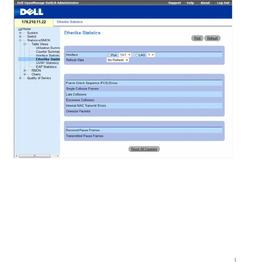
Viewing Statistics 411
Viewing Etherlike Statistics
The Etherlike Statistics page contains interface errors statistics.
To open the Etherlike Statistics page, click Statistics/RMON → Tab le View s → Etherlike Statistics in the
tree view.
Figure 8-4. Etherlike Statistics
The Etherlike Statistics page contains the following fields:
•
Interface
— Specifies whether statistics are displayed for a port or LAG.
•
Refresh Rate
— Amount of time that passes before the interface statistics are refreshed. The possible
field values are:
•
15 Sec
— Indicates that the Etherlike statistics are refreshed every 15 seconds.
•
30 Sec
— Indicates that the Etherlike statistics are refreshed every 30 seconds.
•
60 Sec
— Indicates that the Etherlike statistics are refreshed every 60 seconds.
•
No Refresh
— Indicates that the Etherlike statistics are not refreshed automatically.
•
Frame Check Sequence (FCS) Errors
— Number of FCS errors received on the selected interface.

412 Viewing Statistics
•
Single Collision Frames
— Number of single collision frame errors received on the selected interface.
•
Late Collisions
— Number of late collisions received on the selected interface.
•
Internal MAC Transmit Errors
— Number of internal MAC transmit errors on the selected interface.
•
Oversize Packets
— Number of oversize packets on the selected interface.
•
Received Pause Frames
— Number of received paused errors on the selected interface.
•
Transmitted Pause Frames
— Number of transmitted paused errors on the selected interface.
Displaying Etherlike Statistics for an Interface
1
Open the
Etherlike Statistics
page.
2
Select an interface in the
Interface
field.
Resetting Etherlike Statistics
1
Open the
Etherlike Statistics
page.
2
Click
Reset All Counters
.
The Etherlike Statistics counters are reset.
Viewing Etherlike Statistics Using the CLI Commands
The following table contains the CLI commands for viewing etherlike statistics.
Table 8-2. Etherlike Statistics CLI Commands
CLI Command Description
show interfaces counters [ethernet
interface | port-channel
port-
channel-number
]
Displays traffic seen by the physical
interface.

Viewing Statistics 413
The following is an example of the CLI commands.
Console# show interfaces counters ethernet 1/e1
Port IN Octets InUcastPkts InMcastPkts InBcastPkts
---- --------- ----------- ----------- -----------
1/e1 183892 1289 987 8
Port OUT Octets OutUcastPkts OutMcastPkts OutBcastPkts
---- ---------- ------------ ------------ ------------
1/e1 9188 9 8 0
FCS Errors: 8
Single Collision Frames: 0
Multiple Collision Frames: 0
SQE Test Errors: 0
Deferred Transmissions: 0
Late Collisions: 0
Excessive Collisions: 0
Internal MAC Tx Errors: 0
Carrier Sense Errors: 0
Oversize Packets: 0
Internal MAC Rx Errors: 0
Received Pause Frames: 0
Transmitted Pause Frames: 0
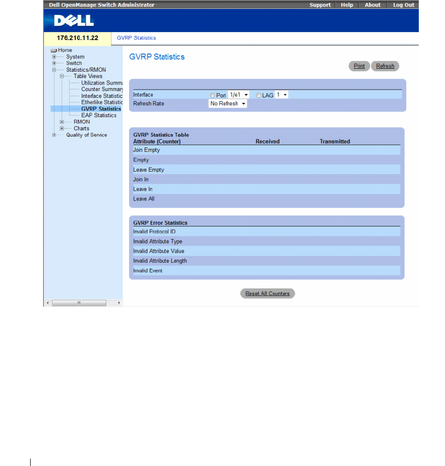
414 Viewing Statistics
Viewing GVRP Statistics
The GVRP Statistics page contains device statistics for GVRP.
To open the page, click Statistics/RMON → Ta bl e View s → GVRP Statistics in the tree view.
Figure 8-5. GVRP Statistics
The GVRP Statistics page contains the following fields:
•
Interface
— Specifies whether statistics are displayed for a port or LAG.
•
Refresh Rate
— Amount of time that passes before the GVRP statistics are refreshed. The possible
field values are:
•
15 Sec
— Indicates that the GVRP statistics are refreshed every 15 seconds.
•
30 Sec
— Indicates that the GVRP statistics are refreshed every 30 seconds.
•
60 Sec
— Indicates that the GVRP statistics are refreshed every 60 seconds.
•
No Refresh
— Indicates that the GVRP statistics are not refreshed automatically.

Viewing Statistics 415
GVRP Statistics Table
•
Join Empty
— Device GVRP Join Empty statistics.
•
Empty
— Indicates the number of empty GVRP statistics.
•
Leave Empty
— Device GVRP Leave Empty statistics.
•
Join In
— Device GVRP Join In statistics.
•
Leave In
— Device GVRP Leave in statistics.
•
Leave All
— Device GVRP Leave all statistics.
GVRP Error Statistics
•
Invalid Protocol ID
— Device GVRP Invalid Protocol ID statistics.
•
Invalid Attribute Type
— Device GVRP Invalid Attribute ID statistics.
•
Invalid Attribute Value
— Device GVRP Invalid Attribute Value statistics.
•
Invalid Attribute Length
— Device GVRP Invalid Attribute Length statistics.
•
Invalid Event
— Device GVRP Invalid Events statistics.
Displaying GVRP Statistics for a Port
1
Open the
GVRP Statistics
page.
2
Select an interface in the
Interface
field.
The GVRP statistics for the selected interface are displayed.
Resetting GVRP Statistics
1
Open the
GVRP Statistics
page.
2
Click
Reset All Counters
.
The GVRP statistics counters are reset.
Viewing GVRP Statistics Using the CLI Commands
The following table contains the CLI commands for viewing GVRP statistics.
Table 8-3. GVRP Statistics CLI Commands
CLI Command Description
show gvrp statistics [ethernet
interface
| port-channel
port-channel-number
]
Displays GVRP statistics.
show gvrp error-statistics [ethernet
interface
| port-
channel
port-channel-number
]
Displays GVRP error statistics.

416 Viewing Statistics
The following is an example of the CLI commands:
console# show gvrp statistics
GVRP statistics:
----------------
Legend:
rJE : Join Empty Received
rJIn : Join In Received
rEmp : Empty Received
rLIn : Leave In Received
rLE : Leave Empty Received
rLA : Leave All Received
sJE : Join Empty Sent
sJIn : Join In Sent
sEmp : Empty Sent
sLIn : Leave In Sent
sLE : Leave Empty Sent
sLA : Leave All Sent
Port rJE rJIn rEmp
rLIn rLE rLA sJE sJIn sEmp sLIn sLE sLA
---- --- ---- ---- ---- --- --- --- --- --- ---- --- ---
1/e1 0 0 0 0 0 0 0 0 0 0 0 0
1/e2 0 0 0 0 0 0 0 0 0 0 0 0
1/e3 0 0 0 0 0 0 0 0 0 0 00 0

Viewing Statistics 417
Console# show gvrp error-statistics
GVRP error statistics:
----------------
Legend:
INVPROT : Invalid Protocol Id
INVPLEN : Invalid PDU Length
INVATYP : Invalid Attribute Type
INVALEN : Invalid Attribute Length
INVAVAL : Invalid Attribute Value
INVEVENT : Invalid Event
Port INVPROT INVATYP INVAVAL INVPLEN INVALEN INVEVENT
---- ------- ------- ------- ------- ------- -------
1/e1 0 0 0 0 0 0
1/e2 0 0 0 0 0 0
1/e3 0 0 0 0 0 0
1/e4 0 0 0 0 0 0
sLE : Leave Empty Sent
sLA : Leave All Sent
Port rJE rJIn rEmp
rLIn rLE rLA sJE sJIn sEmp sLIn sLE sLA
---- --- ---- ---- ---- --- --- --- --- --- ---- --- ---
1/e1 0 0 0 0 0 0 0 0 0 0 0 0
1/e2 0 0 0 0 0 0 0 0 0 0 0 0
1/e3 0 0 0 0 0 0 0 0 0 0 0 0
1/e4 0 0 0 0 0 0 0 0 0 0 0 0
1/e5 0 0 0 0 0 0 0 0 0 0 0 0
1/e6 0 0 0 0 0 0 0 0 0 0 0 0
1/e7 0 0 0 0 0 0 0 0 0 0 0 0
1/e8 0 0 0 0 0 0 0 0 0 0 0 0
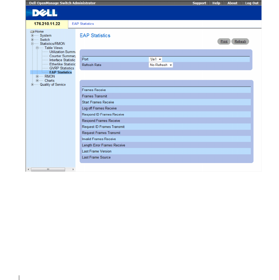
418 Viewing Statistics
Viewing EAP Statistics
The EAP Statistics page contains information about EAP packets received on a specific port. For more
information about EAP, see "Port Based Authentication".
To open the EAP Statistics page, click Statistics/RMON → Table Views → EAP Statistics in the tree view.
Figure 8-6. EAP Statistics
The EAP Statistics page contains the following fields:
•
Port
— Indicates the port which is polled for statistics.
•
Refresh Rate
— Amount of time that passes before the EAP statistics are refreshed. The possible field
values are:
–
15 Sec
— Indicates that the EAP statistics are refreshed every 15 seconds.
–
30 Sec
— Indicates that the EAP statistics are refreshed every 30 seconds.
–
60 Sec
— Indicates that the EAP statistics are refreshed every 60 seconds.
–
No Refresh
— Indicates that the EAP statistics are not refreshed automatically.
•
Frames Receive
— Indicates the number of valid EAPOL frames received on the port.

Viewing Statistics 419
•
Frames Transmit
— Indicates the number of EAPOL frames transmitted via the port.
•
Start Frames Receive
— Indicates the number of EAPOL Start frames received on the port.
•
Log off Frames Receive
— Indicates the number of EAPOL Logoff frames received on the port.
•
Respond ID Frames Receive
— Indicates the number of EAP Resp/Id frames received on the port.
•
Respond Frames Receive
— Indicates the number of valid EAP Response frames received on the port.
•
Request ID Frames Transmit
— Indicates the number of EAP Req/Id frames transmitted via the port.
•
Request Frames Transmit
— Indicates the number of EAP Request frames transmitted via the port.
•
Invalid Frames Receive
— Indicates the number of unrecognized EAPOL frames that have been
received on this port.
•
Length Error Frames Receive
— Indicates the number of EAPOL frames with an invalid Packet Body
Length received on this port.
•
Last Frame Version
— Indicates the protocol version number attached to the most recently received
EAPOL frame.
•
Last Frame Source
— Indicates the source MAC address attached to the most recently received
EAPOL frame.
Displaying EAP statistics for a port
1
Open the
EAP Statistics
page.
2
Select an interface in the
Interface
field.
The interface EAP statistics are displayed.
To reset the EAP Statistics
1
Open the
EAP Statistics
page.
2
Click
Reset All Counters
.
The EAP statistics counters are reset.
Viewing EAP Statistics Using the CLI Commands
The following table summarizes the CLI commands for viewing EAP statistics.
Table 8-4. EAP Statistics CLI Commands
CLI Command Description
show dot1x statistics Displays 802.1X statistics for the
specified interface.

420 Viewing Statistics
The following is an example of the CLI commands:
Viewing RMON Statistics
Remote Monitoring (RMON) allows network managers to view network information from a remote
location. To open the RMON page, cClick a link below to access on-line help for the indicated screen.
lick Statistics/RMON→ RMON in the tree view.
This section contians the following topics:
• "Viewing RMON Statistics Group" on page 420
• "Viewing RMON History Control Statistics" on page 423
• "Viewing the RMON History Table" on page 425
• "Defining Device RMON Events" on page 428
• "Viewing the RMON Events Log" on page 430
• "Defining RMON Device Alarms" on page 431
Viewing RMON Statistics Group
Use the RMON Statistics page view information about device utilization and errors that occurred on the
device. To open the RMON Statistics page, click Statistics/RMON→ RMON→ Statistics in the tree view.
console# show dot1x statistics ethernet 1/e1
EapolFramesRx: 11
EapolFramesTx: 12
EapolStartFramesRx: 1
EapolLogoffFramesRx: 1
EapolRespIdFramesRx: 3
EapolRespFramesRx: 6
EapolReqIdFramesTx: 3
EapolReqFramesTx: 6
InvalidEapolFramesRx: 0
EapLengthErrorFramesRx: 0
LastEapolFrameVersion: 1
LastEapolFrameSource: 0008.3b79.8787
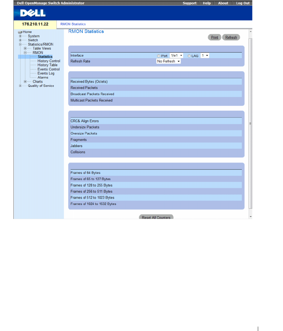
Viewing Statistics 421
Figure 8-7. RMON Statistics
The RMON Statistics page contains the following fields:
•
Interface
— Specifies the port or LAG for which statistics are displayed.
•
Refresh Rate
— Amount of time that passes before the statistics are refreshed.
•
Received Bytes (Octets)
— Number of bytes received on the selected interface.
•
Received Packets
— Number of packets received on the selected interface.
•
Broadcast Packets Received
— Number of good Broadcast packets received on the interface since the
device was last refreshed. This number does not include multicast packets.
•
Multicast Packets Received
— Number of good Multicast packets received on the interface since the
device was last refreshed.

422 Viewing Statistics
•
CRC & Align Errors
— Number of CRC and Align errors that have occurred on the interface since the
device was last refreshed.
•
Undersize Packets
— Number of undersized packets (less than 64 octets) received on the interface
since the device was last refreshed.
•
Oversize Packets
— Number of oversized packets (over 1632 octets) received on the interface since the
device was last refreshed.
•
Fragments
— Number of fragments (packets with less than 64 octets, excluding framing bits, but
including FCS octets) received on the interface since the device was last refreshed.
•
Jabbers
— Number of jabbers (packets longer than 1632 octets) received on the interface since the
device was last refreshed.
•
Collisions
— Number of collisions received on the interface since the device was last refreshed.
•
Frames of
xx
Bytes
— Number of
xx
-byte frames transmitted and received on the interface since the
device was last refreshed.
Viewing Interface Statistics
1
Open the
RMON Statistics
page.
2
Select an interface type and number in the
Interface
field.
The interface statistics are displayed.
Viewing RMON Statistics Using the CLI Commands
The following table contains the CLI commands for viewing RMON statistics.
Table 8-5. RMON Statistics CLI Commands
CLI Command Description
show rmon statistics {ethernet
interface
| port-channel
port-channel-number
}
Displays RMON Ethernet statistics.
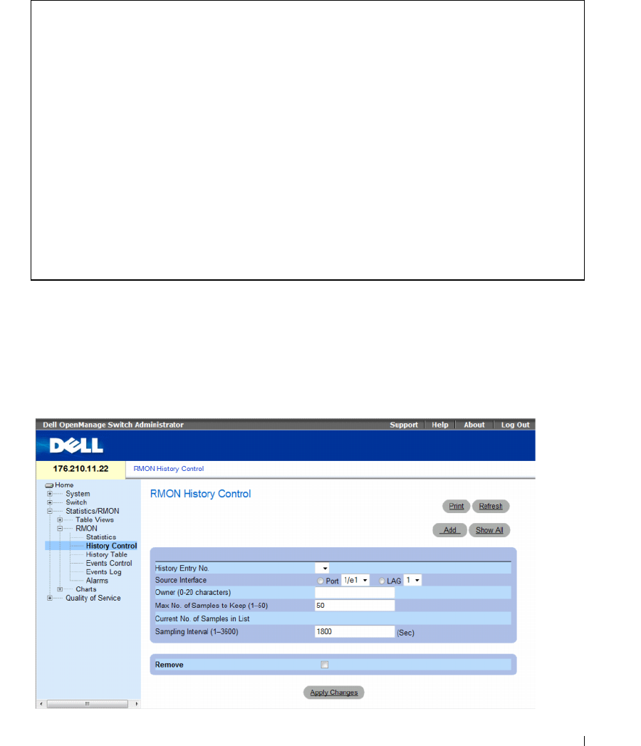
Viewing Statistics 423
The following is an example of the CLI commands:
Viewing RMON History Control Statistics
The RMON History Control contains information about samples of data taken from ports. For example,
the samples may include interface definitions or polling periods. To open the RMON History Control
page, click Statistics/RMON→ RMON→ History Control in the tree view.
Figure 8-8. RMON History Control
console# show rmon statistics ethernet 1/e1
Port 1/e1
Dropped: 8
Octets: 878128 Packets: 978
Broadcast: 7 Multicast: 1
CRC Align Errors: 0 Collisions: 0
Undersize Pkts: 0 Oversize Pkts: 0
Fragments: 0 Jabbers: 0
64 Octets: 98 65 to 127 Octets: 0
128 to 255 Octets: 0 256 to 511 Octets: 0
512 to 1023 Octets: 491 1024 to 1632 Octets: 389

424 Viewing Statistics
The RMON History Control page contains the following fields:
•
History Entry No.
— Entry number for the
History Control
page.
•
Source Interface
— Port or LAG from which the history samples were taken.
•
Owner (0-20 characters)
— RMON station or user that requested the RMON information.
•
Max No. of Samples to Keep (1-50)
— Number of samples to be saved. The default value is 50.
•
Current No. of Samples in List
— Indicates the current number of samples taken.
•
Sampling Interval (1-3600)
—Indicates the time interval in seconds, between what the samplings are
taken from the ports. The possible values are 1-3600 seconds. The default is 1800 seconds
(30 minutes).
•
Remove
— When checked, removes the
History Control Table
entry.
Adding a History Control Entry
1
Open the
RMON History Control
page.
2
Click
Add
.
The
Add History Entry
page opens.
3
Complete the fields in the dialog.
4
Click
Apply Changes
.
The entry is added to the
History Control Table
.
Modifying a History Control Table Entry
1
Open the
RMON History Control
page.
2
Select an entry in the
History Entry No.
field.
3
Modify the fields as desired
4
Click
Apply Changes
.
The table entry is modified, and the device is updated.
Deleting a History Control Table Entry
1
Open the
RMON History Control
page.
2
Select an entry in the
History Entry No.
field.
3
Click
Apply Changes
.
The table entry is deleted, and the device is updated.
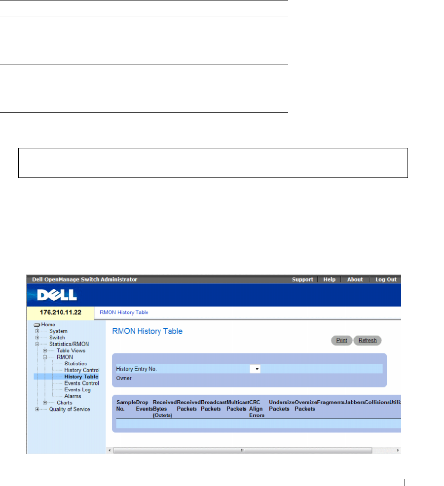
Viewing Statistics 425
Viewing RMON History Control Using the CLI Commands
The following table contains the CLI commands for viewing RMON History Control.
The following is an example of the CLI commands:
Viewing the RMON History Table
The RMON History Table contains interface specific statistical network samplings. Each table entry
represents all counter values compiled during a single sample. To open the RMON History Table,
click Statistics/RMON→ RMON→ History Table in the tree view.
Figure 8-9. RMON History Table
Table 8-6. RMON History CLI Commands
CLI Command Description
rmon collection history
index
[owner
ownername
| buckets
bucket-number
] [interval
seconds
]
Enables and configures RMON on an
interface.
show rmon collection history
[ethernet
interface
| port-
channel
port-channel-
number
]
Displays RMON collection history
statistics.
console(config)# interface ethernet 1/e8
console(config-if)# rmon collection history 1 interval 2400

426 Viewing Statistics
The RMON History Table page contains the following fields:
Not all fields are shown in the RMON History Table in theRMON History Table figure.
•
History Entry No.
— Specifies the entry number from the
History Control
page.
•
Owner
— Indicates the RMON station or user that requested the RMON information.
•
Sample No.
— Indicates the number of specific sample the information in the table reflects.
•
Drop Events
— The number of dropped packets due to lack of network resources during the sampling
interval. This may not represent the exact number of dropped packets, but rather the number of times
dropped packets were detected.
•
Received Bytes (Octets)
— The number of data octets, including bad packets, received on the network.
•
Received Packets
— The number of packets received during the sampling interval.
•
Broadcast Packets
— The number of good broadcast packets received during the sampling interval.
•
Multicast Packets
— The number of good multicast packets received during the sampling interval.
•
CRC Align Errors
— The number of packets received during the sampling session with a length
64-1632 octets. However, the packets has a bad packet Check Sequence (FCS) with an integral
number of octets or a bad FCS with a non-integral number.
•
Undersize Packets
— The number of packets received less than 64 octets long during the
sampling session.
•
Oversize Packets
— The number of packets received more than 1632 octets long during the sampling
session.
•
Fragments
— The number of packets received less than 64 octets long and had a FCS during the
sampling session.
•
Jabbers
— The number of packets received more than 1632 octets long and had a FCS during the
sampling session.
•
Collisions
— Estimates the total number of packet collision that occurred during the sampling
session. Collision are detected when repeater port detects two or more stations transmit
simultaneously.
•
Utilization
— Estimates the main physical layer network usage on an interface during the session
sampling. The value is reflected hundredths of percent.
Viewing Statistics for a Specific History Entry
1
Open the
RMON History Table
.
2
Select an entry in the
History Entry No.
field.
The entry statistics display in the RMON History Table.

Viewing Statistics 427
Viewing RMON History Control Using the CLI Commands
The following table contains the CLI commands for viewing RMON history.
The following is an example of the CLI commands for displaying RMON ethernet statistics for
throughput on index 1:
Table 8-7. RMON History Control CLI Commands
CLI Command Description
show rmon history index
{throughput | errors | other}
[period seconds]
Displays RMON Ethernet statistics history.
console> enable
console# show rmon history 1 throughput
Sample Set: 5Owner: cli
Interface: 24 interval: 10
Requested samples: 50 Granted samples: 50
Maximum table size: 270
Time Octets PacketsBroadcast Multicast%
------------------ ------ ---------------- --------------
09-Mar-2003 18:29:32 00 00 0
09-Mar-2003 18:29:42 00 00 0
09-Mar-2003 18:29:52 00 00 0
09-Mar-2003 18:30:02 00 00 0
09-Mar-2003 18:30:12 00 00 0
09-Mar-2003 18:30:22 00 00 0
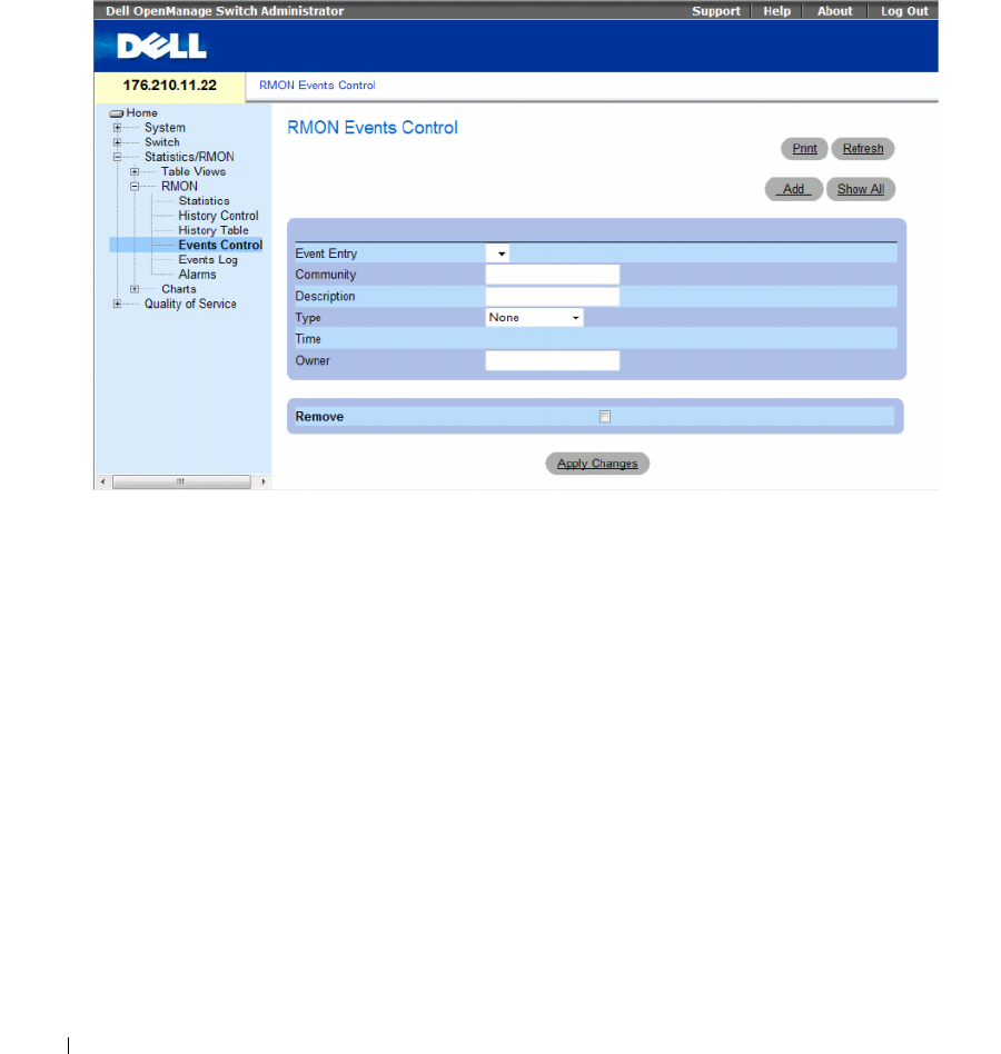
428 Viewing Statistics
Defining Device RMON Events
Use the RMON Events Control page to define RMON events. To open the RMON Events Control
page, click Statistics/RMON→ RMON→ Events Control in the tree view.
Figure 8-10. RMON Events Control
The RMON Events Control page contains the following fields:
•
Event Entry
— Indicates the event.
•
Community
— Community to which the event belongs.
•
Description
— User-defined event description.
•
Ty p e
— Describes the event type. Possible values are:
•
Log
— Event type is a log entry.
•
Trap
— Event type is a trap.
•
Log and Trap
— Event type is both a log entry and a trap.
•
None
— There is no event.
•
Time
— Time when the event occurred.
•
Owner
— The device or user that defined the event.
•
Remove
— When checked, removes the event from the
RMON Events Table
.

Viewing Statistics 429
Adding a RMON Event
1
Open the
RMON Events Control
page.
2
Click
Add
.
The
Add an Event Entry
page opens.
3
Complete the information in the dialog and click
Apply Changes
.
The
Event Table
entry is added, and the device is updated.
Modifying a RMON Event
1
Open the
RMON Events Control
page
2
Select an entry in the
Event Table
.
3
Modify the fields in the dialog and click
Apply Changes
.
The
Event Table
entry is modified, and the device is updated.
Deleting RMON Event Entries
A single event entry can be removed from the RMON Events Control page by checking the Remove
check box on that page.
1
Open the
RMON Events Control
page.
2
Click
Show All
.
The
RMON Events Table
page opens.
3
Check the
Remove
checkbox for the event(s) that needs to be deleted and then click
Apply Changes
.
The table entry is deleted, and the device is updated.
Defining Device Events Using the CLI Commands
The following table contains the CLI commands for defining device events.
Table 8-8. Device Event Definition CLI Commands
CLI Command Description
rmon event
index type
[community
text
] [description
text
] [owner name]
Configures RMON events.
show rmon events Displays RMON event table.
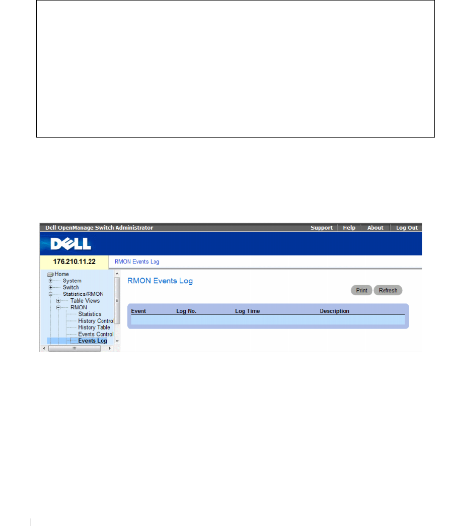
430 Viewing Statistics
The following is an example of the CLI commands:
Viewing the RMON Events Log
The RMON Events Log page contains a list of RMON events. To open the RMON Events Log page,
click Statistics/RMON→ RMON→ Events Log in the tree view.
Figure 8-11. RMON Events Log
The RMON Events Log page contains the following fields:
•
Event
— The RMON Events Log entry number.
•
Log No.
— The log number.
•
Log Time
— Time when the log entry was entered.
•
Description
— Describes the log entry.
console(config)# rmon event 1 log
console(config)# exit
console# show rmon events
Index Description Type Community Owner Last Time Sent
----- ----------- -------- --------- ------- --------------
1 Errors Log CLI Jan 18 2002
23:58:17
2 High
Broadcast
Log-Trap router Manager Jan 18 2002
23:59:48

Viewing Statistics 431
Defining Device Events Using the CLI Commands
The following table contains the CLI commands for defining device events.
The following is an example of the CLI commands:
Defining RMON Device Alarms
Use the RMON Alarms page to set network alarms. Network alarms occur when a network problem,
or event, is detected. Rising and falling thresholds generate events. For more information about events,
see "Viewing the RMON Events Log."
To open the RMON Alarms page, click Statistics/RMON→ RMON→ Alarms in the tree view.
Table 8-9. Device Event Definition CLI Commands
CLI Command Description
show rmon log [
event
]Displays the RMON logging table.
console(config)# rmon event 1 log
Console> show rmon log
Maximum table size: 500
Event Description Time
----- --------------- --------------
1 Errors Jan 18 2002 23:58:17
2 High Broadcast Jan 18 2002 23:59:48
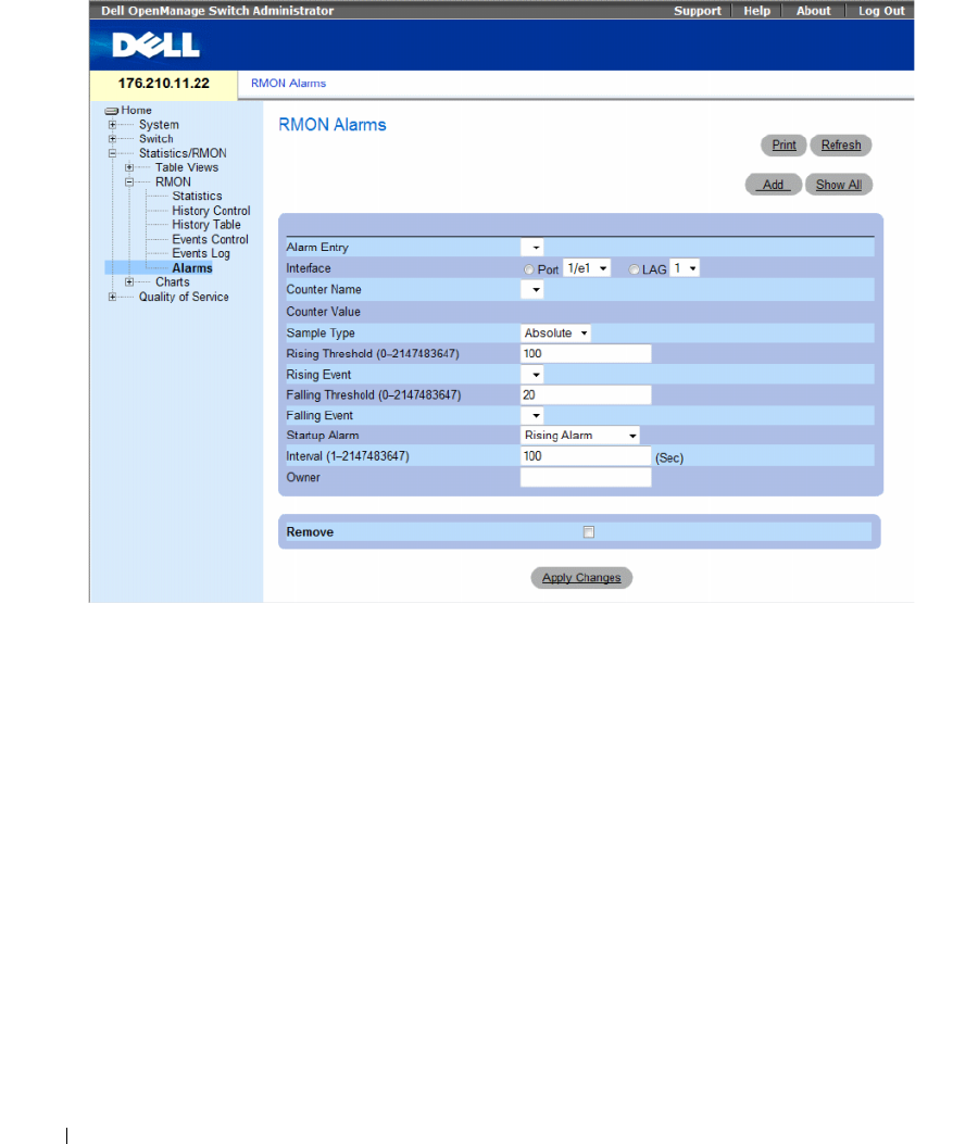
432 Viewing Statistics
Figure 8-12. RMON Alarms
The RMON Alarms page contains the following fields:
•
Alarm Entry
— Indicates a specific alarm.
•
Interface
—
Indicates the interface for which RMON statistics are displayed.
•
Counter Name
— Indicates the selected MIB variable.
•
Counter Value —
The value of the selected MIB variable.
•
Sample Type
— Specifies the sampling method for the selected variable and comparing the value
against the thresholds. The possible field values are:
•
Delta
— Subtracts the last sampled value from the current value. The difference in the values is
compared to the threshold.
•
Absolute
— Compares the values directly with the thresholds at the end of the sampling interval.
•
Rising Threshold
(0–2147483647
) — The rising counter value that triggers the rising threshold alarm.
The rising threshold is presented on top of the graph bars. Each monitored variable is designated a
color. The field default is 100 seconds.
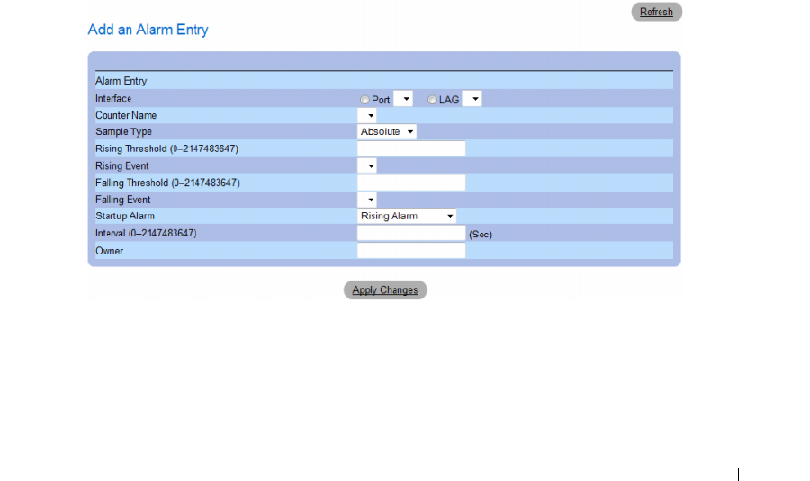
Viewing Statistics 433
•
Rising Event
— The mechanism in which the alarms are reported including a log, a trap, or both.
When a log is selected, there is no saving mechanism either in the device or in the management
system. However, if the device is not being reset, it remains in the device Log table. If a trap is selected,
an SNMP trap is generated and reported via the Trap mechanism. The trap can be saved using the
same mechanism.
•
Falling Threshold
(0–2147483647
) — The falling counter value that triggers the falling threshold
alarm. The falling threshold is graphically presented on top of the graph bars. Each monitored variable
is designated a color. The field default is 20.
•
Startup Alarm
— The trigger that activates the alarm generation. Rising is defined by crossing the
threshold from a low-value threshold to a higher-value threshold.
•
Interval (1–2147483647
)
(sec)
— Alarm interval time. The field default is 100 seconds.
•
Owner
— Device or user that defined the alarm.
•
Remove
— When checked, removes an RMON Alarm.
Adding an Alarm Table Entry
1
Open the
RMON Alarms
page.
2
Click
Add
.
The
Add an Alarm Entry
page opens.
Figure 8-13. Add an Alarm Entry Page
3
Select an interface.
4
Complete the fields.
5
Click
Apply Changes
.
The RMON alarm is added, and the device is updated.

434 Viewing Statistics
Modifying an Alarm Table Entry
1
Open the
RMON Alarms
page.
2
Select an entry in the
Alarm Entry
drop-down menu.
3
Modify the fields.
4
Click
Apply Changes
.
The entry is modified, and the device is updated.
Displaying the Alarm Table
1
Open the
RMON Alarms
page.
2
Click
Show All
.
The
Alarms Table
opens.
Deleting an Alarm Table Entry
1
Open the
RMON Alarms
page.
2
Select an entry in the
Alarm Entry
drop-down menu.
3
Check the
Remove
check box.
4
Click
Apply Changes
.
The entry is deleted, and the device is updated.
Defining Device Alarms Using the CLI Commands
The following table contains the CLI commands for defining device alarms.
Table 8-10. Device Alarm CLI Commands
CLI Command Description
rmon alarm
index MIB_Object_ID interval
rthreshold fthreshold revent fevent
[type
type
] [startup
direction
] [owner
name
]
Configures RMON alarm conditions.
show rmon alarm-table Displays summary of the alarm table.
show rmon alarm Displays the RMON alarm configuration.

Viewing Statistics 435
The following is an example of the CLI commands:
Viewing Charts
The Chart page contains links for displaying statistics in a chart form. To open the page, click Statistics→
Charts in the tree view.
This section contians the following topics:
• "Viewing Port Statistics" on page 436
• "Viewing LAG Statistics" on page 437
• "Viewing the CPU Utilization" on page 439
• "Viewing CPU Utilization Using CLI Commands" on page 440
console(config)# rmon alarm 1000 1.3.6.1.2.1.2.2.1.10.1 360000
1000000 1000000 10 20
Console# show rmon alarm-table
Index OID Owner
------------------------------ -----
11.3.6.1.2.1.2.2.1.10.1 CLI
21.3.6.1.2.1.2.2.1.10.1 Manager
31.3.6.1.2.1.2.2.1.10.9 CLI
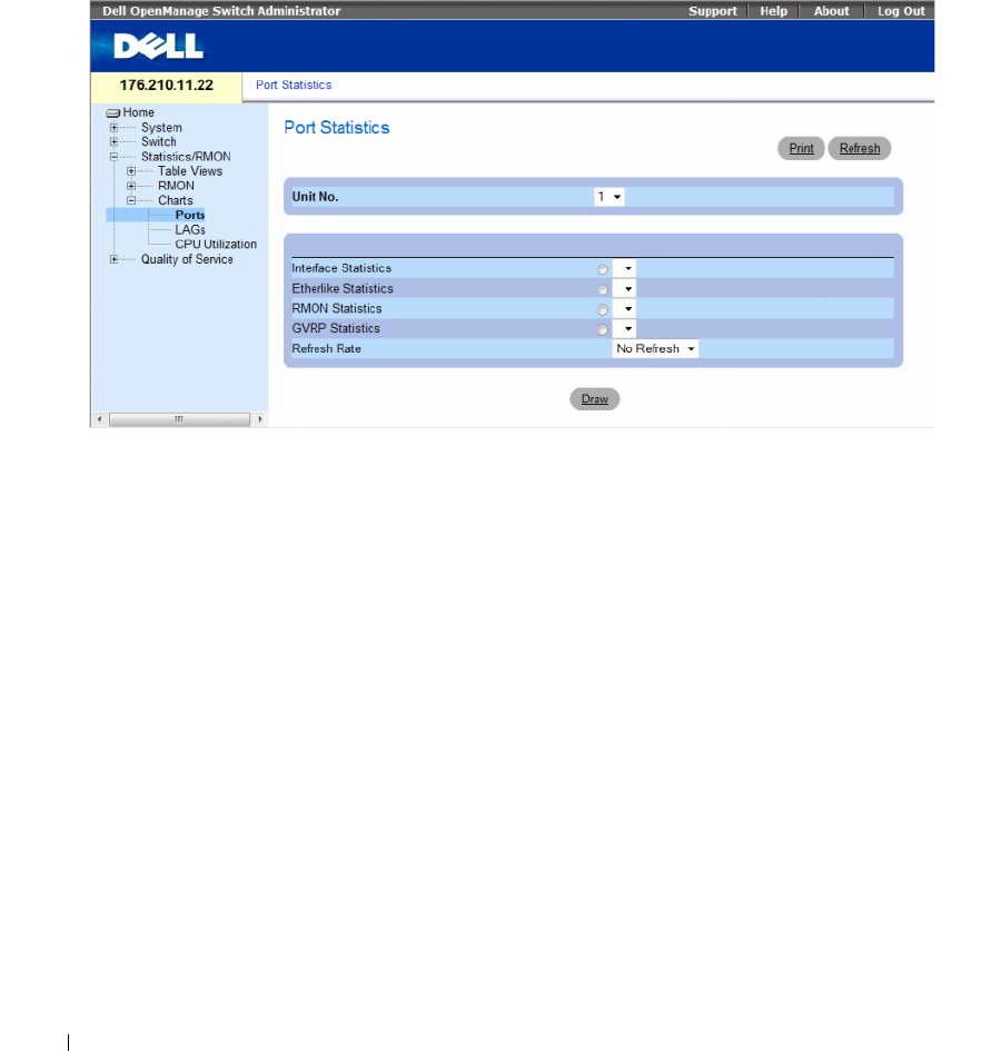
436 Viewing Statistics
Viewing Port Statistics
Use the Port Statistics page to open statistics in a chart form for port elements. To open the Port
Statistics page, click Statistics/RMON→ Charts→ Port Statistics in the tree view.
Figure 8-14. Port Statistics
The Port Statistics page contains the following fields:
•
Unit No.
— Indicates the stacking unit for which the statistics are displayed.
•
Interface Statistics
— Selects the interface statistics to display.
•
Etherlike Statistics
— Selects the Etherlike statistics to display.
•
RMON Statistics
— Selects the RMON statistics to display.
•
GVRP Statistics
— Selects the GVRP statistics type to display.
•
Refresh Rate
— Amount of time that passes before the statistics are refreshed.
Displaying Port Statistics
1
Open the
Port Statistics
page.
2
Select the statistic type of to open.
3
Select the desired refresh rate from the
Refresh Rate
drop-down menu.
4
Click
Draw
.
The graph for the selected statistic is displayed.
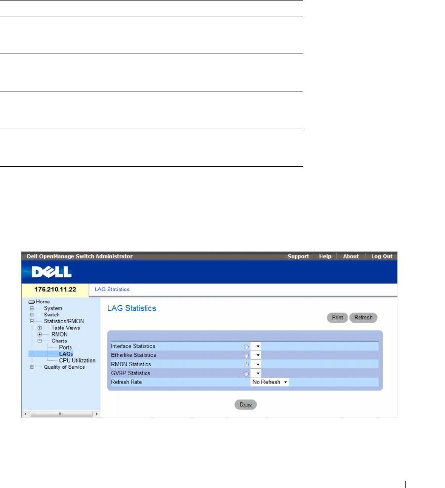
Viewing Statistics 437
Viewing Port Statistics Using the CLI Commands
The following table contains the CLI commands for viewing port statistics.
Viewing LAG Statistics
Use the LAG Statistics page to open statistics in a chart form for LAGs. To open the LAG Statistics
page, click Statistics/RMON→ Charts→ LAG Statistics in the tree view.
Figure 8-15. LAG Statistics
Table 8-11. Port Statistic CLI Commands
CLI Command Description
show interfaces counters [ethernet
interface
| port-channel
port-
channel-number
]
Displays traffic seen by the physical
interface.
show rmon statistics {ethernet
interface
| port-channel
port-
channel-number
}
Displays RMON Ethernet
statistics.
show gvrp statistics {ethernet
interface
| port-channel
port-
channel-number
}
Displays GVRP statistics.
show gvrp-error statistics {ethernet
interface
| port-channel
port-
channel-number
}
Displays GVRP error statistics.

438 Viewing Statistics
The LAG Statistics page contains the following fields:
•
Interface Statistics
— Selects the interface statistics to display.
•
Etherlike Statistics
— Selects the Etherlike statistics to display.
•
RMON Statistics
— Selects the RMON statistics to display.
•
GVRP Statistics
— Selects the GVRP statistics type to display.
•
Refresh Rate
— Amount of time that passes before the statistics are refreshed.
Displaying LAG Statistics
1
Open the
LAG Statistics
page.
2
Select the statistic type to open.
3
Select the desired refresh rate from the
Refresh Rate
drop-down menu.
4
Click
Draw
.
The graph for the selected statistic is displayed.
Viewing LAG Statistics Using the CLI Commands
The following table contains the CLI commands for viewing LAG statistics.
Table 8-12. LAG Statistic CLI Commands
CLI Command Description
show interfaces counters [ethernet
interface
| port-channel
port-
channel-number
]
Displays traffic seen by the physical
interface.
show rmon statistics {ethernet
interface
| port-channel
port-
channel-number
}
Displays RMON Ethernet
statistics.
show gvrp statistics {ethernet
interface
| port-channel
port-
channel-number
}
Displays GVRP statistics.
show gvrp-error statistics {ethernet
interface
| port-channel
port-
channel-number
}
Displays GVRP error statistics.
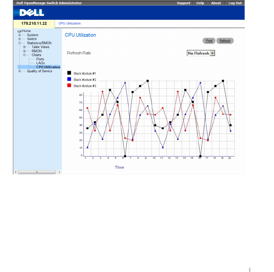
Viewing Statistics 439
Viewing the CPU Utilization
The CPU Utilization page contains information about the system’s CPU utilization and percentage of
CPU resources consumed by each stacking member. Each stacking member is assigned a color on the
graph.
To open the CPU Utilization page, click Statistics/RMON→ Charts→ CPU Utilization in the tree view.
Figure 8-16. CPU Utilization
The CPU Utilization page contains the following information:
•
Refresh Rate
— Amount of time that passes before the statistics are refreshed.

440 Viewing Statistics
Viewing CPU Utilization Using CLI Commands
The following table summarizes the equivalent CLI commands for viewing CPU utilization.
The following is an example of the CLI commands:
Figure 8-17. CPU Utilization CLI Commands
CLI Command Description
show cpu utilization To display the CPU utilization.
Console# show cpu utilization
CPU utilization service is on.
CPU utilization
--------------------------
five seconds: 5%; one minute: 3%; five minutes: 3%

Configuring Quality of Service 441
Configuring Quality of Service
This section provides information for defining and configuring Quality of Service (QoS) parameters.
To open the Quality of Service page, click Quality of Service in the tree view.
This section contians the following topics:
• "Quality of Service (QoS) Overview" on page 441
• "Configuring QoS Global Settings" on page 443
Quality of Service (QoS) Overview
Quality of Service (QoS) provides the ability to implement QoS and priority queuing within a network.
An implementation example that requires QoS includes certain types of traffic such as Voice, Video
and real-time traffic, which can be assigned a high priority queue, while other traffic can be assigned
a lower priority queue. The result is an improved traffic flow for traffic with high demand.
QoS is defined by:
•
Classification
— Specifies which packet fields are matched to specific values. All packets
matching the user-defined specifications are classified together.
•
Action
— Defines traffic management where packets being forwarded are based on packet
information, and packet field values such as VLAN priority tag (VPT) and DSCP (DiffServ
Code Point).
VPT Classification Information
VLAN Priority Tags are used to classify the packets by mapping packets to one of the egress queues.
VLAN Priority Tag to queue assignments are user-definable. The table below details the VPT to
queue default settings:
Table 9-1. CoS to Queue Mapping Table Default values
CoS Value Forwarding Queue Values
0q2
1 q1 (Lowest Priority)
2 q1 (Lowest Priority)
3q2
4q3

442 Configuring Quality of Service
Packets arriving untagged are assigned a default VPT value, which is set on a per port basis. The assigned
VPT is used to map the packet to the egress queue.
DSCP values can be mapped to priority queues. The following table contains the default DSCP mapping
to egress queue values:
DSCP mapping is enabled on a per-system basis.
This section contians the following topics:
• "CoS Services" on page 442
CoS Services
After packets are assigned to a specific egress queue, CoS services can be assigned to the queue(s).
Egress queues are configured with a scheduling scheme by one of the following methods:
•
Strict Priority
— Ensures that time-sensitive applications are always forwarded. Strict Priority (SP)
allows the prioritization of mission-critical, time-sensitive traffic over less time-sensitive applications.
For example, under Strict Priority, voice over IP traffic can be prioritized so the IP traffic is forwarded
before FTP or e-mail (SMTP) traffic.
•
Weighted Round Robin
— Ensures that a single application does not dominate the device forwarding
capacity. Weighted Round Robin (WRR) forwards entire queues in a Round Robin order. All queues
can be configured to WRR or SP queues. If WRR is selected, the following weights are assigned to the
queues: 1, 2, 4, 8.
5q3
6q4
7q4
Table 9-2. DSCP to Queue Mapping Table Default Values
DSCP Value Forwarding Queue Values
0-15 q1 (Lowest Priority)
16-31 q2
32-47 q3
48-63 q4
Table 9-1. CoS to Queue Mapping Table Default values (continued)
CoS Value Forwarding Queue Values
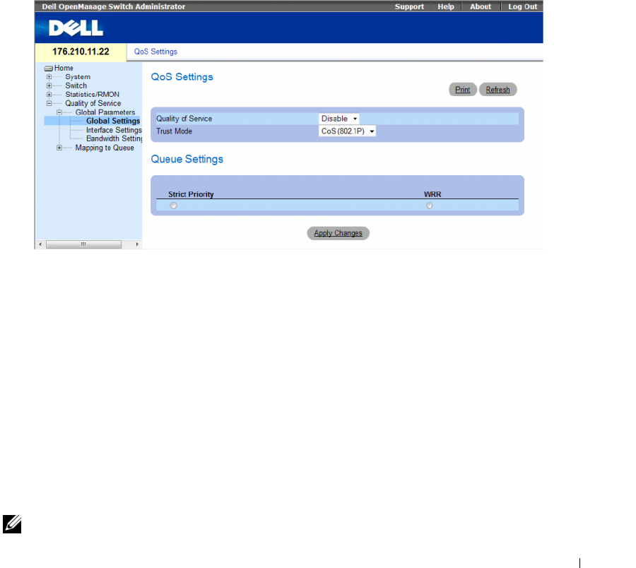
Configuring Quality of Service 443
Configuring QoS Global Settings
Quality of Service (QoS) provides the ability to implement QoS and priority queuing within a network.
The Global Settings page contains a field for enabling or disabling QoS. It also contains a field for selecting
the Trust mode. The Trust mode relies on predefined fields within the packet to determine the egress queue.
In addition, the Global Settings page enables defining queues as either Strict Priority (SP) or Weighted
Round Robin (WRR).
To open the Global Settings page, click Quality of Service→ QoS Parameters → Global Settings in the
tree view.
Figure 9-1. Global Settings
The Global Settings page contains the following sections:
• QoS Settings
• Queue Settings
QoS Settings
•
Quality of Service
— Enables or disables managing network traffic using Quality of Service.
•
Trust Mode
— Determines which packet fields are used to classify packets entering the device.
When no rules are defined, the traffic containing the predefined CoS or DSCP packet field is mapped
according to the selected trust mode. Traffic not containing a predefined packet field is mapped to the
best effort queue (q2). The possible Trust Mode field values are:
–
CoS
(802.1p) — The egress queue assignment is determined by the IEEE802.1p VLAN priority
tag (VPT) or by the default VPT assigned to a port. The device default is the IEEE802.1p.
–
DSCP
— The egress queue assignment is determined by the DSCP field.
NOTE: The interface Trust settings overrides the global Trust setting.

444 Configuring Quality of Service
Queue Settings
•
Strict Priority
— Indicates the system queues are SP queues, when selected.
•
WRR
— Indicates the system queues are WRR queues, when selected.
Enabling Quality of Service:
1
Open the
Global Settings
page
.
2
Select
Enable
in the
Quality of Service
field.
3
Click
Apply Changes
.
Class of Service is enabled on the device.
Enabling the Trust Mode:
1
Open the
Global Settings
page
.
2
Define the
Trust Mode
field.
3
Click
Apply Changes
.
Trust mode is enabled on the device.
Enabling Trust Using the CLI Commands
The following table summarizes the equivalent CLI commands for configuring fields in the Global
Settings page.
The following is an example of the CLI commands:
This section contians the following topics:
• "Defining QoS Interface Settings" on page 445
• "Defining Bandwidth Settings" on page 446
• "Mapping CoS Values to Queues" on page 448
• "Mapping DSCP Values to Queues" on page 450
Table 9-3. QoS Settings CLI Commands
CLI Command Description
qos trust [cos | dscp] Configures the system to trust mode.
no qos trust Returns to the non-trusted state.
console(config)# qos trust dscp
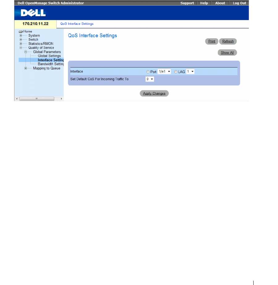
Configuring Quality of Service 445
Defining QoS Interface Settings
The Interface Settings page contains fields for deactivating the Trust mode, and setting the default
CoS value on incoming untagged packets. To open the Interface Settings page, click Quality of Service→
QoS Parameters → Interface Settings in the tree view.
Figure 9-2. Interface Settings
The Interface Settings page contains the following fields:
•
Interface
— The specific port or LAG to configure.
•
Disable "Trust" Mode on Interface
— Disables Trust mode on the specified interface. This setting
overrides the Trust mode configured on the device globally.
•
Set Default CoS For Incoming Traffic To
— Sets the default CoS tag value for untagged packets.
The CoS tag values are 0-7. The default value is 0.
Assigning QoS settings for an interface:
1
Open the
Interface Settings
page.
2
Select an interface in the
Interface
field.
3
Define the fields.
4
Click
Apply Changes
.
The CoS settings are assigned to the interface.
Displaying QoS/CoS settings:
1
Open the
Interface Settings
page.
2
Click
Show All
.
The Interface Table is displayed.
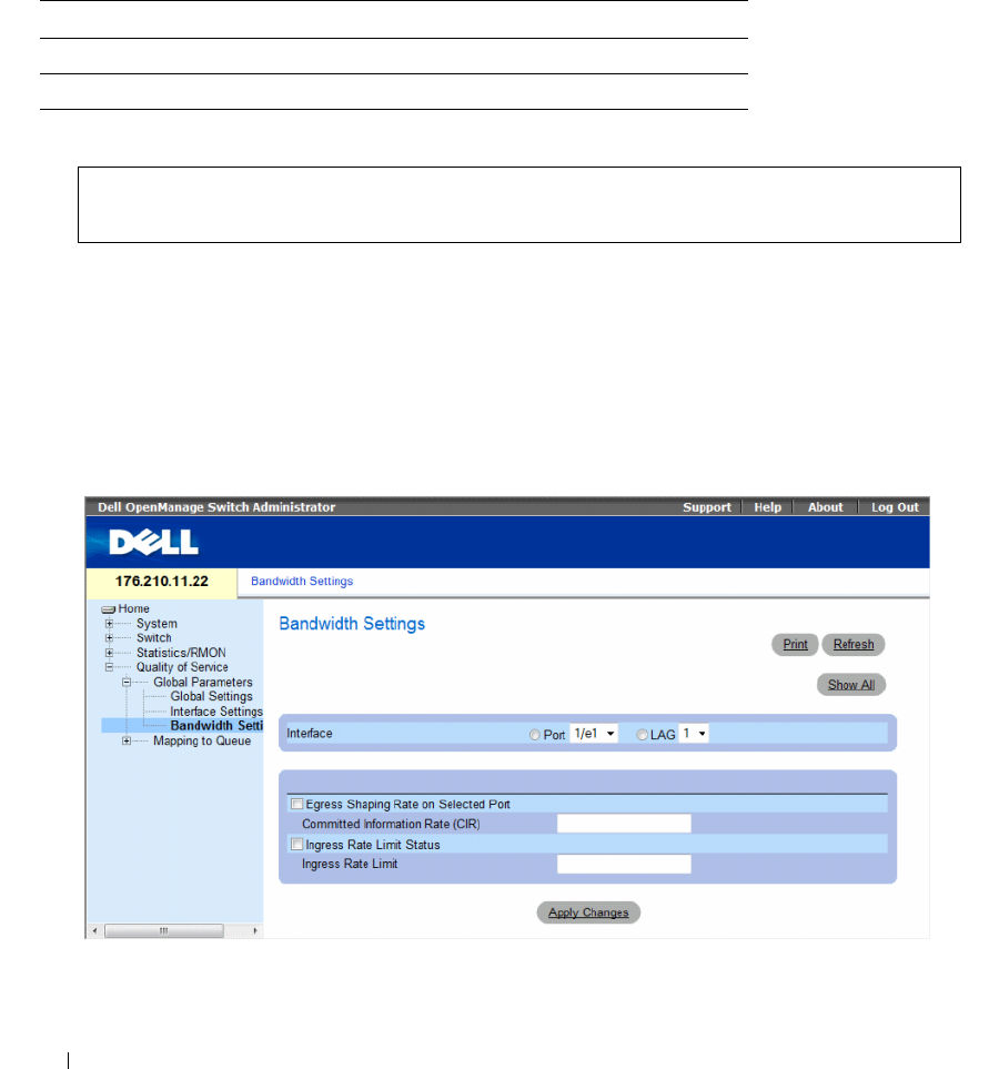
446 Configuring Quality of Service
Assigning QoS Interfaces Using the CLI Commands
The following table summarizes the equivalent CLI commands for configuring fields in the Interface
Settings page.
The following is an example of the CLI commands:
Defining Bandwidth Settings
The Bandwidth Settings page contains fields for defining the bandwidth settings for a specified egress
interface. Modifying queue scheduling affects the queue settings globally. Queue shaping can be based
per queue and/or per interface. Shaping is determined by the lower specified value. The queue shaping
type is selected in the Bandwidth Settings Page, click Quality of Service → CoS Global Parameters→
Bandwidth Settings in the tree view.
Figure 9-3. Bandwidth Settings
Table 9-4. QoS Interface CLI Commands
CLI Command Description
qos trust Enables the trust mode.
no qos trust Disables Trust state on each port.
console(config)# interface ethernet 1/e15
console(config-if)# qos trust
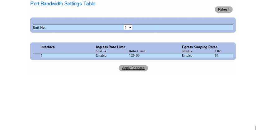
Configuring Quality of Service 447
•
Interface
—
Indicates the port or LAG that is being displayed.
•
Egress Shaping Rate on Selected Port
— Indicates the Egress traffic limit status for the interface.
–
Checked
— The Egress traffic limit is enabled.
–
Not Checked
— The Egress traffic limit is disabled.
•
Committed Information Rate (CIR)
— Defines the Egress CIR traffic limit for the interface.
•
Ingress Rate Limit Status
— Indicates the Ingress traffic limit status for the interface.
–
Checked
— The Ingress traffic limit is enabled.
–
Not Checked
— The Ingress traffic limit is disabled.
•
Ingress Rate Limit
— Defines the Ingress traffic limit for the interface.
Assigning bandwidth settings for an interface:
1
Open the
Bandwidth Settings
page.
2
Select an interface in the
Interface
field.
3
Define the fields.
4
Click
Apply Changes
.
The bandwidth settings are assigned to the interface.
Displaying the Bandwidth Settings Table:
1
Open the
Bandwidth Settings
page.
2
Click
Show All
.
The Bandwidth Settings Table opens.
Figure 9-4. Bandwidth Settings Table
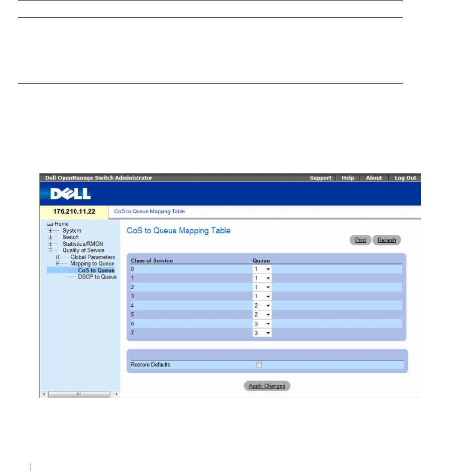
448 Configuring Quality of Service
Assigning Bandwidth Settings Using the CLI Commands
The following table summarizes the equivalent CLI commands for configuring fields in the Bandwidth
Settings page.
Mapping CoS Values to Queues
The CoS to Queue page contains fields for classifying CoS settings to traffic queues. To open the CoS to
Queue page, click Quality of Service→ QoS Mapping→ CoS to Queue in the tree view.
Figure 9-5. CoS to Queue
Table 9-5. Bandwidth Settings CLI Commands
CLI Command Description
traffic-shape committed-rate [committed-burst]
no traffic-shape
Set shaper on egress port. Use no form in
order to disable the shaper.
rate-limit rate
no rate-limit
Limit the rate of the incoming traffic. Use the
no form to disable rate limit.

Configuring Quality of Service 449
The CoS to Queue page contains the following fields:
•
Class of Service
— Specifies the CoS priority tag values, where zero is the lowest and 7 is the highest.
•
Queue
— The queue to which the CoS priority is mapped. Four traffic priority queues are supported.
•
Restore Defaults
— Restores the device factory defaults for mapping CoS values to an egress queue.
Mapping a CoS Value to a Queue
1
Open the
CoS to Queue
page.
2
Select a
CoS
entry.
3
Define the queue number in the
Queue
field.
4
Click
Apply Changes
.
The CoS value is mapped to an egress queue, and the device is updated.
Assigning CoS Values to Queues Using the CLI Commands
The following table summarizes the equivalent CLI commands for configuring fields in the CoS to
Queue page.
The following is an example of the CLI commands:
Table 9-6. CoS to Queue Settings CLI Commands
CLI Command Description
wrr-queue cos-map queue-id
cos0.cos7
Maps assigned CoS values to the egress
queues.
console(config)# wrr-queue cos-map 4 7
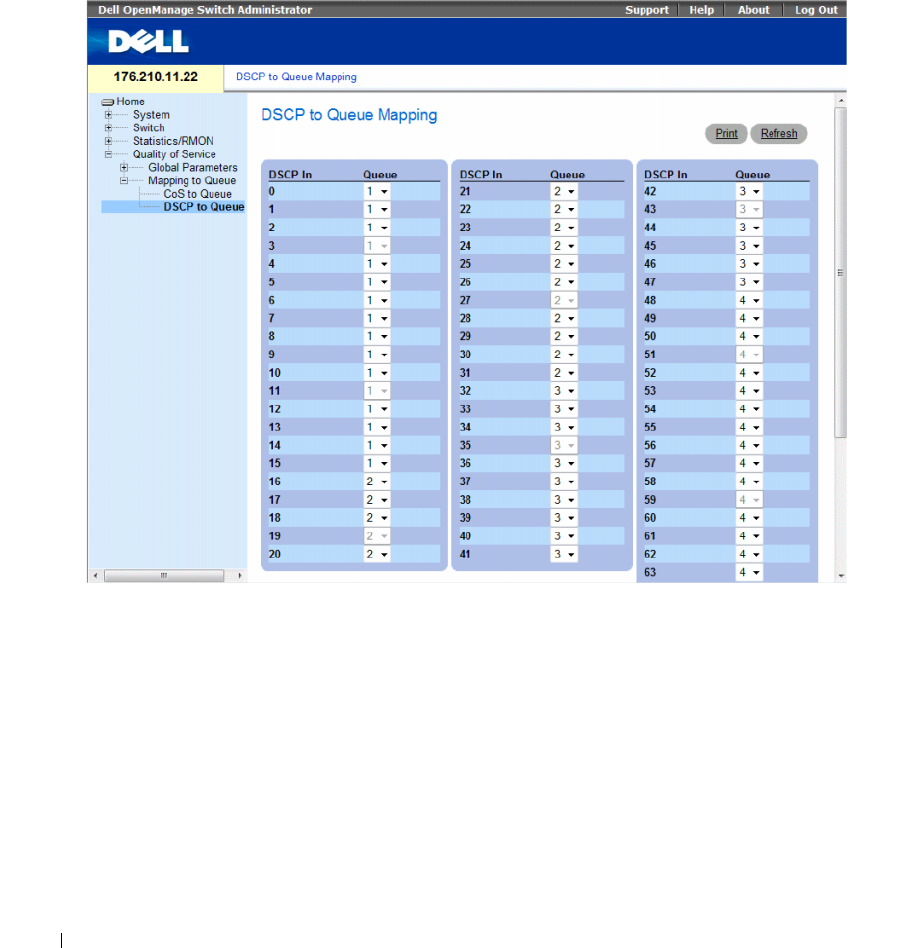
450 Configuring Quality of Service
Mapping DSCP Values to Queues
The DSCP to Queue page provides fields for defining egress queue to specific DSCP fields. To open the
DSCP to Queue page, click Quality of Service→ QoS Mapping→ DSCP to Queue in the tree view.
Figure 9-6. DSCP to Queue
The DSCP to Queue page contains the following fields:
•
DSCP In
— The values of the DSCP field within the incoming packet.
•
Queue
— The queue to which packets with the specific DSCP value is assigned. The values are 1-4,
where 1 is the lowest value and 4 is the highest.
•
Restore Defaults
— Restores the device factory defaults for mapping CoS values to an egress queue.
Configuring Quality of Service 451
Mapping a DSCP Value and Assigning a Priority Queue
1
Open the
DSCP to Queue
page.
2
Select a value in the
DSCP In
column.
3
Define the
Queue
field.
4
Click
Apply Changes
.
The DSCP is overwritten, and the value is assigned an egress queue.
Assigning DSCP Values Using the CLI Commands
The following table summarizes the equivalent CLI commands for configuring fields in the DSCP to
Queue page.
The following is an example of the CLI commands:
Table 9-7. DSCP Value to Queue CLI Commands
CLI Command Description
qos map dscp-queue dscp-list
to queue-id
Modifies the DSCP to queue mapping.
console(config)# qos map dscp-queue 33 40 41 to 1

452 Configuring Quality of Service

Glossary 453
Glossary
This glossary contains key technical words of interest.
A
Access Mode
Specifies the method by which user access is granted to the system.
Access Profiles
Allows network managers to define profiles and rules for accessing the switch module. Access to
management functions can be limited to user groups, which are defined by the following criteria:
• Ingress interfaces
• Source IP address or Source IP subnets
ACL
Access Control List. Allow network managers to define classification actions and rules for specific
ingress ports.
Aggregated VLAN
Groups several VLANs into a single aggregated VLAN. Aggregating VLANs enables routers to
respond to ARP requests for nodes located on different sub-VLANs belonging to the same Super
VLAN. Routers respond with their MAC address.
ARP
Address Resolution Protocol. A protocol that converts IP addresses into physical addresses.
ASIC
Application Specific Integrated Circuit. A custom chip designed for a specific application.
Asset Tag
Specifies the user-defined switch module reference.
Authentication Profiles
Sets of rules which that enables login to and authentication of users and applications.
A
BCDEFGHI LMNOPQRSTUVW

454 Glossary
Auto-negotiation
Allows 10/100 Mpbs or 10/100/1000 Mbps Ethernet ports to establish for the following features:
• Duplex/ Half Duplex mode
• Flow Control
• Speed
B
Back Pressure
A mechanism used with Half Duplex mode that enables a port not to receive a message.
Backplane
The main BUS that carries information in the switch module.
Backup Configuration Files
Contains a backup copy of the switch module configuration. The Backup file changes when the Running
Configuration file or the Startup configuration file is copied to the Backup file.
Bandwidth
Bandwidth specifies the amount of data that can be transmitted in a fixed amount of time. For digital
switch modules, bandwidth is defined in Bits per Second (bps) or Bytes per Second.
Bandwidth Assignments
The amount of bandwidth assigned to a specific application, user, or interface.
Baud
The number of signaling elements transmitted each second.
Best Effort
Traffic is assigned to the lowest priority queue, and packet delivery is not guaranteed.
Boot Version
The boot version.
BootP
Bootstrap Protocol. Enables a workstation to discover its IP address, an IP address of a BootP server on a
network, or a configuration file loaded into the boot of a switch module.
BPDU
Bridge Protocol Data Unit. Provide bridging information in a message format. BPDUs are sent across
switch module information with in Spanning Tree configuration. BPDU packets contain information on
ports, addresses, priorities, and forwarding costs.

Glossary 455
Bridge
A device that connect two networks. Bridges are hardware specific, however they are protocol
independent. Bridges operate at Layer 1 and Layer 2 levels.
Broadcast Domain
device sets that receive broadcast frames originating from any device within a designated set. Routers
bind Broadcast domains, because routers do not forward broadcast frames.
Broadcasting
A method of transmitting packets to all ports on a network.
Broadcast Storm
An excessive amount of broadcast messages simultaneously transmitted across a network by a single port.
Forwarded message responses are heaped onto the network, overloading network resources or causing the
network to time out.
For more information about broadcast storms, see "Defining LAG Parameters" on page 304.
C
CDB
Configuration Data Base. A file containing a device’s configuration information.
Class of Service
Class of Service (CoS). Class of Service is the 802.1p priority scheme. CoS provides a method for tagging
packets with priority information. A CoS value between 0-7 is added to the Layer II header of packets,
where zero is the lowest priority and seven is the highest.
A overlapping transmission of two or more packets that collide. The data transmitted cannot be used,
and the session is restarted.
CLI
Command Line Interface. A set of line commands used to configure the system. For more information
on using the CLI, see Using the CLI.
Communities
Specifies a group of users which retains the same system access rights.
CPU
Central Processing Unit. The part of a computer that processes information. CPUs are composed of a
control unit and an ALU.

456 Glossary
D
DHCP Client
A device using DHCP to obtain configuration parameters, such as a network address.
DHCP Snooping
DHCP Snooping expands network security by providing firewall security between untrusted interfaces
and DHCP servers.
DSCP
DiffServe Code Point (DSCP). DSCP provides a method of tagging IP packets with QoS priority
information.
Domain
A group of computers and devices on a network that are grouped with common rules and procedures.
DRAC/MC
DRAC/MC. Provides a single point of control for Dell Modular Server System components.
Duplex Mode
Permits simultaneous transmissions and reception of data. There are two different types of duplex mode:
•
Full Duplex Mode
— Permits for bisynchronous communication, for example, a telephone. Two
parties can transmit information at the same time.
•
Half Duplex Mode
— Permits asynchronous communication, for example, a walkie-talkie. Only one
party can transmit information at a time.
Dynamic VLAN Assignment (DVA)
• Allows automatic assignment of users to VLANs during the RADIUS server authentication. When a
user is authenticated by the RADIUS server, the user is automatically joined to the VLAN configured
on the RADIUS server.
E
Egress Ports
Ports from which network traffic is transmitted.
End System
An end user device on a network.
Ethernet
Ethernet is standardized as per IEEE 802.3. Ethernet is the most common implemented LAN standard.
Supports data transfer rates of Mpbs, where 10, 100 or 1000 Mbps is supported.
EWS
Embedded Web Server. Provides device management via a standard web browser. Embedded Web
Servers are used in addition to or in place of a CLI or NMS.

Glossary 457
F
FFT
Fast Forward Table. Provides information about forwarding routes. If a packet arrives to a device with a
known route, the packet is forwarded via a route listed in the FFT. If there is not a known route, the CPU
forwards the packet and updates the FFT.
FIFO
First In First Out. A queuing process where the first packet in the queue is the first packet out of the
packet.
Flapping
Flapping occurs when an interfaces state is constantly changing. For example, an STP port constantly
changes from listening to learning to forwarding. This may cause traffic loss.
Flow Control
Enables lower speed devices to communicate with higher speed device s, that is, that the higher speed
device refrains from sending packets.
Fragment
Ethernet packets smaller than 576 bits.
Frame
Packets containing the header and trailer information required by the physical medium.
G
GARP
General Attributes Registration Protocol. Registers client stations into a Multicast domain.
Gigabit Ethernet
Gigabit Ethernet transmits at 1000 Mbps, and is compatible with existing 10/100 Mbps Ethernet
standards.
GVRP
GARP VLAN Registration Protocol. Registers client stations into a VLANs.
H
HOL
Head of Line. Packets are queued. Packets at the head of the queue are forwarded before packets at the
end of the line.
Host
A computer that acts as a source of information or services to other computers.
HTTP
HyperText Transport Protocol. Transmits HTML documents between servers and clients on the internet.

458 Glossary
I
IC
Integrated Circuit. Integrated Circuits are small electronic devices composed from semiconductor
material.
ICMP
Internet Control Message Protocol. Allows gateway or destination host to communicate with a source
host, for example, to report a processing error.
IEEE
Institute of Electrical and Electronics Engineers. An Engineering organization that develops
communications and networking standards.
IEEE 802.1d
Used in the Spanning Tree Protocol, IEEE 802.1d supports MAC bridging to avoid network loops.
IEEE 802.1p
Prioritizes network traffic at the data-link/MAC sublayer.
IEEE 802.1Q
Defines the operation of VLAN Bridges that permit the definition, operation, and administration of
VLANs within Bridged LAN infrastructures.
IGMP Snooping
IGMP Snooping examines IGMP frame contents, when they are forwarded by the device from work
stations to an upstream Multicast router. From the frame, the device identifies work stations configured
for Multicast sessions, and which Multicast routers are sending Multicast frames.
Image File
System images are saved in two Flash sectors called images (Image 1 and Image 2). The active image
stores the active copy; while the other image stores a second copy.
Ingress Port
Ports on which network traffic is received.
IP
Internet Protocol. Specifies the format of packets and there addressing method. IP addresses packets and
forwards the packets to the correct port.
IP Address
Internet Protocol Address. A unique address assigned to a network device with two or more
interconnected LANs or WANs.
IP Version 6 (IPv6)
A version of IP addressing with longer addresses than the traditional IPv4. IPv6 addresses are 128 bits
long, whereas IPv4 addresses are 32 bits; allowing a much larger address space.

Glossary 459
ISATAP
Intra-Site Automatic Tunnel Addressing Protocol .
ISATAP is an automatic overlay tunneling mechanism that uses the underlying IPv4 network as a non-
broadcast/multicast access link layer for IPv6. ISATAP is designed for transporting IPv6 packets within a
site where a native IPv6 infrastructure is not yet available.
L
LAG
Link Aggregated Group. Aggregates ports or VLANs into a single virtual port or VLAN.
For more information on LAGs, see Defining LAG Membership.
LAN
Local Area Networks. A network contained within a single room, building, campus or other limited
geographical area.
Layer 2
Data Link Layer or MAC Layer. Contains the physical address of a client or server station. Layer 2
processing is faster than Layer 3 processing because there is less information to process.
Layer 4
Establishes a connections and ensures that all data arrives to their destination. Packets inspected at the
Layer 4 level are analyzed and forwarding decisions based on their applications.
LLDP-MED
Link Layer Discovery Protocol - Media Endpoint Discovery. LLDP allows network managers to
troubleshoot and enhance network management by discovering and maintaining network topologies over
multi-vendor environments. MED increases network flexibility by allowing different IP systems to co-
exist on a single network LLDP.
Load Balancing
Enables the even distribution of data or processing packets across available network resources. For
example, load balancing may distribute the incoming packets evenly to all servers, or redirect the packets
to the next available server.
M
MAC Address
Media Access Control Address. The MAC Address is a hardware specific address that identifies each
network node.

460 Glossary
MAC Address Learning
MAC Address Learning characterizes a learning bridge, in which the packet’s source MAC address is
recorded. Packets destined for that address are forwarded only to the bridge interface on which that
address is located. Packets addressed to unknown addresses are forwarded to every bridge interface. MAC
Address Learning minimizes traffic on the attached LANs.
MAC Layer
A sub-layer of the Data Link Control (DTL) layer.
Mask
A filter that includes or excludes certain values, for example parts of an IP address.
For example, Unit 2 is inserted in the first minute of a ten-minute cycle, and Unit 1 is inserted in fifth
minute of the same cycle, the units are considered the same age.
MD5
Message Digest 5. An algorithm that produces a 128-bit hash. MD5 is a variation of MD4, and increases
MD4 security. MD5 verifies the integrity of the communication, authenticates the origin of the
communication.
MDI
Media Dependent Interface. A cable used for end stations.
MDIX
Media Dependent Interface with Crossover (MDIX). A cable used for hubs and switches.
MIB
Management Information Base. MIBs contain information describing specific aspects of network
components.
Multicast
Transmits copies of a single packet to multiple ports.
N
NA
Neighbor Advertisement.
ND
Neighbor Discovery.
NS
Neighbor Solicitation.

Glossary 461
NMS
Network Management System. An interface that provides a method of managing a system.
Node
A network connection endpoint or a common junction for multiple network lines. Nodes include:
• Processors
• Controllers
• Workstations
O
OID
Organizationally Unique Identifiers. Identifiers associated with a Voice VLAN.
OUI
Object Identifier. Used by SNMP to identify managed objects. In the SNMP Manager/ Agent network
management paradigm, each managed object must have an OID to identify it.
P
Packets
Blocks of information for transmission in packet switched systems.
PDU
Protocol Data Unit. A data unit specified in a layer protocol consisting of protocol control information
and layer user data.
PING
Packet Internet Groper. Verifies if a specific IP address is available. A packet is sent to another IP address
and waits for a reply.
Port
Physical ports provide connecting components that allow microprocessors to communicate with
peripheral equipment.
Port Mirroring
Monitors and mirrors network traffic by forwarding copies of incoming and outgoing packets from one
port to a monitoring port.
For more information on port mirroring, see Defining Port Mirroring Sessions.

462 Glossary
Port Speed
Indicates port speed of the port. Port speeds include:
• Ethernet 10 Mbps
• Fast Ethernet 100Mbps
• Gigabit Ethernet 1000 Mbps
Protocol
A set of rules that governs how devices exchange information across networks.
PVE
Protocol VLAN Edge. A port can be defined as a Private VLAN Edge (PVE) port of an uplink port, so that
it will be isolated from other ports within the same VLAN.
Q
QoS
Quality of Service. QoS allows network managers to decide how and what network traffic is forwarded
according to priorities, application types, and source and destination addresses.
Query
Extracts information from a database and presents the information for use.
R
RA
RADIUS Advertisement.
RD
RADIUS Discovery.
RS
Router Solicitation.
RADIUS
Remote Authentication Dial-In User Service. A method for authenticating system users, and tracking
connection time.
RMON
Remote Monitoring. Provides network information to be collected from a single workstation.
Router
A device that connects to separate networks. Routers forward packets between two or more networks.
Routers operate at a Layer 3 level.

Glossary 463
RSTP
Rapid Spanning Tree Protocol. Detects and uses network topologies that allow a faster convergence of
the spanning tree, without creating forwarding loops.
Running Configuration File
Contains all startup configuration file commands, as well as all commands entered during the current
session. After the switch module is powered down or rebooted, all commands stored in the Running
Configuration file are lost.
S
Segmentation
Divides LANs into separate LAN segments for bridging. Segmentation eliminates LAN bandwidth
limitations.
Server
A central computer that provides services to other computers on a network. Services may include file
storage and access to applications.
SNMP
Simple Network Management Protocol. Manages LANs. SNMP based software communicates with
network devices with embedded SNMP agents. SNMP agents gather network activity and device status
information, and send the information back to a workstation.
SNTP
Simple Network Time Protocol. SNTP assures accurate network switch clock time synchronization up to
the millisecond.
SoC
System on a Chip. An ASIC that contains an entire system. For example, a telecom SoC application can
contain a microprocessor, digital signal processor, RAM, and ROM.
Spanning Tree Protocol
Prevents loops in network traffic. The Spanning Tree Protocol (STP) provides tree topography for any
arrangement of bridges. STP provides one path between end stations on a network, eliminating loops.
SSH
Secure Shell. Permits logging to another computer over a network, execute commands on a remote
machine, and move files from one machine to another. Secure Shell provides strong authentication and
secure communications methods over insecure channels.
Startup Configuration
Retains the exact switch module configuration when the switch module is powered down or rebooted.

464 Glossary
Subnet
Sub-network. Subnets are portions of a network that share a common address component. On TCP/IP
networks, devices that share a prefix are part of the same subnet. For example, all devices with a prefix of
157.100.100.100 are part of the same subnet.
Subnet Mask
Used to mask all or part of an IP address used in a subnet address.
Switch
Filters and forwards packets between LAN segments. Switches support any packet protocol type.
T
TCP/IP
Transmissions Control Protocol. Enables two hosts to communicate and exchange data streams. TCP
guarantees packet delivery, and guarantees packets are transmitted and received in the order their sent.
Telnet
Terminal Emulation Protocol. Enables system users to log in and use resources on remote networks.
TFTP
Trivial File Transfer Protocol. Uses User Data Protocol (UDP) without security features to transfer files.
Trap
A message sent by the SNMP that indicates that system event has occurred.
Trunking
Link Aggregation. Optimizes port usage by linking a group of ports together to form a single trunk
(aggregated groups).
U
UDP
User Data Protocol. Transmits packets but does not guarantee their delivery.
Unicast
A form of routing that transmits one packet to one user.
V
VLAN
Virtual Local Area Networks. Logical subgroups with a Local Area Network (LAN) created via software
rather than defining a hardware solution.
VoIP
Voice over IP.

Glossary 465
W
WAN
Wide Area Networks. Networks that cover a large geographical area.
Wildcard Mask
Specifies which IP address bits are used, and which bits are ignored. A wild switch module mask of
255.255.255.255 indicates that no bit is important. A wildcard of 0.0.0.0 indicates that all the bits are
important.

466 Glossary

Device Feature Interaction Information 467
Device Feature Interaction Information
The following table contains information about feature interactions
Feature Feature Notes
802.1x Unauthenticated VLAN 802.1x Unauthenticated VLANs have restricted functionality with:
• 802.1X Guest VLAN
• Special VLAN
802.1x Unauthenticated VLAN Port 802.1X Unauthenticated VLAN Ports have restricted functionality
with:
• MAC based VLAN ports
• Ingress Filtering
ACL ACL functionality is restricted with:
• IP Based ACLs
• MAC Based ACLs
• Special VLANs
Auto-negotiation No feature interaction restrictions or limitations.
Back Pressure Support
Bridge Multicast Filtering No feature interaction restrictions or limitations.
Cable Tests No feature interaction restrictions or limitations.
Community ports Community ports have restricted functionality with Locked Ports.
DHCP Snooping No Restrictions or limitations.
DNS No Restrictions or limitations.
Duplex Mode
Flow Control No feature interaction restrictions or limitations.
GARP No feature interaction restrictions or limitations.
Guest VLANs Guest VLANs cannot function with:
• MAC Based VLANs
• Special VLANs
GVRP No feature interaction restrictions or limitations.
IGMP Snooping No feature interaction restrictions or limitations.
Ingress Filtering No feature interaction restrictions or limitations.
LAG Statistics No feature interaction restrictions or limitations.

468 Device Feature Interaction Information
Link Aggregation No feature interaction restrictions or limitations. However, this
feature has several guidelines for configuring Link Aggregation. For
all the feature guidelines, see "Defining LAG Parameters".
LLDP-MED No feature interaction restrictions or limitations.
Locked Ports ‘Locked port functionality is restricted with:
• MAC Based ACLs
• Ingress Filtering
Logging No feature interaction restrictions or limitations.
MAC Address Support No feature interaction restrictions or limitations.
MDI/MDIX Decection No feature interaction restrictions or limitations.
Multicast Filtering No feature interaction restrictions or limitations.
Multiple Hosts 802.1X Standard (multiple hosts) cannot function with:
• MAC Based VLAN Port
Multiple Spanning Tree Multiple Spanning Tree cannot function with:
• Ingress Filtering
Port Based Authentication Port based authentication has limited or restricted functionality
with:
• 802.1 Single
•Locked Ports
• MAC Based VLANs
• Ingress Ports
Port Mirroring No feature interaction restrictions or limitations. However, this
feature has several guidelines for configuring Storm Control. For all
the feature guidelines, see "Defining Port Mirroring Sessions".
Port Statistics No feature interaction restrictions or limitations
Private VLAN Private VLANs cannot function with:
• GVRP
• IGMP Snooping
• Special VLAN
Private VLAN Private VLANs are limited or restricted functionality with:
• GVRP
• IGMP Snooping
• Special VLAN
Quality of Service No feature interaction restrictions or limitations.
RMON Statistics No feature interaction restrictions or limitations.
SNMP Authentication Notifications No feature interaction restrictions or limitations.
SNMP Notifications No feature interaction restrictions or limitations.
Feature Feature Notes

Device Feature Interaction Information 469
SNTP Authentication No feature interaction restrictions or limitations.
Spanning Tree No feature interaction restrictions or limitations.
Special VLAN No feature interaction restrictions or limitations
Static MAC No feature interaction restrictions or limitations
Storm Control No feature interaction restrictions or limitations
System Logs No feature interaction restrictions or limitations
System Time Synchronization No feature interaction restrictions or limitations.
Voice VL AN Voice VLAN has restricted functionality with:
• GVRP
Feature Feature Notes

470 Device Feature Interaction Information

Index 471
Index
Numerics
802.1d, 21
802.1Q, 21, 357, 360
A
AC unit, 35
Access mode, 235
Access profiles, 170
ACE, 453
ACL, 276
Address Resolution
Protocol, 162, 453
Address tables, 315
AH, 453
Alert, 114, 116
Anycast, 101-102, 104
ARP, 162-164, 453
Asset, 78, 81, 210, 219
Authentication Profiles, 180-
181
Authentication profiles, 177
Auto-Negotiation, 66
B
Back panels, 35
Backup master, 12
BootP, 454
BPDU, 327, 344, 454
Bridge Protocol Data
Unit, 454
Broadcast, 102, 104
Buttons, 72
C
Cables, 165, 167
CBC, 219
CIDR, 455
Cipher Block-Chaining, 219
CLI, 12, 24
Command Line Interface, 12,
24
Command Mode Overview, 74
Communities, 234
Configuration file, 248
Console, 116
CoS, 445
Critical, 114, 116
D
Debug, 114, 116
Default Gateway, 129-130
Default Gateway, IPv6, 142
Default settings, 256
Defining device
information, 78
Device installation, 40
Device representation, 71
Device view, 70
DHCP, 23
Dimensions, 30
DNS, 24, 154
Domain Name System, 24,
154
Downloading software, 246
DSCP, 441, 456
Dynamic Address Table, 320
Dynamic VLAN
Assignment, 265
E
E-911, 206
EAP, 25, 262
Emergency, 114, 116
Emergency Call Service, 206
Enable, 178, 195
Error, 114, 116
Extensible Authentication
Protocol, 25, 262

472 Index
472 Index
F
Failure, 12
Fans, 90
Fast link, 22, 332, 336
File Transfer Protocol, 457
Filtering, 358, 360, 387
Firmware, 248
Flow Control, 66
FTP, 457
G
GARP, 321-322, 324, 457
GARP VLAN Registration
Protocol, 21, 457
Gateway, 129
GBIC, 457
Generic Attribute
Registration Protocol, 321
Generic Attributes
Registration Protocol, 457
GRE, 457
GVRP, 21, 351, 371, 414-415,
457
GVRP Parameters Page, 370
H
Hardware version, 98
Hash, 103
Head of Line, 18
Height, 30
HMAC-MD5, 231
HMAC-SHA-96, 231
HMP, 457
HOL, 18, 457
HTTP, 170
HTTPS, 170
I
ICMP, 458
IDRP, 458
IEEE, 458
IEEE 802.1d, 458
IEEE 802.1p, 458
IEEE 802.1Q, 458
IEEE 802.1Q-, 21
IGMP, 458
IGMP Snooping, 458
iles, 246
Image, 458
Image files, 253
Informational, 114, 116
Ingress, 458
IP, 458
IP addresses, 131
IP Version 6 (IPv6), 129
ISATAP Tunnel, 145
L
L2TP, 459
LACP, 383
LAGs, 336, 385, 394, 459
LCP, 341
LEDs, 30
Light Emitting Diodes, 30
Line, 178
Line Passwords, 192
Link aggregation, 383
Link Control Protocol, 341
Link/Duplex/Activity
LEDs, 30
LLDP Media Endpoint
Discovery, 25, 206
LLDP-MED, 25, 206
Local User Database, 189
Locked ports, 276, 282, 286,
288, 290, 292, 294, 296
Log, 114
Log file, 116
Logs, 113, 120-121
Loops, 325
M
MAC Addresses, 459-460
MAC addresses, 273
MAN, 460
Management Access
Lists, 170

Index 473
Management Access
Methods, 181
Management Information
Base, 219, 460
Management methods, 173
Management security, 170
Master Election/Topology
Discovery Algorithm, 460
MD5, 102, 460
MDI, 18, 300, 460
MDI/MDIX, 66
MDIX, 18, 300, 460
MDU, 460
Media Endpoint
Discovery, 211
Message, 103
Message digest 5, 103, 460
MIB, 219, 460
Multicast, 394
N
Network Control
Protocols, 341
Network Management
System., 461
Notice, 114, 116
O
Object ID, 220, 223
OID, 220, 223, 238
OUI, 379
P
Passwords, 69, 195
PDU, 461
PING, 461
PoE, 11, 17, 92
Port, 29
Port LEDs, 30
Port mirroring, 312
Ports, 71, 297, 437
Power over Ethernet, 11, 17,
92
Power supplies, 35, 90
PPP, 462
Profiles, 170
Protocol, 365
Protocol VLAN Edge, 462
PVE, 462
PVID, 357, 360
Q
QinQ, 351
QoS, 441, 443-446, 462
Quality of Service, 441, 462
R
RADIUS, 178, 200, 202-203,
212, 214, 217, 462
RAM logs, 116
Rapid Spanning Tree
Protocol, 339, 463
Rapid STP, 342, 345, 349
Remote Authentication Dial
In User Service, 25
Remote Authentication Dial-
In User Service, 462
Remote Authorization Dial-In
User Service, 200
Reset, 128
Reset button, 37
RMON, 420, 422-423, 425,
462
RMON History Control
Page, 423
RPS, 35
RSTP, 22, 339, 463
Rule, 175
Rules, 170
Running Configuration
file, 246
S
Secure Shell, 182
Security, 170
SFP, 33
Simple Network Management
Protocol, 23, 463
Simple Network Time
Protocol, 24, 101
SNMP, 12, 23, 219, 463
SNMP management
station, 12
SNTP, 24, 101

474 Index
474 Index
Software version, 98
Spanning Tree Protocol, 325
SPF LEDs, 30
SSH, 182, 463
Stack master, 12-13
Stacking, 12, 34, 36
Stacking discovering, 14
Stacking failover topology, 13
Startup file, 246
Static addresses, 318
Storm control, 308
STP, 21, 325-326, 331, 334,
340
SYSLOG RFC, 114
T
TACACS+, 178, 196
Telnet, 170, 182
Terminal Access Controller
Access Control
System, 196
TFTP, 464
Time Domain
Reflectometry, 165
Topology, 13
Traps, 240
Tree view, 69
Trivial File Transfer
Protocol, 464
Trust, 444-445
Tunnel, ISATAP, 145
U
UDP, 464
Understanding the
interface, 69
Unicast, 101-102, 104
Unit failure, 12
Unit IDs, 13
Uploading files, 250
User Data Protocol, 464
User Security Model, 219
USM, 219
V
Ventilation System, 37
Virtual Local Area
Networks, 464
VLAN, 351-352, 355, 357,
360, 394, 464
VLAN ID, 320
VLAN membership, 352
VLAN membership table, 353
VLAN Port Membership
Table, 354
VLAN priority, 441
VLAN tags, 351
Voice VLAN, 374
VoIP, 464
W
Warm standby, 14
Warning, 114, 116
Web management system
icons, 72
Width, 30
