Dell Powerconnect 5324 Owners Manual User’s Guide Addendum
2014-11-13
: Dell Dell-Powerconnect-5324-Owners-Manual-114416 dell-powerconnect-5324-owners-manual-114416 dell pdf
Open the PDF directly: View PDF ![]() .
.
Page Count: 72
- User’s Guide Addendum
- New Features
- Configuring LLDP
- Defining SNMP Parameters
- Defining SNMP Global Parameters
- Enabling SNMP Notifications
- Enabling Authentication Notifications
- Enabling SNMP Notifications Using CLI Commands
- Defining SNMP View Settings
- Adding a View
- Displaying the View Table
- Defining SNMP Views Using CLI Commands
- Defining SNMP Access Control
- Defining SNMP Groups
- Displaying the Access Table
- Removing SNMP Groups
- Defining SNMP Access Control Using CLI Commands
- Assigning SNMP User Security
- Adding Users to a Group
- Displaying the User Security Model Table
- Deleting an User Security Model Table Entry
- Defining Communities
- Defining SNMPv3 Notification Filters
- Adding SNMP Filters
- Displaying the Filter Table
- Removing a Filter
- Defining SNMP Notification Recipients
- Adding a New Trap Recipients
- Displaying Notification Recipients Tables
- Deleting Notification Recipients
- HTTP/HTTPS Upload/Download
- Defining STP Root Guard
- Configuring Multiple Spanning Tree
- Configuring QinQ
- Configuring Load Balancing

1
DellTM PowerConnectTM 5324 Systems
User’s Guide Addendum

2
www.dell.com | support.dell.com
Notes, Notices, and Cautions
NOTE: A NOTE indicates important information that helps you make better use of your computer.
NOTICE: A NOTICE indicates either potential damage to hardware or loss of data and tells you how to avoid the
problem.
CAUTION: A CAUTION indicates a potential for property damage, personal injury, or death.
____________________
Information in this document is subject to change without notice.
© 2006 Dell Inc. All rights reserved.
Reproduction in any manner whatsoever without the written permission of Dell Inc. is strictly forbidden.
Trademarks used in this text: Dell, Dell OpenManage, the DELL logo, and PowerConnect are trademarks of Dell Inc. Microsoft and Windows
are registered trademarks of Microsoft Corporation.
Other trademarks and trade names may be used in this document to refer to either the entities claiming the marks and names or their products.
Dell Inc. disclaims any proprietary interest in trademarks and trade names other than its own.
September 2006

4
www.dell.com | support.dell.com
Configuring LLDP
The
Link Layer Discovery Protocol
(LLDP) allows network managers to troubleshoot and enhance network
management by discovering and maintaining network topologies over multi-vendor environments. LLDP
discovers network neighbors by standardizing methods for network devices to advertise themselves to other
system, and to store discovered information. Device discovery information includes:
• Device Identification
• Device Capabilities
• Device Configuration
The advertising device transmits multiple advertisement message sets in a single LAN packet. The multiple
advertisement sets are sent in the packet
Type Length Value
(TLV) field. LLDP devices must support chassis and
port ID advertisement, as well as system name, system ID, system description, and system capability
advertisements.
The
LLDP Properties
page contains fields for configuring LLDP.
To open the
LLDP Properties
Page, click
Security
→
LLDP
→
LLDP Properties
in the tree view
.
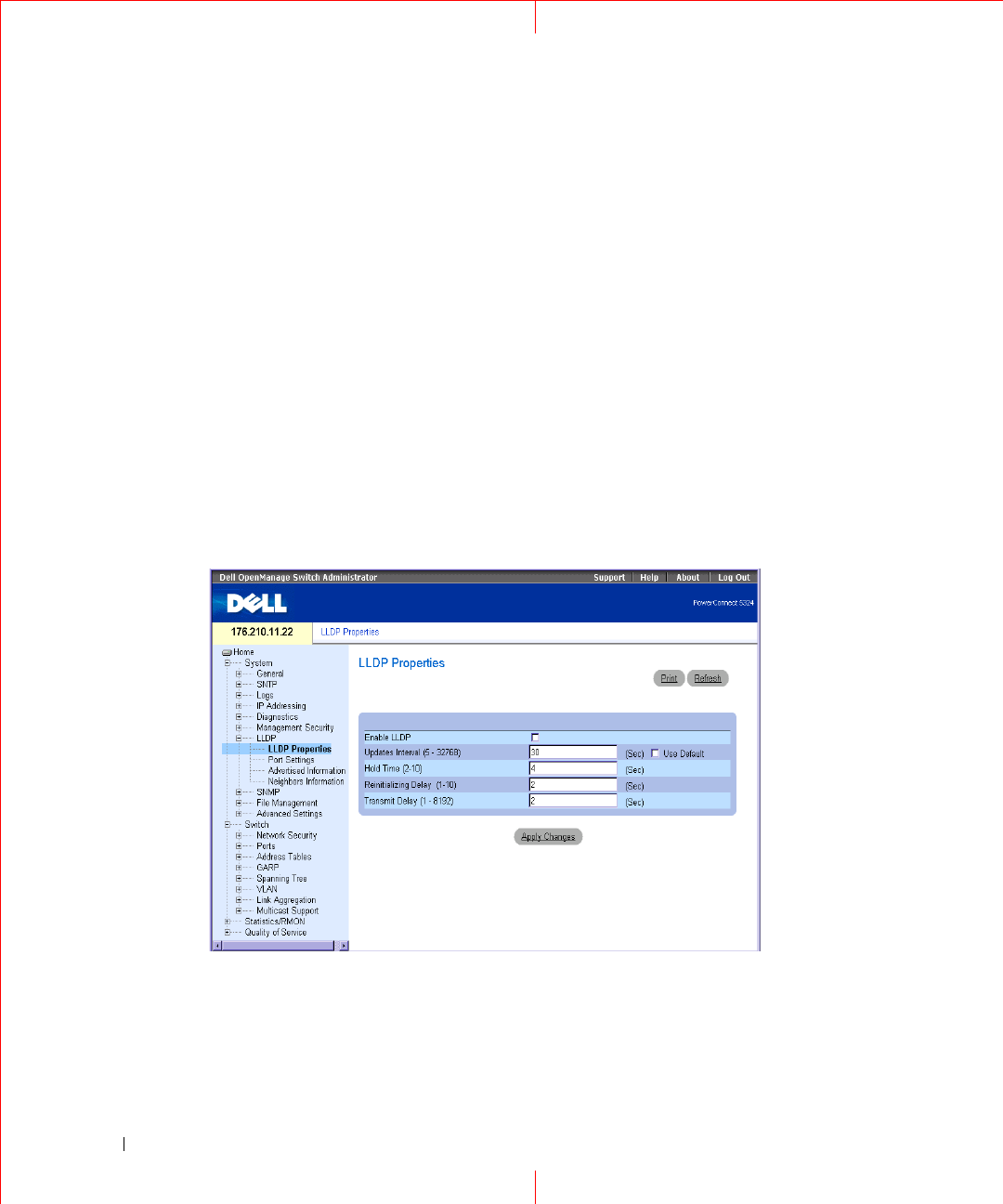
Figure 1-1. LLDP Properties
Enable LLDP
—
Indicates if LLDP is enabled on the device. The possible field values are:
Checked
— Indicates that LLDP is enabled on the device.
Unchecked
— Indicates that LLDP is disabled on the device. This is the default value.

5
Updates Interval (5-32768) —
Indicates that rate at which LLDP advertisement updates are sent. The
possible field range is 5 - 32768 seconds. The default value is 30 seconds.
Hold Time (2-10) —
Indicates the amount of time that LLDP packets are held before the packets are dis-
carded. The possible field range is 2 - 10 seconds. The field default is 4 seconds.
Reinitializing Delay (1-10) — Indicates the amount of time that passes between disabling LLDP and when
reinitializing begins. The possible field range is 1 - 10 seconds. The field default is 2 seconds.
Transmit Delay (1-8192) — Indicates the amount of time that passes between successive LLDP frame trans-
missions due to changes in the LLDP local systems MIB. The possible field value is
1 – 8192 seconds. The field default is 2 seconds.
Configuring LLDP Using CLI Commands
The following is an example of the CLI commands:
Table 1-1. LLDP Properties CLI Commands
CLI Command Description
lldp enable (global) Enables enable Link Layer Discovery
Protocol.
lldp hold-multiplier
number
Specifies the time that the receiving
device should hold a Link Layer
Discovery Protocol (LLDP) packet
before discarding it.
lldp reinit-delay
Seconds
Specifies the minimum time an LLDP
port will wait before reinitializing.
lldp tx-delay
Seconds
Specifies the delay between successive
LLDP frame tr.ansmissions.
Console(config)# interface ethernet g5
Console(config-if)# lldp enable
6
www.dell.com | support.dell.com
Defining LLDP Port Settings
The LLDP
Port Settings
page allows network administrators to define LLDP port settings, including the port
number, the LLDP port number, and the type of port information advertised.
The
Port Settings
page contains fields for configuring LLDP. To open the
Port Settings
page, click
Security
→
LLDP
→
Port Settings
in the tree view
.
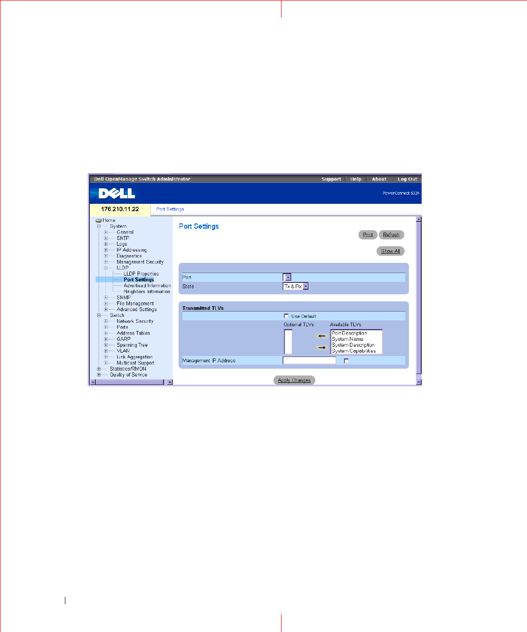
Figure 1-2. Port Settings
Port
— Contains a list of ports on which LLDP is enabled.
State
— Indicates the port type on which LLDP is enabled. The possible field values are:
Tx Only
— Enables transmitting LLDP packets only.
Rx Only
— Enables receiving LLDP packets only.
Tx & Rx
— Enables transmitting and receiving LLDP packets. This is the default value.
Disable
— Indicates that LLDP is disabled on the port.
Use Default
— Indicates that information included in the TLVs is per the device defaults. The possible field
values are:
Checked
— Enables sending the device default LLDP advertisements.
Unchecked
— Indicates that the device LLDP advertisement settings are disabled, and LLDP
advertisement settings are user defined. This is the default value.
7
Optional TLVs
— Contains a list of optional TLVs advertised by the port. For the complete list, see the
Available TLVs
field.
Available TLVs
— Contains a list of available TLVs that can be advertised by the port. The possible field values
are:
Port Description
— Advertises the port description.
System Name
— Advertises the system name.
System Description
— Advertises the system description.
System Capabilities
— Advertises the system capabilities.
Management IP Address
— Indicates the management IP address that is advertised from the interface.
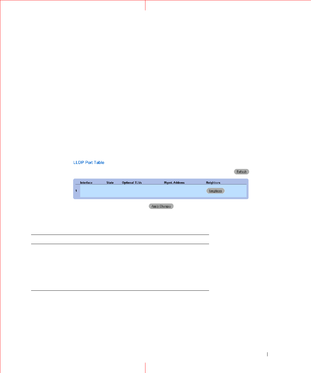
The
LLDP Port Table
page displays the LLDP Port Configuration. To open the
LLDP Port Table
, click
Security
→
LLDP
→
Port Settings
→
S
how All
in the tree view
.
Figure 1-3. LLDP Port Table
Table 1-2. LLDP Port settings CLI Commands
The following is an example of the CLI commands:
CLI Command Description
clear lldp rx
interface
Restarts the LLDP RX state machine
and clearing the neighbors table
lldp optional-tlv
tlv1 [tlv2
… tlv5]
Specifies which optional TLVs from the
basic set should be transmitted
lldp enable [rx | tx | both] To enable Link Layer Discovery
Protocol (LLDP) on an interface.
8
www.dell.com | support.dell.com
Console(config)# interface ethernet g5
Console(config-if)# lldp enable
9
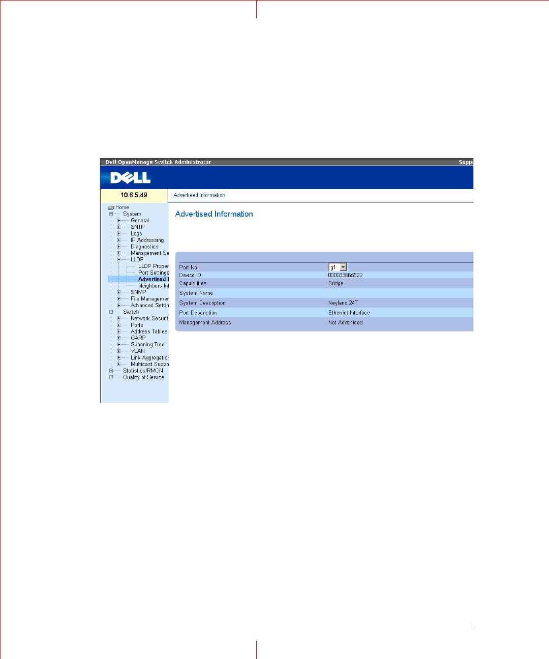
Viewing Advertised Information
The LLDP
Advertised Information
page displays the information advertised by specific ports when advertising
LLDP information. To open the
Advertised Information
page, click
Security
→
LLDP
→
Advertised
Information
in the tree view.
Figure 1-4. Advertised Information
Port
— Displays the port number from which the advertised information is sent.
Device ID
— Displays the advertised device ID.
Capabilities
— Displays the advertised device capabilities.
System Name
— Displays the advertised system name.
System Description
— Displays the advertised system description.
Port Description
— Displays the advertised port description.
Management Address
— Displays the advertised management address.
10
www.dell.com | support.dell.com
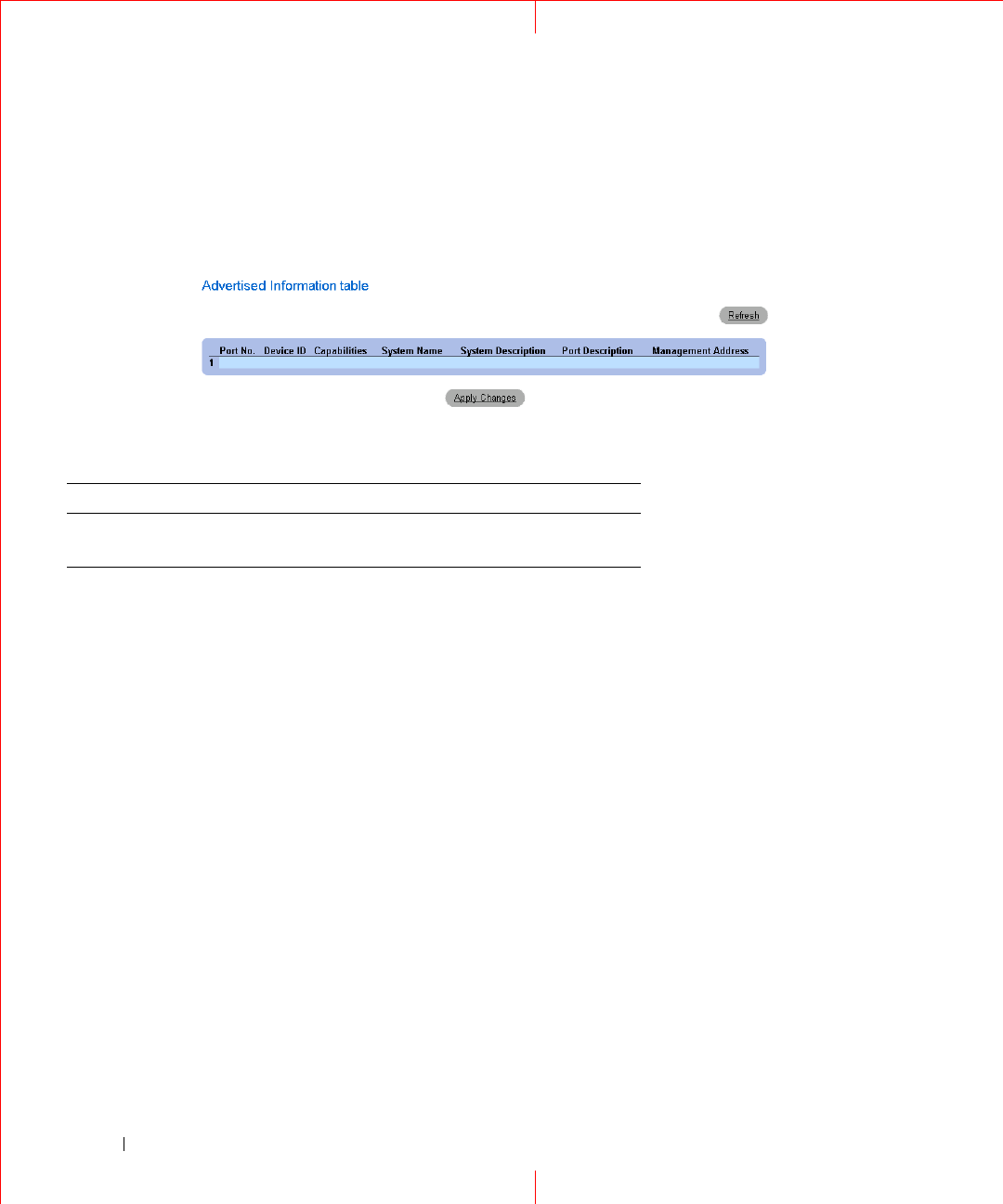
Displaying the Advertised Information Table
To open the
Advertised Information Table
, click
Security
→
LLDP
→
Advertised Information
→
Show All
in
the tree view
.
Figure 1-5. Advertised Information Table
Table 1-3. LLDP Advertised Information CLI Commands
CLI Command Description
show lldp local
ethernet
interface
Displays LLDP information
advertised from a specific port.

11
The following is an example of the CLI commands:
Switch# show lldp local ethernet 1
Device ID: 0060.704C.73FF
Port ID: 1
Capabilities: Bridge
System Name: ts-7800-1
System description:
Port description:
Management address: 172.16.1.8
802.3 MAC/PHY Configuration/Status
Auto-negotiation support: Supported
Auto-negotiation status: Enabled
Auto-negotiation Advertised Capabilities: 100BASE-TX full duplex,
1000BASE-T full duplex
Operational MAU type: 1000BaseTFD
LLDP-MED capabilities: Network Policy, Location Identification
LLDP-MED Device type: Network Connectivity
LLDP-MED Network policy
Application type: Voice
Flags: Tagged VLAN
VLAN ID: 2
Layer 2 priority: 0
DSCP: 0
LLDP-MED Power over Ethernet
Device Type: Power Sourcing Entity
Power source: Primary Power Source
Power priority: High
Power value: 9.6 Watts
LLDP-MED Location
Coordinates: 54:53:c1:f7:51:57:50:ba:5b:97:27:80:00:00:67:01
12
www.dell.com | support.dell.com
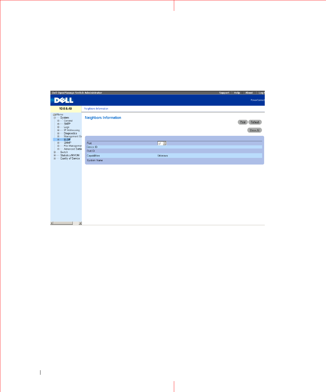
Viewing the LLDP Neighbor Information
The
Neighbors Information
page contains information received from neighboring device LLDP advertisements.
To open the
Neighbor Information
page, click
Security
→
LLDP
→
Neighbors Information
in the tree view
.
Figure 1-6. Neighbors Information
Port
— Displays the neighboring port number.
Device ID
— Displays the neighboring device ID.
Port ID
— Displays the neighboring port ID
Capabilities
— Displays the neighboring device capabilities.
System Name
— Displays the neighboring system time.
1
Select a port.
2
Click
Apply Changes
. The port advertisement information is displayed.
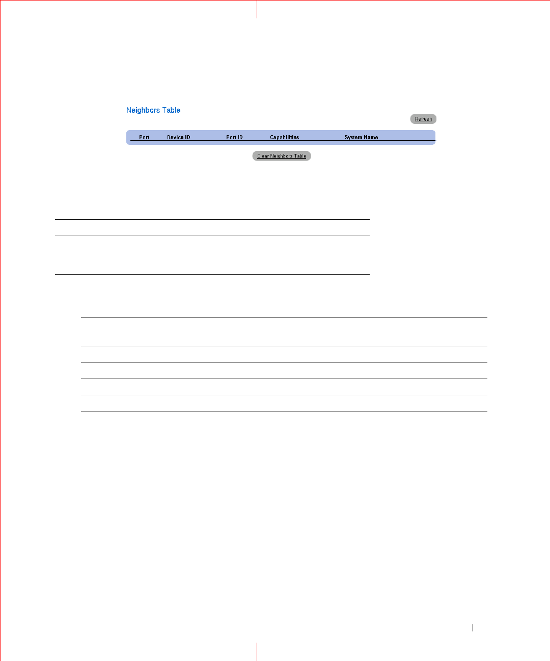
Displaying the Neighbor Information Table
1
Click
Security
→
LLDP
→
Neighbors Information
in the tree view
.
2
Click
Show All
. The
Neighbor
Table opens:
13
Figure 1-7. Neighbors Table
Table 1-4. LLDP Neighbor Information CLI Commands
The following is an example of the CLI commands:
Switch# show lldp neighbors
CLI Command Description
show lldp neighbors
interface
Displays information about
neighboring devices discovered using
Link Layer Discovery Protocol (LLDP)
Port Device ID Port
ID
Hold
Time
Capabilities
System
Name
1 0060.704C.73FE 1 117 B ts-7800-2
1 0060.704C.73FD 1 93 B ts-7800-2
2 0060.704C.73F C 9 1 B, R ts-7900-1
3 0060.704C.73FB 1 92 W ts-7900-2
14
www.dell.com | support.dell.com
Defining SNMP Parameters
Simple Network Management Protocol (SNMP) provides a method for managing network devices. Devices
supporting SNMP run a local software (agent).
The SNMP agents maintain a list of variables, which are used to manage the device. The variables are defined in
the Management Information Base (MIB). The MIB contains the variables controlled by the agent. The SNMP
protocol defines the MIB specification format, as well as the format used to access the information over the
network.
Access rights to the SNMP agents are controlled by access strings. To communicate with the device, the
Embedded Web Server submits a valid community string for authentication. To open the SNMP page, click
System
→
SNMP
in the tree view.
This section contains information for managing the SNMP configuration.
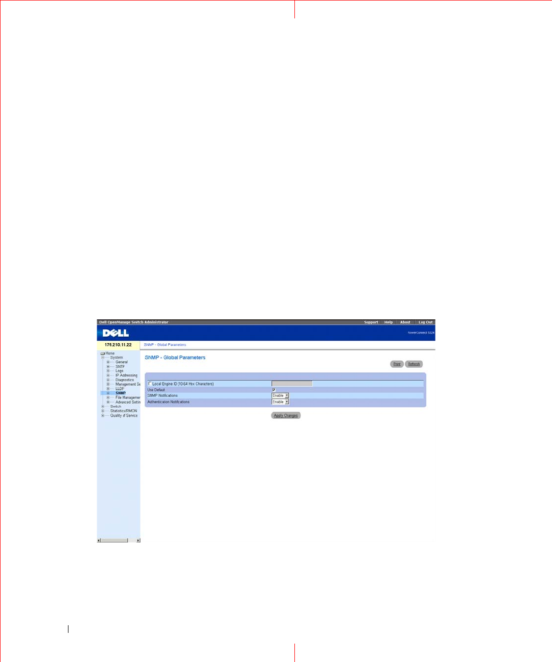
Defining SNMP Global Parameters
The
SNMP Global Parameters
page permits enabling both SNMP and Authentication notifications. To open
the
SNMP Global Parameters
page, click
System
→
SNMP
→
Global Parameters
in the tree view.
Figure 1-8. Global Parameters

15
Local Engine ID
(10 - 64 Hex Characters)
— Indicates the local device engine ID. The field value is a
hexadecimal string. Each byte in hexadecimal character strings is two hexadecimal digits. Each byte can be
separated by a period or a colon. The Engine ID must be defined before SNMPv3 is enabled.
For stand-alone devices select a default Engine ID that is comprised of Enterprise number and the default MAC
address.
Use Default
— Uses the device generated Engine ID. The default Engine ID is based on the device MAC
address and is defined per standard as:
First 4 octets
— first bit = 1, the rest is IANA Enterprise number.
Fifth octet
— Set to 3 to indicate the MAC address that follows.
Last 6 octets
— MAC address of the device.
SNMP
Notifications
— Enables or disables the router sending SNMP notifications.
Authentication Notifications
— Enables or disables the router sending SNMP traps when authentication fails.
Enabling SNMP Notifications
1
Open the
SNMP Global Parameters
page.
2
Select
Enable
in the
SNMP
Notifications
field.
3
Click
Apply
Changes
.
SNMP notifications are enabled, and the device is updated.
Enabling Authentication Notifications
1
Open the
SNMP Global Parameters
page.
2
Select Enable in the
Authentication Notifications
field.
3
Click
Apply
Changes
.
Enabling SNMP Notifications Using CLI Commands
The following table summarizes the equivalent CLI commands for viewing fields displayed in the
SNMP Global
Parameters
page.
Table 1-5. SNMP Notification Commands
CLI Command Description
snmp-server enable
traps
Enables the router to send Simple Network
Management Protocol traps.
snmp-server trap
authentication
Enables the router to send Simple Network
Management Protocol traps when authentication
fails.
show snmp Checks the status of SNMP communications.

16
www.dell.com | support.dell.com
snmp-server engine
ID local {
engineid-
string
| default}
Indicates the local device engine ID. The field
values is a hexadecimal string. Each byte in
hexadecimal character strings is two hexadecimal
digits. Each byte can be separated by a period or
colon. The Engine ID must be defined before
SNMPv3 is enabled.
Table 1-5. SNMP Notification Commands
CLI Command Description

17
The following is an example of the CLI commands:
Defining SNMP View Settings
SNMP Views provides access or blocks access to device features or feature aspects. For example, a view can be
defined which states that SNMP group A has read only (R/O) access to Multicast groups, while SNMP group B
has read-write (R/W) access to Multicast groups. Feature access is granted via the MIB name, or MIB Object ID.
The Up and Down arrows allow navigating through the MIB tree, and MIB branches.
Console (config)# snmp-server enable traps
Console (config)# snmp-server trap authentication
Console# show snmp
Community-String Community-Access View name IP address
---------------- ----------------- --------- ----------
public read only view-1 All
Community-String Group name IP address Type
----
---------------- ---------- ----------
Traps are enabled.
Authentication-failure trap is enabled.
Version 1,2 notifications
Target
Address
Type Community Version Udp
Port
Filter
name
To
Sec
Retries
------- ---- --------- ------- ---- ------ --- -------
Version 3 notifications
Target
Address
Type Username Security
Level
Udp
Port
Filter
name
To
Sec
Retries
-------- ---- --------- -------- ----
-
------
-
--- -------
System Contact: Robert
System Location: Marketing
18
www.dell.com | support.dell.com
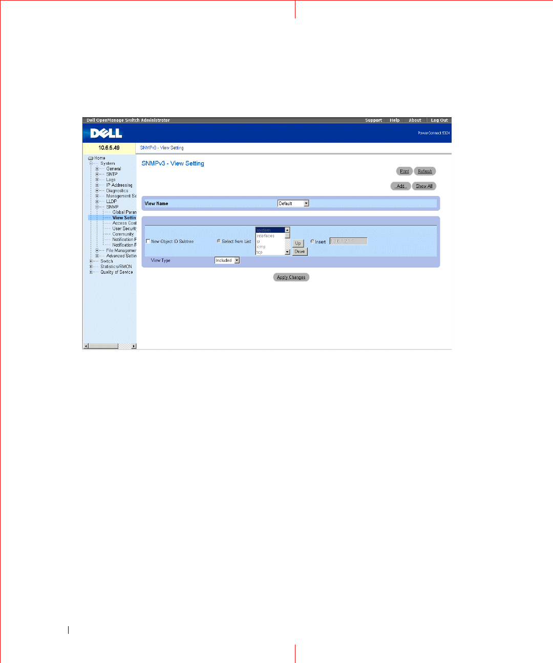
To open the
SNMPv3 View Settings
page, click
System
→
SNMP
→
View Settings
in the tree view.
Figure 1-9. SNMPv3 View Settings
View Name
— Contains a list of user-defined views. The view name can contain a maximum of 30 alphanumeric
characters. The possible field values are:
Default — Displays the default user-defined view.
DefaultSuper — Displays the default super user-defined view.
New Object ID Subtree
— Indicates the device feature OID included or excluded in the selected SNMP view.
Selected from List
— Select the device feature OID by using the Up and Down buttons to scroll through a list of
all device OIDs.
Insert
— Specify the device feature OID.
View Type
— Indicates if the defined OID branch will be included or excluded in the selected
SNMP
view.
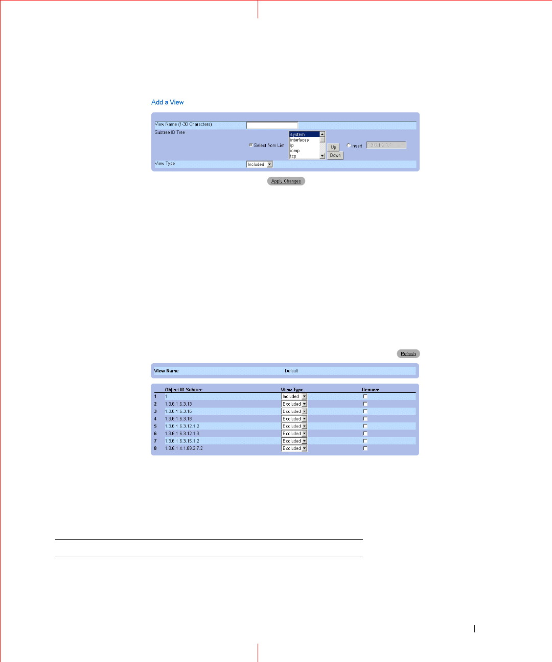
Adding a View
1
Open the
SNMPv3 View Settings
page.
2
Click
Add
.
The
Add a View
page opens.
19
Figure 1-10. Add a View
3
Define the field.
4
Click
Apply Changes
.
The
SNMP
View is added, and the device is updated.
Displaying the View Table
1
Open the
SNMPv3 View Settings
page.
2
Click
Show All
.
The
View Table
page opens.
Figure 1-11. View Table
Defining SNMP Views Using CLI Commands
The following table summarizes the equivalent CLI commands for defining fields displayed in the
SNMPv3
View Settings
page.
Figure 1-12. SNMP View CLI Commands
CLI Command Description
snmp-server view
view-name oid-tree
{included | excluded}
Creates or updates a view entry.

20
www.dell.com | support.dell.com
The following is an example of CLI commands:
show snmp views
[
viewname
]
Displays the configuration of views.
Console (config)# snmp-server view user1 1 included
Console (config)# end
Console # show snmp views
Name OID Tree Type
------------- ----------------- --------
user1 iso included
Default iso included
Default snmpVacmMIB excluded
Default usmUser excluded
Default rndCommunityTable excluded
DefaultSuper iso included
Figure 1-12. SNMP View CLI Commands
CLI Command Description
21
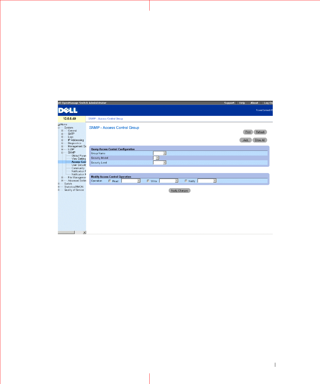
Defining SNMP Access Control
The
Access Control Add Group
page
provides information for creating SNMP groups, and assigning SNMP
access control privileges to SNMP groups. Groups allow network managers to assign access rights to specific
device features, or features aspects. To open the
Access Control Group
page, click
System
→
SNMP
→
Access
Control
in the tree view.
Figure 1-13. Access Control Group
Group Name
— The user-defined group to whom access control rules are applied. The field range is up to 30
characters.
Security Model
— Defines the SNMP version attached to the group. The possible field values are:
SNMPv1
— SNMPv1 is defined for the group.
SNMPv2
— SNMPv2 is defined for the group.
SNMPv3
— SNMPv3 is defined for the group.
Security Level
— The security level attached to the group. Security levels apply to SNMPv3 only. The possible
field values are:
No Authentication
— Neither the Authentication nor the Privacy security levels are assigned to the group.
Authentication
— Authenticates SNMP messages, and ensures the SNMP messages origin is
authenticated.
Operation
— Defines the group access rights. The possible field values are:
22
www.dell.com | support.dell.com
Read
— The management access is restricted to read-only, and changes cannot be made to the assigned
SNMP view.
Write
— The management access is read-write and changes can be made to the assigned SNMP view.
Notify
— Sends traps for the assigned SNMP view.
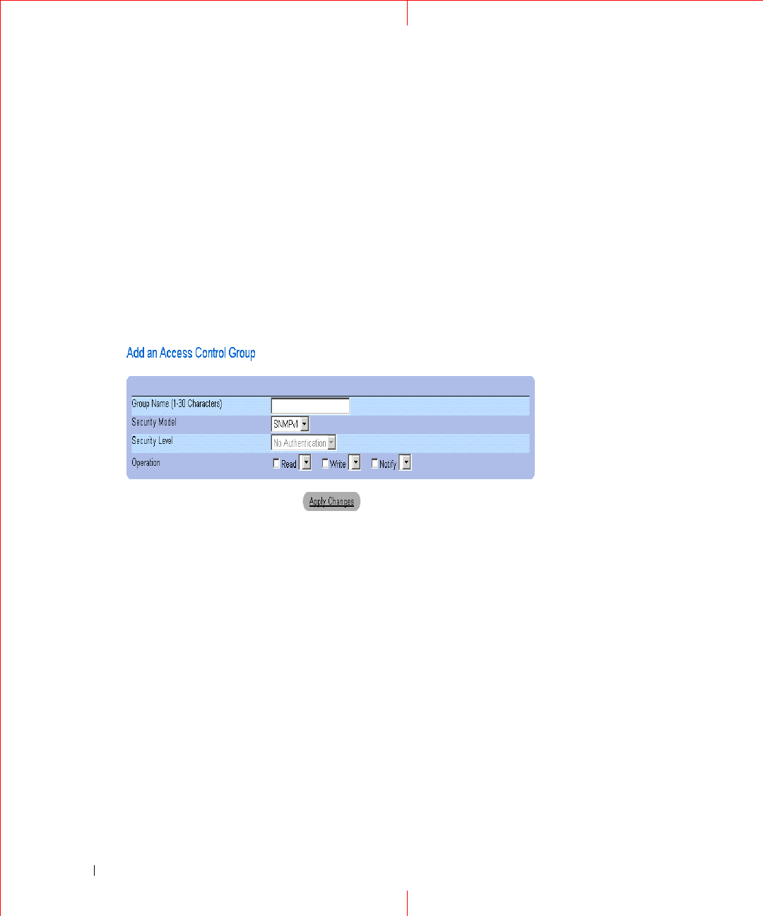
Defining SNMP Groups
1
Open the A
ccess Control Group
page.
2
Click
Add
.
The
Add
an
Access Control Group
page opens:
Figure 1-14. Add an Access Control Group
3
Define the fields in the
Add an Access Control Group
page.
4
Click
Apply
Changes
.
The group is added, and the device is updated.
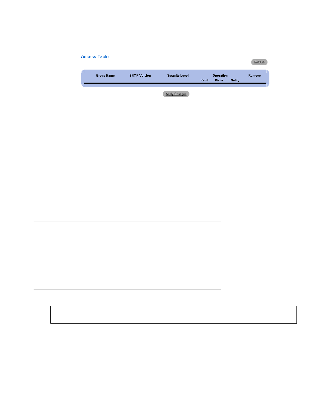
Displaying the Access Table
1
Open the
Access Control Group
page.
2
Click
Show All
.
The Access Table opens.
23
Removing SNMP Groups
1
Open the
Access Control Group
page.
2
Click
Show All
. The Access Table opens.
3
Select an
SNMP group
.
4
Check the
Remove
checkbox.
5
Click
Apply Changes
.
The SNMP group is deleted, and the device is updated.
Defining SNMP Access Control Using CLI Commands
The following table summarizes the equivalent CLI commands for defining fields displayed in the
Access
Control Group
page.
The following is an example of the CLI commands:
Figure 1-15. SNMP Access Control CLI Commands
CLI Command Description
snmp-server group
groupname
{v1 | v2 |
v3 {noauth | auth |
priv}} [read
readview
] [write
writeview
] [notify
notifyview
]
Configure a new Simple Network Management
Protocol (SNMP) group, or a table that maps
SNMP users to SNMP views.
show snmp groups
[
groupname
]
Displays the configuration of groups.
console (config)# snmp-server group user-group v3 priv read user-
view
24
www.dell.com | support.dell.com
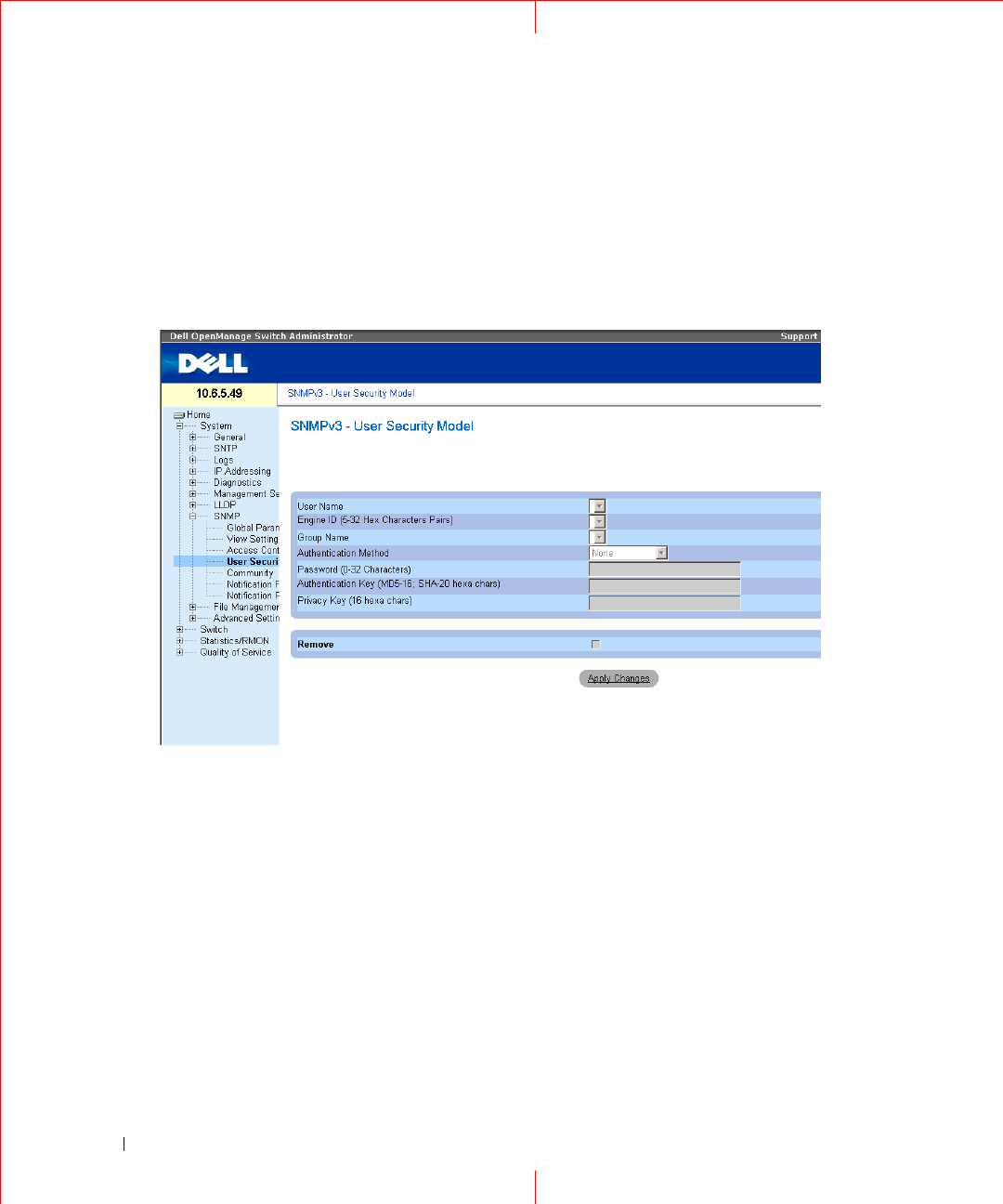
Assigning SNMP User Security
The
SNMPv3
User Security Model
(USM) page enables assigning system users to
SNMP
groups, as well as
defining the user authentication method.
To open the
SNMPv3
U
ser Security Model
(USM) page, click
System
→
SNMP
→
U
ser Security Model
in the
tree view.
Figure 1-16. SNMPv3 User Security Model
User Name
— Contains a list of user-defined user names. The field range is up to 30 alphanumeric characters.
Engine (5-32 Hex Characters Pairs)
— Indicates either the local or remote SNMP entity, to which the user is
connected. Changing or removing the local SNMP Engine ID deletes the SNMPv3 User Database.
Group Name
— Contains a list of user-defined SNMP groups. SNMP groups are defined in the
Access Control
Group
page.
Authentication Method
— The authentication method used to authenticate users. The possible field values are:
MD5 Key
— Users are authenticated using the HMAC-MD5 algorithm.
SHA Ke
y — Users are authenticated using the HMAC-SHA-96 authentication level.
MD5 Password
— Indicates that HMAC-MD5-96 password is used for authentication. The user should
enter a password.
SHA Password
— Users are authenticated using the HMAC-SHA-96 authentication level. The user should
enter a password.
25
None
— No user authentication is used.
Password (0-32 Characters)
— Modifies the user-defined password for a group. Passwords can contain a
maximum of 32 alphanumeric characters.
Authentication
Key
(MD5-16; SHA-20 hexa chars)
— Defines the HMAC-MD5-96 or HMAC-SHA-96
authentication level. The authentication and privacy keys are entered to define the authentication key. If only
authentication is required, 16 bytes are defined for MD5. If both privacy and authentication are required, 32
bytes are defined for MD5. Each byte in hexadecimal character strings is two hexadecimal digits. Each byte can
be separated by a period or a colon.
Privacy Key (16 hexa characters)
— If only authentication is required, 20 bytes are defined. If both privacy and
authentication are required, 16 bytes are defined. Each byte in hexadecimal character strings is two hexadecimal
digits. Each byte can be separated by a period or colon.
Remove
— When checked, removes users from a specified group.
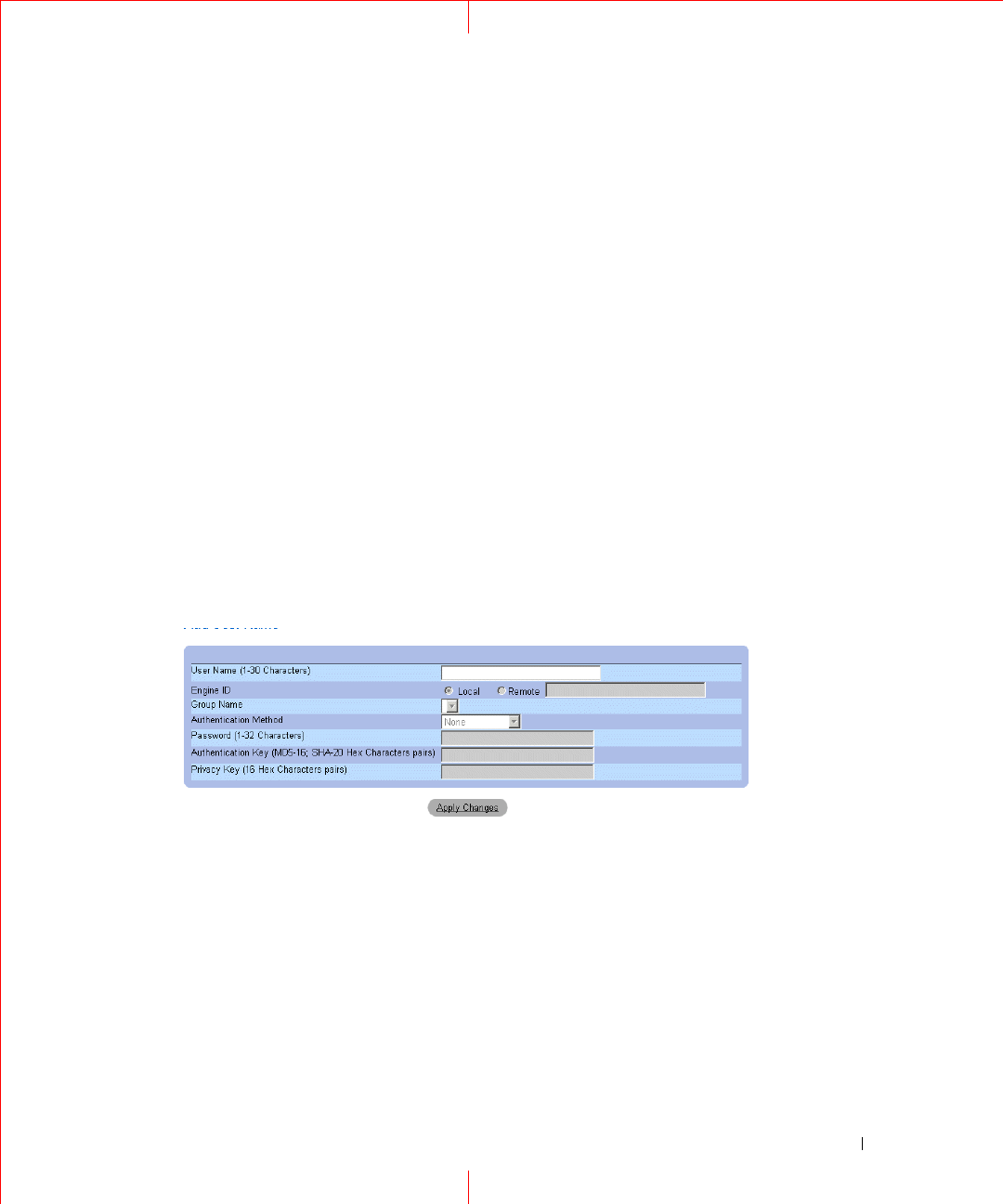
Adding Users to a Group
1
Open the
SNMPv3 User Security Model
page.
2
Click
Add
.
The
Add SNMPv3 User Name
page opens.
Figure 1-17. Add SNMPv3 User Name
3
Define the relevant fields.
4
Click
Apply Changes
.
The user is added to the group, and the device is updated.
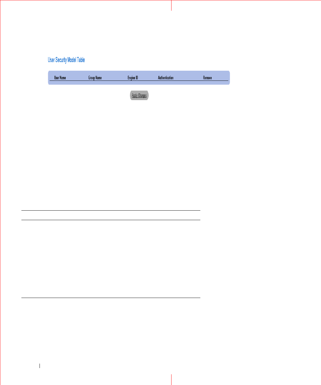
Displaying the User Security Model Table
1
Open the
SNMPv3 User Security Model
(USM) page.
2
Click
Show All
.
The
User Security Model Table
opens.
26
www.dell.com | support.dell.com
Figure 1-18. User Security Model Table
Deleting an User Security Model Table Entry
1
Open the
SNMPv3 User Security Model
(USM)
page.
2
Click Show All. The
User Security Model Table
opens.
3
Select a
User Security Model Table
entry.
4
Check the
Remove
checkbox.
5
Click
Apply Changes
. The User Security Model Table entry is deleted, and the device is updated.
Defining SNMP Users Using CLI Commands
The following table summarizes the equivalent CLI commands for defining fields displayed in the
SNMPv3
User Security Model
page.
Table 1-6. SNMP User CLI Commands
CLI Command Description
snmp-server user
username groupname
[remote
engineid-
strin
g][auth-md5
password
| auth-sha
password
| auth-md5-
key
md5-des-key
|
auth-sha-key
sha-des-
key
]
Configures a new SNMP V3 user.
show snmp users
[
username
]
Displays the configuration of users.
27
The following is an example of the CLI commands:
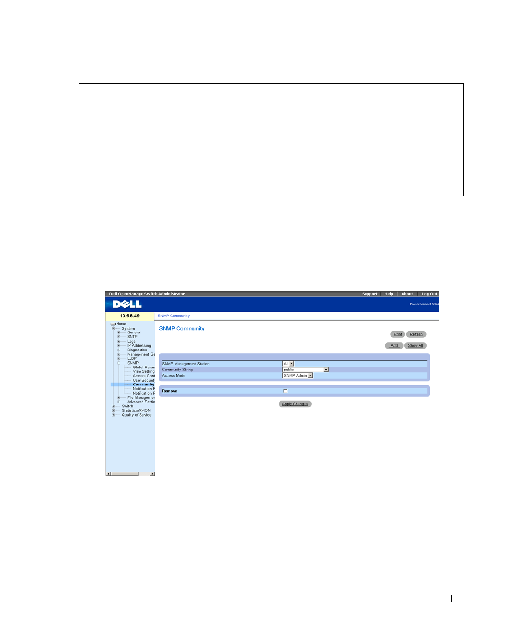
Defining Communities
Access rights are managed by defining communities in the
Community Table
. When the community names are
changed, access rights are also changed. To open the SNMP Communities page, click
System
→
SNMP
→
Community
in the tree view.
Figure 1-19. SNMP Community
SNMP Management Station
— A list of management station IP addresses.
Community String
— Functions as a password and used to authenticate the selected management station to the
device.
Access Mode
— Defines the access rights of the community. The possible field values are:
Read Only
— The management access is restricted to read-only, for all MIBs except the community table,
for which there is no access.
console (config)
# snmp-server user John user-group auth-md5 1234
console (config)
# end
console (config)# show snmp users
Name Group Name Auth Method Remote
------- ---------- ----------- ------
John user-group md5
28
www.dell.com | support.dell.com
Read Write
— The management access is read-write, for all MIBs except the community table, for which
there is no access.
SNMP Admin
— The management access is read-write for all MIBs, including the community table.
Remove
— Removes a community, when selected.
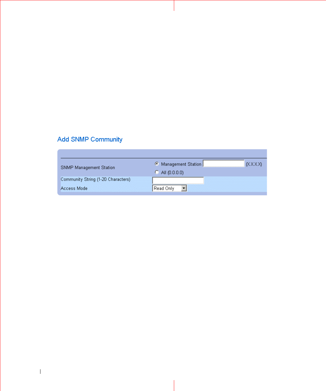
Defining a New Community
1
Open the
SNMP Community
page.
2
Click
Add
.
The
Add SNMP Community
page opens:
Figure 1-20. Add SNMP Community
3
Select one of the following:
Management Station
— Defines an SNMP community for a specific management station. (A value of
0.0.0.0 specifies all management stations.)
All
— Defines an SNMP community for all management stations.
4
Define the remaining fields.
5
Click
Apply
Changes
.
The new community is saved, and the device is updated.
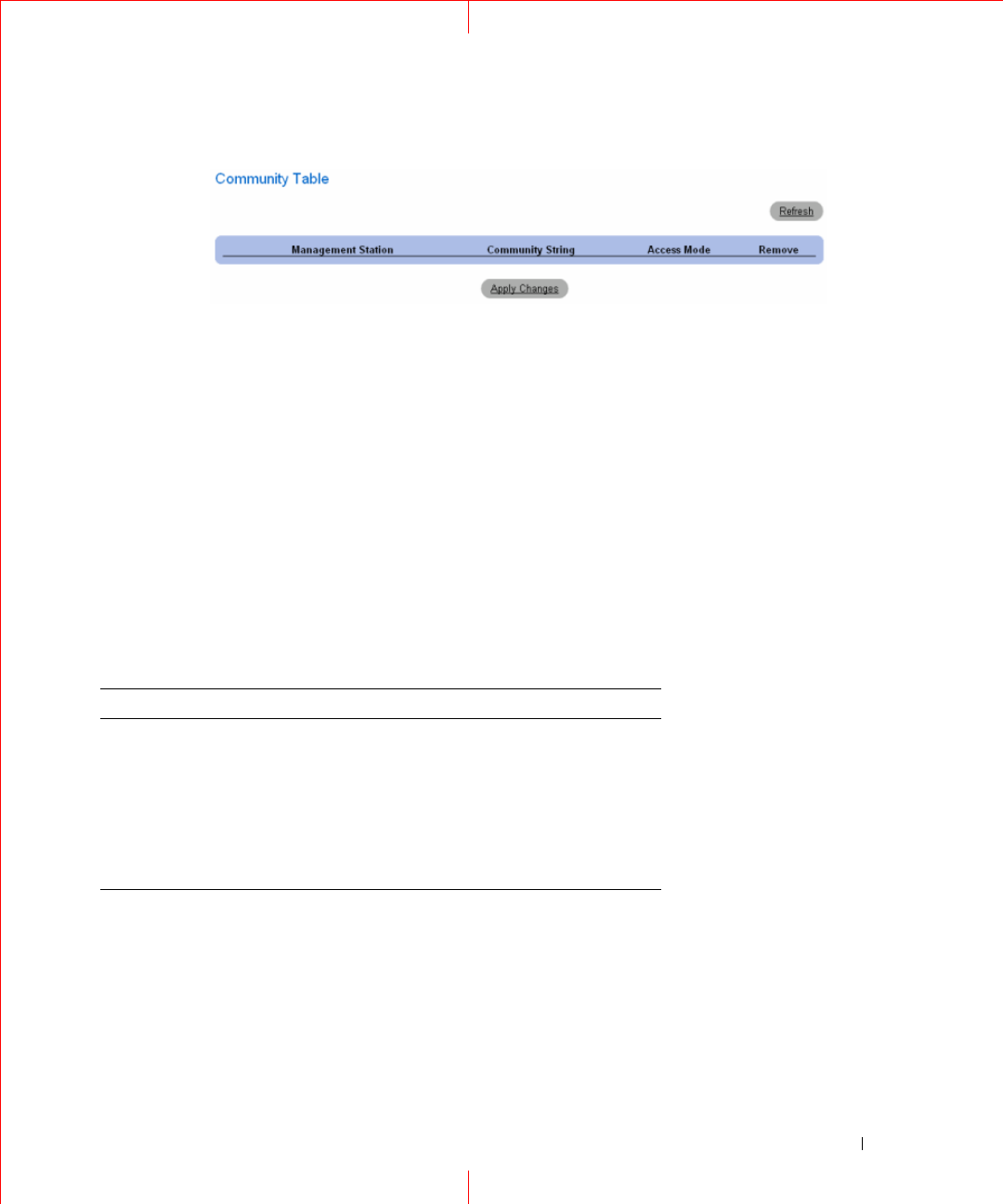
Displaying all Communities
1
Open the
SNMP Community
page.
2
Click
Show All.
The
Community Table
opens:
29
Figure 1-21. Community Table
Deleting Communities
1
Open the
SNMP Community
page.
2
Click
Show All.
The
Community Table
opens.
3
Select a community from the
Community Table.
4
Select the
Remove
check box.
5
Click
Apply Changes
.
The selected community entry is deleted, and the device is updated.
Configuring Communities Using CLI Commands
The following table summarizes the equivalent CLI commands for setting fields displayed in the
SNMP
Community
page.
Table 1-7. SNMP Community CLI Commands
CLI Command Description
snmp-server community
string [ro | rw | su] [ip-
address]
Sets up the community access string to permit
access to SNMP protocol.
snmp-server host {ip-address
| hostname} community-
string [1 | 2]
Determines the trap type sent to the selected
recipient.
show snmp Checks the SNMP communities status.

30
www.dell.com | support.dell.com
The following is an example of the CLI commands:
console(config)# snmp-server community public_1 su 1.1.1.1
console(config)# snmp-server community public_2 rw 2.2.2.2
console(config)# snmp-server community public_3 ro 3.3.3.3
console(config)# snmp-server host 1.1.1.1 public_1 1
console(config)# snmp-server host 2.2.2.2 public_2 2
console(config)#
console# show snmp
Community-String Community-Access IP address
-------------------------------------
public_1 super 1.1.1.1
public_2 readwrite 2.2.2.2
public_3 readonly 3.3.3.3
Traps are enabled.
Authentication-failure trap is enabled.
Trap-Rec-Address Trap-Rec-Community Version
----------------- ------------------- ---------
1.1.1.1 public_1 1
2.2.2.2 public_2 2
System Contact: 345 6789
System Location: 1234 5678
console#
31
Defining SNMPv3 Notification Filters
The
SNMPv3
Notification Filter
page permits filtering traps based on OIDs. Each OID is linked to a device
feature or a feature aspect. The
SNMPV3
-
Notification Filter
page also allows network managers to filter
notifications. To open the
SNMPv3 Notification Filter
page, click
System
→
SNMP
→
Notification Filter
in
the tree view.
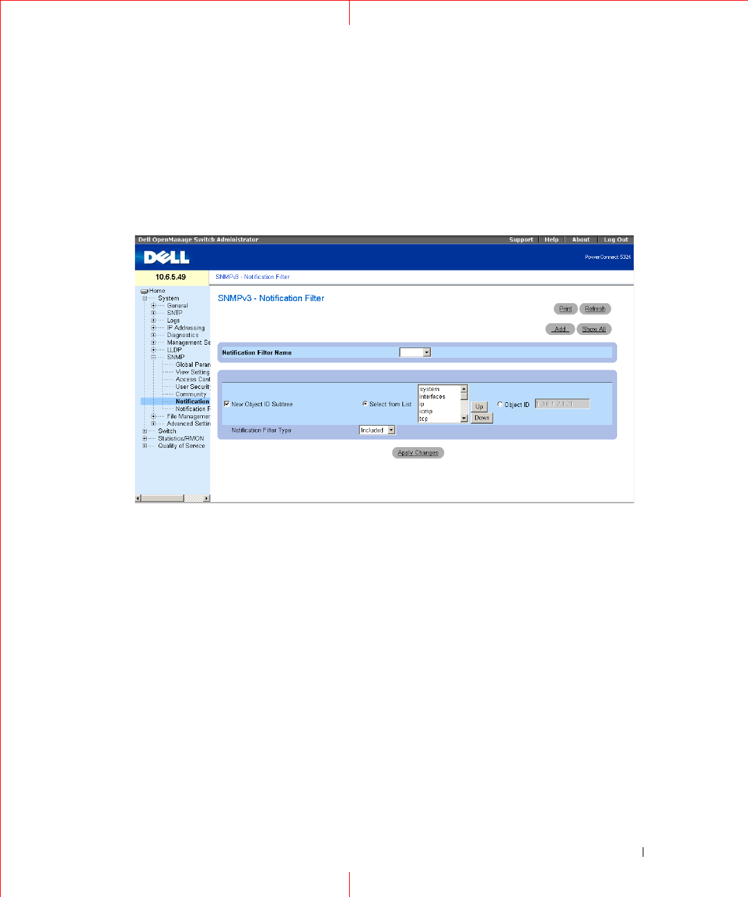
Figure 1-22. SNMPv3 - Notification Filters
Notification Filter Name
— The user-defined notification filter.
New Object Identifier Tree
— The OID for which notifications are sent or blocked. If a filter is attached to an
OID, traps or informs are generated and sent to the trap recipients. Object IDs are selected from either the
Select from List or the Object ID List.
Notification Filter Type
— Indicates whether informs or traps are sent regarding the OID to the trap recipients.
Excluded
— Restricts sending OID traps or informs.
Included
— Sends OID traps or informs.
Adding SNMP Filters
1
Open the
SNMPv3 Notification Filter
page.
2
Click
Add
.
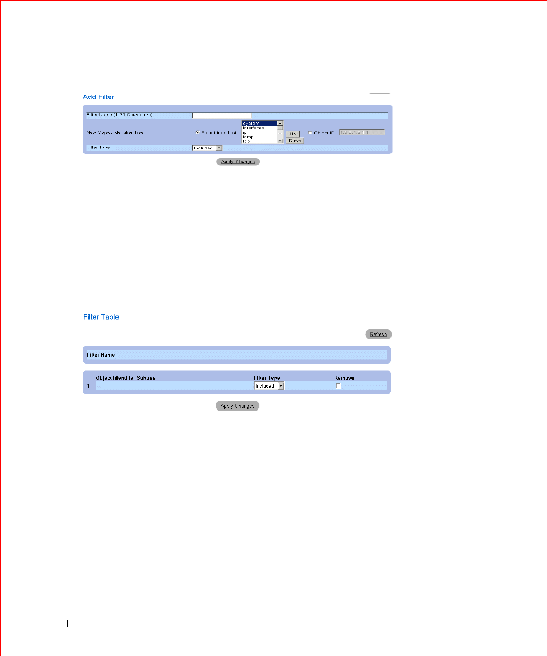
The
Add Filter
page opens.
32
www.dell.com | support.dell.com
Figure 1-23. Add Filter
3
Define the relevant fields.
4
Click
Apply
Changes
.
The new filter is added, and the device is updated.
Displaying the Filter Table
1
Open the
SNMPv3 Notification Filter
page.
2
Click S
how All
.
The Filter Table opens.
Figure 1-24. Filter Table
Removing a Filter
1
Open the
SNMPv3 Notification Filte
r page.
2
Click
Show All
. The
Filter Table
opens.
3
Select a
Filter Table
entry.
4
Check the
Remove
checkbox. The filter entry is deleted, and the device is updated.

33
Configuring Notification Filters Using CLI Commands
The following table summarizes equivalent CLI commands for defining fields displayed in the
SNMPv3 -
Notification Filters
page.
The following is an example of CLI commands:
Defining SNMP Notification Recipients
The
Notification Recipients
page contains information for defining filters that determine whether traps are sent
to specific users, and the trap type sent. SNMP notification filters provide the following services:
• Identifying Management Trap Targets
• Trap Filtering
• Selecting Trap Generation Parameters
• Providing Access Control Checks
To open the
Notification Recipients
page, click
System
→
SNMP
→
Notification Recipient
in the tree view.
Table 1-8. SNMP Notification Filter CLI Commands
CLI Command Description
snmp-server filter
filter-name oid-tree
{included | excluded}
Creates or updates an SNMP notification filter.
show snmp filters
[
filtername
]
Displays the configuration of SNMP
notification filters.
Console (config)# snmp-server filter user1 iso included
Console(config)# end
Console # show snmp filters
Name OID Tree Type
----------- ------------- --------
user1 iso Included
34
www.dell.com | support.dell.com
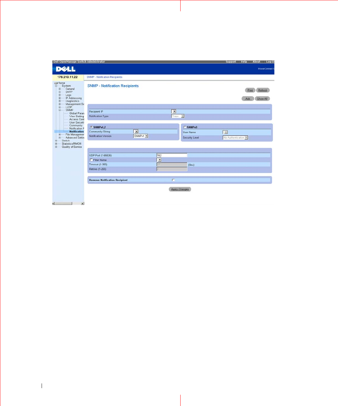
Figure 1-25. Notification Recipients
Recipient IP
— Indicates the IP address to whom the traps are sent.
Notification Typ
e — The notification sent. The possible field values are:
Traps
— Traps are sent.
Informs
— Informs are sent.
SNMPv1,2
— SNMP versions 1 and 2 are enabled for the selected recipient. Define the following fields for
SNMPv1 and SNMPv2:
Community String (1-20 Characters)
— Identifies the community string of the trap manager.
Notification Version
— Determines the trap type. The possible field values are:
SNMPv1
— SNMP Version 1 traps are sent.
SNMPv2
— SNMP Version 2 traps are sent.
SNMPv3
— SNMPv3 is used to send and receive traps. Define the following fields for SNMPv3:
User Name
— The user to whom SNMP notifications are sent.
S
ecurity Leve
l — Defines the means by which the packet is authenticated. The possible field values are:
No Authentication
— The packet is neither authenticated nor encrypted.
Authentication
— The packet is authenticated.
Privacy
— The packet is both authenticated and encrypted.
35
UDP Port (1-65535)
— The UDP port used to send notifications. The default is 162.
Filter Name
— Includes or excludes SNMP filters.
Timeout (1-300
) — The amount of time (seconds) the device waits before resending informs. The default is 15
seconds.
Retries (1-255)
— The amount of times the device resends an inform request. The default is 3.
Remove Notification Recipient
— When checked, removes selected notification recipients.
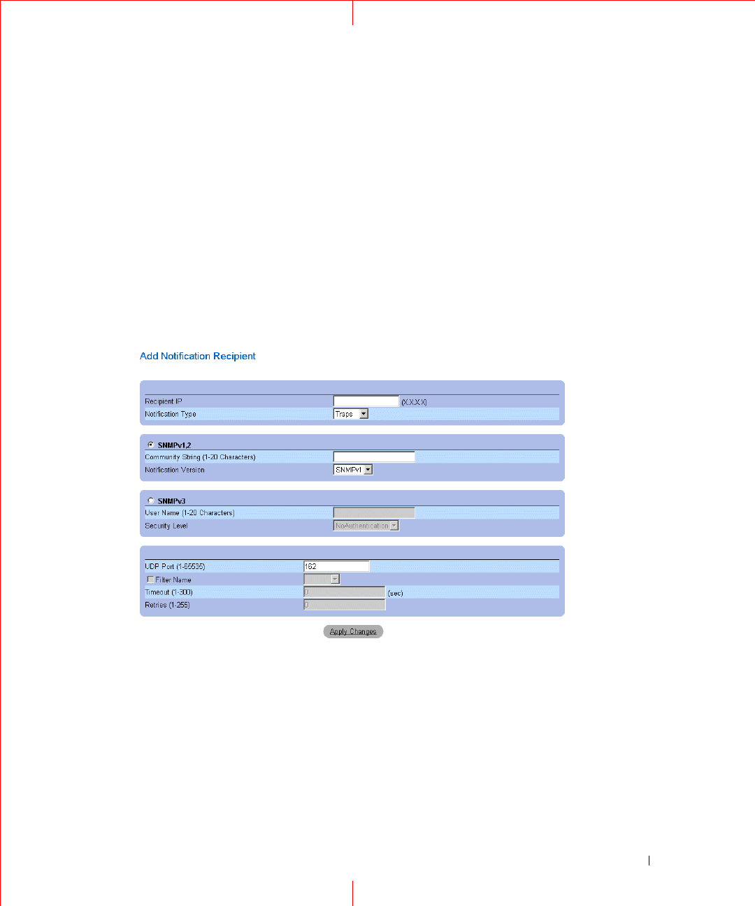
Adding a New Trap Recipients
1
Open
Notification Recipients
page.
2
Click
Add
.
The
Add Notification Recipients
page opens.
3
Define the relevant fields.
4
Click
Apply
Changes
.
The notification recipient is added, and the device is updated.
Displaying Notification Recipients Tables
1
Open
Notification Recipients
page.
2
Click
Show All
.
The
Notification Recipients Tables
page opens.
36
www.dell.com | support.dell.com
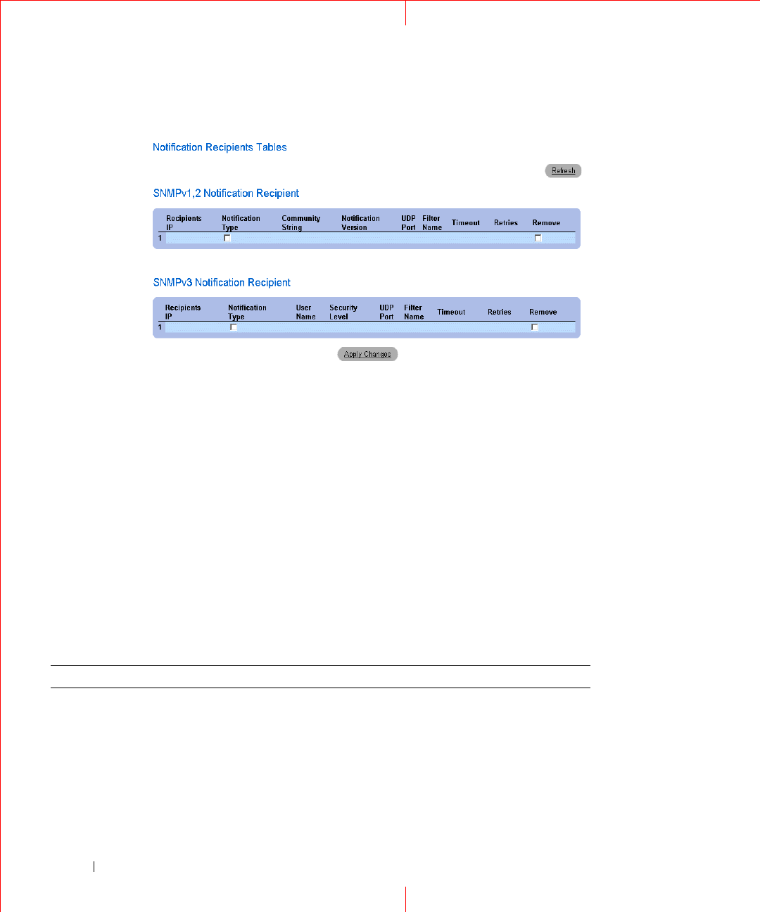
Figure 1-26. Notification Recipients Tables
Deleting Notification Recipients
1
Open
Notification Recipients
page.
2
Click
Show All
.
The
Notification Recipients Tables
page opens.
3
Select a notification recipient in either the
SNMPV1,2 Notification Recipient
or S
NMPv3 Notification
Recipient
Tables.
4
Check the
Remove
checkbox.
5
Click
Apply
Changes
. The recipient is deleted, and the device is updated.
Configuring SNMP Notification Recipients Using CLI Commands
The following table summarizes the equivalent CLI commands for viewing fields displayed in the
SNMP Trap
Settings
page.
Table 1-9. SNMP Notification Recipients CLI Commands
CLI Command Description
snmp-server host {
ipaddress
|
hostname
}
community-string
[traps |
informs] [1 | 2] [udp-port
port
]
[filter
filtername
] [timeout
seconds
] [retries
retries
]
Creates or updates a notification recipient
receiving notifications in SNMP version 1 or 2.

37
The following is an example of the CLI commands:
snmp-server v3-host {ip-
address
|
hostname
}
username
[traps | informs]
{noauth | auth | priv} [udp-port
port
] [filter
filtername
] [timeout
seconds
] [retries
retries
]
Creates or updates a notification recipient
receiving notifications in SNMP version 3.
show snmp Shows the current SNMP configuration.
console (config)# snmp-server host 172.16.1.1 private
console# show snmp
Community-String Community-Access View name IP address
---------------- ---------------- --------- ----------
public read only user-view All
private read write default 172.16.1.1
private su DefaultSuper 172.17.1.1
Table 1-9. SNMP Notification Recipients CLI Commands
CLI Command Description
38
www.dell.com | support.dell.com
HTTP/HTTPS Upload/Download
Downloading Files
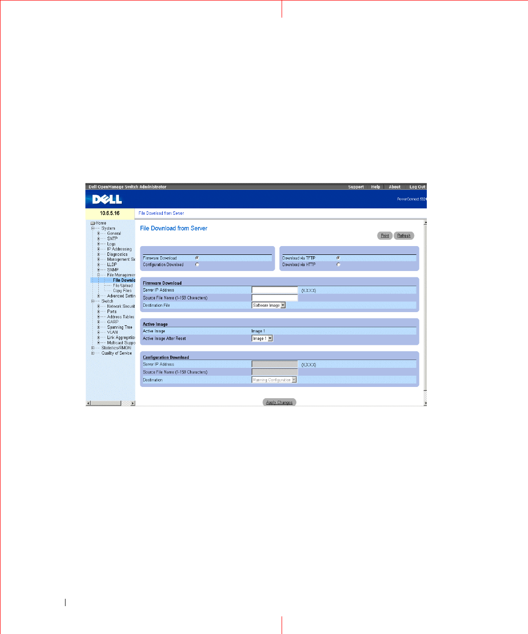
The
File Download From Server
page contains fields for downloading system image and Configuration files
from the TFTP server to the device or the HTTP/S server. To open the
File Download From Server
page, click
System
→
File Management
→
File Download
in the tree view.
Figure 1-27. File Download From Server
Firmware Download —
The Firmware file is downloaded. If
Firmware Download
is selected, the
Configuration
Download
fields are grayed out.
Configuration Download —
The Configuration file is downloaded. If
Configuration Download
is selected, the
Firmware Download
fields are grayed out.
Download via TFTP
—
Enables initiating an upload via the TFTP server.
Download via HTTP
—
Enables initiating an upload via the HTTP server or HTTPS server.
Firmware Download
Server IP Address —
The Server IP Address from which the firmware files are downloaded.
Source File Name —
Indicates the file to be downloaded.
Destination File —
The destination file type to which the file is downloaded. The possible field values are:
Software Image —
Downloads the image file.

39
Boot Code —
Downloads the Boot file.
Active Image
Active Image
— The Image file that is currently active.
Active Image After Reset
— The Image file that is active after the device is reset.
NOTE: The image file overwrites the non-active image. It is recommended to designate that the nonactive image will
become the active image after reset, and then to reset the device following the download. During the image file
download, a dialog box opens which displays the download progress. The window closes automatically when the
download is complete.
Configuration Download
Server IP Address
— The Server IP Address from which the configuration files
are downloaded.
Source File Name
— Indicates the configuration files to be downloaded.
Destination
— The destination file to which the configuration file is downloaded.
The possible field values are:
Running Configuration
— Downloads commands into the Running Configuration file.
Startup Configuration
— Downloads the Startup Configuration file, and overwrites it.
Backup Configuration
— Downloads commands into the Configuration file.
Downloading Files
1
Open the
File Download From Server
page.
2
Define the file type to download.
3
Define the fields.
4
Click
Apply Changes
.
The software is downloaded to the device.

40
www.dell.com | support.dell.com
Downloading Files Using CLI Commands
The following table summarizes the equivalent CLI commands for setting fields displayed in the
File Download
From Server
page.
The following is an example of the CLI commands:
Table 1-10. File Download CLI Commands
CLI Command Description
copy source-url destination-
url [snmp]
Copies any file from a source to a destination.
console# copy running-config tftp://11.1.1.2/pp.txt
41
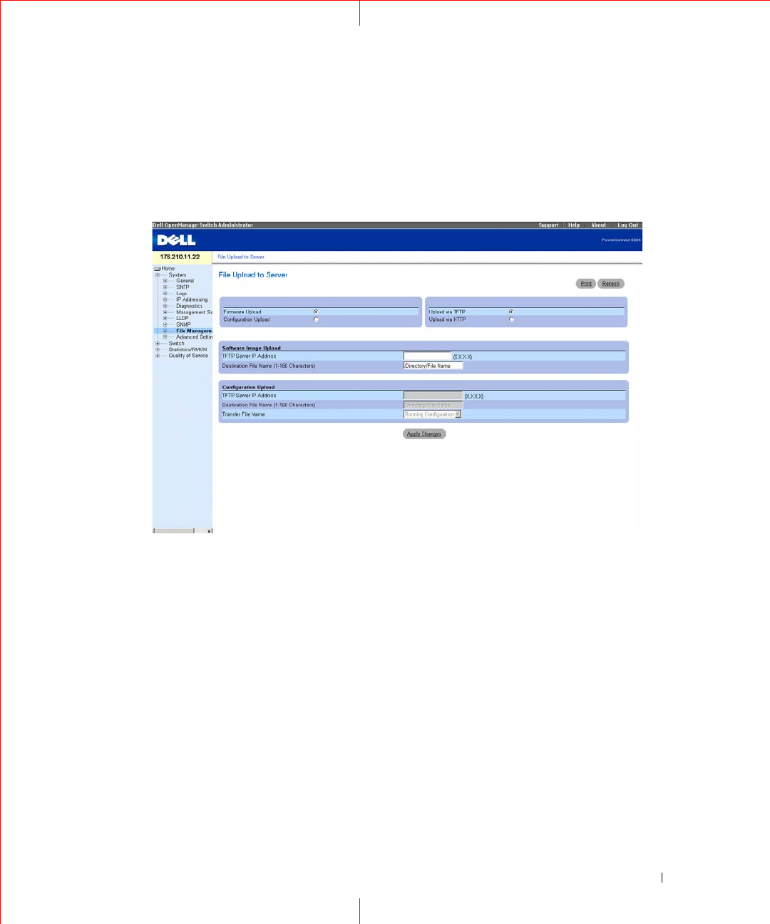
Uploading Files
The
File Upload to Server
page contains fields for uploading the software from the TFTP server to the device.
The image file can also be uploaded from the
File Upload to Server
page. To open the
File Upload to Server
page, click
System
→
File Management
→
File Upload
in the tree view.
Figure 1-28. File Upload to Server
Firmware Upload
—
Indicates that the upload is for firmware. If Firmware Upload is selected, the Configura-
tion Upload fields are grayed out.
Configuration Upload
—
Indicates that the upload is for configuration files. If Configuration Upload is
selected, the Firmware Upload fields are grayed out.
Upload via TFTP
—
Enables initiating an upload via the TFTP server.
Upload via
HTTP
—
Enables initiating an upload via the HTTP or HTTPS server. Only configuration files can
be uploaded using HTTP or HTTPS server.
Software Image Upload
TFTP Server IP Address
—
The TFTP Server IP Address to which the Image file is uploaded.
Destination File Name (1-160 Characters) —
Indicates the Image file path to which the file is uploaded.
Configuration Upload
TFTP Server IP Address —
The TFTP Server IP Address to which the Configuration file is uploaded.

42
www.dell.com | support.dell.com
Destination File Name (1-160 Characters) —
Indicates the Configuration file path to which the file is
uploaded.
Transfer File Name —
The software file to which the configuration is uploaded. The possible field values are:
Running Configuration —
Uploads the Running Configuration file.
Startup Configuration —
Uploads the Startup Configuration file.
Backup Configuration —
Uploads the Backup Configuration file.
Uploading Files
1
Open the
File Upload to Server
page.
2
Define the file type to upload.
3
Define the fields.
4
Click
Apply Changes
.
The software is uploaded to the device.
Uploading Files Using CLI Commands
The following table summarizes the equivalent CLI commands for setting fields displayed in the
File Upload to
Server
page.
The following is an example of the CLI commands:
Table 1-11. File Upload CLI Commands
CLI Command Description
copy source-url destination-
url [snmp]
Copies any file from a source to a destination.
console# copy image tftp://10.6.6.64/uploaded.ros
!!!!!!!!!!!!!!!!!!!!!!!!!!!!!!!!!!!!!!!!!!!!!!!!!!!!!!!!!!!!!!!
!!!!!!!!!!!!!!!!!!!!!!!!!!!!!!!!!!!!!!!!!!!!!!!!!!!!!!!!!!!!!!
!!!!!!!!!!!!!!!!!!!!!!!!!!!!!!!!!!!!!!!!!!!!!!!!!!!!!!!!!!!!!!!
!!!!!!!!!!!!!!!!!!!!!!!!!!!!!!!!!!!!!!!!!!!!!!!!!!!!!!!!!!!!!!!
!!!!!!!!!!!!!!!!!!!!!!!!!!!!!!!!!!!!!!!!!!!!!!!!!!!!!!!!!!!!!!!
!!!!!!!!!!!!!!!!!!!!!!!!!!!!!!!!!!!!!!!!!!!!!!!!!!!!!!!!!!!!!!!
Copy: 4234656 bytes copied in 00:00:33 [hh:mm:ss]
01-Jan-2000 07:30:42 %COPY-W-TRAP: The copy operation was
completed successfully
43
NOTE: Each "! " indicates that 10 packets were successfully transferred.
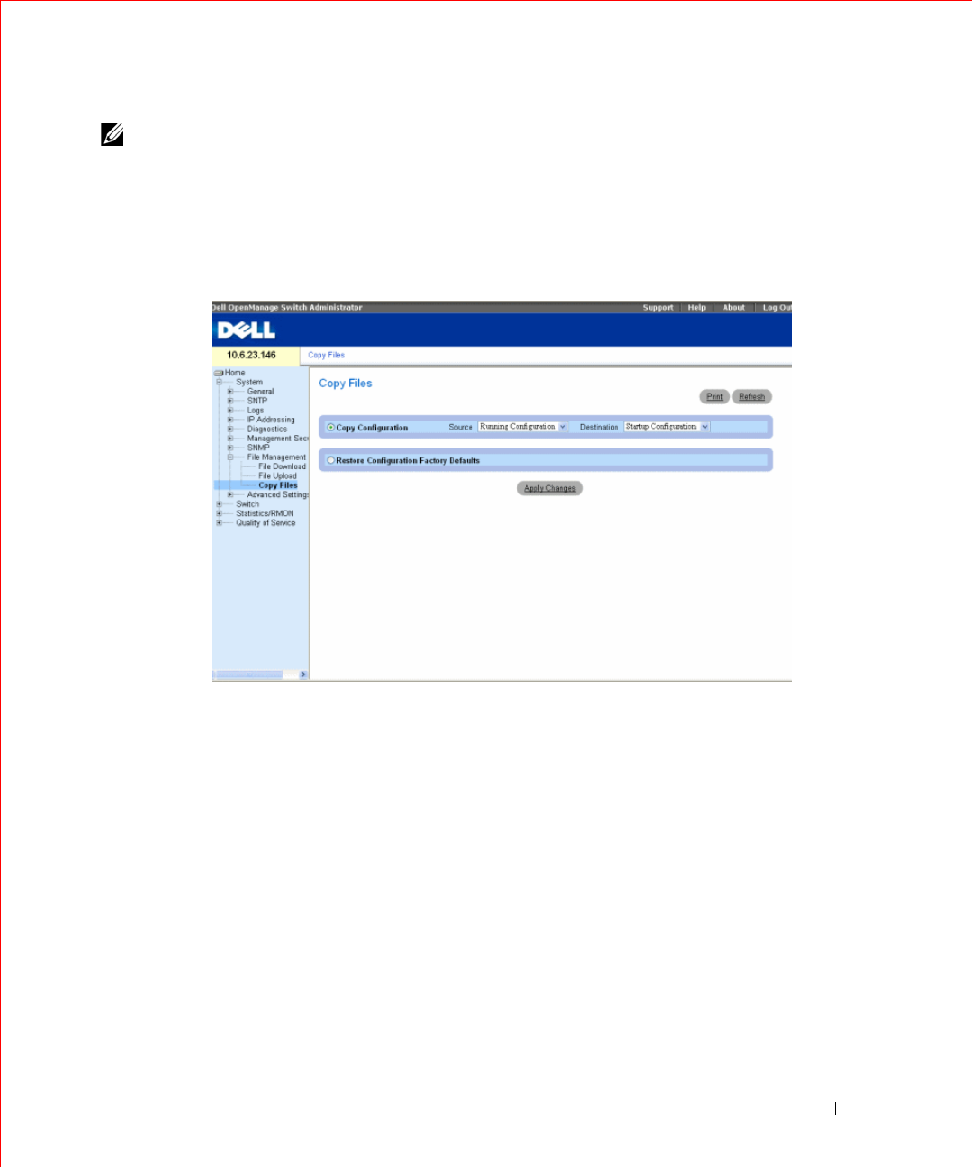
Copying Files
Files can be copied and deleted from the
Copy Files
page. To open the
Copy Files
page, click
System
→
File
Management
→
Copy Files
in the tree view.
Figure 1-29. Copy Files
i
Copy Configuration
— When selected, copies either the Running Configuration, Startup Configuration or
Backup Configuration files. The possible field values are:
Source
— Copies either the Running Configuration, Startup Configuration or Backup Configuration files.
Destination —
The file to which the Running Configuration, Startup Configuration or Backup
Configuration file is copied.
Restore Configuration Factory Defaults
— When selected, specifies that the factory configuration default files
should be reset. When unselected, maintains the current configuration settings.
Copying Files
1
Open the
Copy Files
page.
2
Define the
Source
and
Destination
fields.
3
Click
Apply Changes
.
The file is copied, and the device is updated.

44
www.dell.com | support.dell.com
Restoring Company Factory Default Settings
1
Open the
Copy Files
page.
2
Click
Restore Company Factory Defaults
.
3
Click
Apply Changes
.
The company factory default settings are restored, and the device is updated.
Copying and Deleting Files Using CLI Commands
The following table summarizes the equivalent CLI commands for setting fields displayed in the
Copy Files
page.
The following is an example of the CLI commands:
Table 1-12. Copy Files CLI Commands
CLI Command Description
copy source-url destination-
url [snmp]
Copies any file from a source to a destination.
delete startup-config Deletes the startup-config file.
Console# copy running-config startup-config
01-Jan-2000 01:55:03 %COPY-W-TRAP: The copy operation was
completed successfully
Copy succeeded
45
Defining STP Root Guard
Defining STP Global Settings
The
Spanning Tree Global Settings
page contains parameters for enabling STP on the device. To open the
Spanning Tree Global Settings
page, click
Switch
→
Spanning Tree
→
Global Settings
in the tree view.
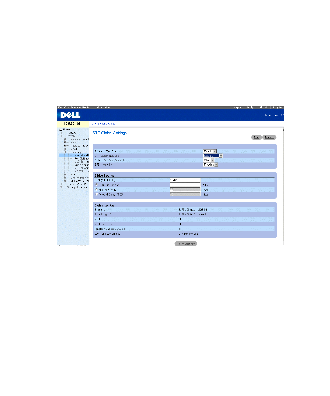
Figure 1-30. Spanning Tree Global Settings
The
Spanning Tree Global Settings
page contains the following fields:
Spanning Tree State
— Enables or disables STP, Rapid STP, or MSTP on the device.
STP Operation Mode
— Indicates the STP mode by which STP is enabled on the device. The possible field
values are:
Classic STP
— Enables Classic STP on the device. This is the default value.
Rapid STP
— Enables Rapid STP on the device.
Multiple STP
— Enables Multiple STP on the device.
Path Cost Default Values
— Specifies the method used to assign default path costs to STP ports. The possible
field values are:
Short
— Specifies 1 through 65,535 range for port path costs. This is the default value.
Long
— Specifies 1 through 200,000,000 range for port path costs.

46
www.dell.com | support.dell.com
The default path costs assigned to an interface vary according to the selected method:
BPDU Handling
— Determines how BPDU packets are managed when STP is disabled on the port/ device.
BPDUs are used to transmit spanning tree information. The possible field values are:
Filtering
— Filters BPDU packets when spanning tree is disabled on an interface. This is the default value.
Flooding
— Floods BPDU packets when spanning tree is disabled on an interface.
Priority (0-61440)
— Specifies the bridge priority value. When switches or bridges are running STP, each is
assigned a priority. After exchanging BPDUs, the device with the lowest priority value becomes the Root Bridge.
The default value is 32768. The port priority value is provided in increments of 4096. For example, 4096, 8192,
12288, etc.
Hello Time (1-10)
— Specifies the device Hello Time. The Hello Time indicates the amount of time in seconds
a root bridge waits between configuration messages. The default is 2 seconds.
Max Age (6-40
) — Specifies the device Maximum Age Time. The Maximum Age Time indicates the amount of
time in seconds a bridge waits before sending configuration messages. The default max age is 20 seconds.
Forward Delay (4-30)
— Specifies the device forward delay time. The Forward Delay Time indicates the amount
of time in seconds a bridge remains in a listening and learning state before forwarding packets. The default is 10
seconds.
Bridge ID
— Identifies the Bridge priority and MAC address.
Root Bridge ID
— Identifies the Root Bridge priority and MAC address.
Root Port
— Indicates the port number that offers the lowest cost path from this bridge to the Root Bridge. It is
significant when the Bridge is not the Root.
Root Path Cost
— The cost of the path from this bridge to the root.
Topology Changes Counts
— Specifies the total amount of STP state changes that have occurred.
Last Topology Change
— Indicates the amount of time that has elapsed since the bridge was initialized or reset,
and the last topographic change occurred. The time is displayed in a D/H/M/S format, for example,
2D/5H/10M/4S.
Interface
Long Short
LAG
20,000 4
1000 Mbps
20,000 4
100 Mbps
200,000 19
10 Mbps
2,000,000 100

47
Defining STP Global Parameters
1
Open the page.
2
Select
Enable
in the
Spanning Tree State
field.
3
Select the
STP
mode in the
STP Operation Mode
field, and define the bridge settings.
4
Click
Apply Changes
.
STP is enabled on the device.
Modifying STP Global Parameters
1
Open the page.
2
Define the fields in the dialog.
3
Click
Apply Changes
.
The STP parameters are modified, and the device is updated.
Defining STP Global Parameters Using CLI Commands
The following table summarizes the equivalent CLI commands for defining STP global parameters as displayed
in the
Spanning Tree Global Settings page.
Table 1-13. STP Global Parameter CLI Commands
CLI Command Description
spanning-tree Enables spanning tree functionality.
spanning-tree mode {stp
| rstp | mstp}
Configures the mode of the spanning tree
protocol.
spanning-tree priority
priority
Configures the spanning tree priority.
spanning-tree hello-time
seconds
Configures the spanning tree bridge Hello
Time, which is how often the device
broadcasts Hello messages to other devices.
spanning-tree max-age
seconds
Configures the spanning tree bridge
maximum age.
spanning-tree forward-
time
seconds
Configures the spanning tree bridge
forward time, which is the amount of time
a port remains in the listening and learning
states before entering the forwarding state.

48
www.dell.com | support.dell.com
show spanning-tree
[ethernet
interface
|
port-channel
port-
channel-number
]
[instance
instance-id
]
Displays spanning tree configuration.
show spanning-tree
[detail] [active |
blockedports] [instance
instance-id
]
Displays detailed spanning tree
information on active or blocked ports.
show spanning-tree mst-
configuration
Displays spanning tree MST configuration
identifier.
Table 1-13. STP Global Parameter CLI Commands (continued)
CLI Command Description

49
The following is an example of the CLI commands:
console(config)# spanning-tree
console(config)# spanning-tree mode rstp
console(config)# spanning-tree priority 12288
console(config)# spanning-tree hello-time 5
console(config)# spanning-tree max-age 12
console(config)# spanning-tree forward-time 25
console(config)# exit
console# show spanning-tree
Spanning tree enabled mode MSTP
Default port cost method: short
Gathering information ..........
###### MST 0 Vlans Mapped: 16-4094
CST Root ID Priority 20480
Address 00:30:ab:00:00:08
Path Cost 4
Root Port ch2
This switch is the IST master
Hello Time 2 sec Max Age 20 sec Forward Delay 15 sec
Bridge ID Priority 32768
Address 00:00:00:16:00:64
Max hops 20
Name State Prio.Nbr Cost Sts Role PortFast Type
---- ----- ------- ---- --- ---- ------- ----
1/e2 enabled 128.2 100 DSBL Dsbl No P2p Intr
1/e3 enabled 128.3 100 DSBL Dsbl No P2p Intr
1/e4 enabled 128.4 100 DSBL Dsbl No P2p Intr
1/e5 enabled 128.5 19 FRW Desg Yes P2p Intr

50
www.dell.com | support.dell.com
1/e6 enabled 128.6 100 DSBL Dsbl No P2p Intr
1/e7 enabled 128.7 100 DSBL Dsbl No P2p Intr
1/e8 enabled 128.8 100 DSBL Dsbl No P2p Intr
1/e9 enabled 128.9 100 DSBL Dsbl No P2p Intr
1/e10 enabled 128.10 100 DSBL Dsbl No P2p Intr
1/e11 enabled 128.11 19 DSBL Desg Yes P2p Intr
console# show spanning-tree active
Spanning tree enabled mode MSTP
Default port cost method: short
Gathering information ..........
###### MST 0 Vlans Mapped: 16-4094
CST Root ID Priority 20480
Address 00:30:ab:00:00:08
Path Cost 4
Root Port ch2
This switch is the IST master
Hello Time 2 sec Max Age 20 sec Forward Delay 15 sec
Bridge ID Priority 32768
Address 00:00:00:16:00:64
Max hops 20
Name State Prio.Nbr Cost Sts Role PortFast Type
---- ----- ------- ---- --- ---- ------- ----
1/e5 enabled 128.2 19 FRW Desg Yes P2p Intr
1/e7 enabled 128.7 19 DSCR Altn No P2p Bound (STP)
1/e11 enabled 128.11 19 FRW Desg Yes P2p Intr
1/e15 enabled 128.15 19 FRW Desg No P2p Intr
1/e22 enabled 128.22 19 FRW Desg Yes P2p Intr
51
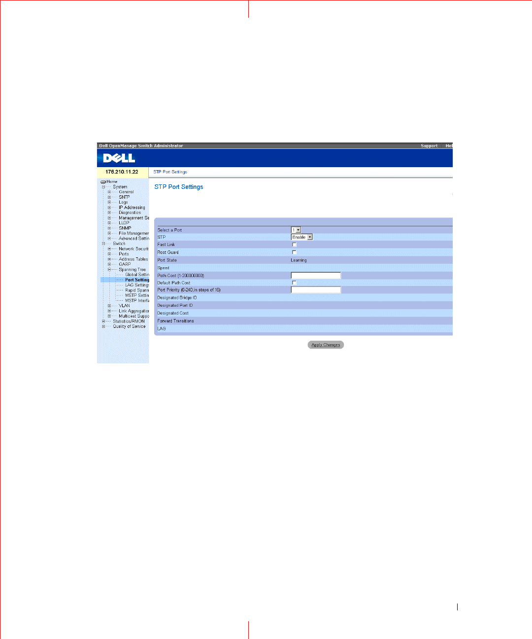
Defining STP Port Settings
The
STP Port Settings
page contains fields for assigning STP properties to individual ports. To open the
STP
Port Settings
page, click
Switch
→
Spanning Tree
→
Port Settings
in the tree view.
Figure 1-31. STP Port Settings
Port
— Port on which STP is enabled.
STP
— Enables or disables STP on the port.
Fast Link
— When selected, enables Fast Link mode for the port. If Fast Link mode is enabled for a port, the
Port State
is automatically placed in the
Forwarding
state
when the port link is up. Fast Link mode optimizes
the time it takes for the STP protocol to converge. STP convergence can take 30-60 seconds in large networks.
Root Guard
—
When checked, prevents devices outside the network core from being assigned the spanning tree
root.
Port State
— The current port STP state. If enabled, the port state determines what forwarding action is taken
on traffic. Possible port states are:
Disabled
— The port link is currently down.
Blocking
— The port is currently blocked and cannot be used to forward traffic or learn MAC addresses.
Blocking is displayed when Classic STP is enabled.
Listening
— The port is currently in the listening mode. The port cannot forward traffic nor can it learn
MAC addresses.

52
www.dell.com | support.dell.com
Learning
— The port is currently in the learning mode. The port cannot forward traffic however it can
learn new MAC addresses.
Forwarding
— The port is currently in the forwarding mode. The port can forward traffic and learn new
MAC addresses.
Speed
— Speed at which the port is operating.
Path Cost (1-200000000)
— The port contribution to the root path cost. The path cost is adjusted to a higher or
lower value, and is used to forward traffic when a path being rerouted.
Default Path Cost
— The default path cost of the port is automatically set by the port speed and the default
path cost method.
The default values for long path costs are:
Ethernet
- 2000000
Fast Ethernet
- 200000
Gigabit Ethernet
- 20000
The default values for short path costs (short path costs are the default) are:
Ethernet
- 100
Fast Ethernet
- 19
Gigabit Ethernet
- 4
Priority (0-240, in steps of 16)
— The priority value of the port. The priority value influences the port choice
when a bridge has two ports connected in a loop. The priority value is between 0-240. The priority value is
provided in increments of 16.
Designated Bridge ID
— The bridge priority and the MAC Address of the designated bridge.
Designated Port ID
— The selected port’s priority and interface.
Designated Cost
— The cost of the port participating in the STP topology. Ports with a lower cost are less likely
to be blocked if STP detects loops.
Forward Transitions
— The number of times the port has changed from the
Blocking
state to the
Forwarding
state.
LAG
— The LAG to which the port is attached.
Enabling STP on a Port
1
Open the
STP Port Settings
page.
2
Select
Enabled
in the
STP Port Status
field.
3
Define the
Fast Link
,
Path Cost
, and the
Priority
fields.
4
Click
Apply Changes
.
STP is enabled on the port.

53
Modifying STP Port Properties
1
Open the
STP Port Settings
page.
2
Modify the
Priority
,
Fast Link
,
Path Cost
, and the
Fast Link
fields.
3
Click
Apply Changes
.
The STP port parameters are modified, and the device is updated.
Displaying the STP Port Table
1
Open the
STP Port Settings
page.
2
Click
Show All
.
The
STP Port Table
opens.
Defining STP Port Settings Using CLI Commands
The following table summarizes the equivalent CLI commands for defining STP port parameters as displayed in
the
STP Port Settings
page.
Table 1-14. STP Port Settings CLI Commands
CLI Command Description
spanning-tree disable Disables spanning tree on a specific
port.
spanning-tree cost cost Configures the spanning tree cost
contribution of a port.
spanning-tree port-priority priority Configures port priority.
spanning-tree portfast Enables PortFast mode.
show spanning-tree [ethernet interface
| port-channel port-channel-number]
Displays spanning tree configuration.
spanning-tree guard root Enables root guard on all the spanning
tree instances on that interface.

54
www.dell.com | support.dell.com
The following is an example of the CLI commands:
console(config)# interface ethernet g5
console(config-if)# spanning-tree disable
console(config-if)# spanning-tree cost 35000
console(config-if)# spanning-tree port-priority 96
console(config-if)# exit
console(config)# exit
console# show spanning-tree ethernet g5
Port g5 disabled
State: disabled
Port id: 96.5
Type: P2p (configured: Auto) STP
Designated bridge Priority : 32768
Designated port id: 96.5
Number of transitions to forwarding state: 0
BPDU: sent 0, received 0
console#
Role: disabled
Port cost: 35000
Port Fast: No (configured: No)
Address: 00:e8:00:b4:c0:00
Designated path cost: 19
55
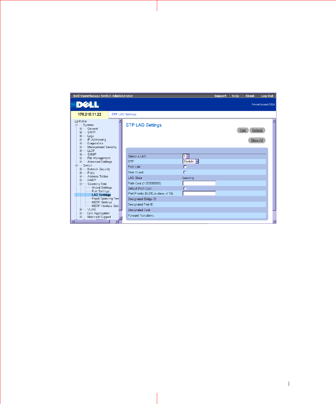
Defining STP LAG Settings
The
STP LAG Settings
page contains fields for assigning STP aggregating port parameters. To open the
STP
LAG Settings
page, click
Switch
→
Spanning Tree
→
LAG Settings
in the tree view.
Figure 1-32. STP LAG Settings
Select a LAG
— The user-defined LAG. For more information, see "Defining LAG Membership" in the
Dell
PowerConnect 5324 User Guide
.
STP
— Enables or disables STP on the LAG.
Fast Link
— Enables Fast Link mode for the LAG. If Fast Link mode is enabled for a LAG, the
LAG State
is
automatically placed in the
Forwarding
state
when the LAG is up. Fast Link mode optimizes the time it takes for
the STP protocol to converge. STP convergence can take 30-60 seconds in large networks.
Root Guard —
When checked, prevents devices outside the network core from being assigned the spanning tree
root.
LAG State
— Current STP state of a LAG. If enabled, the LAG state determines what forwarding action is taken
on traffic. If the bridge discovers a malfunctioning LAG, the LAG is placed in the
Broken
state. Possible LAG
states are:
Disabled
— The LAG link is currently down.
Blocking
— The LAG is blocked and cannot be used to forward traffic or learn MAC addresses.
Listening
— The LAG is in the listening mode and cannot forward traffic or learn MAC addresses.

56
www.dell.com | support.dell.com
Learning
— The LAG is in the learning mode and cannot forward traffic, but it can learn new MAC
addresses.
Forwarding
— The LAG is currently in the forwarding mode, and it can forward traffic and learn new MAC
addresses.
Broken
— The LAG is currently malfunctioning and cannot be used for forwarding traffic.
Path Cost (1-200000000)
— Amount the LAG contributes to the root path cost. The path cost is adjusted to a
higher or lower value, and is used to forward traffic when a path being rerouted. The path cost has a value of 1 to
200000000. If the path cost method is short, the LAG cost default value is 4. If the path cost method is long, the
LAG cost default value is 20000.
Default Path Cost
— When selected, the LAG path cost returns to its default value.
Priority (0-240, in steps of 16)
— The priority value of the LAG. The priority value influences the LAG choice
when a bridge has two looped ports. The priority value is between 0-240, in increments of 16.
Designated Bridge ID
— The bridge priority and the MAC Address of the designated bridge.
Designated Port
ID
— The port priority and interface number of the designated port.
Designated Cost
— The cost of the designated bridge.
Forward Transitions
— The number of times the
LAG State
has changed from the
Blocking
state to a
Forwarding
state.
Modifying the LAG STP Parameters
1
Open the
STP LAG Settings
page.
2
Select a LAG from the
Select a LAG
drop-down menu.
3
Modify the fields as desired.
4
Click
Apply Changes
.
The STP LAG parameters are modified, and the device is updated.
Defining STP LAG Settings Using CLI Commands
The following table summarizes the equivalent CLI commands for defining STP LAG settings.
Table 1-15. STP LAG Settings CLI Commands
CLI Command Description
spanning-tree Enables spanning tree.
spanning-tree disable Disables spanning tree on a specific
LAG.
spanning-tree cost cost Configures the spanning tree cost
contribution of a LAG.
spanning-tree port-priority priority Configures port priority.

57
The following is an example of the CLI commands:
Configuring Multiple Spanning Tree
MSTP operation maps VLANs into STP instances. Multiple Spanning Tree provides differing load balancing
scenario. For example, while port A is blocked in one STP instance, the same port is placed in the
Forwarding
State
in another STP instance.
In addition, packets assigned to various VLANs are transmitted along different paths within Multiple Spanning
Trees Regions (MST Regions). Regions are one or more Multiple Spanning Tree bridges by which frames can be
transmitted. To open the
MSTP Settings
page, click
Switch
→
Spanning Tree
→
MSTP Settings
in the tree
view
.
spanning-tree guard root Enables root guard on all the spanning
tree instances on that interface.
show spanning-tree [ ethernet interface
| port-channel port-channel-number]
Displays spanning tree configuration.
show spanning-tree [detail] [active |
blockedports]
Displays detailed spanning tree
information on active or blocked ports
console(config)# interface port-channel 1
console(config-if)# spanning-tree port-priority 16
Table 1-15. STP LAG Settings CLI Commands
CLI Command Description
58
www.dell.com | support.dell.com
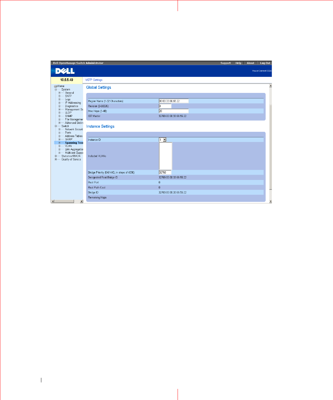
Figure 1-33. MSTP Settings
Region Name (1-32 Characters)
— Indicates user-defined MSTP region name.
Revision
(0-65535) — Defines unsigned 16-bit number that identifies the current MST configuration revision.
The revision number is required as part of the MST configuration. The possible field range is 0-65535.
Max Hops (1-40)
— Defines the total number of hops that occur in a specific region before the BPDU is
discarded. Once the BPDU is discarded, the port information is aged out. The possible field range is 1-40. The
field default is 20 hops.
IST Master
— Indicates the Internal Spanning Tree Master ID. The IST Master is the specified instance root.
Instance ID
— Defines the MSTP instance. The field range is 0-15.
Included VLANs
— Maps the selected VLANs to the selected instance. Each VLAN belongs to one instance.
Bridge Priority (0-61440)
— Specifies the selected spanning tree instance device priority. The field range is 0-
61440
Designated Root Bridge ID
— Indicates the ID of the bridge with the lowest path cost to the instance ID.
Root Port
— Indicates the selected instance’s root port.
Root Path Cost
— Indicates the selected instance’s path cost.
Bridge ID
— Indicates the bridge ID of the selected instance.
Remaining Hops
— Indicates the number of hops remaining to the next destination.
59
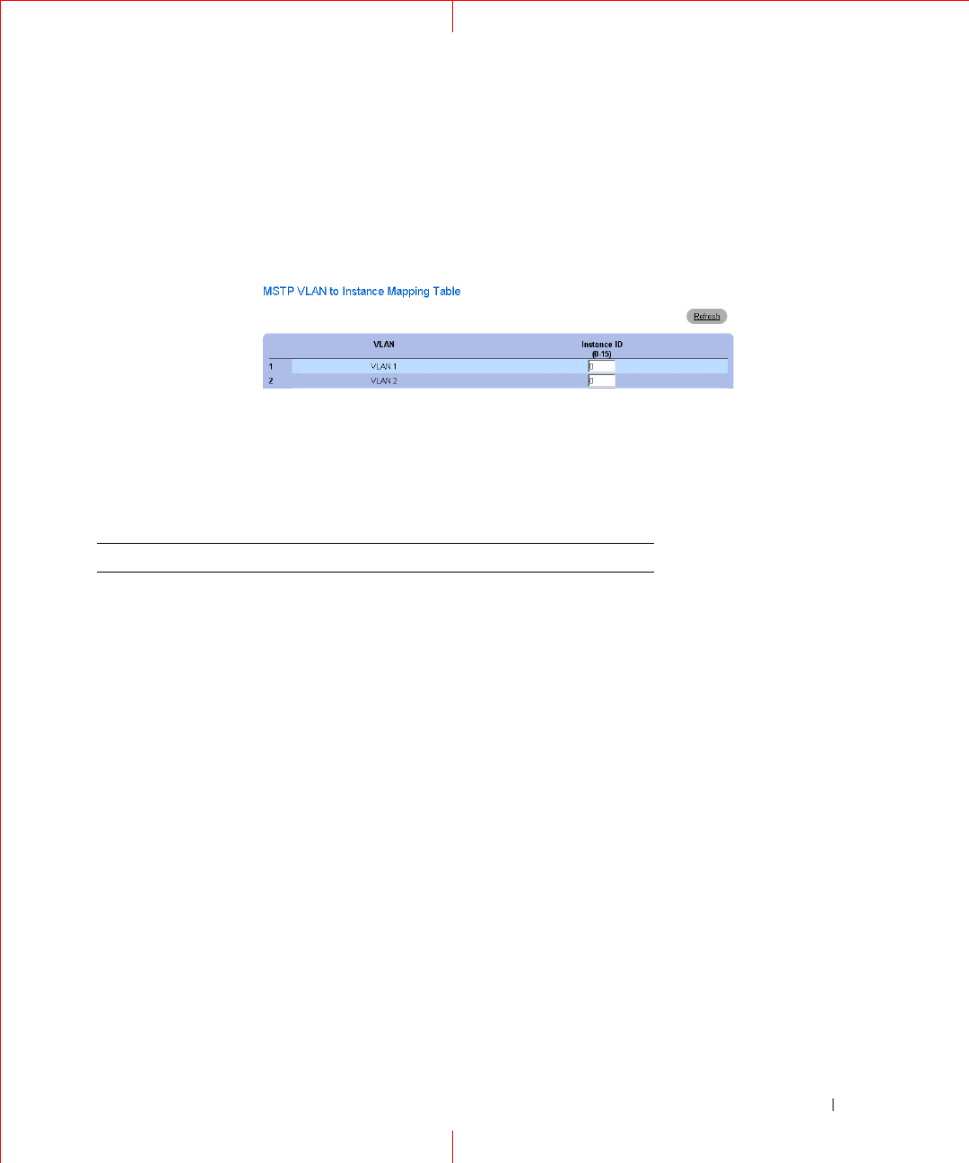
Displaying the MSTP Instance Table
1
Open the
MSTP Settings
page.
2
Click
Show All
to open the
MSTP Instance Table
.
Figure 1-34. MSTP Instance Table
Defining MST Instances Using CLI Commands
The following table summarizes the equivalent CLI commands for defining MST instance groups as displayed in
the
MSTP Settings
page.
Table 1-16. MSTP Instances CLI Commands
CLI Command Description
spanning-tree mst
configuration
Enters MST Configuration mode.
instance
instance-id
{add | remove} vlan
vlan-range
Maps VLANs to the MST instance
name
string
Sets the configuration name.
revision
value
Sets the configuration revision number
spanning-tree mst
instance-id
port-
priority
priority
Sets the priority of a port.
spanning-tree mst
instance-id
priority
priority
Sets the device priority for the specified
spanning tree instance.
spanning-tree mst max-
hops
hop-count
Sets the number of hops in an MST region
before the BPDU is discarded and the
information held for a port is aged.
spanning-tree mst
instance-id
cost
cost
Sets the path cost of the port for MST
calculations
exit Exits the MST region configuration mode and
applies configuration changes
60
www.dell.com | support.dell.com
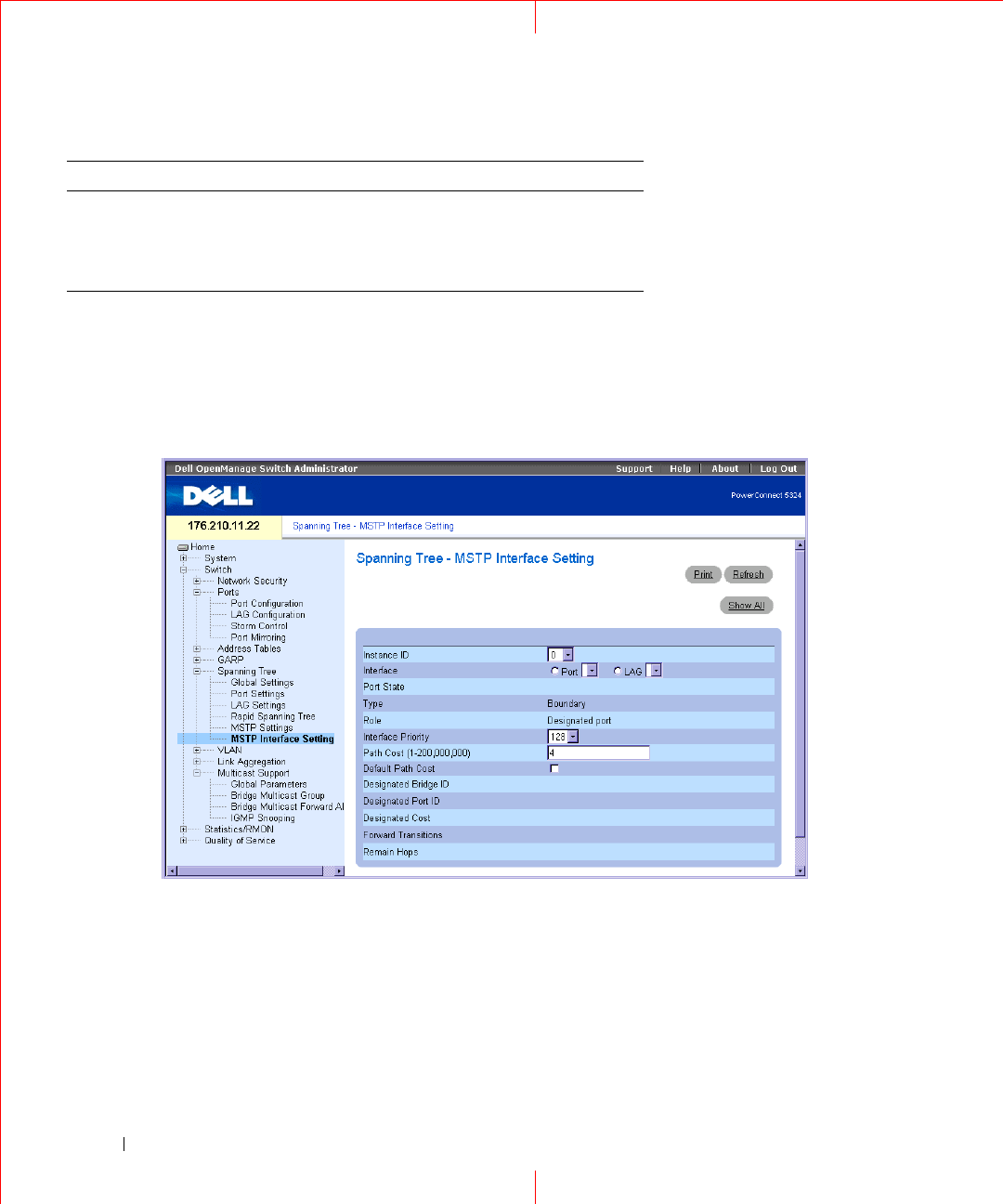
Defining MSTP Interface Settings
The
MSTP Interface Settings
page contains parameters assigning MSTP settings to specific interfaces. To open
the
MSTP Interface Settings
page, click
Switch
→
Spanning Tree
→
MSTP Interface Settings
in the tree view.
Figure 1-35. MSTP Interface Settings
Instance ID —
Defines the VLAN group to which the interface is assigned. Possible field range is 0-15.
Interface —
Assigns either ports or LAGs to the selected MSTP instance.
Port State —
Indicates whether the port is enabled or disabled in the specific instance.
Ty p e —
Indicates whether MSTP treats the port as a point-to-point port, or a port connected to a hub, and
whether the port is internal to the MSTP region or a boundary port. If the port is a boundary port, it also
indicates whether the device on the other side of the link is working in RSTP or STP mode.
Role —
Indicates the port role assigned by the STP algorithm in order to provide to STP paths. The possible
field values are:
abort Exits the MST region configuration mode
without applying configuration changes.
show {current | pending}Displays the current or pending MST region
configuration.
Table 1-16. MSTP Instances CLI Commands
CLI Command Description

61
Root
— Provides the lowest cost path to forward packets to root device.
Designated
— Indicates the port or LAG via which the designated device is attached to the LAN.
Alternate
— Provides an alternate path to the root device from the root interface.
Backup
— Provides a backup path to the designated port path toward the Spanning Tree leaves. Backup
ports occur only when two ports are connected in a loop by a point-to-point link. Backup ports also occur
when a LAN has two or more connections connected to a shared segment.
Disabled
— Indicates the port is not participating in the Spanning Tree.
Interface Priority (0-240,in steps of 16) —
Defines the interface priority for specified instance. The default
value is 128.
P
ath Cost
— Indicates the port contribution to the Spanning Tree instance root path cost. If the Long path cost
method was specified in the
page, the field value range is 1-200,000,000. If the Short path cost method was
specified, the field value range is 1-65,535.
Default Path Cost
— If the Long path cost method was specified in the page, the default path cost values are:
Ethernet (10 Mbps) - 2,000,000
Fast Ethernet (100 Mbps) - 200,000
Gigabit Ethernet (1000 Mbps) - 20,000
Port-Channel - 20,000
If the Short path cost method was specified, the default path cost values are:
Ethernet (10 Mbps) - 100
Fast Ethernet (100 Mbps) - 19
Gigabit Ethernet (1000 Mbps) - 4
Port-Channel - 4
Root —
Provides the lowest cost path to forward packets to the root device.
Designated Bridge ID —
The bridge ID number that connects the link or shared LAN to the root.
Designated Port ID —
The Port ID Number on the designated bridge that connects the link or the shared LAN
to the root.
Designated Cost —
Cost of the path from the link or the shared LAN to the root.
Forward Transitions —
Number of times the port changed to the forwarding state.
Remain Hops —
Indicates the number of hops remaining to the next destination.
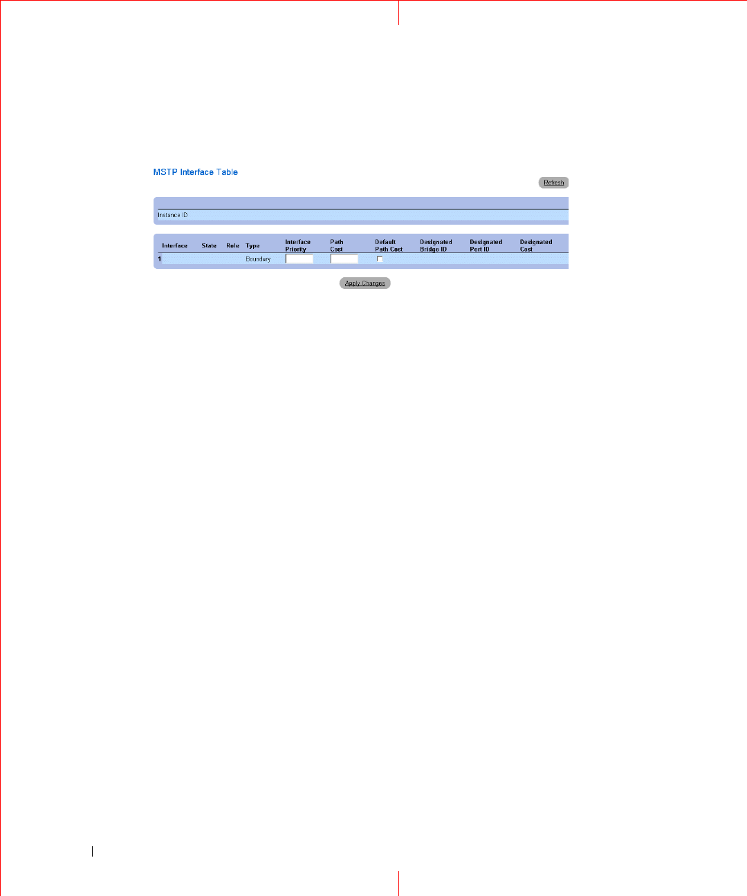
Viewing the MSTP Interface Table
1
Open the
MSTP Interface Settings
page.
2
Click
Show All
.
63
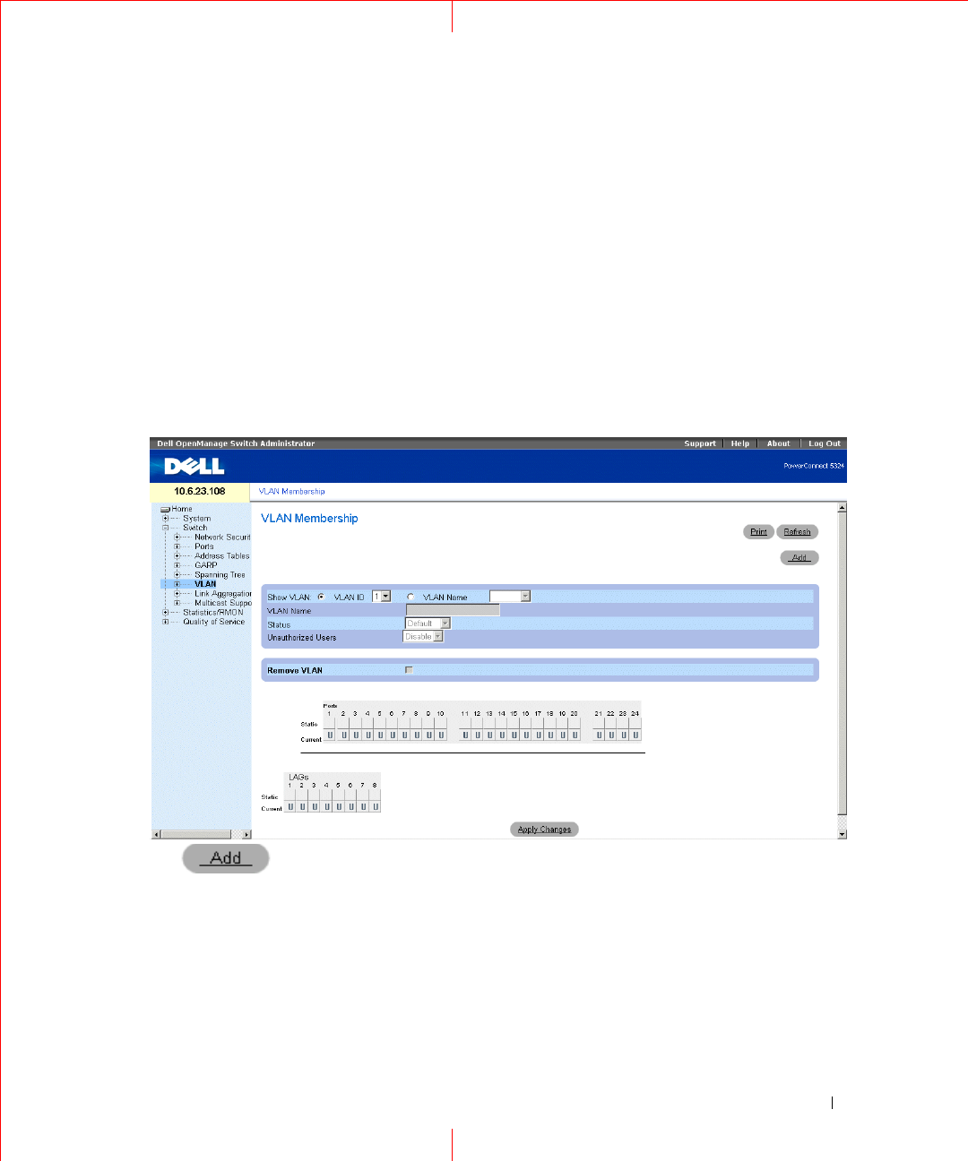
Configuring QinQ
This section contains information for configuring Customer VLANs using the Web Interface and using the CLI.
QinQ tagging allows network managers to add an additional tag to previously tagged packets. Customer VLANs
are configured using QinQ. Adding additional tags to the packets helps create more VLAN space. The added tag
provides VLAN ID to each customer, this ensures private and segregated network traffic. The VLAN ID tag is
assigned to a customer port in the service providers network. The designated port then provides additional
services to the packets with the double-tags. This allows administrators to expand service to VLAN users. To
configure customer VLANs:
To configure customer VLANs:
1
Click
Switch > VLAN > VLAN Membership
. The
VLAN Membership
page opens.
Figure 1-37. VLAN Membership
2
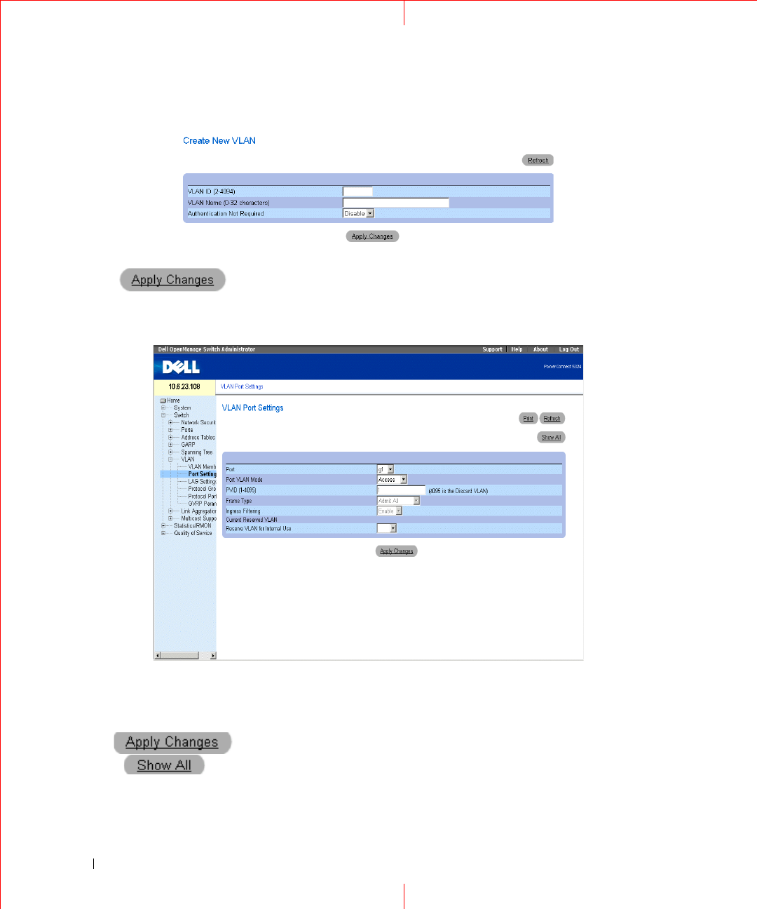
Click . The
Create New VLAN
page opens:
64
www.dell.com | support.dell.com
Figure 1-38. Create New VLAN
3
Define the
VLAN ID
and
VLAN Name
field.
4
Click .
5
Click
Switch > VLAN > Port Settings
. The
Port Settings
page opens.
Figure 1-39. Port Settings
6
Select the port.
7
Set the
Port VLAN Mode
field to
Customer
.
8
Define the remaining fields.
9
Click . The VLAN Port settings are saved, and the device is updated.
10
Click . The
VLAN Port Table
opens.
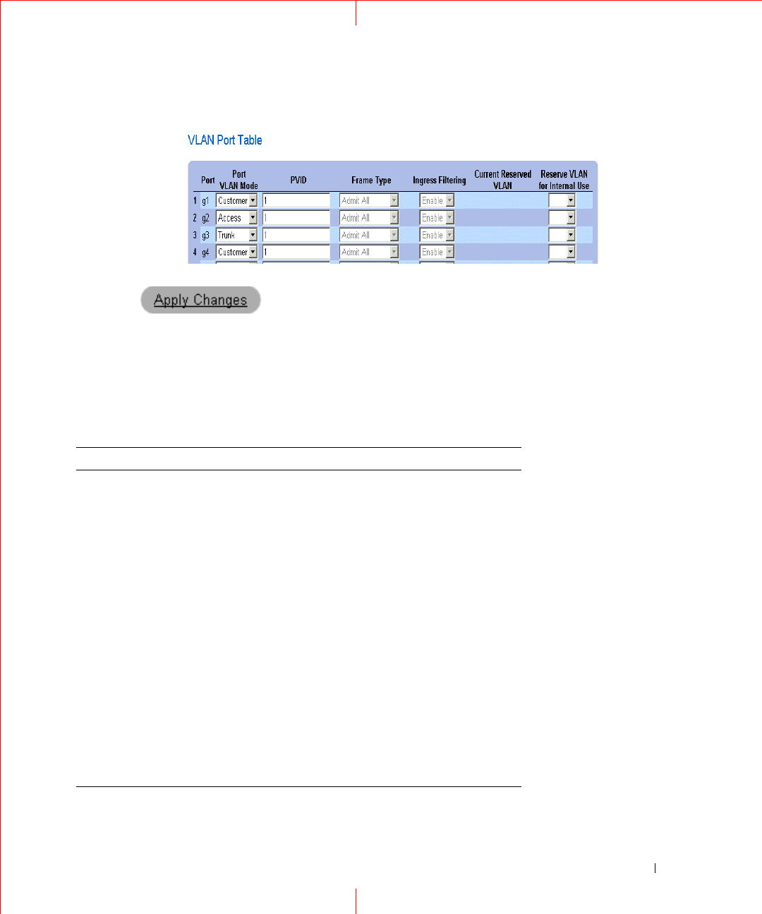
65
Figure 1-40. VLAN Port Table
11
Select the Port VLAN Mode.
12
Click . The customer VLAN is defined, and the device is updated.
VLAN Port Settings Using CLI Commands
The following table summarizes the equivalent CLI commands for viewing fields displayed in the
VLAN Port
Settings
page.
Table 1-17. QinQ CLI Commands
CLI Command
Console>enable
Console#config
Console (config)#
Console (config)# vlan database
Console (config-vlan)# vlan 100
Console (config-vlan)# exit
Console (config)# interface ethernet e5
Console (config-if)# switchport mode customer
Console (config-if)# switchport customer vlan 100
Console (config-if)# exit
Console (config)# interface ethernet e10
Console (config-if)# switchport mode trunk
Console (config-if)# switchport trunk allowed vlan add 100
Console (config-if)# exit

66
www.dell.com | support.dell.com
The following is an example of the QinQ show commands.
Forbidden VLANS:
Classification rules:
Protocol based VLANs:
Console# show interfaces switchport ethernet 1/e5
Port: 1/e5
Port Mode: Customer
Gvrp Status: disabled
Ingress Filtering: true
Acceptable Frame Type: admitAll
Ingress UnTagged VLAN ( NATIVE ): 100
Protected: Disabled
Port is member in:
Vla
n
Name Egress
rule
Port
Membership
Type
---
-
-----------------
------
--------
---
--------------
------
100 100 Untagged Static
Vlan Name
---- -----------------------
Group ID Vlan ID
-------- ------------------

67
Mac based VLANs:
Subnet based VLANs:
console#
Group ID Vlan ID
-------- ------------------
Group ID Vlan ID
-------- ------------------
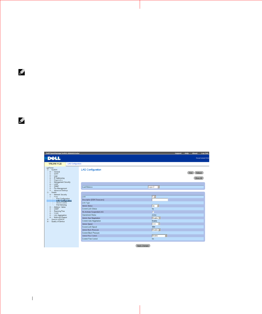
68
www.dell.com | support.dell.com
Configuring Load Balancing
Load Balancing enables the even distribution of data and/or processing packets across available network
resources. For example, load balancing may distribute the incoming packets evenly to all servers, or redirect
the packets to the next available server. Load Balancing is configured on the LAG Configuration page.
NOTE: LAGs can be configured according to the following load balancing types: Layer 2 or Layer 2 and Layer 3 or
Layer2, Layer 3 and Layer 4.
The
LAG Configuration
page contains fields for configuring parameters for configured LAGs. The device
supports up to eight ports per LAG, and eight LAGs per system.
For information about Link
Aggregated Groups
and assigning ports to LAGs, refer to
Aggregating Ports
in the
Dell PowerConnect 5324 User Guide
.
To open the
LAG Configuration
page, click
Switch
→
Ports
→
LAG Configuration
in the tree view.
NOTE: If port configuration is modified while the port is a LAG member, the configuration change is only effective after
the port is removed from the LAG.
Figure 1-41. LAG Configuration
The
LAG Configuration
page contains the following fields:
Load Balance —
Indicates the load balancing type enabled on the LAG. The possible field values are:
Layer 2
— Enables load balancing based on static and dynamic MAC addresses.

69
Layer 2-3
— Enables load balancing based on static and dynamic MAC addresses, and source and
destination IP addresses.
Layer 2-3-4
— Enables load balancing based on static and dynamic MAC addresses, source and destination
IP addresses, and Source and Destination UDP/TCP ports.
LAG
— The LAG number.
Description
(0-64 Characters)
— Provides a user-defined description of the configured LAG.
LAG Type
— The port types that comprise the LAG.
Admin Status
— Enables or disables traffic forwarding through the selected LAG.
Current LAG Status
— Indicates if the LAG is currently operating.
Re-Activate Suspended LAG
— Reactivates a suspended LAG.
Operational Status
— Operational status of the LAG.
Admin Auto Negotiation
— Enables or disables Auto Negotiation on the LAG. Auto-negotiation is a protocol
between two link partners that enables a LAG to advertise its transmission rate, duplex mode and flow control
(the flow control default is disabled) abilities to its partner.
Current Auto Negotiation
— The currently configured Auto Negotiation setting.
Admin Speed
— The speed at which the LAG is operating.
Current LAG Speed
— The currently configured speed at which the LAG is operating.
Admin Back Pressure —
Enables or disables Back Pressure mode on the LAG. Back Pressure mode is effective on
the ports operating in Half Duplex in the LAG.
Current Back Pressure —
The currently configured Back Pressure setting.
Admin Flow Control
— Enables/disables flow control, or enables the auto negotiation of flow control on the
LAG. Flow Control mode is effective on the ports operating in Full Duplex in the LAG.
Current Flow Control
— The user-designated flow control setting.
Defining LAG Parameters
1
Open the
LAG Configuration
page.
2
Select a LAG in the
LAG
field.
3
Define the fields.
4
Click
Apply Changes
.
The LAG parameters are saved to the device.
Modifying LAG Parameters
1
Open the
LAG Configuration
page.
2
Select a LAG in the
LAG
field.
3
Modify the fields.
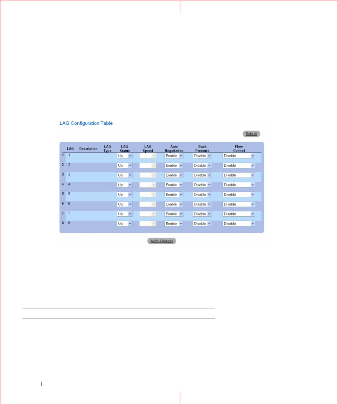
70
www.dell.com | support.dell.com
4
Click
Apply Changes
.
The LAG parameters are saved to the device.
Displaying the LAG Configuration Table:
1
Open the
LAG Configuration
page.
2
Click
Show All.
The
LAG Configuration Table
opens:
Figure 1-42. LAG Configuration Table
Configuring LAGs with CLI Commands
The following table summarizes the equivalent CLI commands for configuring LAGs as displayed in the
LAG
Configuration
page.
Table 1-18. LAG Configuration CLI Commands
CLI Command Description
interface port-channel
port-channel-number
Enters the interface configuration mode of a
specific port-channel.
port-channel load-
balance{
layer-2 |layer
2-3|layer 2-3-4
}
Configures the load balancing policy of the
port channeling.

71
description
string
Adds a description to an interface
configuration.
shutdown Disables interfaces that are part of the
currently set context.
speed
bps
Configures the speed of a given ethernet
interface when not using auto negotiation.
autobaud Sets the line for automatic baud rate
detection.
negotiation Enables auto negotiation operation for the
speed and duplex parameters of a given
interface.
back-pressure Enables Back Pressure on a given interface
flowcontrol {auto | on
| off | rx | tx}
Configures the Flow Control on a given
interface.
show interfaces
configuration
[ethernet
interface
|
port-channel
port-
channel-number
]
Displays the configuration for all configured
interfaces.
show interfaces status
[ethernet
interface
|port-channel
port-
channel-number
]
Displays the status for all configured
interfaces.
show interfaces
description [ethernet
interface
|port-
channel
port-channel-
number
]
Displays the description for all configured
interfaces.
show interfaces port-
channel [
port-channel-
number
]
Displays Port-channel information (which
ports are members of that port-channel, and
whether they are currently active or not).
Table 1-18. LAG Configuration CLI Commands
CLI Command Description

72
www.dell.com | support.dell.com
The following is an example of the CLI commands:
console(config-if)# channel-group 1 mode on
console(config-if)# exit
console(config)# interface range e g21-24
console(config-if)# channel-group 1 mode on
console(config-if)# ex
console(config)# interface ethernet g5
console(config-if)# channel-group 2 mode on
console(config-if)# exit
console(config)# exit
console# show interfaces port-channel
Channel Ports
--------- ---------
ch1 Inactive: g(21-24)
ch2 Active: g5
ch3
ch4
ch5
ch6
ch7
ch8
console#
